Operating Instructions MI 26
Maico Diagnosticsi7625 Golden Triangle DriveiEden Prairie, MN 55344iToll Free 888.941.4201 Maico Diagnostic GmbHi Salzufer 13/14i10587 Berlin, GermanyiTelephone ++030 70 71 46 50
Operating Instructions MI 26
1
Table of Contents Page
1. Introduction 2
2. Description 3
3. Getting started 5
4. How to create a tympanogram 13
5. How to measure the Stapedius reflex 18
6. Interpreting test results 23
7. How to test children 26
8. Audiometric pure tone screening 27
9. Additional reading 30
10. Individual setup of the MI 26 31
11. Care and maintenance of the instrument 36
12. How to change the printer paper 37
13. Warranty, maintenance and after-sales service 38
14. Safety regulations 41
15. Subjective checklist 42
16. Technical data 43
Operating Instructions MI 26
2
1 Introduction
Thank you very much for purchasing a quality product from the family. This automatic Tympanometer MI 26 is manufactured to meet all quality and safety requirements.
In designing the MI 26 we placed particular importance on making it a user-friendly device, meaning its operation is simple and easy to understand. And because all functions are software controlled, upgrading later to new, extended measurement functions will be simple and inexpensive. That means that you have invested in a device that will adjust to your future needs.
This user manual should make it as easy as possible for you to become familiar with the functions of the MI 26. The description of the position (e.g., ) of controls, displays and connections, found again in the text, will make it easier for you to learn how to operate the MI 26.
If you have problems or have ideas for further improvements, please get in touch with us. Simply call.
Your MAICO team
5
Operating Instructions MI 26
3
2 Description
The MI 26 is an automatic instrument that is designed for tympanometric and audiometric pure tone screening. Tests done in the tympanometric screening mode measure middle ear mobility and ipsilateral acoustic reflex. Contralateral acoustic reflex is available as an option. Test results are displayed on the front panel LCD (liquid crystal display) screen and may be printed. The MI 26 not only performs all of these impedance screening functions but has the capability of audiometric pure tone screening. Tests done in the audiometric pure tone screening mode measure hearing response levels. The MI 26 offers a full range of frequencies and levels for complete air conduction hearing screening The design of the MI 26 allows rapid and reliable measurements. This equipment is designed for middle ear function screening. PC-Interface: A serial RS 232C interface for data transfer to a connected computer is built in.
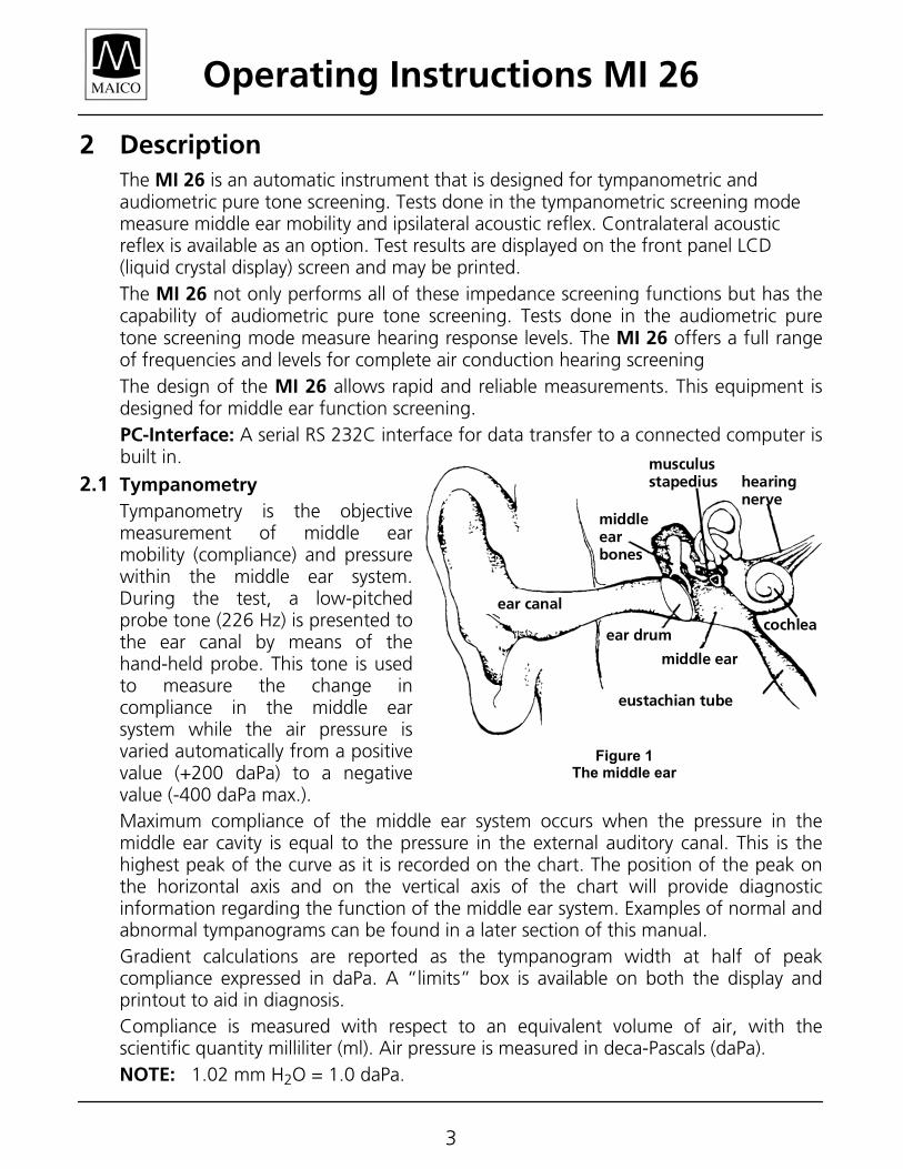
2.1 Tympanometry Tympanometry is the objective measurement of middle ear mobility (compliance) and pressure within the middle ear system. During the test, a low-pitched probe tone (226 Hz) is presented to the ear canal by means of the hand-held probe. This tone is used to measure the change in compliance in the middle ear system while the air pressure is varied automatically from a positive value (+200 daPa) to a negative value (-400 daPa max.). Maximum compliance of the middle ear system occurs when the pressure in the middle ear cavity is equal to the pressure in the external auditory canal. This is the highest peak of the curve as it is recorded on the chart. The position of the peak on the horizontal axis and on the vertical axis of the chart will provide diagnostic information regarding the function of the middle ear system. Examples of normal and abnormal tympanograms can be found in a later section of this manual. Gradient calculations are reported as the tympanogram width at half of peak compliance expressed in daPa. A “limits” box is available on both the display and printout to aid in diagnosis. Compliance is measured with respect to an equivalent volume of air, with the scientific quantity milliliter (ml). Air pressure is measured in deca-Pascals (daPa). NOTE: 1.02 mm H2O = 1.0 daPa.
hearingnerve
ear canal
middleearbones
ear drum
middle ear
eustachian tube
cochlea
musculusstapedius
Figure 1 The middle ear
Operating Instructions MI 26
4
2.2 Acoustic reflex
An acoustic reflex, or contraction of the Stapedial muscle, occurs under normal conditions when a sufficiently intense sound is presented to the auditory pathway. This contraction of the muscle causes a stiffening of the ossicular chain which changes the compliance of the middle ear system. As in tympanometry, a probe tone is used to measure this change in compliance.
When the stimulus presentation and measurement are made in the same ear by means of the probe, this acoustical reflex is referred to as an ipsilateral acoustic reflex. When the stimulus presentation and measurement are made in opposite ears, the reflex is referred to as a contralateral acoustic reflex.
For best results, this reflex measurement is automatically conducted at the air pressure value where the compliance peak occurred during the tympanometric test. Stimulus tones of varying intensities at 500, 1000, 2000 or 4000 Hz are presented as short bursts. If a change in compliance greater than 0.05 ml is detected, a reflex is considered present. Because this is an extremely small compliance change, any movement of the probe during the test may produce an artifact (false response). The test result is recorded as Pass/No response, and in graphical form.
If the tympanometric results display any abnormal findings, the results of the acoustic reflex testing may be inconclusive and should be interpreted with care. Theoretically, a compliance peak is necessary to observe a reflex at peak pressure.
2.3 Audiometric pure tone screening
The purpose of this test is to measure the intensities of pure tones of various frequencies that a listener is just barely able to detect in an otherwise quiet environment. During screening, tones can be presented at a determined frequency and intensity. The MI 26 can be used to find the lowest response level (threshold) at each frequency. Pass/fail criteria can be decided by following the established standards for your organization.
Operating Instructions MI 26
5
3 Getting started Your MI 26 was carefully inspected and packed for shipping. However, it is good practice to thoroughly inspect the outside of the shipping container for signs of damage. If any damage is noted, please notify the carrier immediately.
3.1 Unpacking Remove the accessories. Carefully remove the instrument from the shipping carton. Remove the instrument from the plastic bag and inspect the case for any damage. Notify the carrier immediately if any mechanical damage is noted. This will assure that a proper claim is made. Save all packing material so the claim adjuster can inspect it as well. When the adjuster has completed the inspection, notify the MAICO Special Instrument Distributor you purchased this unit from. Save all the original packing material and the shipping container so the instrument can be properly packaged if it needs to be returned for service or calibration. 3.1.1 Accessories Supplied Please check that all accessories listed below are received in good condition. If any accessories are missing or damaged, immediately notify your MAICO Special Instrument Distributor. Description Part No. Hand-held probe 570G-14 24-count eartips kit: 6613 (4) yellow, 7 mm 6643 (4) green, 9 mm 6644 (4) white, 11 mm 6645 (4) yellow, 13 mm 6646 (4) green, 15 mm 6647 (4) blue, 18 mm 6648 Thermal printer paper 5529 Calibration test cavity 5533 TDH 39 headset 4687 Patient response switch 2169 Operating Instructions 1162-0322 Optional Accessories: Soft-sided carrying case 1035-3002 Contra button phone and cable 4796
Contra TDH 39 phone and cable 4682
Operating Instructions MI 26
6
3.2 Environmental conditions for the MI 26
The MI 26 should be operated in a quiet room.
The test room must be at normal temperature, usually 15° C / 59° F to 35° C / 95° F, and the instrument should be switched on about 10 minutes before the first measurement to guarantee precise measuring results. If the device has been cooled down (e.g. during transport), please wait until it has warmed up to room temperature
3.3 Preparing the MI 26 for use
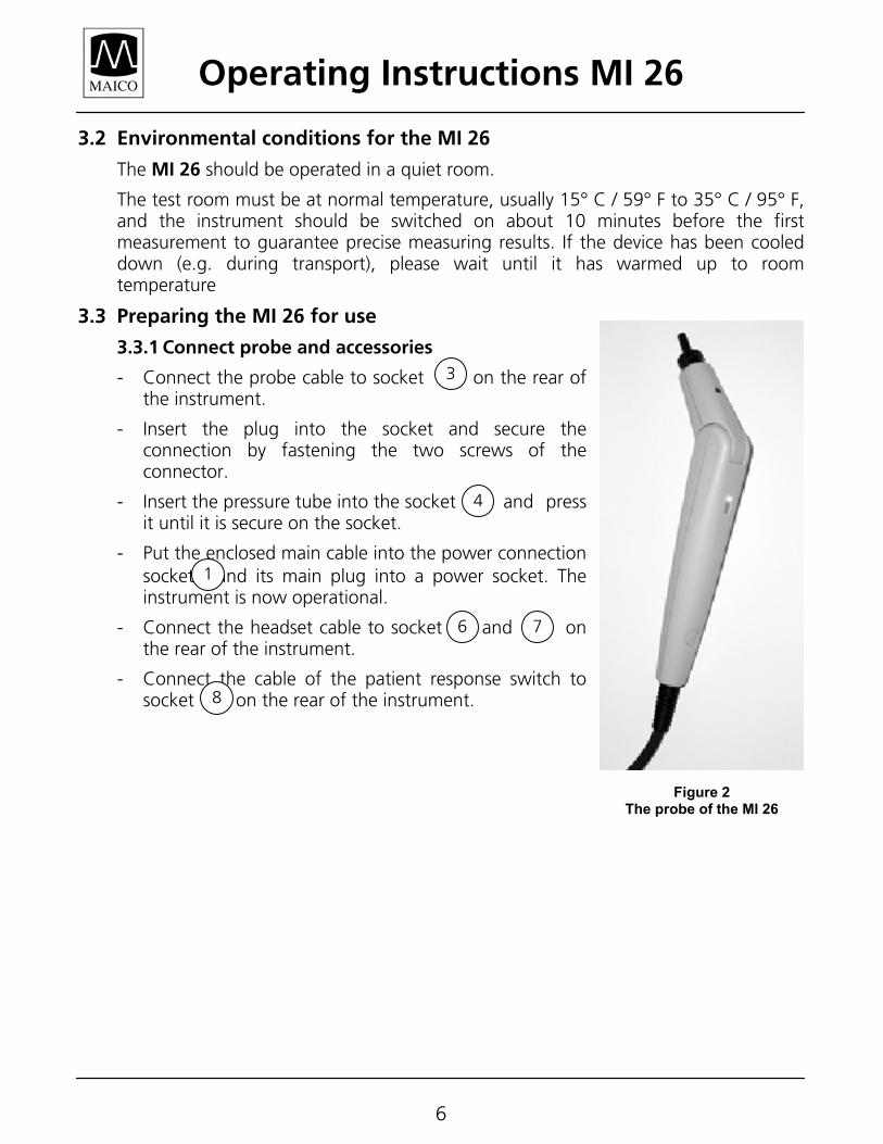
3.3.1 Connect probe and accessories
- Connect the probe cable to socket on the rear of the instrument.
- Insert the plug into the socket and secure the connection by fastening the two screws of the connector.
- Insert the pressure tube into the socket and press it until it is secure on the socket.
- Put the enclosed main cable into the power connection socket and its main plug into a power socket. The instrument is now operational.
- Connect the headset cable to socket and on the rear of the instrument.
- Connect the cable of the patient response switch to socket on the rear of the instrument.
Figure 2 The probe of the MI 26
3
4
1
6 7
8
Operating Instructions MI 26
7
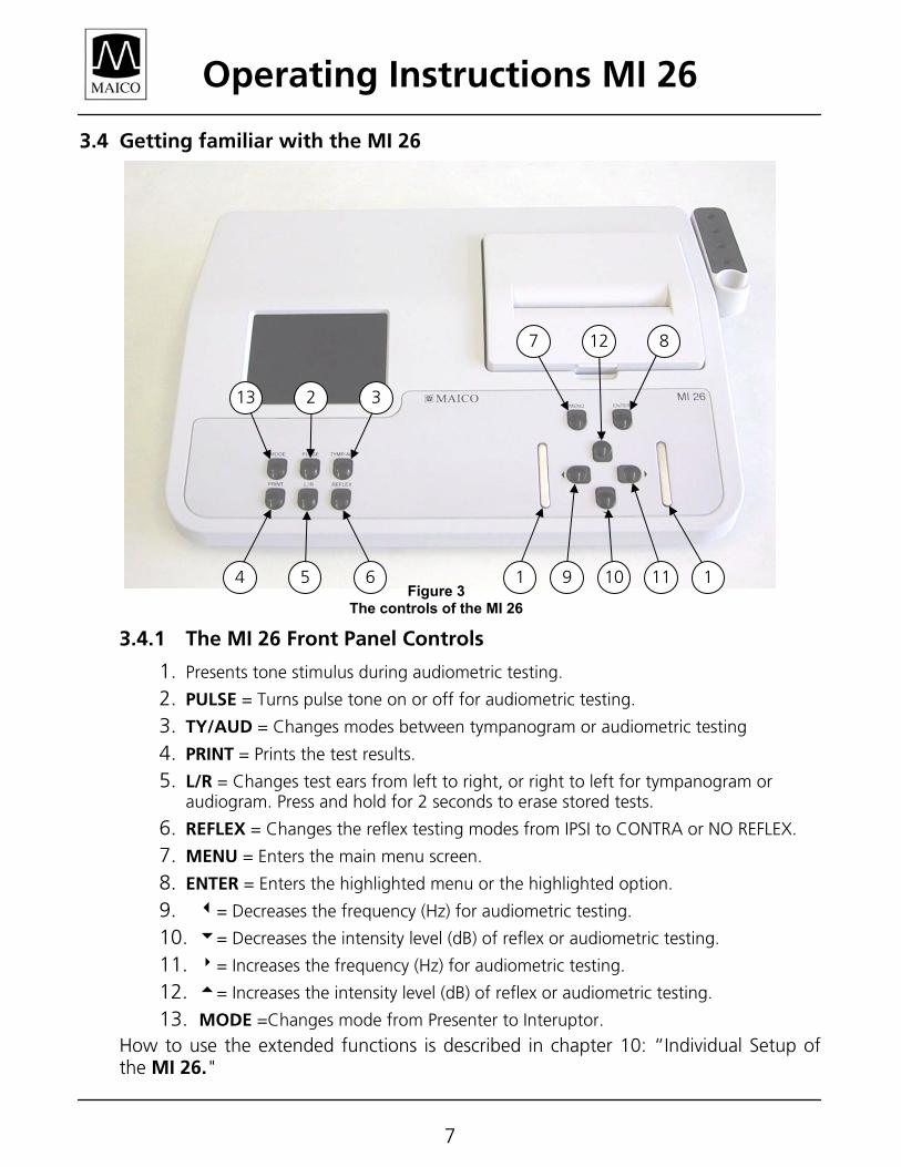
3.4 Getting familiar with the MI 26
3.4.1 The MI 26 Front Panel Controls
1. Presents tone stimulus during audiometric testing. 2. PULSE = Turns pulse tone on or off for audiometric testing. 3. TY/AUD = Changes modes between tympanogram or audiometric testing 4. PRINT = Prints the test results. 5. L/R = Changes test ears from left to right, or right to left for tympanogram or
audiogram. Press and hold for 2 seconds to erase stored tests. 6. REFLEX = Changes the reflex testing modes from IPSI to CONTRA or NO REFLEX. 7. MENU = Enters the main menu screen. 8. ENTER = Enters the highlighted menu or the highlighted option. 9. 3= Decreases the frequency (Hz) for audiometric testing. 10. 6= Decreases the intensity level (dB) of reflex or audiometric testing. 11. 8= Increases the frequency (Hz) for audiometric testing. 12. 5= Increases the intensity level (dB) of reflex or audiometric testing. 13. MODE =Changes mode from Presenter to Interuptor.
How to use the extended functions is described in chapter 10: “Individual Setup of the MI 26."
Figure 3 The controls of the MI 26
6 1 11 10915 4
32 13
8 127
Operating Instructions MI 26
8
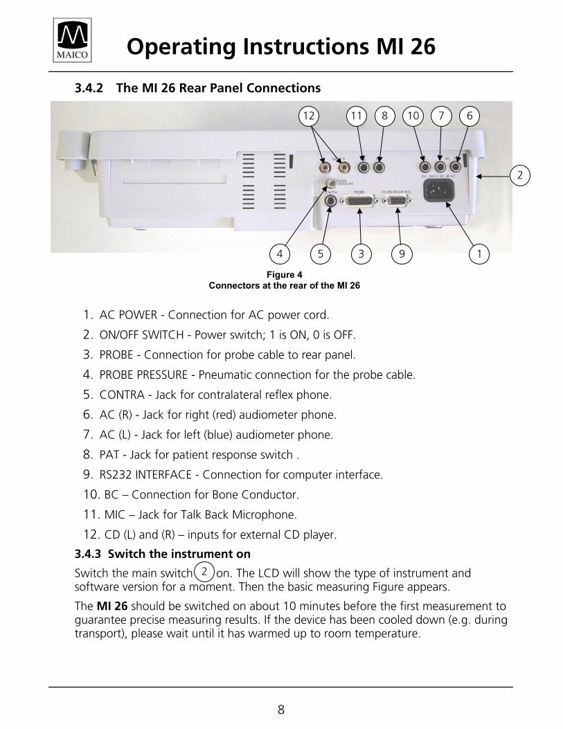
3.4.2 The MI 26 Rear Panel Connections
1. AC POWER - Connection for AC power cord.
2. ON/OFF SWITCH - Power switch; 1 is ON, 0 is OFF. 3. PROBE - Connection for probe cable to rear panel. 4. PROBE PRESSURE - Pneumatic connection for the probe cable. 5. CONTRA - Jack for contralateral reflex phone. 6. AC (R) - Jack for right (red) audiometer phone. 7. AC (L) - Jack for left (blue) audiometer phone. 8. PAT - Jack for patient response switch . 9. RS232 INTERFACE - Connection for computer interface. 10. BC – Connection for Bone Conductor.
11. MIC – Jack for Talk Back Microphone.
12. CD (L) and (R) – inputs for external CD player.
3.4.3 Switch the instrument on
Switch the main switch on. The LCD will show the type of instrument and software version for a moment. Then the basic measuring Figure appears.
The MI 26 should be switched on about 10 minutes before the first measurement to guarantee precise measuring results. If the device has been cooled down (e.g. during transport), please wait until it has warmed up to room temperature.
2
Figure 4 Connectors at the rear of the MI 26
2
19 354
12 11 8 10 7 6
Operating Instructions MI 26
9
3.4.4 The display of the MI 26
The test result is shown during the measurement on the LCD. The measurements are saved automatically and can be printed out in a fast and quiet way with the integrated printer.
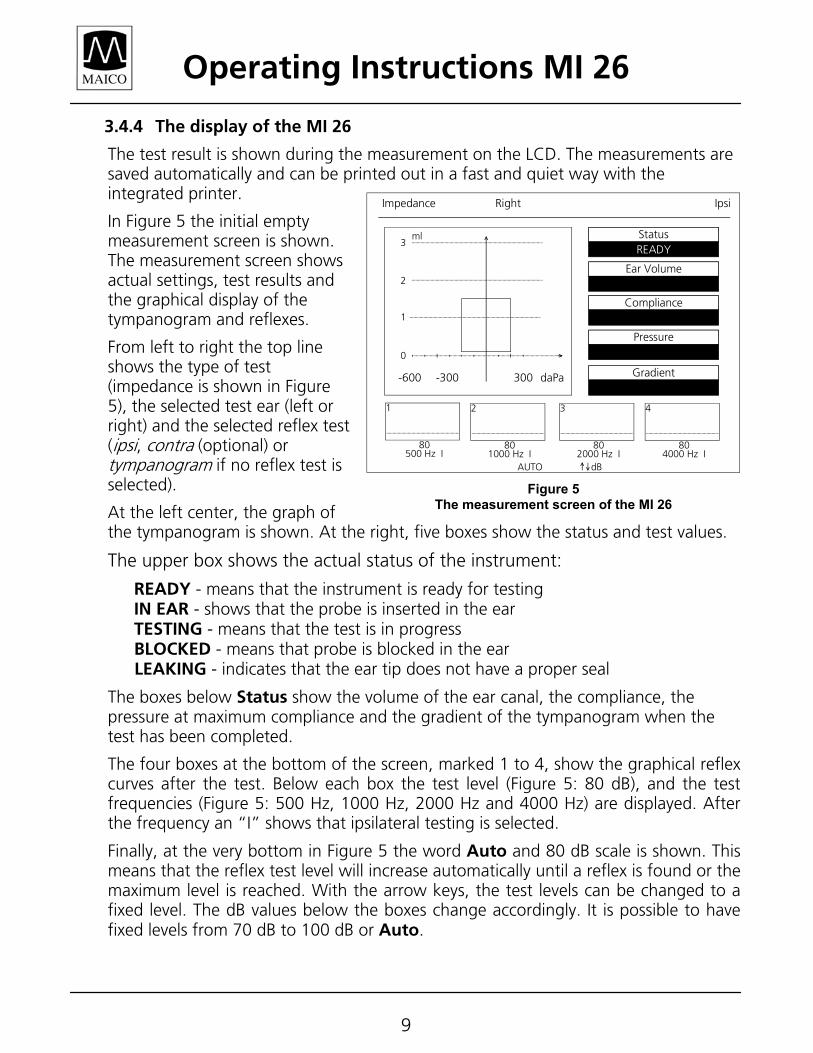
In Figure 5 the initial empty measurement screen is shown. The measurement screen shows actual settings, test results and the graphical display of the tympanogram and reflexes.
From left to right the top line shows the type of test (impedance is shown in Figure 5), the selected test ear (left or right) and the selected reflex test (ipsi, contra (optional) or tympanogram if no reflex test is selected).
At the left center, the graph of the tympanogram is shown. At the right, five boxes show the status and test values.
The upper box shows the actual status of the instrument:
READY - means that the instrument is ready for testing IN EAR - shows that the probe is inserted in the ear TESTING - means that the test is in progress BLOCKED - means that probe is blocked in the ear LEAKING - indicates that the ear tip does not have a proper seal
The boxes below Status show the volume of the ear canal, the compliance, the pressure at maximum compliance and the gradient of the tympanogram when the test has been completed.
The four boxes at the bottom of the screen, marked 1 to 4, show the graphical reflex curves after the test. Below each box the test level (Figure 5: 80 dB), and the test frequencies (Figure 5: 500 Hz, 1000 Hz, 2000 Hz and 4000 Hz) are displayed. After the frequency an “I” shows that ipsilateral testing is selected.
Finally, at the very bottom in Figure 5 the word Auto and 80 dB scale is shown. This means that the reflex test level will increase automatically until a reflex is found or the maximum level is reached. With the arrow keys, the test levels can be changed to a fixed level. The dB values below the boxes change accordingly. It is possible to have fixed levels from 70 dB to 100 dB or Auto.
StatusREADY
Ear Volume
Compliance
Pressure
Gradient
Impedance IpsiRight
ml3
2
1
0
-600 -300 300 daPa
1
80500 Hz I
4
804000 Hz I
3
802000 Hz I
2
801000 Hz I
AUTO dB
Figure 5 The measurement screen of the MI 26
Operating Instructions MI 26
10
3.5 Calibrate the probe
Adjust the impedance measuring instrument every day to the actual atmospheric pressure by means of the enclosed calibration volume. The calibration is very easy and takes only 20 seconds.
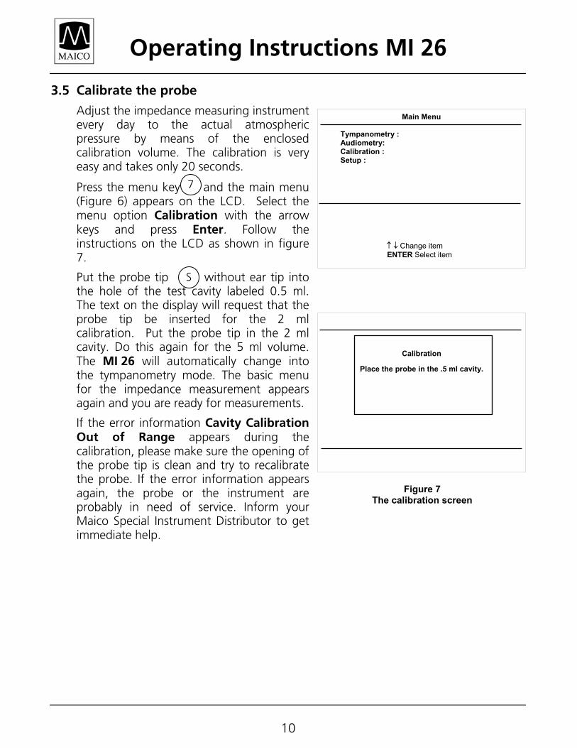
Press the menu key and the main menu (Figure 6) appears on the LCD. Select the menu option Calibration with the arrow keys and press Enter. Follow the instructions on the LCD as shown in figure 7.
Put the probe tip without ear tip into the hole of the test cavity labeled 0.5 ml. The text on the display will request that the probe tip be inserted for the 2 ml calibration. Put the probe tip in the 2 ml cavity. Do this again for the 5 ml volume. The MI 26 will automatically change into the tympanometry mode. The basic menu for the impedance measurement appears again and you are ready for measurements.
If the error information Cavity Calibration Out of Range appears during the calibration, please make sure the opening of the probe tip is clean and try to recalibrate the probe. If the error information appears again, the probe or the instrument are probably in need of service. Inform your Maico Special Instrument Distributor to get immediate help.
Main Menu Tympanometry : Audiometry: Calibration : Setup : ↑ ↓ Change item ENTER Select item
Figure 7 The calibration screen
Calibration
Place the probe in the .5 ml cavity.
7
S
Operating Instructions MI 26
11
3.6 Getting familiar with the probe
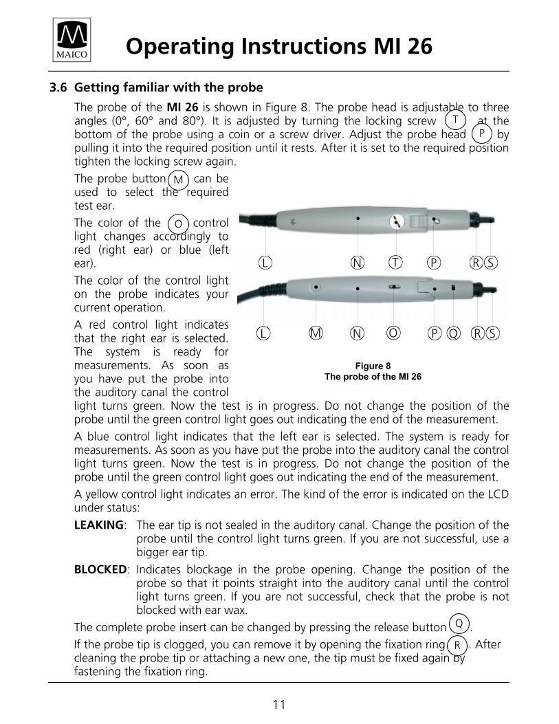
The probe of the MI 26 is shown in Figure 8. The probe head is adjustable to three angles (0°, 60° and 80°). It is adjusted by turning the locking screw at the bottom of the probe using a coin or a screw driver. Adjust the probe head by pulling it into the required position until it rests. After it is set to the required position tighten the locking screw again.
The probe button can be used to select the required test ear.
The color of the control light changes accordingly to red (right ear) or blue (left ear).
The color of the control light on the probe indicates your current operation.
A red control light indicates that the right ear is selected. The system is ready for measurements. As soon as you have put the probe into the auditory canal the control light turns green. Now the test is in progress. Do not change the position of the probe until the green control light goes out indicating the end of the measurement.
A blue control light indicates that the left ear is selected. The system is ready for measurements. As soon as you have put the probe into the auditory canal the control light turns green. Now the test is in progress. Do not change the position of the probe until the green control light goes out indicating the end of the measurement.
A yellow control light indicates an error. The kind of the error is indicated on the LCD under status:
LEAKING: The ear tip is not sealed in the auditory canal. Change the position of the probe until the control light turns green. If you are not successful, use a bigger ear tip.
BLOCKED: Indicates blockage in the probe opening. Change the position of the probe so that it points straight into the auditory canal until the control light turns green. If you are not successful, check that the probe is not blocked with ear wax.
The complete probe insert can be changed by pressing the release button .
If the probe tip is clogged, you can remove it by opening the fixation ring . After cleaning the probe tip or attaching a new one, the tip must be fixed again by fastening the fixation ring.
TP
M
O
Q
R
B DC E GM ON R SEQEPEL
Figure 8 The probe of the MI 26
DC E GTN R SEPEL
Operating Instructions MI 26
12
3.7 Choose an appropriate ear tip
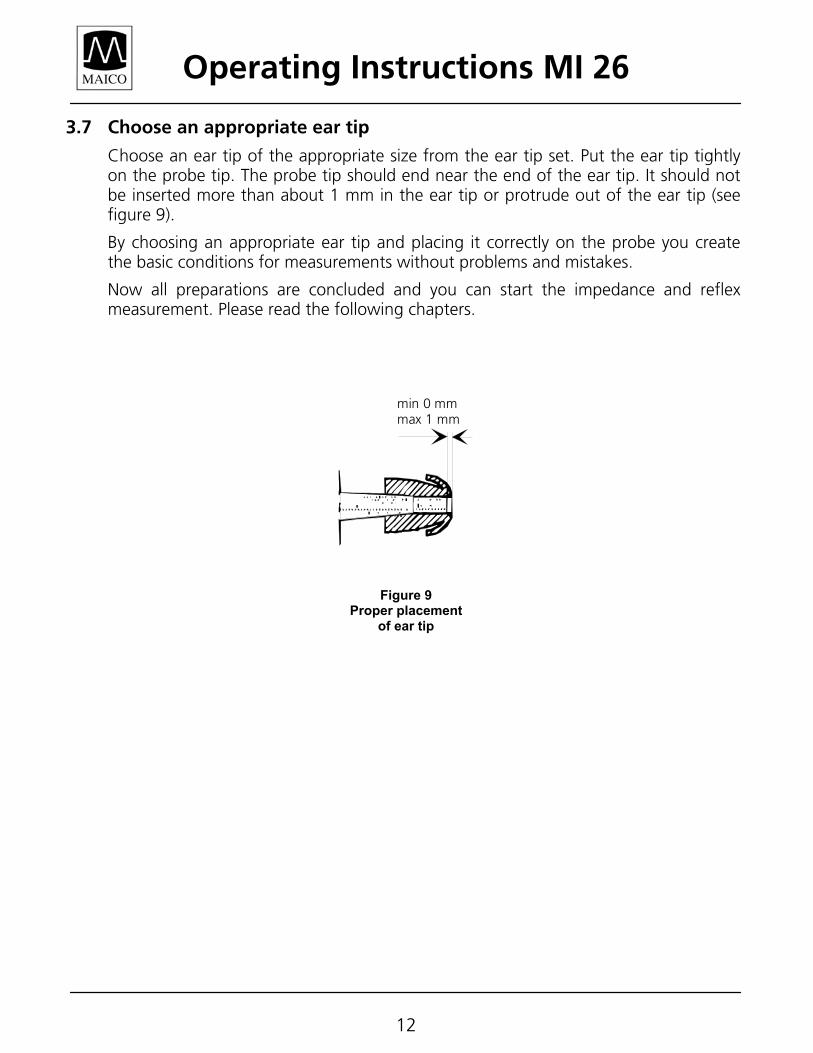
Choose an ear tip of the appropriate size from the ear tip set. Put the ear tip tightly on the probe tip. The probe tip should end near the end of the ear tip. It should not be inserted more than about 1 mm in the ear tip or protrude out of the ear tip (see figure 9).
By choosing an appropriate ear tip and placing it correctly on the probe you create the basic conditions for measurements without problems and mistakes.
Now all preparations are concluded and you can start the impedance and reflex measurement. Please read the following chapters.
min 0 mmmax 1 mm
Figure 9 Proper placement
of ear tip
Operating Instructions MI 26
13
4 How to create a tympanogram In the following paragraph we will deal shortly with the principle and the background of the impedance measurement to create a better understanding. If you want to begin the measurements immediately, just skip this paragraph and continue reading section 4.3 “Preparing the Measurements.”
4.1 The basics of the impedance measurement
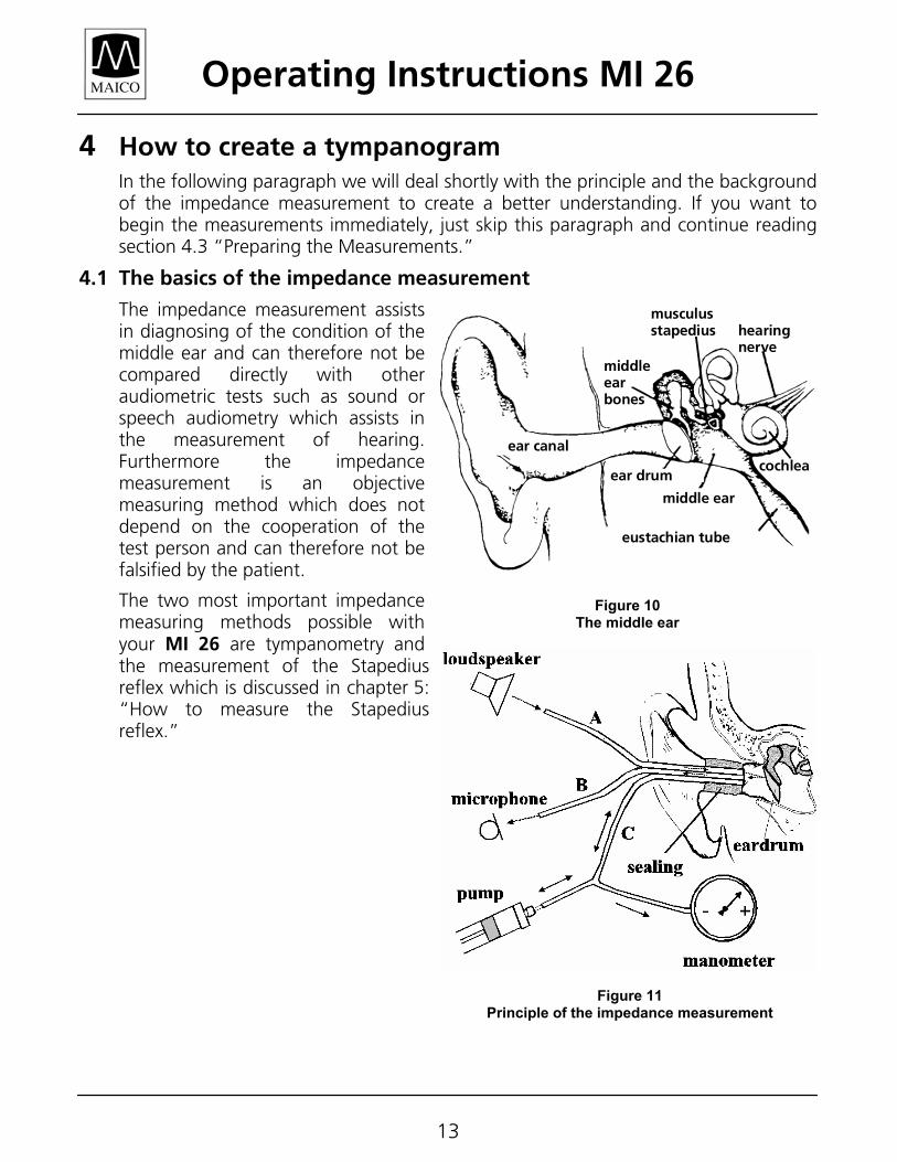
The impedance measurement assists in diagnosing of the condition of the middle ear and can therefore not be compared directly with other audiometric tests such as sound or speech audiometry which assists in the measurement of hearing. Furthermore the impedance measurement is an objective measuring method which does not depend on the cooperation of the test person and can therefore not be falsified by the patient.
The two most important impedance measuring methods possible with your MI 26 are tympanometry and the measurement of the Stapedius reflex which is discussed in chapter 5: “How to measure the Stapedius reflex.”
hearingnerve
ear canal
middleearbones
ear drum
middle ear
eustachian tube
cochlea
musculusstapedius
Figure 10 The middle ear
Figure 11 Principle of the impedance measurement
Operating Instructions MI 26
14
The impedance measurement examines the acoustic resistance of the middle ear. If the eardrum is hit by a sound, part of the sound is absorbed and sent via middle ear to the inner ear while the other part of the sound is reflected. The stiffer the eardrum is the more sound is reflected and the less sound reaches the inner ear. Inside the probe of the impedance measuring instrument a small loudspeaker is installed which emits a low frequency sound through a tube (figure 11: A) into the auditory canal before the eardrum. Another tube (figure 11: B) is connected to the microphone inside the probe which receives the sound. Together with a third tube (figure 11: C), all three are inserted nearly to the eardrum and are made airtight against outside pressure by the ear tip. A manometer and a pump, which can produce both positive and negative pressure, are connected with tube C. Less sound is reflected to the microphone when the eardrum is stiff and the eardrum transmits the majority of the sound via the middle ear to the inner ear. The highest compliance is normally reached with an air pressure corresponding to the outside pressure.
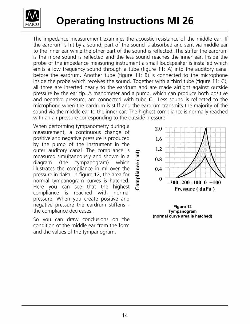
When performing tympanometry during a measurement, a continuous change of positive and negative pressure is produced by the pump of the instrument in the outer auditory canal. The compliance is measured simultaneously and shown in a diagram (the tympanogram) which illustrates the compliance in ml over the pressure in daPa. In figure 12, the area for normal tympanogram curves is hatched. Here you can see that the highest compliance is reached with normal pressure. When you create positive and negative pressure the eardrum stiffens - the compliance decreases.
So you can draw conclusions on the condition of the middle ear from the form and the values of the tympanogram.
-300 -200 -100 0 +100 Pressure ( daPa )
1,2
2,0
1,6
0,8
0,4
0
Com
plia
nce
( ml)
Figure 12 Tympanogram
(normal curve area is hatched)
2.0
1.6
1.2
0.8
0.4
0
Operating Instructions MI 26
15
4.2 Preparing the patient
Explain to the patient that the measurement is painless and that nothing enters the auditory canal. The patient does not have to respond when there are loud test sounds or when the pressure in the auditory canal changes. In no case should the patient swallow, chew or move during the measurement.
4.3 Preparing the measurement
The LCD shows the empty measurement screen for the right ear and the control light of the probe turns red. To measure the left ear, change the side by pressing the L/R key or the probe button . Then the selected test ear shown in the middle-top of the LCD will change from Right to Left and the control light of the probe will turn blue. Switch off the reflex measurement by pressing the Reflex key .
The word Tympanometer must appear at the right top of the display. Make sure the auditory canal is clear. Choose an ear tip according to the size of the auditory canal and put it firmly onto the probe tip (see figure 9 in chapter 3.7).
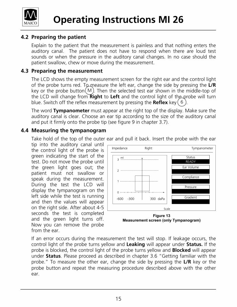
4.4 Measuring the tympanogram
Take hold of the top of the outer ear and pull it back. Insert the probe with the ear tip into the auditory canal until the control light of the probe is green indicating the start of the test. Do not move the probe until the green light goes out; the patient must not swallow or speak during the measurement. During the test the LCD will display the tympanogram on the left side while the test is running and then the values will appear on the right side. After about 4-5 seconds the test is completed and the green light turns off. Now you can remove the probe from the ear.
If an error occurs during the measurement the test will stop. If leakage occurs, the control light of the probe turns yellow and Leaking will appear under Status. If the probe is blocked, the control light of the probe turns yellow and Blocked will appear under Status. Please proceed as described in chapter 3.6 “Getting familiar with the probe.” To measure the other ear, change the side by pressing the L/R key or the probe button and repeat the measuring procedure described above with the other ear.
StatusREADY
Ear Volume
Compliance
Pressure
Gradient
Impedance TympanometerRight
ml3
2
1
0
-600 -300 300 daPa
Scale
Figure 13 Measurement screen (only Tympanogram)
M
6
Operating Instructions MI 26
16
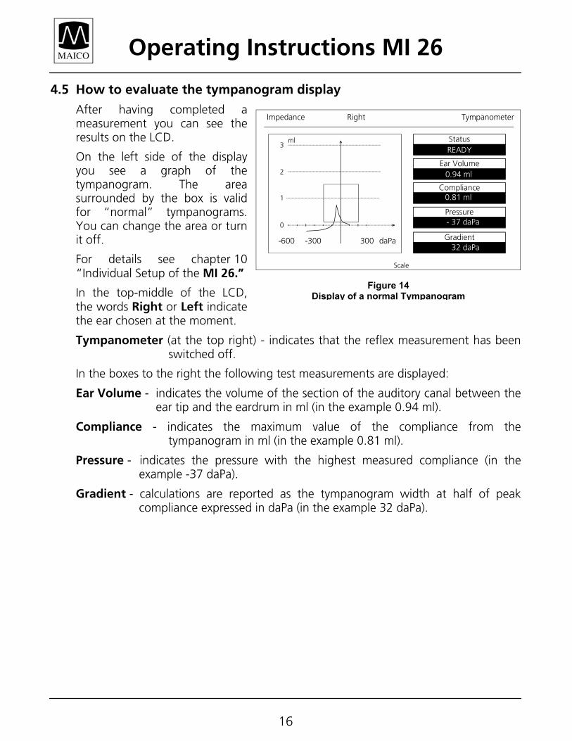
4.5 How to evaluate the tympanogram display
After having completed a measurement you can see the results on the LCD.
On the left side of the display you see a graph of the tympanogram. The area surrounded by the box is valid for “normal” tympanograms. You can change the area or turn it off.
For details see chapter 10 “Individual Setup of the MI 26.”
In the top-middle of the LCD, the words Right or Left indicate the ear chosen at the moment.
Tympanometer (at the top right) - indicates that the reflex measurement has been switched off.
In the boxes to the right the following test measurements are displayed:
Ear Volume - indicates the volume of the section of the auditory canal between the ear tip and the eardrum in ml (in the example 0.94 ml).
Compliance - indicates the maximum value of the compliance from the tympanogram in ml (in the example 0.81 ml).
Pressure - indicates the pressure with the highest measured compliance (in the example -37 daPa).
Gradient - calculations are reported as the tympanogram width at half of peak compliance expressed in daPa (in the example 32 daPa).
StatusREADY
Ear Volume
Compliance
Pressure
Gradient
Impedance TympanometerRight
ml3
2
1
0
-600 -300 300 daPa
Scale
0.94 ml
0.81 ml
- 37 daPa
32 daPa
Figure 14 Display of a normal Tympanogram
Operating Instructions MI 26
17
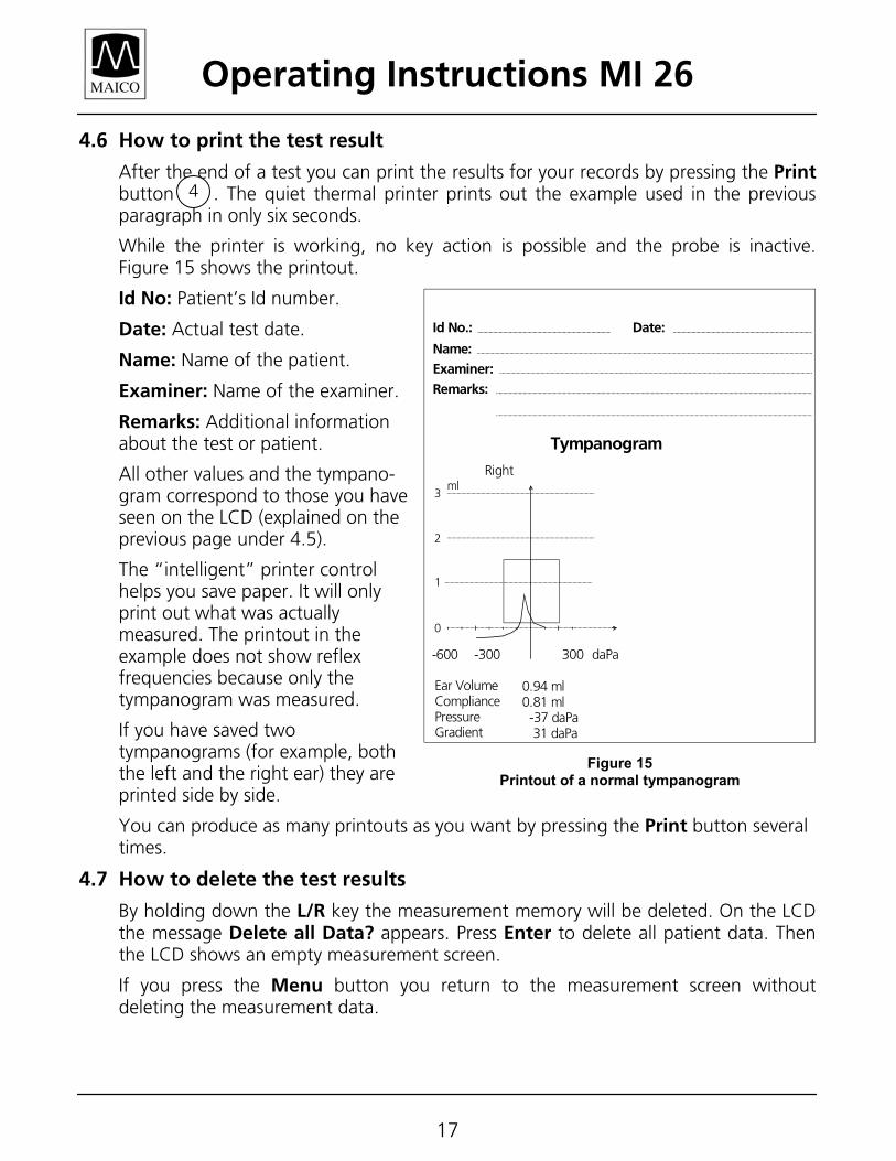
4.6 How to print the test result
After the end of a test you can print the results for your records by pressing the Print button . The quiet thermal printer prints out the example used in the previous paragraph in only six seconds.
While the printer is working, no key action is possible and the probe is inactive. Figure 15 shows the printout.
Id No: Patient’s Id number.
Date: Actual test date.
Name: Name of the patient.
Examiner: Name of the examiner.
Remarks: Additional information about the test or patient.
All other values and the tympano-gram correspond to those you have seen on the LCD (explained on the previous page under 4.5).
The “intelligent” printer control helps you save paper. It will only print out what was actually measured. The printout in the example does not show reflex frequencies because only the tympanogram was measured.
If you have saved two tympanograms (for example, both the left and the right ear) they are printed side by side.
You can produce as many printouts as you want by pressing the Print button several times.
4.7 How to delete the test results
By holding down the L/R key the measurement memory will be deleted. On the LCD the message Delete all Data? appears. Press Enter to delete all patient data. Then the LCD shows an empty measurement screen.
If you press the Menu button you return to the measurement screen without deleting the measurement data.
4
0.94 ml
0.81 ml
- 37 daPa
32 daPa
ml3
2
1
0
-600 -300 300 daPa
Right
Ear VolumeCompliancePressureGradient
0.94 ml0.81 ml -37 daPa 31 daPa
Tympanogram
Remarks:
Examiner:
Name:
Id No.: Date:
MAICO MI 24
Figure 15 Printout of a normal tympanogram
MI 26
Operating Instructions MI 26
18
5 How to measure the Stapedius reflex
5.1 The basics of the Stapedius reflex measurement
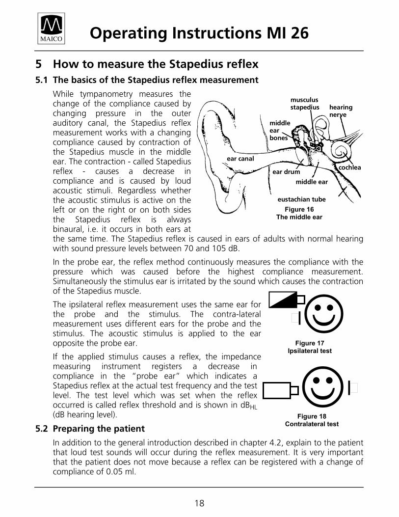
While tympanometry measures the change of the compliance caused by changing pressure in the outer auditory canal, the Stapedius reflex measurement works with a changing compliance caused by contraction of the Stapedius muscle in the middle ear. The contraction - called Stapedius reflex - causes a decrease in compliance and is caused by loud acoustic stimuli. Regardless whether the acoustic stimulus is active on the left or on the right or on both sides the Stapedius reflex is always binaural, i.e. it occurs in both ears at the same time. The Stapedius reflex is caused in ears of adults with normal hearing with sound pressure levels between 70 and 105 dB.
In the probe ear, the reflex method continuously measures the compliance with the pressure which was caused before the highest compliance measurement. Simultaneously the stimulus ear is irritated by the sound which causes the contraction of the Stapedius muscle.
The ipsilateral reflex measurement uses the same ear for the probe and the stimulus. The contra-lateral measurement uses different ears for the probe and the stimulus. The acoustic stimulus is applied to the ear opposite the probe ear.
If the applied stimulus causes a reflex, the impedance measuring instrument registers a decrease in compliance in the “probe ear” which indicates a Stapedius reflex at the actual test frequency and the test level. The test level which was set when the reflex occurred is called reflex threshold and is shown in dBHL (dB hearing level).
5.2 Preparing the patient
In addition to the general introduction described in chapter 4.2, explain to the patient that loud test sounds will occur during the reflex measurement. It is very important that the patient does not move because a reflex can be registered with a change of compliance of 0.05 ml.
hearingnerve
ear canal
middleearbones
ear drum
middle ear
eustachian tube
cochlea
musculusstapedius
Figure 16 The middle ear
Figure 18 Contralateral test
Figure 17 Ipsilateral test
Operating Instructions MI 26
19
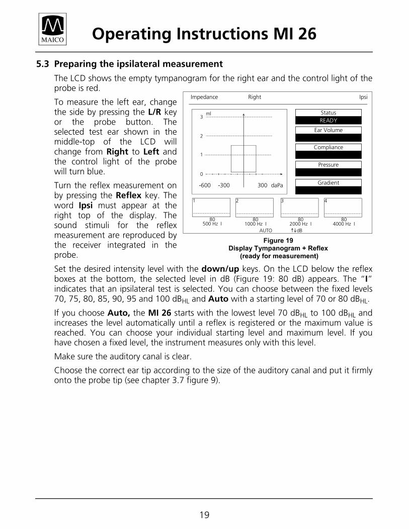
5.3 Preparing the ipsilateral measurement
The LCD shows the empty tympanogram for the right ear and the control light of the probe is red.
To measure the left ear, change the side by pressing the L/R key or the probe button. The selected test ear shown in the middle-top of the LCD will change from Right to Left and the control light of the probe will turn blue.
Turn the reflex measurement on by pressing the Reflex key. The word Ipsi must appear at the right top of the display. The sound stimuli for the reflex measurement are reproduced by the receiver integrated in the probe.
Set the desired intensity level with the down/up keys. On the LCD below the reflex boxes at the bottom, the selected level in dB (Figure 19: 80 dB) appears. The “I” indicates that an ipsilateral test is selected. You can choose between the fixed levels 70, 75, 80, 85, 90, 95 and 100 dBHL and Auto with a starting level of 70 or 80 dBHL.
If you choose Auto, the MI 26 starts with the lowest level 70 dBHL to 100 dBHL and increases the level automatically until a reflex is registered or the maximum value is reached. You can choose your individual starting level and maximum level. If you have chosen a fixed level, the instrument measures only with this level.
Make sure the auditory canal is clear.
Choose the correct ear tip according to the size of the auditory canal and put it firmly onto the probe tip (see chapter 3.7 figure 9).
StatusREADY
Ear Volume
Compliance
Pressure
Gradient
Impedance IpsiRight
ml3
2
1
0
-600 -300 300 daPa
1
80500 Hz I
4
804000 Hz I
3
802000 Hz I
2
801000 Hz I
AUTO dB
Figure 19 Display Tympanogram + Reflex
(ready for measurement)
Operating Instructions MI 26
20
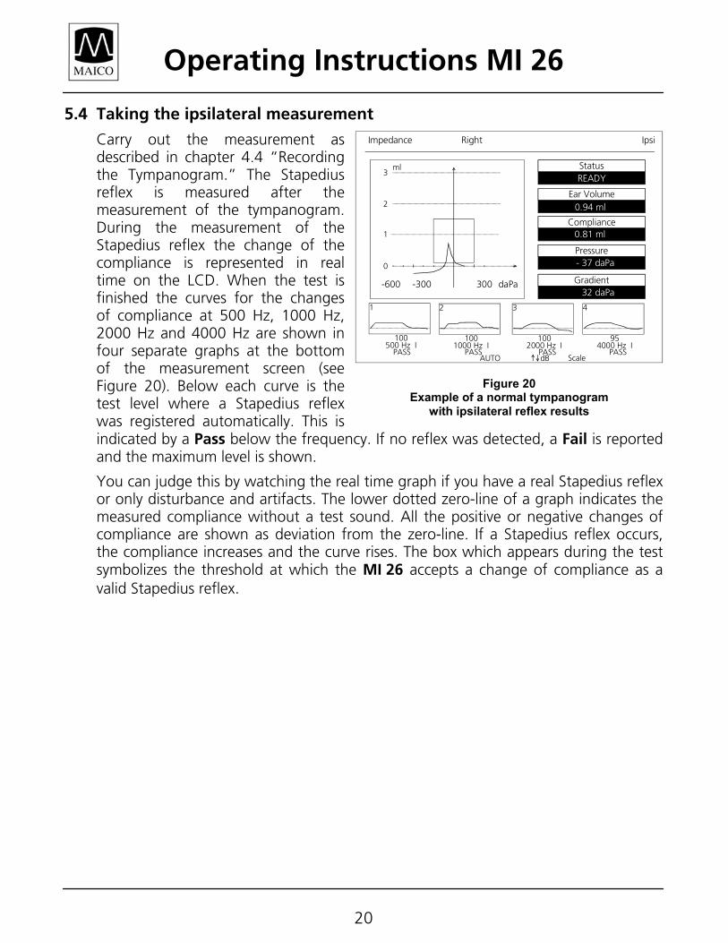
5.4 Taking the ipsilateral measurement
Carry out the measurement as described in chapter 4.4 “Recording the Tympanogram.” The Stapedius reflex is measured after the measurement of the tympanogram. During the measurement of the Stapedius reflex the change of the compliance is represented in real time on the LCD. When the test is finished the curves for the changes of compliance at 500 Hz, 1000 Hz, 2000 Hz and 4000 Hz are shown in four separate graphs at the bottom of the measurement screen (see Figure 20). Below each curve is the test level where a Stapedius reflex was registered automatically. This is indicated by a Pass below the frequency. If no reflex was detected, a Fail is reported and the maximum level is shown.
You can judge this by watching the real time graph if you have a real Stapedius reflex or only disturbance and artifacts. The lower dotted zero-line of a graph indicates the measured compliance without a test sound. All the positive or negative changes of compliance are shown as deviation from the zero-line. If a Stapedius reflex occurs, the compliance increases and the curve rises. The box which appears during the test symbolizes the threshold at which the MI 26 accepts a change of compliance as a valid Stapedius reflex.
StatusREADY
Ear Volume
Compliance
Pressure
Gradient
Impedance IpsiRight
ml3
2
1
0
-600 -300 300 daPa
1
100500 Hz I
4
954000 Hz I
3
1002000 Hz I
2
1001000 Hz I
AUTO dB Scale
0.94 ml
0.81 ml
- 37 daPa
32 daPa
PASS PASS PASS PASS
Figure 20 Example of a normal tympanogram
with ipsilateral reflex results
Operating Instructions MI 26
21
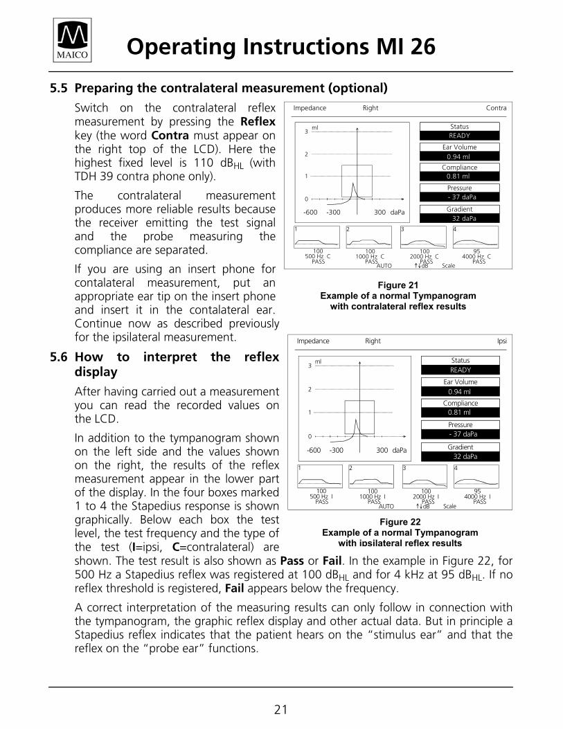
5.5 Preparing the contralateral measurement (optional)
Switch on the contralateral reflex measurement by pressing the Reflex key (the word Contra must appear on the right top of the LCD). Here the highest fixed level is 110 dBHL (with TDH 39 contra phone only).
The contralateral measurement produces more reliable results because the receiver emitting the test signal and the probe measuring the compliance are separated.
If you are using an insert phone for contalateral measurement, put an appropriate ear tip on the insert phone and insert it in the contalateral ear. Continue now as described previously for the ipsilateral measurement.
5.6 How to interpret the reflex display
After having carried out a measurement you can read the recorded values on the LCD.
In addition to the tympanogram shown on the left side and the values shown on the right, the results of the reflex measurement appear in the lower part of the display. In the four boxes marked 1 to 4 the Stapedius response is shown graphically. Below each box the test level, the test frequency and the type of the test (I=ipsi, C=contralateral) are shown. The test result is also shown as Pass or Fail. In the example in Figure 22, for 500 Hz a Stapedius reflex was registered at 100 dBHL and for 4 kHz at 95 dBHL. If no reflex threshold is registered, Fail appears below the frequency.
A correct interpretation of the measuring results can only follow in connection with the tympanogram, the graphic reflex display and other actual data. But in principle a Stapedius reflex indicates that the patient hears on the “stimulus ear” and that the reflex on the “probe ear” functions.
StatusREADY
Ear Volume
Compliance
Pressure
Gradient
Impedance ContraRight
ml3
2
1
0
-600 -300 300 daPa
1
100500 Hz C
4
954000 Hz C
3
1002000 Hz C
2
1001000 Hz C
AUTO dB Scale
0.94 ml
0.81 ml
- 37 daPa
32 daPa
PASS PASS PASS PASS
Figure 21 Example of a normal Tympanogram
with contralateral reflex results
StatusREADY
Ear Volume
Compliance
Pressure
Gradient
Impedance IpsiRight
ml3
2
1
0
-600 -300 300 daPa
1
100500 Hz I
4
954000 Hz I
3
1002000 Hz I
2
1001000 Hz I
AUTO dB Scale
0.94 ml
0.81 ml
- 37 daPa
32 daPa
PASS PASS PASS PASS
Figure 22 Example of a normal Tympanogram
with ipsilateral reflex results
Operating Instructions MI 26
22
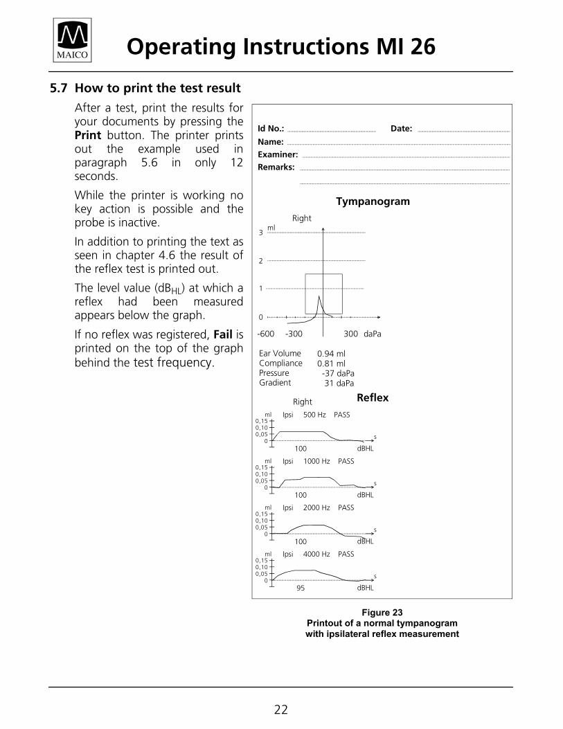
5.7 How to print the test result
After a test, print the results for your documents by pressing the Print button. The printer prints out the example used in paragraph 5.6 in only 12 seconds.
While the printer is working no key action is possible and the probe is inactive.
In addition to printing the text as seen in chapter 4.6 the result of the reflex test is printed out.
The level value (dBHL) at which a reflex had been measured appears below the graph.
If no reflex was registered, Fail is printed on the top of the graph behind the test frequency.
0.94 ml
0.81 ml
- 37 daPa
32 daPa
ml3
2
1
0
-600 -300 300 daPa
Right
Ear VolumeCompliancePressureGradient
0.94 ml0.81 ml -37 daPa 31 daPa
Tympanogram
Remarks:
Examiner:
Name:
Id No.: Date:
MAICO MI 24
100
ReflexRight
Ipsi 500 Hz PASSml0,150,100,05
0dBHL
s
100
Ipsi 1000 Hz PASSml0,150,100,05
0dBHL
s
100
Ipsi 2000 Hz PASSml0,150,100,05
0dBHL
s
95
Ipsi 4000 Hz PASSml0,150,100,05
0dBHL
s
Figure 23 Printout of a normal tympanogram with ipsilateral reflex measurement
MI 26
Operating Instructions MI 26
23
6 Interpreting test results
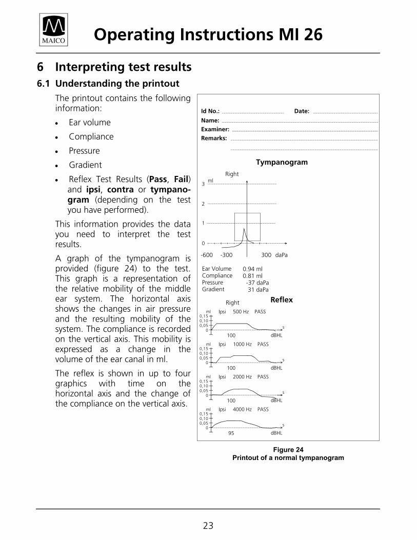
6.1 Understanding the printout
The printout contains the following information:
• Ear volume
• Compliance
• Pressure
• Gradient
• Reflex Test Results (Pass, Fail) and ipsi, contra or tympano-gram (depending on the test you have performed).
This information provides the data you need to interpret the test results.
A graph of the tympanogram is provided (figure 24) to the test. This graph is a representation of the relative mobility of the middle ear system. The horizontal axis shows the changes in air pressure and the resulting mobility of the system. The compliance is recorded on the vertical axis. This mobility is expressed as a change in the volume of the ear canal in ml.
The reflex is shown in up to four graphics with time on the horizontal axis and the change of the compliance on the vertical axis.
0.94 ml
0.81 ml
- 37 daPa
32 daPa
ml3
2
1
0
-600 -300 300 daPa
Right
Ear VolumeCompliancePressureGradient
0.94 ml0.81 ml -37 daPa 31 daPa
Tympanogram
Remarks:
Examiner:
Name:
Id No.: Date:
MAICO MI 24
100
ReflexRight
Ipsi 500 Hz PASSml0,150,100,05
0dBHL
s
100
Ipsi 1000 Hz PASSml0,150,100,05
0dBHL
s
100
Ipsi 2000 Hz PASSml0,150,100,05
0dBHL
s
95
Ipsi 4000 Hz PASSml0,150,100,05
0dBHL
s
Figure 24 Printout of a normal tympanogram
MI 26
Operating Instructions MI 26
24
6.2 Interpreting the tympanometric test result
As a general rule, values for ear canal volume should be between 0.2 and 2.0 ml (children and adults). A variance will be seen within this range depending on the age and ear structure of the person. For example, a 2.0 ml or larger reading in a small child could indicate a perforation in the tympanic membrane, while it may be a normal reading in an adult. You will become more familiar with the normal ranges when you use the instrument.
The normal range for compliance is 0.2 ml to approximately 1.8 ml. A compliance peak within the range indicates normal mobility of the middle ear system. A peak found outside of these limits may be indicative for one of several pathologies.
Middle ear pressure should be equivalent to ambient air pressure (0 daPa on an air pressure scale). Minor shifts of the peak compliance to the negative may occur with congestion and are rarely to the positive side. Establish criteria for abnormal negative pressure when you become more familiar with using the equipment. It is generally accepted that negative pressure of greater than -150 daPa indicates a referral for medical evaluation. A normal tympanogram is seen on the previous page in Figure 24.
6.3 Abnormal Values
It is the purpose of this section to provide samples of tympanograms which reflect abnormal states of the middle ear mechanism. It is not the intention of this section to provide you with a complete guide to interpreting results. Complete information regarding pathologies and abnormal impedance testing can be found in the literature referenced.
A perforation in the tympanic membrane will cause a high ear canal volume measurement because the instrument will measure the volume of the entire middle ear space. The MI 26 may refuse to run the test, with the probe indicating a volume out of tolerance by illuminating the red light, or a flat tympanogram will be recorded since no movement will occur with a change in air pressure. Without a peak compliance of at least 0.1 ml, the reflex test will not initiate.
An extremely flaccid tympanic membrane or an ossicular chain discontinuity will yield a very high peak compliance in the presence of normal middle ear pressure. Ear canal volume will be normal and the reflex will be absent.
A fixation of the ossicular chain, as in otosclerosis, will produce a tympanogram with very low compliance in the presence of normal middle ear air pressure. Ear canal volume is normal and the reflex is absent.
Operating Instructions MI 26
25
Middle ear fluid such as serious otitis media will yield a very flat tympanogram with no definite peak and negative air pressure. A resolving case or beginning case may produce a reduced peak in the presence of severe negative middle ear pressure. The ear canal volume is normal and the reflex is either absent or at an elevated level.
Eustachian tube problems in the absence of fluid will show a normal compliance curve, but it will be displayed to the negative side of the tympanogram. Ear canal volume will be normal and the reflex may be present, depending on the degree of impairment.
Operating Instructions MI 26
26
7 How to test children
When practicing impedance measurement with small children, be aware of problems caused by the child being restless or afraid of the examination or reacting sensitively to the change of pressure and the loud test sound. There are also different conditions of the eardrum and the middle ear which do not appear in ears of adults.
It may be difficult to create a probe seal with restless children. If the child yawns or cries, the instrument will not have stable pressure in the outer auditory canal. In addition, speaking causes Stapedius muscle reflexes which lead to a change in the compliance of the eardrum.
The child should be made familiar with the surroundings and the ear being touched by the probe in order to carry out a successful impedance measurement. This could be done by getting in touch with the child and by playfully touching the ear with the probe. If you can touch the ear without problems, the child will normally accept the probe being inserted.
Operating Instructions MI 26
27
8 Audiometric pure tone screening 8.1 Preparing the patient for the test
Before any kind of hearing testing, a brief patient orientation is required. Simply tell the patient to "press the stimulus response button whenever you hear a "beep", then quickly release the button. The beeps may be very soft, and have different pitches, so you need to listen very carefully". Then place the earphones on the patient’s head making sure the center of the opening of the phones are directly over the opening of the ears. The red phone is for the right ear and the blue phone is for the left ear. The headband should then be tightened so the phones do not slip. Do not let the patient adjust the headset for him or herself.
8.2 Audiometer function recommended procedures Turn the Power switch on the rear panel on, and let warm up 5-10 minutes. Press the TYMP/AUD key to change from the tympanogram mode to the audiogram mode.
Pass/Fail Method:
The initial setting on the LCD screen will indicate a frequency of 1 KHz and an intensity of 30 dB. Pressing the 56 keys will change the intensity levels. Pressing the 34keys will change the frequencies. Holding down these keys will let you scroll through the selections. Pressing the PULSE key chooses either pulsed or steady tone.
1. Set the dB level at a predetermined level for a Pass or Fail criteria. (e.g. a level at 20 dB).
2. Present the tone stimulus at 4 different frequencies (e.g. 500, 1000, 2000 and 4000 Hz). You will only present one stimulus per frequency. Instruct the patient to respond by pressing the response switch or raising their hand when they hear the tone. The Response Box on the LCD screen will light if the patient response switch is pressed.
3. If the patient fails at any frequency you may choose to do a presentation at 10 dB higher (30 dB). The patient may then be referred or rescheduled if they fail at two or more frequencies.
NOTE: This is an example only. You must develop a method that fits your situation.
Operating Instructions MI 26
28
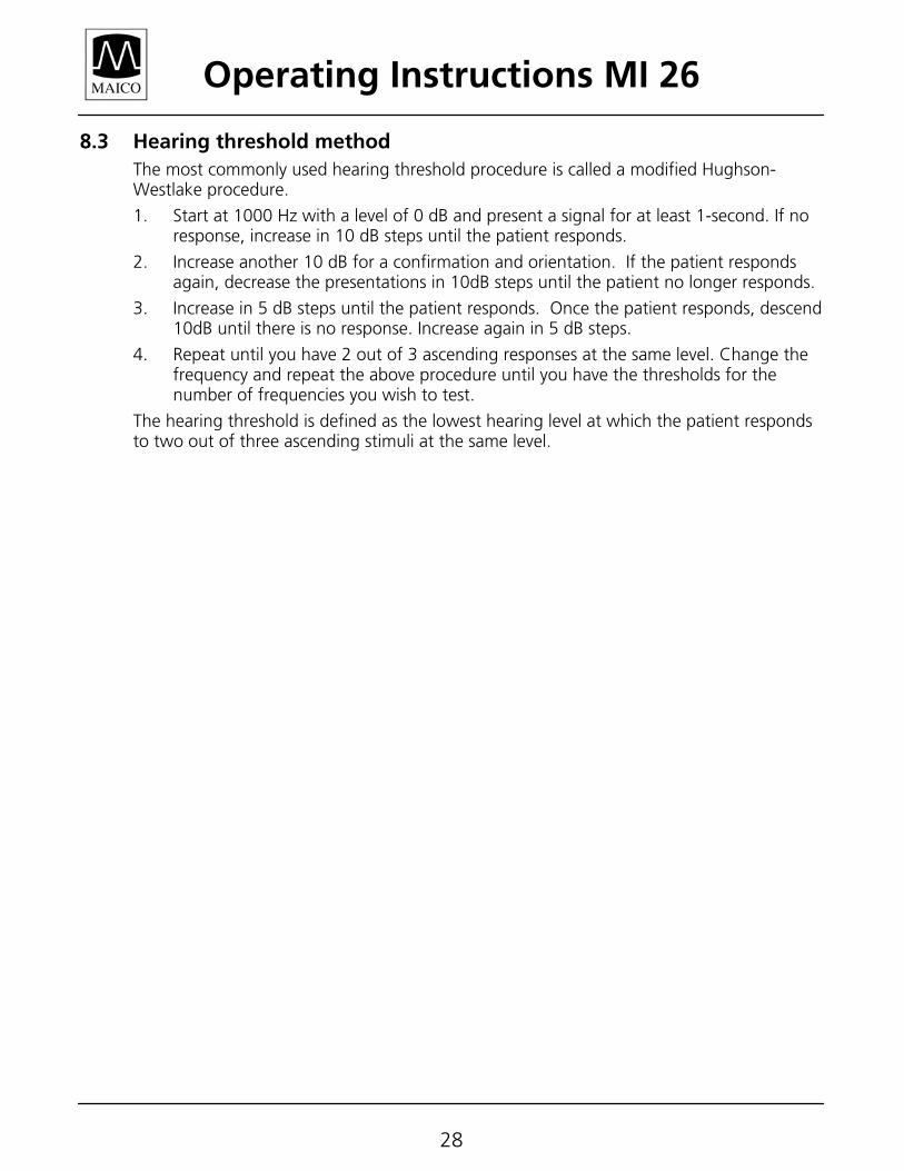
8.3 Hearing threshold method The most commonly used hearing threshold procedure is called a modified Hughson-Westlake procedure.
1. Start at 1000 Hz with a level of 0 dB and present a signal for at least 1-second. If no response, increase in 10 dB steps until the patient responds.
2. Increase another 10 dB for a confirmation and orientation. If the patient responds again, decrease the presentations in 10dB steps until the patient no longer responds.
3. Increase in 5 dB steps until the patient responds. Once the patient responds, descend 10dB until there is no response. Increase again in 5 dB steps.
4. Repeat until you have 2 out of 3 ascending responses at the same level. Change the frequency and repeat the above procedure until you have the thresholds for the number of frequencies you wish to test.
The hearing threshold is defined as the lowest hearing level at which the patient responds to two out of three ascending stimuli at the same level.
Operating Instructions MI 26
29
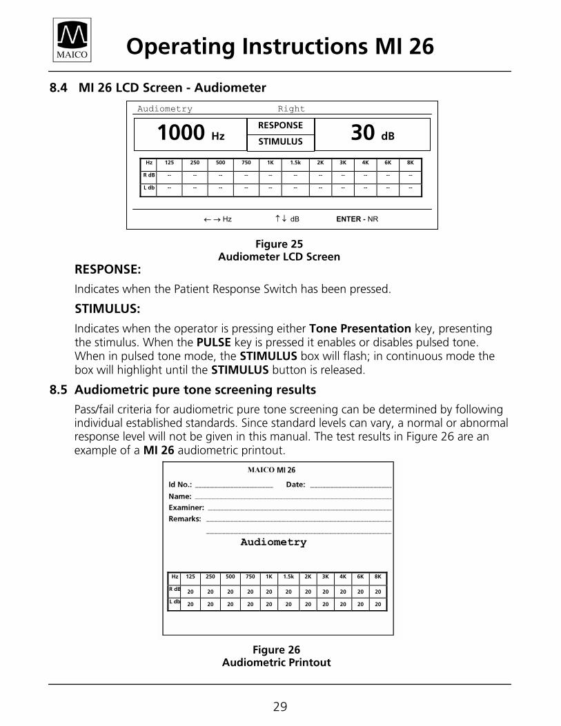
8.4 MI 26 LCD Screen - Audiometer
RESPONSE:
Indicates when the Patient Response Switch has been pressed.
STIMULUS:
Indicates when the operator is pressing either Tone Presentation key, presenting the stimulus. When the PULSE key is pressed it enables or disables pulsed tone. When in pulsed tone mode, the STIMULUS box will flash; in continuous mode the box will highlight until the STIMULUS button is released.
8.5 Audiometric pure tone screening results
Pass/fail criteria for audiometric pure tone screening can be determined by following individual established standards. Since standard levels can vary, a normal or abnormal response level will not be given in this manual. The test results in Figure 26 are an example of a MI 26 audiometric printout.
Audiometry
Hz 125 250 500 750 1K 1.5k 2K 3K 4K 6K 8K
R dB 20 20 20 20 20 20 20 20 20 20 20
L db 20 20 20 20 20 20 20 20 20 20 20
Figure 26 Audiometric Printout
1000 Hz 30 dB RESPONSE STIMULUS
Figure 25 Audiometer LCD Screen
Hz 125 250 500 750 1K 1.5k 2K 3K 4K 6K 8K
R dB -- -- -- -- -- -- -- -- -- -- --
L db -- -- -- -- -- -- -- -- -- -- --
Audiometry Right
← → Hz ↑ ↓ dB ENTER - NR
Operating Instructions MI 26
30
9 Additional Reading
Auditory Disorders: A Manual for Clinical Evaluation
Jerger, Susan, and James Jerger
Boston: College Hill Press, 1981
Handbook of Clinical Audiology
Katz, Jack
Baltimore: William & Wilkins, 1994
Roeser´s Audiology Desk Reference
Roeser, Ross J.
New York / Stuttgart: Thieme, 1996
Auditory Diagnosis
Silam, Shlomo and Carol A. Silvermann
San Diego / London: Singular Publishing Group, 1997
Operating Instructions MI 26
31
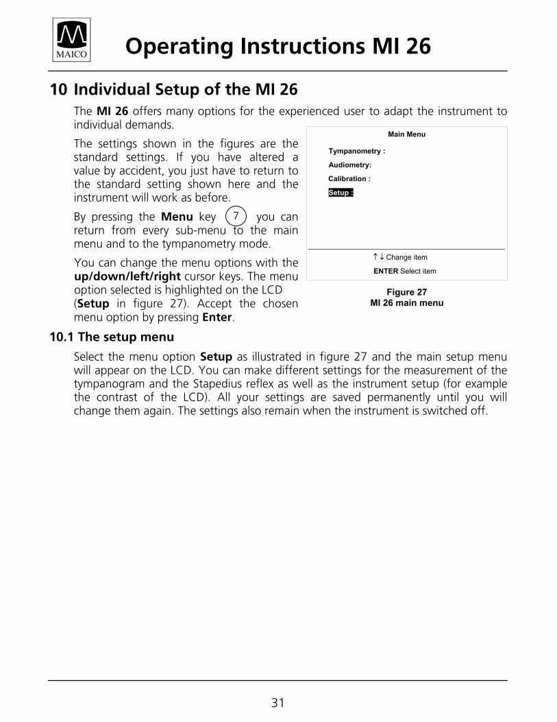
10 Individual Setup of the MI 26 The MI 26 offers many options for the experienced user to adapt the instrument to individual demands.
The settings shown in the figures are the standard settings. If you have altered a value by accident, you just have to return to the standard setting shown here and the instrument will work as before.
By pressing the Menu key you can return from every sub-menu to the main menu and to the tympanometry mode.
You can change the menu options with the up/down/left/right cursor keys. The menu option selected is highlighted on the LCD (Setup in figure 27). Accept the chosen menu option by pressing Enter.
10.1 The setup menu
Select the menu option Setup as illustrated in figure 27 and the main setup menu will appear on the LCD. You can make different settings for the measurement of the tympanogram and the Stapedius reflex as well as the instrument setup (for example the contrast of the LCD). All your settings are saved permanently until you will change them again. The settings also remain when the instrument is switched off.
Main Menu Tympanometry :
Audiometry:
SetupCalibration :
Setup :
↑ ↓ Change item
ENTER Select item
Figure 27 MI 26 main menu
7
Operating Instructions MI 26
32
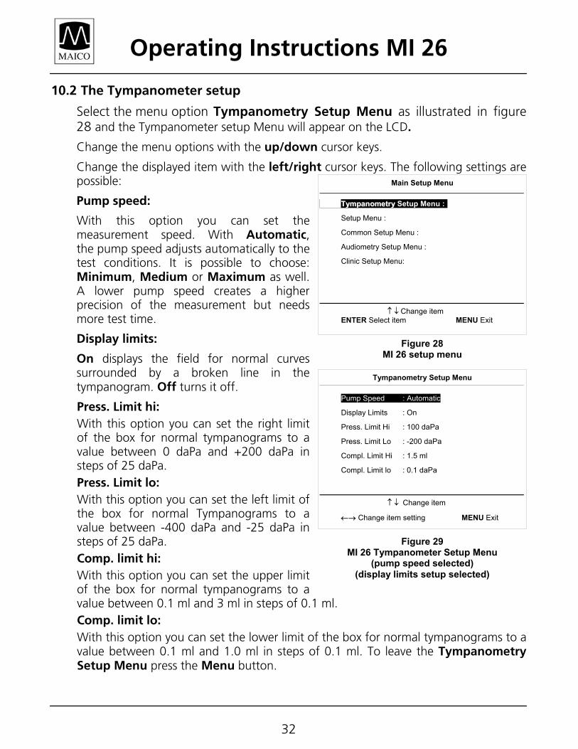
10.2 The Tympanometer setup
Select the menu option Tympanometry Setup Menu as illustrated in figure 28 and the Tympanometer setup Menu will appear on the LCD.
Change the menu options with the up/down cursor keys.
Change the displayed item with the left/right cursor keys. The following settings are possible:
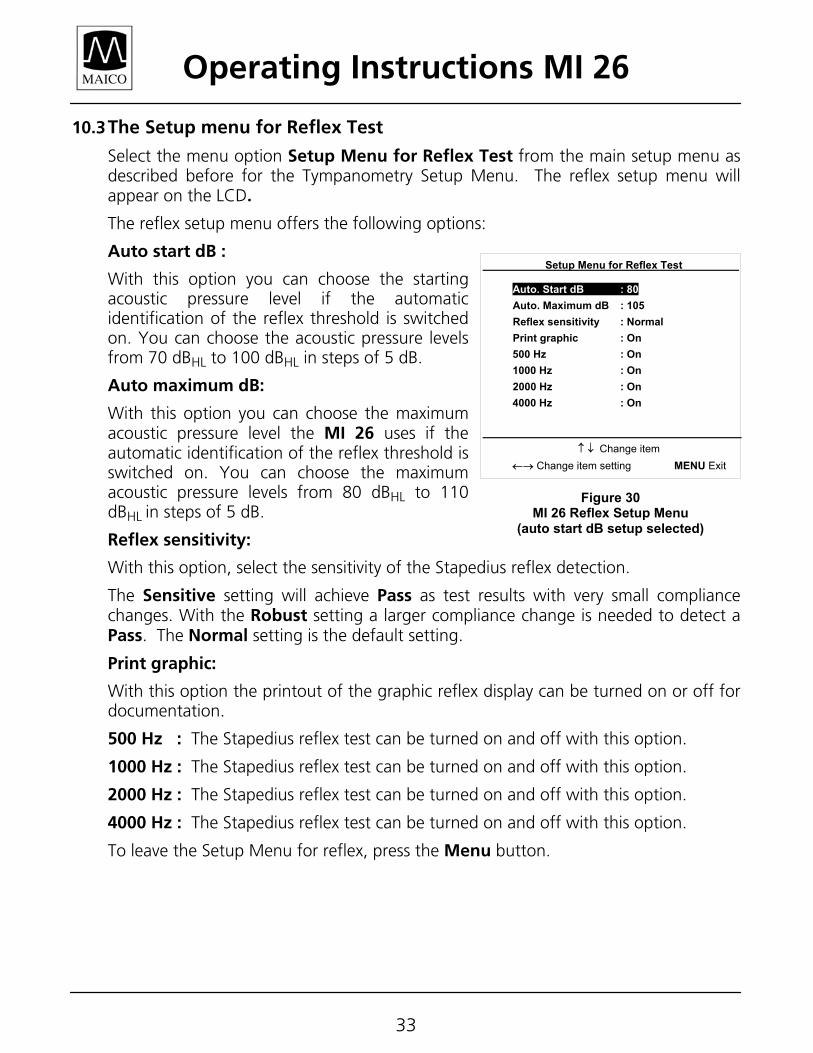
Pump speed:
With this option you can set the measurement speed. With Automatic, the pump speed adjusts automatically to the test conditions. It is possible to choose: Minimum, Medium or Maximum as well. A lower pump speed creates a higher precision of the measurement but needs more test time.
Display limits:
On displays the field for normal curves surrounded by a broken line in the tympanogram. Off turns it off.
Press. Limit hi: With this option you can set the right limit of the box for normal tympanograms to a value between 0 daPa and +200 daPa in steps of 25 daPa. Press. Limit lo: With this option you can set the left limit of the box for normal Tympanograms to a value between -400 daPa and -25 daPa in steps of 25 daPa. Comp. limit hi: With this option you can set the upper limit of the box for normal tympanograms to a value between 0.1 ml and 3 ml in steps of 0.1 ml. Comp. limit lo: With this option you can set the lower limit of the box for normal tympanograms to a value between 0.1 ml and 1.0 ml in steps of 0.1 ml. To leave the Tympanometry Setup Menu press the Menu button.
Figure 28 MI 26 setup menu
Main Setup Menu
TTyymmppaannoommeettrryy Setup Menu :
Setup Menu :
Common Setup Menu :
Audiometry Setup Menu :
Clinic Setup Menu:
↑ ↓ Change item ENTER Select item MENU Exit
Tympanometry Setup Menu
Pump Speed : Automatic Pump Speed : Automatic
Display Limits : On
Press. Limit Hi : 100 daPa
Press. Limit Lo : -200 daPa
Compl. Limit Hi : 1.5 ml
Compl. Limit lo : 0.1 daPa
↑ ↓ Change item
←→ Change item setting MENU Exit
Figure 29 MI 26 Tympanometer Setup Menu
(pump speed selected) (display limits setup selected)
Operating Instructions MI 26
33
10.3 The Setup menu for Reflex Test
Select the menu option Setup Menu for Reflex Test from the main setup menu as described before for the Tympanometry Setup Menu. The reflex setup menu will appear on the LCD.
The reflex setup menu offers the following options:
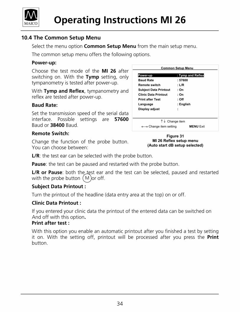
Auto start dB :
With this option you can choose the starting acoustic pressure level if the automatic identification of the reflex threshold is switched on. You can choose the acoustic pressure levels from 70 dBHL to 100 dBHL in steps of 5 dB.
Auto maximum dB:
With this option you can choose the maximum acoustic pressure level the MI 26 uses if the automatic identification of the reflex threshold is switched on. You can choose the maximum acoustic pressure levels from 80 dBHL to 110 dBHL in steps of 5 dB.
Reflex sensitivity:
With this option, select the sensitivity of the Stapedius reflex detection.
The Sensitive setting will achieve Pass as test results with very small compliance changes. With the Robust setting a larger compliance change is needed to detect a Pass. The Normal setting is the default setting.
Print graphic:
With this option the printout of the graphic reflex display can be turned on or off for documentation.
500 Hz : The Stapedius reflex test can be turned on and off with this option.
1000 Hz : The Stapedius reflex test can be turned on and off with this option.
2000 Hz : The Stapedius reflex test can be turned on and off with this option.
4000 Hz : The Stapedius reflex test can be turned on and off with this option.
To leave the Setup Menu for reflex, press the Menu button.
Setup Menu for Reflex Test Auto. Start dB : 80 Auto. Maximum dB : 105 Reflex sensitivity : Normal Print graphic : On
500 Hz : On 1000 Hz : On 2000 Hz : On 4000 Hz : On
↑ ↓ Change item ←→ Change item setting MENU Exit
Figure 30 MI 26 Reflex Setup Menu
(auto start dB setup selected)
Operating Instructions MI 26
34
10.4 The Common Setup Menu
Select the menu option Common Setup Menu from the main setup menu.
The common setup menu offers the following options.
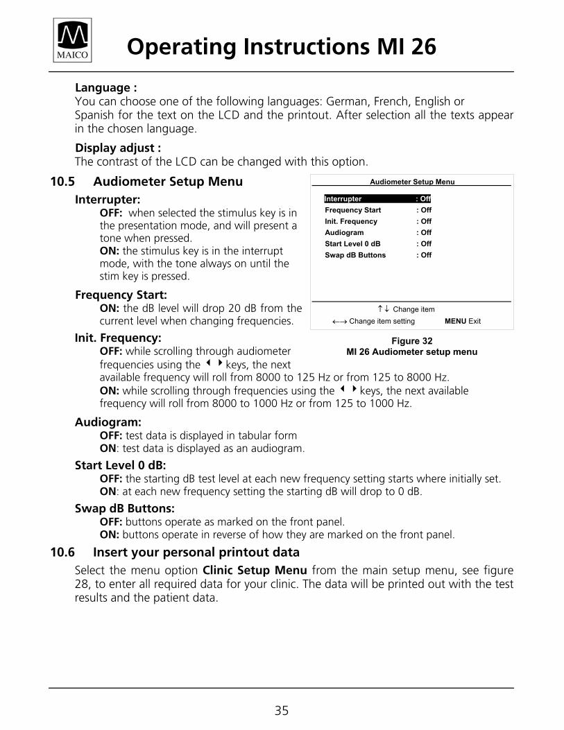
Power-up:
Choose the test mode of the MI 26 after switching on. With the Tymp setting, only tympanometry is tested after power-up.
With Tymp and Reflex, tympanometry and reflex are tested after power-up.
Baud Rate:
Set the transmission speed of the serial data interface. Possible settings are 57600 Baud or 38400 Baud.
Remote Switch:
Change the function of the probe button. You can choose between:
L/R: the test ear can be selected with the probe button.
Pause: the test can be paused and restarted with the probe button.
L/R or Pause: both the test ear and the test can be selected, paused and restarted with the probe button or off.
Subject Data Printout :
Turn the printout of the headline (data entry area at the top) on or off.
Clinic Data Printout :
If you entered your clinic data the printout of the entered data can be switched on And off with this option. Print after test :
With this option you enable an automatic printout after you finished a test by setting it on. With the setting off, printout will be processed after you press the Print button.
Common Setup Menu Power-up : Tymp and Reflex Baud Rate : 57600 Remote switch : L/R Subject Data Printout : On Clinic Data Printout : On Print after Test : Off Language : English Display adjust : ↑ ↓ Change item ←→ Change item setting MENU Exit
Figure 31 MI 26 Reflex setup menu
(Auto start dB setup selected)
M
Operating Instructions MI 26
35
Language : You can choose one of the following languages: German, French, English or Spanish for the text on the LCD and the printout. After selection all the texts appear in the chosen language.
Display adjust : The contrast of the LCD can be changed with this option.
10.5 Audiometer Setup Menu Interrupter:
OFF: when selected the stimulus key is in the presentation mode, and will present a tone when pressed. ON: the stimulus key is in the interrupt mode, with the tone always on until the stim key is pressed.
Frequency Start: ON: the dB level will drop 20 dB from the current level when changing frequencies.
Init. Frequency: OFF: while scrolling through audiometer frequencies using the 34keys, the next available frequency will roll from 8000 to 125 Hz or from 125 to 8000 Hz. ON: while scrolling through frequencies using the 34keys, the next available frequency will roll from 8000 to 1000 Hz or from 125 to 1000 Hz.
Audiogram: OFF: test data is displayed in tabular form ON: test data is displayed as an audiogram.
Start Level 0 dB: OFF: the starting dB test level at each new frequency setting starts where initially set. ON: at each new frequency setting the starting dB will drop to 0 dB.
Swap dB Buttons: OFF: buttons operate as marked on the front panel. ON: buttons operate in reverse of how they are marked on the front panel.
10.6 Insert your personal printout data Select the menu option Clinic Setup Menu from the main setup menu, see figure 28, to enter all required data for your clinic. The data will be printed out with the test results and the patient data.
Audiometer Setup Menu Interrupter : Off Frequency Start : Off Init. Frequency : Off Audiogram : Off Start Level 0 dB : Off Swap dB Buttons : Off ↑ ↓ Change item ←→ Change item setting MENU Exit
Figure 32 MI 26 Audiometer setup menu
Operating Instructions MI 26
36
11 Care and maintenance of the instrument Disconnect the power plug before cleaning.
To clean the instrument, probe, contralateral receiver and other accessories use a soft, damp cloth (use warm soapy water; no liquids containing alcohol or ammonia should be used) to gently wipe the area clean.
During cleaning, please ensure that no liquid runs into the switches, level control or probe openings.
Operating Instructions MI 26
37
12 How to change the printer paper At the right side of the housing, pull the printer cover up using its finger recess in the front of the printer cover.
Remove the printer cover.
Remove the empty paper roll.
Place the new paper roll in the paper compartment in such a way that the paper unrolls from the bottom side of the roll.
Pull the blue lever, which is located on the right front of the printer, forward into position.
The paper must feed from the bottom because it is only coated on one side. If it is inserted wrong, no printout will be visible!
Gently insert the paper end in between the rubber roll and the black plastic part at the rear of the printer.
Feed the printer paper until it appears from the upper part of the rubber roll.
Feed about 4 – 5 inches of paper from the roll.
Push the blue lever back into its backward position.
Guide the paper end through the paper slot of the printer cover.
Close the printer cover by putting the two guide rails at the end of the printer cover into their appropriate slots in the paper compartment of the housing of the MI 26. Press the front of the printer cover down until it fastens.
You are now ready to print.
Operating Instructions MI 26
38
13 Warranty, maintenance and after-sales service
13.1 Warranty
This warranty is extended to the original purchaser of the MI 26 by Maico, through the authorized Special Instrument Distributor from whom it was purchased, and covers defects in material and workmanship for a period of one year from date of delivery of the MI 26.
Should the Maico MI 26 require service due to a defect in material or workmanship, Maico, at its option, will repair or replace the instrument at no charge except for transportation to and from the point of service. It is the purchaser’s responsibility to return the MI 26 to the Maico Special Instrument Distributor from whom it was purchased or directly to Maico after receiving a return authorization.
This warranty does not cover breakage or failure caused by tampering, misuse, carelessness, accident or modification. The warranty is void if the instrument is serviced by other than an authorized Maico Special Instrument Service Center.
NOTE: Specifications in this manual are in effect at the time of printing. Maico reserves the right to modify or change specifications or design at any time without notice or incurring obligation.
WARNING: The Maico MI 26 is designed to be used with a hospital grade outlet. Injury to personnel or damage to equipment can result when a three-prong to two-prong adapter is connected between the power plug and an AC outlet or extension cord.
Operating Instructions MI 26
39
13.2 Maintenance
The MI 26 is designed to require minimal maintenance and should provide you with years of trouble-free use. The following suggestions may assist you in avoiding and/or solving problems.
Calibration:
The optimum length of time between recalibrations for impedance meters or audiometers varies, depending upon the treatment given the instrument and the headphones/probe. It is recommended that the instrument have a laboratory calibration at least once every year. Since rough handling, such as dropping the probe, can easily cause calibration errors it is advisable to establish a biological calibration check as soon as you receive the instrument.
Should you feel at a later date that the impedance or audiometer’s calibration may be in error, perform a biological check on a known ear. If all retests show major changes, calibration is probably in error.
All repair and recalibration should be done at an authorized Maico Special Instruments Distributor service center. This assures the use of quality materials by trained and experienced technicians using the proper, accurate equipment.
Maico Special Instruments Distributors are located in major cities throughout the world. To minimize costs and time delays, contact the Distributor that you purchased the instrument from. If you don’t know who that is, or need to find the Distributor closest to you, contact the factory at:
Maico Diagnostics 7625 Golden Triangle Drive Eden Prairie, MN 55344 Toll free 888-941-4201 Phone 952-941-4200 Fax 952-903-4200 Customers outside of North America and South America may contact: Maico Diagnostic GmbH Salzufer 13/14 10587 Berlin, Germany phone ++030 70 71 46 50 fax ++030 70 71 46 99
Operating Instructions MI 26
40
Care of eartips:
The eartips supplied with your instrument are latex-free silicone rubber and can be cleaned with a mild soap and water, chlorine bleach or with alcohol. Dry the tips thoroughly before replacing them on the probe.
Care of headset:
Always handle earphones with care. Never drop them or permit them to snap together. Mechanical shock may change the earphone’s electrical and operational characteristics and require recalibration of the instrument. Ear cushions are latex-free neoprene rubber and may be cleaned with a mild soap and water.
Care of accessory connections:
Avoid sharp bending or twisting any of the connecting cords. Unplug headset and patient response cords by grasping the barrel of the connecting plug. Never pull on the cord itself.
Shipping instructions for recalibration or repair
In the event it becomes necessary to return the instrument for recalibration or repair, please follow these instructions:
1. Place the instrument in the original shipping carton, using the packaging provided. Be sure to include all accessories, as they are required for proper calibration.
2. Enclose an explanatory letter describing the service you require, carefully detailing any operational problems. Be sure to include your name, phone number, the serial number and your full return address for return shipping.
3. Ship, prepaid, to your Maico Special Instrument service center.
NOTE: Warranty service is provided by your authorized Maico Special Instruments Distributor.
DO NOT ATTEMPT TO REMOVE THE INSTRUMENT CASE YOURSELF.
THIS SHOULD ONLY BE DONE BY AN AUTHORIZED MAICO SERVICE TECHNICIAN.
Operating Instructions MI 26
41
14 Safety regulations
14.1 Electrical safety:
The MI 26 tympanometer is constructed to comply with protection class II of the international standard IEC 601-1 (EN 60601-1).
The instruments are not intended for operation in areas with an explosion hazard.
14.2 Measuring accuracy:
To guarantee that the tympanometer works properly, the instrument has to be checked and calibrated at least once a year.
The service and calibration must be performed by an authorized service center.
The use of non-calibrated tympanometers is not allowed.
14.3 Device control:
The user of the instrument should perform a subjective instrument check once a week. This check can be completed following the list for subjective instrument check (see next page). For your own security, you should copy the enclosed list, fill it in once a week and store it in your files.

Operating Instructions MI 26
42
15 Checklist for subjective device control According to the manufacturer requirements, the user should test the instrument once a week. This is to find errors immediately and to avoid inaccurate test results. This test should test tympanogram and reflex with an otologic normal person and compare the results with earlier measurements. The printout should be filed together with the subjective test protocol to document the instrument test. The test person should be healthy (no otitis etc.) and should not be exposed to loud noise for at least 12 hours before the test. The instrument must be calibrated according to chapter 3.5 of the operating intstuctions.
Instrument type:
Serial No.:
Test person: Connectors and cables OK?
Instrument and probe?
Is the green light of the probe blinking?
Probe tip and ear tip clean?
Are all controls easy to use?
Are the test signals clear and non-distorted?
500 Hz 1000 Hz 2000 Hz 4000 Hz Reflex test
right ear
90 dBHL
500 Hz 1000 Hz 2000 Hz 4000 Hz Reflex test
left ear 90 dBHL
If significant differences or damages are found, please send in for service repair.
Tested by: Date:
Attach the printout of tympanogram and reflex test for both ears.
O
Operating Instructions MI 26
43
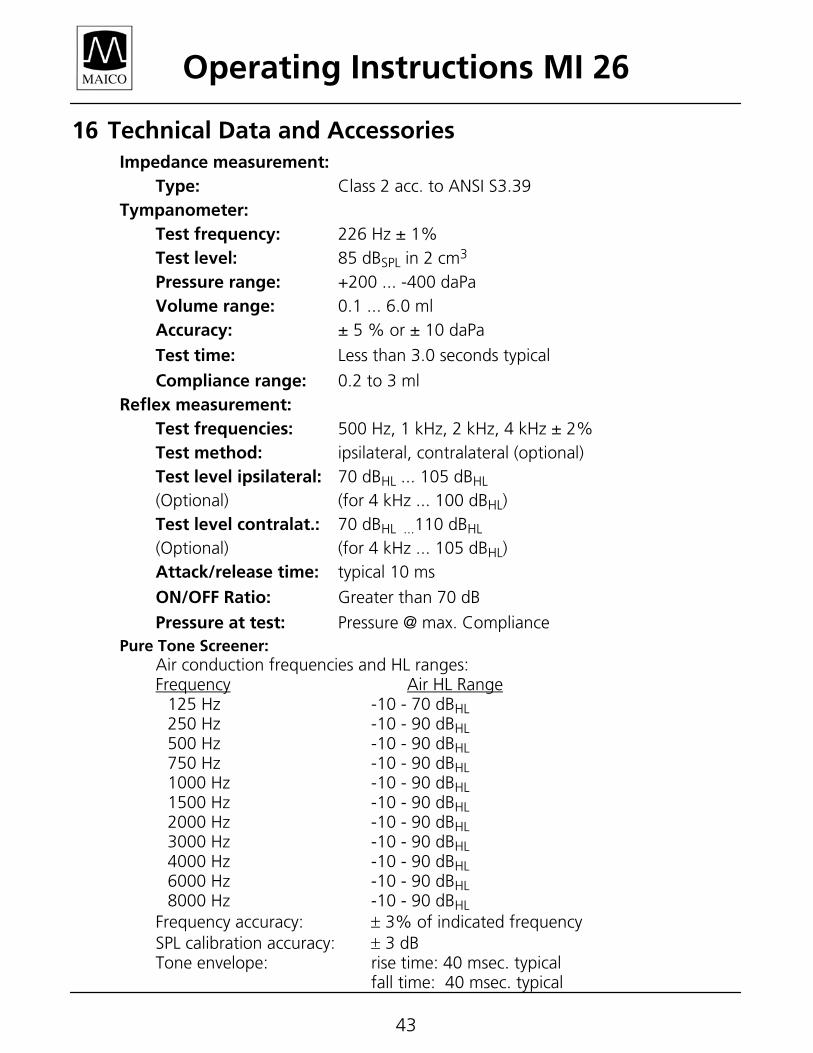
16 Technical Data and Accessories Impedance measurement:
Type: Class 2 acc. to ANSI S3.39 Tympanometer: Test frequency: 226 Hz ± 1% Test level: 85 dBSPL in 2 cm3 Pressure range: +200 ... -400 daPa Volume range: 0.1 ... 6.0 ml Accuracy: ± 5 % or ± 10 daPa
Test time: Less than 3.0 seconds typical
Compliance range: 0.2 to 3 ml Reflex measurement: Test frequencies: 500 Hz, 1 kHz, 2 kHz, 4 kHz ± 2% Test method: ipsilateral, contralateral (optional) Test level ipsilateral: 70 dBHL ... 105 dBHL (Optional) (for 4 kHz ... 100 dBHL) Test level contralat.: 70 dBHL ...110 dBHL
(Optional) (for 4 kHz ... 105 dBHL) Attack/release time: typical 10 ms
ON/OFF Ratio: Greater than 70 dB
Pressure at test: Pressure @ max. Compliance Pure Tone Screener:
Air conduction frequencies and HL ranges: Frequency Air HL Range 125 Hz -10 - 70 dBHL 250 Hz -10 - 90 dBHL
500 Hz -10 - 90 dBHL
750 Hz -10 - 90 dBHL 1000 Hz -10 - 90 dBHL 1500 Hz -10 - 90 dBHL 2000 Hz -10 - 90 dBHL 3000 Hz -10 - 90 dBHL 4000 Hz -10 - 90 dBHL 6000 Hz -10 - 90 dBHL 8000 Hz -10 - 90 dBHL Frequency accuracy: ± 3% of indicated frequency SPL calibration accuracy: ± 3 dB Tone envelope: rise time: 40 msec. typical
fall time: 40 msec. typical
Operating Instructions MI 26
44
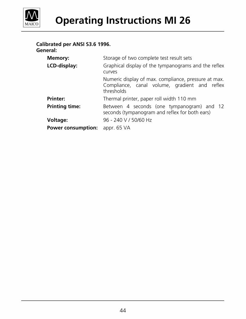
Calibrated per ANSI S3.6 1996. General:
Memory: Storage of two complete test result sets
LCD-display: Graphical display of the tympanograms and the reflex curves
Numeric display of max. compliance, pressure at max. Compliance, canal volume, gradient and reflex thresholds
Printer: Thermal printer, paper roll width 110 mm
Printing time: Between 4 seconds (one tympanogram) and 12 seconds (tympanogram and reflex for both ears)
Voltage: 96 - 240 V / 50/60 Hz
Power consumption: appr. 65 VA
Operating Instructions MI 26
45
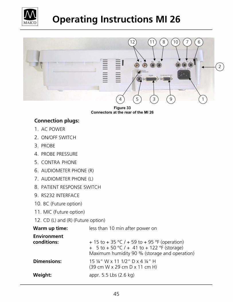
Connection plugs:
1. AC POWER 2. ON/OFF SWITCH 3. PROBE 4. PROBE PRESSURE 5. CONTRA PHONE 6. AUDIOMETER PHONE (R) 7. AUDIOMETER PHONE (L) 8. PATIENT RESPONSE SWITCH
9. RS232 INTERFACE
10. BC (Future option)
11. MIC (Future option)
12. CD (L) and (R) (Future option)
Warm up time: less than 10 min after power on
Environment conditions: + 15 to + 35 °C / + 59 to + 95 °F (operation) + 5 to + 50 °C / + 41 to + 122 °F (storage) Maximum humidity 90 % (storage and operation)
Dimensions: 15 ¼“ W x 11 1/2“ D x 4 ¼“ H (39 cm W x 29 cm D x 11 cm H)
Weight: appr. 5.5 Lbs (2.6 kg)
Figure 33 Connectors at the rear of the MI 26
2
19 354
12 11 8 10 7 6
Operating Instructions MI 26
46
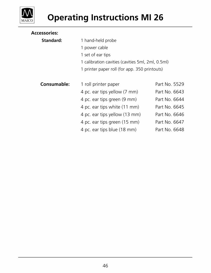
Accessories:
Standard: 1 hand-held probe
1 power cable
1 set of ear tips
1 calibration cavities (cavities 5ml, 2ml, 0.5ml)
1 printer paper roll (for app. 350 printouts)
Consumable: 1 roll printer paper Part No. 5529
4 pc. ear tips yellow (7 mm) Part No. 6643
4 pc. ear tips green (9 mm) Part No. 6644
4 pc. ear tips white (11 mm) Part No. 6645
4 pc. ear tips yellow (13 mm) Part No. 6646
4 pc. ear tips green (15 mm) Part No. 6647
4 pc. ear tips blue (18 mm) Part No. 6648


