
One Way Circuits LimitedPrinted Circuit Board Manufacturer
Front End DRC (Design Rule Checks)
Use Left and Right Cursor keys to navigate ESC to quit presentation
Front End DRC
Presentation Title:Front End DRC (Design Rule Checks).
Created / Modified:15th September 2009.
Compiled By:One Way Circuits Limited.
Description:An introduction to Design Rule Checks.The following is a guide only.
Minimum Track Width
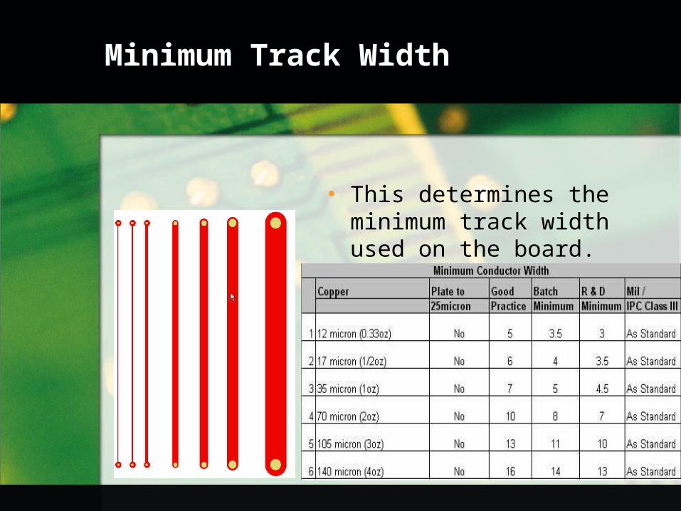
• This determines the minimum track width used on the board.
Feature to feature spacing
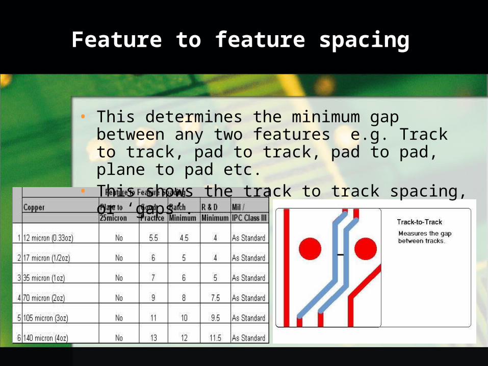
• This determines the minimum gap between any two features e.g. Track to track, pad to track, pad to pad, plane to pad etc.
• This shows the track to track spacing, or ‘gaps’.

Feature to feature spacing
• Pad to pad.• DRC finds the minimum space (gap)
between any pads.
Feature to feature spacing
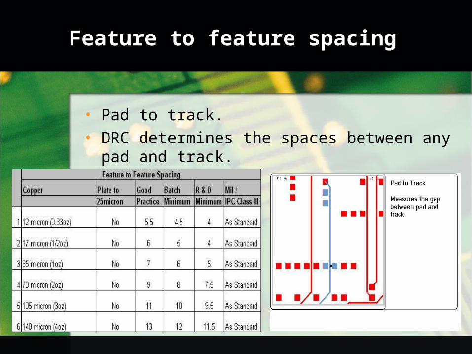
• Pad to track.• DRC determines the spaces between any
pad and track.

Minimum Annular Ring
• There are many standards applied to the minimum annular ring analysis, e.g. MIL Spec, buried/blind vias, copper weight, all of which determine the minimum requirement.
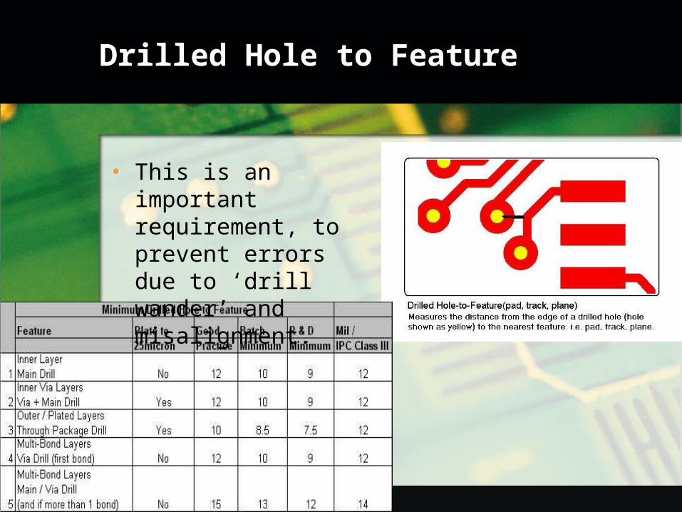
Drilled Hole to Feature
• This is an important requirement, to prevent errors due to ‘drill wander’ and misalignment.

Pad to Nearest Feature
• Multi bond layers (blind/buried vias)
• Again this is an important check to reduce the risk of errors occurring due to misalignment or ‘drill wander’.

Solder Resist Clearance
• The solder resist ‘bridge’ is important to prevent solder shorts across surface mount pads.
• It is also important to provide enough clearance to ensure solderability and alignment of the resist during application.

Solder Resist Clearance- BGA
• On BGA’s (Ball Grid Array) the solder resist clearance must NOT expose the via holes.
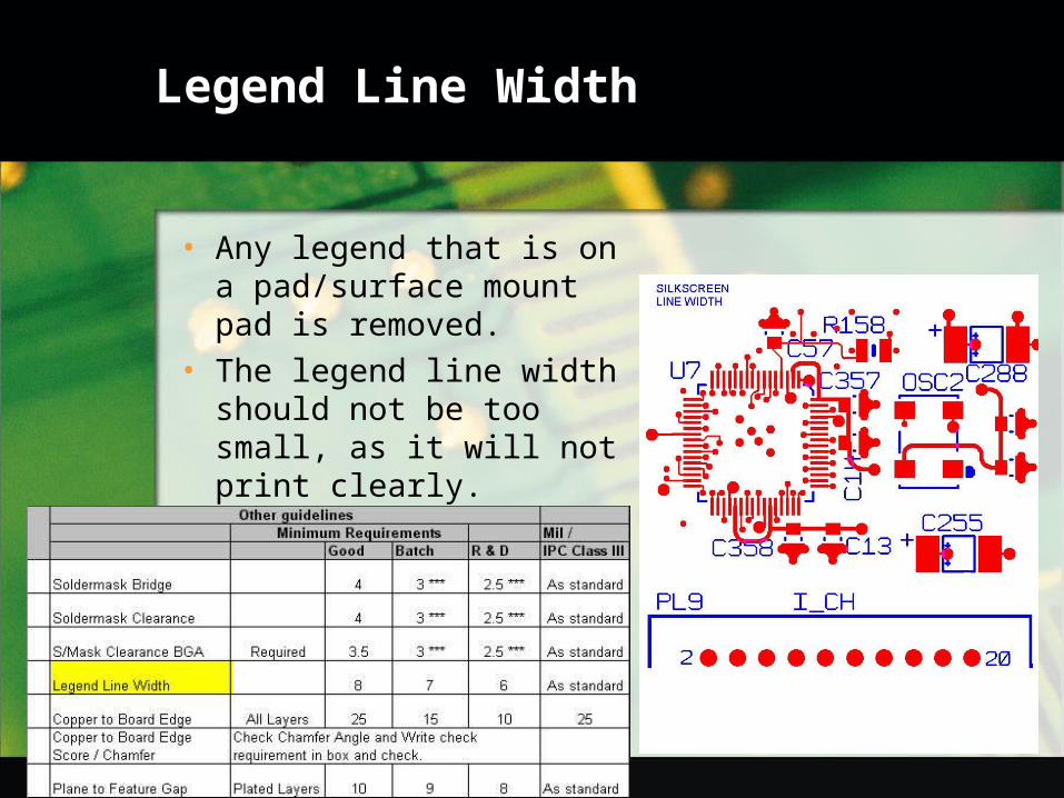
Legend Line Width
• Any legend that is on a pad/surface mount pad is removed.
• The legend line width should not be too small, as it will not print clearly.
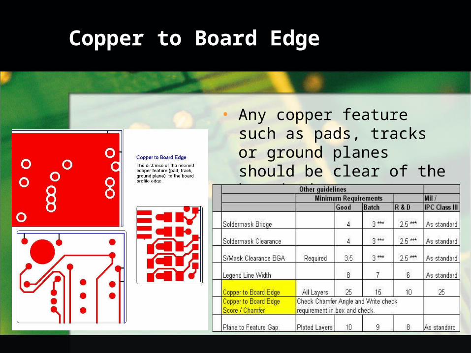
Copper to Board Edge
• Any copper feature such as pads, tracks or ground planes should be clear of the board edge.

Copper to Board Edge - Score
• These dimensions should always be checked against the customers requirements.
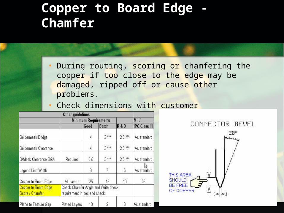
Copper to Board Edge - Chamfer
• During routing, scoring or chamfering the copper if too close to the edge may be damaged, ripped off or cause other problems.
• Check dimensions with customer requirements.

Ground Plane Features
• Some ground plane features to watch out for.

Layer to Layer Registration
• All the layers must be properly registered.• Any mis-registration could lead to further
problems during the DRC.
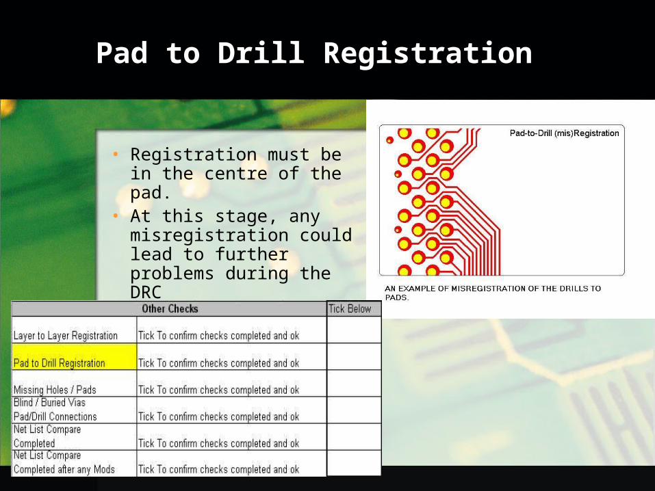
Pad to Drill Registration
• Registration must be in the centre of the pad.
• At this stage, any misregistration could lead to further problems during the DRC
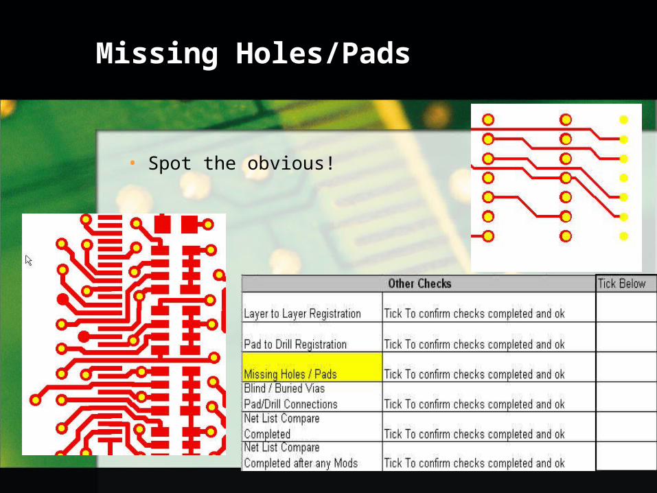
Missing Holes/Pads
• Spot the obvious!

Blind/Buried Vias Pad/Drill Connections
• Check there is a pad(connection) for each drill (via).

Drawn Data
• Drawn pads must be replaced with ‘flashed’ pads.• Modelling replaces the ‘draws’ with a single pad of the
exact size and shape.• On this job 13,770 ‘draws’ were replaced by 1,312 pads!

Thank you for viewing this presentation


