
One Dimensional Steady Heat Conduction problems
P M V Subbarao
Associate Professor
Mechanical Engineering Department
IIT Delhi
Simple ideas for complex Problems…

Electrical Circuit Theory of Heat Transfer
• Thermal Resistance• A resistance can be defined as the ratio of a
driving potential to a corresponding transfer rate.
i
VR
Analogy:
Electrical resistance is to conduction of electricity as thermal resistance is to conduction of heat.
The analog of Q is current, and the analog of the temperature difference, T1 - T2, is voltage difference.
From this perspective the slab is a pure resistance to heat transfer and we can define
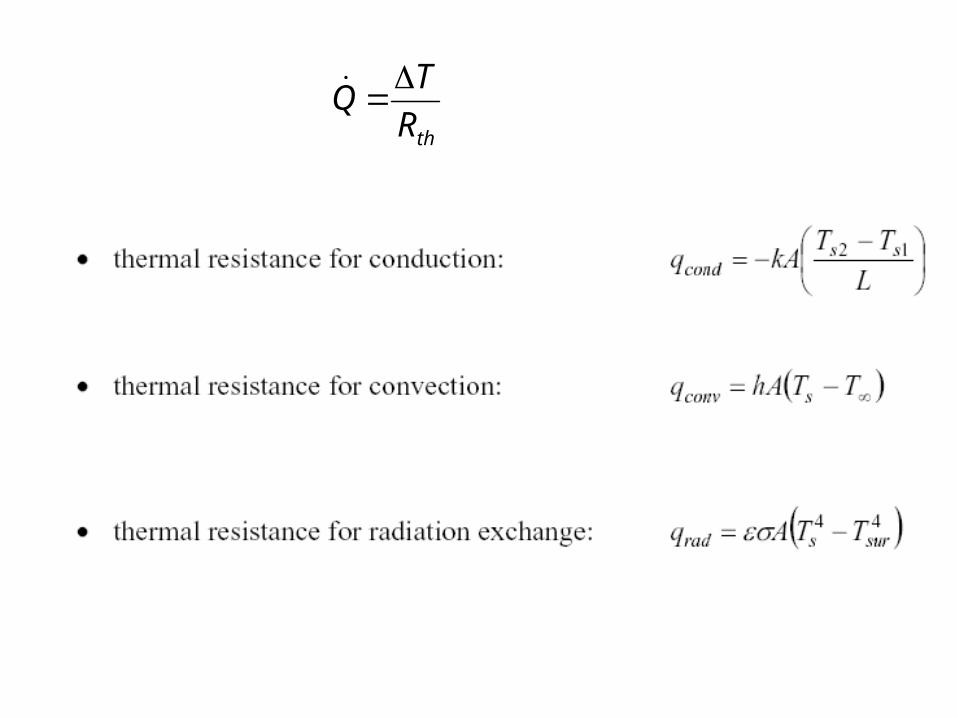
thR
TQ

The composite Wall
• The concept of a thermal resistance circuit allows ready analysis of problems such as a composite slab (composite planar heat transfer surface).
• In the composite slab, the heat flux is constant with x.
• The resistances are in series and sum to R = R1 + R2.
• If TL is the temperature at the left, and TR is the temperature at the right, the heat transfer rate is given by

Wall Surfaces with Convection
2112
2
0 CxCTCdx
dT
dx
TdA
Boundary conditions:
110
)0(
TThdx
dTk
x
22 )(
TLThdx
dTk
Lx
Rconv,1 Rcond Rconv,2
T1 T2

Heat transfer for a wall with dissimilar materials
• For this situation, the total heat flux Q is made up of the heat flux in the two parallel paths:
• Q = Q1+ Q2
with the total resistance given by:

Composite Walls
• The overall thermal resistance is given by

Desert Housing & Composite Walls

One-dimensional Steady Conduction in Radial Systems
0
drdrdT
kAd
Homogeneous and constant property material
0
drdrdT
Ad
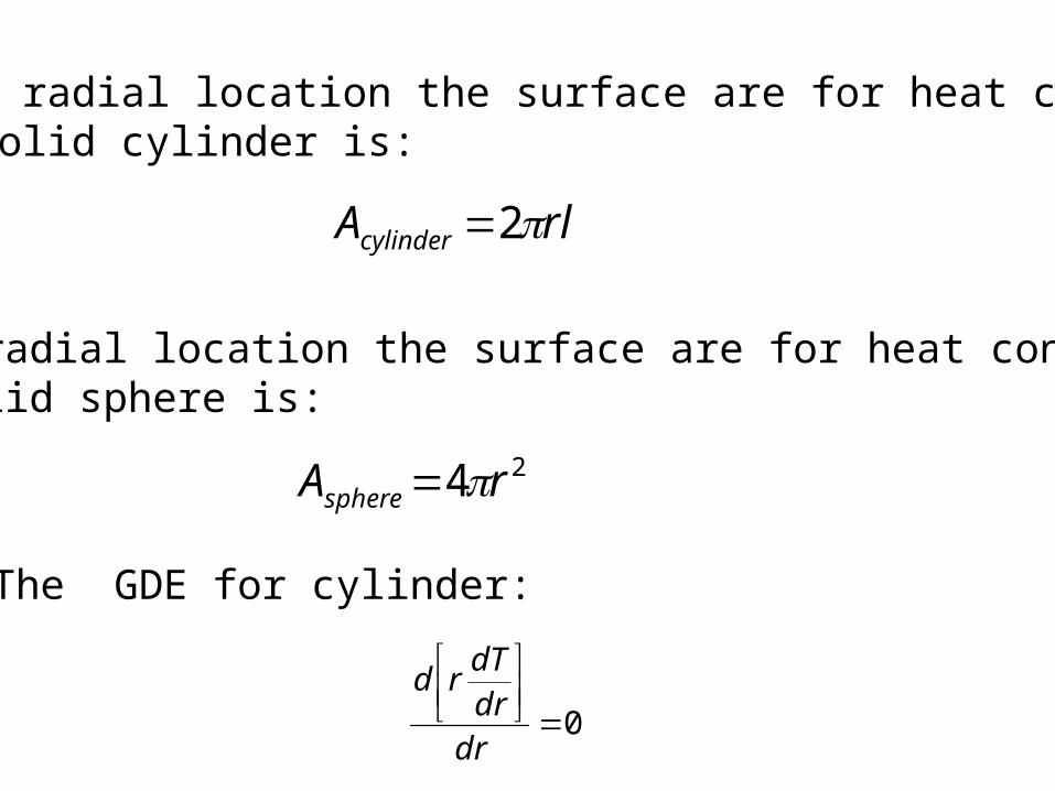
At any radial location the surface are for heat conductionin a solid cylinder is:
rlAcylinder 2
At any radial location the surface are for heat conductionin a solid sphere is:
24 rAsphere
The GDE for cylinder:
0
drdrdTrd

The GDE for sphere:
0
2
drdrdT
rd
General Solution for Cylinder:
21 ln CrCrT
General Solution for Sphere:
r
CCrT 1
2

Boundary Conditions
• No solution exists when r = 0. • Totally solid cylinder or Sphere have no physical relevance!
• Dirichlet Boundary Conditions: The boundary conditions in any heat transfer simulation are expressed in terms of the temperature at the boundary.
• Neumann Boundary Conditions: The boundary conditions in any heat transfer simulation are expressed in terms of the temperature gradient at the boundary.
• Mixed Boundary Conditions: A mixed boundary condition gives information about both the values of a temperature and the values of its derivative on the boundary of the domain.
• Mixed boundary conditions are a combination of Dirichlet boundary conditions and Neumann boundary conditions.

• If A, is increased, Q will increase. • When insulation is added to a pipe, the outside
surface area of the pipe will increase. • This would indicate an increased rate of heat
transfer
• The insulation material has a low thermal conductivity, it reduces the conductive heat transfer lowers the temperature difference between the outer surface temperature of the insulation and the surrounding bulk fluid temperature.
• This contradiction indicates that there must be a critical thickness of insulation.
• The thickness of insulation must be greater than the critical thickness, so that the rate of heat loss is reduced as desired.
Mean Critical Thickness of Insulation
Heat loss from a pipe:
TThAQ s
h,T
Ts
ri
ro

Electrical analogy:totalR
TerheattransfofRate
ooi
o
i
Lhrrr
Lk
TTQ
21
ln2
1
As the outside radius, ro, increases, then in the denominator, the first term increases but the second term decreases.
Thus, there must be a critical radius, rc , that will allow maximum rate of heat transfer, Q
The critical radius, rc, can be obtained by differentiating and setting the resulting equation equal to zero.

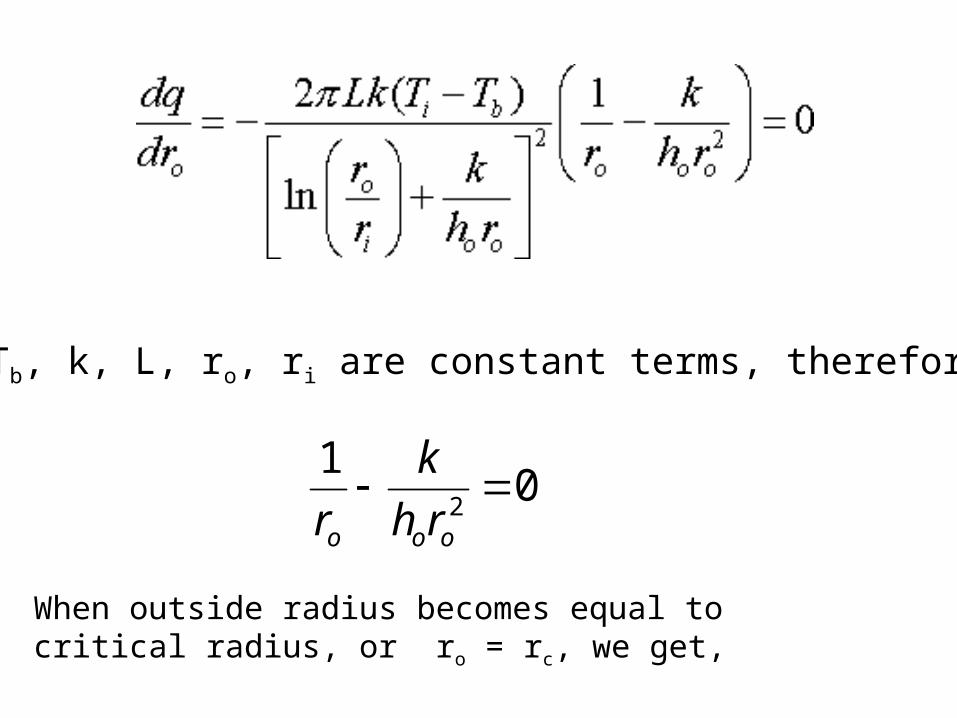
Ti,Tb, k, L, ro, ri are constant terms, therefore:
01
2
ooo rh
k
r
When outside radius becomes equal to critical radius, or ro = rc, we get,
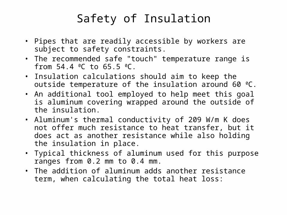
Safety of Insulation
• Pipes that are readily accessible by workers are subject to safety constraints.
• The recommended safe "touch" temperature range is from 54.4 0C to 65.5 0C.
• Insulation calculations should aim to keep the outside temperature of the insulation around 60 0C.
• An additional tool employed to help meet this goal is aluminum covering wrapped around the outside of the insulation.
• Aluminum's thermal conductivity of 209 W/m K does not offer much resistance to heat transfer, but it does act as another resistance while also holding the insulation in place.
• Typical thickness of aluminum used for this purpose ranges from 0.2 mm to 0.4 mm.
• The addition of aluminum adds another resistance term, when calculating the total heat loss:

Structure of Hot Fluid Piping
Rconv,1 Rpipe Rconv,2
T1 T2
Rinsulation RAl

• However, when considering safety, engineers need a quick way to calculate the surface temperature that will come into contact with the workers.
• This can be done with equations or the use of charts.
• We start by looking at diagram:
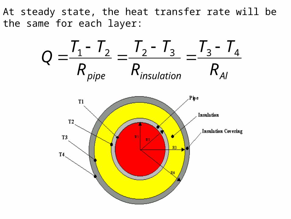
At steady state, the heat transfer rate will be the same for each layer:
Alinsulationpipe R
TT
R
TT
R
TTQ 433221
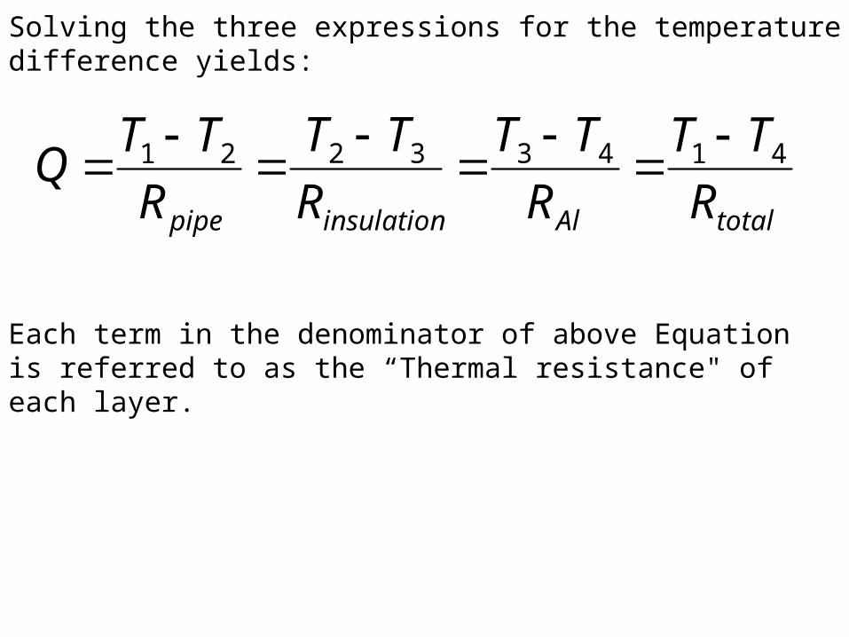
Solving the three expressions for the temperature difference yields:
Each term in the denominator of above Equation is referred to as the “Thermal resistance" of each layer.
totalAlinsulationpipe R
TT
R
TT
R
TT
R
TTQ 41433221

Design Procedure
• Use the economic thickness of your insulation as a basis for your calculation.
• After all, if the most affordable layer of insulation is safe, that's the one you'd want to use.
• Since the heat loss is constant for each layer, calculate Q from the bare pipe.
• Then solve T4 (surface temperature). • If the economic thickness results in too high a surface temperature,
repeat the calculation by increasing the insulation thickness by 12 mm each time until a safe touch temperature is reached.
• Using heat balance equations is certainly a valid means of estimating surface temperatures, but it may not always be the fastest.
• Charts are available that utilize a characteristic called "equivalent thickness" to simplify the heat balance equations.
• This correlation also uses the surface resistance of the outer covering of the pipe.


