
for the
ANSICentrifugal Pumps
IndustryProcessing
Where Innovation Flows
griswoldpump.com
811 ANSI Centrifugal Pumps

O I L & G A S
C H E M I C A LF O O D P R O C E S S I N GT E X T I L E
P H A R M A C E U T I C A LS E M I C O N D U C T O R
2
GRISWOLD™ CENTRIFUGAL PUMPSGriswold™ is a premier manufacturer of centrifugal pumps and baseplate systems. With engineering expertise, lean manufacturing, testing capabilities, and exceptional customer support, Griswold meets its customers’ most demanding application requirements, all while minimizing project costs.
ARE ALL ANSI PUMPS THE SAME?In 1974, the American National Standards Institute (ANSI) established manufacturing criteria for centrifugal pumps to ensure that the demanding needs of the chemical-processing industry are met. Mandatory design features- such as self-ventilation, foot mounting, centerline discharge and back pullout- became the industry’s assurance that complying pumps met production and safety needs.
Even though ANSI compliance would seem to level the playing field for pump specification, your choices are actually far more complex. The fact is that many brands just meet the minimum requirements of this standard, and a pump is far more than just its specifications. While other brands may offer similar features and performance, you may experience inflated cost, delayed delivery and deflated service. In a market where all ANSI pumps seem the same, dare to compare.

3
REDUCED INITIAL & TOTAL COST OF OWNERSHIP
You may have heard that the initial cost of your pump and parts plays a minor role in your total cost of ownership. NOT TRUE! With the Griswold 811, you get identical quality and longevity as the best-known brands—at a lower initial price. Factor in low cost on parts and the long-term savings are even greater! This translates into the industry’s LOWEST total cost of ownership.
PROVEN TRACK RECORD OF PERFORMANCE
The Griswold 811 ANSI line offers the best pumps you’ll find on the market. Engineered for exceptional performance and maximum flexibility, the 811 models go the distance in the harshest and most difficult fluid-processing applications. The Griswold 811 centrifugal pump was among the first pump designs to comply with the new ANSI standards in the 1970s. More than 45 years of proven performance has enabled Griswold to focus on enhancing its ANSI pump features and support offerings to surpass the industry standard and exceed customer expectations.
SPEED AND EASE OF REPLACEMENT
When meeting your production quota is compromised, waiting for repairs can mean significant losses in revenue (which is another factor in true cost of ownership). The Griswold 811 and an extensive inventory of parts are 100% interchangeable with hundreds of thousands of other ANSI pumps currently in use. With stocking distributors from coast-to-coast and throughout the world, you can be up and running before you even get a response call from the competition!
CO
MP
AR
E
811
other brands
CO
MP
AR
E
811
other brands
ü ü
EXTENDED EQUIPMENT LIFE
In addition to exceeding ANSI construction requirements, the 811 models include several features that are critical to long-term operational reliability. To start, the open impeller and seal chambers are designed to facilitate corrosive and erosive substance transport, heat regulation and routine maintenance. The 811’s range of enhanced power frames and rigid baseplates combine the latest technology with the highest quality construction to minimize the effects of work forces and shaft deflection, optimize cooling and further simplify the installation and maintenance process. All told, you can expect the 811 pump series to continue performing long after other ANSIs wear out or break down.
CO
MP
AR
E
811
other brands
CO
MP
AR
E
811 üother
brands
ü

7
8
45
6
&FlexibilityDurability
Engineered for
TECHNOLOGY: CENTRIFUGAL
811 Series ANSI/ASME Centrifugal PumpsThe 811 model is available in a wide range of sizes, capacities and materials to fit virtually any process-fluid application. With more than 30 selections and multiple design options, we’ve got your application covered - for abrasives, corrosive substances and a wide range of capacities.
Applications• Oil & Gas• Chemical• Petrochemical• Water Treatment• Pulp & Paper• Breweries• Grain Processing• Food Processing
• Poultry Processing• Automotive• Pharmaceutical• Steel• Semiconductor• Power Generation• Textile
Features and Benefits:• ASME (ANSI) B73.1-compliant• Magnetic drain plug• Extra-large capacity epoxy-
coated oil sump• Registered alignment between
frame and adapter• Standard and low-flow
models available
• Heavy-duty power frames• Fully open impellers with rear-
adjustment capability• Wide variety of mechanical
seal options• Dynamically balanced impellers
Technical Data:• Ductile iron, CF8M (316) stainless steel, CD4MCu and Alloy 20 materials available• Max. temperature: 260°C (500°F)• Three stuffing-box options available• Multiple port sizes available• Multiple seal-flush plans available• Steel and composite baseplates available• Certified testing per Hydraulic Institute and material certifications per ASTM
Performance Data:• Max. flow: 1,590 m3/hr (7,000 gpm)• Max. head: 275 m (900 ft)
Certifications & Associations:
OHSAS 18001 ISO 14001 ISO 9001
ASME (ANSI) B73.1
4

1 Ductile Iron Frame AdaptersDuctile-iron construction provides strength and safety. Precision machined to accurately align the liquid end to the power end. Large openings simplify installation and maintenance. Includes jacking bolts to facilitate disassembly.
2 Labyrinth Seals StandardINPRO® oil seals keep outside contaminants from lubrication media, significantly extending bearing life. Standard in bronze. Carbon-filled PTFE (Teflon®) and magnetic face seals optional.
3 Mounting Frame FlangeMachined to accommodate C-face motor adapters.
4 Extra-Large Capacity Powder-Coated Oil SumpMaximized oil capacity delivers improved heat transfer and oil temperature, greatly extending bearing life. Designed to accommodate optional fin coolers for high-temperature applications. Impenetrable fusion-bonded epoxy coating on interior surface extends quality, cleanliness and longevity of the lubricating oil.
5 External Clearance AdjustmentDesigned for maintaining original flow, pressure and efficiency, minimizing energy consumption and repairs, and extending mean time between repairs (MTBR).
6 Heavy-Duty Shaft and BearingsEngineered to minimize vibration and shaft deflection, less than 0.002 inch per ANSI/ASME B73.1, optimizing pump life. Sleeved and solid shaft available in a variety of materials. Bearings sized for 10-year life expectancy under tough operating conditions.
7 Oversized Sight GlassOne-inch bullseye reflective sight glass facilitates monitoring oil level and condition, critical to bearing life. Bottle oiler optional.
8 Magnetic Drain PlugCollects damaging metallic contaminants away from the bearings.
9 Extra-Heavy CasingsAll Class 150 pumps are produced with the same heavy-duty wall thicknesses as Class 300 pumps for extended reliability and casing life under severe corrosive/erosive conditions:
• Top centerline, self-venting discharge for air handling
• Back pullout to simplify maintenance
• Rigid casing feet prevent pipe-load misalignment and promote seal/casing life
• Discharge connection for pressure gauge or seal bypass-flush connection standard on ductile iron and stainless steel casings
• Class 150 FF standard for positive sealing; optional Class 150 RF/300 FF/RF available
• Casing drain standard in ductile iron and stainless steel for simplified maintenance
10 Fully Open ImpellerWith double the wear area of enclosed models, the 811’s impeller offers superior handling of solids, corrosives and abrasives. Back pump-out vanes reduce hydraulic loads and seal chamber pressure.
11 Sealing FlexibilityWide range of sealing options coupled with seal chambers and stuffing boxes selected for service condition to improve lubrication and heat dissipation of seal faces, maximizing pump uptime.
12 Contained Casing GasketProvides positive sealing at casing joint to prevent “blow out” of liquids and to facilitate disassembly.
3
2
12
10
1
11
9
5

SEALS TO FIT ANY APPLICATION:
Cartridge Seals, Component Seals & Conventional PackingWith Griswold’s broad selection of seals, you can accommodate most any fluid and temperature for demanding chemical, petroleum, pharmaceutical and general industry applications. Our engineers can recommend the best seal to maximize your application and system life–including cartridge or component, single or double, inside or outside, balance or unbalanced seals or conventional packing.
Double Gas Barrier Seal
Double Cartridge Seal
Single Cartridge Seal
Single Inside Seal Conventional
Double Seal
SEAL CHAMBERS & SEALING FLEXIBILITY:
Our quality seal chambers are engineered to provide optimum seal environment for heat dissipation, solids, entrapped air and vapor. Oversized seal chambers increase radial clearance between the mechanical seal and seal chamber, as well as provide better circulation of liquid to and from the seal faces, preventing failure of the shaft seal. A variety of flush plans are available for additional lubrication and cooling of the seal faces.
Standard Bore Large Bore Tapered Bore
ServicesServices utilizing packing or mechanical seals. For mild fluid at ambient temperatures.
Most services including those with solids greater than 10%. Increased radial clearance between seal and chamber for improved liquid circulation, lubrication and cooling.
Services up to 10% solids or those containing entrained air or vapors. For lower seal face temperatures, self venting and draining. Circulates solids and vapors away from seal faces.
Sealing Flexibility
Packing Most Services Not Available Not Available
Single Seal/No Flush Not Recommended Not Recommended Services with Solids up to 10%
Single Seal/With Flush Mild, Clear Fluids Most Services Including Solids above 10% All Services with Solids up to 10%
Conventional Double Seal with Seal Plan Zero Leakage Applications Zero Leakage Applications Not Available
Cartridge Double Seal with Seal Plan Zero Leakage Applications Zero Leakage Applications Zero Leakage Applications
811 Series Options
6

LUBRICATION OPTIONS
811 power ends accommodate all lubrication systems, including flood oil, oil mist and grease lubrication. The power ends are pre-drilled for all lubrication methods and can be easily converted in the field without modification.
SPECIAL SURFACE PREPARATION
Griswold offers a variety of optional surface-preparation processes for extended corrosion protection and contaminant-free pumping:
• Electro-Polishing
• Passivation
• Hard-Metal Coatings
• Fusion-Bonded, Epoxy- Coated Power End
• Special Paint Systems
SEAL-FLUSH PLANS
ASME (ANSI) B73.1 seal-flush and cooling plans are offered to control emission levels, improve lubrication and cooling of the seal faces, and reduce downtime. Ask for assistance in selecting the best plan.
EXTENSIVE OPTIONSGriswold offers a broad range of options and upgrades to tailor the 811’s handling and performance to meet virtually any fluid-processing application. The Griswold engineering staff can assist you in configuring pump size, material and components to best suit your specific plant and processing requirements.
7

BASEPLATE MOUNTING SYSTEMS
Griswold offers a complete range of pre-engineered rigid baseplates designed to reduce stress and vibration as well as extend MTBR, thus ensuring long-term durability. A wide selection of metallic and non-metallic baseplates provide flexibility in selecting the best base to fit your operating needs and budget. Bases include a fully enclosed steel coupling guard as standard with optional non-sparking coupling guard available.
HEAVY DUTY C-FACE MOTOR ADAPTOR
Optional Feature
The C-face motor adapter bolts directly to the precision machined fit on the power frame. The register fits on both ends of the adapter lock in a standard C-face motor, guaranteeing both parallel and angular alignments. This quick, yet precision installation minimizes time spent aligning shaft couplings, and eliminates seal and bearing replacements caused by misalignment. Best of all, the C-face adapters are directly interchangeable with most ANSI pumps.
Fabricated Steel Base
(enhanced fabricated steel base also available)
Composite Base
Got YouCovered
Accessories: We’ve
8
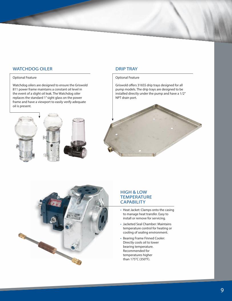
DRIP TRAY
Optional Feature
Griswold offers 316SS drip trays designed for all pump models. The drip trays are designed to be installed directly under the pump and have a 1/2” NPT drain port.
WATCHDOG OILER
Optional Feature
Watchdog oilers are designed to ensure the Griswold 811 power frame maintains a constant oil level in the event of a slight oil leak. The Watchdog oiler replaces the standard 1” sight glass on the power frame and have a viewport to easily verify adequate oil is present.
HIGH & LOW TEMPERATURE CAPABILITY
• Heat Jacket: Clamps onto the casing to manage heat transfer. Easy to install or remove for servicing.
• Jacketed Seal Chamber: Maintains temperature control for heating or cooling of sealing environment.
• Bearing Frame Finned Cooler: Directly cools oil to lower bearing temperature. Recommended for temperatures higher than 175°C (350°F).
9

3x11/2–13
3x11/2–13
3x11/2–10
3x2V8
3x2–10
3x2–13
6x4–10G
4x3–8GLF 1
1 / 2x1
–8
LF 2
x1–1
0
4x3–104x3–13
3x2–6
3x 11/2 –8
3x11/2 –6
11/2x1–8
11/2x1 –6
2x 1–10
CAPACITY – 2850 RPM (50HZ)200
0 GPM
40 60 80 100 120 140 180160 200 220 240 280260 300
100 500 600 700 800 900 1000 1100 1200 1300200 300 400 ft
0
160
TOTA
L HEA
D – 2850 R
PM
(50HZ
)
100
200
300
400
500
600
700
180
210
120
80
40
0
CAPACITY – 3500 RPM (60HZ)
1000 GPM 200 300 400 500 600 700 800 900 1000 1100 1200 1300 1400 1500 1600
60 120 140 160 180 220 240 260 280 300 320 340 36080 1004020 2000
TOTA
L H
EAD
– 3
500
RP
M (
60H
Z)
ft
20
0
60
100
140
180
220240
300
260280
1000
900
800
700
600
500
400
300
200
100
0
3500 2850 RPM Performance Curve
3/h
3/h
10
1750 1450 RPM Performance Curve
TOTA
L H
EAD
– 1
750
RP
M (
60H
Z)
270
300
240
210
180
150
120
100
80
60
40
20
0
ft
10
0
20
30
35
40
45505560657075
808590
200
0 GPM
40 60 100 150 200 300 400 500 600 700 800 900 1000 1100 1200 1300 1400
100 200 300 400 600 800 10001200 1600 2000 2400 2800 3200 3600 4000 4400 4800 5200 5600 6000 6400
CAPACITY – 1750 RPM (60HZ)
0
1000
0
GPM 200 300 400 600 800 1000 1200 1600 2000 2400 2800 3200
20 40 50 75 100 150 200 250 300 400 500 600 700
3600 4000 4400 4800 5200 5600 6000 6400 6800 7000
800 900 1000 1100 1200 1300 1400 1500 1600
CAPACITY – 1450 RPM (50HZ)
ft
20
45
50
55
60
40
60
80
100
120
140
160
180
200
40
35
30
25
20
10
TOTA
L HEA
D – 1450 R
PM
(50HZ
)
3/h
3/h
3x1½–13 3x2–13
3x2–10 4x3–106x4–10G
6x4–10H
4x3–8G4x3–8
LF 1
½ x
1–8
LF 2
x1–
10
4x3–10H
LF 3
x1½
–13
4x3–13 6x4–13 8x6–13
10x8–13
8x6–15
6x4–17
10x8–15G
3x2–8
3x2–6
3x1½
3x1½ –10
2x 1–10
3x1½ –6
1½ x1 –6
1½ x1–8
10x8–17
8x6–17
10x8–16H

Pressure and Temperature Capability
Note: Final selections must be based on temperature and pressure limits
-400 -300 -200 -100 0 100 200 300 400 500
TEMPERATURE–DEGREES FAHRENHEIT
400
350
200
100
0
MA
X. C
ASE
WO
RKIN
G P
RESS
URE
–PS
IG
MAXIMUM WORKING PRESSURE LIMITSMODELS 811S, 811M, 811L; CLASS 300 FLANGES
MIN
IMU
M T
EMPE
RATU
RE
DU
CTIL
E IR
ON
ON
LY
NICKEL
DUCTILE IRON, TYPE 316, W-20, MONEL, NICKEL, HASTELLOY B & C
600
-400 -300 -200 -100 0 100 200 300 400 500
TEMPERATURE–DEGREES FAHRENHEIT
300
250
200
150
100
50
0
MA
X. C
ASE
WO
RKIN
G P
RESS
URE
–PS
IG
MAXIMUM WORKING PRESSURE LIMITSMODELS 811S, 811M, 811L; CLASS 150 FLANGES
HASTELLOY B & CM
INIM
UM T
EMPE
RATU
RE D
UCTI
LE IR
ON
ON
LYDUCTILE
316
W-20
MONEL
NICKEL
600
B.H.P. LimitsMaterials/Casting SpecsDASH MATERIAL CASTING SPECIFICATION
N6 Ductile Iron ASTM A395 Grade 65-45-15
91 316SS ASTM A351 Grade CF8M
20 Alloy 20 ASTM A351 Grade CN7M
X4 Duplex ASTM A995 Grade 1B (CD4MCuN)
R.P.M.MODEL
811S 811M 811L 811XL 811XL17
3560 40.0 122.0 200.0
2900 32.6 99.4 162.9
1780 20.0 61.0 100.0 250.0 350.0
1450 16.3 49.7 81.5 203.7 285.1
1180 13.3 40.4 66.3 165.7 232.0
880 9.9 30.2 49.4 123.6 173.0
Construction Details
Griswold 811 Model Model 811S Model 811M Model 811L Model 811XL Model 811XL17
Corrosion Allowance @ Max. 1/8Max. Allowable Working Pressure (MAWP) See Pressure/Temp. charts aboveHydrostatic Test Pressure 150% MAWP at 100ºF (38ºC)Max. Liquid Temp. 350ºF (177ºC) without Cooling / 500ºF (260ºC) with Cooling
Shaf
t Dia
met
er At Coupling (in.) 7/8 1-1/8 1-7/8 2-3/8 2-3/8Sleeve Dia. Under Seal (in.) 1-3/8 1-3/4 2-1/8 2-1/2 2-1/2Under Impeller (in.) 3/4 1 1-1/4 1-1/2 1-1/2Under Sleeve (in.) 1-1/8 1-1/2 1-7/8 2 2-1/4Overhang (in.) 6-1/8 8-3/8 8-3/8 9 -31/32 9-31/32
Bear
ings Radial SKF 6207 SKF 6309 SKF 6311 SKF 6313 SKF 6313
Thrust SKF 5306 A/C3 SKF 5309 A/C3 SKF 7310 BECBM SKF 5313 A/C3 SKF 5313 A/C3
Bearing Span 4-1/8 6-3/4 6-7/8 9-1/4 9-1/4
Mechanical Seal Size (in.) 1-3/8 1-3/4 2-1/8 2-1/2 2-1/2
Stuffi
ng B
ox
Stan
dard
Bor
e I.D. (in.) 2 2-1/2 2-7/8 3-3/8 3-5/8
Depth (in.) 2-1/8 2-5/8 3 3
Distance End of Box to Nearest Obstruction 2-1/2 2-13/16 2-15/16 2-15/16
Stuffi
ng B
ox
Larg
e Bo
re
I.D. (in.) 2-7/8 3-1/2 3-7/8 4-1/2 4-1/2
Depth (in.) 2-1/8 2-1/8 3 3
Distance End of Box to Nearest Obstruction 2-1/2 2-13/16 2-17/20 2-17/20
Lantern Ring Width (in.) 7/16 5/8 5/8 5/8
11
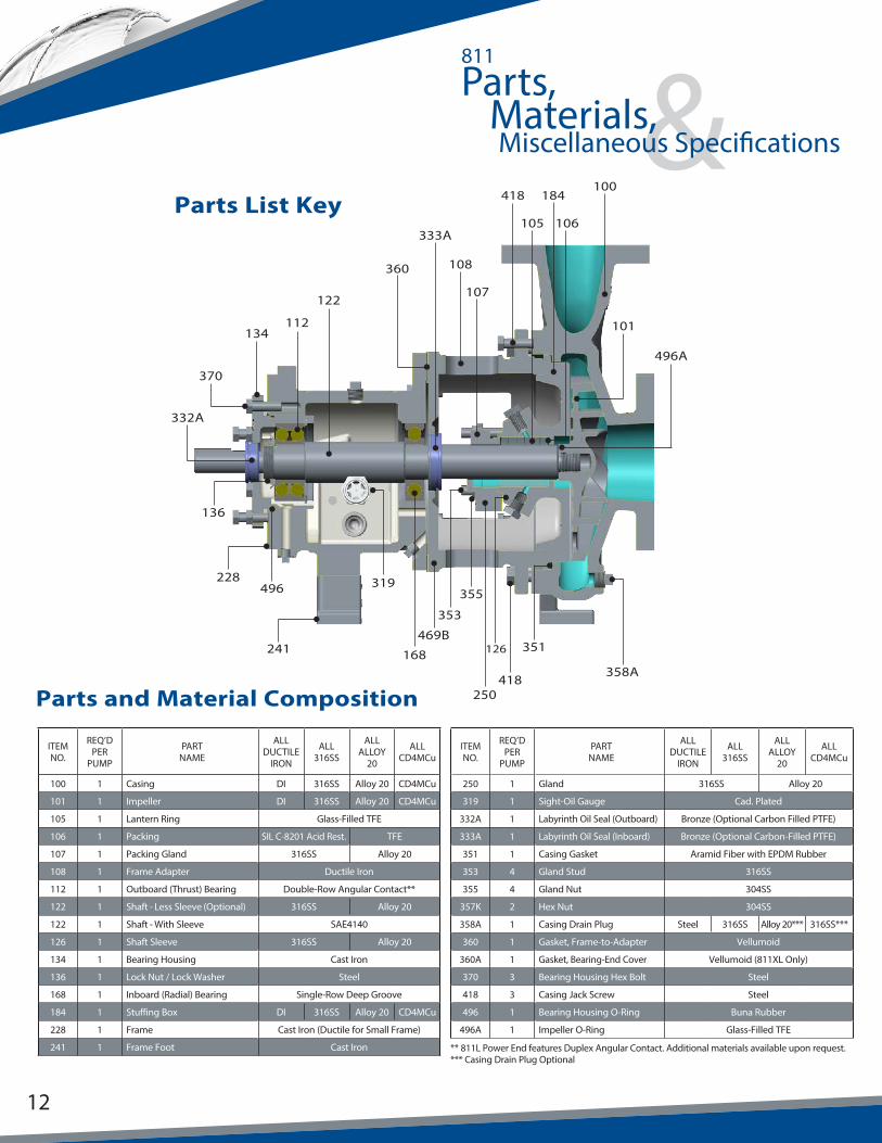
&Parts,Materials,Miscellaneous Specifications
811
Parts and Material Composition
ITEM NO.
REQ’D PER
PUMP
PARTNAME
ALL DUCTILE
IRON
ALL316SS
ALL ALLOY
20
ALL CD4MCu
100 1 Casing DI 316SS Alloy 20 CD4MCu
101 1 Impeller DI 316SS Alloy 20 CD4MCu
105 1 Lantern Ring Glass-Filled TFE
106 1 Packing SIL C-8201 Acid Rest. TFE
107 1 Packing Gland 316SS Alloy 20
108 1 Frame Adapter Ductile Iron
112 1 Outboard (Thrust) Bearing Double-Row Angular Contact**
122 1 Shaft - Less Sleeve (Optional) 316SS Alloy 20
122 1 Shaft - With Sleeve SAE4140
126 1 Shaft Sleeve 316SS Alloy 20
134 1 Bearing Housing Cast Iron
136 1 Lock Nut / Lock Washer Steel
168 1 Inboard (Radial) Bearing Single-Row Deep Groove
184 1 Stuffing Box DI 316SS Alloy 20 CD4MCu
228 1 Frame Cast Iron (Ductile for Small Frame)
241 1 Frame Foot Cast Iron
ITEM NO.
REQ’D PER
PUMP
PARTNAME
ALL DUCTILE
IRON
ALL316SS
ALL ALLOY
20
ALL CD4MCu
250 1 Gland 316SS Alloy 20
319 1 Sight-Oil Gauge Cad. Plated
332A 1 Labyrinth Oil Seal (Outboard) Bronze (Optional Carbon Filled PTFE)
333A 1 Labyrinth Oil Seal (Inboard) Bronze (Optional Carbon-Filled PTFE)
351 1 Casing Gasket Aramid Fiber with EPDM Rubber
353 4 Gland Stud 316SS
355 4 Gland Nut 304SS
357K 2 Hex Nut 304SS
358A 1 Casing Drain Plug Steel 316SS Alloy 20*** 316SS***
360 1 Gasket, Frame-to-Adapter Vellumoid
360A 1 Gasket, Bearing-End Cover Vellumoid (811XL Only)
370 3 Bearing Housing Hex Bolt Steel
418 3 Casing Jack Screw Steel
496 1 Bearing Housing O-Ring Buna Rubber
496A 1 Impeller O-Ring Glass-Filled TFE
** 811L Power End features Duplex Angular Contact. Additional materials available upon request.*** Casing Drain Plug Optional
12
Parts List Key
332A
228
241
136
319
353
355
358A
469B
370
134
496
112
360
122
250
418
333A
108
184100
168
106105
351
418
101
496A
126
107
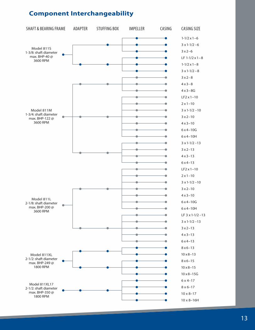
Component Interchangeability
SHAFT & BEARING FRAME ADAPTER STUFFING BOX IMPELLER CASING CASING SIZE
Model 811S1-3/8: shaft diameter
max. BHP-40 @3600 RPM
1-1/2 x 1–6
3 x 1-1/2 –6
3 x 2–6
LF 1-1/2 x 1–8
1-1/2 x 1–8
3 x 1-1/2 –8
Model 811M1-3/4: shaft diameter
max. BHP-122 @ 3600 RPM
3 x 2–8
4 x 3–8
4 x 3–8G
LF2 x 1–10
2 x 1–10
3 x 1-1/2 –10
3 x 2–10
4 x 3–10
6 x 4–10G
6 x 4–10H
3 x 1-1/2 –13
3 x 2–13
4 x 3–13
6 x 4–13
Model 811L2-1/8: shaft diameter
max. BHP-200 @ 3600 RPM
LF2 x 1–10
2 x 1–10
3 x 1-1/2 –10
3 x 2–10
4 x 3–10
6 x 4–10G
6 x 4–10H
LF 3 x 1-1/2 –13
3 x 1-1/2 –13
3 x 2–13
4 x 3–13
6 x 4–13
Model 811XL2-1/2: shaft diameter
max. BHP-249 @ 1800 RPM
8 x 6–13
10 x 8–13
8 x 6–15
10 x 8–15
10 x 8–15G
Model 811XL172-1/2: shaft diameter
max. BHP-350 @ 1800 RPM
6 x 4–17
8 x 6–17
10 x 8–17
10 x 8–16H
13
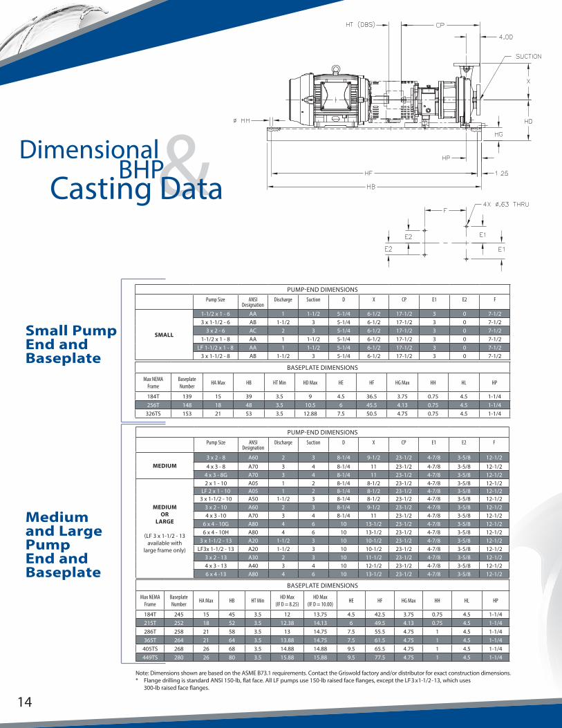
&DimensionalBHP
Casting Data
Small Pump End and Baseplate
Medium and Large Pump End and Baseplate
PUMP-END DIMENSIONSPump Size ANSI
DesignationDischarge Suction D X CP E1 E2 F
SMALL
1-1/2 x 1 - 6 AA 1 1-1/2 5-1/4 6-1/2 17-1/2 3 0 7-1/23 x 1-1/2 - 6 AB 1-1/2 3 5-1/4 6-1/2 17-1/2 3 0 7-1/2
3 x 2 - 6 AC 2 3 5-1/4 6-1/2 17-1/2 3 0 7-1/21-1/2 x 1 - 8 AA 1 1-1/2 5-1/4 6-1/2 17-1/2 3 0 7-1/2
LF 1-1/2 x 1 - 8 AA 1 1-1/2 5-1/4 6-1/2 17-1/2 3 0 7-1/23 x 1-1/2 - 8 AB 1-1/2 3 5-1/4 6-1/2 17-1/2 3 0 7-1/2
BASEPLATE DIMENSIONS
Max NEMA Frame
Baseplate Number
HA Max HB HT Min HD Max HE HF HG Max HH HL HP
184T 139 15 39 3.5 9 4.5 36.5 3.75 0.75 4.5 1-1/4256T 148 18 48 3.5 10.5 6 45.5 4.13 0.75 4.5 1-1/4
326TS 153 21 53 3.5 12.88 7.5 50.5 4.75 0.75 4.5 1-1/4
PUMP-END DIMENSIONSPump Size ANSI
DesignationDischarge Suction D X CP E1 E2 F
MEDIUM3 x 2 - 8 A60 2 3 8-1/4 9-1/2 23-1/2 4-7/8 3-5/8 12-1/2
4 x 3 - 8 A70 3 4 8-1/4 11 23-1/2 4-7/8 3-5/8 12-1/24 x 3 - 8G A70 3 4 8-1/4 11 23-1/2 4-7/8 3-5/8 12-1/2
MEDIUMOR
LARGE
(LF 3 x 1-1/2 - 13 available with
large frame only)
2 x 1 - 10 A05 1 2 8-1/4 8-1/2 23-1/2 4-7/8 3-5/8 12-1/2LF 2 x 1 - 10 A05 1 2 8-1/4 8-1/2 23-1/2 4-7/8 3-5/8 12-1/2
3 x 1-1/2 - 10 A50 1-1/2 3 8-1/4 8-1/2 23-1/2 4-7/8 3-5/8 12-1/23 x 2 - 10 A60 2 3 8-1/4 9-1/2 23-1/2 4-7/8 3-5/8 12-1/24 x 3 -10 A70 3 4 8-1/4 11 23-1/2 4-7/8 3-5/8 12-1/2
6 x 4 - 10G A80 4 6 10 13-1/2 23-1/2 4-7/8 3-5/8 12-1/26 x 4 - 10H A80 4 6 10 13-1/2 23-1/2 4-7/8 3-5/8 12-1/2
3 x 1-1/2 - 13 A20 1-1/2 3 10 10-1/2 23-1/2 4-7/8 3-5/8 12-1/2LF3x 1-1/2 - 13 A20 1-1/2 3 10 10-1/2 23-1/2 4-7/8 3-5/8 12-1/2
3 x 2 - 13 A30 2 3 10 11-1/2 23-1/2 4-7/8 3-5/8 12-1/24 x 3 - 13 A40 3 4 10 12-1/2 23-1/2 4-7/8 3-5/8 12-1/26 x 4 -13 A80 4 6 10 13-1/2 23-1/2 4-7/8 3-5/8 12-1/2
BASEPLATE DIMENSIONS
Max NEMA Frame
Baseplate Number
HA Max HB HT MinHD Max
(IF D = 8.25)HD Max
(IF D = 10.00)HE HF HG Max HH HL HP
184T 245 15 45 3.5 12 13.75 4.5 42.5 3.75 0.75 4.5 1-1/4215T 252 18 52 3.5 12.38 14.13 6 49.5 4.13 0.75 4.5 1-1/4286T 258 21 58 3.5 13 14.75 7.5 55.5 4.75 1 4.5 1-1/4365T 264 21 64 3.5 13.88 14.75 7.5 61.5 4.75 1 4.5 1-1/4
405TS 268 26 68 3.5 14.88 14.88 9.5 65.5 4.75 1 4.5 1-1/4449TS 280 26 80 3.5 15.88 15.88 9.5 77.5 4.75 1 4.5 1-1/4
Note: Dimensions shown are based on the ASME B73.1 requirements. Contact the Griswold factory and/or distributor for exact construction dimensions.* Flange drilling is standard ANSI 150-lb, flat face. All LF pumps use 150-lb raised face flanges, except the LF 3 x 1-1/2 - 13, which uses 300-lb raised face flanges.
14

Extra Large Pump End and Baseplate
Note: Dimensions shown are based on the ASME B73.1 requirements. Contact the Griswold factory and/or distributor for exact construction dimensions.* Flange drilling is standard ANSI 150-lb flat face. All LF pumps use 150-lb raised-face flanges, except the LF 3 x 1-1/2 - 13, which uses
300-lb raised-face flanges.
PUMP-END DIMENSIONS
Pump Size ANSI Designation
Discharge Suction D X CP E1 E2 F
X-LARGE
8 x 6 -13 A90 6 8 14-1/2 16 33-7/8 8 4.5 18-3/4
10 x 8 - 13 A100 8 10 14-1/2 18 33-7/8 8 4.5 18-3/4
8 x 6 - 15 A110 6 8 14-1/2 18 33-7/8 8 4.5 18-3/4
10 x 8 - 15 A120 8 10 14-1/2 19 33-7/8 8 4.5 18-3/4
10 x 8 - 15G A120 8 10 14-1/2 19 33-7/8 8 4.5 18-3/4
6 x 4-17 A105 4 6 14-1/2 16 33-7/8 8 4.5 18-3/4
8 x 6-17 A110 6 8 14-1/2 18 33-7/8 8 4.5 18-3/4
10 x 8-17 A120 8 10 14-1/2 19 33-7/8 8 4.5 18-3/4
10 x 8-16H A120 8 10 14-1/2 19 33-7/8 8 4.5 18-3/4
BASEPLATE DIMENSIONS
Max NEMA Frame
Baseplate Number
HA Max HB HT Min HD HE HF HG Max HH HL HP
286T 368 26 68 5 19.25 9.5 65.5 4.75 1 6.5 1-1/4
405T 380 26 80 5 19.25 9.5 77.5 4.75 1 6.5 1-1/4
449T 398 26 98 5 19.25 9.5 95.5 4.75 1 6.5 1-1/4
15

®
Дистрибутор:България, София 1528, ул."Поручик Неделчо Бончев" 3, eт.5


