NLC - The Next Linear Collider Project
P. Tenenbaum
“I hear the roar of the big machine…”
X-Band Linear Collider (JLC/NLC): Luminosity
Issues2002 Linear Collider Meeting
Monday Plenary
P. Tenenbaum
NLC - The Next Linear Collider Project
The Basics
• JLC/NLC linear collider design uses:– 11.424 GHz (“X-Band”) RF acceleration…– 70 MeV/m unloaded gradient…– 0.75x10¹⁰ e+/e- per bunch…– 192 bunches per RF pulse with 1.4 nsec spacing (268
nsec total train length)…– 120 RF pulses per second…– IP spot sizes approx. 250 nm x 2.5 nm…
• To achieve 2.0 – 3.5 x 1034 luminosity @ 0.5 – 1.0 TeV CM
P. Tenenbaum
NLC - The Next Linear Collider Project
Parameter List
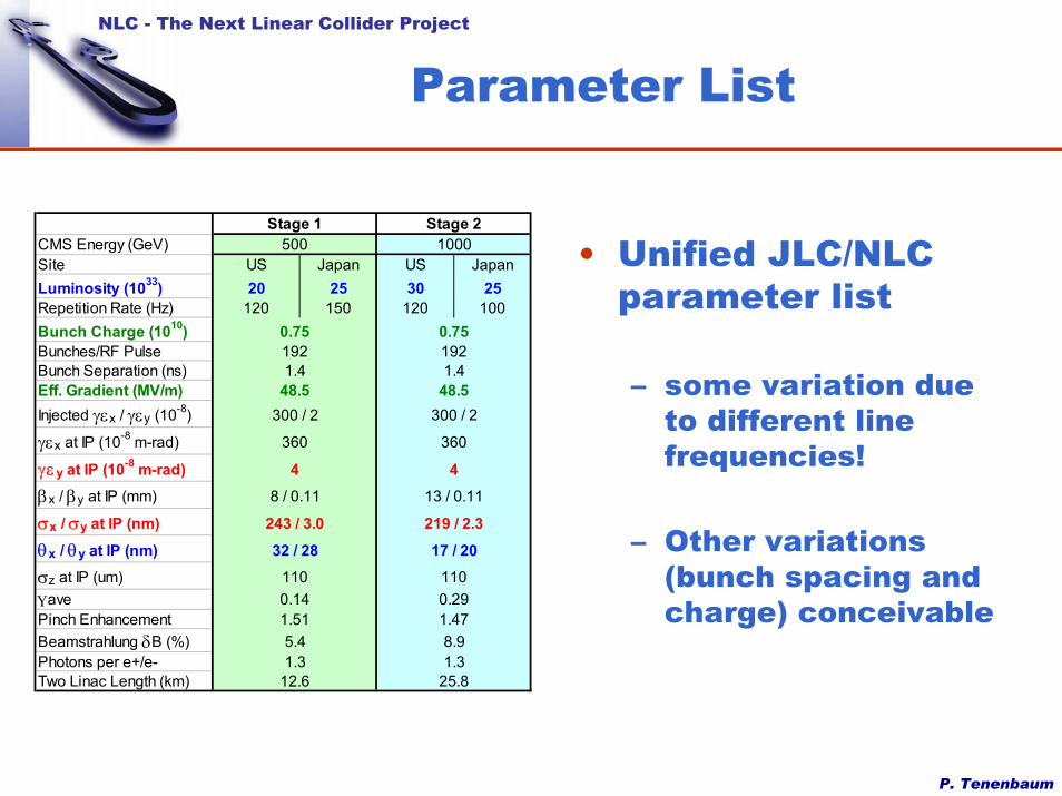
• Unified JLC/NLC parameter list
– some variation due to different line frequencies!
– Other variations (bunch spacing and charge) conceivable
CMS Energy (GeV)Site US Japan US JapanLuminosity (1033) 20 25 30 25Repetition Rate (Hz) 120 150 120 100Bunch Charge (1010)Bunches/RF PulseBunch Separation (ns)Eff. Gradient (MV/m)Injected γεx / γεy (10-8)
γεx at IP (10-8 m-rad)
γεy at IP (10-8 m-rad)βx / βy at IP (mm)
σx / σy at IP (nm)θx / θy at IP (nm)σz at IP (um)ΥavePinch EnhancementBeamstrahlung δB (%)Photons per e+/e-Two Linac Length (km)
1.325.8
0.75
1100.291.478.9
1921.4
48.5300 / 2
360
413 / 0.11
219 / 2.317 / 20
1.51
12.61.35.4
243 / 3.032 / 28
1100.14
300 / 2
360
48 / 0.11
0.75
1.448.5
192
Stage 1 Stage 2500 1000
P. Tenenbaum
NLC - The Next Linear Collider Project
Layout
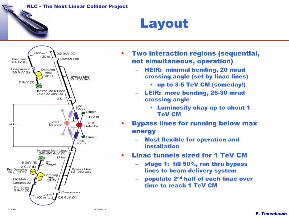
• Two interaction regions (sequential, not simultaneous, operation)– HEIR: minimal bending, 20 mrad
crossing angle (set by linac lines)• up to 3-5 TeV CM (someday!)
– LEIR: more bending, 25-30 mrad crossing angle
• Luminosity okay up to about 1 TeV CM
• Bypass lines for running below max energy– Most flexible for operation and
installation • Linac tunnels sized for 1 TeV CM
– stage 1: fill 50%, run thru bypass lines to beam delivery system
– populate 2nd half of each linac over time to reach 1 TeV CM
P. Tenenbaum
NLC - The Next Linear Collider Project
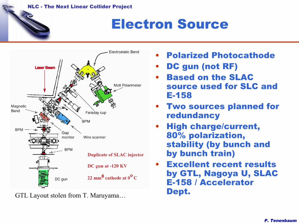
Electron Source
• Polarized Photocathode• DC gun (not RF)• Based on the SLAC
source used for SLC and E-158
• Two sources planned for redundancy
• High charge/current, 80% polarization, stability (by bunch and by bunch train)
• Excellent recent results by GTL, Nagoya U, SLAC E-158 / Accelerator Dept.GTL Layout stolen from T. Maruyama…
P. Tenenbaum
NLC - The Next Linear Collider Project
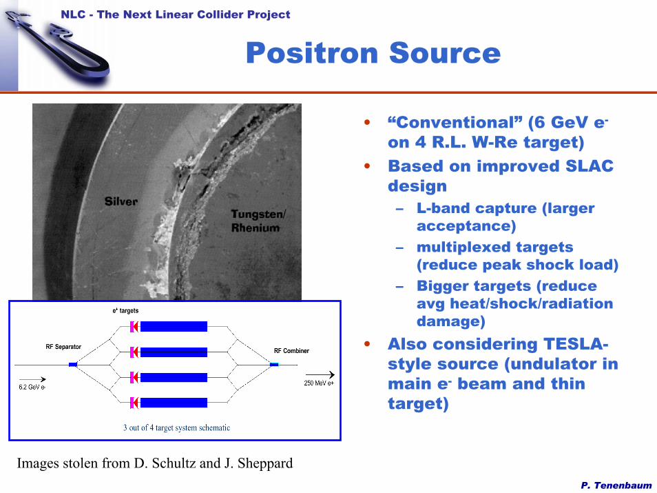
Positron Source
• “Conventional” (6 GeV e-
on 4 R.L. W-Re target)• Based on improved SLAC
design– L-band capture (larger
acceptance)– multiplexed targets
(reduce peak shock load)– Bigger targets (reduce
avg heat/shock/radiation damage)
• Also considering TESLA-style source (undulator in main e- beam and thin target)
Images stolen from D. Schultz and J. Sheppard
P. Tenenbaum
NLC - The Next Linear Collider Project
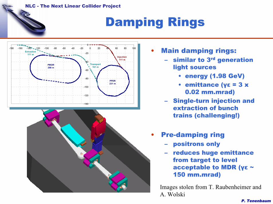
Damping Rings
• Main damping rings: – similar to 3rd generation
light sources• energy (1.98 GeV)• emittance (γε = 3 x
0.02 mm.mrad)– Single-turn injection and
extraction of bunch trains (challenging!)
• Pre-damping ring– positrons only– reduces huge emittance
from target to level acceptable to MDR (γε ~ 150 mm.mrad)
-140
-120
-100
-80
-60
-40
-20
0-180 -160 -140 -120 -100 -80 -60 -40 -20 0 20 40 60 80 100
Injection111 m
Extraction111 m
PMDR298 m
PPDR231 m
Transport161 m
-140
-120
-100
-80
-60
-40
-20
0-180 -160 -140 -120 -100 -80 -60 -40 -20 0 20 40 60 80 100
Injection111 m
Extraction111 m
PMDR298 m
PPDR231 m
Transport161 m
Images stolen from T. Raubenheimer and A. Wolski
P. Tenenbaum
NLC - The Next Linear Collider Project
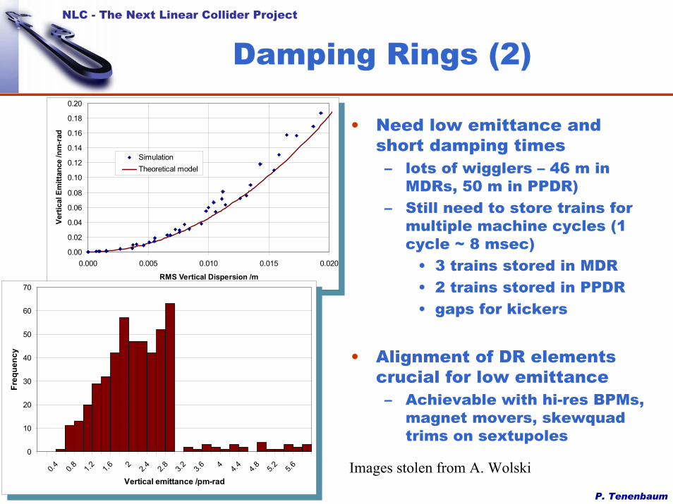
Damping Rings (2)
• Need low emittance and short damping times– lots of wigglers – 46 m in
MDRs, 50 m in PPDR)– Still need to store trains for
multiple machine cycles (1 cycle ~ 8 msec)
• 3 trains stored in MDR• 2 trains stored in PPDR• gaps for kickers
• Alignment of DR elements crucial for low emittance– Achievable with hi-res BPMs,
magnet movers, skewquad trims on sextupoles
0.00
0.02
0.04
0.06
0.08
0.10
0.12
0.14
0.16
0.18
0.20
0.000 0.005 0.010 0.015 0.020
RMS Vertical Dispersion /m
Vert
ical
Em
ittan
ce /n
m-r
ad
SimulationTheoretical model
0.00
0.02
0.04
0.06
0.08
0.10
0.12
0.14
0.16
0.18
0.20
0.000 0.005 0.010 0.015 0.020
RMS Vertical Dispersion /m
Vert
ical
Em
ittan
ce /n
m-r
ad
SimulationTheoretical model
0
10
20
30
40
50
60
70
0.4 0.8 1.2 1.6 2 2.4 2.8 3.2 3.6 4 4.4 4.8 5.2 5.6
Vertical emittance /pm-rad
Freq
uenc
y
0
10
20
30
40
50
60
70
0.4 0.8 1.2 1.6 2 2.4 2.8 3.2 3.6 4 4.4 4.8 5.2 5.6
Vertical emittance /pm-rad
Freq
uenc
y
Images stolen from A. Wolski
P. Tenenbaum
NLC - The Next Linear Collider Project
Damping Rings (3)
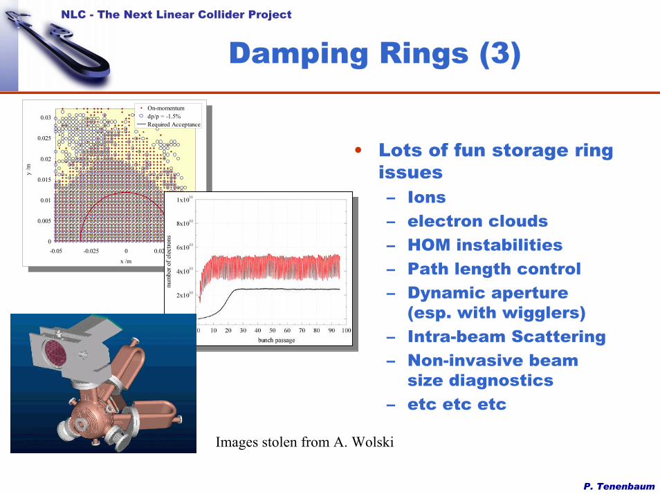
• Lots of fun storage ring issues– Ions– electron clouds– HOM instabilities– Path length control– Dynamic aperture
(esp. with wigglers)– Intra-beam Scattering– Non-invasive beam
size diagnostics– etc etc etc
0
0.005
0.01
0.015
0.02
0.025
0.03
-0.05 -0.025 0 0.025 0.05x /m
y /m
On-momentumdp/p = -1.5%Required Acceptance
0
0.005
0.01
0.015
0.02
0.025
0.03
-0.05 -0.025 0 0.025 0.05x /m
y /m
On-momentumdp/p = -1.5%Required Acceptance
Images stolen from A. Wolski
P. Tenenbaum
NLC - The Next Linear Collider Project
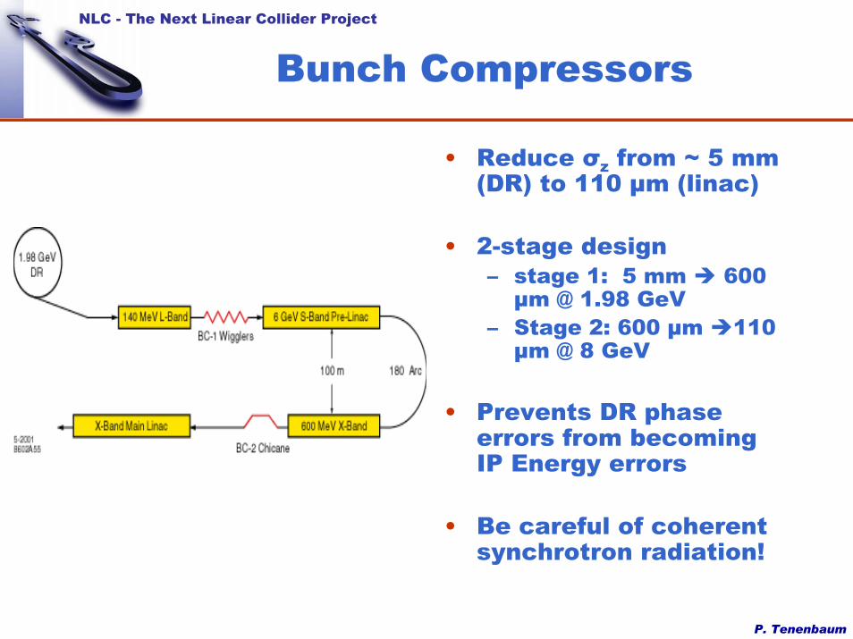
Bunch Compressors
• Reduce σz from ~ 5 mm (DR) to 110 µm (linac)
• 2-stage design– stage 1: 5 mm 600
µm @ 1.98 GeV– Stage 2: 600 µm 110
µm @ 8 GeV
• Prevents DR phase errors from becoming IP Energy errors
• Be careful of coherent synchrotron radiation!

P. Tenenbaum
NLC - The Next Linear Collider Project
Main Linacs
• About 12 km long each• Use 0.6 m or 0.9 m X-
band RF structures
• Strong wakefields drive ML design
• Short-range: cause beam break-up– cure with energy
spread along bunch (“BNS Damping”)
– Leads to tight quad alignment tolerances
0.1
1
10
100
1000
0 2 4 6 8 10 12 14
Growth w/o BNS, %Growth with BNS, %
Vert.
Em
ittan
ce G
row
th [%
] for
1 u
m In
itial
Offs
et
s, km
0.2
0.4
0.6
0.8
1
BNS
Ener
gy S
prea
d, %
00 2 4 6 8 10 12 14
s, km
P. Tenenbaum
NLC - The Next Linear Collider Project
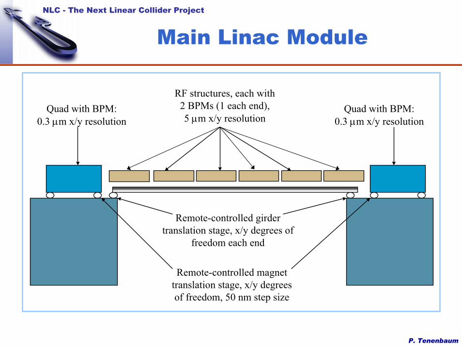
Main Linac Module
Quad with BPM:0.3 µm x/y resolution
Quad with BPM:0.3 µm x/y resolution
RF structures, each with2 BPMs (1 each end), 5 µm x/y resolution
Remote-controlled magnettranslation stage, x/y degrees of freedom, 50 nm step size
Remote-controlled girdertranslation stage, x/y degrees of
freedom each end
P. Tenenbaum
NLC - The Next Linear Collider Project
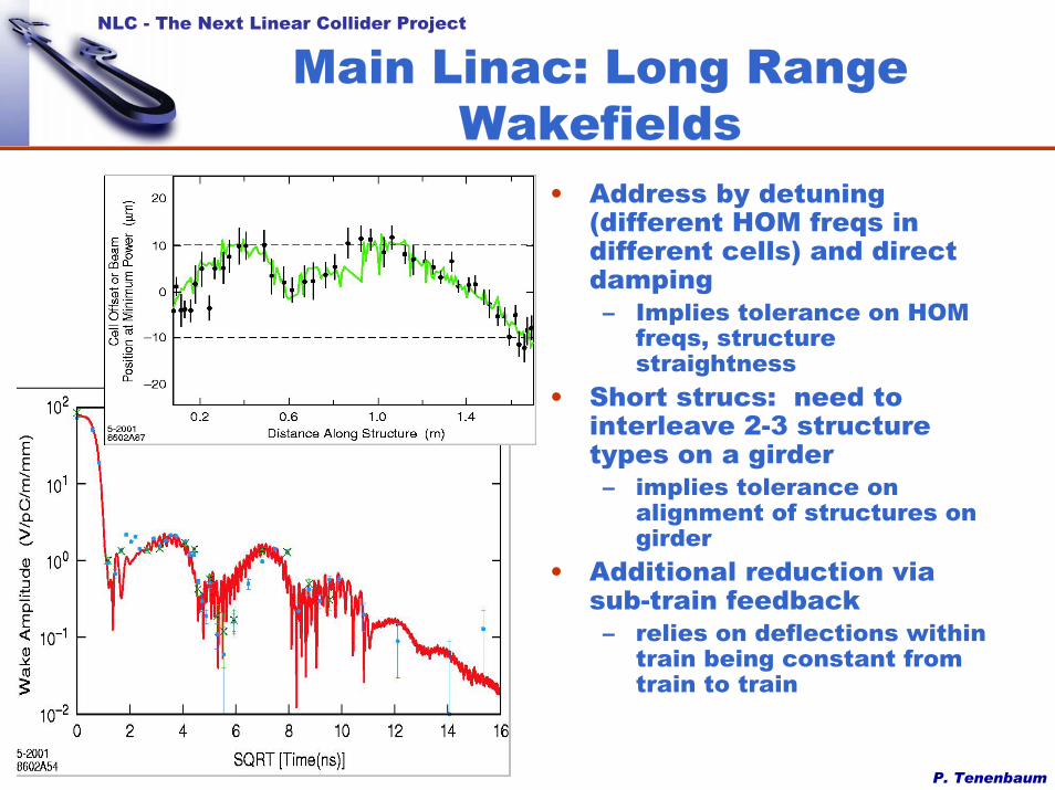
Main Linac: Long Range Wakefields
• Address by detuning (different HOM freqs in different cells) and direct damping– Implies tolerance on HOM
freqs, structure straightness
• Short strucs: need to interleave 2-3 structure types on a girder– implies tolerance on
alignment of structures on girder
• Additional reduction via sub-train feedback– relies on deflections within
train being constant from train to train
P. Tenenbaum
NLC - The Next Linear Collider Project
Main Linac Emittance Budget
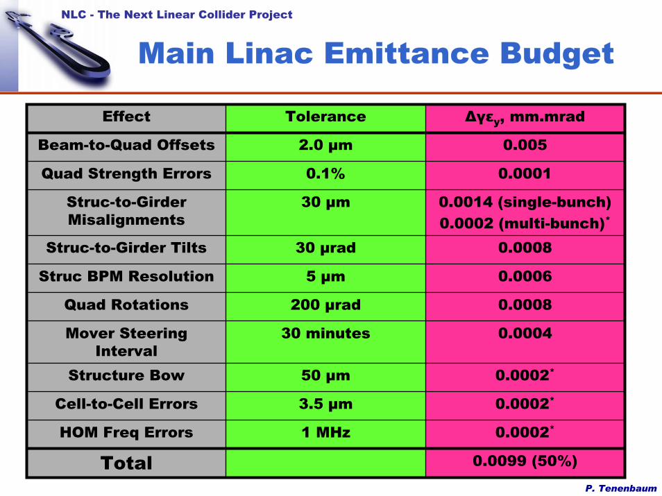
0.0099 (50%)Total0.0002*1 MHzHOM Freq Errors
0.0002*3.5 µmCell-to-Cell Errors
0.0002*50 µmStructure Bow
0.000430 minutesMover Steering Interval
0.0008200 µradQuad Rotations
0.00065 µmStruc BPM Resolution
0.000830 µradStruc-to-Girder Tilts
0.0014 (single-bunch)0.0002 (multi-bunch)*
30 µmStruc-to-Girder Misalignments
0.00010.1%Quad Strength Errors
0.0052.0 µmBeam-to-Quad Offsets
∆γεy, mm.mradToleranceEffect

P. Tenenbaum
NLC - The Next Linear Collider Project
Beam Delivery System
• Both IRs use short “Raimondi/Seryi” design with integrated collimation– Cancel coll aberrations in
FF
• Principal challenges:– delicate cancellation of
aberrations– Stability – both position and
strength – of magnets, esp. final doublet
– Collimation – wakefields, protection of BDS, protection of collimators
P. Tenenbaum
NLC - The Next Linear Collider Project
Stabilization of BDS
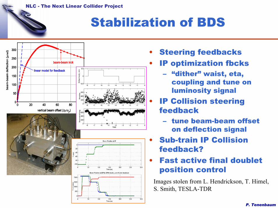
• Steering feedbacks• IP optimization fbcks
– “dither” waist, eta, coupling and tune on luminosity signal
• IP Collision steering feedback– tune beam-beam offset
on deflection signal• Sub-train IP Collision
feedback?• Fast active final doublet
position controlImages stolen from L. Hendrickson, T. Himel, S. Smith, TESLA-TDR

P. Tenenbaum
NLC - The Next Linear Collider Project
Stabilization of BDS (2)
• Longer term: driven by diffusive ground motion
• Tools to preserve luminosity– IP collide feedback– steering feedback
through sextupoles– Adjust aberrations via
dither feedbacks
• Only 1 overall realign needed per year

P. Tenenbaum
NLC - The Next Linear Collider Project
BDS Energy Scaling
• Lower energy –aberrations get worse
• Higher energy – SR dilutions get worse
• Can be addressed by scaling BDS bends– changes geometry
• In practice, little improvement seen at lower energies0
1
2
3
4
5
0 200 400 600 800 1000 1200 1400 1600
No Bend ScalingBend Scaling
Lum
inos
ity, 1
034 c
m-2
sec-1
CM Energy (GeV)
Plot data courtesy Y. Nosochkov
P. Tenenbaum
NLC - The Next Linear Collider Project
Conclusion and Provocation
• JLC/NLC pushes X-band technology to the state of the art (and maybe a bit past)– gradient issues – see next talk!– wakefields make linac more challenging,
requires more/better diagnostic and control• JLC/NLC damping rings are not too far from
existing light sources• JLC/NLC BDS is reasonable extrapolation
from SLC and FFTB– not too different from CLIC, TESLA BDS for
similar energies• It’s been an exciting and productive couple
of years since LC99!


