Moxa VPort 464 Software User’s Manual
Edition 1.0, December 2017
www.moxa.com/product
© 2017 Moxa Inc. All rights reserved.
Moxa VPort 464 Software User’s Manual
The software described in this manual is furnished under a license agreement and may be used only in accordance with the terms of that agreement.
Copyright Notice
© 2017 Moxa Inc. All rights reserved.
Trademarks
The MOXA logo is a registered trademark of Moxa Inc. All other trademarks or registered marks in this manual belong to their respective manufacturers.
Disclaimer
Information in this document is subject to change without notice and does not represent a commitment on the part of Moxa.
Moxa provides this document as is, without warranty of any kind, either expressed or implied, including, but not limited to, its particular purpose. Moxa reserves the right to make improvements and/or changes to this manual, or to the products and/or the programs described in this manual, at any time.
Information provided in this manual is intended to be accurate and reliable. However, Moxa assumes no responsibility for its use, or for any infringements on the rights of third parties that may result from its use.
This product might include unintentional technical or typographical errors. Changes are periodically made to the information herein to correct such errors, and these changes are incorporated into new editions of the publication.
Technical Support Contact Information
www.moxa.com/support
Moxa Americas Toll-free: 1-888-669-2872 Tel: +1-714-528-6777 Fax: +1-714-528-6778
Moxa China (Shanghai office) Toll-free: 800-820-5036 Tel: +86-21-5258-9955 Fax: +86-21-5258-5505
Moxa Europe Tel: +49-89-3 70 03 99-0 Fax: +49-89-3 70 03 99-99
Moxa Asia-Pacific Tel: +886-2-8919-1230 Fax: +886-2-8919-1231
Moxa India Tel: +91-80-4172-9088 Fax: +91-80-4132-1045

Before Getting Started Before using your VPort IP products, be sure to read the following instructions:
To prevent damage or problems caused by improper use, read the Quick Installation Guide (the printed handbook included in the package) before assembling and operating the device and peripherals.
Important Note Surveillance devices may be prohibited by law in your country. Since the VPort is both a high performance surveillance
system and networked video server, verify that the operation of such devices is legal in your locality before installing this unit for surveillance purposes.
Table of Contents
1. Introduction ...................................................................................................................................... 1-1 Overview ........................................................................................................................................... 1-2 Version Information ............................................................................................................................ 1-2
2. Getting Started.................................................................................................................................. 2-1 Introduction ....................................................................................................................................... 2-2 Software Installation ........................................................................................................................... 2-2
3. Accessing the VPort’s Web-based Manager ....................................................................................... 3-1 Functions Featured on the VPort’s Web Homepage .................................................................................. 3-2
VPort’s Information ..................................................................................................................... 3-2 Server Name .............................................................................................................................. 3-2 Camera Image View .................................................................................................................... 3-2 Client Settings ............................................................................................................................ 3-3 System Configuration .................................................................................................................. 3-4 Show PTZ Control Panel ............................................................................................................... 3-5 Video Information ....................................................................................................................... 3-5
Custom PTZ Camera Commands ............................................................................................ 3-6 Relay Control .............................................................................................................................. 3-6 Snapshot .................................................................................................................................... 3-7 Account ...................................................................................................................................... 3-7
4. System Configuration ........................................................................................................................ 4-1 System Configuration by Web Console .................................................................................................. 4-2
Profiles ...................................................................................................................................... 4-5 Configuration....................................................................................................................... 4-5
System ...................................................................................................................................... 4-6 General Settings/Date/Time .................................................................................................. 4-6 Account .............................................................................................................................. 4-8 Account Policy ..................................................................................................................... 4-9 Local Storage .................................................................................................................... 4-10 System Log History ............................................................................................................ 4-11 System Parameters ............................................................................................................ 4-12 System I/O ....................................................................................................................... 4-13 LED Control ....................................................................................................................... 4-14 Firmware Upgrade.............................................................................................................. 4-14 Reset to Factory Default ..................................................................................................... 4-15 Reboot ............................................................................................................................. 4-15
Network ................................................................................................................................... 4-16 General Network Settings ................................................................................................... 4-16 IPv6 ................................................................................................................................. 4-18 Accessible IP List ............................................................................................................... 4-19 RTSP ................................................................................................................................ 4-20 HTTP ................................................................................................................................ 4-23 DDNS ............................................................................................................................... 4-23 UPnP ................................................................................................................................ 4-24 ToS .................................................................................................................................. 4-24 SNMP ............................................................................................................................... 4-25 Configuring SNMP Settings .................................................................................................. 4-25 Modbus/TCP ...................................................................................................................... 4-27 Moxa Service ..................................................................................................................... 4-28 IEEE 802.1x ...................................................................................................................... 4-28 SSH ................................................................................................................................. 4-29 LLDP ................................................................................................................................ 4-30 Ethernet Port ..................................................................................................................... 4-30
Video ....................................................................................................................................... 4-31 Video Source Settings......................................................................................................... 4-31 Image Overlay ................................................................................................................... 4-32 Image Tuning .................................................................................................................... 4-33 Video Encoder ................................................................................................................... 4-33 Prealarm ........................................................................................................................... 4-36
Audio ....................................................................................................................................... 4-36 Audio Input ....................................................................................................................... 4-36 Audio Output ..................................................................................................................... 4-37
Metadata .................................................................................................................................. 4-38 Streaming ................................................................................................................................ 4-38
CBR Pro ............................................................................................................................ 4-38 Streaming Status ............................................................................................................... 4-39
PTZ ......................................................................................................................................... 4-39 PTZ Configuration .............................................................................................................. 4-40

Preset ............................................................................................................................... 4-41 Serial Port ................................................................................................................................ 4-43
PTZ port ........................................................................................................................... 4-43 COM port .......................................................................................................................... 4-45
Event ....................................................................................................................................... 4-47 Enable Event ..................................................................................................................... 4-47 Video Motion Detection ....................................................................................................... 4-47 Camera Tamper ................................................................................................................. 4-49 Sequential Snapshot........................................................................................................... 4-50
Actions ..................................................................................................................................... 4-52 Action Config ..................................................................................................................... 4-52 Action Trigger .................................................................................................................... 4-56
A. Frequently Asked Questions .............................................................................................................. A-1 B. Time Zone Table ................................................................................................................................ B-1 C. VPort 464 Modbus Address Table ...................................................................................................... C-1
1 1. Introduction
This software user’s manual is designed for the VPort 464 firmware.
The following topics are covered in this chapter:
Overview
Version Information
VPort 464 Introduction
1-2
Overview The VPort is supported with ONVIF Profile S specification. The ONVIF specification is an open standard protocol for communicating between IP-based security devices. An ONVIF profile is described by a fixed set of functionalities through a number of services that are provided by the ONVIF standard. ONVIF Profile S allows the ONVIF device and client to communicate information about the PTZ, audio and metadata streaming, and relay outputs.
VPort IP video products with ONVIF Profile S compliance can work with most VMS software for building a complete IP surveillance system immediately, without needing to spend time integrating your hardware and software. ONVIF Profile S saves both time and resources when using VPort IP cameras with VMS software.
Version Information The current version information is listed below:
• ONVIF Core specifications: V2.2
• ONVIF Test tool: 17.01
• VPort Models
Model Firmware Version VPort 464 series V1.0
NOTE The version information given here may change as new versions of the firmware are developed. Check www.moxa.com/support for the latest firmware information, and to download updated user’s manuals.
NOTE To see which VPort models support Profile S, check the ONVIF website at http://www.onvif.org/ for updated information related to VPort models.
2 2. Getting Started
This chapter includes information about how to get started with the VPort’s software configuration.
The following topics are covered in this chapter:
Introduction
Software Installation
VPort 464 Getting Started
2-2
Introduction In what follows, “user” refers to those who can access the IP camera, and “administrator” refers to the person who knows the root password that allows changes to the IP camera’s configuration and has the right to assign general access to other users. Administrators should read this part of the manual carefully, especially during installation.
Software Installation
Step 1: Configure the VPort’s IP address
When the VPort is first powered on, the POST (Power On Self Test) will run for about 30 to 40 seconds. The network environment determines how the IP address is assigned.
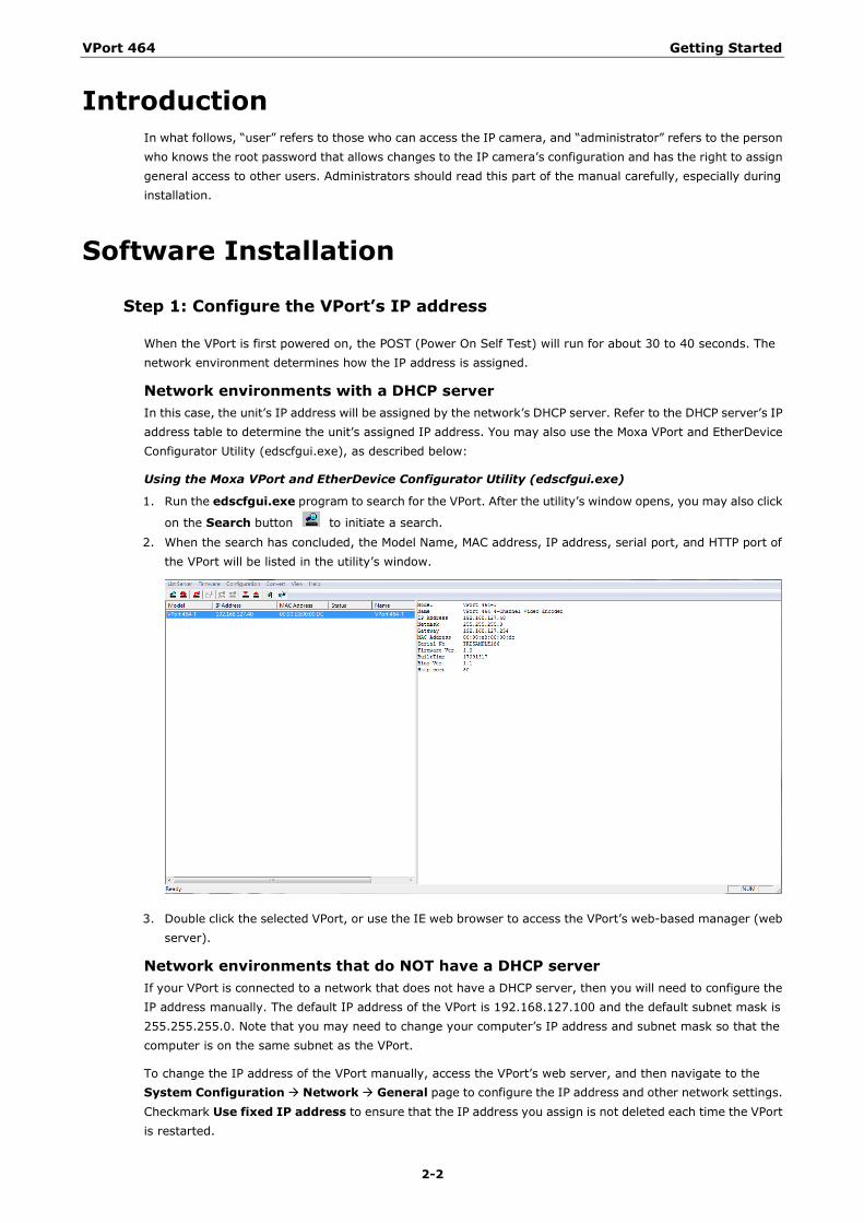
Network environments with a DHCP server In this case, the unit’s IP address will be assigned by the network’s DHCP server. Refer to the DHCP server’s IP address table to determine the unit’s assigned IP address. You may also use the Moxa VPort and EtherDevice Configurator Utility (edscfgui.exe), as described below:
Using the Moxa VPort and EtherDevice Configurator Utility (edscfgui.exe)
1. Run the edscfgui.exe program to search for the VPort. After the utility’s window opens, you may also click
on the Search button to initiate a search. 2. When the search has concluded, the Model Name, MAC address, IP address, serial port, and HTTP port of
the VPort will be listed in the utility’s window.
3. Double click the selected VPort, or use the IE web browser to access the VPort’s web-based manager (web server).
Network environments that do NOT have a DHCP server If your VPort is connected to a network that does not have a DHCP server, then you will need to configure the IP address manually. The default IP address of the VPort is 192.168.127.100 and the default subnet mask is 255.255.255.0. Note that you may need to change your computer’s IP address and subnet mask so that the computer is on the same subnet as the VPort.
To change the IP address of the VPort manually, access the VPort’s web server, and then navigate to the System Configuration Network General page to configure the IP address and other network settings. Checkmark Use fixed IP address to ensure that the IP address you assign is not deleted each time the VPort is restarted.
VPort 464 Getting Started
2-3
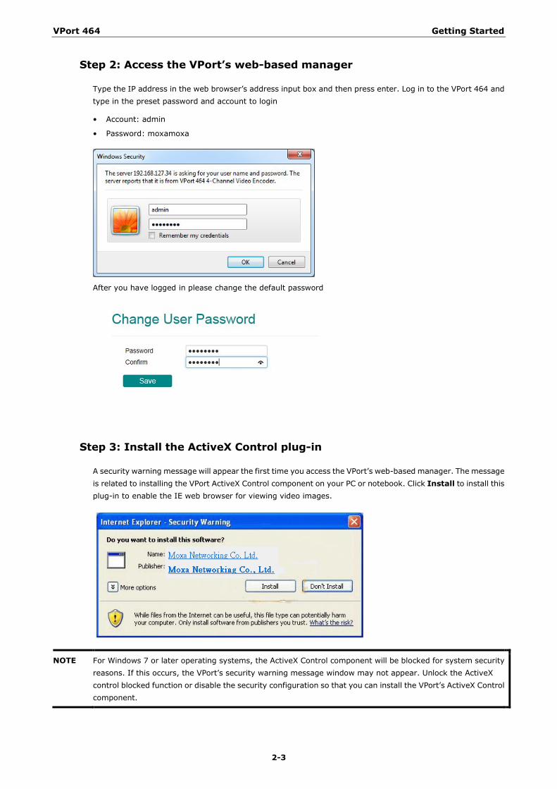
Step 2: Access the VPort’s web-based manager
Type the IP address in the web browser’s address input box and then press enter. Log in to the VPort 464 and type in the preset password and account to login
• Account: admin
• Password: moxamoxa
After you have logged in please change the default password
Step 3: Install the ActiveX Control plug-in
A security warning message will appear the first time you access the VPort’s web-based manager. The message is related to installing the VPort ActiveX Control component on your PC or notebook. Click Install to install this plug-in to enable the IE web browser for viewing video images.
NOTE For Windows 7 or later operating systems, the ActiveX Control component will be blocked for system security reasons. If this occurs, the VPort’s security warning message window may not appear. Unlock the ActiveX control blocked function or disable the security configuration so that you can install the VPort’s ActiveX Control component.
VPort 464 Getting Started
2-4
ATTENTION
This equipment is intended to be used in restricted access locations, such as a computer room. Access can only be gained by service personnel or by users who have been instructed how to handle the metal chassis, which can reach very high temperatures. Further, access to the system should be gained by using a key or a secure identity system. Only authorized persons who have been given professional training should be able to access the restricted access location.
Step 4: Access the homepage of the VPort camera’s web-based manager
After installing the ActiveX Control component, the homepage of the VPort’s web-based manager will appear. Check the following items to make sure the system was installed properly:
1. Video Images
2. Video Information
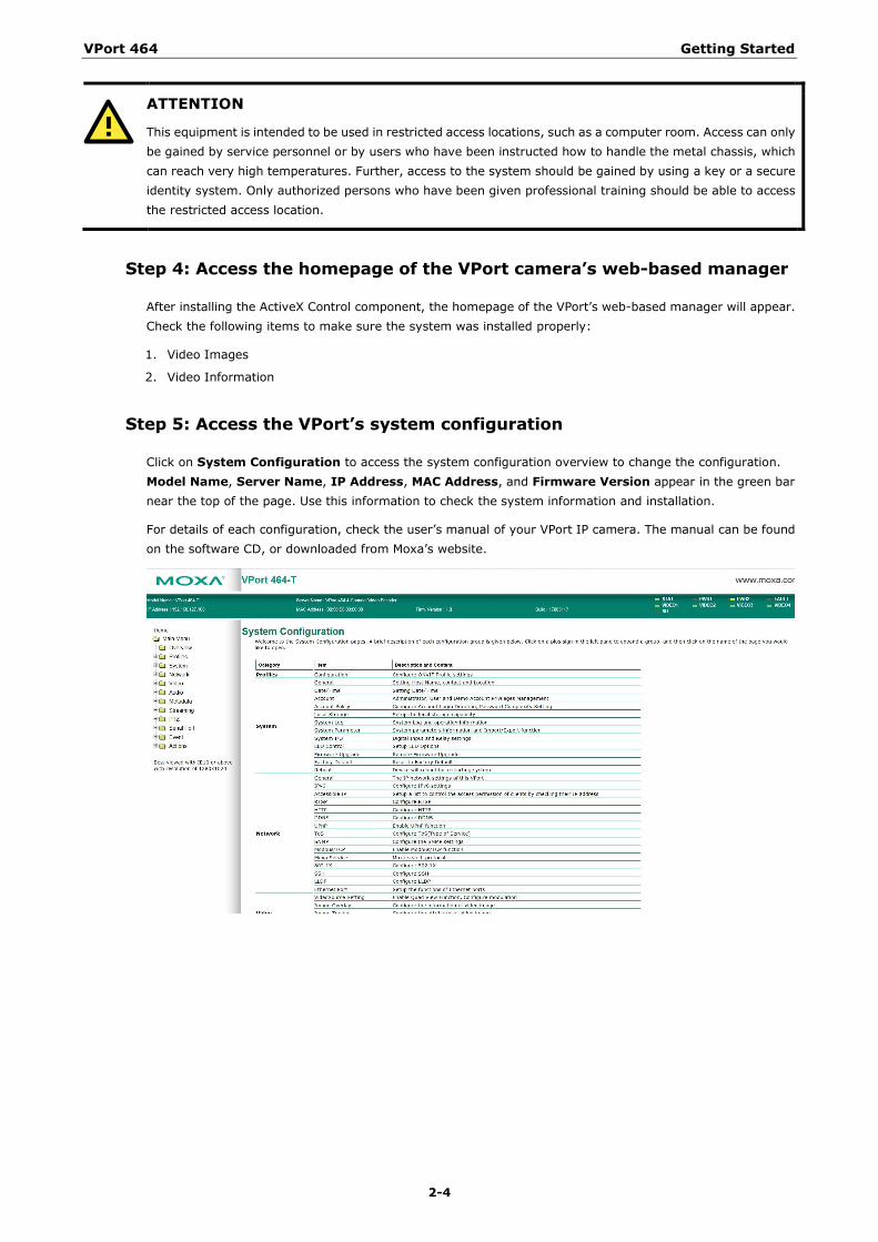
Step 5: Access the VPort’s system configuration
Click on System Configuration to access the system configuration overview to change the configuration. Model Name, Server Name, IP Address, MAC Address, and Firmware Version appear in the green bar near the top of the page. Use this information to check the system information and installation.
For details of each configuration, check the user’s manual of your VPort IP camera. The manual can be found on the software CD, or downloaded from Moxa’s website.
3 3. Accessing the VPort’s Web-based Manager
This chapter includes information about how to access the VPort for the first time.
The following topics are covered in this chapter:
Functions Featured on the VPort’s Web Homepage
VPort’s Information
Server Name
Camera Image View
Client Settings
System Configuration
Show PTZ Control Panel
Video Information
Relay Control
Snapshot
Account
VPort 464 Accessing the VPort’s Web-based Manager
3-2
Functions Featured on the VPort’s Web Homepage
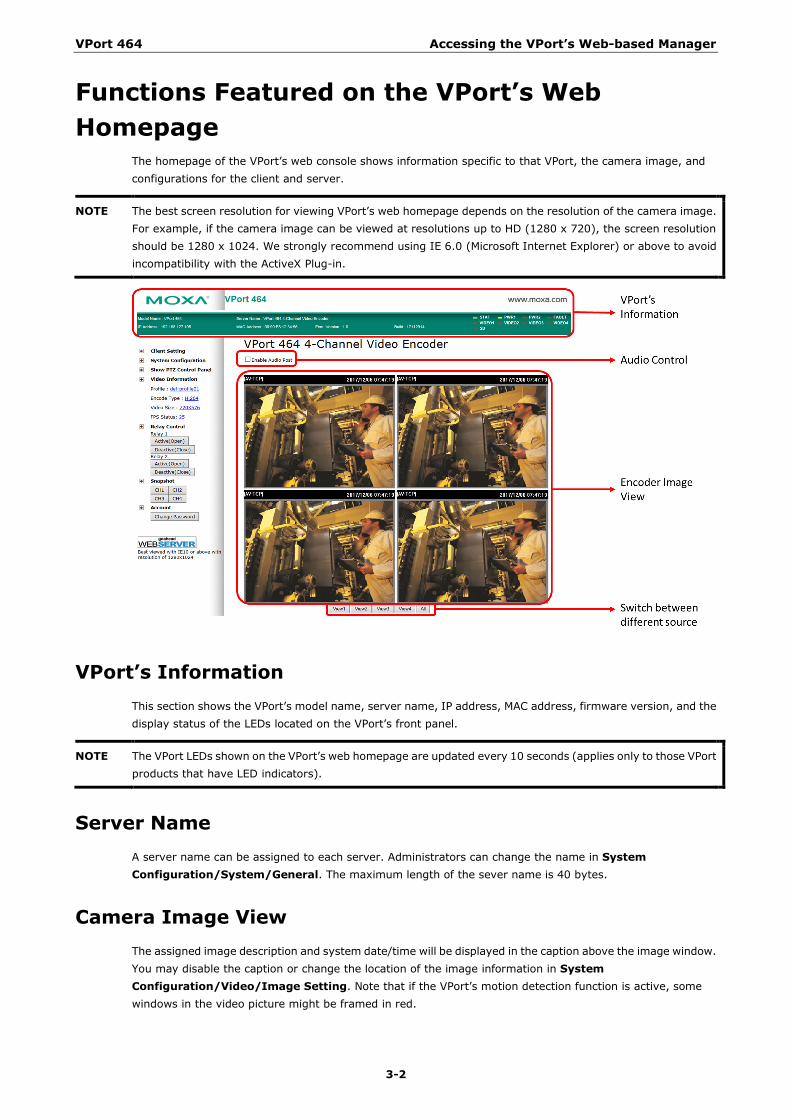
The homepage of the VPort’s web console shows information specific to that VPort, the camera image, and configurations for the client and server.
NOTE The best screen resolution for viewing VPort’s web homepage depends on the resolution of the camera image. For example, if the camera image can be viewed at resolutions up to HD (1280 x 720), the screen resolution should be 1280 x 1024. We strongly recommend using IE 6.0 (Microsoft Internet Explorer) or above to avoid incompatibility with the ActiveX Plug-in.
VPort’s Information This section shows the VPort’s model name, server name, IP address, MAC address, firmware version, and the display status of the LEDs located on the VPort’s front panel.
NOTE The VPort LEDs shown on the VPort’s web homepage are updated every 10 seconds (applies only to those VPort products that have LED indicators).
Server Name A server name can be assigned to each server. Administrators can change the name in System Configuration/System/General. The maximum length of the sever name is 40 bytes.
Camera Image View The assigned image description and system date/time will be displayed in the caption above the image window. You may disable the caption or change the location of the image information in System Configuration/Video/Image Setting. Note that if the VPort’s motion detection function is active, some windows in the video picture might be framed in red.
VPort 464 Accessing the VPort’s Web-based Manager
3-3
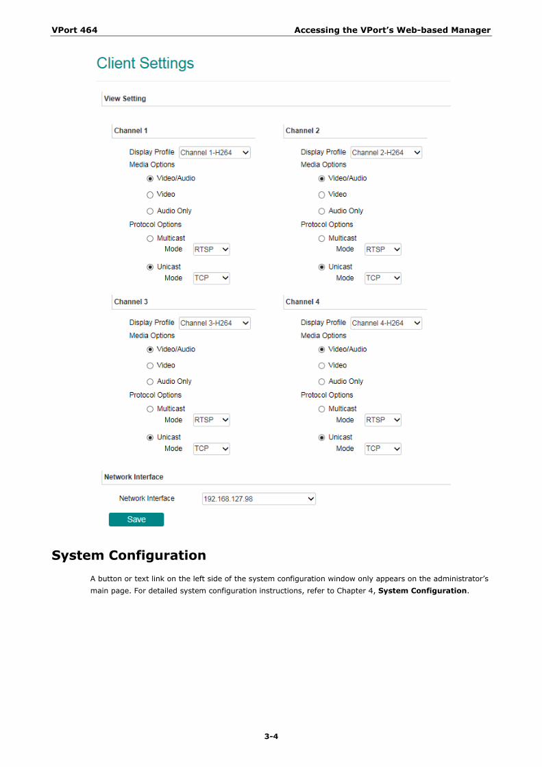
Client Settings The following functions can be configured in Client Settings.
1. Display profile: Shows the profile currently being used. There are two profiles; one supports the H.246 codec the other one supports the MJPEC codec. Each profile refers to one independent video stream with a unique codec, resolution, frame rate (FPS), and video quality. For configuring the profile, please go to System Configuration/profile.
2. Media options: Some VPort models support a line-in or microphone audio input. In this case, you can select from the following options: Video/Audio, Video Only, Audio Only.
3. Protocol Options: Choose one of four protocols to optimize your usage—Multicast (RTSP or Push) or Unicast (UDP, TCP, HTTP).
• Multicast Protocol can be used to send a single video stream to multiple clients. In this case, a lot of bandwidth can be saved since only one video stream is transmitted over the network. However, the network gateway (e.g., a switch) must support the multicast protocol (e.g., IGMP snooping). Otherwise, the multicast video transmission will not be successful.
RTSP: Enable the multicast video stream to be sent using RTSP control, which means the multicast video stream will be sent only if it receives the client’s request.
Push: Enable the multicast video stream to be sent using Push control, which means that after this setting is selected, the multicast video stream will be sent continuously even without any client requests.
• Unicast Protocol is used to send a single video stream to one client.
UDP can be used to produce audio and video streams that are more real-time. However, some packets may be lost due to network burst traffic, and images may become blurred.
TCP can be used to prevent packet loss, which results in a more accurate video display. The downside of using TCP is that the real-time delay is worse than with UDP protocol.
HTTP can be used to prevent being blocked by a router’s firewall. The downside of using HTTP is that the real-time delay is worse than with UDP protocol.
• Network Interface designates the connection interface for multicast video streams selection. The box lists the current NIC interfaces. Select which NIC interface will receive multicast streams.
Once the VPort is connected successfully, Protocol Options will indicate the selected protocol. The selected protocol will be stored on the user’s PC, and will be used for the next connection.
NOTE For multicast video stream settings, see System Configuration Network Multicast.
VPort 464 Accessing the VPort’s Web-based Manager
3-4
System Configuration A button or text link on the left side of the system configuration window only appears on the administrator’s main page. For detailed system configuration instructions, refer to Chapter 4, System Configuration.
VPort 464 Accessing the VPort’s Web-based Manager
3-5
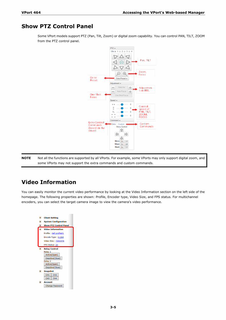
Show PTZ Control Panel Some VPort models support PTZ (Pan, Tilt, Zoom) or digital zoom capability. You can control PAN, TILT, ZOOM from the PTZ control panel.
NOTE Not all the functions are supported by all VPorts. For example, some VPorts may only support digital zoom, and some VPorts may not support the extra commands and custom commands.
Video Information You can easily monitor the current video performance by looking at the Video Information section on the left side of the homepage. The following properties are shown: Profile, Encoder type, Video Size, and FPS status. For multichannel encoders, you can select the target camera image to view the camera’s video performance.
VPort 464 Accessing the VPort’s Web-based Manager
3-6
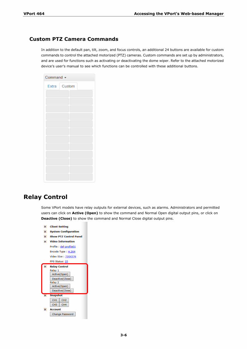
Custom PTZ Camera Commands
In addition to the default pan, tilt, zoom, and focus controls, an additional 24 buttons are available for custom commands to control the attached motorized (PTZ) cameras. Custom commands are set up by administrators, and are used for functions such as activating or deactivating the dome wiper. Refer to the attached motorized device’s user’s manual to see which functions can be controlled with these additional buttons.
Relay Control Some VPort models have relay outputs for external devices, such as alarms. Administrators and permitted users can click on Active (Open) to show the command and Normal Open digital output pins, or click on Deactive (Close) to show the command and Normal Close digital output pins.
VPort 464 Accessing the VPort’s Web-based Manager
3-7
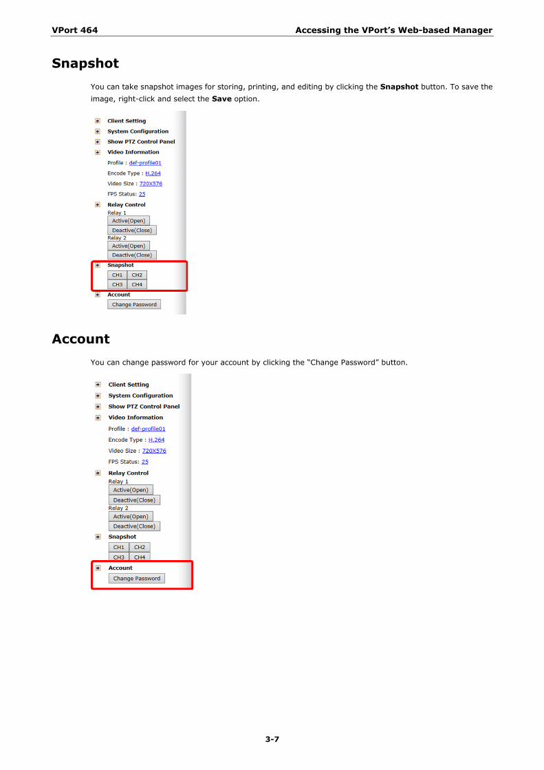
Snapshot You can take snapshot images for storing, printing, and editing by clicking the Snapshot button. To save the image, right-click and select the Save option.
Account You can change password for your account by clicking the “Change Password” button.
4 4. System Configuration
After installing the hardware, the next step is to configure the VPort’s settings. You can do this with the web console.
The following topics are covered in this chapter:
System Configuration by Web Console
Profiles
System
Network
Video
Audio
Metadata
Streaming
PTZ
Serial Port
Event
Actions
VPort 464 System Configuration
4-2
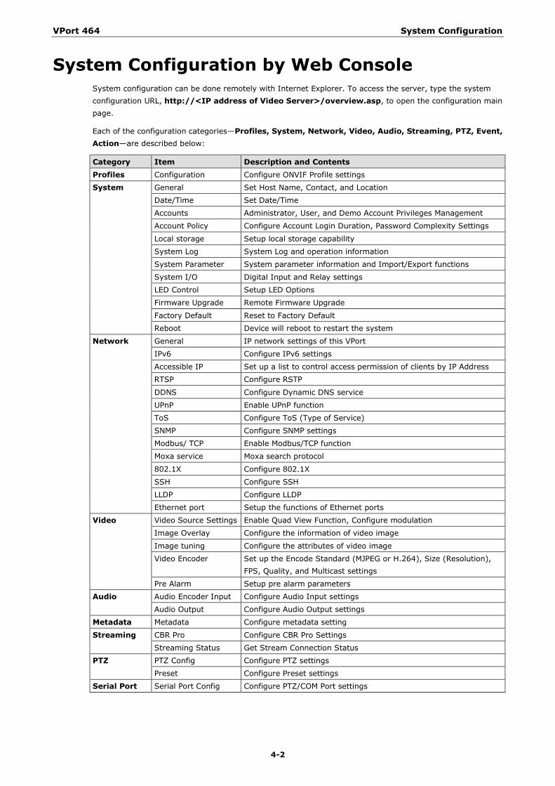
System Configuration by Web Console System configuration can be done remotely with Internet Explorer. To access the server, type the system configuration URL, http://<IP address of Video Server>/overview.asp, to open the configuration main page.
Each of the configuration categories—Profiles, System, Network, Video, Audio, Streaming, PTZ, Event, Action—are described below:
Category Item Description and Contents Profiles Configuration Configure ONVIF Profile settings
System General Set Host Name, Contact, and Location
Date/Time Set Date/Time
Accounts Administrator, User, and Demo Account Privileges Management
Account Policy Configure Account Login Duration, Password Complexity Settings
Local storage Setup local storage capability
System Log System Log and operation information
System Parameter System parameter information and Import/Export functions
System I/O Digital Input and Relay settings
LED Control Setup LED Options
Firmware Upgrade Remote Firmware Upgrade
Factory Default Reset to Factory Default
Reboot Device will reboot to restart the system
Network General IP network settings of this VPort
IPv6 Configure IPv6 settings
Accessible IP Set up a list to control access permission of clients by IP Address
RTSP Configure RSTP
DDNS Configure Dynamic DNS service
UPnP Enable UPnP function
ToS Configure ToS (Type of Service)
SNMP Configure SNMP settings
Modbus/ TCP Enable Modbus/TCP function
Moxa service Moxa search protocol
802.1X Configure 802.1X
SSH Configure SSH
LLDP Configure LLDP
Ethernet port Setup the functions of Ethernet ports
Video Video Source Settings Enable Quad View Function, Configure modulation
Image Overlay Configure the information of video image
Image tuning Configure the attributes of video image
Video Encoder Set up the Encode Standard (MJPEG or H.264), Size (Resolution), FPS, Quality, and Multicast settings
Pre Alarm Setup pre alarm parameters
Audio Audio Encoder Input Configure Audio Input settings
Audio Output Configure Audio Output settings
Metadata Metadata Configure metadata setting
Streaming CBR Pro Configure CBR Pro Settings
Streaming Status Get Stream Connection Status
PTZ PTZ Config Configure PTZ settings
Preset Configure Preset settings
Serial Port Serial Port Config Configure PTZ/COM Port settings
VPort 464 System Configuration
4-3
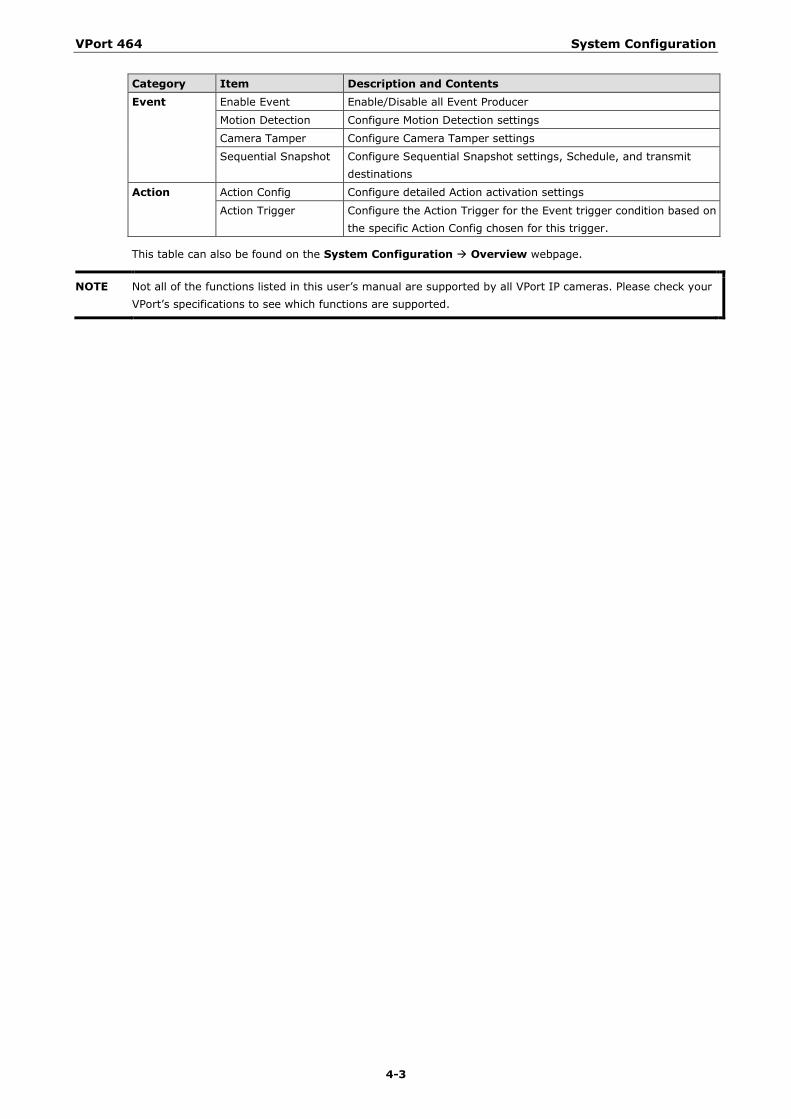
Category Item Description and Contents Event Enable Event Enable/Disable all Event Producer
Motion Detection Configure Motion Detection settings
Camera Tamper Configure Camera Tamper settings
Sequential Snapshot Configure Sequential Snapshot settings, Schedule, and transmit destinations
Action Action Config Configure detailed Action activation settings
Action Trigger Configure the Action Trigger for the Event trigger condition based on the specific Action Config chosen for this trigger.
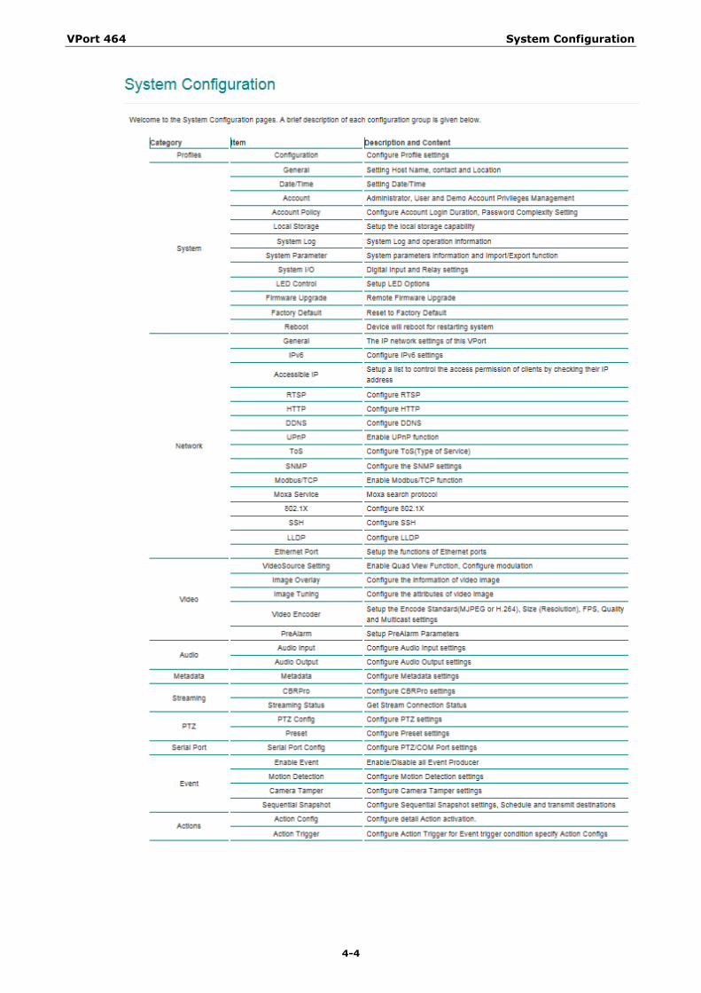
This table can also be found on the System Configuration Overview webpage.
NOTE Not all of the functions listed in this user’s manual are supported by all VPort IP cameras. Please check your VPort’s specifications to see which functions are supported.
VPort 464 System Configuration
4-4
VPort 464 System Configuration
4-5
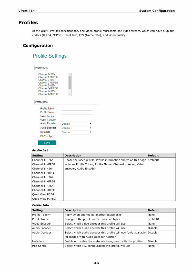
Profiles In the ONVIF Profiles specifications, one video profile represents one video stream, which can have a unique codecs (H.264, MJPEG), resolution, FPS (frame rate), and video quality.
Configuration
Profile List
Setting Description Default Channel 1-H264 Channel 1-MJPEG Channel 1-H264 Channel 1-MJPEG Channel 1-H264 Channel 1-MJPEG Channel 1-H264 Channel 1-MJPEG Quad View H264 Quad View MJPEG
Chose the video profile. Profile information shown on this page includes Profile Token, Profile Name, Channel number, Video encoder, Audio Encoder
profile01
Profile Info
Setting Description Default Profile Token* Reply when queried by another device asks None
Profile Name Configure the profile name, max. 40 bytes profile01
Video Encoder Select which video encoder this profile will use None
Audio Encoder Select which audio encoder this profile will use Disable
Audio Decoder Select which audio decoder this profile will use (only available for models with Audio Decoder function)
Disable
Metadata Enable or disable the metadata being used with the profiles Disable
PTZ Config Select which PTZ configuration this profile will use None
VPort 464 System Configuration
4-6
New Profile
You can create additional profiles if needed. Input the name of the new profile and then click Create. When the new profile appears in the Profile List, select the new profile and then configure its video encoder and audio encoder to generate the video streams. Click Save to save the new profile. To remove a profile, select the profile you wish to remove, and then click Remove.
System
General Settings/Date/Time
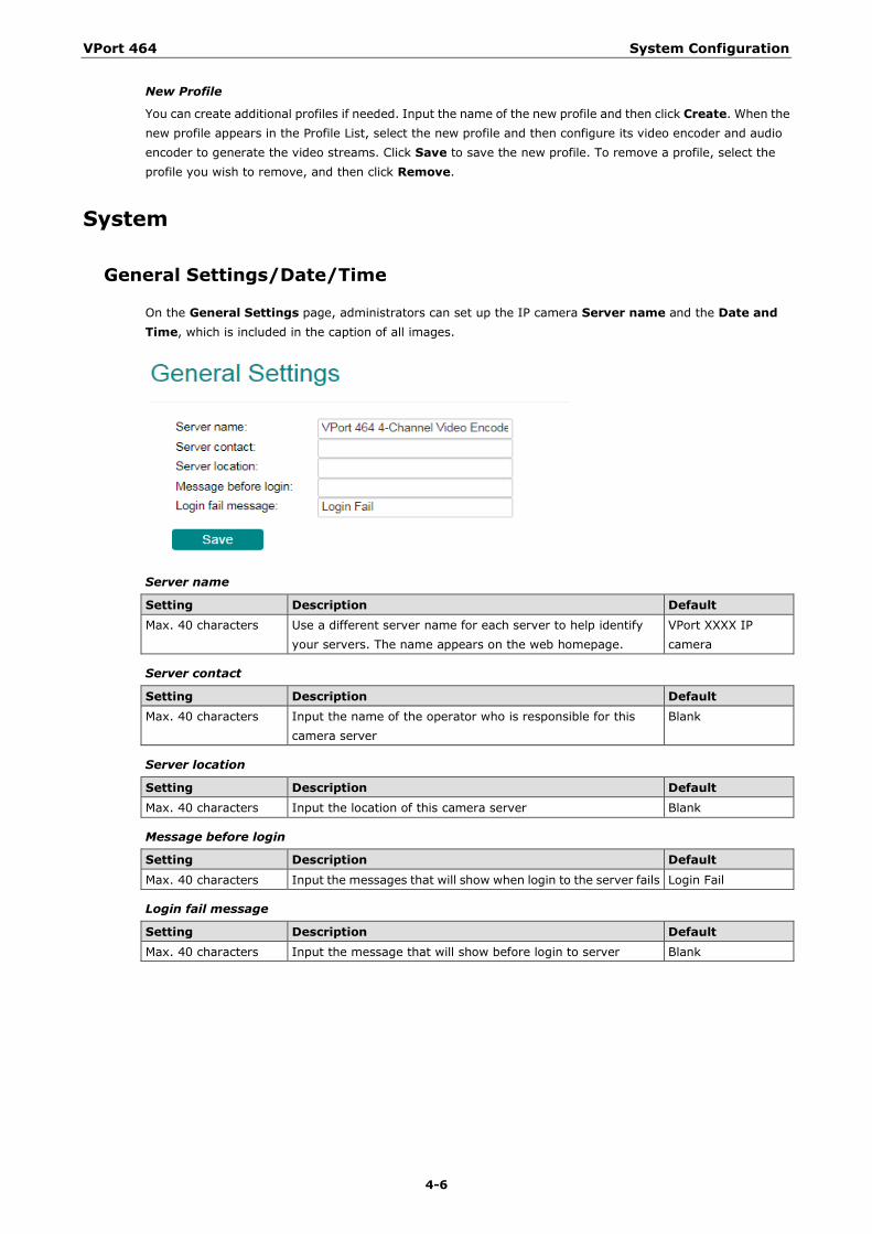
On the General Settings page, administrators can set up the IP camera Server name and the Date and Time, which is included in the caption of all images.
Server name
Setting Description Default Max. 40 characters Use a different server name for each server to help identify
your servers. The name appears on the web homepage. VPort XXXX IP camera
Server contact
Setting Description Default Max. 40 characters Input the name of the operator who is responsible for this
camera server Blank
Server location
Setting Description Default Max. 40 characters Input the location of this camera server Blank
Message before login
Setting Description Default Max. 40 characters Input the messages that will show when login to the server fails Login Fail
Login fail message
Setting Description Default Max. 40 characters Input the message that will show before login to server Blank

VPort 464 System Configuration
4-7
Time zone
Setting Description Default Time Zone Configure the time zone GMT
Manual TimeZone (POSIX 1003.1):
Manually configure the specified time zone. To enable this configuration, select manual setting from the Time Zone drop-down box
Blank
Enable daylight saving time
Enable/disable daylight saving time Disable
Date and Time
Setting Description Default Keep current date and time
Use the current date and time as the VPort’s time setting Keep current date and time
Sync with computer time
Synchronize the VPort’s data and time setting with the local computer time
Manual Manually change the VPort’s date and time setting
Automatic Use the NTP server to set the VPort’s date and time setting
NOTE Select the Automatic option to force the VPort to synchronize automatically with timeservers over the Internet. However, synchronization may fail if the assigned NTP server cannot be reached, or the VPort is connected to a local network. Leaving the NTP server blank will force the VPort to connect to default timeservers. Enter either the Domain name or IP address format of the timeserver if the DNS server is available. You can configure two NTP servers as backups; the update interval can be configured from a minimum of 5 seconds up to one month. Don’t forget to set the Time zone for local settings. Refer to Appendix B for your region’s time zone.
VPort 464 System Configuration
4-8
Account
Authentication Mode
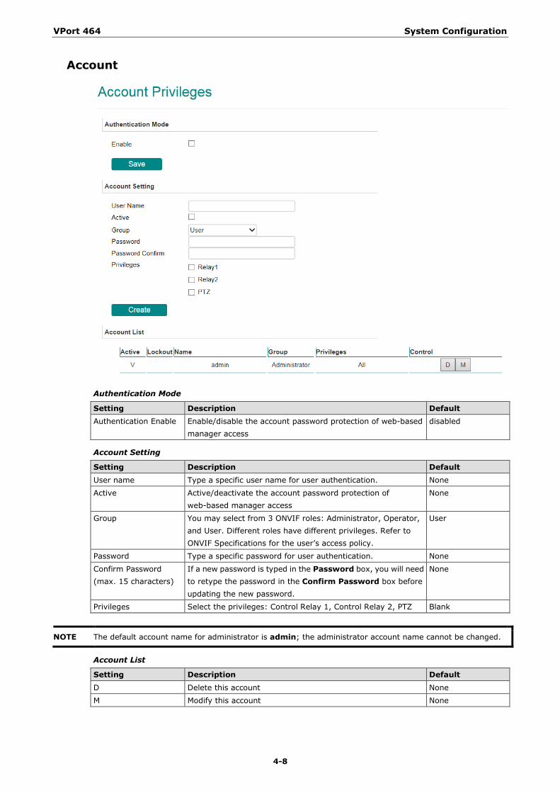
Setting Description Default Authentication Enable Enable/disable the account password protection of web-based
manager access disabled
Account Setting
Setting Description Default User name Type a specific user name for user authentication. None
Active Active/deactivate the account password protection of web-based manager access
None
Group You may select from 3 ONVIF roles: Administrator, Operator, and User. Different roles have different privileges. Refer to ONVIF Specifications for the user’s access policy.
User
Password Type a specific password for user authentication. None
Confirm Password (max. 15 characters)
If a new password is typed in the Password box, you will need to retype the password in the Confirm Password box before updating the new password.
None
Privileges Select the privileges: Control Relay 1, Control Relay 2, PTZ Blank
NOTE The default account name for administrator is admin; the administrator account name cannot be changed.
Account List
Setting Description Default D Delete this account None
M Modify this account None
VPort 464 System Configuration
4-9
NOTE The FPS of the video stream will be reduced as more and more users access the same VPort. Currently, the VPort camera is only allowed to send 10 unicast video streams. To avoid performance problems, limit the number of users who can simultaneously access a VPort.
Account Policy
Account Policy login Settings
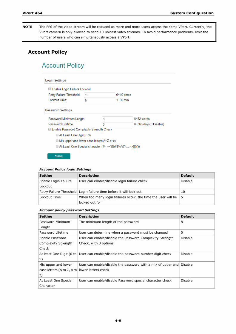
Setting Description Default Enable Login Failure Lockout
User can enable/disable login failure check Disable
Retry Failure Threshold Login failure time before it will lock out 10
Lockout Time When too many login failures occur, the time the user will be locked out for
5
Account policy password Settings
Setting Description Default Password Minimum Length
The minimum length of the password 8
Password Lifetime User can determine when a password must be changed 0
Enable Password Complexity Strength Check
User can enable/disable the Password Complexity Strength Check, with 3 options
Disable
At least One Digit (0 to 9)
User can enable/disable the password number digit check Disable
Mix upper and lower case letters (A to Z, a to z)
User can enable/disable the password with a mix of upper and lower letters check
Disable
At Least One Special Character
User can enable/disable Password special character check Disable
VPort 464 System Configuration
4-10
Local Storage
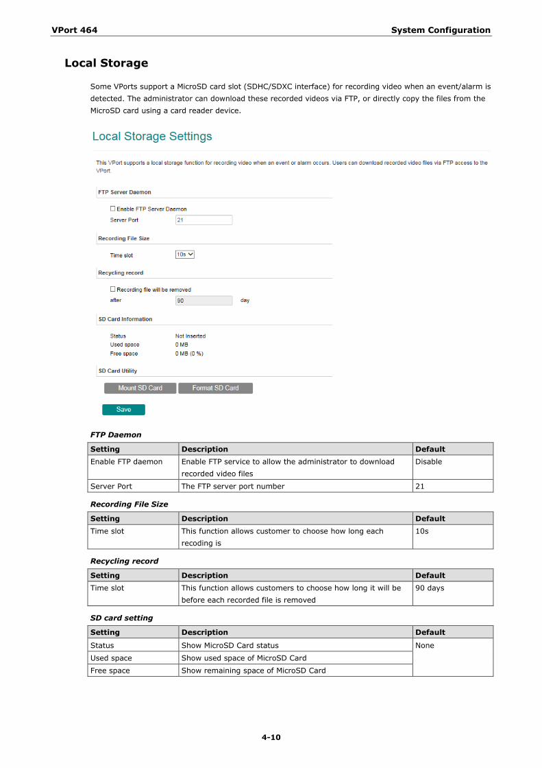
Some VPorts support a MicroSD card slot (SDHC/SDXC interface) for recording video when an event/alarm is detected. The administrator can download these recorded videos via FTP, or directly copy the files from the MicroSD card using a card reader device.
FTP Daemon
Setting Description Default Enable FTP daemon Enable FTP service to allow the administrator to download
recorded video files Disable
Server Port The FTP server port number 21
Recording File Size
Setting Description Default Time slot This function allows customer to choose how long each
recoding is 10s
Recycling record
Setting Description Default Time slot This function allows customers to choose how long it will be
before each recorded file is removed 90 days
SD card setting
Setting Description Default
Status Show MicroSD Card status None
Used space Show used space of MicroSD Card
Free space Show remaining space of MicroSD Card
VPort 464 System Configuration
4-11
SD Card Utility
Setting Description Default Mount SD card Force mount/ unmount the SD card None
NOTE The recorded videos are stored in the “/VPortfolder” folder. Ten seconds of video is recorded on each file. The videos are stored as AVI files, which can be played back using any popular media player.
NOTE Due to file system limitations, the maximum number of files that can be stored is 16584. When the number of files in the SD card reaches 16584, or the free space is less than 100 MB, the system will start deleting the oldest files.
System Log History
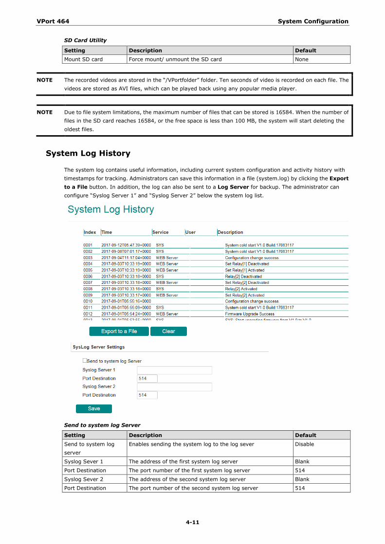
The system log contains useful information, including current system configuration and activity history with timestamps for tracking. Administrators can save this information in a file (system.log) by clicking the Export to a File button. In addition, the log can also be sent to a Log Server for backup. The administrator can configure “Syslog Server 1” and “Syslog Server 2” below the system log list.
Send to system log Server
Setting Description Default Send to system log server
Enables sending the system log to the log sever Disable
Syslog Sever 1 The address of the first system log server Blank
Port Destination The port number of the first system log server 514
Syslog Sever 2 The address of the second system log server Blank
Port Destination The port number of the second system log server 514
VPort 464 System Configuration
4-12
NOTE A maximum of 500 lines is displayed in the log. Earlier log entries are stored in the VPort’s database, which the administrator can export at any time.
System Parameters
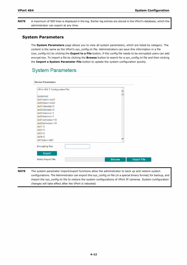
The System Parameters page allows you to view all system parameters, which are listed by category. The content is the same as the VPort’s sys_config.ini file. Administrators can save this information in a file (sys_config.ini) by clicking the Export to a File button, if this config file needs to be encrypted users can add encrypt key. To import a file by clicking the Browse button to search for a sys_config.ini file and then clicking the Import a System Parameter File button to update the system configuration quickly.
NOTE The system parameter import/export functions allow the administrator to back up and restore system configurations. The Administrator can export this sys_config.ini file (in a special binary format) for backup, and import the sys_config.ini file to restore the system configurations of VPort IP cameras. System configuration changes will take effect after the VPort is rebooted.
VPort 464 System Configuration
4-13
System I/O
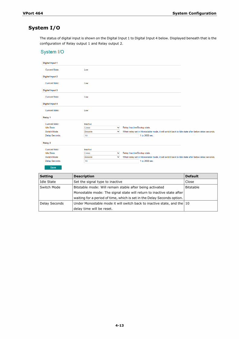
The status of digital input is shown on the Digital Input 1 to Digital Input 4 below. Displayed beneath that is the configuration of Relay output 1 and Relay output 2.
Setting Description Default Idle State Set the signal type to inactive Close
Switch Mode Bitstable mode: Will remain stable after being activated Monostable mode: The signal state will return to inactive state after waiting for a period of time, which is set in the Delay Seconds option.
Bitstable
Delay Seconds Under Monostable mode it will switch back to inactive state, and the delay time will be reset.
10
VPort 464 System Configuration
4-14
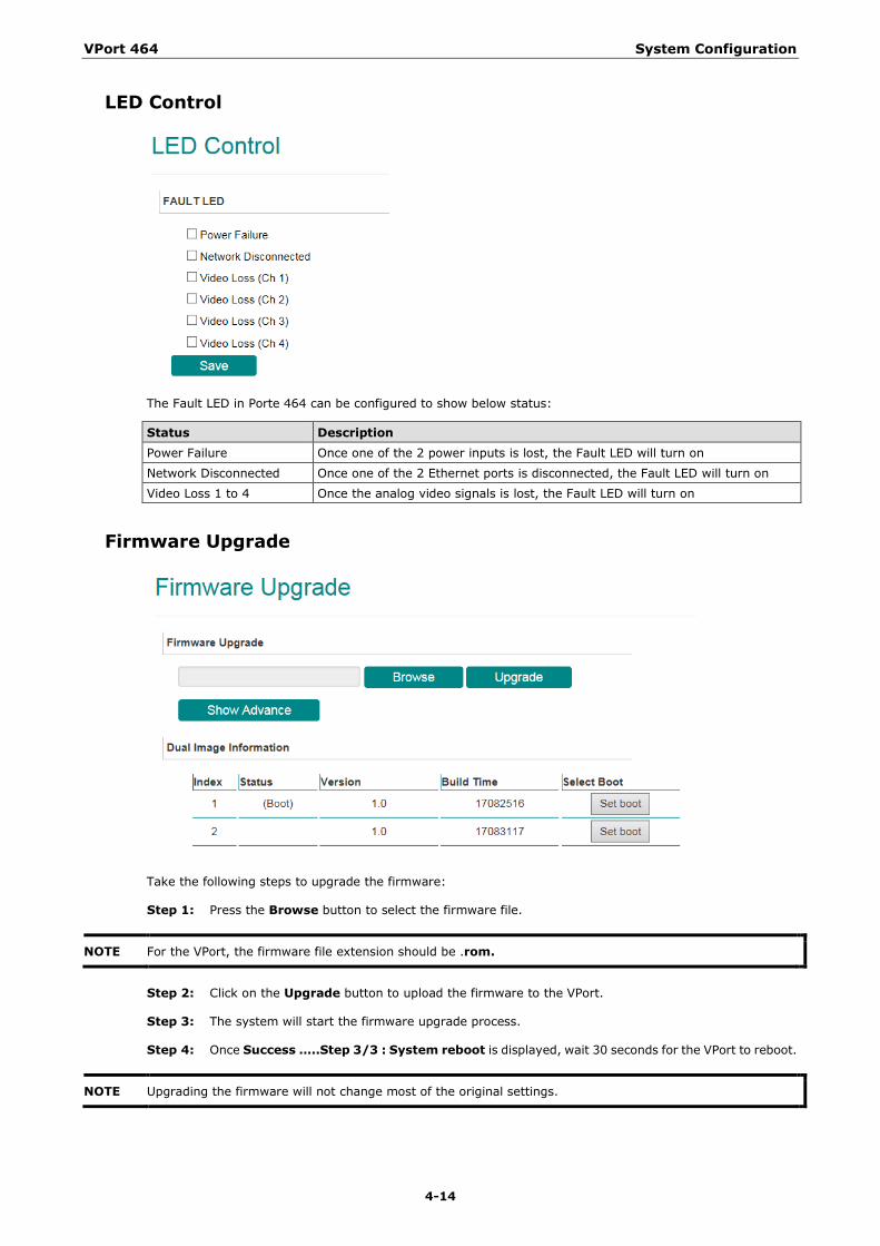
LED Control
The Fault LED in Porte 464 can be configured to show below status:
Status Description Power Failure Once one of the 2 power inputs is lost, the Fault LED will turn on
Network Disconnected Once one of the 2 Ethernet ports is disconnected, the Fault LED will turn on
Video Loss 1 to 4 Once the analog video signals is lost, the Fault LED will turn on
Firmware Upgrade
Take the following steps to upgrade the firmware:
Step 1: Press the Browse button to select the firmware file.
NOTE For the VPort, the firmware file extension should be .rom.
Step 2: Click on the Upgrade button to upload the firmware to the VPort.
Step 3: The system will start the firmware upgrade process.
Step 4: Once Success …..Step 3/3 : System reboot is displayed, wait 30 seconds for the VPort to reboot.
NOTE Upgrading the firmware will not change most of the original settings.
VPort 464 System Configuration
4-15
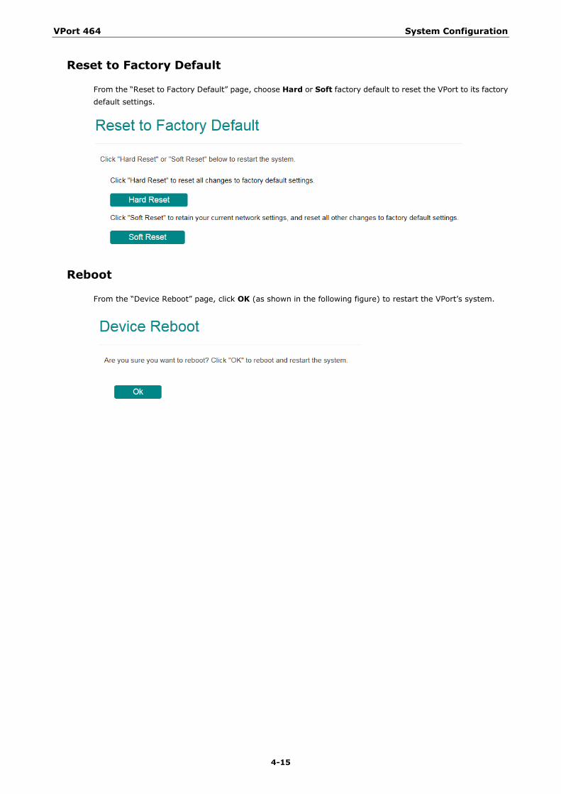
Reset to Factory Default
From the “Reset to Factory Default” page, choose Hard or Soft factory default to reset the VPort to its factory default settings.
Reboot
From the “Device Reboot” page, click OK (as shown in the following figure) to restart the VPort’s system.
VPort 464 System Configuration
4-16
Network
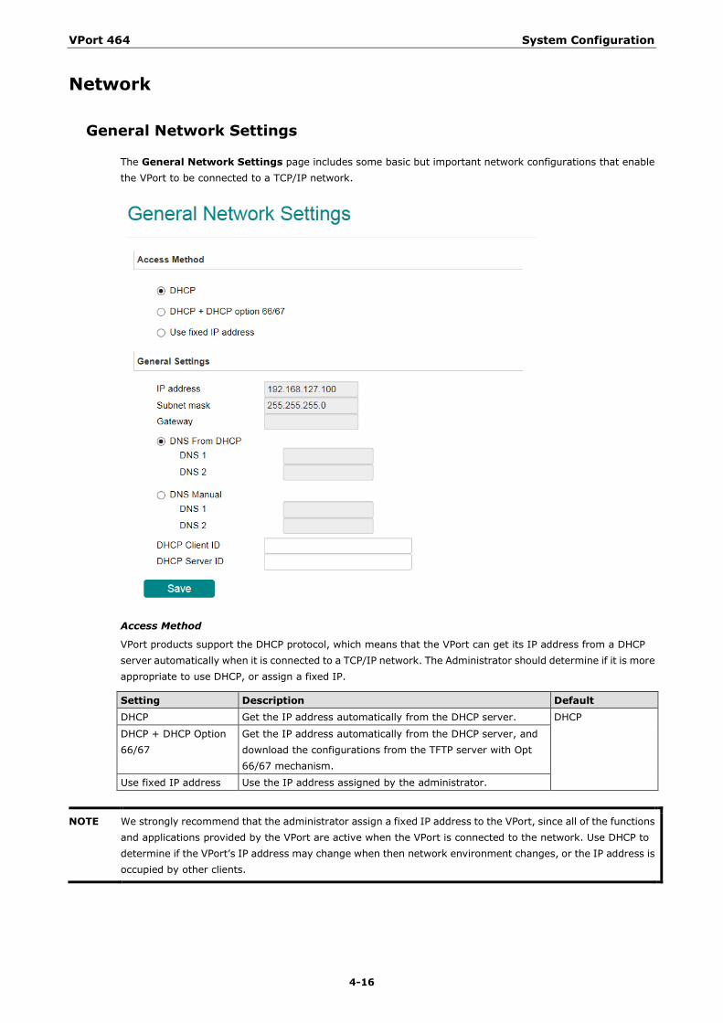
General Network Settings
The General Network Settings page includes some basic but important network configurations that enable the VPort to be connected to a TCP/IP network.
Access Method
VPort products support the DHCP protocol, which means that the VPort can get its IP address from a DHCP server automatically when it is connected to a TCP/IP network. The Administrator should determine if it is more appropriate to use DHCP, or assign a fixed IP.
Setting Description Default DHCP Get the IP address automatically from the DHCP server. DHCP
DHCP + DHCP Option 66/67
Get the IP address automatically from the DHCP server, and download the configurations from the TFTP server with Opt 66/67 mechanism.
Use fixed IP address Use the IP address assigned by the administrator.
NOTE We strongly recommend that the administrator assign a fixed IP address to the VPort, since all of the functions and applications provided by the VPort are active when the VPort is connected to the network. Use DHCP to determine if the VPort’s IP address may change when then network environment changes, or the IP address is occupied by other clients.
VPort 464 System Configuration
4-17
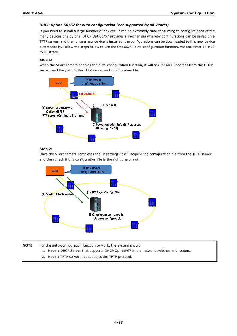
DHCP Option 66/67 for auto configuration (not supported by all VPorts)
If you need to install a large number of devices, it can be extremely time consuming to configure each of the many devices one by one. DHCP Opt 66/67 provides a mechanism whereby configurations can be saved on a TFTP server, and then once a new device is installed, the configurations can be downloaded to this new device automatically. Follow the steps below to use the Opt 66/67 auto-configuration function. We use VPort 16-M12 to illustrate.
Step 1: When the VPort camera enables the auto-configuration function, it will ask for an IP address from the DHCP server, and the path of the TFTP server and configuration file.
Step 2: Once the VPort camera completes the IP settings, it will acquire the configuration file from the TFTP server, and then check if this configuration file is the right one or not.
NOTE For the auto-configuration function to work, the system should 1. Have a DHCP Server that supports DHCP Opt 66/67 in the network switches and routers.
2. Have a TFTP server that supports the TFTP protocol.
VPort 464 System Configuration
4-18
General Settings
Setting Description Default IP address Variable IP assigned automatically by the DHCP server, or fixed
IP assigned by the Administrator. 192.168.127.100
Subnet mask Variable subnet mask assigned automatically by the DHCP server, or a fixed subnet mask assigned by the Administrator.
255.255.255.0
Gateway Assigned automatically by the DHCP server, or assigned by the Administrator.
Blank
DNS from DHCP The DNS server is assigned by DHCP server Disable
DNS1 Enter the IP Address of the DNS Server used by your network. After entering the DNS Server’s IP address, you can input the VPort’s url (e.g., www.VPort.company.com) in your browser’s address field, instead of entering the IP address.
Obtained automatically from the DHCP server, or left blank in non-DHCP environments.
DNS2 Enter the IP address of the DNS Server used by your network. The VPort will try to locate the secondary DNS Server if the primary DNS Server fails to connect.
Obtained automatically from the DHCP server, or left blank in non-DHCP environments.
DHCP Client ID Configure the DHCP Client ID if it is required. Blank
DHCP Server ID Configure the DHCP Server ID if it is required Blank
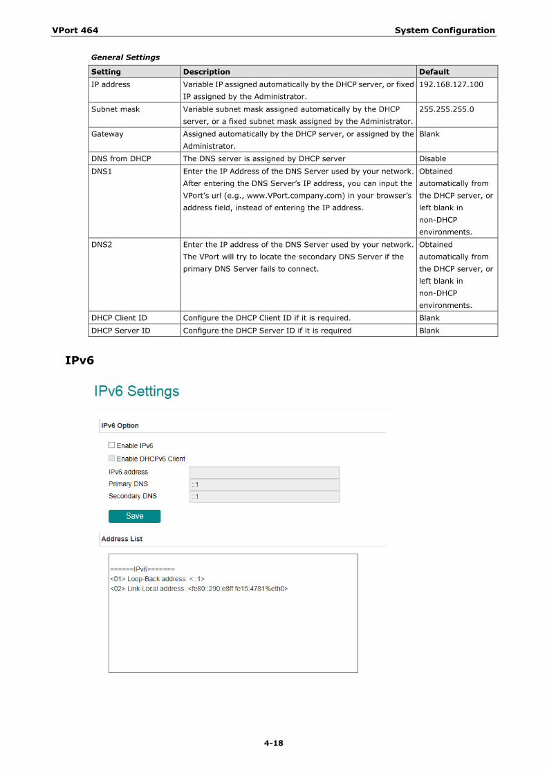
IPv6
VPort 464 System Configuration
4-19
IPv6 Option
Setting Description Default Enable IPv6 Enable the IPv6 Option Disable
Enable DHCPv6 Client Get the IPv6 from the DHCP server Disable
IPv6 address Show the IPv6 from the DHCP server Blank
Primary DNS Show the DNS IPv6 from the DHCP server Blank
Secondary DNS Show the secondary DNS IPv6 from the DHCP server Blank
Address List
Shows all related IPv6 Addresses of the camera in this area.
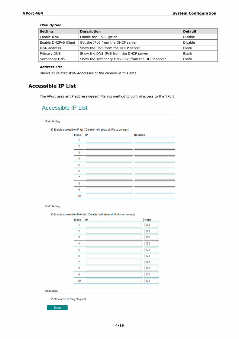
Accessible IP List
The VPort uses an IP address-based filtering method to control access to the VPort
VPort 464 System Configuration
4-20
Accessible IP Settings allow you to add or remove “Legal” remote host IP addresses to prevent unauthorized access. Access to the VPort is controlled by IP address. That is, if a host’s IP address is in the accessible IP table, then the host will be allowed access to the VPort. In particular, an IP together with a NetMask is used to specify a range of IP addresses. Here are some examples:
• Allow only one host with a specific “IP address” to access the VPort. For example:
IP = 192.168.1.16 NetMask = 255.255.255.255
• Allow all hosts on a specific subnet to access the VPort. For example:
will only allow the host with IP = 192.168.1.16 to access the VPort.
• IP = 192.168.1.0 NetMask = 255.255.255.0
will allow all hosts with IP addresses of the form 192.168.1.xxx to access the VPort.
• Allow any host to access the VPort.
Do not checkmark the “Enable accessible IP list” checkbox.
The following table gives additional IP/NetMask configuration examples.
Allowable Hosts Input Formats Any host Disable
192.168.1.120 192.168.1.120/255.255.255.255
192.168.1.1 to 192.168.1.254 192.168.1.0/255.255.255.0
192.168.0.1 to 192.168.255.254 192.168.0.0/255.255.0.0
192.168.1.1 to 192.168.1.126 192.168.1.0/255.255.255.128
192.168.1.129 to 192.168.1.254 192.168.1.128/255.255.255.128
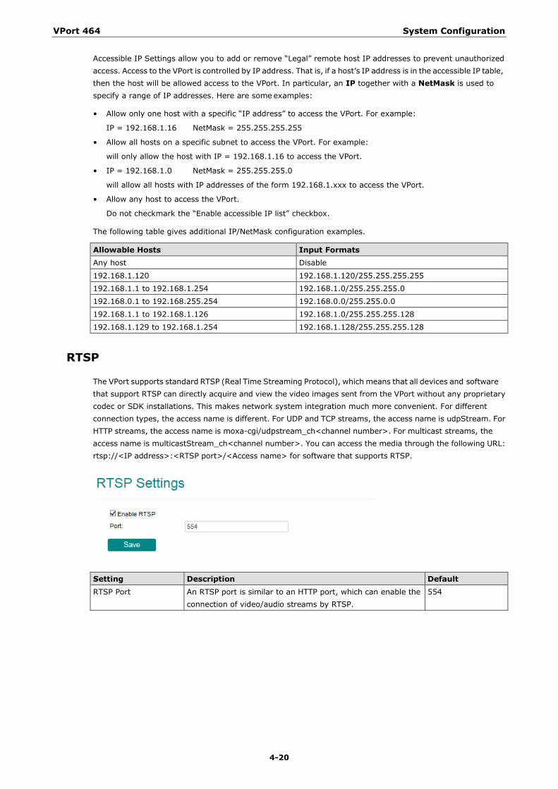
RTSP
The VPort supports standard RTSP (Real Time Streaming Protocol), which means that all devices and software that support RTSP can directly acquire and view the video images sent from the VPort without any proprietary codec or SDK installations. This makes network system integration much more convenient. For different connection types, the access name is different. For UDP and TCP streams, the access name is udpStream. For HTTP streams, the access name is moxa-cgi/udpstream_ch<channel number>. For multicast streams, the access name is multicastStream_ch<channel number>. You can access the media through the following URL: rtsp://<IP address>:<RTSP port>/<Access name> for software that supports RTSP.
Setting Description Default RTSP Port An RTSP port is similar to an HTTP port, which can enable the
connection of video/audio streams by RTSP. 554
VPort 464 System Configuration
4-21
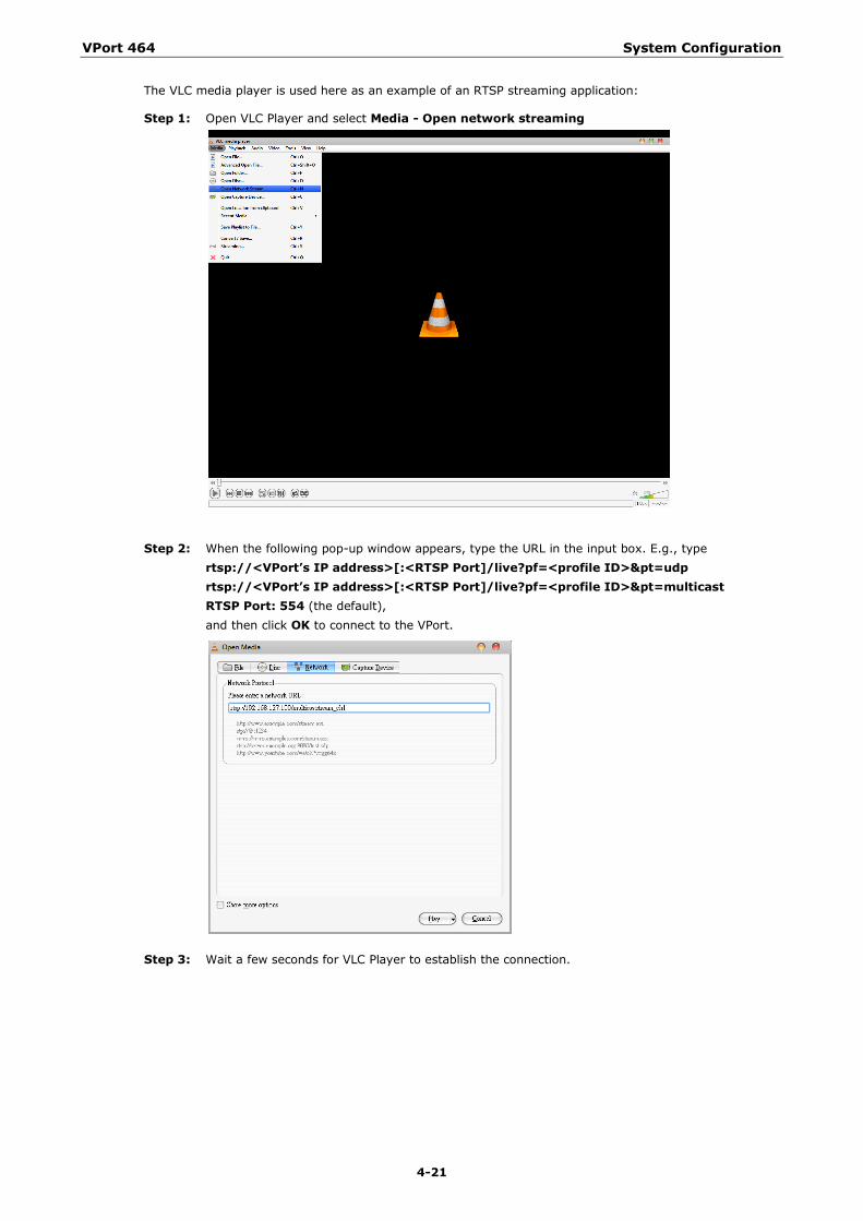
The VLC media player is used here as an example of an RTSP streaming application:
Step 1: Open VLC Player and select Media - Open network streaming
Step 2: When the following pop-up window appears, type the URL in the input box. E.g., type
rtsp://<VPort’s IP address>[:<RTSP Port]/live?pf=<profile ID>&pt=udp rtsp://<VPort’s IP address>[:<RTSP Port]/live?pf=<profile ID>&pt=multicast RTSP Port: 554 (the default), and then click OK to connect to the VPort.
Step 3: Wait a few seconds for VLC Player to establish the connection.
VPort 464 System Configuration
4-22
NOTE For some older firmware versions (versions before the supported versions listed on page 1-2), use the RTSP stream URLs shown below:
rtsp://<VPort’s IP address>[:<RTSP Port]/udpstream_ch1_stream< 1 or 2> rtsp://<VPort’s IP address>[:<RTSP Port]/multicaststream_ch1_stream<1 or 2> RTSP Port: 554 (the default)
For the new firmware versions (versions after the supported versions listed on page 1-2), both kinds of RTSP URL are valid. There is no need to change the RTSP URL design if your software is using the old RTSP URL.
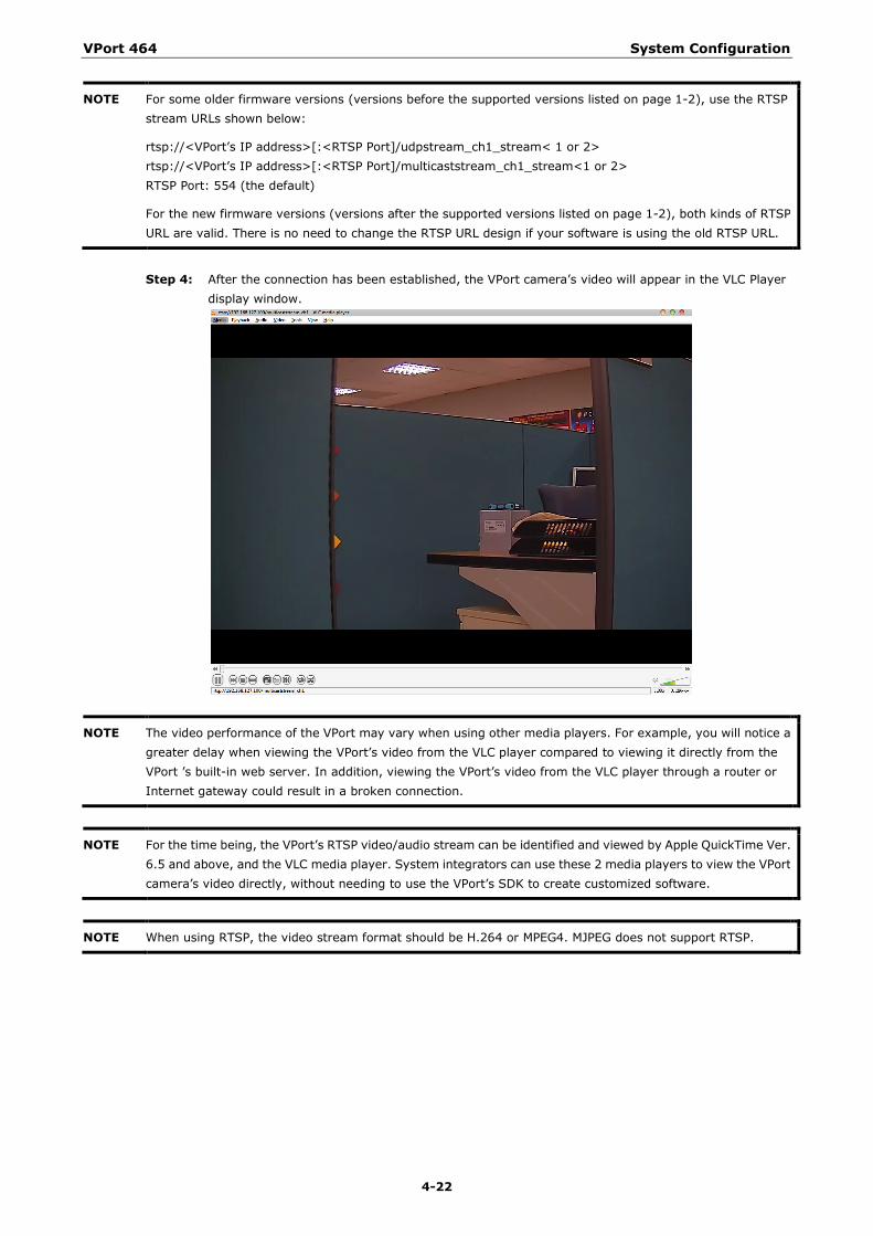
Step 4: After the connection has been established, the VPort camera’s video will appear in the VLC Player
display window.
NOTE The video performance of the VPort may vary when using other media players. For example, you will notice a greater delay when viewing the VPort’s video from the VLC player compared to viewing it directly from the VPort ’s built-in web server. In addition, viewing the VPort’s video from the VLC player through a router or Internet gateway could result in a broken connection.
NOTE For the time being, the VPort’s RTSP video/audio stream can be identified and viewed by Apple QuickTime Ver. 6.5 and above, and the VLC media player. System integrators can use these 2 media players to view the VPort camera’s video directly, without needing to use the VPort’s SDK to create customized software.
NOTE When using RTSP, the video stream format should be H.264 or MPEG4. MJPEG does not support RTSP.
VPort 464 System Configuration
4-23
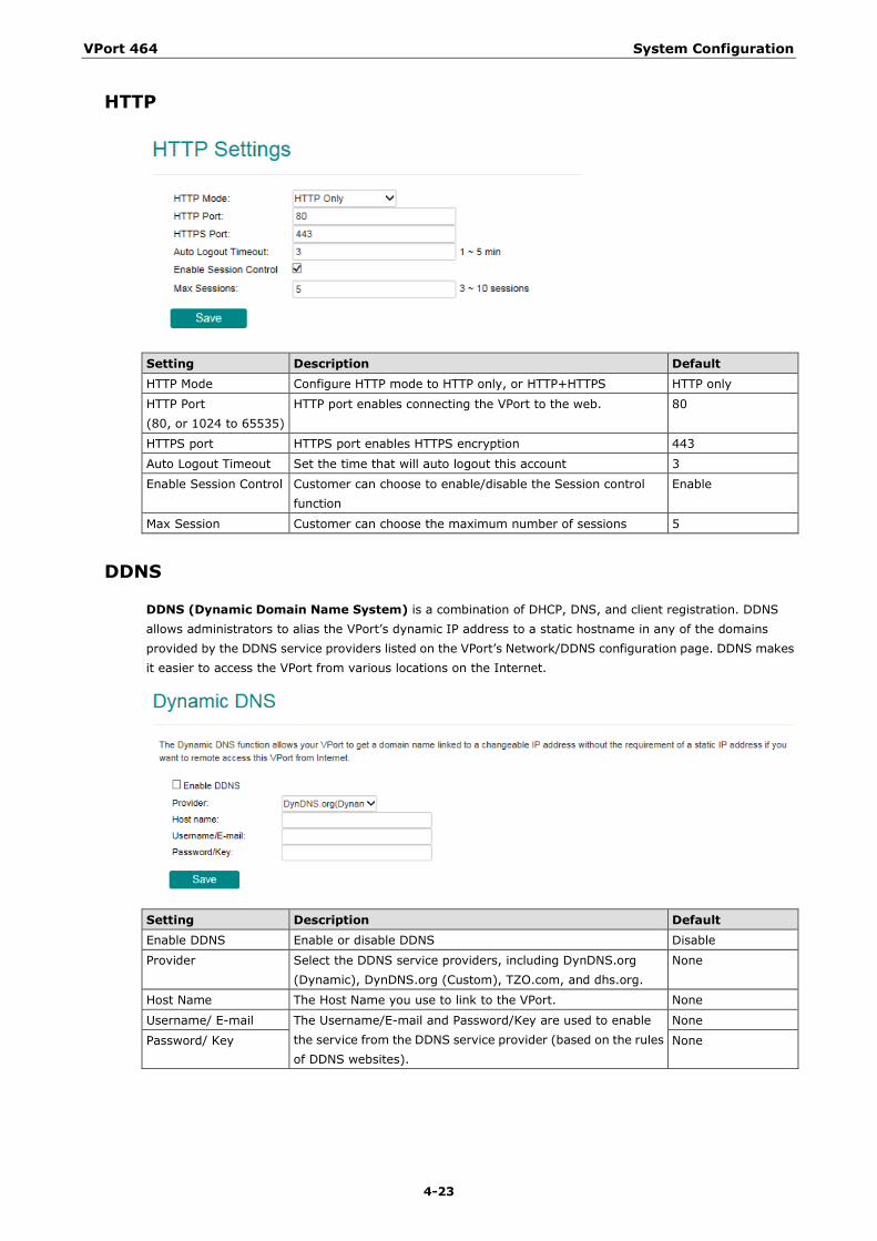
HTTP
Setting Description Default HTTP Mode Configure HTTP mode to HTTP only, or HTTP+HTTPS HTTP only
HTTP Port (80, or 1024 to 65535)
HTTP port enables connecting the VPort to the web. 80
HTTPS port HTTPS port enables HTTPS encryption 443
Auto Logout Timeout Set the time that will auto logout this account 3
Enable Session Control Customer can choose to enable/disable the Session control function
Enable
Max Session Customer can choose the maximum number of sessions 5
DDNS
DDNS (Dynamic Domain Name System) is a combination of DHCP, DNS, and client registration. DDNS allows administrators to alias the VPort’s dynamic IP address to a static hostname in any of the domains provided by the DDNS service providers listed on the VPort’s Network/DDNS configuration page. DDNS makes it easier to access the VPort from various locations on the Internet.
Setting Description Default Enable DDNS Enable or disable DDNS Disable
Provider Select the DDNS service providers, including DynDNS.org (Dynamic), DynDNS.org (Custom), TZO.com, and dhs.org.
None
Host Name The Host Name you use to link to the VPort. None
Username/ E-mail The Username/E-mail and Password/Key are used to enable the service from the DDNS service provider (based on the rules of DDNS websites).
None
Password/ Key None
VPort 464 System Configuration
4-24
NOTE Dynamic DNS is a very useful tool for accessing a VPort over the Internet, especially for xDSL connections with a non-fixed IP address (DHCP). The administrator and users can simplify connecting to a VPort with a non-fixed IP address, by using the unique host name in the URL to establish a connection with the VPort.
NOTE Different DDNS service providers have different application rules. Some applications are free of charge, but most require an application fee.
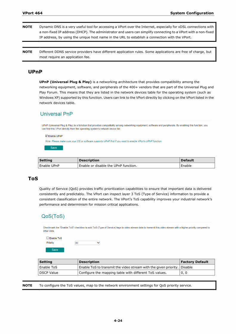
UPnP
UPnP (Universal Plug & Play) is a networking architecture that provides compatibility among the networking equipment, software, and peripherals of the 400+ vendors that are part of the Universal Plug and Play Forum. This means that they are listed in the network devices table for the operating system (such as Windows XP) supported by this function. Users can link to the VPort directly by clicking on the VPort listed in the network devices table.
Setting Description Default Enable UPnP Enable or disable the UPnP function. Enable
ToS
Quality of Service (QoS) provides traffic prioritization capabilities to ensure that important data is delivered consistently and predictably. The VPort can inspect layer 3 ToS (Type of Service) information to provide a consistent classification of the entire network. The VPort’s ToS capability improves your industrial network’s performance and determinism for mission critical applications.
Setting Description Factory Default Enable ToS Enable ToS to transmit the video stream with the given priority. Disable
DSCP Value Configure the mapping table with different ToS values. 0, 0
NOTE To configure the ToS values, map to the network environment settings for QoS priority service.
VPort 464 System Configuration
4-25
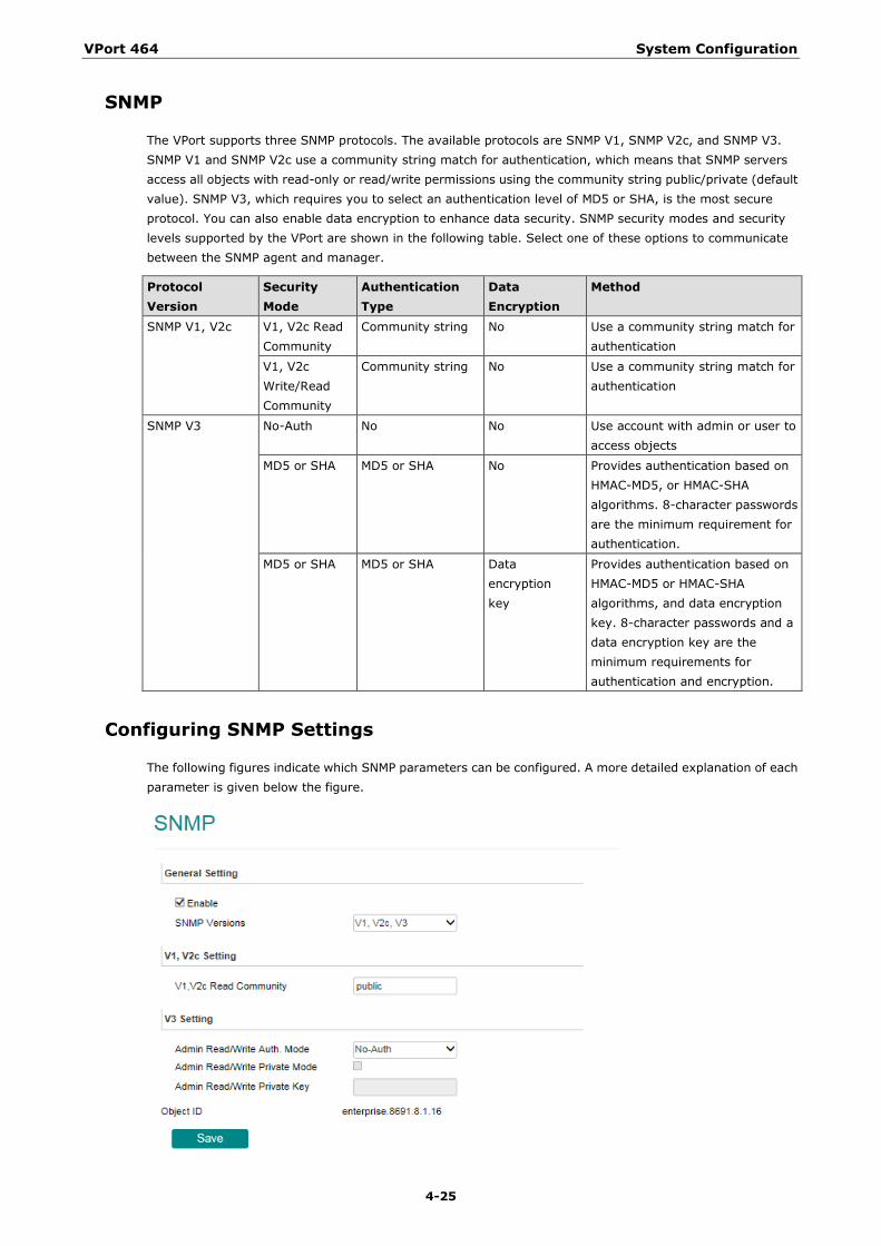
SNMP
The VPort supports three SNMP protocols. The available protocols are SNMP V1, SNMP V2c, and SNMP V3. SNMP V1 and SNMP V2c use a community string match for authentication, which means that SNMP servers access all objects with read-only or read/write permissions using the community string public/private (default value). SNMP V3, which requires you to select an authentication level of MD5 or SHA, is the most secure protocol. You can also enable data encryption to enhance data security. SNMP security modes and security levels supported by the VPort are shown in the following table. Select one of these options to communicate between the SNMP agent and manager.
Protocol Version
Security Mode
Authentication Type
Data Encryption
Method
SNMP V1, V2c V1, V2c Read Community
Community string No Use a community string match for authentication
V1, V2c Write/Read Community
Community string No Use a community string match for authentication
SNMP V3 No-Auth No No Use account with admin or user to access objects
MD5 or SHA MD5 or SHA No Provides authentication based on HMAC-MD5, or HMAC-SHA algorithms. 8-character passwords are the minimum requirement for authentication.
MD5 or SHA MD5 or SHA Data encryption key
Provides authentication based on HMAC-MD5 or HMAC-SHA algorithms, and data encryption key. 8-character passwords and a data encryption key are the minimum requirements for authentication and encryption.
Configuring SNMP Settings
The following figures indicate which SNMP parameters can be configured. A more detailed explanation of each parameter is given below the figure.
VPort 464 System Configuration
4-26
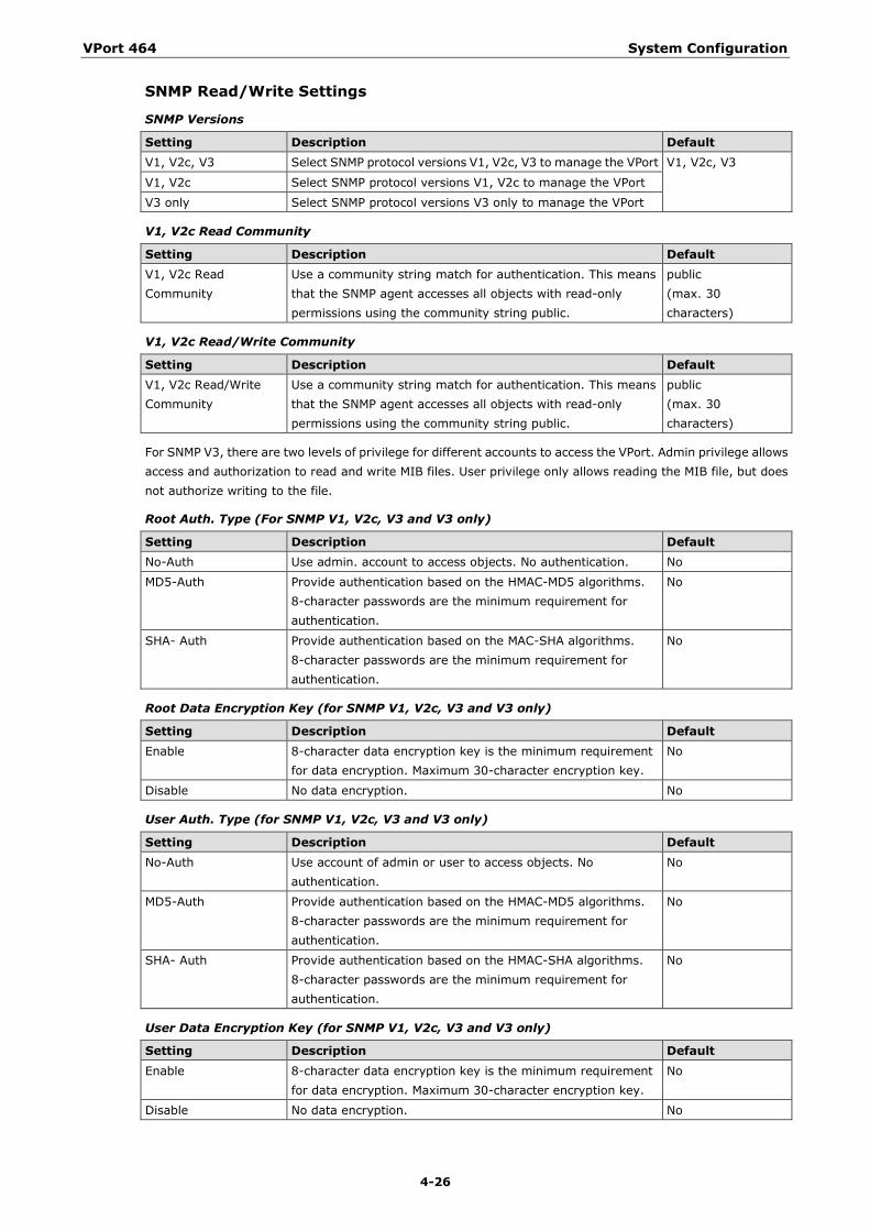
SNMP Read/Write Settings
SNMP Versions
Setting Description Default V1, V2c, V3 Select SNMP protocol versions V1, V2c, V3 to manage the VPort V1, V2c, V3
V1, V2c Select SNMP protocol versions V1, V2c to manage the VPort
V3 only Select SNMP protocol versions V3 only to manage the VPort
V1, V2c Read Community
Setting Description Default V1, V2c Read Community
Use a community string match for authentication. This means that the SNMP agent accesses all objects with read-only permissions using the community string public.
public (max. 30 characters)
V1, V2c Read/Write Community
Setting Description Default V1, V2c Read/Write Community
Use a community string match for authentication. This means that the SNMP agent accesses all objects with read-only permissions using the community string public.
public (max. 30 characters)
For SNMP V3, there are two levels of privilege for different accounts to access the VPort. Admin privilege allows access and authorization to read and write MIB files. User privilege only allows reading the MIB file, but does not authorize writing to the file.
Root Auth. Type (For SNMP V1, V2c, V3 and V3 only)
Setting Description Default No-Auth Use admin. account to access objects. No authentication. No
MD5-Auth Provide authentication based on the HMAC-MD5 algorithms. 8-character passwords are the minimum requirement for authentication.
No
SHA- Auth Provide authentication based on the MAC-SHA algorithms. 8-character passwords are the minimum requirement for authentication.
No
Root Data Encryption Key (for SNMP V1, V2c, V3 and V3 only)
Setting Description Default Enable 8-character data encryption key is the minimum requirement
for data encryption. Maximum 30-character encryption key. No
Disable No data encryption. No
User Auth. Type (for SNMP V1, V2c, V3 and V3 only)
Setting Description Default No-Auth Use account of admin or user to access objects. No
authentication. No
MD5-Auth Provide authentication based on the HMAC-MD5 algorithms. 8-character passwords are the minimum requirement for authentication.
No
SHA- Auth Provide authentication based on the HMAC-SHA algorithms. 8-character passwords are the minimum requirement for authentication.
No
User Data Encryption Key (for SNMP V1, V2c, V3 and V3 only)
Setting Description Default Enable 8-character data encryption key is the minimum requirement
for data encryption. Maximum 30-character encryption key. No
Disable No data encryption. No
VPort 464 System Configuration
4-27
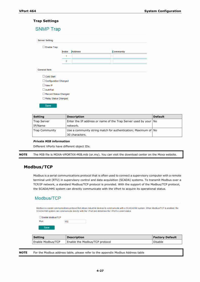
Trap Settings
Setting Description Default Trap Server IP/Name
Enter the IP address or name of the Trap Server used by your network.
No
Trap Community Use a community string match for authentication; Maximum of 30 characters.
No
Private MIB information
Different VPorts have different object IDs.
NOTE The MIB file is MOXA-VPORTXX-MIB.mib (or.my). You can visit the download center on the Moxa website.
Modbus/TCP
Modbus is a serial communications protocol that is often used to connect a supervisory computer with a remote terminal unit (RTU) in supervisory control and data acquisition (SCADA) systems. To transmit Modbus over a TCP/IP network, a standard Modbus/TCP protocol is provided. With the support of the Modbus/TCP protocol, the SCADA/HMI system can directly communicate with the VPort to acquire its operational status.
Setting Description Factory Default Enable Modbus/TCP Enable the Modbus/TCP protocol Disable
NOTE For the Modbus address table, please refer to the appendix Modbus Address table
VPort 464 System Configuration
4-28
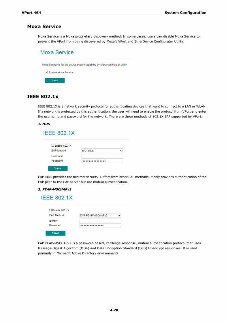
Moxa Service
Moxa Service is a Moxa proprietary discovery method. In some cases, users can disable Moxa Service to prevent the VPort from being discovered by Moxa’s VPort and EtherDevice Configurator Utility.
IEEE 802.1x
IEEE 802.1X is a network security protocol for authenticating devices that want to connect to a LAN or WLAN. If a network is protected by this authentication, the user will need to enable the protocol from VPort and enter the username and password for the network. There are three methods of 802.1X EAP supported by VPort.
1. MD5
EAP-MD5 provides the minimal security. Differs from other EAP methods, it only provides authentication of the EAP peer to the EAP server but not mutual authentication.
2. PEAP-MSCHAPv2
EAP-PEAP/MSCHAPv2 is a password-based, challenge-response, mutual authentication protocol that uses Message-Digest Algorithm (MD4) and Data Encryption Standard (DES) to encrypt responses. It is used primarily in Microsoft Active Directory environments.
VPort 464 System Configuration
4-29
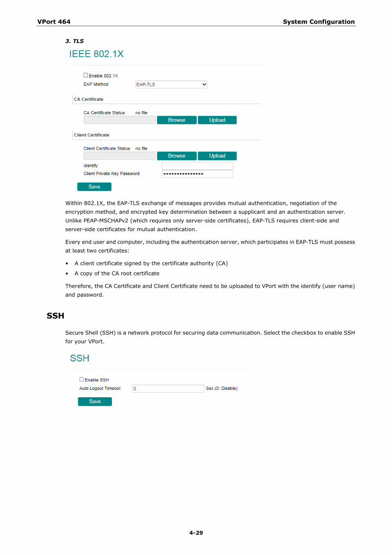
3. TLS
Within 802.1X, the EAP-TLS exchange of messages provides mutual authentication, negotiation of the encryption method, and encrypted key determination between a supplicant and an authentication server. Unlike PEAP-MSCHAPv2 (which requires only server-side certificates), EAP-TLS requires client-side and server-side certificates for mutual authentication.
Every end user and computer, including the authentication server, which participates in EAP-TLS must possess at least two certificates:
• A client certificate signed by the certificate authority (CA)
• A copy of the CA root certificate
Therefore, the CA Certificate and Client Certificate need to be uploaded to VPort with the identify (user name) and password.
SSH
Secure Shell (SSH) is a network protocol for securing data communication. Select the checkbox to enable SSH for your VPort.
VPort 464 System Configuration
4-30
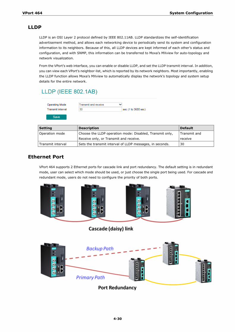
LLDP
LLDP is an OSI Layer 2 protocol defined by IEEE 802.11AB. LLDP standardizes the self-identification advertisement method, and allows each networking device to periodically send its system and configuration information to its neighbors. Because of this, all LLDP devices are kept informed of each other’s status and configuration, and with SNMP, this information can be transferred to Moxa’s MXview for auto-topology and network visualization.
From the VPort’s web interface, you can enable or disable LLDP, and set the LLDP transmit interval. In addition, you can view each VPort’s neighbor-list, which is reported by its network neighbors. Most importantly, enabling the LLDP function allows Moxa’s MXview to automatically display the network’s topology and system setup details for the entire network.
Setting Description Default Operation mode Choose the LLDP operation mode: Disabled, Transmit only,
Receive only, or Transmit and receive. Transmit and receive
Transmit interval Sets the transmit interval of LLDP messages, in seconds. 30
Ethernet Port
VPort 464 supports 2 Ethernet ports for cascade link and port redundancy. The default setting is in redundant mode, user can select which mode should be used, or just choose the single port being used. For cascade and redundant mode, users do not need to configure the priority of both ports.
VPort 464 System Configuration
4-31
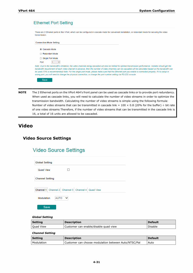
NOTE The 2 Ethernet ports on the VPort 464’s front panel can be used as cascade links or to provide port redundancy. When used as cascade links, you will need to calculate the number of video streams in order to optimize the transmission bandwidth. Calculating the number of video streams is simple using the following formula: Number of video streams that can be transmitted in cascade link = 100 × 0.8 (20% for the buffer) ÷ bit rate of one video streams Therefore, if the number of video streams that can be transmitted in the cascade link is 16, a total of 16 units are allowed to be cascaded.
Video
Video Source Settings
Global Setting
Setting Description Default Quad View Customer can enable/disable quad view Disable
Channel Setting
Setting Description Default Modulation Customer can choose modulation between Auto/NTSC/Pal Auto
VPort 464 System Configuration
4-32
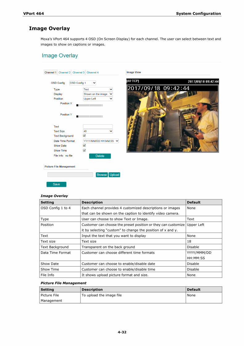
Image Overlay
Moxa’s VPort 464 supports 4 OSD (On Screen Display) for each channel. The user can select between text and images to show on captions or images.
Image Overlay
Setting Description Default OSD Config 1 to 4 Each channel provides 4 customized descriptions or images
that can be shown on the caption to identify video camera. None
Type User can choose to show Text or Image. Text
Position Customer can choose the preset position or they can customize it by selecting “custom” to change the position of x and y.
Upper Left
Text Input the text that you want to display None
Text size Text size 18
Text Background Transparent on the back ground Disable
Data Time Format Customer can choose different time formats YYYY/MMM/DD HH:MM:SS
Show Date Customer can choose to enable/disable date Disable
Show Time Customer can choose to enable/disable time Disable
File Info It shows upload picture format and size. None
Picture File Management
Setting Description Default Picture File Management
To upload the image file None
VPort 464 System Configuration
4-33
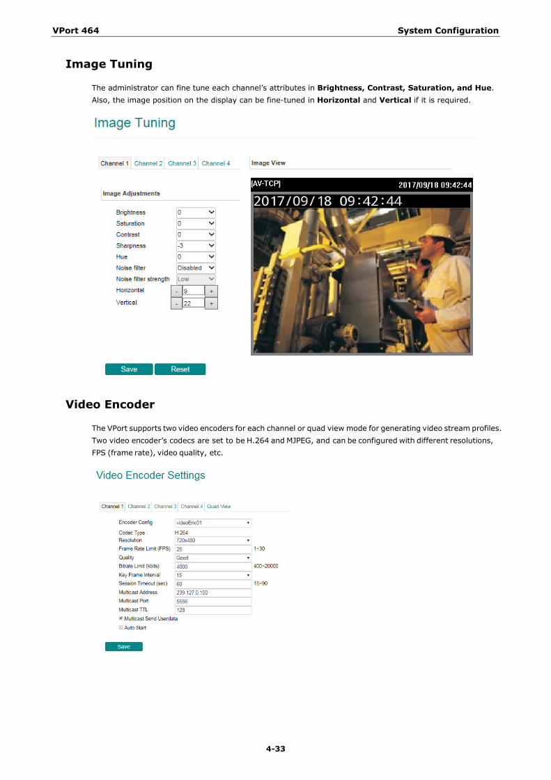
Image Tuning
The administrator can fine tune each channel’s attributes in Brightness, Contrast, Saturation, and Hue. Also, the image position on the display can be fine-tuned in Horizontal and Vertical if it is required.
Video Encoder
The VPort supports two video encoders for each channel or quad view mode for generating video stream profiles. Two video encoder’s codecs are set to be H.264 and MJPEG, and can be configured with different resolutions, FPS (frame rate), video quality, etc.
VPort 464 System Configuration
4-34
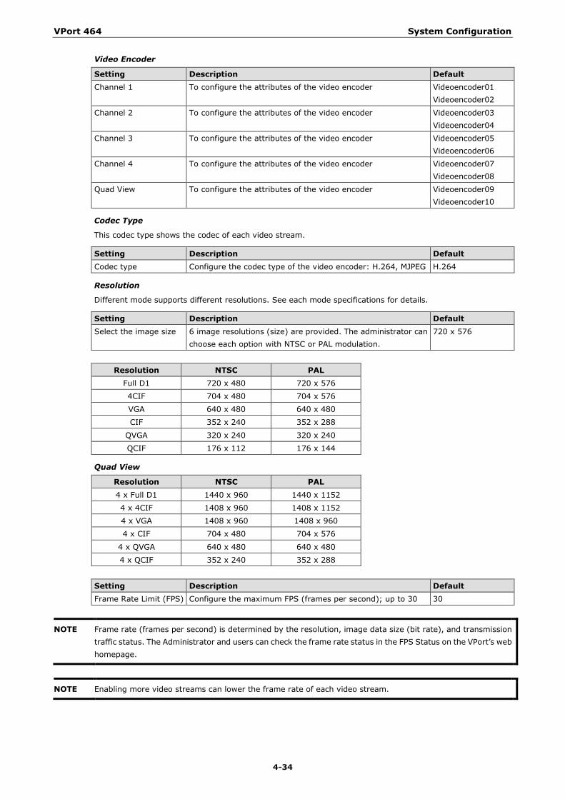
Video Encoder
Setting Description Default Channel 1 To configure the attributes of the video encoder Videoencoder01
Videoencoder02
Channel 2 To configure the attributes of the video encoder Videoencoder03 Videoencoder04
Channel 3 To configure the attributes of the video encoder Videoencoder05 Videoencoder06
Channel 4 To configure the attributes of the video encoder Videoencoder07 Videoencoder08
Quad View To configure the attributes of the video encoder Videoencoder09 Videoencoder10
Codec Type
This codec type shows the codec of each video stream.
Setting Description Default Codec type Configure the codec type of the video encoder: H.264, MJPEG H.264
Resolution
Different mode supports different resolutions. See each mode specifications for details.
Setting Description Default Select the image size 6 image resolutions (size) are provided. The administrator can
choose each option with NTSC or PAL modulation. 720 x 576
Resolution NTSC PAL Full D1 720 x 480 720 x 576
4CIF 704 x 480 704 x 576
VGA 640 x 480 640 x 480
CIF 352 x 240 352 x 288
QVGA 320 x 240 320 x 240
QCIF 176 x 112 176 x 144
Quad View
Resolution NTSC PAL 4 x Full D1 1440 x 960 1440 x 1152
4 x 4CIF 1408 x 960 1408 x 1152
4 x VGA 1408 x 960 1408 x 960
4 x CIF 704 x 480 704 x 576
4 x QVGA 640 x 480 640 x 480
4 x QCIF 352 x 240 352 x 288
Setting Description Default Frame Rate Limit (FPS) Configure the maximum FPS (frames per second); up to 30 30
NOTE Frame rate (frames per second) is determined by the resolution, image data size (bit rate), and transmission traffic status. The Administrator and users can check the frame rate status in the FPS Status on the VPort’s web homepage.
NOTE Enabling more video streams can lower the frame rate of each video stream.
VPort 464 System Configuration
4-35
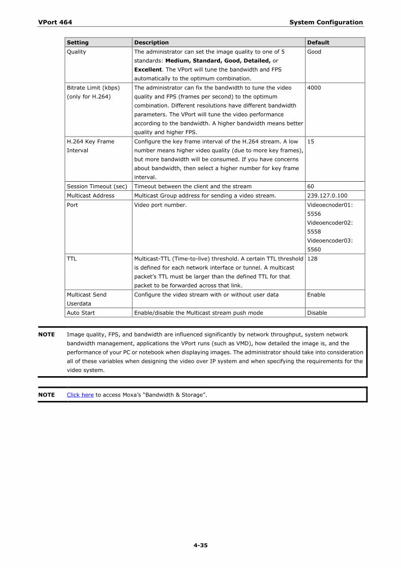
Setting Description Default Quality The administrator can set the image quality to one of 5
standards: Medium, Standard, Good, Detailed, or Excellent. The VPort will tune the bandwidth and FPS automatically to the optimum combination.
Good
Bitrate Limit (kbps) (only for H.264)
The administrator can fix the bandwidth to tune the video quality and FPS (frames per second) to the optimum combination. Different resolutions have different bandwidth parameters. The VPort will tune the video performance according to the bandwidth. A higher bandwidth means better quality and higher FPS.
4000
H.264 Key Frame Interval
Configure the key frame interval of the H.264 stream. A low number means higher video quality (due to more key frames), but more bandwidth will be consumed. If you have concerns about bandwidth, then select a higher number for key frame interval.
15
Session Timeout (sec) Timeout between the client and the stream 60
Multicast Address Multicast Group address for sending a video stream. 239.127.0.100
Port Video port number. Videoecnoder01: 5556 Videoencoder02: 5558 Videoencoder03: 5560
TTL Multicast-TTL (Time-to-live) threshold. A certain TTL threshold is defined for each network interface or tunnel. A multicast packet’s TTL must be larger than the defined TTL for that packet to be forwarded across that link.
128
Multicast Send Userdata
Configure the video stream with or without user data Enable
Auto Start Enable/disable the Multicast stream push mode Disable
NOTE Image quality, FPS, and bandwidth are influenced significantly by network throughput, system network bandwidth management, applications the VPort runs (such as VMD), how detailed the image is, and the performance of your PC or notebook when displaying images. The administrator should take into consideration all of these variables when designing the video over IP system and when specifying the requirements for the video system.
NOTE Click here to access Moxa’s “Bandwidth & Storage”.
VPort 464 System Configuration
4-36
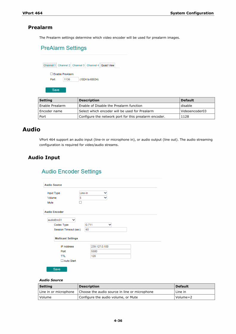
Prealarm
The Prealarm settings determine which video encoder will be used for prealarm images.
Setting Description Default Enable Prealarm Enable of Disable the Prealarm function disable
Encoder name Select which encoder will be used for Prealarm Videoencoder03
Port Configure the network port for this prealarm encoder. 1128
Audio VPort 464 support an audio input (line-in or microphone in), or audio output (line out). The audio streaming configuration is required for video/audio streams.
Audio Input
Audio Source
Setting Description Default Line in or microphone Choose the audio source in line or microphone Line in
Volume Configure the audio volume, or Mute Volume=2
VPort 464 System Configuration
4-37
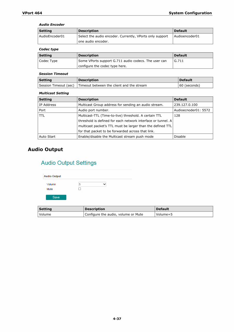
Audio Encoder
Setting Description Default AudioEncoder01 Select the audio encoder. Currently, VPorts only support
one audio encoder. Audioencoder01
Codec type
Setting Description Default Codec Type Some VPorts support G.711 audio codecs. The user can
configure the codec type here. G.711
Session Timeout
Setting Description Default Session Timeout (sec) Timeout between the client and the stream 60 (seconds)
Multicast Setting
Setting Description Default IP Address Multicast Group address for sending an audio stream. 239.127.0.100
Port Audio port number. Audioecnoder01: 5572
TTL Multicast-TTL (Time-to-live) threshold. A certain TTL threshold is defined for each network interface or tunnel. A multicast packet’s TTL must be larger than the defined TTL for that packet to be forwarded across that link.
128
Auto Start Enable/disable the Multicast stream push mode Disable
Audio Output
Setting Description Default Volume Configure the audio, volume or Mute Volume=5
VPort 464 System Configuration
4-38
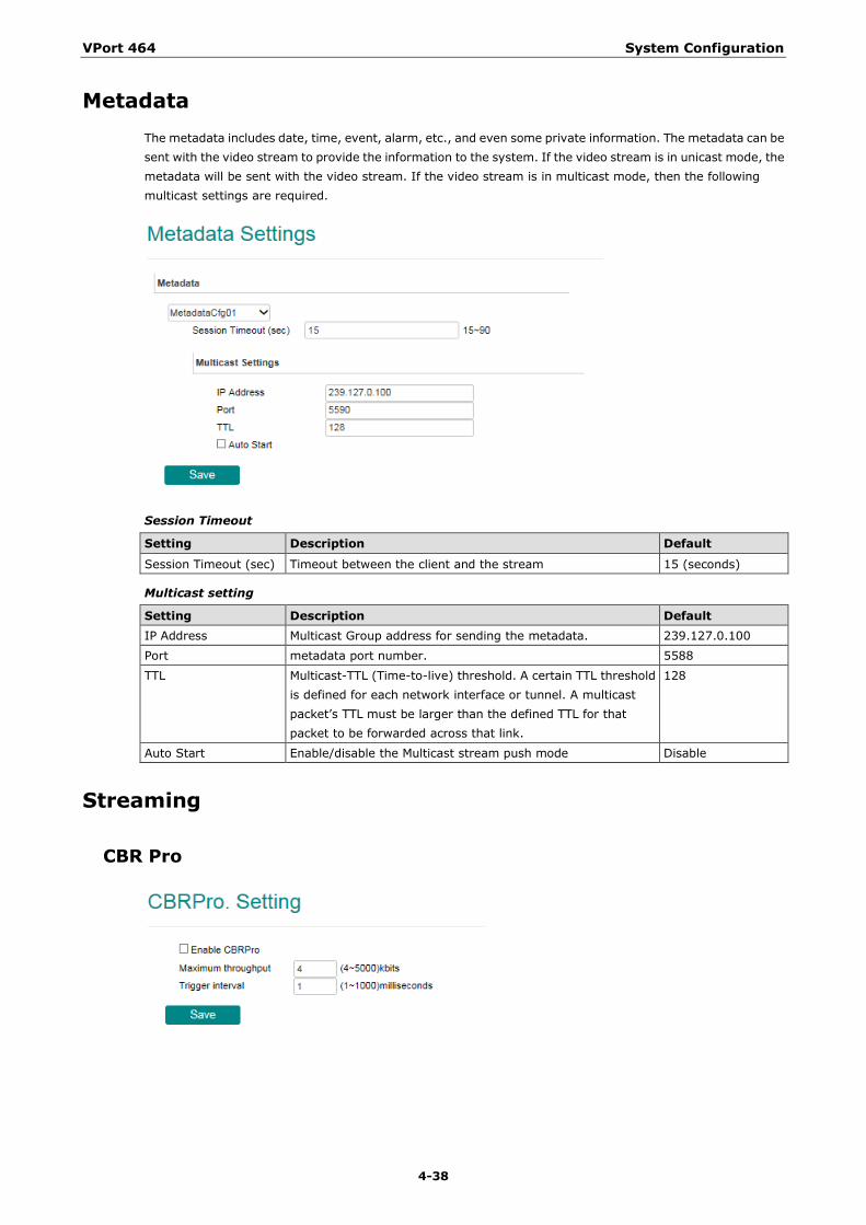
Metadata The metadata includes date, time, event, alarm, etc., and even some private information. The metadata can be sent with the video stream to provide the information to the system. If the video stream is in unicast mode, the metadata will be sent with the video stream. If the video stream is in multicast mode, then the following multicast settings are required.
Session Timeout
Setting Description Default
Session Timeout (sec) Timeout between the client and the stream 15 (seconds)
Multicast setting
Setting Description Default IP Address Multicast Group address for sending the metadata. 239.127.0.100
Port metadata port number. 5588
TTL Multicast-TTL (Time-to-live) threshold. A certain TTL threshold is defined for each network interface or tunnel. A multicast packet’s TTL must be larger than the defined TTL for that packet to be forwarded across that link.
128
Auto Start Enable/disable the Multicast stream push mode Disable
Streaming
CBR Pro
VPort 464 System Configuration
4-39
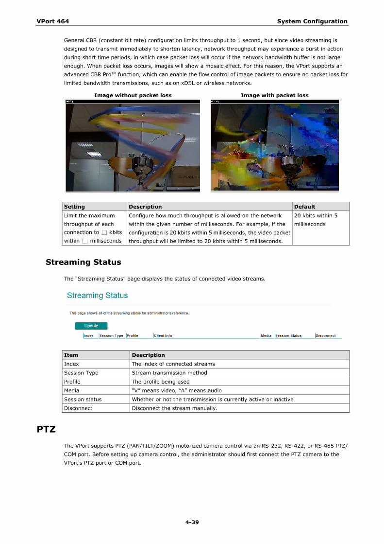
General CBR (constant bit rate) configuration limits throughput to 1 second, but since video streaming is designed to transmit immediately to shorten latency, network throughput may experience a burst in action during short time periods, in which case packet loss will occur if the network bandwidth buffer is not large enough. When packet loss occurs, images will show a mosaic effect. For this reason, the VPort supports an advanced CBR Pro™ function, which can enable the flow control of image packets to ensure no packet loss for limited bandwidth transmissions, such as on xDSL or wireless networks.
Image without packet loss Image with packet loss
Setting Description Default Limit the maximum throughput of each connection to □ kbits within □ milliseconds
Configure how much throughput is allowed on the network within the given number of milliseconds. For example, if the configuration is 20 kbits within 5 milliseconds, the video packet throughput will be limited to 20 kbits within 5 milliseconds.
20 kbits within 5 milliseconds
Streaming Status
The “Streaming Status” page displays the status of connected video streams.
Item Description Index The index of connected streams
Session Type Stream transmission method
Profile The profile being used
Media “V” means video, “A” means audio
Session status Whether or not the transmission is currently active or inactive
Disconnect Disconnect the stream manually.
PTZ The VPort supports PTZ (PAN/TILT/ZOOM) motorized camera control via an RS-232, RS-422, or RS-485 PTZ/ COM port. Before setting up camera control, the administrator should first connect the PTZ camera to the VPort's PTZ port or COM port.
VPort 464 System Configuration
4-40
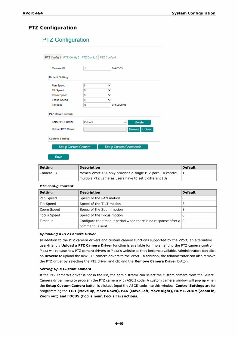
PTZ Configuration
Setting Description Default Camera ID Moxa’s VPort 464 only provides a single PTZ port. To control
multiple PTZ cameras users have to set c different IDs 1
PTZ config content
Setting Description Default
Pan Speed Speed of the PAN motion 8
Tilt Speed Speed of the TILT motion 8
Zoom Speed Speed of the Zoom motion 8
Focus Speed Speed of the Focus motion 8
Timeout Configure the timeout period when there is no response after a command is sent
0
Uploading a PTZ Camera Driver
In addition to the PTZ camera drivers and custom camera functions supported by the VPort, an alternative user-friendly Upload a PTZ Camera Driver function is available for implementing the PTZ camera control. Moxa will release new PTZ camera drivers to Moxa’s website as they become available. Administrators can click on Browse to upload the new PTZ camera drivers to the VPort. In addition, the administrator can also remove the PTZ driver by selecting the PTZ driver and clicking the Remove Camera Driver button.
Setting Up a Custom Camera
If the PTZ camera’s driver is not in the list, the administrator can select the custom camera from the Select Camera driver menu to program the PTZ camera with ASCII code. A custom camera window will pop up when the Setup Custom Camera button is clicked. Input the ASCII code into this window. Control Settings are for programming the TILT (Move Up, Move Down), PAN (Move Left, Move Right), HOME, ZOOM (Zoom in, Zoom out) and FOCUS (Focus near, Focus Far) actions.
VPort 464 System Configuration
4-41
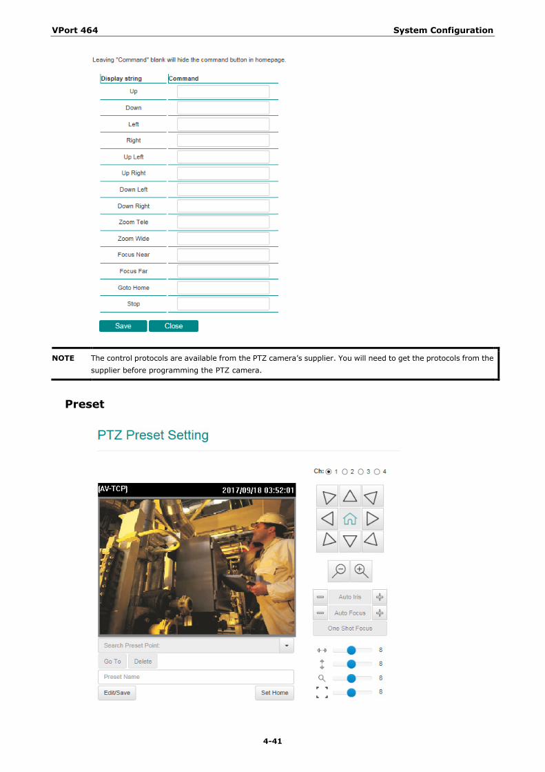
NOTE The control protocols are available from the PTZ camera’s supplier. You will need to get the protocols from the supplier before programming the PTZ camera.
Preset
VPort 464 System Configuration
4-42
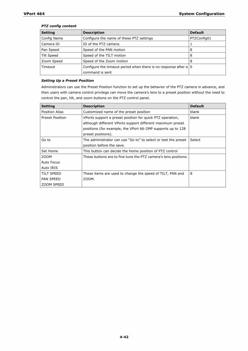
PTZ config content
Setting Description Default Config Name Configure the name of these PTZ settings PTZConfig01
Camera ID ID of the PTZ camera. 1
Pan Speed Speed of the PAN motion 8
Tilt Speed Speed of the TILT motion 8
Zoom Speed Speed of the Zoom motion 8
Timeout Configure the timeout period when there is no response after a command is sent
0
Setting Up a Preset Position
Administrators can use the Preset Position function to set up the behavior of the PTZ camera in advance, and then users with camera control privilege can move the camera’s lens to a preset position without the need to control the pan, tilt, and zoom buttons on the PTZ control panel.
Setting Description Default Position Alias Customized name of the preset position blank
Preset Position VPorts support a preset position for quick PTZ operation, although different VPorts support different maximum preset positions (for example, the VPort 66-2MP supports up to 128 preset positions).
blank
Go to The administrator can use “Go to” to select or test the preset position before the save.
Select
Set Home This button can decide the Home position of PTZ control
ZOOM Auto Focus Auto IRIS
These buttons are to fine tune the PTZ camera’s lens positions.
TILT SPEED PAN SPEED ZOOM SPEED
These items are used to change the speed of TILT, PAN and ZOOM.
8
VPort 464 System Configuration
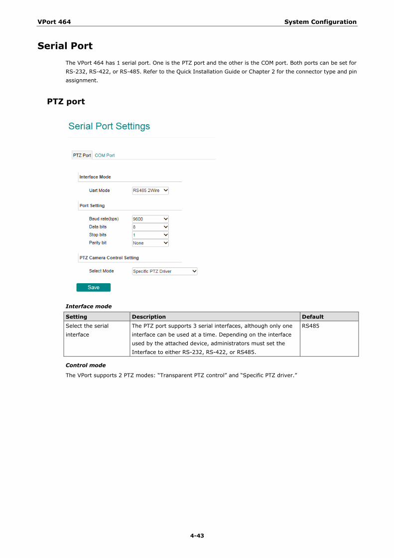
4-43
Serial Port The VPort 464 has 1 serial port. One is the PTZ port and the other is the COM port. Both ports can be set for RS-232, RS-422, or RS-485. Refer to the Quick Installation Guide or Chapter 2 for the connector type and pin assignment.
PTZ port
Interface mode
Setting Description Default Select the serial interface
The PTZ port supports 3 serial interfaces, although only one interface can be used at a time. Depending on the interface used by the attached device, administrators must set the Interface to either RS-232, RS-422, or RS485.
RS485
Control mode
The VPort supports 2 PTZ modes: “Transparent PTZ control” and “Specific PTZ driver.”
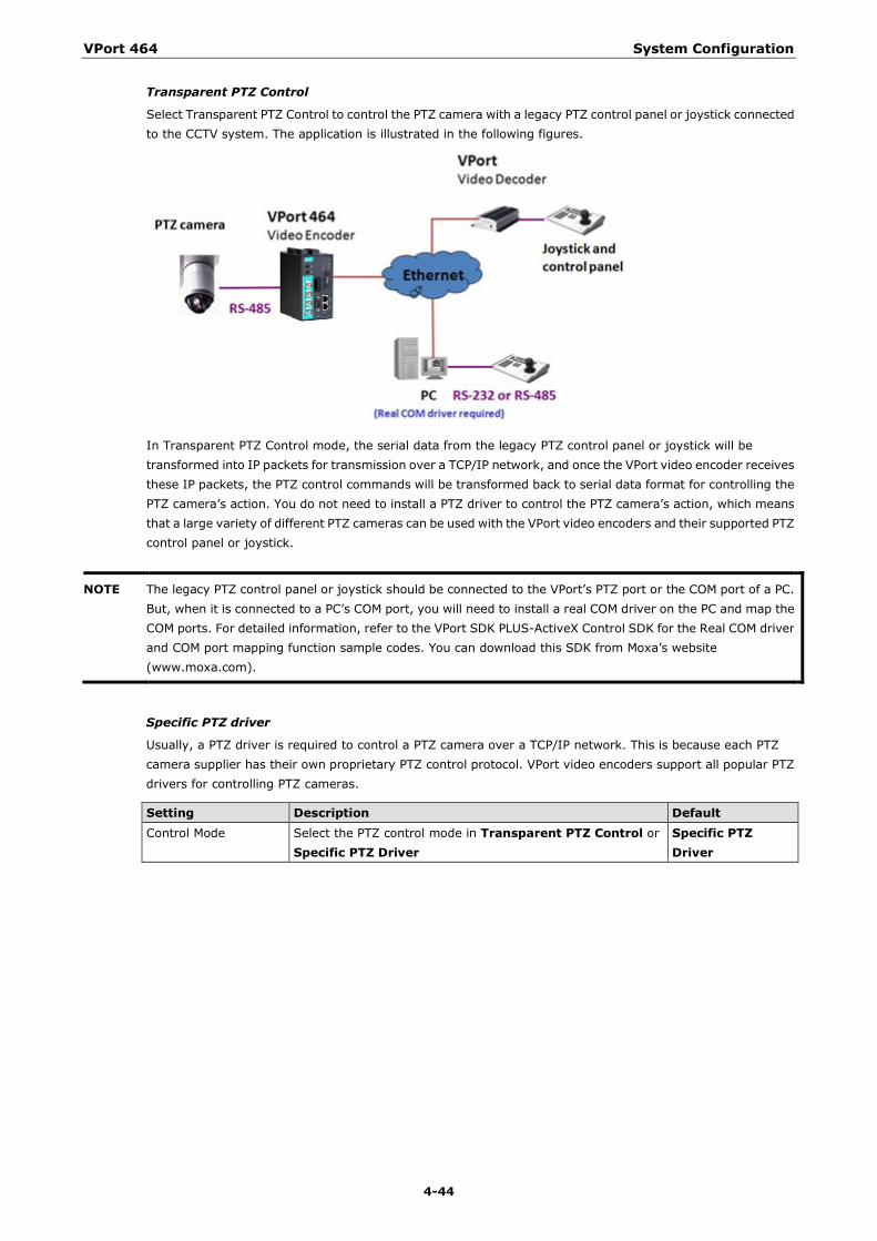
VPort 464 System Configuration
4-44
Transparent PTZ Control
Select Transparent PTZ Control to control the PTZ camera with a legacy PTZ control panel or joystick connected to the CCTV system. The application is illustrated in the following figures.
In Transparent PTZ Control mode, the serial data from the legacy PTZ control panel or joystick will be transformed into IP packets for transmission over a TCP/IP network, and once the VPort video encoder receives these IP packets, the PTZ control commands will be transformed back to serial data format for controlling the PTZ camera’s action. You do not need to install a PTZ driver to control the PTZ camera’s action, which means that a large variety of different PTZ cameras can be used with the VPort video encoders and their supported PTZ control panel or joystick.
NOTE The legacy PTZ control panel or joystick should be connected to the VPort’s PTZ port or the COM port of a PC. But, when it is connected to a PC’s COM port, you will need to install a real COM driver on the PC and map the COM ports. For detailed information, refer to the VPort SDK PLUS-ActiveX Control SDK for the Real COM driver and COM port mapping function sample codes. You can download this SDK from Moxa’s website (www.moxa.com).
Specific PTZ driver
Usually, a PTZ driver is required to control a PTZ camera over a TCP/IP network. This is because each PTZ camera supplier has their own proprietary PTZ control protocol. VPort video encoders support all popular PTZ drivers for controlling PTZ cameras.
Setting Description Default Control Mode Select the PTZ control mode in Transparent PTZ Control or
Specific PTZ Driver Specific PTZ Driver
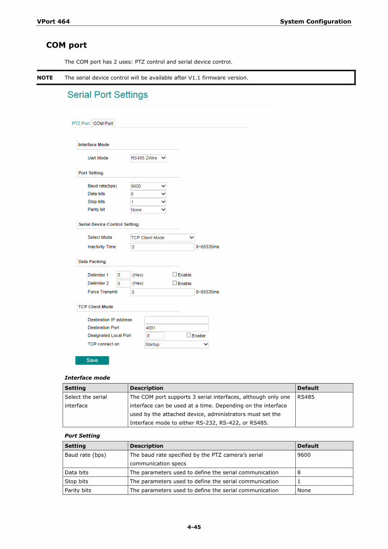
VPort 464 System Configuration
4-45
COM port
The COM port has 2 uses: PTZ control and serial device control.
NOTE The serial device control will be available after V1.1 firmware version.
Interface mode
Setting Description Default Select the serial interface
The COM port supports 3 serial interfaces, although only one interface can be used at a time. Depending on the interface used by the attached device, administrators must set the Interface mode to either RS-232, RS-422, or RS485.
RS485
Port Setting
Setting Description Default Baud rate (bps) The baud rate specified by the PTZ camera’s serial
communication specs 9600
Data bits The parameters used to define the serial communication 8
Stop bits The parameters used to define the serial communication 1
Parity bits The parameters used to define the serial communication None
VPort 464 System Configuration
4-46
NOTE These VPort COM port operation modes only support one connection at the same time.
NOTE For more information on serial-to-Ethernet communications, refer to Moxa’s NPort Device Server products.
Serial Device Control Setting
Setting Description Default Operation Mode Select the serial device control operation modes via the TCP/IP
network: TCP Server Mode, TCP Client Mode TCP Server mode
Inactivity time The VPort automatically closes the TCP connection if there is no serial data activity for the specified time (0 to 65535 milliseconds). Set the time interval to 0 to disable this feature. After the connection is closed, the VPort starts listening for another host’s TCP connection.
0
The VPort supports 2 operation modes when using serial device control mode over a TCP/IP network: TCP Server Mode and TCP Client Mode.
TCP Server Mode
In TCP Server mode, the VPort provides a unique IP: Port address on a TCP/IP network. The VPort waits passively to be contacted by the host computer, allowing the host computer to establish a connection with and get data from the serial device.
TCP Client Mode
In TCP Client mode, the VPort actively establishes a TCP connection to a pre-defined host computer when serial data arrives. After the data has been transferred, the VPort can automatically disconnect from the host computer by using the TCP alive check time or Inactivity timeout settings.
Data Packing
Setting Description Default Delimiter 1 Delimiter 2
Once the VPort receives both delimiters through its serial port, it immediately packs all data currently in its buffer and sends it to the VPort’s Ethernet port. The value of the delimiter can be set from 00 to FF. In addition, both delimiters can be enabled or disabled.
Disable
Force Transmit This parameter defines the time interval during which the VPort fetches the serial data from its internal buffer. If data is incoming through the serial port, the VPort stores the data in the internal buffer. The VPort transmits data stored in the buffer via TCP/IP, but only if the internal buffer is full or if the force transmit time interval reaches the time specified under Force Transmit timeout. The time interval can be set between0 and 65535 milliseconds. Set the time interval to 0 to disable force transmit timeout.
0
NOTE Delimiter 2 is optional. If left blank, then Delimiter 1 alone trips clearing of the buffer. If the size of the serial data received is greater than 1 KB, the VPort will automatically pack the data and send it to the Ethernet. However, to use the delimiter function, you must at least enable Delimiter 1. If Delimiter 1 is left blank and Delimiter 2 is enabled, the delimiter function will not work properly.
TCP Server Mode
Setting Description Default Local TCP port The TCP port that the VPort uses to listen to connections, and
that other devices must use to contact the VPort. The setting 4001
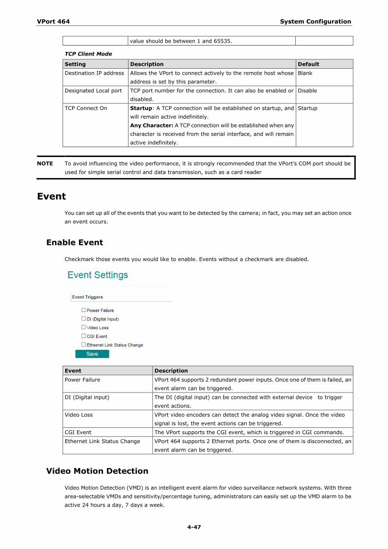
VPort 464 System Configuration
4-47
value should be between 1 and 65535.
TCP Client Mode
Setting Description Default Destination IP address Allows the VPort to connect actively to the remote host whose
address is set by this parameter. Blank
Designated Local port TCP port number for the connection. It can also be enabled or disabled.
Disable
TCP Connect On Startup: A TCP connection will be established on startup, and will remain active indefinitely. Any Character: A TCP connection will be established when any character is received from the serial interface, and will remain active indefinitely.
Startup
NOTE To avoid influencing the video performance, it is strongly recommended that the VPort’s COM port should be used for simple serial control and data transmission, such as a card reader
Event You can set up all of the events that you want to be detected by the camera; in fact, you may set an action once an event occurs.
Enable Event
Checkmark those events you would like to enable. Events without a checkmark are disabled.
Event Description Power Failure VPort 464 supports 2 redundant power inputs. Once one of them is failed, an
event alarm can be triggered.
DI (Digital input) The DI (digital input) can be connected with external device to trigger event actions.
Video Loss VPort video encoders can detect the analog video signal. Once the video signal is lost, the event actions can be triggered.
CGI Event The VPort supports the CGI event, which is triggered in CGI commands.
Ethernet Link Status Change VPort 464 supports 2 Ethernet ports. Once one of them is disconnected, an event alarm can be triggered.
Video Motion Detection
Video Motion Detection (VMD) is an intelligent event alarm for video surveillance network systems. With three area-selectable VMDs and sensitivity/percentage tuning, administrators can easily set up the VMD alarm to be active 24 hours a day, 7 days a week.
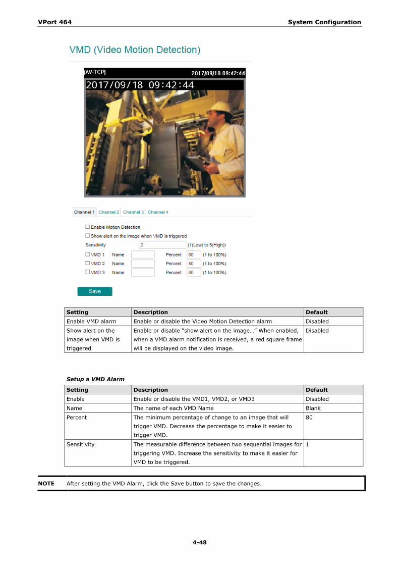
VPort 464 System Configuration
4-48
Setting Description Default Enable VMD alarm Enable or disable the Video Motion Detection alarm Disabled
Show alert on the image when VMD is triggered
Enable or disable “show alert on the image…” When enabled, when a VMD alarm notification is received, a red square frame will be displayed on the video image.
Disabled
Setup a VMD Alarm
Setting Description Default Enable Enable or disable the VMD1, VMD2, or VMD3 Disabled
Name The name of each VMD Name Blank
Percent The minimum percentage of change to an image that will trigger VMD. Decrease the percentage to make it easier to trigger VMD.
80
Sensitivity The measurable difference between two sequential images for triggering VMD. Increase the sensitivity to make it easier for VMD to be triggered.
1
NOTE After setting the VMD Alarm, click the Save button to save the changes.
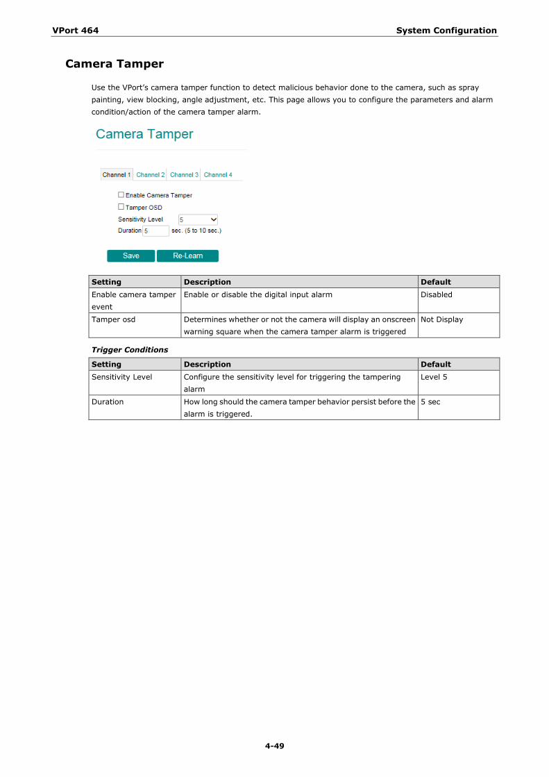
VPort 464 System Configuration
4-49
Camera Tamper
Use the VPort’s camera tamper function to detect malicious behavior done to the camera, such as spray painting, view blocking, angle adjustment, etc. This page allows you to configure the parameters and alarm condition/action of the camera tamper alarm.
Setting Description Default Enable camera tamper event
Enable or disable the digital input alarm Disabled
Tamper osd Determines whether or not the camera will display an onscreen warning square when the camera tamper alarm is triggered
Not Display
Trigger Conditions
Setting Description Default Sensitivity Level Configure the sensitivity level for triggering the tampering
alarm Level 5
Duration How long should the camera tamper behavior persist before the alarm is triggered.
5 sec
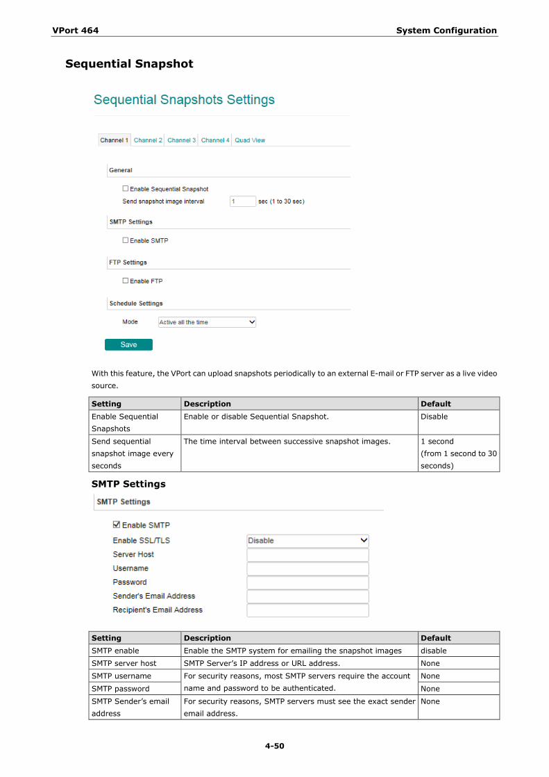
VPort 464 System Configuration
4-50
Sequential Snapshot
With this feature, the VPort can upload snapshots periodically to an external E-mail or FTP server as a live video source.
Setting Description Default Enable Sequential Snapshots
Enable or disable Sequential Snapshot. Disable
Send sequential snapshot image every seconds
The time interval between successive snapshot images. 1 second (from 1 second to 30 seconds)
SMTP Settings
Setting Description Default SMTP enable Enable the SMTP system for emailing the snapshot images disable
SMTP server host SMTP Server’s IP address or URL address. None
SMTP username For security reasons, most SMTP servers require the account name and password to be authenticated.
None
SMTP password None
SMTP Sender’s email address
For security reasons, SMTP servers must see the exact sender email address.
None
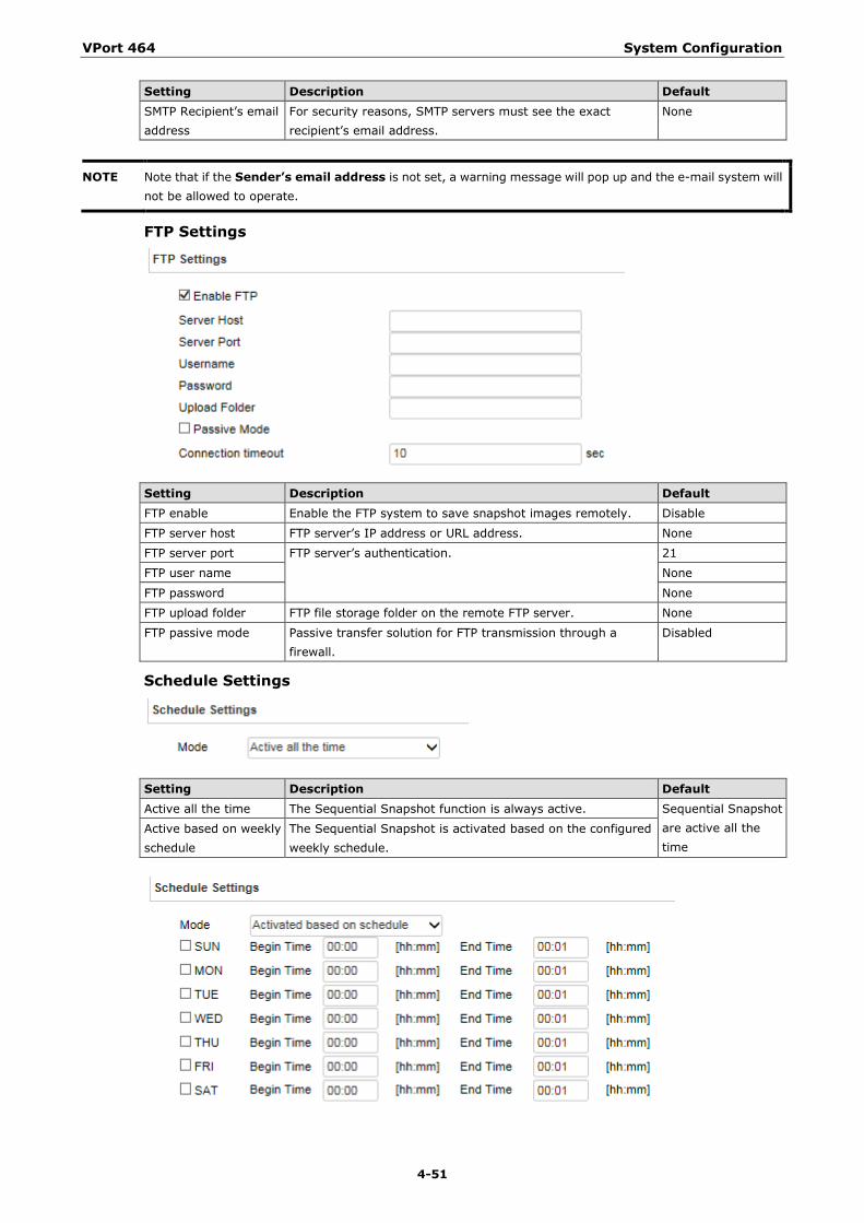
VPort 464 System Configuration
4-51
Setting Description Default SMTP Recipient’s email address
For security reasons, SMTP servers must see the exact recipient’s email address.
None
NOTE Note that if the Sender’s email address is not set, a warning message will pop up and the e-mail system will not be allowed to operate.
FTP Settings
Setting Description Default FTP enable Enable the FTP system to save snapshot images remotely. Disable
FTP server host FTP server’s IP address or URL address. None
FTP server port FTP server’s authentication. 21
FTP user name None
FTP password None
FTP upload folder FTP file storage folder on the remote FTP server. None
FTP passive mode Passive transfer solution for FTP transmission through a firewall.
Disabled
Schedule Settings
Setting Description Default Active all the time The Sequential Snapshot function is always active. Sequential Snapshot
are active all the time
Active based on weekly schedule
The Sequential Snapshot is activated based on the configured weekly schedule.
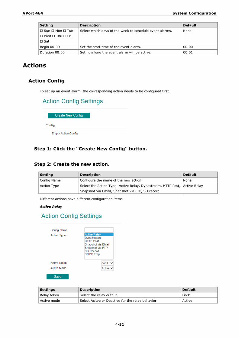
VPort 464 System Configuration
4-52
Setting Description Default Sun Mon Tue Wed Thu Fri Sat
Select which days of the week to schedule event alarms. None
Begin 00:00 Set the start time of the event alarm. 00:00
Duration 00:00 Set how long the event alarm will be active. 00:01
Actions
Action Config
To set up an event alarm, the corresponding action needs to be configured first.
Step 1: Click the “Create New Config” button.
Step 2: Create the new action.
Setting Description Default Config Name Configure the name of the new action None
Action Type Select the Action Type: Active Relay, Dynastream, HTTP Post, Snapshot via Email, Snapshot via FTP, SD record
Active Relay
Different actions have different configuration items.
Active Relay
Settings Description Default Relay token Select the relay output Do01
Active mode Select Acitve or Deactive for the relay behavior Active
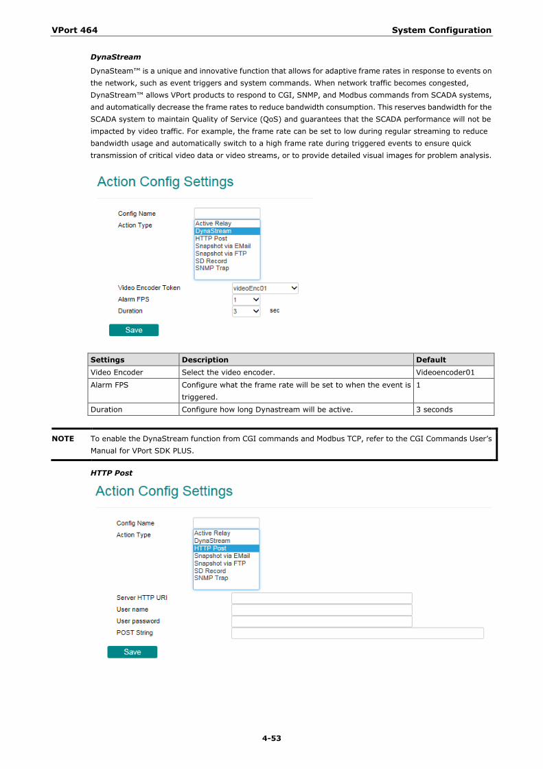
VPort 464 System Configuration
4-53
DynaStream
DynaSteam™ is a unique and innovative function that allows for adaptive frame rates in response to events on the network, such as event triggers and system commands. When network traffic becomes congested, DynaStream™ allows VPort products to respond to CGI, SNMP, and Modbus commands from SCADA systems, and automatically decrease the frame rates to reduce bandwidth consumption. This reserves bandwidth for the SCADA system to maintain Quality of Service (QoS) and guarantees that the SCADA performance will not be impacted by video traffic. For example, the frame rate can be set to low during regular streaming to reduce bandwidth usage and automatically switch to a high frame rate during triggered events to ensure quick transmission of critical video data or video streams, or to provide detailed visual images for problem analysis.
Settings Description Default Video Encoder Select the video encoder. Videoencoder01
Alarm FPS Configure what the frame rate will be set to when the event is triggered.
1
Duration Configure how long Dynastream will be active. 3 seconds
NOTE To enable the DynaStream function from CGI commands and Modbus TCP, refer to the CGI Commands User’s Manual for VPort SDK PLUS.
HTTP Post
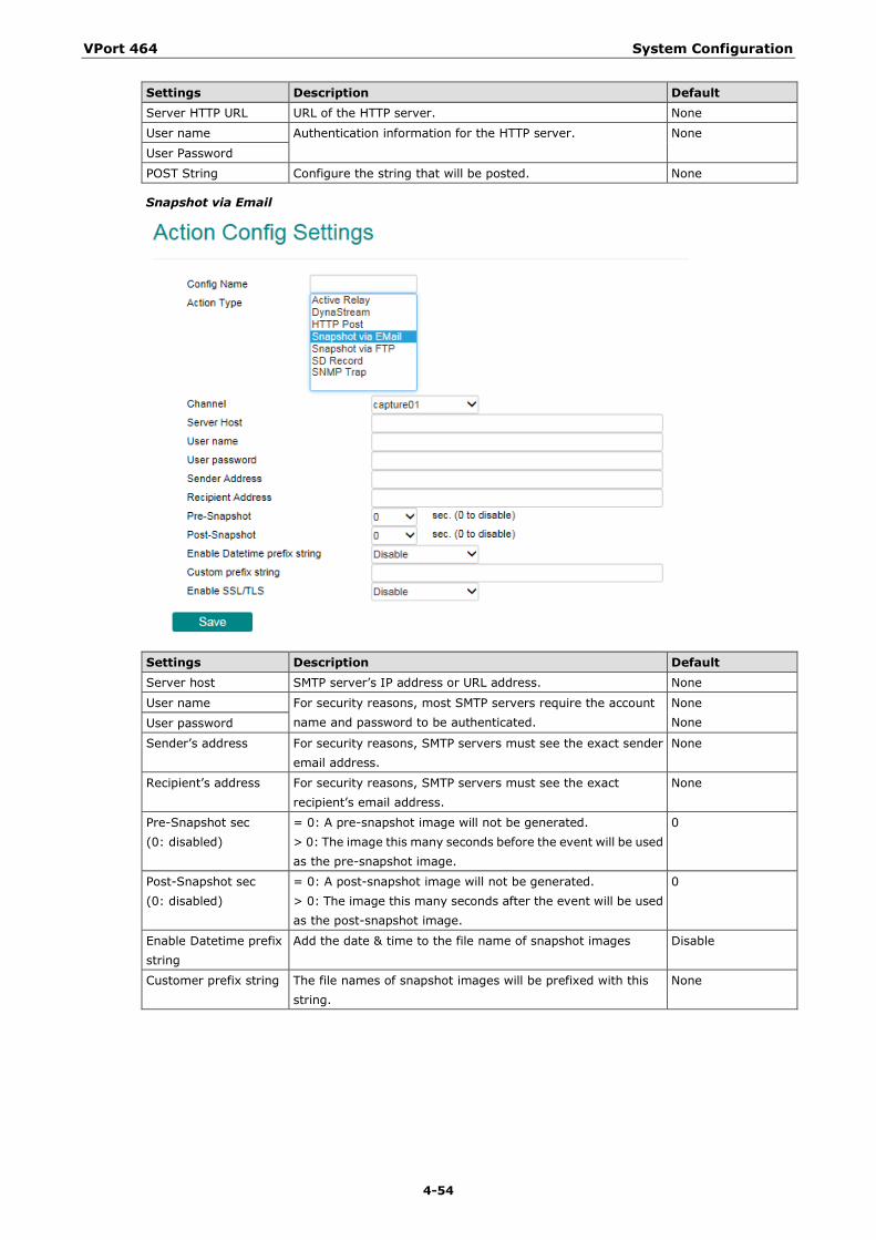
VPort 464 System Configuration
4-54
Settings Description Default Server HTTP URL URL of the HTTP server. None
User name Authentication information for the HTTP server. None
User Password
POST String Configure the string that will be posted. None
Snapshot via Email
Settings Description Default Server host SMTP server’s IP address or URL address. None
User name For security reasons, most SMTP servers require the account name and password to be authenticated.
None None User password
Sender’s address For security reasons, SMTP servers must see the exact sender email address.
None
Recipient’s address For security reasons, SMTP servers must see the exact recipient’s email address.
None
Pre-Snapshot sec (0: disabled)
= 0: A pre-snapshot image will not be generated. > 0: The image this many seconds before the event will be used as the pre-snapshot image.
0
Post-Snapshot sec (0: disabled)
= 0: A post-snapshot image will not be generated. > 0: The image this many seconds after the event will be used as the post-snapshot image.
0
Enable Datetime prefix string
Add the date & time to the file name of snapshot images Disable
Customer prefix string The file names of snapshot images will be prefixed with this string.
None
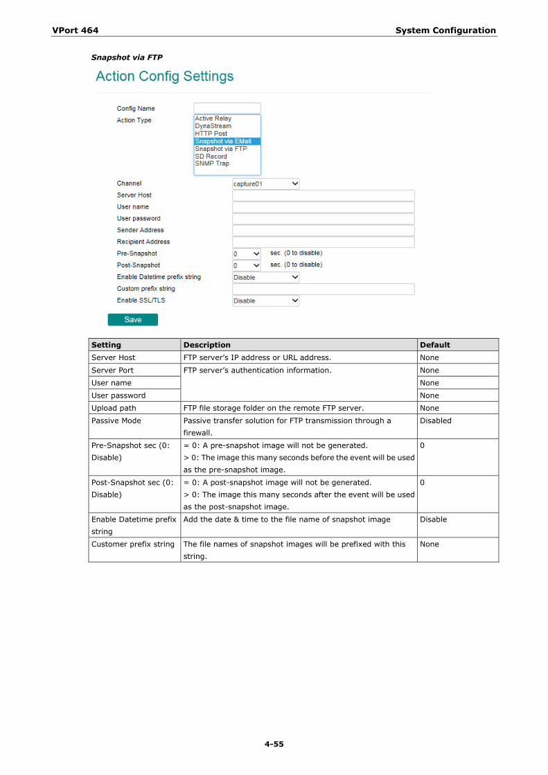
VPort 464 System Configuration
4-55
Snapshot via FTP
Setting Description Default Server Host FTP server’s IP address or URL address. None
Server Port FTP server’s authentication information. None
User name None
User password None
Upload path FTP file storage folder on the remote FTP server. None
Passive Mode Passive transfer solution for FTP transmission through a firewall.
Disabled
Pre-Snapshot sec (0: Disable)
= 0: A pre-snapshot image will not be generated. > 0: The image this many seconds before the event will be used as the pre-snapshot image.
0
Post-Snapshot sec (0: Disable)
= 0: A post-snapshot image will not be generated. > 0: The image this many seconds after the event will be used as the post-snapshot image.
0
Enable Datetime prefix string
Add the date & time to the file name of snapshot image Disable
Customer prefix string The file names of snapshot images will be prefixed with this string.
None
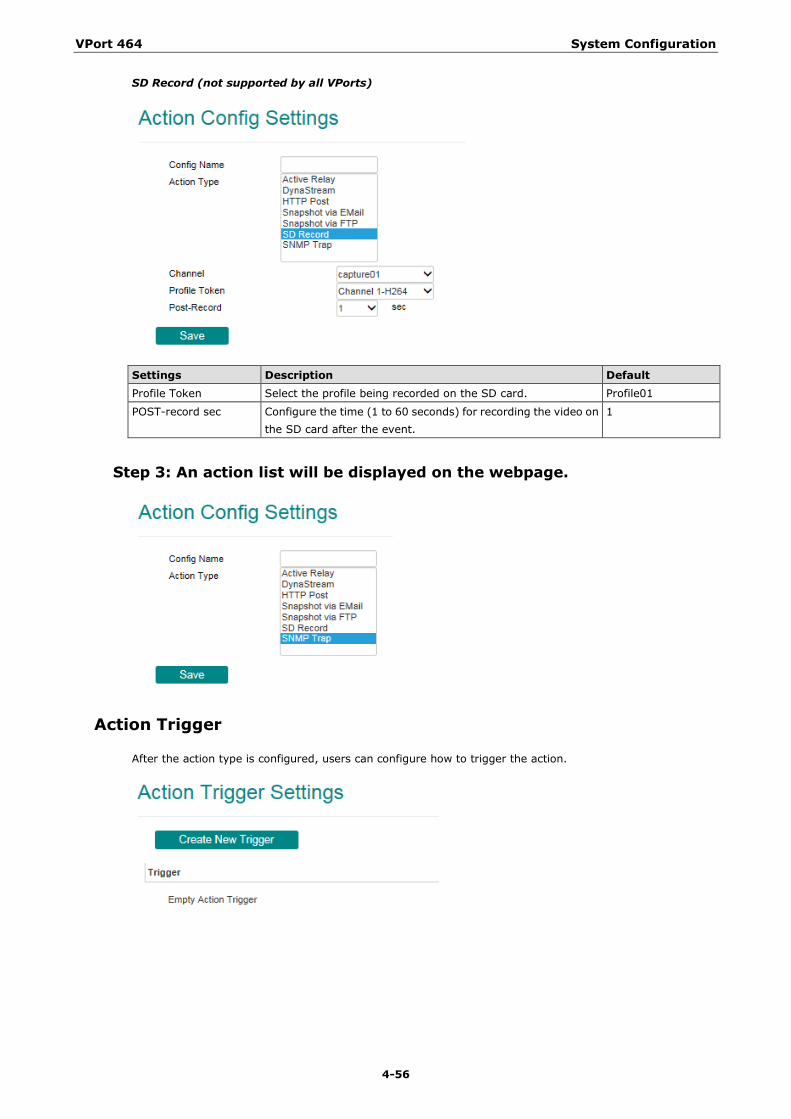
VPort 464 System Configuration
4-56
SD Record (not supported by all VPorts)
Settings Description Default Profile Token Select the profile being recorded on the SD card. Profile01
POST-record sec Configure the time (1 to 60 seconds) for recording the video on the SD card after the event.
1
Step 3: An action list will be displayed on the webpage.
Action Trigger
After the action type is configured, users can configure how to trigger the action.
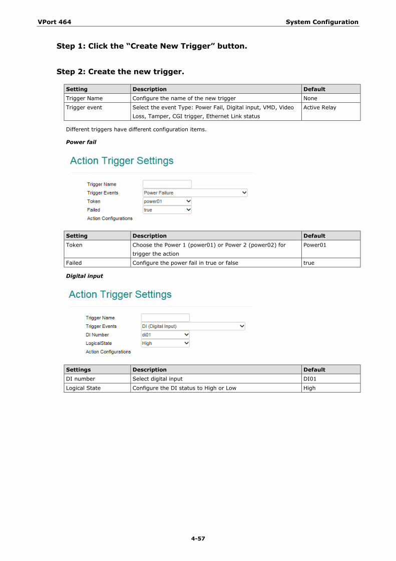
VPort 464 System Configuration
4-57
Step 1: Click the “Create New Trigger” button.
Step 2: Create the new trigger.
Setting Description Default Trigger Name Configure the name of the new trigger None
Trigger event Select the event Type: Power Fail, Digital input, VMD, Video Loss, Tamper, CGI trigger, Ethernet Link status
Active Relay
Different triggers have different configuration items.
Power fail
Setting Description Default Token Choose the Power 1 (power01) or Power 2 (power02) for
trigger the action Power01
Failed Configure the power fail in true or false true
Digital input
Settings Description Default DI number Select digital input DI01
Logical State Configure the DI status to High or Low High
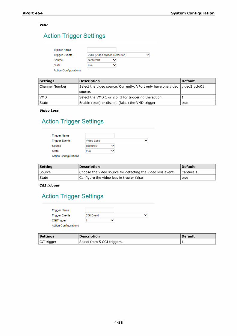
VPort 464 System Configuration
4-58
VMD
Settings Description Default Channel Number Select the video source. Currently, VPort only have one video
source. videoSrccfg01
VMD Select the VMD 1 or 2 or 3 for triggering the action 1
State Enable (true) or disable (false) the VMD trigger true
Video Loss
Setting Description Default Source Choose the video source for detecting the video loss event Capture 1
State Configure the video loss in true or false true
CGI trigger
Settings Description Default CGItrigger Select from 5 CGI triggers. 1
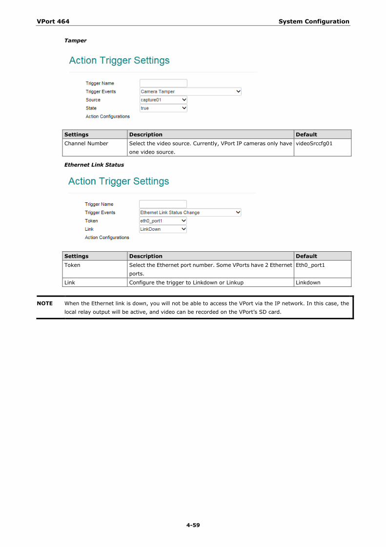
VPort 464 System Configuration
4-59
Tamper
Settings Description Default Channel Number Select the video source. Currently, VPort IP cameras only have
one video source. videoSrccfg01
Ethernet Link Status
Settings Description Default Token Select the Ethernet port number. Some VPorts have 2 Ethernet
ports. Eth0_port1
Link Configure the trigger to Linkdown or Linkup Linkdown
NOTE When the Ethernet link is down, you will not be able to access the VPort via the IP network. In this case, the local relay output will be active, and video can be recorded on the VPort’s SD card.
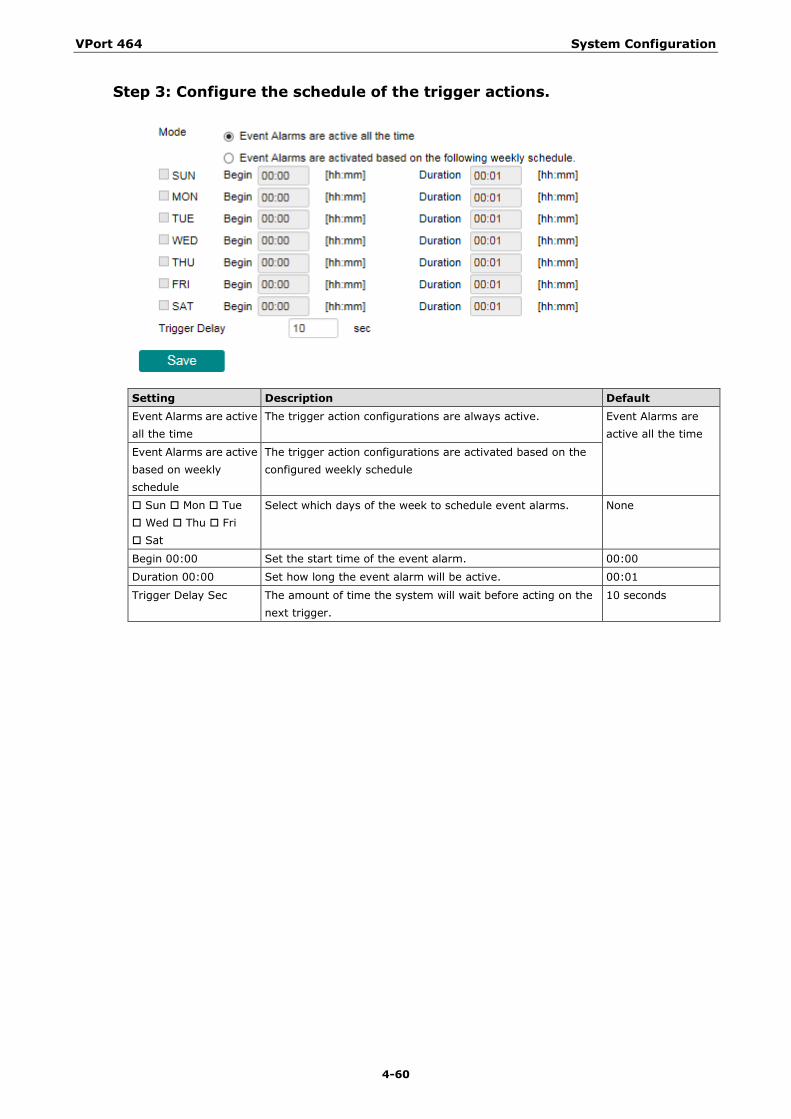
VPort 464 System Configuration
4-60
Step 3: Configure the schedule of the trigger actions.
Setting Description Default Event Alarms are active all the time
The trigger action configurations are always active. Event Alarms are active all the time
Event Alarms are active based on weekly schedule
The trigger action configurations are activated based on the configured weekly schedule
Sun Mon Tue Wed Thu Fri Sat
Select which days of the week to schedule event alarms. None
Begin 00:00 Set the start time of the event alarm. 00:00
Duration 00:00 Set how long the event alarm will be active. 00:01
Trigger Delay Sec The amount of time the system will wait before acting on the next trigger.
10 seconds
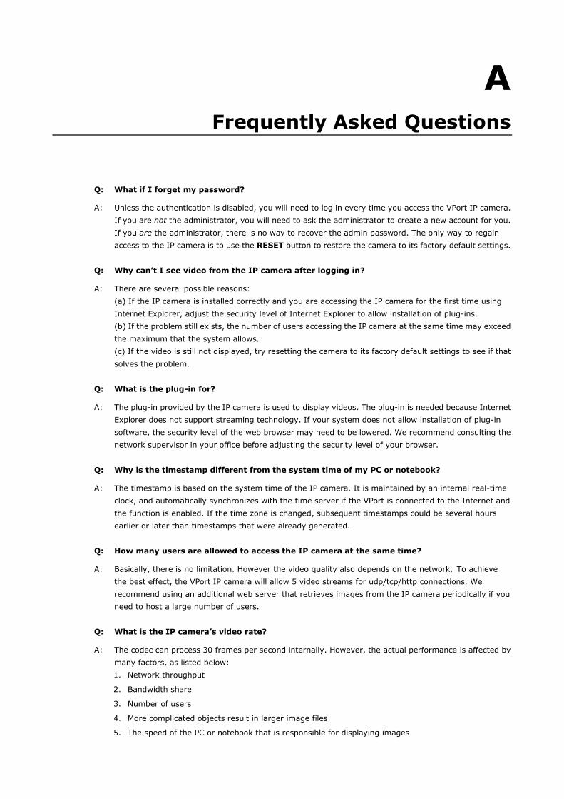
A A. Frequently Asked Questions
Q: What if I forget my password?
A: Unless the authentication is disabled, you will need to log in every time you access the VPort IP camera. If you are not the administrator, you will need to ask the administrator to create a new account for you. If you are the administrator, there is no way to recover the admin password. The only way to regain access to the IP camera is to use the RESET button to restore the camera to its factory default settings.
Q: Why can’t I see video from the IP camera after logging in?
A: There are several possible reasons: (a) If the IP camera is installed correctly and you are accessing the IP camera for the first time using Internet Explorer, adjust the security level of Internet Explorer to allow installation of plug-ins. (b) If the problem still exists, the number of users accessing the IP camera at the same time may exceed the maximum that the system allows. (c) If the video is still not displayed, try resetting the camera to its factory default settings to see if that solves the problem.
Q: What is the plug-in for?
A: The plug-in provided by the IP camera is used to display videos. The plug-in is needed because Internet Explorer does not support streaming technology. If your system does not allow installation of plug-in software, the security level of the web browser may need to be lowered. We recommend consulting the network supervisor in your office before adjusting the security level of your browser.
Q: Why is the timestamp different from the system time of my PC or notebook?
A: The timestamp is based on the system time of the IP camera. It is maintained by an internal real-time clock, and automatically synchronizes with the time server if the VPort is connected to the Internet and the function is enabled. If the time zone is changed, subsequent timestamps could be several hours earlier or later than timestamps that were already generated.
Q: How many users are allowed to access the IP camera at the same time?
A: Basically, there is no limitation. However the video quality also depends on the network. To achieve the best effect, the VPort IP camera will allow 5 video streams for udp/tcp/http connections. We recommend using an additional web server that retrieves images from the IP camera periodically if you need to host a large number of users.
Q: What is the IP camera’s video rate?
A: The codec can process 30 frames per second internally. However, the actual performance is affected by many factors, as listed below: 1. Network throughput
2. Bandwidth share
3. Number of users
4. More complicated objects result in larger image files
5. The speed of the PC or notebook that is responsible for displaying images

VPort 464 Frequently Asked Questions
A-2
Q: How can I keep the IP camera as private as possible?
A: The IP camera is designed for surveillance purposes and has many flexible interfaces. Enabling user authentication during installation can prevent the VPort from being accessed by people without authorization. You may also change the HTTP port to a non-public number. Check the system log to analyze any abnormal activities and trace the origin of the activity.
Q: Why can’t I access the IP camera after activating certain configuration options?
A: When the IP camera is triggered by events, video and snapshots will take more time to write to memory. If the events occur too often, the system will always be busy storing video and images. We recommend using sequential mode or an external recorder program to record video if the event you’re monitoring occurs frequently. If you prefer to retrieve images by FTP, the time could be smaller since an FTP server responds more quickly than a web server. When the system is “too busy to configure” (i.e., it hangs), use the restore factory default and reset button to restart the system.
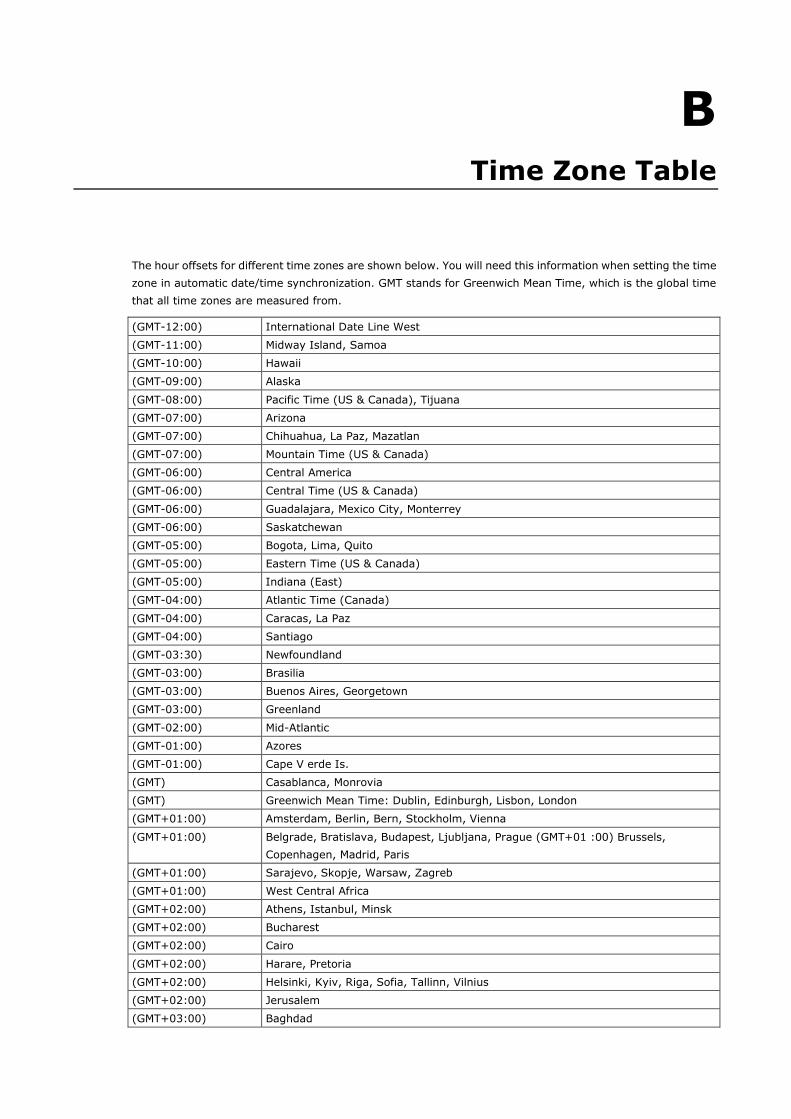
B B. Time Zone Table
The hour offsets for different time zones are shown below. You will need this information when setting the time zone in automatic date/time synchronization. GMT stands for Greenwich Mean Time, which is the global time that all time zones are measured from.
(GMT-12:00) International Date Line West
(GMT-11:00) Midway Island, Samoa
(GMT-10:00) Hawaii
(GMT-09:00) Alaska
(GMT-08:00) Pacific Time (US & Canada), Tijuana
(GMT-07:00) Arizona
(GMT-07:00) Chihuahua, La Paz, Mazatlan
(GMT-07:00) Mountain Time (US & Canada)
(GMT-06:00) Central America
(GMT-06:00) Central Time (US & Canada)
(GMT-06:00) Guadalajara, Mexico City, Monterrey
(GMT-06:00) Saskatchewan
(GMT-05:00) Bogota, Lima, Quito
(GMT-05:00) Eastern Time (US & Canada)
(GMT-05:00) Indiana (East)
(GMT-04:00) Atlantic Time (Canada)
(GMT-04:00) Caracas, La Paz
(GMT-04:00) Santiago
(GMT-03:30) Newfoundland
(GMT-03:00) Brasilia
(GMT-03:00) Buenos Aires, Georgetown
(GMT-03:00) Greenland
(GMT-02:00) Mid-Atlantic
(GMT-01:00) Azores
(GMT-01:00) Cape V erde Is.
(GMT) Casablanca, Monrovia
(GMT) Greenwich Mean Time: Dublin, Edinburgh, Lisbon, London
(GMT+01:00) Amsterdam, Berlin, Bern, Stockholm, Vienna
(GMT+01:00) Belgrade, Bratislava, Budapest, Ljubljana, Prague (GMT+01 :00) Brussels, Copenhagen, Madrid, Paris
(GMT+01:00) Sarajevo, Skopje, Warsaw, Zagreb
(GMT+01:00) West Central Africa
(GMT+02:00) Athens, Istanbul, Minsk
(GMT+02:00) Bucharest
(GMT+02:00) Cairo
(GMT+02:00) Harare, Pretoria
(GMT+02:00) Helsinki, Kyiv, Riga, Sofia, Tallinn, Vilnius
(GMT+02:00) Jerusalem
(GMT+03:00) Baghdad
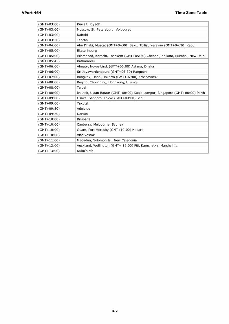
VPort 464 Time Zone Table
B-2
(GMT+03:00) Kuwait, Riyadh
(GMT+03:00) Moscow, St. Petersburg, Volgograd
(GMT+03:00) Nairobi
(GMT+03:30) Tehran
(GMT+04:00) Abu Dhabi, Muscat (GMT+04:00) Baku, Tbilisi, Yerevan (GMT+04:30) Kabul
(GMT+05:00) Ekaterinburg
(GMT+05:00) Islamabad, Karachi, Tashkent (GMT+05:30) Chennai, Kolkata, Mumbai, New Delhi
(GMT+05:45) Kathmandu
(GMT+06:00) Almaty, Novosibirsk (GMT+06:00) Astana, Dhaka
(GMT+06:00) Sri Jayawardenepura (GMT+06:30) Rangoon
(GMT+07:00) Bangkok, Hanoi, Jakarta (GMT+07:00) Krasnoyarsk
(GMT+08:00) Beijing, Chongqing, Hongkong, Urumqi
(GMT+08:00) Taipei
(GMT+08:00) Irkutsk, Ulaan Bataar (GMT+08:00) Kuala Lumpur, Singapore (GMT+08:00) Perth
(GMT+09:00) Osaka, Sapporo, Tokyo (GMT+09:00) Seoul
(GMT+09:00) Yakutsk
(GMT+09:30) Adelaide
(GMT+09:30) Darwin
(GMT+10:00) Brisbane
(GMT+10:00) Canberra, Melbourne, Sydney
(GMT+10:00) Guam, Port Moresby (GMT+10:00) Hobart
(GMT+10:00) Vladivostok
(GMT+11:00) Magadan, Solomon Is., New Caledonia
(GMT+12:00) Auckland, Wellington (GMT+ 12:00) Fiji, Kamchatka, Marshall Is.
(GMT+13:00) Nuku’alofa
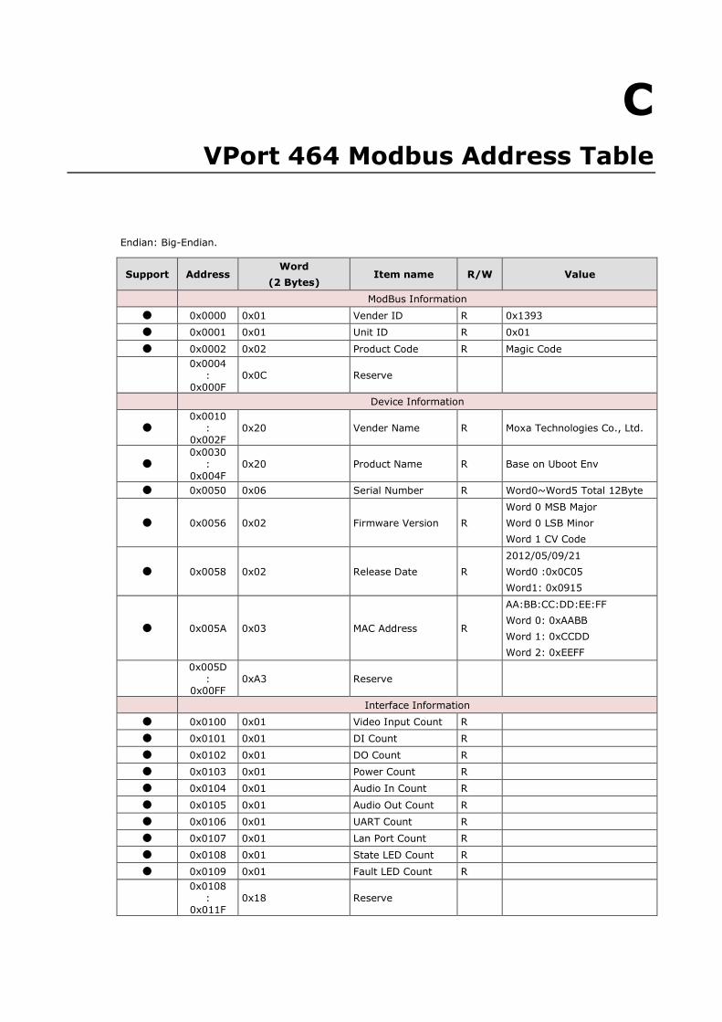
C C. VPort 464 Modbus Address Table
Endian: Big-Endian.
Support Address Word
(2 Bytes) Item name R/W Value
ModBus Information ● 0x0000 0x01 Vender ID R 0x1393 ● 0x0001 0x01 Unit ID R 0x01 ● 0x0002 0x02 Product Code R Magic Code
0x0004
: 0x000F
0x0C Reserve
Device Information
● 0x0010
: 0x002F
0x20 Vender Name R Moxa Technologies Co., Ltd.
● 0x0030
: 0x004F
0x20 Product Name R Base on Uboot Env
● 0x0050 0x06 Serial Number R Word0~Word5 Total 12Byte
● 0x0056 0x02 Firmware Version R Word 0 MSB Major Word 0 LSB Minor Word 1 CV Code
● 0x0058 0x02 Release Date R 2012/05/09/21 Word0 :0x0C05 Word1: 0x0915
● 0x005A 0x03 MAC Address R
AA:BB:CC:DD:EE:FF Word 0: 0xAABB Word 1: 0xCCDD Word 2: 0xEEFF
0x005D
: 0x00FF
0xA3 Reserve
Interface Information ● 0x0100 0x01 Video Input Count R ● 0x0101 0x01 DI Count R ● 0x0102 0x01 DO Count R ● 0x0103 0x01 Power Count R ● 0x0104 0x01 Audio In Count R ● 0x0105 0x01 Audio Out Count R ● 0x0106 0x01 UART Count R ● 0x0107 0x01 Lan Port Count R ● 0x0108 0x01 State LED Count R ● 0x0109 0x01 Fault LED Count R
0x0108
: 0x011F
0x18 Reserve
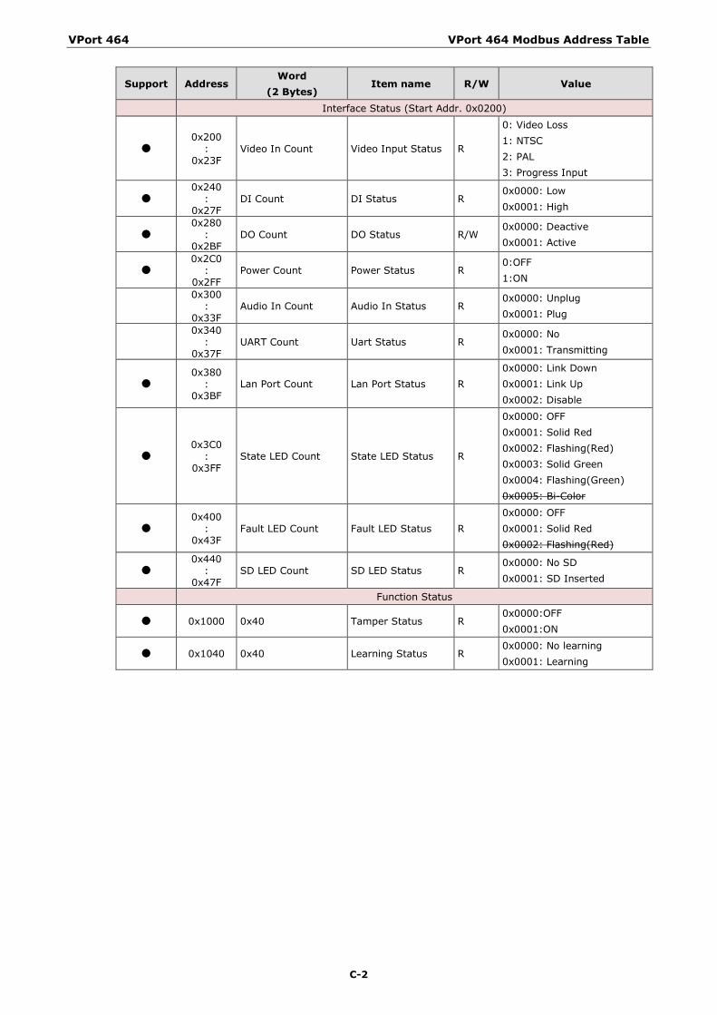
VPort 464 VPort 464 Modbus Address Table
C-2
Support Address Word
(2 Bytes) Item name R/W Value
Interface Status (Start Addr. 0x0200)
● 0x200
: 0x23F
Video In Count Video Input Status R
0: Video Loss 1: NTSC 2: PAL 3: Progress Input
● 0x240
: 0x27F
DI Count DI Status R 0x0000: Low 0x0001: High
● 0x280
: 0x2BF
DO Count DO Status R/W 0x0000: Deactive 0x0001: Active
● 0x2C0
: 0x2FF
Power Count Power Status R 0:OFF 1:ON
0x300
: 0x33F
Audio In Count Audio In Status R 0x0000: Unplug 0x0001: Plug
0x340
: 0x37F
UART Count Uart Status R 0x0000: No 0x0001: Transmitting
● 0x380
: 0x3BF
Lan Port Count Lan Port Status R 0x0000: Link Down 0x0001: Link Up 0x0002: Disable
● 0x3C0
: 0x3FF
State LED Count State LED Status R
0x0000: OFF 0x0001: Solid Red 0x0002: Flashing(Red) 0x0003: Solid Green 0x0004: Flashing(Green) 0x0005: Bi-Color
● 0x400
: 0x43F
Fault LED Count Fault LED Status R 0x0000: OFF 0x0001: Solid Red 0x0002: Flashing(Red)
● 0x440
: 0x47F
SD LED Count SD LED Status R 0x0000: No SD 0x0001: SD Inserted
Function Status
● 0x1000 0x40 Tamper Status R 0x0000:OFF 0x0001:ON
● 0x1040 0x40 Learning Status R 0x0000: No learning 0x0001: Learning


