
Mould tools
John Summerscales

Outline of lecture
• Tool design• Tool materials• Decision matrix• Heating and cooling• Lost cores• Clamping• Ancillary materials and systems

Tool design
•size, complexity and dimensional tolerances•surface finish•thermal expansion, conductivity etc •holes, bosses and ribs •inserts and fasteners •re-entrants/multi-part moulds •number of components to be produced •durability, ease of modification and repairability

Tool materials• Reductive manufacture (CNC machining)
o steel o aluminium o monolithic graphite o syntactic foam (hollow microsphere
composite)
• Additive manufactureo wet lay-up glass reinforced plastics o prepreg carbon fibre composite o electroform nickel (EFN)
• backing structures• Plastech MITTM Multiple Insert Tooling

Pre-preg/EFN tooling
• master
• splash tool
• HT male mandrel/bath master LTM tooling system omits this stage
• Female tool LTM tooling system omits this stage
• Tool with backing structure

Decision matrix: tooling options
Nicholas Tiffin, "Choosing better tooling", Advanced Composites Engineering, Autumn 1988, 18/19.
Note that the following analysis from Tiffin's paper is specific to a CFRP structural fairing
P = PriorityR = RatingV = Value (P*R)

Decision matrix: tooling options
Steel AlWet Lay
Up PrepregEF
Nickel
Critical parameter P R V R V R V R V R V
Dimensional accuracy 10 7 70 6 60 8 80 10 100 8 80
Operating temperatur
e 10 10 100 10 100 7 70 9 90 10 100
Temperature uniformity 9 4 36 5 45 7 63 10 90 10 90
Long tool life 8 10 80 9 72 1 8 8 64 8 64
Short cure cycle 6 3 18 4 24 9 54 9 54 9 54
Tool build time 6 6 36 6 36 9 54 9 54 5 30
TOTA
L 340 337 329 452 418

Trackingbarcodes or RFID insertsmay be attached to mould tools to permit integration,e.g. with resin delivery systems,and automation.

Heating
• fluid in pipes • embedded electrical heaters • ovens and autoclaves
Cooling
• fluid in pipes

Embedded heaters 1
• Thermion fabric
• Gorix ECT
• Plastech cotton/lycra heater cloth
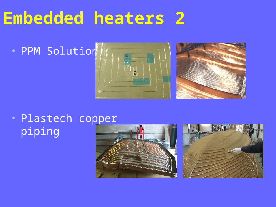
Embedded heaters 2
• PPM Solutions
• Plastech copper piping

Heating performance
20
40
60
80
100
120
140
0 50 100 150 200 250 300 350 400
time (min)
tem
pe
ratu
re (
oC
)
heated tool
oven
Comparison of cure cycle for 11 mm laminate on heated tool and in oven. The two temperature traces in each case are for the opposed laminate faces

Simulated temperature distribution
Steady-state temperature distribution over tool (below) and laminate (above), for fixed heater temperature of 130°C
Model =¼ flat tool(symmetric).

Thermographic monitoringInfrared camera image of an electrically-heated tool-plateshowing hot spots due to wrinkled heater cloth

Thermogram of electrically-heated mould tool 1
tool face during heat-up showing cool spots/lines corresponding to the thermocouple positions/wires and cooler outline at the resin-rich mould cavity lip

Thermogram of electrically-heated mould tool 2
• tool face at target temperature of 90°C showing ~10°C variation across the component

insulated back surface during dwell at 90°C
Thermogram of electrically-heated mould tool 3

Thermogram of electrically-heated mould tool 4
tool back face (GRP side) without insulation showing the resistive heater element spacing (horizontal shading)

Lost cores
• rubber/elastomers [Musch and Bishop] • inflatable mandrels [Musch and Bishop] • low melting point alloys [Haines] • candle or paraffin wax
(melting points typically 50-90ºC) • soluble salts or plaster
(subsequently washed or machined out) • Plastech SmartCore
(granules enclosed in a shaped vacuum bag)

Clamping
• bolts o labour intensive, low pressure
• hydraulic press o capital equipment, good alignment
• vacuum o inexpensive, limit ~1000 mbar, sealing
issues

Ancillary materials and systems
• mould release (coatings and films) • bagging films (1-sided moulds)• breather and bleeder cloths (vacuum
bag) • flow media (infusion) • tacky tape - edge dams - breach units • pressure intensifiers • preforming supports

Acknowledgements
• the respective companies for illustrations of the embedded heaters
• Dr Stephen Grove for the performance graph and simulation
• Dave Nelson of FLIR Systems Limited for wrinkled heater cloth thermograms
• Scott Foster of Metrum Information Storage Limited for skeg thermograms


