
MODELLING AND FABRICATION OF CYLINDER HEAD FOR SINGLE
CYLINDER TWO STROKE ENGINE
ABDUL HADI BIN ABD MAJID
A project report submitted in partial fulfillment of the requirements
for the award of the Diploma of Mechanical Engineeringa
t43WJj j.
t1.0
Faculty of Mechanical Engineering
Universiti Malaysia Pahang
NO\TEMBER 2007

ABSTRACT
Automotive technology is very important to people nowadays. To help them to move
someplace to other place in short time. Automotive technology is very fast growing
because of their needed in human life. The two stroke engine is reciprocating engine
in which the piston takes over any valve functions in order to obtain power stroke
each revolution of the crankshaft. This involves the use of ports in the cylinder walls
which are covered and uncovered by movements of piston. Two stroke engines are
used for motorcycles, lawn mowers, chain saw and marine engine. Cylinder Head is
one of the important parts in engine part. The purpose of The Cylinder Head to cover
the movement of piston from Bottom Dead Centre to Top Dead Centre and also
combustion chamber in The Cylinder Head is very important in combustion process.
A

ABSTRAK
Teknologi Automotif begitu penting dalam kehidupan seharian kita. la
menolong manusia bergerak dari satu tempat ke satu tempat yang lain dalam masa
yang singkat. Teknologi Autornotif mudah berkembang kerana kepentingannya
dalam kehidupan manusia. Enjin dua lejang adalah engine perulangan dimana omboh
menganibil alih f'ungsi injap dimana untuk mengekalkan lejang kuasa pada setiap
pusingan crankshaft. mi melibatkan kegunaan ruang dalam silinder dimana ditutup
dan tidak dilindungi oleh pergerakan omboh. Enjin dua lejang digunakan untuk
motosikal, gergaji rantai dan juga enjin kapal. Cylinder Head adalah salah satu
bahagian yang penting dalam bahagian engine. Kegunaan Cylinder Head adalah
melindungi pergerakan omboh dari puncak tertinggi (TDC) kepada puncak bawah
(BDC) dan juga ruang pembakaran dalain cylinder head untuk proses pembakaran
VII

TABLE OF CONTENTS
CHAPTER TITLE PAGE
PROJECT TITLE
SUPERVISOR DECLARATION
DECLARATION
DEDICATION iv
ACKNOWLEDGEMENT V
ABSTRACT
ABSTRAK vii
TABLE OF CONTENTS viii
LIST OF FIGURES xi
LIST OF TABLES xiv
LIST OF APPENDICES xv
INTRODUCTION I
1.1 Introduction 1
1.2 Problem Statement 2
1.3 Objective of Project 2
1.4 Scope of The Project 2
1.5 Project Organization 2
1.6 Author's Contribution 3
VII'
ix
2
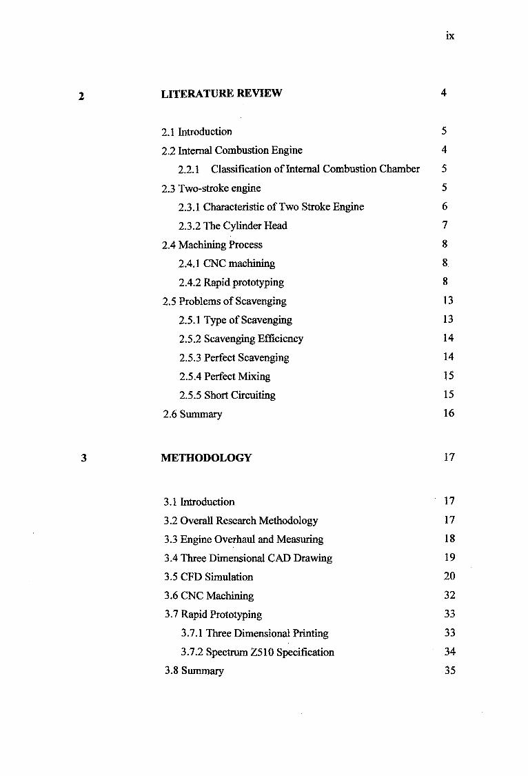
LITERATURE REVIEW 4
2.1 Introduction 5
2.2 Internal Combustion Engine 4
2.2.1 Classification of Internal Combustion Chamber 5
2.3 Two-stroke engine 5
2.3.1 Characteristic of Two Stroke Engine 6
2.3.2 The Cylinder Head 7
2.4 Machining Process 8
2.4.1 CNC machining 8.
2.4.2 Rapid prototyping 8
2.5 Problems of Scavenging 13
2.5.1 Type of Scavenging 13
2.5.2 Scavenging Efficiency 14
2.5.3 Perfect Scavenging 14
2.5.4 Perfect Mixing 15
2.5.5 Short Circuiting 15
2.6 Summary 16
3 METHODOLOGY 17
3.1 Introduction 17
3.2 Overall Research Methodology 17
3.3 Engine Overhaul and Measuring 18
3.4 Three Dimensional CAD Drawing 19
3.5 CFD Simulation 20
3.6 CNC Machining 32
3.7 Rapid Prototyping 33
3.7.1 Three Dimensional Printing 33
3.7.2 Spectrum Z510 Specification 34
3.8 Summary 35

x
4 RESULT AND DISCUSSION 36
4.1 Introduction 36
4.2 Solid Work Result 36
4.3 Flow Analysis Result 37
4.3.1 Result For Inlet Mass Flow 0.03 37
4.3.2 Result For Inlet Mass Flow. 0.3 39
4.3.3 Result For Inlet Mass Flow 0.5 40
4.4 Domain Analysis 42
4.5 Fabrication Result 43
4.6 Conclusion 43
5 CONCLUSION AND RECOMMENDATIONS 44
5.1 Introduction 44
5.2 Conclusion 44
5.3 Future Works 45
5.4 Summary 45
REFERENCES 46
APPENDICES

LIST OF FIGURES
FIGURE NO. TITLE PAGE
2.1 The classification of internal
combustion engine 5
2.2 Additive process 11
2.3 The steps for investing casting that
used rapid prototyping wax 12
2.4 Theoretical scavenging process 15
3.1 Flowchart 18
3.2 The original cylinder head 19
3.3 The vernier caliper 19
3.4 Three dimensional drawing of
cylinder head 20
3.5 Three dimensional drawing of
cylinder head 20
3.6 Project wizard 21
3.7 Unit wizard 21
3.8 Fluid type and physical feature wizard 22
3.9 Analysis type wizard 22
3.10 Roughness wizard 23
3.11 Fluid substances wizard 23
xi

xli
3.12 Default wall condition wizard 24
3.13 Initial and ambient conditions wizard 24
3.14 Result resolutions and geometry
resolution wizard 25
3.15 Cosmos flow tree toolbar 26
3.16 Selection of boundary condition 26
3.17 The selection of boundary codition
for flow opening 26
3.18 Selection for second boundary condition 27
3.19 Selection of boundary condition for
pressure opening 27
3.20 Selection of surface goal 28
3.21 Run toolbar 28
3.22 Solver monitor 29
3.23 Three dimensional mesh toolbar 29
3.24 Three dimensional mesh 30
3.25 Cut plot toolbar 31
3.26 Surface plot toolbar 31
3.27 Flow trajectory toolbar 32
3.28 Simulation of cutting process using
masteream software 33
3.29 Spectrum Z510 34
3.30 Three dimensional printing process 35
4.1 Three dimensional computer aided
design (CAD) drawing 36

xlii
4.2 Solver result for inlet mass flow 0.03kg/s 37
4.3 Surface plot result for inlet mass
flow 0.03kg/s 38
4.4 Flow trajectory result for inlet mass
flow 0.3kg/s 38
4.5 Solver result for inlet mass flow0.3kg/s 39
4.6 Surface plot result for inlet mass
flow 0.3kg/s 39
4.7 Flow trajectory result for inlet mass
flow 0.3kg/s 40
4.8 Solver result for inlet mass flow0.5kg/s 40
4.9 Surface plot result for inlet mass
flow 0.5kg/s 41
4.10 Flow trajectory result for inlet mass
flow 0.5kg/s 41
4.11 Domain analysis 42
4.12 Three dimensional printing result 43

LIST OF TABLES
TABLE NO. TITLE PAGE
2.1 The characteristic of rapid prototyping
technologies
2.2 Types of scavenging 13
xiv
CHAPTER 1
INTRODUCTION
1.1 Introduction
This project title is modelling and fabrication of cylinder head for single
cylinder two stroke engines. First of all, two stroke engine is a simple and light
engine that piston takes over valve function in operating cycle. It is used for
lightweight power units which can be employed in various attitudes as handheld
power tools [5].It is different from four strokes that had valves to control air flow in
operating cycle. Two-stroke engine was develop since 1876, in 1900 there were
engineers develop this engine with special emphasis on the various solution proposed
for improving gas exchange process [1]. The first two stroke engine for marine was
use in 1905, this engine employed uniflow scavenging with scavenge air valves in
cylinder head and exhaust ports in the lower part of the liner [1]. The characteristic
of two-stroke cycle engine are one power stroke per revolution, scavenging with
fresh charge, direct fuel injection, emissions and addition lubricating. Two-stroke
cycle can be used with both spark-ignition and compression-ignition. Common
applications are where weight low, small bulk, simple construction and high power
output are the prime consideration [1]. For the information, the largest and the
smallest internal combustion engines today are two-stroke cycle engine. There are
some example of special applications, free-piston compressor engines, gas producers
and pulse-jet engine [1]. The cylinder head is made of cast iron or aluminium and it
is strong to distribute the gas forces acting on the head as uniformly as possible
through the engine block [2]. It is also contains spark plug for SI engine or fuel
injector for CI engine.

2
1.2 Problem Statement
Mostly the cylinder head was made by casting process. This project is to
produce the cylinder head by using Rapid Prototyping
1.3 Objective of Project
The main objective of this project is to fabricate a cylinder head for single
cylinder 30.5 cc two stroke spark-ignition (Si) engines.
1.4 Scope of Project
There are four scopes in this project:
i) Reverse engineering.
ii) Three dimension Computer Aided Design (CAD) modelling of original
production cylinder head which is design the original cylinder head using
CAD method that is Solid Work Software.
iii) Simplify the design by just maintaining the key dimension such as clearance
volume, port dimension, and spark plug location in accordance of machining
capabilities.
iv) Fabricating the simplified model cylinder head using Rapid Protolyping
1.4 Project Organization
Chapter 2: Find literature about the basic component of two stroke engines, operating
cycle of two stroke engine and advantage and problem of two stroke engines. This
chapter is about the theory of two stroke engine.

3
Chapter 3: First work in this chapter is drawing the original cylinder head and then
simplifies complex geometry of cylinder head. Then simulate the drawing using
Cosmos Flow Software. After transfer drawing to G-code using Master Cam
Software then machining process is begin. CNC Milling Machine is used for this
process, machine simulator calculate machining time and machine running till
cylinder head is produce.
Chapter 4: The results provide detailed information on results and discussion on this
project which are the prediction of internal flow. Result also from machining process
or rapid prototyping
Chapter 5: Summaries the result and provides conclusions of the present work.
Recommendations for further works are also presented in this chapter.
1.5 Author's Contribution
Three dimensional modelling was developed using Computer Aided Design
(CAD) Software. Introduce the step of in-cylinder flow analysis was predicted by
Cosmos Flow Software. Machining process for cylinder head is using Computer
Numerical Control (CNC) Milling or Rapid Prototyping.

CHAPTER 2
LITERATURE REVIEW
2.1 Introduction
This chapter concludes about general internal combustion engine, two-stroke
engine characteristic and application then about machining process and also problem
of scavenging.
2.2 Internal Combustion Engine
The purpose of internal combustion engines production of mechanical power
from the chemical energy contained in the fuel. In internal combustion engines, as
distinct from external combustion engines, this energy is released by burning or
oxidizing the fuel inside the engine [2]. The work transfers which provide desire
power output occur directly between fuel air mixture and component of engine. The
internal combustion engines are spark-ignition (SI) and compression-ratio or diesel
engine. Beau de Rochas outlined the conditions under which maximum efficiency in
an internal combustion engine could be achieved, there were the largest possible
cylinder volume with the minimum boundary surface, the greatest possible working
speed, the greatest possible expansion ratio and the greatest possible pressure at the
beginning of expansion [3].

2.2.1 Classification of Internal Combustion Engines
Internal Combustion Engines
Four-SJoke Engine Two-Sfrolce Engine
SI Engine
Petrol Engine Gas Enrine
Carbureted Type Injection Type
I I
BatIery Ignition Magnetd Ignition
CI Engine
Dual FuelllvLiltifuel Divided Chamber Engine Engine
Prechamber Swirl Chamber
Water Air
Reciprocating (Multicylinder) Reciprocating (Single cylinder) Rotary (Wankel)
I I I I 'V' Cylinder In-line Cylinder Opposed Cylinder Single Rotor Twin Rotor
Figure 2.1 : The classification of internal combustion engines [4]
2.3 l'wo-Stroke Engine
Two-stroke cycle lacks separate intake and exhaust strokes, a scavenging
pump is required to drive the fresh charge into cylinder. In one of the simplest and
most frequently used types of two-stroke engine design, the bottom surface of the
piston in conjunction with that portion of crankcase beneath each cylinder is used as the scavenging pump [I].

2.3.1 Characteristics of The Two-Stroke Cycle Engine
i) One power stroke per revolution. Doubling the number per unit time relative
to the four-stroke cycle increase power output per unit displacement volume.
The output of two-stroke engines range from 20% to 60% above those of
equivalent size four-stroke unit. Doubling the number of power strokes per
unit time also halves the intervals between combustion-generated pressure
impulses.
ii) Scavenging with fresh charge. Inherent in the two-stroke cycle is the process
of scavenging the burned gases from the engine cylinder with fresh charge
[1]. Under normal condition, about 20% of fresh charge that enters the
cylinder is lost due to short circuiting to the exhaust. In carburetted spark
ignition engines, the result in very high hydrocarbon emissions and poor fuel
economy compared with four-stroke engine.
iii) Emissions. The emissions characteristics of two-stroke cycle engines are
obviously important and different from four-stroke engine. It is requirements
that must be met depend on the application and are especially strict in
transportation arena. Conventional two-stroke spark ignition engines with
carburettor which are scavenged with a premixed fuel air mixture have
extremely high unburned hydrocarbon emissions due to the significant
amount of short circuiting fresh charge Eli.
iv) Lubrication. Crankcase scavenged two-stroke engine cannot use conventional
four-stroke wet sump lubrication systems because large quantities of oil
would be drawn into combustion chamber.

7
2.3.2 The Cylinder Head
The two-stroke cylinder head either air or water cooled, certainly doesn't
look very exiting but its design has a large bearing on how well engine will run.
Manufactures use various external shapes and cooling fin patterns but the main
requirement is the cooling area is large enough to adequately cool the engine [3].
What are more important are the shape of the combustion chamber and the location
of spark plug location. Over the years, combustion chambers were design but only a
couple are conducive to a reliable, high horse power engine. Researchers have found
that the gases at the very outer limits of the combustion chamber called 'end gases'
that self-ignite to cause detonation. Detonation occurs when a portion of the fuel air
mixture begins to burn spontaneously after normal ignition takes place. End gases are
heated by surrounding metal of the piston crown and combustion chamber and also
by the heat radiating from advancing spark-ignited flame. If the spark flame reaches
the outer edges of the combustion chamber quickly enough, these end gases will not
have time to heat up sufficiently to self-ignited and precipitate detonation. Herein lies
the key to prevent detonation-keep the end gases cool and reduce the time required
for the combustion flame to reach the end gases [3]. The most obvious step that
would satisfy the second requirement is to make the combustion chamber as small as
possible and then place the spark plug in the centre of the chamber. Naturally
combustion flame will reach the end gases in a small combustion space more quickly
than if chamber were twice as wide. Additionally, a central plug reduces flame travel
to minimum [3].
2.4 Fabrication Process Theory
2.4.1 CNC Machining
Computer Numerical Control (CNC) Machine required G-code or M-code to
operating, please refer to appendix to see the list of codes.

8
2.4.2 Rapid Prototyping
Rapid prototyping mostly used in the development stage of new product. It is
a technology which considerably speeds the iterative product development process.
Advantages of Rapid Prototyping:
i) Reduce product development time and cost
ii) Get product to market fast
iii) Enhance communication between marketing, engineering, manufacturing and
purchasing
iv) Present physical model at critical design reviews
V) Perform functional prototype testing before committing to tooling
vi) Generate precise production tooling
Disadvantage of Rapid prototyping:
i) Investment cost very high
ii) Maintenance cost too high
iii) Limitation on materials available
Application of Rapid Prototyping
i) Visualization
ii) Product verification (it is test for functionality)
iii) Iterative product development
iv) Optimization
V) Fabrication or manufacture
vi) Medical and bioengineering

Table 2.1 : The characteristic of rapid protolyping technologies
-
Supply phase
-
Process Layer
creation
technique
Phase change type Materials
Stereolitogra Liquid layer Photopolyinerizatio Photopolymers
phy curing n (acrylates,
epoxies,
Liquid colorable resins,
filled resins)
Solid-based Liquid layer Photopolymerizatio Photopolymers
curing curing & n
milling
Polymers (ABS,
polyacrylate, Fused- Extrusion of Solidification by
etc), wax, metals deposition melted cooling
& ceramics with modeling polymer
binder
Ballistic- Droplet Solidification by Polymers, wax
particle deposition cooling
manufacturi
ng
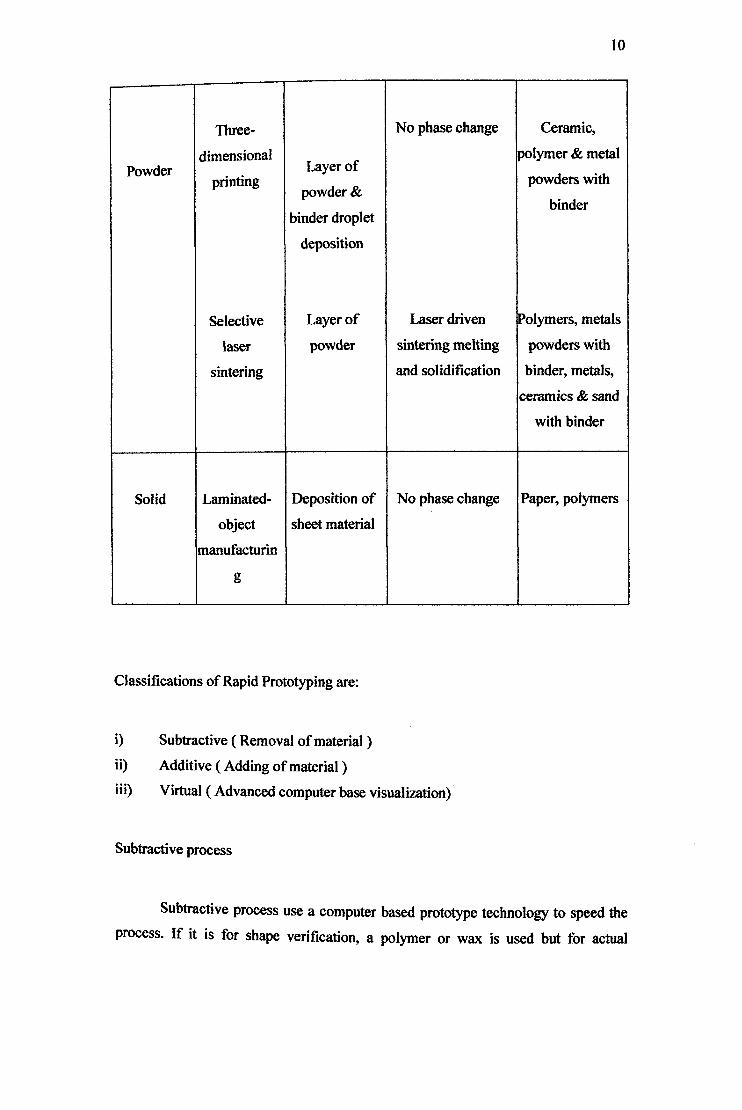
10
Three- No phase change Ceramic,
dimensional polymer & metal Powder
printingLayer of
powders with powder &
binder binder droplet
deposition
Selective Layer of Laser driven Polymers, metals
laser powder sintering melting powders with
sintering and solidification binder, metals,
ceramics & sand
with binder
Solid Laminated- Deposition of No phase change Paper, polymers
object sheet material
manufacturin
g
Classifications of Rapid Prototyping are:
1) Subtractive (Removal of material)
Additive (Adding of material)
Virtual (Advanced computer base visualization)
Subtractive process
Subtractive process use a computer based prototype technology to speed the
process. If it is for shape verification, a polymer or wax is used but for actual

11
application, a machining process still required. Essential technologies for subtractive
protOtyping are computer, interpretation software, manufacturing software or CNC
machinery [4].
Additive process
This process built workpiece or parts in layer by layer which is slice by slice and
require elaborate software. The steps for this process are:
I) Gain drawing file in CAD file
ii) Computer then constructs slice of a three dimensional parts
iii) Slice analyzed and compiled to provide the rapid prototyping machine
iv) Setup the proper unattended and provide rough part after a few hours
v) Finishing operation sanding and painting
-1 - I
I•J),I
_________ I
Figure 2.2: Additive process
Virtual process
Modelling and simulation of all aspects of prototype by a realistic
visualization. All aspects of design process such as mechanical design, kinematics,

12
dynamics and controls but complicated versions use virtual-reality headgear and
gloves with appropriate sensors. Advantage of this process are instant rendering of
parts where the best design in shortest lead time of complex product and process and
allows the exotic, unconventional design be prototyped, rapidly and cost-effectively.
Applications of Rapid Prototyping
i) Production of individual part. Rapid Prototyping can be used to manufacture
marketable products directly especially involve the polymer parts. Pattern
used in investment casting also produced with Rapid Prototyping technique
shown in figure
flfl
Figure 2.3: The steps for investment casting that used rapid prototlyping wax
ii) Rapid tooling. Typically used to describe a process which either uses as
Rapid Prototyping model as a pattern to create a mold quickly or uses the
Rapid Prototyping process directly to fabricate a tool for a limited volume of
prototypes.
13
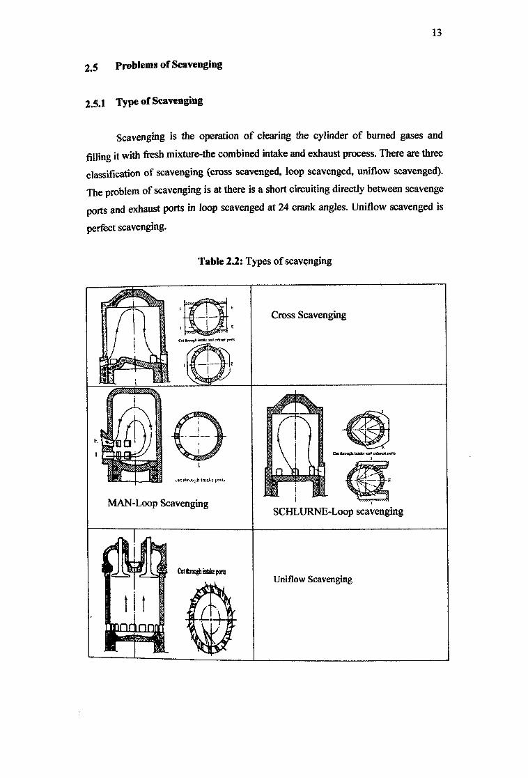
2.5 Problems of Scavenging
2.5.1 Type of Scavenging
Scavenging is the operation of clearing the cylinder of burned gases and
filling it with fresh mixture-the combined intake and exhaust process. There are three
classification of scavenging (cross scavenged, loop scavenged, uniflow scavenged).
The problem of scavenging is at there is a short circuiting directly between scavenge
ports and exhaust ports in loop scavenged at 24 crank angles. Uniflow scavenged is
perfect scavenging.
Table 2.2: Types of scavenging
Cross Scavengin^2 I &
Uniflow Scavenging

14
2.5.2 Scavenging Efficiency
The purity of charge can be measure from the success of scavenging in the
cylinder from combustion of preceding cycle. It is controlled by shape of combustion
chamber and scavenging arrangement. Experiment to determine the purity is
relatively simple, consisting only of analysis of gas sample taken during compression
stroke. In German technical literature the term scavenging efficiency has been widely used.
It define as
- Vret - Vret (2.1) llsc— - Vret+Vres
It can be shown that the delivery ratio, scavenging and trapping efficiency are related
by the following equationCrel flSC
Rdel=Iltrap (2.2)
Scavenging efficiency is a term somewhat similar to purity and expresses the
measure of the success in clearing the cylinder of residual gases from the preceding
cycle. Scavenging efficiency indicates to what extent the residual gases means that
all the gases existing in the cylinder at the beginning of scavenging have swept out.
2.5.3 Perfect Scavenging
The fuel air mixture should remain separate from the residual products of
combustion with respect to both mass and heat transfer during scavenging process
[4]. Fresh charges are pumped into the cylinder by the blower through inlet port then
push the products of combustion in cylinder out through exhaust port. However when
sufficient fresh air has entered to fill the entire cylinder volume the flow abruptly
changes from one of products to one of air [4]. This ideal process will represent perfect scavenging without any short circuiting loss.


