MODEL T500U CAPS NO2 ANALYZER
Operation Manual
© Teledyne API (TAPI) 9970 Carroll Canyon Road San Diego, CA 92131-1106
USA
Toll-free Phone: 800-324-5190 Phone: +1 858-657-9800
Fax: +1 858-657-9816 Email: [email protected]
Website: http://www.teledyne-api.com/
Copyright 2013-2015 07834D DCN6998 Teledyne API 01 June 2015


07834D DCN6998 i
NOTICE OF COPYRIGHT © 2013-2015 Teledyne API. All rights reserved.
TRADEMARKS All trademarks, registered trademarks, brand names or product names appearing in this document are the property of their respective owners and are used herein for identification purposes only. This product is based on technology licensed from Aerodyne Research, Inc.

ii 07834D DCN6998
This page intentionally left blank.
07834D DCN6998 iii
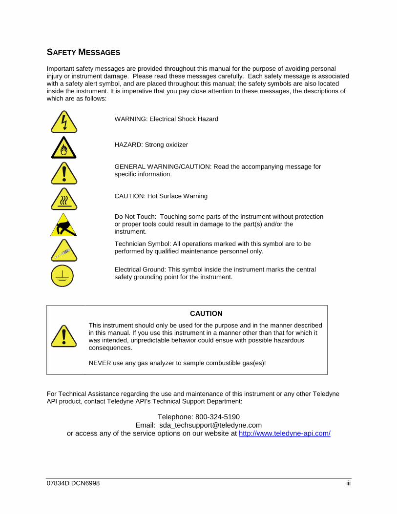
SAFETY MESSAGES Important safety messages are provided throughout this manual for the purpose of avoiding personal injury or instrument damage. Please read these messages carefully. Each safety message is associated with a safety alert symbol, and are placed throughout this manual; the safety symbols are also located inside the instrument. It is imperative that you pay close attention to these messages, the descriptions of which are as follows:
WARNING: Electrical Shock Hazard
HAZARD: Strong oxidizer
GENERAL WARNING/CAUTION: Read the accompanying message for specific information.
CAUTION: Hot Surface Warning
Do Not Touch: Touching some parts of the instrument without protection or proper tools could result in damage to the part(s) and/or the instrument.
Technician Symbol: All operations marked with this symbol are to be performed by qualified maintenance personnel only.
Electrical Ground: This symbol inside the instrument marks the central safety grounding point for the instrument.
CAUTION This instrument should only be used for the purpose and in the manner described in this manual. If you use this instrument in a manner other than that for which it was intended, unpredictable behavior could ensue with possible hazardous consequences.
NEVER use any gas analyzer to sample combustible gas(es)!
For Technical Assistance regarding the use and maintenance of this instrument or any other Teledyne API product, contact Teledyne API’s Technical Support Department:
Telephone: 800-324-5190 Email: [email protected]
or access any of the service options on our website at http://www.teledyne-api.com/
iv 07834D DCN6998
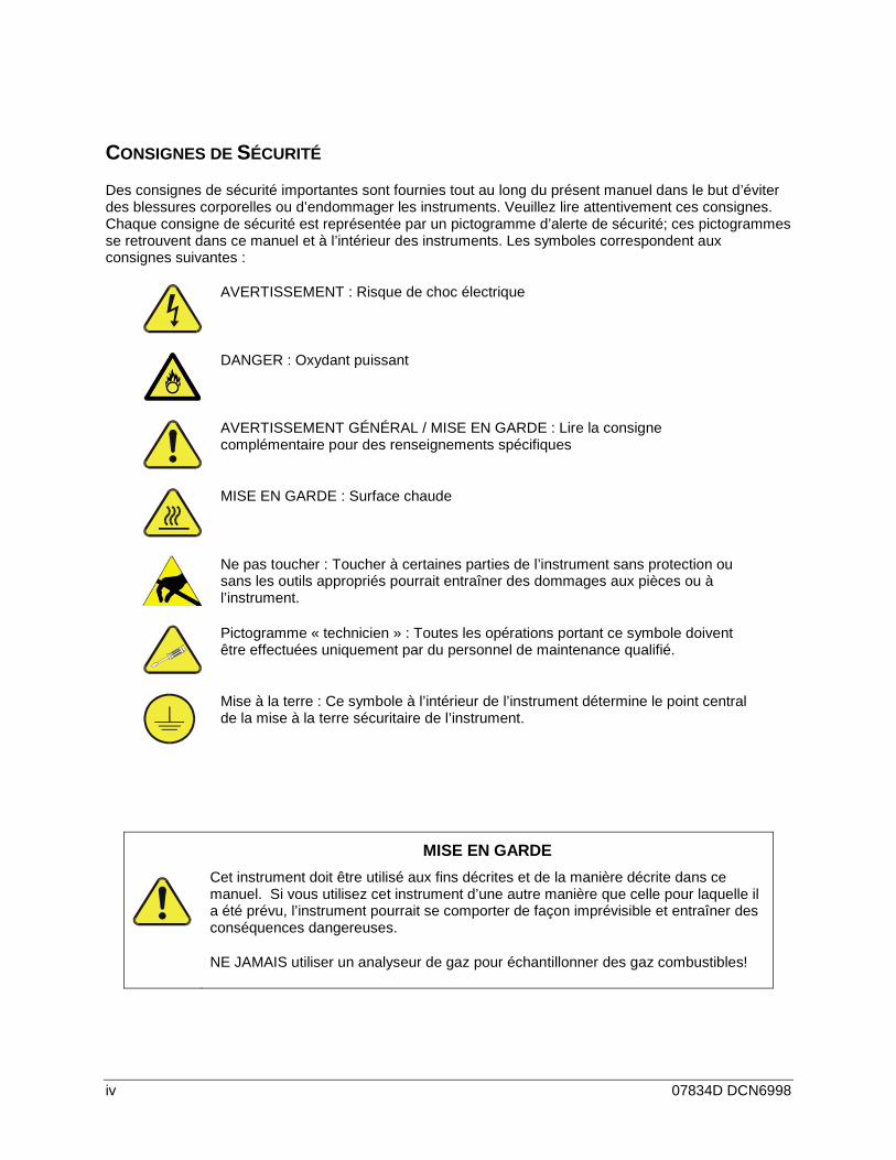
CONSIGNES DE SÉCURITÉ Des consignes de sécurité importantes sont fournies tout au long du présent manuel dans le but d’éviter des blessures corporelles ou d’endommager les instruments. Veuillez lire attentivement ces consignes. Chaque consigne de sécurité est représentée par un pictogramme d’alerte de sécurité; ces pictogrammes se retrouvent dans ce manuel et à l’intérieur des instruments. Les symboles correspondent aux consignes suivantes :
AVERTISSEMENT : Risque de choc électrique
DANGER : Oxydant puissant
AVERTISSEMENT GÉNÉRAL / MISE EN GARDE : Lire la consigne complémentaire pour des renseignements spécifiques
MISE EN GARDE : Surface chaude
Ne pas toucher : Toucher à certaines parties de l’instrument sans protection ou sans les outils appropriés pourrait entraîner des dommages aux pièces ou à l’instrument.
Pictogramme « technicien » : Toutes les opérations portant ce symbole doivent être effectuées uniquement par du personnel de maintenance qualifié.
Mise à la terre : Ce symbole à l’intérieur de l’instrument détermine le point central de la mise à la terre sécuritaire de l’instrument.
MISE EN GARDE Cet instrument doit être utilisé aux fins décrites et de la manière décrite dans ce manuel. Si vous utilisez cet instrument d’une autre manière que celle pour laquelle il a été prévu, l’instrument pourrait se comporter de façon imprévisible et entraîner des conséquences dangereuses.
NE JAMAIS utiliser un analyseur de gaz pour échantillonner des gaz combustibles!
07834D DCN6998 v
WARRANTY
Warranty Policy (02024 G) Teledyne API (TAPI), a business unit of Teledyne Instruments, Inc., provides that:
Prior to shipment, TAPI equipment is thoroughly inspected and tested. Should equipment failure occur, TAPI assures its customers that prompt service and support will be available.
Coverage After the warranty period and throughout the equipment lifetime, TAPI stands ready to provide on-site or in-plant service at reasonable rates similar to those of other manufacturers in the industry. All maintenance and the first level of field troubleshooting are to be performed by the customer.
Non-TAPI Manufactured Equipment Equipment provided but not manufactured by TAPI is warranted and will be repaired to the extent and according to the current terms and conditions of the respective equipment manufacturer’s warranty.
Product Return All units or components returned to Teledyne API should be properly packed for handling and returned freight prepaid to the nearest designated Service Center. After the repair, the equipment will be returned, freight prepaid.
The complete Terms and Conditions of Sale can be reviewed at http://www.teledyne-api.com/terms_and_conditions.asp
CAUTION – Avoid Warranty Invalidation Failure to comply with proper anti-Electro-Static Discharge (ESD) handling and packing instructions and Return Merchandise Authorization (RMA) procedures when returning parts for repair or calibration may void your warranty. For anti-ESD handling and packing instructions please refer to the manual, Fundamentals of ESD, PN 04786, in its “Packing Components for Return to Teledyne API’s Customer Service” section. The manual can be downloaded from our website at http://www.teledyne-api.com under Help Center > Product Manuals in the Special Manuals section; RMA procedures are under Help Center > Return Authorization.

vi 07834D DCN6998
This page intentionally left blank.
07834D DCN6998 vii
ABOUT THIS MANUAL This manual is comprised of multiple documents, in PDF format, as listed below.
Part No. Rev Name/Description 078340000 D T500U Operation Manual (this manual) 080610000 C Software Menu Trees, Appendix A 080670000 A T500U Spare Parts List, Appendix B 080620000 A T500U Repair Questionnaire, Appendix C 078480000 A T500U Interconnect Diagram, Appendix D
Support information such as electrostatic discharge (ESD) prevention and various communications is presented in our manuals, which are available on the TAPI website http://www.teledyne-api.com in Help Center>Product Manuals, under Special Manuals.
Note We recommend that all users read this manual in its entirety before operating the instrument.

viii 07834D DCN6998
This page intentionally left blank.
07834D DCN6998 ix
REVISION HISTORY This section provides information regarding changes to this manual.
T500U CAPS NO2 Analyzer Manual PN 07834
Date Rev DCN Change Summary
2015 May 08 D 6998 Add new Status Outputs and Control Inputs
2014 Sep 09 C 6960 Add DAQ board test points w/voltages.
2014 July 01 B 6927 Update AREF behavior description; adjust lower limit Temperature alarm.
2014 April 21 A 5543 Initial Release

x 07834D DCN6998
This page intentionally left blank.
07834D DCN6998 xi
TABLE OF CONTENTS Safety Messages ........................................................................................................................................... iii WARRANTY .................................................................................................................................................. v About This Manual ....................................................................................................................................... vii Revision History ........................................................................................................................................... ix Table of Contents ......................................................................................................................................... xi
1. INTRODUCTION .................................................................................................................................... 19
2. SPECIFICATIONS, APPROVALS & COMPLIANCE ............................................................................. 21 Specifications ....................................................................................................................................... 21 2.1. EPA Equivalency Designation ............................................................................................................. 22 2.2. Approvals and Certifications ................................................................................................................ 22 2.3.
1.1.1 Safety .......................................................................................................................... 22 1.1.2 EMC ............................................................................................................................ 22
3. GETTING STARTED .............................................................................................................................. 23 Unpacking ............................................................................................................................................ 23 3.1.
Installation Requirements .............................................................................................. 24 3.1.1. Instrument Layout ................................................................................................................................ 24 3.2.
Front Panel .................................................................................................................... 24 3.2.1. Rear Panel ..................................................................................................................... 26 3.2.2. Internal Chassis Layout ................................................................................................. 28 3.2.3.
Connections and Setup ........................................................................................................................ 29 3.3. Electrical Connections ................................................................................................... 29 3.3.1.
Connecting Power ......................................................................................... 29 3.3.1.1. Connecting Analog Inputs (AIN) Option ........................................................ 30 3.3.1.2. Connecting Analog Outputs .......................................................................... 30 3.3.1.3. Current Loop Analog Outputs (Option 41) Setup .......................................... 31 3.3.1.4. Connecting the Status Outputs ..................................................................... 33 3.3.1.5. Connecting the Control Inputs ....................................................................... 34 3.3.1.6. Concentration Alarm Relay (Option 61) ........................................................ 36 3.3.1.7. Connecting the Communications Interfaces ................................................. 37 3.3.1.8.
Pneumatic Connections ................................................................................................. 42 3.3.2. About Zero Air and Calibration (Span) Gas .................................................. 44 3.3.2.1. Basic Connections from Calibrator, with and Without Span Gas .................. 45 3.3.2.2.
4. OVERVIEW OF OPERATING MODES .................................................................................................. 49 Sample Mode ....................................................................................................................................... 50 4.1.
Test Functions ............................................................................................................... 50 4.1.1. Warning Messages ........................................................................................................ 51 4.1.2.
Calibration Mode .................................................................................................................................. 51 4.2. Setup Mode .......................................................................................................................................... 52 4.3.
Primary Setup Menu ...................................................................................................... 52 4.3.1. Secondary Setup Menu (SETUP >MORE) ................................................................... 53 4.3.2.
5. STARTUP, FUNCTIONAL CHECKS, AND INITIAL CALIBRATION...................................................... 55 Startup .................................................................................................................................................. 55 5.1.
Warning Messages ........................................................................................................ 55 5.1.1. Functional Checks ................................................................................................................................ 56 5.2. Initial Calibration ................................................................................................................................... 58 5.3.
Initial Calibration Procedure for T500U Analyzers without VALVE Options .................. 59 5.3.1. Verifying the Reporting Range Settings ........................................................ 59 5.3.1.1. Verifying the Expected NO2 Span Gas Concentration .................................. 61 5.3.1.2. Initial Zero/Span Calibration Procedure ........................................................ 62 5.3.1.3.
6. SETUP .................................................................................................................................................... 63 CFG: Configuration Information ........................................................................................................... 63 6.1.
xii 07834D DCN6998
DAS: Internal Data Acquisition System ................................................................................................ 63 6.2. RNGE: Analog Output Reporting Range ............................................................................................. 63 6.3.
Analog Output Ranges for NO2 Concentration .............................................................. 64 6.3.1. Analog Output Reporting Range Default Settings ......................................................... 65 6.3.2. SETUP > RNGE > MODE ............................................................................................. 65 6.3.3.
SETUP > RNGE > MODE > SNGL: Single Range Mode Configuration ....... 65 6.3.3.1. SETUP > RNGE > MODE > DUAL: Dual Range Mode Configuration ......... 66 6.3.3.2. SETUP > RNGE > MODE > AUTO: Auto Range Mode Configuration ......... 68 6.3.3.3. SETUP > RNGE > UNIT: Setting the Reporting Range Units of Measure ... 69 6.3.3.4. SETUP > RNGE > DIL: Using the Optional Dilution Ratio Feature .............. 69 6.3.3.5.
PASS: Password Protection ................................................................................................................ 71 6.4. CLK: Clock, Setting time and Date ...................................................................................................... 74 6.5.
Setting the Time of Day ................................................................................................. 74 6.5.1. Adjusting the Internal Clock’s Speed ............................................................................. 75 6.5.2.
MORE>COMM: Communications Ports .............................................................................................. 76 6.6. ID (Machine Identification) ............................................................................................. 76 6.6.1. INET (Ethernet) ............................................................................................................. 77 6.6.2. COM1[COM2] (Mode, Baude Rate and Test Port) ....................................................... 77 6.6.3.
MORE>VARS: Variables Setup and Definition .................................................................................... 77 6.7. MORE>DIAG: Diagnostics Functions .................................................................................................. 80 6.8.
Signal I/O ....................................................................................................................... 82 6.8.1. Analog Output (DIAG AOUT) ........................................................................................ 82 6.8.2. Analog I/O Configuration (DIAG AIO) ............................................................................ 83 6.8.3.
Analog Output Voltage / Current Range Selection ........................................ 85 6.8.3.1. Calibration of the Analog Outputs ................................................................. 86 6.8.3.2. Enabling or Disabling the AutoCal for an Individual Analog Output .............. 86 6.8.3.3. Automatic Group Calibration of the Analog Outputs ..................................... 87 6.8.3.4. Automatic Individual Calibration of the Analog Outputs ................................ 89 6.8.3.5. Manual Calibration of the Analog Outputs Configured for Voltage Ranges .. 90 6.8.3.6. Manual Adjustment of Current Loop Output Span and Offset ...................... 92 6.8.3.7. Turning the Analog Output Over-Range Feature On/Off .............................. 95 6.8.3.8. Adding a Recorder Offset to an Analog Output ............................................. 96 6.8.3.9.
AIN (Analog Inputs) Calibration ................................................................... 97 6.8.3.10. External Analog Inputs (XIN1…XIN8) Option Configuration ....................... 98 6.8.3.11.
Test Chan Output (Selecting a Test Channel Function for Output A4) ......................... 99 6.8.4. NO2 LED Disable ......................................................................................................... 101 6.8.5. Pump Disable .............................................................................................................. 101 6.8.6.
SETUP>MORE>AREF:...................................................................................................................... 101 6.9.
7. COMMUNICATIONS SETUP AND OPERATION ................................................................................ 103 Data Terminal/Communication Equipment (DTE DEC) ..................................................................... 103 7.1. Communication Modes, Baud Rate and Port Testing ........................................................................ 103 7.2.
Communication Modes ................................................................................................ 104 7.2.1. Com Port Baud Rate ................................................................................................... 106 7.2.2. Com Port Testing ......................................................................................................... 107 7.2.3.
RS-232 ............................................................................................................................................... 108 7.3. RS-485 (Option) ................................................................................................................................. 108 7.4. Ethernet .............................................................................................................................................. 109 7.5.
Configuring Ethernet Communication Manually (Static IP Address) ........................... 109 7.5.1. Configuring Ethernet Communication Using Dynamic Host Configuration Protocol 7.5.2.
(DHCP) .................................................................................................................................. 111 Changing the Analyzer’s HOSTNAME ........................................................ 113 7.5.2.1.
USB Port for Remote Access ............................................................................................................. 114 7.6. Communications Protocols ................................................................................................................ 116 7.7.
Hessen......................................................................................................................... 116 7.7.1. Hessen Com Port Configuration .................................................................. 116 7.7.1.1. Activating Hessen Protocol ......................................................................... 117 7.7.1.2.
07834D DCN6998 xiii
Selecting a Hessen Protocol Type .............................................................. 118 7.7.1.3. Setting the HessEn Protocol Response Mode ............................................ 119 7.7.1.4. Hessen Protocol Gas List Entry Format and Definitions ............................. 120 7.7.1.5. Setting Hessen Protocol Status Flags ......................................................... 121 7.7.1.6.
MODBUS ..................................................................................................................... 122 7.7.2.
8. DATA ACQUISITION SYSTEM (DAS) AND APICOM ......................................................................... 125 DAS Structure .................................................................................................................................... 126 8.1.
DAS Channels ............................................................................................................. 126 8.1.1. Default DAS Channels ................................................................................ 127 8.1.1.1. DAS Configuration Limits ............................................................................ 128 8.1.1.2.
Viewing DAS Data and Settings .................................................................................. 129 8.1.2. Editing DAS Data Channels ........................................................................................ 130 8.1.3.
Editing DAS Data Channel Names.............................................................. 131 8.1.3.1. Editing DAS Triggering Events .................................................................... 132 8.1.3.2. Editing DAS Parameters ............................................................................. 132 8.1.3.3. Editing Sample Period and Report Period .................................................. 135 8.1.3.4. Report Periods in Progress when Instrument Is Powered Off .................... 137 8.1.3.5. Editing the Number of Records ................................................................... 137 8.1.3.6. RS-232 Report Function .............................................................................. 139 8.1.3.7. HOLDOFF Feature ...................................................................................... 140 8.1.3.8. The Compact Report Feature ...................................................................... 141 8.1.3.9.
The Starting Date Feature ......................................................................... 141 8.1.3.10. Disabling/Enabling Data Channels ............................................................ 141 8.1.3.11.
Remote DAS Configuration ................................................................................................................ 142 8.2. DAS Configuration via APICOM .................................................................................. 142 8.2.1. DAS Configuration via Terminal Emulation Programs ................................................ 142 8.2.2.
9. REMOTE OPERATION ........................................................................................................................ 145 Computer Mode ................................................................................................................................. 145 9.1. Interactive Mode ................................................................................................................................. 145 9.2.
Remote Control via a Terminal Emulation Program .................................................... 145 9.2.1. Help Commands in Interactive Mode .......................................................... 146 9.2.1.1. Command Syntax ........................................................................................ 146 9.2.1.2. Data Types .................................................................................................. 147 9.2.1.3. Status Reporting .......................................................................................... 147 9.2.1.4. General Message Format ............................................................................ 148 9.2.1.5.
Remote Access by Modem ................................................................................................................ 148 9.3. Password Security for Serial Remote Communications .................................................................... 151 9.4.
10. CALIBRATION ................................................................................................................................... 153 Calibration Gases ............................................................................................................................. 153 10.1.
Span Gas for Multipoint Calibration ........................................................................... 153 10.1.1. NO2 Permeation Tubes ............................................................................................. 153 10.1.2.
Data Recording Devices .................................................................................................................. 154 10.2. Manual Calibration Checks and Calibration of the T500U in its Base Configuration ...................... 154 10.3.
Setup for Basic Calibration Checks and Calibration ................................................. 155 10.3.1. Performing a Basic Manual Calibration Check .......................................................... 156 10.3.2. Performing a Basic Manual Calibration ..................................................................... 157 10.3.3.
Setting the Expected Span Gas Concentration ......................................... 157 10.3.3.1. Zero/Span Point Calibration Procedure .................................................... 158 10.3.3.2.
Manual Calibration with the Internal Span Gas Generator .............................................................. 159 10.4. Performing “Precision” Manual Calibration for Internal Span Gas (IZS) Generator 10.4.1.
Option .................................................................................................................................... 159 Setup for Calibration with the Internal Span Gas Generator ..................................... 160 10.4.2. Performing a Manual Calibration Check with the Internal Span Gas Generator ...... 161 10.4.3. Performing a Manual Calibration with the Internal Span Gas Generator .................. 162 10.4.4.
Setting the Expected Span Gas Concentration ......................................... 162 10.4.4.1.
xiv 07834D DCN6998
Manual Calibration Checks with Valve Options Installed .......................................... 163 10.4.5. Manual Calibration Using Valve Options ................................................................... 164 10.4.6.
Setting the Expected Span Gas Concentration ......................................... 164 10.4.6.1. Zero/Span Point Calibration Procedure for Valve Options ........................ 165 10.4.6.2. Use of Zero/Span Valve with Remote Contact Closure ............................ 166 10.4.6.3.
Automatic Zero/Span Cal/Check (AutoCal) ..................................................................................... 166 10.5. SETUP > ACAL: Programming and AUTO CAL Sequence ...................................... 169 10.5.1.
Calibration Quality Analysis ............................................................................................................. 172 10.6.
11. MAINTENANCE ................................................................................................................................. 173 Maintenance Schedule..................................................................................................................... 173 11.1. Predictive Diagnostics ...................................................................................................................... 174 11.2. Maintenance Procedures ................................................................................................................. 175 11.3.
Replacing the Sample Filter ...................................................................................... 175 11.3.1. Replacing the AREF Filter and Charcoal Filter ......................................................... 176 11.3.2. Replacing the Internal Pump ..................................................................................... 177 11.3.3. Changing the Internal Span Gas Generator Permeation Tube ................................. 177 11.3.4. Checking for Pneumatic Leaks .................................................................................. 178 11.3.5.
Detailed Pressure Leak Check .................................................................. 178 11.3.5.1. Performing a Sample Flow Check ............................................................. 179 11.3.5.2.
12. EPA PROTOCOL CALIBRATION ...................................................................................................... 181
13. TROUBLESHOOTING AND SERVICE ............................................................................................. 183 General Troubleshooting ................................................................................................................. 184 13.1.
Fault Diagnosis with WARNING Messages .............................................................. 184 13.1.1. Fault Diagnosis With Test Functions ......................................................................... 188 13.1.2. DIAG > SIGNAL I/O: Using the Diagnostic Signal I/O Function ............................... 189 13.1.3.
Using the Analog Output Test Channel ........................................................................................... 191 13.2. Using the Internal Electronic Status LEDs ....................................................................................... 191 13.3.
CPU Status Indicator ................................................................................................. 191 13.3.1. Relay PCA Status LEDs ............................................................................................ 192 13.3.2.
I2C Bus Watchdog Status LEDs ................................................................ 192 13.3.2.1. Relay PCA Status LEDs ............................................................................ 193 13.3.2.2.
Calibration Problems ........................................................................................................................ 194 13.4. Negative Concentrations ........................................................................................... 194 13.4.1. No Response ............................................................................................................. 194 13.4.2. Unstable Zero and Span ........................................................................................... 194 13.4.3. Inability to Span - No SPAN Button (CALS) .............................................................. 195 13.4.4. Inability to Zero - No ZERO Button (CALZ) ............................................................... 195 13.4.5. Non-Linear Response................................................................................................ 196 13.4.6. Discrepancy Between Analog Output and Display .................................................... 196 13.4.7.
Other Performance Problems .......................................................................................................... 197 13.5. Excessive Noise ........................................................................................................ 197 13.5.1. Slow Response .......................................................................................................... 197 13.5.2. AREF Warnings ........................................................................................................ 198 13.5.3.
Subsystem Checkout ....................................................................................................................... 199 13.6. AC Main Power .......................................................................................................... 199 13.6.1. DC Power Supply ...................................................................................................... 200 13.6.2. I2C Bus ....................................................................................................................... 201 13.6.3. LCD/Display Module, Touchscreen Interface ............................................................ 201 13.6.4. Relay PCA ................................................................................................................. 201 13.6.5. Data Acquisition (DAQ) PCA ..................................................................................... 202 13.6.6. Motherboard .............................................................................................................. 203 13.6.7.
Test Channel / Analog Outputs Voltage .................................................... 203 13.6.7.1. A/D Functions ............................................................................................ 203 13.6.7.2. Status Outputs ........................................................................................... 204 13.6.7.3. Control Inputs ............................................................................................ 205 13.6.7.4.
07834D DCN6998 xv
CPU ........................................................................................................................... 206 13.6.8. RS-232 Communications........................................................................................... 206 13.6.9.
General RS-232 Troubleshooting.............................................................. 206 13.6.9.1. Troubleshooting Analyzer/Modem or Terminal Operation ........................ 207 13.6.9.2.
Internal Span Gas Generator and Valve Options .................................................... 207 13.6.10. Temperature Sensor................................................................................................ 208 13.6.11.
Box Temperature Sensor ........................................................................ 208 13.6.11.1. Service Procedures .......................................................................................................................... 209 13.7.
Disk-On-Module Replacement Procedure................................................................. 210 13.7.1. Removing / Replacing the Relay PCA from the Instrument ...................................... 211 13.7.2.
Frequently Asked Questions ............................................................................................................ 212 13.8. Technical Assistance ....................................................................................................................... 213 13.9.
14. PRINCIPLES OF OPERATION .......................................................................................................... 215 Glossary .................................................................................................................................................... 217
xvi 07834D DCN6998
LIST OF FIGURES Figure 3-1: Front Panel Layout .............................................................................................................. 25
Figure 3-2: Display Screen and Touch Control ..................................................................................... 25
Figure 3-3: T500U Rear Panel............................................................................................................... 26
Figure 3-4: Internal Layout ..................................................................................................................... 28
Figure 3-5: Analog In Connector ........................................................................................................... 30 Figure 3-6: Analog Output Connector .................................................................................................... 31
Figure 3-7: Current Loop Option Installed on the Motherboard ............................................................. 32
Figure 3-8: Status Output Connector ..................................................................................................... 34
Figure 3-9: Energizing the Control Inputs .............................................................................................. 35
Figure 3-10: Concentration Alarm Relay ................................................................................................. 36
Figure 3-11: Rear Panel Connector Pin-Outs for RS-232 Mode ............................................................. 38 Figure 3-12: Pin Assignments for J11, J12 Connectors on CPU Board. ................................................ 38
Figure 3-13: Jumper and Cables for Multidrop Mode .............................................................................. 40
Figure 3-14: RS-232-Multidrop PCA Host/Analyzer Interconnect Diagram ............................................ 41
Figure 3-15: Gas Line Connections from Calibrator – Basic T500U Configuration ................................. 45
Figure 3-16: T500U Pneumatics with Zero Span Valves Option ............................................................. 47
Figure 3-17: T500U Pneumatics with Internal Zero Span Valves Option ................................................ 48 Figure 4-1: Front Panel Display ............................................................................................................. 49
Figure 6-1: Analog Output Connector Pin Out ....................................................................................... 64
Figure 6-2: SETUP – COMM Menu ....................................................................................................... 76
Figure 6-3: COMM– Machine ID ............................................................................................................ 77
Figure 6-4: Accessing the DIAG Submenus .......................................................................................... 81 Figure 6-5: Accessing the Analog I/O Configuration Submenus ........................................................... 84
Figure 6-6: Setup for Checking / Calibrating DCV Analog Output Signal Levels .................................. 90
Figure 6-7: Setup for Checking / Calibration Current Output Signal Levels Using an Ammeter ........... 92
Figure 6-8: Alternative Setup Using 250Ω Resistor for Checking Current Output Signal Levels .......... 94
Figure 7-1: COMM - LAN /Internet Manual Configuration ................................................................... 110
Figure 7-2: COMM – LAN / Internet Automatic Configuration (DHCP) ............................................... 112 Figure 8-1: Example Default DAS Configuration in APICOM Interface ............................................... 128
Figure 8-2: DAS Configuration through a Terminal Emulation Program ............................................. 143
Figure 10-1: Set up for Manual Calibrations/Checks in Base Configuration w/Gas Dilution Calibrator 155
Figure 10-2: Pneumatic Connections for T500U Precision Calibration when IZS Generator Present .. 159
Figure 10-3: Pneumatic Connections for Manual Calibration/Checks with the Internal Span Gas Generator 160
07834D DCN6998 xvii
Figure 11-1: Replacing the Sample Filter .............................................................................................. 176
Figure 11-2: Pneumatic Layout of AREF Filter and Charcoal Filter ...................................................... 176
Figure 11-3: Internal Pump .................................................................................................................... 177 Figure 13-1: CLR and MSG Menu Buttons ............................................................................................ 185
Figure 13-2: Example of Signal I/O Function ......................................................................................... 190
Figure 13-3: CPU Status Indicator ......................................................................................................... 191
Figure 13-4: Relay PCA Status LEDS Used for Troubleshooting ......................................................... 193
Figure 13-5: Location of DC Power Test Points on Relay PCA ............................................................ 200
Figure 13-6 DAQ PCA Test Points and LEDs ...................................................................................... 202 Figure 13-7: Typical Set Up of Status Output Test ................................................................................ 204
Figure 13-8: Relay PCA with AC Relay Retainer In Place .................................................................... 211
Figure 13-9: Relay PCA Mounting Screw Locations ............................................................................. 211
Figure 14-1: T500U Optical Absorption Cell .......................................................................................... 216
Figure 14-2: Phase Shift Representation of Increased Concentration of NO2 ...................................... 216
LIST OF TABLES
Table 2-1: Specifications ...................................................................................................................... 21
Table 3-1: Ventilation Clearance Requirements .................................................................................. 24
Table 3-2: Display Screen and Touch Control Description .................................................................. 26
Table 3-5: Analog Output Pin Assignments ......................................................................................... 31
Table 3-6: Status Output Pin Assignments .......................................................................................... 34 Table 3-7: Control Input Pin Assignments ............................................................................................ 35
Table 4-2: Primary Setup Mode Features and Functions .................................................................... 52
Table 4-3: Secondary Setup Mode Features and Functions ................................................................ 53
Table 5-1: Possible Warning Messages at Start-Up ............................................................................ 56
Table 5-2: Test Functions Defined ....................................................................................................... 57
Table 6-1: Password Levels ................................................................................................................. 71 Table 6-2: Variables (VARS) ................................................................................................................ 78
Table 6-3: Diagnostic Mode (DIAG) Functions ..................................................................................... 80
Table 6-4: DIAG - Analog I/O Functions ............................................................................................... 83
Table 6-5: Analog Output Voltage Range Min/Max .............................................................................. 85
Table 6-7: Current Loop Output Check ................................................................................................ 94
Table 6-8: Test Channels Functions available on the T500U’s Analog Output ................................... 99 Table 7-1: COM port Communication Modes ..................................................................................... 104
Table 7-2: Ethernet Status Indicators ................................................................................................. 109
xviii 07834D DCN6998
Table 7-4: RS-232 Communication Parameters for Hessen Protocol .............................................. 116
Table 7-5: Teledyne API's Hessen Protocol Response Modes ......................................................... 119
Table 7-6: Default Hessen Status Flag Assignments ......................................................................... 121 Table 7-7 MODBUS Setup Instructions ............................................................................................. 122
Table 8-1: DAS Data Channel Properties .......................................................................................... 126
Table 8-2: T500U Default DAS Channels .......................................................................................... 127
Table 8-3: DAS Data Parameter Functions ........................................................................................ 133
Table 9-1: Terminal Mode Software Commands................................................................................ 146
Table 9-2: Teledyne API's Serial I/O Command Types ...................................................................... 146 Table 10-1: AUTOCAL Modes.............................................................................................................. 166
Table 10-2: AutoCal Attribute Setup Parameters ................................................................................ 167
Table 10-3: Example AutoCal Sequence ............................................................................................. 168
Table 10-4: Calibration Data Quality Evaluation .................................................................................. 172
Table 11-1: T500U Maintenance Schedule .......................................................................................... 174
Table 11-2: Predictive Uses for Test Functions ................................................................................... 175 Table 13-1: Front Panel Warning Messages ........................................................................................ 187
Table 13-2: Test Functions - Indicated Failures ................................................................................... 188
Table 13-3: Relay PCA Watchdog LED Failure Indications ................................................................. 192
Table 13-4: Relay PCA Status LED Failure Indications ....................................................................... 193
Table 13-5: DC Power Test Point and Wiring Color Codes ................................................................. 200
Table 13-6: DC Power Supply Acceptable Levels................................................................................ 201 Table 13-7: Analog Output Test Function - Nominal Values Voltage Outputs ..................................... 203
Table 13-8: Status Outputs Check ....................................................................................................... 205
Table 13-9: T500U Control Input Pin Assignments and Corresponding Signal I/O Functions ............ 205
LIST OF APPENDICES
APPENDIX A – MENU TREES and RELATED SOFTWARE DOCUMENTATION APPENDIX B - T700 SPARE PARTS LIST APPENDIX C - REPAIR QUESTIONNAIRE APPENDIX D - SCHEMATICS
07834D DCN6998 19
1. INTRODUCTION Teledyne API’s Model T500U CAPS NO2 Analyzer uses Cavity-Attenuated Phase-Shift (CAPS) spectroscopy to render true measurements of nitrogen dioxide (NO2). The T500U operates as an optical absorption spectrometer, wherein the absorbance (lost light) is directly proportional to the path-length and the concentration of the absorbing gas (Beer-Lambert law), providing direct measurement of NO2.
The T500U uses few components: an optical cell, a pair of highly reflective spherical mirrors centered at 450nm (strong NO2 absorbance band), a light emitting diode (LED), and a vacuum photodiode detector. The LED is located behind a mirror at one end of the cell, and the detector behind the other mirror at the opposite end of the cell. The LED emits ultraviolet light (UV) into the cell; the light reflects back and forth between the two mirrors, building intensity and running a very long path length. The long path length extends the “time” or “life” of the photon, thus providing ample time to measure absorbance when NO2 is present. Through the use of precisely timed data acquisition coupled with a proprietary algorithm the measured absorption is translated into a phase shift, from which the NO2 concentration is calculated. The phase shift decreases as the NO2 signal increases.
The CAPS method is faster than the traditional chemiluminescence method since the sample does not require cycling through a catalytic converter to calculate a difference measurement. Its speed also makes measurement more precise due to the ability to capture samples closer to “real time” before ventilation vortices (e.g., urban canyons and other traffic-related forces) can scatter the concentration.
Economically, the Model T500U CAPS method is less costly to operate than traditional analyzers in that it uses less power (~80W) and fewer components.
The section on Principles of Operation provides more detail on the behavior and technique of the CAPS method for NO2 measurement.

Introduction Teledyne API Model T500U CAPS NO2 Analyzer Manual
20 07834D DCN6998
This page intentionally left blank.
07834D DCN6998 21
2. SPECIFICATIONS, APPROVALS & COMPLIANCE
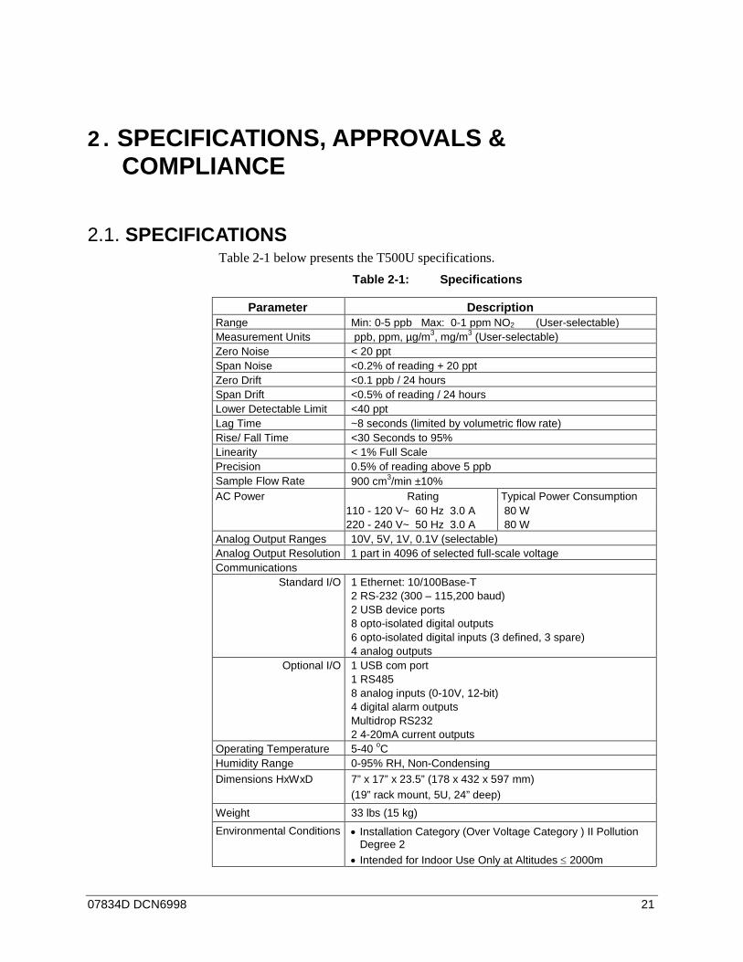
SPECIFICATIONS 2.1.Table 2-1 below presents the T500U specifications.
Table 2-1: Specifications
Parameter Description Range Min: 0-5 ppb Max: 0-1 ppm NO2 (User-selectable) Measurement Units ppb, ppm, µg/m3, mg/m3 (User-selectable) Zero Noise < 20 ppt Span Noise <0.2% of reading + 20 ppt Zero Drift <0.1 ppb / 24 hours Span Drift <0.5% of reading / 24 hours Lower Detectable Limit <40 ppt Lag Time ~8 seconds (limited by volumetric flow rate) Rise/ Fall Time <30 Seconds to 95% Linearity < 1% Full Scale Precision 0.5% of reading above 5 ppb Sample Flow Rate 900 cm3/min ±10% AC Power Rating Typical Power Consumption
110 - 120 V~ 60 Hz 3.0 A 220 - 240 V~ 50 Hz 3.0 A
80 W 80 W
Analog Output Ranges 10V, 5V, 1V, 0.1V (selectable) Analog Output Resolution 1 part in 4096 of selected full-scale voltage Communications
Standard I/O 1 Ethernet: 10/100Base-T 2 RS-232 (300 – 115,200 baud) 2 USB device ports 8 opto-isolated digital outputs 6 opto-isolated digital inputs (3 defined, 3 spare) 4 analog outputs
Optional I/O 1 USB com port 1 RS485 8 analog inputs (0-10V, 12-bit) 4 digital alarm outputs Multidrop RS232 2 4-20mA current outputs
Operating Temperature 5-40 oC Humidity Range 0-95% RH, Non-Condensing Dimensions HxWxD 7” x 17” x 23.5” (178 x 432 x 597 mm)
(19” rack mount, 5U, 24” deep) Weight 33 lbs (15 kg) Environmental Conditions • Installation Category (Over Voltage Category ) II Pollution
Degree 2 • Intended for Indoor Use Only at Altitudes ≤ 2000m

Specifications, Approvals & Compliance Teledyne API Model T500U CAPS NO2 Analyzer Manual
22 07834D DCN6998
EPA EQUIVALENCY DESIGNATION 2.2.Teledyne API’s Model T500U cavity attenuated phase shift spectroscopy nitrogen dioxide analyzer is officially designated as a US EPA Federal Equivalent Method (FEM) (Designation number EQNA-0514-212) for NO2 measurement as defined in 40 CFR Part 53, when the T500U is operated under the following conditions:
• on any full scale range between 0-50 ppb and 0-1000 ppb • with any range mode (Single, Dual, or Auto Range) • with a sample filter • at any operating temperature from 5°C to 40°C • with the software setting: Temperature and Pressure compensation ON • in accordance with this T500U manual • with or without any of the following options:
o Zero/Span (Z/S) valves o internal Zero/Span (IZS) permeation oven o external communication and data monitoring interfaces
This analyzer is approved for use, with proper factory configuration (if applicable), on either 50 or 60 Hertz line frequency and nominal power line voltages of 115 VAC and 230 VAC, or similar voltages as specified in this manual.
APPROVALS AND CERTIFICATIONS 2.3.The Teledyne API Model T500U was designed, tested and certified for Safety and Electromagnetic Compatibility (EMC). This section presents the compliance statements for those requirements and directives. For additional certifications, please contact Technical Support by telephone at 1-800-324-5190 or by email at [email protected].
1.1.1 SAFETY IEC/EN 61010-1:2010 (3rd Edition), Safety requirements for electrical equipment for measurement, control, and laboratory use.
CE: 2006/95/EC, Low-Voltage Directive
1.1.2 EMC IEC/EN 61326-1, Class A Emissions/Industrial Immunity
EN55011 (CISPR 11), Group 1, Class A Emissions
FCC 47 CFR Part 15B, Class A Emissions
CE: 2004/108/EC, Electromagnetic Compatibility Directive
07834D DCN6998 23
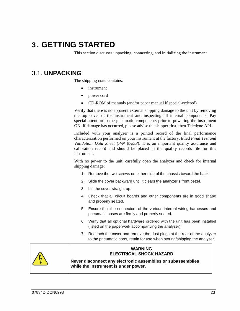
3. GETTING STARTED This section discusses unpacking, connecting, and initializing the instrument.
UNPACKING 3.1.The shipping crate contains:
• instrument
• power cord
• CD-ROM of manuals (and/or paper manual if special-ordered)
Verify that there is no apparent external shipping damage to the unit by removing the top cover of the instrument and inspecting all internal components. Pay special attention to the pneumatic components prior to powering the instrument ON. If damage has occurred, please advise the shipper first, then Teledyne API.
Included with your analyzer is a printed record of the final performance characterization performed on your instrument at the factory, titled Final Test and Validation Data Sheet (P/N 07853). It is an important quality assurance and calibration record and should be placed in the quality records file for this instrument.
With no power to the unit, carefully open the analyzer and check for internal shipping damage:
1. Remove the two screws on either side of the chassis toward the back.
2. Slide the cover backward until it clears the analyzer’s front bezel.
3. Lift the cover straight up.
4. Check that all circuit boards and other components are in good shape and properly seated.
5. Ensure that the connectors of the various internal wiring harnesses and pneumatic hoses are firmly and properly seated.
6. Verify that all optional hardware ordered with the unit has been installed (listed on the paperwork accompanying the analyzer).
7. Reattach the cover and remove the dust plugs at the rear of the analyzer to the pneumatic ports, retain for use when storing/shipping the analyzer.
WARNING ELECTRICAL SHOCK HAZARD
Never disconnect any electronic assemblies or subassemblies while the instrument is under power.
Getting Started Teledyne API Model T500U CAPS NO2 Analyzer Manual
24 07834D DCN6998
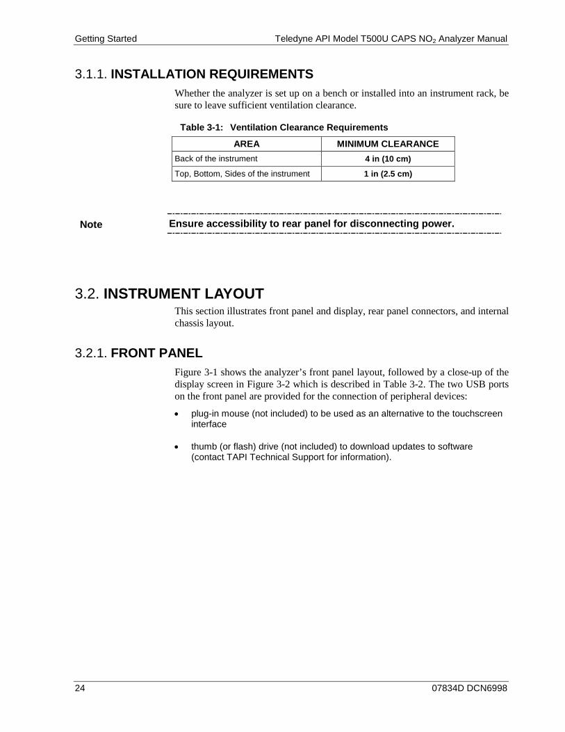
INSTALLATION REQUIREMENTS 3.1.1.Whether the analyzer is set up on a bench or installed into an instrument rack, be sure to leave sufficient ventilation clearance.
Table 3-1: Ventilation Clearance Requirements
AREA MINIMUM CLEARANCE Back of the instrument 4 in (10 cm)
Top, Bottom, Sides of the instrument 1 in (2.5 cm)
Note Ensure accessibility to rear panel for disconnecting power.
INSTRUMENT LAYOUT 3.2.This section illustrates front panel and display, rear panel connectors, and internal chassis layout.
FRONT PANEL 3.2.1.Figure 3-1 shows the analyzer’s front panel layout, followed by a close-up of the display screen in Figure 3-2 which is described in Table 3-2. The two USB ports on the front panel are provided for the connection of peripheral devices:
• plug-in mouse (not included) to be used as an alternative to the touchscreen interface
• thumb (or flash) drive (not included) to download updates to software (contact TAPI Technical Support for information).

Teledyne API Model T500U CAPS NO2 Analyzer Manual Getting Started
07834D DCN6998 25
Figure 3-1: Front Panel Layout
Figure 3-2: Display Screen and Touch Control
Getting Started Teledyne API Model T500U CAPS NO2 Analyzer Manual
26 07834D DCN6998
Table 3-2: Display Screen and Touch Control Description
Field Description/Function
Status LEDs indicating the states of Sample, Calibration and Fault, as follows:
Name Color State Definition
SAMPLE Green
Off On Blinking
Unit is not operating in sample mode, DAS is disabled. Sample Mode active; Front Panel Display being updated; DAS data being stored. Unit is operating in sample mode, front panel display being updated, DAS hold-off mode is ON, DAS disabled
CAL Yellow Off On Blinking
Auto Cal disabled Auto Cal enabled Unit is in calibration mode
FAULT Red Off Blinking
No warnings exist Warnings exist
Conc Displays the actual concentration of the sample gas currently being measured by the analyzer in the currently selected units of measure.
Mode Displays the name of the analyzer’s current operating mode
Param Displays a variety of informational messages such as warning messages, operational data, test function values and response messages during interactive tasks.
Control Buttons Displays dynamic, context sensitive labels on each button, which is blank when inactive until applicable.
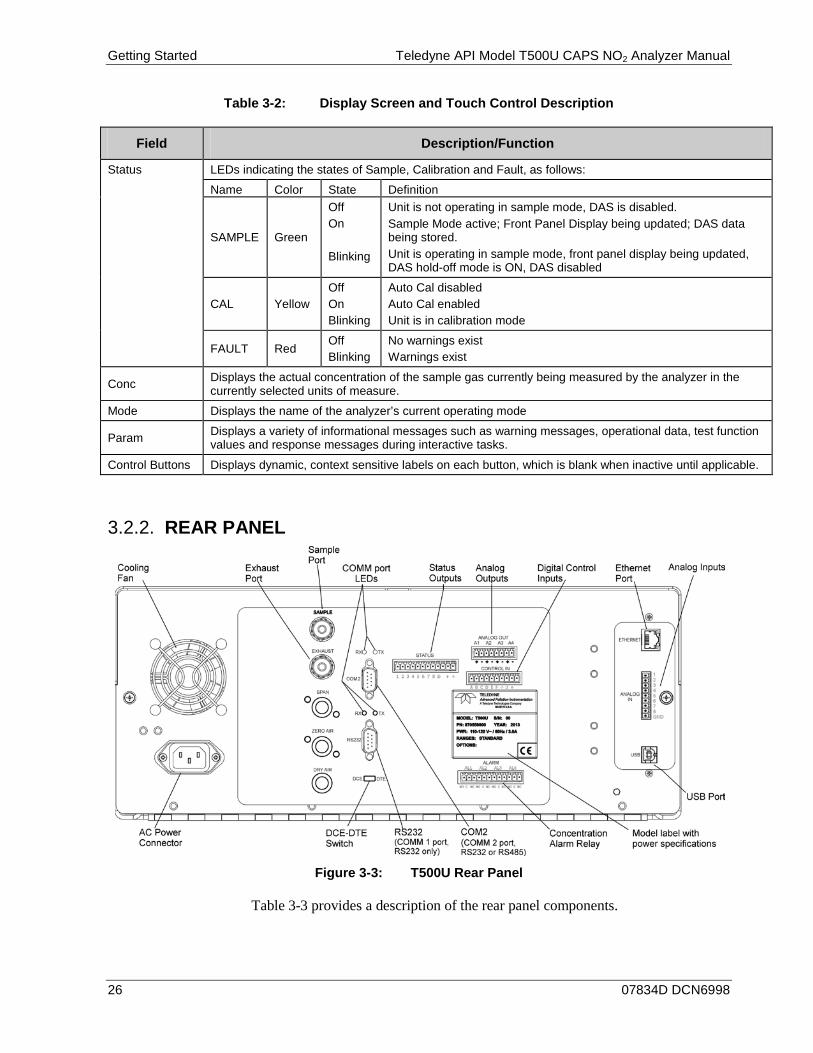
REAR PANEL 3.2.2.
Figure 3-3: T500U Rear Panel
Table 3-3 provides a description of the rear panel components.

Teledyne API Model T500U CAPS NO2 Analyzer Manual Getting Started
07834D DCN6998 27
Table 3-3: Rear Panel Description
Component Function
cooling fan Pulls ambient air into chassis through side vents and exhausts through rear.
AC power connector
Connector for three-prong cord to apply AC power to the analyzer. CAUTION! The cord’s power specifications (specs) MUST comply with the power specs on the analyzer’s rear panel Model label
Model/specs label Identifies the analyzer model number and provides power specs
SAMPLE Connect a gas line from the source of sample gas here. Calibration gases can also enter here on units without zero/span/shutoff valve options installed.
EXHAUST Connect an exhaust gas line of not more than 10 meters long here that leads outside the shelter or immediate area surrounding the instrument. The line must be ¼” tubing or greater.
SPAN On units with zero/span valve option installed, connect a gas line to the source of calibrated span gas here.
ZERO AIR On units with zero/span valve option installed, but no zero air scrubber, attach a gas line to the source of zero air here. If a permeation oven, also known as internal zero/span valve (IZS), option is installed attach the zero air scrubber here.
DRY AIR Not Used
RX TX LEDs indicate receive (RX) and transmit (TX) activity when blinking.
COM 2 Serial communications port for RS-232 or RS-485 (RS-485.
RS-232 Serial communications port for RS-232 only.
DCE DTE Switch to select either data terminal equipment or data communication equipment during RS-232 communication.
STATUS For outputs to devices such as Programmable Logic Controllers (PLCs).
ANALOG OUT (AOUT) For voltage or current loop outputs to a strip chart recorder and/or a data logger.
CONTROL IN For remotely activating the zero and span calibration modes.
ALARM Option for concentration alarms and system warnings.
ETHERNET Connector for network or Internet remote communication, using Ethernet cable
ANALOG IN (AIN) Option for receiving and logging voltage signals from other instrumentation.
USB Connector for direct connection to laptop computer, using USB cable.
Model Label Includes voltage and frequency specifications
Getting Started Teledyne API Model T500U CAPS NO2 Analyzer Manual
28 07834D DCN6998
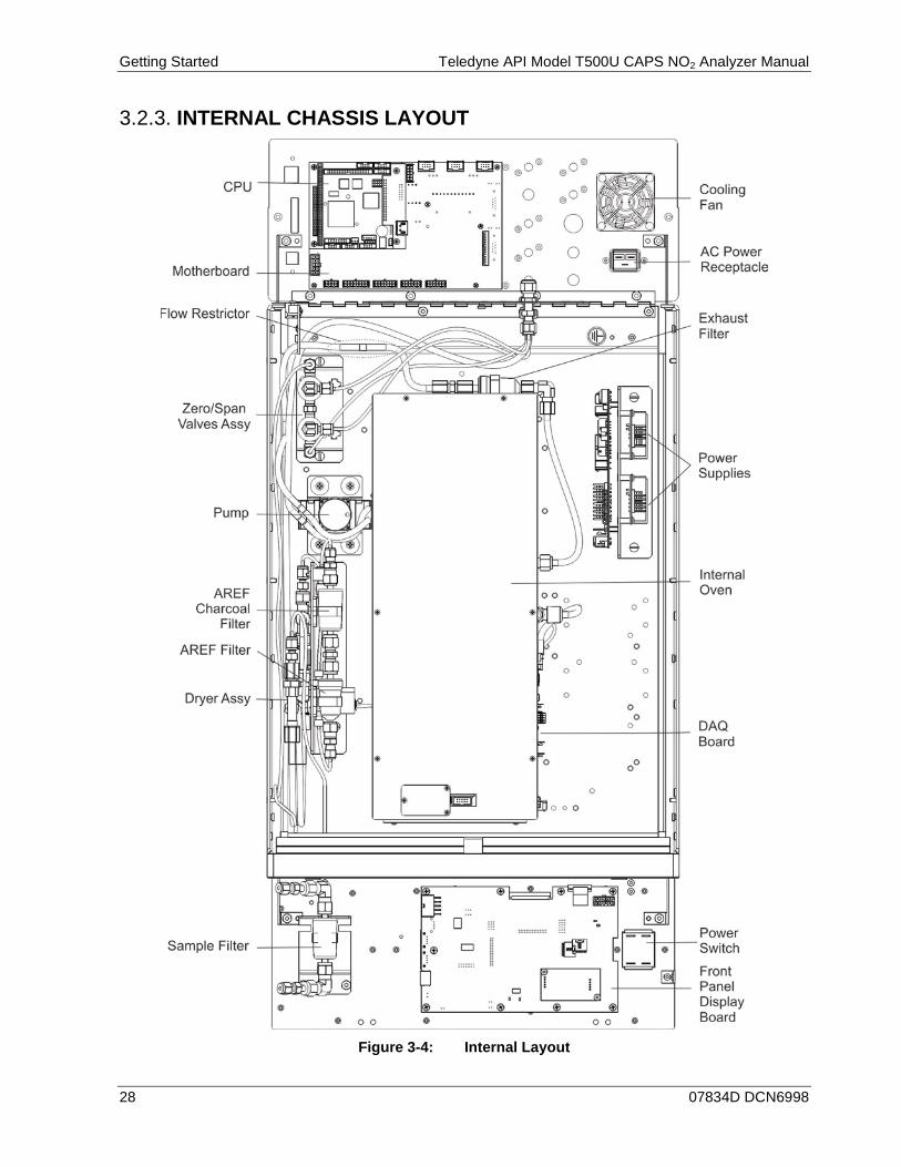
INTERNAL CHASSIS LAYOUT 3.2.3.
Figure 3-4: Internal Layout
Teledyne API Model T500U CAPS NO2 Analyzer Manual Getting Started
07834D DCN6998 29
CONNECTIONS AND SETUP 3.3.This section presents the electrical (Section 3.3.1) and pneumatic (Section 3.3.2) connections for setting up and preparing the instrument for operation.
ELECTRICAL CONNECTIONS 3.3.1.
Note To maintain compliance with EMC standards, it is required that the cable length be no greater than 3 meters for all I/O connections, which include Analog In, Analog Out, Status Out, Control In, Ethernet/LAN, USB, RS-232, and RS-485.
WARNING ELECTRICAL SHOCK HAZARD
High Voltages are present inside the analyzer’s case. Power connection must have functioning ground connection. Do not defeat the ground wire on power plug. Turn off analyzer power before disconnecting or connecting electrical subassemblies. Do not operate with cover off.
CAUTION GENERAL SAFETY HAZARD
To avoid damage to your analyzer, ensure that the AC power voltage matches the voltage indicated on the analyzer’s model/specs label located on the rear panel before plugging the T500U into line power.
CONNECTING POWER 3.3.1.1.
Adhering to all safety and cautionary messages, attach the power cord between the analyzer’s AC power connector and a power outlet capable of carrying at least the rated current at your AC voltage range; also ensure that it is equipped with a functioning earth ground.
Getting Started Teledyne API Model T500U CAPS NO2 Analyzer Manual
30 07834D DCN6998
CONNECTING ANALOG INPUTS (AIN) OPTION 3.3.1.2.
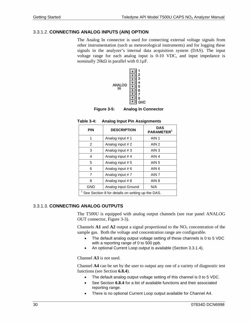
The Analog In connector is used for connecting external voltage signals from other instrumentation (such as meteorological instruments) and for logging these signals in the analyzer’s internal data acquisition system (DAS). The input voltage range for each analog input is 0-10 VDC, and input impedance is nominally 20kΩ in parallel with 0.1µF.
Figure 3-5: Analog In Connector
Table 3-4: Analog Input Pin Assignments
PIN DESCRIPTION DAS PARAMETER1
1 Analog input # 1 AIN 1 2 Analog input # 2 AIN 2 3 Analog input # 3 AIN 3 4 Analog input # 4 AIN 4 5 Analog input # 5 AIN 5 6 Analog input # 6 AIN 6 7 Analog input # 7 AIN 7 8 Analog input # 8 AIN 8
GND Analog input Ground N/A 1 See Section 8 for details on setting up the DAS.
CONNECTING ANALOG OUTPUTS 3.3.1.3.
The T500U is equipped with analog output channels (see rear panel ANALOG OUT connector, Figure 3-3).
Channels A1 and A2 output a signal proportional to the NO2 concentration of the sample gas. Both the voltage and concentration range are configurable.
• The default analog output voltage setting of these channels is 0 to 5 VDC with a reporting range of 0 to 500 ppb.
• An optional Current Loop output is available (Section 3.3.1.4).
Channel A3 is not used.
Channel A4 can be set by the user to output any one of a variety of diagnostic test functions (see Section 6.8.4).
• The default analog output voltage setting of this channel is 0 to 5 VDC. • See Section 6.8.4 for a list of available functions and their associated
reporting range. • There is no optional Current Loop output available for Channel A4.
Teledyne API Model T500U CAPS NO2 Analyzer Manual Getting Started
07834D DCN6998 31
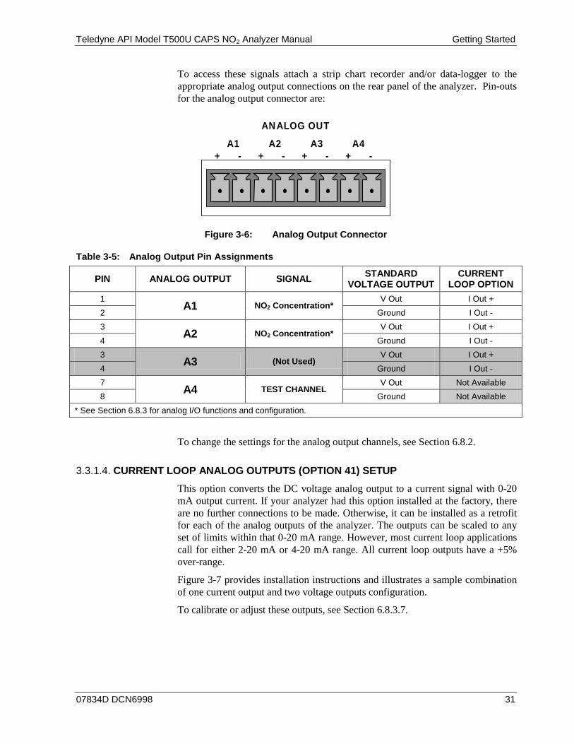
To access these signals attach a strip chart recorder and/or data-logger to the appropriate analog output connections on the rear panel of the analyzer. Pin-outs for the analog output connector are:
ANALOG OUT
A1 A2 A3 A4 + - + - + - + -
Figure 3-6: Analog Output Connector
Table 3-5: Analog Output Pin Assignments
PIN ANALOG OUTPUT SIGNAL STANDARD VOLTAGE OUTPUT
CURRENT LOOP OPTION
1 A1 NO2 Concentration*
V Out I Out + 2 Ground I Out - 3
A2 NO2 Concentration* V Out I Out +
4 Ground I Out - 3
A3 (Not Used) V Out I Out +
4 Ground I Out - 7
A4 TEST CHANNEL V Out Not Available
8 Ground Not Available * See Section 6.8.3 for analog I/O functions and configuration.
To change the settings for the analog output channels, see Section 6.8.2.
CURRENT LOOP ANALOG OUTPUTS (OPTION 41) SETUP 3.3.1.4.
This option converts the DC voltage analog output to a current signal with 0-20 mA output current. If your analyzer had this option installed at the factory, there are no further connections to be made. Otherwise, it can be installed as a retrofit for each of the analog outputs of the analyzer. The outputs can be scaled to any set of limits within that 0-20 mA range. However, most current loop applications call for either 2-20 mA or 4-20 mA range. All current loop outputs have a +5% over-range.
Figure 3-7 provides installation instructions and illustrates a sample combination of one current output and two voltage outputs configuration.
To calibrate or adjust these outputs, see Section 6.8.3.7.
Getting Started Teledyne API Model T500U CAPS NO2 Analyzer Manual
32 07834D DCN6998
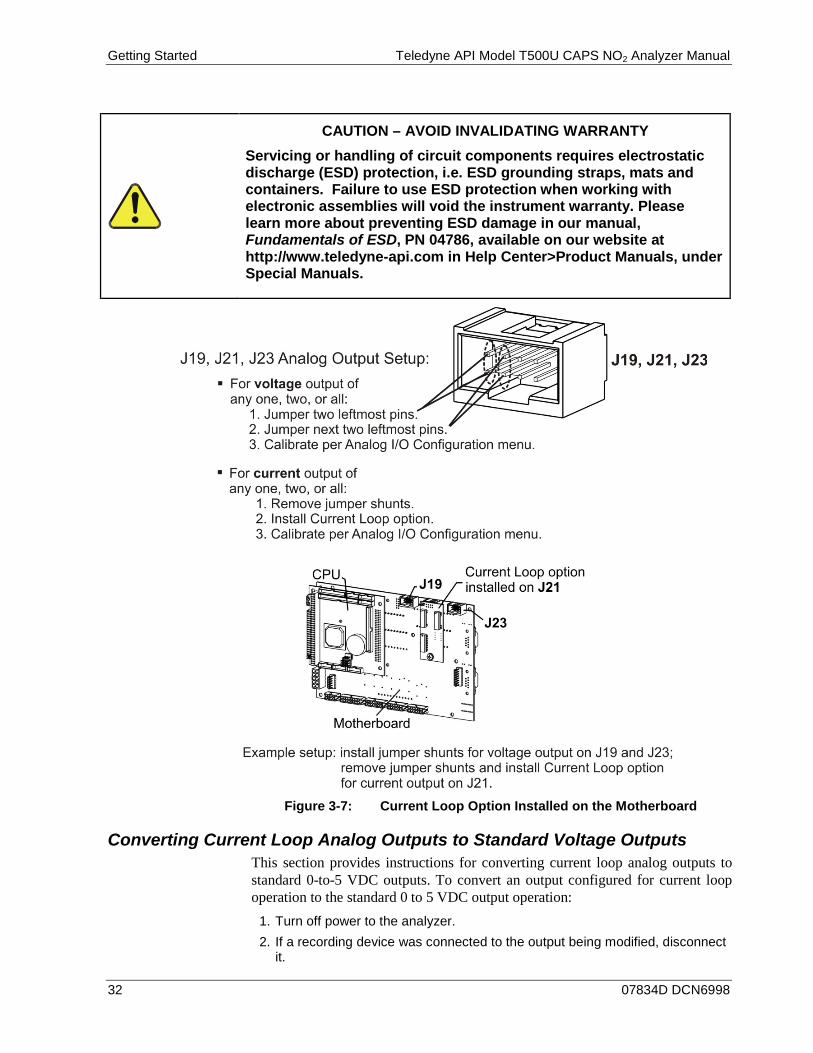
Figure 3-7: Current Loop Option Installed on the Motherboard
Converting Current Loop Analog Outputs to Standard Voltage Outputs This section provides instructions for converting current loop analog outputs to standard 0-to-5 VDC outputs. To convert an output configured for current loop operation to the standard 0 to 5 VDC output operation:
1. Turn off power to the analyzer. 2. If a recording device was connected to the output being modified, disconnect
it.
CAUTION – AVOID INVALIDATING WARRANTY Servicing or handling of circuit components requires electrostatic discharge (ESD) protection, i.e. ESD grounding straps, mats and containers. Failure to use ESD protection when working with electronic assemblies will void the instrument warranty. Please learn more about preventing ESD damage in our manual, Fundamentals of ESD, PN 04786, available on our website at http://www.teledyne-api.com in Help Center>Product Manuals, under Special Manuals.

Teledyne API Model T500U CAPS NO2 Analyzer Manual Getting Started
07834D DCN6998 33
3. Remove the top cover. • Remove the screws fastening the top cover to the unit (one per side). • Slide the cover back and lift the cover straight up.
4. Remove the screw holding the current loop option to the motherboard. 5. Disconnect the current loop option PCA from the appropriate connector on
the motherboard (see Figure 3-7). 6. Each connector, J19 and J23, requires two shunts. Place one shunt on the
two leftmost pins and the second shunt on the two adjacent pins (see Figure 3-7).
7. Reattach the top cover to the analyzer. 8. Attach a voltage-sensing, recording device to that output. 9. Calibrate the analog output as described in Section 6.8.3.2.
CONNECTING THE STATUS OUTPUTS 3.3.1.5.
The Status Outputs report analyzer conditions via optically isolated NPN transistors, which sink up to 50 mA of DC current. These outputs can be used to interface with devices that accept logic-level digital inputs, such as Programmable Logic Controllers (PLCs). Each Status bit is an open collector output that can withstand up to 40 VDC. All of the emitters of these transistors are tied together and available at pin D.
ATTENTION COULD DAMAGE INSTRUMENT AND VOID WARRANTY Most PLC’s have internal provisions for limiting the current that the input will draw from an external device. When connecting to a unit that does not have this feature, an external dropping resistor must be used to limit the current through the transistor output to less than 50 mA. At 50 mA, the transistor will drop approximately 1.2V from its collector to emitter.

Getting Started Teledyne API Model T500U CAPS NO2 Analyzer Manual
34 07834D DCN6998
The status outputs are accessed via a rear panel 12-pin connector labeled STATUS (Figure 3-8). Pin-outs for this connector are:
STATUS
1 2 3 4 5 6 7 8 D +
SYST
EM O
K
HIG
H R
AN
GE
CO
NC
VA
LID
ZER
O C
AL
SPA
N C
AL
DIA
G M
OD
E
+5V to external device
TEM
P A
LAR
M
PRES
S A
LAR
M
Figure 3-8: Status Output Connector
Table 3-6: Status Output Pin Assignments
OUTPUT # STATUS DEFINITION CONDITION 1 SYSTEM OK On if no faults are present.
2 CONC VALID On if NO2 concentration measurement is valid. If the NO2 concentration measurement is invalid, this bit is OFF.
3 HIGH RANGE On if unit is in high range of DUAL or AUTO Range Modes.
4 ZERO CAL On whenever the instrument is in CALZ mode.
5 SPAN CAL On whenever the instrument is in CALS mode.
6 DIAG MODE On whenever the instrument is in DIAGNOSTIC mode.
7 TEMP ALARM On when temperature alarm is active.
8 PRESSURE ALARM On when pressure alarm is active.
D Emitter BUS The emitters of the transistors on pins 1 to 8 are bussed together.
SPARE
+ DC Power + 5 VDC, 300 mA source maximum
Digital Ground The ground level from the analyzer’s internal DC power supplies. This
connection should be used as the ground return when +5VDC power is used.
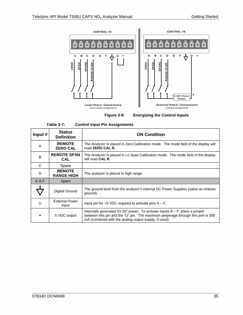
CONNECTING THE CONTROL INPUTS 3.3.1.6.
The 10-pin CONTROL IN connector provides three digital control inputs to remotely activate the zero and span calibration modes.
There are two methods for energizing the Control Inputs. The internal +5V available from the pin labeled “+” is the most convenient method however, to ensure that these inputs are truly isolated; a separate external 5 VDC power supply should be used.
Teledyne API Model T500U CAPS NO2 Analyzer Manual Getting Started
07834D DCN6998 35
Local Power Connections (non-isolated configuration)
External Power Connections (isolated configuration)
CONTROL IN
A B C D E F U +
SP
AN
ZER
O
SP
AR
E
RA
NG
E H
IGH
RA
NG
E H
IGH
CONTROL IN
A B C D E F U +
SP
AN
ZER
O
SP
AR
E
- + 5 VDC Power Supply
Figure 3-9: Energizing the Control Inputs
Table 3-7: Control Input Pin Assignments
Input # Status Definition ON Condition
A REMOTE ZERO CAL
The Analyzer is placed in Zero Calibration mode. The mode field of the display will read ZERO CAL R.
B REMOTE SPAN CAL
The Analyzer is placed in Lo Span Calibration mode. The mode field of the display will read CAL R.
C Spare
D REMOTE RANGE HIGH The analyzer is placed in high range.
E & F Spare
Digital Ground The ground level from the analyzer’s internal DC Power Supplies (same as chassis
ground).
U External Power input Input pin for +5 VDC required to activate pins A – F.
+ 5 VDC output Internally generated 5V DC power. To activate inputs A – F, place a jumper between this pin and the “U” pin. The maximum amperage through this port is 300 mA (combined with the analog output supply, if used).
Getting Started Teledyne API Model T500U CAPS NO2 Analyzer Manual
36 07834D DCN6998
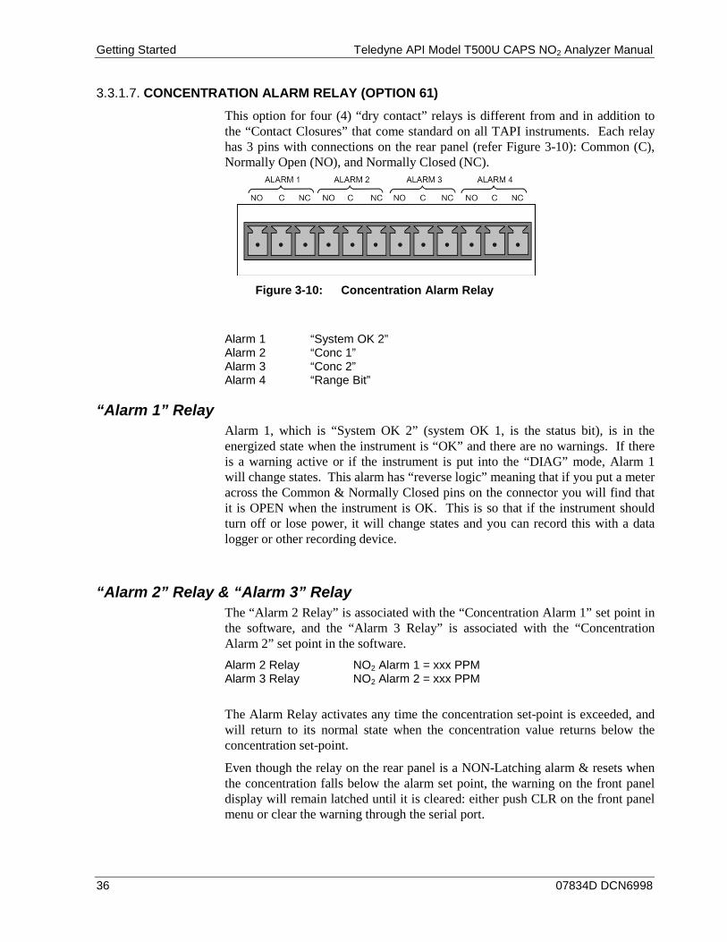
CONCENTRATION ALARM RELAY (OPTION 61) 3.3.1.7.
This option for four (4) “dry contact” relays is different from and in addition to the “Contact Closures” that come standard on all TAPI instruments. Each relay has 3 pins with connections on the rear panel (refer Figure 3-10): Common (C), Normally Open (NO), and Normally Closed (NC).
Figure 3-10: Concentration Alarm Relay
Alarm 1 “System OK 2” Alarm 2 “Conc 1” Alarm 3 “Conc 2” Alarm 4 “Range Bit”
“Alarm 1” Relay Alarm 1, which is “System OK 2” (system OK 1, is the status bit), is in the energized state when the instrument is “OK” and there are no warnings. If there is a warning active or if the instrument is put into the “DIAG” mode, Alarm 1 will change states. This alarm has “reverse logic” meaning that if you put a meter across the Common & Normally Closed pins on the connector you will find that it is OPEN when the instrument is OK. This is so that if the instrument should turn off or lose power, it will change states and you can record this with a data logger or other recording device.
“Alarm 2” Relay & “Alarm 3” Relay The “Alarm 2 Relay” is associated with the “Concentration Alarm 1” set point in the software, and the “Alarm 3 Relay” is associated with the “Concentration Alarm 2” set point in the software. Alarm 2 Relay NO2 Alarm 1 = xxx PPM Alarm 3 Relay NO2 Alarm 2 = xxx PPM
The Alarm Relay activates any time the concentration set-point is exceeded, and will return to its normal state when the concentration value returns below the concentration set-point.
Even though the relay on the rear panel is a NON-Latching alarm & resets when the concentration falls below the alarm set point, the warning on the front panel display will remain latched until it is cleared: either push CLR on the front panel menu or clear the warning through the serial port.

Teledyne API Model T500U CAPS NO2 Analyzer Manual Getting Started
07834D DCN6998 37
“Alarm 4” Relay This relay is connected to the “range bit”. If the instrument is configured for “Auto Range” and the instrument moves into the high range, it activates this relay.
CONNECTING THE COMMUNICATIONS INTERFACES 3.3.1.8.
Connectors for remote communications interfaces are: Ethernet, USB, RS-232, RS-232 Multidrop and RS-485 (each described here). In addition to using the appropriate cables, each type of communication method must be configured using the SETUP>COMM menu (see Section 6.6 for a brief description of the SETUP>COMM menu, and Section 7 for communications configuration).
Ethernet Connection For network or Internet communication with the analyzer, connect an Ethernet cable from the analyzer’s rear panel ETHERNET interface connector to an Ethernet port. Although the analyzer is shipped with DHCP enabled by default (Section 7.5.2), it should be manually assigned a static IP address.
Configuration: (manual, i.e., static) Section 7.5.1.
USB Connection The USB option can be used for direct communication between the analyzer and a PC; connect a USB cable between the analyzer and computer USB ports. This USB connection can only be used when the COM2 port is not in use except for RS-232 Multidrop communication.
Configuration: Section 7.6.
Note If this option is installed, the rear panel COM2 port cannot be used for anything other than Multidrop communication.
RS-232 Connection For RS-232 communications with data terminal equipment (DTE) or with data communication equipment (DCE) connect either a DB9-female-to-DB9-female cable (Teledyne API part number WR000077) or a DB9-female-to-DB25-male cable (Option 60A), as applicable, from the analyzer’s rear panel RS-232 port to the device. Adjust the rear panel DCE-DTE switch to select DTE or DCE as appropriate (Section 7.1).
Configuration: Section 7.3
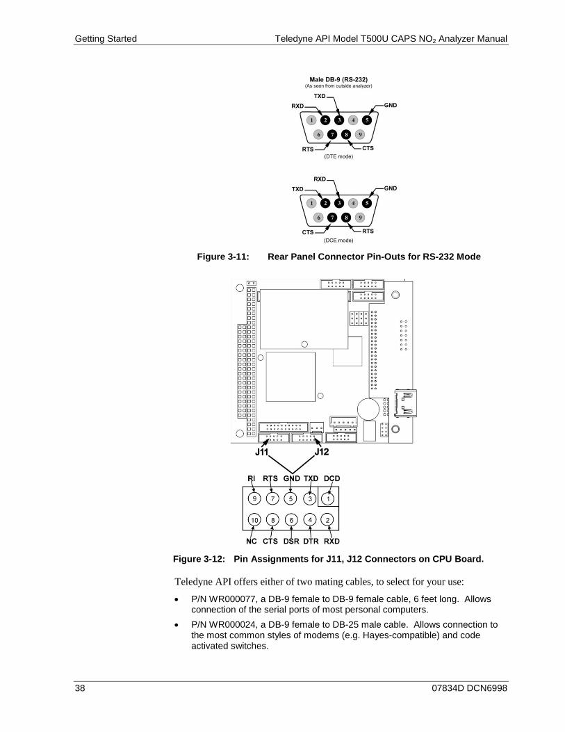
IMPORTANT IMPACT ON READINGS OR DATA Cables that appear to be compatible because of matching connectors may incorporate internal wiring that makes the link inoperable. Check cables acquired from sources other than Teledyne API for pin assignments (Figure 3-11) before using.
Getting Started Teledyne API Model T500U CAPS NO2 Analyzer Manual
38 07834D DCN6998
Figure 3-11: Rear Panel Connector Pin-Outs for RS-232 Mode
Figure 3-12: Pin Assignments for J11, J12 Connectors on CPU Board.
Teledyne API offers either of two mating cables, to select for your use:
• P/N WR000077, a DB-9 female to DB-9 female cable, 6 feet long. Allows connection of the serial ports of most personal computers.
• P/N WR000024, a DB-9 female to DB-25 male cable. Allows connection to the most common styles of modems (e.g. Hayes-compatible) and code activated switches.
Teledyne API Model T500U CAPS NO2 Analyzer Manual Getting Started
07834D DCN6998 39
Both cables are configured with straight-through wiring and should require no additional adapters.
To assist in properly connecting the serial ports to either a computer or a modem, there are activity indicators just above the RS-232 port. Once a cable is connected between the analyzer and a computer or modem, both the red and green LEDs should be on.
• If the lights are not lit, locate the small switch on the rear panel to switch it between DTE and DCE modes.
• If both LEDs are still not illuminated, ensure that the cable properly constructed.
Received from the factory, the analyzer is set up to emulate an RS-232 DCE device. RS-232 (COM1): RS-232 (fixed) DB-9 male connector
• Baud rate: 115200 bits per second (baud) • Data Bits: 8 data bits with 1 stop bit • Parity: None
COM2: RS-232 (configurable to RS 485), DB-9 female connector
• Baud rate:19200 bits per second (baud) • Data Bits: 8 data bits with 1 stop bit • Parity: None
RS-232 Multidrop (Option 62) Connection When the RS-232 Multidrop option is installed, connection adjustments and configuration through the menu system are required. This section provides instructions for the internal connection adjustments, then for external connections, and ends with instructions for menu-driven configuration.
Note Because the RS-232 Multidrop option uses both the RS232 and COM2 DB9 connectors on the analyzer’s rear panel to connect the chain of instruments, COM2 port is no longer available for separate RS-232 or RS-485 operation.
ATTENTION COULD DAMAGE INSTRUMENT AND VOID WARRANTY Printed Circuit Assemblies (PCAs) are sensitive to electro-static discharges (ESD) too small to be felt by the human nervous system. Failure to use ESD protection when working with electronic assemblies will void the instrument warranty. Please learn more about preventing ESD damage in our manual, Fundamentals of ESD, PN 04786, available on our website at http://www.teledyne-api.com in Help Center>Product Manuals, under Special Manuals.

Getting Started Teledyne API Model T500U CAPS NO2 Analyzer Manual
40 07834D DCN6998
In each instrument with the Multidrop option there is a shunt that jumpers two pins on the serial Multidrop and LVDS printed circuit assembly (PCA), as shown in Figure 3-13. This shunt must be removed from all instruments except that designated as last in the multidrop chain, which must remain terminated. This requires powering off and opening each instrument and making the following adjustments: 1. With NO power to the instrument, remove its top cover and lay the rear
panel open for access to the Multidrop/LVDS PCA, which is seated on the CPU.
2. On the Multidrop/LVDS PCA’s JP2 connector, remove the shunt that jumpers Pins 21 ↔ 22 as indicated in Figure 3-13. (Do this for all but the last instrument in the chain where the shunt should remain at Pins 21 ↔ 22).
3. Check that the following cable connections are made in all instruments (again refer to Figure 3-13): • J3 on the Multidrop/LVDS PCA to the CPU’s COM1 connector
(Note that the CPU’s COM2 connector is not used in Multidrop)
• J4 on the Multidrop/LVDS PCA to J12 on the motherboard • J1 on the Multidrop/LVDS PCS to the front panel LCD
Figure 3-13: Jumper and Cables for Multidrop Mode
(Note: If you are adding an instrument to the end of a previously configured chain, remove the shunt between Pins 21 ↔ 22 of JP2 on the
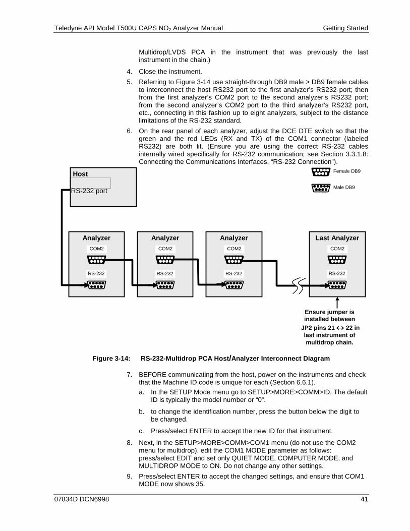
Teledyne API Model T500U CAPS NO2 Analyzer Manual Getting Started
07834D DCN6998 41
Multidrop/LVDS PCA in the instrument that was previously the last instrument in the chain.)
4. Close the instrument. 5. Referring to Figure 3-14 use straight-through DB9 male > DB9 female cables
to interconnect the host RS232 port to the first analyzer’s RS232 port; then from the first analyzer’s COM2 port to the second analyzer’s RS232 port; from the second analyzer’s COM2 port to the third analyzer’s RS232 port, etc., connecting in this fashion up to eight analyzers, subject to the distance limitations of the RS-232 standard.
6. On the rear panel of each analyzer, adjust the DCE DTE switch so that the green and the red LEDs (RX and TX) of the COM1 connector (labeled RS232) are both lit. (Ensure you are using the correct RS-232 cables internally wired specifically for RS-232 communication; see Section 3.3.1.8: Connecting the Communications Interfaces, “RS-232 Connection”).
Analyzer Analyzer Analyzer Last Analyzer
Female DB9
Male DB9
RS-232
COM2
RS-232
COM2
RS-232
COM2
RS-232
COM2
Host RS-232 port
Ensure jumper is installed between
JP2 pins 21 ↔ 22 in last instrument of multidrop chain.
Figure 3-14: RS-232-Multidrop PCA Host/Analyzer Interconnect Diagram
7. BEFORE communicating from the host, power on the instruments and check that the Machine ID code is unique for each (Section 6.6.1). a. In the SETUP Mode menu go to SETUP>MORE>COMM>ID. The default
ID is typically the model number or “0”.
b. to change the identification number, press the button below the digit to be changed.
c. Press/select ENTER to accept the new ID for that instrument.
8. Next, in the SETUP>MORE>COMM>COM1 menu (do not use the COM2 menu for multidrop), edit the COM1 MODE parameter as follows: press/select EDIT and set only QUIET MODE, COMPUTER MODE, and MULTIDROP MODE to ON. Do not change any other settings.
9. Press/select ENTER to accept the changed settings, and ensure that COM1 MODE now shows 35.
Getting Started Teledyne API Model T500U CAPS NO2 Analyzer Manual
42 07834D DCN6998
10. Press/select SET> to go to the COM1 BAUD RATE menu and ensure it reads the same for all instruments (edit as needed so that all instruments are set at the same baud rate).
Note The (communication) Host instrument can address only one instrument at a time, each by its unique ID (see step 7 above).
Note Teledyne API recommends setting up the first link, between the Host and the first analyzer, and testing it before setting up the rest of the chain.
RS-485 Connection (Option) As delivered from the factory, COM2 is configured for RS-232 communications. This port can be reconfigured for operation as a non-isolated, half-duplex RS-485 port. Using COM2 for RS-485 communication will disable the USB port. To reconfigure this port for RS-485 communication, please contact the factory.
PNEUMATIC CONNECTIONS 3.3.2.This section provides not only pneumatic connection information, but also important information about the gases required for accurate calibration (Section 3.3.2.1); it also illustrates the pneumatic layout for the analyzer, including valve option.
Before making the pneumatic connections, carefully note the following cautionary and additional messages:
CAUTION – GENERAL SAFETY HAZARD In units with a permeation tube option installed, the vacuum pump must be connected and powered on to maintain constant gas flow through the analyzer at all times. Insufficient gas flow allows gas to build up to levels that will contaminate the instrument or present a safety hazard to personnel. Remove the permeation tube when taking the analyzer out of operation (Section 11.3.2 provides removal instructions), and store in a sealed container (use original container that tube was shipped in).
CAUTION GENERAL SAFETY HAZARD
Do not vent calibration gas, exhaust gas or sample gas into enclosed areas.
Teledyne API Model T500U CAPS NO2 Analyzer Manual Getting Started
07834D DCN6998 43
CAUTION NEVER operate the analyzer with the gas ports capped at the rear of the analyzer: this can damage the internal pump. NEVER operate the analyzer with the internal pneumatics disconnected: this will allow contaminants to enter the bench.
ATTENTION COULD DAMAGE INSTRUMENT AND VOID WARRANTY Venting Pressurized Gas: In applications where any gas (span gas, zero air supply, sample gas)
is received from a pressurized manifold, a vent must be provided to equalize the gas with ambient atmospheric pressure before it enters the analyzer to ensure that the gases input do not exceed the maximum inlet pressure of the analyzer, as well as to prevent back diffusion and pressure effects. These vents should be:
• at least 0.2m long • no more than 2m long • vented outside the shelter.
Avoiding Introduction of Debris into Optical Cell: Sudden, large changes in pressure can forcibly move debris past the
filters (sample/exhaust) and into the optical cell. To avoid this, relieve pressure slowly when the system is under vacuum and/or pressure.
Dust Plugs: Remove dust plugs from rear panel exhaust and supply line fittings
before powering on/operating instrument. These plugs should be kept for reuse in the event of future storage or shipping to prevent debris from entering the pneumatics.
IMPORTANT IMPACT ON READINGS OR DATA Sample and calibration gases should only come into contact with PTFE tubing.
IMPORTANT IMPACT ON READINGS OR DATA Run a leak check once the appropriate pneumatic connections have been made; check all pneumatic fittings for leaks using the procedures defined in Section 11.3.5.
Getting Started Teledyne API Model T500U CAPS NO2 Analyzer Manual
44 07834D DCN6998
ABOUT ZERO AIR AND CALIBRATION (SPAN) GAS 3.3.2.1.
Zero air and span gas are required for accurate calibration.
Note Zero air and span gases must be supplied at twice the instrument’s specified gas flow rate. Therefore, the T500U zero and span gases should be supplied to their respective inlets in excess of 1800 cm3/min (~900 cm3/min x 2).
Zero Air Zero air or zero calibration gas is defined as a gas that is similar in chemical composition to the measured medium but without the gas to be measured by the analyzer.
For the T500U this means zero air should be devoid of NO2 and H2O vapor.
• If your application is not a measurement in ambient air, the zero calibration gas should be matched to the composition of the gas being measured.
• Pure nitrogen (N2) could be used as a zero gas for applications where NO2 is measured in nitrogen.
Calibration (Span) Gas Calibration gas is specifically mixed to match the chemical composition of the type of gas being measured at near full scale of the desired reporting range. To measure NO2 with the T500U analyzer, it is recommended that you use a span gas with a concentration equal to 80% of the measurement range for your application
EXAMPLE: • If the application is to measure NO2 in ambient air between 0 ppb and 500
ppb, an appropriate span gas would be 400 ppb. • If the application is to measure NO2 in ambient air between 0 ppb and 100
ppb, an appropriate span gas would be 80 ppb.
Cylinders of calibrated NO2 gas traceable to NIST specifications (also referred to as EPA protocol calibration gases or Standard Reference Materials) are commercially available.
Span Gas for Multipoint Calibration Some applications, such as EPA monitoring, require a multipoint calibration where span gases of different concentrations are needed. We recommend using an NO2 gas of higher concentration combined with a gas dilution calibrator such as a Teledyne API Model T700. This type of calibrator mixes a high concentration gas with zero air to accurately produce span gas of the desired concentration. Linearity profiles can be automated with this model and run unattended overnight.
Note TAPI recommends the use of NO2 permeation tubes for performing routine calibration checks only, but not for NO2 span calibration.
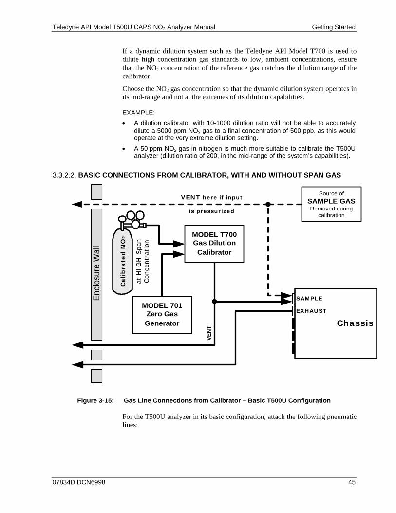
Teledyne API Model T500U CAPS NO2 Analyzer Manual Getting Started
07834D DCN6998 45
If a dynamic dilution system such as the Teledyne API Model T700 is used to dilute high concentration gas standards to low, ambient concentrations, ensure that the NO2 concentration of the reference gas matches the dilution range of the calibrator.
Choose the NO2 gas concentration so that the dynamic dilution system operates in its mid-range and not at the extremes of its dilution capabilities.
EXAMPLE: • A dilution calibrator with 10-1000 dilution ratio will not be able to accurately
dilute a 5000 ppm NO2 gas to a final concentration of 500 ppb, as this would operate at the very extreme dilution setting.
• A 50 ppm NO2 gas in nitrogen is much more suitable to calibrate the T500U analyzer (dilution ratio of 200, in the mid-range of the system’s capabilities).
BASIC CONNECTIONS FROM CALIBRATOR, WITH AND WITHOUT SPAN GAS 3.3.2.2.
VENT here if input
is pressurized
Source of SAMPLE GASRemoved during
calibration
Chassis
SAMPLE
EXHAUST
MODEL T700Gas Dilution
Calibrator
VENT
MODEL 701Zero Gas Generator
Encl
osur
e W
all
Calib
rate
d N
O2
at H
IGH
Spa
n Co
ncen
trat
ion
Figure 3-15: Gas Line Connections from Calibrator – Basic T500U Configuration
For the T500U analyzer in its basic configuration, attach the following pneumatic lines:

Getting Started Teledyne API Model T500U CAPS NO2 Analyzer Manual
46 07834D DCN6998
Sample Gas Source Connect a sample gas line to the SAMPLE inlet
• Use PTFE tubing; minimum OD ¼”. • Sample Gas pressure must not exceed ambient atmospheric pressure by
more than 1.0 psig. • Follow cautionary guidelines for pressurized manifold.
Calibration Gas Sources • CAL GAS & ZERO AIR SOURCES: The source of calibration gas is also
attached to the SAMPLE inlet, but only when a calibration operation is actually being performed.
• Use PTFE tubing; minimum OD ¼”.
Venting In order to prevent back diffusion and pressure effects, both the span gas and zero air supply lines should be:
• Vented outside the shelter. • Minimum OD ¼”. • No less than 2 meters in length. • No greater than 10 meters in length.
Exhaust Outlet Attach an exhaust line to the EXHAUST outlet fitting. The exhaust line should be:
• Use PTFE tubing; minimum OD ¼”. • No greater than 10 meters in length. • Vented outside the shelter.
IMPORTANT IMPACT ON READINGS OR DATA Do NOT place any mufflers or filters downstream of the pump, i.e., external to the instrument.
Note Once the appropriate pneumatic connections have been made, check all pneumatic fittings for leaks (see Section 11.3.5 for detailed leak check).
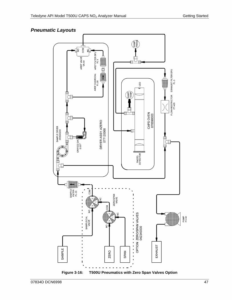
Teledyne API Model T500U CAPS NO2 Analyzer Manual Getting Started
07834D DCN6998 47
Pneumatic Layouts
Figure 3-16: T500U Pneumatics with Zero Span Valves Option

Getting Started Teledyne API Model T500U CAPS NO2 Analyzer Manual
48 07834D DCN6998
Figure 3-17: T500U Pneumatics with Internal Zero Span Valves Option
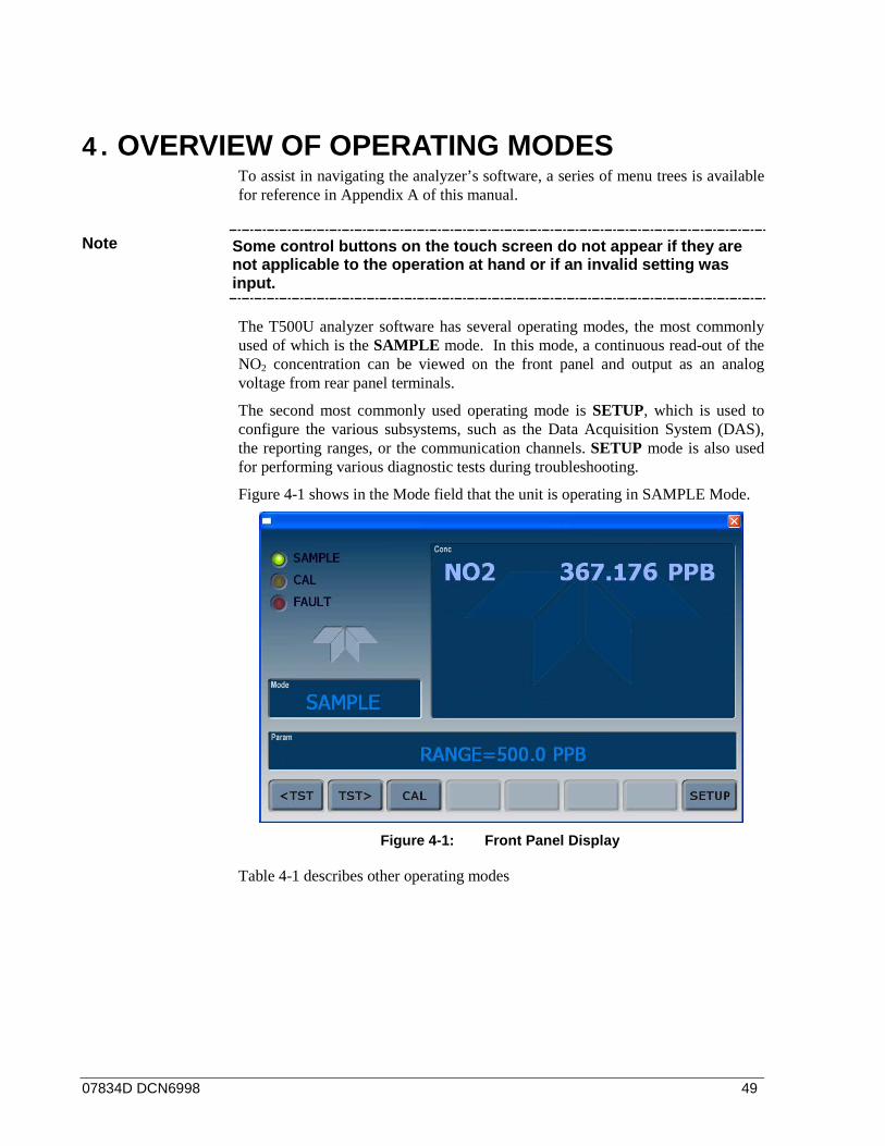
07834D DCN6998 49
4. OVERVIEW OF OPERATING MODES To assist in navigating the analyzer’s software, a series of menu trees is available for reference in Appendix A of this manual.
Note Some control buttons on the touch screen do not appear if they are not applicable to the operation at hand or if an invalid setting was input.
The T500U analyzer software has several operating modes, the most commonly used of which is the SAMPLE mode. In this mode, a continuous read-out of the NO2 concentration can be viewed on the front panel and output as an analog voltage from rear panel terminals.
The second most commonly used operating mode is SETUP, which is used to configure the various subsystems, such as the Data Acquisition System (DAS), the reporting ranges, or the communication channels. SETUP mode is also used for performing various diagnostic tests during troubleshooting.
Figure 4-1 shows in the Mode field that the unit is operating in SAMPLE Mode.
Figure 4-1: Front Panel Display
Table 4-1 describes other operating modes

Overview of Operating Modes Teledyne API Model T500U CAPS NO2 Analyzer Manual
50 07834D DCN6998
Table 4-1: Analyzer Operating Modes MODE EXPLANATION DIAG One of the analyzer’s diagnostic modes is active.
AREF2 Only when in Sample mode an internal valve periodically activates, diverting the sample gas through a charcoal scrubber. The auto reference value is measured during this period.
LO CAL A Unit is performing LOW SPAN calibration initiated automatically by the analyzer’s AUTOCAL feature
LO CAL R Unit is performing LOW SPAN calibration initiated remotely through the COM ports or digital control inputs.
M-P CAL This is the basic calibration mode of the instrument and is activated by pressing the CAL button. SAMPLE Sampling normally, flashing text indicates the adaptive filter has tripped due to a change in
concentration. SETUP SETUP mode is being used to configure the analyzer. The gas measurement will continue during
setup. SAMPLE A1 Indicates that unit is in SAMPLE mode and AUTOCAL feature is activated.
SPAN CAL A1 Unit is performing SPAN calibration initiated automatically by the analyzer’s AUTOCAL feature SPAN CAL M1 Unit is performing SPAN calibration initiated manually by the user. SPAN CAL R1 Unit is performing SPAN calibration initiated remotely through the COM ports or digital control
inputs.
ZERO CAL A1 Unit is performing ZERO calibration procedure initiated automatically by the AUTOCAL feature ZERO CAL M1 Unit is performing ZERO calibration procedure initiated manually by the user. ZERO CAL R1 Unit is performing ZERO calibration procedure initiated remotely through the COM ports or digital
control inputs. 1 Only appears on units with the Z/S or IZS valve option. 2 Initial AREF (automatically runs 20 minutes after power up) and any manual AREF sets the AREF filter output value to the current reading.
SAMPLE MODE 4.1.SAMPLE is the standard operating mode. In this mode, the instrument is continually calculating the NO2 concentration. These values are displayed in the CONC field of the analyzer's front panel display during SAMPLE mode.
Also in this mode the PARAM field will display any warning messages (Section 4.1.2) as well as the test functions (Section 4.1.1), which provide information about the operational status of the analyzer.
TEST FUNCTIONS 4.1.1.TEST functions provide information about the various parameters related to the analyzer’s operation and its measurement of gas concentration. Section 5.2 provides information about these functions.
Teledyne API Model T500U CAPS NO2 Analyzer Manual Overview of Operating Modes
07834D DCN6998 51
WARNING MESSAGES 4.1.2.The most common and serious instrument failures will activate Warning Messages, which are displayed on the analyzer’s Front Panel. A table of Warning Messages and their descriptions is presented in Table 5-1, Section 5.1.1.
CALIBRATION MODE 4.2.
Note Always perform Zero calibration before Span calibration.
Pressing the CAL button, switches the analyzer into calibration mode. In this mode the user can, in conjunction with introducing zero or span gases of known concentrations into the analyzer cause it to adjust and recalculate the slope (gain) and offset of its measurement range.
Note This mode is also used to check the current calibration status of the instrument.
If the instrument includes one of the available zero/span valve options, the SAMPLE mode display will also include CALZ and CALS buttons. Pressing either of these buttons also puts the instrument into calibration mode.
• The CALZ button is used to initiate a calibration of the analyzer’s zero point using zero air.
• The CALS button is used to calibrate the span point of the analyzer’s current reporting range using span gas.
Note It is recommended that this span calibration be performed at 80% of full scale of the analyzer’s currently selected reporting range. EXAMPLE: If the reporting range is set for 0 to 500 ppb, an appropriate span point would be 400 ppb.
Due to their critical importance and complexity, calibration operations are described in in Section 10, which details setting up and performing standard calibration operations or checks.
For information on using the automatic calibrations feature (ACAL) in conjunction with the calibration valve options, see Sections 10.4.6 and 10.5.
IMPORTANT IMPACT ON READINGS OR DATA To avoid inadvertent adjustments to critical settings, activate calibration security by enabling password protection in the SETUP – PASS menu.

Overview of Operating Modes Teledyne API Model T500U CAPS NO2 Analyzer Manual
52 07834D DCN6998
SETUP MODE 4.3.The SETUP Mode contains a variety of choices that are used to configure the analyzer’s hardware and software features, perform diagnostic procedures, gather information on the instruments performance and configure or access data from the internal data acquisition system (DAS). For a visual representation of the software menu trees, refer to Appendix A.
SETUP Mode is divided between Primary and Secondary Setup menus and can be protected through password security through the SETUP>PASS menu (Section 6.4) to prevent unauthorized or inadvertent configuration adjustments.
PRIMARY SETUP MENU 4.3.1.The areas accessed and configured under the primary SETUP Mode menu are shown in Table 4-2.
Table 4-2: Primary Setup Mode Features and Functions
MODE OR FEATURE CONTROL BUTTON LABEL
DESCRIPTION
Analyzer Configuration CFG Lists current hardware and software configuration information.
Auto Cal Feature ACAL Used to set up and operate the AutoCal feature. (Only appears if the Zero/Span valve option is installed).
Internal Data Acquisition (DAS) DAS Used to set up the DAS system and view recorded data. Analog Output Reporting Range Configuration RNGE Used to configure the output signals generated by the
instrument’s analog outputs. Calibration Password Security PASS Turns the calibration password feature ON/OFF. Internal Clock Configuration CLK Used to set or adjust the instrument’s internal clock.
(Advanced SETUP features) MORE Jumps to the secondary setup menu.
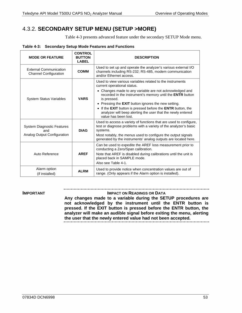
Teledyne API Model T500U CAPS NO2 Analyzer Manual Overview of Operating Modes
07834D DCN6998 53
SECONDARY SETUP MENU (SETUP >MORE) 4.3.2.Table 4-3 presents advanced feature under the secondary SETUP Mode menu.
Table 4-3: Secondary Setup Mode Features and Functions
MODE OR FEATURE CONTROL BUTTON LABEL
DESCRIPTION
External Communication Channel Configuration COMM
Used to set up and operate the analyzer’s various external I/O channels including RS-232; RS-485, modem communication and/or Ethernet access.
System Status Variables VARS
Used to view various variables related to the instruments current operational status. • Changes made to any variable are not acknowledged and
recorded in the instrument’s memory until the ENTR button is pressed.
• Pressing the EXIT button ignores the new setting. • If the EXIT button is pressed before the ENTR button, the
analyzer will beep alerting the user that the newly entered value has been lost.
System Diagnostic Features and
Analog Output Configuration DIAG
Used to access a variety of functions that are used to configure, test or diagnose problems with a variety of the analyzer’s basic systems. Most notably, the menus used to configure the output signals generated by the instruments’ analog outputs are located here.
Auto Reference AREF
Can be used to expedite the AREF loss measurement prior to conducting a Zero/Span calibration. Note that AREF is disabled during calibrations until the unit is placed back in SAMPLE mode. Also see Table 4-1.
Alarm option (if installed)
ALRM Used to provide notice when concentration values are out of range. (Only appears if the Alarm option is installed).
IMPORTANT IMPACT ON READINGS OR DATA Any changes made to a variable during the SETUP procedures are not acknowledged by the instrument until the ENTR button is pressed. If the EXIT button is pressed before the ENTR button, the analyzer will make an audible signal before exiting the menu, alerting the user that the newly entered value had not been accepted.

Overview of Operating Modes Teledyne API Model T500U CAPS NO2 Analyzer Manual
54 07834D DCN6998
This page intentionally left blank.

07834D DCN6998 55
5. STARTUP, FUNCTIONAL CHECKS, AND INITIAL CALIBRATION
STARTUP 5.1.For accurate results, allow the monitor to run for at least 60 minutes to reach a stable operating temperature.
WARNING MESSAGES 5.1.1.Because internal temperatures and other conditions may be outside the specified limits during the analyzer’s warm-up period, the software will suppress most warning conditions for 45 minutes after power up. If warning messages persist after the 45 minutes warm up period is over, investigate their cause using the troubleshooting guidelines in Section 13.1.
To view and clear warning messages, press:
Press CLR to clear the current message.
If more than one warning is active, the next message will take its place until
all warning messages have been cleared.
The CLR button disappears when the last message is
cleared, and <TST TST> buttons reappear for function check.
NOTE:If a warning message persists after
several attempts to clear it, the message may indicate a real problem and not an
artifact of the warm-up period
SAMPLE SYSTEM RESET
TEST CAL MSG CLR SETUP
SAMPLE DATA INITIALIZED
TEST CAL MSG CLR SETUP
SAMPLE CONFIG INITIALIZED
TEST CAL CLR SETUP
MSG returns the active warnings to the message field.
SAMPLE RANGE=500.0 PPB NO2=XXXX
<TST TST> CAL SETUP
Suppresses the warning messages
SAMPLE SYSTEM RESET
TEST CAL MSG CLR SETUP
SAMPLE RANGE=500.0 PPB NO2=XXXX
<TST TST> CAL MSG SETUP
The MSG button disappears when last message displays.
.
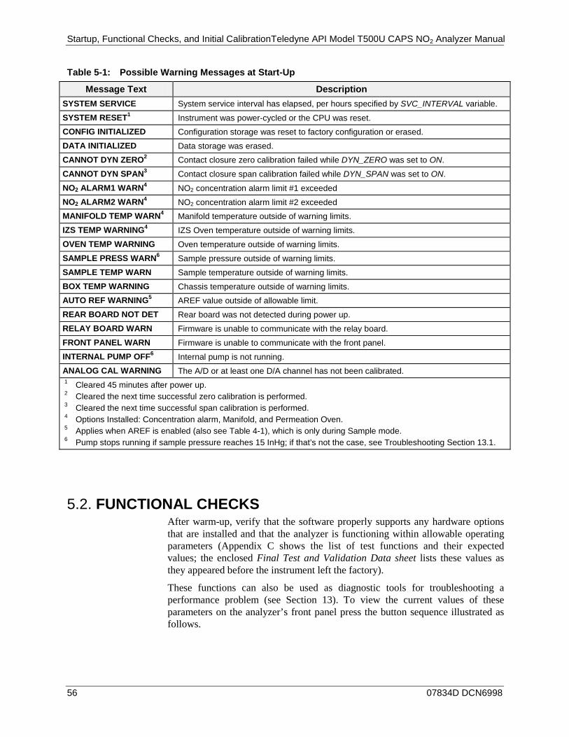
Startup, Functional Checks, and Initial CalibrationTeledyne API Model T500U CAPS NO2 Analyzer Manual
56 07834D DCN6998
Table 5-1: Possible Warning Messages at Start-Up
Message Text Description SYSTEM SERVICE System service interval has elapsed, per hours specified by SVC_INTERVAL variable.
SYSTEM RESET1 Instrument was power-cycled or the CPU was reset. CONFIG INITIALIZED Configuration storage was reset to factory configuration or erased. DATA INITIALIZED Data storage was erased. CANNOT DYN ZERO2 Contact closure zero calibration failed while DYN_ZERO was set to ON.
CANNOT DYN SPAN3 Contact closure span calibration failed while DYN_SPAN was set to ON.
NO2 ALARM1 WARN4 NO2 concentration alarm limit #1 exceeded NO2 ALARM2 WARN4 NO2 concentration alarm limit #2 exceeded MANIFOLD TEMP WARN4 Manifold temperature outside of warning limits. IZS TEMP WARNING4 IZS Oven temperature outside of warning limits. OVEN TEMP WARNING Oven temperature outside of warning limits. SAMPLE PRESS WARN6 Sample pressure outside of warning limits. SAMPLE TEMP WARN Sample temperature outside of warning limits. BOX TEMP WARNING Chassis temperature outside of warning limits. AUTO REF WARNING5 AREF value outside of allowable limit. REAR BOARD NOT DET Rear board was not detected during power up. RELAY BOARD WARN Firmware is unable to communicate with the relay board. FRONT PANEL WARN Firmware is unable to communicate with the front panel. INTERNAL PUMP OFF6 Internal pump is not running. ANALOG CAL WARNING The A/D or at least one D/A channel has not been calibrated. 1 Cleared 45 minutes after power up. 2 Cleared the next time successful zero calibration is performed. 3 Cleared the next time successful span calibration is performed. 4 Options Installed: Concentration alarm, Manifold, and Permeation Oven. 5 Applies when AREF is enabled (also see Table 4-1), which is only during Sample mode. 6 Pump stops running if sample pressure reaches 15 InHg; if that’s not the case, see Troubleshooting Section 13.1.
FUNCTIONAL CHECKS 5.2.After warm-up, verify that the software properly supports any hardware options that are installed and that the analyzer is functioning within allowable operating parameters (Appendix C shows the list of test functions and their expected values; the enclosed Final Test and Validation Data sheet lists these values as they appeared before the instrument left the factory).
These functions can also be used as diagnostic tools for troubleshooting a performance problem (see Section 13). To view the current values of these parameters on the analyzer’s front panel press the button sequence illustrated as follows.
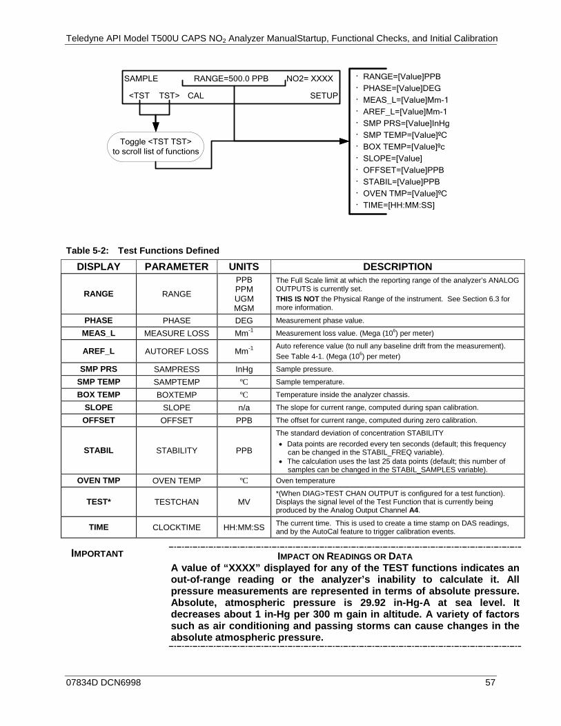
Teledyne API Model T500U CAPS NO2 Analyzer ManualStartup, Functional Checks, and Initial Calibration
07834D DCN6998 57
SAMPLE RANGE=500.0 PPB NO2= XXXX
<TST TST> CAL SETUP
Toggle <TST TST> to scroll list of functions
· RANGE=[Value]PPB· PHASE=[Value]DEG· MEAS_L=[Value]Mm-1· AREF_L=[Value]Mm-1· SMP PRS=[Value]InHg· SMP TEMP=[Value]ºC· BOX TEMP=[Value]ºc· SLOPE=[Value]· OFFSET=[Value]PPB· STABIL=[Value]PPB· OVEN TMP=[Value]ºC· TIME=[HH:MM:SS]
Table 5-2: Test Functions Defined
DISPLAY PARAMETER UNITS DESCRIPTION
RANGE RANGE
PPB PPM UGM MGM
The Full Scale limit at which the reporting range of the analyzer’s ANALOG OUTPUTS is currently set. THIS IS NOT the Physical Range of the instrument. See Section 6.3 for more information.
PHASE PHASE DEG Measurement phase value.
MEAS_L MEASURE LOSS Mm-1 Measurement loss value. (Mega (106) per meter)
AREF_L AUTOREF LOSS Mm-1 Auto reference value (to null any baseline drift from the measurement). See Table 4-1. (Mega (106) per meter)
SMP PRS SAMPRESS InHg Sample pressure.
SMP TEMP SAMPTEMP ºC Sample temperature.
BOX TEMP BOXTEMP ºC Temperature inside the analyzer chassis.
SLOPE SLOPE n/a The slope for current range, computed during span calibration.
OFFSET OFFSET PPB The offset for current range, computed during zero calibration.
STABIL STABILITY PPB
The standard deviation of concentration STABILITY • Data points are recorded every ten seconds (default; this frequency
can be changed in the STABIL_FREQ variable). • The calculation uses the last 25 data points (default; this number of
samples can be changed in the STABIL_SAMPLES variable). OVEN TMP OVEN TEMP ºC Oven temperature
TEST* TESTCHAN MV *(When DIAG>TEST CHAN OUTPUT is configured for a test function). Displays the signal level of the Test Function that is currently being produced by the Analog Output Channel A4.
TIME CLOCKTIME HH:MM:SS The current time. This is used to create a time stamp on DAS readings, and by the AutoCal feature to trigger calibration events.
IMPORTANT IMPACT ON READINGS OR DATA
A value of “XXXX” displayed for any of the TEST functions indicates an out-of-range reading or the analyzer’s inability to calculate it. All pressure measurements are represented in terms of absolute pressure. Absolute, atmospheric pressure is 29.92 in-Hg-A at sea level. It decreases about 1 in-Hg per 300 m gain in altitude. A variety of factors such as air conditioning and passing storms can cause changes in the absolute atmospheric pressure.
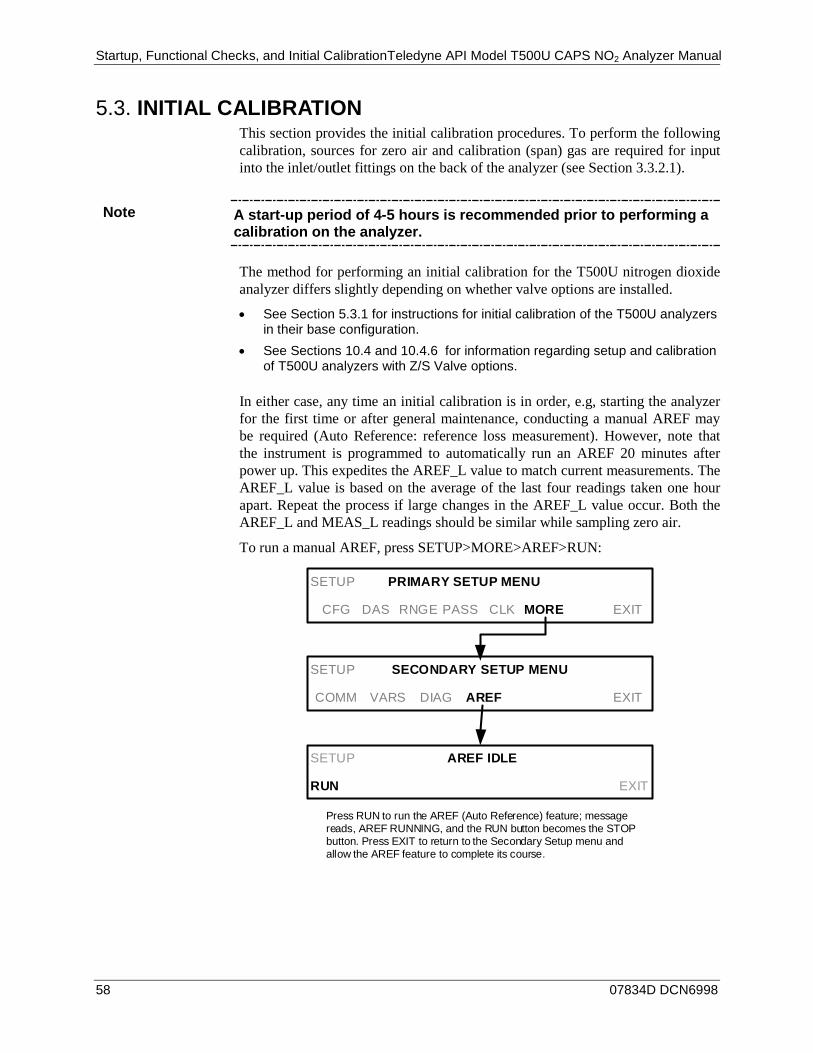
Startup, Functional Checks, and Initial CalibrationTeledyne API Model T500U CAPS NO2 Analyzer Manual
58 07834D DCN6998
INITIAL CALIBRATION 5.3.This section provides the initial calibration procedures. To perform the following calibration, sources for zero air and calibration (span) gas are required for input into the inlet/outlet fittings on the back of the analyzer (see Section 3.3.2.1).
Note A start-up period of 4-5 hours is recommended prior to performing a calibration on the analyzer.
The method for performing an initial calibration for the T500U nitrogen dioxide analyzer differs slightly depending on whether valve options are installed.
• See Section 5.3.1 for instructions for initial calibration of the T500U analyzers in their base configuration.
• See Sections 10.4 and 10.4.6 for information regarding setup and calibration of T500U analyzers with Z/S Valve options.
In either case, any time an initial calibration is in order, e.g, starting the analyzer for the first time or after general maintenance, conducting a manual AREF may be required (Auto Reference: reference loss measurement). However, note that the instrument is programmed to automatically run an AREF 20 minutes after power up. This expedites the AREF_L value to match current measurements. The AREF_L value is based on the average of the last four readings taken one hour apart. Repeat the process if large changes in the AREF_L value occur. Both the AREF_L and MEAS_L readings should be similar while sampling zero air.
To run a manual AREF, press SETUP>MORE>AREF>RUN:
SETUP AREF IDLE
RUN EXIT
SETUP PRIMARY SETUP MENU
CFG DAS RNGE PASS CLK MORE EXIT
SETUP SECONDARY SETUP MENU
COMM VARS DIAG AREF EXIT
Press RUN to run the AREF (Auto Reference) feature; message reads, AREF RUNNING, and the RUN button becomes the STOP button. Press EXIT to return to the Secondary Setup menu and allow the AREF feature to complete its course.
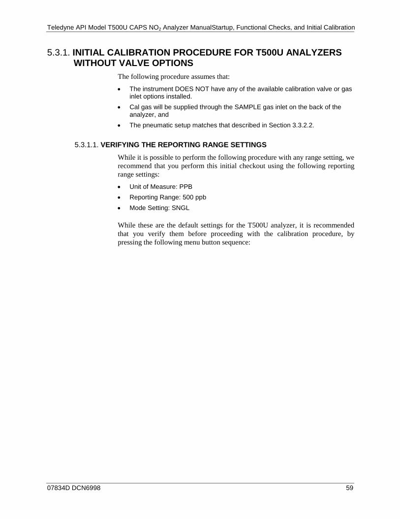
Teledyne API Model T500U CAPS NO2 Analyzer ManualStartup, Functional Checks, and Initial Calibration
07834D DCN6998 59
INITIAL CALIBRATION PROCEDURE FOR T500U ANALYZERS 5.3.1.WITHOUT VALVE OPTIONS
The following procedure assumes that:
• The instrument DOES NOT have any of the available calibration valve or gas inlet options installed.
• Cal gas will be supplied through the SAMPLE gas inlet on the back of the analyzer, and
• The pneumatic setup matches that described in Section 3.3.2.2.
VERIFYING THE REPORTING RANGE SETTINGS 5.3.1.1.
While it is possible to perform the following procedure with any range setting, we recommend that you perform this initial checkout using the following reporting range settings:
• Unit of Measure: PPB • Reporting Range: 500 ppb • Mode Setting: SNGL
While these are the default settings for the T500U analyzer, it is recommended that you verify them before proceeding with the calibration procedure, by pressing the following menu button sequence:
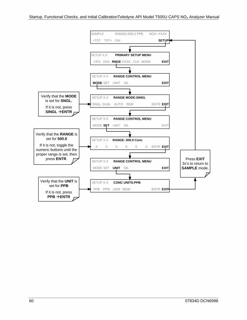
Startup, Functional Checks, and Initial CalibrationTeledyne API Model T500U CAPS NO2 Analyzer Manual
60 07834D DCN6998
SETUP X.X RANGE MODE:SINGL
SNGL DUAL AUTO REM ENTR EXIT
SAMPLE RANGE=500.0 PPB NO2= XXXX
<TST TST> CAL SETUP
SETUP X.X PRIMARY SETUP MENU
CFG DAS RNGE PASS CLK MORE EXIT
SETUP X.X RANGE CONTROL MENU
MODE SET UNIT DIL EXIT
SETUP X.X RANGE: 500.0 Conc
0 0 5 0 0 .0 ENTR EXIT
SETUP X.X CONC UNITS:PPB
PPB PPM UGM MGM ENTR EXIT
SETUP X.X RANGE CONTROL MENU
MODE SET UNIT DIL EXIT
SETUP X.X RANGE CONTROL MENU
MODE SET UNIT DIL EXIT
Verify that the MODE is set for SNGL.If it is not, press SINGL àENTR
Press EXIT 3x’s to return to SAMPLE mode.
Verify that the RANGE is set for 500.0
If it is not, toggle the numeric buttons until the proper range is set, then
press ENTR.
Verify that the UNIT is set for PPB
If it is not, press PPB àENTR

Teledyne API Model T500U CAPS NO2 Analyzer ManualStartup, Functional Checks, and Initial Calibration
07834D DCN6998 61
VERIFYING THE EXPECTED NO2 SPAN GAS CONCENTRATION 5.3.1.2.
The NO2 span concentration value automatically defaults to 400.0 PPB and it is recommended that calibration gases of that concentration be used for the initial calibration of the unit.
To verify that the analyzer span setting is set for 400 PPB, press:
SAMPLE RANGE=500.0 PPB NO2= XXXX
<TST TST> CAL SETUP
M-P CAL RANGE=500.0 PPB NO2=XXXX
<TST TST> ZERO SPAN CONC EXIT
M-P CAL NO2 SPAN CONC:400.0 Conc
0 4 0 0 .0 ENTR EXITThe NO2 span concentration value
automatically defaults to 400.0 PPB
If this is not the the concentration of the span gas being used, toggle these buttons to set the correct
concentration of the NO2 calibration gas.
EXIT ignores the new setting and returns to
the previous level.
ENTR accepts the new setting and returns to the
previous level.
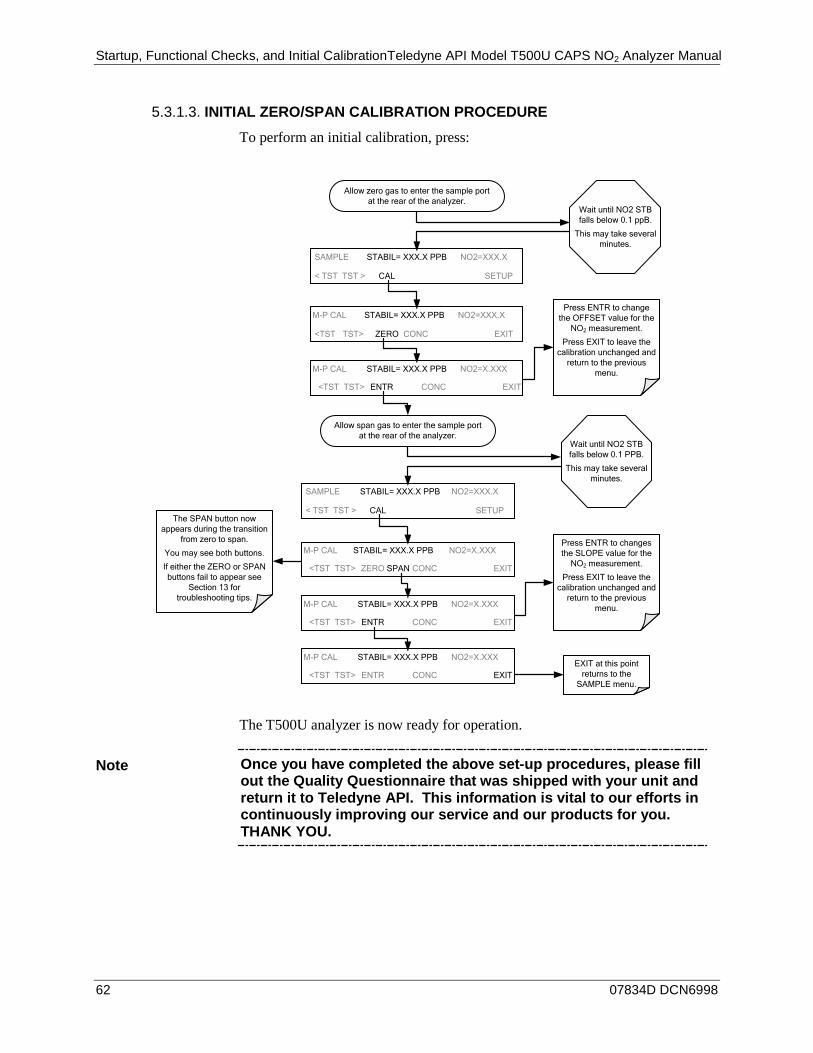
Startup, Functional Checks, and Initial CalibrationTeledyne API Model T500U CAPS NO2 Analyzer Manual
62 07834D DCN6998
INITIAL ZERO/SPAN CALIBRATION PROCEDURE 5.3.1.3.
To perform an initial calibration, press:
Press ENTR to change the OFFSET value for the
NO2 measurement.
Press EXIT to leave the calibration unchanged and
return to the previous menu.
M-P CAL STABIL= XXX.X PPB NO2=XXX.X
<TST TST> ZERO CONC EXIT
EXIT at this point returns to the
SAMPLE menu.
Press ENTR to changes the SLOPE value for the
NO2 measurement.
Press EXIT to leave the calibration unchanged and
return to the previous menu.
Allow zero gas to enter the sample port at the rear of the analyzer.
Wait until NO2 STB falls below 0.1 ppB.
This may take several minutes.
SAMPLE STABIL= XXX.X PPB NO2=XXX.X
< TST TST > CAL SETUP
M-P CAL STABIL= XXX.X PPB NO2=X.XXX
<TST TST> ENTR CONC EXIT
M-P CAL STABIL= XXX.X PPB NO2=X.XXX
<TST TST> ZERO SPAN CONC EXIT
Allow span gas to enter the sample port at the rear of the analyzer.
Wait until NO2 STB falls below 0.1 PPB.
This may take several minutes.
SAMPLE STABIL= XXX.X PPB NO2=XXX.X
< TST TST > CAL SETUP
M-P CAL STABIL= XXX.X PPB NO2=X.XXX
<TST TST> ENTR CONC EXIT
M-P CAL STABIL= XXX.X PPB NO2=X.XXX
<TST TST> ENTR CONC EXIT
The SPAN button now appears during the transition
from zero to span.
You may see both buttons.
If either the ZERO or SPAN buttons fail to appear see
Section 13 for troubleshooting tips.
The T500U analyzer is now ready for operation.
Note Once you have completed the above set-up procedures, please fill out the Quality Questionnaire that was shipped with your unit and return it to Teledyne API. This information is vital to our efforts in continuously improving our service and our products for you. THANK YOU.
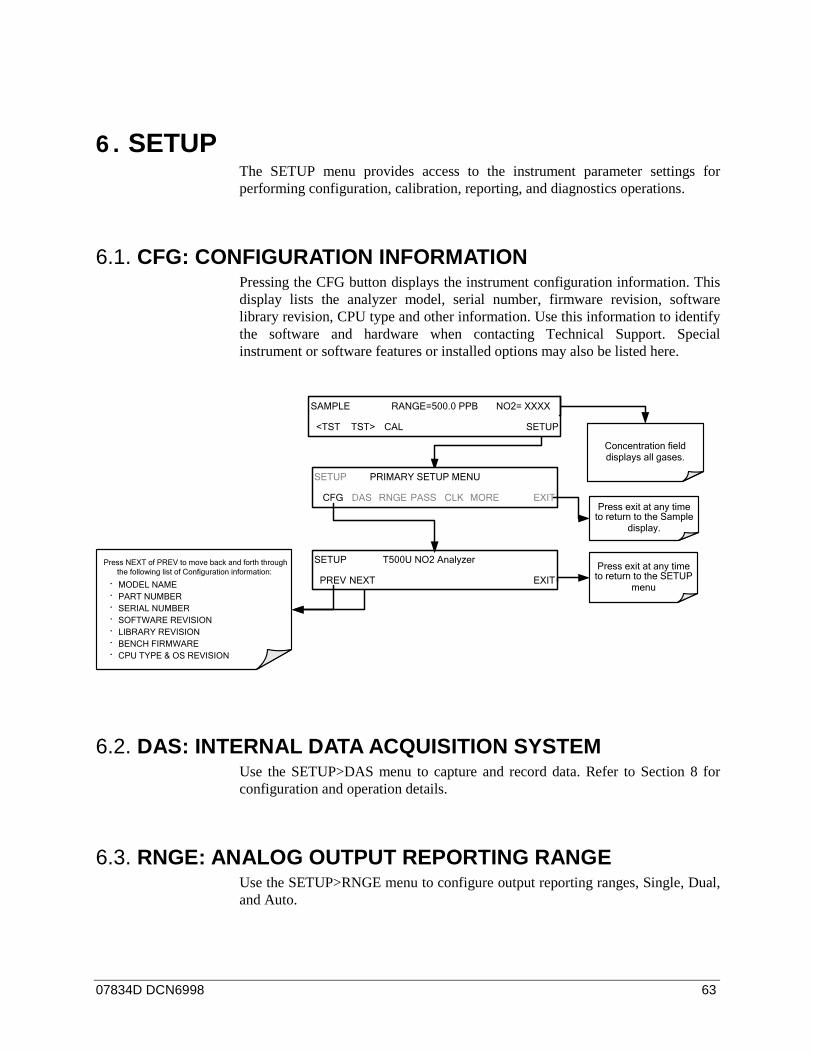
07834D DCN6998 63
6. SETUP The SETUP menu provides access to the instrument parameter settings for performing configuration, calibration, reporting, and diagnostics operations.
CFG: CONFIGURATION INFORMATION 6.1.Pressing the CFG button displays the instrument configuration information. This display lists the analyzer model, serial number, firmware revision, software library revision, CPU type and other information. Use this information to identify the software and hardware when contacting Technical Support. Special instrument or software features or installed options may also be listed here.
SETUP PRIMARY SETUP MENU
CFG DAS RNGE PASS CLK MORE EXIT
SETUP T500U NO2 Analyzer
PREV NEXT EXITPress exit at any time
to return to the SETUP menu
Press NEXT of PREV to move back and forth through the following list of Configuration information:
· MODEL NAME· PART NUMBER· SERIAL NUMBER · SOFTWARE REVISION· LIBRARY REVISION· BENCH FIRMWARE· CPU TYPE & OS REVISION
Concentration field displays all gases.
SAMPLE RANGE=500.0 PPB NO2= XXXX
<TST TST> CAL SETUP
Press exit at any time to return to the Sample
display.
DAS: INTERNAL DATA ACQUISITION SYSTEM 6.2.Use the SETUP>DAS menu to capture and record data. Refer to Section 8 for configuration and operation details.
RNGE: ANALOG OUTPUT REPORTING RANGE 6.3.Use the SETUP>RNGE menu to configure output reporting ranges, Single, Dual, and Auto.
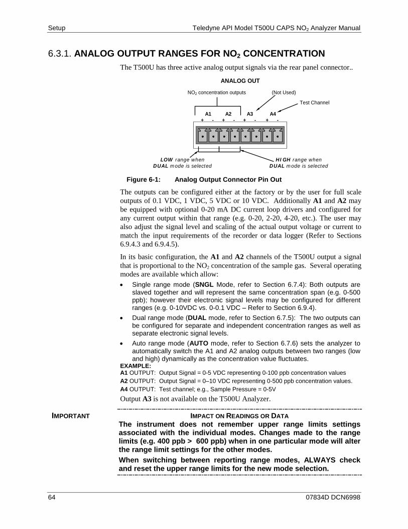
Setup Teledyne API Model T500U CAPS NO2 Analyzer Manual
64 07834D DCN6998
ANALOG OUTPUT RANGES FOR NO2 CONCENTRATION 6.3.1.The T500U has three active analog output signals via the rear panel connector..
(Not Used)
ANALOG OUT
A1 A2 A3 A4 + - + - + - + -
Test Channel
NO2 concentration outputs
HIGH range when DUAL mode is selected
LOW range when DUAL mode is selected
Figure 6-1: Analog Output Connector Pin Out
The outputs can be configured either at the factory or by the user for full scale outputs of 0.1 VDC, 1 VDC, 5 VDC or 10 VDC. Additionally A1 and A2 may be equipped with optional 0-20 mA DC current loop drivers and configured for any current output within that range (e.g. 0-20, 2-20, 4-20, etc.). The user may also adjust the signal level and scaling of the actual output voltage or current to match the input requirements of the recorder or data logger (Refer to Sections 6.9.4.3 and 6.9.4.5).
In its basic configuration, the A1 and A2 channels of the T500U output a signal that is proportional to the NO2 concentration of the sample gas. Several operating modes are available which allow: • Single range mode (SNGL Mode, refer to Section 6.7.4): Both outputs are
slaved together and will represent the same concentration span (e.g. 0-500 ppb); however their electronic signal levels may be configured for different ranges (e.g. 0-10VDC vs. 0-0.1 VDC – Refer to Section 6.9.4).
• Dual range mode (DUAL mode, refer to Section 6.7.5): The two outputs can be configured for separate and independent concentration ranges as well as separate electronic signal levels.
• Auto range mode (AUTO mode, refer to Section 6.7.6) sets the analyzer to automatically switch the A1 and A2 analog outputs between two ranges (low and high) dynamically as the concentration value fluctuates.
EXAMPLE: A1 OUTPUT: Output Signal = 0-5 VDC representing 0-100 ppb concentration values A2 OUTPUT: Output Signal = 0–10 VDC representing 0-500 ppb concentration values. A4 OUTPUT: Test channel; e.g., Sample Pressure = 0-5V Output A3 is not available on the T500U Analyzer.
IMPORTANT IMPACT ON READINGS OR DATA The instrument does not remember upper range limits settings associated with the individual modes. Changes made to the range limits (e.g. 400 ppb > 600 ppb) when in one particular mode will alter the range limit settings for the other modes. When switching between reporting range modes, ALWAYS check and reset the upper range limits for the new mode selection.

Teledyne API Model T500U CAPS NO2 Analyzer Manual Setup
07834D DCN6998 65
ANALOG OUTPUT REPORTING RANGE DEFAULT SETTINGS 6.3.2.The default setting for these the reporting ranges of the analog output channels A1, A2 and A4 are:
• SNGL mode • 0 to 500.0 ppb • 0 to 5 VDC
SETUP > RNGE > MODE 6.3.3.Single range mode (SNGL) is the default range mode for reporting the NO2 gas concentration outputs using the same range span (see Section 6.3.3.1).
Dual range mode (DUAL) allows the NO2 analog outputs to be set with different reporting range spans (see Section 6.3.3.2).
Automatic range mode (AUTO) allows the analyzer to automatically switch the reporting range between two user upper span limits (designated LOW and HIGH) based on the actual concentrations being measured for each (see Section 6.3.3.3).
SETUP > RNGE > MODE > SNGL: SINGLE RANGE MODE CONFIGURATION 6.3.3.1.
Note Single Range is the default reporting range mode for the analyzer.
When the single range mode is selected (SNGL), all analog concentration outputs (A1, A2) are slaved together and set to the same reporting range limits (e.g. 500.0 ppb).
Although both outputs share the same concentration reporting range, the electronic signal ranges of the analog outputs may still be configured for different values (e.g. 0-5 VDC, 0-10 VDC, etc.; see Section 6.8.3.1).
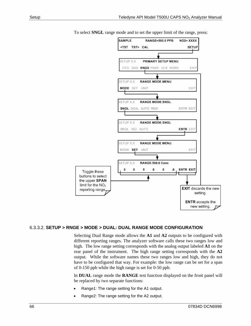
Setup Teledyne API Model T500U CAPS NO2 Analyzer Manual
66 07834D DCN6998
To select SNGL range mode and to set the upper limit of the range, press:
SETUP > RNGE > MODE > DUAL: DUAL RANGE MODE CONFIGURATION 6.3.3.2.
Selecting Dual Range mode allows the A1 and A2 outputs to be configured with different reporting ranges. The analyzer software calls these two ranges low and high. The low range setting corresponds with the analog output labeled A1 on the rear panel of the instrument. The high range setting corresponds with the A2 output. While the software names these two ranges low and high, they do not have to be configured that way. For example: the low range can be set for a span of 0-150 ppb while the high range is set for 0-50 ppb.
In DUAL range mode the RANGE test function displayed on the front panel will be replaced by two separate functions:
• Range1: The range setting for the A1 output.
• Range2: The range setting for the A2 output.
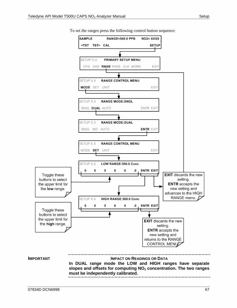
Teledyne API Model T500U CAPS NO2 Analyzer Manual Setup
07834D DCN6998 67
To set the ranges press the following control button sequence:
IMPORTANT IMPACT ON READINGS OR DATA In DUAL range mode the LOW and HIGH ranges have separate slopes and offsets for computing NO2 concentration. The two ranges must be independently calibrated.
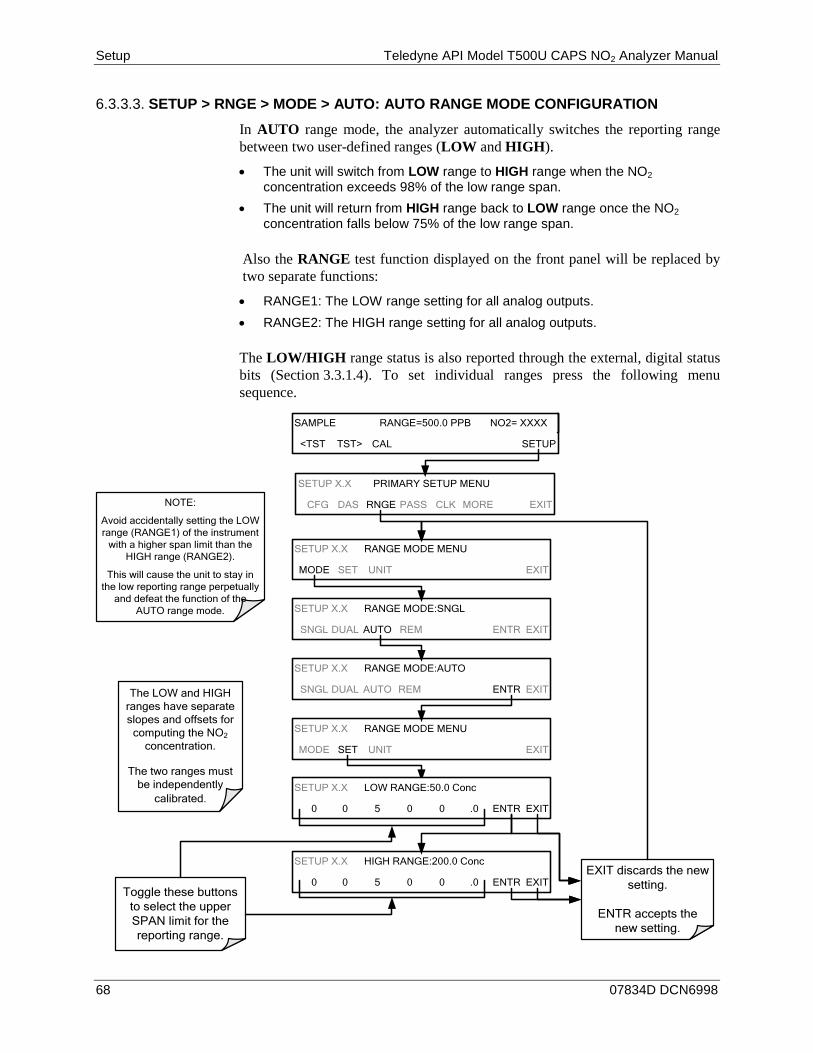
Setup Teledyne API Model T500U CAPS NO2 Analyzer Manual
68 07834D DCN6998
SETUP > RNGE > MODE > AUTO: AUTO RANGE MODE CONFIGURATION 6.3.3.3.
In AUTO range mode, the analyzer automatically switches the reporting range between two user-defined ranges (LOW and HIGH).
• The unit will switch from LOW range to HIGH range when the NO2 concentration exceeds 98% of the low range span.
• The unit will return from HIGH range back to LOW range once the NO2 concentration falls below 75% of the low range span.
Also the RANGE test function displayed on the front panel will be replaced by two separate functions:
• RANGE1: The LOW range setting for all analog outputs. • RANGE2: The HIGH range setting for all analog outputs.
The LOW/HIGH range status is also reported through the external, digital status bits (Section 3.3.1.4). To set individual ranges press the following menu sequence.
SAMPLE RANGE=500.0 PPB NO2= XXXX
<TST TST> CAL SETUP
SETUP X.X PRIMARY SETUP MENU
CFG DAS RNGE PASS CLK MORE EXIT
SETUP X.X RANGE MODE MENU
MODE SET UNIT EXIT
SETUP X.X RANGE MODE:SNGL
SNGL DUAL AUTO REM ENTR EXIT
SETUP X.X RANGE MODE:AUTO
SNGL DUAL AUTO REM ENTR EXIT
SETUP X.X RANGE MODE MENU
MODE SET UNIT EXIT
SETUP X.X HIGH RANGE:200.0 Conc
0 0 5 0 0 .0 ENTR EXITToggle these buttons
to select the upper SPAN limit for the reporting range.
EXIT discards the new setting.
ENTR accepts the new setting.
SETUP X.X LOW RANGE:50.0 Conc
0 0 5 0 0 .0 ENTR EXIT
The LOW and HIGH ranges have separate slopes and offsets for
computing the NO2 concentration.
The two ranges must be independently
calibrated.
NOTE:
Avoid accidentally setting the LOW range (RANGE1) of the instrument
with a higher span limit than the HIGH range (RANGE2).
This will cause the unit to stay in the low reporting range perpetually
and defeat the function of the AUTO range mode.
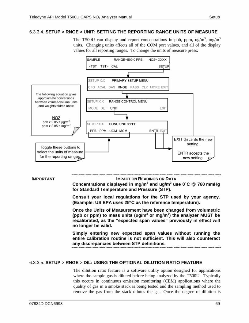
Teledyne API Model T500U CAPS NO2 Analyzer Manual Setup
07834D DCN6998 69
SETUP > RNGE > UNIT: SETTING THE REPORTING RANGE UNITS OF MEASURE 6.3.3.4.
The T500U can display and report concentrations in ppb, ppm, ug/m3, mg/m3 units. Changing units affects all of the COM port values, and all of the display values for all reporting ranges. To change the units of measure press:
The following equation gives approximate conversions
between volume/volume units and weight/volume units:
NO2ppb x 2.05 = µg/m3
ppm x 2.05 = mg/m3
SAMPLE RANGE=500.0 PPB NO2= XXXX
<TST TST> CAL SETUP
SETUP X.X CONC UNITS:PPB
PPB PPM UGM MGM ENTR EXIT
SETUP X.X PRIMARY SETUP MENU
CFG ACAL DAS RNGE PASS CLK MORE EXIT
SETUP X.X RANGE CONTROL MENU
MODE SET UNIT EXIT
Toggle these buttons to select the units of measure
for the reporting ranges.
EXIT discards the new setting.
ENTR accepts the new setting.
IMPORTANT IMPACT ON READINGS OR DATA Concentrations displayed in mg/m3 and ug/m3 use 0°C @ 760 mmHg for Standard Temperature and Pressure (STP). Consult your local regulations for the STP used by your agency. (Example: US EPA uses 25°C as the reference temperature). Once the Units of Measurement have been changed from volumetric (ppb or ppm) to mass units (ug/m3 or mg/m3) the analyzer MUST be recalibrated, as the “expected span values” previously in effect will no longer be valid. Simply entering new expected span values without running the entire calibration routine is not sufficient. This will also counteract any discrepancies between STP definitions.
SETUP > RNGE > DIL: USING THE OPTIONAL DILUTION RATIO FEATURE 6.3.3.5.
The dilution ratio feature is a software utility option designed for applications where the sample gas is diluted before being analyzed by the T500U. Typically this occurs in continuous emission monitoring (CEM) applications where the quality of gas in a smoke stack is being tested and the sampling method used to remove the gas from the stack dilutes the gas. Once the degree of dilution is
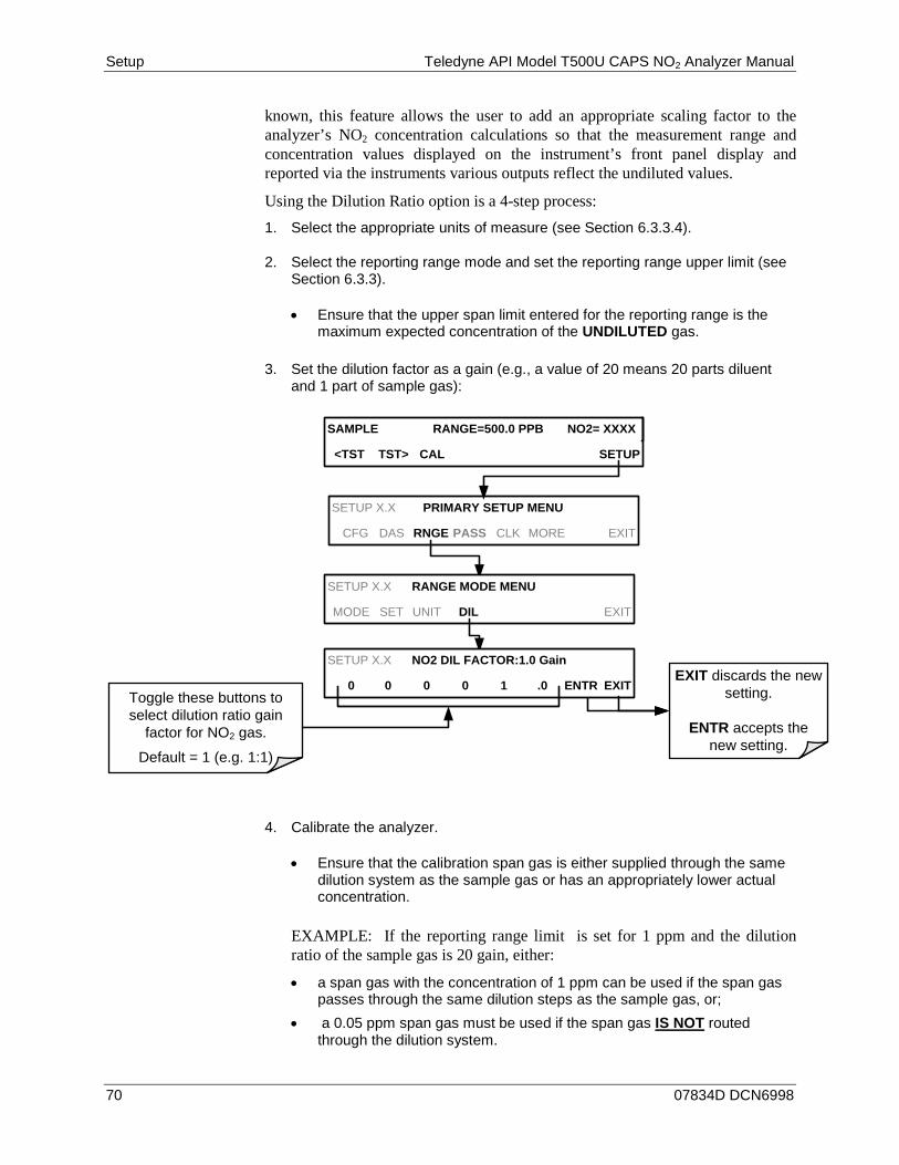
Setup Teledyne API Model T500U CAPS NO2 Analyzer Manual
70 07834D DCN6998
known, this feature allows the user to add an appropriate scaling factor to the analyzer’s NO2 concentration calculations so that the measurement range and concentration values displayed on the instrument’s front panel display and reported via the instruments various outputs reflect the undiluted values.
Using the Dilution Ratio option is a 4-step process: 1. Select the appropriate units of measure (see Section 6.3.3.4).
2. Select the reporting range mode and set the reporting range upper limit (see Section 6.3.3).
• Ensure that the upper span limit entered for the reporting range is the maximum expected concentration of the UNDILUTED gas.
3. Set the dilution factor as a gain (e.g., a value of 20 means 20 parts diluent and 1 part of sample gas):
SAMPLE RANGE=500.0 PPB NO2= XXXX
<TST TST> CAL SETUP
SETUP X.X PRIMARY SETUP MENU
CFG DAS RNGE PASS CLK MORE EXIT
SETUP X.X RANGE MODE MENU
MODE SET UNIT DIL EXIT
Toggle these buttons to select dilution ratio gain
factor for NO2 gas.
Default = 1 (e.g. 1:1)
EXIT discards the new setting.
ENTR accepts the new setting.
SETUP X.X NO2 DIL FACTOR:1.0 Gain
0 0 0 0 1 .0 ENTR EXIT
4. Calibrate the analyzer.
• Ensure that the calibration span gas is either supplied through the same dilution system as the sample gas or has an appropriately lower actual concentration.
EXAMPLE: If the reporting range limit is set for 1 ppm and the dilution ratio of the sample gas is 20 gain, either:
• a span gas with the concentration of 1 ppm can be used if the span gas passes through the same dilution steps as the sample gas, or;
• a 0.05 ppm span gas must be used if the span gas IS NOT routed through the dilution system.

Teledyne API Model T500U CAPS NO2 Analyzer Manual Setup
07834D DCN6998 71
PASS: PASSWORD PROTECTION 6.4.The T500U provides password protection of the calibration and setup functions to prevent unauthorized adjustments. When the passwords have been SETUP>PASS>ON), the system will prompt the user for a password anytime a password-protected function (e.g., SETUP>MORE>DIAG) is selected. This allows normal operation of the instrument, but requires the password (101) to access to the menus under SETUP. When PASSWORD is disabled (SETUP>PASS>OFF), any operator can enter the Primary Setup (SETUP) and Secondary Setup (SETUP>MORE) menus. Whether PASSWORD is enabled or disabled, a password (default 818) is required to enter the VARS or DIAG menus in the SETUP>MORE menu.
There are two levels of password protection above the “null” level, which correspond to operator, maintenance and configuration functions. Each level allows access to all of the functions in the previous level.
Table 6-1: Password Levels PASSWORD LEVEL MENU ACCESS ALLOWED
Null (no password required)
Operation Functions of the menu for general operation.
101 Configuration/Maintenance Access to Primary Setup and Secondary SETUP Menus when PASSWORD is enabled.
818 Configuration/Maintenance Access to Secondary SETUP Submenus VARS and DIAG whether PASSWORD is enabled or disabled.
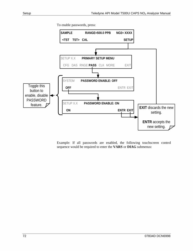
Setup Teledyne API Model T500U CAPS NO2 Analyzer Manual
72 07834D DCN6998
To enable passwords, press:
SETUP X.X PRIMARY SETUP MENU
CFG DAS RNGE PASS CLK MORE EXIT
SYSTEM PASSWORD ENABLE: OFF
OFF ENTR EXIT
SETUP X.X PASSWORD ENABLE: ON
ON ENTR EXIT
Toggle this button to
enable, disable PASSWORD
feature. EXIT discards the new setting.
ENTR accepts the new setting.
SAMPLE RANGE=500.0 PPB NO2= XXXX
<TST TST> CAL SETUP
Example: If all passwords are enabled, the following touchscreen control sequence would be required to enter the VARS or DIAG submenus:
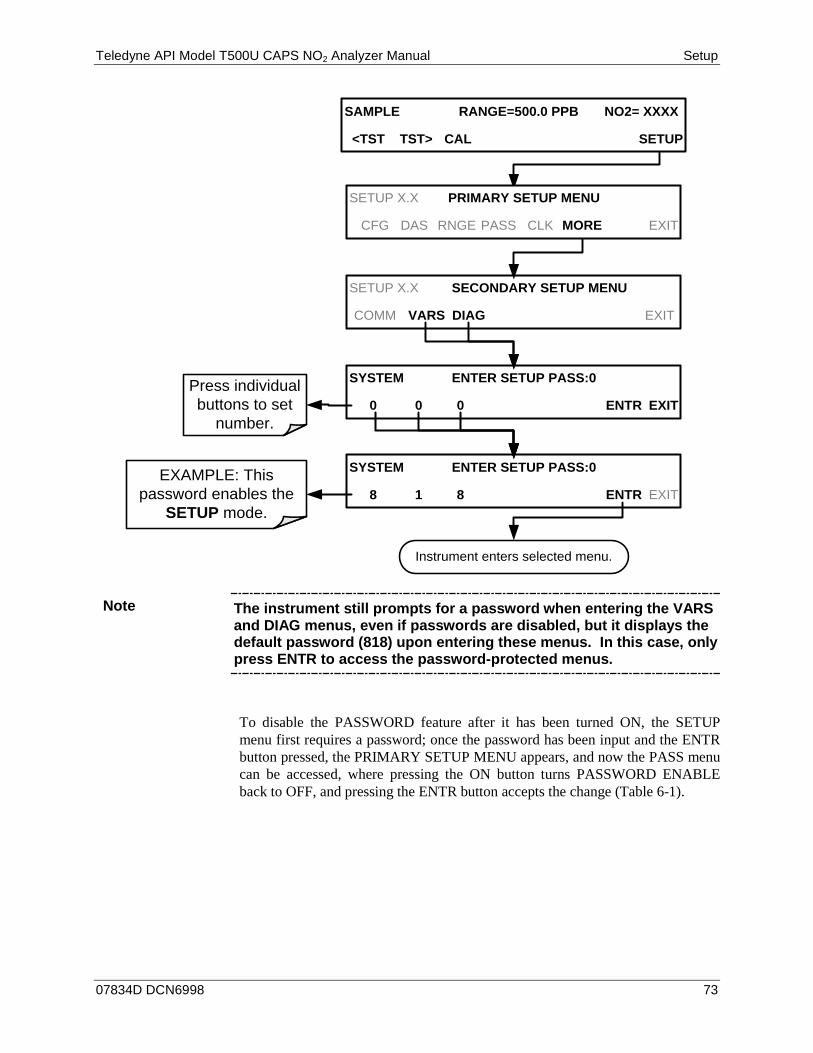
Teledyne API Model T500U CAPS NO2 Analyzer Manual Setup
07834D DCN6998 73
SYSTEM ENTER SETUP PASS:0
8 1 8 ENTR EXIT
SYSTEM ENTER SETUP PASS:0
0 0 0 ENTR EXIT
SETUP X.X SECONDARY SETUP MENU
COMM VARS DIAG EXIT
EXAMPLE: This password enables the
SETUP mode.
Press individual buttons to set
number.
Instrument enters selected menu.
SAMPLE RANGE=500.0 PPB NO2= XXXX
<TST TST> CAL SETUP
SETUP X.X PRIMARY SETUP MENU
CFG DAS RNGE PASS CLK MORE EXIT
Note The instrument still prompts for a password when entering the VARS and DIAG menus, even if passwords are disabled, but it displays the default password (818) upon entering these menus. In this case, only press ENTR to access the password-protected menus.
To disable the PASSWORD feature after it has been turned ON, the SETUP menu first requires a password; once the password has been input and the ENTR button pressed, the PRIMARY SETUP MENU appears, and now the PASS menu can be accessed, where pressing the ON button turns PASSWORD ENABLE back to OFF, and pressing the ENTR button accepts the change (Table 6-1).
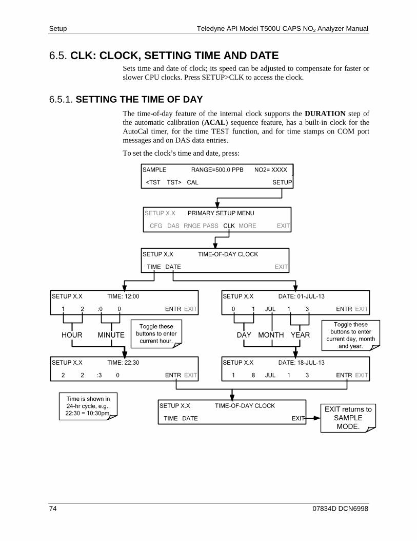
Setup Teledyne API Model T500U CAPS NO2 Analyzer Manual
74 07834D DCN6998
CLK: CLOCK, SETTING TIME AND DATE 6.5.Sets time and date of clock; its speed can be adjusted to compensate for faster or slower CPU clocks. Press SETUP>CLK to access the clock.
SETTING THE TIME OF DAY 6.5.1.The time-of-day feature of the internal clock supports the DURATION step of the automatic calibration (ACAL) sequence feature, has a built-in clock for the AutoCal timer, for the time TEST function, and for time stamps on COM port messages and on DAS data entries.
To set the clock’s time and date, press:
SETUP X.X PRIMARY SETUP MENU
CFG DAS RNGE PASS CLK MORE EXIT
SETUP X.X TIME-OF-DAY CLOCK
TIME DATE EXIT
Toggle these buttons to enter
current hour.
SETUP X.X TIME: 12:00
1 2 :0 0 ENTR EXIT
SETUP X.X TIME: 22:30
2 2 :3 0 ENTR EXIT
SETUP X.X DATE: 01-JUL-13
0 1 JUL 1 3 ENTR EXIT
SETUP X.X DATE: 18-JUL-13
1 8 JUL 1 3 ENTR EXIT
SETUP X.X TIME-OF-DAY CLOCK
TIME DATE EXIT
Toggle these buttons to enter
current day, month and year.
EXIT returns to SAMPLE MODE.
HOUR MINUTE DAY MONTH YEAR
SAMPLE RANGE=500.0 PPB NO2= XXXX
<TST TST> CAL SETUP
Time is shown in 24-hr cycle, e.g., 22:30 = 10:30pm.
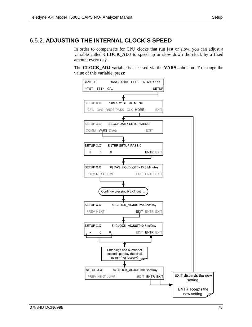
Teledyne API Model T500U CAPS NO2 Analyzer Manual Setup
07834D DCN6998 75
ADJUSTING THE INTERNAL CLOCK’S SPEED 6.5.2.In order to compensate for CPU clocks that run fast or slow, you can adjust a variable called CLOCK_ADJ to speed up or slow down the clock by a fixed amount every day.
The CLOCK_ADJ variable is accessed via the VARS submenu: To change the value of this variable, press:
SETUP X.X 0) DAS_HOLD_OFF=15.0 Minutes
PREV NEXT JUMP EDIT ENTR EXIT
SETUP X.X SECONDARY SETUP MENU
COMM VARS DIAG EXIT
SETUP X.X ENTER SETUP PASS:0
8 1 8 ENTR EXIT
Continue pressing NEXT until ...
SETUP X.X 8) CLOCK_ADJUST=0 Sec/Day
+ 0 0 EDIT ENTR EXIT
SETUP X.X 8) CLOCK_ADJUST=0 Sec/Day
PREV NEXT EDIT ENTR EXIT
Enter sign and number of seconds per day the clock
gains (-) or loses(+)
SETUP X.X 8) CLOCK_ADJUST=0 Sec/Day
PREV NEXT JUMP EDIT ENTR EXIT EXIT discards the new setting.
ENTR accepts the new setting.
SETUP X.X PRIMARY SETUP MENU
CFG DAS RNGE PASS CLK MORE EXIT
SAMPLE RANGE=500.0 PPB NO2= XXXX
<TST TST> CAL SETUP
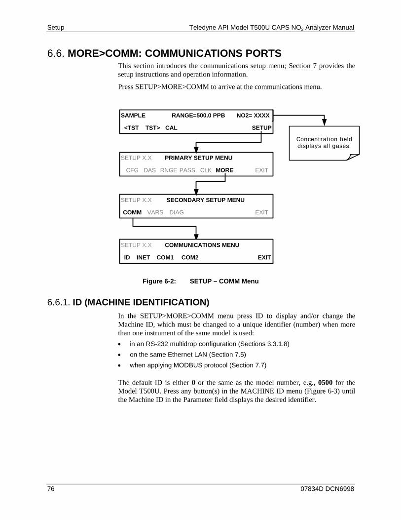
Setup Teledyne API Model T500U CAPS NO2 Analyzer Manual
76 07834D DCN6998
MORE>COMM: COMMUNICATIONS PORTS 6.6.This section introduces the communications setup menu; Section 7 provides the setup instructions and operation information.
Press SETUP>MORE>COMM to arrive at the communications menu.
Concentration field displays all gases.
SAMPLE RANGE=500.0 PPB NO2= XXXX
<TST TST> CAL SETUP
SETUP X.X COMMUNICATIONS MENU
ID INET COM1 COM2 EXIT
SETUP X.X PRIMARY SETUP MENU
CFG DAS RNGE PASS CLK MORE EXIT
SETUP X.X SECONDARY SETUP MENU
COMM VARS DIAG EXIT
Figure 6-2: SETUP – COMM Menu
ID (MACHINE IDENTIFICATION) 6.6.1.In the SETUP>MORE>COMM menu press ID to display and/or change the Machine ID, which must be changed to a unique identifier (number) when more than one instrument of the same model is used: • in an RS-232 multidrop configuration (Sections 3.3.1.8) • on the same Ethernet LAN (Section 7.5) • when applying MODBUS protocol (Section 7.7)
The default ID is either 0 or the same as the model number, e.g., 0500 for the Model T500U. Press any button(s) in the MACHINE ID menu (Figure 6-3) until the Machine ID in the Parameter field displays the desired identifier.
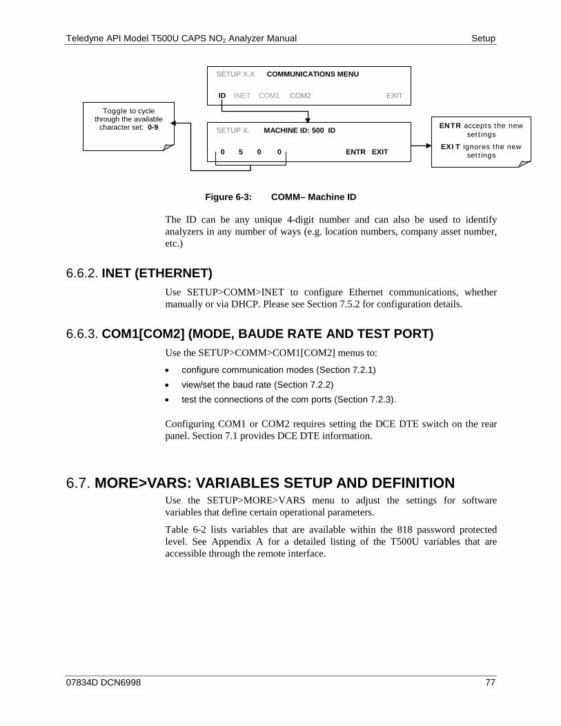
Teledyne API Model T500U CAPS NO2 Analyzer Manual Setup
07834D DCN6998 77
SETUP X.X COMMUNICATIONS MENU
ID INET COM1 COM2 EXIT
SETUP X. MACHINE ID: 500 ID
0 5 0 0 ENTR EXIT
Toggle to cycle through the available
character set: 0-9
ENTR accepts the new settings
EXIT ignores the new settings
Figure 6-3: COMM– Machine ID
The ID can be any unique 4-digit number and can also be used to identify analyzers in any number of ways (e.g. location numbers, company asset number, etc.)
INET (ETHERNET) 6.6.2.Use SETUP>COMM>INET to configure Ethernet communications, whether manually or via DHCP. Please see Section 7.5.2 for configuration details.
COM1[COM2] (MODE, BAUDE RATE AND TEST PORT) 6.6.3.Use the SETUP>COMM>COM1[COM2] menus to:
• configure communication modes (Section 7.2.1) • view/set the baud rate (Section 7.2.2) • test the connections of the com ports (Section 7.2.3).
Configuring COM1 or COM2 requires setting the DCE DTE switch on the rear panel. Section 7.1 provides DCE DTE information.
MORE>VARS: VARIABLES SETUP AND DEFINITION 6.7.Use the SETUP>MORE>VARS menu to adjust the settings for software variables that define certain operational parameters.
Table 6-2 lists variables that are available within the 818 password protected level. See Appendix A for a detailed listing of the T500U variables that are accessible through the remote interface.

Setup Teledyne API Model T500U CAPS NO2 Analyzer Manual
78 07834D DCN6998
Table 6-2: Variables (VARS)
NO. VARIABLE DESCRIPTION ALLOWED VALUES VARS
DEFAULT VALUES
0 DAS_HOLD_OFF
Changes the Internal Data Acquisition System (DAS) HOLDOFF timer: No data is stored in the DAS channels during situations when the software considers the data to be questionable such as during warm up of just after the instrument returns from one of its calibration mode to SAMPLE Mode.
May be set for intervals between
0.5 – 20 min
15 min.
1 CONC_PRECISION Sets the number of significant digits to the right of the decimal point display of concentration and stability values.
AUTO, 1, 2, 3, 4 3
2 CLOCK_ADJ Adjusts the speed of the analyzer’s clock. Choose + sign if the clock is too slow; choose - sign if the clock is too fast.
-60 to +60 s/day 0 sec
3 SERVICE_CLEAR Resets the service timer. Pressing OFF turns the setting to ON. ENTR resets the timer to 0 and returns the setting to OFF.
ON/OFF OFF
4 TIME_SINCE_SVC Displays number of hours since last service (since SERVICE_CLEAR was reset). 0-500000 0 Hrs
5 SVC_INTERVAL Sets the number of hours between service reminders. 0-100000 0 Hrs
Note There is a 2-sec latency period between the time a VARS value is changed and its storage into the analyzer’s memory. DO NOT turn the analyzer off during this period or the new setting will be lost.
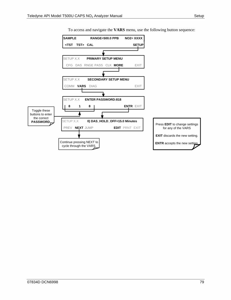
Teledyne API Model T500U CAPS NO2 Analyzer Manual Setup
07834D DCN6998 79
To access and navigate the VARS menu, use the following button sequence:
Continue pressing NEXT to cycle through the VARS.
SAMPLE RANGE=500.0 PPB NO2= XXXX
<TST TST> CAL SETUP
SETUP X.X 0) DAS_HOLD_OFF=15.0 Minutes
PREV NEXT JUMP EDIT PRNT EXIT
SETUP X.X PRIMARY SETUP MENU
CFG DAS RNGE PASS CLK MORE EXIT
SETUP X.X SECONDARY SETUP MENU
COMM VARS DIAG EXIT
SETUP X.X ENTER PASSWORD:818
8 1 8 ENTR EXITToggle these
buttons to enter the correct
PASSWORD.Press EDIT to change settings
for any of the VARS
EXIT discards the new setting.
ENTR accepts the new setting.
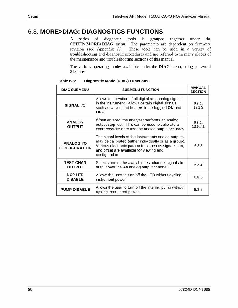
Setup Teledyne API Model T500U CAPS NO2 Analyzer Manual
80 07834D DCN6998
MORE>DIAG: DIAGNOSTICS FUNCTIONS 6.8.A series of diagnostic tools is grouped together under the SETUP>MORE>DIAG menu. The parameters are dependent on firmware revision (see Appendix A). These tools can be used in a variety of troubleshooting and diagnostic procedures and are referred to in many places of the maintenance and troubleshooting sections of this manual.
The various operating modes available under the DIAG menu, using password 818, are:
Table 6-3: Diagnostic Mode (DIAG) Functions
DIAG SUBMENU SUBMENU FUNCTION MANUAL SECTION
SIGNAL I/O
Allows observation of all digital and analog signals in the instrument. Allows certain digital signals such as valves and heaters to be toggled ON and OFF.
6.8.1, 13.1.3
ANALOG OUTPUT
When entered, the analyzer performs an analog output step test. This can be used to calibrate a chart recorder or to test the analog output accuracy.
6.8.2, 13.6.7.1
ANALOG I/O CONFIGURATION
The signal levels of the instruments analog outputs may be calibrated (either individually or as a group). Various electronic parameters such as signal span, and offset are available for viewing and configuration.
6.8.3
TEST CHAN OUTPUT
Selects one of the available test channel signals to output over the A4 analog output channel. 6.8.4
NO2 LED DISABLE
Allows the user to turn off the LED without cycling instrument power. 6.8.5
PUMP DISABLE Allows the user to turn off the internal pump without cycling instrument power. 6.8.6
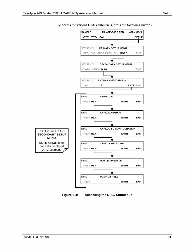
Teledyne API Model T500U CAPS NO2 Analyzer Manual Setup
07834D DCN6998 81
To access the various DIAG submenus, press the following buttons:
SAMPLE RANGE=500.0 PPB NO2= XXXX
<TST TST> CAL SETUP
SETUP X.X PRIMARY SETUP MENU
CFG DAS RNGE PASS CLK MORE EXIT
SETUP X.X SECONDARY SETUP MENU
COMM VARS DIAG EXIT
SETUP X.X ENTER PASSWORD:818
8 1 8 ENTR EXIT
DIAG SIGNAL I/O
PREV NEXT ENTR EXIT
EXIT returns to the SECONDARY SETUP
MENU.ENTR Activates the currently displayed
DIAG submenu.
DIAG ANALOG OUTPUT
PREV NEXT ENTR EXIT
DIAG ANALOG I/O CONFIGURATION
PREV NEXT ENTR EXIT
DIAG NO2 LED DISABLE
PREV NEXT ENTR EXIT
DIAG PUMP DISABLE
PREV ENTR EXIT
DIAG TEST CHAN OUTPUT
PREV NEXT ENTR EXIT
Figure 6-4: Accessing the DIAG Submenus

Setup Teledyne API Model T500U CAPS NO2 Analyzer Manual
82 07834D DCN6998
SIGNAL I/O 6.8.1.The signal I/O diagnostic mode allows a user to review and change the digital and analog input/output functions of the analyzer. Refer to Appendix A for a list of the parameters available for review under this menu.
Access the signal I/O test mode from the DIAG Menu (Figure 6-4), then press:
EXAMPLE
DIAG SIGNAL I / O
PREV NEXT JUMP ENTR EXIT
DIAG I / O 0) EXT_ZERO_CAL=OFF
PREV NEXT JUMP PRNT EXIT
Press JUMP to go directly to a specific
signal See Appendix A-4 for
a complete list of available SIGNALS
DIAG I / O JUMP TO: 09
0 9 ENTR EXIT EXAMPLE:
Toggle the second button until it displays 9 to Jump to
9) ST SYSTEM OK
DIAG I / O 9) ST_SYSTEM_OK = ON
PREV NEXT JUMP ON PRNT EXIT
Exit to return to the
DIAG menu
Press NEXT & PREV to move between signal
types.
Pressing the PRNT button will send a formatted printout to the serial port and can be captured
with a computer or other output device. Toggle ON/(OFF) button to
change status.
ANALOG OUTPUT (DIAG AOUT) 6.8.2.Analog Output (AOUT) is used to verify functionality and accuracy of the analog outputs. The test forces all analog output channels to produce signals ranging from 0% to 100% of the full scale range in 20% increments. This test is useful to verify the operation of the data logging/recording devices attached to the analyzer.
Section 13.6.7.1 presents instructions for use in troubleshooting and service.
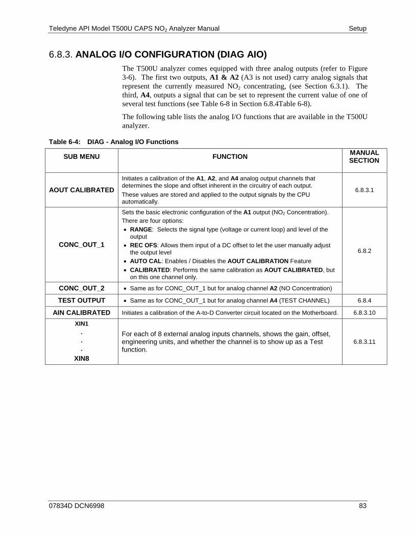
Teledyne API Model T500U CAPS NO2 Analyzer Manual Setup
07834D DCN6998 83
ANALOG I/O CONFIGURATION (DIAG AIO) 6.8.3.The T500U analyzer comes equipped with three analog outputs (refer to Figure 3-6). The first two outputs, A1 & A2 (A3 is not used) carry analog signals that represent the currently measured NO2 concentrating, (see Section 6.3.1). The third, A4, outputs a signal that can be set to represent the current value of one of several test functions (see Table 6-8 in Section 6.8.4Table 6-8).
The following table lists the analog I/O functions that are available in the T500U analyzer.
Table 6-4: DIAG - Analog I/O Functions
SUB MENU FUNCTION MANUAL SECTION
AOUT CALIBRATED
Initiates a calibration of the A1, A2, and A4 analog output channels that determines the slope and offset inherent in the circuitry of each output. These values are stored and applied to the output signals by the CPU automatically.
6.8.3.1
CONC_OUT_1
Sets the basic electronic configuration of the A1 output (NO2 Concentration). There are four options: • RANGE: Selects the signal type (voltage or current loop) and level of the
output • REC OFS: Allows them input of a DC offset to let the user manually adjust
the output level • AUTO CAL: Enables / Disables the AOUT CALIBRATION Feature • CALIBRATED: Performs the same calibration as AOUT CALIBRATED, but
on this one channel only.
6.8.2
CONC_OUT_2 • Same as for CONC_OUT_1 but for analog channel A2 (NO Concentration)
TEST OUTPUT • Same as for CONC_OUT_1 but for analog channel A4 (TEST CHANNEL) 6.8.4 AIN CALIBRATED Initiates a calibration of the A-to-D Converter circuit located on the Motherboard. 6.8.3.10
XIN1 . . .
XIN8
For each of 8 external analog inputs channels, shows the gain, offset, engineering units, and whether the channel is to show up as a Test function.
6.8.3.11
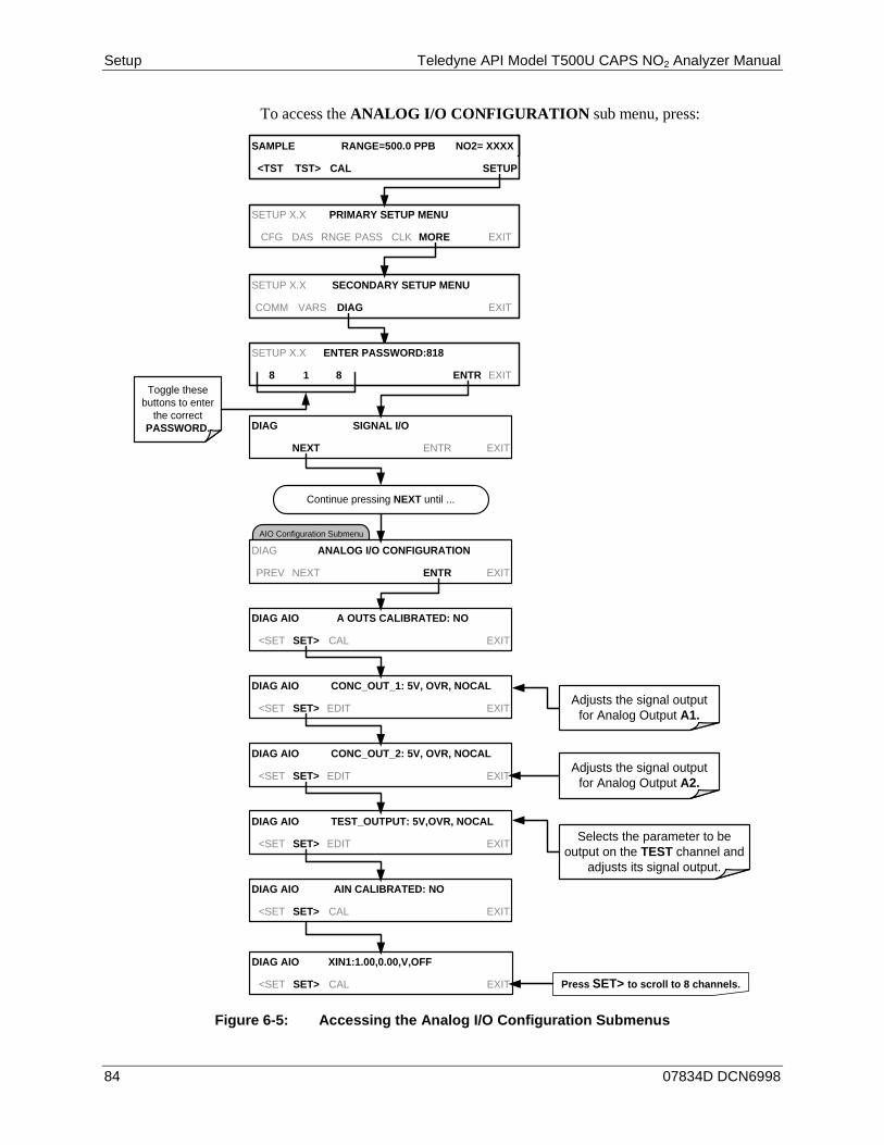
Setup Teledyne API Model T500U CAPS NO2 Analyzer Manual
84 07834D DCN6998
To access the ANALOG I/O CONFIGURATION sub menu, press:
DIAG AIO AIN CALIBRATED: NO
<SET SET> CAL EXIT
DIAG AIO TEST_OUTPUT: 5V,OVR, NOCAL
<SET SET> EDIT EXIT
SAMPLE RANGE=500.0 PPB NO2= XXXX
<TST TST> CAL SETUP
SETUP X.X PRIMARY SETUP MENU
CFG DAS RNGE PASS CLK MORE EXIT
SETUP X.X SECONDARY SETUP MENU
COMM VARS DIAG EXIT
SETUP X.X ENTER PASSWORD:818
8 1 8 ENTR EXIT
AIO Configuration Submenu
DIAG SIGNAL I/O
NEXT ENTR EXIT
Continue pressing NEXT until ...
DIAG ANALOG I/O CONFIGURATION
PREV NEXT ENTR EXIT
DIAG AIO A OUTS CALIBRATED: NO
<SET SET> CAL EXIT
DIAG AIO CONC_OUT_1: 5V, OVR, NOCAL
<SET SET> EDIT EXIT
DIAG AIO CONC_OUT_2: 5V, OVR, NOCAL
<SET SET> EDIT EXIT
Toggle these buttons to enter
the correct PASSWORD.
Adjusts the signal output for Analog Output A1.
Adjusts the signal output for Analog Output A2.
Selects the parameter to be output on the TEST channel and
adjusts its signal output.
DIAG AIO XIN1:1.00,0.00,V,OFF
<SET SET> CAL EXIT Press SET> to scroll to 8 channels.
Figure 6-5: Accessing the Analog I/O Configuration Submenus
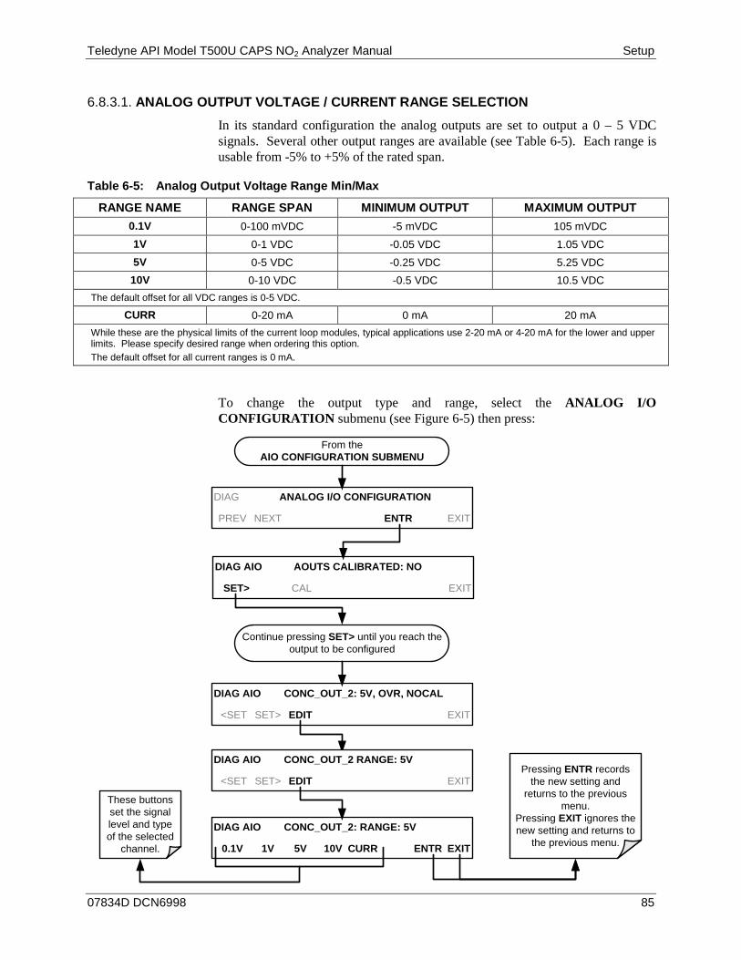
Teledyne API Model T500U CAPS NO2 Analyzer Manual Setup
07834D DCN6998 85
ANALOG OUTPUT VOLTAGE / CURRENT RANGE SELECTION 6.8.3.1.
In its standard configuration the analog outputs are set to output a 0 – 5 VDC signals. Several other output ranges are available (see Table 6-5). Each range is usable from -5% to +5% of the rated span.
Table 6-5: Analog Output Voltage Range Min/Max
RANGE NAME RANGE SPAN MINIMUM OUTPUT MAXIMUM OUTPUT 0.1V 0-100 mVDC -5 mVDC 105 mVDC 1V 0-1 VDC -0.05 VDC 1.05 VDC 5V 0-5 VDC -0.25 VDC 5.25 VDC 10V 0-10 VDC -0.5 VDC 10.5 VDC
The default offset for all VDC ranges is 0-5 VDC.
CURR 0-20 mA 0 mA 20 mA While these are the physical limits of the current loop modules, typical applications use 2-20 mA or 4-20 mA for the lower and upper limits. Please specify desired range when ordering this option. The default offset for all current ranges is 0 mA.
To change the output type and range, select the ANALOG I/O CONFIGURATION submenu (see Figure 6-5) then press:
DIAG AIO AOUTS CALIBRATED: NO
SET> CAL EXIT
From the AIO CONFIGURATION SUBMENU
DIAG ANALOG I/O CONFIGURATION
PREV NEXT ENTR EXIT
Continue pressing SET> until you reach the output to be configured
DIAG AIO CONC_OUT_2: 5V, OVR, NOCAL
<SET SET> EDIT EXIT
DIAG AIO CONC_OUT_2: RANGE: 5V
0.1V 1V 5V 10V CURR ENTR EXIT
These buttons set the signal level and type of the selected
channel.
Pressing ENTR records the new setting and
returns to the previous menu.
Pressing EXIT ignores the new setting and returns to
the previous menu.
DIAG AIO CONC_OUT_2 RANGE: 5V
<SET SET> EDIT EXIT
Setup Teledyne API Model T500U CAPS NO2 Analyzer Manual
86 07834D DCN6998
CALIBRATION OF THE ANALOG OUTPUTS 6.8.3.2.
Analog output calibration should be carried out on first startup of the analyzer (performed in the factory as part of the configuration process) and whenever recalibration is required. The analog outputs can be calibrated automatically, either as a group or individually, or calibrated manually.
In its default mode, the instrument is configured for automatic calibration of all channels, which is useful for clearing any analog calibration warnings associated with channels that will not be used or connected to any input or recording device, e.g., data logger.
Manual calibration should be used for the 0.1V range or in cases where the outputs must be closely matched to the characteristics of the recording device. The AUTOCAL feature must be disabled first for manual calibration.
ENABLING OR DISABLING THE AUTOCAL FOR AN INDIVIDUAL ANALOG 6.8.3.3.OUTPUT
To enable or disable the AutoCal feature for an individual analog output, elect the ANALOG I/O CONFIGURATION submenu (see Figure 6-5) then press:
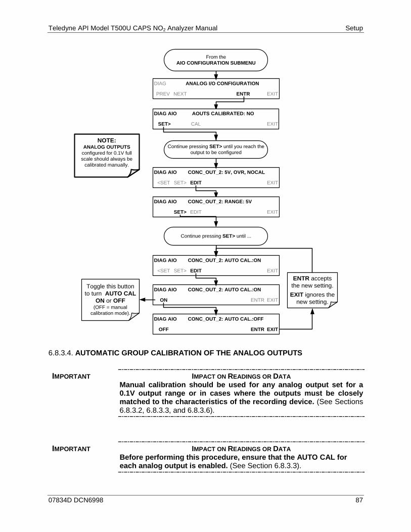
Teledyne API Model T500U CAPS NO2 Analyzer Manual Setup
07834D DCN6998 87
From the AIO CONFIGURATION SUBMENU
DIAG ANALOG I/O CONFIGURATION
PREV NEXT ENTR EXIT
DIAG AIO CONC_OUT_2: 5V, OVR, NOCAL
<SET SET> EDIT EXIT
DIAG AIO CONC_OUT_2: AUTO CAL.:ON
<SET SET> EDIT EXIT
DIAG AIO CONC_OUT_2: AUTO CAL.:ON
ON ENTR EXIT
Toggle this button to turn AUTO CAL
ON or OFF (OFF = manual
calibration mode).
ENTR accepts the new setting.EXIT ignores the
new setting.
Continue pressing SET> until ...
DIAG AIO CONC_OUT_2: RANGE: 5V
SET> EDIT EXIT
DIAG AIO CONC_OUT_2: AUTO CAL.:OFF
OFF ENTR EXIT
Continue pressing SET> until you reach the output to be configured
DIAG AIO AOUTS CALIBRATED: NO
SET> CAL EXIT
NOTE: ANALOG OUTPUTS
configured for 0.1V full scale should always be
calibrated manually.
AUTOMATIC GROUP CALIBRATION OF THE ANALOG OUTPUTS 6.8.3.4.
IMPORTANT IMPACT ON READINGS OR DATA Manual calibration should be used for any analog output set for a 0.1V output range or in cases where the outputs must be closely matched to the characteristics of the recording device. (See Sections 6.8.3.2, 6.8.3.3, and 6.8.3.6).
IMPORTANT IMPACT ON READINGS OR DATA Before performing this procedure, ensure that the AUTO CAL for each analog output is enabled. (See Section 6.8.3.3).

Setup Teledyne API Model T500U CAPS NO2 Analyzer Manual
88 07834D DCN6998
To calibrate the outputs as a group with the AOUTS CALIBRATION command, select the ANALOG I/O CONFIGURATION submenu (see Figure 6-5) then press:
From the AIO CONFIGURATION SUBMENU
Analyzer automatically calibrates all
channels for which AUTO-CAL is turned
ON
If any of the channels have not been calibrated or if at least one channel has AUTO-CAL turned OFF, this message will read NO.
DIAG AIO AUTO CALIBRATING CONC_OUT_1
DIAG AIO NOT AUTO CAL. CONC_OUT_2This message appears when AUTO-CAL is
Turned OFF for a channel
DIAG AIO AOUTS CALIBRATED: NO
SET> CAL EXIT
DIAG AIO AOUTS CALIBRATED: NO
SET> CAL EXIT
DIAG ANALOG I/O CONFIGURATION
PREV NEXT ENTR EXIT
DIAG AIO AUTO CALIBRATING CONC_OUT_3
DIAG AIO AUTO CALIBRATING TEST_OUTPUT
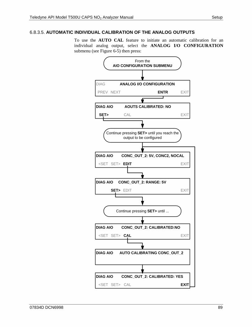
Teledyne API Model T500U CAPS NO2 Analyzer Manual Setup
07834D DCN6998 89
AUTOMATIC INDIVIDUAL CALIBRATION OF THE ANALOG OUTPUTS 6.8.3.5.
To use the AUTO CAL feature to initiate an automatic calibration for an individual analog output, select the ANALOG I/O CONFIGURATION submenu (see Figure 6-5) then press:
From the AIO CONFIGURATION SUBMENU
DIAG AIO CONC_OUT_2: 5V, CONC2, NOCAL
<SET SET> EDIT EXIT
Continue pressing SET> until ...
DIAG AIO CONC_OUT_2: CALIBRATED:NO
<SET SET> CAL EXIT
DIAG AIO CONC_OUT_2: RANGE: 5V
SET> EDIT EXIT
DIAG AIO AUTO CALIBRATING CONC_OUT_2
DIAG AIO CONC_OUT_2: CALIBRATED: YES
<SET SET> CAL EXIT
DIAG ANALOG I/O CONFIGURATION
PREV NEXT ENTR EXIT
Continue pressing SET> until you reach the output to be configured
DIAG AIO AOUTS CALIBRATED: NO
SET> CAL EXIT

Setup Teledyne API Model T500U CAPS NO2 Analyzer Manual
90 07834D DCN6998
MANUAL CALIBRATION OF THE ANALOG OUTPUTS CONFIGURED FOR 6.8.3.6.VOLTAGE RANGES
For highest accuracy, the voltages of the analog outputs can be manually calibrated.
Note The menu for manually adjusting the analog output signal level will only appear if the AUTO-CAL feature is turned off for the channel being adjusted. (See Section 6.8.3.3).
Calibration is performed with a voltmeter connected across the output terminals and by changing the actual output signal level using the front panel buttons in 100, 10 or 1 count increments. See Figure 3-6 for pin assignments and diagram of the analog output connector.
V +DC Gnd
Recording Device
V IN +
V IN -
ANALYZER
V OUT +
V OUT -
Volt Meter
Figure 6-6: Setup for Checking / Calibrating DCV Analog Output Signal Levels
Table 6-6: Voltage Tolerances for the TEST CHANNEL Calibration
FULL SCALE
ZERO TOLERANCE SPAN VOLTAGE SPAN
TOLERANCE MINIMUM
ADJUSTMENT (1 count)
0.1 VDC ±0.0005V 90 mV ±0.001V 0.02 mV
1 VDC ±0.001V 900 mV ±0.001V 0.24 mV
5 VDC ±0.002V 4500 mV ±0.003V 1.22 mV
10 VDC ±0.004V 4500 mV ±0.006V 2.44 mV
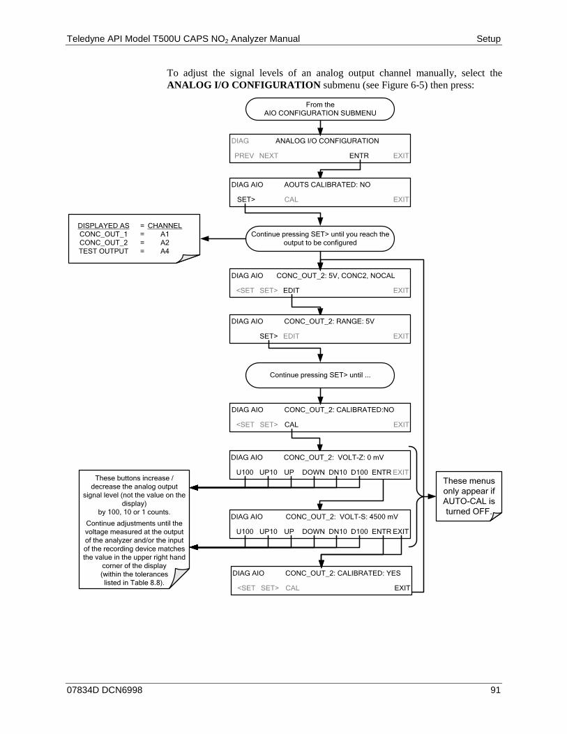
Teledyne API Model T500U CAPS NO2 Analyzer Manual Setup
07834D DCN6998 91
To adjust the signal levels of an analog output channel manually, select the ANALOG I/O CONFIGURATION submenu (see Figure 6-5) then press:
From the AIO CONFIGURATION SUBMENU
DIAG ANALOG I/O CONFIGURATION
PREV NEXT ENTR EXIT
Continue pressing SET> until you reach the output to be configured
DIAG AIO CONC_OUT_2: 5V, CONC2, NOCAL
<SET SET> EDIT EXIT
Continue pressing SET> until ...
DIAG AIO CONC_OUT_2: CALIBRATED:NO
<SET SET> CAL EXIT
DIAG AIO CONC_OUT_2: RANGE: 5V
SET> EDIT EXIT
DIAG AIO CONC_OUT_2: VOLT-Z: 0 mV
U100 UP10 UP DOWN DN10 D100 ENTR EXIT
DIAG AIO CONC_OUT_2: VOLT-S: 4500 mV
U100 UP10 UP DOWN DN10 D100 ENTR EXIT
DIAG AIO CONC_OUT_2: CALIBRATED: YES
<SET SET> CAL EXIT
These menus only appear if AUTO-CAL is turned OFF.
These buttons increase / decrease the analog output
signal level (not the value on the display)
by 100, 10 or 1 counts.
Continue adjustments until the voltage measured at the output of the analyzer and/or the input of the recording device matches the value in the upper right hand
corner of the display (within the tolerances listed in Table 8.8).
DIAG AIO AOUTS CALIBRATED: NO
SET> CAL EXIT
DISPLAYED AS = CHANNELCONC_OUT_1 = A1CONC_OUT_2 = A2TEST OUTPUT = A4
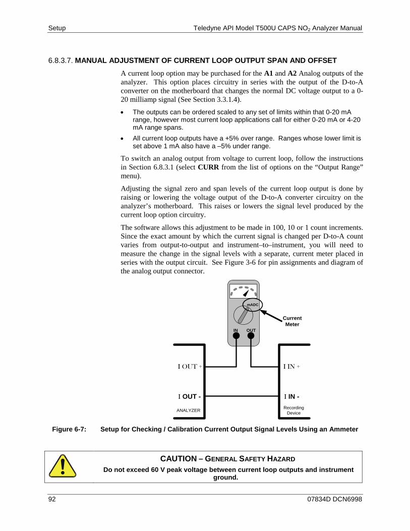
Setup Teledyne API Model T500U CAPS NO2 Analyzer Manual
92 07834D DCN6998
MANUAL ADJUSTMENT OF CURRENT LOOP OUTPUT SPAN AND OFFSET 6.8.3.7.
A current loop option may be purchased for the A1 and A2 Analog outputs of the analyzer. This option places circuitry in series with the output of the D-to-A converter on the motherboard that changes the normal DC voltage output to a 0-20 milliamp signal (See Section 3.3.1.4).
• The outputs can be ordered scaled to any set of limits within that 0-20 mA range, however most current loop applications call for either 0-20 mA or 4-20 mA range spans.
• All current loop outputs have a +5% over range. Ranges whose lower limit is set above 1 mA also have a –5% under range.
To switch an analog output from voltage to current loop, follow the instructions in Section 6.8.3.1 (select CURR from the list of options on the “Output Range” menu).
Adjusting the signal zero and span levels of the current loop output is done by raising or lowering the voltage output of the D-to-A converter circuitry on the analyzer’s motherboard. This raises or lowers the signal level produced by the current loop option circuitry.
The software allows this adjustment to be made in 100, 10 or 1 count increments. Since the exact amount by which the current signal is changed per D-to-A count varies from output-to-output and instrument–to–instrument, you will need to measure the change in the signal levels with a separate, current meter placed in series with the output circuit. See Figure 3-6 for pin assignments and diagram of the analog output connector.
mADC
IN OUT
Recording Device
I IN +
I IN -
ANALYZER
I OUT +
I OUT -
Current Meter
Figure 6-7: Setup for Checking / Calibration Current Output Signal Levels Using an Ammeter
CAUTION – GENERAL SAFETY HAZARD Do not exceed 60 V peak voltage between current loop outputs and instrument
ground.
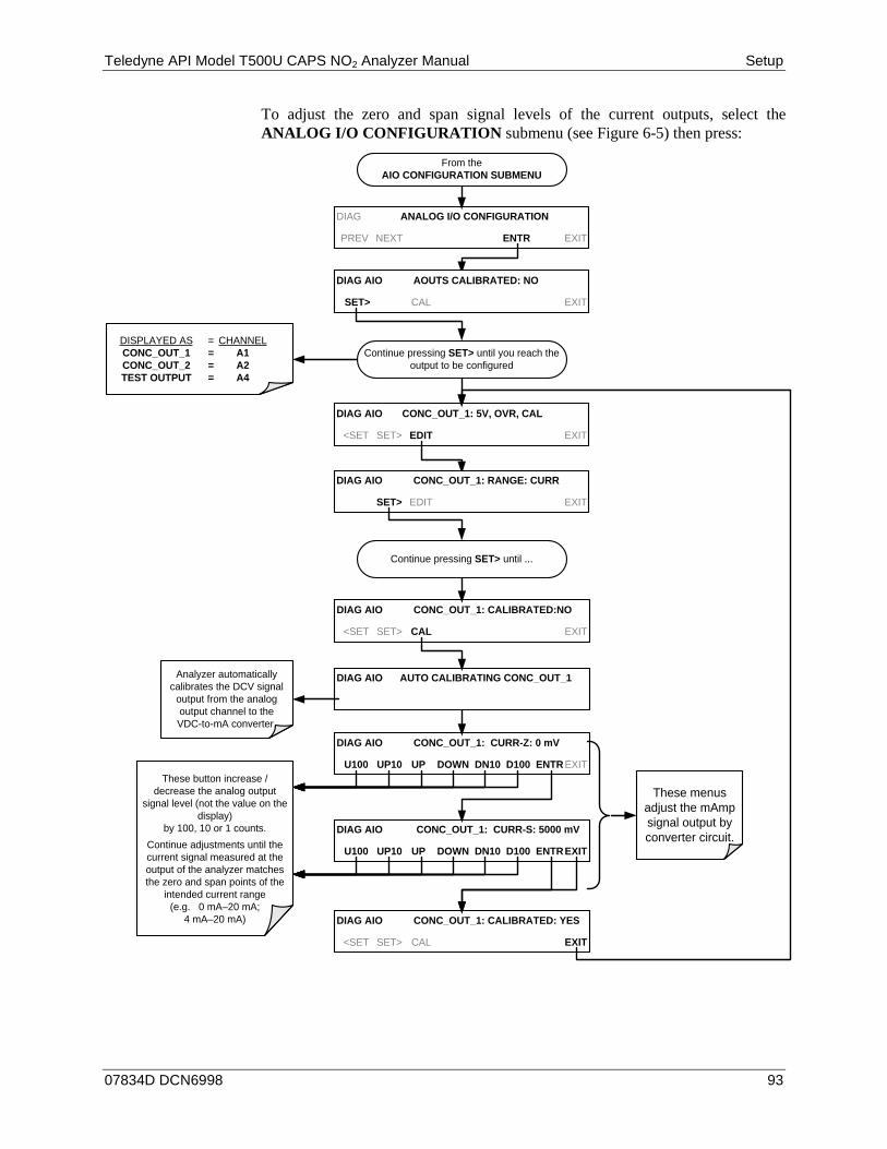
Teledyne API Model T500U CAPS NO2 Analyzer Manual Setup
07834D DCN6998 93
To adjust the zero and span signal levels of the current outputs, select the ANALOG I/O CONFIGURATION submenu (see Figure 6-5) then press:
DIAG AIO CONC_OUT_1: CURR-Z: 0 mV
U100 UP10 UP DOWN DN10 D100 ENTREXIT
DIAG AIO CONC_OUT_1: CURR-S: 5000 mV
U100 UP10 UP DOWN DN10 D100 ENTREXIT
DIAG AIO CONC_OUT_1: CALIBRATED: YES
<SET SET> CAL EXIT
DIAG ANALOG I/O CONFIGURATION
PREV NEXT ENTR EXIT
Continue pressing SET> until you reach the output to be configured
DIAG AIO CONC_OUT_1: 5V, OVR, CAL
<SET SET> EDIT EXIT
Continue pressing SET> until ...
DIAG AIO CONC_OUT_1: CALIBRATED:NO
<SET SET> CAL EXIT
DIAG AIO CONC_OUT_1: RANGE: CURR
SET> EDIT EXIT
These menus adjust the mAmp signal output by converter circuit.
These button increase / decrease the analog output
signal level (not the value on the display)
by 100, 10 or 1 counts. Continue adjustments until the current signal measured at the output of the analyzer matches the zero and span points of the
intended current range (e.g. 0 mA–20 mA;
4 mA–20 mA)
DIAG AIO AOUTS CALIBRATED: NO
SET> CAL EXIT
DISPLAYED AS = CHANNELCONC_OUT_1 = A1CONC_OUT_2 = A2TEST OUTPUT = A4
From the AIO CONFIGURATION SUBMENU
Analyzer automatically calibrates the DCV signal
output from the analog output channel to the VDC-to-mA converter.
DIAG AIO AUTO CALIBRATING CONC_OUT_1
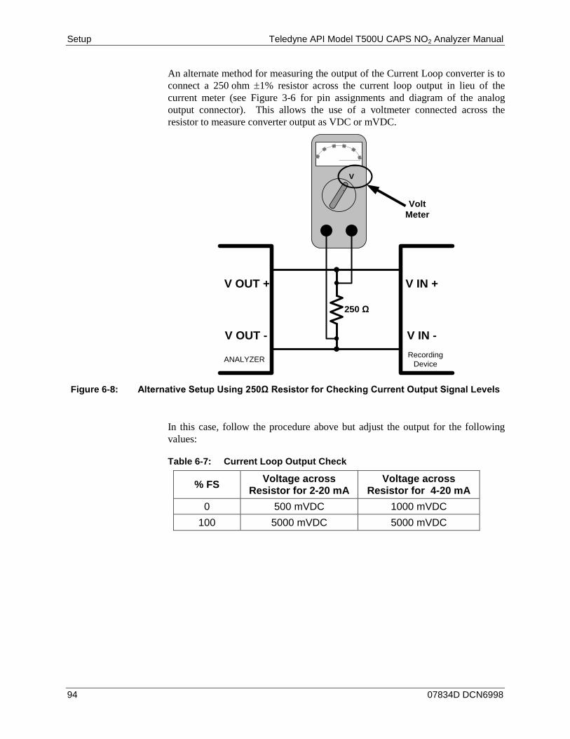
Setup Teledyne API Model T500U CAPS NO2 Analyzer Manual
94 07834D DCN6998
An alternate method for measuring the output of the Current Loop converter is to connect a 250 ohm ±1% resistor across the current loop output in lieu of the current meter (see Figure 3-6 for pin assignments and diagram of the analog output connector). This allows the use of a voltmeter connected across the resistor to measure converter output as VDC or mVDC.
V +DC Gnd
Recording Device
V IN +
V IN -
ANALYZER
V OUT +
V OUT -
250 Ω
Volt Meter
Figure 6-8: Alternative Setup Using 250Ω Resistor for Checking Current Output Signal Levels
In this case, follow the procedure above but adjust the output for the following values:
Table 6-7: Current Loop Output Check
% FS Voltage across Resistor for 2-20 mA
Voltage across Resistor for 4-20 mA
0 500 mVDC 1000 mVDC 100 5000 mVDC 5000 mVDC
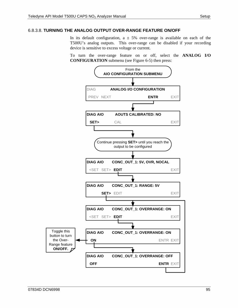
Teledyne API Model T500U CAPS NO2 Analyzer Manual Setup
07834D DCN6998 95
TURNING THE ANALOG OUTPUT OVER-RANGE FEATURE ON/OFF 6.8.3.8.
In its default configuration, a ± 5% over-range is available on each of the T500U’s analog outputs. This over-range can be disabled if your recording device is sensitive to excess voltage or current.
To turn the over-range feature on or off, select the ANALOG I/O CONFIGURATION submenu (see Figure 6-5) then press:
DIAG AIO CONC_OUT_1: 5V, OVR, NOCAL
<SET SET> EDIT EXIT
DIAG AIO CONC_OUT_1: OVERRANGE: ON
<SET SET> EDIT EXIT
DIAG AIO CONC_OUT_1: RANGE: 5V
SET> EDIT EXIT
DIAG AIO CONC_OUT_1: OVERRANGE: ON
ON ENTR EXIT
DIAG AIO CONC_OUT_1: OVERRANGE: OFF
OFF ENTR EXIT
DIAG ANALOG I/O CONFIGURATION
PREV NEXT ENTR EXIT
Toggle this button to turn
the Over-Range feature
ON/OFF.
Continue pressing SET> until you reach the output to be configured
DIAG AIO AOUTS CALIBRATED: NO
SET> CAL EXIT
From the AIO CONFIGURATION SUBMENU
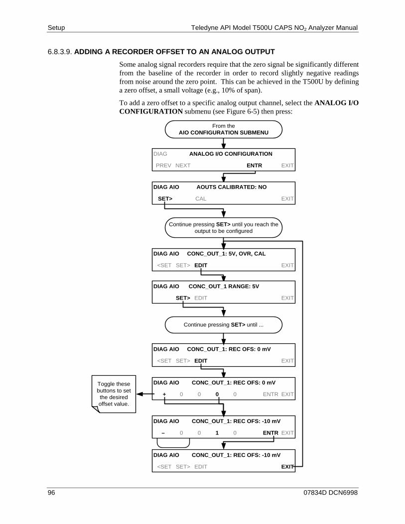
Setup Teledyne API Model T500U CAPS NO2 Analyzer Manual
96 07834D DCN6998
ADDING A RECORDER OFFSET TO AN ANALOG OUTPUT 6.8.3.9.
Some analog signal recorders require that the zero signal be significantly different from the baseline of the recorder in order to record slightly negative readings from noise around the zero point. This can be achieved in the T500U by defining a zero offset, a small voltage (e.g., 10% of span).
To add a zero offset to a specific analog output channel, select the ANALOG I/O CONFIGURATION submenu (see Figure 6-5) then press:
EXAMPLE
DIAG AIO CONC_OUT_1: 5V, OVR, CAL
<SET SET> EDIT EXIT
DIAG AIO CONC_OUT_1: REC OFS: 0 mV
<SET SET> EDIT EXIT
DIAG AIO CONC_OUT_1 RANGE: 5V
SET> EDIT EXIT
DIAG AIO CONC_OUT_1: REC OFS: 0 mV
+ 0 0 0 0 ENTR EXIT
DIAG AIO CONC_OUT_1: REC OFS: -10 mV
<SET SET> EDIT EXIT
DIAG ANALOG I/O CONFIGURATION
PREV NEXT ENTR EXIT
Toggle these buttons to set the desired offset value.
Continue pressing SET> until ...
DIAG AIO CONC_OUT_1: REC OFS: -10 mV
– 0 0 1 0 ENTR EXIT
Continue pressing SET> until you reach the output to be configured
DIAG AIO AOUTS CALIBRATED: NO
SET> CAL EXIT
From the AIO CONFIGURATION SUBMENU
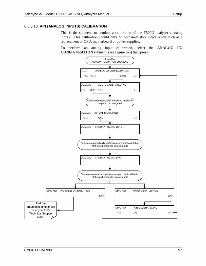
Teledyne API Model T500U CAPS NO2 Analyzer Manual Setup
07834D DCN6998 97
AIN (ANALOG INPUTS) CALIBRATION 6.8.3.10.
This is the submenu to conduct a calibration of the T500U analyzer’s analog inputs. This calibration should only be necessary after major repair such as a replacement of CPU, motherboard or power supplies.
To perform an analog input calibration, select the ANALOG I/O CONFIGURATION submenu (see Figure 6-5) then press:
DIAG AIO AIN CALIBRATED:NO
<SET CAL EXIT
DIAG ANALOG I/O CONFIGURATION
PREV NEXT ENTR EXIT
Firmware automatically performs a zero point calibration of the Motherboard’s analog Inputs
Continue pressing SET> until you reach the output to be configured
DIAG AIO AOUTS CALIBRATED: NO
<SET SET> CAL EXIT
Firmware automatically performs a span point calibration of the Motherboard’s analog Inputs
DIAG AIO CALIBRATING A/D ZERO
DIAG AIO CALIBRATING A/D SPAN
DIAG AIO A/D CALIBRATION ERROR
EXIT
DIAG AIO AIN CALIBRATED: YES
EXIT
DIAG AIO AIN CALIBRATED:NO
<SET CAL EXIT
Perform Troubleshooting or call
Teledyne API’s Technical Support
Dept.
From the AIO CONFIGURATION SUBMENU
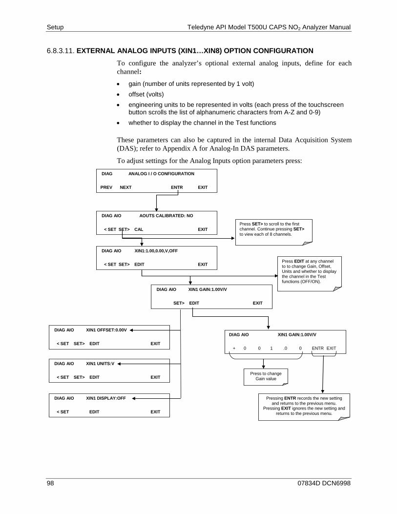
Setup Teledyne API Model T500U CAPS NO2 Analyzer Manual
98 07834D DCN6998
EXTERNAL ANALOG INPUTS (XIN1…XIN8) OPTION CONFIGURATION 6.8.3.11.
To configure the analyzer’s optional external analog inputs, define for each channel:
• gain (number of units represented by 1 volt) • offset (volts) • engineering units to be represented in volts (each press of the touchscreen
button scrolls the list of alphanumeric characters from A-Z and 0-9) • whether to display the channel in the Test functions
These parameters can also be captured in the internal Data Acquisition System (DAS); refer to Appendix A for Analog-In DAS parameters.
To adjust settings for the Analog Inputs option parameters press:
DIAG AIO XIN1 GAIN:1.00V/V
SET> EDIT EXIT
DIAG ANALOG I / O CONFIGURATION
PREV NEXT ENTR EXIT
DIAG AIO AOUTS CALIBRATED: NO
< SET SET> CAL EXIT
DIAG AIO XIN1 GAIN:1.00V/V
+ 0 0 1 .0 0 ENTR EXIT
Press to change Gain value
DIAG AIO XIN1:1.00,0.00,V,OFF
< SET SET> EDIT EXIT
Press SET> to scroll to the first channel. Continue pressing SET> to view each of 8 channels.
Pressing ENTR records the new setting and returns to the previous menu.
Pressing EXIT ignores the new setting and returns to the previous menu.
Press EDIT at any channel to to change Gain, Offset, Units and whether to display the channel in the Test functions (OFF/ON).
DIAG AIO XIN1 OFFSET:0.00V
< SET SET> EDIT EXIT
DIAG AIO XIN1 UNITS:V
< SET SET> EDIT EXIT
DIAG AIO XIN1 DISPLAY:OFF
< SET EDIT EXIT

Teledyne API Model T500U CAPS NO2 Analyzer Manual Setup
07834D DCN6998 99
TEST CHAN OUTPUT (SELECTING A TEST CHANNEL 6.8.4.FUNCTION FOR OUTPUT A4)
The test functions available to be reported are listed in Table 6-8:
Table 6-8: Test Channels Functions available on the T500U’s Analog Output
TEST CHANNEL DESCRIPTION ZERO FULL SCALE
NONE TEST CHANNEL IS TURNED OFF
SMP PRS The pressure of the sample gas measured at the entrance of the Optical bench.
Ambient InHg-A 32 InHg-A
SMP TEMP The temperature of the sample gas measured at the exhaust of the Optical bench.
0 °C 70 °C
MEASURED LOSS Optical loss in the bench. 400-800 Mm-1 1800 Mm-1 OVEN TEMP The temperature of the internal oven. 0 °C 70 °C BOX TEMP The temperature inside the chassis. 0 °C 70 °C
MANIFOLD TEMP Option –Temperature of heated manifold. 0 °C 70 °C
IZS TEMP The temperature inside the chassis. 0 °C 70 °C
Once a function is selected, the instrument not only begins to output a signal on the analog output, but also adds TEST to the list of test functions viewable in the front panel display.
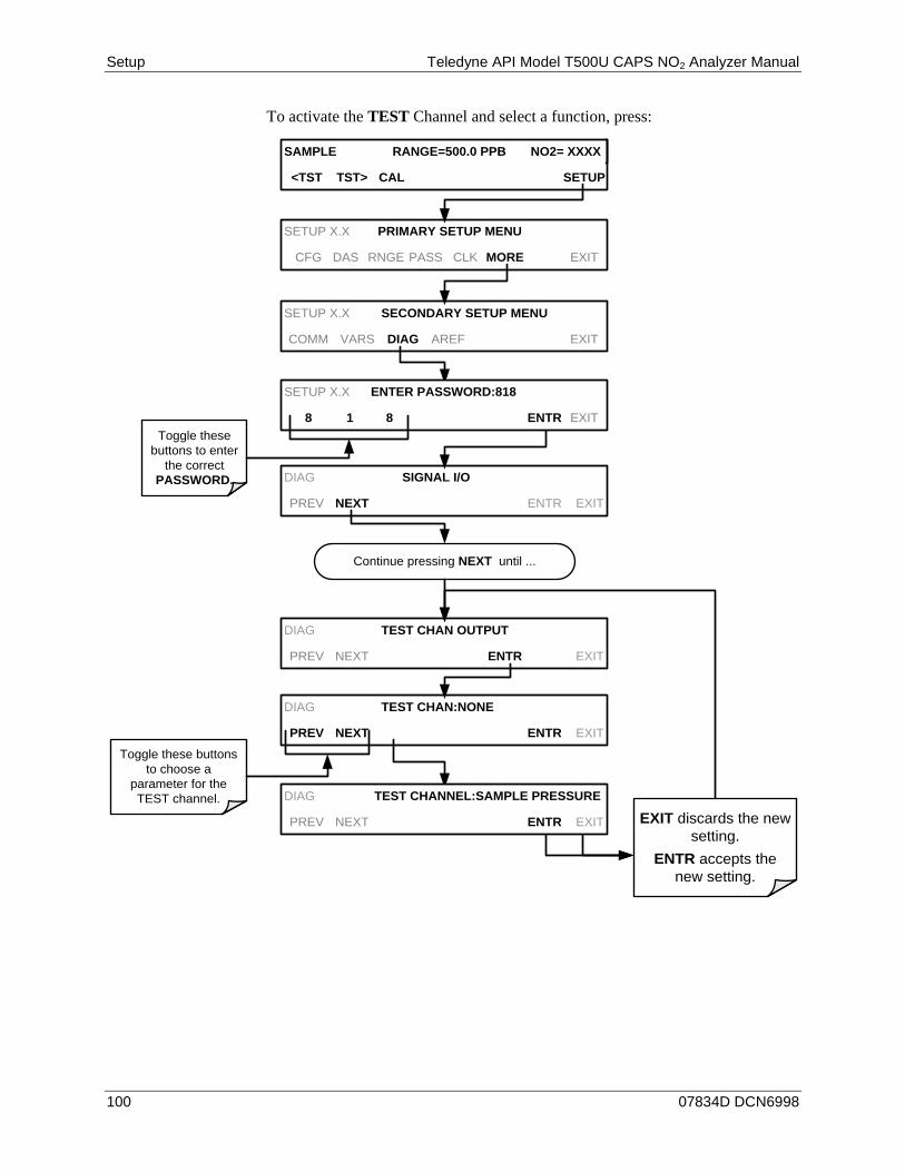
Setup Teledyne API Model T500U CAPS NO2 Analyzer Manual
100 07834D DCN6998
To activate the TEST Channel and select a function, press:
SAMPLE RANGE=500.0 PPB NO2= XXXX
<TST TST> CAL SETUP
DIAG TEST CHAN:NONE
PREV NEXT ENTR EXIT
DIAG SIGNAL I/O
PREV NEXT ENTR EXIT
DIAG TEST CHAN OUTPUT
PREV NEXT ENTR EXIT
Continue pressing NEXT until ...
Toggle these buttons to choose a
parameter for the TEST channel. DIAG TEST CHANNEL:SAMPLE PRESSURE
PREV NEXT ENTR EXIT EXIT discards the new setting.
ENTR accepts the new setting.
SETUP X.X PRIMARY SETUP MENU
CFG DAS RNGE PASS CLK MORE EXIT
SETUP X.X SECONDARY SETUP MENU
COMM VARS DIAG AREF EXIT
SETUP X.X ENTER PASSWORD:818
8 1 8 ENTR EXITToggle these
buttons to enter the correct
PASSWORD.
Teledyne API Model T500U CAPS NO2 Analyzer Manual Setup
07834D DCN6998 101
NO2 LED DISABLE 6.8.5.This feature is for turning off or on the NO2 LED. Access NO2 LED DISABLE in the SETUP>MORE>DIAG> . . . menu, and press ENTR, then YES to disable (turn off) or NO to enable (turn on) the LED.
PUMP DISABLE 6.8.6.This feature in the DIAG menu is used to turn the internal pump ON or OFF while keeping the instrument running. This is an important feature when maintenance is required where reading the front panel display is necessary, such as for the internal bench.
SETUP>MORE>AREF: 6.9.At 20 minutes after power up and periodically thereafter when in Sample mode, the analyzer conducts a background measurement, known as an auto reference (AREF), whereby the sample is routed through an internal charcoal scrubber. This measurement accounts for drift in the baseline loss. A manual AREF is recommended prior to initial calibration (Section 5.3).
Please note that AREF becomes disabled during calibration if the instrument stays in calibration mode (CALZ or CALS) for longer than it would normally take to run a calibration. To ensure that AREF is enabled, return to Sample mode after conducting a calibration.

Setup Teledyne API Model T500U CAPS NO2 Analyzer Manual
102 07834D DCN6998
This page intentionally left blank.
07834D DCN6998 103
7. COMMUNICATIONS SETUP AND OPERATION Communication connection instructions were provided in Section 3.3.1.8.
This section provides pertinent information regarding communication equipment, describes the instrument’s communications modes, presents configuration instructions for the communications ports, and provides instructions for their use, including communications protocol. Data acquisition is presented in Section 8.
DATA TERMINAL/COMMUNICATION EQUIPMENT (DTE 7.1.DEC)
RS-232 was developed for allowing communications between data terminal equipment (DTE) and data communication equipment (DCE). Basic terminals always fall into the DTE category whereas modems are always considered DCE devices. The difference between the two is the pin assignment of the Data Receive and Data Transmit functions.
• DTE devices receive data on pin 2 and transmit data on pin 3. • DCE devices receive data on pin 3 and transmit data on pin 2.
To allow the analyzer to be used with terminals (DTE), modems (DCE) and computers (which can be either), a switch mounted below the serial ports on the rear panel labeled DCE DTE (Figure 3-3) allows the user to set the RS-232 configuration for one of these two data devices. This switch exchanges the Receive and Transmit lines on RS-232 emulating a cross-over or null-modem cable. The switch has no effect on COM2.
COMMUNICATION MODES, BAUD RATE AND PORT 7.2.TESTING
Use the SETUP>MORE>COMM menu to configure COM1 (labeled RS232 on instrument rear panel) and/or COM2 (labeled COM2 on instrument rear panel) for communication modes, baud rate and/or port testing for correct connection. If using a USB option communication connection, setup requires configuring the COM2 baud rate (Section 7.2.2).
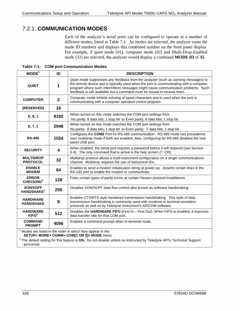
Communications Setup and Operation Teledyne API Model T500U CAPS NO2 Analyzer Manual
104 07834D DCN6998
COMMUNICATION MODES 7.2.1.Each of the analyzer’s serial ports can be configured to operate in a number of different modes, listed in Table 7-1. As modes are selected, the analyzer sums the mode ID numbers and displays this combined number on the front panel display. For example, if quiet mode (01), computer mode (02) and Multi-Drop-Enabled mode (32) are selected, the analyzer would display a combined MODE ID of 35.
Table 7-1: COM port Communication Modes
MODE1 ID DESCRIPTION
QUIET 1 Quiet mode suppresses any feedback from the analyzer (such as warning messages) to the remote device and is typically used when the port is communicating with a computer program where such intermittent messages might cause communication problems. Such feedback is still available but a command must be issued to receive them.
COMPUTER 2 Computer mode inhibits echoing of typed characters and is used when the port is communicating with a computer operated control program.
(RESERVED) 16
E, 8, 1 8192 When turned on this mode switches the COM port settings from No parity; 8 data bits; 1 stop bit to Even parity; 8 data bits; 1 stop bit.
E, 7, 1 2048 When turned on this mode switches the COM port settings from No parity; 8 data bits; 1 stop bit to Even parity; 7 data bits; 1 stop bit.
RS-485 1024 Configures the COM2 Port for RS-485 communication. RS-485 mode has precedence over multidrop mode if both are enabled. Also, configuring for RS-485 disables the rear panel USB port.
SECURITY 4 When enabled, the serial port requires a password before it will respond (see Section 6.4). The only command that is active is the help screen (? CR).
MULTIDROP PROTOCOL 32 Multidrop protocol allows a multi-instrument configuration on a single communications
channel. Multidrop requires the use of instrument IDs. ENABLE MODEM 64 Enables to send a modem initialization string at power-up. Asserts certain lines in the
RS-232 port to enable the modem to communicate. ERROR
CHECKING2 128 Fixes certain types of parity errors at certain Hessen protocol installations.
XON/XOFF HANDSHAKE2 256 Disables XON/XOFF data flow control also known as software handshaking.
HARDWARE HANDSHAKE 8
Enables CTS/RTS style hardwired transmission handshaking. This style of data transmission handshaking is commonly used with modems or terminal emulation protocols as well as by Teledyne Instrument’s APICOM software.
HARDWARE FIFO2 512 Disables the HARDWARE FIFO (First In – First Out). When FIFO is enabled, it improves
data transfer rate for that COM port. COMMAND PROMPT 4096 Enables a command prompt when in terminal mode.
1 Modes are listed in the order in which they appear in the SETUP> MORE> COMM> COM[1 OR 2]> MODE menu
2 The default setting for this feature is ON. Do not disable unless so instructed by Teledyne API's Technical Support personnel.
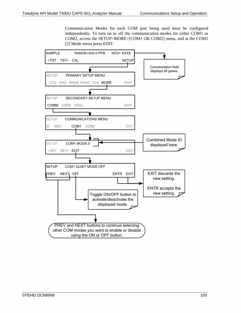
Teledyne API Model T500U CAPS NO2 Analyzer Manual Communications Setup and Operation
07834D DCN6998 105
Communication Modes for each COM port being used must be configured independently. To turn on or off the communication modes for either COM1 or COM2, access the SETUP>MORE>[COM1 OR COM2] menu, and at the COM1 [2] Mode menu press EDIT.
SETUP COMMUNICATIONS MENU
ID INET COM1 COM2 EXIT
SETUP COM1 MODE:0
<SET SET> EDIT EXIT
SETUP COM1 QUIET MODE:OFF
PREV NEXT OFF ENTR EXIT EXIT discards the new setting.
ENTR accepts the new setting.Toggle ON/OFF button to
activate/deactivate the displayed mode.
PREV and NEXT buttons to continue selecting other COM modes you want to enable or disable
using the ON or OFF button.
Combined Mode ID displayed here.
Concentration field displays all gases.
SAMPLE RANGE=500.0 PPB NO2= XXXX
<TST TST> CAL SETUP
SETUP PRIMARY SETUP MENU
CFG DAS RNGE PASS CLK MORE EXIT
SETUP SECONDARY SETUP MENU
COMM VARS DIAG EXIT

Communications Setup and Operation Teledyne API Model T500U CAPS NO2 Analyzer Manual
106 07834D DCN6998
COM PORT BAUD RATE 7.2.2.To select the baud rate of either COM port, go to SETUP>MORE>COMM and select either COM1 or COM2 as follows (use COM2 to view/match your personal computer baud rate when using the USB port, Section 7.6):
EXAMPLE
SETUP X.X COM1 BAUD RATE:115200
PREV ENTR EXIT
SETUP X.X COM1 BAUD RATE:9600
PREV NEXT ENTR EXIT
SETUP X.X COMMUNICATIONS MENU
ID INET COM1 COM2 EXIT
SETUP X.X COM1 MODE:0
SET> EDIT EXIT
SETUP X.X COM1 BAUD RATE:115200
<SET SET> EDIT EXIT
Select which COM port to configure.
(COM1 for example).
Use PREV and NEXT to move between
available baud rates.
300 1200 4800 9600
19200 38400 57600
115200
Press SET> until you reach the COM1
BAUD RATE
ENTR accepts
the setting Displayed.
EXIT ignores the new setting
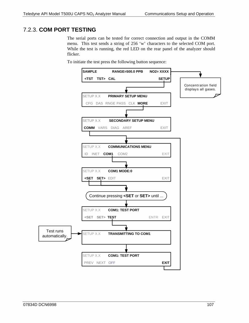
Teledyne API Model T500U CAPS NO2 Analyzer Manual Communications Setup and Operation
07834D DCN6998 107
COM PORT TESTING 7.2.3.The serial ports can be tested for correct connection and output in the COMM menu. This test sends a string of 256 ‘w’ characters to the selected COM port. While the test is running, the red LED on the rear panel of the analyzer should flicker.
To initiate the test press the following button sequence:
Concentration field displays all gases.
SAMPLE RANGE=500.0 PPB NO2= XXXX
<TST TST> CAL SETUP
SETUP X.X COMMUNICATIONS MENU
ID INET COM1 COM2 EXIT
SETUP X.X COM1 MODE:0
<SET SET> EDIT EXIT
SETUP X.X COM1: TEST PORT
<SET SET> TEST ENTR EXIT
SETUP X.X COM1: TEST PORT
PREV NEXT OFF EXIT
Continue pressing <SET or SET> until ...
SETUP X.X TRANSMITTING TO COM1Test runs
automatically.
SETUP X.X PRIMARY SETUP MENU
CFG DAS RNGE PASS CLK MORE EXIT
SETUP X.X SECONDARY SETUP MENU
COMM VARS DIAG AREF EXIT

Communications Setup and Operation Teledyne API Model T500U CAPS NO2 Analyzer Manual
108 07834D DCN6998
RS-232 7.3.The RS232 and COM2 communications (COMM) ports operate on the RS-232 protocol (default configuration). Possible configurations for these two COM ports are summarized as follows:
• RS232 port can also be configured to operate in single or RS-232 Multidrop mode (Option 62); refer to Section 3.3.1.8.
• COM2 port can be left in its default configuration for standard RS-232 operation including multidrop, or it can be reconfigured for half-duplex RS-485 operation (please contact the factory for this configuration).
Note that the COM2 port and the USB port cannot be used simultaneously except when COM2 is used for multidrop communication.
A code-activated switch (CAS) can also be used on either RS232 or COM2 port to connect typically between 2 and 16 send/receive instruments (host computer(s) printers, data loggers, analyzers, monitors, calibrators, etc.) into one communications hub. Contact Teledyne API Sales for more information on CAS systems.
To configure the analyzer’s communication ports, use the SETUP>MORE>COMM menu (Section 6.6), and configure per Section 7.2 information.
RS-485 (OPTION) 7.4.The COM2 port of the instrument’s rear panel is set up for RS-232 communication but can be reconfigured for RS-485 communication. Contact Technical Support. If this option was elected at the time of purchase, the rear panel was preconfigured at the factory. USB communications is not available when RS-485 is configured.
Teledyne API Model T500U CAPS NO2 Analyzer Manual Communications Setup and Operation
07834D DCN6998 109
ETHERNET 7.5.When using the Ethernet interface, the analyzer can be connected to any standard 10BaseT or 100BaseT Ethernet network via low-cost network hubs, switches or routers. The interface operates as a standard TCP/IP device on port 3000. This allows a remote computer to connect through the network to the analyzer using APICOM, terminal emulators or other programs.
The Ethernet connector has two LEDs that are on the connector itself, indicating its current operating status.
Table 7-2: Ethernet Status Indicators LED FUNCTION
amber (link) On when connection to the LAN is valid. green (activity Flickers during any activity on the LAN.
The analyzer is shipped with DHCP enabled by default. This allows the instrument to be connected to a network or router with a DHCP server. The instrument will automatically be assigned an IP address by the DHCP server (Section 7.5.2). This configuration is useful for quickly getting an instrument up and running on a network. However, for permanent Ethernet connections, a static IP address should be used. Section 7.5.1 below details static IP address configuration.
CONFIGURING ETHERNET COMMUNICATION MANUALLY 7.5.1.(STATIC IP ADDRESS)
To configure Ethernet communication manually:
1. Connect a cable from the analyzer’s Ethernet port to a Local Area Network (LAN) or Internet port.
2. From the analyzer’s front panel touchscreen, access the Communications Menu (SETUP>MORE>COMM, see Figure 6-2).
3. Enter the INET menu shown in Figure 7-1, turning DHCP mode to OFF and editing the Instrument and Gateway IP addresses and Subnet Mask to the desired settings (default settings shown in Table 7-3).
Alternatively, from the computer, enter the same information through an application such as HyperTerminal.
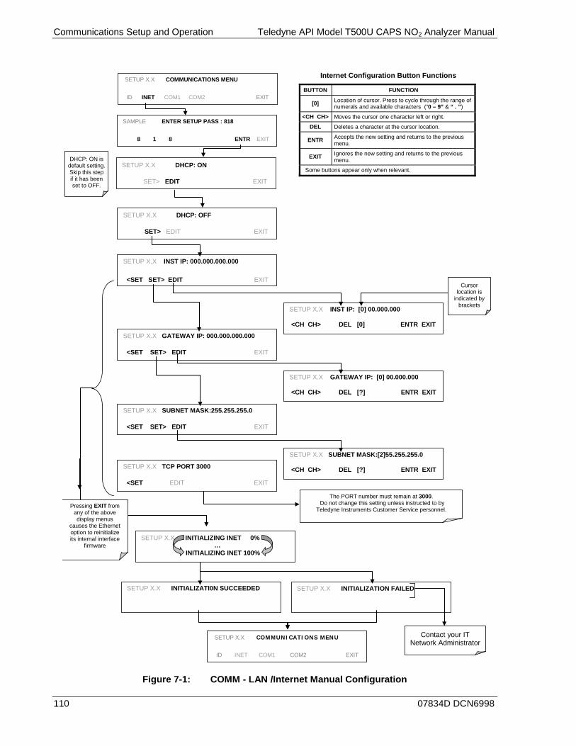
Communications Setup and Operation Teledyne API Model T500U CAPS NO2 Analyzer Manual
110 07834D DCN6998
Internet Configuration Button Functions
BUTTON FUNCTION
[0] Location of cursor. Press to cycle through the range of numerals and available characters (“0 – 9” & “ . ”)
<CH CH> Moves the cursor one character left or right.
DEL Deletes a character at the cursor location.
ENTR Accepts the new setting and returns to the previous menu.
EXIT Ignores the new setting and returns to the previous menu.
Some buttons appear only when relevant.
SETUP X.X DHCP: OFF
SET> EDIT EXIT
SETUP X.X INST IP: 000.000.000.000
<SET SET> EDIT EXIT
SETUP X.X GATEWAY IP: 000.000.000.000
<SET SET> EDIT EXIT
SETUP X.X INST IP: [0] 00.000.000 <CH CH> DEL [0] ENTR EXIT
SETUP X.X SUBNET MASK:255.255.255.0
<SET SET> EDIT EXIT
SETUP X.X SUBNET MASK:[2]55.255.255.0 <CH CH> DEL [?] ENTR EXIT SETUP X.X TCP PORT 3000
<SET EDIT EXIT
The PORT number must remain at 3000. Do not change this setting unless instructed to by
Teledyne Instruments Customer Service personnel.
SETUP X.X GATEWAY IP: [0] 00.000.000 <CH CH> DEL [?] ENTR EXIT
Cursor location is
indicated by brackets
SETUP X.X INITIALIZING INET 0% … INITIALIZING INET 100%
SETUP X.X INITIALIZATI0N SUCCEEDED
SETUP X.X INITIALIZATION FAILED
SETUP X.X COMMUNICATIONS MENU
ID INET COM1 COM2 EXIT
Pressing EXIT from any of the above display menus
causes the Ethernet option to reinitialize its internal interface
firmware
Contact your IT Network Administrator
SAMPLE ENTER SETUP PASS : 818
8 1 8 ENTR EXIT
SETUP X.X COMMUNICATIONS MENU
ID INET COM1 COM2 EXIT
DHCP: ON is default setting. Skip this step if it has been set to OFF.
SETUP X.X DHCP: ON
SET> EDIT EXIT
Figure 7-1: COMM - LAN /Internet Manual Configuration
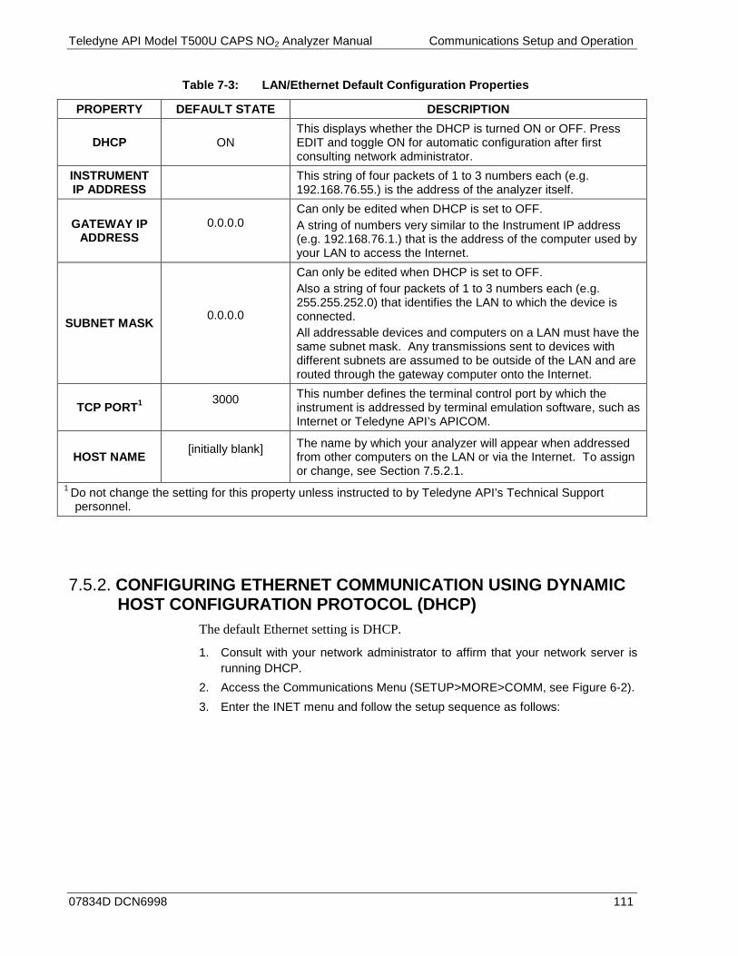
Teledyne API Model T500U CAPS NO2 Analyzer Manual Communications Setup and Operation
07834D DCN6998 111
Table 7-3: LAN/Ethernet Default Configuration Properties
PROPERTY DEFAULT STATE DESCRIPTION
DHCP ON This displays whether the DHCP is turned ON or OFF. Press EDIT and toggle ON for automatic configuration after first consulting network administrator.
INSTRUMENT IP ADDRESS This string of four packets of 1 to 3 numbers each (e.g.
192.168.76.55.) is the address of the analyzer itself.
GATEWAY IP ADDRESS
0.0.0.0
Can only be edited when DHCP is set to OFF. A string of numbers very similar to the Instrument IP address (e.g. 192.168.76.1.) that is the address of the computer used by your LAN to access the Internet.
SUBNET MASK 0.0.0.0
Can only be edited when DHCP is set to OFF. Also a string of four packets of 1 to 3 numbers each (e.g. 255.255.252.0) that identifies the LAN to which the device is connected. All addressable devices and computers on a LAN must have the same subnet mask. Any transmissions sent to devices with different subnets are assumed to be outside of the LAN and are routed through the gateway computer onto the Internet.
TCP PORT1 3000
This number defines the terminal control port by which the instrument is addressed by terminal emulation software, such as Internet or Teledyne API’s APICOM.
HOST NAME [initially blank]
The name by which your analyzer will appear when addressed from other computers on the LAN or via the Internet. To assign or change, see Section 7.5.2.1.
1 Do not change the setting for this property unless instructed to by Teledyne API’s Technical Support personnel.
CONFIGURING ETHERNET COMMUNICATION USING DYNAMIC 7.5.2.HOST CONFIGURATION PROTOCOL (DHCP)
The default Ethernet setting is DHCP.
1. Consult with your network administrator to affirm that your network server is running DHCP.
2. Access the Communications Menu (SETUP>MORE>COMM, see Figure 6-2). 3. Enter the INET menu and follow the setup sequence as follows:
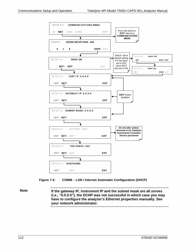
Communications Setup and Operation Teledyne API Model T500U CAPS NO2 Analyzer Manual
112 07834D DCN6998
SETUP X.X COMMUNICATIONS MENU
ID INET COM1 COM2 EXIT
SETUP X.X INST IP: 0.0.0.0
<SET SET> EXIT
SETUP X.X GATEWAY IP: 0.0.0.0
<SET SET> EXIT
SETUP X.X TCP PORT2: 502
<SET SET> EDIT EXIT
EDIT button
disabled
From this point on, EXIT returns to
COMMUNICATIONS MENU
Do not alter unless directed to by Teledyne Instruments Customer
Service personnel
SETUP X.X HOSTNAME:
<SET EDIT EXIT
SAMPLE ENTER SETUP PASS : 818
8 1 8 ENTR EXIT
SETUP X.X SUBNET MASK: 0.0.0.0
<SET SET> EXIT
SETUP X.X TCP PORT: 3000
<SET SET> EDIT EXIT
SETUP X.X DHCP: ON
SET> EDIT EXIT
DHCP: ON is default setting. If it has been set to OFF, press EDIT
and set to ON.
SETUP X.X DHCP: OFF
OFF ENTR EXIT
SETUP X.X DHCP: ON
ON ENTR EXIT
Figure 7-2: COMM – LAN / Internet Automatic Configuration (DHCP)
Note If the gateway IP, instrument IP and the subnet mask are all zeroes (i.e., “0.0.0.0”), the DCHP was not successful in which case you may have to configure the analyzer’s Ethernet properties manually. See your network administrator.
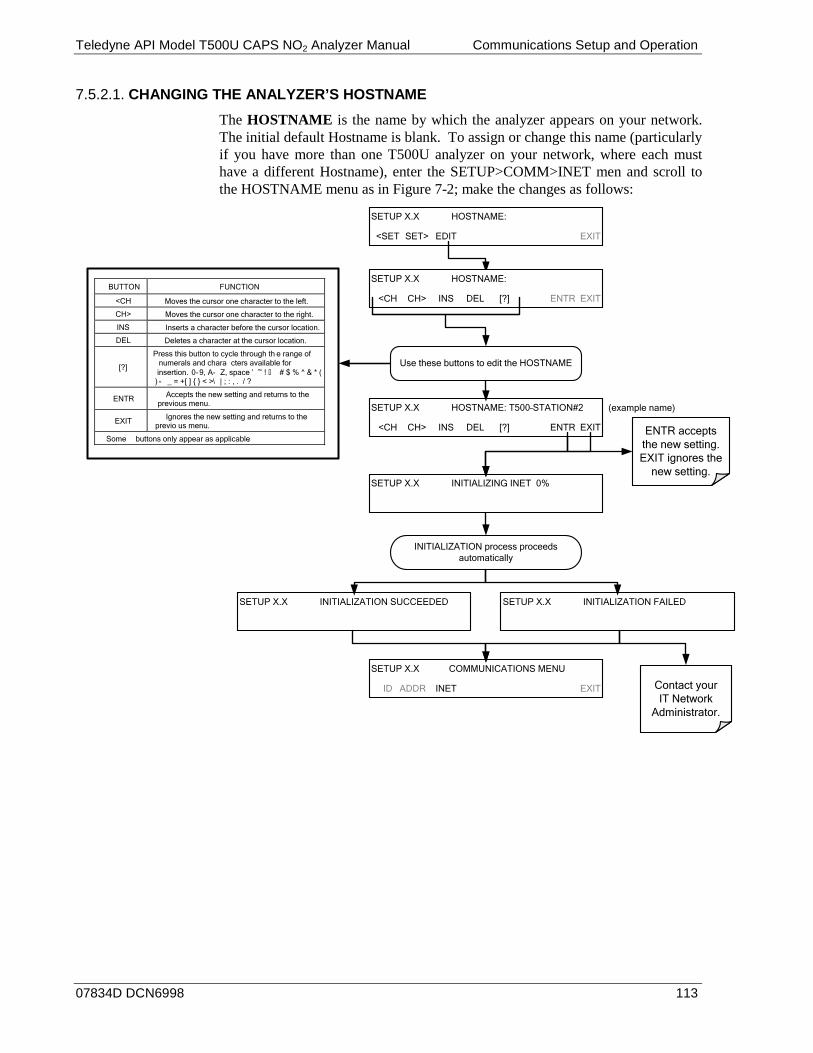
Teledyne API Model T500U CAPS NO2 Analyzer Manual Communications Setup and Operation
07834D DCN6998 113
CHANGING THE ANALYZER’S HOSTNAME 7.5.2.1.
The HOSTNAME is the name by which the analyzer appears on your network. The initial default Hostname is blank. To assign or change this name (particularly if you have more than one T500U analyzer on your network, where each must have a different Hostname), enter the SETUP>COMM>INET men and scroll to the HOSTNAME menu as in Figure 7-2; make the changes as follows:
Use these buttons to edit the HOSTNAME
SETUP X.X HOSTNAME:
<SET SET> EDIT EXIT
SETUP X.X INITIALIZING INET 0%
INITIALIZATION process proceeds automatically
SETUP X.X COMMUNICATIONS MENU
ID ADDR INET EXIT
SETUP X.X INITIALIZATION SUCCEEDED SETUP X.X INITIALIZATION FAILED
Contact your IT Network
Administrator.
SETUP X.X HOSTNAME:
<CH CH> INS DEL [?] ENTR EXIT
SETUP X.X HOSTNAME: T500–STATION#2
<CH CH> INS DEL [?] ENTR EXIT ENTR accepts the new setting.EXIT ignores the
new setting.
BUTTON FUNCTION
<CH Moves the cursor one character to the left.
CH> Moves the cursor one character to the right.
INS Inserts a character before the cursor location.
DEL Deletes a character at the cursor location.
[?]
Press this button to cycle through th e range of numerals and chara cters available for insertion. 0-9, A- Z, space ’ ~ ! # $ % ^ & * (
) - _ = +[ ] { } < >\ | ; : , . / ?
ENTR Accepts the new setting and returns to the previous menu.
EXIT Ignores the new setting and returns to the previo us menu.
Some buttons only appear as applicable.
(example name)

Communications Setup and Operation Teledyne API Model T500U CAPS NO2 Analyzer Manual
114 07834D DCN6998
USB PORT FOR REMOTE ACCESS 7.6.The analyzer can be operated through a personal computer by downloading the TAPI USB driver and taking the following steps:
1. Install the Teledyne T-Series USB driver onto your computer, downloadable from the Teledyne API website under Help Center>Software Downloads (www.teledyne-api.com/software).
2. Run the installer file: “TAPIVCPInstaller.exe”
3. Connect the USB cable between a USB port on your personal computer to
the rear panel USB port of your analyzer. The USB cable should be a Type A – Type B cable, commonly used as a USB printer cable.
4. Determine the Windows XP Com Port number that was automatically assigned to the USB connection. (Start>Control Panel>System>Hardware>Device Manager). This is the com port that should be set in the communications software, such as APICOM or Hyperterminal.
Refer to the Quick Start (Direct Cable Connection) section of the Teledyne APICOM Manual, PN 07463.

Teledyne API Model T500U CAPS NO2 Analyzer Manual Communications Setup and Operation
07834D DCN6998 115
5. In the instrument’s SETUP>MORE>COMM>COM2 menu, make the following settings:
Baud Rate: 115200 COM2 Mode Settings: Quiet Mode ON Computer Mode ON MODBUS RTU OFF MODBUS ASCII OFF E,8,1 MODE OFF E,7,1 MODE OFF RS-485 MODE OFF SECURITY MODE OFF MULTIDROP MODE OFF ENABLE MODEM OFF ERROR CHECKING ON XON/XOFF HANDSHAKE OFF HARDWARE HANDSHAKE OFF HARDWARE FIFO ON COMMAND PROMPT OFF
6. Next, configure your communications software, such as APICOM. Use the COM port determined in Step 4 and the baud rate set in Step 5. The figures below show how these parameters would be configured in the Instrument Properties window in APICOM when configuring a new instrument. See the APICOM manual (PN 07463) for more details.
Note Using the USB port disallows use of the rear panel COM2 port except for multidrop communication.
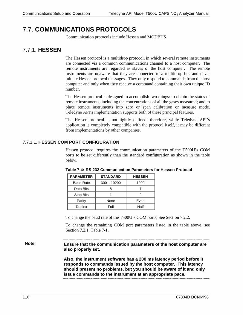
Communications Setup and Operation Teledyne API Model T500U CAPS NO2 Analyzer Manual
116 07834D DCN6998
COMMUNICATIONS PROTOCOLS 7.7.Communication protocols include Hessen and MODBUS.
HESSEN 7.7.1.The Hessen protocol is a multidrop protocol, in which several remote instruments are connected via a common communications channel to a host computer. The remote instruments are regarded as slaves of the host computer. The remote instruments are unaware that they are connected to a multidrop bus and never initiate Hessen protocol messages. They only respond to commands from the host computer and only when they receive a command containing their own unique ID number.
The Hessen protocol is designed to accomplish two things: to obtain the status of remote instruments, including the concentrations of all the gases measured; and to place remote instruments into zero or span calibration or measure mode. Teledyne API’s implementation supports both of these principal features.
The Hessen protocol is not tightly defined; therefore, while Teledyne API’s application is completely compatible with the protocol itself, it may be different from implementations by other companies.
HESSEN COM PORT CONFIGURATION 7.7.1.1.
Hessen protocol requires the communication parameters of the T500U’s COM ports to be set differently than the standard configuration as shown in the table below.
Table 7-4: RS-232 Communication Parameters for Hessen Protocol PARAMETER STANDARD HESSEN
Baud Rate 300 – 19200 1200
Data Bits 8 7
Stop Bits 1 2
Parity None Even
Duplex Full Half
To change the baud rate of the T500U’s COM ports, See Section 7.2.2.
To change the remaining COM port parameters listed in the table above, see Section 7.2.1, Table 7-1.
Note Ensure that the communication parameters of the host computer are also properly set.
Also, the instrument software has a 200 ms latency period before it responds to commands issued by the host computer. This latency should present no problems, but you should be aware of it and only issue commands to the instrument at an appropriate pace.

Teledyne API Model T500U CAPS NO2 Analyzer Manual Communications Setup and Operation
07834D DCN6998 117
ACTIVATING HESSEN PROTOCOL 7.7.1.2.
Once the COM port has been properly configured, the next step is to activate the Hessen mode for COM ports and configure the communication parameters for the port(s) appropriately.
To activate the Hessen Protocol, press:
Concentration field displays all gases.
SAMPLE RANGE=500.0 PPB NO2= XXXX
<TST TST> CAL SETUP
SETUP X.X COMMUNICATIONS MENU
ID COM1 COM2 EXIT
SETUP X.X COM1 MODE:0
<SET SET> EDIT EXIT
SETUP X.X COM1 QUIET MODE:OFF
PREV NEXT OFF EXIT
EXIT discards the new setting.
ENTR accepts the new setting.
SETUP X.X COM1 HESSEN PROTOCOL: OFF
PREV NEXT OFF ENTR EXITActivate / Deactivate the HESSEN mode by toggling the ON /
OFF button. SETUP X.X COM1 HESSEN PROTOCOL: OFF
PREV NEXT ON ENTR EXIT
Continue pressing NEXT until ...
Use the PREV and NEXT buttons to
between the available modes.
Combined Mode ID displayed here.
SETUP X.X PRIMARY SETUP MENU
CFG DAS RNGE PASS CLK MORE EXIT
SETUP X.X SECONDARY SETUP MENU
COMM VARS DIAG AREF EXIT
SETUP X.X COM1 MODE:16
<SET SET> EDIT EXIT
SETUP X.X COMMUNICATIONS MENU
ID HESN COM1 COM2 EXIT

Communications Setup and Operation Teledyne API Model T500U CAPS NO2 Analyzer Manual
118 07834D DCN6998
SELECTING A HESSEN PROTOCOL TYPE 7.7.1.3.
Currently there are two versions of Hessen Protocol in use. The original implementation, referred to as TYPE 1, and a more recently released version, TYPE 2 that has more flexibility when operating with instruments that can measure more than one type of gas. For more specific information about the difference between TYPE 1 and TYPE 2 download the Manual Addendum for Hessen Protocol from the Teledyne API's web site: http://www.teledyne-api.com/manuals/.
To select a Hessen Protocol Type press:
Concentration field displays all gases.
SAMPLE RANGE=500.0 PPB NO2= XXXX
<TST TST> CAL SETUP
SETUP X.X COMMUNICATIONS MENU
ID HESN COM1 COM2 EXIT
SETUP X.X HESSEN VARIATION:TYPE1
<SET SET> EDIT EXIT
SETUP X.X HESSEN VARIATION:TYPE1
TYP1 TYP2 ENTR EXIT EXIT discards the new setting.
ENTR accepts the new setting.
Use these buttons to choose the
Hessen type.
SETUP X.X PRIMARY SETUP MENU
CFG DAS RNGE PASS CLK MORE EXIT
SETUP X.X SECONDARY SETUP MENU
COMM VARS DIAG AREF EXIT
Note While Hessen Protocol Mode can be activated independently for COM1 and COM2, the TYPE selection affects both ports.
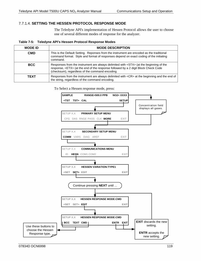
Teledyne API Model T500U CAPS NO2 Analyzer Manual Communications Setup and Operation
07834D DCN6998 119
SETTING THE HESSEN PROTOCOL RESPONSE MODE 7.7.1.4.
The Teledyne API's implementation of Hessen Protocol allows the user to choose one of several different modes of response for the analyzer.
Table 7-5: Teledyne API's Hessen Protocol Response Modes
MODE ID MODE DESCRIPTION CMD This is the Default Setting. Reponses from the instrument are encoded as the traditional
command format. Style and format of responses depend on exact coding of the initiating command.
BCC Responses from the instrument are always delimited with <STX> (at the beginning of the response, <ETX> (at the end of the response followed by a 2 digit Block Check Code (checksum), regardless of the command encoding.
TEXT Responses from the instrument are always delimited with <CR> at the beginning and the end of the string, regardless of the command encoding.
To Select a Hessen response mode, press:
Concentration field displays all gases.
SAMPLE RANGE=500.0 PPB NO2= XXXX
<TST TST> CAL SETUP
SETUP X.X HESSEN RESPONSE MODE:CMD
<SET SET> EDIT EXIT
SETUP X.X COMMUNICATIONS MENU
ID HESN COM1 COM2 EXIT
SETUP X.X HESSEN VARIATION:TYPE1
<SET SET> EDIT EXIT
SETUP X.X PRIMARY SETUP MENU
CFG DAS RNGE PASS CLK MORE EXIT
SETUP X.X SECONDARY SETUP MENU
COMM VARS DIAG AREF EXIT
SETUP X.X HESSEN RESPONSE MODE:CMD
BCC TEXT CMD ENTR EXIT EXIT discards the new setting.
ENTR accepts the new setting.
Use these buttons to choose the Hessen
Response type.
Continue pressing NEXT until ...

Communications Setup and Operation Teledyne API Model T500U CAPS NO2 Analyzer Manual
120 07834D DCN6998
HESSEN PROTOCOL GAS LIST ENTRY FORMAT AND DEFINITIONS 7.7.1.5.
The T500U analyzer keeps a list of available gas types. Each entry in this list is of the following format.
[GAS TYPE],[RANGE],[GAS ID],[REPORTED]
WHERE:
GAS TYPE The type of gas to be reported (the T500U has only one gas type: NO2).
RANGE The concentration range for this gas. This feature permits the user to select which concentration range will be used. The T500U analyzer has two ranges: RANGE1 or LOW & RANGE2 or HIGH (see Section 6.3).
0 - The HESSEN protocol to use whatever range is currently 1.active.
1 - The HESSEN protocol will always use RANGE1 for this 2.gas.
2 - The HESSEN protocol will always use RANGE2 for this 3.gas.
3 - Not applicable to the T500U analyzer. 4.
GAS ID An identification number assigned to a specific gas. The T500U analyzer measures only NO2, which has the following ID number: NO2 213
REPORT States whether this list entry is to be reported or not reported whenever this gas type or instrument is polled by the HESSEN network. If the list entry is not to be reported this field will be blank. It’s default gas list consists of only reads:
NO2, 0, 213, REPORTED These default settings cause the instrument to report the concentration value of the currently active range. If you wish to have just concentration value stored for a specific range, this list entry should be edited or additional entries should be added to the list.

Teledyne API Model T500U CAPS NO2 Analyzer Manual Communications Setup and Operation
07834D DCN6998 121
SETTING HESSEN PROTOCOL STATUS FLAGS 7.7.1.6.
Teledyne API's’ implementation of Hessen protocols includes a set of 16 status bits that the instrument includes in responses to inform the host computer of its condition. This status flag includes an 8-bit set for Operational status follows by another 8-bit set for Failure status. Each 8-bit status message is formatted as a 2-digit hexadecimal number. Each bit can be assigned to one operational or warning message flag. The default settings for these bit/flags are:
Table 7-6: Default Hessen Status Flag Assignments
STATUS FLAG NAME DEFAULT BIT ASSIGNMENT HEX BITS
OPERATIONAL FLAGS (8 BITS) In MANUAL Calibration Mode x02 0000 0010
In ZERO Calibration Mode x04 0000 0100
In SPAN Calibration Mode x08 0000 1000
INVALID CONC x80 1000 0000
SPARE/UNUSED x01 0000 0001
UNITS OF MEASURE FLAGS (ONLY BITS 5 AND 6 OF THE OPERATIONAL FLAG) UGM 00
MGM 01
PPB 10
PPM 11
WARNING FLAGS (8 BITS) ANY PRESS WARN x04 0000 0100
SAMPLE TEMP WARNING x08 0000 1000
INTERNAL PUMP OVERRIDE SET TO OFF x10 0001 0000
IZS TEMP WARNING1 x20 0010 0000
BENCH LED DISABLED x40 0100 0000
OVEN TEMP WARNING x80 1000 0000
UNASSIGNED FLAGS MANIFOLD TEMPERATURE2 FRONT PANEL COMMUNICATION WARNING
BOX TEMP WARNING ANALOG CALIBRATION WARNING
SYSTEM RESET DYNAMIC ZERO WARNING
RELAY BOARD WARNING DYNAMIC SPAN WARNING
REAR BOARD NOT DETECTED IN MULTI-POINT CALIBRATION MODE
AUTOREF WARNING 1 Only applicable if the optional internal span gas generator is installed. 2 Only applicable if the T500U is equipped with the optional manifold. It is possible to assign more than one flag to the same Hessen status bit. This allows the grouping of similar flags, such as all temperature warnings, under the same status bit.
Be careful not to assign conflicting flags to the same bit as each status bit will be triggered if any of the assigned flags is active.
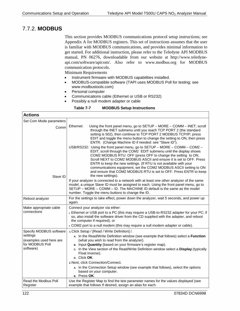
Communications Setup and Operation Teledyne API Model T500U CAPS NO2 Analyzer Manual
122 07834D DCN6998
MODBUS 7.7.2.This section provides MODBUS communications protocol setup instructions; see Appendix A for MODBUS registers. This set of instructions assumes that the user is familiar with MODBUS communications, and provides minimal information to get started. For additional instruction, please refer to the Teledyne API MODBUS manual, PN 06276, downloadable from our website at http://www.teledyne-api.com/software/apicom/. Also refer to www.modbus.org for MODBUS communication protocols. Minimum Requirements • Instrument firmware with MODBUS capabilities installed. • MODBUS-compatible software (TAPI uses MODBUS Poll for testing; see
www.modbustools.com) • Personal computer • Communications cable (Ethernet or USB or RS232) • Possibly a null modem adapter or cable
Table 7-7 MODBUS Setup Instructions
Actions
Set Com Mode parameters
Comm
Slave ID
Ethernet: Using the front panel menu, go to SETUP – MORE – COMM – INET; scroll through the INET submenu until you reach TCP PORT 2 (the standard setting is 502), then continue to TCP PORT 2 MODBUS TCP/IP; press EDIT and toggle the menu button to change the setting to ON, then press ENTR. (Change Machine ID if needed: see “Slave ID”).
USB/RS232: Using the front panel menu, go to SETUP – MORE – COMM – COM2 – EDIT; scroll through the COM2 EDIT submenu until the display shows COM2 MODBUS RTU: OFF (press OFF to change the setting to ON. Scroll NEXT to COM2 MODBUS ASCII and ensure it is set to OFF. Press ENTR to keep the new settings. (If RTU is not available with your communications equipment, set the COM2 MODBUS ASCII setting to ON and ensure that COM2 MODBUS RTU is set to OFF. Press ENTR to keep the new settings).
If your analyzer is connected to a network with at least one other analyzer of the same model, a unique Slave ID must be assigned to each. Using the front panel menu, go to SETUP – MORE – COMM – ID. The MACHINE ID default is the same as the model number. Toggle the menu buttons to change the ID.
Reboot analyzer For the settings to take effect, power down the analyzer, wait 5 seconds, and power up again.
Make appropriate cable connections
Connect your analyzer via either: • Ethernet or USB port to a PC (this may require a USB-to-RS232 adapter for your PC; if
so, also install the software driver from the CD supplied with the adapter, and reboot the computer if required), or
• COM2 port to a null modem (this may require a null modem adapter or cable). Specify MODBUS software settings (examples used here are for MODBUS Poll software)
1. Click Setup / [Read / Write Definition] /. A. In the Read/Write Definition window (see example that follows) select a Function
(what you wish to read from the analyzer). B. Input Quantity (based on your firmware’s register map). C. In the View section of the Read/Write Definition window select a Display (typically
Float Inverse). D. Click OK.
2. Next, click Connection/Connect. A. In the Connection Setup window (see example that follows), select the options
based on your computer. B. Press OK.
Read the Modbus Poll Register
Use the Register Map to find the test parameter names for the values displayed (see example that follows If desired, assign an alias for each.
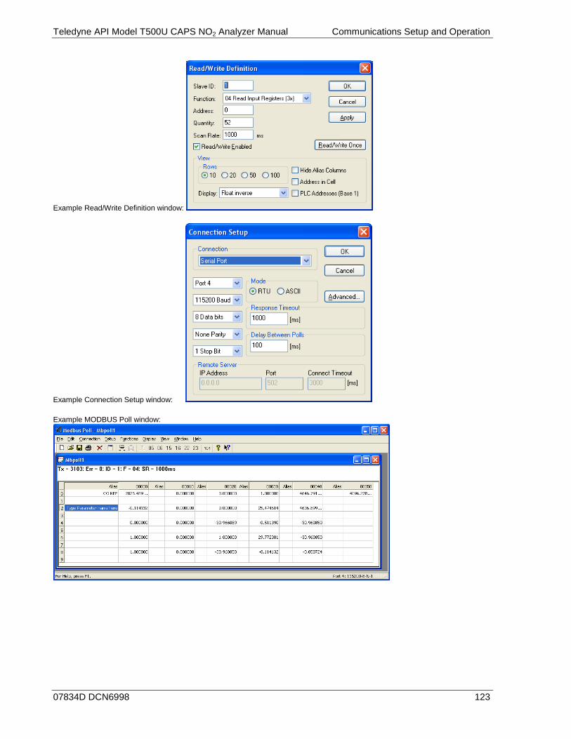
Teledyne API Model T500U CAPS NO2 Analyzer Manual Communications Setup and Operation
07834D DCN6998 123
Example Read/Write Definition window:
Example Connection Setup window:
Example MODBUS Poll window:
Communications Setup and Operation Teledyne API Model T500U CAPS NO2 Analyzer Manual
124 07834D DCN6998
This page intentionally left blank.

07834D DCN6998 125
8. DATA ACQUISITION SYSTEM (DAS) AND APICOM
The internal data acquisition system (DAS) enables the analyzer to store concentration and calibration data as well as a host of diagnostic parameters. This feature can store a large number of data points covering days, weeks or months of valuable measurements, depending on individual configurations. The data records are stored in non-volatile memory and are retained even when the instrument is powered off. Data are stored in plain text format for easy retrieval and use in common data analysis programs (such as electronic spreadsheets).
The DAS permits users to access stored data through the instrument’s front panel or remotely through its communication ports. To support the DAS functionality, Teledyne API offers APICOM, a program that provides a visual interface for remote or local setup, configuration and data retrieval of the DAS (APICOM DAS Manual, PN 07463, which can be downloaded from our website at http://www.teledyne-api.com under Help Center > Product Manuals in the Special Manuals section).
IMPORTANT IMPACT ON READINGS OR DATA DAS operation is suspended whenever its configuration is edited using the analyzer’s front panel and therefore data may be lost. To prevent such data loss, it is recommended to use the APICOM graphical user interface for DAS changes (Section 8.2.1). Please be aware that all stored data will be erased if the analyzer’s disk-on-module or CPU board is replaced or if the configuration data stored there is reset.
Note The DAS can be disabled only by disabling or deleting its individual data channels.
The principal use of the DAS is logging data for trend analysis and predictive diagnostics, which can assist in identifying possible problems before they affect the functionality of the analyzer. The secondary use is for data analysis, documentation and archival in electronic format.
The green SAMPLE LED on the instrument front panel not only indicates the analyzer status, but also indicates certain aspects of the DAS status:
• OFF: System is in calibration mode. Data logging can be enabled or disabled for this mode. Calibration data are typically stored at the end of calibration periods, concentration data are typically not sampled, diagnostic data should be collected.
• BLINKING: Instrument is in hold-off mode, a short period after the system exits calibrations. DAS channels can be enabled or disabled for this period. Concentration data are typically disabled whereas diagnostic should be collected.
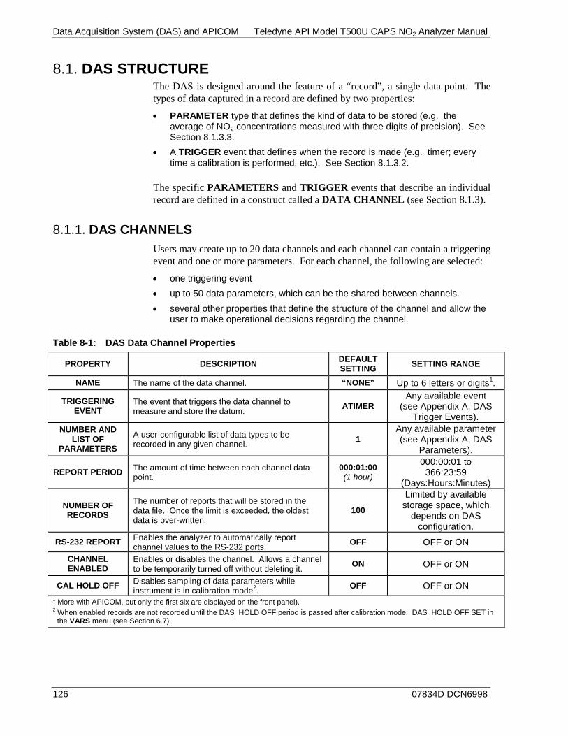
Data Acquisition System (DAS) and APICOM Teledyne API Model T500U CAPS NO2 Analyzer Manual
126 07834D DCN6998
DAS STRUCTURE 8.1.The DAS is designed around the feature of a “record”, a single data point. The types of data captured in a record are defined by two properties:
• PARAMETER type that defines the kind of data to be stored (e.g. the average of NO2 concentrations measured with three digits of precision). See Section 8.1.3.3.
• A TRIGGER event that defines when the record is made (e.g. timer; every time a calibration is performed, etc.). See Section 8.1.3.2.
The specific PARAMETERS and TRIGGER events that describe an individual record are defined in a construct called a DATA CHANNEL (see Section 8.1.3).
DAS CHANNELS 8.1.1.Users may create up to 20 data channels and each channel can contain a triggering event and one or more parameters. For each channel, the following are selected:
• one triggering event • up to 50 data parameters, which can be the shared between channels. • several other properties that define the structure of the channel and allow the
user to make operational decisions regarding the channel.
Table 8-1: DAS Data Channel Properties
PROPERTY DESCRIPTION DEFAULT SETTING SETTING RANGE
NAME The name of the data channel. “NONE” Up to 6 letters or digits1.
TRIGGERING EVENT
The event that triggers the data channel to measure and store the datum. ATIMER
Any available event (see Appendix A, DAS
Trigger Events). NUMBER AND
LIST OF PARAMETERS
A user-configurable list of data types to be recorded in any given channel. 1
Any available parameter (see Appendix A, DAS
Parameters).
REPORT PERIOD The amount of time between each channel data point.
000:01:00 (1 hour)
000:00:01 to 366:23:59
(Days:Hours:Minutes)
NUMBER OF RECORDS
The number of reports that will be stored in the data file. Once the limit is exceeded, the oldest data is over-written.
100
Limited by available storage space, which
depends on DAS configuration.
RS-232 REPORT Enables the analyzer to automatically report channel values to the RS-232 ports. OFF OFF or ON
CHANNEL ENABLED
Enables or disables the channel. Allows a channel to be temporarily turned off without deleting it. ON OFF or ON
CAL HOLD OFF Disables sampling of data parameters while instrument is in calibration mode2. OFF OFF or ON
1 More with APICOM, but only the first six are displayed on the front panel). 2 When enabled records are not recorded until the DAS_HOLD OFF period is passed after calibration mode. DAS_HOLD OFF SET in
the VARS menu (see Section 6.7).
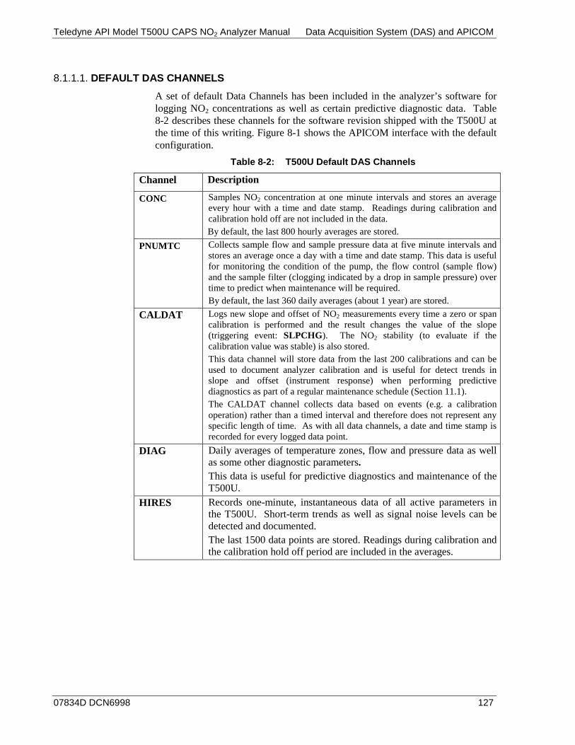
Teledyne API Model T500U CAPS NO2 Analyzer Manual Data Acquisition System (DAS) and APICOM
07834D DCN6998 127
DEFAULT DAS CHANNELS 8.1.1.1.
A set of default Data Channels has been included in the analyzer’s software for logging NO2 concentrations as well as certain predictive diagnostic data. Table 8-2 describes these channels for the software revision shipped with the T500U at the time of this writing. Figure 8-1 shows the APICOM interface with the default configuration.
Table 8-2: T500U Default DAS Channels
Channel Description
CONC Samples NO2 concentration at one minute intervals and stores an average every hour with a time and date stamp. Readings during calibration and calibration hold off are not included in the data. By default, the last 800 hourly averages are stored.
PNUMTC Collects sample flow and sample pressure data at five minute intervals and stores an average once a day with a time and date stamp. This data is useful for monitoring the condition of the pump, the flow control (sample flow) and the sample filter (clogging indicated by a drop in sample pressure) over time to predict when maintenance will be required. By default, the last 360 daily averages (about 1 year) are stored.
CALDAT Logs new slope and offset of NO2 measurements every time a zero or span calibration is performed and the result changes the value of the slope (triggering event: SLPCHG). The NO2 stability (to evaluate if the calibration value was stable) is also stored. This data channel will store data from the last 200 calibrations and can be used to document analyzer calibration and is useful for detect trends in slope and offset (instrument response) when performing predictive diagnostics as part of a regular maintenance schedule (Section 11.1). The CALDAT channel collects data based on events (e.g. a calibration operation) rather than a timed interval and therefore does not represent any specific length of time. As with all data channels, a date and time stamp is recorded for every logged data point.
DIAG Daily averages of temperature zones, flow and pressure data as well as some other diagnostic parameters. This data is useful for predictive diagnostics and maintenance of the T500U.
HIRES Records one-minute, instantaneous data of all active parameters in the T500U. Short-term trends as well as signal noise levels can be detected and documented. The last 1500 data points are stored. Readings during calibration and the calibration hold off period are included in the averages.

Data Acquisition System (DAS) and APICOM Teledyne API Model T500U CAPS NO2 Analyzer Manual
128 07834D DCN6998
Figure 8-1: Example Default DAS Configuration in APICOM Interface
These default data channels can be used as they are, or they can be customized (Section 8.1.3) from the front panel to fit a specific application. They can also be deleted to make room for custom user-programmed Data Channels.
IMPORTANT IMPACT ON READINGS OR DATA Sending a DAS configuration to the analyzer through its COM ports will replace the existing configuration and will delete all stored data. Back up any existing data and the DAS configuration before uploading new settings.
DAS CONFIGURATION LIMITS 8.1.1.2.
The number of DAS objects is limited by the instrument’s finite storage capacity. For information regarding the maximum number of channels, parameters, and records and how to calculate the file size for each data channel, refer to the APICOM DAS manual.

Teledyne API Model T500U CAPS NO2 Analyzer Manual Data Acquisition System (DAS) and APICOM
07834D DCN6998 129
VIEWING DAS DATA AND SETTINGS 8.1.2.DAS data and settings can be viewed on the front panel through the following menu sequence.
Continue pressing NEXT to view remaining DAS channels
SAMPLE RANGE=500.0 PPB NOX= XXXX
<TST TST> CAL SETUP
<PRM
PRM>
PREV
PV10
NEXT
NX10
Button
Selects the previous parameter on the list
Selects the next parameter on the list
Moves the VIEW backward 1 records or channel
Moves the VIEW backward 10 record
Moves the VIEW forward 1 record or channel
Moves the VIEW forward 10 records
FUNCTION
Buttons only appear when applicable.
DAS VIEW – Touchscreen Functions
SETUP X.X PRIMARY SETUP MENU
CFG DAS RNGE PASS CLK MORE EXIT
SETUP X.X DATA ACQUISITION
VIEW EDIT EXIT
SETUP X.X CONC: DATA AVAILABLE
NEXT VIEW EXIT
SETUP X.X 101:21:00 CONC1=59.0346 PPB
PV10 PREV NX10 NEXT <PRM PRM> EXIT
SETUP X.X CALDAT: DATA AVAILABLE
NEXT VIEW EXIT
SETUP X.X 101:19:45 ZSCONC1=401.0346
PV10 PREV NX10 NEXT <PRM PRM> EXIT
SETUP X.X 102:04:55 ZSCONC1=400.9868
PV10 PREV NX10 NEXT <PRM PRM> EXIT
SETUP X.X 101:19:45 SLP1=0.9987 PPB
PV10 PREV NX10 NEXT <PRM PRM> EXIT
SAMPLE RANGE=500.0 PPB NO2= XXXX
<TST TST> CAL SETUP
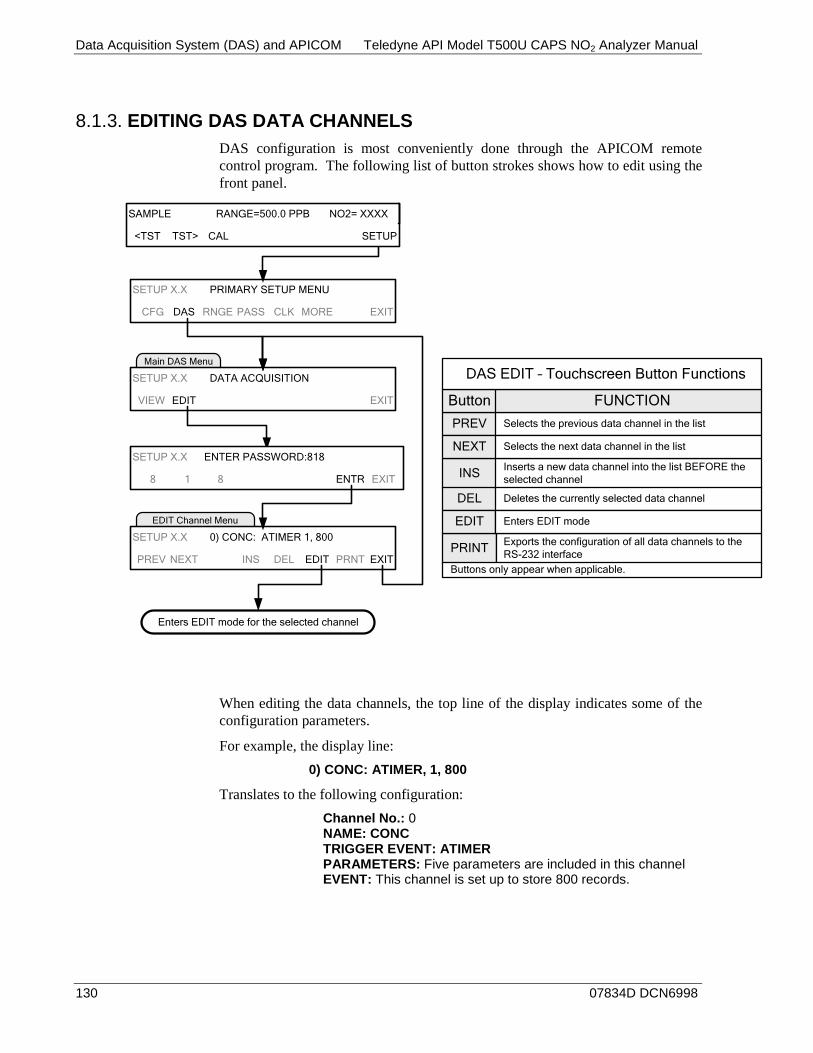
Data Acquisition System (DAS) and APICOM Teledyne API Model T500U CAPS NO2 Analyzer Manual
130 07834D DCN6998
EDITING DAS DATA CHANNELS 8.1.3.DAS configuration is most conveniently done through the APICOM remote control program. The following list of button strokes shows how to edit using the front panel.
EDIT Channel Menu
Main DAS Menu
SETUP X.X PRIMARY SETUP MENU
CFG DAS RNGE PASS CLK MORE EXIT
SETUP X.X DATA ACQUISITION
VIEW EDIT EXIT
SETUP X.X 0) CONC: ATIMER 1, 800
PREV NEXT INS DEL EDIT PRNT EXIT
SETUP X.X ENTER PASSWORD:818
8 1 8 ENTR EXIT
Enters EDIT mode for the selected channel
PREV
INS
NEXT
DEL
Button
Exports the configuration of all data channels to the RS-232 interface
Selects the previous data channel in the list
Inserts a new data channel into the list BEFORE the selected channel
Selects the next data channel in the list
Deletes the currently selected data channel
FUNCTION
Buttons only appear when applicable.
DAS EDIT – Touchscreen Button Functions
EDIT Enters EDIT mode
SAMPLE RANGE=500.0 PPB NO2= XXXX
<TST TST> CAL SETUP
When editing the data channels, the top line of the display indicates some of the configuration parameters.
For example, the display line: 0) CONC: ATIMER, 1, 800
Translates to the following configuration: Channel No.: 0 NAME: CONC TRIGGER EVENT: ATIMER PARAMETERS: Five parameters are included in this channel EVENT: This channel is set up to store 800 records.
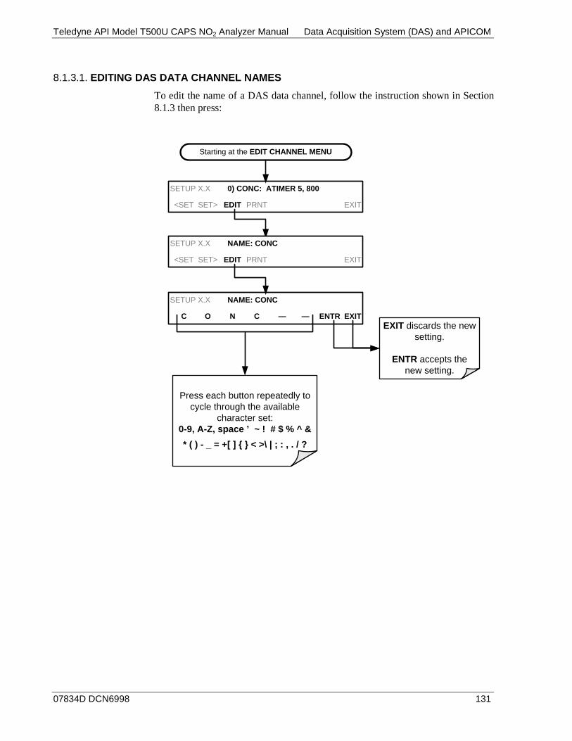
Teledyne API Model T500U CAPS NO2 Analyzer Manual Data Acquisition System (DAS) and APICOM
07834D DCN6998 131
EDITING DAS DATA CHANNEL NAMES 8.1.3.1.
To edit the name of a DAS data channel, follow the instruction shown in Section 8.1.3 then press:
Starting at the EDIT CHANNEL MENU
SETUP X.X 0) CONC: ATIMER 5, 800
<SET SET> EDIT PRNT EXIT
SETUP X.X NAME: CONC
C O N C — — ENTR EXITEXIT discards the new
setting.
ENTR accepts the new setting.
Press each button repeatedly to cycle through the available
character set:0-9, A-Z, space ’ ~ ! # $ % ^ & * ( ) - _ = +[ ] { } < >\ | ; : , . / ?
SETUP X.X NAME: CONC
<SET SET> EDIT PRNT EXIT
Data Acquisition System (DAS) and APICOM Teledyne API Model T500U CAPS NO2 Analyzer Manual
132 07834D DCN6998
EDITING DAS TRIGGERING EVENTS 8.1.3.2.
Triggering events define when and how the DAS records a measurement of any given data channel. Triggering events are firmware-specific; they are listed Appendix A of this manual. The most commonly used triggering events are:
• ATIMER: Sampling at regular intervals specified by an automatic timer. Most trending information is usually stored at such regular intervals, which can be instantaneous or averaged.
• EXITZR, EXITSP, and SLPCHG (exit zero, exit span, slope change): Sampling at the end of (irregularly occurring) calibrations or when the response slope changes. These triggering events create instantaneous data points, e.g., for the new slope and offset (concentration response) values at the end of a calibration. Zero and slope values are useful for monitoring response drift and documenting when the instrument was calibrated.
• WARNINGS: Some data may be useful when stored if one of several warning messages appears such as WSAMPPRESS (sample pressure warning). This is helpful for troubleshooting by monitoring when a particular warning occurred.
Note A list of DAS Trigger Events can be found in Appendix A of this manual.
EDITING DAS PARAMETERS 8.1.3.3.
Data parameters are types of data that may be measured and stored by the DAS. For each Teledyne API's analyzer model, the list of available data parameters is different, fully defined and not customizable. Appendix A-5 lists firmware specific data parameters for the T500U. DAS parameters include data such as NO2 concentration measurements, temperatures of the various heaters placed around the analyzer, and pressure of the pneumatic subsystem and other diagnostic measurements, as well as calibration data such as stability, slope and offset.
Most data parameters have associated measurement units, such as mV, ppb, Mm-1, etc., although some parameters have no units (e.g. SLOPE). With the exception of concentration readings, none of these units of measure can be changed. To change the units of measure for concentration readings, see Section 6.3.3.4.
Note DAS does not keep track of the units (i.e., PPM or PPB) of each concentration value. Therefore, DAS data files may contain concentration data recorded in more than one type of unit if the units of measure were changed during data acquisition
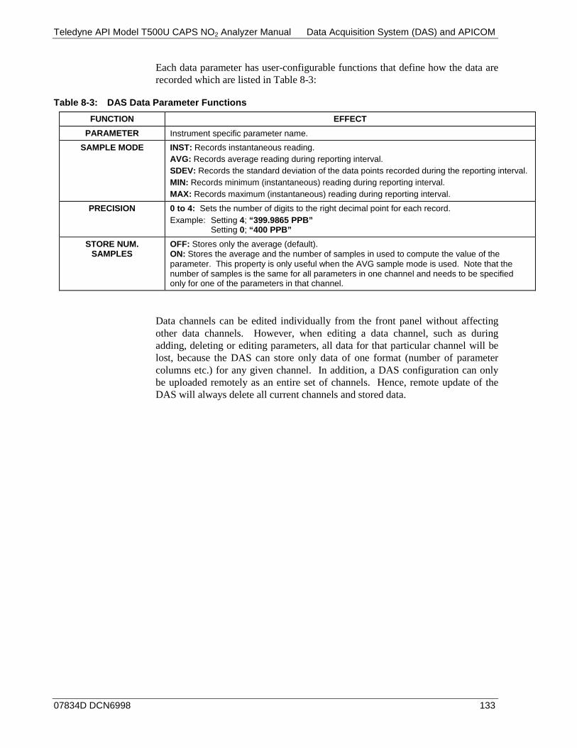
Teledyne API Model T500U CAPS NO2 Analyzer Manual Data Acquisition System (DAS) and APICOM
07834D DCN6998 133
Each data parameter has user-configurable functions that define how the data are recorded which are listed in Table 8-3:
Table 8-3: DAS Data Parameter Functions FUNCTION EFFECT
PARAMETER Instrument specific parameter name. SAMPLE MODE INST: Records instantaneous reading.
AVG: Records average reading during reporting interval. SDEV: Records the standard deviation of the data points recorded during the reporting interval. MIN: Records minimum (instantaneous) reading during reporting interval. MAX: Records maximum (instantaneous) reading during reporting interval.
PRECISION 0 to 4: Sets the number of digits to the right decimal point for each record. Example: Setting 4; “399.9865 PPB”
Setting 0; “400 PPB”
STORE NUM. SAMPLES
OFF: Stores only the average (default). ON: Stores the average and the number of samples in used to compute the value of the parameter. This property is only useful when the AVG sample mode is used. Note that the number of samples is the same for all parameters in one channel and needs to be specified only for one of the parameters in that channel.
Data channels can be edited individually from the front panel without affecting other data channels. However, when editing a data channel, such as during adding, deleting or editing parameters, all data for that particular channel will be lost, because the DAS can store only data of one format (number of parameter columns etc.) for any given channel. In addition, a DAS configuration can only be uploaded remotely as an entire set of channels. Hence, remote update of the DAS will always delete all current channels and stored data.

Data Acquisition System (DAS) and APICOM Teledyne API Model T500U CAPS NO2 Analyzer Manual
134 07834D DCN6998
To modify, add or delete a parameter, follow the instruction shown in Section 8.1.3 then press:
Starting at the EDIT CHANNEL MENU
SETUP X.X 0) CONC:ATIMER,1,800
PREV NEXT INS DEL EDIT PRNT EXIT
SETUP X.X NAME: CONC
<SET SET> EDIT EXIT
Continue pressing <SET or SET> until ...
SETUP X.X PARAMETERS:5
<SET SET> EDIT EXIT
SETUP X.X 0) PARAM=CONC1, MODE=AVG
PREV NEXT INS DEL EDIT EXIT
SETUP X.X EDIT PARAMS (DELETE DATA)?
YES NOYES deletes all data currently stored for
this data channel and continues into EDIT
mode.
NO retains the data and
returns to the previous menu.
SETUP X.X PARAMETER:CONC1
<SET SET> EDIT EXITSETUP X.X PARAMETER:CONC1
PREV NEXT ENTR EXIT
SETUP X.X SAMPLE MODE:AVG
<SET SET> EDIT EXITSETUP X.X SAMPLE MODE:AVG
INST AVG SDEV MIN MAX ENTR EXITPress the desired
MODE button.
SETUP X.X PRECISION:1
<SET SET> EDIT EXITSETUP X.X PRECISION:1
1 ENTR EXITToggle this button to
set from 1 to 4.
SETUP X.X STORE NUM. SAMPLES:OFF
<SET EDIT EXITSETUP X.X STOR NUM SAMPLE:OFF
OFF ENTR EXITToggle this button to
turn ON/OFF.
Pressing <SET returns to the
previous Function.
EXIT discards the new setting.
ENTR accepts the new setting.
Toggle these buttons to cycle through the list of available parameters.
PREV
INS
NEXT
DEL
Button
Exports the configuration of all data channels to the RS-232 interface
Selects the previous data channel or parameter
Inserts a new data channel or parameter into the list BEFORE the selected channel
Selects the next data channel or parameter
Deletes the currently selected data channel or parameter
FUNCTION
Buttons only appear when applicable
DAS EDIT – Touchscreen Functions
EDIT Enters EDIT mode
<SET
SET>
Selects the previous property to be edited
Selects the next property to be edited
Toggle these buttons to select a
different parameter.
Note When the STOR NUM. SAMPLES feature is turned on, the instrument will store the number of measurements that were used to compute the AVG, SDEV, MIN or MAX value but not the actual measurements themselves.
Teledyne API Model T500U CAPS NO2 Analyzer Manual Data Acquisition System (DAS) and APICOM
07834D DCN6998 135
EDITING SAMPLE PERIOD AND REPORT PERIOD 8.1.3.4.
The DAS defines two principal time periods by which sample readings are taken and permanently recorded: Sample Period and Report Period.
• SAMPLE PERIOD: Determines how often DAS temporarily records a sample reading of the parameter in volatile memory (default is one minute), and generally cannot be accessed from the standard DAS front panel menu, but is available via the instruments communication ports by using APICOM or the analyzer’s standard serial data protocol. SAMPLE PERIOD is only used when the DAS parameter’s sample mode is set for AVG, SDEV, MIN or MAX
• REPORT PERIOD: Sets how often the sample readings stored in volatile memory are processed, (e.g., average, minimum or maximum are calculated) and the results stored permanently in the instrument’s Disk-on-Module (DOM) as well as transmitted via the analyzer’s communication ports. The Report Period may be set from the front panel. If the INST sample mode is selected, the instrument stores and reports an instantaneous reading of the selected parameter at the end of the chosen report period.
Note In AVG, SDEV, MIN or MAX sample modes (see Section 8.1.3.3), the settings for the Sample Period and the Report Period determine the number of data points used each time the parameters are calculated, stored and reported to the COM ports.
The actual sample readings are not stored past the end of the chosen report period.
When the STORE NUM SAMPLES feature is turned on, the instrument will store the number of measurements that were used to compute the AVG, SDEV, MIN or MAX value but not the actual measurements themselves.
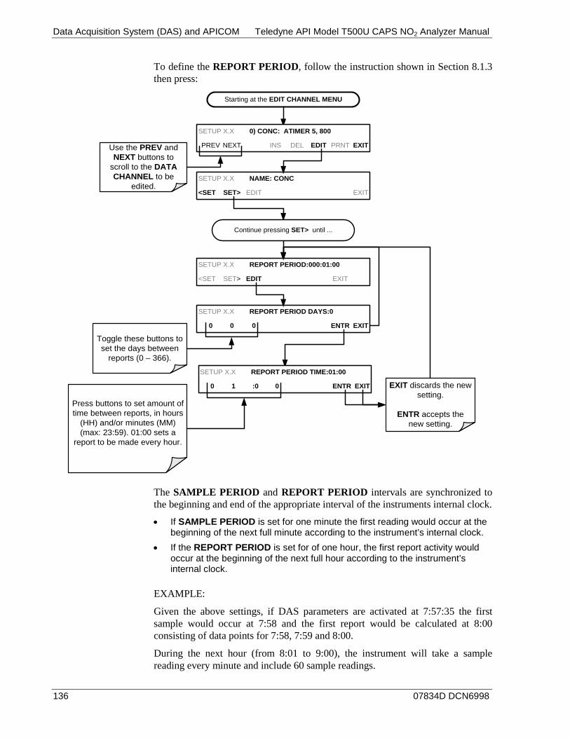
Data Acquisition System (DAS) and APICOM Teledyne API Model T500U CAPS NO2 Analyzer Manual
136 07834D DCN6998
To define the REPORT PERIOD, follow the instruction shown in Section 8.1.3 then press:
Starting at the EDIT CHANNEL MENU
SETUP X.X 0) CONC: ATIMER 5, 800
PREV NEXT INS DEL EDIT PRNT EXIT
SETUP X.X NAME: CONC
<SET SET> EDIT EXIT
SETUP X.X REPORT PERIOD:000:01:00
<SET SET> EDIT EXIT
Use the PREV and NEXT buttons to
scroll to the DATA CHANNEL to be
edited.
SETUP X.X REPORT PERIOD DAYS:0
0 0 0 ENTR EXIT
Toggle these buttons to set the days between
reports (0 – 366).
SETUP X.X REPORT PERIOD TIME:01:00
0 1 :0 0 ENTR EXIT
Press buttons to set amount of time between reports, in hours
(HH) and/or minutes (MM) (max: 23:59). 01:00 sets a
report to be made every hour.
EXIT discards the new setting.
ENTR accepts the new setting.
Continue pressing SET> until ...
The SAMPLE PERIOD and REPORT PERIOD intervals are synchronized to the beginning and end of the appropriate interval of the instruments internal clock.
• If SAMPLE PERIOD is set for one minute the first reading would occur at the beginning of the next full minute according to the instrument’s internal clock.
• If the REPORT PERIOD is set for of one hour, the first report activity would occur at the beginning of the next full hour according to the instrument’s internal clock.
EXAMPLE:
Given the above settings, if DAS parameters are activated at 7:57:35 the first sample would occur at 7:58 and the first report would be calculated at 8:00 consisting of data points for 7:58, 7:59 and 8:00.
During the next hour (from 8:01 to 9:00), the instrument will take a sample reading every minute and include 60 sample readings.

Teledyne API Model T500U CAPS NO2 Analyzer Manual Data Acquisition System (DAS) and APICOM
07834D DCN6998 137
REPORT PERIODS IN PROGRESS WHEN INSTRUMENT IS POWERED OFF 8.1.3.5.
If the instrument is powered off in the middle of a REPORT PERIOD, the samples accumulated during that period are lost. Once the instrument is turned back on, the DAS restarts taking samples and temporarily stores them in volatile memory as part of the REPORT PERIOD currently active at the time of restart. At the end of this REPORT PERIOD, only the sample readings taken since the instrument was turned back on will be included in any AVG, SDEV, MIN or MAX calculation.
The STORE NUM SAMPLES feature will also report the number of sample readings taken since the instrument was restarted.
EDITING THE NUMBER OF RECORDS 8.1.3.6.
The number of data records in the DAS is limited by its configuration. Every additional data channel, parameter, number of samples setting etc. will reduce the maximum amount of data points. In general, however, the maximum data capacity is divided among all channels (max: 20) and parameters (max: 50 per channel).
The DAS will check the amount of available data space and prevent the user from specifying too many records at any given point. (The ENTR button will disappear when trying to specify more records than space allows). This check for memory space may also make an upload of a DAS configuration with APICOM or a terminal program fail, if the combined number of records would be exceeded. In this case, it is suggested to either try to determine what the maximum number of records available is using the front panel interface or use trial-and-error in designing the DAS script or calculate the number of records using the DAS or APICOM manuals.
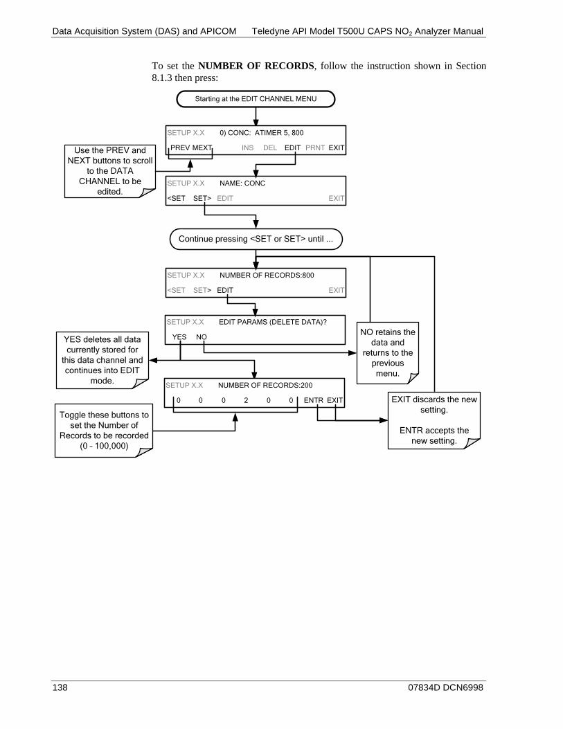
Data Acquisition System (DAS) and APICOM Teledyne API Model T500U CAPS NO2 Analyzer Manual
138 07834D DCN6998
To set the NUMBER OF RECORDS, follow the instruction shown in Section 8.1.3 then press:
Starting at the EDIT CHANNEL MENU
SETUP X.X 0) CONC: ATIMER 5, 800
PREV MEXT INS DEL EDIT PRNT EXIT
SETUP X.X NAME: CONC
<SET SET> EDIT EXIT
Continue pressing <SET or SET> until ...
SETUP X.X NUMBER OF RECORDS:800
<SET SET> EDIT EXIT
Use the PREV and NEXT buttons to scroll
to the DATA CHANNEL to be
edited.
SETUP X.X EDIT PARAMS (DELETE DATA)?
YES NOYES deletes all data currently stored for
this data channel and continues into EDIT
mode.
NO retains the data and
returns to the previous menu.
SETUP X.X NUMBER OF RECORDS:200
0 0 0 2 0 0 ENTR EXIT EXIT discards the new setting.
ENTR accepts the new setting.
Toggle these buttons to set the Number of
Records to be recorded (0 – 100,000)
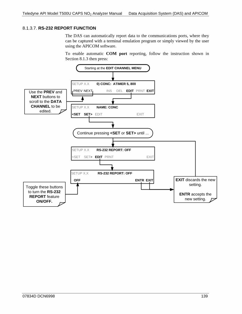
Teledyne API Model T500U CAPS NO2 Analyzer Manual Data Acquisition System (DAS) and APICOM
07834D DCN6998 139
RS-232 REPORT FUNCTION 8.1.3.7.
The DAS can automatically report data to the communications ports, where they can be captured with a terminal emulation program or simply viewed by the user using the APICOM software.
To enable automatic COM port reporting, follow the instruction shown in Section 8.1.3 then press:
Starting at the EDIT CHANNEL MENU
SETUP X.X 0) CONC: ATIMER 5, 800
PREV NEXT INS DEL EDIT PRNT EXIT
SETUP X.X NAME: CONC
<SET SET> EDIT EXIT
Continue pressing <SET or SET> until ...
SETUP X.X RS-232 REPORT: OFF
<SET SET> EDIT PRNT EXIT
Use the PREV and NEXT buttons to
scroll to the DATA CHANNEL to be
edited.
SETUP X.X RS-232 REPORT: OFF
OFF ENTR EXIT EXIT discards the new setting.
ENTR accepts the new setting.
Toggle these buttons to turn the RS-232 REPORT feature
ON/OFF.
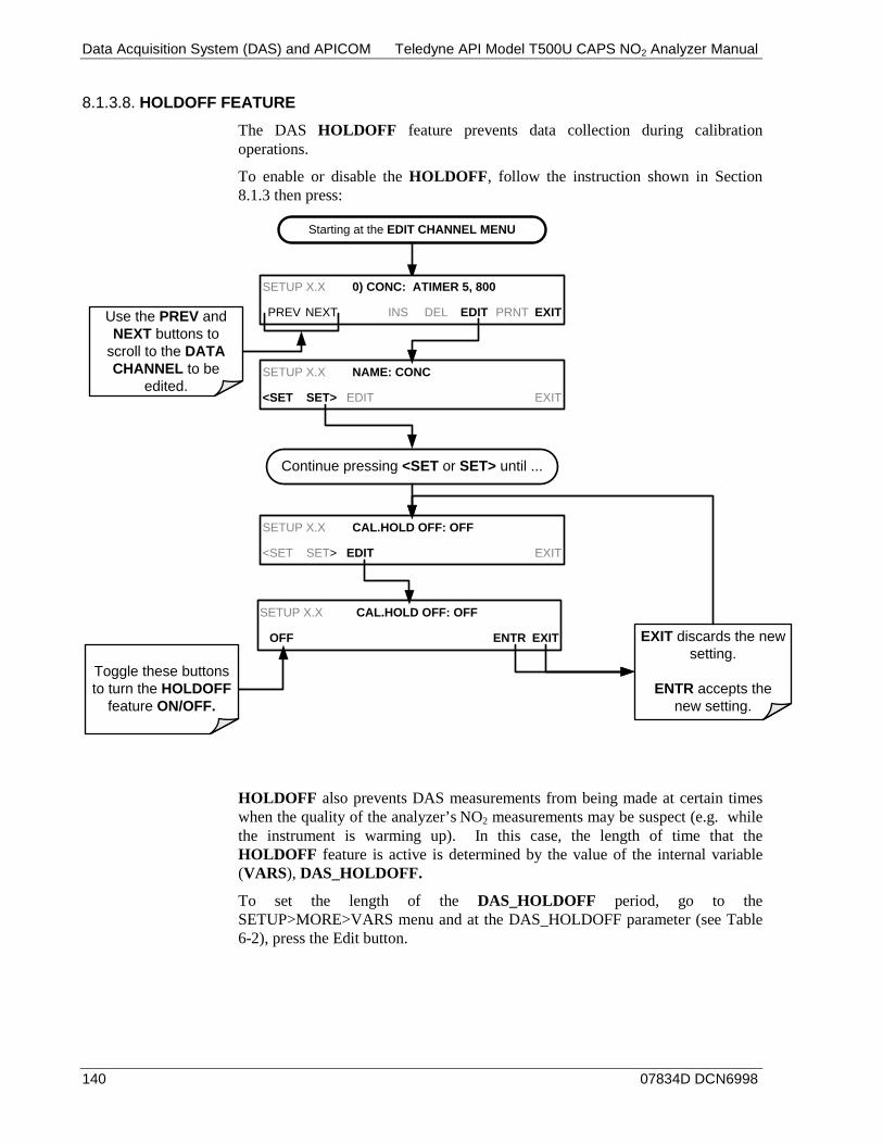
Data Acquisition System (DAS) and APICOM Teledyne API Model T500U CAPS NO2 Analyzer Manual
140 07834D DCN6998
HOLDOFF FEATURE 8.1.3.8.
The DAS HOLDOFF feature prevents data collection during calibration operations.
To enable or disable the HOLDOFF, follow the instruction shown in Section 8.1.3 then press:
Starting at the EDIT CHANNEL MENU
SETUP X.X 0) CONC: ATIMER 5, 800
PREV NEXT INS DEL EDIT PRNT EXIT
SETUP X.X NAME: CONC
<SET SET> EDIT EXIT
Continue pressing <SET or SET> until ...
SETUP X.X CAL.HOLD OFF: OFF
<SET SET> EDIT EXIT
Use the PREV and NEXT buttons to
scroll to the DATA CHANNEL to be
edited.
SETUP X.X CAL.HOLD OFF: OFF
OFF ENTR EXIT EXIT discards the new setting.
ENTR accepts the new setting.
Toggle these buttons to turn the HOLDOFF
feature ON/OFF.
HOLDOFF also prevents DAS measurements from being made at certain times when the quality of the analyzer’s NO2 measurements may be suspect (e.g. while the instrument is warming up). In this case, the length of time that the HOLDOFF feature is active is determined by the value of the internal variable (VARS), DAS_HOLDOFF.
To set the length of the DAS_HOLDOFF period, go to the SETUP>MORE>VARS menu and at the DAS_HOLDOFF parameter (see Table 6-2), press the Edit button.
Teledyne API Model T500U CAPS NO2 Analyzer Manual Data Acquisition System (DAS) and APICOM
07834D DCN6998 141
THE COMPACT REPORT FEATURE 8.1.3.9.
When enabled, this option avoids unnecessary line breaks on all RS-232 reports. Instead of reporting each parameter in one channel on a separate line, up to five parameters are reported in one line.
The COMPACT DATA REPORT generally cannot be accessed from the standard DAS front panel menu, but is available via the instrument’s communication ports by using APICOM or the analyzer’s standard serial data protocol.
THE STARTING DATE FEATURE 8.1.3.10.
This option allows the user to specify a starting date for any given channel when the user wants to start data acquisition only after a certain time and date. If the STARTING DATE is in the past (the default condition), the DAS ignores this setting and begins recording data as defined by the REPORT PERIOD setting.
The STARTING DATE generally cannot be accessed from the standard DAS front panel menu, but is available via the instrument’s communication ports by using APICOM or the analyzer’s standard serial data protocol.
DISABLING/ENABLING DATA CHANNELS 8.1.3.11.
Data channels can be temporarily disabled, which can reduce the read/write wear on the Disk-on-Module (DOM).
To disable a data channel, go to the DAS>EDIT menu as shown in Section 8.1.3 then continue as follows:

Data Acquisition System (DAS) and APICOM Teledyne API Model T500U CAPS NO2 Analyzer Manual
142 07834D DCN6998
Starting at the EDIT CHANNEL MENU
SETUP X.X 0) CONC: ATIMER 5, 800
PREV NEXT INS DEL EDIT PRNT EXIT
SETUP X.X NAME: CONC
<SET SET> EDIT PRNT EXIT
Continue pressing <SET or SET> until ...
SETUP X.X CHANNEL ENABLE:ON
<SET SET> EDIT EXIT
Use the PREV and NEXT buttons to
scroll to the DATA CHANNEL to be
edited.
SETUP X.X CHANNEL ENABLE:ON
ON ENTR EXIT EXIT discards the new setting.
ENTR accepts the new setting.
Toggle these buttons to enable or disable
the CHANNEL.
REMOTE DAS CONFIGURATION 8.2.The DAS can be configured and operated remotely via either the APICOM interface or a terminal emulation program. Once a DAS configuration is edited (which can be done offline and without interrupting DAS data collection), it is conveniently uploaded to the instrument and can be stored on a computer for later review, alteration or documentation and archival.
DAS CONFIGURATION VIA APICOM 8.2.1.Refer to the APICOM DAS user manual (Teledyne API’s P/N 07463) for configuring DAS through the APICOM interface. (Download the APICOM software from our website at http://www.teledyne-api.com/software/apicom/).
DAS CONFIGURATION VIA TERMINAL EMULATION PROGRAMS 8.2.2.Although Teledyne API recommends the use of APICOM, the DAS can also be accessed and configured through a terminal emulation program such as HyperTerminal (see Figure 8-2 for example). It is best to start by downloading the default DAS configuration, getting familiar with its command structure and syntax conventions, and then altering a copy of the original file offline before uploading the new configuration.
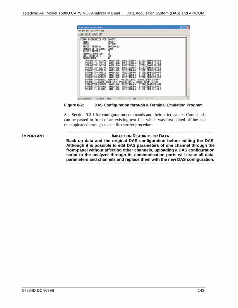
Teledyne API Model T500U CAPS NO2 Analyzer Manual Data Acquisition System (DAS) and APICOM
07834D DCN6998 143
Figure 8-2: DAS Configuration through a Terminal Emulation Program
See Section 9.2.1 for configuration commands and their strict syntax. Commands can be pasted in from of an existing text file, which was first edited offline and then uploaded through a specific transfer procedure.
IMPORTANT IMPACT ON READINGS OR DATA Back up data and the original DAS configuration before editing the DAS. Although it is possible to edit DAS parameters of one channel through the front-panel without affecting other channels, uploading a DAS configuration script to the analyzer through its communication ports will erase all data, parameters and channels and replace them with the new DAS configuration.

Data Acquisition System (DAS) and APICOM Teledyne API Model T500U CAPS NO2 Analyzer Manual
144 07834D DCN6998
This page intentionally left blank.
07834D DCN6998 145
9. REMOTE OPERATION This section provides information needed when using external digital and serial I/O for remote operation. It assumes that the electrical connections have been made as described in Section 3.3.1.8.
The T500U can be remotely configured, calibrated or queried for stored data through the serial ports, via either Computer mode (using a personal computer) or Interactive mode (using a terminal emulation program).
COMPUTER MODE 9.1.Computer Mode is used when the analyzer is connected to a computer with a dedicated interface program such as APICOM, downloadable from our website at http://www.teledyne-api.com/software/apicom/.
INTERACTIVE MODE 9.2.Interactive mode is used with a terminal emulation programs or a “dumb” computer terminal.
REMOTE CONTROL VIA A TERMINAL EMULATION PROGRAM 9.2.1.Start a terminal emulation programs such as HyperTerminal. All configuration commands must be created following a strict syntax or be pasted in from a text file, which was edited offline and then uploaded through a specific transfer procedure. The commands that are used to operate the analyzer in this mode are listed in Table 9-1 and in Appendix A.
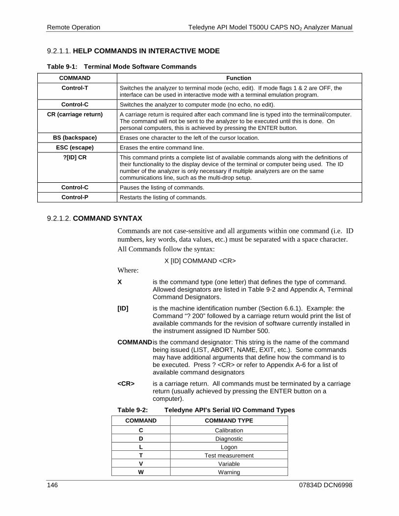
Remote Operation Teledyne API Model T500U CAPS NO2 Analyzer Manual
146 07834D DCN6998
HELP COMMANDS IN INTERACTIVE MODE 9.2.1.1.
Table 9-1: Terminal Mode Software Commands COMMAND Function Control-T Switches the analyzer to terminal mode (echo, edit). If mode flags 1 & 2 are OFF, the
interface can be used in interactive mode with a terminal emulation program. Control-C Switches the analyzer to computer mode (no echo, no edit).
CR (carriage return) A carriage return is required after each command line is typed into the terminal/computer. The command will not be sent to the analyzer to be executed until this is done. On personal computers, this is achieved by pressing the ENTER button.
BS (backspace) Erases one character to the left of the cursor location. ESC (escape) Erases the entire command line.
?[ID] CR This command prints a complete list of available commands along with the definitions of their functionality to the display device of the terminal or computer being used. The ID number of the analyzer is only necessary if multiple analyzers are on the same communications line, such as the multi-drop setup.
Control-C Pauses the listing of commands. Control-P Restarts the listing of commands.
COMMAND SYNTAX 9.2.1.2.
Commands are not case-sensitive and all arguments within one command (i.e. ID numbers, key words, data values, etc.) must be separated with a space character. All Commands follow the syntax:
X [ID] COMMAND <CR> Where: X is the command type (one letter) that defines the type of command.
Allowed designators are listed in Table 9-2 and Appendix A, Terminal Command Designators.
[ID] is the machine identification number (Section 6.6.1). Example: the Command “? 200” followed by a carriage return would print the list of available commands for the revision of software currently installed in the instrument assigned ID Number 500.
COMMAND is the command designator: This string is the name of the command being issued (LIST, ABORT, NAME, EXIT, etc.). Some commands may have additional arguments that define how the command is to be executed. Press ? <CR> or refer to Appendix A-6 for a list of available command designators
<CR> is a carriage return. All commands must be terminated by a carriage return (usually achieved by pressing the ENTER button on a computer).
Table 9-2: Teledyne API's Serial I/O Command Types COMMAND COMMAND TYPE
C Calibration D Diagnostic L Logon T Test measurement V Variable W Warning

Teledyne API Model T500U CAPS NO2 Analyzer Manual Remote Operation
07834D DCN6998 147
DATA TYPES 9.2.1.3.
Data types consist of integers, hexadecimal integers, floating-point numbers, Boolean expressions and text strings.
Integer data are used to indicate integral quantities such as a number of records, a filter length, etc. They consist of an optional plus or minus sign, followed by one or more digits. For example, +1, -12, 123 are all valid integers.
Hexadecimal integer data are used for the same purposes as integers. They consist of the two characters “0x,” followed by one or more hexadecimal digits (0-9, A-F, a-f), which is the ‘C’ programming language convention. No plus or minus sign is permitted. For example, 0x1, 0x12, 0x1234abcd are all valid hexadecimal integers.
Floating-point numbers are used to specify continuously variable values such as temperature set points, time intervals, warning limits, voltages, etc. They consist of an optional plus or minus sign, followed by zero or more digits, an optional decimal point and zero or more digits. (At least one digit must appear before or after the decimal point.) Scientific notation is not permitted. For example, +1.0, 1234.5678, -0.1, 1 are all valid floating-point numbers.
Boolean expressions are used to specify the value of variables or I/O signals that may assume only two values. They are denoted by the key words ON and OFF.
Text strings are used to represent data that cannot be easily represented by other data types, such as data channel names, which may contain letters and numbers. They consist of a quotation mark, followed by one or more printable characters, including spaces, letters, numbers, and symbols, and a final quotation mark. For example, “a”, “1”, “123abc”, and “()[]<>” are all valid text strings. It is not possible to include a quotation mark character within a text string.
Some commands allow you to access variables, messages, and other items. When using these commands, you must type the entire name of the item; you cannot abbreviate any names.
STATUS REPORTING 9.2.1.4.
Reporting of status messages as an audit trail is one of the three principal uses for the RS-232 interface (the other two being the command line interface for controlling the instrument and the download of data in electronic format). You can effectively disable the reporting feature by setting the interface to quiet mode (Section 7.2.1, Table 7-1).
Status reports include warning messages, calibration and diagnostic status messages. Refer to Appendix A-3, Warnings and Test Measurements, for a list of the possible messages, and this for information on controlling the instrument through the RS-232 interface.

Remote Operation Teledyne API Model T500U CAPS NO2 Analyzer Manual
148 07834D DCN6998
GENERAL MESSAGE FORMAT 9.2.1.5.
All messages from the instrument (including those in response to a command line request) are in the format:
X DDD:HH:MM [Id] MESSAGE<CRLF>
Where: X is a command type designator, a single character indicating the
message type, as shown in the Table 9-2.
DDD:HH:MM is the time stamp, the date and time when the message was issued. It consists of the Day-of-year (DDD) as a number from 1 to 366, the hour of the day (HH) as a number from 00 to 23, and the minute (MM) as a number from 00 to 59.
[ID] is the analyzer ID, a number with 1 to 4 digits.
MESSAGE is the message content that may contain warning messages, test measurements, variable values, etc.
<CRLF> is a carriage return / line feed pair, which terminates the message.
The uniform nature of the output messages makes it easy for a host computer to parse them into an easy structure. Keep in mind that the front panel display does not give any information on the time a message was issued, hence it is useful to log such messages for troubleshooting and reference purposes. Terminal emulation programs such as HyperTerminal can capture these messages to text files for later review.
REMOTE ACCESS BY MODEM 9.3.The T500U can be connected to a modem for remote access. This requires a cable between the analyzer’s COM port and the modem, typically a DB-9F to DB-25M cable (available from Teledyne API with P/N WR0000024).
Once the cable has been connected, check to ensure that:
• The DTE-DCE is in the DCE position. • The T500U COM port is set for a baud rate that is compatible with the
modem, • The Modem is designed to operate with an 8-bit word length with one stop
bit. • The MODEM ENABLE communication mode is turned ON (Mode 64, see
Section 7.2.1).
Once this is completed, the appropriate setup command line for your modem can be entered into the analyzer. The default setting for this feature is:
AT Y0 D0 H0 I0 S0=0
This string can be edited to match your modem’s initialization and can be up to 100 characters long.
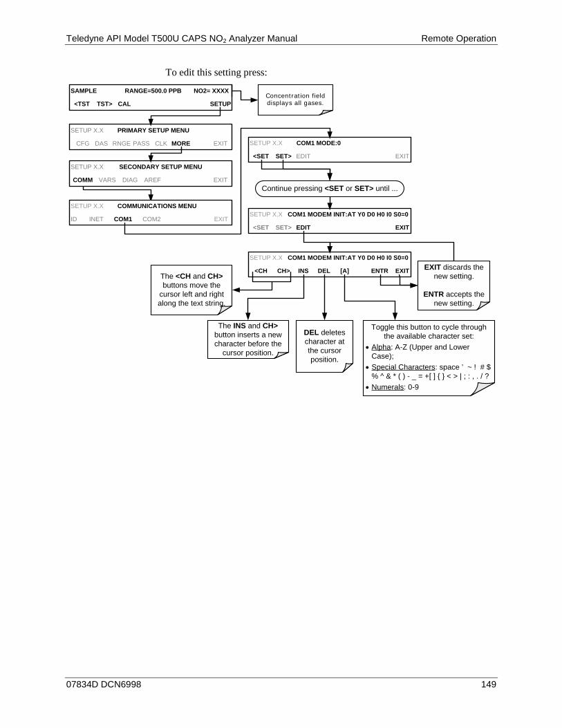
Teledyne API Model T500U CAPS NO2 Analyzer Manual Remote Operation
07834D DCN6998 149
To edit this setting press:
Concentration field displays all gases.
SAMPLE RANGE=500.0 PPB NO2= XXXX
<TST TST> CAL SETUP
SETUP X.X COMMUNICATIONS MENU
ID INET COM1 COM2 EXIT
SETUP X.X COM1 MODE:0
<SET SET> EDIT EXIT
SETUP X.X COM1 MODEM INIT:AT Y0 D0 H0 I0 S0=0
<SET SET> EDIT EXIT
Continue pressing <SET or SET> until ...
SETUP X.X COM1 MODEM INIT:AT Y0 D0 H0 I0 S0=0
<CH CH> INS DEL [A] ENTR EXIT EXIT discards the new setting.
ENTR accepts the new setting.
The <CH and CH> buttons move the
cursor left and right along the text string.
The INS and CH> button inserts a new character before the
cursor position.
DEL deletes character at the cursor position.
Toggle this button to cycle through the available character set:
• Alpha: A-Z (Upper and Lower Case);
• Special Characters: space ’ ~ ! # $ % ^ & * ( ) - _ = +[ ] { } < > | ; : , . / ?
• Numerals: 0-9
SETUP X.X PRIMARY SETUP MENU
CFG DAS RNGE PASS CLK MORE EXIT
SETUP X.X SECONDARY SETUP MENU
COMM VARS DIAG AREF EXIT
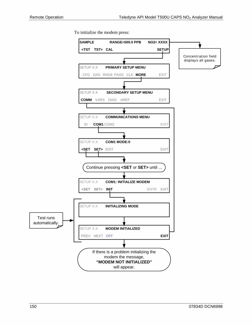
Remote Operation Teledyne API Model T500U CAPS NO2 Analyzer Manual
150 07834D DCN6998
To initialize the modem press:
Concentration field displays all gases.
SAMPLE RANGE=500.0 PPB NO2= XXXX
<TST TST> CAL SETUP
If there is a problem initializing the modem the message,
“MODEM NOT INITIALIZED” will appear.
SETUP X.X COMMUNICATIONS MENU
ID COM1 COM2 EXIT
SETUP X.X COM1 MODE:0
<SET SET> EDIT EXIT
SETUP X.X COM1: INITIALIZE MODEM
<SET SET> INIT ENTR EXIT
SETUP X.X MODEM INITIALIZED
PREV NEXT OFF EXIT
Continue pressing <SET or SET> until ...
SETUP X.X INITIALIZING MODE
Test runs automatically.
SETUP X.X PRIMARY SETUP MENU
CFG DAS RNGE PASS CLK MORE EXIT
SETUP X.X SECONDARY SETUP MENU
COMM VARS DIAG AREF EXIT
Teledyne API Model T500U CAPS NO2 Analyzer Manual Remote Operation
07834D DCN6998 151
PASSWORD SECURITY FOR SERIAL REMOTE 9.4.COMMUNICATIONS
In order to provide security for remote access of the T500U, a LOGON feature can be enabled to require a password before the instrument will accept commands. This is done by turning on the SECURITY MODE (refer to Section 6.4). Once the SECURITY MODE is enabled, the following items apply.
• A password is required before the port will respond or pass on commands. • If the port is inactive for one hour, it will automatically logoff, which can also
be achieved with the LOGOFF command. • Three unsuccessful attempts to log on with an incorrect password will cause
subsequent logins to be disabled for 1 hour, even if the correct password is used.
• If not logged on, the only active command is the '?' request for the help screen.
• The following messages will be returned at logon: • LOGON SUCCESSFUL - Correct password given • LOGON FAILED - Password not given or incorrect • LOGOFF SUCCESSFUL - Connection terminated successfully
To log on to the T500U analyzer with SECURITY MODE feature enabled, type: LOGON 940331
940331 is the default password. To change the default password, use the variable RS-232_PASS issued as follows:
V RS-232_PASS=NNNNNN
Where N is any numeral between 0 and 9.

Remote Operation Teledyne API Model T500U CAPS NO2 Analyzer Manual
152 07834D DCN6998
This page intentionally left blank.
07834D DCN6998 153
10. CALIBRATION Calibration of the T500U Analyzer requires:
• Zero-air source
• Span gas source
• Teflon-type for all gas line materials
• A recording device such as a strip-chart recorder and/or data logger (optional)
• Exiting the calibration mode to sample mode, following a successful CALZ or CALS. The Auto Reference feature (Section 6.9) is disabled while in calibration mode.
For electronic documentation, the internal data acquisition system (DAS) can be used (Section 8).
This section discusses calibration gases, provides the basic method for manually checking the calibration, and for manually performing actual calibration of the T500U analyzer.
CALIBRATION GASES 10.1.Zero air or zero calibration gas is defined as a gas that is similar in chemical composition to the measured medium but without the gas to be measured by the analyzer. A zero air generator such as the Teledyne API's Model 701 can be used. Please visit the company website for more information.
Span calibration gas is specifically mixed to match the chemical composition of the type of gas being measured at near full scale of the desired reporting range.
Alternatively, if a calibrator is available that is a trusted source of stable ozone, e.g., Teledyne API Model T700U with certified photometer, it is possible to use that O3 output directly to obtain the NO2 concentration.
SPAN GAS FOR MULTIPOINT CALIBRATION 10.1.1.Some applications, such as EPA monitoring, require a multipoint calibration where span gases of different concentrations are needed. We recommend using an NO2 gas of higher concentration combined with a gas dilution calibrator such as a Teledyne API's Model T700. For more information see Section 3.3.2.1 and Section 12.
NO2 PERMEATION TUBES 10.1.2.Teledyne API offers an optional internal span gas generator that utilizes an NO2 permeation tube as a span gas source. The accuracy of these devices is only about ±5%.
Whereas this may be sufficient for quick, daily calibration checks, we recommend using certified NO2 gases for accurate calibration.
Calibration Teledyne API Model T500U CAPS NO2 Analyzer Manual
154 07834D DCN6998
CAUTION!
Insufficient gas flow allows gas to build up to levels that will contaminate the instrument or present a safety hazard to personnel. In units with a permeation tube option installed, either the tube must be removed and stored in sealed container (use original container that tube was shipped in) during periods of non-operation, or vacuum pump must be connected and powered on to maintain constant gas flow though the analyzer at all times. (See Figure 3-4 for location and Section 11.3.2 for instructions on how to remove the perm tube when the unit is not in operation).
DATA RECORDING DEVICES 10.2.A strip chart recorder, data acquisition system or digital data acquisition system should be used to record data from the serial or analog outputs of the T500U.
• If analog readings are used, the response of the recording system should be checked against a NIST traceable voltage source or meter.
• Data recording devices should be capable of bi-polar operation so that negative readings can be recorded.
For electronic data recording, the T500U provides an internal data acquisition system (DAS), which is described in detail in Section 8.
APICOM, a remote control program, is also provided as a convenient and powerful tool for data handling, download, storage, quick check and plotting (see Sections 8.2.1, and the APICOM software manual downloadable from:
http://www.teledyne-api.com/manuals ).
MANUAL CALIBRATION CHECKS AND CALIBRATION 10.3.OF THE T500U IN ITS BASE CONFIGURATION
IMPORTANT IMPACT ON READINGS OR DATA ZERO/SPAN CALIBRATION CHECKS VS. ZERO/SPAN CALIBRATION
NEVER press the ENTR button if you are only checking calibration. Pressing the ENTR button during the following procedure resets the stored values for OFFSET and SLOPE and alters the instrument’s Calibration. This should ONLY BE DONE during an actual calibration of the T500U.

Teledyne API Model T500U CAPS NO2 Analyzer Manual Calibration
07834D DCN6998 155
SETUP FOR BASIC CALIBRATION CHECKS AND 10.3.1.CALIBRATION
Connect the sources of zero air and span gas as shown below in one of the following ways:
VENT here if input
is pressurized
Source of SAMPLE GASRemoved during
calibration
Chassis
SAMPLE
EXHAUST
MODEL T700Gas Dilution
Calibrator
Vent here if output of calibrator
is not already vented.
MODEL 701Zero Gas Generator
Encl
osur
e W
all
Cal
ibra
ted
NO
2
at H
IGH
Spa
n Co
ncen
trat
ion
Figure 10-1: Set up for Manual Calibrations/Checks in Base Configuration w/Gas Dilution
Calibrator

Calibration Teledyne API Model T500U CAPS NO2 Analyzer Manual
156 07834D DCN6998
PERFORMING A BASIC MANUAL CALIBRATION CHECK 10.3.2.
Allow ZERO GAS to enter the sample port at the rear of the analyzer.
SAMPLE NO2 STB= XXX.X PPM NO2=XXX.X
< TST TST > CAL SETUP
The ZERO and/or SPAN buttons will appear at various
points of this process. It is not necessary to press
them.
SAMPLE RANGE=500.0 PPB NO2= XXXX
<TST TST> CAL SETUP
Toggle TST> button until ...
Wait until NO2 STB falls below 0.1 ppb.
This may take several minutes.
Allow SPAN GAS to enter the sample port at the rear of the analyzer.
Wait until NO2 STB falls below 0.5 ppb.
This may take several minutes.
Concentration field displays all of the
available gas measurements throughout this
procedure.
Record the zero point reading
DO NOT press the ENTR button
Record the span point reading
DO NOT press the ENTR button
NOTE:In certain instances where low Span gas concentrations are present (≤ 50 ppb), both the ZERO & SPAN buttons
may appear simultaneously.
Note If the ZERO or SPAN buttons are not displayed, the measurement made is outside the allowable range for a reliable calibration.
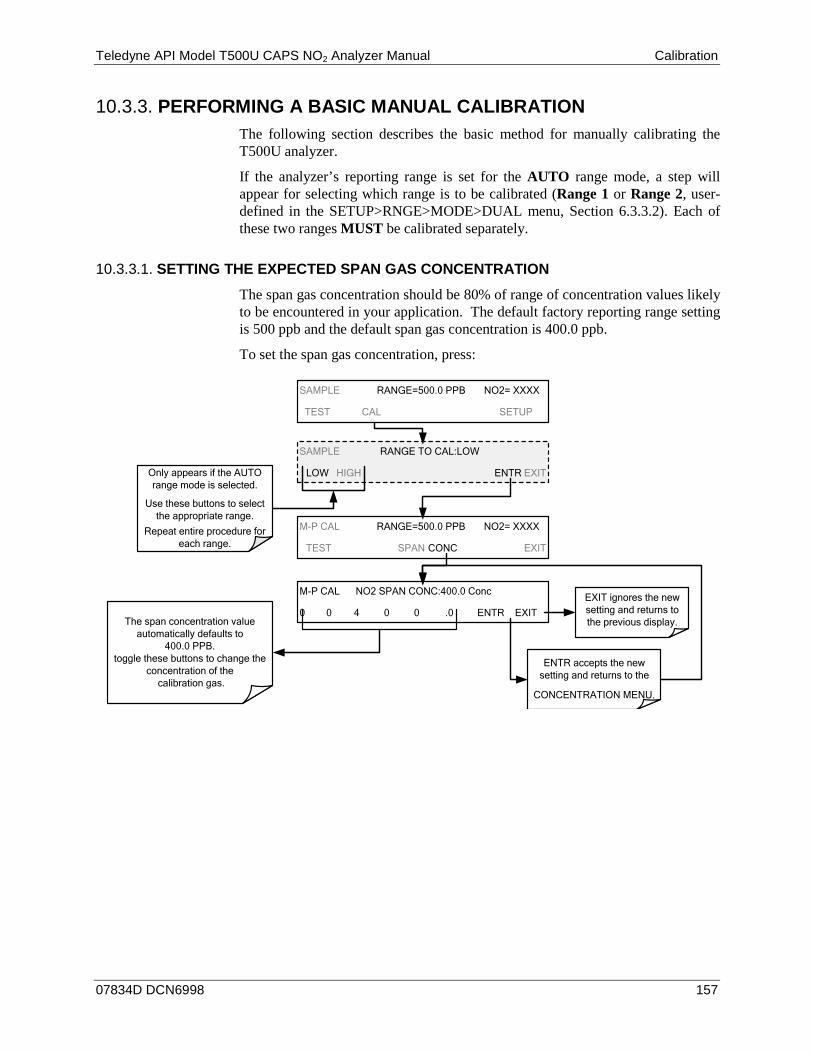
Teledyne API Model T500U CAPS NO2 Analyzer Manual Calibration
07834D DCN6998 157
PERFORMING A BASIC MANUAL CALIBRATION 10.3.3.The following section describes the basic method for manually calibrating the T500U analyzer.
If the analyzer’s reporting range is set for the AUTO range mode, a step will appear for selecting which range is to be calibrated (Range 1 or Range 2, user-defined in the SETUP>RNGE>MODE>DUAL menu, Section 6.3.3.2). Each of these two ranges MUST be calibrated separately.
SETTING THE EXPECTED SPAN GAS CONCENTRATION 10.3.3.1.
The span gas concentration should be 80% of range of concentration values likely to be encountered in your application. The default factory reporting range setting is 500 ppb and the default span gas concentration is 400.0 ppb.
To set the span gas concentration, press:
SAMPLE RANGE TO CAL:LOW
LOW HIGH ENTR EXIT
SAMPLE RANGE=500.0 PPB NO2= XXXX
TEST CAL SETUP
M-P CAL RANGE=500.0 PPB NO2= XXXX
TEST SPAN CONC EXIT
M-P CAL NO2 SPAN CONC:400.0 Conc
0 0 4 0 0 .0 ENTR EXITThe span concentration value
automatically defaults to 400.0 PPB.
toggle these buttons to change the concentration of the
calibration gas.
EXIT ignores the new setting and returns to the previous display.
ENTR accepts the new setting and returns to the
CONCENTRATION MENU.
Only appears if the AUTO range mode is selected.
Use these buttons to select the appropriate range.
Repeat entire procedure for each range.
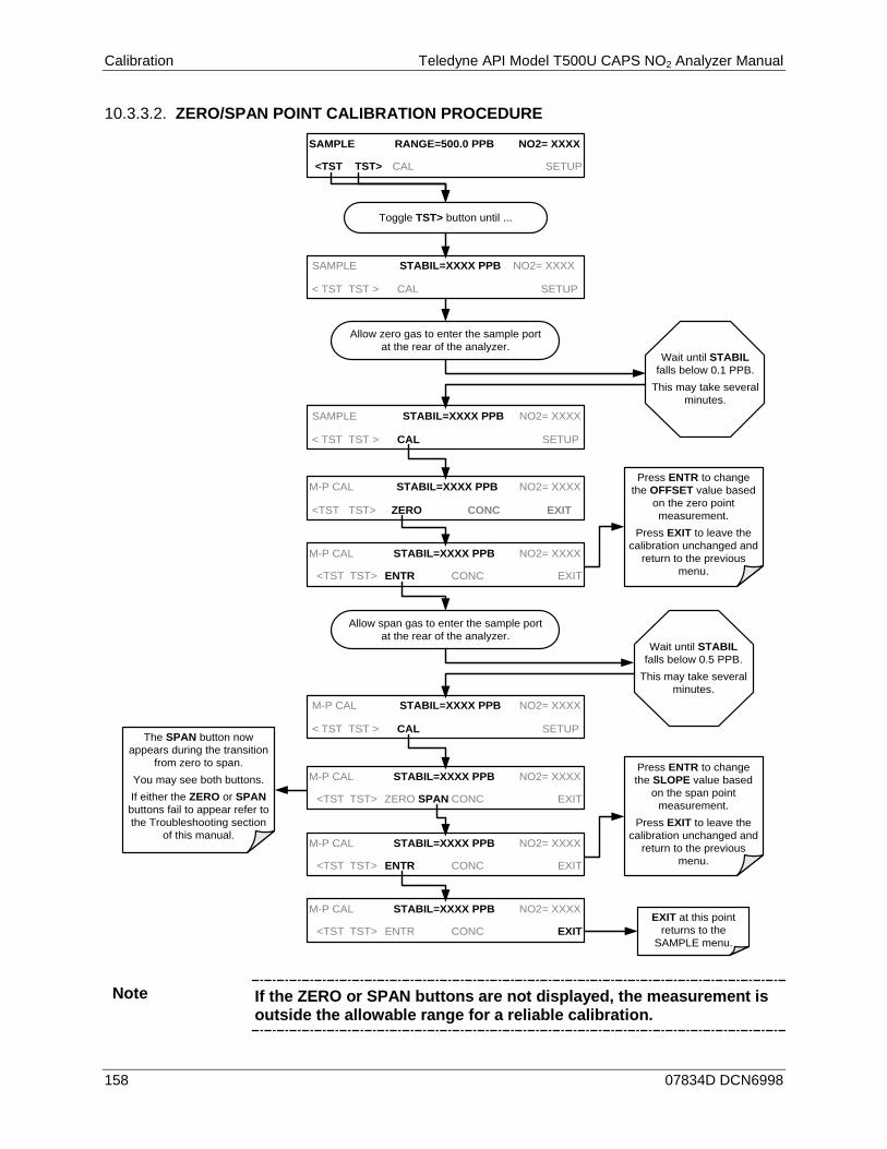
Calibration Teledyne API Model T500U CAPS NO2 Analyzer Manual
158 07834D DCN6998
ZERO/SPAN POINT CALIBRATION PROCEDURE 10.3.3.2.
Press ENTR to change the OFFSET value based
on the zero point measurement.
Press EXIT to leave the calibration unchanged and
return to the previous menu.
SAMPLE STABIL=XXXX PPB NO2= XXXX
< TST TST > CAL SETUP
M-P CAL STABIL=XXXX PPB NO2= XXXX
<TST TST> ZERO CONC EXIT
EXIT at this point returns to the
SAMPLE menu.
Press ENTR to change the SLOPE value based
on the span point measurement.
Press EXIT to leave the calibration unchanged and
return to the previous menu.
Allow zero gas to enter the sample port at the rear of the analyzer.
Wait until STABIL falls below 0.1 PPB.
This may take several minutes.
SAMPLE STABIL=XXXX PPB NO2= XXXX
< TST TST > CAL SETUP
M-P CAL STABIL=XXXX PPB NO2= XXXX
<TST TST> ENTR CONC EXIT
M-P CAL STABIL=XXXX PPB NO2= XXXX
<TST TST> ZERO SPAN CONC EXIT
Allow span gas to enter the sample port at the rear of the analyzer.
Wait until STABIL falls below 0.5 PPB.
This may take several minutes.
M-P CAL STABIL=XXXX PPB NO2= XXXX
< TST TST > CAL SETUP
M-P CAL STABIL=XXXX PPB NO2= XXXX
<TST TST> ENTR CONC EXIT
M-P CAL STABIL=XXXX PPB NO2= XXXX
<TST TST> ENTR CONC EXIT
The SPAN button now appears during the transition
from zero to span.You may see both buttons.If either the ZERO or SPAN buttons fail to appear refer to the Troubleshooting section
of this manual.
SAMPLE RANGE=500.0 PPB NO2= XXXX
<TST TST> CAL SETUP
Toggle TST> button until ...
Note If the ZERO or SPAN buttons are not displayed, the measurement is outside the allowable range for a reliable calibration.
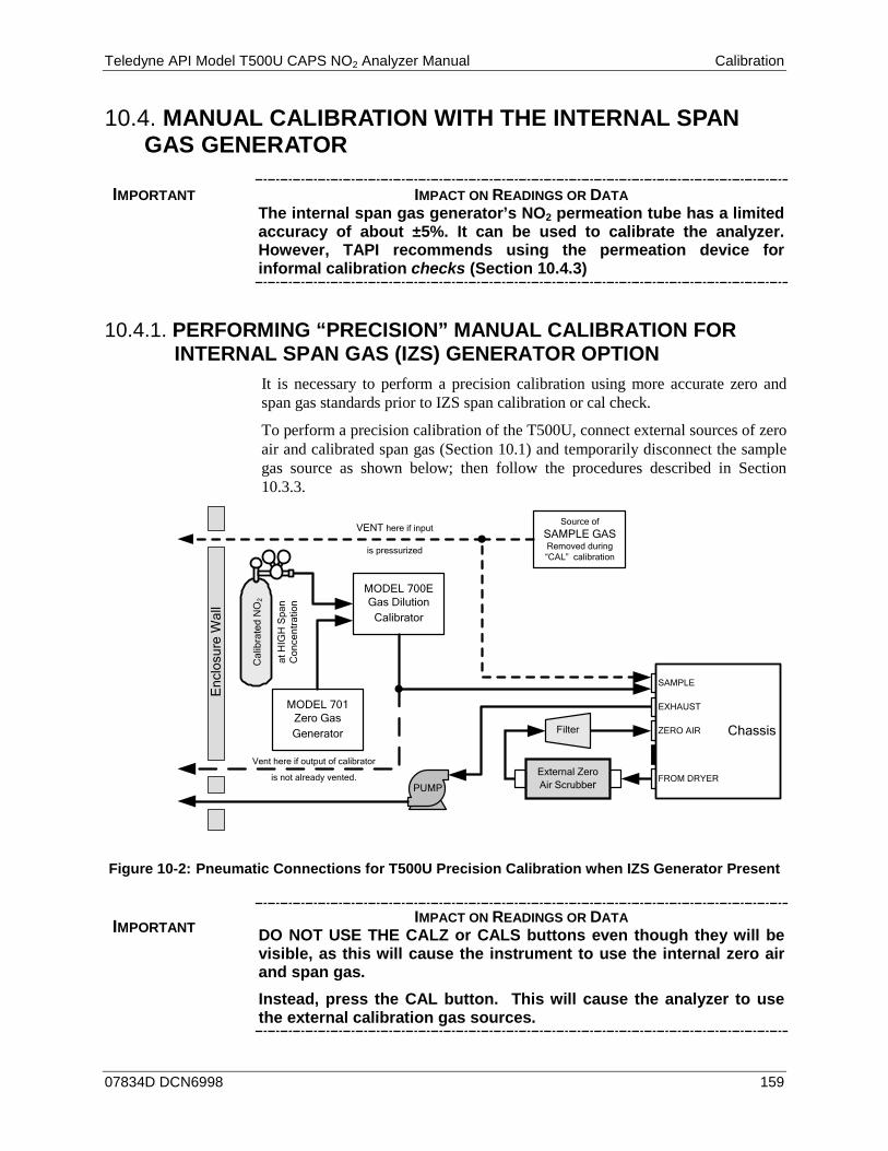
Teledyne API Model T500U CAPS NO2 Analyzer Manual Calibration
07834D DCN6998 159
MANUAL CALIBRATION WITH THE INTERNAL SPAN 10.4.GAS GENERATOR
IMPORTANT IMPACT ON READINGS OR DATA The internal span gas generator’s NO2 permeation tube has a limited accuracy of about ±5%. It can be used to calibrate the analyzer. However, TAPI recommends using the permeation device for informal calibration checks (Section 10.4.3)
PERFORMING “PRECISION” MANUAL CALIBRATION FOR 10.4.1.INTERNAL SPAN GAS (IZS) GENERATOR OPTION
It is necessary to perform a precision calibration using more accurate zero and span gas standards prior to IZS span calibration or cal check.
To perform a precision calibration of the T500U, connect external sources of zero air and calibrated span gas (Section 10.1) and temporarily disconnect the sample gas source as shown below; then follow the procedures described in Section 10.3.3.
VENT here if input
is pressurized
Source of SAMPLE GASRemoved during “CAL” calibration
PUMP
MODEL 700EGas Dilution
Calibrator
Vent here if output of calibrator
is not already vented.
MODEL 701Zero Gas Generator
Enc
losu
re W
all
Cal
ibra
ted
NO
2
at H
IGH
Spa
n C
once
ntra
tion
External Zero Air Scrubber
Filter Chassis
SAMPLE
EXHAUST
ZERO AIR
FROM DRYER
Figure 10-2: Pneumatic Connections for T500U Precision Calibration when IZS Generator Present
IMPORTANT IMPACT ON READINGS OR DATA DO NOT USE THE CALZ or CALS buttons even though they will be visible, as this will cause the instrument to use the internal zero air and span gas. Instead, press the CAL button. This will cause the analyzer to use the external calibration gas sources.
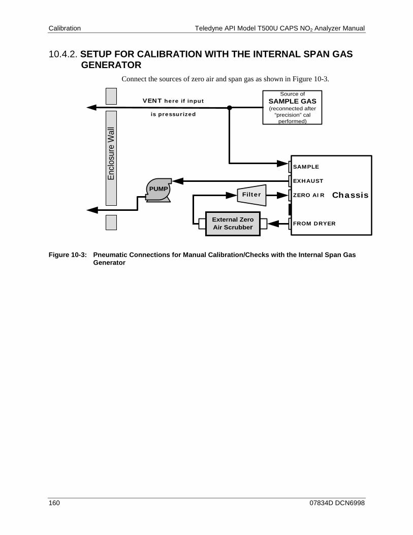
Calibration Teledyne API Model T500U CAPS NO2 Analyzer Manual
160 07834D DCN6998
SETUP FOR CALIBRATION WITH THE INTERNAL SPAN GAS 10.4.2.GENERATOR
Connect the sources of zero air and span gas as shown in Figure 10-3.
VENT here if input
is pressurized
Source of SAMPLE GAS(reconnected after
“precision” cal performed)
PUMP
Enclo
sure
Wal
l
External Zero Air Scrubber
Filter Chassis
SAMPLE
EXHAUST
ZERO AIR
FROM DRYER
Figure 10-3: Pneumatic Connections for Manual Calibration/Checks with the Internal Span Gas
Generator

Teledyne API Model T500U CAPS NO2 Analyzer Manual Calibration
07834D DCN6998 161
PERFORMING A MANUAL CALIBRATION CHECK WITH THE 10.4.3.INTERNAL SPAN GAS GENERATOR
Turn ON the CAL_ON_NO2 feature
SAMPLE NO2 STB= XXX.X PPB NO2= XXXX
<TST TST> CAL CALZ CALS SETUP
SAMPLE NO2 STB= XXX.X PPB NO2= XXXX
<TST TST> CAL CALZ CALS SETUP
Set the Display to show the NO2 STB test
function.This function calculates
the stability of the NO/NOx measurement.Toggle TST> button until ...
SAMPLE RANGE=500.0 PPB NO2= XXXX
<TST TST> CAL CALZ CALS SETUP
ZERO GAS enters the analyzer via the External Scrubber.
The ZERO and/or SPAN buttons will appear at various
points of this process.
It is not necessary to press them.
Wait until NO2 STB falls below 0.5 PPB.
This may take several minutes.
SPAN GAS enters the reaction cell from the internal NO2 permeation tube.
Wait until NO2 STB falls below 0.5 PPB.
This may take several minutes.
Record NO2 zero point reading.
DO NOT press the ENTR button
Record NO2 span point reading.
DO NOT press the ENTR button.
Turn OFF the CAL_ON_NO2 feature
Note If the ZERO or SPAN buttons are not displayed, the measurement made is out of the allowable range for a reliable calibration. See Section 13.4.4 for troubleshooting tips.
Calibration Teledyne API Model T500U CAPS NO2 Analyzer Manual
162 07834D DCN6998
PERFORMING A MANUAL CALIBRATION WITH THE INTERNAL 10.4.4.SPAN GAS GENERATOR
If the analyzer’s reporting range is set for the AUTO range mode, a step will appear for selecting which range is to be calibrated (LOW or HIGH, user- selected in the SETUP>RNGE>MODE>DUAL menu, Section 6.3.3.2). Each of these two ranges MUST be calibrated separately.
SETTING THE EXPECTED SPAN GAS CONCENTRATION 10.4.4.1.
When calibrating the instrument using the internal permeation tube as a span gas source, it is necessary to know, as close as possible, the concentration value of the gas being outputted by the tube. To determine this value: 1. Perform a precision calibration of the instrument as described in Section
10.4.1. 2. Perform a calibration check as described in Section 10.4.3.
• Record the value displayed for NO2 during the span check portion of the procedure.
• This will be the concentration value used in subsequent calibrations using the internal span gas source.
• It is a good idea to measure the permeation tube output once every 4 to 6 months.
3. Ensure that the reporting range span point is set for a value at least 10% higher than the measured value of the permeation tube output.

Teledyne API Model T500U CAPS NO2 Analyzer Manual Calibration
07834D DCN6998 163
MANUAL CALIBRATION CHECKS WITH VALVE OPTIONS 10.4.5.INSTALLED
SAMPLE NO2 STB= XXX.X PPB NO2= XXXX
<TST TST> CAL CALZ CALS SETUP
SAMPLE NO2 STB= XXX.X PPB NO2= XXXX
<TST TST> CAL CALZ CALS SETUP
Toggle TST> button until ...
SAMPLE RANGE=500.0 PPB NO2= XXXX
<TST TST> CAL CALZ CALS SETUP
The ZERO and/or SPAN buttons will appear at various
points of this process. It is not necessary to press
them.
Wait until NO2 STB falls below 0.1 PPB.
This may take several minutes.
Wait until NO2 STB falls below 0.5 PPB.
This may take several minutes.
Record the NO2 zero point reading
DO NOT PRESS THE ENTR KEY
Record the NO2 span point readings
DO NOT PRESS THE ENTR button
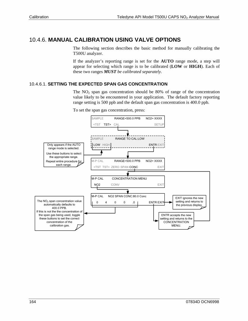
Calibration Teledyne API Model T500U CAPS NO2 Analyzer Manual
164 07834D DCN6998
MANUAL CALIBRATION USING VALVE OPTIONS 10.4.6.The following section describes the basic method for manually calibrating the T500U analyzer.
If the analyzer’s reporting range is set for the AUTO range mode, a step will appear for selecting which range is to be calibrated (LOW or HIGH). Each of these two ranges MUST be calibrated separately.
SETTING THE EXPECTED SPAN GAS CONCENTRATION 10.4.6.1.
The NO2 span gas concentration should be 80% of range of the concentration value likely to be encountered in your application. The default factory reporting range setting is 500 ppb and the default span gas concentration is 400.0 ppb.
To set the span gas concentration, press:
SAMPLE RANGE TO CAL:LOW
LOW HIGH ENTR EXIT
SAMPLE RANGE=500.0 PPB NO2= XXXX
<TST TST> CAL SETUP
M-P CAL RANGE=500.0 PPB NO2= XXXX
<TST TST> ZERO SPAN CONC EXIT
M-P CAL CONCENTRATION MENU
NO2 CONV EXIT
M-P CAL NO2 SPAN CONC:80.0 Conc
0 4 0 0 .0 ENTR EXITThe NO2 span concentration value automatically defaults to
400.0 PPB. If this is not the the concentration of
the span gas being used, toggle these buttons to set the correct
concentration of the calibration gas.
EXIT ignores the new setting and returns to the previous display.
ENTR accepts the new setting and returns to the
CONCENTRATION MENU.
Only appears if the AUTO range mode is selected.
Use these buttons to select the appropriate range.
Repeat entire procedure for each range.

Teledyne API Model T500U CAPS NO2 Analyzer Manual Calibration
07834D DCN6998 165
ZERO/SPAN POINT CALIBRATION PROCEDURE FOR VALVE OPTIONS 10.4.6.2.
Press ENTR to change the OFFSET value.
Press EXIT to leave the calibration unchanged and
return to the previous menu.
SAMPLE NO2 STB= XXX.X PPB NO2=XXX.X
< TST TST > CAL SETUP
M-P CAL NO2 STB= XXX.X PPB NO2=XXX.X
<TST TST> ZERO CONC EXIT
SAMPLE RANGE TO CAL:LOW
LOW HIGH ENTR EXIT
EXIT at this point returns to the
SAMPLE menu.
Press ENTR to changes the SLOPE value for both.
Press EXIT to leave the calibration unchanged and
return to the previous menu.
Toggle TST> button until ...
Allow zero gas to enter the sample port at the rear of the analyzer.
Wait until NO2 STB falls below 0.1 PPB.
This may take several minutes.
M-P CAL NO2 STB= XXX.X PPB NO2=X.XXX
<TST TST> ENTR CONC EXIT
M-P CAL NO2 STB= XXX.X PPB NO2=X.XXX
<TST TST> ZERO SPAN CONC EXIT
SAMPLE RANGE TO CAL:LOW
LOW HIGH ENTR EXIT
Allow span gas to enter the sample port at the rear of the analyzer. Wait until NO2 STB
falls below 0.5 PPB.This may take several
minutes.
M-P CAL NO2 STB= XXX.X PPB NO2=X.XXX
<TST TST> ENTR CONC EXIT
M-P CAL NO2 STB= XXX.X PPB NO2=X.XXX
<TST TST> ENTR CONC EXIT
The SPAN button now appears during the transition
from zero to span.You may see both buttons.If either the ZERO or SPAN buttons fail to appear see
Section 11 for troubleshooting tips.
Only appears if the AUTO range mode is selected.
Press to select the appropriate range.
Repeat entire procedure for each range.
Only appears if the AUTO range mode is selected.
Press to select the appropriate range.
Repeat entire procedure for each range.
SAMPLE RANGE=500.0 PPB NO2= XXXX
<TST TST> CAL CALZ CALS SETUP
SAMPLE RANGE=500.0 PPB NO2= XXXX
<TST TST> CAL CALZ CALS SETUP
SAMPLE RANGE=500.0 PPB NO2= XXXX
<TST TST> CAL CALZ CALS SETUP
Note If the ZERO or SPAN buttons are not displayed, the measurement made during is out of the range allowed for a reliable calibration.
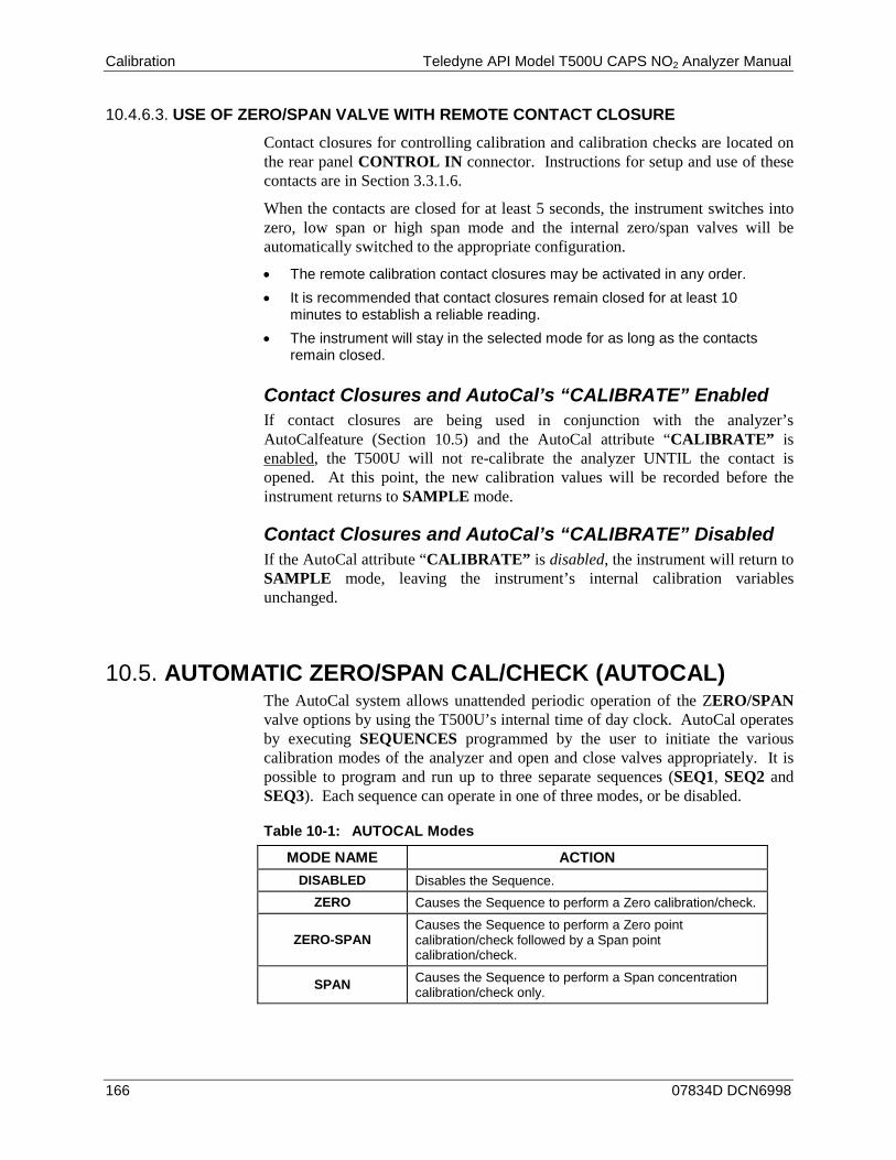
Calibration Teledyne API Model T500U CAPS NO2 Analyzer Manual
166 07834D DCN6998
USE OF ZERO/SPAN VALVE WITH REMOTE CONTACT CLOSURE 10.4.6.3.
Contact closures for controlling calibration and calibration checks are located on the rear panel CONTROL IN connector. Instructions for setup and use of these contacts are in Section 3.3.1.6.
When the contacts are closed for at least 5 seconds, the instrument switches into zero, low span or high span mode and the internal zero/span valves will be automatically switched to the appropriate configuration.
• The remote calibration contact closures may be activated in any order. • It is recommended that contact closures remain closed for at least 10
minutes to establish a reliable reading. • The instrument will stay in the selected mode for as long as the contacts
remain closed.
Contact Closures and AutoCal’s “CALIBRATE” Enabled If contact closures are being used in conjunction with the analyzer’s AutoCalfeature (Section 10.5) and the AutoCal attribute “CALIBRATE” is enabled, the T500U will not re-calibrate the analyzer UNTIL the contact is opened. At this point, the new calibration values will be recorded before the instrument returns to SAMPLE mode.
Contact Closures and AutoCal’s “CALIBRATE” Disabled If the AutoCal attribute “CALIBRATE” is disabled, the instrument will return to SAMPLE mode, leaving the instrument’s internal calibration variables unchanged.
AUTOMATIC ZERO/SPAN CAL/CHECK (AUTOCAL) 10.5.The AutoCal system allows unattended periodic operation of the ZERO/SPAN valve options by using the T500U’s internal time of day clock. AutoCal operates by executing SEQUENCES programmed by the user to initiate the various calibration modes of the analyzer and open and close valves appropriately. It is possible to program and run up to three separate sequences (SEQ1, SEQ2 and SEQ3). Each sequence can operate in one of three modes, or be disabled.
Table 10-1: AUTOCAL Modes
MODE NAME ACTION DISABLED Disables the Sequence.
ZERO Causes the Sequence to perform a Zero calibration/check.
ZERO-SPAN Causes the Sequence to perform a Zero point calibration/check followed by a Span point calibration/check.
SPAN Causes the Sequence to perform a Span concentration calibration/check only.
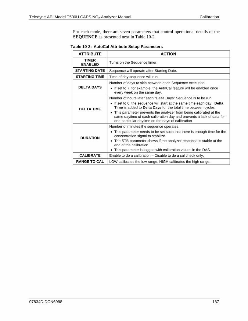
Teledyne API Model T500U CAPS NO2 Analyzer Manual Calibration
07834D DCN6998 167
For each mode, there are seven parameters that control operational details of the SEQUENCE as presented next in Table 10-2.
Table 10-2: AutoCal Attribute Setup Parameters
ATTRIBUTE ACTION TIMER
ENABLED Turns on the Sequence timer.
STARTING DATE Sequence will operate after Starting Date. STARTING TIME Time of day sequence will run.
DELTA DAYS Number of days to skip between each Sequence execution. • If set to 7, for example, the AutoCal feature will be enabled once
every week on the same day.
DELTA TIME
Number of hours later each “Delta Days” Sequence is to be run. • If set to 0, the sequence will start at the same time each day. Delta
Time is added to Delta Days for the total time between cycles. • This parameter prevents the analyzer from being calibrated at the
same daytime of each calibration day and prevents a lack of data for one particular daytime on the days of calibration
DURATION
Number of minutes the sequence operates. • This parameter needs to be set such that there is enough time for the
concentration signal to stabilize. • The STB parameter shows if the analyzer response is stable at the
end of the calibration. • This parameter is logged with calibration values in the DAS.
CALIBRATE Enable to do a calibration – Disable to do a cal check only. RANGE TO CAL LOW calibrates the low range, HIGH calibrates the high range.
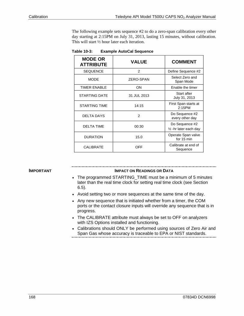
Calibration Teledyne API Model T500U CAPS NO2 Analyzer Manual
168 07834D DCN6998
The following example sets sequence #2 to do a zero-span calibration every other day starting at 2:15PM on July 31, 2013, lasting 15 minutes, without calibration. This will start ½ hour later each iteration.
Table 10-3: Example AutoCal Sequence
MODE OR ATTRIBUTE VALUE COMMENT
SEQUENCE 2 Define Sequence #2
MODE ZERO-SPAN Select Zero and Span Mode
TIMER ENABLE ON Enable the timer
STARTING DATE 31 JUL 2013 Start after July 31, 2013
STARTING TIME 14:15 First Span starts at 2:15PM
DELTA DAYS 2 Do Sequence #2 every other day
DELTA TIME 00:30 Do Sequence #2
½ -hr later each day
DURATION 15.0 Operate Span valve for 15 min
CALIBRATE OFF Calibrate at end of Sequence
IMPORTANT IMPACT ON READINGS OR DATA • The programmed STARTING_TIME must be a minimum of 5 minutes
later than the real time clock for setting real time clock (see Section 6.5).
• Avoid setting two or more sequences at the same time of the day. • Any new sequence that is initiated whether from a timer, the COM
ports or the contact closure inputs will override any sequence that is in progress.
• The CALIBRATE attribute must always be set to OFF on analyzers with IZS Options installed and functioning.
• Calibrations should ONLY be performed using sources of Zero Air and Span Gas whose accuracy is traceable to EPA or NIST standards.

Teledyne API Model T500U CAPS NO2 Analyzer Manual Calibration
07834D DCN6998 169
SETUP > ACAL: PROGRAMMING AND AUTO CAL SEQUENCE 10.5.1.To program the example sequence shown in Table 10-3, press:
CONTINUE NEXT PAGE with STARTING TIME
SAMPLE RANGE = 500.0 PPB NO2=XXX.X < TST TST > CAL CALZ CZLS SETUP
SETUP X.X CFG ACAL DAS RNGE PASS CLK MORE EXIT
SETUP X.X SEQ 1) DISABLED NEXT MODE EXIT
SETUP X.X SEQ 2) DISABLED PREV NEXT MODE EXIT
SETUP X.X MODE: DISABLED NEXT ENTR EXIT
SETUP X.X MODE: ZERO PREV NEXT ENTR EXIT
SETUP X.X SEQ 2) ZERO–SPAN, 1:00:00 PREV NEXT MODE SET EXIT
SETUP X.X TIMER ENABLE: ON SET> EDIT EXIT
SETUP X.X STARTING DATE: 31–JUL–13 <SET SET> EDIT EXIT
SETUP X.X STARTING DATE: 31–JUL–13 3 1 JUL 1 3 ENTR EXIT
Toggle buttons to set Day, Month & Year:
Format : DD-MON-YY
SETUP X.X MODE: ZERO–SPAN PREV NEXT ENTR EXIT
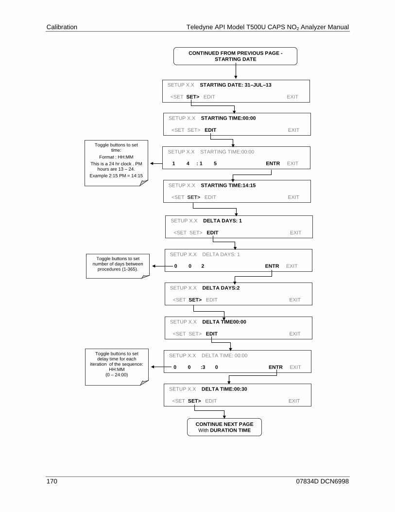
Calibration Teledyne API Model T500U CAPS NO2 Analyzer Manual
170 07834D DCN6998
SETUP X.X STARTING DATE: 31–JUL–13 <SET SET> EDIT EXIT
SETUP X.X STARTING TIME:00:00 <SET SET> EDIT EXIT
SETUP X.X STARTING TIME:00:00 1 4 : 1 5 ENTR EXIT
Toggle buttons to set time:
Format : HH:MM This is a 24 hr clock . PM
hours are 13 – 24. Example 2:15 PM = 14:15
CONTINUED FROM PREVIOUS PAGE - STARTING DATE
CONTINUE NEXT PAGE With DURATION TIME
SETUP X.X STARTING TIME:14:15 <SET SET> EDIT EXIT
SETUP X.X DELTA DAYS: 1 <SET SET> EDIT EXIT
SETUP X.X DELTA DAYS: 1 0 0 2 ENTR EXIT
Toggle buttons to set number of days between
procedures (1-365).
SETUP X.X DELTA DAYS:2 <SET SET> EDIT EXIT
SETUP X.X DELTA TIME00:00 <SET SET> EDIT EXIT
SETUP X.X DELTA TIME: 00:00 0 0 :3 0 ENTR EXIT
SETUP X.X DELTA TIME:00:30 <SET SET> EDIT EXIT
Toggle buttons to set delay time for each
iteration of the sequence: HH:MM
(0 – 24:00)

Teledyne API Model T500U CAPS NO2 Analyzer Manual Calibration
07834D DCN6998 171
EXIT returns to the SETUP
Menu.
SETUP DURATION:15.0 MINUTES <SET SET> EDIT EXIT
SETUP DURATION 15.0MINUTES 3 0 .0 ENTR EXIT
SETUP DURATION:30.0 MINUTES <SET SET> EDIT EXIT
Toggle buttons to set duration for each iteration
of the sequence: Set in Decimal minutes
from 0.1 – 60.0.
SETUP CALIBRATE: OFF <SET SET> EDIT EXIT
SETUP CALIBRATE: OFF ON ENTR EXIT
SETUP X.X CALIBRATE: ON <SET SET> EDIT EXIT
Toggle button Between Off and
ON.
SETUP X.X SEQ 2) ZERO–SPAN, 2:00:30 PREV NEXT MODE SET EXIT
Display show: SEQ 2) ZERO–SPAN, 2:00:30
Sequence Delta Time MODE Delta Days
CONTINUED FROM PREVIOUS PAGE DELTA TIME
Note If at any time an unallowable entry is selected (Example: Delta Days > 367) the ENTR button will disappear from the display.

Calibration Teledyne API Model T500U CAPS NO2 Analyzer Manual
172 07834D DCN6998
CALIBRATION QUALITY ANALYSIS 10.6.Following calibration, evaluate the analyzer’s calibration SLOPE and OFFSET parameters. Their values describe the linear response curve of the analyzer, indicating the quality of the calibration.
First, record the values of the SLOPE and OFFSET test functions (in SAMPLE Mode press the <TST TST> buttons, see Section 5.2), all of which are automatically stored in the DAS channel CALDAT for data analysis, documentation and archival.
Ensure that these values are within the limits listed in Table 10-4 and frequently compare them to those values on the Final Test and Validation Data Sheet (P/N 07853) that came attached to your manual, which should not be significantly different. If they are, refer to Section 13.1.2 in Troubleshooting and Service.
Table 10-4: Calibration Data Quality Evaluation
Function Minimum Value Optimum Value Maximum Value SLOPE -0.800 1.000 1.200
OFFSET -10 ppb 0.0 ppb 10.0 ppb
07834D DCN6998 173
11. MAINTENANCE Although the T500U analyzer requires little service, a few simple procedures should be performed regularly to ensure that the T500U continues to operate accurately and reliably over its lifetime. In general, the exterior can be wiped down with a lightly damp cloth; avoid spraying anything directly onto any part of the analyzer.
Service and troubleshooting are covered in Section 13.
MAINTENANCE SCHEDULE 11.1.Table 11-1 shows a typical maintenance schedule for the T500U. Please note that in certain environments (i.e., dusty, very high ambient pollutant levels) some maintenance procedures may need to be performed more often than shown.
WARNING – ELECTRICAL SHOCK HAZARD Disconnect power before performing any of the following operations that require
entry into the interior of the analyzer.
CAUTION – QUALIFIED PERSONNEL These maintenance procedures must be performed by qualified technicians only.
IMPORTANT IMPACT ON READINGS OR DATA A span and zero calibration check (see CAL CHECK REQ’D Column of Table 11-1, T500U Maintenance Schedule) must be performed following some of the maintenance procedures.
To perform a CHECK of the instrument’s Zero or Span Calibration, follow the calibration check steps in Section 10.4.
DO NOT press the ENTR button at the end of each operation. Pressing the ENTR button resets the stored values for OFFSET and SLOPE and alters the instrument’s Calibration.
Alternately, use the Auto Cal feature described in Section 10.5 with the CALIBRATE attribute set to OFF.
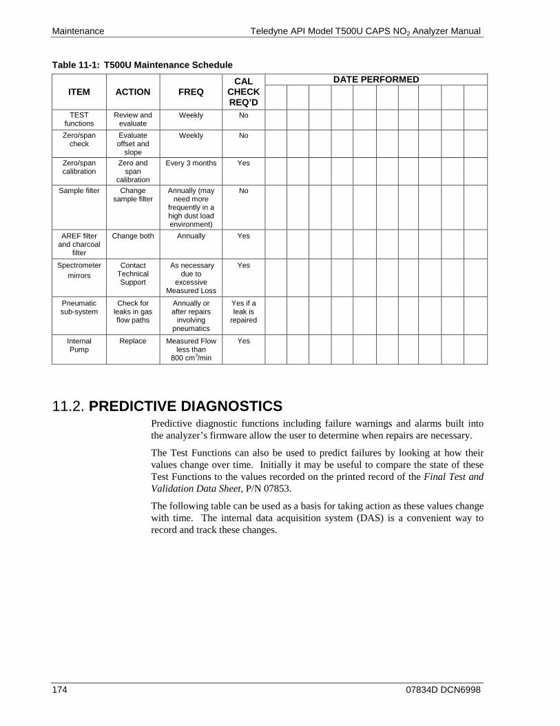
Maintenance Teledyne API Model T500U CAPS NO2 Analyzer Manual
174 07834D DCN6998
Table 11-1: T500U Maintenance Schedule
ITEM ACTION FREQ CAL
CHECK REQ’D
DATE PERFORMED
TEST functions
Review and evaluate
Weekly No
Zero/span check
Evaluate offset and
slope
Weekly No
Zero/span calibration
Zero and span
calibration
Every 3 months Yes
Sample filter Change sample filter
Annually (may need more
frequently in a high dust load environment)
No
AREF filter and charcoal
filter
Change both Annually Yes
Spectrometer mirrors
Contact Technical Support
As necessary due to
excessive Measured Loss
Yes
Pneumatic sub-system
Check for leaks in gas flow paths
Annually or after repairs
involving pneumatics
Yes if a leak is
repaired
Internal Pump
Replace Measured Flow less than
800 cm3/min
Yes
PREDICTIVE DIAGNOSTICS 11.2.Predictive diagnostic functions including failure warnings and alarms built into the analyzer’s firmware allow the user to determine when repairs are necessary.
The Test Functions can also be used to predict failures by looking at how their values change over time. Initially it may be useful to compare the state of these Test Functions to the values recorded on the printed record of the Final Test and Validation Data Sheet, P/N 07853.
The following table can be used as a basis for taking action as these values change with time. The internal data acquisition system (DAS) is a convenient way to record and track these changes.

Teledyne API Model T500U CAPS NO2 Analyzer Manual Maintenance
07834D DCN6998 175
Table 11-2: Predictive Uses for Test Functions
FUNCTION EXPECTED ACTUAL INTERPRETATION & ACTION
SAMP (pressure)
Constant within atmospheric
changes (Typically 2 InHg below ambient)
Fluctuating Developing leak in pneumatic system. Check for leaks (Section 11.3.5.1).
Slowly increasing
Developing leak in pneumatic system prior to the sample restrictor. Check for leaks. (Section 11.3.5.1) Sample pump requires replacement. (Section 11.3.3) Check flow rate. (Section 11.3.5.2)
Slowly decreasing
Kink in tubing. Check and adjust tubing. Flow path is clogging up. Run a flow check (Section 11.3.5.2) to determine whether to replace the flow restrictor or the sample filter.
AREF Constant within ±100Mm-1 of
check-out value
Significantly increasing
Developing AREF valve failure. Replace valve.
Developing leak in pneumatic system. Check for leaks. (Section 11.3.5.1)
Debris on mirrors. Replace charcoal scrubber. (Section 11.3.2)
NO2 (Concentration)
Constant for constant
concentrations
Slowly decreasing signal for same concentration
Developing leak in pneumatic system. Check for leaks. (Section 11.3.5.1)
Note It is recommended that the above test functions be checked weekly.
MAINTENANCE PROCEDURES 11.3.The following procedures are to be performed periodically as part of the standard maintenance of the T500U.
REPLACING THE SAMPLE FILTER 11.3.1.The sample filter (see Figure 11-1 and Figure 3-4) should be inspected often for signs of plugging or contamination. (See procedures for flow check in Section 11.3.5.2).
To change the filter: 1. Turn OFF the analyzer to prevent drawing debris into the instrument.
2. Open the T500U’s hinged front panel and disconnect the pneumatic fittings, using the appropriate wrenches, and remove the disposable sample filter.
3. Insert new filter and reconnect pneumatic fittings.
4. Close the front panel.
Note Flow enters filter at bottom and exits at top.
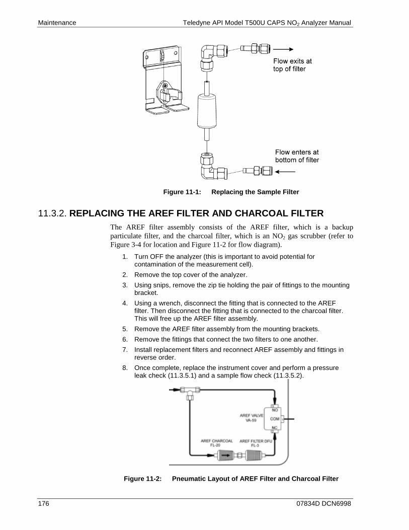
Maintenance Teledyne API Model T500U CAPS NO2 Analyzer Manual
176 07834D DCN6998
Figure 11-1: Replacing the Sample Filter
REPLACING THE AREF FILTER AND CHARCOAL FILTER 11.3.2.The AREF filter assembly consists of the AREF filter, which is a backup particulate filter, and the charcoal filter, which is an NO2 gas scrubber (refer to Figure 3-4 for location and Figure 11-2 for flow diagram).
1. Turn OFF the analyzer (this is important to avoid potential for contamination of the measurement cell).
2. Remove the top cover of the analyzer. 3. Using snips, remove the zip tie holding the pair of fittings to the mounting
bracket. 4. Using a wrench, disconnect the fitting that is connected to the AREF
filter. Then disconnect the fitting that is connected to the charcoal filter. This will free up the AREF filter assembly.
5. Remove the AREF filter assembly from the mounting brackets. 6. Remove the fittings that connect the two filters to one another. 7. Install replacement filters and reconnect AREF assembly and fittings in
reverse order. 8. Once complete, replace the instrument cover and perform a pressure
leak check (11.3.5.1) and a sample flow check (11.3.5.2).
Figure 11-2: Pneumatic Layout of AREF Filter and Charcoal Filter
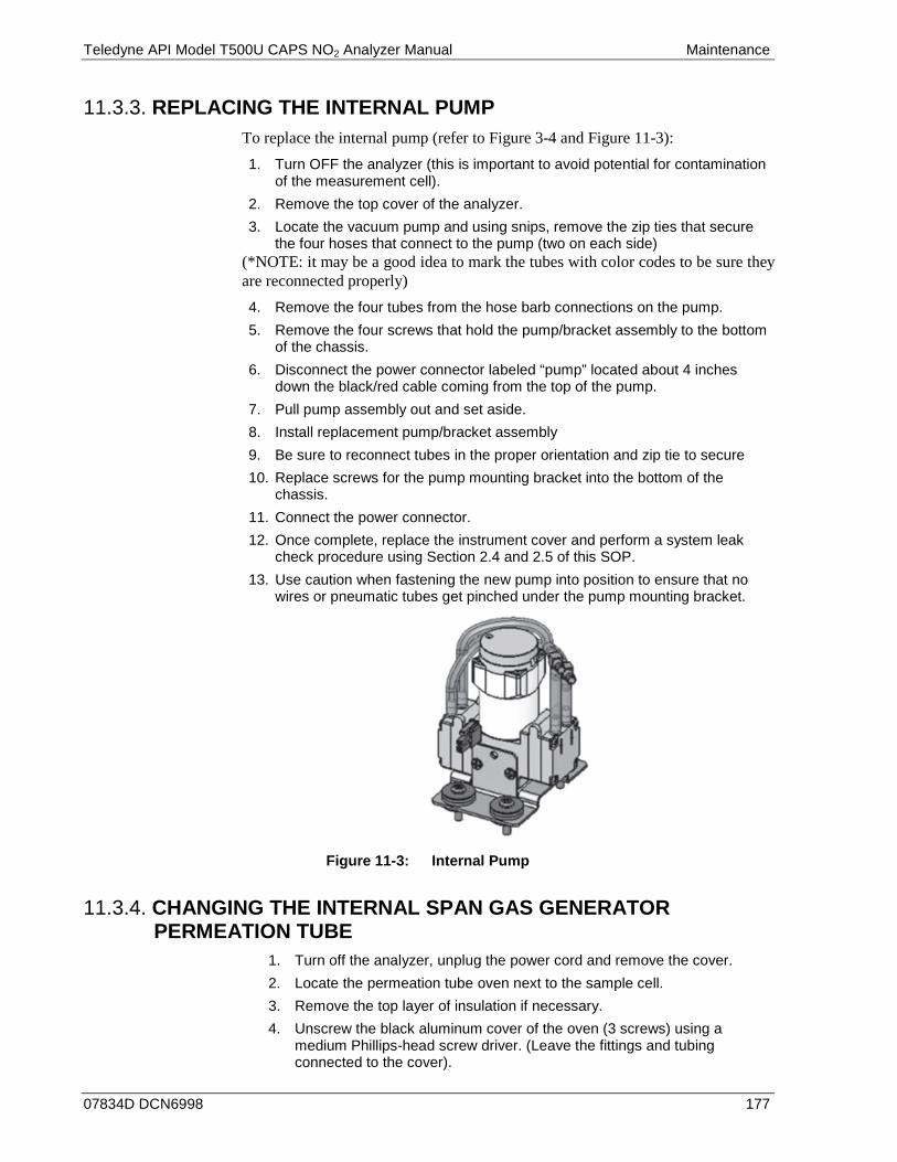
Teledyne API Model T500U CAPS NO2 Analyzer Manual Maintenance
07834D DCN6998 177
REPLACING THE INTERNAL PUMP 11.3.3.To replace the internal pump (refer to Figure 3-4 and Figure 11-3): 1. Turn OFF the analyzer (this is important to avoid potential for contamination
of the measurement cell). 2. Remove the top cover of the analyzer. 3. Locate the vacuum pump and using snips, remove the zip ties that secure
the four hoses that connect to the pump (two on each side) (*NOTE: it may be a good idea to mark the tubes with color codes to be sure they are reconnected properly) 4. Remove the four tubes from the hose barb connections on the pump. 5. Remove the four screws that hold the pump/bracket assembly to the bottom
of the chassis. 6. Disconnect the power connector labeled “pump” located about 4 inches
down the black/red cable coming from the top of the pump. 7. Pull pump assembly out and set aside. 8. Install replacement pump/bracket assembly 9. Be sure to reconnect tubes in the proper orientation and zip tie to secure 10. Replace screws for the pump mounting bracket into the bottom of the
chassis. 11. Connect the power connector. 12. Once complete, replace the instrument cover and perform a system leak
check procedure using Section 2.4 and 2.5 of this SOP. 13. Use caution when fastening the new pump into position to ensure that no
wires or pneumatic tubes get pinched under the pump mounting bracket.
Figure 11-3: Internal Pump
CHANGING THE INTERNAL SPAN GAS GENERATOR 11.3.4.PERMEATION TUBE
1. Turn off the analyzer, unplug the power cord and remove the cover. 2. Locate the permeation tube oven next to the sample cell. 3. Remove the top layer of insulation if necessary. 4. Unscrew the black aluminum cover of the oven (3 screws) using a
medium Phillips-head screw driver. (Leave the fittings and tubing connected to the cover).
Maintenance Teledyne API Model T500U CAPS NO2 Analyzer Manual
178 07834D DCN6998
5. Remove the old permeation tube and replace it with the new tube. (Ensure that the tube is placed into the larger of two holes and that the open permeation end of the tube (plastic) is facing up).
6. Re-attach the cover with three screws (Ensure that the three screws are tightened evenly).
7. Replace the analyzer cover, plug the power cord back in and turn on the analyzer.
8. Carry out a span check to see if the new permeation device works properly (see Section 10.3.2).
9. The permeation rate may need several days to stabilize.
ATTENTION COULD DAMAGE INSTRUMENT AND VOID WARRANTY Do not leave instrument turned off for more than 8 hours without removing the permeation tube. Do not ship the instrument without removing the permeation tube. The tube continues to emit NO2, even at room temperature and will contaminate the entire instrument.
CHECKING FOR PNEUMATIC LEAKS 11.3.5.
CAUTION - TECHNICAL INFORMATION Do not exceed 10 psi when pressurizing the system during either Sample Flow
checks or Detailed Leak checks.
DETAILED PRESSURE LEAK CHECK 11.3.5.1.
Obtain a leak checker that has a small pump, shut-off valve, and pressure gauge to create an over-pressure condition. Alternatively, a tank of pressurized gas, with the two-stage regulator adjusted to ≤ 10 psi, a shutoff valve and a pressure gauge may be used.
ATTENTION COULD DAMAGE INSTRUMENT AND VOID WARRANTY Once tube fittings have been wetted with soap solution under a pressurized system, do not apply or reapply vacuum as this will cause soap solution to be sucked into the instrument, contaminating inside surfaces.
1. Turn OFF power to the instrument and remove the instrument cover. 2. Install a leak checker on the sample inlet at the rear panel. 3. Cap rear panel ports and cap the pump port.
• If zero/span valves are installed, disconnect the tubing from the zero and span gas ports and cap the ports (Figure 3-3).
4. Pressurize the instrument with the leak checker, allowing enough time to fully pressurize the instrument. • Do not exceed 10 psi pressure.
Teledyne API Model T500U CAPS NO2 Analyzer Manual Maintenance
07834D DCN6998 179
5. Once the leak has been located and repaired, the leak-down rate of the indicated pressure should be less than 1 psi in 5 minutes after the pressure is turned off. Replace the instrument cover and restart the analyzer.
6. If the leak still cannot be found, check each tube connection (fittings, hose clamps) with soap bubble solution, looking for fine bubbles. • Pressurize the instrument with the leak checker, allowing enough
time to fully pressurize the instrument. • Do not exceed 10 psi pressure. • Wet the bench last with soap solution.
ATTENTION COULD DAMAGE INSTRUMENT AND VOID WARRANTY Once the fittings have been wetted with soap solution, do not reapply vacuum as doing so will draw soap solution into the instrument and contaminate it.
• 7. Clean surfaces from soap solution, reconnect the sample and pump lines
and replace the instrument cover. 8. Restart the analyzer.
PERFORMING A SAMPLE FLOW CHECK 11.3.5.2.
IMPORTANT IMPACT ON READINGS OR DATA Use a calibrated flow meter capable of measuring flows between 0 and 1000 cm³/min to measure the gas flow rate though the analyzer.
Sample flow checks are useful for monitoring the actual flow of the instrument. A decreasing sample flow may point to slowly clogging pneumatic paths, most likely the sample flow restrictor or the sample filter. To perform a sample flow check:
1. Disconnect the sample inlet tubing from the rear panel SAMPLE port. 2. Attach the outlet port of a flow meter to the sample inlet port on the rear
panel. • Ensure that the inlet to the flow meter is at atmospheric pressure.
3. Check that the sample flow measured with the external flow meter is within specification.
4. If sample flow is out of specification, first check for kinks in the tubing, then check for leaks (Section 11.3.5.1). Once kinks and leaks are ruled out, first replace the sample flow restrictor (see Figure 3-4 for location), and if the sample flow is still out of specification, replace the sample filter (Section 11.3.1).
If sample flow is still out of spec, call Technical Support.

Maintenance Teledyne API Model T500U CAPS NO2 Analyzer Manual
180 07834D DCN6998
This page intentionally left blank.
07834D DCN6998 181
12. EPA PROTOCOL CALIBRATION For U.S. EPA compliance monitoring, always calibrate this instrument prior to use, adhering to the EPA designation conditions for operation (Section 2.2). Pay strict attention to the built-in warning features of the analyzer, periodic inspection, regular zero/span checks, regular evaluation of test parameters for predictive diagnostics and data analysis, and routine maintenance. Any instrument(s) supplying the zero air and span calibration gasses used must themselves be calibrated, and that calibration must be traceable to an EPA/NIST primary standard.
Comply with Code of Federal Regulations, Title 40 (downloadable from the U.S. Government Publishing Office at http://www.gpo.gov/fdsys/) and with Quality Assurance Guidance documents (available on the EPA website, http://www.epa.gov/ttn/amtic/qalist.html). Give special attention to specific regulations regarding the use and operation of ambient NOx analyzers.

EPA Protocol Calibration Teledyne API Model T500U CAPS NO2 Analyzer Manual
182 07834D DCN6998
This page intentionally left blank.
07834D DCN6998 183
13. TROUBLESHOOTING AND SERVICE This section contains a variety of methods for identifying the source of performance problems with the analyzer. Also included in this section are procedures that are used in repairing the instrument.
Note: To support your understanding of the technical details of maintenance, Section 14, Principles of Operation, provides information about how the instrument works.
CAUTION The operations outlined in this section must be performed by qualified maintenance personnel only.
WARNING RISK OF ELECTRICAL SHOCK
Some operations need to be carried out with the analyzer open and running. Exercise caution to avoid electrical shocks and electrostatic or mechanical damage to the analyzer. Do not drop tools into the analyzer or leave those after your procedures. Do not short or touch electric connections with metallic tools while operating inside the analyzer. Use common sense when operating inside a running analyzer.
Note The front panel of the analyzer is hinged at the bottom and may be opened to gain access to various components mounted on the panel itself or located near the front of the instrument (such as the sample filter). Remove the locking screw located at the right-hand side of the front panel.

Troubleshooting and Service Teledyne API Model T500U CAPS NO2 Analyzer Manual
184 07834D DCN6998
GENERAL TROUBLESHOOTING 13.1.The T500U has been designed so that problems can be rapidly detected, evaluated and repaired. During operation, it continuously performs diagnostic tests and provides the ability to evaluate its key operating parameters without disturbing monitoring operations.
A systematic approach to troubleshooting will generally consist of the following five steps:
• Note any WARNING MESSAGES and take corrective action as necessary.
• Examine the values of all TEST functions and compare them to factory values. Note any major deviations from the factory values and take corrective action.
• Use the internal electronic status LEDs to determine whether the electronic communication channels are operating properly.
• Verify that the DC power supplies are operating properly by checking the voltage test points on the relay PCA.
• Note that the analyzer’s DC power wiring is color-coded and these colors match the color of the corresponding test points on the relay PCA.
• Suspect a leak first!
• Technical Support data indicate that the majority of all problems are eventually traced to leaks in the internal pneumatics of the analyzer or the diluent gas and source gases delivery systems (refer to Section 11.3.5).
• Check for gas flow problems such as clogged or blocked internal/external gas lines, damaged seals, punctured gas lines, a damaged / malfunctioning pumps, etc.
FAULT DIAGNOSIS WITH WARNING MESSAGES 13.1.1.The most common and/or serious instrument failures will result in a warning message being displayed on the front panel. Table 13-1 lists warning messages, along with their meaning and recommended corrective action.
It should be noted that if more than two or three warning messages occur at the same time, it is often an indication that some fundamental sub-system (power supply, relay PCA motherboard) has failed rather than an indication of the specific failures referenced by the warnings.
The analyzer will alert the user that a Warning Message is active by flashing the FAULT LED and displaying the Warning message in the Param field along with the CLR button (press to clear Warning message). The MSG button displays if there is more than one warning in queue, or if you are in the TEST menu and have not yet cleared the message.
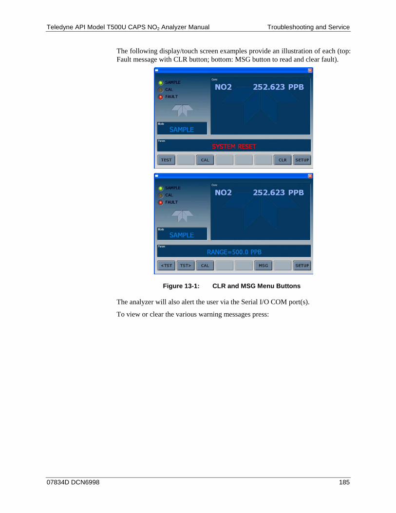
Teledyne API Model T500U CAPS NO2 Analyzer Manual Troubleshooting and Service
07834D DCN6998 185
The following display/touch screen examples provide an illustration of each (top: Fault message with CLR button; bottom: MSG button to read and clear fault).
Figure 13-1: CLR and MSG Menu Buttons
The analyzer will also alert the user via the Serial I/O COM port(s).
To view or clear the various warning messages press:
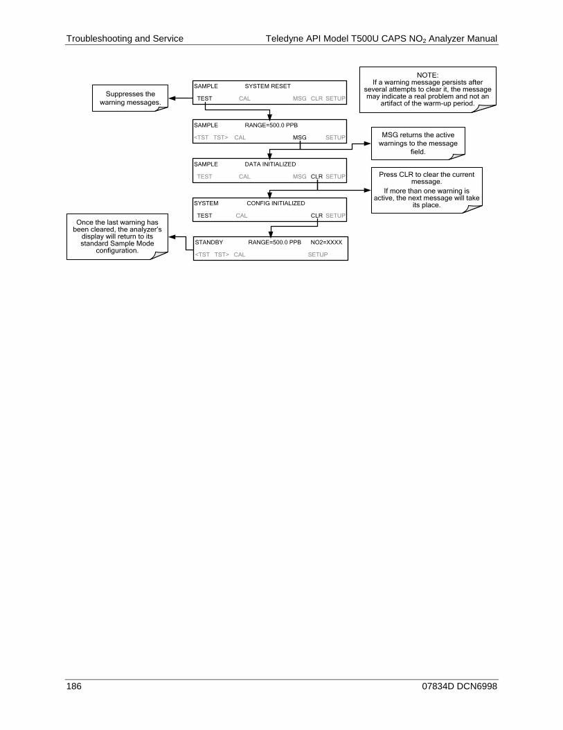
Troubleshooting and Service Teledyne API Model T500U CAPS NO2 Analyzer Manual
186 07834D DCN6998
Suppresses the warning messages.
Press CLR to clear the current message.
If more than one warning is active, the next message will take
its place.
Once the last warning has been cleared, the analyzer’s
display will return to its standard Sample Mode
configuration.
NOTE:If a warning message persists after
several attempts to clear it, the message may indicate a real problem and not an
artifact of the warm-up period.
SAMPLE SYSTEM RESET
TEST CAL MSG CLR SETUP
SAMPLE RANGE=500.0 PPB
<TST TST> CAL MSG SETUP
SAMPLE DATA INITIALIZED
TEST CAL MSG CLR SETUP
SYSTEM CONFIG INITIALIZED
TEST CAL CLR SETUP
MSG returns the active warnings to the message
field.
STANDBY RANGE=500.0 PPB NO2=XXXX
<TST TST> CAL SETUP
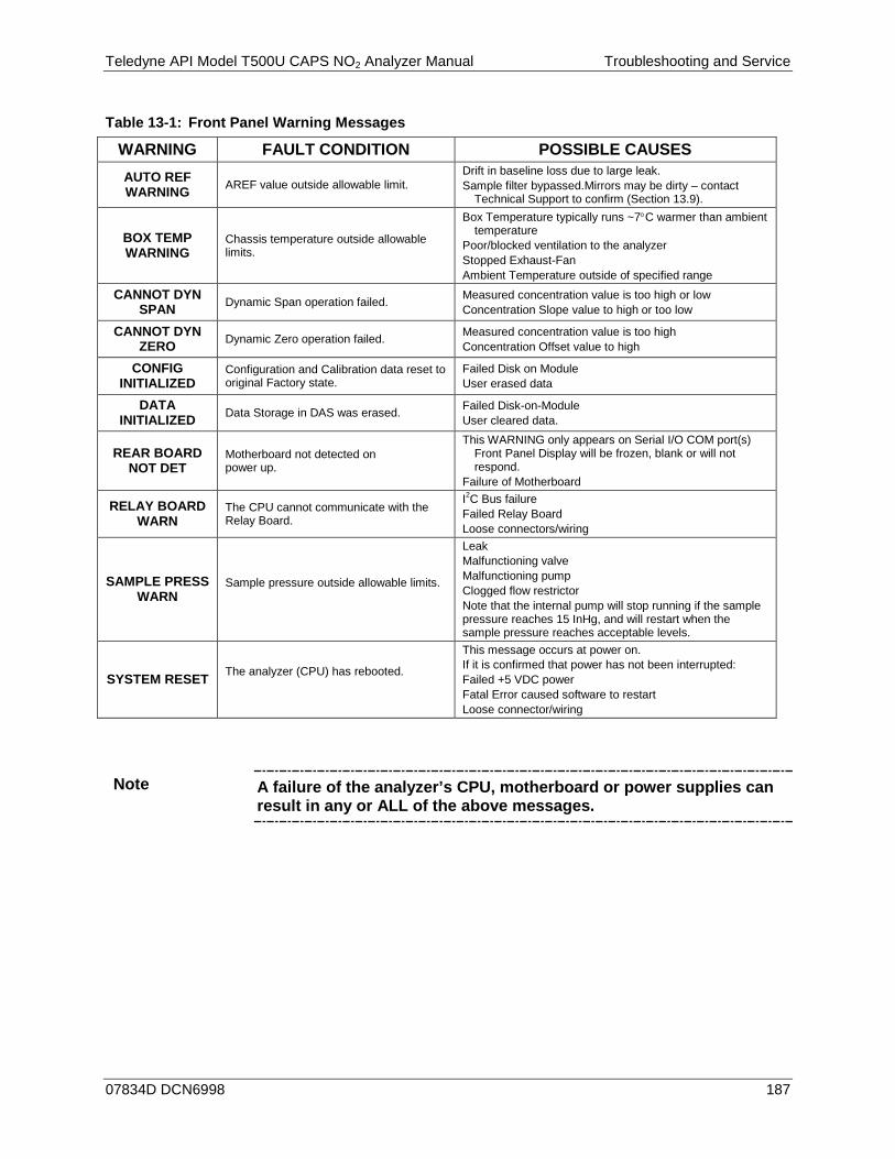
Teledyne API Model T500U CAPS NO2 Analyzer Manual Troubleshooting and Service
07834D DCN6998 187
Table 13-1: Front Panel Warning Messages
WARNING FAULT CONDITION POSSIBLE CAUSES
AUTO REF WARNING AREF value outside allowable limit.
Drift in baseline loss due to large leak. Sample filter bypassed.Mirrors may be dirty – contact
Technical Support to confirm (Section 13.9).
BOX TEMP WARNING
Chassis temperature outside allowable limits.
Box Temperature typically runs ~7°C warmer than ambient temperature
Poor/blocked ventilation to the analyzer Stopped Exhaust-Fan Ambient Temperature outside of specified range
CANNOT DYN SPAN Dynamic Span operation failed. Measured concentration value is too high or low
Concentration Slope value to high or too low
CANNOT DYN ZERO Dynamic Zero operation failed. Measured concentration value is too high
Concentration Offset value to high
CONFIG INITIALIZED
Configuration and Calibration data reset to original Factory state.
Failed Disk on Module User erased data
DATA INITIALIZED Data Storage in DAS was erased. Failed Disk-on-Module
User cleared data.
REAR BOARD NOT DET
Motherboard not detected on power up.
This WARNING only appears on Serial I/O COM port(s) Front Panel Display will be frozen, blank or will not respond.
Failure of Motherboard
RELAY BOARD WARN
The CPU cannot communicate with the Relay Board.
I2C Bus failure Failed Relay Board Loose connectors/wiring
SAMPLE PRESS WARN
Sample pressure outside allowable limits.
Leak Malfunctioning valve Malfunctioning pump Clogged flow restrictor Note that the internal pump will stop running if the sample pressure reaches 15 InHg, and will restart when the sample pressure reaches acceptable levels.
SYSTEM RESET The analyzer (CPU) has rebooted.
This message occurs at power on. If it is confirmed that power has not been interrupted: Failed +5 VDC power Fatal Error caused software to restart Loose connector/wiring
Note A failure of the analyzer’s CPU, motherboard or power supplies can result in any or ALL of the above messages.
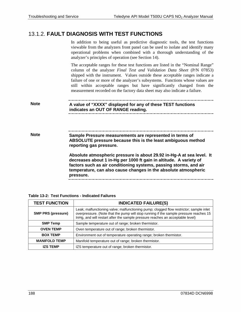
Troubleshooting and Service Teledyne API Model T500U CAPS NO2 Analyzer Manual
188 07834D DCN6998
FAULT DIAGNOSIS WITH TEST FUNCTIONS 13.1.2.In addition to being useful as predictive diagnostic tools, the test functions viewable from the analyzers front panel can be used to isolate and identify many operational problems when combined with a thorough understanding of the analyzer’s principles of operation (see Section 14).
The acceptable ranges for these test functions are listed in the “Nominal Range” column of the analyzer Final Test and Validation Data Sheet (P/N 07853) shipped with the instrument. Values outside these acceptable ranges indicate a failure of one or more of the analyzer’s subsystems. Functions whose values are still within acceptable ranges but have significantly changed from the measurement recorded on the factory data sheet may also indicate a failure.
Note A value of “XXXX” displayed for any of these TEST functions indicates an OUT OF RANGE reading.
Note Sample Pressure measurements are represented in terms of ABSOLUTE pressure because this is the least ambiguous method reporting gas pressure.
Absolute atmospheric pressure is about 29.92 in-Hg-A at sea level. It decreases about 1 in-Hg per 1000 ft gain in altitude. A variety of factors such as air conditioning systems, passing storms, and air temperature, can also cause changes in the absolute atmospheric pressure.
Table 13-2: Test Functions - Indicated Failures
TEST FUNCTION INDICATED FAILURE(S)
SMP PRS (pressure) Leak; malfunctioning valve; malfunctioning pump; clogged flow restrictor; sample inlet overpressure. (Note that the pump will stop running if the sample pressure reaches 15 InHg, and will restart after the sample pressure reaches an acceptable level)
SMP Temp Sample temperature out of range; broken thermistor. OVEN TEMP Oven temperature out of range; broken thermistor. BOX TEMP Environment out of temperature operating range; broken thermistor.
MANIFOLD TEMP Manifold temperature out of range; broken thermistor. IZS TEMP IZS temperature out of range; broken thermistor.

Teledyne API Model T500U CAPS NO2 Analyzer Manual Troubleshooting and Service
07834D DCN6998 189
DIAG > SIGNAL I/O: USING THE DIAGNOSTIC SIGNAL I/O 13.1.3.FUNCTION
The signal I/O diagnostic mode allows access to the digital and analog I/O in the analyzer. Some of the digital signals can be controlled through the touchscreen. These signals are useful for troubleshooting in three ways:
• The technician can view the raw, unprocessed signal level of the analyzer’s critical inputs and outputs.
• Many of the components and functions that are normally under algorithmic control of the CPU can be manually exercised.
• The technician can directly control the signal level Analog and Digital Output signals.
This allows the technician to observe systematically the effect of directly controlling these signals on the operation of the analyzer. Following is an example of how to use the Signal I/O menu to view the raw voltage of an input signal or to control the state of an output voltage or control signal.
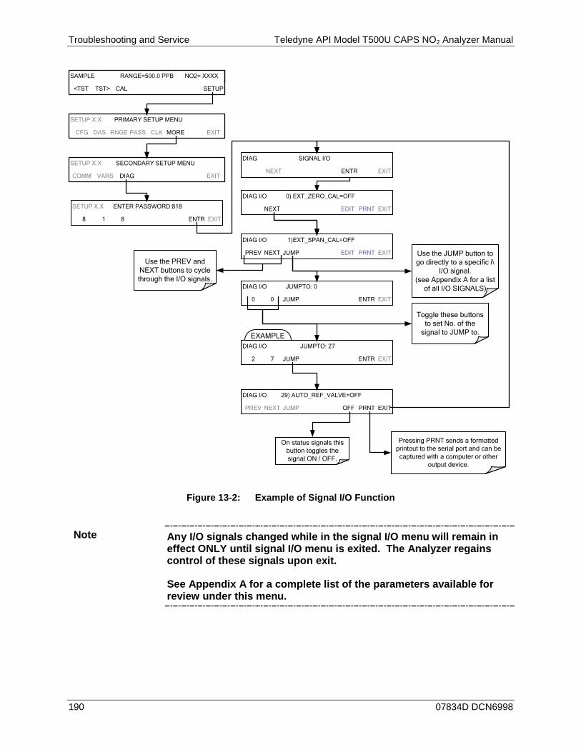
Troubleshooting and Service Teledyne API Model T500U CAPS NO2 Analyzer Manual
190 07834D DCN6998
SAMPLE RANGE=500.0 PPB NO2= XXXX
<TST TST> CAL SETUP
SETUP X.X SECONDARY SETUP MENU
COMM VARS DIAG EXIT
EXAMPLE
DIAG I/O 0) EXT_ZERO_CAL=OFF
NEXT EDIT PRNT EXIT
Use the PREV and NEXT buttons to cycle through the I/O signals.
DIAG I/O 1)EXT_SPAN_CAL=OFF
PREV NEXT JUMP EDIT PRNT EXIT Use the JUMP button to go directly to a specific i\
I/O signal. (see Appendix A for a list
of all I/O SIGNALS)DIAG I/O JUMPTO: 0
0 0 JUMP ENTR EXIT
Toggle these buttons to set No. of the
signal to JUMP to.
DIAG I/O JUMPTO: 27
2 7 JUMP ENTR EXIT
DIAG I/O 29) AUTO_REF_VALVE=OFF
PREV NEXT JUMP OFF PRNT EXIT
Pressing PRNT sends a formatted printout to the serial port and can be captured with a computer or other
output device.
SETUP X.X ENTER PASSWORD:818
8 1 8 ENTR EXIT
DIAG SIGNAL I/O
NEXT ENTR EXIT
On status signals this button toggles the signal ON / OFF.
SETUP X.X PRIMARY SETUP MENU
CFG DAS RNGE PASS CLK MORE EXIT
Figure 13-2: Example of Signal I/O Function
Note Any I/O signals changed while in the signal I/O menu will remain in effect ONLY until signal I/O menu is exited. The Analyzer regains control of these signals upon exit.
See Appendix A for a complete list of the parameters available for review under this menu.

Teledyne API Model T500U CAPS NO2 Analyzer Manual Troubleshooting and Service
07834D DCN6998 191
USING THE ANALOG OUTPUT TEST CHANNEL 13.2.The signals available for output over the T500U’s analog output channel can also be used as diagnostic tools. See Section 6.8.2 for instruction on activating the analog output and selecting a function. See Table 13-1 for possible causes of extremely high or low readings.
USING THE INTERNAL ELECTRONIC STATUS LEDS 13.3.Several LEDs are located inside the instrument to assist in determining if the analyzer’s CPU, I2C bus and Relay PCA are functioning properly.
CPU STATUS INDICATOR 13.3.1.DS5, a red LED, that is located on upper portion of the motherboard, just to the right of the CPU board, flashes when the CPU is running the main program loop. After power-up, approximately 30 – 60 seconds, DS5 should flash on and off. If characters are written to the front panel display but DS5 does not flash then the program files have become corrupted, contact Teledyne API's Technical Support Department (see Section 13.9) because it may be possible to recover operation of the analyzer. If after 30 – 60 seconds, neither DS5 is flashing nor have any characters been written to the front panel display then the CPU is bad and must be replaced.
Motherboard
CPU Status LED
Figure 13-3: CPU Status Indicator
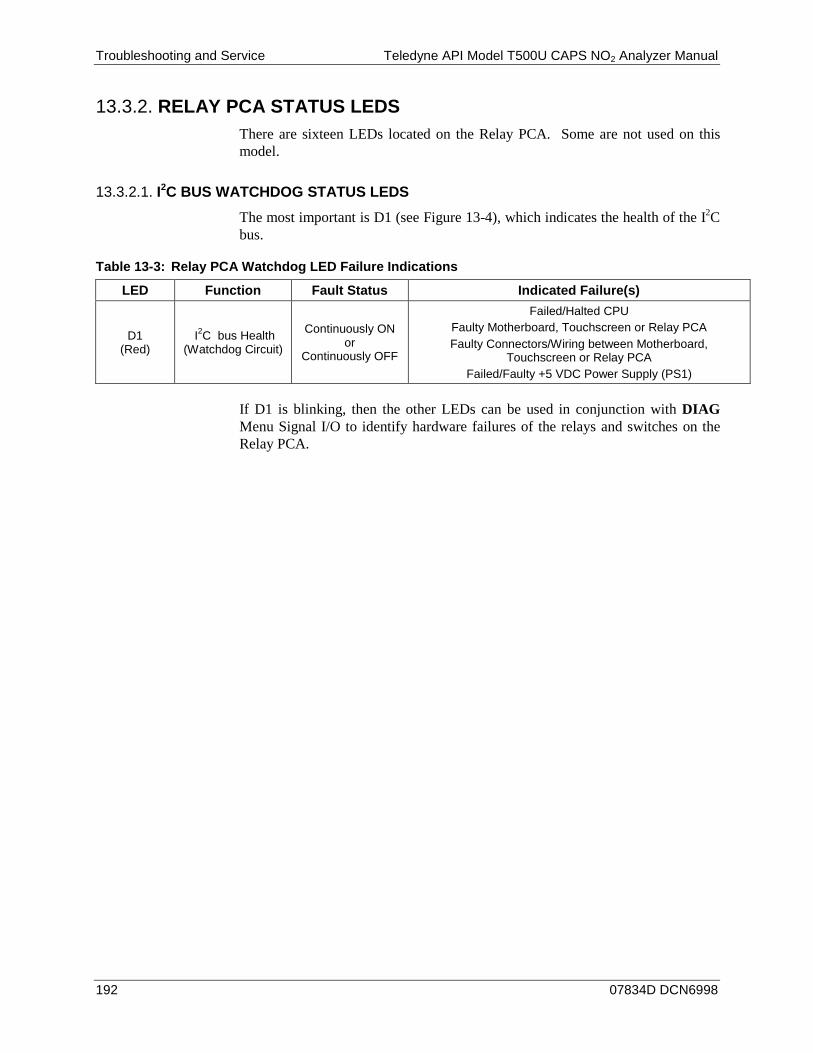
Troubleshooting and Service Teledyne API Model T500U CAPS NO2 Analyzer Manual
192 07834D DCN6998
RELAY PCA STATUS LEDS 13.3.2.There are sixteen LEDs located on the Relay PCA. Some are not used on this model.
I2C BUS WATCHDOG STATUS LEDS 13.3.2.1.
The most important is D1 (see Figure 13-4), which indicates the health of the I2C bus.
Table 13-3: Relay PCA Watchdog LED Failure Indications
LED Function Fault Status Indicated Failure(s)
D1 (Red)
I2C bus Health (Watchdog Circuit)
Continuously ON or
Continuously OFF
Failed/Halted CPU Faulty Motherboard, Touchscreen or Relay PCA Faulty Connectors/Wiring between Motherboard,
Touchscreen or Relay PCA Failed/Faulty +5 VDC Power Supply (PS1)
If D1 is blinking, then the other LEDs can be used in conjunction with DIAG Menu Signal I/O to identify hardware failures of the relays and switches on the Relay PCA.

Teledyne API Model T500U CAPS NO2 Analyzer Manual Troubleshooting and Service
07834D DCN6998 193
RELAY PCA STATUS LEDS 13.3.2.2.
D7 (Green) – Optional Zero/Span Valve
D4 (Yellow) Manifold Heater
D5 (Yellow) – Optional Internal Zero/Span Heater
D8 (Green) – Optional Sample/Cal Valve
D1 (RED) Watchdog Indicator
D9 (Green) – AUTO-REF Valve
D6 (Green) – Oven Heater
D16 (Green) – Internal Pump
Figure 13-4: Relay PCA Status LEDS Used for Troubleshooting
Table 13-4: Relay PCA Status LED Failure Indications
LED COLOR COMPONENT FAULT STATUS INDICATED FAILURE(S)
LED ROW 1 D2-D3 spares
D4 Yellow Manifold heater Continuously ON or OFF Heater broken, thermistor broken
D7 Green Internal Zero/Span (option) valve Continuously ON or OFF Valve broken or stuck, valve driver chip broken
D8 Green Sample/Cal valve (option) Continuously ON or OFF Valve broken or stuck, valve driver chip broken
D9 Green Auto Reference valve Continuously ON or OFF Valve broken or stuck, valve driver chip broken
D10 spare
LED ROW 2
D5 Yellow Internal Zero/Span (option) heater
Continuously ON or OFF Heater broken, thermocouple broken
D6 Green Oven heater Continuously ON or OFF Heater broken, thermistor broken
D11-15 spares
D16 Green Internal pump Continuously ON or OFF Not receiving power; relay board bad

Troubleshooting and Service Teledyne API Model T500U CAPS NO2 Analyzer Manual
194 07834D DCN6998
CALIBRATION PROBLEMS 13.4.This section describes possible causes of calibration problems.
NEGATIVE CONCENTRATIONS 13.4.1.A negative concentration value can be caused by calibration error: If the zero air were contaminated, and the analyzer was calibrated at “zero”, the analyzer may report a negative value when measuring air that contains little or no NO2.
NO RESPONSE 13.4.2.If the instrument shows no response (display value is near zero) even though sample gas is supplied properly and the instrument seems to perform correctly. 1. Confirm the lack of response by supplying or NO2 span gas of about 80% of
the range value to the analyzer. 2. Check the sample flow rate for proper value. 3. Check for disconnected cables to the sensor module.
UNSTABLE ZERO AND SPAN 13.4.3.Leaks in the T500U or in the external gas supply and vacuum systems are the most common source of unstable and non-repeatable concentration readings. 1. Check for leaks in the pneumatic systems as described in Section 11.3.5. 2. Consider pneumatic components in the gas delivery system outside the
T500U such as a change in zero air source (ambient air leaking into zero air line or a worn-out zero air scrubber) or a change in the span gas concentration due to zero air or ambient air leaking into the span gas line.
3. Once the instrument passes a leak check, do a flow check (this chapter) to ensure that the instrument is supplied with adequate sample air.
4. Confirm the sample pressure, sample temperature, and sample flow readings are correct and steady.
5. Verify that the sample filter element is clean and does not need to be replaced.
Teledyne API Model T500U CAPS NO2 Analyzer Manual Troubleshooting and Service
07834D DCN6998 195
INABILITY TO SPAN - NO SPAN BUTTON (CALS) 13.4.4.In general, the T500U will not display certain buttons whenever the actual value of a parameter is outside of the expected range for that parameter. If the calibration menu does not show a SPAN button when carrying out a span calibration, the actual concentration must be outside of the range of the expected span gas concentration, which can have several reasons. 1. Verify that the expected concentration is set properly to the actual span gas
concentration in the CONC sub-menu. 2. Confirm that the span gas source is accurate.
• This can be done by comparing the source with another calibrated analyzer, or by having the span gas source verified by an independent traceable photometer.
3. Check for leaks in the pneumatic systems as described in Section 11.3.5. • Leaks can dilute the span gas and, hence, the concentration that the
analyzer measures may fall short of the expected concentration defined in the CONC sub-menu.
4. If the low-level, hardware calibration has drifted or was accidentally altered by the user, a low-level calibration may be necessary to get the analyzer back into its proper range of expected values. • One possible indicator of this scenario is a slope or offset value that is
outside of its allowed range (0.8-1.2 for slope, -10 to 10 for offsets.
INABILITY TO ZERO - NO ZERO BUTTON (CALZ) 13.4.5.In general, the T500U will not display certain buttons whenever the actual value of a parameter is outside of the expected range for that parameter. If the calibration menu does not show a ZERO button when carrying out a zero calibration, the actual gas concentration must be significantly different from the actual zero point (as per last calibration), which may be for any of several reasons.
• Confirm that there is a good source of zero air.
• Check to ensure that there is no ambient air leaking into the zero air line.
• Check for leaks in the pneumatic systems as described in Section 11.3.5.

Troubleshooting and Service Teledyne API Model T500U CAPS NO2 Analyzer Manual
196 07834D DCN6998
NON-LINEAR RESPONSE 13.4.6.The T500U was factory calibrated to a high level of NO2 and should be linear to within 1% of full scale. Common causes for non-linearity are:
• Leaks in the pneumatic system:
• Leaks can add an offset signal to the ambient sample, zero air or span gas, whose concentration can fluctuate while a linearity test is being performed.
• Check for leaks as described in Section 11.3.5.
• The calibration device is in error:
• Check flow rates and concentrations, particularly when using low concentrations.
• If a mass flow calibrator is used and the flow is less than 10% of the full scale flow on either flow controller, you may need to purchase lower concentration standards.
• The standard gases may be mislabeled as to type or concentration.
• Labeled concentrations may be outside the certified tolerance.
• The sample delivery system may be contaminated.
• Check for dirt in the sample lines.
• Dilution air contains sample or span gas. • Incoming concentrations may not be linear.
• Check input bottles.
• Span gas overflow is not properly vented and creates a back-pressure on the sample inlet port.
• Also, if the span gas is not vented at all and does not supply enough sample gas, the analyzer may be evacuating the sample line.
• Ensure to create and properly vent excess span gas.
DISCREPANCY BETWEEN ANALOG OUTPUT AND DISPLAY 13.4.7.If the concentration reported through the analog outputs does not agree with the value reported on the front panel, you may need to recalibrate the analog outputs.
• This becomes more likely when using a low concentration or low analog output range.
• Analog outputs running at 0.1 V full scale should always be calibrated manually.
• See Section 6.8.3.2 for a detailed description of this procedure.

Teledyne API Model T500U CAPS NO2 Analyzer Manual Troubleshooting and Service
07834D DCN6998 197
OTHER PERFORMANCE PROBLEMS 13.5.Dynamic problems (i.e. problems that only manifest themselves when the analyzer is monitoring sample gas) can be the most difficult and time consuming to isolate and resolve. The following section provides an itemized list of the most common dynamic problems with recommended troubleshooting checks and corrective actions.
EXCESSIVE NOISE 13.5.1.Excessive noise levels under normal operation usually indicate leaks in the sample supply or the analyzer itself. Ensure that the sample or span gas supply is leak-free and carry out a detailed leak check as described earlier in this chapter.
Other sources of measurement noise may be related to cabling issues. Gain access to the instrument, when powered down, and reset the cable connectors.
SLOW RESPONSE 13.5.2.If the analyzer starts responding too slowly to any changes in sample, zero or span gas, check for the following:
• Dirty or plugged sample filter or sample lines. • Sample inlet line is too long. • Dirty or plugged flow restrictor. Check flows, pressures and, if necessary,
change restrictor. • Wrong materials in contact with sample - use glass, stainless steel or Teflon
materials only. • Insufficient time allowed for purging of lines upstream of the analyzer. Wait
until stability is reached. • Insufficient time allowed for NO2 calibration gas source to become stable.
Wait until stability is reached.

Troubleshooting and Service Teledyne API Model T500U CAPS NO2 Analyzer Manual
198 07834D DCN6998
AREF WARNINGS 13.5.3.Auto Reference (AREF) warnings occur if the signal measured during an AREF cycle is higher than 1100 Mm-1.
Note There will not be an AREF warning if the AREF feature was disabled due to prolonged time in CAL mode. Ensure the instrument is returned to SAMPLE mode as soon as a calibration has been completed.
Note The AREF warning displays the value of the Auto Reference reading when the warning occurs.
If this value is higher than 1100 Mm-1, check that the Auto Reference valve is operating properly:
• In the DIAG menu go to SIGNAL I/O>AUTO_REF_VALVE to toggle the valve on and off.
• Listen to hear whether the valve is switching, and see if the respective LED on the relay board lights accordingly.
• Check the power supply to the valve (12 V to the valve should turn on and off when measured with a voltmeter).
Note It takes only a small leak across the ports of the valve to show excessive Auto Reference values when supplying high concentrations of span gas.
If the Auto Reference valve is working properly, then the problem could be due to dirty mirrors. Please contact Technical Support to confirm this and to rule out other possibilities (Section 13.9).
Teledyne API Model T500U CAPS NO2 Analyzer Manual Troubleshooting and Service
07834D DCN6998 199
SUBSYSTEM CHECKOUT 13.6.The preceding sections of this manual discussed a variety of methods for identifying possible sources of failures or performance problems within the analyzer. In most cases this included a list of possible causes and, in some cases, quick solutions or at least a pointer to the appropriate sections describing them. This section describes how to determine if a certain component or subsystem is actually the cause of the problem being investigated.
AC MAIN POWER 13.6.1.The T500U analyzer’s electronic systems will operate with any of the specified power regimes. As long as the system is connected to 100-120 VAC or 220-240 VAC at either 50 or 60 Hz it will turn on and after about 30 seconds show a front panel display.
• Internally, the status LEDs located on the Relay PCA, Motherboard and CPU should turn on as soon as the power is supplied.
• If they do not, check the circuit breaker built into the ON/OFF switch on the instruments front panel.
• If the instrument is equipped with an internal pump, it will begin to run. If it does not:
• Verify that the pump connection is mated correctly. • Verify that there are no kinks in the tubing that would restrict pump
operation. • Note that the pump will stop running if the sample pressure reaches 15
InHg, and will restart after the sample pressure reaches an acceptable level.
WARNING – ELECTRICAL SHOCK HAZARD Should the AC power circuit breaker trip, investigate and correct the condition
causing this situation before turning the analyzer back on.

Troubleshooting and Service Teledyne API Model T500U CAPS NO2 Analyzer Manual
200 07834D DCN6998
DC POWER SUPPLY 13.6.2.If you have determined that the analyzer’s AC mains power is working, but the unit is still not operating properly, there may be a problem with one of the instrument’s switching power supplies. The supplies can have two faults, namely no DC output, and noisy output.
To assist tracing DC Power Supply problems, the wiring used to connect the various printed circuit assemblies and DC Powered components and the associated test points on the relay PCA follow a standard color-coding scheme as defined in the following table.
Table 13-5: DC Power Test Point and Wiring Color Codes NAME TEST POINT# COLOR DEFINITION DGND 1 Black Digital ground
+5V 2 Red
AGND 3 Green Analog ground
+15V 4 Blue
-15V 5 Yellow
+12R 6 Purple 12 V return (ground) line
+12V 7 Orange
TP1 TP2 TP3 TP4 TP5 TP6 TP7 DGND +5V AGND +15V -15V +12R 12V
Figure 13-5: Location of DC Power Test Points on Relay PCA
A voltmeter should be used to verify that the DC voltages are correct per the values in the table below, and an oscilloscope, in AC mode, with band limiting turned on, can be used to evaluate if the supplies are producing excessive noise (> 100 mV p-p).
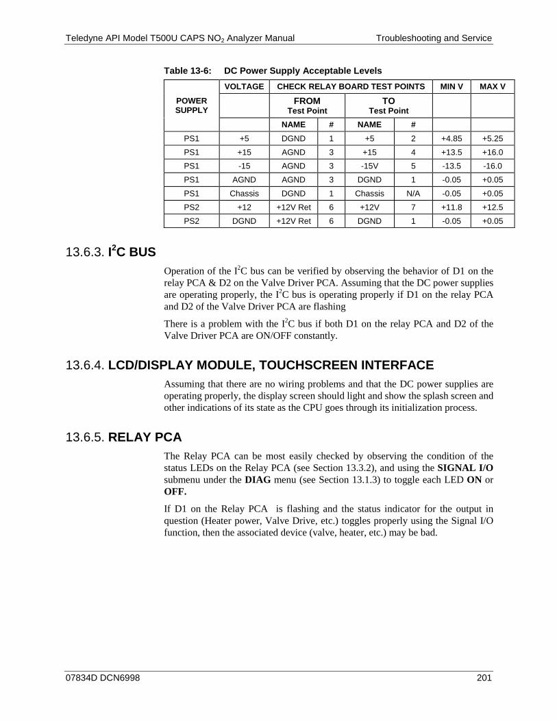
Teledyne API Model T500U CAPS NO2 Analyzer Manual Troubleshooting and Service
07834D DCN6998 201
Table 13-6: DC Power Supply Acceptable Levels
POWER SUPPLY
VOLTAGE CHECK RELAY BOARD TEST POINTS MIN V MAX V
FROM Test Point
TO Test Point
NAME # NAME # PS1 +5 DGND 1 +5 2 +4.85 +5.25
PS1 +15 AGND 3 +15 4 +13.5 +16.0
PS1 -15 AGND 3 -15V 5 -13.5 -16.0
PS1 AGND AGND 3 DGND 1 -0.05 +0.05
PS1 Chassis DGND 1 Chassis N/A -0.05 +0.05
PS2 +12 +12V Ret 6 +12V 7 +11.8 +12.5
PS2 DGND +12V Ret 6 DGND 1 -0.05 +0.05
I2C BUS 13.6.3.Operation of the I2C bus can be verified by observing the behavior of D1 on the relay PCA & D2 on the Valve Driver PCA. Assuming that the DC power supplies are operating properly, the I2C bus is operating properly if D1 on the relay PCA and D2 of the Valve Driver PCA are flashing
There is a problem with the I2C bus if both D1 on the relay PCA and D2 of the Valve Driver PCA are ON/OFF constantly.
LCD/DISPLAY MODULE, TOUCHSCREEN INTERFACE 13.6.4.Assuming that there are no wiring problems and that the DC power supplies are operating properly, the display screen should light and show the splash screen and other indications of its state as the CPU goes through its initialization process.
RELAY PCA 13.6.5.The Relay PCA can be most easily checked by observing the condition of the status LEDs on the Relay PCA (see Section 13.3.2), and using the SIGNAL I/O submenu under the DIAG menu (see Section 13.1.3) to toggle each LED ON or OFF.
If D1 on the Relay PCA is flashing and the status indicator for the output in question (Heater power, Valve Drive, etc.) toggles properly using the Signal I/O function, then the associated device (valve, heater, etc.) may be bad.
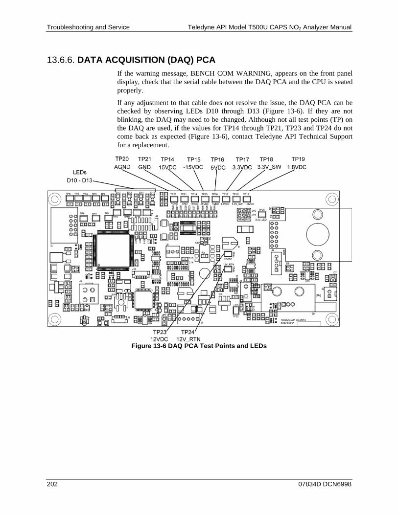
Troubleshooting and Service Teledyne API Model T500U CAPS NO2 Analyzer Manual
202 07834D DCN6998
DATA ACQUISITION (DAQ) PCA 13.6.6.If the warning message, BENCH COM WARNING, appears on the front panel display, check that the serial cable between the DAQ PCA and the CPU is seated properly.
If any adjustment to that cable does not resolve the issue, the DAQ PCA can be checked by observing LEDs D10 through D13 (Figure 13-6). If they are not blinking, the DAQ may need to be changed. Although not all test points (TP) on the DAQ are used, if the values for TP14 through TP21, TP23 and TP24 do not come back as expected (Figure 13-6), contact Teledyne API Technical Support for a replacement.
Figure 13-6 DAQ PCA Test Points and LEDs

Teledyne API Model T500U CAPS NO2 Analyzer Manual Troubleshooting and Service
07834D DCN6998 203
MOTHERBOARD 13.6.7.
TEST CHANNEL / ANALOG OUTPUTS VOLTAGE 13.6.7.1.
The ANALOG OUTPUT submenu, located under the SETUP > MORE > DIAG menu is used to verify that the T500U analyzer’s three analog outputs are working properly. The test generates a signal on all three outputs simultaneously as shown in the following table:
Table 13-7: Analog Output Test Function - Nominal Values Voltage Outputs
FULL SCALE OUTPUT OF VOLTAGE RANGE (see Section 6.8.3.1)
100MV 1V 5V 10V* STEP % NOMINAL OUTPUT VOLTAGE
1 0 0 0 0 0 2 20 20 mV 0.2 1 2 3 40 40 mV 0.4 2 4 4 60 60 mV 0.6 3 6 5 80 80 mV 0.8 4 8 6 100 100 mV 1.0 5 10
* For 10V output, increase the Analog Output Calibration Limits (AOUT CAL LIM in the DIAG>Analog I/O Config menu) to 4% (offset limit) and 20% (slope limit).
For each of the steps the output should be within 1% of the nominal value listed except for the 0% step, which should be within 0mV ±2 to 3 mV. Ensure you take into account any offset that may have been programmed into channel (See Section 6.8.3.9).
If one or more of the steps fails to be within these ranges, it is likely that there has been a failure of the either or both of the Digital-to-Analog Converters (DACs) and their associated circuitry on the motherboard. To perform the test connect a voltmeter to the output in question and perform an analog output step test as follows:
A/D FUNCTIONS 13.6.7.2.
The simplest method to check the operation of the A-to-D converter on the motherboard is to use the Signal I/O function under the DIAG menu to check the two A/D reference voltages and input signals that can be easily measured with a voltmeter. Use the Signal I/O function (see Section 13.1.3 and Appendix A) to view the
value of REF_4096_MV and REF_GND. • If both are within 3 mV of nominal (4096 and 0), and are stable, ±0.2 mV,
then the basic A/D is functioning properly. If not, then the motherboard is bad.
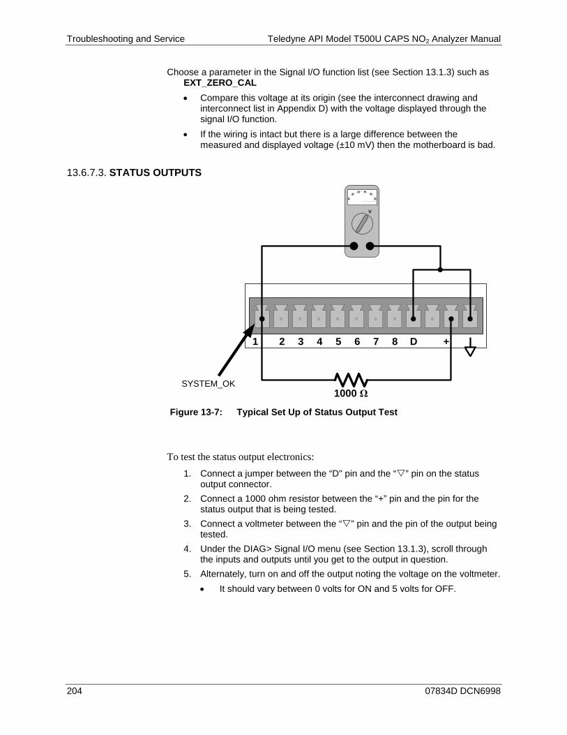
Troubleshooting and Service Teledyne API Model T500U CAPS NO2 Analyzer Manual
204 07834D DCN6998
Choose a parameter in the Signal I/O function list (see Section 13.1.3) such as EXT_ZERO_CAL • Compare this voltage at its origin (see the interconnect drawing and
interconnect list in Appendix D) with the voltage displayed through the signal I/O function.
• If the wiring is intact but there is a large difference between the measured and displayed voltage (±10 mV) then the motherboard is bad.
STATUS OUTPUTS 13.6.7.3.
Figure 13-7: Typical Set Up of Status Output Test
To test the status output electronics: 1. Connect a jumper between the “D" pin and the “” pin on the status
output connector. 2. Connect a 1000 ohm resistor between the “+” pin and the pin for the
status output that is being tested. 3. Connect a voltmeter between the “” pin and the pin of the output being
tested. 4. Under the DIAG> Signal I/O menu (see Section 13.1.3), scroll through
the inputs and outputs until you get to the output in question. 5. Alternately, turn on and off the output noting the voltage on the voltmeter.
• It should vary between 0 volts for ON and 5 volts for OFF.
1 2 3 84 D5 6 7 +
V +DC Gnd
1000 ΩSYSTEM_OK
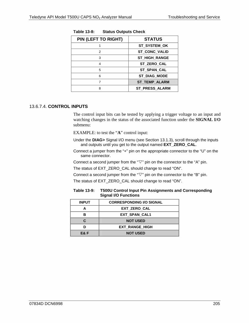
Teledyne API Model T500U CAPS NO2 Analyzer Manual Troubleshooting and Service
07834D DCN6998 205
Table 13-8: Status Outputs Check
PIN (LEFT TO RIGHT) STATUS 1 ST_SYSTEM_OK 2 ST_CONC_VALID 3 ST_HIGH_RANGE 4 ST_ZERO_CAL 5 ST_SPAN_CAL 6 ST_DIAG_MODE 7 ST_TEMP_ALARM
8 ST_PRESS_ALARM
CONTROL INPUTS 13.6.7.4.
The control input bits can be tested by applying a trigger voltage to an input and watching changes in the status of the associated function under the SIGNAL I/O submenu:
EXAMPLE: to test the “A” control input: Under the DIAG> Signal I/O menu (see Section 13.1.3), scroll through the inputs
and outputs until you get to the output named EXT_ZERO_CAL. Connect a jumper from the “+” pin on the appropriate connector to the “U” on the
same connector. Connect a second jumper from the “” pin on the connector to the “A” pin. The status of EXT_ZERO_CAL should change to read “ON”. Connect a second jumper from the “” pin on the connector to the “B” pin. The status of EXT_ZERO_CAL should change to read “ON”.
Table 13-9: T500U Control Input Pin Assignments and Corresponding Signal I/O Functions
INPUT CORRESPONDING I/O SIGNAL A EXT_ZERO_CAL B EXT_SPAN_CAL1 C NOT USED D EXT_RANGE_HIGH
E& F NOT USED
Troubleshooting and Service Teledyne API Model T500U CAPS NO2 Analyzer Manual
206 07834D DCN6998
CPU 13.6.8.There are two major types of CPU board failures, a complete failure and a failure associated with the Disk On Module (DOM). If either of these failures occurs, contact the factory.
For complete failures, assuming that the power supplies are operating properly and the wiring is intact, the CPU is faulty if on power-on, the watchdog LED on the motherboard is not flashing.
• In some rare circumstances, this failure may be caused by a bad IC on the motherboard, specifically U57, the large, 44 pin device on the lower right hand side of the board. If this is true, removing U57 from its socket will allow the instrument to start up but the measurements will be invalid.
• If the analyzer stops during initialization (the front panel display shows a fault or warning message), it is likely that the DOM, the firmware or the configuration and data files have been corrupted.
RS-232 COMMUNICATIONS 13.6.9.
GENERAL RS-232 TROUBLESHOOTING 13.6.9.1.
Teledyne API's analyzers use the RS-232 communications protocol to allow the instrument to be connected to a variety of computer-based equipment. RS-232 has been used for many years and as equipment has become more advanced, connections between various types of hardware have become increasingly difficult. Generally, every manufacturer observes the signal and timing requirements of the protocol very carefully.
Problems with RS-232 connections usually center around 4 general areas:
• Incorrect cabling and connectors. See Section 3.3.1.8, RS-232 Connection, and Figure 3-11 for connector and pin-out information.
• The BAUD rate and protocol are incorrectly configured. See Sections 3.3.1.8 and 7.2.2.
• If a modem is being used, additional configuration and wiring rules must be observed. See Section 9.3
• Incorrect setting of the DTE – DCE Switch. See Section 7.1 to set correctly. • Verify that cable (P/N 03596) that connects the serial COM ports of the CPU
to J12 of the motherboard is properly seated.
Teledyne API Model T500U CAPS NO2 Analyzer Manual Troubleshooting and Service
07834D DCN6998 207
TROUBLESHOOTING ANALYZER/MODEM OR TERMINAL OPERATION 13.6.9.2.
These are the general steps for troubleshooting problems with a modem connected to a Teledyne API's analyzer. 1. Check cables for proper connection to the modem, terminal or computer. 2. Check to ensure that the DTE-DCE is in the correct position as described in
Section 7.1. 3. Check to ensure that the set up command is correct (see Section 9.3). 4. Verify that the Ready to Send (RTS) signal is at logic high. The T500U sets
pin 7 (RTS) to greater than 3 volts to enable modem transmission. 5. Ensure that the BAUD rate, word length, and stop bit settings between
modem and analyzer match. See Section 7.2.2. 6. Use the RS-232 test function to send “w” characters to the modem, terminal
or computer. See Section 7.2.3. 7. Get your terminal, modem or computer to transmit data to the analyzer
(holding down the space bar is one way); the green LED should flicker as the instrument is receiving data.
8. Ensure that the communications software or terminal emulation software is functioning properly.
Note Further help with serial communications is available in a separate manual “RS-232 Programming Notes” Teledyne API's P/N 01350.
INTERNAL SPAN GAS GENERATOR AND VALVE OPTIONS 13.6.10.The zero/span valves and internal span gas generator options need to be enabled in the software (contact the factory on how to do this).
• Check for the physical presence of the valves or the IZS option. • Check front panel for correct software configuration. When the instrument is
in SAMPLE mode, the front panel display should show CALS and CALZ buttons in the second line of the display. The presence of the buttons indicates that the option has been enabled in software. In addition, the IZS option is enabled if the TEST functions show a parameter named IZS TEMP.
The semi-permeable PTFE membrane of the permeation tube is severely affected by humidity. Variations in humidity between day and night are usually enough to yield very variable output results. If the instrument is installed in an air-conditioned shelter, the air is usually dry enough to produce good results. If the instrument is installed in an environment with variable or high humidity, variations in the permeation tube output will be significant. In this case, a dryer for the supply air is recommended (dew point should be –20° C or less).
The permeation tube of the internal span gas generator option is heated with a proportional heater circuit and the temperature is maintained at 50°C ±1°C. Check the front panel display or the IZS_TEMP signal voltage using the SIGNAL I/O function under the DIAG Menu (Section 6.8.1). At 50° C, the temperature signal from the IZS thermistor should be around 2500 mV.
Troubleshooting and Service Teledyne API Model T500U CAPS NO2 Analyzer Manual
208 07834D DCN6998
TEMPERATURE SENSOR 13.6.11.
BOX TEMPERATURE SENSOR 13.6.11.1.
The box temperature sensor (thermistor) is mounted on the motherboard below the bottom edge of the CPU board when looking at it from the front. It cannot be disconnected to check its resistance.
• Box temperature will vary with, but will usually read about 5° C higher than, ambient (room) temperature because of the internal heating zones.
• To check the box temperature functionality, we recommend checking the BOX_TEMP signal voltage using the SIGNAL I/O function under the DIAG Menu (Section 13.1.3).
• At about 30° C, the signal should be around 1500 mV. • To check the accuracy of the sensor, use a calibrated external thermometer /
temperature sensor to verify the accuracy of the box temperature as follows:
• Place it inside the chassis, next to the thermistor labeled XT1 (above connector J108) on the motherboard.
• Compare its reading to the value of the test function BOX TEMP.

Teledyne API Model T500U CAPS NO2 Analyzer Manual Troubleshooting and Service
07834D DCN6998 209
SERVICE PROCEDURES 13.7.This section contains some procedures that may need to be performed when a major component of the analyzer requires repair or replacement.
Note Maintenance procedures (e.g., replacement of regularly changed expendables) are discussed in Section 11 and are not listed here).
Also, there may be more detailed service notes for some of the below procedures. Contact Teledyne API's Technical Support Department.
WARNING – ELECTRICAL SHOCK HAZARD Unless the procedure being performed requires the instrument be operating, turn it off and disconnect power before opening the analyzer and removing, adjusting or
repairing any of its components or subsystems.
CAUTION – QUALIFIED TECHNICIAN The operations outlined in this chapter are to be performed by qualified
maintenance personnel only.

Troubleshooting and Service Teledyne API Model T500U CAPS NO2 Analyzer Manual
210 07834D DCN6998
DISK-ON-MODULE REPLACEMENT PROCEDURE 13.7.1.
Note Servicing of circuit components requires electrostatic discharge (ESD) protection, i.e. ESD grounding straps, mats and containers. Failure to use ESD protection when working with electronic assemblies will void the instrument warranty. Please learn more about preventing ESD damage in our manual, Fundamentals of ESD, PN 04786, available on our website at http://www.teledyne-api.com in Help Center>Product Manuals, under Special Manuals.
Replacing the Disk-on-Module (DOM) will cause loss of all DAS data; it may also cause loss of some instrument configuration parameters unless the replacement DOM carries the exact same firmware version. Whenever changing the version of installed software, the memory must be reset. Failure to ensure that memory is reset can cause the analyzer to malfunction, and invalidate measurements. After the memory is reset, the A/D converter must be re-calibrated, and all information collected in Step 1 below must be re-entered before the instrument will function correctly. Also, zero and span calibration should be performed.
1. Document all analyzer parameters that may have been changed, such as range, auto-cal, analog output, serial port and other settings before replacing the DOM.
2. Turn off power to the instrument, fold down the rear panel by loosening the mounting screws.
3. While looking at the electronic circuits from the back of the analyzer, locate the Disk-on-Module in the right-most socket of the CPU board.
4. The DOM should carry a label with firmware revision, date and initials of the programmer.
5. Remove the nylon standoff clip that mounts the DOM over the CPU board, and lift the DOM off the CPU. Do not bend the connector pins.
6. Install the new Disk-on-Module, making sure the notch at the end of the chip matches the notch in the socket.
7. It may be necessary to straighten the pins somewhat to fit them into the socket. Press the chip all the way in.
8. Close the rear panel and turn on power to the machine.
If the replacement DOM carries a firmware revision, re-enter all of the setup information.
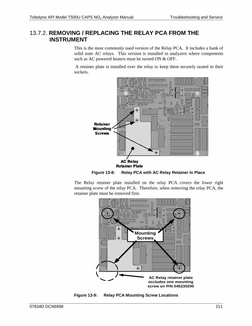
Teledyne API Model T500U CAPS NO2 Analyzer Manual Troubleshooting and Service
07834D DCN6998 211
REMOVING / REPLACING THE RELAY PCA FROM THE 13.7.2.INSTRUMENT
This is the most commonly used version of the Relay PCA. It includes a bank of solid state AC relays. This version is installed in analyzers where components such as AC powered heaters must be turned ON & OFF.
A retainer plate is installed over the relay to keep them securely seated in their sockets.
Figure 13-8: Relay PCA with AC Relay Retainer In Place
The Relay retainer plate installed on the relay PCA covers the lower right mounting screw of the relay PCA. Therefore, when removing the relay PCA, the retainer plate must be removed first.
AC Relay retainer plate occludes one mounting screw on P/N 045230200
Mounting Screws
Figure 13-9: Relay PCA Mounting Screw Locations
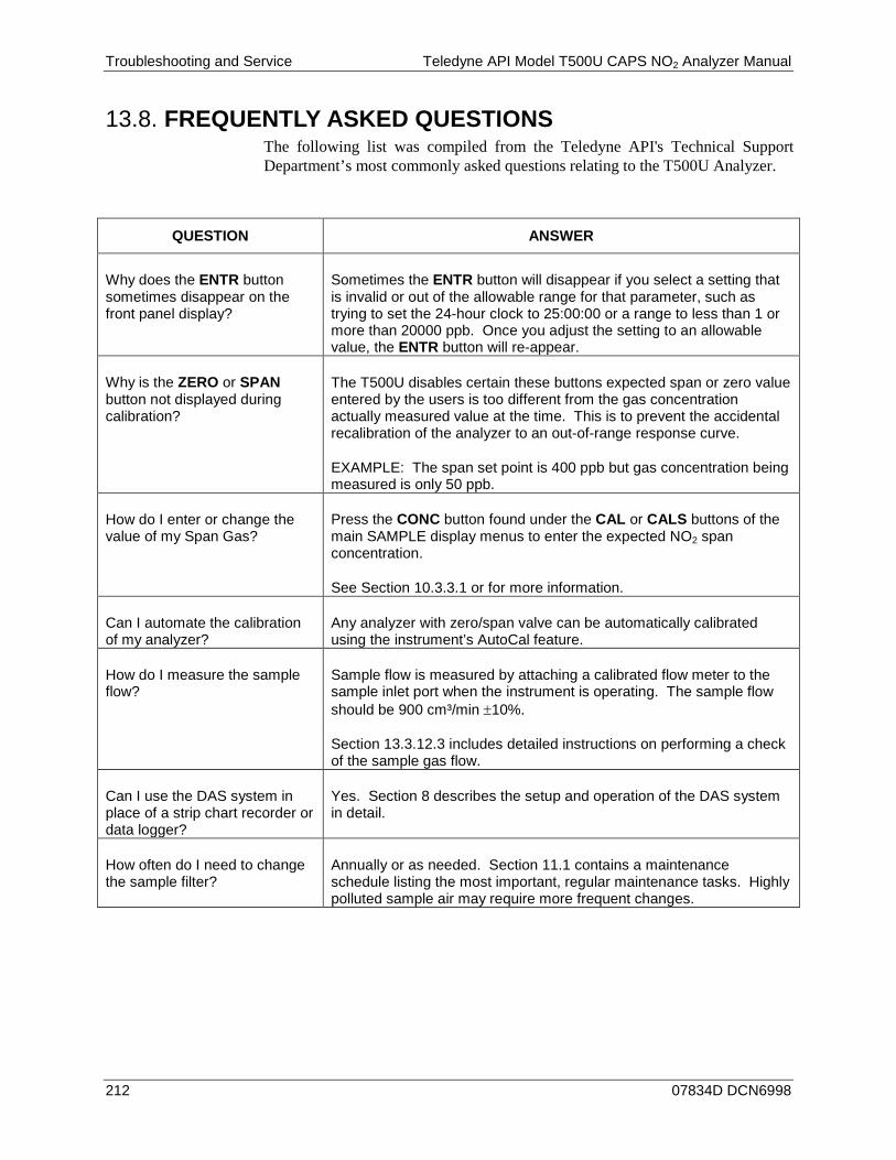
Troubleshooting and Service Teledyne API Model T500U CAPS NO2 Analyzer Manual
212 07834D DCN6998
FREQUENTLY ASKED QUESTIONS 13.8.The following list was compiled from the Teledyne API's Technical Support Department’s most commonly asked questions relating to the T500U Analyzer.
QUESTION ANSWER
Why does the ENTR button sometimes disappear on the front panel display?
Sometimes the ENTR button will disappear if you select a setting that is invalid or out of the allowable range for that parameter, such as trying to set the 24-hour clock to 25:00:00 or a range to less than 1 or more than 20000 ppb. Once you adjust the setting to an allowable value, the ENTR button will re-appear.
Why is the ZERO or SPAN button not displayed during calibration?
The T500U disables certain these buttons expected span or zero value entered by the users is too different from the gas concentration actually measured value at the time. This is to prevent the accidental recalibration of the analyzer to an out-of-range response curve.
EXAMPLE: The span set point is 400 ppb but gas concentration being measured is only 50 ppb.
How do I enter or change the value of my Span Gas?
Press the CONC button found under the CAL or CALS buttons of the main SAMPLE display menus to enter the expected NO2 span concentration.
See Section 10.3.3.1 or for more information.
Can I automate the calibration of my analyzer?
Any analyzer with zero/span valve can be automatically calibrated using the instrument’s AutoCal feature.
How do I measure the sample flow?
Sample flow is measured by attaching a calibrated flow meter to the sample inlet port when the instrument is operating. The sample flow should be 900 cm³/min ±10%.
Section 13.3.12.3 includes detailed instructions on performing a check of the sample gas flow.
Can I use the DAS system in place of a strip chart recorder or data logger?
Yes. Section 8 describes the setup and operation of the DAS system in detail.
How often do I need to change the sample filter?
Annually or as needed. Section 11.1 contains a maintenance schedule listing the most important, regular maintenance tasks. Highly polluted sample air may require more frequent changes.
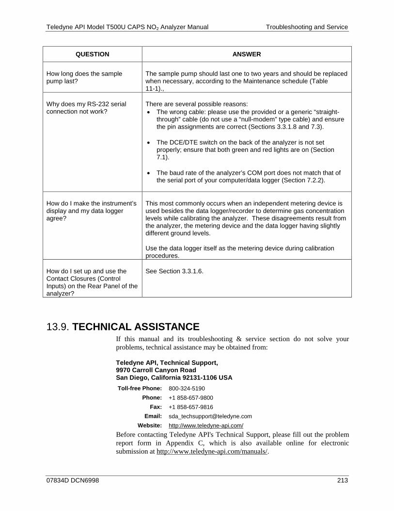
Teledyne API Model T500U CAPS NO2 Analyzer Manual Troubleshooting and Service
07834D DCN6998 213
QUESTION ANSWER
How long does the sample pump last?
The sample pump should last one to two years and should be replaced when necessary, according to the Maintenance schedule (Table 11-1).,
Why does my RS-232 serial connection not work?
There are several possible reasons: • The wrong cable: please use the provided or a generic “straight-
through” cable (do not use a “null-modem” type cable) and ensure the pin assignments are correct (Sections 3.3.1.8 and 7.3).
• The DCE/DTE switch on the back of the analyzer is not set properly; ensure that both green and red lights are on (Section 7.1).
• The baud rate of the analyzer’s COM port does not match that of the serial port of your computer/data logger (Section 7.2.2).
How do I make the instrument’s display and my data logger agree?
This most commonly occurs when an independent metering device is used besides the data logger/recorder to determine gas concentration levels while calibrating the analyzer. These disagreements result from the analyzer, the metering device and the data logger having slightly different ground levels.
Use the data logger itself as the metering device during calibration procedures.
How do I set up and use the Contact Closures (Control Inputs) on the Rear Panel of the analyzer?
See Section 3.3.1.6.
TECHNICAL ASSISTANCE 13.9.If this manual and its troubleshooting & service section do not solve your problems, technical assistance may be obtained from:
Teledyne API, Technical Support, 9970 Carroll Canyon Road San Diego, California 92131-1106 USA Toll-free Phone: 800-324-5190
Phone: +1 858-657-9800 Fax: +1 858-657-9816
Email: [email protected] Website: http://www.teledyne-api.com/
Before contacting Teledyne API's Technical Support, please fill out the problem report form in Appendix C, which is also available online for electronic submission at http://www.teledyne-api.com/manuals/.

Troubleshooting and Service Teledyne API Model T500U CAPS NO2 Analyzer Manual
214 07834D DCN6998
This page intentionally left blank.
07834D DCN6998 215
14. PRINCIPLES OF OPERATION The Cavity Attenuated Phase Shift (CAPS) NO2 monitor operates as an optical absorption spectrometer that yields both reliable and accurate measurements of ambient nitrogen dioxide down to sub ppb concentrations, with lower noise levels than chemiluminescence-based monitors. The CAPS method uses light from a blue Ultraviolet (UV) light emitting diode (LED) centered at 450 nm, a measurement cell with high reflectivity mirrors located at either end to provide an extensive optical path length, and a vacuum photodiode detector. These components are assembled into the optical cell which resides in a temperature-controlled oven. The oven raises the ambient temperature of the sample gas to 45 degrees Celsius. This mitigates the formation of moisture on the surfaces of the mirrors while also minimizing changes in the absorption coefficient due to temperature fluctuations.
As stated, the T500U analyzer measures NO2 directly, using optical absorption. This phenomenon is well-defined and is described by Beer’s Law, where the Absorbance (lost light) is directly proportional to both the path-length and concentration of the absorbing gas.
A = ε l c
(A = Absorbance, ε = Molar absorptivity, l = Mean path Length, c = concentration)
The CAPS method employed in the T500U is unique in that it applies this fundamental optical absorption law in the frequency domain, rather than using relative changes in light intensity as the primary signal. Ultraviolet light (UV) from the modulating high intensity LED enters a near confocal optical cell (Figure 14-1) through the rear of mirror A. The intensity of the light, as observed by the detector, which is also modulating at a slightly different frequency, located behind Mirror B, builds exponentially in the cell while the LED is ON. The opposite is true when the LED is OFF. Because both mirrors are highly reflective at 450 nm, a prominent absorption band for NO2, the light takes a considerable amount of time to plateau in the absence of the absorbing gas. However, when NO2 is present, the mean path length traveled by the light is significantly reduced. This has two effects on the observed intensity as measured by the detector:
• The light plateau intensity level is lower, more importantly for the T500U
• The light intensity plateaus sooner.
Thus, an observed phase shift from the modulating LED is detected (Figure 14-2). The phase shift is largest when measuring zero air and decreases when NO2 is present.
Both the LED and the Detector are modulated ON and OFF such that the observed signal has a much lower frequency, equal to the difference between the modulated frequencies and is referred to as a beat frequency. The system hardware and software take advantage of this, as it makes it easier to post process the signal using a micro controller. The technique is known as heterodyning.
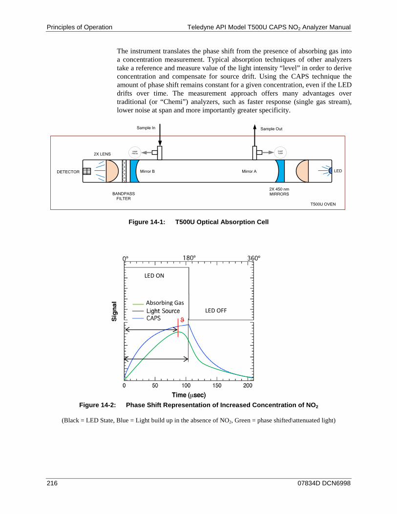
Principles of Operation Teledyne API Model T500U CAPS NO2 Analyzer Manual
216 07834D DCN6998
The instrument translates the phase shift from the presence of absorbing gas into a concentration measurement. Typical absorption techniques of other analyzers take a reference and measure value of the light intensity “level” in order to derive concentration and compensate for source drift. Using the CAPS technique the amount of phase shift remains constant for a given concentration, even if the LED drifts over time. The measurement approach offers many advantages over traditional (or “Chemi”) analyzers, such as faster response (single gas stream), lower noise at span and more importantly greater specificity.
SAMPPRESS
SAMPTEMP
T500U OVEN
DETECTOR LED
2X LENS
BANDPASSFILTER
2X 450 nm MIRRORS
Sample In Sample Out
Mirror AMirror B
Figure 14-1: T500U Optical Absorption Cell
Figure 14-2: Phase Shift Representation of Increased Concentration of NO2
(Black = LED State, Blue = Light build up in the absence of NO2, Green = phase shifted\attenuated light)
ϑ
Absorbing Gas LED OFF
LED ON
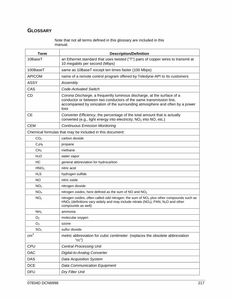
07834D DCN6998 217
GLOSSARY Note that not all terms defined in this glossary are included in this manual.
Term Description/Definition 10BaseT an Ethernet standard that uses twisted (“T”) pairs of copper wires to transmit at
10 megabits per second (Mbps)
100BaseT same as 10BaseT except ten times faster (100 Mbps)
APICOM name of a remote control program offered by Teledyne-API to its customers
ASSY Assembly
CAS Code-Activated Switch
CD Corona Discharge, a frequently luminous discharge, at the surface of a conductor or between two conductors of the same transmission line, accompanied by ionization of the surrounding atmosphere and often by a power loss
CE Converter Efficiency, the percentage of the total amount that is actually converted (e.g., light energy into electricity; NO2 into NO, etc.)
CEM Continuous Emission Monitoring
Chemical formulas that may be included in this document: CO2 carbon dioxide
C3H8 propane
CH4 methane
H2O water vapor
HC general abbreviation for hydrocarbon
HNO3 nitric acid
H2S hydrogen sulfide
NO nitric oxide
NO2 nitrogen dioxide
NOX nitrogen oxides, here defined as the sum of NO and NO2
NOy nitrogen oxides, often called odd nitrogen: the sum of NOX plus other compounds such as HNO3 (definitions vary widely and may include nitrate (NO3), PAN, N2O and other compounds as well)
NH3 ammonia
O2 molecular oxygen
O3 ozone
SO2 sulfur dioxide
cm3 metric abbreviation for cubic centimeter (replaces the obsolete abbreviation “cc”)
CPU Central Processing Unit
DAC Digital-to-Analog Converter
DAS Data Acquisition System
DCE Data Communication Equipment
DFU Dry Filter Unit
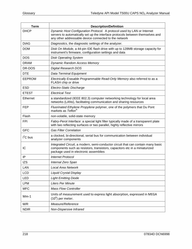
Glossary Teledyne API Model T500U CAPS NO2 Analyzer Manual
218 07834D DCN6998
Term Description/Definition DHCP Dynamic Host Configuration Protocol. A protocol used by LAN or Internet
servers to automatically set up the interface protocols between themselves and any other addressable device connected to the network
DIAG Diagnostics, the diagnostic settings of the analyzer.
DOM Disk On Module, a 44-pin IDE flash drive with up to 128MB storage capacity for instrument’s firmware, configuration settings and data
DOS Disk Operating System
DRAM Dynamic Random Access Memory
DR-DOS Digital Research DOS
DTE Data Terminal Equipment
EEPROM Electrically Erasable Programmable Read-Only Memory also referred to as a FLASH chip or drive
ESD Electro-Static Discharge
ETEST Electrical Test
Ethernet a standardized (IEEE 802.3) computer networking technology for local area networks (LANs), facilitating communication and sharing resources
FEP Fluorinated Ethylene Propylene polymer, one of the polymers that Du Pont markets as Teflon®
Flash non-volatile, solid-state memory
FPI Fabry-Perot Interface: a special light filter typically made of a transparent plate with two reflecting surfaces or two parallel, highly reflective mirrors
GFC Gas Filter Correlation
I2C bus a clocked, bi-directional, serial bus for communication between individual analyzer components
IC Integrated Circuit, a modern, semi-conductor circuit that can contain many basic components such as resistors, transistors, capacitors etc in a miniaturized package used in electronic assemblies
IP Internet Protocol
IZS Internal Zero Span
LAN Local Area Network
LCD Liquid Crystal Display
LED Light Emitting Diode
LPM Liters Per Minute
MFC Mass Flow Controller
Mm-1 Units of measurement used to express light absorption, expressed in MEGA (106) per meter.
M/R Measure/Reference
NDIR Non-Dispersive Infrared

Teledyne API Model T500U CAPS NO2 Analyzer Manual Principles of Operation
07834D DCN6998 219
Term Description/Definition
MOLAR MASS
the mass, expressed in grams, of 1 mole of a specific substance. Conversely, one mole is the amount of the substance needed for the molar mass to be the same number in grams as the atomic mass of that substance. EXAMPLE: The atomic weight of Carbon is 12 therefore the molar mass of Carbon is 12 grams. Conversely, one mole of carbon equals the amount of carbon atoms that weighs 12 grams. Atomic weights can be found on any Periodic Table of Elements.
NDIR Non-Dispersive Infrared
NIST-SRM National Institute of Standards and Technology - Standard Reference Material
PC Personal Computer
PCA Printed Circuit Assembly, the PCB with electronic components, ready to use
PC/AT Personal Computer / Advanced Technology
PCB Printed Circuit Board, the bare board without electronic component
PFA Per-Fluoro-Alkoxy, an inert polymer; one of the polymers that Du Pont markets as Teflon®
PLC Programmable Logic Controller, a device that is used to control instruments based on a logic level signal coming from the analyzer
PLD Programmable Logic Device
PLL Phase Lock Loop
PMT Photo Multiplier Tube, a vacuum tube of electrodes that multiply electrons collected and charged to create a detectable current signal
P/N (or PN) Part Number
PPB Parts per billion
PPM Parts per million
PPT Parts per trillion
PSD Prevention of Significant Deterioration
PTFE Poly-Tetra-Fluoro-Ethylene, a very inert polymer material used to handle gases that may react on other surfaces; one of the polymers that Du Pont markets as Teflon®
PVC Poly Vinyl Chloride, a polymer used for downstream tubing
Rdg Reading
RS-232 specification and standard describing a serial communication method between DTE (Data Terminal Equipment) and DCE (Data Circuit-terminating Equipment) devices, using a maximum cable-length of 50 feet
RS-485 specification and standard describing a binary serial communication method among multiple devices at a data rate faster than RS-232 with a much longer distance between the host and the furthest device
SAROAD Storage and Retrieval of Aerometric Data
SLAMS State and Local Air Monitoring Network Plan
SLPM Standard Liters Per Minute of a gas at standard temperature and pressure
STP Standard Temperature and Pressure

Glossary Teledyne API Model T500U CAPS NO2 Analyzer Manual
220 07834D DCN6998
Term Description/Definition
TCP/IP Transfer Control Protocol / Internet Protocol, the standard communications protocol for Ethernet devices
TEC Thermal Electric Cooler
TPC Temperature/Pressure Compensation
USB Universal Serial Bus: a standard connection method to establish communication between peripheral devices and a host controller, such as a mouse and/or keyboard and a personal computer or laptop
VARS Variables, the variable settings of the instrument
V-F Voltage-to-Frequency
Z/S Zero / Span

A-1
APPENDIX A: T500U Software Documentation, F/W Revision 1.0.2.22
APPENDIX A-1: SOFTWARE MENU TREES AND INDEX ....................................................... A-3 APPENDIX A-2: SETUP VARIABLES FOR SERIAL I/O ......................................................... A-9 APPENDIX A-3: WARNINGS AND TEST MEASUREMENTS ................................................. A-10 APPENDIX A-4: SIGNAL I/O DEFINITIONS ..................................................................... A-13 APPENDIX A-5: TRIGGER EVENTS AND DAS FUNCTIONS ................................................ A-17 APPENDIX A-6: TERMINAL COMMAND DESIGNATORS AND COMMAND LINE OPTIONS ... A-20 APPENDIX A-7: MODBUS REGISTER MAP ........................................................................ A-22
07834D DCN6998

APPENDIX A: Software Documentation, F/W Revision 1.0.2.22 Teledyne API - T500U Menu Trees 08061C DCN6998
A-2
This page intentionally left blank.
07834D DCN6998

Teledyne API - T500U Menu Trees 08061C DCN6998 APPENDIX A-1: Software Menu Trees and Index
A-3
APPENDIX A-1: Software Menu Trees and Index
PRIMARY SETUP
MENU
SAMPLE
MSG1CALZ
2CALS
2CLR
1SETUP
SPAN<TST TST>
CALTEST1
CONC
ZERO
DASCFG ACAL2
CLKRNGE PASS MORE
1 Only appears when warning messages are active.
2 Only appears if analyzer is equipped with Internal Span Gas option.
3 Only appears when the Concentration Alarm option is active.
SECONDARY SETUP
MENU
Press to cycle
through the
active warning
messages.
Press to clear
an active
warning
messages.
HIGHLOW
· RANGE=[Value]PPB
· PHASE=[Value]DEG
· MEAS_L=[Value]Mm-1
· AREF_L=[Value]Mm-1
· SMP PRS=[Value]InHg
· SMP TEMP=[Value]ºC
· BOX TEMP=[Value]ºC
· SLOPE=[Value]
· OFFSET=[Value]PPB
· STABIL=[Value]PPB
· OVEN TMP=[Value]ºC5
· TIME=[HH:MM:SS]
DIAG COMM VARS ALRM3
CONCSPAN
AREF
Figure A-1: Basic Sample Display Menu
07834D DCN6998
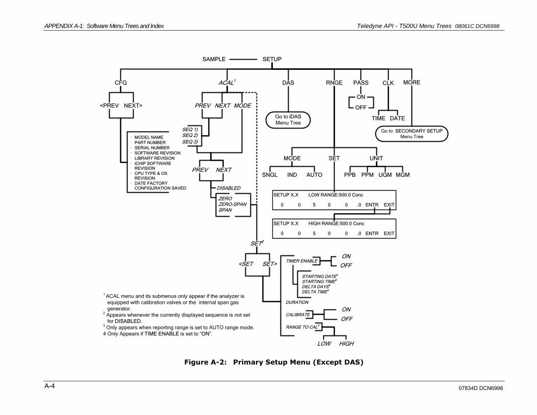
APPENDIX A-1: Software Menu Trees and Index Teledyne API - T500U Menu Trees 08061C DCN6998
A-4
SETUP
PASSDAS RNGE CLK MOREACAL1CFG
<PREV NEXT>
· MODEL NAME
· PART NUMBER
· SERIAL NUMBER
· SOFTWARE REVISION
· LIBRARY REVISION
· iCHIP SOFTWARE REVISION
· CPU TYPE & OS REVISION
· DATE FACTORY CONFIGURATION SAVED
Go to iDAS
Menu Tree
ON
OFFPREV MODENEXT
SEQ 1)SEQ 2)
SEQ 3)
PREV NEXT
DISABLED
ZEROZERO-SPANSPAN
SET2
<SET SET>
LOW HIGH
RANGE TO CAL3
DURATION
STARTING DATE4
STARTING TIME4
DELTA DAYS4
DELTA TIME4
TIMER ENABLE
SAMPLE
1 ACAL menu and its submenus only appear if the analyzer is
equipped with calibration valves or the internal span gas
generator.2 Appears whenever the currently displayed sequence is not set
for DISABLED.3 Only appears when reporting range is set to AUTO range mode.
4 Only Appears if TIME ENABLE is set to “ON”.
Go to SECONDARY SETUP
Menu Tree
CALIBRATE
SET UNITMODE
TIME DATE
PPM UGMPPB MGM
SETUP X.X LOW RANGE:500.0 Conc
0 0 5 0 0 .0 ENTR EXIT
SETUP X.X HIGH RANGE:500.0 Conc
0 0 5 0 0 .0 ENTR EXIT
OFF
ON
OFF
ON
SNGL IND AUTO
Figure A-2: Primary Setup Menu (Except DAS)
07834D DCN6998
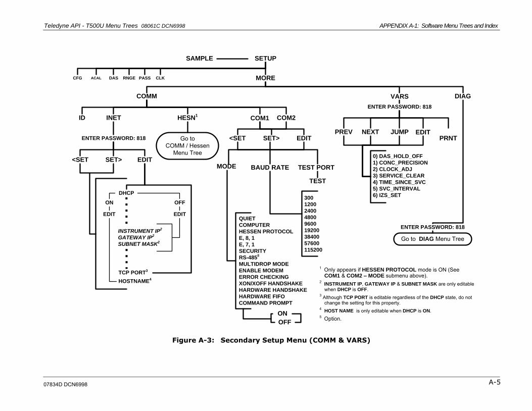
Teledyne API - T500U Menu Trees 08061C DCN6998 APPENDIX A-1: Software Menu Trees and Index
A-5
SETUP
PASSDAS RNGE CLK MOREACALCFG
SAMPLE
COMM VARS DIAG
EDITPRNT
JUMPNEXTPREV
0) DAS_HOLD_OFF
1) CONC_PRECISION
2) CLOCK_ADJ
3) SERVICE_CLEAR
4) TIME_SINCE_SVC
5) SVC_INTERVAL
6) IZS_SET
Go to DIAG Menu Tree
HESN1
INETID
EDITSET><SET
COM1 COM2
TEST PORTBAUD RATEMODE
TEST
300
1200
2400
4800
9600
19200
38400
57600
115200
QUIET
COMPUTER
HESSEN PROTOCOL
E, 8, 1
E, 7, 1
SECURITY
RS-4855
MULTIDROP MODE
ENABLE MODEM
ERROR CHECKING
XON/XOFF HANDSHAKE
HARDWARE HANDSHAKE
HARDWARE FIFO
COMMAND PROMPT
ON
OFF
ENTER PASSWORD: 818
ENTER PASSWORD: 818
Go to COMM / Hessen
Menu Tree
ENTER PASSWORD: 818
EDITSET><SET
DHCP
ON OFF
INSTRUMENT IP2
GATEWAY IP2
SUBNET MASK2
TCP PORT3
HOSTNAME4
1 Only appears if HESSEN PROTOCOL mode is ON (See COM1 & COM2 – MODE submenu above).
2INSTRUMENT IP, GATEWAY IP & SUBNET MASK are only editable when DHCP is OFF.
3 Although TCP PORT is editable regardless of the DHCP state, do not change the setting for this property.
4HOST NAME is only editable when DHCP is ON.
5 Option.
EDITEDIT
Figure A-3: Secondary Setup Menu (COMM & VARS)
07834D DCN6998
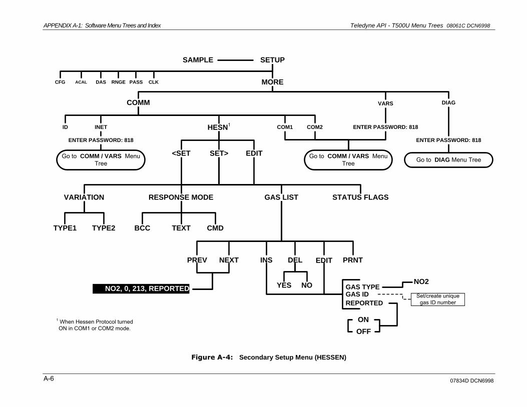
APPENDIX A-1: Software Menu Trees and Index Teledyne API - T500U Menu Trees 08061C DCN6998
A-6
SETUP
PASSDAS RNGE CLK MOREACALCFG
SAMPLE
COMM VARS DIAG
Go to DIAG Menu Tree
HESN1
INETID ENTER PASSWORD: 818
ENTER PASSWORD: 818ENTER PASSWORD: 818
Go to COMM / VARS Menu Tree
Go to COMM / VARS Menu Tree
COM1 COM2
EDITSET><SET
GAS LISTRESPONSE MODEVARIATION STATUS FLAGS
TYPE2TYPE1 CMDTEXTBCC
EDIT PRNTDELINSNEXTPREV
NOYES GAS TYPEGAS ID
REPORTED
ON
OFF
Set/create unique gas ID number
NO2, 0, 213, REPORTEDNO2
1 When Hessen Protocol turned ON in COM1 or COM2 mode.
Figure A-4: Secondary Setup Menu (HESSEN)
07834D DCN6998
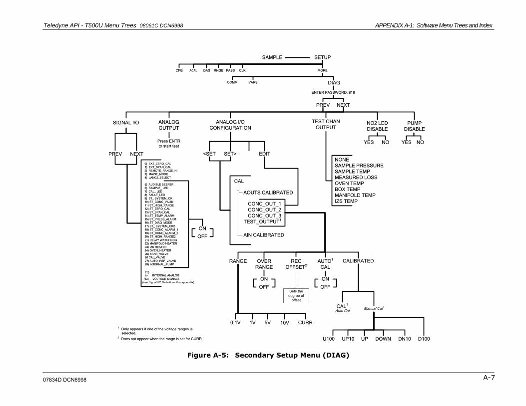
Teledyne API - T500U Menu Trees 08061C DCN6998 APPENDIX A-1: Software Menu Trees and Index
A-7
ANALOG
OUTPUT
SETUP
PASSDAS RNGE CLK MOREACALCFG
SAMPLE
COMM VARS DIAG
NEXTPREV
SIGNAL I/O ANALOG I/O
CONFIGURATIONPUMP
DISABLE
Press ENTR
to start test
ENTER PASSWORD: 818
NEXTPREV
0) EXT_ZERO_CAL
1) EXT_SPAN_CAL
2) REMOTE_RANGE_HI
3) MAINT_MODE
4) LANG2_SELECT
5) AUDIBLE BEEPER
6) SAMPLE_ LED
7) CAL_ LED
8) FAULT_LED
9) ST_ SYSTEM_OK
10) ST_CONC_VALID
11) ST_HIGH_RANGE
12) ST_ZERO_CAL
13) ST_SPAN_CAL
14) ST_TEMP_ALARM
15) ST_PRESS_ALARM
16) ST_DIAG_MODE
17) ST_ SYSTEM_OK2
18) ST_CONC_ALARM_1
19) ST_CONC_ALARM_2
20) ST_HIGH_RANGE2
21) RELAY WATCHDOG
22) MANIFOLD HEATER
23) IZS HEATER
24) OVEN_HEATER
25) SPAN_VALVE
26 CAL_VALVE
27) AUTO_REF_VALVE
28) INTERNAL_PUMP
25)
to INTERNAL ANALOG
63) VOLTAGE SIGNALS
(see Signal I/O Definitions this appendix)
ON
OFF
CAL
EDITSET><SET
AOUTS CALIBRATED
CONC_OUT_1
CONC_OUT_2
CONC_OUT_3
AIN CALIBRATED
10V CURR5V1V0.1V
ON
OFF
CAL1
Auto Cal
RANGE OVER
RANGE
CALIBRATEDREC
OFFSET2
AUTO1
CAL
Sets the
degree of
offset
ON
OFF
U100 UP10 UP DOWN DN10 D100
Manual Cal2
1Only appears if one of the voltage ranges is selected.
2Does not appear when the range is set for CURR
NOYES
TEST_OUTPUT1
TEST CHAN
OUTPUT
NONE
SAMPLE PRESSURE
SAMPLE TEMP
MEASURED LOSS
OVEN TEMP
BOX TEMP
MANIFOLD TEMP
IZS TEMP
NO2 LED
DISABLE
NOYES
Figure A-5: Secondary Setup Menu (DIAG)
07834D DCN6998

APPENDIX A-1: Software Menu Trees and Index Teledyne API - T500U Menu Trees 08061C DCN6998
A-8
SETUP
PASSDAS RNGE CLK MOREACAL1CFG
SAMPLE
1 ACAL menu only appear if analyzer is equipped with
Zero/Span or IZS valve options.2 Editing an existing DAS channel will erase any
data stored on the channel options.3 Changing the event for an existing DAS channel
DOES NOT erase the data stored on the
channel.
EDITVIEW
PREV NEXT
CONC
PNUMTC
CALDAT
Selects the data point to be viewed
Cycles through
parameters assigned
to this DAS channel
<PRM PRM>NX10NEXTPREVPV10
EDIT2 PRNTDELINSNEXTPREV
ENTER PASSWORD: 818
NO
NX10NEXTSET><SET
YES
NAMEEVENT
PARAMETERS
NUMBER OF RECORDSREPORT PERIOD
RS-232 REPORT
CAL MODECHANNEL ENABLE
ON
OFFNO
YES2
Sets the maximum number of
records recorded by this channel
Sets the time lapse between each
report
Create/edit the name of the channel
PREV NEXT
Cycles through list
of available trigger
events3
NOYES2
EDIT2 PRNTDELINSNEXTPREV
NO
PRNTEDITSET><SET
YESCycles through list of
currently active
parameters for this
channel
MAXMINAVGINST
PRECISIONSAMPLE MODEPARAMETER
Cycles through list of available &
currently active parameters for this
channel
NEXTPREV
HIRES
VIEW
CONC
PNUMTC
CALDAT
DIAG
HIRES
DIAG
Figure A-6: Internal Data Acquisition (DAS) Menu
07834D DCN6998
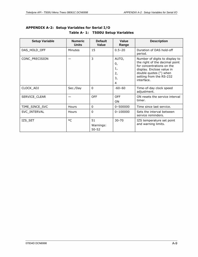
Teledyne API - T500U Menu Trees 08061C DCN6998 APPENDIX A-2: Setup Variables for Serial I/O
A-9
APPENDIX A-2: Setup Variables for Serial I/O
Table A- 1: T500U Setup Variables
Setup Variable Numeric Units
Default Value
Value Range
Description
DAS_HOLD_OFF Minutes 15 0.5–20 Duration of DAS hold-off period.
CONC_PRECISION — 3 AUTO,
0,
1,
2,
3,
4
Number of digits to display to
the right of the decimal point for concentrations on the display. Enclose value in
double quotes (") when setting from the RS-232 interface.
CLOCK_ADJ Sec./Day 0 -60–60 Time-of-day clock speed adjustment.
SERVICE_CLEAR — OFF OFF
ON
ON resets the service interval timer.
TIME_SINCE_SVC Hours 0 0–500000 Time since last service.
SVC_INTERVAL Hours 0 0–100000 Sets the interval between service reminders.
IZS_SET ºC 51
Warnings:
50-52
30-70 IZS temperature set point and warning limits.
07834D DCN6998
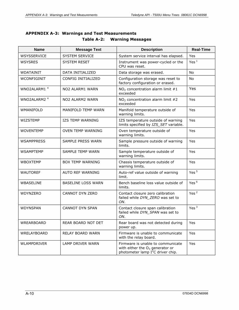
APPENDIX A-3: Warnings and Test Measurements Teledyne API - T500U Menu Trees 08061C DCN6998
A-10
APPENDIX A-3: Warnings and Test Measurements
Table A-2: Warning Messages
Name Message Text Description Real-Time
WSYSSERVICE SYSTEM SERVICE System service interval has elapsed. Yes
WSYSRES SYSTEM RESET Instrument was power-cycled or the CPU was reset.
Yes 1
WDATAINIT DATA INITIALIZED Data storage was erased. No
WCONFIGINIT CONFIG INITIALIZED Configuration storage was reset to factory configuration or erased.
No
WNO2ALARM1 4 NO2 ALARM1 WARN NO2 concentration alarm limit #1 exceeded
Yes
WNO2ALARM2 4 NO2 ALARM2 WARN NO2 concentration alarm limit #2 exceeded
Yes
WMANIFOLD MANIFOLD TEMP WARN Manifold temperature outside of warning limits.
Yes
WIZSTEMP IZS TEMP WARNING IZS temperature outside of warning limits specified by IZS_SET variable.
Yes
WOVENTEMP OVEN TEMP WARNING Oven temperature outside of warning limits.
Yes
WSAMPPRESS SAMPLE PRESS WARN Sample pressure outside of warning limits.
Yes
WSAMPTEMP SAMPLE TEMP WARN Sample temperature outside of warning limits.
Yes
WBOXTEMP BOX TEMP WARNING Chassis temperature outside of warning limits.
Yes
WAUTOREF AUTO REF WARNING Auto-ref value outside of warning limit.
Yes 5
WBASELINE BASELINE LOSS WARN Bench baseline loss value outside of limits.
Yes 6
WDYNZERO CANNOT DYN ZERO Contact closure zero calibration failed while DYN_ZERO was set to ON.
Yes 2
WDYNSPAN CANNOT DYN SPAN Contact closure span calibration failed while DYN_SPAN was set to ON.
Yes 3
WREARBOARD REAR BOARD NOT DET Rear board was not detected during power up.
Yes
WRELAYBOARD RELAY BOARD WARN Firmware is unable to communicate with the relay board.
Yes
WLAMPDRIVER LAMP DRIVER WARN Firmware is unable to communicate
with either the O3 generator or photometer lamp I2C driver chip.
Yes
07834D DCN6998
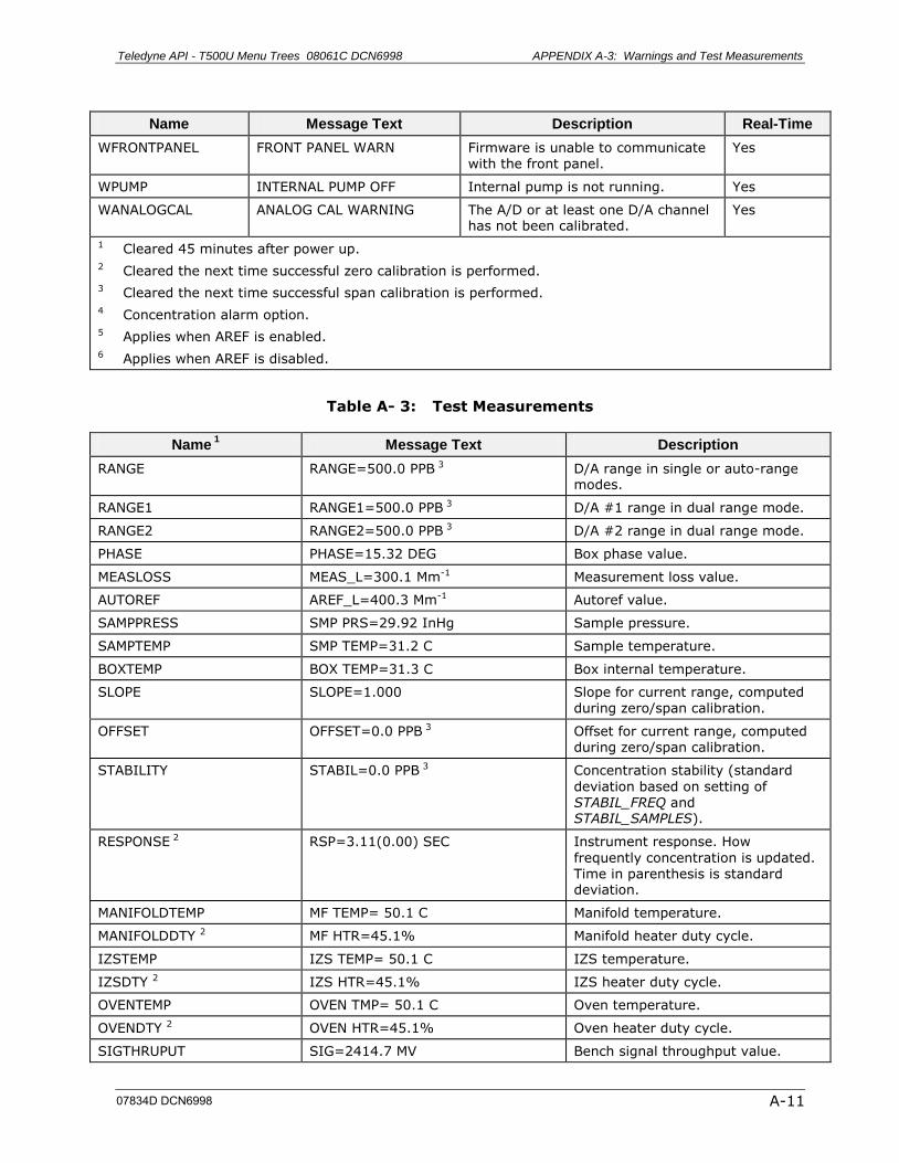
Teledyne API - T500U Menu Trees 08061C DCN6998 APPENDIX A-3: Warnings and Test Measurements
A-11
Name Message Text Description Real-Time
WFRONTPANEL FRONT PANEL WARN Firmware is unable to communicate with the front panel.
Yes
WPUMP INTERNAL PUMP OFF Internal pump is not running. Yes
WANALOGCAL ANALOG CAL WARNING The A/D or at least one D/A channel has not been calibrated.
Yes
1 Cleared 45 minutes after power up.
2 Cleared the next time successful zero calibration is performed. 3 Cleared the next time successful span calibration is performed.
4 Concentration alarm option. 5 Applies when AREF is enabled.
6 Applies when AREF is disabled.
Table A- 3: Test Measurements
Name 1 Message Text Description
RANGE RANGE=500.0 PPB 3 D/A range in single or auto-range modes.
RANGE1 RANGE1=500.0 PPB 3 D/A #1 range in dual range mode.
RANGE2 RANGE2=500.0 PPB 3 D/A #2 range in dual range mode.
PHASE PHASE=15.32 DEG Box phase value.
MEASLOSS MEAS_L=300.1 Mm-1 Measurement loss value.
AUTOREF AREF_L=400.3 Mm-1 Autoref value.
SAMPPRESS SMP PRS=29.92 InHg Sample pressure.
SAMPTEMP SMP TEMP=31.2 C Sample temperature.
BOXTEMP BOX TEMP=31.3 C Box internal temperature.
SLOPE SLOPE=1.000 Slope for current range, computed during zero/span calibration.
OFFSET OFFSET=0.0 PPB 3 Offset for current range, computed during zero/span calibration.
STABILITY STABIL=0.0 PPB 3 Concentration stability (standard
deviation based on setting of STABIL_FREQ and STABIL_SAMPLES).
RESPONSE 2 RSP=3.11(0.00) SEC Instrument response. How
frequently concentration is updated. Time in parenthesis is standard deviation.
MANIFOLDTEMP MF TEMP= 50.1 C Manifold temperature.
MANIFOLDDTY 2 MF HTR=45.1% Manifold heater duty cycle.
IZSTEMP IZS TEMP= 50.1 C IZS temperature.
IZSDTY 2 IZS HTR=45.1% IZS heater duty cycle.
OVENTEMP OVEN TMP= 50.1 C Oven temperature.
OVENDTY 2 OVEN HTR=45.1% Oven heater duty cycle.
SIGTHRUPUT SIG=2414.7 MV Bench signal throughput value.
07834D DCN6998
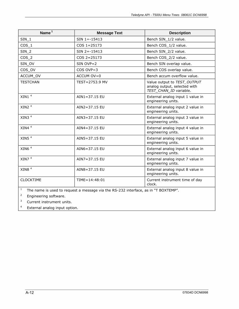
Teledyne API - T500U Menu Trees 08061C DCN6998
A-12
Name 1 Message Text Description
SIN_1 SIN 1=-15413 Bench SIN_1/2 value.
COS_1 COS 1=25173 Bench COS_1/2 value.
SIN_2 SIN 2=-15413 Bench SIN_2/2 value.
COS_2 COS 2=25173 Bench COS_2/2 value.
SIN_OV SIN OVP=2 Bench SIN overlap value.
COS_OV COS OVP=3 Bench COS overlap value.
ACCUM_OV ACCUM OV=0 Bench accum overflow value.
TESTCHAN TEST=2753.9 MV Value output to TEST_OUTPUT
analog output, selected with TEST_CHAN_ID variable.
XIN1 4 AIN1=37.15 EU External analog input 1 value in engineering units.
XIN2 4 AIN2=37.15 EU External analog input 2 value in engineering units.
XIN3 4 AIN3=37.15 EU External analog input 3 value in engineering units.
XIN4 4 AIN4=37.15 EU External analog input 4 value in engineering units.
XIN5 4 AIN5=37.15 EU External analog input 5 value in engineering units.
XIN6 4 AIN6=37.15 EU External analog input 6 value in engineering units.
XIN7 4 AIN7=37.15 EU External analog input 7 value in engineering units.
XIN8 4 AIN8=37.15 EU External analog input 8 value in engineering units.
CLOCKTIME TIME=14:48:01 Current instrument time of day clock.
1 The name is used to request a message via the RS-232 interface, as in ―T BOXTEMP‖.
2 Engineering software. 3 Current instrument units.
4 External analog input option.
07834D DCN6998
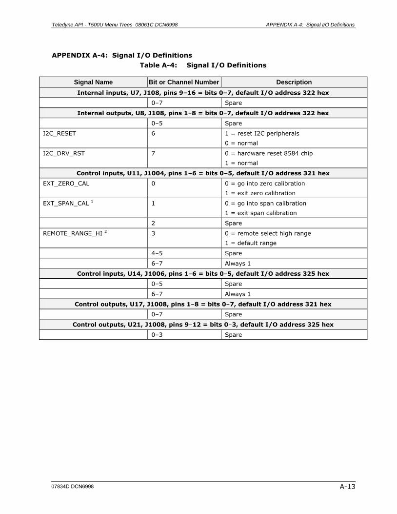
Teledyne API - T500U Menu Trees 08061C DCN6998 APPENDIX A-4: Signal I/O Definitions
A-13
APPENDIX A-4: Signal I/O Definitions
Table A-4: Signal I/O Definitions
Signal Name Bit or Channel Number Description
Internal inputs, U7, J108, pins 9–16 = bits 0–7, default I/O address 322 hex
0–7 Spare
Internal outputs, U8, J108, pins 1–8 = bits 0–7, default I/O address 322 hex
0–5 Spare
I2C_RESET 6 1 = reset I2C peripherals
0 = normal
I2C_DRV_RST 7 0 = hardware reset 8584 chip
1 = normal
Control inputs, U11, J1004, pins 1–6 = bits 0–5, default I/O address 321 hex
EXT_ZERO_CAL 0 0 = go into zero calibration
1 = exit zero calibration
EXT_SPAN_CAL 1 1 0 = go into span calibration
1 = exit span calibration
2 Spare
REMOTE_RANGE_HI 2 3 0 = remote select high range
1 = default range
4–5 Spare
6–7 Always 1
Control inputs, U14, J1006, pins 1–6 = bits 0–5, default I/O address 325 hex
0–5 Spare
6–7 Always 1
Control outputs, U17, J1008, pins 1–8 = bits 0–7, default I/O address 321 hex
0–7 Spare
Control outputs, U21, J1008, pins 9–12 = bits 0–3, default I/O address 325 hex
0–3 Spare
07834D DCN6998

APPENDIX A-4: Signal I/O Definitions Teledyne API - T500U Menu Trees 08061C DCN6998
A-14
Signal Name Bit or Channel Number Description
Alarm outputs, U21, J1009, pins 1–12 = bits 4–7, default I/O address 325 hex
ST_SYSTEM_OK2,
MB_RELAY_36 3
4 1 = system OK
0 = any alarm condition or in diagnostics mode
Controlled by MODBUS coil register
ST_CONC_ALARM_1 4,
MB_RELAY_37 3
5 1 = conc. limit 1 exceeded
0 = conc. OK
Controlled by MODBUS coil register
ST_CONC_ALARM_2 4,
MB_RELAY_38 3
6 1 = conc. limit 2 exceeded
0 = conc. OK
Controlled by MODBUS coil register
ST_HIGH_RANGE2 5,
MB_RELAY_39 3
7 1 = high auto-range in use (mirrors ST_HIGH_RANGE status output)
0 = low auto-range
Controlled by MODBUS coil register
A status outputs, U24, J1017, pins 1–8 = bits 0–7, default I/O address 323 hex
ST_SYSTEM_OK 0 0 = system OK
1 = any alarm condition
ST_CONC_VALID 1 0 = conc. valid
1 = hold off or other conditions
ST_HIGH_RANGE 2 0 = high auto-range in use
1 = low auto-range
ST_ZERO_CAL 3 0 = in zero calibration
1 = not in zero
ST_SPAN_CAL 4 0 = in span calibration
1 = not in span
ST_DIAG_MODE 5 0 = in diagnostic mode
1 = not in diagnostic mode
ST_TEMP_ALARM 6 0 = any temperature alarm
1 = all temperatures OK
ST_PRESS_ALARM 7 0 = any pressure alarm
1 = all pressures OK
A status outputs, alternate status outputs factory option
ST_DIAG_MODE 5 0 = in diagnostic mode 1 = not in diagnostic mode
B status outputs, U27, J1018, pins 1–8 = bits 0–7, default I/O address 324 hex
ST_DIAG_MODE 0 0 = in diagnostic mode 1 = not in diagnostic mode
1–7 Spare
07834D DCN6998
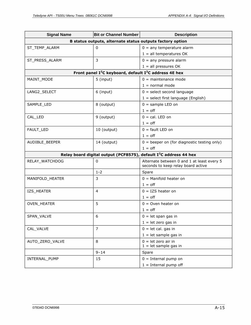
Teledyne API - T500U Menu Trees 08061C DCN6998 APPENDIX A-4: Signal I/O Definitions
A-15
Signal Name Bit or Channel Number Description
B status outputs, alternate status outputs factory option
ST_TEMP_ALARM 0 0 = any temperature alarm
1 = all temperatures OK
ST_PRESS_ALARM 3 0 = any pressure alarm
1 = all pressures OK
Front panel I2C keyboard, default I2C address 4E hex
MAINT_MODE 5 (input) 0 = maintenance mode
1 = normal mode
LANG2_SELECT 6 (input) 0 = select second language
1 = select first language (English)
SAMPLE_LED 8 (output) 0 = sample LED on
1 = off
CAL_LED 9 (output) 0 = cal. LED on
1 = off
FAULT_LED 10 (output) 0 = fault LED on
1 = off
AUDIBLE_BEEPER 14 (output) 0 = beeper on (for diagnostic testing only)
1 = off
Relay board digital output (PCF8575), default I2C address 44 hex
RELAY_WATCHDOG 0 Alternate between 0 and 1 at least every 5 seconds to keep relay board active
1-2 Spare
MANIFOLD_HEATER 3 0 = Manifold heater on
1 = off
IZS_HEATER 4 0 = IZS heater on
1 = off
OVEN_HEATER 5 0 = Oven heater on
1 = off
SPAN_VALVE 6 0 = let span gas in
1 = let zero gas in
CAL_VALVE 7 0 = let cal. gas in
1 = let sample gas in
AUTO_ZERO_VALVE 8 0 = let zero air in 1 = let sample gas in
9–14 Spare
INTERNAL_PUMP 15 0 = Internal pump on
1 = Internal pump off
07834D DCN6998
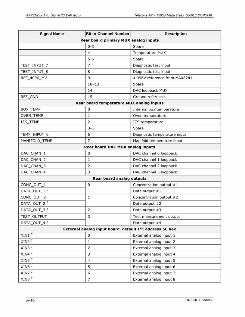
APPENDIX A-4: Signal I/O Definitions Teledyne API - T500U Menu Trees 08061C DCN6998
A-16
Signal Name Bit or Channel Number Description
Rear board primary MUX analog inputs
0-3 Spare
4 Temperature MUX
5-6 Spare
TEST_INPUT_7 7 Diagnostic test input
TEST_INPUT_8 8 Diagnostic test input
REF_4096_MV 9 4.096V reference from MAX6241
10–13 Spare
14 DAC loopback MUX
REF_GND 15 Ground reference
Rear board temperature MUX analog inputs
BOX_TEMP 0 Internal box temperature
OVEN_TEMP 1 Oven temperature
IZS_TEMP 2 IZS temperature
3–5 Spare
TEMP_INPUT_6 6 Diagnostic temperature input
MANIFOLD_TEMP 7 Manifold temperature input
Rear board DAC MUX analog inputs
DAC_CHAN_1 0 DAC channel 0 loopback
DAC_CHAN_2 1 DAC channel 1 loopback
DAC_CHAN_3 2 DAC channel 2 loopback
DAC_CHAN_4 3 DAC channel 3 loopback
Rear board analog outputs
CONC_OUT_1 0 Concentration output #1
DATA_OUT_1 6 Data output #1
CONC_OUT_2 1 Concentration output #2
DATA_OUT_2 6 Data output #2
DATA_OUT_3 6 2 Data output #3
TEST_OUTPUT 3 Test measurement output
DATA_OUT_4 6 Data output #4
External analog input board, default I2C address 5C hex
XIN1 7 0 External analog input 1
XIN2 7 1 External analog input 2
XIN3 7 2 External analog input 3
XIN4 7 3 External analog input 4
XIN5 7 4 External analog input 5
XIN6 7 5 External analog input 6
XIN7 7 6 External analog input 7
XIN8 7 7 External analog input 8
07834D DCN6998
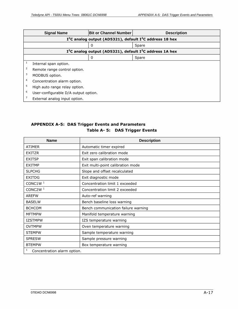
Teledyne API - T500U Menu Trees 08061C DCN6998 APPENDIX A-5: DAS Trigger Events and Parameters
A-17
Signal Name Bit or Channel Number Description
I2C analog output (AD5321), default I2C address 18 hex
0 Spare
I2C analog output (AD5321), default I2C address 1A hex
0 Spare
1 Internal span option. 2 Remote range control option.
3 MODBUS option. 4 Concentration alarm option.
5 High auto range relay option. 6 User-configurable D/A output option.
7 External analog input option.
APPENDIX A-5: DAS Trigger Events and Parameters
Table A- 5: DAS Trigger Events
Name Description
ATIMER Automatic timer expired
EXITZR Exit zero calibration mode
EXITSP Exit span calibration mode
EXITMP Exit multi-point calibration mode
SLPCHG Slope and offset recalculated
EXITDG Exit diagnostic mode
CONC1W 1 Concentration limit 1 exceeded
CONC2W 1 Concentration limit 2 exceeded
AREFW Auto-ref warning
BASELW Bench baseline loss warning
BCHCOM Bench communication failure warning
MFTMPW Manifold temperature warning
IZSTMPW IZS temperature warning
OVTMPW Oven temperature warning
STEMPW Sample temperature warning
SPRESW Sample pressure warning
BTEMPW Box temperature warning
1 Concentration alarm option.
07834D DCN6998
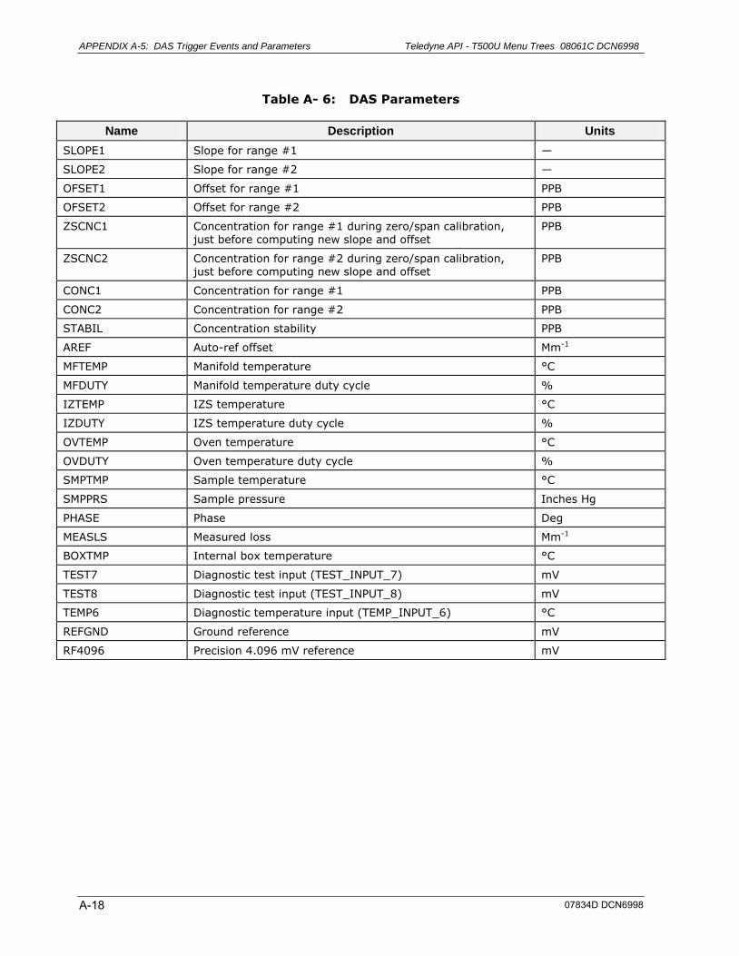
APPENDIX A-5: DAS Trigger Events and Parameters Teledyne API - T500U Menu Trees 08061C DCN6998
A-18
Table A- 6: DAS Parameters
Name Description Units
SLOPE1 Slope for range #1 —
SLOPE2 Slope for range #2 —
OFSET1 Offset for range #1 PPB
OFSET2 Offset for range #2 PPB
ZSCNC1 Concentration for range #1 during zero/span calibration, just before computing new slope and offset
PPB
ZSCNC2 Concentration for range #2 during zero/span calibration, just before computing new slope and offset
PPB
CONC1 Concentration for range #1 PPB
CONC2 Concentration for range #2 PPB
STABIL Concentration stability PPB
AREF Auto-ref offset Mm-1
MFTEMP Manifold temperature °C
MFDUTY Manifold temperature duty cycle %
IZTEMP IZS temperature °C
IZDUTY IZS temperature duty cycle %
OVTEMP Oven temperature °C
OVDUTY Oven temperature duty cycle %
SMPTMP Sample temperature °C
SMPPRS Sample pressure Inches Hg
PHASE Phase Deg
MEASLS Measured loss Mm-1
BOXTMP Internal box temperature °C
TEST7 Diagnostic test input (TEST_INPUT_7) mV
TEST8 Diagnostic test input (TEST_INPUT_8) mV
TEMP6 Diagnostic temperature input (TEMP_INPUT_6) °C
REFGND Ground reference mV
RF4096 Precision 4.096 mV reference mV
07834D DCN6998
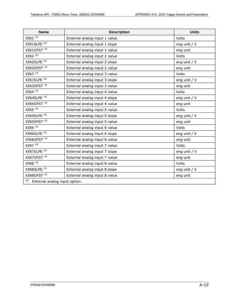
Teledyne API - T500U Menu Trees 08061C DCN6998 APPENDIX A-5: DAS Trigger Events and Parameters
A-19
Name Description Units
XIN1 10 External analog input 1 value Volts
XIN1SLPE 10 External analog input 1 slope eng unit / V
XIN1OFST 10 External analog input 1 value eng unit
XIN2 10 External analog input 2 value Volts
XIN2SLPE 10 External analog input 2 slope eng unit / V
XIN2OFST 10 External analog input 2 value eng unit
XIN3 10 External analog input 3 value Volts
XIN3SLPE 10 External analog input 3 slope eng unit / V
XIN3OFST 10 External analog input 3 value eng unit
XIN4 10 External analog input 4 value Volts
XIN4SLPE 10 External analog input 4 slope eng unit / V
XIN4OFST 10 External analog input 4 value eng unit
XIN5 10 External analog input 5 value Volts
XIN5SLPE 10 External analog input 5 slope eng unit / V
XIN5OFST 10 External analog input 5 value eng unit
XIN6 10 External analog input 6 value Volts
XIN6SLPE 10 External analog input 6 slope eng unit / V
XIN6OFST 10 External analog input 6 value eng unit
XIN7 10 External analog input 7 value Volts
XIN7SLPE 10 External analog input 7 slope eng unit / V
XIN7OFST 10 External analog input 7 value eng unit
XIN8 10 External analog input 8 value Volts
XIN8SLPE 10 External analog input 8 slope eng unit / V
XIN8OFST 10 External analog input 8 value eng unit
10 External analog input option.
07834D DCN6998
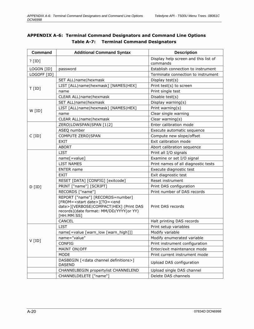
APPENDIX A-6: Terminal Command Designators and Command Line Options Teledyne API - T500U Menu Trees 08061C DCN6998
A-20
APPENDIX A-6: Terminal Command Designators and Command Line Options
Table A-7: Terminal Command Designators
Command Additional Command Syntax Description
? [ID] Display help screen and this list of
commands
LOGON [ID] password Establish connection to instrument
LOGOFF [ID] Terminate connection to instrument
T [ID]
SET ALL|name|hexmask Display test(s)
LIST [ALL|name|hexmask] [NAMES|HEX] Print test(s) to screen
name Print single test
CLEAR ALL|name|hexmask Disable test(s)
W [ID]
SET ALL|name|hexmask Display warning(s)
LIST [ALL|name|hexmask] [NAMES|HEX] Print warning(s)
name Clear single warning
CLEAR ALL|name|hexmask Clear warning(s)
C [ID]
ZERO|LOWSPAN|SPAN [1|2] Enter calibration mode
ASEQ number Execute automatic sequence
COMPUTE ZERO|SPAN Compute new slope/offset
EXIT Exit calibration mode
ABORT Abort calibration sequence
D [ID]
LIST Print all I/O signals
name[=value] Examine or set I/O signal
LIST NAMES Print names of all diagnostic tests
ENTER name Execute diagnostic test
EXIT Exit diagnostic test
RESET [DATA] [CONFIG] [exitcode] Reset instrument
PRINT ["name"] [SCRIPT] Print DAS configuration
RECORDS ["name"] Print number of DAS records
REPORT ["name"] [RECORDS=number]
[FROM=<start date>][TO=<end date>][VERBOSE|COMPACT|HEX] (Print DAS records)(date format: MM/DD/YYYY(or YY) [HH:MM:SS]
Print DAS records
CANCEL Halt printing DAS records
V [ID]
LIST Print setup variables
name[=value [warn_low [warn_high]]] Modify variable
name="value" Modify enumerated variable
CONFIG Print instrument configuration
MAINT ON|OFF Enter/exit maintenance mode
MODE Print current instrument mode
DASBEGIN [<data channel definitions>] DASEND
Upload DAS configuration
CHANNELBEGIN propertylist CHANNELEND Upload single DAS channel
CHANNELDELETE ["name"] Delete DAS channels
07834D DCN6998

Teledyne API - T500U Menu Trees 08061C DCN6998 APPENDIX A-6: Terminal Command Designators and Command Line Options
A-21
The command syntax follows the command type, separated by a space character. Strings in
[brackets] are optional designators. The following key assignments also apply.
Terminal Key Assignments
ESC Abort line
CR (ENTER) Execute command
Ctrl-C Switch to computer mode
Computer Mode Key Assignments
LF (line feed) Execute command
Ctrl-T Switch to terminal mode
Table A-8 Firmware Command Line Options
Option Description
/?, /h Prints command line usage without executing the firmware.
/u CPU-type CPU-type specifies the CPU type to use:
0 = Generic PC (default)
1 = AR-B1320, 386SX, PC/104
2 = AR-B9612A, 386SX, PC/104
/d device Device specifies the display type to use:
0 = PC video display and keyboard (default)
1 = Onyx I/O, parallel display (not currently supported)
2 = DMM-32 I/O, parallel display (not currently supported)
3 = ICA90, 8574-based I2C display
4 = API "E" series rear board, parallel display
5 = API "E" series rear board, 8574-based I2C display
/y Runs the firmware without prompting. This is useful for executing the
firmware automatically from within a batch file. The default is to prompt for confirmation.
/w Disables the watchdog timer. The default is enabled.
/n file File specifies a different name and/or location for the configuration file. The
default is “config.bin” in the same directory as the executable file. If you have configured flash memory as a disk drive, such as B:, then you can store the configuration information in the flash using the command line option –o “b:\config.bin”.
/r file File specifies an alternate resource file containing the firmware’s default configuration. The default is the executable file.
/a address Address specifies the Com port for the bench interface. The default is 3. Valid values are 2-4.
/b address 3, 5 Address specifies the I/O address of the I2C interface data register. The default is 0x32c (hex). This is usually 0x310 for the ICA90 board.
/c address 3, 5 Address specifies the I/O address of the I2C interface control register. The default is 0x32f (hex). This is usually 0x311 for the ICA90 board.
/q irq 3, 5 IRQ specifies the IRQ number of the I2C interface. The default is IRQ5.
/k irq 3, 4, 5 IRQ specifies the IRQ number of the keyboard (0 = use polling mode instead of interrupt mode). The default is IRQ12.
07834D DCN6998
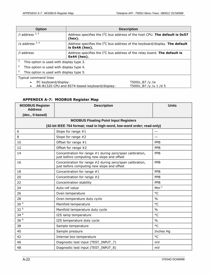
APPENDIX A-7: MODBUS Register Map Teledyne API - T500U Menu Trees 08061C DCN6998
A-22
Option Description
/i address 3, 5 Address specifies the I2C bus address of the host CPU. The default is 0x57 (hex).
/s address 3, 5 Address specifies the I2C bus address of the keyboard/display. The default is 0x4A (hex).
/l address Address specifies the I2C bus address of the relay board. The default is 0x44 (hex).
3 This option is used with display type 3.
4 This option is used with display type 4. 5 This option is used with display type 5.
Typical command lines
PC keyboard/display: T500U_B7 /y /w
AR-B1320 CPU and 8574-based keyboard/display: T500U_B7 /y /u 1 /d 5
APPENDIX A-7: MODBUS Register Map
MODBUS Register Address
(dec., 0-based)
Description Units
MODBUS Floating Point Input Registers
(32-bit IEEE 754 format; read in high-word, low-word order; read-only)
6 Slope for range #1 —
8 Slope for range #2 —
10 Offset for range #1 PPB
12 Offset for range #2 PPB
14 Concentration for range #1 during zero/span calibration, just before computing new slope and offset
PPB
16 Concentration for range #2 during zero/span calibration, just before computing new slope and offset
PPB
18 Concentration for range #1 PPB
20 Concentration for range #2 PPB
22 Concentration stability PPB
24 Auto-ref value Mm-1
26 Oven temperature °C
28 Oven temperature duty cycle %
30 5 Manifold temperature °C
32 5 Manifold temperature duty cycle %
34 6 IZS lamp temperature °C
36 6 IZS temperature duty cycle %
38 Sample temperature °C
40 Sample pressure Inches Hg
42 Internal box temperature °C
46 Diagnostic test input (TEST_INPUT_7) mV
48 Diagnostic test input (TEST_INPUT_8) mV
07834D DCN6998

Teledyne API - T500U Menu Trees 08061C DCN6998 APPENDIX A-7: MODBUS Register Map
A-23
MODBUS Register Address
(dec., 0-based)
Description Units
50 Diagnostic temperature input (TEMP_INPUT_6) °C
54 Ground reference mV
56 Precision 4.096 mV reference mV
130 10 External analog input 1 value Volts
132 10 External analog input 1 slope eng unit /V
134 10 External analog input 1 offset eng unit
136 10 External analog input 2 value Volts
138 10 External analog input 2 slope eng unit /V
140 10 External analog input 2 offset eng unit
142 10 External analog input 3 value Volts
144 10 External analog input 3 slope eng unit /V
146 10 External analog input 3 offset eng unit
148 10 External analog input 4 value Volts
150 10 External analog input 4 slope eng unit /V
152 10 External analog input 4 offset eng unit
154 10 External analog input 5 value Volts
156 10 External analog input 5 slope eng unit /V
158 10 External analog input 5 offset eng unit
160 10 External analog input 6 value Volts
162 10 External analog input 6 slope eng unit /V
164 10 External analog input 6 offset eng unit
166 10 External analog input 7 value Volts
168 10 External analog input 7 slope eng unit /V
170 10 External analog input 7 offset eng unit
172 10 External analog input 8 value Volts
174 10 External analog input 8 slope eng unit /V
176 10 External analog input 8 offset eng unit
MODBUS Floating Point Holding Registers
(32-bit IEEE 754 format; read/write in high-word, low-word order; read/write)
2 Maps to NO2_SPAN1 variable; target span concentration for range #1
Conc. units
6 Maps to NO2_SPAN2 variable; target span concentration for range #2
Conc. units
MODBUS Discrete Input Registers
(single-bit; read-only)
0 Auto-ref warning
1 Oven temperature warning
2 5 Manifold temperature warning
3 6 IZS temperature warning
4 Baseline loss warning
07834D DCN6998
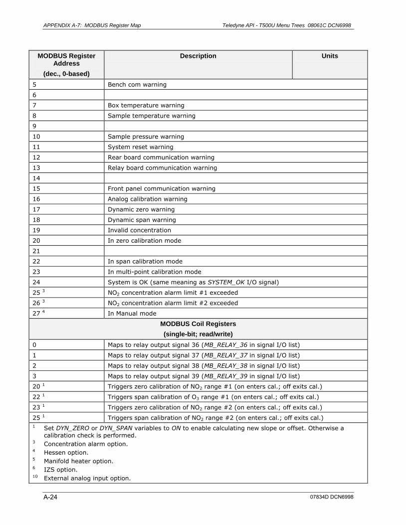
APPENDIX A-7: MODBUS Register Map Teledyne API - T500U Menu Trees 08061C DCN6998
A-24
MODBUS Register Address
(dec., 0-based)
Description Units
5 Bench com warning
6
7 Box temperature warning
8 Sample temperature warning
9
10 Sample pressure warning
11 System reset warning
12 Rear board communication warning
13 Relay board communication warning
14
15 Front panel communication warning
16 Analog calibration warning
17 Dynamic zero warning
18 Dynamic span warning
19 Invalid concentration
20 In zero calibration mode
21
22 In span calibration mode
23 In multi-point calibration mode
24 System is OK (same meaning as SYSTEM_OK I/O signal)
25 3 NO2 concentration alarm limit #1 exceeded
26 3 NO2 concentration alarm limit #2 exceeded
27 4 In Manual mode
MODBUS Coil Registers
(single-bit; read/write)
0 Maps to relay output signal 36 (MB_RELAY_36 in signal I/O list)
1 Maps to relay output signal 37 (MB_RELAY_37 in signal I/O list)
2 Maps to relay output signal 38 (MB_RELAY_38 in signal I/O list)
3 Maps to relay output signal 39 (MB_RELAY_39 in signal I/O list)
20 1 Triggers zero calibration of NO2 range #1 (on enters cal.; off exits cal.)
22 1 Triggers span calibration of O3 range #1 (on enters cal.; off exits cal.)
23 1 Triggers zero calibration of NO2 range #2 (on enters cal.; off exits cal.)
25 1 Triggers span calibration of NO2 range #2 (on enters cal.; off exits cal.)
1 Set DYN_ZERO or DYN_SPAN variables to ON to enable calculating new slope or offset. Otherwise a calibration check is performed.
3 Concentration alarm option. 4 Hessen option. 5 Manifold heater option. 6 IZS option. 10 External analog input option.
07834D DCN6998
APPENDIX B - Spare Parts
Note Use of replacement parts other than those supplied by Teledyne Advanced Pollution Instrumentation (TAPI) may result in non-compliance with European standard EN 61010-1.
Note Due to the dynamic nature of part numbers, please refer to the TAPI Website at http://www.teledyne-api.com or call Customer Service at 800-324-5190 for more recent updates to part numbers.
07834D DCN6998 B-1

This page intentionally left blank.
B-2 07834D DCN6998
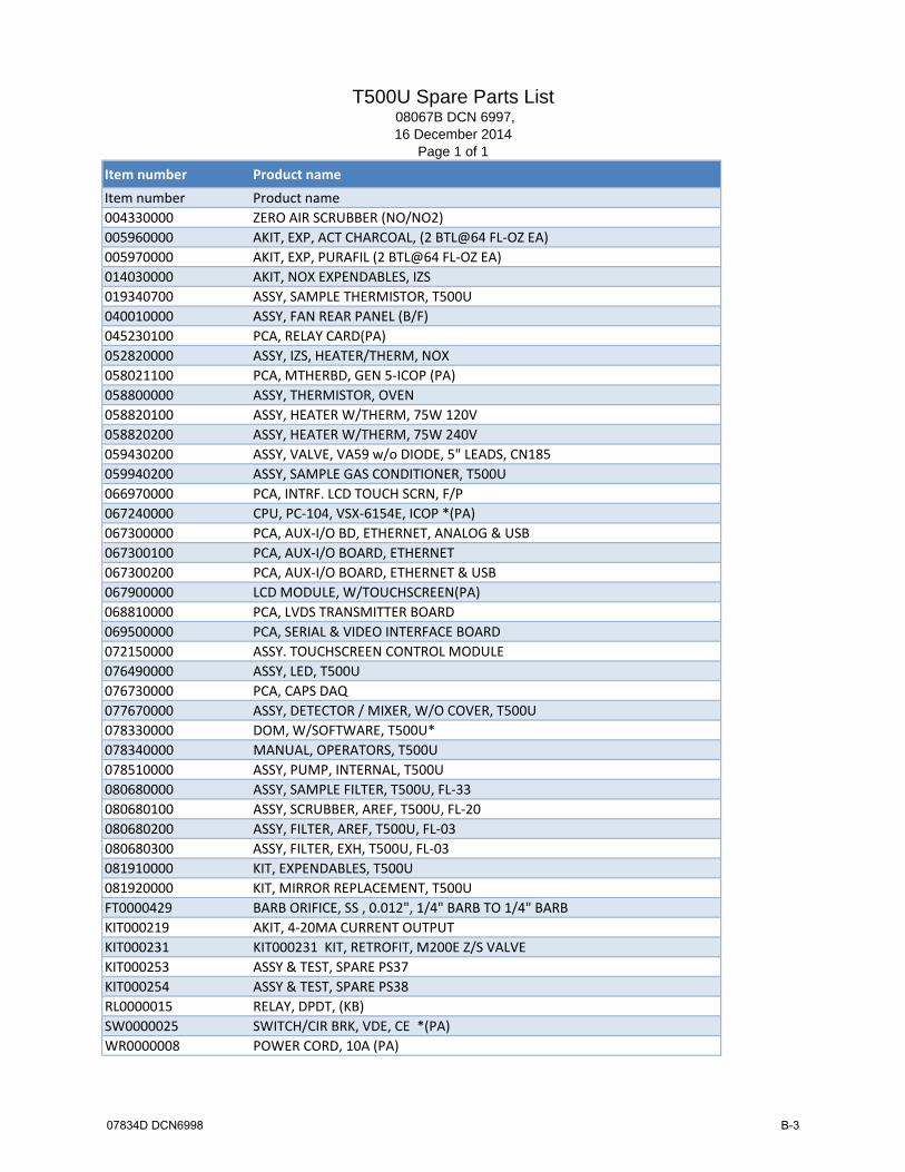
T500U Spare Parts List 08067B DCN 6997, 16 December 2014
Page 1 of 1
Item number Product name
Item number Product name
004330000 ZERO AIR SCRUBBER (NO/NO2)
005960000 AKIT, EXP, ACT CHARCOAL, (2 BTL@64 FL‐OZ EA)
005970000 AKIT, EXP, PURAFIL (2 BTL@64 FL‐OZ EA)
014030000 AKIT, NOX EXPENDABLES, IZS
019340700 ASSY, SAMPLE THERMISTOR, T500U
040010000 ASSY, FAN REAR PANEL (B/F)
045230100 PCA, RELAY CARD(PA)
052820000 ASSY, IZS, HEATER/THERM, NOX
058021100 PCA, MTHERBD, GEN 5‐ICOP (PA)
058800000 ASSY, THERMISTOR, OVEN
058820100 ASSY, HEATER W/THERM, 75W 120V
058820200 ASSY, HEATER W/THERM, 75W 240V
059430200 ASSY, VALVE, VA59 w/o DIODE, 5" LEADS, CN185
059940200 ASSY, SAMPLE GAS CONDITIONER, T500U
066970000 PCA, INTRF. LCD TOUCH SCRN, F/P
067240000 CPU, PC‐104, VSX‐6154E, ICOP *(PA)
067300000 PCA, AUX‐I/O BD, ETHERNET, ANALOG & USB
067300100 PCA, AUX‐I/O BOARD, ETHERNET
067300200 PCA, AUX‐I/O BOARD, ETHERNET & USB
067900000 LCD MODULE, W/TOUCHSCREEN(PA)
068810000 PCA, LVDS TRANSMITTER BOARD
069500000 PCA, SERIAL & VIDEO INTERFACE BOARD
072150000 ASSY. TOUCHSCREEN CONTROL MODULE
076490000 ASSY, LED, T500U
076730000 PCA, CAPS DAQ
077670000 ASSY, DETECTOR / MIXER, W/O COVER, T500U
078330000 DOM, W/SOFTWARE, T500U*
078340000 MANUAL, OPERATORS, T500U
078510000 ASSY, PUMP, INTERNAL, T500U
080680000 ASSY, SAMPLE FILTER, T500U, FL‐33
080680100 ASSY, SCRUBBER, AREF, T500U, FL‐20
080680200 ASSY, FILTER, AREF, T500U, FL‐03
080680300 ASSY, FILTER, EXH, T500U, FL‐03
081910000 KIT, EXPENDABLES, T500U
081920000 KIT, MIRROR REPLACEMENT, T500U
FT0000429 BARB ORIFICE, SS , 0.012", 1/4" BARB TO 1/4" BARB
KIT000219 AKIT, 4‐20MA CURRENT OUTPUT
KIT000231 KIT000231 KIT, RETROFIT, M200E Z/S VALVE
KIT000253 ASSY & TEST, SPARE PS37
KIT000254 ASSY & TEST, SPARE PS38
RL0000015 RELAY, DPDT, (KB)
SW0000025 SWITCH/CIR BRK, VDE, CE *(PA)
WR0000008 POWER CORD, 10A (PA)
07834D DCN6998 B-3

This page intentionally left blank.
B-4 07834D DCN6998
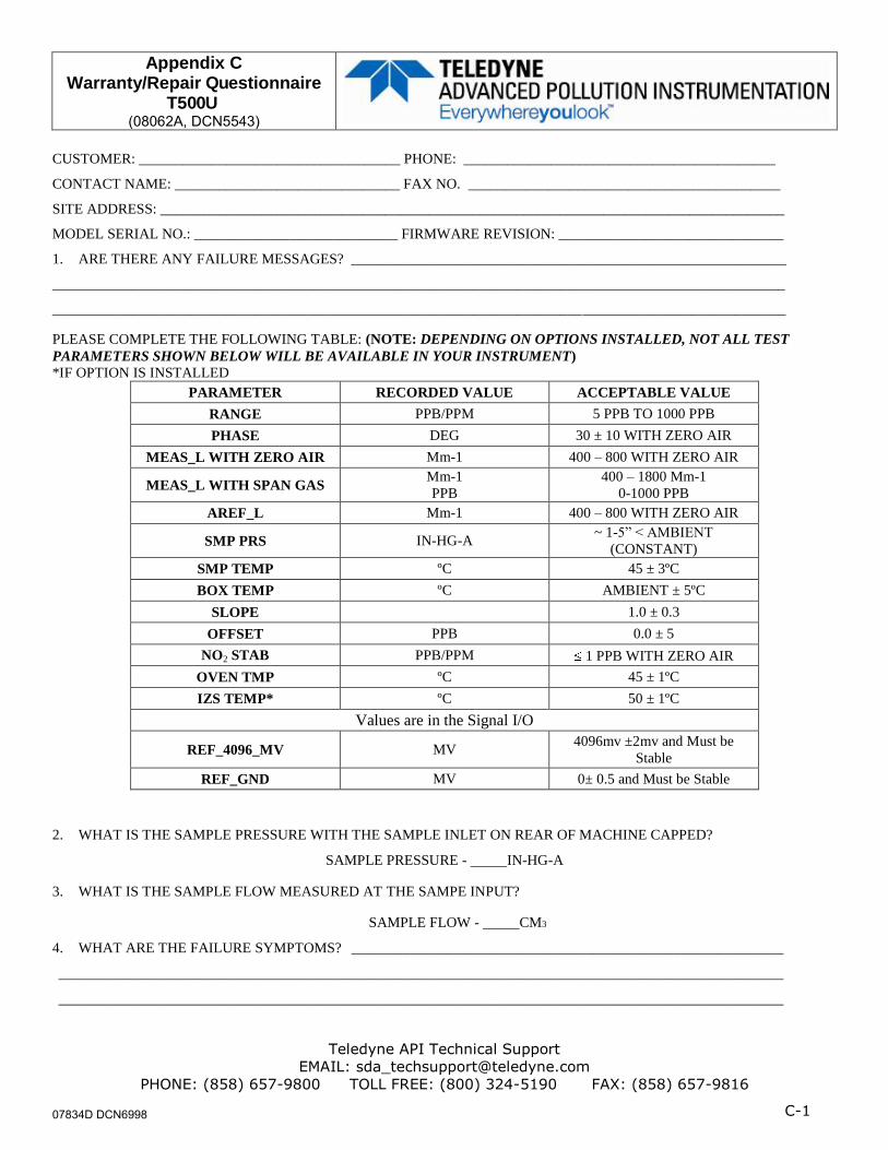
Appendix C Warranty/Repair Questionnaire
T500U (08062A, DCN5543)
Teledyne API Technical Support
EMAIL: [email protected]
PHONE: (858) 657-9800 TOLL FREE: (800) 324-5190 FAX: (858) 657-9816
C-1
CUSTOMER: ____________________________________ PHONE: ___________________________________________
CONTACT NAME: _______________________________ FAX NO. ___________________________________________
SITE ADDRESS: ______________________________________________________________________________________
MODEL SERIAL NO.: ____________________________ FIRMWARE REVISION: _______________________________
1. ARE THERE ANY FAILURE MESSAGES? ____________________________________________________________
_____________________________________________________________________________________________________
_____________________________________________________________________________________________________
PLEASE COMPLETE THE FOLLOWING TABLE: (NOTE: DEPENDING ON OPTIONS INSTALLED, NOT ALL TEST
PARAMETERS SHOWN BELOW WILL BE AVAILABLE IN YOUR INSTRUMENT)
*IF OPTION IS INSTALLED
PARAMETER RECORDED VALUE ACCEPTABLE VALUE
RANGE PPB/PPM 5 PPB TO 1000 PPB
PHASE DEG 30 ± 10 WITH ZERO AIR
MEAS_L WITH ZERO AIR Mm-1 400 – 800 WITH ZERO AIR
MEAS_L WITH SPAN GAS Mm-1
PPB
400 – 1800 Mm-1
0-1000 PPB
AREF_L Mm-1 400 – 800 WITH ZERO AIR
SMP PRS IN-HG-A ~ 1-5” < AMBIENT
(CONSTANT)
SMP TEMP ºC 45 ± 3ºC
BOX TEMP ºC AMBIENT ± 5ºC
SLOPE 1.0 ± 0.3
OFFSET PPB 0.0 ± 5
NO2 STAB PPB/PPM 1 PPB WITH ZERO AIR
OVEN TMP ºC 45 ± 1ºC
IZS TEMP* ºC 50 ± 1ºC
Values are in the Signal I/O
REF_4096_MV MV 4096mv ±2mv and Must be
Stable
REF_GND MV 0± 0.5 and Must be Stable
2. WHAT IS THE SAMPLE PRESSURE WITH THE SAMPLE INLET ON REAR OF MACHINE CAPPED?
SAMPLE PRESSURE - IN-HG-A
3. WHAT IS THE SAMPLE FLOW MEASURED AT THE SAMPE INPUT?
SAMPLE FLOW - CM3
4. WHAT ARE THE FAILURE SYMPTOMS? ___________________________________________________________
___________________________________________________________________________________________________
___________________________________________________________________________________________________
07834D DCN6998

Appendix C Warranty/Repair Questionnaire
T500U
(08062A, DCN5543)
Teledyne API Technical Support
EMAIL: [email protected]
PHONE: (858) 657-9800 TOLL FREE: (800) 324-5190 FAX: (858) 657-9816
C-2
5. WHAT TEST(S) HAVE YOU DONE TRYING TO SOLVE THE PROBLEM? ________________________________
___________________________________________________________________________________________________
___________________________________________________________________________________________________
___________________________________________________________________________________________________
___________________________________________________________________________________________________
___________________________________________________________________________________________________
6. IF POSSIBLE, PLEASE INCLUDE A PORTION OF A STRIP CHART PERTAINING TO THE PROBLEM AND CIRCLE
THE PERTINENT DATA.
THANK YOU FOR PROVIDING THIS INFORMATION. YOUR ASSISTANCE ENABLES TELEDYNE API TO RESPOND
FASTER TO THE PROBLEM THAT YOU ARE ENCOUNTERING.
07834D DCN6998

APPENDIX D – Interconnect Diagram
07834D DCN6998 D-1

This page intentionally left blank.
D-2 07834D DCN6998

The
info
rma
tion
here
on is
the
pro
per
ty o
fA
PI a
nd is
sub
mitt
ed in
stric
test
conf
iden
ce fo
r ref
eren
ce o
nly.
Una
utho
rized
use
by
any
one
for a
ny o
the
rpur
pos
ese
is p
rohi
bite
d.
This
doc
umen
tor
any
info
rma
tion
cont
ain
ed in
it m
ay
be
dup
lica
ted
with
out p
rop
er a
utho
rizat
ion.
Prin
ted
Doc
umen
ts a
re U
ncon
trolle
d
Ever
ywhe
relo
okAD
VANC
ED P
OLLU
TION
INST
RUME
NTAT
ION
J14
J106
J107
Ana
log
Out
J102
0O
ut J1
017
Stat
usC
ontro
lIn
J100
4R
S-23
2J1
013
J101
0 &
101
1R
S-48
5
J106
AUX I/O 0673001
LCD
w/T
ouch
scre
en06
790
Cnt
rl M
odLC
D In
terfa
ce06
697
J2
J107
215
J9J15
(+12
)
(+5,
±15
)
J14
AZ V
alve
Sam
ple
Valv
e
J1 J4
J3
J8
SK1
SK1
SK2
SK2
0452
3010
0
SW
ITC
HA
C P
OW
ER
EN
TRA
NC
EA
C P
OW
ER
RE
LAY
BO
AR
D
PS
2
PS
1
J11
CN
3CN
5CN
4
J1Xmitter06881
W/MD06950J3
J4
DO
MC
P34
CPU
067
24
Mot
herb
oard
0580
2140
0
J12
ZS V
alve
J9
J2
J15 J7
J6
J2PC
A, C
aps
Daq
0767
3000
0J8 J5
J2P
ream
p/M
ixr
0776
7
IZS
Thrm
/Hea
ter
Ove
n Th
rm05
8800
000
Ass
y H
ter/s
w05
8820
100
J18
J27
Ove
n Fa
n07
713
J11
AS
SY, C
APS
OVE
N
07
6990
000
J10
Box
Fan
PU
MP
0785
1000
0
0423
4000
0
0423
4000
0
0771
2000
0
Ass
y LE
D07
6490
000
J9
KEY
:1.
All
part
num
bers
in
iden
tify
cabl
es
that
are
refe
red
to in
the
acco
mpa
nyin
g
docu
men
t 078
4801
00.
2. A
ll ite
ms
in D
ashe
d bo
xes
are
optio
nal.
Sam
p Th
rm01
9340
700
J3
0783
4D D
CN
6998
D-3


