Model 1850F DehumidifierInstallation and Operating Manual
READ AND SAVE THESE INSTRUCTIONS
CAUTION
1. Read all instructions before beginning installation.
2. Improper installation may cause property damage or injury. Read instructions before installation, service or maintenance.
3. Do not use in pool applications. Pool chemicals can damage the dehumidifier.
4. Do not use solvents or cleaners on or near the circuit board. Chemicals can damage circuit board components.
5. Wait 24 hours before running the unit if it was not shipped or stored in the upright position
6. Do not use dehumidification to prevent window condensation in the winter. To address window condensation, use ventilation to lower indoor humidity in the winter.
WARNING
1. 120 Volts may cause serious injury from electric shock. Disconnect electrical power before starting installation or servicing. Leave power disconnected until installation/service is completed.
2. Dropping may cause personal injury or equipment damage. Handle with care and follow installation instructions.
SAFETy INSTRUCTIONS
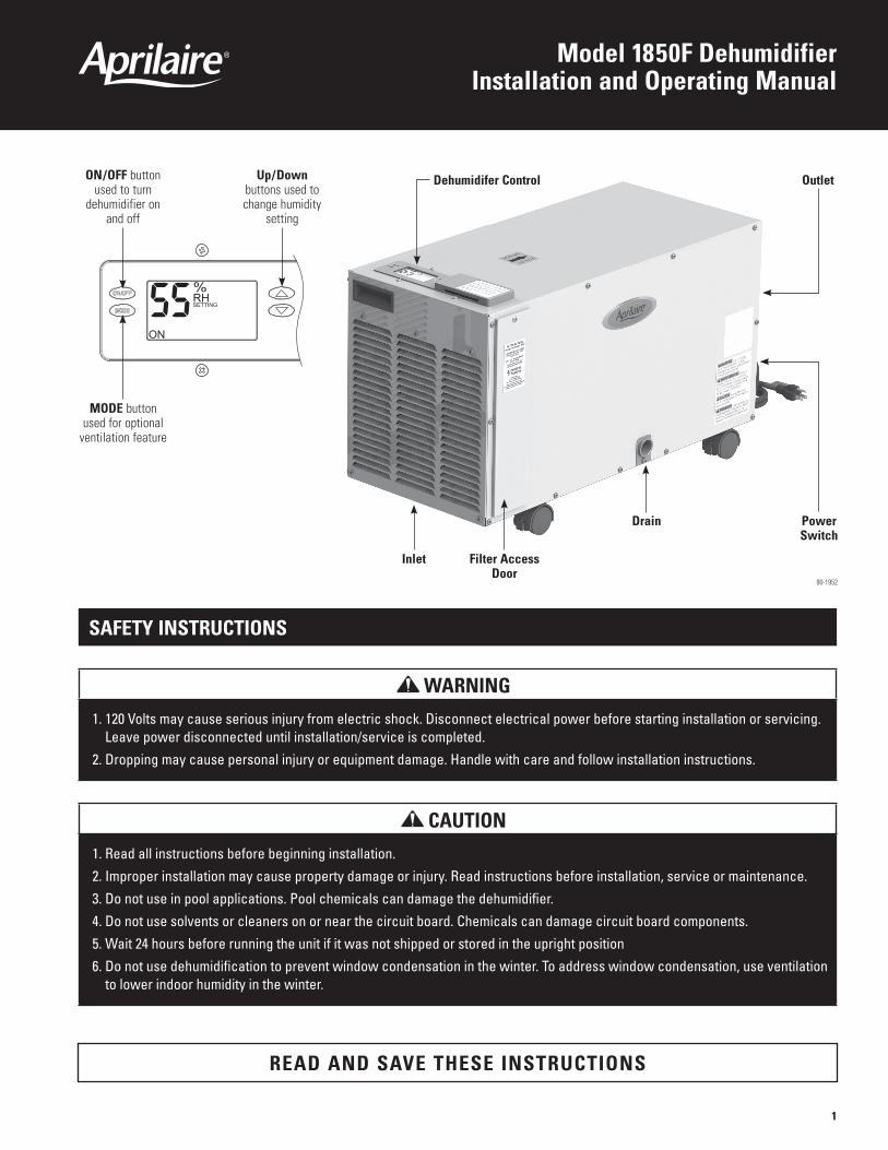
Dehumidifer ControlON/OFF button used to turn
dehumidifier on and off
Up/Down buttons used to change humidity
setting
MODE button used for optional
ventilation feature
Inlet Filter Access Door
Drain Power Switch
Outlet
90-1952
1

SPECIFICATIONS
Model 1850F
Weight 70 lbs.
Capacity AHAM DH-1-2008 80°F, 60% RH Conditions
95 pints per day @ 230 CFM
Power 115 VAC, Single Phase, 60Hz
8A operating current
Dehumidifier Inlet Air ConditionsDehumidification: 50°F – 104°F, 40°F dew point minimum
Ventilation: 40°F – 140°F, 0%RH – 99%RH (non-condensing)
Filter MERV 8, washable
Airflow 230 CFM
TAblE OF CONTENTS
Safety Instructions. . . . . . . . . . . . . . . . . . . . . . . . . . . . . . . . . . . . . . . . . . . . . . . . . . . . . . . . . . . . . . . . . . . . . . . . . . . . . . . . . . . . . . . . . . . . . . . . . . . . . . 1
Specifications. . . . . . . . . . . . . . . . . . . . . . . . . . . . . . . . . . . . . . . . . . . . . . . . . . . . . . . . . . . . . . . . . . . . . . . . . . . . . . . . . . . . . . . . . . . . . . . . . . . . . . . . . . 2
Set Up Dehumidifier for Installation . . . . . . . . . . . . . . . . . . . . . . . . . . . . . . . . . . . . . . . . . . . . . . . . . . . . . . . . . . . . . . . . . . . . . . . . . . . . . . . . . . . . . . 3
location Considerations. . . . . . . . . . . . . . . . . . . . . . . . . . . . . . . . . . . . . . . . . . . . . . . . . . . . . . . . . . . . . . . . . . . . . . . . . . . . . . . . . . . . . . . . . . . . . . . . . 3
Drain Installation . . . . . . . . . . . . . . . . . . . . . . . . . . . . . . . . . . . . . . . . . . . . . . . . . . . . . . . . . . . . . . . . . . . . . . . . . . . . . . . . . . . . . . . . . . . . . . . . . . . . . . . 4 Leveling . . . . . . . . . . . . . . . . . . . . . . . . . . . . . . . . . . . . . . . . . . . . . . . . . . . . . . . . . . . . . . . . . . . . . . . . . . . . . . . . . . . . . . . . . . . . . . . . . . . . . . . . . . . . . . 4 Condensate Pan, Condensate Pump and Float Switch . . . . . . . . . . . . . . . . . . . . . . . . . . . . . . . . . . . . . . . . . . . . . . . . . . . . . . . . . . . . . . . . . . . . . . . . . 4
Setting the Desired Humidity level . . . . . . . . . . . . . . . . . . . . . . . . . . . . . . . . . . . . . . . . . . . . . . . . . . . . . . . . . . . . . . . . . . . . . . . . . . . . . . . . . . . . . . . 5
Maintenance . . . . . . . . . . . . . . . . . . . . . . . . . . . . . . . . . . . . . . . . . . . . . . . . . . . . . . . . . . . . . . . . . . . . . . . . . . . . . . . . . . . . . . . . . . . . . . . . . . . . . . . . . . . 6
Model 76 – External Control or Crawl Space/Sealed Attic Control and Wiring. . . . . . . . . . . . . . . . . . . . . . . . . . . . . . . . . . . . . . . . . . . . . . . . 7
Troubleshooting . . . . . . . . . . . . . . . . . . . . . . . . . . . . . . . . . . . . . . . . . . . . . . . . . . . . . . . . . . . . . . . . . . . . . . . . . . . . . . . . . . . . . . . . . . . . . . . . . . . . . . . . 8 Table 1 – Diagnostic Codes . . . . . . . . . . . . . . . . . . . . . . . . . . . . . . . . . . . . . . . . . . . . . . . . . . . . . . . . . . . . . . . . . . . . . . . . . . . . . . . . . . . . . . . . . . . . . . 8 Table 2 – Troubleshooting Guide . . . . . . . . . . . . . . . . . . . . . . . . . . . . . . . . . . . . . . . . . . . . . . . . . . . . . . . . . . . . . . . . . . . . . . . . . . . . . . . . . . . . . . . . . . 9
Service Parts. . . . . . . . . . . . . . . . . . . . . . . . . . . . . . . . . . . . . . . . . . . . . . . . . . . . . . . . . . . . . . . . . . . . . . . . . . . . . . . . . . . . . . . . . . . . . . . . . . . . . . . . . . 10
Warranty . . . . . . . . . . . . . . . . . . . . . . . . . . . . . . . . . . . . . . . . . . . . . . . . . . . . . . . . . . . . . . . . . . . . . . . . . . . . . . . . . . . . . . . . . . . . . . . . . . . . . . . . . . . . . 11
2
lOCATION CONSIDERATIONS
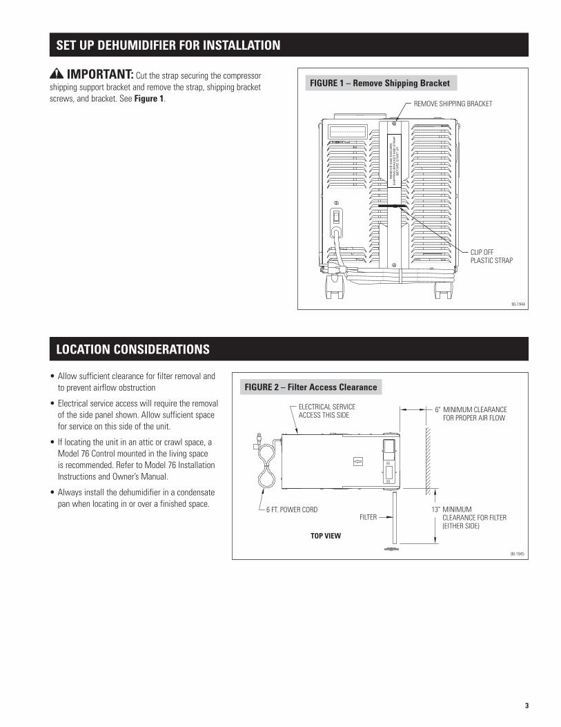
TOP VIEW
FILTERMINIMUMCLEARANCE FOR FILTER(EITHER SIDE)
13"
6" MINIMUM CLEARANCEFOR PROPER AIR FLOW
ELECTRICAL SERVICEACCESS THIS SIDE
6 FT. POWER CORD
FIGURE 2 – Filter Access Clearance
90-1945
•Allowsufficientclearanceforfilterremovalandto prevent airflow obstruction
•Electricalserviceaccesswillrequiretheremovalof the side panel shown. Allow sufficient space for service on this side of the unit.
•Iflocatingtheunitinanatticorcrawlspace,aModel 76 Control mounted in the living space isrecommended.RefertoModel76InstallationInstructionsandOwner’sManual.
•Alwaysinstallthedehumidifierinacondensatepan when locating in or over a finished space.
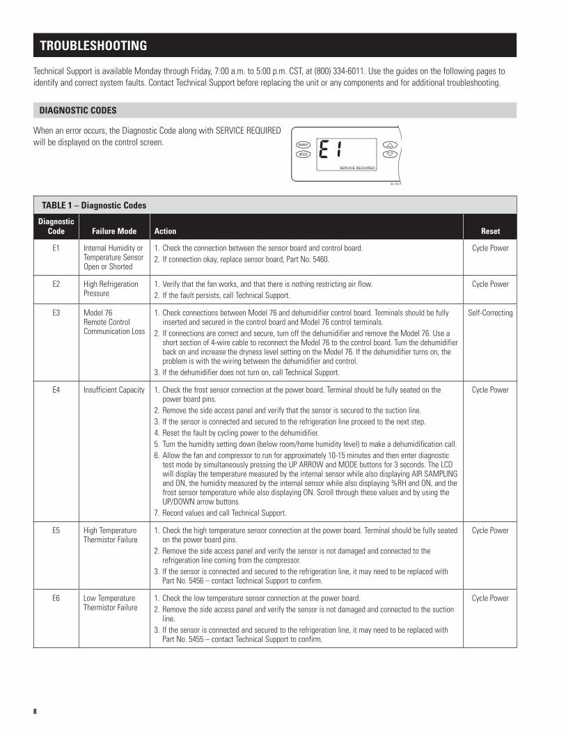
CLIP OFFPLASTIC STRAP
REMOVE SHIPPING BRACKET
RE
MO
VE
AN
D D
ISC
AR
DS
HIP
PIN
G B
RA
CK
ET
AN
D S
TR
AP
BE
FO
RE
STA
RT
UP.
FIGURE 1 – Remove Shipping bracket
90-1944
IMPORTANT: Cut the strap securing the compressor shipping support bracket and remove the strap, shipping bracket screws, and bracket. See Figure 1.
SET UP DEHUMIDIFIER FOR INSTAllATION
3

FLO
ATSw
itch
DH
DH
NORMALLY CLOSEDFLOAT SWITCH
DRAIN INSTAllATION
lEVElING
CONDENSATE PAN, CONDENSATE PUMP AND FlOAT SWITCH
Alevelsurfaceisrequiredtoensureproperdrainagefromthedehumidifier.
The drain outlet on the dehumidifier can be hard piped using 3/4” nominal drain tubing or the provided fittings and 1/2” clear PVC tubing can be used to drain the dehumidifier. Always maintain a constant downward slope from the dehumidifier to the drain and do not allow soft tubing to curl up which may result in air lock.
Always install the dehumidifier in a condensate pan when locating in or above a finished space. Adhere to local codes regarding drainingofthecondensatepan.Ifacondensatepumpisneeded,install it in the condensate pan as well.
Installacondensateoverflowsafetyswitch(i.e.floatswitch)inthecondensate pan, remove the factory installed jumper wire between the Float Switch terminals on the control and wire the float switch to the dehumidifier as shown in Figure 4.Overflowsafetyswitcheson condensate pumps can be wired to the Float Switch terminals in a similar fashion.
FIGURE 4 – Float Switch Wiring
90-1857
4

SETTING THE DESIRED HUMIDITy lEVEl
1.PresstheON/OFFbuttontoturnthedehumidifiercontrolON.Thedisplaywillshowthecurrent setting, and the dehumidifier blower will turn on to start sampling the air.
2.TheUPandDOWNarrowbuttonsallowthehumidityleveltobesetfrom40%to80%relativehumidity.UsetheON/OFFbuttontoturnthedehumidifierONorOFF.
Set the control at 55%RH when first installed. Allow the dehumidifier to run until it reaches the setting before deciding if you want to change the setting.
• Ifyouprefertheairtobemoredry, decrease the humidity setting.
• Ifyouprefertheairtobelessdry, increase the humidity setting.
Yourcomfortisthebestmeasureofhowtoadjustyoursetting.Whenfirstinstalled,yourdehumidifier has to remove all the moisture that is initially in your home. The home acts like a sponge so the moisture in the materials of your home is at the same level as the air. After drying the air, the materials of the home will release moisture back into the air until they are again at the same level. As a result, it is not uncommon for the dehumidifier to operate for an extended period when first installed.
3. After three (3) minutes of sampling, the measured humidity will be compared to the setting:
a.Ifthehumidityisabovethesetting,thedehumidifiercompressorturnsonand“AIRSAMPLING”willbereplacedby“DEHUMIDIFYING”.Thecompressorremainsonuntilthemeasured humidity falls 3% RH below the setting.
b.Ifthemeasuredhumidityisbelowthesetting,theblowersturnoffandthedisplayreturns to showing the RH setting.
4. The dehumidifier will sample again every 60 minutes, or at any time if the humidity setting is lowered.
ENERGy SAVINGS TIPS
Energy Savings Tip #1: Adjust the humidity setting to be as high as is comfortable to reduce dehumidifier runtime.Ifitfeelsclammyor“smellsmusty”, lower the humidity setting. To save energy, turn the dehumidifier to OFFwhenyouopenyourwindows,justas you would with air conditioning.
Energy Savings Tip #2:Ifvacatingyour home for an extended period in the summer, set the RH at 55% and set your thermostat as high as you are comfortable setting it to in the cooling mode. Consult with appropriate professionals regarding the highest temperature that is safe for your pets or possessions. This will keep the humidity at a controlled level while minimizing the amount of cooling energy used.
90-1853
5

MAINTENANCE
ClEAN OR REPlACE THE AIR FIlTER
After initial installation the air filter should be checked and cleaned every 6 months. TheCLEANFILTERservicereminderwilldisplayontheon-boardcontrolscreenevery6months.Tocleartheservicemessage,presstheUPandDOWNarrowssimultaneouslyfor3seconds.
Filter Cleaning Procedure
1.TurntheON/OFFswitchOFF.
2. Remove the filter access door from either side of the dehumidifier.
3. Slide the filter out of the dehumidifier.
4. Flush the filter with warm water and a mild detergent solution.
5. Shake off the excess water from the filter.
6. Replace the filter, making sure the filter is secured in both the top and bottom filter rails.
7. Replace the filter access door.
8.TurntheON/OFFswitchON.
9.PresstheUPandDOWNbuttonssimultaneouslyfor3secondstocleartheservicemessage.
CAUTIONDo not use spray solvents or cleaners on or near the inlet side of the dehumidifier.
If desired, apply cleaner to a cloth and use to clean the cabinet.
CHECk THE DRAIN
Thedrainshouldbecheckedannuallytoensuretherearenoblockagesorairlockinthedrainsystem.Iftheunitisnotdrainingproperly,haveitcheckedbyaqualifiedserviceprofessional.
90-1854
6

MODEl 76 – EXTERNAl CONTROl OR CRAWl SPACE/SEAlED ATTIC CONTROl AND WIRING
Whenthedehumidifierislocatedinacrawlspace,sealedattic,orotherhardtoaccessarea, a Model 76 can be installed in the living space and will operate as a remote control. RefertotheModel76InstallationInstructionsandOwner’sManualforinstallationandoperating instructions.
NOTE:Use18-22AWGwireforcontrolwiring.
Model 76 Control
7
TROUblESHOOTING
Technical Support is available Monday through Friday, 7:00 a.m. to 5:00 p.m. CST, at (800) 334-6011. Use the guides on the following pages to identify and correct system faults. Contact Technical Support before replacing the unit or any components and for additional troubleshooting.
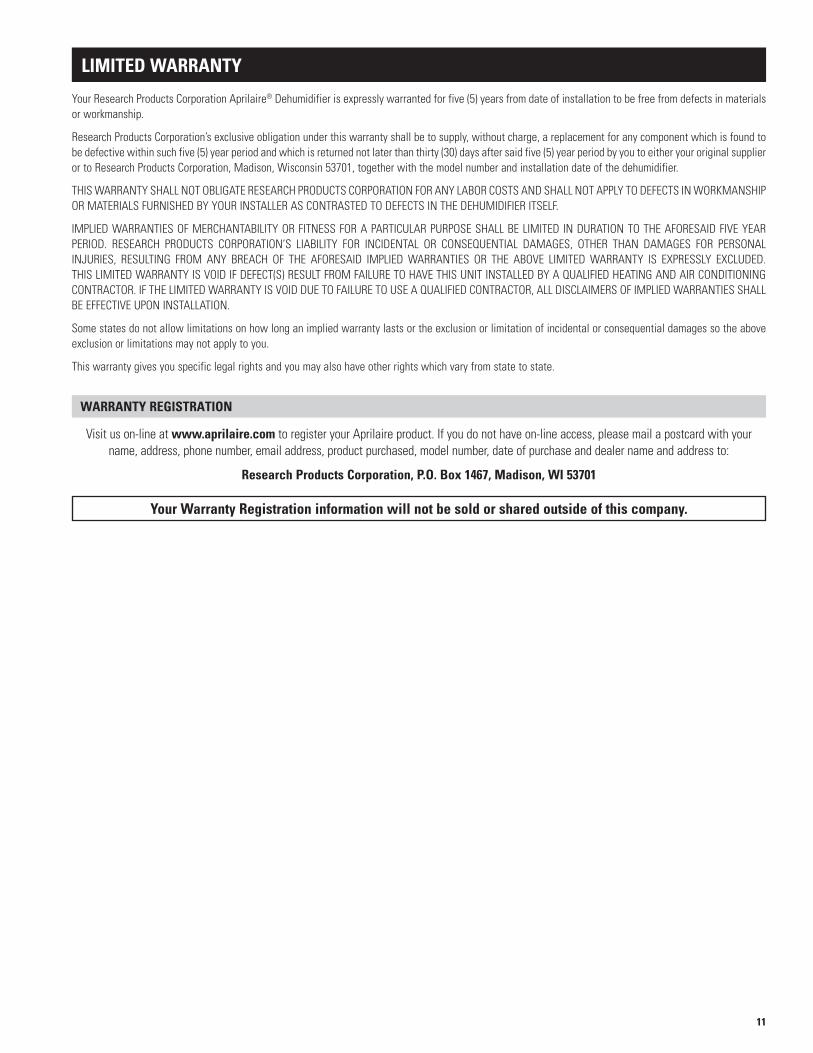
DIAGNOSTIC CODES
Whenanerroroccurs,theDiagnosticCodealongwithSERVICEREQUIREDwill be displayed on the control screen.
TAblE 1 – Diagnostic Codes
Diagnostic Code Failure Mode Action Reset
E1 InternalHumidityorTemperature Sensor OpenorShorted
1. Check the connection between the sensor board and control board.2. Ifconnectionokay,replacesensorboard,PartNo.5460.
Cycle Power
E2 High Refrigeration Pressure
1. Verify that the fan works, and that there is nothing restricting air flow.2. Ifthefaultpersists,callTechnicalSupport.
Cycle Power
E3 Model 76 Remote Control Communication Loss
1. Check connections between Model 76 and dehumidifier control board. Terminals should be fully inserted and secured in the control board and Model 76 control terminals.
2. Ifconnectionsarecorrectandsecure,turnoffthedehumidifierandremovetheModel76.Useashort section of 4-wire cable to reconnect the Model 76 to the control board. Turn the dehumidifier backonandincreasethedrynesslevelsettingontheModel76.Ifthedehumidifierturnson,theproblem is with the wiring between the dehumidifier and control.
3. Ifthedehumidifierdoesnotturnon,callTechnicalSupport.
Self-Correcting
E4 InsufficientCapacity 1. Check the frost sensor connection at the power board. Terminal should be fully seated on the power board pins.
2. Remove the side access panel and verify that the sensor is secured to the suction line.3. Ifthesensorisconnectedandsecuredtotherefrigerationlineproceedtothenextstep.4. Reset the fault by cycling power to the dehumidifier.5. Turn the humidity setting down (below room/home humidity level) to make a dehumidification call. 6. Allow the fan and compressor to run for approximately 10-15 minutes and then enter diagnostic testmodebysimultaneouslypressingtheUPARROWandMODEbuttonsfor3seconds.TheLCDwilldisplaythetemperaturemeasuredbytheinternalsensorwhilealsodisplayingAIRSAMPLINGandON,thehumiditymeasuredbytheinternalsensorwhilealsodisplaying%RHandON,andthefrostsensortemperaturewhilealsodisplayingON.ScrollthroughthesevaluesandbyusingtheUP/DOWNarrowbuttons.
7. Record values and call Technical Support.
Cycle Power
E5 High Temperature Thermistor Failure
1. Check the high temperature sensor connection at the power board. Terminal should be fully seated on the power board pins.
2. Remove the side access panel and verify the sensor is not damaged and connected to the refrigeration line coming from the compressor.
3. Ifthesensorisconnectedandsecuredtotherefrigerationline,itmayneedtobereplacedwithPartNo.5456–contactTechnicalSupporttoconfirm.
Cycle Power
E6 Low Temperature Thermistor Failure
1. Check the low temperature sensor connection at the power board.2. Remove the side access panel and verify the sensor is not damaged and connected to the suction
line.3. Ifthesensorisconnectedandsecuredtotherefrigerationline,itmayneedtobereplacedwithPartNo.5455–contactTechnicalSupporttoconfirm.
Cycle Power
90-1854
8

TAblE 2 – Troubleshooting Guide
Symptom Possible Reason Troubleshooting Procedure
Dehumidifier does not turn on/run.
Nopowertounit. • Checkthatthedehumidifierispluggedin.• CheckthatthepowerswitchisturnedON.• CheckthatthecontrolisturnedON.• Checkthatthecircuitbreakerhasnottripped.
Dehumidifier blower is running but with little or no airflow.
Pressure drop across dehumidifier is higher than 0.6”w.c.
• Checkdehumidifierairfilterandwashorreplace.
Dehumidifier blower is running but compressor is not.
Float switch open. • Iffloatswitchinstalled,checkconnectionsatcontrolboardandemptycondensatepan.• Ifnofloatswitchinstalledcheckthatthejumperisinstalledatthefloatswitchterminals
on the control board.
Coil frosting. • Lackoforreducedairflow.Checkdehumidifierairfilterandwashorreplace.• Checkthatthereisnothingblockingtheinletoroutletofthedehumidifier.• Inletairconditionsbelow60°F.Increasethehumiditysetting.
Inletairtemperatureisoutsideofthe 50°F – 104°F range or the dew point is below 40°F and there is a demand for dehumidification.
• Noaction.Thecompressorwillnotrunifinletconditionsareoutofrange.
Dehumidifier is not draining properly.
Drain line blocked or unit not level. • Verifythattheunitislevel.• Checkthedrainlineblockagesandforacontinuousdownwardslope.
Dehumidifier is producing hot air.
Normalfunction. • Airisreheatedacrossthecondensercoil,resultinginatemperaturerisebetweeninletand outlet.
TROUblESHOOTING (CONTINUED)
TAblE 1 – Diagnostic Codes (continued)
Diagnostic Code Failure Mode Action Reset
E7 FloatSwitchOpen 1. Empty the condensate pan.2. Check the float switch connection at the control board.3. Ifnotusingafloatswitch,verifyjumperisbetweenfloatswitchterminalsondehumidifier
control board.4. Iftheproblempersists,replacethefloatswitch.
Self-Correcting
E8 InletAirTemperatureOutof50°F–104°For dew point below 40°F
1. Iftemperatureisoutofrange,noaction,normaloperation.2. Ifairtemperatureisbetween50°F –104°Fwithadewpointabove40°F,contactTechnical
Support.
Self-Correcting
9

SERVICE PARTS
No. Part Description Part No.
1 Filter, 12” x 12” x 1” EZK 5499
2 InternalControlBoard,Deh 5444
3 UserInterfaceAssembly,Deh 5445
4 WiringAccessDoor,AADeh 5446
5 Door, Filter Access, AA Deh 5506
6 Fan, 95pt Deh 5467
7 WireHarness,Power,Deh 5454
No. Part Description Part No.
8 Sensor, Low Temperature, Deh 5455
9 Sensor, High Temperature, Deh 5456
10 Capacitor, 45MFD, 370VAC, 70pt/95pt Deh, (compressor) 5458
11 Capacitor, 12MFD, 450VAC, 95pt Deh, (fan) 5468
12 RH Sensor, Deh 5460
13 Drain Tube + Fittings 5461
1
6
5
8
9 11
2
7
1013
3
124
90-1947
10
lIMITED WARRANTy
WARRANTy REGISTRATION
Your Research Products Corporation Aprilaire® Dehumidifier is expressly warranted for five (5) years from date of installation to be free from defects in materials or workmanship.
ResearchProductsCorporation’sexclusiveobligationunderthiswarrantyshallbetosupply,withoutcharge,areplacementforanycomponentwhichisfoundtobe defective within such five (5) year period and which is returned not later than thirty (30) days after said five (5) year period by you to either your original supplier ortoResearchProductsCorporation,Madison,Wisconsin53701,togetherwiththemodelnumberandinstallationdateofthedehumidifier.
THISWARRANTYSHALLNOTOBLIGATERESEARCHPRODUCTSCORPORATIONFORANYLABORCOSTSANDSHALLNOTAPPLYTODEFECTSINWORKMANSHIPORMATERIALSFURNISHEDBYYOURINSTALLERASCONTRASTEDTODEFECTSINTHEDEHUMIDIFIERITSELF.
IMPLIEDWARRANTIESOFMERCHANTABILITYORFITNESSFORAPARTICULARPURPOSESHALLBELIMITED INDURATIONTOTHEAFORESAIDFIVEYEARPERIOD. RESEARCH PRODUCTS CORPORATION’S LIABILITY FOR INCIDENTAL OR CONSEQUENTIAL DAMAGES, OTHER THAN DAMAGES FOR PERSONALINJURIES, RESULTING FROM ANY BREACH OF THE AFORESAID IMPLIEDWARRANTIES OR THE ABOVE LIMITEDWARRANTY IS EXPRESSLY EXCLUDED.THISLIMITEDWARRANTYISVOIDIFDEFECT(S)RESULTFROMFAILURETOHAVETHISUNITINSTALLEDBYAQUALIFIEDHEATINGANDAIRCONDITIONINGCONTRACTOR.IFTHELIMITEDWARRANTYISVOIDDUETOFAILURETOUSEAQUALIFIEDCONTRACTOR,ALLDISCLAIMERSOFIMPLIEDWARRANTIESSHALLBEEFFECTIVEUPONINSTALLATION.
Somestatesdonotallowlimitationsonhowlonganimpliedwarrantylastsortheexclusionorlimitationofincidentalorconsequentialdamagessotheaboveexclusion or limitations may not apply to you.
This warranty gives you specific legal rights and you may also have other rights which vary from state to state.
Visit us on-line at www.aprilaire.comtoregisteryourAprilaireproduct.Ifyoudonothaveon-lineaccess,pleasemailapostcardwithyourname, address, phone number, email address, product purchased, model number, date of purchase and dealer name and address to:
Research Products Corporation, P.O. box 1467, Madison, WI 53701
your Warranty Registration information will not be sold or shared outside of this company.
11

P.O.Box1467•Madison,WI53701-1467•Phone:800/334-6011 •Fax:608/257-4357•www.aprilairepartners.com
10010677 3.14B2206280A
Printed in U.S.A.© 2014 Aprilaire – A division of Research Products Corporation


