Y. Lin et al, APS-DPP 2016, BP10.042 “Mode Conversion in 3-Ion Species ICRF Heating Experiment”
Mode Conversion in Three Ion Species ICRF Heating Experiment
Yijun Lin, E. Edlund, P. Ennever, M. Porkolab, J. Wright, S.J. Wukitch and the Alcator C-Mod team
MIT Plasma Science and Fusion Center, Cambridge, MA 02139, USA
Work supported by US DoE Cooperative agreement DE-FC02-99ER54512 at MIT using the Alcator C-Mod tokamak, a DOE Office of Science user facility.
58th APS-DPP meeting , 2016, San Jose CA, USA
Y. Lin et al, APS-DPP 2016, BP10.042 “Mode Conversion in 3-Ion Species ICRF Heating Experiment”
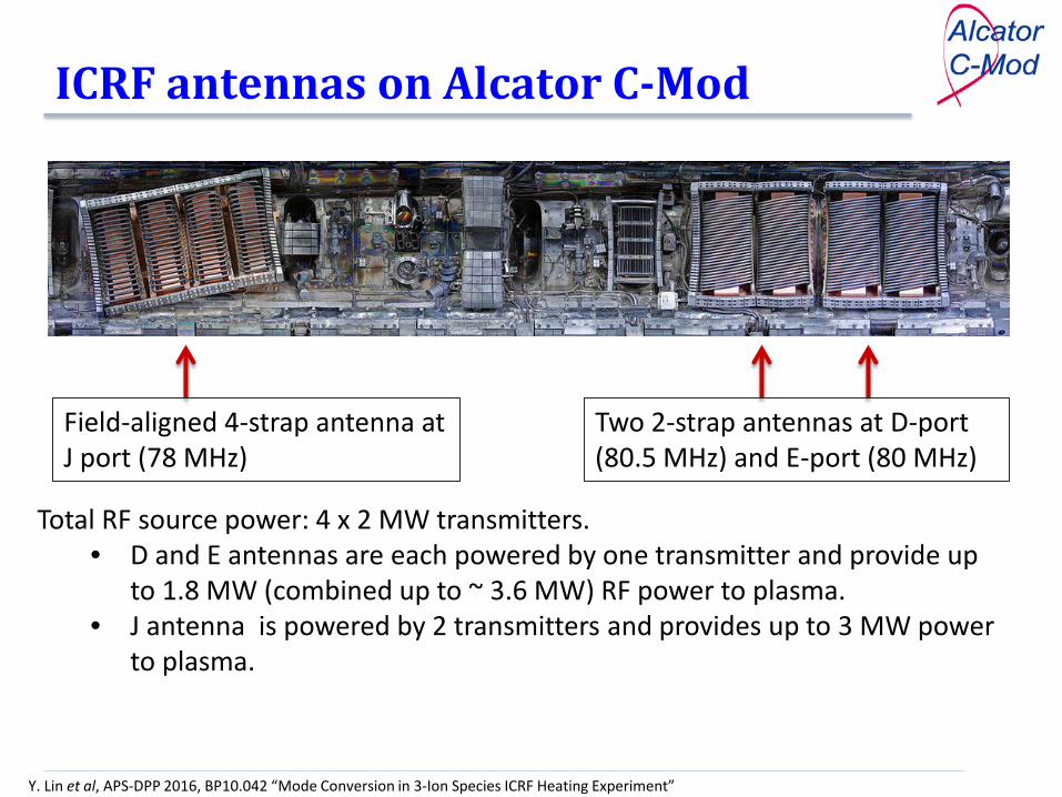
ICRF antennas on Alcator C-Mod
Total RF source power: 4 x 2 MW transmitters. • D and E antennas are each powered by one transmitter and provide up
to 1.8 MW (combined up to ~ 3.6 MW) RF power to plasma. • J antenna is powered by 2 transmitters and provides up to 3 MW power
to plasma.
Field-aligned 4-strap antenna at J port (78 MHz)
Two 2-strap antennas at D-port (80.5 MHz) and E-port (80 MHz)
Y. Lin et al, APS-DPP 2016, BP10.042 “Mode Conversion in 3-Ion Species ICRF Heating Experiment”
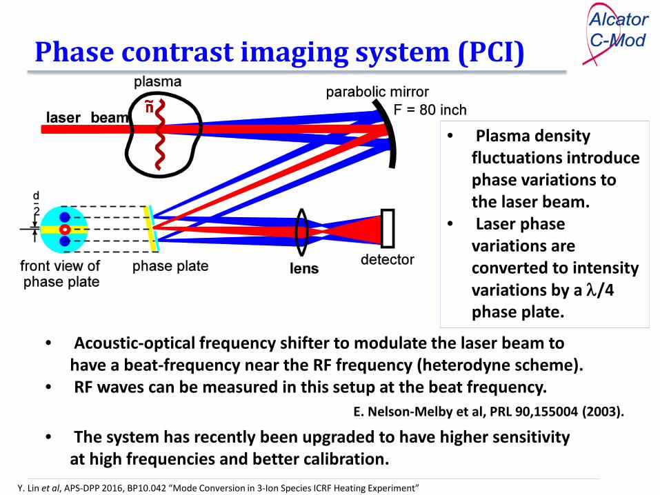
Phase contrast imaging system (PCI)
• Plasma density fluctuations introduce phase variations to the laser beam.
• Laser phase variations are converted to intensity variations by a λ/4 phase plate.
• Acoustic-optical frequency shifter to modulate the laser beam to have a beat-frequency near the RF frequency (heterodyne scheme).
• RF waves can be measured in this setup at the beat frequency. E. Nelson-Melby et al, PRL 90,155004 (2003).
• The system has recently been upgraded to have higher sensitivity at high frequencies and better calibration.

Y. Lin et al, APS-DPP 2016, BP10.042 “Mode Conversion in 3-Ion Species ICRF Heating Experiment”
PCI is in front of E antenna but some toroidal angles away from D and J

Y. Lin et al, APS-DPP 2016, BP10.042 “Mode Conversion in 3-Ion Species ICRF Heating Experiment”
RF signals shown in PCI data
• RF wave appears as a coherent signal in the PCI spectra (contour image in frequency and time);
• Signal amplitude is indicative of the wave E field amplitude; • Signal phases from different PCI channels kR of the RF waves.
80 MHz RF signal from E antenna, shown in PCI spectra at ~880 kHz after heterodyne modulation
For this typical D(H) minority heating plasma, the PCI signal is mostly from the fast wave.

Y. Lin et al, APS-DPP 2016, BP10.042 “Mode Conversion in 3-Ion Species ICRF Heating Experiment”
ICRF 3-ion heating scenario • Majority D and H, e.g., ~50% each • And small amount of X[3He] = n3He/ne ~ ≤1% • 3He cyclotron resonance in the vicinity of both the D-3He hybrid layer and
3He-H hybrid layer. • Potentially strong absorption on 3He ions due to favorable wave polarization
at the 3He cyclotron resonance. • This scenario can be used for general plasma heating and also for fast ion
generation, e.g., fast ion confinement study on W7-X. • It is also possibly applicable for ITER D-T plasma heating.
Y. Lin et al, APS-DPP 2016, BP10.042 “Mode Conversion in 3-Ion Species ICRF Heating Experiment”
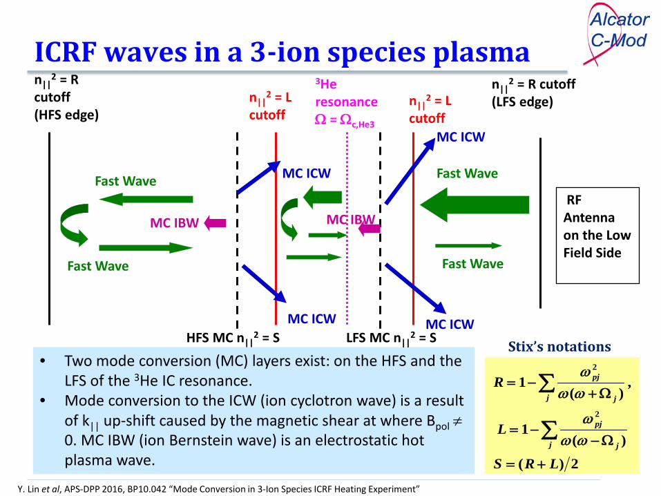
ICRF waves in a 3-ion species plasma
RF Antenna on the Low Field Side
n||2 = R cutoff
(LFS edge)
HFS MC n||2 = S
n||2 = L
cutoff
n||2 = R
cutoff (HFS edge)
3He resonance Ω = Ωc,He3
Fast Wave Fast Wave
MC IBW
MC ICW
Fast Wave Fast Wave
• Two mode conversion (MC) layers exist: on the HFS and the LFS of the 3He IC resonance.
• Mode conversion to the ICW (ion cyclotron wave) is a result of k|| up-shift caused by the magnetic shear at where Bpol ≠ 0. MC IBW (ion Bernstein wave) is an electrostatic hot plasma wave. 2)(
)(1
, )(
1
2
2
LRS
L
R
j j
pj
j j
pj
+=
Ω−−=
Ω+−=
∑
∑
ωωω
ωωω
Stix’s notations
n||2 = L
cutoff
LFS MC n||2 = S
MC IBW
MC ICW
MC ICW
MC ICW

Y. Lin et al, APS-DPP 2016, BP10.042 “Mode Conversion in 3-Ion Species ICRF Heating Experiment”
Energetic ions are generated in plasmas with low 3He and high RF power
• AE activities are indicative of the existence of a population of energetic 3He ions near the plasma center.
• X[3He] = n3He/ne ~ 0.6%, PICRF ~ 4 MW (More discussion in Kazakov’s and Wright’s talks)
Y. Lin et al, APS-DPP 2016, BP10.042 “Mode Conversion in 3-Ion Species ICRF Heating Experiment”
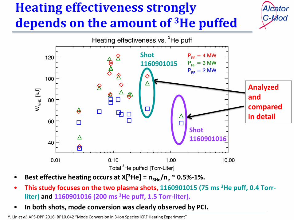
Heating effectiveness strongly depends on the amount of 3He puffed
• Best effective heating occurs at X[3He] = n3He/ne ~ 0.5%-1%. • This study focuses on the two plasma shots, 1160901015 (75 ms 3He puff, 0.4 Torr-
liter) and 1160901016 (200 ms 3He puff, 1.5 Torr-liter). • In both shots, mode conversion was clearly observed by PCI.
Analyzed and compared in detail
Shot 1160901016
Shot 1160901015

Y. Lin et al, APS-DPP 2016, BP10.042 “Mode Conversion in 3-Ion Species ICRF Heating Experiment”
Shot 1160901015 (75 ms 3He puff) - double MC observed in PCI
• PCI has 32 channels, covering 0.64 m < R < 0.74 m. • Two peaks are observed at R ~ 0.64 m and R ~ 0.71 m, corresponding to the HFS
and LFS MC layer locations. Ion cyclotron resonance is at R = 0.69 m.
PCI signal vs R at a time slice
MC waves
LFS MC
HFS MC
3He IC 3He IC

Y. Lin et al, APS-DPP 2016, BP10.042 “Mode Conversion in 3-Ion Species ICRF Heating Experiment”
Determine X[3He] and X[H] from the two observed MC locations
• The location of the two MC locations from PCI can be used to estimate X[H] and X[3He]
– Larger X[H] moves both layers to HFS; – Larger X[3He] increases the distance between the two layers.
• X[H] ≈ 65% and X[3He] ≈ 0.9% have the best match.
LFS MC HFS MC
Y. Lin et al, APS-DPP 2016, BP10.042 “Mode Conversion in 3-Ion Species ICRF Heating Experiment”
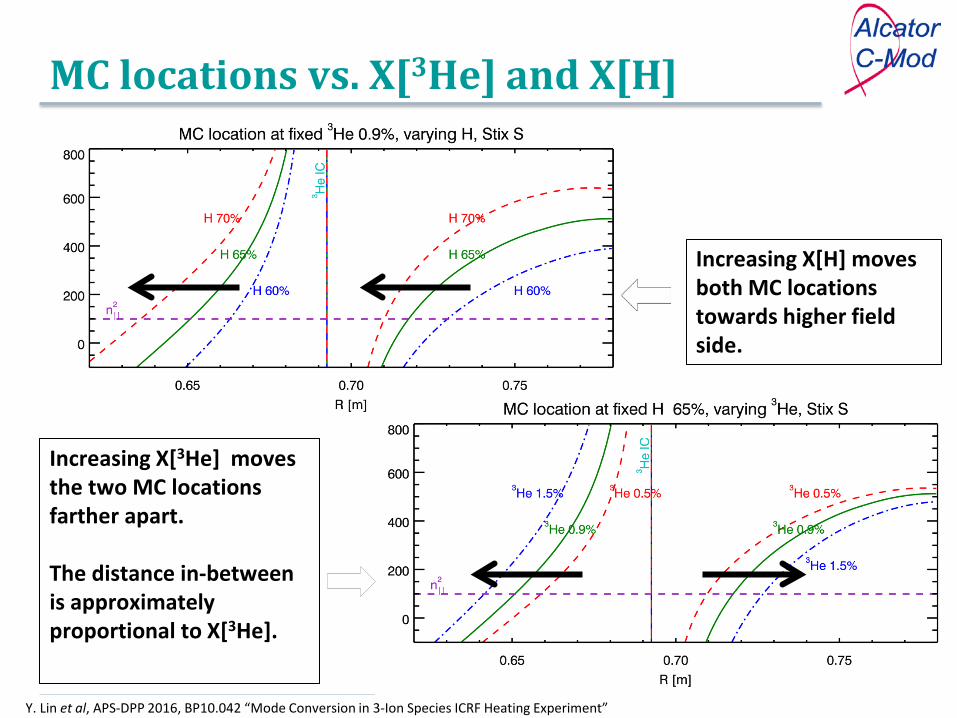
MC locations vs. X[3He] and X[H]
Increasing X[3He] moves the two MC locations farther apart. The distance in-between is approximately proportional to X[3He].
Increasing X[H] moves both MC locations towards higher field side.
Y. Lin et al, APS-DPP 2016, BP10.042 “Mode Conversion in 3-Ion Species ICRF Heating Experiment”
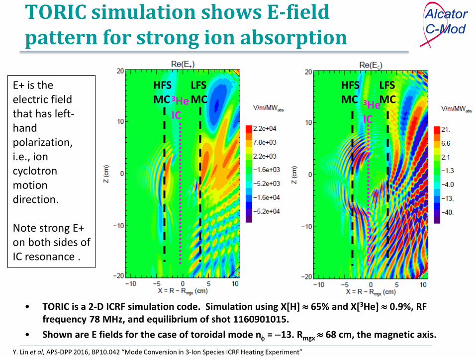
TORIC simulation shows E-field pattern for strong ion absorption
HFS MC
LFS MC 3He
IC
HFS MC
LFS MC 3He
IC
• TORIC is a 2-D ICRF simulation code. Simulation using X[H] ≈ 65% and X[3He] ≈ 0.9%, RF frequency 78 MHz, and equilibrium of shot 1160901015.
• Shown are E fields for the case of toroidal mode nφ = −13. Rmgx ≈ 68 cm, the magnetic axis.
E+ is the electric field that has left-hand polarization, i.e., ion cyclotron motion direction. Note strong E+ on both sides of IC resonance .
Y. Lin et al, APS-DPP 2016, BP10.042 “Mode Conversion in 3-Ion Species ICRF Heating Experiment”
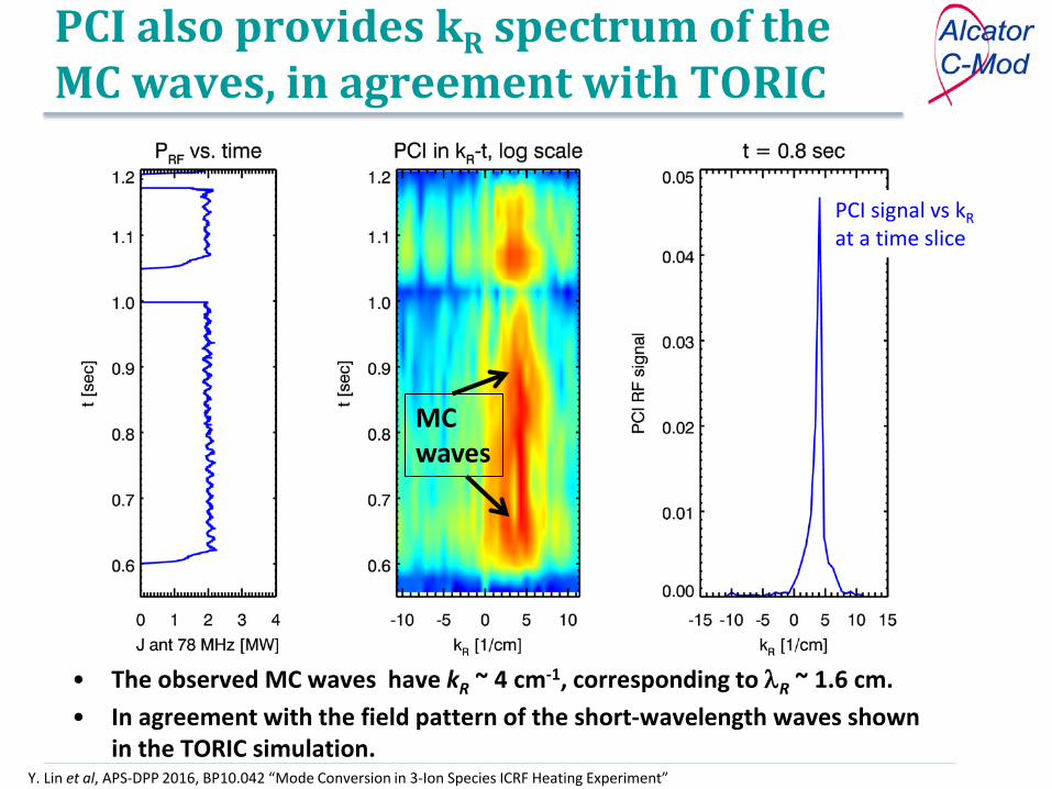
PCI also provides kR spectrum of the MC waves, in agreement with TORIC
• The observed MC waves have kR ~ 4 cm-1, corresponding to λR ~ 1.6 cm. • In agreement with the field pattern of the short-wavelength waves shown
in the TORIC simulation.
PCI signal vs kR at a time slice
MC waves

Y. Lin et al, APS-DPP 2016, BP10.042 “Mode Conversion in 3-Ion Species ICRF Heating Experiment”
Power deposition to ions and electrons in 2-D from simulation
• Power deposition to 3He ions is through the interaction of 3He ions with fast wave and the MC waves at the resonance;
• Power to electrons is mostly through MC waves and relatively much weaker.
3He IC
X[H] = 65%, X[3He] = 0.9% nφ = −13 f = 78 MHz Bt0 = 7.8 T

Y. Lin et al, APS-DPP 2016, BP10.042 “Mode Conversion in 3-Ion Species ICRF Heating Experiment”
RF power mostly goes to the 3He ions
• For this plasma, most RF power is absorbed by the 3He ions. • 69% to 3He ions, 30% to electrons, and the rest to D and H ions. • See Wright - TO4.012 for simulation on how the fast ions are generated.
Power to 3He Ions 69%
Power to electrons 30%

Y. Lin et al, APS-DPP 2016, BP10.042 “Mode Conversion in 3-Ion Species ICRF Heating Experiment”
Shot 1160901016 (200 ms 3He) – only HFS MC layer shown in PCI (78 MHz)
• With increase of 3He, the distance between the HFS and LFS MC layers are increased. • Only the HFS MC at R ~ 0.64 m is observed in the PCI window for J antenna power at 78
MHz and the LFS MC is out of the PCI window.
PCI signal vs R at a time slice
3He IC 3He IC
HFS MC
HFS MC waves

Y. Lin et al, APS-DPP 2016, BP10.042 “Mode Conversion in 3-Ion Species ICRF Heating Experiment”
The LFS MC is observed at 80.5 MHz
• The LFS MC at R ~ 0.74 m appears in 80.5 MHz D antenna signal, while the HFS MC at this frequency is out of the PCI window.
PCI signal vs R at a time slice
LFS MC waves
3He IC
LFS MC
Y. Lin et al, APS-DPP 2016, BP10.042 “Mode Conversion in 3-Ion Species ICRF Heating Experiment”
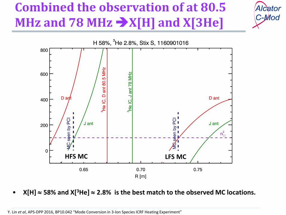
Combined the observation of at 80.5 MHz and 78 MHz X[H] and X[3He]
• X[H] ≈ 58% and X[3He] ≈ 2.8% is the best match to the observed MC locations.
LFS MC HFS MC

Y. Lin et al, APS-DPP 2016, BP10.042 “Mode Conversion in 3-Ion Species ICRF Heating Experiment”
Electric field pattern is not conducive for ion absorption
3He IC
HFS MC
LFS MC 3He
IC
HFS MC
LFS MC
X[H] = 58%, X[3He] = 2.8% nφ = −13 f = 78 MHz Bt0 = 7.8 T
• Clear short wavelength MC waves appear at both HFS and LFS MC layers. • IC resonance is quite far away from the region with large E+ field. The Doppler broadening of
the resonance (~ ±1 cm for thermal ions) would be insufficient for strong ion absorption.
Y. Lin et al, APS-DPP 2016, BP10.042 “Mode Conversion in 3-Ion Species ICRF Heating Experiment”
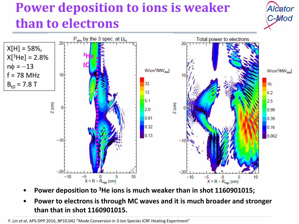
Power deposition to ions is weaker than to electrons
X[H] = 58%, X[3He] = 2.8% nφ = −13 f = 78 MHz Bt0 = 7.8 T
• Power deposition to 3He ions is much weaker than in shot 1160901015; • Power to electrons is through MC waves and it is much broader and stronger
than that in shot 1160901015.
3He IC

Y. Lin et al, APS-DPP 2016, BP10.042 “Mode Conversion in 3-Ion Species ICRF Heating Experiment”
Most RF power goes to electrons via mode conversion electron heating
• 15% power to 3He ions, 82% power electrons and the rest to D and H ions. • Power to electrons is off-axis and broad. • Heating effectiveness (increment in stored energy vs. PRF) is low.
Power to 3He Ions 15%
Power to electrons 82%

Y. Lin et al, APS-DPP 2016, BP10.042 “Mode Conversion in 3-Ion Species ICRF Heating Experiment”
Summary • RF waves have been measured by PCI in the 3-ion species ICRF heating
experiment; • Double mode-conversion has been confirmed, and the PCI measurement is
used to infer the species concentrations; • TORIC simulation shows that for the low 3He scenario (X[3He] <1%), most
RF power is deposited to ions and such power deposition can generate energetic ions at high RF power.
• At higher level of X[3He], most RF power is deposited to electrons via mode conversion, and heating effectiveness is significantly reduced.
More on 3-ion ICRF heating experiment on C-Mod and JET: Yevgen Kazakov – Invited talk NI3.005, Wednesday morning John Wright – ITER session TO4.012, Thursday morning


