
MINILASE PRO Laser Software Programming and Installation Manual
TYKMA Technologies 931 E Water Street
Chillicothe, OH 45601 Toll Free: 877‐318‐9562
Fax: 740‐779‐9910 www.permanentmarking.com

Published on: 9.1.2010 Microsoft, MS, MS‐DOS, Windows 98, Windows NT, Windows XP, Windows 7, Visual Basic, PowerPoint, Microsoft Press are registered trademark of Intel Inc. TrueType is a registered trademark of Apple Computer Inc. The information contained in this document is subject to change without prior notice. All product or program names mentioned in this document are registered trademarks owned by the respective companies. They are only used in this document for editorial purposes.

Minilase Pro Software Manual
3
Contents 1 Introduction .......................................................................................................................................... 5
1.1 System requirements for Minilase Pro Laser Software ................................................................ 6
1.2 Minilase Pro Installation ............................................................................................................... 6
2 Basic Concepts .................................................................................................................................... 11
2.1 Overview ..................................................................................................................................... 11
2.2 Creating a new project ................................................................................................................ 12
2.3 Language Selection ..................................................................................................................... 14
2.4 Minilase Pro work environment ................................................................................................. 15
2.4.1 Icons .................................................................................................................................... 15
2.4.2 Basic Icon Functionality ....................................................................................................... 17
2.5 Zooming reducing ....................................................................................................................... 23
2.6 Property window ......................................................................................................................... 23
2.7 Setting the measurement unit .................................................................................................... 25
2.8 Coloring of graphic objects ......................................................................................................... 26
3 Creating Graphics ................................................................................................................................ 27
3.1 Minilase Pro Drawing Tools ........................................................................................................ 27
3.2 Imported graphics ....................................................................................................................... 27
3.3 Importing graphics with Minilase Pro ......................................................................................... 29
3.4 Information on bitmap and vector graphics ............................................................................... 30
3.4.1 Vector Graphics ................................................................................................................... 30
3.4.2 Bitmap graphics: ................................................................................................................. 31
3.5 Creating basic shapes within Minilase Pro .................................................................................. 32
3.6 Minilase Pro objects .................................................................................................................... 33
3.6.1 Using the text tool .............................................................................................................. 33
3.7 Special character sequences ....................................................................................................... 38
3.8 Barcodes and 2D / Datamatrix codes ......................................................................................... 41
3.9 Matrix code ................................................................................................................................. 43
3.10 Manual Movement of Objects on the Plain Work ...................................................................... 45
4 Laser Marking Parameters .................................................................................................................. 46

Minilase Pro Software Manual
4
4.1 Laser Settings .............................................................................................................................. 46
4.1.1 WOBBLE .............................................................................................................................. 48
4.2 Laser Settings Quick Guide .......................................................................................................... 49
4.3 LASER TEST .................................................................................................................................. 50
5 Advanced Features.............................................................................................................................. 51
5.1 HW STATUS ................................................................................................................................. 51
5.2 KEYBOARD SHORTCUTS .............................................................................................................. 53
5.3 Adding New Fonts ....................................................................................................................... 57
6 Creating a Sample Project ................................................................................................................... 58
6.1 Creating a Sample Project ........................................................................................................... 58
7 Troubleshooting .................................................................................................................................. 63

Minilase Pro Software Manual
5
1 Introduction TYKMA Minilase Pro is an application program for the graphic creation of two dimensional objects for engraving with the TYKMA Laser Systems Utilizing the 5 Watt Laser Engine

Minilase Pro Software Manual
6
1.1 System requirements for Minilase Pro Laser Software
Windows XP Pro / Windows 7 Professional 32 Bit Minimum Pentium 4 Processor Minimum 100 GB Hard Drive Storage System Minimum 2GB RAM USB 2.0
1.2 Minilase Pro Installation
The Minilase Pro software program must be installed on a PC with 800 x 600 or higher resolution color monitor. Follow this procedure to install Minilase Pro onto your Windows computer:
Before installation of the software please follow the Laser System Quick Start Manual to power up your laser system. Please wait until you are prompted by the software installation wizard before plugging the USB connection into your computer.
Insert the provided USB Memory Stick into a USB 2.0 port on your computer
Browse to “My Computer” on your PC and locate the USB Drive titled TYKMA Laser Software and Manuals
Right click on the USB Drive and click “Explore” Locate the icon titled “TYKMA Minilase Pro Installer” and double click
the icon to start the installation process. You will the follow the prompts as shown below.
Minilase Pro Software Manual
7
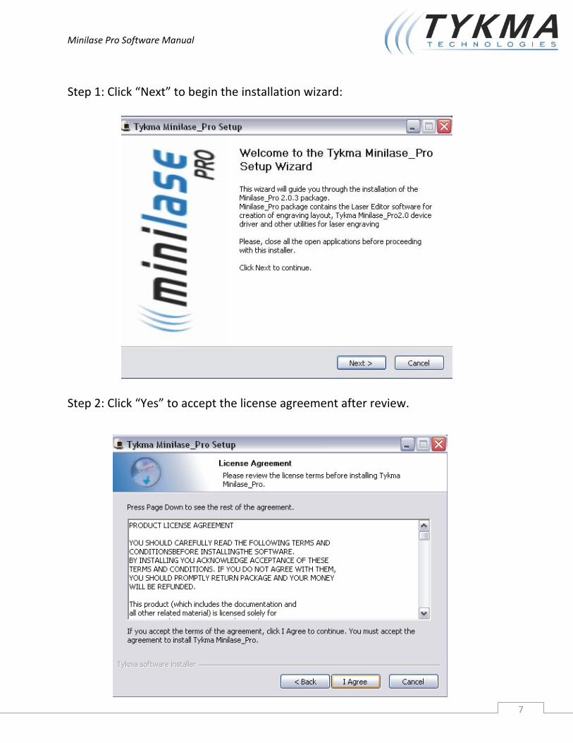
Step 1: Click “Next” to begin the installation wizard:
Step 2: Click “Yes” to accept the license agreement after review.

Minilase Pro Software Manual
8
Step 3: Click “Next” to install the software into the default directory.
Step 4: Click “Next” to choose the full installation package.
Minilase Pro Software Manual
9
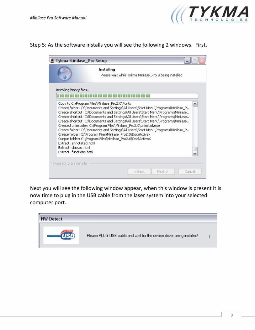
Step 5: As the software installs you will see the following 2 windows. First,
Next you will see the following window appear, when this window is present it is now time to plug in the USB cable from the laser system into your selected computer port.

Minilase Pro Software Manual
10
Step 6: After plugging in the USB cable you will receive the following message from windows, please click “Continue Anyway”.
Step 7: Your Minilase Pro software installation is now complete. You may exit the software and launch the Minilase Pro Laser Marking Software Icon located on your desktop to begin programming your laser system.
Minilase Pro Software Manual
11
2 Basic Concepts
2.1 Overview The Minilase Pro software package makes it possible to generate graphic files and translate them into paths for laser marking and engraving.
Minilase Pro is capable of creating the following objects for marking and engraving:
Text strings
Customized date and time
Counters
Barcodes
Datamatrix / 2D codes
Vector Graphics (PLT, DXF)
Bitmap Drawings (BMP, JPG, GIF)
Minilase Pro has two separate operating modes:
Work Mode: This mode is for marking and engraving only. In other words, the loaded laser project file cannot be edited in anyway. In this mode, the program automatically updates the “active” components (for example the date or the counter) at each engraving job beginning and end. This mode can also be protected by password.
Edit Mode: This mode is used for creating/editing laser project files (text, barcodes, DXF files, etc.) and saving the project files to your hard disk.

Minilase Pro Software Manual
12
2.2 Creating a new project When creating a new project, you will first need to select “File ‐> New” to create a new file for the laser engraver.
When the new file is created the system will automatically create a “Plain”, which is a new work area where you may create text, graphics, etc. and align/size the graphics accordingly. The size of the plain working area will coordinate with the available marking area of your laser system.
1
The icon titled 1 refers to the marking plain.
The size of the plain working area will coordinate with the available marking area of your laser system. The available marking window is determined by the focal length of the lens installed in your system. (100mm, 160mm lens or 254mm lens)

Minilase Pro Software Manual
13
With the software open you will need to double click the small yellow triangle icon located in your control panel of your windows toolbar.
Under the tab labeled “corrections” you will need to choose the lens size in the drop down that coordinates with the installed lens of your laser system.
The marking window will now be set so that the software plain work area coordinates with your installed laser lens and available marking area.
Minilase Pro Software Manual
14
2.3 Language Selection
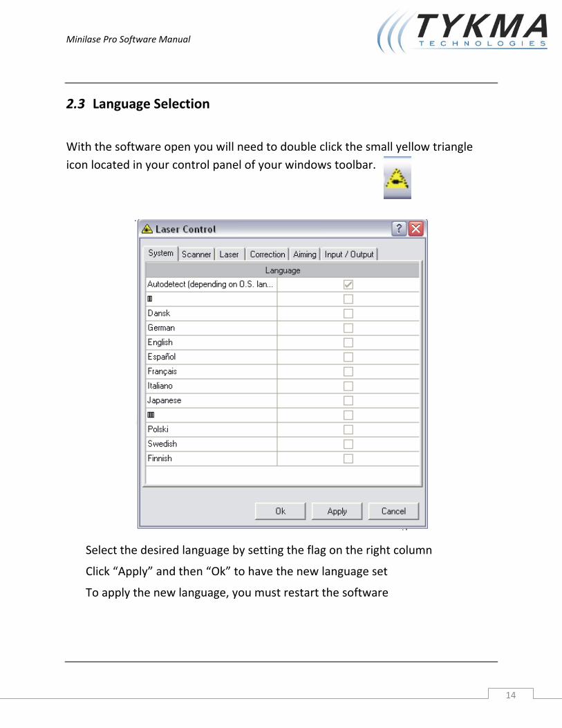
With the software open you will need to double click the small yellow triangle icon located in your control panel of your windows toolbar.
Select the desired language by setting the flag on the right column
Click “Apply” and then “Ok” to have the new language set
To apply the new language, you must restart the software

Minilase Pro Software Manual
15
2.4 Minilase Pro work environment During the creation and editing of laser marking projects, there are a few commonly used areas of the software.
The plain work area where the graphics/text/objects/etc. are located The project work area where any sequences and functions are
displayed within the individual project Property window, where the marking parameters and properties for
the graphics are set Simulation for displaying a new window with graphical simulation of
the marking that will take place (when no laser is connected) Toolbar for editing various project and drawing elements
2.4.1 Icons
The following icons form the Minilase Pro Toolbar.
Icon Meaning Icon Meaning Icon Meaning
New Stop marking Resize as dominant
Open Laser test Reflect X
Save Software connected to Laser Reflect Y
Save All Software not connected to laser Cancel transformations
Cut Simulation mode Group
Copy Show HW Status Intersect
Paste Context Help Separate
Undo Add string
Refresh view
Minilase Pro Software Manual
16
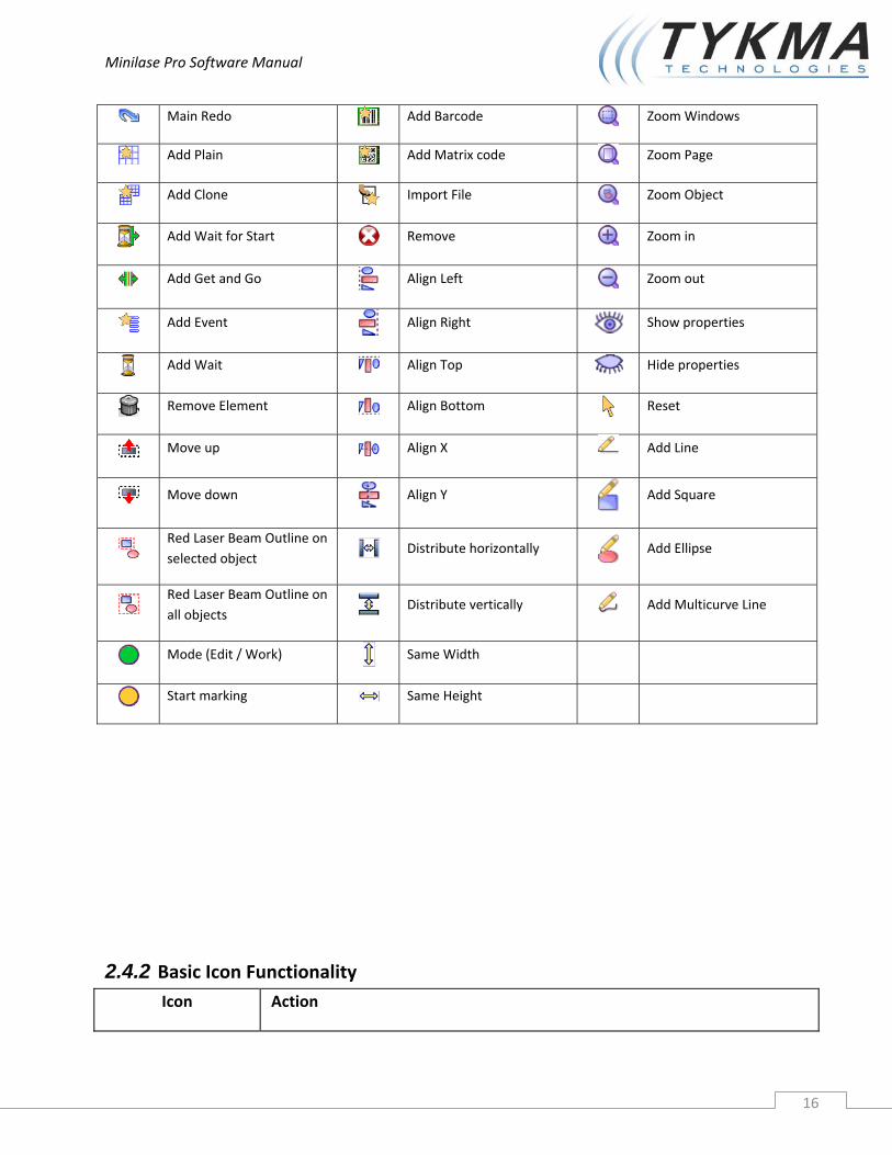
Main Redo Add Barcode Zoom Windows
Add Plain Add Matrix code Zoom Page
Add Clone Import File Zoom Object
Add Wait for Start Remove Zoom in
Add Get and Go Align Left Zoom out
Add Event Align Right Show properties
Add Wait Align Top Hide properties
Remove Element Align Bottom Reset
Move up Align X Add Line
Move down Align Y
Add Square
Red Laser Beam Outline on selected object Distribute horizontally
Add Ellipse
Red Laser Beam Outline on all objects Distribute vertically
Add Multicurve Line
Mode (Edit / Work) Same Width
Start marking Same Height
2.4.2 Basic Icon Functionality Icon Action
Minilase Pro Software Manual
17
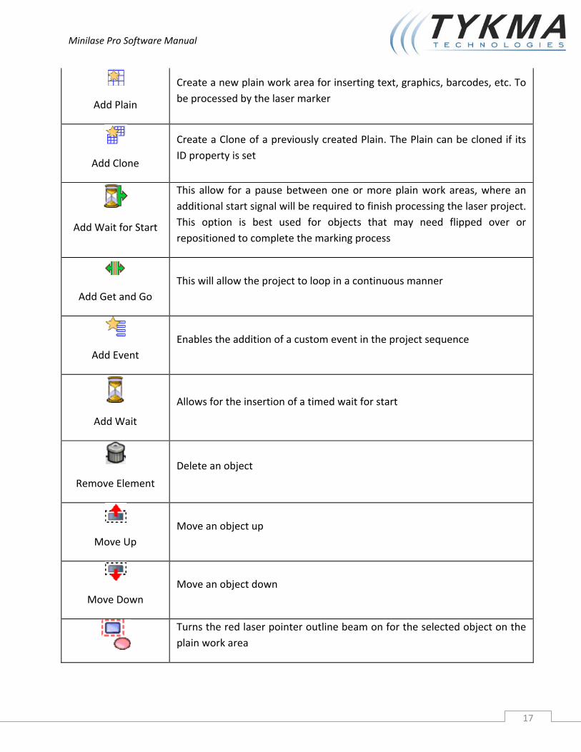
Add Plain
Create a new plain work area for inserting text, graphics, barcodes, etc. To be processed by the laser marker
Add Clone
Create a Clone of a previously created Plain. The Plain can be cloned if its ID property is set
Add Wait for Start
This allow for a pause between one or more plain work areas, where an additional start signal will be required to finish processing the laser project. This option is best used for objects that may need flipped over or repositioned to complete the marking process
Add Get and Go This will allow the project to loop in a continuous manner
Add Event Enables the addition of a custom event in the project sequence
Add Wait
Allows for the insertion of a timed wait for start
Remove Element
Delete an object
Move Up Move an object up
Move Down Move an object down
Turns the red laser pointer outline beam on for the selected object on the plain work area

Minilase Pro Software Manual
18
Selection Limits
Limits
Turns the red laser pointer outline beam on for all the objects in the plain work area
Mode (Edit/Work)
Switches between Edit Mode and Work Mode.
Edit mode is for designing the marking file layout
Work mode is for running the laser marking file
Start marking
Start the engraving.
Stop marking
Stop the engraving.
Laser test
Continuously engrave a shape (could be a line, a square or a circle) for laser focus or testing purposes
Laser Connection
Status:
CONNECTED
Minilase Pro is connected to the laser marking system.
Click the button to switch to the SIMULATOR device.
Minilase Pro Software Manual
19
Icon Action
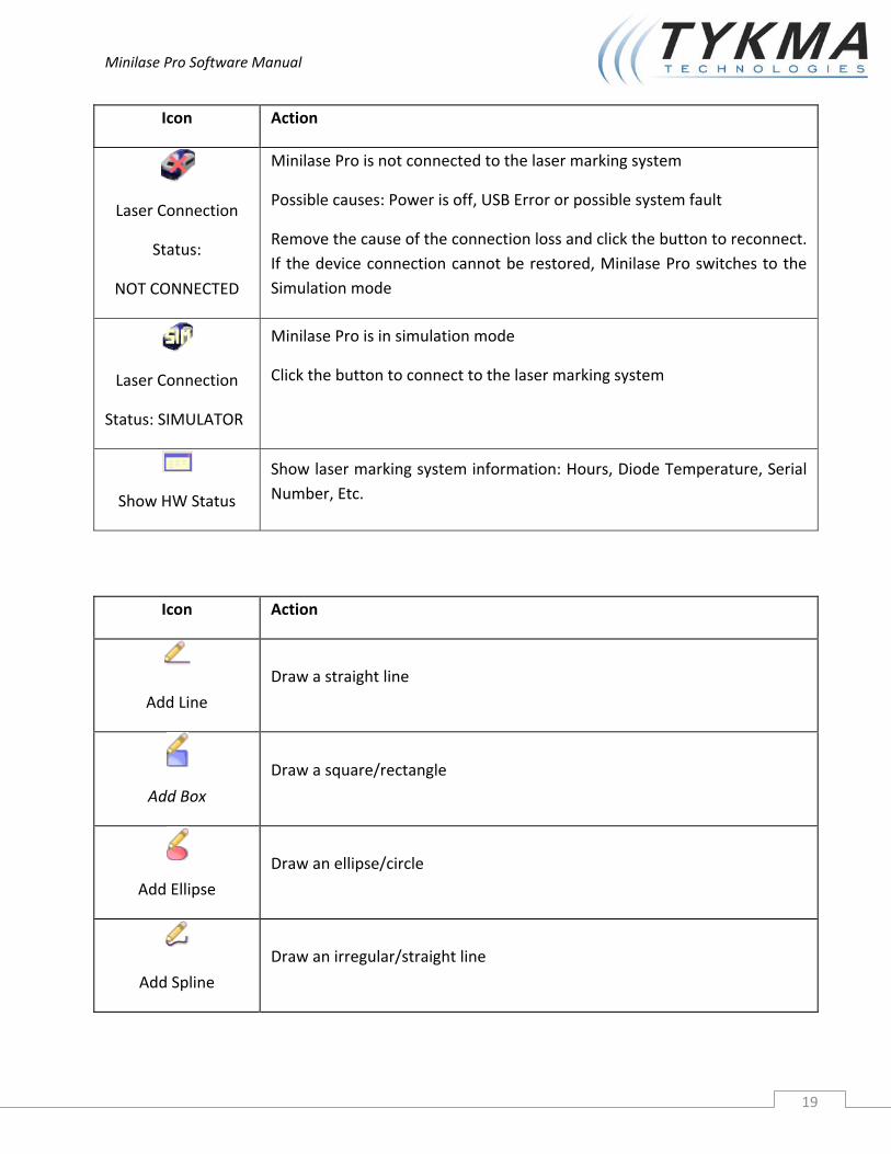
Laser Connection
Status:
NOT CONNECTED
Minilase Pro is not connected to the laser marking system
Possible causes: Power is off, USB Error or possible system fault
Remove the cause of the connection loss and click the button to reconnect. If the device connection cannot be restored, Minilase Pro switches to the Simulation mode
Laser Connection
Status: SIMULATOR
Minilase Pro is in simulation mode
Click the button to connect to the laser marking system
Show HW Status
Show laser marking system information: Hours, Diode Temperature, Serial Number, Etc.
Icon Action
Add Line
Draw a straight line
Add Box
Draw a square/rectangle
Add Ellipse
Draw an ellipse/circle
Add Spline
Draw an irregular/straight line

Minilase Pro Software Manual
20
Alignment
Icon Action
Align Left
Align selected objects left in plain work area
Align Right
Align selected objects right in plain work area
Align Top Align selected objects to their top boundary in plain work area
Align Bottom Align selected objects to their bottom boundary in plain work area
Align X
Align selected objects along their center x axis in plain work area
Align Y Aligh selected objects along their center y axis in plain work area
Minilase Pro Software Manual
21
Picture Management
Icon Action
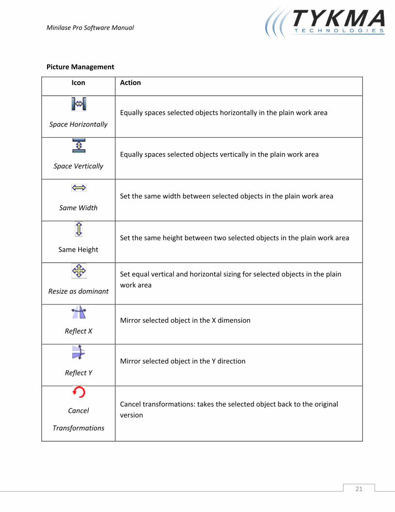
Space Horizontally
Equally spaces selected objects horizontally in the plain work area
Space Vertically
Equally spaces selected objects vertically in the plain work area
Same Width
Set the same width between selected objects in the plain work area
Same Height
Set the same height between two selected objects in the plain work area
Resize as dominant
Set equal vertical and horizontal sizing for selected objects in the plain work area
Reflect X Mirror selected object in the X dimension
Reflect Y
Mirror selected object in the Y direction
Cancel
Transformations
Cancel transformations: takes the selected object back to the original version
Minilase Pro Software Manual
22
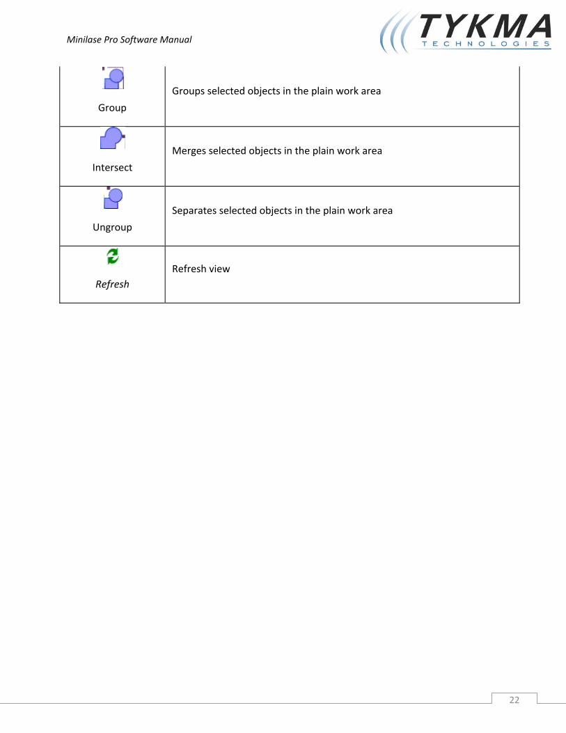
Group
Groups selected objects in the plain work area
Intersect
Merges selected objects in the plain work area
Ungroup
Separates selected objects in the plain work area
Refresh Refresh view
Minilase Pro Software Manual
23
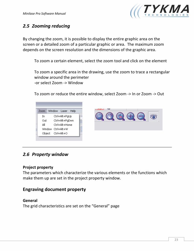
2.5 Zooming reducing By changing the zoom, it is possible to display the entire graphic area on the screen or a detailed zoom of a particular graphic or area. The maximum zoom depends on the screen resolution and the dimensions of the graphic area.
To zoom a certain element, select the zoom tool and click on the element
To zoom a specific area in the drawing, use the zoom to trace a rectangular window around the perimeter ‐or select Zoom ‐> Window
To zoom or reduce the entire window, select Zoom ‐> In or Zoom ‐> Out
2.6 Property window Project property The parameters which characterize the various elements or the functions which make them up are set in the project property window. Engraving document property General The grid characteristics are set on the “General” page
Minilase Pro Software Manual
24
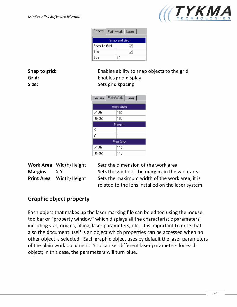
Snap to grid: Enables ability to snap objects to the grid Grid: Enables grid display Size: Sets grid spacing
Work Area Width/Height Sets the dimension of the work area Margins X Y Sets the width of the margins in the work area Print Area Width/Height Sets the maximum width of the work area, it is related to the lens installed on the laser system Graphic object property Each object that makes up the laser marking file can be edited using the mouse, toolbar or “property window” which displays all the characteristic parameters including size, origins, filling, laser parameters, etc. It is important to note that also the document itself is an object which properties can be accessed when no other object is selected. Each graphic object uses by default the laser parameters of the plain work document. You can set different laser parameters for each object; in this case, the parameters will turn blue.
Minilase Pro Software Manual
25
Object properties depend on the selected object, this is discussed in the paragraphs related to individual graphics. (text, bar codes, 2D codes, imported graphics)
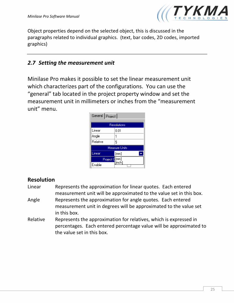
2.7 Setting the measurement unit Minilase Pro makes it possible to set the linear measurement unit which characterizes part of the configurations. You can use the “general” tab located in the project property window and set the measurement unit in millimeters or inches from the “measurement unit” menu.
Resolution Linear Represents the approximation for linear quotes. Each entered
measurement unit will be approximated to the value set in this box. Angle Represents the approximation for angle quotes. Each entered
measurement unit in degrees will be approximated to the value set in this box.
Relative Represents the approximation for relatives, which is expressed in percentages. Each entered percentage value will be approximated to the value set in this box.

Minilase Pro Software Manual
26
2.8 Coloring of graphic objects The objects in the plain work area may be different colors.
Black – Black indicates that the object is correctly placed within the graphic area and is enabled for engraving. The object’s engraving parameters are the standard ones in the document.
Blue – Blue indicated that the graphic object is correctly placed within the graphic area and is enabled for engraving. Its engraving parameters are NOT the standard ones
NOTE: There can be various blue colored objects within the graphic area. Each object has laser parameters which are different than the standard document ones. The blue colored objects may have laser parameters which are different from each other.
Red ‐ Red indicates that graphic object is NOT correctly placed within the graphic area. A red colored object will NOT be engraved.
Grey – Grey indicates that the graphic object is correctly placed within the graphic area but is not enabled for engraving. (see the area highlighted in the property window. A grey colored object will NOT be engraved.
Minilase Pro Software Manual
27
3 Creating Graphics
3.1 Minilase Pro Drawing Tools Minilase Pro drawing tools can be divided into two different categories:
Imported graphics Minilase Pro objects
3.2 Imported graphics In Minilase Pro you have the option to import graphics created by other programs (Autocad, Coreldraw, Adobe, etc.) or you can draw and create simple lines, curved lines, squares and circles.
The following types of graphics can be imported:
DXF: is a two dimensional vector graphic exchange format primarily used by CAD applications but available for most vector graphic applications on the market.
PLT: is a vector format used as an exchange for plotters. The filters are equipped with vector graphic programs can be used to generate it, or be installing HP model 7475A plotters in the windows operating system and printing the graphic created with an application to file.
BMP: is the new standard for bitmap graphics. It can be generated with any graphics application, from digital camera or scanners.
JPG: is one of the most common compressed bitmap formats. A BMP image converted into JPG has a much smaller dimension; it is generally used in continuous tone images.

Minilase Pro Software Manual
28
GIF: is a format similar to BMP. It can be generated with any graphic application, from digital cameras or scanners.
Imported graphics can be located in the plain work area and moved, dimensioned, rotated or transformed so they are compatible for the object you wish to engrave them on.

Minilase Pro Software Manual
29
3.3 Importing graphics with Minilase Pro After creating a new project, it is possible to import a graphic as follows:
Select: Actions ‐> Add ‐> Imported File The following window will be displayed
Select the file type from the selection box Specify the path of the file to be imported Select the file
After importing the file inside the plain work area, the object can be manipulated, for example:
Positioned to set coordinates Changing the height and width Filling the object with filler lines (only if the lines comprising the area to be
filled are closed)

Minilase Pro Software Manual
30
3.4 Information on bitmap and vector graphics Computers display vector or bitmap graphic formats. Understanding the difference between the two can be helpful for working more efficiently.
3.4.1 Vector Graphics Vector graphics describe the images using lines and curves, called vectors, which all include properties related to color and position. For example the image of a feather is described by points through which lines pass, creating the form of the outline of a leaf. The color of the leaf is determined by the color of the outline and the color enclosed within the outline. In the example described below a black and white feather is represented because the laser engraving is monochromatic. When vector graphics are edited, all the properties of the lines and curves which describe the form are also edited. It is possible to move, re‐dimension, remodel and change the color of the vector graphic without changing its quality. Vector graphics are not resolution dependent, this means they can be displayed on output devices with different resolutions with no change in quality.
In laser engraving a vector graphic is faster in engraving and more defined in terms of outline lines and filling. A vector graphic cannot be used for engraving digital photographs.
Minilase Pro Software Manual
31
3.4.2 Bitmap graphics:
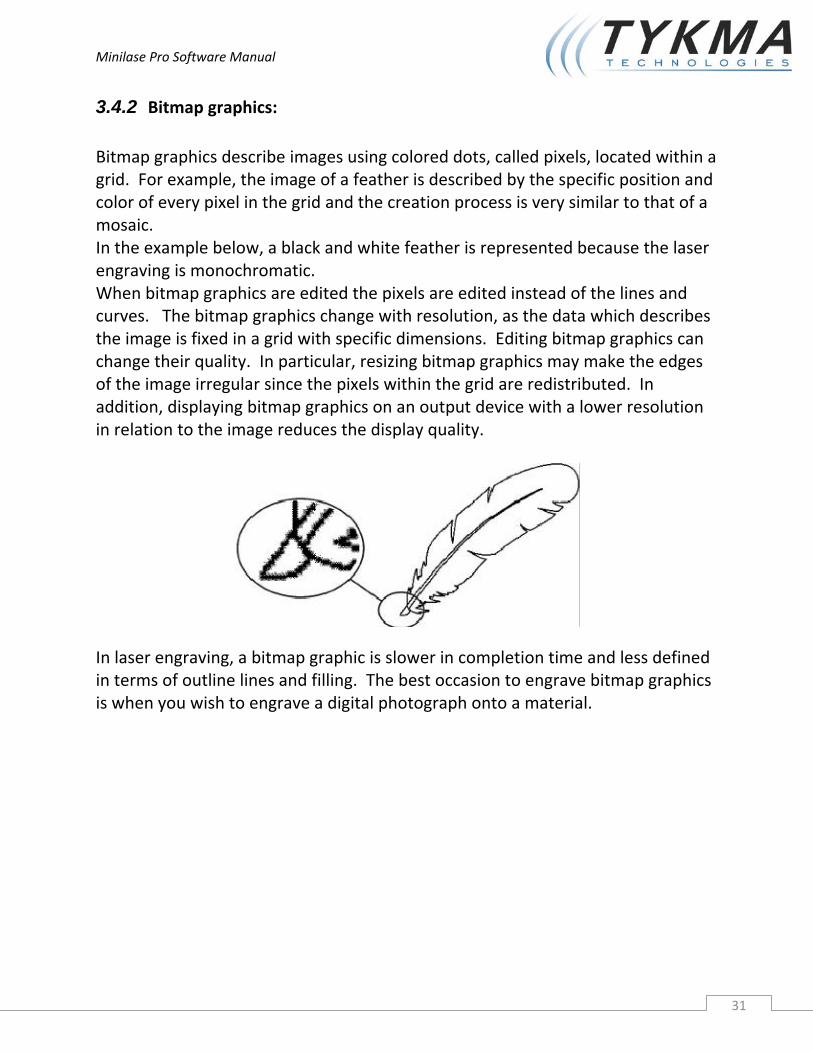
Bitmap graphics describe images using colored dots, called pixels, located within a grid. For example, the image of a feather is described by the specific position and color of every pixel in the grid and the creation process is very similar to that of a mosaic. In the example below, a black and white feather is represented because the laser engraving is monochromatic. When bitmap graphics are edited the pixels are edited instead of the lines and curves. The bitmap graphics change with resolution, as the data which describes the image is fixed in a grid with specific dimensions. Editing bitmap graphics can change their quality. In particular, resizing bitmap graphics may make the edges of the image irregular since the pixels within the grid are redistributed. In addition, displaying bitmap graphics on an output device with a lower resolution in relation to the image reduces the display quality.
In laser engraving, a bitmap graphic is slower in completion time and less defined in terms of outline lines and filling. The best occasion to engrave bitmap graphics is when you wish to engrave a digital photograph onto a material.
Minilase Pro Software Manual
32
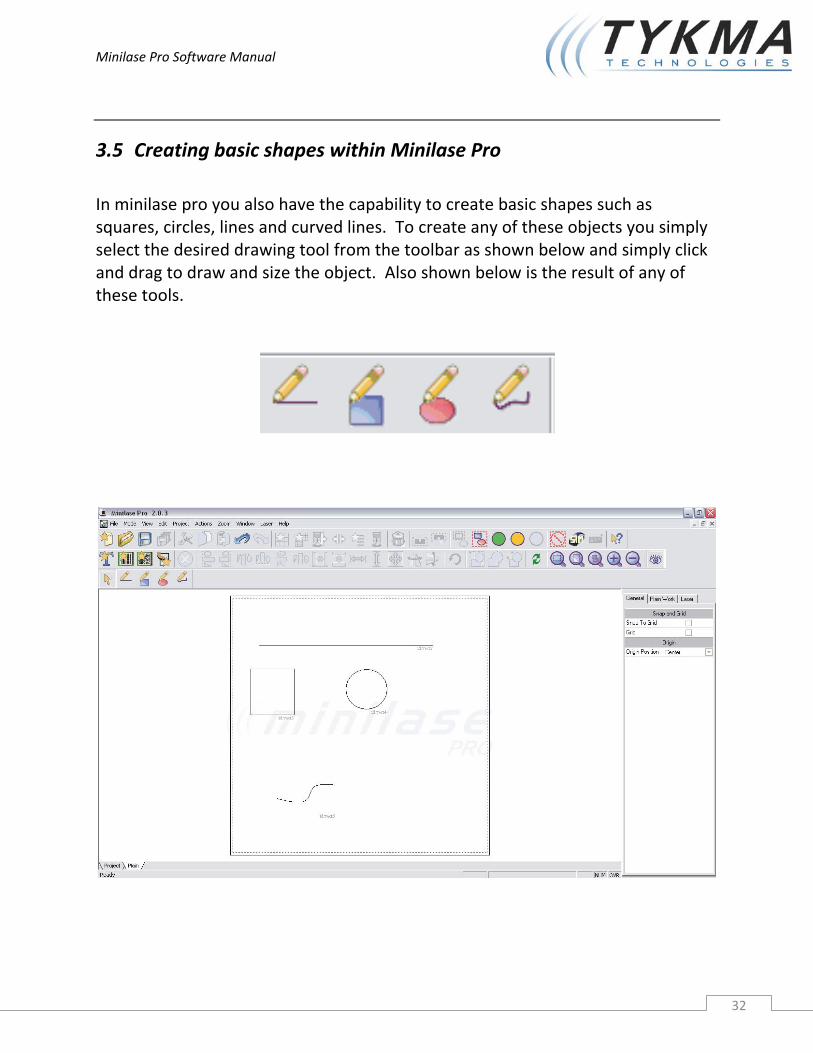
3.5 Creating basic shapes within Minilase Pro In minilase pro you also have the capability to create basic shapes such as squares, circles, lines and curved lines. To create any of these objects you simply select the desired drawing tool from the toolbar as shown below and simply click and drag to draw and size the object. Also shown below is the result of any of these tools.

Minilase Pro Software Manual
33
3.6 Minilase Pro objects There are other types of objects that can also be introduced into the plain work graphic area.
Text Barcodes 2D codes
3.6.1 Using the text tool When text is used in Minilase Pro it is possible to set dimensions, font, style, spacing, shear and text fill. The text can also be transformed by rotating it, shearing it and mirroring it, while still maintaining the ability to edit the characters. It is possible to insert text boxes in the projects destined for user input or dynamically displaying updated text, by associating and identification ID to the text string. It is also possible to place the text inside or outside of a circumference arc. Minilase Pro can utilize any type of true type font, including Asian origin ideogram fonts. To import fonts, see chapter 5, Advanced Features To add a text string in Minilase Pro: from the top menu select: “Actions” ‐> “Add” ‐> “Text” or use the mouse to click on the “Add String” icon on the tool bar.

Minilase Pro Software Manual
34
3.6.1.1 Selecting text properties The property window displays the text parameters only when the text in the graphic area is selected. Typical text parameters are shown on the various pages in the figure.
General: Main: Enable Enables the engraving of the selected text (if not enabled the text is grey) Position XY Sets the text coordinates in relation to the origin of the engraving area (0,0 is the center of the area) Width, Height Sets the text width, height Maintain Aspect If enabled, keeps the proportions between width and height Angle Sets the rotation angle (in degrees) of the string on the engraving area Shear X Sets a shear on axis X. The shear in the figure is set at “50” Shear Y Sets a shear on axis Y. The shear in the figure is set at “50”.

Minilase Pro Software Manual
35
Origin: Position This is used to move the reference origin of the string. The origin is indentified by an X placed in the center, this can be moved to one of the four corners of the selected object. Fill: Fill type Use to fill a text string. Single pass, double pass or triple pass Fill Angle Angle that the beam travels relative to the object during filling Fill Space Represents the value of spacing between each pass of the laser beam during filling Not Engrave Path When selected the object will not be outlined after filling is complete
Clone Object Enable Enable to generate clones of the selected object. Clones
will be duplicates of the original object in a square or rectangular matrix.
Clones in X The number of clones in the X axis Clones in Y The number of clones in the Y axis Offset X Represents the offset spacing of the clones in the X axis Offset Y Represents the offset spacing of the clones in the Y axis
It is also possible to offset individual cloned items
Minilase Pro Software Manual
36
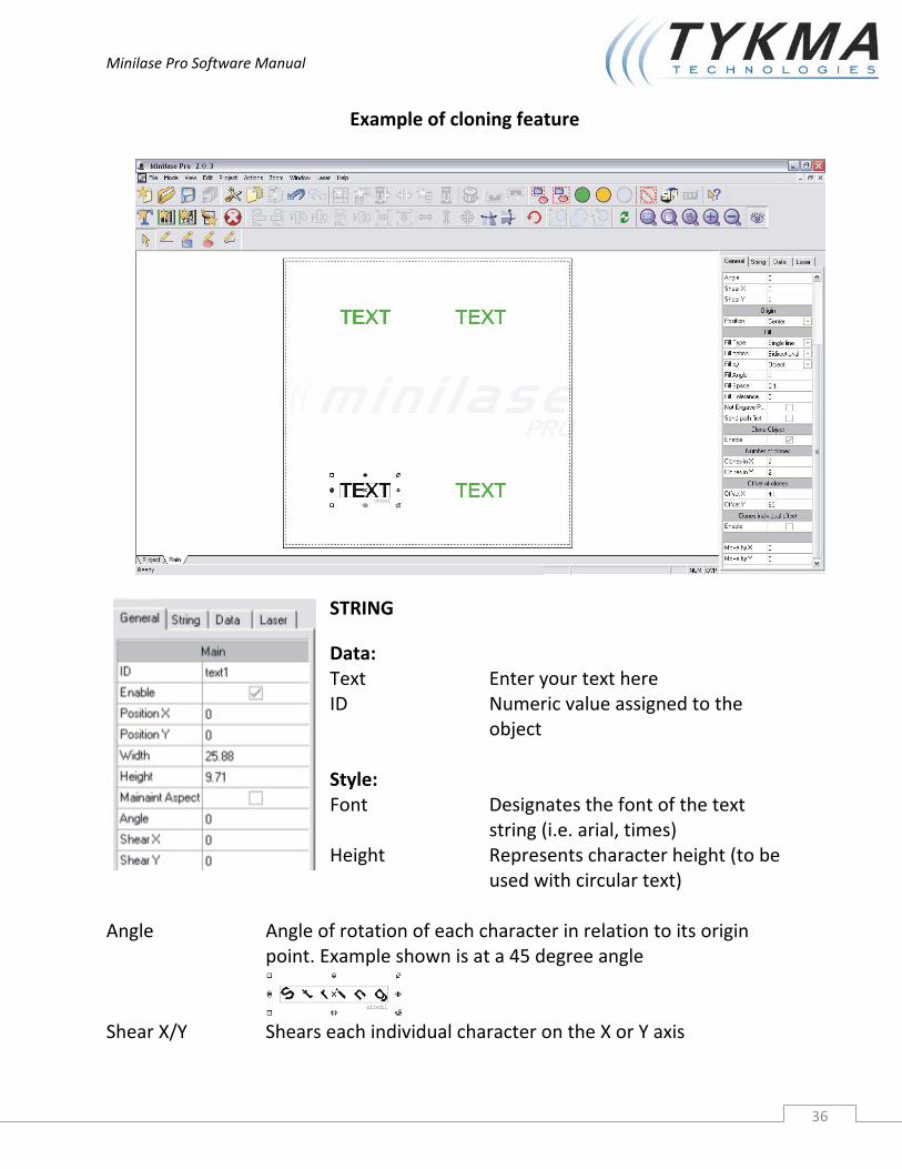
Example of cloning feature
STRING
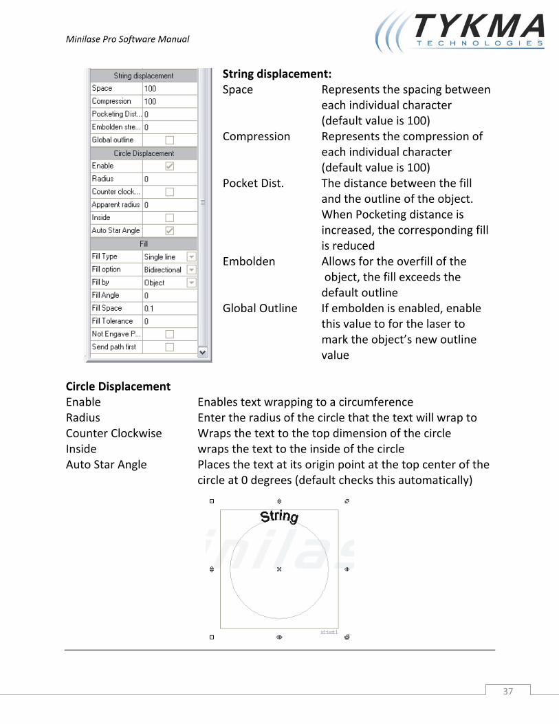
Data: Text Enter your text here ID Numeric value assigned to the object Style: Font Designates the font of the text string (i.e. arial, times) Height Represents character height (to be used with circular text)
Angle Angle of rotation of each character in relation to its origin
point. Example shown is at a 45 degree angle Shear X/Y Shears each individual character on the X or Y axis
Minilase Pro Software Manual
37
String displacement: Space Represents the spacing between each individual character (default value is 100) Compression Represents the compression of each individual character (default value is 100) Pocket Dist. The distance between the fill and the outline of the object. When Pocketing distance is increased, the corresponding fill is reduced Embolden Allows for the overfill of the object, the fill exceeds the default outline Global Outline If embolden is enabled, enable this value to for the laser to mark the object’s new outline value
Circle Displacement Enable Enables text wrapping to a circumference Radius Enter the radius of the circle that the text will wrap to Counter Clockwise Wraps the text to the top dimension of the circle Inside wraps the text to the inside of the circle Auto Star Angle Places the text at its origin point at the top center of the circle at 0 degrees (default checks this automatically)

Minilase Pro Software Manual
38
3.7 Special character sequences The text string can contain any alphanumeric character and one or more of the following special character sequences: %a, %A Day of the week, abbreviated (a) or full (A) %b, %B Month of the year abbreviated (b) or full (B) %c Date and time according to current location %d Day of the month, decimal number (01‐31) %H Time 24 hour clock format (00‐23) %l Time 12 hour clock format (01‐12) %j Day of the year, decimal number (001‐366) %m Month of the year, decimal number (01‐12) %M Minutes, decimal number (00‐59) %p A.M. / P.M. indicator %S Seconds, decimal number (00‐59) %U Week of the year, decimal number (00‐51, Monday is the first day of the week) %w Day of the week, decimal number (0‐6, Sunday = 0) %W Week of the year, decimal number (00‐51, Monday is the first day of
the week) %x Date according to current location %X Time according to current location %y Year, two digit decimal number (00‐99) %Y Year, four digit decimal number %z, %Z Time zone, name (Z) or abbreviation (z) %n Counter, decimal format %o Counter, octave format %e, %E Counter, hexadecimal format, lower case (e) or upper case (E) %s Data from serial RS232‐C %% Percentage sign (%) %ID (Percentage sign followed by an ID number) Copies that ID’s data Example of date in dd/mm/yyyy format Proceed as follows to make a text string with the format: day (two digits), month (two digits), year (four digits) separated by “/”:
Create a text string cont. on next page

Minilase Pro Software Manual
39
Select the required parameters (font, character height, etc.) Enter the string “%d/%m/%Y” in the text box and press enter
Example of data in dd/mm/yy format Proceed as follows to make a text string with the format: day (two digits), month (two digits), year (two digits) separated by “/”:
Create a text string Select the required parameters (font, character height, etc.) Enter the string “%d/%m/%y” in the text box and press enter
Example of a counter Proceed as follows to make a text string including a decimal format counter:
Create a text string Select the required parameters (font, character height, etc.) Select the required counter parameters (see below) Enter the string “%n” in the text box and press enter
The counter parameters can be accessed from the “Properties” window on the string “Data” page. The parameters are:
Start, the minimum value of the counter Stop, the maximum value of the counter Cycles, the number of engraving jobs required
to increase the counter Increment, increment value (positive or
negative) Digits, minimum number of digits to be
displayed
For example, with the following parameters: Current =9 Start =1 Stop =10 Cycles =2 Increment =2 Digits =3 cont. on next page

Minilase Pro Software Manual
40
The following would appear: “001” to become: “003”…”005”…”007”…”009”…”002”…”004”…”006”…”008”…”010” In this example an increment would occur every two engraving jobs.
Minilase Pro Software Manual
41
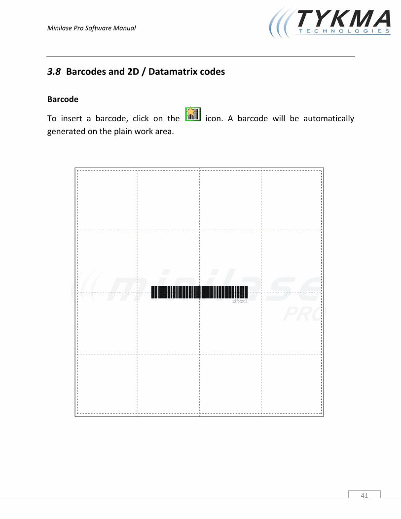
3.8 Barcodes and 2D / Datamatrix codes
Barcode
To insert a barcode, click on the icon. A barcode will be automatically generated on the plain work area.

Minilase Pro Software Manual
42
Data: Text Enter the text to be placed into the barcode ID Numeric value assigned to the object Encode Code Sets the type of barcode Checksum Enables a checksum calculation on the bar code string (if installed) Barcode Height Height of the barcode Size Width of the barcode Ratio Represents the size of the black bars in relation to the white bars in the barcode, utilized to improve resolution with smaller barcodes Quiet Zone Sizes the extra space to the right and left of the barcode when using a reverse barcode Reverse Makes a reverse barcode (swaps black and whites)
Module Ratio Controls the ratio of the black and white bars while
simultaneously adjusting the overall width of the barcode

Minilase Pro Software Manual
43
3.9 Matrix code
To insert a 2D or Datamatrix, click on the icon. The code will be automatically generated on the plain work area.
Minilase Pro Software Manual
44
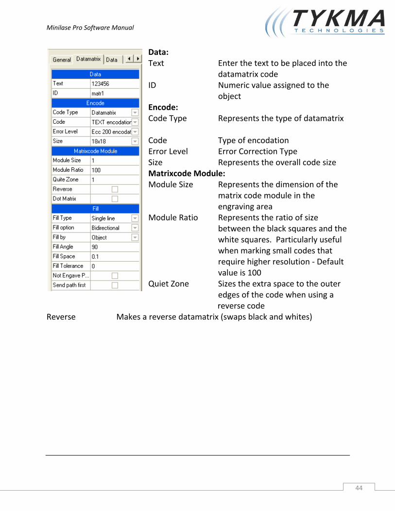
Data: Text Enter the text to be placed into the datamatrix code ID Numeric value assigned to the object Encode: Code Type Represents the type of datamatrix Code Type of encodation Error Level Error Correction Type Size Represents the overall code size Matrixcode Module: Module Size Represents the dimension of the matrix code module in the engraving area Module Ratio Represents the ratio of size between the black squares and the white squares. Particularly useful when marking small codes that require higher resolution ‐ Default value is 100 Quiet Zone Sizes the extra space to the outer edges of the code when using a
reverse code Reverse Makes a reverse datamatrix (swaps black and whites)
Minilase Pro Software Manual
45
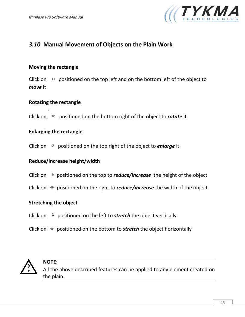
3.10 Manual Movement of Objects on the Plain Work
Moving the rectangle
Click on positioned on the top left and on the bottom left of the object to move it
Rotating the rectangle
Click on positioned on the bottom right of the object to rotate it
Enlarging the rectangle
Click on positioned on the top right of the object to enlarge it
Reduce/Increase height/width
Click on positioned on the top to reduce/increase the height of the object
Click on positioned on the right to reduce/increase the width of the object
Stretching the object
Click on positioned on the left to stretch the object vertically
Click on positioned on the bottom to stretch the object horizontally
NOTE: All the above described features can be applied to any element created on the plain.
Minilase Pro Software Manual
46
4 Laser Marking Parameters
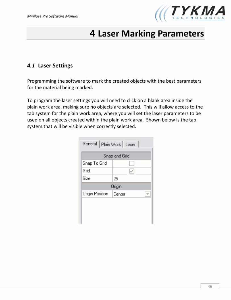
4.1 Laser Settings Programming the software to mark the created objects with the best parameters for the material being marked. To program the laser settings you will need to click on a blank area inside the plain work area, making sure no objects are selected. This will allow access to the tab system for the plain work area, where you will set the laser parameters to be used on all objects created within the plain work area. Shown below is the tab system that will be visible when correctly selected.
Minilase Pro Software Manual
47
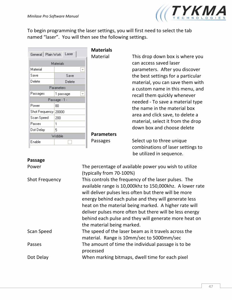
To begin programming the laser settings, you will first need to select the tab named “laser”. You will then see the following settings.
Materials Material This drop down box is where you can access saved laser parameters. After you discover the best settings for a particular material, you can save them with a custom name in this menu, and recall them quickly whenever needed ‐ To save a material type the name in the material box area and click save, to delete a material, select it from the drop down box and choose delete Parameters Passages Select up to three unique combinations of laser settings to
be utilized in sequence. Passage Power The percentage of available power you wish to utilize (typically from 70‐100%) Shot Frequency This controls the frequency of the laser pulses. The available range is 10,000khz to 150,000khz. A lower rate will deliver pulses less often but there will be more energy behind each pulse and they will generate less heat on the material being marked. A higher rate will deliver pulses more often but there will be less energy behind each pulse and they will generate more heat on the material being marked. Scan Speed The speed of the laser beam as it travels across the
material. Range is 10mm/sec to 5000mm/sec Passes The amount of time the individual passage is to be
processed Dot Delay When marking bitmaps, dwell time for each pixel

Minilase Pro Software Manual
48
4.1.1 WOBBLE
The purpose of wobble is to mark the single lines of vector graphics with thicker lines (either True Type characters or imported figures). The line thickness is normally equal to the dimension of the laser spot. However, for some applications this thickness may not be sufficient, the wobble function solves this problem.
The picture below represents the functioning principle of the wobble.
Picture 1 shows the result of a vector marking with the wobble disabled. Picture 2 shows the same vector but with the wobble enabled.
The conversion of the vector into a dense spiral provides greater thickness of the engraved line. The same function can be applied to any vector graphic that is going to undergo plain marking.
Ø Diameter Represents the diameter of the spiral curve
Speed Represents the frequency of spiral repetition
NOTE: The wobble function configuration parameters must be tested and checked in order to obtain the desired effect.
Minilase Pro Software Manual
49
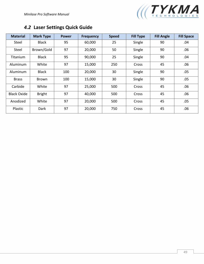
4.2 Laser Settings Quick Guide
Material Mark Type Power Frequency Speed Fill Type Fill Angle Fill Space
Steel Black 95 60,000 25 Single 90 .04
Steel Brown/Gold 97 20,000 50 Single 90 .06
Titanium Black 95 90,000 25 Single 90 .04
Aluminum White 97 15,000 250 Cross 45 .06
Aluminum Black 100 20,000 30 Single 90 .05
Brass Brown 100 15,000 30 Single 90 .05
Carbide White 97 25,000 500 Cross 45 .06
Black Oxide Bright 97 40,000 500 Cross 45 .06
Anodized White 97 20,000 500 Cross 45 .05
Plastic Dark 97 20,000 750 Cross 45 .06
Minilase Pro Software Manual
50
4.3 LASER TEST
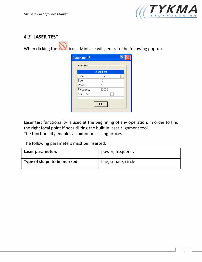
When clicking the icon. Minilase will generate the following pop‐up
Laser test functionality is used at the beginning of any operation, in order to find the right focal point if not utilizing the built in laser alignment tool. The functionality enables a continuous lasing process.
The following parameters must be inserted:
Laser parameters power, frequency
Type of shape to be marked line, square, circle
Minilase Pro Software Manual
51
5 Advanced Features
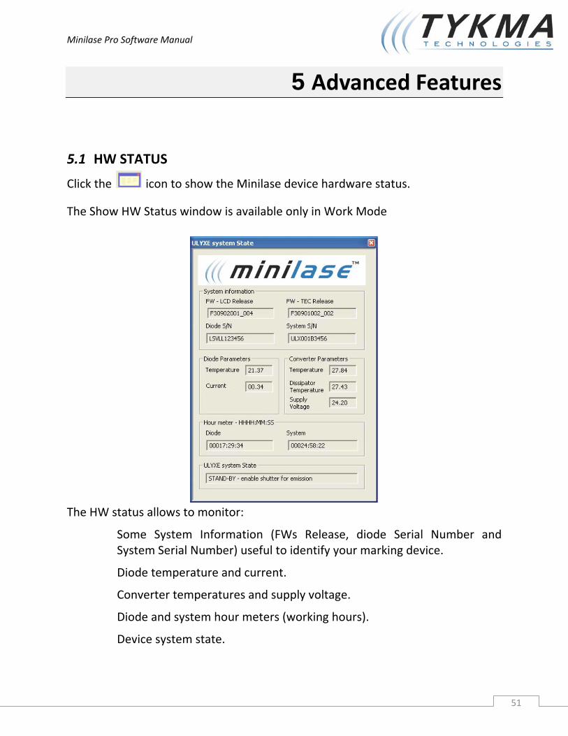
5.1 HW STATUS
Click the icon to show the Minilase device hardware status.
The Show HW Status window is available only in Work Mode
The HW status allows to monitor:
Some System Information (FWs Release, diode Serial Number and System Serial Number) useful to identify your marking device.
Diode temperature and current.
Converter temperatures and supply voltage.
Diode and system hour meters (working hours).
Device system state.

Minilase Pro Software Manual
52
The device state reported could be one of the following:
STATUS DESCRIPTION
SYSTEM READY The shutter is enabled for laser emission and the laser system is ready to mark
STAND‐BY The shutter is not enabled for laser emission.
WARM‐UP Device is warming up
LASER‐OFF The laser system key is in OFF position: the laser is not operative. The following marking functionalities ‐ hence icons ‐ are disabled; turn the key ON to enable them again
Laser Test
Start
Limit All
Limit Object
If the user turns OFF the key during an engraving job (Laser Test, Limit All, Limit Object) the system State will be updated at the end of the job
FAULT: … There is an internal laser HW problem: switch off the system
Poweroff The device has been powered off
Buffer overrun: USB bandwidth low
The USB communication bandwidth is low: current job aborted
The device buffer contains invalid data
Invalid data to process: current job aborted
The working parameters are refreshed any 4 seconds.
Minilase Pro Software Manual
53
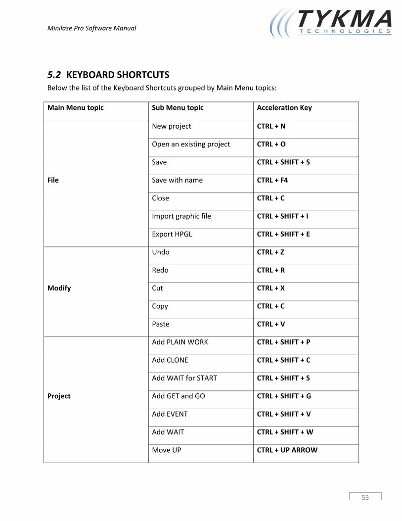
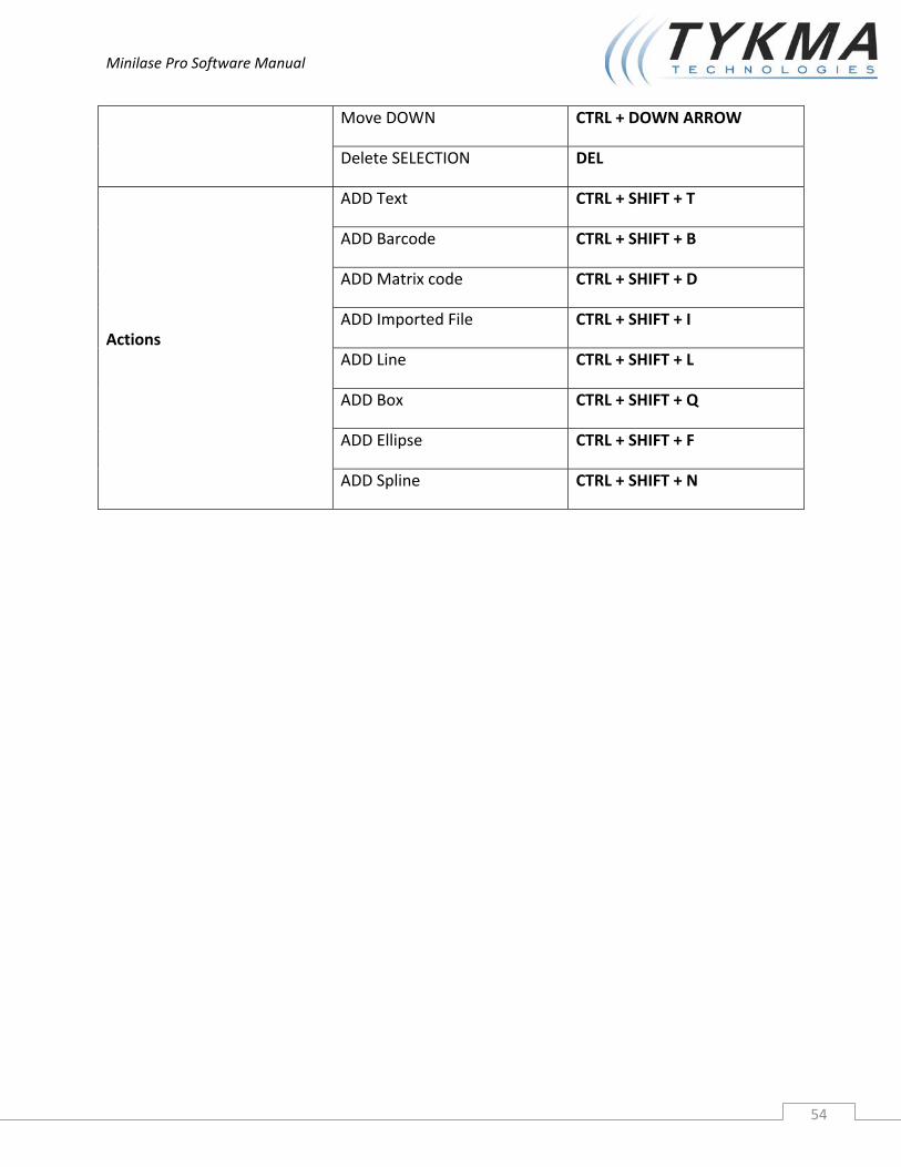
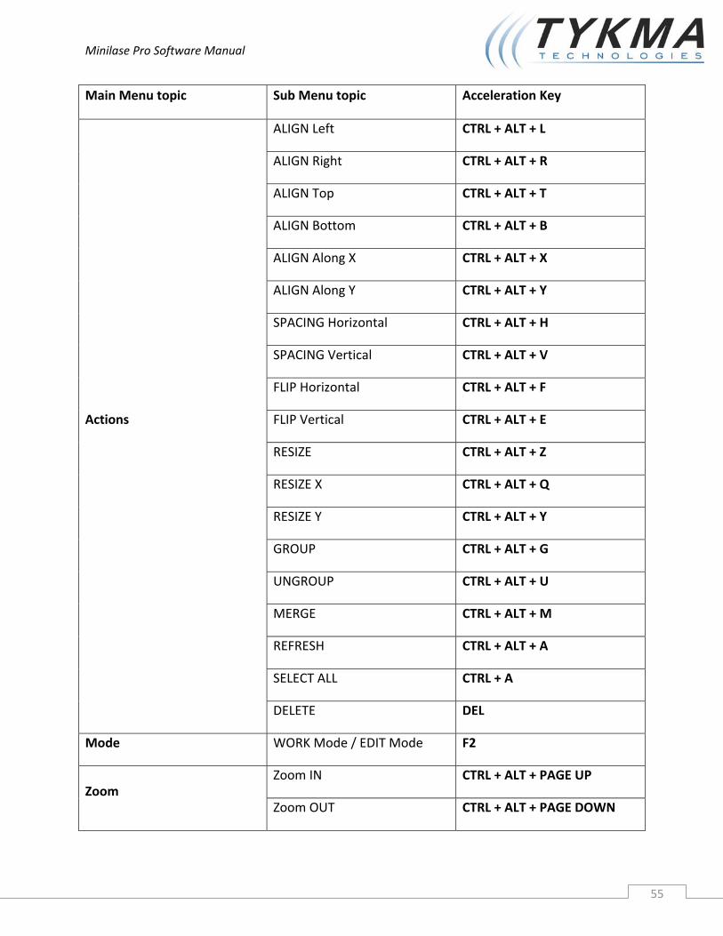
5.2 KEYBOARD SHORTCUTS Below the list of the Keyboard Shortcuts grouped by Main Menu topics:
Main Menu topic Sub Menu topic Acceleration Key
File
New project CTRL + N
Open an existing project CTRL + O
Save CTRL + SHIFT + S
Save with name CTRL + F4
Close CTRL + C
Import graphic file CTRL + SHIFT + I
Export HPGL CTRL + SHIFT + E
Modify
Undo CTRL + Z
Redo CTRL + R
Cut CTRL + X
Copy CTRL + C
Paste CTRL + V
Project
Add PLAIN WORK CTRL + SHIFT + P
Add CLONE CTRL + SHIFT + C
Add WAIT for START CTRL + SHIFT + S
Add GET and GO CTRL + SHIFT + G
Add EVENT CTRL + SHIFT + V
Add WAIT CTRL + SHIFT + W
Move UP CTRL + UP ARROW
Minilase Pro Software Manual
54
Move DOWN CTRL + DOWN ARROW
Delete SELECTION DEL
Actions
ADD Text CTRL + SHIFT + T
ADD Barcode CTRL + SHIFT + B
ADD Matrix code CTRL + SHIFT + D
ADD Imported File CTRL + SHIFT + I
ADD Line CTRL + SHIFT + L
ADD Box CTRL + SHIFT + Q
ADD Ellipse CTRL + SHIFT + F
ADD Spline CTRL + SHIFT + N
Minilase Pro Software Manual
55
Main Menu topic Sub Menu topic Acceleration Key
Actions
ALIGN Left CTRL + ALT + L
ALIGN Right CTRL + ALT + R
ALIGN Top CTRL + ALT + T
ALIGN Bottom CTRL + ALT + B
ALIGN Along X CTRL + ALT + X
ALIGN Along Y CTRL + ALT + Y
SPACING Horizontal CTRL + ALT + H
SPACING Vertical CTRL + ALT + V
FLIP Horizontal CTRL + ALT + F
FLIP Vertical CTRL + ALT + E
RESIZE CTRL + ALT + Z
RESIZE X CTRL + ALT + Q
RESIZE Y CTRL + ALT + Y
GROUP CTRL + ALT + G
UNGROUP CTRL + ALT + U
MERGE CTRL + ALT + M
REFRESH CTRL + ALT + A
SELECT ALL CTRL + A
DELETE DEL
Mode WORK Mode / EDIT Mode F2
Zoom Zoom IN CTRL + ALT + PAGE UP
Zoom OUT CTRL + ALT + PAGE DOWN
Minilase Pro Software Manual
56
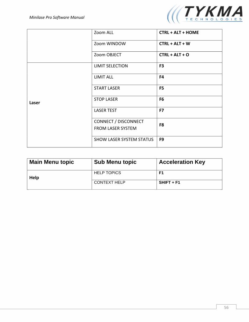
Zoom ALL CTRL + ALT + HOME
Zoom WINDOW CTRL + ALT + W
Zoom OBJECT CTRL + ALT + O
Laser
LIMIT SELECTION F3
LIMIT ALL F4
START LASER F5
STOP LASER F6
LASER TEST F7
CONNECT / DISCONNECT FROM LASER SYSTEM
F8
SHOW LASER SYSTEM STATUS F9
Main Menu topic Sub Menu topic Acceleration Key
Help HELP TOPICS F1
CONTEXT HELP SHIFT + F1
Minilase Pro Software Manual
57
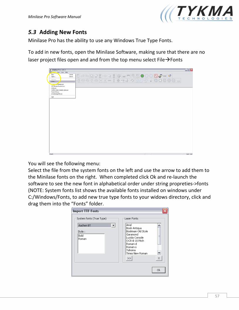
5.3 Adding New Fonts Minilase Pro has the ability to use any Windows True Type Fonts.
To add in new fonts, open the Minilase Software, making sure that there are no laser project files open and and from the top menu select File Fonts
You will see the following menu: Select the file from the system fonts on the left and use the arrow to add them to the Minilase fonts on the right. When completed click Ok and re‐launch the software to see the new font in alphabetical order under string propreties‐>fonts (NOTE: System fonts list shows the available fonts installed on windows under C:/Windows/Fonts, to add new true type fonts to your widows directory, click and drag them into the “Fonts” folder.

Minilase Pro Software Manual
58
6 Creating a Sample Project
6.1 Creating a Sample Project
1. Start by opening Minilase Pro and clicking the icon shown below to create a new project.
2. This will create a new laser project with a plain work area where you will lay out the graphics you wish to mark.
Minilase Pro Software Manual
59
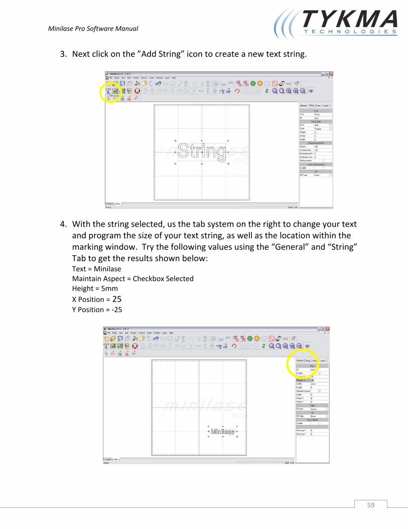
3. Next click on the ”Add String” icon to create a new text string.
4. With the string selected, us the tab system on the right to change your text and program the size of your text string, as well as the location within the marking window. Try the following values using the “General” and “String” Tab to get the results shown below: Text = Minilase Maintain Aspect = Checkbox Selected Height = 5mm X Position = 25 Y Position = ‐25
Minilase Pro Software Manual
60
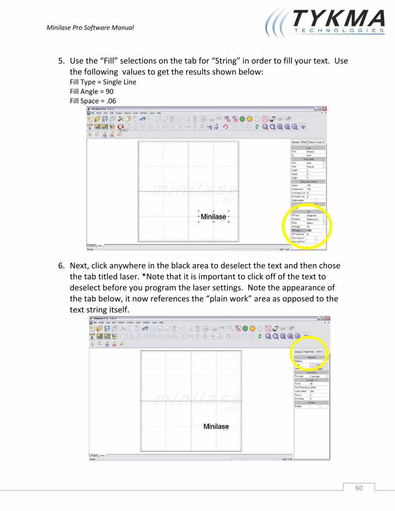
5. Use the “Fill” selections on the tab for “String” in order to fill your text. Use the following values to get the results shown below: Fill Type = Single Line Fill Angle = 90 Fill Space = .06
6. Next, click anywhere in the black area to deselect the text and then chose the tab titled laser. *Note that it is important to click off of the text to deselect before you program the laser settings. Note the appearance of the tab below, it now references the “plain work” area as opposed to the text string itself.

Minilase Pro Software Manual
61
7. Program the laser settings tab with the following settings:
Power = 95 Frequency = 20,000 Speed = 100 Passes = 1
8. Next click on the text string again and click on the icon in the top icon menu titled “Limits on Selection” to turn on red laser aiming beam outline. This will create an outline representing the size and location of the text to be marked inside of your laser system. Visually verify that the box is present during this step. (Note: you must first make sure your laser is in focus using the focus finder system, reference the “Quick Start Guide” for this feature and focusing)
Minilase Pro Software Manual
62
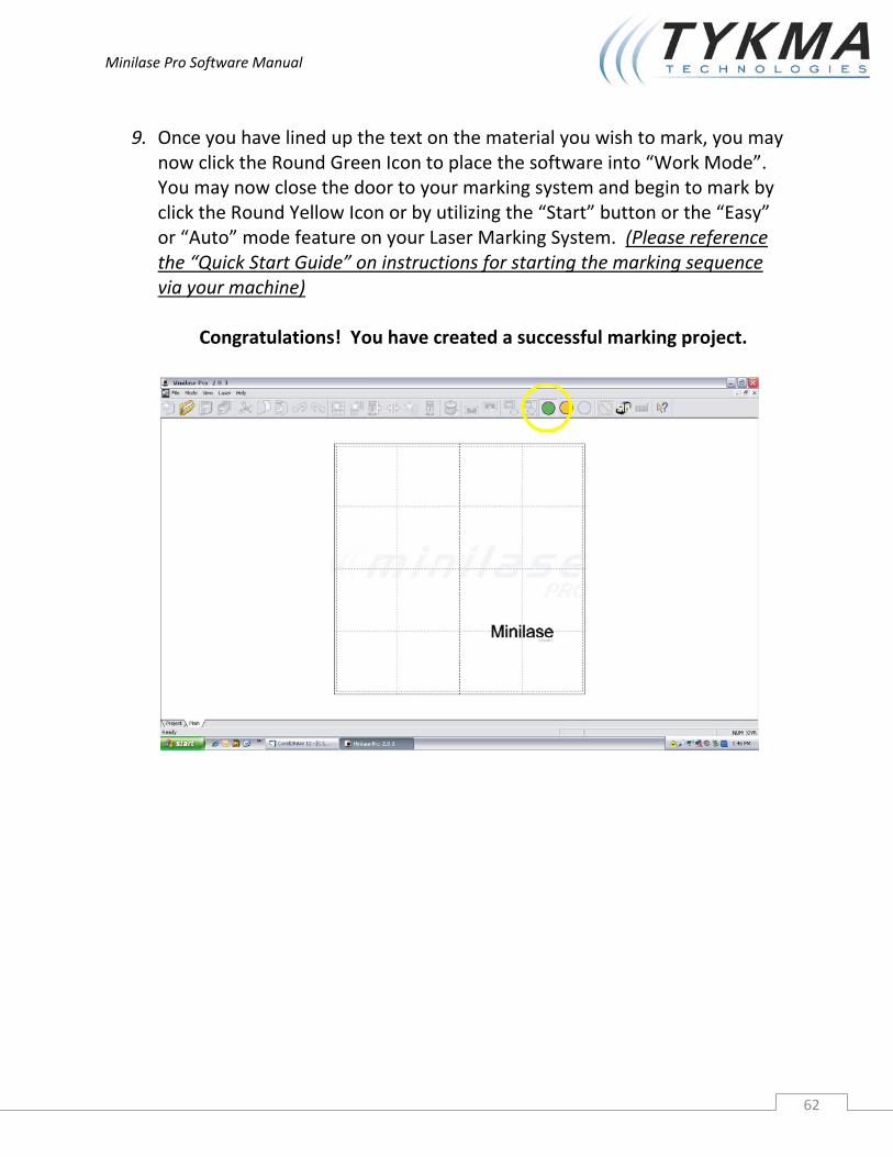
9. Once you have lined up the text on the material you wish to mark, you may now click the Round Green Icon to place the software into “Work Mode”. You may now close the door to your marking system and begin to mark by click the Round Yellow Icon or by utilizing the “Start” button or the “Easy” or “Auto” mode feature on your Laser Marking System. (Please reference the “Quick Start Guide” on instructions for starting the marking sequence via your machine)
Congratulations! You have created a successful marking project.
Minilase Pro Software Manual
63
7 Troubleshooting
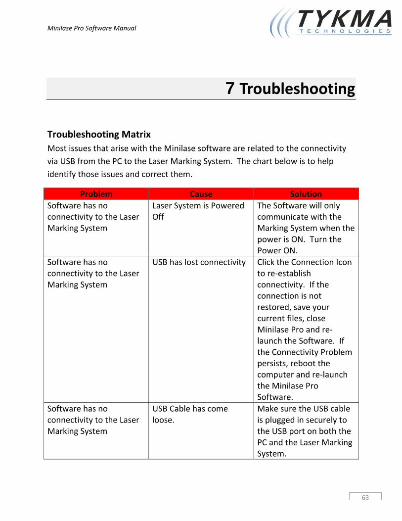
Troubleshooting Matrix Most issues that arise with the Minilase software are related to the connectivity via USB from the PC to the Laser Marking System. The chart below is to help identify those issues and correct them.
Problem Cause Solution Software has no connectivity to the Laser Marking System
Laser System is Powered Off
The Software will only communicate with the Marking System when the power is ON. Turn the Power ON.
Software has no connectivity to the Laser Marking System
USB has lost connectivity Click the Connection Icon to re‐establish connectivity. If the connection is not restored, save your current files, close Minilase Pro and re‐launch the Software. If the Connectivity Problem persists, reboot the computer and re‐launch the Minilase Pro Software.
Software has no connectivity to the Laser Marking System
USB Cable has come loose.
Make sure the USB cable is plugged in securely to the USB port on both the PC and the Laser Marking System.

Minilase Pro Software Manual
64
Problem Cause Solution
Software has no connectivity to the Laser Marking System
USB cable is not plugged into the correct USB connection on the PC
It is important to utilize the same USB connection on the PC every time you run the system. If not, the driver may not have installed properly for the other USB connections on the PC, which could prevent the Software from connecting to the Laser Marking System.
FAULT Error is show in the status bar
Laser Marking System has an Internal Fault
Shut down the system and call Technical Support at 877‐318‐9562 to Diagnose the Issue.

Minilase Pro Software Manual
65
TYKMA TECHNOLOGIES Inc. 931 East Water Street Chillicothe, OH 45601 877‐318‐9562 www.permanentmarking.com [email protected]


