
Microchannel Fuel ProcessingFuel Cells for Transportation/Fuels for Fuel Cells
2002 Annual Program/Lab R&D ReviewMay 6-10, 2002
Kriston Brooks, Jim Davis, Chris Fischer, Adam Heintzelman, Dave King, Larry Pederson, Susie Stenkamp,
Ward Tegrotenhuis, Bob Wegeng, Greg Whyatt
Pacific Northwest National Laboratory
U.S. Department of EnergyPacific Northwest National Laboratory 5/19/200
22
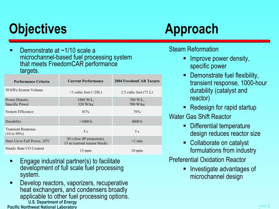
Objectives ApproachSteam Reformation
Improve power density, specific power Demonstrate fuel flexibility, transient response, 1000-hour durability (catalyst and reactor)Redesign for rapid startup
Water Gas Shift ReactorDifferential temperature design reduces reactor sizeCollaborate on catalyst formulations from industry
Preferential Oxidation ReactorInvestigate advantages of microchannel design
Demonstrate at ~1/10 scale amicrochannel-based fuel processing system that meets FreedomCAR performance targets.
Engage industrial partner(s) to facilitate development of full scale fuel processing system.Develop reactors, vaporizers, recuperative heat exchangers, and condensers broadly applicable to other fuel processing options.
Performance Criteria
Current Performance 2004 FreedomCAR Targets
50 kWe System Volume <1 cubic foot (<28L) 2.5 cubic foot (71 L)
Power Density, Specific Power
1800 W/L, 320 W/kg
700 W/L, 700 W/kg
System Efficiency 81% 76%
Durability >1000 h 4000 h
Transient Response (10 to 90%) 5 s 5 s
Start-Up to Full Power, 20oC 30 s (low dP projection), 15 m (current reactor block) <1 min
Steady State CO Content 15 ppm 10 ppm

Project Timeline
FY 2000Designed and built
10 kWe SR with integratedHX network
FY200110 kWe reactor testing
First “low dP” vaporizersModular test stand established
2002 2003 2004 2005 2006 2007 2008
Engineered catalyst, reactordevelopment
Demonstrate rapid startup
Sulfur management
Collaborate with industrial partner(s) on manufacturing, field testing, lifetime, controls
Integrated reformer/fuel cell demonstration at ~5 kWeFY 2002
SR fuel flexibility, durability testingWGS/PROX catalyst studies
Differential temperature reactor conceptSR/WGS/PROX initial integration
Full-scale low dP vaporizers delivered
FY 1999Fast SR kinetics
demonstrated in amicrochannel reactor
FY 1998Full-size gasoline
vaporizer/combustorR&D100 Award
Reforming Reactor HT WGS Reactor
LT WGS Reactor
Combustor
Reformate Recuperator

U.S. Department of EnergyPacific Northwest National Laboratory 5/19/200
24
Reactor Volumetric Productivity Improved(isooctane at 3:1 S:C / GHSV basis: 1atm, 25C, exit conditions, bulk catalyst volume)
0.84
0.86
0.88
0.90
0.92
0.94
0.96
0.98
1.00
0 50,000 100,000 150,000 200,000 250,000 300,000
GHSV in Steam Reforming Reactor [hr-1 ]
Frac
tion
conv
ersi
on to
C1 C
ompo
unds
662C676C
684C
661C
672CFactor of ~3X Increase
in Processing Rate
680C660C
Catalyst A
Catalyst B

U.S. Department of EnergyPacific Northwest National Laboratory 5/19/200
25
Fuel Flexibility Demonstrated(cat. “B”, 3:1 O:C / GHSV basis: 1atm, 25C, exit composition, bulk catalyst volume)
0.80
0.82
0.84
0.86
0.88
0.90
0.92
0.94
0.96
0.98
1.00
0 50,000 100,000 150,000 200,000 250,000 300,000
GHSV in Steam Reforming Reactor [h-1]
Frac
tion
conv
ersi
on to
C1 C
ompo
unds
Methane
Propane
Butane
Ethanol
Methanol
Isooctane
Benchmark Fuel
Methanol (646-663C)
Butane (643-702C)
Isooctane (661-664C)
Ethanol (663-652C)Methane (644-657C)

U.S. Department of EnergyPacific Northwest National Laboratory 5/19/200
26
012345678
0.0 5.0 10.0 15.0
secondsre
form
ate
flow
liquid inputsreduced from 100%
to 10%
liquid inputsincreased from 10%
to 100%
0.0%
10.0%
20.0%
30.0%
40.0%
50.0%
60.0%
70.0%
80.0%
90.0%
100.0%
0 100 200 300 400 500 600 700 800 900 1000
Elapsed Time Reforming Benchmark Fuel [hr]
% C
onve
rsio
n to
C1 C
ompo
unds
99.8%99.4%93.4% 97.0%
26 hr Steam Purge andBackpressure Regulator Change
74 wt% isooctane20 wt% xylene5 wt% methyl cyclohexane1 wt% 1-pentene
BenchmarkFuel
3:1 S:C ratio650oC
Response to step changes in liquid fuel andwater feed rates of 100% to 10% and 10%to 100% in 51 cc reactor
Durability and Transient Response1000-Hour Reforming Test 5 Second Warm Transient Response

U.S. Department of EnergyPacific Northwest National Laboratory 5/19/200
27
Air-CooledGradient WGS
Section
Steam&Fuel-Cooled Gradient
WGS Section
Steam Reforming Reactor
Reformate Recuperator
Combustor
WaterVaporizer
Fuel Vaporizer
HT Air Recuperator
ManualAdjustment
Valves
CatalystScreening
KineticModel
ReactorModeling
Reactor Prototypes
Integrate into
system
y = 34686e-10368x
R2 = 0.9627
0.00001
0.0001
0.001
0.01
0.00150 0.00170 0.00190 0.002101/T (1/K)
Kin
etic
Co
effic
ien
t (m
ol C
O /s
.g c
at)
0
20
40
60
80
100
200 225 250 275 300 325
Temperature, C
CO
Co
nve
rsio
n, %
Equil CO Conversion
WHSV = 75393
Water-Gas Shift DevelopmentApproach / Progress

U.S. Department of EnergyPacific Northwest National Laboratory 5/19/200
28
WGS Catalyst ScreeningSud-Chemie Copper-Zinc (T2650) and Precious Metal/Ceria (PMS5)
Low Shift Feed at 0.5 S/G
0
20
40
60
80
100
200 225 250 275 300 325Temperature, C
CO
Con
vers
ion,
%
EquilibriumT2650 @ GHSV = 60,000T2650 @ GHSV =30,000PMS5 @ GHSV=75,000
PMS5 preferred for microchannel WGS development

U.S. Department of EnergyPacific Northwest National Laboratory 5/19/200
29
Water-Gas ShiftWhy microchannels? – To control temperature profile
HTS LTS
Hxr
Conventional 2-stage Adiabatic
200
300
400
500
600
700
0 0.2 0.4 0.6 0.8 1
Fraction of catalystTe
mpe
ratu
re (C
)250
300
350
400
450
0.0 0.3 0.5 0.8 1.0
Fraction of catalyst
Tem
pera
ture
(C)
1 Integrated Unit2.3X Less Catalyst
Based on Sud-Chemie PMS5 PM catalyst and SR reformate
Ideal profile

U.S. Department of EnergyPacific Northwest National Laboratory 5/19/200
210
Differential Temperature Water-Gas ShiftReactor volume < 3L projected from experimental results
150,000 GHSV, 0.5 Steam/Dry Gas, 4.6% CO Feed
Differential temperature out performs isothermal operation
Prototype 7-channel ReactorPrototype 7-channel Reactor
1
1.5
2
2.5
250 275 300 325 350 375
Temperature, oC
CO
Out
let C
once
ntra
tion
(mol
e %
)
kineticallylimited
equilibriumlimited
isothermal
differential temperature(350 270oC) equilibrium
Reactor can be operated isothermally or with a temperature gradient

U.S. Department of EnergyPacific Northwest National Laboratory 5/19/200
211
Performance of Engineered PROX Catalysts
Stage 2 PROX Performance of Precious Metal Catalyst in a Single Channel Reactor: 0.1% CO, 100oC, GHSV = 200K; S/G=0.3
010
2030
4050
6070
8090
100
0.50 1.50 2.50 3.50 4.50
O2/CO
% C
O C
onve
rsio
n or
O2 S
elec
tivity
Conversion
Selectivity
35 ppm CO 15 ppm CO
30
40
50
60
70
80
90
100
140 160 180 200 220 240
Temperature, C
CO
Con
vers
ion,
%
30
40
50
60
70
80
90
100
O2
Sele
ctiv
ity, %
Base Metal
Precious Metal
Base Metal
Precious Metal
Stage 1 PROX, Precious and Base Metal Catalysts ; 1% CO, O2/CO = 1, GHSV = 400K, S/G = 0.3
Base metal catalyst preferred for Stage 1; Precious metal catalyst preferred for Stage 2

U.S. Department of EnergyPacific Northwest National Laboratory 5/19/200
212
Industry InteractionsFormally seeking to engage industrial partnerWater Vaporizer for 50 kWe ATR designed, built,
tested and delivered to McDermott Technology, Inc.Water Vaporizer delivered to Gas Technology
Institute for boiler-related research, funded by OIT.Interaction with Engelhard, Süd Chemie, NexTech,
and ANL for catalyst formulationsVaporizer and recuperator delivered to Innovatek for
Army reformer demonstration50 kWe Water Vaporizer Panel Size:
dimensions 22.2 cm x 10 cm x 1.8 cmweight = 2.4 kg
At max operating point:HX duty = 24.6 kWHX intensity = 60 W/cm3
Steam225oC, 425 kPa abs.
Water23oC, 4.08 g/s
Combustion Gas685oC, 69.1 kg/h
Combustion Gas157oC, ambient pressuredP = 5 in. H2O
Sample Operating Point

U.S. Department of EnergyPacific Northwest National Laboratory 5/19/200
213
Plans, Future MilestonesComplete catalyst optimization (FY03)WGS, PROX reactor development and integration (FY03)High temperature reformation/sulfur tolerance study complete (FY02)Demonstrate rapid start-up concepts based on low dP design (FY03)Develop sulfur management approach (FY03)Engage industrial partner(s) to facilitate development (FY03)Demonstrate fast-start, integrated fuel processor at 5 kWe, and operate with a PEM fuel cell (FY04)

U.S. Department of EnergyPacific Northwest National Laboratory 5/19/200
214
Rapid Cold Start Concept for Steam ReformerLow combustion gas dP key to rapid startup (30 second start projected)Target test system has four reformer stages with one water vaporizer
Key Data For 30-Second Startup Calculation - 2.4 kWe System∆P at Normal Cond. ∆P at Startup
(~60 SLPM, Air) (~800 SLPM, Air)
Reforming Reactor, 650C (4 stages, 600We each)
720 g (180 g, per stage)
1.6 in H2O (0.4 in H2O, per stage)
21.3 in H2O (5.33 in H2O, per stage)
Water Vaporizer (1 stage) 91 g 0.1 in H2O 1.3 in H2O
MassComponent

U.S. Department of EnergyPacific Northwest National Laboratory 5/19/200
215
Responses to Comments from Last YearAn effort should be made to test this reformer with methanol: Tests conducted showed that methanol was the most easily reformed of all fuels evaluated. Productivity is >2x higher than rate for benchmark gasoline, or ~4 kWe/L.Engage an industrial partner to build a complete reforming system:Formal process underway.More studies evaluating catalyst performance and life:
Completed 1000 hour reformer durability test on benchmark gasoline.Commercial and prototype WGS and PROX catalysts extensively studied in powder and engineered form.Developed single channel reactors that provide flexibility in testing of engineered catalysts, provide data to develop kinetic model.


