i
METHANATION OF SIMULATED NATURAL GAS USING ALUMINA SUPPORTED MANGANESE DOPED RUTHENIUM AND PALLADIUM OXIDE
CATALYST
HAZWAN FAIZ BIN ABD RAHIM
A thesis submitted in fulfilment of the requirements for the award of the degree of
Master of Science (Chemistry)
Faculty of Science Universiti Teknologi Malaysia
MARCH 2012

iv
To my beloved father, mother and sisters.
You are the sunshine of my life.
v
ACKNOWLEDGEMENT
The development of this work was made possible above all through the expert
guidance and encouragement of Professor Dr. Wan Azelee Wan Abu Bakar as my
supervisor, and Associate Professor Dr. Rusmidah Ali as my co-supervisor.I would
like to express my sincere and deepest thanks for their valuable advice and also being
understanding and patience in solving problems until the completion of this thesis.
Special thanks dedicated to all who have helped me in this research: Mr.
JunaidiMohd. Nasir, Mr. Mokhtar, Mr. Hamzah, Mrs. Nurul and Mr. ZainalAbidin
Abbas.I am very grateful for their help in my laboratory works.
I also thank dozens of others – all lecturers, supporting staffs, Department of
Chemistry and my fellow friends who contributed in many ways to my research. I
am grateful to UniversitiTeknologiMalaysia and Ministry of Science, Technology and
Innovation Malaysia for financial support.
Heartiest thanks are extended to my beloved family who support me thickly
and sweeten my life. Thank to the love pouring into my life.

vi
ABSTRACT
Malaysian crude natural gas categorized as a sour gas due to the
contamination of CO2 other gases. Therefore in this research, manganese oxide doped
noble metal oxides suppor ted on alumina were prepared for methanation reaction to
convert CO2 to CH4. All prepared Ru/Mn-Al2O3(10:90, 20:80, 25:75, 30:70, 35:75
and 40:60) catalysts were calcined at 400ºC, and 1000ºC and Pd/Mn-Al2O3(10:90 and
30:70) catalysts were only calcined at 400ºC for 5 hours separately in screening
process.Ru/Mn(25:75)-Al2O3 catalyst then being calcined at 700°C, 800°C, 900°C
and 1100°C for optimization parameter. In-house-built micro reactor with Fourier
Transform Infra Red, (FTIR) detector and Gas Chromatography, (GC) were used to
study the catalytic activity. It was found that the catalyst with Ru/Mn(25:75)-Al2O3
calcined at 1000oC showed 60.21% conversion of CO2 and 57.84% formation of CH4
at reaction temperature 200oC. When using two series furnace reactors,
Ru/Mn(25:75)-Al2O3 catalyst calcined at 1000oC achieved 95.12% CO2 conversion
and 53.10% CH4 formation at reaction temperature 100°C. The same catalyst with
coating more than one coat reducing the catalytic reaction compared with single coat.
The catalyst finally reached 100% CO2 conversion with 100% CH4 formation after
through the 3rd testing using 100°C of reaction temperature. In pretreatment testing,
the catalyst managed to get 100% CO2 conversion with 100% CH4 formation at first
test at reaction temperature 100°C. For adding compressed gas (O2) testing, the
catalyst shows 100% of CO2 conversion with 100% CH4 formation with only 6% of
compressed gas loading at reactiontemperature 100°C. Using 1% of H2S, reduce the
potential of the catalyst compared with using 0.5% of H2S feed. FESEM illustrated
the catalyst surface is covered with small and dispersed particles with undefined
shape. The X-Ray Diffraction (XRD) analysis revealed that the catalyst is crystalline.
Nitrogen Gas Adsorption (NA) analysis showed that both fresh and spent catalysts
are of mesoporous material with Type IV isotherm and type H3 hysteresis loop.
vii
ABSTRAK
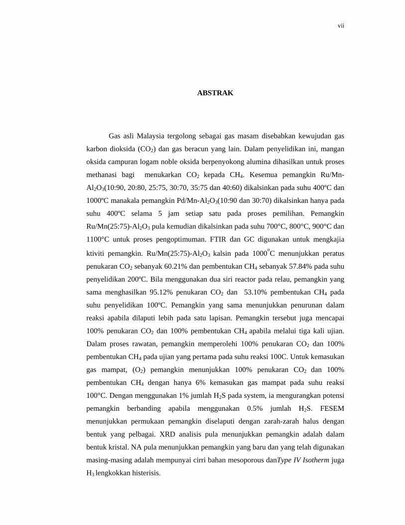
Gas asli Malaysia tergolong sebagai gas masam disebabkan kewujudan gas
karbon dioksida (CO2) dan gas beracun yang lain. Dalam penyelidikan ini, mangan
oksida campuran logam noble oksida berpenyokong alumina dihasilkan untuk proses
methanasi bagi menukarkan CO2 kepada CH4. Kesemua pemangkin Ru/Mn-
Al2O3(10:90, 20:80, 25:75, 30:70, 35:75 dan 40:60) dikalsinkan pada suhu 400ºC dan
1000ºC manakala pemangkin Pd/Mn-Al2O3(10:90 dan 30:70) dikalsinkan hanya pada
suhu 400ºC selama 5 jam setiap satu pada proses pemilihan. Pemangkin
Ru/Mn(25:75)-Al2O3 pula kemudian dikalsinkan pada suhu 700°C, 800°C, 900°C dan
1100°C untuk proses pengoptimuman. FTIR dan GC digunakan untuk mengkajia
ktiviti pemangkin. Ru/Mn(25:75)-Al2O3 kalsin pada 1000oC menunjukkan peratus
penukaran CO2 sebanyak 60.21% dan pembentukan CH4 sebanyak 57.84% pada suhu
penyelidikan 200ºC. Bila menggunakan dua siri reactor pada relau, pemangkin yang
sama menghasilkan 95.12% penukaran CO2 dan 53.10% pembentukan CH4 pada
suhu penyelidikan 100ºC. Pemangkin yang sama menunjukkan penurunan dalam
reaksi apabila dilaputi lebih pada satu lapisan. Pemangkin tersebut juga mencapai
100% penukaran CO2 dan 100% pembentukan CH4 apabila melalui tiga kali ujian.
Dalam proses rawatan, pemangkin memperolehi 100% penukaran CO2 dan 100%
pembentukan CH4 pada ujian yang pertama pada suhu reaksi 100C. Untuk kemasukan
gas mampat, (O2) pemangkin menunjukkan 100% penukaran CO2 dan 100%
pembentukan CH4 dengan hanya 6% kemasukan gas mampat pada suhu reaksi
100°C. Dengan menggunakan 1% jumlah H2S pada system, ia mengurangkan potensi
pemangkin berbanding apabila menggunakan 0.5% jumlah H2S. FESEM
menunjukkan permukaan pemangkin diselaputi dengan zarah-zarah halus dengan
bentuk yang pelbagai. XRD analisis pula menunjukkan pemangkin adalah dalam
bentuk kristal. NA pula menunjukkan pemangkin yang baru dan yang telah digunakan
masing-masing adalah mempunyai cirri bahan mesoporous danType IV Isotherm juga
H3 lengkokkan histerisis.

viii
TABLE OF CONTENT
CHAPTER TITLE
PAGE
SUPERVISOR’S DECLARATION
ii
DECLARATION
iii
DEDICATION
iv
ACKNOWLEDGEMENTS
v
ABSTRACT
vi
ABSTRAK
vii
LIST OF TABLES
xiv
LIST OF FIGURES
xvi
LIST OF ABBREVIATIONS
xi
LIST OF APPENDICES
xxiii
1 INTRODUCTION
1
1.1 Natural Gas
1
1.2 Current Technologies Used in Purification of Natural Gas
5
1.3 Problem Statement
9
1.4 Significant of Study
10
ix
1.4.1 Mechanism of Reaction Process
11
1.4.2 Mechanism of methanation
12
1.5 Research Objectives
13
1.6 Scope of Research
13
2 LITERATURE REVIEW
14
2.1 Methanation
14
2.2 Noble Metals Used in Methanation
15
2.3 Catalyst Based in Methanation Reaction
20
2.4 Supports for Methanation Catalyst
23
3 EXPERIMENTAL
26
3.1 Chemicals and Reagents
26
3.2 Catalyst Preparation
26
3.3 Doped Catalyst Preparation
27
3.4 Catalytic Activity Measurements
28
3.4.1 Coating Testing
30
3.4.2 Catalytic Activity Measurement Using Double Reactors
31
3.4.3 Reproducibility Testing
31
3.4.4 Compressed Air (O2) Testing
32
3.4.5 Treatment Activity
32
3.4.6 H2S Testing
32
3.5 Methane Measurement via Gas Chromatography
32

x
3.6 Catalyst Characterization
33
3.6.1 X-Ray Diffraction (XRD)
34
3.6.2 Field Emission Scanning Electron Microscopy - Energy Dispersive X-Ray (FESEM-EDX)
34
3.6.3 Nitrogen Adsorption Analysis
35
3.6.4 Fourier Transform Infrared Spectroscopy (FTIR)
36
4 RESULTS AND DISCUSSION
37
4.1 Characterization of the Potential Catalyst
37
4.1.1 X-Ray Diffraction Analysis (XRD)
37
4.1.1.1 X-Ray Diffraction Analysis (XRD) over Ru/Mn (25:75)-Al2O3 Catalyst
38
4.1.1.2 X-Ray Diffraction Analysis (XRD) over Ru/Mn (25:75)-Al2O3 Catalyst With Various Calcination Temperatures
42
4.1.1.3 X-Ray Diffraction (XRD) Analysis for Ru/Mn (20:80)-Al2O3 and Ru/Mn(35:75)-Al2O3 Catalysts Each Calcined at 1000°C for 5 Hours
47
4.1.2 Field Emission Scanning Electron Microscopy and Energy Dispersive X-Ray (FESEM-EDX)
51
4.1.2.1 Field Emission Scanning Electron Microscopy and Energy Dispersive X-Ray (FESEM-EDX) over Catalyst Ru/Mn(25:75)-Al2O3 Calcined at 1000°C for 5 Hours
52
4.1.2.2 Field Emission Scanning Electron Microscopy and Energy Dispersive X-Ray (FESEM-EDX) over Catalyst with Different Ratios.
55

xi
4.1.2.3 Field Emission Scanning Electron Microscopy and Energy Dispersive X-Ray (FESEM-EDX) over Ru/Mn(25:75)-Al2O3 Catalyst with Different Calcination Temperatures
59
4.1.3 Nitrogen Absorption Analysis (NA)
63
4.1.3.1 Nitrogen Absorption Analysis (NA) for Ru/Mn (25:75)-Al2O3 Catalyst Calcined at 1000°C
64
4.1.3.2 Nitrogen Absorption Analysis (NA) for Ru/Mn Catalyst with ratios 20:80, 25:75 and 35:65 Supported Alumina Calcined at 1000°C for 5 Hours
65
4.1.3.3 Nitrogen Absorption Analysis (NA) for Ru/Mn (25:75)-Al2O3 Catalysts calcined 900°C, 1000°C and 1100°C for 5 Hours
67
4.2 Catalytic Activity Measurement
69
4.2.1 Catalytic Activity Screening of Alumina Supported Manganese Oxide Calcined at 400°C
70
4.2.2 Catalytic Activity Screening of Alumina Supported Manganese Oxide Doped Noble Metal Oxide Catalysts Calcined at 400°C for CO2 Conversion in Methanation Reaction
71
4.2.3 Catalytic Activity Screening of Alumina Supported Manganese Oxide Doped Noble Metal Oxides Catalysts Calcined at 700°C for CO2 Conversion in Methanation Reaction
75
4.2.4 Catalytic Activity Screening of Alumina Supported Manganese Oxide Doped Noble Metal Oxide Catalysts Calcined at 1000°C for CO2 Conversion in Methanation Reaction
77
4.3 Optimization Parameter for Potential Catalyst, Ru/Mn(25:75)-Al2O3 Calcined at 1000°C
79
4.3.1 Effect of Different Calcination Temperatures for The Synthesize of Ru/Mn(25:75)-Al2O3 Catalyst
80

xii
4.3.2 Effect of Different Number of Coatings Applied When Preparing Ru/Mn(25:75)-Al2O3 Catalyst Calcined at 1000°C
83
4.3.3 Catalyst Testing of CO2 Methanation Reaction using Double Reactors over Ru/Mn(25:75)-Al2O3 Catalyst Calcined at 1000°C
85
4.3.4 Detection of Methane by Gas Chromatography for CO2 Methanation Reaction for Potential Catalysts
86
4.3.5 Pretreatment Prior to Testing Using Two Reactors for Catalyst Ru/Mn(25:75)-Al2O3 at reaction temperature 100°C
89
4.3.6 Effect of Reproducibility Test Using Two Reactors for Ru/Mn(25:75)-Al2O3 Catalyst Calcined at 1000°C for Reaction Temperature 100°C
91
4.3.7 Effect of Adding O2 Using Two Reactors over Ru/Mn(25:75)-Al2O3 Catalyst Calcined at 1000°C for Reaction Temperature 100°C of CO2/H2 Methanation Reaction
94
4.3.8 Effect of H2S Using Two Reactors over Ru/Mn(25:75) Al2O3 Catalyst Calcined at 1000°C for reaction Temperature 100°C of CO2/H2 Methanation Reaction
96
5
CONCLUSION AND RECOMMENDATIONS
100
5.1 Conclusion
100
5.2 Recommendations
101
REFERENCES
102
APPENDIX 113

xvi
LIST OF FIGURES
FIGURE NO.
TITLE PAGE
1.1 Selected Southeast Asia proven natural gas reserves taken from EUMCCI, 2011
3
1.2 CO2 emission in Malaysia according to sector taken Rawshan and Joy, 2010
5
3.1 Schematic diagram of home-built micro reactor
28
3.2 Schematic diagram of glass tube for home-built micro reactor
28
3.3 Diagram of FTIR sample cell
29
3.4 Fresh and Used Catalyst
29
3.5 Schematic diagram of glass tube for home-built using double micro Reactor
31
4.1 XRD Diffractograms of Ru/Mn(25:75)-Al2O3 catalyst (a) as synthesized before calcined, (b) fresh catalyst calcined at 1000°C and (c) used catalyst calcined at 1000°C
38
4.2 XRD Diffractograms of Ru/Mn(25:75)-Al2O3 catalysts calcined at (a) 900°C (b) 1000°C (b) and (c) 1100°C for 5 hours
42
4.3 XRD Diffractograms of (a) Ru/Mn(20:80)-Al2O3 catalyst calcined at 1000°C, (b) Ru/Mn(25:75)-Al2O3 calcined at 1000°C and (c) Ru/Mn(35:65)-Al2O3 calcined at 1000°C for 5 hours
47
4.4 FESEM Micrographs of Ru/Mn(25:75)-Al2O3 catalyst calcined at 1000ºC, (a) fresh and (b) used catalyst
52
4.5 EDX Mapping over Ru/Mn(25:75)-Al2O3 catalyst calcined at 1000oC for 5 hours
54

xvii
4.6 FESEM Micrographs of Ru/Mn/Al2O3 catalyst in the ratios of (a) 20:80, (b) 25:75 and (c) 35:65 calcined at 1000ºC for 5 hours
56
4.7 EDX Mapping over (a) Ru/Mn(20:80)-Al2O3, (b) Ru/Mn(25:75)-Al2O3 and (c) Ru/Mn(35:65)-Al2O3 catalysts calcined at 1000oC for 5 hours
58
4.8 FESEM micrographs of Ru/Mn(25:75)-Al2O3 catalyst calcined at (a) 900°, (b) 1000°C and (c) 1100°C for hours
60
4.9 EDX Mapping over Ru/Mn(25:75)-Al2O3 catalyst calcined at (a) 900°C, (b) 1000°C and (c) 1100°C for 5 hours
62
4.10 Isotherm plot of Ru/Mn(25:75)-Al2O3 catalyst calcined at 1000ºC for 5 hours before undergo catalytic activity testing
64
4.11 Isotherm plot of Ru/Mn(25:75)-Al2O3 catalyst calcined at 1000ºC for 5 hours after undergo catalytic activity process
65
4.12 Isotherm plot of Ru/Mn(20:80)-Al2O3 catalyst calcined at 1000ºC for 5 hours
66
4.13 Isotherm plot of Ru/Mn(35:65)-Al2O3 catalyst calcined at 1000ºC for 5 hours
67
4.14 Isotherm plot of Ru/Mn(25:75)-Al2O3 catalyst calcined at 900ºC for 5 hours
68
4.15 Isotherm plot of Ru/Mn(25:75)-Al2O3 catalyst calcined at 1100°C for 5 hours
69
4.16 Catalytic performance of MnO/Al2O3 catalyst calcined at 400ºC for CO2 conversion towards CO2/H2 methanation reaction
70
4.17 Percentage CO2 conversion plot for CO2/H2 methanation reaction over Ru/Mn(35:65)-Al2O3, Ru/Mn(40:60)-Al2O3, Pd/Mn(10:90)-Al2O3, Pd/Mn(30:70)-Al2O3 (ii) Ru/Mn (10:90)-Al2O3,Ru/Mn(20:80)-Al2O3, Ru/Mn(25:75)Al2O3, Ru/Mn(30:70)-Al2O3 supported alumina calcined at 400°C for 5 hours
73

xviii
4.18 Percentage CO2 conversion plot for CO2/H2 methanation reaction over manganese oxide doped noble metal oxides supported Al2O3 catalysts calcined at 700°C
76
4.19 Percentage CO2 conversion plot for CO2/H2 methanation reaction over manganese oxide doped noble metal oxides supported Al2O3 catalysts calcined at 1000°C
78
4.20 Percentage conversion of CO2 over Ru/Mn(25:75)-Al2O3 catalyst by using various calcination temperatures (i) 400°C, 700C, 800°C and (ii) 900°C, 1000°C, 1100°C
81
4.21 The trend plot of percentage CO2 conversion for Ru/Mn (25:75)-Al2O3 catalysts calcined at 1000°C using different number of coatings
84
4.22 The trend plot of CO2 conversion for Ru/Mn(25:75)-Al2O3 catalyst calcined at 1000°C using double reactors
86
4.23
Calibration graph of standard 99.0% pure methane 87
4.24 The trend plot formation of CH4 over Ru/Mn(25:75)-Al2O3 catalyst calcined at 1000°C using single and double reactors
88
4.25 The percentage of CO2 conversion using Ru/Mn(25:75)- Al2O3 catalyst calcined at 1000°C with N2 was fed in for 30 minutes, one hour and two hours using reaction temperature 100°C towards CO2/H2 methanation reaction
90
4.26 The percentage of CH4 formation using Ru/Mn(25:75)- Al2O3 catalyst calcined at 1000°C with N2 was fed in for 30 minutes, one hour and two hours using reaction temperature 100°C towards CO2/H2 methanation reaction
91
4.27 The percentage of CO2 conversion using Ru/Mn(25:75) Al2O3 catalyst at calcined 1000°C for reproducibility test using reaction temperature 100°C
92
4.28 The percentage of CH4 formation using Ru/Mn(25:75)- Al2O3 catalyst calcined at 1000°C for reproducibility test using reaction temperature 100°C
92
4.29 The percentage of CO2 conversion using Ru/Mn(25:75)- Al2O3 catalyst calcined at 1000°C with compressed gas (O2) feeding at 6%, 12% and 18% using reaction temperature 100°C
94

xix
4.30 The percentage of CH4 formation using Ru/Mn(25:75)- Al2O3 catalyst calcined at 1000°C with compressed gas (O2) feeding at 6%, 12% and 18% using reaction temperature 100°C
95
4.31 Catalytic performance of CO2 conversion and CH4 formation from methanation reaction over Ru/Mn(25:75)- Al2O3 catalyst calcined at 1000°C, testing with 0.5% of H2S gas for several hours at reaction temperature 100°C
97
4.32 Catalytic performance of CO2 conversion and CH4 formation from methanation reaction over Ru/Mn(25:75)- Al2O3 catalyst calcined at 1000°C, testing with 1% of H2S gas for several hours at reaction temperature 100°C
98

xix
LIST OF ABBREVIATIONS C2H6 - Ethane
C3H8 - Propane
C4H10 - Butane
N2 - Nitrogen
LNG - Liquefied Natural Gas
GC-MS - Gas Chromatography-Mass Spectroscopy
UNIPEM - Unit Petroleum Malaysia
AW - Atomic Weight
BET - Brunnauer, Emmet and Teller
CH4 - Methane
CO - Carbon monoxide
CO2 - Carbon dioxide
EDX - Energy Dispersive X-Ray Analysis
FESEM - Field Emission Scanning Electron Microscopy
XRD - X-Ray Diffractogram
FTIR - Fourier Transform Infrared
GC - Gas Chromatography
H2S - Hydrogen sulfide
S - Sulphur
Mn - Manganese
Ru - Ruthenium
Pd - Paladium
Al2O3 - Alumina
LH - Langmuir-Hinshelwood
MW - Molecular Weight
NA - Nitrogen Adsorption
KBr - Potassium Bromide
FID - Flame Ionization Detector
xx
PDF - Powder Diffraction File
λ - Wavelength
d*obs - d spacing values obtained from XRD analysis
d*ref - d spacing values obtained from the reference
2θ - Diffraction angles in degrees

xxi
LIST OF APPENDICES
APPENDIX TITLE
PAGE
A Preparation of Alumina Supported Manganese Oxide Based Catalysts and Its Ratio
113
B Calculation of Methane Percentage
114
C Schematic Diagram of Home Built Micro Reactor Connected using One Isothermal Furnaces
115
D Schematic Diagram of Home Built Micro Reactor Connected using Two Isothermal Furnaces
116
E Calculation of Atomic Weight Percentage Ratio of Element in Catalyst Preparation
117
F Spectrometer of Fourier Trasnform Infrared Spectroscopy of Ru/Mn(25:75)-Al2O3 Catalyst in Catalytic Activity Measurement Process
118

CHAPTER 1
INTRODUCTION
1.1 Natural Gas
Natural gas can be normally described as the deep-seated or “fossil” gasses
which are usually produced by the anaerobic decay of non–fossil organic material.
This highly flammable and combustible gas is a homogenous liquid with low density
and viscosity (Cury, 1981). The primary component of natural gas is methane (CH4)
which depends on the heat, more likely formed in high temperature. It also contains
heavier gaseous hydrocarbons such as ethane (C2H6), propane (C3H8) and butane
(C4H10). Besides that it also contains other toxic and acidic gaseous impurities like
CO2, N2 and H2S. Natural Gas considered as an environmental friendly clean fuel
that offer important environmental benefits when compared to other fossil fuels.
Natural gas requires minimal processing before use therefore natural gas is
establishing world wide as the safest, cleanest and most application of all energy
resource (Kidnay and Parish, 2006).
Natural gas that been found in oil fields contain both phases either dissolved
or isolated crude. When this methane-rich gas is produced by the anaerobic decay of
natural process, it is called biogas. The source of this biogas is at swamps, marshes
and landfills. The process of organic mater is compressed under the earth at very
high pressure for a long time is the natural converting organic matter to fossil

2
fuels. The higher temperature is exposed to the organic matter, more gas will be
created. Deeper ground level usually contains natural gas having high pure methane.
Malaysia’s oil productions normally located at offshore and near Peninsular
Malaysia. There is also major production site in Sabah and Sarawak where all of this
ranked Malaysia at the 14th largest gas reserves and 27th largest crude oil reserves in
the world. Current oil reserves are estimated at approximately 3 billion barrels with a
declining tendency, due to the lack of major new oil discoveries in the last years.
Petronas is the state oil and gas company and followed by other company such as
Sabah shell Petroleum Company and Sweden’s Ludin Oil (T.G. Chuah et al., 2006).
In Malaysia, the total natural gas reserves are three times larger than its oil
reserves. It shows that Malaysia has a potential to develop more profit based on its
total proven natural gas reserves of 2400 billion cubic metres. In year 2010, Malaysia
recorded approximately 15% of total natural gas exportsand was estimated to held 83
trillion cubic metres of proven natural gas reserved as mentioned by EUMCCI
(2011). About 60% of its marketed gas production is consumed domestically, three
quarters (45%) of which is used for generating electricity. Malaysia is also the
region’s second largest LNG exporter, accounting for 14% of total world trade in
LNG in 2002. Malaysia’s reserves are mainly in eastern Malaysia, which is Sarawak
and Sabah (59%) and the rest are at the offshore east coast of peninsular Malaysia.
The largest gas field is in Miri, Sarawak, followed by Kota Kinabalu, Sabah.

3
Figure 1.1: Selected Southeast Asia proven natural gas reserves taken from
EUMCCI, 2011
The country is seeking ways to increase its production of natural gas.
Approximately 38% of Malaysia’s reserves are under PetronasCarigaliSdn. Bhd.
Malaysia also has offshore fields in the South China Sea, which are being developed
by ExxonMobil (William, 2006). It is expected that total investment requirements in
the gas sector will reach $3.1 trillion, of which exploration and development will
account for 55%, or $1.7 trillion. Even though Malaysia succeeds in production of
natural gas, it seems that the natural gas still consists more of the impurities such as
sour gas, flue gas than any other country. This problem will absolutely lower the
price of natural gas that Malaysia has produce but it also cause trouble distributing
them.
Natural gas as one of the three main energy sources has many advantages
such as combustible, abundant resource, lower price, high energy efficiency and
gives a great deal of power upon consumption (Tiratsoo, 1979). In the chemical
industry natural gas is becoming analternative feedstock to crude oil whose supplies
might run out in the present century(Borko and Guczi, 2006). Table 1.1 shows the
chemical composition of Malaysian crude natural gas, analyzed by using Gas
Chromatography-Mass Spectroscopy (GC-MS). The primary component of natural
gas is methane (CH4), the shortest and lightest hydrocarbon molecule.However, the
gas often contains the other light alkanes and a variety of inorganic compounds that
0 20 40 60 80 100 120
Australia
China
Indonesia
Malaysia
India
Trillion Cubic Feet

4
been called wet natural gas. It contains at most 20 to 30% of carbon dioxide (CO2),
hydrogen sulfide (H2S), helium (He) and hydrogen (H2).
Table 1.1: Chemical composition of Malaysian natural gas, source from Wan Azelee et al., (2008)
Gases Composition (%)
CH4 47.9
C2H6 5.9
C3H8 3.2
CO2 23.5
H2S 5.4
Others (CO, O2, N2) 24.1
Malaysian crude natural gas is categorized as a sour gas due to the
contamination of H2S.The hydrogen sulfide in natural gas has several possible
sources. One is the decomposition of amino acids which contain the thiol functional
group, -SH. The anaerobic decay of sulfur-containing proteins or their thermal
decomposition at mild conditions could liberate the sulfur as H2S.Similar to the H2S
gas, CO2 in the presence of water may enhance the production of carbonic acid
which leads to the acid rain phenomena.
The development of technology that can increase the production and quality
of Malaysian natural gas is not only the main thing, but it also came along with
developing a green technology that meets the needs of society in ways that it can
continue indefinitely into the future without damaging or depleting natural resources.
With its rapid industrialization, Malaysia is becoming more and more dependent on
conventional energy supplies such as fossil fuels. The escalating consumption of
energy over the years that heavily relied on fossil fuels had resultant significant
increment of greenhouse gas emissions (mainly carbon dioxide) from the sector
(Rawshan and Joy, 2010). As the level of carbon dioxide increases the warming of
the earth’s surface will also increase (Schneider, 1989).

F
h
d
p
i
c
g
t
p
c
a
p
a
m
Figure 1.2:
1.2. Curr
Du
hydrocarbon
dioxide whi
purification
involves the
conventiona
gasses” CO2
the various
problems of
catalyst deac
are available
potassium
solvents); c
adsorption
membranes(
2%
1%(A
2%(C
CO2 emis2010
rent Techno
ue to the va
ns, but also
ich are cons
processes
e removal
al separation
2 and H2S f
gas-purific
f corrosion (
ctivation (Tr
e. They inclu
carbonate
cryogenic p
(PSA), the
(Du et al., 20
%(Residential)
griculture)
Commersial)
Sector
ssion in Mal
ologies Used
arious comp
o non-hydro
sidered as im
to produce
of vapour-p
n methods
from crude n
cation proce
(Lieberman,
rimm, 1980)
ude absorpti
solutions)
processes;
ermal swin
007)
30%(Transporion)
14%(Ot
ral CO2
laysia accord
d in Purifica
ositions of
ocarbons suc
mpurities, th
high quali
phase impur
are presentl
natural gas.
esses are fr
1987),side
).A wide var
ion processe
and Amin
adsorption
ng adsorptio
31%(Indu
20%(In
rtat
thers)
Emissio
ding to secto
ation of Nat
natural gas
ch as hydro
he natural g
ity of natur
rities from
ly being us
However, c
requently p
reactions, fo
riety of acid
es,such as th
ne Guard-F
processes,
on (TSA)
(Power ustries)
ndustry)
on in M
or taken Raw
tural Gas
which cont
ogen sulfide
gas must un
ral gas. Ga
gas stream.
sed to remo
commercial
lagued by
oaming (Cur
gas remova
e BenfieldTM
FSTMprocess
such as p
and iron
alaysia
wshan and Jo
tains not on
e and carbo
ndergo sever
s purificatio
.A variety
ove the “ac
application
unpredictab
ry, 1981), an
al technologiM process (h
(formulate
pressureswin
sponge; an
5
oy,
nly
on
ral
on
of
cid
of
ble
nd
es
hot
ed
ng
nd

6
Iron-sponge process is the oldest and also the most limited known for
removal of sulfur compounds. It is a dry process consisting of iron oxide (Fe2O3)
impregnated on wood chips or shavings. It is usually used on small gas volumes
with low H2S contents. A vessel can operate 30 to 60 days either without any
regeneration or with the partial generation that can be affected with air passage
through the vessel. The vessel must be recharged with new iron-sponge material
when gas sweetening is no longer possible. This process is selective toward H2S
only. Although this process seems to be less expensive,the operation and disposal of
the spent sponge are difficult to handle. Hydrogen sulfide can also be removed by
stripping. However, a toxic waste stream is created.
Alkanolamine process is commonly being used in the industry because it is a
continuous operation liquid process using absorption for the acid gas removal with
subsequent heat addition to strip the acid gas components from the absorbent
solution (Herzog, H et al., 2009). The primary disadvantages of this process are this
process is not selective and absorbs total acid gas components. The absorbing
alkanolamine solution (weak base) chemically reacts with the H2S or CO2 (weak
acid) to give a water soluble salt. Similarly, a significant amount of waste was
formed with the absorption.
Among those techniques, membrane technique are selected to be the most
practical technique for H2S and CO2 removal because of this process has advantage
in term of compactness, not having moving parts and being noise free. Currently, the
only commercially viable membranes used for H2S and CO2 removal are polymer
based, for example, cellulose acetate, polyimides, polyamides, polysulphone,
polycarbonates, and polyetherimide. However, this technique incurs high cost and
low selectivity towards toxic gas separation (Houet al., 2003). At present, the
treatment of removing CO2 from the crude natural gas at Gas Refinery Plant was
achieved using membrane technique. Meanwhile, the H2S gas was removed using
the catalyst known as Puraspec. Puraspec processes are based on fixed beds of
catalysts and chemical absorbents which remove traces of contaminants from
hydrocarbon gases and liquids. In particular the processes remove. Both of the above
methods of treatment are very expensive and need stringent maintenance. As such,

7
an alternative, viable and reliable cost effective method is crucial in running the
production at cost effective mode.
In addition, hydrogen sulfide in the crud natural gas can be reduced to
elemental sulfur by the Claus process (Smith, W. J et al., 2007). H2S is partially
burned to create a mixture of H2S and sulfur dioxide (SO2). The H2S and SO2 then
react in the presence of a catalyst to form sulfur and water. Sulfates formation is an
undesired side reaction of Claus catalyst. However, when the proper metal is used,
the spinel compound reacts to form sulfates that are unstable enough to react with
H2S and other compounds to form elemental sulfur. Thus, sulfates do not inhibit
catalyst performance. Then the sulfur produced can be sold commercially. There are
problem arises when significant amounts of hydrocarbons reduce the catalyst
efficiency. Hydrocarbons reduce to form graphite, which contaminates the sulfur.
Equation 1.1 shows the desulfurization reaction which is an endothermic
process while Equation 1.2 shows the stoichiometric conditions for CO2/ H2
conversion to methane.
H2S (g) + ½ O2(g)→ S (s) + H2O (l) (1.1)
CO2(g) + 4H2(g)→ CH4(g) + 2H2O (l) (1.2)
Besides that, co-generation of heat is also possible because the methanation
of CO2 is an exothermic reaction, with ∆H = -165 kJ/mol. Removal of H2S is an
oxidation reaction, while removal of CO2 is a reduction reaction. Enthalpies of the
reduction and oxidation reactions play an important role. CO2 in this case can act as
an oxidizing agent to oxidize the oxidation reaction.
H2S (g) + CO2(g) → SO2(g) + 2CO (g) + H2 (g) (1.3)
The CO produced in the previous step can be converted to CH4 in the presence of H2.
CO (g) + 3H2(g) → CH4(g) + H2O (l) (1.4)
CO2(g) + 4H2(g) → CH4 (g) + 2H2O (l) (1.5)

8
Moreover, the removal of sour gases via chemical conversion techniques
using catalyst becomes the most promising technique. Methanation has received
attention from a viewpoint of environmental protection because the emission of CO2
in the atmosphere brings about global warming by the greenhouse effect and these
harmful gases can simultaneously be converted to useful methane gas (Hayakawa et
al., 1999). This process can increase the purity of the natural gas without wasting the
undesired components but fully used them to produce high concentration of methane.
However, this reaction is an eight electron process involving thermodynamics. It is
difficult to achieve this reaction under mild conditions due to kinetic barriers. These
conditions are inconvenient in a laboratory because they required specialized
equipment, and the rate of the reaction is difficult to control. Therefore, the
development of catalysts to lower the activation energy of this reaction is needed.
Catalytic activity is defined as the rate at which a chemical reaction reaches
the equilibrium. From the industrial point of view, activity is also defined as the
amount of reactant transformed into product per unit of time and unit of reactor
volume. Meanwhile, the selectivity of a catalyst is defined as the rate of reactant
conversion into the desired products. Selectivity usually depends on reaction
parameters such as temperature, pressure, reactants composition and also on the
catalyst nature. Therefore, the main effect of a catalyst is to provide an alternative
reaction path that permits to decrease the activation energies of the different reaction
steps, reaching therefore the equilibrium in an easier and faster way. On the other
hand, the catalyst should be high selectivity towards yielding of CH4 and minimizes
the possibility of side reactions. Equation 1.6 shows an undesired side reaction in
this study.
CO2(g) + H2(g) → CO (g) + H2O (l) (1.6)
Finally, present catalyst systems do not give high percentage of conversion
due to instability of the catalysts at high temperature and the highly exothermic
reaction of methanation reaction. Therefore, a new catalysts system must be studied
in order to see what material can give the highest percentage conversion of CO2to
methane from the methanationreaction. Since the catalytic process for methanation

9
reaction offer the best way to remove CO2 in the natural gas, therefore the researcher
decided to carry an extensive study to develop a new effective catalyst was
conducted using transition metal oxide based on manganese with modifying the
dopants using noble metal such as paladium and ruhtenium whichcan give high
conversion percentage of carbon dioxide to methane at low temperature.
1.3 Problem Statement CO2 removal is required because CO2 will form a complex, CO2·CO2, which
is quite corrosive in the presence of water. For gas being sent to cryogenic plants,
removal of CO2 may be necessary to prevent solidification of the CO2 (Sanjay,
1987). Moreover, according to United Nations Development Report (2007),
Malaysia ranked as the 26th largest greenhouse gases emitters with the population
over 27 million people. This showed that removing CO2 gases from natural gas is
very important for maintaining a green environment.
In the presence of water, CO2 and H2S gases will react and lead to severe
internal corrosion attack on the metallic piping and processing vessels. Moreover,
carbon dioxide will reduce the heating value of a natural gas stream and wastes
pipeline capacity. Carbon dioxide alsomay enhance the formation of carbonic acid
when it reacts with the vapour. In addition, H2S gases should be removed from the
natural gas since it has an unpleasant smell, cause catalyst poisoning in refinery
vessels and necessitates that many other expensive precautionary measures be taken.
Thus it will add cost to the industry.
In addition, low temperature in natural gas process is very important because
high temperature will require expensive construction materials for reactors therefore,
methanation technology provide low reaction temperature. Even though others
technologies have existing, there are still problems and limitation regarding to the
technologies itself as discussed in Section 1.2. Thus, CO2/H2methanation technology
is seen as the potential answer to all problems.

10
Many researchers chose to use Ni-based alumina supported system which is
the traditional catalyst for methanation. One of the reason is because Ni are cheap
and was proven to be able in producing high CO2 conversion however, there are
some point Ni are poor that is producing high CO2 conversion at possible low
reaction temperature and reproducibility properties. This is agreed by Wan Azelee
(2011) in her researched using Pd/Ru/Ni (2:8:90)/Al2O3 catalyst calcined at 400oC.
After undergo 4th test of reproducibility testing, Pd/Ru/Ni (2:8:90)/Al2O3 catalyst
calcined at 400oC have 26.17% CO2 conversion compared to fresh catalyst which
was 43.60% at reaction temperature 200°C. Therefore, a new catalysts that have
potential to convert CO2 to CH4 need to be found and it leed us to chose manganese
as a n alternative based catalyst.
Several metals, including ruthenium are known to be active in
CO2/H2methanation reaction however there are gap in findings in using ruthenium as
dopant coupled with manganese as based catalyst. Ruthenium is believed to be
known even more active in CO2/H2methanation reaction than other noble metals but
is also considerable more expensive. By pairing with manganese and used as dopant
material, small amount is only needed thus, create a good catalyst.
1.4 Significant of Study
In this research, the potential catalyst that can be used to remove which
present in wet natural gas consisting of approximately 23% CO2 was developed
based on manganese oxide doped with noble metal. This catalyst offers very
promising techniques for natural gas purification since unwanted CO2 gas is being
converted to the product, CH4 thus will enhance the methane production.
The removal of acid gases (CO2, H2S and other sulfur components) from
natural gas is often referred to as gas sweetening process. There are many acid gas
treating processes available for removal of CO2 natural gas. Besides, it may be
necessary to avoid the corrosion and clogging to the delivery pipeline. This
11
purification method will certainly improve the quality and quantity of Malaysian
natural gas and increase the market price of our natural gas that will benefit to our
country. The utmost important, the potential catalyst will contribute to the growth of
the national economy and create green and sustainable environment.
The catalyst is easily prepared, environmental friendly and reusable. All the
ingredients in the fabrication of the catalyst are easily available, cheap and stable.
The beauty of the catalyst is safer to handle because it can be used at low reaction
temperature.It requires minimum modification to the already existing system and
offers cost effective operating system.
1.4.1 Mechanism of Reaction Process The researcher believe that in many cases of reaction process, it involves a
Langmuir-Hinshelwood (LH) mechanism. This is because the most common surface
reaction mechanism is one in which both reactants are adsorbed on the surface where
they collide and form products. Adsorption, desorption and surface diffusion plays
essential role in LH mechanism. It might be expected that the reaction rate should
depend on surface coverage of both species.
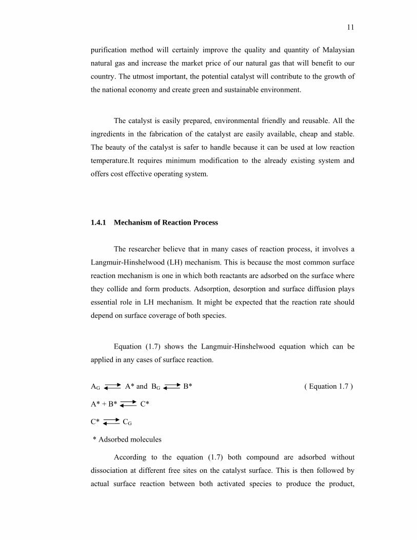
Equation (1.7) shows the Langmuir-Hinshelwood equation which can be
applied in any cases of surface reaction.
AG A* and BG B* ( Equation 1.7 ) A* + B* C* C* CG * Adsorbed molecules
According to the equation (1.7) both compound are adsorbed without
dissociation at different free sites on the catalyst surface. This is then followed by
actual surface reaction between both activated species to produce the product,

12
adsorbed on the surface. Then the product is desorbed from the surface. In such a
way, LH process assume that molecule from a fluid phase is in contact with a solid
catalyst surface. The fluid phase will combine chemically with the solid surface. It
will combine chemically with surface and reaction subsequently proceeds between
chemisorbed molecule followed by desorption of the products.
1.4.2 Mechanism of Methanation
Mechanism of methanation reaction has been studied a long time ago. A lot
of researcher agreed that in methanation process involve LH mechanism to support
the reaction process between active species and surface catalyst.
For the simplest possible reaction, methanation process can be describe as follows CO2 + S CO2(ads) ( 1.8 ) H2 + S H2(ads) ( 1.9 ) CO2(ads) + H2(ads) CH4(ads) + H2O(ads) ( 2.0 ) CH4(ads) CH4(desorp) + S ( 2.1 ) H2O(ads) H2O(desorp) + S ( 2.2 ) *S = Catalyst
According to Equation 1.8, carbon dioxide is reacting with the catalyst
surface, (S) by chemisorptions and creates an active species that adsorbed onto
catalyst surface. This is followed by hydrogen compound that also react with catalyst
surface by chemisorptions and adsorbed onto catalyst surface as an active species.
Both active species than react each other to produce products that is methane and
water. Finally, (Equation 2.2) both products the researchers dissociated from the
catalyst surface.

13
1.5 Research Objectives
The ultimate goal of this research is to synthesize a potential novel catalyst
that is able to catalyze the reactions of CO2 methanation at low temperature possible
with as many conversions possible.
The objectives of the research are:
1. To synthesize potential manganese based catalyst doped with paladium and
ruthenium for the methanation reaction.
2. To test the catalytic performance of the prepared catalysts towards
methanation reaction.
3. To characterize the physical properties of the potential catalyst using various
techniques for further understanding of the properties of the prepared catalyst.
4. To create a catalyst that can be regenerated.
1.6 Scope of Research
In this research, the series catalyst based on manganeseoxide doped noble
metal from selected noble metals such as palladium and ruthenium that was prepared
using impregnation method and also modification sol-gel method will be used for the
synthesizing of manganese oxide based catalyst. Micro-reactor was used to prepare
the catalysts activity by simulation natural gas and was monitored by FTIR and
GC.The simulation is done by mixing the hydrogen gas and carbon dioxide for
methanation process while desulphurization process is done by using hydrogen
sulphide.
Then the potential catalyst was characterized using instruments such as
X-Ray Diffraction (XRD), Field Emission Scanning Electron Microscope – Energy
Dispersive X-ray Analysis (FESEM - EDX), Nitrogen Adsorption Analysis (NA),
Fourier Transform Infrared Spectroscopy (FTIR)

REFERENCES Abe, T., Tanizawa, M., Watanabe, K and Taguchi, A. (2008). CO2 methanation property
of Ru nanoparticle-loaed TiO2 prepared by a polygonal barrel-sputtering method.
Energy & Environmental Science. 2, 315-321.
Alina Rahayu Mohamed., 2003. The Development of Manganese Oxide Based Catalyst
Materials Ageing for Emission Control: Synthesis, Catalytic Activity and
Characterization. M.Sc. Thesis. Universiti Teknologi Malaysia, Skudai,
Malaysia.
Baylet, A., Royer, S., Labrugere, C., Valencia, H., Marecot, P., Tatibouet, M. J and
Duprez, D. (2008). Effect of Palladium On The Reducibility of Mn Based
Materials: Correlation With Methane Oxidation Activity. Physical Chemistry
Chemical Physics. 10 .5983-5992.
Betancourt. P., Rivers. A., Hubaut. R., Scott. C. E and Goldwasser. J. (1998). A Study of
The Ruthenium – Alumina System. Applied Catalysis A: General. 170, 304-307.
Berman, A., Karn, R.K. and Epstein M. (2006). A new catalyst system for high-
temperature solar reforming of methane. Energy & Fuels. 2. 455-462.
Borko and L. Guczi (2006). Non-oxidative Methane Transformations into Higher
Hydrocarbons over Bimetallic Pt–Co Catalysts Supported on Al2O3 and NaY.
Topics in Catalysis. Vol. 39

103
Bradford, C.J.M and Vannice, A.M., 1999. CO2 Reforming of CH4 over Supported Ru
Catalyst, Journ. of Catal, 183, 69-78.
Brooks, K.P., Hu, J., Zhu, H. and Kee, R.J. (2007). Methanation of carbon dioxide by
hydrogen reduction using the Sabatier process in microchannel reactors.
Chemical Engineering Science. 62, 1161-1170.
Castaño, P., Pawelec, B., Fierro, J.L.G., Arandes, J.M. and Bilbao, J. (2007).
Enhancement of pyrolysis gasoline hydrogenation over Pd-promoted Ni/ SiO2–
Al2O3 catalysts. Fuel. 86, 2262-2274.
Chang, F.W., Kuo, M.S., Tsay, M.T. and Hsieh, M.C. (2003). Hydrogenation of CO2
over nickel catalysts on rice husk ash-alumina prepared by incipient wetness
impregnation. Applied catalysis A: General. 247, 309-320.
Chen, H., Lin, Y., Tan, L. K and Li, J (1998). Comparative Studies of Manganese-doped
Coppr-based Catalysts: The Promoter Effect of Mn on Methanol Synthesis.
Applied Surface Scince. 126. 323-331
Chen, C., Lin, C., Tsai, M., Tsay, C., Lee, C. and Chen, G. (2008). Characterization of
Nanocrystalline Manganese Oxide Powder Prepared by Inert Gas Condensation.
Ceramics International. 34. 1661-1666.
Ching Kuan Yong (2008). Nickel oxide based catalysts for the in-situ reactions of
methanation and desulfurization in the removal of sour gases from simulated
natural gas. M. Sc. Thesis. Universiti Teknologi Malaysia, Skudai.
Chuah, T. G., Wan Azlina, A. G K., Robian, Y and Omar, R. (2006). Biomass as The
Renewable Energy Sources in Malaysia: An Overview. International Journal of
Green Energy. 3, 323-346.
Cury, R.N. (1981). Fundamentals of Natural Gas Conditioning. Tulsa, Oklahoma: Penn
Well Publishing Company.

104
Dangle, R. A., Wang, Y., Xia, G–G., Strohm, J. J., Holladay, J. and Palo, D. R. (2007).
Selective CO2 methanation catalysts for fuel processing applications. Applied
Catalysis A: General. 326, 213–218.
David. L. K. (1977). A Fisher-Tropsh Study of Supported Ruthenium Catalysts. Journal
pf Catalysis. 51, 386-397.
Du, G., Lim, S., Yang, Y., Wang, C., Pfefferle, L. and Haller, G.L. (2007). Methanation
of Carbon Dioxide on Ni-incorporated MCM-41 Catalysts: The Influence of
Catalyst Pretreatment and Study of Steady-State Reaction. Journal of Catalyst.
249. 370-379.
El-Shobaky, G.A., El-Molla, S.A. and Ali, A.M.I. (2003). Catalytic Promotion of
NiO/MgO System by Doping With Some Transition Metal Cations. Applied
Catalysis A: General. 253, 417-425.
EUMCCI. (2011). Malaysia Business. EUMCCI Trade Issue and Recommendations
2011.
Erdohelyi, A., Fodor, K. and Szailer, T. (2004). Effect of H2S on the reaction of methane
with carbon dioxide over supported Rh catalysts. Applied Catalysis B:
Environmental. 53, 153-160.
Finch, J. N. (1979). United States Patent 4168276. Retrieved on September 18, 1979
from http://patft.uspto.gov/.
Gardner, D.C. and Bartholomew, C.H. (1981). Kinetics of carbon deposition during
methanation of CO. Industrial and Engineering Chemistry Product Research and
Development. 20 (1), 80-87.
Galetti, C., Speechia, S., Saracco, G and Speechia, V. (2010). CO- Selective
Methanation Over Ru-Ƴ- Al2O3 Catalyst in H2 Rich Gas for PEM FC
applications. Chemical Engineering Science.65. 590-596.

105
Gorke, O., Pfeifer, P and Schubert, K. (2005). Highly Selective Methanation by the use
of a Microchannel Reactor. Catalysis Today. 110. 132-139.
Gordon. D. N and Calvin. H. B. (1984). Hydrogenation of CO2 on Group VIII Metals.
Journal of Catalysis. 87, 352-362.
Habazaki, H., Yamasaki, M., Zhang, B., Kawashima, A., Kohno, S., Takai, T. and
Hashimoto, K. (1998). Co-Methanation of Carbon Monoxide and Carbon
Dioxide on Supported Nickel and Cobalt Catalysts Prepared from Amorphous
Alloy. Applied Catalysis A: General. 172, 131-140.
Happel, J. and Hnatow, M. A. (1981). United States Patent 4260553. Retrieved on April
7, 1981 from http://patft.uspto.gov/
Hayakawa, T., Suzuki, S., Nakamura, J., Uchijima, T., Hamakawa, S., Suzuki, K.,
Shishido, T. and Takehira, K. (1999). CO2 reforming of CH4 over Ni/ perovskite
catalysts prepared by solid phase crystallization method. Applied Catalysis A:
General. 183, 271-285. Elsevier.
Herzog, H., Meldon, J and Hatton, A. (2009). Advanced Post-Combustion CO2 capture.
Doris Duke Foundation.
Hou, Z., Yokota, O., Tanaka, T. and Yashima, T. (2003). Characterization of Ca-
promoted Ni/α-Al2O3 Catalyst for CH4 Reforming with CO2. Applied Catalysis
A: General. 253. 381-387.
Hu, J., Chu, W and Shi, L. (2008). Effect of Carrier and Mn Loading On Supported
Manganese Oxide Catalysts for Catalytic Combustion of Methane. Journal of
Natural gas Chemistry. 17. 159-164.
Ishihara, A., Qian, W. E., Finahari, N. I., Sutrisma, P. I and Kabe, T. (2005). Addition
Effect of Ruthenium in Nickel Steam Reforming Catalysts. Fuel. 84. 1462-1468.

106
Jiang, Q., Deng, G., Chen, R. and Huang, Z. (1997). A Study on Catalysts for
methanation of Carbon Dioxide II. The Effects of Preparation Conditions and
Promoters. Chinese Journal of Catalysis. 18. 42-45.
Karim. H. H. (2010). Regeneration and activity test of spent zinc oxide hydrogen
sulphide removal catalyst. European Journal of Scientific Research. 39 (2), 289-
295.
Kidnay, A.J. and Parrish, W.R. (2006). Fundamentals of Natural Gas Processing. Boca
Raton, Florida: CRC Press
Kodama, T., Kitayama, Y., Tsuji, M. and Tamaura, Y., 1997. Methanation of CO2 using
ultrafine NixFe3-xO4. Energy. 22 (2-3), 183-187.
Kowalczyk, Z., Jodzis, S., Rarog, W., Zielinski, J and Pielaszek, J. (1998). Effect of
Potassium and Barium on the Stability of a Carbon-Supported Ruthenium
Catalyst for the Synthesis of Ammonia. Applied Catalyst A: General. 173. 153-
160.
Kusmierz, M. (2008). Kinetic study on carbon dioxide hydrogenation over Ru/g-Al2O3
catalysts. Catalysis Today. 5678. 4.
. Kusmierz, M. (2008). Kinetic Study on Carbon Dioxide Hydrogenation over Ru/γ-Al2O3
Catalysts. Catalysis Today. 137, 429-432.
Li, J., Liang, X., Xu, S and Hao, J. (2009). Catalytic Performance of Manganese Cobalt
Oxides on Methane Combustion at Low Temperature. Applied Catalysis B:
Environmental. 90. 307-312.
Lieberman, N.P. (1987). Troubleshooting Natural Gas Processing-Wellhead to
Transmission. Tulsa, Oklahoma: Penn Well Publishing Company.
Luna, A. E. C and Iriate, M. E. (2008). Carbon Dioxide Reforming of Methane over a
Metal Modified Ni- Al2O3 Catalyst. Applied Catalysts A: General. 343. 10-15.

107
Mills, G. A and Steffgen, F. W. (1973). Catalytic Methanation. Catalysis Review 8. 2
159-210.
Mori, S., Xu, W. C., Ishidzuku, T., Ogasawara, N., Imal, J and Kobayashi, K. (1998).
Mechanochemical Activation of Catalysts for CO2 Methanation. Applied
Catalysts A: General. 137. 225-269
Murata, K., Okabe, K., Inaba, M., Takahara, I. and Liu, Y. (2009). Mn-Modified Ru
Catalysts Supported on Carbon Nanotubes for Fischer-Tropsch Synthesis.
Journal of the Japan Petroleum Institute. 52. 16-20.
Najwa Binti Sulaiman. (2009). Manganese Oxide Doped Nobel Metals Supported
Catalyst for Carbon Dioxide Methanation Reaction. Universiti Teknologi
Malaysia, Skudai.
Natesakhawat, S., Watson, R.B., Wang, X. and Ozkan, U.S. (2005). Deactivation
characteristics of lanthanide-promoted sol-gel Ni/Al2O3 catalysts in propane
steam reforming. Journal of Catalysis. 234 (2), 496-508.
Nurunnabi, M., Murata, K., Okabe, K., Inaba, M. and Takahara, I., 2008. Performance
and characterization of Ru/Al2O3 and Ru/SiO2 catalysts modified with Mn for
Fischer–Tropsch synthesis, App.l Catal. A: General, 340, 203-211.
Oh, S.W., Bang, H.Y., Bae, Y.C. and Sun, Y.K. (2007). Effect of calcinations
temperature on morphology, crystallinity and electrochemical properties of nano-
crystalline metal oxides (Co3O4, CuO and NiO) prepared via ultrasonic spray
pyrolysis. Journal of Power Sources. 173, 502-509.
Panagiotopoulou , Dimitris I. Kondarides, Xenophon E. Verykios (2009). Selective
Methanation of CO over Supported Ru Catalysts. Applied Catalysis B:
Environmental. 88. 470–478.

108
Panagiotopoulou, P., Kondarides, D. I. and Verykios, X.E. (2008). Selective
Methanation Of CO over Supported Nobel Metal Catalyst: Effects of the Nature
of the Metallic Phase on Catalytic Performance. Applied Catalysis A: General.
334. 45-54.
Park, J-N. & McFarland, E. W. (2009). A highly dispersed Pd–Mg/SiO2 catalyst active
for methanation of CO2. Journal of Catalysis. 266. 92–97.
Parida, K., Samal, A., Das, D and Chintalpudi, N. S. (1999). Effect of Calcination
Temperature on Indian Ocean Manganese Nodules. Mossbauer, XRD, FT-IR and
TG-DTA Studies. Thermocjimica Acta. 32. 69-76.
Peter. J. L and Frank. L. K. (1973). Rates of Methane Formation From Carbon Dioxide
and Hydrogen Over A Ruthenium Catalyst. Journal of Catalysts. 30, 423-429.
Profeti, L.P.R., Ticianelli, E.A. and Assaf, E.M. (2008). Co/Al2O3 catalysts promoted
with noble metals for production of hydrogen by methane steam reforming. Fuel.
87, 2076-2081.
Qinghong. Z., Xianhung. L., Wenqiang. F and Ye. W. (2011). Manganese-Promoted
Cobalt Oxide as Efficient and Stable Non-Noble Metal Catalysts for Preferential
Oxidation of CO in H2 Steam. Applied Catalysts B: Environmental. 102, 207-
214.
Rawshan, A. B and Joy, J. P. (2010). GHG Emissions and Energy Efficiency Potential in
the Building Sector of Malaysia. Australian Journal of Basic and Applied
Sciences. 2(10), 5012-5017.
Riedel, T. and Schaub, G. (2003). Low-temperature Fischer-Tropsch synthesis on cobalt
catalysts – effects of CO2. Topics in Catalysis. 26: 145-156.
Rosso, I., Antonini, M., Galletti, C., Saracco, G. and Specchia V., 2004. Selective CO-
oxidation over Ru-based catalysts in H2-rich gas for fuel cell applications, Topics
In Catalysts, 30-31, 1,223.

109
Rostrup-Nielsen, J.R. (1968). Chemisorption of hydrogen sulfide on a supported nickel
catalyst. Journal of Catalysis. 11 (3), 220-227.
Ruckenstein, E. and Hu, H. Y. (1995). Carbon Dioxide Reforming of Methane over
Nickel/Alkaline Earth Metal Oxide Catalysts. Applied Catalysis A:General. 133.
149-161.
Ruddiman, F. W and Raymo, E. M. (2002). A Methane-Based Time Scale for Vostok
Ice. Quaternary Science Review. 22, 141-155.
Sanjay, K. (1987). Gas Production Engineering. Houston: Gulf Publishing Company Schneider, S.H. (1989). Global Warming Are We Entering the Greenhouse Century. San
Francisco, USA: Sierra Club Books. 13-17.
Seok, H. S., Han, H. S and Lee, S. J. (2001). The Role of MnO in Ni/MnO-Al2O3
Catalysts for Carbon Dioxide Reforming of Methane. Applied Catalysis A:
General. 215. 31-38.
Silver, R. G., Jackson, N. B. and Ekerdt, J.G. (1988). Adsorption and reaction of carbon
dioxide on zirconium dioxide. In Ayers, W.T. (Ed.). Catalytic activation of
Carbon Dioxide. (pp. 123-132). Washington, DC: American Chemical Society.
Smith, W. J. (2007). Hydrogen Sulfide Removal From Industrial Gases Using
Advanced, Modified Claus Technology. Biogass Purification Technology.
Stoop, F., Verbiest, A. M. G and Van Der Wiele, K. (1986). The Influence of The
Support on The Catalytic Properties of Ru Catalysts in the CO Hydrogenation.
Applied Catalysis. 25, 51-57.
Sudhanshu. S., Zhenpeng. H., Peng. Z., Eric. W. M and Horia. M. (2011). CO2
Methanation On Ru-Doped Ceria. Journal of Catalysis. 278, 297-309.

110
Szailer, Eva Novaka, Albert Oszko and Andra Erdohelyia (2007). Effect of H2S on the
Hydrogenation of Carbon Dioxide over Supported Rh Catalysts. Topics in
Catalysis. 46.
Takeishi, K and Aika, K.I. (1995). Comparison of Carbon Dioxide and Carbon
Monoxide with Respect to Hydrogenation on Raney Ruthenium Catalysts.
Applied Catalysis A: General. 133, 31-45.
Takeishi, K., Yamashita, T and Aika, K. (1998). Comparison of Carbon Dioxide and
Carbon Monoxide with Respects to Hydrogenation on Raney Ruthenium
Catalysts under 1.1 and 2.1 MPa. Applied Catalysis A: General. 168. 345-351.
Takenaka, S., Shimizu, T. and Otsuka, K. (2004). Complete Removal of Carbon
Monoxide in Hydrogen-Rich Gas Stream Through Methanation Over Supported
Metal Catalysts. International Journal of Hydrogen Energy. 29, 1065-1073.
Tiratsoo, E.N. (1979). Natural Gas. (3rd ed.) Texas, USA: Gulf Publishing Company. Traa, Y. and Weitkamp, J. (1999). Kinetics of the methanation of carbon dioxide over
ruthenium on titania. Chemistry Engineering Technology. 21, 291-293.
Trimm, D.L. (1980). Design Industrial Catalysts. Netherland, USA: Elsevier Science
Publisher. 11.
Vanderwiel, D.P., Zilka-Marco, J.L., Wang, Y., Tonkovich, A.Y. and Wegeng, R.S.
(2000). Carbon dioxide conversions in microreactors. Pasific Northwest National
Laboratory.
Vicente, M.A., Belver, C., Trujillano, R., Rives, V., Alvarez, A.C., Lambert, J.F.,
Korili, S.A., Gandia, L.M. and Gil, A. (2004). Preparation and characterization
of Mn- and Co-supported catalysts derived from Al-pillared clays and Mn- and
Co-complexes. Applied Catalysis A: General. 267. 47-58.

111
Wang, M., Hao, C.J., Wang Y.P. and Li, S.B. (1999). Amino Acid Schiff Base Complex
Catalyst for Effective Oxidation of Olefins With Molecular Oxygen. Journal of
Molecular Catalysis. 147. 173-178.
Wachs, I.E. (2005). Recent Conceptual Advances in The Catalysis Science of Mixed
Metal Oxide Catalytic Materials. Catalysis Today. 100. 79-94.
Wachs, I.E. (1996). Raman and IR Studies of Surface Metal Oxide Species on Oxide
Supports: Supported Metal Oxide Catalysts. Catalysis Today. 27. 437-455.
Wan Abu Bakar, W. A, Ali, R. and Toeman, S (2011). Catalytic Methanation Reaction
Over Supported Nickel-Rhondium Oxide for Purification of Simulated Natural
gas. Journal of Natural Gas Chemistry. 20, 585-594.
Wan Abu Bakar, W. A, Othman, M. Y. and Yong, C. K. (2008). Nickel Oxide Based
Supported Catalyst for The In-Situ Reaction of Methanation and Desulfurization
in The removal of Sour Gases from Simulated Natural Gas. Catalysts Letter. 128,
127-136
William E. Less et al. (2006). Natural Gas Composition, Information Report, Gas
Technology Institute.
Wojciechowska, M., Przystajko, W and Zielinski, M. (2007). CO Oxidation Catalysts
Based on Copper and Manganese or Cobalt Oxides Supported on MgF2 and
Al2O3. Catalysis Today. 119. 338-348.
Wu, J.C.S. and Chou, H.C. (2009). Bimetallic Rh-Ni/BN catalyst for methane reforming
with CO2. Chemical Engineering Journal. 148, 539-545.
Yaccato, K., Carhart, R., Hagemeyer, A., Lesik, A., Strasser, P., Jr, A.F.V., Turner, H.,
Weinberg, H., Grasselli, R.K. and Brooks, C. (2005). Competitive CO and CO2
Methanation over Supported Noble Metal Catalysts in High Throughout
Scanning Mass Spectrometer. Applied Catalysis A: General. 296, 30-48.

112
Zhao, L., Ma, J., Sun, Z. and Zhai, X. (2008). Catalytic Ozonation for The Degradation
of Nitrobenzene in Aqueous Solution by Ceramic Honeycomb-Supported
Manganese. Applied Catalysis B: Environmental. 83. 256-264.


