M E A S U R E M E N T OF S C A L E S BY M E A N S OF THE I N T E R F E R E N C E
M E T H O D W I T H A U T O M A T I C R E C O R D I N G
M. L. B r z h e z i n s k i i , M. Y a . D r a p k i n , D. I . Z o r i n , V. V. K a e k i n , V. D. S v e r d l i c h e n k o , N. V. T r o f i m o v a , a n d Y u . N. S h e s t o p a l o v
UDC 681.2.085.089.62
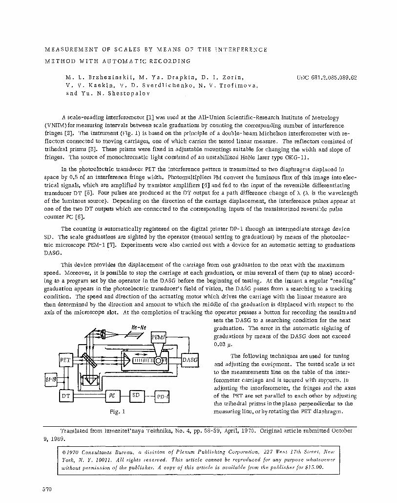
A scale-reading interferometer [1] was used at the All-Union Scientific-Research Institute of Metrology (VNIIM) for measuring intervals between scale graduations by counting the corresponding number of interference fringes [2]. The instrument (Fig. 1) is based on the principle of a double-beam Michelson interferometer with re- flectors connected to moving carriages, one of which carries the tested linear measure. The reflectors consisted of trthedral prisms [3]. These prisms were fixed in adjustable mountings suitable for changing the width and slope of fringes. The source of monochromatic light consisted of an unstabilized HeNe laser type OKG-11.
In the photoelectric transducer PET the interference pattern is transmitted to two diaphragms displaced in space by 0.5 of an interference fringe width. Photemultipliers PM convert the luminous flux of this image into elec- trical signals, which are amplified by transistor amplifiers [4] and fed to the input of the reversible differentiating transducer DT [5]. Four pulses are produced at the DT output for a path difference change of X (X is the wavelength of the luminous source). Depending on the direction of the carriage displacement, the interference pulses appear at one of the two DT outputs which are connected to the corresponding inputs of the transistorized reversible pulse counter PC [6].
The counting is automatically registered on the digital printer DP-1 through an intermediate storage device SD. The scale graduations are sighted by the operator (manual setting to graduations) by means of the photoelec- tric microscope PEM-1 [7]. Experiments were also carried out with a device for an automatic setting to graduations DASG.
This device provides the displacement of the carriage from one graduation to the next with the maximum speed. Moreover, it is possible to stop the carriage at each graduation, or miss several of them (up to nine) accord- ing to a program set by the operator in the DASG before the beginning of testing. At the instant a regular "reading" graduation appears in the photoelectric transducer's field of vision, the DASG passes from a searching to a tracking condition. The speed and direction of the actuating motor which drives the carriage with the linear measure are then determined by the direction and amount to which the middle of the graduation is displaced with respect to the axis of the microscope slot. At the completion of tracking the operator presses a button for recording the resultsand
sets the DASG to a searching condition for the next z L _ He-Ne
Fig. 1
graduation. The error in the automatic sighting of graduations by means of the DASG does not exceed
0.03 p.
The following mchniques areused for tuning and adjusting the equipment. The tested scale is set to the measurements line on the table of the inter- ferometer carriage and is secured with supports. In adjusting the interferometer, the fringes and the axes of the PET are set parallel to each other by adjusting the trihedral prisms in the plane perpendicular to the measuring line, or byrotating the PET diaphragm.
Translated from Izmeritel 'naya Tekhnika, No. 4, pp. 58-59, April, 1970. Original article submitted October 9, 1969.
�9 Consultants Bureau, a division of Plenum Publishing Corporation, 227 West 17th Street, New
York, N. Y. 10011. All rights reserved. This article cannot be reproduced for any purpose whatsoever
without permission of the publisher. A copy of this article is available from the publisher for $15.00.
570
The PET and the DT are adjusted with a voltmeter. The amplitude of the input sinusoidal signals is set by matching the diaphragms with the interference pattern and adjusting the compensation voItage by means of the PET variable resistors. The interferometer carriage is set into motion and the PET dividing plate is adjusted to provide a phase shift of 90 ~ between the input sinusoidal signals by means of the Lissajous figures (circles) on the screen of the S1-19 oscilloscope. The slot of the photoelectric microscope is set parallel to the axis of the graduations, and a maximum and uniform illumination of the microscope field of vision is obtained by adjusting the light source.
Single measurements of mill imeter and centimeter graduations on glass scales made by means of the inter- ferometer method with the counting of fringes and by means of the stereocomparator SKS-1 provided a good agree- ment within the precision range of either instrument.
The above method for measuring linear spacings directly in terms of wavelengths with an automatic record- ing of results in a digital form has potentialities for a wide application in metrological practice.
1,
2.
3.
4. 5. 6.
%
L I T E R A T U R E C I T E D
N. V. Trofimova, Transactions of the VNIIM, No. 47(10~/) (1961). D. I. Zorin, N. V. Trofimova, and Yu. N. Shestopalov, Transactions of the Committee of Standards' Institutes, No. 78 (138) (1965). N. V. Trofimova, Transactions of the USSR MetroIogical Institutes, No. 101 (161) (1968). M. Ya. Drapkin and Yu. N. Shestopalov, Transactions of the USSR Metrological Institutes, No. 98 (158) (1968). D. I. Zorin and Yu. N. Shestopalov, Transactions of the USSR Metroiogical Institutes, No. 101 (161) (1968). M. Ya. Drapkin and Yu. N. Shestopalov, Abstracts of Papers Read at the All-Union Conference on Automatic Control, SO AN SSSR (1961). M. L. Brzhezinskii, D. I. Zorin, and V. D. Sverdlichenko, Transactions of the Commit tee of Standards' Institutes, No. 78 (138) (1965).
5~/1


