
ME451 Kinematics and Dynamics
of Machine Systems
Dynamics of Planar Systems
March 31, 2009
6.2, starting 6.3
© Dan Negrut, 2009ME451, UW-Madison
Quote of the Lecture:History will be kind to me, for I intend to write it.- Winston Churchill
Before we get started… [1]
Coming up on Thursday Guest Lecturer
Dr. Kevin Chang of British Aerospace Engineering (BAE), Land Division
Last Time Wrapped up the derivation of the EOM for planar rigid bodies
Recall that Looked into inertia properties of 2D geometries
Center of mass Parallel axis theorem Mass moment of inertia for composite geometries
Today Example, application of ma=F for rigid bodies Discuss the concept of generalized force HW (due on April 7): 6.1.5, 6.2.1
2
Before we get started… [2]
HW Hint: Problem 6.1.5 Use 6.1.23 to find the location of the centroidal RF
Also use the fact that the composite body has an axis of symmetry to reduce your effort
Use 6.1.24 and 6.1.25 to find mass moment of inertia See also Example 6.1.2 if you run into difficulties
3
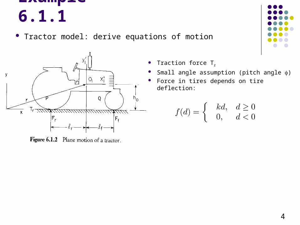
Example 6.1.1 Tractor model: derive equations of motion
4
Traction force Tr
Small angle assumption (pitch angle ) Force in tires depends on tire deflection:
P Q
What’s Left30,000 Feet Perspective
Two important issues remain to be addressed:
1) How do I take into account forces that act on the body when writing the equation of motion for that body?
Concentrated forces (“Point forces”) Forces coming out of translational spring-damper-actuator elements Forces coming out of rotational spring-damper-actuator elements
2) We only derived the variational form of the equation of motion for the trivial case of *one* rigid body. How do I derive the variational form of the equations of motion for a mechanism with many components (bodies) connected through joints?
Just like before, we’ll rely on the principle of virtual work
Why do I care to do this? In one week we’ll be able to formulate the equations that govern the time evolution
of an arbitrary set of rigid bodies interconnected by an arbitrary set of kinematic constraints. These two issues are important pieces of the puzzle. 5
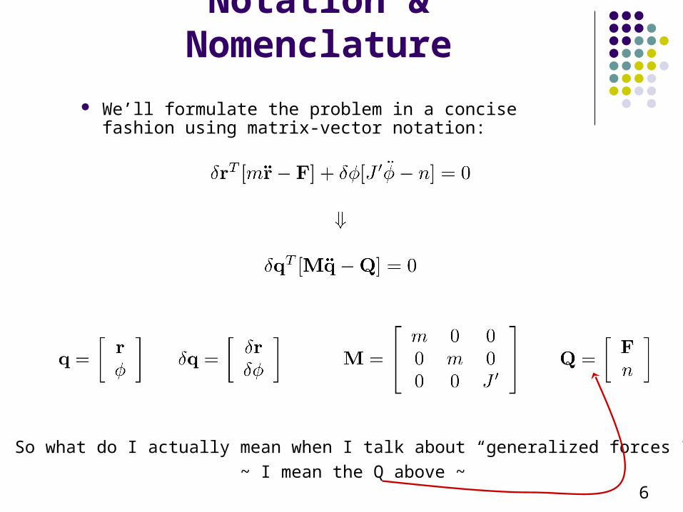
Notation & Nomenclature
We’ll formulate the problem in a concise fashion using matrix-vector notation:
So what do I actually mean when I talk about “generalized forces”?
~ I mean the Q above ~6
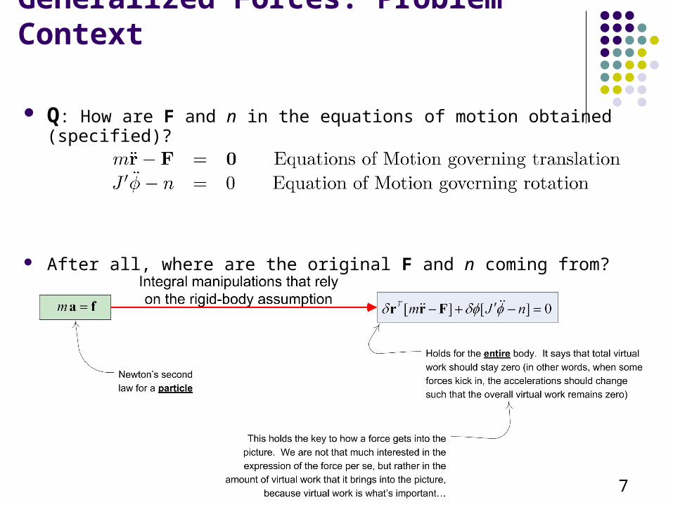
Generalized Forces: Problem Context
Q: How are F and n in the equations of motion obtained (specified)?
After all, where are the original F and n coming from?
7
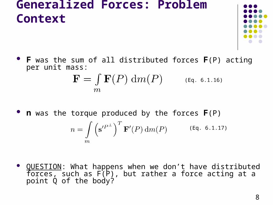
Generalized Forces: Problem Context
F was the sum of all distributed forces F(P) acting per unit mass:
n was the torque produced by the forces F(P)
QUESTION: What happens when we don’t have distributed forces, such as F(P), but rather a force acting at a point Q of the body?
(Eq. 6.1.16)
(Eq. 6.1.17)
8
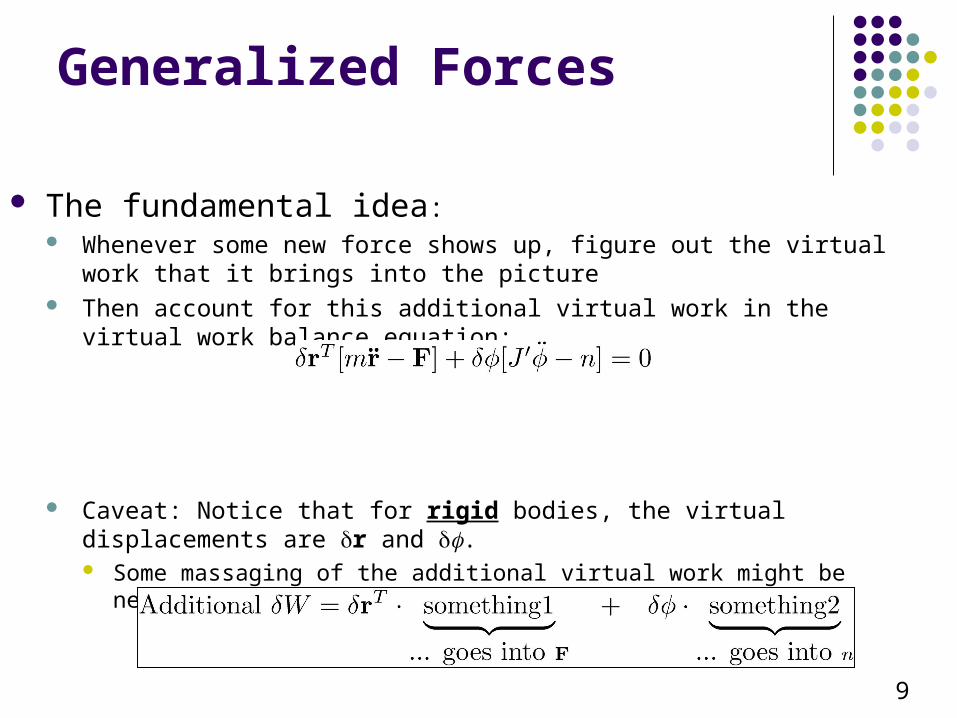
Generalized Forces
The fundamental idea: Whenever some new force shows up, figure out the virtual work that it brings into
the picture Then account for this additional virtual work in the virtual work balance equation:
Caveat: Notice that for rigid bodies, the virtual displacements are r and . Some massaging of the additional virtual work might be needed to bring it into the
standard form, that is
9
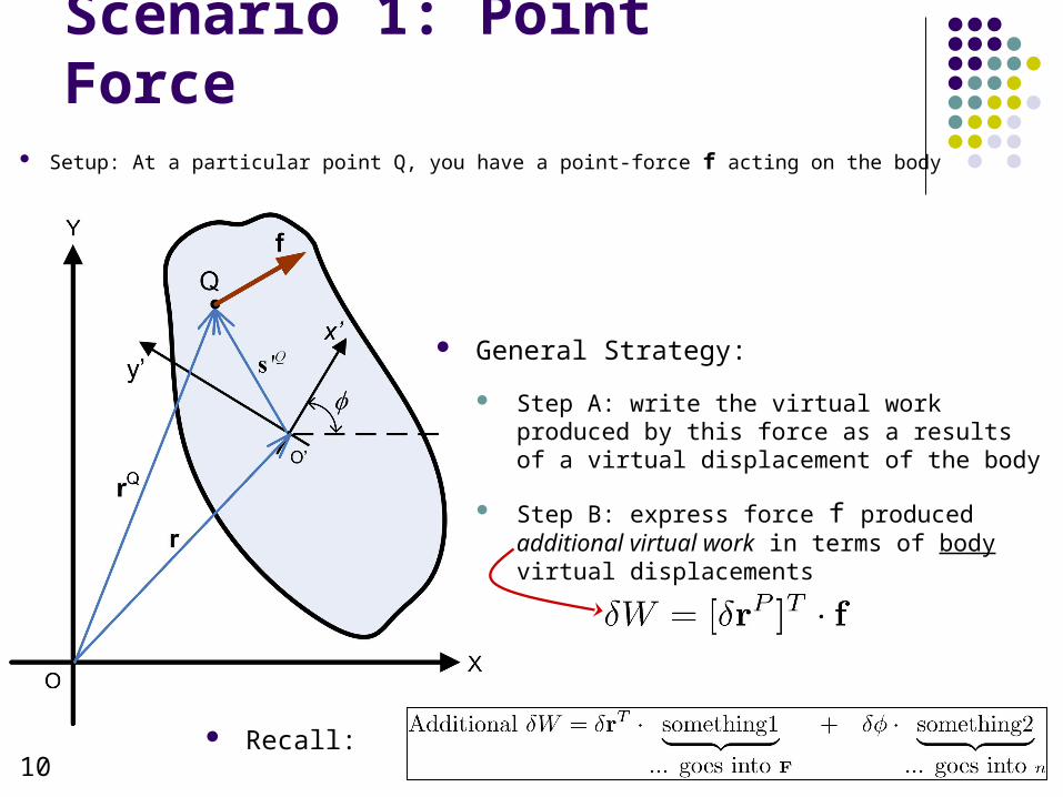
Scenario 1: Point Force Setup: At a particular point Q, you have a point-force f acting on the body
10
General Strategy:
Step A: write the virtual work produced by this force as a results of a virtual displacement of the body
Step B: express force f produced additional virtual work in terms of body virtual displacements
Recall:
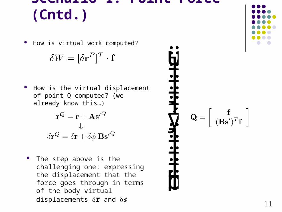
Scenario 1: Point Force (Cntd.)
How is virtual work computed?
How is the virtual displacement of point Q computed? (we already know this…)
11
The step above is the challenging one: expressing the displacement that the force goes through in terms of the body virtual displacements r and
üïïïïïýïïïïïþ
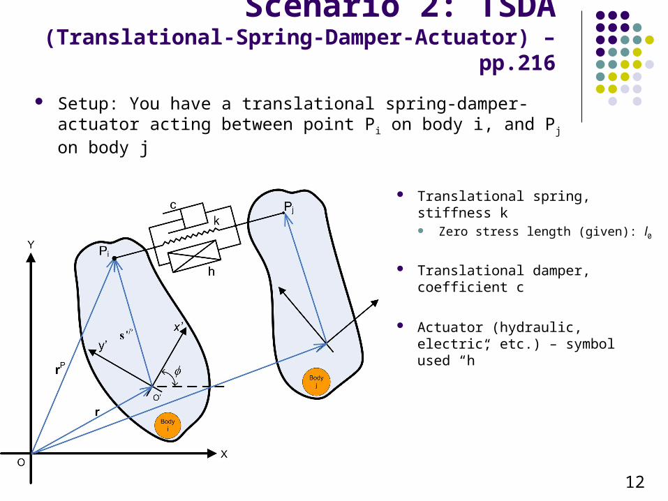
Scenario 2: TSDA(Translational-Spring-Damper-Actuator) – pp.216
Setup: You have a translational spring-damper-actuator acting between point Pi on body i, and Pj on body j
12
Translational spring, stiffness k Zero stress length (given): l0
Translational damper, coefficient c
Actuator (hydraulic, electric, etc.) – symbol used “h”
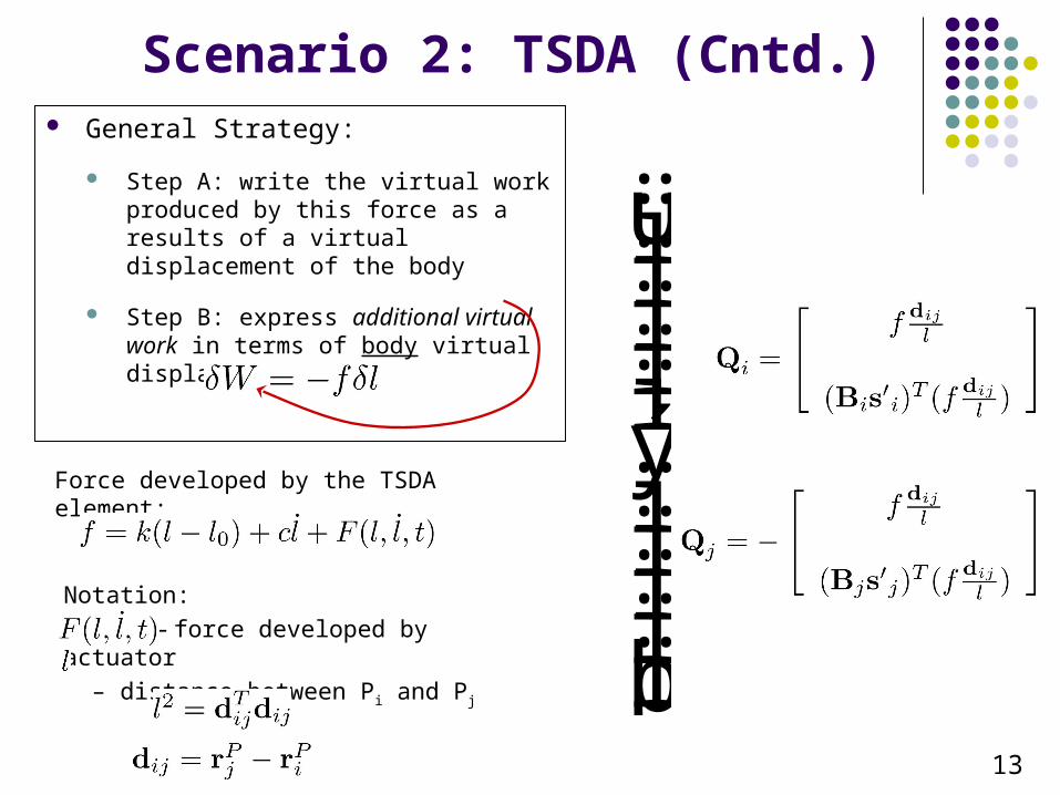
Scenario 2: TSDA (Cntd.) General Strategy:
Step A: write the virtual work produced by this force as a results of a virtual displacement of the body
Step B: express additional virtual work in terms of body virtual displacements
13
Force developed by the TSDA element:
Notation:
– force developed by actuator
– distance between Pi and Pj
üïïïïïýïïïïïþ
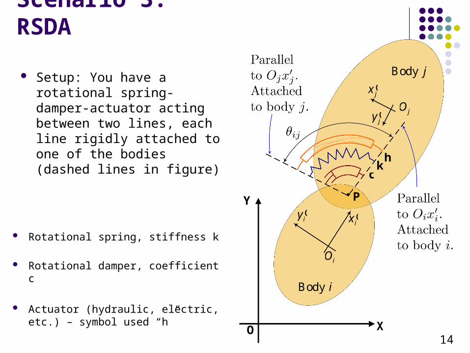
Scenario 3: RSDA
14
Body i
Body j
P
ckh
ix¢iy¢
iO
jx¢
jy¢ jO
X
Y
O
Rotational spring, stiffness k
Rotational damper, coefficient c
Actuator (hydraulic, electric, etc.) – symbol used “h”
Setup: You have a rotational spring-damper-actuator acting between two lines, each line rigidly attached to one of the bodies (dashed lines in figure)

Example 3: RSDA (Cntd.) General Strategy:
Step A: write the virtual work produced by this force as a results of a virtual displacement of the body
Step B: express additional virtual work in terms of body virtual displacements
15
Torque developed by the TSDA element:
Notation:
– torque developed by actuator
– relative angle between two bodies
üïïïïïýïïïïïþ


