
LTOwww.altoproaudio.com
Version 2.0 September 2003
MAXIDRIVE3.43 WAY STEREO
DIGITAL CROSSOVER–
User's Manual

1
SAFETY RELATED SYMBOLS
CAUTIONRISKOFELECTRICSHOCK
DONOTOPEN
∼Protective GroundTerminal
AC mains(AlternatingCurrent)
Hazardous LiveTerminal
ON: Denotestheproductisturnedon.
OFF: Denotes theproductisturnedoff.
WARNING
Describesprecautionsthatshouldbeobservedtopreventthepossibilityofdeathorinjurytothe user.
CAUTION
Describesprecautionsthat shouldbe observed topreventdamagetotheproduct.
Always useproperready-madeinsulated mainscabling (power cord).Failureto dosocouldresultin sho ck/death o r fire. I f indoubt,seekadvicefromaregisteredelectrician.
To prevent fireanddamagetotheproduct, use only
Always i nstallinaccordance with t he manufacturer'sinstructions.
Keep productawayfrom nakedflames.
IMPORTANT SAFETYINSTRUCTIONS
Read theseinstructionsFollowall instructions
Keeptheseinstructions.Donot d iscard.
Heed allwarnings.
Onlyuse attachments/accessories specifiedbythemanufacturer.
Do nottamper with the powercordorplug.Thesearedesignedforyoursafety.
DonotremoveGroundconnections!
Protect thepowercordandplugfromanyphysicalstresstoavoidriskof electricshock.
Donotplaceheavyobjectsonthepowercord.Thiscouldcauseelectricshockorfire.
WARNING
the recommendedfusetypeas indicatedinthismanual.Donotshort-circuitthefuseholder.Beforereplacingthefuse,makesure thattheproductis OFFanddisconnectedfromthe ACoutlet.
˙ProtectiveGround
˙OperatingConditions
˙PowerCordandPlug
˙Cleaning
˙Servicing
˙PowerSupply
˙ExternalConnection
˙Do NotRemoveAnyCovers
˙Fuse
Referallservicingtoqualifiedservicepersonnelonly.Donot performanyservicing other than those instructionscontainedwithintheUser'sManual.
Whenrequired,eitherblowoffdustfrom theproduct oruseadrycloth.
DonotuseanysolventssuchasBenzolorAlcohol.For safety, keepproduct clean andfreefromdust.
Ifthe plugdoesnotfityourACoutletseekadvicefromaqualifiedelectrician.
Toavoid the risk ofelectricshockanddamage,donotsubject thisproducttoany liquid/rainormoisture.Donot usethisproductwhenincloseproximitytowater.
Donotinstallthisproduct nearanydirectheatsource.
Donotblockareasofventilation.Failuretodosocouldresultinfire.
Never cut internal orexternal Ground wires.Likewise,never removeGround wiringfrom theProtectiveGroundTerminal.
Before turning theproductON, make sure that it isconnectedto Ground.Thisis topreventtheriskofelectric shock.
Covers should be r emoved b y qualified servicepersonnel only.
Within theproductareareaswhere high voltages maypresent.Toreducetherisk ofelectricshockdonotremoveany coversunlesstheACmains power cord is removed.
Ensurethatthemainssourcevoltage(ACoutlet)matchesthe voltageratingoftheproduct.Failuretodosocould
result indamageto theproductandpossiblytheuser.Unplugtheproductbeforeelectricalstormsoccurandwhenunusedforlongperiodsoftime toreducetheriskof
electricshockorfire.
No userserviceablepartsinside.
Thissymbol,whereverused, alertsyoutoimpo-rtantoperating andmaintenance instructions.Please r ead.
This symbol, whereverused, alertsyoutothe pre-sence ofun-insulatedanddangerous voltageswith-intheproductenclosure.Thesearevoltagesthatmaybesufficient toconstitute the risk of electricshock ordeath.

DearCustomer:
PREFACE
Thankyou verymuch
▲LTOAUDIO TEAM
2
ThanksforchoosingMAXIDRIVE3.43 - WayStereoDigitalCrossoverandthanksforchoosingone oftheresultsof▲LTOAUDIO TEAM jobandresearches.
Forour LTO AUDIO TEAM, musicandsoundaremorethanajob...arefirstofallpassionand letussayourobsession!▲
Wehavebeendesigningprofessionalaudio products fora long time incooperationwith someof themajorbrandsin theworldintheaudiofield.
The LTOlinepresents unparalleled analogueanddigitalproductsmade by MusiciansforMusicians inourR&D▲centersinItaly,Netherlands, UnitedKingdomandTaiwan.Thecoreof our digitalaudioproductsisasophisticatedDSP(DigitalSoundProcessor)andalargerangeof stateoftheartalgorithmswhich have eendeveloped byourbSoftware Team for the last7 years.Because weareconvincedyouare the mostimportantmemberof LTOAUDIOTEAMandthe oneconfirmingthe▲qualityofourjob,wewouldlike to sharewith youourwork andourdreams,payingattentiontoyoursuggestionsandyourcomments.
Following thisidea wecreate our products and wewillcreatethenewones!Fromourside,weguaranteeyouandwewillguaranteeyoualsoinfuturethebestquality,thebestfruitsofourcontinuousresearches andthebestprices .
Our AXIDRIVE3.43-WayStereo DigitalCrossoveristheresultofmanyhoursof listening andtestsinvolvingMcommonpeople, areaexperts,musiciansandtechnicians.TheresultsofthiseffortisaDSPhi-performanceequalizerthatcan beused inapplicationsasmusicalperformances,Installation andsound reinforcement.Besides we o fferto you a number offactory EQ curvesthatwecollectedandtransformedinpresetsnowavailableinoursmall, effi-cientandeasy touse AXIDRIVE3.4.M
Nothingelseto add,butthatwewouldliketothankallthepeople thatmadethe AXIDRIVE3.4areality availabletoMourcustomers, andthankourdesignersandallthe LTO staff, peoplewhomakepossibletherealizationofproducts▲containingourideaof musicandsoundandarereadytosupportyou,ourCustomers,inthebestway,consciousthatyouare ourbestrichness.

TABLE OFCONTENTS
1. INTRODUCTION ................................................................................................................................... 4..
2.FEATURES .............................................................................................................................................4
3.CONTROLELEMENTS .........................................................................................................................4
3.1TheFrontPanel
3.2TheRearPanel
4. GETTINGSTARTED ..................................................................................................................... 6..........
4.1Configurationof TheSystem
8.TECHNICALSPECIFICATIONS ......................................................................................................... 38
9. WARRANTY ........... ........................................................................................ ............................. ..........39
4.2AdjustThe Input Signal
3
5. ..................................................................THEMENUMAPCONFIGURATIONDESCRIPTION ....... 10
5.1PresetMenu
5.2DelayMenu
5.3Edit Menu
5.4UtilityMenu
6. CONNECTIONS .......................................................................................................................... ........31
7.APPLICATION ........................................... ........................................................ ............................. ......32
7.1FactoryPresetConfiguration
7.2Organization
4.3FirstSetup
4.4SystemConfiguration
4.5Numberof Presets
4.6Type ofPreset
4.7NameofThePreset
4.8PresetModifications
4.9SystemProtection

1. INTRODUCTION
2. FEATURES
3.1TheFrontPanel
3. CONTROLELEMENTS
4
˙
˙˙
˙˙˙˙
˙˙
Singlerack unitDelay lines upto2.5sfor eachinputandupto 300msforeachoutputStereodigitalinput inAEX/EBU formatA/DandD/Aconvertersfora117dBdynamicrangeSlotforamemory cardforthestorage ofmore presetsand aneasierupgradeofother units10Factorypresets,64userpresetsand128cardpresetsbylarge memorycapacitySwitchingpowersupplyRemotecontrolmanufacturedunderQS9000,VDA6.1 certifiedmanagementsystem
2.LEDsTheseLEDsindicate theselecting status ofthe menus.
3.DisplayRear-lit 2 16 d isplay.×Itshowsthepagesofthevariousmenus andthe relativeparameters.
4.DIALknobTheknoballows youtoeditvalue oftheselectedparameter.ThevalueraiseswhileturningtheDIALclockwiseandlowers counterclockwise.
6.NavigationcursorkeysEacheditingpagecomprisesavariablenumber of parameters (fields).Therightand leftkeysallow youto select thevarious required parametersviacontrolling themovementcursorinthepage.
ofthe
1285 10
9674321 11
ENTER
RLTO
PREV NEXT
ESC
MODE
CLIP
-6
-12
-18
-24
A BINPUTLEVEL MUTE
CLIP
-6
-12
-24
LIMIT
OUTPUT
2LEVEL
CLIP
-6
-12
-24
LIMIT
CLIP
- 6
-12
-24
LIMIT
CLIP
-6
-12
-24
LIMIT
CLIP
-6
-12
-24
LIMIT
CLIP
- 6
-12
-24
LIMIT
OUTPUT
1LEVEL
OUTPUT
3LEVEL
OUTPUT
4LEVEL
OUTPUT
5LEVEL
OUTPUT
6LEVEL
MUTE MUTE MUTE MUTE MUTE
EDIT
UTILITY
DELAY
PRESET
CARD
YourMAXIDRIVE3.4 isa3-way stereodigitalcrossoveranditisapowerfulversatilesignalprocessor. Theapparatuswillprovide 3,4,5or6-waymonoX-overwith6 outputs.Thanks totheuseofselectedandexpensivecomponents,theperformancesofMAXIDRIVE3.4areworthmuchmorethan itsprice:youcanset the inputandoutput routingcon-figurationonly throughrecallingoneofthe Presetsincludedin theinternalmemory.
1.MODE buttonThebuttonallowsyoutoselectfourmodes:PRESET,DELAY,EDITandUTILITY.PressingMODErepeatedlytoreachtotherequiredmenuandthecorresponding LEDwilllightup.Youcaneditthe parametersoftheselectedmenus.IfnoneofthemenuLEDsislit,theDisplayshowsthe nameofthecurrentPRESETandno parameterscanbe modified.
5.PREV/NEXTbuttonEachmenucomprisesseveralpages.These buttonsallow youtoturnoverthepagesand/oravariablenumberofparameters.

5
8.ENTERkeyThekeyallowsyoutoaccesstotheselectedediting . P oucaneditandconfirmvalue ofparameter.
page ressingthis key,y therequired
10.InputLevelLEDsTheLEDsareusedtoindicatethelevelofinputA/B.Inordertogetanup-front distortion-freesignal,youkeepthesignalquitehigh,butdoassurethatthe redCLIP LED doesn'tlightup continually.
11.Mute switchesThereare sixmute switches(1-6).They areusedtomutethe signal oftherespectiveoutputs.Whenthe switchison,thecorrespondingledwilllightup.Theseswitchescanavoidsignalpeakswhenswitchingonandoffthesoundsystemandisolatetheindividualaudiosectionsduringtestingorcheckingsound,etc..Therestored Mutefunctioncan besettousetheWakeUp Function(UtilitymenuMisc.Setup submenu)and canbesetasNormal(lastsettingbeforetheunitwasswitchedoff) orMute (alloutputsautomaticallyforcedinto Mutestatus).
3.2TheRearPanel
7.Memory Card SlotTheSlotallowsyoutoinserttheMemoryCardwhichisvery usefulforsafestorageofPRESETS andfor
one MAXIDRIVE3.4to another.their
transferfrom
1913 2014 15 16 17 18
PUSH
2 13
N E W TIDE
PUSH
2 13
NEW TIDE
Apparatenskallanslutastilljordatuttagnardenansluts
tillettnatverk
PWR
OFF
ON
ACINPUT 14W95-240V50/60HzFUSE:95-120VT500mAL
210-240VT315mAL
DIGITALIN RS485OUT RS485IN RS232 I N P U T AI N P U T B4 3 2 1
OUTPUTS
56
A102
9.ESCkeyThe key allowsyouto exittheselectedediting page.It also used torejectthe valueto enter and returnto thestored value.
12.Output LevelLEDs
TheseLEDsindicatetheleveloftherespectiveoutputs(youcanadjust theoutputviaadjustingtheOutputGainparameterof Editmenu.)
Note:TheLIMITER onanyoutputwillchangethewayinwhich thelevelisdisplayed onthecorrespondingLED.Infact, thelevelshown ontheladderisnolonger the"absolute"output level, butthelevelofthesignalat-24dB,-12dB,-6dBcomparedtothelimiterthreshold(indicatedbytheorangeLIMITLED).
PUSH
1
3
2
NEW TIDE
PUSH
1
3
2
N E W TIDE
13.ACinletand fuse holder
CAUTION: Ifthereis something wrong with the fuseorthefuseneedstochange, please refertoaqualifiedtechnician.If thefusecontinuestoblowafterreplacing,discontinue using of thisunitbeforebeingrepaired.
14.PowerSwitchTheswitchisusedto turnthemainPOWER onand off.Note: beforeturningontheunit,pleasemakesuretheamplifiersof thesoundsystemareofftoavoidtheannoyingandsometimesdangeroussignalpeaks.
15.DigitalIn
UsethebalancedXLR-Fconnector(onecableisenoughtofeedbothinputsconnecttheprocessortounitsfittedwith AES/EBU digitaloutputs.Inthiscase,thetwobypassedconventionwillimprovethe qualityofthe signal.Asignalconnected tothedigitalinputhasthesameprocessingasthatconnectedtoanaloginput.TheDigital/AnaloginputselectioncanbesetbyusingtheInputSelectfunction(UtilityMenu-Misc.SetupSubmenu).
Use it to connectyour MAXIDRIVE3.4to thesuppliedACcord.PleasechecktheVoltageinyour countryandwhat voltagefor yourMAXIDRIVE3.4is configured before attempting to connect theunitfor themainAC.ThefusecanprotecttheACsuppliescircuit oftheequipment.

6
4. GETTINGSTARTED
4.1Configuration ofthesystem
Meanwhile,thesystemwillrestorethe exact operatingconditions atthe timeof switchingoff.
16.RS485OUT
Thisisthestandardserial communicationinterface port.ItallowsoutgoingcommunicationbetweenaMAXI-DRIVE3.4andPCorotherMAXIDRIVE3.4units.TheRS485interfaceisvery suitablefor remote controloverlongdistances (difficultwithRS232 standardports)and daisy-chaining severalMAXIDRIVE3.4.
17.RS485IN
The function oftheRS485INport isoppositetoRS485OUT.Itallows incoming communicationbetweenaMAXIDRIVE3.4 andPCorotherMAXIDRIVE3.4 units. The R S485 interfaceisverysuitableforremotecontroloverlong distances(Difficult with RS232standard ports) andfordaisy-chainingseveralMAXIDRIVE3.4.
18.RS 232
Thisistheserialcommunicationinterfaceport.ItallowsincomingandoutgoingcommunicationbetweenaMAXI-DRIVE3.4and a PCorother MAXIDRIVE3.4units.Communication protocolincludes:-Remote control: 1). Connectthe MAXIDRIVE3.4toa PC;2) . I t is possibletousethe LTO editing software▲tocontrolfunctionsofalltheprocessorremotely.
-PresetDump: 1).ConnecttwoMAXIDRIVE3.4;2).It'spossibleto Dumpthe singlePresetsfromoneunittoanother (refer toDumpprocedure).
-ProgramChange commands send/receive: 1).ConnecttwoDAXIDRIVE3.4;2).WhenaPresetisrecalledonthefirstone,it'spossibletosendaProgramChangecommandtothesecondonetorecallthesamePresetnumber (refertoLoadPresetprocedure).
19.OUTPUTS
These(Outputs1~6)arebalancedXLR-Mconnectors.Thehighquality,lownoise,20bitconverterscanmakeA/Dconversion.
20.INPUTS
INPUTAandINPUTBarecompatible withbalancedXLRandJACK.Theyare audioconnectorsof therespectivesections.Thehighquality,low noise,20bit converterscanmakeA/Dconversion.
Thepowerfulversatilesignalprocessor MAXIDRIVE3.4ismainlydesignedforusewithaudiosystems.Its routing con-figurations ofthe input andoutputcanbeonly set byrecallingoneofthePRESETSincludedintheinternalmemory.SotheusermustbeveryclearaboutthemainfunctionoftheunitinordertogetabestoperationofyourMAXIDRIVE3.4.Beforeyoustart youroperation, pleasereadthefollowingpartscarefully:
Atfirst,switch off theequipment,carry outtheaudioand powerconnectionfromthevariouscomponentsof yoursoundsystem.
Then, connectthemaincordandonlyswitchontheMAXIDRIVE3.4.Thedisplaywillshowthedataregardingwiththeoperating systemrelease fora few seconds.
M A X D R I V E 3 . 4R e l e a s e 1 . 0- -
I

7
Andthe systemWillenter intodefaultstatus,showing themain operatinginformationonthedisplay.
˙Load the containingthe you'vefound.FactoryPRESET configuration
˙Press the Keyuntilthe menuLED lightsup.MODE PRESET
Thedisplaywillshowthe page:LoadPRESET
˙SetalltheMAXIDRIVE3.4outputsin status (LEDslit)bypressingtherelativekeys.MUTE
˙ thePRESETSU s e the t o findthenecessaryFactoryPRESET(indicated bythe letter ).Checkthatif,amongDIAL Favailable,therearealreadysomeoptimisedforthespecificspeakerenclosuresbeing used.
˙Press .ENTERThedisplayshowsthePRESETloadedintheunitsmemoryandtherelativeconfiguration:
Proceedasfollows:
˙Keep theMAXIDRIVE3.4outputsin status(LEDslighton).MUTE˙ MAXIDRIVE3.4'sFeed a signal inonthe inputand watchthe LEDladders.INPUT LEVELA-B
To obtainagoodsignal/noise ratio,i.e. anup-frontdistortion-freesignal,keepthesignalquite high,but makecertain the red CLIP LEDdoesn'tlightup continually.
˙ MAXIDRIVE3.4Adjustthe input gainifnecessary:
Pressthe key untilthe menuLEDlightsup.MODE EDITUsethe and keystogotothe page:PREV NEXT InputGain
Itismuchmoreimportanttoset theinputsignalofadigitalunitthanthatof excessivelyananalogunit,becausehigh inputsignals will m ake particularly distinctnoise (highany saturationof theA/Dconverters causea typicallevelsquarewave).
(example)
(example)
˙Press ENTER.
The displaywillshowthe page(accordingtotheconfigurationINAGainorINA&BGain andotherutilitiesloadedin thememory):
A 1 3 B 2 4 S 5 62 F 2 x 2 W + 2 M A X
L o a d3 F 2 x 3 W
P r e s e t
4.2Adjusting theinputsignal
A 1 3 B 2 45 63 F 2 x 3 W
I n p u t G a i n
Find out the output levelsettingfor yourmixer(or otherunit)and connect it tothe inputoftheMAXIDRIVE3.4.
8
4.3FirstSetup
˙ checksDisable theMUTE functionon theoutputsyouintend usingand listenthesound,carry outinstrumental(ifyouhavethenecessary equipment) and a ny corrections required.
4.4System configuration
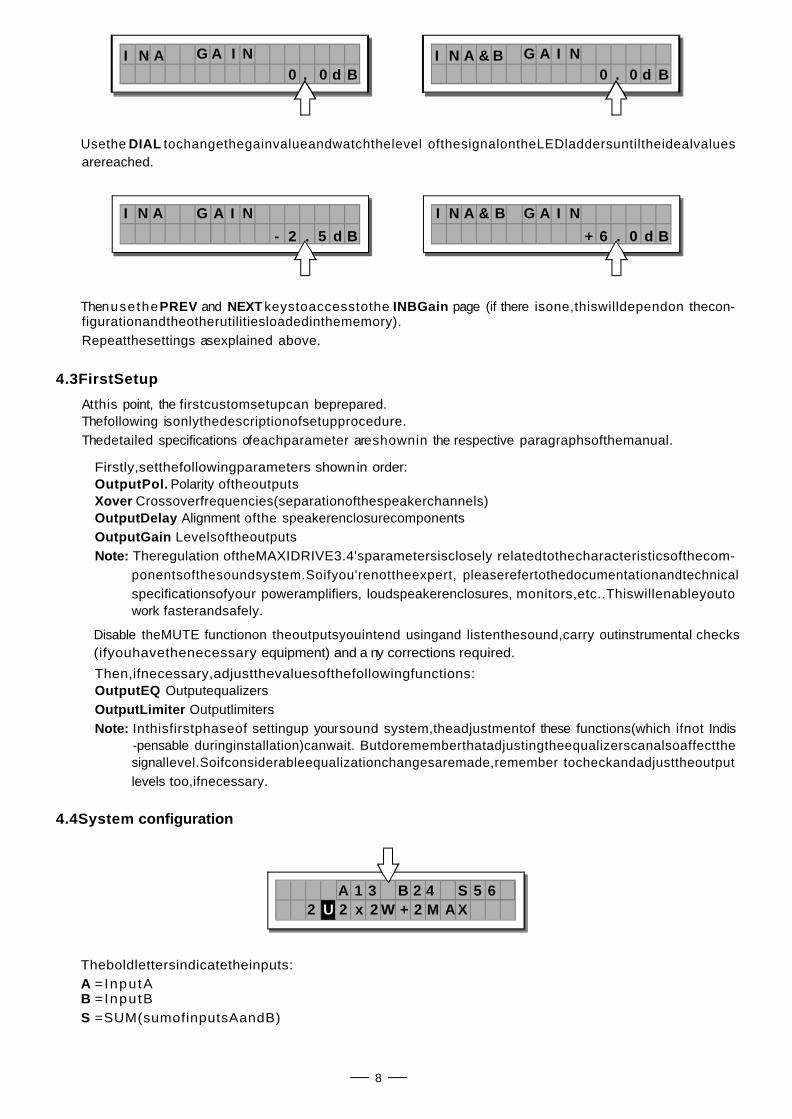
Theboldlettersindicatetheinputs:A =InputAB =InputBS =SUM(sumofinputsAandB)
2 U 2 x 2 W + 2 M A XA 1 3 B 2 4 S 5 6
I N A G A I N& B. 0 d B0
I N A G A I N. 0 d B0
I N A G A I N
. 5 d B2-
I N A G A I N& B
. 0 d B6+
˙Firstly,setthefollowingparameters in order:shownOutputPol. Polarity oftheoutputsXover Crossoverfrequencies(separationofthespeakerchannels)OutputDelay Alignment ofthe speakerenclosurecomponentsOutputGain Levelsoftheoutputs
˙Then,ifnecessary,adjustthevaluesofthefollowingfunctions:OutputEQ OutputequalizersOutputLimiter Outputlimiters
Usethe tochangethegainvalueandwatchthelevel ofthesignalontheLEDladdersuntiltheidealvaluesDIALarereached.
Thenusethe and keystoaccesstothe page (if there isone,thiswilldependon thecon-PREV NEXT INBGainfigurationandtheotherutilitiesloadedinthememory).Repeatthesettings asexplained above.
Atthis point, the firstcustomsetupcan beprepared.Thefollowing isonlythedescriptionofsetupprocedure.Thedetailed specifications ofeachparameter areshownin the respective paragraphsofthemanual.
Note: Theregulation oftheMAXIDRIVE3.4'sparametersisclosely relatedtothecharacteristicsofthecom-ponentsofthesoundsystem.Soifyou'renottheexpert, pleaserefertothedocumentationandtechnicalspecificationsofyour poweramplifiers, loudspeakerenclosures, monitors,etc..Thiswillenableyoutowork fasterandsafely.
Note: Inthisfirstphaseof settingup yoursound system,theadjustmentof these functions(which ifnot Indis-pensable duringinstallation)canwait. Butdorememberthatadjustingtheequalizerscanalsoaffectthesignallevel.Soifconsiderableequalizationchangesaremade,remember tocheckandadjusttheoutputlevels too,ifnecessary.

9
Numbers and indicate therespective outputs.1 ,2 ,3 ,4 ,5 6Intheexample:Thesignal connectedtoInput isassignedto outputs and .A 1 3Thesignal connectedtoInput isassigned tooutputs and .B 2 4The ofthesignaloninputs and is assigned tooutputs and .Sum A B 5 6Thesystemisthereforeconfiguredasshowninthefollowingdiagram.
A13B24S56 2-WAYSTEREO+2MONOAUX(2X2W+2MAX)
LEFT
RIGHT
HIGHLEFT
HIGHRIGHT
LOWLEFT
LOWRIGHT
MONOAUXL+R
MONOAUXL+R
INA
INA+B
INB
OUT1
OUT2
OUT3
OUT4
OUT5
OUT6
There are3categoriesofPRESETS:
F = F actoryPRESETS factoryprogrammed, cannot be permanentlychanged.
4.6TypeofPRESET
4.5NumberOfPRESETS
10 Factory PRESETS, 64 UserPRESETSand 128 Card PRESETSareavailable.
F 2 x 2 W + 2 M A X
A 1 3 B 2 4 S 5 6
2
fromscratch.U = U serPRESETS can be p rogrammedby users.
C = C ard P RESETS can be p rogrammedby users a nd storedon a Multimedia M emoryCard.
4.7NameofthePRESET
Intheexample, thenameindicatesatwo-waystereosystem+twoauxiliarymonooutputs.
F
A 1 3 B 2 4 S 5 6
2 2 x 2 W + M A X
These includeall the s ystem's u sable c onfigurations.
F 2 x 2 W + 2 M A XA 1 3 B 2 4 S 5 6
2
Theseare thestartingpointsforCreatingUserPRESETSandCardPRESETS

10
4.8PRESETModifications
4.9.System Protection
5.THEMENUMAPCONFIGURATIONDESCRIPTION
5.1.PresetMenu
LoadPreset
StorePreset
DumpOutPreset
IncomingDump
menu
PRESET
U 2 x 2 W + 2 M A XA 1 3 B 2 4 S 5 6
2M
U 2 x 2W + 2 A XA 1 3 B 2 4 S 5 6
2T
U 2 x 2 W + 2 M A XA 1 3 B 2 4 S 5 6
2P
Thisindicatesthatthevalueofoneormoreparametershasbeentemporarilymodifiedwithrespecttothe storedinthePRESETshown.Practicallyspeaking,thisindicationmeansthatthechangesmadetothePRESET havenotbeenstored.
Note: onceithasbeenenabled,theindicationremainsevenifthe"original"valuesareresetmanually.TheindicationdisappearsassoonasthePRESETissavedorassoonasanewPRESETisloaded(includ-ingthissamePRESET).
Inotherwords,theindicationdisappearsassoonasstoredvaluesareaccessed.IfthePRESETisn'tsaved,temporarychangesarelostassoonasanewPRESETis loaded(includingthis samePRESET).
Note: temporary changesarekeptontheotherhandinthe"buffermemory":whentheunitisswitchedon,thesystem maintainsexactlythesamesettingsaswhentheunitwasswitchedoff,includingtemporarychanges.
Theseindicationsappearwhen the function( menu)isenabled,i.e.whenthesystemistotally( )LOCK UTILITY Torpartially ( )protectedagainstaccidentalorunauthorizedchanges(even iftemporary).PProtectionis ensuredbya ,withoutwhicheditingprocedurecan'tbeunlocked.password
Thecontrolsoftwareisorganizedin and , eachofwhich contains the relativePRESET, DELAY,EDIT UTILITYmenustypesof parametersandfunctions.
11
Thereare3distinctcategoriesofPRESETS:
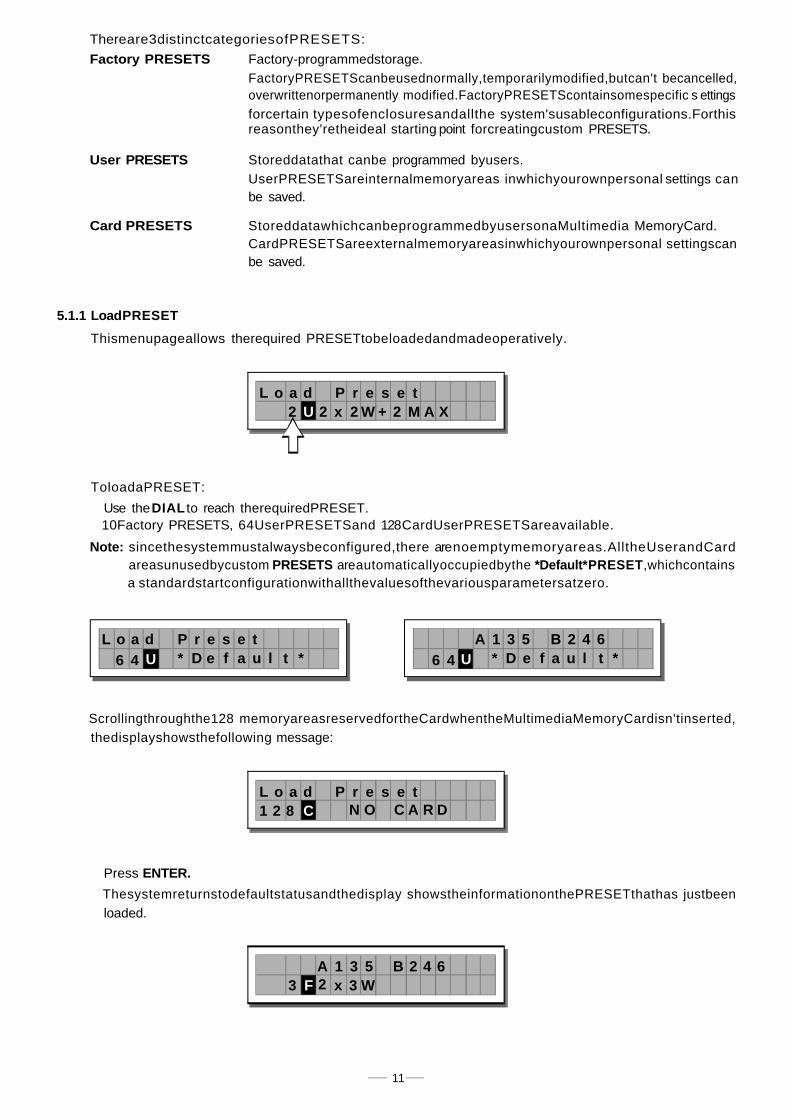
User PRESETS
Card PRESETS
5.1.1 LoadPRESET
Thismenupageallows therequired PRESETtobeloadedandmadeoperatively.
ToloadaPRESET:
˙Use the to reach therequiredPRESET.DIAL10Factory PRESETS, 64UserPRESETSand 128CardUserPRESETSareavailable.
thedisplayshowsthefollowing message:
˙Press ENTER.
Factory PRESETS
L o a d2 U 2 x 2 W
P r e s e t+ 2 M A X
L o a dU
P r e s e t6 4 * D e f a u l t *
A 1 3 5U6 4 * D e f a u l t *
B 2 4 6
L o a dC
P r e s e t1 2 8 N O C A R D
A 1 3 5F3
B 2 4 62 x 3 W
Scrollingthroughthe128 memoryareasreservedfortheCardwhentheMultimediaMemoryCardisn'tinserted,
Factory-programmedstorage.FactoryPRESETScanbeusednormally,temporarilymodified,butcan't becancelled,overwrittenorpermanently modified.FactoryPRESETScontainsomespecific s ettingsforcertain typesofenclosuresandallthe system'susableconfigurations.Forthisreasonthey'retheideal starting point forcreatingcustom PRESETS.
Storeddatathat canbe programmed byusers.UserPRESETSareinternalmemoryareas inwhichyourownpersonal settings canbe saved.
StoreddatawhichcanbeprogrammedbyusersonaMultimedia MemoryCard.CardPRESETSareexternalmemoryareasinwhichyourownpersonal settingscanbe saved.
Note: sincethesystemmustalwaysbeconfigured,there arenoemptymemoryareas.AlltheUserandCardareasunusedbycustom areautomaticallyoccupiedbythe ,whichcontainsPRESETS *Default*PRESETa standardstartconfigurationwithallthevaluesofthevariousparametersatzero.
Thesystemreturnstodefaultstatusandthedisplay showstheinformationonthePRESETthathas justbeenloaded.

5.1.2 Store&NamingPRESETUse this menu tocreatenewPRESETS, i.e. to saveallthe currentsystem settings.
TosaveaPRESET:
Press The pageappears,by means ofwhich its possible to edit the nameof theENTER. PRESET NamingPRESETto be saved.
remainsunvaried.
Thenameofthe start PRESET (i.e.of the PRESET currentlyloaded)isproposedasdefault.Thecursortakesupposition on the firstof the twelve characterspacesavailable.
Atthispoint:If you decide to accept and confirmthe name suggested,press ENTER.I fyouwant toabort procedure (for examplebecause you'vechosen the wrongmemoryarea)andNamingreturn toStorePRESETprocedure,press .ESCIf you wanttoassigna new name tothePRESET you're storing:- use the and keys toposition the cursor ontherequiredcharacter- use toenter the alphanumeric valuewantedDIAL- afterfinishing, press ENTER.
12
S t o r e2 U 2 x 2 W
P r e s e t+ 2 M A X
S t o r e3 U O p e
P r e s e tr a H a l l 1
S t o r e1 C N
P r e s e t01 O C A R D
P r e s m ni2 ×
N ae t2 W + 2 M A X ]]
Note: Ifyou'reinoneofthe128memoryareasreservedfortheCard andyouremovetheMultimediaMemoryCardbeforepressing nothinghappens:thedisplayremainsunchangedandStore procedureENTER, PRESET
Note: FactoryPRESET#3In theexample, ,named"2x3W"hasbeenloaded:ItssystemconfigurationisInputAsignalassigned tooutputs1,3and5;InputBsignalassignedtooutputs2,4 and6.
LoadingaPRESET,aPRESETChangecommandisalsoautomaticallysenttotheserial portsandcanbeusedtoautomaticallyloadaPRESETwiththesamenumbertoanyotherMAXIDRIVE3.4unitsconnectedandenabled(Refer to menu submenu option).UTILITY -Comm. Setup -PRESET ChangeRX
Use toreachthememoryareainwhichthePRESETis tobesaved.DIAL
Note: FactoryPRESET FactoryPRESETSPRESET,
UserPRESET CardPRESET UserorCard
Inthisprocedure,the areasaren'tavailable,since the can notbepermanentlyrememberthat it is possible toloadaFactory modified.Neverthelesssaveitina
or area,modifyit asrequiredandthen store itagain inthe samearea.
Note: PRESETSScrollingthrough the memoryareas, the display showsthenumber,typeand nameofthecontainedinthem;scrollingthroughthe 128Cardmemory areas withouttheMultimedia Memory Card,a warningappearson thedisplay:
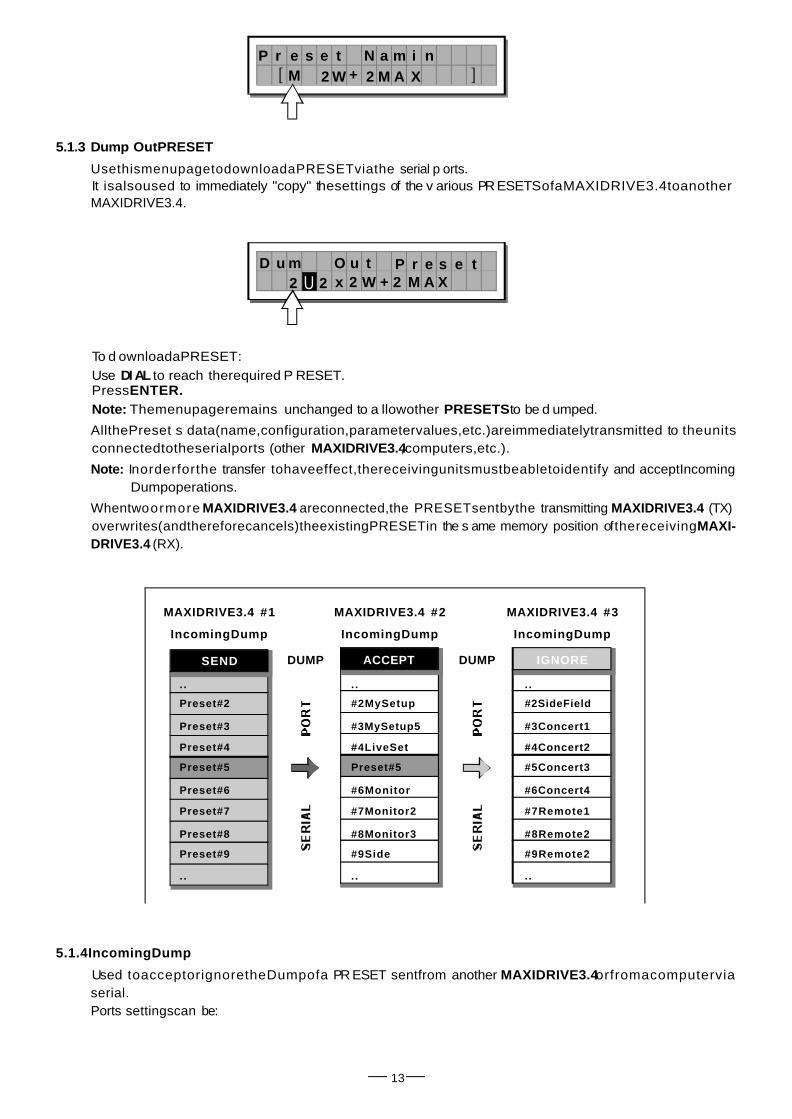
5.1.3 Dump OutPRESET
To d ownloadaPRESET:Use to reach therequired P RESET.DI ALPressENTER.Note: Themenupageremains unchanged to a llowother to be d umped.PRESETS
AllthePreset s data(name,configuration,parametervalues,etc.)areimmediatelytransmitted to theunitsconnectedtotheserialports (other ,computers,etc.).MAXIDRIVE3.4
Note: Inorderforthe transfer tohaveeffect,thereceivingunitsmustbeabletoidentify and acceptIncomingDumpoperations.
5.1.4IncomingDump
13
SEND ACCEPT IGNORE
. .
Preset#2
Preset#3
Preset#4
Preset#5
Preset#6
Preset#7
Preset#8
Preset#9
..
#2MySetup
#3MySetup5
#4LiveSet
Preset#5
#6Monitor
#7Monitor2
#8Monitor3
#9Side
..
. .
#2SideField
#3Concert1
#4Concert2
#5Concert3
#6Concert4
#7Remote1
#8Remote2
#9Remote2
..
IncomingDump
MAXIDRIVE3.4 #2
IncomingDump
MAXIDRIVE3.4 #1
IncomingDump
MAXIDRIVE3.4 #3
DUMP DUMP
. .
P r e s m niM×
N ae t2 W + 2 M A X ]]
D u m t2 x
O u2 W + 2 M A X
P r e s e t2 U
UsethismenupagetodownloadaPRESETviathe serial p orts.It isalsoused to immediately "copy" thesettings of the v arious PRESETSofaMAXIDRIVE3.4toanotherMAXIDRIVE3.4.
Whentwoormore areconnected,the PRESETsentbythe transmitting (TX)MAXIDRIVE3.4 MAXIDRIVE3.4overwrites(andthereforecancels)theexistingPRESETin the s ame memory position ofthereceivingMAXI-DRIVE3.4 (RX).
Used toacceptorignoretheDumpofa PR ESET sentfrom another orfromacomputerviaMAXIDRIVE3.4serial.Ports settingscan be:

5.2.DelayMenuUsethismenuto workon thesystems delaylines.
Thepractical differences between andDelayInput Delay Output
ADelayisonlyaprocessorbymeansofwhichasignalisdeliberatelydelayedbyaprogrammablelength oftime.Fromatechnical pointofview,theDelays applied totheinputsandoutputs are equivalent.Nevertheless,theirapplicationisdifferent:
In these pages,the numberof theparametersandhow they arepresentedvariesaccordingtothe configurationof the PRESETandaccordingto and settings (Ganging Units UTILITYmenu).Infact,thesepages onlyshowtheparametersthatcanactuallybeused,in the mostsuitable form of editing.
Parameters
Input Delay delays the signal of aninput(orthesumoftheinputs)beforesendingit totheroutingsystem.In thisway,alltheoutputswhichdependonthatinput are delayedbythe samelengthoftime.
Also c alled input Delay ismainly u se d t o compensate fortheeffectsMaster Delay, dues tothedistance betweenthevariousspeaker enclosures or b etween various blocksofacomplex
14
InputDelay
OutputDelay
Parameters
menu
DELAY
Parameters
Ignorethe datareceived via the serial ports. Accept the datareceived via the serialports.
INPUTDELAY
OUTPUT DELAY
DELAY
I n c o m i n g D u mpn o r eI g
I n c o m i n g D u m pc e p tA c
soundsystem(forexampleinlargeconcerthalls,stadiums,etc.),Thusachievingvirtualalignment.

OutputDelay onlydelaysthesignalofaspecificoutput.Also called ChannelDelay,outputdelay ismainlyused tocompensateforthe distancebetween differentblocksofthesamesoundsystem(forexample clusters)ortocorrectinternalalignmentofaspeakerenclosurecomponents.
5.2.1InputDelay
Usethismenu page toadjustthedelaylinesofInputA,Input B and SUM.
Thevaluescanbesetinthefollowingranges:
Themeasurementunitcan bechosenwiththefunction ( menu submenu).Delay Unit UTILITY - Units
5.2.2OutputDelay
Usethismenu page toadjustthedelaylinesofoutputs 1,2,3,4,5, and6.
15
INA ADC
unit
m
mm
ms
range step
0.0~900.0 0.5
0 ~ 9 00000 7
0~2621 1
INPUTDELAY
us 0 ~ 2621438 21
I n p u t D e l a y
I N A D E L A Y7 7 m S
O u t p u t D e l a y
16
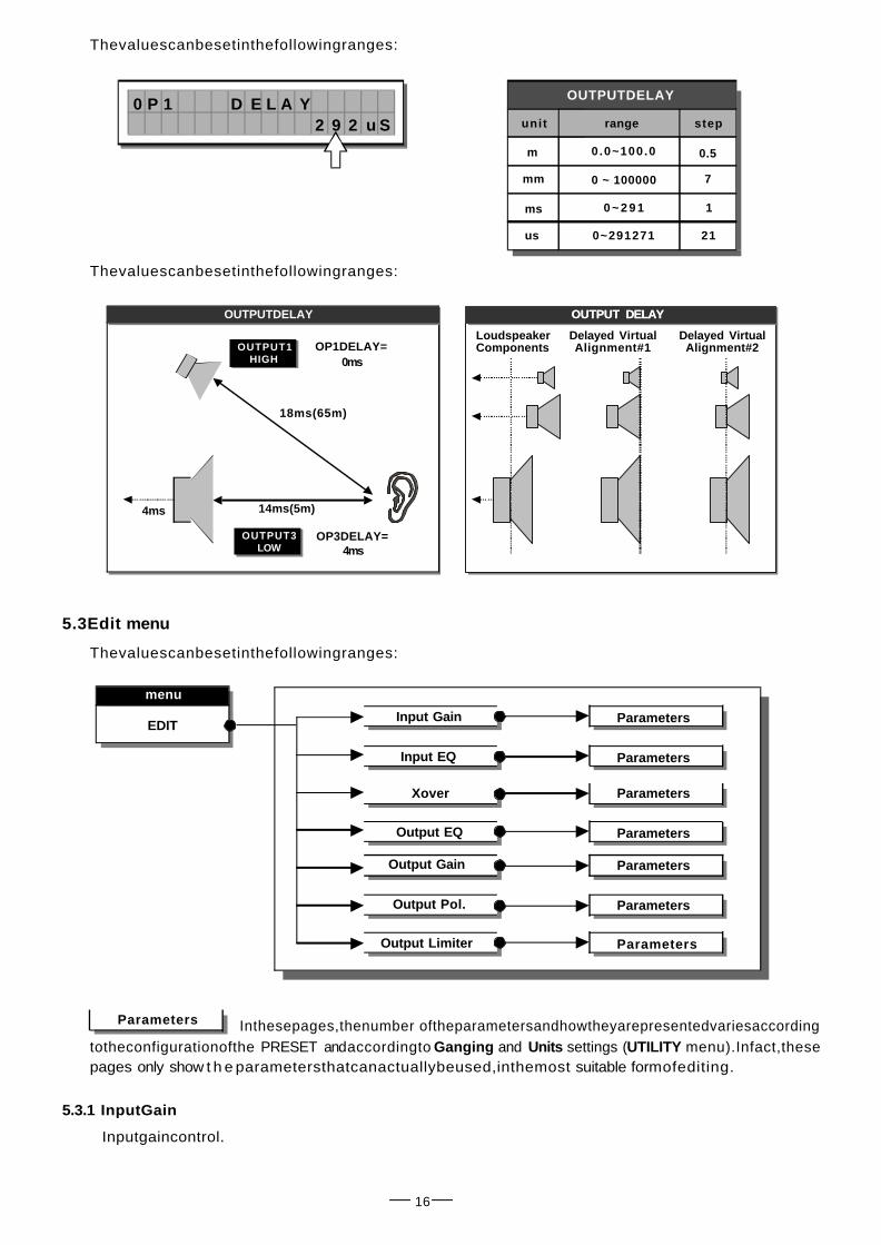
Thevaluescanbesetinthefollowingranges:
Thevaluescanbesetinthefollowingranges:
5.3Edit menu
Thevaluescanbesetinthefollowingranges:
menu
EDITInput Gain
Input EQ
Xover
Output EQ
Output Gain
Output Pol.
Output Limiter
Parameters
Parameters
Parameters
Parameters
Parameters
Parameters
Parameters
Inthesepages,thenumber oftheparametersandhowtheyarepresentedvariesaccordingtotheconfigurationofthe PRESET andaccordingto and settings ( menu).Infact,theseGanging Units UTILITYpages only show t h e parametersthatcanactuallybeused,inthemost suitable formofediting.
Parameters
unit
m
mm
ms
range step
0.0~100.0 0.5
0 ~ 100000 7
0 ~ 2 9 1 1
OUTPUTDELAY
us 0~291271 21
OUTPUT DELAY
ComponentsLoudspeaker
Alignment#1Delayed Virtual
Alignment#2Delayed Virtual
OUTPUTDELAY
OUTPUT1HIGH
OUTPUT DELAY
OP1DELAY=0ms
18ms(65m)
14ms(5m)
OP3DELAY=4ms
OUTPUT3LOW
4ms
5.3.1 InputGain
Inputgaincontrol.
0 P 1 D E L A Y2 9 2 u S

17
Allowstoadjusttheamplificationof the signalfedinthroughInputsAandB.Editingvalues areintherange +6dB~-30dB, with0.5dBsteps.
5.3.2 Input EQ
Input equalizer with 5 p arametric filters.
Allows toaltertheoverall tone of the signalconnectedtotherespectiveinput.Also called the equalization oftheinput signal effects alltheoutputsconnectedtotheMaster EQ, inputandtheinputSUM.Thiscomponent'scharacteristicqualityandprogrammability(identicaltotheoutputEqualizer) enable it tobeUsedsoeffectively and flexiblyas to maketheuseofgraphicequalizersoftenunnecessary.
Each equalizerhas5pages(oneforeachfilter),showingthenameoftheinput itaffectsandthe numberofthefilter.
The following editableparametersareavailableforeachfilter:
Allowsto choose among P eaking,Low or HighShelvingwith a s lopeof6 or 12 dB peroctaveand Notchfilter.
Peaking LowShelving HighShelving Notch
17
a.Typeoffilter
Peaking LowShelving HighShelving Notch
I N A ADCI N A ADC
I n p u t G a i n
I N A G A I N- 2 . 5 d B
I n p u t E Q
I N A E Q 1- 5 . 0
kaeP1 . 02 k 00
I N A E Q 1- 5 . 0
kaeP1 . 02 k 00
Note:Setting the inputsignalofadigitalunitisparticularlyimportant,much morethanonananalogunit,asany saturationoftheA/D converterduetoanexcessivelyhigh inputsignalcausesatypicalparticularlydistinctnoise.To achieveagoodsignal/noiseratio,i.e.anup-front distortionfreesignal,feed a signalinonthe MAXI-DRIVE3.4'sinput andwatchthe LEDladders.Keepthe signal quitehINPUT LEVELA-B igh,but makecertainthe red LEDdoesn'tlightonCLIP continually.

18
b. Centre Frequency / C utoff Frequency
Peaking LowShelving HighShelving Notch
c. Bandwidth
AllowstochoosethewidthinoctavesofthePeakingorNotchtypecurve.ItsnotusedwithShelvingcurves.
Peaking Notch
d. Gain
Allows t o c ontroltheboost or cutoftheselected frequencies.It'snotusedwiththe which hasafixedcut.NotchFilter,
Peaking LowShelving HighShelving
I N A E Q 1- 5 . 0
kaeP1 . 02 k 00
I N A E Q 1- 5 . 0
kaeP1 . 02 k 00
I N A E Q 1- 5 . 0
kaeP1 . 02 k 00
Allows tochoosethecentrefrequency ofthePeaking curveandNotchfilter,orthe cutofffrequencyofShelv-ing curves.

19
The valuescanbesetinthefollowingranges:
5.3.3Xover
Low-passandhigh-passfilters.Madeupofacombinationofalow-passfilterandhigh-passfilter,thecrossoverallowstodivide theinto segments thatcanbeused bytheindividualsectionofasoundsystem(forexample
audiosignalHigh, Mid&Low).
EachXoverhas2slightlydifferentpages(oneforeachfilter),wherethename oftheoutput itaffects and thetypeoffilterareshown.
Low PassFilter
HighPassFilterThehigh-passfilterallowsallthefrequenciesaboveaspecificfrequency topass,whereasitcutsallthe frequenciesbelowit.
LPF HPFHPFLPF
SignalsegmentobtainedwiththecombinationofLPFandHPF.
X o v e r
Output1-LowPassFi l ter
PO 10
L P F h r uT1 k 0 0 H z
Output1-HighPassFi l ter
O P 1 H P F h r uT1 k 0 0 H z
~
~
~
The low-pass filterallowsallthefrequenciesbelowaspecificfrequencytopass,whereasitcutsallthe frequenciesaboveit.
20
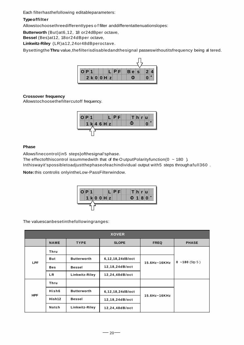
Each filterhasthefollowing editableparameters:
TypeoffilterAllowstochoosethreedifferenttypes o f filter anddifferentattenuationslopes:
Butterworth (But)at6,12, 18 or24dBper octave,Bessel (Bes)at12, 18or24dBper octave,Linkwitz-Riley (LR)a12,24or48dBperoctave.
Bysettingthe value,thefilterisdisabledandthesignal passeswithoutitsfrequency being alThru tered.
Crossover frequencyAllowstochoosethefiltercutoff frequency.
Phase
Allowsfinecontrol(in5 steps)ofthesignal'sphase.°The effectofthiscontrol issummedwith that of the O utputPolarityfunction(0 ~ 180 ).° °Inthiswayit'spossibletoadjustthephaseofeachindividual output with5 steps throughaful l360 .° °
Note: this controlis onlyintheLow-PassFilterwindow.
The valuescanbesetinthefollowingranges:
NAME TYPE SLOPE FREQ PHASE
XOVER
Thru
But
Bes
LR
Butterworth
Bessel
Linkwitz-Riley
6,12,18,24dB/oct
12 ,18 ,24dB/oct
12 ,24 ,48dB/oct
Thru
H i s h 6
Hish12
Notch
Butterworth
Bessel
Linkwitz-Riley
6,12,18,24dB/oct
12 ,18 ,24dB/oct
12 ,24 ,48dB/oct
15.6Hz~16KHz
15.6Hz~16KHz
0 ~180 (Stp 5 )° ° °LPF
HPF
O P 1 L P F2 k 0 0 zH
B e s02 4
O P 1 L P F1 k 4 6 zH
T h r0u
O P 1 L P F1 k 0 0 zH
T h r0u
81

21
5.3.4OutputEQ
Output equalizer with 5 parametric filters.
AlsocalledChannelEQ,allowstoalterthe toneof eachindividualoutput.Thecharacteristics ofqualityandprogrammabilityareidenticaltothoseoftheInputEqualizerand enablethis unitto b e usedextremelyeffectivelyand flexibly.
Eachequalizer has5pages(one perfilter),indicatingthenameoftheoutputiteffectsandthenumber ofthefilter.
Sincetechnicalspecifications andeditingfieldsofthe Output EQ areidenticaltothoseoftheInputEQ, please referto INPUT EQsectionfordescriptions.
Example:Output1-Filter1
5.3.5OutputGain
Output levelcontrolAllowsto adjust thesignallevelofeachindividual output.
Editingvaluesarebetween +6dB~-30dB, with0.5dBsteps.
5.3.6OutputPol
Controlstheoutput'spolarity.Allowsto invertthephaseofthesignalofindividualoutputs.
Editingvaluesare:
O u t p u t E Q
O P 1+ 1 . 5
E Q 1 e a kP2 k 0 0 1 . 0
O u t p u t G a i n
O P 1- 6 . 5
G A I Nd B
O u t p u t P o l
Note: ThelevelofeachoutputisshownbytherespectiveOUTPUTLEVELLEDladder.Toavoiddistortion,don'tlettheredCLIPLEDlightup.Asautomaticprotection,youcanalsoenablethe LIMITER(EDITmenu)ontheoutputsthatrequireit.Inthiscase,rememberthat enablingthe LIMITERchangesthe displaymodeon the level,butthelevelofrelativeLED ladder: infact, thelevelshownisnolongertheabsoluteoutputthe signalInrelationto theLIMITER threshold.
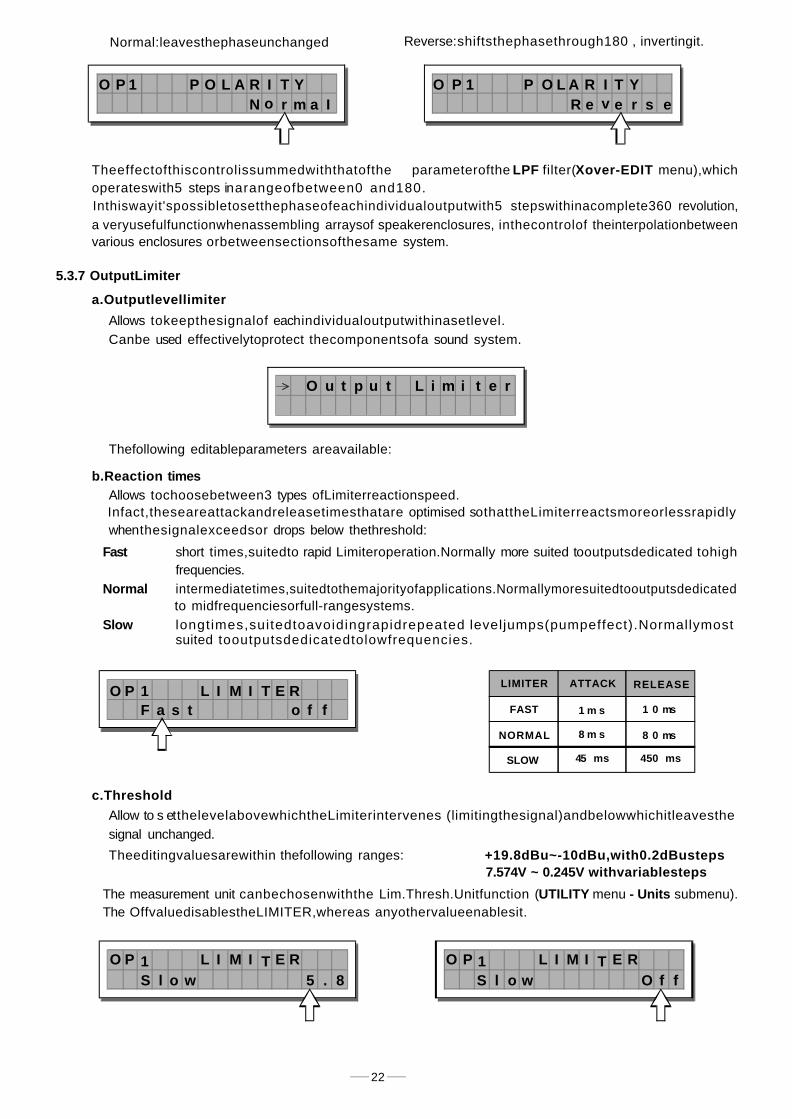
5.3.7 OutputLimiter
a.Outputlevellimiter
Allows tokeepthesignalof eachindividualoutputwithinasetlevel.Canbe used effectivelytoprotect thecomponentsofa sound system.
Thefollowing editableparameters areavailable:
b.Reaction timesAllows tochoosebetween3 types ofLimiterreactionspeed.Infact,theseareattackandreleasetimesthatare optimised sothattheLimiterreactsmoreorlessrapidlywhenthesignalexceedsor drops below thethreshold:
Fast
Normalto midfrequenciesorfull-rangesystems.
Slowsuited tooutputsdedicatedtolowfrequencies.
c.Threshold
signal unchanged.
Theeditingvaluesarewithin thefollowing ranges: +19.8dBu~-10dBu,with0.2dBusteps7.574V ~ 0.245V withvariablesteps
The OffvaluedisablestheLIMITER,whereas anyothervalueenablesit.
22
Normal:leavesthephaseunchanged Reverse:shiftsthephasethrough180 , invertingit.°
LIMITER
FAST
NORMAL
SLOW
ATTACK RELEASE
1 m s 1 0 ms
8 m s 8 0 ms
45 ms 450 ms
O P 1N o r m
P O L Aa I
R I T Y O P 1e v e r
P O L As e
R I T YR
O u t p u t L i m i t e r
O P 1f
L I M I T E RfosaF t
O P 18
L I M I T E R5olS w .
O P 1f
L I M I T E RfOolS w
short times,suitedto rapid Limiteroperation.Normally more suited tooutputsdedicated tohighfrequencies.intermediatetimes,suitedtothemajorityofapplications.Normallymoresuitedtooutputsdedicated
longtimes,suitedtoavoidingrapidrepeated leveljumps(pumpeffect).Normallymost
Allow to s etthelevelabovewhichtheLimiterintervenes (limitingthesignal)andbelowwhichitleavesthe
The measurement unit canbechosenwiththe Lim.Thresh.Unitfunction ( menu submenu).UTILITY - Units
Theeffectofthiscontrolissummedwiththatofthe parameterofthe filter( menu),whichLPF Xover-EDITΦoperateswith5 steps inarangeofbetween0 and180.° ° °Inthiswayit'spossibletosetthephaseofeachindividualoutputwith5 stepswithinacomplete360 revolution,° °a veryusefulfunctionwhenassembling arraysof speakerenclosures, inthecontrolof theinterpolationbetweenvarious enclosures orbetweensectionsofthesame system.

23
5.4UTILITY Menu
5.4.1GANGINGSUBMENU
Ganging InputGanging
OutputGanging
menu
UTILITYGanging
Lock
MemoryCard
InputGanging
OutputGanging
DelayUnit
Lim.Thresh.Unit
Lock
FormatCard
PresetChangeRX
Units
TemperatureUnit
InputSelect
OutputMeters
Misc.Setup
Temperature
WakeUp
LCDContrast
Comm.Setup
IDSelect
IMPORTANT! Enabling theLIMITER ona specificoutput alsochangestheway inwhichthelevel isdisplayedonthecorresponding In fact,thelevelshown onthisladderisnolongerthe"absolute"outputlevel,LED ladder:but thelevelof thesignalat-24dB,-12dB,-6dB comparedtothe (orange LED),noLIMITER's threshold LIMITmatterwhat thethreshold valueis.
Thismenucomprisesaseriesofsubmenusthatallowtosetaseriesofsystemoptionsandaccesscertainutilities,such asthe control ofthe MultimediaMemory CARD orprotection againstaccidentalorunauthorizedchanges:
Thissubmenuallowstogrouptogetherthetreatmentofsimilarinputsand/oroutputs.Similarisintendedasmeaningelements which have thesamepropertiesand/or thesamestructure.Forexample,therightandleftsectionsofastereosystemaresimilar,astheyaremadeupsymmetricallyofthesamequantity andtypeofelements(thesamecomponentsforHigh,MidandLowfrequencies).

24
To checkthis:
1.setInputGangin=Off,loadthe*Default*PRESET,setINA Delay=1andINBDelay=0;2.setInputGangin=On,returnto the InputDelaymenu:thedisplay shows INA&B Delay=1:
a.ifyouleavethevalueunchangedandonceagainsetInputGangin=OffgoingbacktotheInputDelaymenu,thedisplayshowsINADelay=1 andINBDelay=0("original"values).
b.ifyouchangethevalue,forexampleINA&B Delay=3,andyouonceagainsetInputGangin=OffgoingbacktotheInput Delaymenu, thedisplayshowsINADelay=3andINBDelay=3("new"values).
a.InputGangingAllowstoenable/disable Gangingfunctionon theinputs.
Thesettingsare:
G a n g i n g
Disabled
I n p u t G a n g i n gO f f
Enabled
I n p u t G a n g i n gO n
ThepracticaluseoftheGangingfunctionconsistsin thepossibility ofeditingwithidenticalvaluestheparametersofsimilarelements, carryingoutsingle(instead ofdouble)operations.
For example,it's possible to setthesameDelayvalueor equalization onboth inputswithjustone operation;orsetidenticalXover parametersforthevariousoutputsfedtoa stereosoundsystem;oryetagain,enable theLIMITERsimultaneouslyon thetwooutputsdedicated to two mono stagemonitors.
Thesystemautomatically recognizesincompatibleelementscontainedinthevariousconfigurationsandonlyenables theGanging function whereit can effectivelybeused.Therefore,the Gangingfunctiondoesn'thaveany effectontheMONOsetups.TheGangingfunctioncanbeenabled separatelyfor bothgroupsof inputandgroups ofoutputs.
IMPORTANT: Preciselyforitscharacteristics,the Gangingfunctionaffectsthewayinwhichtherelativepara-meters audio areeditedor represented:AssoonasInputsand/orOutputs areganged,thevariousmenupagesonlyshow thevaluesthatcan actuallybeused. This however doesn'tmean that thevalues change immediately.Onthecontrary,the valuesremainunchanged(Evenif notshown)untilnewvaluesareentered.Onlyatthatpoint ganged,Inputsand/orOutputsassumethesamevaluewiththejustoneoperation.
Forexample,evenifthedisplayshows that"Input A&B" are gangedin thepage with a certain parameter,thevalue shownremainsthatofInputAuntilanewvalueisentered,asInputBdoesn'tautomatically assumethevalues of InputA.
Thisconditionisusedtoavoidaccidentalortemporaryenablingofthe Ganging function from changingthevaluesofallthe storedPRESET.Therulecanbe summedupas follows: "onlythe values thathavetobeintentionallychangedarechanged".Sogenerallyspeaking, toavoid contradictions, oversightsandconfusion between whatisshownandwhatiseffectivelycarriedout,itsadvisabletoenabletheGangingfunctionsbeforestartingtoeditaPRESET.Moreover,itsbesttomakecertaintoeffectivelyset the requiredvalue,manuallyconfirming all theparametersrequired.Note: Theelements inGangingassume the "new"valueassoonas the DIALchangesthestatusofthe"old"value. So,ifthevaluewhichhastobeallocated tothe elementsinGanging is the same asthe old value,it'snecessaryto use the DIAL, temporarily c hange the value(evenonly byonestep) andthengobackto the"old"value.

b.OutputGanging
Usedtoenable/disableGangingfunction ontheoutputs.Thesettingsare:
25
5.4.2 UNITS SUBMENU
Used thissubmenutochoosethemeasurementunitstobe usedwithcertainfunctions.
a.DelayUnit
UsedtosetthemeasurementunitsinwhichDelaysareexpressed(DELAY menu).Theoptions include: meters millimeters milliseconds microsecondsm = - mm= - ms = - m s =
b.Lim.Thresh.Unit
UsedtosetthemeasurementunitsforthethresholdoftheLimiter( menu- Limiter).EDIT OutputTheoptions include: decibel (0dBu=0.775Vrms) voltdBu = - V =
c.TemperatureUnit
UsedtosetthemeasurementunitsfortheTemperature function ( menu-Misc.Setupsubmenu).UTILITYTheoptions include: degreesCentigrade - degreesFahrenheitF =
DelayUnit
Lim.Thresh.Unit
Units
TemperatureUnit
Disabled
O u t p u t G a n g i n gO f f
Enabled
O u t p u t G a n g i n gO n
U n i t s
MeasurementunitsforInputDelay
D e l a y U n i tI n m s t u sO u
MeasurementunitsforOutputDelay
D e l a y U n i tI n m tO u mm
L i m . T r e s hV
h . U n i tL i m . T r e s hud B
h . U n i t
T e m P e utC
r U n i ta er T e m P e utF
r U n i ta er

26
5.4.3 Misc. Setupsubmenu
Usethissubmenutosetaseriesofsystemoptions.
a.InputSelect
Used tochoose whichMAXIDRIVE3.4 shoulduse.inputsTheoptions include:
Theinputsselectedbecome and .Anysignalontheinputsnotselectedis ignored.
InputA InputB
b.OutputMeters
Used todecidewhetherto displaytheoutputs signalbefore orafter MUTE.Theoptions include:
InputSelect
OutputMeters
Misc.Setup
Temperature
WakeUp
LCDContrast
M i s c . S e t u p
I n p u t S e l e c tA n a l o g
PreMutethesignalisalwaysshown
nomatterwhattheMUTEstatus
u t p u t M e t e r sP r e M t e
Ou
PostMutethesignalisonlyshowniftheoutputisn'tinMUTE
u t p u t M e t e r so s t M t e
OuP
PUSH
2 13
N E W T I D E
PUSH
2 13
N E W TIDE
Apparatenskallanslutastilljordatuttagnardenanslutstillettnatverk
PWR
OFF
ON
ACINPUT 14W95-240V 50/60HzFUSE:95-120VT500mAL
210-240VT315mAL
DIGITALIN RS485OUT RS485IN RS232 I N P U T AINPUTB4 3 2 1
OUTPUTS
56A102
ENTER
RLTO
PREV NEXT
ESC
MODE
CLIP
-6
-12
-18
-24A B
INPUTLEVEL MUTE
CLIP
-6
-12
-24
LIMIT
OUTPUT
2LEVEL
CLIP
-6
-12
-24
LIMIT
CLIP
-6
-12
-24
LIMIT
CLIP
-6
-12
-24
LIMIT
CLIP
-6
-12
-24
LIMIT
CLIP
-6
-12
-24
LIMIT
OUTPUT
1LEVEL
OUTPUT
3LEVEL
OUTPUT
4LEVEL
OUTPUT
5LEVEL
OUTPUT
6LEVEL
MUTE MUTE MUTE MUTE MUTE
EDIT
UTILITY
DELAY
PRESET
CARD
I n p u t S e l e c ti g i t a lD
PUSH
1
3
2
N E W TIDE
PUSH
1
3
2
NEW TIDE
DigitalInputs AnalogInputs

27
c.Temperature
Usedtokeyin thevalueoftheenvironmentaltemperatureof place ofinstallation.The systemuses thisvalue toautomaticallycompensate for thedifferentialsdueto the difference speedofsoundTransmission accordingtothe airtemperature.This allowstosetthedelaysduringthe sound-checkandonlyhavetoresetthemautomaticallywhennecessary(Forexampleduring a concert, in the event ofbig jumpsintemperature, etc.).
The editingvaluesareinthefollowing ranges: with 1 C steps+60 C ~ -30 C° ° °with1.8 Fsteps140.0 F ~ -22.0 F° ° °
Note: themeasurementunitscanbe chosenbetween C(degreesCentigrade)and F(degreesFahrenheit)° °bymeansofthe TemperatureUnit function(UTILITYmenu-Unitssubmenu).
d.WakeUp
Allowsto choosethemodein which MUTEfunctionsare restoredwhentheMAXIDRIVE3.4isswitchedon.
Theoptionsinclude:
e.LCDContrast
AllowstoadjusttheDisplaycontrast.The values areinthefollowingrange: 0 (minimumcontrast)~32 (maximum contrast).
5.4.4LOCKSUBMENU
Used toenableor disable theprotectionofthesystemagainstaccidentalorunauthorizedchanges.
Lock Lock
T e m p e r a t u r e2 0 C
T e mp e r a t u r eF6 8 . 0
Mutewhenswitchedon,thesystemautomatically
setsalltheoutputsinMUTE
Normalwhenswitchedon,thesystemrestoresthelast
MUTEconfigurationbeforeswitchingoff
N o r m a lW a k e U p
2 6L C D C o n t r a s t
W a k e U pM u t e

28
Howtoenable protection
˙Firstof all, choosetheprotectionmode:
Twomodesareavailable:
Total: Partial:all editingfunctions areblockedand only theparameters relativetotheInputs
accesstothePRESETmenuis disabled canbeedited(Delay, Gain,EQ),allothereditingfunctionsareblocked
andaccesstothePRESET menu disabled
˙Afterentering thepassword,press ENTER.
Confirmationis onlyacceptedifthe cursorispositioned ononeof the p asswords four characters.Note: Thisallowsto avoidaccidentalenabling,withouthavingseenthepassword.
Protectionisenabledandthesystem takes updefaultstatus.Howtodisablethe protectionIftheprotectionisenabled,whenthesystemisindefaultstatus(i.e.whennonemenu arelitandLEDs thereforeno typeofeditingisenabled), thefollowingappearsonthedisplay:
L o c k
L O C K T o t a lP a s s w o r d [ 1 2 3 4 ]
L O C K r it a lP a s s w o r d [ 1 2 3 4 ]
P a
L O C K r it a lP a s s w o r d [ B I R D ]
P aL O C KP a s s w o r d [ 1 2 3 4 ]
r it a lP a
TotalProtectionenabled
T A 1 3 B 2 4 S 5 62 U 2 ×2 W + 2 M A X
Partial Protectionenabled
P A 1 3 B 2 4 S 5 62 U 2× 2W + 2 M A X
Thisfunctionisveryusefulwhenevereventemporarychangesortampering withthesettingsstoredinthesystemmust beprevented.For example:fixedinstallationsusedbyseveraloperators(discotheques, clubs,conferencehalls,etc.),soundsystemrental,etc.
˙Thenusethe and keys toaccessthe areainwhichthe isentered.password
IMPORTANT! password!Theprotection cannotbeunlockedwithouttheSo write it downoratleastchooseawordthatiseasilyremembered.Thepassword ismadeupoffouralphanumerical characters,obtainable usingthe and keysandeditablewiththeDIAL.

Note: intheeventofanincorrectpassword,thedisplaypromptsagain,encryptingallthecharactersagain.
Protection isunlocked andthe system entersdefaultstatus.
5.4.5MEMORYCARDSUBMENU
Allowsto the Multimedia MemoryCard.format
TheCardcan'tbeusedbythesystem.
Howto attheCardform
˙ Insert a MultimediaMemoryCardin theslot.New orusedCardscanbeused,providingtheyare compatible(min1MB).
29
To unlockthe protection:
˙Accessthe submenu.LOCKThedisplayshowsthepromptforenteringthepasswordtounlocktheprotection.Thefour alphanumericcharactersofthepasswordareencrypted.
MemoryCard FormatCardMemoryCard FormatCard
29
ENTERPREV NEXT
ESC
Note: Malongside thesymbol ofTotal orPartialprotection,theletter mayalsoappear.Thismeansthatthesystemisprotected, but the PRESET in question has undergoneone ormorechanges that havenotyetbeenstored.Youcanhowever switchthesystemonandoffwithoutanyproblems,as thecurrentsettingsarekeptin thebuffermemory.Nevertheless,ifthisisyourwork setup, it'sadvisableto store itinaPRESET.
Enterinthe usingthe combinationofthe keys a nd the then presspassword and DIAL, ENTER.
T M A 1 3 B 2 4 S 5 62 U 2× 2 W + 2 M A X
U N L O C K[ * * * * ]P a s s w o r d
U N L O C K[ B I R D ]P a s s w o r d
M e m o r y C a r d
Formattingisthe preparation ofthememoryareasof theCard.Withoutformatting(orwithoutcompatibleformatting)

30
ATTENTION!ENTER.
Formatting cancelsany datacontainedintheCard.IntheMemoryCardsubmenu, press
Note: intheevent of an error or a Card fault, ifthereisnoCardintheslotoriftheCardisremovedduringformatting,thedisplayshowsthefollowing message:
Note: sincethesystem mustalwaysbeconfigured, there are noempty memoryareas. AlltheUserand Cardareasnotyetusedbystoreduserdataareautomaticallyoccupied bythe*Default* PRESET, whichcontainsastandard start configuration withallthevaluesofthevarious parameters at zero.
5.4.6COMM.SETUPSUBMENU
This submenuallowsaccessto thesettingof communicationwith other unitsviatheserialports.
PRESETChange RX
AllowstoacceptorignorethePRESETChangecommandsentviatheserialportsfroma computeroranotherMAXIDRIVE3.4whenitloadsaPRESET.
The settingscanbe:IgnorePRESETChange commandsreceived.Acceptand execute PRESETChangecommands.
30
˙PressENTER.
The system formatsthe Carduntilitcommunicates that it h ascompleted.
Duringformatting,thesystemautomaticallystoresthe*Default*PRESETinallthe128CARDmemory areas.
TheFormatCardpageappears
Thisoperationonlyrequiresafewseconds. TheCardisreadytobeused.
Comm.Setup PresetChangeRXComm.Setup PresetChangeRX
PresetChangeRXIDSelect
inthe menu.PRESET
F o r a t C am dr
F o r a t C am drF o r a tm t i n g . . .
F o r a t C am drF o r a tm D o n e !
F o r a t C am drF o r a tm E r r o r !
C mo . S t u pm e
P er e t C h as n g e R XA c c e p t
P er e t C h as n g e R XI g n o r e
Note: Dump OutPreset IncomingDumpthe and functionsareanexception,as they're controlled directly

31
SEND ACCEPT IGNORE
. .
Preset#2
Preset#3
Preset#4
Preset#5
Preset#6
Preset#7
Preset#8
Preset#9
..
#2MySetup
#3MySetup5
#4LiveSet1
#5LiveSet2
#6Monitor
#7Monitor2
#8Monitor3
#9Side
..
. .
#2SideField
#3Concert1
#4Concert2
#5Concert3
#6Concert4
#7Remote1
#8Remote2
#9Remote2
..
PresetChangeRX
MAXIDRIVE3.4 #2
LoadPreset
MAXIDRIVE3.4 #1
PresetChangeRX
MAXIDRIVE3.4 #3
. .
6. CONNECTIONS
The f ollowingdiagramsshowtheschemesoftherecommendedcablesandsomeconnectionexamples referred tovarious system configurations.
InputsA & B,Digital IN,RS485IN
31
2
GROUND
HOT(+)COLD( )–
InputsA & B
GROUND
HOT(+)COLD( )–RING
SLEEVE
TIP
BALANCEDXLR-M
BALANCEDJACK
The PRESETChange command iscompletely identicaltoMIDIProgramChange:thetransmittingunitsendsaninstructioncontaininga number o f PRESETStoload; thereceivingunits (iftheyareabletoacceptthe com-mand)each loads intoitsownmemorythePRESETwiththecorrespondingnumber.
Thismeansthat,ina chainofMAXIDRIVE3.4,alltheunitssetwithPRESETChangeRX=Acceptloadthesamenumber ofPRESET, inspiteofthefactthatitcorrespondstoPRESETS withdifferentcontentsinthevariousunits.
Note: thePRESET Dump functionisusedtotransmitthesamecontents.

RS232
RS232(9-Pin)
7.APPLICATION
Thefollowing diagramsshowtheMAXIDRIVE3.4'svarioussystemconfigurations,asiftosay,thevarious inputandoutputhardwarecombinations.
#
01
02
03
04
05
06
07
08
09
10
Name
DEFAULT
2X2W+MAX
2X3W
2X3W+MSB+MAX
4W+2MAX
4W+BSB+2MAX
5W+MAX
5W+BSB+MAX
6W
6W+BSB
Configuration
A135B246
A13 B24S56
A135B246
A13 B24S56
A1324S56
A123B4S56
A12345S6
A1234B5S6
A123456
A12345B6
Configuration
Defaultpreset-routing=3-WAYSTEREO
2-WAYSTEREO+2MONOFULL-RANGEOUT
3-WAYSTEREO
3-WAYSTEREO withMONOSUB+1MONOFULL-RANGEOUT
4-WAYMONO+2MONOFULL-RANGEOUT
4-WAYMONOwithB-SUB+2MONOFULL-RANGEOUT
5-WAYMONO+1MONOFULL-RANGEOUT
5-WAYMONOwithB-SUB+1MONOFULL-RANGEOUT
6-WAYMONO
6-WAYMONOwithB-SUB
32
Outputs1~ 6,RS485OUT
GROUND
HOT(+)
COLD( )–
32
1
BALANCEDXLR-F
7.1.FactoryPresetConfiguration

C H - A CH-B
CLIP SIG
P O W E R
ON
O F F
CLIP S I GPROT
MACRO2400
C H - A CH-B
CLIP SIG
P O W E R
ON
O F F
CLIP S I GPROT
LTO
PROFESSIONALHIGHPOWERSTEREOAMPLIFIER
PROFESSIONALHIGHPOWERSTEREOAMPLIFIER
C H - A CH-B
CLIP SIG
P O W E R
ON
O F F
CLIP S I GPROT
MACRO2400
C H - A CH-B
CLIP SIG
P O W E R
ON
O F F
CLIP S I GPROT
LTO
PROFESSIONALHIGHPOWERSTEREOAMPLIFIER
C H - A CH-B
CLIP SIG
P O W E R
ON
O F F
CLIP S I GPROT
MACRO2400
C H - A CH-B
CLIP SIG
P O W E R
ON
O F F
CLIP S I GPROT
LTO
a.A13B24S562-WAYSTEREO+2MONOAUX[2X2W+2MAX]
33
MAXIDRIVE3.4 3-WAYSTEREODIGITALCROSSOVER
AUDIOMIXER
7.2OrganizationThe following exampleswillhelpyouwell useandconnect the unit.
1
3
5
2
4
6
12
34
56
AB
SIGNAL
POWER
PUSH
2 13
N E W TIDE
PUSH
2 13
NEW TIDE
Apparatenskallanslutastilljordatuttagnardenansluts
tillettnatverk
PWR
OFF
ON
ACINPUT 1 4 W95-240V50/60HzFUSE:95-120VT500mAL
210-240VT315mAL
DIGITALIN RS485OUT RS485IN RS232 INPUTAINPUTB4 3 2 1
OUTPUTS
56
A102
PUSH
1
3
2
N E W TIDE
PUSH
1
3
2
N E W T I D E

C H - A CH-B
CLIP SIG
POWER
ON
O F F
CLIP S I GPROT
MACRO2400
C H - A CH-B
CLIP SIG
POWER
ON
O F F
CLIP S I GPROT
LTO
PROFESSIONALHIGHPOWERSTEREOAMPLIFIER
PROFESSIONALHIGHPOWERSTEREOAMPLIFIER
C H - A CH-B
CLIP SIG
POWER
ON
O F F
CLIP S I GPROT
MACRO2400
C H - A CH-B
CLIP SIG
POWER
ON
O F F
CLIP S I GPROT
LTO
PROFESSIONALHIGHPOWERSTEREOAMPLIFIER
C H - A CH-B
CLIP SIG
POWER
ON
O F F
CLIP S I GPROT
MACRO2400
C H - A CH-B
CLIP SIG
POWER
ON
O F F
CLIP S I GPROT
LTO
34
b.A135B2463-WAYSTEREO[2X2W]
MAXIDRIVE3.4 3-WAYSTEREODIGITALCROSSOVER
AUDIOMIXER
SIGNAL
POWER
1
2
3
4
5
6
5
6
5
3
2
1
AB
PUSH
2 13
NEW TIDE
PUSH
2 13
NEW TIDE
Apparatenskallanslutastilljordatuttagnardenansluts
tillettnatverk
PWR
OFF
ON
ACINPUT 14W95-240V50/60HzFUSE:95-120VT500mAL
210-240VT315mAL
DIGITALIN RS485OUT R S 4 8 5 I N RS232 I N P U T AINPUTB4 3 2 1
OUTPUTS
56
A102
PUSH
1
3
2
N E W T I D E
PUSH
1
3
2
NEW T I D E
C H - A CH-B
CLIP SIG
POWER
ON
O F F
CLIP SIGP R O T
MACRO2400
C H - A CH-B
CLIP SIG
POWER
ON
O F F
CLIP SIGP R O T
LTO
PROFESSIONALHIGHPOWERSTEREOAMPLIFIER
PROFESSIONALHIGHPOWERSTEREOAMPLIFIER
C H - A CH-B
CLIP SIG
POWER
ON
O F F
CLIP SIGP R O T
MACRO2400
C H - A CH-B
CLIP SIG
POWER
ON
O F F
CLIP SIGP R O T
LTO
PROFESSIONALHIGHPOWERSTEREOAMPLIFIER
C H - A CH-B
CLIP SIG
POWER
ON
O F F
CLIP SIGP R O T
MACRO2400
C H - A CH-B
CLIP SIG
POWER
ON
O F F
CLIP SIGP R O T
LTO
35
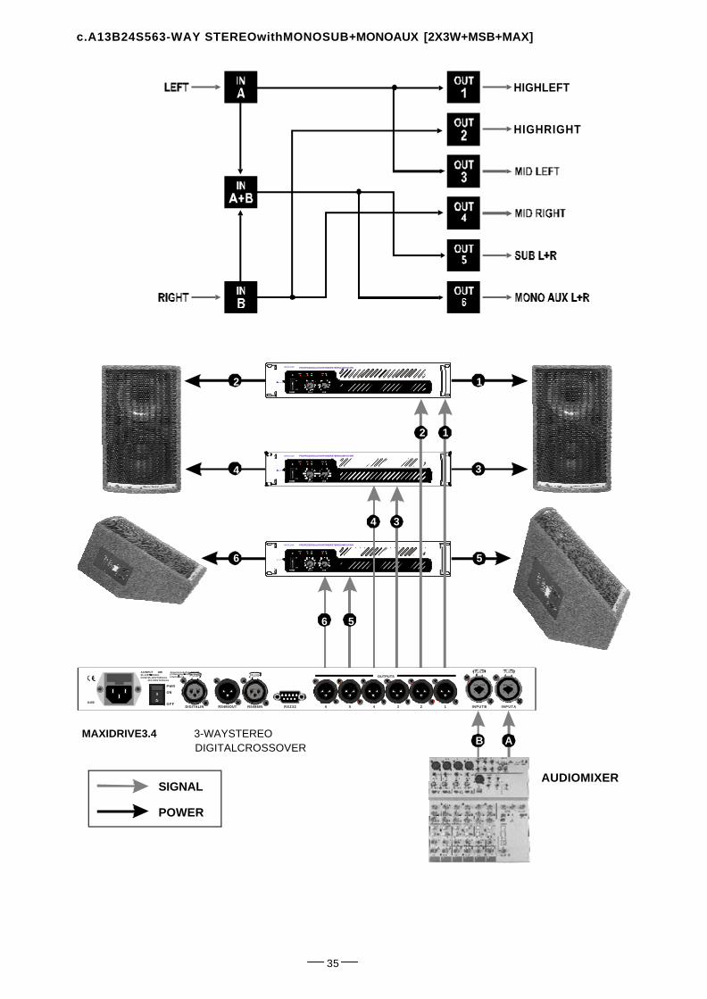
c.A13B24S563-WAY STEREOwithMONOSUB+ [2X3W+MSB+MAX]MONOAUX
AUDIOMIXER
MAXIDRIVE3.4 3-WAYSTEREODIGITALCROSSOVER
SIGNAL
POWER
HIGHLEFT
HIGHRIGHT
1
12
3
5
34
56
2
4
6
AB
PUSH
2 13
NEW TIDE
PUSH
2 13
N E W T I D E
Apparatenskallanslutastilljordatuttagnardenanslutstillettnatverk
PWR
O F F
ON
ACINPUT 14W95-240V50/60HzFUSE:95-120VT500mAL
210-240VT315mAL
DIGITALIN RS485OUT RS485IN R S 2 3 2 I N P U T AI N P U T B4 3 2 1
OUTPUTS
56A102
PUSH
1
3
2
NEW T I D E
PUSH
1
3
2
NEW TIDE

C H - A CH-B
CLIP SIG
POWER
ON
OFF
CLIP SIGP R O T
MACRO2400
C H - A CH-B
CLIP SIG
POWER
ON
OFF
CLIP SIGP R O T
LTO
PROFESSIONALHIGHPOWERSTEREOAMPLIFIER
PROFESSIONALHIGHPOWERSTEREOAMPLIFIER
C H - A CH-B
CLIP SIG
POWER
ON
OFF
CLIP SIGP R O T
MACRO2400
C H - A CH-B
CLIP SIG
POWER
ON
OFF
CLIP SIGP R O T
LTO
PROFESSIONALHIGHPOWERSTEREOAMPLIFIER
C H - A CH-B
CLIP SIG
POWER
ON
OFF
CLIP SIGP R O T
MACRO2400
C H - A CH-B
CLIP SIG
POWER
ON
OFF
CLIP SIGP R O T
LTO
36
d.A1324S564-WAY4MONO+2MONOAUX[4W+2MAX]
SIGNAL
POWER
MAXIDRIVE3.4 3-WAYSTEREODIGITALCROSSOVER
AUDIOMIXER
12
34
56
5
6
1
2
3
4
AB
PUSH
2 13
NEW TIDE
PUSH
2 13
NEW TIDE
Apparatenskallanslutastilljordatuttagnardenansluts
tillettnatverk
PWR
OFF
O N
A C I N P U T 1 4 W95-240V50/60HzFUSE:95-120VT500mAL
210-240VT315mAL
DIGITALIN RS485OUT RS485IN R S 2 3 2 INPUTAINPUTB4 3 2 1
OUTPUTS
56
A102
PUSH
1
3
2
NEW T I D E
PUSH
1
3
2
N E W T I D E

FromRS485OUT
toRS485IN
FromRS485OUT
toRS485IN
to/fromRS232
to / fromRS232SerialPort
MAXIDRIVE3.4 3-WAYSTEREODIGITALCROSSOVER
e.Communications:PC&oneormoreMAXIDRIVE3.4 connection
37
PUSH
2 13
NEW T I D E
PUSH
2 13
N E W TIDE
Apparatenskallanslutastilljordatuttagnardenanslutstillettnatverk
PWR
O F F
ON
ACINPUT 1 4 W95-240V50/60HzFUSE:95-120VT500mAL
210-240VT315mAL
DIGITALIN RS485OUT RS485IN RS232 INPUTAI N P U T B4 3 2 1
OUTPUTS
56A102
PUSH
2 13
NEW T I D E
PUSH
2 13
N E W TIDE
Apparatenskallanslutastilljordatuttagnardenanslutstillettnatverk
PWR
O F F
ON
ACINPUT 1 4 W95-240V50/60HzFUSE:95-120VT500mAL
210-240VT315mAL
DIGITALIN RS485OUT RS485IN RS232 INPUTAI N P U T B4 3 2 1
OUTPUTS
56
A102
PUSH
2 13
NEW T I D E
PUSH
2 13
N E W TIDE
Apparatenskallanslutastilljordatuttagnardenanslutstillettnatverk
PWR
O F F
ON
ACINPUT 1 4 W95-240V50/60HzFUSE:95-120VT500mAL
210-240VT315mAL
DIGITALIN RS485OUT RS485IN RS232 INPUTAI N P U T B4 3 2 1
OUTPUTS
56A102
PUSH
1
3
2
NEW TIDE
PUSH
1
3
2
N E W TIDE
PUSH
1
3
2
NEW TIDE
PUSH
1
3
2
N E W TIDE
PUSH
1
3
2
NEW TIDE
PUSH
1
3
2
N E W TIDE

8.TECHNICALSPECIFICATIONS
38
Peak, 6dBLo-Shelf,12dBLo-Shelf,6dBHi-Shelf,12dBLo-Shelf,Notch
-24dB, -18dB,-12dB,-6dB,CLIPrelativetoClippoint(+20dBu)-24dB, -12dB,-6dB,LIMITrelativetolimiter thresholdsetting,CLIP
INPUT sectionConnectors 2 x COMBONominal inputsensitivity 0 dB(0.775V)Input Impedance 30kOhm, electronically balancedMaximum InputLevel +20dBuInput Gain -30 / +6dBvariablein0.5dB stepsDigital input AES/EBU, XLR-FDigital input samplerate 32 kHz~48kHz
OutputSectionConnectors 6 x XLR-MOutput Impedance 600 Ohms,electronicallybalancedNominal OutputLevel 0 dBuMaximum Out putLevel +20 dBuOutput Gain -30 / +6dBvariablein0.5dB steps
DSPSectionA/D converters 20 bitD/A converters 20 bitInternal dynamics 40 bitSampling frequency 48 kHz
FeaturesConfiguration 2-WAY STEREO, 3-WAYSTEREO,2,3,4,5,6-WAYMONOCrossover Filters Type Bessel,ButterworthorLinkwitz-RileyCrossover Filters Slope 6, 12,18,24,or48dBperoctaveDelay Step 21 microseconds minimumMax Delay time 2621 ms(inputs),291ms(outputs)EQ filters Up to40maximum(dependingonthecrossoverslope)
EQ Gain +/15dB, variable in0.5dBsteps
EQ Bandwidth 0.05 to3.00octaves,variablein0.05stepsEQ freq 15.6 Hzto 16kHzDynamics Digital limiteron all theoutput
+128CARDPRESETSCommunications 9-pin RS232,XLR-FRS485IN,XLR-FRS485IN
GeneralPerformanceFrequency Response 20Hz -20kHz, 0.25dBDynamic range >117dB 20Hzto20kHz
>120dB20Hzto20kHzonAES/EBUinputChannelSeparation >100dB 20Hzto20kHzDistortion (THD) 0.05%, 20Hzto20kHzInput MeterOutput Metering
Memories FACTORY PRESETSare10+64USERPRESETS
GeneralDimensionsWeightPower supply
483 44 300× × mm4.0 Kgsee label ontheunit
EQType

39
9 . WARRANTY
1. WARRANTY REGISTRATIONCARD
ToobtainWarrantyService, thebuyer shouldfirstfilloutandreturntheenclosedWarrantyRegistrationCard within10daysofthe PurchaseDate.
Alltheinformationpresentedin thisWarranty R egistration Cardgivesthemanufacturerabetterunderstanding ofthesalesstatus,soastopurportamoreeffectiveandefficientafter-saleswarrantyservice.Pleasefilloutall theinformationcarefully andgenuinely,miswriting orabsence ofthiscard will voidyourwarrantyservice.
2. RETURNNOTICE
2.1Incaseofreturnforanywarrantyservice,pleasemakesurethattheproductiswellpackedinitsoriginalshippingcarton,anditcanprotectyourunitfrom anyother extradamage.
2.2Pleaseprovideacopyofyoursalesreceiptorotherproofofpurchasewiththereturnedmachine,andgivedetailinformationaboutyourreturnaddressand contacttelephonenumber.
2.3A briefdescriptionofthedefectwill beappreciated.
2.4Pleaseprepay allthe costsinvolved inthereturn shipping,handlingandinsurance.
3. TERMSAND CONDITIONS
3.1 warrants thatthis pr oductwillbefreefrom any defectsinmaterials and/orworkmanshipforaperiod▲LTO
of1yearfromthepurchasedateifyouhavecompletedtheWarrantyRegistrationCardintime.
3.3During thewarrantyservice, may repair orreplace thisproductatits own option atnochargetoyou for▲LTOparts orforlaborinaccordancewiththerightsideofthis limitedwarranty.
3.4Thiswarrantydoesnotapplytothedamages tothisproductthatoccurredasthe followingconditions:
˙Normal tear andwear.
˙Instead of operatinginaccordancewith theuser'smanualthoroughly,anyabuse ormisuseofthisproduct.
˙Theproduct hasbeenalteredor modifiedinanyway.
˙Damage whichmayhavebeen causedeitherdirectly orindirectlyby another product/ force / etc.
˙Abnormalserviceorrepairingby anyoneother thanthequalifiedpersonnelortechnician.
Andinsuchcases, allthe expenseswill bechargedtothebuyer.
3.5Innoeventshall beliable foranyincidentalorconsequentialdamages. Somestatesdonotallowthe exclu-▲LTOsionorlimitationofincidental orconsequentialdamages,sotheaboveexclusionorlimitation maynotapplytoyou.
3.6This warranty givesyouthespecific rights,andthese rightsarecompatible with the state laws, youmay alsohaveotherstatutoryrightsthatmayvaryfromstate tostate.
3.2 The warrantyserviceis onlyavailabletotheoriginalconsumer,whopurchased this productdirectlyfromtheretail dealer,anditcannotbetransferred.

SEIKAKU TECHNICAL GROUP LIMITEDNo. 1, Lane 17, Sec. 2, Han Shi W. Road, Taichung, 401 Taiwan
http://www.altomobile.com Tel: 886-4-22313737email: [email protected] Fax: 886-4-22346757
All rights reserved to ALTO Mobile. Due to continued development in response tocustomer feedback, product features, specifications and/or internal/external design may be
changed without prior notice. No photocopying, translation or reproduction of any part of this usermanual is allowed without prior written permission.Copyright 2004 Seikaku Technical Group Limited.c
NF01131-1.0


