1
Sponsored by theCalifornia Energy Commission(Project Manager: Chris Scruton)
6 March 2008Oak Ridge National LaboratoryOak Ridge, TN
Project Advisory Committee (PAC) Meeting
Market Deployment ofCool-Colored Roofing Materials
LBNL ORNL
INDUSTRY
COLLABORATIVE R&D
COLLABORATIVE R&D
CEC

2
Project goals
• Help California utilities and public interest organizations develop incentive programs for residential cool roofs
• Help manufacturers of cool-colored materialsdeploy their products
• Measure the energy savings yielded by cool-colored roofing materials, and use these data to validate an energy savings calculator
• Educate consumers, contractors, engineers and architects by publicizing the results of the research
3
Project Advisory Committee(PAC) members
1. Asphalt Roofing Manufacturers Association (ARMA)2. Cedar Shake and Shingle Bureau (CSSB)3. Construction Engineering Research Lab (CERL/DOD)4. Cool Metal Roofing Coalition (CMRC)5. Cool Roof Rating Council (CRRC)6. Department of Energy (DOE)7. Environmental Protection Agency (Energy Star/EPA)8. EPA San Francisco Office 9. Florida Solar Energy Center (FSEC)10. Pacific Gas and Electric Company (PG&E)11. Roof Coating Manufacturers Association (RCMA)12. Southern California Edison Company (SCE)13. Tile Roofing Institute (TRI)
4
Industrial partners
• 3M Industrial Minerals• Akzo Nobel Coatings• American Rooftile
Coatings• Arkema• BASF Industrial
Coatings • CertainTeed • Custom-Bilt Metals • Eagle Roofing
• Ferro • GAF/Elk• Hanson Roof Tile • ISP Minerals• MCA• MonierLifetile• Owens Corning • Steelscape• Shepherd Color
5
Project team
• Lawrence BerkeleyNational Lab (LBNL)
– Hashem Akbari(Project Director andTechnical Lead)
[email protected]– Paul Berdahl
[email protected]– Ronnen Levinson
• Oak RidgeNational Lab (ORNL)
– André Desjarlais(Technical Lead)
[email protected]– Bill Miller
6
Technical tasks
• 2.4 Help California utilities develop cool roofing programs for their residential customers
• 2.5 Help manufacturers of cool-colored materials deploy their products
• 2.6 Technology transfer activities

7
2.4 Help California utilities developresidential cool roofing programs
• Objective– Help California utilities develop cool roofing programs
for their residential customers• Deliverables:
– Work with California utilities to help them develop incentive programs
– Documented in quarterly progress reports• Schedule: 08/20/2006 – 06/20/2008• Funds expended: 75%

8
Activities
• Answered inquiries from utilities and their customers
9
2.5 Help manufacturers of cool-colored materials deploy their products
• Objective: Continue working with roofing manufacturersto deploy and market their cool products
• Subtasks:– Enhance the solar reflectance of non-white roofing materials– Develop tools to measure solar reflectance for factory quality
control– Correlate the solar reflectance of a shingle
to that of its constituent granules– Develop industry-consensus energy-savings calculator– Conduct natural exposure testing in California– Conduct natural exposure testing at ORNL– Monitor building cooling energy use in Southern California to
evaluate new cool-colored roofing materials for validation of the industry-consensus energy savings calculator
10
2.5.1 Enhance the solar reflectance of non-white roofing materials
• Objective: Continue working with roofing manufacturers to enhance the solar reflectance of their products
• Deliverables:– Prototype cool-colored roofing products
with increased solar reflectance• Schedule: 07/20/2006 – 07/20/2008 • Funds expended: 65%
11
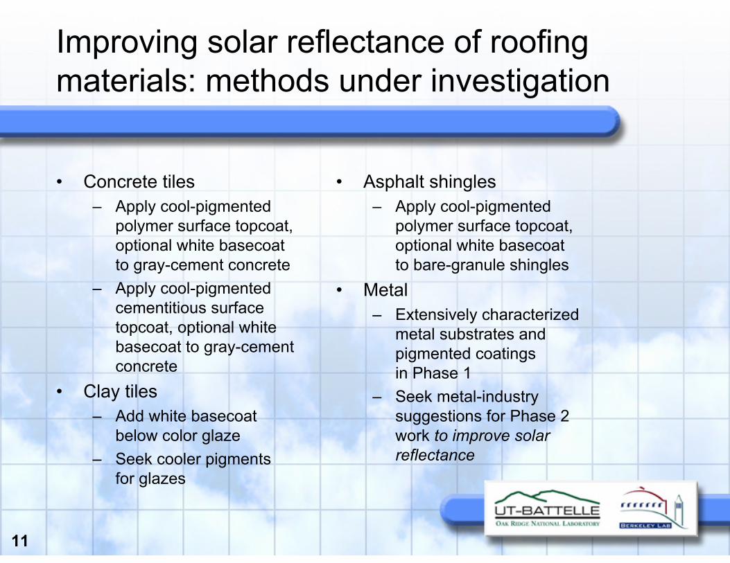
Improving solar reflectance of roofing materials: methods under investigation
• Concrete tiles– Apply cool-pigmented
polymer surface topcoat,optional white basecoatto gray-cement concrete
– Apply cool-pigmented cementitious surface topcoat, optional white basecoat to gray-cement concrete
• Clay tiles– Add white basecoat
below color glaze– Seek cooler pigments
for glazes
• Asphalt shingles– Apply cool-pigmented
polymer surface topcoat,optional white basecoatto bare-granule shingles
• Metal– Extensively characterized
metal substrates and pigmented coatingsin Phase 1
– Seek metal-industry suggestions for Phase 2 work to improve solar reflectance
12
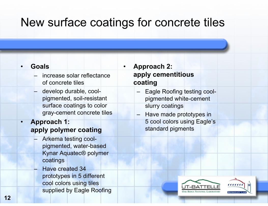
New surface coatings for concrete tiles
• Goals– increase solar reflectance
of concrete tiles– develop durable, cool-
pigmented, soil-resistant surface coatings to color gray-cement concrete tiles
• Approach 1:apply polymer coating
– Arkema testing cool-pigmented, water-based Kynar Aquatec® polymer coatings
– Have created 34 prototypes in 5 different cool colors using tiles supplied by Eagle Roofing
• Approach 2:apply cementitiouscoating
– Eagle Roofing testing cool-pigmented white-cement slurry coatings
– Have made prototypes in 5 cool colors using Eagle’s standard pigments

13
Examples of Kynar Aquatec® cool surface coatings on gray-cement concrete
whiteR = 0.80
white + cool red A R = 0.31
white + cool red BR = 0.36
white + cool brownR = 0.35
white + cool green AR = 0.38
white + cool green BR = 0.35
R is E903 AM1.5 global solar reflectance

14
Examples of Eagle’s white cement + pigment surface coatings on gray-cement concrete
R is E903 AM1.5 global solar reflectance
white cement onlyR = 0.75
white cement + red R = 0.44
white cement + greenR = 0.48
white cement + apricotR = 0.45
Red, green, and apricot samples were colored with Eagle Roofing’s standard pigments sprayed over white cement slurry
15
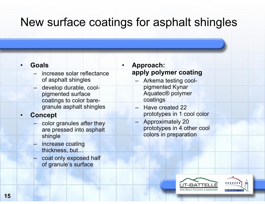
New surface coatings for asphalt shingles
• Goals– increase solar reflectance
of asphalt shingles– develop durable, cool-
pigmented surface coatings to color bare-granule asphalt shingles
• Concept– color granules after they
are pressed into asphalt shingle
– increase coating thickness, but…
– coat only exposed halfof granule’s surface
• Approach:apply polymer coating
– Arkema testing cool-pigmented KynarAquatec® polymer coatings
– Have created 22 prototypes in 1 cool color
– Approximately 20 prototypes in 4 other cool colors in preparation
16
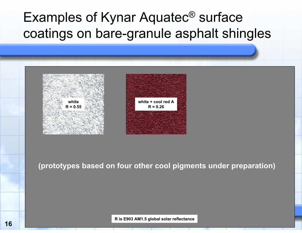
Examples of Kynar Aquatec® surface coatings on bare-granule asphalt shingles
R is E903 AM1.5 global solar reflectance
whiteR = 0.55
white + cool red AR = 0.26
(prototypes based on four other cool pigments under preparation)

17
New surface coatings for clay tiles
• Goal– improve solar reflectance
of glazed clay tiles (MCA Clay Tile)
• Approach 1:add white basecoat
– identified four most promising glazes for addition of white basecoat
– white basecoat did not appreciably increasesolar reflectance
– red clay tile substrate already NIR reflective
– glazes not especially transparent in NIR
• Approach 2: reformulate glaze
– characterized solar spectral reflectances of32 cool-colored glazed clay tiles
– obtained glaze compositions from manufacturer
– seek to reduce NIR absorption in glazes by changing components (e.g., pigments)

18
2.5.1 Status
• Many new prototypes produced by industry, characterized by LBNL
• Kynar Aquatec® coatings promising for concrete tiles, asphalt shingles
• White-cement + pigment slurry coatings promisingfor concrete tiles
• Over next 6 months, we will continue working with partners to– Test cool slurry coats for concrete tiles– Test Kynar Aquatec® coatings for concrete tiles– Test alternative pigments for clay-tile glazes– Review options for other technologies

19
2.5.2 Develop tool to measure solar reflectance for factory quality control
• Objective: Develop instrument to measure product solar reflectance for quality control in roofing factories
• Deliverables:– A prototype instrument and protocol for measuring solar
reflectance of variegated products in the factory• Schedule: 07/20/2006 – 07/20/2008• Funds expended: 50%
20
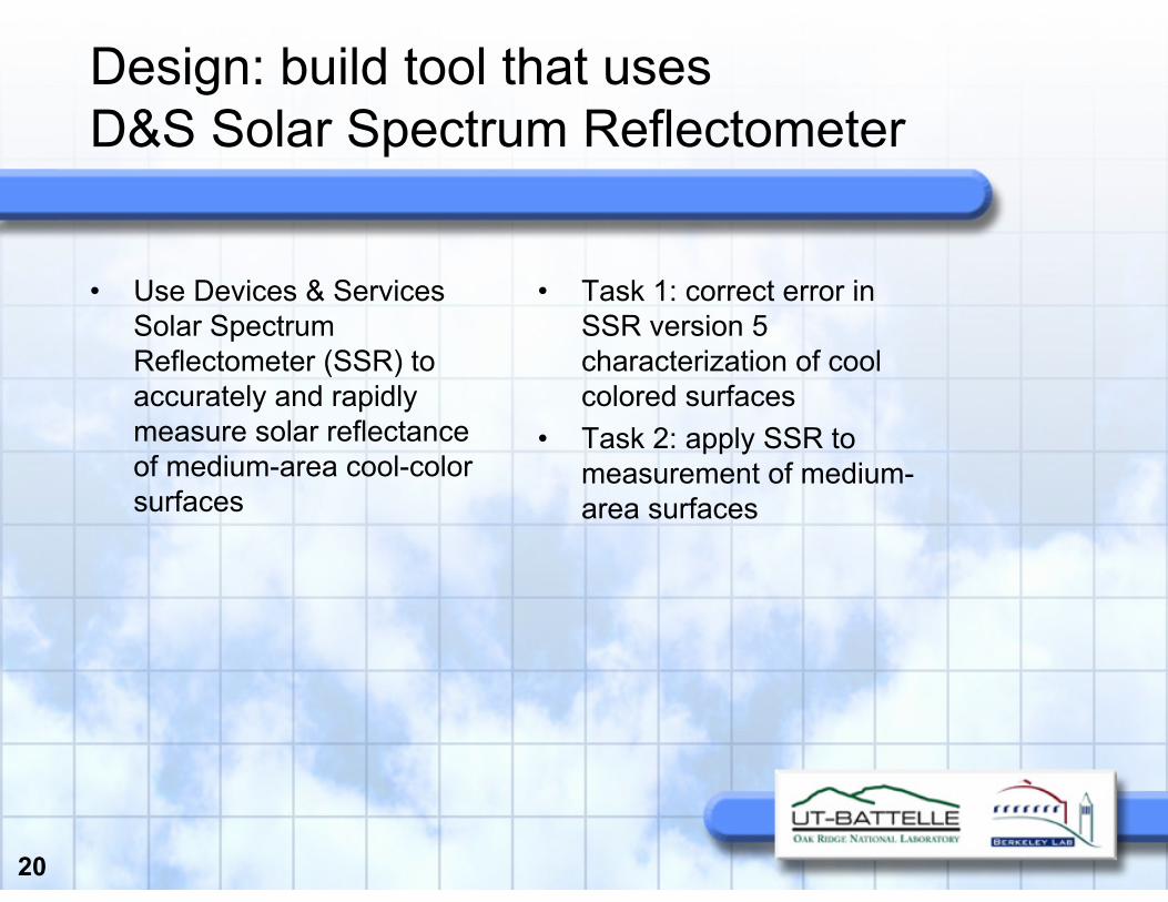
Design: build tool that usesD&S Solar Spectrum Reflectometer
• Use Devices & Services Solar Spectrum Reflectometer (SSR) to accurately and rapidly measure solar reflectance of medium-area cool-color surfaces
• Task 1: correct error in SSR version 5 characterization of cool colored surfaces
• Task 2: apply SSR to measurement of medium-area surfaces
21
Task 1: Correcting SSR (i)
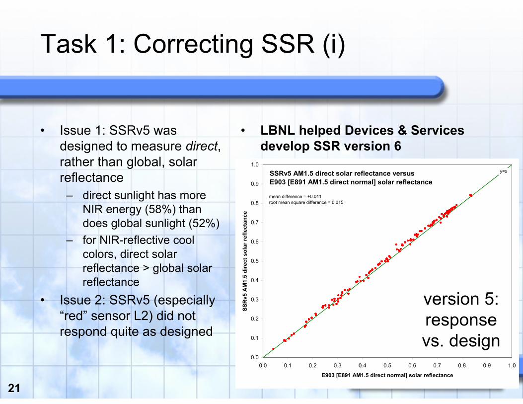
• Issue 1: SSRv5 was designed to measure direct, rather than global, solar reflectance
– direct sunlight has more NIR energy (58%) than does global sunlight (52%)
– for NIR-reflective cool colors, direct solar reflectance > global solar reflectance
• Issue 2: SSRv5 (especially “red” sensor L2) did not respond quite as designed
• LBNL helped Devices & Services develop SSR version 6
SSRv5 AM1.5 direct solar reflectance versusE903 [E891 AM1.5 direct normal] solar reflectance
0.0
0.1
0.2
0.3
0.4
0.5
0.6
0.7
0.8
0.9
1.0
0.0 0.1 0.2 0.3 0.4 0.5 0.6 0.7 0.8 0.9 1.0
E903 [E891 AM1.5 direct normal] solar reflectance
SSR
v5 A
M1.
5 di
rect
sol
ar re
flect
ance
mean difference = +0.011root mean square difference = 0.015
y=x
version 5:responsevs. design

22
Task 1: Correcting SSR (ii)
SSRv6 AM1.5 global horizontal solar reflectance versusE903 [AM1.5 global horizontal] solar reflectance
0.0
0.1
0.2
0.3
0.4
0.5
0.6
0.7
0.8
0.9
1.0
0.0 0.1 0.2 0.3 0.4 0.5 0.6 0.7 0.8 0.9 1.0
E903 [AM1.5 global horizontal] solar reflectance
SSR
v6 A
M1.
5 gl
obal
hor
izon
tal s
olar
refle
ctan
ce mean difference = -0.001root mean square difference = 0.009
y=x
version 6:bias = 0.00
AM1.5 solar reflectances measured with SSRv5, SSRv6 compared to E903 global
SSRv5 AM1.5 direct solar reflectance versusE903 [AM1.5 global horizontal] solar reflectance
0.0
0.1
0.2
0.3
0.4
0.5
0.6
0.7
0.8
0.9
1.0
0.0 0.1 0.2 0.3 0.4 0.5 0.6 0.7 0.8 0.9 1.0
E903 [AM1.5 global horizontal] solar reflectance
SSR
v5 A
M1.
5 di
rect
sol
ar re
flect
ance
mean difference = +0.046root mean square difference = 0.050
y=x
version 5:bias = +0.05
23
Task 1: Correcting SSR (iii)
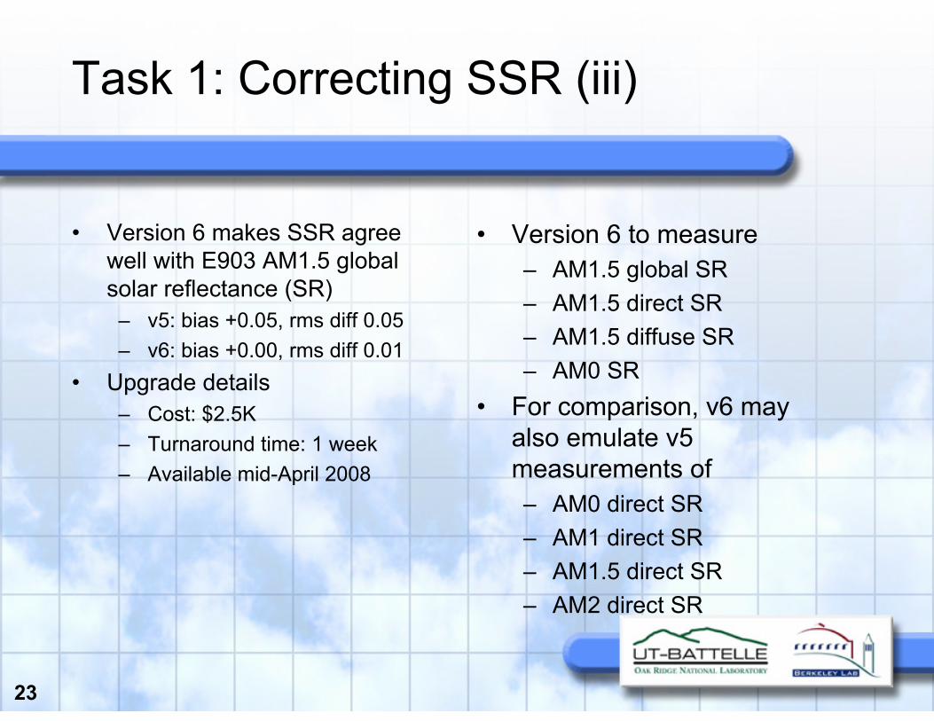
• Version 6 makes SSR agree well with E903 AM1.5 global solar reflectance (SR)
– v5: bias +0.05, rms diff 0.05– v6: bias +0.00, rms diff 0.01
• Upgrade details– Cost: $2.5K– Turnaround time: 1 week– Available mid-April 2008
• Version 6 to measure– AM1.5 global SR– AM1.5 direct SR– AM1.5 diffuse SR– AM0 SR
• For comparison, v6 may also emulate v5 measurements of– AM0 direct SR– AM1 direct SR– AM1.5 direct SR– AM2 direct SR

24
Task 1: Correcting SSR (iv)
• Refurbish SSR-ER to factory specs (excludes major repairs)
• Replace firmware• Replace Acrylic IR Filter with
the 0.156” thick UV-transmissive filter and new spacer ring
• Update the UV detector amplifier circuit to reduce noise by an order of magnitude
• Install a tighter tolerance current sense resistor if not already present (0.1% or better)
• Calibrate and re-mark standards; provide new calibration certificate
• Include Ferro tile or equivalent samples for tracking detector response
• Update labeling according to safety lab report
• Install a separate grounding post
• Other miscellaneous hardware upgrades depending on serial number
• Software updates to improve error reporting
What’s included in upgrade to SSRv6?

25
Task 2: Measure solar reflectance of medium-area surface
• Task more challenging than anticipated
– have evaluated 3 different instrument designs
– converging on “scanning”technique
• LBNL working with Devices & Services to develop “Scanning SSR”
• Expected scan rate about 1500 cm2/min [1.6 ft2/min]
– About 4 min to measure6 ft2 shingle board
• May also be useful to measure reflectanceof variegated product samples for CRRC rating
– CRRC requires minimum sample area 2.5 ft2
– scan time ~ 2 min
26
2.5.2 Status
• Upgrade to SSR version 6 available mid-April
• Scanning SSR under development this spring
27
2.5.3 Correlate the solar reflectance of a shingle to that of its constituent granules
• Objective: Relate the solar reflectance of a roofing shingle to that of its granules
• Deliverable:– A technique for correlating the reflectance of a cool-
colored shingle to that of its surface granules• Schedule: 07/20/2006 – 07/20/2008• Funds expended: 70%

28
Published study detailing effects of surface roughness on shingle reflectance

29
New data on surface roughness
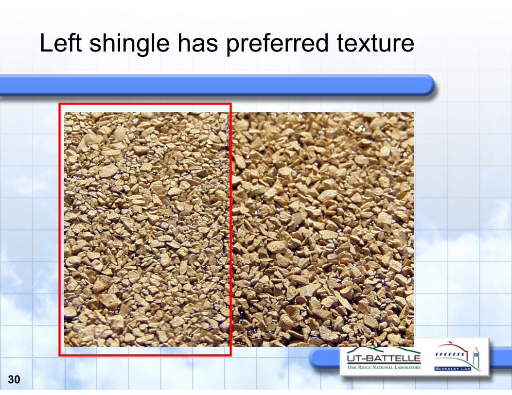
• Paper concluded that granule orientation “texture” is important for high solar reflectance
• Now we have confirmation from additional samples: non-optimal texture can reduce solar reflectance of cool shingle by up to 0.03
30
Left shingle has preferred texture

31
3-year exposure tests now underway at Berkeley Lab (February 2008)

32
How much does a lap reduce the solar reflectance?
Scan of lap joint with SSR
Distance (mm)
01020304050
Ref
lect
ance
(tho
usan
dths
)
200
220
240
260
280
300
320
Mean reflectance 0.294
Size of dip 0.039
FWHM: 10 mm
Scan of 1 mm black line on paper (divided by 3.5)
FWHM: 13 mm
33
Effects of laps
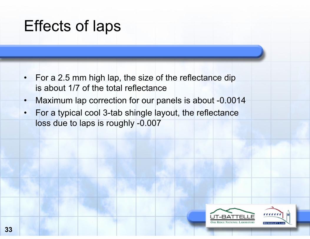
• For a 2.5 mm high lap, the size of the reflectance dipis about 1/7 of the total reflectance
• Maximum lap correction for our panels is about -0.0014• For a typical cool 3-tab shingle layout, the reflectance
loss due to laps is roughly -0.007
34
Asphalt shingle reflectance - future work
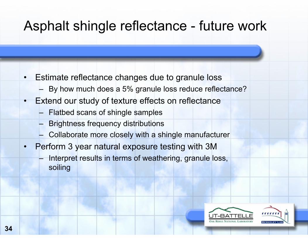
• Estimate reflectance changes due to granule loss– By how much does a 5% granule loss reduce reflectance?
• Extend our study of texture effects on reflectance– Flatbed scans of shingle samples– Brightness frequency distributions– Collaborate more closely with a shingle manufacturer
• Perform 3 year natural exposure testing with 3M– Interpret results in terms of weathering, granule loss,
soiling
35
2.5.4 Develop industry-consensusenergy-savings calculator
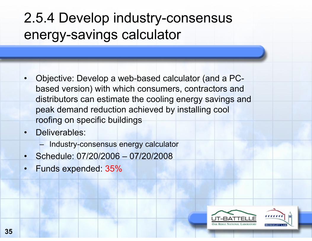
• Objective: Develop a web-based calculator (and a PC-based version) with which consumers, contractors and distributors can estimate the cooling energy savings and peak demand reduction achieved by installing cool roofing on specific buildings
• Deliverables:– Industry-consensus energy calculator
• Schedule: 07/20/2006 – 07/20/2008• Funds expended: 35%
36
Energy-savings calculator
• Methodology– Developed by LBNL and ORNL– Approved by CEC, EPA, and DOE– Was presented to a national advisory committee (via web)– Their comments were incorporated
• We are reviewing the available roof/attic algorithms• DOE continues to be interested in and co-fund the task

37
Technical approach
• Use hourly building-energy simulation models and building prototypes
• Use advanced algorithms to calculate heat transfer through the roof
– Existing residential- and commercial-building roof algorithms
– New algorithms developed in this program
– Fully documented algorithms
• Integrate the adopted algorithms in hourly simulation models
• Use DOE-2 to simulate buildings with for low-sloped roofs
• Use MICROPAS if source code is available AND we conclude MICROPAS is suitable
• Evaluate and modify available prototypes

38
Calculator design
• Building simulation inputs and outputs results stored in relational database
• User defines characteristics of base-case building
• Calculator estimates base-case annual heating energy use, cooling energy use, and peak demand
• User defines characteristics of modified-case building
• Calculator estimates modified-case annual heating-energy use, cooling-energy use, and peak demand
• Calculator estimates the heating- and cooling-energy and peak demand difference between the base and modified case
• Calculator estimates the annual heating- and cooling-energy expenditure difference between the base and modified case

39
Prototype simulations for buildings with low-sloped roofs
• Three prototypes (two non-residential, one residential)
• Two levels of internal load for non-res building (standard, high)
• Two levels of roof thermal mass for non-res building (standard, high)
• Two stocks of buildings and HVAC systems (pre-1980, post-1980)
• Two types of heating (gas furnace, electric heat pump)
• Six levels of roofing/ceiling insulation (R0, R3, R7, R11, R19, R38)
• Five levels of roof solar reflectance (0.10, 0.20, 0.40, 0.60, 0.80)
• Three levels of roof thermal emittance (0.10, 0.50, 0.90)
• 250 climates (approx)• Total simulations: 450,000• Simulations outputs: annual
heating- and cooling-energy uses, peak demand

40
Simulation cities (climates)

41
Base- and modified-case inputs for building with low-sloped roof
• Building location(e.g., ZIP code)
• Building type(three choices)
• Building stock(pre-1980, post-1980)
• Cooling system EER• Heating system (gas, HP)• Heating system efficiency
(for gas) or EER (for HP)• Days of operation per week
• Conditioned space under the roof (only the top floor)
• Roof insulation• Roof thermal mass
(high, standard)• Roof solar reflectance• Roof thermal emittance• Internal load (high, standard)• Gas and electricity unit costs

42
Prototype simulations for buildings with steep-sloped roofs
• Two prototypes (one non-residential, one residential)
• Two level of internal load for non-res building (standard, high)
• Two level of roof thermal mass (standard, high)
• Two duct location cases (attic, conditioned space)
• Two choices for radiant barrier (yes, no)
• Two choices for above-sheathing ventilation (yes, no)
• Two stock of buildings and HVAC systems (pre-1980, post-1980)
• Gas and heat pump electric heating
• Six roofing/ceiling insulation (R0, R3, R7, R11, R19, R38)
• Five roof solar reflectance (0.10, 0.20, 0.40, 0.60, 0.80)
• Three roof thermal emittance (0.10, 0.50, 0.90)
• 250 climates (approx)• Total simulations: 4,320,000• Simulations output: annual
heating- and cooling energy uses, peak demand

43
Base- and modified-case buildingsteep-sloped roof input data
• Building location or zip code• Building type (choice of two)• Building stock
(Pre-1980 and Post-1980)• Cooling system EER• Heating system (gas or HP)• Heating system efficiency
(for gas) and EER (for HP)• Duct location (in attic or
conditioned space)• Radiant barrier (yes, no)
• Above-sheathing ventilation (yes, no)
• Days of operation per week• Conditioned space under the
roof (only the top floor)• Roof insulation• Roof thermal mass
(high, standard)• Roof solar reflectance• Roof thermal emittance• Internal load (high or standard)• Gas and electricity unit cost

44
2.5.5 Conduct natural exposure testing in California
• Objective: Conduct natural exposure testing of currently tested roofing samples and new roofing materials
• Deliverables:– A technical report summarizing the results of the exposure testing
• Schedule: 07/20/2006 – 07/20/2009• Funds expended: 60%
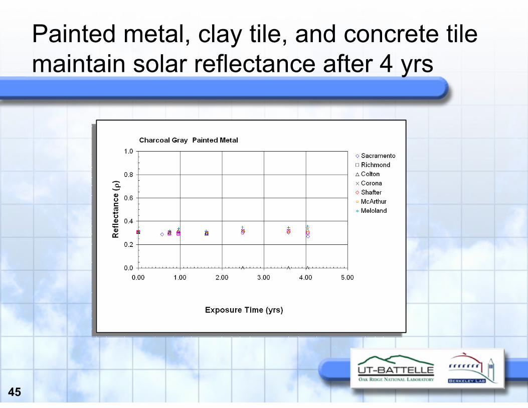
45
Painted metal, clay tile, and concrete tile maintain solar reflectance after 4 yrs

46
Deposition of airborne particlesanalyzed after 1.6, 4.1 yrs of exposure
El Centro Mar 07 Colton Aug 07

47
COOLTILE IR COATING™by American Rooftile CoatingsContaminants soiling samples at Sacramento

48
Elemental compositions and carbon content of particulate matter on samples

49
2.5.6 Conduct field exposure testing at ORNL
• Objective: conduct field exposure testing of new cool roofing materials at ORNL
• Deliverables:– Use data to validate industry-consensus energy savings
calculator– A technical report summarizing the results of field
exposure testing at ORNL• Schedule: 07/20/2006 – 07/20/2009• Funds expended: 60%

50
Clay tile, concrete tile, painted metal, asphalt shingle, and stone-coated metal roofs tested on ESRA
Formulate and Validate AtticSim for Cool Color and Above-Sheathing Ventilation

51
MCA field testing of painted metal
ESRA
Lane Installation Surface emittance Insulation
101 Offset from deck 4.0-in, dual air channel Low-e foil on deck facing up Hardy Board (0.5-in)2
11 Offset from deck 0.75-in using clips Backer on metal underside No insulation above deck
12 Direct-to-Deck (option for variable space) Low-e paint on underside No insulation above deck
131Offset from deck 4.0-in, forced ventilation Low-e foil on deck facing up No insulation above deck
14 Offset from deck 0.75-in using clips Backer on metal underside ≈ R-1.0 above deck
15 Offset from deck 0.75-in using clips Low-e paint on underside No insulation above deck
1Roof and attic assemblies already under evaluation.2Hardy board used to separate two air channels above roof deck.

52
Roof with R-1 insulation placed above deck yields similar thermal performance to roof with ¾-in airspace above deck

53
AtticSIM II (Attic Simulation) Model
Δ=
kh

54
Medium-profile concrete tile
Same setup used at Fair Oaks Demonstration
Batten and Counter-Batten
BattenDirect-to-Deck

55
Medium-profile conventional concrete tile on double batten performs as well as cool-color tile direct-to-deck

56
2.5.7 Carry out field experiments in S. CA for validation of the energy savings calculator
• Objective: Carry out field experiments to evaluate new cool-colored roofing materials in Southern California for validation of the industry-consensus energy savings calculator
• Deliverables:– Comparison of validated steep-slope roof calculator to
demonstration data– A technical report summarizing the results of the field
experiments and comparison of the energy-savings calculator
• Schedule: 07/20/2006 – 07/20/2009• Funds expended: 60%

57
Southern CA field experiments atFort Irwin, CA Located in the High Mojave Desert
Excellent Demonstration Opportunity
ARMY providing safe, secure, reliable, environmentally compliant, and cost-effective energy and water services on ARMY installations.
Clark Pinnacle is building some 200+
private dwellings

58
Field experiments collecting data at Fort Irwin
• Test Plan submitted to the CEC
• Memorandum of Understanding in place
• Wiring of 4 homes completed in May 07
• DAS Commissioned Nov. 07
• Energy Star Homes
– International Residential Code (IRC)
– 15% more efficient than homes built 2004

59
South- and north-facing roof deck heat flux Heat pumps operating in heating mode.
February 22, 2008

60
Ceiling Temperatures for Heat Flux Calculation Top of R-38 Batt colder than sheet rock.
House 10: Conventional Tile Direct-to-Deck

61
2.6 Technology transfer activities
• Objective: Make the knowledge gained, experimental results and lessons learned available to key decision-makers
• Deliverables:– Publish results in trade magazines and academic journals– Participate in building-product exhibitions– Develop a brochure summarizing the research results and
characterizing the benefits of cool colored roofing materials
• Schedule: 07/20/2006 – 07/20/2008• Funds expended: 85%

62
Technology transfer (i)
• “Surface roughness effects on the solar reflectance of cool asphalt shingles” by Berdahl et al. was published in Solar Energy Materials and Solar Cells
• “Global cooling: Effect of urban albedo on global temperature” by Akbari et al. was published at the PALENC conference, September 27, 2007; Crete, Greece
• “Status of cool roof standards in the United States” was published at the PALENC conference, September 27, 2007; Crete, Greece
• Another cool-roof standards paper by Akbari and Levinson was accepted by Advances in Building Energy Research
• “Natural convection heat transfer in roofs with above-sheathing ventilation” by Miller et al. was published in Thermal Performance of the Exterior Envelopes of Buildings, IX, proceedings of ASHRAE THERM X, Clearwater, FL, Dec. 2007
• “Procedure for measuring the solar reflectance of flat or curved roofing assemblies” by Akbari et al. was accepted for publication in Solar Energy
Published 6 papers in journals, conference proceedings, magazines

63
Technology transfer (ii)
• On September 20, 2007, Dr. Melvin Pomerantz (member of the Heat Island Group at LBNL) delivered an invited talk about the project's cool colored roofing technology at West Coast Green, the world's largest exhibition for residential builders (San Francisco)
• On September 19, 2007, Akbariconducted a workshop of Heat Island Mitigation and Cool Roof Technologies in Delhi, India
• On September 21, 2007, Akbari gave two presentations (U.S. Cool Roof Standards and Policies; Advances in Cool Roofing Technologies) at the Green Building Congress, in Chennai, India
• On October 19, 2007, Akbari gave a keynote presentation on Cool Urban Surfaces and Global Warming at the GEA conference in Tokyo, Japan
• On November 9, 2007, Akbari and Desjarlais attended the CRRC board meeting
• On December 5, 2007, Akbari gave a keynote presentation on the cool roof standards and technologies at the 38th International Congress on Heating, Refrigeration and Air-conditioning, Beograd, Serbia
• In January 2008, W. Miller presented "Cool Roof Cool Gap Research“ at a technical forum of the was guest speaker at the Metal Construction Association Annual
• On February 20, 2007, Akbari and Desjarlais attended the CRRC board meeting in Las Vegas
Meeting the public

64
Schedule of PAC meetings
Date Location
PAC-1 Sep. 7, 2006 CEC
PAC-2 Mar. 15, 2007 LBNL
PAC-3 Sep. 6, 2007 Corona, CA
PAC-4 Mar. 6, 2008 ORNL
PAC-5 Sep. 4, 2008 ?
PAC-6 Mar. 5, 2009 ?

65
Cool colors project website
• Project information (including copies of this presentation) available online at
http://CoolColors.LBL.gov


