
Maintenance and Troubleshooting
of Progressing Cavity Pumps
Chad Huskey MOYNO Tech Eng. [email protected]

4
The Progressing Cavity Pump
and it’s Geometry • A progressing cavity (PC) pump, or a single screw pump, is a
positive displacement pump and therefore a fixed volume is
displaced with each revolution of the pump’s Rotor.
• The Rotor forms a single helix (like a corkscrew) and rotates
eccentrically in the Stator.
• The Stator has a double helix cavity (like a double corkscrew)
double the total volume of the rotor.
• When combined, as the rotor turns, cavities or pockets nearly half of
the total volume are formed in the stator which push the product
from the suction toward the discharge end of the pump.
5
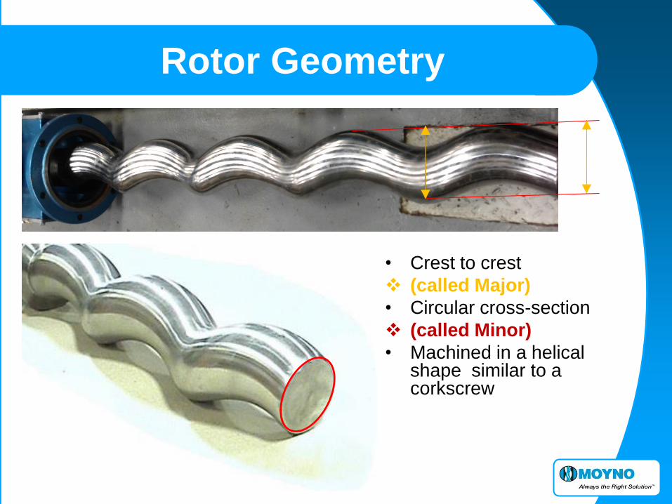
Rotor Geometry
• Crest to crest
(called Major)
• Circular cross-section
(called Minor)
• Machined in a helical shape similar to a corkscrew
6
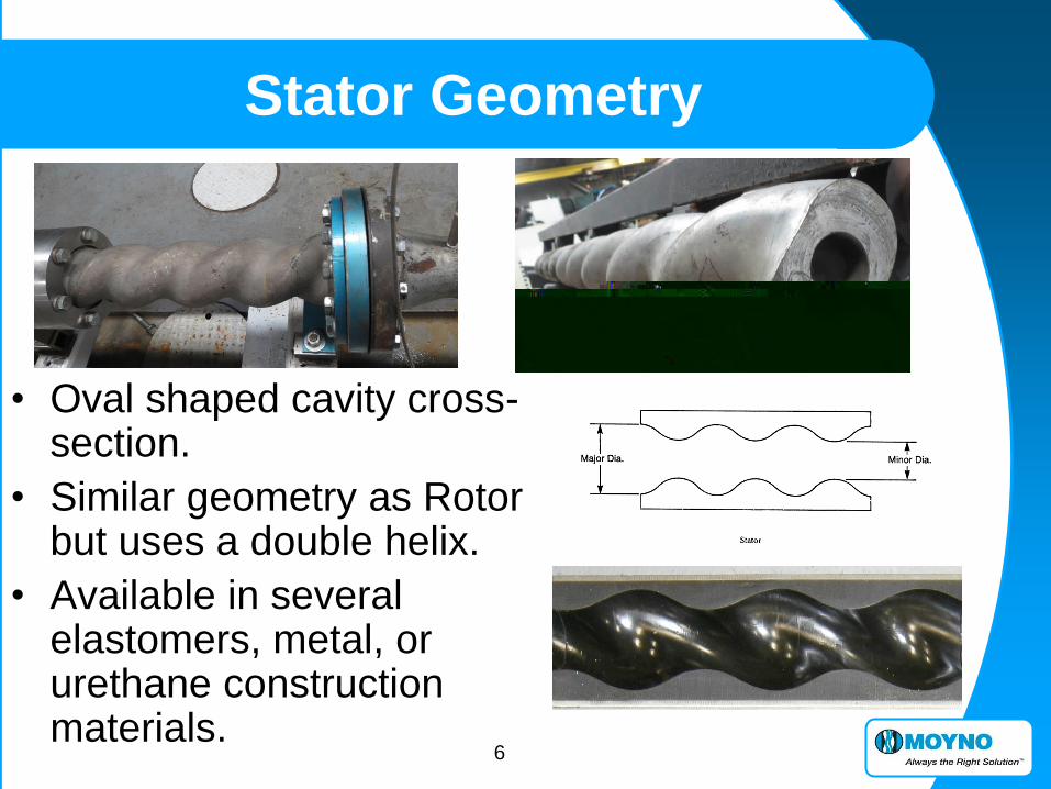
Stator Geometry
• Oval shaped cavity cross-section.
• Similar geometry as Rotor but uses a double helix.
• Available in several elastomers, metal, or urethane construction materials.

7
Cavities
• As Rotor orbits (turns eccentrically)
inside the Stator.
• The motion creates cavities and progresses them from suction to discharge.
8
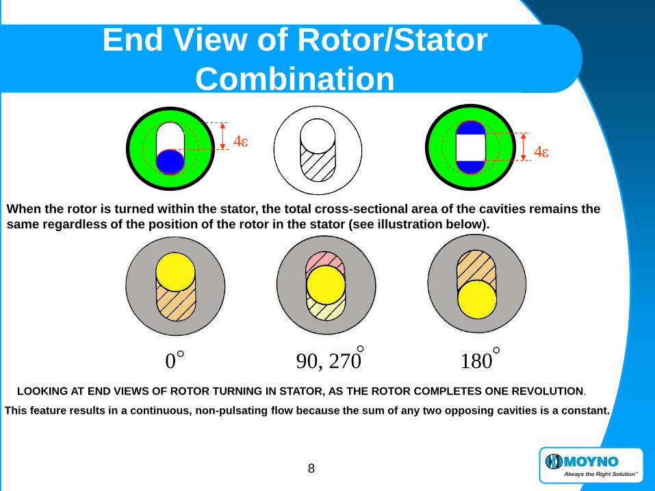
End View of Rotor/Stator
Combination
LOOKING AT END VIEWS OF ROTOR TURNING IN STATOR, AS THE ROTOR COMPLETES ONE REVOLUTION.
This feature results in a continuous, non-pulsating flow because the sum of any two opposing cavities is a constant.
90, 270 180
When the rotor is turned within the stator, the total cross-sectional area of the cavities remains the
same regardless of the position of the rotor in the stator (see illustration below).
4e 4e
0
9
Application Variables
APPLICATION INFLUENCES
“THE BIG THREE”
Abrasion
Temperature
Viscosity
10
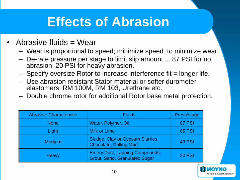
Abrasive Characteristic Fluids Press/stage
None Water, Polymer, Oil 87 PSI
Light Milk or Lime 65 PSI
Medium Sludge, Clay or Gypsum Slurries,
Chocolate, Drilling Mud 43 PSI
Heavy Emery Dust, Lapping Compounds,
Grout, Sand, Granulated Sugar 20 PSI
Effects of Abrasion
• Abrasive fluids = Wear – Wear is proportional to speed; minimize speed to minimize wear.
– De-rate pressure per stage to limit slip amount ... 87 PSI for no abrasion; 20 PSI for heavy abrasion.
– Specify oversize Rotor to increase interference fit = longer life.
– Use abrasion resistant Stator material or softer durometer elastomers: RM 100M, RM 103, Urethane etc.
– Double chrome rotor for additional Rotor base metal protection.

11
Effects of Temperature
• Stator Elastomers swell from 70 to 130° (physical Rotor dimensions require adjustment above this 130° temperature) and Elastomers shrink with Lower temperature (Below 50°).
• Metal parts such as the rotor and drive train tend to expand and contract at a negligible rate than elastomer counterparts.
• Since Stator is bonded to a metal tube, the rubber can only swell inward on the rotor, or shrink away from the rotor.
• This changes the compressive fit between the rotor and stator. Again, to keep a standard fit, the Rotor requires under sizing above 130 º, and over sizing below 50º.
• Under extreme heat or cold, elastomer Stators may not be appropriate.
• Metal Rotor and Stator combinations can be used for extreme temperature applications because they swell or shrink at the similar rates.

12
Cavity only half full
• The more viscous a fluid, the slower the pump will have to run in
order to permit the fluid to flow into the cavity.
1 CPS = Above 1800 RPM 100 CPS = 700 RPM
1000 CPS = 150 RPM 10,000 CPS = 30 RPM
Loss of Fill (volumetric) Efficiency starts at
• Even at reduced speeds, the pump may not develop 100% volumetric
efficiency and this must be accounted for in the selection process.
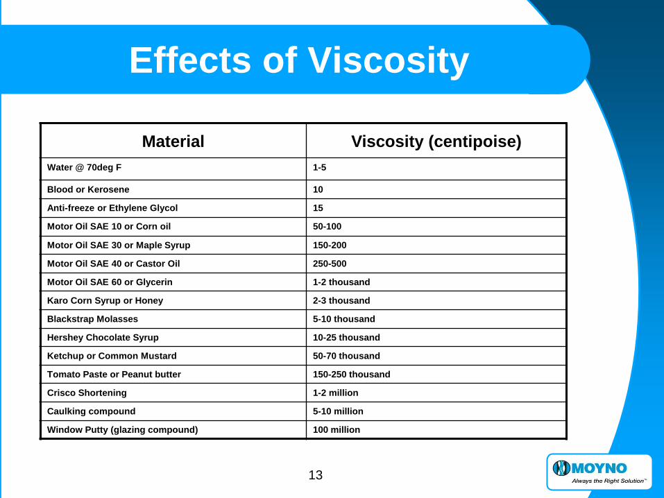
Effects of Viscosity
13
Material Viscosity (centipoise)
Water @ 70deg F 1-5
Blood or Kerosene 10
Anti-freeze or Ethylene Glycol 15
Motor Oil SAE 10 or Corn oil 50-100
Motor Oil SAE 30 or Maple Syrup 150-200
Motor Oil SAE 40 or Castor Oil 250-500
Motor Oil SAE 60 or Glycerin 1-2 thousand
Karo Corn Syrup or Honey 2-3 thousand
Blackstrap Molasses 5-10 thousand
Hershey Chocolate Syrup 10-25 thousand
Ketchup or Common Mustard 50-70 thousand
Tomato Paste or Peanut butter 150-250 thousand
Crisco Shortening 1-2 million
Caulking compound 5-10 million
Window Putty (glazing compound) 100 million
Effects of Viscosity

14
Summary
• The standard PC pump consists of a Rotor (metal) which rotates within an elastomeric Stator. – The Rotor has a circular cross-section and is machined
in a single helix like a corkscrew.
– The Stator cavity is molded as a double helix with an Oval cross-section. The helix geometry is similar to the rotor to create an interference fit.
– As the rotor turns inside the stator it orbits on an eccentric (at an offset around the center axis), this motion creates cavities that progresses from suction to discharge; moving product and building pressure.
How does a MOYNO Pump Work?
15
Summary
• The MOYNO design creates a low shear, metered, and pulse-less flow.
• The PC pump is able to effectively handle “water-like” to super viscous fluids including levels of air or gases. It can gently pump large particulates and handle abrasive solids.
Provides excellent suction capabilities and does not air lock.
• The flexible geometry of the MOYNO pump allows.
Multiple drive end choices (power) and multiple stages (pressure).
MOYNO pumps allow precise control of the interference fit.
• MOYNO can best match the pump to your application.
Progressing Cavity Pump Advantages
16
General Maintenance
PUMP MAINTENANCE

DAILY INSPECTION; • Lip seals on bearing housing
• Packing/Mech seal
(flow/pressure/noise)
• Gear reducer (temp/noise).
WEEKLY MAINT; • Adjust packing (should drip
2-5 times per minute)
• Lube packing (typically 2-3
pumps per week).
Preventative Maintenance Most of the maintenance needed for a MOYNO pump is based on “look-feel”
YEARLY MAINT; • Replace packing, inspect
shaft wear.
• Replace automatic lubricator
(if applicable).
• Pull spool piece to inspect
pipe internal condition.
Lubrication Schedule
• Bearings
Bearings are lubricated and the factory and do not
normally need periodic re-lubrication-recommended only
when drive shaft is removed for maintenance.
• Packing
Once a week or more, frequency determined by process.
• Gear Joints
Only recommended when gear joints are disassembled.
(example; when replace rotor)
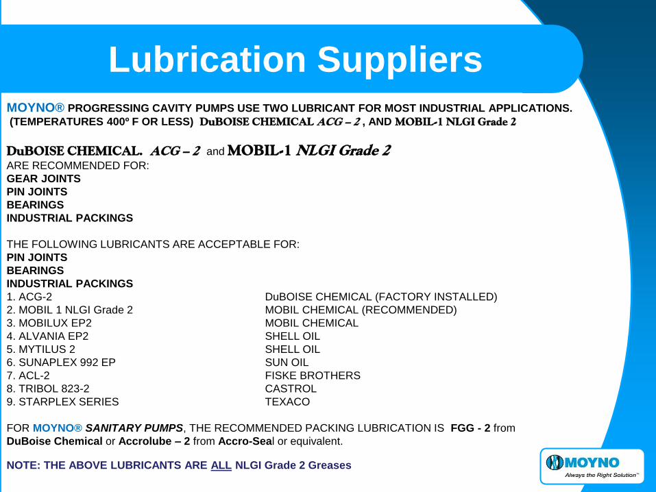
Lubrication Suppliers MOYNO® PROGRESSING CAVITY PUMPS USE TWO LUBRICANT FOR MOST INDUSTRIAL APPLICATIONS.
(TEMPERATURES 400º F OR LESS) DuBOISE CHEMICAL ACG – 2 , AND MOBIL-1 NLGI Grade 2
DuBOISE CHEMICAL. ACG – 2 and MOBIL-1 NLGI Grade 2 ARE RECOMMENDED FOR:
GEAR JOINTS
PIN JOINTS
BEARINGS
INDUSTRIAL PACKINGS
THE FOLLOWING LUBRICANTS ARE ACCEPTABLE FOR:
PIN JOINTS
BEARINGS
INDUSTRIAL PACKINGS
1. ACG-2 DuBOISE CHEMICAL (FACTORY INSTALLED)
2. MOBIL 1 NLGI Grade 2 MOBIL CHEMICAL (RECOMMENDED)
3. MOBILUX EP2 MOBIL CHEMICAL
4. ALVANIA EP2 SHELL OIL
5. MYTILUS 2 SHELL OIL
6. SUNAPLEX 992 EP SUN OIL
7. ACL-2 FISKE BROTHERS
8. TRIBOL 823-2 CASTROL
9. STARPLEX SERIES TEXACO
FOR MOYNO® SANITARY PUMPS, THE RECOMMENDED PACKING LUBRICATION IS FGG - 2 from
DuBoise Chemical or Accrolube – 2 from Accro-Seal or equivalent.
NOTE: THE ABOVE LUBRICANTS ARE ALL NLGI Grade 2 Greases
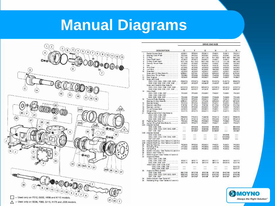
Manual Diagrams

21
Remember…

FAILURE ANALYSIS AND
EXAMPLES OF WORN &
FAILED MOYNO PARTS
Failure Analysis
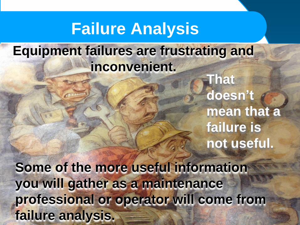
Failure Analysis
Equipment failures are frustrating and
inconvenient.
Some of the more useful information
you will gather as a maintenance
professional or operator will come from
failure analysis.
That
doesn’t
mean that a
failure is
not useful.
Failure Analysis
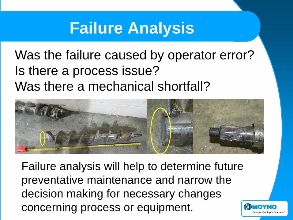
Was the failure caused by operator error?
Is there a process issue?
Was there a mechanical shortfall?
Failure analysis will help to determine future
preventative maintenance and narrow the
decision making for necessary changes
concerning process or equipment.
Failure Analysis
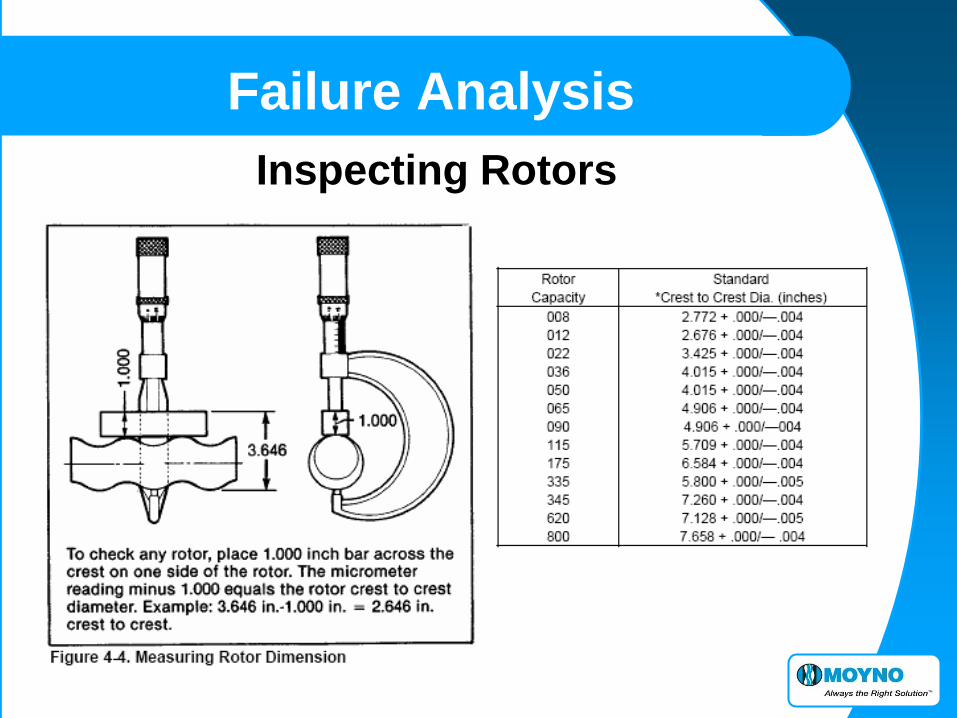
Inspecting Rotors

Failure Analysis
Inspecting Stators A worn stator may appear pitted and gauged, or may appear smooth similar to new.
Performance is the best measure of rotor to stator fit. If unable to measure performance adequately, suspected stator wear can be evaluated by a MOYNO sales representative.

Failure Analysis What is cavitation and how can I tell if my pump is cavitating? In summary, cavitation is an abnormal condition that can result in loss of production, and
equipment damage. In the context of pumps, the term cavitation implies a dynamic
process of formation of bubbles inside the liquid, their growth and subsequent collapse as
the liquid flows through the pump. It can be vaporous or gaseous.
Both types of bubbles are formed at a
point inside the pump where the local static
pressure is less than the vapor pressure of
the liquid (vaporous cavitation) or saturation
pressure of the gas (gaseous cavitation, also
referred to as “air binding”). The noise and pump
vibration is caused by the collapse of the
air bubble when it gets pressurized.
Typically in a MOYNO pump the cause of
cavitation is a lack of suction volume.
The symptoms are reduced flow, a rumble
with vibration or and may include a rapid
popping sound.

• TYPICAL ROTOR ABRASIVE WEAR PATTERN
• NOTE THE TELLTALE RIDGES
Failure Analysis

• ABRASIVE WEAR ON A ROTOR
• NOTE THE RIDGES OR GROOVES
Failure Analysis
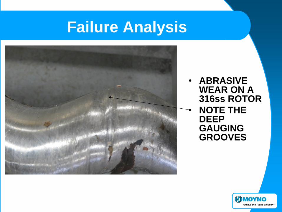
• ABRASIVE WEAR ON A 316ss ROTOR
• NOTE THE DEEP GAUGING GROOVES
Failure Analysis

• TYPICAL ROTOR EVEN WEAR PATTERN
• A LITTLE TOO WORN TO RE-PLATE
• ADJUSTING THE MAINTENANCE INTERVAL MAY LOWER COSTS
Failure Analysis
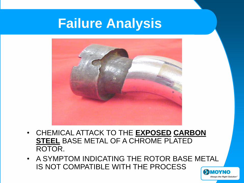
• CHEMICAL ATTACK TO THE EXPOSED CARBON STEEL BASE METAL OF A CHROME PLATED ROTOR.
• A SYMPTOM INDICATING THE ROTOR BASE METAL IS NOT COMPATIBLE WITH THE PROCESS
Failure Analysis

• CHEMICAL ATTACK UNDERMINING THE
CARBON STEEL BASE METAL THRU THE
CHROME PLATING.
Failure Analysis

• CHEMICAL ATTACK TO THE CARBON STEEL BASE
METAL THRU THE CHROME PLATING.
Failure Analysis

• CHEMICAL ATTACK TO THE 316 SS BASE METAL
UNDER THE CHROME PLATING.
Failure Analysis

• THE INNER SURFACE OF A RUN DRY STATOR IS HARD AND HAS A VERY ROUGH TEXTURE.
• AN ORANGE PEEL TEXTURE ALONG SEAL LINES IS A TELLTALE SIGN OF RUN DRY.
Failure Analysis
SUCTION
RUN DRY DAMAGE NORMALLY BEGINS AT THE SUCTION END.
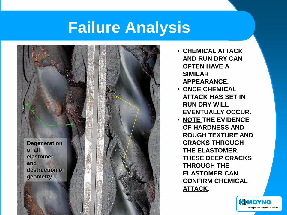
• CHEMICAL ATTACK
AND RUN DRY CAN
OFTEN HAVE A
SIMILAR
APPEARANCE.
• ONCE CHEMICAL
ATTACK HAS SET IN
RUN DRY WILL
EVENTUALLY OCCUR.
• NOTE THE EVIDENCE
OF HARDNESS AND
ROUGH TEXTURE AND
CRACKS THROUGH
THE ELASTOMER.
THESE DEEP CRACKS
THROUGH THE
ELASTOMER CAN
CONFIRM CHEMICAL
ATTACK.
Failure Analysis
Degeneration
of all
elastomer
and
destruction of
geometry.

• THE SURFACE OF THE STATOR IS HARD AND HAS AN ORANGE PEEL TEXTURE.
• THE SURFACE BLISTERING AND CRACKING COMBINED WITH A BURNED SMELL AND THE ELASTOMER INTACT IN SURROUNDING AREAS IS CONSISTENT WITH RUN DRY
Failure Analysis
Elastomer totally burnt by run dry.
THE SURROUNDING AREAS
STILL HAVE INTERGRITY

Elastomer totally burnt by running dry. Note that surrounds areas are perfect.
This results in a different diagnostic process and narrows the focus when
evaluating the loss of performance.
Failure Analysis
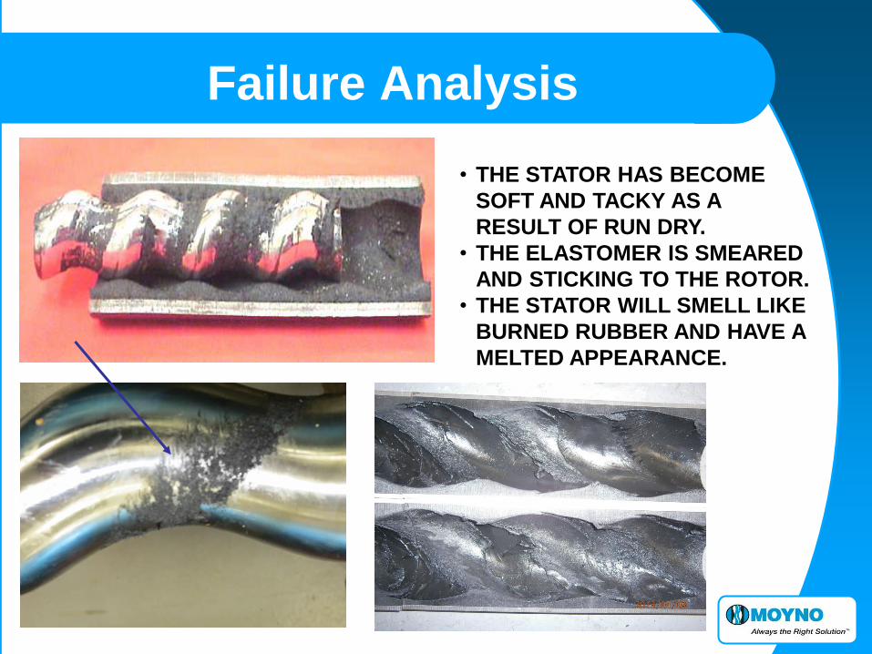
• THE STATOR HAS BECOME
SOFT AND TACKY AS A
RESULT OF RUN DRY.
• THE ELASTOMER IS SMEARED
AND STICKING TO THE ROTOR.
• THE STATOR WILL SMELL LIKE
BURNED RUBBER AND HAVE A
MELTED APPEARANCE.
Failure Analysis

• ELASTOMER SWELLING IS EVIDENT ON THE
ENDS OF THIS STATOR.
• SIGNIFICANT SWELLING OR SHRINKING IS A
CLEAR SIGN OF CHEMICAL ATTACK.
Failure Analysis
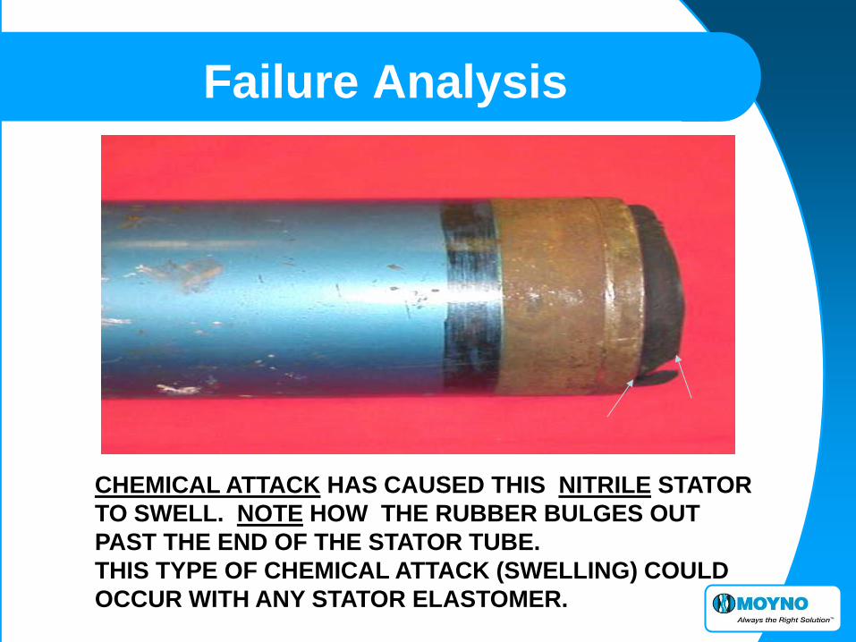
CHEMICAL ATTACK HAS CAUSED THIS NITRILE STATOR
TO SWELL. NOTE HOW THE RUBBER BULGES OUT
PAST THE END OF THE STATOR TUBE.
THIS TYPE OF CHEMICAL ATTACK (SWELLING) COULD
OCCUR WITH ANY STATOR ELASTOMER.
Failure Analysis

DELAMINATION IS THE RESULT OF THE ELASTOMER MOLECULES
NOT KNITTING PROPERLY DURING THE MANUFACTURING PROCESS.
THE ELASTOMER MAY THEN COME LOOSE IN LAYERS WHILE
PUMPING AGAINST HIGH DISCHARGE PRESSURE.
Failure Analysis

Hysteresis (fatigue)
Action: Cycling loads on elastomer increases internal temperature
and causes a secondary vulcanization.
Result: The elastomer loses its elastic properties, becomes very hard
and cracks arise in the surrounds areas of cycling loading
LARGE CHUNKS TYPICALLY WILL BREAK LOOSE
Failure Analysis

WORN TEETH NORMAL
Failure Analysis

Failure Analysis
WORN TEETH
NORMAL
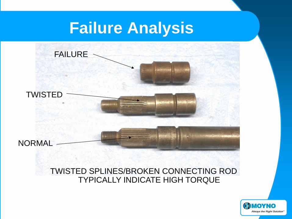
FAILURE
TWISTED
NORMAL
TWISTED SPLINES/BROKEN CONNECTING ROD TYPICALLY INDICATE HIGH TORQUE
Failure Analysis

Failure Analysis
TYPICAL CIRCULAR
PATTERN INDICATES
TORQUE FAILURE THE TWIST
INDICATES
THIS
CONNECTING
ROD WILL
FAIL SOON!

Failure Analysis
• Gear joint
seals
should be
inspected
for damage
when the
pump is
serviced
BAD SEAL NORMAL
Failure Analysis
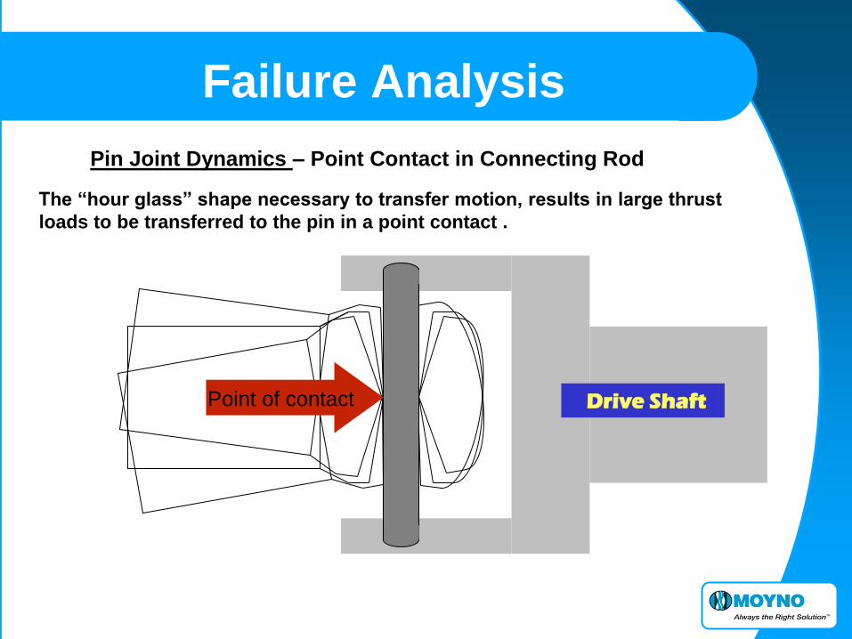
Pin Joint Dynamics – Point Contact in Connecting Rod
The “hour glass” shape necessary to transfer motion, results in large thrust
loads to be transferred to the pin in a point contact .
Drive Shaft Point of contact
Failure Analysis
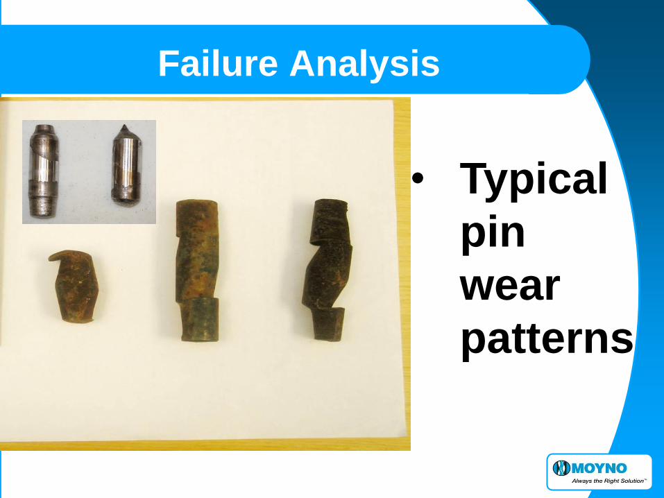
• Typical
pin
wear
patterns
Failure Analysis
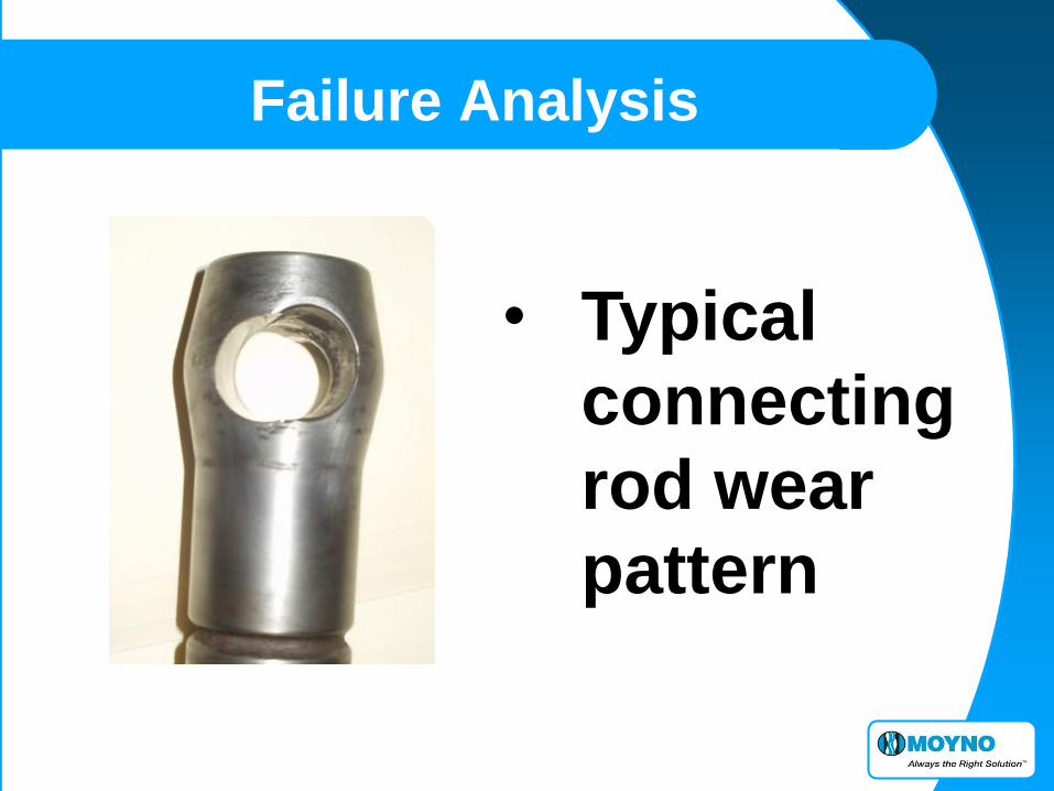
• Typical
connecting
rod wear
pattern

Failure Analysis
• Excessive
rotor
head wear
54
Failure Analysis
Questions?
55
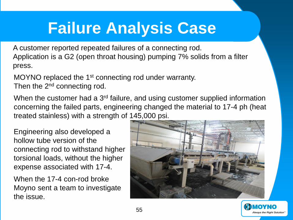
Failure Analysis Case A customer reported repeated failures of a connecting rod.
Application is a G2 (open throat housing) pumping 7% solids from a filter
press.
MOYNO replaced the 1st connecting rod under warranty.
Then the 2nd connecting rod.
When the customer had a 3rd failure, and using customer supplied information
concerning the failed parts, engineering changed the material to 17-4 ph (heat
treated stainless) with a strength of 145,000 psi.
Engineering also developed a
hollow tube version of the
connecting rod to withstand higher
torsional loads, without the higher
expense associated with 17-4.
When the 17-4 con-rod broke
Moyno sent a team to investigate
the issue.
56
Failure Analysis Case
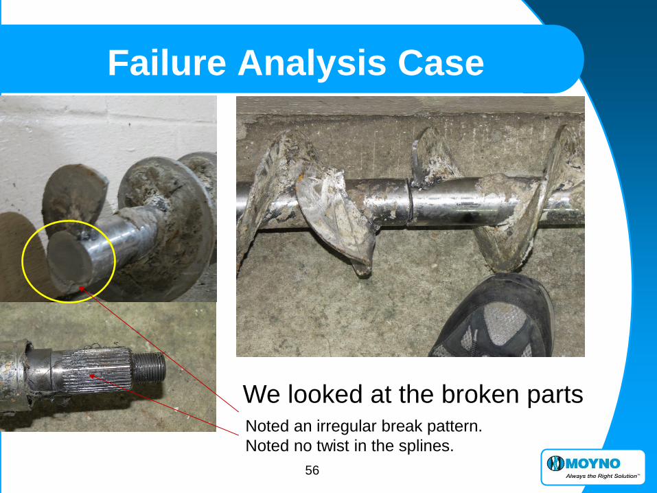
We looked at the broken parts Noted an irregular break pattern.
Noted no twist in the splines.

57
Failure Analysis Case
We looked
at and
evaluated
the normal
wear parts
for damage
or anything
that could
cause
binding.
Parts have even wear patterns

58
Failure Analysis Case
When nothing was obvious we further evaluated the type of failure
And began to carefully review the operational information.
The type of failure pattern is not consistent with a torque failure and is
consistent with a fatigue failure.
Example of torque failure
Spiral pattern
Fatigue failure
Lip
Then the operational
information; how the
system operates and
conditions when operating
were closely reviewed.
The system has high levels
of whey from a cheese
producer, which results in
significant pipe build up.

59
Failure Analysis Case
The system is run by the flow rate (maintain a certain flow), so if the pipe
buildup results in restriction the pump speeds up. The max speed by design is
419 rpm, which is faster than we would prefer for a 2 meter open throat.
The system is protected from high pressure using a pressure ring switch
assembly and analog gauge.
Spool piece
with one week
of build up
Plant maintenance reported that pipe
buildup regularly restricted the
internal pipe dimension to 2” or less.
High pressure safeguard is set to shut
off at 80psi, but heavy buildup can stop
the switch and the pressure gauge from
properly reading = malfunctioning.
The restriction would also lower the
flow rate resulting in faster, and faster
pump speeds to keep up.

60
Failure Analysis Case Review of the VFD settings revealed the system is enabled to run over the
design speed at a max 78Hz which translates to 544rpm max.
The system failures/breakages generally occurred on third shift when the
system was not closely monitored.
The conclusion after reviewing all
the information was the pipe
internal buildup needed to be
addressed by more frequent
maintenance or a process change.
But more importantly the speed
needed to be restricted to at or
below the original design speed.

61
Failure Analysis Case
Questions?


