Download - MachineDesign Intro SSRoy
1
4 February 2009 Machine Design 1
Under Graduate Course on
Machine Design-I
Design of Machine Elements
Shibendu Shekhar RoyRobotics & A.I Lab. (RAIL)
Department of Mechanical Engineering
4 February 2009 Machine Design 2
Reference Books1. V.B. Bhandari, “Design of Machine Elements ”, <second edition>, Tata McGraw Hill.2. J.E. Shigley, C.R. Mischke, “Mechanical Engineering Design”, Tata McGraw Hill.3. M.F. Spotts & T.E. Shoup, “Design of Machine Elements”, Pearson Education.
Machine Design Handbook
1. “Design Data”, Compiled by Faculty of Mechanical Engineering, PSG College, Coimbatore2. “CMTI Hand Book”, Compiled by Scientists of Central Manufacturing technology Institute, Bangalore

2
4 February 2009 Machine Design 3
- Mechanical properties of Engineering materials- B.I.S system of designation of commonly used Engineering Materials
- Selection of Materials
Engineering Materials
- Design of Threaded Joints- Design of Welded Joints
Plate Joints
- Design of Cotter Joint- Design of Knuckle Joint
Rod Joints
- Review of Stress, Strain and Complex stresses in machine members
- Basic procedure of machine design & machine element design
- Manufacturing & other consideration in machine design- Modern Computational Tools for Machine Design- Role of CAD/CAE in Machine Design
Introduction TopicsChapter
Topics to be Covered
4 February 2009 Machine Design 4
Topics to be Covered
TopicsChapter- Elastic failure theories, Factor of safety, Service factor
- General principles & procedures of design of machine elements
Design against Static Load
- Stress Concentration factor, Fatigue failure, Endurance limit etc.
- Reversed stresses- design for finite & infinite life, Impact stresses etc.
Design against Dynamic Load
- Design of Shaft under Torsion, Bending, Axial & Combined loads
- Design of keys like square & flat, saddle, sunk, woodruff keys etc.
Design of Shafts, Keys, Splines
3
4 February 2009 Machine Design 5
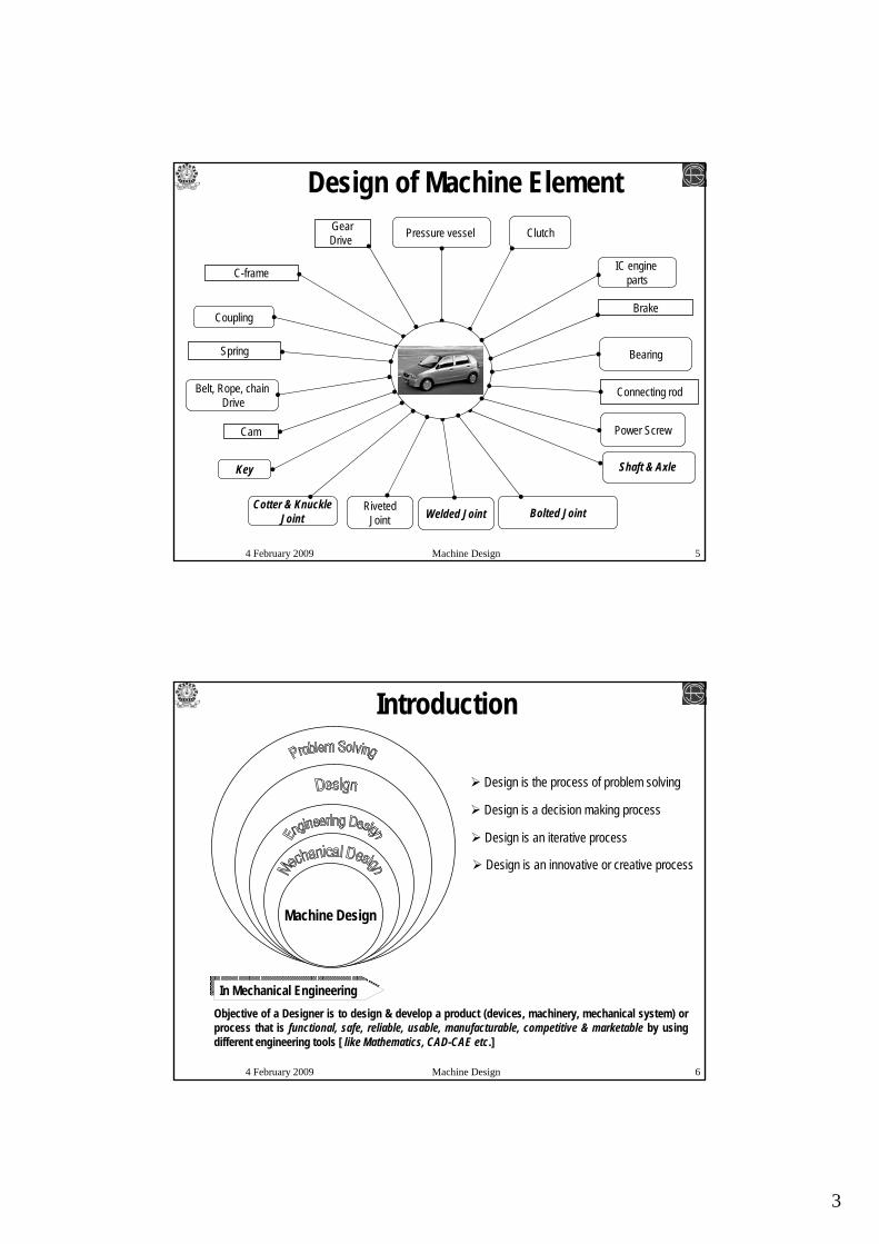
Design of Machine Element
Cam
C-frame
Spring
Brake
Connecting rod
GearDrive
Shaft & Axle
Welded Joint
Belt, Rope, chainDrive
Bearing
Key
IC engine parts
Pressure vessel
Cotter & KnuckleJoint Bolted JointRiveted
Joint
Clutch
Coupling
Power Screw
4 February 2009 Machine Design 6
Machine Design
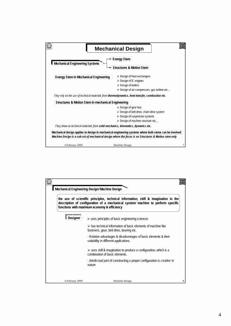
Introduction
Objective of a Designer is to design & develop a product (devices, machinery, mechanical system) or process that is functional, safe, reliable, usable, manufacturable, competitive & marketable by using different engineering tools [ like Mathematics, CAD-CAE etc.]
Design is the process of problem solving
Design is a decision making process
Design is an iterative process
Design is an innovative or creative process
In Mechanical Engineering
4
4 February 2009 Machine Design 7
Mechanical Engineering Systems
Mechanical Design
Structures & Motion Stem
Energy Stem
Energy Stem in Mechanical Engineering Design of heat exchangersDesign of IC enginesDesign of boilersDesign of air compressors, gas turbine etc…
They rely on the use of technical materials from thermodynamics, heat transfer, combustion etc.
Structures & Motion Stem in mechanical EngineeringDesign of gear boxDesign of belt drive, chain drive systemDesign of suspension systemsDesign of machine structure etc…
They draw on technical materials from solid mechanics, kinematics, dynamics etc.
Mechanical design applies to design in mechanical engineering systems where both stems can be involvedMachine Design is a sub-set of mechanical design where the focus is on Structures & Motion stem only
4 February 2009 Machine Design 8
the use of scientific principles, technical information, skill & imagination in the description of configuration of a mechanical system/ machine to perform specific functions with maximum economy & efficiency
Mechanical Engineering Design/ Machine Design
uses principles of basic engineering sciencesDesigner
has technical information of basic elements of machine like fasteners, gear, belt drive, bearing etc.
- Relative advantages & disadvantages of basic elements & their suitability in different applications.
uses skill & imagination to produce a configuration, which is a combination of basic elements.
- Intellectual part of constructing a proper configuration is creative in nature

5
4 February 2009 Machine Design 9
Machine Design
Mechanism
Kinematic Link
MachineMachine Tool
Kinematic Pair
One link fixed
All Machines are Mechanism but all Mechanisms are not Machine
All Machine Tools are Machine but all Machines are not Machine Tool
Mechanismtransfers
transforms
Motion
transfers
transforms
Energy
Kinematic ChainMachine
Machine tool is a contrivance having a combination of mechanisms/machines whereby a cutting tool is enabled to operate in a pre-conceived manner in order to produce a surface of desired shape, size or a degree of finish by removing metal from workpiece in the form of chips.
Primary Objectives
4 February 2009 Machine Design 10
Basics of Mechanism
Mechanism
Kinematic Link
Kinematic Pair
One link fixed
Mechanismtransfers
transforms
Motion
Kinematic Chain
Kinematic Link - Each part of a mechanism which has motion relative to some other part
Kinematic Pair - is a joint of two links having relative motion between them
Machine
6
4 February 2009 Machine Design 11
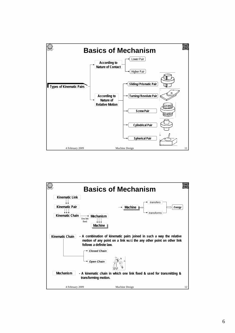
Basics of Mechanism
Types of Kinematic Pairs
According to Nature of Contact
According to Nature of
Relative Motion
Turning/ Revolute Pair
Screw Pair
Cylindrical Pair
Lower Pair
Sliding/ Prismatic Pair
Higher Pair
Spherical Pair
4 February 2009 Machine Design 12
Kinematic Chain
Basics of Mechanism
- A combination of kinematic pairs joined in such a way the relative motion of any point on a link w.r.t the any other point on other link follows a definite law.
Mechanism
Kinematic Link
Kinematic Pair
One link fixed
Kinematic Chain
Machine
Mechanism - A kinematic chain in which one link fixed & used for transmitting & transforming motion.
transfers
transforms
EnergyMachine
Closed Chain
Open Chain
7
4 February 2009 Machine Design 13
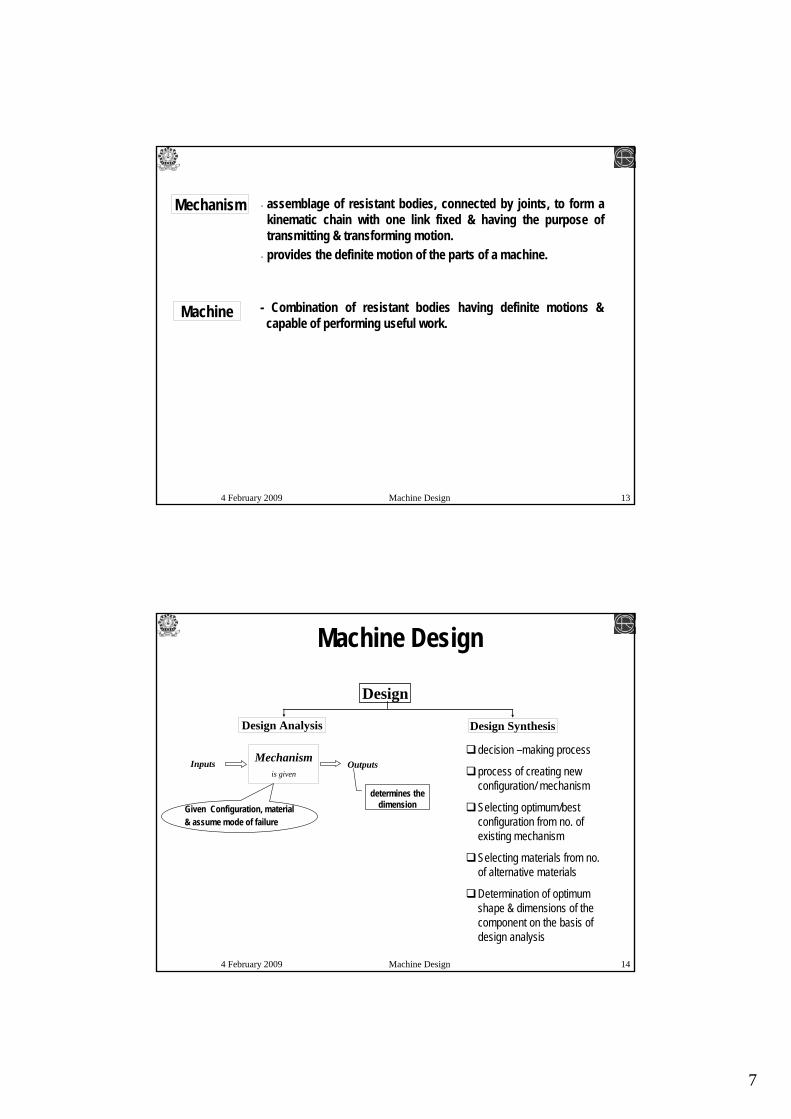
Machine - Combination of resistant bodies having definite motions & capable of performing useful work.
Mechanism - assemblage of resistant bodies, connected by joints, to form a kinematic chain with one link fixed & having the purpose of transmitting & transforming motion.
- provides the definite motion of the parts of a machine.
4 February 2009 Machine Design 14
Design
Design SynthesisDesign Analysis
Mechanismis given
Inputs Outputs
Machine Design
Given Configuration, material & assume mode of failure
determines the dimension
decision –making process
process of creating new configuration/ mechanism
Selecting optimum/best configuration from no. of existing mechanism
Selecting materials from no. of alternative materials
Determination of optimum shape & dimensions of the component on the basis of design analysis
8
4 February 2009 Machine Design 15
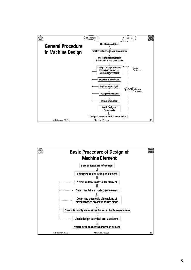
Identification of Need
Engineering Analysis
Problem definition, Design specification
Collecting relevant design information & feasibility study
Design Conceptualization/ Preliminary design i.e. Mechanism synthesis
General Procedure in Machine Design
Detail Design of Components
Design Optimization
Modeling & Simulation
Design Evaluation
CustomerManufacturer
CAD/CAE
Design Synthesis
Design Analysis
Design Communication & Documentation
4 February 2009 Machine Design 16
Basic Procedure of Design of Machine Element
Specify functions of element
Determine forces acting on element
Check design at critical cross-sections
Determine failure mode (s) of element
Select suitable material for element
Check & modify dimensions for assembly & manufacture
Determine geometric dimensions of element based on above failure mode
Prepare detail engineering drawing of element
9
4 February 2009 Machine Design 17
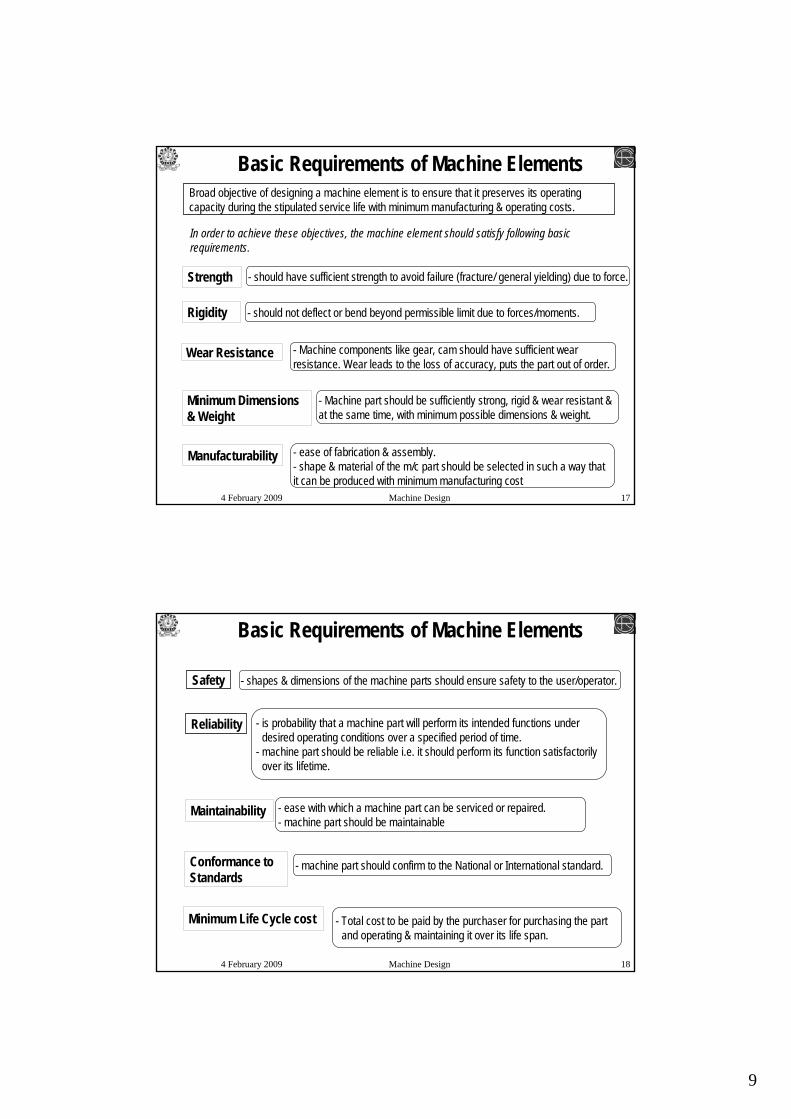
Strength
Manufacturability
Minimum Dimensions & Weight
Rigidity
Wear Resistance
Basic Requirements of Machine ElementsBroad objective of designing a machine element is to ensure that it preserves its operating capacity during the stipulated service life with minimum manufacturing & operating costs.
In order to achieve these objectives, the machine element should satisfy following basic requirements.
- should have sufficient strength to avoid failure (fracture/ general yielding) due to force.
- should not deflect or bend beyond permissible limit due to forces/moments.
- Machine components like gear, cam should have sufficient wear resistance. Wear leads to the loss of accuracy, puts the part out of order.
- Machine part should be sufficiently strong, rigid & wear resistant & at the same time, with minimum possible dimensions & weight.
- ease of fabrication & assembly.- shape & material of the m/c part should be selected in such a way that it can be produced with minimum manufacturing cost
4 February 2009 Machine Design 18
Conformance to Standards
Minimum Life Cycle cost
Reliability
Safety
Maintainability
Basic Requirements of Machine Elements
- shapes & dimensions of the machine parts should ensure safety to the user/operator.
- is probability that a machine part will perform its intended functions under desired operating conditions over a specified period of time.
- machine part should be reliable i.e. it should perform its function satisfactorily over its lifetime.
- ease with which a machine part can be serviced or repaired.- machine part should be maintainable
- machine part should confirm to the National or International standard.
- Total cost to be paid by the purchaser for purchasing the part and operating & maintaining it over its life span.
10
4 February 2009 Machine Design 19
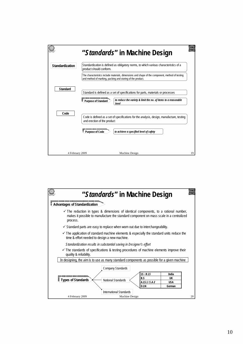
“Standards” in Machine DesignStandardization Standardization is defined as obligatory norms, to which various characteristics of a
product should conform.
The characteristics include materials, dimensions and shape of the component, method of testing and method of marking, packing and storing of the product.
StandardStandard is defined as a set of specifications for parts, materials or processes
Code is defined as a set of specifications for the analysis, design, manufacture, testing and erection of the product
Purpose of Code to achieve a specified level of safety
Purpose of Standard to reduce the variety & limit the no. of items to a reasonable level
Code
4 February 2009 Machine Design 20
“Standards” in Machine DesignAdvantages of Standardization
The reduction in types & dimensions of identical components, to a rational number, makes it possible to manufacture the standard component on mass scale in a centralized process.
Standard parts are easy to replace when worn out due to interchangeability.
The application of standard machine elements & especially the standard units reduce the time & effort needed to design a new machine.
Standardization results in substantial saving in Designer’s effort The standards of specifications & testing procedures of machine elements improve their quality & reliability.
In designing, the aim is to use as many standard components as possible for a given machine
International Standards
National Standards
Company Standards
Types of StandardsGermanD.I.N
USAA.I.S.I / S.A.EUKB.S
IndiaI.S / B.I.S
11
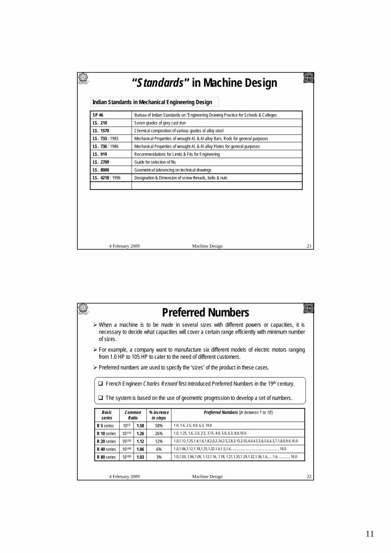
4 February 2009 Machine Design 21
“Standards” in Machine Design
Designation & Dimension of screw threads, bolts & nutsI.S. 4218 : 1996Geometrical tolerancing on technical drawingsI.S. 8000Guide for selection of fitsI.S. 2709Recommendations for Limits & Fits for EngineeringI.S. 919Mechanical Properties of wrought Al. & Al alloy Plates for general purposesI.S. 736 : 1986Mechanical Properties of wrought Al. & Al alloy Bars, Rods for general purposesI.S. 733 : 1983Chemical composition of various grades of alloy steelI.S. 1570 Seven grades of grey cast ironI.S. 210Bureau of Indian Standards on “Engineering Drawing Practice for Schools & CollegesSP 46
Indian Standards in Mechanical Engineering Design
4 February 2009 Machine Design 22
Preferred NumbersWhen a machine is to be made in several sizes with different powers or capacities, it is necessary to decide what capacities will cover a certain range efficiently with minimum number of sizes.
For example, a company want to manufacture six different models of electric motors ranging from 1.0 HP to 105 HP to cater to the need of different customers.
Preferred numbers are used to specify the ‘sizes’ of the product in these cases.
French Engineer Charles Renard first introduced Preferred Numbers in the 19th century.
The system is based on the use of geometric progression to develop a set of numbers.
1.0,1.03, 1.06,1.09, 1.12,1.16, 1.18, 1.21,1.25,1.29,1.32,1.36,1.4,…..1.6, ………, 10.03%1.03101/80R 80 series
1.0,1.06,1.12,1.18,1.25,1.32,1.4,1.5,1.6, ……………………………………, 10.06%1.06101/40R 40 series
1.0,1.12,1.25,1.4,1.6,1.8,2.0,2.24,2.5,2.8,3.15,3.55,4.0,4.5,5.0,5.6,6.3,7.1,8.0,9.0,10.012%1.12101/20R 20 series
1.0, 1.25, 1.6, 2.0, 2.5, 3.15, 4.0, 5.0, 6.3, 8.0,10.026%1.26101/10R 10 series
1.0, 1.6, 2.5, 4.0, 6.3, 10.058%1.58101/5R 5 series
Preferred Numbers [in between 1 to 10]% increase in steps
Common Ratio
Basic series
12
4 February 2009 Machine Design 23
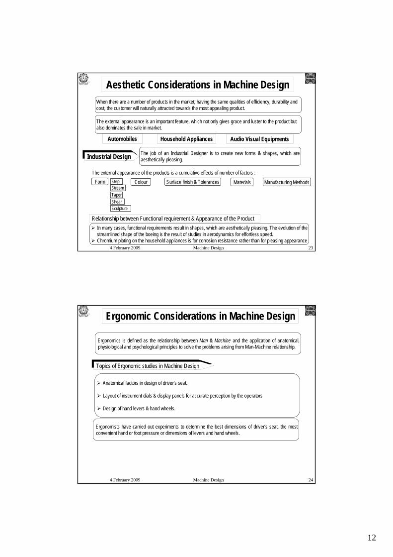
Aesthetic Considerations in Machine DesignWhen there are a number of products in the market, having the same qualities of efficiency, durability and cost, the customer will naturally attracted towards the most appealing product.
The external appearance is an important feature, which not only gives grace and luster to the product but also dominates the sale in market.
Automobiles Audio Visual EquipmentsHousehold Appliances
Industrial Design The job of an Industrial Designer is to create new forms & shapes, which are aesthetically pleasing.
The external appearance of the products is a cumulative effects of number of factors :
ColourForm Surface finish & Tolerances Materials Manufacturing Methods
In many cases, functional requirements result in shapes, which are aesthetically pleasing. The evolution of the streamlined shape of the boeing is the result of studies in aerodynamics for effortless speed.Chromium plating on the household appliances is for corrosion resistance rather than for pleasing appearance
Relationship between Functional requirement & Appearance of the Product
Stream
Sculpture
Step
TaperShear
4 February 2009 Machine Design 24
Ergonomic Considerations in Machine Design
Ergonomics is defined as the relationship between Man & Machine and the application of anatomical, physiological and psychological principles to solve the problems arising from Man-Machine relationship.
Anatomical factors in design of driver’s seat.
Layout of instrument dials & display panels for accurate perception by the operators
Design of hand levers & hand wheels.
Topics of Ergonomic studies in Machine Design
Ergonomists have carried out experiments to determine the best dimensions of driver’s seat, the most convenient hand or foot pressure or dimensions of levers and hand wheels.
13
4 February 2009 Machine Design 25
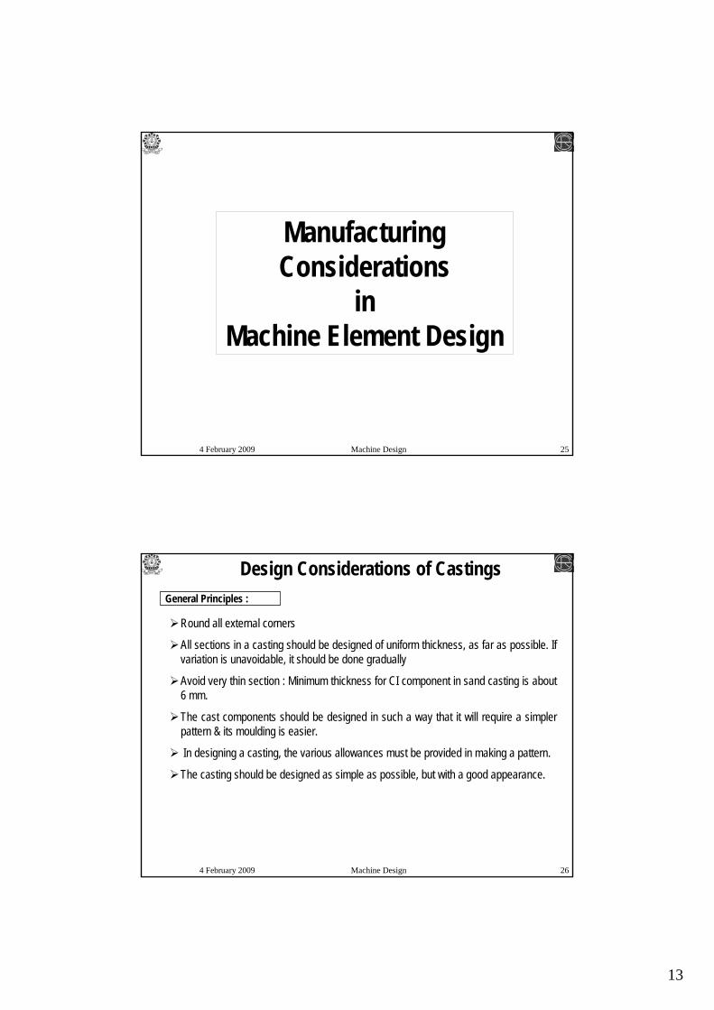
Manufacturing Considerations
in Machine Element Design
4 February 2009 Machine Design 26
General Principles :
Design Considerations of Castings
Round all external corners
All sections in a casting should be designed of uniform thickness, as far as possible. If variation is unavoidable, it should be done gradually
Avoid very thin section : Minimum thickness for CI component in sand casting is about 6 mm.
The cast components should be designed in such a way that it will require a simpler pattern & its moulding is easier.
In designing a casting, the various allowances must be provided in making a pattern.
The casting should be designed as simple as possible, but with a good appearance.

14
4 February 2009 Machine Design 27
General Principles :
Design Considerations of Machined Components
Machining is basically secondary & finishing manufacturing process.
Geometric / Form Accuracy
Dimensional Accuracy
Surface finish
Avoid sharp corners
Avoid too many shoulders & undercuts
Avoid hard materials.
Dimensional Tolerance
Geometric Tolerance
Surface roughness
4 February 2009 Machine Design 28
Sequential Engineering Approach Vs. Concurrent Engineering Approach
Marketing Department
Design Office
Production Department
Sales & Service Department
Sequential Design Process
Customer
Prototype Development Stage
15
4 February 2009 Machine Design 29
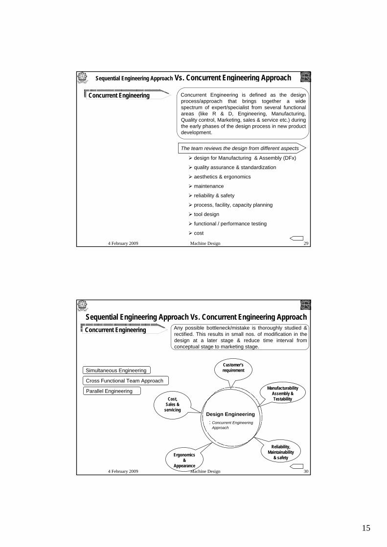
Concurrent Engineering Concurrent Engineering is defined as the design process/approach that brings together a wide spectrum of expert/specialist from several functional areas (like R & D, Engineering, Manufacturing, Quality control, Marketing, sales & service etc.) during the early phases of the design process in new product development.
Sequential Engineering Approach Vs. Concurrent Engineering Approach
The team reviews the design from different aspects
design for Manufacturing & Assembly (DFx)
quality assurance & standardization
aesthetics & ergonomics
maintenance
reliability & safety
process, facility, capacity planning
tool design
functional / performance testing
cost
4 February 2009 Machine Design 30
Cost,Sales &
servicing
Customer’s requirement
Ergonomics &
Appearance
Reliability, Maintainability
& safety
Manufacturability Assembly & Testability
Concurrent Engineering
Design Engineering: Concurrent Engineering
Approach
Sequential Engineering Approach Vs. Concurrent Engineering Approach Any possible bottleneck/mistake is thoroughly studied & rectified. This results in small nos. of modification in the design at a later stage & reduce time interval from conceptual stage to marketing stage.
Parallel Engineering
Cross Functional Team Approach
Simultaneous Engineering
16
4 February 2009 Machine Design 31
4 February 2009 Machine Design 32
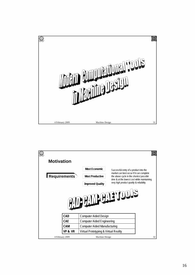
Requirements Most Productive
Most Economic
Improved Quality
Motivation
Successful entry of a product into the market can best occur if it can complete the above cycle in the shortest possible time & at the lowest cost while maintaining very high product quality & reliability
Computer Aided ManufacturingCAMVirtual Prototyping & Virtual RealityVP & VR
Computer Aided EngineeringCAEComputer Aided DesignCAD
17
4 February 2009 Machine Design 33
is the use of wide range of computer based tools that assist Engineers & other Design Professionals in their design activities.
is to design, develop and optimize the product.
is the use of Information technology/ computer based tools for supporting Engineers in tasks such as Design, Analysis, Simulation, Optimization, Manufacturing, Planning etc.
is to design, develop and optimize the product or process.
CAE areas:
Stress analysis, Vibration analysis using FEM
Thermal & fluid flow analysis using CFD
Kinematic & Dynamic Analysis & Simulation
Analysis tools for manufacturing process simulation
Optimization of the product or process
is the use of wide range of computer based tools that assist Production Engineers & Tool and Die maker, CNC machinists, in the manufacture or prototyping of products.
4 February 2009 Machine Design 34
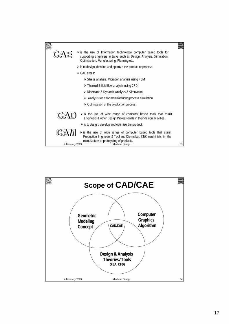
Geometric ModelingConcept
Design & Analysis Theories/ Tools
(FEA, CFD)
Computer GraphicsAlgorithmCAD/CAE
Scope of CAD/CAE
18
4 February 2009 Machine Design 35
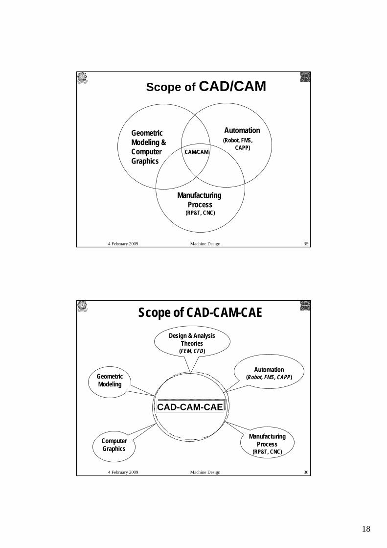
Scope of CAD/CAM
Geometric Modeling & Computer Graphics
Manufacturing Process
(RP&T, CNC)
Automation(Robot, FMS,
CAPP)CAM/CAM
4 February 2009 Machine Design 36
Scope of CAD-CAM-CAE
Geometric Modeling
Design & Analysis Theories
(FEM, CFD)
Computer Graphics
Manufacturing Process
(RP&T, CNC)
Automation(Robot, FMS, CAPP)
CAD-CAM-CAE

19
4 February 2009 Machine Design 37
Requirements Most Productive
Most Economic
Improved Quality
MotivationSuccessful entry of a product into the market can best occur if it can complete the above cycle in the shortest possible time & at the lowest cost while maintaining very high product quality & reliability
VP : Virtual PrototypingVP is about Presentation, Testing, & Analysis of 3-D CAD models prior to creating any physical prototype
Visualization Models : greater communication, productivity & efficiency through realistic graphical modelling based on full colour, natural texture & appearance, dynamic viewing of models from any user-specified angle & orientation.
Fit & Interference checking of mechanical assemblies
Testing & Verification of functions & performance : Structural & Physical phenomena analysis [FEM, CFD], Motion analysis.
Manufacturing Evaluation
Assembly analysis
Human factor analysis
4 February 2009 Machine Design 38
VP : Virtual PrototypingVP is about Presentation, Testing, & Analysis of 3-D CAD models prior to creating any physical prototype
Visualization Models : greater communication, productivity & efficiency through realistic graphical modelling based on full colour, natural texture & appearance, dynamic viewing of models from any user-specified angle & orientation.
Fit & Interference checking of mechanical assemblies
Testing & Verification of functions & performance : Structural & Physical phenomena analysis [FEM, CFD], Motion analysis.
Manufacturing Evaluation
Assembly analysis
Human factor analysis
Digital Prototyping

20
4 February 2009 Machine Design 39
4 February 2009 Machine Design 40
CAD-CAM-CAE Software
INVENTOR
SmartCAM
SolidCAM 3-D modeling & Manufacturing SimulationMasterCAM
Mechanical DESKTOP
SOLID EDGE
SOLID WORKS
PRO-ENGINEER
NX ( Siemens PLM ) 3-D modeling, Analysis & Simulation etc.CATIA ( CATIA PLM Express )
PurposeCAD/CAM/CAE software

21
4 February 2009 Machine Design 41
CAD-CAE Software
Multi-body dynamic analysis & simulationWorking Model
Multi-body dynamic analysis & simulationSimDESIGNER Motion with CATIA
Multi-body dynamic analysis & simulationADAMS
Computational Fluid DynamicsFLUENTMeshing for Finite Element AnalysisAltair Hyper Mesh
Finite Element Analysis, Crash simulationPAMCRASH
Finite Element Analysis, Crash simulationDEFORM
Finite Element Analysis, Crash simulationLS-DYNA
Finite Element AnalysisABAQUS
Finite Element Analysis NASTRAN
Finite Element AnalysisANSYS
PurposeCAE software
4 February 2009 Machine Design 42
Computational Tools
MathCAD Design calculationMathematica
Design calculation, dynamic analysis & simulation, design optimization, control
MATLAB
Excel
TK Solver
Maple
PurposeSoftware

22
4 February 2009 Machine Design 43
CATIA -Drafting, AutoCAD, MATLAB, MS-EXCEL
Geometric modeling, Drafting moduleDesign communication & documentation
CATIA – DMU Navigator, Fitting, Space analysis, Tolerancing review
Geometric modeling, Customized programs & Package
Design Evaluation
CATIA – DMU Optimizer, MATLAB –Optimization tool box
Geometric modeling, Optimization module
Design Optimization
CATIA – SimDesigner Structural, NASTRAN, ANSYS
Geometric modeling, Analysis module, visualization
Design Analysis
CATIA – DMU Kinematics, SimDesigner Motion, ADAMS
Geometric modeling, Graphics aids, visualization, Simulation module
Modeling & Simulation
CATIA – Part design, Assembly, Generative Shape, Surface Design,
Geometric modeling, Graphics aids, visualization
Design conceptualization
Related Software (s)(available at ME, NITD)
Required Modules of CAD-CAE Tools
Design Phase
CAD-CAE Tools
4 February 2009 Machine Design 44
3-D CAD model Pre-Processor Solver Post-Processor
CAD-CAE Tools
CAD
CAE
Define the model & environment factors to be
applied
Performed computation on
high end computer
Display results in graphical form using visualization tools
23
4 February 2009 Machine Design 45
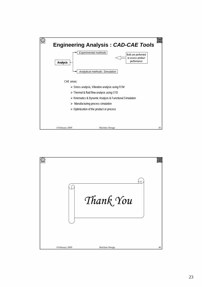
CAE areas:
Stress analysis, Vibration analysis using FEM
Thermal & fluid flow analysis using CFD
Kinematics & Dynamic Analysis & Functional Simulation
Manufacturing process simulation
Optimization of the product or process
Engineering Analysis : CAD-CAE Tools
Analysis
Analytical methods: Simulation
Experimental methodsBoth are performed to assess product
performance
4 February 2009 Machine Design 46
Thank You
24
4 February 2009 Machine Design 47
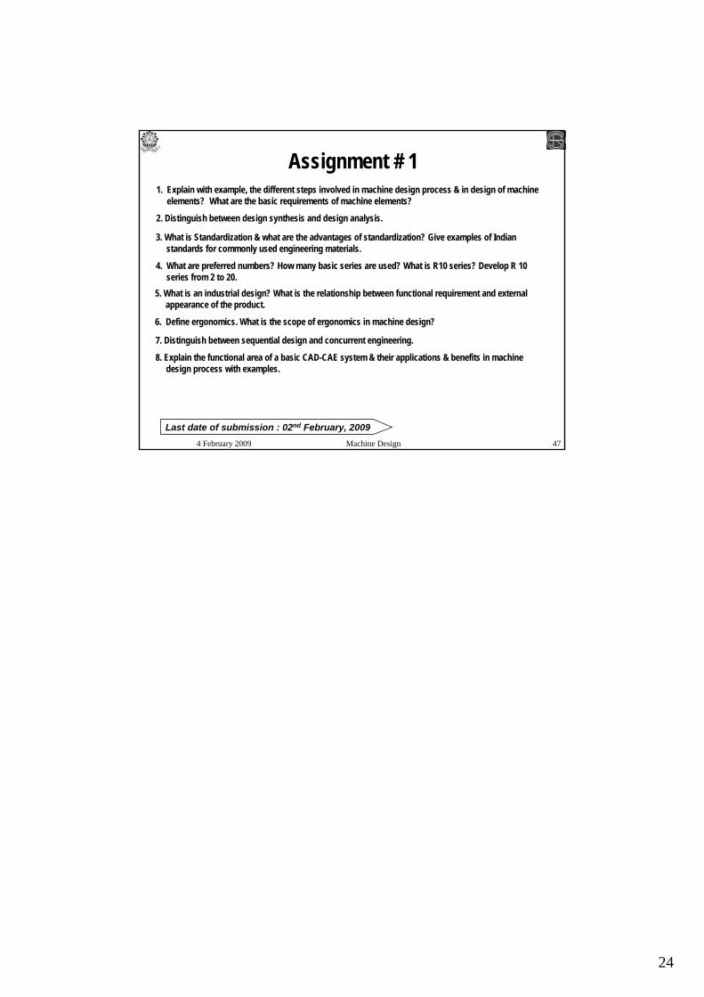
Assignment # 11. Explain with example, the different steps involved in machine design process & in design of machine
elements? What are the basic requirements of machine elements?
2. Distinguish between design synthesis and design analysis.
3. What is Standardization & what are the advantages of standardization? Give examples of Indian standards for commonly used engineering materials.
4. What are preferred numbers? How many basic series are used? What is R10 series? Develop R 10 series from 2 to 20.
5. What is an industrial design? What is the relationship between functional requirement and external appearance of the product.
6. Define ergonomics. What is the scope of ergonomics in machine design?
7. Distinguish between sequential design and concurrent engineering.
8. Explain the functional area of a basic CAD-CAE system & their applications & benefits in machine design process with examples.
Last date of submission : 02nd February, 2009


