Download - LTE eutran rsanov2012

8/22/2019 LTE eutran rsanov2012
http://slidepdf.com/reader/full/lte-eutran-rsanov2012 1/284
UMTS Long Term Evolution(LTE)
Reiner Stuhlfauth
Training Centre
Rohde & Schwarz, Germany
Subject to change – Data without tolerance limits is not binding.
R&S® is a registered trademark of Rohde & Schwarz GmbH & Co. KG. Trade names are trademarks
of the owners.
2011 ROHDE & SCHWARZ GmbH & Co. KG
Test & Measurement Division
- Training Center -This folder may be taken outside ROHDE & SCHWARZ facilities.
ROHDE & SCHWARZ GmbH reserves the copy right to all of any part of these course notes.
Permission to produce, publish or copy sections or pages of these notes or to translate them must f irst
be obtained in writing from
ROHDE & SCHWARZ GmbH & Co. KG, Training Center, Mühldorfstr. 15, 81671 Munich, Germany

8/22/2019 LTE eutran rsanov2012
http://slidepdf.com/reader/full/lte-eutran-rsanov2012 2/284
November 2012 | LTE Introduction | 2
2013/20142009/2010
Technology evolution path
GSM/
GPRS
EDGE, 200 kHzDL: 473 kbps
UL: 473 kbps
EDGEevoDL: 1.9 Mbps
UL: 947 kbps
HSDPA, 5 MHzDL: 14.4 Mbps
UL: 2.0 Mbps
HSPA, 5 MHzDL: 14.4 Mbps
UL: 5.76 Mbps
HSPA+, R7DL: 28.0 Mbps
UL: 11.5 Mbps
2005/2006 2007/2008 2011/2012
HSPA+, R8DL: 42.0 Mbps
UL: 11.5 Mbps
cdma
2000
1xEV-DO, Rev. 0
1.25 MHz
DL: 2.4 MbpsUL: 153 kbps
1xEV-DO, Rev. A
1.25 MHz
DL: 3.1 MbpsUL: 1.8 Mbps
1xEV-DO, Rev. B
5.0 MHz
DL: 14.7 MbpsUL: 4.9 Mbps
HSPA+, R9DL: 84 Mbps
UL: 23 Mbps
DO-AdvancedDL: 32 Mbps and beyond
UL: 12.4 Mbps and beyond
LTE-Advanced R10
DL: 1 Gbps (low mobility)UL: 500 Mbps
Fixed WiMAX
scalable bandwidth1.25 … 28 MHz
typical up to 15 Mbps
Mobile WiMAX, 802.16e
Up to 20 MHzDL: 75 Mbps (2x2)
UL: 28 Mbps (1x2)
Advanced Mobile
WiMAX, 802.16mDL: up to 1 Gbps (low mobility)
UL: up to 100 Mbps
VAMOSDouble Speech
Capacity
HSPA+, R10DL: 84 Mbps
UL: 23 Mbps
LTE (4x4), R8+R9, 20MHz
DL: 300 MbpsUL: 75 Mbps
UMTSDL: 2.0 Mbps
UL: 2.0 Mbps

8/22/2019 LTE eutran rsanov2012
http://slidepdf.com/reader/full/lte-eutran-rsanov2012 3/284
November 2012 | LTE Introduction | 3
3GPP work plan
GERAN EUTRAN
UTRAN
Up from Rel. 8
Rel. 9
Rel. 10
Evolution
Also contained in
Phase 1
Phase 2, 2+
Rel. 95
…
Rel.7
New
RAN
Rel. 97
Rel. 99
…
Rel. 7
8/22/2019 LTE eutran rsanov2012
http://slidepdf.com/reader/full/lte-eutran-rsanov2012 4/284
November 2012 | LTE Introduction | 4
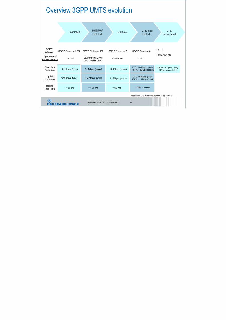
Overview 3GPP UMTS evolution
WCDMA
WCDMAHSDPA/
HSUPAHSPA+
LTE and
HSPA+LTE-
advanced
3GPP Release 73GPP
release
20102008/20092005/6 (HSDPA)
2007/8 (HSUPA)
App. year of
network rollout
Round
Trip Time
11 Mbps (peak)128 kbps (typ.)
28 Mbps (peak)384 kbps (typ.)
3GPP Release 83GPP Release 5/63GPP Release 99/4
2003/4
< 50 ms< 100 ms~ 150 ms
LTE: 75 Mbps (peak)HSPA+: 11 Mbps (peak)
11 Mbps (peak)5.7 Mbps (peak)128 kbps (typ.)Uplinkdata rate
LTE: 150 Mbps* (peak)
HSPA+: 42 Mbps (peak)28 Mbps (peak)14 Mbps (peak)384 kbps (typ.)Downlink
data rate
LTE: ~10 ms
100 Mbps high mobility
1 Gbps low mobility
*based on 2x2 MIMO and 20 MHz operation
3GPP StudyItem initiated
3GPPRelease 10

8/22/2019 LTE eutran rsanov2012
http://slidepdf.com/reader/full/lte-eutran-rsanov2012 5/284
November 2012 | LTE Introduction | 5
Why LTE? Ensuring Long Term Competitiveness of UMTS
l LTE is the next UMTS evolution step after HSPA and HSPA+.
l LTE is also referred to as
EUTRA(N) = Evolved UMTS Terrestrial Radio Access (Network).
l Main targets of LTE:
l Peak data rates of 100 Mbps (downlink) and 50 Mbps (uplink)l Scaleable bandwidths up to 20 MHz
l Reduced latency
l Cost efficiency
l
Operation in paired (FDD) and unpaired (TDD) spectrum

8/22/2019 LTE eutran rsanov2012
http://slidepdf.com/reader/full/lte-eutran-rsanov2012 6/284
November 2012 | LTE Introduction | 6
Peak data rates and real average throughput (UL)
0,174
0,473
2 2
0,947
0,153
1,8
5,76
11,5
58
0,1
15
0,1
0,03
0,1
0,2
0,50,7
2
5
0,01
0,1
1
10
100
GPRS
(Rel. 97)
EDGE
(Rel. 4)
1xRTT WCDMA
(Rel. 99/4)
E-EDGE
(Rel. 7)
1xEV-DO
Rev. 0
1xEV-DO
Rev. A
HSPA
(Rel. 5/6)
HSPA+
(Rel. 7)
LTE 2x2
(Rel. 8)
Technology
D a t a r
a t e i n M b p s
max. peak UL data rate [Mbps] max. avg. UL throughput [Mbps]

8/22/2019 LTE eutran rsanov2012
http://slidepdf.com/reader/full/lte-eutran-rsanov2012 7/284
November 2012 | LTE Introduction | 7
Comparison of network latency by technology
710
190
320
46
158
85
70
30
0
100
200
300
400
500
600
700
800
GPRS
(Rel. 97)
EDGE
(Rel. 4)
WCDMA
(Rel. 99/4)
HSDPA
(Rel. 5)
HSUPA
(Rel. 6)
E-EDGE
(Rel. 7)
HSPA+
(Rel. 7)
LTE
(Rel. 8)
Technology
2 G / 2 . 5
G
l a t e n c y
0
20
40
60
80
100
120
140
160
3 G
/ 3 . 5 G
/ 3 . 9
G
l a t e n c y
Total UE Air interface Node B Iub RNC Iu + core Internet

8/22/2019 LTE eutran rsanov2012
http://slidepdf.com/reader/full/lte-eutran-rsanov2012 8/284
November 2012 | LTE Introduction | 8
Round Trip Time, RTT
Serving
RNC
MSC
SGSN
Iub/Iur Iu
• ACK/NACK
generation in RNC
MME/SAE Gateway
• ACK/NACK
generation in node B
Node B
eNode B
TTI~10msec
TTI
=1msec

8/22/2019 LTE eutran rsanov2012
http://slidepdf.com/reader/full/lte-eutran-rsanov2012 9/284
November 2012 | LTE Introduction | 9
Multi-RAT requirements
(GSM/EDGE, UMTS, CDMA)
MIMO multiple antennaschemes
Timing requirements
(1 ms transm.time interval)
New radio transmission
schemes (OFDMA / SC-FDMA)
Major technical challenges in LTE
Throughput / data raterequirements
Scheduling (shared channels,
HARQ, adaptive modulation)
System Architecture
Evolution (SAE)
FDD and
TDD mode

8/22/2019 LTE eutran rsanov2012
http://slidepdf.com/reader/full/lte-eutran-rsanov2012 10/284
November 2012 | LTE Introduction | 10
Introduction to UMTS LTE: Key parameters
Frequency
Range UMTS FDD bands and UMTS TDD bands
Channel
bandwidth,
1 Resource
Block=180 kHz
1.4 MHz 3 MHz 5 MHz 10 MHz 15 MHz 20 MHz
6
Resource
Blocks
15
Resource
Blocks
25
Resource
Blocks
50
Resource
Blocks
75
Resource
Blocks
100
Resource
Blocks
Modulation
Schemes
Downlink: QPSK, 16QAM, 64QAM
Uplink: QPSK, 16QAM, 64QAM (optional for handset)
Multiple Access Downlink: OFDMA (Orthogonal Frequency Division Multiple Access)
Uplink: SC-FDMA (Single Carrier Frequency Division Multiple Access)
MIMOtechnology
Downlink: Wide choice of MIMO configuration options for transmit diversity, spatial
multiplexing, and cyclic delay diversity (max. 4 antennas at base station and handset)Uplink: Multi user collaborative MIMO
Peak Data Rate
Downlink: 150 Mbps (UE category 4, 2x2 MIMO, 20 MHz)
300 Mbps (UE category 5, 4x4 MIMO, 20 MHz)
Uplink: 75 Mbps (20 MHz)

8/22/2019 LTE eutran rsanov2012
http://slidepdf.com/reader/full/lte-eutran-rsanov2012 11/284
November 2012 | LTE Introduction | 11
E-UTRA
Operating
Band
Uplink (UL) operating band
BS receive UE transmit
Downlink (DL) operating band
BS transmit UE receive Duplex Mode
FUL_low – FUL_high FDL_low – FDL_high
1 1920 MHz – 1980 MHz 2110 MHz – 2170 MHz FDD
2 1850 MHz – 1910 MHz 1930 MHz – 1990 MHz FDD
3 1710 MHz – 1785 MHz 1805 MHz – 1880 MHz FDD
4 1710 MHz – 1755 MHz 2110 MHz – 2155 MHz FDD
5 824 MHz – 849 MHz 869 MHz – 894MHz FDD
6 830 MHz – 840 MHz 875 MHz – 885 MHz FDD
7 2500 MHz – 2570 MHz 2620 MHz – 2690 MHz FDD
8 880 MHz – 915 MHz 925 MHz – 960 MHz FDD
9 1749.9 MHz – 1784.9 MHz 1844.9 MHz – 1879.9 MHz FDD
10 1710 MHz – 1770 MHz 2110 MHz – 2170 MHz FDD
11 1427.9 MHz – 1452.9 MHz 1475.9 MHz – 1500.9 MHz FDD
12 698 MHz – 716 MHz 728 MHz – 746 MHz FDD
13 777 MHz – 787 MHz 746 MHz – 756 MHz FDD
14 788 MHz – 798 MHz 758 MHz – 768 MHz FDD
17 704 MHz – 716 MHz 734 MHz – 746 MHz FDD
18 815 MHz – 830 MHz 860 MHz – 875 MHz FDD
19 830 MHz – 845 MHz 875 MHz – 890 MHz FDD
20 832 MHz - 862 MHz 791 MHz - 821 MHz FDD
21 1447.9 MHz - 1462.9 MHz 1495.9 MHz - 1510.9 MHz FDD
22 3410 MHz - 3500 MHz 3510 MHz - 3600 MHz FDD
LTE/LTE-A Frequency Bands (FDD)

8/22/2019 LTE eutran rsanov2012
http://slidepdf.com/reader/full/lte-eutran-rsanov2012 12/284
November 2012 | LTE Introduction | 12
LTE/LTE-A Frequency Bands (TDD)
E-UTRA
Operating
Band
Uplink (UL) operating band
BS receive UE transmit
Downlink (DL) operating band
BS transmit UE receiveDuplex Mode
FUL_low – FUL_high FDL_low – FDL_high
33 1900 MHz – 1920 MHz 1900 MHz – 1920 MHz TDD
34 2010 MHz – 2025 MHz 2010 MHz – 2025 MHz TDD
35 1850 MHz – 1910 MHz 1850 MHz – 1910 MHz TDD
36 1930 MHz – 1990 MHz 1930 MHz – 1990 MHz TDD
37 1910 MHz – 1930 MHz 1910 MHz – 1930 MHz TDD
38 2570 MHz – 2620 MHz 2570 MHz – 2620 MHz TDD
39 1880 MHz – 1920 MHz 1880 MHz – 1920 MHz TDD
40 2300 MHz – 2400 MHz 2300 MHz – 2400 MHz TDD
413400 MHz –
3600MHz
3400 MHz –
3600MHzTDD

8/22/2019 LTE eutran rsanov2012
http://slidepdf.com/reader/full/lte-eutran-rsanov2012 13/284
November 2012 | LTE Introduction | 13
l OFDM is the modulation scheme for LTE in downlink and
uplink (as reference)
l Some technical explanation about our physical base: radio
link aspects
Orthogonal Frequency Division Multiple Access

8/22/2019 LTE eutran rsanov2012
http://slidepdf.com/reader/full/lte-eutran-rsanov2012 14/284
November 2012 | LTE Introduction | 14
What does it mean to use the radio channel?
Using the radio channel means to deal with aspects like:
Doppler effectTime variant channel
Frequency selectivity
C
A
D
B
Receiver Transmitter
MPP
attenuation

8/22/2019 LTE eutran rsanov2012
http://slidepdf.com/reader/full/lte-eutran-rsanov2012 15/284
November 2012 | LTE Introduction | 15
Still the same “mobile” radio problem: Time variant multipath propagation
C
A
D
B
Receiver Transmitter
A: free space
B: reflection
C: diffraction
D: scattering
A: free spaceB: reflectionC: diffractionD: scattering
reflection: object is large
compared to wavelengthscattering: object issmall or its surfaceirregular
Multipath Propagation
and Doppler shift

8/22/2019 LTE eutran rsanov2012
http://slidepdf.com/reader/full/lte-eutran-rsanov2012 16/284
November 2012 | LTE Introduction | 16
Multipath channel impulse response
path delay path attenuation path phase
1
0
, i
L j t
i i
i
h t a t e
The CIR consists of L resolvable propagation paths
delay spread
|h|²
8/22/2019 LTE eutran rsanov2012
http://slidepdf.com/reader/full/lte-eutran-rsanov2012 17/284
November 2012 | LTE Introduction | 17
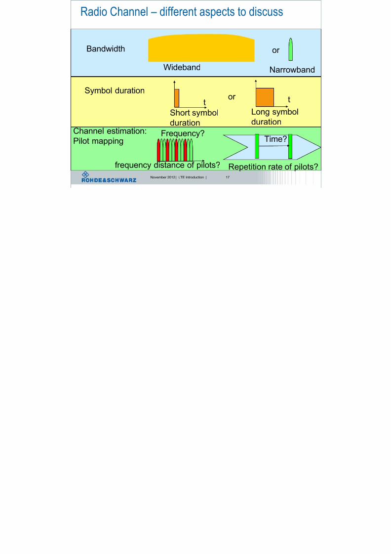
Radio Channel – different aspects to discuss
Bandwidth
Wideband Narrowband
Symbol duration
Short symbol
duration
Long symbol
duration
t t
Repetition rate of pilots?
Channel estimation:Pilot mapping
or
or
Time?Frequency?
frequency distance of pilots?

8/22/2019 LTE eutran rsanov2012
http://slidepdf.com/reader/full/lte-eutran-rsanov2012 18/284
November 2012 | LTE Introduction | 18
Frequency selectivity - Coherence Bandwidth
Frequency selectivity
f
power
Wideband = equalizer
Must be frequency selective
Narrowband = equalizer
Can be 1 - tap
Here: find
Math. Equation
for this curve
Here: substitute with single
Scalar factor = 1-tap
How to combat
channel influence?

8/22/2019 LTE eutran rsanov2012
http://slidepdf.com/reader/full/lte-eutran-rsanov2012 19/284
November 2012 | LTE Introduction | 19
Time-Invariant Channel: Scenario
Transmitter Fixed Receiver
Fixed Scatterer
Delay Delay spread
Transmitter
Signal
t
Receiver
Signal
t
→time dispersive
ISI: Inter SymbolInterference:
Happens, when
Delay spread >
Symbol time
Successive
symbols
will interfere Channel Impulse Response, CIR
collision

8/22/2019 LTE eutran rsanov2012
http://slidepdf.com/reader/full/lte-eutran-rsanov2012 20/284
November 2012 | LTE Introduction | 20
t
f T SC
|H(f)|
Motivation: Single Carrier versus Multi Carrier
|h(t)|
t
B
l Frequency Domain
l Coherence Bandwidth Bc < Systembandwidth B
→ Frequency Selective Fading → equalization effort
l Time Domain
l Delay spread > Symboltime TSC
→ Inter-Symbol-Interference (ISI) → equalization effort
1SC
BT
Source: Kammeyer; Nachrichtenübertragung; 3. Auflage

8/22/2019 LTE eutran rsanov2012
http://slidepdf.com/reader/full/lte-eutran-rsanov2012 21/284
November 2012 | LTE Introduction | 21
|h(t)|
t
t
f
f
t
T SC |H(f)|
1
SC
BT
1
MC
B f
N T
MC SC T N T
Motivation: Single Carrier versus Multi Carrier
B
B
|H(f)|
Source: Kammeyer; Nachrichtenübertragung; 3. Auflage

8/22/2019 LTE eutran rsanov2012
http://slidepdf.com/reader/full/lte-eutran-rsanov2012 22/284
November 2012 | LTE Introduction | 22
What is OFDM?
Single carrier transmission,
e.g. WCDMA
Broadband, e.g. 5MHz for WCDMA
Orthogonal
Frequency
DivisionMultiplex
Several 100 subcarriers, with x kHz spacing

8/22/2019 LTE eutran rsanov2012
http://slidepdf.com/reader/full/lte-eutran-rsanov2012 23/284
November 2012 | LTE Introduction | 23
Idea: Wide/Narrow band conversion
One high rate signal:
Frequency selective fading
N low rate signals:
Frequency flat fading
S/P
t / T bt / Ts
… … … ƒ
H(ƒ) h(τ)
τ
h(τ)
τ
„Channel
Memory“

8/22/2019 LTE eutran rsanov2012
http://slidepdf.com/reader/full/lte-eutran-rsanov2012 24/284
November 2012 | LTE Introduction | 24
COFDM
X
X M a
p p e r
+
X
X M a
p p e r
+
. . . . .OFDM
symbolΣ
Data
with
FECoverhead

8/22/2019 LTE eutran rsanov2012
http://slidepdf.com/reader/full/lte-eutran-rsanov2012 25/284
November 2012 | LTE Introduction | 25
OFDM signal generation
00 11 10 10 01 01 11 01 …. e.g. QPSK
h*(sin jwt + cos jwt) h*(sin jwt + cos jwt)
OFDM
symbol
duration Δt
Frequency
time
=> Σ h * (sin.. + cos…)

8/22/2019 LTE eutran rsanov2012
http://slidepdf.com/reader/full/lte-eutran-rsanov2012 26/284
November 2012 | LTE Introduction | 26
Fourier Transform, Discrete FT
;)()(
;)()(
2
2
df e f H t h
dt et h f H
t f j
t f j
;1
);2sin()2cos(
1
0
2
1
0
1
0
1
0
/2
N
n
N
nk j
nk
N
k
k
N
k
k
N
k
N nk j
k n
e H N
h
N
nk h j N
nk heh H
Fourier Transform
Discrete Fourier Transform (DFT)

8/22/2019 LTE eutran rsanov2012
http://slidepdf.com/reader/full/lte-eutran-rsanov2012 27/284
November 2012 | LTE Introduction | 27
OFDM Implementation with FFT(Fast Fourier Transformation)
Receiver
Transmitter Channel
n(n)
(k)b
h(n)
r(n)
S / P
P / S
( )ˆ b k P / S
I D F T
N F F T
Map
Map
Map
S / P
D F T
N
F F T
d(0)
d(1)
Demap
Demap
Demap
s(n)
d(FFT-1)
d(FFT-1)
d(0)
d(1)
.
.
.
.
.
.
8/22/2019 LTE eutran rsanov2012
http://slidepdf.com/reader/full/lte-eutran-rsanov2012 28/284
November 2012 | LTE Introduction | 28
-1 -0.5 0 0.5 1-70
-60
-50
-40
-30
-20
-10
0
10
S x x
f f -1
f -2
f 1
f 2
f 0
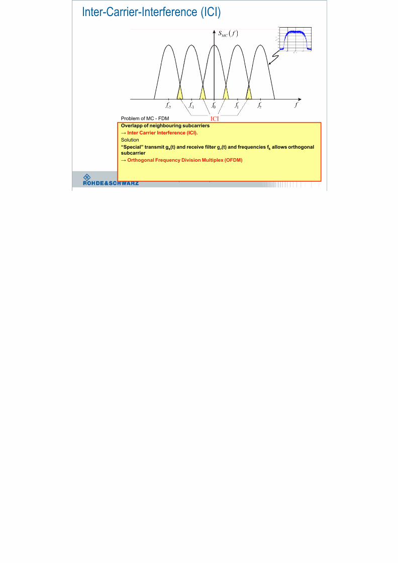
Problem of MC - FDM
Overlapp of neighbouring subcarriers
→
Inter Carrier Interference (ICI).Solution
“Special” transmit gs(t) and receive filter gr (t) and frequencies f k allows orthogonal
subcarrier
→ Orthogonal Frequency Division Multiplex (OFDM)
Inter-Carrier-Interference (ICI)
ICI
MC S f

8/22/2019 LTE eutran rsanov2012
http://slidepdf.com/reader/full/lte-eutran-rsanov2012 29/284
November 2012 | LTE Introduction | 29
Rectangular Pulse
Δt
Δf
t
f
A(f)
sin(x)/xConvolution
time frequency
8/22/2019 LTE eutran rsanov2012
http://slidepdf.com/reader/full/lte-eutran-rsanov2012 30/284
November 2012 | LTE Introduction | 30
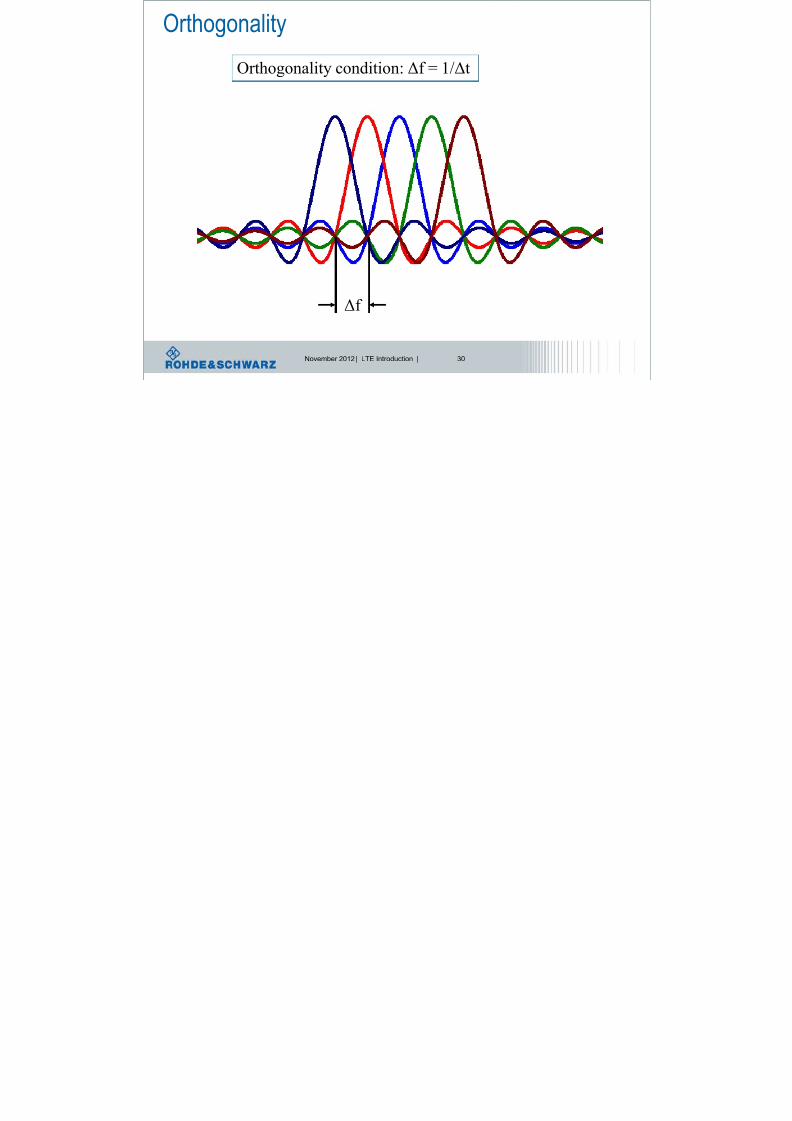
Orthogonality
Δf
Orthogonality condition: Δf = 1/Δt

8/22/2019 LTE eutran rsanov2012
http://slidepdf.com/reader/full/lte-eutran-rsanov2012 31/284
November 2012 | LTE Introduction | 31
ISI and ICI due to channel
lSymbol l-1 l+1
n
h n
Delay spread
Receiver DFT
Window
fade in (ISI) fade out (ISI)
S C G
8/22/2019 LTE eutran rsanov2012
http://slidepdf.com/reader/full/lte-eutran-rsanov2012 32/284
November 2012 | LTE Introduction | 32
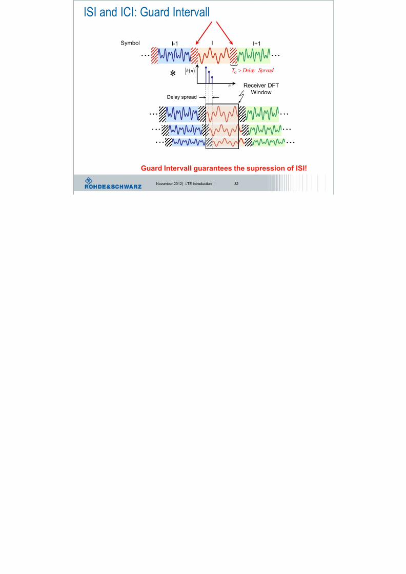
ISI and ICI: Guard Intervall
lSymbol l-1 l+1
n
h n
Delay spread
Receiver DFT
Window
GT Delay Spread
Guard Intervall guarantees the supression of ISI!
G d I t ll C li P fi

8/22/2019 LTE eutran rsanov2012
http://slidepdf.com/reader/full/lte-eutran-rsanov2012 33/284
November 2012 | LTE Introduction | 33
Receiver DFT
Window
Guard Intervall as Cyclic Prefix
lSymbol l-1 l+1
n
h n
Delay spread
GT Delay Spread
Cyclic Prefix guarantees the supression of ISI and ICI!
Cyclic Prefix
S h i ti

8/22/2019 LTE eutran rsanov2012
http://slidepdf.com/reader/full/lte-eutran-rsanov2012 34/284
November 2012 | LTE Introduction | 34
Synchronisation
Cyclic Prefix
CP CP CP CP
:S ymbol OFDM
Metric
1l l 1l
n~
Search window-
DL CP OFDM i l ti h i

8/22/2019 LTE eutran rsanov2012
http://slidepdf.com/reader/full/lte-eutran-rsanov2012 35/284
November 2012 | LTE Introduction | 35
Frequency Domain Time Domain
DL CP-OFDM signal generation chain
l OFDM signal generation is based on Inverse Fast Fourier Transform
(IFFT) operation on transmitter side:
Datasource
QAMModulator
1:NN
symbol
streams
IFFT OFDMsymbols
N:1 Cyclic prefixinsertion
Useful
OFDM
symbols
l On receiver side, an FFT operation will be used.
OFDM P d C

8/22/2019 LTE eutran rsanov2012
http://slidepdf.com/reader/full/lte-eutran-rsanov2012 36/284
November 2012 | LTE Introduction | 36
OFDM: Pros and Cons
Pros:
scalable data rate
efficient use of the available bandwidth
robust against fading
1-tap equalization in frequency domain
Cons:
high crest factor or PAPR. Peak to average power ratio
very sensitive to phase noise, frequency- and clock-offset
guard intervals necessary (ISI, ICI) → reduced data rate

8/22/2019 LTE eutran rsanov2012
http://slidepdf.com/reader/full/lte-eutran-rsanov2012 37/284
November 2012 | LTE Introduction | 37
MIMO =
Multiple Input Multiple Output Antennas
MIMO i d fi d b th b f R / T A t

8/22/2019 LTE eutran rsanov2012
http://slidepdf.com/reader/full/lte-eutran-rsanov2012 38/284
November 2012 | LTE Introduction | 38
MIMO is defined by the number of Rx / Tx Antennasand not by the Mode which is supported Mode
SISOSingle Input Single Output
1 1 Typical todays wireless Communication System
MISOMultiple Input Single Output
1 1
M
Transmit Diversity
l Maximum Ratio Combining (MRC)
l Matrix A also known as STC
l Space Time / Frequency Coding (STC / SFC)
SIMOSingle Input Multiple Output
1 1
M
Receive Diversity
l Maximum Ratio Combining (MRC)
MIMOMultiple Input Multiple Output
1 1
MM
Definition is seen from Channel
Multiple In = Multiple Transmit Antennas
Receive / Transmit Diversity
Spatial Multiplexing (SM) also known as:
l Space Division Multiplex (SDM)
l True MIMO
l Single User MIMO (SU-MIMO)
l Matrix B
Space Division Multiple Access (SDMA) also known as:
l Multi User MIMO (MU MIMO)
l Virtual MIMO
l Collaborative MIMO
Beamforming
MIMO d i LTE

8/22/2019 LTE eutran rsanov2012
http://slidepdf.com/reader/full/lte-eutran-rsanov2012 39/284
November 2012 | LTE Introduction | 39
MIMO modes in LTE
-Tx diversity
-Beamforming
-Rx diversity
-Multi-User MIMO
-Spatial Multiplexing
Better S/N
Increased
Throughput at
Node B
IncreasedThroughput per
UE
Di it th ht

8/22/2019 LTE eutran rsanov2012
http://slidepdf.com/reader/full/lte-eutran-rsanov2012 40/284
November 2012 | LTE Introduction | 40
Diversity – some thoughts
Fading on the air interfaceThe SISO channel:
h11
n sehn shr j 1111
The transmit signal is modified in amplitude and phase
plus additional noise
Amplitude
scalingphase
rotation
transmit signal s received signal r
Di it th ht t h d filt
8/22/2019 LTE eutran rsanov2012
http://slidepdf.com/reader/full/lte-eutran-rsanov2012 41/284
November 2012 | LTE Introduction | 41
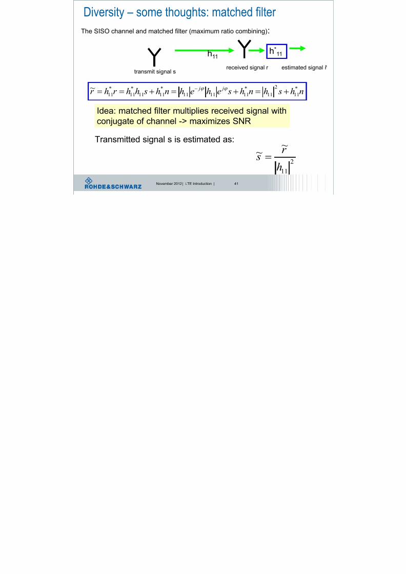
Diversity – some thoughts: matched filter
nh shnh sehehnh shhr hr j j *
11
2
11
*
111111
*
1111
*
11
*
11
~
The SISO channel and matched filter (maximum ratio combining):
h11
transmit signal sreceived signal r
h*11
estimated signal ř
Idea: matched filter multiplies received signal with
conjugate of channel -> maximizes SNR
Transmitted signal s is estimated as:
2
11
~~
h
r s
Di ersit some tho ghts performance of SISO

8/22/2019 LTE eutran rsanov2012
http://slidepdf.com/reader/full/lte-eutran-rsanov2012 42/284
November 2012 | LTE Introduction | 42
Diversity – some thoughts: performance of SISO
Modulation
scheme
Bit error
probability
Data rate = bits
per symbol
BPSK 1/(4*SNR) 1
QPSK 1/(2*SNR) 2
16 QAM 5/(2*SNR) 4
noise amplitude
distribution
Detector
threshold10
Bit error rate
Euclidic distance
Decay with SNR, onlyone channel available -
> fading will deteriorate
RX Diversity
8/22/2019 LTE eutran rsanov2012
http://slidepdf.com/reader/full/lte-eutran-rsanov2012 43/284
November 2012 | LTE Introduction | 43
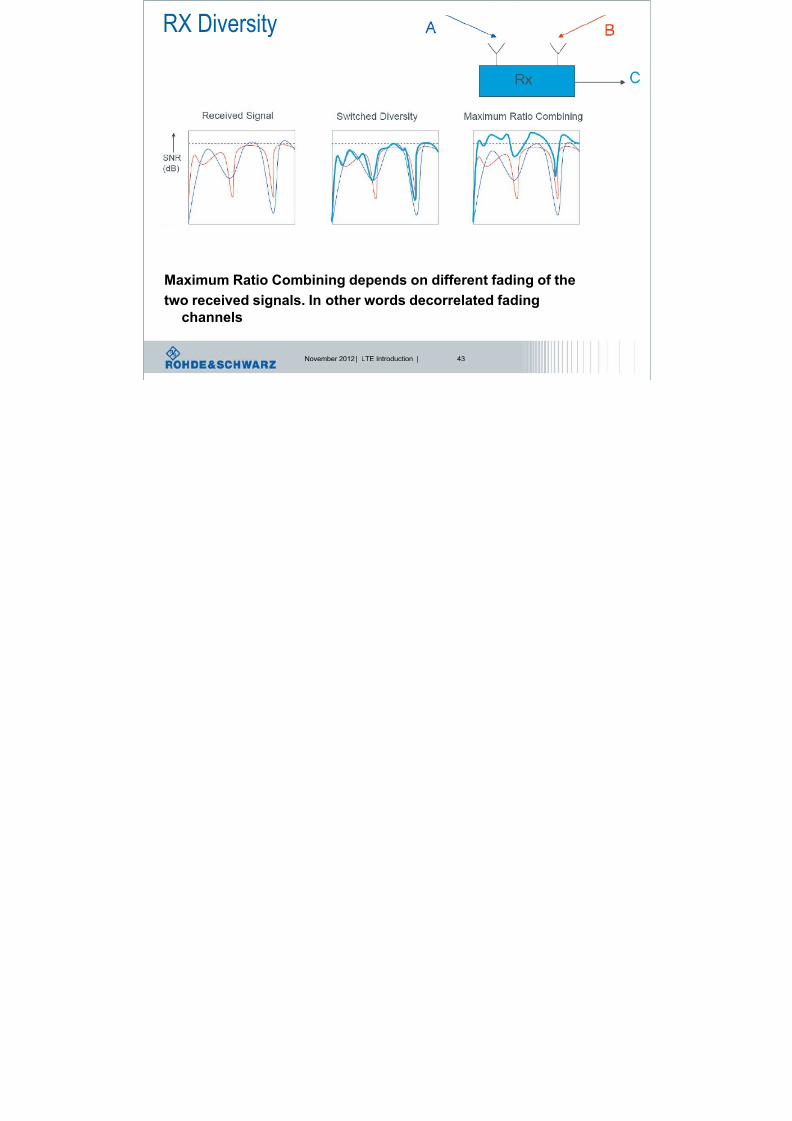
RX Diversity
Maximum Ratio Combining depends on different fading of the
two received signals. In other words decorrelated fading
channels
Receive diversity gain SIMO: 1*N

8/22/2019 LTE eutran rsanov2012
http://slidepdf.com/reader/full/lte-eutran-rsanov2012 44/284
November 2012 | LTE Introduction | 44
Receive diversity gain – SIMO: 1*NRx
time
Transmitantenna
s
Rx Rx Rx
RX RX
nnn
nn
nhnhnh shhh
sh sh shr
*
12
*
121
*
11
2
1
2
12
2
11
*
12
*
121
*
11
......
...~
NTx NRxh11
h12
h1NRx
Receive antenna 1
r 1=h11s+n1
r 2=h12s+n2
r nrx=h1nrxs+nnrx
Receive antenna 2
Receive antenna NRx
RxneSNR
P 1
~
signal after maximum ratio combining
Probability for errors
Said:
diversity
order nRx
TX Diversity: Space Time Coding
8/22/2019 LTE eutran rsanov2012
http://slidepdf.com/reader/full/lte-eutran-rsanov2012 45/284
November 2012 | LTE Introduction | 45
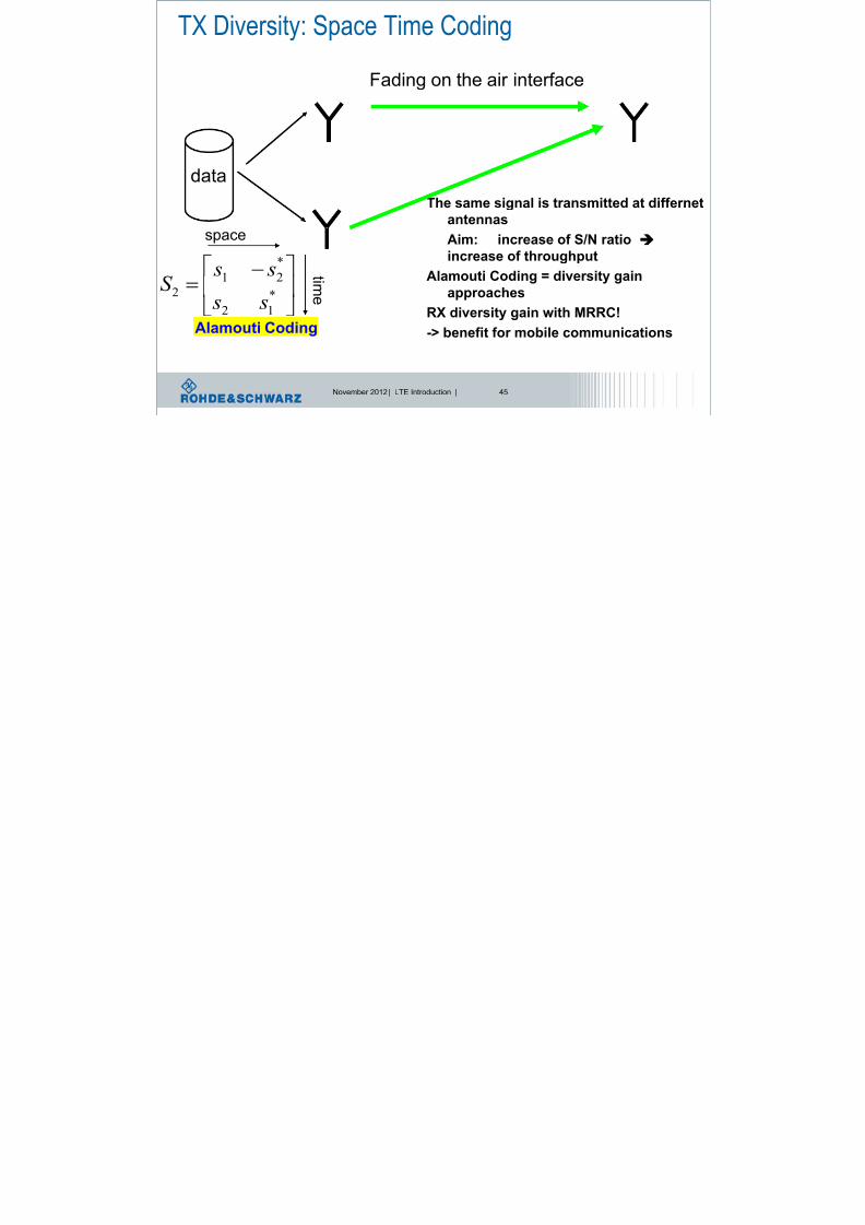
TX Diversity: Space Time Coding
The same signal is transmitted at differnetantennas
Aim: increase of S/N ratio
increase of throughput
Alamouti Coding = diversity gain
approachesRX diversity gain with MRRC!
-> benefit for mobile communications
data
Fading on the air interface
*12
*
21
2 s s
s sS
Alamouti Coding
t i m e
space
Space Time Block Coding according to Alamouti

8/22/2019 LTE eutran rsanov2012
http://slidepdf.com/reader/full/lte-eutran-rsanov2012 46/284
November 2012 | LTE Introduction | 46
Space Time Block Coding according to Alamouti(when no channel information at all available at transmitter)
2
1~
SNR P e
2221
*
211
*
22
1121
*
221
*
1
1
'²²
'²²
nd hhr hr hd
nd hhr hr hd
e
e
Probability for errors (Alamouti)
From slide before:
RxneSNR
P 1~
Compare
with Rx diversity
Alamouti coding is full diversity gain
and full rate, but it only works for 2 antennas
(due to Alamouti matrix is orthogonal)
MIMO Spatial Multiplexing

8/22/2019 LTE eutran rsanov2012
http://slidepdf.com/reader/full/lte-eutran-rsanov2012 47/284
November 2012 | LTE Introduction | 47
MIMO Spatial Multiplexing
SISO:
Single Input
Single Output
MIMO:
Multiple Input
Multiple Output
Increasing
capacity per cell
C=B*T*ld(1+S/N)
) , min(
1
) 1 ( R T N N
i
i
i
i
N
S ld B T C ?
Higher capacity without additional spectrum!
Spatial multiplexing capacity aspects

8/22/2019 LTE eutran rsanov2012
http://slidepdf.com/reader/full/lte-eutran-rsanov2012 48/284
November 2012 | LTE Introduction | 48
Spatial multiplexing – capacity aspects
)}1({log2
112 h E C H
2 P
nh sr 11
represents the signal to noise ratio SNR
at the receiver branch
Ergodic mean capacity of a SISO channel calculated as:
h11
Received signal r withsent signal s, channel h11 and
AWGN with σ=n
N
S BC 1log* 2
Or simplified: With B = bandwidth
and S/N = signal to
noise ratio
Spatial multiplexing capacity aspects

8/22/2019 LTE eutran rsanov2012
http://slidepdf.com/reader/full/lte-eutran-rsanov2012 49/284
November 2012 | LTE Introduction | 49
Spatial multiplexing – capacity aspects
H
T
n H HH n
I og l E C R
det2
Ergodic mean capacity of a MIMO channel is even worse
Received signal r with
sent signal s, channel H and
AWGN with σ=n
n1
n2
nRnT
n2
n1
InR is an Identity matrix with size nT x nR
HH is the Hermetian complex n H sr
Spatial multiplexing capacity aspects

8/22/2019 LTE eutran rsanov2012
http://slidepdf.com/reader/full/lte-eutran-rsanov2012 50/284
November 2012 | LTE Introduction | 50
Spatial multiplexing – capacity aspects
1log*det 22 R H
H
T
n H n E HH n
I og l E C R
Some theoretical ideas:
R
T
n
T
H
n
I n
HH
limWe increase to number of transmit antennas to ∞, and see:
So the result is, if the number of Tx antennas is infinity, the
capacity depends on the number of Rx antennas:
After this heavy mathematics the result: If we increase the
number of Tx and Rx antennas, we can increase the capacity!
The MIMO promise

8/22/2019 LTE eutran rsanov2012
http://slidepdf.com/reader/full/lte-eutran-rsanov2012 51/284
November 2012 | LTE Introduction | 51
The MIMO promise
l Channel capacity grows linearly with antennas
l Assumptions l Perfect channel knowledgel Spatially uncorrelated fading
l Reality l Imperfect channel knowledgel Correlation ≠ 0 and rather unknown
Max Capacity ~ min(NTX, NRX)
Spatial Multiplexing

8/22/2019 LTE eutran rsanov2012
http://slidepdf.com/reader/full/lte-eutran-rsanov2012 52/284
November 2012 | LTE Introduction | 52
Spatial Multiplexing
Throughput:
data
Coding Fading on the air interface
data
100%200%<200%
Spatial Multiplexing: We increase the throughput
but we also increase the interference!
MIMO capacity calculations e g 2x2 MIMO

8/22/2019 LTE eutran rsanov2012
http://slidepdf.com/reader/full/lte-eutran-rsanov2012 53/284
November 2012 | LTE Introduction | 53
MIMO – capacity calculations, e.g. 2x2 MIMO
100%
s1
s2
n1
n2
r 1
r 2
h11
h22
h12
h21
r 1 = s1*h11 + s2*h21 + n1
r 2 = s2*h22 + s1*h12 + n2
2
1
2
1
2221
1211
2
1*
n
n
s
s
hh
hh
r
r
This results in the equations:Or as matrix:
General written as: r = s*H +n
To solve this equation, we have to know H
Introduction Channel Model II

8/22/2019 LTE eutran rsanov2012
http://slidepdf.com/reader/full/lte-eutran-rsanov2012 54/284
November 2012 | LTE Introduction | 54
Correlation of
propagation
pathes
Transmitter Receiver
h11
h21
hMR1
h1MT
h12
h22
hMR2
h2MT
hMRMT
s1
s2
sNTx
r 1
r 2
r NRx
Hs r
Introduction – Channel Model II
NTx
antennasNRx
antennas
Capacity ~ min(NTX, NRX) → max. possible rank!
But effective rank depends on channel, i.e. the
correlation situation of H
Rank indicator
estimates
Spatial Multiplexing prerequisites

8/22/2019 LTE eutran rsanov2012
http://slidepdf.com/reader/full/lte-eutran-rsanov2012 55/284
November 2012 | LTE Introduction | 55
Spatial Multiplexing prerequisites
Decorrelation is achieved by:
l Decorrelated data content on each spatial stream
l Large antenna spacing
l Environment with a lot of scatters near the antenna
(e.g. MS or indoor operation, but not BS)
l Precoding
l Cyclic Delay Diversity
But, also possible
that decorrelation
is not given
difficult
Channel
condition
Technical
assist
MIMO: channel interference + precoding

8/22/2019 LTE eutran rsanov2012
http://slidepdf.com/reader/full/lte-eutran-rsanov2012 56/284
November 2012 | LTE Introduction | 56
MIMO: channel interference + precoding
MIMO channel models: different ways to combat against
channel impact:
I.: Receiver cancels impact of channel
II.: Precoding by using codebook. Transmitter assists receiver incancellation of channel impact
III.: Precoding at transmitter side to cancel channel impact
MIMO: Principle of linear equalizing

8/22/2019 LTE eutran rsanov2012
http://slidepdf.com/reader/full/lte-eutran-rsanov2012 57/284
November 2012 | LTE Introduction | 57
MIMO: Principle of linear equalizing
H
-1
LE
s
n
r r̂
HTx
Rx
The receiver multiplies the signal r with the
Hermetian conjugate complex of the transmitting
function to eliminate the channel influence.
R = S*H + n
Transmitter will send reference signals or pilot sequence
to enable receiver to estimate H.
Linear equalization – compute power increase

8/22/2019 LTE eutran rsanov2012
http://slidepdf.com/reader/full/lte-eutran-rsanov2012 58/284
November 2012 | LTE Introduction | 58
SISO: Equalizer has to estimate 1 channel
Linear equalization – compute power increase
H =h11
h21
h12
h22
h11 H = h11
h11
h12
h21 h22
2x2 MIMO: Equalizer has to estimate 4 channels
transmission – reception model

8/22/2019 LTE eutran rsanov2012
http://slidepdf.com/reader/full/lte-eutran-rsanov2012 59/284
November 2012 | LTE Introduction | 59
receiver channeltransmitter
transmission reception model
A H R+
noise
s r
•Modulation,
•Power
•„precoding“,
•etc.
•detection,
•estimation
•Eliminating channel
impact•etc.
Linear equalizationat receiver is not
very efficient, i.e.
noise can not be cancelled
MIMO – work shift to transmitter

8/22/2019 LTE eutran rsanov2012
http://slidepdf.com/reader/full/lte-eutran-rsanov2012 60/284
November 2012 | LTE Introduction | 60
MIMO work shift to transmitter
Transmitter Receiver Channel
MIMO Precoding in LTE (DL)
8/22/2019 LTE eutran rsanov2012
http://slidepdf.com/reader/full/lte-eutran-rsanov2012 61/284
November 2012 | LTE Introduction | 61
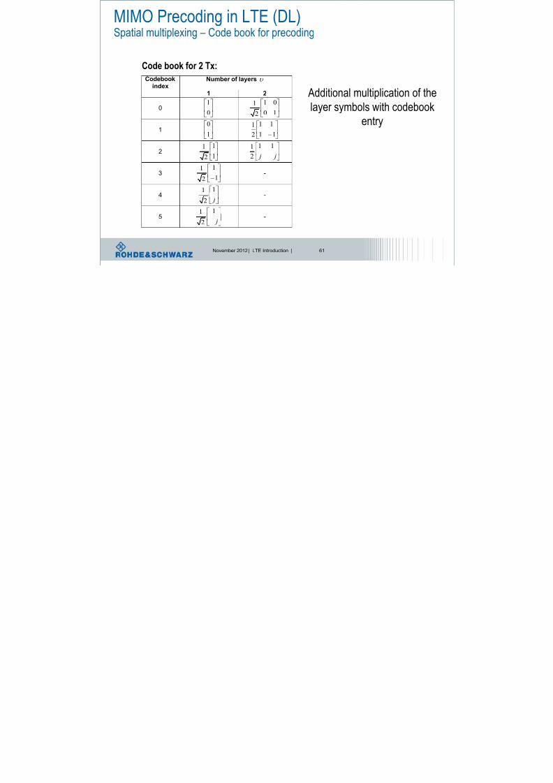
MIMO Precoding in LTE (DL)Spatial multiplexing – Code book for precoding
Codebookindex
Number of layers
1 2
0
0
1
10
01
2
1
1
1
0
11
11
2
1
2
1
1
2
1
j j
11
2
1
3
1
1
2
1 -
4
j1
21 -
5
j
1
2
1 -
Code book for 2 Tx:
Additional multiplication of the
layer symbols with codebook
entry
MIMO precoding

8/22/2019 LTE eutran rsanov2012
http://slidepdf.com/reader/full/lte-eutran-rsanov2012 62/284
November 2012 | LTE Introduction | 62
MIMO precoding
+
+
precoding
precoding
t
t
1
1
t t
∑=0
1
-1
1
1
Ant1
Ant2
2
∑
MIMO – codebook based precoding

8/22/2019 LTE eutran rsanov2012
http://slidepdf.com/reader/full/lte-eutran-rsanov2012 63/284
November 2012 | LTE Introduction | 63
receiver channeltransmitter
MIMO codebook based precoding
A H R+
noise
s r
Precoding
codebook
Precoding Matrix Identifier, PMI
Codebook based precoding creates
some kind of „beamforming light“
MIMO: avoid inter-channel interference – future outlook

8/22/2019 LTE eutran rsanov2012
http://slidepdf.com/reader/full/lte-eutran-rsanov2012 64/284
November 2012 | LTE Introduction | 64
MIMO: avoid inter channel interference future outlook
Idea: F adapts transmitted signal to current channel conditions
Link adaptation
Transmitter
F
H+
+
Space time
receiver
xk yk
V1,k
VM,k
Feedback about H
e.g. linear precoding: Y=H*F*S+V
S
MAS: „Dirty Paper“ Coding – future outlook

8/22/2019 LTE eutran rsanov2012
http://slidepdf.com/reader/full/lte-eutran-rsanov2012 65/284
November 2012 | LTE Introduction | 65
MAS: „Dirty Paper Coding future outlook
l Multiple Antenna Signal Processing: „Known Interference“
l Is like NO interference
l Analogy to writing on „dirty paper“ by changing ink color accordingly
„Known
Interference
is No
Interference“
„Known
Interference
is No
Interference“
„Known
Interference
is No
Interference“
„Known
Interference
is No
Interference“
Spatial Multiplexing

8/22/2019 LTE eutran rsanov2012
http://slidepdf.com/reader/full/lte-eutran-rsanov2012 66/284
November 2012 | LTE Introduction | 66
Spatial Multiplexing
data
Codeword Fading on the air interface
data
Spatial Multiplexing: We like to distinguish the 2 useful
Propagation passes:
How to do that? => one idea is SVD
Codeword
Idea of Singular Value Decomposition

8/22/2019 LTE eutran rsanov2012
http://slidepdf.com/reader/full/lte-eutran-rsanov2012 67/284
November 2012 | LTE Introduction | 67
Idea of Singular Value Decomposition
know
Singular ValueDecomposition
r = H s + n
s1
s2
r1
r2
channel H
MIMO
wanted
r = D s + n~ ~~
s1
s2
r1
r2
channel D
~
~ ~
~SISO
Singular Value Decomposition (SVD)
8/22/2019 LTE eutran rsanov2012
http://slidepdf.com/reader/full/lte-eutran-rsanov2012 68/284
November 2012 | LTE Introduction | 68
h11
h21
h12
h22
r = H s + n
r = H s + n
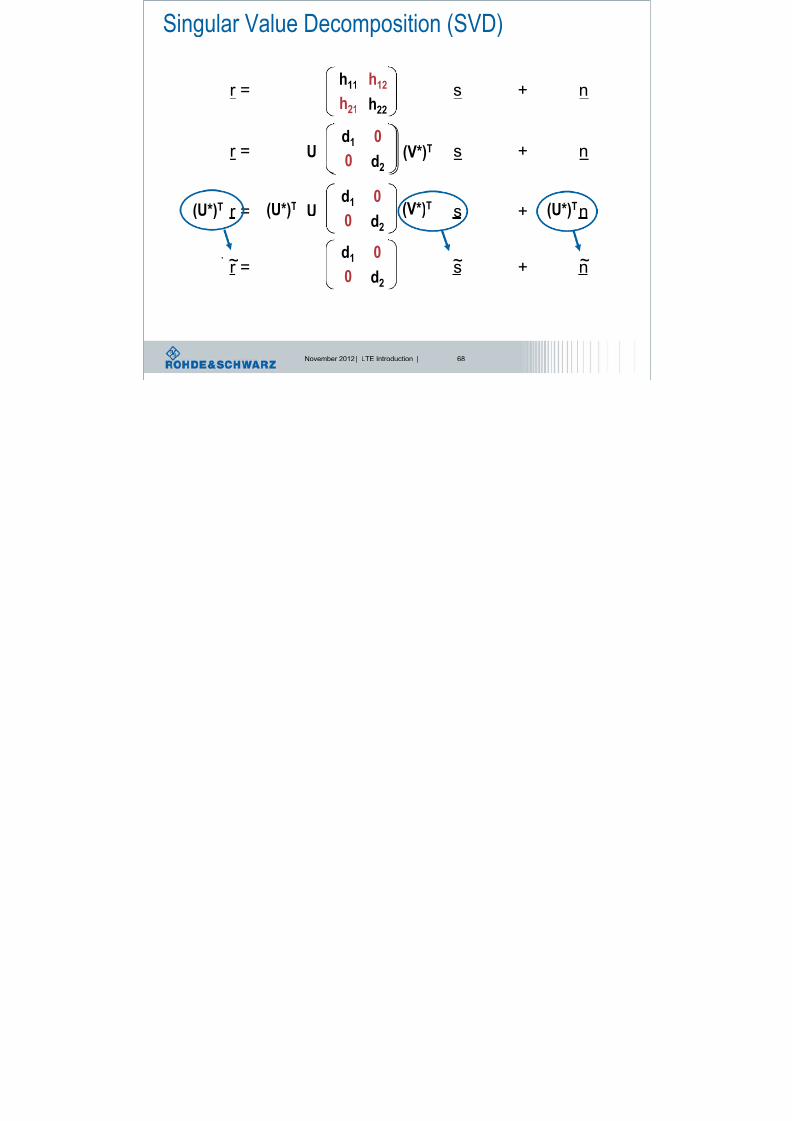
Singular Value Decomposition (SVD)
(U*)T (U*)T(U*)T
h11
h21
h12
h22
U (V*)Td1
0
0
d2
r = D s + nU (V*)Td1
0
0
d2
(U*)T
(U*)
T
(U*)
T
U(V*)T
r = D s + n
d1
0
0
d2
~~ ~
Singular Value Decomposition (SVD)

8/22/2019 LTE eutran rsanov2012
http://slidepdf.com/reader/full/lte-eutran-rsanov2012 69/284
November 2012 | LTE Introduction | 69
Singular Value Decomposition (SVD)
r = H s + n
H = U Σ (V*)T
00
0
00
00
00
3
2
1
U = [u1,...,un] eigenvectors of (H*)T H
V = [v1,...,vm] eigenvectors of H (H*)T
i isingular values
i eigenvalues of (H*)T H
~r = (U*)T r
s = (V*)T s~
n = (U*)T n~
r = Σ s + n~ ~~
MIMO and singular value decomposition SVD

8/22/2019 LTE eutran rsanov2012
http://slidepdf.com/reader/full/lte-eutran-rsanov2012 70/284
November 2012 | LTE Introduction | 70
O a d s gu a a ue deco pos t o S
s1
s2
n1
n2
r 1
r 2
h11
h22
h12
h21
s1
s2
n2
r 1
r 2
U
n1
VH
σ1
σ2
Σ
Real channel
Channel model with SVD
SVD transforms channel into k parallel AWGN channels
n1
MIMO: Signal processing considerations

8/22/2019 LTE eutran rsanov2012
http://slidepdf.com/reader/full/lte-eutran-rsanov2012 71/284
November 2012 | LTE Introduction | 71
g p gMIMO transmission can be expressed as
r = Hs+n which is, using SVD = UΣVHs+n
Imagine we do the following:
1.) Precoding at the transmitter:
Instead of transmitting s, the transmitter sends s = V*s
2.) Signal processing at the receiver
Multiply the received signal with UH, r = r*UH
So after signal processing the whole signal can be expressed as:
r =UH*(UΣVHVs+n)=UHU Σ VHVs+UHn = Σs+UHn
=InTnT =InTnT
s1
s2
n2
r 1
r 2
U VH
σ1
σ2
Σ
n1
UHV
MIMO: limited channel feedback

8/22/2019 LTE eutran rsanov2012
http://slidepdf.com/reader/full/lte-eutran-rsanov2012 72/284
November 2012 | LTE Introduction | 72
s1
s2
n2
r 1
r 2
U VH
σ1
σ2
Σ
n1
UHV
Transmitter Receiver
Idea 1: Rx sends feedback about full H to Tx.
-> but too complex,-> big overhead
-> sensitive to noise and quantization effects
H
Idea 2: Tx does not need to know full H, only unitary matrix V
-> define a set of unitary matrices (codebook) and find one matrix in the codebook thatmaximizes the capacity for the current channel H
-> these unitary matrices from the codebook approximate the singular vector structure
of the channel
=> Limited feedback is almost as good as ideal channel knowledge feedback
Cyclic Delay Diversity, CDD

8/22/2019 LTE eutran rsanov2012
http://slidepdf.com/reader/full/lte-eutran-rsanov2012 73/284
November 2012 | LTE Introduction | 73
Transmitter
Time
Delay
A1
A2
D
B
y y y,
Amp
litud
e
Delay Spread
+
+
precoding
precoding
Multipath propagation
No multipath propagation
Time
Delay
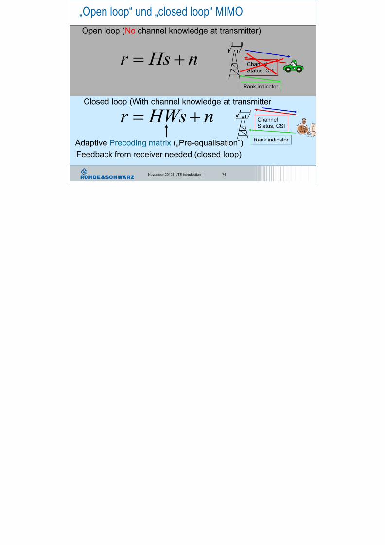
„Open loop“ und „closed loop“ MIMO
8/22/2019 LTE eutran rsanov2012
http://slidepdf.com/reader/full/lte-eutran-rsanov2012 74/284
November 2012 | LTE Introduction | 74
„ p p „ p
n HWsr
n Hsr
Open loop (No channel knowledge at transmitter)
Closed loop (With channel knowledge at transmitter
Adaptive Precoding matrix („Pre-equalisation“)
Feedback from receiver needed (closed loop)
Channel
Status, CSI
Rank indicator
Channel
Status, CSI
Rank indicator
MIMO transmission modes

8/22/2019 LTE eutran rsanov2012
http://slidepdf.com/reader/full/lte-eutran-rsanov2012 75/284
November 2012 | LTE Introduction | 75
Transmission mode1
SISO
Transmission mode2
TX diversityTransmission mode3
Open-loop spatial
multiplexing
Transmission mode4
Closed-loop spatialmultiplexing
Transmission mode5
Multi-User MIMO
Transmission mode6
Closed-loop
spatial multiplexing,
using 1 layer
Transmission mode7
SISO, port 5= beamforming in TDD
7 transmission
modes are
defined
Transmission mode is given by higher layer IE: AntennaInfo
MIMO transmission modes
8/22/2019 LTE eutran rsanov2012
http://slidepdf.com/reader/full/lte-eutran-rsanov2012 76/284
November 2012 | LTE Introduction | 76
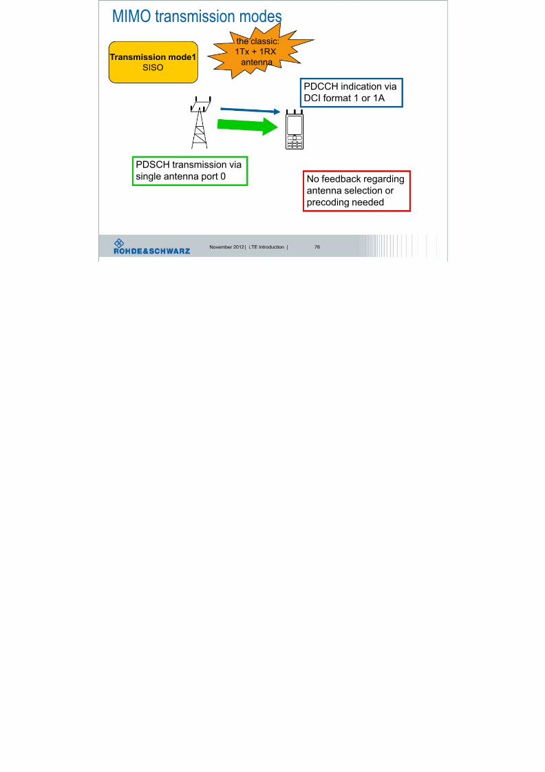
Transmission mode1
SISO
PDCCH indication via
DCI format 1 or 1A
PDSCH transmission via
single antenna port 0 No feedback regarding
antenna selection or precoding needed
the classic:
1Tx + 1RX
antenna
MIMO transmission modes

8/22/2019 LTE eutran rsanov2012
http://slidepdf.com/reader/full/lte-eutran-rsanov2012 77/284
November 2012 | LTE Introduction | 77
Transmission mode 2
Transmit
diversity PDCCH indication viaDCI format 1 or 1A
PDSCH transmission via
2 Or 4 antenna ports No feedback regarding
antenna selection or
precoding needed
1 codeword
Codeword is sent
redundantly over several
streams
PDCCH indication viaDCI format 1 or 1A
MIMO transmission modesNo feedback regarding

8/22/2019 LTE eutran rsanov2012
http://slidepdf.com/reader/full/lte-eutran-rsanov2012 78/284
November 2012 | LTE Introduction | 78
Transmission mode 3
Transmit diversity or Open loop
spatial multiplexing
PDCCH indication via
DCI format 1A
PDSCH transmission
Via 2 or 4 antenna ports
No feedback regarding
antenna selection or
precoding needed
1 codeword
PDCCH indication via
DCI format 2A
1codeword
PDSCH spatial multiplexing
with 1 layer
2codewords
PDSCH spatial multiplexing, using CDD
PMI feedback
MIMO transmission modesClosed loop MIMO =

8/22/2019 LTE eutran rsanov2012
http://slidepdf.com/reader/full/lte-eutran-rsanov2012 79/284
November 2012 | LTE Introduction | 79
Transmission mode 4
Transmit diversity or Closed loop
spatial multiplexing
PDCCH indication via
DCI format 1A
PDSCH transmission
Via 2 or 4 antenna ports
Closed loop MIMO =
UE feedback needed regarding
precoding and antenna
selection
1 codeword
PDCCH indication via
DCI format 2
1codeword
PDSCH spatial multiplexing
with 1 layer
2codewords
PDSCH spatial multiplexing
PMI feedbackPMI feedback
pr e c o d
i n g
pr e c o d
i n g
MIMO transmission modes
8/22/2019 LTE eutran rsanov2012
http://slidepdf.com/reader/full/lte-eutran-rsanov2012 80/284
November 2012 | LTE Introduction | 80
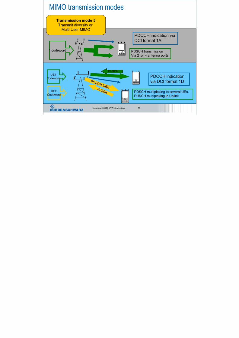
Transmission mode 5
Transmit diversity or
Multi User MIMO
PDCCH indication via
DCI format 1A
PDSCH transmission
Via 2 or 4 antenna ports
1 codeword
PDCCH indication
via DCI format 1D
UE1
Codeword
PDSCH multiplexing to several UEs.
PUSCH multiplexing in Uplink
PUSCH
UE2
Codeword
MIMO transmission modesClosed loop MIMO =

8/22/2019 LTE eutran rsanov2012
http://slidepdf.com/reader/full/lte-eutran-rsanov2012 81/284
November 2012 | LTE Introduction | 81
Transmission mode 6
Transmit diversity or Closed loop
spatial multiplexing with 1 layer
PDCCH indication via
DCI format 1A
PDSCH transmission
via 2 or 4 antenna ports
Closed loop MIMO =
UE feedback needed regarding
precoding and antenna
selection
1 codeword
PDCCH indication via
DCI format 1B
1codeword
PDSCH spatial multiplexing, only 1 codewordfeedback
Codeword is split intostreams, both streams have
to be combined
MIMO transmission modes

8/22/2019 LTE eutran rsanov2012
http://slidepdf.com/reader/full/lte-eutran-rsanov2012 82/284
November 2012 | LTE Introduction | 82
Transmission mode 7
Transmit diversity or beamforming
PDCCH indication via
DCI format 1A
PDSCH transmission
via 1, 2 or 4 antenna ports
1 codeword
PDCCH indication via
DCI format 1
1codeword
PDSCH sent over antenna port 5 = beamforming
Beamforming

8/22/2019 LTE eutran rsanov2012
http://slidepdf.com/reader/full/lte-eutran-rsanov2012 83/284
November 2012 | LTE Introduction | 83
Adaptive Beamforming
Closed loop precoded
beamforming
•Classic way
• Antenna weights to adjust beam
•Directional characteristics
•Specific antenna array geometrie
•Dedicated pilots required
•Kind of MISO with channel
knowledge at transmitter
•Precoding based on feedback
•No specific antenna
array geometrie
•Common pilots are sufficient
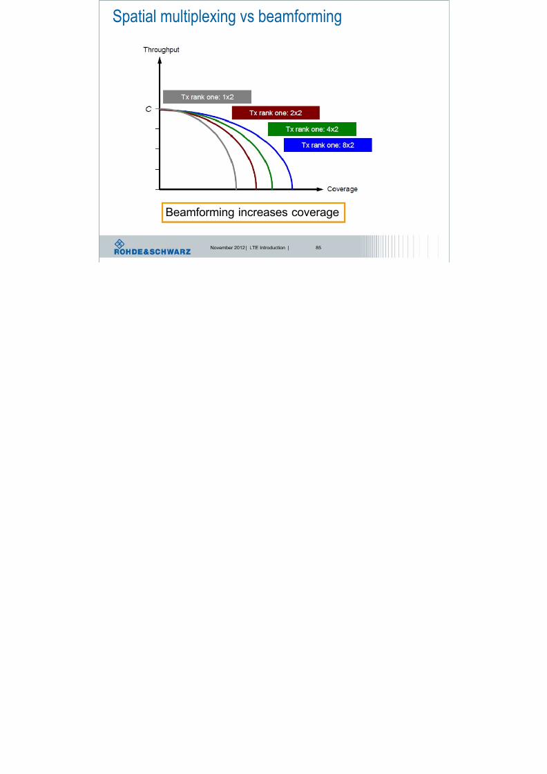
Spatial multiplexing vs beamforming

8/22/2019 LTE eutran rsanov2012
http://slidepdf.com/reader/full/lte-eutran-rsanov2012 84/284
November 2012 | LTE Introduction | 84
Spatial multiplexing increases throughput, but looses coverage
Spatial multiplexing vs beamforming
8/22/2019 LTE eutran rsanov2012
http://slidepdf.com/reader/full/lte-eutran-rsanov2012 85/284
November 2012 | LTE Introduction | 85
Beamforming increases coverage
Basic OFDM parameter

8/22/2019 LTE eutran rsanov2012
http://slidepdf.com/reader/full/lte-eutran-rsanov2012 86/284
November 2012 | LTE Introduction | 86
2048
84.3256
115
FFT
FFT s
FFT s
N
Mcps N
F
f N F
T kHz f
LTE
Data symbols
f
S/P Sub - carrier Mapping
CP insertion
Size - N FFT
Coded symbol rate= R
N TX
IFFT
LTE Downlink:

8/22/2019 LTE eutran rsanov2012
http://slidepdf.com/reader/full/lte-eutran-rsanov2012 87/284
November 2012 | LTE Introduction | 87
LTE Downlink:Downlink slot and (sub)frame structure
Ts = 32.522 ns
#0 #0 #1 #1 #2 #2 #3 #3 #19 #19
One slot, T slot
= 15360 T s = 0.5 ms
One radio frame, T f = 307200 T s = 10 ms
#18 #18
One subframe
We talk about 1 slot, but the minimum resource is 1 subframe = 2 slots !!!!!
2048150001s T
Symbol time, or number of symbols per time slot is not fixed
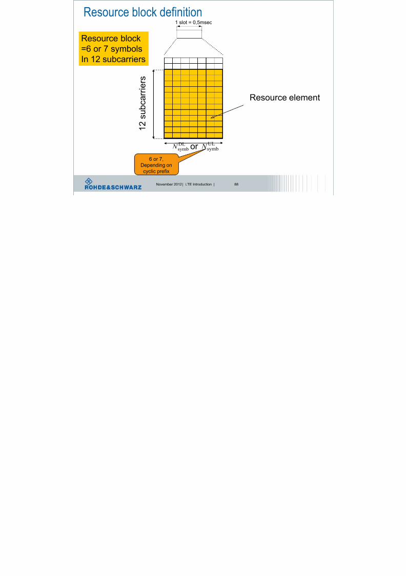
Resource block definition1 l t 0 5
8/22/2019 LTE eutran rsanov2012
http://slidepdf.com/reader/full/lte-eutran-rsanov2012 88/284
November 2012 | LTE Introduction | 88
1 slot = 0,5msec
1 2 s u
b c a r r i e r s
DLsymb N
ULsymb N or
Resource element
Resource block
=6 or 7 symbolsIn 12 subcarriers
6 or 7,
Depending on
cyclic prefix
LTE DownlinkOFDMA ti f lti l i

8/22/2019 LTE eutran rsanov2012
http://slidepdf.com/reader/full/lte-eutran-rsanov2012 89/284
November 2012 | LTE Introduction | 89
time
frequency
1 resource block =
180 kHz = 12 subcarriers
1 slot = 0.5 ms =
7 OFDM symbols**
1 subframe =
1 ms= 1 TTI*=
1 resource block pair
OFDMA time-frequency multiplexing
*TTI = transmission time interval
** For normal cyclic prefix duration
Subcarrier spacing = 15 kHz
QPSK, 16QAM or 64QAM modulation
UE1
UE4
UE3UE2
UE5
UE6
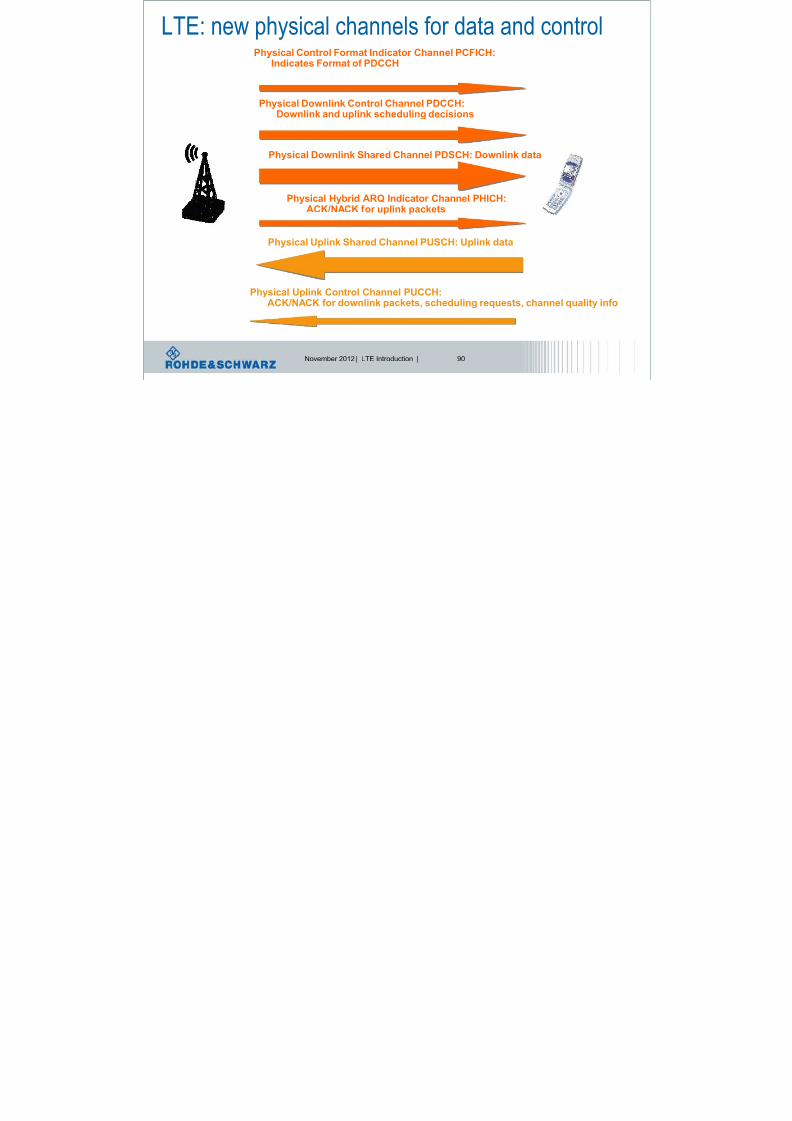
LTE: new physical channels for data and control
8/22/2019 LTE eutran rsanov2012
http://slidepdf.com/reader/full/lte-eutran-rsanov2012 90/284
November 2012 | LTE Introduction | 90
Physical Downlink Control Channel PDCCH:Downlink and uplink scheduling decisions
Physical Downlink Shared Channel PDSCH: Downlink data
Physical Control Format Indicator Channel PCFICH:Indicates Format of PDCCH
Physical Hybrid ARQ Indicator Channel PHICH:ACK/NACK for uplink packets
Physical Uplink Control Channel PUCCH:ACK/NACK for downlink packets, scheduling requests, channel quality info
Physical Uplink Shared Channel PUSCH: Uplink data
LTE Downlink: FDD channel mapping example

8/22/2019 LTE eutran rsanov2012
http://slidepdf.com/reader/full/lte-eutran-rsanov2012 91/284
November 2012 | LTE Introduction | 91RBSubcarrier #0
LTE – spectrum flexibility

8/22/2019 LTE eutran rsanov2012
http://slidepdf.com/reader/full/lte-eutran-rsanov2012 92/284
November 2012 | LTE Introduction | 92
l LTE physical layer supports any bandwidth from 1.4 MHz
to 20 MHz in steps of 180 kHz (resource block)l Current LTE specification supports only a subset of 6
different system bandwidths
l All UEs must support the maximum bandwidth of 20 MHz
Transmission
Bandwidth [RB]
Transmission Bandwidth Configuration [RB]
Channel Bandwidth [MHz]
Resourceblock
Chan
neledge
Chan
neledge
DC carrier (downlink only)Active Resource Blocks
Channel
bandwidth
BWChannel
[MHz]
1.4 3 5 10 15 20
FDD and
TDD mode6 15 25 50 75 100
number of resource blocks
LTE Downlink:

8/22/2019 LTE eutran rsanov2012
http://slidepdf.com/reader/full/lte-eutran-rsanov2012 93/284
November 2012 | LTE Introduction | 93
baseband signal generation
OFDM
Mapper
OFDM signal
generationLayer
Mapper
Scrambling
Precoding
Modulation
Mapper
ModulationMapper
OFDMMapper
OFDM signalgeneration
Scrambling
code words layers antenna ports
Avoid
constantsequences
QPSK
16 QAM64 QAM
For MIMO
Split intoSeveral
streams if
needed
Weighting
datastreams for
MIMO
1 OFDM
symbol per stream
1 stream =
several
subcarriers,based on
Physical
ressource
blocks
Adaptive modulation and coding

8/22/2019 LTE eutran rsanov2012
http://slidepdf.com/reader/full/lte-eutran-rsanov2012 94/284
November 2012 | LTE Introduction | 94
Transportation block size
FECUser data
Flexible ratio between data and FEC = adaptive coding
Channel Coding Performance

8/22/2019 LTE eutran rsanov2012
http://slidepdf.com/reader/full/lte-eutran-rsanov2012 95/284
November 2012 | LTE Introduction | 95
Automatic repeat request, latency aspects

8/22/2019 LTE eutran rsanov2012
http://slidepdf.com/reader/full/lte-eutran-rsanov2012 96/284
November 2012 | LTE Introduction | 96
Network UE
RoundTrip
Time
Transport block
•Transport block size = amount of
data bits (excluding redundancy!)
•TTI, Transmit Time Interval = timeduration for transmitting 1 transport
block
ACK/NACK
Immediate acknowledged or non-acknowledged
feedback of data transmission
HARQ principle: Stop and Wait

8/22/2019 LTE eutran rsanov2012
http://slidepdf.com/reader/full/lte-eutran-rsanov2012 97/284
November 2012 | LTE Introduction | 97
Tx
Rx
process
Data
Δt = Round trip time
Demodulate, decode, descramble,
FFT operation, check CRC, etc.
ACK /NACK
Processing time for receiver
DataData Data Data Data Data Data Data Data
Described as 1 HARQ process
HARQ principle: Multitasking

8/22/2019 LTE eutran rsanov2012
http://slidepdf.com/reader/full/lte-eutran-rsanov2012 98/284
November 2012 | LTE Introduction | 98
t
Tx
Rx
process
Data
Δt = Round trip time
Demodulate, decode, descramble,
FFT operation, check CRC, etc.
ACK /NACK
Processing time for receiver
Rx
process
Demodulate, decode, descramble,
FFT operation, check CRC, etc.
ACK /NACK
DataData Data Data Data Data Data Data Data
Described as 1 HARQ process
LTE Round Trip Time RTT

8/22/2019 LTE eutran rsanov2012
http://slidepdf.com/reader/full/lte-eutran-rsanov2012 99/284
November 2012 | LTE Introduction | 99
t=0 t=1 t=2 t=3 t=4 t=5 t=6 t=7 t=8 t=9 t=0 t=1 t=2 t=3 t=4 t=5
P D C C H
U L
D a t a
P H I C H
A C K / N A C
K
H
A R Q
D a t a
Downlink
Uplink
n+4 n+4 n+4
1 frame = 10 subframes
8 HARQ processesRTT = 8 msec
HARQ principle: Soft combining

8/22/2019 LTE eutran rsanov2012
http://slidepdf.com/reader/full/lte-eutran-rsanov2012 100/284
November 2012 | LTE Introduction | 100
lT i is a e am l o h n e co i g
Reception of first transportation block.
Unfortunately containing transmission errors
HARQ principle: Soft combining

8/22/2019 LTE eutran rsanov2012
http://slidepdf.com/reader/full/lte-eutran-rsanov2012 101/284
November 2012 | LTE Introduction | 101
l
hi i n x m le f cha n l c ing
Reception of retransmitted
transportation block.
Still containing transmission errors
g
HARQ principle: Soft combining

8/22/2019 LTE eutran rsanov2012
http://slidepdf.com/reader/full/lte-eutran-rsanov2012 102/284
November 2012 | LTE Introduction | 102
lThis is an example of channel coding
l T i is a e am l o h n e co i g
l hi i n x m le f cha n l c ing
l Thi is an exam le of channel co ing
1st transmission with puncturing scheme P1
2nd transmission with puncturing scheme P2
Soft Combining = Σ of transmission 1 and 2
Final decoding
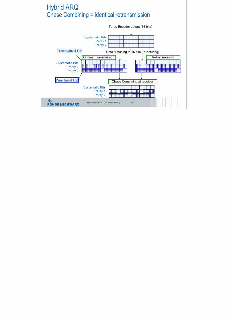
Hybrid ARQChase Combining = identical retransmission
8/22/2019 LTE eutran rsanov2012
http://slidepdf.com/reader/full/lte-eutran-rsanov2012 103/284
November 2012 | LTE Introduction | 103
Chase Combining = identical retransmission
Turbo Encoder output (36 bits)
Rate Matching to 16 bits (Puncturing)
Chase Combining at receiver
Systematic Bits
Parity 1
Parity 2
Systematic Bits
Parity 1
Parity 2
Systematic Bits
Parity 1
Parity 2
Original Transmission Retransmission
Transmitted Bit
Punctured Bit
Hybrid ARQIncremental Redundancy

8/22/2019 LTE eutran rsanov2012
http://slidepdf.com/reader/full/lte-eutran-rsanov2012 104/284
November 2012 | LTE Introduction | 104
Incremental Redundancy
Turbo Encoder output (36 bits)
Rate Matching to 16 bits (Puncturing)
Incremental Redundancy Combining at receiver
Systematic Bits
Parity 1
Parity 2
Systematic Bits
Parity 1
Parity 2
Systematic Bits
Parity 1
Parity 2
Original Transmission Retransmission
Punctured Bit

8/22/2019 LTE eutran rsanov2012
http://slidepdf.com/reader/full/lte-eutran-rsanov2012 105/284
November 2012 | LTE Introduction | 105
LTE Physical Layer:SC-FDMA in uplink
Single Carrier Frequency DivisionMultiple Access
LTE Uplink:

8/22/2019 LTE eutran rsanov2012
http://slidepdf.com/reader/full/lte-eutran-rsanov2012 106/284
November 2012 | LTE Introduction | 106
How to generate an SC-FDMA signal in theory?
LTE provides QPSK,16QAM, and 64QAM as uplink modulation schemes
DFT is first applied to block of NTX modulated data symbols to transform them into
frequency domain
Sub-carrier mapping allows flexible allocation of signal to available sub-carriers IFFT and cyclic prefix (CP) insertion as in OFDM
Each subcarrier carries a portion of superposed DFT spread data symbols
Can also be seen as “pre-coded OFDM” or “DFT-spread OFDM”
DFT Sub-carrier Mapping
CP
insertion
Size-N TX Size-N FFT
Coded symbol rate= R
N TX symbols
IFFT
LTE Uplink:SC ?

8/22/2019 LTE eutran rsanov2012
http://slidepdf.com/reader/full/lte-eutran-rsanov2012 107/284
November 2012 | LTE Introduction | 107
How does the SC-FDMA signal look like?
In principle similar to OFDMA, BUT:
In OFDMA, each sub-carrier only carries information related to one specific symbol
In SC-FDMA, each sub-carrier contains information of ALL transmitted symbols
LTE uplinkSC FDMA time frequency multiplexing

8/22/2019 LTE eutran rsanov2012
http://slidepdf.com/reader/full/lte-eutran-rsanov2012 108/284
November 2012 | LTE Introduction | 108
time
frequency
1 resource block =
180 kHz = 12 subcarriers
1 slot = 0.5 ms =
7 SC-FDMA symbols**
1 subframe =
1 ms= 1 TTI*
SC-FDMA time-frequency multiplexing
*TTI = transmission time interval
** For normal cyclic prefix duration
Subcarrier spacing = 15 kHz
QPSK, 16QAM or 64QAM modulation
UE1
UE4
UE3UE2
UE5 UE6
LTE Uplink:b b d i l ti

8/22/2019 LTE eutran rsanov2012
http://slidepdf.com/reader/full/lte-eutran-rsanov2012 109/284
November 2012 | LTE Introduction | 109
baseband signal generation
Avoid
constantsequences
QPSK
16 QAM64 QAM
(optional)
Discrete
Fourier
Transform
Mapping on
physical
Ressource,
i.e.
subcarriers
not used for
reference
signals
1 stream =
several
subcarriers,
based on
Physical
ressource
blocks
Modulation
mapper
Transform
precoder Scrambling
SC-FDMA
signal gen.
Resource
element mapper
UE specific
Scrambling code

8/22/2019 LTE eutran rsanov2012
http://slidepdf.com/reader/full/lte-eutran-rsanov2012 110/284
November 2012 | LTE Introduction | 110
LTE Protocol Architecture
LTE Protocol ArchitectureReduced complexity

8/22/2019 LTE eutran rsanov2012
http://slidepdf.com/reader/full/lte-eutran-rsanov2012 111/284
November 2012 | LTE Introduction | 111
l Reduced number of transport channels
l Shared channels instead of dedicated channels
l Reduction of Medium Access Control (MAC) entities
l Streamlined concepts for broadcast / multicast (MBMS)
l No inter eNodeB soft handover in downlink/uplink
l No compressed mode
l Reduction of RRC states
Reduced complexity
EUTRAN stack: protocol layers overviewEMM ESM

8/22/2019 LTE eutran rsanov2012
http://slidepdf.com/reader/full/lte-eutran-rsanov2012 112/284
November 2012 | LTE Introduction | 112
PHYSICAL LAYER
Medium Access Control
MAC
Radio Resource Control
RRC
C o n t r o l & M e a s u r e m
e n t s
Radio Link Control
RLC
Packet Data Convergence
PDCP
EMM ESM User plane
Transport channels
Logical channels
Radio Bearer
User plane Header compression (ROHC)
In-sequence delivery at handover
Duplicate detection
Ciphering for ser/control plane

8/22/2019 LTE eutran rsanov2012
http://slidepdf.com/reader/full/lte-eutran-rsanov2012 113/284
November 2012 | LTE Introduction | 113
eNB
PHY
UE
PHY
MAC
RLC
MAC
PDCPPDCP
RLC
PDCP = Packet Data Convergence Protocol
RLC = Radio Link Control
MAC = Medium Access ControlPHY = Physical Layer
SDU = Service Data Unit
(H)ARQ = (Hybrid) Automatic Repeat Request
Ciphering for user/control plane
Integrity protection for control plane
Timer based SDU discard in Uplink…
AM, UM, TM
ARQ
(Re-)segmentation
Concatenation
In-sequence delivery
Duplicate detection
SDU discardReset…
Mapping between logical and
transport channels
(De)-MultiplexingTraffic volume measurements
HARQ
Priority handling
Transport format selection…
Control plane Broadcast
Paging
RRC connection setup
R di B C t l

8/22/2019 LTE eutran rsanov2012
http://slidepdf.com/reader/full/lte-eutran-rsanov2012 114/284
November 2012 | LTE Introduction | 114
EPS = Evolved packet system
RRC = Radio Resource Control
NAS = Non Access Stratum
ECM = EPS Connection Management
eNB
PHY
UE
PHY
MAC
RLC
MAC
MME
RLC
NAS NAS
RRC RRC
PDCP PDCP
Radio Bearer Control
Mobility functions
UE measurement control…
EPS bearer management
Authentication
ECM_IDLE mobility handling
Paging origination in ECM_IDLE
Security control…
EPS Bearer Service Architecture

8/22/2019 LTE eutran rsanov2012
http://slidepdf.com/reader/full/lte-eutran-rsanov2012 115/284
November 2012 | LTE Introduction | 115
P-GWS-GW Peer
Entity
UE eNB
EPS Bearer
Radio Bearer S1 Bearer
End-to-end Service
External Bearer
Radio S5/S8
Internet
S1
E-UTRAN EPC
Gi
S5/S8 Bearer
Channel structure: User + Control plane
P t l t t

8/22/2019 LTE eutran rsanov2012
http://slidepdf.com/reader/full/lte-eutran-rsanov2012 116/284
November 2012 | LTE Introduction | 116
Protocol structure

8/22/2019 LTE eutran rsanov2012
http://slidepdf.com/reader/full/lte-eutran-rsanov2012 117/284
November 2012 | LTE Introduction | 117
LTE channel mapping
LTE – channels

8/22/2019 LTE eutran rsanov2012
http://slidepdf.com/reader/full/lte-eutran-rsanov2012 118/284
November 2012 | LTE Introduction | 118
PBCHPDCCH PDSCH
DL-SCH BCH
DTCHCCCH DCCH
DL logical channels
DL transport channels
DL physical channels
BCCH
PCH
PCCHMTCH MCCH
MCH
PMCH PCFICH PHICH
PRACH PUCCH PUSCH
UL-SCHRACH
DTCHCCCH DCCH
UL logical channels
UL transport channels
UL physical channels
LTE – uplink channelsMapping between logical and transport channels

8/22/2019 LTE eutran rsanov2012
http://slidepdf.com/reader/full/lte-eutran-rsanov2012 119/284
November 2012 | LTE Introduction | 119
Mapping between logical and transport channels
CCCH DCCH DTCH
UL-SCHRACH
Uplink
Logical channels
Uplink Transport channels

8/22/2019 LTE eutran rsanov2012
http://slidepdf.com/reader/full/lte-eutran-rsanov2012 120/284
November 2012 | LTE Introduction | 120
LTE resource allocation principles
LTE resource allocationScheduling of downlink and uplink data

8/22/2019 LTE eutran rsanov2012
http://slidepdf.com/reader/full/lte-eutran-rsanov2012 121/284
November 2012 | LTE Introduction | 121
Physical Downlink Shared
Channel (PDSCH)
I would like to receive data on PDSCH
and / or send data on PUSCH
?
Physical Downlink Control
Channel (PDCCH)
Check PDCCH for your UE ID. You mayfind here Uplink and/or Downlink
resource allocation information
Scheduling of downlink and uplink data
Physical Control Format
Indicator Channel (PCFICH),
Info about PDCCH format
Physical Uplink Shared Channel
(PUSCH)
Resource allocation types in LTE
All ti t DCI F t S h d li A t

8/22/2019 LTE eutran rsanov2012
http://slidepdf.com/reader/full/lte-eutran-rsanov2012 122/284
November 2012 | LTE Introduction | 122
Allocation type DCI Format Scheduling
Type
Antenna
configuration
Type 0 / 1 DCI 1 PDSCH, onecodeword SISO,TxDiversity
DCI 2A PDSCH, two
codewords
MIMO, open
loop
DCI 2 PDSCH, two
codewords
MIMO, closed
loop
Type 2 DCI 0 PUSCH SISO
DCI 1A PDSCH, one
codeword
SISO,
TxDiversity
DCI 1C PDSCH, verycompact
codeword
SISO
Resource allocation types in LTE
Type 0 and 1 for distributed allocation in frequency domain

8/22/2019 LTE eutran rsanov2012
http://slidepdf.com/reader/full/lte-eutran-rsanov2012 123/284
November 2012 | LTE Introduction | 123
Type 0 and 1 for distributed allocation in frequency domain
Type 2 for contiguous allocation in frequency domain
f
f
Channel bandwidth
Channel bandwidth
Transmission bandwidth
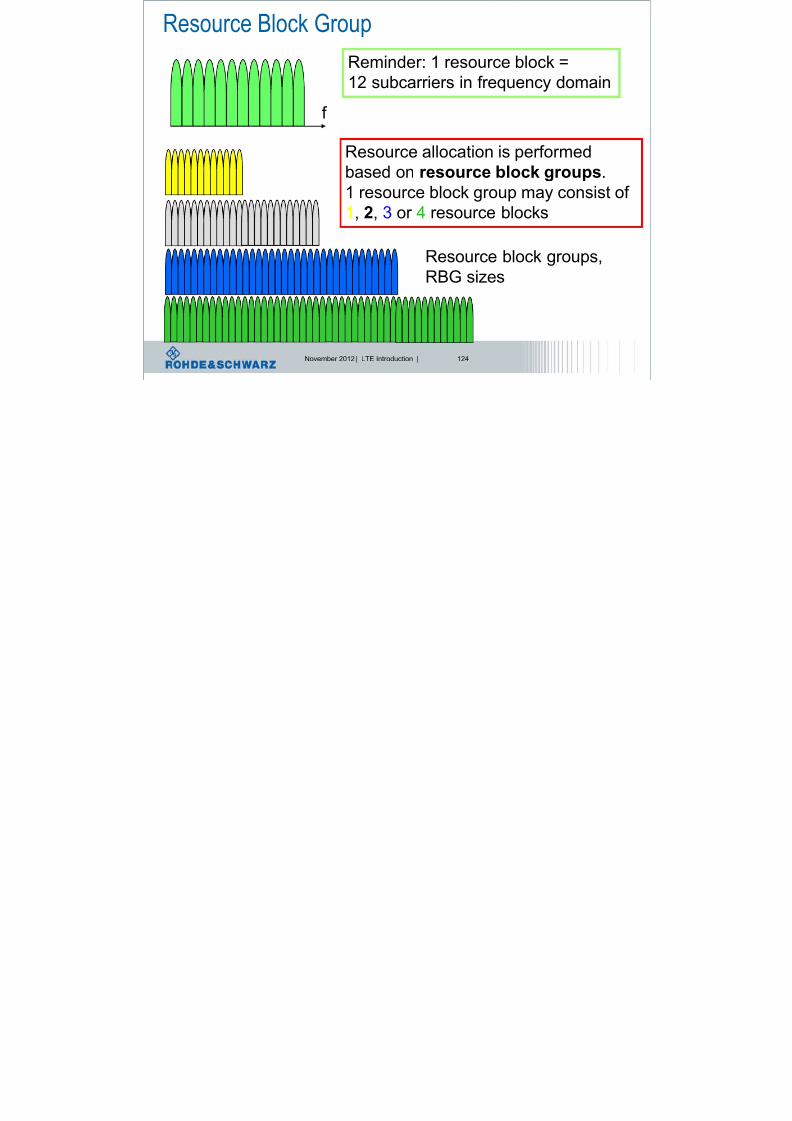
Resource Block Group
R i d 1 bl k
8/22/2019 LTE eutran rsanov2012
http://slidepdf.com/reader/full/lte-eutran-rsanov2012 124/284
November 2012 | LTE Introduction | 124
f
Reminder: 1 resource block =
12 subcarriers in frequency domain
Resource allocation is performed
based on resource block groups.
1 resource block group may consist of 1, 2, 3 or 4 resource blocks
Resource block groups,
RBG sizes
Resource allocation type 0
Type 0 (for distributed frequency allocation of Downlink resource

8/22/2019 LTE eutran rsanov2012
http://slidepdf.com/reader/full/lte-eutran-rsanov2012 125/284
November 2012 | LTE Introduction | 125
Type 0 (for distributed frequency allocation of Downlink resource,
SISO and MIMO possible)
l Bitmap to indicate which resource block groups, RBG are allocated
l One RBG consists of 1-4 resource blocks:
lGranularity is RBG size
l Number of resource block groups NRBG
is given as:
l Allocation bitmap has same length than NRBG
Channel
bandwidth
RBG size P
≤10 1
11-26 227-63 3
64-110 4
P N N RBG /DLRB
Resource allocation type 0 exampleCalculation example for type 0:

8/22/2019 LTE eutran rsanov2012
http://slidepdf.com/reader/full/lte-eutran-rsanov2012 126/284
November 2012 | LTE Introduction | 126
l Channel bandwidth = 10MHz
l -> 50 resource blocksl -> Resource block group RBG size = 3
l -> bitmap size = 17
P N N RBG /DLRB = round up, i.e. = 4 5.3
P N /DLRB = round down, i.e. = 3 49.3
Calculation example for type 0:
if 0modDL
RB P N then one of the RBGs is of size P N P N /DLRB
DLRB
i.e. here 50 mod 3 = 16, so the last resource block group has the size 2.
-> some allocations are not possible, e.g. here you can allocate
48 or 50 resource blocks, but not 49!
reminder
Resource allocation type 0: exampleChannel bandwidth = 10MHz -> 50 RBs -> RBG size = 3 -> number of RBGs = 17

8/22/2019 LTE eutran rsanov2012
http://slidepdf.com/reader/full/lte-eutran-rsanov2012 127/284
November 2012 | LTE Introduction | 127
1 2 3 16 17 18 19 20 21 22 23 3 DL
RB N 2 DL
RB N 1 DL
RB N 0
RBG#0 RBG#1 RBG#NRBG-1
Allocation bitmap (17bit): 10000011000000001
´f
RBG#6
Granularity: 1 bit allocates 1 ressource block group
Resource allocation type 1Type 1 (for distributed frequency allocation of Downlink resource,

8/22/2019 LTE eutran rsanov2012
http://slidepdf.com/reader/full/lte-eutran-rsanov2012 128/284
November 2012 | LTE Introduction | 128
yp ( q y ,
SISO and MIMO possible)
One Resource Block Group
consists of 1-4 resource blocks:
l RBs are divided into
RBG subsets
l Granularity is resource block
l Bitmap indicates RBs inside a RBG subset allocated to the UE
l Resource block assignment consists of 3 fields:l Field to indicate the selected RBG
l Field to indicate a shift of the resource allocationl Field to indicate the specific RB within a RBG subset
Channelbandwidth
RBG size P
≤10 1
11-26 2
27-63 3
64-110 4
)(log2 P
Resource allocation type 1Channel bandwidth = 10MHz -> 50 RBs -> RBG size = 3 -> number of RBGs = 17

8/22/2019 LTE eutran rsanov2012
http://slidepdf.com/reader/full/lte-eutran-rsanov2012 129/284
November 2012 | LTE Introduction | 129
1 2 3 16 17 18 19 20 21 22 23 3 DL
RB N 2 DL
RB N 1 DL
RB N 0
RBG#0 RBG#1 RBG#NRBG-1
RBG#0 RBG#3 RBG#6 RBG#9 RBG#12
RBG#1 RBG#4 RBG#7 RBG#10 RBG#13
RBG#2 RBG#5 RBG#8 RBG#11 RBG#14
P P
N p
P P
N p
P
P
N p
P P
N
P N P P
N
P P
P
N
p N
mod1
,
mod1
,
mod1
,
1
1mod)1(1
1
)(
DL
RB
DL
RB
DL
RB
2
DL
RB
DL
RB2
DL
RB
2
DL
RB
subsetRBG
RB
RBG#15RBG subset #0
RBG#16 RBG subset #1
RBG subset #2
)(log2 P
P= Number of RBG subsets with length:
Number of bits to indicate subset
Size 18 resource blocks
Size 17 resource blocks
Size 15 resource blocks
Resource allocation type 1Channel bandwidth = 10MHz -> 50 RBs -> RBG size = 3 -> number of RBGs = 17

8/22/2019 LTE eutran rsanov2012
http://slidepdf.com/reader/full/lte-eutran-rsanov2012 130/284
November 2012 | LTE Introduction | 130
1 2 3 16 17 18 19 20 21 22 23 2 DL
RB N 1 DL
RB N 0
RBG#0 RBG#1 RBG#NRBG-1
RBG#1 RBG#4 RBG#7 RBG#10 RBG#13
RBG#2 RBG#5 RBG#8 RBG#11 RBG#14RBG#0 RBG#3 RBG#6 RBG#9 RBG#12 RBG#15
RBG subset #0
RBG#16 RBG subset #1
RBG subset #2
Allocation bitmap (17bit): 01 0 00011000000001
Field 1: RBG subset selection
RBG subset#1 is selected
Field 2: offset shift indication
Bit = 0, no shift
Field 3: resource block allocation
3 4 5 12 13 14 21 22 23 30 31 32 39 40 41 48 49 Resource blocks
assignment
Size 17 resource blocks
Size 14 bits
Resource allocation type 1Channel bandwidth = 10MHz -> 50 RBs -> RBG size = 3 -> number of RBGs = 17

8/22/2019 LTE eutran rsanov2012
http://slidepdf.com/reader/full/lte-eutran-rsanov2012 131/284
November 2012 | LTE Introduction | 131
RBG#1 RBG#4 RBG#7 RBG#10 RBG#13 RBG#16 RBG subset #1
Allocation bitmap (17bit): 01 0 10000000000001 RBG subset#1 is selected
Bit = 0, no shift
3 4 5 12 13 14 21 22 23 30 31 32 39 40 41 48 49 Resource blocks
assignment
The meaning of the shift offset bit:
Number of resource blocks in one RBG subset is bigger than the allocation bitmap-> you can not allocate all the available resource blocks
-> offset shift to indicate which RBs are assigned
17 resource blocks belonging to the RBG subset#1
14 bits in allocation bitmap
Resource allocation type 1Channel bandwidth = 10MHz -> 50 RBs -> RBG size = 3 -> number of RBGs = 17

8/22/2019 LTE eutran rsanov2012
http://slidepdf.com/reader/full/lte-eutran-rsanov2012 132/284
November 2012 | LTE Introduction | 132
RBG#1 RBG#4 RBG#7 RBG#10 RBG#13 RBG#16 RBG subset #1
Allocation bitmap (17bit): 01 1 10000000000001 RBG subset#1 is selected
Bit = 1, offset shift
3 4 5 12 1
3
14 21 22 23 30 31 32 39 40 41 48 49 Resource blocks
assignment
The meaning of the shift offset bit:
Number of resource blocks in one RBG subset is bigger than the allocation bitmap-> you can not allocate all the available resource blocks
-> offset shift to indicate which RBs are assigned
17 resource blocks belonging to the RBG subset #1
14 bits in allocation bitmap
Resource allocation types in LTE
Type 0 allows the allocation based on resource block groups granularity

8/22/2019 LTE eutran rsanov2012
http://slidepdf.com/reader/full/lte-eutran-rsanov2012 133/284
November 2012 | LTE Introduction | 133
Type 0 allows the allocation based on resource block groups granularity
Type 1 allows the allocation based on resource block granularity
f
f
Channel bandwidth
Channel bandwidth
Example: RBG size = 3 RBs
1 resource block, RB
Resource allocation type 2
Localized mode

8/22/2019 LTE eutran rsanov2012
http://slidepdf.com/reader/full/lte-eutran-rsanov2012 134/284
November 2012 | LTE Introduction | 134
Localized mode
Channel bandwidth
Transmission bandwidth
Resource block offset
Number of allocated Resource blocks NRB
RB#0
Starting resource block: RBStartLCRB, length of contiguously allocated RBs
f
Resource indication value, RIV
Type 0: bitmap used to indicate the resource allocation:

8/22/2019 LTE eutran rsanov2012
http://slidepdf.com/reader/full/lte-eutran-rsanov2012 135/284
November 2012 | LTE Introduction | 135
Type 0: bitmap used to indicate the resource allocation:
= Length of allocation bitmap (17bit): 10000011000000001 P N /DLRB
Type 1: bitmap used to indicate the resource allocation, with 3 fields:
Resource block group subset, shift indictor + resource allocation
Allocation bitmap (17bit): 01 1 10000000000000
if 2/)1( DL
RBCRBs N L
then
start CRBs
DL
RB RB L N RIV )1(
else
)1()1( start
DL
RBCRBs
DL
RB
DL
RB RB N L N N RIV
Type 2: TS 36.213 section 7.1.6.3. gives formula to calculate RIV:
RIV = bin to
dec
conversion
Resource indication value, RIV in type 2 allocationHow to calculate the RIV value in allocation type 2, according to TS 36.213

8/22/2019 LTE eutran rsanov2012
http://slidepdf.com/reader/full/lte-eutran-rsanov2012 136/284
November 2012 | LTE Introduction | 136
Assumptions and given:
Localized mode, RBStart = 5, LCRB = 20NDL
RB = 50
Starting resource block: RBStart=5
LCRB, length of contiguously allocated RBs=20
f
start CRBs
DL
RB RB L N RIV )1( Formula from TS
36.213
Here:
RIV = 50 * (20-1) + 5
RIV = 955
Benefit of localized or distributed mode„static UE“: frequency selectivity is not time variant -> localized allocation

8/22/2019 LTE eutran rsanov2012
http://slidepdf.com/reader/full/lte-eutran-rsanov2012 137/284
November 2012 | LTE Introduction | 137
„high velocity UE“: frequency selectivity is time variant -> distributed allocation
Multipath causes frequency
Selective channel,
It can be time variant or
Non-time variant
Resource allocation Uplink
Allocation type DCI Format Scheduling Antenna

8/22/2019 LTE eutran rsanov2012
http://slidepdf.com/reader/full/lte-eutran-rsanov2012 138/284
November 2012 | LTE Introduction | 138
Allocation type DCI Format Scheduling
Type
Antenna
configuration
Type 0 / 1 DCI 1 PDSCH, one codeword SISO, TxDiversity
DCI 2A PDSCH, two
codewords
MIMO, open loop
DCI 2 PDSCH, two
codewords
MIMO, closed loop
Type 2 DCI 0 PUSCH SISO
DCI 1A PDSCH, one codeword SISO, TxDiversity
DCI 1C PDSCH, very compact
codeword
SISO
Channel bandwidth
RB#0
Starting resource block: RBStart LCRB, length of contiguously allocated RBs
LTE Uplink uses
Type 2 allocation
LTE Uplink: allocation of UL ressourceScheduled UL
bandwidth
UL bandwidth
configuration

8/22/2019 LTE eutran rsanov2012
http://slidepdf.com/reader/full/lte-eutran-rsanov2012 139/284
November 2012 | LTE Introduction | 139
ULRB
PUSCHRB
532 532 N M
bandwidth g
Scheduled number of ressource blocks in UL must fullfill
formula above(αx are integer). Possible values are:
1 2 3 4 5 6 8 9 10 12
15 16 18 20 24 25 27 30 32 36
40 45 48 50 54 60 64 72 75 80
81 90 96 100
Relaying
eICIC
enhancements
The LTE evolution
R l 10
Rel-9

8/22/2019 LTE eutran rsanov2012
http://slidepdf.com/reader/full/lte-eutran-rsanov2012 140/284
November 2012 | LTE Introduction | 140
CoMP
In-device
co-existenceDiverse Data
Application
eMBMS
enhancements
LTE Release 8
FDD / TDD
DL UL
DL UL
Rel-10
Relaying
SON
enhancements
Carrier
Aggregation
MIMO 8x8 MIMO 4x4Enhanced
SC-FDMA
eICICRel-11
eMBMS
Positioning
Dual Layer
Beamforming
Multi carrier /Multi-RAT
Base Stations
Home eNodeB
Self Organizing
Networks
Public Warning
System
What are antenna ports?

8/22/2019 LTE eutran rsanov2012
http://slidepdf.com/reader/full/lte-eutran-rsanov2012 141/284
November 2012 | LTE Introduction | 141
l 3GPP TS 36.211(Downlink)
“An antenna port is defined such that the channel over which a symbol on the
antenna port is conveyed can be inferred from the channel over which another
symbol on the same antenna port is conveyed.”
l What does that mean?
l The UE shall demodulate a received signal – which is transmitted over a
certain antenna port – based on the channel estimation performed on the
reference signals belonging to this (same) antenna port.
What are antenna ports?

8/22/2019 LTE eutran rsanov2012
http://slidepdf.com/reader/full/lte-eutran-rsanov2012 142/284
November 2012 | LTE Introduction | 142
l Consequences of the definition
l There is one sort of reference signal per antenna portl Whenever a new sort of reference signal is introduced by 3GPP (e.g. PRS),
a new antenna port needs to be defined (e.g. Antenna Port 6)
l 3GPP defines the following antenna port / reference signal
combinations for downlink transmission:
l Port 0-3: Cell-specific Reference Signals (CS-RS)
l Port 4: MBSFN-RS
l Port 5: UE-specific Reference Signals (DM-RS): single layer (TX mode 7)
l Port 6: Positioning Reference Signals (PRS)
l Port 7-8: UE-specific Reference Signals (DM-RS): dual layer (TX mode 8)
l Port 7-14: UE specific Referene Signals for Rel. 10l Port 15 – 22: CSI specific reference signals, channel status info in Rel. 10
What are antenna ports?

8/22/2019 LTE eutran rsanov2012
http://slidepdf.com/reader/full/lte-eutran-rsanov2012 143/284
November 2012 | LTE Introduction | 143
l Mapping „Antenna Port“ to „Physical Antennas“
AP7
AP8
AP0
AP2
AP3
AP1
AP4
AP6
AP5
Antenna Port Physical Antennas
PA0
PA1
PA2
PA3
…
1
1
1
1
W5,0
W5,1
W5,2
W5,3
The way the "logical" antenna ports are mapped to the "physical" TX antennas liescompletely in the responsibility of the base station. There's no need for the base station
to tell the UE.
…
… …
LTE antenna port definition
Antenna ports are linked to the reference signals

8/22/2019 LTE eutran rsanov2012
http://slidepdf.com/reader/full/lte-eutran-rsanov2012 144/284
November 2012 | LTE Introduction | 144
p g
-> one example:
Cell Specific RS
PA - RS
PCFICH / PHICH / PDCCH
Normal CP
PUSCH or No Transmission
UE in idle mode, scans for
Antenna port 0, cell specific RS
UE in connected mode, scans
Positioning RS on antenna port 6
to locate its position
eMBMSPhysical Layer Scenarios

8/22/2019 LTE eutran rsanov2012
http://slidepdf.com/reader/full/lte-eutran-rsanov2012 145/284
November 2012 | LTE Introduction | 145
l Dedicated and mixed mode.
l Dedicated: carrier is only for MBMS = Single-cell MBMS.l MBMS/Unicast mixed mode: MBMS and user data are transmitted using
time division duplex. Certain subframes carry MBMS data.
l Dedicated mode (single-cell scenario) offers use of new
subscarrier spacing, longer cyclic prefix (CP), 3 OFDM symbols.
ConfigurationOFDM
Symbols
Sub-
carrier
Cyclic Prefix Length
in Samples
Cyclic Prefix
Length in µs
Normal CP
∆f = 15 kHz 7
12
160 for 1st symbol
144 for other symbols
5.2 for 1st symbol
4.7 for other symbols
Extended CP
∆f = 15 kHz
6 512 16.7
Extended CP
∆f = 7.5 kHz 3 24 1024 33.3 eMBMS
(Single cell scenario)
Resource block definition for MBMS Δf=1/TSYMBOL=15kHz
1 Resource

8/22/2019 LTE eutran rsanov2012
http://slidepdf.com/reader/full/lte-eutran-rsanov2012 146/284
November 2012 | LTE Introduction | 146
7 OFDM symbols
CP CP CP CP CP CPOFDMSymbol
OFDMSymbol
OFDMSymbol
OFDMSymbol
OFDMSymbol
OFDMSymbol
f f 0 f 1 f 2
1 2 3 4 5 6 7
Block =
12 subcarriers
CP CP CPOFDMSymbol
OFDMSymbol
OFDMSymbol
Δf=7.5kHz
f
1 Resource
Block =
24 subcarriers For MBMS
only!
6 OFDM symbols
Multimedia Broadcast Messaging Services, MBMS

8/22/2019 LTE eutran rsanov2012
http://slidepdf.com/reader/full/lte-eutran-rsanov2012 147/284
November 2012 | LTE Introduction | 147
Broadcast:
Public info for
everybody
Multicast:
Common info for
User after authentication
Unicast:
Private info for dedicated user
LTE MBMS architecture

8/22/2019 LTE eutran rsanov2012
http://slidepdf.com/reader/full/lte-eutran-rsanov2012 148/284
November 2012 | LTE Introduction | 148
MBMS in LTE

8/22/2019 LTE eutran rsanov2012
http://slidepdf.com/reader/full/lte-eutran-rsanov2012 149/284
November 2012 | LTE Introduction | 149
MBMS
GW
eNB
MCE |
|
M1
M3 MBMS GW: MBMS Gateway
MCE: Multi-Cell/Multicast Coordination Entity
M1: user plane interface
M2: E-UTRAN internal control plane interface
M3: control plane interface between E-UTRAN and EPC
MME
|M2
Logical architecture for MBMS
MBMS broadcast service provision

8/22/2019 LTE eutran rsanov2012
http://slidepdf.com/reader/full/lte-eutran-rsanov2012 150/284
November 2012 | LTE Introduction | 150
Service announcement
Data transfer
MBMS notification
Session Start
Session Stop
See 3GPP TS23.246, Section 4.4.3
MBMS broadcast service provision
ti

8/22/2019 LTE eutran rsanov2012
http://slidepdf.com/reader/full/lte-eutran-rsanov2012 151/284
November 2012 | LTE Introduction | 151
UE1
time
UE localservice
activation
Broadcast service Announcement
Stop
announcment
t
Data
transfer
Service 1 Session 2
Service 1 session1
UE2
Local service de -
activation
Start Broadcast
Service
announcement
Broadcast session start
Data
transfer
Session stop
Idle period
of seconds
Data
transfer
How is theUE informed about all
this in detail?
MBMS Signaling

8/22/2019 LTE eutran rsanov2012
http://slidepdf.com/reader/full/lte-eutran-rsanov2012 152/284
November 2012 | LTE Introduction | 152
l New logical Channels:
l MBMS point-to-multipoint ControlChannel (MCCH)
l MBMS point-to-multipoint Traffic
Channel (MTCH)
l MBMS point-to-multipoint Scheduling
Channel (MSCH)
l Reception of MSCH is optional
l MxCH channels are mapped on
Multicast Channel MCH
FTP WAP HTTP MMS SIP
POC VoIP
TCP / UDP
GMM
PDCPRRC
RLC
PHY
GMMREG
GMMSM
GC NT DC
UM PUM
PDCP
MCH
GMMMM
TC CTC SM
SNSM
SMREG
MM
MMTC
IP
MAC
DCCH /
DTCH MTCH MSCH MCCH
New SIB 13 informs
about MBMS configuration
MBSFNMBSFN, Multicast/Broadcast Single Frequency Network

8/22/2019 LTE eutran rsanov2012
http://slidepdf.com/reader/full/lte-eutran-rsanov2012 153/284
November 2012 | LTE Introduction | 153
Cells belonging to MBSFN area are co-ordinated
and transmit a time-synchronized common waveform
eNodeBs within an MBSFN area are synchronized.
From point of view of the terminal, this appears to be a single
transmission as if originating from one large cell(with correspondingly large delay spread).
Cyclic prefix is utilized to cover the difference in the propagation delays
from the multiple cells. MBMS therefore uses an extended cyclic prefix
MBSFN – MBMS Single Frequency Network

8/22/2019 LTE eutran rsanov2012
http://slidepdf.com/reader/full/lte-eutran-rsanov2012 154/284
November 2012 | LTE Introduction | 154
Mobile communication network
each eNode B sends individualsignals
Single Frequency Network
each eNode B sends identicalsignals
MBSFN

8/22/2019 LTE eutran rsanov2012
http://slidepdf.com/reader/full/lte-eutran-rsanov2012 155/284
November 2012 | LTE Introduction | 155
If network is synchronised,
Signals in downlink can be
combined
evolved Multimedia Broadcast Multicast Services Multimedia Broadcast Single Frequency Network (MBSFN) area
U f l if i ifi b f h d
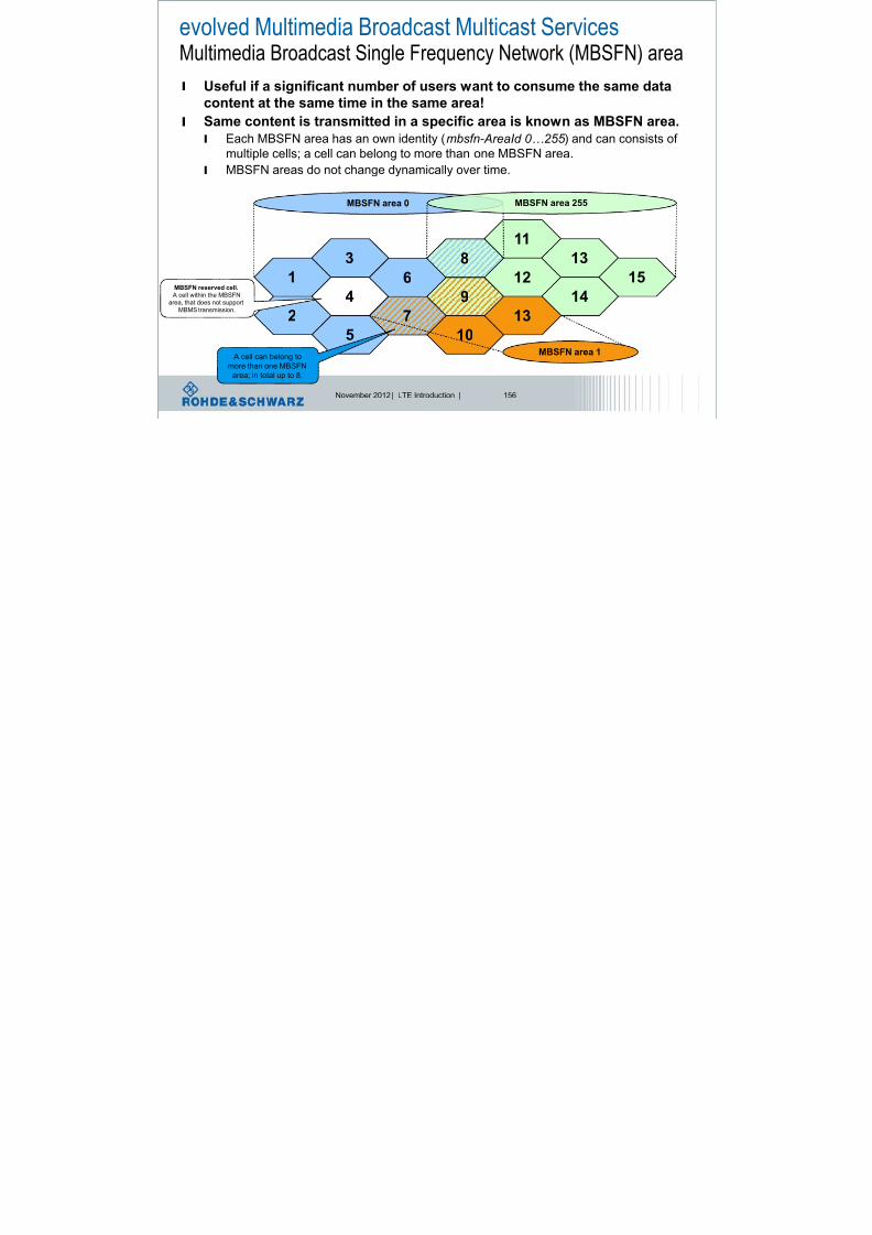
8/22/2019 LTE eutran rsanov2012
http://slidepdf.com/reader/full/lte-eutran-rsanov2012 156/284
November 2012 | LTE Introduction | 156
l Useful if a significant number of users want to consume the same data
content at the same time in the same area!
l Same content is transmitted in a specific area is known as MBSFN area.l Each MBSFN area has an own identity (mbsfn- AreaId 0…255 ) and can consists of
multiple cells; a cell can belong to more than one MBSFN area.
l MBSFN areas do not change dynamically over time.
52
1
3
4
6
7
9
11
12
13
10
MBSFN area 0
14
A cell can belong to
more than one MBSFN
area; in total up to 8.
MBSFN area 1
13
8
MBSFN area 255
MBSFN reserved cell.
A cell within the MBSFN
area, that does not support
MBMS transmission.
15
eMBMSDownlink Channels

8/22/2019 LTE eutran rsanov2012
http://slidepdf.com/reader/full/lte-eutran-rsanov2012 157/284
November 2012 | LTE Introduction | 157
l Downlink channels related to MBMS
l MCCH Multicast Control Channell MTCH Multicast Traffic Channel
l MCH Multicast Channel
l PMCH Physical Multicast Channel
l MCH is transmitted over MBSFN in
specific subrames on physical layer
l MCH is a downlink only channel (no HARQ, no RLC repetitions)
l Higher Layer Forward Error Correction (see TS26.346)
l Different services (MTCHs and MCCH) can be multiplexed
eMBMS channel mapping

8/22/2019 LTE eutran rsanov2012
http://slidepdf.com/reader/full/lte-eutran-rsanov2012 158/284
November 2012 | LTE Introduction | 159
Subframes 0 and 5 are not MBMS, because
of PBCH and Sync Channels
Subframes 0,4,5 and 9 are not MBMS, because
Of paging occasion can occur here
eMBMS allocation based on SIB2 information
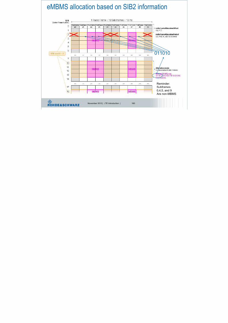
8/22/2019 LTE eutran rsanov2012
http://slidepdf.com/reader/full/lte-eutran-rsanov2012 159/284
November 2012 | LTE Introduction | 160
011010
Reminder:
Subframes
0,4,5, and 9
Are non-MBMS
eMBMS: MCCH position according to SIB13

8/22/2019 LTE eutran rsanov2012
http://slidepdf.com/reader/full/lte-eutran-rsanov2012 160/284
November 2012 | LTE Introduction | 161
LTE Release 9Dual-layer beamforming

8/22/2019 LTE eutran rsanov2012
http://slidepdf.com/reader/full/lte-eutran-rsanov2012 161/284
November 2012 | LTE Introduction | 162
l 3GPP Rel-8 – Transmission Mode 7 = beamforming without
UE feedback, using UE-specific reference signal pattern,l Estimate the position of the UE (Direction of Arrival, DoA),
l Pre-code digital baseband to direct beam at direction of arrival,
l BUT single-layer beamforming, only one codeword (TB),
l 3GPP Rel-9 – Transmission Mode 8 = beamforming with or without UE feedback (PMI/RI) using UE-specific reference
signal pattern, bu t dual-layer,
l Mandatory for TDD, optional for FDD,
l 2 (new) reference signal pattern for two new antenna ports 7 and 8,
l New DCI format 2B to schedule transmission mode 8,l Performance test in 3GPP TS 36.521 Part 1 (Rel-9) are adopted to
support testing of transmission mode 8.
LTE Release 9Dual-layer beamforming – Reference Symbol Details

8/22/2019 LTE eutran rsanov2012
http://slidepdf.com/reader/full/lte-eutran-rsanov2012 162/284
November 2012 | LTE Introduction | 163
l Cell specificantenna port 0 andantenna port 1 reference symbols
Antenna Port 0 Antenna Port 1
Antenna Port 7 Antenna Port 8
l UE specific antenna
port 7 and antenna
port 8 reference
symbols
2 layer beamforming
throughput

8/22/2019 LTE eutran rsanov2012
http://slidepdf.com/reader/full/lte-eutran-rsanov2012 163/284
November 2012 | LTE Introduction | 164
Spatial multiplexing increases throughput, but looses coverage
coverage
Spatial multiplexing: increase throughput but less coverage
1 layer beamforming: increase coverage
SISO: coverage and throughput, no increase
2 layer beamforming
Increases throughput andcoverage
Location based servicesl Location Based Services“

8/22/2019 LTE eutran rsanov2012
http://slidepdf.com/reader/full/lte-eutran-rsanov2012 164/284
November 2012 | LTE Introduction | 165
l Products and services which need location
information
l Future Trend:
Augmented Reality
Where is Waldo?

8/22/2019 LTE eutran rsanov2012
http://slidepdf.com/reader/full/lte-eutran-rsanov2012 165/284
November 2012 | LTE Introduction | 166
Location based services
The idea is not new, … so what to discuss?

8/22/2019 LTE eutran rsanov2012
http://slidepdf.com/reader/full/lte-eutran-rsanov2012 166/284
November 2012 | LTE Introduction | 167
Satellite based services
Network based services
Location
controller
Who will do the measurements? The UE or the network? = „assisted“
Who will do the calculation? The UE or the network? = „based“
So what is new?
Several ideas are defined and hybrid mode is possible as well,
Various methods can be combined.
E-UTRA supported positioning methods

8/22/2019 LTE eutran rsanov2012
http://slidepdf.com/reader/full/lte-eutran-rsanov2012 167/284
November 2012 | LTE Introduction | 168
LTE Release 9LTE positioning

8/22/2019 LTE eutran rsanov2012
http://slidepdf.com/reader/full/lte-eutran-rsanov2012 168/284
November 2012 | LTE Introduction | 169
l The standard positioning methods supported for E-UTRAN
access are:l network-assisted GNSS (Global Navigation Satellite System) methods
– These methods make use of UEs that are equipped with radio receivers
capable of receiving GNSS signals, e.g. GPS.
l downlink positioning
– The downlink (OTDOA – Observed Time Difference Of Arrival) positioning
method makes use of the measured timing of downlink signals received from
multiple eNode Bs at the UE. The UE measures the timing of the received
signals using assistance data received from the positioning server, and the
resulting measurements are used to locate the UE in relation to the
neighbouring eNode Bs.
l enhanced cell ID method
– In the Cell ID (CID) positioning method, the position of an UE is estimated withthe knowledge of its serving eNode B and cell. The information about the
serving eNode B and cell may be obtained by paging, tracking area update, or
other methods.
E-UTRA supported positioning network architectureControl plane and user plane signaling
LCS4)

8/22/2019 LTE eutran rsanov2012
http://slidepdf.com/reader/full/lte-eutran-rsanov2012 169/284
November 2012 | LTE Introduction | 170
Secure User Plane
SUPL= user plane
signaling
LCS
Server (LS)
SUPL / LPP
LPPa
1) SLP – SUPL Location Platform, SUPL – Secure User Plane Location 2) E-SMLC – Evolved Serving Mobile Location Center 3) GMLC – Gateway Mobile Location Center 4) LCS – Location Service5) 3GPP TS 36.455 LTE Positioning Protocol Annex (LPPa)6) 3GPP TS 36.355 LTE Positioning Protocol (LPP)
LTE base station
eNodeB (eNB)
E-SMLC2)
SLP1)
Mobile
Management
Entity (MME)
Serving
Gateway
(S-GW)
Packet
Gateway
(P-GW)
SLs
S1-MME
S5
LTE-capable deviceUser Equipment, UE
(LCS Target)
S1-U Lup
LCS4)
Client
GMLC3)
LPP
SLs
Location positioning
protocol LPP =
control plane
signaling
E-UTRAN UE Positioning Architecturel In contrast to GERAN and UTRAN, the E-UTRAN positioning
capabilities are intended to be forward compatible to other access

8/22/2019 LTE eutran rsanov2012
http://slidepdf.com/reader/full/lte-eutran-rsanov2012 170/284
November 2012 | LTE Introduction | 171
capabilities are intended to be forward compatible to other access
types (e.g. WLAN) and other positioning methods (e.g. RAT uplink
measurements).
l Supports user plane solutions, e.g. OMA SUPL 2.0
Source: 3GPP TS 36.305
UE = User Equipment
SUPL* = Secure User Plane LocationOMA* = Open Mobile Alliance
SET = SUPL enabled terminal
SLP = SUPL locaiton platform
E-SMLC = Evolved Serving Mobile
Location Center
MME = Mobility Management Entity
RAT = Radio Access Technology
*www.openmobilealliance.org/technical/release_program/supl_v2_0.aspx
Global Navigation Satellite Systems
GNSS Gl b l N i ti S t llit S t t

8/22/2019 LTE eutran rsanov2012
http://slidepdf.com/reader/full/lte-eutran-rsanov2012 171/284
November 2012 | LTE Introduction | 172
http://www.hindawi.com/journals/ijno/2010/812945/
l GNSS – Global Navigation Satellite Systems; autonomous
systems:
l GPS – USA 1995.
l GLONASS – Russia, 2012.
l Gallileo – Europe, target 201?.
l Compass (Beidou) – China, under
development, target 2015.
l IRNSS – India, planning process.
lGNSS are designed for continuous
reception, outdoors.
l Challenging environments:
urban, indoors, changing
locations.
GALLILEO GPS GLONASS
Signal f Carrier [MHz] Signal f Carrier [MHz] Signal f Carrier [MHz]
E1 1575,420 L1C/A 1575,420 G1 1602±k*0,5625
E6 1278,750 L1C 1575,420 G21246±k*0,562
5
E5 1191,795 L2C 1227,600 k = -7 … 13
E5a 1176,450 L5 1176,450
E5b 1207,140
1164 1215 1237 1260 1300 1559 1591
161015871563
E5a
L5 L5b L2 G2
E1
L1 G1E6
f [MHz]
Assisted GNSS (A-GNSS)
Th t k i t th d i GNSS i
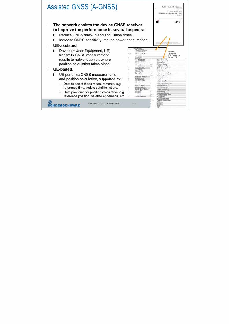
8/22/2019 LTE eutran rsanov2012
http://slidepdf.com/reader/full/lte-eutran-rsanov2012 172/284
November 2012 | LTE Introduction | 173
l The network assists the device GNSS receiver
to improve the performance in several aspects:l Reduce GNSS start-up and acquisition times.
l Increase GNSS sensitivity, reduce power consumption.
l UE-assisted.
l Device (= User Equipment, UE)
transmits GNSS measurementresults to network server, where
position calculation takes place.
l UE-based.
l UE performs GNSS measurements
and position calculation, supported by:
– Data to assist these measurements, e.g.reference time, visible satellite list etc.
– Data providing for position calculation, e.g.
reference position, satellite ephemeris, etc.
Source:
TS 36.355
LTE Positioning
Protocol (LPP)
LTE Positioning Protocol (LPP) 3GPP TS 36.355LPP position methods- A-GNSS Assisted Global Navigation Satellite System

8/22/2019 LTE eutran rsanov2012
http://slidepdf.com/reader/full/lte-eutran-rsanov2012 173/284
November 2012 | LTE Introduction | 174
UE E-SMLC
LPP over SUPL
User plane solution
LPP over RRC
Control plane solution
SET SLP
Target
Device
LPPLocation
Server Assistance data
Measurements based on reference sources*
eNB
LTE radiosignal
g y
- E-CID Enhanced Cell ID
- OTDOA Observed time differerence of arrival
*GNSS and LTE radio signals
SUPL enabled
Terminal
SUPL location
platform
Enhanced Serving
Mobile Location Center
LPP and lower layers
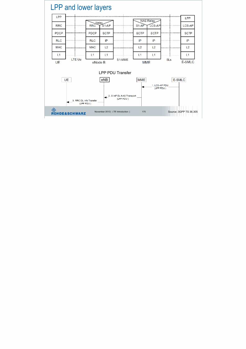
8/22/2019 LTE eutran rsanov2012
http://slidepdf.com/reader/full/lte-eutran-rsanov2012 174/284
November 2012 | LTE Introduction | 175
LPP PDU Transfer
eNB
Source: 3GPP TS 36.305
User plane stackSUPL occupies the application layer in the LTE user plane stack,
with LPP (or another positioning protocol !) transported as another layer

8/22/2019 LTE eutran rsanov2012
http://slidepdf.com/reader/full/lte-eutran-rsanov2012 175/284
November 2012 | LTE Introduction | 176
with LPP (or another positioning protocol !) transported as another layer
above SUPL.
Source: 3GPP TS 36.305
GNSS positioning methods supportedl Autonomeous GNSS

8/22/2019 LTE eutran rsanov2012
http://slidepdf.com/reader/full/lte-eutran-rsanov2012 176/284
November 2012 | LTE Introduction | 177
l Assisted GNSS (A-GNSS)
l The network assists the UE GNSS receiver to
improve the performance in several aspects:
– Reduce UE GNSS start-up and acquisition times
– Increase UE GNSS sensitivity
– Allow UE to consume less handset power
l UE Assisted – UE transmits GNSS measurement results to E-SMLC where the position calculation
takes place
l UE Based
– UE performs GNSS measurements and position calculation, suppported by data …
– … assisting the measurements, e.g. with reference time, visible satellite list etc.
– … providing means for position calculation, e.g. reference position, satellite ephemeris, etc.
Source: 3GPP TS 36.305
GNSS candidates and augmentation systems
l GPS/Modernized GPS – Global Positioning System (USA, since 1995)
l Galileo (E rope nder de elopment target 2013)

8/22/2019 LTE eutran rsanov2012
http://slidepdf.com/reader/full/lte-eutran-rsanov2012 177/284
November 2012 | LTE Introduction | 178
l Galileo (Europe, under development, target 2013)
l GLONASS (Russia)l Compass, Beidou-2 (China, under development, target 2015)
l IRNSS (India, in process of planning)
l SBAS – Satellite based augmentation systems
– Geostationary satellites supporting error corrections by overlay signals
– WAAS – Wide Area Augmentation System (USA)
– EGNOS – European Geostationary Navigation Overlay Service (Europa)
– MSAS – Mulit-Functional Satellite Augmentation System (Japan)
– QZSS – Quasi-Zenith Satellite System (Japan, supports GPS, expected 2013)
– GAGAN – GPS Aided Geo Augmented Navigation (India)
GNSS band allocations

8/22/2019 LTE eutran rsanov2012
http://slidepdf.com/reader/full/lte-eutran-rsanov2012 178/284
November 2012 | LTE Introduction | 179
E1
L5 E5b L2 G2 E6 L1 G1
1164 1215 1260 1300 1559 1610
E5a
1237 15911563 1587
f/MHz
GPS and GLONASS satellite orbits

8/22/2019 LTE eutran rsanov2012
http://slidepdf.com/reader/full/lte-eutran-rsanov2012 179/284
November 2012 | LTE Introduction | 180
GPS:26 Satellites
Orbital radius 26560 km
GLONASS:
26 Satellites
Orbital radius 25510 km
Position Determination
R Δt
tsj trj

8/22/2019 LTE eutran rsanov2012
http://slidepdf.com/reader/full/lte-eutran-rsanov2012 180/284
November 2012 | LTE Introduction | 181
l „Pseudo distance“ Satellite – Receiver
l R j = c · Δt j=c· (trj-tsj) = ρ j + c· Δclock + ΔIono + ΔTropo + ΔMpath + ΔInt + ΔNoise
– ρ j = real distance („error -free“) – c· Δclock = Clock error (4th unknown variable → 4th satellite required)
– ΔIono , ΔTropo = „speed of light“ error due to ionosphere and troposhere
– ΔMpath , ΔInt , ΔNoise = trj uncertainty due to multipath propagation, interference,
noise
l Each satellite j broadcasts its current position ρSAT,j and local time tsj.
l With ρSAT,j and ρ j the receiver position can be evalutated
l Additional signal phase measurements to increase accuracy
R j = c·Δt j
Backup basic terms
l Ephemeris

8/22/2019 LTE eutran rsanov2012
http://slidepdf.com/reader/full/lte-eutran-rsanov2012 181/284
November 2012 | LTE Introduction | 182
l Ephemeris
l Table of values that gives the positions of objects in the sky at a given timel Almanach
l Set of data that every satellite transmits. It includes information about the
state (health) of the entire satellite constellation and coarse data on every
satellite‘s orbit.
l Cold startl No ephemeris, almanac or location data available (reset state)
l Hot start
l Location data available
Why is GNSS not sufficent?

8/22/2019 LTE eutran rsanov2012
http://slidepdf.com/reader/full/lte-eutran-rsanov2012 182/284
November 2012 | LTE Introduction | 183
l Global navigation satellite systems (GNSSs) have restricted
performance in certain environments
l Often less than four satellites visible: critical situation for GNSS
positioning support required (Assisted GNSS)
alternative required (Mobile radio positioning)
Critical scenario Very critical scenario GPS Satellites visibility (Urban)
Reference [DLR]
(A-)GNSS vs. mobile radio positioningmethods

8/22/2019 LTE eutran rsanov2012
http://slidepdf.com/reader/full/lte-eutran-rsanov2012 183/284
November 2012 | LTE Introduction | 184
(A-)GNSS Mobile radio systems
Low bandwidth (1-2 MHz) High bandwidth (up to 20 MHz for LTE)
Very weak received signals Comparatively strong received signals
Similar received power levels from all satellites One strong signal from the serving BS,strong interference situation
Long synchronization sequences Short synchronization sequences
Signal a-priori known due to low data ratesComplete signal not a-priori known to
support high data rates, only certain pilots
Very accurate synchronization of the satellites
by atomic clocksSynchronization of the BSs not a-priori guaranteed
Line of sight (LOS) access as normal case
not suitable for urban / indoor areas
Non line of sight (NLOS) access as normal case
suitable for urban / indoor areas
3-dimensional positioning 2-dimensional positioning
Measurements for positioning
l UE-assisted measurements l eNB-assisted measurements

8/22/2019 LTE eutran rsanov2012
http://slidepdf.com/reader/full/lte-eutran-rsanov2012 184/284
November 2012 | LTE Introduction | 185
l UE assisted measurements.
l Reference Signal Received
Power
(RSRP) and Reference Signal
Received Quality (RSRQ).
l RSTD – Reference Signal Time
Difference.
l UE Rx –Tx time difference.
l eNB assisted measurements.
l eNB Rx – Tx time difference.
l TADV – Timing Advance.
– For positioning Type 1 is of
relevance.
l AoA – Angle of Arrival.
l UTDOA – Uplink Time Difference
of Arrival.
RSRP, RSRQ are
measured on reference
signals of serving cell i
Serving cell i
Neighbor cell j
RSTD – Relative time difference
between a subframe received from
neighbor cell j and corresponding
subframe from serving cell i:
TSubframeRxj - TSubframeRxi
Source: see TS 36.214 Physical Layer measurements for detailed definitions
UE Rx-Tx time difference is defined
as TUE-RX – TUE-TX, where TUE-RX is the
received timing of downlink radio frame
#i from the serving cell i and TUE-TX the
transmit timing of uplink radio frame #i.
DL radio frame #i
UL radio frame #i
eNB Rx-Tx time difference is definedas TeNB-RX – TeNB-TX, where TeNB-RX is the
received timing of uplink radio frame #i
and TeNB-TX the transmit timing of
downlink radio frame #i.
UL radio frame #iDL radio frame #i
TADV (Timing Advance)= eNB Rx-Tx time difference + UE Rx-Tx time difference
= (TeNB-RX – TeNB-TX) + (TUE-RX – TUE-TX)
Observed Time difference

8/22/2019 LTE eutran rsanov2012
http://slidepdf.com/reader/full/lte-eutran-rsanov2012 185/284
November 2012 | LTE Introduction | 186
If network is synchronised,
UE can measure time difference
Observed Time
Difference of ArrivalOTDOA
Methods‘ overview CID E-CID (RSRP/TOA/TADV) E-CID (RSRP/TOA/TADV) [Trilateration]

8/22/2019 LTE eutran rsanov2012
http://slidepdf.com/reader/full/lte-eutran-rsanov2012 186/284
November 2012 | LTE Introduction | 187
E-CID (AOA) [Triangulation] Downlink / Uplink (O/U-TDOA) [Multilateration] RF Pattern matching
To be updated!!
Cell ID
l Not new other definition: Cell of Origin (COO)

8/22/2019 LTE eutran rsanov2012
http://slidepdf.com/reader/full/lte-eutran-rsanov2012 187/284
November 2012 | LTE Introduction | 188
l Not new, other definition: Cell of Origin (COO).
lUE position is estimated with the knowledge of the geographicalcoordinates of its serving eNB.
l Position accuracy = One whole cell .
Enhanced-Cell ID (E-CID)
l UE positioning compared to CID is specified more

8/22/2019 LTE eutran rsanov2012
http://slidepdf.com/reader/full/lte-eutran-rsanov2012 188/284
November 2012 | LTE Introduction | 189
l UE positioning compared to CID is specified more
accurately using additional UE and/or E UTRAN radiomeasurements:
l E-CID with distance from serving eNB position accuracy: a circle.
– Distance calculated by measuring RSRP / TOA / TADV (RTT).
l E-CID with distances from 3 eNB-s position accuracy: a point.
– Distance calculated by measuring RSRP / TOA / TADV (RTT).
l E-CID with Angels of Arrival position accuracy: a point.
– AOA are measured for at least 2, better 3 eNB‘s.
RSRP – Reference Signal Received Power
TOA – Time of Arrival
TADV – Timing Advance
RTT – Round Trip Time
TADV – Timing Advance (Round Trip Time, RTT) l Base station measures:
eNB Rx-Tx = TeNB-Rx – TeNB-Tx eNB Rx Timing of subframe n
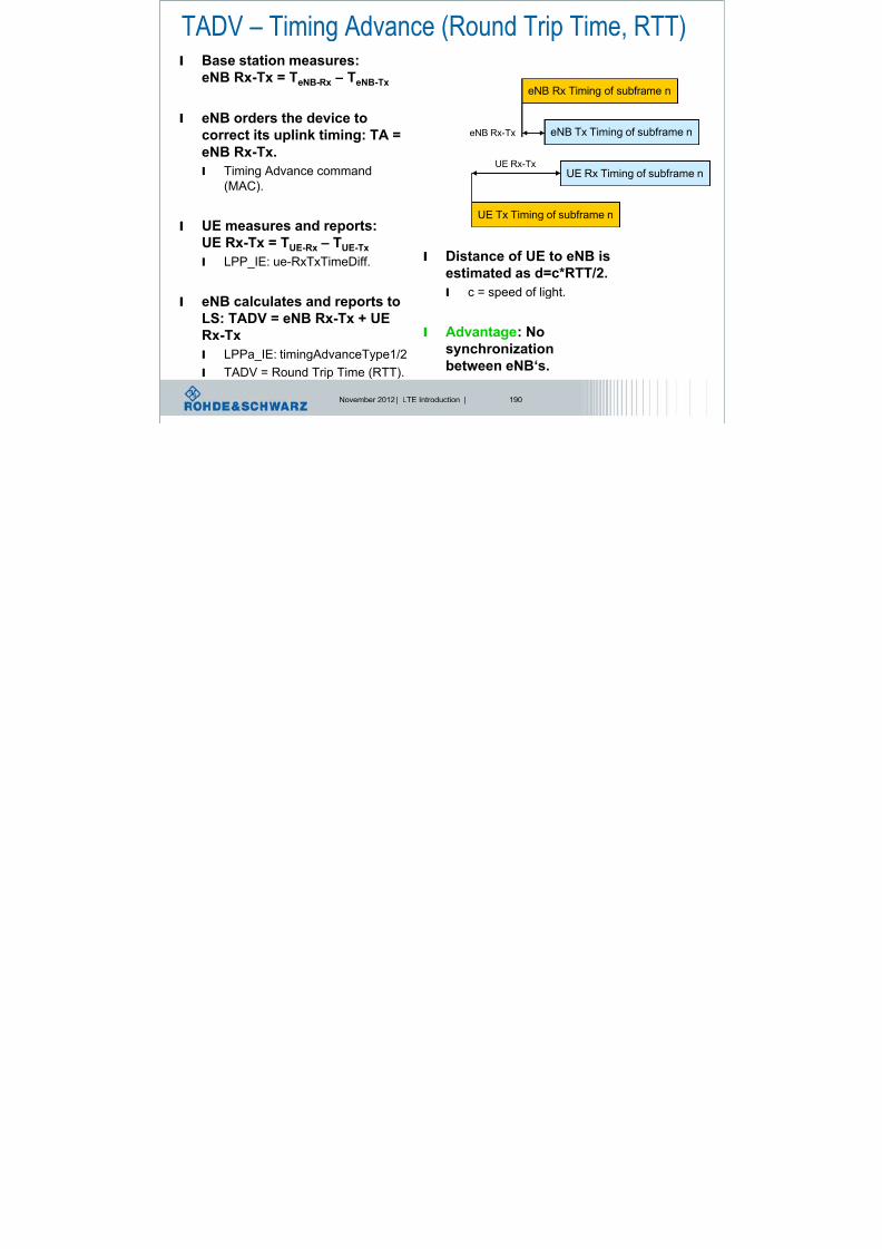
8/22/2019 LTE eutran rsanov2012
http://slidepdf.com/reader/full/lte-eutran-rsanov2012 189/284
November 2012 | LTE Introduction | 190
l eNB orders the device tocorrect its uplink timing: TA =
eNB Rx-Tx.
l Timing Advance command
(MAC).
l UE measures and reports:UE Rx-Tx = TUE-Rx – TUE-Tx
l LPP_IE: ue-RxTxTimeDiff.
l eNB calculates and reports to
LS: TADV = eNB Rx-Tx + UERx-Tx
l LPPa_IE: timingAdvanceType1/2
l TADV = Round Trip Time (RTT).
UE Rx Timing of subframe n
eNB Tx Timing of subframe n
UE Tx Timing of subframe n
eNB Rx-Tx
UE Rx-Tx
l Distance of UE to eNB is
estimated as d=c*RTT/2.
l c = speed of light.
l Advantage: No
synchronization
between eNB‘s.
Angle of Arrival (AOA)
l AoA = Estimated angle of a UE with respect to a reference

8/22/2019 LTE eutran rsanov2012
http://slidepdf.com/reader/full/lte-eutran-rsanov2012 190/284
November 2012 | LTE Introduction | 191
l AoA Estimated angle of a UE with respect to a reference
direction (= geographical North), positive in a counter-clockwise direction, as seen from an eNB.
l Determined at eNB antenna based
on a received UL signal (SRS).
l Measurement at eNB:
l
eNB uses antenna array to estimatedirection i.e. Angle of Arrival (AOA).
l The larger the array, the more
accurate is the estimated AOA.
l eNB reports AOA to LS.
l Advantage: No synchronization
between eNB‘s.
l Drawback: costly antenna arrays.
OTDOA – Observed Time Difference of Arrival
l UE position is estimated based on measuring TDOA of

8/22/2019 LTE eutran rsanov2012
http://slidepdf.com/reader/full/lte-eutran-rsanov2012 191/284
November 2012 | LTE Introduction | 192
l UE position is estimated based on measuring TDOA of
Positioning Reference Signals (PRS) embedded into overallDL signal received from different eNB’s.
l Each TDOA measurement describes a hyperbola (line of constant
difference 2a), the two focus points of which (F1, F2) are the two
measured eNB-s (PRS sources), and along which the UE may be
located.
l UE’s position = intersection of hyperbolas for at least 3 pairs of eNB’s.
LTE Release 9UE positioning – Reference Symbol Details

8/22/2019 LTE eutran rsanov2012
http://slidepdf.com/reader/full/lte-eutran-rsanov2012 192/284
November 2012 | LTE Introduction | 193
l PRS is a pseudo-random QPSKsequence similar to CRS
l PRS pattern (baseline for further
discussion and CR drafting):
l Diagonal pattern with time
varying frequency shift,
l PRS mapped around CRS (to
avoid collisions)
Antenna Port 0
Positioning Reference Signals (PRS) for OTDOADefinition
l Cell-specific reference signals (CRS) are not sufficient for

8/22/2019 LTE eutran rsanov2012
http://slidepdf.com/reader/full/lte-eutran-rsanov2012 193/284
November 2012 | LTE Introduction | 194
p g ( )
positioning, introduction of positioning reference signals(PRS) for antenna port 6.
l SINR for synchronization
and reference signals of
neighboring cells needs to
be at least -6 dB.
l PRS is a pseudo-randomQPSK sequence similar
to CRS; PRS pattern:
l Diagonal pattern with time
varying frequency shift.
l PRS mapped around CRS to avoid collisions;never overlaps with PDCCH; example shows
CRS mapping for usage of 4 antenna ports.
Uplink (UTDOA)
l UTDOA = Uplink Time Difference of Arrival

8/22/2019 LTE eutran rsanov2012
http://slidepdf.com/reader/full/lte-eutran-rsanov2012 194/284
November 2012 | LTE Introduction | 195
l UE positioning estimated based on:
– measuring TDOA of UL (SRS) signals received in different eNB-s
– each TDOA measurement describes a hyperbola (line of constant difference 2a),the 2 focus points of which (F1, F2) are the two receiving eNB-s (SRSreceiptors), and along which the UE may be located.
– UE’s position = intersection of hyperbolas for at least three pairs of eNB-s(= 3 eNB-s)
– knowledge of the geographical coordinates of the measured eNode Bs
l Method as such not specified for LTE Similarity to 3G assumed
Location
Server
- eNB-s measure and
report to eNB_Rx-Tx to LS
-LS calculates UTDOA
and estimates the UE
position
What is Self Organizing Networks, SON?
l SON = Self-Organizing Networks, methods for automatic configuration
and optimization of the network

8/22/2019 LTE eutran rsanov2012
http://slidepdf.com/reader/full/lte-eutran-rsanov2012 195/284
November 2012 | LTE Introduction | 196
p
l 3 components:
l Self-Configuration:
l basic setup: IP address configuration, association with a
Gateway, software download,…
l Initial radio configuration: neighbour list configuration,…
l Self-Optimization:
l Neighbour list optimization, coverage/capacity
optimization,…
l Self-Healing:
l Failure detection/localization,…
Motivation for SON
Heterogeneous Networks:

8/22/2019 LTE eutran rsanov2012
http://slidepdf.com/reader/full/lte-eutran-rsanov2012 196/284
November 2012 | LTE Introduction | 197
Heterogeneous Networks:
No way without SON
Source: Deutsche Telekom
Overview SON
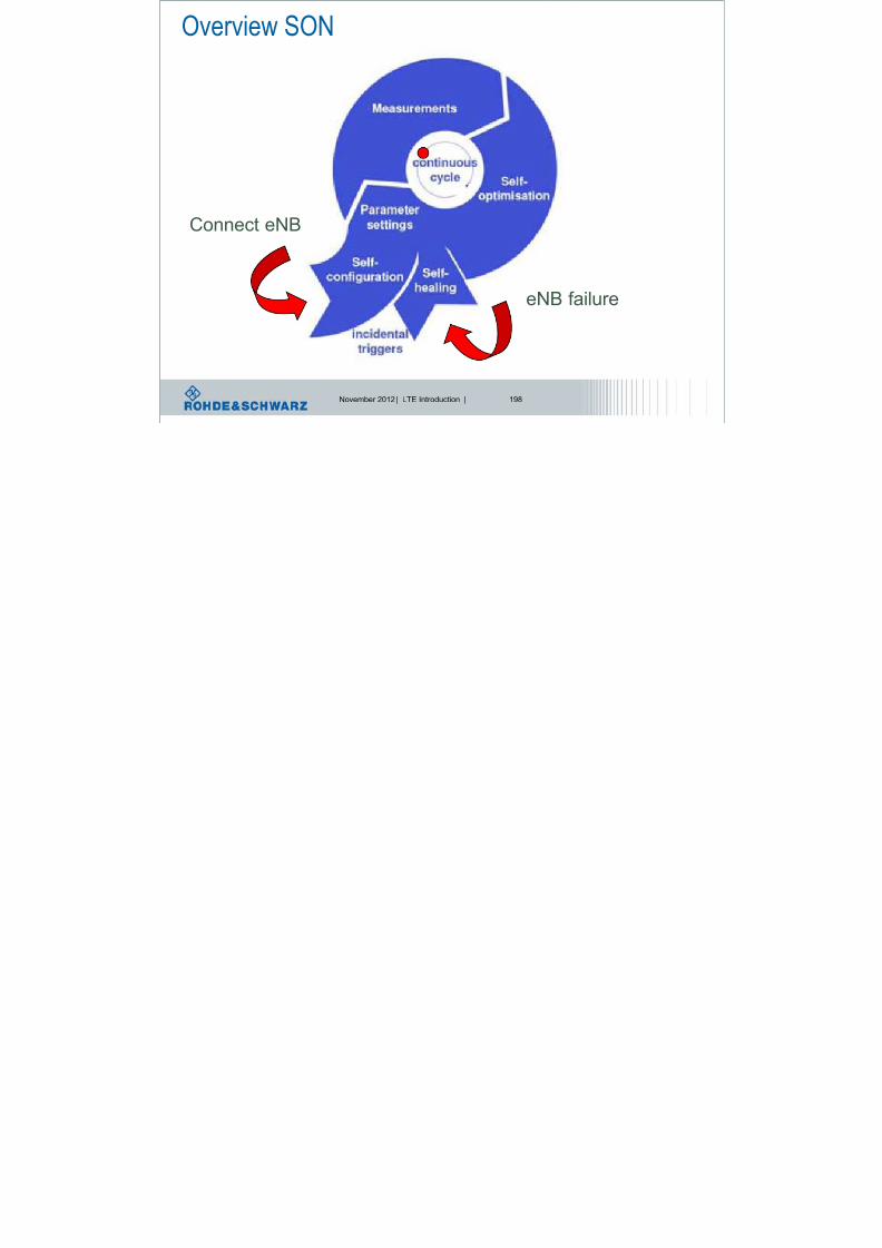
8/22/2019 LTE eutran rsanov2012
http://slidepdf.com/reader/full/lte-eutran-rsanov2012 197/284
November 2012 | LTE Introduction | 198
Connect eNB
eNB failure
Architecture
Centralized
O&M SON
Centralized SON
Distributed SON

8/22/2019 LTE eutran rsanov2012
http://slidepdf.com/reader/full/lte-eutran-rsanov2012 198/284
November 2012 | LTE Introduction | 199
O&M
O&M O&MSON
SON
SON
eNB eNB
SON SON
Hybrid SON
Energy Savings
l Match Network Capacitiy to the required traffic

8/22/2019 LTE eutran rsanov2012
http://slidepdf.com/reader/full/lte-eutran-rsanov2012 199/284
November 2012 | LTE Introduction | 200
p y q
lSwitch on / off cell on demand
l Vodafone contribution on NGMN:
Self Healing
l Automatic detection of failures (Sleeping Cells)
l Usually detected by performance statistics

8/22/2019 LTE eutran rsanov2012
http://slidepdf.com/reader/full/lte-eutran-rsanov2012 200/284
November 2012 | LTE Introduction | 201
l
Unreliable, because statistics sometimes fluctuate largely
l Cell Outage Compensation
l Recovery actions
– Fallback to previous SW
– Switching to backup units for HW
l Self optimization of the surrounding NW
Automatic Configuration of Physical Cell IDRelease 8
l Automatic configuration of new deployed eNodeBs

8/22/2019 LTE eutran rsanov2012
http://slidepdf.com/reader/full/lte-eutran-rsanov2012 201/284
November 2012 | LTE Introduction | 202
l Automatic configuration of new deployed eNodeBs
l 504 Physical Cell IDs are supported
l Selection of Physical Cell ID must be
l Collision free
– The ID is unique in the area the cell covers
l Confusion free
– A cell shall not have neighboring cells with identical IDs
l Definitely a must for Femto-Cells (HeNBs)
l Centralized or Distributed Architecture
Mobility Robustness Optimization (MRO)Release 9
l Manually setting of HO parameters

8/22/2019 LTE eutran rsanov2012
http://slidepdf.com/reader/full/lte-eutran-rsanov2012 202/284
November 2012 | LTE Introduction | 203
l Manually setting of HO parameters
l Time consuming → Often neglected l Optimal settings may depend on momentary radio conditions
– Difficult to control manually
l Incorrect HO parameter setting may lead to
l Non-optimal use of network resources – Unnecessary handovers
– Prolonged connection to a non-optimal cell
l HO failures
– Degradation of the service performance
l Radio Link failures – Combined impact on user experience and network performance
– The main objective of MRO is to reduce RLF
Coverage and Capacity Optimization
Trade-Off between coverage and capacityCell edge performance
Pilot pollution (Interference)

8/22/2019 LTE eutran rsanov2012
http://slidepdf.com/reader/full/lte-eutran-rsanov2012 203/284
November 2012 | LTE Introduction | 204
eNodeB
g p y
Coverage has priority
Detection of unintended coverage holes
eNodeB
eNodeB
Measurement by Network:
l Call drop rates→ Indication of
insufficient coverage
l Traffic counters
→ Capacity problems
Mobility Load Balancing (MLB) OptimizationRelease 9

8/22/2019 LTE eutran rsanov2012
http://slidepdf.com/reader/full/lte-eutran-rsanov2012 204/284
November 2012 | LTE Introduction | 205
IMT-Advanced Requirements
l A high degree of commonality of functionality worldwide while
t i i th fl ibilit t t id f i d

8/22/2019 LTE eutran rsanov2012
http://slidepdf.com/reader/full/lte-eutran-rsanov2012 205/284
November 2012 | LTE Introduction | 206
retaining the flexibility to support a wide range of services and
applications in a cost efficient manner,
l Compatibility of services within IMT and with fixed networks,
l Capability of interworking with other radio access systems,
l High quality mobile services,
l User equipment suitable for worldwide use,
l User-friendly applications, services and equipment,
l Worldwide roaming capability; and
l Enhanced peak data rates to support advanced services and
applications,
l 100 Mbit/s for high and
l 1 Gbit/s for low mobility
were established as targets for research,
Do you Remember?Targets of ITU IMT-2000 Program (1998)
IMT-2000
The ITU vision of global wireless access

8/22/2019 LTE eutran rsanov2012
http://slidepdf.com/reader/full/lte-eutran-rsanov2012 206/284
November 2012 | LTE Introduction | 207
The ITU vision of global wireless access
in the 21
st
century
Satellite
MacrocellMicrocell
UrbanIn-Building
Picocell
Global
Suburban
Basic Terminal
PDA TerminalAudio/Visual Terminal
l Flexible and global – Full coverage and mobility at 144 kbps .. 384 kbps
– Hot spot coverage with limited mobility at 2 Mbps
– Terrestrial based radio access technologies
l The IMT-2000 family of standards now supports four different multiple
access technologies:
l FDMA, TDMA, CDMA (WCDMA) and OFDMA (since 2007)
IMT Spectrum
MHz

8/22/2019 LTE eutran rsanov2012
http://slidepdf.com/reader/full/lte-eutran-rsanov2012 207/284
November 2012 | LTE Introduction | 208
Next possible spectrum
allocation at WRC 2015!
MHz
MHz
MHz
Expected IMT-Advanced candidates
Long
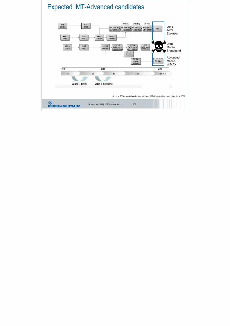
8/22/2019 LTE eutran rsanov2012
http://slidepdf.com/reader/full/lte-eutran-rsanov2012 208/284
November 2012 | LTE Introduction | 209
Source: TTA‘s workshop for the future of IMT-Advanced technologies, June 2008
Term
Evolution
Ultra
Mobile
Broadband
AdvancedMobile
WiMAX
IMT – International Mobile Communication
l IMT-2000

8/22/2019 LTE eutran rsanov2012
http://slidepdf.com/reader/full/lte-eutran-rsanov2012 209/284
November 2012 | LTE Introduction | 210
l Was the framework for the third Generation mobile communication
systems, i.e. 3GPP-UMTS and 3GPP2-C2K
l Focus was on high performance transmission schemes:
Link Level Efficiency
l Originally created to harmonize 3G mobile systems and to increase
opportunities for worldwide interoperability, the IMT-2000 family of
standards now supports four different access technologies, includingOFDMA (WiMAX), FDMA, TDMA and CDMA (WCDMA).
l IMT-Advanced
l Basis of (really) broadband mobile communication
l Focus on System Level Efficiency (e.g. cognitive network
systems)l Vision 2010 – 2015
System level efficiencyl Todays mobile communication networks use static frequency allocation
l Network planning
l Adaptation to traffic load over cell boarder not possible
l Dynamic spectrum allocation to increase system efficiency

8/22/2019 LTE eutran rsanov2012
http://slidepdf.com/reader/full/lte-eutran-rsanov2012 210/284
November 2012 | LTE Introduction | 211
l Dynamic spectrum allocation to increase system efficiency
l Radio resource management to configure the occupied bandwidth of each celll Dynamic management for inter-cell interference reduction
l Cognitive networks (self organizing networks SON) which adjust automatically totraffic load and interference conditions.
l Application oriented source and channel codingl Typically, source and channel coding are separated, i.e. MPEG and convolutional
coding. Joint Source & Channel Coding (JSCC) promises better efficiency
l Base stations are on 24/7 – but why?l Basisstations/Relaystations operate in „sleep“ or „off“ modes
l Enhancements of interference situations and energy consumption
l Too many interfaces reduce the throughputl Reducing the amount of components in the network structure
l Heterogenuous networks
l Usage of various radio access technologies of same core network
LTE-AdvancedPossible technology features

8/22/2019 LTE eutran rsanov2012
http://slidepdf.com/reader/full/lte-eutran-rsanov2012 211/284
November 2012 | LTE Introduction | 212
Cognitive radio
methods
Enhanced MIMO
schemes for DL and UL
Interference management
methods
Relayingtechnology
Cooperative
base stations
Radio network evolution Further enhanced
MBMS
Wider bandwidthsupport
Bandwidth extension with Carrier aggregation

8/22/2019 LTE eutran rsanov2012
http://slidepdf.com/reader/full/lte-eutran-rsanov2012 212/284
November 2012 | LTE Introduction | 213
LTE-AdvancedCarrier Aggregation
Component carrier CC
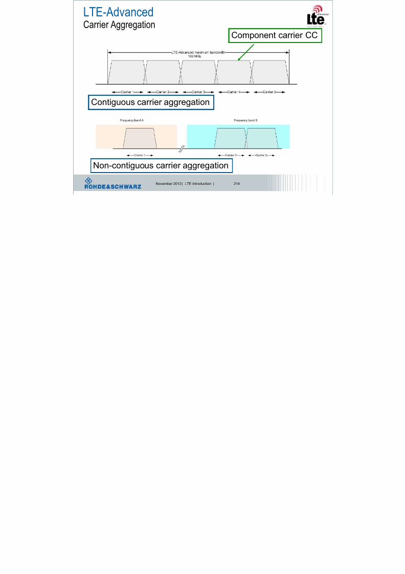
8/22/2019 LTE eutran rsanov2012
http://slidepdf.com/reader/full/lte-eutran-rsanov2012 213/284
November 2012 | LTE Introduction | 214
Contiguous carrier aggregation
Non-contiguous carrier aggregation
Aggregationl Contiguous
l Intra-Band
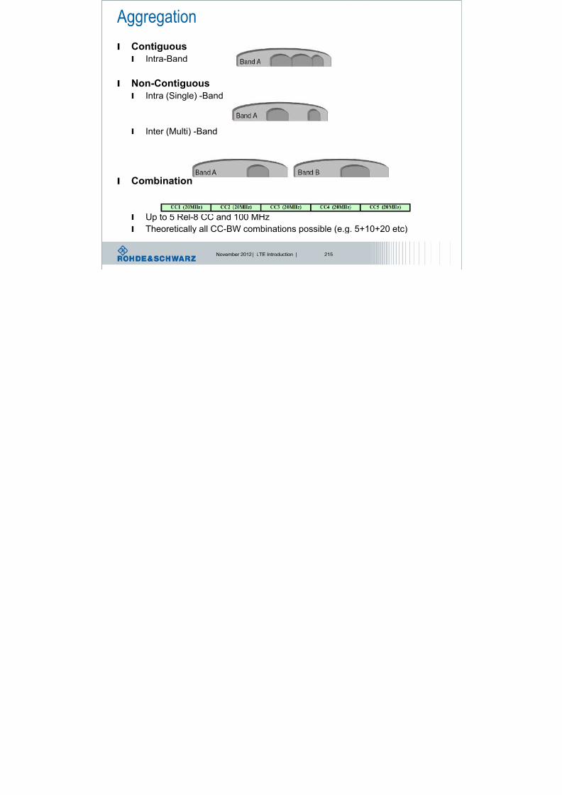
8/22/2019 LTE eutran rsanov2012
http://slidepdf.com/reader/full/lte-eutran-rsanov2012 214/284
November 2012 | LTE Introduction | 215
l Non-Contiguousl Intra (Single) -Band
l Inter (Multi) -Band
l Combination
l Up to 5 Rel-8 CC and 100 MHz
l Theoretically all CC-BW combinations possible (e.g. 5+10+20 etc)
Motivation
l 1) Higher data rate through
more spectrum allocation

8/22/2019 LTE eutran rsanov2012
http://slidepdf.com/reader/full/lte-eutran-rsanov2012 215/284
November 2012 | LTE Introduction | 216
more spectrum allocation
l to fulfill 4G requirements
l 1 Gbit/s in downlink (up to 5
component carriers, up to 100
MHz)
l Other methods (spectral
efficiency etc.) alreadyexploited or not relevant
l 2) Exploit the total
(combined) BW assigned in
form of separated bandsl scattered spectrum
l Two or more component carriers are aggregated in LTE-Advanced
in order to support wider bandwidths up to 100 MHz
Carrier aggregation (CA)General comments

8/22/2019 LTE eutran rsanov2012
http://slidepdf.com/reader/full/lte-eutran-rsanov2012 216/284
November 2012 | LTE Introduction | 217
in order to support wider bandwidths up to 100 MHz.
l Support for contiguous and non-
contiguous component carrier
aggregation (intra-band) and
inter-band carrier aggregation.
l Different bandwidths per
component carrier (CC) are possible.l Each CC limited to a max. of 110 RB
using the 3GPP Rel-8 numerology
(max. 5 carriers, 20 MHz each).
l Motivation.
l Higher peak data rates to meetIMT-Advanced requirements.
l NW operators: spectrum aggregation, enabling Heterogonous Networks.
Frequency band A Frequency band B
Frequency band A Frequency band B
Frequency band A Frequency band B
Intra-band contiguous
Intra-band non-contiguous
Inter-band
Component
Carrier (CC)
2012 © by Rohde&Schwarz
Overviewl Carrier Aggregation (CA)
enables to aggregate up to 5 differentcells (component carriers CC), so that amaximum system bandwidth of 100 MHz

8/22/2019 LTE eutran rsanov2012
http://slidepdf.com/reader/full/lte-eutran-rsanov2012 217/284
November 2012 | LTE Introduction | 219
maximum system bandwidth of 100 MHz
can be supported (LTE-Advancedrequirement).
l Each CC = Rel-8 autonomous cell
– Backwards compatibility
l CC-Set is UE specific
– Registration Primary (P)CC
– Additional BW Secondary (S)CC-s 1-4
l Network perspective
– Same single RLC-connection for one UE(independent on the CC-s)
– Many CC (starting at MAC scheduler)operating the UE
l For TDD
– Same UL/DL configuration for all CC-s
UE1 U3
UE3
UE2
UE4
UE1
UE4 UE3 UE4 U2
CC1CC2
CC1CC2
Cell 1 Cell 2
Carrier aggregation (CA)General comments, cont’d. l A device capable of carrier aggregation has 1 DL primary component
carrier and 1 associated primary UL component carrier.
l Basic linkage between DL and UL is signaled in SIB Type 2.
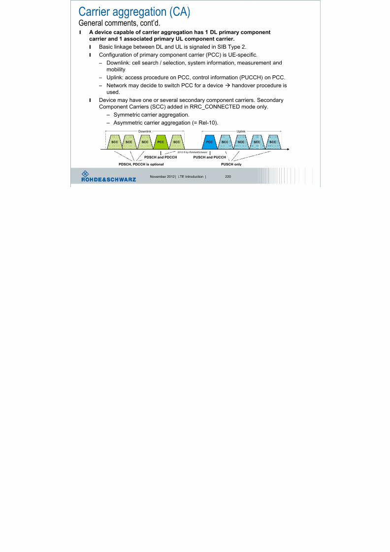
8/22/2019 LTE eutran rsanov2012
http://slidepdf.com/reader/full/lte-eutran-rsanov2012 218/284
November 2012 | LTE Introduction | 220
l Configuration of primary component carrier (PCC) is UE-specific. – Downlink: cell search / selection, system information, measurement and
mobility.
– Uplink: access procedure on PCC, control information (PUCCH) on PCC.
– Network may decide to switch PCC for a device handover procedure is
used.
l Device may have one or several secondary component carriers. SecondaryComponent Carriers (SCC) added in RRC_CONNECTED mode only.
– Symmetric carrier aggregation.
– Asymmetric carrier aggregation (= Rel-10).
SCC PCC PCC SCC
Downlink Uplink
SCC SCC SCCSCCSCCSCC
PDSCH, PDCCH is optional
PDSCH and PDCCH
PUSCH only
PUSCH and PUCCH
2012 © by Rohde&Schwarz
LTE-AdvancedCarrier Aggregation – Initial Deployment
l Initial LTE-Advanced deployments will likely be limited to
the use of two component carrier

8/22/2019 LTE eutran rsanov2012
http://slidepdf.com/reader/full/lte-eutran-rsanov2012 219/284
November 2012 | LTE Introduction | 221
the use of two component carrier.
l The below are focus scenarios identified by 3GPP RAN4.
Bandwidthl General
– Up to 5 CC
– Up to 100 RB-s pro CC
MHz3.06.0
1.0 spacingchannel Nominal
)2()1()2()1(
Channel Channel Channel Channel BW BW BW BW

8/22/2019 LTE eutran rsanov2012
http://slidepdf.com/reader/full/lte-eutran-rsanov2012 220/284
November 2012 | LTE Introduction | 222
– Up to 500 RB-s aggregated
l Aggregated transmission
bandwidth
– Sum of aggregated channel
bandwidths – Illustration for Intra band
contiguous
– Channel raster 300 kHz
l Bandwidth classes
– UE Capability
Bands / Band-Combinations (I)l E-UTRA CA Band
l Band / Band-Combinatios specified in RAN4 for CA scenarios
l Already 4 CA Bands specified

8/22/2019 LTE eutran rsanov2012
http://slidepdf.com/reader/full/lte-eutran-rsanov2012 221/284
November 2012 | LTE Introduction | 223
– For inter frequency bands without practical interest to guarantee quickprogress of the work
Bands / Band-Combinations (II)l Under discussion
l 25 WI-s in RAN4 with
practical interest
– Inter band (1 UL CC)

8/22/2019 LTE eutran rsanov2012
http://slidepdf.com/reader/full/lte-eutran-rsanov2012 222/284
November 2012 | LTE Introduction | 224
Inter band (1 UL CC)
– Intra band cont (1 UL CC)
– Intra band non cont
(1 UL CC)
– Inter band (2 UL CC)
l Release independencyl Band performance is
release independent
– Band introduced in Rel-11
– Performance tested for Rel-
10
Carrier aggregation - configurationsl CA Configurations
l E-UTRA CA Band + Allowed BW= CA Configuration
– Intra band contiguous

8/22/2019 LTE eutran rsanov2012
http://slidepdf.com/reader/full/lte-eutran-rsanov2012 223/284
November 2012 | LTE Introduction | 225
Intra band contiguous
– Most requirements
– Inter band
– Some requirements
– Main interest of many companies
– Intra band non contiguous
– No configuration / requirements
– Feature of later releases?
l CA Requirement applicability – CL_X Intra band CA
– CL_X-Y Inter band
– Non-CA no CA
(explicitely stated for the Test pointwhich are tested differently for CAand not CA)
UE categories for Rel-10 NEW! UE categories 6…8 (DL and UL)
UE
Category
Maximum number
of DL-SCH transport
block bits received
Maximum number of bits
of a DL-SCH transport
block received within a TTI
Total number of
soft channel bits
Maximum number of
supported layers for
spatial multiplexing in DL

8/22/2019 LTE eutran rsanov2012
http://slidepdf.com/reader/full/lte-eutran-rsanov2012 224/284
November 2012 | LTE Introduction | 226
within a TTI
block received within a TTI spatial multiplexing in DL
… … … … …
Category 6 301504149776 (4 layers)
75376 (2 layers)3654144 2 or 4
Category 7 301504149776 (4 layers)
75376 (2 layers)3654144 2 or 4
Category 8 2998560 299856 35982720 8
~3 Gbps peak
DL data rate
for 8x8 MIMOUE
Category
Maximum number
of UL-SCH
transport
block bits
transmitted
within a TTI
Maximum number
of bits of an UL-SCH
transport block
transmitted within a
TTI
Support
for
64Q
AM
in UL
… … … …
Category 6 51024 51024 No
Category 7 102048 51024 No
Category 8 1497760 149776 Yes
Total layer 2
buffer size
[bytes]
…
3 300 000
3 800 000
42 200 000
~1.5 Gbps peak
UL data rate, 4x4 MIMO
Deployment scenarios
F1 F2
3) Improve coverage
l #1: Contiguous frequency aggregationCo located & Same coverage

8/22/2019 LTE eutran rsanov2012
http://slidepdf.com/reader/full/lte-eutran-rsanov2012 225/284
November 2012 | LTE Introduction | 227
– Co-located & Same coverage
– Same f
l #2: Discontiguous frequency aggregation – Co-located & Similar coverage
– Different f
l #3: Discontiguous frequency aggregation – Co-Located & Different coverage
– Different f
– Antenna direction for CC2 to cover blank spots
l #4: Remote radio heads – Not co-located
– Intelligence in central eNB, radio heads = only transmissionantennas
– Cover spots with more traffic
– Is the transmission of each radio head within the cell thesame?
l #5:Frequency-selective repeaters – Combination #2 & #4
– Different f
– Extend the coverage of the 2nd CC with Relays
Physical channel arrangement in downlink

8/22/2019 LTE eutran rsanov2012
http://slidepdf.com/reader/full/lte-eutran-rsanov2012 226/284
November 2012 | LTE Introduction | 228
Each component
carrier transmits P-
SCH and S-SCH,Like Rel.8
Each component
carrier transmitsPBCH,
Like Rel.8
Non-Contiguous spectrum allocation
Contiguous spectrum allocation
LTE-AdvancedCarrier Aggregation – Scheduling
l There is one transport block (in
absence of spatial multiplexing)
and one HARQ entity per Dynamic
RLC transmission buffer

8/22/2019 LTE eutran rsanov2012
http://slidepdf.com/reader/full/lte-eutran-rsanov2012 227/284
November 2012 | LTE Introduction | 229
and one HARQ entity per
scheduled component carrier
(from the UE perspective),
l A UE may receive multiple
component carriers
simultaneously,
l Two different approaches arediscussed how to inform the UE
about the scheduling for each
band,l Separate PDCCH for each carrier,
l Common PDCCH for multiple carrier,
Datamod.
Mapping
Channelcoding
HARQ
Datamod.
Mapping
Channelcoding
HARQ
Datamod.
Mapping
Channelcoding
HARQ
Datamod.
Mapping
Channelcoding
HARQ
Dynamic
switching
[frequency in MHz]
e.g. 20 MHz
LTE-AdvancedCarrier Aggregation – Scheduling
Non-Contiguous spectrum allocation
Contiguous spectrum allocation
Dynamic
switching
RLC transmission buffer

8/22/2019 LTE eutran rsanov2012
http://slidepdf.com/reader/full/lte-eutran-rsanov2012 228/284
November 2012 | LTE Introduction | 230
Datamod.
Mapping
Channelcoding
HARQ
Datamod.
Mapping
Channelcoding
HARQ
Datamod.
Mapping
Channelcoding
HARQ
Datamod.
Mapping
Channelcoding
HARQ
switching
[frequency in MHz]
e.g. 20 MHz
Each component
Carrier may use its
own AMC,
= modulation + codingscheme
Carrier Aggregation – Architecture downlink
Radio Bearers
ROHC ROHC... ROHC ROHC... ROHC ROHC
Radio Bearers
1 UE using carrier aggregation

8/22/2019 LTE eutran rsanov2012
http://slidepdf.com/reader/full/lte-eutran-rsanov2012 229/284
November 2012 | LTE Introduction | 231
HARQ HARQ
DL-SCH
on CC1
...
Segm.
ARQ etc
Multiplexing UE1 Multiplexing UEn
BCCH PCCH
Unicast Scheduling / Priority Handling
Logical Channels
MAC
Security Security...
CCCH
MCCH
Multiplexing
MTCH
MBMS Scheduling
PCH BCH MCH
RLC
PDCP
Segm.
ARQ etc...
Transport Channels
Segm.
ARQ etc
Security Security...
Segm.
ARQ etc...
Segm. Segm.
...
...
...
DL-SCH
on CC x
HARQ HARQ
DL-SCH
on CC1
...
DL-SCH
on CC y
In case of CA, the multi-carrier nature of the physical layer is only exposed
to the MAC layer for which one HARQ entity is required per serving cell
Multiplexing
...
Scheduling / Priority Handling
Transport Channels
MAC
RLC
PDCP
Segm.
ARQ etc
Segm.
ARQ etc
Logical Channels
Security Security
CCCH
HARQ HARQ
UL-SCH
on CC1
...
UL-SCH
on CC z
Common or separate PDCCH per Component Carrier?
Time
up to 3 (4) symbols
per subframe 1 subframe = 1 ms
1 slot = 0.5 ms
l No cross-carrier scheduling.
l PDCCH on a component carrier

8/22/2019 LTE eutran rsanov2012
http://slidepdf.com/reader/full/lte-eutran-rsanov2012 230/284
November 2012 | LTE Introduction | 232
No cro ss-carr ier
schedul ing
F r e q u e n c y
P D C C H
P D
C C H
P D C C H PDSCH
PDSCH
PDSCH P D C C H
Cross-carrier
schedul ing
P D C C H
P D C C H PDSCH
PDSCH
PDSCH
assigns PDSCH resources on thesame component carrier (and
PUSCH resources on a single
linked UL component carrier).
l Reuse of Rel-8 PDCCH structure
(same coding, same CCE-based
resource mapping) and DCI formats.
l Cross-carrier scheduling.
l PDCCH on a component carrier
can assign PDSCH or PUSCH
resources in one of multiple component
carriers using the carrier indicator field.
l Rel-8 DCI formats extended with
3 bit carrier indicator field.
l Reusing Rel-8 PDCCH structure (same
coding, same CCE-based resource
mapping).
P C C
Carrier aggregation: control signals + schedulingEach CC has
its own control
channels,
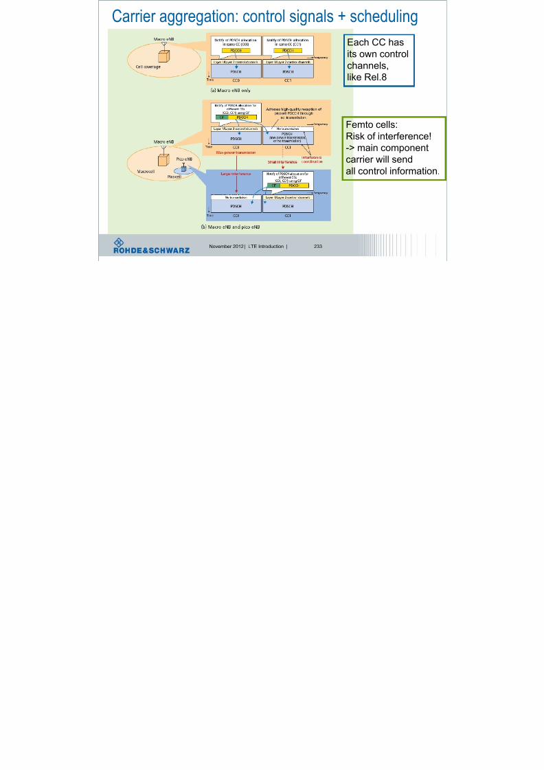
8/22/2019 LTE eutran rsanov2012
http://slidepdf.com/reader/full/lte-eutran-rsanov2012 231/284
November 2012 | LTE Introduction | 233
like Rel.8
Femto cells:
Risk of interference!-> main component
carrier will send
all control information.
Cross-carrier scheduling
l Main motivation for cross carrier scheduling: Interference
management for HetNet (eICIC); load balancing.

8/22/2019 LTE eutran rsanov2012
http://slidepdf.com/reader/full/lte-eutran-rsanov2012 232/284
November 2012 | LTE Introduction | 234
g ( ) g
l Cross carrier scheduling is optional to a UE.
l Activated by RRC signaling, if not activated no CFI is present.
l Component carriers are numbered, Primary Component Carrier
(PCC) is always cell index 0.
l Scheduling on a component carrier is only possible from ONE
component, independent if cross-carrier scheduling is ON or OFF:
l If cross carrier-scheduling active, UE needs to be informed about
PDSCH start on component carrier RRC signaling.
PDCCH
PDSCH
ComponentCarrier #1 ComponentCarrier #2 ComponentCarrier #5
… not possible,
transmission
can only be
scheduled by
one CC
PDCCH
PDCCH
PDSCH start
signaled by RRC
PCFICH
DCI control elements: CIF field
New field: carrier indicator field gives information,

8/22/2019 LTE eutran rsanov2012
http://slidepdf.com/reader/full/lte-eutran-rsanov2012 233/284
November 2012 | LTE Introduction | 235
Carrier Indicator Field, CIF, 3bits
f f f
which component carrier is valid.=> reminder: maximum 5 component carriers!
Component carrier 1 Component carrier 2 Component carrier N
PDSCH start field
Example: 1 Resource block
Of a component carrier

8/22/2019 LTE eutran rsanov2012
http://slidepdf.com/reader/full/lte-eutran-rsanov2012 234/284
November 2012 | LTE Introduction | 236
R R RPCFICH PCFICH PCFICH
e.g. PCC
Primary componentcarrier PDSCH start
field indicates
position
In cross-carrier scheduling,the UE does not read the PCFICHandPDCCH on SCC, thus it has to know the start of the
PDSCH
PDCCHe.g. SCC
Secondary component
carrier
Component Carrier – RACH configuration
Asymmetric carrier
Aggregation possible,
Downlink

8/22/2019 LTE eutran rsanov2012
http://slidepdf.com/reader/full/lte-eutran-rsanov2012 235/284
November 2012 | LTE Introduction | 237
gg g p
e.g. DL more CC than UL
Uplink
Each CC has its own RACH All CC use same RACH preamble
Network responds on all CCs
Only 1 CC contains RACH
Symmetryl DL-UL
l Number of CC
– TDD: DL = UL
– FDD: DL >= UL
l Component Carrier
– However position of DC
not known to System
Simulator

8/22/2019 LTE eutran rsanov2012
http://slidepdf.com/reader/full/lte-eutran-rsanov2012 236/284
November 2012 | LTE Introduction | 238
l Bandwidth
l Both
Addition, modification, release of additional CC
l RRCConnectionReconfigurat ion Message contains new Rel-
10 information element:
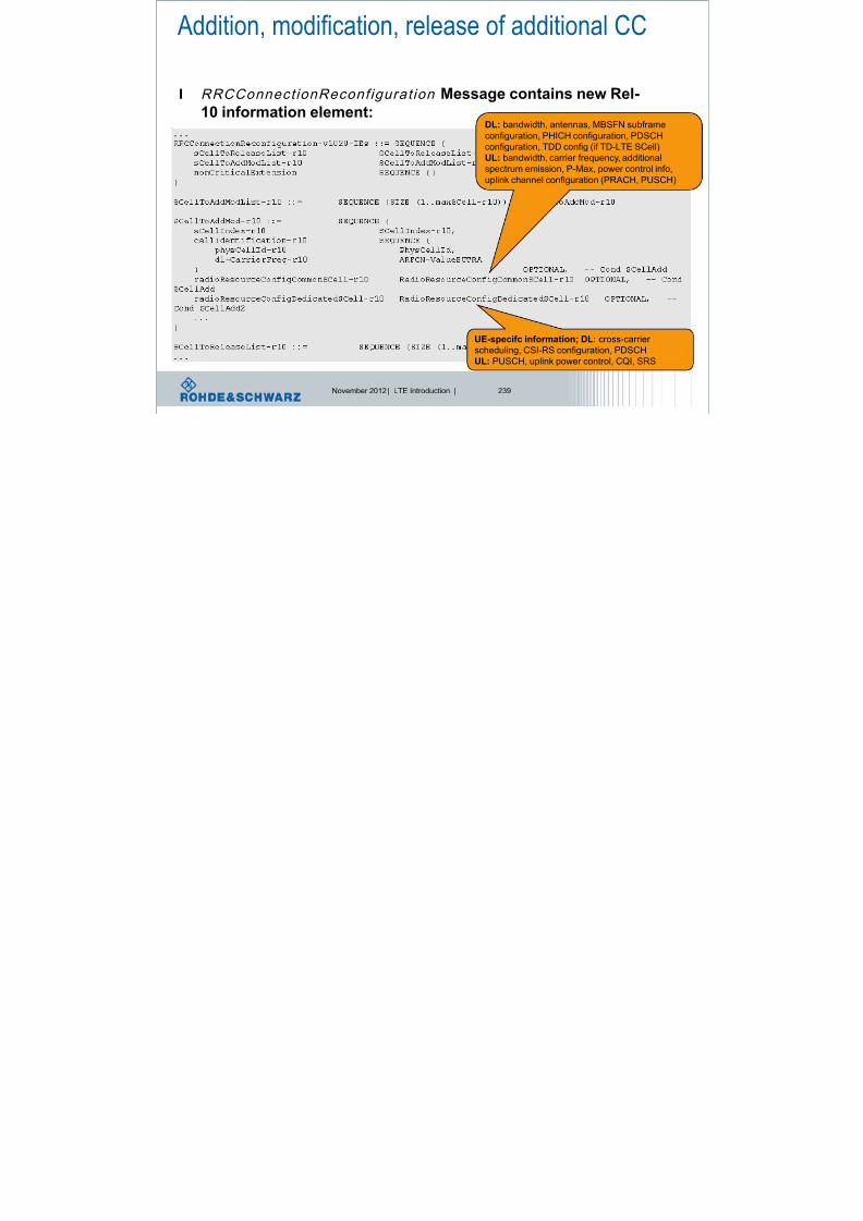
8/22/2019 LTE eutran rsanov2012
http://slidepdf.com/reader/full/lte-eutran-rsanov2012 237/284
November 2012 | LTE Introduction | 239
DL: bandwidth, antennas, MBSFN subframeconfiguration, PHICH configuration, PDSCH
configuration, TDD config (if TD-LTE SCell)
UL: bandwidth, carrier frequency, additional
spectrum emission, P-Max, power control info,
uplink channel configuration (PRACH, PUSCH)
UE-specifc information; DL: cross-carrier
scheduling, CSI-RS configuration, PDSCH
UL: PUSCH, uplink power control, CQI, SRS
UE EUTRAN
Default EPS bearer setup (3GPP LTE Rel-8)

8/22/2019 LTE eutran rsanov2012
http://slidepdf.com/reader/full/lte-eutran-rsanov2012 238/284
November 2012 | LTE Introduction | 240
Initial access and RRC connection establishment
attach request and PDN connectivity request
Authentication
NAS security
UE capability procedure
AS security
RRC connection reconfiguration
Attach accept and default EPS bearer context request
Default EPS bearer context accept
Additional information
being submitted by a
3GPP Rel-10 device…
UE capability information transfer 3GPP Rel-10 add on’s
l New IE’s within the for a 3GPP Rel-10 device:Carrier aggregation capabilities
are signaled separately for DL, UL.
Not all combinations
are allowed!

8/22/2019 LTE eutran rsanov2012
http://slidepdf.com/reader/full/lte-eutran-rsanov2012 239/284
November 2012 | LTE Introduction | 241
What frequency bands, band combination (CA
and MIMO capabilities, inter-band, intra-band
contiguous and non-contiguous, bandwidth class
does the device support?
!
2012 © by Rohde&Schwarz
Carrier Aggregation - Activation
l A new MAC control element for Component Carrier Management is
defined containing at least the activation respectively deactivation

8/22/2019 LTE eutran rsanov2012
http://slidepdf.com/reader/full/lte-eutran-rsanov2012 240/284
November 2012 | LTE Introduction | 242
command for the secondary DL component carriers configured for a UE. The new MAC CE is identified by a unique LCID
l
l For actual deactivation and activation signalling for the DL SCCs,
the MAC CE for CC Management includes a 4/5-bit bitmap where
each bit is representing one of the DL CCs that can be configuredin the UE. A bit set to 1 denotes activation of the corresponding DL
CC, a bit set to 0 respectively denotes deactivation
l New timer for implicit CC deactivation
l CC's are "just" additional resources. UL scheduling will assume
we do not have different QOS (delay/loss) on different CC's
Carrier Aggregation
l The transmission mode is not constrained to be the same
on all CCs scheduled for a UE

8/22/2019 LTE eutran rsanov2012
http://slidepdf.com/reader/full/lte-eutran-rsanov2012 241/284
November 2012 | LTE Introduction | 243
l A single UE-specific UL CC is configured semi-statically for
carrying PUCCH A/N, SR, and periodic CSI from a UE
l Frequency hopping is not supported simultaneously withnon-contiguous PUSCH resource allocation
l UCI cannot be carried on more than one PUSCH in a given
subframe.
Carrier Aggregation
l Working assumption is confirmed that a single set of PHICH
resources is shared by all UEs (Rel-8 to Rel-10)

8/22/2019 LTE eutran rsanov2012
http://slidepdf.com/reader/full/lte-eutran-rsanov2012 242/284
November 2012 | LTE Introduction | 244
l If simultaneous PUCCH+PUSCH is configured and there is
at least one PUSCH transmission
l UCI can be transmitted on either PUCCH or PUSCH with a
dependency on the situation that needs to be further discussed
l All UCI mapped onto PUSCH in a given subframe gets mapped onto
a single CC irrespective of the number of PUSCH CCs
UE Architectures

8/22/2019 LTE eutran rsanov2012
http://slidepdf.com/reader/full/lte-eutran-rsanov2012 243/284
November 2012 | LTE Introduction | 245
l Possible TX architecturesl Same / Different antenna (connectors) for each CC
l D1/D2 could be switched to support CA or UL MIMO
LTE – Advanced solutions from R&SR&S® SMU200 Vector Signal Generator
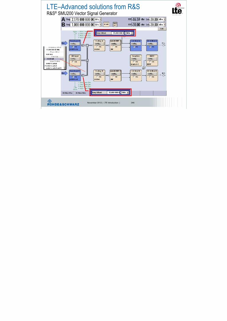
8/22/2019 LTE eutran rsanov2012
http://slidepdf.com/reader/full/lte-eutran-rsanov2012 244/284
November 2012 | LTE Introduction | 246
Ref -20 dBm Att 5 dB
RBW 2 MHz
VBW 5 MHz
SWT 2.5 ms
A -30
-20
LTE – Advanced solutions from R&SR&S® FSQ Signal Analyzer

8/22/2019 LTE eutran rsanov2012
http://slidepdf.com/reader/full/lte-eutran-rsanov2012 245/284
November 2012 | LTE Introduction | 247
Center 2.17 GHz Span 100 MHz10 MHz/
1 AP
CLRWR
3DB
EXT
-120
-110
-100
-90
-80
-70
-60
-50
-40
Date: 8.OCT.2009 14:13:24
LTE-Advanced – An introduction
A. Roessler | October 2009 | 247
20 MHz
E-UTRA carrier 2f c,E-UTRA carrier 2 = 2205 MHz
-10 dB
20 MHz
E-UTRA carrier 2f c,E-UTRA carrier 2 = 2135 MHz
Enhanced MIMO schemes
l Increased number of layers:
l Up to 8x8 MIMO in downlink.

8/22/2019 LTE eutran rsanov2012
http://slidepdf.com/reader/full/lte-eutran-rsanov2012 246/284
November 2012 | LTE Introduction | 248
l Up to 4x4 MIMO in uplink.
l In addition the downlink reference signal structure has been
enhanced compared with LTE Release 8 by:
l Demodulation Reference signals (DM-RS) targeting PDSCH demodulation.
– UE specific, i.e. an extension to multiple layers of the concept of Release 8 UE-
specific reference signals used for beamforming.
l Reference signals targeting channel state information (CSI-RS) estimation
for CQI/PMI/RI/etc reporting when needed.
– Cell specific, sparse in the frequency and time domain and punctured into the dataregion of normal subframes.
Downlink reference signals in LTE-Advanced
l Define two types of RS,
l RS targeting PDSCH demodulation,
l RS t ti CSI ti (f
l RS and data are subject to the same
pre-coding operation,
l complementary use of Rel-8 CRS by

8/22/2019 LTE eutran rsanov2012
http://slidepdf.com/reader/full/lte-eutran-rsanov2012 247/284
November 2012 | LTE Introduction | 249
l RS targeting CSI generation (for CQI/PMI/RI/etc reporting when
needed),
l RS targeting PDSCH demodulation
(for LTE-Advanced operation) are
l UE specific
– Transmitted only in scheduled RBs and
the corresponding layers – Different layers can target the same or
different UEs
– Design principle is an extension of the
concept of Rel-8 UE-specific RS (used for
beamforming) to multiple layersDetails on
UE-specific RS pattern, location, etc are
FFS
l RS on different layers are mutuallyorthogonal,
the UE is not precluded,
l RS targeting CSI generation (for
LTE-A operation) are
l Cell specific and sparse in frequency
and time
l Rel-8 transmission schemes using
Rel-8 cell-specific and/or UE-specific RS still supported,
Cell specific Reference Signals vs. DM-RSLTE Rel.8 LTE-Advanced (Rel.10)
s1 s1
CRS0 DM-RS0 CRS0 + CSI-RS0

8/22/2019 LTE eutran rsanov2012
http://slidepdf.com/reader/full/lte-eutran-rsanov2012 248/284
November 2012 | LTE Introduction | 250
l Demodulation-Reference signals DM-RS and data are precodedthe same way, enabling non-codebook based precoding and
enhanced multi-user beamforming.
s2
sN
........
Pre-
coding
s2
sN
........
Pre-
coding
Cell specific
Reference signalsN
DM-RSN Cell specific
reference signalsN +
Channel status information
reference signals 0
Ref. signal mapping: Rel.8 vs. LTE-Advancedl Example:
l 2 antenna ports, antenna port 0,
CSI-RS configuration 8.
l PDCCH (control) allocated in the
f O
LTE (Release 8) LTE-A (Release 10)0 1 2 3 4 5 6 0 1 2 3 4 5 6 0 1 2 3 4 5 6 0 1 2 3 4 5 6
0
x x x x 1

8/22/2019 LTE eutran rsanov2012
http://slidepdf.com/reader/full/lte-eutran-rsanov2012 249/284
November 2012 | LTE Introduction | 251
first 2 OFDM symbols.
l CRS sent on all RBs; DTX sent
for the CRS of 2nd antenna
port.
l DM-RS sent only for scheduledRBs on all antennas; each set
coded differently between the
two layers.
l CSI-RS punctures Rel. 8 data;
sent periodically over allotted
REs (not more than twice per
frame)
x x x x 1
E
x x x x S
A
E
x x x x L
E
R
x x x x
8
x x x x
E
x x x x S
A
E
x x x x L
E
R
x x x x
PDSCH PDCCH CRS DM-RS CSI-RS
DL MIMOExtension up to 8x8
l Max number of transport blocks: 2
l Number of MCS fields
lone for each transport block
Codeword to layer mapping for spatial multiplexing
Number
of layers
Number
of code
words
Codeword-to-layer mapping
110 layer
symb M , ,i

8/22/2019 LTE eutran rsanov2012
http://slidepdf.com/reader/full/lte-eutran-rsanov2012 250/284
November 2012 | LTE Introduction | 252
one for each transport blockl ACK/NACK feedback
l 1 bit per transport block for evaluation
as a baseline
l Closed-loop precoding supported
l Rely on precoded dedicated
demodulation RS (decision on DL RS)
l Conclusion on the codeword-to-layer mapping:
l DL spatial multiplexing of up to eight
layers is considered for LTE-Advanced,
l Up to 4 layers, reuse LTE codeword-to-
layer mapping,
l Above 4 layers mapping – see table
l Discussion on control signalingdetails ongoing
5 2
6 2
7 2
8 2
)34()()24()(
)14()(
)4()(
)1()7(
)1()6(
)1()5(
)1()4(
id i xid i x
id i x
id i x
)34()(
)24()(
)14()(
)4()(
)0()3(
)0()2(
)0()1(
)0()0(
id i x
id i x
id i x
id i x
)34()()24()()14()(
)4()(
)1()6(
)1()5(
)1()4(
)1()3(
id i xid i xid i xid i x
)23()()13()(
)3()(
)0()2(
)0()1(
)0()0(
id i xid i xid i x
)23()(
)13()(
)3()(
)1()5(
)1()4(
)1()3(
id i x
id i x
id i x
)23()()13()(
)3()(
)0()2(
)0()1(
)0()0(
id i xid i xid i x
)23()()13()(
)3()(
)1()4(
)1()3(
)1()2(
id i xid i xid i x
)12()(
)2()()0()1(
)0()0(
id i x
id i x
32 )1(
symb
)0(
symb
layer
symb M M M
33)1(
symb
)0(
symb
layer
symb M M M
43)1(
symb
)0(
symb
layer
symb M M M
44)1(
symb
)0(
symb
layer
symb M M M
MIMO – layer and codeword
Codeword 1:
111000011101
1 0 1
1 0 1
1 0 0Codeword 1:

8/22/2019 LTE eutran rsanov2012
http://slidepdf.com/reader/full/lte-eutran-rsanov2012 251/284
November 2012 | LTE Introduction | 253
111000011101
Codeword 2:
010101010011
0 1 1
1 0 0
0 0 0
1 1 1
1 1 1
0 0 1
111000011101
Codeword 2:010101010011
ACK ACK
ACK
Up to 8 timesthe data ->
8 layers
Receiver onlySends
2 ACK/NACKs
Scheduling of Transmission Mode 9 (TM9) l NEW DCI format 2C with 3GPP Rel-10.
l Used to schedule transmission mode 9 (TM9), which is spatial
multiplexing with DM-RS support of up to 8 layers (multi-layer
transmission).
DM RS scrambling and number of layers are jointly signaled in a 3 bit

8/22/2019 LTE eutran rsanov2012
http://slidepdf.com/reader/full/lte-eutran-rsanov2012 252/284
November 2012 | LTE Introduction | 254
– DM-RS scrambling and number of layers are jointly signaled in a 3-bit
field.
l DCI format 2C.
– Carrier indicator [3 bit].
– Resource allocation header [1 bit]
– Resource Allocation Type 0 and 1. – TPC command for PUCCH [2 bit].
– Downlink Assignment Index1) [2 bit].
– HARQ process number
[3 bit (FDD), 4 bit (TDD)].
– Antenna ports, scrambling identiy
and # of layers; see table [3 bit]. – SRS request1) [0-1 bit].
– MCS, new data indicator, RV for 2 transport block [each 5 bit].
One Codeword:
Codeword 0 enabled,
Codeword 1 disabled
Two Codewords:
Codeword 0 enabled,
Codeword 1 enabled
Value Message Value Message
0 1 layer, port 7, nSCID=0 0 2 layers, ports 7-8, nSCID=0
1 1 layer, port 7, nSCID=1 1 2 layers, ports 7-8, nSCID=1
2 1 layer, port 8, nSCID=0 2 3 layers, ports 7-9
3 1 layer, port 8, nSCID=1 3 4 layers, ports 7-10
4 2 layers, ports 7-8 4 5 layers, ports 7-11
5 3 layers, ports 7-9 5 6 layers, ports 7-12
6 4 layers, ports 7-10 6 7 layers, ports 7-13
7 Reserved 7 8 layers, ports 7-14
1) TDD only
Uplink MIMOExtension up to 4x4l Rel-8 LTE.
l UEs must have 2 antennas for reception.
l But only 1 amplifier for transmission is available (costs/complexity).

8/22/2019 LTE eutran rsanov2012
http://slidepdf.com/reader/full/lte-eutran-rsanov2012 253/284
November 2012 | LTE Introduction | 255
l UL MIMO only as antenna switching mode (switched diversity).
l 4x4 UL SU-MIMO is needed to fulfill peak data rate requirement of
15 bps/Hz.
l Schemes are very similar to DL MIMO modes.
l UL spatial multiplexing of up to 4 layers is considered for LTE-Advanced.
l SRS enables link and SU-MIMO adaptation.
l
Number of receive antennas are receiver-implementationspecific.
l At least two receive antennas is assumed on the terminal side.
UL MIMO – signal generation in uplink
layerscodewords antenna ports
Similar to Rel.8 Downlink:

8/22/2019 LTE eutran rsanov2012
http://slidepdf.com/reader/full/lte-eutran-rsanov2012 254/284
November 2012 | LTE Introduction | 256
ScramblingModulation
mapper
Layer
mapper Precoding
Resource element
mapper
SC-FDMA
signal gen.
Resource element
mapper
SC-FDMA
signal gen.Scrambling
Modulation
mapper
Transform
precoder
Transform
precoder
Avoid
periodic bit
sequenceQPSK
16-QAM
64-QAM
Up to
4 layer
DFT,
as in Rel 8,
but non-
contiguous
allocation possible
UL MIMO – layers and codewords
Number of layers Number of codewords Codeword-to-layer mapping
1,...,1,0layer symb M i
1 1 )()( )0()0( id i x )0(
symblayer symb M M
)2()( )0()0( idi
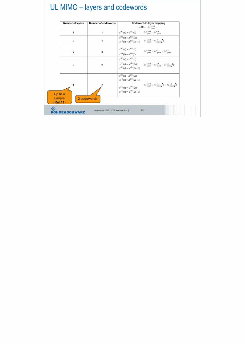
8/22/2019 LTE eutran rsanov2012
http://slidepdf.com/reader/full/lte-eutran-rsanov2012 255/284
November 2012 | LTE Introduction | 257
2 1 )12()(
)2()()0()1(
)0()0(
id i x
id i x
2)0(
symblayer symb M M
)()()0()0(
id i x 2 2
)()()1()1(
id i x
)1(symb
)0(symb
layer symb M M M
3 2
)()( )0()0( id i x
)12()(
)2()()1()2(
)1()1(
id i x
id i x
2)1(symb
)0(symb
layer symb M M M
)12()(
)2()()0()1(
)0()0(
id i x
id i x
4 2
)12()(
)2()(
)1()3(
)1()2(
id i x
id i x
22)1(
symb)0(
symblayer symb M M M
Up to 4
Layers
(Rel.11)2 codewords
UL MIMO scheduling – DCI format 4 NEW! l Carrier indicator [0-3 bit].
l Resource Block Assignment:
l [bits] for Resource Allocation
Type 0
l Downlink Assignment Index [2
bit].
l TDD only, UL-DL config. 1-6.
l CSI request [1 or 2 bit].
l 2 bit for cells with more than two ULUL
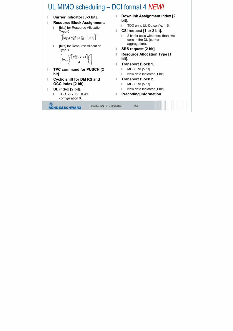
8/22/2019 LTE eutran rsanov2012
http://slidepdf.com/reader/full/lte-eutran-rsanov2012 256/284
November 2012 | LTE Introduction | 258
l [bits] for Resource Allocation
Type 1.
l TPC command for PUSCH [2
bit].
l Cyclic shift for DM RS and
OCC index [2 bit].
l UL index [2 bit].
l TDD only for UL-DL
configuration 0.
l 2 bit for cells with more than twocells in the DL (carrier
aggregation).
l SRS request [2 bit].
l Resource Allocation Type [1
bit].
l Transport Block 1.
l MCS, RV [5 bit].
l New data indicator [1 bit].
l Transport Block 2.
l MCS, RV [5 bit].
l New data indicator [1 bit].
l Precoding information.
)2/)1((log
ULRB
ULRB2 N N
4
1/
log2
P N UL
RB
LTE-AdvancedEnhanced uplink SC-FDMA
l The uplink
transmission
scheme remains

8/22/2019 LTE eutran rsanov2012
http://slidepdf.com/reader/full/lte-eutran-rsanov2012 257/284
November 2012 | LTE Introduction | 259
scheme remainsSC-FDMA.
l The transmission of
the physical uplink
shared channel
(PUSCH) uses DFTprecoding.
l Two enhancements:
l Control-data
decoupling
l Non-contiguousdata transmission
Physical channel arrangement - uplink

8/22/2019 LTE eutran rsanov2012
http://slidepdf.com/reader/full/lte-eutran-rsanov2012 258/284
November 2012 | LTE Introduction | 260
Simultaneous transmission of
PUCCH and PUSCH from
the same UE is supported
Clustered-DFTS-OFDM
= Clustered DFT spread
OFDM.
Non-contiguous resource block allocation => will cause higher Crest factor at UE side
LTE-AdvancedEnhanced uplink SC-FDMA
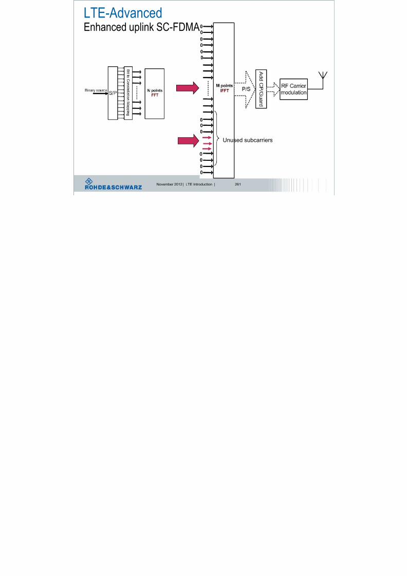
8/22/2019 LTE eutran rsanov2012
http://slidepdf.com/reader/full/lte-eutran-rsanov2012 259/284
November 2012 | LTE Introduction | 261
Unused subcarriers
LTE-AdvancedEnhanced uplink SC-FDMA

8/22/2019 LTE eutran rsanov2012
http://slidepdf.com/reader/full/lte-eutran-rsanov2012 260/284
November 2012 | LTE Introduction | 262
Due to distribution we get active subcarriers beside
non-active subcarriers: worse peak to average ratio,
e.g. Crest factor
Simultaneous PUSCH-PUCCH transmission, multi-cluster transmission l Remember, only one UL carrier in 3GPP Release 10;
scenarios:
l Feature support is indicated by PhyLayerParameters-v1020 IE*)
PUCCH d PUCCH d f ll

8/22/2019 LTE eutran rsanov2012
http://slidepdf.com/reader/full/lte-eutran-rsanov2012 261/284
November 2012 | LTE Introduction | 263
f [MHz]
l Feature support is indicated by PhyLayerParameters-v1020 IE .
PUCCH PUSCH
PUCCH and
allocated PUSCH
PUCCH and fully
allocated PUSCH
PUCCH and partially
allocated PUSCH
partially
allocated PUSCH
f [MHz]
f [MHz] f [MHz]
*) see 3GPP TS 36.331 RRC Protocol Specification
Benefit of localized or distributed mode„static UE“: frequency selectivity is not time variant -> localized allocation

8/22/2019 LTE eutran rsanov2012
http://slidepdf.com/reader/full/lte-eutran-rsanov2012 262/284
November 2012 | LTE Introduction | 264
„high velocity UE“: frequency selectivity is time variant -> distributed allocation
Multipath causes frequency
Selective channel,
It can be time variant or
Non-time variant
Resource Allocation types in the uplink
l Uplink Resource Allocation Type 0.
l Contiguous allocation as today in 3GPP Release 8.

8/22/2019 LTE eutran rsanov2012
http://slidepdf.com/reader/full/lte-eutran-rsanov2012 263/284
November 2012 | LTE Introduction | 265
l Uplink Resource Allocation Type 1.
lUL bandwidth is divided into two sets of Resource Blocks (RB).
l Each set has a number of Resource Block Groups (RBG) of size P.
l Combinatorial index r, indicates RBG starting and ending index for
both set of RB (s0, s1-1 | s2, s3-1.
– M = 4, N is bandwidth dependent,
System
Bandwidth
RBG
Size (P )
≤10 1
11 – 26 2
27 – 63 3
64 – 110 4
1
0
M i
i
N sr
M i
1/ULRB P N N
1
0
M
i i s
11 ,
i i i s N s s
l Example: LTE 10 MHz (50 RB), P = 3 leads to 17 RBG.
l Combinatorial index r indicates RBG starting indices for RB set #1
(s0
, s1
-1, defining cluster #1) and RB set #2 (s2
, s3
-1, defining cluster
#2)
Multi-cluster allocationUplink Resource Allocation Type 1

8/22/2019 LTE eutran rsanov2012
http://slidepdf.com/reader/full/lte-eutran-rsanov2012 264/284
November 2012 | LTE Introduction | 266
#2).
l Range for s0, s1, s2, s3 for 10 MHz (50 RB): 1 to 18 (see previous
slide).
l Applied rule: s0 < s1 < s2 < s3 (see previous slide).
l Example: s0=2, s1=9, s2=10, s3=11: “START”
(s0)“END”
(s1-1)“START”
(s2) “END” (s3-1)
Cluster #1 Cluster #2
RBG#11 RBG#13 RBG#15RBG#1 RBG#3 RBG#5 RBG#7 RBG#9
RBG#0 RBG#8 RBG#12 RBG#14 RBG#16RBG#10RBG#2 RBG#4 RBG#6
What are the effects of “Enhanced SC-FDMA”?

8/22/2019 LTE eutran rsanov2012
http://slidepdf.com/reader/full/lte-eutran-rsanov2012 265/284
November 2012 | LTE Introduction | 267
Sou rce: http :/ /www.3gpp.org /f tp/tsg_ran/WG4_Radio/TSGR4_54/Documen ts/R4-101056.zip
Significant step towards 4G: Relaying ?

8/22/2019 LTE eutran rsanov2012
http://slidepdf.com/reader/full/lte-eutran-rsanov2012 266/284
November 2012 | LTE Introduction | 268
Source: TTA‘s workshop for the future of IMT-Advanced technologies, June 2008
Radio Relaying approach

8/22/2019 LTE eutran rsanov2012
http://slidepdf.com/reader/full/lte-eutran-rsanov2012 267/284
November 2012 | LTE Introduction | 269
Source: TTA‘s workshop for the future of IMT-Advanced technologies, June 2008
No Improvement of SNR resp. CINR
L1/L2 Relaying approach

8/22/2019 LTE eutran rsanov2012
http://slidepdf.com/reader/full/lte-eutran-rsanov2012 268/284
November 2012 | LTE Introduction | 270
Source: TTA‘s workshop for the future of IMT-Advanced technologies, June 2008
LTE-AdvancedRelaying
l LTE-Advanced extends LTE Release 8 with support for
relaying in order to enhance coverage and capacity
l Classification of relays based on
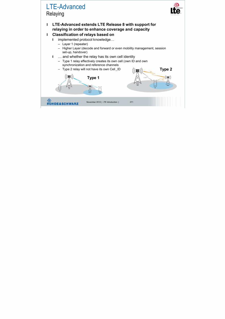
8/22/2019 LTE eutran rsanov2012
http://slidepdf.com/reader/full/lte-eutran-rsanov2012 269/284
November 2012 | LTE Introduction | 271
Classification of relays based onl implemented protocol knowledge…
– Layer 1 (repeater)
– Higher Layer (decode and forward or even mobility management, session
set-up, handover)
l … and whether the relay has its own cell identity
– Type 1 relay effectively creates its own cell (own ID and own
synchronization and reference channels
– Type 2 relay will not have its own Cell_ID
Type 1
Type 2
LTE-Advanced: Relaying
The relay node (RN) is wirelessly connected to a donor cell of a
donor eNB via the Un interface, and UEs connect to the RN via
the Uu interface

8/22/2019 LTE eutran rsanov2012
http://slidepdf.com/reader/full/lte-eutran-rsanov2012 270/284
November 2012 | LTE Introduction | 272
RN eNBUE
UnUu EPC
the Uu interface
Inband: 2 links operate in the same frequency
Outband: 2 links operate in different frequencies
Co-operative Relaying Approaches
l Receiver in MS (or BS) gains from both, the signal origin and the relay
station
l Co-operative Relaying creates virtual MIMO

8/22/2019 LTE eutran rsanov2012
http://slidepdf.com/reader/full/lte-eutran-rsanov2012 271/284
November 2012 | LTE Introduction | 273
p y g
• RSs are „decode-and-forward“ devices
LTE-AdvancedCoordinated Multipoint Tx/Rx (CoMP)
CoMP

8/22/2019 LTE eutran rsanov2012
http://slidepdf.com/reader/full/lte-eutran-rsanov2012 272/284
November 2012 | LTE Introduction | 276
Coordination between cells
Coordinated Multipoint, CoMPController
Controller
CSI
feedback
UE estimates
Various DL
+ feedback
Info about CoMP,

8/22/2019 LTE eutran rsanov2012
http://slidepdf.com/reader/full/lte-eutran-rsanov2012 273/284
November 2012 | LTE Introduction | 277
Each eNB
Estimates Uplink
UE estimates various
Downlink + feedbac
No info about CoMP
at UE
Controller
CSI
feedback
CoMPInfo
Info about CoMP,UE perform signal
processing
LTE-A: PCFICH indicating PDCCH size
Subframe where
PCFICH is sent
Subframe 1 and 6
in TDD mode
1, 2 2
Number of OFDM symbols for PDCCH when
10DLRB N 10DL
RB N
PCFICH content in LTE R-8 PCFICH content in LTE-A
PCFICH can
indicate up to 4
OFDM symbols

8/22/2019 LTE eutran rsanov2012
http://slidepdf.com/reader/full/lte-eutran-rsanov2012 274/284
November 2012 | LTE Introduction | 278
PDSCH
PDCCH
PCFICH
PBCH
S-SCH
P-SCH
Frequency
Subframe 0 in FDD
mode
1, 2, 3 2, 3, 4
T i m e
OFDM symbolsfor used by PDCCH
LTE-A: Multiple Access MAC layer conceptTransport block 1 Transport block K
Segmentation Segmentation
FEC FEC FEC FEC

8/22/2019 LTE eutran rsanov2012
http://slidepdf.com/reader/full/lte-eutran-rsanov2012 275/284
November 2012 | LTE Introduction | 279
Non-frequency adaptive Frequency adaptive
Mapping on dispersed chunks Mapping on frequency optimal chunks
Bit interleaved coded modulation
Quasi cyclic block low density partity check
Antenna summation, linear precoding
IFFT + CP insertion
Resource scheduler
Packet processing
Bit interleaved coded modulation
Quasi cyclic block low density partity check
RF generation
LTE-Advanced: C-Plane latency
Connected
Dormant Active
10ms
Already fullfills ITU

8/22/2019 LTE eutran rsanov2012
http://slidepdf.com/reader/full/lte-eutran-rsanov2012 276/284
November 2012 | LTE Introduction | 280
Idle
50ms
Already fullfills ITU
Requirement with Rel.8,
but ideas to speed up:
•Combined RRC Connection Request and NAS Service Request•Reduced processing delays in network nodes
•Reduced RACH scheduling period: 10ms to 5ms
Shorter PUCCH cycle: requests are sent faster
Contention based uplink: UE sends data without previous request
LTE Registration – R8 to R10…. incl. security activation UE SS
RRC ConnectionnSetup
RRC ConnectionSetupComplete
NAS ATTACH REQUEST
NAS AUTHENTICATION REQUEST
contains
RRC ConnectionnRequest
PDN CONNECTIVITY REQUEST
NAS

8/22/2019 LTE eutran rsanov2012
http://slidepdf.com/reader/full/lte-eutran-rsanov2012 277/284
November 2012 | LTE Introduction | 281
NAS : AUTHENTICATION REQUEST
NAS : AUTHENTICATION RESPONSE
NAS : SECURITY MODE COMMAND
NAS : SECURITY MODE COMMAND COMPLETE
RRC : SECURITY MODE COMMAND
RRC : SECURITY MODE COMMAND COMPLETE
RRC ConnectionReconfiguration
NAS ATTACH ACCEPT
NAS : ACTIVATE DEFAULT EPS BEARER CONTEXT REQ
RRC ConnectionReconfigurationComplete
NAS : ATTACH COMPLETE
NAS : ACTIVATE DEFAULT EPS BEARER CONTEXT
ACCEPT
contains
NASRegistration
Already in RRC
Connection
Request
Present Thrust- Spectrum EfficiencyMomentary snapshot of frequency spectrum allocation

8/22/2019 LTE eutran rsanov2012
http://slidepdf.com/reader/full/lte-eutran-rsanov2012 278/284
November 2012 | LTE Introduction | 282
l FCC Measurements:- Temporal and geographical variations in the utilization of the assignedspectrum range from 15% to 85%.
Why not use this
part of the spectrum?
ODMA – some ideas… BTS

8/22/2019 LTE eutran rsanov2012
http://slidepdf.com/reader/full/lte-eutran-rsanov2012 279/284
November 2012 | LTE Introduction | 283
Mobile devices behave as
relay station
Cooperative communicationHow to implement antenna arrays in mobile handsets?
Multi-access

8/22/2019 LTE eutran rsanov2012
http://slidepdf.com/reader/full/lte-eutran-rsanov2012 280/284
November 2012 | LTE Introduction | 284
Each mobile
is user and relay 3 principles of aid:
•Amplify and forward
•Decode and forward
•Coded cooperation
Independent
fading paths
Cooperative communication
Multi-access

8/22/2019 LTE eutran rsanov2012
http://slidepdf.com/reader/full/lte-eutran-rsanov2012 281/284
November 2012 | LTE Introduction | 285
Higher signaling
System complexity
Cell edge coverage
Group mobility
Independent
fading paths
Virtual
Antenna
Array
Mobile going GREEN

8/22/2019 LTE eutran rsanov2012
http://slidepdf.com/reader/full/lte-eutran-rsanov2012 282/284
November 2012 | LTE Introduction | 286
Ubiquitous communication

8/22/2019 LTE eutran rsanov2012
http://slidepdf.com/reader/full/lte-eutran-rsanov2012 283/284
November 2012 | LTE Introduction | 287
There will be enough topics
for future trainings

8/22/2019 LTE eutran rsanov2012
http://slidepdf.com/reader/full/lte-eutran-rsanov2012 284/284
Thank you for your attention!


