
GE Healthcare
LOGIQ C3/C5 Premium
Basic Service Manual
Part Number: 5341787-100Revision: 8


GE HEALTHCARE LOGIQ C3/C5 PREMIUM DIRECTION 5341787-100, REVISION 8 BASIC SERVICE MANUAL
i
Important Precautions
THIS SERVICE MANUAL IS AVAILABLE IN ENGLISH ONLY.• IF A CUSTOMER’S SERVICE PROVIDER REQUIRES A LANGUAGE OTHER
THAN ENGLISH, IT IS THE CUSTOMER’S RESPONSIBILITY TO PROVIDE TRANSLATION SERVICES.
• DO NOT ATTEMPT TO SERVICE THE EQUIPMENT UNLESS THIS SERVICE MANUAL HAS BEEN CONSULTED AND IS UNDERSTOOD.
• FAILURE TO HEED THIS WARNING MAY RESULT IN INJURY TO THE SERVICE PROVIDER, OPERATOR OR PATIENT FROM ELECTRIC SHOCK, MECHANICAL OR OTHER HAZARDS.
CE MANUEL DE MAINTENANCE N’EST DISPONIBLE QU’EN ANGLAIS.• SI LE TECHNICIEN DU CLIENT A BESOIN DE CE MANUEL DANS UNE AUTRE
LANGUE QUE L’ANGLAIS, C’EST AU CLIENT QU’IL INCOMBE DE LE FAIRE TRADUIRE.
• NE PAS TENTER D’INTERVENTION SUR LES ÉQUIPEMENTS TANT QUE LE MANUEL SERVICE N’A PAS ÉTÉ CONSULTÉ ET COMPRIS.
• LE NON-RESPECT DE CET AVERTISSEMENT PEUT ENTRAÎNER CHEZ LE TECHNICIEN, L’OPÉRATEUR OU LE PATIENT DES BLESSURES DUES À DES DANGERS ÉLECTRIQUES, MÉCANIQUES OU AUTRES.
DIESES KUNDENDIENST-HANDBUCH EXISTIERT NUR IN ENGLISCHER SPRACHE.• FALLS EIN FREMDER KUNDENDIENST EINE ANDERE SPRACHE BENÖTIGT,
IST ES AUFGABE DES KUNDEN FÜR EINE ENTSPRECHENDE ÜBERSETZUNG ZU SORGEN.
• VERSUCHEN SIE NICHT, DAS GERÄT ZU REPARIEREN, BEVOR DIESES KUNDENDIENST-HANDBUCH NICHT ZU RATE GEZOGEN UND VERSTANDEN WURDE.
• WIRD DIESE WARNUNG NICHT BEACHTET, SO KANN ES ZU VERLETZUNGEN DES KUNDENDIENSTTECHNIKERS, DES BEDIENERS ODER DES PATIENTEN DURCH ELEKTRISCHE SCHLÄGE, MECHANISCHE ODER SONSTIGE GEFAHREN KOMMEN.
WARNING(EN)
AVERTISSEMENT(FR)
WARNUNG(DE)

GE HEALTHCARE LOGIQ C3/C5 PREMIUMDIRECTION 5341787-100, REVISION 8 BASIC SERVICE MANUAL
ii -
ESTE MANUAL DE SERVICIO SÓLO EXISTE EN INGLÉS.• SI ALGÚN PROVEEDOR DE SERVICIOS AJENO A GEHC SOLICITA UN IDIOMA
QUE NO SEA EL INGLÉS, ES RESPONSABILIDAD DEL CLIENTE OFRECER UN SERVICIO DE TRADUCCIÓN.
• NO SE DEBERÁ DAR SERVICIO TÉCNICO AL EQUIPO, SIN HABER CONSULTADO Y COMPRENDIDO ESTE MANUAL DE SERVICIO.
• LA NO OBSERVANCIA DEL PRESENTE AVISO PUEDE DAR LUGAR A QUE EL PROVEEDOR DE SERVICIOS, EL OPERADOR O EL PACIENTE SUFRAN LESIONES PROVOCADAS POR CAUSAS ELÉCTRICAS, MECÁNICAS O DE OTRA NATURALEZA.
ESTE MANUAL DE ASSISTÊNCIA TÉCNICA SÓ SE ENCONTRA DISPONÍVEL EM INGLÊS.• SE QUALQUER OUTRO SERVIÇO DE ASSISTÊNCIA TÉCNICA, QUE NÃO A
GEHC, SOLICITAR ESTES MANUAIS NOUTRO IDIOMA, É DA RESPONSABILIDADE DO CLIENTE FORNECER OS SERVIÇOS DE TRADUÇÃO.
• NÃO TENTE REPARAR O EQUIPAMENTO SEM TER CONSULTADO E COMPREENDIDO ESTE MANUAL DE ASSISTÊNCIA TÉCNICA.
• O NÃO CUMPRIMENTO DESTE AVISO PODE POR EM PERIGO A SEGURANÇA DO TÉCNICO, OPERADOR OU PACIENTE DEVIDO A‘ CHOQUES ELÉTRICOS, MECÂNICOS OU OUTROS.
ESTE MANUAL DE ASSISTÊNCIA ESTÁ DISPONÍVEL APENAS EM INGLÊS.• SE QUALQUER OUTRO SERVIÇO DE ASSISTÊNCIA TÉCNICA, QUE NÃO A
GEHC, SOLICITAR ESTES MANUAIS NOUTRO IDIOMA, É DA RESPONSABILIDADE DO CLIENTE FORNECER OS SERVIÇOS DE TRADUÇÃO.
• NÃO TENTE EFECTUAR REPARAÇÕES NO EQUIPAMENTO SEM TER CONSULTADO E COMPREENDIDO PREVIAMENTE ESTE MANUAL.
• A INOBSERVÂNCIA DESTE AVISO PODE RESULTAR EM FERIMENTOS NO TÉCNICO DE ASSISTÊNCIA, OPERADOR OU PACIENTE EM CONSEQUÊNCIA DE CHOQUE ELÉCTRICO, PERIGOS DE ORIGEM MECÂNICA, BEM COMO DE OUTROS TIPOS.
IL PRESENTE MANUALE DI MANUTENZIONE È DISPONIBILE SOLTANTO IN INGLESE.• SE UN ADDETTO ALLA MANUTENZIONE ESTERNO ALLA GEHC RICHIEDE IL
MANUALE IN UNA LINGUA DIVERSA, IL CLIENTE È TENUTO A PROVVEDERE DIRETTAMENTE ALLA TRADUZIONE.
• SI PROCEDA ALLA MANUTENZIONE DELL’APPARECCHIATURA SOLO DOPO AVER CONSULTATO IL PRESENTE MANUALE ED AVERNE COMPRESO IL CONTENUTO.
• NON TENERE CONTO DELLA PRESENTE AVVERTENZA POTREBBE FAR COMPIERE OPERAZIONI DA CUI DERIVINO LESIONI ALL’ADDETTO ALLA MANUTENZIONE, ALL’UTILIZZATORE ED AL PAZIENTE PER FOLGORAZIONE ELETTRICA, PER URTI MECCANICI OD ALTRI RISCHI.
AVISO(ES)
ATENÇÃO(PT-Br)
(PT-pt)AVISO
AVVERTENZA(IT)

GE HEALTHCARE LOGIQ C3/C5 PREMIUM DIRECTION 5341787-100, REVISION 8 BASIC SERVICE MANUAL
iii
KÄESOLEV TEENINDUSJUHEND ON SAADAVAL AINULT INGLISE KEELES.• KUI KLIENDITEENINDUSE OSUTAJA NÕUAB JUHENDIT INGLISE KEELEST
ERINEVAS KEELES, VASTUTAB KLIENT TÕLKETEENUSE OSUTAMISE EEST. • ÄRGE ÜRITAGE SEADMEID TEENINDADA ENNE EELNEVALT KÄESOLEVA
TEENINDUSJUHENDIGA TUTVUMIST JA SELLEST ARU SAAMIST.• KÄESOLEVA HOIATUSE EIRAMINE VÕIB PÕHJUSTADA TEENUSEOSUTAJA,
OPERAATORI VÕI PATSIENDI VIGASTAMIST ELEKTRILÖÖGI, MEHAANILISE VÕI MUU OHU TAGAJÄRJEL.
TÄMÄ HUOLTO-OHJE ON SAATAVILLA VAIN ENGLANNIKSI.• JOS ASIAKKAAN PALVELUNTARJOAJA VAATII MUUTA KUIN
ENGLANNINKIELISTÄ MATERIAALIA, TARVITTAVAN KÄÄNNÖKSEN HANKKIMINEN ON ASIAKKAAN VASTUULLA.
• ÄLÄ YRITÄ KORJATA LAITTEISTOA ENNEN KUIN OLET VARMASTI LUKENUT JA YMMÄRTÄNYT TÄMÄN HUOLTO-OHJEEN.
• MIKÄLI TÄTÄ VAROITUSTA EI NOUDATETA, SEURAUKSENA VOI OLLA PALVELUNTARJOAJAN, LAITTEISTON KÄYTTÄJÄN TAI POTILAAN VAHINGOITTUMINEN SÄHKÖISKUN, MEKAANISEN VIAN TAI MUUN VAARATILANTEEN VUOKSI.
ΤΟ ΠΑΡΟΝ ΕΓΧΕΙΡΙΔΙΟ ΣΕΡΒΙΣ ΔΙΑΤΙΘΕΤΑΙ ΣΤΑ ΑΓΓΛΙΚΑ ΜΟΝΟ.• ΕΑΝ ΤΟ ΑΤΟΜΟ ΠΑΡΟΧΗΣ ΣΕΡΒΙΣ ΕΝΟΣ ΠΕΛΑΤΗ ΑΠΑΙΤΕΙ ΤΟ ΠΑΡΟΝ ΕΓΧΕΙΡΙΔΙΟ ΣΕ ΓΛΩΣΣΑ ΕΚΤΟΣ ΤΩΝ ΑΓΓΛΙΚΩΝ, ΑΠΟΤΕΛΕΙ ΕΥΘΥΝΗ ΤΟΥ ΠΕΛΑΤΗ ΝΑ ΠΑΡΕΧΕΙ ΥΠΗΡΕΣΙΕΣ ΜΕΤΑΦΡΑΣΗΣ.
• ΜΗΝ ΕΠΙΧΕΙΡΗΣΕΤΕ ΤΗΝ ΕΚΤΕΛΕΣΗ ΕΡΓΑΣΙΩΝ ΣΕΡΒΙΣ ΣΤΟΝ ΕΞΟΠΛΙΣΜΟ ΕΚΤΟΣ ΕΑΝ ΕΧΕΤΕ ΣΥΜΒΟΥΛΕΥΤΕΙ ΚΑΙ ΕΧΕΤΕ ΚΑΤΑΝΟΗΣΕΙ ΤΟ ΠΑΡΟΝ ΕΓΧΕΙΡΙΔΙΟ ΣΕΡΒΙΣ.
• ΕΑΝ ΔΕ ΛΑΒΕΤΕ ΥΠΟΨΗ ΤΗΝ ΠΡΟΕΙΔΟΠΟΙΗΣΗ ΑΥΤΗ, ΕΝΔΕΧΕΤΑΙ ΝΑ ΠΡΟΚΛΗΘΕΙ ΤΡΑΥΜΑΤΙΣΜΟΣ ΣΤΟ ΑΤΟΜΟ ΠΑΡΟΧΗΣ ΣΕΡΒΙΣ, ΣΤΟ ΧΕΙΡΙΣΤΗ Ή ΣΤΟΝ ΑΣΘΕΝΗ ΑΠΟ ΗΛΕΚΤΡΟΠΛΗΞΙΑ, ΜΗΧΑΝΙΚΟΥΣ Ή ΑΛΛΟΥΣ ΚΙΝΔΥΝΟΥΣ.
EZEN KARBANTARTÁSI KÉZIKÖNYV KIZÁRÓLAG ANGOL NYELVEN ÉRHETŐ EL.• HA A VEVŐ SZOLGÁLTATÓJA ANGOLTÓL ELTÉRŐ NYELVRE TART IGÉNYT,
AKKOR A VEVŐ FELELŐSSÉGE A FORDÍTÁS ELKÉSZÍTTETÉSE.• NE PRÓBÁLJA ELKEZDENI HASZNÁLNI A BERENDEZÉST, AMÍG A
KARBANTARTÁSI KÉZIKÖNYVBEN LEÍRTAKAT NEM ÉRTELMEZTÉK.• EZEN FIGYELMEZTETÉS FIGYELMEN KÍVÜL HAGYÁSA A SZOLGÁLTATÓ,
MŰKÖDTETŐ VAGY A BETEG ÁRAMÜTÉS, MECHANIKAI VAGY EGYÉB VESZÉLYHELYZET MIATTI SÉRÜLÉSÉT EREDMÉNYEZHETI.
HOIATUS (ET)
VAROITUS (FI)
ΠΡΟΕΙΔΟΠΟΙΗΣΗ (EL)
FIGYELMEZTETÉS (HU)

GE HEALTHCARE LOGIQ C3/C5 PREMIUMDIRECTION 5341787-100, REVISION 8 BASIC SERVICE MANUAL
iv -
ÞESSI ÞJÓNUSTUHANDBÓK ER EINGÖNGU FÁANLEG Á ENSKU.• EF ÞJÓNUSTUAÐILI VIÐSKIPTAMANNS ÞARFNAST ANNARS TUNGUMÁLS EN
ENSKU, ER ÞAÐ Á ÁBYRGÐ VIÐSKIPTAMANNS AÐ ÚTVEGA ÞÝÐINGU.• REYNIÐ EKKI AÐ ÞJÓNUSTA TÆKIÐ NEMA EFTIR AÐ HAFA SKOÐAÐ OG
SKILIÐ ÞESSA ÞJÓNUSTUHANDBÓK.• EF EKKI ER FARIÐ AÐ ÞESSARI VIÐVÖRUN GETUR ÞAÐ VALDIÐ MEIÐSLUM
ÞJÓNUSTUVEITANDA, STJÓRNANDA EÐA SJÚKLINGS VEGNA RAFLOSTS, VÉLRÆNNAR EÐA ANNARRAR HÆTTU.
TENTO SERVISNÍ NÁVOD EXISTUJE POUZE V ANGLICKÉM JAZYCE.• V PŘÍPADĚ, ŽE POSKYTOVATEL SLUŽEB ZÁKAZNÍKŮM POTŘEBUJE NÁVOD
V JINÉM JAZYCE, JE ZAJIŠTĚNÍ PŘEKLADU DO ODPOVÍDAJÍCÍHO JAZYKA ÚKOLEM ZÁKAZNÍKA.
• NEPROVÁDĚJTE ÚDRŽBU TOHOTO ZAŘÍZENÍ, ANIŽ BYSTE SI PŘEČETLI TENTO SERVISNÍ NÁVOD A POCHOPILI JEHO OBSAH.
• V PŘÍPADĚ NEDODRŽOVÁNÍ TÉTO VÝSTRAHY MŮŽE DOJÍT ÚRAZU ELEKTRICKÁM PROUDEM PRACOVNÍKA POSKYTOVATELE SLUŽEB, OBSLUŽNÉHO PERSONÁLU NEBO PACIENTŮ VLIVEM ELEKTRICKÉHOP PROUDU, RESPEKTIVE VLIVEM K RIZIKU MECHANICKÉHO POŠKOZENÍ NEBO JINÉMU RIZIKU.
DENNE SERVICEMANUAL FINDES KUN PÅ ENGELSK.• HVIS EN KUNDES TEKNIKER HAR BRUG FOR ET ANDET SPROG END
ENGELSK, ER DET KUNDENS ANSVAR AT SØRGE FOR OVERSÆTTELSE.• FORSØG IKKE AT SERVICERE UDSTYRET MEDMINDRE
DENNE SERVICEMANUAL ER BLEVET LÆST OG FORSTÅET.• MANGLENDE OVERHOLDELSE AF DENNE ADVARSEL KAN MEDFŘRE SKADE
PĹ GRUND AF ELEKTRISK, MEKANISK ELLER ANDEN FARE FOR TEKNIKEREN, OPERATŘREN ELLER PATIENTEN.
DEZE ONDERHOUDSHANDLEIDING IS ENKEL IN HET ENGELS VERKRIJGBAAR.• ALS HET ONDERHOUDSPERSONEEL EEN ANDERE TAAL VEREIST, DAN IS DE
KLANT VERANTWOORDELIJK VOOR DE VERTALING ERVAN.• PROBEER DE APPARATUUR NIET TE ONDERHOUDEN VOORDAT DEZE
ONDERHOUDSHANDLEIDING WERD GERAADPLEEGD EN BEGREPEN IS.• INDIEN DEZE WAARSCHUWING NIET WORDT OPGEVOLGD, ZOU HET
ONDERHOUDSPERSONEEL, DE OPERATOR OF EEN PATIËNT GEWOND KUNNEN RAKEN ALS GEVOLG VAN EEN ELEKTRISCHE SCHOK, MECHANISCHE OF ANDERE GEVAREN.
VIÐVÖRUN(IS)
VÝSTRAHA(CS)
ADVARSEL(DA)
WAARSCHUWING(NL)

GE HEALTHCARE LOGIQ C3/C5 PREMIUM DIRECTION 5341787-100, REVISION 8 BASIC SERVICE MANUAL
v
ŠĪ APKALPES ROKASGRĀMATA IR PIEEJAMA TIKAI ANGĻU VALODĀ.• JA KLIENTA APKALPES SNIEDZĒJAM NEPIECIEŠAMA INFORMĀCIJA CITĀ
VALODĀ, NEVIS ANGĻU, KLIENTA PIENĀKUMS IR NODROŠINĀT TULKOŠANU.• NEVEICIET APRĪKOJUMA APKALPI BEZ APKALPES ROKASGRĀMATAS
IZLASĪŠANAS UN SAPRAŠANAS.• ŠĪ BRĪDINĀJUMA NEIEVĒROŠANA VAR RADĪT ELEKTRISKĀS STRĀVAS
TRIECIENA, MEHĀNISKU VAI CITU RISKU IZRAISĪTU TRAUMU APKALPES SNIEDZĒJAM, OPERATORAM VAI PACIENTAM.
ŠIS EKSPLOATAVIMO VADOVAS YRA IŠLEISTAS TIK ANGLŲ KALBA.• JEI KLIENTO PASLAUGŲ TEIKĖJUI REIKIA VADOVO KITA KALBA – NE ANGLŲ,
VERTIMU PASIRŪPINTI TURI KLIENTAS.• NEMĖGINKITE ATLIKTI ĮRANGOS TECHNINĖS PRIEŽIŪROS DARBŲ, NEBENT
VADOVAUTUMĖTĖS ŠIUO EKSPLOATAVIMO VADOVU IR JĮ SUPRASTUMĖTE• NEPAISANT ŠIO PERSPĖJIMO, PASLAUGŲ TEIKĖJAS, OPERATORIUS AR
PACIENTAS GALI BŪTI SUŽEISTAS DĖL ELEKTROS SMŪGIO, MECHANINIŲ AR KITŲ PAVOJŲ.
DENNE SERVICEHÅNDBOKEN FINNES BARE PÅ ENGELSK.• HVIS KUNDENS SERVICELEVERANDØR TRENGER ET ANNET SPRÅK, ER DET
KUNDENS ANSVAR Å SØRGE FOR OVERSETTELSE.• IKKE FORSØK Å REPARERE UTSTYRET UTEN AT DENNE
SERVICEHÅNDBOKEN ER LEST OG FORSTÅTT.• MANGLENDE HENSYN TIL DENNE ADVARSELEN KAN FØRE TIL AT
SERVICELEVERANDØREN, OPERATØREN ELLER PASIENTEN SKADES PÅ GRUNN AV ELEKTRISK STØT, MEKANISKE ELLER ANDRE FARER.
NINIEJSZY PODRĘCZNIK SERWISOWY DOSTĘPNY JEST JEDYNIE W JĘZYKU ANGIELSKIM.• JEŚLI FIRMA ŚWIADCZĄCA KLIENTOWI USłUGI SERWISOWE WYMAGA
UDOSTĘPNIENIA PODRĘCZNIKA W JĘZYKU INNYM NIŻ ANGIELSKI, OBOWIĄZEK ZAPEWNIENIA STOSOWNEGO TłUMACZENIA SPOCZYWA NA KLIENCIE.
• NIE PRÓBOWAĆ SERWISOWAĆ NINIEJSZEGO SPRZĘTU BEZ UPRZEDNIEGO ZAPOZNANIA SIĘ Z PODRĘCZNIKIEM SERWISOWYM.
• NIEZASTOSOWANIE SIĘ DO TEGO OSTRZEŻENIA MOżE GROZIĆ OBRAŻENIAMI CIAłA SERWISANTA, OPERATORA LUB PACJENTA W WYNIKU PORAŻENIA PRĄDEM, URAZU MECHANICZNEGO LUB INNEGO RODZAJU ZAGROŻEŃ.
BRĪDINĀJUMS(LV)
ĮSPĖJIMAS(LT)
ADVARSEL(NO)
OSTRZEŻENIE(PL)

GE HEALTHCARE LOGIQ C3/C5 PREMIUMDIRECTION 5341787-100, REVISION 8 BASIC SERVICE MANUAL
vi -
ACEST MANUAL DE SERVICE ESTE DISPONIBIL NUMAI ÎN LIMBA ENGLEZĂ.• DACĂ UN FURNIZOR DE SERVICII PENTRU CLIENŢI NECESITĂ O ALTĂ LIMBĂ
DECÂT CEA ENGLEZĂ, ESTE DE DATORIA CLIENTULUI SĂ FURNIZEZE O TRADUCERE.
• NU ÎNCERCAŢI SĂ REPARAŢI ECHIPAMENTUL DECÂT ULTERIOR CONSULTĂRII ŞI ÎNŢELEGERII ACESTUI MANUAL DE SERVICE.
• IGNORAREA ACESTUI AVERTISMENT AR PUTEA DUCE LA RĂNIREA DEPANATORULUI, OPERATORULUI SAU PACIENTULUI ÎN URMA PERICOLELOR DE ELECTROCUTARE, MECANICE SAU DE ALTĂ NATURĂ.
ДАННОЕ РУКОВОДСТВО ПО ОБСЛУЖИВАНИЮ ПРЕДОСТАВЛЯЕТСЯ ТОЛЬКО НА АНГЛИЙСКОМ ЯЗЫКЕ.• ЕСЛИ СЕРВИСНОМУ ПЕРСОНАЛУ КЛИЕНТА НЕОБХОДИМО РУКОВОДСТВО НЕ НА АНГЛИЙСКОМ ЯЗЫКЕ, КЛИЕНТУ СЛЕДУЕТ САМОСТОЯТЕЛЬНО ОБЕСПЕЧИТЬ ПЕРЕВОД.
• ПЕРЕД ОБСЛУЖИВАНИЕМ ОБОРУДОВАНИЯ ОБЯЗАТЕЛЬНО ОБРАТИТЕСЬ К ДАННОМУ РУКОВОДСТВУ И ПОЙМИТЕ ИЗЛОЖЕННЫЕ В НЕМ СВЕДЕНИЯ.
• НЕСОБЛЮДЕНИЕ УКАЗАННЫХ ТРЕБОВАНИЙ МОЖЕТ ПРИВЕСТИ К ТОМУ, ЧТО СПЕЦИАЛИСТ ПО ТЕХОБСЛУЖИВАНИЮ, ОПЕРАТОР ИЛИ ПАЦИЕНТ ПОЛУЧАТ УДАР ЗЛЕКТРИЧЕСКИМ ТОКОМ, МЕХАНИЧЕСКУЮ ТРАВМУ ИЛИ ДРУГОЕ ПОВРЕЖДЕНИЕ.
ТОВА СЕРВИЗНО РЪКОВОДСТВО Е НАЛИЧНО САМО НА АНГЛИЙСКИ ЕЗИК.• АКО ДОСТАВЧИКЪТ НА СЕРВИЗНИ УСЛУГИ НА КЛИЕНТ СЕ НУЖДАЕ ОТ ЕЗИК, РАЗЛИЧЕН ОТ АНГЛИЙСКИ, ЗАДЪЛЖЕНИЕ НА КЛИЕНТА Е ДА ПРЕДОСТАВИ ПРЕВОДАЧЕСКА УСЛУГА.
• НЕ СЕ ОПИТВАЙТЕ ДА ИЗВЪРШВАТЕ СЕРВИЗНО ОБСЛУЖВАНЕ НА ТОВА ОБОРУДВАНЕ, ОСВЕН ВСЛУЧАЙ, ЧЕ СЕРВИЗНОТО РЪКОВОДСТВО Е ПРОЧЕТЕНО И СЕ РАЗБИРА.
• НЕСПАЗВАНЕТО НА ТОВА ПРЕДУПРЕЖДЕНИЕ МОЖЕ ДА ДОВЕДЕ ДО НАРАНЯВАНЕ НА ДОСТАВЧИКА НА СЕРВИЗНИ УСЛУГИ, НА ОПЕРАТОРА ИЛИ ПАЦИЕНТА ВСЛЕДСТВИЕНА ТОКОВ УДАР, МЕХАНИЧНИ ИЛИ ДРУГИ РИСКОВЕ.
OVAJ PRIRUČNIK ZA SERVISIRANJE DOSTUPAN JE SAMO NA ENGLESKOM JEZIKU.• AKO KLIJENTOV SERVISER ZAHTEVA JEZIK KOJI NIJE ENGLESKI,
ODGOVORNOST JE NA KLIJENTU DA PRUŽI USLUGE PREVOĐENJA.• NEMOJTE POKUŠAVATI DA SERVISIRATE OPREMU AKO NISTE PROČITALI I
RAZUMELI PRIRUČNIK ZA SERVISIRANJE.• AKO NE POŠTUJETE OVO UPOZORENJE, MOŽE DOĆI DO POVREĐIVANJA
SERVISERA, OPERATERA ILI PACIJENTA UZROKOVANOG ELEKTRIČNIM UDAROM, MEHANIČKIM I DRUGIM OPASNOSTIMA.
ATENŢIE(RO)
ОСТОРОЖНО!(RU)
(BG)ПРЕДУПРЕЖДЕНИЕ
UPOZORENJE(SR)

GE HEALTHCARE LOGIQ C3/C5 PREMIUM DIRECTION 5341787-100, REVISION 8 BASIC SERVICE MANUAL
vii
TA SERVISNI PRIROČNIK JE NA VOLJO SAMO V ANGLEŠČINI.• ČE PONUDNIK SERVISNIH STORITEV ZA STRANKO POTREBUJE NAVODILA V
DRUGEM JEZIKU, JE ZA PREVOD ODGOVORNA STRANKA SAMA.• NE POSKUŠAJTE SERVISIRATI OPREME, NE DA BI PREJ PREBRALI IN
RAZUMELI SERVISNI PRIROČNIK.• ČE TEGA OPOZORILA NE UPOŠTEVATE, OBSTAJA NEVARNOST
ELEKTRIČNEGA UDARA, MEHANSKIH ALI DRUGIH NEVARNOSTI IN POSLEDIČNIH POŠKODB PONUDNIKA SERVISNIH STORITEV, UPORABNIKA OPREME ALI PACIENTA.
OVAJ SERVISNI PRIRUČNIK DOSTUPAN JE SAMO NA ENGLESKOM JEZIKU.• AKO KLIJENTOV SERVISER ZAHTIJEVA JEZIK KOJI NIJE ENGLESKI,
ODGOVORNOST KLIJENTA JE PRUŽITI USLUGE PREVOĐENJA.• NEMOJTE POKUŠAVATI SERVISIRATI OPREMU AKO NISTE PROČITALI I
RAZUMJELI SERVISNI PRIRUČNIK.• AKO NE POŠTUJETE OVO UPOZORENJE, MOŽE DOĆI DO OZLJEDE
SERVISERA, OPERATERA ILI PACIJENTA PROUZROČENE STRUJNIM UDAROM, MEHANIČKIM I DRUGIM OPASNOSTIMA.
TÁTO SERVISNÁ PRÍRUČKA JE K DISPOZÍCII LEN V ANGLIČTINE.• AK ZÁKAZNÍKOV POSKYTOVATEĽ SLUŽIEB VYŽADUJE INÝ JAZYK AKO
ANGLIČTINU, POSKYTNUTIE PREKLADATEĽSKÝCH SLUŽIEB JE ZODPOVEDNOSŤOU ZÁKAZNÍKA.
• NEPOKÚŠAJTE SA VYKONÁVAŤ SERVIS ZARIADENIA SKÔR, AKO SI NEPREČÍTATE SERVISNÚ PRÍRUČKU A NEPOROZUMIETE JEJ.
• ZANEDBANIE TOHTO UPOZORNENIA MÔŽE VYÚSTIŤ DO ZRANENIA POSKYTOVATEĽA SLUŽIEB, OBSLUHUJÚCEJ OSOBY ALEBO PACIENTA ELEKTRICKÝM PRÚDOM, PRÍPADNE DO MECHANICKÉHO ALEBO INÉHO NEBEZPEČENSTVA.
DEN HÄR SERVICEHANDBOKEN FINNS BARA TILLGÄNGLIG PÅ ENGELSKA.• OM EN KUNDS SERVICETEKNIKER HAR BEHOV AV ETT ANNAT SPRÅK ÄN
ENGELSKA ANSVARAR KUNDEN FÖR ATT TILLHANDAHÅLLA ÖVERSÄTTNINGSTJÄNSTER.
• FÖRSÖK INTE UTFÖRA SERVICE PÅ UTRUSTNINGEN OM DU INTE HAR LÄST OCH FÖRSTÅR DEN HÄR SERVICEHANDBOKEN.
• OM DU INTE TAR HÄNSYN TILL DEN HÄR VARNINGEN KAN DET RESULTERA I SKADOR PÅ SERVICETEKNIKERN, OPERATÖREN ELLER PATIENTEN TILL FÖLJD AV ELEKTRISKA STÖTAR, MEKANISKA FAROR ELLER ANDRA FAROR.
OPOZORILO(SL)
UPOZORENJE(HR)
UPOZORNENIE(SK)
VARNING(SV)

GE HEALTHCARE LOGIQ C3/C5 PREMIUMDIRECTION 5341787-100, REVISION 8 BASIC SERVICE MANUAL
viii -
BU SERVİS KILAVUZU YALNIZCA İNGİLİZCE OLARAK SAĞLANMIŞTIR.• EĞER MÜŞTERİ TEKNİSYENİ KILAVUZUN İNGİLİZCE DIŞINDAKİ BİR DİLDE
OLMASINI İSTERSE, KILAVUZU TERCÜME ETTİRMEK MÜŞTERİNİN SORUMLULUĞUNDADIR.
• SERVİS KILAVUZUNU OKUYUP ANLAMADAN EKİPMANLARA MÜDAHALE ETMEYİNİZ.
• BU UYARININ GÖZ ARDI EDİLMESİ, ELEKTRİK ÇARPMASI YA DA MEKANİK VEYA DİĞER TÜRDEN KAZALAR SONUCUNDA TEKNİSYENİN, OPERATÖRÜN YA DA HASTANIN YARALANMASINA YOL AÇABİLİR.
DİKKAT(TR)
(JA)
TraditionalChinese

GE HEALTHCARE LOGIQ C3/C5 PREMIUM DIRECTION 5341787-100, REVISION 8 BASIC SERVICE MANUAL
ix
(ZH-CN)
(KO)

GE HEALTHCARE LOGIQ C3/C5 PREMIUMDIRECTION 5341787-100, REVISION 8 BASIC SERVICE MANUAL
x -
DAMAGE IN TRANSPORTATIONAll packages should be closely examined at time of delivery. If damage is apparent write “Damage In Shipment” on ALL copies of the freight or express bill BEFORE delivery is accepted or “signed for” by a GE representative or hospital receiving agent. Whether noted or concealed, damage MUST be reported to the carrier immediately upon discovery, or in any event, within 14 days after receipt, and the contents and containers held for inspection by the carrier. A transportation company will not pay a claim for damage if an inspection is not requested within this 14 day period.
CERTIFIED ELECTRICAL CONTRACTOR STATEMENT - FOR USA ONLYAll electrical Installations that are preliminary to positioning of the equipment at the site prepared for the equipment shall be performed by licensed electrical contractors. Other connections between pieces of electrical equipment, calibrations and testing shall be performed by qualified GE Healthcare personnel. In performing all electrical work on these products, GE will use its own specially trained field engineers. All of GE’s electrical work on these products will comply with the requirements of the applicable electrical codes.
The purchaser of GE equipment shall only utilize qualified personnel (i.e., GE’s field engineers, personnel of third-party service companies with equivalent training, or licensed electricians) to perform electrical servicing on the equipment.
OMISSIONS & ERRORSIf there are any omissions, errors or suggestions for improving this documentation, please contact the GE Healthcare Global Documentation Group with specific information listing the system type, manual title, part number, revision number, page number and suggestion details.
Mail the information to:
Service Documentation, GE Medical Systems (China) Co., Ltd. No.19 Changjiang RoadWuXi National Hi-Tech Development ZoneJiangsu, P.R China 214028TEL: +86 510 85225888; FAX: +86 510 85226688
GE Healthcare employees should use TrackWise to report service documentation issues. These issues will then be in the internal problem reporting tool and communicated to the writer.
SERVICE SAFETY CONSIDERATIONS
For a complete review of all safety requirements, see the Chapter 1, Safety Considerations section in the Service Manual.
DANGER DANGEROUS VOLTAGES, CAPABLE OF CAUSING DEATH, ARE PRESENT IN THIS EQUIPMENT. USE EXTREME CAUTION WHEN HANDLING, TESTING AND ADJUSTING.
WARNINGWARNING Use all Personal Protection Equipment (PPE) such as gloves, safety shoes, safety glasses, and kneeling pad, to reduce the risk of injury.

GE HEALTHCARE LOGIQ C3/C5 PREMIUM DIRECTION 5341787-100, REVISION 8 BASIC SERVICE MANUAL
xi
LEGAL NOTES
The contents of this publication may not be copied or duplicated in any form, in whole or in part, without prior written permission of GE Healthcare.
GE Healthcare may revise this publication from time to time without written notice.
PROPRIETARY TO GE HEALTHCAREPermission to use this Advanced Service Software and related documentation (herein called the material) by persons other than GE Healthcare employees is provided only under an Advanced Service Package License relating specifically to this Proprietary Material. This is a different agreement from the one under which operating and basic service software is licensed. A license to use operating or basic service software does not extend to or cover this software or related documentation.
If you are a GE Healthcare employee or a customer who has entered into such a license agreement with GE Healthcare to use this proprietary software, you are authorized to use this Material according to the conditions stated in your license agreement.
However, you do not have the permission of GE Healthcare to alter, decompose or reverse-assemble the software, and unless you are a GE employee, you MAY NOT COPY the Material. The Material is protected by Copyright and Trade Secret laws; the violation of which can result in civil damages and criminal prosecution.
If you are not party to such a license agreement or a GE Healthcare Employee, you must exit this Material now.
TRADEMARKSAll products and their name brands are trademarks of their respective holders.
COPYRIGHTSAll Material Copyright© 2009-2012 by General Electric Company Inc. All Rights Reserved.

GE HEALTHCARE LOGIQ C3/C5 PREMIUMDIRECTION 5341787-100, REVISION 8 BASIC SERVICE MANUAL
xii -
Revision History
List of Effected Pages(LOEP)
Revision Date Reason for change1 2009/05/02 Initial Release.
2 2010/03/29 Update the Renewal Part List
3 2010/05/27 Add PHI information
4 2011/05/18 Add probe new probes information
5 2011/05/18 Update for Software update
6 2011/11/08 Update for Software update
7 2012/05/16 Update the FRU list
8 2012/12/05 Update environmental labels and add new spare parts
Pages Revision Pages Revision
Title Page N/AChapter 5 - Theorypages 5-1 to 5-4
8
Important Precautionsi to ix
8Chapter 6 - Service
Adjustmentspages 6-1 to 6-2
8
Table of Contentspages i to xii
8Chapter 7 - Diagnostics/
Troubleshootingpages 7-1 to 7-14
8
Chapter 1 - Introductionpages 1-1 to 1-16
8Chapter 8 - Replacement
Procedurespages 8-1 to 8-8
8
Chapter 2 - Pre-Installationpages 2-1 to 2-10
8Chapter 9 - Replacement
Partspages 9-1 to 9-8
8
Chapter 3 - Installationpages 3-1 to 3-24
8Chapter 10 - Periodic
Maintenancepages 10-1 to 10-16
8
Chapter 4 - Functional Checks
pages 4-1 to 4-368
Indexpages I to II
8

GE HEALTHCARE LOGIQ C3/C5 PREMIUMDIRECTION 5341787-100, REVISION 8 BASIC SERVICE MANUAL
Table of Contents i
CHAPTER 1Introduction
Overview. . . . . . . . . . . . . . . . . . . . . . . . . . . . . . . . . . . . . . . . . . . . . . . . . . . . . . . . . 1 - 1Purpose of Chapter 1 . . . . . . . . . . . . . . . . . . . . . . . . . . . . . . . . . . . . . . . . . 1 - 1Purpose of Service Manual . . . . . . . . . . . . . . . . . . . . . . . . . . . . . . . . . . . . . 1 - 1Typical Users of the Basic Service Manual . . . . . . . . . . . . . . . . . . . . . . . . 1 - 2Purpose of Operator Manual(s) . . . . . . . . . . . . . . . . . . . . . . . . . . . . . . . . . 1 - 2LOGIQ C3/C5 Premium Models Covered by this Manual . . . . . . . . . . . . . 1 - 2
Important Conventions . . . . . . . . . . . . . . . . . . . . . . . . . . . . . . . . . . . . . . . . . . . . . . 1 - 4Conventions Used in Book . . . . . . . . . . . . . . . . . . . . . . . . . . . . . . . . . . . . . 1 - 4Standard Hazard Icons . . . . . . . . . . . . . . . . . . . . . . . . . . . . . . . . . . . . . . . . 1 - 5Product Icons . . . . . . . . . . . . . . . . . . . . . . . . . . . . . . . . . . . . . . . . . . . . . . . 1 - 6
Safety Considerations . . . . . . . . . . . . . . . . . . . . . . . . . . . . . . . . . . . . . . . . . . . . . . 1 - 9Introduction . . . . . . . . . . . . . . . . . . . . . . . . . . . . . . . . . . . . . . . . . . . . . . . . . 1 - 9Human Safety . . . . . . . . . . . . . . . . . . . . . . . . . . . . . . . . . . . . . . . . . . . . . . . 1 - 9Mechanical Safety . . . . . . . . . . . . . . . . . . . . . . . . . . . . . . . . . . . . . . . . . . . 1 - 9Electrical Safety . . . . . . . . . . . . . . . . . . . . . . . . . . . . . . . . . . . . . . . . . . . . . 1 - 10Label Locations . . . . . . . . . . . . . . . . . . . . . . . . . . . . . . . . . . . . . . . . . . . . . . 1 - 10Dangerous Procedure Warnings . . . . . . . . . . . . . . . . . . . . . . . . . . . . . . . . 1 - 11Returning/Shipping Probes and Repair Parts . . . . . . . . . . . . . . . . . . . . . . . 1 - 11
EMC, EMI, and ESD. . . . . . . . . . . . . . . . . . . . . . . . . . . . . . . . . . . . . . . . . . . . . . . . 1 - 12Electromagnetic Compatibility (EMC) . . . . . . . . . . . . . . . . . . . . . . . . . . . . . 1 - 12CE Compliance . . . . . . . . . . . . . . . . . . . . . . . . . . . . . . . . . . . . . . . . . . . . . . 1 - 12Electrostatic Discharge (ESD) Prevention . . . . . . . . . . . . . . . . . . . . . . . . . 1 - 12
Lockout/Tagout (LOTO) requirements . . . . . . . . . . . . . . . . . . . . . . . . . . . . . . . . . . 1 - 13
Customer Assistance . . . . . . . . . . . . . . . . . . . . . . . . . . . . . . . . . . . . . . . . . . . . . . . 1 - 14Contact Information . . . . . . . . . . . . . . . . . . . . . . . . . . . . . . . . . . . . . . . . . . 1 - 14System Manufacturer . . . . . . . . . . . . . . . . . . . . . . . . . . . . . . . . . . . . . . . . . 1 - 15Factory Site . . . . . . . . . . . . . . . . . . . . . . . . . . . . . . . . . . . . . . . . . . . . . . . . . 1 - 15

GE HEALTHCARE LOGIQ C3/C5 PREMIUMDIRECTION 5341787-100, REVISION 8 BASIC SERVICE MANUAL
ii Table of Contents
CHAPTER 2Site Preparations
Overview . . . . . . . . . . . . . . . . . . . . . . . . . . . . . . . . . . . . . . . . . . . . . . . . . . . . . . . . . 2 - 1Purpose of chapter 2 . . . . . . . . . . . . . . . . . . . . . . . . . . . . . . . . . . . . . . . . . . 2 - 1
General Console Requirements. . . . . . . . . . . . . . . . . . . . . . . . . . . . . . . . . . . . . . . . 2 - 2Console Environmental Requirements . . . . . . . . . . . . . . . . . . . . . . . . . . . . . 2 - 2Electrical Requirements . . . . . . . . . . . . . . . . . . . . . . . . . . . . . . . . . . . . . . . . 2 - 2EMI Limitations . . . . . . . . . . . . . . . . . . . . . . . . . . . . . . . . . . . . . . . . . . . . . . . 2 - 4Scan Probe Environmental Requirements . . . . . . . . . . . . . . . . . . . . . . . . . . 2 - 5
Facility Needs . . . . . . . . . . . . . . . . . . . . . . . . . . . . . . . . . . . . . . . . . . . . . . . . . . . . . 2 - 6Purchaser Responsibilities . . . . . . . . . . . . . . . . . . . . . . . . . . . . . . . . . . . . . . 2 - 6Required Features . . . . . . . . . . . . . . . . . . . . . . . . . . . . . . . . . . . . . . . . . . . . 2 - 7Recommended and Alternate Ultrasound Room Layout . . . . . . . . . . . . . . . 2 - 8Networking Pre-installation Requirements . . . . . . . . . . . . . . . . . . . . . . . . . . 2 - 9

GE HEALTHCARE LOGIQ C3/C5 PREMIUMDIRECTION 5341787-100, REVISION 8 BASIC SERVICE MANUAL
Table of Contents iii
CHAPTER 3System Setup
Overview. . . . . . . . . . . . . . . . . . . . . . . . . . . . . . . . . . . . . . . . . . . . . . . . . . . . . . . . . 3 - 1Purpose of Chapter 3 . . . . . . . . . . . . . . . . . . . . . . . . . . . . . . . . . . . . . . . . . 3 - 1
Setup Reminders . . . . . . . . . . . . . . . . . . . . . . . . . . . . . . . . . . . . . . . . . . . . . . . . . . 3 - 2Average Installation Time . . . . . . . . . . . . . . . . . . . . . . . . . . . . . . . . . . . . . . 3 - 2Installation Warnings . . . . . . . . . . . . . . . . . . . . . . . . . . . . . . . . . . . . . . . . . 3 - 3Safety Reminders . . . . . . . . . . . . . . . . . . . . . . . . . . . . . . . . . . . . . . . . . . . . 3 - 4
Receiving and Unpacking the Equipment. . . . . . . . . . . . . . . . . . . . . . . . . . . . . . . . 3 - 5Moving into Position . . . . . . . . . . . . . . . . . . . . . . . . . . . . . . . . . . . . . . . . . . 3 - 6Product Locator Installation Card . . . . . . . . . . . . . . . . . . . . . . . . . . . . . . . . 3 - 6
Preparing for Installation. . . . . . . . . . . . . . . . . . . . . . . . . . . . . . . . . . . . . . . . . . . . . 3 - 7Verify Customer Order . . . . . . . . . . . . . . . . . . . . . . . . . . . . . . . . . . . . . . . . 3 - 7Physical Inspection . . . . . . . . . . . . . . . . . . . . . . . . . . . . . . . . . . . . . . . . . . . 3 - 7EMI Protection . . . . . . . . . . . . . . . . . . . . . . . . . . . . . . . . . . . . . . . . . . . . . . 3 - 7
Completing the Installation . . . . . . . . . . . . . . . . . . . . . . . . . . . . . . . . . . . . . . . . . . . 3 - 8Power On / Boot Up . . . . . . . . . . . . . . . . . . . . . . . . . . . . . . . . . . . . . . . . . . 3 - 8Power Off/ Shutdown . . . . . . . . . . . . . . . . . . . . . . . . . . . . . . . . . . . . . . . . . 3 - 8Transducer Connection . . . . . . . . . . . . . . . . . . . . . . . . . . . . . . . . . . . . . . . 3 - 9
System Configuration . . . . . . . . . . . . . . . . . . . . . . . . . . . . . . . . . . . . . . . . . . . . . . . 3 - 10System Specifications . . . . . . . . . . . . . . . . . . . . . . . . . . . . . . . . . . . . . . . . . 3 - 10Electrical Specifications . . . . . . . . . . . . . . . . . . . . . . . . . . . . . . . . . . . . . . . 3 - 11On-Board Optional Peripherals . . . . . . . . . . . . . . . . . . . . . . . . . . . . . . . . . . 3 - 11Connecting Cables . . . . . . . . . . . . . . . . . . . . . . . . . . . . . . . . . . . . . . . . . . . 3 - 12Peripherals/Accessories Connector Panel . . . . . . . . . . . . . . . . . . . . . . . . . 3 - 12Available Probes . . . . . . . . . . . . . . . . . . . . . . . . . . . . . . . . . . . . . . . . . . . . . 3 - 19
Software/Option Configuration . . . . . . . . . . . . . . . . . . . . . . . . . . . . . . . . . . . . . . . . 3 - 19
Connectivity Installation Worksheet . . . . . . . . . . . . . . . . . . . . . . . . . . . . . . . . . . . . 3 - 20
Loading Base Image Software . . . . . . . . . . . . . . . . . . . . . . . . . . . . . . . . . . . . . . . . 3 - 21Software Version check out . . . . . . . . . . . . . . . . . . . . . . . . . . . . . . . . . . . . . . . . . . 3 - 22
Functional Check-out . . . . . . . . . . . . . . . . . . . . . . . . . . . . . . . . . . . . . . . . . 3 - 22
Paperwork . . . . . . . . . . . . . . . . . . . . . . . . . . . . . . . . . . . . . . . . . . . . . . . . . . . . . . . 3 - 23Product Locator Installation . . . . . . . . . . . . . . . . . . . . . . . . . . . . . . . . . . . . 3 - 23User Manual(s) . . . . . . . . . . . . . . . . . . . . . . . . . . . . . . . . . . . . . . . . . . . . . . 3 - 23

GE HEALTHCARE LOGIQ C3/C5 PREMIUMDIRECTION 5341787-100, REVISION 8 BASIC SERVICE MANUAL
iv Table of Contents
CHAPTER 4Functional Checks
Overview . . . . . . . . . . . . . . . . . . . . . . . . . . . . . . . . . . . . . . . . . . . . . . . . . . . . . . . . . 4 - 1Purpose for Chapter 4 . . . . . . . . . . . . . . . . . . . . . . . . . . . . . . . . . . . . . . . . . 4 - 1
Required Equipment . . . . . . . . . . . . . . . . . . . . . . . . . . . . . . . . . . . . . . . . . . . . . . . . 4 - 1
General Procedure. . . . . . . . . . . . . . . . . . . . . . . . . . . . . . . . . . . . . . . . . . . . . . . . . . 4 - 2Power On/Boot Up . . . . . . . . . . . . . . . . . . . . . . . . . . . . . . . . . . . . . . . . . . . . 4 - 2Power Off/ Shutdown . . . . . . . . . . . . . . . . . . . . . . . . . . . . . . . . . . . . . . . . . . 4 - 2Archiving and Loading Presets . . . . . . . . . . . . . . . . . . . . . . . . . . . . . . . . . . 4 - 4Adjusting the Display Monitor . . . . . . . . . . . . . . . . . . . . . . . . . . . . . . . . . . . . 4 - 5System Features . . . . . . . . . . . . . . . . . . . . . . . . . . . . . . . . . . . . . . . . . . . . . 4 - 6B Mode Checks . . . . . . . . . . . . . . . . . . . . . . . . . . . . . . . . . . . . . . . . . . . . . . 4 - 9M Mode Controls . . . . . . . . . . . . . . . . . . . . . . . . . . . . . . . . . . . . . . . . . . . . . 4 - 12Doppler Mode Checks . . . . . . . . . . . . . . . . . . . . . . . . . . . . . . . . . . . . . . . . . 4 - 15Color Flow Mode Checks . . . . . . . . . . . . . . . . . . . . . . . . . . . . . . . . . . . . . . . 4 - 19Basic Measurements . . . . . . . . . . . . . . . . . . . . . . . . . . . . . . . . . . . . . . . . . . 4 - 23Probe/Connectors Usage . . . . . . . . . . . . . . . . . . . . . . . . . . . . . . . . . . . . . . . 4 - 24Using Cine . . . . . . . . . . . . . . . . . . . . . . . . . . . . . . . . . . . . . . . . . . . . . . . . . . 4 - 24Image Management (QG) . . . . . . . . . . . . . . . . . . . . . . . . . . . . . . . . . . . . . . 4 - 25Backup and Restore Database, Preset Configurations and Images . . . . . . 4 - 26
Software Configuration Checks . . . . . . . . . . . . . . . . . . . . . . . . . . . . . . . . . . . . . . . . 4 - 36
Peripheral Checks . . . . . . . . . . . . . . . . . . . . . . . . . . . . . . . . . . . . . . . . . . . . . . . . . . 4 - 36

GE HEALTHCARE LOGIQ C3/C5 PREMIUMDIRECTION 5341787-100, REVISION 8 BASIC SERVICE MANUAL
Table of Contents v
CHAPTER 5Components and Functions (Theory)
Overview. . . . . . . . . . . . . . . . . . . . . . . . . . . . . . . . . . . . . . . . . . . . . . . . . . . . . . . . . 5 - 1Purpose of Chapter 5 . . . . . . . . . . . . . . . . . . . . . . . . . . . . . . . . . . . . . . . . . 5 - 1
Block Diagram . . . . . . . . . . . . . . . . . . . . . . . . . . . . . . . . . . . . . . . . . . . . . . . . . . . . 5 - 2System Diagram . . . . . . . . . . . . . . . . . . . . . . . . . . . . . . . . . . . . . . . . . . . . . 5 - 2Software Diagram . . . . . . . . . . . . . . . . . . . . . . . . . . . . . . . . . . . . . . . . . . . . 5 - 3
Common Service Platform . . . . . . . . . . . . . . . . . . . . . . . . . . . . . . . . . . . . . . . . . . . 5 - 4Introduction . . . . . . . . . . . . . . . . . . . . . . . . . . . . . . . . . . . . . . . . . . . . . . . . . 5 - 4

GE HEALTHCARE LOGIQ C3/C5 PREMIUMDIRECTION 5341787-100, REVISION 8 BASIC SERVICE MANUAL
vi Table of Contents
CHAPTER 6Service Adjustments
Overview . . . . . . . . . . . . . . . . . . . . . . . . . . . . . . . . . . . . . . . . . . . . . . . . . . . . . . . . . 6 - 1Purpose of this chapter 6 . . . . . . . . . . . . . . . . . . . . . . . . . . . . . . . . . . . . . . . 6 - 1
Monitor Adjustments . . . . . . . . . . . . . . . . . . . . . . . . . . . . . . . . . . . . . . . . . . . . . . . . 6 - 2Adjustments Procedures . . . . . . . . . . . . . . . . . . . . . . . . . . . . . . . . . . . . . . . 6 - 2

GE HEALTHCARE LOGIQ C3/C5 PREMIUMDIRECTION 5341787-100, REVISION 8 BASIC SERVICE MANUAL
Table of Contents vii
CHAPTER 7Diagnostics/Troubleshooting
Overview. . . . . . . . . . . . . . . . . . . . . . . . . . . . . . . . . . . . . . . . . . . . . . . . . . . . . . . . . 7 - 1Purpose of Chapter 7 . . . . . . . . . . . . . . . . . . . . . . . . . . . . . . . . . . . . . . . . . 7 - 1
Gathering Trouble Data . . . . . . . . . . . . . . . . . . . . . . . . . . . . . . . . . . . . . . . . . . . . . 7 - 2Overview . . . . . . . . . . . . . . . . . . . . . . . . . . . . . . . . . . . . . . . . . . . . . . . . . . . 7 - 2Collect Vital System Information . . . . . . . . . . . . . . . . . . . . . . . . . . . . . . . . . 7 - 2Collect a Trouble Image with Logs . . . . . . . . . . . . . . . . . . . . . . . . . . . . . . . 7 - 3
USB Quick Save. . . . . . . . . . . . . . . . . . . . . . . . . . . . . . . . . . . . . . . . . . . . . . . . . . . 7 - 4Overview . . . . . . . . . . . . . . . . . . . . . . . . . . . . . . . . . . . . . . . . . . . . . . . . . . . 7 - 4Check and Record the Print or Store Key Function . . . . . . . . . . . . . . . . . . 7 - 4Setting the Print or Store Key to USB Quick Save . . . . . . . . . . . . . . . . . . . 7 - 5
Screen Captures. . . . . . . . . . . . . . . . . . . . . . . . . . . . . . . . . . . . . . . . . . . . . . . . . . . 7 - 6Check and Record the Store Key Function . . . . . . . . . . . . . . . . . . . . . . . . 7 - 6Setting the Store Key to Screen Capture . . . . . . . . . . . . . . . . . . . . . . . . . . 7 - 6Capturing a Screen . . . . . . . . . . . . . . . . . . . . . . . . . . . . . . . . . . . . . . . . . . . 7 - 6Reset the Store Key to Customer’s Functionality . . . . . . . . . . . . . . . . . . . . 7 - 8
Common Diagnostics . . . . . . . . . . . . . . . . . . . . . . . . . . . . . . . . . . . . . . . . . . . . . . . 7 - 9Utilities . . . . . . . . . . . . . . . . . . . . . . . . . . . . . . . . . . . . . . . . . . . . . . . . . . . . 7 - 9PC Diagnostics (Non-Interactive Tests) . . . . . . . . . . . . . . . . . . . . . . . . . . . 7 - 10PC Diagnostics (Interactive Tests) . . . . . . . . . . . . . . . . . . . . . . . . . . . . . . . 7 - 11Restart LOGIQ C3/C5 Premium After Diagnostics . . . . . . . . . . . . . . . . . . . 7 - 11
Network Configuration . . . . . . . . . . . . . . . . . . . . . . . . . . . . . . . . . . . . . . . . . . . . . . 7 - 12Network Configuration . . . . . . . . . . . . . . . . . . . . . . . . . . . . . . . . . . . . . . . . 7 - 12

GE HEALTHCARE LOGIQ C3/C5 PREMIUMDIRECTION 5341787-100, REVISION 8 BASIC SERVICE MANUAL
viii Table of Contents
CHAPTER 8Replacement Procedures
Overview . . . . . . . . . . . . . . . . . . . . . . . . . . . . . . . . . . . . . . . . . . . . . . . . . . . . . . . . . 8 - 1Purpose of Chapter 8 . . . . . . . . . . . . . . . . . . . . . . . . . . . . . . . . . . . . . . . . . . 8 - 1
DISASSEMBLY/RE-ASSEMBLY . . . . . . . . . . . . . . . . . . . . . . . . . . . . . . . . . . . . . . . 8 - 2Warning and Caution . . . . . . . . . . . . . . . . . . . . . . . . . . . . . . . . . . . . . . . . . 8 - 2Returning/Shipping for repairs . . . . . . . . . . . . . . . . . . . . . . . . . . . . . . . . . . . 8 - 2Air filter and Knob Screw . . . . . . . . . . . . . . . . . . . . . . . . . . . . . . . . . . . . . . . 8 - 3
Trackball Roller Cleaning. . . . . . . . . . . . . . . . . . . . . . . . . . . . . . . . . . . . . . . . . . . . . 8 - 4Loading Base Image Software. . . . . . . . . . . . . . . . . . . . . . . . . . . . . . . . . . . . . . . . . 8 - 6

GE HEALTHCARE LOGIQ C3/C5 PREMIUMDIRECTION 5341787-100, REVISION 8 BASIC SERVICE MANUAL
Table of Contents ix
CHAPTER 9Renewal Parts
Overview. . . . . . . . . . . . . . . . . . . . . . . . . . . . . . . . . . . . . . . . . . . . . . . . . . . . . . . . . 9 - 1Purpose of Chapter 9 . . . . . . . . . . . . . . . . . . . . . . . . . . . . . . . . . . . . . . . . . 9 - 1
List of Abbreviations . . . . . . . . . . . . . . . . . . . . . . . . . . . . . . . . . . . . . . . . . . . . . . . . 9 - 1Renewal Parts Lists . . . . . . . . . . . . . . . . . . . . . . . . . . . . . . . . . . . . . . . . . . . . . . . . 9 - 2
Equipment Models Covered in this Chapter . . . . . . . . . . . . . . . . . . . . . . . . 9 - 2Operator Console Assy . . . . . . . . . . . . . . . . . . . . . . . . . . . . . . . . . . . . . . . . . . . . . 9 - 3Accessories and kits. . . . . . . . . . . . . . . . . . . . . . . . . . . . . . . . . . . . . . . . . . . . . . . . 9 - 4Manuals . . . . . . . . . . . . . . . . . . . . . . . . . . . . . . . . . . . . . . . . . . . . . . . . . . . . . . . . . 9 - 6Probes . . . . . . . . . . . . . . . . . . . . . . . . . . . . . . . . . . . . . . . . . . . . . . . . . . . . . . . . . . 9 - 7

GE HEALTHCARE LOGIQ C3/C5 PREMIUMDIRECTION 5341787-100, REVISION 8 BASIC SERVICE MANUAL
x Table of Contents
CHAPTER 10Care & Maintenance
Overview . . . . . . . . . . . . . . . . . . . . . . . . . . . . . . . . . . . . . . . . . . . . . . . . . . . . . . . . . 10 - 1Periodic Maintenance Inspections . . . . . . . . . . . . . . . . . . . . . . . . . . . . . . . . 10 - 1Purpose of Chapter 10 . . . . . . . . . . . . . . . . . . . . . . . . . . . . . . . . . . . . . . . . . 10 - 1
Why do Maintenance . . . . . . . . . . . . . . . . . . . . . . . . . . . . . . . . . . . . . . . . . . . . . . . . 10 - 2Keeping Records . . . . . . . . . . . . . . . . . . . . . . . . . . . . . . . . . . . . . . . . . . . . . 10 - 2Quality Assurance . . . . . . . . . . . . . . . . . . . . . . . . . . . . . . . . . . . . . . . . . . . . 10 - 2
Maintenance Task Schedule . . . . . . . . . . . . . . . . . . . . . . . . . . . . . . . . . . . . . . . . . . 10 - 2How often should care & maintenance tasks be performed? . . . . . . . . . . . . 10 - 2
Tools Required. . . . . . . . . . . . . . . . . . . . . . . . . . . . . . . . . . . . . . . . . . . . . . . . . . . . . 10 - 4
Standard GE Tool Kit . . . . . . . . . . . . . . . . . . . . . . . . . . . . . . . . . . . . . . . . . . 10 - 4Special Tools, Supplies and Equipment . . . . . . . . . . . . . . . . . . . . . . . . . . . . 10 - 6Input Power . . . . . . . . . . . . . . . . . . . . . . . . . . . . . . . . . . . . . . . . . . . . . . . . . 10 - 7Cleaning . . . . . . . . . . . . . . . . . . . . . . . . . . . . . . . . . . . . . . . . . . . . . . . . . . . . 10 - 7Physical Inspection . . . . . . . . . . . . . . . . . . . . . . . . . . . . . . . . . . . . . . . . . . . 10 - 7Outlet Test -Wiring Arrangement - USA & Canada . . . . . . . . . . . . . . . . . . . 10 - 8Grounding Continuity . . . . . . . . . . . . . . . . . . . . . . . . . . . . . . . . . . . . . . . . . . 10 - 9Chassis Leakage Current Test . . . . . . . . . . . . . . . . . . . . . . . . . . . . . . . . . . . 10 - 10Isolated Patient Lead (Source) Leakage–Lead to Lead . . . . . . . . . . . . . . . . 10 - 11Isolated Patient Lead (Sink) Leakage-Isolation Test . . . . . . . . . . . . . . . . . . 10 - 11Probe Leakage Current Test . . . . . . . . . . . . . . . . . . . . . . . . . . . . . . . . . . . . 10 - 13
When There's Too Much Leakage Current... . . . . . . . . . . . . . . . . . . . . . . . . . . . . . . 10 - 15

GE HEALTHCARE LOGIQ C3/C5 PREMIUMDIRECTION 5341787-100, REVISION 8 BASIC SERVICE MANUAL
Section 1-1 - Overview 1 - 1
Chapter 1Introduction
Section 1-1Overview
1-1-1 Purpose of Chapter 1This chapter describes important issues related to safely servicing the LOGIQ C3/C5 Premium. The service provider must read and understand all the information presented in this manual before installing or servicing a unit.
1-1-2 Purpose of Service ManualThis Service Manual provides installation and service information for the LOGIQ C3/C5 Premium and contains the following chapters:
1.) Chapter 1 - Introduction: Contains a content summary and warnings.2.) Chapter 2 - Site Preparations: Contains pre-installation requirements for the LOGIQ C3/C5
Premium.3.) Chapter 3 - System Setup: Contains installation procedures.4.) Chapter 4 - Functional Checks: Contains functional checks that are recommended as part of the
installation, or as required during servicing and periodic maintenance.5.) Chapter 5 - Components and Functions (Theory): Contains block diagrams and functional
explanations of the electronics.6.) Chapter 6 - Service Adjustments: Contains instructions on how to make available adjustments to
the LOGIQ C3/C5 Premium.7.) Chapter 7 - Diagnostics/Troubleshooting: Provides procedures for running diagnostic or related
routines for the LOGIQ C3/C5 Premium.8.) Chapter 8 - Replacement Procedures: Provides disassembly procedures and reassembly
procedures for all changeable Field Replaceable Units (FRU).9.) Chapter 9 - Renewal Parts: Contains a complete list of field replaceable parts for the LOGIQ C3/
C5 Premium.10.)Chapter 10 - Care & Maintenance: Provides periodic maintenance procedures for the LOGIQ C3/
C5 Premium.
Table 1-1 Contents in Chapter 1
Section Description Page Number
1-1 Overview 1-1
1-2 Important Conventions 1-4
1-3 Safety Considerations 1-9
1-4 EMC, EMI, and ESD 1-12
1-5 Lockout/Tagout (LOTO) requirements 1-13
1-6 Customer Assistance 1-14

GE HEALTHCARE LOGIQ C3/C5 PREMIUMDIRECTION 5341787-100, REVISION 8 BASIC SERVICE MANUAL
1 - 2 Section 1-1 - Overview
1-1-3 Typical Users of the Basic Service Manual• Service Personnel (installation, maintenance, etc.).• Hospital’s Service Personnel• Contractors (Some parts of Chapter 2 - Site Preparation)
1-1-4 Purpose of Operator Manual(s)The Operator Manual(s) should be fully read and understood before operating the LOGIQ C3/C5 Premium and also kept near the unit for quick reference.
NOTE: Probe information displayed on screen does not necessarily reflect the probes available on your ultrasound system. Please refer to the probe list for available probes and features.
1-1-5 LOGIQ C3/C5 Premium Models Covered by this Manual
Table 1-2 LOGIQ C3 Model Designations (For Software Version R2.0.1, R 2.0.2, R2.0.3 )
Part Number Description
5346769 LOGIQ C3 Premium Console for Europe
5346771 LOGIQ C3 Premium Console for India
5346772 LOGIQ C3 Premium Console for Argentina
5346774 LOGIQ C3 Premium Console for 110V
Table 1-3 LOGIQ C5 Model Designations (For Software Version R2.0.1, R 2.0.2, R2.0.3 )
Part Number Description
5346775 LOGIQ C5 Premium Console for Europe
5346777 LOGIQ C5 Premium Console for India
5346778 LOGIQ C5 Premium Console for Argentina
5346779 LOGIQ C5 Premium Console for 110V
Table 1-4 LOGIQ C3 Model Designations (For Software Version R2.0.6)
Part Number Description
5430949 LOGIQ C3 Premium Console for Europe
5431009 LOGIQ C3 Premium Console for India
5430951 LOGIQ C3 Premium Console for Argentina
5430952 LOGIQ C3 Premium Console for 110V
Table 1-5 LOGIQ C5 Model Designations (For Software Version R2.0.6)
Part Number Description
5430954 LOGIQ C5 Premium Console for Europe
5431010 LOGIQ C5 Premium Console for India
5430958 LOGIQ C5 Premium Console for Argentina
5430960 LOGIQ C5 Premium Console for 110V

GE HEALTHCARE LOGIQ C3/C5 PREMIUMDIRECTION 5341787-100, REVISION 8 BASIC SERVICE MANUAL
Section 1-1 - Overview 1 - 3
1-1-5 LOGIQ C3/C5 Premium Models Covered by this Manual (cont’d)
Table 1-6 LOGIQ C3 Model Designations (For Software Version R2.1.0)
Part Number Description
5433023 LOGIQ C3 Premium Console for Europe (220V)
5433034 LOGIQ C3 Premium Console for Latin America (220V)
5433035 LOGIQ C3 Premium Console for Latin America (110V)
Table 1-7 LOGIQ C5 Model Designations (For Software Version R2.1.0)
Part Number Description
5433036 LOGIQ C5Premium Console for Europe (220V)
5433038 LOGIQ C5 Premium Console for Latin America (220V)
5433039 LOGIQ C5 Premium Console for Latin America (110V)
5433043 LOGIQ C5 Premium 4D Console for Latin America (220V)
5433046 LOGIQ C5 Premium 4D Console for Latin America (110V)
GE HEALTHCARE LOGIQ C3/C5 PREMIUMDIRECTION 5341787-100, REVISION 8 BASIC SERVICE MANUAL
1 - 4 Section 1-2 - Important Conventions
Section 1-2Important Conventions
1-2-1 Conventions Used in BookIcons
Pictures, or icons, are used wherever they reinforce the printed message. The icons, labels and conventions used on the product and in the service information are described in this chapter.
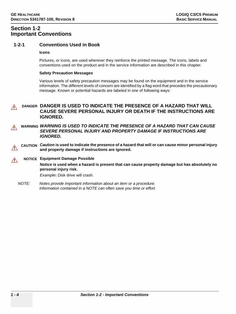
Safety Precaution Messages
Various levels of safety precaution messages may be found on the equipment and in the service information. The different levels of concern are identified by a flag word that precedes the precautionary message. Known or potential hazards are labeled in one of following ways:
NOTE: Notes provide important information about an item or a procedure. Information contained in a NOTE can often save you time or effort.
DANGER DANGER IS USED TO INDICATE THE PRESENCE OF A HAZARD THAT WILL CAUSE SEVERE PERSONAL INJURY OR DEATH IF THE INSTRUCTIONS ARE IGNORED.
WARNINGWARNING WARNING IS USED TO INDICATE THE PRESENCE OF A HAZARD THAT CAN CAUSE SEVERE PERSONAL INJURY AND PROPERTY DAMAGE IF INSTRUCTIONS ARE IGNORED.
CAUTION Caution is used to indicate the presence of a hazard that will or can cause minor personal injury and property damage if instructions are ignored.
NOTICE Equipment Damage PossibleNotice is used when a hazard is present that can cause property damage but has absolutely no personal injury risk. Example: Disk drive will crash.

GE HEALTHCARE LOGIQ C3/C5 PREMIUMDIRECTION 5341787-100, REVISION 8 BASIC SERVICE MANUAL
Section 1-2 - Important Conventions 1 - 5
1-2-2 Standard Hazard IconsImportant information will always be preceded by the exclamation point contained within a triangle, as seen throughout this chapter. In addition to text, several different graphical icons (symbols) may be used to make you aware of specific types of hazards that could cause harm.
Other hazard icons make you aware of specific procedures that should be followed.
Table 1-8 Standard Hazard Icons
ELECTRICAL MECHANICAL RADIATION
LASER HEAT PINCH
Table 1-9 Standard Icons Indicating a Special Procedure Be Used
AVOID STATIC ELECTRICITY TAG AND LOCK OUT WEAR EYE PROTECTION
LASERLIGHT
Signed Date
TAG &
LOCKOUT EYEPROTECTION

GE HEALTHCARE LOGIQ C3/C5 PREMIUMDIRECTION 5341787-100, REVISION 8 BASIC SERVICE MANUAL
1 - 6 Section 1-2 - Important Conventions
1-2-3 Product IconsThe following table describes the purpose and location of safety labels and other important information provided on the equipment.
Table 1-10: Product Icons
Label/Icon Purpose/Meaning Location
Identification and Rating Plate
• Manufacture’s name and address
• Date of manufacture• Model and serial numbers• Electrical ratings (Volts,
Amps, phase, and frequency)
Type/Class Label Used to indicate the degree of safety or protection.
IP Code (IPX8)
IPX8: FSU-1000
Indicates the degree of protection provided by the enclosure per IEC60 529.
Bottom of footswitch
Type BF Applied Part (man in the box) symbol is in accordance with IEC 60878-02-03.
Beside the probe connector
General Warning. Various
“CAUTION” - Dangerous voltage” (the lightning flash with arrowhead) is used to indicate electric shock hazards.
Various
Indicates the power on and power off position of the power switch.
CAUTION: This Power Switch DOES NOT ISOLATE Mains Supply.
See the Console Overview section for location information.
“Protective Earth” indicates the protective earth (grounding) terminal.
Inside PowerBox and Console

GE HEALTHCARE LOGIQ C3/C5 PREMIUMDIRECTION 5341787-100, REVISION 8 BASIC SERVICE MANUAL
Section 1-2 - Important Conventions 1 - 7
This symbol indicates that waste electrical and electronic equipment must not be disposed of as unsorted municipal waste and must be collected separately. Please contact an authorized representative of the manufacturer for information concerning the decommissioning of your equipment.
Bottom
Indicates the presence of hazardous substance(s) above the maximum concentration value. Maximum concentration values for electronic information products, as set by the People’s Republic of China Electronic Industry Standard SJ/T11364-2006, include the hazardous substances of lead, mercury, hexavalent chromium, cadmium, polybrominated biphenyl (PBB), and polybrominated diphenyl ether (PBDE). “10” indicates the number of years during which the hazardous substance(s) will not leak or mutate so that the use of this product will not result in any severe environmental pollution, bodily injury, or damage to any assets.
Probe and Rear Panel, China Rating Plate
Type CF Defib-Proof Applied Part (heart in the box with paddle) symbol is in accordance with IEC 60878-02-06.
ECG module
Utilize additional care and personnel when moving on steep inclines (>5 degrees) or loading into vehicle for transport.
Back of LCD
Table 1-10: Product Icons
Label/Icon Purpose/Meaning Location

GE HEALTHCARE LOGIQ C3/C5 PREMIUMDIRECTION 5341787-100, REVISION 8 BASIC SERVICE MANUAL
1 - 8 Section 1-2 - Important Conventions
Do not place any objects on the monitor.
Back of LCD
Do not force the LCD monitor with your hands.
Back of LCD
There is a pinch point on the LCD monitor. Take care to avoid injuring hands or fingers when flipping down the LCD monitor.
Back of LCD
Use the rear handle for horizontal movement only..
Back of LCD
“Consult accompanying documents“ is intended to alert the user to refer to the operator manual or other instructions when complete information cannot be provided on the label.
Various
Do not push the system Back of LCD
Table 1-10: Product Icons
Label/Icon Purpose/Meaning Location

GE HEALTHCARE LOGIQ C3/C5 PREMIUMDIRECTION 5341787-100, REVISION 8 BASIC SERVICE MANUAL
Section 1-3 - Safety Considerations 1 - 9
Section 1-3Safety Considerations
1-3-1 IntroductionThe following safety precautions must be observed during all phases of operation, service and repair of this equipment. Failure to comply with these precautions or with specific warnings elsewhere in this manual, violates safety standards of design, manufacture and intended use of the equipment.
1-3-2 Human SafetyServicing should be performed by authorized personnel only. Only personnel who have participated in a LOGIQ C3/C5 Premium Training are authorized to service the equipment.
1-3-3 Mechanical Safety
WARNINGWARNING WHEN THE UNIT IS RAISED FOR A REPAIR OR MOVED ALONG ANY INCLINE, USE EXTREME CAUTION SINCE IT MAY BECOME UNSTABLE AND TIP OVER.
WARNINGWARNING ULTRASOUND PROBES ARE HIGHLY SENSITIVE MEDICAL INSTRUMENTS THAT CAN EASILY BE DAMAGED BY IMPROPER HANDLING. USE CARE WHEN HANDLING AND PROTECT FROM DAMAGE WHEN NOT IN USE. DO NOT USE A DAMAGED OR DEFECTIVE PROBE. FAILURE TO FOLLOW THESE PRECAUTIONS CAN RESULT IN SERIOUS INJURY AND EQUIPMENT DAMAGE.
WARNINGWARNING NEVER USE A PROBE THAT HAS FALLEN TO THE FLOOR. EVEN IF IT LOOKS OK, IT MAY BE DAMAGED.
CAUTION The LOGIQ C3/C5 Premium weighs 75 kg or more, depending on installed peripherals, when ready for use. Care must be used when moving it or replacing its parts. Failure to follow the precautions listed could result in injury, uncontrolled motion and costly damage.ALWAYS:Be sure the pathway is clear.Use slow, careful motions.Use two people when moving on inclines or lifting more than 75 kg (169 lbs).
WARNINGWARNING AFTER UNPLUG POWER CORD, WAIT FOR AT LEAST 20 SECONDS FOR CAPACITORS TO DISCHARGE AS THERE ARE NO TEST POINTS TO VERIFY ISOLATION.

GE HEALTHCARE LOGIQ C3/C5 PREMIUMDIRECTION 5341787-100, REVISION 8 BASIC SERVICE MANUAL
1 - 10 Section 1-3 - Safety Considerations
1-3-3 Mechanical Safety (cont’d)
NOTE: Special care should be taken when transporting the unit in a vehicle:
• Secure the unit in an upright position.• Lock the wheels (brake)
1-3-4 Electrical SafetyTo minimize shock hazard, the equipment chassis must be connected to an electrical ground. The system is equipped with a three-conductor AC power cable. This must be plugged into an approved electrical outlet with safety ground. The power outlet used for this equipment should not be shared with other types of equipment.
Both the system power cable and the power connector meet international electrical standards.
1-3-5 Label LocationsRefer to LOGIQ C3/LOGIQ C5 Premium Basic User Manual Section Warning Label Location at page 2-31.
WARNINGWARNING DO NOT SERVICE OR DISASSEMBLE PARTS UNDER FRU UNIT LEVEL AT ANY CIRCUMSTANCES.

GE HEALTHCARE LOGIQ C3/C5 PREMIUMDIRECTION 5341787-100, REVISION 8 BASIC SERVICE MANUAL
Section 1-3 - Safety Considerations 1 - 11
1-3-6 Dangerous Procedure WarningsWarnings, such as the examples below, precede potentially dangerous procedures throughout this manual. Instructions contained in the warnings must be followed.
1-3-7 Returning/Shipping Probes and Repair PartsEquipment being returned must be clean and free of blood and other infectious substances.
GEMS policy states that body fluids must be properly removed from any part or equipment prior to shipment. GEMS employees, as well as customers, are responsible for ensuring that parts/equipment have been properly decontaminated prior to shipment. Under no circumstance should a part or equipment with visible body fluids be taken or shipped from a clinic or site (for example, body coils or an ultrasound probe).
The purpose of the regulation is to protect employees in the transportation industry, as well as the people who will receive or open this package.
NOTE: The USER/SERVICE staff should dispose all the waste properly as per federal, state, and local waste disposal regulation.
DANGER DANGEROUS VOLTAGES, CAPABLE OF CAUSING DEATH, ARE PRESENT IN THIS EQUIPMENT. USE EXTREME CAUTION WHEN HANDLING, TESTING AND ADJUSTING.
WARNINGWARNING EXPLOSION WARNINGDO NOT OPERATE THE EQUIPMENT IN AN EXPLOSIVE ATMOSPHERE. OPERATION OF ANY ELECTRICAL EQUIPMENT IN SUCH AN ENVIRONMENT CONSTITUTES A DEFINITE SAFETY HAZARD.
WARNINGWARNING DO NOT SUBSTITUTE PARTS OR MODIFY EQUIPMENTBECAUSE OF THE DANGER OF INTRODUCING ADDITIONAL HAZARDS, DO NOT INSTALL SUBSTITUTE PARTS OR PERFORM ANY UNAUTHORIZED MODIFICATION OF THE EQUIPMENT.
WARNINGWARNING SHUT DOWN FORCEDLY OR PLUG IN/OUT ACDC INVALID MAY CAUSE THE DAMAGE OF SYSTEM FILES.
WARNINGWARNING AFTER UNPLUG POWER CORD, WAIT FOR AT LEAST 20 SECONDS FOR CAPACITORS TO DISCHARGE AS THERE ARE NO TEST POINTS TO VERIFY ISOLATION.

GE HEALTHCARE LOGIQ C3/C5 PREMIUMDIRECTION 5341787-100, REVISION 8 BASIC SERVICE MANUAL
1 - 12 Section 1-4 - EMC, EMI, and ESD
Section 1-4EMC, EMI, and ESD
1-4-1 Electromagnetic Compatibility (EMC)Electromagnetic compatibility describes a level of performance of a device within its electromagnetic environment. This environment consists of the device itself and its surroundings including other equipment, power sources and persons with which the device must interface. Inadequate compatibility results when a susceptible device fails to perform as intended due interference from its environment or when the device produces unacceptable levels of emission to its environment. This interference is often referred to as radio–frequency or electromagnetic interference (RFI/EMI) and can be radiated through space or conducted over interconnecting power of signal cables. In addition to electromagnetic energy, EMC also includes possible effects from electrical fields, magnetic fields, electrostatic discharge and disturbances in the electrical power supply.
1-4-2 CE ComplianceThe LOGIQ C3/C5 Premium unit conforms to all applicable conducted and radiated emission limits and to immunity from electrostatic discharge, radiated and conducted RF fields, magnetic fields and power line transient requirements.
For applicable standards refer to the Safety Chapter in the Basic User Manual.
NOTE: For CE Compliance, it is critical that all covers, screws, shielding, gaskets, mesh, clamps, are in good condition, installed tightly without skew or stress. Proper installation following all comments noted in this service manual is required in order to achieve full EMC performance.
1-4-3 Electrostatic Discharge (ESD) Prevention
WARNINGWARNING DO NOT TOUCH ANY BOARDS WITH INTEGRATED CIRCUITS PRIOR TO TAKING THE NECESSARY ESD PRECAUTIONS: 1.FOLLOW GENERAL GUIDELINES FOR HANDLING OF ELECTROSTATIC
SENSITIVE EQUIPMENT.

GE HEALTHCARE LOGIQ C3/C5 PREMIUMDIRECTION 5341787-100, REVISION 8 BASIC SERVICE MANUAL
Section 1-5 - Lockout/Tagout (LOTO) requirements 1 - 13
Section 1-5Lockout/Tagout (LOTO) requirements
Follow OSHA Lockout/Tagout requirements (USA) or local Lockout/Tagout requirements by ensuring you are in total control of the AC power plug at all times during the service process.
To apply Lockout/Tagout:
1.) Plan and prepare for shutdown.2.) Shutdown the equipment.3.) Isolate the equipment.4.) Apply Lockout/Tagout Devices.5.) Remove battery.6.) Control all stored and residual energy.7.) Verify isolation.
All potentially hazardous stored or residual energy is relieved.
Equipment being returned must be clean and free of blood and other infectious substances.
GE Healthcare policy states that body fluids must be properly removed from any part or equipment prior to shipment. GE Healthcare employees, as well as customers, are responsible for ensuring that parts/equipment have been properly decontaminated prior to shipment. Under no circumstance should a part or equipment with visible body fluids be taken or shipped from a clinic or site (for example, body coils or an ultrasound probe).
The purpose of the regulation is to protect employees in the transportation industry, as well as the people who will receive or open this package.
NOTE: The US Department of Transportation (DOT) has ruled that “items that were saturated and/or dripping with human blood that are now caked with dried blood; or which were used or intended for use in patient care” are “regulated medical waste” for transportation purposes and must be transported as a hazardous material.
NOTE: The USER/SERVICE staff should dispose all the waste properly as per federal, state, and local waste disposal regulation.
NOTICE Energy Control and Power Lockout for LOGIQ C3/C5 PremiumWHEN SERVICING PARTS OF THE SYSTEM WHERE THERE IS EXPOSURE TO VOLTAGE GREATER THAN 30 VOLTS:1. TURN OFF THE SCANNER.2. UNPLUG THE SYSTEM.3. MAINTAIN CONTROL OF THE SYSTEM POWER PLUG.4. WAIT FOR AT LEAST 20 SECONDS FOR CAPACITORS TO DISCHARGE AS THERE ARE NO TEST POINTS TO VERIFY ISOLATION. THE AMBER LIGHT ON THE OP PANEL ON/OFF BUTTON WILL TURN OFF.5. REMOVE THE SYSTEM BATTERY.Signed Date
TAG &
LOCKOUT

GE HEALTHCARE LOGIQ C3/C5 PREMIUMDIRECTION 5341787-100, REVISION 8 BASIC SERVICE MANUAL
1 - 14 Section 1-6 - Customer Assistance
Section 1-6Customer Assistance
1-6-1 Contact InformationIf this equipment does not work as indicated in this service manual or in the User Manual, or if you require additional assistance, please contact the local distributor or appropriate support resource, as listed below.
Prepare the following information before you call:
- System ID serial number.- Software version.
Table 1-11 Phone Numbers for Customer Assistance
Location Phone Number
USAGE Vingmed UltrasoundUltrasound Service Engineering9900 Innovation DriveWauwatosa, WI 53226
Service: On-site
Service Parts
Application Support
1-800-437-1171
1-800-558-2040
1-800-682-5327 or 1-262-524-5698
Canada 1-800-668-0732
Latin AmericaServiceApplication Support
1-800-321-79371-262-524-5698
Europe (OLC- EMEA)GE Ultraschall Deutschland GmbHBeethovenstraße 239Postfach 11 05 60, D-42655 SolingenGermany
OLC - EMEAPhone: +49 (0)212 2802 - 652
+33 1 3083 1300Fax: +49 (0) 212 2802 - 431
Online Services Ultrasound AsiaAustraliaChinaIndiaJapanKoreaSingapore
Phone: +(61) 1-800-647-855+(86) 800-810-8188+(91) 1-800-11-4567+(81) 42-648-2924+(82) 2620 13585+(95) 6277-3444

GE HEALTHCARE LOGIQ C3/C5 PREMIUMDIRECTION 5341787-100, REVISION 8 BASIC SERVICE MANUAL
Section 1-6 - Customer Assistance 1 - 15
1-6-2 System Manufacturer
1-6-3 Factory Site
Table 1-12 System Manufacturer
Manufacturer FAX Number
GE Medical Systems (China) Co., Ltd.No.19, Changjiang Road, Wuxi National Hi-Tech Development Zone, Jiangsu, P.R. China 214028
TEL: +86 510-85225888FAX: +86 510-85226688
Table 1-13 Factory Site
Factory Site FAX Number
GE Medical Systems (China) Co., Ltd.No.19, Changjiang Road, Wuxi National Hi-Tech Development Zone, Jiangsu, P.R. China 214028
TEL: +86 510-85225888FAX: +86 510-85226688

GE HEALTHCARE LOGIQ C3/C5 PREMIUMDIRECTION 5341787-100, REVISION 8 BASIC SERVICE MANUAL
1 - 16 Section 1-6 - Customer Assistance
This page was intentionally left blank.

GE HEALTHCARE LOGIQ C3/C5 PREMIUMDIRECTION 5341787-100, REVISION 8 BASIC SERVICE MANUAL
Section 2-1 - Overview 2 - 1
Chapter 2Site Preparations
Section 2-1Overview
2-1-1 Purpose of chapter 2This chapter provides the information required to plan and prepare for the installation of LOGIQ C3/C5 Premium.Included are descriptions of the facility and electrical needs to be met by the purchaser of the unit.
Table 2-1 Contents in Chapter 2
Section Description Page Number
2-1 Overview 2-1
2-2 General Console Requirements 2-2
2-3 Facility Needs 2-6

GE HEALTHCARE LOGIQ C3/C5 PREMIUMDIRECTION 5341787-100, REVISION 8 BASIC SERVICE MANUAL
2 - 2 Section 2-2 - General Console Requirements
Section 2-2General Console Requirements
2-2-1 Console Environmental Requirements
NOTE: Temperature in degrees C. Conversion to Degrees F = (Degrees C * 9/5) + 32.
2-2-1-1 LightingBright light is needed for system installation, updates and repairs. However, operator and patient comfort may be optimized if the room light is subdued and indirect. Therefore a combination lighting system (dim/bright) is recommended. Keep in mind that lighting controls and diameters can be a source of EMI which could degrade image quality. These controls should be selected to minimize possible interface.
2-2-2 Electrical Requirements
NOTE: GE Healthcare requires a dedicated power and ground for the proper operation of its Ultrasound equipment. This dedicated power shall originate at the last distribution panel before the system.
Sites with a mains power system with defined Neutral and Live:
The dedicated line shall consist of one phase, a neutral (not shared with any other circuit), and a full size ground wire from the distribution panel to the Ultrasound outlet.
Sites with a mains power system without a defined Neutral:
The dedicated line shall consist of one phase (two lines), not shared with any other circuit, and a full size ground wire from the distribution panel to the Ultrasound outlet.
NOTE: Please note that image artifacts can occur, if at any time within the facility, the ground from the main facility's incoming power source to the Ultrasound unit is only a conduit.
Table 2-2 Environmental Requirements for LOGIQ C3/C5 Premium Scanners
Operational Storage Transport
Temperature 10 - 40oC50 - 104 oF
-5 - 50 oC23 - 122oF
-5 - 50 oC23 - 122oF
Humidity 30 - 75%non-condensing
10 - 90%non-condensing
10 - 90%non-condensing
Pressure 700 - 1060hPa 700 - 1060hPa 700 - 1060hPa

GE HEALTHCARE LOGIQ C3/C5 PREMIUMDIRECTION 5341787-100, REVISION 8 BASIC SERVICE MANUAL
Section 2-2 - General Console Requirements 2 - 3
2-2-2 Electrical Requirements (cont’d)
2-2-2-1 LOGIQ C3/C5 Premium Power RequirementsThe following power line parameters should be monitored for one week before installation. We recommend that you use an analyzer Dranetz Model 606-3 or Dranetz Model 626:
2-2-2-2 Inrush CurrentInrush Current is not a factor to consider due to the inrush current limiting properties of the power supplies.
2-2-2-3 Site Circuit BreakerIt is recommended that the branch circuit breaker for the machine be ready accessible.
2-2-2-4 Site Power OutletsA desiccated AC power outlet must be within reach of the unit without extension cords. Other outlets adequate for the external peripherals, medical and test equipment needed to support this unit must also be present within 1 m (3.2 ft.) of the unit. Electrical installation must meet all current local, state, and national electrical codes.
2-2-2-5 Unit Power PlugIf the unit arrives without the power plug, or with the wrong plug, you must contact your GE dealer or the installation engineer must supply what is locally required.
2-2-2-6 Power Stability RequirementsVoltage drop-outMax 10 ms.
Power Transients(All applications)Less than 25% of nominal peak voltage for less than 1 millisecond for any type of transient, including line frequency, synchronous, asynchronous, or aperiodic transients.
Table 2-3 Electrical Specifications for LOGIQ C3/C5 Premium
PARAMETER AREA LIMITS
Voltage Range100-120V~ 500VA
220-240V~ 500VA
Power All applications MAX. 750 VA
Line Frequency All applications 50/60Hz (±2Hz)
Power Transients All applications
Less than 25% of nominal peak voltage for less than 1 millisecond for any type of transient, including line frequency, synchronous, asynchronous, or aperiodic transients.
Decaying Oscillation All applications Less than 15% of peak voltage for less than 1 millisecond.
CAUTION POWER OUTAGE MAY OCCURE. The LOGIQ C3/C5 Premium requires a dedicated single branch circuit. To avoid circuit overload and possible loss of critical care equipment, make sure you DO NOT have any other equipment operating on the same circuit.

GE HEALTHCARE LOGIQ C3/C5 PREMIUMDIRECTION 5341787-100, REVISION 8 BASIC SERVICE MANUAL
2 - 4 Section 2-2 - General Console Requirements
2-2-3 EMI LimitationsUltrasound machines are susceptible to Electromagnetic Interference (EMI) from radio frequencies, magnetic fields, and transient in the air wiring. They also generate EMI. The LOGIQ C3/C5 Premium complies with limits as stated on the EMC label. However there is no guarantee that interface will not occur in a particular installation.
Possible EMI sources should be identified before the unit is installed.
Electrical and electronic equipment may produce EMI unintentionally as the result of defect.
These sources include:
• medical lasers,• scanners,• cauterizing guns,• computers,• monitors,• fans,• gel warmers,• microwave ovens,• light dimmers,• portable phones.The presence of broadcast station or broadcast van may also cause interference. See for EMI Prevention tips.
See Table 2-4 for EMI Prevention tips.
Table 2-4 EMI Prevention/abatement
EMI Rule Details
Be aware of RF sourcesKeep the unit at least 5 meters or 15 feet away from other EMI sources. Special shielding may be required to eliminate interference problems caused by high frequency, high powered radio or video broadcast signals.
Ground the unit Poor grounding is the most likely reason a unit will have noisy images. Check grounding of the power cord and power outlet.
Replace all screws, RF gaskets, covers, cores
After you finish repairing or updating the system, replace all covers and tighten all screws. Any cable with an external connection requires a magnet wrap at each end. Install the shield over the front of card cage. Loose or missing covers or RF gaskets allow radio frequencies to interface with the ultrasound signals.
Replace broken RF gaskets If more than 20% or a pair of fingers on the RF gaskets are broken, replace the gaskets. Do not turn on the unit until any loose metallic part is removed.
Do not place labels where RF gaskets touch metal
Never place a label where RF gaskets meet the unit. Otherwise, the gap created will permit RF leakage. Or, if a label has been found in such a position, move the label.
Use GE specified harnesses and peripherals
The interconnect cables are grounded and require ferrite beads and other shielding. Also, cable length, material, and routing are all important; do not change from what is specified.
Take care with cellular phones Cellular phones may transmit a 5 V/m signal; that could cause image artifacts.
Properly dress peripheral cables
Do not allow cables to lie across the top of the card cage or hang out of the peripheral bays. Loop the excess length for peripheral cables inside the peripheral bays. Attach the monitor cables to the frame.

GE HEALTHCARE LOGIQ C3/C5 PREMIUMDIRECTION 5341787-100, REVISION 8 BASIC SERVICE MANUAL
Section 2-2 - General Console Requirements 2 - 5
2-2-4 Scan Probe Environmental RequirementsOperation:10° to 40° C
Storage:-5° to 50° C
NOTE: Temperature in degrees C. Conversion to Degrees F = (Degrees C * (9/5) + 32).
NOTICE SYSTEMS AND ELECTRONIC PROBES ARE DESIGNED FOR STORAGE TEMPERATURES OF -10 TO + 60 degrees C. WHEN EXPOSED TO LARGE TEMPERATURE VARIATIONS, THE PRODUCT SHOULD BE KEPT IN ROOM TEMPERATURE FOR 10 HOURS BEFORE USE.

GE HEALTHCARE LOGIQ C3/C5 PREMIUMDIRECTION 5341787-100, REVISION 8 BASIC SERVICE MANUAL
2 - 6 Section 2-3 - Facility Needs
Section 2-3Facility Needs
2-3-1 Purchaser ResponsibilitiesThe work and materials needed to prepare the site is the responsibility of the purchaser. Delay, confusion, and waste of manpower can be avoided by completing pre installation work before delivery. User the Pre Installation checklist to verify that all needed steps have been taken,Purchaser reasonability includes:
• Procuring the materials required.• Completing the preparations before delivery of the ultrasound system.• Paying the costs for any alternations and modifications not specifically provided in the sales
contract.
NOTE: All electrical installation that are preliminary to the positioning of the equipment at the site prepared for the equipment must be performed by licensed electrical contractors. Other connections between pieces of electrical equipment, products involved (and the accompanying electrical installations) are highly sophisticated and special engineering competence is required. All electrical work on these product must comply with the requirements of applicable electrical codes. The purchaser of GE equipment must only utilize qualified personnel to perform electrical servicing on the equipment.
The desire to use a non-listed or customer provided product or to place an approved product further from the system than the interface kit allows presents challenges to the installation team. To avoid delays during installation, such variances should be made known to the individuals or group performing the installation at the earliest possible date (preferable prior to purchase).The ultrasound suite must be clean proof to delivery of the machine. Carpet is not recommended because it collects dust and creates static. Potential sources of EMI (electromagnetic interference) should also be investigated before delivery. Dirt, static, and EMI can negatively impact system.

GE HEALTHCARE LOGIQ C3/C5 PREMIUMDIRECTION 5341787-100, REVISION 8 BASIC SERVICE MANUAL
Section 2-3 - Facility Needs 2 - 7
2-3-2 Required Features
NOTE: GE Medical Systems requires a dedicated power and ground for the proper operation of its Ultrasound equipment. This dedicated power shall originate at the last distribution panel before the system.
Sites with a mains power system with defined Neutral and Live:
The dedicated line shall consist of one phase, a neutral (not shared with any other circuit), and a full size ground wire from the distribution panel to the Ultrasound outlet.
Sites with a mains power system without a defined Neutral:
The dedicated line shall consist of one phase (two lines), not shared with any other circuit, and a full size ground wire from the distribution panel to the Ultrasound outlet.
Please note that image artifacts can occur, if at any time within the facility, the ground from the main facility's incoming power source to the Ultrasound unit is only a conduit.
• Dedicated single branch power outlet of adequate amperage meeting all local and national codes which is located less than 2.5 m (8 ft.) from the unit’s proposed location
• Door opening is at least 76 cm (30 in) wide• Proposed location for unit is at least 0.3 m (1 ft.) from the wall for cooling• Power outlet and place for any external peripheral are within 2 m (6.5 ft.) of each other with
peripheral within 1 m of the unit to connect cables.

GE HEALTHCARE LOGIQ C3/C5 PREMIUMDIRECTION 5341787-100, REVISION 8 BASIC SERVICE MANUAL
2 - 8 Section 2-3 - Facility Needs
2-3-3 Recommended and Alternate Ultrasound Room LayoutRecommended standard floor plan and a minimal floor plan for ultrasound equipment:
Figure 2-1 RECOMMENDED ULTRASOUND ROOM LAYOUT
LINEN SUPPLY
EX
AM
INAT
ION
TAB
LE
FILM VIEWER
COUNTER TOP
F
ILE
CA
BIN
ET
SECRETARYS ORDOCTOR’S DESK
FILM
P
RO
CE
SS
ING
R
OO
M,
OVERHEADLIGHTS DIMMER
DEDICATEDPOWER
RECEPTACLE
EXTERNALPERIPHERALS
SINK
CO
UN
TER
TOP
FILM VIEWER
FILM SUPPLIESSINK
LINEN SUPPLY
PROBES/SUPPLIES
24 IN.(61 CM)
EXAMINARIONTABLE
76 IN.(193 CM)DOOR
30 IN.(76 CM)
An 8 by 10 foot Minimal Floor Plan
DEDICATED POWEROUTLETS
DEDICATED ANALOG TELEPHONELINE FOR CONNECTION TO INSITE
A 14 by 17 foot Recommended Floor Plan
GE CABINETFOT SOFTWAREAND MANUALS
Scale : Each square equals one square foot
DOOR42 IN.
(107 CM)
DEDICATED ALALOG TELEPHONELINE FOR CONNECTION TO INSITE
SUCTION LINE
EMERGECYOXYGEN
24 IN.(61 CM)
76 IN.(193 CM)
PATIENTTOILET
FACILITY
FOOTSW
FOOTSW
LOGIQ 5
CONSOLE
CONSOLE
18 IN.(46 CM)
STOOL
STOOL

GE HEALTHCARE LOGIQ C3/C5 PREMIUMDIRECTION 5341787-100, REVISION 8 BASIC SERVICE MANUAL
Section 2-3 - Facility Needs 2 - 9
2-3-4 Networking Pre-installation Requirements
2-3-4-1 Stand Alone Scanner (without Network Connection)None.
2-3-4-2 Scanner Connected to Hospital’s NetworkSupported networks:
Wire LAN
2-3-4-3 Purpose of DICOM Network FunctionDICOM services provide the operator with clinically useful features for moving images and patient information over a hospital network. Examples of DICOM services include the transfer of images to workstations for viewing or transferring images to remote printers. As an added benefit, transferring images in this manner frees up the on-board monitor and peripherals, enabling viewing to be done while scanning continues. With DICOM, images can be archived, stored, and retrieved faster, easier, and at a lower cost.
2-3-4-4 DICOM Option Pre-installation RequirementsTo configure the LOGIQ C3/C5 Premium to work with other network connections, the site’s network administrator must provide some necessary information.
Information must include:
• A host name, local port number, AE Title, IP address and Net Mask for the LOGIQ C3/C5 Premium. • The IP addresses for the default gateway and other routers at the site for ROUTING
INFORMATION.• The host name, IP address, port and AE Title for each device the site wants connected to the
LOGIQ C3/C5 Premium for DICOM APPLICATION INFORMATION. A field for the make (manufacturer) and the revision of the device, is also included. This information may be useful for solving errors.

GE HEALTHCARE LOGIQ C3/C5 PREMIUMDIRECTION 5341787-100, REVISION 8 BASIC SERVICE MANUAL
2 - 10 Section 2-3 - Facility Needs
2-3-4-4 DICOM Option Pre-installation Requirements (cont’d).
Figure 2-2 Worksheet for DICOM Network Information
LOGIQ C3/Host Name
AE Title
Local Port IP Address
Net Mask
.. .
.. .
ROUTING INFORMATION
ROUTER2ROUTER3
ROUTER1
.. .
.. .
.. .
.. .
.. .
.. .
.. .
Destination IP Addresses
GATEWAY IP Addresses
Default
DICOM APPLICATION INFORMATION
NAME
Store 2
Store 3
Store 1
MAKE/REVISION IP ADDRESSES PORTAE TITLE
Store 5
Store 6
Store 4
Storage Commit
MPPS
Worklist .. .
.. .
.. .
.. .
.. .
.. .
.. .
.. .
.. .

GE HEALTHCARE VIVID FIVEDIRECTION 5273008-100, REVISION 8 BASIC SERVICE MANUAL
Chapter 3 System Setup 3 - 1
Chapter 3System Setup
Section 3-1Overview
3-1-1 Purpose of Chapter 3This chapter contains information needed to install the unit. Included are references to a procedure that describes how to receive and unpack the equipment and how to file a damage or loss claim.How to prepare the facility and unit of the actual installation, and how to check and test the unit and external peripherals for electrical safety are included in this procedure. Also included LOGIQ C3/C5 Premium in this section are guidelines for transporting the unit to a new site.
Table 3-1 Contents in Chapter 3
Section Description Page Number
3-1 Overview 3-1
3-2 Setup Reminders 3-2
3-3 Receiving and Unpacking the Equipment 3-3
3-4 Preparing for Installation 3-4
3-5 Completing the Installation 3-5
3-6 System Configuration 3-6
3-7 Software/Option Configuration 3-7
3-8 Connectivity Installation Worksheet 3-8
3-9 Loading Base Image Software 3-9
3-10 Software Version check out 3-10
3-11 Paperwork 3-11

GE HEALTHCARE VIVID FIVEDIRECTION 5341787-100, REVISION 8 BASIC SERVICE MANUAL
3 - 2 Section 3-2 - Setup Reminders
Section 3-2Setup Reminders
3-2-1 Average Installation Time
The LOGIQ C3/C5 Premium has been designed to be installed and checked out by an experienced service technician in approximately 1 hour. LOGIQ C3/C5 Premium consoles with optional equipment may take slightly longer.
Table 3-2 Average Installation Time
Description Average Installation Time Comments
Unpacking the scanner 0.5 hour
Scanner wo/options 0.5 hour Dependant on the configuration that is required
DICOM Option 0.5 hour Dependant on the amount of configuration

GE HEALTHCARE VIVID FIVEDIRECTION 5273008-100, REVISION 8 BASIC SERVICE MANUAL
Chapter 3 System Setup 3 - 3
3-2-2 Installation Warnings1.) Since the LOGIQ C3/C5 Premium weighs approximately 75 kg without options, preferably two
people should unpack it. Two people are also preferable for installing any additional bulky items.2.) There are no operator serviceable components. To prevent shock, do not remove any covers or
panels. Should problems or malfunctions occur, unplug the power cord. Only qualified service personnel should carry out servicing and troubleshooting.
NOTE: For information regarding packing labels, refer to LABELS ON PACKAGE.
3.) After being transported, the unit may be very cold or hot. If this is the case, allow the unit to acclimate before you turn it on. It requires one hour for each 2.5°C increment it's temperature is below 10°C or above 30°C.
CAUTION Equipment damage possibility. Turning the system on without acclimation after arriving at site may cause the system to be damaged.
Table 3-3 Acclimation Time
°C 60 55 50 45 40 35 30 25 20 15 10 5 0 -5 -10 -15 -20 -25 -30 -35 -40
°F 140 131 122 113 104 95 86 77 68 59 50 41 32 23 14 5 -4 -13 -22 -31 -40
hrs 8 6 4 2 0 0 0 0 0 0 0 2 4 6 8 10 12 14 16 18 20

GE HEALTHCARE VIVID FIVEDIRECTION 5341787-100, REVISION 8 BASIC SERVICE MANUAL
3 - 4 Section 3-2 - Setup Reminders
3-2-3 Safety Reminders
DANGER WHEN USING ANY TEST INSTRUMENT THAT IS CAPABLE OF OPENING THE AC GROUND LINE (I.E., METER’S GROUND SWITCH IS OPEN), DON’T TOUCH THE UNIT!
CAUTION Two people should unpack the unit because of its weight. Two people are required whenever a part weighing 19kg (35 lb.) or more must be lifted.
CAUTION If the unit is very cold or hot, do not turn on its power until it has had a chance to acclimate to its operating environment.
CAUTION To prevent electrical shock, connect the unit to a properly grounded power outlet. Do not use a three to two prong adapter. This defeats safety grounding.
CAUTION Do NOT wear the ESD wrist strap when you work on live circuits and more than 30 V peak is present.
CAUTION Do not use a 20 Amp to 15 Amp adapter on the 120 Vac unit’s power cord. This unit requires a dedicated 20 A circuit and can have a 15A plug if the on board peripherals do not cause the unit to draw more than 14.0 amps.
CAUTION Do not operate this unit unless all board covers and frame panels are securely in place. System performance and cooling require this.
CAUTION OPERATOR MANUAL(S) The User Manual(s) should be fully read and understood before operating the LOGIQ C3/C5 Premium and kept near the unit for quick reference.
Figure 3-1 Environmental Labels

GE HEALTHCARE VIVID FIVEDIRECTION 5273008-100, REVISION 8 BASIC SERVICE MANUAL
Chapter 3 System Setup 3 - 5
Section 3-3Receiving and Unpacking the Equipment
When a new system arrives, check that any components are not damaged and are not in short supply. If shipping damage or shortage occurs, contact the address shown in Chapter 1.
Unpacking the the equipment
1.) Remove all the strapping tapes from the packing box.2.) Remove the upper cover of the packing box and then rotate the knob to the right to open the
packing box.3.) Remove the PE bag and plastic film from the system.4.) Remove Accessories Carton from the system.5.) Remove the PE bag and plastic film from the syste6.) Remove strapping tapes .7.) Lift down the system .
CAUTION Do not lift the unit by the Keyboard. Equipment damage may result.
CAUTION The crate with the LOGIQ C3/C5 Premium weighs approximately 75kg. Be prepared for a sudden shift of weight as the unit is removed from its base (pallet)
Figure 3-2 Open the box
2)

GE HEALTHCARE VIVID FIVEDIRECTION 5341787-100, REVISION 8 BASIC SERVICE MANUAL
3 - 6 Section 3-3 - Receiving and Unpacking the Equipment
3-3-1 Moving into Position
In general, a single adult can move the LOGIQ C3/C5 Premium along an even surface with no steep grades. At least two people should move the machine when large humps, grooves, or grades will be encountered. (It is better to pull from the rear rather than push from the front of the unit). Before moving, store all loose parts in the unit. Wrap transducers in soft cloth or foam to prevent damage.
Although LOGIQ C3/C5 Premium is a mobile machine, two people should move it over rough surfaces or up and down grades.
3-3-2 Product Locator Installation Card
NOTE: The Product Locator Installation Card shown may not be same as the provided Product Locator card.
CAUTION Do not tilt the unit more than 5 degrees to avoid tipping it over.To avoid injury by tipping over. Set the monitor to the lowest position before moving.
Figure 3-3 Product Locator Installation Card

GE HEALTHCARE VIVID FIVEDIRECTION 5273008-100, REVISION 8 BASIC SERVICE MANUAL
Chapter 3 System Setup 3 - 7
Section 3-4Preparing for Installation
3-4-1 Verify Customer OrderCompare items received by the customer to that which is listed on the delivery order. Report any items that are missing, back ordered or damaged.
3-4-2 Physical Inspection
3-4-2-1 System Voltage SettingsVerify that Docking Cart is set to the correct voltage.The Voltage settings for the LOGIQ C3/C5 Premium is found on a label to the right of the Power switch and External I/O, on the rear of the system.
3-4-2-2 Video FormatsCheck that the video format is set to the locally used video standard, NTSC or PAL.
3-4-3 EMI ProtectionThis Unit has been designed to minimize the effects of Electro Magnetic Interference (EMI). Many of the covers, shields, and screws are provided primarily to protect the system from image artifacts caused by this interference. For this reason, it is imperative that all covers and hardware are installed and secured before the unit is put into operation.
WARNINGWARNING Connecting a LOGIQ C3/C5 Premium to the wrong voltage level will most likely destroy it.

GE HEALTHCARE VIVID FIVEDIRECTION 5341787-100, REVISION 8 BASIC SERVICE MANUAL
3 - 8 Section 3-5 - Completing the Installation
Section 3-5Completing the Installation
3-5-1 Power On / Boot Up
NOTE: After turning off a system, wait at least ten seconds before turning it on again. The system may not be able to boot if power is recycled too quickly.
3-5-1-1 Scanner Power OnWhen power is applied to the scanner, power is distributed to the Cooling Unit, Control Panel, LCD, Peripherals and the Back-end Processor.
3-5-1-2 Turn on the systemPress the Power On/Off switch at the front of the system once.
When the Power On/Off switch on the Control Panel is pressed once, the Back-end Processor starts and the software code is distributed to initiate the scanner.
No status messages are displayed during this process.
3-5-2 Power Off/ Shutdown
NOTE: After turning off a system, wait at least ten seconds before turning it on again. The system may not be able to boot if power is recycled too quickly.
3-5-2-1 Back-end Processor Power DownTo power down the system:
1.) Press the Power On/Off switch once.
Figure 3-4 Power On/Off Switch

GE HEALTHCARE VIVID FIVEDIRECTION 5273008-100, REVISION 8 BASIC SERVICE MANUAL
Chapter 3 System Setup 3 - 9
3-5-2-1 Back-end Processor Power Down (cont’d)2.) The System-Exit window is displayed.
Figure 3-5 System Exit Window
3.) Using the Trackball or Select key, select Shutdown.4.) The shutdown process takes a few seconds and is complete when the power status LED is turned
amber.5.) Disconnect the probes.Clean or disinfect all probes as necessary. Store them in their shipping
cases to avoid damage.
3-5-2-2 Scanner ShutdownDisconnect the Mains Power Cable if necessary. For example: Relocating the scanner.
3-5-3 Transducer Connection1.) Plug the probe connector into the probe port, then lock the probe.
NOTE: Please ensure that the probe latch is in an unlocked position before you connect the probe to the system.
NOTE: It is not necessary to turn OFF power to connect or disconnect a probe.

GE HEALTHCARE VIVID FIVEDIRECTION 5341787-100, REVISION 8 BASIC SERVICE MANUAL
3 - 10 Section 3-6 - System Configuration
Section 3-6System Configuration
3-6-1 System Specifications3-6-1-1 Physical Dimensions
The physical dimensions of the LOGIQ C3/C5 Premium unit are summarized in Table 3-4 on page 3-10 .The Size of LOGIQ C3/C5 Premium.
Table 3-4 Physical Dimensions of LOGIQ C3/C5 Premium
Height Width Depth Unit
1400 500 700 mm
55.16 19.70 27.58 inches

GE HEALTHCARE VIVID FIVEDIRECTION 5273008-100, REVISION 8 BASIC SERVICE MANUAL
Chapter 3 System Setup 3 - 11
3-6-1-2 Weight
3-6-2 Electrical Specifications
3-6-3 On-Board Optional Peripherals
NOTE: ECG are only supported by LOGIQ C5 Premium.
NOTE: For detailed installation information and connection procedures, please refer to Peripheral Installation Instruction manual (5266280-100).
Table 3-5 Weight of LOGIQ C3/C5 Premium With Monitor and Without Other Peripherals
Model Weight [kg] Weight [lb]
LOGIQ C3/C5 Premium Approximately 75 Approximately 165
Table 3-6 Electrical Specifications for LOGIQ C3/C5 Premium
System Voltage Current Frequency
1 110 -120 V AC 500VA 50/60Hz
2 220- 240 V AC 500VA 50/60Hz
Table 3-7 List of Optional Peripherals
Device Manufacturer Model Video Signal
B/W Printer SONY UP-D897MD USB
B/W Printer SONY UP-D897 USB
HP Printer HP HP 470 Officejet USB
HP Printer HP HP8000 USB
HP Printer HP HP6000 USB
USB Memory SanDisk SanDisk 4G USB
1-Pedal Footswitch Whanam FSU1000 USB
3-Pedal Footswitch Whanam MKF 2-MED GP26 USB
USB Hard Disk Seagate USBHDD 250G USB
USB Hard Disk Seagate USBHDD 500G USB
Color Printer SONY UP-D23MD USB
Color Printer SONY UP-D25MD USB
Color Printer MITSUBISHI P95D USB
Color Printer MITSUBISHI CP30DW-Z USB
ECG NORAV ECG -USB1 USB

GE HEALTHCARE VIVID FIVEDIRECTION 5341787-100, REVISION 8 BASIC SERVICE MANUAL
3 - 12 Section 3-6 - System Configuration
3-6-4 Connecting Cables
3-6-5 Peripherals/Accessories Connector PanelLOGIQ C3/C5 Premium peripherals and accessories can be properly connected using the side connector panel.
3-6-5-1 Rear Panel ConnectorLocated on the rear panel are Network port, 2 USB port, S-Video Out, VGA, Audio Out, Composite Out.
1.) 2 USB Ports (Printers, Footswitch, etc)2.) Network Port3.) VGA4.) Audio Out 5.) S-Video Out6.) Composite Out
WARNINGWARNING Equipment damage possibility. Be sure to use the following recommended connecting cables to connect recording devices and a network with LOGIQ C3/C5 Premium console.
Table 3-8 List of Connecting Cables
Name Part No. Figure NOTE
USB Cable 5122305 For USB Printer
Figure 3-6 Rear Connector Panel

GE HEALTHCARE VIVID FIVEDIRECTION 5273008-100, REVISION 8 BASIC SERVICE MANUAL
Chapter 3 System Setup 3 - 13
3-6-5-2 Left Panel Connector1 USB port is Located on the left panel.
1.) 1 USB Ports (Printers, Footswitch, etc)
3-6-5-3 Printer Box Rear Panel connector
1.) 1 USB Ports only for B/W Printer
NOTE: Each outer (case) ground line of peripheral/accessory connectors are protectively grounded. Signal ground lines are not isolated, except the Service port (3). All of signal lines (include signal GND) of the Service port are isolated.
Figure 3-7 Left Connector Panel
Figure 3-8 Printer Box Rear Connector Panel

GE HEALTHCARE VIVID FIVEDIRECTION 5341787-100, REVISION 8 BASIC SERVICE MANUAL
3 - 14 Section 3-6 - System Configuration
3-6-5-4 Pin assignment for each connector
Table 3-9 Pin Assignments of External VGA
Pin No. Signal Pin No. Signal
1 RED 9 NC
2 GREEN 10 NC
3 BLUE 11 NC
4 NC 12 NC
5 NC 13 HSY
6 GND 14 VSY
7 GND 15 NC
8 GND
Table 3-10 Pin Assignments of USB
Pin No. Signal Pin No. Signal
1 +5 VDC 5 +5 VDC
2 DATA 6 DATA
3 DATA 7 DATA
4 GND 8 GND
Table 3-11 Pin Assignments of Audio
Pin No. Signal Pin No. Signal
1 GND 4 NC
2 L+ 5 R+
3 Speaker L 6 Speaker R
Table 3-12 Pin Assignment of S-Video
Pin No. Output Signal Pin No. Output Signal
1 GND 3 Y
2 GND 4 C
Table 3-13 Pin Assignment of Composite Video Out
Pin No. Output Signal Pin No. Output Signal
1 Composite Out 2 GND

GE HEALTHCARE VIVID FIVEDIRECTION 5273008-100, REVISION 8 BASIC SERVICE MANUAL
Chapter 3 System Setup 3 - 15
3-6-5-5 Connect Peripherals
A.) Connect B/W printer to the system.B/W Printer can be properly connected using USB Ports.
B.) Connect UP-D23 color printer to the system.UP-D23 Color Printer can be properly connected using USB Ports.
Figure 3-9 Connect B/W printer to the system
Figure 3-10 Connect color printer to the system

GE HEALTHCARE VIVID FIVEDIRECTION 5341787-100, REVISION 8 BASIC SERVICE MANUAL
3 - 16 Section 3-6 - System Configuration
3-6-5-5 Connect Peripherals (cont’d)C.) Connect the B/W printer (Sony UP-897MD)to the system
The B/W printer can be properly connected using the Composite Out Port.
D.) Connect Foot Switch to the system.Foot Switch can be properly connected using USB Ports.
Figure 3-11 Connect B/W Printer (Sony UP-897MD) to the system
Figure 3-12 Connect Foot Switch to the system
1-Pedal Footswitch 3-Pedal Footswitch

GE HEALTHCARE VIVID FIVEDIRECTION 5273008-100, REVISION 8 BASIC SERVICE MANUAL
Chapter 3 System Setup 3 - 17
3-6-5-5 Connect Peripherals (cont’d)E.) Connect the USB Memory to the system. The USB Memory can be properly connected using USB
ports.
F.) ECG can be properly connected using USB ports. (ECG only supported by LOGIQ C5 Premium)
Figure 3-13 USB Memory Connection
Figure 3-14 ECG Connection

GE HEALTHCARE VIVID FIVEDIRECTION 5341787-100, REVISION 8 BASIC SERVICE MANUAL
3 - 18 Section 3-6 - System Configuration
3-6-5-5 Connect Peripherals (cont’d)G.) Connect HP 470 Officejet printer to the system. HP 470b Officejet Printer can be properly
connected using USB Ports.
H.) Connect the USB HDD to the system. The USB Harddisk can be properly connected using USB ports.
Figure 3-15 HP 470b Officejet printer to the system
Figure 3-16 USB Hard Disk Connection

GE HEALTHCARE VIVID FIVEDIRECTION 5273008-100, REVISION 8 BASIC SERVICE MANUAL
Chapter 3 System Setup 3 - 19
3-6-6 Available ProbesSee in specification in the LOGIQ C3/C5 Premium User Reference Manual for Probes and intended use.
Table 3-14 List of Probes on LOGIQ C3/C5 Premium
Section 3-7Software/Option Configuration
Refer to the LOGIQ C3/C5 Premium Basic User Manual, Chapter 16, Customizing Your System for information on configuring items like Hospital, Department, Language, Units (of measure), Date, Time and Date Format.
For information on configuring Software Options, Refer to the LOGIQ C3/C5 Premium Basic User Manual, Chapter 16, Customizing Your System.
For information on configuring DICOM Connectivity, Refer to the LOGIQ C3/C5 Premium Basic User Manual, Chapter 16, Customizing Your System.
Probe Name Material of Headshell Area of Using TYPE Catalog Number Part Number
4C-RC NORYL GENERAL PURPOSE CONVEX H48102LE 5315581
6.5C-RC VALOXVETERINARYPEDIATRICNEONATAL
MICRO-CONVEX H48102LF 5315685
E7C-RC VALOXTRANSVAGINALTRANSRECTAL
MICRO-CONVEX H48102LG 5315686
7.5L-RC VALOX SMALL PARTSPERIPHERAL VASCULAR LINEAR H48102LJ 5315683
3S-RC VALOX CARDIAC SECTOR H40452LA 5213343
L6-12-RC VALOX SMALL PARTSPERIPHERAL VASCULAR LINEAR H40462LJ 5399465
C2-5-RC NORYL GENERAL PURPOSE CONVEX H40462LH 5401243

GE HEALTHCARE VIVID FIVEDIRECTION 5341787-100, REVISION 8 BASIC SERVICE MANUAL
3 - 20 Section 3-8 - Connectivity Installation Worksheet
Section 3-8Connectivity Installation Worksheet
Site System Information
Services (Destination Devices)
TCP/IP Settings
Device Type Manufacturer Name IP Address Port AE Title123456789101112
Name - AE Title:
Dept:
LOGIQ SN: Type:
Floor:
Room:
REV:
Comments:
CONTACT INFORMATION
Name Title Phone E-Mail Address
Site:
IP Settings
IP Address:
Subnet Mask:
Default Gateway:
Remote Archive Setup
Remote Archive IP:
Remote Archive Name:

GE HEALTHCARE VIVID FIVEDIRECTION 5273008-100, REVISION 8 BASIC SERVICE MANUAL
Chapter 3 System Setup 3 - 21
Section 3-9Loading Base Image Software
Refer to
Section 8-4 "Loading Base Image Software" on page 8-6.

GE HEALTHCARE VIVID FIVEDIRECTION 5341787-100, REVISION 8 BASIC SERVICE MANUAL
3 - 22 Section 3-10 - Software Version check out
Section 3-10Software Version check out
3-10-1 Functional Check-out1.) Power on LOGIQ C3/C5 Premium scanner and wait until system booting to main screen.2.) Press UTILITY key on control panel.3.) Choose the About button on the right.
Figure 3-17 About and Software version

GE HEALTHCARE VIVID FIVEDIRECTION 5273008-100, REVISION 8 BASIC SERVICE MANUAL
Chapter 3 System Setup 3 - 23
Section 3-11Paperwork
NOTE: During and after installation, the documentation (i.e. User Manuals, Installation Manuals...) for the peripheral units must be kept as part of the original system documentation. This will ensure that all relevant safety and user information is available during the operation and service of the complete system.
3-11-1 Product Locator Installation
NOTE: The Product Locator Installation Card shown may not be same as the provided Product Locator card.
3-11-2 User Manual(s)User Check that the correct User Manual(s) for the system and software revision, is included with the installation. Specific language versions of the User Manual may also be available. Check with your GE Sales Representative for availability.
Figure 3-18 Product Locator Installation Card

GE HEALTHCARE VIVID FIVEDIRECTION 5341787-100, REVISION 8 BASIC SERVICE MANUAL
3 - 24 Section 3-11 - Paperwork
This page was intentionally left blank.

GE HEALTHCARE LOGIQ C3/C5 PREMIUMDIRECTION 5341787-100, REVISION 8 BASIC SERVICE MANUAL
Chapter 4 Functional Checks 4 - 1
Chapter 4Functional Checks
Section 4-1Overview
4-1-1 Purpose for Chapter 4This chapter provides procedures for quickly checking major functions of the LOGIQ C3/C5 Premium console, diagnostics by using the built-in service software, and power supply.
Section 4-2Required Equipment
To perform these tests, you'll need any of the sector, linear, or convex transducers.
(normally you should check all the transducers used on the system)
Table 4-1 Contents in Chapter 4
Section Description Page Number
4-1 Overview 4-1
4-2 Required Equipment 4-1
4-3 General Procedure 4-2
4-4 Software Configuration Checks 4-36
4-5 Peripheral Checks 4-36

GE HEALTHCARE LOGIQ C3/C5 PREMIUMDIRECTION 5341787-100, REVISION 8 BASIC SERVICE MANUAL
4 - 2 Section 4-3 - General Procedure
Section 4-3General Procedure
4-3-1 Power On/Boot UpAfter connect the system to the electrical supply, the power is applied to the scanner. When the Control panel Power On/Off key is pressed once, the System starts.
4-3-1-1 Scanner Power OnWhen power is applied to the scanner, power is distributed to the Cooling Unit, Control Panel, LCD, Peripherals and the Back-end Processor.
4-3-1-2 Turn on the systemPress the Power On/Off switch at the front of the system once.
When the Power On/Off switch on the Control Panel is pressed once, the Back-end Processor starts and the software code is distributed to initiate the scanner.
No status messages are displayed during this process.
4-3-2 Power Off/ Shutdown
NOTE: After turning off a system, wait at least ten seconds before turning it on again. The system may not be able to boot if power is recycled too quickly.
4-3-2-1 Back-end Processor Power DownTo power down the system:
1.) Press the Power On/Off switch at the front of the system once.
CAUTION SYSTEM REQUIRES ALL COVERSOperate this unit only when all board covers and frame panels are securely in place. The covers are required for safe operation, good system performance and cooling purposes.
Figure 4-19 Power On/Off Switch

GE HEALTHCARE LOGIQ C3/C5 PREMIUMDIRECTION 5341787-100, REVISION 8 BASIC SERVICE MANUAL
Chapter 4 Functional Checks 4 - 3
4-3-2-1Back-end Processor Power Down (cont’d)2.) The System-Exit window is displayed.
Figure 4-20 System Exit Window
3.) Using the Trackball or Select key, select Shutdown.4.) The shutdown process takes a few seconds and the power off sequence is complete when the
power status LED is turned amber.5.) Disconnect the probes.Clean or disinfect all probes as necessary. Store them in their shipping
cases to avoid damage.
4-3-2-2 Scanner Shutdown
Disconnect the Mains Power Cable is necessary. For example: Relocating the scanner.
CAUTION DO NOT unplug and/or transport the unit until after the power off sequence has been completed. Failure to do so may result in corrupted patient files.

GE HEALTHCARE LOGIQ C3/C5 PREMIUMDIRECTION 5341787-100, REVISION 8 BASIC SERVICE MANUAL
4 - 4 Section 4-3 - General Procedure
4-3-3 Archiving and Loading Presets
NOTE: Always save presets before any software reload. This ensures the presets loaded after the software reload are as up–to–date as possible.
NOTE: The system may crash if use a DVD for Archive/Backup/EZBackup/Restore, so always use a CD-R or USB HDD for Archive/Backup/EZBackup/Restore. DVD only can be used for upgrade.
All user presets except changes to Summary, Anatomy, and Biometry pages, can be saved on an CD-R disk (or USB memory device) for reloading on the system.
4-3-3-1 Archiving Presets to an CD-R Disk (or USB memory device)
1.) Insert an empty (blank) CD-R disk into the DVD-RW.2.) Access to the Utility Menu, and select System. The Backup sheet will be shown on the LCD display.
3.) Select the item to back up either from Resource Files.4.) Enter backup destination or browse through the disk to locate the destination.5.) Select Backup now. The backup status for each item is displayed on the Result column.
NOTICE Presets should NOT be saved on the same CD-R disk (or USB memory device) as images. The Archive Menu lists the images but does NOT list the presets stored on a CD-R disk (or USB memory device).
Figure 4-21 Backup Sheet

GE HEALTHCARE LOGIQ C3/C5 PREMIUMDIRECTION 5341787-100, REVISION 8 BASIC SERVICE MANUAL
Chapter 4 Functional Checks 4 - 5
4-3-3-2 Loading Presets from an CD-R disk (or USB memory device)
1.) Insert the CD-R disk with the archived Presets into the DVD-RW.2.) Access to the Utility Menu, and select System. The Restore sheet will be shown on the LCD display. 3.) Select the item to restore either from Resource Files.4.) Enter restore destination or browse through the disk to locate the destination.5.) Select Restore. The restore status for each item is displayed on the Result column.
4-3-4 Adjusting the Display MonitorPlease refer to Section 6-2 "Monitor Adjustments" on page 6-2

GE HEALTHCARE LOGIQ C3/C5 PREMIUMDIRECTION 5341787-100, REVISION 8 BASIC SERVICE MANUAL
4 - 6 Section 4-3 - General Procedure
4-3-5 System Features
4-3-5-1 Control Panel
1.) Power On/Off Switch2.) Probe Key3.) Top Menu Controls4.) Keyboard5.) Preset, Comment, Harmonics keys6.) Patient key7.) Mode keys: B-Mode, M-Mode, PW-Mode, PDI,CF Mode.8.) Gain/Auto key9.) Zoom key10.)Ellipse key11.)Depth key12.)Reverse, Print, Store keys13.)Left, Right key14.)Freeze key15.)Trackball16.)Imaging/Measurement keys17.)TGC18.)Gel Holder19.)Probe Holder
NOTE: LOGIQ C3 Premium does not support PW Mode and CF Mode.
Figure 4-22 Control Panel Tour

GE HEALTHCARE LOGIQ C3/C5 PREMIUMDIRECTION 5341787-100, REVISION 8 BASIC SERVICE MANUAL
Chapter 4 Functional Checks 4 - 7
4-3-5-2 LOGIQ C3/C5 Premium SoftMenu Key Tour
1.) Top Menu Controls op Menu Controls
2.) Sub menu Controls: Activates Sub Menu for Modes and toggles/changes functions
A.) Press F5 on the keyboard to activate Sub Menu,
B.) Use the Direction keys to toggle/change functions
Figure 4-23 SoftMenu Key Tour
Figure 4-24 Sub Menu Controls

GE HEALTHCARE LOGIQ C3/C5 PREMIUMDIRECTION 5341787-100, REVISION 8 BASIC SERVICE MANUAL
4 - 8 Section 4-3 - General Procedure
4-3-5-3 Monitor Display
Figure 4-25 Monitor Display Tour
Table 4-2 Monitor Display Features
1. Institution/Hospital Name, Date, Time, Operator Identification, system status (real-time of frozen).
12. Probe Identifier. Exam Study.
2. Patient Name, Patient Identification. 13. Imaging Parameters by Mode (current mode highlighted).
3. Acoustic Output Readout, 14. Focal Zone.
4. GE Symbol: Probe Orientation Marker. Coincides with a probe orientation marking on the probe.
15. Trackball Functionality Status: Scroll, M&A (Measurement and Analysis), Position, Size, Scan Area Width and Tilt.
5. Image Preview. 16. Body Pattern.
6. Grey/Color Bar. 17. Depth Scale.
7. Cine Gauge. 18. SoftMenu
8. Measurement Summary Window. 19. Caps Lock: On/Off.
9. Image. 20. Start menu icon.
10. Measurement. 21. Card icon.
11. Results Window.

GE HEALTHCARE LOGIQ C3/C5 PREMIUMDIRECTION 5341787-100, REVISION 8 BASIC SERVICE MANUAL
Chapter 4 Functional Checks 4 - 9
4-3-6 B Mode Checks
4-3-6-1 Preparations
1.) Connect one of the probes listed in 3-6-6 "Available Probes" on page 3-19, in Chapter 3 Installation to the System probe connector.
2.) Turn ON the scanner (if it isn’t turned on already).
Figure 4-26 Controls available in B Mode
Figure 4-27 B Mode Screen Picture Example
Biopsy KitFrame AverageLine DensityFocus WidthB softenerPower OutputSuppressionRange Focus
Secondary Menu
TGC
Depth
Scan Area
Freeze
Zoom
SoftMenu KeyFrequencyVirtual ConvexEdge EnhanceColorizeDynamic RangeGray MapRotationRejectionFocus PositionFocus Number
B Mode

GE HEALTHCARE LOGIQ C3/C5 PREMIUMDIRECTION 5341787-100, REVISION 8 BASIC SERVICE MANUAL
4 - 10 Section 4-3 - General Procedure
4-3-6-2 B Mode OP Panel Controls
Table 4-3 B Mode Control Panel Controls
Step Task Expected Result(s)
1 Press B Mode key B Mode Starts
2 Adjust Depth
Adjust the field of view. Increasing the depth may view larger/deeper structures rates, and decreasing the depth may view near the skin line.Press Up/Down Button to increase/decrease. Depth displays on the monitor in cm.
3 Adjust Gain
Controls the amount of echo information displayed in an image. Turn B Mode dial to the left/right to increase/decrease Gain. Gain displays on the monitor in G (dB).
4 Adjust Focus
Increases the number of focal zones or moves the focal zone(s) to tighten up the beam for specific area. Press the control to toggle between Focus Position and Focus Number. Press Up/Down Button to move or adjust the focal numbers.
5 Activate Auto Optimize
Optimize the image based upon a specified region of interest or anatomy. Press the Center Button in the Gain Dial to toggle the ATO/ACE On and Off.
7 Adjust Time Gain Compensation (TGC)
Amplifies the returning signals to correct for the attenuation caused by tissues at increasing depth. TGC slide pots spaced proportional to the depth. Move the slide pots to the left/right to decrease/increase TGC. A TGC curve appears on the display.
8 Adjust Scan Area
Widen or narrow the size of the sector angle to maximize the image’s region of interest (ROI). Press Scan Area and move the Trackball to narrow/widen the angle.
9 Adjust ZoomChanges the location of the focal point(s). A triangular focus marker indicates the depth of the focal point.
10 Zoom Clear Clear Zoom to normal condition.
11 Reverse Toggles the left/right orientation of the scan image.

GE HEALTHCARE LOGIQ C3/C5 PREMIUMDIRECTION 5341787-100, REVISION 8 BASIC SERVICE MANUAL
Chapter 4 Functional Checks 4 - 11
4-3-6-3 B Mode Softmenu
Table 4-4 B Mode Softmenu
Step Task Expected Result(s)
1 Activate Colorize Enables gray scale image colorization. To deactivate, reselect a Gray Map.
2 Adjust Edge Enhance
Edge Enhance brings out subtle tissue differences and boundaries by enhancing the gray scale differences corresponding to the edges of structures. Adjustments to M Mode's edge enhancement affects the M Mode only.
3 Activate Grey MapDetermines how the echo intensity levels received are presented as shades of gray.
4 Adjust FrequencyMulti Frequency mode lets you downshift to the probe's next lower frequency or shift up to a higher frequency.
5 Adjust Frame AverageTemporal filter that averages frames together. This has the effect of presenting a smoother, softer image.
6 Adjust Rotation Rotates the image by selecting the value from the pop-up menu.
7 Power output
Optimizes image quality and allows user to reduce beam intensity. 10% increments between 0-100%. Values greater than 0.1 are displayed.
8 Dynamic Range
Dynamic Range controls how echo intensities are converted to shades of gray, thereby increasing the adjustable range of contrast.
9 Focus Number and Position
Increases the number of transmit focal zones or moves the focal zone(s) so that you can tighten up the beam for a specific area. A graphic caret corresponding to the focal zone position(s) appears on the right edge of the image.
10 Adjust Rejection
Selects a level below which echoes will not be amplified (an echo must have a certain minimum amplitude before it will be processed).

GE HEALTHCARE LOGIQ C3/C5 PREMIUMDIRECTION 5341787-100, REVISION 8 BASIC SERVICE MANUAL
4 - 12 Section 4-3 - General Procedure
4-3-7 M Mode Controls
4-3-7-1 Preparations
1.) Connect one of the probes listed in 3-6-6 "Available Probes" on page 3-19, in Chapter 3 Installation to the System probe connector.
2.) Turn ON the scanner (if it isn’t turned on already).
Figure 4-28 Controls available in M Mode
Figure 4-29 M Mode Screen Picture Example
Secondary Menu
Gain
M Cursor
Primary MenuPower OutputAnatomical MDynamic RangeColorizeRejectionFull TimelineSweep SpeedDisplay Format
M-Mode
TGC

GE HEALTHCARE LOGIQ C3/C5 PREMIUMDIRECTION 5341787-100, REVISION 8 BASIC SERVICE MANUAL
Chapter 4 Functional Checks 4 - 13
4-3-7-2 M Mode OP Panel Controls
Table 4-5 M Mode OP Panel Controls
Step Task Expected Result(s)
1 Press M Mode key M Mode Starts
2 Adjust Gain
Controls the amount of echo information displayed in an image. Turn B Mode dial to the left/right to increase/decrease Gain. Gain displays on the monitor in G (dB).
3 Display M-Mode CursorDisplays the M-Mode cursor on the B-Mode image. Press Cursor and Trackball to position M-Mode Cursor.

GE HEALTHCARE LOGIQ C3/C5 PREMIUMDIRECTION 5341787-100, REVISION 8 BASIC SERVICE MANUAL
4 - 14 Section 4-3 - General Procedure
4-3-7-3 M Mode Softmenu
Table 4-6 M Mode Softmenu
Step Task Expected Result(s)
1 Adjust Sweep SpeedChanges the speed at which the time line is swept. The following speed values are available, 1, 2, 3, 4, 6, 8, 12, 16.
2 Adjust Edge Enhance
Edge Enhance brings out subtle tissue differences and boundaries by enhancing the gray scale differences corresponding to the edges of structures. Adjustments to M Mode's edge enhancement affects the M Mode only.
3 Activate Grey Map Determines how the echo intensity levels received are presented as shades of gray.
4 Activate Colorize Enables gray scale image colorization. To deactivate, reselect a Gray Map.
5 Activate Full Timeline Displays only timeline screen. Press the Full Timescreen to activate.
6 Select Display FormatSelect the format to display B image and M image on the LCD. Press Display Format, and select from the pop up menu.
7 Adjust Dynamic Range
Dynamic Range controls how echo intensities are converted to shades of gray, thereby increasing the adjustable range of contrast.
8 Power output
Optimizes image quality and allows user to reduce beam intensity. 10% increments between 0-100%. Values greater than 0.1 are displayed.
9 Anatomical M Enter into AMM Mode (Option).
10 Adjust Rejection
Selects a level below which echoes will not be amplified (an echo must have a certain minimum amplitude before it will be processed).

GE HEALTHCARE LOGIQ C3/C5 PREMIUMDIRECTION 5341787-100, REVISION 8 BASIC SERVICE MANUAL
Chapter 4 Functional Checks 4 - 15
4-3-8 Doppler Mode Checks
4-3-8-1 Preparations
1.) Connect one of the probes listed in 3-6-6 "Available Probes" on page 3-19, in Chapter 3 Installation to the System probe connector.
2.) Turn ON the scanner (if it isn’t turned on already).
Figure 4-30 Controls available in Doppler Mode
Figure 4-31 Doppler Mode Screen Picture Example
Secondary Menu
Gain M/D Cursor
Primary MenuFrequencySV LengthSweep SpeedAngle SteerAngle CorrectQuick AngleBaselineInvertPRFWall Filter
PW-Mode
RejectionDynamic RangeDisplay FormatFull TimelineTrace MethodTrace SensitivityTrace directionModify, Auto CalcsPW/CF RatioDuplexTime ResolutionColorizeGray MapPower OutputAuto CalcsSpectral AverageCycles, to Average
B Pause Cursor
TGC

GE HEALTHCARE LOGIQ C3/C5 PREMIUMDIRECTION 5341787-100, REVISION 8 BASIC SERVICE MANUAL
4 - 16 Section 4-3 - General Procedure
4-3-8-2 Doppler Mode OP Panel Controls
Table 4-7 Doppler Mode OP Panel Controls
Step Task Expected Result(s)
1 Press PW Mode key PW Mode Starts
2 Adjust Gain
Amplifies the overall strength of the echoes processed in the Color Flow window. Turn the Gain dial (PW Mode key) to the left/right to increase/decrease Gain.
3 Display M/D-Mode Cursor
Displays the M/D-Mode cursor on the B-Mode image. Press Cursor and Trackball to position sample volume graphic. Click SV gate to adjust sample volume gate size.
4 B-Pause
Toggle between simultaneous and update presentation while viewing Spectral Doppler. Press B Pause to toggle between simultaneous and update.

GE HEALTHCARE LOGIQ C3/C5 PREMIUMDIRECTION 5341787-100, REVISION 8 BASIC SERVICE MANUAL
Chapter 4 Functional Checks 4 - 17
4-3-8-3 Doppler Mode OP Panel Controls
Table 4-8 Doppler Mode Touch Panel Controls
Step Task Expected Result(s)
1 Adjust Rejection
Selects a level below which echoes will not be amplified (an echo must have a certain minimum amplitude before it will be processed).
2 Adjust Sweep SpeedChanges the speed at which timeline is swept. Press Sweep Speed up/down to increase/decrease the value.
3 Activate Full Timeline Displays only timeline screen. Press the Full Timescreen to activate.
4 Select Display Format Display layout can be preset to have B-Mode and Time-motion side-by-side or over-under.
5 Adjust Frequency
Enables the adjustment of the probe’s operating frequency. Press Frequency and select desired value. The selected frequency is displayed in the status window.
6 Trace Direction Allows to select different trace direction.
7 Invert
Vertically inverts the spectral trace without affecting the baseline position. Press invert to invert the spectral trace. The Plus and Minus signs on the velocity scale reverse when the spectrum is inverted.
8 Auto Calculation Enables or disables auto calculation.
9 Modify Calcs Activates the window to modify the auto calculation items.
10 Trace Method Allows to select different trace method.
11 Activate Colorize
Colorize the gray scale image to enhance the eyes’ discrimination capability. Press the Cololize, Trackball to cycle through available maps and press Set to select.
12 Activate Gray Map
Displays a map window adjacent to the image. Move the trackball to select the map. The image reflects the map as scrolled through the selections. Press Set to select.
13 Dynamic RangeControls how echo intensities are converted to shades of gray. Click Dynamic Range to increase/decrease the value.
14 Adjust Angle Correct
Estimates the flow velocity in a direction at an angle to the Doppler vector by computing the angle between the Doppler vector and the flow to be measured.
15 Adjust Angle Steer
Slant the Color Flow linear image left or right to get more information without moving probes. Click Angle Steer to the left to slant the linear image.
16 Move Baseline Adjusts the baseline to accommodate faster or slower blood flows to eliminate aliasing.

GE HEALTHCARE LOGIQ C3/C5 PREMIUMDIRECTION 5341787-100, REVISION 8 BASIC SERVICE MANUAL
4 - 18 Section 4-3 - General Procedure
17 Change PRF (Pulse Repetition Frequencies) - (Wall Filter)
Velocity scale determines pulse repetition frequency. If the sample volume gate range exceeds single gate PRF capability, the system automatically switches to high PRF mode. Multiple gates appear, and HPRF is indicated on the display.
18 Trace Sensitivity Adjusts the sensitivity to get more accurate envelope trace.
19 Time Resolution Adjusts the resolution in frequency domain.
20 Spectral Average Optimizes the smoothness of the spectrum. Different levels can be selected.
21 Power output
Optimizes image quality and allows user to reduce beam intensity. 10% increments between 0-100%. Values greater than 0.1 are displayed.
22 SV Length Sizes the sample volume gate.
23 Wall FilterWall Filter insulates the Doppler signal from excessive noise caused from vessel movement.
Table 4-8 Doppler Mode Touch Panel Controls
Step Task Expected Result(s)

GE HEALTHCARE LOGIQ C3/C5 PREMIUMDIRECTION 5341787-100, REVISION 8 BASIC SERVICE MANUAL
Chapter 4 Functional Checks 4 - 19
4-3-9 Color Flow Mode Checks
NOTE: Color Flow Mode only support by LOGIQ C5 Premium
4-3-9-1 Preparations
1.) Connect one of the probes listed in 3-6-6 "Available Probes" on page 3-19, in Chapter 3 Installation to the System probe connector.
2.) Turn ON the scanner (if it isn’t turned on already).
Figure 4-32 Controls available in Color Flow Mode
Figure 4-33 CFM Mode Screen Picture Example
Primary Menu
CF Mode
Gain
Frequency Spatial FilterAngle SteerPacket SizePRFMapThresholdInvertWall FilterVirtual Convex
BaselineLine DensityFlash SuppressionTransparency MapFocus PositionFrame AveragePower Output
Secondary Menu
TGC

GE HEALTHCARE LOGIQ C3/C5 PREMIUMDIRECTION 5341787-100, REVISION 8 BASIC SERVICE MANUAL
4 - 20 Section 4-3 - General Procedure
4-3-9-2 Color Flow Mode OP Panel Controls
Table 4-9 Color Flow Mode OP Panel Controls
Step Task Expected Result(s)
1 Press CFM-Mode key CFM Mode Starts
2 Adjust Gain
Amplifies the overall strength of the echoes processed in the Color Flow window. Turn the Gain dial (CFM Mode key) to the left/right to increase/decrease Gain.

GE HEALTHCARE LOGIQ C3/C5 PREMIUMDIRECTION 5341787-100, REVISION 8 BASIC SERVICE MANUAL
Chapter 4 Functional Checks 4 - 21
4-3-9-3 Color Flow Mode Softmenu Key
Table 4-10 Color Flow Mode Softmenu Key
Step Task Expected Result(s)
1 Threshold Threshold assigns the gray scale level at which color information stops.
2 Packet Size Controls the number of samples gathered for a single color flow vector.
3 Select Color mapsAllows a specific color map to be selected. After a selection has been made, the color bar displays the resultant map.
4 Adjust Frequency
Enables the adjustment of the probe’s operating frequency. Press Frequency and select desired value. The selected frequency is displayed in the status window.
5 Set Frame AverageAverages color frames. Press Frame Average up/down to smooth temporal averaging.
6 Color Invert Views blood flow from a different perspective. Press Invert to reverse the color map.
7 Adjust LIne Density
Trades frame rate for sensitivity and spatial resolution. If the frame rate is too slow, reduce the size of the region of interest, select a different line density setting, or reduce the packet size.
8 Activate Spatial Filter
9 Adjust Dynamic Range
Dynamic Range controls how echo intensities are converted to shades of gray, thereby increasing the adjustable range of contrast.
10 Activate ACE Eliminates the motion artifacts. Press Ace to activate.
11 Adjust Angle SteerSlants the Color Flow region of interest or the Doppler line to obtain a better Doppler angle.
12 Move Baseline Adjusts the baseline to accommodate faster or slower blood flows to eliminate aliasing.
13 Change PRF (Pulse Repetition Frequency)
Velocity scale determines pulse repetition frequency. If the sample volume gate range exceeds single gate PRF capability, the system automatically switches to high PRF mode. Multiple gates appear, and HPRF is indicated on the display.
14 Transparency Map Allows to select specific transparency map
15 Focus Position
Increases the number of transmit focal zones or moves the focal zone(s) so that you can tighten up the beam for a specific area. A graphic caret corresponding to the focal zone position(s) appears on the right edge of the image.
16 Capture

GE HEALTHCARE LOGIQ C3/C5 PREMIUMDIRECTION 5341787-100, REVISION 8 BASIC SERVICE MANUAL
4 - 22 Section 4-3 - General Procedure
17 Power output
Optimizes image quality and allows user to reduce beam intensity. 10% increments between 0-100%. Values greater than 0.1 are displayed.
18 Wall FilterWall Filter insulates the Doppler signal from excessive noise caused from vessel movement.
Table 4-10 Color Flow Mode Softmenu Key
Step Task Expected Result(s)

GE HEALTHCARE LOGIQ C3/C5 PREMIUMDIRECTION 5341787-100, REVISION 8 BASIC SERVICE MANUAL
Chapter 4 Functional Checks 4 - 23
4-3-10 Basic Measurements
NOTE: The following instructions assume that you first scan the patient and then press Freeze.
4-3-10-1 Distance and Tissue Depth Measurements
1.) Press MEASURE once; an active caliper displays.2.) To position the active caliper at the start point (distance) or the most anterior point (tissue
depth), move the TRACKBALL.3.) To fix the start point, press Set. The system fixes the first caliper and displays a second active
caliper.4.) To position the second active caliper at the end point (distance) or the most posterior point
(tissue depth), move the TRACKBALL.5.) To complete the measurement, press SET. The system displays the distance or tissue depth
value in the measurement results window.Before you complete a measurement:
To toggle between active calipers, press MEASURE.
To erase the second caliper and the current data measured and start the measurement again, press CLEAR once.
NOTE: To rotate through and activate previously fixed calipers, adjust CURSOR SELECT.
NOTE: After you complete the measurement, to erase all data that has been measured to this point, but not data entered onto worksheets, press CLEAR.
4-3-10-2 Circumference/Area (Ellipse) Measurement
1.) Press MEASURE once; an active caliper displays.2.) To position the active caliper, move the TRACKBALL.3.) To fix the start point, press SET. The system fixes the first caliper and displays a second active
caliper.4.) To position the second caliper, move the TRACKBALL.5.) Adjust the ELLIPSE; an ellipse with an initial circle shape appears.
NOTE: Be careful not to press the Ellipse control as this activates the Body Pattern.
6.) To position the ellipse and to size the measured axes (move the calipers), move the TRACKBALL.
7.) To increase the size, adjust the ELLIPSE upward button. To decrease the size, adjust the ELLIPSE downward button.
8.) To toggle between active calipers, press MEASURE.9.) To complete the measurement, press SET. The system displays the circumference and area
in the measurement results window.Before you complete a measurement:
- To erase the ellipse and the current data measured, press CLEAR once. The original caliper is displayed to restart the measurement.
- To exit the measurement function without completing the measurement, press CLEAR a second time.

GE HEALTHCARE LOGIQ C3/C5 PREMIUMDIRECTION 5341787-100, REVISION 8 BASIC SERVICE MANUAL
4 - 24 Section 4-3 - General Procedure
4-3-10-3 WorksheetsMeasurement/Calculation worksheets are available to display and edit measurements and calculations. There are generic worksheets as well as Application specific worksheets. The worksheets are selected from the Measurement Touch Panel.
4-3-10-4 Report Pages Measurements/Calculations that are included on the worksheet can also be displayed on Report Pages. Report Pages can be customized to meet the appropriate needs of the user.
4-3-11 Probe/Connectors Usage
4-3-11-1 Connecting a probe
1.) Place the probe's carrying case on a stable surface and open the case.2.) Carefully remove the probe and unwrap the probe cable.3.) DO NOT allow the probe head to hang free. Impact to the probe head could result in irreparable
damage.4.) Align the connector with the probe port and carefully push into place.5.) Lock the probe.6.) Carefully position the probe cord so it is free to move and is not resting on the floor.
4-3-11-2 Activating the probeThe probe activates in the currently-selected operating mode. The probe's default settings for the mode and selected exam are used automatically.
4-3-11-3 Deactivating the probe
1.) Press the Freeze key.2.) Gently wipe the excess gel from the face of the probe. (Refer to the Basic User Manual for
complete probe cleaning instructions.)3.) Carefully slide the probe around the right side of the keyboard, toward the probe holder. Ensure
that the probe is placed gently in the probe holder.
4-3-11-4 Disconnecting the probeProbes can be disconnected at any time. However, the probe should not be selected as the active probe.
1.) Unlock the probe.2.) Pull the probe and connector straight out of the probe port.3.) Carefully slide the probe and connector away from the probe port and around the right side of the
keyboard.4.) Ensure the cable is free.
5.) Be sure that the probe head is clean before placing the probe in its storage box.
4-3-12 Using Cine
4-3-12-1 Activating CINEPress Freeze, then roll the Trackball to activate CINE. To start CINE Loop playback, press Run/Stop. To stop CINE Loop playback. press Run/Stop.
WARNINGWARNING Take the following precautions with the probe cables: Do not bend, be sure to keep probe cables free from the wheels.

GE HEALTHCARE LOGIQ C3/C5 PREMIUMDIRECTION 5341787-100, REVISION 8 BASIC SERVICE MANUAL
Chapter 4 Functional Checks 4 - 25
4-3-12-2 Quickly Move to Start/End FramePress First to move to the first CINE frame; press Last to move to the last CINE frame.
4-3-12-3 Start Frame/End FramePress the Start Frame Two-Button Softkey to move to the beginning of the CINE Loop. Adjust the Start Frame up/down Two-Button Softkey upward to move forward through the CINE Loop. Adjust the Softkey downward to move backward through the CINE Loop.
Press the End Frame Two-Button Softkey to move to the end of the CINE Loop. Adjust the End Frame up/down Two-Button Softkey upward to move forward through the CINE Loop. Adjust the Softkey downward to move backward through the CINE Loop.
4-3-12-4 Adjusting the CINE Loop Playback SpeedAdjust the Loop Speed up/down Two-Button Softkey to increase/decrease the CINE Loop playback speed.
4-3-12-5 Moving through a CINE Loop Frame By FrameAdjust the Frame by Frame up/down Two-Button Softkey to move through CINE memory one frame at a time.
4-3-13 Image Management (QG) For Image Management functionality refer to the LOGIQ C3/C5 Premium Quick Guide. It talks about several topics:
• Clipboard*• Printing Images• Browsing and Managing an Exam’s Stored Image• Connectivity, and Dataflow Concept and Creation• Starting an Exam• Configuring Connectivity• TCP/IP• Services (Destinations)• Buttons• Views• Verifying and Pinging a Device

GE HEALTHCARE LOGIQ C3/C5 PREMIUMDIRECTION 5341787-100, REVISION 8 BASIC SERVICE MANUAL
4 - 26 Section 4-3 - General Procedure
4-3-14 Backup and Restore Database, Preset Configurations and Images
4-3-14-1 Formatting Media
NOTE: The system may crash if use a DVD for Archive/Backup/EZBackup/Restore, so always use a CD-R or USB HDD for Archive/Backup/EZBackup/Restore.You only can use DVD for upgrade.
1.) To format the backup media, select the UTILITY button on the Keyboard.2.) Select CONNECTIVITY, then REMOVABLE MEDIA. Properly label and Insert the backup
media. 3.) Select the media type from the drop down menu.4.) Enter the label for the media as shown in Figure 4-34. It is best to use all capital letters with no
spaces or punctuation marks. Press Format.
5.) The Ultrasound system displays a pop-up menu, as shown in Figure 4-35. When the formatting has been completed, press OK to continue.
6.) If desired, verify that the format was successful by returning to Utility->Connectivity->Removable Media and selecting VERIFY as shown in Figure 4-34.
Figure 4-34 Format and Verify Media

GE HEALTHCARE LOGIQ C3/C5 PREMIUMDIRECTION 5341787-100, REVISION 8 BASIC SERVICE MANUAL
Chapter 4 Functional Checks 4 - 27
4-3-14-2 Backup System Presets and Configurations
NOTE: Always backup any preset configurations before a software reload. This ensures that if the presets need to be reloaded, after the software update, they will be the same ones the customer was using prior to service.
1.) Insert a formatted CD into the drive.2.) On the Keyboard, press UTILITY.3.) On the LCD display, press SYSTEM.4.) On the LCD display, select BACKUP/RESTORE.
NOTE: If you are not logged in as GE Service or with administrator privileges, the Operator Login window is displayed. Log on with administrator privileges.
5.) In the Backup list, select Patient Archive, Report Archive and User Defined Configuration.6.) In the Media field, select CD/DVD (or USB memory device).7.) Select BACKUP.The system performs the backup. As it proceeds, status information is displayed on the Backup/Restore screen.
Figure 4-35 Format Successful Pop-up Menu

GE HEALTHCARE LOGIQ C3/C5 PREMIUMDIRECTION 5341787-100, REVISION 8 BASIC SERVICE MANUAL
4 - 28 Section 4-3 - General Procedure
4-3-14-2Backup System Presets and Configurations (cont’d)
Figure 4-36 Backup/Restore Menu
Check here to backup presets and configurations

GE HEALTHCARE LOGIQ C3/C5 PREMIUMDIRECTION 5341787-100, REVISION 8 BASIC SERVICE MANUAL
Chapter 4 Functional Checks 4 - 29
4-3-14-3 Restore System Presets and Configurations
1.) Insert the Backup/Restore CD (or USB memory device) into the drive. 2.) On the Keyboard, press UTILITY.3.) On the LCD display, press SYSTEM.4.) On the LCD display, select BACKUP/RESTORE.
NOTE: If you are not logged in with administrator privileges, the Operator Login window is displayed. Log on with administrator privileges.
5.) In the Restore list, select Patient Archive, Report Archive and User Defined Configuration.6.) In the Media field, select the Backup/Restore CD/DVD (or USB memory device).7.) Select RESTORE.The system performs the restore. As it proceeds, status information is displayed on the Backup/Restore screen.
CAUTION The restore procedure overwrites the existing database on the local hard drive. Make sure to insert the correct CD (or USB memory device).
Figure 4-37 Backup/Restore Menu
Check here to restore presets and configurations.

GE HEALTHCARE LOGIQ C3/C5 PREMIUMDIRECTION 5341787-100, REVISION 8 BASIC SERVICE MANUAL
4 - 30 Section 4-3 - General Procedure
4-3-14-4 Archiving Images
1.) Insert the archive media. To format the archive media, select the Utility button on the Keyboard.
2.) Select Connectivity, then Removable Media. 3.) Format the CD. Verify the format if desired.4.) Images will be moved from the hard drive by date. Therefore, the best way is to label media by
date.
NOTE: Images will be moved from the hard drive by date. Therefore, the best way to label media is by date. When images are moved to the archive media, they will be deleted from the system hard drive. However, the patient database (backed up earlier) maintains pointers to the location of the images on the archive media.
5.) Select Backup/Restore, then EZBackup/Move.6.) Select “Backup File Older Than in Days”.
Figure 4-38 Format CD Screen
Figure 4-39 EZBackup/Move
Choose the days which want to older than current exam date.

GE HEALTHCARE LOGIQ C3/C5 PREMIUMDIRECTION 5341787-100, REVISION 8 BASIC SERVICE MANUAL
Chapter 4 Functional Checks 4 - 31
4-3-14-4 Archiving Images (cont’d)7.) Press PATIENT and set the Dataflow to store images directly to CD-ROM.8.) From the image screen, press EZBACKUP/MOVE. The Move Images pop-up appears.
9.) Press Next on pop-up message.10.)A media check message appears. Press OK to continue.
Figure 4-40 Image Archive Move Pop-up Menu
Figure 4-41 Media check message

GE HEALTHCARE LOGIQ C3/C5 PREMIUMDIRECTION 5341787-100, REVISION 8 BASIC SERVICE MANUAL
4 - 32 Section 4-3 - General Procedure
4-3-14-4 Archiving Images (cont’d)11.)Press Finish after Backup/Move complete.
All databases, presets and images should now be saved to removable media.
4-3-14-5 Full Backup
1.) Connect the USB HDD to system.
2.) Select Backup/Restore, then Emergency Repair Disk.3.) Select “Reminder Dialog Interval Days”.
Figure 4-42 EZBackup/Move complete
Figure 4-43 Emergency Repair Disk
Reminder Dialog Interval Days

GE HEALTHCARE LOGIQ C3/C5 PREMIUMDIRECTION 5341787-100, REVISION 8 BASIC SERVICE MANUAL
Chapter 4 Functional Checks 4 - 33
4-3-14-5 Full Backup (cont’d)4.) Return to scan mode. Press Ctrl + B, the Emergency Disk Making window pop-up appears.
5.) Press Next on pop-up message.6.) A storage information message appears. Press Next to continue.
Figure 4-44 Emergency Disk Making Pop-up Menu
Figure 4-45 Storage Information message

GE HEALTHCARE LOGIQ C3/C5 PREMIUMDIRECTION 5341787-100, REVISION 8 BASIC SERVICE MANUAL
4 - 34 Section 4-3 - General Procedure
4-3-14-5 Full Backup (cont’d)7.) Press Finish after Emergency Disk Making complete.
All databases, presets and images should now be saved to Emergency Disk.
8.) Press Ctrl + R, Emergency Disk Recovery window pop-up appear.
9.) Press Next on pop-up message.
Figure 4-46 Emergency Disk Making Complete
Figure 4-47 Emergency Disk Recovery

GE HEALTHCARE LOGIQ C3/C5 PREMIUMDIRECTION 5341787-100, REVISION 8 BASIC SERVICE MANUAL
Chapter 4 Functional Checks 4 - 35
4-3-14-5 Full Backup (cont’d)10.)A recovery information message appears. Press Next to continue.
11.)Press Finish after Emergency Disk Recovery complete.
Figure 4-48 Recovery Information message
Figure 4-49 Emergency Disk Recovery Complete
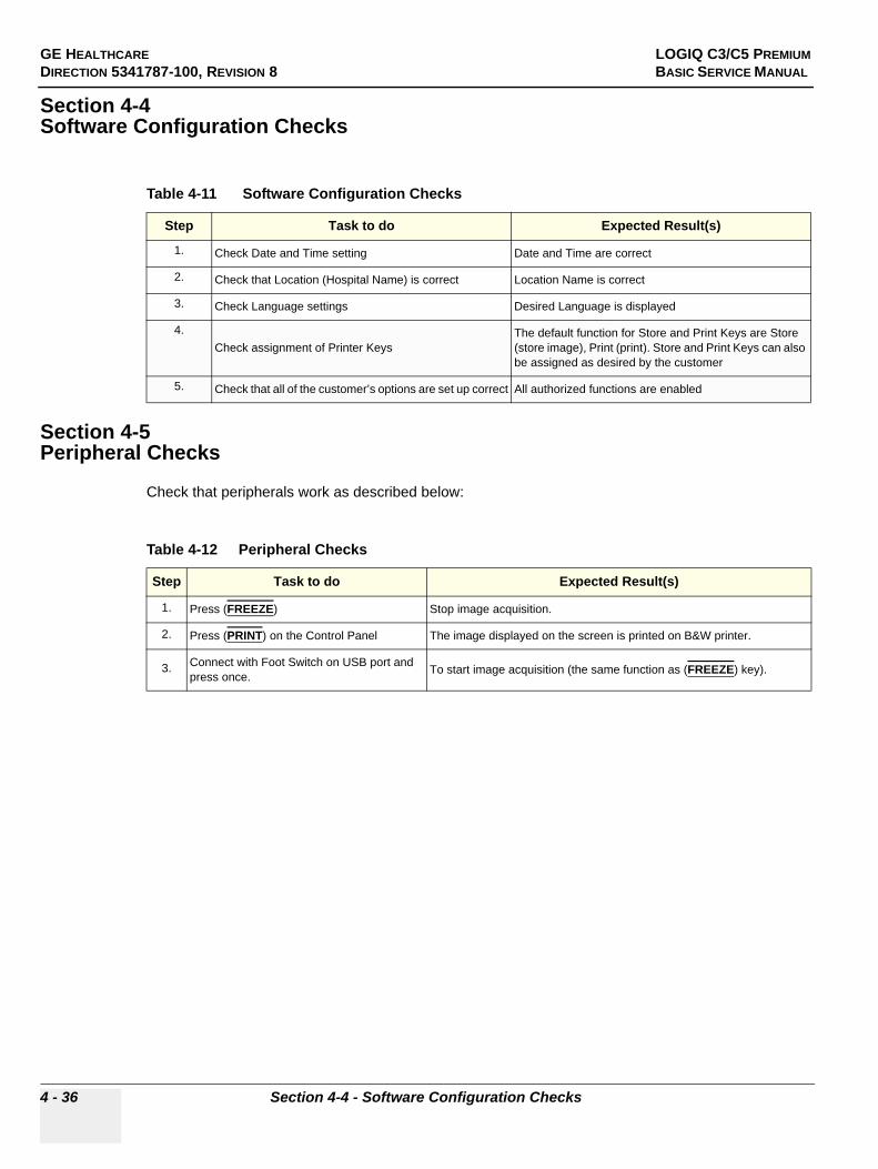
GE HEALTHCARE LOGIQ C3/C5 PREMIUMDIRECTION 5341787-100, REVISION 8 BASIC SERVICE MANUAL
4 - 36 Section 4-4 - Software Configuration Checks
Section 4-4Software Configuration Checks
Section 4-5Peripheral Checks
Check that peripherals work as described below:
Table 4-11 Software Configuration Checks
Step Task to do Expected Result(s)
1. Check Date and Time setting Date and Time are correct
2. Check that Location (Hospital Name) is correct Location Name is correct
3. Check Language settings Desired Language is displayed
4.Check assignment of Printer Keys
The default function for Store and Print Keys are Store (store image), Print (print). Store and Print Keys can also be assigned as desired by the customer
5. Check that all of the customer’s options are set up correct All authorized functions are enabled
Table 4-12 Peripheral Checks
Step Task to do Expected Result(s)
1. Press (FREEZE) Stop image acquisition.
2. Press (PRINT) on the Control Panel The image displayed on the screen is printed on B&W printer.
3. Connect with Foot Switch on USB port and press once. To start image acquisition (the same function as (FREEZE) key).

GE HEALTHCARE VIVID FIVEDIRECTION 5341787-100, REVISION 8 BASIC SERVICE MANUAL
Chapter 5 Components and Functions (Theory) 5 - 1
Chapter 5Components and Functions (Theory)
Section 5-1Overview
5-1-1 Purpose of Chapter 5This chapter explains LOGIQ C3/C5 Premium' system concepts, component arrangement, and subsystem function.
Table 5-1 Contents in Chapter 5
Section Description Page Number
5-1 Overview 5-1
5-2 Block Diagram 5-2
5-3 Common Service Platform 5-4

GE HEALTHCARE VIVID FIVEDIRECTION 5341787-100, REVISION 8 BASIC SERVICE MANUAL
5 - 2 Chapter 5 Components and Functions (Theory)
Section 5-2Block Diagram
5-2-1 System Diagram
Figure 5-50 LOGIQ C3/C5 Premium System Diagram

GE HEALTHCARE VIVID FIVEDIRECTION 5341787-100, REVISION 8 BASIC SERVICE MANUAL
Chapter 5 Components and Functions (Theory) 5 - 3
5-2-2 Software Diagram
Figure 5-51 LOGIQ C3/C5 Premium Software Diagram

GE HEALTHCARE VIVID FIVEDIRECTION 5341787-100, REVISION 8 BASIC SERVICE MANUAL
5 - 4 Chapter 5 Components and Functions (Theory)
Section 5-3Common Service Platform
5-3-1 IntroductionThe Service Platform contains a set of software modules that are common to all PC backend ultrasound and cardiology systems. The Common Service Platform will increase service productivity and reduce training and service costs.

GE HEALTHCARE VIVID FIVEDIRECTION 5341787-100, REVISION 8 BASIC SERVICE MANUAL
Chapter 6 Service Adjustments 6 - 1
Chapter 6Service Adjustments
Section 6-1Overview
6-1-1 Purpose of this chapter 6This section describes how to test and adjust the scanner. These tests are optional. You may use them to check the system for errors.
Table 6-2 Contents in chapter
Section Description Page Number
6-1 Overview 6-1
6-2 Monitor Adjustments 6-2

GE HEALTHCARE VIVID FIVEDIRECTION 5341787-100, REVISION 8 BASIC SERVICE MANUAL
6 - 2 Section 6-2 - Monitor Adjustments
Section 6-2Monitor Adjustments
6-2-1 Adjustments ProceduresTo adjust the brightness:
For LOGIQ C3/LC5 Premium: Adjust the LCD monitor’s button, located the right side of the LCD Monitor.
For LOGIQ C3/LC5 Premium: Adjust the LCD monitor’s button, located the bottom of the LCD Monitor.
To adjust the light:
NOTE: If the left side button of the LCD has the light symbol, the LCD has the lights to light the keyboard.
For LOGIQ C3/C5 Premium: Adjust the left side button of the monitor to turn on/off the light.
Figure 6-52 LCD Monitor
Figure 6-53 Light Adjustment

GE HEALTHCARE LOGIQ C3/C5 PREMIUMDIRECTION 5341787-100, REVISION 8 BASIC SERVICE MANUAL
Section 7-1 - Overview 7 - 1
Chapter 7Diagnostics/Troubleshooting
Section 7-1Overview
7-1-1 Purpose of Chapter 7This section describes how to setup and run the tools and software that help maintain image quality and system operation. Very basic host, system and board level diagnostics are run whenever power is applied. Some Service Tools may be run at the application level. However most software tests are required.
Table 7-3 Contents in Chapter 7
Section Description Page Number
7-1 Overview 7-1
7-2 Gathering Trouble Data 7-2
7-3 USB Quick Save 7-4
7-4 Screen Captures 7-6
7-5 Common Diagnostics 7-9
7-6 Network Configuration 7-12

GE HEALTHCARE LOGIQ C3/C5 PREMIUMDIRECTION 5341787-100, REVISION 8 BASIC SERVICE MANUAL
7 - 2 Section 7-2 - Gathering Trouble Data
Section 7-2Gathering Trouble Data
7-2-1 OverviewThere may be a time when it would be advantageous to capture trouble images and system data (logs) for acquisition to be sent back to the manufacturer for analysis. There are different options to acquire this data that would give different results.
7-2-2 Collect Vital System InformationThe following information is necessary in order to properly analyze data or images being reported as a malfunction or being returned to the manufacturer:
- Product Name = LOGIQ C3/C5 PremiumFrom the Utility>System>General>About screen:
Applications Software
- Software Version- Software Part Number
System Image Software
- Image Revision- Image Part Number

GE HEALTHCARE LOGIQ C3/C5 PREMIUMDIRECTION 5341787-100, REVISION 8 BASIC SERVICE MANUAL
Section 7-2 - Gathering Trouble Data 7 - 3
7-2-3 Collect a Trouble Image with LogsIf the system should malfunction, press the Alt-D keys simultaneously. This will collect a screen capture of the image monitor, system presets and the following logs:
- Keyboard Shadow Log- Error Logs- Crash Log- Power Supply- Temperature
NOTE: Power Supply and Temperature logs are not currently being updated by the LOGIQ C3/C5 Premium.
This Alt-D function is available at all times.
When Alt-D is pressed, a menu box appears that allows for:
- A place to enter a description of the problem- A choice to store to a pre-formatted CD-R, RD (Removable Disk) or to the Export directory D:
drive.The subsequent file is compressed and time stamped. The screen capture is a bitmap which eliminates the possibility of artifacts from compression.
Figure 7-54 ALT-D Dialog Box

GE HEALTHCARE LOGIQ C3/C5 PREMIUMDIRECTION 5341787-100, REVISION 8 BASIC SERVICE MANUAL
7 - 4 Section 7-3 - USB Quick Save
Section 7-3USB Quick Save
7-3-1 OverviewThere may be times when the customer or field engineer will want to directly save images into USB memory. This is accomplished by saving individual Cine clips (moving images- avi format) or still images (jpg format) directly to a USB memory disk by pressing Print or Store Key.
There’s no factory default print key to accomplish USB Quick Save. However, customer may have customize Print and Store Key function.
When performing a USB Quick Save, you can only define one USB Quick Save operation with either Print or Store keys.
NOTE: The print key that has been assigned to the USB Quick Save function should not have any other service functions assigned to it.
7-3-2 Check and Record the Print or Store Key FunctionCheck the function of the Print or Store Key in the event that the customer may have made some custom settings.
1.) Click Utility on the keyboard.2.) Select Connectivity from the Utilities Menu.3.) Select the Buttons tab on the Connectivity screen.4.) In the Physical Print Buttons field, select Print or Store.
The Connectivity/Buttons Screen will be displayed like the one shown below.
If Print or Store key is not set to Image Area, proceed to step 5 to record the customer’s customized settings.
5.) In the Destinations section, record the service that is displayed. 6.) In the Physical Print Buttons section, record the parameters related to the service.
Figure 7-55 Defining Print or Store Key Operation

GE HEALTHCARE LOGIQ C3/C5 PREMIUMDIRECTION 5341787-100, REVISION 8 BASIC SERVICE MANUAL
Section 7-3 - USB Quick Save 7 - 5
7-3-3 Setting the Print or Store Key to USB Quick SaveIf the Print or Store Key is not set to screen capture:
1.) While on the Connect screen, with the Buttons tab displayed, go to the Destinations list.2.) From the list select USB Quick Save. Press [>>] to add the selection to the Printflow View
section.3.) Ensure that the Physical Print Buttons section for capture Area is set to Image Area and No
Image Compression.4.) The Print and Store Key should now be set up for USB Quick Save, sending the images directly
to the USB memory.
NOTICE It is unable to get full screen using USB Quick Save, just Image Area is available.

GE HEALTHCARE LOGIQ C3/C5 PREMIUMDIRECTION 5341787-100, REVISION 8 BASIC SERVICE MANUAL
7 - 6 Section 7-4 - Screen Captures
Section 7-4Screen Captures
There may be times when the customer or field engineer will want to capture a presentation on the screen. This is accomplished by first saving the image(s) to the clipboard using a Print or Store Key.
The Store key is the factory default print key to accomplish a secondary Screen Capture. However, the customer may have customized the Store Key function.
7-4-1 Check and Record the Store Key FunctionCheck the function of the Store Key in the event that the customer may have made some custom settings.
1.) Click Utility on the keyboard.2.) Select Connectivity from the Utilities Menu.3.) Select the Buttons tab on the Connectivity screen.4.) In the Physical Print Buttons field, select Store.
The Connectivity/Buttons Screen will be displayed like the one shown in Figure 7-55 on page 7-4.
If Store key is not set to Whole Screen, as shown in Figure 7-55, proceed to step 5 to record the customer’s customized settings.
5.) In the Destinations section, record the service that is displayed. 6.) In the Physical Print Buttons section, record the parameters related to the service.
7-4-2 Setting the Store Key to Screen CaptureIf the Store Key is not set to screen capture:
1.) While on the Connect screen, with the Buttons tab displayed, go to the Destinations list.2.) From the list select Copy To Dataflow. Press [>>] to add the selection to the Printflow View
section.3.) Ensure that the Physical Print Buttons section for capture Area is set to Whole Screen,
secondary Capture and No Image Compression.4.) The Store Key should now be set up for whole screen capture, sending the screens to the
image buffer (clipboard).
7-4-3 Capturing a ScreenThe following is a generic process to capture any screen from the scanner:
1.) Navigate to and display the image/screen to be captured.2.) Press STORE. This will place a snapshot of the screen on the “clipboard” displayed at the
bottom of the scan image display.

GE HEALTHCARE LOGIQ C3/C5 PREMIUMDIRECTION 5341787-100, REVISION 8 BASIC SERVICE MANUAL
Section 7-4 - Screen Captures 7 - 7
7-4-3 Capturing a Screen (cont’d)
3.) Click FREEZE to unfreeze the image to view the image screen and the snapshots displayed on the bottom.
4.) Highlight the snapshot to be stored to RD (Removable Disk) or CD-R.5.) Select Menu on the right side of the image screen, then highlight and select SAVE AS.
Figure 7-56 Select Image to Capture
Figure 7-57 Menu > Save As
Clipboard Thumbnails
Menu
Save As

GE HEALTHCARE LOGIQ C3/C5 PREMIUMDIRECTION 5341787-100, REVISION 8 BASIC SERVICE MANUAL
7 - 8 Section 7-4 - Screen Captures
7-4-3 Capturing a Screen (cont’d)
6.) A Save dialog box will be opened. Choose d:\export folder as the archive location to save the image on the hard disk or CD-R.
7-4-4 Reset the Store Key to Customer’s FunctionalityIf the customer had programmed the Store Key to a function other than screen capture, restore that functionality recorded in section 7-3-2 on page 4. Refer to Figure 7-55.
1.) Click Utility on the keyboard.2.) Select Connectivity from the Utilities Menu.3.) Select the Buttons tab on the Connectivity screen.4.) In the Physical Print Button field, select Store.5.) In the Destinations list, select the service(s) recorded in step 5, Section 7-3-2. 6.) In the Physical Print Buttons section, select the parameters related to the service recorded in
step 6, Section 7-3-2.
Figure 7-58 Save Dialog Box
NOTICE After capture the snapshot of the screen to the “clipboard” and save it to the hard disk or other media, it is not full screen image on the hard disk or media.

GE HEALTHCARE LOGIQ C3/C5 PREMIUMDIRECTION 5341787-100, REVISION 8 BASIC SERVICE MANUAL
Section 7-5 - Common Diagnostics 7 - 9
Section 7-5Common Diagnostics
7-5-1 UtilitiesProvides two selections:
7-5-1-1 Disruptive ModeAllows you to enable or disable disruptive mode troubleshooting.
7-5-1-2 System ShutdownAllows for system shutdown from the diagnostic menu. Select to Restart System or Shutdown System. Also, select to retain Disruptive Mode or Not.
After submitting to restart or shutdown a confirmation screen gives one last chance to confirm or cancel the request.

GE HEALTHCARE LOGIQ C3/C5 PREMIUMDIRECTION 5341787-100, REVISION 8 BASIC SERVICE MANUAL
7 - 10 Section 7-5 - Common Diagnostics
7-5-2 PC Diagnostics (Non-Interactive Tests)
7-5-2-1 Essential Tests
7-5-2-2 System Board
7-5-2-3 Hard Disk Surface Scan
7-5-2-4 Hard Disk Quick Test
7-5-2-5 PCIBus
7-5-2-6 Video Card
7-5-2-7 Network Interface
7-5-2-8 CMOS
7-5-2-9 DRAM Memory
7-5-2-10 Parallel Port

GE HEALTHCARE LOGIQ C3/C5 PREMIUMDIRECTION 5341787-100, REVISION 8 BASIC SERVICE MANUAL
Section 7-5 - Common Diagnostics 7 - 11
7-5-3 PC Diagnostics (Interactive Tests)
7-5-3-1 Keyboard Test
7-5-3-2 Mouse Test
7-5-4 Restart LOGIQ C3/C5 Premium After DiagnosticsAlways shutdown the system and reboot after a diagnostics session.

GE HEALTHCARE LOGIQ C3/C5 PREMIUMDIRECTION 5341787-100, REVISION 8 BASIC SERVICE MANUAL
7 - 12 Section 7-6 - Network Configuration
Section 7-6Network Configuration
7-6-1 Network Configuration
7-6-1-1 Wire-LAN Network
1.) Connect system with network.2.) Press Utility -> Connectivity -> TCPIP, in IP Settings window check the Enable DHCP box. In
Network Speed box, choose the proper speed available.
Figure 7-59 Enable DHCP

GE HEALTHCARE LOGIQ C3/C5 PREMIUMDIRECTION 5341787-100, REVISION 8 BASIC SERVICE MANUAL
Section 7-6 - Network Configuration 7 - 13
7-6-1-1 Wire-LAN Network (cont’d)
NOTE: If user want to setup static IP address, uncheck Enable DHCP option, input static address in IP-Address box, Subnet Mask and Default Gateway box. In Network Speed box, choose the proper speed available.
3.) Click Save, in popped-up dialog choose Shutdown.
4.) After the system shutdown, reboot the system.5.) After reboot, the network icon at the left bottom of screen turns green.
Figure 7-60 Input static address
Figure 7-61 Save and reboot inquiry dialog
Figure 7-62 Network icon

GE HEALTHCARE LOGIQ C3/C5 PREMIUMDIRECTION 5341787-100, REVISION 8 BASIC SERVICE MANUAL
7 - 14 Section 7-6 - Network Configuration
This page was intentionally left blank.

GE HEALTHCARE VIVID FIVEDIRECTION 5341787-100, REVISION 8 BASIC SERVICE MANUAL
Section 8-1 - Overview 8 - 1
Chapter 8Replacement Procedures
Section 8-1Overview
8-1-1 Purpose of Chapter 8This chapter describes replacement procedures for the following modules and subsystems.
Table 8-1 Contents in Chapter 8
Section Description Page Number
8-1 Overview 8-1
8-2 DISASSEMBLY/RE-ASSEMBLY 8-2
8-2-1 Warning and Caution 8-2
8-2-2 Returning/Shipping for repairs 8-2
8-2-3 Air filter and Knob Screw 8-3
8-4 Loading Base Image Software 8-6

GE HEALTHCARE VIVID FIVEDIRECTION 5341787-100, REVISION 8 BASIC SERVICE MANUAL
8 - 2 Section 8-2 - DISASSEMBLY/RE-ASSEMBLY
Section 8-2 DISASSEMBLY/RE-ASSEMBLY
8-2-1 Warning and Caution
8-2-2 Returning/Shipping for repairsEquipment being returned must be clean and free of blood and other infectious substances.
GEHC policy states that body fluids must be properly removed from any part or equipment prior to shipment. GEHC employees, as well as customers, are responsible for ensuring that parts/equipment have been properly decontaminated prior to shipment. Under no circumstance should a part or equipment with visible body fluids be taken or shipped from a clinic or site (for example, body coils or an ultrasound probe). The purpose of the regulation is to protect employees in the transportation industry, as well as the people who will receive or open this package.
NOTE: The US Department of Transportation (DOT) has ruled that “items that were saturated and/or dripping with human blood that are now caked with dried blood; or which were used or intended for use in patient care” are “regulated medical waste” for transportation purposes and must be transported as a hazardous material.
If the LOGIC3/C5 Premium needs to be sent for repair, ensure that any patient information is erased from the Harddisk/Storage Device. In case that any patient information is still residing on the LOGIC3/C5 Premium, GE will contact the customer and request for urgent collection of that patient information. GE will keep this patient information in a secure environment for a maximum period of 1 month. All patient information will be permanently deleted at that point.
If PHI (Patient Healthcare Information) data needs to be sent to GE employees for service purposes, GE will ascertain agreement from the customer. The paitent information shall only be transfered by approved service processes, tools and devices restricting access, protecting or encrypting data where required, and providing traceability in the form of paper or electronic documents at each stage of the procedure while maintaining compliance with cross-border restrictions of patient information transfers.
WARNINGWARNING ONLY QUALIFIED SERVICE PERSONNEL SHOULD REMOVE ANY COVERS OR PANELS. ELECTRICAL HAZARDS EXISTS AT SEVERAL POINTS INSIDE. BECOME THOROUGHLY FAMILIAR WITH ALL HAZARDOUS VOLTAGES AND HIGH CURRENT LEVELS TO AVOID ACCIDENTAL CONTACT
CAUTION Do not wear the ESD wrist strap when you remove a part of power supply unit. Turn OFF power and unplug the power cord before removing a part of power supply unit. However be sure to turn off power and wear the strap before you remove a circuit boards.
WARNINGWARNING DO NOT SERVICE OR DISASSEMBLE PARTS UNDER FRU UNIT LEVEL AT ANY CIRCUMSTANCES.

GE HEALTHCARE VIVID FIVEDIRECTION 5341787-100, REVISION 8 BASIC SERVICE MANUAL
Section 8-2 - DISASSEMBLY/RE-ASSEMBLY 8 - 3
8-2-3 Air filter and Knob Screw
8-2-3-1 Tools• Common phillips screwdrivers
8-2-3-2 Preparations• Shut Down the System and disconnect the power cord.
8-2-3-3 Removal Procedure
1.) Unscrew the knob screw which fix air filter on the edge of power box, refer to 8-2-3 "Air filter and Knob Screw" on page 8-3.
2.) Pull rightward the knob screw out the air filter, refer to 8-2-3 "Air filter and Knob Screw" on page 8-3.3.) Lift down the air filter and plastic frame, refer to 8-2-3 "Air filter and Knob Screw" on page 8-3.4.) Remove the plastic frame , refer to 8-2-3 "Air filter and Knob Screw" on page 8-3
8-2-3-4 Mounting procedureInstall the new parts in the reverse order of removal.
Figure 8-63 Air filter and Knob Screw Disassembly
1) 2)
3) 4)

GE HEALTHCARE VIVID FIVEDIRECTION 5341787-100, REVISION 8 BASIC SERVICE MANUAL
8 - 4 Section 8-3 - Trackball Roller Cleaning
Section 8-3Trackball Roller Cleaning
Purpose: This is a description on how to remove the trackball and clean the roller.
8-3-0-1 Tools• No need.
8-3-0-2 Needed Manpower• 1 person, 3 minutes + travel
8-3-0-3 Preparations• Shut down the system.
8-3-0-4 ProcedureRefer to Figure 8-64 on page 8-5
1.) Turn the ring counterclockwise.2.) Remove the ring.3.) Using hand, carefully grab and remove the trackball.4.) Carefully clean the roller using swab.

GE HEALTHCARE VIVID FIVEDIRECTION 5341787-100, REVISION 8 BASIC SERVICE MANUAL
Section 8-3 - Trackball Roller Cleaning 8 - 5
Section 8-3 Trackball Roller Cleaning (cont’d)
Figure 8-64 Trackball Roller Cleaning
1) 2)
3) 4)

GE HEALTHCARE VIVID FIVEDIRECTION 5341787-100, REVISION 8 BASIC SERVICE MANUAL
8 - 6 Section 8-4 - Loading Base Image Software
Section 8-4Loading Base Image Software
NOTE: While it is believed to be unnecessary, It would not hurt to disconnect the system from the network and remove all transducers.
NOTE: Please ensure power cable is connected during system upgrade!
1.) Insert the disk labeled “System & Application Software” into the DVD ROM drive.2.) Properly turn off the scanner by momentarily pressing the Power On/Off Switch. Select “Shut
Down” from the System Exit menu. 3.) If the system will not shutdown normally, hold down the Power On/Off Switch until the light
turns from green to amber.4.) Turn on the system. System will detect the DVD-RW automatically.5.) Press any key to continue when below message display as shown below.
Figure 8-65 Upgrade message

GE HEALTHCARE VIVID FIVEDIRECTION 5341787-100, REVISION 8 BASIC SERVICE MANUAL
Section 8-4 - Loading Base Image Software 8 - 7
Section 8-4 Loading Base Image Software (cont’d)
6.) Select one of the options for loading the system. Select choice 1] to load the complete disk.
7.) Press any key to continue when below message display as shown below.
Figure 8-66 Selection for loading the system
WARNINGWARNING While the software install procedure is designed to preserve data, you should select choice [2] to format disk C only.
Figure 8-67 Upgrade continue message

GE HEALTHCARE VIVID FIVEDIRECTION 5341787-100, REVISION 8 BASIC SERVICE MANUAL
8 - 8 Section 8-4 - Loading Base Image Software
Section 8-4 Loading Base Image Software (cont’d)
8.) System CD will be loaded as shown in the screen below.
9.) System updating finished, refer to Figure 8-69 on page 8-8 .
10.)Press power key to reboot system, then remove the CDROM from the drive immediately. When system first time boot up after upgrading complete, type Serial Number and Option Key before starting up.
Figure 8-68 Upgrading message
Figure 8-69 System upgrade complete

GE HEALTHCARE VIVID FIVEDIRECTION 5341787-100, REVISION 8 BASIC SERVICE MANUAL
Chapter 9 Renewal Parts 9 - 1
Chapter 9Renewal Parts
Section 9-1Overview
9-1-1 Purpose of Chapter 9This chapter gives you an overview of Renewal Parts for LOGIQ C3/C5 Premium.
Section 9-2List of Abbreviations
• Assy - Assembly• Ctrl - Control• FRU 1 - Replacement part available in part hub• FRU 2 - Replacement part available from the manufacturer (lead time involved)• Int - Internal• I/O - Input/Output• LCD - Liquid Crystal Display• MON - Monitor• PAT. - Patient• PC - Personal Computer (Back End Processor)
Table 9-1 Contents in Chapter 9
Section Description Page Number
9-1 Overview 9-1
9-2 List of Abbreviations 9-1
9-3 Renewal Parts Lists 9-2
9-4 Operator Console Assy 9-3
9-5 Accessories and kits 9-4
9-7 Probes 9-7

GE HEALTHCARE VIVID FIVEDIRECTION 5341787-100, REVISION 8 BASIC SERVICE MANUAL
9 - 2 Section 9-3 - Renewal Parts Lists
Section 9-3Renewal Parts Lists
9-3-1 Equipment Models Covered in this Chapter
Table 9-2 Renewal Parts List for Customer
Part Name Part Number Description Quantity FRU
AC Power Cord 5177123 Power cord Europe Class 1 1
AC Power Cord 5176304 Power cord China Class 1 1
AC Power Cord 5176773 Power cord India Class 1 1
AC Power Cord 5177195 Power cord Argentina Class 1 1
AC Power Cord 5176907 Power cord UK Class 1 1
AC Power Cord 5177153 Power cord Denmark Class 1 1
AC Power Cord 5177154 Power cord Switzerland Class 1 1
AC Power Cord 5177187-2 Power cord Australia Class 1 1
AC Power Cord 5177146 Power cord USA Class 1 1
AC Power Cord 5400868 Power cord Brazilian Class 1 1
AC Power Cord 5176753 Power cord Israel Class 1 1
Probe ,Gel Holder and Cable Hook Kit 5315730 Probe ,Gel Holder and Cable Hook Kit 1 1
Probe ,Gel Holder and Cable Hook Kit 5315730 Probe ,Gel Holder and Cable Hook Kit 1 1

GE HEALTHCARE VIVID FIVEDIRECTION 5341787-100, REVISION 8 BASIC SERVICE MANUAL
Chapter 9 Renewal Parts 9 - 3
Section 9-4Operator Console Assy
Figure 9-70 Operator Console Assy
LOGIQ C3 Premium LOGIQ C5 Premium
LCD Assy
Keyboard Assy
Boay Assy
Base Assy

GE HEALTHCARE VIVID FIVEDIRECTION 5341787-100, REVISION 8 BASIC SERVICE MANUAL
9 - 4 Section 9-5 - Accessories and kits
Section 9-5Accessories and kits
Table 9-3 Accessories ,Cables and Kits
Item Part Number Description Qty FRU
5000 5352411
Cable Kit for Upper Part (including the following cables) 1 2
5332380 Cable from KBDTRSF board to Main
5333069 Cable from MainKBD to PWRSW board for probe key
5333070 LCD Power Cable
5333070 LCD DVI Cable
5220407 Encoder Cable
5220410 TGC Cable
5001 5352549
Cable Kit Underside (including the following cables) 1 2
5332371 MTK
5332373 HDD_SATA
5340119 DVD_SATA
5340734 Cable from MST PWA to TX and Relay
5333465 System DC Cable
5333468 Printer Cable
5224314 Printer Power Cable From Power Box
5332370 MTM (MST 2 rear panel)
5341010 LAN Cable
5001A 5426738
Cable Kit Underside (including the following cables) 1 2
5332371 MTK
5332373 HDD_SATA
5340119 DVD_SATA
5340734 Cable from MST PWA to TX and Relay
5333465 System DC Cable
5333468 Printer Cable
5224314 Printer Power Cable From Power Box
5332370 MTM (MST 2 rear panel)
5341010 LAN Cable
5416388 LC_Premium 4D control cable

GE HEALTHCARE VIVID FIVEDIRECTION 5341787-100, REVISION 8 BASIC SERVICE MANUAL
Chapter 9 Renewal Parts 9 - 5
5003 5328133
Service Tools for LOGIQ C (including the following tools) 1 1
5262716 Caster Spanner
5324751 TBJMA Screw Driver FJ6-40
5324786 SATA Hex Blade 80108
5008 5324832 Support Jig for Service 1 1
5009 5315697 EMC Sheet Kit 2 1
5010 5343395-3 LOGIQ C Premium R2.0.2 System and Application DVD 2 1
5011 5343395-4 LOGIQ C Premium R2.0.3 System and Application DVD 2 1
5012 5343395-7 LOGIQ C Premium R2.0.6 System and Application DVD 2 1
5013 5343395-8 LOGIQ C Premium R2.0.7 System and Application DVD 2 1
5014 5343395-9 LOGIQ C Premium R2.0.8 System and Application DVD 2 1
5015 5343395-10 LOGIQ C Premium R2.0.9 System and Application DVD 2 1
5016 5426284-2 LOGIQ C Premium R2.1.1 System and Application DVD 2 1
5017 5426284-3 LOGIQ C Premium R2.1.2 System and Application DVD 2 1
5018 5426284-4 LOGIQ C Premium R2.1.3 System and Application DVD 2 1
Table 9-3 Accessories ,Cables and Kits
Item Part Number Description Qty FRU

GE HEALTHCARE VIVID FIVEDIRECTION 5341787-100, REVISION 8 BASIC SERVICE MANUAL
9 - 6 Section 9-6 - Manuals
Section 9-6Manuals
Item Part Number Description Qty FRU
6000 5341787-100 LOGIQ C3/C5 Premium Service Manual 1 N
System User Manuals
6001 5341361 -100 User Manual, LOGIQ C3/C5 Premium, English 1 N
6002 5341361 -101 User Manual, LOGIQ C3/C5 Premium, French 1 N
6003 5341361 -106 User Manual, LOGIQ C3/C5 Premium, Spanish 1 N
6004 5341361 -108 User Manual, LOGIQ C3/C5 Premium, German 1 N
6005 5341361 -111 User Manual, LOGIQ C3/C5 Premium, Italian 1 N
6006 5341361 -127 User Manual, LOGIQ C3/C5 Premium, portuguese 1 N
6007 5341361 -141 User Manual, LOGIQ C3/C5 Premium, Chinese 1 N
System Quick Start Guide
6008 5341784-100 Quick Start Guide, LOGIQ C3/C5 Premium 1 N

GE HEALTHCARE VIVID FIVEDIRECTION 5341787-100, REVISION 8 BASIC SERVICE MANUAL
Chapter 9 Renewal Parts 9 - 7
Section 9-7Probes
Table 9-4 Probes on LOGIQ C3/C5 Premium
Item Part Name Part Number Description Quantity FRU
7000 4C-RC 5315581 Probe (Center Frequency: 3.75MHz) 1 1
7001 7.5C-RC 5315683 Probe (Center Frequency: 7.5MHz) 1 1
7002 6.5C-RC 5315685 Probe (Center Frequency: 6.5MHz) 1 1
7003 E7C-RC 5315686 Probe (Center Frequency: 6.5MHz) 1 1
7004 3S-RC 5213343 Probe (Center Frequency: 2.0MHz) 1 1
7005 L6-12-RC 5399465 Probe (Center Frequency: 7.75MHz) 1 1
7006 C2-5-RC 5401243 Probe (Center Frequency: 3.2MHz) 1 1
7007 E8CS-RC 5395336 Probe (Center Frequency: 6.5MHz) 1 1
7008 RAB4-8-RC KTZ157074 Probe (Center Frequency: 4.4MHz) 1 1
NOTICE All the spare parts should be disposed according to local laws.

GE HEALTHCARE VIVID FIVEDIRECTION 5341787-100, REVISION 8 BASIC SERVICE MANUAL
9 - 8 Section 9-7 - Probes
This page was intentionally left blank.

GE HEALTHCARE PROPRIETARY TO GE LOGIQ C3/C5 PREMIUMDIRECTION 5341787-100, REVISION 8 BASIC SERVICE MANUAL
Section 10-1 - Overview 10 - 1
Chapter 10Care & Maintenance
Section 10-1Overview
10-1-1 Periodic Maintenance Inspections It has been determined by engineering that your system does not have any high wear components that fail with use, therefore no Periodic Maintenance Inspections are mandatory. Some Customers Quality Assurance Programs may require additional tasks and or inspections at a different frequency than listed in this manual.
10-1-2 Purpose of Chapter 10This chapter describes Care & Maintenance on the scanner and peripherals. These procedures are intended to maintain the quality of the ultrasound systems performance. Read this chapter completely and familiarize yourself with the procedures before performing a task.
Table 10-1 Contents in Chapter 10
Section Description Page Number
10-1 Overview 10-1
10-2 Why do Maintenance 10-2
10-3 Maintenance Task Schedule 10-2
10-4 Tools Required 10-4
Section 10-5 When There's Too Much Leakage Current... 10-15
CAUTION Practice good ESD prevention. Wear an anti–static strap when handling electronic parts and even when disconnecting/connecting cables.
DANGER THERE ARE SEVERAL PLACES ON THE BACKPLANE, THE AC DISTRIBUTION, AND DC DISTRIBUTION THAT ARE DANGEROUS. BE SURE TO DISCONNECT THE SYSTEM POWER PLUG AND OPEN THE MAIN CIRCUIT BREAKER BEFORE YOU REMOVE ANY PARTS. BE CAUTIOUS WHENEVER POWER IS STILL ON AND COVERS ARE REMOVED.
CAUTION Do not pull out or insert circuit boards while power is ON.
CAUTION Do not operate this unit unless all board covers and frame panels are securely in place. System performance and cooling require this.

GE HEALTHCARE LOGIQ C3/C5 PREMIUMDIRECTION 5341787-100, REVISION 8 BASIC SERVICE MANUAL
10 - 2 Section 10-2 - Why do Maintenance
Section 10-2Why do Maintenance
10-2-1 Keeping RecordsIt is good business practice that ultrasound facilities maintain records of quality checks and corrective maintenance. The Ultrasound Inspection Certificate (provided on page 10-16) provides the customer with documentation that the ultrasound scanner is maintained on a periodic basis.
A copy of the Ultrasound Periodic Maintenance Inspection Certificate should be kept in the same room or near the scanner.
10-2-2 Quality AssuranceIn order to gain accreditation from organizations such as the American College of Radiology (USA), it is the customer’s responsibility to have a quality assurance program in place for each scanner. The program must be directed by a medical physicists, the supervising radiologist/physician or appropriate designee.
Routine quality control testing must occur regularly. The same tests are performed during each period so that changes can be monitored over time and effective corrective action can be taken.
Testing results, corrective action and the effects of corrective action must be documented and maintained on the site.
Your GE service representative can help you with establishing, performing and maintaining records for a quality assurance program. Please contact us for coverage information and/or price for service.
Section 10-3Maintenance Task Schedule
10-3-1 How often should care & maintenance tasks be performed?The Care & Maintenance Task Schedule (provided on page 10-3) specifies how often your LOGIQ C3/C5 Premium should be serviced and outlines items requiring special attention.
NOTE: It is the customer’s responsibility to ensure the LOGIQ C3/C5 Premium care & maintenance is performed as scheduled in order to retain its high level of safety, dependability and performance.
Your GE Service Representative has an in-depth knowledge of your LOGIQ C3/C5 Premium ultrasound scanning system and can best provide competent, efficient service. Please contact us for coverage information and/or price for service.
The service procedures and recommended intervals shown in the Care & Maintenance Task Schedule assumes that you use your LOGIQ C3/C5 Premium for an average patient load (10-12 per day) and not use it as a primary mobile unit which is transported between diagnostic facilities.
NOTE: If conditions exist which exceed typical usage and patient load, then it is recommended to increase the maintenance frequencies.

GE HEALTHCARE PROPRIETARY TO GE LOGIQ C3/C5 PREMIUMDIRECTION 5341787-100, REVISION 8 BASIC SERVICE MANUAL
Section 10-3 - Maintenance Task Schedule 10 - 3
Section 10-3 Maintenance Task Schedule (cont’d)
NOTE: PMs are not mandatory, the table above is for reference only.
NOTE: May require specialized equipment to complete.
Table 10-2 Customer Care Schedule
Service at Indicated Time Daily Weekly MonthlyPer Facilities QA Program Notes
Clean Probe Holders •Clean Air Filter • more frequently depending on
your environment
Inspect AC Mains Cable • Mobile Unit Check Weekly
Inspect Cables and Connectors •Clean Console •Inspect Wheels, Casters, brakes and Swivel Locks • Mobile Unit Check Daily
Check Control Panel Movement • Mobile Unit Check Daily
Console Leakage Current Checks • also after corrective maintenance
Peripheral Leakage Current Checks • also after corrective maintenance
Surface Probe Leakage Current Checks • also after corrective maintenance
Endocavity Probe Leakage Current Checks
• also after corrective maintenance
Transesphongeal Probe Leakage Current Checks
• also after corrective maintenance
Surgical Probe Leakage Current Checks
• also after corrective maintenance
Measurement Accuracy Checks • also after corrective maintenance
Functional Checks • also after corrective maintenance

GE HEALTHCARE LOGIQ C3/C5 PREMIUMDIRECTION 5341787-100, REVISION 8 BASIC SERVICE MANUAL
10 - 4 Section 10-4 - Tools Required
Section 10-4 Tools Required
10-4-1 Standard GE Tool KitThe following is a description of the “Standard” GE tool kit in the USA. Not all tools are required for PMs.
Table 10-3 Overview of GE-1 Tool Kit Contents
Tool ID Description Tool ID Description
9-45358 Pliers Retaining Ring 9-XL9971MM Xcelite-hex Blade 1.27mm
9-4078 Scribe 9-XL9972MM Xcelite-hex Blade 1.5mm
9-44572 Wrench Open End 3/8 - 7/16 9-XL9973MM Xcelite-hex Blade 2 mm
9-44579 Wrench Open End 1/2 - 9/16 9-XL9974MM Xcelite-hex Blade 2.5mm
9-44579 Wrench Open End 1/2 - 9/16 9-XL9975MM Xcelite-hex Blade 3mm
9-45385 Pliers, Arc Joint 7 inch 9-XL9976MM Xcelite-hex Blade 4mm
9-45378 Pliers, Slip Joint 9-XL9977MM Xcelite-hex Blade 5mm
9-4518 Pliers, Long Nose, Miniature 9-XL991CM Handle
9-4518 Pliers, Long Nose, Miniature C2356E Screw starter - Kedman Quick Wedge
9-44776 Ignition Wrench Set, 10 pc. BLBO Box - 18 Compartment
9-44601 Wrench, Adj., 4 inch DWL4283T Box - 5 Compartment
9-4151 Screwdriver, Blade, Stubby 9-41322 Pickup Tool, Claw type
9-41421 Screwdriver, Blade, Pocket clip 9-6757 6 pc Needle File Set
9-41594 Screwdriver, Blade 1/8 in. x 4 in. 9-9487 Utility Knife
9-41581 Screwdriver, Blade 3/16 in. x 4 in. 9-45341 Pliers Vice Grip 10 inch
9-39451 20' Steel Tape, locking Spring load 9-3001 Xacto Pen Knife
9-GH807 Ratchet, Offset, Slotted 9-HT62002 Solder Aid, Fork and Hook
68-412 Ratchet, Offset, Phillips 9-4099 Mirror, Round, Telescoping
9-GH130 Tapered Reamer 9-GH3001 Steel Rule Decimal 6 inch
9-41584 Screwdriver, slotted 1/4 in.X 6 in. 9-GH300ME Steel Rule Metric 6 inch
9-4118 Screwdriver, Phillips #2, Stubby 9-XL9920 Xcelite-hex Blade.050 inch
9-41293 Screwdriver, Phillips #0 9-XL9921 Xcelite-hex Blade 1/16 inch
9-41294 Screwdriver, Phillips #1 9-XL9922 Xcelite-hex Blade 5/16 inch
9-41295 Screwdriver, Phillips #2 9-XL9923 Xcelite-hex Blade 3/32 inch
9-46677 Hex Keys, 20 pc., Metric 9-XL9924 Xcelite-hex Blade 1/8 inch
9-34701 1/4 in. Standard.Socket set (19 pc) 9-XL9925 Xcelite-hex Blade 5/32 inch
9-43499 1/2 inch Socket 1/4 inch drive 9-XL9926 Xcelite-hex Blade 3/16 inch
9-4355 Flex Spinner 9-XL99764 Xcelite-hex Blade 7/64
9-43523 Breaker 9-XL99964 Xcelite-hex Blade 9/64
9-43531 6 inch Ext. 9-XLM60 Mini-screwdriver kit

GE HEALTHCARE PROPRIETARY TO GE LOGIQ C3/C5 PREMIUMDIRECTION 5341787-100, REVISION 8 BASIC SERVICE MANUAL
Section 10-4 - Tools Required 10 - 5
Table 10-4 Overview of GE-2 Tool Kit Contents(Continued)
9-65283 Case 8.5 in. x 4.5 in. x 2 in. Deep 9-45072 Pliers 6 inch Diagonal
9-46696 Hex Keys 9-XL100X Wire Stripper/Cutter 5 inch - 100X
9-39829 Torpedo Level, Magnetic 9-XL87CG Pliers - very fine needle nose-87CG
9-38461 Hammer, Ball Peen, 4 oz 9-WEWDT-07 Weller-Soldering-Replacement Tip(1)
9-4280 Universal Joint 1/4 inch 9-WS175-E Wiss - Surgical Scissors
9-WEW60P3 Weller - Soldering Iron, 3 wire KH174 Hemostat 5 inch Straight
9-WECT5B6 Weller - Soldering Iron Tip KH175 Hemostat 5 inch curved
9-WEWDP12 Weller - Desoldering Pump 9-Z9480121 Alignment tool (red)
93383 Flashlight Mini-Mag Lite (AAA Bat.)
9-GH408 Tweezers
21576 Brush - Bristle
9-4516 Pliers 4 1/4 inch Diagonal
GE-2 Sears Kit (#99034)
Tool ID Description Tool ID Description
9-45381 Pliers, Arc Joint 9 1/2 inch 9-44067 Socket 1 1/16 in. for 1/2 in. drive
9-45092 Pliers, Linesman 8 1/2 inch 9-42679 Socket 10MM Hex for 1/2 in. drive (2273333)
9-42882 Punch, Pin 3/32 inch 9-44262 Extension 10 inch for 1/2 in. drive (2273405)
9-42884 Punch, Pin 5/32 inch 9-4258 3/8 inch to 1/2 inch Adapter
9-42886 Punch, Pin 1/4 inch 9-34374 3/8 inch Metric Socket Set - 12 PT
9-42973 Cold Chisel 1/2 inch 9-44311 16mm Socket 12 pt.
9-GH77 Center Punch Automatic 9-33485 Metal Socket Tray
9-GH890 File Handle, Adj. 9-33484 Metal Socket Tray
9-31276 File, Round, Bastard 8 inch 9-33484 Metal Socket Tray
9-31277 File, Half Round, Bastard 8 inch 9-52068 Tap and Drill Set
9-31263 File, Flat Mill 8 inch 9-52722 #6 Tap
21045C Close Quarter Saw 9-52723 #8 Tap
9-44604 Wrench, Adj 10 inch High Speed Drill Set
9-41587 Screwdriver 5/16 inch x 8 inch #36 Drill
9-41586 Screwdriver, Stubby 5/16 inch #29 Drill
9-GH19512 Countersink 1/2 inch 9-44046 3/8 inch Socket Set
9-44741 12 PC Combination Wrench Set
Table 10-3 Overview of GE-1 Tool Kit Contents (Continued)
Tool ID Description Tool ID Description

GE HEALTHCARE LOGIQ C3/C5 PREMIUMDIRECTION 5341787-100, REVISION 8 BASIC SERVICE MANUAL
10 - 6 Section 10-4 - Tools Required
10-4-2 Special Tools, Supplies and Equipment
10-4-2-1 Specific Requirements for Care & Maintenance
Table 10-5 Overview of Requirements for Care & Maintenance
Tool Part Number Comments
Digital Volt Meter (DVM)
Leakage Current Ultrasound Kit 2113015 For 120V and 220V Units
Anti Static Kit
46–194427P23146–194427P27946–194427P36946–194427P37346–194427P370
Kit includes anti–static mat, wrist strap and cables for 200 to 240 V system3M #2204 Large adjustable wrist strap3M #2214 Small adjustable wrist strap3M #3051 conductive ground cord
Anti Static Vacuum Cleaner46–194427P27846–194427P279
120V230V
Air Filter air intake
Safety Analyzer The Safety Analyzer tool should be calibrated and compliant with AAMI/ESI 1993 or IEC 60601 or AS/NZS 3551
SVHS VCR CassetteE7010GGE7010GF
60 minute120 minute
SVHS VCR Head Cleaner See VCR user manual for requirements
3.5” MOD MEDIA
E8381AAE8381AB
blank 128 M diskblank 230 M disk
5.25” MOD Media
3.5” MOD Media Cleaner 2117811 cleans the diskettes
5.25” MOD Media Cleaner cleans the diskettes
3.5” MOD Head Cleaner Kit 2148392 cleans the drive heads
5.25” MOD Head Cleaner Kit cleans the drive heads
QIQ Phantom E8370RB RMI Grayscale Target Model 403GS
B/W Printer Cleaning Sheet See printer user manual for requirements
Color Printer Cleaning Sheet See printer user manual for requirements
Disposable Gloves

GE HEALTHCARE PROPRIETARY TO GE LOGIQ C3/C5 PREMIUMDIRECTION 5341787-100, REVISION 8 BASIC SERVICE MANUAL
Section 10-4 - Tools Required 10 - 7
10-4-3 Input Power
10-4-3-1 Mains Cable Inspection
10-4-4 Cleaning
10-4-4-1 General Cleaning
NOTE: For your convenience or of the air filter is too dirty, replacement filters are available. refer to Chapter 9 for the air filter replacement part number.
10-4-5 Physical Inspection
Table 10-6 Mains Cable Inspection
Step Item Description
1 Unplug Cord Disconnect the mains cable from the wall and system.
2 Inspect Inspect it and its connectors for damage of any kind.
3 Verify Verify that the LINE, NEUTRAL and GROUND wires are properly attached to the terminals, and that no strands may cause a short circuit.
4 Verify Inlet connector retainer is functional.
Table 10-7 General Cleaning
Step Item Description
1 Console Use a fluid detergent in warm water on a soft, damp cloth to carefully wipe the entire system. Be careful not to get the cloth too wet so that moisture does not enter the console.
2 Probe Holder Clean probe holders (they may need to be soaked to remove excess gel).
Table 10-8 Physical Checks
Step Item Description
1 Labeling Verify that all system labeling is present and in readable condition. refer to the LOGIQ C3/C5 Premium User Manual for details.
2 Scratches & Dents Inspect the console for dents, scratches or cracks.
3 Wheels & Brakes Check all wheels and casters for wear and verify operation of foot brake, to stop the unit from moving, and release mechanism. Check all caster locks and caster swivel locks for proper operation.
4 Cables & Connectors
Check all internal cable harnesses and connectors for wear and secure connector seating. Pay special attention to footswitch assembly and probe strain or bend reliefs.
5 Shielding & Covers
Check to ensure that all EMI shielding, internal covers, air flow panels and screws are in place. Missing covers and hardware could cause EMI/RFI problems while scanning.
6 External I/O Check all connectors for damage and verify that the labeling is good.
7 Op Panel Lights Check for proper operation of all operator panel and TGC lights.
8 Monitor Light Check for proper operation of any monitor lights if available.
9 External Microphone Check for proper operation of any external microphones by recording an audio test.

GE HEALTHCARE LOGIQ C3/C5 PREMIUMDIRECTION 5341787-100, REVISION 8 BASIC SERVICE MANUAL
10 - 8 Section 10-4 - Tools Required
10-4-6 Outlet Test -Wiring Arrangement - USA & CanadaTest all outlets in the area for proper grounding and wiring arrangment by plugging in the neon outlet tester and noting the combination of lights that are illuminated. Any problems found should be reported to the hospital immediately and the receptacle should not be used.
NOTE: No outlet tester can detect the condition where the Neutral (grounded supply) conductor and the Grounding (protective earth) conductor are reversed. If later tests indicate high leakage currents, this should be suspected as a possible cause and the outlet wiring should be visually inspected.
Figure 10-1 Typical Outlet Tester

GE HEALTHCARE PROPRIETARY TO GE LOGIQ C3/C5 PREMIUMDIRECTION 5341787-100, REVISION 8 BASIC SERVICE MANUAL
Section 10-4 - Tools Required 10 - 9
10-4-7 Grounding Continuity
Measure the resistance from the third pin of the attachment plug to the exposed metal parts of the case. The ground wire resistance should be less than 0.2 ohms. Reference the procedure in the IEC 601-1.1.
10-4-7-1 Meter ProcedureFollow these steps to test the ground wire resistance.
1.) Turn the LOGIQ C3/C5 Premium unit OFF.2.) Plug the unit into the meter, and the meter into the tested AC wall outlet.3.) Plug the black chassis cable into the meter’s “CHASSIS” connector and attach the black chassis
cable clamp to an exposed metal part of the LOGIQ C3/C5 Premium unit.4.) Set the meter’s “FUNCTION” switch to the RESISTANCE position.5.) Set the meter’s “POLARITY” switch to the OFF (center) position.6.) Measure and record the ground wire resistance.
CAUTION Electric Shock Hazard. The patient must not be contacted to the equipment during this test.
Figure 10-2 Ground Continuity Test

GE HEALTHCARE LOGIQ C3/C5 PREMIUMDIRECTION 5341787-100, REVISION 8 BASIC SERVICE MANUAL
10 - 10 Section 10-4 - Tools Required
10-4-8 Chassis Leakage Current Test
10-4-8-1 DefinitionThis test measures the current that would flow in a grounded person who touched accessible metal parts of the bedside station if the ground wire should break. The test verifies the isolation of the power line from the chassis. The meter is connected from accessible metal parts of the case to ground. Measurements should be made with the unit On and Off, with the power line polarity Normal and Reversed. Record the highest reading.
.
10-4-8-2 Generic ProcedureThe test verifies the isolation of the power line from the chassis. The testing meter is connected from accessible metal parts of the case to ground. Measurements should be made with the unit ON and OFF, with the power line polarity Normal and Reversed. Record the highest reading of current.
When using the Microguard or a similar test instrument, its power plug may be inserted into the wall outlet and the equipment under test is plugged into the receptacle on the panel of the meter. This places the meter in the grounding conductor and the current flowing from the case to ground will be indicated in any of the current ranges. The maximum allowable limit for chassis source leakage is shown in Table 10-12.
CAUTION Electric Shock Hazard. When the meter's ground switch is OPEN, don't touch the unit!
CAUTION Equipment damage possibility. Never switch the Polarity and the status of Neutral when the unit is powered ON. Be sure to turn the unit power OFF before switching them using the POLARITY switch and/or the NEUTRAL switch. Otherwise, the unit may be damaged.
Figure 10-3 Set Up for Chassis Source Leakage Current, IEC 601-1 Clause 19 - Continuos Leakage Currents and
Patient, Auxiliary Currents

GE HEALTHCARE PROPRIETARY TO GE LOGIQ C3/C5 PREMIUMDIRECTION 5341787-100, REVISION 8 BASIC SERVICE MANUAL
Section 10-4 - Tools Required 10 - 11
10-4-9 Isolated Patient Lead (Source) Leakage–Lead to LeadReference the procedure in the IEC 60601-1. Select and test each of the five ECG lead positions (except ALL) on the LEAD selector, testing each to the power condition combinations found in the table. Record the highest leakage current measured.
10-4-10 Isolated Patient Lead (Sink) Leakage-Isolation Testreference the procedure in the IEC 60601-1. Select the ALL position on the lead selector. Depress the rocker switch to ISO TEST to test lead isolation.
NOTE: It is not necessary to test each lead individually or power condition combinations as required in previous tests.
CAUTION Line voltage is applied to the ECG leads during this test. To avoid possible electric shock hazard, the system being tested must not be touched by patients, users or anyone while the ISO TEST switch is depressed.

GE HEALTHCARE LOGIQ C3/C5 PREMIUMDIRECTION 5341787-100, REVISION 8 BASIC SERVICE MANUAL
10 - 12 Section 10-4 - Tools Required
10-4-10-1 Data Sheet for ECG Leakage CurrentThe test passes when all readings measure less than the value shown in the table below. Record all data on the PM Inspection Certificate.
Table 10-9 Maximum Allowance Limit for ECG Leakage Current
AC Power Source
MaximumAllowance Limit
GROUND OPENGROUND CLOSED
Patient Lead to Ground Leakage Current Testand
Patient Lead to Lead Leakage Current Test
115V 10uA 10uA
220/240V 500uA 10uA
Table 10-10 Maximum Allowance Limit for ECG Leakage Current
AC Power Source
MaximumAllowance Limit
Patient Lead Isolation Current Test115V 20uA
220/240V 5mA
Table 10-11 Typical Data Sheet for ECG Leakage Current
ECG Power
Tester Polarity Switch
Tester Ground Switch
Tester Lead Selector
RL RA LA LL C
ON NORM CLOSED
ON REVERSE CLOSED
ON NORM OPEN
ON REVERSE OPEN
OFF NORM CLOSED
OFF REVERSE CLOSED
OFF NORM OPEN
OFF REVERSE OPEN

GE HEALTHCARE PROPRIETARY TO GE LOGIQ C3/C5 PREMIUMDIRECTION 5341787-100, REVISION 8 BASIC SERVICE MANUAL
Section 10-4 - Tools Required 10 - 13
10-4-11 Probe Leakage Current Test
10-4-11-1 DefinitionThis test measures the current that would flow to ground from any of the probes through a patient who is being scanned and becomes grounded by touching some other grounded surface.
10-4-11-2 Generic ProcedureMeasurements should be made with the ground open and closed, with power line polarity normal and reversed, and with the unit Off and On. For each combination, the probe must be active to find the worst case condition.
NOTE: Each probe will have some amount of leakage current, dependent on its design. Small variations in probe leakage currents are normal from probe to probe. Other variations will result from differences in line voltage and test lead placement.
10-4-11-3 Meter Procedure Using Probe AdapterFollow the Safety Analyzer tool instruction to test each transducer for leakage current.
The electrical Safety Analyzer tool should be calibrated and compliant with AMMI/ESI 1993 or IEC 60601 or AS/NZS 3551.
10-4-11-4 No Meter Probe Adapter Procedure
Follow the Safety Analyzer tool instruction to test each transducer for leakage current.
The electrical Safety Analyzer tool should be calibrated and compliant with AMMI/ESI 1993 or IEC 60601 or AS/NZS 3551.
Figure 10-4 Set Up for Probe Leakage Current
POWEROUTLET
H (BLACK)POLARITY REVERSING SWITCH
MOMENTARYSWITCH
N (WHITE)
G (GREEN)
LEAKAGE TESTMETER
CONSOLE
PROBE

GE HEALTHCARE LOGIQ C3/C5 PREMIUMDIRECTION 5341787-100, REVISION 8 BASIC SERVICE MANUAL
10 - 14 Section 10-4 - Tools Required
10-4-11-5 Data Sheet for Transducer Source Leakage CurrentThe test passes when all readings measure less than the values. Record all data on the PM Inspection Certificate.
.
CAUTION Equipment damage possibility. Never switch the Polarity and the status of Neutral when the unit is powered ON. Be sure to turn the unit power OFF before switching them using the POLARITY switch and/or the NEUTRAL switch. Otherwise, the unit may be damaged
Table 10-12 Typical Data Sheet For Transducer Source Leakage Current
Transducer Tested:
Unit PowerTester Power Polarity
SwitchTester GROUND or NEUTRAL Switch Measurement
ON NORM OPEN
ON NORM CLOSED
ON REV OPEN
ON REV CLOSED
OFF NORM OPEN
OFF NORM CLOSED
OFF REV OPEN
OFF REV CLOSED

GE HEALTHCARE PROPRIETARY TO GE LOGIQ C3/C5 PREMIUMDIRECTION 5341787-100, REVISION 8 BASIC SERVICE MANUAL
Section 10-5 - When There's Too Much Leakage Current... 10 - 15
Section 10-5When There's Too Much Leakage Current...
CHASSIS FAILSCheck the ground on the power cord and plug for continuity. Ensure the ground is not broken, frayed, or intermittent. Replace any defective part.
Tighten all grounds. Ensure star washers are under all ground studs.
Inspect wiring for bad crimps, poor connections, or damage.
Test the wall outlet; verify it is grounded and is free of other wiring abnormalities. Notify the user or owner to correct any deviations. As a work around, check the other outlets to see if they could be used instead.
NOTE: No outlet tester can detect the condition where the white neutral wire and the green grounding wire are reversed. If later tests indicate high leakage currents, this should be suspected as a possible cause and the outlet wiring should be visually inspected.
PROBE FAILSTest the probe in another connector to isolate if the fault lies with the probe or the scanner.
NOTE: Each probe will have some amount of leakage, dependent on its design. Small variations in probe leakage currents are normal from probe to probe. Other variations will result from differences in line voltage and test lead placement. The maximum allowable leakage current for body surface contact probe differs from inter-cavity probe. Be sure to enter the correct probe type in the appropriate space on the check list.
If excessive leakage current is slot dependent, inspect the system connector for bent pins, poor connections, and ground continuity.
If the problem remains with the probe, replace the probe.
PERIPHERAL FAILSTighten all grounds. Ensure star washers are under all ground studs.
Inspect wiring for bad crimps, poor connections, or damage.
STILL FAILSIf all else fails, begin isolation by removing the probes, external peripherals, then the on board ones, one at a time while monitoring the leakage current measurement.
NEW UNITIf the leakage current measurement tests fail on a new unit and if situation can not be corrected, submit a Safety Failure Report to document the system problem. Remove unit from operation.
ECG FAILSInspect cables for damage or poor connections.

GE HEALTHCARE LOGIQ C3/C5 PREMIUMDIRECTION 5341787-100, REVISION 8 BASIC SERVICE MANUAL
10 - 16 Section 10-5 - When There's Too Much Leakage Current...
ULTRASOUND INSPECTION CERTIFICATE
* Scan Format: Phased Array, Linear Array, Curved Array, Mechanical Array or Other
FUNCTIONAL CHECKS PHYSICAL INSPECTION AND CLEANING
COMMENTS: ________________________________________________________________________________________________________________________________________________________________________________________________________________________________________________________________________________________________________________________
Customer Name: System ID: Dispatch Number / Date Performed: Warranty/Contract/HBS
System Type Model Number: Serial Number: Manufacture Date:
Probe 1: Frequency: Scan Format*: Model Number: Serial Number:
Probe 2: Frequency: Scan Format*: Model Number: Serial Number:
Probe 3: Frequency: Scan Format*: Model Number: Serial Number:
Probe 4: Frequency: Scan Format*: Model Number: Serial Number:
Probe 5: Frequency: Scan Format*: Model Number: Serial Number:
Probe 6: Frequency: Scan Format*: Model Number: Serial Number:
Probe 7: Frequency: Scan Format*: Model Number: Serial Number:
Probe 8: Frequency: Scan Format*: Model Number: Serial Number:
Probe 9: Frequency: Scan Format*: Model Number: Serial Number:
Functional Check (if applicable)OK? or
N/APhysical Inspection and Cleaning
(if applicable) Inspect Clean
B-Mode Function Console
Doppler Modes Function Monitor
CF-Mode Function Touch Panel
M-Mode Function Air Filter
Applicable Software Options Probe Holders
Applicable Hardware Options External I/O
Control Panel Wheels, Brakes & Swivel Locks
Monitor Cables and Connectors
Touch Panel GE Approved Peripherals (VCR, CD-RW, MOD, Printers)
Measurement Accuracy
GE Approved Peripherals

GE HEALTHCARE PROPRIETARY TO GE LOGIQ C3/C5 PREMIUMDIRECTION 5341787-100, REVISION 8 BASIC SERVICE MANUAL
Section 10-5 - When There's Too Much Leakage Current... 10 - 17
ELECTRICAL SAFETY
Final Check. All system covers are in place. System scans with all probes as expected.
Electrical Test PerformedMax Value Allowed
Value Measured OK? Comments
Outlet (correct ground &wiring config.)
System Ground Continuity
Chassis Source Leakage Current - Probe
Chassis Source Leakage Current - Caster
Chassis Source Leakage Current - CRT
Patient Lead Source Leakage(Lead to Ground)
Patient Lead Source Leakage(Lead to Lead)
Patient Lead Source Leakage(Isolation)
Peripheral 1 Leakage Current
Peripheral 1Ground Continuity
Peripheral 2 Leakage Current
Peripheral 2Ground Continuity
Peripheral 3 Leakage Current
Peripheral 3Ground Continuity
PROBES
Probe Number (from previous page)
Max Value Allowed
Max Value Measured OK? Comments
Probe 1:
Probe 2:
Probe 3:
Probe 4:
Probe 5:
Probe 6:
Probe 7:
Probe 8:
Probe 9:

GE HEALTHCARE LOGIQ C3/C5 PREMIUMDIRECTION 5341787-100, REVISION 8 BASIC SERVICE MANUAL
10 - 18 Section 10-5 - When There's Too Much Leakage Current...
This page was intentionally left blank.

GE HEALTHCARE VIVID FIVEDIRECTION 5273008-100, REVISION 8 LOGIQ™ 9 PROPRIETARY MANUAL
Index I
INDEXA,BAbbreviations, 9-1Archiving Images
Move, 4-30Backup
Patient Database, 4-26Preset Configurations, 4-26
Basic MeasurementsFunctional Checks, 4-23
Body patterndisplay location, 4-8
Boot Up, 3-8
CCaps lock
display location, 4-8CE Compliance, 1-12Cine gauge
display location, 4-8Color Mode
Overview, 4-15Connectivity
Worksheet, 3-20Contact Information, 1-14Control Panel, 4-6Customer Assistance, 1-14
DDangerous Procedure Warnings, 1-11Date/Time
display location, 4-8Depth scale
display location, 4-8DICOM Network Function, 2-9
EElectrical Safety, 1-10Electrostatic Discharge Warning, 1-12EMI, 1-12ESD, 1-12Exam study
display location, 4-8
FFocal zone
display location, 4-8
Functional Checks, 4-1Basic Measurements, 4-23Control Panel, 4-6Image Management, 4-25Monitor Display, 4-8Peripherals, 4-36Probes/Connector Usage, 4-24
GGathering Trouble Data, 7-2General Cleaning, 10-7Gray/color bar
display location, 4-8
HHazard Icons, 1-5Hospital name
display location, 4-8Human Safety, 1-9
IImage Management
Functional Checks, 4-25Image preview
display location, 4-8Imaging parameters
display location, 4-8Institution name
display location, 4-8
LLOTO, 1-13
MMeasurement summary window
display location, 4-8Mechanical Safety, 1-9Models Covered, 1-2Monitor Display
Functioanl Checks, 4-8Monitor display
location, 4-8Move
Archiving Images, 4-30

GE HEALTHCARE VIVID FIVEDIRECTION 5273008-100, REVISION 8 LOGIQ™ 9 PROPRIETARY MANUAL
II Index
OOperator identification
display location, 4-8
PP4 Key Function, 7-4, , 7-6Patient identification
display location, 4-8Patient name
display location, 4-8PC Diagnostics, 7-10
Hard Drive Tests, 7-10Keyboard Test, 7-11Memory Tests, 7-10
PC Diagnostics (Interactive Tests), 7-11Peripherals
Functional Checks, 4-36Power On, 3-8Power-up Procedures
Voltage Settings, 3-7Probe identifier
display location, 4-8Probe orientation marker
display location, 4-8Probes/Connector Usage
Functional Checks, 4-24Product Icons, 1-6
RRequired Features, 2-7Restore
Patient Database, 4-29Preset Configurations, 4-29
SSafety Considerations, 1-9Screen Captures, 7-6Service Manual
Purpose of, 1-1System Manufacturer, 1-15
TTouch Panel
Functional Checks, 4-6Trouble Image with Logs, 7-3Troubleshooting
Gathering Trouble Data, 7-2Screen Captures, 7-6Trouble Image with Logs, 7-3Vital System Information, 7-2
UUltrasound Room Layout, 2-8
VVoltage Settings, 3-7
WWarnings and Cautions, 1-9


© 2009-2012, General Electric Company.GE Healthcare-GEMedical Systems Ultrasound.9900 Innovation DriveWawautosa, Wisconsin 53226USA


