
Siemens LV 1 · 2006
66/2 Introduction
3RW Soft Starters6/4 General data6/5 3RW30, 3RW31 for standard applications6/12 3RW40 for standard applications6/15 3RW44 for High Feature applications
3RA Fuseless Load Feeders6/23 General data
3RA11 Combination Starters,Direct-On-Line
6/24 For snapping onto standard mounting rails or for screw mounting
6/28 For busbar systems3RA12 Reversing Starters
6/32 For snapping onto standard mounting rails or for screw mounting
6/36 For busbar systemsAccessories
6/40 For direct-on-line and reversing startersInfeed System
6/46 3RV19 infeed system
3RA71 Load Feeders with Safety Integrated
6/50 General data6/51 Fuseless load feeders6/55 Fused load feeders
AS-Interface Motor Starters and Soft StartersIP65/67 Motor Starters and Load Feeders
6/56 AS-Interface compact starters (400 V AC)
6/59 AS-Interface motor starters (24 V DC)IP20 Motor Starters and Load Feeders
6/61 AS-Interface load feeder modules6/63 Combination starters for busbar
systems, direct-on-line6/65 Reversing starters for busbar systems
ET 200S Motor Starters6/67 ET 200S motor starters6/73 Power modules
for ET 200S motor starters6/74 Terminal modules
for ET 200S motor starters6/77 Interface/solid-state modules
ET 200S Safety Motor Starters Solutions Local/PROFIsafe
6/88 General data6/89 ET 200S Failsafe motor starters6/91 Safety modules local6/95 Safety modules PROFIsafe
ET 200pro Motor Starters6/98 Standard and High Feature6/100 ET 200pro isolator modules6/101 Safety modules local6/102 Accessories
for ET 200pro motor starters6/103 Components for ET 200pro
ET 200X Motor Starters6/109 ET 200X motor starters6/113 Basic and expansion modules
ECOFAST Motor Starters and Soft Starters
6/120 3RK1 3 ECOFAST motor starters and soft starters
3RE Encapsulated Starters6/121 General data6/122 3RE10 combination starters,
direct-on-line6/123 3RE13 reversing starters6/124 Accessories
Load Feeders, Motor Starters and Soft Starters

Load Feeders, Motor Starters and Soft Starters
Introduction
6/2 Siemens LV 1 · 2006
6
■ Overview
3RW30 3RW40 3RW44 3RA11 3RA12 3RA71
Order No. Page
3RW soft startersFor standard applications • Application areas
- Fans- Building/construction machines- Escalators- Air conditioning systems- Assembly lines- Operating mechanisms
- Pumps- Presses- Transport systems- Ventilators- Compressors and coolers
3RW30, 3RW31 • SIRIUS 3RW30/31 soft starters for soft starting and smooth ramp-down ofthree-phase asynchronous motors
• Rating range of up to 55 kW (at 400 V)
3RW30, 3RW31 6/5
3RW40 • SIRIUS 3RW40 soft starters with the integral functions- solid-state motor overload and intrinsic device protection and- adjustable current limitingfor the soft starting and stopping of three-phase asynchronous motors
• Rating range from 75 to 250 kW (at 400 V)
3RW40 6/12
For High Feature applications • Application areas- Pumps- Compressors- Industrial refrigerating systems- Conveying systems- Machine tools
- Ventilators- Cooling systems- Water transport- Hydraulics- Mills
3RW44 • In addition to soft starting and soft ramp-down, the solid-state SIRIUS 3RW44 soft starters provide numerous functions for higher-level requirements
• Rating range- up to 710 kW (at 400 V) in inline circuit and - up to 1200 kW (at 400 V) in inside-delta circuit
3RW44 6/15
3RA fuseless load feeders• The 3RA1 fuseless load feeders consist of the 3RV1 motor starter protector and
the 3RT1 contactor. The motor starter protector and contactor are prewired and mechanically connected in pre-assembled installation sets (link modules, wiring sets and standard mounting rail or busbar adapters). The motor starter protector and contactor are mechanically and electrically connected by means of the link module
• 4 sizes (S00, S0, S2, S3)• Can be supplied for direct start or reversing duty as
- complete unit or- single units for self-assembly
3RA11 combination starters, direct-on-lineFor snapping onto standard mounting rails or for screw mounting
• Rated control supply voltage 50 Hz 230 V AC and 24 V DC for 35 mm standard mounting rail or screw mounting
3RA11 6/24
For busbar systems • Rated control supply voltage 50 Hz 230 V AC and 24 V DC for 40 mm and 60 mm busbar systems
3RA11 6/28
3RA12 reversing startersFor snapping onto standard mounting rails or for screw mounting
• Rated control supply voltage 230 V AC, 50 Hz and 24 V DC for 35 mm standard mounting rail or screw mounting
3RA12 6/32
For busbar systems • Rated control supply voltage 50 Hz 230 V AC and 24 V DC for 40 mm and 60 mm busbar systems
3RA12 6/36
Infeed system3RV19 infeed system • Convenient means of power supply and distribution 3RV19 6/46
3RA71 load feeders with safety integratedFuseless load feeders • Safe load feeders for direct start
• Actuating voltage 230 V AC, 50/60 Hz• Actuating voltage 24 V DC
3RA71 6/51
Fused load feeders • Safe load feeders for direct start• Actuating voltage 230 V AC, 50/60 Hz• Actuating voltage 24 V DC
3RA71 6/55

Load Feeders, Motor Starters and Soft Starters
Introduction
6/3Siemens LV 1 · 2006
66
3RK1 322 3RA51 3RA52 3RK1 301 3RK1 304 3RE10
Order No. Page
AS-Interface motor starters and soft startersIP65/67 motor starters and load feeders AS-Interface compact starters, IP65 (400 V AC)
• Completely factory-wired load feeders with degree of protection IP65, designed for switching and protecting any type of three-phase loads, in particular standard induction motors in direct-on-line or reversing duty
3RK1 322 6/56
AS-Interface motor starters, IP67 (24 V DC) • For the lowest power range up to 70 W, 24 V DC motors and the associated sensor systems can also be directly and locally connected to AS-Interface quickly and easily. Three different versions are available:- Single direct-on-line starter- Double direct-on-line starter- Reversing starter
3RK1 400-1 6/59
IP20 motor starters and load feeders • Quick and cost-effective connection of motor starters to higher-level automation
systems• For busbar systems with a busbar center-to-center distance of 40 mm and
60 mm• Completely factory-wired and adaptable to busbar systems
Combination starters for busbar systems, direct-on-line
• For direct start, a load can be switched on and off with the load feeder 3RA51 6/63
Reversing starters for busbar systems • The feeder for reversing duty is designed for two directions of rotating ofinduction motors
3RA52 6/65
ET 200S motor startersET 200S motor starters • Completely factory-wired motor starters for switching and protecting any
three-phase loads, optionally as direct-on-line, reversing or soft starters3RK1 301 6/67
Power modules for ET 200S motor starters • For supplying and monitoring the auxiliary voltages for motor starters 3RK1 903-0BA00 6/73
Terminal modules for ET 200S motor starters • Mechanical modules in which motor starters and expansion modules are inserted 3RK1 903 6/74
Interface/solid-state modules • Interface modules, power modules, reserve modules, digital/analog solid-state modules, F power and F solid-state modules, F terminal modules, 4 IQ-Sense sensor module, SSI module, 1 STEP step module, positioning modules, counter modules, terminal modules for power and solid-state modules
6ES7 1 6/77
ET 200S Safety motor starters Solutions local/PROFIsafeET 200S Failsafe motor starters • High Feature direct-on-line and reversing starters 3RK1 301 6/89
Safety modules local • For safety catgeory 4 according to EN 954-1 3RK1 903 6/91
Safety modules PROFIsafe • Sensor and actuator assignment are freely configurable (distributed safety concept)
3RK1 903 6/95
ET 200pro motor startersET 200pro motor starters • Standard and High Feature 3RK1 304 6/98
ET 200pro isolator modules • With switch disconnector function for safe disconnection 3RK1 304 6/100
Safety local modules • Isolator module and 400 V disconnecting module 3RK1 304 6/101
Accessories for ET 200pro motor starters • Interface, expansion and power modules 6ES7 1 6/102
ET 200X motor startersET 200X motor starters • For switching and protection of any three-phase loads
• Direct-on-line or reversing starters, electromechanical or solid-state3RK1 300 6/109
Basic and expansion modules • Intelligent basic modules, ECOFAST basic modules, PM 148 power module, digital/analog expansion modules, PM 148-P pneumatic module, PM 148-P pneumatic interface
6ES7 14 6/113
ECOFAST motor starters and soft starters3RK1 3 ECOFAST motor starters and soft starters
• Distributed motor starters for PROFIBUS and AS-Interface• Functionality ranges from direct-on-line starters, through reversing starters and
soft starters as far as frequency converters
3RK1 3 6/120
3RE encapsulated starters• The 3RE1 encapsulated starters are used for switching and for the inverse-time
delayed protection of load feeders up to 22 kW at 400 V AC• The starters are available as direct-on-line starters for motors with a single direction
of rotation and as reversing starters for motors with two directions of rotation
3RE10 combination starters, direct-on-line • Molded-plastic enclosure, degree of protection IP65, including contactor 3RE10 6/122
3RE13 reversing starters • Molded-plastic enclosure, deg. of protection IP65, including cont. assembly 3RE13 6/123
Accessories • Molded-plastic enclos., deg. of prot. IP65, for direct-on-line and reversing starters 3RE19 6/124
3RW Soft Starters
General data
6/4 Siemens LV 1 · 2006
6
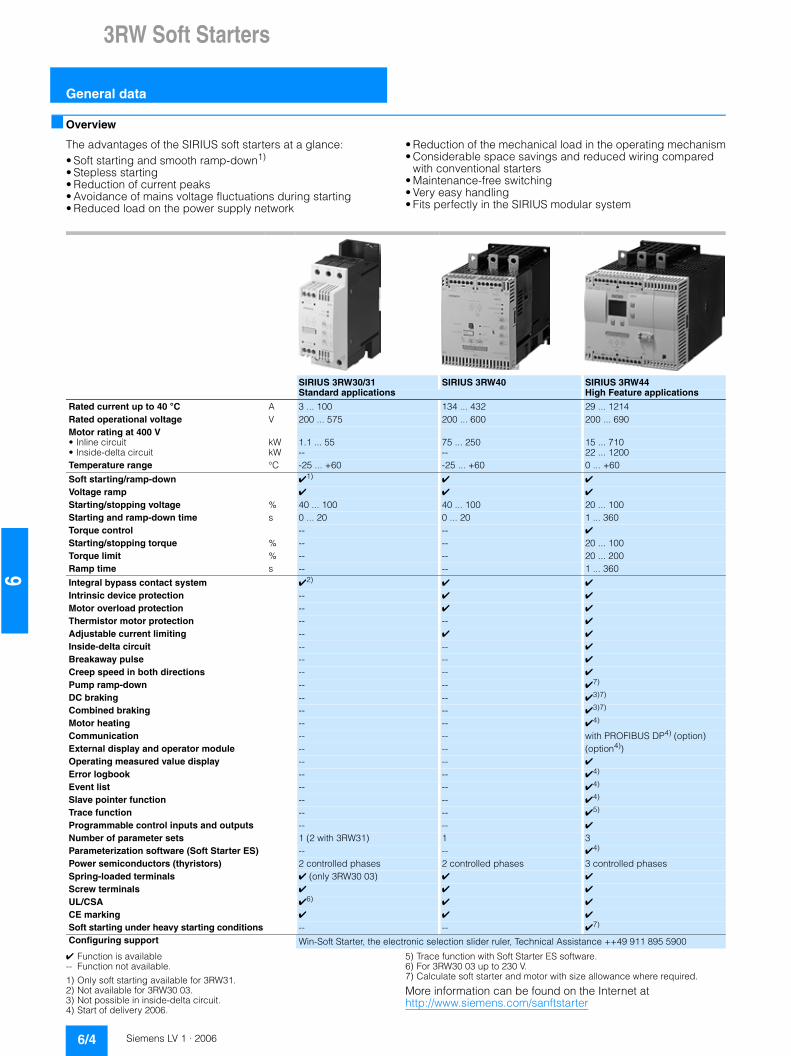
■ Overview
The advantages of the SIRIUS soft starters at a glance:• Soft starting and smooth ramp-down1)
• Stepless starting• Reduction of current peaks• Avoidance of mains voltage fluctuations during starting• Reduced load on the power supply network
• Reduction of the mechanical load in the operating mechanism• Considerable space savings and reduced wiring compared
with conventional starters• Maintenance-free switching• Very easy handling• Fits perfectly in the SIRIUS modular system
✔ Function is available-- Function not available.
1) Only soft starting available for 3RW31.2) Not available for 3RW30 03.3) Not possible in inside-delta circuit.4) Start of delivery 2006.
5) Trace function with Soft Starter ES software.6) For 3RW30 03 up to 230 V.7) Calculate soft starter and motor with size allowance where required.
More information can be found on the Internet at http://www.siemens.com/sanftstarter
SIRIUS 3RW30/31 SIRIUS 3RW40 SIRIUS 3RW44Standard applications High Feature applications
Rated current up to 40 °C A 3 ... 100 134 ... 432 29 ... 1214Rated operational voltage V 200 ... 575 200 ... 600 200 ... 690Motor rating at 400 V• Inline circuit kW 1.1 ... 55 75 ... 250 15 ... 710• Inside-delta circuit kW -- -- 22 ... 1200 Temperature range °C -25 ... +60 -25 ... +60 0 ... +60
Soft starting/ramp-down ✔1) ✔ ✔
Voltage ramp ✔ ✔ ✔
Starting/stopping voltage % 40 ... 100 40 ... 100 20 ... 100Starting and ramp-down time s 0 ... 20 0 ... 20 1 ... 360 Torque control -- -- ✔
Starting/stopping torque % -- -- 20 ... 100Torque limit % -- -- 20 ... 200Ramp time s -- -- 1 ... 360
Integral bypass contact system ✔2) ✔ ✔
Intrinsic device protection -- ✔ ✔
Motor overload protection -- ✔ ✔
Thermistor motor protection -- -- ✔
Adjustable current limiting -- ✔ ✔
Inside-delta circuit -- -- ✔
Breakaway pulse -- -- ✔
Creep speed in both directions -- -- ✔
Pump ramp-down -- -- ✔7) DC braking -- -- ✔3)7)
Combined braking -- -- ✔3)7)
Motor heating -- -- ✔4) Communication -- -- with PROFIBUS DP4) (option)External display and operator module -- -- (option4))Operating measured value display -- -- ✔
Error logbook -- -- ✔4)
Event list -- -- ✔4)
Slave pointer function -- -- ✔4)
Trace function -- -- ✔5)
Programmable control inputs and outputs -- -- ✔
Number of parameter sets 1 (2 with 3RW31) 1 3Parameterization software (Soft Starter ES) -- -- ✔4) Power semiconductors (thyristors) 2 controlled phases 2 controlled phases 3 controlled phasesSpring-loaded terminals ✔ (only 3RW30 03) ✔ ✔
Screw terminals ✔ ✔ ✔
UL/CSA ✔6) ✔ ✔
CE marking ✔ ✔ ✔
Soft starting under heavy starting conditions -- -- ✔7)
Configuring support Win-Soft Starter, the electronic selection slider ruler, Technical Assistance ++49 911 895 5900

3RW Soft Starters
3RW30, 3RW31for standard applications
6/5Siemens LV 1 · 2006
66
■ Overview
Various versions of the SIRUS 3RW30/31 soft starters are available:• Standard version for fixed frequency three-phase motors,
sizes S00, S0, S2 and S3• Version for fixed-speed three-phase motors in a 22.5 mm
enclosure• Special-purpose version 3RW31 for Dahlander motors only in
size S0• Version for soft starting single-phase motors of sizes S0, S2
and S3.
SIRIUS 3RW30/31 for three-phase motors
Soft starters rated up to 55 kW (at 400 V) for standard applica-tions in three-phase networks. Extremely small sizes, low power losses and simple commissioning are just a few of the many ad-vantages of this soft starter. The special feature of the 3RW31 series is that it allows independent definition of two separate acceleration ramps (Dahlander motors).
SIRIUS 3RW30 for single-phase motors
The additional version for standard applications in single-phase networks. Its voltage edge function reduces the motor's inrush current and effectively lowers the torque at the point of starting up. The load and the supplying network are thus protected.
■ Application
The SIRIUS 3RW30/31 solid-state soft starters are suitable for soft starting and stopping of three-phase asynchronous ma-chines.
Due to two-phase control, the current is kept at minimum values in all three phases throughout the entire starting time. Due to continuous voltage influencing, current and torque peaks, which are unavoidable in the case of wye-delta starters, for instance, do not occur.
Application areas• Fans• Pumps• Building/construction machines• Presses• Escalators• Transport systems• Air conditioning systems• Ventilators• Assembly lines• Compressors and coolers• Operating mechanisms

3RW Soft Starters
3RW30, 3RW31for standard applications
6/6 Siemens LV 1 · 2006
6
■ Selection and ordering data
Selection of the soft starter depends on the motor’s rated current.
3RW30 03-2CB54
3RW30 25-1AB14
3RW30 35-1AB14
3RW30 35-1AA12
Ambient temperature 40 °C Ambient temperature 50 °C Size DT Order No. Price per PU
PU (UNIT, SET, M)
PS* PG Weight per PU approx.
Rated opera-tional current Ie
Rated output of three-phase induction motors for rated operational voltage Ue
Rated opera-tional current Ie
Rated output of three-phase induction motors for rated operational voltage Ue
115 V 230 V 400 V 500 V 115 V 200 V 230 V 460 V 575 V
A kW kW kW W A hp hp hp hp hp kgSoft starters for easy starting conditions and high operating frequency,rated operational voltage Ue 200 ... 400 V3 -- 0.55 1.1 -- 2.6 -- 0.5 0.5 -- -- 22.5
mm} 3RW30 03-@CB54 1 1 unit 131 0.207
Order No. supplement for connection methods
With screw terminals 1
With spring-loaded terminals 2
Ambient temperature 40 °C Ambient temperature 50 °C Size DT Order No. Price per PU
PU (UNIT, SET, M)
PS* PG Weight per PU approx.
Rated opera-tional current Ie
Rated output of three-phase induction motors for rated operational voltage Ue
Rated opera-tional current Ie
Rated output of three-phase induction motors for rated operational voltage Ue
115 V 230 V 400 V 500 V 115 V 200 V 230 V 460 V 575 V
A kW kW kW kW A hp hp hp hp hp kgSoft starters for three-phase asynchronous motors, rated operational voltage Ue 200 ... 460 V6 -- 1.5 3 -- 4.8 -- 1 1 3 -- S00 } 3RW30 14-1CB@4 1 1 unit 131 0.3149 -- 2.2 4 -- 7.8 -- 2 2 5 -- S00 } 3RW30 16-1CB@4 1 1 unit 131 0.314
12.5 -- 3 5.5 -- 11 -- 3 3 7.5 -- S0 } 3RW30 24-1AB@4 1 1 unit 131 0.49016 -- 4 7.5 -- 14 -- 3 3 10 -- S0 } 3RW30 25-1AB@4 1 1 unit 131 0.49325 -- 5.5 11 -- 21 -- 5 5 15 -- S0 } 3RW30 26-1AB@4 1 1 unit 131 0.489
32 -- 7.5 15 -- 27 -- 7.5 7.5 20 -- S2 } 3RW30 34-1AB@4 1 1 unit 131 0.79438 -- 11 18.5 -- 32 -- 10 10 25 -- S2 } 3RW30 35-1AB@4 1 1 unit 131 0.77945 -- 15 22 -- 38 -- 10 15 30 -- S2 } 3RW30 36-1AB@4 1 1 unit 131 0.791
63 -- 18.5 30 -- 54 -- 15 20 40 -- S3 } 3RW30 44-1AB@4 1 1 unit 131 1.66775 -- 22 37 -- 64 -- 20 25 50 -- S3 } 3RW30 45-1AB@4 1 1 unit 131 1.806100 -- 30 55 -- 85 -- 25 30 60 -- S3 } 3RW30 46-1AB@4 1 1 unit 131 1.813Soft starters for three-phase asynchronous motors, rated operational voltage Ue 460 ... 575 V12.5 -- -- -- 7.5 11 -- -- -- 7.5 10 S0 A 3RW30 24-1AB@5 1 1 unit 131 0.49016 -- -- -- 11 14 -- -- -- 10 10 S0 A 3RW30 25-1AB@5 1 1 unit 131 0.48925 -- -- -- 15 21 -- -- -- 15 20 S0 A 3RW30 26-1AB@5 1 1 unit 131 0.489
32 -- -- -- 18.5 27 -- -- -- 20 25 S2 A 3RW30 34-1AB@5 1 1 unit 131 0.79138 -- -- -- 22 32 -- -- -- 25 30 S2 A 3RW30 35-1AB@5 1 1 unit 131 0.79345 -- -- -- 30 38 -- -- -- 30 40 S2 A 3RW30 36-1AB@5 1 1 unit 131 0.792
63 -- -- -- 37 54 -- -- -- 40 50 S3 A 3RW30 44-1AB@5 1 1 unit 131 1.66975 -- -- -- 55 64 -- -- -- 50 60 S3 A 3RW30 45-1AB@5 1 1 unit 131 1.811100 -- -- -- 70 85 -- -- -- 60 75 S3 A 3RW30 46-1AB@5 1 1 unit 131 1.806
Order No. supplement for rated control supply voltage Us
24 V AC/DC 0
110 ... 230 V AC/DC 1
* You can order this quantity or a multiple thereof.

3RW Soft Starters
3RW30, 3RW31for standard applications
6/7Siemens LV 1 · 2006
66
1) Rated control supply voltage Us 110 ... 230 V AC/DC.
Selection of the soft starter depends on the motor’s rated current.
The SIRIUS 3RW3 solid-state soft starters are designed for easy starting conditions. JLoad < 10 x JMotor. In the event of deviating conditions or increased switching frequency, it may be neces-sary to choose a larger device. Siemens recommends the use of the selection and simulation program Win-Soft Starter. See LV 1 T for information about rated currents for ambient temperatures >40 °C.
Ambient temperature 40 °C Ambient temperature 50 °C Size DT Order No. Priceper PU
PU (UNIT, SET, M)
PS* PG Weight per PU approx.
Rated opera-tional current Ie
Rated output of three-phase induction motors for rated operational voltage Ue
Rated opera-tional current Ie
Rated output of three-phase induction motors for rated operational voltage Ue
115 V 230 V 400 V 500 V 115 V 200 V 230 V 460 V 575 V
A kW kW kW kW A hp hp hp hp hp kgSoft starters with two-ramp control for three-phase induction motors with two speeds (double pole-reversing),rated operational voltage Ue 200 ... 460 V1)
12.5 -- 3 5.5 -- 11 -- 3 3 7.5 -- S0 B 3RW31 24-1CB14 1 1 unit 131 0.46816 -- 4 7.5 -- 14 -- 3 3 10 -- S0 B 3RW31 25-1CB14 1 1 unit 131 0.47525 -- 5.5 11 -- 21 -- 5 5 15 -- S0 B 3RW31 26-1CB14 1 1 unit 131 0.464Soft starters with two-ramp control for three-phase induction motors with two speeds (double pole-reversing),rated operational voltage Ue 460 ... 575 V1)
12.5 -- -- -- 7.5 11 -- -- -- 7.5 10 S0 B 3RW31 24-1CB15 1 1 unit 131 0.46716 -- -- -- 11 14 -- -- -- 10 10 S0 B 3RW31 25-1CB15 1 1 unit 131 0.47625 -- -- -- 15 21 -- -- -- 15 20 S0 B 3RW31 26-1CB15 1 1 unit 131 0.475Soft starters for single-phase motors,rated operational voltage Ue 115 ... 240 V1)
25 2.2 4 -- -- 21 1.5 3 3 -- -- S0 A 3RW30 26-1AA12 1 1 unit 131 0.43938 3 5.5 -- -- 32 2 5 5 -- -- S2 B 3RW30 35-1AA12 1 1 unit 131 0.68975 5.5 11 -- -- 64 5 10 10 -- -- S3 B 3RW30 45-1AA12 1 1 unit 131 1.393
* You can order this quantity or a multiple thereof.

3RW Soft Starters
3RW30, 3RW31for standard applications
6/8 Siemens LV 1 · 2006
6
Accessories
1) With internal soft starter power supply.
For soft starters
Size Version DT Order No. Priceper PU
PU (UNIT, SET, M)
PS* PG Weight per PU approx.
Type kgFans1)
3RW39 26-8A
3RW39 36-8A
3RW3 . 2. S0 To increase switching frequency and for device mounting in posi-tions different from the normal posi-tion. The fan is snapped into the enclo-sure from below. During operation, (control signal input "IN" at potential A1), the fan is running. After a stop, the fan contin-ues to run for about another 60 min-utes.
} 3RW39 26-8A 1 1 unit 131 0.0083RW30 3. and 3RW30 4.
S2 S3
} 3RW39 36-8A 1 1 unit 131 0.030
CoversTerminal covers for box terminals
3RT19 36-4EA2
3RW30 3. S2 Additional touch protection to be fitted at the box terminals (2 units required per device)
} 3RT19 36-4EA2 1 1 unit 101 0.0163RW30 4. S3 } 3RT19 46-4EA2 1 1 unit 101 0.023
Terminal covers for cable lugs and bar connections
3RT19 46-4EA1
3RW30 4. S3 For complying with the phase clearances and as touch protec-tion if box terminal is removed (2 units required per contactor)
} 3RT19 46-4EA1 1 1 unit 101 0.037
Version FunctionalityFunctions
Use DT Order No. Price per PU
PU (UNIT, SET, M)
PS* PG Weight per PU approx.
kgCovering caps and plug-in lugs (only for 3RW30 03)
Sealable caps For securing against unauthorized adjust-ment of setting knobs
For devices with 1 or 2 CO contacts
} 3RP1 902 1 5 units 101 0.004
Push-in lugsfor screw mounting
For devices with 1 or 2 CO contacts
} 3RP1 903 1 10 units 101 0.002
* You can order this quantity or a multiple thereof.

3RW Soft Starters
3RW30, 3RW31for standard applications
6/9Siemens LV 1 · 2006
66
Note: The covers and connection modules listed here are also used for load feeders (3RV motor starter protector + 3RT contactor). For further technical specifications see Controls –> Contactors and Contactor Assemblies.
For fuseless load feeders with size S00 soft starter, the link module has an integrated conductor routing.
1) Computer labeling system for individual labeling of device labeling plates available from: murrplastik Systemtechnik GmbH
For soft starters
Size Version DT Order No. Priceper PU
PU (UNIT, SET, M)
PS* PG Weight per PU approx.
Type kgLink modules
3RA19 11-1A
3RA19 21-1A
3RA19 31-1A
Electrical and mechanical link between motor starter protector and soft starter.
Single unit packaging 3RW30 1.. S00 } 3RA19 11-1AA00 1 1 unit 101 0.0273RW30 2.. S0 } 3RA19 21-1AA00 1 1 unit 101 0.0373RW30 3.. S2 } 3RA19 31-1AA00 1 1 unit 101 0.0423RW30 4.. S3 } 3RA19 41-1AA00 1 1 unit 101 0.090Multi-packs 3RW30 1.. S00 } 3RA19 11-1A 1 10 units 101 0.0193RW30 2.. S0 } 3RA19 21-1A 1 10 units 101 0.0283RW30 3.. S2 } 3RA19 31-1A 1 5 units 101 0.0333RW30 4.. S3 } 3RA19 41-1A 1 5 units 101 0.072
Designation Labeling areaColor
DT Order No. Price per PU
PU (UNIT, SET, M)
PS* PG Weight per PU approx.
W x H mm x mm
kg
Blank labeling plates
Device labeling plates 1 frame = 20 labeling plates
Device labeling plates for "SIRIUS"1)
20 x 7 mm, pastel turquoise
C 3RT19 00-1SB20 100 340 units 101 0.220
Labels for stick-ing for "SIRIUS"
19 x 6, pastel turquoise
D 3RT19 00-1SB60 100 3060 units 101 0.153
19 x 6 zinc yellow
C 3RT19 00-1SD60 100 3060 units 101 0.120
NS
K-7
237
* You can order this quantity or a multiple thereof.

3RW Soft Starters
3RW30, 3RW31for standard applications
6/10 Siemens LV 1 · 2006
6
1) Without connectors for data and auxiliary power (yellow and black).
2) With one connector each for data and auxiliary power (yellow and red).
For busbar accessories, see SIVACON Switchgear, Distribution Systems and Cabinets –> 8US Busbar Systems.
For soft starters
Version DT Order No. Price per PU
PU (UNIT, SET, M)
PS* PG Weight per PU approx.
Type kgAS-Interface load feeder modules
3RK14 00-1KG01-0AA13RK14 00-1MG01-0AA1
AS-Interface load feeder modules For standard rail mounting sizes S00 and S0. For mounting onto 40 mm or 60 mm busbar systems and SIRIUS stan-dard mounting rail adapters the matching support is required (see 3RK1 901-3GA00); the AS-Interface connectors for the data and auxiliary power cable (yellow and black) must be ordered separately (see 3RK1 901-0.A00)
Rated opera-tional voltage Ue
2 inputs / 1 output 24 V DC1)} 3RK1 400-1KG01-0AA1 1 1 unit 121 0.097
4 inputs / 2 outputs A 3RK1 400-1MG01-0AA1 1 1 unit 121 0.100
2 inputs / 1 relay output 120/230 V AC2) C 3RK1 402-3KG02-0AA1 1 1 unit 121 0.1243 inputs / 2 relay outputs B 3RK1 402-3LG02-0AA1 1 1 unit 121 0.143
Manuals for AS-Interface load feeder modules
German, English } 3RK1 701-2GB00-0AA0 1 1 unit 192 0.197French, Italian A 3RK1 701-2HB00-0AA0 1 1 unit 192 0.196
Supports for AS-Interface load feeder modules
Width
For mounting onto3RA19 22-1A SIRIUS standard mounting rail adapter
45 mm B 3RK1 901-3GA00 1 1 unit 121 0.048
Support with mounted power connector coupling
Power connector sets
5-pole, 2.5 mm2
(1 package = 5 connec-tors and 5 couplings)
C 3RK1 901-0EA00 1 5 sets 121 0.111
3RK19 01-0NA003RK19 01-0PA00
AS-Interface connectors for data and auxiliary supply cables
Color
With insulation displace-ment terminals for 2 x (0.5 to 0.75 mm2) flexible lead
Yellow C 3RK1 901-0NA00 1 5 units 121 0.015Black C 3RK1 901-0PA00 1 5 units 121 0.015
Standard mounting rail adapters
3RA19 22
3RW30 1. Standard mounting rail adapter for mechanical mounting of motor starter protector and contactor; can be snapped onto standard mounting rail or for screw mounting, suit-able for size S00
} 3RA19 22-1A 1 5 units 101 0.095
Surge suppressors � RC elements for PLC control
3TX7 462-3.
RC elements
Rated opera-tional voltage Ue
For lateral snapping onto auxiliary switch or 35 mm standard mounting rail
127 ... 240 V AC A 3TX7 462-3T 1 1 unit 101 0.081
* You can order this quantity or a multiple thereof.

3RW Soft Starters
3RW30, 3RW31for standard applications
6/11Siemens LV 1 · 2006
66
■ More information
Configuration
The 3RW solid-state motor controllers are designed for easy starting conditions. In the event of deviating conditions or in-creased switching frequency, it may be necessary to choose a larger device. For accurate dimensioning, use the Win-Soft Starter selection and simulation program.
If necessary, an overload relay for heavy-starting must be se-lected where long starting times are involved. PTC sensors are recommended. This also applies for the smooth ramp-down be-cause during the ramp-down time an additional current loading applies in contrast to free ramp-down.
In the motor feeder between the SIRIUS 3RW soft starter and the motor, no capacitive elements are permitted (e.g. no reactive-power compensation equipment). In addition, neither static sys-tems for reactive-power compensation nor dynamic PFC (Power Factor Correction) must be operated in parallel during starting and ramp-down of the soft starter. This is important to prevent faults arising on the compensation equipment and/or the soft starter.
All elements of the main circuit (such as fuses, controls and over-load relays) should be dimensioned for direct starting, following the local short-circuit conditions. Fuses, switching devices and overload relays must be ordered separately. Please observe the maximum switching frequencies specified in the technical specifications.
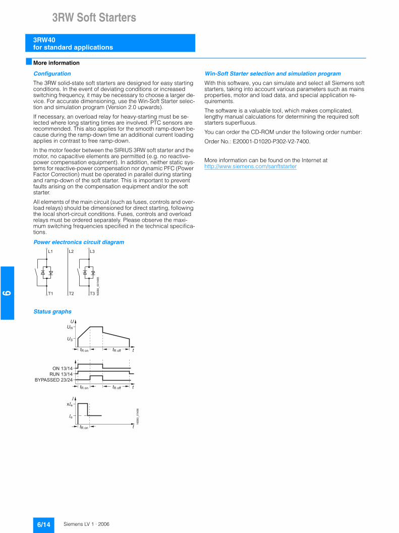
Power electronics circuit diagram1)
Status graphs
1) Circuit diagram applies to sizes S0 and S2;for size S00, phase L3 is bridged;for size S3, phase L2 is bridged.
Control with a PLC
When a 3RW30 is operated with a triac output or thyristor output, the leakage current at the PLC output should be < 1 mA be-cause otherwise the 3RW30 will interpret the resultant voltage drop at the input as an "On command". As a corrective measure for PLC outputs with a higher leakage current, an RC element with > 100 nF and 220 W can be connected in series between "IN1" and terminal "A2" of the 3RW30 (Order No.: 3TX7 462-3T see Selection and Ordering Data).
Win-Soft Starter selection and simulation program
With this software, you can simulate and select all Siemens soft starters, taking into account various parameters such as mains properties, motor and load data, and special application requirements.
The software is a valuable tool, which makes complicated, lengthy manual calculations for determining the required soft starters superfluous.
You can order the CD-ROM under the following order number:
Order No.: E20001-D1020-P302-V2-7400.
You can find more information on the Internet at:
http://www.siemens.com/sanftstarter
L1
NS
B0_
0041
0b
L2 L3
T1 T2 T3
�
�
��
��
����� ������
��
��
�
�� �
����� ������
�� �
Auxiliary contacts (sizes S0 to S3 only)
�
�
��
��
��� ���
��
�
��
3RW30 – 3-ph. mot.
3RW31

3RW Soft Starters
3RW40for standard applications
6/12 Siemens LV 1 · 2006
6
■ Overview
SIRIUS 3RW40 soft starters have all the same advantages as the 3RW30/31 soft starters. At the same time they come with addi-tional functions, e.g. solid-state motor overload and intrinsic de-vice protection and adjustable current limiting, as well as a two-phase control method (Polarity Balancing) that is unique in this rating range.SIRIUS 3RW40 soft starters are part of the SIRIUS modular sys-tem. This results in advantages such as identical sizes and a uni-form connection system. Thanks to their particularly compact design, SIRIUS 3RW40 soft starters are only half as big as com-parable wye-delta starters. Hence they can be mounted in min-imum space in the control cabinet. Configuring and installing are carried out quickly and easily thanks to the 3-wire connection.
SIRIUS 3RW40 for three-phase motorsSoft starters rated up to 250 kW (at 400 V) for standard applica-tions in three-phase networks. Extremely small sizes, low power losses and simple commissioning are just three of the many ad-vantages of the SIRIUS 3RW40 soft starters.
■ Application
The SIRIUS 3RW40 solid-state soft starters are suitable for soft starting and stopping of three-phase asynchronous motors.Due to two-phase control, the current is kept at minimum values in all three phases throughout the entire starting time and dis-turbing direct current components are eliminated in addition. This not only enables the two-phase starting of motors up to 250 kW (at 400 V) but also avoids the current and torque peaks which occur e.g. with wye-delta starters.
Application areas• Fans• Pumps• Building/construction machines• Presses• Escalators• Transport systems• Air conditioning systems• Ventilators• Assembly lines• Compressors and coolers• Operating mechanisms
■ Selection and ordering data
1) Soft starter with screw terminals: delivery time class } (preferred type).
2) Soft starter with screw terminals: delivery time class A.
3) Control by way of the internal 24 V DC supply and direct control by means of PLC possible.
Selection of the soft starter depends on the motor's rated current.
The SIRIUS 3RW40 solid-state soft starters are designed for easy starting conditions. JLoad < 10 x JMotor. In the event of deviating conditions or increased switching frequency, it may be necessary to choose a larger device. Siemens recommends the use of the selection and simulation program Win-Soft Starter. See Technical Specifications for information about rated currents for ambient temperatures >40 °C.
Ambient temperature 40 °C Ambient temperature 50 °C Size DT Order No. Price per PU
PU (UNIT, SET, M)
PS* PG Weight per PU approx.
Rated operat-ing cur-rent Ie
Rated output of three-phase induction motors for rated operational voltage Ue
Rated operational current Ie
Rated output of three-phase induction motors for rated operational voltage Ue
230 V 400 V 500 V 200 V 230 V 460 V 575 V
A kW kW kW A hp hp hp hp kg
Inline circuits, rated operational voltage 200 ... 460 V1)
134 37 75 -- 117 30 40 75 -- S6 B 3RW40 55-@BB@4 1 1 unit 131 5.700162 45 90 -- 145 40 50 100 -- B 3RW40 56-@BB@4 1 1 unit 131 5.700
230 75 132 -- 205 60 75 150 -- S12 B 3RW40 73-@BB@4 1 1 unit 131 7.000280 90 160 -- 248 75 100 200 -- B 3RW40 74-@BB@4 1 1 unit 131 7.000
356 110 200 -- 315 100 125 250 -- B 3RW40 75-@BB@4 1 1 unit 131 7.000432 132 250 -- 385 125 150 300 -- B 3RW40 76-@BB@4 1 1 unit 131 7.000
Inline circuits, rated operational voltage 400 ... 600 V2)
134 -- 75 90 117 -- -- 75 100 S6 B 3RW40 55-@BB@5 1 1 unit 131 5.700162 -- 90 110 145 -- -- 100 150 B 3RW40 56-@BB@5 1 1 unit 131 5.700
230 -- 132 160 205 -- -- 150 200 S12 B 3RW40 73-@BB@5 1 1 unit 131 7.000280 -- 160 200 248 -- -- 200 250 B 3RW40 74-@BB@5 1 1 unit 131 7.000
356 -- 200 250 315 -- -- 250 300 B 3RW40 75-@BB@5 1 1 unit 131 7.000432 -- 250 315 385 -- -- 300 400 B 3RW40 76-@BB@5 1 1 unit 131 7.000
Order No. supplement for connection methods
• With spring-loaded terminals 2• With screw terminals 6
Order No. supplement for the rated control supply voltage Us3)
• 115 V AC 3• 230 V AC 4
3RW40 56-6BB44 3RW40 76-6BB44
* You can order this quantity or a multiple thereof.

3RW Soft Starters
3RW40for standard applications
6/13Siemens LV 1 · 2006
66
Accessories
Spare parts
For soft starters Version DT Order No. Price per PU
PU (UNIT, SET, M)
PS* PG Weight per PU approx.
Type Size kgBox terminal blocks for soft starters
For round and ribbon cables
3RW40 5. S6 • up to 70 mm2} 3RT19 55-4G 1 1 unit 101 0.237
• up to 120 mm2} 3RT19 56-4G 1 1 unit 101 0.270
3RW40 7. S12 • up to 240 mm2} 3RT19 66-4G 1 1 unit 101 0.676
Covers for soft startersTerminal covers for box terminals
Additional touch protection to be fitted at the box terminals (2 units required per device)
3RW40 5. S6 } 3RT19 56-4EA2 1 1 unit 101 0.0283RW40 7. S12 } 3RT19 66-4EA2 1 1 unit 101 0.038
Terminal covers for cable lugs and busbar connections
3RW40 5. S6 } 3RT19 56-4EA1 1 1 unit 101 0.0673RW40 7. S12 } 3RT19 66-4EA1 1 1 unit 101 0.124
Sealing covers
3RW40 5. and3RW40 7.
S6, S12
} 3RW49 00-0PB00 1 1 unit 131 0.010
Modules for RESETModules for remote RESET, electrical
Operating range 0.85 ... 1.1 x Us, power consumption 80 VA AC, 70 W DC, ON period 0.2 s ... 4 s, operating frequency 60/h
3RW40 5. and3RW40 7.
S6, S12
• 24 V ... 30 V AC/DC } 3RU19 00-2AB71 1 1 unit 101 0.066• 110 V ... 127 V AC/DC } 3RU19 00-2AF71 1 1 unit 101 0.067• 220 V ... 250 V AC/DC } 3RU19 00-2AM71 1 1 unit 101 0.066
Mechanical RESET comprising
3RW40 5. and3RW40 7.
S6, S12
• Resetting plunger, holder and former } 3RU19 00-1A 1 1 set 101 0.038• Suitable pushbutton IP65, Ø 22 mm,
12 mm strokeB 3SB30 00-0EA11 1 1 unit 102 0.021
• Extension plunger A 3SX13 35 1 1 unit 102 0.004
Cable releases with holders for RESET
For Ø 6.5 mm holes in the control panel; max. control panel thickness 8 mm
3RW40 5. and3RW40 7.
S6, S12
• Length 400 mm } 3RU19 00-1B 1 1 unit 101 0.063• Length 600 mm } 3RU19 00-1C 1 1 unit 101 0.073
For soft starters Version DT Order No. Price per PU
PU (UNIT, SET, M)
PS* PG Weight per PU approx.
Type Size Rated control supply voltage Us
kg
FansFans
3RW40 5.-.BB3. S6 115 V AC } 3RW49 36-8VX30 1 1 unit 131 0.3003RW40 5.-.BB4. S6 230 V AC } 3RW49 36-8VX40 1 1 unit 131 0.300
3RW40 7.-.BB3. S12 115 V AC } 3RW49 47-8VX30 1 1 unit 131 0.5003RW40 7.-.BB4. S12 230 V AC } 3RW49 47-8VX40 1 1 unit 131 0.500
* You can order this quantity or a multiple thereof.
3RW Soft Starters
3RW40for standard applications
6/14 Siemens LV 1 · 2006
6
■ More information
Configuration
The 3RW solid-state soft starters are designed for easy starting conditions. In the event of deviating conditions or increased switching frequency, it may be necessary to choose a larger de-vice. For accurate dimensioning, use the Win-Soft Starter selec-tion and simulation program (Version 2.0 upwards).
If necessary, an overload relay for heavy-starting must be se-lected where long starting times are involved. PTC sensors are recommended. This also applies for the smooth ramp-down be-cause during the ramp-down time an additional current loading applies in contrast to free ramp-down.
In the motor feeder between the SIRIUS 3RW soft starter and the motor, no capacitive elements are permitted (e.g. no reactive-power compensation equipment). In addition, neither static sys-tems for reactive-power compensation nor dynamic PFC (Power Factor Correction) must be operated in parallel during starting and ramp-down of the soft starter. This is important to prevent faults arising on the compensation equipment and/or the soft starter.
All elements of the main circuit (such as fuses, controls and over-load relays) should be dimensioned for direct starting, following the local short-circuit conditions. Fuses, controls and overload relays must be ordered separately. Please observe the maxi-mum switching frequencies specified in the technical specifica-tions.
Power electronics circuit diagram
Status graphs
Win-Soft Starter selection and simulation program
With this software, you can simulate and select all Siemens soft starters, taking into account various parameters such as mains properties, motor and load data, and special application re-quirements.
The software is a valuable tool, which makes complicated, lengthy manual calculations for determining the required soft starters superfluous.
You can order the CD-ROM under the following order number:
Order No.: E20001-D1020-P302-V2-7400.
More information can be found on the Internet at http://www.siemens.com/sanftstarter
� �
���������
� � � �
� � �
����
��
����� �
���
��
����� ������
����� ������
���� �����
�������������
����� ��
�
�

3RW Soft Starters
3RW44for High Feature applications
6/15Siemens LV 1 · 2006
66
■ Overview
In addition to soft starting and soft ramp-down, the solid-state SIRIUS 3RW44 soft starters provide numerous functions for higher-level requirements. They cover a rating range up to 710 kW (at 400 V) in the inline circuit and up to 1200 kW (at 400 V) in the inside-delta circuit.
The SIRIUS 3RW44 soft starters are characterized by a compact design for space-saving and clearly arranged control cabinet layouts. For optimized motor starting and stopping the innova-tive SIRIUS 3RW44 soft starters are an attractive alternative with considerable savings potential compared to applications with a frequency converter. The new torque control and adjustable cur-rent limiting enable the High Feature soft starters to be used in nearly every conceivable task. They guarantee the reliable avoidance of sudden torque applications and current peaks dur-ing motor starting and stopping. This creates savings potential when calculating the size of the switchgear and when servicing the machinery installed. Be it for inline circuits or inside-delta cir-cuits – the SIRIUS 3RW44 soft starter offers savings especially in terms of size and equipment costs.
Combinations of various starting, operating and ramp-down possibilities ensure an optimum adaptation to the application-specific requirements. Operating and commissioning can be performed by means of the user-friendly keypad and a menu-prompted, multi-line graphic display with background lighting. The optimized motor ramp-up and ramp-down can be effected by means of just a few settings with a previously selected lan-guage. Four-key operation and plain-text displays for each menu point guarantee full clarity at every moment of the parameteriza-tion and operation.
Applicable standards • IEC 60947-4-2• UL/CSA
■ Application
The SIRIUS 3RW44 solid-state soft starters are suitable for the torque-controlled soft starting and smooth ramp-down as well as braking of three-phase asynchronous motors.
Application areas, e.g.• Pumps• Ventilators• Compressors• Water transport• Conveying systems and lifts• Hydraulics• Machine tools• Mills• Saws• Breakers• Mixers• Centrifuges• Industrial cooling and refrigerating systems
3RW Soft Starters
3RW44for High Feature applications
6/16 Siemens LV 1 · 2006
6
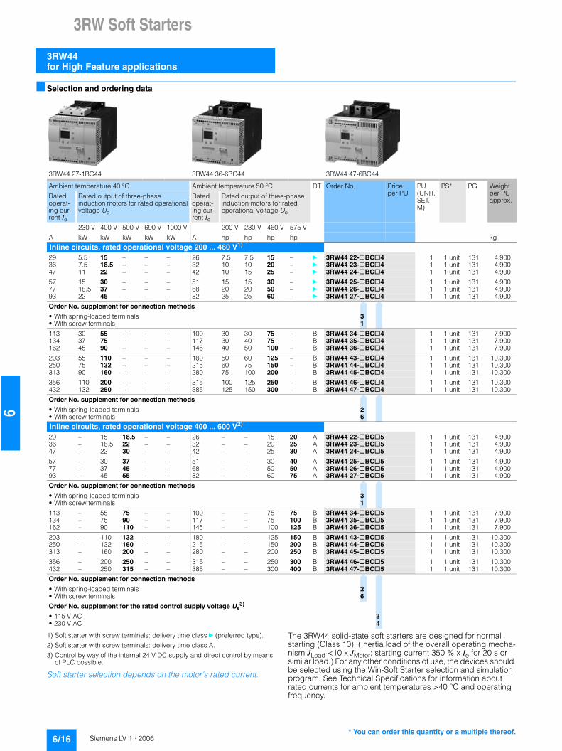
■ Selection and ordering data
1) Soft starter with screw terminals: delivery time class } (preferred type).
2) Soft starter with screw terminals: delivery time class A.
3) Control by way of the internal 24 V DC supply and direct control by means of PLC possible.
Soft starter selection depends on the motor’s rated current.
The 3RW44 solid-state soft starters are designed for normal starting (Class 10). (Inertia load of the overall operating mecha-nism JLoad <10 x JMotor; starting current 350 % x Ie for 20 s or similar load.) For any other conditions of use, the devices should be selected using the Win-Soft Starter selection and simulation program. See Technical Specifications for information about rated currents for ambient temperatures >40 °C and operating frequency.
3RW44 27-1BC44 3RW44 36-6BC44 3RW44 47-6BC44
Ambient temperature 40 °C Ambient temperature 50 °C DT Order No. Priceper PU
PU (UNIT, SET, M)
PS* PG Weight per PU approx.
Rated operat-ing cur-rent Ie
Rated output of three-phase induction motors for rated operational voltage Ue
Rated operat-ing cur-rent Ie
Rated output of three-phase induction motors for rated operational voltage Ue
230 V 400 V 500 V 690 V 1000 V 200 V 230 V 460 V 575 V
A kW kW kW kW kW A hp hp hp hp kg
Inline circuits, rated operational voltage 200 ... 460 V1)
29 5.5 15 – – – 26 7.5 7.5 15 – } 3RW44 22-@BC@4 1 1 unit 131 4.90036 7.5 18.5 – – – 32 10 10 20 – } 3RW44 23-@BC@4 1 1 unit 131 4.90047 11 22 – – – 42 10 15 25 – } 3RW44 24-@BC@4 1 1 unit 131 4.900
57 15 30 – – – 51 15 15 30 – } 3RW44 25-@BC@4 1 1 unit 131 4.90077 18.5 37 – – – 68 20 20 50 – } 3RW44 26-@BC@4 1 1 unit 131 4.90093 22 45 – – – 82 25 25 60 – } 3RW44 27-@BC@4 1 1 unit 131 4.900
Order No. supplement for connection methods
• With spring-loaded terminals 3• With screw terminals 1
113 30 55 – – – 100 30 30 75 – B 3RW44 34-@BC@4 1 1 unit 131 7.900134 37 75 – – – 117 30 40 75 – B 3RW44 35-@BC@4 1 1 unit 131 7.900162 45 90 – – – 145 40 50 100 – B 3RW44 36-@BC@4 1 1 unit 131 7.900
203 55 110 – – – 180 50 60 125 – B 3RW44 43-@BC@4 1 1 unit 131 10.300250 75 132 – – – 215 60 75 150 – B 3RW44 44-@BC@4 1 1 unit 131 10.300313 90 160 – – – 280 75 100 200 – B 3RW44 45-@BC@4 1 1 unit 131 10.300
356 110 200 – – – 315 100 125 250 – B 3RW44 46-@BC@4 1 1 unit 131 10.300432 132 250 – – – 385 125 150 300 – B 3RW44 47-@BC@4 1 1 unit 131 10.300
Order No. supplement for connection methods
• With spring-loaded terminals 2• With screw terminals 6
Inline circuits, rated operational voltage 400 ... 600 V2)
29 – 15 18.5 – – 26 – – 15 20 A 3RW44 22-@BC@5 1 1 unit 131 4.90036 – 18.5 22 – – 32 – – 20 25 A 3RW44 23-@BC@5 1 1 unit 131 4.90047 – 22 30 – – 42 – – 25 30 A 3RW44 24-@BC@5 1 1 unit 131 4.900
57 – 30 37 – – 51 – – 30 40 A 3RW44 25-@BC@5 1 1 unit 131 4.90077 – 37 45 – – 68 – – 50 50 A 3RW44 26-@BC@5 1 1 unit 131 4.90093 – 45 55 – – 82 – – 60 75 A 3RW44 27-@BC@5 1 1 unit 131 4.900
Order No. supplement for connection methods
• With spring-loaded terminals 3• With screw terminals 1
113 – 55 75 – – 100 – – 75 75 B 3RW44 34-@BC@5 1 1 unit 131 7.900134 – 75 90 – – 117 – – 75 100 B 3RW44 35-@BC@5 1 1 unit 131 7.900162 – 90 110 – – 145 – – 100 125 B 3RW44 36-@BC@5 1 1 unit 131 7.900
203 – 110 132 – – 180 – – 125 150 B 3RW44 43-@BC@5 1 1 unit 131 10.300250 – 132 160 – – 215 – – 150 200 B 3RW44 44-@BC@5 1 1 unit 131 10.300313 – 160 200 – – 280 – – 200 250 B 3RW44 45-@BC@5 1 1 unit 131 10.300
356 – 200 250 – – 315 – – 250 300 B 3RW44 46-@BC@5 1 1 unit 131 10.300432 – 250 315 – – 385 – – 300 400 B 3RW44 47-@BC@5 1 1 unit 131 10.300
Order No. supplement for connection methods
• With spring-loaded terminals 2• With screw terminals 6
Order No. supplement for the rated control supply voltage Us3)
• 115 V AC 3• 230 V AC 4
* You can order this quantity or a multiple thereof.

3RW Soft Starters
3RW44for High Feature applications
6/17Siemens LV 1 · 2006
66
1) Control by way of the internal 24 V DC supply and direct control by means of PLC possible.
Soft starter selection depends on the motor’s rated current.
The 3RW44 solid-state soft starters are designed for normal starting (Class 10). (Inertia load of the overall operating mecha-nism JLoad <10 x JMotor; starting current 350 % x Ie for 20 s or similar load). For any other conditions of use, the devices should be selected using the Win-Soft Starter selection and simulation program. See Technical Specifications for information about rated currents for ambient temperatures >40 °C and operating frequency.
Ambient temperature 40 °C Ambient temperature 50 °C DT Order No. Priceper PU
PU (UNIT, SET, M)
PS* PG Weight per PU approx.
Rated operat-ing cur-rent Ie
Rated output of three-phase induction motors for rated operational voltage Ue
Rated operat-ing cur-rent Ie
Rated output of three-phase induction motors for rated operational voltage Ue
230 V 400 V 500 V 690 V 1000 V 200 V 230 V 460 V 575 V
A kW kW kW kW kW A hp hp hp hp kg
Inline circuits, rated operational voltage 400 ... 690 V29 – 15 18.5 30 – 26 – – 15 20 B 3RW44 22-@BC@6 1 1 unit 131 4.90036 – 18.5 22 37 – 32 – – 20 25 B 3RW44 23-@BC@6 1 1 unit 131 4.90047 – 22 30 45 – 42 – – 25 30 B 3RW44 24-@BC@6 1 1 unit 131 4.900
57 – 30 37 55 – 51 – – 30 40 B 3RW44 25-@BC@6 1 1 unit 131 4.90077 – 37 45 75 – 68 – – 50 50 B 3RW44 26-@BC@6 1 1 unit 131 4.90093 – 45 55 90 – 82 – – 60 75 B 3RW44 27-@BC@6 1 1 unit 131 4.900
Order No. supplement for connection methods
• With spring-loaded terminals 3• With screw terminals 1
113 – 55 75 110 – 100 – – 75 75 B 3RW44 34-@BC@6 1 1 unit 131 7.900134 – 75 90 132 – 117 – – 75 100 B 3RW44 35-@BC@6 1 1 unit 131 7.900162 – 90 110 160 – 145 – – 100 125 B 3RW44 36-@BC@6 1 1 unit 131 7.900
203 – 110 132 200 – 180 – – 125 150 B 3RW44 43-@BC@6 1 1 unit 131 10.300250 – 132 160 250 – 215 – – 150 200 B 3RW44 44-@BC@6 1 1 unit 131 10.300313 – 160 200 315 – 280 – – 200 250 B 3RW44 45-@BC@6 1 1 unit 131 10.300
356 – 200 250 355 – 315 – – 250 300 B 3RW44 46-@BC@6 1 1 unit 131 10.300432 – 250 315 400 – 385 – – 300 400 B 3RW44 47-@BC@6 1 1 unit 131 10.300
Order No. supplement for connection methods
• With spring-loaded terminals 2• With screw terminals 6
Order No. supplement for the rated control supply voltage Us1)
• 115 V AC 3• 230 V AC 4
* You can order this quantity or a multiple thereof.

3RW Soft Starters
3RW44for High Feature applications
6/18 Siemens LV 1 · 2006
6
1) In the selection table, the rated operational current Ie refers to the three-phase motor’s rated operational current in the inside-delta circuit. The actual current of the device is approx. 58 % of this value.
2) Soft starter with screw terminals: delivery time class } (preferred type).
3) Soft starter with screw terminals: delivery time class A.
4) Control by way of the internal 24 V DC supply and direct control by means of PLC possible.
Soft starter selection depends on the motor’s rated current.
The 3RW44 solid-state soft starters are designed for normal starting (Class 10). (Inertia load of the overall operating mecha-nism JLoad <10 x JMotor; starting current 350 % x Ie for 20 s or similar load). For any other conditions of use, the devices should be selected using the Win-Soft Starter selection and simulation program. See Technical Specifications for information about rated currents for ambient temperatures >40 °C and operating frequency.
3RW44 27-1BC44 3RW44 36-6BC44 3RW44 47-6BC44
Ambient temperature 40 °C Ambient temperature 50 °C DT Order No. Priceper PU
PU (UNIT, SET, M)
PS* PG Weight per PU approx.
Rated opera-tional current Ie
1)
Rated output of three-phase induction motors for rated operational voltage Ue
Rated operat-ing cur-rent Ie
Rated output of three-phase induction motors for rated operational voltage Ue
230 V 400 V 500 V 690 V 1000 V 200 V 230 V 460 V 575 V
A kW kW kW kW kW A hp hp hp hp kg
Inside-delta circuits, rated operational voltage 200 ... 400 V2)
50 15 22 – – – 45 10 15 – – B 3RW44 22-@BC@4 1 1 unit 131 4.90062 18.5 30 – – – 55 15 20 – – B 3RW44 23-@BC@4 1 1 unit 131 4.90081 22 45 – – – 73 20 25 – – B 3RW44 24-@BC@4 1 1 unit 131 4.900
99 30 55 – – – 88 25 30 – – B 3RW44 25-@BC@4 1 1 unit 131 4.900133 37 75 – – – 118 30 40 – – B 3RW44 26-@BC@4 1 1 unit 131 4.900161 45 90 – – – 142 40 50 – – B 3RW44 27-@BC@4 1 1 unit 131 4.900
Order No. supplement for connection methods
• With spring-loaded terminals 3• With screw terminals 1
196 55 110 – – – 173 50 60 – – B 3RW44 34-@BC@4 1 1 unit 131 7.900232 75 132 – – – 203 60 75 – – B 3RW44 35-@BC@4 1 1 unit 131 7.900281 90 160 – – – 251 75 100 – – B 3RW44 36-@BC@4 1 1 unit 131 7.900
352 110 200 – – – 312 100 125 – – B 3RW44 43-@BC@4 1 1 unit 131 10.300433 132 250 – – – 372 125 150 – – B 3RW44 44-@BC@4 1 1 unit 131 10.300542 160 315 – – – 485 150 200 – – B 3RW44 45-@BC@4 1 1 unit 131 10.300
617 200 355 – – – 546 150 200 – – B 3RW44 46-@BC@4 1 1 unit 131 10.300748 250 400 – – – 667 200 250 – – B 3RW44 47-@BC@4 1 1 unit 131 10.300
Order No. supplement for connection methods
• With spring-loaded terminals 2• With screw terminals 6
Inside-delta circuits, rated operational voltage 400 ... 600 V3)
50 – 22 30 – – 45 – – 30 40 B 3RW44 22-@BC@5 1 1 unit 131 4.90062 – 30 37 – – 55 – – 40 50 B 3RW44 23-@BC@5 1 1 unit 131 4.90081 – 45 45 – – 73 – – 50 60 B 3RW44 24-@BC@5 1 1 unit 131 4.900
99 – 55 55 – – 88 – – 60 75 B 3RW44 25-@BC@5 1 1 unit 131 4.900133 – 75 90 – – 118 – – 75 100 B 3RW44 26-@BC@5 1 1 unit 131 4.900161 – 90 110 – – 142 – – 100 125 B 3RW44 27-@BC@5 1 1 unit 131 4.900
Order No. supplement for connection methods
• With spring-loaded terminals 3• With screw terminals 1
196 – 110 132 – – 173 – – 125 150 B 3RW44 34-@BC@5 1 1 unit 131 7.900232 – 132 160 – – 203 – – 150 200 B 3RW44 35-@BC@5 1 1 unit 131 7.900281 – 160 200 – – 251 – – 200 250 B 3RW44 36-@BC@5 1 1 unit 131 7.900
352 – 200 250 – – 312 – – 250 300 B 3RW44 43-@BC@5 1 1 unit 131 10.300433 – 250 315 – – 372 – – 300 350 B 3RW44 44-@BC@5 1 1 unit 131 10.300542 – 315 355 – – 485 – – 400 500 B 3RW44 45-@BC@5 1 1 unit 131 10.300
617 – 355 450 – – 546 – – 450 600 B 3RW44 46-@BC@5 1 1 unit 131 10.300748 – 400 500 – – 667 – – 600 750 B 3RW44 47-@BC@5 1 1 unit 131 10.300
Order No. supplement for connection methods
• With spring-loaded terminals 2• With screw terminals 6
Order No. supplement for the rated control supply voltage Us4)
• 115 V AC 3• 230 V AC 4
* You can order this quantity or a multiple thereof.

3RW Soft Starters
3RW44for High Feature applications
6/19Siemens LV 1 · 2006
66
Accessories
Spare parts
For soft starters
Version DT Order No. Priceper PU
PU (UNIT, SET, M)
PS* PG Weight per PU approx.
Type kgBox terminal blocks for soft starters
Box terminal blocks
3RW44 2. Included in delivery
3RW44 3. • up to 70 mm2} 3RT19 55-4G 1 1 unit 101 0.237
• up to 120 mm2} 3RT19 56-4G 1 1 unit 101 0.270
3RW44 3. • up to 240 mm2} 3RT19 66-4G 1 1 unit 101 0.676
Covers for soft startersTerminal covers for box terminals
Additional touch protection to be fitted at the box terminals (2 units required per device)
3RW44 2. and 3RW44 3.
} 3RT19 56-4EA2 1 1 unit 101 0.028
3RW44 4. } 3RT19 66-4EA2 1 1 unit 101 0.038
Terminal covers for cable lugs and busbar connections
3RW44 2. and 3RW44 3.
} 3RT19 56-4EA1 1 1 unit 101 0.067
3RW44 4. } 3RT19 66-4EA1 1 1 unit 101 0.124
For soft starters
Version DT Order No. Priceper PU
PU (UNIT, SET, M)
PS* PG Weight per PU approx.
Type kgFans
Fans
3RW44 2. and 3RW44 3.
115 V AC } 3RW49 36-8VX30 1 1 unit 131 0.300230 V AC } 3RW49 36-8VX40 1 1 unit 131 0.300
3RW44 4. 115 V AC } 3RW49 47-8VX30 1 1 unit 131 0.500230 V AC } 3RW49 47-8VX40 1 1 unit 131 0.500
* You can order this quantity or a multiple thereof.

3RW Soft Starters
3RW44for High Feature applications
6/20 Siemens LV 1 · 2006
6
■ More information
Application examples for normal starting (Class 10)
Application examples for heavy starting (Class 20)
Application examples for very heavy starting (Class 30)
Note:These tables present sample setting values and device sizes. They are intended only for the purposes of information and are not binding. The setting values depend on the application in question and must be optimized during commissioning. The soft starter dimensions should be checked where necessary with the Win-Soft Starter software or with the help of Technical Assistance.
Normal starting Class 10 (up to 20 s with 350 % In motor), The soft starter rating can be selected to be as high as the rating of the motor used
Applications Conveyor belt Roller conveyor Compressor Small ventilator Pump Hydraulic pump
Starting parameters
• Voltage ramp and current limiting- Starting voltage % 70 60 50 30 30 30- Starting time s 10 10 10 10 10 10- Current limit value Deactivated Deactivated 4 x IM 4 x IM Deactivated Deactivated
• Torque ramp- Starting torque 60 50 40 20 10 10- End torque 150 150 150 150 150 150- Starting time 10 10 10 10 10 10
• Breakaway pulse Deactivated (0 ms) Deactivated (0 ms) Deactivated (0 ms) Deactivated (0 ms) Deactivated (0 ms) Deactivated (0 ms)
Ramp-down mode Smooth ramp-down
Smooth ramp-down
Free ramp-down
Free ramp-down
Pump ramp-down Free ramp-down
Heavy starting Class 20 (up to 40 s with 350 % In motor), The soft starter has to be selected one rating class higher than the motor used
Applications Stirrer Centrifuge Milling machine
Starting parameters
• Voltage ramp and current limiting- Starting voltage % 30 30 30- Starting time s 30 30 30- Current limit value 4 x IM 4 x IM 4 x IM
• Torque ramp- Starting torque 30 30 30- End torque 150 150 150- Starting time 30 30 30
• Breakaway pulse Deactivated (0 ms) Deactivated (0 ms) Deactivated (0 ms)
Ramp-down mode Free ramp-down Free ramp-down Free ramp-down or DC braking
Very heavy starting Class 30 (up to 60 s with 350 % In motor), The soft starter has to be selected two rating classes higher than the motor used
Applications Large ventilator Mill Breakers Circular saw/bandsaw
Starting parameters
• Voltage ramp and current limiting- Starting voltage % 30 50 50 30- Starting time s 60 60 60 60- Current limit value 4 x IM 4 x IM 4 x IM 4 x IM
• Torque ramp- Starting torque 20 50 50 20- End torque 150 150 150 150- Starting time 60 60 60 60
• Breakaway pulse Deactivated (0 ms) 80 %, 300 ms 80 %, 300 ms Deactivated (0 ms)
Ramp-down mode Free ramp-down Free ramp-down Free ramp-down Free ramp-down

3RW Soft Starters
3RW44for High Feature applications
6/21Siemens LV 1 · 2006
66
Circuit concept
The SIRIUS 3RW44 soft starters can be operated in two different types of circuit.• Inline circuit
The controls for isolating and protecting the motor are simply connected in series with the soft starter. The motor is connected to the soft starter with three leads.
• Inside-delta circuit The wiring is similar to that of wye-delta starters. The phases of the soft starter are connected in series with the individual motor windings. The soft starter then only has to carry the phase current, amounting to about 58 % of the rated motor current (conductor current).
Comparison of the types of circuit
Inline circuit:Rated current Ie corresponds to the rated motor current In,3 leads to the motor
Inside-delta circuit:Rated current Ie corresponds to approx. 58 % of the rated motor current In, 6 leads to the motor (as with wye-delta starters)
Which circuit?
Using the inline circuit involves the lowest wiring complexity. If the soft starter to motor connections are long, this contact sequence is preferable. With the inside-delta circuit there is double the wiring complexity but a smaller size of device can be used at the same rating.
Thanks to the possibility of switching between the inline circuit and inside-delta circuit, the most favorable solution can always be chosen.
The braking function is possible only in the inline circuit.
Configuration
The 3RW44 solid-state soft starters are designed for normal starting. In case of heavy starting or increased starting frequency, a larger device must be selected.
For long starting times it is recommended to have a PTC ther-mistor detector in the motor. This also applies for the ramp-down modes smooth ramp-down, pump ramp-down and DC braking, because during the ramp-down time in these modes, an addi-tional current loading applies in contrast to free ramp-down.
In the motor feeder between the SIRIUS 3RW soft starter and the motor, no capacitive elements are permitted (e.g. no reactive-power compensation equipment). In addition, neither static systems for reactive-power compensation nor dynamic PFC (Power Factor Correction) must be operated in parallel during starting and ramp-down of the soft starter. This is important to prevent faults arising on the compensation equipment and/or the soft starter.
All elements of the main circuit (such as fuses and controls) should be dimensioned for direct starting, following the local short-circuit conditions. Fuses, controls and overload relays must be ordered separately.
The harmonic component load for starting currents must be taken into consideration for the selection of motor starter protec-tors (selection of release).
RS 232 serial PC interface and Soft Starter ES parameteriz-ing and operating software
The solid-state 3RW44 soft starters have a PC interface for communicating with the Soft Starter ES smart software and an operating and monitoring module.
Manual for SIRIUS 3RW44
Besides containing all important information on planning, commissioning and servicing, the manual also contains sug-gested circuits and the technical specifications for all devices.
Win-Soft Starter selection and simulation program
With this software, you can simulate and select all Siemens soft starters, taking into account various parameters such as mains properties, motor and load data, and special application requirements.
The software is a valuable tool, which makes complicated, lengthy manual calculations for determining the required soft starters superfluous.
You can order the CD-ROM under the following order number: Order No.: E20001-D1020-P302-V2-7400.
More information can be found on the Internet at http://www.siemens.com/sanftstarter
SIRIUS soft starter training course (SD-SIRIUSO)
Siemens offers a 2-day training course on the SIRIUS solid-state soft starters to keep customers and own personnel up-to-date on configuring, commissioning and servicing issues.
Please direct enquiries and applications to:
Training Center I&S IS E&C TC Werner-von-Siemens-Str. 65 D-91052 Erlangen Telephone: +49 (0)9131 729262 Telefax: +49 (0)9131 [email protected]://www.siemens.com/sibrain
� � � � � � � � � �� �
� �
� �
�
� �
� � � � � � � � � � �
� �
� �
�
� �
� � � � � � �
� �
� �
� �
�
� �
� �
�
� �

3RW Soft Starters
Notes
6/22 Siemens LV 1 · 2006
6

3RA Fuseless Load Feeders
General data
6/23Siemens LV 1 · 2006
66
■ Overview
3RA fuseless load feeders
The 3RA1 fuseless load feeders consist of the 3RV1 motor starter protector and the 3RT1 contactor. Motor starter protectors and contactors are electrically and mechanically connected us-ing pre-assembled sets of components (link modules, wiring sets and standard mounting rail or busbar adapters).
As the 3RA1 fuseless load feeders are constructed from 3RV1 motor starter protectors and 3RT1 contactors, the same accessories can be used for the 3RA fuseless load feeders as for these motor starter protectors and contactors.
Pre-assembled link modules are available as accessories for the power spectrum up to 45 kW. The desired fuseless load feeder can thus be assembled quickly and economically by the customer. A time saving is also achieved in connection with controlgear acceptances, as – unlike with conventional wiring systems – there is no need to rectify possible wiring errors.
The 3RV1 motor starter protector is responsible for overload and short-circuit protection in the fuseless load feeder. Back-up pro-tective devices, such as fuses or limiters, are superfluous here, as the motor starter protector is capable of withstanding short-circuits of up to 50 or 100 kA at 400 V.
The 3RT1 contactor is particularly suitable for extremely complex switching tasks requiring the greatest endurance.
The permissible ambient temperature is 60 °C with butt-mount-ing and without derating (70 °C possible subject to certain re-strictions).
3RA1 fuseless load feeders are available for motors up to 45 kW at AC-3 and 400 V (grounded network) and setting ranges from 0.14 A to 100 A.
3RA1 fuseless load feeders are supplied in four different sizes:
The SENTRON 3VL circuit-breakers and the SIRIUS 3RT contac-tors can be used for fuseless load feeders >100 A. The corre-sponding distances from grounded or live parts, as detailed in the technical specifications, must be observed. The selection tables for assemblies up to 250 kW for self-assembly of 400 V, 500 V and 690 V voltages under different starting conditions (Class 10, 20) can be found in the Technical Information LV 1 T.
Operating conditions
3RA1 load feeders are climate-proof. They are intended for use in enclosed rooms in which no severe conditions (such as dust, caustic vapors, hazardous gases) prevail. Suitable covers must be provided for installation in dusty and damp loca-tions.
Overload tripping times
All 3RA1 fuseless load feeders described here are designed for normal starting, in other words for overload tripping times of less than 10 s (CLASS 10). At rated-load operating temperature the tripping times are shorter, depending on the particular equip-ment and the setting range. The exact values can be derived from the tripping characteristics of the motor starter protectors.
Types of coordination
EN 60947-4-1 (VDE 0660 Part 102) and IEC 60947-4-1 make a distinction between two different types of coordination, which are designated type of coordination "1" and type of coordination "2". Any short-circuits that occur are cleared safely by both types of coordination. The only differences concern the extent of the damage caused to the equipment by a short-circuit.
Size Width Max. rated current In max
For induction motors up to
mm A kW
S00 45 12 5.5
S0 45 25 11
S2 55 50 22
S3 70 100 45
• Type of coordination 1
The fuseless load feeder may be non-operational after a short-circuit has been cleared. Damage to the contactor or to the overload relay is permissible. For 3RA1 load feeders, the motor starter protector itself always achieves type 2 coordination.
• Type of coordination 2
There must be no damage to the overload trip or to any other components after a short-circuit has been cleared. The 3RA1 fuseless load feeder can resume operation without needing to be renewed. At most, it is permissible to weld the contactor contacts if they can be disconnected easily without any signifi-cant deformation.

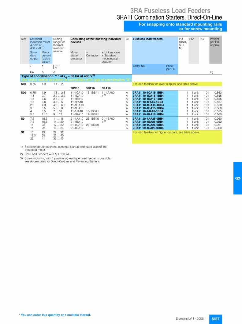
3RA Fuseless Load Feeders3RA11 Combination Starters, Direct-On-LineFor snapping onto standard mounting railsor for screw mounting
6/24 Siemens LV 1 · 2006
6
■ Selection and ordering data
1) Size S00 also suitable for 60 Hz.
2) Standard mounting rail adapter is also suitable for screw mounting.
3) For auxiliary switches, see Accessories for Direct-On-Line and Reversing Starters
4) Selection depends on the concrete startup and rated data of the protected motor.
5) See Load Feeders with Iq�� 100 kA.
6) Screw mounting with 1 push-in lug each per load feeder is possible; see Accessories for Direct-On-Line and Reversing Starters.
3RA11 10 3RA11 20 3RA11 30
Direct start Rated control supply voltage 50 Hz 230 V AC1)
for 35 mm standard mounting rail or screw mounting
• Motor starter protector and contactor are linked electrically and mechani-cally by means of a link module
• As from size S2 with standard mounting rail adapter2) for mechanical reinforcement
• Auxiliary switches3) on the motor starter protector and the contactor can be easily fitted due to the modular system (on contactor size S00: 1 NO integrated)
Size Standard induction motor 4-pole at 400 V AC4)
Setting range for thermal overload release
Consisting of the following individual devices
DT Fuseless load feeders PU (UNIT, SET, M)
PS* PG Weight per PU approx.
Stan-dard output
Motor current (guide value)
Motor starter protector
+Contactor
+ Link module + Standard mounting rail adapter
P I Order No. Priceper PU
kW A A kgType of coordination "2" at Iq = 50 kA/100 kA at 400 V (compatible with type of coordination "1")5)
3RV10 3RT10 3RA19
S00 0.06 0.2 0.14 ... 0.2 11-0BA10 15-1AP01 11-1AA00 +6)
A 3RA11 10-0BA15-1AP0 1 1 unit 101 0.4540.06 0.2 0.18 ... 0.25 11-0CA10 A 3RA11 10-0CA15-1AP0 1 1 unit 101 0.4500.09 0.3 0.22 ... 0.32 11-0DA10 A 3RA11 10-0DA15-1AP0 1 1 unit 101 0.4500.09 0.3 0.28 ... 0.4 11-0EA10 A 3RA11 10-0EA15-1AP0 1 1 unit 101 0.4520.12 0.4 0.35 ... 0.5 11-0FA10 A 3RA11 10-0FA15-1AP0 1 1 unit 101 0.4500.18 0.6 0.45 ... 0.63 11-0GA10 A 3RA11 10-0GA15-1AP0 1 1 unit 101 0.4480.18 0.6 0.55 ... 0.8 11-0HA10 A 3RA11 10-0HA15-1AP0 1 1 unit 101 0.4460.25 0.85 0.7 ... 1 11-0JA10 A 3RA11 10-0JA15-1AP0 1 1 unit 101 0.4510.37 1.1 0.9 ... 1.25 11-0KA10 A 3RA11 10-0KA15-1AP0 1 1 unit 101 0.4950.55 1.5 1.1 ... 1.6 11-1AA10 A 3RA11 10-1AA15-1AP0 1 1 unit 101 0.5020.75 1.9 1.4 ... 2 11-1BA10 A 3RA11 10-1BA15-1AP0 1 1 unit 101 0.490
S0 0.75 1.9 1.8 ... 2.5 21-1CA10 24-1AP00 21-1AA00 +6)
A 3RA11 20-1CA24-0AP0 1 1 unit 101 0.7201.1 2.7 2.2 ... 3.2 21-1DA10 A 3RA11 20-1DA24-0AP0 1 1 unit 101 0.7201.5 3.6 2.8 ... 4 21-1EA10 A 3RA11 20-1EA24-0AP0 1 1 unit 101 0.7101.5 3.6 3.5 ... 5 21-1FA10 A 3RA11 20-1FA24-0AP0 1 1 unit 101 0.7232.2 4.9 4.5 ... 6.3 21-1GA10 A 3RA11 20-1GA24-0AP0 1 1 unit 101 0.7173 6.5 5.5 ... 8 21-1HA10 A 3RA11 20-1HA24-0AP0 1 1 unit 101 0.7304 8.5 7 ... 10 21-1JA10 26-1AP00 A 3RA11 20-1JA26-0AP0 1 1 unit 101 0.7205.5 11.5 9 ... 12.5 21-1KA10 A 3RA11 20-1KA26-0AP0 1 1 unit 101 0.7257.5 15.5 11 ... 16 21-4AA10 A 3RA11 20-4AA26-0AP0 1 1 unit 101 0.7207.5 15.5 14 ... 20 21-4BA10 A 3RA11 20-4BA26-0AP0 1 1 unit 101 0.722
S2 11 22 18 ... 25 31-4DA10 34-1AP00 31-1AA00 + 32-1AA00
A 3RA11 30-4DB34-0AP0 1 1 unit 101 2.07015 29 22 ... 32 31-4EA10 A 3RA11 30-4EB34-0AP0 1 1 unit 101 2.08318.5 35 28 ... 40 31-4FA10 35-1AP00 A 3RA11 30-4FB35-0AP0 1 1 unit 101 2.12622 41 36 ... 45 31-4GA10 36-1AP00 A 3RA11 30-4GB36-0AP0 1 1 unit 101 2.13022 41 40 ... 50 31-4HA10 A 3RA11 30-4HB36-0AP0 1 1 unit 101 2.091
S3 30 55 45 ... 63 41-4JA10 44-1AP00 41-1AA00 + 42-1AA00
Size S3 is only available for self-assembly37 66 57 ... 75 41-4KA10 45-1AP0045 80 70 ... 90 41-4LA10 46-1AP0045 80 80 ... 100 41-4MA10
* You can order this quantity or a multiple thereof.

3RA Fuseless Load Feeders3RA11 Combination Starters, Direct-On-Line
For snapping onto standard mounting railsor for screw mounting
6/25Siemens LV 1 · 2006
66
1) Selection depends on the concrete startup and rated data of the protected motor.
2) See Load Feeders with Iq�� 100 kA.
3) Screw mounting with 1 push-in lug each per load feeder is possible; see Accessories for Direct-On-Line and Reversing Starters.
Size Standard induction motor 4-pole at 400 V AC1)
Setting range for thermal overload release
Consisting of the following individual devices
DT Fuseless load feeders PU (UNIT, SET, M)
PS* PG Weight per PU approx.
Stan-dard output
Motor current (guide value)
Motor starter protector
+Contactor
+ Link module + Standard mounting rail adapter
P I Order No. Priceper PU
kW A A kgType of coordination "1" at Iq = 50 kA at 400 V2) (the motor starter protector is compatible with type of coordination "2")S00 0.75 1.9 1.4 ... 2 For load feeders for lower outputs, see table above.
3RV10 3RT10 3RA19
S00 0.75 1.9 1.8 ... 2.5 11-1CA10 15-1AP01 11-1AA00 +3)
A 3RA11 10-1CA15-1AP0 1 1 unit 101 0.4971.1 2.7 2.2 ... 3.2 11-1DA10 A 3RA11 10-1DA15-1AP0 1 1 unit 101 0.4981.5 3.6 2.8 ... 4 11-1EA10 A 3RA11 10-1EA15-1AP0 1 1 unit 101 0.5001.5 3.6 3.5 ... 5 11-1FA10 A 3RA11 10-1FA15-1AP0 1 1 unit 101 0.5012.2 4.9 4.5 ... 6.3 11-1GA10 A 3RA11 10-1GA15-1AP0 1 1 unit 101 0.5083 6.5 5.5 ... 8 11-1HA10 A 3RA11 10-1HA15-1AP0 1 1 unit 101 0.5084 8.5 7 ... 10 11-1JA10 16-1AP01 A 3RA11 10-1JA16-1AP0 1 1 unit 101 0.4935.5 11.5 9 ... 12 11-1KA10 17-1AP01 A 3RA11 10-1KA17-1AP0 1 1 unit 101 0.500
S0 7.5 15.5 11 ... 16 21-4AA10 25-1AP00 21-1AA00 +3)
A 3RA11 20-4AA25-0AP0 1 1 unit 101 0.7297.5 15.5 14 ... 20 21-4BA10 A 3RA11 20-4BA25-0AP0 1 1 unit 101 0.72411 22 17 ... 22 21-4CA10 26-1AP00 A 3RA11 20-4CA26-0AP0 1 1 unit 101 0.72111 22 18 ... 25 21-4DA10 26-1AP00 A 3RA11 20-4DA26-0AP0 1 1 unit 101 0.729
S2 15 29 22 ... 32 For load feeders for higher outputs, see table above.18.5 35 28 ... 4022 41 36 ... 45
...
* You can order this quantity or a multiple thereof.

3RA Fuseless Load Feeders3RA11 Combination Starters, Direct-On-LineFor snapping onto standard mounting railsor for screw mounting
6/26 Siemens LV 1 · 2006
6
1) Standard mounting rail adapter is also suitable for screw mounting.
2) For auxiliary switches, see Accessories for Direct-On-Line and Reversing Starters
3) Selection depends on the concrete startup and rated data of the protected motor.
4) See Load Feeders with Iq�� 100 kA.
5) Screw mounting with 1 push-in lug each per load feeder is possible; see Accessories for Direct-On-Line and Reversing Starters.
3RA11 10 3RA11 20 3RA11 30
Direct start Rated control supply voltage 24 V DC for 35 mm standard mounting rail or screw mounting
• Motor starter protector and contactor are linked electrically and mechani-cally by means of a link module
• As from size S2 with standard mounting rail adapter1) for mechanical reinforcement
• Auxiliary switches2) on the motor starter protector and the contactor can be easily fitted due to the modular system (on contactor size S00: 1 NO integrated)
Size Standard induction motor 4-pole at 400 V AC3)
Setting range for thermal overload release
Consisting of the following individual devices
DT Fuseless load feeders PU (UNIT, SET, M)
PS* PG Weight per PU approx.
Stan-dard output
Motor current (guide value)
Motor starter protector
+Contactor
+ Link module + Standard mounting rail adapter
P I Order No. Priceper PU
kW A A kgType of coordination "2" at Iq = 50 kA/100 kA at 400 V (compatible with type of coordination "1")4)
3RV10 3RT10 3RA19
S00 0.06 0.2 0.14 ... 0.2 11-0BA10 15-1BB41 11-1AA00 +5)
A 3RA11 10-0BA15-1BB4 1 1 unit 101 0.5100.06 0.2 0.18 ... 0.25 11-0CA10 A 3RA11 10-0CA15-1BB4 1 1 unit 101 0.5120.09 0.3 0.22 ... 0.32 11-0DA10 A 3RA11 10-0DA15-1BB4 1 1 unit 101 0.5050.09 0.3 0.28 ... 0.4 11-0EA10 A 3RA11 10-0EA15-1BB4 1 1 unit 101 0.5080.12 0.4 0.35 ... 0.5 11-0FA10 A 3RA11 10-0FA15-1BB4 1 1 unit 101 0.5000.18 0.6 0.45 ... 0.63 11-0GA10 A 3RA11 10-0GA15-1BB4 1 1 unit 101 0.5050.18 0.6 0.55 ... 0.8 11-0HA10 A 3RA11 10-0HA15-1BB4 1 1 unit 101 0.5130.25 0.85 0.7 ... 1 11-0JA10 A 3RA11 10-0JA15-1BB4 1 1 unit 101 0.5080.37 1.1 0.9 ... 1.25 11-0KA10 A 3RA11 10-0KA15-1BB4 1 1 unit 101 0.5560.55 1.5 1.1 ... 1.6 11-1AA10 A 3RA11 10-1AA15-1BB4 1 1 unit 101 0.5530.75 1.9 1.4 ... 2 11-1BA10 A 3RA11 10-1BA15-1BB4 1 1 unit 101 0.554
S0 0.75 1.9 1.8 ... 2.5 21-1CA10 24-1BB40 21-1BA00 +5)
A 3RA11 20-1CA24-0BB4 1 1 unit 101 0.9471.1 2.7 2.2 ... 3.2 21-1DA10 A 3RA11 20-1DA24-0BB4 1 1 unit 101 0.9401.5 3.6 2.8 ... 4 21-1EA10 A 3RA11 20-1EA24-0BB4 1 1 unit 101 0.9451.5 3.6 3.5 ... 5 21-1FA10 A 3RA11 20-1FA24-0BB4 1 1 unit 101 0.9512.2 4.9 4.5 ... 6.3 21-1GA10 A 3RA11 20-1GA24-0BB4 1 1 unit 101 0.9483 6.5 5.5 ... 8 21-1HA10 A 3RA11 20-1HA24-0BB4 1 1 unit 101 0.9604 8.5 7 ... 10 21-1JA10 26-1BB40 A 3RA11 20-1JA26-0BB4 1 1 unit 101 0.9515.5 11.5 9 ... 12.5 21-1KA10 A 3RA11 20-1KA26-0BB4 1 1 unit 101 0.9407.5 15.5 11 ... 16 21-4AA10 A 3RA11 20-4AA26-0BB4 1 1 unit 101 0.9597.5 15.5 14 ... 20 21-4BA10 A 3RA11 20-4BA26-0BB4 1 1 unit 101 0.950
S2 11 22 18 ... 25 31-4DA10 34-1BB40 31-1BA00 + 32-1AA00
A 3RA11 30-4DB34-0BB4 1 1 unit 101 2.70015 29 22 ... 32 31-4EA10 A 3RA11 30-4EB34-0BB4 1 1 unit 101 2.70018.5 35 28 ... 40 31-4FA10 35-1BB40 A 3RA11 30-4FB35-0BB4 1 1 unit 101 2.73022 41 36 ... 45 31-4GA10 36-1BB40 A 3RA11 30-4GB36-0BB4 1 1 unit 101 2.69922 41 40 ... 50 31-4HA10 A 3RA11 30-4HB36-0BB4 1 1 unit 101 2.696
S3 30 55 45 ... 63 41-4JA10 44-1BB40 41-1AB00 +42-1AA00
Size S3 is only available for self-assembly37 66 57 ... 75 41-4KA10 45-1BB4045 80 70 ... 90 41-4LA10 46-1BB4045 80 80 ... 100 41-4MA10
* You can order this quantity or a multiple thereof.
3RA Fuseless Load Feeders3RA11 Combination Starters, Direct-On-Line
For snapping onto standard mounting railsor for screw mounting
6/27Siemens LV 1 · 2006
66
1) Selection depends on the concrete startup and rated data of the protected motor.
2) See Load Feeders with Iq�� 100 kA.
3) Screw mounting with 1 push-in lug each per load feeder is possible; see Accessories for Direct-On-Line and Reversing Starters.
Size Standard induction motor 4-pole at 400 V AC1)
Setting range for thermal overload release
Consisting of the following individual devices
DT Fuseless load feeders PU (UNIT, SET, M)
PS* PG Weight per PU approx.
Stan-dard output
Motor current (guide value)
Motor starter protector
+Contactor
+ Link module + Standard mounting rail adapter
P I Order No. Priceper PU
kW A A kgType of coordination "1" at Iq = 50 kA at 400 V2)
(the motor starter protector is compatible with type of coordination "2")S00 0.75 1.9 1.4 ... 2 For load feeders for lower outputs, see table above.
3RV10 3RT10 3RA19
S00 0.75 1.9 1.8 ... 2.5 11-1CA10 15-1BB41 11-1AA00 +3)
A 3RA11 10-1CA15-1BB4 1 1 unit 101 0.5631.1 2.7 2.2 ... 3.2 11-1DA10 A 3RA11 10-1DA15-1BB4 1 1 unit 101 0.5551.5 3.6 2.8 ... 4 11-1EA10 A 3RA11 10-1EA15-1BB4 1 1 unit 101 0.5551.5 3.6 3.5 ... 5 11-1FA10 A 3RA11 10-1FA15-1BB4 1 1 unit 101 0.5672.2 4.9 4.5 ... 6.3 11-1GA10 A 3RA11 10-1GA15-1BB4 1 1 unit 101 0.5583 6.5 5.5 ... 8 11-1HA10 A 3RA11 10-1HA15-1BB4 1 1 unit 101 0.5604 8.5 7 ... 10 11-1JA10 16-1BB41 A 3RA11 10-1JA16-1BB4 1 1 unit 101 0.5555.5 11.5 9 ... 12 11-1KA10 17-1BB41 A 3RA11 10-1KA17-1BB4 1 1 unit 101 0.560
S0 7.5 15.5 11 ... 16 21-4AA10 25-1BB40 21-1BA00 +3)
A 3RA11 20-4AA25-0BB4 1 1 unit 101 0.9607.5 15.5 14 ... 20 21-4BA10 A 3RA11 20-4BA25-0BB4 1 1 unit 101 0.95211 22 17 ... 22 21-4CA10 26-1BB40 A 3RA11 20-4CA26-0BB4 1 1 unit 101 0.96111 22 18 ... 25 21-4DA10 A 3RA11 20-4DA26-0BB4 1 1 unit 101 0.960
S2 15 29 22 ... 32 For load feeders for higher outputs, see table above.18.5 35 28 ... 4022 41 36 ... 45
...
* You can order this quantity or a multiple thereof.

3RA Fuseless Load Feeders3RA11 Combination Starters, Direct-On-Line
For busbar systems
6/28 Siemens LV 1 · 2006
6
■ Selection and ordering data
1) Size S00 also suitable for 60 Hz.
2) For auxiliary switches, see Accessories for Direct-On-Line and Reversing Starters
3) Selection depends on the concrete startup and rated data of the protected motor.
3RA11 10 3RA11 20
Direct start Rated control supply voltage 50 Hz 230 V AC1)
for 40 and 60 mm busbar systems
• Motor starter protector and contactor are linked electrically and mechani-cally by means of a link module
• Auxiliary switches2) on the motor starter protector and the contactor can be easily fitted due to the modular system (on contactor size S00: 1 NO integrated)
Size Standard induction motor 4-pole at 400 V AC3)
Setting range for thermal overload release
Consisting of the following individual devices
DT Fuseless load feeders PU (UNIT, SET, M)
PS* PG Weight per PU approx.
Stan-dard output
Motor current (guide value)
Motor starter protector
+Contactor
+ Link module + Busbar adapter
P I Order No. Price per PU
kW A A kgType of coordination "2" at Iq = 50 kA at 400 V(compatible with type of coordination "1")
3RV10 3RT10
S00 0.06 0.2 0.14 … 0.2 11-0BA10 15-1AP01 3RA19 11-1AA00+40 mm8US10 51-5DM07or 60 mm8US12 51-5DM07
A 3RA11 10-0B@15-1AP0 1 1 unit 101 0.7900.06 0.2 0.18 … 0.25 11-0CA10 A 3RA11 10-0C@15-1AP0 1 1 unit 101 0.7020.09 0.3 0.22 … 0.32 11-0DA10 A 3RA11 10-0D@15-1AP0 1 1 unit 101 0.6750.09 0.3 0.28 … 0.4 11-0EA10 A 3RA11 10-0E@15-1AP0 1 1 unit 101 0.6700.12 0.4 0.35 … 0.5 11-0FA10 A 3RA11 10-0F@15-1AP0 1 1 unit 101 0.6800.18 0.6 0.45 … 0.63 11-0GA10 A 3RA11 10-0G@15-1AP0 1 1 unit 101 0.6700.18 0.6 0.55 … 0.8 11-0HA10 A 3RA11 10-0H@15-1AP0 1 1 unit 101 0.6700.25 0.85 0.7 … 1 11-0JA10 A 3RA11 10-0J@15-1AP0 1 1 unit 101 0.6670.37 1.1 0.9 … 1.25 11-0KA10 A 3RA11 10-0K@15-1AP0 1 1 unit 101 0.7150.55 1.5 1.1 … 1.6 11-1AA10 A 3RA11 10-1A@15-1AP0 1 1 unit 101 0.7150.75 1.9 1.4 … 2 11-1BA10 A 3RA11 10-1B@15-1AP0 1 1 unit 101 0.715
S0 0.75 1.9 1.8 … 2.5 21-1CA10 24-1AP00 3RA19 21-1AA00+40 mm8US10 51-5DM07or 60 mm8US12 51-5DM07
A 3RA11 20-1C@24-0AP0 1 1 unit 101 0.9391.1 2.7 2.2 … 3.2 21-1DA10 A 3RA11 20-1D@24-0AP0 1 1 unit 101 0.9401.5 3.6 2.8 … 4 21-1EA10 A 3RA11 20-1E@24-0AP0 1 1 unit 101 0.9401.5 3.6 3.5 … 5 21-1FA10 A 3RA11 20-1F@24-0AP0 1 1 unit 101 0.9272.2 4.9 4.5 … 6.3 21-1GA10 A 3RA11 20-1G@24-0AP0 1 1 unit 101 0.9273 6.5 5.5 … 8 21-1HA10 A 3RA11 20-1H@24-0AP0 1 1 unit 101 0.9314 8.5 7 … 10 21-1JA10 26-1AP00 A 3RA11 20-1J@26-0AP0 1 1 unit 101 0.9355.5 11.5 9 … 12.5 21-1KA10 A 3RA11 20-1K@26-0AP0 1 1 unit 101 0.9367.5 15.5 11 … 16 21-4AA10 A 3RA11 20-4A@26-0AP0 1 1 unit 101 0.9407.5 15.5 14 … 20 21-4BA10 A 3RA11 20-4B@26-0AP0 1 1 unit 101 0.943
S2 11 22 18 ... 25 31-4DA10 34-1AP00 3RA19 31-1AA00+40 mm8US10 61-5FP08or 60 mm8US12 61-5FP08
Size S2 is only available for self-assembly.15 29 22 ... 32 31-4EA1018.5 35 28 ... 40 31-4FA10 35-1AP0022 41 36 ... 45 31-4GA10 36-1AP0022 41 40 ... 50 31-4HA10
S3 30 55 45 ... 63 41-4JA10 44-1AP00 3RA19 41-1AA00+not available
For size S3, a busbar adapter is not necessary.37 66 57 ... 75 41-4KA10 45-1AP0045 80 70 ... 90 41-4LA10 46-1AP0045 80 80 ... 100 41-4MA10
Order No. supplement for busbar center-line spacing
40 mm C60 mm D
* You can order this quantity or a multiple thereof.

3RA Fuseless Load Feeders3RA11 Combination Starters, Direct-On-Line
For busbar systems
6/29Siemens LV 1 · 2006
66
1) Selection depends on the concrete startup and rated data of the protected motor.
Size Standard induction motor 4-pole at 400 V AC1)
Setting range for thermal overload release
Consisting of the following individual devices
DT Fuseless load feeders PU (UNIT, SET, M)
PS* PG Weight per PU approx.
Stan-dard output
Motor current (guide value)
Motor starter protector
+Contactor
+ Link module + Busbar adapter
P I Order No. Priceper PU
kW A A kgType of coordination "1" at Iq = 50 kA at 400 V(the motor starter protector is compatible with type of coordination "2")S00 0.75 1.9 1.4 ... 2 For load feeders for lower outputs, see table above.
3RV10 3RT10
S00 0.75 1.9 1.8 … 2.5 11-1CA10 15-1AP01 3RA19 11-1AA00+40 mm8US10 51-5DM07or 60 mm8US12 51-5DM07
A 3RA11 10-1C@15-1AP0 1 1 unit 101 0.7141.1 2.7 2.2 … 3.2 11-1DA10 A 3RA11 10-1D@15-1AP0 1 1 unit 101 0.7161.5 3.6 2.8 … 4 11-1EA10 A 3RA11 10-1E@15-1AP0 1 1 unit 101 0.7151.5 3.6 3.5 … 5 11-1FA10 A 3RA11 10-1F@15-1AP0 1 1 unit 101 0.7172.2 4.9 4.5 … 6.3 11-1GA10 A 3RA11 10-1G@15-1AP0 1 1 unit 101 0.5023 6.5 5.5 … 8 11-1HA10 A 3RA11 10-1H@15-1AP0 1 1 unit 101 0.6954 8.5 7 … 10 11-1JA10 16-1AP01 A 3RA11 10-1J@16-1AP0 1 1 unit 101 0.6505.5 11.5 9 … 12 11-1KA10 17-1AP01 A 3RA11 10-1K@17-1AP0 1 1 unit 101 0.717
S0 7.5 15.5 11 … 16 21-4AA10 25-1AP00 3RA19 21-1AA00+40 mm8US10 51-5DM07or 60 mm8US12 51-5DM07
A 3RA11 20-4A@25-0AP0 1 1 unit 101 0.9407.5 15.5 14 … 20 21-4BA10 A 3RA11 20-4B@25-0AP0 1 1 unit 101 0.93911 22 17 … 22 21-4CA10 26-1AP00 A 3RA11 20-4C@26-0AP0 1 1 unit 101 0.93511 22 18 … 25 21-4DA10 A 3RA11 20-4D@26-0AP0 1 1 unit 101 0.937
S2 15 29 22 ... 32 For load feeders for higher outputs, see table above.18.5 35 28 ... 4022 41 36 ... 45
...
Order No. supplement for busbar center-line spacing
40 mm C60 mm D
* You can order this quantity or a multiple thereof.

3RA Fuseless Load Feeders3RA11 Combination Starters, Direct-On-Line
For busbar systems
6/30 Siemens LV 1 · 2006
6
1) For auxiliary switches, see Accessories for Direct-On-Line and Reversing Starters
2) Selection depends on the concrete startup and rated data of the protected motor.
3RA11 10 3RA11 20
Direct start Rated control supply voltage 24 V DC for 40 and 60 mm busbar systems
• Motor starter protector and contactor are linked electrically and mechani-cally by means of a link module
• Auxiliary switches1) on the motor starter protector and the contactor can be easily fitted due to the modular system (on contactor size S00: 1 NO integrated)
Size Standard induction motor 4-pole at 400 V AC2)
Setting range for thermal overload release
Consisting of the following individual devices
DT Fuseless load feeders PU (UNIT, SET, M)
PS* PG Weight per PU approx.
Stan-dard output
Motor current (guide value)
Motor starter protector
+Contactor
+ Link module + Busbar adapter
P I Order No. Price per PU
kW A A kgType of coordination "2" at Iq = 50 kA at 400 V(compatible with type of coordination "1")
3RV10 3RT10
S00 0.06 0.2 0.14 ... 0.2 11-0BA10 15-1BB41 3RA19 11-1AA00+40 mm8US10 51-5DM07or 60 mm8US12 51-5DM07
A 3RA11 10-0B@15-1BB4 1 1 unit 101 0.7300.06 0.2 0.18 ... 0.25 11-0CA10 A 3RA11 10-0C@15-1BB4 1 1 unit 101 0.7200.09 0.3 0.22 ... 0.32 11-0DA10 A 3RA11 10-0D@15-1BB4 1 1 unit 101 0.7110.09 0.3 0.28 ... 0.4 11-0EA10 A 3RA11 10-0E@15-1BB4 1 1 unit 101 0.7160.12 0.4 0.35 ... 0.5 11-0FA10 A 3RA11 10-0F@15-1BB4 1 1 unit 101 0.7200.18 0.6 0.45 ... 0.63 11-0GA10 A 3RA11 10-0G@15-1BB4 1 1 unit 101 0.7280.18 0.6 0.55 ... 0.8 11-0HA10 A 3RA11 10-0H@15-1BB4 1 1 unit 101 0.7140.25 0.85 0.7 ... 1 11-0JA10 A 3RA11 10-0J@15-1BB4 1 1 unit 101 0.7240.37 1.1 0.9 ... 1.25 11-0KA10 A 3RA11 10-0K@15-1BB4 1 1 unit 101 0.7800.55 1.5 1.1 ... 1.6 11-1AA10 A 3RA11 10-1A@15-1BB4 1 1 unit 101 0.7670.75 1.9 1.4 ... 2 11-1BA10 A 3RA11 10-1B@15-1BB4 1 1 unit 101 0.764
S0 0.75 1.9 1.8 ... 2.5 21-1CA10 24-1BB40 3RA19 21-1BA00+40 mm8US10 51-5DM07or 60 mm8US12 51-5DM07
A 3RA11 20-1C@24-0BB4 1 1 unit 101 1.1581.1 2.7 2.2 ... 3.2 21-1DA10 A 3RA11 20-1D@24-0BB4 1 1 unit 101 1.1331.5 3.6 2.8 ... 4 21-1EA10 A 3RA11 20-1E@24-0BB4 1 1 unit 101 1.1321.5 3.6 3.5 ... 5 21-1FA10 A 3RA11 20-1F@24-0BB4 1 1 unit 101 1.1602.2 4.9 4.5 ... 6.3 21-1GA10 A 3RA11 20-1G@24-0BB4 1 1 unit 101 1.1653 6.5 5.5 ... 8 21-1HA10 A 3RA11 20-1H@24-0BB4 1 1 unit 101 1.1704 8.5 7 ... 10 21-1JA10 26-1BB40 A 3RA11 20-1J@26-0BB4 1 1 unit 101 1.1675.5 11.5 9 ... 12.5 21-1KA10 A 3RA11 20-1K@26-0BB4 1 1 unit 101 1.1637.5 15.5 11 ... 16 21-4AA10 A 3RA11 20-4A@26-0BB4 1 1 unit 101 1.1727.5 15.5 14 ... 20 21-4BA10 A 3RA11 20-4B@26-0BB4 1 1 unit 101 1.168
S2 11 22 18 ... 25 31-4DA10 34-1BB40 3RA19 31-1BA00+40 mm8US10 61-5FP08or 60 mm8US12 61-5FP08
Size S2 is only available for self-assembly.15 29 22 ... 32 31-4EA1018.5 35 28 ... 40 31-4FA10 35-1BB4022 41 36 ... 45 31-4GA10 36-1BB4022 41 40 ... 50 31-4HA10
S3 30 55 45 ... 63 41-4JA10 44-1BB40 3RA19 41-1BA00+not available
For size S3, a busbar adapter is not necessary.37 66 57 ... 75 41-4KA10 45-1BB4045 80 70 ... 90 41-4LA10 46-1BB4045 80 80 ... 100 41-4MA10
Order No. supplement for busbar center-line spacing
40 mm C60 mm D
* You can order this quantity or a multiple thereof.

3RA Fuseless Load Feeders3RA11 Combination Starters, Direct-On-Line
For busbar systems
6/31Siemens LV 1 · 2006
66
1) Selection depends on the concrete startup and rated data of the protected motor.
Size Standard induction motor 4-pole at 400 V AC1)
Setting range for thermal overload release
Consisting of the following individual devices
DT Fuseless load feeders PU (UNIT, SET, M)
PS* PG Weight per PU approx.
Stan-dard output
Motor current (guide value)
Motor starter protector
+Contactor
+ Link module + Busbar adapter
P I Order No. Price per PU
kW A A kgType of coordination "1" at Iq = 50 kA at 400 V(the motor starter protector is compatible with type of coordination "2")S00 0.75 1.9 1.4 ... 2 For load feeders for lower outputs, see table above.
3RV10 3RT10
S00 0.75 1.9 1.8 ... 2.5 11-1CA10 15-1BB41 3RA19 11-1AA00+40 mm8US10 51-5DM07or 60 mm8US12 51-5DM07
A 3RA11 10-1C@15-1BB4 1 1 unit 101 0.7841.1 2.7 2.2 ... 3.2 11-1DA10 A 3RA11 10-1D@15-1BB4 1 1 unit 101 0.7751.5 3.6 2.8 ... 4 11-1EA10 A 3RA11 10-1E@15-1BB4 1 1 unit 101 0.7811.5 3.6 3.5 ... 5 11-1FA10 A 3RA11 10-1F@15-1BB4 1 1 unit 101 0.7822.2 4.9 4.5 ... 6.3 11-1GA10 A 3RA11 10-1G@15-1BB4 1 1 unit 101 0.7803 6.5 5.5 ... 8 11-1HA10 A 3RA11 10-1H@15-1BB4 1 1 unit 101 0.7704 8.5 7 ... 10 11-1JA10 16-1BB41 A 3RA11 10-1J@16-1BB4 1 1 unit 101 0.7745.5 11.5 9 ... 12 11-1KA10 17-1BB41 A 3RA11 10-1K@17-1BB4 1 1 unit 101 0.772
S0 7.5 15.5 11 ... 16 21-4AA10 25-1BB40 3RA19 21-1BA00+40 mm8US10 51-5DM07or 60 mm8US12 51-5DM07
A 3RA11 20-4A@25-0BB4 1 1 unit 101 1.1777.5 15.5 14 ... 20 21-4BA10 A 3RA11 20-4B@25-0BB4 1 1 unit 101 1.16311 22 17 ... 22 21-4CA10 26-1BB40 A 3RA11 20-4C@26-0BB4 1 1 unit 101 1.16411 22 18 ... 25 21-4DA10 A 3RA11 20-4D@26-0BB4 1 1 unit 101 1.175
S2 15 29 22 ... 32 For load feeders for higher outputs, see table above.18.5 35 28 ... 4022 41 36 ... 45
...
Order No. supplement for busbar center-line spacing
40 mm C60 mm D
* You can order this quantity or a multiple thereof.

3RA Fuseless Load Feeders3RA12 Reversing StartersFor snapping onto standard mounting railsor for screw mounting
6/32 Siemens LV 1 · 2006
6
■ Selection and ordering data
1) Size S00 also suitable for 60 Hz.
2) Assembly kit for standard mounting rail adapter also suitable for screw mounting.
3) For auxiliary switches, see Accessories for Direct-On-Line and Reversing Starters
4) Selection depends on the concrete startup and rated data of the protected motor.
5) RH = Reversing duty for standard rail mounting.
6) See Load Feeders with Iq�� 100 kA.
7) Wiring kit necessary: for screw mounting with 1 push-in lug each per load feeder, see Accessories for Direct-On-Line and Reversing Starters.
8) Mechanical locking device must be ordered separately; see Accessories for Direct-On-Line and Reversing Starters.
3RA12 10 3RA12 20
Reversing duty Rated control supply voltage 50 Hz 230 V AC1)
for 35 mm standard mounting rail or screw mounting
• The motor starter protector and contactor are mechanically and electrically connected by means of the link module
• As from size S0 with standard mounting rail adapter2) for mechanical rein-forcement
• Auxiliary switches3) on the motor starter protector and the contactor can be easily fitted due to the modular system
• Complete unit always with electrical and mechanical interlock
Size Standard induction motor 4-pole at 400 V AC4)
Setting range for thermal overload release
Consisting of the following individual devices
DT Fuseless load feeders PU (UNIT, SET, M)
PS* PG Weight per PU approx.
Stan-dard output
Motor current (guide value)
Motor starter protector
+ 2contactors
+ Link module + Assembly kit RH2)5)
P I Order No. Priceper PU
kW A A kgType of coordination "2" at Iq = 50 kA/100 kA at 400 V (compatible with type of coordination "1")6)
3RV10 3RT10 3RA19
S00 0.06 0.2 0.14 ... 0.2 11-0BA10 15-1AP02 11-1AA00 + 13-2A7)
A 3RA12 10-0BA15-0AP0 1 1 unit 101 0.7170.06 0.2 0.18 ... 0.25 11-0CA10 A 3RA12 10-0CA15-0AP0 1 1 unit 101 0.7000.09 0.3 0.22 ... 0.32 11-0DA10 A 3RA12 10-0DA15-0AP0 1 1 unit 101 0.7000.09 0.3 0.28 ... 0.4 11-0EA10 A 3RA12 10-0EA15-0AP0 1 1 unit 101 0.7200.12 0.4 0.35 ... 0.5 11-0FA10 A 3RA12 10-0FA15-0AP0 1 1 unit 101 0.7080.18 0.6 0.45 ... 0.63 11-0GA10 A 3RA12 10-0GA15-0AP0 1 1 unit 101 0.7170.18 0.6 0.55 ... 0.8 11-0HA10 A 3RA12 10-0HA15-0AP0 1 1 unit 101 0.7100.25 0.85 0.7 ... 1 11-0JA10 A 3RA12 10-0JA15-0AP0 1 1 unit 101 0.7100.37 1.1 0.9 ... 1.25 11-0KA10 A 3RA12 10-0KA15-0AP0 1 1 unit 101 0.7550.55 1.5 1.1 ... 1.6 11-1AA10 A 3RA12 10-1AA15-0AP0 1 1 unit 101 0.7650.75 1.9 1.4 ... 2 11-1BA10 A 3RA12 10-1BA15-0AP0 1 1 unit 101 0.765
S0 0.75 1.9 1.8 ... 2.5 21-1CA10 24-1AP00 21-1AA00 + 23-1B8)
A 3RA12 20-1CB24-0AP0 1 1 unit 101 1.4001.1 2.7 2.2 ... 3.2 21-1DA10 A 3RA12 20-1DB24-0AP0 1 1 unit 101 1.3941.5 3.6 2.8 ... 4 21-1EA10 A 3RA12 20-1EB24-0AP0 1 1 unit 101 1.3851.5 3.6 3.5 ... 5 21-1FA10 A 3RA12 20-1FB24-0AP0 1 1 unit 101 1.3872.2 4.9 4.5 ... 6.3 21-1GA10 A 3RA12 20-1GB24-0AP0 1 1 unit 101 1.3903 6.5 5.5 ... 8 21-1HA10 A 3RA12 20-1HB24-0AP0 1 1 unit 101 1.3894 8.5 7 ... 10 21-1JA10 26-1AP00 A 3RA12 20-1JB26-0AP0 1 1 unit 101 1.3895.5 11.5 9 ... 12.5 21-1KA10 A 3RA12 20-1KB26-0AP0 1 1 unit 101 1.3867.5 15.5 11 ... 16 21-4AA10 A 3RA12 20-4AB26-0AP0 1 1 unit 101 1.4087.5 15.5 14 ... 20 21-4BA10 A 3RA12 20-4BB26-0AP0 1 1 unit 101 1.400
S2 11 22 18 ... 25 31-4DA10 34-1AP00 31-1AA00 + 33-1B8)
Size S2 is only available for self-assembly.15 29 22 ... 32 31-4EA1018.5 35 28 ... 40 31-4FA10 35-1AP0022 41 36 ... 45 31-4GA10 36-1AP0022 41 40 ... 50 31-4HA10
S3 30 55 45 ... 63 41-4JA10 44-1AP00 41-1AA00 + 43-1B8)
Size S3 is only available for self-assembly.37 66 57 ... 75 41-4KA10 45-1AP0045 80 70 ... 90 41-4LA10 46-1AP0045 80 80 ... 100 41-4MA10
* You can order this quantity or a multiple thereof.

3RA Fuseless Load Feeders3RA12 Reversing Starters
For snapping onto standard mounting railsor for screw mounting
6/33Siemens LV 1 · 2006
66
1) Selection depends on the concrete startup and rated data of the protected motor.
2) Assembly kit for standard mounting rail adapter also suitable for screw mounting.
3) RH = Reversing duty for standard rail mounting.
4) See Load Feeders with Iq�� 100 kA.
5) Wiring kit necessary: for screw mounting with 1 push-in lug each per load feeder, see Accessories for Direct-On-Line and Reversing Starters.
6) Mechanical locking device must be ordered separately; see Accessories for Direct-On-Line and Reversing Starters.
Size Standard induction motor 4-pole at 400 V AC1)
Setting range for thermal overload release
Consisting of the following individual devices
DT Fuseless load feeders PU (UNIT, SET, M)
PS* PG Weight per PU approx.
Stan-dard output
Motor current (guide value)
Motor starter protector
+ 2contactors
+ Link module + Assembly kit RH2)3)
P I Order No. Priceper PU
kW A A kgType of coordination "1" at Iq = 50 kA at 400 V4)
(the motor starter protector is compatible with type of coordination "2")S00 0.75 1.9 1.4 ... 2 For load feeders for lower outputs, see table above.
3RV10 3RT10 3RA19
S00 0.75 1.9 1.8 ... 2.5 11-1CA10 15-1AP02 11-1AA00 + 13-2A5)
A 3RA12 10-1CA15-0AP0 1 1 unit 101 0.7551.1 2.7 2.2 ... 3.2 11-1DA10 A 3RA12 10-1DA15-0AP0 1 1 unit 101 0.7601.5 3.6 2.8 ... 4 11-1EA10 A 3RA12 10-1EA15-0AP0 1 1 unit 101 0.7641.5 3.6 3.5 ... 5 11-1FA10 A 3RA12 10-1FA15-0AP0 1 1 unit 101 0.7662.2 4.9 4.5 ... 6.3 11-1GA10 A 3RA12 10-1GA15-0AP0 1 1 unit 101 0.7603 6.5 5.5 ... 8 11-1HA10 A 3RA12 10-1HA15-0AP0 1 1 unit 101 0.7554 8.5 7 ... 10 11-1JA10 16-1AP02 A 3RA12 10-1JA16-0AP0 1 1 unit 101 0.7615.5 11.5 9 ... 12 11-1KA10 17-1AP02 A 3RA12 10-1KA17-0AP0 1 1 unit 101 0.760
S0 7.5 15.5 11 ... 16 21-4AA10 25-1AP00 21-1AA00 + 23-1B6)
A 3RA12 20-4AB25-0AP0 1 1 unit 101 1.3977.5 15.5 14 ... 20 21-4BA10 A 3RA12 20-4BB25-0AP0 1 1 unit 101 1.38511 22 17 ... 22 21-4CA10 26-1AP00 A 3RA12 20-4CB26-0AP0 1 1 unit 101 1.40011 22 20 ... 25 21-4DA10 A 3RA12 20-4DB26-0AP0 1 1 unit 101 1.420
S2 15 29 22 ... 32 For load feeders for higher outputs, see table above.18.5 35 28 ... 4022 41 36 ... 45
...
* You can order this quantity or a multiple thereof.
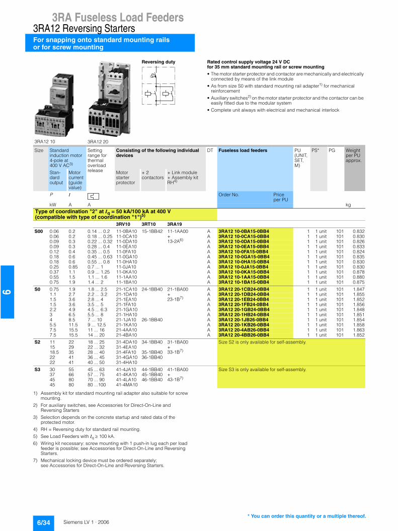
3RA Fuseless Load Feeders3RA12 Reversing StartersFor snapping onto standard mounting railsor for screw mounting
6/34 Siemens LV 1 · 2006
6
1) Assembly kit for standard mounting rail adapter also suitable for screw mounting.
2) For auxiliary switches, see Accessories for Direct-On-Line and Reversing Starters
3) Selection depends on the concrete startup and rated data of the protected motor.
4) RH = Reversing duty for standard rail mounting.
5) See Load Feeders with Iq�� 100 kA.
6) Wiring kit necessary: screw mounting with 1 push-in lug each per load feeder is possible; see Accessories for Direct-On-Line and Reversing Starters.
7) Mechanical locking device must be ordered separately; see Accessories for Direct-On-Line and Reversing Starters.
3RA12 10 3RA12 20
Reversing duty Rated control supply voltage 24 V DC for 35 mm standard mounting rail or screw mounting
• The motor starter protector and contactor are mechanically and electrically connected by means of the link module
• As from size S0 with standard mounting rail adapter1) for mechanical reinforcement
• Auxiliary switches2) on the motor starter protector and the contactor can be easily fitted due to the modular system
• Complete unit always with electrical and mechanical interlock
Size Standard induction motor 4-pole at 400 V AC3)
Setting range for thermal overload release
Consisting of the following individual devices
DT Fuseless load feeders PU (UNIT, SET, M)
PS* PG Weight per PU approx.
Stan-dard output
Motor current (guide value)
Motor starter protector
+ 2contactors
+ Link module + Assembly kit RH4)
P I Order No. Price per PU
kW A A kgType of coordination "2" at Iq = 50 kA/100 kA at 400 V (compatible with type of coordination "1")5)
3RV10 3RT10 3RA19
S00 0.06 0.2 0.14 ... 0.2 11-0BA10 15-1BB42 11-1AA00 + 13-2A6)
A 3RA12 10-0BA15-0BB4 1 1 unit 101 0.8320.06 0.2 0.18 ... 0.25 11-0CA10 A 3RA12 10-0CA15-0BB4 1 1 unit 101 0.8300.09 0.3 0.22 ... 0.32 11-0DA10 A 3RA12 10-0DA15-0BB4 1 1 unit 101 0.8260.09 0.3 0.28 ... 0.4 11-0EA10 A 3RA12 10-0EA15-0BB4 1 1 unit 101 0.8330.12 0.4 0.35 ... 0.5 11-0FA10 A 3RA12 10-0FA15-0BB4 1 1 unit 101 0.8240.18 0.6 0.45 ... 0.63 11-0GA10 A 3RA12 10-0GA15-0BB4 1 1 unit 101 0.8350.18 0.6 0.55 ... 0.8 11-0HA10 A 3RA12 10-0HA15-0BB4 1 1 unit 101 0.8300.25 0.85 0.7 ... 1 11-0JA10 A 3RA12 10-0JA15-0BB4 1 1 unit 101 0.8300.37 1.1 0.9 ... 1.25 11-0KA10 A 3RA12 10-0KA15-0BB4 1 1 unit 101 0.8780.55 1.5 1.1 ... 1.6 11-1AA10 A 3RA12 10-1AA15-0BB4 1 1 unit 101 0.8800.75 1.9 1.4 ... 2 11-1BA10 A 3RA12 10-1BA15-0BB4 1 1 unit 101 0.875
S0 0.75 1.9 1.8 ... 2.5 21-1CA10 24-1BB40 21-1BA00 +23-1B7)
A 3RA12 20-1CB24-0BB4 1 1 unit 101 1.8471.1 2.7 2.2 ... 3.2 21-1DA10 A 3RA12 20-1DB24-0BB4 1 1 unit 101 1.8551.5 3.6 2.8 ... 4 21-1EA10 A 3RA12 20-1EB24-0BB4 1 1 unit 101 1.8521.5 3.6 3.5 ... 5 21-1FA10 A 3RA12 20-1FB24-0BB4 1 1 unit 101 1.8562.2 4.9 4.5 ... 6.3 21-1GA10 A 3RA12 20-1GB24-0BB4 1 1 unit 101 1.8483 6.5 5.5 ... 8 21-1HA10 A 3RA12 20-1HB24-0BB4 1 1 unit 101 1.8514 8.5 7 ... 10 21-1JA10 26-1BB40 A 3RA12 20-1JB26-0BB4 1 1 unit 101 1.8545.5 11.5 9 ... 12.5 21-1KA10 A 3RA12 20-1KB26-0BB4 1 1 unit 101 1.8587.5 15.5 11 ... 16 21-4AA10 A 3RA12 20-4AB26-0BB4 1 1 unit 101 1.8637.5 15.5 14 ... 20 21-4BA10 A 3RA12 20-4BB26-0BB4 1 1 unit 101 1.852
S2 11 22 18 ... 25 31-4DA10 34-1BB40 31-1BA00 +33-1B7)
Size S2 is only available for self-assembly.15 29 22 ... 32 31-4EA1018.5 35 28 ... 40 31-4FA10 35-1BB4022 41 36 ... 45 31-4GA10 36-1BB4022 41 40 ... 50 31-4HA10
S3 30 55 45 ... 63 41-4JA10 44-1BB40 41-1BA00 +43-1B7)
Size S3 is only available for self-assembly.37 66 57 ... 75 41-4KA10 45-1BB4045 80 70 ... 90 41-4LA10 46-1BB4045 80 80 ...100 41-4MA10
* You can order this quantity or a multiple thereof.

3RA Fuseless Load Feeders3RA12 Reversing Starters
For snapping onto standard mounting railsor for screw mounting
6/35Siemens LV 1 · 2006
66
1) Selection depends on the concrete startup and rated data of the protected motor.
2) Assembly kit for standard mounting rail adapter also suitable for screw mounting.
3) RH = Reversing duty for standard rail mounting.
4) See Load Feeders with Iq�� 100 kA.
5) Wiring kit necessary: screw mounting with 1 push-in lug each per load feeder is possible; see Accessories for Direct-On-Line and Reversing Starters.
6) Mechanical locking device must be ordered separately; see Accessories for Direct-On-Line and Reversing Starters.
Size Standard induction motor 4-pole at 400 V AC1)
Setting range for thermal overload release
Consisting of the following individual devices
DT Fuseless load feeders PU (UNIT, SET, M)
PS* PG Weight per PU approx.
Stan-dard output
Motor current (guide value)
Motor starter protector
+ 2contactors
+ Link module + Assembly kit RH2)3)
P I Order No. Price per PU
kW A A kgType of coordination "1" at Iq = 50 kA at 400 V4)
(the motor starter protector is compatible with type of coordination "2")S00 0.75 1.9 1.4 ... 2 For load feeders for lower outputs, see table above.
3RV10 3RT10 3RA19
S00 0.75 1.9 1.8 ... 2.5 11-1CA10 15-1BB42 11-1AA00 + 13-2A5)
A 3RA12 10-1CA15-0BB4 1 1 unit 101 0.8831.1 2.7 2.2 ... 3.2 11-1DA10 A 3RA12 10-1DA15-0BB4 1 1 unit 101 0.8821.5 3.6 2.8 ... 4 11-1EA10 A 3RA12 10-1EA15-0BB4 1 1 unit 101 0.8791.5 3.6 3.5 ... 5 11-1FA10 A 3RA12 10-1FA15-0BB4 1 1 unit 101 0.8812.2 4.9 4.5 ... 6.3 11-1GA10 A 3RA12 10-1GA15-0BB4 1 1 unit 101 0.8883 6.5 5.5 ... 8 11-1HA10 A 3RA12 10-1HA15-0BB4 1 1 unit 101 0.8904 8.5 7 ... 10 11-1JA10 16-1BB42 A 3RA12 10-1JA16-0BB4 1 1 unit 101 0.8825.5 11.5 9 ... 12 11-1KA10 17-1BB42 A 3RA12 10-1KA17-0BB4 1 1 unit 101 0.872
S0 7.5 15.5 11 ... 16 21-4AA10 25-1BB40 21-1BA00 +23-1B6)
A 3RA12 20-4AB25-0BB4 1 1 unit 101 1.8577.5 15.5 14 ... 20 21-4BA10 A 3RA12 20-4BB25-0BB4 1 1 unit 101 1.85311 22 17 ... 22 21-4CA10 26-1BB40 A 3RA12 20-4CB26-0BB4 1 1 unit 101 1.85811 22 20 ... 25 21-4DA10 A 3RA12 20-4DB26-0BB4 1 1 unit 101 1.860
S2 15 29 22 ... 32 For load feeders for higher outputs, see table above.18.5 35 28 ... 4022 41 36 ... 45
...
* You can order this quantity or a multiple thereof.

3RA Fuseless Load Feeders3RA12 Reversing Starters
For busbar systems
6/36 Siemens LV 1 · 2006
6
■ Selection and ordering data
1) Size S00 also suitable for 60 Hz.
2) For auxiliary switches, see Accessories for Direct-On-Line and Reversing Starters
3) Selection depends on the concrete startup and rated data of the protected motor.
4) RS = Reversing duty for busbar systems.
5) Mechanical locking device must be ordered separately; see Accessories for Direct-On-Line and Reversing Starters.
3RA12 10 3RA12 20
Reversing duty Rated control supply voltage 50 Hz 230 V AC1)
for 40 and 60 mm busbar systems
• The motor starter protector and contactor are mechanically and electrically connected by means of the link module
• Auxiliary switches2) on the motor starter protector and the contactor can be easily fitted due to the modular system
• Complete unit always with electrical and mechanical interlock
Size Standard induction motor 4-pole at 400 V AC3)
Setting range for thermal overload release
Consisting of the following individual devices
DT Fuseless load feeders PU (UNIT, SET, M)
PS* PG Weight per PU approx.
Stan-dard output
Motor current (guide value)
Motor starter protector
+ 2contactors
+ Link module + Assembly kit RS4)
P I Order No. Price per PU
kW A A kgType of coordination "2" at Iq = 50 kA at 400 V(compatible with type of coordination "1")
3RV10 3RT10 3RA19
S00 0.06 0.2 0.14 ... 0.2 11-0BA10 15-1AP02 11-1AA00 +40 mm13-1Cor 60 mm13-1D
A 3RA12 10-0B@15-0AP0 1 1 unit 101 1.0800.06 0.2 0.18 ... 0.25 11-0CA10 A 3RA12 10-0C@15-0AP0 1 1 unit 101 1.0800.09 0.3 0.22 ... 0.32 11-0DA10 A 3RA12 10-0D@15-0AP0 1 1 unit 101 1.1000.09 0.3 0.28 ... 0.4 11-0EA10 A 3RA12 10-0E@15-0AP0 1 1 unit 101 1.1230.12 0.4 0.35 ... 0.5 11-0FA10 A 3RA12 10-0F@15-0AP0 1 1 unit 101 1.0500.18 0.6 0.45 ... 0.63 11-0GA10 A 3RA12 10-0G@15-0AP0 1 1 unit 101 1.0700.18 0.6 0.55 ... 0.8 11-0HA10 A 3RA12 10-0H@15-0AP0 1 1 unit 101 1.0750.25 0.85 0.7 ... 1 11-0JA10 A 3RA12 10-0J@15-0AP0 1 1 unit 101 1.0580.37 1.1 0.9 ... 1.25 11-0KA10 A 3RA12 10-0K@15-0AP0 1 1 unit 101 1.1030.55 1.5 1.1 ... 1.6 11-1AA10 A 3RA12 10-1A@15-0AP0 1 1 unit 101 1.1040.75 1.9 1.4 ... 2 11-1BA10 A 3RA12 10-1B@15-0AP0 1 1 unit 101 1.111
S0 0.75 1.9 1.8 ... 2.5 21-1CA10 24-1AP00 21-1AA00 +40 mm23-1C5)
or 60 mm23-1D5)
A 3RA12 20-1C@24-0AP0 1 1 unit 101 1.5121.1 2.7 2.2 ... 3.2 21-1DA10 A 3RA12 20-1D@24-0AP0 1 1 unit 101 1.5481.5 3.6 2.8 ... 4 21-1EA10 A 3RA12 20-1E@24-0AP0 1 1 unit 101 1.5321.5 3.6 3.5 ... 5 21-1FA10 A 3RA12 20-1F@24-0AP0 1 1 unit 101 1.5502.2 4.9 4.5 ... 6.3 21-1GA10 A 3RA12 20-1G@24-0AP0 1 1 unit 101 1.5583 6.5 5.5 ... 8 21-1HA10 A 3RA12 20-1H@24-0AP0 1 1 unit 101 1.5454 8.5 7 ... 10 21-1JA10 26-1AP00 A 3RA12 20-1J@26-0AP0 1 1 unit 101 1.5575.5 11.5 9 ... 12.5 21-1KA10 A 3RA12 20-1K@26-0AP0 1 1 unit 101 1.5757.5 15.5 11 ... 16 21-4AA10 A 3RA12 20-4A@26-0AP0 1 1 unit 101 1.5497.5 15.5 14 ... 20 21-4BA10 A 3RA12 20-4B@26-0AP0 1 1 unit 101 1.544
S2 11 22 18 ... 25 31-4DA10 34-1AP00 31-1AA00 +40 mm33-1C5)
or 60 mm33-1D5)
Size S2 is only available for self-assembly.15 29 22 ... 32 31-4EA1018.5 35 28 ... 40 31-4FA10 35-1AP0022 41 36 ... 45 31-4GA10 36-1AP0022 41 40 ... 50 31-4HA10
S3 30 55 45 ... 63 41-4JA10 44-1AP00 41-1AA00 +not available
For size S3, a busbar adapter is not necessary.37 66 57 ... 75 41-4KA10 45-1AP0045 80 70 ... 90 41-4LA10 46-1AP0045 80 80 ... 100 41-4MA10
Order No. supplement for busbar center-line spacing
40 mm C60 mm D
* You can order this quantity or a multiple thereof.

3RA Fuseless Load Feeders3RA12 Reversing Starters
For busbar systems
6/37Siemens LV 1 · 2006
66
1) Selection depends on the concrete startup and rated data of the protected motor.
2) RS = Reversing duty for busbar systems.
3) Mechanical locking device must be ordered separately; see Accessories for Direct-On-Line and Reversing Starters.
Size Standard induction motor 4-pole at 400 V AC1)
Setting range for thermal overload release
Consisting of the following individual devices
DT Fuseless load feeders PU (UNIT, SET, M)
PS* PG Weight per PU approx.
Stan-dard output
Motor current (guide value)
Motor starter protector
+ 2contactors
+ Link module + Assembly kit RS2)
P I Order No. Priceper PU
kW A A kgType of coordination "1" at Iq = 50 kA at 400 V(the motor starter protector is compatible with type of coordination "2")S00 0.75 1.9 1.4 ... 2 For load feeders for lower outputs, see table above.
3RV10 3RT10 3RA19
S00 0.75 1.9 1.8 ... 2.5 11-1CA10 15-1AP02 11-1AA00 +40 mm13-1Cor 60 mm13-1D
A 3RA12 10-1C@15-0AP0 1 1 unit 101 1.1151.1 2.7 2.2 ... 3.2 11-1DA10 A 3RA12 10-1D@15-0AP0 1 1 unit 101 1.1051.5 3.6 2.8 ... 4 11-1EA10 A 3RA12 10-1E@15-0AP0 1 1 unit 101 1.1161.5 3.6 3.5 ... 5 11-1FA10 A 3RA12 10-1F@15-0AP0 1 1 unit 101 1.1182.2 4.9 4.5 ... 6.3 11-1GA10 A 3RA12 10-1G@15-0AP0 1 1 unit 101 1.1293 6.5 5.5 ... 8 11-1HA10 A 3RA12 10-1H@15-0AP0 1 1 unit 101 1.1224 8.5 7 ... 10 11-1JA10 16-1AP02 A 3RA12 10-1J@16-0AP0 1 1 unit 101 1.1085.5 11.5 9 ... 12 11-1KA10 17-1AP02 A 3RA12 10-1K@17-0AP0 1 1 unit 101 1.100
S0 7.5 15.5 11 ... 16 21-4AA10 25-1AP00 21-1AA00 +40 mm23-1C3)
or 60 mm23-1D3)
A 3RA12 20-4A@25-0AP0 1 1 unit 101 1.6007.5 15.5 14 ... 20 21-4BA10 A 3RA12 20-4B@25-0AP0 1 1 unit 101 1.60011 22 17 ... 22 21-4CA10 26-1AP00 A 3RA12 20-4C@26-0AP0 1 1 unit 101 1.57011 22 20 ... 25 21-4DA10 A 3RA12 20-4D@26-0AP0 1 1 unit 101 1.557
S2 15 29 22 ... 32 For load feeders for higher outputs, see table above.18.5 35 28 ... 4022 41 36 ... 45
...
Order No. supplement for busbar center-line spacing
40 mm C60 mm D
* You can order this quantity or a multiple thereof.

3RA Fuseless Load Feeders3RA12 Reversing Starters
For busbar systems
6/38 Siemens LV 1 · 2006
6
1) For auxiliary switches, see Accessories for Direct-On-Line and Reversing Starters
2) Selection depends on the concrete startup and rated data of the protected motor.
3) RS = Reversing duty for busbar systems.
4) Mechanical locking device must be ordered separately; see Accessories for Direct-On-Line and Reversing Starters.
3RA12 10 3RA12 20
Reversing duty Rated control supply voltage 24 V DC for 40 and 60 mm busbar systems
• The motor starter protector and contactor are mechanically and electrically connected by means of the link module
• Auxiliary switches1) on the motor starter protector and the contactor can be easily fitted due to the modular system
• Complete unit always with electrical and mechanical interlock
Size Standard induction motor 4-pole at 400 V AC2)
Setting range for thermal overload release
Consisting of the following individual devices
DT Fuseless load feeders PU (UNIT, SET, M)
PS* PG Weight per PU approx.
Stan-dard output
Motor current (guide value)
Motor starter protector
+ 2contactors
+ Link module + Assembly kit RS3)
P I Order No. Price per PU
kW A A kgType of coordination "2" at Iq = 50 kA at 400 V(compatible with type of coordination "1")
3RV10 3RT10 3RA19
S00 0.06 0.2 0.14 ... 0.2 11-0BA10 15-1BB42 11-1AA00 +40 mm13-1Cor 60 mm13-1D
A 3RA12 10-0B@15-0BB4 1 1 unit 101 1.1950.06 0.2 0.18 ... 0.25 11-0CA10 A 3RA12 10-0C@15-0BB4 1 1 unit 101 1.2340.09 0.3 0.22 ... 0.32 11-0DA10 A 3RA12 10-0D@15-0BB4 1 1 unit 101 1.2230.09 0.3 0.28 ... 0.4 11-0EA10 A 3RA12 10-0E@15-0BB4 1 1 unit 101 1.1850.12 0.4 0.35 ... 0.5 11-0FA10 A 3RA12 10-0F@15-0BB4 1 1 unit 101 1.1900.18 0.6 0.45 ... 0.63 11-0GA10 A 3RA12 10-0G@15-0BB4 1 1 unit 101 1.1950.18 0.6 0.55 ... 0.8 11-0HA10 A 3RA12 10-0H@15-0BB4 1 1 unit 101 1.1900.25 0.85 0.7 ... 1 11-0JA10 A 3RA12 10-0J@15-0BB4 1 1 unit 101 1.1970.37 1.1 0.9 ... 1.25 11-0KA10 A 3RA12 10-0K@15-0BB4 1 1 unit 101 1.1600.55 1.5 1.1 ... 1.6 11-1AA10 A 3RA12 10-1A@15-0BB4 1 1 unit 101 1.2460.75 1.9 1.4 ... 2 11-1BA10 A 3RA12 10-1B@15-0BB4 1 1 unit 101 1.233
S0 0.75 1.9 1.8 ... 2.5 21-1CA10 24-1BB40 21-1BA00 +40 mm23-1C4)
or 60 mm23-1D4)
A 3RA12 20-1C@24-0BB4 1 1 unit 101 1.9851.1 2.7 2.2 ... 3.2 21-1DA10 A 3RA12 20-1D@24-0BB4 1 1 unit 101 2.0171.5 3.6 2.8 ... 4 21-1EA10 A 3RA12 20-1E@24-0BB4 1 1 unit 101 1.9981.5 3.6 3.5 ... 5 21-1FA10 A 3RA12 20-1F@24-0BB4 1 1 unit 101 2.0132.2 4.9 4.5 ... 6.3 21-1GA10 A 3RA12 20-1G@24-0BB4 1 1 unit 101 2.0183 6.5 5.5 ... 8 21-1HA10 A 3RA12 20-1H@24-0BB4 1 1 unit 101 2.0034 8.5 7 ... 10 21-1JA10 26-1BB40 A 3RA12 20-1J@26-0BB4 1 1 unit 101 2.0135.5 11.5 9 ... 12.5 21-1KA10 A 3RA12 20-1K@26-0BB4 1 1 unit 101 2.0177.5 15.5 11 ... 16 21-4AA10 A 3RA12 20-4A@26-0BB4 1 1 unit 101 2.0107.5 15.5 14 ... 20 21-4BA10 A 3RA12 20-4B@26-0BB4 1 1 unit 101 2.002
S2 11 22 18 ... 25 31-4DA10 34-1BB40 31-1BA00 +40 mm33-1C4)
or 60 mm33-1D4)
Size S2 is only available for self-assembly.15 29 22 ... 32 31-4EA1018.5 35 28 ... 40 31-4FA10 35-1BB4022 41 36 ... 45 31-4GA10 36-1BB4022 41 40 ... 50 31-4HA10
S3 30 55 45 ... 63 41-4JA10 44-1BB40 41-1BA00 +not available
For size S3, a busbar adapter is not necessary.37 66 57 ... 75 41-4KA10 45-1BB4045 80 70 ... 90 41-4LA10 46-1BB4045 80 80 ... 100 41-4MA10
Order No. supplement for busbar center-line spacing
40 mm C60 mm D
* You can order this quantity or a multiple thereof.

3RA Fuseless Load Feeders3RA12 Reversing Starters
For busbar systems
6/39Siemens LV 1 · 2006
66
1) Selection depends on the concrete startup and rated data of the protected motor.
2) RS = Reversing duty for busbar systems.
3) Mechanical locking device must be ordered separately; see Accessories for Direct-On-Line and Reversing Starters.
Size Standard induction motor 4-pole at 400 V AC1)
Setting range for thermal overload release
Consisting of the following individual devices
DT Fuseless load feeders PU (UNIT, SET, M)
PS* PG Weight per PU approx.
Stan-dard output
Motor current (guide value)
Motor starter protector
+ 2contactors
+ Link module + Assembly kit RS2)
P I Order No. Price per PU
kW A A kgType of coordination "1" at Iq = 50 kA at 400 V(the motor starter protector is compatible with type of coordination "2")S00 0.75 1.9 1.4 ... 2 For load feeders for lower outputs, see table above.
3RV10 3RT10 3RA19
S00 0.75 1.9 1.8 ... 2.5 11-1CA10 15-1BB42 11-1AA00 +40 mm13-1Cor 60 mm13-1D
A 3RA12 10-1C@15-0BB4 1 1 unit 101 1.2331.1 2.7 2.2 ... 3.2 11-1DA10 A 3RA12 10-1D@15-0BB4 1 1 unit 101 1.2401.5 3.6 2.8 ... 4 11-1EA10 A 3RA12 10-1E@15-0BB4 1 1 unit 101 1.2651.5 3.6 3.5 ... 5 11-1FA10 A 3RA12 10-1F@15-0BB4 1 1 unit 101 1.2452.2 4.9 4.5 ... 6.3 11-1GA10 A 3RA12 10-1G@15-0BB4 1 1 unit 101 1.2403 6.5 5.5 ... 8 11-1HA10 A 3RA12 10-1H@15-0BB4 1 1 unit 101 1.2334 8.5 7 ... 10 11-1JA10 16-1BB42 A 3RA12 10-1J@16-0BB4 1 1 unit 101 1.2425.5 11.5 9 ... 12 11-1KA10 17-1BB42 A 3RA12 10-1K@17-0BB4 1 1 unit 101 1.210
S0 7.5 15.5 11 ... 16 21-4AA10 25-1BB40 21-1BA00 +40 mm23-1C3)
or 60 mm23-1D3)
A 3RA12 20-4A@25-0BB4 1 1 unit 101 2.1007.5 15.5 14 ... 20 21-4BA10 A 3RA12 20-4B@25-0BB4 1 1 unit 101 2.10011 22 17 ... 22 21-4CA10 26-1BB40 A 3RA12 20-4C@26-0BB4 1 1 unit 101 2.02311 22 20 ... 25 21-4DA10 A 3RA12 20-4D@26-0BB4 1 1 unit 101 2.018
S2 15 29 22 ... 32 For load feeders for higher outputs, see table above.18.5 35 28 ... 4022 41 36 ... 45
...
Order No. supplement for busbar center-line spacing
40 mm C60 mm D
* You can order this quantity or a multiple thereof.

3RA Fuseless Load FeedersAccessories
For direct-on-line and reversing starters
6/40 Siemens LV 1 · 2006
6
■ Selection and ordering data
1) See also Protection Equipment: 3RV Motor Starter Protectors.
2) See also Controls: contactors and Contactor Assemblies.
For motor starter protector
For contactor
Version DT Order No. Price per PU
PU (UNIT, SET, M)
PS* PG Weight per PU approx.
Size Size kg
Motor starter protectors1)
3RV19 01-1E
3RV19 01-1A
Auxiliary switches
S00 ... S3 -- Transverse 1 CO contact } 3RV19 01-1D 1 1 unit 101 0.015Transverse 1 NO + 1 NC } 3RV19 01-1E 1 1 unit 101 0.018
S00 ... S3 -- Laterally mountable 1 NO + 1 NC } 3RV19 01-1A 1 1 unit 101 0.045
3RV19 02-1...
S00 ... S3 -- Undervoltage releases 50 Hz 230 V AC
} 3RV19 02-1AP0 1 1 unit 101 0.131
S00 ... S3 -- Shunt releases50 Hz 230 V AC
} 3RV19 02-1DP0 1 1 unit 101 0.130
Contactors2)
Snap-on auxiliary contact blocks
Connection from below
3RH19 11-1BA..
-- S00 1-pole 1 NO } 3RH19 11-1BA10 1 1 unit 101 0.0151 NC } 3RH19 11-1BA01 1 1 unit 101 0.016
-- S00 2-pole 1 NO + 1 NC } 3RH19 11-1MA11 1 1 unit 101 0.0522 NO } 3RH19 11-1MA20 1 1 unit 101 0.053
-- S0 ... S3 1 NO + 1 NC } 3RH19 21-1MA11 1 1 unit 101 0.0742 NO } 3RH19 21-1MA20 1 1 unit 101 0.0762 NC } 3RH19 21-1MA02 1 1 unit 101 0.073
3RH19 11-1F ...
Connection from 2 sides
-- S00 4-pole 2 NO +2 NC } 3RH19 11-1FA22 1 1 unit 101 0.052
-- S0 ... S3 1-pole 1 NO } 3RH19 21-1CA10 1 1 unit 101 0.0201 NC } 3RH19 21-1CA01 1 1 unit 101 0.019
-- S0 ... S3 4-pole 2 NO +2 NC } 3RH19 21-1FA22 1 1 unit 101 0.073
* You can order this quantity or a multiple thereof.
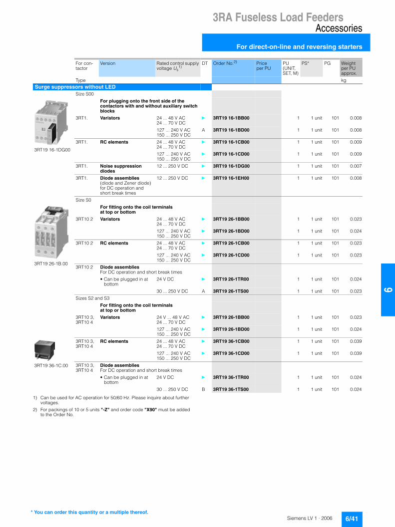
3RA Fuseless Load FeedersAccessories
For direct-on-line and reversing starters
6/41Siemens LV 1 · 2006
661) Can be used for AC operation for 50/60 Hz. Please inquire about further
voltages.
2) For packings of 10 or 5 units "-Z" and order code "X90" must be added to the Order No.
For con-tactor
Version Rated control supply voltage Us
1)DT Order No.2) Price
per PUPU (UNIT, SET, M)
PS* PG Weight per PU approx.
Type kgSurge suppressors without LED
Size S00
3RT19 16-1DG00
For plugging onto the front side of the contactors with and without auxiliary switch blocks
3RT1. Varistors 24 ... 48 V AC24 ... 70 V DC
} 3RT19 16-1BB00 1 1 unit 101 0.008
127 ... 240 V AC150 ... 250 V DC
A 3RT19 16-1BD00 1 1 unit 101 0.008
3RT1. RC elements 24 ... 48 V AC24 ... 70 V DC
} 3RT19 16-1CB00 1 1 unit 101 0.009
127 ... 240 V AC150 ... 250 V DC
} 3RT19 16-1CD00 1 1 unit 101 0.009
3RT1. Noise suppression diodes
12 ... 250 V DC } 3RT19 16-1DG00 1 1 unit 101 0.007
3RT1. Diode assemblies (diode and Zener diode)for DC operation and short break times
12 ... 250 V DC } 3RT19 16-1EH00 1 1 unit 101 0.008
Size S0
3RT19 26-1B.00
For fitting onto the coil terminals at top or bottom
3RT10 2 Varistors 24 ... 48 V AC24 ... 70 V DC
} 3RT19 26-1BB00 1 1 unit 101 0.023
127 ... 240 V AC150 ... 250 V DC
} 3RT19 26-1BD00 1 1 unit 101 0.024
3RT10 2 RC elements 24 ... 48 V AC24 ... 70 V DC
} 3RT19 26-1CB00 1 1 unit 101 0.023
127 ... 240 V AC150 ... 250 V DC
} 3RT19 26-1CD00 1 1 unit 101 0.023
3RT10 2 Diode assemblies For DC operation and short break times
• Can be plugged in at bottom
24 V DC } 3RT19 26-1TR00 1 1 unit 101 0.024
30 ... 250 V DC A 3RT19 26-1TS00 1 1 unit 101 0.023
Sizes S2 and S3
For fitting onto the coil terminals at top or bottom
3RT10 3,3RT10 4
Varistors 24 V ... 48 V AC24 ... 70 V DC
} 3RT19 26-1BB00 1 1 unit 101 0.023
127 ... 240 V AC150 ... 250 V DC
} 3RT19 26-1BD00 1 1 unit 101 0.024
3RT19 36-1C.00
3RT10 3,3RT10 4
RC elements 24 ... 48 V AC24 ... 70 V DC
} 3RT19 36-1CB00 1 1 unit 101 0.039
127 ... 240 V AC150 ... 250 V DC
} 3RT19 36-1CD00 1 1 unit 101 0.039
3RT10 3,3RT10 4
Diode assemblies For DC operation and short break times
• Can be plugged in at bottom
24 V DC } 3RT19 36-1TR00 1 1 unit 101 0.024
30 ... 250 V DC B 3RT19 36-1TS00 1 1 unit 101 0.024
* You can order this quantity or a multiple thereof.

3RA Fuseless Load FeedersAccessories
For direct-on-line and reversing starters
6/42 Siemens LV 1 · 2006
6
For motor starter protector
For contactor
Version DT Order No. Price per PU
PU (UNIT, SET, M)
PS* PG Weight per PU approx.
Size Size kgLink modules
3RA19 11-1A
Electrical and mechanical link between motor starter protector and contactor.
Single-unit packaging
Actuating voltage of contactor
S00 S00 AC and DC } 3RA19 11-1AA00 1 1 unit 101 0.027S0 S00 } 3RA19 21-1DA00 1 1 unit 101 0.028
3RA19 21-1A
S0 S0 AC } 3RA19 21-1AA00 1 1 unit 101 0.037S2 S2 } 3RA19 31-1AA00 1 1 unit 101 0.042S3 S3 } 3RA19 41-1AA00 1 1 unit 101 0.090S0 S0 DC } 3RA19 21-1BA00 1 1 unit 101 0.039S2 S2 } 3RA19 31-1BA00 1 1 unit 101 0.043S3 S3 } 3RA19 41-1BA00 1 1 unit 101 0.089
Multi-unit packaging Actuating voltage of contactor
3RA19 31-1A
S00 S00 AC and DC } 3RA19 11-1A 1 10 units 101 0.019S0 S00 } 3RA19 21-1D 1 10 units 101 0.021S0 S0 AC } 3RA19 21-1A 1 10 units 101 0.028S2 S2 } 3RA19 31-1A 1 5 units 101 0.033S3 S3 } 3RA19 41-1A 1 5 units 101 0.072S0 S0 DC } 3RA19 21-1B 1 10 units 101 0.030S2 S2 } 3RA19 31-1B 1 5 units 101 0.034S3 S3 } 3RA19 41-1B 1 5 units 101 0.073
Hybrid link modules
3RA19 21-2FA00
Screw terminals
Cage Clamp terminals
Electrical and mechanical con-nection between motor starter protector with screw terminals and contactor with Cage Clamp terminals
Single-unit packaging
Actuating voltage of contactor
S00 S00 AC and DC } 3RA19 11-2FA00 1 1 unit 101 0.038S0 S00 } 3RA19 21-2FA00 1 1 unit 101 0.028
Multi-unit packaging Actuating voltage of contactor
S00 S00 AC and DC } 3RA19 11-2F 1 10 units 101 0.031S0 S00 } 3RA19 21-2F 1 10 units 101 0.030
Wiring kits
3RA19 13-2A
Reversing duty-- S00 Electrical and mechanical link for
reversing contactors. Combinable with link module. For size S00: optionally with integrated electri-cal and mechanical locking. For sizes S0 to S3: mechanical locking device must be ordered separately.
} 3RA19 13-2A 1 1 set 101 0.041S0 } 3RA19 23-2A 1 1 set 101 0.052S2 } 3RA19 33-2A 1 1 set 101 0.122S3 } 3RA19 43-2A 1 1 set 101 0.294
Wye-delta starting -- S00 Electrical and mechanical link for
three contactors of same size} 3RA19 13-2B 1 1 set 101 0.048
S0 } 3RA19 23-2B 1 1 set 101 0.061S2 } 3RA19 33-2B 1 1 set 101 0.072S3 } 3RA19 43-2B 1 1 set 101 0.165
Mechanical interlocks
3RA19 24-2B
-- S0, S2, S3 For reversing contactors, later-ally fittable with 1 auxiliary con-tact (1 NC) each per contactor.
} 3RA19 24-2B 1 1 unit 101 0.060
Terminals for contactor coils
3RA19 23-3B
-- S0, S2, S3 For A1 and A2 of the reversing contactors (one set contains 10 x A1 and 5 x A2)
B 3RA19 23-3B 1 1 set 101 0.082
* You can order this quantity or a multiple thereof.

3RA Fuseless Load FeedersAccessories
For direct-on-line and reversing starters
6/43Siemens LV 1 · 2006
66
For motor starter protector
For contactor
Version DT Order No. Price per PU
PU (UNIT, SET, M)
PS* PG Weight per PU approx.
Size Size kg
Standard mounting rail adapters
3RA19 32 3RA19 22
Single unit packaging
S00, S0 S00, S0 For mechanical fixing of motor starter pro-tector and contactor; for snapping onto standard mounting rail or for screw mounting
} 3RA19 22-1AA00 1 1 unit 101 0.104S2 S2 } 3RA19 32-1AA00 1 1 unit 101 0.202S3 S3 } 3RA19 42-1AA00 1 1 unit 101 0.264
Multi-unit packaging
S00, S0 S00, S0 } 3RA19 22-1A 1 5 units 101 0.095S2 S2 } 3RA19 32-1A 1 5 units 101 0.187S3 S3 } 3RA19 42-1A 1 5 units 101 0.238
Lateral modules
3RA19 02
S00 ... S3 S00 ... S3 For standard mount-ing rail adapter 10 mm wide, 96 mm long, for widening stan-dard mounting rail adapters. For sizes S00 to S2: 2 units required. For size S3: 3 units required.
} 3RA19 02-1B 1 10 units 101 0.009
Assembly kits (RH) for reversing duty for standard mounting rails
3RA19 33-1B
S0 S0 Also suitable for screw mounting. Consiting of: Wiring kit, standard mounting rail adapt-ers, side modules. Link modules to be ordered separately. Mechanical locking device also to be ordered separately.
A 3RA19 23-1B 1 1 set 101 0.288S2 S2 A 3RA19 33-1B 1 1 set 101 0.557S3 S3 A 3RA19 43-1B 1 1 set 101 0.818
* You can order this quantity or a multiple thereof.

3RA Fuseless Load FeedersAccessories
For direct-on-line and reversing starters
6/44 Siemens LV 1 · 2006
6
For motor starter protector
For contactor
Version DT Order No. Price per PU
PU (UNIT, SET, M)
PS* PG Weight per PU approx.
Size Size kgAccessories, adapters and link modules for Cage Clamp connection
3RA19 11-2A + 8US10 51-5CM47
3RA19 11-2E
S00 -- Link modules, Cage Clamp Electrical connection between motor starter protector and contactor (1 pack = 10 units)
} 3RA19 11-2A 1 10 units 101 0.016
S00 -- Link modules, Cage Clamp with mechanical connection Mechanical and electrical connection between motor starter protector and contactor (1 pack = 10 units)
} 3RA19 11-2E 1 10 units 101 0.028
-- Standard mounting rail adaptersFor Cage Clamp with 2 mounting rails, one is movable, 45 mm wide
} 3RA19 22-1L 1 5 units 101 0.413
-- Busbar adapters45 mm wide, 182 mm long, adapted for Cage Clamp motor starter protectors. If there is an additional contactor, a further standard mounting rail must be fitted.
} 8US10 51-5CM47 1 1 unit 103 0.193
-- } 8US12 51-5CM47 1 1 unit 103 0.190
-- Standard mounting rails 35 mm Plastic incl. fixing screws (1 pack = 10 units)
A 8US19 98-7CA15 1 10 units 103 0.009
Push-in lugs for screw mounting
3RB19 00-0B
S00, S0 -- For 3RV1 motor starter protec-tors: 2 units each required, for 3RA1 fuseless load feeders: 1 unit each required, for AS-Interface switching device holder: 2 units each required(1 pack = 10 units)
} 3RB19 00-0B 100 10 units 101 0.100
Busbar adapters
8US12 51-5DM07
Busbar center-line spacingmm
S00, S0 S00, S0 45 mm wide, 182 mm long for busbars
40 } 8US10 51-5DM07 1 1 unit 103 0.18460 } 8US12 51-5DM07 1 1 unit 103 0.183
S2 S2 55 mm wide, 242 mm long including screw and spacer
40 } 8US10 61-5FP08 1 1 unit 103 0.30860 } 8US12 61-5FP08 1 1 unit 103 0.292
Switching device holders
8US12 50-5AM00
S00, S0 S00, S0 With standard mounting rail, without connecting cables 45 mm wide, 182 mm long for busbars
40 } 8US10 50-5AM00 1 1 unit 103 0.18260 } 8US12 50-5AM00 1 1 unit 103 0.158
S0 S0 55 mm wide, 182 mm long
40 } 8US10 60-5AM00 1 1 unit 103 0.19760 } 8US12 60-5AM00 1 4 units 103 0.202
S2 S2 55 mm wide, 242 mm long including screw and spacer
40 } 8US10 60-5AP00 1 1 unit 103 0.24460 } 8US12 60-5AP00 1 1 unit 103 0.243
* You can order this quantity or a multiple thereof.
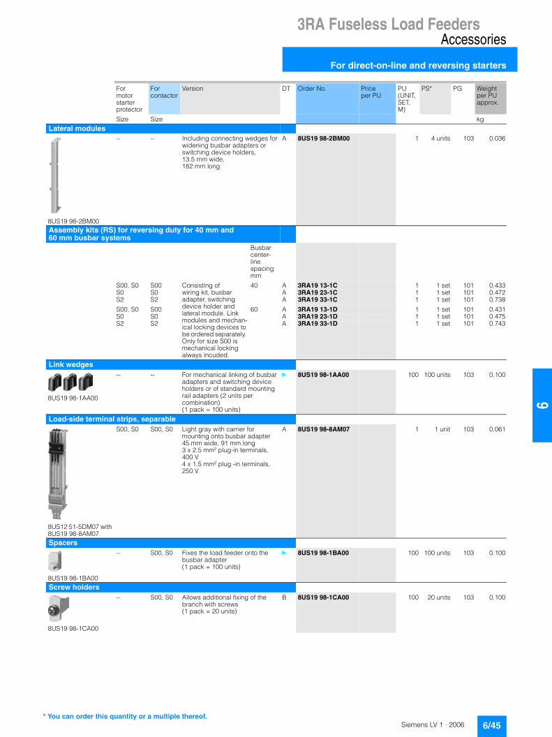
3RA Fuseless Load FeedersAccessories
For direct-on-line and reversing starters
6/45Siemens LV 1 · 2006
66
For motor starter protector
For contactor
Version DT Order No. Price per PU
PU (UNIT, SET, M)
PS* PG Weight per PU approx.
Size Size kgLateral modules
8US19 98-2BM00
-- -- Including connecting wedges for widening busbar adapters or switching device holders, 13.5 mm wide, 182 mm long
A 8US19 98-2BM00 1 4 units 103 0.036
Assembly kits (RS) for reversing duty for 40 mm and 60 mm busbar systems
Busbar center-line spacingmm
S00, S0 S00 Consisting of wiring kit, busbar adapter, switching device holder and lateral module. Link modules and mechan-ical locking devices to be ordered separately. Only for size S00 is mechanical locking always incuded.
40 A 3RA19 13-1C 1 1 set 101 0.433S0 S0 A 3RA19 23-1C 1 1 set 101 0.472S2 S2 A 3RA19 33-1C 1 1 set 101 0.738
S00, S0 S00 60 A 3RA19 13-1D 1 1 set 101 0.431S0 S0 A 3RA19 23-1D 1 1 set 101 0.475S2 S2 A 3RA19 33-1D 1 1 set 101 0.743
Link wedges
8US19 98-1AA00
-- -- For mechanical linking of busbar adapters and switching device holders or of standard mounting rail adapters (2 units per combination)(1 pack = 100 units)
} 8US19 98-1AA00 100 100 units 103 0.100
Load-side terminal strips, separable
8US12 51-5DM07 with 8US19 98-8AM07
S00, S0 S00, S0 Light gray with carrier for mounting onto busbar adapter 45 mm wide, 91 mm long 3 x 2.5 mm² plug-in terminals, 400 V 4 x 1.5 mm² plug -in terminals, 250 V
A 8US19 98-8AM07 1 1 unit 103 0.061
Spacers
8US19 98-1BA00
-- S00, S0 Fixes the load feeder onto the busbar adapter(1 pack = 100 units)
} 8US19 98-1BA00 100 100 units 103 0.100
Screw holders
8US19 98-1CA00
-- S00, S0 Allows additional fixing of the branch with screws(1 pack = 20 units)
B 8US19 98-1CA00 100 20 units 103 0.100
* You can order this quantity or a multiple thereof.

3RA Fuseless Load FeedersInfeed System
3RV19 infeed system
6/46 Siemens LV 1 · 2006
6
■ Overview
The 3RV19 infeed system is a convenient means of power sup-ply and distribution for a group of several motor starter protec-tors or complete load feeders with a screw-type or spring-loaded connection system up to size S0.
The devices with spring-loaded connections are available in the SIRIUS modular system up to 5.5 kW at 400 V AC. The motor starter protectors and load feeders with screw connections for sizes S00 and S0 can also be integrated in the system at the same time.
The system is based on a basic module complete with a lateral incoming unit (3-phase busbar with infeed). This incoming unit with spring-loaded terminals is mounted on the right or left de-pending on the design and can be supplied with a maximum conductor cross-section of 25 mm2 (with end sleeve). A basic module has two sockets onto each of which a motor starter pro-tector can be snapped.
Expansion modules are available for extending the system (3-phase busbars for system expansion). The individual mod-ules are connected through an expansion plug.
Electrical connection between the 3-phase busbars and the mo-tor starter protectors is implemented through plug-in connec-tors. The complete system can be mounted on a 35 mm stan-dard mounting rail according to EN 50022 and can be expanded as required up to a maximum current carrying capacity of 80 A.
The system is mounted extremely quickly and easily thanks to the simple plug-in technique. Thanks to the lateral infeed, the system also saves space in the control cabinet. The additional overall height required for the infeed unit is only 30 mm. The al-ternative infeed possibilities on each side offer a high degree of flexibility for configuring the control cabinet: Infeed on left-hand or right-hand side, ring infeed or infeed on one side and loop-through from the other side to supply further loads are all possi-ble. A terminal block with spring-loaded connections in combi-nation with a standard mounting rail enables the integration of not only SIRIUS motor starter protectors but also single-phase, 2-phase and 3-phase components such as 5SY miniaturecircuit-breakers or SIRIUS relay components.
����
�
��
�
��
�
�
��
�
� � ��� ���
�
�� !�"���#"��$�%&'!�&����(
�� !�"���#"��$���$�")"'�*��� ��"&��
�� ��"&��� +#,
��'$��%&(���� ��"&��� +#,
��(�-�.�$
�+#,�&��-����-'�$
/��'�-'�$���"�
0�$*&��+��+�-1

3RA Fuseless Load FeedersInfeed System
3RV19 infeed system
6/47Siemens LV 1 · 2006
66
$ 3-phase busbars with infeed
A 3-phase busbar with infeed unit is required for connecting the incoming supply. This module comprises one infeed module and 2 sockets which each accept one motor starter protector. A choice of two designs with infeed on the left or right is avail-able. The incoming supply is connected using spring-loaded terminals. The Cage Clamp springs permit conductor cross-sec-tions of up to 25 mm2 with end sleeves. An end cover is supplied with each module.
% 3-phase busbars for system expansion
The 3-phase busbars for system expansion support expansion of the system. There is a choice of modules with 2 or 3 sockets. The system can be expanded as required up to a maximum cur-rent carrying capacity of 80 A. An expansion plug is supplied with each module.
&a Expansion plug
The expansion plug is used for electrical connection of adjacent 3-phase busbars. The current carrying capacity of this plug equals 63 A. One expansion plug is supplied with each 3-phase busbar for system expansion. Additional expansion plugs are therefore only required as spare parts.
&b Extra-wide expansion plug
The extra-wide expansion plug makes the electrical connection between two 3-phase busbars, thus performing the same func-tion as the 3RV19 17-5BA00 expansion plug; the electrical char-acteristics (e.g. a current carrying capacity of 63 A) are identi-cal.
The 3RV19 17-5E expansion plug is 10 mm wider than the 3RV19 17-5BA00 expansion plug, hence in the plugged state there is a clearance of 10 mm between the connected 3-phase busbars. This clearance can be used to lay the auxiliary current and control current wiring ("wiring duct"). As the result, the motor starter protector and contactor can be wired from underneath, which means that the complete cable duct above the system can be omitted.
( End cover
The end cover is used to cover the 3-phase busbar at the open end of the system. This cover is therefore only required once for each system. An end cover is supplied with each 3-phase bus-bar system with infeed. Further end covers are therefore only re-quired as spare parts.
) Plug-in connector
The plug-in connector is used for the electrical connection be-tween the 3-phase busbar and the motor starter protector. There are three different versions:• One version for 3RV motor starter protectors size S00 with
screw connections• One version for 3RV motor starter protectors size S0 with
screw connections• One version for 3RV motor starter protectors size S00 with
spring-loaded terminals
* Contactor base
Load feeders can be assembled in the system using the contac-tor base. The contactor bases are suitable for contactors of size S00 with spring-loaded terminals and are simply snapped onto the 3-phase busbars. Direct-on-line starters and reversing starters are possible. One contactor base is required for direct-on-line starters and two are required for reversing starters. To assemble load feeders for reversing starters, the contactor bases can be arranged either below each other (45 mm overall width) or alongside each other (90 mm overall width). It is impor-tant to note that mechanical interlocking of the contactors is only possible when they are arranged vertically.
The infeed system is designed for mounting on a 35 mm stan-dard mounting rail with 7.5 mm overall depth. This standard mounting rail gives the contactor base a stable mounting sur-face to sit on. If standard mounting rails with a depth of 15 mm are used, the spacer connected to the bottom of the contactor base must be knocked out and plugged into the mating piece that is also on the underside. Then the contactor base also has a stable mounting surface. When standard mounting rails with a depth of 7.5 mm are used, the spacer has no function and can be removed.
As an alternative to using a contactor base, the 3RA19 11-2E electrical link modules can also be used for load feeders for di-rect-on-line starters of size S00. Motor starter protector and con-tactor assemblies can then be directly snapped into the sockets of the 3-phase busbars. For feeders of size S00 and S0, the cor-responding 3RA19 11-1.... or 3RA19 21-1... link modules should generally be used. For size S0, it is only possible integrate direct start load feeders and they must be integrated in the system as complete assemblies.
+ Terminal block
The 3RV19 17-5D terminal block enables the integration of not only SIRIUS motor starter protectors but also single-phase, 2-phase and 3-phase components in addition. Using the termi-nal block the 3 phases can be fed out of the system; single-phase loads can also be integrated in the system as the result. The terminal block is plugged into the slot of the expansion plug and thus enables outfeeding from the middle or end of the infeed system. The terminal block can be rotated through 180 ° and be locked to the support modules of the infeed system. The 3RV19 17-7B 45 mm standard mounting rail for screwing onto the support plate is available in addition in order to be able to plug the single-phase, 2-phase and 3-phase components onto the infeed system.

3RA Fuseless Load FeedersInfeed System
3RV19 infeed system
6/48 Siemens LV 1 · 2006
6
■ Selection and ordering data
1) Compatible with the following motor starter protectors: 3RV10 11-...2. (size S00, Cage Clamp) product version E03 and upwards.
Type Version For motor starter protector
DT Order No. Price per PU
PU (UNIT, SET, M)
PS* PG Weight per PU approx.
Size kg3-phase busbars with infeed
3RV19 17-1A
3-phase busbars with infeed incl. 3RV19 17-6A end cover
For 2 motor starter protcors with infeed from the left
S00 (Cage Clamp)1),S00, S0 (screw)
A 3RV19 17-1A 1 1 unit 101 0.438
For 2 motor starter protcors with infeed from the right
S00 (Cage Clamp)1),S00, S0 (screw)
A 3RV19 17-1E 1 1 unit 101 0.438
3-phase busbars for system expansion
3RV19 17-4B
3-phase busbarsincl. 3RV19 17-5BA00 expansion plug
For 2 motor starter protcors
S00 (Cage Clamp)1),S00, S0 (screw)
A 3RV19 17-4A 1 1 unit 101 0.261
For 3 motor starter protcors
S00 (Cage Clamp)1),S00, S0 (screw)
A 3RV19 17-4B 1 1 unit 101 0.364
Plug-in connectors
3RV19 17-5AA00
Plug-in connectorsto make contact with the motor starter protectors
Single-unit packaging
S00 (Cage Clamp)1)
A 3RV19 17-5AA00 1 1 unit 101 0.053
Multi-unit packaging
S00 (Cage Clamp)1)
A 3RV19 17-5A 1 10 units 101 0.048
3RV19 27-5AA00
Single-unit packaging
S00 (screw)
D 3RV19 17-5CA00 1 1 unit 101 0.040
Multi-unit packaging
S00 (screw)
D 3RV19 17-5C 1 10 units 101 0.036
Single-unit packaging
S0 (screw) A 3RV19 27-5AA00 1 1 unit 101 0.040
Multi-unit packaging
S0 (screw) A 3RV19 27-5A 1 10 units 101 0.036
Type Version For contactor
DT Order No. Price per PU
PU (UNIT, SET, M)
PS* PG Weight per PU approx.
Size kgContactor bases
3RV19 17-7A
Contactor basesfor mounting direct-on-line or reversing starters
Single-unit packaging
S00 A 3RV19 17-7AA00 1 1 unit 101 0.042
Multi-unit packaging
S00 A 3RV19 17-7A 1 10 units 101 0.048
* You can order this quantity or a multiple thereof.

3RA Fuseless Load FeedersInfeed System
3RV19 infeed system
6/49Siemens LV 1 · 2006
66
1) The expansion plug is included in the scope of supply of the 3RV19 17-4. 3-phase busbars for system expansion.
2) The end cover is included in the scope of supply of the 3RV19 17-1.3-phase busbars with infeed system.
Type Version DT Order No. Price per PU
PU (UNIT, SET, M)
PS* PG Weight per PU approx.
kg
Terminal blocksTerminal blocks For integration of single-phase, 2-phase and 3-phase components
Single unit packaging A 3RV19 17-5D 1 1 unit 101 0.050
45 mm standard mounting rails45 mm standard mounting rails For mounting onto 3-phase busbar
Single unit packaging A 3RV19 17-7B 1 1 unit 101 0.261
Extra-wide expansion plugsExtra-wide expansion plugsAs accessory
Single unit packaging D 3RV19 17-5E 1 1 unit 101 0.050
Expansion plugsExpansion plugs1)
As spare partSingle unit packaging A 3RV19 17-5BA00 1 1 unit 101 0.035
End coversEnd covers2)
as spare partMulti-unit packaging A 3RV19 17-6A 100 10 units 101 0.500
ToolsFor opening the springs of the 3RV19 17-1. infeed terminal
Length: approx. 175 mm,Blade dimensions: 5.5 x 0.8 mm
A 8WA2 806 7.01 1 1 unit 041 0.063
* You can order this quantity or a multiple thereof.

3RA71 Load Feeders with Safety Integrated
General data
6/50 Siemens LV 1 · 2006
6
■ Application
The 3RA71 safety load feeders are offered for direct start. They are available with operating voltages of 230 V 50/60 Hz (cate-gory 3) and 24 V DC (categories 3 and 4). Depending on the ex-ternal circuit, choice of actuator and its position on the machine, categories 3 or 4 according to EN 954-1 or SIL 2 or 3 (Safety Integrity Level) according to IEC 61508 can be achieved.
Similarly the product range of safety load feeders contains expansion units with and without time delays. These expansion units can only be used in combination with a basic unit. Load feeders can be configured in Stop category 1 thanks to expan-sion units with time delays from 0.05 to 3 s, or 0.5 to 30 s.
Types of coordination
EN 60947-4-1 (VDE 0660 Part 102) and IEC 60947-4-1 make a distinction between two different types of coordination, which are designated type of coordination "1" and type of coordination "2". Any short-circuits that occur are cleared safely by both types of coordination. The only differences concern the extent of the damage caused to the equipment by a short-circuit.• Type of coordination 2
There must be no damage to the overload trip or to any other component after a short-circuit has been cleared. The 3RA71 fuseless load feeder can resume operation without needing to be renewed. At most, it is permissible to weld the contactor contacts if they can be disconnected easily without any signifi-cant deformation. Classification of a machine in categories according to EN 954-1.

3RA71 Load Feeders with Safety Integrated
Fuseless load feeders
6/51Siemens LV 1 · 2006
66
■ Selection and ordering data
1) Selection depends on the correct startup and rated data of the protected motor.
Rated control supply voltage 50/60 Hz 230 V AC for mounting onto 35 mm standard mounting rail • Motor starter protectors, contactors and safety electronics pre-wired and
certified up to category 3 according to EN 954-1.• Auxiliary switches on the motor starter protector and the contactor can be
easily fitted thanks to the SIRIUS modular system.
3RA71 02
Direct start
Size Standard induction motor1)
4-pole at 400 V ACSetting range for thermal overload release
DT Basic units, category 3 PU (UNIT, SET, M)
PS* PG Weight per PU approx.Rated power P Motor current I
Order No. Price per PU
kW A A kgType of coordination 2 at Iq = 50 kA at 400 V(compatible with type of coordination 1)S00 0.04 0.16 0.11 … 0.16 B 3RA71 01-0AA17-0AL2 1 1 unit 102 0.820
0.06 0.2 0.14 … 0.2 B 3RA71 01-0BA17-0AL2 1 1 unit 102 1.4400.06 0.2 0.18 … 0.25 B 3RA71 01-0CA17-0AL2 1 1 unit 102 0.8200.09 0.3 0.22 … 0.32 B 3RA71 01-0DA17-0AL2 1 1 unit 102 1.438
0.09 0.3 0.28 … 0.4 B 3RA71 01-0EA17-0AL2 1 1 unit 102 0.8200.12 0.4 0.35 … 0.5 B 3RA71 01-0FA17-0AL2 1 1 unit 102 0.8200.18 0.6 0.45 … 0.63 B 3RA71 01-0GA17-0AL2 1 1 unit 102 0.8200.25 0.8 0.55 … 0.8 B 3RA71 01-0HA17-0AL2 1 1 unit 102 0.820
0.25 0.8 0.7 … 1 B 3RA71 01-0JA17-0AL2 1 1 unit 102 0.8200.37 1.1 0.9 … 1.25 B 3RA71 01-0KA17-0AL2 1 1 unit 102 1.4800.55 1.5 1.1 … 1.6 B 3RA71 01-1AA17-0AL2 1 1 unit 102 1.4650.75 1.9 1.4 … 2 B 3RA71 01-1BA17-0AL2 1 1 unit 102 1.475
S0 0.75 1.9 1.8 … 2.5 B 3RA71 02-1CA26-0AL2 1 1 unit 102 1.8691.1 2.7 2.2 … 3.2 B 3RA71 02-1DA26-0AL2 1 1 unit 102 1.8691.5 3.6 2.8 … 4 B 3RA71 02-1EA26-0AL2 1 1 unit 102 1.8541.5 3.6 3.5 … 5 B 3RA71 02-1FA26-0AL2 1 1 unit 102 1.861
2.2 5.2 4.5 … 6.3 B 3RA71 02-1GA26-0AL2 1 1 unit 102 1.9173 6.8 5.5 … 8 B 3RA71 02-1HA26-0AL2 1 1 unit 102 1.9254 9 7 … 10 B 3RA71 02-1JA26-0AL2 1 1 unit 102 1.2005.5 11.5 9 … 12.5 B 3RA71 02-1KA26-0AL2 1 1 unit 102 1.200
7.5 15.5 11 … 16 B 3RA71 02-4AA26-0AL2 1 1 unit 102 1.2007.5 15.5 14 … 20 B 3RA71 02-4BA26-0AL2 1 1 unit 102 1.2007.5 15.5 17 … 22 B 3RA71 02-4CA26-0AL2 1 1 unit 102 1.924
* You can order this quantity or a multiple thereof.

3RA71 Load Feeders with Safety Integrated
Fuseless load feeders
6/52 Siemens LV 1 · 2006
6
1) Selection depends on the correct startup and rated data of the protected motor.
Rated control supply voltage 24 V DC for mounting onto 35 mm standard mounting rail• Motor starter protectors, contactors and safety electronics pre-wired and
certified up to category 3 according to EN 954-1.• Auxiliary switches on the motor starter protector and the contactor can be
easily fitted thanks to the SIRIUS modular system.• Expansion units for multiple load feeders in one safety circuit
3RA71 02
Direct start
Size Standard induction motor1)
4-pole at 400 V ACSetting range for thermal overload release
DT Basic units, category 3 PU (UNIT, SET, M)
PS* PG Weight per PU approx.Rated power P Motor current I
Order No. Price per PU
kW A A kgType of coordination 2 at Iq = 50 kA at 400 VS00 0.06 0.2 0.11 … 0.16 B 3RA71 01-0AA17-0AB4 1 1 unit 102 1.507
0.06 0.2 0.14 … 0.2 B 3RA71 01-0BA17-0AB4 1 1 unit 102 0.8200.06 0.2 0.18 … 0.25 B 3RA71 01-0CA17-0AB4 1 1 unit 102 0.8200.09 0.3 0.22 … 0.32 A 3RA71 01-0DA17-0AB4 1 1 unit 102 0.100
0.09 0.3 0.28 … 0.4 A 3RA71 01-0EA17-0AB4 1 1 unit 102 0.1000.12 0.4 0.35 … 0.5 A 3RA71 01-0FA17-0AB4 1 1 unit 102 0.1000.18 0.6 0.45 … 0.63 B 3RA71 01-0GA17-0AB4 1 1 unit 102 0.8200.25 0.8 0.55 … 0.8 B 3RA71 01-0HA17-0AB4 1 1 unit 102 0.820
0.25 0.8 0.7 … 1 B 3RA71 01-0JA17-0AB4 1 1 unit 102 0.8200.37 1.1 0.9 … 1.25 B 3RA71 01-0KA17-0AB4 1 1 unit 102 0.8200.55 1.5 1.1 … 1.6 B 3RA71 01-1AA17-0AB4 1 1 unit 102 1.5510.75 1.9 1.4 … 2 B 3RA71 01-1BA17-0AB4 1 1 unit 102 2.266
S0 0.75 2.7 1.8 … 2.5 B 3RA71 02-1CA26-0AB4 1 1 unit 102 2.2551.1 2.7 2.2 … 3.2 B 3RA71 02-1DA26-0AB4 1 1 unit 102 2.2541.5 3.6 2.8 … 4 B 3RA71 02-1EA26-0AB4 1 1 unit 102 1.2001.5 3.6 3.5 … 5 A 3RA71 02-1FA26-0AB4 1 1 unit 102 0.100
2.2 5.2 4.5 … 6.3 B 3RA71 02-1GA26-0AB4 1 1 unit 102 2.2983 6.8 5.5 … 8 A 3RA71 02-1HA26-0AB4 1 1 unit 102 0.1004 9 7 … 10 A 3RA71 02-1JA26-0AB4 1 1 unit 102 0.1005.5 11.5 9 … 12.5 A 3RA71 02-1KA26-0AB4 1 1 unit 102 0.100
7.5 15.5 11 … 16 B 3RA71 02-4AA26-0AB4 1 1 unit 102 0.1007.5 15.5 14 … 20 B 3RA71 02-4BA26-0AB4 1 1 unit 102 2.2457.5 15.5 17 … 22 B 3RA71 02-4CA26-0AB4 1 1 unit 102 2.275
* You can order this quantity or a multiple thereof.

3RA71 Load Feeders with Safety Integrated
Fuseless load feeders
6/53Siemens LV 1 · 2006
66
1) Selection depends on the correct startup and rated data of the protected motor.
1) Selection depends on the correct startup and rated data of the protected motor.
Size Standard induction motor1)
4-pole at 400 V ACSetting range for thermal overload release
DT Basic units, category 4 PU (UNIT, SET, M)
PS* PG Weight per PU approx.Rated power P Motor current I
Order No. Price per PU
kW A A kgType of coordination 2 at Iq = 50 kA at 400 VS00 0.06 0.2 0.11 … 0.16 B 3RA71 11-0AA17-0AB4 1 1 unit 102 1.377
0.06 0.2 0.18 … 0.25 B 3RA71 11-0CA17-0AB4 1 1 unit 102 0.8200.09 0.3 0.22 … 0.32 B 3RA71 11-0DA17-0AB4 1 1 unit 102 0.820
0.09 0.3 0.28 … 0.4 B 3RA71 11-0EA17-0AB4 1 1 unit 102 0.8200.12 0.4 0.35 … 0.5 B 3RA71 11-0FA17-0AB4 1 1 unit 102 0.8200.18 0.6 0.45 … 0.63 B 3RA71 11-0GA17-0AB4 1 1 unit 102 0.8200.25 0.8 0.55 … 0.8 B 3RA71 11-0HA17-0AB4 1 1 unit 102 0.820
0.25 0.8 0.7 … 1 B 3RA71 11-0JA17-0AB4 1 1 unit 102 0.8200.37 1.1 0.9 … 1.25 B 3RA71 11-0KA17-0AB4 1 1 unit 102 0.8200.55 1.5 1.1 … 1.6 B 3RA71 11-1AA17-0AB4 1 1 unit 102 0.8200.75 1.9 1.4 … 2 B 3RA71 11-1BA17-0AB4 1 1 unit 102 0.820
S0 0.75 2.7 1.8 … 2.5 B 3RA71 12-1CA26-0AB4 1 1 unit 102 1.8301.1 2.7 2.2 … 3.2 B 3RA71 12-1DA26-0AB4 1 1 unit 102 1.8601.5 3.6 2.8 … 4 B 3RA71 12-1EA26-0AB4 1 1 unit 102 1.2001.5 3.6 3.5 … 5 B 3RA71 12-1FA26-0AB4 1 1 unit 102 1.200
2.2 5.2 4.5 … 6.3 B 3RA71 12-1GA26-0AB4 1 1 unit 102 1.8073 6.8 5.5 … 8 B 3RA71 12-1HA26-0AB4 1 1 unit 102 1.8154 9 7 … 10 B 3RA71 12-1JA26-0AB4 1 1 unit 102 1.8305.5 11.5 9 … 12.5 B 3RA71 12-1KA26-0AB4 1 1 unit 102 1.850
7.5 15.5 11 … 16 B 3RA71 12-4AA26-0AB4 1 1 unit 102 1.2007.5 15.5 14 … 20 B 3RA71 12-4BA26-0AB4 1 1 unit 102 1.2007.5 15.5 17 … 22 B 3RA71 12-4CA26-0AB4 1 1 unit 102 1.810
Size Standard induction motor1)
4-pole at 400 V ACSetting range for thermal overload release
DT Expansion devices, category as for basic unit
PU (UNIT, SET, M)
PS* PG Weight per PU approx.Rated power P Motor current I
Order No. Price per PU
kW A A kgType of coordination 2 at Iq = 50 kA at 400 VS00 0.06 0.2 0.11 … 0.16 B 3RA71 21-0AA17-0AB4 1 1 unit 102 1.383
0.06 0.2 0.14 … 0.2 B 3RA71 21-0BA17-0AB4 1 1 unit 102 0.8200.06 0.2 0.18 … 0.25 B 3RA71 21-0CA17-0AB4 1 1 unit 102 0.8200.09 0.3 0.22 … 0.32 B 3RA71 21-0DA17-0AB4 1 1 unit 102 0.820
0.09 0.3 0.28 … 0.4 B 3RA71 21-0EA17-0AB4 1 1 unit 102 0.8200.12 0.4 0.35 … 0.5 B 3RA71 21-0FA17-0AB4 1 1 unit 102 0.8200.18 0.6 0.45 … 0.63 B 3RA71 21-0GA17-0AB4 1 1 unit 102 0.8200.25 0.8 0.55 … 0.8 B 3RA71 21-0HA17-0AB4 1 1 unit 102 0.820
0.25 0.8 0.7 … 1 B 3RA71 21-0JA17-0AB4 1 1 unit 102 0.8200.37 1.1 0.9 … 1.25 B 3RA71 21-0KA17-0AB4 1 1 unit 102 0.8200.55 1.5 1.1 … 1.6 B 3RA71 21-1AA17-0AB4 1 1 unit 102 0.8200.75 1.9 1.4 … 2 B 3RA71 21-1BA17-0AB4 1 1 unit 102 0.820
S0 0.75 2.7 1.8 … 2.5 B 3RA71 22-1CA26-0AB4 1 1 unit 102 1.8301.1 2.7 2.2 … 3.2 B 3RA71 22-1DA26-0AB4 1 1 unit 102 1.2001.5 3.6 2.8 … 4 B 3RA71 22-1EA26-0AB4 1 1 unit 102 1.2001.5 3.6 3.5 … 5 B 3RA71 22-1FA26-0AB4 1 1 unit 102 1.200
2.2 5.2 4.5 … 6.3 B 3RA71 22-1GA26-0AB4 1 1 unit 102 1.2003 6.8 5.5 … 8 B 3RA71 22-1HA26-0AB4 1 1 unit 102 1.8364 9 7 … 10 B 3RA71 22-1JA26-0AB4 1 1 unit 102 1.2005.5 11.5 9 … 12.5 B 3RA71 22-1KA26-0AB4 1 1 unit 102 1.200
7.5 15.5 11 … 16 B 3RA71 22-4AA26-0AB4 1 1 unit 102 1.2007.5 15.5 14 … 20 B 3RA71 22-4BA26-0AB4 1 1 unit 102 1.2007.5 15.5 17 … 22 B 3RA71 22-4CA26-0AB4 1 1 unit 102 1.200
* You can order this quantity or a multiple thereof.
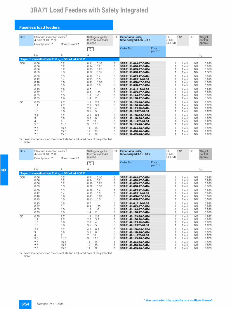
3RA71 Load Feeders with Safety Integrated
Fuseless load feeders
6/54 Siemens LV 1 · 2006
6
1) Selection depends on the correct startup and rated data of the protected motor.
1) Selection depends on the correct startup and rated data of the protected motor.
Size Standard induction motor1)
4-pole at 400 V ACSetting range for thermal overload release
DT Expansion units, time-delayed 0.05 ... 3 s
PU (UNIT, SET, M)
PS* PG Weight per PU approx.Rated power P Motor current I
Order No. Price per PU
kW A A kgType of coordination 2 at Iq = 50 kA at 400 VS00 0.06 0.2 0.11 … 0.16 B 3RA71 31-0AA17-0AB4 1 1 unit 102 0.820
0.06 0.2 0.14 … 0.2 B 3RA71 31-0BA17-0AB4 1 1 unit 102 0.8200.06 0.2 0.18 … 0.25 B 3RA71 31-0CA17-0AB4 1 1 unit 102 0.8200.09 0.3 0.22 … 0.32 B 3RA71 31-0DA17-0AB4 1 1 unit 102 1.383
0.09 0.3 0.28 … 0.4 B 3RA71 31-0EA17-0AB4 1 1 unit 102 0.8200.12 0.4 0.35 … 0.5 B 3RA71 31-0FA17-0AB4 1 1 unit 102 0.8200.18 0.6 0.45 … 0.63 B 3RA71 31-0GA17-0AB4 1 1 unit 102 0.8200.25 0.8 0.55 … 0.8 B 3RA71 31-0HA17-0AB4 1 1 unit 102 0.820
0.25 0.8 0.7 … 1 B 3RA71 31-0JA17-0AB4 1 1 unit 102 0.8200.37 1.1 0.9 … 1.25 B 3RA71 31-0KA17-0AB4 1 1 unit 102 0.8200.55 1.5 1.1 … 1.6 B 3RA71 31-1AA17-0AB4 1 1 unit 102 0.8200.75 1.9 1.4 … 2 B 3RA71 31-1BA17-0AB4 1 1 unit 102 0.820
S0 0.75 2.7 1.8 … 2.5 B 3RA71 32-1CA26-0AB4 1 1 unit 102 1.2001.1 2.7 2.2 … 3.2 B 3RA71 32-1DA26-0AB4 1 1 unit 102 1.2001.5 3.6 2.8 … 4 B 3RA71 32-1EA26-0AB4 1 1 unit 102 1.2001.5 3.6 3.5 … 5 B 3RA71 32-1FA26-0AB4 1 1 unit 102 1.200
2.2 5.2 4.5 … 6.3 B 3RA71 32-1GA26-0AB4 1 1 unit 102 1.2003 6.8 5.5 … 8 B 3RA71 32-1HA26-0AB4 1 1 unit 102 1.2004 9 7 … 10 B 3RA71 32-1JA26-0AB4 1 1 unit 102 1.2005.5 11.5 9 … 12.5 B 3RA71 32-1KA26-0AB4 1 1 unit 102 1.200
7.5 15.5 11 … 16 B 3RA71 32-4AA26-0AB4 1 1 unit 102 1.2007.5 15.5 14 … 20 B 3RA71 32-4BA26-0AB4 1 1 unit 102 1.2007.5 15.5 17 … 22 B 3RA71 32-4CA26-0AB4 1 1 unit 102 1.200
Size Standard induction motor1)
4-pole at 400 V ACSetting range for thermal overload release
DT Expansion units, time-delayed 0.5 ... 30 s
PU (UNIT, SET, M)
PS* PG Weight per PU approx.Rated power P Motor current I
Order No. Price per PU
kW A A kgType of coordination 2 at Iq = 50 kA at 400 VS00 0.06 0.2 0.11 … 0.16 B 3RA71 41-0AA17-0AB4 1 1 unit 102 0.820
0.06 0.2 0.14 … 0.2 B 3RA71 41-0BA17-0AB4 1 1 unit 102 0.8200.06 0.2 0.18 … 0.25 B 3RA71 41-0CA17-0AB4 1 1 unit 102 0.8200.09 0.3 0.22 … 0.32 B 3RA71 41-0DA17-0AB4 1 1 unit 102 0.820
0.09 0.3 0.28 … 0.4 B 3RA71 41-0EA17-0AB4 1 1 unit 102 0.8200.12 0.4 0.35 … 0.5 B 3RA71 41-0FA17-0AB4 1 1 unit 102 0.8200.18 0.6 0.45 … 0.63 B 3RA71 41-0GA17-0AB4 1 1 unit 102 0.8200.25 0.8 0.55 … 0.8 B 3RA71 41-0HA17-0AB4 1 1 unit 102 0.820
0.25 0.8 0.7 … 1 B 3RA71 41-0JA17-0AB4 1 1 unit 102 0.8200.37 1.1 0.9 … 1.25 B 3RA71 41-0KA17-0AB4 1 1 unit 102 0.8200.55 1.5 1.1 … 1.6 B 3RA71 41-1AA17-0AB4 1 1 unit 102 0.8200.75 1.9 1.4 … 2 B 3RA71 41-1BA17-0AB4 1 1 unit 102 0.820
S0 0.75 2.7 1.8 … 2.5 B 3RA71 42-1CA26-0AB4 1 1 unit 102 1.8321.1 2.7 2.2 … 3.2 B 3RA71 42-1DA26-0AB4 1 1 unit 102 1.8301.5 3.6 2.8 … 4 B 3RA71 42-1EA26-0AB4 1 1 unit 102 1.2001.5 3.6 3.5 … 5 B 3RA71 42-1FA26-0AB4 1 1 unit 102 1.200
2.2 5.2 4.5 … 6.3 B 3RA71 42-1GA26-0AB4 1 1 unit 102 1.2003 6.8 5.5 … 8 B 3RA71 42-1HA26-0AB4 1 1 unit 102 1.2004 9 7 … 10 B 3RA71 42-1JA26-0AB4 1 1 unit 102 1.2005.5 11.5 9 … 12.5 B 3RA71 42-1KA26-0AB4 1 1 unit 102 1.200
7.5 15.5 11 … 16 B 3RA71 42-4AA26-0AB4 1 1 unit 102 1.2007.5 15.5 14 … 20 B 3RA71 42-4BA26-0AB4 1 1 unit 102 1.2007.5 15.5 17 … 22 B 3RA71 42-4CA26-0AB4 1 1 unit 102 1.200
* You can order this quantity or a multiple thereof.

3RA71 Load Feeders with Safety Integrated
Fused load feeders
6/55Siemens LV 1 · 2006
66
■ Selection and ordering data
1) Selection depends on the correct startup and rated data of the protected motor.
1) Selection depends on the correct startup and rated data of the protected motor.
Rated control supply voltage 50/60 Hz 230 V AC for mounting onto 35 mm standard mounting rail • For the separate mounting of contactors with fuses.• Contactors and safety electronics pre-assembled, pre-wired and certified
up to category 3 according to EN 954-1.• Auxiliary switches on the contactor can be easily fitted thanks to the
SIRIUS modular system.
3RA71 00
Direct start
Size Category according to EN 954-1
Standard induction motor1)
4-pole at 400 V ACDT Order No. Price
per PUPU (UNIT, SET, M)
PS* PG Weight per PU approx.Rated power
PMotor current I
kW A kg
S0 3 11 22.5 B 3RA71 00-5AA26-0AL2 1 1 unit 102 1.129
Rated control supply voltage 24 V DC for mounting onto 35 mm standard mounting rail• For the separate mounting of contactors with fuses.• Contactors and safety electronics pre-assembled, pre-wired and certified
up to category 4 according to EN 954-1.• Auxiliary switches on the contactor can be easily fitted thanks to the
SIRIUS modular system.• Expansion units for multiple load feeders in one safety circuit.
3RA71 00
Direct start
Size Category according to EN 954-1
Standard induction motor1)
4-pole at 400 V ACDevice type DT Order No. Price
per PUPU (UNIT, SET, M)
PS* PG Weight per PU approx.Rated power
PMotor current I
kW A kg
S0 3 11 22.5 Basic unit B 3RA71 00-5AA26-0AB4 1 1 unit 102 1.516
4 11 22.5 Basic unit B 3RA71 10-5AA26-0AB4 1 1 unit 102 1.040
As basic unit Expansion unit
B 3RA71 20-5AA26-0AB4 1 1 unit 102 1.054
As basic unit Expansion unit, time-delayed 0.05-3 s
B 3RA71 30-5AA26-0AB4 1 1 unit 102 1.056
As basic unit Expansion unit, time-delayed 0.5 ... 30 s
B 3RA71 40-5AA26-0AB4 1 1 unit 102 0.620
* You can order this quantity or a multiple thereof.

AS-Interface Motor Starters and Soft StartersIP65/67 Motor Starters and Load Feeders
AS-Interface compact starters (400 V AC)
6/56 Siemens LV 1 · 2006
6
■ Overview
The AS-Interface compact starter is a load feeder with degree of protection IP65, which is fully prewired inside, for switching and protecting any three-phase loads up to 5.5 kW at 400/500 V AC (electromechanical compact starter) or up to 2.2 kW (solid-state compact starter) – mostly standard induction motors in direct start and reversing duty. It consists either of an electromechani-cal controlgear combination or a solid-state overload relay and motor starter protector unit. The overload or short-circuit protec-tion is located below a sealable, transparent cover and is there-fore available for diagnostics. Two LEDs are provided to the left of the cover for diagnostic purposes for the AS-Interface and the auxiliary power.
It is not possible for live parts to be touched even when the cover is open. The control elements are activated through the inte-grated outputs. The status of the device is scanned through the inputs, e.g. checkbacks from the auxiliary contacts of the motor starter protector and contactor(s). A further input is used to de-tect the operating state of the optional hand-held device. The three power connectors are used to feed and loop through to the load supply voltage (power bus) and to connect to the load itself. Prefabricated power supply lines can be used to connect com-pact starters which are directly adjacent to each other. Prefabri-cated power supply lines can be used to connect compact start-ers which are directly adjacent to each other. The maximum number of starters that can be supplied with one power supply cable is limited by the maximum permissible total current (up to max. 4 mm2 corresponds to ~ 35 A).
DS/RS compact starters (electromechanical)
The electromechanical compact starters consist of a conven-tional controlgear combination with a SIRIUS motor starter pro-tector for protection against short-circuits and overloading and SIRIUS contactor(s) for normal switching. The advantages of the electromechanical starters are the reliable isolation during dis-connection and tripping, the integrated fuseless protection against short-circuits and the favorable price. What is more, direct currents can also be switched with the electromechanical starters.
Configuring note: In the case of temperature-critical applica-tions, we recommend operation in the lower setting range of the motor starter protector.
EDS/ERS compact starters (solid-state)
The solid-state compact starters EDS (direct-on-line starter) and ERS (reversing starter) consist of a solid-state overload relay and a solid-state motor starter protector unit.
The advantages of these solid-state compact starters are the broad limits within which the overload protection can be ad-justed (the power range up to 2.2 kW at 400/500 V AC is covered with just 2 variants), the fact that the solid-state contact elements in the power section are non-wearing, current detec-tion (used for monitoring the energy connector), emergency operation in the event of an overload as well as remote resetting via the AS-Interface after overload tripping.
The ERS compact starter is designed for direct start in reversing duty. The solid-state overload protection and the shutdown response in the event of overload can be adjusted directly at the device.
Version with brake contact
All compact starters are available optionally with a separately activated brake contact for electrically operated motor brakes. For externally fed motor brakes, 24 V DC is supplied jointly with the load voltage through the power connector on -X1. It is looped through via -X3 for supplying the next compact starter on -X1. The 24 V DC supply for the brakes is only linked in those devices equipped with a brake contact. At the project planning stage, it is important to ensure that these starters are located alongside each other.
All compact starters with a brake contact for 500 V DC can be equipped with an 400 AC brake contact.
Hand-held device
The hand-held device enables the compact starter to be oper-ated locally and autonomously, providing that the auxiliary volt-age supply is connected. Thus, assuming that the automation level is functioning correctly, local switching operations can be carried out in addition to normal manual operations in the event of a programmable controller / bus system failure (emergency mode) or during test runs before commissioning, e.g. for testing the direction of rotation of the motor. The hand-held device can be connected to the compact starter by means of a connecting cable through a socket underneath the transparent cover.
Spare inputs
The compact starters are also equipped with two spare inputs.
The M12 socket is a "Y" connector. The signal inputs are applied to PIN 2 and 4. In this manner, it is possible, for example, to con-nect an optical proximity switch that supplies a signal and the "fouling" alarm.
A "T" adapter can be used to split the signal inputs onto two M12 sockets. Compact starters modified in this way offer additional advantages. At no extra cost, it is possible to save AS-i ad-dresses, reduce the space requirement and to build up logical groupings.

AS-Interface Motor Starters and Soft StartersIP65/67 Motor Starters and Load Feeders
AS-Interface compact starters (400 V AC)
6/57Siemens LV 1 · 2006
66
■ Selection and ordering data
Version DT Order No. Price per PU
PU (UNIT, SET, M)
PS* PG Weight per PU approx.
kg
EDS compact startersSolid-state direct-on-line starter with two spare digital inputs
B 3RK1 322-@@S12-0AA@ 1 1 unit 131 1.690
ERS compact startersSolid-state reversing starter with two spare digital inputs
B 3RK1 322-@@S12-1AA@ 1 1 unit 131 1.766
Order No. supplement forInduction motor 4-pole at 400 V ACStandard output P
Setting range of the overcurrent release
kW A
0.18 ... 0.8 0.6 ... 2.18 0A0.75 ... 2.2 2.0 ... 5.95 0B
DS compact startersElectromechanical direct-on-line starter, with two spare digital inputs
B 3RK1 322-@@S02-0AA@ 1 1 unit 131 1.860
RS compact startersElectromechanical reversing starter, with two spare digital inputs
B 3RK1 322-@@S02-1AA@ 1 1 unit 131 2.140
Order No. supplement forInduction motor 4-pole at 400 V ACStandard output P
Setting range of the overcurrent release
kW A
<0.06 0.14 ... 0.20 0B0.06 0.18 ... 0.25 0C0.09 0.22 ... 0.32 0D0.10 0.28 ... 0.40 0E0.12 0.35 ... 0.50 0F
0.18 0.45 ... 0.63 0G0.21 0.55 ... 0.80 0H0.25 0.70 ... 1.0 0J0.37 0.9 ... 1.25 0K0.55 1.1 ... 1.6 1A
0.75 1.4 ... 2.0 1B0.90 1.8 ... 2.5 1C1.1 2.2 ... 3.2 1D1.5 2.8 ... 4.0 1E1.9 3.5 ... 5.0 1F
2.2 4.5 ... 6.3 1G3.0 5.5 ... 8.0 1H4.0 7.0 ... 10 1J5.5 9.0 ... 12 1K
Additional price
Standard version 0Version with brake contact for 24 V DC/3 A exter-nally-fed brakes
1
Version with brake contact for 400 V AC/0.5 A infeed for brake rectifier
3
Version with brake contact for DC-side switching of the brakes with 500 V DC/0.2 A
4
Accessories for 24 V DC, M12 plugs
6ES7 194-1KA01-0XA0
M12 coupler plugsFor connecting actuators or sensors5-pole
A 3RX1 667 1 1 unit 574 0.026
M12 angular coupler plugsFor connecting actuators or sensors5-pole
A 3RX1 668 1 1 unit 574 0.027
M12 Y-shaped coupler plugsFor connecting two sensors with a single cable5-pole
A 6ES7 194-1KA01-0XA0 1 1 unit 250 0.046
M12 sealing capsFor sealing unused input and output sockets(one set contains ten sealing caps)
} 3RX9 802-0AA00 100 10 units 121 0.100
�����
����
* You can order this quantity or a multiple thereof.

AS-Interface Motor Starters and Soft StartersIP65/67 Motor Starters and Load Feeders
AS-Interface compact starters (400 V AC)
6/58 Siemens LV 1 · 2006
6
Accessories for AS-Interface compact starters (Han Q 8/0)
3RK1 902-0CA00
3RK1 902-0CC00
3RK1 902-0AH00
Plug sets for power infeed, 9-poleComprising1 plug case with Pg16 heavy-duty threaded jointFemale insert, 9-pole6 female contacts• Suitable for cable 4 � 2.5 mm2, 6 � 2.5 mm2 B 3RK1 902-0CA00 1 1 set 121 0.057• Suitable for cable 4 � 4 mm2/6 � 4 mm2 B 3RK1 902-0CB00 1 1 set 121 0.055
Plug sets for power loop-through, 9-poleComprising1 plug case with Pg16 heavy-duty threaded joint1 male insert, 9-pole6 male contacts• Suitable for cable 4 � 2.5 mm2/6 � 2.5 mm2 B 3RK1 902-0CC00 1 1 set 121 0.059• Suitable for cable 4 � 4 mm2/6 � 4 mm2 B 3RK1 902-0CD00 1 1 set 121 0.055
Plug sets for motor connections, 1.5 mm2, 9-poleComprising1 plug case with Pg16 heavy-duty threaded joint1 male insert, 9-pole8 male contacts 1.5 mm2
B 3RK1 902-0CE00 1 1 set 121 0.064
Sealing capsFor 9-pole power socket (-X3)• One set contains one unit B 3RK1 902-0CK00 1 1 unit 121 0.012• One set contains ten units B 3RK1 902-0CJ00 1 10 units 121 0.093
Power supply cables9-pole• 6 �4 mm2, 0.12 m long B 3RK1 902-0CH00 1 1 unit 121 0.206• 4 �4 mm2, 0.12 m long B 3RK1 902-0CG00 1 1 unit 121 0.165
Motor connection cables, 4 x 1.5 mm2
With power connector, 9-pole• Length: 3 m B 3RK1 902-0CM00 1 1 unit 121 0.432• Length: 5 m B 3RK1 902-0CP00 1 1 unit 121 0.620• Length: 10 m B 3RK1 902-0CQ00 1 1 unit 121 1.278
Motor connection cables, 6 x 1.5 mm2
With power connector, 9-pole• Length: 3 m B 3RK1 902-0CN00 1 1 unit 121 0.696• Length: 5 m B 3RK1 902-0CR00 1 1 unit 121 1.110• Length: 10 m B 3RK1 902-0CS00 1 1 unit 121 1.840
Crimping tools• For male and female contacts
1.5 ... 2.5 mm2B 3RK1 902-0AH00 1 1 unit 121 0.576
• For male and female contacts 1.5 ... 4 mm2
B 3RK1 902-0CT00 1 1 unit 121 0.644
Disassembly toolsFor disassembling male and female contacts in 9-pole inserts
B 3RK1 902-0AJ00 1 1 unit 121 0.047
Miscellaneous accessories
3RK1 902-0AP00
3RK1 902-0AM00
Manuals for AS-Interface compact starters• German, English A 3RK1 702-2GB10-2AA0 1 1 unit 192 0.439
Mounting plates for compact startersFor accommodating the trapezoidal-section cable for AS-Interface line and auxiliary supply
B 3RK1 902-0AP00 1 1 unit 121 0.119
Gasket sets for mounting platesFor sealing the enclosure at the end of a drop cable(1 set = 5 straight gaskets,5 shaped gaskets)
B 3RK1 902-0AR00 100 5 sets 121 0.100
Hand-held devices for start-upWith 0.5 m connection cable and plug
B 3RK1 902-0AM00 1 1 unit 121 0.217
Version DT Order No. Price per PU
PU (UNIT, SET, M)
PS* PG Weight per PU approx.
kg
* You can order this quantity or a multiple thereof.
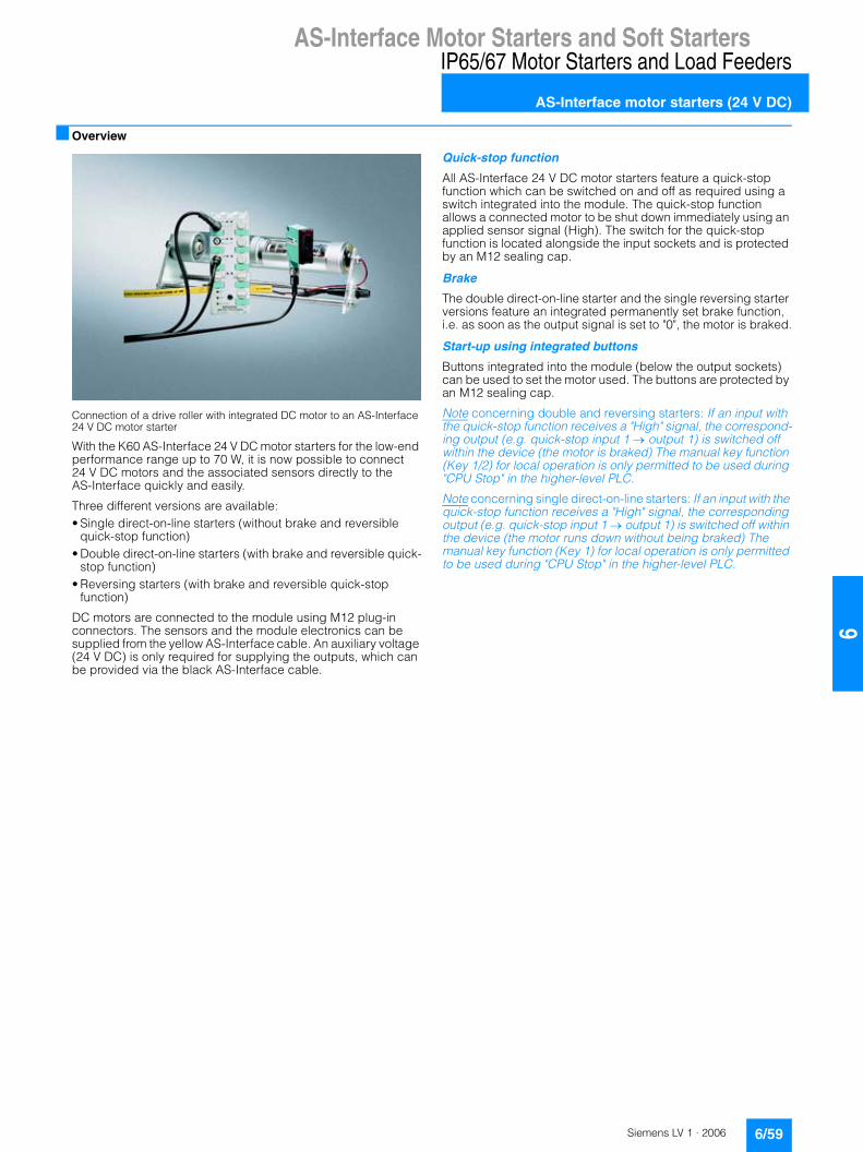
AS-Interface Motor Starters and Soft StartersIP65/67 Motor Starters and Load Feeders
AS-Interface motor starters (24 V DC)
6/59Siemens LV 1 · 2006
66
■ Overview
Connection of a drive roller with integrated DC motor to an AS-Interface 24 V DC motor starter
With the K60 AS-Interface 24 V DC motor starters for the low-end performance range up to 70 W, it is now possible to connect 24 V DC motors and the associated sensors directly to the AS-Interface quickly and easily.
Three different versions are available:• Single direct-on-line starters (without brake and reversible
quick-stop function)• Double direct-on-line starters (with brake and reversible quick-
stop function)• Reversing starters (with brake and reversible quick-stop
function)
DC motors are connected to the module using M12 plug-in connectors. The sensors and the module electronics can be supplied from the yellow AS-Interface cable. An auxiliary voltage (24 V DC) is only required for supplying the outputs, which can be provided via the black AS-Interface cable.
Quick-stop function
All AS-Interface 24 V DC motor starters feature a quick-stop function which can be switched on and off as required using a switch integrated into the module. The quick-stop function allows a connected motor to be shut down immediately using an applied sensor signal (High). The switch for the quick-stop function is located alongside the input sockets and is protected by an M12 sealing cap.
Brake
The double direct-on-line starter and the single reversing starter versions feature an integrated permanently set brake function, i.e. as soon as the output signal is set to "0", the motor is braked.
Start-up using integrated buttons
Buttons integrated into the module (below the output sockets) can be used to set the motor used. The buttons are protected by an M12 sealing cap.
Note concerning double and reversing starters: If an input with the quick-stop function receives a "High" signal, the correspond-ing output (e.g. quick-stop input 1 � output 1) is switched off within the device (the motor is braked) The manual key function (Key 1/2) for local operation is only permitted to be used during "CPU Stop" in the higher-level PLC.
Note concerning single direct-on-line starters: If an input with the quick-stop function receives a "High" signal, the corresponding output (e.g. quick-stop input 1 � output 1) is switched off within the device (the motor runs down without being braked) The manual key function (Key 1) for local operation is only permitted to be used during "CPU Stop" in the higher-level PLC.

AS-Interface Motor Starters and Soft StartersIP65/67 Motor Starters and Load Feeders
AS-Interface motor starters (24 V DC)
6/60 Siemens LV 1 · 2006
6
Applications
■ Selection and ordering data
1) Modules supplied without mounting plate.
� �
�
�
� �
�
�
� �
�
�
� �
�
�
� �
�
�
� �
�
�
� � � � � � � � � �
� � � � � � �
� � � � � � �
� � � � � � �
� � � � � � �� � � � � � �
� � ! " � � # � � $
% � # & ' ( ) � � � � * � "� � � � � �� � + � * *
� , , " ! ) )
� ! � ) � " � �
� ! � ) � " � �
� ! � ) � " � �
� ! � ) � " � �
- � � � "
� ! � ) � " � ) # . � � � ! � ) � " � ) # . � �
� ! � ) � " � ) # . � � � ! � ) � " � ) # . � �
� * *� �
� " � ' !� / # � 0 � & � � ) � # � . $
� � � � � � �
� � � � � � �
� � � � � �
� � � � � �� � � � � �
� � ! " � � # � � $
% � # & ' ( ) � � � � * � "� � � � � �� � + � * *
� , , " ! ) )
� ! � ) � " � �
� ! � ) � " � �
� � � � # � � � ) # . � �
� ! � ) � " � ) # . � �
� ! � ) � " � ) # . � �
� � � � # � � � ) # . � �
- � � � "
� " � ' !� / # � 0 � & � � ) � # � . $
� * *� �
� � � � � � �
� � � � � � �
� � � � � � � �
� � � � � � � �� � � � � �
� � ! " � � # � � $
� � � � � � � �
% � # & ' ( ) � � � � * � "� � � � � � � � � � � + � * *
% � # & ' ( ) � � � � * � "� � � � � � � � � � � + � * *
� � � � � � � �� � � � � � � � � ! " � � # � � $
� , , " ! ) )
� ! � ) � " � �
� ! � ) � " � �
� ! � ) � " � �
� ! � ) � " � �
� ! � ) � " � ) # . � �
� ! � ) � " � ) # . � �
� ! � ) � " � ) # . � �
� ! � ) � " � ) # . � �
� * *� �
� * *� �
- � � � " � �
- � � � " � �
� 0 � " � ( & # " & � # � � 1 " � ' !
� � � � � � �
� � � � � � �
� � � � � � � �
% � # & ' ( ) � � � � * � "� � � � � � � � � � � + � * *
� , , " ! ) )
� ! � ) � " � �
� ! � ) � " � �
- � � � " � �
� � � � # � � � ) # . � �
� ! � ) � " � ) # . � �
� ! � ) � " � ) # . � �
� * *� �
� * *� �
% � # & ' ( ) � � � � * � "� � � � � � � � � � � + � * *� � . � 1 " � ' !
� � � � # � � � ) # . � �
� � � � � � � �
� � � � � � � � � ! " � � # � � $� � � � � � � �
- � � � " � �
� � � � � � �
� � � � � � �
� � � � � �
% � # & ' ( ) � � � � * � "� � � � � � � � � � � + � * *
� , , " ! ) )
� ! � ) � " � �
� ! � ) � " � �
� ! � ) � " � �
� ! � ) � " � �
- � � � "2 � & ' / # ) ! � " � � � � # � �2 � � � � ! " ( & � & ' / # ) !" � � � � # � �
� ! � ) � " � ) # . � �
� ! � ) � " � ) # . � �
� ! � ) � " � ) # . � �
� ! � ) � " � ) # . � �
� * *� �
� * *� �
% � # & ' ( ) � � � � * � "� � � � � � � � � � � + � * *
� � . � 1 " � ' !
� � � � � � �
� � � � � � �
� � � � � � �
% � # & ' ( ) � � � � * � "� � � � � � � � � � � + � * *
� , , " ! ) )
� ! � ) � " � �
� ! � ) � " � �
- � � � "2 � & ' / # ) ! � " � � � � # � �2 � � � � ! " ( & � & ' / # ) !" � � � � # � �
� ! � ) � " � ) # . � �
� ! � ) � " � ) # . � �
� * *� �
� * *� �
% � # & ' ( ) � � � � * � "� � � � � � � � � � � + � * *
� � . � 1 " � ' !
� � � � # � � � ) # . � �
� � � � # � � � ) # . � �
� � � � � � � �� � � � � �
� � ! " � � # � � � * � "& � & ' / # ) !" � � � � # � � $
� � � � � � � �� � � � � � � � � ! " � � # � �* � " � & � & ' / # ) ! � " � � � � # � � $
� � � � � � � �� � � � � � � � � ! " � � # � �* � " � & � & ' / # ) ! � " � � � � # � � $
� � � � � � � �� � � � � �
� � ! " � � # � � � * � "& � & ' / # ) !" � � � � # � � $
� � � � � � � �� � � � � �
� � ! " � � # � � $
� / # � 0 � � , 3 � ) � � 1 ! � 4 � # & ' ( ) � � � � * � � & � # � � $
� ) � � � � ) ) # 1 # # � 5 6 2 � � � ! & � # � � � � � � � � � � 7 # � � � � � * � * � � ") ! � ) � " ) � / # � 0 � � � � � � � � # � � � # � , # & � � # � �
� � � � � � � � � � � � � � � � � � � � � � � � � � � �
� / # � 0 � � , 3 � ) � � 1 ! � 4 � # & ' ( ) � � � � * � � & � # � � $
� � � � � � � � � � � � � � � � � � � � � � � � �
� ) � � � � ) ) # 1 # # � 5 6 2 � � � ! & � # � � � � � � � � � � 7 # � � � � � * � * � � ") ! � ) � " ) � / # � 0 � � � � � � � � # � � � # � , # & � � # � �
� / # � 0 � � , 3 � ) � � 1 ! � 4 � # & ' ( ) � � � � * � � & � # � � $
� � � � � � � � � � � � � � � � � � � � � � � � � � � �
2 � � � ! & � # � � � � � � � � � � 7 # � � � � � * � * � � ") ! � ) � " ) � / # � 0 � � � � � � � � # � � � # � , # & � � # � �
� ) � � � � ) ) # 1 # # � 5 6
� � , � � � ) ) # 1 # # � 5 6 2 � � � ! & � # � � � � � � � � � � 7 # � � � � � * � � / �) ! � ) � " ) � / # � 0 � � � � � # � � � # � , # & � � # � �
� � , � � � ) ) # 1 # # � 5 6 2 � � � ! & � # � � � � � � � � � � 7 # � � � � � * � � / �) ! � ) � " ) � / # � 0 � � � � � # � � � # � , # & � � # � �
2 � � � ! & � # � � � � � � � � � � 7 # � � � � � * � � / �) ! � ) � " ) � / # � 0 � � � � � # � � � # � , # & � � # � �
� � , � � � ) ) # 1 # # � 5 6
Version DT Order No. Priceper PU
PU (UNIT, SET, M)
PS* PG Weight per PU approx.
kg
3RK1 400-1MQ01-0AA4
Single direct-on-line starters1)
4 inputs1 outputQuick-stop function
C 3RK1 400-1NQ01-0AA4 1 1 unit 121 0.205
Double direct-on-line starters1)
4 inputs2 outputsQuick-stop function
B 3RK1 400-1MQ01-0AA4 1 1 unit 121 0.208
Single reversing starters1)
4 inputs1 outputQuick-stop function
C 3RK1 400-1MQ03-0AA4 1 1 unit 121 0.218
* You can order this quantity or a multiple thereof.

AS-Interface Motor Starters and Soft StartersIP20 Motor Starters and Load Feeders
AS-Interface load feeder modules
6/61Siemens LV 1 · 2006
66
■ Overview
The AS-Interface load feeder module adds an input/output mod-ule to the conventional busbar and standard mounting rail adapters. With this module the control current circuit of a load feeder is available completely factory-wired. The series has been optimized for use in conjunction with the SIRIUS load feed-ers size S00 and S0. Connection to the higher level automation system is made through the AS-Interface interface of the load feeder module. A non-shielded flexible lead can be used as data line and for the auxiliary current supply. Connection to the AS-In-terface load feeder module is made using two connectors with the insulation displacement method.
Four different AS-Interface load feeder modules are available: Differences exist in the number of inputs and outputs and in the type of outputs. The units with solid-stated outputs are designed for 24 V DC, those with relay outputs are suitable for voltages of max. 230 V AC. Direct-on-line and reversing starters as well as double direct-on-line starters and starter combinations can be wired therefore for pole reversal. The inputs can be used to sep-arately scan the checkbacks from motor starter protectors and contactors. The outputs can be used for direct control of the con-tactor coils.
As the outputs already have overvoltage protection integrated, no additional measures for the contactors are required.
The outputs are supplied with separate auxiliary voltage – a selectively configured EMERGENCY-STOP concept is possi-ble therefore. The inputs are supplied from the AS-Interface data line. Inputs and outputs have to be wired using integrated, spring-loaded terminals, each connected to a common potential.
3RA5 fuseless load feeder with connection to AS-Interface
The 3RA5 fuseless load feeder, comprised of the AS-Interface load module, motor starter protector, contactor and all neces-sary connectors (AS-Interface, auxiliary power and 5-pole power connector), is delivered completely assembled, factory-wired and tested. The user can thus save valuable time when mounting, wiring and servicing. Direct-on-line starters as well as reversing starters are available with SIRIUS switching devices size S00 up to 10 A and size S0 – on account of the power connector – up to 16 A. The complete feeders are available with AS-Interface load feeder modules with solid-state outputs for 24 V DC auxiliary voltage.
Load feeders with this type of configuration are used to control standard induction motors for example. The load feeders can be installed in central control cabinets as well as in local control boxes. They are particularly suitable for highly automated machines and plants that place high demands on availability.

AS-Interface Motor Starters and Soft StartersIP20 Motor Starters and Load Feeders
AS-Interface load feeder modules
6/62 Siemens LV 1 · 2006
6
■ Selection and ordering data
1) Without plug connector for data and auxiliary power.
2) With one plug connector each for data and auxiliary power.
Version DT Order No. Priceper PU
PU (UNIT, SET, M)
PS* PG Weight per PU approx.
kg
3RK1 400-1KG01-0AA13RK1 400-1MG01-0AA1
AS-Interface load feeder modules For standard rail mountingFor contactors size S00 and S0For mounting onto 40 mm or 60 mm busbar systems and SIRIUS standard mounting rail adapt-ers the matching support is required (see Acces-sories)The AS-Interface connectors for the data and auxiliary power cable (yellow and black) must be ordered separately (see Accessories)
Type Supply in V
• 2 inputs / 1 output 24 DC1)} 3RK1 400-1KG01-0AA1 1 1 unit 121 0.097
• 4 inputs / 2 outputs A 3RK1 400-1MG01-0AA1 1 1 unit 121 0.100
• 2 inputs / 1 relay output 120/230 AC2) C 3RK1 402-3KG02-0AA1 1 1 unit 121 0.124• 3 inputs/ 2 relay outputs B 3RK1 402-3LG02-0AA1 1 1 unit 121 0.143
* You can order this quantity or a multiple thereof.
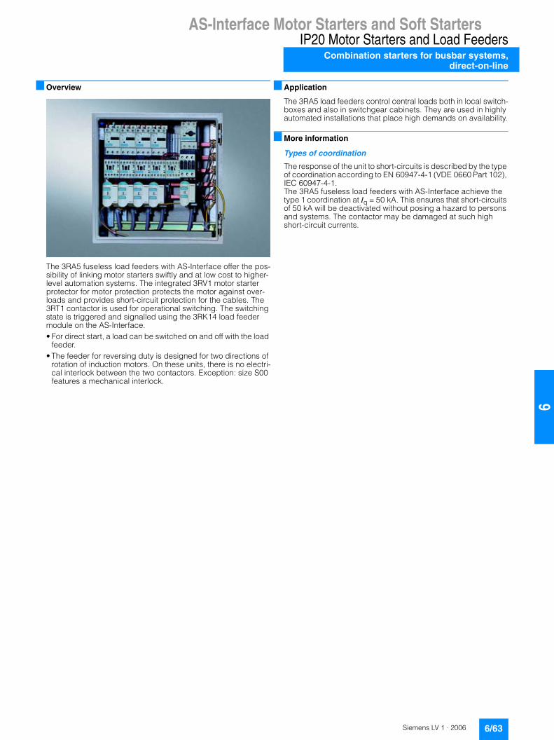
AS-Interface Motor Starters and Soft StartersIP20 Motor Starters and Load Feeders
Combination starters for busbar systems,direct-on-line
6/63Siemens LV 1 · 2006
66
■ Overview
The 3RA5 fuseless load feeders with AS-Interface offer the pos-sibility of linking motor starters swiftly and at low cost to higher-level automation systems. The integrated 3RV1 motor starter protector for motor protection protects the motor against over-loads and provides short-circuit protection for the cables. The 3RT1 contactor is used for operational switching. The switching state is triggered and signalled using the 3RK14 load feeder module on the AS-Interface.• For direct start, a load can be switched on and off with the load
feeder.• The feeder for reversing duty is designed for two directions of
rotation of induction motors. On these units, there is no electri-cal interlock between the two contactors. Exception: size S00 features a mechanical interlock.
■ Application
The 3RA5 load feeders control central loads both in local switch-boxes and also in switchgear cabinets. They are used in highly automated installations that place high demands on availability.
■ More information
Types of coordination
The response of the unit to short-circuits is described by the type of coordination according to EN 60947-4-1 (VDE 0660 Part 102), IEC 60947-4-1. The 3RA5 fuseless load feeders with AS-Interface achieve the type 1 coordination at Iq = 50 kA. This ensures that short-circuits of 50 kA will be deactivated without posing a hazard to persons and systems. The contactor may be damaged at such high short-circuit currents.

AS-Interface Motor Starters and Soft StartersIP20 Motor Starters and Load FeedersCombination starters for busbar systems,direct-on-line
6/64 Siemens LV 1 · 2006
6
■ Selection and ordering data
1) Selection depends on the concrete startup and rated data of the protected motor.
2) For Iq = 50 kA at 400 V.
For 5 or 4-pole busbar systems,can also be used for 3-pole busbar systems.24 V DC auxiliary power.Power and communication connectors included.
Direct start
Size Standard induction motor 4-pole at 400 V AC1)
Setting range for thermal over-load release
DT Fuseless load feeders PU (UNIT, SET, M)
PS* PG Weight per PU approx.
Stan-dard output
Motor current (guide value)
P I Order No. Price per PU
kW A A kg
Type of coordination 12) For 40 mm busbar systems, 5-pole
3RA51 10(with 3RK1 400-1KG01-0AA1, 2I/1O, 24 V DC)
S00 0.06 0.2 0.14 ... 0.2 C 3RA51 10-0BC15-0BB4 1 1 unit 101 1.3200.06 0.2 0.18 ... 0.25 C 3RA51 10-0CC15-0BB4 1 1 unit 101 0.8100.09 0.3 0.22 ... 0.32 C 3RA51 10-0DC15-0BB4 1 1 unit 101 1.395
0.09 0.3 0.28 ... 0.4 C 3RA51 10-0EC15-0BB4 1 1 unit 101 1.3600.12 0.4 0.35 ... 0.5 C 3RA51 10-0FC15-0BB4 1 1 unit 101 0.8100.18 0.6 0.45 ... 0.63 C 3RA51 10-0GC15-0BB4 1 1 unit 101 1.330
0.25 0.8 0.55 ... 0.8 C 3RA51 10-0HC15-0BB4 1 1 unit 101 1.4400.25 0.8 0.7 ... 1 C 3RA51 10-0JC15-0BB4 1 1 unit 101 0.8100.37 1.1 0.9 ... 1.25 C 3RA51 10-0KC15-0BB4 1 1 unit 101 1.395
0.55 1.5 1.1 ... 1.6 C 3RA51 10-1AC15-0BB4 1 1 unit 101 1.3810.75 1.9 1.4 ... 2 C 3RA51 10-1BC15-0BB4 1 1 unit 101 1.3550.75 1.9 1.8 ... 2.5 C 3RA51 10-1CC15-0BB4 1 1 unit 101 1.450
1.1 2.7 2.2 ... 3.2 C 3RA51 10-1DC15-0BB4 1 1 unit 101 1.3931.5 3.6 2.8 ... 4 C 3RA51 10-1EC15-0BB4 1 1 unit 101 1.4101.5 3.6 3.5 ... 5 C 3RA51 10-1FC15-0BB4 1 1 unit 101 1.400
2.2 5.2 4.5 ... 6.3 C 3RA51 10-1GC15-0BB4 1 1 unit 101 1.3723 6.8 5.5 ... 8 C 3RA51 10-1HC15-0BB4 1 1 unit 101 1.4434 9 7 ... 10 C 3RA51 10-1JC16-0BB4 1 1 unit 101 1.3805.5 11.5 9 ... 12 C 3RA51 10-1KC17-0BB4 1 1 unit 101 1.410
Type of coordination 12) For 60 mm busbar systems, 4-pole
3RA51 20(with 3RK1 400-1KG01-0AA1, 2I/1O, 24 V DC)
S00 0.06 0.2 0.14 ... 0.2 C 3RA51 10-0BD15-0BB4 1 1 unit 101 1.4500.06 0.2 0.18 ... 0.25 C 3RA51 10-0CD15-0BB4 1 1 unit 101 1.3400.09 0.3 0.22 ... 0.32 C 3RA51 10-0DD15-0BB4 1 1 unit 101 0.810
0.09 0.3 0.28 ... 0.4 C 3RA51 10-0ED15-0BB4 1 1 unit 101 1.3600.12 0.4 0.35 ... 0.5 C 3RA51 10-0FD15-0BB4 1 1 unit 101 1.3600.18 0.6 0.45 ... 0.63 C 3RA51 10-0GD15-0BB4 1 1 unit 101 1.490
0.25 0.8 0.55 ... 0.8 C 3RA51 10-0HD15-0BB4 1 1 unit 101 1.4900.25 0.8 0.7 ... 1 C 3RA51 10-0JD15-0BB4 1 1 unit 101 1.4030.37 1.1 0.9 ... 1.25 C 3RA51 10-0KD15-0BB4 1 1 unit 101 1.530
0.55 1.5 1.1 ... 1.6 C 3RA51 10-1AD15-0BB4 1 1 unit 101 1.5150.75 1.9 1.4 ... 2 C 3RA51 10-1BD15-0BB4 1 1 unit 101 1.4800.75 1.9 1.8 ... 2.5 C 3RA51 10-1CD15-0BB4 1 1 unit 101 1.480
1.1 2.7 2.2 ... 3.2 C 3RA51 10-1DD15-0BB4 1 1 unit 101 1.5201.5 3.6 2.8 ... 4 C 3RA51 10-1ED15-0BB4 1 1 unit 101 1.5601.5 3.6 3.5 ... 5 C 3RA51 10-1FD15-0BB4 1 1 unit 101 1.540
2.2 5.2 4.5 ... 6.3 C 3RA51 10-1GD15-0BB4 1 1 unit 101 1.5403 6.8 5.5 ... 8 C 3RA51 10-1HD15-0BB4 1 1 unit 101 1.5504 9 7 ... 10 C 3RA51 10-1JD16-0BB4 1 1 unit 101 1.4655.5 11.5 9 ... 12 C 3RA51 10-1KD17-0BB4 1 1 unit 101 1.540
S0 7.5 15.5 11 ... 16 C 3RA51 20-4AD25-0BB4 1 1 unit 101 1.940
* You can order this quantity or a multiple thereof.

AS-Interface Motor Starters and Soft StartersIP20 Motor Starters and Load Feeders
Reversing starters for busbar systems
6/65Siemens LV 1 · 2006
66
■ Selection and ordering data
1) Selection depends on the concrete startup and rated data of the protected motor.
2) For Iq = 50 kA at 400 V.
For 5 or 4-pole busbar systems,can also be used for 3-pole busbar systems.24 V DC auxiliary power.Power and communication connectors included.
Reversing duty
Size Standard induction motor 4-pole at 400 V AC1)
Setting range for thermal over-load release
DT Fuseless load feeders PU (UNIT, SET, M)
PS* PG Weight per PU approx.
Stan-dard output
Motor current (guide value)
P I Order No. Price per PU
kW A A kg
Type of coordination 12) For 40 mm busbar systems, 5-pole
3RA52 10(with 3RK1 400-1MG01-0AA1, 4I/2O, 24 V DC)
S00 0.06 0.2 0.14 ... 0.2 C 3RA52 10-0BC15-0BB4 1 1 unit 101 1.7500.06 0.2 0.18 ... 0.25 C 3RA52 10-0CC15-0BB4 1 1 unit 101 0.8100.09 0.3 0.22 ... 0.32 C 3RA52 10-0DC15-0BB4 1 1 unit 101 0.810
0.09 0.4 0.28 ... 0.4 C 3RA52 10-0EC15-0BB4 1 1 unit 101 0.8100.12 0.4 0.35 ... 0.5 C 3RA52 10-0FC15-0BB4 1 1 unit 101 1.7000.18 0.6 0.45 ... 0.63 C 3RA52 10-0GC15-0BB4 1 1 unit 101 1.742
0.25 0.8 0.55 ... 0.8 C 3RA52 10-0HC15-0BB4 1 1 unit 101 0.8100.25 0.8 0.7 ... 1.0 C 3RA52 10-0JC15-0BB4 1 1 unit 101 0.8100.37 1.1 0.9 ... 1.25 C 3RA52 10-0KC15-0BB4 1 1 unit 101 1.790
0.55 1.5 1.1 ... 1.6 C 3RA52 10-1AC15-0BB4 1 1 unit 101 1.9100.75 1.9 1.4 ... 2.0 C 3RA52 10-1BC15-0BB4 1 1 unit 101 1.8200.75 1.9 1.8 ... 2.5 C 3RA52 10-1CC15-0BB4 1 1 unit 101 1.759
1.1 2.7 2.2 ... 3.2 C 3RA52 10-1DC15-0BB4 1 1 unit 101 1.8351.5 3.6 2.8 ... 4.0 C 3RA52 10-1EC15-0BB4 1 1 unit 101 1.7601.5 3.6 3.5 ... 5.0 C 3RA52 10-1FC15-0BB4 1 1 unit 101 1.777
2.2 5.2 4.5 ... 6.3 C 3RA52 10-1GC15-0BB4 1 1 unit 101 1.8353 6.8 5.5 ... 8.0 C 3RA52 10-1HC15-0BB4 1 1 unit 101 1.7614 9 7.0 ... 10 C 3RA52 10-1JC16-0BB4 1 1 unit 101 1.7655.5 11.5 9.0 ... 12 C 3RA52 10-1KC17-0BB4 1 1 unit 101 0.810
Type of coordination 12) For 60 mm busbar systems, 4-pole
3RA52 10(with 3RK1 400-1MG01-0AA1, 4I/2O, 24 V DC)
S00 0.06 0.2 0.14 ... 0.2 C 3RA52 10-0BD15-0BB4 1 1 unit 101 0.8100.06 0.2 0.18 ... 0.25 C 3RA52 10-0CD15-0BB4 1 1 unit 101 1.8300.09 0.3 0.22 ... 0.32 C 3RA52 10-0DD15-0BB4 1 1 unit 101 0.810
0.09 0.4 0.28 ... 0.4 C 3RA52 10-0ED15-0BB4 1 1 unit 101 1.7530.12 0.4 0.35 ... 0.5 C 3RA52 10-0FD15-0BB4 1 1 unit 101 1.7580.18 0.6 0.45 ... 0.63 C 3RA52 10-0GD15-0BB4 1 1 unit 101 1.869
0.25 0.8 0.55 ... 0.8 C 3RA52 10-0HD15-0BB4 1 1 unit 101 1.7650.25 0.8 0.7 ... 1.0 C 3RA52 10-0JD15-0BB4 1 1 unit 101 0.8100.37 1.1 0.9 ... 1.25 C 3RA52 10-0KD15-0BB4 1 1 unit 101 1.818
0.55 1.5 1.1 ... 1.6 C 3RA52 10-1AD15-0BB4 1 1 unit 101 1.9350.75 1.9 1.4 ... 2.0 C 3RA52 10-1BD15-0BB4 1 1 unit 101 1.9350.75 1.9 1.8 ... 2.5 C 3RA52 10-1CD15-0BB4 1 1 unit 101 1.940
1.1 2.7 2.2 ... 3.2 C 3RA52 10-1DD15-0BB4 1 1 unit 101 1.9501.5 3.6 2.8 ... 4.0 C 3RA52 10-1ED15-0BB4 1 1 unit 101 1.8501.5 3.6 3.5 ... 5.0 C 3RA52 10-1FD15-0BB4 1 1 unit 101 1.870
2.2 5.2 4.5 ... 6.3 C 3RA52 10-1GD15-0BB4 1 1 unit 101 1.9303 6.8 5.5 ... 8.0 C 3RA52 10-1HD15-0BB4 1 1 unit 101 1.8304 9 7.0 ... 10 C 3RA52 10-1JD16-0BB4 1 1 unit 101 1.9495.5 11.5 9.0 ... 12 C 3RA52 10-1KD17-0BB4 1 1 unit 101 1.850
S0 7.5 15.5 11 ... 16 C 3RA52 20-4AD25-0BB4 1 1 unit 101 2.564
���������
* You can order this quantity or a multiple thereof.

AS-Interface Motor Starters and Soft StartersIP20 Motor Starters and Load Feeders
Reversing starters for busbar systems
6/66 Siemens LV 1 · 2006
6
Version DT Order No. Price per PU
PU (UNIT, SET, M)
PS* PG Weight per PU approx.
kg
Manuals for AS-Interface load feeder modules• German, English } 3RK1 701-2GB00-0AA0 1 1 unit 192 0.197• Italian, French A 3RK1 701-2HB00-0AA0 1 1 unit 192 0.196
Carrier with mounted 3RK1 901-3.A00 power connector coupling
Carriers for AS-Interface load feeder modules
• With PE/ground and N conductor connection,for mounting on busbar adapter with 40 mm center-line spacing3RK1 901-0EA00 power connector set is required- 45 mm width B 3RK1 901-3AA00 1 1 unit 121 0.073- 54 mm width B 3RK1 901-3BA00 1 1 unit 121 0.082
• With PE/ground and N conductor connection,for mounting on busbar adapter with 60 mmcenter-line spacing3RK1 901-0EA00 power connector set is required- 45 mm width B 3RK1 901-3CA00 1 1 unit 121 0.069- 54 mm width B 3RK1 901-3DA00 1 1 unit 121 0.080
• With PE/ground and N conductor connection,for mounting on busbar adapter with 40 mm or 60 mm center-line spacing- 45 mm width B 3RK1 901-3EA00 1 1 unit 121 0.064- 54 mm width B 3RK1 901-3FA00 1 1 unit 121 0.073
• For mounting onto 3RA19 22-1A SIRIUS standard mounting rail adapter- 45 mm width
B 3RK1 901-3GA00 1 1 unit 121 0.048
3RK1 901-0EA00
Power connector sets5-pole, 2.5 mm2
(1 set contains 5 connectors and 5 couplings)
C 3RK1 901-0EA00 1 5 sets 121 0.111
3RK1 901-0NA003RK1 901-0PA00
AS-Interface connectors for data and auxiliary supply cablesWith insulation displacement terminals for 2 x (0.5 ... 0.75 mm2)standard litz wires (one set contains five plug connectors)• Yellow C 3RK1 901-0NA00 1 5 units 121 0.015• Black C 3RK1 901-0PA00 1 5 units 121 0.015
* You can order this quantity or a multiple thereof.

ET 200S Motor Starters
ET 200S motor starters
6/67Siemens LV 1 · 2006
66
■ Overview
Motor starters, Standard, DS1-x direct-on-line starter
Motor starters, High Feature, DS1e-x direct-on-line starter
• Completely factory-wired motor starters for switching and protecting any three-phase loads
• Can be used as a direct-on-line, reversing or soft starter• Standard motor starter with motor starter protector and
contactor assembly up to 5.5 kW• High Feature motor starter with a combination comprising a
starter circuit-breaker, solid-state overload protection and contactor or soft starter up to 7.5 kW
• With self-assembling 40/50 A power bus, i.e. the load voltage is only supplied once for a group of motor starters
• Hot swapping is permissible• Inputs and outputs for activating and signaling the statistics
have been integrated• Diagnostics capability for active monitoring of the switching
and protection functions• Can be combined with expansion modules: Brake control
module for controlling electromechanical brakes in induction motors and with two optional inputs for special functions (for quick stop with the standard motor starter and for parameter-izable special functions with the High Feature motor starter)
• For combining with safety systems (see ET 200S Safety motor starters Solutions local/PROFIsafe) for use in safety-related subsystems (EN 954-1)

ET 200S Motor Starters
ET 200S motor starters
6/68 Siemens LV 1 · 2006
6
Interplay of ET 200S motor starter components
����
���
�
23���&�'�$��-��*�(#+�
�3�� �%�$�*�(#+�
����� �4��/� ���$�1��-��'$�+�*�(#+��+�-�+�-��'$�+
�3�4�" �-�$�*�(#+�
����(&$�-'�"'�$'�$
�25�����3��6 �%�$�*�(#+�
�25�����3�7-����-'&���*�(#+�
03���������'�$*&��+�*�(#+�
/�+�$�-�(&�,�+���+"��$�03��8���8���
03���������'�$*&��+�*�(#+�
03���������'�$*&��+�*�(#+�
/��'$�+�1&'
03�������� ��'�$*&��+��+�-1���$��� ��"&��*�(#+�
03��� �����'�$*&��+�*�(#+����$(&$�-'�"'�$'�$"�%&'!"# +)�-����-'&��
����3 �����6'�$*&��+��+�-1
9�9��9��3��9��'�$*&��+��+�-1
����3����'�$*&��+��+�-1
����3 ������'�$*&��+��+�-1
03��� ����'�$*&��+��+�-1���$�(&$�-'�"'�$'�$"%&'!�#'�"# +)�-����-'&��
/��'$�+�#�&'03��6���� ���'�$*&��+�*�(#+����$�25����� �%�$�*�(#+�
�#�&+&�$)�"%&'-!����'!���&+"�����:#& *��'���$(&$�-'�"'�$'�$�6�;&'�
03�7�������'�$*&��+�*�(#+����$�25����-����-'&���*�(#+�
�3���� �4��/ �%�$�*�(#+�
����� �4��/��<���(&,&'�+��#' #'�*�(#+�

ET 200S Motor Starters
ET 200S motor starters
6/69Siemens LV 1 · 2006
66
■ Selection and ordering data
Version DT Order No. Price per PU
PU (UNIT, SET, M)
PS* PG Weight per PU approx.
kg
Motor starters, Standard, with diagnostics, electromechanical, fuseless, expandable with brake control module
DS1-x
DS1-x direct-on-line starters
Motor rating of standard induction motor
Setting range of the overcurrent release
kW A
< 0.06 0.14 ... 0.20 A 3RK1 301-0BB00-0AA2 1 1 unit 121 0.9220.06 0.18 ... 0.25 A 3RK1 301-0CB00-0AA2 1 1 unit 121 0.9230.09 0.22 ... 0.32 A 3RK1 301-0DB00-0AA2 1 1 unit 121 0.919
0.10 0.28 ... 0.40 A 3RK1 301-0EB00-0AA2 1 1 unit 121 0.9250.12 0.35 ... 0.50 A 3RK1 301-0FB00-0AA2 1 1 unit 121 0.9290.18 0.45 ... 0.63 A 3RK1 301-0GB00-0AA2 1 1 unit 121 0.922
0.21 0.55 ... 0.80 A 3RK1 301-0HB00-0AA2 1 1 unit 121 0.9280.35 0.70 ... 1.00 A 3RK1 301-0JB00-0AA2 1 1 unit 121 0.9230.37 0.90 ... 1.25 A 3RK1 301-0KB00-0AA2 1 1 unit 121 0.971
0.55 1.1 ... 1.6 A 3RK1 301-1AB00-0AA2 1 1 unit 121 0.9700.75 1.4 ... 2.0 A 3RK1 301-1BB00-0AA2 1 1 unit 121 0.9680.90 1.8 ... 2.5 A 3RK1 301-1CB00-0AA2 1 1 unit 121 0.972
1.1 2.2 ... 3.2 A 3RK1 301-1DB00-0AA2 1 1 unit 121 0.9761.5 2.8 ... 4.0 A 3RK1 301-1EB00-0AA2 1 1 unit 121 0.9741.9 3.5 ... 5.0 A 3RK1 301-1FB00-0AA2 1 1 unit 121 0.973
2.2 4.5 ... 6.3 A 3RK1 301-1GB00-0AA2 1 1 unit 121 0.9893.0 5.5 ... 8.0 A 3RK1 301-1HB00-0AA2 1 1 unit 121 0.9694.0 7 ... 10 A 3RK1 301-1JB00-0AA2 1 1 unit 121 0.9715.5 9 ... 12 A 3RK1 301-1KB00-0AA2 1 1 unit 121 0.966
RS1-x
RS1-x reversing starters
kW A
< 0.06 0.14 ... 0.20 B 3RK1 301-0BB00-1AA2 1 1 unit 121 1.3420.06 0.18 ... 0.25 B 3RK1 301-0CB00-1AA2 1 1 unit 121 1.3600.09 0.22 ... 0.32 B 3RK1 301-0DB00-1AA2 1 1 unit 121 1.365
0.10 0.28 ... 0.40 B 3RK1 301-0EB00-1AA2 1 1 unit 121 1.3200.12 0.35 ... 0.50 A 3RK1 301-0FB00-1AA2 1 1 unit 121 1.3260.18 0.45 ... 0.63 A 3RK1 301-0GB00-1AA2 1 1 unit 121 1.318
0.21 0.55 ... 0.80 A 3RK1 301-0HB00-1AA2 1 1 unit 121 1.3410.35 0.70 ... 1.00 A 3RK1 301-0JB00-1AA2 1 1 unit 121 1.3360.37 0.90 ... 1.25 A 3RK1 301-0KB00-1AA2 1 1 unit 121 1.390
0.55 1.1 ... 1.6 A 3RK1 301-1AB00-1AA2 1 1 unit 121 1.3900.75 1.4 ... 2.0 A 3RK1 301-1BB00-1AA2 1 1 unit 121 1.3880.90 1.8 ... 2.5 A 3RK1 301-1CB00-1AA2 1 1 unit 121 1.370
1.1 2.2 ... 3.2 A 3RK1 301-1DB00-1AA2 1 1 unit 121 1.3721.5 2.8 ... 4.0 A 3RK1 301-1EB00-1AA2 1 1 unit 121 1.3841.9 3.5 ... 5.0 A 3RK1 301-1FB00-1AA2 1 1 unit 121 1.370
2.2 4.5 ... 6.3 A 3RK1 301-1GB00-1AA2 1 1 unit 121 1.3943.0 5.5 ... 8.0 A 3RK1 301-1HB00-1AA2 1 1 unit 121 1.3744.0 7 ... 10 B 3RK1 301-1JB00-1AA2 1 1 unit 121 1.3705.5 9 ... 12 B 3RK1 301-1KB00-1AA2 1 1 unit 121 1.390
* You can order this quantity or a multiple thereof.

ET 200S Motor Starters
ET 200S motor starters
6/70 Siemens LV 1 · 2006
6
Motor starters, High Feature, with diagnostics, solid-state overload protection, fuseless, expandable with brake control module
DS1e-x
DS1e-x direct-on-line starters With switch interface
Setting range of the overcurrent release in A
0.3 ... 3 A 3RK1 301-0AB10-0AA3 1 1 unit 121 1.3402.4 ... 8 A 3RK1 301-0BB10-0AA3 1 1 unit 121 1.3272.4 ... 16 A 3RK1 301-0CB10-0AA3 1 1 unit 121 1.330
RS1e-x reversing starters
Setting range of the overcurrent release in A
0.3 ... 3 A 3RK1 301-0AB10-1AA3 1 1 unit 121 1.9502.4 ... 8 A 3RK1 301-0BB10-1AA3 1 1 unit 121 1.9402.4 ... 16 A 3RK1 301-0CB10-1AA3 1 1 unit 121 1.943
DSS1e-x soft starters
Setting range of the overcurrent release in A
0.3 ... 3 A 3RK1 301-0AB20-0AA3 1 1 unit 121 1.1682.4 ... 8 B 3RK1 301-0BB20-0AA3 1 1 unit 121 1.1952.4 ... 16 A 3RK1 301-0CB20-0AA3 1 1 unit 121 1.198
Accessories for Standard motor starters
3RK1 903-0CA00
Control kits For manually operating the contactor contacts during start-up and servicing (one set contains five control kits)
A 3RK1 903-0CA00 1 1 unit 121 0.015
3RK1 903-0CG00
Control units For direct contactor control (manual control)24 V DC
A 3RK1 903-0CG00 1 1 unit 121 0.038
3RK1 903-0CD00
DM-V15 distance modules for DS1-x direct-on-line starters with high temperatures or high load currents 15 mm wide
A 3RK1 903-0CD00 1 1 unit 121 0.128
Accessories for High Feature motor starters
3RK1 903-0CH20
2DI control modules 24 V DC COM Digital input module with two inputs for local motor starter functionsFor mounting onto the front of motor starters Operational voltage 24 V DC (supplied from U1), short-circuit proof, floating contact with serial interface for connecting to Switch ESConnected using LOGO! PC cable, max. cable length (out and back) 50 m
A 3RK1 903-0CH20 1 1 unit 121 0.025
LOGO! PC cables For connecting the High Feature motor starter with Switch ES interface to a PC
A 6ED1 057-1AA00-0BA0 1 1 unit 200 0.159
Version DT Order No. Price per PU
PU (UNIT, SET, M)
PS* PG Weight per PU approx.
kg
* You can order this quantity or a multiple thereof.

ET 200S Motor Starters
ET 200S motor starters
6/71Siemens LV 1 · 2006
66
Accessories for Standard / High Feature motor starters and frequency converters
3RK1 903-0AH00
M15-PEN bridge modules15 mm widefor bridging a 15 mm module
A 3RK1 903-0AH00 1 1 unit 121 0.019
3RK1 903-0AJ00
M30-PEN bridge modules 30 mm widefor bridging a 30 mm module
A 3RK1 903-0AJ00 1 1 unit 121 0.032
3RK1 903-0AE00
M15-L123 bridge modules 15 mm widefor bridging a 15 mm module
A 3RK1 903-0AE00 1 1 unit 121 0.027
3RK1 903-0AF00
M30-L123 bridge modules 30 mm widefor bridging a 30 mm module
A 3RK1 903-0AF00 1 1 unit 121 0.046
3RK1 903-0CB00
Brake control modules For motors with mechanical brakes
• xB1 for motor starters andfrequency converters 24 V DC/ 4 A
A 3RK1 903-0CB00 1 1 unit 121 0.106
• xB2 for motor starters andfrequency converters 500 V DC/ 0.7 A
A 3RK1 903-0CC00 1 1 unit 121 0.109
• xB3 for motor starters 24 V DC / 4 A / 2 DI 24 V DC local controlwith diagnostics with two inputs
A 3RK1 903-0CE00 1 1 unit 121 0.110
• xB4 for motor starters 500 V DC / 0.7 A / 2 DI 24 V DC local controlwith diagnostics with two inputs
A 3RK1 903-0CF00 1 1 unit 121 0.114
Terminal modules for brake control modules
• TM-xB15 S24-01 for xB1 or xB2
A 3RK1 903-0AG00 1 1 unit 121 0.174
• TM-xB215 S24-01 for xB3 or xB4
A 3RK1 903-0AG01 1 1 unit 121 0.188
EMC filters for frequency converters For achieving EMC Class A the frequency converter is connected upstream to the shared power bus; EMC-compatible design with shielded motor cables required
• Rated current 25 A } 6SL3 203-0BE22-5AA0 1 1 unit 337 2.700
• Rated current 50 A } 6SL3 203-0BE25-0AA0 1 1 unit 337 3.000
Version DT Order No. Price per PU
PU (UNIT, SET, M)
PS* PG Weight per PU approx.
kg
* You can order this quantity or a multiple thereof.

ET 200S Motor Starters
ET 200S motor starters
6/72 Siemens LV 1 · 2006
6
MMC parameter memory for frequency converters Suitable for MMC slot of ICU24 / ICU24F control module; other memory cards are not accepted
} 6SL3 254-0AM00-0AA0 1 1 unit 335 0.050
RS 232/zero modem cables (5m) Connection cable for starting up the ET 200S FC frequency converter with the "STARTER" PC tool
A 6ES7 901-1BF00-0XA0 1 1 unit 261 0.280
Version DT Order No. Price per PU
PU (UNIT, SET, M)
PS* PG Weight per PU approx.
kg
* You can order this quantity or a multiple thereof.

ET 200S Motor Starters
Power modules for ET 200S motor starters
6/73Siemens LV 1 · 2006
66
■ Overview
• For supplying and monitoring the auxiliary voltages for motor starters
• Deactivation of a complete group of motor starters is possible without any additional outlay (safety category 1 according to EN 954-1)
• For plugging into TM-P15 terminal module• For supplying and monitoring the voltage supply for the
ET 200S FC frequency converter
■ Selection and ordering data
Version DT Order No. Price per PU
PU (UNIT, SET, M)
PS* PG Weight per PU approx.kg
3RK1 903-0BA00
PM-D power modules For 24 V DC with diagnostics
A 3RK1 903-0BA00 1 1 unit 121 0.071
AccessoriesColor coding plates 6 x 200 color coding plates for terminal modules One set contains 10 strips of 20 color coding plates per color
• White A 6ES7 193-4LA10-0AA0 1 1 unit 250 0.005• Yellow A 6ES7 193-4LB10-0AA0 1 1 unit 250 0.005• Yellow and green A 6ES7 193-4LC10-0AA0 1 1 unit 250 0.043• Red A 6ES7 193-4LD10-0AA0 1 1 unit 250 0.005• Blue A 6ES7 193-4LF10-0AA0 1 1 unit 250 0.005• Brown A 6ES7 193-4LG10-0AA0 1 1 unit 250 0.005• Petrol A 6ES7 193-4LH10-0AA0 1 1 unit 250 0.005
* You can order this quantity or a multiple thereof.

ET 200S Motor Starters
Terminal modules for ET 200S motor starters
6/74 Siemens LV 1 · 2006
6
■ Overview
Terminal modules for motor starters• Mechanical modules in which the motor starter and expansion
modules are inserted• For constructing the permanent wiring and self-assembling
voltage bus• For connecting the motor connection cables• Positive-locking connection to ensure enhanced vibration
resistance
Terminal modules for frequency converters• Mechanical modules in which the components of the
frequency converter are inserted• For constructing the permanent wiring and self-assembling
voltage bus• For connecting the motor cables• Integrated shield attachments for receiving the
busbar 3 x 10 mm
Terminal modules for power modules• Connection by means of screw terminals• Light colored enclosure for visual distinction• Always before the first TM-DS/TM-RS
■ Application
Terminal modules for motor starters and frequency converters
Terminal modules are purely mechanical components for accommodating the ET 200S peripherals. The self-assembling voltage buses integrated in the terminal modules reduce wiring work to the single infeed. All modules following on the right are automatically supplied upon plugging the terminal modules together. The robust design and keyed connection technology enables use in harsh industrial conditions.
The terminal modules for motor starters and frequency converters are available in different variants:• Terminal modules for TM-DS and TM-RS motor starters• Terminal modules for frequency converters:
- TM-ICU for the control module- TM-IPM for the power section
• Terminal modules for connection modules (TM-xB)
Terminal modules for TM-DS and TM-RS motor starters
The TM-DS and TM-RS terminal modules are available in various versions for the Standard motor starters and the High Feature motor starters. The terminal modules with the suffix "-S32" have connection terminals for feeding into the integrated 40A/50A power bus and connection terminals for the motor connection cable. They are mounted at the beginning (left) of a power bus segment.
The terminal modules with the suffix "–S31" have only connection terminals for the motor connection cable. These terminal modules follow on the right after a "–S32" terminal module. To configure a new load group, another "–S32" terminal module is plugged in. All connection terminals of the terminal modules for motor starters are equipped with strong 10 mm² terminals. The "–S32" terminal modules are delivered with three caps for closing the power bus contacts on the final terminal module of asegment.
Terminal modules for frequency converters
The TM-ICU terminal module is used for both variants of the ICU24 / ICU24F control module. A TM-IPM is then always plugged in after a TM-ICU. The TM-IPM with a width of 65 mm is used to accommodate the IPM25 power section with 0.75 kW. A terminal module with a width of 130 mm is needed for the power sections with 2.2 or 4.0 kW. Each TM-IPM terminal module has a shield attachment for accommodating a shield bar. Hence shielded motor lines can be grounded using shield terminals. The terminal modules with the suffix "-S32" have connection terminals for feeding into the integrated 50 A power bus and connection terminals for the motor connection cable. They are mounted at the beginning (left) of a power bus segment.The terminal modules with the suffix "-S31" have only connection terminals for the motor connection cable. These terminal mod-ules follow on the right after a "-S32" terminal module. To configure a new load group, another "-S32" terminal module is plugged in. All connection terminals of the terminal modules for frequency converters are equipped with strong 10 mm² termi-nals. The "-S32" terminal modules are delivered with three caps for closing the power bus contacts on the final terminal module of a segment.

ET 200S Motor Starters
Terminal modules for ET 200S motor starters
6/75Siemens LV 1 · 2006
66
Terminal modules for connection modules (TM-xB)
The TM-xB terminal modules are used to accommodate the xB1, xB2, xB3 and xB4 brake control modules. The TM-terminal module must always follow directly after a terminal module for Standard motor starters, High Feature motor starters or frequency converters as control of the solid-state braking switch is provided through an output of the motor starter / frequency converter. The xB215 terminal modules for the brake control modules have not only the terminals for connecting the line for the motor braking unit but also the terminals of the two local acting inputs. These local inputs are not evaluated by a fre-quency converter; for this reason the xB215 terminal module may be plugged in only downstream from a motor starter (Technical Specifications, Selection and Ordering Data, see the section "Accessories for Motor Starters and Frequency Converters").
PE/N terminal blocks
The PE/N terminal block is required for direct connection of the motor connection cables without intermediate terminals. It is plugged together with the terminal module for motor starters / frequency converters before the latter is mounted on the stan-dard mounting rail. With two PU terminals and one N terminal the "-F" variant is connected to the "-S32" terminal modules for motor starters / frequency converters. The "-S" variant is combined with the "-S31" terminal module. The "F" terminal modules are delivered with two caps for closing the PU/N bus contacts on the final terminal module of a segment. The modules for the Standard motor starters have a width of 45 mm and the modules for the High Feature motors starters / frequency converters have a width of 65 mm.
■ Selection and ordering data
Version DT Order No. Price per PU
PU (UNIT, SET, M)
PS* PG Weight per PU approx.kg
Components for Standard motor startersTerminal modules
3RK1 903-0AB00
• TM-DS45-S32 for DS1-x direct-on-line starters With incoming energy bus connection including three caps for terminating the energy bus
A 3RK1 903-0AB00 1 1 unit 121 0.376
3RK1 903-0AB10
• TM-DS45-S31 for DS1-x direct-on-line starters Without incoming energy bus connection
A 3RK1 903-0AB10 1 1 unit 121 0.374
3RK1 903-0AC00
• TM-RS90-S32 for RS1-x reversing starters With incoming energy bus connectionincluding three caps for terminating the energy bus
A 3RK1 903-0AC00 1 1 unit 121 0.498
• TM-RS90-S31 for RS1-x reversing starters Without incoming energy bus connection
A 3RK1 903-0AC10 1 1 unit 121 0.618
3RK1 903-2AA00
PU/N M45-PEN-F terminal blocks 45 mm wideincluding two caps in combination with TM-DS45-S32 / TM-RS90-S32
A 3RK1 903-2AA00 1 1 unit 121 0.077
* You can order this quantity or a multiple thereof.

ET 200S Motor Starters
Terminal modules for ET 200S motor starters
6/76 Siemens LV 1 · 2006
6
3RK1 903-2AA10
PU/N M45-PEN-S terminal blocks 45 mm widein combination with TM-DS45-S31 / TM-RS90-S31
A 3RK1 903-2AA10 1 1 unit 121 0.087
Components for High Feature motor starters
3RK1 903-0AK00
Terminal modules
• TM-DS65-S32 for DS1e-x and DSS1e-x direct-on-line starters With incoming energy bus connection including three caps for terminating the energy bus
A 3RK1 903-0AK00 1 1 unit 121 0.473
• TM-DS65-S31 for DS1e-x and DSS1e-x direct-on-line starters Without incoming energy bus connection
A 3RK1 903-0AK10 1 1 unit 121 0.472
• TM-RS130-S32 for RS1e-x reversing starters With incoming energy bus connection including three caps for terminating the energy bus
A 3RK1 903-0AL00 1 1 unit 121 0.787
• TM-RS130-S31 for RS1e-x reversing starters Without incoming energy bus connection
A 3RK1 903-0AL10 1 1 unit 121 0.847
M65-PEN-F infeed modules 65 mm wideincluding two caps in combination with TM-DS65-S32 / TM-RS130-S32
A 3RK1 903-2AC00 1 1 unit 121 0.093
M65-PEN-S connection modules 65 mm widein combination with TM-DS65-S31 / TM-RS130-S31
A 3RK1 903-2AC10 1 1 unit 121 0.099
Components for power modules
3RK1 903-0AA00
TM-P15 S27-01 terminal modulesfor PM-D power module
A 3RK1 903-0AA00 1 1 unit 121 0.224
Components for frequency converters and Failsafe frequency converters
TM-ICU15 terminal modules For ICU24 / ICU24F control module of the frequency converter
A 3RK1 903-3EA10 1 1 unit 121 0.097
TM-IPM65 terminal modulesFor IPM25 power section, 0.75 kW, of the frequency converter
• With incoming energy bus connection (TM-IPM65-S32)
A 3RK1 903-3EC00 1 1 unit 121 0.020
• Without incoming energy bus connection (TM-IPM65-S31)
A 3RK1 903-3EC10 1 1 unit 121 0.020
TM-IPM130 terminal modulesFor IPM25 power section, 2.2 kW and 4.0 kW, of the frequency converter
• With incoming energy bus connection (TM-IPM130-S32)
A 3RK1 903-3ED00 1 1 unit 121 0.020
• Without incoming energy bus connection (TM-IPM130-S31)
A 3RK1 903-3ED10 1 1 unit 121 0.020
M65-PEN-F infeed modules A 3RK1 903-2AC00 1 1 unit 121 0.093
M65-PEN-S connection modules A 3RK1 903-2AC10 1 1 unit 121 0.099
Version DT Order No. Price per PU
PU (UNIT, SET, M)
PS* PG Weight per PU approx.kg
* You can order this quantity or a multiple thereof.

ET 200S Motor Starters
Interface/solid-state modules
6/77Siemens LV 1 · 2006
66
■ Selection and ordering data
Version DT Order No. Priceper PU
PU (UNIT, SET, M)
PS* PG Weight per PU approx.kg
IM151-1 BASIC interface modulesIM 151-1 BASIC interface modulesFor ET 200S; data transfer rates up to 12 Mbit/s; up to 12 power, solid-state and motor starter modules can be connected; connection to bus through 9-pole Sub-D including bus termination module
A 6ES7 151-1CA00-0AB0 1 1 unit 250 0.184
IM 151-1 COMPACT interface modules 32DI 24 V DCFor ET 200S; data transfer rates up to 12 Mbit/s; 32 digital inputs, up to 12 power, solid-state and motor starter modules can be connected; con-nection to bus through 9-pole Sub-D including bus termination module
A 6ES7151-1CA00-1BL0 1 1 unit 250 0.200
IM 151-1 COMPACT interface modules 16DI 24 V DC / 16DO 24 V / 0.5A For ET 200S; data transfer rates up to 12 Mbit/s; 16 digital inputs and 16 digital outputs, up to 12 power, solid-state and motor starter modules can be connected; connection to bus through 9-pole Sub-D including bus termination module
A 6ES7151-1CA00-3BL0 1 1 unit 250 0.200
IM 151-1 Standard interface modulesFor ET 200S; data transfer rates up to 12 Mbit/s; data volume of 244 bytes each for inputs and outputs; up to 63 power, solid-state and motor starter modules can be connected; connection to bus through 9-pole Sub-D including bus termination module
A 6ES7 151-1AA04-0AB0 1 1 unit 250 0.186
IM 151-1 FO Standard interface modulesFor ET 200S; data transfer rates up to 12 Mbit/s; data volume of 128 bytes each for inputs and outputs; up to 63 power, solid-state and motor starter modules can be connected; connection to bus through integrated fiber-optic cable including bus termination module
A 6ES7 151-1AB02-0AB0 1 1 unit 250 0.194
IM 151-1 High Feature interface modulesFor ET 200S; data transfer rates up to 12 Mbit/s; data volume of 244 bytes each for inputs and outputs; up to 63 modules can be connected; con-nection of PROFIsafe modules, isochrone mode (clocked operation); con-nection to bus through 9-pole Sub-D including bus termination module
A 6ES7 151-1BA01-0AB0 1 1 unit 250 0.181
AccessoriesTM-C120S terminal modulesTerminal module for ET 200S COMPACT, screw terminals
A 6ES7 193-4DL10-0AA0 1 1 unit 250 0.072
TM-C120C terminal modulesTerminal module for ET 200S COMPACT, spring-loaded terminals
A 6ES7 193-4DL00-0AA0 1 1 unit 250 0.072
TE-U120S4x10 terminal modulesAdditional terminal for TM-C120x terminal modules of ET 200S COMPACT; screw terminals for 3-wire connection; please order two for 4-wire connectionCan also be plugged into TM-E/TM-P if the same height of the terminal modules exists over a width of at least 120 mm
A 6ES7 193-4FL10-0AA0 1 1 unit 250 0.162
TE-U120C4x10 terminal modulesAdditional terminal for TM-C120x terminal modules of ET 200S COMPACT; spring-loaded terminals for 3-wire connection; please order two for 4-wire connectionCan also be plugged into TM-E/TM-P if the same height of the terminal modules exists over a width of at least 120 mm
A 6ES7 193-4FL00-0AA0 1 1 unit 250 0.162
ET 200S manualsIn German, English, French, Spanish and ItalianCan be downloaded as a PDF file from the Internet:http://www.siemens.com/automation/support
SIMATIC Manual CollectionManuals on CD-ROM, multi-lingual: S7-200, TD 200, S7-300, M7-300, C7, S7-400, M7-400, STEP 7, Engineer-ing Tools, Runtime Software, SIMATIC DP (Distributed I/O), SIMATIC HMI (Human Machine Interface), SIMATIC NET (Industrial Communication)
A 6ES7 998-8XC01-8YE0 1 1 unit 230 0.227
SIMATIC Manual Collection – Update service for 1 yearScope of delivery: The current CD S7 Manual Collection as well as the three subsequent updates
X 6ES7 998-8XC01-8YE2 1 1 unit 230 0.400
100 Simplex connectorsFor plastic fiber-optic cable including 5 polishing sets
A 6GK1 901-0FB00-0AA0 1 1 unit 550 0.200
50 plug-in adaptersEach for 2 Simplex connectors
A 6ES7 195-1BE00-0XA0 1 1 unit 250 0.117
Inscription sheets in A4 format, perforatedOrder unit is 1 set of 10 sheets of 60 strips that can be used for solid-state modules, power modules and motor starters + 20 strips that can be used for IM 151
• Petrol A 6ES7 193-4BH00-0AA0 1 1 unit 250 0.200• Red A 6ES7 193-4BD00-0AA0 1 1 unit 250 0.200• Yellow A 6ES7 193-4BB00-0AA0 1 1 unit 250 0.200• Light beige A 6ES7 193-4BA00-0AA0 1 1 unit 250 0.200
* You can order this quantity or a multiple thereof.

ET 200S Motor Starters
Interface/solid-state modules
6/78 Siemens LV 1 · 2006
6
IM151-1 BASIC interface modules (continued)Termination modulesFor ET 200S
A 6ES7 193-4JA00-0AA0 1 1 unit 250 0.027
SIMATIC S5, 35 mm standard mounting rails
• 483 mm long for 19" cabinets A 6ES5 710-8MA11 1 1 unit 229 0.440• 530 mm long for 600 mm cabinets A 6ES5 710-8MA21 1 1 unit 229 0.466• 830 mm long for 900 mm cabinets A 6ES5 710-8MA31 1 1 unit 229 0.820• Length 2 m A 6ES5 710-8MA41 1 1 unit 229 1.930
IM 151-3PN interface modulesIM 151-3 PN interface modulesFor ET 200S; data transfer rates up to 100 Mbit/s; data volume dependent on number of modules mounted, up to 63 modules can be connected, connection to bus through RJ45
A 6ES7 151-3AA10-0AB0 1 1 unit 250 0.188
AccessoriesIndustrial Ethernet FC RJ45 Plug 90RJ45 plug-in connector for Industrial Ethernet, with robust metal enclosure and integrated cutting and clamping contacts for connection of Industrial Ethernet FC installation cables; with 90° cable feeder1 unit A 6GK1 901-1BB20-2AA0 1 1 unit 543 0.03010 units A 6GK1 901-1BB20-2AB0 1 1 unit 543 0.30050 units A 6GK1 901-1BB20-2AE0 1 1 unit 543 1.500
Industrial Ethernet Fast Connect installation cablesFast Connect standard cable A 6XV1 840-2AH10 1 1 unit 550 0.055Fast Connect trailing cable A 6XV1 840-3AH10 1 1 unit 550 0.055Fast Connect marine cable A 6XV1 840-4AH10 1 1 unit 550 0.055
Industrial Ethernet Fast Connect stripping tools A 6GK1 901-1GA00 1 1 unit 543 0.100
MMC 64 Kbyte1)
For storing the unit's nameA 6ES7 953-8LF11-0AA0 1 1 unit 230 0.014
MMC 128 Kbyte1)
For storing the unit's nameA 6ES7 953-8LG11-0AA0 1 1 unit 230 0.014
MMC 512 Kbyte1)
For storing the unit's nameA 6ES7 953-8LJ11-0AA0 1 1 unit 230 0.014
MMC 2 Mbyte1)
For storing the unit's name and/or the firmware updateA 6ES7 953-8LL11-0AA0 1 1 unit 230 0.014
MMC 4 Mbyte1)
For storing the unit's name and/or the firmware updateA 6ES7 953-8LM11-0AA0 1 1 unit 230 0.014
MMC 8 Mbyte1)
For storing the unit's name and/or the firmware updateA 6ES7 953-8LP11-0AA0 1 1 unit 230 0.014
ET 200S manualsIn German, English, French, Spanish and ItalianCan be downloaded as a PDF file from the Internet:http://www.siemens.com/automation/support
SIMATIC Manual CollectionManuals on CD-ROM, multi-lingual: S7-200, TD 200, S7-300, M7-300, C7, S7-400, M7-400, STEP 7, Engineer-ing Tools, Runtime Software, SIMATIC DP (Distributed I/O), SIMATIC HMI (Human Machine Interface), SIMATIC NET (Industrial Communication)
A 6ES7 998-8XC01-8YE0 1 1 unit 230 0.227
SIMATIC Manual Collection – Update service for 1 yearScope of delivery: The current CD S7 Manual Collection as well as the three subsequent updates
X 6ES7 998-8XC01-8YE2 1 1 unit 230 0.400
Inscription sheets in A4 format, perforatedOrder unit is 1 set of 10 sheets of 60 strips that can be used for solid-state modules, power modules and motor starters + 20 strips that can be used for IM 151
• Petrol A 6ES7 193-4BH00-0AA0 1 1 unit 250 0.200• Red A 6ES7 193-4BD00-0AA0 1 1 unit 250 0.200• Yellow A 6ES7 193-4BB00-0AA0 1 1 unit 250 0.200• Light beige A 6ES7 193-4BA00-0AA0 1 1 unit 250 0.200
Termination modulesFor ET 200S
A 6ES7 193-4JA00-0AA0 1 1 unit 250 0.027
SIMATIC S5, 35 mm standard mounting rails
• 483 mm long for 19" cabinets A 6ES5 710-8MA11 1 1 unit 229 0.440• 530 mm long for 600 mm cabinets A 6ES5 710-8MA21 1 1 unit 229 0.466• 830 mm long for 900 mm cabinets A 6ES5 710-8MA31 1 1 unit 229 0.820• Length 2 m A 6ES5 710-8MA41 1 1 unit 229 1.930
Version DT Order No. Priceper PU
PU (UNIT, SET, M)
PS* PG Weight per PU approx.kg
* You can order this quantity or a multiple thereof.

ET 200S Motor Starters
Interface/solid-state modules
6/79Siemens LV 1 · 2006
661) For operation of the CPU, an MMC is essential.
Version DT Order No. Price per PU
PU (UNIT, SET, M)
PS* PG Weight per PU approx.kg
IM 151-7 CPU interface modulesIM 151/CPU interface modules (48 K)Including termination module
A 6ES7 151-7AA11-0AB0 1 1 unit 250 0.246
IM 151/CPU FO interface modules (48 K)Including termination module
A 6ES7 151-7AB00-0AB0 1 1 unit 250 0.257
AccessoriesMMC 64 Kbyte1)
For storing the program backupA 6ES7 953-8LF11-0AA0 1 1 unit 230 0.014
MMC 128 Kbyte1)
For storing the program backupA 6ES7 953-8LG11-0AA0 1 1 unit 230 0.014
MMC 512 Kbyte1)
For storing the program backupA 6ES7 953-8LJ11-0AA0 1 1 unit 230 0.014
MMC 2 Mbyte1)
For storing the program backup and/or the firmware updateA 6ES7 953-8LL11-0AA0 1 1 unit 230 0.014
MMC 4 Mbyte1)
For storing the program backupA 6ES7 953-8LM11-0AA0 1 1 unit 230 0.014
MMC 8 Mbyte1)
For storing the program backupA 6ES7 953-8LP11-0AA0 1 1 unit 230 0.014
MMC adaptersFor PG memory card slot
C 6ES7 798-0BA00-0XA0 1 1 unit 2Z3 0.041
External prommersFor e.g. MMC with USB interface
A 6ES7 792-0AA00-0XA0 1 1 unit 260 1.282
PGWith integrated MMC interface
On request
Inscription sheets in A4 format
• Petrol A 6ES7 193-4BH00-0AA0 1 1 unit 250 0.200• Red A 6ES7 193-4BD00-0AA0 1 1 unit 250 0.200• Yellow A 6ES7 193-4BB00-0AA0 1 1 unit 250 0.200• Light beige A 6ES7 193-4BA00-0AA0 1 1 unit 250 0.200
ET 200S Manuals
• German D 6ES7 151-1AB00-8AA0 1 1 unit 250 1.000• English D 6ES7 151-1AB00-8BA0 1 1 unit 250 0.503
Termination modulesFor ET 200S
A 6ES7 193-4JA00-0AA0 1 1 unit 250 0.027
SIMATIC S5, 35 mm standard mounting rails
• 483 mm long for 19" cabinets A 6ES5 710-8MA11 1 1 unit 229 0.440• 530 mm long for 600 mm cabinets A 6ES5 710-8MA21 1 1 unit 229 0.466• 830 mm long for 900 mm cabinets A 6ES5 710-8MA31 1 1 unit 229 0.820• Length 2 m A 6ES5 710-8MA41 1 1 unit 229 1.930
Master interface for IM151-7 CPU interface modulesMaster interface modules for IM151-7 CPU interface modules A 6ES7 138-4HA00-0AB0 1 1 unit 250 0.124
AccessoriesInscription sheets in A4 format
• Petrol A 6ES7 193-4BH00-0AA0 1 1 unit 250 0.200• Red A 6ES7 193-4BD00-0AA0 1 1 unit 250 0.200• Yellow A 6ES7 193-4BB00-0AA0 1 1 unit 250 0.200• Light beige A 6ES7 193-4BA00-0AA0 1 1 unit 250 0.200
ET 200S Manuals
• German D 6ES7 151-1AB00-8AA0 1 1 unit 250 1.000• English D 6ES7 151-1AB00-8BA0 1 1 unit 250 0.503
* You can order this quantity or a multiple thereof.

ET 200S Motor Starters
Interface/solid-state modules
6/80 Siemens LV 1 · 2006
6
1) For operation of the CPU, an MMC is essential.
2) For all solid-state and technology modules except 2 DI 120 V AC/2 DI 230 V AC/2 DO 120/230 V AC.
Version DT Order No. Priceper PU
PU (UNIT, SET, M)
PS* PG Weight per PU approx.kg
IM151-7 F-CPU interface modulesIM151-7 F-CPU interface modulesFor constructing a failsafe automation system
A 6ES7 151-7FA01-0AB0 1 1 unit 241 0.247
AccessoriesDistributed Safety V5.4 programming toolsTask: Configuration software for configuring failsafe application programs for SIMATIC S7-300F, S7-400F and ET 200S Precondition: STEP 7 V5.3 SP3 and higher
• Floating license A 6ES7 833-1FC02-0YA5 1 1 unit 241 0.300• Software update service B 6ES7 833-1FC00-0YX2 1 1 unit 2Z3 0.300
Distributed Safety upgradesFrom V5.x to V5.3; floating license for 1 user
6ES7 833-1FC02-0YE5
MMC 64 Kbyte1)
For storing the program backupA 6ES7 953-8LF11-0AA0 1 1 unit 230 0.014
MMC 128 Kbyte1)
For storing the program backupA 6ES7 953-8LG11-0AA0 1 1 unit 230 0.014
MMC 512 Kbyte1)
For storing the program backupA 6ES7 953-8LJ11-0AA0 1 1 unit 230 0.014
MMC 2 Mbyte1)
For storing the program backup and/or the firmware updateA 6ES7 953-8LL11-0AA0 1 1 unit 230 0.014
MMC 4 Mbyte1)
For storing the program backupA 6ES7 953-8LM11-0AA0 1 1 unit 230 0.014
MMC adaptersFor PG memory card slot
C 6ES7 798-0BA00-0XA0 1 1 unit 2Z3 0.041
External prommersFor e.g. MMC with USB interface
A 6ES7 792-0AA00-0XA0 1 1 unit 260 1.282
Termination modulesFor ET 200S
A 6ES7 193-4JA00-0AA0 1 1 unit 250 0.027
SIMATIC S5, 35 mm standard mounting rails
• 483 mm long for 19" cabinets A 6ES5 710-8MA11 1 1 unit 229 0.440• 530 mm long for 600 mm cabinets A 6ES5 710-8MA21 1 1 unit 229 0.466• 830 mm long for 900 mm cabinets A 6ES5 710-8MA31 1 1 unit 229 0.820• Length 2 m A 6ES5 710-8MA41 1 1 unit 229 1.930
PM-E power modules for solid-state modulesPM-E power modules 24 V DC2)
For solid-state modules; with diagnosticsA 6ES7 138-4CA01-0AA0 1 1 unit 250 0.040
PM-E power modules 24 ... 48 V DCFor solid-state modules, with diagnostics
A 6ES7 138-4CA50-0AB0 1 1 unit 250 0.041
PM-E power modules 24 ... 48 V DC, 42 ... 230 V ACFor solid-state modules; with diagnostics and fuse
A 6ES7 138-4CB10-0AB0 1 1 unit 250 0.045
AccessoriesInscription sheets in A4 format
• Petrol A 6ES7 193-4BH00-0AA0 1 1 unit 250 0.200• Red A 6ES7 193-4BD00-0AA0 1 1 unit 250 0.200• Yellow A 6ES7 193-4BB00-0AA0 1 1 unit 250 0.200• Light beige A 6ES7 193-4BA00-0AA0 1 1 unit 250 0.200
Reserve modulesReserve modules for ET 200SFor reserving space in unused slots
• 15 mm width (5 units) A 6ES7 138-4AA01-0AA0 1 1 unit 250 0.135• 30 mm width (1 unit) A 6ES7 138-4AA11-0AA0 1 1 unit 250 0.045
* You can order this quantity or a multiple thereof.

ET 200S Motor Starters
Interface/solid-state modules
6/81Siemens LV 1 · 2006
66
Version DT Order No. Price per PU
PU (UNIT, SET, M)
PS* PG Weight per PU approx.kg
Digital solid-state modulesDigital input modules
• 2 DI 24 V DC Standard A 6ES7 131-4BB01-0AA0 1 1 unit 250 0.175• 2 DI 24 V DC High Feature A 6ES7 131-4BB01-0AB0 1 1 unit 250 0.007• 4 DI 24 V DC Standard A 6ES7 131-4BD01-0AA0 1 1 unit 250 0.180• 4 DI 24 V DC High Feature A 6ES7 131-4BD01-0AB0 1 1 unit 250 0.185
• 2DI 120 V AC A 6ES7 131-4EB00-0AB0 1 1 unit 2Z3 0.200• 2 DI 230 V AC A 6ES7 131-4FB00-0AB0 1 1 unit 2Z3 0.200
• 4 DI 24 ... 48 V UC A 6ES7 131-4CD00-0AB0 1 1 unit 2Z3 0.200• 4 DI 24 V DC SOURCE INPUT A 6ES7 131-4BD51-0AA0 1 1 unit 250 0.180• 4 DI 24 V DC NAMUR A 6ES7 131-4RD00-0AB0 1 1 unit 2Z3 0.042
Digital output modules
• 2 DO 24 V DC/0.5 A Standard A 6ES7 132-4BB01-0AA0 1 1 unit 250 0.180• 2 DO 24 V DC/0.5 A High Feature A 6ES7 132-4BB01-0AB0 1 1 unit 250 0.187• 2 DO 24 V DC/2 A Standard A 6ES7 132-4BB31-0AA0 1 1 unit 250 0.185• 2 DO 24 V DC/2 A High Feature A 6ES7 132-4BB31-0AB0 1 1 unit 250 0.204
• 4 DO 24 V DC/0.5 A Standard A 6ES7 132-4BD01-0AA0 1 1 unit 250 0.187• 4 DO 24 V DC/2 A Standard A 6ES7 132-4BD31-0AA0 1 1 unit 250 0.189
• 2 DO 24 V ... 230 V AC/1 A A 6ES7 132-4FB00-0AB0 1 1 unit 2Z3 0.215• 2 DO 24 V DC ... 230 V AC/5 A relay, NO A 6ES7 132-4HB01-0AB0 1 1 unit 250 0.218• 2 DO 24...48 V DC to 230 V AC/5 A relay, CO A 6ES7 132-4HB10-0AB0 1 1 unit 250 0.200
AccessoriesInscription sheets in A4 format
• Petrol A 6ES7 193-4BH00-0AA0 1 1 unit 250 0.200• Red A 6ES7 193-4BD00-0AA0 1 1 unit 250 0.200• Yellow A 6ES7 193-4BB00-0AA0 1 1 unit 250 0.200• Light beige A 6ES7 193-4BA00-0AA0 1 1 unit 250 0.200
Analog solid-state modulesAnalog input modules
• 2 AI U Standard A 6ES7 134-4FB01-0AB0 1 1 unit 250 0.045• 2 AI U High Speed A 6ES7 134-4FB51-0AB0 1 1 unit 250 0.060• 2 AI U High Feature A 6ES7 134-4LB00-0AB0 1 1 unit 250 0.047
• 2 AI I Standard 2-wire A 6ES7 134-4GB01-0AB0 1 1 unit 250 0.045• 2 AI I High Speed 2-wire A 6ES7 134-4GB51-0AB0 1 1 unit 250 0.032• 2 AI I Standard 4-wire A 6ES7 134-4GB11-0AB0 1 1 unit 250 0.045• 2 AI I High Speed 4-wire A 6ES7 134-4GB61-0AB0 1 1 unit 250 0.033• 2 AI I High Feature 2/4-wire (15 bits + sign) A 6ES7 134-4MB00-0AB0 1 1 unit 250 0.050
• 2 AI RTD Standard A 6ES7 134-4JB50-0AB0 1 1 unit 250 0.047• 2 AI TC Standard A 6ES7 134-4JB00-0AB0 1 1 unit 250 0.044• 2 AI RTD High Feature A 6ES7 134-4NB51-0AB0 1 1 unit 250 0.046• 2 AI TC High Feature A 6ES7 134-4NB01-0AB0 1 1 unit 250 0.045• 4 AI Standard 2-wire A 6ES7 134-4GD00-0AB0 1 1 unit 250 0.045
Analog output modules
• 2 AO U Standard A 6ES7 135-4FB01-0AB0 1 1 unit 250 0.045• 2 AO U High Feature A 6ES7 135-4LB01-0AB0 1 1 unit 250 0.046• 2 AO I Standard A 6ES7 135-4GB01-0AB0 1 1 unit 250 0.046• 2 AO I High Feature A 6ES7 135-4MB01-0AB0 1 1 unit 250 0.046
Accessories for inscriptionInscription sheets in A4 format
• Petrol A 6ES7 193-4BH00-0AA0 1 1 unit 250 0.200• Red A 6ES7 193-4BD00-0AA0 1 1 unit 250 0.200• Yellow A 6ES7 193-4BB00-0AA0 1 1 unit 250 0.200• Light beige A 6ES7 193-4BA00-0AA0 1 1 unit 250 0.200
Accessories for system-integrated shield connectionsShield attachmentsFor plugging into TM-E and TM-P
A 6ES7 193-4GA00-0AA0 1 1 unit 250 0.050
Shield terminalsFor busbars 3 � 10 mm
A 6ES7 193-4GB00-0AA0 1 1 unit 250 0.050
Ground connection terminalsFor conductor cross-sections up to 25 mm2
A 8WA2 868 1 50 units 041 0.014
Busbars 3 � 10 mm A 8WA2 842 1 1 unit 041 0.267
* You can order this quantity or a multiple thereof.

ET 200S Motor Starters
Interface/solid-state modules
6/82 Siemens LV 1 · 2006
6
PM-E F PROFIsafe F power modulesPM-E F pm PROFIsafe power module 24 V DC For the safe switch-off of digital output modules
B 6ES7 138-4CF02-0AB0 1 1 unit 241 0.100
PM-E F pp PROFIsafe power module 24 V DCFor the safe switch-off of digital output modules
B 6ES7 138-4CF41-0AB0 1 1 unit 241 0.100
AccessoriesTerminal modules for power modules see F terminal modules
Distributed Safety V5.4 programming tool Task: Configuration software for configuring failsafe application programs for SIMATIC S7-300F, S7-400F and ET 200SPrecondition: STEP 7 V5.3 SP3 and higher
• Floating license A 6ES7 833-1FC02-0YA5 1 1 unit 241 0.300• Software update service B 6ES7 833-1FC00-0YX2 1 1 unit 2Z3 0.300
Distributed Safety upgradeFrom V5.x to V5.3; floating license for 1 user
B 6ES7 833-1FC02-0YE5 1 1 unit 241 0.300
SIMATIC Manual CollectionManuals on CD-ROM, five languages: S7-200/300/400, C7, LOGO!, SIMATIC DP, PC, PG, STEP 7, Engineering Software, Runtime Software, PCS 7, SIMATIC HMI, SIMATIC NET
A 6ES7 998-8XC01-8YE0 1 1 unit 230 0.227
SIMATIC Manual Collection update service for 1 year X 6ES7 998-8XC01-8YE2 1 1 unit 230 0.400
F solid-state modulesSolid-state modules 4/8 F-DI PROFIsafe 24 V DC30 mm width, up to category 4 (EN 954-1)
B 6ES7 138-4FA02-0AB0 1 1 unit 241 0.100
Solid-state modules 4 F-DO PROFIsafe 24 V DC/2A30 mm width, up to category 4 (EN 954-1)
B 6ES7 138-4FB02-0AB0 1 1 unit 241 0.100
AccessoriesTerminal modules for solid-state modules see F terminal modules
Distributed Safety V5.4 programming tool Task: Configuration software for configuring failsafe application programs for SIMATIC S7-300F, S7-400F and ET 200SPrecondition: STEP 7 V5.3 SP3 and higher
• Floating license A 6ES7 833-1FC02-0YA5 1 1 unit 241 0.300• Software update service B 6ES7 833-1FC00-0YX2 1 1 unit 2Z3 0.300
Distributed Safety upgradeFrom V5.x to V5.3; floating license for 1 user
B 6ES7 833-1FC02-0YE5 1 1 unit 241 0.300
F terminal modulesF terminal modules for power modulesTM-P15S23-A12 � 3 terminals, termination onto AUX1 rail, AUX1 connected through to the left, screw-type terminals
A 6ES7 193-4CC20-0AA0 1 1 unit 250 0.072
TM-P15C23-A12 � 3 terminals, termination onto AUX1 rail, AUX1 connected throughto the left, spring-loaded terminals
A 6ES7 193-4CC30-0AA0 1 1 unit 250 0.071
TM-P15S23-A02 � 3 terminals, termination onto AUX1 rail, AUX1 disconnected through to the left, screw-type terminals
A 6ES7 193-4CD20-0AA0 1 1 unit 250 0.077
TM-P15C23-A02 � 3 terminals, termination onto AUX1 rail, AUX1 disconnected through to the left, spring-loaded terminals
A 6ES7 193-4CD30-0AA0 1 1 unit 250 0.069
TM-P15S22-012 � 2 terminals, no termination onto AUX1 rail, AUX1 connected through to the left, screw-type terminals
A 6ES7 193-4CE00-0AA0 1 1 unit 250 0.060
TM-P15C22-012 � 2 terminals, no termination onto AUX1 rail, AUX1 connected through to the left, spring-loaded terminals
A 6ES7 193-4CE10-0AA0 1 1 unit 250 0.064
TM-P30S44-A07 � 2 terminals, termination onto AUX1 rail, AUX1 disconnected through to the left, screw-type terminals for PM-E F PROFIsafe
A 6ES7 193-4CK20-0AA0 1 1 unit 241 0.140
TM-P30C44-A07 � 2 terminals, termination onto AUX1 rail, AUX1 disconnected through to the left, spring-loaded terminals for PM-E F PROFIsafe
A 6ES7 193-4CK30-0AA0 1 1 unit 241 0.127
Version DT Order No. Price per PU
PU (UNIT, SET, M)
PS* PG Weight per PU approx.kg
* You can order this quantity or a multiple thereof.

ET 200S Motor Starters
Interface/solid-state modules
6/83Siemens LV 1 · 2006
66
F terminal modules (continued)F terminal modules for solid-state modulesTM-E30S44-014 � 4 terminals, no termination onto AUX1 rail, AUX1 connected through to the left, screw-type terminals
A 6ES7 193-4CG20-0AA0 1 1 unit 250 0.140
TM-E30C44-014 � 4 terminals, no termination onto AUX1 rail, AUX1 connected through to the left, spring-loaded terminals
A 6ES7 193-4CG30-0AA0 1 1 unit 250 0.120
TM-E30S46-A14 � 6 terminals, termination onto AUX1 rail, AUX1 connected throughto the left, screw-type terminals
A 6ES7 193-4CF40-0AA0 1 1 unit 250 0.184
TM-E30C46-A14 � 6 terminals, termination onto AUX1 rail, AUX1 connected through to the left, spring-loaded terminals
A 6ES7 193-4CF50-0AA0 1 1 unit 250 0.160
AccessoriesColor coding plates1200 units in 60 strips of 20 plates
• Yellow A 6ES7 193-4LB10-0AA0 1 1 unit 250 0.005• Yellow and green A 6ES7 193-4LC10-0AA0 1 1 unit 250 0.043
Distributed Safety V5.2 programming tool Task: Configuration software for configuring failsafe application programs for SIMATIC S7-300FPrecondition: STEP 7 V5.1 SP6 and higher
A 6ES7 833-1FC00-0YX0 1 1 unit 2Z3 0.280
Documentation for S7-300FSystem description Configuration and Programming, PROFIsafe Failsafe Modules
• German 6ES7 988-8FB10-8AA0• English 6ES7 988-8FB10-8BA0• French 6ES7 988-8FB10-8CA0
Ground connection terminalsFor conductor cross-sections up to 25 mm2
A 8WA2 868 1 50 units 041 0.014
Busbars 3 � 10 mm A 8WA2 842 1 1 unit 041 0.267
Labeling plates, with inscription
• For slot numbering (1 ... 20) 10 � A 8WA8 861-0AB 100 200 units 041 0.016• For slot numbering (1 ... 40) 5 � A 8WA8 861-0AC 100 200 units 041 0.016• For slot numbering (1 ... 64) 1 �, (1 ... 68) 2 � A 8WA8 861-0DA 100 200 units 041 0.016
Labeling plates, without inscriptionFor slot numbering
A 8WA8 848-2AY 100 100 units 041 0.050
4 IQ-Sense sensor modules4 IQ-Sense sensor modules A 6ES7 138-4GA00-0AB0 1 1 unit 250 0.010
8 IQ-Sense sensor modules A 6ES7 338-7XF00-0AB0 1 1 unit 230 0.240
SensorsFor connecting to the 4 IQ-Sense sensor module
• Diffuse sensor, type C40 IQ-Sense } 3SF7 240-3JQ00 1 1 unit 575 0.093• Diffuse sensor, type K80 IQ-Sense } 3SF7 210-3JQ00 1 1 unit 575 0.123• Retroflective sensor, type C40 IQ-Sense } 3SF7 241-3JQ00 1 1 unit 575 0.094• Retroflective sensor, type K80 IQ-Sense } 3SF7 211-3JQ00 1 1 unit 575 0.118• Diffuse sensor with background suppression, type K80 IQ-Sense A 3SF7 214-3JQ00 1 1 unit 575 0.126• M18 IQ-Sense ultrasonic sensors
Detection range 5 ... 30 cmC 3SF6 232-3JA00 1 1 unit 575 0.084
• M18 IQ-Sense ultrasonic sensorsDetection range 15 ... 100 cm
C 3SF6 233-3JA00 1 1 unit 575 0.084
IQ-Sense photoelectric sensorsPhotoelectric sensors for connecting to IQ-Sense• Design: C40 IQ-Sense
- Operating mode: diffuse sensor } 3SF7 240-3JQ00 1 1 unit 575 0.093- Operating mode: diffuse light barrier } 3SF7 241-3JQ00 1 1 unit 575 0.094
• Design: K80 IQ-Sense- Operating mode: diffuse sensor } 3SF7 210-3JQ00 1 1 unit 575 0.123- Operating mode: diffuse sensor with background suppression A 3SF7 214-3JQ00 1 1 unit 575 0.126- Operating mode: diffuse light barrier } 3SF7 211-3JQ00 1 1 unit 575 0.118
IQ-Sense ultrasonic sensorsUltrasonic sensors for connecting to the 4 IQ-Sense sensor modules• Design: M18 IQ-Sense
- Detection range 5 ... 30 cm C 3SF62 32–3JA00 1 1 unit 575 0.084- Detection range 15 ... 100 cm C 3SF62 33–3JA00 1 1 unit 575 0.084
Version DT Order No. Price per PU
PU (UNIT, SET, M)
PS* PG Weight per PU approx.kg
* You can order this quantity or a multiple thereof.

ET 200S Motor Starters
Interface/solid-state modules
6/84 Siemens LV 1 · 2006
6
SSI modulesSSI modulesFor the connection of absolute encoders with SSI interface
A 6ES7 138-4DB02-0AB0 1 1 unit 250 0.044
AccessoriesInscription sheets in A4 format
• Petrol A 6ES7 193-4BH00-0AA0 1 1 unit 250 0.200• Red A 6ES7 193-4BD00-0AA0 1 1 unit 250 0.200• Yellow A 6ES7 193-4BB00-0AA0 1 1 unit 250 0.200• Light beige A 6ES7 193-4BA00-0AA0 1 1 unit 250 0.200
2 PULSE pulse generators2 PULSE pulse generators and timer modulesfor ET 200S
A 6ES7 138-4DD00-0AB0 1 1 unit 250 0.049
AccessoriesInscription sheets in A4 format
• Petrol A 6ES7 193-4BH00-0AA0 1 1 unit 250 0.200• Red A 6ES7 193-4BD00-0AA0 1 1 unit 250 0.200• Yellow A 6ES7 193-4BB00-0AA0 1 1 unit 250 0.200• Light beige A 6ES7 193-4BA00-0AA0 1 1 unit 250 0.200
1 STEP step modules1 STEP step modulesFor simple positioning tasks with stepper motor axes
A 6ES7 138-4DC00-0AB0 1 1 unit 250 0.048
Accessories Inscription sheets in A4 format
• Petrol A 6ES7 193-4BH00-0AA0 1 1 unit 250 0.200• Red A 6ES7 193-4BD00-0AA0 1 1 unit 250 0.200• Yellow A 6ES7 193-4BB00-0AA0 1 1 unit 250 0.200• Light beige A 6ES7 193-4BA00-0AA0 1 1 unit 250 0.200
SIMOSTEP stepper motors see ST 70 Catalog
Power section for stepper motors FM STEPDRIVE see ST 70 Catalog
1 POS U positioning modules1 POS U positioning modulesSingle-channel positioning module for ET 200S for positioning of adjusting and operating axes
A 6ES7 138-4DL00-0AB0 1 1 unit 250 0.079
1 COUNT 24 V/100 kHz counter modules1 COUNT 24 V/100 kHz counter modulesFor universal counting and measuring tasks with ET 200S
A 6ES7 138-4DA04-0AB0 1 1 unit 250 0.054
Accessories Inscription sheets in A4 format
• Petrol A 6ES7 193-4BH00-0AA0 1 1 unit 250 0.200• Red A 6ES7 193-4BD00-0AA0 1 1 unit 250 0.200• Yellow A 6ES7 193-4BB00-0AA0 1 1 unit 250 0.200• Light beige A 6ES7 193-4BA00-0AA0 1 1 unit 250 0.200
Shield attachmentsFor TM-P und TM-E terminal modules, as support for busbar 3 x 10 mm
A 6ES7 193-4GA00-0AA0 1 1 unit 250 0.050
Shield terminalsFor connection of braided shields to busbars
A 6ES7 193-4GB00-0AA0 1 1 unit 250 0.050
SIMODRIVE sensor incremental encoders 6FX2 001-4...
Signal cables Assembled, for HTL and TTL sensors, without Sub-D connector, UL/DESINA
C 6FX5 002-2CA12-.... 1 1 unit 701 0.110
1 COUNT 5 V/500 kHz counter modules1 COUNT 5 V/500 kHz counter modulesFor universal counting and measuring tasks with ET 200S
A 6ES7 138-4DE02-0AB0 1 1 unit 250 0.080
Accessories Inscription sheets in A4 format
• Petrol A 6ES7 193-4BH00-0AA0 1 1 unit 250 0.200• Red A 6ES7 193-4BD00-0AA0 1 1 unit 250 0.200• Yellow A 6ES7 193-4BB00-0AA0 1 1 unit 250 0.200• Light beige A 6ES7 193-4BA00-0AA0 1 1 unit 250 0.200
Shield attachmentsFor TM-P und TM-E terminal modules, as support for busbar 3 x 10 mm
A 6ES7 193-4GA00-0AA0 1 1 unit 250 0.050
Shield terminalsFor connection of braided shields to busbars
A 6ES7 193-4GB00-0AA0 1 1 unit 250 0.050
SIMODRIVE incremental encoders 6FX2 001-2...Signal cables Assembled, for HTL and TTL sensors, without Sub-D connector, UL/DESINA
C 6FX5 002-2CA12-.... 1 1 unit 701 0.110
Version DT Order No. Price per PU
PU (UNIT, SET, M)
PS* PG Weight per PU approx.kg
* You can order this quantity or a multiple thereof.

ET 200S Motor Starters
Interface/solid-state modules
6/85Siemens LV 1 · 2006
66
1 SI interface modules1 SI interface modules
• ASCII and 3964(R) protocol A 6ES7 138-4DF01-0AB0 1 1 unit 250 0.045• Modbus and USS protocol A 6ES7 138-4DF11-0AB0 1 1 unit 250 0.046
AccessoriesTM-E15S26-A1 terminal modules A 6ES7 193-4CA40-0AA0 1 1 unit 250 0.480
TM-E15C26-A1 terminal modules A 6ES7 193-4CA50-0AA0 1 1 unit 250 0.440
TM-E15N24-A1 terminal modules A 6ES7 193-4CA70-0AA0 1 1 unit 250 0.435
TM-E15S24-01 terminal modules A 6ES7 193-4CB20-0AA0 1 1 unit 250 0.007
TM-E15C24-01 terminal modules A 6ES7 193-4CB30-0AA0 1 1 unit 250 0.060
TM-E15N24-01 terminal modules A 6ES7 193-4CB70-0AA0 1 1 unit 250 0.443
Terminal modules for power and solid-state modulesTM-P terminal modules for PM-E power modulesTM-P15S23-A12 � 3 terminals, termination onto AUX1 rail, AUX1 connected through to the left, screw-type terminals
A 6ES7 193-4CC20-0AA0 1 1 unit 250 0.072
TM-P15C23-A12 � 3 terminals, termination onto AUX1 rail, AUX1 connected through to the left, spring-loaded terminals
A 6ES7 193-4CC30-0AA0 1 1 unit 250 0.071
TM-P15N23-A12 � 3 terminals, termination onto AUX1 rail, AUX1 connected through to the left, FastConnect
A 6ES7 193-4CC70-0AA0 1 1 unit 250 0.082
TM-P15S23-A02 � 3 terminals, termination onto AUX1 rail, AUX1 disconnected through to the left, screw-type terminals
A 6ES7 193-4CD20-0AA0 1 1 unit 250 0.077
TM-P15C23-A02 � 3 terminals, termination onto AUX1 rail, AUX1 disconnected through to the left, spring-loaded terminals
A 6ES7 193-4CD30-0AA0 1 1 unit 250 0.069
TM-P15N23-A02 � 3 terminals, termination onto AUX1 rail, AUX1 disconnected through to the left, FastConnect
A 6ES7 193-4CD70-0AA0 1 1 unit 250 0.082
TM-P15S22-012 � 2 terminals, no termination onto AUX1 rail, AUX1 connected through to the left, screw-type terminals
A 6ES7 193-4CE00-0AA0 1 1 unit 250 0.060
TM-P15C22-012 � 2 terminals, no termination onto AUX1 rail, AUX1 connected through to the left, spring-loaded terminals
A 6ES7 193-4CE10-0AA0 1 1 unit 250 0.064
TM-P15N22-012 � 2 terminals, no termination onto AUX1 rail, AUX1 connected through to the left, FastConnect
A 6ES7 193-4CE60-0AA0 1 1 unit 250 0.053
TM-P30S44-A07 � 2 terminals, termination onto AUX1 rail, AUX1 disconnected through to the left, screw-type terminals for PM-E F PROFIsafe
A 6ES7 193-4CK20-0AA0 1 1 unit 241 0.140
TM-P30C44-A07 � 2 terminals, termination onto AUX1 rail, AUX1 disconnected through to the left, spring-loaded terminals for PM-E F PROFIsafe
A 6ES7 193-4CK30-0AA0 1 1 unit 241 0.127
Version DT Order No. Price per PU
PU (UNIT, SET, M)
PS* PG Weight per PU approx.kg
* You can order this quantity or a multiple thereof.

ET 200S Motor Starters
Interface/solid-state modules
6/86 Siemens LV 1 · 2006
6
1) Note for selecting suitable TM-E and TM-P configuration aids.
Terminal modules for power and solid-state modules (continued)TM-E terminal modules for solid-state modules1)
TM-E15S24-A12 � 4 terminals, termination onto AUX1 rail, AUX1 connected through to the left, screw-type terminals
A 6ES7 193-4CA20-0AA0 1 1 unit 250 0.372
TM-E15C24-A12 � 4 terminals, termination onto AUX1 rail, AUX1 connected through to the left, spring-loaded terminals
A 6ES7 193-4CA30-0AA0 1 1 unit 250 0.060
TM-E15S24-012 � 4 terminals, no termination onto AUX1 rail, AUX1 connected through to the left, screw-type terminals
A 6ES7 193-4CB20-0AA0 1 1 unit 250 0.007
TM-E15C24-012 � 4 terminals, no termination onto AUX1 rail, AUX1 connected through to the left, spring-loaded terminals
A 6ES7 193-4CB30-0AA0 1 1 unit 250 0.060
TM-E15S23-012 � 3 terminals, no termination onto AUX1 rail, AUX1 connected through to the left, screw-type terminals
A 6ES7 193-4CB00-0AA0 1 1 unit 250 0.020
TM-E15C23-012 � 3 terminals, no termination onto AUX1 rail, AUX1 connected through to the left, spring-loaded terminals
A 6ES7 193-4CB10-0AA0 1 1 unit 250 0.320
TM-E15N23-012 � 3 terminals, no termination onto AUX1 rail, AUX1 connected through to the left, FastConnect
A 6ES7 193-4CB60-0AA0 1 1 unit 250 0.387
TM-E15N24-012 � 4 terminals, no termination onto AUX1 rail, AUX1 connected through to the left, FastConnect
A 6ES7 193-4CB70-0AA0 1 1 unit 250 0.443
TM-E15S26-A12 � 6 terminals, termination onto AUX1 rail, AUX1 connected through to the left, screw-type terminals
A 6ES7 193-4CA40-0AA0 1 1 unit 250 0.480
TM-E15C26-A12 � 6 terminals, termination onto AUX1 rail, AUX1 connected through to the left, spring-loaded terminals
A 6ES7 193-4CA50-0AA0 1 1 unit 250 0.440
TM-P15N24-A12 � 4 terminals, termination onto AUX1 rail, AUX1 connected through to the left, FastConnect
A 6ES7 193-4CA70-0AA0 1 1 unit 250 0.435
TM-P15N26-A12 � 6 terminals, termination onto AUX1 rail, AUX1 connected through to the left, FastConnect
A 6ES7 193-4CA80-0AA0 1 1 unit 250 0.558
TM-E30S44-014 � 4 terminals, no termination onto AUX1 rail, AUX1 connected through to the left, screw-type terminals
A 6ES7 193-4CG20-0AA0 1 1 unit 250 0.140
TM-E30C44-014 � 4 terminals, no termination onto AUX1 rail, AUX1 connected through to the left, spring-loaded terminals
A 6ES7 193-4CG30-0AA0 1 1 unit 250 0.120
TM-E30S46-A14 � 6 terminals, termination onto AUX1 rail, AUX1 connected through to the left, screw-type terminals
A 6ES7 193-4CF40-0AA0 1 1 unit 250 0.184
TM-E30C46-A14 � 6 terminals, termination onto AUX1 rail, AUX1 connected through to the left, spring-loaded terminals
A 6ES7 193-4CF50-0AA0 1 1 unit 250 0.160
TM-E15S24-ATFor internal temperature compensation for 2 AI TC High Feature, screw-type terminals
A 6ES7 193-4CL20-0AA0 1 1 unit 250 0.076
TM-E15C24-ATFor internal temperature compensation for 2 AI TC High Feature, screw-type terminals
A 6ES7 193-4CL30-0AA0 1 1 unit 250 0.064
Version DT Order No. Price per PU
PU (UNIT, SET, M)
PS* PG Weight per PU approx.kg
* You can order this quantity or a multiple thereof.

ET 200S Motor Starters
Interface/solid-state modules
6/87Siemens LV 1 · 2006
66
Version DT Order No. Priceper PU
PU (UNIT, SET, M)
PS* PG Weight per PU approx.kg
Terminal modules for power and solid-state modules (continued)Accessories for shield attachmentShield attachmentsFor plugging into TM-E and TM-P
A 6ES7 193-4GA00-0AA0 1 1 unit 250 0.050
Shield terminalsFor busbars 3 � 10 mm
A 6ES7 193-4GB00-0AA0 1 1 unit 250 0.050
Ground connection terminalsFor conductor cross-sections up to 25 mm2
A 8WA2 868 1 50 units 041 0.014
Busbars 3 � 10 mm A 8WA2 842 1 1 unit 041 0.267
Accessories for inscriptionInscriptions sheets in A4 format, perforated10 sheets of 60 strips that can be used for solid-state modules, power modules and motor starters + 20 strips that can be used for IM 151
• Petrol A 6ES7 193-4BH00-0AA0 1 1 unit 250 0.200• Red A 6ES7 193-4BD00-0AA0 1 1 unit 250 0.200• Yellow A 6ES7 193-4BB00-0AA0 1 1 unit 250 0.200• Light beige A 6ES7 193-4BA00-0AA0 1 1 unit 250 0.200
Accessories for codingColor coding platesFor TM-P, TM-E
• White A 6ES7 193-4LA10-0AA0 1 1 unit 250 0.005• Yellow A 6ES7 193-4LB10-0AA0 1 1 unit 250 0.005• Yellow and green A 6ES7 193-4LC10-0AA0 1 1 unit 250 0.043• Red A 6ES7 193-4LD10-0AA0 1 1 unit 250 0.005• Blue A 6ES7 193-4LF10-0AA0 1 1 unit 250 0.005• Brown A 6ES7 193-4LG10-0AA0 1 1 unit 250 0.005• Petrol A 6ES7 193-4LH10-0AA0 1 1 unit 250 0.005
Labeling plates, with inscription
For slot numbering (1 ... 20) 10 � A 8WA8 861-0AB 100 200 units 041 0.016
For slot numbering (1 ... 40) 5 � A 8WA8 861-0AC 100 200 units 041 0.016
For slot numbering (1 ... 64) 1 �, (1 ... 68) 2 � A 8WA8 861-0DA 100 200 units 041 0.016
Labeling plates, without inscriptionFor slot numbering
A 8WA8 848-2AY 100 100 units 041 0.050
* You can order this quantity or a multiple thereof.

ET 200S Safety Motor Starter Solutions local/PROFIsafe
General data
6/88 Siemens LV 1 · 2006
6
■ Overview
The ET 200S Safety motor starter Solutions comprise:• Safety modules• Standard motor starters• High Feature motor starters• Failsafe motor starters
With the ET 200S Safety motor starter Solutions there is no complicated and hence cost-intensive configuring and wiring compared to the conventional safety systems. The ET 200S Safety motor starter Solutions are designed for category 4 according to EN 954- or SIL 3 IEC 61508.
They enable the use of safety-oriented direct-on-line starters or reversing starters in the SIMATIC ET 200S distributed peripherals system on PROFINET or PROFIBUS. The fine modular architecture of the system enables optimum imaging of machine or plant applications.
Within an ET 200S station the Safety motor starter Solutions can also be combined with Standard motor starters or High Feature motor starters without safety functions or the SIMATIC ET 200S FC frequency converter up to max. 4 kW up to category 3 according to EN 954-1 or SIL 2 according to IEC 61508.
Standard and High Feature ET 200S motor starters can be found on page 6/67 onwards.
The ET 200S configurator software can be found in catalog CA 01 on CD or DVD (Motor Starter Selection Aid). You can also download the ET 200S configurator software from the Internet:
http://www.siemens.com/sirius-starten
http://www.siemens.com/ET200S
■ Application
The ET 200S Safety motor starter Solutions are preferred in all production and process automation fields in which the enhance-ment of plant availability and flexibility plays a key role.• Safety motor starters Solutions local are preferred from the
safety engineering point of view for locally restricted safety applications. These motor starters are not dependent on a safe control system.
• Safety motor starters Solutions PROFIsafe are often found by contrast in safety applications of the more complex type that are interlinked. In this case a safe control system is used with the bus systems PROFINET or PROFIBUS with the PROFIsafe profile.

ET 200S Safety Motor Starter Solutions local/PROFIsafe
ET 200S Failsafe motor starters
6/89Siemens LV 1 · 2006
66
■ Overview
The Failsafe motor starter has been developed on the basis of the High Feature motor starter. It differs in that, in addition to a motor starter protector and contactor assembly, a safe solid-state evaluation circuit is installed for error detection purposes which makes the motor starter failsafe.
If the contactor to be switched fails in an EMERGENCY-STOP case, the evaluation electronics detects a fault and opens the motor starter protector in the motor starter through a shunt re-lease in a failsafe manner. The second redundant shutdown component is therefore no longer a main contactor, as is gener-ally the case, but the motor starter protector installed in the mo-tor.
All functions of the High Feature starter are already integrated
The new failsafe motor starters are characterized by easy, space-saving assembly as well as minimal wiring outlay. Like the High Feature starters, the failsafe motor starters have a switching capacity of up to 7.5 kW (16 A) which is achieved with just two motor starter versions. Another important feature is the high availability due to the high short-circuit withstand capability (type of coordination 2).
■ Benefits
Advantages over conventional safety systems• Significant savings in components (less hardware)• Less mounting and installation work• Motor starters are failsafe and offer high availability
■ Application
Use
The Failsafe motor starter is predestined for use in combination with PROFIsafe (see figure Failsafe motor starter with ET 200S PROFIsafe). Another field of application is in combina-tion with AS-i Safety at Work or safety relays (see example 2 on page 6/92 Failsafe motor starters with AS-i Safety at Work and 3TK28).

ET 200S Safety Motor Starter Solutions local/PROFIsafe
ET 200S Failsafe motor starters
6/90 Siemens LV 1 · 2006
6
■ Selection and ordering data
Version DT Order No. Priceper PU
PU (UNIT, SET, M)
PS* PG Weight per PU approx.kg
ET 200S Failsafe motor starters
F-DS1e-x direct-on-line starter
F-DS1e-x direct-on-line startersFailsafe direct-on-line starters up to 7.5 kWMechanically switchingSolid-state UE protection
• 0.3 ... 3 A A 3RK1 301-0AB13-0AA2 1 1 unit 121 1.700
• 2.4 ... 8 A B 3RK1 301-0BB13-0AA2 1 1 unit 121 1.700
• 2.4 ... 16 A A 3RK1 301-0CB13-0AA2 1 1 unit 121 1.700
F-RS1e-x reversing startersFailsafe reversing starters up to 7.5 kWMechanically switchingSolid-state UE protection, fuseless
• 0.3 ... 3 A A 3RK1 301-0AB13-1AA2 1 1 unit 121 2.600
• 2.4 ... 8 A B 3RK1 301-0BB13-1AA2 1 1 unit 121 2.600
• 2.4 ... 16 A B 3RK1 301-0CB13-1AA2 1 1 unit 121 2.600
Components for Failsafe motor startersTM-FDS65-S32-01/S31-01terminal modulesFor F-DS1e-x direct-on-line starterswith coding
• With incoming energy bus connection(TM-FDS65-S32-01)
A 3RK1 903-3AC00 1 1 unit 121 0.471
• Without incoming energy bus connection (TM-FDS65-S31-01)
A 3RK1 903-3AC10 1 1 unit 121 0.473
TM-FRS130-S32-01/S31-01terminal modulesFor F-RS1e-x reversing starterwith coding
• With incoming energy bus connection (TM-FRS130-S32-01)
A 3RK1 903-3AD00 1 1 unit 121 0.807
• Without incoming energy bus connection (TM-FRS130-S31-01)
A 3RK1 903-3AD10 1 1 unit 121 0.848
PU/N terminal blocksM65-PEN-FWith incoming energy connection, with caps
A 3RK1 903-2AC00 1 1 unit 121 0.093
M65-PEN-S terminal blocksWithout incoming energy connection
A 3RK1 903-2AC10 1 1 unit 121 0.099
* You can order this quantity or a multiple thereof.

ET 200S Safety Motor Starter Solutions local/PROFIsafe
Safety modules local
6/91Siemens LV 1 · 2006
66
■ Overview
Interplay of ET 200S Safety motor starter Solutions local components
PM-D F1 safety module
Safety motor starters Solutions local• For use of standard, High Feature or Failsafe motor starters in
systems with safety categories 2 to 4 (according to EN 954-1)• No complex wiring for conventional safety systems• Can also be used in combination with external safety relays• Can also be used to activate external safety systems• Safety module available for function-monitored and automatic
starting• Safety module available for stop category 0 and 1• Safety module for monitoring the auxiliary voltages for motor
starters• Safety modules can be plugged into the TM-PF30 terminal
modules.
0�$*&��+�*�(#+���$��3�7�"���')�*�(#+�
0�$*&��+�*�(#+���$�(&$�-'�"'�$'�$%&'!�03���������"# +)�-����-'&��
0�$*&��+�*�(#+���$��3���6��"���')�*�(#+�
0�$*&��+�*�(#+���$��3�7�"���')�*�(#+�
0�$*&��+�*�(#+���$�(&$�-'�"'�$'�$%&'!�#'�03��� ����"# +)�-����-'&��
0�$*&��+�*�(#+���$�(&$�-'�"'�$'�$%&'!�03��� �����"# +)�-����-'&��
�#�&+&�$)�"%&'-!���'!����&+"�����:#& *��'��$�6�;&'�(&$�-'�"'�$'�$
0�$*&��+�*�(#+���$��3���6��"���')�*�(#+�
�3���6"���')�*�(#+�
����"'��(�$((&$�-'�"'�$'�$
�3�7"���')�*�(#+�
�3���6�"���')�*�(#+�
�����!&,!����'#$�(&$�-'�"'�$'�$
�3�7"���')�*�(#+�
0�$*&��+�*�(#+���$�(&$�-'�"'�$'�$%&'!�#'�03��������"# +)�-����-'&��
5�
����
�� �
23��&�'�$��-��*�(#+�
����'�$*&��+��+�-1%&'!�#'�3�������"# +)�-����-'&��
����'�$*&��+��+�-1%&'!�3������6"# +)�-����-'&��

ET 200S Safety Motor Starter Solutions local/PROFIsafe
Safety modules local
6/92 Siemens LV 1 · 2006
6
PM-D F1/F2/F3/F4/F5 safety modules• PM-D F1/F2/F3/F4 safety modules monitor auxiliary voltages
and contain the complete functionality of a safety relay:- PM-D F1
For evaluation of EMERGENCY-STOP circuits with the function "monitored start".
- PM-D F2 For evaluation of protective doors with the function "automatic start".
- PM-D F3 Expansion to PM-D F1/F2 for time-delayed shutdown.
- PM-D F4 For expansion of safety circuits with other ET 200S motor starters, e.g. in a different line.
- PM-D F5 Transmits the status from PM-D F1 ... 4 through four floating enabling circuits to external safety equipment (contact mulitpliers)
• The PM-D F1 and PM-D F2 modules can be combined with the PM-D F3 or PM-D F4 modules.
• A PM-D F5 can be positioned at any point between a PM-D F1 ... 4 and a PM-X.
• Safety modules monitor the U1 and U2 auxiliary voltages. A voltage failure is relayed as a diagnostics signal over the bus.
• No additional PM-D safety module is required when the safety modules are used.
• Each safety circuit, beginning with a PM-D F1 ... 4, must be terminated with one PM-X each.
Failsafe Kit
The Failsafe Kit (F-Kit) must be added to each standard motor starter in a safety segment in order to monitor the switching function.
F-Kit 1 supplements the DS1-x direct-on-line starter, F-Kit 2 the RS1-x reversing starter.
The F-Kits are comprised of:• Contact supports for the terminal modules• One or two auxiliary switch blocks for the contactor/contactors
of the motor starter• Connecting leads
High Feature motor starters and their terminal modules come as standard with the functionality of the F-Kits integrated.
Examples
The diverse possible uses of the Safety motor starters Solutions local are presented in the manual SIMATIC ET 200S motor starters in the context of typical sample applications.
Safety functional examples for easy, quick and low-cost imple-mentations of applications with Safety motor starters Solutions local are available on the Internet:
You can find more information on the Internet at:
http://www.siemens.com/sirius-starten
http://www.siemens.com/ET200S
Example 1:
ET 200S Safety motor starter Solutions local with 2 safety circuits (= shutdown groups), standard motor starters and High Feature motor starters.
Example 2:
ET 200S Safety motor starter Solutions local with 2 external safety assemblies (= safety relays or ASIsafe monitors) and with failsafe motor starters (PM-DFX-1 application). 2 of the 6 available safe shutdown groups are used.Signals with relevance for safety can be input to ET 200S through a PM-DFX1 infeed terminal module through the release circuits of the ASIsafe monitor or the safety relay to control the Failsafe motor starters which then selectively switch off the downstream motors.
NSA0_00433
ET 200S
PM-D F1 PM-D F2PM-XPM-X
PROFIBUSPROFINET /
PLC
EMERGENCY-STOP Bowden wire
Motor 4 Motor 5Motor 1 Motor 2 Motor 3
ET 200S
PROFIBUSPROFINET /
PM-D FX1
ASIsafe
AS-Interface
AS-Interface
NSA0_00431
Safety relay,e. g. 3TK28
Variant 2Variant 1
Standard PLC
Motor 1 Motor 2

ET 200S Safety Motor Starter Solutions local/PROFIsafe
Safety modules local
6/93Siemens LV 1 · 2006
66
■ Application
Safety motor starters Solutions local
With the Safety motor starters Solutions local it is easy to config-ure several safety circuits. The safety sensors are connected directly and locally to the safety modules. These safety modules perform the work of the otherwise obligatory safety relays and safely shut down the downstream motor starters in accordance with the function selected. The crosslinks required for this are already integrated in the system and need no additional wiring. All signals from the safety modules are automatically relayed as diagnostics signals, e.g. in the event of crossover in the EMERGENCY-STOP circuit.
The highest safety category 4 according to EN 954-1 can be obtained with Safety motor starters Solutions local. They can thus be used for evaluation of EMERGENCY-STOP circuits or for monitoring protective doors and also for time-delayed shut-downs. With the contact multiplier the safety-relevant signals can also be made available to external systems.
All standard safety applications can be covered through combi-nation of different TM-PF30 terminal modules. Needless to say, ET 200S motor starters can also be used in conjunction with external safety relays or with ASIsafe.
Use of the PM-DFX1 safety module: The PM-DFX1 safety module is used for feeding in 1 to 6 shutdown groups. The infeed voltage can be switched using 1 to 6 external safety shutdown devices (either ASIsafe monitors or 3TK28 safety relays). This safety module is used in applications with external safety shutdown devices where there is a need for the fully selective safety shutdown of Failsafe motor starters/frequency converters.
With the Safety motor starters Solutions local, up to 80 % of wir-ing is saved compared to conventional safety systems with local safety applications.
Terminal modules for safety module (TM-PF30)
For supplying load and sensor voltage to the potential bars of the motor starters, and for connection of the 2-channel sensor circuit (e.g. EMERGENCY-STOP button) and a reset button. Different terminal modules are available for the configuring of separate safety circuits or for the cascading of safety circuits, and for applications with time-delayed shutdown.
Terminal modules for safety module (TM-X)
For connection of an external infeed contactor (2nd shutdown possibility). With terminals for contactor coil and feedback contact. Is always required to terminate a group of safety-oriented motor starters.
■ Selection and ordering data
Version DT Order No. Priceper PU
PU (UNIT, SET, M)
PS* PG Weight per PU approx.kg
Safety modules
3RK1 903-1BA00
PM-D F1With diagnosticsSafety module for EMERGENCY-STOP applicationMonitored start
A 3RK1 903-1BA00 1 1 unit 121 0.216
PM-D F2With diagnosticsSafety module for door safety monitoringAutomatic start
A 3RK1 903-1BB00 1 1 unit 121 0.218
PM-D F3With diagnosticsSafety module for expanding PM-D F1/2 for another voltage groupTime-delayed 0 to 15 s
A 3RK1 903-1BD00 1 1 unit 121 0.209
PM-D F4With diagnosticsSafety module for expanding PM-D F1/2 for another voltage group
A 3RK1 903-1BC00 1 1 unit 121 0.225
3RK1 903-3DA00
PM-D F5With diagnosticsSafety module for expanding PM-D F1 ... 4 with four floating enabling circuitsContact multiplier
A 3RK1 903-1BE00 1 1 unit 121 0.222
PM-D FX1 With diagnosticsInfeed terminal module for supply of 1 to 6 shutdown groups
A 3RK1 903-3DA00 1 1 unit 121 0.123
FC-M contact multipliersWith 4 safe floating contacts
A 3RK1 903-3CA00 1 1 unit 121 0.223
* You can order this quantity or a multiple thereof.

ET 200S Safety Motor Starter Solutions local/PROFIsafe
Safety modules local
6/94 Siemens LV 1 · 2006
6
1) The function of the Failsafe Kit is already integrated into High Feature motor starters.
Version DT Order No. Priceper PU
PU (UNIT, SET, M)
PS* PG Weight per PU approx.kg
Accessories
3RK1 903-1CA00
3RK1 903-1CA01
PM-X safety modulesWith diagnosticsModule for connecting a safety group and for connecting an external infeed contactor or for connecting to an external safety circuit
A 3RK1 903-1CB00 1 1 unit 121 0.068
F-Kit 1 Failsafe equipment for DS1-x1) standard motor starters
A 3RK1 903-1CA00 1 1 unit 121 0.030
F-Kit 2 Failsafe equipment for RS1-x1) standard motor starters
A 3RK1 903-1CA01 1 1 unit 121 0.056
Components for safety modulesTerminal modules
3RK1 903-1AA00
TM-PF30 S47-B1For PM-D F1/2 safety modules With infeed U1/U2 and sensor connection
A 3RK1 903-1AA00 1 1 unit 121 0.408
TM-PF30 S47-B0For PM-D F1/2 safety modules With sensor connection
A 3RK1 903-1AA10 1 1 unit 121 0.393
TM-PF30 S47-C1For PM-D F3/4 safety modules With infeed U1/U2 and actuation input IN+/IN-
A 3RK1 903-1AC00 1 1 unit 121 0.399
TM-PF30 S47-C0For PM-D F3/4 safety modules With infeed U2
A 3RK1 903-1AC10 1 1 unit 121 0.378
TM-PF30 S47-D0For PM-D F5 safety modules
A 3RK1 903-1AD10 1 1 unit 121 0.400
TM-X15 S27-01For PM-X safety module
A 3RK1 903-1AB00 1 1 unit 121 0.201
TM-P15-S27-01 terminal modulesFor PM-D power module
A 3RK1 903-0AA00 1 1 unit 121 0.224
TM-PFX30 S47-G0/G1 terminal modulesFor PM-D F X1 safety module (infeed terminal module)
• Infeed left (TM-PFX30 S47-G0) A 3RK1 903-3AE10 1 1 unit 121 0.408
• Infeed center (TM-PFX30 S47-G1) A 3RK1 903-3AE00 1 1 unit 121 0.405
TM-FCM30 S47-F01 terminal modulesFor F-CM contact multiplier
A 3RK1 903-3AB10 1 1 unit 121 0.410
* You can order this quantity or a multiple thereof.

ET 200S Safety Motor Starter Solutions local/PROFIsafe
Safety modules PROFIsafe
6/95Siemens LV 1 · 2006
66
■ Overview
Interplay of ET 200S Safety motor starter Solutions PROFIsafe components
Safety motor starter Solutions PROFIsafe
Sensor and actuator assignment are freely configurable within the framework of the distributed safety concept:
The logic of the safety functions is implemented by software. Safety-oriented PROFIsafe communication and the use of a safety-oriented control system are required. Integration of the safety system in the standard automation is realized through a single bus system (see Advantages of PROFIsafe), using PROFIBUS as well as PROFINET.• For the use of Failsafe motor starters in plants with safety
category 2 to 4 according to EN 954-1 and SIL 2 and 3 ac-cording to IEC 61508. The use of standard or High Feature motor starters is also possible with certain assemblies
• High flexibility (any assignment of sensors to motor starters using the PLC)
• Full selectivity of disconnection of the Failsafe motor starters• No complex wiring for conventional safety systems, e.g. no
infeed contactors even in the highest safety category• Can also be used in combination with external safety relays• Can also be used to activate external safety systems• Safety module available for any safety function• Safety module available for stop category 0 and 1• Safety module for monitoring the auxiliary voltages for motor
starters• Safety modules can be plugged into the TM-PF30 terminal
modules.
0�$*&��+�*�(#+���$�6������%&'!�03�6��������"# +)�-����-'&��
6��������&+"����(&$�-'�"'�$'�$
0�$*&��+�*�(#+���$��3���6����62"���03��6���� ��6�
�3���6����62"���"���')�*�(#+�
����'�$*&��+��+�-1%&'!�3������6"# +)�-����-'&��
����
�� �
�
23��&�'�$��-��*�(#+�
0�$*&��+�*�(#+���$�6������%&'!�#'�03�6�������"# +)�-����-'&��
����'�$*&��+��+�-1%&'!�#'�3�������"# +)�-����-'&��
0�$*&��+�*�(#+���$�6������%&'!�#'�03�6���������"# +)�-����-'&��
6��������&+"����$�.�$"&�,�"'�$'�$

ET 200S Safety Motor Starter Solutions local/PROFIsafe
Safety modules PROFIsafe
6/96 Siemens LV 1 · 2006
6
Safety motor starter Solutions PROFIsafe
High degree of flexibility with safety engineering
Failsafe motor starters for PROFIsafe: In EMERGENCY-STOP applications, the Failsafe motor starters are selectively switched off through the upstreamPM-D F PROFIsafe safety module . For each safety module, six switch-off groups can be formed. In the first delivery stage, the failsafe freely-programmable logic of the SIMATIC controller is used to interface with the relevant failsafe sensors. The interface between PROFIsafe and installations that use conventional safety systems is implemented through the F-CM Failsafe con-tact multiplier with four floating contacts.
Example:
The diverse possible uses of the Safety motor starter Solutions PROFIsafe are presented in the manual SIMATIC ET 200S Motor Starters in the context of typical sample applications.
Safety functional examples for easy, quick and low-cost implementations of applications with Safety motor starters Solutions local are available on the Internet:
You can find more information on the Internet at:
http://www.siemens.com/sirius-starten
http://www.siemens.com/ET200SET 200S Safety motor starter Solutions PROFIsafe with Failsafe motor starters and fully selective shutdown (PM-DF PROFIsafe application)
Within an ET 200S station the Failsafe motor starters are as-signed to one of 6 safety segments. For plants with distributed configuration the shutdown signals of these safety segments are preferably issued by a higher level, safety-oriented control sys-tem through PROFIsafe. This permits the greatest flexibility for assigning the motor starters to different safety circuits.
Alternatively, an ET 200S F-CPU can also be used for control purposes.
■ Application
Safety motor starter Solutions PROFIsafe
If a safety-oriented SIMATIC CPU is used, the ET 200S is avail-able as a safety-oriented peripheral. Nevertheless, in such a station it is possible to configure conventional motor starters and input/output modules mixed with modules with safety functions.
Thanks to the PROFIsafe profile the safety functions are avail-able in the complete network, which means that the Safety motor starter Solutions PROFIsafe enable the selective shutdown of a group of Standard, High Feature or Failsafe motor starters regardless of where and on which peripheral station the safe control devices were connected. As such this solution provides an unprecedented level of flexibility and reduction of wiring for applications in wide-spread plants or with a sporadic demand for changes in the assignment of safety segments.
The Solutions PROFIsafe Safety motor starters are ideally suited for safety concepts with category 2 to 4 according to EN 954-1- or up to SIL 3 according to IEC 61508.
Each safety module switches up to 6 shutdown groups forFailsafe motor starters/frequency converters.
The PM-D F PROFIsafe safety module receives the shutdown signal from the interface module of the ET 200S and safely switches off 1 to 6 shutdown groups. This safety module is used in PROFIsafe applications where there is a need for the selective safety shutdown of Failsafe motor starters/frequency converters.
NSA0_00432
ET 200S
PM-D FPROFIsafePROFIBUS
PROFINET /F-PLC
EMERGENCY-STOP
EMERGENCYSTOP
Positionswitch
Cable-operatedswitch
Motor 1 Motor 2
PROFIsafetelegram

ET 200S Safety Motor Starter Solutions local/PROFIsafe
Safety modules PROFIsafe
6/97Siemens LV 1 · 2006
66
■ Selection and ordering data
Version DT Order No. Price per PU
PU (UNIT, SET, M)
PS* PG Weight per PU approx.kg
PM-D F PROFIsafe safety modulesFor PROFIBUS and PROFINETFor Failsafe motor startersFor Failsafe contact multipliersWith six switch-off groups (SG1 to SG6)
A 3RK1 903-3BA01 1 1 unit 121 0.139
F-CM contact multipliersWith 4 safe floating contacts
A 3RK1 903-3CA00 1 1 unit 121 0.223
Components for safety modules PROFIsafeTM-PF30 S47-F0 terminal modulesFor PM-D F PROFIsafe safety module
A 3RK1 903-3AA00 1 1 unit 121 0.360
TM-FCM30 S47-F01 terminal modulesFor F-CM contact multiplier
A 3RK1 903-3AB10 1 1 unit 121 0.410
Components for frequency converters and Failsafe frequency converters
TM-ICU15 terminal modulesFor ICU24 / ICU24F control module of the frequency converter
A 3RK1 903-3EA10 1 1 unit 121 0.097
TM-IPM65 terminal modulesFor IPM25 power section, 0.75 kW of frequency converter
• With incoming energy bus connection(TM-IPM65-S32)
A 3RK1 903-3EC00 1 1 unit 121 0.020
• Without incoming energy bus connection (TM-IPM65-S31)
A 3RK1 903-3EC10 1 1 unit 121 0.020
TM-IPM130 terminal modulesFor IPM25 power section, 2.2 kW and 4.0 kW of frequency converter
• With incoming energy bus connection (TM-IPM130-S32)
A 3RK1 903-3ED00 1 1 unit 121 0.020
• Without incoming energy bus connection (TM-IPM130-S31)
A 3RK1 903-3ED10 1 1 unit 121 0.020
PU/N terminal blocks M65-PEN-FWith incoming energy connection, with caps
A 3RK1 903-2AC00 1 1 unit 121 0.093
M65-PEN-S terminal blocksWithout incoming energy connection
A 3RK1 903-2AC10 1 1 unit 121 0.099
* You can order this quantity or a multiple thereof.

ET 200pro Motor Starters
Standard and High Feature
6/98 Siemens LV 1 · 2006
6
■ Overview
Motor starters• Only two variants up to 5.5 kW• All settings can be parameterized by bus• Comprehensive diagnostics signals• Overload can be acknowledged by remote reset• Current unbalance monitoring• Stall protection• Emergency start function in the event of overload• Current value transmission by bus• Current limit monitoring • Direct-on-line or reversing starters• Power bus can be plugged in using the new HAN Q4/2
plug-in connectors• Conductor cross-sections up to 6 x 4 mm²• 25 A per segment
(power looped through using jumper plug)• Supplied with 400 V AC brake contact as an option
Isolator module
The isolator module with switch disconnector function is used for safe disconnection of the 400 V operational voltage during re-pair work in the plant and provides an integrated group fusing function (i.e. additional group short-circuit protection for all subsequently supplied motor starters).
Depending on the power distribution concept, all stations can be equipped with an isolator module as an option.
Safety local isolator module
With the Safety local modules • Safety local isolator module and • 400 V disconnecting moduleit is possible to achieve safety category 4 with an appropriate circuit.
The Safety local isolator module is a maintenance switch with in-tegrated safety evaluation functions that can be parameterized using DIP switches.
It is used for:• Connection of a 1 or 2-channel EMERGENCY-STOP circuit up
to category 3-4/Sil3 (protective door or EMERGENCY-STOP buttons) and parameterizable start behavior
• Control of the 400 V disconnecting module by means of a safety rail signal
■ Benefits
ET 200pro motor starters provide the following advantages:• High flexibility thanks to a modular and compact design• Little variance among all motor starter versions (2 units up to
5.5 kW) • Extensive parameterization using STEP 7 HW-Config • Increase of plant availability through fast replacement of units
(easy mounting and plug-in technology) • Extensive diagnostics and information for preventive
maintenance• Parameterizable inputs for local control functions
(High Feature) • Cabinet-free construction thanks to high degree of
protection IP65
■ Application
With the ET 200pro motor starters, any three-phase loads can be protected and switched. They are an integral part of ET 200pro and have the high degree of protection IP65. This makes them ideal for use in modular, distributed peripherals without control cabinets or control enclosures.
As the result of the protection concept with solid-state overload evaluation and the use of SIRIUS contols size S00, additional advantages are realized on the standard and High Feature motor starters – advantages which soon make themselves positively felt particularly in manufacturing processes with high plant stoppage costs: • Configuration is made easier by the fine modular structure.
When using the ET 200pro motor starters, the list of parts per load feeder is reduced to two main items: the bus module and the motor starter. This makes the ET 200pro ideal for modular machine concepts or solutions for conveying systems and in machine-tool building.
• Expansions are easily possible through the subsequent add-ing of modules. The innovative plug-in technology also does away with the wiring needed up to now. Through the hot swap-ping function (disconnection and connection during opera-tion) a motor starter can be replaced within seconds if neces-sary, without having to shut down the ET 200pro station and with it the process in the plant. The motor starters are therefore recommendable in particular for applications with special de-mands on availability. Storage costs are optimized in addition by the low level of variance (2 units up to 5.5 kW).
The ordering option for motor starters with a 400 V AC brake output provides the possibility of controlling motors with 400 V AC brakes. With four locally acting inputs available on the High Feature motor starter it is possible to realize autonomous special functions which work independently of the bus and the higher level control system, e.g. as a quick stop on gate valve controls or limit position disconnectors. In parallel with this, the states of these inputs are signaled to the control system.
When using the optional isolator module with switch disconnec-tor and group fusing function for the ET 200pro, the 400 V supply of the motor starters can be switched on and off directly in the field, i.e. locally.
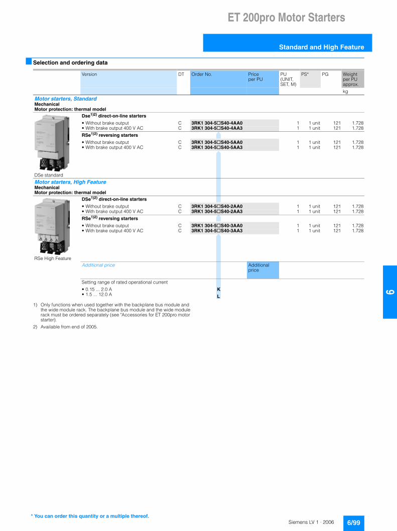
ET 200pro Motor Starters
Standard and High Feature
6/99Siemens LV 1 · 2006
66
■ Selection and ordering data
1) Only functions when used together with the backplane bus module and the wide module rack. The backplane bus module and the wide module rack must be ordered separately (see "Accessories for ET 200pro motor starter).
2) Available from end of 2005.
Version DT Order No. Price per PU
PU (UNIT, SET, M)
PS* PG Weight per PU approx.
kg
Motor starters, StandardMechanicalMotor protection: thermal model
DSe standard
Dse1)2) direct-on-line starters
• Without brake output C 3RK1 304-5@S40-4AA0 1 1 unit 121 1.728• With brake output 400 V AC C 3RK1 304-5@S40-4AA3 1 1 unit 121 1.728
RSe1)2) reversing starters
• Without brake output C 3RK1 304-5@S40-5AA0 1 1 unit 121 1.728• With brake output 400 V AC C 3RK1 304-5@S40-5AA3 1 1 unit 121 1.728
Motor starters, High FeatureMechanicalMotor protection: thermal model
RSe High Feature
DSe1)2) direct-on-line starters
• Without brake output C 3RK1 304-5@S40-2AA0 1 1 unit 121 1.728• With brake output 400 V AC C 3RK1 304-5@S40-2AA3 1 1 unit 121 1.728
RSe1)2) reversing starters
• Without brake output C 3RK1 304-5@S40-3AA0 1 1 unit 121 1.728• With brake output 400 V AC C 3RK1 304-5@S40-3AA3 1 1 unit 121 1.728
Additional price Additional price
Setting range of rated operational current
• 0.15 ... 2.0 A K• 1.5 ... 12.0 A L
* You can order this quantity or a multiple thereof.

ET 200pro Motor Starters
ET 200pro isolator modules
6/100 Siemens LV 1 · 2006
6
■ Overview
The isolator module with integrated group fusing function (i.e. additional group short-circuit protection for all subsequently supplied motor starters) and switch disconnector function is used for safe disconnection of the 400 V operational voltage in the plant.
Depending on the power distribution concept, all stations can be equipped with an isolator module as an option.
The isolator module is available in addition in a safety version. See Safety local Isolator Modules.
■ Benefits
The following properties apply to the isolator module:• Increase of plant availability through fast replacement of units
(easy mounting and plug-in technology) • Cabinet-free construction thanks to high degree of
protection IP65
■ Selection and ordering data
1) Only functions when used together with the backplane bus module and the wide module rack. The backplane bus module and the wide module rack must be ordered separately (see Accessories for ET 200pro motor starter).
2) The Safety local isolator module only functions when used together with the 400 V disconnecting module.
3) Available from end of 2005.
Version DT Order No. Price per PU
PU (UNIT, SET, M)
PS* PG Weight per PU approx.
kg
ET 200pro isolator modules, mechanicalIsolator modules1)3)
Rated operational current 25 A C 3RK1 304-0HS00-6AA0 1 1 unit 121 1.728
Safety local isolator modules1)2)3)
Rated operational current 25 A B 3RK1 304-0HS00-7AA0 1 1 unit 121 1.728
* You can order this quantity or a multiple thereof.
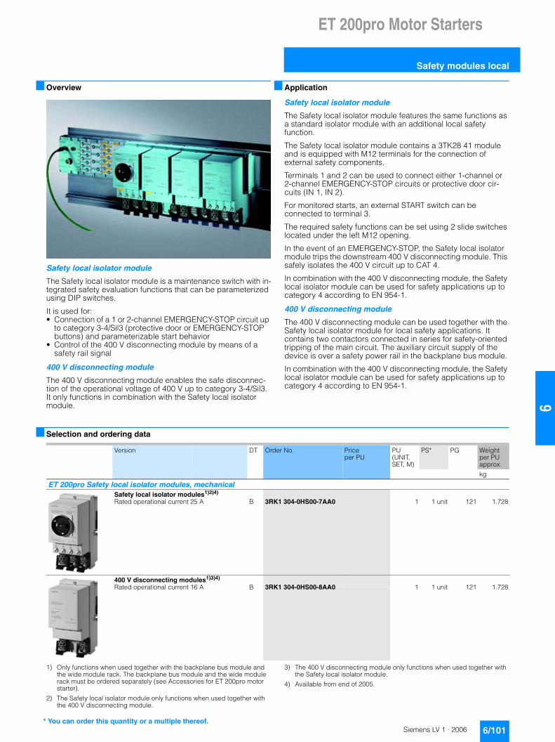
ET 200pro Motor Starters
Safety modules local
6/101Siemens LV 1 · 2006
66
■ Overview
Safety local isolator module
The Safety local isolator module is a maintenance switch with in-tegrated safety evaluation functions that can be parameterized using DIP switches.
It is used for:• Connection of a 1 or 2-channel EMERGENCY-STOP circuit up
to category 3-4/Sil3 (protective door or EMERGENCY-STOP buttons) and parameterizable start behavior
• Control of the 400 V disconnecting module by means of a safety rail signal
400 V disconnecting module
The 400 V disconnecting module enables the safe disconnec-tion of the operational voltage of 400 V up to category 3-4/Sil3. It only functions in combination with the Safety local isolator module.
■ Application
Safety local isolator module
The Safety local isolator module features the same functions as a standard isolator module with an additional local safetyfunction.
The Safety local isolator module contains a 3TK28 41 module and is equipped with M12 terminals for the connection of external safety components.
Terminals 1 and 2 can be used to connect either 1-channel or 2-channel EMERGENCY-STOP circuits or protective door cir-cuits (IN 1, IN 2).
For monitored starts, an external START switch can be connected to terminal 3.
The required safety functions can be set using 2 slide switches located under the left M12 opening.
In the event of an EMERGENCY-STOP, the Safety local isolator module trips the downstream 400 V disconnecting module. This safely isolates the 400 V circuit up to CAT 4.
In combination with the 400 V disconnecting module, the Safety local isolator module can be used for safety applications up to category 4 according to EN 954-1.
400 V disconnecting module
The 400 V disconnecting module can be used together with the Safety local isolator module for local safety applications. It contains two contactors connected in series for safety-oriented tripping of the main circuit. The auxiliary circuit supply of the device is over a safety power rail in the backplane bus module.
In combination with the 400 V disconnecting module, the Safety local isolator module can be used for safety applications up to category 4 according to EN 954-1.
■ Selection and ordering data
1) Only functions when used together with the backplane bus module and the wide module rack. The backplane bus module and the wide module rack must be ordered separately (see Accessories for ET 200pro motor starter).
2) The Safety local isolator module only functions when used together with the 400 V disconnecting module.
3) The 400 V disconnecting module only functions when used together with the Safety local isolator module.
4) Available from end of 2005.
Version DT Order No. Price per PU
PU (UNIT, SET, M)
PS* PG Weight per PU approx.
kg
ET 200pro Safety local isolator modules, mechanicalSafety local isolator modules1)2)4)
Rated operational current 25 A B 3RK1 304-0HS00-7AA0 1 1 unit 121 1.728
400 V disconnecting modules1)3)4)
Rated operational current 16 A B 3RK1 304-0HS00-8AA0 1 1 unit 121 1.728
* You can order this quantity or a multiple thereof.

ET 200pro Motor Starters
Accessories for ET 200pro motor starters
6/102 Siemens LV 1 · 2006
6
■ Selection and ordering data
1) The wide module rack can accommodate all ET 200pro motor starters and any optional modules (isolator module, Safety local isolator module and 400 V disconnecting module).
2) The backplane bus module is a prerequisite for operation of the ET 200pro motor starter and the optional modules (isolator module, Safety local isolator module and 400 V disconnecting module).
Version DT Order No. Price per PU
PU (UNIT, SET, M)
PS* PG Approx. weightper PUin kg
ET 200pro accessoriesWide module racks1)
• Length 500 mm } 6ES7 194-4GB00-0AA0 1 1 unit 250 4.000• Length 1000 mm } 6ES7 194-4GB10-0AA0 1 1 unit 250 8.000• Length 2000 mm } 6ES7 194-4GB20-0AA0 1 1 unit 250 16.000
Backplane bus modules 110 mm2) B 3RK1 922-2BA00 1 1 unit 121 0.330
RS 232 interface cables B 3RK1 922-2BQ00 1 1 unit 121 0.330
Power jumper plugs B 3RK1 922-2BP00 1 1 unit 121 0.330
Plug sets for incoming energy supply (HAN Q4/2)• 2.5 mm2 C 3RK1 911-2BE50 1 1 unit 121 2.000• 4.0 mm2 B 3RK1 911-2BE10 1 1 unit 121 2.000• 6.0 mm2 B 3RK1 911-2BE30 1 1 unit 121 2.000
Plug sets for motor connections (HAN Q8/0)• 1.5 mm2 B 3RK1 902-0CE00 1 1 set 121 0.064• 2.5 mm2 B 3RK1 902-0CC00 1 1 set 121 0.059
Sealing caps (for power supply) B 3RK1 902-0CJ00 1 10 units 121 0.093
Plug set for cable-end connector hoods with pin inserts 4 mm2 C 3RK1 911-2BF10 1 1 unit 121 On req.
Dismantling tools for HAN Q4/2 C 3RK1 902-0AB00 1 1 unit 121 On req.
Crimping tools for pins/sockets 4 and 6 mm2 C 3RK1 902-0CW00 1 1 unit 121 On req.
Crimping tools for contact pins and sockets up to 4.0 mm2 (HAN Q8/0)
B 3RK1 902-0CT00 1 1 unit 121 0.644
Dismantling tools for contact pins and sockets (HAN Q8/0) B 3RK1 902-0AJ00 1 1 unit 121 0.047
M12 sealing caps } 3RX9 802-0AA00 100 10 units 121 0.100
* You can order this quantity or a multiple thereof.
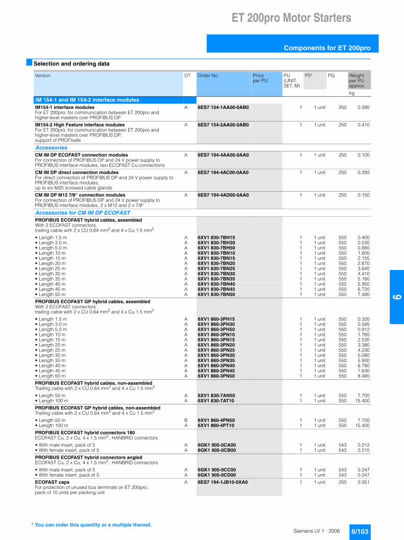
ET 200pro Motor Starters
Components for ET 200pro
6/103Siemens LV 1 · 2006
66
■ Selection and ordering data
Version DT Order No. Price per PU
PU (UNIT, SET, M)
PS* PG Weight per PU approx.
kg
IM 154-1 and IM 154-2 interface modulesIM154-1 interface modules A 6ES7 154-1AA00-0AB0 1 1 unit 250 0.395For ET 200pro; for communication between ET 200pro and higher-level masters over PROFIBUS DP
IM154-2 High Feature interface modules A 6ES7 154-2AA00-0AB0 1 1 unit 250 0.410For ET 200pro; for communication between ET 200pro and higher-level masters over PROFIBUS DP; support of PROFIsafe
AccessoriesCM IM DP ECOFAST connection modules A 6ES7 194-4AA00-0AA0 1 1 unit 250 0.100For connection of PROFIBUS DP and 24 V power supply to PROFIBUS interface modules, two ECOFAST Cu connections
CM IM DP direct connection modules A 6ES7 194-4AC00-0AA0 1 1 unit 250 0.292For direct connection of PROFIBUS DP and 24 V power supply to PROFIBUS interface modules, up to six M20 screwed cable glands
CM IM DP M12 7/8“ connection modules A 6ES7 194-4AD00-0AA0 1 1 unit 250 0.150For connection of PROFIBUS DP and 24 V power supply to PROFIBUS interface modules, 2 x M12 and 2 x 7/8“
Accessories for CM IM DP ECOFAST PROFIBUS ECOFAST hybrid cables, assembledWith 2 ECOFAST connectors, trailing cable with 2 x CU 0.64 mm2 and 4 x Cu 1.5 mm2
• Length 1.5 m A 6XV1 830-7BH15 1 1 unit 550 0.400• Length 3.0 m A 6XV1 830-7BH30 1 1 unit 550 0.535• Length 5.0 m A 6XV1 830-7BH50 1 1 unit 550 0.880• Length 10 m A 6XV1 830-7BN10 1 1 unit 550 1.600• Length 15 m A 6XV1 830-7BN15 1 1 unit 550 2.155• Length 20 m A 6XV1 830-7BN20 1 1 unit 550 2.870• Length 25 m A 6XV1 830-7BN25 1 1 unit 550 3.640• Length 30 m A 6XV1 830-7BN30 1 1 unit 550 4.410• Length 35 m A 6XV1 830-7BN35 1 1 unit 550 5.180• Length 40 m A 6XV1 830-7BN40 1 1 unit 550 5.950• Length 45 m A 6XV1 830-7BN45 1 1 unit 550 6.720• Length 50 m A 6XV1 830-7BN50 1 1 unit 550 7.490
PROFIBUS ECOFAST GP hybrid cables, assembledWith 2 ECOFAST connectors, trailing cable with 2 x CU 0.64 mm2 and 4 x Cu 1.5 mm2
• Length 1.5 m A 6XV1 860-3PH15 1 1 unit 550 0.320• Length 3.0 m A 6XV1 860-3PH30 1 1 unit 550 0.585• Length 5.0 m A 6XV1 860-3PH50 1 1 unit 550 0.912• Length 10 m A 6XV1 860-3PN10 1 1 unit 550 1.760• Length 15 m A 6XV1 860-3PN15 1 1 unit 550 2.530• Length 20 m A 6XV1 860-3PN20 1 1 unit 550 3.380• Length 25 m A 6XV1 860-3PN25 1 1 unit 550 4.230• Length 30 m A 6XV1 860-3PN30 1 1 unit 550 5.080• Length 35 m A 6XV1 860-3PN35 1 1 unit 550 5.930• Length 40 m A 6XV1 860-3PN40 1 1 unit 550 6.780• Length 45 m A 6XV1 860-3PN45 1 1 unit 550 7.630• Length 50 m A 6XV1 860-3PN50 1 1 unit 550 8.480
PROFIBUS ECOFAST hybrid cables, non-assembledTrailing cable with 2 x CU 0.64 mm2 and 4 x Cu 1.5 mm2
• Length 50 m A 6XV1 830-7AN50 1 1 unit 550 7.700• Length 100 m A 6XV1 830-7AT10 1 1 unit 550 15.400
PROFIBUS ECOFAST GP hybrid cables, non-assembledTrailing cable with 2 x CU 0.64 mm2 and 4 x Cu 1.5 mm2
• Length 50 m B 6XV1 860-4PN50 1 1 unit 550 7.700• Length 100 m A 6XV1 860-4PT10 1 1 unit 550 15.400
PROFIBUS ECOFAST hybrid connectors 180ECOFAST Cu, 2 x Cu, 4 x 1.5 mm2,, HANBRID connectors
• With male insert, pack of 5 A 6GK1 905-0CA00 1 1 unit 543 0.212• With female insert, pack of 5 A 6GK1 905-0CB00 1 1 unit 543 0.215
PROFIBUS ECOFAST hybrid connectors angledECOFAST Cu, 2 x Cu, 4 x 1.5 mm2,, HANBRID connectors
• With male insert, pack of 5 A 6GK1 905-0CC00 1 1 unit 543 0.247• With female insert, pack of 5 A 6GK1 905-0CD00 1 1 unit 543 0.247
ECOFAST caps A 6ES7 194-1JB10-0XA0 1 1 unit 250 0.051For protection of unused bus terminals on ET 200pro; pack of 10 units per packing unit
* You can order this quantity or a multiple thereof.

ET 200pro Motor Starters
Components for ET 200pro
6/104 Siemens LV 1 · 2006
6
Accessories for CM IM DP DirectPROFIBUS trailing cables A 6XV1 830-3EH10 1 1 unit 550 0.072Max. acceleration 4 m/s2, at least 3000000 bending cycles, bending radius at least 60 mm, 2-core, shielded, sold by the meter, minimum order quantity 20 m, maximum order quantity 1000 m
PROFIBUS FC Food bus cables A 6XV1 830-0GH10 1 1 unit 550 0.069With PE outer sheath for use in the food and drinks industry, 2-core, shielded, sold by the meter, minimum order quantity 20 m, maximum order quantity 1000 m
PROFIBUS FC Robust bus cables A 6XV1 830-0JH10 1 1 unit 550 0.075With PUR outer sheath for use in environments exposed to chemicals and mechanical loads, 2-core, shielded, sold by the meter, minimum order quantity 20 m, maximum order quantity 1000 m
Power cables A 6XV1 830-8AH10 1 1 unit 550 0.1495-core, 5 x 1.5 mm2, trailing, sold by the meter, minimum order quantity 20 m, maximum order quantity 1000 m
Accessories for CM IM DP M12 7/8“PROFIBUS M12 connecting cablesPreassembled with two M12 connectors, 5-pole
• Length 1.5 m A 6XV1 830-3DH15 1 1 unit 550 0.400• Length 2.0 m A 6XV1 830-3DH20 1 1 unit 550 0.480• Length 3.0 m A 6XV1 830-3DH30 1 1 unit 550 0.800• Length 5.0 m A 6XV1 830-5DH50 1 1 unit 550 1.200• Length 10 m A 6XV1 830-3DN10 1 1 unit 550 2.400• Length 15 m A 6XV1 830-3DN15 1 1 unit 550 1.240
7/8“ connecting cables for power supply5-core, 5 x 1.5 mm2, trailing, preassembled with two 7/8" connectors, 5-pole
• Length 1.5 m A 6XV1 822-5BH15 1 1 unit 550 0.700• Length 2.0 m A 6XV1 822-5BH20 1 1 unit 550 0.780• Length 3.0 m A 6XV1 822-5BH30 1 1 unit 550 0.570• Length 5.0 m A 6XV1 822-5BH50 1 1 unit 550 3.000• Length 10 m A 6XV1 822-5BN10 1 1 unit 550 6.000• Length 15 m A 6XV1 822-5BN15 1 1 unit 550 2.540
M12 connectorsFor ET 200eco, with axial cable feeder
• With male insert, pack of 5 A 6GK1 905-0EA00 1 1 unit 543 0.250• With female insert, pack of 5 A 6GK1 905-0EB00 1 1 unit 543 0.265
7/8" connectorsFor ET 200eco, with axial cable feeder
• With male insert, pack of 5 A 6GK1 905-0FA00 1 1 unit 543 0.265• With female insert, pack of 5 A 6GK1 905-0FB00 1 1 unit 543 0.250
M12 sealing caps } 3RX9 802-0AA00 100 10 units 121 0.100For protection of unused M12 terminals on ET 200pro
7/8" sealing caps A 6ES7 194-3JA00-0AA0 1 1 unit 250 0.040For protection of unused 7/8" terminals on ET 200pro; pack of 10 units per packing unit
Version DT Order No. Price per PU
PU (UNIT, SET, M)
PS* PG Weight per PU approx.
kg
* You can order this quantity or a multiple thereof.

ET 200pro Motor Starters
Components for ET 200pro
6/105Siemens LV 1 · 2006
66
General accessories ET 200pro module carriers
• Narrow, for interface, solid-state and power modules
- 500 mm A 6ES7 194-4GA00-0AA0 1 1 unit 250 1.337- 1000 mm A 6ES7 194-4GA10-0AA0 1 1 unit 250 2.881- 2000 mm, can be cut to size A 6ES7 194-4GA20-0AA0 1 1 unit 250 5.348
• Compact, for interface, solid-state and power modules
- 500 mm A 6ES7 194-4GC00-0AA0 1 1 unit 250 1.300- 1000 mm A 6ES7 194-4GC10-0AA0 1 1 unit 250 2.600- 2000 mm, can be cut to size A 6ES7 194-4GC20-0AA0 1 1 unit 250 5.200
• Wide, for interface, solid-state, power modules and motor starters
- 500 mm } 6ES7 194-4GB00-0AA0 1 1 unit 250 4.000- 1000 mm } 6ES7 194-4GB10-0AA0 1 1 unit 250 8.000- 2000 mm, can be cut to size } 6ES7 194-4GB20-0AA0 1 1 unit 250 16.000
Spare fuses A 6ES7 194-4HB00-0AA0 1 1 unit 250 0.05012.5 A quick, for interface and power modules, pack of 10
Technical product specifications A 6ES7 991-0CC00-0YX0 1 1 unit 266 0.234For CAX applications, one-off license
Technical product specifications X 6ES7 991-0CC00-0YX2 1 1 unit 266 0.100For CAX applications, one-off license, update service
SIMATIC Manual Collection A 6ES7 998-8XC01-8YE0 1 1 unit 230 0.227Manuals on CD, several languages: S7-200, TD 200, S7-300, M7-300, C7, S7-400, M7-400, STEP 7, Engineering Tools, Runtime Software, SIMATIC DP (Distributed I/O), SIMATIC HMI (Human Machine Interface), SIMATIC NET (Industrial Communication)
SIMATIC Manual Collection – Update service for 1 year X 6ES7 998-8XC01-8YE2 1 1 unit 230 0.400Scope of delivery: The current CD S7 Manual Collection as well as the three subsequent updates
Version DT Order No. Price per PU
PU (UNIT, SET, M)
PS* PG Weight per PU approx.
kg
* You can order this quantity or a multiple thereof.

ET 200pro Motor Starters
Components for ET 200pro
6/106 Siemens LV 1 · 2006
6
IM 154-4 PN interface modulesIM 154-4 PN High Feature interface modules A 6ES7 154-4AB00-0AB0 1 1 unit 250 0.200For communication between ET 200pro and higher-level controller over PROFINET IO; support of PROFIsafe
AccessoriesM12 sealing caps } 3RX9 802-0AA00 100 10 units 121 0.100For protection of unused M12 terminals on ET 200pro
Micro memory cards, 3.3 V, NFLASH
• 64 Kbyte A 6ES7 953-8LF11-0AA0 1 1 unit 230 0.014• 128 Kbyte A 6ES7 953-8LG11-0AA0 1 1 unit 230 0.014• 512 Kbyte A 6ES7 953-8LJ11-0AA0 1 1 unit 230 0.014• 2 Mbyte A 6ES7 953-8LL11-0AA0 1 1 unit 230 0.014• 4 Mbyte A 6ES7 953-8LM11-0AA0 1 1 unit 230 0.014• 8 Mbyte A 6ES7 953-8LP11-0AA0 1 1 unit 230 0.014
M12-180/M12-180 IE connecting cables Preassembled IE FC TP trailing cable GP 2 x 2 (PROFINET Type C) with two M12 connectors (4-pole, D-coded), degree of protection IP65
• Length 0.3 m A 6XV1 870-8AE30 1 1 unit 550 0.180• Length 0.5 m A 6XV1 870-8AE50 1 1 unit 550 0.200• Length 1.0 m A 6XV1 870-8AH10 1 1 unit 550 0.610• Length 1.5 m A 6XV1 870-8AH15 1 1 unit 550 0.700• Length 2.0 m A 6XV1 870-8AH20 1 1 unit 550 0.780• Length 3.0 m A 6XV1 870-8AH30 1 1 unit 550 0.570• Length 5.0 m A 6XV1 870-8AH50 1 1 unit 550 3.000• Length 10 m A 6XV1 870-8AN10 1 1 unit 550 6.000• Length 15 m A 6XV1 870-8AN15 1 1 unit 550 2.540
7/8" connecting cablesFor power supply; preassembled with two 7/8" connectors/sockets, 5-pole
• Length 1.5 m A 6XV1 822-5BH15 1 1 unit 550 0.700• Length 2.0 m A 6XV1 822-5BH20 1 1 unit 550 0.780• Length 3.0 m A 6XV1 822-5BH30 1 1 unit 550 0.570• Length 5.0 m A 6XV1 822-5BH50 1 1 unit 550 3.000• Length 10 m A 6XV1 822-5BN10 1 1 unit 550 6.000• Length 15 m A 6XV1 822-5BN15 1 1 unit 550 2.540
IE cables A 6XV1 870-2D 1 1 unit 550 0.100Trailing, sold by the meter, minimum order quantity 20 m, maximum order quantity 1000 m
Power cables (5 x 1.5 mm2) A 6XV1 830-8AH10 1 1 unit 550 0.149Trailing power cable with 5 copper cores (1.5 mm2) for connection to 7/8" plug-in connector, sold by the meter, minimum order quantity 20 m, maximum order quantity 1000 m
7/8" connectors5-pole, plastic enclosure
• With male insert, pack of 5 A 6GK1 905-0FA00 1 1 unit 543 0.265• With female insert, pack of 5 A 6GK1 905-0FB00 1 1 unit 543 0.250
Spare fuses A 6ES7 194-4HB00-0AA0 1 1 unit 250 0.05012.5 A quick, for interface and power modules, pack of 10
SIMATIC Manual Collection A 6ES7 998-8XC01-8YE0 1 1 unit 230 0.227Manuals on CD, several languages: S7-200, TD 200, S7-300, M7-300, C7, S7-400, M7-400, STEP 7, Engineering Tools, Runtime Software, SIMATIC DP (Distributed I/O), SIMATIC HMI (Human Machine Interface), SIMATIC NET (Industrial Communication)
SIMATIC Manual Collection – Update service for 1 year X 6ES7 998-8XC01-8YE2 1 1 unit 230 0.400Scope of delivery: The current CD S7 Manual Collection as well as the three subsequent updates
Version DT Order No. Price per PU
PU (UNIT, SET, M)
PS* PG Weight per PU approx.
kg
* You can order this quantity or a multiple thereof.

ET 200pro Motor Starters
Components for ET 200pro
6/107Siemens LV 1 · 2006
66
EM 141 and EM 142 digital expansion modules8 DI digital input modules A 6ES7 141-4BF00-0AA0 1 1 unit 250 0.14124 V DC, with module diagnostics, including bus module. Connection module to be ordered separately8 DI High Feature digital input modules A 6ES7 141-4BF00-0AB0 1 1 unit 250 0.10024 V DC, with channel diagnostics, including bus module. Connection module to be ordered separately4 DO digital output modules A 6ES7 142-4BD00-0AA0 1 1 unit 250 0.14124 V DC, 2 A, with module diagnostics, including bus module. Connection module to be ordered separately4 DO High Feature digital output modules A 6ES7 142-4BD00-0AB0 1 1 unit 250 0.10024 V DC, 2 A, with channel diagnostics, including bus module. Connection module to be ordered separately
AccessoriesCM IO 4 x M12 connection modules A 6ES7 194-4CA00-0AA0 1 1 unit 250 0.300Four M12 sockets for connection of digital or analog sensors of actuators to ET 200proCM IO 8 x M12 connection modules A 6ES7 194-4CB00-0AA0 1 1 unit 250 0.305Eight M12 sockets for connection of digital or analog sensors of actuators to ET 200proModule labeling plates A 6ES7 194-4HA00-0AA0 1 1 unit 250 0.300For color coding of CM IOs in the colors white, red, blue and green; pack of 100 M12 sealing caps } 3RX9 802-0AA00 100 10 units 121 0.100For protection of unused M12 terminals on ET 200proInscription plates C 3RT1 900-1SB20 100 340 units 101 22.00020 x 7, pastel turquoise, pack of 340M12 connectors, for field assembly A 3RX1 667 1 1 unit 574 0.0265-pole, for connecting digital sensors and actuators, 1 unitM12 connecting cablesWith PUR sheath, for connecting digital sensors and actuators, preassembled, with box and connector at both ends
• 3 x 0.34 mm2, fixed lengths, 1 unit
- 0.6 m C 3RX1 633 1 1 unit 574 0.045- 1 m C 3RX1 634 1 1 unit 574 0.056- 1.5 m C 3RX1 635 1 1 unit 574 0.069
• 4 x 0.34 mm2, fixed lengths, 1 unit
- 0.6 m C 3RX1 640 1 1 unit 574 0.060- 1 m A 3RX1 641 1 1 unit 574 0.042- 1.5 m A 3RX1 642 1 1 unit 574 0.078
EM 144 and EM 145 analog expansion modules4AI U analog input modules A 6ES7 144-4FF00-0AB0 1 1 unit 250 0.149High Feature, �10 V; �5 V; 0 to 10 V; 1 to 5 V, channel diagnostics, including bus module. Connection module to be ordered separately
4AI I analog input modules A 6ES7 144-4GF00-0AB0 1 1 unit 250 0.149High Feature, �20 mA; 0 to 20 mA; 4 to 20 mA, channel diagnostics, including bus module. Connection module to be ordered separately
4AO U analog output modules A 6ES7 145-4FF00-0AB0 1 1 unit 250 0.100High Feature, �10 V; 0 to 10 V; 1 to 5 V, channel diagnostics, including bus module. Connection module to be ordered separately
4AO I analog output modules A 6ES7 145-4GF00-0AB0 1 1 unit 250 0.100High Feature, �20 mA; 0 to 20 mA; 4 to 20 mA, channel diagnostics, including bus module. Connection module to be ordered separately
AccessoriesCM IO 4 x M12 connection modules A 6ES7 194-4CA00-0AA0 1 1 unit 250 0.300Four M12 sockets for connection of digital or analog sensors of actuators to ET 200pro
Module labeling plates A 6ES7 194-4HA00-0AA0 1 1 unit 250 0.300For color coding of CM IOs in the colors white, red, blue and green; pack of 100
M12 sealing caps } 3RX9 802-0AA00 100 10 units 121 0.100For protection of unused M12 terminals on ET 200pro
Version DT Order No. Price per PU
PU (UNIT, SET, M)
PS* PG Weight per PU approx.
kg
* You can order this quantity or a multiple thereof.

ET 200pro Motor Starters
Components for ET 200pro
6/108 Siemens LV 1 · 2006
6
PM-E power modulesPM-E power modules 24 V DC A 6ES7148-4CA00-0AA0 1 1 unit 250 0.100For resupply and group formation of the 24 V DC load voltage for solid-state modules within an ET 200pro station.
AccessoriesCM PM-E ECOFAST connection modules X 6ES7 194-4BA00-0AA0 1 1 unit 250 0.100For resupply of 24 V load voltage, one ECOFAST Cu terminal
CM PM-E Direct connection modules X 6ES7 194-4BC00-0AA0 1 1 unit 250 0.100For resupply of 24 V load voltage, up to two M20 screwed cable glands
CM PM-E 7/8" connection modules X 6ES7 194-4BD00-0AA0 1 1 unit 250 0.100For resupply of 24 V load voltage, 1 x 7/8"
Spare fuses A 6ES7 194-4HB00-0AA0 1 1 unit 250 0.05012.5 A quick, for interface and power modules, pack of 10
Accessories for CM PM-E ECOFASTPROFIBUS ECOFAST hybrid connectors 180ECOFAST Cu, 2 x Cu, 4 x 1.5 mm2,, HANBRID connectors
• With male insert, pack of 5 A 6GK1 905-0CA00 1 1 unit 543 0.212• With female insert, pack of 5 A 6GK1 905-0CB00 1 1 unit 543 0.215
PROFIBUS ECOFAST hybrid connectors angledECOFAST Cu, 2 x Cu, 4 x 1.5 mm2,, HANBRID connectors
• With male insert, pack of 5 A 6GK1 905-0CC00 1 1 unit 543 0.247• With female insert, pack of 5 A 6GK1 905-0CD00 1 1 unit 543 0.247
Accessories for CM PM-E DirectPower cables A 6XV1 830-8AH10 1 1 unit 550 0.1495-core, 5 x 1.5 mm2, trailing, sold by the meter, minimum order quantity 20 m, maximum order quantity 1000 m
Accessories for CM PM-E 7/8"7/8" connecting cables for power supplies5-core, 5 x 1.5 mm2, trailing, preassembled with two 7/8" connectors, 5-pole
• Length 1.5 m A 6XV1 822-5BH15 1 1 unit 550 0.700• Length 2.0 m A 6XV1 822-5BH20 1 1 unit 550 0.780• Length 3.0 m A 6XV1 822-5BH30 1 1 unit 550 0.570• Length 5.0 m A 6XV1 822-5BH50 1 1 unit 550 3.000• Length 10 m A 6XV1 822-5BN10 1 1 unit 550 6.000• Length 15 m A 6XV1 822-5BN15 1 1 unit 550 2.540
7/8" connectorsWith axial cable feeder
• With male insert, pack of 5 A 6GK1 905-0FA00 1 1 unit 543 0.265• With female insert, pack of 5 A 6GK1 905-0FB00 1 1 unit 543 0.250
General accessories ET 200pro module carriers
• Narrow, for interface, solid-state and power modules
- 500 mm A 6ES7 194-4GA00-0AA0 1 1 unit 250 1.337- 1000 mm A 6ES7 194-4GA10-0AA0 1 1 unit 250 2.881- 2000 mm, can be cut to size A 6ES7 194-4GA20-0AA0 1 1 unit 250 5.348
• Compact, for interface, solid-state and power modules
- 500 mm A 6ES7 194-4GC00-0AA0 1 1 unit 250 1.300- 1000 mm A 6ES7 194-4GC10-0AA0 1 1 unit 250 2.600- 2000 mm, can be cut to size A 6ES7 194-4GC20-0AA0 1 1 unit 250 5.200
• Wide, for interface, solid-state, power modules and motor starters
- 500 mm } 6ES7 194-4GB00-0AA0 1 1 unit 250 4.000- 1000 mm } 6ES7 194-4GB10-0AA0 1 1 unit 250 8.000- 2000 mm, can be cut to size } 6ES7 194-4GB20-0AA0 1 1 unit 250 16.000
Spare fuses A 6ES7 194-4HB00-0AA0 1 1 unit 250 0.05012.5 A quick, for interface and power modules, pack of 10
SIMATIC Manual Collection A 6ES7 998-8XC01-8YE0 1 1 unit 230 0.227Manuals on CD, several languages: S7-200, TD 200, S7-300, M7-300, C7, S7-400, M7-400, STEP 7, Engineering Tools, Runtime Software, SIMATIC DP (Distributed I/O), SIMATIC HMI (Human Machine Interface), SIMATIC NET (Industrial Communication)
SIMATIC Manual Collection – Update service for 1 year X 6ES7 998-8XC01-8YE2 1 1 unit 230 0.400Scope of delivery: The current CD S7 Manual Collection as well as the three subsequent updates
Version DT Order No. Price per PU
PU (UNIT, SET, M)
PS* PG Weight per PU approx.
kg
* You can order this quantity or a multiple thereof.

ET 200X Motor Starters
ET 200X motor starters
6/109Siemens LV 1 · 2006
66
■ Overview
• For switching and protection of any three-phase loads• Direct-on-line or reversing starters• Electromechanical or solid-state• Power bus can be plugged in using the new HAN Q8 plug-in
connectors• Conductor cross-sections up to 4 mm2
• 35 A per segment• Supplied with different brake contacts as an option
■ Application
With the ET 200X motor starters, any three-phase loads, e.g. induction motors, can be protected and switched.
Motor starters are available in two variants:• Electromechanical motor starters
for electrical isolation of loads from the supply system• Solid-state motor starters
- Suitable for high starting frequency- Behavior in case of overload can be selectively configured,
e.g. emergency mode in the event of overloading, remote reset by bus after an overload tripping operation
Motor starters can be operated with a hand-held device,making start-ups easier.
■ Selection and ordering data
Version DT Order No. Price per PU
PU (UNIT, SET, M)
PS* PG Weight per PU approx.
kg
Expansion modules for electromechanical motor starters
EM 300 DS expansion modules Electromechanical direct-on-line starter
B 3RK1 300-@@S01-0AA@ 1 1 unit 121 1.900
EM 300 RS expansion modules Electromechanical reversing starter
B 3RK1 300-@@S01-1AA@ 1 1 unit 121 2.200
Induction motor 4-pole at 400 V AC Standard output P in kW
Setting range of the overcurrent release in A
< 0.06 0.14 ... 0.20 0B 0.06 0.18 ... 0.25 0C 0.09 0.22 ... 0.32 0D 0.10 0.28 ... 0.40 0E
0.12 0.35 ... 0.50 0F 0.18 0.45 ... 0.63 0G 0.21 0.55 ... 0.80 0H 0.25 0.70 ... 1.00 0J
0.37 0.90 ... 1.25 0K 0.55 1.1 ... 1.6 1 A 0.75 1.4 ... 2.0 1B 0.90 1.8 ... 2.5 1C
1.1 2.2 ... 3.2 1D 1.5 2.8 ... 4.0 1E 1.9 3.5 ... 5.0 1F 2.2 4.5 ... 6.3 1G
3.0 5.5 ... 8.0 1H 4.0 7 ... 10 1J 5.5 9 ... 12 1K
Additional price
• Standard version 0
• Version with brake contact for 24 V DC/3 A externally-fed brakes
1
• Version with brake contact for 400 V AC/0.5 A infeed for brake rectifier
3
• Version with brake contact for DC-side switching of the brakes with 500 V DC/0.2 A
4
* You can order this quantity or a multiple thereof.

ET 200X Motor Starters
ET 200X motor starters
6/110 Siemens LV 1 · 2006
6
Expansion modules for solid-state motor starters
EM 300 EDS expansion modules Electromechanical direct-on-line starter
B 3RK1 300-@@S10-0AA@ 1 1 unit 121 1.800
EM 300 ERS expansion modules Electromechanical reversing starter
B 3RK1 300-@@S10-1AA@ 1 1 unit 121 1.800
Induction motor 4-pole at 400 V AC Standard output P in kW
Setting range of the overcurrent release in A
0.18 ... 0.80 0.60 ... 2.18 0A
0.75 ... 2.20 2.00 ... 5.95 0B
Additional price
• Standard version 0
• Version with brake contact for 24 V DC/3 A externally-fed brakes
1
• Version with brake contact for 400 V AC/0.5 A infeed for brake rectifier
3
• Version with brake contact for DC-side switching of the brakes with500 V DC/0.2 A
4
Accessories for 24 V DC
6ES7 194-1AA00-0XA0
6ES7 194-1KA01-0XA0
Manuals
• German D 6ES7 198-8FA01-8AA0 1 1 unit 250 1.956• English C 6ES7 198-8FA01-8BA0 1 1 unit 250 1.925• French A 6ES7 198-8FA01-8CA0 1 1 unit 250 1.676
Connectors for PROFIBUS DP, control andauxiliary voltage(including two Pg glands)
A 6ES7 194-1AA00-0XA0 1 1 unit 2Z3 0.086
Cables For bus and control voltage 5-coreWithout assemblyAny length1)
• PVC C 6ES7 194-1LY00-0AA0 1 1 m 250 0.100
• PURTrailing permittedOil-resistantConditionally resistant to electromagnetic fields
C 6ES7 194-1LY10-0AA0 1 1 m 250 0.111
M12 coupler plugs
• 5-polefor connecting actuators and sensors
A 3RX1 667 1 1 unit 574 0.026
• 4-pole ShieldedFor connecting analog expansion modules
Available from:Franz Binder GmbH & Co
(see Appendix –>External Partners)
M12 angular coupler plugs
• 5-polefor connecting actuators and sensors
A 3RX1 668 1 1 unit 574 0.027
• 4-pole ShieldedFor connecting analog expansionmodules
Available from:Franz Binder GmbH & Co
(see Appendix –>External Partners)
M12 Y-shaped coupler plugs 5-poleFor double connection of sensors using single cable
A 6ES7 194-1KA01-0XA0 1 1 unit 250 0.046
M12 sealing caps For sealing unused input and output sockets(one set contains ten sealing caps)
} 3RK1 901-1KA00 100 10 units 121 0.100
Version DT Order No. Price per PU
PU (UNIT, SET, M)
PS* PG Weight per PU approx.
kg��
����
���
* You can order this quantity or a multiple thereof.

ET 200X Motor Starters
ET 200X motor starters
6/111Siemens LV 1 · 2006
66
Accessories for EM 300 motor starters, 9-pole connectors (Han Q8/0)
3RK1 902-0CA00
3RK1 902-0CC00
3RK1 902-0CH00
Connector sets for power infeed 9-poleComprisingOne connector enclosure with Pg16 cable glandOne female insert, 9-poleSix female contacts, suitable for cable
• 4 x 2.5 mm2, 6 x 2.5 mm2 B 3RK1 902-0CA00 1 1 set 121 0.057• 4 x 4 mm2, 6 x 4 mm2 B 3RK1 902-0CB00 1 1 set 121 0.055
Connector sets for power loop-through connections 9-poleComprisingOne connector enclosure with Pg16 cable glandOne male insert, 9-poleSix contact pins, suitable for cable
• 6 x 2.5 mm2 B 3RK1 902-0CC00 1 1 set 121 0.059• 4 x 4 mm2, 6 x 4 mm2 B 3RK1 902-0CD00 1 1 set 121 0.055
Connector sets for motor connections 1.5 mm2
9-poleComprisingOne connector enclosure with Pg16 cable glandOne male insert, 9-poleEight contact pins 1.5 mm2
B 3RK1 902-0CE00 1 1 set 121 0.064
Sealing caps For 9-pole power socket (-X3)
• One set comprises ten sealing caps B 3RK1 902-0CJ00 1 10 units 121 0.093• One set comprises one sealing cap B 3RK1 902-0CK00 1 1 unit 121 0.012
Power connection cables 0.12 m long
• From motor starter to frequency converter, DESINA
- 5 x 4 mm2 , without brake lead B 3RK1 902-0CF00 1 1 unit 121 0.202
• From motor starter to motor starter
- 4 x 4 mm2 B 3RK1 902-0CG00 1 1 unit 121 0.165- 6 x 4 mm2 B 3RK1 902-0CH00 1 1 unit 121 0.206
Motor connection cables, 4 x 1.5 mm2 With power connector9-pole
• 1.5 m B 3RK1 902-0CL00 1 1 unit 121 0.218• 3 m B 3RK1 902-0CM00 1 1 unit 121 0.432• 5 m B 3RK1 902-0CP00 1 1 unit 121 0.620• 10m B 3RK1 902-0CQ00 1 1 unit 121 1.278
Motor connection cables, 6 x 1.5 mm2 With power connector9-pole
• 3 m B 3RK1 902-0CN00 1 1 unit 121 0.696• 5 m B 3RK1 902-0CR00 1 1 unit 121 1.110• 10m B 3RK1 902-0CS00 1 1 unit 121 1.840
Version DT Order No. Price per PU
PU (UNIT, SET, M)
PS* PG Weight per PU approx.
kg
* You can order this quantity or a multiple thereof.* You can order this quantity or a multiple thereof.

ET 200X Motor Starters
ET 200X motor starters
6/112 Siemens LV 1 · 2006
6
1) The suffix "-Z" must be appended to the order number and the length must be specified in plain text. Example for a cable with a PVC sheath and a length of 35 m:6ES7 194-1LY00-0AA0-ZY01 35 m
Mounting accessories
3RK1 194-1GA.0-0XA0
3RK1 902-0AH00
Single mounting rails for SIMATIC ET 200X (narrow)
• 400 mm long for basic module+ three expansion modules (60 mm)
A 6ES7 194-1GA00-0XA0 1 1 unit 250 0.773
• 640 mm long for basic module+ seven expansion modules(60 mm)
A 6ES7 194-1GA10-0XA0 1 1 unit 250 1.235
• 2000 mm long for customer-specific lengths
A 6ES7 194-1GA20-0XA0 1 1 unit 250 3.900
Double mounting rails for SIMATIC ET 200X (wide)
• 520 mm long for basic module+ one expansion module (60 mm)+ two motor starters/frequency converters
A 6ES7 194-1GB00-0XA0 1 1 unit 250 3.120
• 1000 mm long for basic module+ one expansion module (60 mm)+ six motor starters/frequency converters
A 6ES7 194-1GB10-0XA0 1 1 unit 250 6.000
Fixing screws M5 x 20One set contains 100 fixing screws
A 6ES7 194-1KC00-0XA0 1 1 unit 250 0.512
Crimping tools For male and female contacts of
• 1.5 to 2.5 mm2 B 3RK1 902-0AH00 1 1 unit 121 0.576• 1.5 to 4 mm2 B 3RK1 902-0CT00 1 1 unit 121 0.644
Disassembly tools For disassembling male and female contacts in 9-pole inserts
B 3RK1 902-0AJ00 1 1 unit 121 0.047
Miscellaneous accessories
3RK1 902-0AM00
6ES7 194-1BA00-0XA0
Hand-held devices for start-up with 0.5 m connection cable and plug
B 3RK1 902-0AM00 1 1 unit 121 0.217
Labeling plates For labeling inputs and outputs as well as item codesOne set contains 20 frames with 40 labels each, 8 x 10 mm, petrol colored
A 6ES7 194-1BA00-0XA0 1 1 unit 250 0.050
Version DT Order No. Price per PU
PU (UNIT, SET, M)
PS* PG Weight per PU approx.
kg
* You can order this quantity or a multiple thereof.

ET 200X Motor Starters
Basic and expansion modules
6/113Siemens LV 1 · 2006
66
■ Selection and ordering data
Version DT Order No. Price per PU
PU (UNIT, SET, M)
PS* PG Total weight per PU approx.
kg
BM 147/CPU intelligent basic modulesBM 147-1 CPU basic modules A 6ES7 147-1AA11-0XB0 1 1 unit 250 0.822
With integrated PLC functionality, with 64 Kbyte RAM
BM 147-2 CPU basic modules
With integrated PLC functionality and additional PROFIBUS master interface
• With 64 Kbyte RAM A 6ES7 147-2AA01-0XB0 1 1 unit 250 0.853• With 128 Kbyte RAM A 6ES7 147-2AB01-0XB0 1 1 unit 250 0.853
AccessoriesManuals for ET 200X distributed I/O station
• German D 6ES7 198-8FA01-8AA0 1 1 unit 250 1.956• English C 6ES7 198-8FA01-8BA0 1 1 unit 250 1.925• French A 6ES7 198-8FA01-8CA0 1 1 unit 250 1.676
Cover plates for ET 200X basic modules A 6ES7 194-1JB00-0XA0 1 1 unit 250 0.189
Protective cover for bus terminals and power supply terminals (pack of 10)
Single mounting rails for SIMATIC ET 200X (narrow)
• 400 mm long for basic module+ three expansion modules (60 mm)
A 6ES7 194-1GA00-0XA0 1 1 unit 250 0.773
• 640 mm long for basic module+ seven expansion modules (60 mm)
A 6ES7 194-1GA10-0XA0 1 1 unit 250 1.235
• 2000 mm long for customer-specific lengths A 6ES7 194-1GA20-0XA0 1 1 unit 250 3.900
Double mounting rails for SIMATIC ET 200X (wide)
• 520 mm long for basic module+ one expansion module (60 mm)+ two motor starters/frequency converters/pneumatic interfaces
A 6ES7 194-1GB00-0XA0 1 1 unit 250 3.120
• 1000 mm long for basic module+ one expansion module (60 mm)+ six motor starters/frequency converters
A 6ES7 194-1GB10-0XA0 1 1 unit 250 6.000
Fixing screws A 6ES7 194-1KC00-0XA0 1 1 unit 250 0.512
M5 x 20, 1 pack. = 100 units
Connecting cables for PROFIBUS A 6ES7 901-4BD00-0XA0 1 1 unit 250 0.315
12 Mbaud, for PG connection to PROFIBUS DP, assembled with 2 x 9-pole Sub-D connector, 3.0 m
ECOFAST hybrid cables
Assembled with ECOFAST plug connectors
• 1.5 A 6XV1 830-7BH15 1 1 unit 550 0.400• 3.0 A 6XV1 830-7BH30 1 1 unit 550 0.535• 5.0 A 6XV1 830-7BH50 1 1 unit 550 0.880• 10.0 A 6XV1 830-7BN10 1 1 unit 550 1.600• 15.0 A 6XV1 830-7BN15 1 1 unit 550 2.155
ECOFAST termination resistors
• Order unit 1 unit A 6GK1 905-0DA10 1 1 unit 543 0.036• Order unit 5 units A 6GK1 905-0DA00 1 1 unit 543 0.180
ECOFAST plug connectors, can be preassembled A 6GK1 905-0CA00 1 1 unit 543 0.212
Male contacts; Order unit 5 units
ECOFAST plug connectors, can be preassembled A 6GK1 905-0CB00 1 1 unit 543 0.215
Female contacts; Order unit 5 units
MMC memory cards up to 8 MB (as for S7-314)
* You can order this quantity or a multiple thereof.* You can order this quantity or a multiple thereof.

ET 200X Motor Starters
Basic and expansion modules
6/114 Siemens LV 1 · 2006
6
BM 141 and BM 142 basic modulesBM 141 basic modules A 6ES7 141-1BF12-0XB0 1 1 unit 250 0.560
DI 8 � DC 24 V
BM 142 basic modules A 6ES7 142-1BD22-0XB0 1 1 unit 250 0.560
DO 4 � DC 24 V/2 A
AccessoriesManuals for ET 200X distributed I/O station
• German D 6ES7 198-8FA01-8AA0 1 1 unit 250 1.956• English C 6ES7 198-8FA01-8BA0 1 1 unit 250 1.925• French A 6ES7 198-8FA01-8CA0 1 1 unit 250 1.676
Cover plates for ET 200X basic modules
Protective cover for bus terminals and power supply terminals (pack of 10)
Single mounting rails for SIMATIC ET 200X (narrow)
• 400 mm long for basic module+ three expansion modules (60 mm)
A 6ES7 194-1GA00-0XA0 1 1 unit 250 0.773
• 640 mm long for basic module+ seven expansion modules (60 mm)
A 6ES7 194-1GA10-0XA0 1 1 unit 250 1.235
• 2000 mm long for customer-specific lengths A 6ES7 194-1GA20-0XA0 1 1 unit 250 3.900
Double mounting rails for SIMATIC ET 200X (wide)
• 520 mm long for basic module+ one expansion module (60 mm)+ two motor starters/frequency converters/pneumatic interfaces
A 6ES7 194-1GB00-0XA0 1 1 unit 250 3.120
• 1000 mm long for basic module+ one expansion module (60 mm)+ six motor starters/frequency converters
A 6ES7 194-1GB10-0XA0 1 1 unit 250 6.000
Fixing screws A 6ES7 194-1KC00-0XA0 1 1 unit 250 0.512
M5 x 20, 1 pack. = 100 units
Connector plates for BM 141, BM 142 A 6ES7 194-1FC00-0XA0 1 1 unit 250 0.049
T functionality for PROFIBUS DP (spare part)
Plug connectors for PROFIBUS DP A 6ES7 194-1AA01-0XA0 1 1 unit 250 0.081
Control voltage and auxiliary voltage (including 2 PG glands and 1 blanking plug); 3 connectors required for each basic module
Cables
5-core, for bus signals, power supply, sold by the meter, minimum order quantity: 10 m
• PVC sheath (standard) Specify length in m (minimum order quantity 10 m)
C 6ES7 194-1LY00-0AA0 1 1 m 250 0.100
• PVC sheath (trailing permitted, oil-resistant, conditionally resistant to electromagnetic fields) Specify length in m (minimum order quantity 10 m)
C 6ES7 194-1LY10-0AA0 1 1 m 250 0.111
Cover plates A 6ES7 194-1JB00-0XA0 1 1 unit 250 0.189
To protect the bus terminals and power supply terminals on BM 141, BM 142 and BM 147 (pack of 10)
M12 coupler plugs A 3RX1 667 1 1 unit 574 0.0265-pole, for connecting actuators and sensors
M12 angular coupler plugs A 3RX1 668 1 1 unit 574 0.0275-pole, for connecting actuators and sensors
M12 Y-shaped coupler plugs A 6ES7 194-1KA01-0XA0 1 1 unit 250 0.046
For connecting two sensors with a single cable, 5-pole
Preassembled Y cables
Available from:Franz Binder GmbH & Co
(see Appendix –>External Partners)
For actuators and sensors
M12 sealing caps } 3RX9 802-0AA00 100 10 units 121 0.100
For closing unused input or output sockets
S7 Manual Collection A 6ES7 998-8XC01-8YE0 1 1 unit 230 0.227
Manuals on CD, several languages: S7-200, TD 200, S7-300, M7-300, C7, S7-400, M7-400, STEP 7, Engineering Tools, Runtime Software, SIMATIC DP (Distributed I/O), SIMATIC HMI (Human Machine Interface), SIMATIC NET (Industrial Communication)
S7 Manual Collection update service for 1 year X 6ES7 998-8XC01-8YE2 1 1 unit 230 0.400
Scope of delivery: The current CD S7 Manual Collection as well as thethree subsequent updates
Version DT Order No. Price per PU
PU (UNIT, SET, M)
PS* PG Total weight per PU approx.
kg
* You can order this quantity or a multiple thereof.

ET 200X Motor Starters
Basic and expansion modules
6/115Siemens LV 1 · 2006
66
■ Selection and ordering data
Version DT Order No. Price per PU
PU (UNIT, SET, M)
PS* PG Total weight per PU approx.
kg
ECOFAST basic modulesBM 141/ECOFAST basic modules A 6ES7 141-1BF01-0AB0 1 1 unit 250 0.827
8 DI, 24 V DC, 5-pole, M12 with single-channel connection hybrid field bus port (copper), identification plug, IP67
BM 141/ECOFAST RS 485 basic modules A 6ES7 141-1BF40-0AB0 1 1 unit 250 0.841
8 DI, 24 V DC, 5-pole, M12 channel diagnostics, short-circuit and wire-break, process interrupts, input delay time: 0.5 ms/3 ms/15 ms/20 ms
BM 143/DESINA basic modules A 6ES7 143-1BF00-0AB0 1 1 unit 250 0.835
8 DI/DO, parameterizable, additional diagnostics inputs, hybrid fieldbus port (copper), identification plug, IP67
BM 143/DESINA basic modules A 6ES7 143-1BF00-0XB0 1 1 unit 250 0.817
8 DI/DO, parameterizable, additional diagnostics inputs, hybrid fieldbus port (fiber-optic), identification plug, IP67
AccessoriesManuals for ET 200X distributed I/O station
• German D 6ES7 198-8FA01-8AA0 1 1 unit 250 1.956• English C 6ES7 198-8FA01-8BA0 1 1 unit 250 1.925• French A 6ES7 198-8FA01-8CA0 1 1 unit 250 1.676
Cover plates for ET 200X basic modules
Protective cover for bus terminals and power supply terminals (pack of 10)
Single mounting rails for SIMATIC ET 200X (narrow)
• 400 mm long for basic module+ three expansion modules (60 mm)
A 6ES7 194-1GA00-0XA0 1 1 unit 250 0.773
• 640 mm long for basic module+ seven expansion modules (60 mm)
A 6ES7 194-1GA10-0XA0 1 1 unit 250 1.235
• 2000 mm long for customer-specific lengths A 6ES7 194-1GA20-0XA0 1 1 unit 250 3.900
Double mounting rails for SIMATIC ET 200X (wide)
• 520 mm long for basic module+ one expansion module (60 mm)+ two motor starters/frequency converters/pneumatic interfaces
A 6ES7 194-1GB00-0XA0 1 1 unit 250 3.120
• 1000 mm long for basic module+ one expansion module (60 mm)+ six motor starters/frequency converters
A 6ES7 194-1GB10-0XA0 1 1 unit 250 6.000
Fixing screws A 6ES7 194-1KC00-0XA0 1 1 unit 250 0.512
M5 x 20, 1 pack. = 100 units
PROFIBUS ECOFAST hybrid cables – copper see IK PI Catalog
Trailing cable with 4 copper cores, 1.5 mm2 and 2 copper cores, shielded
PROFIBUS ECOFAST hybrid cables – fiber-optic see IK PI Catalog
Trailing cable with two plastic FO conductors for PROFIBUS DP and four copper cores with 1.5 mm2 only for use in DESINA-compatible devices
Identification plugs A 6ES7 194-1KB00-0XA0 1 1 unit 250 0.030
For setting the PROFIBUS station address(included in scope of supply of BM 143/DESINA)
M12 coupler plugs A 3RX1 667 1 1 unit 574 0.0265-pole, for connecting actuators and sensors
M12 angular coupler plugs A 3RX1 668 1 1 unit 574 0.0275-pole, for connecting actuators and sensors
Preassembled Y cables
For actuators and sensors Available from:Franz Binder GmbH & Co
(see Appendix –>External Partners)
M12 sealing caps } 3RX9 802-0AA00 100 10 units 121 0.100
For closing unused input or output sockets
Crimping tools
For male and female contacts
• 1.5 to 2.5 mm2 B 3RK1 902-0AH00 1 1 unit 121 0.576• 1.5 to 4 mm2 B 3RK1 902-0CT00 1 1 unit 121 0.644
Disassembly tools B 3RK1 902-0AJ00 1 1 unit 121 0.047
For male and female contacts for 9-pole inserts/Cu
* You can order this quantity or a multiple thereof.

ET 200X Motor Starters
Basic and expansion modules
6/116 Siemens LV 1 · 2006
6
S7 Manual Collection A 6ES7 998-8XC01-8YE0 1 1 unit 230 0.227
Manuals on CD, several languages: S7-200, TD 200, S7-300, M7-300, C7, S7-400, M7-400, STEP 7, Engineering Tools, Runtime Software, SIMATIC DP (Distributed I/O), SIMATIC HMI (Human Machine Interface), SIMATIC NET (Industrial Communication)
S7 Manual Collection update service for 1 year X 6ES7 998-8XC01-8YE2 1 1 unit 230 0.400
Scope of delivery: The current CD S7 Manual Collection as well as thethree subsequent updates
EM 141 and EM 142 digital expansion modulesEM 141 expansion modules
• DI 8 � 24 V DC, double assignment A 6ES7 141-1BF31-0XA0 1 1 unit 250 0.288• DI 8 � 24 V DC, double assignment with single-channel diagnostics A 6ES7 141-1BF30-0XB0 1 1 unit 250 0.300• DI 4 � 24 V DC A 6ES7 141-1BD31-0XA0 1 1 unit 250 0.287• DI 8 � 24 V DC, single assignment A 6ES7 141-1BF41-0XA0 1 1 unit 250 0.374• DI 8 � 24 V DC, single assignment with single-channel diagnostics A 6ES7 141-1BF40-0XB0 1 1 unit 250 0.383
EM 142 expansion modules
• DO 4 � 24 V DC, 2 A without diagnostics A 6ES7 142-1BD40-0XA0 1 1 unit 250 0.296• DO 4 � 24 V DC, 2 A with diagnostics A 6ES7 142-1BD40-0XB0 1 1 unit 250 0.303• DO 4 � 24 V DC; 0.5 A A 6ES7 142-1BD30-0XA0 1 1 unit 250 0.288• DO 8 ��24 V DC/1.2 A single assignment A 6ES7 142-1BF30-0XA0 1 1 unit 250 0.371
AccessoriesManuals for ET 200X distributed I/O station
• German D 6ES7 198-8FA01-8AA0 1 1 unit 250 1.956• English C 6ES7 198-8FA01-8BA0 1 1 unit 250 1.925• French A 6ES7 198-8FA01-8CA0 1 1 unit 250 1.676
M12 coupler plugs A 3RX1 667 1 1 unit 574 0.0265-pole, for connecting actuators and sensors
M12 angular coupler plugs A 3RX1 668 1 1 unit 574 0.0275-pole, for connecting actuators and sensors
M12 Y-shaped coupler plugs A 6ES7 194-1KA01-0XA0 1 1 unit 250 0.046
For connecting two sensors with a single cable, 5-pole
Preassembled Y cables
For actuators and sensors Available from:Franz Binder GmbH & Co
M12 sealing caps } 3RX9 802-0AA00 100 10 units 121 0.100
For closing unused input or output sockets
S7 Manual Collection A 6ES7 998-8XC01-8YE0 1 1 unit 230 0.227
Manuals on CD, several languages: S7-200, TD 200, S7-300, M7-300, C7, S7-400, M7-400, STEP 7, Engineering Tools, Runtime Software, SIMATIC DP (Distributed I/O), SIMATIC HMI (Human Machine Interface), SIMATIC NET (Industrial Communication)
S7 Manual Collection update service for 1 year X 6ES7 998-8XC01-8YE2 1 1 unit 230 0.400
Scope of delivery: The current CD S7 Manual Collection as well as the three subsequent updates
Version DT Order No. Price per PU
PU (UNIT, SET, M)
PS* PG Total weight per PU approx.
kg
* You can order this quantity or a multiple thereof.

ET 200X Motor Starters
Basic and expansion modules
6/117Siemens LV 1 · 2006
66
PM 148 power modulesPM 148 power modules A 6ES7 148-1CA00-0XB0 1 1 unit 250 0.360
DO 4 x 24 V DC, 2 A with diagnostics and infeed for auxiliary voltage (load)
AccessoriesManuals for ET 200X distributed I/O station
• German D 6ES7 198-8FA01-8AA0 1 1 unit 250 1.956• English C 6ES7 198-8FA01-8BA0 1 1 unit 250 1.925• French A 6ES7 198-8FA01-8CA0 1 1 unit 250 1.676
M12 coupler plugs A 3RX1 667 1 1 unit 574 0.0265-pole, for connecting actuators and sensors
M12 angular coupler plugs A 3RX1 668 1 1 unit 574 0.0275-pole, for connecting actuators and sensors
Preassembled Y cables
For actuators and sensors Available from:Franz Binder GmbH & Co
M12 sealing caps } 3RX9 802-0AA00 100 10 units 121 0.100
For closing unused input or output sockets
Plug connectors for PROFIBUS DP A 6ES7 194-1AA01-0XA0 1 1 unit 250 0.081
Control voltage and auxiliary voltage (including 2 PG glands and 1 blanking plug); 3 connectors required for each basic module
S7 Manual Collection A 6ES7 998-8XC01-8YE0 1 1 unit 230 0.227
Manuals on CD, several languages: S7-200, TD 200, S7-300, M7-300, C7, S7-400, M7-400, STEP 7, Engineering Tools, Runtime Software, SIMATIC DP (Distributed I/O), SIMATIC HMI (Human Machine Interface), SIMATIC NET (Industrial Communication)
S7 Manual Collection update service for 1 year X 6ES7 998-8XC01-8YE2 1 1 unit 230 0.400
Scope of delivery: The current CD S7 Manual Collection as well as the three subsequent updates
EM 143/DESINA digital expansion modulesEM 143/DESINA expansion modules A 6ES7 143-1BF30-0XB0 1 1 unit 250 0.377
8 I/O DESINA
AccessoriesManuals for ET 200X distributed I/O station
• German D 6ES7 198-8FA01-8AA0 1 1 unit 250 1.956• English C 6ES7 198-8FA01-8BA0 1 1 unit 250 1.925• French A 6ES7 198-8FA01-8CA0 1 1 unit 250 1.676
M12 coupler plugs A 3RX1 667 1 1 unit 574 0.0265-pole, for connecting actuators and sensors
M12 angular coupler plugs A 3RX1 668 1 1 unit 574 0.0275-pole, for connecting actuators and sensors
Preassembled Y cables
For actuators and sensors Available from:Franz Binder GmbH & Co
M12 sealing caps } 3RX9 802-0AA00 100 10 units 121 0.100
For closing unused input or output sockets
S7 Manual Collection A 6ES7 998-8XC01-8YE0 1 1 unit 230 0.227
Manuals on CD, several languages: S7-200, TD 200, S7-300, M7-300, C7, S7-400, M7-400, STEP 7, Engineering Tools, Runtime Software, SIMATIC DP (Distributed I/O), SIMATIC HMI (Human Machine Interface), SIMATIC NET (Industrial Communication)
S7 Manual Collection update service for 1 year X 6ES7 998-8XC01-8YE2 1 1 unit 230 0.400
Scope of delivery: The current CD S7 Manual Collection as well as the three subsequent updates
Version DT Order No. Price per PU
PU (UNIT, SET, M)
PS* PG Total weight per PU approx.
kg
* You can order this quantity or a multiple thereof.

ET 200X Motor Starters
Basic and expansion modules
6/118 Siemens LV 1 · 2006
6
EM 144 and EM 145 analog expansion modulesEM 144 expansion modules
With diagnostics/limit values
• AI 2 � �10 V A 6ES7 144-1FB31-0XB0 1 1 unit 250 0.291• AI 2 � �20 mA, 4DMU A 6ES7 144-1GB31-0XB0 1 1 unit 250 0.291• AI 2 � 4 to 20 mA, 2DMU A 6ES7 144-1GB41-0XB0 1 1 unit 250 0.289• AI 2 � RTD (Pt100)10 V A 6ES7 144-1JB31-0XB0 1 1 unit 250 0.292
EM 145 expansion modules
With diagnostics/substitute values
• AO 2 � �10 V A 6ES7 145-1FB31-0XB0 1 1 unit 250 0.294• AO 2 � � 20 mA, 4 to 20 mA A 6ES7 145-1GB31-0XB0 1 1 unit 250 0.306
AccessoriesManuals for ET 200X distributed I/O station
• German D 6ES7 198-8FA01-8AA0 1 1 unit 250 1.956• English C 6ES7 198-8FA01-8BA0 1 1 unit 250 1.925• French A 6ES7 198-8FA01-8CA0 1 1 unit 250 1.676
S7 Manual Collection A 6ES7 998-8XC01-8YE0 1 1 unit 230 0.227
Manuals on CD, several languages: S7-200, TD 200, S7-300, M7-300, C7, S7-400, M7-400, STEP 7, Engineering Tools, Runtime Software, SIMATIC DP (Distributed I/O), SIMATIC HMI (Human Machine Interface), SIMATIC NET (Industrial Communication)
S7 Manual Collection update service for 1 year X 6ES7 998-8XC01-8YE2 1 1 unit 230 0.400
Scope of delivery: The current CD S7 Manual Collection as well as the three subsequent updates
ASM 473MOBY ASM 473 interface modules C 6GT2 002-0HA10 1 1 unit 572 0.275
ET 200X expansion module for BM 141/142/143/147, one SLG can be connected per ASM 473
AccessoriesMOBY connectors for ASM 450/452/473 C 6GT2 090-0BC00 1 1 unit 572 0.041
Without cable
MOBY E, I, U connecting cables
Assembled, between ASM 450/452/473 and SLG, angular connector,in the following lengths:
• 2 m (preferred length) C 6GT2 091-1CH20 1 1 unit 572 0.185• 5 m D 6GT2 091-1CH50 1 1 unit 572 0.350• 10 m D 6GT2 091-1CN10 1 1 unit 572 0.625• 20 m D 6GT2 091-1CN20 1 1 unit 572 1.175• 50 m D 6GT2 091-1CN50 1 1 unit 572 2.825
Assembled, between ASM 450/452/473 and SLG, straight connector,in the following lengths:
2 m B 6GT2 091-2CH20 1 1 unit 572 1.200
MOBY D/F connecting cables
Assembled, between ASM 450/452/473 and SLG 8x, IP65, angular connector, in the following lengths:
• 2 m (preferred length) C 6GT2 491-1CH20 1 1 unit 572 0.185• 5 m B 6GT2 491-1CH50 1 1 unit 572 0.350• 20 m D 6GT2 491-1CN20 1 1 unit 572 1.181
MOBY software packages C 6GT2 080-2AA10 1 1 unit 572 0.208
On CD-ROM, FB/FC for SIMATIC, MOBY Demo for PC
CP 142-2CP 142-2 communications processors A 6GK7 142-2AH00-0XA0 1 1 unit 541 0.322
For connection of SIMATIC ET 200X to AS-Interface
Manual for CP 142-2 X 6GK7 142-2AH00-8AA0 1 1 unit 540 0.500• German
Electronic manuals B 6GK1 975-1AA00-3AA0 1 1 unit 540 0.017
Communication systems, protocols, products on CD-ROM German/English
Version DT Order No. Price per PU
PU (UNIT, SET, M)
PS* PG Total weight per PU approx.
kg
* You can order this quantity or a multiple thereof.

ET 200X Motor Starters
Basic and expansion modules
6/119Siemens LV 1 · 2006
66
EM 148-P pneumatic modulesEM 148-P pneumatic modules DI 4 x 24 V DC/DO 2 x P A 6ES7 148-1DA00-0XA0 1 1 unit 250 0.570
With 2 integrated 4/2-way valves
AccessoriesSilencers for pneumatic modules A 6ES7 194-1EA00-0XA0 1 1 unit 250 0.005
Sealing caps for pneumatic modules A 6ES7 194-1JA00-0XA0 1 1 unit 250 0.001
For using the 4/2-way valve as a 3/2-way valve, to protect the connections
EM 148-P pneumatic interfacesEM 148-P pneumatic interfaces
• DO 16 �P/CPV 10 for direct connection of the FESTO valve terminal CPV 10 16 DO � P
A 6ES7 148-1EH01-0XA0 1 1 unit 250 0.521
• DO 16 �P/CPV 14 for direct connection of the FESTO valve terminal CPV 14 16 DO � P
A 6ES7 148-1EH11-0XA0 1 1 unit 250 0.534
FESTO valve terminals CPV 10 Can be ordered fromFESTO AG & Co
FESTO valve terminals CPV 14 Can be ordered fromFESTO AG & Co
EM 148-FC frequency convertersEM 148-FC frequency converters A 6ES7 148-1FA10-0XB0 1 1 unit 250 4.103
For controlling 3-phase induction motors 380–500 V AC up to 1.5 kW, with integrated line filter
AccessoriesConnectors for motor outgoing feeders A 6ES7 194-1AB01-0XA0 1 1 unit 250 0.235
HAN Q8 shielded, assignments according to DESINA specification
Connector sets HAN Q8
For power infeed
• 2.5 mm2, 9-pole B 3RK1 902-0CA00 1 1 set 121 0.057• 4 mm2, 9-pole B 3RK1 902-0CB00 1 1 set 121 0.055
For power loop-through connection
• 2.5 mm2, 9-pole B 3RK1 902-0CC00 1 1 set 121 0.059• 4 mm2, 9-pole B 3RK1 902-0CD00 1 1 set 121 0.055
Motor cables
Pre-assembled, shielded, HAN Q8 open end
• 1.5 m A 6ES7 194-1LA01-0AA0 1 1 unit 250 0.731• 3 m A 6ES7 194-1LB01-0AA0 1 1 unit 250 1.267• 5 m A 6ES7 194-1LC01-0AA0 1 1 unit 250 1.737• 10 m A 6ES7 194-1LD01-0AA0 1 1 unit 250 3.415
Sealing caps B 3RK1 902-0CJ00 1 10 units 121 0.093
For 9-pole power socket, 1 pack. = 10 units
Disassembly tools B 3RK1 902-0AJ00 1 1 unit 121 0.047
For disassembling male and female contacts in 6-pole inserts
Hand-held devices B 3RK1 902-0AM00 1 1 unit 121 0.217
With 0.5 m connection cable and plug
Labeling plates A 6ES7 194-1BA00-0XA0 1 1 unit 250 0.050
For labeling of inputs and outputs as well as item codes;20 frames with 40 labels each, 8 x 10 mm, petrol colored
Manuals for ET 200X distributed I/O station
• German D 6ES7 198-8FA01-8AA0 1 1 unit 250 1.956• English C 6ES7 198-8FA01-8BA0 1 1 unit 250 1.925• French A 6ES7 198-8FA01-8CA0 1 1 unit 250 1.676
S7 Manual Collection A 6ES7 998-8XC01-8YE0 1 1 unit 230 0.227
Manuals on CD, several languages: S7-200, TD 200, S7-300, M7-300, C7, S7-400, M7-400, STEP 7, Engineering Tools, Runtime Software, SIMATIC DP (Distributed I/O), SIMATIC HMI (Human Machine Interface), SIMATIC NET (Industrial Communication)
S7 Manual Collection update service for 1 year X 6ES7 998-8XC01-8YE2 1 1 unit 230 0.400
Scope of delivery: The current CD S7 Manual Collection as well as thethree subsequent updates
Version DT Order No. Price per PU
PU (UNIT, SET, M)
PS* PG Total weight per PU approx.
kg
* You can order this quantity or a multiple thereof.

ECOFAST Motor Starters and Soft Starters
3RK1 3 ECOFAST motor starters and soft starters
6/120 Siemens LV 1 · 2006
6
■ Overview
Distributed motor starters are used for switching and protecting loads locally. Variants with graded functional scope and with different installation possibilities ensure that both the functional requirements of the process and the constructional boundary conditions of the machine or installation are taken into account. Distributed motor starters are available for PROFIBUS DP and AS-Interface.
The starters can be installed close to the motor or mounted on the motor.
The following are available• Single units for geographically distributed motors and• Isolated solutions (ET 200X) for drives installed close together.
The functionality in the ECOFAST system ranges from direct-on-line starters, to reversing starters and soft starters through to frequency converters.
Brake contacts are available as an option for the starters. Two or four integrated digital contacts enable sensors to be scanned locally.
All starters are equipped throughout with standardized inter-faces for data and power in accordance with the ECOFAST specification:• HanBrid for PROFIBUS DP and insulation piercing method for
AS-Interface• Han Q4 for the power supply• Han 10e for motor connection
The starters can be connected using T pieces for data and T terminal connectors for power to prevent interruption.
■ Selection and ordering data
1) The range from 0.3 to 9 A is fixed and cannot be set or modified manually.
Version DT Order No. Priceper PU
PU (UNIT, SET, M)
PS* PG Weight per PU approx.
kg
Fieldbus interface
Switching function
Motor protection
Setting range/ performance range
Brake output
PROFIBUS DP Mechanical Thermistor 0.3 ... 9 A/4 kW1) No B 3RK1 303-2AS54-1AA0 1 1 unit 121 1.592
400 V AC B 3RK1 303-2AS54-1AA3 1 1 unit 121 1.580
Thermal motor model
0.3 ... 3 A/1.1 kW No B 3RK1 303-5BS44-3AA0 1 1 unit 121 1.635
400 V AC B 3RK1 303-5BS44-3AA3 1 1 unit 121 1.645
2.4 ... 9 A/4 kW No B 3RK1 303-5CS44-3AA0 1 1 unit 121 1.625
400 V AC B 3RK1 303-5CS44-3AA3 1 1 unit 121 1.647
Electronic, soft
Full motor protection
0.3 ... 3 A/1.1 kW No B 3RK1 303-6BS74-3AA0 1 1 unit 121 2.170
400 V AC B 3RK1 303-6BS74-3AA3 1 1 unit 121 2.225
2.4 ... 12 A/5.5 kW No B 3RK1 303-6DS74-3AA0 1 1 unit 121 2.245
400 V AC B 3RK1 303-6DS74-3AA3 1 1 unit 121 2.138
Electronic, soft, multi-speed, R2SS
Full motor protection
0.6 ... 4 A/1.5 kW 400 V AC B 3RK1 303-6ES84-3AA3 1 1 unit 121 3.083
AS-Interface Mechanical Thermistor 0.3 ... 9 A/4 kW1) No B 3RK1 323-2AS54-1AA0 1 1 unit 121 1.538
400 V AC B 3RK1 323-2AS54-1AA3 1 1 unit 121 1.560
Thermal motor model
0.3 ... 3 A/1.1 kW No B 3RK1 323-5BS44-3AA0 1 1 unit 121 1.603
400 V AC B 3RK1 323-5BS44-3AA3 1 1 unit 121 1.633
2.4 ... 9 A/4 kW No B 3RK1 323-5CS44-3AA0 1 1 unit 121 1.607
400 V AC B 3RK1 323-5CS44-3AA3 1 1 unit 121 1.637
Electronic, soft
Full motor protection
0.3 ... 3 A/1.1 kW No B 3RK1 323-6BS74-3AA0 1 1 unit 121 2.120
400 V AC B 3RK1 323-6BS74-3AA3 1 1 unit 121 2.185
2.4 ... 12 A/5.5 kW No B 3RK1 323-6DS74-3AA0 1 1 unit 121 2.119
400 V AC B 3RK1 323-6DS74-3AA3 1 1 unit 121 2.220
Electronic, soft, multi-speed, R2SS
Full motor protection
0.6 ... 4 A/1.5 kW 400 V AC B 3RK1 323-6ES84-3AA3 1 1 unit 121 3.038
* You can order this quantity or a multiple thereof.
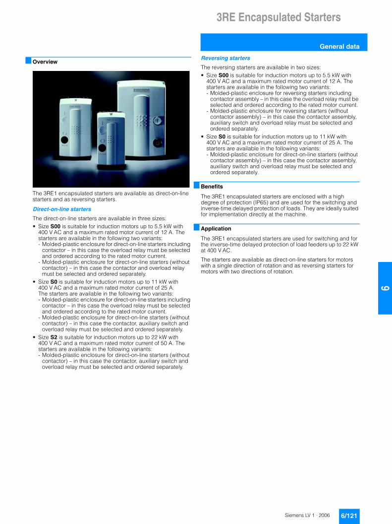
3RE Encapsulated Starters
General data
6/121Siemens LV 1 · 2006
66
■ Overview
The 3RE1 encapsulated starters are available as direct-on-line starters and as reversing starters.
Direct-on-line starters
The direct-on-line starters are available in three sizes:• Size S00 is suitable for induction motors up to 5.5 kW with
400 V AC and a maximum rated motor current of 12 A. The starters are available in the following two variants: - Molded-plastic enclosure for direct-on-line starters including
contactor – in this case the overload relay must be selected and ordered according to the rated motor current.
- Molded-plastic enclosure for direct-on-line starters (without contactor) – in this case the contactor and overload relay must be selected and ordered separately.
• Size S0 is suitable for induction motors up to 11 kW with 400 V AC and a maximum rated motor current of 25 A. The starters are available in the following two variants: - Molded-plastic enclosure for direct-on-line starters including
contactor – in this case the overload relay must be selected and ordered according to the rated motor current.
- Molded-plastic enclosure for direct-on-line starters (without contactor) – in this case the contactor, auxiliary switch and overload relay must be selected and ordered separately.
• Size S2 is suitable for induction motors up to 22 kW with 400 V AC and a maximum rated motor current of 50 A. The starters are available in the following variants: - Molded-plastic enclosure for direct-on-line starters (without
contactor) – in this case the contactor, auxiliary switch and overload relay must be selected and ordered separately.
Reversing starters
The reversing starters are available in two sizes:• Size S00 is suitable for induction motors up to 5.5 kW with
400 V AC and a maximum rated motor current of 12 A. The starters are available in the following two variants: - Molded-plastic enclosure for reversing starters including
contactor assembly – in this case the overload relay must be selected and ordered according to the rated motor current.
- Molded-plastic enclosure for reversing starters (without contactor assembly) – in this case the contactor assembly, auxiliary switch and overload relay must be selected and ordered separately.
• Size S0 is suitable for induction motors up to 11 kW with 400 V AC and a maximum rated motor current of 25 A. The starters are available in the following variants: - Molded-plastic enclosure for direct-on-line starters (without
contactor assembly) – in this case the contactor assembly, auxiliary switch and overload relay must be selected and ordered separately.
■ Benefits
The 3RE1 encapsulated starters are enclosed with a high degree of protection (IP65) and are used for the switching and inverse-time delayed protection of loads. They are ideally suited for implementation directly at the machine.
■ Application
The 3RE1 encapsulated starters are used for switching and for the inverse-time delayed protection of load feeders up to 22 kW at 400 V AC.
The starters are available as direct-on-line starters for motors with a single direction of rotation and as reversing starters for motors with two directions of rotation.

3RE Encapsulated Starters
3RE10 combination starters, direct-on-line
6/122 Siemens LV 1 · 2006
6
■ Selection and ordering data
Size Rated dataUtilization category AC-2/AC-3 Tu: up to + 35 °C
Rated control supply voltage Us
DT Screw connections PU (UNIT, SET, M)
PS* PG Weight per PU approx.
Opera-tional cur-rent Ie at 400 V
Output of induction motors at 400 V/50 Hz
Order No. Price per PU
A kW V at Hz kg
Direct-on-line starters including contactor
3RE10 10
S00 12 5.5 230 AC 50 / 60 B 3RE10 10-8XC17-0AP0 1 1 unit 101 0.510400 AC 50 / 60 B 3RE10 10-8XC17-0AV0 1 1 unit 101 0.510
S0 17 7.5 230 AC 50 B 3RE10 20-8XC25-0AP0 1 1 unit 101 0.830400 AC 50 B 3RE10 20-8XC25-0AV0 1 1 unit 101 0.810
25 11 230 AC 50 B 3RE10 20-8XC26-0AP0 1 1 unit 101 0.830400 AC 50 B 3RE10 20-8XC26-0AV0 1 1 unit 101 0.810
* You can order this quantity or a multiple thereof.

3RE Encapsulated Starters
3RE13 reversing starters
6/123Siemens LV 1 · 2006
66
■ Selection and ordering data
Size Rated dataUtilization category AC-2/AC-3 Tu: up to + 35 °C
Rated control supply voltage Us
DT Screw connections PU (UNIT, SET, M)
PS* PG Weight per PU approx.
Opera-tional cur-rent Ie at 400 V
Output of induction motors at 400 V/50 Hz
Order No. Price per PU
A kW V at Hz kg
Reversing starters including contactor assembly
3RE13 10
S00 12 5.5 230 AC 50 / 60 B 3RE13 10-8XC17-0AP0 1 1 unit 101 1.000400 AC 50 / 60 B 3RE13 10-8XC17-0AV0 1 1 unit 101 2.460
* You can order this quantity or a multiple thereof.

3RE Encapsulated Starters
Accessories
6/124 Siemens LV 1 · 2006
6
■ Selection and ordering data
Version For con-tactor Overload relay
DT Order No. Price per PU
PU (UNIT, SET, M)
PS* PG Weight per PU approx.
Size kg
Enclosures for direct-on-line starters
3RE19 23-1CB2
Molded-plastic enclosures for surface mounting
Degree of protection IP65, with actuating elements, with metric cable gland
• With PE/ground terminal S00 B 3RE19 13-1CB1 1 1 unit 101 0.320
• With N and PE/ground terminals S0 B 3RE19 23-1CB2 1 1 unit 101 0.450
• With N and PE/ground terminals S2 B 3RE19 33-1CB3 1 1 unit 101 1.000
Enclosures for reversing starters
3RE19 23-2CB3
Molded-plastic enclosures for surface mounting
Degree of protection IP65, with actuating elements, with metric cable gland
• With N and PE/ground terminals S00/S0 B 3RE19 13-2CB3 1 1 unit 101 1.020
7* You can order this quantity or a multiple thereof.


