
Lenovo S50-30 All-In-One PC HardwareMaintenance Manual
Machine Types: F0BA [S50-30]

Lenovo S50-30 All-In-One PCHardware Maintenance Manual
Machine Types: F0BA [S50-30]

First Edition (March 2015)25th
© Copyright Lenovo 2015, 2015.
LIMITED AND RESTRICTED RIGHTS NOTICE: If data or software are delivered pursuant a General ServicesAdministration “GSA” contract, use, reproduction, or disclosure is subject to restrictions set forth in Contract No.GS-35F-05925
Contents
Chapter 1. About this manual . . . . . 1Important Safety Information . . . . . . . . . 1
Chapter 2. Safety information. . . . . 3General safety . . . . . . . . . . . . . . . 3Electrical safety . . . . . . . . . . . . . . 3Safety inspection guide . . . . . . . . . . . 5Handling electrostatic discharge-sensitivedevices . . . . . . . . . . . . . . . . . 5Grounding requirements . . . . . . . . . . . 6Safety notices . . . . . . . . . . . . . . . 6
Chapter 3. General information . . . . 9Specifications . . . . . . . . . . . . . . . 9
Chapter 4. General Checkout . . . . . 11
Chapter 5. Using the Setup Utility. . . 13Starting the Lenovo BIOS Setup Utility program . 13Viewing and changing settings . . . . . . . . 13Using passwords. . . . . . . . . . . . . . 13Enabling or disabling a device . . . . . . . . 15Selecting a startup device . . . . . . . . . . 16Changing booting mode . . . . . . . . . . . 17Exiting the Lenovo BIOS Setup Utility program . . 17
Chapter 6. Symptom-to-FRU Index . . 19Hard disk drive boot error . . . . . . . . . . 19Power Supply Problems . . . . . . . . . . . 19POST error codes . . . . . . . . . . . . . 20Undetermined problems . . . . . . . . . . . 20
Chapter 7. Locations . . . . . . . . . 21
Chapter 8. Replacing hardware . . . . 25General information. . . . . . . . . . . . . 25Replacing the keyboard and mouse . . . . . . 26Replacing the power adapter . . . . . . . . . 26Removing the frame stand . . . . . . . . . . 28Removing the monitor stand . . . . . . . . . 29Removing the transformer stand. . . . . . . . 30Removing the rear cover . . . . . . . . . . . 31Replacing the hard disk drive . . . . . . . . . 32Replacing the optical drive . . . . . . . . . . 33Replacing the camera . . . . . . . . . . . . 34Replacing the converter board . . . . . . . . 35Replacing the button board. . . . . . . . . . 36Replacing the LCD switch board. . . . . . . . 37Removing the hinge fixing bracket . . . . . . . 37Removing the EMI cover . . . . . . . . . . . 38Replacing the system fan . . . . . . . . . . 39Replacing the heat-sink . . . . . . . . . . . 40Replacing the Wi-Fi card. . . . . . . . . . . 41Replacing a memory module . . . . . . . . . 42Replacing the speaker system . . . . . . . . 43Replacing the motherboard. . . . . . . . . . 44Replacing the LED panel. . . . . . . . . . . 45
Chapter 9. FRU lists . . . . . . . . . . 49
Chapter 10. Additional ServiceInformation . . . . . . . . . . . . . . 57
© Copyright Lenovo 2015, 2015 iii

iv Lenovo S50-30 All-In-One PC Hardware Maintenance Manual

Chapter 1. About this manual
This manual contains service and reference information for Lenovo S50-30 All-In-One computers listed onthe cover. It is intended only for trained servicers who are familiar with Lenovo computer products.
Before servicing a Lenovo product, be sure to read the Safety Information.
The description of the TV-tuner card in this manual applies only to computers with a TV-tuner card installed.It does not apply to computers without a TV-tuner card.
Important Safety InformationBe sure to read all CAUTION and DANGER sections in this manual before following any of the instructions.
Veuillez lire toutes les consignes de type DANGER et ATTENTION du présent document avant d’exécuterles instructions.
Lesen Sie unbedingt alle Hinweise vom Typ “ACHTUNG” oder “VORSICHT” in dieser Dokumentation, bevorSie irgendwelche Vorgänge durchführen
Leggere le istruzioni introdotte da ATTENZIONE e PERICOLO presenti nel manuale prima di eseguire unaqualsiasi delle istruzioni
Certifique-se de ler todas as instruções de cuidado e perigo neste manual antes de executar qualqueruma das instruções
Es importante que lea todas las declaraciones de precaución y de peligro de este manual antes de seguirlas instrucciones.
© Copyright Lenovo 2015, 2015 1

2 Lenovo S50-30 All-In-One PC Hardware Maintenance Manual
Chapter 2. Safety information
This chapter contains the safety information that you need to be familiar with before servicing a computer.
General safetyFollow these rules to ensure general safety:
• Keep the areas around the computer clear and clean during and after maintenance.
• When lifting any heavy object:
1. Ensure you can stand safely without slipping.
2. Distribute the weight of the object equally across both feet.
3. Lift slowly. Never move suddenly or twist when you attempt to lift.
4. Lift by standing or by pushing up with your leg muscles; this action removes the strain from themuscles in your back.Do not attempt to lift any objects that weigh more than 16 kg (35 lbs.) or objects that you thinkare too heavy for you.
• Do not perform any action that would create a hazard for the customer, or would make the computerunsafe.
• Before you start the computer, ensure that other service representatives and customer personnel are notin a position that would create a hazard for them.
• Place removed covers and other parts in a safe place, away from all personnel, while you are servicing thecomputer.
• Keep your tool case away from areas that people may walk through to ensure no-one trips over it.
• Do not wear loose clothing that can be trapped in the moving parts of a machine. Ensure that your sleevesare fastened or rolled up above your elbows. If your hair is long, tie or fasten it back.
• Insert the ends of your necktie or scarf inside clothing or fasten it with a nonconductive clip, approximately8 centimeters (3 inches) from the end.
• Do not wear jewelry, chains, metal-frame eyeglasses, or metal fasteners for your clothing.Remember: Metal objects are good electrical conductors.
• Wear safety glasses when you are: hammering, drilling soldering, cutting wire, attaching springs, usingsolvents, or working in any other conditions that might be hazardous to your eyes.
• After service, reinstall all safety shields, guards, labels, and ground wires. Replace any safety devicethat is worn or defective.
• Reattach all covers correctly before returning the computer to the customer.
Electrical safety
CAUTION:Electrical current from power, telephone, and communication cables can be hazardous. To avoidpersonal injury or equipment damage, disconnect any attached power cords, telecommunicationcables, network cables, and modem cables before you open the computer covers, unless instructedotherwise in the installation and configuration procedures.
© Copyright Lenovo 2015, 2015 3

Observe the following rules when working on electrical equipment.
Important: Use only approved tools and test equipment. Some hand tools have handles covered with a softmaterial that does not insulate you when working with live electrical currents. Many customers have rubberfloor mats near their equipment that contain small conductive fibers to decrease electrostatic discharge.
• Find the room emergency power-off (EPO) switch, disconnecting switch, or electrical outlet. If an electricalaccident occurs, you can then operate the switch or unplug the power cord quickly.
• Do not work alone under hazardous conditions or near equipment that has hazardous voltages.
• Disconnect all power before:
– Performing a mechanical inspection
– Working near power supplies
– Removing or installing Field Replaceable Units (FRUs)
• Before you start to work on the computer, unplug the power cord. If you cannot unplug it, ask thecustomer to power-off the electrical outlet that supplies power to the machine and to lock the electricaloutlet in the off position.
• If you need to work on a computer that has exposed electrical circuits, observe the following precautions:
– Ensure that another person, familiar with the power-off controls, is near you.Remember: Another person must be there to switch off the power, if necessary.
– Use only one hand when working with powered-on electrical equipment; keep the other hand in yourpocket or behind your back.Remember: There must be a complete circuit to cause electrical shock. By observing the above rule,you may prevent a current from passing through your body.
– When using a tester, set the controls correctly and use the approved probe leads and accessories forthat tester.
– Stand on suitable rubber mats (obtained locally, if necessary) to insulate you from grounds such asmetal floor strips and machine frames.
Observe the special safety precautions when you work with very high voltages; these instructions are inthe safety sections of the maintenance information. Use extreme care when measuring high voltages.
• Regularly inspect and maintain your electrical hand tools to ensure they are safe to use.
• Do not use worn or broken tools and testers.
• Never assume that power has been disconnected from a circuit. First, check that it has been powered off.
• Always look carefully for possible hazards in your work area. Examples of these hazards are wet floors,non-grounded power extension cables, conditions that may cause or allow power surges, and missingsafety grounds.
• Do not touch live electrical circuits with the reflective surface of a plastic dental mirror. This surface isconductive, and touching a live circuit can cause personal injury and damage to the computer.
• Do not service the following parts with the power on when they are removed from their normal operatingpositions in a computer:
– Power supply units
– Pumps
– Blowers and fans
– Motor generators
and similar units. (This practice ensures correct grounding of the units.)
• If an electrical accident occurs:
– Use caution; do not become a victim yourself.
4 Lenovo S50-30 All-In-One PC Hardware Maintenance Manual

– Switch off power.
– Send another person to get medical aid.
Safety inspection guideThe intent of this inspection guide is to assist you in identifying potential hazards posed by these products.Each computer, as it was designed and built, had required safety items installed to protect users andservice personnel from injury. This guide addresses only those items. However, good judgment should beused to identify potential safety hazards due to attachment of features or options not covered by thisinspection guide.
If any hazards are present, you must determine how serious the apparent hazard could be and whether youcan continue without first resolving the problem.
Consider the following items and the safety hazards they present:
• Electrical hazards, especially primary power (primary voltage on the frame can cause serious or fatalelectrical shock).
• Explosive hazards, such as a damaged CRT face or bulging capacitor
• Mechanical hazards, such as loose or missing hardware
The guide consists of a series of steps presented as a checklist. Begin the checks with the power off, andthe power cord disconnected.
Checklist:
1. Check exterior covers for damage (loose, broken, or sharp edges).
2. Power-off the computer. Disconnect the power cord.
3. Check the power cord for:
a. A third-wire ground connector in good condition. Use a meter to measure third-wire groundcontinuity for 0.1 ohm or less between the external ground pin and frame ground.
b. The power cord should be the appropriate type as specified in the parts listings.
c. Insulation must not be frayed or worn.
4. Remove the cover.
5. Check for any obvious alterations. Use good judgment as to the safety of any alterations.
6. Check inside the unit for any obvious hazards, such as metal filings, contamination, water or otherliquids, or signs of fire or smoke damage.
7. Check for worn, frayed, or pinched cables.
8. Check that the power-supply cover fasteners (screws or rivets) have not been removed or tampered with.
Handling electrostatic discharge-sensitive devicesAny computer part containing transistors or integrated circuits (ICs) should be considered sensitive toelectrostatic discharge (ESD). ESD damage can occur when there is a difference in charge between objects.Protect against ESD damage by equalizing the charge so that the computer, the part, the work mat, and theperson handling the part are all at the same charge.
Notes:
1. Use product-specific ESD procedures when they exceed the requirements noted here.
2. Make sure that the ESD protective devices you use have been certified (ISO 9000) as fully effective.
When handling ESD-sensitive parts:
Chapter 2. Safety information 5
• Keep the parts in protective packages until they are inserted into the product.
• Avoid contact with other people while handling the part.
• Wear a grounded wrist strap against your skin to eliminate static on your body.
• Prevent the part from touching your clothing. Most clothing is insulative and retains a charge evenwhen you are wearing a wrist strap.
• Use the black side of a grounded work mat to provide a static-free work surface. The mat is especiallyuseful when handling ESD-sensitive devices.
• Select a grounding system, such as those listed below, to provide protection that meets the specificservice requirement.
Note: The use of a grounding system is desirable but not required to protect against ESD damage.
– Attach the ESD ground clip to any frame ground, ground braid, or green-wire ground.
– Use an ESD common ground or reference point when working on a double-insulated orbattery-operated system. You can use coax or connector-outside shells on these systems.
– Use the round ground-prong of the AC plug on AC-operated computers.
Grounding requirementsElectrical grounding of the computer is required for operator safety and correct system function. Propergrounding of the electrical outlet can be verified by a certified electrician.
Safety noticesThe CAUTION and DANGER safety notices in this section are provided in the language of English.
DANGER
Electrical current from power, telephone and communication cables is hazardous.
To avoid a shock hazard:
• Do not connect or disconnect any cables or perform installation, maintenance, or reconfigurationof this product during an electrical storm.
• Connect all power cords to a properly wired and grounded electrical outlet.
• Connect any equipment that will be attached to this product to a properly wired outlet.
• When possible, use one hand only to connect or disconnect signal cables.
• Never turn on any equipment when there is evidence of fire, water, or structural damage.
• Disconnect the attached power cords, telecommunications cables, network cables, and modemcables before you open the device covers, unless instructed otherwise in the installation andconfiguration procedures.
• Connect and disconnect cables as described in the following table when installing, moving, oropening covers on this product or attached devices.
6 Lenovo S50-30 All-In-One PC Hardware Maintenance Manual
To Connect To Disconnect
1. Turn everything OFF.
2. First, attach all cables to devices.
3. Attach signal cables to connectors.
4. Attach power cords to outlet.
5. Turn device ON.
1. Turn everything OFF.
2. First, remove power cords from outlets.
3. Remove signal cables from connectors.
4. Remove all cables from devices.
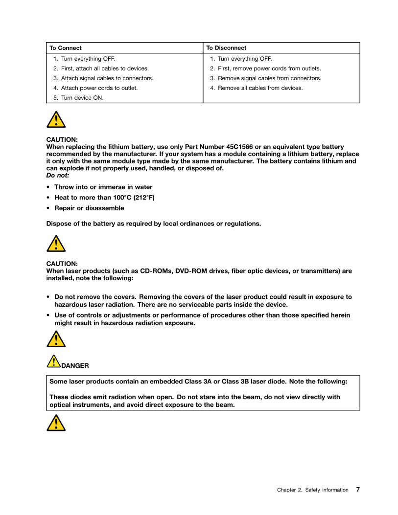
CAUTION:When replacing the lithium battery, use only Part Number 45C1566 or an equivalent type batteryrecommended by the manufacturer. If your system has a module containing a lithium battery, replaceit only with the same module type made by the same manufacturer. The battery contains lithium andcan explode if not properly used, handled, or disposed of.Do not:
• Throw into or immerse in water
• Heat to more than 100°C (212°F)
• Repair or disassemble
Dispose of the battery as required by local ordinances or regulations.
CAUTION:When laser products (such as CD-ROMs, DVD-ROM drives, fiber optic devices, or transmitters) areinstalled, note the following:
• Do not remove the covers. Removing the covers of the laser product could result in exposure tohazardous laser radiation. There are no serviceable parts inside the device.
• Use of controls or adjustments or performance of procedures other than those specified hereinmight result in hazardous radiation exposure.
DANGER
Some laser products contain an embedded Class 3A or Class 3B laser diode. Note the following:
These diodes emit radiation when open. Do not stare into the beam, do not view directly withoptical instruments, and avoid direct exposure to the beam.
Chapter 2. Safety information 7
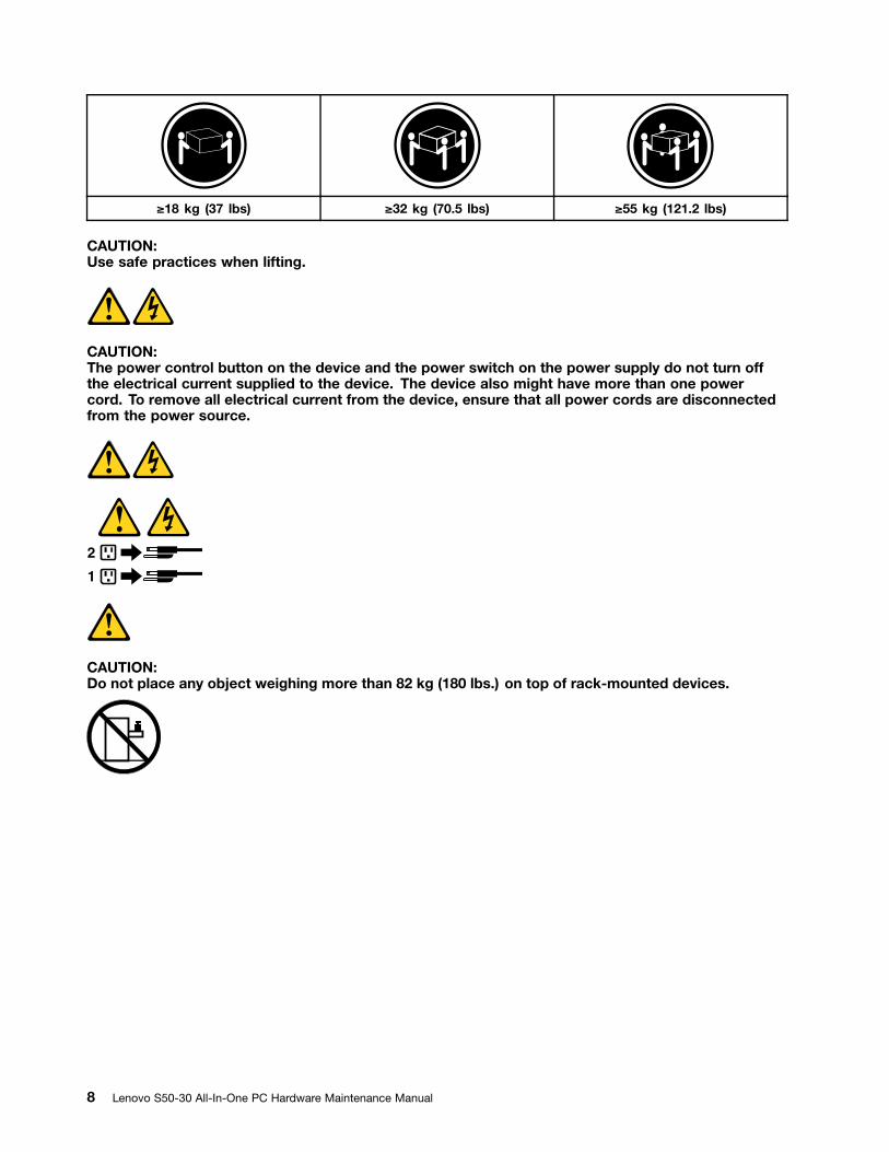
≥18 kg (37 lbs) ≥32 kg (70.5 lbs) ≥55 kg (121.2 lbs)
CAUTION:Use safe practices when lifting.
CAUTION:The power control button on the device and the power switch on the power supply do not turn offthe electrical current supplied to the device. The device also might have more than one powercord. To remove all electrical current from the device, ensure that all power cords are disconnectedfrom the power source.
1
2
CAUTION:Do not place any object weighing more than 82 kg (180 lbs.) on top of rack-mounted devices.
8 Lenovo S50-30 All-In-One PC Hardware Maintenance Manual

Chapter 3. General information
This chapter provides general information that applies to all computer models covered by this manual.
SpecificationsThis section lists the physical specifications for your computer.
This section lists the physical specifications for your computer.
Type Lenovo S50-30
This section lists the physical specifications.
Environment
Air temperature:
Operating: 10° to 35°C
Transit: -20° to 55°C
Humidity:
Operating: 35% to 80%
Transit: 20% to 90% (40°C)
Altitude: 86KPa to 106KPa
Electrical input:
Input voltage: 90V-264V(AC)
Input frequency: 47Hz-63Hz
© Copyright Lenovo 2015, 2015 9

10 Lenovo S50-30 All-In-One PC Hardware Maintenance Manual
Chapter 4. General Checkout
Attention: The drives in the computer you are servicing might have been rearranged or the drive startupsequence may have been changed. Be extremely careful during write operations such as copying, saving, orformatting. Data or programs can be overwritten if you select an incorrect drive.
General error messages appear if a problem or conflict is found by an application, the operating system, orboth. For an explanation of these messages, refer to the information supplied with that software package.
Use the following procedure to help determine the cause of the problem:
1. Power-off the computer and all external devices.
2. Check all cables and power cords.
3. Set all display controls to the middle position.
4. Power-on all external devices.
5. Power-on the computer.
• Look for displayed error codes.
• Look for readable instructions or a main menu on the display.
If you did not receive the correct response, proceed to step 6.
If you did receive the correct response, proceed to step 7.
6. If one of the following happens, follow the instruction given:
• If the computer displays a POST error, go to “POST error codes”.
• If the computer hangs and no error is displayed, continue at step 7.
7. If the test stops and you cannot continue, replace the last device tested.
© Copyright Lenovo 2015, 2015 11

12 Lenovo S50-30 All-In-One PC Hardware Maintenance Manual
Chapter 5. Using the Setup Utility
The Setup Utility program is used to view and change the configuration settings of your computer, regardlessof which operating system you are using. However, the operating system settings might override any similarsettings in the Setup Utility program.
Starting the Lenovo BIOS Setup Utility programTo start the Lenovo BIOS Setup Utility program, do the following:
1. If your computer is already on when you start this procedure, shut down the operating system andturn off the computer.
2. Press and hold the F1 key then turn on the computer. When the Lenovo BIOS Setup Utility program isdisplayed, release the F1 key.
Note: If a Power-On Password or an Administrator Password has been set, the Setup Utility program menuwill not be displayed until you type your password. For more information, see “Using passwords.”
Viewing and changing settingsSystem configuration options are listed in the Lenovo BIOS Setup Utility program menu. To view or changesettings, see “Starting the Setup Utility program.”
You must use the keyboard when using the Lenovo BIOS Setup Utility menu. The keys used to performvarious tasks are displayed on the bottom of each screen.
Using passwordsYou can use the Lenovo BIOS Setup Utility program to set passwords to prevent unauthorized personsfrom gaining access to your computer and data. See “Starting the Setup Utility program.” The followingtypes of passwords are available:
• Administrator Password
• Power-On Password
You do not have to set any passwords to use your computer. However, if you decide to set passwords, readthe following sections.
Password considerations
A password can be any combination of letters and numbers up to 16 characters (a-z and 0-9). For securityreasons, it is a good idea to use a strong password that cannot be easily compromised. We suggest thatpasswords should follow these rules:
• For a strong password, use 7-16 characters and a mix of letters and numbers.
• Do not use your name or your user name.
• Do not use a common word or a common name.
• Use something significantly different from your previous password.
Attention: Administrator and Power-On passwords are not case sensitive.
© Copyright Lenovo 2015, 2015 13
Administrator Password
Setting an Administrator Password deters unauthorized persons from changing configuration settings. Youmight want to set an Administrator Password if you are responsible for maintaining the settings of severalcomputers.
After you set an Administrator Password, a password prompt is displayed every time you access the LenovoBIOS Setup Utility program.
If both the Administrator and Power-On Password are set, you can type either password. However, you mustuse your Administrator Password to change any configuration settings.
Setting, changing, or deleting an Administrator Password
To set an Administrator Password, do the following:
Note: A password can be any combination of letters and numbers up to 16 characters (a-z and 0-9). Formore information, see “Password considerations” on page 13.
1. Start the Lenovo BIOS Setup Utility program (see “Starting the Lenovo BIOS Setup Utility program” onpage 13).
2. From the Security menu, select Set Administrator Password and press the Enter key.
3. The password dialog box will be displayed. Type the password then press the Enter key.
4. Retype the password to confirm, then press the Enter key. If you typed the password correctly, thepassword will be installed. A Setup Notice will be displayed confirming that your changes has beensaved.
5. Return to the Lenovo BIOS Setup Utility program menu and select the Exit option.
6. Select Save Changes and Exit from the menu.
To change an Administrator Password, do the following:
1. Start the Lenovo BIOS Setup Utility program (see “Starting the Lenovo BIOS Setup Utility program” onpage 13).
2. From the Security menu, select Set Administrator Password and press the Enter key.
3. The password dialog box will be displayed. Type the current password then press the Enter key.
4. Type the new password, then press the Enter key. Retype the new password to confirm it. If you typedthe new password correctly, the new password will be installed. A Setup Notice will be displayedconfirming that your changes have been saved.
5. Return to the Lenovo BIOS Setup Utility program menu and select the Exit option.
6. Select Save Changes and Exit from the menu.
To delete a previously set Administrator Password, do the following :
1. Start the Lenovo BIOS Setup Utility program (see “Starting the Lenovo BIOS Setup Utility program” onpage 13).
2. From the Security menu, select Set Administrator Password and press the Enter key.
3. The password dialog box will be displayed. Type the current password and press the Enter key.
4. Leave each new password line item blank, then press the Enter key. A Setup Notice will be displayedconfirming that your changes have been saved.
5. Return to the Lenovo BIOS Setup Utility program menu and select the Exit option.
6. Select Save Changes and Exit from the menu.
14 Lenovo S50-30 All-In-One PC Hardware Maintenance Manual
Power-On Password
When a Power-On Password is set, you cannot start the Lenovo BIOS Setup Utility program until a validpassword is typed from the keyboard.
Setting, changing, or deleting a Power-On Password
Note: A password can be any combination of letters and numbers up to 16 characters (a-z and 0-9).
To set a Power-On Password, do the following:
1. Start the Lenovo BIOS Setup Utility program (see ”Starting the Lenovo BIOS Setup Utility program” onpage 13).
2. From the Security menu, select Set Power-On Password and press the Enter key.
3. The password dialog box will be displayed. Type the password, then press the Enter key.
4. Retype the password to confirm. If you typed the password correctly, the password will be installed.
5. Return to the Lenovo BIOS Setup Utility program menu and select the Exit option.
6. Select Save Changes and Exit from the menu.
To change a Power-On Password, do the following:
1. Start the Lenovo BIOS Setup Utility program (see ”Starting the Lenovo BIOS Setup Utility program” onpage 13).
2. From the Security menu, select Set Power-On Password and press the Enter key.
3. The password dialog box will be displayed. Type the current password then press the Enter key.
4. Type the new password, then press the Enter key. Retype the new password to confirm it. If you typedthe new password correctly, the new password will be installed. A Setup Notice will be displayedconfirming that your changes have been saved.
5. Return to the Lenovo BIOS Setup Utility program menu and select the Exit option.
6. Select Save Changes and Exit from the menu.
To delete a previously set Power-On Password, do the following :
1. Start the Lenovo BIOS Setup Utility program (see ”Starting the Lenovo BIOS Setup Utility program” onpage 13).
2. From the Security menu, select Set Power-On Password and press the Enter key.
3. The password dialog box will be displayed. Type the current password and press the Enter key.
4. Leave each new password line item blank, then press Enter. A Setup Notice will be displayed confirmingthat your changes have been saved.
5. Return to the Lenovo BIOS Setup Utility program menu and select the Exit option.
6. Select Save Changes and Exit from the menu.
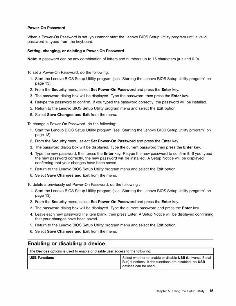
Enabling or disabling a deviceThe Devices options is used to enable or disable user access to the following:
USB Functions Select whether to enable or disable USB (Universal SerialBus) functions. If the functions are disabled, no USBdevices can be used.
Chapter 5. Using the Setup Utility 15
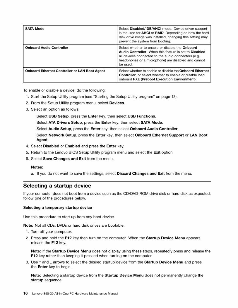
SATA Mode Select Disabled/IDE/AHCI mode. Device driver supportis required for AHCI or RAID. Depending on how the harddisk drive image was installed, changing this setting mayprevent the system from booting.
Onboard Audio Controller Select whether to enable or disable the OnboardAudio Controller. When this feature is set to Disabledall devices connected to the audio connectors (e.g.headphones or a microphone) are disabled and cannotbe used.
Onboard Ethernet Controller or LAN Boot Agent Select whether to enable or disable the Onboard EthernetController, or select whether to enable or disable loadonboard PXE (Preboot Execution Environment).
To enable or disable a device, do the following:
1. Start the Setup Utility program (see “Starting the Setup Utility program” on page 13).
2. From the Setup Utility program menu, select Devices.
3. Select an option as follows:
Select USB Setup, press the Enter key, then select USB Functions.
Select ATA Drivers Setup, press the Enter key, then select SATA Mode.
Select Audio Setup, press the Enter key, then select Onboard Audio Controller.
Select Network Setup, press the Enter key, then select Onboard Ethernet Support or LAN BootAgent.
4. Select Disabled or Enabled and press the Enter key.
5. Return to the Lenovo BIOS Setup Utility program menu and select the Exit option.
6. Select Save Changes and Exit from the menu.
Notes:
a. If you do not want to save the settings, select Discard Changes and Exit from the menu.
Selecting a startup deviceIf your computer does not boot from a device such as the CD/DVD-ROM drive disk or hard disk as expected,follow one of the procedures below.
Selecting a temporary startup device
Use this procedure to start up from any boot device.
Note: Not all CDs, DVDs or hard disk drives are bootable.
1. Turn off your computer.
2. Press and hold the F12 key then turn on the computer. When the Startup Device Menu appears,release the F12 key.
Note: If the Startup Device Menu does not display using these steps, repeatedly press and release theF12 key rather than keeping it pressed when turning on the computer.
3. Use ↑ and ↓ arrows to select the desired startup device from the Startup Device Menu and pressthe Enter key to begin.
Note: Selecting a startup device from the Startup Device Menu does not permanently change thestartup sequence.
16 Lenovo S50-30 All-In-One PC Hardware Maintenance Manual
Selecting or changing the startup device sequence
To view or permanently change the configured startup device sequence, do the following:
1. Start the Lenovo BIOS Setup Utility program (see “Starting the Lenovo BIOS Setup Utility program” onpage 13).
2. From the Lenovo BIOS Setup Utility program main menu, select the Startup option.
3. Press the Enter key, and select the devices for the Primary Boot Sequence. Read the informationdisplayed on the right side of the screen.
4. Use and ¯ arrows to select a device. Use the <+> or <-> keys to move a device up or down. Use the<×> key to exclude the device from or include the device in the boot sequence.
5. Return to the Lenovo BIOS Setup Utility program menu and select the Exit option.
6. Select Save Changes and Exit from the menu.
Notes:
a. If you do not want to save the settings, select Discard Changes and Exit from the menu.
b. If you have changed these settings and want to return to the default settings, select Load OptimalDefaults from the menu.
Changing booting modeThere are two boot modes UEFI and Legacy for your computer. The default boot mode for your computer isthe UEFI mode. If you need to install a legacy Windows operating system (any operating system beforeWindows 8) on your computer, you must change the boot mode to Legacy support. The legacy Windowsoperating system cannot be installed if you don’t change the boot mode.
To change the booting mode, do the following:
1. Start the Lenovo BIOS Setup Utility program (see “Starting the Lenovo BIOS Setup Utility program” onpage 13).
2. From the Lenovo BIOS Setup Utility program main menu, select the Startup option.
3. Select the Boot Priority, then press Enter key. From the pop up “Boot Priority” window chooseLegacy mode.
4. Return to the Lenovo BIOS Setup Utility program menu and select the Exit option.
5. Select Save Changes and Exit from the menu.
Exiting the Lenovo BIOS Setup Utility programAfter you finish viewing or changing settings, press the Esc key to return to the Lenovo BIOS Setup Utilityprogram main menu. You might have to press the Esc key several times. Do one of the following:
• If you want to save the new settings, select Save Changes and Exit from the menu. When the Save& reset window shows, select the Yes button, and then press the Enter key to exit the Lenovo BIOSSetup Utility program.
• If you do not want to save the settings, select Discard Changes and Exit from the menu. When theReset Without Saving window shows, select the Yes button, and then press the Enter key to exit theLenovo BIOS Setup Utility program.
Chapter 5. Using the Setup Utility 17

18 Lenovo S50-30 All-In-One PC Hardware Maintenance Manual
Chapter 6. Symptom-to-FRU Index
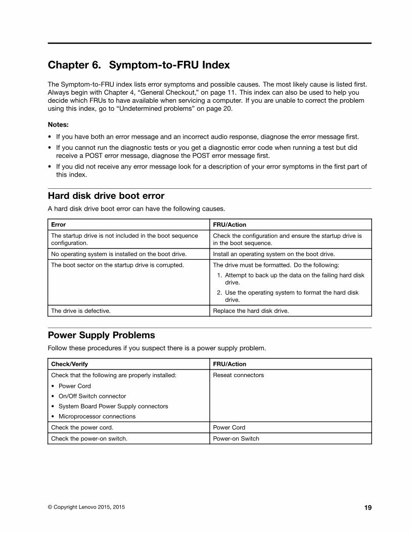
The Symptom-to-FRU index lists error symptoms and possible causes. The most likely cause is listed first.Always begin with Chapter 4, “General Checkout,” on page 11. This index can also be used to help youdecide which FRUs to have available when servicing a computer. If you are unable to correct the problemusing this index, go to “Undetermined problems” on page 20.
Notes:
• If you have both an error message and an incorrect audio response, diagnose the error message first.
• If you cannot run the diagnostic tests or you get a diagnostic error code when running a test but didreceive a POST error message, diagnose the POST error message first.
• If you did not receive any error message look for a description of your error symptoms in the first part ofthis index.
Hard disk drive boot errorA hard disk drive boot error can have the following causes.
Error FRU/Action
The startup drive is not included in the boot sequenceconfiguration.
Check the configuration and ensure the startup drive isin the boot sequence.
No operating system is installed on the boot drive. Install an operating system on the boot drive.
The boot sector on the startup drive is corrupted. The drive must be formatted. Do the following:
1. Attempt to back up the data on the failing hard diskdrive.
2. Use the operating system to format the hard diskdrive.
The drive is defective. Replace the hard disk drive.
Power Supply ProblemsFollow these procedures if you suspect there is a power supply problem.
Check/Verify FRU/Action
Check that the following are properly installed:
• Power Cord
• On/Off Switch connector
• System Board Power Supply connectors
• Microprocessor connections
Reseat connectors
Check the power cord. Power Cord
Check the power-on switch. Power-on Switch
© Copyright Lenovo 2015, 2015 19
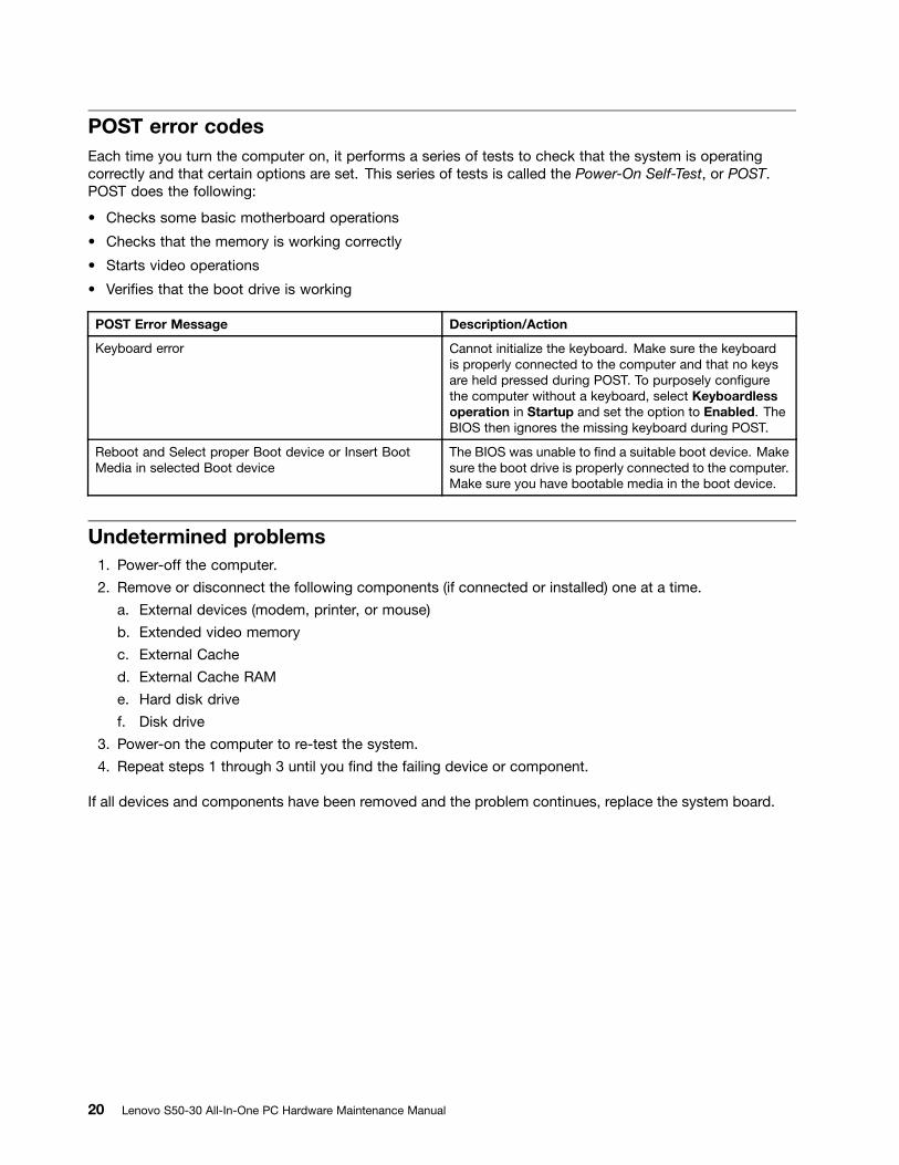
POST error codesEach time you turn the computer on, it performs a series of tests to check that the system is operatingcorrectly and that certain options are set. This series of tests is called the Power-On Self-Test, or POST.POST does the following:
• Checks some basic motherboard operations
• Checks that the memory is working correctly
• Starts video operations
• Verifies that the boot drive is working
POST Error Message Description/Action
Keyboard error Cannot initialize the keyboard. Make sure the keyboardis properly connected to the computer and that no keysare held pressed during POST. To purposely configurethe computer without a keyboard, select Keyboardlessoperation in Startup and set the option to Enabled. TheBIOS then ignores the missing keyboard during POST.
Reboot and Select proper Boot device or Insert BootMedia in selected Boot device
The BIOS was unable to find a suitable boot device. Makesure the boot drive is properly connected to the computer.Make sure you have bootable media in the boot device.
Undetermined problems1. Power-off the computer.
2. Remove or disconnect the following components (if connected or installed) one at a time.
a. External devices (modem, printer, or mouse)
b. Extended video memory
c. External Cache
d. External Cache RAM
e. Hard disk drive
f. Disk drive
3. Power-on the computer to re-test the system.
4. Repeat steps 1 through 3 until you find the failing device or component.
If all devices and components have been removed and the problem continues, replace the system board.
20 Lenovo S50-30 All-In-One PC Hardware Maintenance Manual
Chapter 7. Locations
This section provides illustrations to help locate the various connectors, controls and components of thecomputer.
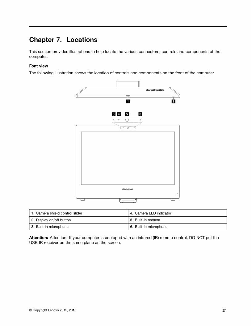
Font view
The following illustration shows the location of controls and components on the front of the computer.
3 4
1 2
5 6
1. Camera shield control slider 4. Camera LED indicator
2. Display on/off button 5. Built-in camera
3. Built-in microphone 6. Built-in microphone
Attention: Attention: If your computer is equipped with an infrared (IR) remote control, DO NOT put theUSB IR receiver on the same plane as the screen.
© Copyright Lenovo 2015, 2015 21

Left and right views of the computer
1
4
6
7
8
9
23
5
1. USB 3.0 connector 6. Optical drive eject button
2. Headphone connector 7. Volume control button
3. Microphone connector 8. PC mode/HDMI-in switch
4. Always On USB 3.0 connector 9. Power button
5. Memory card reader
22 Lenovo S50-30 All-In-One PC Hardware Maintenance Manual

Rear view of the computer
2 3 4 5 6 71
8
8
1. Security cable slot 5. USB 2.0 connectors (2)
2. Power connector 6. HDMI-out connector
3. Ethernet connector 7. HDMI-in connector
4. USB 2.0 connector / USB keyboard power onconnector*
8. Air vents
Note: * USB keyboard power on: Press Alt + P to power on if the USB keyboard is connected to thisUSB port.
Attention: Be sure not to block any air vents on the computer. Blocked air vents may cause thermalproblems.
Chapter 7. Locations 23
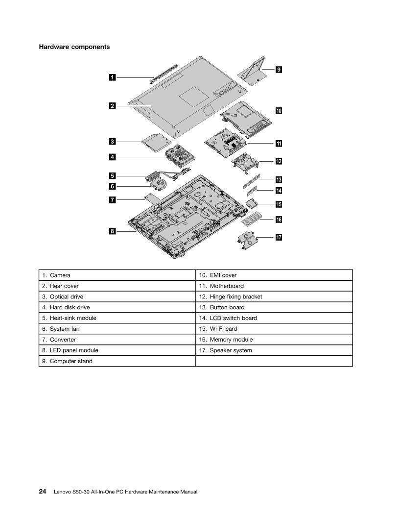
Hardware components
1
2
3
4
5
6
7
9
8
10
11
12
13
14
15
16
17
1. Camera 10. EMI cover
2. Rear cover 11. Motherboard
3. Optical drive 12. Hinge fixing bracket
4. Hard disk drive 13. Button board
5. Heat-sink module 14. LCD switch board
6. System fan 15. Wi-Fi card
7. Converter 16. Memory module
8. LED panel module 17. Speaker system
9. Computer stand
24 Lenovo S50-30 All-In-One PC Hardware Maintenance Manual

Chapter 8. Replacing hardware
Attention: Do not remove the computer cover or attempt any repair before reading the “Important safety information”in the Safety and Warranty Guide that was included with your computer. To obtain copies of the Safety and WarrantyGuide, go to the Support Web site at: http://support.lenovo.com.
Note: Use only parts provided by Lenovo.
General informationPre-disassembly instructions
Before starting the disassembly procedure, make sure that you do the following:
1. Turn off the power to the system and all peripherals.
2. Unplug all power and signal cables from the computer.
3. Place the system on a flat, stable surface.
© Copyright Lenovo 2015, 2015 25
Replacing the keyboard and mouseTo replace the keyboard and mouse:
Step 1. Remove any media (disks, CDs, DVDs or memory cards) from the drives, shut down the operatingsystem, and turn off the computer and all attached devices.
Step 2. Unplug all power cords from electrical outlets.
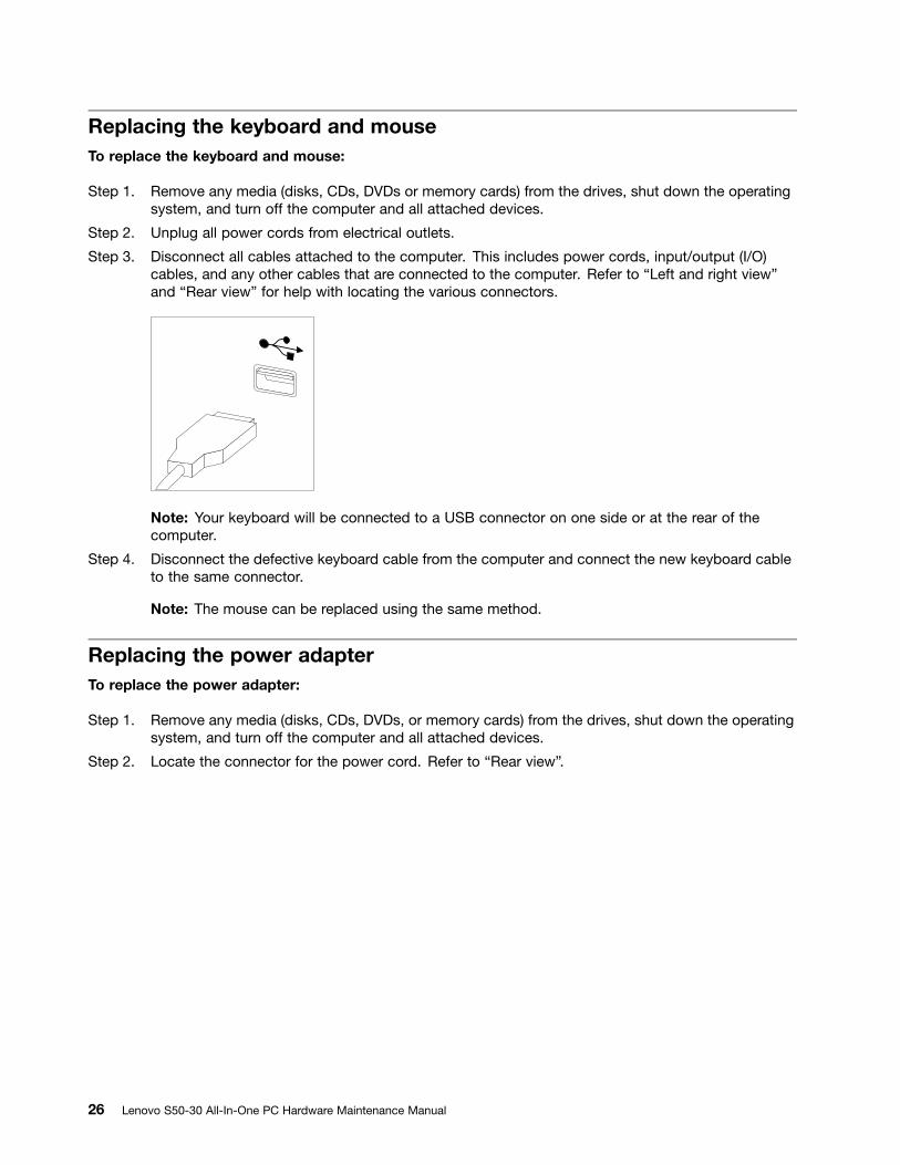
Step 3. Disconnect all cables attached to the computer. This includes power cords, input/output (I/O)cables, and any other cables that are connected to the computer. Refer to “Left and right view”and “Rear view” for help with locating the various connectors.
Note: Your keyboard will be connected to a USB connector on one side or at the rear of thecomputer.
Step 4. Disconnect the defective keyboard cable from the computer and connect the new keyboard cableto the same connector.
Note: The mouse can be replaced using the same method.
Replacing the power adapterTo replace the power adapter:
Step 1. Remove any media (disks, CDs, DVDs, or memory cards) from the drives, shut down the operatingsystem, and turn off the computer and all attached devices.
Step 2. Locate the connector for the power cord. Refer to “Rear view”.
26 Lenovo S50-30 All-In-One PC Hardware Maintenance Manual
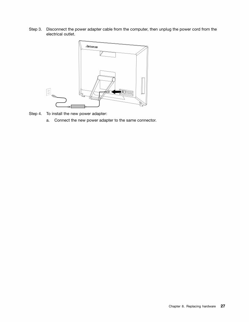
Step 3. Disconnect the power adapter cable from the computer, then unplug the power cord from theelectrical outlet.
Step 4. To install the new power adapter:
a. Connect the new power adapter to the same connector.
Chapter 8. Replacing hardware 27

Removing the frame standNote: Turn off the computer and wait 3 to 5 minutes to let it cool down before removing the cover.
Note: It may be helpful to place the computer face-down on a soft flat surface for this procedure. Lenovorecommends that you use a blanket, towel, or other soft cloth to protect the computer screen from scratchesor other damage.
To remove the computer stand
Step 1. Remove any media (disks, CDs, or memory cards) from the drives, shut down the operatingsystem, and turn off the computer and all attached devices.
Step 2. Unplug all power cords from electrical outlets.
Step 3. Disconnect all cables attached to the computer. This includes power cords, input/output (I/O)cables, and any other cables that are connected to the computer. Refer to “Left and right view”and “Rear view” for help with locating the various connectors.
Step 4. Remove the rubber block 1 that protects the screw 2 . Carefully loosen the screw 2 that securesthe frame stand. Then, lift the frame stand up to remove it from the computer.
Step 5. To reattach the frame stand, fasten the screw to secure the stand to the computer. Then, put therubber block back into the hole to protect the screw. 1
28 Lenovo S50-30 All-In-One PC Hardware Maintenance Manual

Removing the monitor standNote: Turn off the computer and wait 3 to 5 minutes to let it cool down before removing the cover.
Note: It may be helpful to place the computer face-down on a soft flat surface for this procedure. Lenovorecommends that you use a blanket, towel, or other soft cloth to protect the computer screen from scratchesor other damage.
To remove the monitor stand
Step 1. Remove any media (disks, CDs, or memory cards) from the drives, shut down the operatingsystem, and turn off the computer and all attached devices.
Step 2. Unplug all power cords from electrical outlets.
Step 3. Disconnect all cables attached to the computer. This includes power cords, input/output (I/O)cables, and any other cables that are connected to the computer. Refer to “Left and right view”and “Rear view” for help with locating the various connectors.
Step 4. Remove the rubber block 1 that protects the screw 2 . Carefully loosen the screw 2 that securesthe monitor stand. Then, lift the monitor stand up to remove it from the computer.
Step 5. To reattach the monitor stand, insert the two tabs 1 on the monitor stand into the correspondingslots in the chassis and slide the monitor stand in and down as shown.
Chapter 8. Replacing hardware 29

Removing the transformer standNote: Turn off the computer and wait 3 to 5 minutes to let it cool down before removing the cover.
Note: It may be helpful to place the computer face-down on a soft flat surface for this procedure. Lenovorecommends that you use a blanket, towel, or other soft cloth to protect the computer screen from scratchesor other damage.
To remove the transformer stand
Step 1. Remove any media (disks, CDs, or memory cards) from the drives, shut down the operatingsystem, and turn off the computer and all attached devices.
Step 2. Unplug all power cords from electrical outlets.
Step 3. Disconnect all cables attached to the computer. This includes power cords, input/output (I/O)cables, and any other cables that are connected to the computer. Refer to “Left and right view”and “Rear view” for help with locating the various connectors.
Step 4. Push the release button toward the top of the computer as shown. Then, lift the transformer standup to remove it from the computer.
Step 5. To reattach the transformer stand, insert the two tabs 1 on the transformer stand into thecorresponding slots in the chassis. Then, push the release button toward the top of the computerand slide the transformer stand in and down at the same time. Release the release button tosecure the transformer stand to the computer.
30 Lenovo S50-30 All-In-One PC Hardware Maintenance Manual
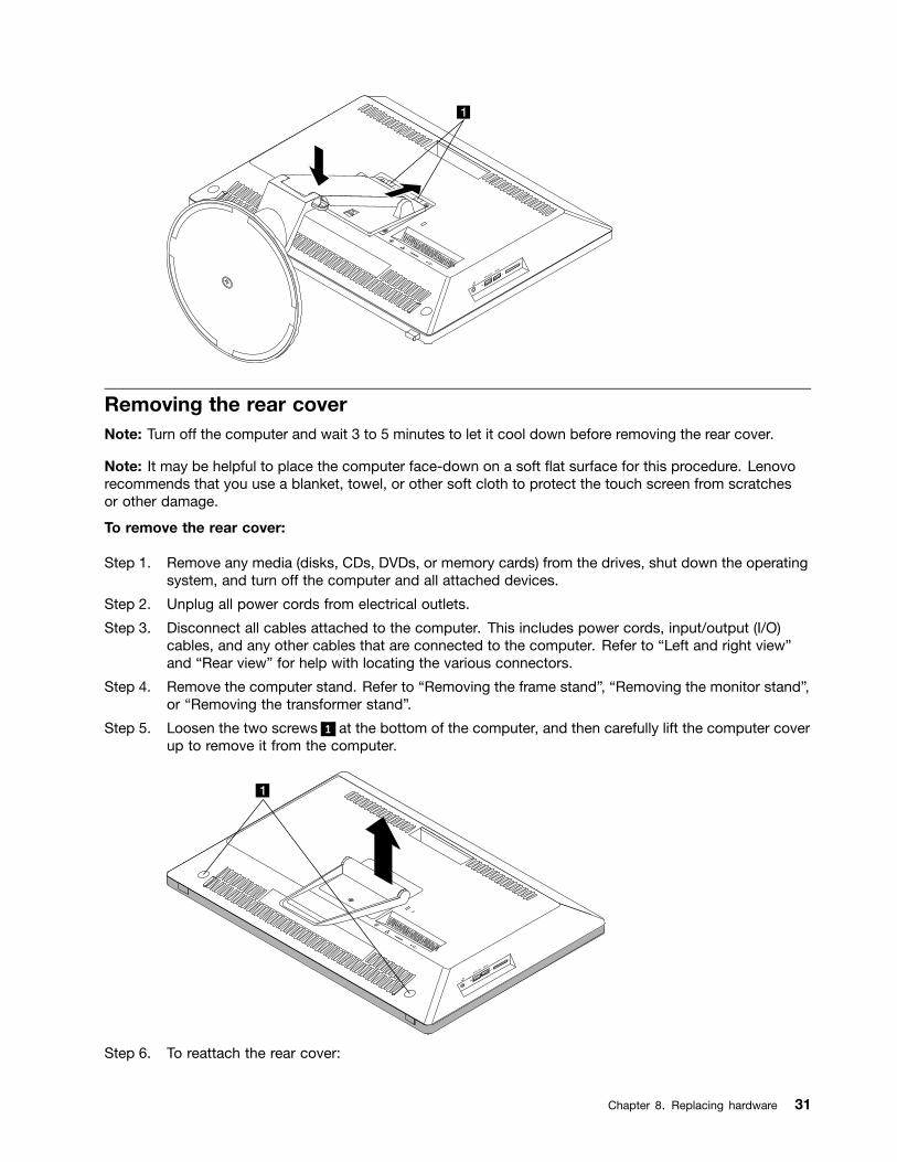
Removing the rear coverNote: Turn off the computer and wait 3 to 5 minutes to let it cool down before removing the rear cover.
Note: It may be helpful to place the computer face-down on a soft flat surface for this procedure. Lenovorecommends that you use a blanket, towel, or other soft cloth to protect the touch screen from scratchesor other damage.
To remove the rear cover:
Step 1. Remove any media (disks, CDs, DVDs, or memory cards) from the drives, shut down the operatingsystem, and turn off the computer and all attached devices.
Step 2. Unplug all power cords from electrical outlets.
Step 3. Disconnect all cables attached to the computer. This includes power cords, input/output (I/O)cables, and any other cables that are connected to the computer. Refer to “Left and right view”and “Rear view” for help with locating the various connectors.
Step 4. Remove the computer stand. Refer to “Removing the frame stand”, “Removing the monitor stand”,or “Removing the transformer stand”.
Step 5. Loosen the two screws 1 at the bottom of the computer, and then carefully lift the computer coverup to remove it from the computer.
Step 6. To reattach the rear cover:
Chapter 8. Replacing hardware 31
a. Line up the pins on the computer cover with the mounting holes on the chassis, then putthe computer cover back in place.
b. Secure the computer cover to the chassis with the two screws.
Step 7. Reattach the computer stand.
Replacing the hard disk driveAttention: Turn off the computer and wait 3 to 5 minutes to let it cool down before removing the rear cover.
To replace the hard disk drive:
Step 1. Remove any media (disks, CDs, DVDs or memory cards) from the drives, shut down the operatingsystem, and turn off the computer and all attached devices.
Step 2. Unplug all power cords from electrical outlets.
Step 3. Disconnect all cables attached to the computer. This includes power cords, input/output (I/O)cables, and any other cables that are connected to the computer. Refer to “Left and right view”and “Rear view” for help with locating the various connectors.
Step 4. Remove the computer stand. Refer to “Removing the frame stand”, “Removing the monitor stand”,or “Removing the transformer stand”.
Step 5. Remove the rear cover. Refer to "Removing the rear cover".
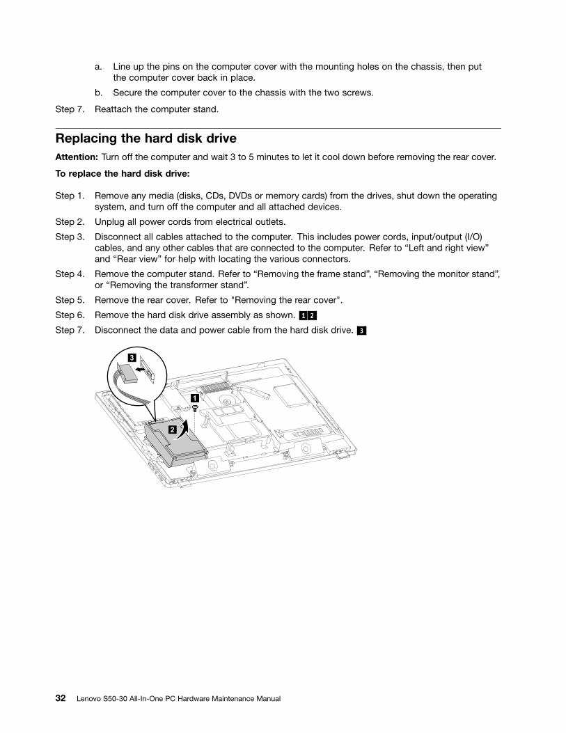
Step 6. Remove the hard disk drive assembly as shown. 1 2
Step 7. Disconnect the data and power cable from the hard disk drive. 3
32 Lenovo S50-30 All-In-One PC Hardware Maintenance Manual
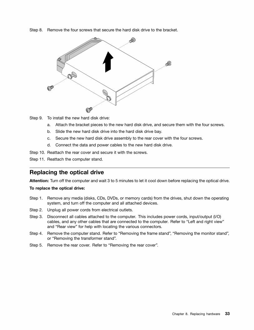
Step 8. Remove the four screws that secure the hard disk drive to the bracket.
Step 9. To install the new hard disk drive:
a. Attach the bracket pieces to the new hard disk drive, and secure them with the four screws.
b. Slide the new hard disk drive into the hard disk drive bay.
c. Secure the new hard disk drive assembly to the rear cover with the four screws.
d. Connect the data and power cables to the new hard disk drive.
Step 10. Reattach the rear cover and secure it with the screws.
Step 11. Reattach the computer stand.
Replacing the optical driveAttention: Turn off the computer and wait 3 to 5 minutes to let it cool down before replacing the optical drive.
To replace the optical drive:
Step 1. Remove any media (disks, CDs, DVDs, or memory cards) from the drives, shut down the operatingsystem, and turn off the computer and all attached devices.
Step 2. Unplug all power cords from electrical outlets.
Step 3. Disconnect all cables attached to the computer. This includes power cords, input/output (I/O)cables, and any other cables that are connected to the computer. Refer to “Left and right view”and “Rear view” for help with locating the various connectors.
Step 4. Remove the computer stand. Refer to “Removing the frame stand”, “Removing the monitor stand”,or “Removing the transformer stand”.
Step 5. Remove the rear cover. Refer to “Removing the rear cover”.
Chapter 8. Replacing hardware 33
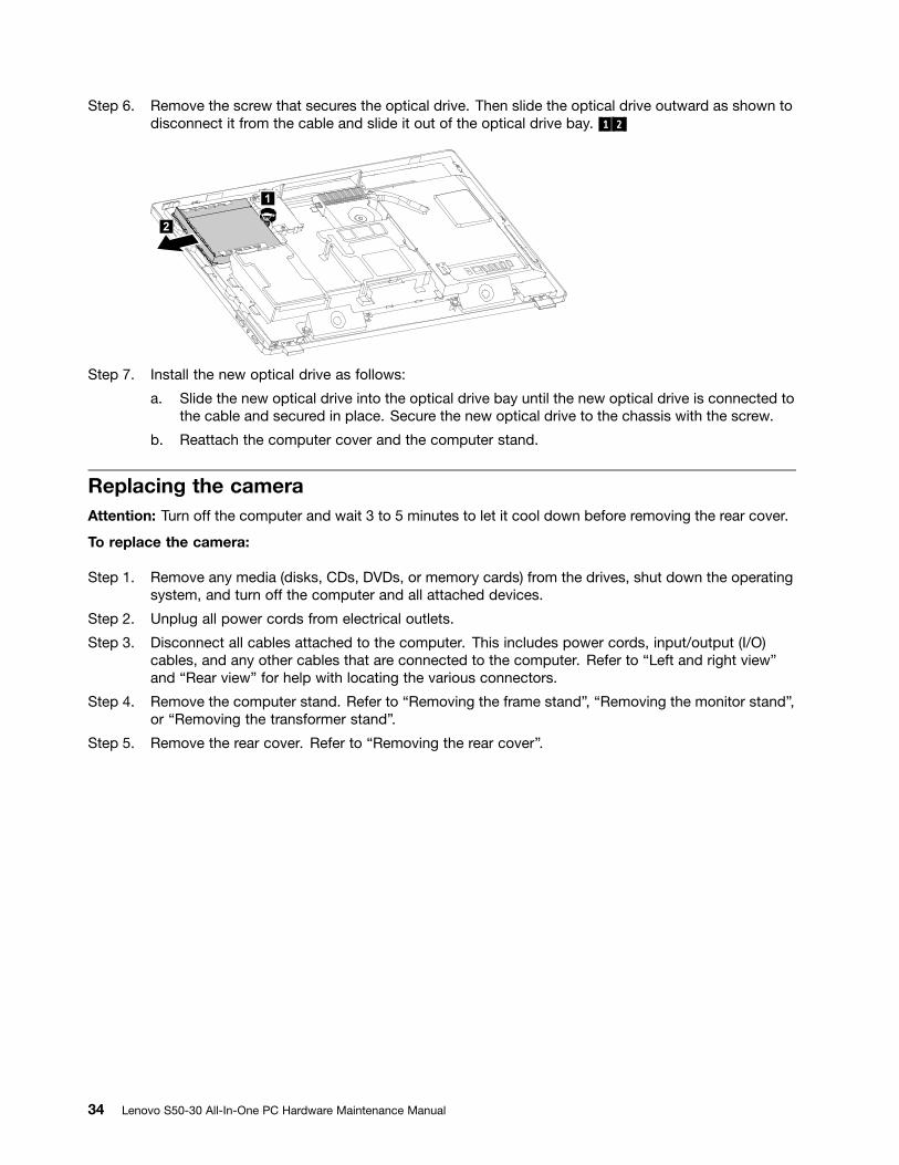
Step 6. Remove the screw that secures the optical drive. Then slide the optical drive outward as shown todisconnect it from the cable and slide it out of the optical drive bay. 1 2
2
Step 7. Install the new optical drive as follows:
a. Slide the new optical drive into the optical drive bay until the new optical drive is connected tothe cable and secured in place. Secure the new optical drive to the chassis with the screw.
b. Reattach the computer cover and the computer stand.
Replacing the cameraAttention: Turn off the computer and wait 3 to 5 minutes to let it cool down before removing the rear cover.
To replace the camera:
Step 1. Remove any media (disks, CDs, DVDs, or memory cards) from the drives, shut down the operatingsystem, and turn off the computer and all attached devices.
Step 2. Unplug all power cords from electrical outlets.
Step 3. Disconnect all cables attached to the computer. This includes power cords, input/output (I/O)cables, and any other cables that are connected to the computer. Refer to “Left and right view”and “Rear view” for help with locating the various connectors.
Step 4. Remove the computer stand. Refer to “Removing the frame stand”, “Removing the monitor stand”,or “Removing the transformer stand”.
Step 5. Remove the rear cover. Refer to “Removing the rear cover”.
34 Lenovo S50-30 All-In-One PC Hardware Maintenance Manual
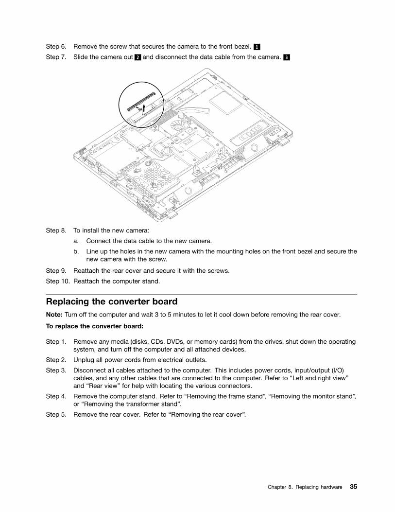
Step 6. Remove the screw that secures the camera to the front bezel. 1
Step 7. Slide the camera out 2 and disconnect the data cable from the camera. 3
Step 8. To install the new camera:
a. Connect the data cable to the new camera.
b. Line up the holes in the new camera with the mounting holes on the front bezel and secure thenew camera with the screw.
Step 9. Reattach the rear cover and secure it with the screws.
Step 10. Reattach the computer stand.
Replacing the converter boardNote: Turn off the computer and wait 3 to 5 minutes to let it cool down before removing the rear cover.
To replace the converter board:
Step 1. Remove any media (disks, CDs, DVDs, or memory cards) from the drives, shut down the operatingsystem, and turn off the computer and all attached devices.
Step 2. Unplug all power cords from electrical outlets.
Step 3. Disconnect all cables attached to the computer. This includes power cords, input/output (I/O)cables, and any other cables that are connected to the computer. Refer to “Left and right view”and “Rear view” for help with locating the various connectors.
Step 4. Remove the computer stand. Refer to “Removing the frame stand”, “Removing the monitor stand”,or “Removing the transformer stand”.
Step 5. Remove the rear cover. Refer to “Removing the rear cover”.
Chapter 8. Replacing hardware 35
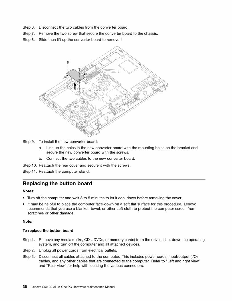
Step 6. Disconnect the two cables from the converter board.
Step 7. Remove the two screw that secure the converter board to the chassis.
Step 8. Slide then lift up the converter board to remove it.
Step 9. To install the new converter board:
a. Line up the holes in the new converter board with the mounting holes on the bracket andsecure the new converter board with the screws.
b. Connect the two cables to the new converter board.
Step 10. Reattach the rear cover and secure it with the screws.
Step 11. Reattach the computer stand.
Replacing the button boardNotes:
• Turn off the computer and wait 3 to 5 minutes to let it cool down before removing the cover.
• It may be helpful to place the computer face-down on a soft flat surface for this procedure. Lenovorecommends that you use a blanket, towel, or other soft cloth to protect the computer screen fromscratches or other damage.
Note:
To replace the button board
Step 1. Remove any media (disks, CDs, DVDs, or memory cards) from the drives, shut down the operatingsystem, and turn off the computer and all attached devices.
Step 2. Unplug all power cords from electrical outlets.
Step 3. Disconnect all cables attached to the computer. This includes power cords, input/output (I/O)cables, and any other cables that are connected to the computer. Refer to “Left and right view”and “Rear view” for help with locating the various connectors.
36 Lenovo S50-30 All-In-One PC Hardware Maintenance Manual
Step 4. Remove the computer stand. Refer to “Removing the frame stand”, “Removing the monitor stand”,or “Removing the transformer stand”.
Step 5. Remove the rear cover. Refer to “Removing the rear cover”.
Step 6. Disconnect the power cable from the button board and remove the three screws that securethe button board to the front bezel.
Step 7. Remove the button board as shown. 1 2 3
Step 8. Slide out the button board.
a. Line up the holes on the new button board with the three mounting holes on the front bezel,then place it into position.
b. Connect the power cable to the new button board.
Step 9. Reattach the rear cover and stand.
Replacing the LCD switch boardNotes:
• Turn off the computer and wait 3 to 5 minutes to let it cool down before removing the cover.
• It may be helpful to place the computer face-down on a soft flat surface for this procedure. Lenovorecommends that you use a blanket, towel, or other soft cloth to protect the computer screen fromscratches or other damage.
Replacing the LCD switch board
Step 1. Remove any media (disks, CDs, DVDs, or memory cards) from the drives, shut down the operatingsystem, and turn off the computer and all attached devices.
Step 2. Unplug all power cords from electrical outlets.
Step 3. Disconnect all cables attached to the computer. This includes power cords, input/output (I/O)cables, and any other cables that are connected to the computer. Refer to “Left and right view”and “Rear view” for help with locating the various connectors.
Step 4. Remove the computer stand. Refer to “Removing the frame stand”, “Removing the monitor stand”,or “Removing the transformer stand”.
Step 5. Remove the rear cover. Refer to “Removing the rear cover”.
Step 6. Disconnect the cable from the LCD switch board , and then remove the two screws that secure theLCD switch board to the front bezel. 1 2 3
Slide out the LCD switch board to remove it.
Step 7. To install the new LCD switch board:
a. Line up the holes on the new LCD switch board with the mounting holes on the front bezel andsecure the LCD switch board with the two screws.
b. Connect the cable to the new LCD switch board.
Step 8. Reattach the rear cover and computer stand.
Removing the hinge fixing bracketNotes:
Chapter 8. Replacing hardware 37
• Turn off the computer and wait 3 to 5 minutes to let it cool down before removing the cover.
• It may be helpful to place the computer face-down on a soft flat surface for this procedure. Lenovorecommends that you use a blanket, towel, or other soft cloth to protect the computer screen fromscratches or other damage.
To remove the hinge fixing bracket
Step 1. Remove any media (disks, CDs, DVDs, or memory cards) from the drives, shut down the operatingsystem, and turn off the computer and all attached devices.
Step 2. Unplug all power cords from electrical outlets.
Step 3. Disconnect all cables attached to the computer. This includes power cords, input/output (I/O)cables, and any other cables that are connected to the computer. Refer to “Left and right view”and “Rear view” for help with locating the various connectors.
Step 4. Remove the computer stand. Refer to “Removing the frame stand”, “Removing the monitor stand”,or “Removing the transformer stand”.
Step 5. Remove the rear cover. Refer to “Removing the rear cover”.
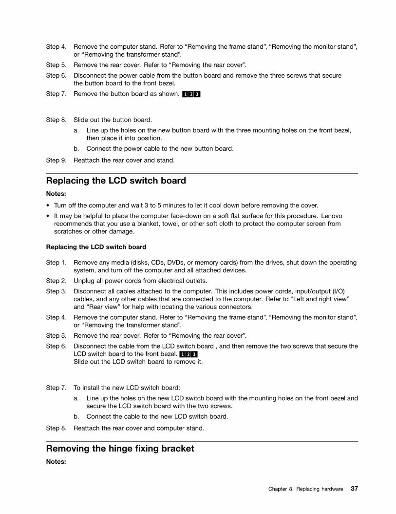
Step 6. Remove the four screws that secure the hinge fixing bracket to the chassis, and then lift it up.
Step 7. To reattach the hinge fixing bracket :
a. Line up the holes on the hinge fixing bracket with mounting holes on the chassis, then placethe hinge fixing bracket back into position.
b. Secure the hinge fixing bracket to the chassis with four screws.
Step 8. Reattach the rear cover and computer stand.
Removing the EMI coverNotes:
• Turn off the computer and wait 3 to 5 minutes to let it cool down before removing the cover.
38 Lenovo S50-30 All-In-One PC Hardware Maintenance Manual
• It may be helpful to place the computer face-down on a soft flat surface for this procedure. Lenovorecommends that you use a blanket, towel, or other soft cloth to protect the computer screen fromscratches or other damage.
To replace the EMI cover
Step 1. Remove any media (disks, CDs, DVDs, or memory cards) from the drives, shut down the operatingsystem, and turn off the computer and all attached devices.
Step 2. Unplug all power cords from electrical outlets.
Step 3. Disconnect all cables attached to the computer. This includes power cords, input/output (I/O)cables, and any other cables that are connected to the computer. Refer to “Left and right view”and “Rear view” for help with locating the various connectors.
Step 4. Remove the computer stand. Refer to “Removing the frame stand”, “Removing the monitor stand”,or “Removing the transformer stand”.
Step 5. Remove the rear cover. Refer to “Removing the rear cover”.
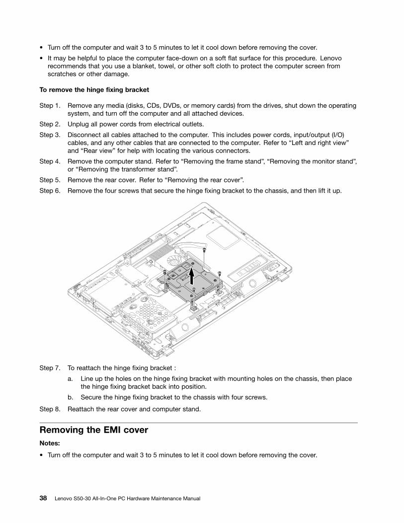
Step 6. Remove the three screws that secure the motherboard cover to the chassis, and then lift themotherboard cover up.
Step 7. To reattach the motherboard cover:
a. Line up the holes on the motherboard cover with mounting holes on the chassis, then placethe motherboard cover back into position.
b. Secure the motherboard cover to the chassis with three screws.
Step 8. Reattach the rear cover and computer stand.
Replacing the system fanNotes:
• Turn off the computer and wait 3 to 5 minutes to let it cool down before removing the rear cover.
• It may be helpful to place the computer face-down on a soft flat surface for this procedure. Lenovorecommends that you use a blanket, towel, or other soft cloth to protect the computer screen fromscratches or other damage.
Chapter 8. Replacing hardware 39
To replace the system fan:
Step 1. Remove any media (disks, CDs, DVDs, or memory cards) from the drives, shut down the operatingsystem, and turn off the computer and all attached devices.
Step 2. Unplug all power cords from electrical outlets.
Step 3. Disconnect all cables attached to the computer. This includes power cords, input/output (I/O)cables, and any other cables that are connected to the computer. Refer to “Left and right view”and “Rear view” for help with locating the various connectors.
Step 4. Remove the computer stand. Refer to “Removing the frame stand”, “Removing the monitor stand”,or “Removing the transformer stand”.
Step 5. Remove the rear cover. Refer to “Removing the rear cover”.
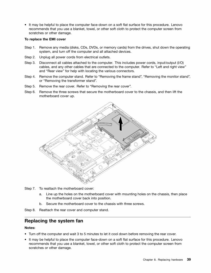
Step 6. Disconnect the power cable from the connector on the motherboard.
Step 7. Remove the two screws that secure the system fan to the rear cover.
Step 8. Lift up the system fan to remove it.
Step 9. To install the new system fan:
a. Line up the new system fan with the mounting holes on the rear cover and place it into position.
b. Secure the new system fan to the rear cover with the two screws.
c. Connect the new power cable to the connector on the motherboard.
Step 10. Reattach the rear cover and computer stand.
Replacing the heat-sinkNotes:
• Turn off the computer and wait 3 to 5 minutes to let it cool down before removing the cover.
• It may be helpful to place the computer face-down on a soft flat surface for this procedure. Lenovorecommends that you use a blanket, towel, or other soft cloth to protect the computer screen fromscratches or other damage.
To replace the heat-sink
40 Lenovo S50-30 All-In-One PC Hardware Maintenance Manual
Step 1. Remove any media (disks, CDs, DVDs, or memory cards) from the drives, shut down the operatingsystem, and turn off the computer and all attached devices.
Step 2. Unplug all power cords from electrical outlets.
Step 3. Disconnect all cables attached to the computer. This includes power cords, input/output (I/O)cables, and any other cables that are connected to the computer. Refer to “Left and right view”and “Rear view” for help with locating the various connectors.
Step 4. Remove the computer stand. Refer to “Removing the frame stand”, “Removing the monitor stand”,or “Removing the transformer stand”.
Step 5. Remove the rear cover. Refer to “Removing the rear cover”.
Step 6. Remove the EMI cover. Refer to “Removing the EMI cover”.
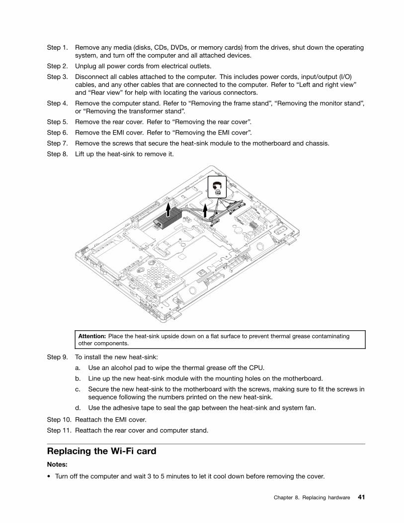
Step 7. Remove the screws that secure the heat-sink module to the motherboard and chassis.
Step 8. Lift up the heat-sink to remove it.
Attention: Place the heat-sink upside down on a flat surface to prevent thermal grease contaminatingother components.
Step 9. To install the new heat-sink:
a. Use an alcohol pad to wipe the thermal grease off the CPU.
b. Line up the new heat-sink module with the mounting holes on the motherboard.
c. Secure the new heat-sink to the motherboard with the screws, making sure to fit the screws insequence following the numbers printed on the new heat-sink.
d. Use the adhesive tape to seal the gap between the heat-sink and system fan.
Step 10. Reattach the EMI cover.
Step 11. Reattach the rear cover and computer stand.
Replacing the Wi-Fi cardNotes:
• Turn off the computer and wait 3 to 5 minutes to let it cool down before removing the cover.
Chapter 8. Replacing hardware 41

• It may be helpful to place the computer face-down on a soft flat surface for this procedure. Lenovorecommends that you use a blanket, towel, or other soft cloth to protect the computer screen fromscratches or other damage.
To replace the Wi-Fi card
Step 1. Remove any media (disks, CDs, DVDs, or memory cards) from the drives, shut down the operatingsystem, and turn off the computer and all attached devices.
Step 2. Unplug all power cords from electrical outlets.
Step 3. Disconnect all cables attached to the computer. This includes power cords, input/output (I/O)cables, and any other cables that are connected to the computer. Refer to “Left and right view”and “Rear view” for help with locating the various connectors.
Step 4. Remove the computer stand. Refer to “Removing the frame stand”, “Removing the monitor stand”,or “Removing the transformer stand”.
Step 5. Remove the rear cover. Refer to “Removing the rear cover”.
Step 6. Remove the EMI cover. Refer to “Removing the EMI cover”.
Step 7. Disconnect the antenna and data cables from the Wi-Fi card.
Step 8. Remove the screw that secures the Wi-Fi card to the motherboard.
Step 9. Pull the Wi-Fi card upward to remove it from the socket.
21
3
Step 10. To install the new Wi-Fi card:
a. Insert the new Wi-Fi card into the card port and secure it with the screw.
b. Connect the antenna cables to the new Wi-Fi card.
Step 11. Reattach the EMI cover.
Step 12. Reattach the rear cover and computer stand.
Replacing a memory moduleNotes:
• Turn off the computer and wait 3 to 5 minutes to let it cool down before removing the cover.
42 Lenovo S50-30 All-In-One PC Hardware Maintenance Manual
• It may be helpful to place the computer face-down on a soft flat surface for this procedure. Lenovorecommends that you use a blanket, towel, or other soft cloth to protect the computer screen fromscratches or other damage.
To replace a memory module:
Step 1. Remove any media (disks, CDs, DVDs, or memory cards) from the drives, shut down the operatingsystem, and turn off the computer and all attached devices.
Step 2. Unplug all power cords from electrical outlets.
Step 3. Disconnect all cables attached to the computer. This includes power cords, input/output (I/O)cables, and any other cables that are connected to the computer. Refer to “Left and right view”and “Rear view” for help with locating the various connectors.
Step 4. Remove the computer stand. Refer to “Removing the frame stand”, “Removing the monitor stand”,or “Removing the transformer stand”.
Step 5. Remove the rear cover. Refer to “Removing the rear cover”.
Step 6. Remove the EMI cover. Refer to “Removing the EMI cover”.
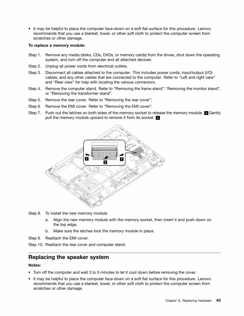
Step 7. Push out the latches on both sides of the memory socket to release the memory module. 1 Gentlypull the memory module upward to remove it from its socket. 2
1 12
Step 8. To install the new memory module:
a. Align the new memory module with the memory socket, then insert it and push down onthe top edge.
b. Make sure the latches lock the memory module in place.
Step 9. Reattach the EMI cover.
Step 10. Reattach the rear cover and computer stand.
Replacing the speaker systemNotes:
• Turn off the computer and wait 3 to 5 minutes to let it cool down before removing the cover.
• It may be helpful to place the computer face-down on a soft flat surface for this procedure. Lenovorecommends that you use a blanket, towel, or other soft cloth to protect the computer screen fromscratches or other damage.
Chapter 8. Replacing hardware 43

To replace the speaker system:
Step 1. Remove any media (disks, CDs, DVDs, or memory cards) from the drives, shut down the operatingsystem, and turn off the computer and all attached devices.
Step 2. Unplug all power cords from electrical outlets.
Step 3. Disconnect all cables attached to the computer. This includes power cords, input/output (I/O)cables, and any other cables that are connected to the computer. Refer to “Left and right view”and “Rear view” for help with locating the various connectors.
Step 4. Remove the computer stand. Refer to “Removing the frame stand”, “Removing the monitor stand”,or “Removing the transformer stand”.
Step 5. Remove the rear cover. Refer to “Removing the rear cover”.
Step 6. Remove the EMI cover. Refer to “Removing the EMI cover”.
Step 7. Disconnect the speaker cable from the connector on motherboard.
Step 8. Lift up the speaker system to remove it.
Step 9. To install the new speaker system:
a. Place the new speaker into position with the mounting screws..
b. Connect the new speaker cable to the connector on the motherboard.
Step 10. Reattach the EMI cover.
Step 11. Reattach the rear cover and computer stand.
Replacing the motherboardNote: Turn off the computer and wait 3 to 5 minutes to let it cool down before removing the rear cover.
To replace the motherboard:
Step 1. Remove any media (disks, CDs, DVDs, or memory cards) from the drives, shut down the operatingsystem, and turn off the computer and all attached devices.
Step 2. Unplug all power cords from electrical outlets.
44 Lenovo S50-30 All-In-One PC Hardware Maintenance Manual
Step 3. Disconnect all cables attached to the computer. This includes power cords, input/output (I/O)cables, and any other cables that are connected to the computer. Refer to “Left and right view”and “Rear view” for help with locating the various connectors.
Step 4. Remove the computer stand. Refer to “Removing the frame stand”, “Removing the monitor stand”,or “Removing the transformer stand”.
Step 5. Remove the rear cover. Refer to “Removing the rear cover”.
Step 6. Remove the EMI cover. Refer to “Removing the EMI cover”.
Step 7. Remove the heat-sink. Refer to “Replacing heat-sink”.
Step 8. Remove the memory module. Refer to “Replacing the memory module”.
Step 9. Remove the Wi-Fi card. Refer to “Replacing the Wi-Fi card”.
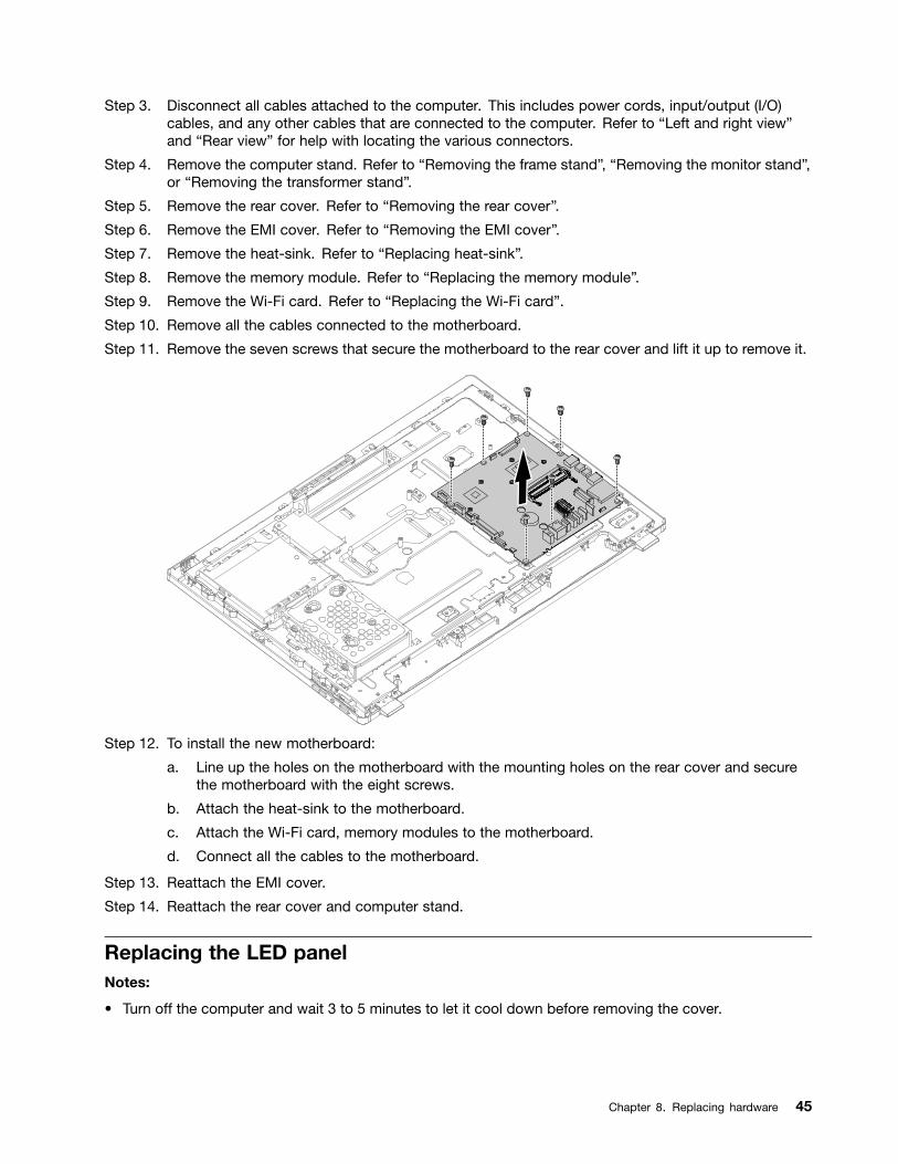
Step 10. Remove all the cables connected to the motherboard.
Step 11. Remove the seven screws that secure the motherboard to the rear cover and lift it up to remove it.
Step 12. To install the new motherboard:
a. Line up the holes on the motherboard with the mounting holes on the rear cover and securethe motherboard with the eight screws.
b. Attach the heat-sink to the motherboard.
c. Attach the Wi-Fi card, memory modules to the motherboard.
d. Connect all the cables to the motherboard.
Step 13. Reattach the EMI cover.
Step 14. Reattach the rear cover and computer stand.
Replacing the LED panelNotes:
• Turn off the computer and wait 3 to 5 minutes to let it cool down before removing the cover.
Chapter 8. Replacing hardware 45
• It may be helpful to place the computer face-down on a soft flat surface for this procedure. Lenovorecommends that you use a blanket, towel, or other soft cloth to protect the computer screen fromscratches or other damage.
To replace the LED panel:
Step 1. Remove any media (disks, CDs, DVDs, or memory cards) from the drives, shut down the operatingsystem, and turn off the computer and all attached devices.
Step 2. Unplug all power cords from electrical outlets.
Step 3. Disconnect all cables attached to the computer. This includes power cords, input/output (I/O)cables, and any other cables that are connected to the computer. Refer to “Left and right view”and “Rear view” for help with locating the various connectors.
Step 4. Remove the computer stand. Refer to “Removing the frame stand”, “Removing the monitor stand”,or “Removing the transformer stand”.
Step 5. Remove the rear cover. Refer to “Removing the rear cover”.
Step 6. Remove the hard disk drive. Refer to “Replacing the hard disk drive”.
Step 7. Remove the optical disk. Refer to “Replacing the optical disk”.
Step 8. Remove the converter. Refer to “Replacing the converter”.
Step 9. Remove the EMI cover. Refer to “Removing the EMI cover”.
Step 10. Remove the memory modules. Refer to “Replacing a memory module”.
Step 11. Remove the heat-sink. Refer to “Replacing the heat-sink module”.
Step 12. Remove the system fan. Refer to “Replacing the system fan”.
Step 13. Remove the Wi-Fi card. Refer to “Replacing the Wi-Fi card”.
Step 14. Remove the speaker system. Refer to “Replacing the speaker system”.
Step 15. Remove the mother board. Refer to “Replacing the motherboard”.
Step 16. Remove the hinge fixing bracket. Refer to “Removing the hinge fixing bracket”.
Step 17. Remove the button board. Refer to “Replacing the button board”.
Step 18. Replacing the LCD switch board. Refer to “Replacing LCD switch board”.
Step 19. Remove the camera. Refer to “Replacing the camera”.
46 Lenovo S50-30 All-In-One PC Hardware Maintenance Manual

Step 20. Remove all the cables left on the LED module.
Step 21. To install the new the LED panel:
a. Attach all the cables to the new LED panel.
b. Reattach all the parts to the chassis.
Step 22. Reattach the EMI cover.
Step 23. Reattach the rear cover and computer stand.
Chapter 8. Replacing hardware 47

48 Lenovo S50-30 All-In-One PC Hardware Maintenance Manual

Chapter 9. FRU lists
This chapter lists the information on the field replaceable units (FRUs) for Lenovo S20–20 All-In-One desktopcomputers.
Attention: Be sure to read and understand all the safety information before replacing any FRUs.
Notes: FRUs that have a 1 or 2 in the CRU column are Customer Replaceable Units (CRUs).
• 1– identifies parts that are fairly simple to replace, requiring few or no tools.
• 2– identifies parts that are slightly more difficult to replace.
• N-identifies parts that are not to be replaced by the customer.
Item # Description Lenovo PN CRU ID
Rear Cover
Cover Rear BLK W S5030 5CB0H29988
Cover Rear WHT W S5030 5CB0H30012
Foot BLK W S5030 Monitor cover 5CB0H34343
Foot WHT W S5030 Monitor cover 5CB0H34344
1
Computer Stand
Stand Frame BLK W S5030 5SE0H30016
Stand Frame WHT W S5030 5SE0H29999
Stand Monitor BLK W S5030 5SE0H30022
Stand Monitor WHT W S5030 5SE0H29990
1
Hard Disk Drive
WD XL1000B WD10EZEX-08M2NA0 1TB HDD 16200613
ST Pharaoh 4K Non-MC ST500DM002 500GHDD 16200674
SGT Grenada 2TB ST2000DX001 SSHD-LH 16200535
WDXL500A WD5000AAKX-08U6AA0 500G HDD-LH 16200544
TSB Mars 4K 500G DT01ACA050 -LH 16200512
ST Grenada BP2 ST1000DM003 1TB HDD 16200688
SGT Grenada 1TB ST1000DX001 SSHD-LH 16200534
TSB Mars 4K 1TB DT01ACA100 -LH 16200513
1
Brackets
Main Frame LG BLK W S5030 5B40H29995
Main Frame SAM BLK W S5030 5B40H30026
Main Frame LG WHT W S5030 5B40H30009
Main Frame SAM WHT W S5030 5B40H29996
Bracket HDD W A9050 5B40G93177
Bracket ODD W S5030 5B40H30027
Stand Bracket W A9050 5B40H00066
N
© Copyright Lenovo 2015, 2015 49
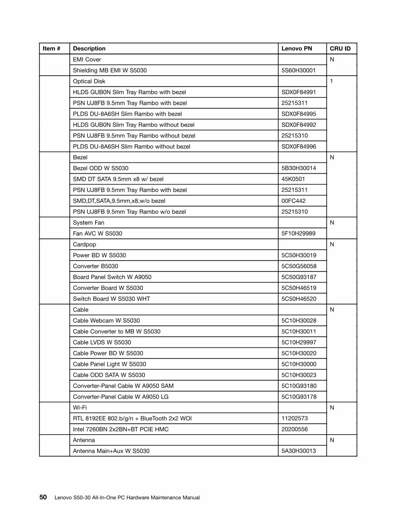
Item # Description Lenovo PN CRU ID
EMI Cover
Shielding MB EMI W S5030 5S60H30001
N
Optical Disk
HLDS GUB0N Slim Tray Rambo with bezel SDX0F84991
PSN UJ8FB 9.5mm Tray Rambo with bezel 25215311
PLDS DU-8A6SH Slim Rambo with bezel SDX0F84995
HLDS GUB0N Slim Tray Rambo without bezel SDX0F84992
PSN UJ8FB 9.5mm Tray Rambo without bezel 25215310
PLDS DU-8A6SH Slim Rambo without bezel SDX0F84996
1
Bezel
Bezel ODD W S5030 5B30H30014
SMD DT SATA 9.5mm x8 w/ bezel 45K0501
PSN UJ8FB 9.5mm Tray Rambo with bezel 25215311
SMD,DT,SATA,9.5mm,x8,w/o bezel 00FC442
PSN UJ8FB 9.5mm Tray Rambo w/o bezel 25215310
N
System Fan
Fan AVC W S5030 5F10H29989
N
Cardpop
Power BD W S5030 5C50H30019
Converter B5030 5C50G56058
Board Panel Switch W A9050 5C50G93187
Converter Board W S5030 5C50H46519
Switch Board W S5030 WHT 5C50H46520
N
Cable
Cable Webcam W S5030 5C10H30028
Cable Converter to MB W S5030 5C10H30011
Cable LVDS W S5030 5C10H29997
Cable Power BD W S5030 5C10H30020
Cable Panel Light W S5030 5C10H30000
Cable ODD SATA W S5030 5C10H30023
Converter-Panel Cable W A9050 SAM 5C10G93180
Converter-Panel Cable W A9050 LG 5C10G93178
N
Wi-Fi
RTL 8192EE 802.b/g/n + BlueTooth 2x2 WOI 11202573
Intel 7260BN 2x2BN+BT PCIE HMC 20200556
N
Antenna
Antenna Main+Aux W S5030 5A30H30013
N
50 Lenovo S50-30 All-In-One PC Hardware Maintenance Manual

Item # Description Lenovo PN CRU ID
Motherboard
W S5030 NOK 2G I7-4510U New MB 5B20J35787
W S5030 W8S 2G I7-4510U New MB 5B20J35785
W S5030 W8P 2G I7-4510U New MB 5B20J35782
W S5030 NOK 3558U UMA New MB 5B20J35781
W S5030 W8S 3558U UMA New MB 5B20J35779
W S5030 W8P 3558U UMA New MB 5B20J35773
W S5030 NOK 1G I3-4005U New MB 5B20J35807
W S5030 W8S 1G I3-4005U New MB 5B20J35804
W S5030 W8P 1G I3-4005U New MB 5B20J35803
W S5030 NOK 2G I3-4025U New MB 5B20J35800
W S5030 NOK 2G I3-4025U New MB 5B20J35800
W S5030 W8S 2G I3-4025U New MB 5B20J35798
W S5030 W8S 2G I3-4025U New MB 5B20J35798
W S5030 W8P 2G I3-4025U New MB 5B20J35796
W S5030 W8P 2G I3-4025U New MB 5B20J35796
W S5030 NOK 2G I5-4210U New MB 5B20J35795
W S5030 W8S 2G I5-4210U New MB 5B20J35780
W S5030 W8P 2G I5-4210U New MB 5B20J35778
W S5030 NOK 1G 3558U New MB 5B20J35774
W S5030 W8S 1G 3558U New MB 5B20J35806
W S5030 W8P 1G 3558U New MB 5B20J35801
W S5030 NOK 1G I3-4025U New MB 5B20J35799
W S5030 W8S 1G I3-4025U New MB 5B20J35797
W S5030 W8P 1G I3-4025U New MB 5B20J35793
W S5030 NOK 2G I3-4005U New MB 5B20J35792
W S5030 NOK 2G I3-4005U New MB 5B20J35792
W S5030 W8S 2G I3-4005U New MB 5B20J35790
W S5030 W8S 2G I3-4005U New MB 5B20J35790
W S5030 W8P 2G I3-4005U New MB 5B20J35777
W S5030 W8P 2G I3-4005U New MB 5B20J35777
W S5030 NOK I3-4025U UMA ROW MB 5B20J35775
W S5030 W8S I3-4025U UMA ROW MB 5B20J35789
W S5030 W8P I3-4025U UMA ROW MB 5B20J35784
W S5030 NOK I3-4005U UMA ROW MB 5B20J35808
W S5030 W8S I3-4005U UMA ROW MB 5B20J35794
W S5030 W8P I3-4005U UMA ROW MB 5B20J35786
W S5030 NOK I3-4025U UMA PRC MB 5B20J35776
W S5030 W8S I3-4025U UMA PRC MB 5B20J35802
N
Chapter 9. FRU lists 51

Item # Description Lenovo PN CRU ID
W S5030 W8P I3-4025U UMA PRC MB 5B20J35788
W S5030 NOK I3-4005U UMA PRC MB 5B20J35783
W S5030 W8S I3-4005U UMA PRC MB 5B20J35805
W S5030 W8P I3-4005U UMA PRC MB 5B20J35791
Memory Module
MT16KTF1G64HZ-1G6E1 8G D3L-1600S MEMORY 1100635
SODIMM,4G,DDR3L,1600 03T7117
M471B5674QH0-YK0 2GB DDR3L 1600 Sodimm 1100983
Mic_R D9QBJ 4GB D3L-1600S MEMORY 1100967
HMT41GS6BFR8A-PB 8GB DDR3L 1600 Sodimm 1100986
Mic_R D9QBJ ?8GB D3L-1600 Sodimm 1101012
HMT425S6AFR6A-PB 2GB D3L-1600S MEMORY 1100643
SODIMM,8G,DDR3L,1600 03T7118
HMT451S6BFR8A-PB 4GB DDR3L 1600 Sodimm 1100985
MT4KTF25664HZ-1G6E1 2GB 1600 Sodimm 1100956
MT8KTF51264HZ-1G6E1 4GB 1600 Sodimm 1100957
N
Speaker System
Speaker 3w W S5030 5SB0H30015
N
Heat-Sink
Heatsink DIS CM W S5030 5H40H30021
Heatsink UMA AVC W S5030 5H40H30008
N
Foot
Foot WHT W S5030 5F40H29993
Foot BLK W S5030 5F40H30010
N
Camera
Camera W S5030 W/Holder 5C20H34342
Bison A9050 WB 720P Hi162 1Mic 5C20G15212
LT A9050 WB 720P Hi162 1Mic 5C20G15213
N
Rubber
RUB HINGE,BLACK,Tri 04X2180
N
Display
LCD Module LG BLK NT W S5030 5D10H30002
LCD Module LG WHT NT W S5030 5D10H29992
LCD Module SAM BLK NT W S5030 5D10H30030
LCD Module SAM WHT NT W S5030 5D10H30024
LG LM230WF5-TLF1 5D10G75091
N
Power Supply
DELTA ADP-120ZB BBHT common 120W adapter 36200439
CRU,CMN 90W Common adapter 54Y8917
1
52 Lenovo S50-30 All-In-One PC Hardware Maintenance Manual

Item # Description Lenovo PN CRU ID
KB
Liteon Edge USB KB(FR)_YT 00KT357
Edge USB KB Russian/Cyrillic 00PC353
Edge USB KB Slovenian 234 00PC387
Edge USB KB Portugese 163 00PC379
Edge USB KB Czech (ABB) 00PC351
Liteon Edge USB KB(HB)_YT 00KT362
Edge USB KB UK English 166 00PC356
Liteon Edge USB KB(Nordic)_YT 00KT359
Liteon Edge USB KB(IT)_YT 00KT360
Liteon Edge USB KB(SP)_YT 00KT361
Edge USB KB Arabic(New) 470 00PC357
Edge USB KB US English 103P 00PC350
Edge USB KB US Euro103P 00PC386
Liteon SK8821(S PKG)(CN-EN)USB KB 00KT365
Edge USB KB LA Spanish 171 00PC352
Liteon Edge USB KB(GE)_YT 00KT358
Edge USB KB Belgium English120 00PC362
Edge USB KB Thailand 191 00PC354
Edge USB KB Turkish 179 00PC355
Edge USB KB India(M & H) 00PC358
Edge 2.4G KB+MC kit SL 234 00PC345
Primax Edge 2.4G KB+MC(UK) CALC8 25214495
Liteon SK8821 (RU)NewF5 USB KB Win8 25214482
Chicony KU0989 (RU)NewF5 USB KB Win8 25214483
Liteon SK8821 (CZ)NewF5 USB KB Win8 25214491
Chicony KU0989 (CZ)NewF5 USB KB Win8 25214492
Edge 2.4G KB+MC(Nordic) CALC8 00PC347
Primax Edge 2.4G KB+MC(TH) CALC8 25216247
Primax Edge 2.4G KB+MC(IN) CALC8 25214493
Primax Edge 2.4G KB+MC(SA) CALC8 25216342
Liteon SM-8861(WW) 2.4G Mouse White 25211016
Chicony KU0989 (UK)NewF5 USB KB Win8 25214486
Edge 2.4G KB+MC kit BG EN 120 00PC318
Liteon SK8821 (SA)NewF5 USB KB Win8 25216338
Liteon SK8821 (TR)NewF5 USB KB Win8 25214488
Liteon SK8821(EN) New F5 USB KB Win8 25209241
Chicony KU0989 (TR)NewF5 USB KB Win8 25214489
Chicony KU0989(EN) New F5 USB KB Win8 25209242
1
Chapter 9. FRU lists 53
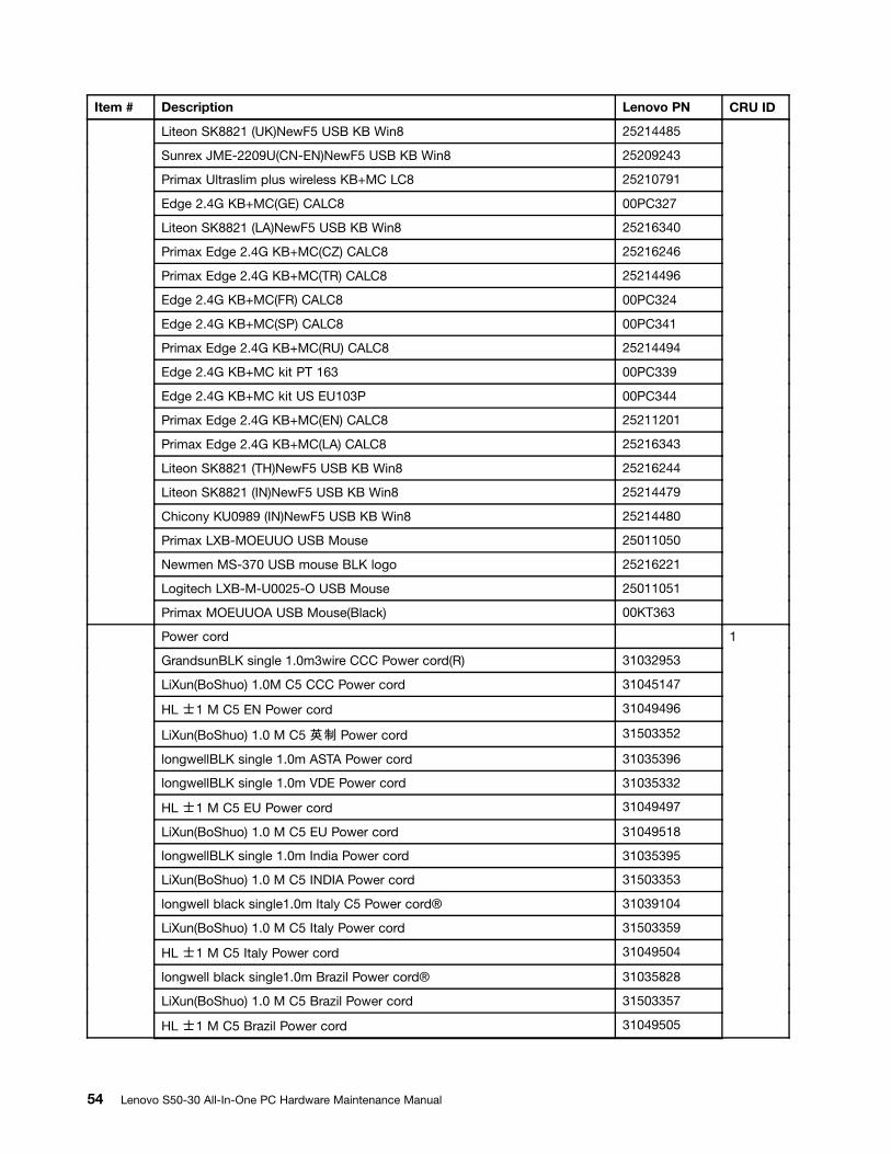
Item # Description Lenovo PN CRU ID
Liteon SK8821 (UK)NewF5 USB KB Win8 25214485
Sunrex JME-2209U(CN-EN)NewF5 USB KB Win8 25209243
Primax Ultraslim plus wireless KB+MC LC8 25210791
Edge 2.4G KB+MC(GE) CALC8 00PC327
Liteon SK8821 (LA)NewF5 USB KB Win8 25216340
Primax Edge 2.4G KB+MC(CZ) CALC8 25216246
Primax Edge 2.4G KB+MC(TR) CALC8 25214496
Edge 2.4G KB+MC(FR) CALC8 00PC324
Edge 2.4G KB+MC(SP) CALC8 00PC341
Primax Edge 2.4G KB+MC(RU) CALC8 25214494
Edge 2.4G KB+MC kit PT 163 00PC339
Edge 2.4G KB+MC kit US EU103P 00PC344
Primax Edge 2.4G KB+MC(EN) CALC8 25211201
Primax Edge 2.4G KB+MC(LA) CALC8 25216343
Liteon SK8821 (TH)NewF5 USB KB Win8 25216244
Liteon SK8821 (IN)NewF5 USB KB Win8 25214479
Chicony KU0989 (IN)NewF5 USB KB Win8 25214480
Primax LXB-MOEUUO USB Mouse 25011050
Newmen MS-370 USB mouse BLK logo 25216221
Logitech LXB-M-U0025-O USB Mouse 25011051
Primax MOEUUOA USB Mouse(Black) 00KT363
Power cord
GrandsunBLK single 1.0m3wire CCC Power cord(R) 31032953
LiXun(BoShuo) 1.0M C5 CCC Power cord 31045147
HL 士1 M C5 EN Power cord 31049496
LiXun(BoShuo) 1.0 M C5 英制 Power cord 31503352
longwellBLK single 1.0m ASTA Power cord 31035396
longwellBLK single 1.0m VDE Power cord 31035332
HL 士1 M C5 EU Power cord 31049497
LiXun(BoShuo) 1.0 M C5 EU Power cord 31049518
longwellBLK single 1.0m India Power cord 31035395
LiXun(BoShuo) 1.0 M C5 INDIA Power cord 31503353
longwell black single1.0m Italy C5 Power cord® 31039104
LiXun(BoShuo) 1.0 M C5 Italy Power cord 31503359
HL 士1 M C5 Italy Power cord 31049504
longwell black single1.0m Brazil Power cord® 31035828
LiXun(BoShuo) 1.0 M C5 Brazil Power cord 31503357
HL 士1 M C5 Brazil Power cord 31049505
1
54 Lenovo S50-30 All-In-One PC Hardware Maintenance Manual

Item # Description Lenovo PN CRU ID
longwell black single1.0m Argentina C5 Power cord® 31039100
LiXun(BoShuo) 1.0 M C5 LAS Power cord 31503356
HL 士1 M C5 LAS Power cord 31049507
longwell black single1.0m Denmark C5 Power cord® 31039101
LiXun(BoShuo) 1.0 M C5 Denmark Power cord 31503360
HL 士1 M C5 Denmark Power cord 31049503
longwell black single1.0m Switzerland C5 Power cord® 31039103
LiXun(BoShuo) 1.0 M C5 Switzerland Power cord 31503361
HL 士1 M C5 Switzerland Power cord 31049508
longwell black single1.0m Israel C5 Power cord® 31039107
LiXun(BoShuo) 1.0 M C5 Israel Power cord 31503362
HL 士1 M C5 Israel Power cord 31049502
longwell black single1.0m Taiwan C5 Power cord® 31038885
LiXun(BoShuo) 1.0 M C5 TW Power cord 31503354
HL 士1 M C5 TW Power cord 31049499
longwell black single1.0m Korea C5 Power cord® 31039106
LiXun(BoShuo) 1.0 M C5 Korea Power cord 31503358
HL 士1 M C5 Korea Power cord 31049498
longwell black single1.0m SA C5 Power cord® 31039105
LiXun(BoShuo) 1.0 M C5 SA Power cord 31503355
HL 士1 M C5 SA Power cord 31049501
Chapter 9. FRU lists 55

56 Lenovo S50-30 All-In-One PC Hardware Maintenance Manual
Chapter 10. Additional Service Information
This chapter provides additional information that the service representative might find helpful.
Power management
Power management reduces the power consumption of certain components of the computer such as thesystem power supply, processor, hard disk drives, and some monitors.
Advanced configuration and power interface (ACPI) BIOS
As this computer has an ACPI BIOS system, the operating system is allowed to control the powermanagement features of the computer and the settings for Advanced Power Management (APM) BIOS modeis ignored. Not all operating systems support ACPI BIOS mode.
Automatic Power-On features
The Automatic Power-On features within the Power Management menu allow you to enable and disablefeatures that turn on the computer automatically.
• Wake Up on Alarm: You can specify a date and time at which the computer will be turned on automatically.This can be either a single event , a daily event or a weekly event.
• Wake Up on LAN: This feature allows LAN adapter card to wake the System.
© Copyright Lenovo 2015, 2015 57


![Lenovo S50 Series - CNET Contentcdn.cnetcontent.com › a1 › cb › a1cbe111-977a-4bab-87d7-64a8d78a674c.pdfVersion 2.0 Machine type: F0BA [S50-30] 2015.02 Lenovo S50 Series User](https://cdn.vdocuments.site/doc/165x107/60bc5e9cced4c810a35b3bc3/lenovo-s50-series-cnet-a-a1-a-cb-a-a1cbe111-977a-4bab-87d7-64a8d78a674cpdf.jpg)


