
Lecture schedule for IV Year B.Tech I Sem - ECE
Subject: COMPUTER NETWORKS Code: 13ITD006
Lectures per week: 5 Academic Year: 2016-17 Faculty member: K. Jyostna No. of Weeks: 16
Course Objectives (COs):
Build an understanding of the fundamental concepts of computer networking. Familiarize the student with the basic taxonomy and terminology of the computer networking
area. Introduce the student to advanced networking concepts, preparing the student for entry into
advanced courses in computer networking. Allow the student to gain expertise in some specific area of networking such as the design and
maintenance of individual networks.
Course Outcomes (LOs): Upon completion of this course, students should be able to: Understand the layered architecture of computer networks. Understand the operation of the main components of computer networks. Learn various network protocols and algorithms. Acquire the required skill to design simple computer networks. Become familiar with security risks threatening computer networks
UNIT-I
DATA COMMUNICATIONS: Components – Direction of Data flow – Networks – Components and Categories – Types of Connections – Topologies –Protocols and Standards – ISO / OSI model, Example Networks such as NSF NET, ARPANET, ATM, Frame Relay, ISDN
Physical layer: Digital transmission, Multiplexing, Transmission Media, Switching, Circuit Switched Networks, Datagram Networks, Virtual Circuit Networks, Switch and Telephone Networks.
Learning Objectives
At the end of Unit –I student must be able to
Explain components of data communication system
Explain various network topologies, categories and connection
Explain the protocols and standards
Define OSI Layers and Protocols
Describe the functions of layers
Explain the types of line coding schemes
Classification of transmission modes
Types of multiplexing
Explain various Transmission media
Define and describe need for switching, types of switched networks
Describe the services of switch and telephone network

Topic Method of teaching No. of Hours
Components of data communication
system
Chalk & Talk, PPT 01
Direction of Data flow Chalk & Talk 01
Networks Chalk & Talk, PPT 01
Components of a network PPT, Mind mapping 01
Categories of networks Chalk & Talk, PPT 01
Types of Connections Chalk & Talk, PPT 01
Topologies Mind mapping 01
Protocols and Standards Chalk & Talk, PPT 01
ISO / OSI model Chalk & Talk, PPT 02
Example Networks Chalk & Talk 01
Digital transmission PPT 02
Multiplexing Videos 01
Transmission Media PPT, Mind mapping 01
Switching & Types of switched networks Chalk & Talk 01
Circuit switched networks Chalk & Talk, PPT 01
Datagram switched networks Chalk & Talk, PPT 01
Virtual circuit networks Chalk & Talk, PPT 01
Switch network Chalk & Talk, PPT 01
Telephone Networks Chalk & Talk, PPT 01
Assignment-I
1. Explain the functions of each OSI layer. 2. Explain different physical transmission media 3. Describe the types of multiplexing 4. Describe encoding 5. Differentiate between types of switched networks
UNIT-II
Data link layer: Introduction, Framing, and Error – Detection and Correction – Parity – LRC – CRC Hamming code, Flow and Error Control, Noiseless Channels, Noisy Channels, HDLC, Point to Point Protocols. Medium Access sub layer: ALOHA, CSMA/CD, LAN - Ethernet IEEE 802.3 - IEEE 802.4 - IEEE 802.5 - IEEE 802.11, Random access, Controlled access, Channelization, Collision Free Protocols
Learning Objectives
At the end of Unit –II student must be able to
Define the functions of Data link layer

Explain Error detection and Error correction mechanisms Explain Flow control and error control mechanisms Define Protocols-for noiseless and noisy channels Explain HDLC & Point to point protocol Describe various protocols of Medium Access sub layer Identify various multiple access protocols Describe IEEE Standards Describe Ethernet LANs
Topic Method of Teaching No. of Hours
Functions of data link layer Chalk & Talk, PPT 02
Framing Chalk & Talk, Video 01
Error – Detection and Correction Chalk & Talk, PPT 01
Parity, LRC Chalk & Talk 01
Cyclic Redundancy Check Chalk & Talk 01
Hamming code Chalk & Talk 01
Flow and Error Control Chalk & Talk, Video 01
Noiseless & Noisy Channels Chalk & Talk 01
HDLC Protocol PPT 01
Point to Point Protocol PPT 01
ALOHA Chalk & Talk, PPT 01
CSMA/CD Chalk & Talk, PPT 01
IEEE 802.3 PPT 01
IEEE 802.4 PPT 01
IEEE 802.5 PPT 01
IEEE 802.11 PPT 01
Random access Chalk & Talk, PPT, Video 01
Controlled access Chalk & Talk, PPT, Video 01
Channelization Chalk & Talk, PPT, Video 01
Collision Free Protocols Chalk & Talk, PPT 01
Assignment-II
1. What is Medium Access Sub layer? Explain. 2. Explain the Multiple Access Protocols with appropriate frame formats. 3. Explain ALOHA & CSMA 4. Comment on IEEE standards for LANs 5. Compare the data rates of Standard Ethernet, Fast Ethernet, Giga bit Ethernet and Ten
Gigabit Ethernet

UNIT-III
Network layer: Logical Addressing, Internetworking, Tunneling, Address mapping, ICMP, IGMP, Forwarding, Uni-Cast Routing Protocols, Multicast Routing Protocols, Congestion Control Mechanism
Learning Objectives
At the end of Unit –III student must be able to
Explain Logical Addressing
Explain Internetworking
Discuss the need for transition from IPv4 to IPv6
Explain the concept of Tunneling
Discuss Address mapping
ICMP(Internet Control Message Protocol)
IGMP(Internet Group Management Protocols)
Forwarding and Routing protocols
Notice the various congestion control mechanisms
Topic Method of Teaching No. of Hours
Logical Addressing Chalk & Talk, PPT 02
Internetworking Chalk & Talk, PPT 02
Tunneling Chalk & Talk, PPT 01
Address mapping Chalk & Talk, Mind map 01
ICMP, IGMP PPT 01
Forwarding Chalk & Talk, PPT, Video
01
Uni-Cast Routing Protocols Chalk & Talk, PPT 01
Multicast Routing Protocols Chalk & Talk, PPT 01
Congestion Control Mechanism Chalk & Talk, PPT 02
Assignment - III
1. Explain static and dynamic mapping of logical addresses to physical addresses 2. Briefly explain RARP 3. Explain the IGMP message types 4. Contrast two different routing tables
UNIT IV
Transport Layer: Process to Process Delivery, UDP and TCP protocols, SCTP, Data Traffic, Congestion, Congestion Control, QoS, Integrated Services, Differentiated Services and QoS in Switched Networks.

Learning Objectives
At the end of Unit –IV student must be able to
Explain Transport services Explain connection management Define and Differentiate TCP and UDP protocols Explain congestion Explain congestion control algorithms Integrated services QoS in switched networks
Topic Method of Teaching No. of Hours
Transport Layer functions - Process to Process Delivery
Chalk & Talk, Video 02
UDP and TCP protocols Chalk & Talk, PPT 02
SCTP, Data Traffic Chalk & Talk, PPT 02
Congestion & Congestion Control Chalk & Talk, PPT 02
QoS Chalk & Talk 01
Integrated Services PPT 01
Differentiated Services PPT 01
QoS in Switched Networks PPT 01
Assignment-IV
1. Explain Transport layer 2. Classify Transport Protocols 3. State how to combine various services of transport layer. 4. Compare and Contrast TCP and UDP. 5. Explain four general techniques to improve quality of service
Unit V
Application Layer: Domain name space, DNS in internet, electronic mail, SMTP, FTP, WWW, HTTP,
SNMP, Network Security, Cryptography.
Learning Objectives
At the end of Unit –V student must be able to
Define an Application Layer Compare and Contrast E- mail and WWW List the uses of Application Layer Classify DNS Components, records, servers Demonstrate Electronic mail architecture and services Illustrate the Role World Wide Web (WWW) Explain the concept of Security Compare and Contrast DSN and SNMP

Topic Method of Teaching No. of Hours
Domain name space Chalk & Talk, PPT 02
DNS in internet Chalk & Talk, PPT 02
electronic mail Chalk & Talk, PPT 01 SMTP & FTP Chalk & Talk, PPT 02
WWW, HTTP, SNMP Chalk & Talk, PPT 03
Network Security Chalk & Talk, PPT 02
Cryptography Chalk & Talk, PPT 02
Assignment-V
1. What are the different services of Application layer 2. Comment on Security issues of computer networks. 3. Explain the SNMP. 4. Explain the working principle of E-mail. 5. Discuss about WWW.

VNR VIGNANA JYOTHI INSTITUTE OF ENGINEERING & TECHNOLOGY
DEPARTMENT OF ELECTRONICS AND COMMUNICATIONS ENGINEERING
IV B. Tech, Semester I (ECE)
Subject : DIGITAL DESIGN THROUGH VERILOG
Subject Code : 13ECE018
Academic Year : 2015 – 16
Number of working days : 54
Number of Hours / week : 5
Total number of periods planned : 40
Name of the Faculty Member : K.Swetha Reddy
IV Year B.Tech ECE – I Sem L T/P/D C
3 0 3 Course Objectives
To model, simulate and synthesize the digital designs using Verilog HDL
To describe and realize the functionality of the digital design by using ASM charts
To know architectural features and implementation of digital designs in CPLDs
To know architectural features and building blocks of Altera’s FPGAs.
Course Outcomes After completing this course the student will be able to
Develop HDL code for digital system designs.
Describe ASM charts for synchronous sequential systems
Acquire knowledge to Implement and test designs on the target CPLDs &
FPGAs.
Develop different digital solutions ranging from signal processing ,data
manipulation, electronic instrumentation, control, telecommunications to
consumer electronics
Suggested Text Books:
1. Design through Verilog HDL – T.R. Padmanabhan and B. Bala Tripura Sundari, WSE, IEEE Press,2004.

2. A Verilog Primier – J. Bhaskar, BSP, 2003. 3. Fundamentals of Logic Design with Verilog – Stephen. Brown and
ZvonkoVranesic, TMH, 2005. 4. Digital Systems Design using VHDL – Charles H Roth, Jr. Thomson Publications,
2004.
Unit I:
INTRODUCTION TO VERILOG: Verilog as HDL, Levels of Design Description, Concurrency, Simulation and Synthesis, Functional Verification, System Tasks, Programming Language Interface (PLI), Module, Test Benches. LANGUAGE CONSTRUCTS AND CONVENTIONS : Introduction, Keywords, Identifiers, White Space Characters, Comments, Numbers, Strings, Logic Values, Strengths, Data Types, Scalars and Vectors, Parameters, Memory, Operators, System Tasks.
Learning Objectives:
At the conclusion of this unit the student will be able to :
Describe the digital systems Know about Verilog HDL Classify Levels of design description Define concurrency,simulation and synthesis What is functional verification What are system tasks Importance of PLI What is a module and test bench Identifying keywords ,identifiers, white space characters, logic values Different data types and operators in Verilog
Lecture plan:
S.NO TOPICS UNIT NAME LECTURE NO.
01 Verilog as HDL, Levels of Design Description
Introduction to
L1
02 Concurrency, Simulation and Synthesis, Functional Verification
L2

03 System Tasks, Programming Language Interface (PLI), Module, Test Benches
Verilog
Language Constructs and
Conventions
L3,L4
04 Introduction, Keywords L5,L6 05 Identifiers, White Space
Characters, Comments L7
06 Numbers, Strings, Logic Values
L8
07 Q&A Discussion L9 08 Strengths, Data Types L10 09 Parameters, Memory L11,L12 10 Operators, System Tasks L13,L14,L15 11 Introduction to
Programming L17,L18,L19
Assignment – I:
1) Define Verilog HDL and describe different levels of design description.
2) Explain simulation, synthesis and functional verification.
3) Name different system tasks and quote importance of PLI.
4) Define module and give syntax for it.
5) Define operator ? Explain different types of operators.
6) Define data type ? Explain different types of data types
Unit – II:
GATE LEVEL MODELING : Introduction, AND Gate Primitive, Module Structure, Other Gate Primitives, Illustrative Examples, Tri-State Gates, Array of Instances of Primitives, Design of Flip-flops with Gate Primitives, Delays, Strengths and Contention Resolution, Net Types, Design of Basic Circuits. BEHAVIORAL MODELING : Introduction, Operations and Assignments, Functional Bifurcation, Initial Construct, Always Construct, Assignments with Delays, Wait construct, Multiple Always Blocks, Designs at Behavioral Level, Blocking and Non blocking Assignments, The case statement, Simulation Flow,iƒ and iƒ-else constructs, assign-deassign construct, repeat construct, for loop, the disable construct, while loop, forever loop, parallel blocks, force-release construct, Event.

Learning Objectives:
At the conclusion of this unit, the student will be able to:
What is gate madeling and represent AND Gate Primitive, Module Structure, Other Gate Primitives.
Describe illustrative examples. Explain Tri-State Gates, Array of Instances of Primitives. Design Flip-flops with Gate Primitives. Explain Delays, Strengths and Contention Resolution, Net Types. Design basic circuits. What is behavioral modeling Learn Operations and Assignments, Functional Bifurcation, Initial Construct,
Always Construct, Assignments with Delays, Wait construct . Learn Multiple Always Blocks, Designs at Behavioral Level, Blocking and Non
blocking Assignments, The case statement, Simulation Flow Analyze different conditional and loop statements.
Lecture plan:
S.NO TOPICS UNIT NAME LECTURE NO.
12 Introduction, AND Gate Primitive, Module Structure, Other Gate Primitives, Illustrative Examples
GATE LEVEL MODELING and BEHAVIORAL
MODELING
L20
13 Tri-State Gates, Array of Instances of Primitives, Design of Flip-flops with Gate Primitives, Delays, Strengths and Contention Resolution, Net Types, Design of Basic Circuits.
L21
14 Introduction, Operations and Assignments, Functional Bifurcation, Initial Construct, Always Construct, Assignments with Delays, Wait construct
L22
15 Multiple Always Blocks, Designs at Behavioral
L23

Level, Blocking and Non blocking Assignments, The case statement, Simulation Flow
16 iƒ and iƒ-else constructs, assign-deassign construct, repeat construct, for loop, the disable construct, while loop, forever loop, parallel blocks, force-release construct, Event.
L24,L25
Assignment - II :
1) Explain AND Gate Primitive, Module Structure, Other Gate Primitives with Illustrative
Examples.
2) What are Tri-State Gates, Array of Instances of Primitives
3) a) Design Flip-flops with Gate Primitives.
b) Explain Delays, Strengths and Contention Resolution, Net Types.
4) Explain different conditional and loop statements.
Unit – III:
MODELING AT DATA FLOW LEVEL: Introduction, Continuous Assignment Structures, Delays and Continuous Assignments, Assignment to Vectors, Operators. SWITCH LEVEL MODELING: Introduction, Basic Transistor Switches, CMOS Switch, Bi-directional Gates, Time Delays with Switch Primitives, Instantiations with Strengths and Delays, Strength Contention with Trireg Nets
Learning Objectives:
At the conclusion of this unit the student will be able to:
Differentiate between data flow level and switch level. Explain Continuous Assignment Structures, Delays and Continuous Assignments,
Assignment to Vectors . Explain Basic Transistor Switches. Differentiating CMOS Switch, Bi-directional Gates Explain Time Delays with Switch Primitives Instantiations with Strengths and Delays, Strength Contention with Trireg Nets

LECTURE PLAN:
S.NO TOPICS UNIT NAME LECTURE NO.
17 Introduction, Continuous Assignment Structures, Delays and Continuous Assignments, Assignment to Vectors
Modeling at data flow level & Switch level
modeling
L26
18 Operators L27 19 CMOS Switch, Bi-
directional Gates, Time Delays with Switch Primitives
L28
20 Instantiations with Strengths and Delays, Strength Contention with Trireg Nets
L29
Assignment – III:
1) Differentiate between data flow level and switch level
2) Explain Continuous Assignment Structures, Delays and Continuous Assignments, Assignment to Vectors .
3) Explain Basic Transistor Switches.
4) Differentiate between CMOS Switch, Bi-directional Gates
5) Explain Time Delays with Switch Primitives
6) Explain Instantiations with Strengths and Delays, Strength Contention with Trireg Nets
Unit – IV:
SYSTEM TASKS, FUNCTIONS, AND COMPILER DIRECTIVES: Introduction, Parameters, Path Delays, Module Parameters, System Tasks and Functions, File-Based Tasks and Functions, Compiler Directives, Hierarchical Access.

FUNCTIONS, TASKS, AND USER-DEFINED PRIMITIVES: Introduction, Function, Tasks, User- Defined Primitives (UDP), FSM Design (Moore and Mealy Machines)
Learning Objectives:
At the end of this unit the student will be to:
Know about Parameters, Path Delays, Module Parameters. Classify System Tasks and Functions and File-Based Tasks Study about Functions, Compiler Directives, Hierarchical Access Know about Functions and Tasks What are user defined primitives Difference between Mealy and Moore machines. Design different FSM.
Lecture Plan
S.NO TOPICS UNIT NAME LECTURE NO.
21 Introduction, Parameters, Path Delays
System tasks, functions, and
compiler directives & Functions, tasks, and user-defined
primitives
L30
22 Module Parameters L31 23 System Tasks and
Functions L32
24 File-Based Tasks and Functions
L33
25 Compiler Directives, Hierarchical Access
L34
26 Introduction, Function, Tasks
L35
27 User- Defined Primitives (UDP), FSM Design (Moore and Mealy Machines)
L36,L37,L38
Assignment IV:
1) Write about Parameters, Path Delays, Module Parameters.
2) Classify System Tasks and Functions and File-Based Tasks

3) Explain about Functions, Compiler Directives, Hierarchical Access
4) What are user defined primitives 5) Difference between Mealy and Moore machines.
6) Design sequence detector 10001010.
Unit – V:
DIGITAL DESIGN WITH SM CHARTS: State Machine Charts, Derivation of SM Charts, Realization of SM Charts, Implementation of the Dice Game, Alternative realizations for SM Charts using Microprogramming, Linked State Machines. DESIGNING WITH PROGRAMMABLE GATE ARRAYS AND COMPLEXPROGRAMMABLE LOGIC DEVICES: Xilinx 3000 Series FPGAs, Altera FLEX 10K Series CPLDs
Learning Objectives:
At the conclusion of this unit the student will be able to:
Know about State Machine Charts. Derive and realise SM charts. Implementation of the Dice Game, Alternative realizations for SM Charts using
Microprogramming y Explain Linked State Machines Know about Xilinx 3000 Series FPGAs. Know about Altera FLEX 10K Series CPLDs.
Lesson plan:
S.NO TOPICS UNIT NAME LECTURE
NO. 28 State Machine Charts,
Derivation of SM Charts, Realization of SM Charts
Digital design with sm charts & Designing
with programmable gate arrays and
complexprogrammable logic devices
L39,L40
29 Implementation of the Dice Game, Alternative realizations for SM Charts using Microprogramming
L41,L42
30 Linked State Machines L43 31 Xilinx 3000 Series FPGAs L44 32 Altera FLEX 10K Series
CPLDs. L45

Assignment – V:
1) Explain about State Machine Charts.
2) Derive and realise SM charts.
3) Explain Implementation of the Dice Game
4) Explain Linked State Machines
5) Explain about Xilinx 3000 Series FPGAs.
6) Explain about Altera FLEX 10K Series CPLDs

VNR VIGNANA JYOTHI INSTITUTE OF ENGINEERING & TECHNOLOGY
(An Autonomous Institute & Accredited by NBA & NAAC with ‘A’ Grade)
Bachupally, Nizampet (S.O.), Hyderabad – 500 090
Department of ECE
IV B. Tech, Ist Semester (ECE)
Subject : DIGITAL IMAGE PROCESSING
Subject Code : 13ECE013
Academic Year : 2016 – 17
Number of working days : 90
Number of Hours / week : 4 + 1
Total number of periods planned: 74
Name of the Faculty Member: K. Aruna Kumari
Course Objectives:
To introduce fundamentals of digital image processing and study image transforms
To demonstrate digital image processing techniques in spatial and frequency domains
To study and compare various image compression algorithms
To study advanced image analysis methods: image segmentation, morphological image
processing, & image restoration
Course Outcomes (COs):
.After going through this course the student will be able to
Understand the basic principles of digital image processing and perform image transforms
Understand and perform basic image processing methods such as Image filtering
operations, Image enhancement
Analyze and compare various image compression techniques and their applications
Design and implement various algorithms for image analysis

UNIT : I
Syllabus:
Fundamentals of Image Processing: Digital Image Fundamentals, Basic steps of Image Processing System, Sampling and Quantization of an image, relationship between pixels, Imaging Geometry.
Image Transforms: 2 D- Discrete Fourier Transform, Discrete Cosine Transform (DCT), Haar Transform, Hadmard Transform, Hotelling Transform and slant transform.
Learning Objectives: After completion of the unit, the student must able to:
Know the application of DIP. How a digital image is formed. Various steps in Digital Image Processing. How formulation of image depends on illumination and reflectance Component. What are the ranges of Components Connectivity relation between Pixels. Various types of distance Measures. Effect of Sampling and quantization of digital Image Mechanics of human visual systems. Important transformations used in imaging. Understand imaging geometry.
Explain what is image transform? Why image transform are required? What are different types of Image transforms? Derive different properties of 2-D DFT. Explain how to apply an image transform to an image.
Lecture Plan
S.No
.
Description of Topic No. of
Hrs.
Method of Teaching
1. Introduction, Digital image
representation, fundamental steps in
image processing, Block Diagram of
Digital image processing
1 Video + PPT

2. Image acquisition, principal of CCD, CCD
line sensor and area sensor, storage,
processing, Elements of visual
perception, structure of the human eye,
image formation in the eye, brightness
adaptation and discrimination (weber
ratio, Mach band pattern)
2 PPT + Videos
3. A simple image model, sampling 1-D
functions and 2-D functions, Gray level
to binary image conversion
1 PPT + Video
4. Quantization, concept of a checkerboard
effect, false contouring, Isopreference
curves, some basic relationships between
pixels, Neighbors of a pixel, Connectivity,
labeling of connected components,
2 PPT
5. Relations, Equivalence and transitive
closure, distance measures, Arithmetic /
Logic operations, imaging geometry some
basic transformations ( translation,
scaling and rotation ), concatenation and
inverse transformations
2 PPT+ Videos + Chalk and Talk
6. Introduction to the fourier transform,
Numericals, The discrete fourier
transform, Numericals, some properties
of the 2-D fourier transform,
separability
2 PPT+ Videos + Chalk and Talk
7. Translation, periodicity and conjugate
symmetry, rotation, distributivity and
scaling, average value. Convolution and
correlation, Numericals, The fast fourier
transform, fft algorithm, number of
operations, Other separable image
transforms, walsh transform
2 PPT + chalk and Talk
8. Hadamard transform, Discrete cosine
transform
2 PPT + Chalk and Talk
9. The haar transform, The slant transform 1 PPT + Chalk and Talk

10. The hotelling transform. 1 Chalk and Talk
Assignment – 1
1. (a) What is meant by digital image processing? What are the various ways to define an image ?
What are the applications of digital image processing.
(b) Explain various steps involved in digital image processing.
2. Explain the process of sampling and quantization of an Image.
3. Give the properties of 2-D DFT and prove any three of them.
4. Explain about various types of connectivity relations between Pixels with an example for each.
5. Explain the Hadamard transform and give the properties of Hadamard transformation matrix.
6. For the given image segment let V = {0,2}. Compute the D4, D8 and Dm distances between p and f :
3 1 2 1 f
2 2 0 2
Image segment: (p) 1 2 1 1
1 0 1 2
UNIT : II
Syllabus:
Image Enhancement:
Spatial domain methods: Histogram processing, Fundamentals of Spatial filtering, Smoothing spatial
filters, Sharpening spatial filters.
Frequency domain methods: Basics of filtering in frequency domain, image smoothing, image
sharpening, Selective filtering.

Learning Objectives: After completion of the unit, the student must able to:
Explain the Purpose of enhancement. How to apply enhancement to an Image. Explain the enhancement techniques based on Point processing. Explain the enhancement techniques based on Mask processing. Explain the enhancement techniques based on Histogram. Know about spatial Filtering. Explain the enhancement techniques in frequency domain . How to smooth the image. How to sharpen the image Know about Selective Filtering
Lecture Plan
S.No
.
Description of Topic No. of
Hrs.
Method of Teaching
1. Introduction to enhancement
1 PPT + Chalk and Talk +
video
2. Spatial domain methods, frequency
domain methods enhancement by point
processing, some simple intensity
transformations, image negatives,
contrast stretching compression of
dynamic range.
2 PPT + Chalk and Talk +
video
3. Gray – level slicing, bit plane slicing, and
histogram processing histogram
equalization.
2 PPT + Chalk and Talk +
video
4. Numerical Problems, histogram
specification, local enhancement, image-
Subtraction
1 PPT + Chalk and Talk
5. Image averaging, spatial filtering,
smoothing filters (Low pass spatial
filtering, median filtering).
2 PPT + Chalk and Talk

6. Sharpening filters, high pass spatial
filtering, high boost filtering, derivative
filters, directional smoothing, other
smoothing techniques.
2 PPT + Chalk and Talk
7. High pass filtering, ideal filter, butter
worth filter.
1 PPT + Chalk and Talk
8. Homomorphic filtering. 1 PPT + Chalk and Talk
9. Selective filtering. 1 PPT + Chalk and Talk
Assignment - 2
1. Define Histogram Equalization and Histogram Specification on an image.
2. Distinguish between Smoothing and Sharpening Techniques.
3. Distinguish between spatial domain and frequency domain enhancement techniques.
4. Explain the concept of Homomorphic filtering.
5.Explain the concept of selective filtering.
6. For a 3 bit image of size 64 x 64 pixels with the intensity distribution given below, perform Histogram
equalization:
UNIT : III
Syllabus:
Image Segmentation: Segmentation concepts, Point, Line and Edge Detection, Edge Linking using Hough Transform, Thresholding, Region Based segmentation.

Wavelet based Image Processing: Introduction to wavelet Transform, Continuous wavelet Transform, Discrete wavelet Transform, Filter banks, Wavelet based image compression.
Learning Objectives: After completion of the unit, the student must able to:
Explain about Image segmentation, detection of discontinuities (point, line, edge and combined detection).
Explain about Gradient operators, Laplacian Explain about Edge linking and boundary detection, local processing, global processing via the
Hough transforms Explain about Global processing via graph – theoretic techniques Explain about Thresholding, the role of illumination, simple global thresholding Explain about Optimal thresholding, threshold selection based on boundary Characteristics Explain about Region – oriented segmentation Explain about wavelet transforms Differences between continuous wavelet transform and discrete wavelet transform. Explain about the filter banks. Explain about the wavelet based image compression.
Lecture Plan
S.No
.
Description of Topic No. of
Hrs.
Method of Teaching
1. Image segmentation, detection of
discontinuities (point, line, edge and
combined detection).
2 PPT + Chalk and Talk +
video
2. Gradient operators, laplacian. 1 PPT + Chalk and Talk +
video
3. Edge linking and boundary detection,
local processing, global Processing via the
Hough transforms.
2 PPT + Chalk and Talk
4. Global processing via graph – theoretic
techniques.
1 PPT + Chalk and Talk
5. Thresholding, the role of illumination,
simple global thresholding
2 PPT + Chalk and Talk
6. Optimal thresholding, threshold selection
based on boundary characteristics.
2 PPT + Chalk and Talk

7. Region – oriented segmentation. 1 PPT + Chalk and Talk
8. Region growing by pixel aggregation 1 PPT + Chalk and Talk
9. Region splitting and merging. 1 PPT + Chalk and Talk
10. wavelet transforms 1 PPT + Chalk and Talk +
video
11. Differences between continuous wavelet
transform and discrete wavelet
transform.
1 PPT + Chalk and Talk
12. filter banks 1 PPT + Chalk and Talk
13. Explain about the wavelet based image
compression.
1 PPT + Chalk and Talk + video
Assignment – 3
1. What are the derivative operators useful in image segmentation? Explain.
2. Explain the segmentation method based on similarities in gray level.
3. What are the various approaches in image segmentation? Explain the methods of detecting
discontinuities.
4. Explain about
i) Continuous wavelet transforms
ii) Discrete wavelet transforms
5. a) Write short notes on:
i) Compression using wavelets. ii) Segmentation using wavelets.
b) Discuss various denoising methods using wavelets.
.6. How wavelets are superior when compared to other image processing transformations to carry put
various image processing operations.
7. Write the differences between continuous wavelet transform and Discrete wavelet transforms.
8. Explain about various issues involved in edge linking.

9. Write the merits and demerits of discontinuity and region based segmentation.
UNIT : IV
Syllabus:
Image Compression: Image compression fundamentals - Coding Redundancy, Spatial and Temporal redundancy, Compression models: Lossy and Lossless, Huffman coding, Arithmetic coding, LZW coding, Run length coding, Bit plane coding, Transform coding, Predictive coding, JPEG Standards.
Learning Objectives: After completion of the unit, the student must able to:
Understand the significance and applications of image compression. Understand coding fundamentals, inter pixel and psycho visual redundancy. Understand fidelity criteria, objective, subjective fidelity. Understand image compression models, the source encoder and decoder. Analyse error free compression, variable length coding Huffman coding. Describe other near optimal variable length codes. Perform arithmetic coding, bit – plane coding. Perform 1-D & 2-D run length coding. Understand lossless predictive coding, lossy compression, lossy predictive coding. Describe optimal quantization, Transform coding. Understand zonal coding and JPEG standards.
Lecture Plan
S.No
.
Description of Topic No. of
Hrs.
Method of Teaching
1. Significance and applications of image
compression.
2 PPT + Chalk and Talk +
video

2. Coding fundamentals, coding, inter pixel
and psycho visual redundancy.
1 PPT + Chalk and Talk +
video
3. Fidelity criteria, objective, subjective
fidelity criteria.
2 PPT + Chalk and Talk
4. Image compression models, the source
encoder and decoder.
1 PPT + Chalk and Talk
5. Error free compression, variable length
coding Huffman coding, problems.
2 PPT + Chalk and Talk
6. Other near optimal variable length codes. 2 PPT + Chalk and Talk
7. Arithmetic coding, bit – plane coding, LZW
coding
1 PPT + Chalk and Talk
8. 1-D & 2-D run length coding 1 PPT + Chalk and Talk
9. Lossless predictive coding, lossy
compression, lossy predictive coding.
1 PPT + Chalk and Talk
10. Optimal quantization, Transform coding. 1 PPT + Chalk and Talk
11. Zonal coding and JPEG standards. 1 PPT + Chalk and Talk +
video Video
Assignment
1. a) What is meant by image Compression and how it is achieved.
2. Write short notes on:
i) Inter pixel redundancy. ii) Psychovisual redundancy.
3. What do you mean by run length coding? Explain with an example.
4. How statistical coding is differentiated from spatial coding? Give one example for both the coding.
Explain.
5. List out the advantages and drawbacks of different types of lossy compression Techniques.
6. Differentiate Lossy and Lossless compression techniques.

UNIT : V
Syllabus:
Image Restoration: Image Restoration Degradation model, Algebraic approach to restoration, Inverse Filtering, Least Mean square filters.
Morphological Image Processing: Dilation and Erosion, Opening and closing, the hit or miss Transformation, Overview of Digital Image Watermarking Methods.
Learning Objectives: After completion of the unit, the student must able to:
Explain purpose of image restoration. Explain about degradation model. Explain about Algebraic approach to restoration. Explain about the mathematical form of Inverse filtering. Explain about wiener filtering. Explain about Constrained least square restoration. Explain about Interactive restoration. Understand morphological image processing. Perform Dilation & Erosion operation on an image. Perform Opening & Closing operation on an image. Know the fundamentals of digital water marking methods.
Lecture Plan
S.No
.
Description of Topic No. of
Hrs.
Method of Teaching
1. Introduction to Image restoration,
degradation model, degradation model
for continuous functions.
2 PPT + Chalk and Talk +
video
2. Algebraic approach to restoration,
unconstrained restoration, and
2 PPT + Chalk and Talk

constrained restoration
3. Inverse filtering. 2 PPT + Chalk and Talk
4. Least mean square filter (wiener). 1 PPT + Chalk and Talk
5. Constrained least square restoration. 2 PPT + Chalk and Talk
6. Morphological image processing: Dilation
& Erosion
1 PPT + Chalk and Talk
7. Opening & Closing 1 PPT + Chalk and Talk
8. Hit or Miss Transform 1 PPT + Chalk and Talk
9. Overview of digital watermarking
methods.
1 PPT + Chalk and Talk +
video
Assignment - 5
1. Explain the procedure of diagonalization of circulant matrices.
2.What is meant by inverse filtering? Derive an expression for inverse filtering and what are draw backs
of this method in the presence of Noise.
3. Explain the process of Dilation and Erosion.
4. Explain about Hit or Miss Transformation.
5. Explain about the digital- watermarking methods in detail.
TEXT BOOKS
1. Digital Image Processing- Rafael C. Gonzalez and Richard E.Woods, 3rd Edition, Pearson, 2008.
2. Digital Image Processing- S.Jayaraman, S Esakkirajan, T Veerakumar, TMH, 2010.

REFERENCES
1. Digital Image Processing-William K.Pratt, 3rd Edition, John Willey, 2004.
2. Fundamentals of Digital Image Processing-A.K.Jain, PHI, 1989.
3. Digital Image Processing using MATLAB - Rafael C. Gonzalez, Richard E.Woods and Steven L.Edding 2nd , TMH. 2010.
4. Digital Image Processing and Computer Vision – Somka, Hlavac, Boyl, Cengage Learning, 2008.
5. Introduction to image Processing and Analysis – John C. Russ, J. Christian Russ, CRC Press, 2010.

VNR VIGNANA JYOTHI INSTITUTE OF ENGINEERING & TECHNOLOGY
DEPARTMENT OF ELECTRONICS AND COMMUNICATIONS ENGINEERING
IV B. Tech, Semester I (ECE)
Subject : RADAR SYSTEMS
Subject Code : 13ECE016
Academic Year : 2016 – 17
Number of working days : 90
Number of Hours / week : 5 Total number of periods planned: 68
Name of the Faculty Member: G.RADHA KRISHNA
IV Year B.Tech ECE – I Sem L T/P/D C
4 0 4 (13ECE016) RADAR SYSTEMS
Course Learning Objectives
To understand the basic concept of different types of Radars
To know the various types of tracking techniques involved.
To understand Radar Receiver filters, displays and antennas
Course Outcomes After going through this course the student will be able to
Demonstrate an understanding of the factors affecting the radar performance using Radar Range
Equation.
Analyze the principle of FM-CW radar and apply it in FM- CW Altimeter.
Differentiate between a MTI Radar and a Pulse Doppler Radar based on their working principle.
Demonstrate an understanding of the importance of Matched Filter Receivers in Radars.
Familiarize with the different types of Radar Displays and their application in real time scenario.

UNIT I Basics of Radar: Introduction, Radar block diagram and operation, Maximum Unambiguous Range, Simple form of
Radar Equation, Radar frequencies and Applications. Prediction of Range Performance, Minimum detectable Signal,
Receiver Noise, Modified Radar Range Equation, Illustrative Problems.
Radar Equation : SNR, Envelope Detector, False Alarm Time and Probability, Integration of Radar Pulses, Radar
Cross Section of Targets (simple targets: sphere, cone–sphere), Transmitter Power , PRF and Range Ambiguities.
Systems Losses (qualitative treatment) Illustrative Problems.
Learning objectives:
After completion of the unit, the students will be able to:
Identify RADAR blocks
Understand the maximum unambiguous range
Analyze radar frequencies
Recognize the practical importance of RCS
Lecture plan:
S.No. Description of Topic No. of Hrs. Method of Teaching
1 WIT &WIL::What I am teaching,why I am teaching;overview of 2 PPT + chalk & board
all units.
2 Radar block diagram and operation, Maximum Unambiguous Range 2 PPT + chalk & board
3 Simple form of Radar Equation, RADAR frequencies
1 PPT + chalk & board,
Video
4 Prediction of Range Performance, Minimum detectable Signal 1 PPT+ chalk & board
5 Radar Equation : SNR, Envelope Detector, 1 PPT+ chalk & board
6 False Alarm Time and Probability 1 PPT+ chalk & board
7 Integration of Radar Pulses 1 PPT+ chalk & board
8 Radar Cross Section of Targets (simple targets: sphere
1 PPT+ chalk & board
9 Transmitter Power PRF and Range Ambiguities
1 PPT+ chalk & board
10 Systems Losses (qualitative treatment) 1 PPT+ chalk & board
11 Problems(1hr)+Revision class(1hr)+ class test on unit1(1hr) 3
Total = 15

UNIT II CW and Frequency Modulated Radar: Doppler Effect, CW Radar – Block Diagram , Isolation between Transmitter
and receiver , Non zero IF Receiver , Receiver Bandwidth Requirements, Applications of CW Radar. Illustrative
Problems.
FM-CW Radar: Range and Doppler Measurement, Block Diagram and Characteristics (Approaching/ Receding
Targets), FM-CW altimeter, Multiple Frequency CW Radar
Learning objectives:
After completion of the unit, the students will be able to: Understand what is a Doppler effect?
Analyze Receiver Bandwidth Requirements
Calculate the range
LECTURE PLAN:
S.No. Description of Topic No. of Hrs. Method of Teaching
1 CW and Frequency Modulated Radar 1 PPT + chalk & board
2 Doppler Effect, CW Radar – Block Diagram 1 PPT + chalk & board
3 Isolation between Transmitter and receiver 2 PPT + chalk & board,
Video
4 Non zero IF Receiver 1 PPT+ chalk & board
5 Receiver Bandwidth Requirements 1 PPT+ chalk & board
6 Applications of CW Radar. 1 PPT+ chalk & board
7 FM-CW Radar: 1 PPT+ chalk & board
8 Range and Doppler Measurement, Block Diagram and Characteristics, 1 PPT+ chalk & board
9 FM-CW altimeter 1 PPT+ chalk & board
10
Multiple Frequency CW Radar
1 PPT+ chalk & board
11 Revision+class test+problems 3
Total:14

UNIT III
MTI and Pulse Doppler radar: Introduction, Principle, MTI Radar with - Power Amplifier Transmitter and Power
Oscillator Transmitter, Delay Line Cancellers – Filter Characteristics, Blind Speeds, Double Cancellation, Staggered
PRFs. Range GatedDoppler Filter. MTI Radar Parameters, Limitations to MTI Performance, MTI versus Pulse
Doppler Radar.
Tracking Radar: Tracking with Radar, Sequential Lobing, Conical Scan, Monopulse Tracking Radar – Amplitude
Comparison Monopulse (one- and two- coordinates), Phase Comparison Monopulse. Tracking in Range, Acquisition
and Scanning Patterns. Comparison of Trackers.
Learning objectives: After completion of the unit, the students will be able to: Explain the Importance of trackingLECTURE PLAN
S.No. Description of Topic No. of Hrs. Method of Teaching
1 MTI and Pulse Doppler radar: Introduction, Principle 1 PPT + chalk & board
2
MTI Radar with - Power Amplifier Transmitter and Power Oscillator Transmitter, Delay Line Cancellers – Filter Characteristics 2 PPT + chalk & board
3 Blind Speeds, Double Cancellation 1 PPT + chalk & board,
Video
4
Staggered PRFs. Range GatedDoppler Filter. MTI Radar
Parameters, Limitations to MTI Performance, MTI versus Pulse
Doppler Radar. Tracking Radar: Tracking with Radar 2 PPT+ chalk & board
5
Sequential Lobing, Conical Scan, Monopulse Tracking Radar – Amplitude Comparison Monopulse (one- and two- coordinates), Phase Comparison Monopulse 1 PPT+ chalk & board
6 Tracking in Range, Acquisition and Scanning Patterns. 2 PPT+ chalk & board
7 Comparison of Trackers 2 PPT+ chalk & board
8 Problems 1 PPT+ chalk & board
9 Rivison+class test on u-3 2 PPT+ chalk & board
Total::14

UNIT IV
Detection of Radar Signals in Noise: Introduction, Matched Filter Receiver – Response Characteristics and Derivation, Correlation Function and Cross-correlation Receiver, Efficiency of Non-matched Filters, Matched Filter
with Non-white Noise.
Learning objectives:
After completion of the unit, the students will be able to:
Explain the advantages of Matched filter
Know the concept of cross-correlation function
Know the difference between matched and non matched filters
LECTURE PLAN:
S.No. Description of Topic No. of Hrs. Method of Teaching
1 Detection of Radar Signals in Noise: Introduction 1 PPT + chalk & board
2 2 PPT + chalk & board
Matched Filter Receiver – Response Characteristics and
Derivation
3 Correlation Function 2 PPT + chalk & board,
Video
4 Cross-correlation Receiver 2 PPT+ chalk & board
5 1 PPT+ chalk & board
Efficiency of Non-matched Filters
6 1 PPT+ chalk & board
Matched Filter with Non-white Noise.
7 Problems 1 PPT+ chalk & board
9 Revision+ class test on unit4 2 PPT+ chalk & board
Total::12
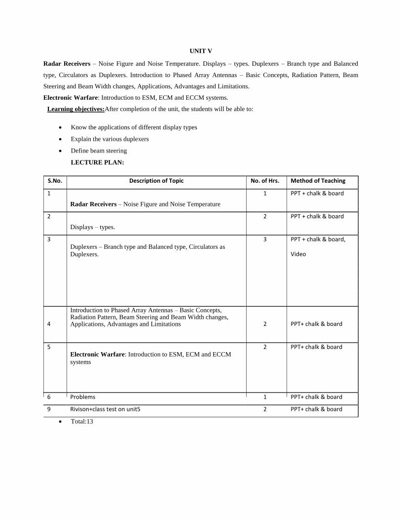
UNIT V Radar Receivers – Noise Figure and Noise Temperature. Displays – types. Duplexers – Branch type and Balanced
type, Circulators as Duplexers. Introduction to Phased Array Antennas – Basic Concepts, Radiation Pattern, Beam
Steering and Beam Width changes, Applications, Advantages and Limitations.
Electronic Warfare: Introduction to ESM, ECM and ECCM systems.
Learning objectives:After completion of the unit, the students will be able to:
Know the applications of different display types
Explain the various duplexers
Define beam steering
LECTURE PLAN:
S.No. Description of Topic No. of Hrs. Method of Teaching
1 1 PPT + chalk & board
Radar Receivers – Noise Figure and Noise Temperature
2 2 PPT + chalk & board
Displays – types.
3 3 PPT + chalk & board,
Duplexers – Branch type and Balanced type, Circulators as
Duplexers. Video
4
Introduction to Phased Array Antennas – Basic Concepts, Radiation Pattern, Beam Steering and Beam Width changes, Applications, Advantages and Limitations 2 PPT+ chalk & board
5 2 PPT+ chalk & board
Electronic Warfare: Introduction to ESM, ECM and ECCM
systems
6 Problems 1 PPT+ chalk & board
9 Rivison+class test on unit5 2 PPT+ chalk & board
Total:13

TEXT BOOKS 1. Introduction to Radar Systems – Merrill I. Skolnik, TMH Special Indian Edition, 2nd ed., 2007.
2. Radar Principles – Peebles, Jr., P.Z., Wiley, New York, 1998. REFERENCES 1. Introduction to Radar Systems – Merrill I. Skolnik, 3rd ed., TMH, 2001.
2. Radar : Principles, Technology, Aplications – Byron Edde, Pearson Education, 2004

VNR VIGNANA JYOTHI INSTITUTE OF ENGINEERING & TECHNOLOGY
(An Autonomous Institute & Accredited by NBA & NAAC with ‘A’ Grade)
Bachupally, Nizampet (S.O.), Hyderabad – 500 090
Department of ECE
Subject :VLSI Design Class: IV B.Tech I Sem (ECE)
Name of faculty :V.Priyanka Brahmaiah, P.Anudeep,
Asst. Professor,ECE.
Date: 21-05-2016
Pre-requisites
Electronic Devices and circuits, Digital IC Concepts
Course Objectives
To learn the various fabrication steps of IC and come across basic electrical properties of MOSFET.
To study the concepts of stick diagrams and layouts with the knowledge of MOS layers through design rules.
To study gate level design of subsystems, integrated circuits To learn concepts of PLD’s ,design capture tools and CMOS testing.
Course Outcomes
After Completion of the course the student is able to
Understand IC Fabrication process steps required for various MOS circuits
Analyze electrical properties and layout flow for circuit level and gate level models
Design and test VLSI circuits.
S.No Unit Period(S) Brief Note of Topic(S) Covered Active Learning Technique used
1
Un
it-1
01 Introduction to IC Technology ,
Comparing MOS, PMOS, NMOS,
CMOS & BiCMOS technologies
Chalk & Talk,
PPT's, Mind
mapping
2 01 Explanation of n channel enhancement
MOS Transistor working with the aid of
the cross- sectional layout.
Chalk & Talk
3 01 Working principles of the other types of
MOSFETs such as depletion MOSFET
and p channel enhancement MOSFET.
Chalk & Talk
4 01 Oxidation, Lithography, Diffusion, Ion PPT's

implantation
5 01 Metallization, Encapsulation, Packing. PPT's
6 01 Basic Electrical Properties of
MOS,CMOS and BiCMOS Circuits: Ids-
Vds relationships,
Chalk & Talk
7 01 MOS transistor threshold Voltage, gm,
gds. Chalk & Talk
8 01 Figure of merit wo; Pass transistor, Chalk & Talk
9 01 NMOS Inverter, Various pull ups Chalk & Talk
10 01 Working principles of the other types of
MOSFETs such as depletion MOSFET
and p channel enhancement MOSFET.
Chalk & Talk
11 01 Determination of pull–up to pull-down
ratio (Zp.u/Zp.d) Chalk & Talk
12 01 Study of NMOS & CMOS Inverter
Processes Chalk & Talk
13 01 Study of Bi-CMOS Inverter Processes Chalk & Talk
14 01 VLSI Design Flow PPT's,
Mind mapping
15 01 Layers of Abstractions (Physical,
Layout, Logic, Functional, System
Layers)
PPT's
16 01 Stick notation and stick diagram for
nMOS & CMOS Inverter design style
Chalk & Talk,
Video
17 01 Sizing of the NMOS and CMOS circuits
18 01 Design Rules ( 5 μm, 2 μm, λ based
design rules).
Chalk & Talk,
PPT's
19
Un
it 2
01 Developing the stick diagram into layout
by applying the design rules.
Chalk &
Talk,PPT's
20 01 Contact cuts, vias and double metal
process rules
Chalk &
Talk,PPT's
21 01 Scaling models Chalk &
Talk,PPT's
22 01 Limitations of Scaling Chalk &
Talk,PPT's
23 01 Review of the unit. Quiz,Group
Discussions
24
Un
it 3
01 Architectural issues PPT's
25 01 Developing Switch logic networks:
Implementation of AND, Or and
Multiplexer, Gate logic
Chalk & Talk
26 01 Other CMOS logic structures such as
Pseudo NMOS logic, Dynamic CMOS
logic, Clocked CMOS logic etc.
Chalk & Talk
27 01 Calculation of the sheet resistance of
simple circuits. Chalk & Talk
28 01 Introducing the area capacitance Chalk & Talk

calculations.
29 01 Explanation on inverter delays and how
they can be estimated. Chalk & Talk
30 01 Probing into the fact that the delay gets
changed depending on the driver. Chalk & Talk
31 01 Introducing the other circuit concepts
such as fan-in and fan-out and explaining
how the layout depends on these factors.
Chalk & Talk
32 01 Choice of layers Chalk & Talk
33 01 Review of the unit. Quiz, Group
Discussions
34
Un
it 4
01 Review on the basic adder circuits and
introduction on how the adder circuits
can be implemented.
POGIL Activity,
Chalk & Talk
35 01
Review on carry save adder and Carry
lookahead adder circuits and
introduction to Transmission gate adder
and carry propagate adder
Chalk & Talk
36 01 Zero/one detector and it’s
implementation Chalk & Talk
37 01 Explanation on how comparator circuits
can be constructed using XNOR gates,
pass transistor and pseudo NMOS
Chalk & Talk
38 01 Review of the basic combinational
multiplier circuits and explanation of
array multiplier
Chalk & Talk
39 01 Radix-n multiplication and Booth
recoded values Chalk & Talk
40 01 Wallace tree multipliers and serial
multiplication including analysis of 4: 2
compressor circuit
Chalk & Talk
41
Un
it 4
01 Analysis of Array shifter using
transmission gates and multiplexer
Chalk & Talk,
PPT's
42 01 Transistor based Static and dynamic
RAM and their read and write operations
Chalk & Talk,
PPT's
43 01 Description of Sense amplifier circuits
and Row and column decoders Chalk & Talk
44 01 Basic ROM architecture and power
saving ROM circuitry Chalk & Talk
45 01 Description of serial access memories
and CAM Chalk & Talk
46 01 Introductions to semiconductor
Integrated Circuits, Types of ASIC’s Chalk & Talk
47 01 Full Custom and Semi Custom ASIC’s Chalk & Talk
48 01 Programmable Logic Devices (PLDs,
FPGAs) Chalk & Talk
49 01 ASIC Design Flow Chalk & Talk,
PPT's

50 01 Types of PLDs and PROM Architecture,
PLA and PAL Architecture
Chalk & Talk,
PPT's
51 01 Realization of different logics and
circuits using PROM, PAL and PLA
Architecture.
Chalk & Talk,
PPT's
52 01 Complex PLDs, FPGAs and its
Architecture
Chalk & Talk,
PPT's
53 01 Standard cells and Anti- fuse technology. Chalk & Talk,
PPT's
54
Un
it 5
01 Concept of VHDL Synthesis Chalk & Talk,
PPT's
55 01 Concept of Circuit Design Flow, Circuit
Synthesis, Simulation, Layout PPT's
56 01 Design Capture tools, Design
Verification Tools Video, PPT's
57 01 Why is testing needed? POGIL Activity
58 01 Explanation on fault models,
observability, controllability etc Chalk & Talk
59 01 Explanation on ATPG and fault grading Chalk & Talk
60 01 Delay fault testing, Statistical fault
analysis and fault sampling Chalk & Talk
61 01 Different strategies for test Chalk & Talk
62 01 Self test techniques and IDDQ test Chalk & Talk
63 01 Previous question papers discussion Quiz, Group
Discussions
Faculty Sign HOD/ECE


