Laboratory integration testing of railway signalling systems for high-speed trains
J.-G. Hwang & J.-W. Lee Railway Signalling Research Group, Korea Railroad Research Institute (KRRI), Korea
Abstract
Railway signalling systems consist of several items of vital computerized equipment such as CTC (Centralized Traffic Control system), EIS (Electronic Interlocking System), ATC (Automatic Train Control system) and so on. Currently, railway signalling systems for the next-generation high-speed trains are being developed in Korea. The railway signalling systems being developed, called kTCS (Korean Train Control System), are composed of kTCS-CTC, kTCS-IXL, kTCS-ATC etc. kTCS signalling systems have to be operated at the laboratory level as integrated signalling systems with an interface between each developed signalling systems before trackside field installation and revenue service. For this laboratory testing for interface and functions verification, communication protocols between the signalling equipment are designed and message codes for each defined protocol are defined. Also several emulation modules have been developed for the integrated railway signalling systems for laboratory testing. We have plentifully tested and verified the designed protocols and the characteristics of integrated railway signalling systems with each of our developed kTCS signalling systems, communication protocols and several emulation modules. Keywords: kTCS (Korean Train Control System), laboratory integration testing, trackside emulation module, railway signalling systems.
1 Introduction
A very high safety level is required for railway signalling systems for protection against vital accidents such as collisions and derailment of the train. Railway signalling systems consist of an electric interlocking system, ATC (Automatic
Computers in Railways IX, J. Allan, C. A. Brebbia, R. J. Hill, G. Sciutto & S. Sone (Editors)© 2004 WIT Press, www.witpress.com, ISBN 1-85312-715-9
Train Control system), CTC (Centralized Traffic Control system) and other trackside vital systems. These signalling systems are vital equipment for the guarantee of safe train operation. Recently electric signalling systems have been changed to computerized electronic systems. The computerized railway signalling systems have achieved unique function so far, but the interoperation of each signalling system has become more important according to the computerization. That is, nowadays computerized railway signalling systems are operated as a full-featured signal system through an interface with signalling equipment. Currently, the next-generation signalling systems for high-speed trains are being developed in Korea. The developed signalling systems, called kTCS, consist of kTCS-CTC, kTCS-IXL, kTCS-ATC and other trackside signalling systems. We have designed dedicated protocols for interface between the developed kTCS signalling systems. Many matters have to be considered for the design of a reliable protocol for railway signalling communication such as an error detection technique, error correction algorithm, flow control, message frame structure, transmitted message type etc. Protocols for railway signalling systems are designed by consideration of various kinds of parameters in this research. The kTCS signalling systems have to be operated at the laboratory level as an integrated system by interface between each developed signalling system before trackside field installation and revenue service. For this laboratory testing for interface and function verification, communication protocols between signalling equipment are designed and message codes for each defined protocol are defined. Also several emulation modules have been developed for the integrated signalling systems for laboratory testing. We have plentifully tested and verified the designed protocols and the characteristics of integrated railway signalling systems with each of our developed kTCS signalling systems, communication protocols and several emulation modules.
2 Integrated kTCS system configuration
The kTCS systems consist of kTCS-ATC for space control between trains through speed control of the following train, kTCS-IXL for safety route setting and release of a train and on the whole by kTCS-CTC for control and monitoring of operation of trains and trackside signalling systems. Figure 1 shows the configuration of the developed kTCS system. As we can see the control commands for trackside signalling systems are transferred from kTCS-CTC to trackside signalling systems through the kTCS-IXL communication module. The state information for signalling systems is transferred in reverse from trackside equipment to kTCS-CTC via the kTCS-IXL communication module. Also, the kTCS-ATC system generally consists of two systems. One is a ground control system to calculate the target speed for the current block section referring to the location information of the preceding train, and the other is an on-board control system to carry out safety control of the train through the present running speed information and target limit speed from the ground ATC system. Track circuits
Computers in Railways IX, J. Allan, C. A. Brebbia, R. J. Hill, G. Sciutto & S. Sone (Editors)© 2004 WIT Press, www.witpress.com, ISBN 1-85312-715-9
432 Computers in Railways IX
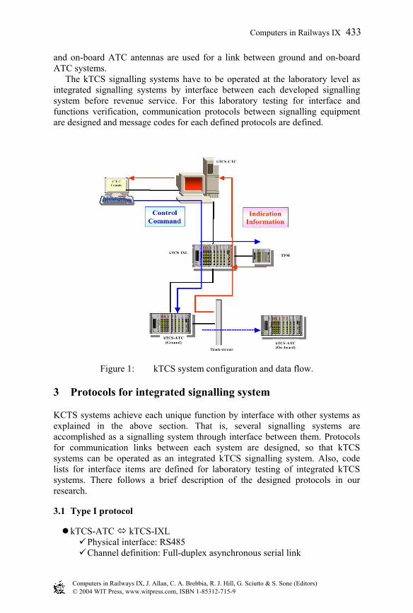
and on-board ATC antennas are used for a link between ground and on-board ATC systems. The kTCS signalling systems have to be operated at the laboratory level as integrated signalling systems by interface between each developed signalling system before revenue service. For this laboratory testing for interface and functions verification, communication protocols between signalling equipment are designed and message codes for each defined protocols are defined.
Figure 1: kTCS system configuration and data flow.
3 Protocols for integrated signalling system
KCTS systems achieve each unique function by interface with other systems as explained in the above section. That is, several signalling systems are accomplished as a signalling system through interface between them. Protocols for communication links between each system are designed, so that kTCS systems can be operated as an integrated kTCS signalling system. Also, code lists for interface items are defined for laboratory testing of integrated kTCS systems. There follows a brief description of the designed protocols in our research.
3.1 Type I protocol
kTCS-ATC kTCS-IXL Physical interface: RS485 Channel definition: Full-duplex asynchronous serial link
Computers in Railways IX, J. Allan, C. A. Brebbia, R. J. Hill, G. Sciutto & S. Sone (Editors)© 2004 WIT Press, www.witpress.com, ISBN 1-85312-715-9
Computers in Railways IX 433

Transmission speed: 9600 bps Error detection code: CRC-16
STX Data Length
Sequence No.
OP Code Data CRC ETX
1 byte 2 byte 1 byte 2 byte N byte 4 byte 1 byte
Figure 2: Message frame format.
Communication links between these two systems applied the RS485 serial interface standard, and the frame format of the transmitted message is designed for kTCS systems. One important entity for the designed protocol is the error control method in the data link protocol. This protocol used CRC-16 code (X16 + X15 + X2 + 1) that is a surplus field for error detection of transmitted messages. The stop and wait ARQ scheme is also applied to error correction based on the CRC 16 error detection code, and the ‘ACK/NAK’ control message is used for error correction and flow control. The following is a description of the retransmission mechanism. If the following cases occur to the sender, the same message must be retransmitted to the receiver up to a maximum of 3 times.
Error detection in transmission frame by error detection code, fault of sequence number at receiver (‘NAK’ message transmission to sender)
S e n d e r
R e c e iv e r
S T X E T X S T X A C K
e r ro r
E T XN A K
∆ R∆ R
∆ S ∆ S
No reception of ‘ETX’ message to receiver in spite of expiration of receiver timer setting time R∆ (‘NAK’ message transmission to sender)
S e n d e r
R e c e iv e r
S T X E T X S T X A C K
e r r o r
E T XN A K
∆ R
∆ S ∆ S
∆ R
If sender could not receive any response message from the communication receiver such as ‘ACK’ or NAK, even though the sender timer had expired, then previous message retransmits to destination.
S e n d e r
R e c e iv e r
S T X E T X
A C K
∆ R
∆ S
S T X E T X
A C K
∆ R
∆ S
S T X E T X
A C K
∆ R
∆ S
A la rm
Computers in Railways IX, J. Allan, C. A. Brebbia, R. J. Hill, G. Sciutto & S. Sone (Editors)© 2004 WIT Press, www.witpress.com, ISBN 1-85312-715-9
434 Computers in Railways IX
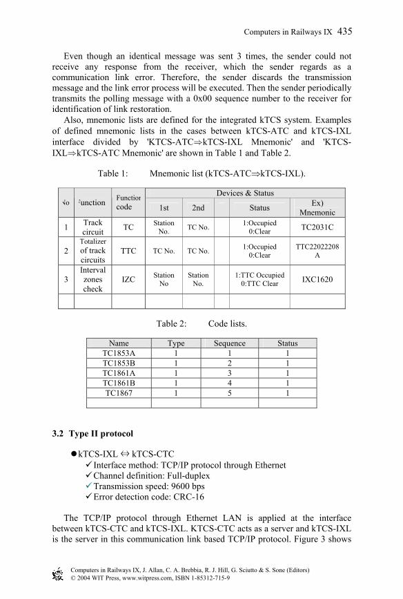
Even though an identical message was sent 3 times, the sender could not receive any response from the receiver, which the sender regards as a communication link error. Therefore, the sender discards the transmission message and the link error process will be executed. Then the sender periodically transmits the polling message with a 0x00 sequence number to the receiver for identification of link restoration. Also, mnemonic lists are defined for the integrated kTCS system. Examples of defined mnemonic lists in the cases between kTCS-ATC and kTCS-IXL interface divided by 'KTCS-ATC⇒kTCS-IXL Mnemonic' and 'KTCS-IXL⇒kTCS-ATC Mnemonic' are shown in Table 1 and Table 2.
Table 1: Mnemonic list (kTCS-ATC⇒kTCS-IXL).
Devices & Status No. Function Function
code 1st 2nd Status Ex) Mnemonic
1 Track circuit TC Station
No. TC No. 1:Occupied 0:Clear TC2031C
2 Totalizer of track circuits
TTC TC No. TC No. 1:Occupied 0:Clear
TTC22022208A
3 Interval zones check
IZC Station No
Station No. 1:TTC Occupied
0:TTC Clear IXC1620
Table 2: Code lists.
Name Type Sequence Status TC1853A 1 1 1 TC1853B 1 2 1 TC1861A 1 3 1 TC1861B 1 4 1 TC1867 1 5 1
3.2 Type II protocol
kTCS-IXL ⇔ kTCS-CTC Interface method: TCP/IP protocol through Ethernet Channel definition: Full-duplex Transmission speed: 9600 bps Error detection code: CRC-16
The TCP/IP protocol through Ethernet LAN is applied at the interface between kTCS-CTC and kTCS-IXL. KTCS-CTC acts as a server and kTCS-IXL is the server in this communication link based TCP/IP protocol. Figure 3 shows
Computers in Railways IX, J. Allan, C. A. Brebbia, R. J. Hill, G. Sciutto & S. Sone (Editors)© 2004 WIT Press, www.witpress.com, ISBN 1-85312-715-9
Computers in Railways IX 435
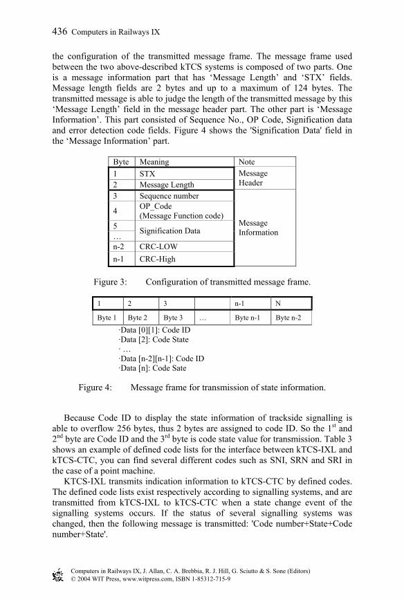
the configuration of the transmitted message frame. The message frame used between the two above-described kTCS systems is composed of two parts. One is a message information part that has ‘Message Length’ and ‘STX’ fields. Message length fields are 2 bytes and up to a maximum of 124 bytes. The transmitted message is able to judge the length of the transmitted message by this ‘Message Length’ field in the message header part. The other part is ‘Message Information’. This part consisted of Sequence No., OP Code, Signification data and error detection code fields. Figure 4 shows the 'Signification Data' field in the ‘Message Information’ part.
Byte Meaning Note 1 STX 2 Message Length
Message Header
3 Sequence number
4 OP_Code (Message Function code)
5 …
Signification Data
n-2 CRC-LOW n-1 CRC-High
Message Information
Figure 3: Configuration of transmitted message frame.
1 2 3 n-1 N
Byte 1 Byte 2 Byte 3 … Byte n-1 Byte n-2
·Data [0][1]: Code ID ·Data [2]: Code State · … ·Data [n-2][n-1]: Code ID ·Data [n]: Code Sate
Figure 4: Message frame for transmission of state information.
Because Code ID to display the state information of trackside signalling is able to overflow 256 bytes, thus 2 bytes are assigned to code ID. So the 1st and 2nd byte are Code ID and the 3rd byte is code state value for transmission. Table 3 shows an example of defined code lists for the interface between kTCS-IXL and kTCS-CTC, you can find several different codes such as SNI, SRN and SRI in the case of a point machine. KTCS-IXL transmits indication information to kTCS-CTC by defined codes. The defined code lists exist respectively according to signalling systems, and are transmitted from kTCS-IXL to kTCS-CTC when a state change event of the signalling systems occurs. If the status of several signalling systems was changed, then the following message is transmitted: 'Code number+State+Code number+State'.
Computers in Railways IX, J. Allan, C. A. Brebbia, R. J. Hill, G. Sciutto & S. Sone (Editors)© 2004 WIT Press, www.witpress.com, ISBN 1-85312-715-9
436 Computers in Railways IX
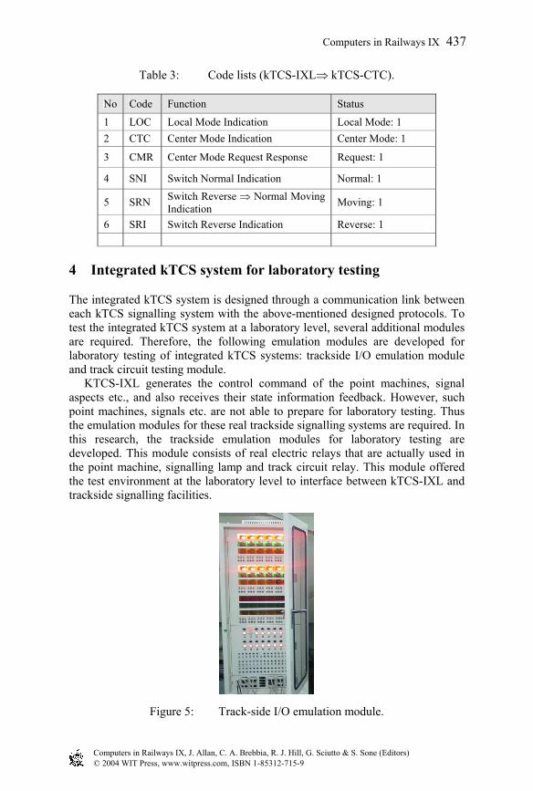
Table 3: Code lists (kTCS-IXL⇒ kTCS-CTC).
No Code Function Status
1 LOC Local Mode Indication Local Mode: 1 2 CTC Center Mode Indication Center Mode: 1
3 CMR Center Mode Request Response Request: 1
4 SNI Switch Normal Indication Normal: 1
5 SRN Switch Reverse ⇒ Normal Moving Indication Moving: 1
6 SRI Switch Reverse Indication Reverse: 1
4 Integrated kTCS system for laboratory testing
The integrated kTCS system is designed through a communication link between each kTCS signalling system with the above-mentioned designed protocols. To test the integrated kTCS system at a laboratory level, several additional modules are required. Therefore, the following emulation modules are developed for laboratory testing of integrated kTCS systems: trackside I/O emulation module and track circuit testing module. KTCS-IXL generates the control command of the point machines, signal aspects etc., and also receives their state information feedback. However, such point machines, signals etc. are not able to prepare for laboratory testing. Thus the emulation modules for these real trackside signalling systems are required. In this research, the trackside emulation modules for laboratory testing are developed. This module consists of real electric relays that are actually used in the point machine, signalling lamp and track circuit relay. This module offered the test environment at the laboratory level to interface between kTCS-IXL and trackside signalling facilities.
Figure 5: Track-side I/O emulation module.
Computers in Railways IX, J. Allan, C. A. Brebbia, R. J. Hill, G. Sciutto & S. Sone (Editors)© 2004 WIT Press, www.witpress.com, ISBN 1-85312-715-9
Computers in Railways IX 437
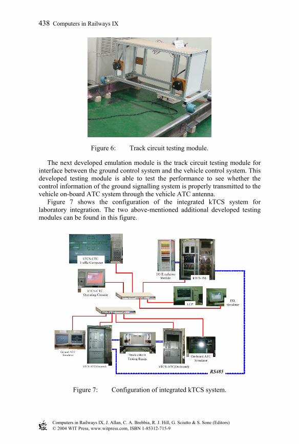
Figure 6: Track circuit testing module.
The next developed emulation module is the track circuit testing module for interface between the ground control system and the vehicle control system. This developed testing module is able to test the performance to see whether the control information of the ground signalling system is properly transmitted to the vehicle on-board ATC system through the vehicle ATC antenna. Figure 7 shows the configuration of the integrated kTCS system for laboratory integration. The two above-mentioned additional developed testing modules can be found in this figure.
Figure 7: Configuration of integrated kTCS system.
Computers in Railways IX, J. Allan, C. A. Brebbia, R. J. Hill, G. Sciutto & S. Sone (Editors)© 2004 WIT Press, www.witpress.com, ISBN 1-85312-715-9
438 Computers in Railways IX

Figure 8: Display of route setting by console.
Figure 9: Configuration of laboratory integration testing of the kTCS system.
5 Conclusion
The kTCS signalling systems have to be operated at the laboratory level as integrated signalling systems by interface between each developed signalling system before revenue service. For this laboratory testing, protocols between signalling systems are designed in this research. Also several emulation modules have been developed for the laboratory integration testing. We have plentifully tested and verified the designed protocols and the characteristics of the integrated railway signalling systems. We have verified the interface and integration performance of the kTCS signalling system by laboratory integration testing. Figure 8 shows an example of laboratory integration testing. If a route setting request occurs in kTCS-CTC, then this command is transferred to kTCS-IXL and
Computers in Railways IX, J. Allan, C. A. Brebbia, R. J. Hill, G. Sciutto & S. Sone (Editors)© 2004 WIT Press, www.witpress.com, ISBN 1-85312-715-9
Computers in Railways IX 439
a safe route established. After establishment of this safe route, the state information on route setting is sent to kTCS-CTC from kTCS-IXL. Figure 8 shows the CTC operating console screen when the state of route setting is transmitted from kTCS-IXL. Figure 9 shows the testing status of the integrated kTCS system installed in the KRRI laboratory.
References
[1] J. G. Hwang and J. W. Lee, ‘Communication Protocol Structure for Railway Signalling and Its Experimental Applications’, Proceeding of ICEE’01, July 2001.
[2] http://www.azurenet.com/. [3] Hirotane Inage, Haruo Yamamoto, Yuji Hirao, Yutaka Hasegawa,
‘Laboratory Development of New Train Control System by radio’, RTRI Report Vol. 5, No. 1, pp. 48-55, Jan. 1991.
[4] Institute of Railway Signal Engineers, ‘Railway Signalling’, A & C Black, London, 1991.
Computers in Railways IX, J. Allan, C. A. Brebbia, R. J. Hill, G. Sciutto & S. Sone (Editors)© 2004 WIT Press, www.witpress.com, ISBN 1-85312-715-9
440 Computers in Railways IX


