
Mechatronics Engineering and Automation
Faculty of Engineering, Ain Shams University
MCT-151, Spring 2015
Lab-3: LCDs | Serial Communication | Analog Inputs
| Temperature Measurement System
Ahmed Okasha

Understanding LCD
LCD (Liquid Crystal Display) screen is an electronic display module and find a wide range of applications. A 16x2 LCD display is very basic module and is very commonly used in various devices and circuits. These modules are preferred over seven segments and other multi segment LEDs. The reasons being: LCDs are economical; easily programmable; have no limitation of displaying special & even custom characters (unlike in seven segments), animations and so on.
A 16x2 LCD means it can display 16 characters per line and there are 2 such lines. In this LCD each character is displayed in 5x7 pixel matrix. This LCD has two registers, namely, Command and Data.
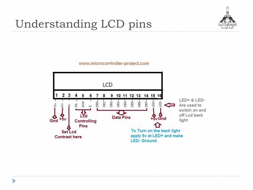
Understanding LCD pins
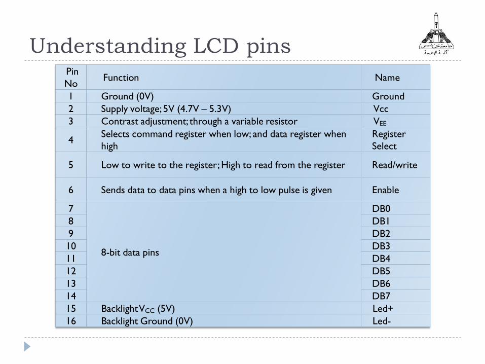
Understanding LCD pinsPin
NoFunction Name
1 Ground (0V) Ground
2 Supply voltage; 5V (4.7V – 5.3V) Vcc
3 Contrast adjustment; through a variable resistor VEE
4Selects command register when low; and data register when
high
Register
Select
5 Low to write to the register; High to read from the register Read/write
6 Sends data to data pins when a high to low pulse is given Enable
7
8-bit data pins
DB0
8 DB1
9 DB2
10 DB3
11 DB4
12 DB5
13 DB6
14 DB7
15 Backlight VCC (5V) Led+
16 Backlight Ground (0V) Led-

LCD Registers
The command register stores the command instructions given to the LCD. A command is an instruction given to LCD to do a predefined task like initializing it, clearing its screen, setting the cursor position, controlling display etc. The data register stores the data to be displayed on the LCD. The data is the ASCII value of the character to be displayed on the LCD. Click to learn more about internal structure of a LCD.
Why only 4 data bit not 8? The idea of 4 bit communication is introduced to save pins of a microcontroller. You may think that 4 bit mode will be slower than 8 bit. But the speed difference is only minimal.
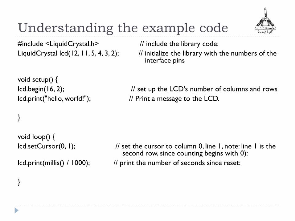
Understanding the example code#include <LiquidCrystal.h> // include the library code:
LiquidCrystal lcd(12, 11, 5, 4, 3, 2); // initialize the library with the numbers of the interface pins
void setup() {
lcd.begin(16, 2); // set up the LCD's number of columns and rows
lcd.print("hello, world!"); // Print a message to the LCD.
}
void loop() {
lcd.setCursor(0, 1); // set the cursor to column 0, line 1, note: line 1 is the second row, since counting begins with 0):
lcd.print(millis() / 1000); // print the number of seconds since reset:
}

Serial Communication
Serial data transfer is when we transfer data one bit at a
time, one right after the other.
Used for communication between the Arduino board and
a computer or other devices. All Arduino boards have at
least one serial port (also known as a UART or
USART): Serial. It communicates on digital pins 0 (RX) and
1 (TX) as well as with the computer via USB. Thus, if you
use these functions, you cannot also use pins 0 and 1 for
digital input or output.

Serial Communication
When you Compile/Verify what you're really doing is
turning the sketch into binary data (ones and zeros). When
you Upload it to the Arduino, the bits are shoved out one at a
time through the USB cable to the Arduino where they are
stored in the main chip.

Notes
library name procedure name (input values)
Serial begin (9600)
Baud rate: 9600 bps, this is how fast the connection can read
and write bits on the wire.
TO show the serial monitor: Tools>>serial monitor
Baud rate match up!
If you ever find that you're getting a whole lot of garbage instead
of proper text, make sure that you have the correct baud rate
selected in the drop down menu of the Serial Monitor. Note that
this communication baud rate is indepedent of the upload
process, which is fixed at 19200 bps.
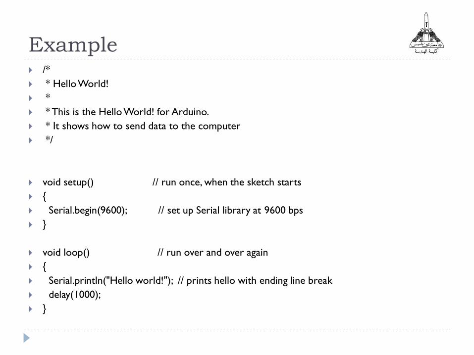
Example /*
* Hello World!
*
* This is the Hello World! for Arduino.
* It shows how to send data to the computer
*/
void setup() // run once, when the sketch starts
{
Serial.begin(9600); // set up Serial library at 9600 bps
}
void loop() // run over and over again
{
Serial.println("Hello world!"); // prints hello with ending line break
delay(1000);
}

Example
Go to Tools>> Serial Monitor

Analog Inputs
Arduino UNO has 6 analog inputs pins to deal with a
wide variety of analog sensors such as Potentiometers,
LDRs, pressure sensor,…etc.

How to read from analog pins?
analogRead(pin):
Reads the value from the specified analog pin. The
Arduino board contains a 6 channel,10-bit analog to
digital converter.
This means that it will map input voltages between 0 and
5 volts into integer values between 0 and 1023.
This yields a resolution between readings of: 5 volts /
1024 units or, .0049 volts (4.9 mV) per unit.
Analog Sensor Examples
Potentiometer
Photo-resistor
LM35 Temperature sensor
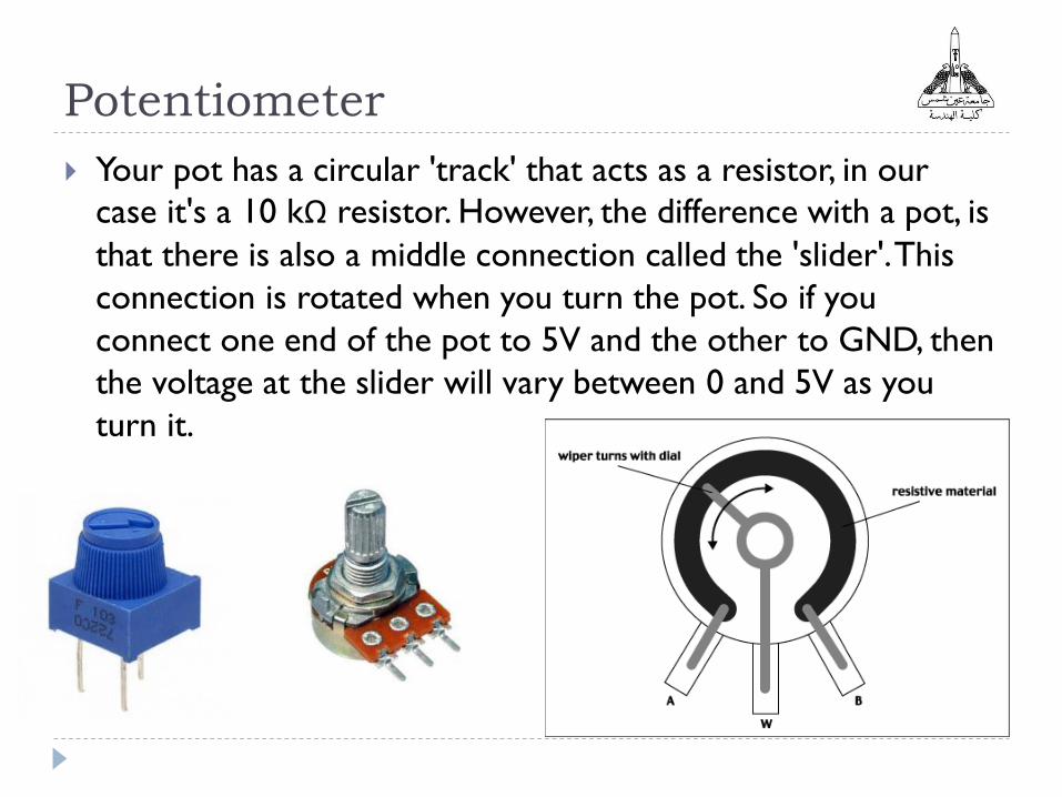
Potentiometer
Your pot has a circular 'track' that acts as a resistor, in our
case it's a 10 kΩ resistor. However, the difference with a pot, is
that there is also a middle connection called the 'slider'. This
connection is rotated when you turn the pot. So if you
connect one end of the pot to 5V and the other to GND, then
the voltage at the slider will vary between 0 and 5V as you
turn it.

Example:
int val = 0; // variable to store the value read
void setup()
{
Serial.begin(9600); // setup serial
}
void loop()
{
val = analogRead(analogPin); // read the input pin
Serial.println(val); //Serial print
}
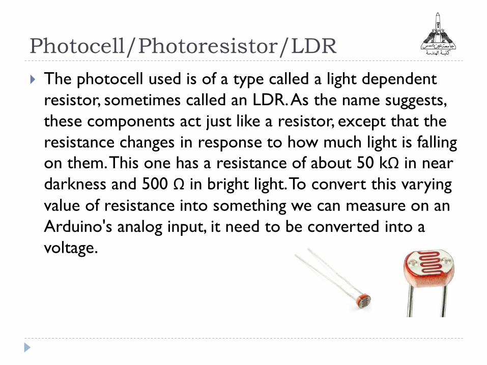
Photocell/Photoresistor/LDR
The photocell used is of a type called a light dependent
resistor, sometimes called an LDR. As the name suggests,
these components act just like a resistor, except that the
resistance changes in response to how much light is falling
on them. This one has a resistance of about 50 kΩ in near
darkness and 500 Ω in bright light. To convert this varying
value of resistance into something we can measure on an
Arduino's analog input, it need to be converted into a
voltage.

Interfacing LDR to Arduino
The simplest way to do that is to combine it with a fixed
resistor. The resistor and photocell together behave rather like
a pot. When the light is very bright, then the resistance of the
photocell is very low compared with the fixed value resistor,
and so it is as if the pot were turned to maximum. When the
photocell is in dull light the resistance becomes greater than
the fixed 1kΩ resistor and it is as if the pot were being turned
towards GND.
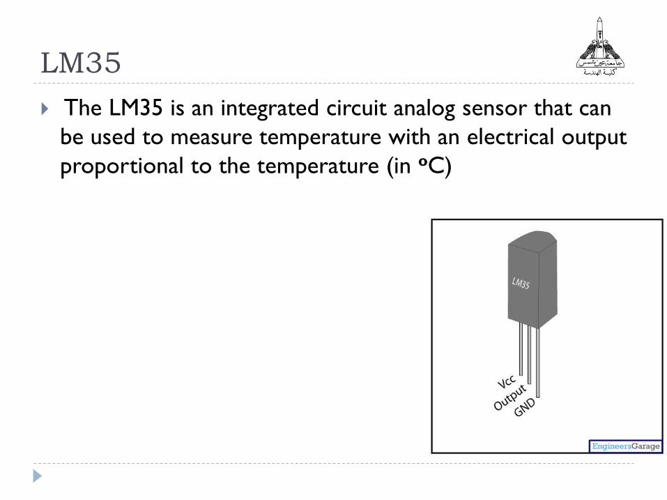
LM35
The LM35 is an integrated circuit analog sensor that can
be used to measure temperature with an electrical output
proportional to the temperature (in oC)

LM35 sensitivity equation
The analog value read from LM35 is converted to a digital
value in the range of (0-1023).
LM35 sensitivity:
𝑆𝑒𝑛𝑠𝑖𝑡𝑖𝑣𝑖𝑡𝑦 =𝑂𝑢𝑡𝑝𝑢𝑡 𝑉𝑜𝑙𝑡𝑎𝑔𝑒 (𝑉𝑖𝑛)
𝐼𝑛𝑝𝑢𝑡 𝑇𝑒𝑚𝑝𝑒𝑟𝑎𝑡𝑢𝑟𝑒 (𝑇)= 10
𝑚𝑉
°𝐶= 0.01
𝑉
°𝐶
This means: For 𝑉𝑖𝑛 = 1023 (5𝑉) ≫ 𝑇 =5
0.01= 500 °𝐶
1023 −−−−→ 500°𝐶𝑉𝑖𝑛 −−−−→ 𝑇 =?
𝑇 =𝑉𝑖𝑛
1023∗ 500
The value read
from the sensor
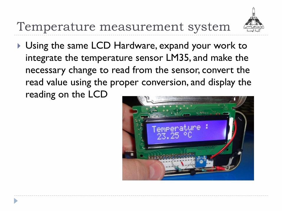
Temperature measurement system
Using the same LCD Hardware, expand your work to
integrate the temperature sensor LM35, and make the
necessary change to read from the sensor, convert the
read value using the proper conversion, and display the
reading on the LCD
References
http://www.engineersgarage.com/electronic-
components/16x2-lcd-module-datasheet
https://electrosome.com/interfacing-lcd-with-pic-
microcontroller-hi-tech-c/


