KING
KMA20/KR21MARKERBEACONRECEIVER
ISOLATIONAMPLIFIER
INSTALLATIONMANUAL006-0044-02
REV. 2 JUNE, 1976

KlNGKMA 20 /KR 21
MARKER BEACON RECEIVER/ISOLATION AMPLIFIER
TABLEOFCONTENTSSECTIONI GENERALINFORMATION
Paragraph Page
1. 1 Introduction 1-1
1. 2 Technical Characteristics 1-2
1. 3 Accessories Required 1-6
SECTIONII INSTALLATION2. 1 General 2-1
2.2 Unpacking and Inspecting Equipment 2-1
2. 3 Installation Notes and Precautions 2-1
2.4 Installation Procedure 2-22. 5 Marker Antenna Installation 2-2
2. 6 KA 40 Installation (Optional) 2-3
SECTIONIIIOPERATION3. 1 Marker Beacon (KMA 20 and KR 21) 3-13.2 Isolation Amplifier (KMA 20) 3-2
LISTOFILLUSTRATIONSFigure Page
2-1 KMA 20 Installation Drawing 2-42-2 KR 21 Instanation Drawing 2-52-3 KA 40 Instanation Drawing 2-62-4 KMA 20 Interconnect Diagram 2-72-5 KR 21 Interconnect Diagram (27. BV DC') 2-92-6 KR 21 lnterconnect Diagram (13. 75VD(') 2-92-7 KA 40 lnterconnect Diagram 2-102-8 Pin Function for 000-1024-00 thru -16 2-11
i

KINGKMA 20/KR 21
MARKER BEACON RECEIVER/ISOIATION AMPLIFIER
HISTORYOFREVISIONSHevision 1, August 1972
Page Reason for Change
Title Page Denotes New RevisionWarranty New WarrantyContents Table of Contents AddedHistory of Rev. History Revision Added
1-1 Lamp Test Information Added1-3 Sensitivity and Selectivity Revised1-4 Word Misspelled1-6 Installation Parts List Added
2-1 Warning Note Added2 -2 Paragraph 6 Changed to 7. New Paragraph 6 added.2-3 Figure Numbers corrected2-4 New Installation Drawing2 -5 New Installation Drawing2-6 Drawing Turned on Page2-7 Interconnect Corrected2-11 Pins Reversed2 -13 Figure Added2-15 Figure Added
3 -1 Marker Dese ription Changed3-1 Information Added about HI-LO Switch3-2 09/11 Information Added
ii

KMA20/KR 21MARKERBEACONRECEIVER/
ISOLATIONAMPLIFIER
HISTORYOFREVISIONS
Revision 2, June, 1976
Page Reasons for Change
Title Page Denotes New RevisionWarranty DeletedContents Page Number changesHistory of Revision Added for Revision 2
1-3 Technical Characteristics Updated
2-2 Paragraph 2.3 (5) updatedParagraph 2.3 (7) updated
2-7 Interconnect updated2-9 Figure 2-6A changed to 2-5
Figure 2-6B changed to 2-62-11 Figure 2-8 updated
3-2 Section 3.2 updated
iii

KINGKMA 20/KR 21
MARKER BEACON RECEIVER/ISOLATION AMPLIFIER
SECTIONI
GENERALINFORMATION
1.1 INTRODUCTION
The King KMA 20 is a compact transistorized unit providing the functions of markerbeacon receiver, isolation amplifier and audio control panel. The unit has been styledto harmonize with the all new generation of Silver Crown panel mounted equipment.TSO certification of the KMA 20 assures operation under varying environmentalconditions.
The KMA 20 is designed to provide a uniformly functioning aircraft radio system whenutilized with other units of the new Silver Crown line. Although the equipment is designedprimarily for use with the KX 170 NAV/COMM unit, it will also perform effeciently witholder Silver Crown transceivers and radios.
Significant new features of the KMA 20 design include its AUTO switch feature: semi-concealed marker light presentation and its ability to control COMM and NAV audioindependently. Automatic dimming circuitry for the marker lamps, to compensate forambient cockpit lighting, is also incorporated in the design.
Within the KMA 20, the marker beacon receiver comprises one section of the unit.The marker receiver of the KMA 20, available without the isolation amplifier and audiopanel is the KR 21. The receiver is a crystal controlled superheterodyne receiver andhas excellent selectivity and freedom from interference of television and FM stations.Operating controls for the marker receiver consists of two toggle switches on the KMA20: a HI-LO sensitivity and lamp test control and an audio selector switch. The KR 21has only the HI-LO sensitivity and lamp test control. A three light presentation is designed into the front panel of the unit with colored lenses to indicate passage over themarkers. Besides the colors, the stations are identified by the letters A-O-M engravedon the lenses plus the appropriate frequency audio tone. Should the aircraft user desire aa remote location for the marker lights, King Radio Corporation manufacturers anoptional remote light assembly designated the KA 40 for use with the KMA 20 only.
The isolation amplifier of the KMA 20 makes possible the combining of all receiveraudio inputs into a single cockpit speaker with 40db of isolation between each radio. Theinput power levels of the signals are amplified to the level necessary to drive a 4 ohmspeaker. An electronic muting circuit (diode switch) is provided to automatically isolatethe output of all receivers from the isolation amplifier whenever the microphone button
Rev. 1, August, 1972 Page 1-1

KINGKMA 20/KR 21
MARKER BEACON RECËIVER/ISOLATION AMPLIFIER
is pressed. This feature eliminates the possiblity of audio feedback in the cockpit. Theamplifier design utilizes only one integrated circuit and a push-pull output stage forhigh reliability.
Audio control functions of the Silver Crown radio system are performed at the frontpanel of the KMA 20. A microphone selector rotary switch, a series of eight audioselector switches and a marker beacon receiver sensitivity control are the operatingcontrols of the unit. The microphone selector routes audio and keying information tothe selected transceiver or to a EXT ramp hail speaker or passenger address system.The AUTO switch control of the standard model is utilized in conjunction with the micro-phone selector switch. For normal operation of the AUTO switch, COMM 1 and COMM2 are placed in the center (off) position. With the AUTO switch in the SPEAKER position,the receiver audio selected is automatically controlled by the operation of the micro-phone selector. Thus if transmitting on COMM 1, receiver audio for COMM 1 will berouted to the cockpit speaker. This feature eliminates the constant manipulation ofCOMM receiver audio selectors when switching back and forth between transmitters.Speaker, off or mute, and headphone audio control of each of the aircraft radios isaccomplished with the remaining three-position toggle switches.
A series type solid state regulator is used to supply the regulated voltage to the markerreceiver and audio boards of the unit. Since each aircraft installation is wired for eithier
13. 75 or 27. 5V operation of the unit, the KMA 20 and KR 21 are completely interchange-able between aircraft with no internal wiring changes.
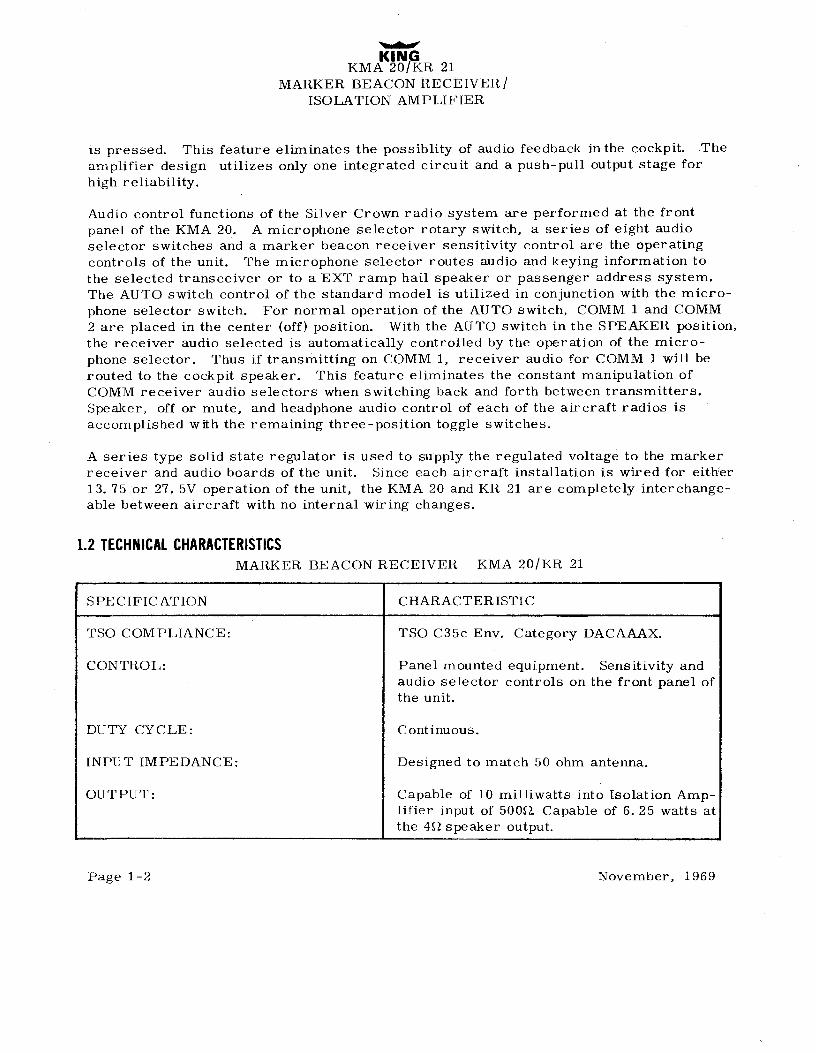
1.2 TECHNICALCHARACTERISTICSMARKER BEACON RECEIVER - KMA 20/KR 21
SPECIFICATION CHARACTERISTIC
TSO COMPLIANCE: TSO C35c Env. Category DACAAAX.
CONTROL: Panel mounted equipment. Sensitivity andaudio selector controls on the front panel ofthe unit.
DUTY CYCLE: Continuous.
INPUT IMPEDANCE: Designed to match 50 ohm antenna.
OUTPUT: Capable of 10 milliwatts into Isolation Amp-lifier input of 5000. Capable of 6. 25 watts atthe 4O speaker output.
Page 1-2 November, 1969

KINGKMA 20/KR 21
MARKER BEACON RECEIVER/ISOLATION AMPLIFIER
SPECIFICATION CHARACTERISTIC
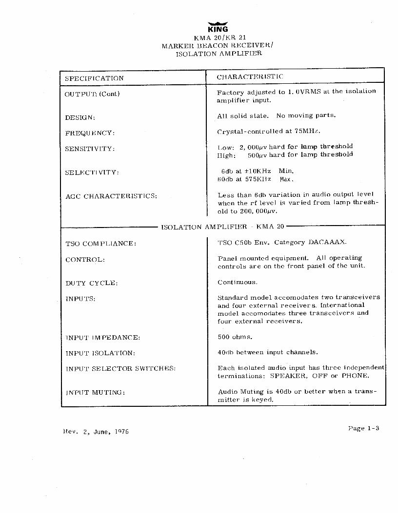
OUTPUT: (Cont) Factory adjusted to 1. OVRMS at the isolationamplifier input.
DESIGN: All solid state. No moving parts.
FREQUENCY: Crystal-controlled at 75MHz.
SENSITIVITY: Low: 2, 000µv hard for lamp thresholdHigh: 500µv hard for lamp threshold
SELECTIVITY: 6db at ±10KHz Min.60db at 575KHz Max.
AGC CHARACTERISTICS: Less than 6db variation in audio output levelwhen the rf level is varied from lamp thresh-old to 200, 000µv.
ISOLATION AMPLIFIER - KMA 20
TSO COMPLIANCE: TSO C50b Env. Category DACAAAX.
CONTROL: Panel mounted equipment. All operatingcontrols are on the front panel of the unit.
DUTY CYCLE: Continuous.
INPUTS: Standard model accomodates two transceiversand four external receivers, Internationalmodel accomodates three transceivers andfour external receivers.
INPUT IMPEDANCE: 500 ohms.
INPUT ISOLATION: 40db between input channels.
INPUT SELECTOR SWITCHES: Each isolated audio input has three independentterminations: SPEAKER, OFF or PHONE.
INPUT MUTING: Audio Muting is 40db or better when a trans-mitter is keyed.
Rev. 2, June, 1076 Page 1-3

KINGKMA 20/KR 21
MARKER BEACON RECEIVER/ISOLATION AMPLIFIER
SPECIFICATION CHARACTERISTIC
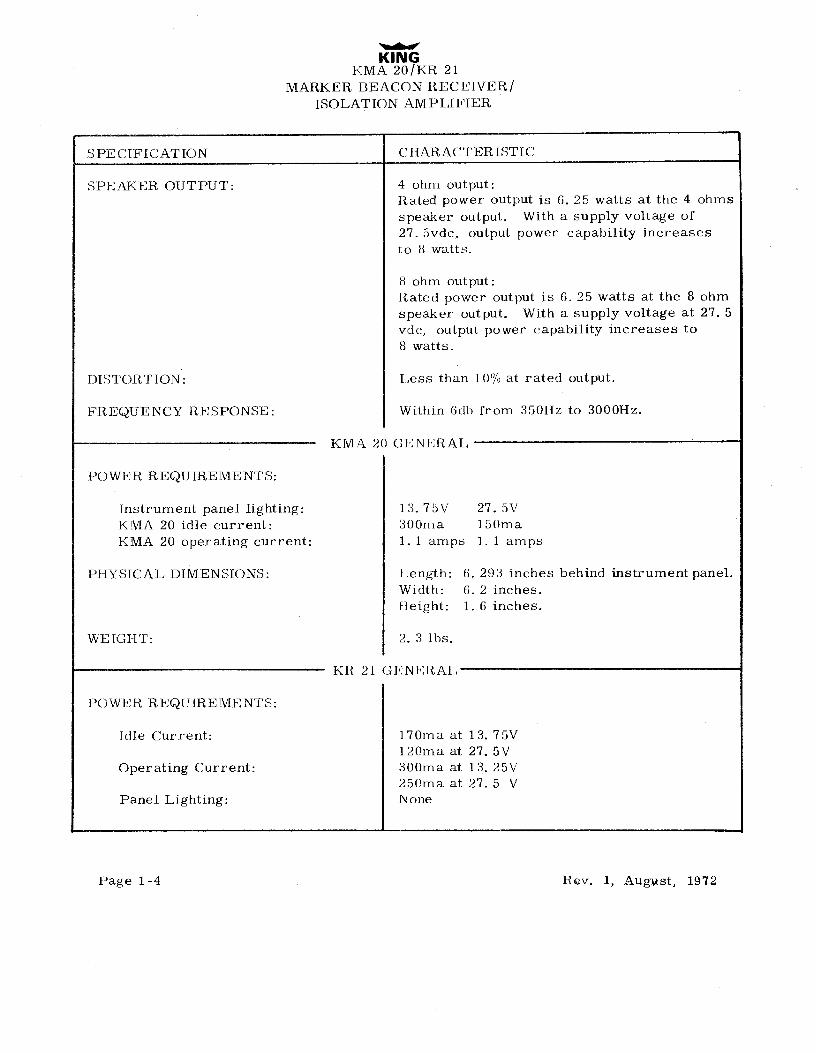
SPEAKER OUTPUT: 4 ohm output:Rated power output is 6. 25 watts at the 4 ohmsspeaker output. With a supply voltage of27. Svde, output power capability increasesto 8 watts.
8 ohm output:Rated power output is 6, 25 watts at the 8 ohmspeaker output. With a supply voltage at 27. 5vde, output power capability increases to8 watts.
DISTORTION: Less than 10a/o at rated output.
FREQUENCY RESPONSE: . Within 6dh from 350Hz to 3000Hz.
KMA 20 GENERAL
POWER REQUIREMENTS:
lnstrument panel lighting: 13. 75V 27. 5VKMA 20 idle current: 300ma 150maKMA 20 operating current: 1. 1 amps 1. 1 amps
PHYSICAL DIMENSIONS: Length: 6. 293 inches behind instrument panel.Width: 6. 2 inches.Height: 1. 6 inches.
WEIGHT: 2. 3 lbs.
KR 21 GENERAL
POWER REQUIREMENTS:
Idle Current: 170ma at 13. 75V120ma at 27. 5V
Operating Current: 300ma at 13. 25V250ma at 27. 5 V
Panel Lighting: None
Page 1-4 Rev. 1, August, 1972

KINGKMA 20/101 21
MAR<ER BEACON REC,EIVER/I3OLATION AMPLIFIER
SPE CIFICATION CHARACTERISTIC
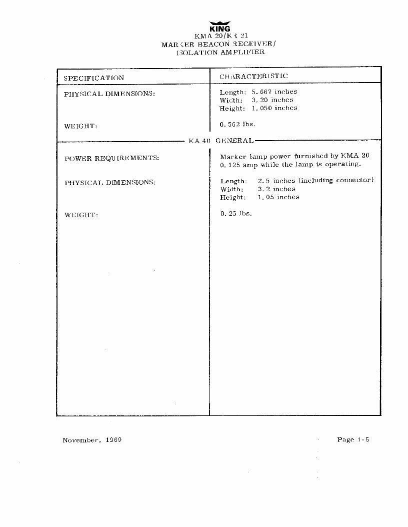
PHYSICAL DIMENSIONS: Length: 5. 667 inchesWidth: 3. 20 inchesHeight: 1. 050 inches
WEIGHT: 0. 562 lbs.
KA 40 GENERAL
POWER REQUIREMENTS: Marker lamp power furnished by KMA 200. 125 amp while the lamp is operating.
PHYSICAL DIMENSIONS: Length: 2. 5 inches (including connector)Width: 3. 2 inchesHeight: 1. 05 inches
WEIGHT: 0. 25 lbs.
November, 1969 Page 1-5

KMA20/KR 21MARKERBEACONRECEIVER/
ISOLATION AMPLIFIER
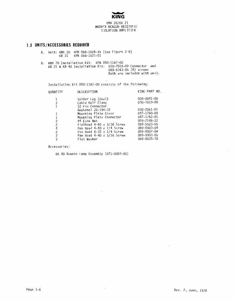
1.3 UNITS/ACCESSORIESREQUIREDA. Unit: KMA20 KPN 066-1024-XX (See Figure 2-8)
KR 21 KPN 066-1021-01
B. KMA20 Installation Kit: KPN 050-1167-00KR 21 & KA40 Installation Kit: 030-2016-00 Connector and
089-6163-05 (4) screwsBoth are included with unit.
Installation Kit 050-1167-00 consists of the,following:
QUANTITY DESCRIPTION KING PARTNO.
1 Solder Lug (Dual) 008-0041-002 Cable Half Clamp 030-1019-001 32 Pin Connector
Ampheno1 26-190-32 030-2061-011 Mounting Plate Cover 047-1760-001 Mounting Plate Connector 047-1762-012 #4 Esna Nut 089-2188-222 Flathead 4-40 x 5/16 Screw 089-5523-054 Pan Head 4-40 x 1/4 Screw 089-5903-042 Pan Head 6-32 x 1/4 Screw 089-5907-042 Pan Head 4-40 x 5/16 Screw 089-5903-052 Flat Washer 089-8025-30
Accessories:
KA 40 Remote Lamp Assembly (071-0003-00)
Page 1-6 Rev. 2, June, 1976

KINGKMA 20/KH 21
MARKER BEACON RECEIVElt/ISOLATION AMPLIFIER
SECTIONII
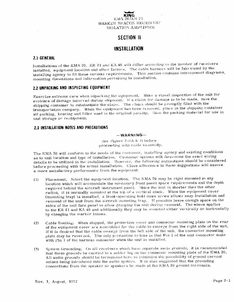
INSTALLATION2.1 GENERAL
Installations of the KMA 20, KR 21 and KA 40 will differ according to the number of receivers
installed, equipment location and other factors. The cable harness will be fabricated by theinstalling agency to fit these various requirements. This section contains interconnect diagrams,mounting dimensions and information pertaining to installation.
2.2 UNPACKINGANÐINSPECTINGEQUIPMENT
Exercise extreme care when unpacking the equipment. Make a visual inspection of the unit forevidence of damage incurred during shipment. If a claim for damage is to be made, save theshipping container to substantiate the claim. The claim should be promptly filed with thetransportation company. When the equipment has been removed, place in the shipping containerall packing, bracing and filler used in the original packing. Save the packing material for use inunit storage or reshipment.
2.3 INSTALLATIONNOTESANDPRECAUTIONS-WARNING-
See Figure 2-BA & H beforeproceeding with cable assembly.
The KMA 20 will conform to the needs of the customer, installing agency and existing conditionsas to unit location and type of installation. Customer options will determine the exact wiringdetails to be utilized in the installation. llowever, the following suggestions should be consideredbefore proceeding with the actual installation. Close adherence to these suggestions will assurea more satisfactory performance from the equipment.
(1) Placement. Select the equipment location. The KMA 20 may be rigid mounted in anylocation which will accomodate the necessary front panel space requirements and the depthrequired behind the aircraft instrument panel. Since the unit is shorter than the otherradios, it is normally mounted at the top of a vertical stack. When the equipment cover(mounting tray) is installed, a front-operating hold down screw allows easy installation andremoval of the unit from the aircraft mounting tray. If possible leave enough space on thesides of the unit face panel to allow grasping the unit during removal. Thembove appliesto the KR 21 and KA 40 and additionally they may be mounted either vertically or horizontallyby changing the marker lenses.
(2) Cable Routing. When shipped, the protective cover and connector mounting plate on the rearof the equipment cover are assembled for the cable to emerge from the right side of the unit.If it is desired that the cable emerge from the left side of the unit, the connector mountingplate may be reversed. The only precaution to take is that Pin 1 of the unit connector matewith Pin 1 of the harness connector when the unit is installed.
(3) System Grounding. On all receivers which have separate audio grounds, it is recommended
that these grounds be carried to a solder lug on the connector mounting plate of the KMA 20.All audio grounds should be terminated here io minimize the possibility of ground currentnoises being introduced into the audio system. It is also suggested that the groundingconnections from the speaker or speakers be made at the KMA 20 ground terminals.
Rev. 1, August, 1972 Page 2-1

KINGKMA 20/KH 21
MARKER BEACON RECElVER/ISOLATION AMPLIFIER
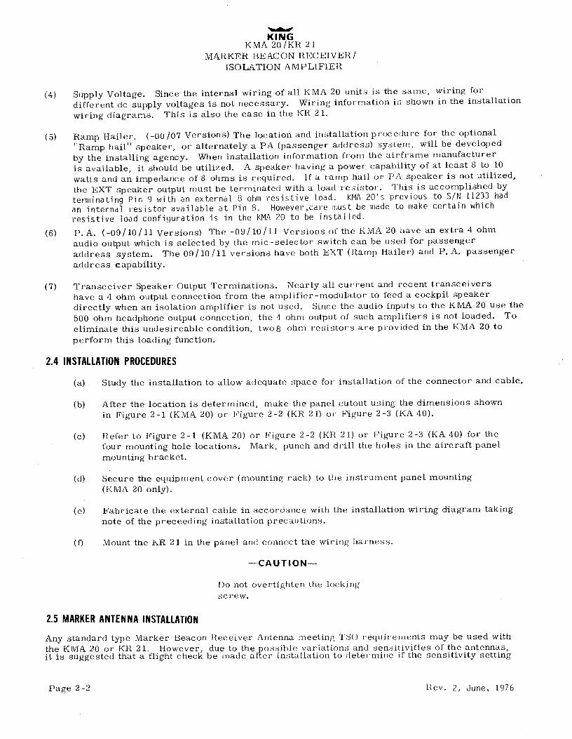
(4) Supply Voltage. Since the internal wiring of all KMA 20 units is the same, wiring fordifferent de supply voltages is not necessary. Wiring information is shown in the installationwiring diagrams. This is also the case in the KR 21,
(5) Ramp Hailer. (-00/07 Versions) The location and installation procedure for the optionalRamp hail" speaker, or alternately a PA (passenger address) system, will be developed
by the installing agency. When installation information from the airframe manufactureris available, it should be utilized. A speaker having a power capability of at least 8 to 10watts and an impedance of 8 ohms is required. If a ramp hail or PA speaker is not utilized,the EXT speaker output must be terminated with a load resistor. This is accomplished byterminating Pin 9 with an external 8 ohm resistive load. KMA20's previous to S/N 11233 hadan internal resistor available at Pin 8. However,care must .be made to make certain whichresistive load configuration is in the KMA20 to be installed.
(6) P.A. (-09/10/11 Versions) The -09/10/11 Versions of the KMA 20 have an extra 4 ohmaudio output which is selected by the mic-selector switch can be used for passengeraddress system. The 09/10/11 versions have both EXT (Ramp Hailer) and P.A. passengeraddress capability.
(7) Transceiver Speaker Output Terminations. Nearly all current and recent transceivershave a 4 ohm output connection from the amplifier-modulator to feed a cockpit speakerdirectly when an isolation amplifier is not used. Since the audio inputs to the KMA 20 use the500 ohm headphone output connection, the 4 ohm output of such amplifiers is not loaded. Toeliminate this undesireable condition, twos ohm resistors are provided in the KMA 20 toperform this loading function.
2.4 INSTALLATIONPROCEDURES
(a) Study the installation to allow adequate space for installation of the connector and cable.
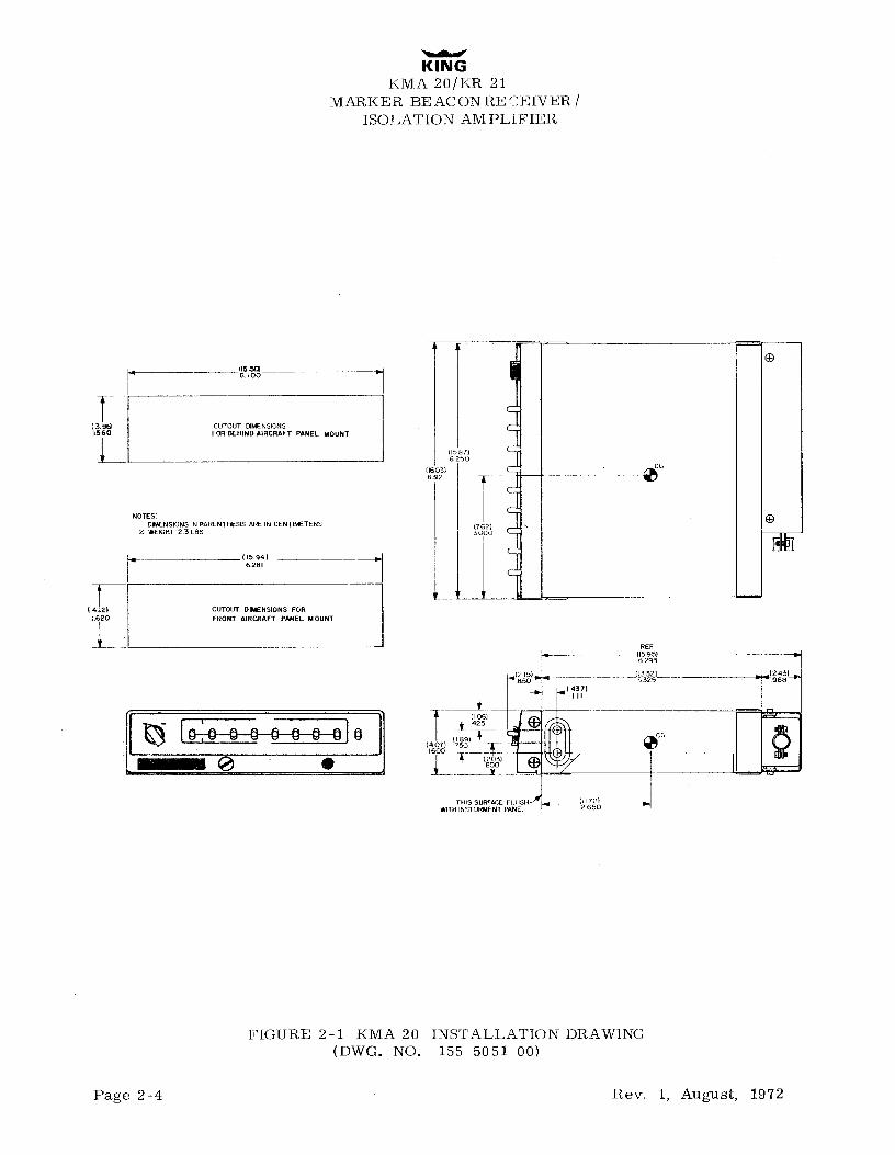
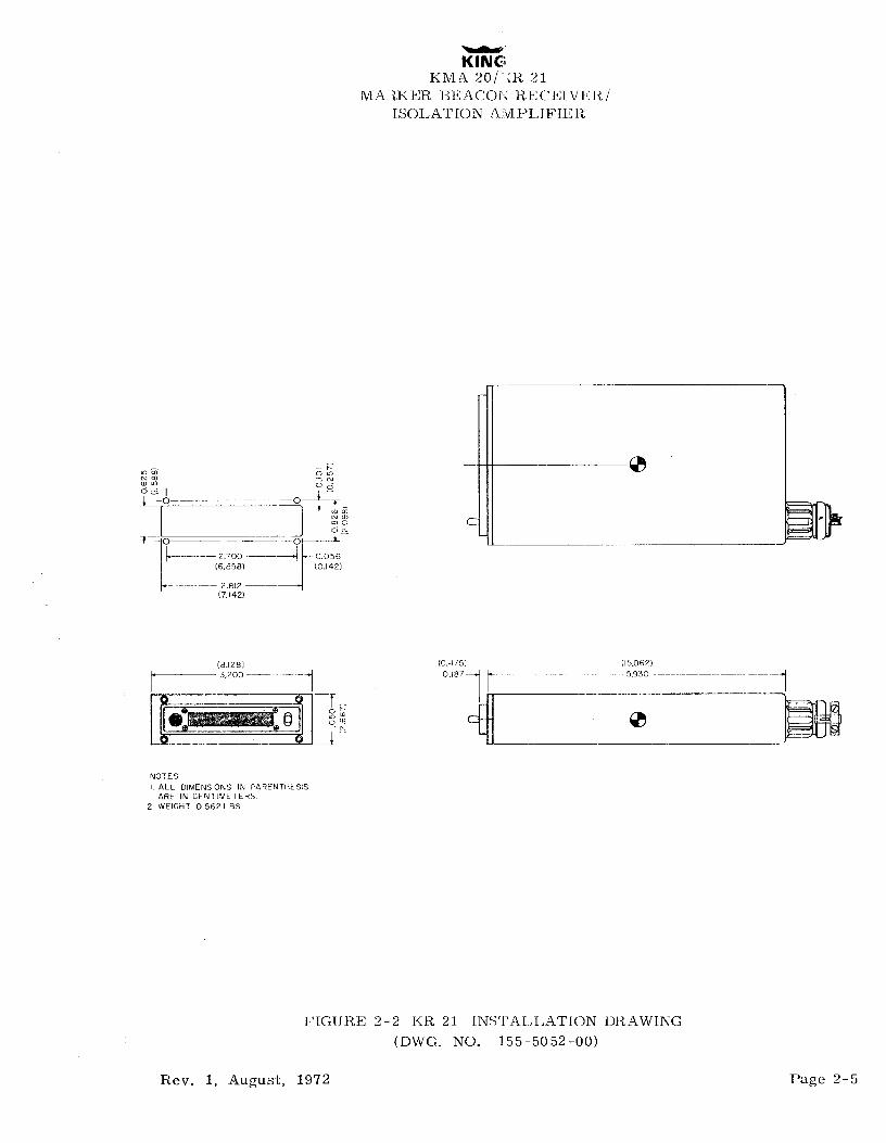
(b) After the location is determined, make the panel cutout using the dimensions shownin Figure 2-1 (KMA 20) or Figure 2-2 (KR 21) or Figure 2-3 (KA 40).
(c) Refer to Figure 2-1 (KMA 20) or Figure 2-2 (KR 21) or Figure 2-3 (KA 40) for thefour mounting hole locations. Mark, punch and drill the holes in the aircraft panelmounting bracket.
(d) Secure the equipment cover (mounting rack) to the instrument panel mounting(KMA 20 only).
(e) Fabricate the external cable in accordance with the installation wiring diagram takingnote of the preceeding installation precautions.
(f) Mount the KR 21 in the panel and connect the wiring harness.
-CAUTION-
Do not overtighten the lockingscrew.
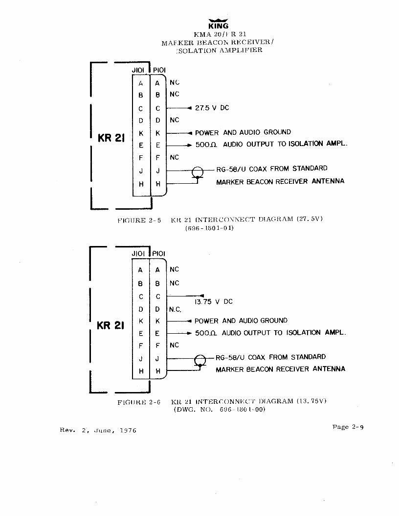
2.5 MARKERANTENNAINSTALLATION
Any standard type Marker Beacon Receiver Antenna meeting TSO requit ements may be used withthe KMA 20 or KR 21. However, due to the possible variations and sensitivifles of the antennas,it is suggested that a flight check be made after installation to determine if the sensitivity setting
Page 2-2 Rev. 2, June, 1976

KINGKMA 2Ò/KE 21
MAHKER BEACON RECEIVER/ISOLATION AN PLI FIER
in the receiver should be changed to compensate for the sensitivity of the antenna. It is recom-
mended that coaxial cable RG-58/U be used for connecting the antenna to the KMA 20 or KR 21Marker Receiver Antenna terminals.
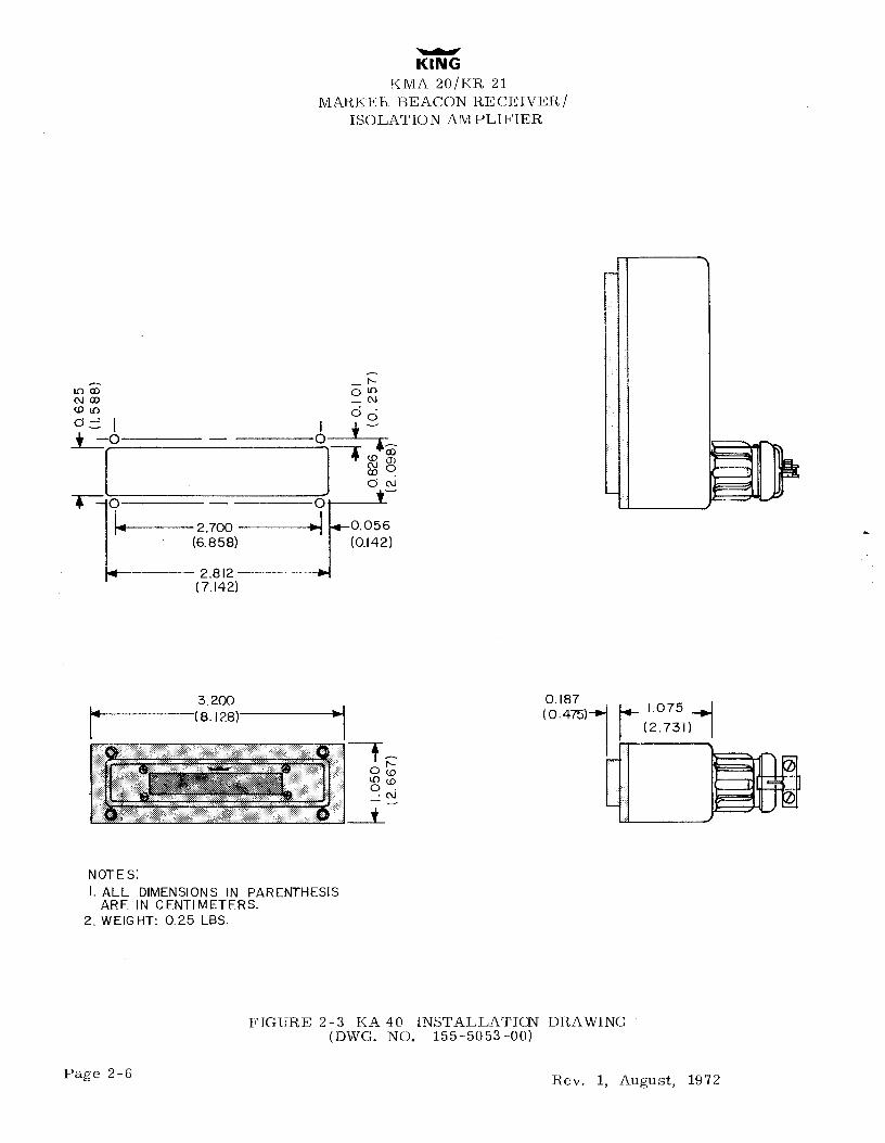
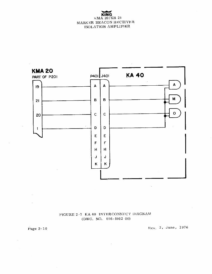
2.6 KA40 INSTALLATION(OPTION)
If the King KA 40 Remote Light Adapter is utilized, consult the outline and dimension drawing,Figure 2-3 for attaching the unit to the instrument panel. Wiring information for the KA 40 iscontained in the installation wiring diagram of the KMA 20.
Rev, 1, August, 1972 Page 2-3

KINGKMA 20/KR 21
MARKER BEACONREGEIVER/ISOLATION AMPLIFIER
I O
(3 CUTOUT DIMENSIONSLS60 FOR BEHIND AIRCRAFT PANEL MOUNT
(587)6750
NOTESI DIMENSIONS IN PARENTHESIS ARE IN CENTlMETERS (762)2. WEIGHT 2.3LBS 3000
I g (15.94)6281
(4.12) CUTOUT DIMENSIONS FOR1.620 FRONT AIRCRAFT PANEL MOUNT
REE
293
THIS SURFACE FLUSHWITH INSTURMENT PANEL 2 650
FIGURE 2-1 KMA 20 INSTALLATION DRAWING(DWG. NO. 155 -50 51-00)
Page 2-4 Rev. 1, August, 1972

KINGKMA 20/ R 21
MA (KER BEACON RECEIVER/ISOLATION AMPLIFIER
- o--- 2.700 - 0.056
(6.858) (0.142)
-- 2.812 --(7.142)
(8.128) (0.4 75) (IS.062)3.200 - O.iB7 -- 5.930---- ---
NOTESI ALL DIMENSIONS IN PARENTHESIS
ARE IN CENTlMETERS.2 WEIGHT 0.562 LBS.
FIGURE 2-2 KR 21 ÏNSTALLATION DRAWING(DWG. NO. 155-5052-00)
Rev. 1, August, 1972 Page 2-5

KINGKMA 20/KR 21
MARKER BEACON RE CEIVER /ISOLATION AMPLIFIER
† -O - O
* -O- O
2.700 i WO.056(6.858) (0.142)
2.8 12 a(7.l42)
(38
(OO
4 )2
O7 5
NOTE SiI. ALL DIMENSIONS IN PARENTHESIS
ARE IN CENTIMETERS.2. WEIGHT: 0.25 LBS.
FIGURE 2-3 KA 40 INSTALLATICN DRAWING(DWG. NO. 155-5053-00)
Page 2-6 Rev. 1, August, 1972

KINGKMA 20/KR 21
MAEKER BEACOlN RECEIVER/SOLATION AMPLIFIER
JiOI PIOI
A A NC
B B NC
| C C a 27.5 V DC
D D NC
KR 21 K K POWER ANDAUDIO GROUND
IE E i 500A AUDIOOUTPUT TO ISOLATIONAMPL.
F F NC
J J RG-58/U COAX FROM STANDARD
H H MARKER BEACONRECEIVER ANTENNA
L -
FIGURE 2-5 KR 21 INTERCONNECT DIAGRAM (27. SV)(696-1801-01)
JIOI PIOI
A A NC
B B NC
C C13.75 V DC
D D N.C.
KR 21 K K POWER AND AUDIOGROUND
I E E 500.0. AUDIOOUTPUT TO ISOLATIONAMPL.F F NC
J J RG-58/U COAX FROM STANDARD
L H H MARKER BEACONRECEIVER ANTENNA
FIGURE 2-6 KR 21 INTERCONNECT DIAGRAM (13. 75V)(DWG. NO. 696-180 1-00)
Rev. 2, June, 1976 Page 2-9

KINGKMA 20/KR 21
MARKER BEACON RECEIVERISOLATION AMPLIFIER
KMA20 |PART OF P2OI P401|J4OI KA 40
A A
21 B B
20 C C
f D D
E E
F F
H H
J J
K K
l
FIGURE 2-7 KA 40 INTERCONNECT DIAGRAM(DWG. NO. 696-1802-00)
Page 2-10 Rev. 2, June, 1976

(MA20/KR 21MARKERBEACON RECEIVER/
ISOLATION AMPLIFIER
PIN FUNCTION VERSION
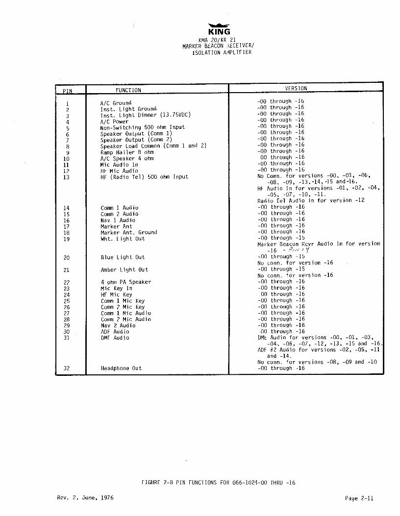
1 A/C Ground -00 through -16
2 Inst. Light Ground -00 through -16
3 Inst. Light Dimmer (13.75VDC) -00 through -16
4 A/C Power -00 through -16
5 Non-Switching 500 ohm Input -00 through -16
6 Speaker Output (Comm 1) -00 through -16
7 Speaker Output (Comm 2) -00 through -16
8 Speaker Load Common (Comm 1 and 2) -00 through -16
9 Ramp Hailer 8 ohm -00 through -16
10 A/C Speaker 4 ohm -00 through -16
11 Mic Audio In -00 through -16
12 HF Mic Audio -00 through -16
13 HF (Radio Tel) 500 ohm Input No Conn. for versions -00, -03, -06,
-08, -09,
-13,-14,-15 and-16.HF Audio In for versions -01, -02, -04,
-05, -07, -10,-11.
Radio Tel Audio in for version -12
14 Comm1 Audio -00 through -16
15 Comm2 Audio -00 through -16
16 Nav 1 Audio -00 through -16
17 Marker Ant -00 through -16
18 Marker Ant. Ground -00 through -16
19 Wht. Light Out -00 through -15
Marker Beacon Rcvr Audio In for version-16
- ?/ / Ÿ20 Blue Light Out -00 through -15
No conn. for version -16
21 Amber Light Out -00 through -15
No conn. for version -16
22 4 ohm PA Speaker -00 through -16
23 Mic Key In -00 through -16
24 HF Mic Key -00 through -16
25 Comm1 Mic Key -00 through -16
26 Comm2 Mic Key -00 through -16
27 Comm1 Mic Audio -00 through -16
28 Comm 2 Mic Audio -00 through -16
29 Nav 2 Audio -00 through -16
30 ADF Audio -00 through -16
31 DME Audio DMEAudio for versions -00, -01, -03,
-04, -06, -07, -12, -13,-15 and -16.
ADF #2 Audio for versions -02, -05,-11
and -14.
No conn. for versions -08,-09 and -10
32 Headphone Out -00 through -16
FIGURE 2-8 PIN FUNCTIONS FOR 066-1024-00 THRU -16
Rev. 2, June, 1976 Page 2-11

KINGKMA 20 /KR 21
MARKER BEACON RECEIVER/TSOLATION AMPLIFIER
SECTIONIII
OPERATION
3.1 MARKERBEACON(KMA20 ANDKR21)
Marker beacon receivers are used to provide accurate fixes by informing the pilot of hispassage over beacon stations located on airways and ILS approach courses. Three typesof beacons are used. They are the inner marker, the outer marker and the middlemarker.
The outer, middleand inner markers are used in conjunction with the radio instrumentlanding systems. The outer marker is normally positioned on the front localizer coursenear the point where the glideslope approach path intersects the minimum inbound altitude
after the procedure turn. Distance from the airport will vary from 4 to 7 miles. Radiofrequency from the marker is projected vertically in an elliptical cone shaped pattern.The marker signal is modulated at 400Hz and is keyed to emit dashes at a rate of twoper second.
When passing the outer marker the blue light will flash "on/off" at a two per second rateand the pilot will hear a series of low tone dashes.
The middle marker is normally located on the front localizer course about 3200 feetfrom the approach end of the ILS runway. The radiated pattern is similar in shape andpower to the outer marker. The middle marker signal is modulated with 1300Hz and themodulation is keyed to identify by alternate dots and dashes. When the KMA 20 (KR 21)equipped aircraft passes the middle marker the pilot hears a medium pitched tone in aseries of dots and dashes and the amber light flashes synchronously with the tones.
The inner marker is located close to the end of the runway. The beacon transmitter andantenna are designed to project a cone shaped pattern of 75MHz energy, vertically. Theradio frequency output of the transmitter is modulated with an audio tone of 3000Hz. Anaircraft equipped with the KMA 20 (KR 21) will receive a 3000Hz tone in headphone orspeaker and the white lamp will be lighted while over the station. The inner marker isused to indicate a point approximately 1500 ft. from the runway and if on proper glidepath the altitude above the runway should be approximately 100 feet.
The marker beacon function in the KMA 20 provides the pilot with audio switching controland the Hi-Lo Switch in the KR 21 and KMA 20 provide sensitivity switching control.Many marker receivers provide only a "low sensitivity" position. The effect of the highsensitivity position is to greatly enlarge the size of the cone shaped "area of indication"above the station. An aircraft flying at high altitude or slightly off course may fail toreceive the signal when in the low sensitivity postion. It is suggested that the KMA 20
Rev. 1, August, 1972 Page 3-1

KINGKMA 20/KR 21
MARKER BEACON RECEIVER/ISOLATION AMPLIFIER
marker sensitivity switch first be placed in high sensitivity position until aural and/or lampindication is received. The control switch may be turned to low sensitivity to reduce the durationof the indication and to obtain a more accurate reading of passage since the signal appears tobuild and fade faster on low sensitivity. The marker audio may now be turned off to obtain theexact time of center passage from the light only, since the imminence of station passage hasalready been indicated. This suggestion is especially appropriate if he is involved in radio com-
munication with approach control or tower at that moment.
The high sensitivity position may be used to effectively give the pilot an advance indication that heis approaching the outer marker. In order to expidite the ILS approach the pilot may wish toretain higher speed until he is nearby the outer marker inbound. With the KMA 20 (KR 21) markerin high sensitivity position the aural tone will begin about one mile from the outer marker. Atthis time, the pilot may switch the KM.A 20 (KIl 21) marker to low sensitivity and reduce enginepower for final approach speed, also retrim and perform cockpit checks. He is then prepared tobegin descent when the marker indicates actual passage over the outer marker and the glideslopeis intercepted.
3.2 IsotATIONAMPLIFIER(KMA20)
Both transmitting and audio distribution functions of the Silver Crown radio system are controlledat the front panel of the KMA 20. Basically the functional controls consist of a microphone selectorswitch and receiver audio selector switches.
The microphone selector switch performs two tasks. It routes microphone keying and audioinformation to the appropriate destination and secondly, it switches the output of the isolationamplifier to one of two speakers. In the COMM 1 or COMM 2 positions, microphone informationis rounted to the appropriate transmitter. In the HF position of the International model, thisinformation is routed to the high frequency transmitter. Likewise, when the TEL. position is sel-ected, the keying and mic audio is routed to KT 96 King phone in the -12 version. In these threepositions the isolation amplifier output is fed to the cockpit speaker.
The EXT position on 00 /07 provides the pilot with several capabilities depending on the option madeat installation. In the EXT position, the output of the amplifier is normally connected to a "ramphail" speaker or alternately to a passenger address system. Should one of the receivers be select-ed in this mode, the audio will be heard in the EXT speaker until the microphone is keyed. Whenthe microphone is keyed, the receiver audio is muted and the microphone output is fed to the EXTspeaker output.
The EXT position on 09/11 provides the pilot with a "ramp hail" function. And an added 4 ohm out-put is provided for use as a passenger address system.
A series of toggle switches control the audio inputs to the isolation amplifier. Each of these con-
trols can be switched from the center off position to connect each receiver's audio tothe input ofthe isolation amplifier which then routes the audio to the speaker output in the "up" position or toexternal headphones in the "down" position. In the PilONE position, receiver audio completelybypasses the amplifier and the KlVIA 20 performs only a bypass switching function. Since individualcontrol of the receivers is provided, the pilot may listen to one receiver with the speaker while theco-pilot could monitor another receiver utilizing headphones. One non-switched audio input has beenprovided which can be used for audio signals that are not to be switched, as Hadar Altimeter Au dioand the ring signal from the King KT 06 KLng Phone.
Page 3-2 Hev. 2, June, 1976

KINGKMA 20/KR 21
MARKER BEACON RECEIVER/ISOLATION AMPLIFIER
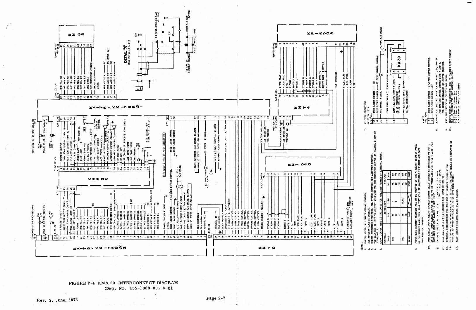
KN-70 LOAD JUMPER
JUMPER PINS AS INDICATED FORGIVEN NUMBER OF EXTERNAL LOADS
EXTERNAL GLIDESLOPE VOR/LOCLOADS DEV FLAG DEV FLAG 1NTERNAL WIRING D)AGRAM
27.5 V ONLYM F KK NN
ONE H B PP TTC UU XX
M KK NNTWO NONE
THREE NONE NONE NONE_A 3
PRE-RFEGURLATOR 030-006Ì-00 Pi73 73 Pl72 030-OO6l-OO
275V OPERATION NAV COMM.. ANT '
ANT.J201 P2OlO30-2|O5-OO PARTOF P70l PA?TOF J70l
030-2106-01, I +27.5VDC A A +l3.75VDC ¯X
STATOR D t' go C
WSTATOR E N.C. O C N.C.
030-206
V STATOR F LL i , CSOLDER
STATORG e - PARTOF PARTOF Pl7\ 030-2101-03 LUG INROTOR C
(A/C) (A/C) J l7lSPKR GROUND
CONNECTOR
R,0TOR H PARTOF PART OF Xtl6AWG PART OF PARTOF 42 .a
J70l P70l p 7 7|
+ i O' #16AWG
N.C.LAMPD1M'R(13.75V)
33AIRFRAME GNU #2
t-+FROM Y
LAMPDIM'R(27.5V)38 20 A/C 3USS 27.5Vt‡16AWG ,A INST LIGHT DIMMEl
-VOR FLAGWW
R J3.75V INPUT IS N.C.!NST LIGHT DIMME
q JJ 27.5V ( SWITCHED)A/C+VOR FLAG KN 70 w
T † NA +iOV (ILS SWITCHING MATRJX) A/C BUSS 27,5
KPl 550 i------TyVOR / LOC ×
VOR /LOC OUT SIGNAL OUT2 AIRFRAME GROUND(N 16 AWG)
INDICATOR L___.xx
CONVERTER ^^.!MHz CONTROL
21SPEAKER OUTPUT
-G.S.FLAGL GLIDE ^
.3MHz CONTROL6
6 AUX AUDIO#l(NO CONNECTION)
FF+G.S.FLAG
F SLOPE E.5MHz CONTROL
e KX l70 34 COM 500- OUTPUT (COMI)- 8 RE CVR .7MHz CONTROL NAV 500 OUTPUT (NAV I)
+RIGHT P e COMM =
4LEFT UDIDMS HCz CONRORLOL AA AA Dllo
3
NNOCCONNNNEECCTONN
---PP IO9MHzCONTROL AUXAUDIOi‡4(NOCONNECTION)J I2 l6--- UU i 1 0 MHz CONTROL A MIC KEY (COMM l)
EE+ UP
SN
ll I MHz CONTROL [3 ^0
ÍMic AUDIO(COMMI)+DOWN T i4 39 I
M ILS ENERGIZE2 DME MHz"A" -
LAMPDIM'R (l3.75V) *¿Cs ---- HDD 1 2
L LAMPDIM'R(27.5V)--- C
23
FOR REFERENCE PHASE 21 aU TESTING
VARIABLE PHASERR J 702 P702O30 0005-00
25" "
"D"ONLY vy GLIDE " "E"
SLOPE 26TO
ANT. 27DME KHz "A"
i ) REMOTE¯¯
28 a DME--
29" " "C"
3 C" "D"
3 I" "E"
32 DME SWITCHING COMMON
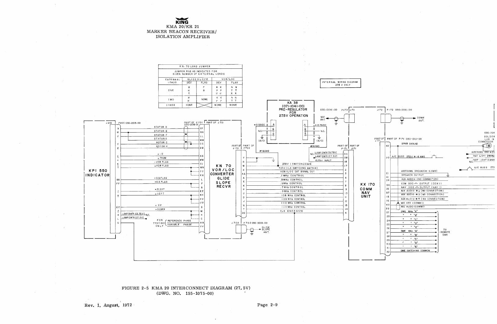
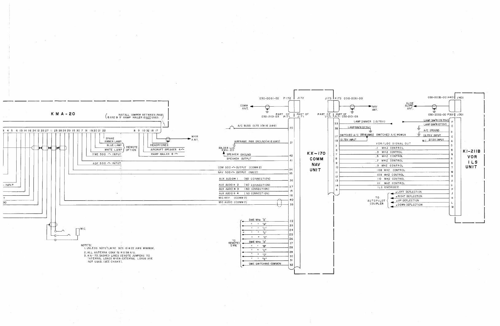
FIGURE 2-5 KMA 20 INTERCONNECT DIAGRAM (27, 5V)(DWG. NO. 155-1075-00)
llev. 1, August, 1972 Page 2-9
KA 39(07HO4 l-O I )
PRE-REGULATORFOR
27.5V OPERATION
+ 27.5VDC A ACi +I3.75VDC
Î B B Ë-N.C. O O N.C.
(A C) (A C)
kl6AWG 16AWG
050-006f-OO PJ72 I dl72 JI73 IPl73 030-0061-00 030-OO35-OOP40l OI
GLIDECOMM i NAV SLOPE
ANT, ANT.ANT,
KM A 20 INSTALL JUMPER BETWEEN PINS PART OF PART OF PART OF PART OF 030-2002-00 P30l J30lBANDS IF RAMP HAI.LERlSETUSED. 030-2|Ol-03 Pl7| J 7l J,7l Pl7l 030-2lO-03
(l3.75V) LAMP DIMMER NC. LAMP DIM R (l3.75V)FJ2Of
A/C BUSS 27.5V (#)6 AWG)20
3383 LAMPDIM'Rí275V)N.C LAMPD\M'R(27.5V)E
P20l I 2 3 4 5 6 l3 l4 16 24 J2 25 27 Il 23 2826 29 15 30 7 31 l9 20 2f 22 8. 9 JO 32 IS !7 A/C GROUND030-206l-OO' H
SOLDER SPARE IM KR 17 SWITCHED A/C (:l‡l6AWG) SWITCHED A/C POWER [3.75V INPUT
CCONNLECTORNHOUSING N.C AMBLERELLAAMMP
HEADPHONE
ANTAfRFRAME PWR GROUND(Bl6AWG) 2l
3
\3.75V INPUT .VOR/LOC SIGNAL OUT
27.5VlNPUT A
----- --- ' WHITE LAMP
OREM EAIRCRAFT SPEAKER 4^ SOLDMEARL2OG
6.i MHZ CONTROL
| 1 v I-; .3 MHZ CONTROLAIRFRAME UNU#2OAWG DME 500 - INPUT RAMP HAILER 8 SPEAKER GROUND ^ I• 7 N42
.5 MHZ CONTROL VORINST LIGHT DIMMER 275V SPEAKER OUTPUT COMM e R.7 MHZ CONTROL
INST LIGHT DIMMER (13.75V) ADF 500 - INPUT 9 S I LSN.C.
COM 500 - OUTPUT (COMM 2)NAV
.9 MHZ CONTROL- - 1 UN I T
A/C BUSS 27.5V ‡120AWG NAV 500^OUTPUT (NAV2)UNIT (08 MHZ CONTROL
W(09 MHZ CONTROL X
AUX AUDlON I (NO CONNECTION) IIO MHZ CONTROL36 l3 V
HF 5002 INPUT AUX AUDIO‡‡ 2 (NO CONNECTÍON) ¡4Ill MHZ CONTROL
UAUX AUDIO*l 3 (NO CONNECTION)
374
ILS ENERGlZE
AUX AUDIO# 4 (NO CONNECTION) g+LEFT DEFLECTION
HF MIC KEY MIC KEY (COMM 2) TO g+RIGHT DEFLECTION
HF MIC AUDIO MIC AUDIO (COMM2)I AUTOPILOT +UP DEFLECTION
L30 COUPLER DOWN DEFLECTION
M
'. DME MHz A-- 22
MIC, ""C"
"D"2425
TO26
REMOTE ( e DME KHz "A 27NOTESI DME li a ligu
l.UNLESS NOTE'D,WIRE SIZE IS‡i22AWG MINIMUM. 28""C"
2.ALL ANTENNA COAX IS RGS8 A/U. 293.KN-70.DASHED LINES DENOTE JUMPERS TO
" "D" 30INTERNAL LOADS WHEN EXTERNAL LOADS ARE "
"E" 3\NOT USED.(SEE CHART).4. USE JWl6AWG TO INTERCONNECT EQUlPMENT ¡
DME SWITCHING COMMO 32155-1075-00 (R-I)
POWER GROUNDS.
KINGKMA 20/KR 21
MARKER BEACON/RECEIVERISOLATION AMPLIFIER
KN-70 LOAD JUMPER
JUMPER PlNS AS INDICATED FORGIVEN NUMBER OF EXTERNAL LOADS
EXTERNAL GLIDESLOPE VOR/LOCLOADS DEV FLAG DEV FLAG INTERNAL WIRING DIAGRAM
13.75 V ONLYM F KK NN
ONE H B PP TTC UU XX
M KK NNTWO H
NONE
THREE NONE NONE NONE
030-006l-00 Pl73 73 Pl72 030-0061-00
NAV COMM
J 201 P20 I 030-2|O5-00 PART OF P 70 I PA IT OF J 701ANI ANT. I
030-2106-01, - J 201STATOR D t'
W STATOR E P2Ol I 2 3030-2061-00
STATOR FV LL SOLDERSTATOR G
MM PAR OF PART OF PI71 030-2|Ol-03 LUG INROTOR C CONNECTOR HOUSING
Y a CC SPKR GROUNDROTORH PARTOF PART OF PARTOF PARTOF 42
Z _,,BB J 701 P701 p 7| a y
+TO LAMPDIM'R(l3.75V)33
AIRFRAME GND#20 AWG
+ FROM YLAMPD1M'R(27.5V)
38 20 A/C BUSS [3.75V i‡ 16 AWG INST LIGHT GND
u NW JNST LIGHT DJMMER (13.75V)-VOR FLAG R ¯ 17 si9 JJ 13.75V ( SWlTCHED)+VOR FLAG
,, K N-70 w .o
T .N +I V{lLS SWlTCHING MATRJX) A/C BUSS 13.75V ‡‡2OAWGKP I-550 VOR / LOC x
VOR /LO C OUT SIGNAL OUT2
AIRFRAME GROUND(4* l6 AWG)
INDICATOR L CONVERTER ^^MHz CONTROL
3 21SPEAKER OUTPUT
GG-G.S.FLAG
L GLIDE ^.3MHz CONTROL
6 AUX AUDIO#l(NO CONNECTION) HF 500- I+G.S.FLAG
F SLOPE E.5MHz CONTROL - COM 500^ OUTPUT (COM I)
- -- B RE CVR .7MHz CONTROL NAV 500 - OUTPUT (NAV I)+RIGHT P g CO MM 36EE .9MHz CONTROL AUX AUDj0 #2 (NO CONNECTION) HF MIC KEY
LEFT U 10 NAV 37
DLOS MHz CONTROL
ir UNIT reAUX AUDIO 43(NO CONNECTlON) HF M1C AUDIO
--- PP IO9MHz CONTROL AUX AUDIO N4 (NO CONNECT]ON)J [2 16-- UU Y I O MHz CONTROL --, MIC KEY (COMM I)
+ UP N l3 40 I
I EE S i i I MHz CONTROL 1 MIC AUDIO (COMMI)+DOWN T 14 39 Q
M |LS ENERGIZE 22 DME MHz"A" -s
K | LAMPDIM'R (13.75V)_- H
1
LAMP DIM'R (27.5V) 23L .l. FOR ( REFERENCE PHASE
--- C21
U ¯
TESTING RR J702 P702O30-OOO5-00 " "D"ONLY .VARIABLE PHASE
GLIDE25 " "E"
SLOPE 26 a TOANT- 27 DME KHz "A" a ) REMOTE
28" " "B" DME
-
29" "C" b
30'" " "D"
3l" "E"
| 32 . DME SWlTCHING COMMON,
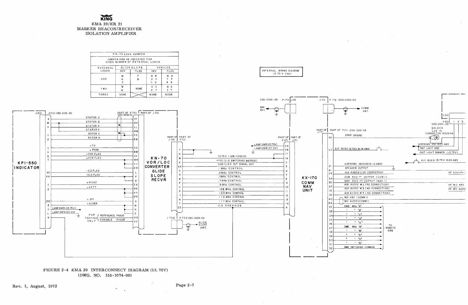
FIGURE 2 -4 KMA 20 INTER CONNE CT DIAGRAM (13. 75V)(DWG. NO. 155-1074-00)
Rev. 1, August, 1972 Page 2-7
030-OO6l-OO Pl72 I JI72 JI73 IPl73 030-006|-00 030-0035-00P401 J40I j
l GLIDECOMM i NAV SLOPE
ANT ANT. ANT.
KM A - 20 ( INSTALL JUMPER BETWEEN PINS\ PART OF PART OF PART OF PART OF¯
030-2002-00 P30! J30\\ 8 AND 9 IF RAMP HAl.LER IS T USED. ) 030-2|O!-03 Pf 7\ J 7 i J i7l Pl7\ 030-2|Ol-03
LAMP DIMMER (13.75V) p LAMP DIM'R (13.75V) FA/C BUSS |3.75 V(4tl6 AWG)
20
3383LAMPDIM'R(27.5V
LAMPDIM'R(27.5V) E
5 4 5 6 \3 f4 16 24 l2 2527 Il 23 2826 29 [5 30 7 31 l920 21 22 8 9 10 32 18 (7 ¯ A/C GROUND H
MKR 17 SWITCHED A/C (#l6AWG) SWITCHED A/C POWER 13.75V INPUT CSPARE a A NT. \3.75V INPUT 27.5V INPUTAMBER LAMP AIRFRAME PWR GROUND(NI6AWG) IS N.C. A
.. BLUE LAMP HEADPHONES -A- 2!3
VOR/LOC SIGNAL OUTD. REMOTE SOLDER LUÜ .! MHZ CONTROL
WHITE LAMP OPTION AIRCRAFT SPEAKER 4 KMA-20 6 8 17 i al inA v gy .3 MHZ CONTROL ni"CIIU
DME 500 -3- INPUT RAMP HAILER 8 ^ T SPEAKER GROUND ^ · · 7 N42.5 MHZ CONTROL VORSPEAKER OUTPUT COMM e--.7 MHZ CONTROL
ADF 500 ^ INPUT 9 S I LSNAV.9 MHZ CONTROL li :-
COM 500 -0-OUTPUT (COMM 2) (O T UN I I31 UNIT 108 MHZ CONTROL
NAV 500^ OUTPUT (NAV2) 35 ll W109 MHZ CONTROL X
AUX AUDiO‡‡ I (NO CONNECTION) IIO MHZ CONTROL36 ylli MHZ CONTROL
- INPUT AUX AUDIO*l 2 (NO CONNECTION) 4 U37 ILS ENERGlZEAUX AUDIO*l 3 (NO CONNECTION) 4AUX AUDIO# 4 ( NO CONNECTION) 6
+LEFT DEFLECTION
Y MIC KEY (COMM 2) TO g+RIGHT DEFLECTION
'. 4n AUTOPILOT +UP DEFLECTION3|O MIC AUDIO (COMM 2) L
! 39 COUPLER DOWN DEFLECT]ONM
DME MHz "A" 22-e " " "B" 23
MIC. " " "C"e n .nD" 2 4
" "E"25
TO26
REMOTE ( e DME MHz "A' 27NOTE'SI DME a .ngu
l. UNLESS NOTE'D,WiRE Sl1E IS ‡f 22 AWG MINIMUM. s 28u "C"
2.ALL ANTENNA COAX IS RG58A/U. I 293. KN - 70. DASHED LlNES 1)ENOTE JUMPERS TO
" "D" 30INTERNAL LOADS WHEN EXTERNAL LOADS ARE " "E" 31NOT USED. (SEE CHART).
DME SWITCHING COMMON 32
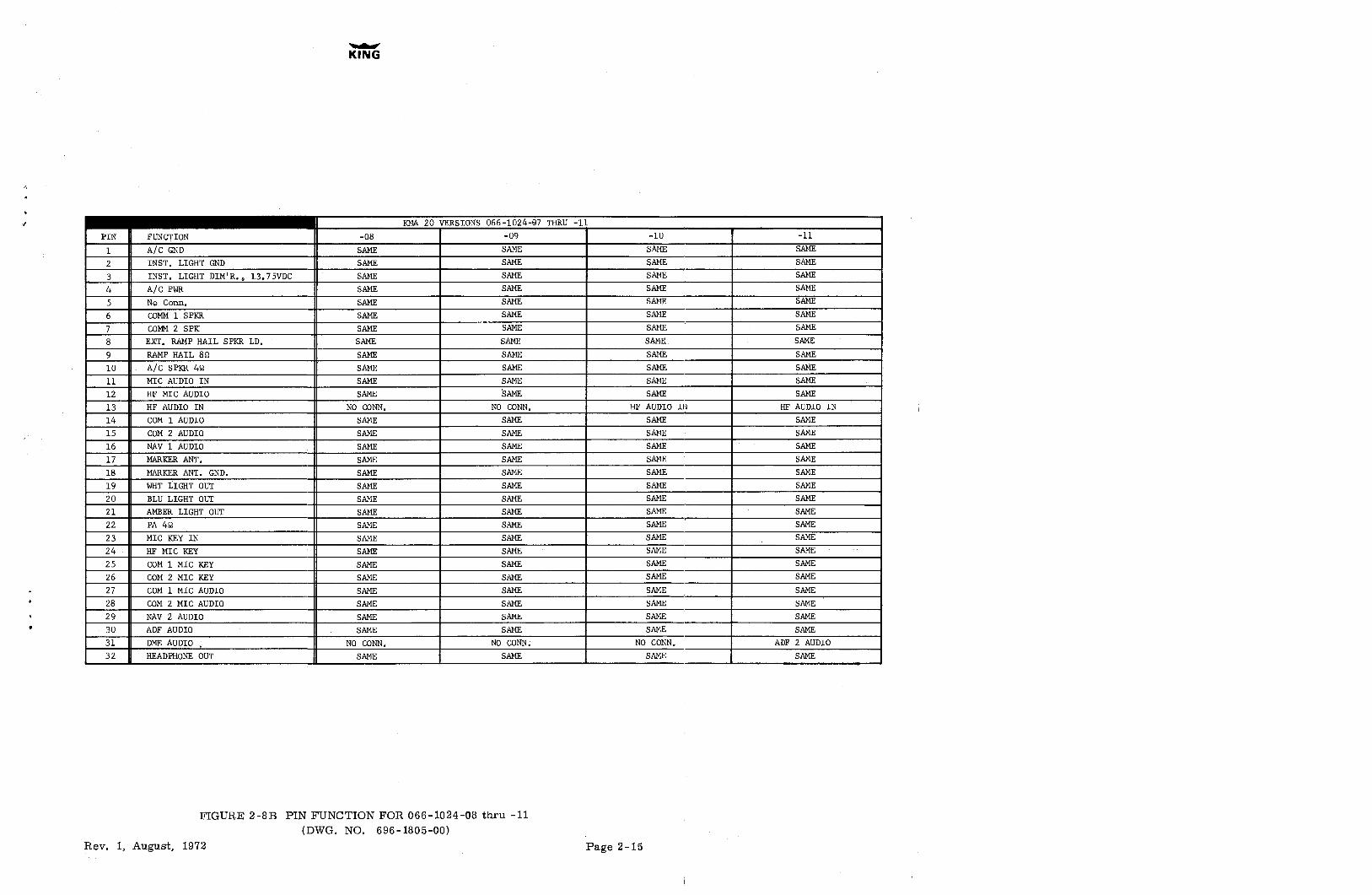
PIN FUNCTION -08 -09 -10 -11
1 A/C GND SAME SAME SAME SAME
2 INST. LIGHT GND SAME SAME SAME SAME
3 INST. LIGHT DIM'R., 13.75VDC SAME SAME SAME SAME
4 A/C PWR SAME SAME SAME SAME
5 No Conn. SAME SAME SAME SAME
6 COMM1 SPKR SAME SAME SAME SAME
7 COMM2 SPK SAME SAME SAME SAME
8 EXT. RAMP HAIL SPKR LD. SAME SAME SAME. SAME
9 RAMP HAIL 89 SAME SAME SAME SAME
10 - A/C SPKR 42 SAME SAME SAME SAME
11 MIC AUDIO IN SAME SAME SAME SAME
12 HF MIC AUDIO SAME SAME SAME SAME
13 HF AUDIO IN NO CONN. NO CONN. HF AUDIO IN HF AUDIO IN
14 COM 1 AUDIO SAME SAME SAME SAME
15 COM 2 AUDIO SAME SAME SAME SAME
16 NAV 1 AUDIO SAME SAME SAME SAME
17 MARKER ANT. SAME SAME SAME SAME
18 MARKER ANT. GND. SAME SAME SAME SAME
19 WHT LIGHT OUT SAME SAME SAME SAME
20 BLU LIGHT OUT SAME SAME SAME SAME
21 AMBER LIGHT OUT SAME SAME SAME SAME22 PA 42 SAME SAME SAME SAME
23 MIC KEY IN SAME SAME SAME SAME
24 HF MIC KEY SAME SAME SAME SAME
25 COM 1 MIC KEY SAME SAME SAME SAME
26 COM 2 MIC KEY SAME SAME SAME SAME
27 COM 1 MIC AUDIO SAME SAME SAME SAME28 COM 2 MIC AUDIO SAME SAME SAME SAME
29 NAV 2 AUDIO SAME SAME SAME SEME
30 ADF AUDIO SAME SAME SAME SAME
31 DME AUDIO NO CONN. NO CONN. NO CONN. ADF 2 AUDIO
32 HEADPHONE OUT SAME SAME SAME SAME
FIGURE 2-8B PIN FUNCTION FOR 066-1024-08 thru -11
(ETVVGr.PIC). 696-1805-00)
Rev. 1, Atuggist, 1972 I'age 2-15
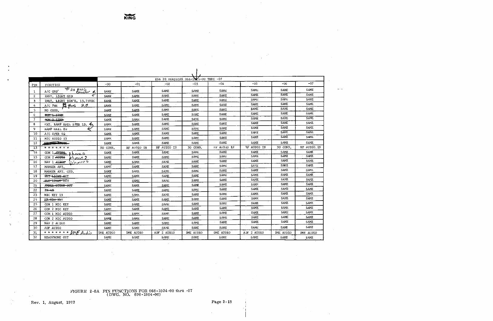
KMA 20 VERSION:: 066- -00 ERU -07
PIN FUNCTION -00 -01 -02-03 -04 -05 -06 -07
1 A/C GND' gr 4 SAME SAME SAME SAME SAME SAKE SAME SAME
2 INST, LIGHT GND SAME SAME SAKE SAME SAKE SAME SAME SAME
3 INST. LIGHT DIM'R. 13,75VDC SAME SAME SAME SAME SAME SAME SAME SAME
4 A/C PWR Àssä SLAÊ SAME SAME SAME SAME SAME SAME SAME SAMES NO CONN. SAME SAME SAME SAME SAME SAME SAME SAME6 88R-4-GBER SABE SAME SAME SAME SAME SAME SAME SAME
7 SGM-a-ZZEÐe SAME SAKE SAME SAME SAME SAKE SEME SAME8 EXT. RAMP HAIL SPKR LD. SAME SAME SAME SAME SAKE SAME SAME SAME
9 RAMP HAIL 89 SAME SAME SAME SAME SAME SAME SAME SAME10 A/C SPKR 49 SAME SAKE SAME SAME SAME SAME SAME SAME
11 MIC AUDIO IN SAME . SAME SAME SAME SAME SAMË SAME SAME
12 SAME SAME SAME SAME SAME SAME SAME SAME13 * * * *,* * * NO CONN. HF AUÙIO IN HF AUDIO IN NO CONN, HF AUDIO IN HF AUDIO IN NO CONN. HF AUDIO.IN14 COM lå a-, SAME SAME SAME SAME SAME SAME SAME SAME15 COM 2 aWÐEG k j SAME SAME SAME SAME SAME SAME SAME SAME
16 NAV 1 AUDW k yv~f 4 SAME SAME SAME SAME SAME SAME SAME SAME
17 MARKER ANT. SAMÉ SAME SAME SAME SAME SAME SR4E SAME
18 MARKER ANT. GND, SAME SAME SAME SAME SAME SAME SAME SAME
19 WRT-LIGHE-9UT SAME SAME SAME SAME SAME SAME SAME SAME
20 WWhe-tf@HT-00T SAME SAME SAME SAME SAKE SAME SAME SAME
21 AMBER-tTORT-BUT SAME SAME SAME SAME SAKE SAME SAME SAME22 PA-4 SAME SAME SAME SAME SAME SAME SAME SAME23 MIC KEY IN SAME SAME SAME SAME SAME SAKE SAME SAME24 ßÐ-4G£rõëiY SAME SAME SAME SAME SAME SAME SAME SAME25 COM 1 MIC KEY SAME SAME SAME SAME SAME SAME SAME SAME26 COM 2 MIC KEY SAME SAME SAME SAME SAME SAKE SAME SAME27 COM 1 MIC AUDIO SAME SAME SAME SAME SAME SAME SAME SAME
28 COM 2 MIC ADDIO SABE SAKE SAME SANE SAKE SAME SAME SAME
29 NAV 2 AUDIO SAME SAME SAME SAME SAME SAME SAME SAME
30 ADF AUDIO SAME SAME SAME SAME SAME SAME SAME SAME
3\ * * * * * * * f4 DME AUDIO DME AUDIO ADF 2 AUDIO DME AUDIO DME AUDIO ADF 2 AUDIO DME AUDIO DME32 HEADPHONE OUT SAME SAME SAME SAKE SAME SB4E SAME SAME
FIGURE 2-8A PIN FUNCTIONS FOR 066-1024-00 thru -07
(I39VCI. fšCI. 696-1804-00)
Rev. 1, JLugpast, 1972 I>age 2-13
030-
0061
-00
OR
030-
0101
-00
030-
0101
-00
OR
030-
0061
-00
Pl73
P173
NA
VN
AV
-
AN
TA
NT
030
0061
-00
OR
030-
0101
-00
030-
0101
-00
OR
030-
0061
-00
P17
P172
CO
MM
CO
MM
AN
TA
NT
030
2101
-06
030
2061
-00
030-
2101
-04
030-
2146
-00
Pl7
P/O
P201
P20
.P/
OP1
71P1
71P/
O96
51-
SPEA
KER
OU
TPU
T7
---
SPEA
KER
OU
TPU
T--
ON
EM
HE
MO
1434
--C
OM
M50
00O
UTP
UT
(CO
MM
2)--
1514
---C
OM
M50
02O
UTP
UT
(CO
MM
1)--
3A23
--D
ME
HR
zM
115
35--
NA
V50
00O
tfrPU
T(N
AV
2)--
--29
16--
NA
V50
00O
UTP
UT
(NA
V1)
3524
--D
ME
MH
zM
216
39M
ICA
UD
IO(C
OM
M2)
2827
MIC
AU
DIO
(CO
MM
1)p
3925
--D
ME
MH
zM
317
KK
40-M
ICK
EY(c
oMM
2)26
25M
ICK
EY(C
OM
M1)
940
27--
DM
EK
Hz
KO
32N
X5
-50
KH
zIL
S19
WH
ITE
LAM
PSE
EN
OTE
14""
¯
28--
DM
EH
zK
133
22-
DM
EM
Hz
MD
-
20B
LUE
LAM
P-
29--
DM
EH
zK
23A
23-D
ME
MH
zM
I---
21A
MB
ERlA
MP
(SEE
NO
TE7
30--
DM
EH
zK
335
524
-D
ME
MH
zM
2---
22A
uPA
SPEA
KER
31--
DM
E50
KH
z36
25--
DM
EM
Hz
M3
K5
NO
N-S
HIT
CH
500
ohm
INPU
T.
K32
--D
ME
SWIT
CH
ING
CO
MM
DN
2227
--D
ME
KH
zK
OIN
cM
2IN
STLI
GH
TD
IMM
ER-
13.7
5VD
eX
5--
50K
Hz
ILS-
NC
K28
-D
ME
KH
zK
l---
3IN
STLI
GH
TD
IMM
ERD
œM
NT
L42
--SP
AR
E
X29
-D
ME
KH
zK
2---
4A
/CPO
WER
--#2
0AW
G
30--
DM
EK
Hz
K3-
-~0
9R
AM
PH
AIL
ER89
(SEE
NO
TEIS
)5
36--
-A
UX
AU
DIO
#1--
---
NC
31-
DM
E50
KH
z-,
8SP
EAK
ERID
AD
CO
MM
ON y
E10
37--
AU
XA
UD
IO#2
-N
C(N
GTE
12)
32-
DM
ESW
ITC
HIN
GC
OM
MO
N--
-N
C1
AIR
FRA
ME
GR
OU
ND
#16n
WG
15-
Aux
AU
DIO
#3-
Nc
2--
+10.
0VD
CG
.S.
SWIT
CH
ING
-N
C10
AIR
CR
AFT
SPEA
KER
42.
Kis
--A
uxau
nto
es-
ac6
--0.
1MH
zC
ON
TRO
L--
12H
FM
ICA
UD
IO
7--
0.3M
Hz
CO
NTR
OL
-24
HF
MIC
KEY
8-0
.5M
Hz
CO
NTR
OL
-
13H
F(R
AD
IOT£
LEPH
ON
E)50
02IN
PUT
9-
0.7M
Hz
CO
NTR
OL
--30
AD
F50
00IN
PUT
(SEE
NO
TES
13&
14)
10-
0.0M
Hz
CO
NTR
OL
--N
C31
DM
E50
02IN
PUT
11--
108M
Hz
CO
NTR
OL
--32
HEA
DPH
ON
ES
12--
109M
Hz
CO
NTR
OL
--17
RM
IC
13--
110M
Hz
CO
NTR
OL
--18
16--
111M
Hz
CO
NTR
OL
--,
11.
MK
36--
AU
XA
UD
IO#1
----
NC
23EE
DL1
14)
37--
AU
XA
UD
IO#2
-N
C(N
OTE
12)
15--
AU
XA
UD
IO#3
---
NC
Kl(0
32-0
008-
0014
V)
16--
AU
XA
UD
IO#4
-N
C-0
128
V)
21--
POW
ERG
RO
UN
D#1
6AW
G--
SFE
NO
TE7
FOR
27.5
VD
CO
PER
ATI
ON
42--
SPA
RE
P/O
£1C
33--
INST
LIG
HT
DIM
MER
---1
3.75
VD
CD
IMM
ERC
ON
TRO
LIN
STLI
GH
TD
IMM
ER-
3338
--IN
STLI
GH
TD
IMM
ERIN
STLI
GH
TD
IMM
ER38
20--
A/C
POW
ER--
-#16
AW
G13
.75V
DC
1--
NA
V13
.75V
DC
INPU
T#1
6AW
G-
A/C
POW
ER
26--
NA
VSW
ITC
HED
13.7
5VD
C-N
C
17--
CO
MM
SNIT
CH
EDA
/CED
WER
#16A
kGC
CR
EAK
ESW
TCH
18--
CO
MM
13.7
5VD
CIN
PUT
#16A
WG
CO
MM
SWIT
CH
EDA
/CPO
WER
#16A
NC
---
17C
R1
7-60
21-0
0)
4--
ILS
ENER
GI2
EC
OM
M13
.75V
DC
INPU
T#1
6AW
G18
19--
ILS
CO
MM
ON--
-
3--
VO
R/1
ßCO
UT
13.7
5VD
CA
/CEO
WER
#16A
WG
----
-20
A/C
POW
ER5A
030-
2106
-01
P7C
12A
AA
--V
OR
/LO
CIN
NA
V13
.75V
DC
INPU
T-#1
6AW
G•-
1
RIL
SC
OM
MO
N----
....
#16A
WG
POW
ERG
RO
UN
D21
DD
ILS
ENER
GIZ
E--
-
SWIT
CH
EDA
/CPO
WER
NA
VSW
ITC
HED
13.7
5VD
C-
26X
+10.
0VD
CG
.S.
3HIT
CilI
ll:;
2
A0.
11til
etu
llTR
OL
6E
--0.
3MH
zC
ON
TRO
L7
-iŠM
iizC
ON
TRÕ
L
P--
0.7M
Hz
CO
NTR
OL
U--
0.9M
Hz
CO
NTR
OL
10
D--
108M
Hz
CO
NTR
OL
11
J--
109M
Hz
CO
NTR
OL
12N
---
110M
Hz
CO
NTR
OL
13
T--
111M
Hz
CO
NTR
OL
1'K
Y--
POW
ERG
RO
UN
D(#
22A
WG
)03
0-20
70-0
0V
OR
/IDC
OU
T--
-3
N3
es21
---
ILS
ENER
GI2
E--
4FF
--ST
ATO
RD
-ILS
CO
MM
ON
----
-19
HH
--ST
ATO
RE
aD
0os
o-2o
st-o
oos
o-21
erao
LL--
STA
TOR
FF
P/O
P100
1P/
OP1
001
P201
MM
--ST
ATO
RG
E--
POW
ERG
RO
UN
D18
26--
•+
VO
RFL
AG
T
---I
LSEN
ERG
IZE
310
---
TOR
FIA
G_q
CC
--R
OTO
RC
B
BB
--R
OTO
RH
AV
OR
/LO
CIN
19
-+
TOt
K2
29--
-+
raon
.SS
--+
WW
a.11
AR
OW
RH
ZW
--+
PRC
11X
ii
27R
OTO
RC
TJJ
---
VO
RFM
GT
NN
Ny
+V
OR
FMG
S5
12,
star
ono
aa
|N
OTE
528
STA
TOR
FV
'¯'
O4
13ST
ATO
RE
,K
L--
-G
.S.
FMG
Vn
29ST
ATO
RD
Xr
|Fy
+G
.S.
F1A
GU
23+
LEFT
1I
B-
-N
OTE
524
DO
MH
YID
AD
,m
EE--
+R
IGH
TM
8D
UM
MY
IDA
D-#
NO
TE8
KK
+LE
FTN
7+
RIG
HT
Êr
NO
TE5
-
O
IU
U--
S--
+U
PP
ILS
ENER
GIZ
EU
M-g
+D
OW
NB
H-
4N
OTE
5
Lc
-Ai
G.S
.FL
AG
FF
RR
--R
EFER
ENC
EPR
ASE
FOR
G.S
.FI
AG
GG
VV
--V
AR
IAB
LEPR
ASE
TUTI
NG
igg
¡gi
NO
TES:
1.U
NLE
SSN
OTE
D,
ALL
WIR
ES#2
4AW
GH
INIM
UM
.7,
27.3
VD
CO
FER
ATI
ON
2.A
LLA
NTE
NN
AC
OA
XIS
RG
58A
/U.
EX17
5/X
X17
55
3.U
NLE
SSO
THER
MIS
ESP
ECIF
IED
,A
LLSY
STEM
GR
OU
ND
SA
RE
AIR
FRA
ME
GR
OU
ND
S.P
P171
4.TH
EK
A47
MA
YB
EU
SED
10C
ON
VER
TK
Il75/
KIl7
5BItt
ESW
ITC
HIN
GO
ITTP
UT
TOG
IAN
NEL
2O
UT
OF
33--
INST
LIG
HT
DIM
MER
-NC
SCO
DE
DM
E'S.
38--
INST
LIG
HT
DIM
MER
---2
7.5V
DC
DIM
MER
CO
NTR
OL
5.K
N70
JUM
PER
P1N
SA
SIN
DIC
ATE
DFO
RR
EQU
IRED
NU
HB
ERO
FEX
TER
NA
LID
AD
S.20
--A
/CPO
WER
#16A
WG
7.5V
DC
A/C
PON
ER
EXTE
RN
AL
GLI
DES
1ßPE
VO
R/L
OC
2ALO
AD
SD
EVFI
AG
DEV
FIA
G17
--C
OM
MSN
ITC
HED
A/C
EON
ER#1
6AW
G OU
TPU
TIN
PUT
ON
EM
FK
KN
N18
--C
OB
9113
.75V
DC
INPU
T#1
6AW
G--
AA
HB
PPTT
(1,
SAC
OR
TIN
UO
US)
CU
UX
X(5
.0A
201
DU
TYFA
CTO
R)
yK
A39
G
TWO
MN
ON
EK
KN
N1
--N
AV
13.7
5VD
CIN
PUT
#16A
WG
--B
B--
-
HPP
TT...
..(0
.75A
CO
NTI
NU
GU
S)TH
REE
NO
NE
NO
NE
NO
NE
6.PO
WER
BU
SSC
IRC
UIT
BR
EAK
ERS
AR
ETO
BE
MO
UN
TEDIN
THE
AIR
CR
AFT
BR
EAK
ERPA
NEL
OR
INST
RU
MEN
TPA
NEL
SUC
HTR
AT
THEY
WIL
LB
EA
CC
ESSI
BLE
INFL
IGH
TA
ND
SAFE
FRO
MPH
YSI
CA
LIM
MA
GE,
KM
A20
P/O
P201
10.
RA
MP
HA
ILER
AN
DA
IRC
RA
FTSP
EAK
ERR
ETU
RN
LEA
DS
SHO
ULD
BE
CO
NN
ECTE
DTO
PIN
12
INST
LIG
HT
DIM
MER
-27.
5VD
CD
Det
ERC
ON
TRO
L
AT
KM
A20
,R
AM
PH
AIL
ERO
UTP
UT
(Pin
9)TO
BE
TER
MIN
ATE
DW
ITH
7.52
5W
ATT
IDA
D3
INST
LIG
HT
DIM
MER
-NC
RES
1STO
RW
HEN
RA
MP
HA
ILER
15N
OT
USE
D"
11.
EXTE
RN
AL
SWIT
CH
ING
CA
PAB
ILIT
Y:
CO
MM
-PI
N17
-N
ON
E8.
KN
74-
FOR
ON
EIN
DIC
ATO
RJU
MPE
RPI
NS
7,8.
AN
D24
.N
AV
-PI
N26
-30
0MA
FOR
TUD
IND
ICA
TOR
SJU
MPE
RPI
NS
7A
ND
8.12
.A
UX
ILIA
RY
AU
DIO
#2IS
INTE
RŒ
lMM
ICIN
PUT
ON
KX
175B
.FO
RTH
REE
IND
ICA
TOR
SN
OJU
MPE
RR
EQU
IRED
.
13.
OPT
ION
AL
INTE
RC
ON
NEC
TFO
RB
OO
MM
ICO
HEA
DSE
TIN
STA
LIA
TIO
N.
9.K
NG
SD
ME
IND
ICA
TOR
(KI2
65)
NG
ESH
OW
N.
16.
IFST
AN
DA
RD
3-W
IRE
MIC
AD
PHO
NE
PLU
GIS
USE
D,
THE
FRA
ME
SHO
ULD
BE
INSU
LATE
DB
Y16
.R
EMO
TEO
PTIO
NFO
RV
ERSI
ON
S-0
0/-1
5(M
AR
KER
LIG
HT
OU
TPU
T)W
ASH
ERS
TOA
VO
IDIN
TRO
DU
CIN
GN
OIS
EIN
TOM
IKE
AU
DIO
.FO
R-1
6V
ERSI
ON
THE
lAM
PO
UTP
UTS
BEC
OM
E:PI
N21
has
noco
nnec
tion
15.
KEE
PG
RO
UN
DSE
PAR
ATE
FRO
MK
MA
20G
RO
UN
D,
PIN
20ha
sno
conn
ectio
n.PI
N19
MA
RK
ERR
AD
IO50
02IN
PUT


