Download - Ka 01069 Fen
KA01069F/00/EN/01.11
71145369
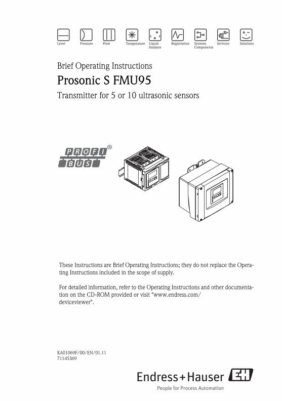
Brief Operating Instructions
Prosonic S FMU95Transmitter for 5 or 10 ultrasonic sensors
These Instructions are Brief Operating Instructions; they do not replace the Opera-
ting Instructions included in the scope of supply.
For detailed information, refer to the Operating Instructions and other documenta-
tion on the CD-ROM provided or visit "www.endress.com/
deviceviewer".
Prosonic S FMU95 PROFIBUS
2
Table of contents
1 Safety Instructions. . . . . . . . . . . . . . . . . . . . . . . . . . . . . . . . . . . . . . . . . 3
1.1 Designated use . . . . . . . . . . . . . . . . . . . . . . . . . . . . . . . . . . . . . . . . . . . . . . . . . . . . . . . . . . . . . . 3
1.2 Installation, commissioning, operation . . . . . . . . . . . . . . . . . . . . . . . . . . . . . . . . . . . . . . . . . . . . 3
1.3 Operational safety and process safety . . . . . . . . . . . . . . . . . . . . . . . . . . . . . . . . . . . . . . . . . . . . . 3
1.4 Return . . . . . . . . . . . . . . . . . . . . . . . . . . . . . . . . . . . . . . . . . . . . . . . . . . . . . . . . . . . . . . . . . . . . 3
1.5 Safety icons . . . . . . . . . . . . . . . . . . . . . . . . . . . . . . . . . . . . . . . . . . . . . . . . . . . . . . . . . . . . . . . . 4
2 Mounting. . . . . . . . . . . . . . . . . . . . . . . . . . . . . . . . . . . . . . . . . . . . . . . . 4
2.1 Incoming acceptance, storage . . . . . . . . . . . . . . . . . . . . . . . . . . . . . . . . . . . . . . . . . . . . . . . . . . . 4
2.2 Installation . . . . . . . . . . . . . . . . . . . . . . . . . . . . . . . . . . . . . . . . . . . . . . . . . . . . . . . . . . . . . . . . . 5
2.3 Mounting the remote display and operating module . . . . . . . . . . . . . . . . . . . . . . . . . . . . . . . . . . 7
2.4 Mounting of the sensors . . . . . . . . . . . . . . . . . . . . . . . . . . . . . . . . . . . . . . . . . . . . . . . . . . . . . . . 9
2.5 Installation check . . . . . . . . . . . . . . . . . . . . . . . . . . . . . . . . . . . . . . . . . . . . . . . . . . . . . . . . . . . . 9
3 Wiring . . . . . . . . . . . . . . . . . . . . . . . . . . . . . . . . . . . . . . . . . . . . . . . . . 10
3.1 Terminal compartment of the field housing . . . . . . . . . . . . . . . . . . . . . . . . . . . . . . . . . . . . . . . . 10
3.2 Terminal compartment of the DIN-rail
housing . . . . . . . . . . . . . . . . . . . . . . . . . . . . . . . . . . . . . . . . . . . . . . . . . . . . . . . . . . . . . . . . . . 11
3.3 Terminal assignment . . . . . . . . . . . . . . . . . . . . . . . . . . . . . . . . . . . . . . . . . . . . . . . . . . . . . . . . 13
3.4 Sensor connection . . . . . . . . . . . . . . . . . . . . . . . . . . . . . . . . . . . . . . . . . . . . . . . . . . . . . . . . . . 15
3.5 Synchronization line . . . . . . . . . . . . . . . . . . . . . . . . . . . . . . . . . . . . . . . . . . . . . . . . . . . . . . . . . 16
3.6 Connection of the separate display and operating module . . . . . . . . . . . . . . . . . . . . . . . . . . . . . 17
3.7 Potential equalization . . . . . . . . . . . . . . . . . . . . . . . . . . . . . . . . . . . . . . . . . . . . . . . . . . . . . . . . 17
3.8 Post-connection check . . . . . . . . . . . . . . . . . . . . . . . . . . . . . . . . . . . . . . . . . . . . . . . . . . . . . . . 20
4 Operation . . . . . . . . . . . . . . . . . . . . . . . . . . . . . . . . . . . . . . . . . . . . . . 21
4.1 Operating options . . . . . . . . . . . . . . . . . . . . . . . . . . . . . . . . . . . . . . . . . . . . . . . . . . . . . . . . . . . 21
4.2 Operation via the display and operating module . . . . . . . . . . . . . . . . . . . . . . . . . . . . . . . . . . . . 21
5 Commissioning . . . . . . . . . . . . . . . . . . . . . . . . . . . . . . . . . . . . . . . . . . 26
5.1 Setting the device address . . . . . . . . . . . . . . . . . . . . . . . . . . . . . . . . . . . . . . . . . . . . . . . . . . . . . 26
5.2 Bus termination . . . . . . . . . . . . . . . . . . . . . . . . . . . . . . . . . . . . . . . . . . . . . . . . . . . . . . . . . . . . 27
5.3 Loading the device database and type files (GSD) . . . . . . . . . . . . . . . . . . . . . . . . . . . . . . . . . . . 28
5.4 First setup . . . . . . . . . . . . . . . . . . . . . . . . . . . . . . . . . . . . . . . . . . . . . . . . . . . . . . . . . . . . . . . . 28
5.5 Basic setup . . . . . . . . . . . . . . . . . . . . . . . . . . . . . . . . . . . . . . . . . . . . . . . . . . . . . . . . . . . . . . . . 29
Prosonic S FMU95 PROFIBUS Safety Instructions
Endress+Hauser 3
1 Safety Instructions
1.1 Designated use
The Prosonic S FMU95 is a transmitter for the ultrasonic sensors FDU90, FDU91, FDU91F,
FDU92, FDU93, FDU95 and FDU96. The sensors of the class FDU8x can be connected as well.
1.2 Installation, commissioning, operation
The Prosonic S FMU95 is fail-safe and constructed to the state-of-the-art. It meets the approp-
riate standards and EC directives. However, if you use it improperly or other than for its desig-
nated use, it may pose application-specific hazards, e.g. product overflow due to incorrect ins-
tallation or configuration. Installation, electrical connection, start-up, operation and
maintenance of the measuring device must therefore be carried out exclusively by trained spe-
cialists authorised by the system operator. Technical personnel must have read and understood
these operating instructions and must adhere to them. You may only undertake modifications or
repair work to the device when it is expressly permitted by the operating instructions.
1.3 Operational safety and process safety
• Alternative monitoring measures must be taken to ensure operational safety and process safety
during confiugration, testing and maintenance work on the device.
• The device is safely built and tested according to state-of-the-art technology and has left the
factory in perfect condition as regards technical safety. The applicable regulations and Euro-
pean standards have been taken into account.
• Pay particular attention to the technical data on the nameplate.
• If the device is to be installed in an explosion hazardous area, then the specifications in the
certificate as well as all national and local regulations must be observed. The device is accom-
panied by separate "Ex documentation", which is an integral part of this Operating Instruc-
tions. The installation regulations, connection values and Safety Instructions listed in this Ex
document must be observed. The documentation number of the related Safety Instructions is
also indicated.
• If using devices for applications with safety integrity level, the separate manual on functional
safety must be observed thoroughly (→ see CD-ROM).
# Warning!
The sensors FDU83, FDU84, FDU85 and FDU86 with an ATEX, FM or CSA certificate are not
certified for connection to the FMU90 transmitter.
1.4 Return
Follow the instructions on returning the device as outlined in the Operating Instructions on the
CD-ROM provided.

Mounting Prosonic S FMU95 PROFIBUS
4 Endress+Hauser
1.5 Safety icons
2 Mounting
2.1 Incoming acceptance, storage
2.1.1 Incoming acceptance
Check the packing and contents for any signs of damage. Check the shipment, make sure
nothing is missing and that the scope of supply matches your order.
2.1.2 Storage
Pack the measuring instrument so that is protected against impacts for storage and transport. The
original packing material provides the optimum protection for this.
The permissible storage temperature is -40 to +60 °C (-40 to +140 °F).
Safety conventions
#Warning!
A warning highlights actions or procedures which, if not performed correctly, will lead to personal injury,
a safety hazard or destruction of the instrument
"Caution!
Caution highlights actions or procedures which, if not performed correctly, may lead to personal injury or
incorrect functioning of the instrument
!Note!
A note highlights actions or procedures which, if not performed correctly, may indirectly affect operation
or may lead to an instrument response which is not planned
Explosion protection
0 Device certified for use in explosion hazardous area
If the device has this symbol embossed on its name plate it can be installed in an explosion hazardous area
- Explosion hazardous area
Symbol used in drawings to indicate explosion hazardous areas. Devices located in and wiring entering
areas with the designation “explosion hazardous areas” must conform with the stated type of protection.
. Safe area (non-explosion hazardous area)
Symbol used in drawings to indicate, if necessary, non-explosion hazardous areas. Devices located in safe
areas still require a certificate if their outputs run into explosion hazardous areas

Prosonic S FMU95 PROFIBUS Mounting
Endress+Hauser 5
2.2 Installation
2.2.1 Installation conditions of the field housing
Weather protection
In order to avoid excessive sunlight exposure, the instrument should be mounted in a position
which is protected against direct sunlight or a protection cover should be applied.
Overvoltage protection
In order to protect the Prosonic against overvoltages (especially if mounted outdoors),
connection of an overvoltage protection is recommended.
Wall mounting
A mounting help for wall mounting is supplied. It also serves as drilling template. The mounting
help should be mounted on a flat surface and may not become distorted.
Pipe mounting
A mounting plate is available for mounting of the field housing to 1" to 2" pipes.
! Note!
For more information and details, see the Operating Instructions BA00344F, chapter
"Accessories" on the CD-ROM provided.
L00-FMU90xxx-17-00-00-xx-003
Wall mounting with mounting help (1)
1. 2. 3.
4.
1
Mounting Prosonic S FMU95 PROFIBUS
6 Endress+Hauser
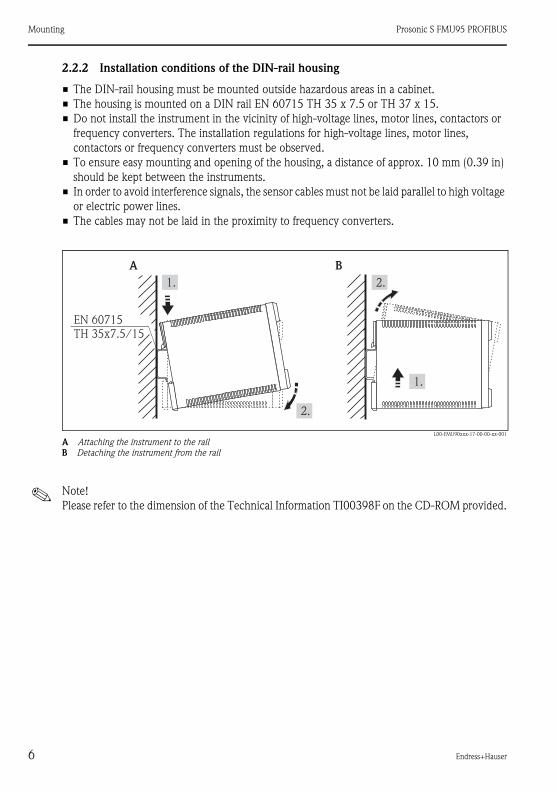
2.2.2 Installation conditions of the DIN-rail housing
• The DIN-rail housing must be mounted outside hazardous areas in a cabinet.
• The housing is mounted on a DIN rail EN 60715 TH 35 x 7.5 or TH 37 x 15.
• Do not install the instrument in the vicinity of high-voltage lines, motor lines, contactors or
frequency converters. The installation regulations for high-voltage lines, motor lines,
contactors or frequency converters must be observed.
• To ensure easy mounting and opening of the housing, a distance of approx. 10 mm (0.39 in)
should be kept between the instruments.
• In order to avoid interference signals, the sensor cables must not be laid parallel to high voltage
or electric power lines.
• The cables may not be laid in the proximity to frequency converters.
L00-FMU90xxx-17-00-00-xx-001
A Attaching the instrument to the rail
B Detaching the instrument from the rail
! Note!
Please refer to the dimension of the Technical Information TI00398F on the CD-ROM provided.
A B
1.
2.
1.
2.
EN 60715TH 35x7.5/15
Prosonic S FMU95 PROFIBUS Mounting
Endress+Hauser 7
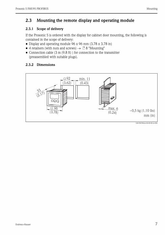
2.3 Mounting the remote display and operating module
2.3.1 Scope of delivery
If the Prosonic S is ordered with the display for cabinet door mounting, the following is
contained in the scope of delivery:
• Display and operating module 96 x 96 mm (3.78 x 3.78 in)
• 4 retainers (with nuts and screws) → ä 8 "Mounting"
• Connection cable (3 m (9.8 ft) ) for connection to the transmitter
(preassembled with suitable plugs).
2.3.2 Dimensions
L00-FMU90xxx-06-00-00-xx-004
96
55
max. 6
92 min. 11
~0,5 kg (1.10 lbs)
(0.43)(3.62)
(0.24)(3.78)
(2.17)
mm (in)
Mounting Prosonic S FMU95 PROFIBUS
8 Endress+Hauser
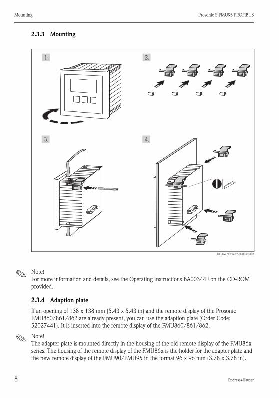
2.3.3 Mounting
L00-FMU90xxx-17-00-00-xx-002
! Note!
For more information and details, see the Operating Instructions BA00344F on the CD-ROM
provided.
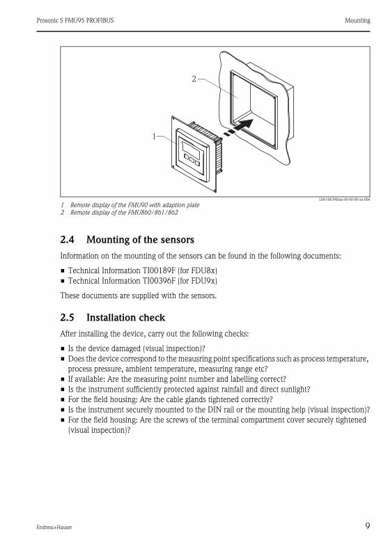
2.3.4 Adaption plate
If an opening of 138 x 138 mm (5.43 x 5.43 in) and the remote display of the Prosonic
FMU860/861/862 are already present, you can use the adaption plate (Order Code:
52027441). It is inserted into the remote display of the FMU860/861/862.
! Note!
The adapter plate is mounted directly in the housing of the old remote display of the FMU86x
series. The housing of the remote display of the FMU86x is the holder for the adapter plate and
the new remote display of the FMU90/FMU95 in the format 96 x 96 mm (3.78 x 3.78 in).
1.
3. 4.
2.
Prosonic S FMU95 PROFIBUS Mounting
Endress+Hauser 9
L00-FMU90xxx-06-00-00-xx-006
1 Remote display of the FMU90 with adaption plate
2 Remote display of the FMU860/861/862
2.4 Mounting of the sensors
Information on the mounting of the sensors can be found in the following documents:
• Technical Information TI00189F (for FDU8x)
• Technical Information TI00396F (for FDU9x)
These documents are supplied with the sensors.
2.5 Installation check
After installing the device, carry out the following checks:
• Is the device damaged (visual inspection)?
• Does the device correspond to the meausring point specifications such as process temperature,
process pressure, ambient temperature, measuring range etc?
• If available: Are the measuring point number and labelling correct?
• Is the instrument sufficiently protected against rainfall and direct sunlight?
• For the field housing: Are the cable glands tightened correctly?
• Is the instrument securely mounted to the DIN rail or the mounting help (visual inspection)?
• For the field housing: Are the screws of the terminal compartment cover securely tightened
(visual inspection)?
1
2
Wiring Prosonic S FMU95 PROFIBUS
10 Endress+Hauser
3 Wiring
# Warning!
The instrument may only be installed if the supply voltage is switched off.
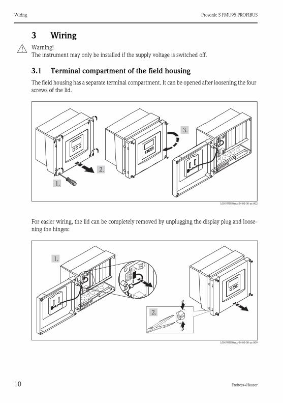
3.1 Terminal compartment of the field housing
The field housing has a separate terminal compartment. It can be opened after loosening the four
screws of the lid.
L00-FMU90xxx-04-00-00-xx-002
For easier wiring, the lid can be completely removed by unplugging the display plug and loose-
ning the hinges:
L00-FMU90xxx-04-00-00-xx-009
1.
2.
3.
1.
2.

Prosonic S FMU95 PROFIBUS Wiring
Endress+Hauser 11
3.1.1 Cable entries of the field housing
The following openings for cable entries are prestamped on the bottom of the housing:
M20x1.5 (10 openings), M16x1.5 (5 openings), M25x1.5 (1 opening)
The required number and types of cable entries depend on the application at hand.
3.2 Terminal compartment of the DIN-rail housing
3.2.1 Single instrument
L00-FMU95xxx-04-00-00-xx-005
! Note!
• The cables can be inserted into the housing from above or from below.
• The pictures show the smallest housing version but are valid for the larger versions as well.
• If the instruments are mounted next to each other and if the sensor cables run in parallel, the
synchronization terminals (39 and 40) must be interconnected (→ ä 13, "Terminal
assignment" and → ä 16, "Synchronization line").
1. 2.

Wiring Prosonic S FMU95 PROFIBUS
12 Endress+Hauser
3.2.2 Several instruments mounted side by side
L00-FMU95KAx-04-00-00-xx-005
1.
2.
3.

Prosonic S FMU95 PROFIBUS Wiring
Endress+Hauser 13
3.3 Terminal assignment
L00-FMU95xxx-04-00-00-xx-003
Terminals of the Prosonic S FMU95; the terminals depicted in grey are not present in every instrument version.
Ad
dre
ss
Te
rm.
DP
off
on
off
on
SWHW
12345678
1234
A(N
)
66
B(P
)
65
Display
PO
WE
R Sync
Fuse
40
39
Service3
21
11
10
91
FDU-Sensor
YE
BK
RD
14
13
12
2
YE
BK
RD
17
16
15
3
YE
BK
RD
20
19
18
4
YE
BK
RD
23
22
21
5
YE
BK
RD
26
25
24
6
YE
BK
RD
29
28
27
7
YE
BK
RD
32
31
30
8
YE
BK
RD
35
34
33
9
YE
BK
RD
38
37
36
10
YE
BK
RD
FDU-Sensor
Terminals Meaning Remarks
Auxiliary energy
1• L (for AC version)
• L+ (for DC version) depending on instrument version:
• 90 ... 253 VAC
• 10.5 ... 32 VDC2• N (for AC version)
• L- (for DC version)
3 Potential equalization
Fuse
depending on instrument version:
• 400 mA T (for AC)
• 2 A T (for DC)
Bus communication
65 PROFIBUS A (RxT/TxD - N)
66 PROFIBUS B (RxT/TxD - P)
Synchronization
39, 40 Synchronization → ä 16, "Synchronization line"

Wiring Prosonic S FMU95 PROFIBUS
14 Endress+Hauser
# Warning!
When using the public supply mains, an easily accesible power switch must be installed in the
proximity of the device. The power switch must be marked as a disconnector for the device
(IEC/EN 61010).
! Note!
• In order to avoid interference signals, the sensor cables should not be laid parallel to high
voltage or electric power lines.
• The cables may not be laid in the proximity to frequnecy converters.
Additional elements on the terminal areas
# Warning!
On wiring, the supply voltage must be switched off.
Level inputs
09,10,11 Sensor 1 (FDU8x/9x)
YE: yellow strand
BK: black strand
RD: red strand
12, 13, 14 Sensor 2 (FDU8x/9x)
15, 16, 17 Sensor 3 (FDU8x/9x)
18, 19, 20 Sensor 4 (FDU8x/9x)
21, 22, 23 Sensor 5 (FDU8x/9x)
24, 25, 26 Sensor 6 (FDU8x/9x)
only available for the version with 10 sensor inputs
YE: yellow strand
BK: black strand
RD: red strand
27, 28, 29 Sensor 7 (FDU8x/9x)
30, 31, 32 Sensor 8 (FDU8x/9x)
33, 34, 35 Sensor 9 (FDU8x/9x)
36, 37, 38 Sensor 10 (FDU8x/9x)
Terminals Meaning Remarks
Designation Meaning/Remarks
Fuse Fuse: 2 A T /DC or 400 mA T/AC
Display Connection of the display or the remote display and operating module (→ ä 17)
Service Service interface for connection of a PC/Notebook via Commubox FXA291
Locking switch
Term. Bus termination
Address Bus address
Prosonic S FMU95 PROFIBUS Wiring
Endress+Hauser 15
! Hinweis!
• Information on the structure of a PROFIBUS DP network can be found in the Operating
Instructions BA00034S ("PROFIBUS PA/DP - Guidelines for planning and commissioning".
• For more information and details, see the Operating Instructions BA00344F on the CD-ROM
provided.
3.4 Sensor connection
Information on the mounting of the sensors can be found in the following documents:
• Technical Information TI00189F (for FDU8x)
• Technical Information TI00396F (for FDU9x)
These documents are supplied with the sensors.
Wiring Prosonic S FMU95 PROFIBUS
16 Endress+Hauser
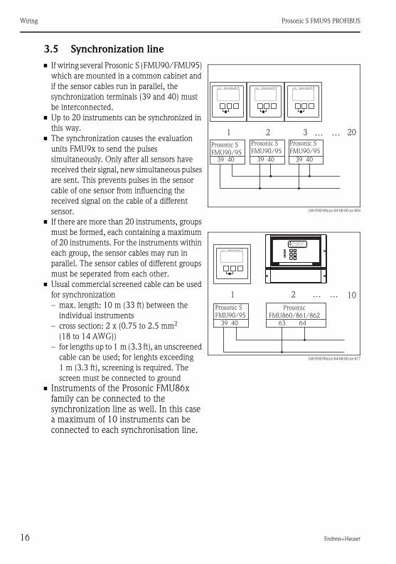
3.5 Synchronization line
• If wiring several Prosonic S (FMU90/FMU95)
which are mounted in a common cabinet and
if the sensor cables run in parallel, the
synchronization terminals (39 and 40) must
be interconnected.
• Up to 20 instruments can be synchronized in
this way.
• The synchronization causes the evaluation
units FMU9x to send the pulses
simultaneously. Only after all sensors have
received their signal, new simultaneous pulses
are sent. This prevents pulses in the sensor
cable of one sensor from influencing the
received signal on the cable of a different
sensor.
• If there are more than 20 instruments, groups
must be formed, each containing a maximum
of 20 instruments. For the instruments within
each group, the sensor cables may run in
parallel. The sensor cables of different groups
must be seperated from each other.
• Usual commercial screened cable can be used
for synchronization
– max. length: 10 m (33 ft) between the
individual instruments
– cross section: 2 x (0.75 to 2.5 mm2
(18 to 14 AWG))
– for lengths up to 1 m (3.3 ft), an unscreened
cable can be used; for lenghts exceeding
1 m (3.3 ft), screening is required. The
screen must be connected to ground
• Instruments of the Prosonic FMU86x family can be connected to the synchronization line as well. In this case a maximum of 10 instruments can be connected to each synchronisation line.
L00-FMU90xxx-04-00-00-xx-004
L00-FMU90xxx-04-00-00-xx-017
Prosonic SFMU90/95
39 40
1 2 3 20……
FMU90 FMU90 FMU90
Prosonic SFMU90/95
39 40
Prosonic SFMU90/95
39 40
Prosonic SFMU90/95
39 40
ProsonicFMU860/861/862
63 64
1 2 10……
FMU90
V H

Prosonic S FMU95 PROFIBUS Wiring
Endress+Hauser 17
3.6 Connection of the separate display and operating module
L00-FMU95xxx-04-00-00-xx-008
1 Connection of the display plug with the cable (3 m (9.8 ft))
For the version of the Prosonic S with a separate display for panel mounting, a pre-assembled
connecting cable (3 m (9.8 ft)) is supplied. The cable must be connected to the display plug of
the Prosonic S.
! Note!
Minimum diameter for cable bushing: 20 mm (0.79 in).
3.7 Potential equalization
3.7.1 Potential equalization in the field housing
Ad
dre
ss
Te
rm.
DP
off
on
off
on
SWHW
12345678
1234
A(N
)
66
B(P
)
65
Display
PO
WE
R Sync
Fuse40
39
Service3
21
11
10
9
1
FDU-Sensor
YE
BK
RD
14
13
12
2Y
EB
KR
D
17
16
15
3
YE
BK
RD
20
19
18
4
YE
BK
RD
23
22
21
5
YE
BK
RD
26
25
24
6
YE
BK
RD
29
28
27
7
YE
BK
RD
32
31
30
8
YE
BK
RD
35
34
33
9
YE
BK
RD
38
37
36
10
YE
BK
RD
FDU-Sensor
1
# Warning!
The grounding line of the sensors
FDU91F/93/95/96 and FDU83/84/85/86
must be connected to the local potential
equalization system after a maximum of 30 m
(98 ft). The metallic terminal block (1) in the
field housing can be used for this.
L00-FMU90xxx-04-00-00-xx-006
1

Wiring Prosonic S FMU95 PROFIBUS
18 Endress+Hauser
Example
L00-FMU95xxx-04-00-00-xx-009
1 The wire is already connected on delivery
90 … 253 VAC10,5 … 32 VDC
N L PEFDU91F/93/95/96(FDU83/84/85/86)
1
FMU95
Addre
ss
Term
.
DP
off
on
off
on
SWHW
12345678
1234
A(N
)
66
B(P
)
65
Display
PO
WE
R Sync
Fuse
40
39
Service
32
1
11
10
9
1
FDU-Sensor
YE
BK
RD
14
13
12
2
YE
BK
RD
17
16
15
3
YE
BK
RD
20
19
18
4
YE
BK
RD
23
22
21
5
YE
BK
RD
26
25
24
6
YE
BK
RD
29
28
27
7
YE
BK
RD
32
31
30
8
YE
BK
RD
35
34
33
9
YE
BK
RD
38
37
36
10
YE
BK
RD
FDU-Sensor
GNYE
FDU91F/93/95/96(FDU83/84/85/86)
GNYE

Prosonic S FMU95 PROFIBUS Wiring
Endress+Hauser 19
3.7.2 Potential equalization for the DIN-rail hosuing
If the DIN-rail housing is used, the potential equalization must be connected in the cabinet, e.g.
at a metallic DIN rail:
# Warning!
The grounding line of the sensors FDU91F/93/95/96 and FDU83/84/85/86 must be
connected to the local potential equalization system after a maximum of 30 m (98 ft).
L00-FMU95xxx-04-00-00-xx-010
1 Terminal (isolated from the DIN rail)
2 Protective earth terminal (with contact to the DIN rail)
3 Protective ground via DIN rail
90 … 253 VAC10.5 … 32 VDC
FMU95
Addre
ss
Term
.
DP
off
on
off
on
SWHW
12345678
1234
A(N
)
66
B(P
)
65
Display
PO
WE
R Sync
Fuse
40
39
Service
32
1
11
10
9
1
FDU-Sensor
YE
BK
RD
14
13
12
2Y
EB
KR
D
17
16
15
3
YE
BK
RD
20
19
18
4
YE
BK
RD
23
22
21
5
YE
BK
RD
26
25
24
6Y
EB
KR
D
29
28
27
7
YE
BK
RD
32
31
30
8
YE
BK
RD
35
34
33
9
YE
BK
RD
38
37
36
10
YE
BK
RD
FDU-Sensor
GNYE
FDU91F/93/95/96(FDU83/84/85/86)
GNYE
PE PE PE
FDU91F/93/95/96(FDU83/84/85/86)
LN
1 23
Wiring Prosonic S FMU95 PROFIBUS
20 Endress+Hauser
" Caution!
The signal evaluation electronics and its direct connections (display interface, service interface
etc.) are galvanically isolated from the supply voltage and the communication signals. Their
electric potential is identiacal to the potential of the sensor electronics.
Pay attention to the potential difference if the sensors are connected to ground!
! Note!
The longest required distance has to be taken into account when removing the jacket of the
sensor cable (GNYE in the above example).
3.8 Post-connection check
After wiring the transmitter, carry out the following checks:
• Is the terminal assignment correct?
• For the field housing: Are the cable glands tight and is the cover of the terminal compartment
securely closed?
• If auxiliary energy is switched on: Does a display appear on the display module (if available)
and does the green LED light up?
Prosonic S FMU95 PROFIBUS Operation
Endress+Hauser 21
4 Operation
4.1 Operating options
• On-site operation
via the display and operating module at the Prosonic S
• Remote operation
– Via the service interface with the Commubox FXA291 and the operating program FieldCare
– Via PROFIBUS DP with the PROFIcard, PROFIboard or PROFIusb
– Acyclic data exchange, SLOT index tables
! Note!
For more information and details, see the Operating Instructions BA00344F on the CD-ROM
provided.
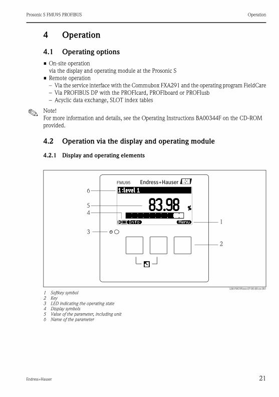
4.2 Operation via the display and operating module
4.2.1 Display and operating elements
L00-FMU95xxx-07-00-00-xx-001
1 Softkey symbol
2 Key
3 LED indicating the operating state
4 Display symbols
5 Value of the parameter, including unit
6 Name of the parameter
FMU95
3
1
2
6
5
4
Operation Prosonic S FMU95 PROFIBUS
22 Endress+Hauser
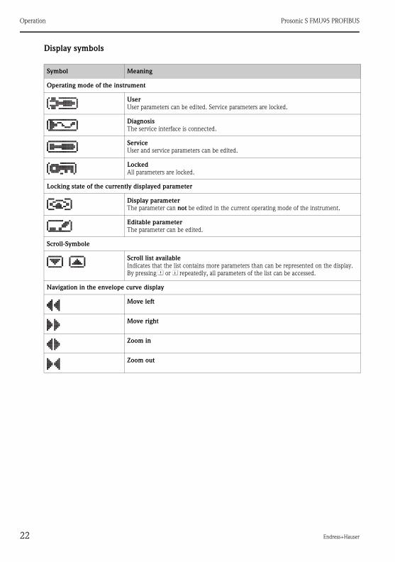
Display symbols
Symbol Meaning
Operating mode of the instrument
User
User parameters can be edited. Service parameters are locked.
Diagnosis
The service interface is connected.
Service
User and service parameters can be edited.
Locked
All parameters are locked.
Locking state of the currently displayed parameter
Display parameter
The parameter can not be edited in the current operating mode of the instrument.
Editable parameter
The parameter can be edited.
Scroll-Symbole
Scroll list available
Indicates that the list contains more parameters than can be represented on the display.
By pressing V or W repeatedly, all parameters of the list can be accessed.
Navigation in the envelope curve display
Move left
Move right
Zoom in
Zoom out

Prosonic S FMU95 PROFIBUS Operation
Endress+Hauser 23
Keys (softkey operation)
The function of the keys depends on the current position within the operating menu (softkey
functionality). The key functions are indicated by softkey symbols in the bottom line of the
display.
Symbol Meaning
Move downwards
Moves the marking bar downwards within a selection list.
Move upwards
Moves the marking bar upwards within a selection list.
Enter
• Opens the marked submenu, the marked parameter set or the marked parameter
• Confirms the edited parameter value
Previous parameter set
Reopens the previous parameter set within the submenu.
Next parameter set
Opens the next parameter set within the submenu.
Confirm selection
Selects the option of a selection list which is currently marked by the bar.
Increase value
Increases the active digit of an alphanumeric parameter.
Decrease value
Decreases the active digit of an alphanumeric parameter
Error list
Opens the list of all errors which are currently detected.
If a warning is present, this symbol flashes.
If an alarm is present, the symbol is displayed continuously.
Change Display
Change to the next page of measured values (only available if more than one pages of measu-
red values have been defined; see "display" menu)
Info
Opens the Shortcut Menu, which contains the most important information about the current
state of the instrument
Menu
Opens the Main Menu, which contains all parameters of the Prosonic S

Operation Prosonic S FMU95 PROFIBUS
24 Endress+Hauser
General key combinations
The following key combinations do not depend on the menu position:
Key combination Meaning
Escape
• While editing a parameter: Exit the editing mode without accepting the changes.
• Within the navigation: Move upwards to the previous layer of the menu.
Increase contrast
Increases the contrast of the display module.
Decrease contrast
Decreases the contrast of the display module.
Locking
Locks the instrument against parameter changes.
The instrument can only be unlocked again by the keys.

Prosonic S FMU95 PROFIBUS Operation
Endress+Hauser 25
4.2.2 The operating menu
Structure of the menu
The parameters of the Prosonic S are organized in an operating menu (consisting of a main menu
and several submenus). Parameters which are related to each other are comprised in a common
parameter set. To simplify the navigation within the menu, a five-digit position code is displayed
with each parameter set.
LVL 1 appl.para L1004
tank shape :dome ceiling
medium property:liquid
process cond:standard liq. ⇒
Identification of the parameter sets:
1 Submenu2 Number of the associated input or output 3 Number of the parameter set within the submenus
! Note!
More information for selection and editing of parameters refer to the Operating Instructions
BA00344F on the provided CD-ROM.
321

Commissioning Prosonic S FMU95 PROFIBUS
26 Endress+Hauser
5 Commissioning
5.1 Setting the device address
5.1.1 Selecting the device address
• Every PROFIBUS device must be given an address. If the address is not set correctly, the
device will not be recognised by the process control system.
• A device address may appear only once within a particular PROFIBUS network.
• Valid device addresses are in the range between 1 and 126. All devices are delivered from the
factory with the address 126, which is set by software.
• The default address can be used to check the function of the device and connect it to an
operating PROFIBUS system. Afterwards the address must be changed to allow other devices
to be connected to the network.
5.1.2 Software addressing
Software addressing comes into operation, when DIP-switch 8 on the PROFIBUS DP terminal
area is in the position "ON".
In this case, the address can be set by an operating tool ("FieldCare").
The address is displayed in the function "Output-calculations/PROFIBUS DP/instrument
address".
5.1.3 Hardware addressing
L00-FMU90xxx-04-00-00-xx-016
Ad
dre
ss
Te
rm.
DP
off
on
off
on
SWHW
12345678
1234
Address
offonS
WH
W
12345678
8 + 2 = 10
A(N
)
66
B(P
)
65
Prosonic S FMU95 PROFIBUS Commissioning
Endress+Hauser 27
Hardware addressing comes into operation when DIP switch 8 is in the position "HW (OFF)". In
this case the address is determinded by the position of DIP-switches 1 to 7 according to the
following table:
The new address becomes valid 10 seconds after switching.
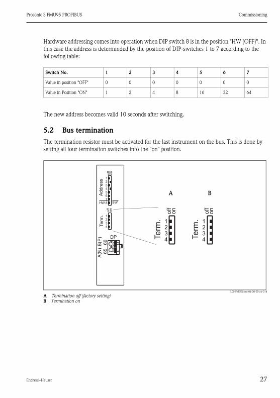
5.2 Bus termination
The termination resistor must be activated for the last instrument on the bus. This is done by
setting all four termination switches into the "on" position.
L00-FMU90xxx-04-00-00-xx-018
A Termination off (factory setting)
B Termination on
Switch No. 1 2 3 4 5 6 7
Value in position "OFF" 0 0 0 0 0 0 0
Value in Position "ON" 1 2 4 8 16 32 64
Ad
dre
ss
Te
rm.
DP
off
on
off
on
SWHW
12345678
1234
A(N
)
66
B(P
)
65
Te
rm.
off
on
1234 Te
rm.
off
on
1234
A B

Commissioning Prosonic S FMU95 PROFIBUS
28 Endress+Hauser
5.3 Loading the device database and type files (GSD)
5.3.1 Meaning of the GSD files
A device database file (GSD) contains a description of the properties of the PROFIBUS device,
e.g. the supported transmission rates and the type and format of the digital information output
to the PLC. Additional bitmap files are required in order to represent the device by an icon in
the network design software. The device database and bitmap files are needed for the
commissioning of a PROFIBUS DP network.
! Note!
For more information and details, see the Operating Instructions BA00344F on the CD-ROM
provided.
5.4 First setup
After switching on the power supply for the first time, the instrument asks for a number of
operating parameters:
• Select by ↓ or ↑
• Confirm by ↵
! Note!
By pressing you can return to the previous parameter (e.g. in order to correct the
value). All these parameters can also be changed at a later point of time in the "device
properties/operating parameters" and "device properties/language" parameter sets.
Step Parameter Remarks
1 → language Select the display language.
2 → distance unit Select the unit for distance measurements.
3 → temperature unit Select the temperature unit.

Prosonic S FMU95 PROFIBUS Commissioning
Endress+Hauser 29
5.5 Basic setup
After the first setup the main screen appears.
However, the displayed value does not correspond to the real level before you have performed
the basic setup. To do so, enter the main menu by pressing "Menu" (right key).
5.5.1 Overview basic setup
The following table gives an overview of the basic setup for level measurements. Detailed infor-
mation on the parameters can be found in the Operating Instructions BA00344F on the
CD-ROM provided .
Step Parameter set Parameter Remarks
1 Main menu → level → level (LVL)1 Select the "level" submenu. In the following sub-
menu select the level channel you are going to
calibrate.
2 Main menu → level → level (LVL)1
→ basic setup In the following submenu select "basic setup".
This submenu contains all parameters needed for
the basic setup.
Step Parameter set Parameter Remarks
Configuring the sensor (Details → Chap. 5.5.2)
1 → LVL N sensor selection
(N = 1 - 5 or 10)
→ input Allocate a sensor to the channel.
→ sensor selection Specify the type of sensor ("automatic" for FDU9x)
→ detected only available for "sensor selection" = "automatic";
indicates the detected type of sensor
2 → LVL N application
parameter
(N = 1 - 5 or 10)
→ tank shape Select the appropriate values for your application.
→ medium property
→ process conditions
Empty and full calibration (Details → Chap. 5.5.3)
3 → LVL N empty calibra-
tion
(N = 1 - 5 or 10)
→ empty E Specify the distance between the reference point
of the sensor and the minimum level (0%).
4 → LVL N full calibration
(N = 1 - 5 or 10)
→ full F Specify the distance between the minimum (0%)
and maximum (100%) level.
→ blocking distance (BD) Display parameter; the maximum value for the full
calibration is: Fmax = E - BD

Commissioning Prosonic S FMU95 PROFIBUS
30 Endress+Hauser
5 → LVL N unit
(N = 1 - 5 or 10)
→ unit level Select the unit for the level measurement.
→ level N (N = 1 - 5 or 10) Displays the currently measured level.
→ distance Displays the currently measured distance between
the reference point of the sensor and the product
level.
Linearization (Details → Chap. 5.5.4)
If no linearization is required: continue by step 7: "distance correction"
6 → LVL N linearization
(N = 1 - 5 or 10)
→ type Select type of linearization
(Details → ä 36 "type")
→ mode Specify, to which value the measurement refers:
"level" or "ullage"
→ customer unit Specify the unit for the linearized value;
(not available for "type" = "none")
(Details → ä 38 "customer unit")
→ max. scale Specify the maximum contents of the vessel (in
customer units); (not available for "type" = "none")
→ diameter Specify the diameter of the tank;
(only available for "type" = "horizontal cylinder" or
"sphere")
→ intermediate height Specify the intermediate height of the tank or silo;
(only available for "type" = "pyramid bottom",
"conical bottom" oder "angled bottom")
→ edit Used to enter, change or delete a linearization
table; (only available for "type" = "table")
Details → ä 38 "edit"
→ status table Enables or disables the linearization table;
(only available for "type" = "table")
Details → ä 39 "status table"
Interference echo suppression (Details → Chap. 5.5.5)
7 → LVL N check value
(N = 1 - 5 or 10)
→ act. distance N Indicates the currently measured distance bet-
ween the reference point of the sensor and the
product surface.
→ check distance Compare the indicated distance with the real
value:
• "distance = ok" → "distance mapping"
• "distance too small" → "distance mapping"
• "distance too big" → Basic setup completed
• "distance unknown" → Basic setup completed
• "manual" → "distance mapping"
Step Parameter set Parameter Remarks
Prosonic S FMU95 PROFIBUS Commissioning
Endress+Hauser 31
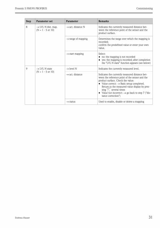
8 → LVL N dist. map.
(N = 1 - 5 or 10)
→ act. distance N Indicates the currently measured distance bet-
ween the reference point of the sensor and the
product surface.
→ range of mapping Determines the range over which the mapping is
recorded;
confirm the predefined value or enter your own
value.
→ start mapping Select:
• no: the mapping is not recorded
• yes: the mapping is recorded; after completion
the "LVL N state" function appears (see below)
9 → LVL N state
(N = 1 - 5 or 10)
→ level N Indicates the currently measured level.
→ act. distance Indicates the currently measured distance bet-
ween the reference point of the sensor and the
product surface. Check the value:
• Value correct: → Basic setup completed.
Return to the measured value display by pres-
sing several times
• Value not incorrect: → go back to step 7 ("dis-
tance correction")
→ status Used to enable, disable or delete a mapping
Step Parameter set Parameter Remarks
Commissioning Prosonic S FMU95 PROFIBUS
32 Endress+Hauser
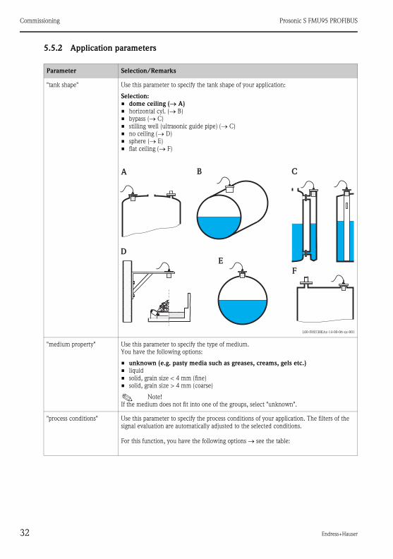
5.5.2 Application parameters
Parameter Selection/Remarks
"tank shape" Use this parameter to specify the tank shape of your application:
Selection:
• dome ceiling (→ A)
• horizontal cyl. (→ B)
• bypass (→ C)
• stilling well (ultrasonic guide pipe) (→ C)
• no ceiling (→ D)
• sphere (→ E)
• flat ceiling (→ F)
L00-FMU30KAx-14-00-06-xx-001
"medium property" Use this parameter to specify the type of medium.
You have the following options:
• unknown (e.g. pasty media such as greases, creams, gels etc.)
• liquid
• solid, grain size < 4 mm (fine)
• solid, grain size > 4 mm (coarse)
! Note!
If the medium does not fit into one of the groups, select "unknown".
"process conditions" Use this parameter to specify the process conditions of your application. The filters of the
signal evaluation are automatically adjusted to the selected conditions.
For this function, you have the following options → see the table:
A B C
D
E
F
Prosonic S FMU95 PROFIBUS Commissioning
Endress+Hauser 33
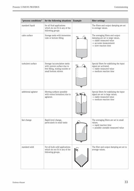
"process conditions" for the following situations Example filter settings
standard liquid for all fluid applications
which do not fit in any of the
following groups
The filters and output damping are set
to average values.
calm surface Storage tanks with immersion
tube or bottom filling
The averaging filters and output
damping are set to large values.
-> stable measured value
-> accurate measurement
-> slow reaction time
turbulent surface Storage/accumulation tanks
with uneven surface due to
free filling, mixing nozzles or
small bottom stirrers
Special filters for stabilizing the input
signal are activated.
-> stable measured value
-> medium reaction time
additional agitator Moving surfaces (possibly
with vortex formation) due to
agitators
Special filters for stabilizing the input
signal are set to large values.
-> stable measured value
-> medium reaction time
fast change Rapid level change,
particularly in small tanks
The averaging filters are set to small
values.
-> rapid reaction time
-> possibly unstable measured value
standard solid For all bulk solid applications
which do not fit in any of the
following groups.
The filter and output damping are set to
average values.

Commissioning Prosonic S FMU95 PROFIBUS
34 Endress+Hauser
solid dusty Dusty bulk solids The averaging filters are set to detect
even relatively weak signals.
conveyor belt Bulk solids with rapid level
change
The averaging filters are set to small
values.
-> rapid reaction time
-> possibly unstable measured value
test: no filter For service and diagnosis only All filters are switched off.
"process conditions" for the following situations Example filter settings
Prosonic S FMU95 PROFIBUS Commissioning
Endress+Hauser 35
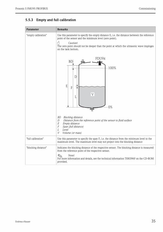
5.5.3 Empty and full calibration
Parameter Remarks
"empty calibration" Use this parameter to specify the empty distance E, i.e. the distance between the reference
point of the sensor and the minimum level (zero point).
" Caution!
The zero point should not be deeper than the point at which the ultrasonic wave impinges
on the tank bottom.
BD Blocking distance
D Distance from the reference point of the sensor to fluid surface
E Empty distance
F Span (full distance)
L Level
V Volume (or mass)
"full calibration" Use this parameter to specify the span F, i.e. the distance from the minimum level to the
maximum level. The maximum level may not project into the blocking distance
"blocking distance" Indicates the blocking distance of the respective sensor. The blocking distance is measured
from the reference point of the respective sensor.
! Note!
For more information and details, see the technical information TI00396F on the CD-ROM
provided.
FDU9x
100%
0%
D
L
FE
BD
V

Commissioning Prosonic S FMU95 PROFIBUS
36 Endress+Hauser
5.5.4 Linearization
Parameter Selection/Remarks
"type" ! Note!
Number and type of the parameters in this set depend on the selected linearization type.
Only the parameters "type" and "mode" are always present.
Selection
• none
In this linearization type the measured level is not converted but displayed in the selected
level unit (see "unit level").
Selection
• linear
The following additional parameter have to be specified.
• the unit for the linearized value, e.g. kg, m3, ft3, ... ("customer unit")
• the maximum capacity (a) of the vessel, measured in the customer unit ("maximum
scale").
100%20mA
0%0/4mA (a)
kg
m
ft
3
3

Prosonic S FMU95 PROFIBUS Commissioning
Endress+Hauser 37
"type" In these linearization types the measured level is convertet to the volume in a horizontal
cylinder or a spherical tank.
Selection
• horizontal cylinder 1)
• sphere
The following additional parameters have to be specified:
• the unit of the linearized value, e.g. kg, m3, ft3, ... ("customer unit")
• the diameter (D) of the tank ("diameter")
• the maximum capacity (a) of the tank, measured in the customer unit ("maximum
scale")
In these linearization modes the measured level is converted to the volume in the respec-
tive type of vessel.
Selection
• angled bottom (A)
• pyramid bottom (B)
• conical bottom (B)
The following additional parameters have to be specified:
• the unit for the linearized value, e.g. kg, m3, ft3, ... ("customer unit")
• the intermediate height H according to the diagram ("intermediate height")
• the maximum capacity (a) of the tank, measured in the customer unit ("maximum
scale").
Parameter Selection/Remarks
100%20mA
0%0/4mA
(D)Ø
(a)
kg
m
ft
3
3
100%20mA
0%0/4mA
H
(a)
A B
kg
m
ft
3
3

Commissioning Prosonic S FMU95 PROFIBUS
38 Endress+Hauser
"type" In this linearization mode the measured value is calculated from a linearization table. The
table may consist of up to 32 pairs of values (level - volume). The table must be monoto-
nically increasing or decreasing.
Selection
• table
The following additional parameters have to be specified:
• the unit of the linearized value, e.g. kg, m3, ft3, ... ("customer unit")
• the linearization table ("edit")
"customer unit" Use this parameter to select the desired unit for the linearized values (e.g. kg, m3, ft3,
...). This unit is only indicated on the display. It does not cause a conversion of the mea-
sured value.
! Note!
After selecting the option "customer specific", the parameter "customized text" appears.
An arbitrary string (consisting of up to 5 alphanumeric characters) can be entered into
this parameter.
"edit" Use this parameter to enter, change or read a linearization table. There are the following
options:
Selection
• read
The table editor is opened. The existing table can be read but not changed.
• manual
The table editor is opened. Table values can be entered and changed.
(→ ä 39, "status table").
• semi automatic
The table editor is opened. The level is automatically read by the Prosonic S. The mea-
sured value (volume, weight or flow) must be entered by the user.
• delete
The linearization table is deleted.
Parameter Selection/Remarks
100%20mA
0%0/4mA
kg
m
ft
3
3
Prosonic S FMU95 PROFIBUS Commissioning
Endress+Hauser 39
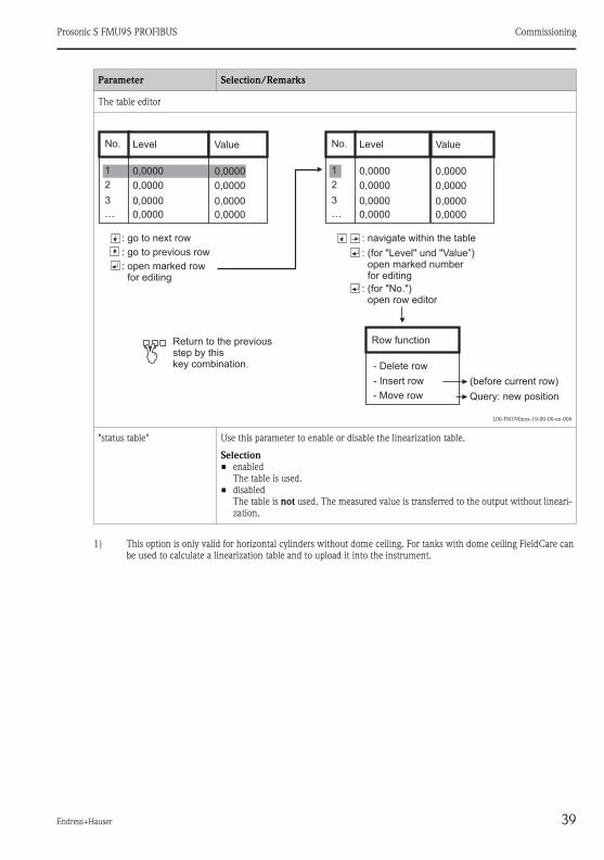
The table editor
L00-FMU90xxx-19-00-00-en-006
"status table" Use this parameter to enable or disable the linearization table.
Selection
• enabled
The table is used.
• disabled
The table is not used. The measured value is transferred to the output without lineari-
zation.
1) This option is only valid for horizontal cylinders without dome ceiling. For tanks with dome ceiling FieldCare can
be used to calculate a linearization table and to upload it into the instrument.
Parameter Selection/Remarks
No. Level Value
1 0,0000 0,0000
2 0,0000 0,0000
3 0,0000 0,0000
… 0,0000 0,0000
: go to next row
: go to previous row
: open marked rowfor editing
No. Level Value
1 0,0000 0,0000
2 0,0000 0,0000
3 0,0000 0,0000
… 0,0000 0,0000
: navigate within the table
: (for "Level" und "Value”)open marked numberfor editing
: (for "No.")open row editor
Row function
(before current row)
Query: new position
Return to the previousstep by thiskey combination. - Delete row
- Insert row
- Move row
Commissioning Prosonic S FMU95 PROFIBUS
40 Endress+Hauser
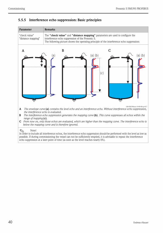
5.5.5 Interference echo suppression: Basic principles
Parameter Remarks
"check value"
"distance mapping"
The "check value" and "distance mapping" parameters are used to configure the
interference echo suppression of the Prosonic S.
The following picture shows the operating principle of the interference echo suppression:
L00-FMU90xxx-19-00-00-yy-017
A The envelope curve (a) contains the level echo and an interference echo. Without interference echo suppression,
the interference echo is evaluated.
B The interference echo suppression generates the mapping curve (b). This curve suppresses all echos within the
range of mapping (c).
C From now on, only those echos are evaluated, which are higher than the mapping curve. The interference echo is
below the mapping curve and is therefore ignored.
! Note!
In order to include all interference echos, the interference echo suppression should be performed with the level as low as
possible. If during commissioning the vessel can not be sufficiently emptied, it is advisable to repeat the interference
echo suppression at a later point of time (as soon as the level reaches nearly 0%).
A B
(a) (a) (b)
(c)
C
(a) (b)

Prosonic S FMU95 PROFIBUS Commissioning
Endress+Hauser 41

Commissioning Prosonic S FMU95 PROFIBUS
42 Endress+Hauser

Prosonic S FMU95 PROFIBUS Commissioning
Endress+Hauser 43

KA01069F/00/EN/01.11
71145369
CCS/FM+SGML 9.071145369


