Instalaciones de fibra óptica en entornos de centros de datos y campus para
suportar 40, 100g y más
Jim DavisRegional Marketing Engineer
Fluke Networks
Agenda
• Where is the technology today• 10 G per Wavelength• SM vs MM (OM5)
• What makes fiber go faster• More efficient encoding – PAM 4• More fiber – MPO
• What parameters do we measure• Tier I – Loss, Length, Polarity• Tier II – Tier I + OTDR
(troubleshooting)
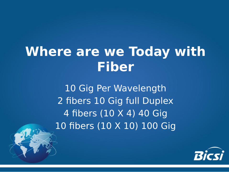
Where are we Today with Fiber
10 Gig Per Wavelength2 fibers 10 Gig full Duplex
4 fibers (10 X 4) 40 Gig10 fibers (10 X 10) 100 Gig

© 2015 Fluke Corporation. All rights reserved.
Single Mode vs Multimode
• Number of Wavelengths• Cost of electronics• Distance Requirements• Ease of Use
– UPC vs APC
..

© 2015 Fluke Corporation. All rights reserved.
Wideband Multimode Fiber OM5 (WBMMF)
• Optical characteristics other than bandwidth remain essentially the same.
• At 10 G per Wavelength, we can do 40 Gig (4 x 10 G) on a single fiber
• New Wavelengths Available – Short Wave Division Multiplexing

© 2015 Fluke Corporation. All rights reserved.
Wideband Multimode Fiber OM5 (WBMMF)
• Field Testing is the same as OM4• Test with traditional duplex fiber OLTS
– Encircled Flux compliant– Wavelengths at 850/1300nm
• Bounds all wavelengths between
• And the jacket will be green
Testing’s

© 2015 Fluke Corporation. All rights reserved.
Going Faster with the Same Fiber
• PAM-4 – more efficient encoding– 4 symbols vs 2 – doubles throughput
• From 10 Gig per wavelength to 25 Gig per Wavelength
• Where we were doing 4 X 10 for 40 Gig, now we can do 4 x 25 for 100 Gig

© 2015 Fluke Corporation. All rights reserved.
Serial LC/SC or Parallel MPO/MTP

From – Less Efficient – More Latency

To – Spine and Leaf - Faster

For Port Density, put a 12 or 24 fiber QSFP in the spine and, potentially, 2 fiber LC in the Leafs (leaves?)

© 2015 Fluke Corporation. All rights reserved.
Fiber Testing and Certification
How can you determine if your premise fiber is good?
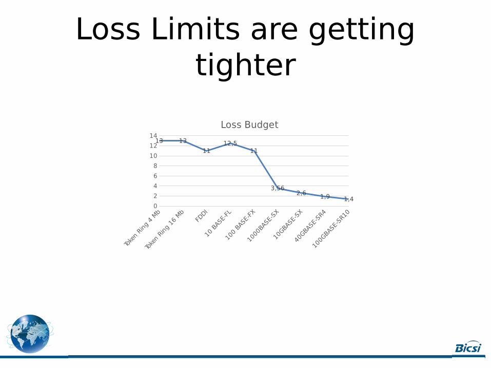
Loss Limits are getting tighter
0
2
4
6
8
10
12
1413 13
1112,5
11
3,562,6 1,9 1,4
Loss Budget

0
500
1000
1500
2000
2500
Distance
Distances for MM are getting shorter

© 2015 Fluke Corporation. All rights reserved.
Types of Standards and Specifications define the loss budget
• Application Standards– Fixed test limits are defined by ‘system’ specs– Examples: 100BASE-FX, 1000BASE-SX,
1000BASE-LX, 10GBASE-S, ATM, Fibre Channel
• Cable Installation Standards– Test limits for installed fiber link are
independent of any network application– Limit is calculated, based on cable length,
number of adapters, and number of splices– Examples: TIA/EIA-568-B, ISO11801, EN50173

© 2015 Fluke Corporation. All rights reserved.
Which Limits to use?• There is no “Cat 5e” for fiber• There is conflict between what the
standard will support and what the application requires
Cabling Standards:TIA 568ISO 11801
Application Standards:10GBaseSX40GBase-SR4Cus
tom
Lim
its

© 2015 Fluke Corporation. All rights reserved.
Using a TIA limit without understanding the
application• Customer wants to run 10GBASE-SR
on this multimode link0.75 dB
0.75 dB
0.75 dB
0.75 dB
1.05 dB @ 850 nm(300 m)
TIA (tester) Limit = 0.75 dB + 0.75 dB + 1.05 dB + 0.75 dB + 0.75 dB = 4.05 dB @ 850 nm10GBASE-SR Limit = 2.55 dB @ 850 nm This design will not support 10GBASE-SR
© 2015 Fluke Corporation. All rights reserved.
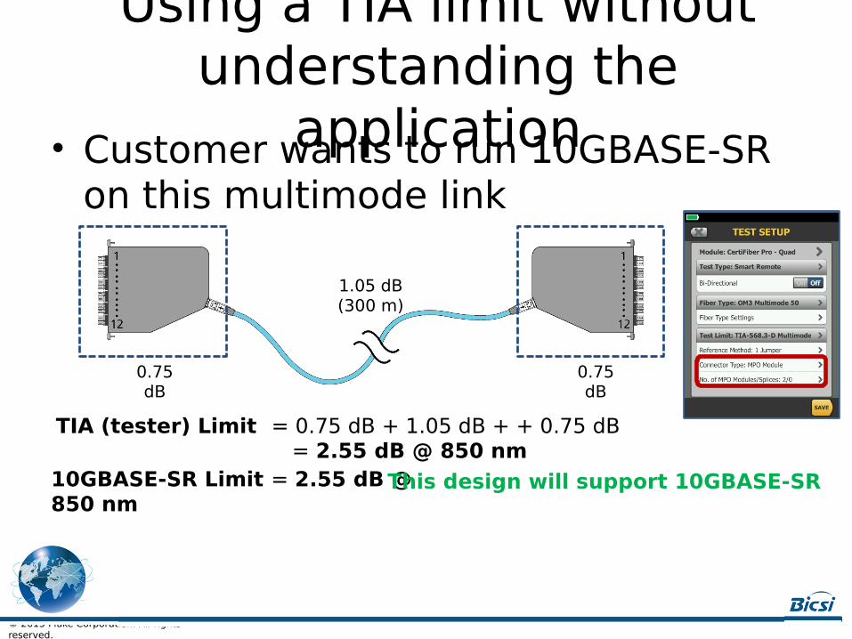
Using a TIA limit without understanding the
application• Customer wants to run 10GBASE-SR on this multimode link
0.75 dB
1.05 dB(300 m)
TIA (tester) Limit = 0.75 dB + 1.05 dB + + 0.75 dB = 2.55 dB @ 850 nm10GBASE-SR Limit = 2.55 dB @ 850 nm
This design will support 10GBASE-SR
0.75 dB

© 2015 Fluke Corporation. All rights reserved.
What if your customer wants to do this?
• Concatenate two MPO jumpers/trunks
(30 m)
© 2015 Fluke Corporation. All rights reserved.
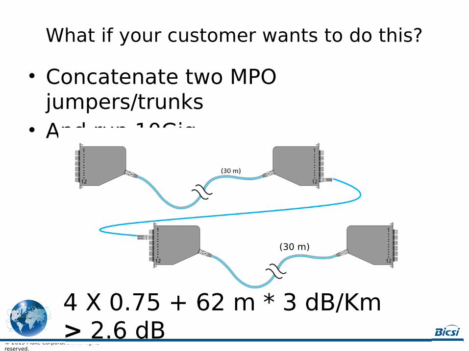
What if your customer wants to do this?
• Concatenate two MPO jumpers/trunks
• And run 10Gig
(30 m)
4 X 0.75 + 62 m * 3 dB/Km > 2.6 dB

© 2015 Fluke Corporation. All rights reserved.
Welcome to Low Loss Cassettes
• Manufacturers offer cassettes with > 0.5 dB of loss
(30 m)
4 X 0.50 + 62 * 3 dB/Km < 2.6 dB

TIER I TESTING – HOW MUCH LIGHT IS COMING OUT OF THE FIBER

© 2015 Fluke Corporation. All rights reserved.
Four Essential Elements to Reduce Uncertainty in Tier I Testing
• One Jumper Reference• Reference Grade Conectors• LED Light Source• Encircled Flux Launch condition

Loss Budgets must be more accurate to support these new links
• In ISO/IEC 14763-3 (2006), cords were recognized as a source of great uncertainty
• This standard reduced uncertainty by defining the performance of the test cord connector
• Reference grade connectors were required– Multimode ≤ 0.10 dB– Singlemode ≤ 0.20 dB
0.75 dB0.10 dB
≤ 0.30 dB0.75 dB0.20 dB
≤ 0.50 dB
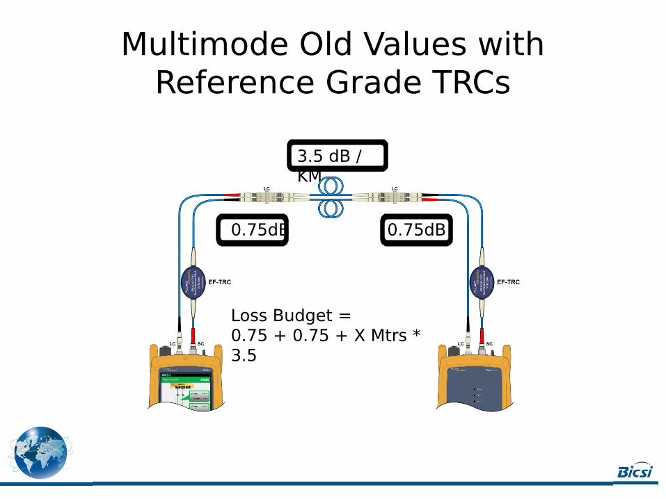
Multimode Old Values with Reference Grade TRCs
0.75dB 0.75dB
3.5 dB / KM
Loss Budget =0.75 + 0.75 + X Mtrs * 3.5

Multimode New Values with Reference Grade TRCs
0.3dB 0.3dB
3.0 dB / KM
Loss Budget =0.3 + 0.3 + X Mtrs * 3.0

Multimode New Values with Reference Grade TRCs
3.0 dB / KM
0.75 dB 0.75 dB
Loss Budget =0.3 + 0.3 + 0.75 + 0.75 + X Mtrs * 3.0
TIER 2 TESTING
Tier 2 testing is Tier 1 plus the use of an OTDR

© 2015 Fluke Corporation. All rights reserved.
29
Accurate OTDR Testing for HighSpeed Links
Launch Fiber
Will give loss of the first connector
Tail Fiber
Will give loss of the last connector

© 2015 Fluke Corporation. All rights reserved.
OTDR testing for High Speed Links
• Must use launch and receive fibers• Need to run the test Bi-Directionally• Need to measure reflectance

© 2015 Fluke Corporation. All rights reserved.
What is reflectance?
An air gap between the end faces of a fiber also cause Fresnel reflections to
occur.

Reflectance is Caused by Poor Termination and Dirty Connectors

© 2015 Fluke Corporation. All rights reserved.
Reflected Signal Arriving Outside of Bit Period
Fiber with poor reflectance 10 Gb/s
Bit Period
Fiber with Good Reflectance
10 Gb/sBit Period
Slide courtesy of OFS

Poor ACR (and NEXT problems)can lead to FCS and CRC errors and –
Retransmissions!

FCS/ACR Errors Lead to Slow NetworksBelow is a an example of a typical TCP conversation
HTTP “Get” data I want
ACK – I see your request
Here is your data (with Bad FCS)
ReTransmit – Here is your Data - again
Time goes by
ACK – I received the data
Yuck, bad FCS!I’ll just discard at Physical Layer
Where’s my ACK?
Web Server
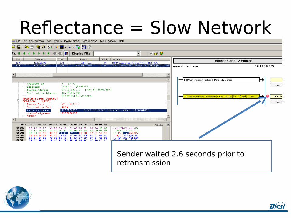
Reflectance = Slow Network
Sender waited 2.6 seconds prior to retransmission

© 2015 Fluke Corporation. All rights reserved.
Specify a Reflectance Limit for OTDR testing
• OTDR loss event measurements heavily rely on good reflectance
• Poor reflectance can result in– Optimistic / negative loss readings– Errors when the application runs
• Agree on a reflectance limit• As a guide (talk to your vendor)
– -35 dB for multimode– -40 dB for singlemode– -55 dB for APC singlemode
Same link tested
No reflectance limit Reflectance limit -35 dB
© 2015 Fluke Corporation. All rights reserved.
In Conclusion• Follow specs• Know your current requirements• Future applications will have tighter
loss and length budgets• Measure accurately
– Tier I – use correct budget values REF vs STD
– Tier 2 – Measure reflectance in addition to loss

Logo da empresa aqui
Thank you, Gracias, ObrigadoJim Davis
Fluke Networks
[email protected] Seaway BlvdEverett, WA 98271


