Introduction to the MIPS
Lecture for CPSC 5155
Edward Bosworth, Ph.D.
Computer Science Department
Columbus State University
Introduction to the MIPS
• The Microprocessor without Interlocked Pipeline Stages is a RISC microprocessor architecture developed by MIPS Technologies, Inc, starting in about 1981.
• The first commercial product was the R2000, marketed in 1984.
• For a good historical account, go to http://en.wikipedia.org/wiki/MIPS_architecture
• MIPS processors are found in a variety of products, such as TiVo, Cisco routers, the Nintendo 64, and Sony PlayStation.
MIPS Integer Arithmetic
• The integer arithmetic used in our version of the MIPS is 32-bit arithmetic.
• There is a 64-bit version of the MIPS.
• The range of integers represented in 32 bits Unsigned: 0 to 232 – 1 Signed: -231 to 231 – 1
• All memory addresses are unsigned integers.

8-bit example of Signed Integers
• The number 0 is denoted as 0000 0000.
• Consider the pattern 1111 1111. Add one to this 0000 0001 The result is 0000 0000
The carry-out from the left column is dropped.
• Thus, the pattern 1111 1111 represents the negative number -1.
• This pattern generalizes to 16 bits, 32 bits, etc.

The Two’s Complement
• Recall that the one’s complement of a bit pattern is achieved by changing every 0 to a 1 and every 1 to a 0. What is the sum X + X’?
• We have only 0 + 1 = 1 and 1 + 0 = 1, so X + X’ = -1. Consider the example. X 1011 1001 X’ 0100 0110 Sum 1111 1111
• If X + X’ = -1, then X + (X’ + 1) = 0; -X = X’ + 1.

Chapter 2 — Instructions: Language of the Computer — 6
Register Operands
Arithmetic instructions use register operands
MIPS has a 32 × 32-bit register file Use for frequently accessed data
Numbered 0 to 31
32-bit data called a “word”
Assembler names $t0, $t1, …, $t9 for temporary values
$s0, $s1, …, $s7 for saved variables
Design Principle 2: Smaller is faster c.f. main memory: millions of locations
§2.3
Opera
nds o
f the C
om
pute
r Hard
ware
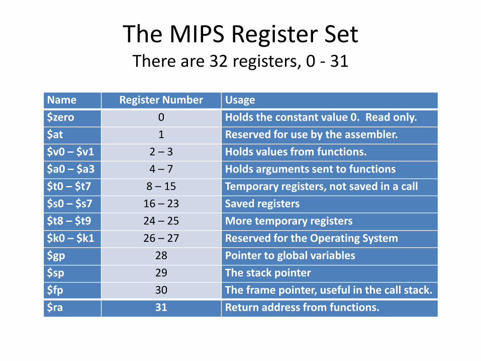
The MIPS Register Set There are 32 registers, 0 - 31
Name Register Number Usage
$zero 0 Holds the constant value 0. Read only.
$at 1 Reserved for use by the assembler.
$v0 – $v1 2 – 3 Holds values from functions.
$a0 – $a3 4 – 7 Holds arguments sent to functions
$t0 – $t7 8 – 15 Temporary registers, not saved in a call
$s0 – $s7 16 – 23 Saved registers
$t8 – $t9 24 – 25 More temporary registers
$k0 – $k1 26 – 27 Reserved for the Operating System
$gp 28 Pointer to global variables
$sp 29 The stack pointer
$fp 30 The frame pointer, useful in the call stack.
$ra 31 Return address from functions.
Chapter 2 — Instructions: Language of the Computer — 8
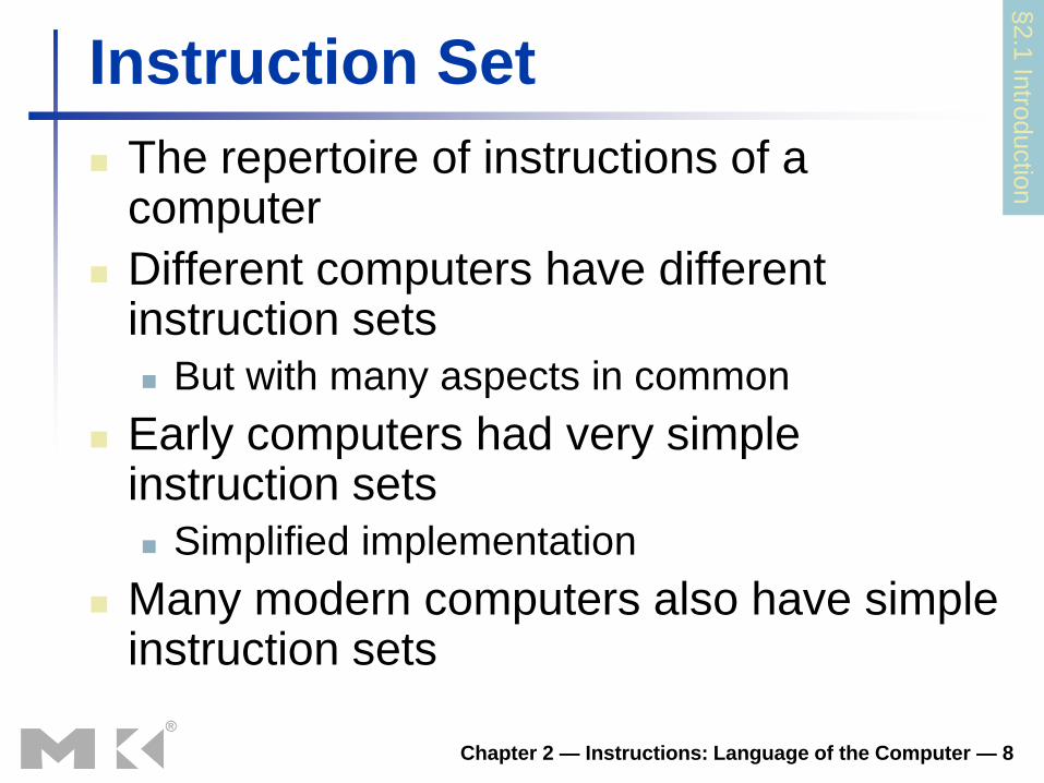
Instruction Set
The repertoire of instructions of a computer
Different computers have different instruction sets
But with many aspects in common
Early computers had very simple instruction sets
Simplified implementation
Many modern computers also have simple instruction sets
§2.1
Intro
ductio
n

Variables and Labels
• The idea of a “variable” is a construct of high level languages only. Each variable is given a type, which determines the operations on it.
• In assembly language, there are no variables. Labels are used to identify locations only. The operation is determined by the assembly language instruction only.
Chapter 2 — Instructions: Language of the Computer — 10
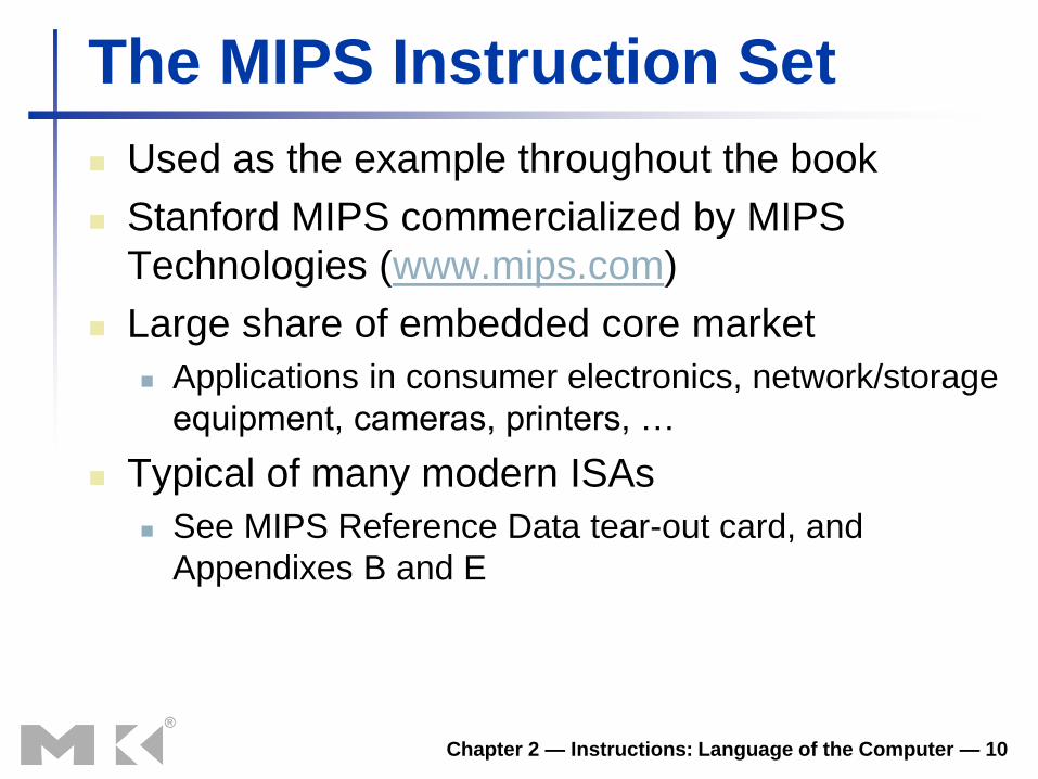
The MIPS Instruction Set
Used as the example throughout the book
Stanford MIPS commercialized by MIPS
Technologies (www.mips.com)
Large share of embedded core market
Applications in consumer electronics, network/storage
equipment, cameras, printers, …
Typical of many modern ISAs
See MIPS Reference Data tear-out card, and
Appendixes B and E

Chapter 2 — Instructions: Language of the Computer — 11
Arithmetic Operations
Add and subtract, three operands
Two sources and one destination
add a, b, c # a gets b + c
All arithmetic operations have this form
Design Principle 1: Simplicity favours
regularity
Regularity makes implementation simpler
Simplicity enables higher performance at
lower cost
§2.2
Opera
tions o
f the C
om
pute
r Hard
ware
Chapter 2 — Instructions: Language of the Computer — 12
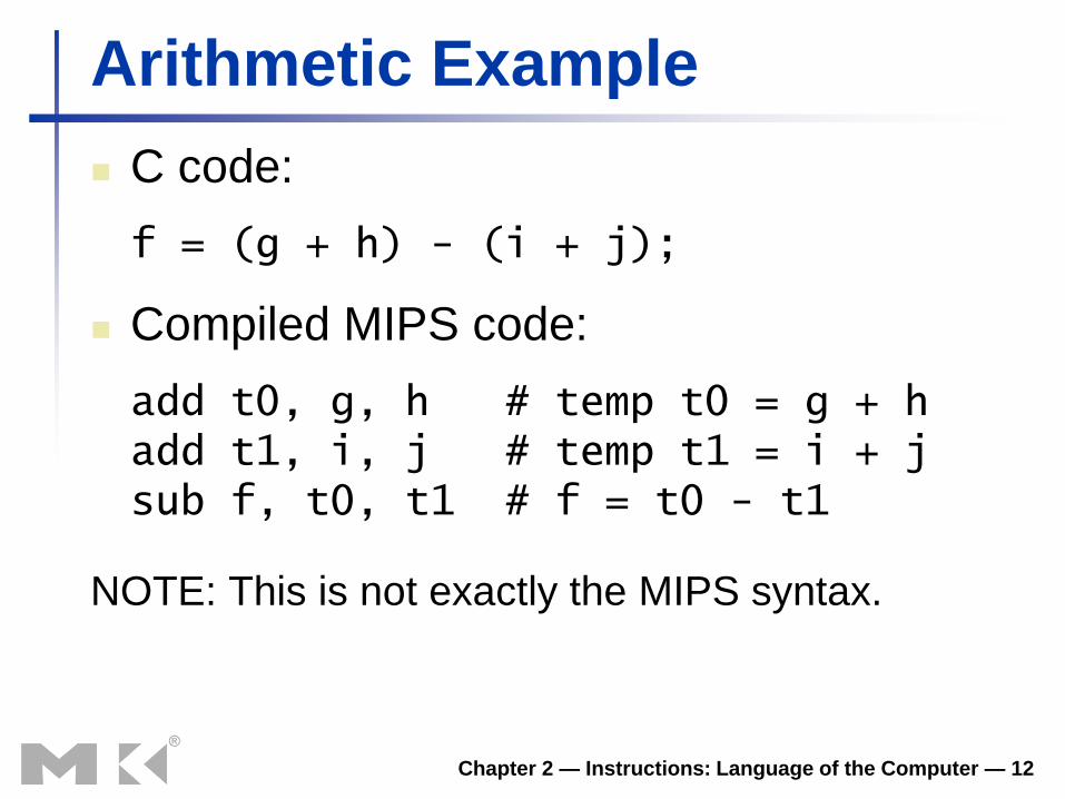
Arithmetic Example
C code:
f = (g + h) - (i + j);
Compiled MIPS code:
add t0, g, h # temp t0 = g + h add t1, i, j # temp t1 = i + j sub f, t0, t1 # f = t0 - t1
NOTE: This is not exactly the MIPS syntax.

Chapter 2 — Instructions: Language of the Computer — 13
Register Operand Example
C code:
f = (g + h) - (i + j);
f, …, j in $s0, …, $s4
Compiled MIPS code:
add $t0, $s1, $s2 add $t1, $s3, $s4 sub $s0, $t0, $t1
Chapter 2 — Instructions: Language of the Computer — 14
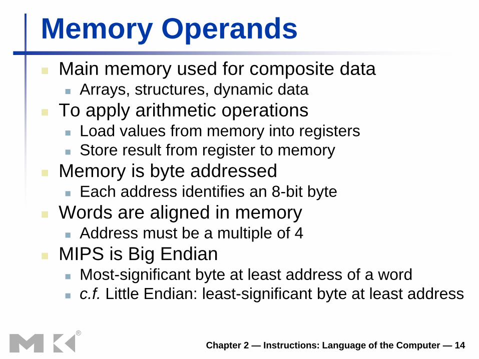
Memory Operands
Main memory used for composite data Arrays, structures, dynamic data
To apply arithmetic operations Load values from memory into registers
Store result from register to memory
Memory is byte addressed Each address identifies an 8-bit byte
Words are aligned in memory Address must be a multiple of 4
MIPS is Big Endian Most-significant byte at least address of a word
c.f. Little Endian: least-significant byte at least address
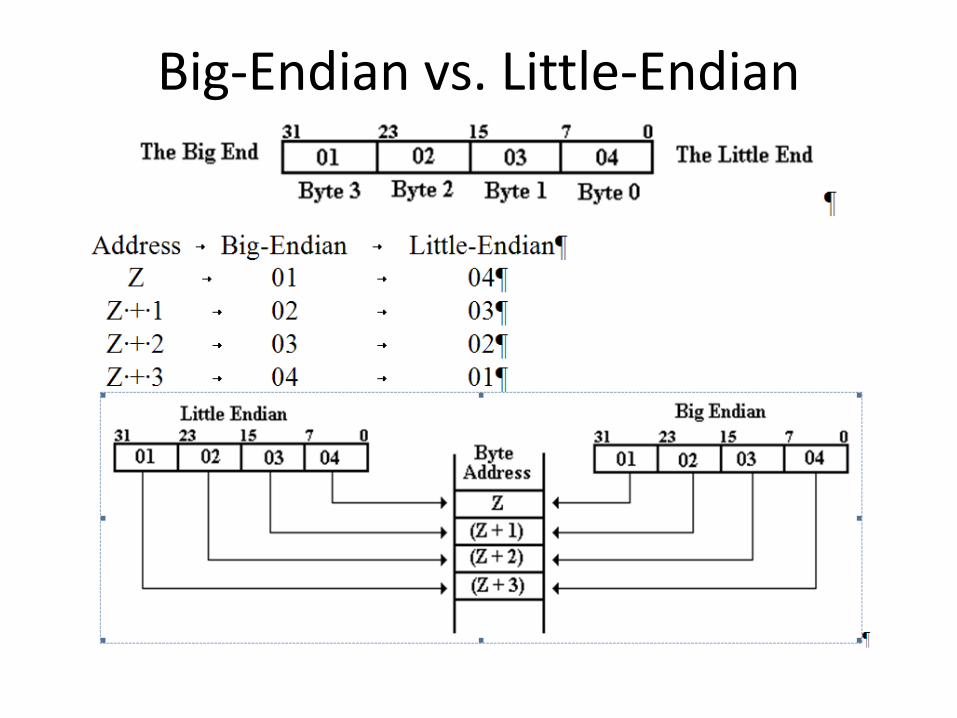
Big-Endian vs. Little-Endian
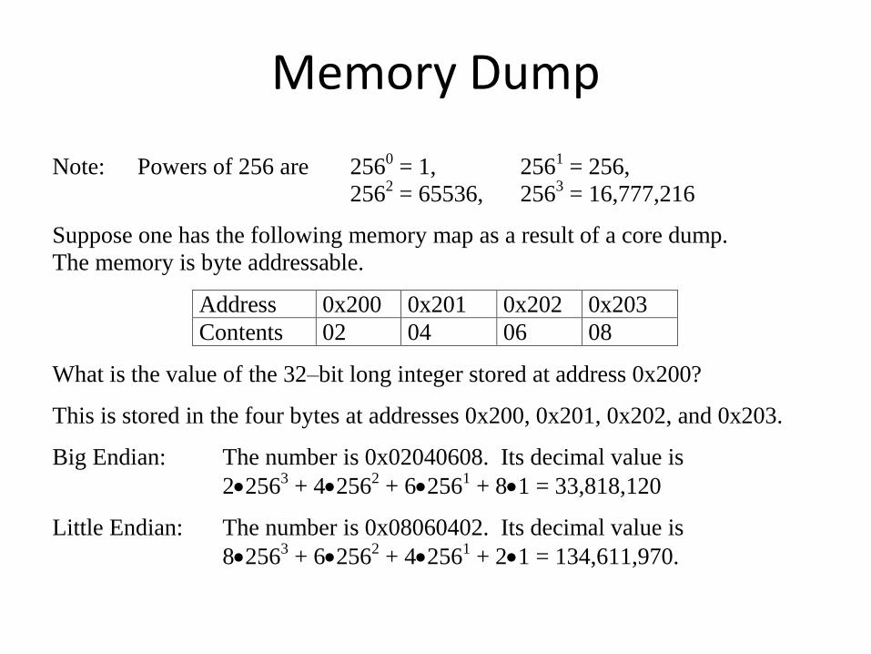
Memory Dump
Note: Powers of 256 are 2560 = 1, 2561 = 256,
2562 = 65536, 2563 = 16,777,216
Suppose one has the following memory map as a result of a core dump.
The memory is byte addressable.
Address 0x200 0x201 0x202 0x203
Contents 02 04 06 08
What is the value of the 32–bit long integer stored at address 0x200?
This is stored in the four bytes at addresses 0x200, 0x201, 0x202, and 0x203.
Big Endian: The number is 0x02040608. Its decimal value is
22563 + 42562 + 62561 + 81 = 33,818,120
Little Endian: The number is 0x08060402. Its decimal value is
82563 + 62562 + 42561 + 21 = 134,611,970.

Chapter 2 — Instructions: Language of the Computer — 17
Memory Operand Example 1
C code:
g = h + A[8];
g in $s1, h in $s2, base address of A in $s3
Compiled MIPS code:
Index 8 requires offset of 32
4 bytes per word
lw $t0, 32($s3) # load word add $s1, $s2, $t0
offset base register
Chapter 2 — Instructions: Language of the Computer — 18
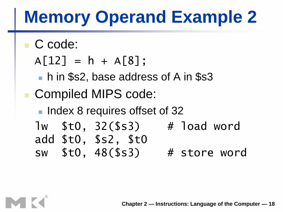
Memory Operand Example 2
C code:
A[12] = h + A[8];
h in $s2, base address of A in $s3
Compiled MIPS code:
Index 8 requires offset of 32
lw $t0, 32($s3) # load word add $t0, $s2, $t0 sw $t0, 48($s3) # store word
Chapter 2 — Instructions: Language of the Computer — 19
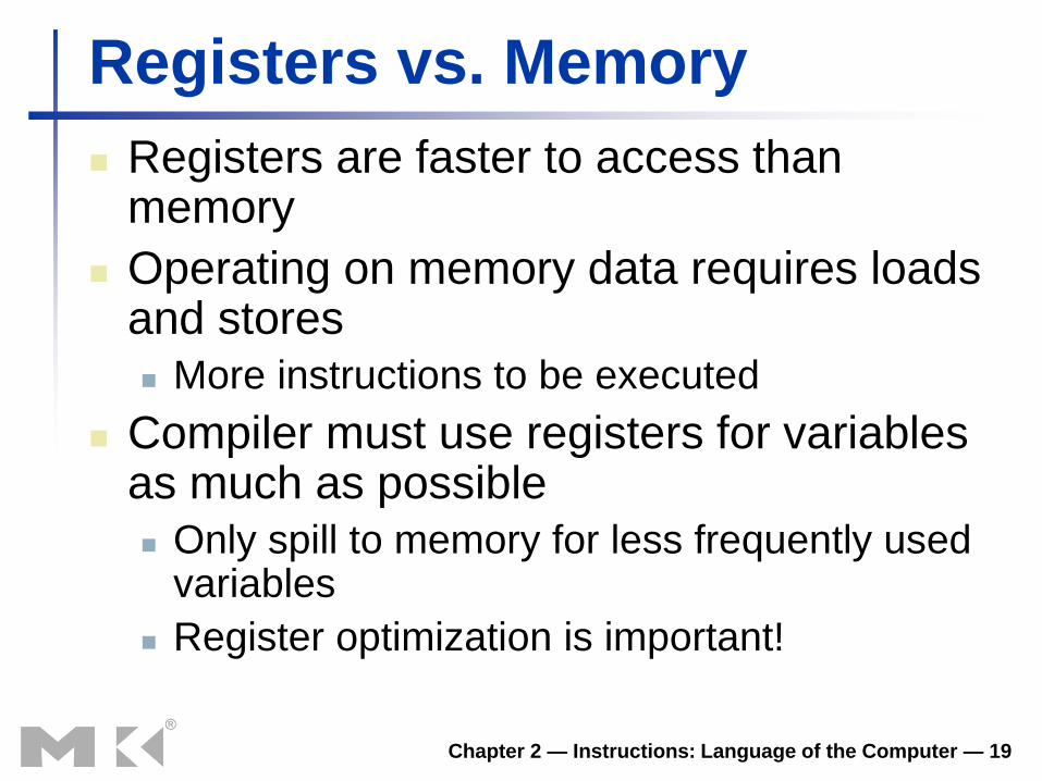
Registers vs. Memory
Registers are faster to access than memory
Operating on memory data requires loads and stores
More instructions to be executed
Compiler must use registers for variables as much as possible
Only spill to memory for less frequently used variables
Register optimization is important!

Chapter 2 — Instructions: Language of the Computer — 20
Immediate Operands
Constant data specified in an instruction
addi $s3, $s3, 4 #$s3 = $s3 + 4
No subtract immediate instruction
Just use a negative constant
addi $s2, $s1, -1 #$s2 = $s1 - 1
Design Principle 3: Make the common
case fast
Small constants are common
Immediate operand avoids a load instruction

Chapter 2 — Instructions: Language of the Computer — 21
The Constant Zero
MIPS register 0 ($zero) is the constant 0
Cannot be overwritten
Useful for common operations
E.g., move between registers
add $t2, $s1, $zero
Chapter 2 — Instructions: Language of the Computer — 22
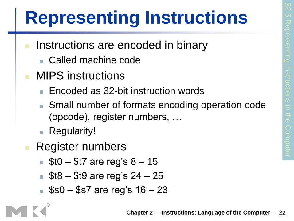
Representing Instructions
Instructions are encoded in binary
Called machine code
MIPS instructions
Encoded as 32-bit instruction words
Small number of formats encoding operation code
(opcode), register numbers, …
Regularity!
Register numbers
$t0 – $t7 are reg’s 8 – 15
$t8 – $t9 are reg’s 24 – 25
$s0 – $s7 are reg’s 16 – 23
§2.5
Repre
sentin
g In
stru
ctio
ns in
the C
om
pute
r
Chapter 2 — Instructions: Language of the Computer — 23
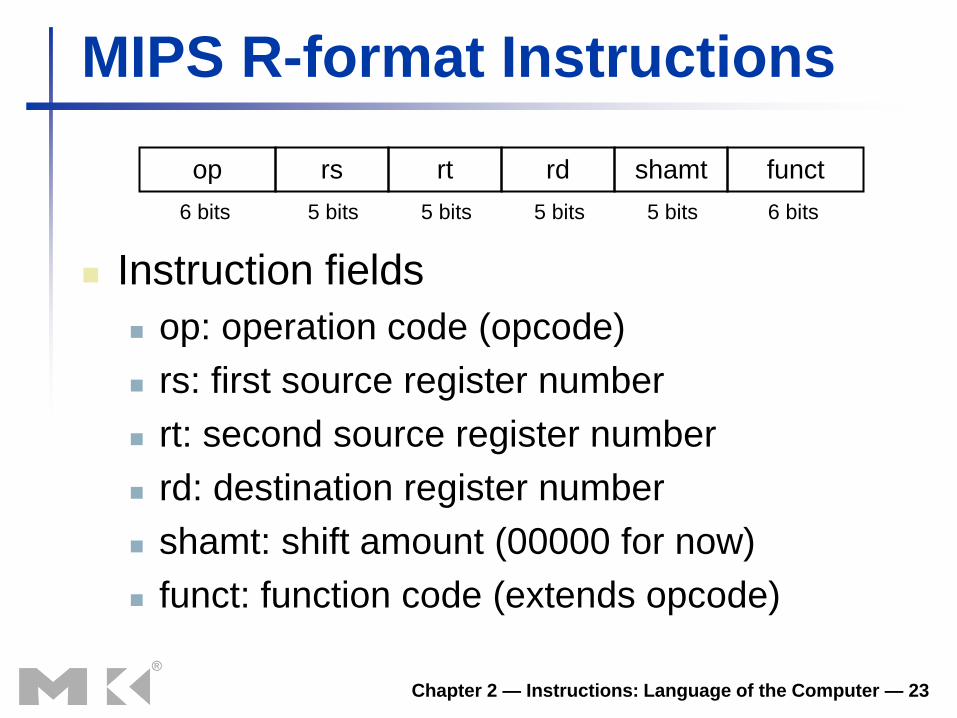
MIPS R-format Instructions
Instruction fields
op: operation code (opcode)
rs: first source register number
rt: second source register number
rd: destination register number
shamt: shift amount (00000 for now)
funct: function code (extends opcode)
op rs rt rd shamt funct
6 bits 6 bits 5 bits 5 bits 5 bits 5 bits
Chapter 2 — Instructions: Language of the Computer — 24
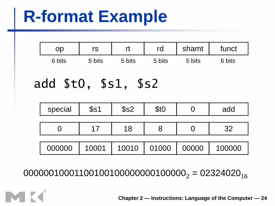
R-format Example
add $t0, $s1, $s2
special $s1 $s2 $t0 0 add
0 17 18 8 0 32
000000 10001 10010 01000 00000 100000
000000100011001001000000001000002 = 0232402016
op rs rt rd shamt funct
6 bits 6 bits 5 bits 5 bits 5 bits 5 bits
Chapter 2 — Instructions: Language of the Computer — 25
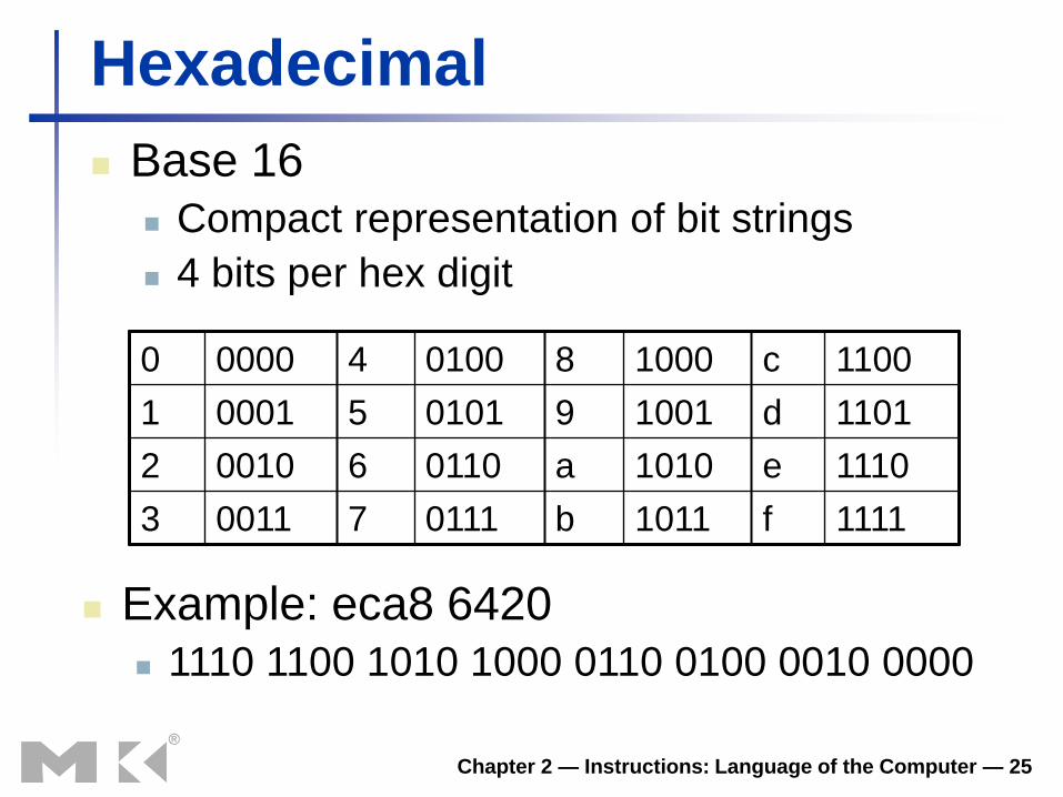
Hexadecimal
Base 16
Compact representation of bit strings
4 bits per hex digit
0 0000 4 0100 8 1000 c 1100
1 0001 5 0101 9 1001 d 1101
2 0010 6 0110 a 1010 e 1110
3 0011 7 0111 b 1011 f 1111
Example: eca8 6420
1110 1100 1010 1000 0110 0100 0010 0000
Chapter 2 — Instructions: Language of the Computer — 26
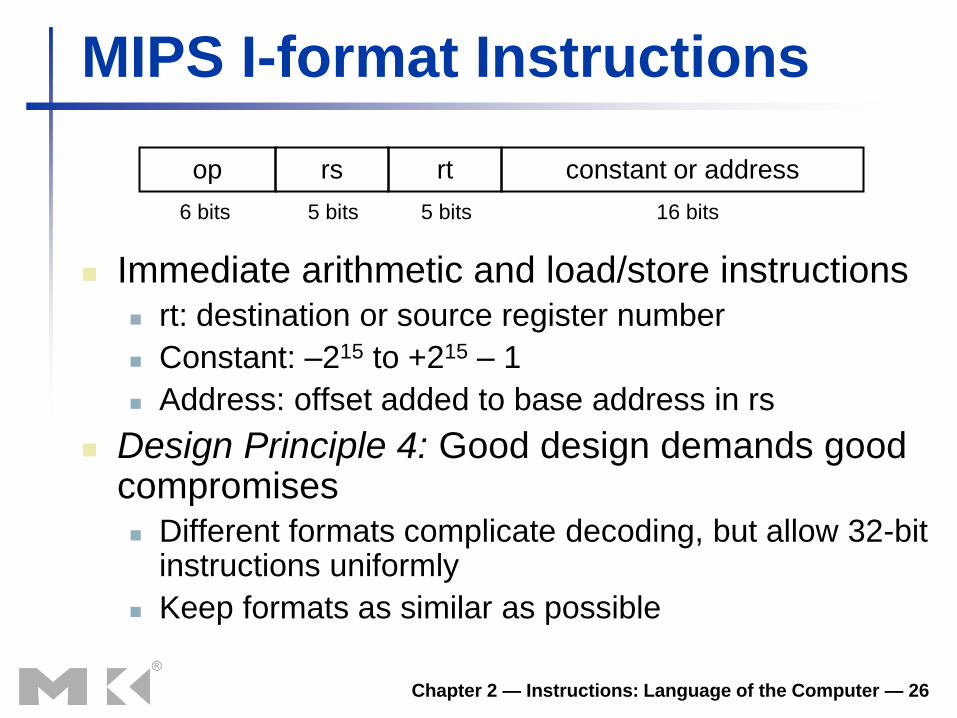
MIPS I-format Instructions
Immediate arithmetic and load/store instructions rt: destination or source register number
Constant: –215 to +215 – 1
Address: offset added to base address in rs
Design Principle 4: Good design demands good compromises Different formats complicate decoding, but allow 32-bit
instructions uniformly
Keep formats as similar as possible
op rs rt constant or address
6 bits 5 bits 5 bits 16 bits

Chapter 2 — Instructions: Language of the Computer — 27
Stored Program Computers
Instructions represented in binary, just like data
Instructions and data stored in memory
Programs can operate on programs e.g., compilers, linkers, …
Binary compatibility allows compiled programs to work on different computers Standardized ISAs
The BIG Picture
Chapter 2 — Instructions: Language of the Computer — 28
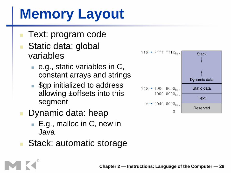
Memory Layout
Text: program code
Static data: global variables e.g., static variables in C,
constant arrays and strings
$gp initialized to address allowing ±offsets into this segment
Dynamic data: heap E.g., malloc in C, new in
Java
Stack: automatic storage
All Memory Maps Use Virtual Addresses
• Virtual memory is a service of the computer’s operating system in conjunction with the MMU (Memory Management Unit).
• Logical addresses are generated by the code and then translated into physical addresses.
• For example, the global pointer contains the logical address 0x1000 8000. The actual physical address is determined by the OS.
The Stack and Heap
• The stack and heap are two dynamic memory structures, assigned to occupy memory with virtual addresses above the static data.
• To avoid a rigid partitioning of this block of memory, the stack starts at the top and grows down, while the heap starts at the bottom and grows up.

Chapter 2 — Instructions: Language of the Computer — 31
Logical Operations
Instructions for bitwise manipulation
Operation C Java MIPS
Shift left << << sll
Shift right >> >>> srl
Bitwise AND & & and, andi
Bitwise OR | | or, ori
Bitwise NOT ~ ~ nor
Useful for extracting and inserting
groups of bits in a word
§2.6
Logic
al O
pera
tions

Chapter 2 — Instructions: Language of the Computer — 32
AND Operations
Useful to mask bits in a word
Select some bits, clear others to 0
and $t0, $t1, $t2
0000 0000 0000 0000 0000 1101 1100 0000
0000 0000 0000 0000 0011 1100 0000 0000
$t2
$t1
0000 0000 0000 0000 0000 1100 0000 0000 $t0
Chapter 2 — Instructions: Language of the Computer — 33
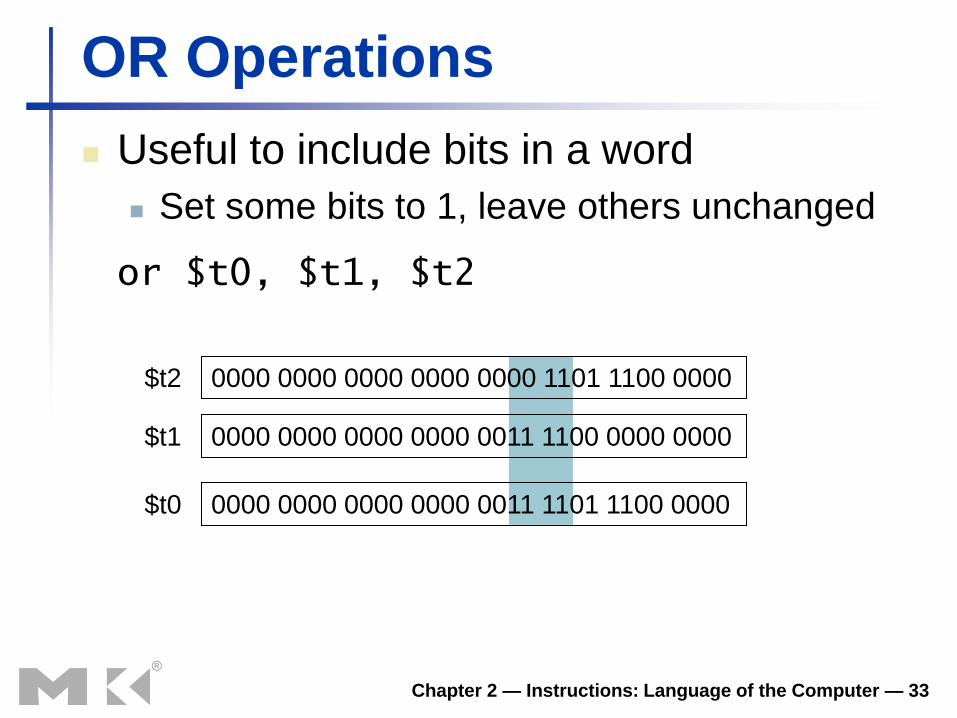
OR Operations
Useful to include bits in a word
Set some bits to 1, leave others unchanged
or $t0, $t1, $t2
0000 0000 0000 0000 0000 1101 1100 0000
0000 0000 0000 0000 0011 1100 0000 0000
$t2
$t1
0000 0000 0000 0000 0011 1101 1100 0000 $t0
Chapter 2 — Instructions: Language of the Computer — 34
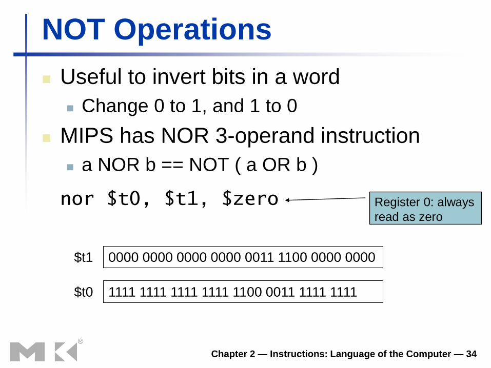
NOT Operations
Useful to invert bits in a word
Change 0 to 1, and 1 to 0
MIPS has NOR 3-operand instruction
a NOR b == NOT ( a OR b )
nor $t0, $t1, $zero
0000 0000 0000 0000 0011 1100 0000 0000 $t1
1111 1111 1111 1111 1100 0011 1111 1111 $t0
Register 0: always
read as zero
Chapter 2 — Instructions: Language of the Computer — 35
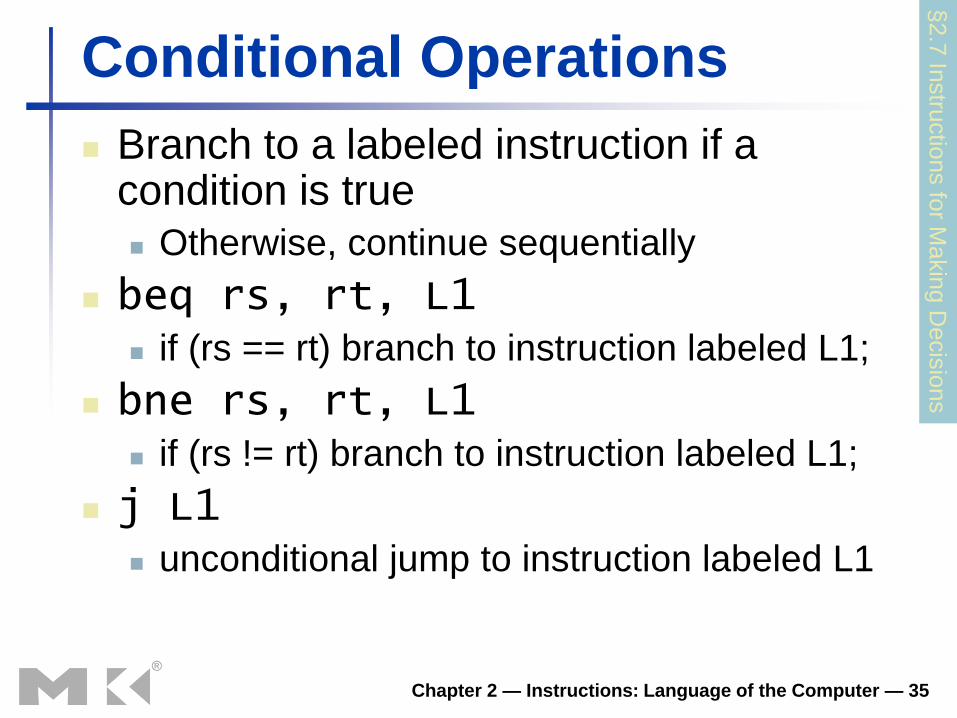
Conditional Operations
Branch to a labeled instruction if a condition is true
Otherwise, continue sequentially
beq rs, rt, L1 if (rs == rt) branch to instruction labeled L1;
bne rs, rt, L1 if (rs != rt) branch to instruction labeled L1;
j L1 unconditional jump to instruction labeled L1
§2.7
Instru
ctio
ns fo
r Makin
g D
ecis
ions
Chapter 2 — Instructions: Language of the Computer — 36
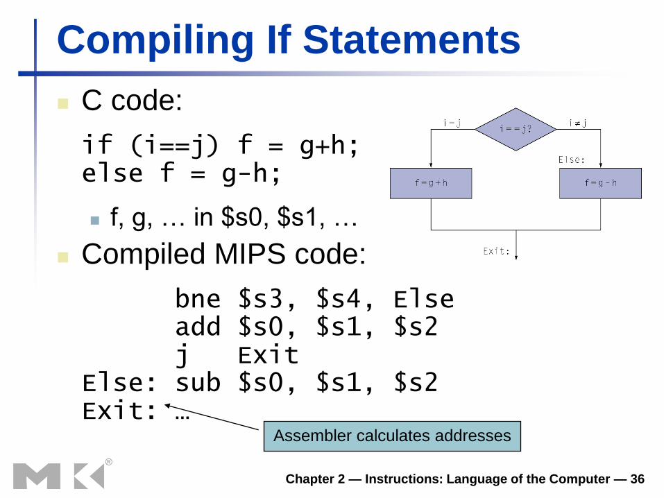
Compiling If Statements
C code:
if (i==j) f = g+h; else f = g-h;
f, g, … in $s0, $s1, …
Compiled MIPS code:
bne $s3, $s4, Else add $s0, $s1, $s2 j Exit Else: sub $s0, $s1, $s2 Exit: …
Assembler calculates addresses
Chapter 2 — Instructions: Language of the Computer — 37
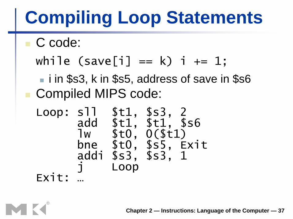
Compiling Loop Statements
C code:
while (save[i] == k) i += 1;
i in $s3, k in $s5, address of save in $s6
Compiled MIPS code:
Loop: sll $t1, $s3, 2 add $t1, $t1, $s6 lw $t0, 0($t1) bne $t0, $s5, Exit addi $s3, $s3, 1 j Loop Exit: …

Chapter 2 — Instructions: Language of the Computer — 38
More Conditional Operations
Set result to 1 if a condition is true
Otherwise, set to 0
slt rd, rs, rt
if (rs < rt) rd = 1; else rd = 0;
slti rt, rs, constant
if (rs < constant) rt = 1; else rt = 0;
Use in combination with beq, bne slt $t0, $s1, $s2 # if ($s1 < $s2) bne $t0, $zero, L # branch to L

Chapter 2 — Instructions: Language of the Computer — 39
Branch Instruction Design
Why not blt, bge, etc?
Hardware for <, ≥, … slower than =, ≠
Combining with branch involves more work
per instruction, requiring a slower clock
All instructions penalized!
beq and bne are the common case
This is a good design compromise
Chapter 2 — Instructions: Language of the Computer — 40
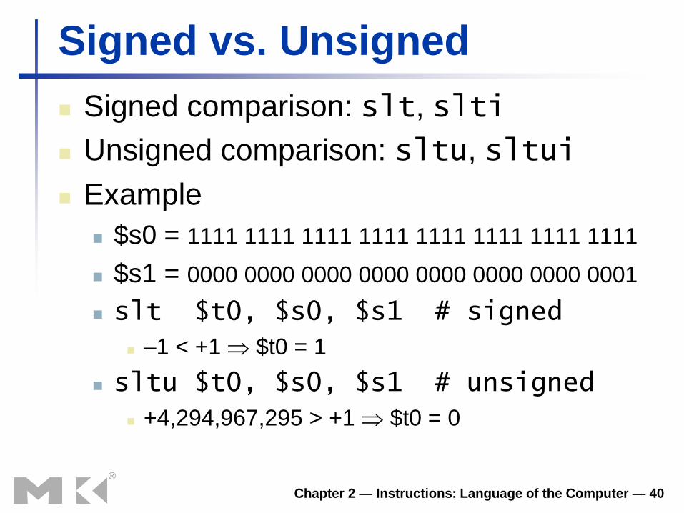
Signed vs. Unsigned
Signed comparison: slt, slti
Unsigned comparison: sltu, sltui
Example
$s0 = 1111 1111 1111 1111 1111 1111 1111 1111
$s1 = 0000 0000 0000 0000 0000 0000 0000 0001
slt $t0, $s0, $s1 # signed
–1 < +1 $t0 = 1
sltu $t0, $s0, $s1 # unsigned
+4,294,967,295 > +1 $t0 = 0
The MIPS is a Load/Store RISC
• Only 2 types of instructions reference memory Load register from memory: LW, LB, LBU, etc. Store register to memory: SW, SB, etc.
• This restriction leads to a CPU design that is considerably simpler and faster.
• The MIPS is designed to work with a virtual memory system. The load/store feature simplifies the handling of page faults. More on this when we discuss the control unit.

Chapter 2 — Instructions: Language of the Computer — 42
Byte/Halfword Operations
Could use bitwise operations
MIPS byte/halfword load/store
String processing is a common case
lb rt, offset(rs) lh rt, offset(rs)
Sign extend to 32 bits in rt
lbu rt, offset(rs) lhu rt, offset(rs)
Zero extend to 32 bits in rt
sb rt, offset(rs) sh rt, offset(rs)
Store just rightmost byte/halfword

Example: EBCDIC “E” • The EBCDIC for “E” is 0xC5 or 1100 0101.
• A LB (load byte) instruction would treat this as a negative 8-bit number and sign extend it. 1111 1111 1111 1111 1111 1111 1100 0101
or 0xFFFF FFC5.
• A LBU (load unsigned byte) would treat this as a character and zero extend the value. 0000 0000 0000 0000 0000 0000 1100 0101
or 0x0000 00C5.

Value vs. Address
• Consider the following data declaration: L1: .word 7 # Decimal value 7
• Suppose the assembler has located this at address 0x1000 7FF8.
• The instruction lw $a0, L1 would place the value 7 into register $a0.
• The instruction la $a0, L1 would place the value 0x1000 7FF8 into register $a0.


