
8/3/2019 Introduction to IBM Real-Time Compression Appliances
http://slidepdf.com/reader/full/introduction-to-ibm-real-time-compression-appliances 1/168ibm.com /redbooks
Front cover
Introduction to IBM
Real-time CompressionAppliances
Roland Treta
Michael Jah
Christof Schirr
Eyal Trait
Lucian Vlaic
See how seamless compressionintegrates into storage environments
Get familiar with the leading edge
real-time compression solution
Learn how to set up and
configure the appliance

8/3/2019 Introduction to IBM Real-Time Compression Appliances
http://slidepdf.com/reader/full/introduction-to-ibm-real-time-compression-appliances 2/168

8/3/2019 Introduction to IBM Real-Time Compression Appliances
http://slidepdf.com/reader/full/introduction-to-ibm-real-time-compression-appliances 3/168
International Technical Support Organization
Introduction to IBM Real-timeCompression Appliances
July 2011
SG24-7953-00

8/3/2019 Introduction to IBM Real-Time Compression Appliances
http://slidepdf.com/reader/full/introduction-to-ibm-real-time-compression-appliances 4/168
© Copyright International Business Machines Corporation 2011. All rights reserved.
Note to U.S. Government Users Restricted Rights -- Use, duplication or disclosure restricted by GSA ADP Schedule
Contract with IBM Corp.
First Edition (July 2011)
This edition applies to IBM Real-time Compression Appliances for Network Attached Storage (NAS)as of April 2011.
Note: Before using this information and the product it supports, read the information in “Notices” onpage vii.

8/3/2019 Introduction to IBM Real-Time Compression Appliances
http://slidepdf.com/reader/full/introduction-to-ibm-real-time-compression-appliances 5/168
© Copyright IBM Corp. 2011. All rights reserved.iii
Contents
Notices . . . . . . . . . . . . . . . . . . . . . . . . . . . . . . . . . . . . . . . . . . . . . . . . . . . . . . . . . . . . . . . . .vii
Trademarks . . . . . . . . . . . . . . . . . . . . . . . . . . . . . . . . . . . . . . . . . . . . . . . . . . . . . . . . . . . . . viii
Preface . . . . . . . . . . . . . . . . . . . . . . . . . . . . . . . . . . . . . . . . . . . . . . . . . . . . . . . . . . . . . . . . . ixThe team who wrote this book . . . . . . . . . . . . . . . . . . . . . . . . . . . . . . . . . . . . . . . . . . . . . . . . ixNow you can become a published author, too! . . . . . . . . . . . . . . . . . . . . . . . . . . . . . . . . . . . xiComments welcome. . . . . . . . . . . . . . . . . . . . . . . . . . . . . . . . . . . . . . . . . . . . . . . . . . . . . . . .xiiStay connected to IBM Redbooks . . . . . . . . . . . . . . . . . . . . . . . . . . . . . . . . . . . . . . . . . . . . . xii
Chapter 1. The industry requirement for compression . . . . . . . . . . . . . . . . . . . . . . . . . . 11.1 Current IT challenges . . . . . . . . . . . . . . . . . . . . . . . . . . . . . . . . . . . . . . . . . . . . . . . . . . . 2
1.2 How compression can overcome the challenges . . . . . . . . . . . . . . . . . . . . . . . . . . . . . . 21.3 Identifying use cases for compression . . . . . . . . . . . . . . . . . . . . . . . . . . . . . . . . . . . . . . 3
1.3.1 Home directories. . . . . . . . . . . . . . . . . . . . . . . . . . . . . . . . . . . . . . . . . . . . . . . . . . . 4
1.3.2 CAD/CAM . . . . . . . . . . . . . . . . . . . . . . . . . . . . . . . . . . . . . . . . . . . . . . . . . . . . . . . . 41.3.3 Oil and gas data . . . . . . . . . . . . . . . . . . . . . . . . . . . . . . . . . . . . . . . . . . . . . . . . . . . 41.3.4 Log data . . . . . . . . . . . . . . . . . . . . . . . . . . . . . . . . . . . . . . . . . . . . . . . . . . . . . . . . . 41.3.5 Database. . . . . . . . . . . . . . . . . . . . . . . . . . . . . . . . . . . . . . . . . . . . . . . . . . . . . . . . . 41.3.6 Virtualized infrastructures . . . . . . . . . . . . . . . . . . . . . . . . . . . . . . . . . . . . . . . . . . . . 5
Chapter 2. Compression technology discussed . . . . . . . . . . . . . . . . . . . . . . . . . . . . . . . 72.1 Compression technology history. . . . . . . . . . . . . . . . . . . . . . . . . . . . . . . . . . . . . . . . . . . 82.2 Data efficiency technologies . . . . . . . . . . . . . . . . . . . . . . . . . . . . . . . . . . . . . . . . . . . . . . 9
2.2.1 Space efficient . . . . . . . . . . . . . . . . . . . . . . . . . . . . . . . . . . . . . . . . . . . . . . . . . . . . 92.2.2 Flash Copy (space efficient) . . . . . . . . . . . . . . . . . . . . . . . . . . . . . . . . . . . . . . . . . . 92.2.3 Easy Tiering . . . . . . . . . . . . . . . . . . . . . . . . . . . . . . . . . . . . . . . . . . . . . . . . . . . . . 10
2.2.4 Archiving and space management . . . . . . . . . . . . . . . . . . . . . . . . . . . . . . . . . . . . 112.2.5 Data deduplication . . . . . . . . . . . . . . . . . . . . . . . . . . . . . . . . . . . . . . . . . . . . . . . . 112.3 Data compression technologies . . . . . . . . . . . . . . . . . . . . . . . . . . . . . . . . . . . . . . . . . . 12
Chapter 3. Introduction to RTCA design. . . . . . . . . . . . . . . . . . . . . . . . . . . . . . . . . . . . . 153.1 The RTCA approach . . . . . . . . . . . . . . . . . . . . . . . . . . . . . . . . . . . . . . . . . . . . . . . . . . . 163.2 IBM Real-time Compression . . . . . . . . . . . . . . . . . . . . . . . . . . . . . . . . . . . . . . . . . . . . . 16
3.2.1 Lempel-Ziv algorithm. . . . . . . . . . . . . . . . . . . . . . . . . . . . . . . . . . . . . . . . . . . . . . . 173.2.2 Huffman coding. . . . . . . . . . . . . . . . . . . . . . . . . . . . . . . . . . . . . . . . . . . . . . . . . . . 173.2.3 Compression in real-time . . . . . . . . . . . . . . . . . . . . . . . . . . . . . . . . . . . . . . . . . . . 17
3.3 Random Access Compression Engine . . . . . . . . . . . . . . . . . . . . . . . . . . . . . . . . . . . . . 18
3.3.1 Random Access Compression Engine: RACE . . . . . . . . . . . . . . . . . . . . . . . . . . . 183.3.2 Unified Protocol Manager . . . . . . . . . . . . . . . . . . . . . . . . . . . . . . . . . . . . . . . . . . . 20
3.3.3 Monitoring and Reporting Manager. . . . . . . . . . . . . . . . . . . . . . . . . . . . . . . . . . . . 203.4 Performance considerations . . . . . . . . . . . . . . . . . . . . . . . . . . . . . . . . . . . . . . . . . . . . . 213.5 Data integrity . . . . . . . . . . . . . . . . . . . . . . . . . . . . . . . . . . . . . . . . . . . . . . . . . . . . . . . . . 22
3.5.1 Data integrity at the network level. . . . . . . . . . . . . . . . . . . . . . . . . . . . . . . . . . . . . 223.5.2 Data integrity at the protocol layer . . . . . . . . . . . . . . . . . . . . . . . . . . . . . . . . . . . . 233.5.3 Data integrity at the storage layer . . . . . . . . . . . . . . . . . . . . . . . . . . . . . . . . . . . . . 23
3.6 Storage advantages . . . . . . . . . . . . . . . . . . . . . . . . . . . . . . . . . . . . . . . . . . . . . . . . . . . 24
Chapter 4. Hardware and software components . . . . . . . . . . . . . . . . . . . . . . . . . . . . . . 254.1 Base model configurations . . . . . . . . . . . . . . . . . . . . . . . . . . . . . . . . . . . . . . . . . . . . . . 26
8/3/2019 Introduction to IBM Real-Time Compression Appliances
http://slidepdf.com/reader/full/introduction-to-ibm-real-time-compression-appliances 6/168
iv Introduction to IBM Real-time Compression Appliances
4.1.1 IBM Real-time Compression Appliance STN6500 (2452-650) . . . . . . . . . . . . . . . 264.1.2 IBM Real-time Compression Appliance STN6800 (2452-680) . . . . . . . . . . . . . . . 26
4.2 Front-panel components . . . . . . . . . . . . . . . . . . . . . . . . . . . . . . . . . . . . . . . . . . . . . . . . 274.3 Rear-panel components . . . . . . . . . . . . . . . . . . . . . . . . . . . . . . . . . . . . . . . . . . . . . . . . 274.4 Technical specifications . . . . . . . . . . . . . . . . . . . . . . . . . . . . . . . . . . . . . . . . . . . . . . . . 29
4.4.1 Physical specifications . . . . . . . . . . . . . . . . . . . . . . . . . . . . . . . . . . . . . . . . . . . . . 29
4.4.2 Technical specifications . . . . . . . . . . . . . . . . . . . . . . . . . . . . . . . . . . . . . . . . . . . . 304.4.3 Operating environment . . . . . . . . . . . . . . . . . . . . . . . . . . . . . . . . . . . . . . . . . . . . . 304.4.4 Supported clients and servers . . . . . . . . . . . . . . . . . . . . . . . . . . . . . . . . . . . . . . . 30
4.5 Software components . . . . . . . . . . . . . . . . . . . . . . . . . . . . . . . . . . . . . . . . . . . . . . . . . . 31
Chapter 5. Performance considerations . . . . . . . . . . . . . . . . . . . . . . . . . . . . . . . . . . . . . 335.1 Performance requirements . . . . . . . . . . . . . . . . . . . . . . . . . . . . . . . . . . . . . . . . . . . . . . 345.2 Performance best practices . . . . . . . . . . . . . . . . . . . . . . . . . . . . . . . . . . . . . . . . . . . . . 34
5.2.1 Read-cache allocation . . . . . . . . . . . . . . . . . . . . . . . . . . . . . . . . . . . . . . . . . . . . . 345.2.2 Parallelism of I/O. . . . . . . . . . . . . . . . . . . . . . . . . . . . . . . . . . . . . . . . . . . . . . . . . . 355.2.3 Compression ratio. . . . . . . . . . . . . . . . . . . . . . . . . . . . . . . . . . . . . . . . . . . . . . . . . 355.2.4 Transparent versus compressed traffic. . . . . . . . . . . . . . . . . . . . . . . . . . . . . . . . . 35
Chapter 6. Implementation planning . . . . . . . . . . . . . . . . . . . . . . . . . . . . . . . . . . . . . . . . 376.1 Solution requirements . . . . . . . . . . . . . . . . . . . . . . . . . . . . . . . . . . . . . . . . . . . . . . . . . . 386.2 Architectural planning . . . . . . . . . . . . . . . . . . . . . . . . . . . . . . . . . . . . . . . . . . . . . . . . . . 38
6.2.1 Physical installation and cabling considerations. . . . . . . . . . . . . . . . . . . . . . . . . . 38
6.2.2 Network. . . . . . . . . . . . . . . . . . . . . . . . . . . . . . . . . . . . . . . . . . . . . . . . . . . . . . . . . 396.2.3 Antivirus services considerations . . . . . . . . . . . . . . . . . . . . . . . . . . . . . . . . . . . . . 42
6.3 Network considerations summary . . . . . . . . . . . . . . . . . . . . . . . . . . . . . . . . . . . . . . . . . 436.4 Configuration planning . . . . . . . . . . . . . . . . . . . . . . . . . . . . . . . . . . . . . . . . . . . . . . . . . 45
Chapter 7. Deploying Real-time Compression Appliances . . . . . . . . . . . . . . . . . . . . . . 477.1 Physical installation of Real-time Compression Appliance . . . . . . . . . . . . . . . . . . . . . . 487.2 Cabling the RTCA product for configuration . . . . . . . . . . . . . . . . . . . . . . . . . . . . . . . . . 48
7.3 Connecting to the RTCA product . . . . . . . . . . . . . . . . . . . . . . . . . . . . . . . . . . . . . . . . . 487.3.1 Direct connection . . . . . . . . . . . . . . . . . . . . . . . . . . . . . . . . . . . . . . . . . . . . . . . . . 497.3.2 Remote connection . . . . . . . . . . . . . . . . . . . . . . . . . . . . . . . . . . . . . . . . . . . . . . . . 49
7.4 Configuring the RTCA product . . . . . . . . . . . . . . . . . . . . . . . . . . . . . . . . . . . . . . . . . . . 507.5 Configuring bonds and bridges . . . . . . . . . . . . . . . . . . . . . . . . . . . . . . . . . . . . . . . . . . . 53
7.5.1 Creating bonds . . . . . . . . . . . . . . . . . . . . . . . . . . . . . . . . . . . . . . . . . . . . . . . . . . . 54
7.5.2 Creating bridges . . . . . . . . . . . . . . . . . . . . . . . . . . . . . . . . . . . . . . . . . . . . . . . . . . 577.6 Configuring high availability . . . . . . . . . . . . . . . . . . . . . . . . . . . . . . . . . . . . . . . . . . . . . 62
7.6.1 Synchronizing high availability manually. . . . . . . . . . . . . . . . . . . . . . . . . . . . . . . . 63
7.6.2 Synchronizing high availability automatically . . . . . . . . . . . . . . . . . . . . . . . . . . . . 657.6.3 Configuring high availability from the command line interface . . . . . . . . . . . . . . . 67
Chapter 8. Administration . . . . . . . . . . . . . . . . . . . . . . . . . . . . . . . . . . . . . . . . . . . . . . . . 69
8.1 Working with the IBM Real-time Compression Appliance. . . . . . . . . . . . . . . . . . . . . . . 708.1.1 The web interface . . . . . . . . . . . . . . . . . . . . . . . . . . . . . . . . . . . . . . . . . . . . . . . . . 708.1.2 The menu . . . . . . . . . . . . . . . . . . . . . . . . . . . . . . . . . . . . . . . . . . . . . . . . . . . . . . . 708.1.3 Input area . . . . . . . . . . . . . . . . . . . . . . . . . . . . . . . . . . . . . . . . . . . . . . . . . . . . . . . 718.1.4 Connecting to the web interface and access permissions . . . . . . . . . . . . . . . . . . 71
8.2 Configuring compression accelerator . . . . . . . . . . . . . . . . . . . . . . . . . . . . . . . . . . . . . . 728.2.1 Compression accelerator procedure. . . . . . . . . . . . . . . . . . . . . . . . . . . . . . . . . . . 728.2.2 Scheduling . . . . . . . . . . . . . . . . . . . . . . . . . . . . . . . . . . . . . . . . . . . . . . . . . . . . . . 758.2.3 Monitoring the Compression Accelerator . . . . . . . . . . . . . . . . . . . . . . . . . . . . . . . 778.2.4 Resetting the accelerator log . . . . . . . . . . . . . . . . . . . . . . . . . . . . . . . . . . . . . . . . 78

8/3/2019 Introduction to IBM Real-Time Compression Appliances
http://slidepdf.com/reader/full/introduction-to-ibm-real-time-compression-appliances 7/168
Contentsv
8.3 High availability concepts . . . . . . . . . . . . . . . . . . . . . . . . . . . . . . . . . . . . . . . . . . . . . . . 788.4 Configuring storage and compression filters. . . . . . . . . . . . . . . . . . . . . . . . . . . . . . . . . 79
8.4.1 Transparent mode. . . . . . . . . . . . . . . . . . . . . . . . . . . . . . . . . . . . . . . . . . . . . . . . . 808.4.2 Compress mode . . . . . . . . . . . . . . . . . . . . . . . . . . . . . . . . . . . . . . . . . . . . . . . . . . 83
8.5 Monitoring the compression appliance . . . . . . . . . . . . . . . . . . . . . . . . . . . . . . . . . . . . . 888.5.1 Displaying compression appliance status. . . . . . . . . . . . . . . . . . . . . . . . . . . . . . . 89
8.5.2 Displaying storage status . . . . . . . . . . . . . . . . . . . . . . . . . . . . . . . . . . . . . . . . . . . 948.5.3 Displaying compression status . . . . . . . . . . . . . . . . . . . . . . . . . . . . . . . . . . . . . . . 95
8.6 Configuring SNMP . . . . . . . . . . . . . . . . . . . . . . . . . . . . . . . . . . . . . . . . . . . . . . . . . . . . 978.7 Configuring LDAP . . . . . . . . . . . . . . . . . . . . . . . . . . . . . . . . . . . . . . . . . . . . . . . . . . . . . 99
8.7.1 Configure . . . . . . . . . . . . . . . . . . . . . . . . . . . . . . . . . . . . . . . . . . . . . . . . . . . . . . . 99
8.7.2 Diagnose. . . . . . . . . . . . . . . . . . . . . . . . . . . . . . . . . . . . . . . . . . . . . . . . . . . . . . . 1038.8 Miscellaneous tasks . . . . . . . . . . . . . . . . . . . . . . . . . . . . . . . . . . . . . . . . . . . . . . . . . . 105
8.8.1 Date and time settings . . . . . . . . . . . . . . . . . . . . . . . . . . . . . . . . . . . . . . . . . . . . 1058.8.2 Setting up the remote syslog servers . . . . . . . . . . . . . . . . . . . . . . . . . . . . . . . . . 1068.8.3 Resetting the compression statistics. . . . . . . . . . . . . . . . . . . . . . . . . . . . . . . . . . 1078.8.4 Web interface session timeout . . . . . . . . . . . . . . . . . . . . . . . . . . . . . . . . . . . . . . 1078.8.5 DNS server setup . . . . . . . . . . . . . . . . . . . . . . . . . . . . . . . . . . . . . . . . . . . . . . . . 107
8.9 Maintaining the compression appliances . . . . . . . . . . . . . . . . . . . . . . . . . . . . . . . . . . 1088.9.1 Reboot and shutdown. . . . . . . . . . . . . . . . . . . . . . . . . . . . . . . . . . . . . . . . . . . . . 108
8.9.2 Backing up and restoring the configuration settings . . . . . . . . . . . . . . . . . . . . . . 1098.10 Software installation or upgrade . . . . . . . . . . . . . . . . . . . . . . . . . . . . . . . . . . . . . . . . 111
8.10.1 Installing/upgrade on a single RTCA. . . . . . . . . . . . . . . . . . . . . . . . . . . . . . . . . 1118.10.2 Installing/upgrade on a high availability RTCA . . . . . . . . . . . . . . . . . . . . . . . . . 1138.10.3 Updating the hardware configuration file. . . . . . . . . . . . . . . . . . . . . . . . . . . . . . 113
8.11 Configuring system options. . . . . . . . . . . . . . . . . . . . . . . . . . . . . . . . . . . . . . . . . . . . 1148.12 Diagnosing problems . . . . . . . . . . . . . . . . . . . . . . . . . . . . . . . . . . . . . . . . . . . . . . . . 1198.13 Recovering files when appliance is unavailable . . . . . . . . . . . . . . . . . . . . . . . . . . . . 119
8.13.1 Using the data recovery utility . . . . . . . . . . . . . . . . . . . . . . . . . . . . . . . . . . . . . . 119
8.13.2 Recovery procedure . . . . . . . . . . . . . . . . . . . . . . . . . . . . . . . . . . . . . . . . . . . . . 1208.13.3 Creating data-recovery tasks . . . . . . . . . . . . . . . . . . . . . . . . . . . . . . . . . . . . . . 1218.13.4 Running data-recovery tasks . . . . . . . . . . . . . . . . . . . . . . . . . . . . . . . . . . . . . . 1228.13.5 Viewing data-recovery logs. . . . . . . . . . . . . . . . . . . . . . . . . . . . . . . . . . . . . . . . 122
Chapter 9. NAS / N series solution design . . . . . . . . . . . . . . . . . . . . . . . . . . . . . . . . . . 1239.1 Terms and definitions . . . . . . . . . . . . . . . . . . . . . . . . . . . . . . . . . . . . . . . . . . . . . . . . . 1249.2 N series single node solutions . . . . . . . . . . . . . . . . . . . . . . . . . . . . . . . . . . . . . . . . . . 124
9.2.1 N series and single RTCA product . . . . . . . . . . . . . . . . . . . . . . . . . . . . . . . . . . . 1249.2.2 N series and single RTCA product, active/passive path . . . . . . . . . . . . . . . . . . . 1259.2.3 N series and active/passive path, RTCA product HA pair. . . . . . . . . . . . . . . . . . 1279.2.4 Active/passive path, RTCA product HA, EtherChannel/LACP bonds . . . . . . . . . 128
9.3 N series dual node solutions. . . . . . . . . . . . . . . . . . . . . . . . . . . . . . . . . . . . . . . . . . . . 1319.3.1 Active/passive RTCA product on LACP bonds . . . . . . . . . . . . . . . . . . . . . . . . . . 131
9.3.2 Controller configurations. . . . . . . . . . . . . . . . . . . . . . . . . . . . . . . . . . . . . . . . . . . 1329.4 N series MetroCluster solutions . . . . . . . . . . . . . . . . . . . . . . . . . . . . . . . . . . . . . . . . . 1339.5 N series with MultiStore . . . . . . . . . . . . . . . . . . . . . . . . . . . . . . . . . . . . . . . . . . . . . . . 136
9.5.1 Considerations for vfilers. . . . . . . . . . . . . . . . . . . . . . . . . . . . . . . . . . . . . . . . . . . 1379.5.2 Types of configurations. . . . . . . . . . . . . . . . . . . . . . . . . . . . . . . . . . . . . . . . . . . . 137
Chapter 10. ProtecTIER solution design. . . . . . . . . . . . . . . . . . . . . . . . . . . . . . . . . . . . 13910.1 Combining RTCA and IBM ProtecTIER deduplication . . . . . . . . . . . . . . . . . . . . . . . 14010.2 Solution setup . . . . . . . . . . . . . . . . . . . . . . . . . . . . . . . . . . . . . . . . . . . . . . . . . . . . . . 141
Abbreviations and acronyms . . . . . . . . . . . . . . . . . . . . . . . . . . . . . . . . . . . . . . . . . . . . . 143

8/3/2019 Introduction to IBM Real-Time Compression Appliances
http://slidepdf.com/reader/full/introduction-to-ibm-real-time-compression-appliances 8/168
vi Introduction to IBM Real-time Compression Appliances
Related publications . . . . . . . . . . . . . . . . . . . . . . . . . . . . . . . . . . . . . . . . . . . . . . . . . . . . 145IBM Redbooks publications . . . . . . . . . . . . . . . . . . . . . . . . . . . . . . . . . . . . . . . . . . . . . . . . 145
Other publications . . . . . . . . . . . . . . . . . . . . . . . . . . . . . . . . . . . . . . . . . . . . . . . . . . . . . . . 145Online resources . . . . . . . . . . . . . . . . . . . . . . . . . . . . . . . . . . . . . . . . . . . . . . . . . . . . . . . . 145Help from IBM . . . . . . . . . . . . . . . . . . . . . . . . . . . . . . . . . . . . . . . . . . . . . . . . . . . . . . . . . . 146
Index . . . . . . . . . . . . . . . . . . . . . . . . . . . . . . . . . . . . . . . . . . . . . . . . . . . . . . . . . . . . . . . . . 147

8/3/2019 Introduction to IBM Real-Time Compression Appliances
http://slidepdf.com/reader/full/introduction-to-ibm-real-time-compression-appliances 9/168
© Copyright IBM Corp. 2011. All rights reserved.vii
Notices
This information was developed for products and services offered in the U.S.A.
IBM may not offer the products, services, or features discussed in this document in other countries. Consultyour local IBM representative for information on the products and services currently available in your area. Anyreference to an IBM product, program, or service is not intended to state or imply that only that IBM product,program, or service may be used. Any functionally equivalent product, program, or service that does notinfringe any IBM intellectual property right may be used instead. However, it is the user's responsibility toevaluate and verify the operation of any non-IBM product, program, or service.
IBM may have patents or pending patent applications covering subject matter described in this document. Thefurnishing of this document does not give you any license to these patents. You can send license inquiries, inwriting, to:IBM Director of Licensing, IBM Corporation, North Castle Drive, Armonk, NY 10504-1785 U.S.A.
The following paragraph does not apply to the United Kingdom or any other country where suchprovisions are inconsistent with local law: INTERNATIONAL BUSINESS MACHINES CORPORATIONPROVIDES THIS PUBLICATION "AS IS" WITHOUT WARRANTY OF ANY KIND, EITHER EXPRESS OR
IMPLIED, INCLUDING, BUT NOT LIMITED TO, THE IMPLIED WARRANTIES OF NON-INFRINGEMENT,MERCHANTABILITY OR FITNESS FOR A PARTICULAR PURPOSE. Some states do not allow disclaimer ofexpress or implied warranties in cer tain transactions, therefore, this statement may not apply to you.
This information could include technical inaccuracies or typographical errors. Changes are periodically madeto the information herein; these changes will be incorporated in new editions of the publication. IBM may makeimprovements and/or changes in the product(s) and/or the program(s) described in this publication at any timewithout notice.
Any references in this information to non-IBM Web sites are provided for convenience only and do not in anymanner serve as an endorsement of those Web sites. The materials at those Web sites are not part of thematerials for this IBM product and use of those Web sites is at your own risk.
IBM may use or distribute any of the information you supply in any way it believes appropriate without incurringany obligation to you.
Information concerning non-IBM products was obtained from the suppliers of those products, their publishedannouncements or other publicly available sources. IBM has not tested those products and cannot confirm theaccuracy of performance, compatibility or any other claims related to non-IBM products. Questions on thecapabilities of non-IBM products should be addressed to the suppliers of those products.
This information contains examples of data and reports used in daily business operations. To illustrate themas completely as possible, the examples include the names of individuals, companies, brands, and products.All of these names are fictitious and any similarity to the names and addresses used by an actual businessenterprise is entirely coincidental.
COPYRIGHT LICENSE:
This information contains sample application programs in source language, which illustrate programmingtechniques on various operating platforms. You may copy, modify, and distribute these sample programs in
any form without payment to IBM, for the purposes of developing, using, marketing or distributing applicationprograms conforming to the application programming interface for the operating platform for which the sampleprograms are written. These examples have not been thoroughly tested under all conditions. IBM, therefore,cannot guarantee or imply reliability, serviceability, or function of these programs.

8/3/2019 Introduction to IBM Real-Time Compression Appliances
http://slidepdf.com/reader/full/introduction-to-ibm-real-time-compression-appliances 10/168
viii Introduction to IBM Real-time Compression Appliances
Trademarks
IBM, the IBM logo, and ibm.com are trademarks or registered trademarks of International Business MachinesCorporation in the United States, other countries, or both. These and other IBM trademarked terms aremarked on their first occurrence in this information with the appropriate symbol (® or ™), indicating USregistered or common law trademarks owned by IBM at the time this information was published. Such
trademarks may also be registered or common law trademarks in other countries. A current list of IBMtrademarks is available on the Web at http://www.ibm.com/legal/copytrade.shtml
The following terms are trademarks of the International Business Machines Corporation in the United States,other countries, or both:
IBM® ProtecTIER®
Redbooks® Redbooks (logo) ®
System Storage®
The following terms are trademarks of other companies:
MultiStore, Data ONTAP, NetApp, and the NetApp logo are trademarks or registered trademarks of NetApp,Inc. in the U.S. and other countries.
Oracle, JD Edwards, PeopleSoft, Siebel, and TopLink are registered trademarks of Oracle Corporation and/orits affiliates.
Microsoft, Windows, and the Windows logo are trademarks of Microsoft Corporation in the United States,other countries, or both.
Intel, Intel logo, Intel Inside logo, and Intel Centrino logo are trademarks or registered trademarks of IntelCorporation or its subsidiaries in the United States and other countries.
Linux is a trademark of Linus Torvalds in the United States, other countries, or both.
Other company, product, or service names may be trademarks or service marks of others.

8/3/2019 Introduction to IBM Real-Time Compression Appliances
http://slidepdf.com/reader/full/introduction-to-ibm-real-time-compression-appliances 11/168
© Copyright IBM Corp. 2011. All rights reserved.ix
Preface
Continuing its commitment to developing and delivering industry-leading storage
technologies, IBM® is introducing the IBM Real-time Compression Appliances for NAS, aninnovative new storage offering that delivers essential storage efficiency technologies,combined with exceptional ease of use and performance.
In an era when the amount of information, particularly in unstructured files, is exploding, butbudgets for storing that information are stagnant, IBM Real-time Compression technologyoffers a powerful tool for better information management, protection, and access.
IBM Real-time Compression can help slow the growth of storage acquisition, reducingstorage costs while simplifying both operations and management. It also enablesorganizations to keep more data available for use rather than storing it offsite or onharder-to-access tape, so they can support improved analytics and decision making.
IBM Real-time Compression Appliances provide on-line storage optimization throughreal-time data compression, delivering dramatic cost reduction without performancedegradation.
This IBM Redbooks® publication is an easy-to-follow guide that describes how to designsolutions successfully using IBM Real-time Compression Appliances. It provides practicalinstallation examples, ease of use, remote management, high availability, and administrationtechniques.
The team who wrote this book
This book was produced by a team of specialists from around the world working at the IBMEuropean Storage Competence Center (ESCC) located in Mainz, Germany in closecooperation with the International Technical Support Organization (ITSO), San Jose,California, USA.

8/3/2019 Introduction to IBM Real-Time Compression Appliances
http://slidepdf.com/reader/full/introduction-to-ibm-real-time-compression-appliances 12/168
x Introduction to IBM Real-time Compression Appliances
The team, from left to r ight: Lucian, Michael, Christof, Eyal, and Roland
Roland Tretau is an Information Systems professional with over 15 years experience in the ITindustry. He holds Engineering and Business Masters degrees, and is the author of manystorage related IBM Redbooks publications. Roland has a solid background in projectmanagement, consulting, operating systems, storage solutions, enterprise searchtechnologies, and data management.
Michael Jahn is a Client Technical Specialist for IBM Storage Systems Sales in Germany.Michael has 18 years of experience as an IT professional and joined IBM 5 years ago. Hisfocus area is providing technical pre-sales support covering the IBM storage product portfolio.He is an IBM System Storage® N series expert and designs the storage concepts andcomplex solution designs using N series systems.

8/3/2019 Introduction to IBM Real-Time Compression Appliances
http://slidepdf.com/reader/full/introduction-to-ibm-real-time-compression-appliances 13/168
Prefacexi
Christof Schirra is an IBM level 2 Certified Consulting IT Specialist and expert for StorageNetworking and Virtualization Architecture. Christof has a solid background in informationinfrastructure solutions. He joined IBM in 1999 and holds an Electrical Engineering degree.As a member of the Advanced Technical Support (ATS) team, he is responsible for technicalsales support in Europe for IBM System Storage Solutions. The ATS System Storage teamacts as the leader to detect new and sustainable areas in the IT business, developing
invaluable IBM System Storage solutions to address and enable the field force to becomeself-sufficient in selling IT infrastructure solutions.
Eyal Traitel is a Manager of Development Support for IBM Real-time Compression in Israel.Eyal has 15 years of IT, support, sales, and marketing experience in Network AttachedStorage in various established and start-up storage vendors. He joined IBM through theacquisition of Storwize in 2010. He is managing the worldwide product support team for theIBM Real-time Compression Appliance product. His team provides analysis of complexcustomer problems and is extensively involved in improving the overall customer experiencethrough product improvements and documentation.
Lucian Vlaicu is a Client Technical Specialist for IBM Systems and Technology Group inRomania. Lucian has seven years of experience in the IT professional hardware field, movingfrom installation and management to consulting and design for the last five years. Since 2008,when he joined IBM, his areas of expertise include performance analysis, designing storagearea networks, storage virtualization, backup solutions, and disaster recovery for highavailability solutions. He holds a degree in Electrical Engineering and Computers and aMasters degree in Communication Technology Science, both from University Transylvania inRomania.
Thanks to the following people for their contributions to this project:
Bertrand Dufrasne, Alex Osuna, Ann LundInternational Technical Support Organization, Poughkeepsie Center
Chaim Koifman, Guy Meir, Tzahi ShahakIBM Israel
Jochen ErbIBM Germany
Now you can become a published author, too!
Here's an opportunity to spotlight your skills, grow your career, and become a publishedauthor—all at the same time! Join an ITSO residency project and help write a book in yourarea of expertise, while honing your experience using leading-edge technologies. Your effortswill help to increase product acceptance and customer satisfaction, as you expand yournetwork of technical contacts and relationships. Residencies run from two to six weeks in
length, and you can participate either in person or as a remote resident working from yourhome base.
Find out more about the residency program, browse the residency index, and apply online at:
ibm.com/redbooks/residencies.html

8/3/2019 Introduction to IBM Real-Time Compression Appliances
http://slidepdf.com/reader/full/introduction-to-ibm-real-time-compression-appliances 14/168
xii Introduction to IBM Real-time Compression Appliances
Comments welcome
Your comments are important to us!
We want our books to be as helpful as possible. Send us your comments about this book orother IBM Redbooks® publications in one of the following ways:
Use the online Contact us review Redbooks form found at:
ibm.com/redbooks
Send your comments in an email to:
Mail your comments to:
IBM Corporation, International Technical Support OrganizationDept. HYTD Mail Station P0992455 South RoadPoughkeepsie, NY 12601-5400
Stay connected to IBM Redbooks
Find us on Facebook:
http://www.facebook.com/IBMRedbooks
Follow us on Twitter:
http://twitter.com/ibmredbooks
Look for us on LinkedIn:
http://www.linkedin.com/groups?home=&gid=2130806
Explore new Redbooks publications, residencies, and workshops with the IBM Redbooksweekly newsletter:
https://www.redbooks.ibm.com/Redbooks.nsf/subscribe?OpenForm
Stay current on recent Redbooks publications with RSS Feeds:
http://www.redbooks.ibm.com/rss.html

8/3/2019 Introduction to IBM Real-Time Compression Appliances
http://slidepdf.com/reader/full/introduction-to-ibm-real-time-compression-appliances 15/168
© Copyright IBM Corp. 2011. All rights reserved.1
Chapter 1. The industry requirement for
compression
With file capacity projected to grow from 10,000 PB in 2008 to over 62,000 PB in 2012 (55%CAGR), file data growth and economic pressures are driving rapid adoption of data reductiontechnologies. While much of the attention around data reduction has focused on backup,many businesses are taking advantage of the opportunity to apply data reduction throughoutthe entire data life-cycle. Not surprisingly, according to recent research from leading marketresearch firms, NAS users are looking for features that reduce costs associated with power,cooling, floor space, and data footprint:
30% of users say they will not buy NAS without data reduction. 46% of users say they strongly
prefer a solution with data reduction.
Traditionally, the most common form of data reduction technology has been deduplication,generally for use with highly redundant data sets found in backup-to-disk, virtual tape, orphysical tape library applications. Although deduplication provides an acceptable solution forsuch sequential access workloads that are less sensitive to performance, deduplicationcannot meet the demanding requirements of primary storage for random-access, hightransaction volumes, and high throughput.
The IBM Real-time Compression Appliance (RTCA) solution addresses all the requirementsof primary storage data reduction, including performance, using a purpose-built technologycalled real-time compression. This IBM Redbooks publication discusses the key requirementsfor primary storage data reduction.
1

8/3/2019 Introduction to IBM Real-Time Compression Appliances
http://slidepdf.com/reader/full/introduction-to-ibm-real-time-compression-appliances 16/168
2 Introduction to IBM Real-time Compression Appliances
1.1 Current IT challenges
Businesses and organizations around the world are challenged with tough economicconditions. The IT environment, which was historically viewed as an expense, is now viewedas a source of innovation that can drive future revenue. However, the reality is of everincreasing data storage requirements that consume the available resources and disruptattempts to innovate the IT environment.
Now let us review each challenge in detail:
Support for increasing data storage requirements: Shrinking IT budgets are pressuring ITmanagers to increase the lifetime of existing storage systems. The traditional methods ofcleanup of unneeded data and archival of files to secondary storage are very timeconsuming and therefore shift one resource constraint, physical storage, to another:the human work of storage administrators.
Power, cooling, and floor space: A data center provides the means to host the storagesystems. However, the physical characteristics of the hard drive based systems, which arethe primary form of storage in use today, limit the amount of data that can be stored perrack unit. High power consumption and heat dissipation have become major concerns forIT managers, who are also challenged with fitting the storage systems into a limited datacenter. This conflicts with the increased demand for computing power that is needed forsupporting new types of applications.
High availability of data: Digital information has become the basis for any service in usetoday. As a result, the underlying systems providing access to digital information areexpected to be online at all times of day. This has made it impossible to introduce datareduction solutions that impose any kind of down time, be it actual inability to access thedata, or even a major slowdown when accessing an optimized data set.
Compression of primary storage provides an innovative approach designed to overcomethese challenges.
1.2 How compression can overcome the challenges
A compression solution can overcome the challenges just mentioned if it is designed from theground up for primary storage:
Immediate reduction to the required physical storage across all storage tiers: A solutionthat supports online compression of existing data allows storage administrators to gainback free disk space in the existing storage system without the need to change anyadministrative processes or enforcing users to clean up or archive data. The benefits tothe business are immediate because the capital expense of upgrading the storage systemis delayed. As data is stored in compressed format at the primary storage system, all otherstorage tiers and the transports in between them observe the same benefits. Replicas,backup images, and replication links all require less expenditure after implementingcompression at the source.
Reduction of environmental requirements per unit of storage: After compression is appliedto stored data, the required power and cooling per unit of storage are reduced becausemore logical data is stored on the same amount of physical storage. In addition, within aparticular storage system, more data can be stored, therefore the overall rack unitrequirements are lowered.

8/3/2019 Introduction to IBM Real-Time Compression Appliances
http://slidepdf.com/reader/full/introduction-to-ibm-real-time-compression-appliances 17/168
Chapter 1. The industry requirement for compression3
Implemented without impacting the existing environment: A compression solution that isdesigned with transparency in mind can be implemented without changes to applications,servers, networks or storage systems. In addition, it is compatible with downstreamstorage processes such as snapshots, cloning, mirroring, archiving and backup, includingdeduplicated backups. This enables administrators to provide the business benefits ofstorage efficiency without incurring additional costs in the form of human intervention.
High availability access to compressed data: A compression solution which senselesslyintegrates with existing high availability storage system configurations enables storageadministrators to maintain the same level of availability that the storage system isproviding before compression is implemented. In addition, with high availability built intothe solution, the compression can be implemented into an existing environment without animpact to service, and existing data can be compressed transparently while data is beingaccessed by users and applications.
1.3 Identifying use cases for compression
In this section we explore the most common use cases for implementing compression. We
discuss the following use cases:
Home directories CAD/CAM Oil and gas data Log data Database Virtualized infrastructures
Various use cases for compression are depicted in Figure 1-1. B aware that values providedcan vary, depending on different environments, and cannot be guaranteed.
Figure 1-1 Compression use cases
8/3/2019 Introduction to IBM Real-Time Compression Appliances
http://slidepdf.com/reader/full/introduction-to-ibm-real-time-compression-appliances 18/168
4 Introduction to IBM Real-time Compression Appliances
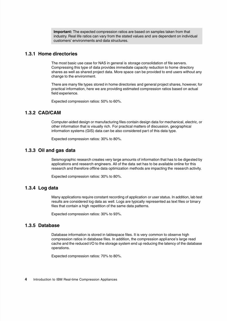
1.3.1 Home directoriesThe most basic use case for NAS in general is storage consolidation of file servers.Compressing this type of data provides immediate capacity reduction to home directoryshares as well as shared project data. More space can be provided to end users without anychange to the environment.
There are many file types stored in home directories and general project shares, however, forpractical information, here we are providing estimated compression ratios based on actualfield experience.
Expected compression ratios: 50% to 60%.
1.3.2 CAD/CAM
Computer-aided design or manufacturing files contain design data for mechanical, electric, orother information that is visually rich. For practical matters of discussion, geographicalinformation systems (GIS) data can be also considered part of this data type.
Expected compression ratios: 30% to 80%.
1.3.3 Oil and gas data
Seismographic research creates very large amounts of information that has to be digested byapplications and research engineers. All of the data set has to be available online for this
research and therefore offline data optimization methods are impacting the research activity.
Expected compression ratios: 30% to 80%.
1.3.4 Log data
Many applications require constant recording of application or user status. In addition, lab testresults are considered log data as well. Logs are typically represented as text files or binaryfiles that contain a high repetition of the same data patterns.
Expected compression ratios: 30% to 93%.
1.3.5 Database
Database information is stored in tablespace files. It is very common to observe highcompression ratios in database files. In addition, the compression appliance’s large readcache and the reduced I/O to the storage system end up reducing the latency of the databaseoperations.
Expected compression ratios: 70% to 80%.
Important: The expected compression ratios are based on samples taken from thatindustry. Real life ratios can vary from the stated values and are dependent on individualcustomers’ environments and data structures.

8/3/2019 Introduction to IBM Real-Time Compression Appliances
http://slidepdf.com/reader/full/introduction-to-ibm-real-time-compression-appliances 19/168
Chapter 1. The industry requirement for compression5
1.3.6 Virtualized infrastructures
The proliferation of open systems virtualizations in the market has actually increased the useof storage space with more and more virtual server images and backups kept online. The useof compression assists in reducing the storage requirements at the source. Again, reducedI/O to the storage system and the large read cache provide higher scalability to the existing
storage system.
Expected compression ratios: 50% to 80%.

8/3/2019 Introduction to IBM Real-Time Compression Appliances
http://slidepdf.com/reader/full/introduction-to-ibm-real-time-compression-appliances 20/168
6 Introduction to IBM Real-time Compression Appliances

8/3/2019 Introduction to IBM Real-Time Compression Appliances
http://slidepdf.com/reader/full/introduction-to-ibm-real-time-compression-appliances 21/168
© Copyright IBM Corp. 2011. All rights reserved.7
Chapter 2. Compression technology
discussed
In this chapter we provide a general overview of data compression and data efficiencytechnologies.
2

8/3/2019 Introduction to IBM Real-Time Compression Appliances
http://slidepdf.com/reader/full/introduction-to-ibm-real-time-compression-appliances 22/168
8 Introduction to IBM Real-time Compression Appliances
2.1 Compression technology history
For the last 100 years, the IT technology has evolved from very large systems built to executesimple mathematical operations to small devices able to execute, generate, and manipulatemassive amounts of data. Devices that are able to store and capture data are showing anexponentially growth from year to year.
Because of requirements that data must be stored over a long period of time for long-termreference, compliance, and/or security purposes, new ways to optimize the capacity utilizationare needed. For more information about data growth evolution, see Chapter 1, “The industryrequirement for compression” on page 1.
Historically, over the last 200 years, the technologies available to reduce the amount of datastored or transported from one place to another have been greatly improved.
One of the first methods for reducing the amount of data was the usage of symbols andrepresentations in mathematical format. For example, instead of writing the words “multipliedby,” the related representation used is the asterisk character ( * ). In the same way, the word“minus” is represented with the dash character ( - ).
In 1938 the invention of Morse code allowed messages to be transmitted very quickly overlong distances by replacing the Roman letters and Arabic numbers with symbols formed fromlines and dots. In order to reduce the amount of dots or lines used to represent each letter,statistical analysis of the commonality of letters was performed. The most common letters arerepresented with a shorter combination of dots and lines. The commonality is different foreach language, as is the Morse code. For example, in the English language, the letter “c” isrepresented in the Morse code by 3 dots, while the letter “h” is represented by 4 dots. Therepresentation would therefore consist of 7 dots. However, in some languages “ch” is a verycommon combination, so the dots were replaced by lines, and “ch” is represented by 4 lines,effectively saving transmission time.
Later in the 20th century the development of IT technologies raised the need for complex
algorithms able to reduce the amount of data by interpreting the information beyond thesimple substitution of specific strings or letters.
One of the first techniques of mathematical data compression was proposed by Claude E.Shannon and Robert Fano in 1949. In the Shannon-Fano coding, symbols are sorted from themost probably to the least probable, and then encoded in a growing number of bits. Forexample, if the source data contains A B C D E, where A is the most common letter and E isthe least common letter, the Shannon-Fano coding will be: 00-01-10-110-111.
In 1952 a Ph.D. student at MIT named David A. Huffman proposed a more efficient algorithmfor mapping source symbols to unique string of bits. In fact, Huffman has proved that hiscoding is the most efficient method for this task, with the smallest average output bits persource symbol.
Later, Abraham Lempel and Jacob Ziv in 1977 proposed a method of replacing repeatingwords with code words. The method was applicable also to a pattern of text such asexpressions. This was the actual dawn of modern data compression.
Later in 1984 Terry Welch improved the algorithm proposed by Lempel and Ziv (also knownas LZ78) and developed a method known as LZW. Today this algorithm is the basis of moderncompression techniques used in PKZIP for general file compression, or within GIF and TIFFformats for images.

8/3/2019 Introduction to IBM Real-Time Compression Appliances
http://slidepdf.com/reader/full/introduction-to-ibm-real-time-compression-appliances 23/168
Chapter 2. Compression technology discussed9
Over time, many data compression algorithms have been developed around the Lempel - Zivmethod: LZSS (LZ - Storer-Szymanski), LZARI (LZ with Arithmetic encoding), and LZH(LZ + Huffman encoding, used by the ARJ utility).
2.2 Data efficiency technologies
Data compression technologies can be found in various implementations over the last 15years. These range from compression at the application level to in-band solutions that areable to compress data as it is transferred from a host to a storage device. During recent years,a lot of new technologies and new concepts have been developed in order to address theneed for optimized storage space and more efficient capacity usage. We discuss some ofthese technologies briefly in this chapter in order to avoid confusion between datacompression and other space optimization methods.
2.2.1 Space efficient
Space efficient, sometimes also referred to as Thin Provisioning, is a technology that allows
the storage to declare the required capacity at the host level, but to allocate on the physicalstorage media—hard disk drives—only the actual used capacity in terms of space. Figure 2-1 presents the difference between a traditional volume and a space efficient volume.
Figure 2-1 Space efficient volume
2.2.2 Flash Copy (space efficient)
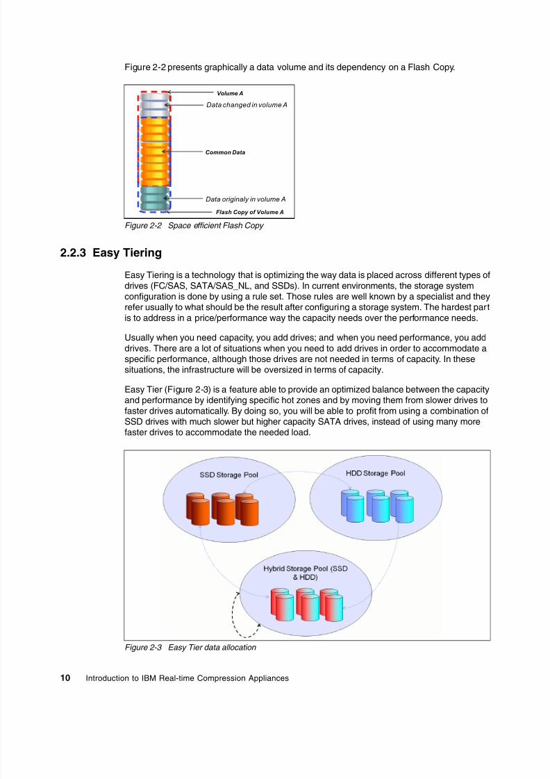
Space efficient Flash Copy is a technique that allows the multiplication of volume data anddata instances without multiplying the required space with the number of copies. Thistechnology allows the copy to depend on the source with all the data that is in common. Whendata is changed from the original volume those changes will be available and reflected only in
the updated instance while the rest of the data will remain as a common foundation.
Detected Space by the H ost
Free Sp ace(allocated)
Used Sp ace(allocated)
Tradit ional Volum e Spa ce Eff ic ient Volume
8/3/2019 Introduction to IBM Real-Time Compression Appliances
http://slidepdf.com/reader/full/introduction-to-ibm-real-time-compression-appliances 24/168
10 Introduction to IBM Real-time Compression Appliances
Figure 2-2 presents graphically a data volume and its dependency on a Flash Copy.
Figure 2-2 Space efficient Flash Copy
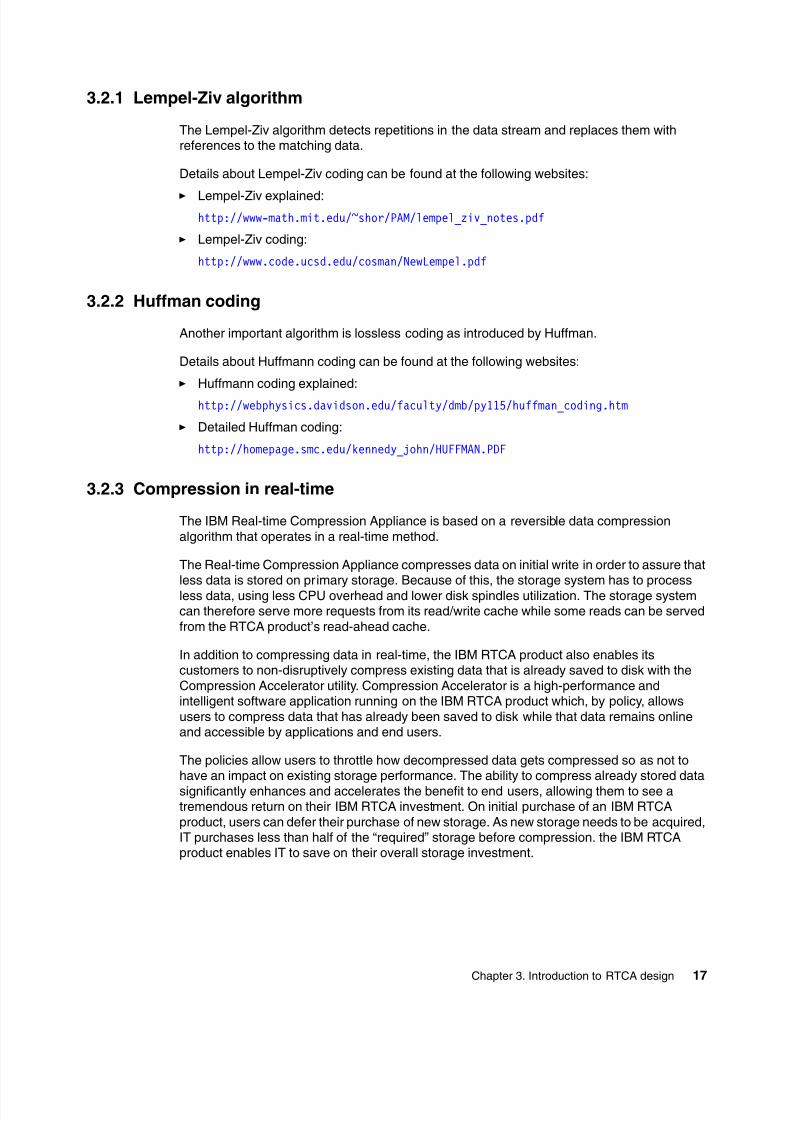
2.2.3 Easy Tiering
Easy Tiering is a technology that is optimizing the way data is placed across different types ofdrives (FC/SAS, SATA/SAS_NL, and SSDs). In current environments, the storage systemconfiguration is done by using a rule set. Those rules are well known by a specialist and theyrefer usually to what should be the result after configuring a storage system. The hardest partis to address in a price/performance way the capacity needs over the performance needs.
Usually when you need capacity, you add drives; and when you need performance, you adddrives. There are a lot of situations when you need to add drives in order to accommodate aspecific performance, although those drives are not needed in terms of capacity. In thesesituations, the infrastructure will be oversized in terms of capacity.
Easy Tier (Figure 2-3) is a feature able to provide an optimized balance between the capacityand performance by identifying specific hot zones and by moving them from slower drives to
faster drives automatically. By doing so, you will be able to profit from using a combination ofSSD drives with much slower but higher capacity SATA drives, instead of using many morefaster drives to accommodate the needed load.
Figure 2-3 Easy Tier data allocation
Volume A
Common Data
Data changed in volume A
Flash Copy of Volume A
Data originaly in volume A

8/3/2019 Introduction to IBM Real-Time Compression Appliances
http://slidepdf.com/reader/full/introduction-to-ibm-real-time-compression-appliances 25/168
Chapter 2. Compression technology discussed11
2.2.4 Archiving and space management
Archiving and space management, also known as Information Life-cycle Management (ILM)is a concept rather than a dedicated technology solution. It can be used in environmentswhere you need to keep data over a long period of time and you need to optimize the spaceoccupied on different storage types (tapes, hard disk drives, and so on). The old or not used
data can be moved out of the production area and placed on a much cheaper support (that is,by moving data from enterprise storage systems to low end storage systems and then fromhard drives to tapes). The historical information is usually kept in a database that holdsmetadata to provide accurate information about the managed data.
2.2.5 Data deduplication
The data deduplication mechanism identifies identical chunks of data within a storagecontainer and keeps only one copy of each chunk, while all the other logically identical chunkswill be pointed to this chunk. There are various implementations of this method. Onepossibility is in-line deduplication and the other one is post-processing. In-line solutions(Figure 2-4) deduplicate information as it is stored, and post-processing solutions deduplicate
data after the information is stored in the original format at certain time intervals.
Figure 2-4 Data deduplication
Comparison: All the technologies presented in 2.2, “Data efficiency technologies” onpage 9 are used to optimize the way that the available storage capacity is used. None ofthose technologies change information but rather optimize how this information is stored orhow much of this information is duplicated within the storage system. Data compressiontechnologies are able to interpret data. For that, they are able to provide storageoptimization, both regarding the amount of data stored and the performance needed for thestorage system used in back-end systems.

8/3/2019 Introduction to IBM Real-Time Compression Appliances
http://slidepdf.com/reader/full/introduction-to-ibm-real-time-compression-appliances 26/168
12 Introduction to IBM Real-time Compression Appliances
2.3 Data compression technologies
The compression of data has rapidly become a focus for the IT industry. Because of thedifferent types of data and the reasons why data is compressed, two concepts are used:
Reversible data compression: This method allows the information to be rebuilt completely
with no impact on the quantity or quality of the original information. Irreversible data compression: This method synthesizes the information and keeps only
the data that is needed. The original information cannot be rebuilt completely to its originalform when the data is decompressed.
Examples of irreversible data compression include audio, image, video compression, reports,and graphics generated in order to visualize large amounts of data, statistics, and so on. Oneclear example can be a situation with the runners at the Olympic Games who manage to gounder 10.1 seconds in the 100 meter speed running probe. We can say for example that 35%of the runners manage to go under 10.1 seconds and retain this value. But if we do not look atthe input data where all runners have their time, we cannot say that runner “X” has that time.
In this way, reversible data compression offers the advantage of the possibility to recreate
completely and accurately the input information, whereas the irreversible method offers onlysome specific information related to the original information.
Because of the massive amounts of data and the calculation needed to be made forcompressing data there are two approaches: real-time compression and post-processingcompression. These are their major characteristics:
Real-time compression: This method processes the data before it is written to the storagedevice. The key advantage of this approach is that it reduces the storage resourcesrequired for a given data set. If done correctly, the capacity-reduction application willpreserve the inherent performance of the storage environment. Data, already optimized,will be written to storage and mitigate the capacity explosion challenge at the point oforigin by eliminating the need to allocate additional storage capacity as required withpost-processing solutions. In addition, because this is primary storage, any compressiontechnique has to be performed in real time and must maintain the high availability featuresof the existing storage system.
Post-processing optimization: These solutions eliminate the need to deal with theperformance issues in real time and usually do not have any advanced high availabilitycapabilities. The challenge with post-processing optimization is that it uses storageresources for the capacity-reduction application, which causes a significant impact onstorage I/O resources. Post-process solutions require a read operation and pull a full copyof the original data to the storage; continue scanning the data, reading the data, andwriting the optimized file; and then delete the original file. In addition, when datadeduplication is thrown into the equation, the pointer between the optimized file and itsdeduplicated file needs to be written to storage before the deletion of the original file. Thisis a very complex and I/O intensive process. It is also the case that when you want the
optimized data, there must be enough space available on disk to uncompress it, whichmeans you do not actually improve storage utilization.
It is important to keep in mind, when considering post-process optimization techniques,that all optimization operations should be scheduled during a time of day when there arefree resources on the subsystem (non-production, non-backup windows) and after a pointin time when snapshots have been completed and newly optimized files have been writtento disk. Managing a schedule like this is next to impossible, and you risk not finding thetime to optimize your capacity before you actually run out of disk space.

8/3/2019 Introduction to IBM Real-Time Compression Appliances
http://slidepdf.com/reader/full/introduction-to-ibm-real-time-compression-appliances 27/168
Chapter 2. Compression technology discussed13
Over the years, IBM has introduced a series of reversible, real-time compression algorithmsand solutions used in wide range of technologies:
The LTO-DC algorithm used in IBM Linear Tape Open, formally known as LTO tape drives
The Streaming Lossless Data Compression (SLDC) algorithm used in IBMEnterprise-class TS1130 tape drives
The Adaptive Lossless Data Compression (ALDC) used by the IBM Information Archivefor its disk pool collections
The Random Access Compression Engine (RACE) used inside Real-time CompressionAppliance.

8/3/2019 Introduction to IBM Real-Time Compression Appliances
http://slidepdf.com/reader/full/introduction-to-ibm-real-time-compression-appliances 28/168
14 Introduction to IBM Real-time Compression Appliances

8/3/2019 Introduction to IBM Real-Time Compression Appliances
http://slidepdf.com/reader/full/introduction-to-ibm-real-time-compression-appliances 29/168
© Copyright IBM Corp. 2011. All rights reserved.15
Chapter 3. Introduction to RTCA design
In this chapter we discuss the main concepts used in the IBM Real-time CompressionAppliance (RTCA), namely the Random Access Compression Engine (RACE) algorithm.We also examine the way the RTCA product manages to deliver high performance and thetechnology used for preserving data integrity.
3

8/3/2019 Introduction to IBM Real-Time Compression Appliances
http://slidepdf.com/reader/full/introduction-to-ibm-real-time-compression-appliances 30/168
16 Introduction to IBM Real-time Compression Appliances
3.1 The RTCA approach
The industry need for data compression is clearly to be fast, reliable, and scalable. Thecompression algorithm used must assure date consistency and a very good compression ratein order to be implemented. In addition, the data compression solution must also be easy toimplement, and the compression should occur without impacting the production use of thedata at any time.
From the technologies described in 2.3, “Data compression technologies” on page 12, andbased on industry requirements, the best model was chosen for the RTCA product, which is acombination of both reversible data compression and a real-time compression algorithm.In other words, the RTCA solution compresses the incoming flow of the data with minimumperformance impact. A generic overview of the RTCA solution is presented in Figure 3-1.
Figure 3-1 Real-time Compression Appliance overview
3.2 IBM Real-time Compression
To understand the basic design of the IBM Real-time Compression technology, it is necessaryto review in detail the basics of modern compression techniques - the Lempel-Ziv algorithmand Huffman coding mentioned in 2.1, “Compression technology history” on page 8.
8/3/2019 Introduction to IBM Real-Time Compression Appliances
http://slidepdf.com/reader/full/introduction-to-ibm-real-time-compression-appliances 31/168
Chapter 3. Introduction to RTCA design17
3.2.1 Lempel-Ziv algorithm
The Lempel-Ziv algorithm detects repetitions in the data stream and replaces them withreferences to the matching data.
Details about Lempel-Ziv coding can be found at the following websites:
Lempel-Ziv explained:http://www-math.mit.edu/~shor/PAM/lempel_ziv_notes.pdf
Lempel-Ziv coding:
http://www.code.ucsd.edu/cosman/NewLempel.pdf
3.2.2 Huffman coding
Another important algorithm is lossless coding as introduced by Huffman.
Details about Huffmann coding can be found at the following websites:
Huffmann coding explained:
http://webphysics.davidson.edu/faculty/dmb/py115/huffman_coding.htm
Detailed Huffman coding:
http://homepage.smc.edu/kennedy_john/HUFFMAN.PDF
3.2.3 Compression in real-time
The IBM Real-time Compression Appliance is based on a reversible data compressionalgorithm that operates in a real-time method.
The Real-time Compression Appliance compresses data on initial write in order to assure thatless data is stored on primary storage. Because of this, the storage system has to processless data, using less CPU overhead and lower disk spindles utilization. The storage systemcan therefore serve more requests from its read/write cache while some reads can be servedfrom the RTCA product’s read-ahead cache.
In addition to compressing data in real-time, the IBM RTCA product also enables itscustomers to non-disruptively compress existing data that is already saved to disk with theCompression Accelerator utility. Compression Accelerator is a high-performance andintelligent software application running on the IBM RTCA product which, by policy, allowsusers to compress data that has already been saved to disk while that data remains onlineand accessible by applications and end users.
The policies allow users to throttle how decompressed data gets compressed so as not tohave an impact on existing storage performance. The ability to compress already stored datasignificantly enhances and accelerates the benefit to end users, allowing them to see atremendous return on their IBM RTCA investment. On initial purchase of an IBM RTCAproduct, users can defer their purchase of new storage. As new storage needs to be acquired,IT purchases less than half of the “required” storage before compression. the IBM RTCAproduct enables IT to save on their overall storage investment.

8/3/2019 Introduction to IBM Real-Time Compression Appliances
http://slidepdf.com/reader/full/introduction-to-ibm-real-time-compression-appliances 32/168
18 Introduction to IBM Real-time Compression Appliances
3.3 Random Access Compression Engine
The IBM Random Access Compression Engine (RACE) technology is the core of IBM RTCAproducts for NAS. RACE is based on 35 patents that are not about compression, but ratherdefine how to make industry standard LZ compression of primary storage operate in real-timeand allow random access. The primary intellectual property behind this is our RACE engine.
The IBM RACE engine sits on an appliance in front of any NFS or CIFS deployment, acting asan “intelligent cable” between the IP switch and the storage, as shown in Figure 3-1 onpage 16; no software agents or drivers are required on clients or servers.
The RACE technology (see Figure 3-2) is made up of three components:
1. Random Access Compression Engine (RACE): Enables random-access datacompression without compromising performance.
2. Unified Protocol Manager (UPM): Enables transparent support of multiple storage andnetwork protocols, including CIFS and NFS.
3. Monitoring and Reporting Manager (MRM): Enables online storage compression trending,analysis and reporting.
Figure 3-2 RACE technology overview
3.3.1 Random Access Compression Engine: RACE
The traditional Compression Technologies start from a constant file size and, aftercompression, the result is a variable file in terms of capacity. Because of this, when usinglarge data chunks, the performance impact is high. However, when using small data chunks,
although the performance impact is small, the compression ratio is also very small. Over time,there are many disadvantages that can occur: garbage collection, poor performance while thevolume of the data increases, or losing parts of metadata, such as the date of creation, dateaccessed, user rights, or modification dates. Another issue can be fragmentation in the targetstorage space because after the file is stored in its original size, the result of compression isstored in a new zone and then the input is deleted.
The Random Access Compression Engine (RACE) starts from an unknown data stream andcompresses data coming from the host. The resulting compressed file keeps all attributesfrom the original; metadata is not changed. Also, because of the in-line approach, there is noneed at the storage level to write original data, read it, write the result of compression, and

8/3/2019 Introduction to IBM Real-Time Compression Appliances
http://slidepdf.com/reader/full/introduction-to-ibm-real-time-compression-appliances 33/168
Chapter 3. Introduction to RTCA design19
finally, delete the initial file. At the end, there will not be any garbage or fragmentation on thestorage system. The performance needed at the storage level will be decreased because thewrites and reads will be made only in compressed format instead of a complete one. A logicaloverview of the Random Access Engine is presented in Figure 3-3.
Figure 3-3 Random Access Compression Engine
RACE takes incoming data streams and compresses the data within these data requests,leaving the metadata intact, to the storage array. The data is stored in the array and theacknowledgement that the write has been committed is sent directly back from the array tothe end user or application. This process flow is important because from a data availabilityperspective, it is imperative that it is the storage array that acknowledges the write
commitment—not the IBM RTCA product. It is for this reason that the IBM RTCA product hasno write cache. All storage commits come from the array, preserving the integrity of the databetween the storage and the application.
As stated before, the IBM RTCA technology leverages industry standard LZ compressionalgorithms. Although the “secret sauce” is not the compression algorithms that the RTCAproduct uses to do its compression, but rather the manner in which that compression isaccomplished. One of the key ways that the RTCA product is able to achieve its highcompression ratios and performance is by compressing data utilizing random accesstechniques.
The benefits of compressing data using random access techniques are twofold. First, theability to read or write only the blocks of the compressed file that require read or modification
means faster access performance for these operations. If you only need to write a small pieceof data in order to update a whole file, your storage performance is maximized. Second,because the RTCA product has this capability, updates to the file are accomplished in a waythat does not disrupt the other blocks in the compressed file.
Operating under the notion that upstream data compression significantly reducesdownstream data deduplication ratios, it is preferable to apply data deduplication technologiesover decompressed data prior to performing a deduplicated backup. While this can be true fordata compressed with traditional techniques, the unique, random access nature of the IBMRTCA product's compression preserves data deduplication ratios, allowing end users toexperience maximum data optimization in both primary and downstream tiers.
8/3/2019 Introduction to IBM Real-Time Compression Appliances
http://slidepdf.com/reader/full/introduction-to-ibm-real-time-compression-appliances 34/168
20 Introduction to IBM Real-time Compression Appliances
In order for the IBM RTCA product to appear in the network as an intelligent cable, thereneeds to be technology to ensure that the system provides the same functionally to act like acable even though it is a device in the network. This is achieved through Link Status Mirroringor LSM. LSM sits behind each cable in the data path. If any cable fails, or for that matter, if anycomponent in the data path fails—the switch or storage or the I/O traffic coming into thatcable, from either the sending or receiving end—all need to be failed over to the other
available link in the solution.When a failure occurs and one link in the device is not available, LSM ensures that the otherside of the link is also downed such that data traffic can be rerouted to the available link in thedata path. This operation happens in microseconds to ensure the highest degree ofavailability to the data. Additionally, when the failure is fixed, and the link is restored, LSM alsoprovides a mechanism to fail the link back to the predominant active link.
3.3.2 Unified Protocol Manager
One of the key components of RACE is the Unified Protocol Manager (UPM) that allows theIBM RTCA product to seat in line between the storage NAS (NFS and CIFS shares) and theuser and to act as an intelligent cable.
This transparent behavior means there is no change required to the end user environment.Further, there are no changes required to storage, networking or applications. The IBM RTCAproduct does not require any changes to the existing infrastructure or to downstreamprocesses such as snapshots, backup, replication and archiving; the RTCA product enhancesthese environments because you are moving and storing less data.
The following use cases are examples:
Snapshots: After you have installed the RTCA product, if your array allows you to takesnapshots of your data, your snapshot data will also be compressed and be accessible,without any system changes to the server. The metadata, such as file permissions, size,ownership, and the Access Control List (ACL), are maintained in the compressed file.
Conserving the file attributes: When a user performs a directory listing of the compresseddata, the RTCA product reports back all of the actual file metadata as if the file was notcompressed, including the file size and all of the ownership and permissions. Byinterpreting the file envelope and providing the native file attributes, the IBM RTCA productnegates the need for applications to be changed in order to read the compressed data ondisk. This means that there is no change required for IT, allowing the solution to fitseamlessly into the environment.
When operating system commands such as df are run on the storage subsystem, the IBMRTCA product does not mask the compressed file size, allowing the server to always knowexactly how much free space there is for files, and if quotas are in use, they can be enforced.These functions truly make the IBM RTCA product fully transparent in the environment.
3.3.3 Monitoring and Reporting Manager
Another component to the overall RACE technology is the Monitoring and Reporting Manageror MRM. The MRM enables online storage compression trending, analysis, and reporting.Further, MRM provides users with a host of services to efficiently manage and report on theIBM RTCA status and activities, and to quantify the benefits of the solution across theenvironment.
Space: The df command displays information about total space and available space on afile system.

8/3/2019 Introduction to IBM Real-Time Compression Appliances
http://slidepdf.com/reader/full/introduction-to-ibm-real-time-compression-appliances 35/168
Chapter 3. Introduction to RTCA design21
The MRM provides users standard interfaces such as SNMP, allowing visibility into appliancehealth and performance through numerous traps and “poll-able” objects. DownloadableSNMP MIB libraries allow end users to integrate IBM RTCA monitoring into their monitoringand reporting tool of choice. MRM also allows users to integrate LDAP with the IBM RTCAproduct, facilitating auditable login authorizations. In an HA configuration, MRM alsoautomatically synchronizes the configuration setting between partner appliances to ensure
the accuracy of configuration and streamline solution management.In addition, MRM provides the users with the ability to select certain file types to include orexclude from compression as well as the ability to select shares to include or exclude fromcompression. MRM also allows users to see the amount of space saved by utilizing the IBMRTCA product. MRM provides the ability to select the file types to include or exclude fromcompression. But more importantly, in most cases, it selects which shares to include orexclude from compression.
3.4 Performance considerations
There are many factors that impact storage performance, including but not limited to these:
Disk drives: Performance cannot be any faster in any system than the slowest mechanismin the chain. In storage, this is the mechanical movement of the disk drive. The greater theactuator arm has to travel, the slower the disk performance.
I/O: The next consideration involves reads and writes, or I/O. The more reads and writesthere are in a storage system, the more the storage system has to processes these I/Orequests, the longer it takes for the storage system to respond, and consequently, theslower the storage system. If the storage system is busy processing all of these I/Orequests and moving the storage arm to read and write data, it means that the storageCPU gets busier and busier, and the response to more storage requests gets slower.
Cache: At the top of the storage array performance is its cache. Storage cache is veryexpensive; however, if configured properly for a given application, it can take a lot of theworkload off of the disk, I/O, and CPU, and provide faster response back to the end user or
application requesting data. Data that lives in cache is served significantly faster than datathat must be retrieved from disk.
In order for any storage compression solution to fit into this environment, it cannot negativelyimpact any of these functions. To be a good solution, it must enhance these functions.
Also, because there is less data being written to the storage array, there is less I/O. With lessI/O also come more CPU cycles to process the given read and write requests.
Finally, by compressing data in front of the storage array, a net increase in effective cachesize is achieved. Whatever the compression ratio is for your data, this compression ratiotranscends to your storage cache. Because cache is one of the most expensive componentsof a storage array, and also, cache tends to have the biggest impact on storage performance,the more you can increase cache, the better performance users and applications will see.
Performing compression in real-time, before the data gets to the storage, has tremendousbenefits to overall storage performance. It removes a lot of the hurdles that storageadministrators face when considering compression as a technology for their primary storage.
For more best practices and performance considerations, see Chapter 5, “Performanceconsiderations” on page 33.
Tip: If your data is compressible by 3:1, IBM Real-time Compression provides theequivalent of increasing the size of your storage cache by 3 times.

8/3/2019 Introduction to IBM Real-Time Compression Appliances
http://slidepdf.com/reader/full/introduction-to-ibm-real-time-compression-appliances 36/168
22 Introduction to IBM Real-time Compression Appliances
3.5 Data integrity
As part of the solution design, IBM Real-time Compression has developed the DIA DataIntegrity Assurance architecture. The multi tiered data protection it provides, built into everyIBM Real-time Compression data compression appliance, is a quantum leap forward inguaranteeing data integrity.
To ensure 100% data integrity, the IBM Real-time Compression product line was developedhaving in mind the following goals:
Preserving existing data integrity mechanisms in the storage array Preserving existing data integrity mechanisms in the network Verifying the reliability of storing and retrieving the compressed data Using the industry-proven Lempel-Ziv (LZ) lossless data compression algorithm Using error-correcting code (ECC) memory modules to ensure data integrity for memory
access
This list describes how the IBM Real-time Compression Appliance integrates seamlessly intoNAS environments, increasing the storage capacity, while assuring data integrity as follows:
Preserving the data integrity mechanisms already in place in the network Providing mechanisms to guarantee the reliability of the compressed data through the DIA
Data Integrity Assurance architecture
3.5.1 Data integrity at the network level
The IBM Real-time Compression Appliance preserves data integrity mechanisms at theprotocol and storage levels.
Performing verification checks at the network protocol layer ensures data integrity duringtransmission between components in your network. These checks are cyclic redundancycheck (CRC) checksum mechanisms that verify data integrity during transmission of data
between components. A graphical representation is shown in Figure 3-4.
Figure 3-4 Network data integrity mechanism

8/3/2019 Introduction to IBM Real-Time Compression Appliances
http://slidepdf.com/reader/full/introduction-to-ibm-real-time-compression-appliances 37/168
Chapter 3. Introduction to RTCA design23
3.5.2 Data integrity at the protocol layer
When you install the IBM Real-time Compression Appliance (Figure 3-5), the checksummechanisms employed in your network continue to function as usual. The IBM Real-timeCompression Appliance manages two sets of checksum mechanisms:
Checksums on the uncompressed data in the connection between the IBM Real-time
Compression Appliance and the switch
Checksums on the compressed data in the connection between the IBM Real-timeCompression Appliance and the storage array
The network protocol layer checksums include these:
Ethernet-layer checksum (IEEE 802.3): A checksum that protects data against corruptionduring transmission on the Ethernet wire by performing a CRC checksum at the framelevel
IP header checksum (RFC 791): A checksum that ensures the integrity of the data fields inthe IP header
TCP checksum (RFC 793): A checksum that verifies the integrity of each data block during
TCP/IP transmission UDP checksum (RFC 1122) – An optional checksum that verifies the integrity of data
packets associated with the UDP datagram
Figure 3-5 Network implementation
3.5.3 Data integrity at the storage layer
The write acknowledgement is a critical aspect of the functionality of client server storage
applications. When the storage system completes a client write request, the storage systemreturns a write acknowledgement message. The write acknowledgement message providesconfirmation that the data was transmitted successfully through the network and written tostorage. This confirmation protects against failures in transmission caused by any componentof the network, between the client server and the storage system.
When the IBM Real-time Compression Appliance is installed in your network, it transparentlypasses write acknowledgement messages received from the storage system to the client thatrequested the write, ensuring that the data was stored on the storage array (Figure 3-5).
8/3/2019 Introduction to IBM Real-Time Compression Appliances
http://slidepdf.com/reader/full/introduction-to-ibm-real-time-compression-appliances 38/168
24 Introduction to IBM Real-time Compression Appliances
3.6 Storage advantages
Installing the IBM Real-time Compression Appliance in a storage configuration providesunmatched benefits to the storage environment:
Primary storage compression: The IBM Real-time Compression Appliance compresses
the data before it reaches the storage unit. This provides unique advantages over otherstorage capacity solutions:
– Improves response time: Reduces traffic to and from the storage system.
– Reduces the storage system’s read/write activity: Compressing data before it reachesthe storage system enables the storage system to store and provide data with lessread and write activity.
– Read gains: Increases the effective size of the storage read cache, improving theperformance of read operations. Storage system read performance is greatlyinfluenced by the cache hit ratio. Better use of the read cache reduces the need for diskhead movement, which is slower than cache access. Because IBM Real-timeCompression compresses the data before it reaches the storage system, the effectivesize of the read cache increases. The read cache improvement is proportionate to the
compression ratio.
– Write gains: Increases the effective size of the write cache, improving the performanceof write operations. Storage systems typically cache write operations to enableimmediate acknowledgement to clients and reduce response time. The size of the writecache significantly impacts the throughput of write operations to storage. The IBMReal-time Compression Appliance compresses the data before it reaches the writecache, so the effective size of the cache increases proportionately with thecompression ratio.
Reduces infrastructure costs: Using IBM Real-time Compression appliances reduces yourstorage capacity by up to 80 percent, and helps to eliminate the expensive infrastructurerequirements of expanding your storage footprint.
No changes or server resources required: The IBM Real-time Compression Applianceprovides storage gains with the advantages of self-contained, appliance simplicity:
– No need to change the storage system configuration– No need to change your workflow– No server resources used

8/3/2019 Introduction to IBM Real-Time Compression Appliances
http://slidepdf.com/reader/full/introduction-to-ibm-real-time-compression-appliances 39/168
© Copyright IBM Corp. 2011. All rights reserved.25
Chapter 4. Hardware and software
components
In this chapter we provide an overview of the IBM Real-time Compression Appliance (RTCA)hardware and software components. Currently, the IBM RTCA product portfolio consists oftwo models.
This chapter outlines base model configurations and the technical specifications, such asnumber of ports, memory capacity, and the physical attributes of the products.
4

8/3/2019 Introduction to IBM Real-Time Compression Appliances
http://slidepdf.com/reader/full/introduction-to-ibm-real-time-compression-appliances 40/168
26 Introduction to IBM Real-time Compression Appliances
4.1 Base model configurations
Currently, the IBM RTCA product portfolio consists of two models that are configurable withbase and optional features.
4.1.1 IBM Real-time Compression Appliance STN6500 (2452-650)
The STN6500 is a 2U appliance. It comes equipped with 16 one-gigabit copper Ethernetports and one management port. These ports are factory-set when the appliance is ordered.
At least two cables are required for each NAS. One cable connects the NAS to the STN6500,and another cable connects the STN6500 to the LAN switch for that NAS. Port layoutdepends on product revision. Figure 4-1 on page 27 shows the front panel of the STN6500appliance. Figure 4-2 on page 28 shows the rear panel of the STN6500 appliance.
The following list provides a hardware overview of STN6500 base components:
IBM System x3650 M3 7945AC1 Dual Xeon E5620 4C 2.40 GHz 12 MB cache processors 72 GB 1333 MHz LP RDIMM Dual 146GB 10K 6Gbps SAS HDD Optical drive Redundant 675W ac power supplies Two C13-C14 PDU cables Four Intel® PRO/1000 Quad Port NICs One 3m Blue Cat5e cable Eight 3m Green Cat5e cables One 3m RS-232 cable
4.1.2 IBM Real-time Compression Appliance STN6800 (2452-680)
The STN6800 is a 2U appliance. It comes equipped with 1-gigabit copper Ethernet, 10-gigabitoptical Ethernet (10GBASE-SR), or both ports in the following configurations:
Four 10-GbE optical ports and eight 1-GbE copper ports Eight 10-GbE optical ports
In addition, the STN6800 is equipped with a management port. This port configuration isfactory-set when the appliance is ordered. At least two cables are required for each NAS.One cable connects the NAS to the STN6800, and another cable connects the STN6800 tothe LAN switch for that NAS. Figure 4-1 on page 27 shows the front panel of the STN6800appliance. Figure 4-3 on page 28 and Figure 4-4 on page 28 show the rear panel options ofthe STN6800 appliance.
The following list provides a hardware overview of STN6800 base components: IBM System x3650 M3 7945AC1 Dual Xeon X5660 6C 2.80 GHz 12 MB cache processors 72 GB 1333 MHz LP RDIMM Dual 146GB 10K 6Gbps SAS HDD Optical drive Redundant 675W ac power supplies Two C13-C14 PDU cables One 3m Blue Cat5e cable One 3m RS-232 cable
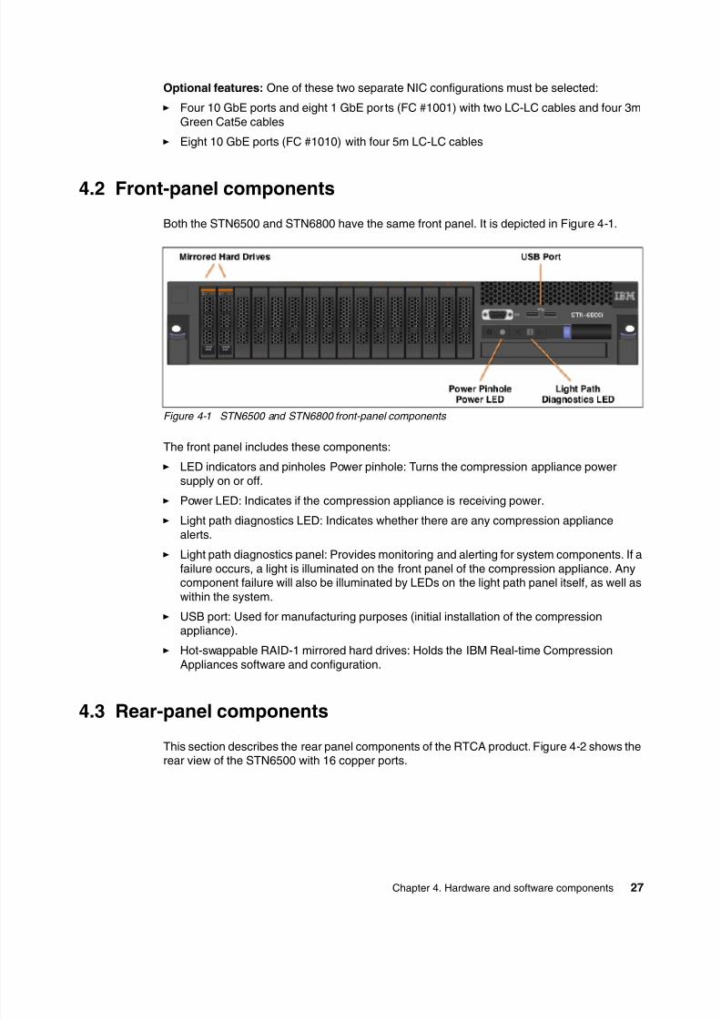
8/3/2019 Introduction to IBM Real-Time Compression Appliances
http://slidepdf.com/reader/full/introduction-to-ibm-real-time-compression-appliances 41/168
Chapter 4. Hardware and software components27
Optional features: One of these two separate NIC configurations must be selected:
Four 10 GbE ports and eight 1 GbE ports (FC #1001) with two LC-LC cables and four 3mGreen Cat5e cables
Eight 10 GbE ports (FC #1010) with four 5m LC-LC cables
4.2 Front-panel components
Both the STN6500 and STN6800 have the same front panel. It is depicted in Figure 4-1.
Figure 4-1 STN6500 and STN6800 front-panel components
The front panel includes these components:
LED indicators and pinholes Power pinhole: Turns the compression appliance powersupply on or off.
Power LED: Indicates if the compression appliance is receiving power.
Light path diagnostics LED: Indicates whether there are any compression appliance
alerts. Light path diagnostics panel: Provides monitoring and alerting for system components. If a
failure occurs, a light is illuminated on the front panel of the compression appliance. Anycomponent failure will also be illuminated by LEDs on the light path panel itself, as well aswithin the system.
USB port: Used for manufacturing purposes (initial installation of the compressionappliance).
Hot-swappable RAID-1 mirrored hard drives: Holds the IBM Real-time CompressionAppliances software and configuration.
4.3 Rear-panel componentsThis section describes the rear panel components of the RTCA product. Figure 4-2 shows therear view of the STN6500 with 16 copper ports.

8/3/2019 Introduction to IBM Real-Time Compression Appliances
http://slidepdf.com/reader/full/introduction-to-ibm-real-time-compression-appliances 42/168
28 Introduction to IBM Real-time Compression Appliances
Figure 4-2 STN6500 rear-panel components with 16 copper ports
Figure 4-3 displays the rear view of the STN6800 with four 10 GbE ports and eight 1 GbEports (FC #1001)
Figure 4-3 STN6800 rear panel with four 10 GbE ports and eight 1 GbE ports (FC #1001)
Figure 4-4 displays the rear view of the STN6800 with eight 10 GbE ports (FC #1010)
Figure 4-4 STN6800 rear panel with Eight 10 GbE ports (FC #1010)
The STN6500 and STN6800 have different rear panels. Nevertheless, many of the por ts andconnections serve the same functions:
STN6500 data ports (eth0-eth15):
The STN6500 has 16 copper data ports. Each pair of data ports can be connected to asingle NAS and the LAN switch for that NAS. See Figure 4-2 on page 28.

8/3/2019 Introduction to IBM Real-Time Compression Appliances
http://slidepdf.com/reader/full/introduction-to-ibm-real-time-compression-appliances 43/168
Chapter 4. Hardware and software components29
STN6800 optical and copper data ports (eth0-eth11): The STN6800 can have four 10-GbEoptical ports and eight 1-GbE copper ports. Each pair of data ports can be connected to asingle NAS and the LAN switch for that NAS. See Figure 4-3 on page 28.
STN6800 optical data ports (eth0-eth7): The STN6800 can have eight 10-GbE opticalports. Each pair of data ports can be connected to a single NAS and the LAN switch forthat NAS. Figure 4-4 on page 28.
Serial console port (RJ-45): Connects a terminal directly to the compression appliance.
Management port: Configures the compression appliance using the web interface. Ingeneral, you should connect to the administration tool through the management port.
Power supply units (PSUs): There are 2 power supply units. If a single power supplymalfunctions or stops receiving power, a beeping sound is emitted, informing you thatthere is a problem. The other power supply unit automatically senses the failure andmaintains uninterrupted power to the appliance.
AC connectors: Connects the power supply units to the power source through the acconnectors.
PSU cable lock: Ensures the power source cables are securely fixed to the ac connectors.
4.4 Technical specifications
This section discusses the technical specifications for the RTCA models STN6500 andSTN6800.
4.4.1 Physical specifications
Table 4-1 lists the physical specifications for models STN6500 and STN6800.
Table 4-1 Physical specifications for models STN6500 and STN6800
Table 4-2 lists the network interfaces of the RTCA product.
Table 4-2 Network interfaces of the RTCA product
Feature STN6500 STN6800
1 GbE ports 16 Up to 8
10 GbE ports None Up to 8
ECC Memory (GB) 72 72
Network interfaces STN6500 STN6800
with feature #1001a
a. (#1001) 4x10Gb and 8x1Gb Enet ports, this feature provides both 1-Gb and 10-Gb Ethernet.
STN6800
with feature #1010b
b. (#1010) 8x10Gb Ethernet ports, this feature provides a 10-Gb-only configurationEither feature #1010 or #1001 must be included in the initial order of STN6800.
1 Gbps copper ports 16 8 -
10 Gbps copper ports - 4 8
1Gbps copperManagement port
1 1 1
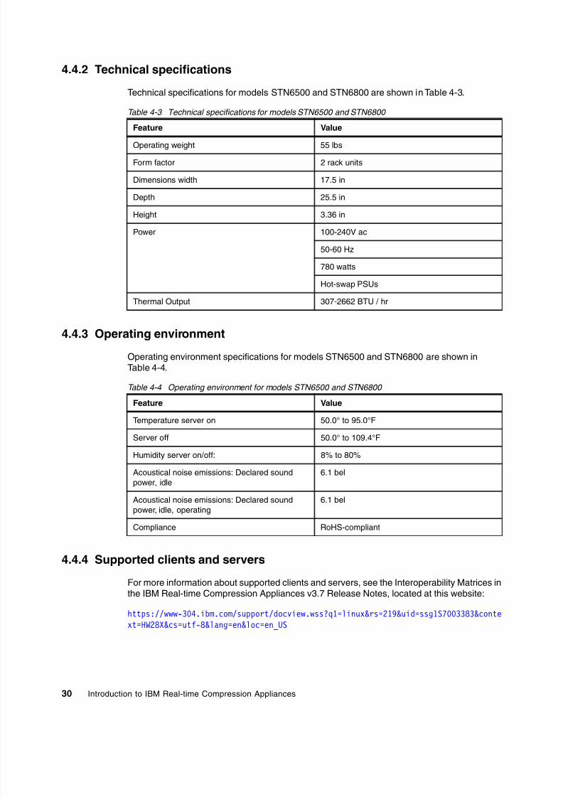
8/3/2019 Introduction to IBM Real-Time Compression Appliances
http://slidepdf.com/reader/full/introduction-to-ibm-real-time-compression-appliances 44/168
30 Introduction to IBM Real-time Compression Appliances
4.4.2 Technical specifications
Technical specifications for models STN6500 and STN6800 are shown in Table 4-3.
Table 4-3 Technical specifications for models STN6500 and STN6800
4.4.3 Operating environment
Operating environment specifications for models STN6500 and STN6800 are shown inTable 4-4.
Table 4-4 Operating environment for models STN6500 and STN6800
4.4.4 Supported clients and servers
For more information about supported clients and servers, see the Interoperability Matrices inthe IBM Real-time Compression Appliances v3.7 Release Notes, located at this website:
https://www-304.ibm.com/support/docview.wss?q1=linux&rs=219&uid=ssg1S7003383&context=HW28X&cs=utf-8&lang=en&loc=en_US
Feature Value
Operating weight 55 lbs
Form factor 2 rack units
Dimensions width 17.5 in
Depth 25.5 in
Height 3.36 in
Power 100-240V ac
50-60 Hz
780 watts
Hot-swap PSUs
Thermal Output 307-2662 BTU / hr
Feature Value
Temperature server on 50.0° to 95.0°F
Server off 50.0° to 109.4°F
Humidity server on/off: 8% to 80%
Acoustical noise emissions: Declared soundpower, idle
6.1 bel
Acoustical noise emissions: Declared soundpower, idle, operating
6.1 bel
Compliance RoHS-compliant

8/3/2019 Introduction to IBM Real-Time Compression Appliances
http://slidepdf.com/reader/full/introduction-to-ibm-real-time-compression-appliances 45/168
Chapter 4. Hardware and software components31
4.5 Software components
Three main software components enable the IBM RTCA product to perform storagecompression:
Random Access Compression Engine: Enables data compression without compromising
performance. Details can be found in 3.3.1, “Random Access Compression Engine:RACE” on page 18.
Unified Protocol Manager: Enables transparent support of multiple storage and networkprotocols, including CIFS and NFS. Details can be found in 3.3.2, “Unified ProtocolManager” on page 20.
Monitoring and Reporting Manager: Enables online storage compression managementand reporting. Details can be found in 3.3.3, “Monitoring and Reporting Manager” onpage 20.

8/3/2019 Introduction to IBM Real-Time Compression Appliances
http://slidepdf.com/reader/full/introduction-to-ibm-real-time-compression-appliances 46/168
32 Introduction to IBM Real-time Compression Appliances
8/3/2019 Introduction to IBM Real-Time Compression Appliances
http://slidepdf.com/reader/full/introduction-to-ibm-real-time-compression-appliances 47/168
© Copyright IBM Corp. 2011. All rights reserved.33
Chapter 5. Performance considerations
In this chapter we discuss various considerations in designing an optimal configuration withthe IBM Real-time Compression Appliance (RTCA).
A key benefit of the IBM RTCA solution is the ability to perform compression whilemaintaining high performance. The compression appliance is part of the overall storagesolution, and as such, it has to be reviewed together with the storage system itself. There arevarious performance requirements that need to be part of this review.
5

8/3/2019 Introduction to IBM Real-Time Compression Appliances
http://slidepdf.com/reader/full/introduction-to-ibm-real-time-compression-appliances 48/168
34 Introduction to IBM Real-time Compression Appliances
5.1 Performance requirements
The following list provides three focus areas:
Throughput The storage solution is typically measured by the number megabytesper second of data being read or written to it. We can measure this
throughput during work hours as well as peak time, to make sure thesystem is designed to provide expected service levels even in highload time windows.
Response time End users are sensitive to how responsive the system is to the actionsand jobs that they perform in the computing systems. The end userresponse time is affected by many components: the user actionsthemselves, client side application processing time, operatingsystems, networking layers, physical links, file system processing, andthe disk sub-system.
Scalability Any computer system is typically designed to handle current andfuture load levels. Planning ahead requires a detailed review of theperformance metrics of an overall storage solution.
Next we review best practices for configuring the highest performance Real-timeCompression Appliances solutions.
5.2 Performance best practices
There are various configuration items and parameters that affect the performance of aNetwork Attached Storage (NAS) setup that includes the IBM Real-time CompressionAppliances solutions.
5.2.1 Read-cache allocationA specific amount of the compression appliance memory is allocated for read cachepurposes. The default allocation in V3.7.1 is 30 gigabytes, which typically provides very highcache hit ratios. However, in some cases it would be necessary to increase the read cache.
To increase the read cache to 50 GB, run the following commands:
option Buffer:MaxMemoryUse4Pages 10000option Buffer:NumberOfBuffers 50000
An engine warm restart is required to apply the settings.
Read cache: For various releases, other values might be applicable. Consult with IBM
Support if you are running a release other than V3.7.0 or V3.7.1. Do not increase the readcache if the appliance is implemented in option General:MemoryProfileMode 1 modebecause in this mode, the read cache is reduced to a minimal size such that more memoryis available for other appliance tasks.

8/3/2019 Introduction to IBM Real-Time Compression Appliances
http://slidepdf.com/reader/full/introduction-to-ibm-real-time-compression-appliances 49/168
Chapter 5. Performance considerations35
5.2.2 Parallelism of I/O
The Real-time Compression Appliance software is tuned for a multi-core processorarchitecture and is highly efficient in handling concurrent compression and decompressiontasks. However, single threaded I/O does not fully utilize this capability. For this reason, anyapplication configuration changes that increase the concurrency of I/O operations will
increase the overall performance and reduce the overall load of the appliance.
5.2.3 Compression ratio
The rule of thumb is that the higher the compression ratio, the lower the CPU time spent oncompressing the data. The same rule applies for decompression as well. It is thereforepreferable to configure file types with low expected compression ratio in the “File Extensionsto Exclude” field in the “Compression Filters” page. This will reduce CPU time spent onattempting to compress files with low expected file size reduction.
Here is a list of file extensions to exclude:
zip gz tgz arj
5.2.4 Transparent versus compressed traffic
A basic concept of the compression appliance is that it adds minimal latency when trafficarrives to it and gets processed by its network interfaces. However, it reduces the latency ofI/O requests sent to the storage, as less data is sent to the storage compared with the originaldata sent by the client. However when the appliance is implemented without compressingdata, or when only a minimal amount of data is compressed, the latency added by theappliance being an additional network hop will not be compensated, and the overall
throughput will be lowered. It is best to implement the appliance and start compressing filesright away.
Tip: Multi threaded parallel I/O increases performance.

8/3/2019 Introduction to IBM Real-Time Compression Appliances
http://slidepdf.com/reader/full/introduction-to-ibm-real-time-compression-appliances 50/168
36 Introduction to IBM Real-time Compression Appliances

8/3/2019 Introduction to IBM Real-Time Compression Appliances
http://slidepdf.com/reader/full/introduction-to-ibm-real-time-compression-appliances 51/168
© Copyright IBM Corp. 2011. All rights reserved.37
Chapter 6. Implementation planning
In this chapter we present a planning guide to provide proper solution design. We discussphysical and logical installation of the IBM Real-time Compression Appliance (RTCA).
6

8/3/2019 Introduction to IBM Real-Time Compression Appliances
http://slidepdf.com/reader/full/introduction-to-ibm-real-time-compression-appliances 52/168
38 Introduction to IBM Real-time Compression Appliances
6.1 Solution requirements
The following list provides an outline for important solution requirements:
NAS storage platform: The IBM Real-time Compression Appliance supports NASprotocols only. Ensure that your Storage Server and required NAS protocols are
supported. Information about supported features can be found at the following Web site:http://www.ibm.com/support/entry/portal
Data type: It is highly desirable to identify compressible data before starting theconfiguration of the IBM Real-time Compression Appliance. See 1.3, “Identifying usecases for compression” on page 3.
Capacity: It is best to have enough capacity to make the solution cost effective. Fromexperience, in most cases this should be more than 20 TB NAS data.
Growth rate: You should not have a negligible annual growth rate. The higher the growthrate, the more cost effective will be the RTCA product.
6.2 Architectural planning
The following section discusses architectural planning for RTCA solutions.
6.2.1 Physical installation and cabling considerations
Next we start to evaluate physical and cabling considerations.
Network interfacesTable 6-1 shows the three different network options of the RTCA product.
Table 6-1 Network interfaces of the RTCA product
Rack considerationsIBM RTCA hardware (2452-650 and 2452-680) must be installed in a standard 19-inch rackusing the rack mounting hardware provided with the machine. The rack cabinet must have a2U slot available for each RTCA product. For more detailed information about the physicalspecifications, see 4.4.2, “Technical specifications” on page 30.
Network interfaces STN6500 STN6800
with feature #1001a
a. (#1001) 4x10Gb and 8x1Gb Enet ports; this feature provides both 1-Gb and 10-Gb Ethernet.
STN6800
with feature #1010b
b. (#1010) 8x10Gb Ethernet ports; this feature provides a 10-Gb-only configuration.Either feature #1010 or #1001 must be included in the initial order of STN6800.
1 Gbps copper ports 16 8 -
10 Gbps copper ports - 4 8
1 Gbps copperManagement port
1 1 1

8/3/2019 Introduction to IBM Real-Time Compression Appliances
http://slidepdf.com/reader/full/introduction-to-ibm-real-time-compression-appliances 53/168
Chapter 6. Implementation planning39
Cables and portsYour network cables would be unplugged from current storage, and plugged into thecompression appliance. IBM supplies cables that go from the compression appliance to thestorage:
(#3003) 3m Green Cat5e cable:
This feature provides one 3-meter Green Cat5e cable with RJ-45 connectors for 1-GbEthernet connections.
(#3705) 5m LC-LC optical cable:
This feature provides one 5-meter LC-LC Optical cable for 10-Gb Ethernet connections.
If you do not purchase cables from IBM, you need an additional set of network cables toconnect the RTCA product with your NAS storage server.
If the NAS storage is connected with eight 1-Gb copper cables to one Ethernet switch,you will need additionally eight 1-Gb copper cables and one 1-Gb copper cable for themanagement port for installing the RTCA product. This means that only one additionalnetwork port per RTCA product is required on the Ethernet switch.
Physical bypassUnder normal conditions it is not necessary to bypass the RTCA product for any Ethernettraffic.
If you have free Ethernet ports an your NAS storage server an want to use these ports foriSCSI or replication purposes, at these Ethernet ports all NAS protocols should bedeactivated.
6.2.2 Network
This section discusses network terms associated with the RTCA product.
Introduction to RTCA network terminologyThe RTCA product acts as a “intelligent cable” between the Ethernet switch and the NASstorage server. To provide network connectivity it is necessary bonds and bridges.
Bond A bond combines physical RTCA ports to a single virtual interface. In other words, a bond isthe vehicle for port aggregation. The RTCA product supports the common port aggregationprotocols Etherchannel and 802.3ad (LACP). Also, you can create active-backup bonds.
Bridge
A bridge combines two physical interfaces or bonds to establish a network connectionbetween the Ethernet switch and the NAS storage server. For every bridge, a new IP addresshas to be configured. This IP address is used by the RTCA product to poll the NAS sharesand exports.
Tip: To avoid direct access to compressed data by clients without passing the RTCAproduct, it is best to connect all network interfaces of the NAS storage server with theRTCA product.
Important: For proper solution design, you must understand these networking concepts.

8/3/2019 Introduction to IBM Real-Time Compression Appliances
http://slidepdf.com/reader/full/introduction-to-ibm-real-time-compression-appliances 54/168
40 Introduction to IBM Real-time Compression Appliances
The general use of bridges and bonds is illustrated in Figure 6-1.
Figure 6-1 general use of bonds and bridges
Logical interfacesIf your NAS storage system is configured with port aggregation, it is necessary to have a lookat the port aggregation configuration and to document the allocation of virtual interfaces to
physical interfaces. It is preferable that you adapt the aggregated physical interfaces of yourNAS storage server to corresponding bonds at your RTCA product. In other words, allphysical interfaces of an aggregated interface will be in the same bond.
In Example 6-1, you see the configuration of different types of virtual interfaces of a IBMSystem Storage N series controller. The physical interfaces ‘e0a’ and ‘e0c’ are trunked by‘vifa’ as multi mode vif. The physical interfaces ‘e0b’ and ‘e0d’ are trunked by ‘vifb’ as anothermulti mode vif. ‘vifa’ and ‘vifb’ are configured as member in a second level vif ‘vif1’ as a singlemode vif.
In an HA configuration, you need to use one bond for ‘vifa’ at the first RTCA product and onebond for ‘vivb’ at the second RTCA product. Both bonds will be bridged to the correspondingbonds, which include the Ethernet connection to the switch. The vif configuration will be
unchanged at the N series system.

8/3/2019 Introduction to IBM Real-Time Compression Appliances
http://slidepdf.com/reader/full/introduction-to-ibm-real-time-compression-appliances 55/168
Chapter 6. Implementation planning41
Example 6-1 Virtual interface configuration of N series with four physical interfaces
bran1> vif statusdefault: transmit 'IP Load balancing', VIF Type 'multi_mode', fail 'log'vifa: 2 links, transmit 'Round-Robin Load balancing', VIF Type ' multi_mode' fail'default'
VIF Status Up Addr_set
trunked: vif1up:
e0a: state up, since 23Mar2011 15:24:49 (22:18:23)mediatype: auto-1000t-fd-upflags: enabledinput packets 19529, input bytes 2358737output packets 30533, output bytes 1509659up indications 10, broken indications 7drops (if) 0, drops (link) 0indication: up at 23Mar2011 15:24:49
consecutive 170269, transitions 17 e0c: state up, since 23Mar2011 10:00:55 (1+03:42:17)
mediatype: auto-1000t-fd-up
flags: enabledinput packets 278152, input bytes 16971759output packets 30757, output bytes 1522361up indications 8, broken indications 5drops (if) 0, drops (link) 0indication: up at 23Mar2011 10:00:55
consecutive 170755, transitions 13vifb: 2 links, transmit 'Round-Robin Load balancing', VIF Type ' multi_mode' fail'default'
VIF Status Up Addr_settrunked: vif1down:
e0b: state up, since 23Mar2011 09:55:33 (1+03:47:39)mediatype: auto-1000t-fd-upflags: enabledinput packets 346488, input bytes 101244051output packets 86193, output bytes 41936062up indications 4, broken indications 2drops (if) 0, drops (link) 0indication: up at 23Mar2011 09:55:33
consecutive 171415, transitions 6 e0d: state up, since 23Mar2011 09:55:33 (1+03:47:39)
mediatype: auto-1000t-fd-upflags: enabledinput packets 347356, input bytes 98485301
output packets 84014, output bytes 43590209up indications 2, broken indications 0drops (if) 0, drops (link) 0indication: up at 23Mar2011 09:55:33
consecutive 171880, transitions 2

8/3/2019 Introduction to IBM Real-Time Compression Appliances
http://slidepdf.com/reader/full/introduction-to-ibm-real-time-compression-appliances 56/168
42 Introduction to IBM Real-time Compression Appliances
vif1: 1 link, transmit 'none', VIF Type 'single_mode' fail 'default'VIF Status Up Addr_set
up: vifa: state up, since 23Mar2011 10:00:55 (1+03:42:17)
mediatype: Enabled virtual interfaceflags: enabled favored
input packets 297681, input bytes 19330496output packets 61290, output bytes 3032020output probe packets 56815, input probe packets 167902strike count: 0 of 10up indications 7, broken indications 4drops (if) 0, drops (link) 0indication: up at 23Mar2011 10:00:55
consecutive 170785, transitions 11down:
vifb: state down, since 23Mar2011 10:01:27 (1+03:41:45)mediatype: Enabled virtual interfaceflags: enabled unfavoredinput packets 693844, input bytes 199729352
output packets 170207, output bytes 85526271output probe packets 56831, input probe packets 170706strike count: 0 of 10up indications 2, broken indications 0drops (if) 0, drops (link) 0indication: up at 23Mar2011 09:55:33
consecutive 171880, transitions 2
For further support information, see the RTCA Release Notes and the RTCA AdministrationGuide at this website:
http://www.ibm.com/support/entry/portal
Planning the physical connectionBefore you begin to create bridges and bonds, document the existing cabling diagram todetermine which RTCA ports will be used to bring the switch-to-RTCA and the RTCA-to-NASconnection together. It is preferable that paired cables (cable from the switch to RTCA andcable from NAS) reside on the same PCI card if possible for ease of cabling management andbetter availability.
6.2.3 Antivirus services considerations
In many NAS environments, the antivirus scanning activities are offloaded for betterscalability and performance. NAS vendors often advise having a dedicated physical networkconnection or dedicated VLAN configuration to transmit data from the NAS storage server tothe antivirus server. It is highly desirable that you configure your physical network and theRTCA product, thus all data passes the RTCA product. If you configure a physical bypass ofthe RTCA product, compressed files will be transmitted to the antivirus server and maliciousvirus code will never be detected. If necessary, you can configure a dedicated bridge toseparate the antivirus scanning traffic from all other network traffic.
Attention: All members of an active/active port aggregation, such as multi vif or lacp vif ofData ONTAP®, must be connected to the same RTCA product. If the same shares/exportsare accessed through different links, an active/active setup can lead to data access issuesbecause concurrent access to files through separate RTCA products is prohibited.

8/3/2019 Introduction to IBM Real-Time Compression Appliances
http://slidepdf.com/reader/full/introduction-to-ibm-real-time-compression-appliances 57/168
Chapter 6. Implementation planning43
An example of an antivirus configuration is illustrated in Figure 6-2.
Figure 6-2 Antivirus server in an RTCA environment
6.3 Network considerations summary
This section summarizes important network considerations:
Bridges connecting between the network and storage:
Each side of a bridge has to be connected to either a network switch or a NAS storageserver interface. Do not connect the two sides of the bridge to the network switch; this willcreate a network loop that can impact service to users.
Direct connection to the NAS:
The Link State Mirroring (LSM) is monitoring the network link status and automaticallymirrors this status between the bridge interfaces. Connecting active components such aslink converters or powered patch panels in between the appliance and the NAS storageserver can cause the LSM mechanism to fail and is therefore not supported.

8/3/2019 Introduction to IBM Real-Time Compression Appliances
http://slidepdf.com/reader/full/introduction-to-ibm-real-time-compression-appliances 58/168
44 Introduction to IBM Real-time Compression Appliances
Number of network interface ports:
The compression appliance acts a bridge between two “sides”, so the number of requiredports is 50% of the total number of links configured in the NAS storage server. Forexample, if an N series system is configured with four 1-gigabit links, a total of eight1-gigabit links will be required on the RTCA product to support this configuration.
In addition, the total number of links must support the expected aggregate throughput.For example, a particular NAS storage server is expected to provide ~500 MB/s totalthroughput. Because each 1-gigabit link provides ~80-100 MB/s, in this environment it isbest to configure at least five interfaces.
Number of bridges:
Up to eight physical bridges can be configured on a single appliance, and up to 128bridges configured with VLAN tagging (802.1q).
Number of storage system interfaces:
Each individual storage system physical and VLAN-tagged interface has to berepresented in the RTCA network configuration. Each RTCA product provides up to 16ports, so a NAS storage server with up to 8 physical interfaces can be implemented.Connect all network interfaces through the appliance unless some interfaces are used
solely for NDMP or replication traffic that is not based on NFS/CIFS.
Number of IP addresses configured in the NAS:
Each NAS IP address must be configured in the compression appliance to supportcommunication between the client and the NAS storage server. This includes IP aliasesand virtual server IP addresses.
Distribution of network links across NICs:
The RTCA product is configured with either quad-port gigabit Ethernet cards, or dual-port10 gigabit Ethernet cards. To provide the highest redundancy possible, it is preferable toconfigure bridges from ports located on separate cards.
For example:
br0 – eth0 and eth4br1 – eth1 and eth5br2 – eth2 and eth6br3 – eth3 and eth7br4 – eth8 and eth12br5 – eth9 and eth13br6 – eth10 and eth14br7 – eth11 and eth15

8/3/2019 Introduction to IBM Real-Time Compression Appliances
http://slidepdf.com/reader/full/introduction-to-ibm-real-time-compression-appliances 59/168
Chapter 6. Implementation planning45
6.4 Configuration planning
Before powering on your RTCA product for the first time, use the configuration worksheets togather the information that the upcoming setup process will require:
Use Table 6-2 to gather the information for the initial setup.
Fill in Table 6-3 with the required information for configuring autosupport. Insert miscellaneous information for NTP, DNS, and logging in Table 6-4.
For every NAS storage server, fill in Table 6-5 to gather the required information for laterconfigurations.
Depending on the interface configuration of your NAS storage server, you can use eitherTable 6-6 or Table 6-7 to gather the network information.
Table 6-2 Port management port setup
Table 6-3 Autosupport configuration
Table 6-4 Miscellaneous configurations
RTCA product hostname
IP Address
Subnet MaskGateway
MTU (default 1500)
Link mode auto10baseT/Half10baseT/Full100baseT/Half100baseT/Full1000baseT/Full
Email from(the “from” user used for sending email)
SMTP server(IP address or hostname)
SMTP remote port(default - 25)
Attachment prefix(The names of email attachments are prefixedwith this name to avoid the possibility that theemail will be rejected by some email servers)
IP address NTP server 1
IP address NTP server 2
IP address Remote syslog server
DNS domain
DNS search list
DNS name server IP address

8/3/2019 Introduction to IBM Real-Time Compression Appliances
http://slidepdf.com/reader/full/introduction-to-ibm-real-time-compression-appliances 60/168
46 Introduction to IBM Real-time Compression Appliances
Table 6-5 NAS storage configuration - one table per NAS storage server IP address
Table 6-6 NAS storage physical interfaces to bridge directly switch - one table per interface
Table 6-7 NAS storage virtual interface configuration - one table per virtual interface
Storage system name
Storage Vendor
Storage IP address
Name of the interface
IP address for the bridge
Name of virtual interface
Member of virtual interface (physical interfaces)
Type multi (Etherchannel)multi (802.3ad LACP)
single (active-backup)
IP address for the bridge
8/3/2019 Introduction to IBM Real-Time Compression Appliances
http://slidepdf.com/reader/full/introduction-to-ibm-real-time-compression-appliances 61/168
© Copyright IBM Corp. 2011. All rights reserved.47
Chapter 7. Deploying Real-time
Compression Appliances
In this chapter we provide a description of the first installation steps that are needed in orderto configure the Real-time Compression Appliance (RTCA) system.
7

8/3/2019 Introduction to IBM Real-Time Compression Appliances
http://slidepdf.com/reader/full/introduction-to-ibm-real-time-compression-appliances 62/168
48 Introduction to IBM Real-time Compression Appliances
7.1 Physical installation of Real-time Compression Appliance
The first step is to install the IBM Real-time Compression Appliance (RTCA) in the rack.Follow the instructions in the Rack Installation Instructions for IBM Gen-II Slides Kit, 69Y4034document. You can find it on the IBM Real-time Compression Appliances Documentation CDor on the IBM support website:
http://www.ibm.com/support
7.2 Cabling the RTCA product for configuration
The second step after mounting the device in the rack is to connect the minimum cablingneeded in order to perform the basic installation steps.
At this stage it is not necessary to connect the RTCA product within the data paths. You cando it later after the initial installation setup in order to provide non-disruptive implementation.
7.3 Connecting to the RTCA product
The RTCA product can be managed using two kinds of connections:
Direct connection: Standard KVM or using serial console connection by RS232 serialprotocol as shown in Figure 7-1.
Figure 7-1 Direct management connection
Remote connection: Web GUI management or SSH CLI. In this case, you will have toconfigure the remote access protocol by setting up an IP address at the Real-timeCompression Appliance as shown in Figure 7-2.
Important: Connect the RTCA product to an appropriate power source. For higherredundancy, connect both power supplies to different main electricity lines, while at leastone power supply for the engine must be connected through an uninterruptible power
supply.
Precaution: This product is not intended to be connected directly or indirectly by anymeans whatsoever to interfaces of public telecommunications networks.

8/3/2019 Introduction to IBM Real-Time Compression Appliances
http://slidepdf.com/reader/full/introduction-to-ibm-real-time-compression-appliances 63/168
Chapter 7. Deploying Real-time Compression Appliances49
Figure 7-2 Remote management connection
Using the KVM, RS232, and SSH, you will be able to perform CLI management at theReal-time Compression Appliance.
7.3.1 Direct connection
The direct connection can be made by using a standard VGA monitor and a USB keyboard orby RS232. Table 7-1 presents the required information for connecting using console or serialinterface.
Table 7-1 Connect a communication device
7.3.2 Remote connection
The remote connection can be made using HTTP and SSH. For both interfaces, the default IPaddress is: 10.10.0.254.
Communication device How to connect
VGA monitor and keyboard 1. Connect the VGA monitor to any of the VGA ports onthe compression appliance.
2. Connect the USB keyboard to any of the USB ports onthe compression appliance.
Standard RS-232 serial console 1. Connect the serial port cable to the 9-pin console port
on the compression appliance;2. Connect the other side to a terminal server, or to a PC
or server with serial console port;
3. Configure the terminal emulation software to thefollowing settings:
– Bits per second: 38400– Data bits: 8– Parity: None– Stop bits: 1– Flow control: None
Connection: Use the following default credentials to connect to the RTCA system:
User name: userPassword: a1b2c3

8/3/2019 Introduction to IBM Real-Time Compression Appliances
http://slidepdf.com/reader/full/introduction-to-ibm-real-time-compression-appliances 64/168
50 Introduction to IBM Real-time Compression Appliances
The minimum requirements to use the web interface are as follows:
Microsoft® Internet Explorer 5.5 or later Mozilla Firefox 2.0 or later
7.4 Configuring the RTCA product
After the cabling is made, the next step is to power-up the RTCA product. Simply press thepower button. The RTCA product starts the initial boot sequence. Wait for the compressionappliance software to start. This process might take up to five minutes:
1. The following text will display on a direct connection management system when the
compression appliance is fully operational:
2. The next step is to connect to the RTCA product to change the standard IP address andthe default administrator password.
3. Use a web browser and go to http://10.10.0.254 as shown in Figure 7-3.
Figure 7-3 Log in welcome screen
After logging in, the following interface displays as depicted in Figure 7-4. This view showsthe general status of your system, and you are able to perform different tasks.
Connection: Use the following credentials to connect to the RTCA product over HTTP orSSH:
User name: userPassword: a1b2c3
Starting Appliance ManagementLogin:
Tip: If you have configured a DHCP server, the RTCA product will not request an IPaddress from the DHCP server.

8/3/2019 Introduction to IBM Real-Time Compression Appliances
http://slidepdf.com/reader/full/introduction-to-ibm-real-time-compression-appliances 65/168
Chapter 7. Deploying Real-time Compression Appliances51
Figure 7-4 First view after login to the RTCA product
4. From the left panel, select Management Port (see Figure 7-5). Enter the desired IPaddress, subnet mask, and gateway. If necessary, you can change the default MTU or theLink Mode. In the last field, named Hostname, you will have to enter the designated namefor this host. After finishing the settings, click the Accept button.
Figure 7-5 Setting the management interface
IP address: After changing the IP address, the following message will display askingyou to log on again on the new IP address. The Management Port IP has changed.
Wait up to 30 seconds before trying to connect on the new IP address.

8/3/2019 Introduction to IBM Real-Time Compression Appliances
http://slidepdf.com/reader/full/introduction-to-ibm-real-time-compression-appliances 66/168
52 Introduction to IBM Real-time Compression Appliances
5. If you are using a Direct Connection or over SSH, change the IP address using theifconfig command (see Example 7-1).
Example 7-1 Changing the management settings
[email protected]> ifconfig mgmt -i 9.155.66.157 -s 255.255.255.0 -gw 9.155.66.1 -m1500 -f auto
6. After the command was executed successfully, log on again on the new IP address. Inorder to check if the new configuration was made correctly, submit the ifconfig mgmt command (see Example 7-2).
Example 7-2 Verifying the current configuration of the management interface
[email protected]> ifconfig mgmtManagement PortIP: 9.155.66.157Subnet: 255.255.255.0Gateway: 9.155.66.1MTU: 1500Link mode: autoActual link mode: 100baseT/Half
7. Next change the administrator password. From the web interface, choose the Security option. From the newly configured state (see Figure 7-6), change the administrationpassword and also secure the web management interface by imposing only one IP thatwill be served. The password must be between 6 and 8 characters.
Figure 7-6 Changing the admin password

8/3/2019 Introduction to IBM Real-Time Compression Appliances
http://slidepdf.com/reader/full/introduction-to-ibm-real-time-compression-appliances 67/168
Chapter 7. Deploying Real-time Compression Appliances53
a. You can do the same task from the CLI using the passwd command (Example 7-3). Thepasswd command will change the password only for the default user: ‘user’. You haveto enter the password twice. After successfully changing the password, the followingmessage is displayed: “User password changed successfully”.
Example 7-3 Changing the default management password - part 1
[email protected]> passwdNOTE: This will change the login password for username 'user'Enter password:Enter password:User password changed successfully
b. You can also change the passwd command using the following syntax: passwd a1b2c3(Example 7-4). In this situation, the password will be changed instantly without anyother confirmation.
Example 7-4 Changing the default management password - part 2
[email protected]> passwd a1b2c3User password changed successfully
7.5 Configuring bonds and bridges
After configuring the management interface and the administrator password, the next step isto configure bonds and bridges. A brief definition can be found in 6.2.2, “Network” onpage 39.
To configure first bonds and bridges, proceed as follows:
1. On the left panel of the interface, select the Network option. In the Network pane(Figure 7-7), you can see the current configuration of your compression engine, showing
the following information:
– Interface cards installed– Created bonds and bridges– Compression engine status
2. From the top of the panel, select to create a new bond, a new bridge, or to define a staticrouting table for the management interface. At the bottom of the page, select to start, stop,or restart the compression engine.
Tip: The compression engine cannot be started if there are no bridges defined. InFigure 7-7, the status of the compression engine is: Halted .

8/3/2019 Introduction to IBM Real-Time Compression Appliances
http://slidepdf.com/reader/full/introduction-to-ibm-real-time-compression-appliances 68/168
54 Introduction to IBM Real-time Compression Appliances
Figure 7-7 Network panel overview
7.5.1 Creating bonds
If your implementation design includes some adapter bonding between different interfaces,first you have to replicate the bonds defined in your storage at the appliance level. Becausethe appliance is acting as an intelligent cable by using adapter bonding topology, you will notbe able to achieve higher failover support than the standard storage configuration.
Tip: The bonds and bridges can be defined without moving the storage traffic through thestorage engine or without cabling the compression appliance. Good planning can save alot of time during the implementation and can assure a proper implementation withoutdowntime. For more details on how to plan the implementation, see Chapter 7, “DeployingReal-time Compression Appliances” on page 47.
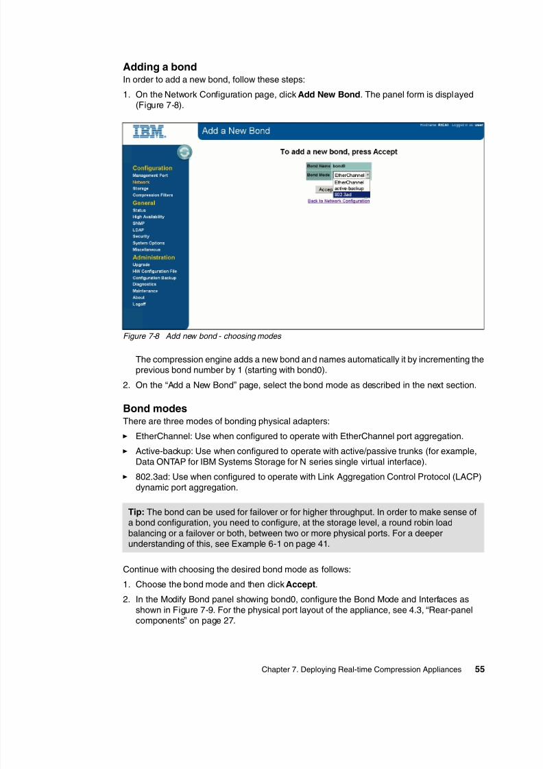
8/3/2019 Introduction to IBM Real-Time Compression Appliances
http://slidepdf.com/reader/full/introduction-to-ibm-real-time-compression-appliances 69/168
Chapter 7. Deploying Real-time Compression Appliances55
Adding a bondIn order to add a new bond, follow these steps:
1. On the Network Configuration page, click Add New Bond. The panel form is displayed(Figure 7-8).
Figure 7-8 Add new bond - choosing modes
The compression engine adds a new bond and names automatically it by incrementing theprevious bond number by 1 (starting with bond0).
2. On the “Add a New Bond” page, select the bond mode as described in the next section.
Bond modesThere are three modes of bonding physical adapters:
EtherChannel: Use when configured to operate with EtherChannel port aggregation.
Active-backup: Use when configured to operate with active/passive trunks (for example,Data ONTAP for IBM Systems Storage for N series single virtual interface).
802.3ad: Use when configured to operate with Link Aggregation Control Protocol (LACP)dynamic port aggregation.
Continue with choosing the desired bond mode as follows:
1. Choose the bond mode and then click Accept.
2. In the Modify Bond panel showing bond0, configure the Bond Mode and Interfaces asshown in Figure 7-9. For the physical port layout of the appliance, see 4.3, “Rear-panelcomponents” on page 27.
Tip: The bond can be used for failover or for higher throughput. In order to make sense ofa bond configuration, you need to configure, at the storage level, a round robin loadbalancing or a failover or both, between two or more physical ports. For a deeperunderstanding of this, see Example 6-1 on page 41.
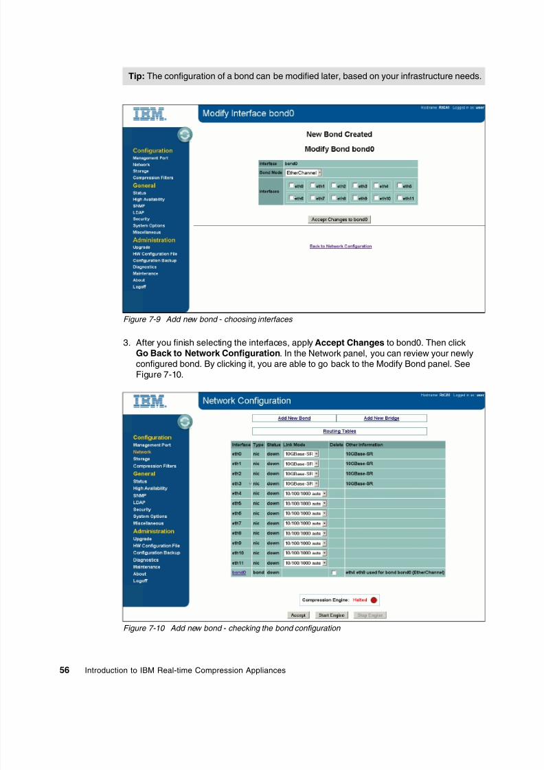
8/3/2019 Introduction to IBM Real-Time Compression Appliances
http://slidepdf.com/reader/full/introduction-to-ibm-real-time-compression-appliances 70/168
56 Introduction to IBM Real-time Compression Appliances
Figure 7-9 Add new bond - choosing interfaces
3. After you finish selecting the interfaces, apply Accept Changes to bond0. Then clickGo Back to Network Configuration. In the Network panel, you can review your newlyconfigured bond. By clicking it, you are able to go back to the Modify Bond panel. SeeFigure 7-10.
Figure 7-10 Add new bond - checking the bond configuration
Tip: The configuration of a bond can be modified later, based on your infrastructure needs.

8/3/2019 Introduction to IBM Real-Time Compression Appliances
http://slidepdf.com/reader/full/introduction-to-ibm-real-time-compression-appliances 71/168
Chapter 7. Deploying Real-time Compression Appliances57
Adding a bond is a procedure that you can perform using the CLI. The command used isshown in Example 7-5.
Example 7-5 Bond command structure
bond create BondInterfaceName -t [bond mode] [PhysicalInterfaceName...]
The bond command syntax is as follows:
BondInterfaceName: Must have the following structure “bond[1 to 12]. Comparing to theGUI here, you can define bonds without incrementing the previous number starting from 0.
bond mode: See “Bond modes” on page 55.
PhysicalInterfaceName: Defines the interfaces that should be included in bondsseparated by space.
You can use the bond command to list the current bond configuration. In Example 7-6, wecreate a second bond using the CLI by SSH connection.
Example 7-6 Add new bond using CLI
[email protected]> bondBond Mode Interfacesbond0 EtherChannel eth4 eth8
[email protected]> bond create bond1 -t EtherChannel eth5 [email protected]> bondBond Mode Interfacesbond0 EtherChannel eth4 eth8bond1 EtherChannel eth5 eth9
7.5.2 Creating bridges
To create a bridge using the GUI, proceed as follows:
1. From the GUI interface left panel, choose Network (see Figure 7-4 on page 51).
2. From the Network panel select Add New Bridge (see Figure 7-10 on page 56).
3. In the new panel (see Figure 7-11 on page 58), select Accept.
4. The system now generates a new bridge name and you are able to review it on theNetwork Configuration page below the ports and any configured bonds.
Important: A physical interface cannot belong to two different bonds at the same time.

8/3/2019 Introduction to IBM Real-Time Compression Appliances
http://slidepdf.com/reader/full/introduction-to-ibm-real-time-compression-appliances 72/168
58 Introduction to IBM Real-time Compression Appliances
Figure 7-11 Add new bridge
5. On the Network Configuration page, click the bridge name (br0) as shown in Figure 7-12 to review the information.
Figure 7-12 Add new bridge - list current configuration
6. In the next panel, named “Modify Bridge” (see Figure 7-13 on page 60), select the physicalor logical interfaces that are part of the bridge.

8/3/2019 Introduction to IBM Real-Time Compression Appliances
http://slidepdf.com/reader/full/introduction-to-ibm-real-time-compression-appliances 73/168
Chapter 7. Deploying Real-time Compression Appliances59
The IP address used for the bridge is used for discovering shares and exports from thestorage system. This IP address must be in the same network as the IP address of thestorage system connected to the interfaces of the specific bridge.
The bridge IP address is also used by the auto-support, diagnostics features for shares,and exports discovery, as well as by the various network probes. Client communication tothe storage system will continue to use the storage system IP address as endpoint.
At the storage level, the client IP address will be detected while discovery process occurs.
7. For using VLANs, you have to provide the following information (see Figure 7-13):
– VLAN ID: A unique number between 1 and 4094 that identifies a particular VLAN.VLAN ID 1 is typically reserved for the default VLAN.
– IP: The IP address of the bridge port. The IP address must be in the same subnet as
the assigned storage server.
– Subnet: The network mask of the IP address.
– Gateway: The default gateway IP address for that bridge.
– MTU: An optional maximum transmission unit size. The default value is 1500.
8. Click Accept Changes to VLAN if you configured a VLAN and want to apply changes tothe bridge name to complete the configuration. The system creates the bridge anddisplays a success message. Click Back to Network Configuration to display the currentconfiguration.
Tip: When using bonds, select the bonds to configure; otherwise, select the twophysical ports (storage port and network port). Mixing bonds with physical interfaces isnot allowed.
Important: Consider these important points when using bonds: A physical interface or a bond cannot be part of two bridges in the same time.
A bridge can have only two members of logical or physical interfaces.
Physical network interfaces are identified during the boot process, before thecompression engine is active. This can affect configurations with active/passive linksor bonds, such as IBM N series single vif and EMC Fail-Safe Networking thatinclude favoring a particular link (or bond) in case a failover of the storage systemstakes place during the RTCA boot process. It is important to notice that this issue isonly relevant for single links or EtherChannel bonds. LACP bonds are unaffected bythis issue are therefore the best bond type.
Important: When configuring VLAN-tagged bridges, a top-level bridge IP configurationis required. The top-level bridge can use any subnet.

8/3/2019 Introduction to IBM Real-Time Compression Appliances
http://slidepdf.com/reader/full/introduction-to-ibm-real-time-compression-appliances 74/168
60 Introduction to IBM Real-time Compression Appliances
Figure 7-13 New bridge parameters.
9. After completing the bridge configuration, you can start up the Real-time CompressionEngine. After a successful start, go on the Status Panel and verify if all indicators aregreen (see Figure 7-14).
Figure 7-14 Checking the RTCA Engine status
Important: A bridge configuration cannot be changed while the compression engine isstarted. In order to change a bridge configuration, you must stop the compression engine.

8/3/2019 Introduction to IBM Real-Time Compression Appliances
http://slidepdf.com/reader/full/introduction-to-ibm-real-time-compression-appliances 75/168
Chapter 7. Deploying Real-time Compression Appliances61
To create a bridge by using the CLI, proceed as follows:
1. Use the bridge command. The command used to create a new bridge has the structureshown in Example 7-7.
Example 7-7 Bridge command structure
bridge create BridgeIfName [-i BridgeIP -s BridgeMask [-b broadcastMask] [-gw
GateWay]]
2. Define the following parameters:
– BridgeIfName - the name of the bridge you want to create. The name must containbr[number of the bridge].
– Bridge IP - the IP address used by the bridge in the network.
– BridgeMask
– GateWay
3. Add the logical or physical interfaces to the bridge, as shown in Example 7-8.
Example 7-8 Add new interfaces to the bridge
bridge addif BridgeIfName InterfaceA InterfaceB
Example 7-9 presents the complete sequence shown before by using the GUI, but done herefrom the CLI, using the bridge command and the engine start command.
Example 7-9 Add new bridge
[email protected]> bridgeNo bridges or vlans have been defined
[email protected]> bridge create br0 -i 192.168.0.110 -s 255.255.255.0
[email protected]> bridge
Bridge IP Netmask Broadcast Gateway MTUbr0 192.168.0.110 255.255.255.0 192.168.0.255 - 1500Interfaces-
[email protected]> bridge addif br0 bond0 [email protected]> bridgeBridge IP Netmask Broadcast Gateway MTUbr0 192.168.0.110 255.255.255.0 192.168.0.255 - 1500Interfacesbond0 bond1
[email protected]> engine startEngine started successfully

8/3/2019 Introduction to IBM Real-Time Compression Appliances
http://slidepdf.com/reader/full/introduction-to-ibm-real-time-compression-appliances 76/168
62 Introduction to IBM Real-time Compression Appliances
7.6 Configuring high availability
Continuous data access to network storage solutions involves a redundant and fault-tolerantnetwork infrastructure and a highly available storage solution with built-in data protectionfeatures. The IBM Real-time Compression Appliance product integrates into all highavailability topologies and configurations seamlessly, without introducing any new single point
of failure or degradation of the service level that is offered by the storage and networkingequipment.
If a network link of any of the bridge interfaces fails for any reason (such as switch poweredoff or cable disconnected), the corresponding NAS-connected port of the same bridge is shutdown as well to reflect the status of the network. This feature makes the compressionappliance consistent with the configuration in place before connecting the IBM Real-timeCompression Appliance.
The following list summarizes four possible topologies for high availability:
Active/passive at access path, defines path failover Active/active link aggregation, using vifs
Path failover using two switches Clustered environment
For detailed descriptions, see Chapter 6, “Implementation planning” on page 37 and theIBM RTCA Administration Guide available at the following website:
http://www.ibm.com/support
Because IBM has developed a unique link status mirroring (LSM) feature to support variouslink aggregation and high availability configurations, this feature helps the compressionappliance to integrate transparently and seamlessly into the high availability configuration inplace. LSM reflects the link status of interfaces that are members of the same virtual bridgeinterface in the compression appliance configuration.
Keep in mind that the RTCA product will preserve performance and availability configurationsfor the back-end NAS. If the NAS configuration is not configured to assure high availability, theRTCA product will offer the same level after complete installation (that is, single filterconfigurations or vifs created using single physical interfaces are not consider to be highavailability topologies).
The high availability synchronization option allows you to export the compression appliancecompression filters to a different appliance in a high availability configuration. There aremanual and automatic modes for synchronizing a high availability configuration.
As described previously, there are two types of information that can be set on the RTCAproduct regarding the compression process:
Compression Filters: Shares from the NAS storage that will be included in the
compression process.
File Extensions to exclude: Types of files that will not be compressed but will be “dropped”as they are on the share.
You have two options to configure the high availability function on the RTCA product:manually or automatically. Details are discussed in the following sections.
Tip: When you configure a compression appliance in a high availability configuration, bothappliances must have the same compression filters and file extension set.

8/3/2019 Introduction to IBM Real-Time Compression Appliances
http://slidepdf.com/reader/full/introduction-to-ibm-real-time-compression-appliances 77/168
Chapter 7. Deploying Real-time Compression Appliances63
7.6.1 Synchronizing high availability manually
In order to create a manual synchronization, you have to export the current configuration ofthe filters from one appliance, and then import it on all other partner appliances.
Proceed as follows:
1. From the management interface, choose High Availability in order to open the HighAvailability panel (see Figure 7-15).
Figure 7-15 Configuring High Availability

8/3/2019 Introduction to IBM Real-Time Compression Appliances
http://slidepdf.com/reader/full/introduction-to-ibm-real-time-compression-appliances 78/168
64 Introduction to IBM Real-time Compression Appliances
2. From the top menu, select MANUAL. In the new panel, select Exports For HighAvailability. Choose to save the *.stn file on a preferred path as shown in Figure 7-16.
Figure 7-16 Exporting the configuration for High Availability
3. Next, log in to the other compression appliance that you want to configure in the highavailability configuration. Have prepared the file that was saved from the first appliance,and this time select Browse from the Import field (see Figure 7-16). Locate yourpreviously saved *.stn file and upload it on the new appliance. If the configuration was
imported successfully, the success message shown in Figure 7-17 will be displayed.
Figure 7-17 Importing the configuration for High Availability

8/3/2019 Introduction to IBM Real-Time Compression Appliances
http://slidepdf.com/reader/full/introduction-to-ibm-real-time-compression-appliances 79/168
Chapter 7. Deploying Real-time Compression Appliances65
After a successful configuration, the newly added appliance will return to you a message withthe new imported configurations.
Be aware that for a manual configuration, the modifications (new/deleted filters, and new fileextension exclusions or extensions) made on one appliance will not be sent to the otherpartners automatically. You will have to export them and import them every time you arechanging any settings.
7.6.2 Synchronizing high availability automatically
If you want to configure the high availability to update the changes automatically, you can
configure the Management IPs on one appliance, and credentials for all other appliances.The distribution will be made automatically after that in a mesh topology.
Proceed as follows:
1. Starting at the Main panel, select the High Availability panel (see Figure 7-15) andchoose the options that you want to be automatically synchronized between the HApartners: File Extensions and Filters.
2. Define the name that you want to appear on the other appliance as the high availabilitypartner. This name is different than the one described before in 7.4, “Configuring theRTCA product” on page 50. This name function is only descriptive and is not mandatory tocomply with the RTCA name, which is configured for management purposes.
3. In the “Remote Partner List” you must enter the IP address of the high availability partnertogether with the User name and password used to manage the partner appliance. Afterfinishing completing these fields, select Apply Changes and Synchronize.
4. A message will confirm to you that the partner has been found, and the Shared Serverslist will show you the common storage devices that are configured on both appliances (seeFigure 7-18). For these storage devices, the appliances will exchange information everytime when something is changed in the filters or file extension configuration.
Errors: The high availability configuration returns an error message in these situations:
The Storage device, NAS, is not configured on all appliances that have access to it withthe same name for the same share - different filters interpretation.
The File extensions exclusions are configured differently on the appliances involved inhigh availability.

8/3/2019 Introduction to IBM Real-Time Compression Appliances
http://slidepdf.com/reader/full/introduction-to-ibm-real-time-compression-appliances 80/168
66 Introduction to IBM Real-time Compression Appliances
Figure 7-18 Configuring the filters and file extension automatic synchronization
In case that some File Extensions are configured wrongly the following error message canappear asking you if there the RTCA product can perform a forced configuration on theremote partner (see Figure 7-19).
Figure 7-19 High Availability Auto Synchronization Error message
Tip: Be aware that all appliances must be able to communicate at the managementinterface level in order to synchronize the filters and file extension exclusions.

8/3/2019 Introduction to IBM Real-Time Compression Appliances
http://slidepdf.com/reader/full/introduction-to-ibm-real-time-compression-appliances 81/168
Chapter 7. Deploying Real-time Compression Appliances67
7.6.3 Configuring high availability from the command line interface
All steps described before can be performed using the CLI. The command used to configurehigh availability configuration is partner. A general overview of the commands andassociated options to do so can be found in Example 7-10.
Example 7-10 Partner command
partneradd -i IPRemote -u userName -p passwordcheckdelete name
{disable | enable}globalsyncextensionsyncsync name}
sync_all forceset name
localPartnerName
The parameters from Table 7-2 can be applied by using the partner command.
Table 7-2 Partner command parameters
Parameter Description
IpRemote Specifies the IP address of the remote appliance.
userName The name used to log on at the remote appliance.
password The password used to access the remote appliance.
add Adds a new partner appliance.
check Checks that the appliance configuration is synchronized with its par tners.
delete Deletes a par tner appliance from the synchronization configuration.
globalsync Enables or disables the automatic synchronization of filters.
extensionsync Enables or disables the automatic synchronization of files extensions.
set name Sets up the name of the current appliance.
sync Synchronizes filters with a partner appliance.
sync_all force Synchronizes filters with all partners and automatically forces updates to allpartners.
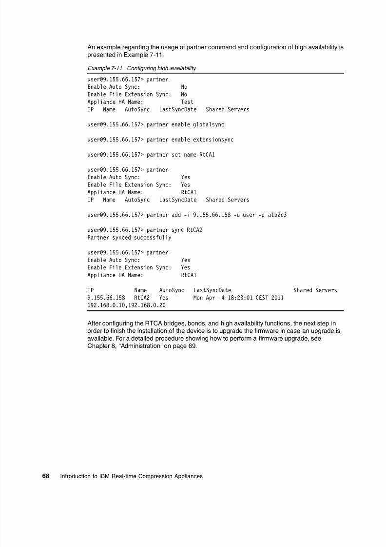
8/3/2019 Introduction to IBM Real-Time Compression Appliances
http://slidepdf.com/reader/full/introduction-to-ibm-real-time-compression-appliances 82/168
68 Introduction to IBM Real-time Compression Appliances
An example regarding the usage of partner command and configuration of high availability ispresented in Example 7-11.
Example 7-11 Configuring high availability
[email protected]> partnerEnable Auto Sync: No
Enable File Extension Sync: NoAppliance HA Name: TestIP Name AutoSync LastSyncDate Shared Servers
[email protected]> partner enable globalsync
[email protected]> partner enable extensionsync
[email protected]> partner set name RtCA1
[email protected]> partnerEnable Auto Sync: YesEnable File Extension Sync: Yes
Appliance HA Name: RtCA1IP Name AutoSync LastSyncDate Shared Servers
[email protected]> partner add -i 9.155.66.158 -u user -p a1b2c3
[email protected]> partner sync RtCA2Partner synced successfully
[email protected]> partnerEnable Auto Sync: YesEnable File Extension Sync: YesAppliance HA Name: RtCA1
IP Name AutoSync LastSyncDate Shared Servers9.155.66.158 RtCA2 Yes Mon Apr 4 18:23:01 CEST 2011192.168.0.10,192.168.0.20
After configuring the RTCA bridges, bonds, and high availability functions, the next step inorder to finish the installation of the device is to upgrade the firmware in case an upgrade isavailable. For a detailed procedure showing how to perform a firmware upgrade, seeChapter 8, “Administration” on page 69.

8/3/2019 Introduction to IBM Real-Time Compression Appliances
http://slidepdf.com/reader/full/introduction-to-ibm-real-time-compression-appliances 83/168

8/3/2019 Introduction to IBM Real-Time Compression Appliances
http://slidepdf.com/reader/full/introduction-to-ibm-real-time-compression-appliances 84/168
70 Introduction to IBM Real-time Compression Appliances
8.1 Working with the IBM Real-time Compression Appliance
After hardware installation and initial configuration, you can use the web interface to furtherconfigure the IBM Real-time Compression Appliance (RTCA).
8.1.1 The web interface
This topic provides a brief overview of the IBM Real-time Compression Appliance web-basedadministration tool and describes the elements of the compression appliance web-basedadministration tool.
Each page in the web interface has a structure that is consistent with the page that isdisplayed in Figure 8-1, including a menu pane and an input area. The link in the lower rightcorner displays the direction to the next step and displays only on some pages.
Figure 8-1 IBM Real-time Compression Appliance web interface
8.1.2 The menu
The main page has a menu bar on the left that consists of three main menu options:Configuration, General, and Administration.
The Configuration menu contains the following options:
Management Port: Used for configuring the compression appliance management port.
Network: Used for configuring the compression appliance data ports, creating bonds andbridges, and stopping and starting the compression engine.
Storage: Used for configuring which storage systems the compression applianceconnects to.
Compression Filters: Used for configuring which CIFS shares and NFS exports have to becompressed.

8/3/2019 Introduction to IBM Real-Time Compression Appliances
http://slidepdf.com/reader/full/introduction-to-ibm-real-time-compression-appliances 85/168
Chapter 8. Administration71
The General menu contains the following options:
Status: This page provides an overview of the compression appliance configuration,status, network ports, and resource utilization. This is also the main page displayed afterthe login is performed.
High Availability: Used for configuring the high availability of the compression appliance.
SNMP: Used for configuring SNMP settings.
LDAP: Used for configuring LDAP settings.
Security: Used for changing the compression appliance login password and specifying theIP addresses that can access the management interface.
System Options: Used for configuring various settings, such as web interface accessprotocol (HTTP and HTTPS), SNMP and other compression engine settings.
Miscellaneous: Used for setting the current date, time, and web interface session time-out;resetting the statistics counters; and configuring remote syslog servers.
The Administration menu contains the following options:
Upgrade: Used for upgrading the software version. For more information, see Upgrading
the compression appliance software .
HW Configuration File: Used for installing and reviewing the compression appliancehardware configuration file.
Configuration Backup: Used for saving or restoring the compression applianceconfiguration settings. For more information, see Backing up the configuration.
Diagnostics: Used for saving system logs and downloading diagnostic information.
Maintenance: Used for either shutting down or rebooting the system.
About: Used for viewing details of the software components versions installed.
Logoff: Used for logging out of the web interface.
8.1.3 Input area
Each page displays information according to the selected menu option. Parameters and otherinformation items are displayed and can be configured here.
The next step to be performed is displayed in the lower right-hand corner of each page and isoptional (see Figure 8-1).
8.1.4 Connecting to the web interface and access permissions
You can find information about how to connect to the RTCA using a web browser in7.4, “Configuring the RTCA product” on page 50.
Reference: See the IBM Real-time Compression Appliances Installation and Planning Guide for information about configuring remote management, bonds, bridges, storageservers, and compression filters.

8/3/2019 Introduction to IBM Real-Time Compression Appliances
http://slidepdf.com/reader/full/introduction-to-ibm-real-time-compression-appliances 86/168
72 Introduction to IBM Real-time Compression Appliances
8.2 Configuring compression accelerator
This topic provides a description of configuration options to be used when configuring theCompression Accelerator feature.
Before you begin, configure the compression filters for the shares and exports that need to be
compressed by Compression Accelerator.
By default, only newly written data is compressed on shares that are configured withcompression filters; existing files that are not updated are not compressed. The compressionaccelerator feature on the Storage page can be configured to compress existing files inspecified shares.
8.2.1 Compression accelerator procedure
Following is a step-by-step process showing how to configure the compression accelerator:
1. On the Storage page (Figure 8-2), click Configure on the Compression Accelerator tab.The Compression Accelerator page opens.
Figure 8-2 Storage configuration
2. Start the compression appliance.
3. When you compress NFS exports using Compression Accelerator, verify that the export
provides read/write access to the bridge IP addresses.4. When you compress CIFS shares using the Compression Accelerator, configure a user
name, password, and domain name in the CIFS user name, CIFS password, and CIFSdomain fields, respectively, and click Apply Changes.
Tip: Configure a CIFS user with read/write permissions on files that are processed bythe compression accelerator.

8/3/2019 Introduction to IBM Real-Time Compression Appliances
http://slidepdf.com/reader/full/introduction-to-ibm-real-time-compression-appliances 87/168
Chapter 8. Administration73
The Compression Accelerator supports various configuration parameters for scheduling,throttling, and policy-based file optimization that you can use to fine-tune the process.Figure 8-3 shows the Compression Accelerator Configuration items.
Figure 8-3 Compression accelerator settings
The Compression Accelerator Shares tab allows you to select the CIFS shares on the storageto be compressed in place (Figure 8-4).
Figure 8-4 Compression accelerator shares tab

8/3/2019 Introduction to IBM Real-Time Compression Appliances
http://slidepdf.com/reader/full/introduction-to-ibm-real-time-compression-appliances 88/168
74 Introduction to IBM Real-time Compression Appliances
The Compression Accelerator Exports tab allows you to select the NFS exports on thestorage to be compressed in place (Figure 8-5).
Figure 8-5 Compression Accelerator Exports tab
The Compression Accelerator Status tab allows you to manage and monitor compressiontasks (Figure 8-6).
Figure 8-6 Compression Accelerator Status tab
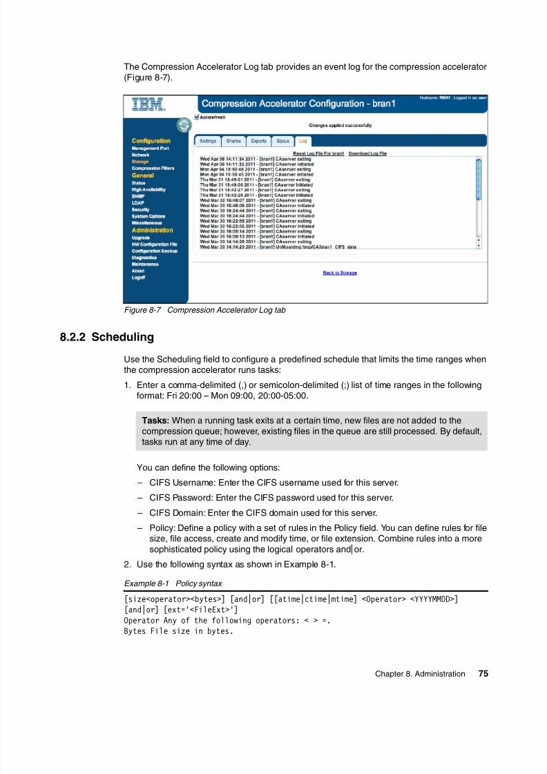
8/3/2019 Introduction to IBM Real-Time Compression Appliances
http://slidepdf.com/reader/full/introduction-to-ibm-real-time-compression-appliances 89/168

8/3/2019 Introduction to IBM Real-Time Compression Appliances
http://slidepdf.com/reader/full/introduction-to-ibm-real-time-compression-appliances 90/168
76 Introduction to IBM Real-time Compression Appliances
YYYYMMDD The file time stamp in the format: YYYY (year), MM (month), DD (day ofweek).FileExt The file extension of the file. Example:((size > 9000) or (ctime >20080304)) andmtime=20080909 and ext ='doc' The default policy is size > 512. Using the default,only files larger than a compressed file header size (512 bytes) are compressed.
– Directories to Ignore: Define the subdirectories to ignore when the task is processed inthe entire share or export using the Directories to Ignore field. Use this option forvarious types of snapshot or backup directories, which usually have the same name. Itis sufficient to specify only a directory name and not its path. The default policy is asfollows:
.snapshot ~snapshot .ckpt .isilon .ifsvar
– Maximum Total Throughput: Define compression I/O throttling in MB/sec using theMaximum Total Throughput field. When the throughput of write I/O that is directedtoward the NAS IP address that was configured on the Storage page reaches the limitspecified in this field, Compression Accelerator stops adding new files to itscompression queue until the throughput drops below the specified threshold.
– Amount of Changes: Define a quota (in MB/hours) for the aggregated changes that canbe written to the NAS server within the defined number of hours using the Amount ofChanges field. Define values that reflect the rate of change as observed on the NASsystem; for example, in N series snap delta output.
– Free Space Threshold: Set a minimum percentage of free space in the Free SpaceThreshold field and then click Apply Changes. Compression Accelerator In-Placetasks automatically pause if this threshold is exceeded. The default setting is 5%.
– Interval Between Files: Define the interval (in milliseconds) between new files enteringthe compression accelerator queue using the Interval Between Files field. The valuecan be in the range 1 - 10000; the default value is 10 milliseconds. Increasing thisvalue reduces the load on the storage; however, it slows the compression. Setting theinterval to 1 millisecond provides the highest compression throughput.
3. Click Save Configuration to apply the settings.
4. Select the shares or exports to compress from the list of available compression filters andthen click Update List.
Results: After applying the configuration and adding the shares, the CompressionAccelerator Configuration page opens showing the changes.
NAS: The free disk space verification relies on reporting that is provided by theNAS. The NAS configuration items such as quotas can affect the behavior of thisfeature.
Tip: Avoid adding the NAS root file system (for example, /vol/vol0 in N series systems)to the Compression Accelerator task list. Adding this file system to the task list can
result in compression of the storage system files, which are read directly by the NASsystem and therefore must remain uncompressed.

8/3/2019 Introduction to IBM Real-Time Compression Appliances
http://slidepdf.com/reader/full/introduction-to-ibm-real-time-compression-appliances 91/168
Chapter 8. Administration77
8.2.3 Monitoring the Compression Accelerator
You can start and monitor the Compression Accelerator processes (see Figure 8-8).
The following procedure shows how to perform the task:
1. Click Start.
Figure 8-8 Compression Accelerator Status tab
2. Click Refresh in the upper-right corner of the menu to refresh the page.
3. View the Compression Accelerator status under Current Status. The following states arepossible:
– Not started: The compression accelerator process has not started.– Pending: The compression accelerator process is busy mounting an export.– Started: The compression accelerator process has started.– Finished: The compression accelerator process has finished processing all exports or
shares and has now stopped.
4. View information about the configured compression tasks:
– Export or Share: The name of the export or share that is configured for compression.
– Type: NFS or CIFS
– State: The state of the compression task for this export or share; the following valuesare possible:
• Not running: The compression task for this export or share is not running.• Started: The compression task is running.• Pending: The compression task is pending, for example, when another task is
running.• Paused: The compression task is paused because a configured threshold has been
reached.
Status: The status is updated in real time on the page and shows the files that arecurrently being compressed.

8/3/2019 Introduction to IBM Real-Time Compression Appliances
http://slidepdf.com/reader/full/introduction-to-ibm-real-time-compression-appliances 92/168
78 Introduction to IBM Real-time Compression Appliances
• Unmounting: The compression task is disconnecting from the export or share.• Finished: The compression task has finished.
– Number of Files processed: Total number of files that have been processed by thecompression accelerator.
– Number of Files scanned: Total number of files that have been scanned by thecompression accelerator.
– Total Data processed: Total amount of data that has been processed by thecompression accelerator.
– Total Data scanned: Total amount of data that has been scanned by the compressionaccelerator.
– Start Time: The start time of the compression task.
– End Time: The end time of the compression task.
8.2.4 Resetting the accelerator log
You can reset the Compression Accelerator log. To do so, click Reset Log File For
<server_name> at the bottom of the Compression Accelerator Configuration page.
8.3 High availability concepts
The high availability (HA) concept for the IBM RTCA refers to both the appliance configurationand external environment configuration. Because the IBM RTCA is acting as an intelligent cable without involvement in the TCP/IP traffic management, but only reducing the amount ofdata from IP frames, the way high availability is implemented is different from other similarimplementations. When you configure a compression appliance in a high availabilityconfiguration, both appliances must have the same compression filters because the dataflows are not under RTCA care but more on the network and storage mechanism.
The important aspect in RTCA HA implementation is to be sure that if failover occurs and thedata becomes accessible over the second appliance, the filters are also in place and userswill not connect directly to an uncompressed volume. A procedure for synchronizing the filtersis given in 7.6, “Configuring high availability” on page 62. Suggested configurations to achievehigh availability can be found in Chapter 6, “Implementation planning” on page 37 andChapter 9, “NAS / N series solution design” on page 123.
Another very important aspect is the configuration of the appliance behavior as Compress orNot Compress and No New Compression activation. These topics are described in 8.4,“Configuring storage and compression filters”.
Important: When synchronizing the filters, you need to know that if there are differences,the filters from the target appliance or partner will be deleted and replaced with the filtersfrom the initiator of the sync procedure. In this situation, if on the target appliance there aresome filters that are not created on the sync initiator, those filters will be lost and thecompressed volumes can become accessible directly by the user. In this situation, youmight affect data integrity by changing the information without being aware that data iscompressed, not affected or compromised. This situation can apply also when you breakthe high availability pair, remove the Sync Pair, and modify the filters on both appliances.When rebuilding the high availability pair, filters are replicated in one way and thedifferences are replicated at this stage, also in one way.

8/3/2019 Introduction to IBM Real-Time Compression Appliances
http://slidepdf.com/reader/full/introduction-to-ibm-real-time-compression-appliances 93/168

8/3/2019 Introduction to IBM Real-Time Compression Appliances
http://slidepdf.com/reader/full/introduction-to-ibm-real-time-compression-appliances 94/168
80 Introduction to IBM Real-time Compression Appliances
8.4.1 Transparent mode
The transparent mode is the default in the software version 3.7. If you have a lot of NASresources at your NAS storage server that must not be compressed, such as datacompressed by an ECM application in many shares, and you want to compress only a part ofyour NAS storage server, it is best to use the transparent mode.
To switch to the transparent mode, proceed as follows:
1. Set the option “Compress Mode” to disabled. Click System Option under the Generalsection and then click disabled in the row “Compress Mode” as shown in Figure 8-10.
Figure 8-10 Compress Mode Disabled, No New Compression Disabled
2. If you want to enable the “No New Compression” configuration capability, you have to setthe system option “No New Compression” to enable.
The option “No New Compression” unhides the drop-down box in the “CompressionFilters” menu under the Configuration section to switch on or off the condition that newdata will be written pass-through or compressed. Click System Options under theGeneral section and then click Enable in the row “No New Compression,” as you can seein Figure 8-11.

8/3/2019 Introduction to IBM Real-Time Compression Appliances
http://slidepdf.com/reader/full/introduction-to-ibm-real-time-compression-appliances 95/168
Chapter 8. Administration81
Figure 8-11 Compress Mode Disabled, No New Compression Enabled
The configuration of compression of shares/exports can be done on the “CompressionFilters” menu under the “Configuration” section, as shown in Figure 8-12 for CIFS and inFigure 8-13 for NFS. You can see CLI examples in Example 8-2.
3. To create a new compressed share, select the share from the drop-down box or type theUNC name of the share manually in the appropriate field and click Apply changes toShares/Exports. Additionally you can add some file extension in the field “Extension to
exclude” to avoid double compressing of compressed data.
The impact of the NNC switch is as follows:
– If you set the NNC option to “off”, all new data in the corresponding share/export will becompressed.
– If you set the NNC option to “on”, any new written data will not be compressed.
However, independently of the NNC switch, all existing data will not be changed.
4. To remove a compressed share/export from the filter list, mark the Delete check box of thecorresponding share/export and click Apply Changes to Shares/Exports.
Tip: If you delete a share/export from the list, all data will be unchanged and presented to
the clients directly without passing the compression engine. If the share/export containcompressed data, you can only access them after manually recovery; see “Recoveringfiles when appliance is unavailable” on page 119.

8/3/2019 Introduction to IBM Real-Time Compression Appliances
http://slidepdf.com/reader/full/introduction-to-ibm-real-time-compression-appliances 96/168
82 Introduction to IBM Real-time Compression Appliances
Figure 8-12 Compression filters CIFS
Example 8-2 creating a compression filter for CIFS by command line
[email protected]> filter add bran1b -c nocheck -t cifs homeTransparent - - \\bran1b\C$Transparent - - \\bran1b\D$Transparent - - \\bran1b\E$Transparent - - \\bran1b\ETC$Transparent - - \\bran1b\F$Transparent - - \\bran1b\HIDDEN$Transparent - - \\bran1b\IPC$Transparent - - \\bran1b\home
Tip: The column NNC is only displayed if the system option “No New Compression” is setto enabled.

8/3/2019 Introduction to IBM Real-Time Compression Appliances
http://slidepdf.com/reader/full/introduction-to-ibm-real-time-compression-appliances 97/168
Chapter 8. Administration83
Figure 8-13 Compression filters NFS
Example 8-3 Creating a compression filter for NFS by CLI
[email protected]> filter list available -t nfsbran1:/vol/bran1abran1:/vol/bran1bbran1:/vol/databran1a:/vol/bran1a/databran1a:/vol/bran1a/rootbran1b:/vol/bran1b/data
bran1b:/vol/bran1b/rootbran2:/vol/databran2:/vol/vol0bran2:/vol/vol0/home
[email protected]> filter add bran1b -c check -t nfs /vol/bran1b/[email protected]> filter list -t nfsCompression Mode No New Compression Warnings Share/ExportCompressed Off - bran1:/vol/dataTransparent - - bran1b:/vol/bran1b/dataTransparent - - bran1b:/vol/bran1b/rootCompressed Off - bran2:/vol/data
8.4.2 Compress mode
In large environments with a lot of NAS resources that you want to compress, it can be easierto switch the system-wide policy to compress mode. An additional advantage of compressmode is the possibility to compress data of dynamic shares, such as home directory shares ofNetApp FAS or IBM N series in an easier way without creating a dedicated compression filterfor every share.
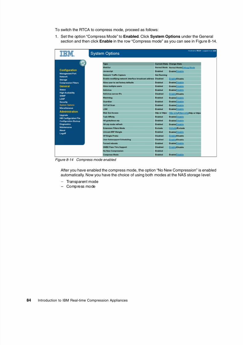
8/3/2019 Introduction to IBM Real-Time Compression Appliances
http://slidepdf.com/reader/full/introduction-to-ibm-real-time-compression-appliances 98/168
84 Introduction to IBM Real-time Compression Appliances
To switch the RTCA to compress mode, proceed as follows:
1. Set the option “Compress Mode” to Enabled. Click System Options under the Generalsection and then click Enable in the row “Compress mode” as you can see in Figure 8-14.
Figure 8-14 Compress mode enabled
After you have enabled the compress mode, the option “No New Compression” is enabledautomatically. Now you have the choice of using both modes at the NAS storage level:
– Transparent mode– Compress mode

8/3/2019 Introduction to IBM Real-Time Compression Appliances
http://slidepdf.com/reader/full/introduction-to-ibm-real-time-compression-appliances 99/168
Chapter 8. Administration85
In Figure 8-15 you can see the new menu for configuring storage servers. For everystorage server, you can configure the compression mode independently.
Figure 8-15 Compress mode and transparent mode for different storage servers
2. Choose Compressed from the drop-down box and click Apply changes. Alternatively,change the compress mode by using the CLI, as shown in Example 8-4.
Example 8-4 Changing compress mode by CLI
[email protected]> server display bran1aServer Name Storage Vendor Storage IP Mode No New CompressionStatus Antivirus Server IPbran1a N-Series 192.168.0.11 Transparent -Active
[email protected]> server change bran1a -m Compressed -noNewCompression onServer successfully changed
[email protected]> server display bran1aServer Name Storage Vendor Storage IP Mode No New CompressionStatus Antivirus Server IPbran1a N-Series 192.168.0.11 Compressed OnActive
The data of a storage server in transparent mode will be handled as described in“Transparent mode” on page 80.
Attention: A transition from compressed mode to transparent mode is not allowed.

8/3/2019 Introduction to IBM Real-Time Compression Appliances
http://slidepdf.com/reader/full/introduction-to-ibm-real-time-compression-appliances 100/168
86 Introduction to IBM Real-time Compression Appliances
When converting a storage system from transparent mode to compressed mode, thecompression filters for this storage system will be modified accordingly to preserve theexisting configuration.
Administrators must check the compression filter exclusion list so that all administrativeshares or exports are included. Otherwise the RTCA will store configuration files of theroot directory or etc$ share as compressed files.
Writing compressed data to administrative shares or exports, which contain the storagesystem's operating system and configuration parameters (such as /vol/vol0), can causesevere storage system functionality issues. If you have a virtual filer (vfiler) configured, itmight be necessary to add the root qtrees/volumes of vfiler manually; see Figure 8-16.
3. To complete the conversion of your NAS storage server, select off on the drop-down box“NNC” and click Apply Changes, as shown in Figure 8-15 on page 85, or change it by CLIas you can see here in Example 8-5.
Example 8-5 Changing No New Compression using the CLI
[email protected]> server change bran1a -noNewCompression offServer successfully [email protected]> server display bran1aServer Name Storage Vendor Storage IP Mode No New CompressionStatus Antivirus Server IPbran1a N-Series 192.168.0.11 Compressed Off Active
After the conversion is complete (that is, the storage system is now configured incompressed mode), by default, all new shares or exports created on the storage systemand accessed through this interface will be compressed (Figure 8-16).
Figure 8-16 Compression filter, exclude administrative shares/exports of vfiler manually
Tip: For security reasons, the NNC option is set to “on” for a freshly converted storageserver. This means that no data will be compressed until this option is set to “off”.

8/3/2019 Introduction to IBM Real-Time Compression Appliances
http://slidepdf.com/reader/full/introduction-to-ibm-real-time-compression-appliances 101/168
Chapter 8. Administration87
“No New Compression” sets the operation mode for new files created on shares andexports marked for compression using the compression filters mechanism. After settingthis mode to Off, new files will be created as compressed or non-compressed, based onthe compression mode in the compression filters list.
In Figure 8-17 you can see the default administrative shares of \\bran1b after conversion.The Compression mode for these shares is configured as “Transparent”.
Figure 8-17 Compression filter in RTCA compress mode, default administrative shares
If the storage server will be operated in compress mode, it is not necessary to create anynew compression filter for new created shares and exports.
To disable the compression of specific shares or exports, create those shares or exportson the storage system, and then add them to the compression filters exclusion list whilethis storage server is configured in “No New Compression” (NNC) mode.
4. Open the CIFS/NFS filters menu by clicking Compression Filters under the“Configuration” section. Now you can either select the share from the drop-down box ortype it manually. Click Apply changes to Shares/Exports” to finish, as you can see inFigure 8-17. The configuration steps to add a compression filter exclusion using the CLIare shown in Example 8-6.

8/3/2019 Introduction to IBM Real-Time Compression Appliances
http://slidepdf.com/reader/full/introduction-to-ibm-real-time-compression-appliances 102/168
88 Introduction to IBM Real-time Compression Appliances
Example 8-6 Creating a compression filter exclusion for NFS by CLI
[email protected]> filter list available -t nfsbran1:/vol/bran1abran1:/vol/bran1bbran1:/vol/databran1a:/vol/bran1a/data
bran1a:/vol/bran1a/rootbran1b:/vol/bran1b/databran1b:/vol/bran1b/rootbran2:/vol/databran2:/vol/vol0bran2:/vol/vol0/home
[email protected]> filter add bran1a -t nfs /vol/bran1a/[email protected]> filter list -t nfsCompression Mode No New Compression Warnings Share/ExportCompressed Off - bran1:/vol/dataTransparent - - bran1a:/vol/bran1a/rootTransparent - - bran1b:/vol/bran1b/data
Transparent - - bran1b:/vol/bran1b/rootCompressed Off - bran2:/vol/[email protected]>
8.5 Monitoring the compression appliance
The management of the RTCA can be done by using the CLI or GUI. For most use cases, theGUI would provide an easier approach, but we also describe the CLI commands used in ourexamples. The main tasks for management are as follows:
Displaying compression appliance status: Compression appliance status informationavailable on the Status page.
Displaying storage status: Review information about the connectivity status of each fileserver or NAS.
Displaying compression status: Describes how to display information about thecompression engine, including the status of the shares and exports and the file nameextensions excluded from compression.
Configuring SNMP: Configure and modify the SNMP configuration settings.
Configuring LDAP: Configure and modify the LDAP notification settings.
Performing other compression appliance tasks: Set the time and date, reset compressionstatistics, configure the web interface session time-out, configure an external syslog
server, and configure DNS.
In the following sections, we describe these main tasks in detail.

8/3/2019 Introduction to IBM Real-Time Compression Appliances
http://slidepdf.com/reader/full/introduction-to-ibm-real-time-compression-appliances 103/168
Chapter 8. Administration89
8.5.1 Displaying compression appliance status
A general view of the Status panel is shown in Figure 8-18.
Figure 8-18 Status panel overview
On the status page, use the panel components as follows:
1. Device Information (Figure 8-18): Data about the compression appliance hardware andsoftware. Use this panel to see the following device information:
– Product: The compression appliance model.– Hostname: The compression appliance host name.– Version: The compression software version ID.– Serial Number: The compression appliance serial number.
2. Status (Figure 8-18): The current state of the compression engine and various diagnosticprobes. Use this panel to see the following status information:
– Engine: The recent status of the compression engine, either running (green) orstopped (red).
– Bonds: The recent status of the bonding probe. This probe verifies whether ports ofLink Aggregation Control Protocol (LACP) bonds are connected according to theconfiguration. This probe uses LACP information that is available for each port to verifythat ports are connected correctly.
LACP: The LACP, also known as IEEE 802.3ad standard, is a port aggregationprotocol that allows for multiple network cables and ports to work in parallel toincrease the link speed beyond the limits of any one single cable or port, and toincrease the redundancy for higher availability.

8/3/2019 Introduction to IBM Real-Time Compression Appliances
http://slidepdf.com/reader/full/introduction-to-ibm-real-time-compression-appliances 104/168
90 Introduction to IBM Real-time Compression Appliances
– Duplicate IPs: The recent status of the duplicate IP addresses probe. This probedetects whether there are any duplicate IP addresses in the network (using any of thecompression appliance bridge IP addresses).
– Gateways: The recent status of the default gateway probe. This probe detects whetherthere is access to the default gateways that are configured for the compressionappliance bridges. This probe uses Internet Control Message Protocol (ICMP) todetect connectivity to the default gateways.
– Vendors: The recent status of the storage vendor probe. This probe detects whetherthe NAS system vendor that was chosen on the Storage page matches the actualsystem vendor that was detected.
– Hardware: The current state of the hardware platform.This probe is using the hardwarealarms form the server to signal if there are any failed components.
3. Network (Figure 8-18): Use this panel to see the status of network ports (Figure 8-19).
Figure 8-19 Network interface legend
The following interface status information is displayed:
– Interface Up: The interface is configured and the physical link is up - port green.
– Interface Down: The interface is configured and the physical link is down - port red.
– Not configured: The interface is not configured; the physical link state is unknownbecause the interface is shut down from the software - port grey.
4. Resource (Figure 8-18): Utilization Monitoring of various system resources andperformance metrics. Use this panel to see the following resources:
– CPU: Current compression appliance CPU utilization.
– System Memory: Total amount of RAM that is installed in the appliance.
– Engine Memory: Amount of memory that is currently allocated to the compression
engine.– CIFS Connections: Current and peak number of CIFS connections.
– NFS Connections: Current and peak number of NFS connections.
– Compression Rate: The percentage of capacity saved; as data passes through thecompression engine and gets compressed, the compression rate is calculated by theamount of data that has been saved (during write operations) compared to the totalamount of data that has passed through the compression appliance.
Probe: This probe uses information that is available in networking command outputson the compression appliance to detect duplicate IP addresses. The duplicate IPsprobe is checked only on the direct attached network (not on passing routers).

8/3/2019 Introduction to IBM Real-Time Compression Appliances
http://slidepdf.com/reader/full/introduction-to-ibm-real-time-compression-appliances 105/168
Chapter 8. Administration91
– Accumulated Space Savings: The accumulated amount of disk space that has beensaved by the compression over the complete runtime of the compression appliance orsince the time the space savings counter was reset.
5. From the CLI, use the following commands to monitor all previous parameters:
– Hostname (Example 8-7): Returns the name of your appliance. Also you can modifythe name of the appliance with this command.
Example 8-7 Hostname command output
[email protected]> hostnameHostname: RtCA1
– Display (Example 8-8): With the “config” or “sensor” attribute will return most of thehardware, software and networking information. The values attributes for probingmodules are: green value is 1 and for red value is 0. Example 8-8 is displaying only theoutput for the display config command.
Example 8-8 Display command output
[email protected]> display config
======================================== DNS ========================================DNS Enabled: noDNS Domain:DNS Search:
======================================== NTP ========================================There are no ntp servers defined======================================== SNMP ========================================SNMP Enabled Yessyslocation Computer roomsyscontactRead Only Community publicLow Free Memory Trap Interval (secs) 1800
Low Free Disk Space Trap Interval (secs) 1800Fan Failed Trap Interval (secs) 1800Power Supply Failed Trap Interval (secs) 1800High Temperature Trap Interval (secs) 1800Disk Failed Trap Interval (secs) 60
Trap Destination Trap Port (Default 162) Trap Community127.0.0.1 - public
======================================== SYSLOG ========================================Send messages: yesSend changelog: yesSend sw_hw_snmp: yes======================================== LDAP ========================================
LDAP: Disableduri:base:LDAP Server Type:binddn:bindpw: ******anonymous bind: noauthorization filter:

8/3/2019 Introduction to IBM Real-Time Compression Appliances
http://slidepdf.com/reader/full/introduction-to-ibm-real-time-compression-appliances 106/168

8/3/2019 Introduction to IBM Real-Time Compression Appliances
http://slidepdf.com/reader/full/introduction-to-ibm-real-time-compression-appliances 107/168
Chapter 8. Administration93
======================================== OPTIONS advanced========================================Key ValueCAInPlace:CAInPlaceMode 2General:logbuf 4General:logcifs 4General:logfs 4
General:lognfs 4General:logsock 4General:logutil 4General:noOcteon 1Z_OPTIONS:AutoSequenceTimeoutMins 30Z_OPTIONS:CAthreads 10Z_OPTIONS:engineWatchdog 1
– Engine (Example 8-9): Returns the status of the compression engine.
Example 8-9 Engine command output
[email protected]> engineEngine: running
– Partner (Example 8-10): Returns the state and configuration of the high availabilityfeature.
Example 8-10 Partner command output
[email protected]> partnerEnable Auto Sync: YesEnable File Extension Sync: YesAppliance HA Name: RtCA1
IP Name AutoSync LastSyncDate Shared Servers9.155.66.158 RtCA2 Yes Wed Apr 13 12:53:08 CEST 2011192.168.0.11,192.168.0.10,192.168.0.20,192.168.0.12

8/3/2019 Introduction to IBM Real-Time Compression Appliances
http://slidepdf.com/reader/full/introduction-to-ibm-real-time-compression-appliances 108/168
94 Introduction to IBM Real-time Compression Appliances
8.5.2 Displaying storage status
To display the storage status, proceed as follows:
1. From the left panel, choose Storage to view the current status of your storage device.
Figure 8-20 Storage status monitoring
The Storage panel provides information about the connectivity status of each fileserver/storage.
There are three possible states for the Status parameter:
– Not Connected: The compression appliance is unable to reach the file server.– Active: The compression appliance is connected in a high availability configuration and
is currently the active appliance for this file server.
– Standby: The compression appliance is connected in a high availability configurationand is currently the passive appliance for this file server.
2. To monitor the storage systems from the CLI, use the server command as shown in
Example 8-11. Here you can see the output of this command.
Example 8-11 Server command output
[email protected]> serverServer Name Storage Vendor Storage IP Mode No New Compression Statusbran1 N-Series 192.168.0.10 Transparent - Activebran1a N-Series 192.168.0.11 Transparent - Activebran1b N-Series 192.168.0.12 Transparent - Activebran2 N-Series 192.168.0.20 Transparent - Standby
Attention: The columns “Compression Mode” and “NNC” (No New Compression) areavailable for settings only if, from the “System Options,” you choose to enable them. The“Compression Mode” setting will automatically activate the “NNC” option.

8/3/2019 Introduction to IBM Real-Time Compression Appliances
http://slidepdf.com/reader/full/introduction-to-ibm-real-time-compression-appliances 109/168
Chapter 8. Administration95
8.5.3 Displaying compression statusTo view the compression status at each volume level, proceed as follows:
1. ,Navigate to Diagnose from the left panel and then choose the Display CompressionFilters option (Figure 8-21).
Figure 8-21 Compression filters status
This page displays information about the compression engine, including these items:
– Status: Lists the status of each of the CIFS shares and NFS exports that are definedon the Compression Filters page.
– CIFS shares: Lists the status of the CIFS shares that were defined in the CompressionFilters page.
– NFS Exports: Lists the status of the NFS exports that were defined in the CompressionFilters page. Child exports are displayed indented under the parent.
– File name extensions: Lists those that are excluded from compression. Displays anyfile name extensions that have been configured to be excluded from compression.
Tip: There could be several reasons why a file server is unreachable. For example, theserver might be physically disconnected, the network switch port settings might beincorrect (wrong VLAN), and so on.
Status: A green status indicates that the share/export exists and compression isapplied for the share/export. A red status indicates that compression is not applied forthe share/export.

8/3/2019 Introduction to IBM Real-Time Compression Appliances
http://slidepdf.com/reader/full/introduction-to-ibm-real-time-compression-appliances 110/168
96 Introduction to IBM Real-time Compression Appliances
2. From the CLI, use the filter command with the list parameter, as shown inExample 8-12.
Example 8-12 Filter output command
[email protected]> filter list available -t cifs\\bran1\data
\\bran1\data_bz\\bran1a\data\\bran1b\data\\bran2\dataz
[email protected]> filter list -t cifsCompression Mode No New Compression Warnings Share/ExportCompressed Off - \\bran1\dataCompressed Off - \\bran1a\dataCompressed Off - \\bran1b\data
[email protected]> filter list available -t nfsbran1:/vol/bran1abran1:/vol/bran1b
bran1:/vol/databran1a:/vol/bran1a/databran1a:/vol/bran1a/rootbran1b:/vol/bran1b/databran1b:/vol/bran1b/rootbran2:/vol/databran2:/vol/vol0bran2:/vol/vol0/home
[email protected]> filter list -t nfsCompression Mode No New Compression Warnings Share/ExportCompressed Off - bran2:/vol/data
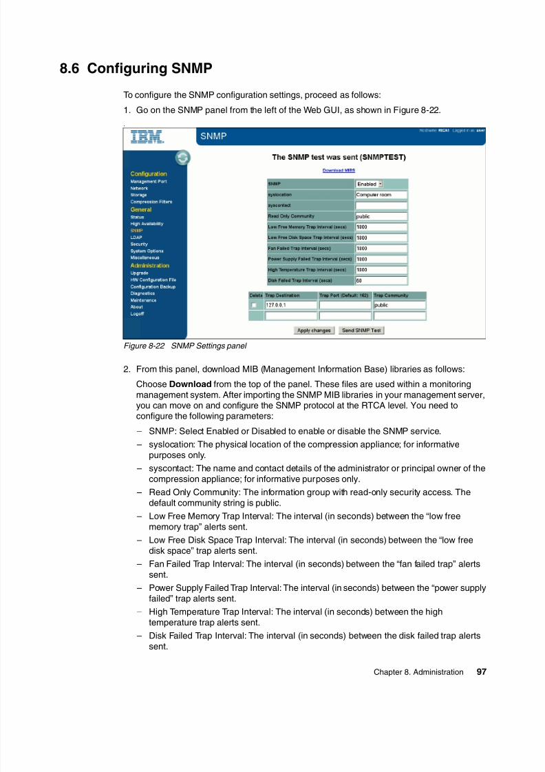
8/3/2019 Introduction to IBM Real-Time Compression Appliances
http://slidepdf.com/reader/full/introduction-to-ibm-real-time-compression-appliances 111/168
Chapter 8. Administration97
8.6 Configuring SNMP
To configure the SNMP configuration settings, proceed as follows:
1. Go on the SNMP panel from the left of the Web GUI, as shown in Figure 8-22.
.
Figure 8-22 SNMP Settings panel
2. From this panel, download MIB (Management Information Base) libraries as follows:
Choose Download from the top of the panel. These files are used within a monitoringmanagement system. After importing the SNMP MIB libraries in your management server,
you can move on and configure the SNMP protocol at the RTCA level. You need toconfigure the following parameters:
– SNMP: Select Enabled or Disabled to enable or disable the SNMP service.
– syslocation: The physical location of the compression appliance; for informativepurposes only.
– syscontact: The name and contact details of the administrator or principal owner of thecompression appliance; for informative purposes only.
– Read Only Community: The information group with read-only security access. Thedefault community string is public.
– Low Free Memory Trap Interval: The interval (in seconds) between the “low freememory trap” alerts sent.
– Low Free Disk Space Trap Interval: The interval (in seconds) between the “low freedisk space” trap alerts sent.
– Fan Failed Trap Interval: The interval (in seconds) between the “fan failed trap” alertssent.
– Power Supply Failed Trap Interval: The interval (in seconds) between the “power supplyfailed” trap alerts sent.
– High Temperature Trap Interval: The interval (in seconds) between the hightemperature trap alerts sent.
– Disk Failed Trap Interval: The interval (in seconds) between the disk failed trap alertssent.

8/3/2019 Introduction to IBM Real-Time Compression Appliances
http://slidepdf.com/reader/full/introduction-to-ibm-real-time-compression-appliances 112/168
98 Introduction to IBM Real-time Compression Appliances
3. Set the monitoring server parameters:
– Trap Destination: The IP address of the server that receives the SNMP traps.
– Trap Port: The port on which the server receives SNMP traps. The default port is port162.
– Trap Community: The information group to which the alerts are associated.
4. After the SNMP options have been configured, send a test SNMP trap by clickingSend SNMP Test. A test trap is sent to the configured trap hosts. Now connect to yourmanagement server and verify the test results.
5. To configure the SNMP protocol from CLI, use the SNMP command to set all the previousparameters as necessary. In addition, you can use the command to review the currentsettings of the SNMP protocol (see Example 8-13).
Example 8-13 Checking SNMP Status
[email protected]> snmpSNMP Enabled Yessyslocation Computer roomsyscontactRead Only Community publicLow Free Memory Trap Interval (secs) 1800Low Free Disk Space Trap Interval (secs) 1800
Fan Failed Trap Interval (secs) 1800Power Supply Failed Trap Interval (secs) 1800High Temperature Trap Interval (secs) 1800Disk Failed Trap Interval (secs) 60
Trap Destination Trap Port (Default 162) Trap Community127.0.0.1 - public
Example 8-14 shows how to configure SNMP step by step using the CLI interface. Also, for anextensive help, you can use the SNMP help command.
Example 8-14 Configure SNMP using CLI
//enable SNMP on RtCA [email protected]> snmp enable
//download the MIB file to a workstation - the download is not supported ininteractive SSH mode.bash> ssh [email protected] snmp mibs download > MIB_file.zip
//add an SNMP trap receiver to the system - management [email protected]> snmp trap add -i 9.155.66.190 -c public
SNMP: Default values for SNMP traps are as follows:
Low Free Memory Trap Interval: 1800s Low Free Disk Space Trap Interval: 1800s Fan Failed Trap Interval: 1800s Power Supply Failed Trap Interval: 1800s
High Temperature Trap Interval: 1800s Disk Failed Trap Interval: 1800s

8/3/2019 Introduction to IBM Real-Time Compression Appliances
http://slidepdf.com/reader/full/introduction-to-ibm-real-time-compression-appliances 113/168
Chapter 8. Administration99
//define the System Location in the [email protected]> snmp -l RightHere
//Define the interval between sending fan failure traps to 10 [email protected]> snmp -f 10
//test by sending a SNMP [email protected]> snmp test
8.7 Configuring LDAP
The LDAP (Lightweight Directory Access Protocol) option can be used to configure thecompression appliance to authorize administration users to log in to the web interface andCLI. The accounts that are configured in an LDAP directory service (that is, Active Directory)can be utilized in this way to log on and administrate the appliance.
8.7.1 Configure
In order to configure the LDAP protocol, proceed as follows
1. Go on the left panel and click the LDAP option under the “General” section. The new panelwill give you the possibility to choose and configure different LDAP parameters(Figure 8-23). The following parameters are available for configuration:
– LDAP: Choose whether LDAP authorization service is enabled or disabled. LDAP is
disabled by default.– type: The LDAP server type. Currently, only Microsoft Active Directory (Windows®
2003/2008 - based) is supported.
– basedn: The LDAP directory base distinguished name (DN). Typically, the base DN isin the format DC=privatedomain, DC=com, where privatedomain.com is the ActiveDirectory fully-qualified domain name (FQDN).
– Anonymous bind: Choose if configuring anonymous LDAP bind requests. Thecompression appliance attempts to bind to the LDAP server without specifying anycredentials.
– binddn: Configure the bind domain name with a user name from the LDAP directory tosend login-based LDAP bind requests. In most cases, any user in the LDAP tree can
be used. LDAP searches do not usually require unique permissions. Use the followingformat:
CN=Administrator, OU=Users, DC=privatedomain, DC=com
– bindpw: Enter the password of the user name specified in the bind DN.
– Authorization filter: After configuring the LDAP, by default, all users in the basedirectory are allowed access to the compression appliance. If a restriction is imposed,you can limit the users allowed to log on by limiting the search of the RTCA in the LDAPdata base. In order to limit the compression appliance access to a specific section ofthe LDAP directory, configure the authorization filter. A user is usually added to a groupand the authorization filter is specified as a full FQDN (Example 8-15(,
Important: The LDAP option is used only for administrative connection purposes. It will notbe used for shares security or any other communication between the storage and theusers.

8/3/2019 Introduction to IBM Real-Time Compression Appliances
http://slidepdf.com/reader/full/introduction-to-ibm-real-time-compression-appliances 114/168
100 Introduction to IBM Real-time Compression Appliances
Example 8-15 Authorization filter setting example
memberOf=CN=STNUsers,DC=privatedomain,DC=com.
Figure 8-23 LDAP configuration
2. After configuring the LDAP protocol, as the next step, add LDAP servers. To do that, fill in
the options from the bottom of the “LDAP” panel (Figure 8-23) with the name of the serverand the IP address. If you are using more than one server for authentication, you canchoose to give priority to the LDAP Server.
Tip: Selecting the Anonymous bind option causes the “binddn” and “bindpw” fields todisappear. The default Active Directory security policy does not accept anonymousbinds. However, Active Directory can be configured to accept anonymous binds.
User rights: The Priority parameter will give the order of querying the LDAP server inthe list. If one server is not accessible, the next one will be asked. If one server returns“user does not have rights” then the query is stopped and the “login failed” will bereturned to the user. The highest priority is 1 and the lowest is 9.

8/3/2019 Introduction to IBM Real-Time Compression Appliances
http://slidepdf.com/reader/full/introduction-to-ibm-real-time-compression-appliances 115/168
Chapter 8. Administration101
Figure 8-24 Adding server to LDAP configuration
3. If needed after adding the servers (Figure 8-24), change the basic parameters of LDAPcommunication (see Figure 8-25):
– Change the usage of simple LDAP authentication with use of LDAP over SSL - LDAPS.– Change the LDAP or LDAPS ports.
Figure 8-25 LDAP change server communication parameters
Ports: By default, port number 3268 is used for LDAP and port number 3269 forLDAPS.

8/3/2019 Introduction to IBM Real-Time Compression Appliances
http://slidepdf.com/reader/full/introduction-to-ibm-real-time-compression-appliances 116/168
102 Introduction to IBM Real-time Compression Appliances
4. To configure LDAP protocol and servers using the CLI, follow Example 8-16.
Example 8-16 Configuring LDAP using CLI
//check LDAP [email protected]> ldapLDAP: Disabled
uri:base:LDAP Server Type:binddn:bindpw: ******anonymous bind: noauthorization filter:
//set LDAP [email protected]> ldap set type ActiveDirectoryLDAP type set to Active Directory
//set base domain
[email protected]> ldap set base DC=privatedomain,DC=tstLDAP basedn set
//set anonymous [email protected]> ldap set no_anonymous_bindNo anonymous bind set
//Set the user used to bind [email protected]> ldap set binddn CN=Admin,OU=RtCA,CN=privatedomain,CN=tst
//set password for user accesing the [email protected]> ldap set bindpw a1b2c3
//Restrict the groups that should be search to approve log [email protected]> ldap set filter memberOf=CN=RtCA,DC=privatedomain,DC=tstLDAP filter set
//Enable and check the [email protected]> ldap enableLDAP [email protected]> ldapLDAP: Enableduri:base: DC=privatedomain,DC=tstLDAP Server Type: ActiveDirectory
binddn: CN=Admin,OU=RtCA,CN=privatedomain,CN=tstbindpw: ******anonymous bind: noauthorization filter: memberOf=CN=RtCA,DC=privatedomain,DC=tst
//add server - prior to add a server you should check the DNS configuration - itmust be disabled
[email protected]> dnsDNS Enabled: yesDNS Domain: privatedomain.tst

8/3/2019 Introduction to IBM Real-Time Compression Appliances
http://slidepdf.com/reader/full/introduction-to-ibm-real-time-compression-appliances 117/168

8/3/2019 Introduction to IBM Real-Time Compression Appliances
http://slidepdf.com/reader/full/introduction-to-ibm-real-time-compression-appliances 118/168
104 Introduction to IBM Real-time Compression Appliances
Here is a description of the fields and kinds of information that you can find on this panel:
– LDAP Server Name: The name of the LDAP server as defined in the compressionappliance.
– LDAP Protocol: The configured LDAP protocol (LDAP or LDAPS) for the current server.
– Port: The TCP/IP port configured for communicating with the RTCA product.
– IP: The P address that is configured for the LDAP server.
– Ping Results: Returns results of the ping utility to the LDAP server, verifying theconnectivity to the server.
– nmap results: Output of nmap utility to the LDAP server to verify the open TCP/IP portson the LDAP server.
– Show rootDSE Results: Displays the root of the directory data tree on which thedirectory server configuration is.
– getent entries: Displays the result of the getent utility.
– Show ldap search: Lists the users passing the authorization filter. These users are ableto successfully log in to the compression appliance. If the authorization filter was not
configured, this lists all users in the LDAP directory - maximum number listed is 200entries.
2. To check for user credential availability, enter a user name in the “Get attributes forspecified user” field. The information for the specified user name is retrieved from theLDAP server and displayed on the page.
By using the CLI, you can run the server diagnostics by using the ldap serverdiagnostics command (see Example 8-17). The function for each parameter is describedin the GUI description.
Example 8-17 Diagnose LDAP using CLI
//Diagnose ldap using the following parameters
[email protected]> ldap server diagnostics ldap1 -diagauthusers localcert ping rootdsesslgetent nmap rootdse sslclient
Definitions:
nmap: A network security tool.
getent: UNIX command that queries administrative databases in UNIX.The following databases can be queried: password, groups, hosts, services,networks, or protocols.

8/3/2019 Introduction to IBM Real-Time Compression Appliances
http://slidepdf.com/reader/full/introduction-to-ibm-real-time-compression-appliances 119/168
Chapter 8. Administration105
8.8 Miscellaneous tasks
For changing parameters that do not fit into previous categories, select the Miscellaneous page and choose the appropriate link for your task (see Figure 8-27).
Figure 8-27 Miscellaneous settings page
8.8.1 Date and time settings
In order to change the date and time settings, choose the Date and Time Configuration option from the Miscellaneous panel (Figure 8-27). In the new panel, you can change the
date and time and also configure the NTP servers.
To set up from the CLI, you can use the date, nt, and timezone commands (Example 8-18).
Example 8-18 Setting date and time parameters
//change the data and time settings - you must stop the engine first
[email protected]> date -d 2011-04-14 -t 16:59The date cannot be changed while the engine is running
//Stoping engine for time and date [email protected]> engine stopEngine stopped successfully
//set and check the time and [email protected]> date -d 2011-04-14 -t 16:[email protected]> dateThu Apr 14 16:59:41 CEST 2011
//set and check the ntp server
Tip: Before changing the RTCA date and time, you must turn off the compression engine.

8/3/2019 Introduction to IBM Real-Time Compression Appliances
http://slidepdf.com/reader/full/introduction-to-ibm-real-time-compression-appliances 120/168
106 Introduction to IBM Real-time Compression Appliances
[email protected]> ntpThere are no ntp servers [email protected]> ntp add [email protected]> ntpServer: 192.168.0.190
//set and check the [email protected]> timezone set Europe/[email protected]> timezone currentCurrent timezone: Europe/Berlin
//restart the [email protected]> engine startEngine started successfully
8.8.2 Setting up the remote syslog servers
In order to set up the remote syslog servers, choose the Remote Syslog Configuration from
the Miscellaneous panel (Figure 8-27 on page 105). Enter the IP address of the server andchoose what kind of data do you want to save on it (Example 8-19).
Example 8-19 Changing the logs settings
//add new syslog [email protected]> syslog server add 192.168.1.190Syslog server added
//enables the audit log to be send to the defined [email protected]> syslog changelog enablesSyslog audit enabled
//enables the messages log to be send to the defined [email protected]> syslog messages enableSyslog messages enabled
//enables the snmp to be send to the defined [email protected]> syslog snmp enableSyslog snmp enabled
//check the status of the system [email protected]> syslog
Remote Syslog Server: 192.168.1.190Send messages: yesSend changelog: yesSend sw_hw_snmp: yes
Remote logging: The syslog servers must be enabled to support remote logging.For example, on Red Hat Linux® servers, /etc/sysconfig/syslog must be edited to startsyslogd with -r.

8/3/2019 Introduction to IBM Real-Time Compression Appliances
http://slidepdf.com/reader/full/introduction-to-ibm-real-time-compression-appliances 121/168
Chapter 8. Administration107
8.8.3 Resetting the compression statistics
To reset the RTCA statistics, choose Reset Statistics from Miscellaneous panel(Figure 8-27). When using the CLI, use the statistics reset command.
Example 8-20 Statistics view and reset
[email protected]> statisticsSpace Saved: 40 MBCompression Ratio: 94 %
[email protected]> statistics resetStatistics reset successfully
[email protected]> statisticsSpace Saved: 0 MBCompression Ratio: 0 %[email protected]>
8.8.4 Web interface session timeout
To change the web interface timeout value, go to the Miscellaneous panel, SessionTimeout field, and change the value (Figure 8-27).
8.8.5 DNS server setup
When you are using DNS servers, select the DNS Configuration option from theMiscellaneous panel (Figure 8-27 on page 105).
To execute the previous tasks using the CLI, use the dns command as shown inExample 8-21.
Example 8-21 Changing DNS settings
//verify DNS [email protected]> dnsDNS Enabled: noDNS Domain:DNS Search:
//set domain [email protected]> dns domain set privatedomain.tstSet DNS Domain privatedomain.tst
//set IP adress for DNS [email protected]> dns server add 192.168.0.190Added DNS Nameserver 192.168.0.190
//set the search DNS [email protected]> dns search set privatedomain.tstSet DNS Search privatedomain.tst
Tip: When the DNS is configured, you can use DNS host names when you configure the
SMTP, NTP, LDAP, and syslog servers.

8/3/2019 Introduction to IBM Real-Time Compression Appliances
http://slidepdf.com/reader/full/introduction-to-ibm-real-time-compression-appliances 122/168
108 Introduction to IBM Real-time Compression Appliances
//check dns [email protected]> dnsDNS Enabled: noDNS Domain: privatedomain.tstDNS Search: privatedomain.tst
DNS server 192.168.0.190: up//enable [email protected]> dns enableDNS Enabled
8.9 Maintaining the compression appliances
This section focuses on maintenance tasks for the RTCA.
8.9.1 Reboot and shutdown
The RTCA must remain operational at all times to maintain access to the NAS storage server.Only perform a restart or shutdown in exceptional cases, such as for planned downtime.
On the Maintenance page you can find the two options Reboot and Shutdown (Figure 8-28).
Figure 8-28 Reboot and Shutdown
To execute the reboot or the shutdown task, you need to enter the password of the user whois currently logged in. Optionally, you are able to enter a textual note regarding the reason forthe reboot or shutdown. This text appears in the audit log.
Important: It is best to stop the compression engine before shutting down the system.To stop the compression engine, click Stop Engine in the Network page.

8/3/2019 Introduction to IBM Real-Time Compression Appliances
http://slidepdf.com/reader/full/introduction-to-ibm-real-time-compression-appliances 123/168
Chapter 8. Administration109
8.9.2 Backing up and restoring the configuration settings
You need to back up the RTCA configuration for recovery purposes and before doing anysystem upgrade. The configuration backup option enables you to export the configurationsettings to an external file, restore configuration settings from an external file previouslysaved, and restore factory default configuration settings (optional). To open the input area,
click the Configuration Backup option in the menu as shown in Figure 8-29.
Figure 8-29 Backup appliance configuration
BackupClick Backup Configuration under the Administration section to open the ConfigurationBackup page. Click Save Settings Locally and select the location to save the configurationbackup file to. A windows will query for the location; simply enter the desired location and clickSave.
Restore
Any RTCA configuration settings that were previously backed up are available for restore.Open with Restore Settings under the Administration section the input area for the restore.Click Browse and locate the configuration backup file. Click Upload to restore. After asuccessful restore, a reboot of the RTCA is required as shown in Figure 8-30.
Tip: The option “Restore factory Defaults” is hidden by default. You can enable it with the
option “Allow user to set factory defaults” in the “System Options” menu.
Tip: To restore the configuration settings, it is necessary to stop the compression engine.To do this, click Stop Engine in the Network page.
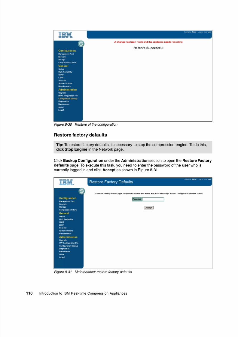
8/3/2019 Introduction to IBM Real-Time Compression Appliances
http://slidepdf.com/reader/full/introduction-to-ibm-real-time-compression-appliances 124/168
110 Introduction to IBM Real-time Compression Appliances
Figure 8-30 Restore of the configuration
Restore factory defaults
Click Backup Configuration under the Administration section to open the Restore Factorydefaults page. To execute this task, you need to enter the password of the user who iscurrently logged in and click Accept as shown in Figure 8-31.
Figure 8-31 Maintenance: restore factory defaults
Tip: To restore factory defaults, is necessary to stop the compression engine. To do this,click Stop Engine in the Network page.

8/3/2019 Introduction to IBM Real-Time Compression Appliances
http://slidepdf.com/reader/full/introduction-to-ibm-real-time-compression-appliances 125/168
Chapter 8. Administration111
8.10 Software installation or upgrade
Currently, minor software release upgrades can be implemented without stopping the RTCA.For example, software updates for the web interface can be performed without stopping thecompression engine. Upgrades to other parts of the software might require restarting thecompression engine or rebooting the system.
Before you begin, make sure you have a valid configuration backup file; see “Backing up andrestoring the configuration settings” on page 109.
8.10.1 Installing/upgrade on a single RTCA
To install the software, log in to the web interface. Click Upgrade under the Administration
section. Click Browse and browse to the location where the software installation file is located(the installation file is named “IBM_Real-time_Compression_3.7.x.xx.stn”) and click Upgrade as shown in Figure 8-32.
Figure 8-32 Software upgrade
Tip: To receive the installation file, download it from the following Web site:www.ibm.com/support/entry/portal or contact IBM Support.
Reboot: If a reboot of a single RTCA is required, the NAS storage server is not available
during the time of the reboot. You need to perform it in a planned downtime window.
Warning messages: The file upload can take up to 5 minutes to complete. Severalwarning messages might be displayed at this time and can safely be ignored.

8/3/2019 Introduction to IBM Real-Time Compression Appliances
http://slidepdf.com/reader/full/introduction-to-ibm-real-time-compression-appliances 126/168
112 Introduction to IBM Real-time Compression Appliances
After the file has been uploaded successfully, you have to read and accept the licenseagreement (see Figure 8-33). Then you can click on Install to install the new software to theRTCA. The installation process will automatically stop the compression engine, upgrade thesoftware, and when the installation is complete, the appliance will reboot.
Figure 8-33 License agreement for upgrade
If the software upgrade was executed successfully, the message “Upgrade Successful” willdisplay, as you can see in Figure 8-34.
Figure 8-34 Successful upgrade
After the appliance has been completely rebooted, verify the software upgrade by reviewingthe version number on the Status page. Finally, click Management Port under theConfiguration section, and then Accept to update the SNMP configuration file.

8/3/2019 Introduction to IBM Real-Time Compression Appliances
http://slidepdf.com/reader/full/introduction-to-ibm-real-time-compression-appliances 127/168
Chapter 8. Administration113
8.10.2 Installing/upgrade on a high availability RTCA
When installing the software in a high availability environment, ensure that the same versionis running on a partner RTCA. To avoid any downtime on a high availability environment, youshould install the software on one RTCA after another. Perform the same steps as describedfor installing on a single appliance. On the Status page, verify that the expected version is
running after the first appliance was rebooted. On a second appliance, perform the stepsdescribed for installing on a single appliance. On the Status page, verify that the expectedversion is running after the second appliance was rebooted.
8.10.3 Updating the hardware configuration file
The RTCA requires a valid hardware configuration file. Typically the appliance is pre-installedwith a proper hardware configuration file as part of the manufacturing process. However,there might be a need to update the hardware configuration file. The “Hardware ConfigurationFile” page enables updating of the compression appliance with details of the hardwareconfiguration file, which specifies the hardware identity of the components in the appliance.Among other information, the hardware configuration file includes the amount of memory inthe appliance, its serial number, and the hardware (MAC) addresses used in the networkinterfaces.
To Update the hardware configuration file, go to the HW Configuration File option under theAdministration section (see Figure 8-35). If a hardware configuration file is not installed orprovided, click Generate Hardware Configuration File Request first, save the file locallyand send the file to IBM Support. After IBM have provided the new hardware configurationfile, you can upload it by clicking Browse and searching for your hardware configuration file.When you have located the hardware configuration file, click Upload.
Figure 8-35 Hardware configuration file
Tip: The bonds probe is displayed only when the system has configured bonds.

8/3/2019 Introduction to IBM Real-Time Compression Appliances
http://slidepdf.com/reader/full/introduction-to-ibm-real-time-compression-appliances 128/168
114 Introduction to IBM Real-time Compression Appliances
8.11 Configuring system options
To modify general options for the IBM RTCA product, go on the System Options panel. It canbe found on the left in your GUI as shown in Figure 8-36.
Figure 8-36 System Options
The following options are accessible:
WebGui: The default setting is normal mode. If you change to debug mode, additionaldebug information is displayed at the top of each page.
JavaScript: Choose Enable or Disable to activate or stop the use of JavaScript in the webinterface pages. JavaScript is mainly used for pop-ups when you use the web interface.The default setting is enabled.
Network Traffic Capture line: To see the status of the tcpdump network capture. This linewill only show the status of the “tcpdump” option while the activation of “tcpdump” is madefrom “Diagnostics” panel “Run tcpdump”
Enable modifying network interface broadcast address: This option allows you to enable ordisable the user from modifying the broadcast address for the management and bridgeinterfaces. By default, this option is disabled. If you enable this option, the Broadcast fieldon the Management Port and Modify Bridge pages is enabled (Figure 8-37).
Attention: The broadcast address is assigned automatically by the management interface;modifying the broadcast address is typically not required. Consult with your networkadministrator before you change the broadcast address.

8/3/2019 Introduction to IBM Real-Time Compression Appliances
http://slidepdf.com/reader/full/introduction-to-ibm-real-time-compression-appliances 129/168
Chapter 8. Administration115
Figure 8-37 Broadcast field
Allow user to set factory defaults: Prevents the user from restoring the IBM Real-timeCompression Appliance configuration to factory defaults. By default, this option isdisabled. If you enable this option, a “Restore Factory Defaults” link appears on the“Configuration Backup” panel (see Figure 8-38).
Figure 8-38 Restore to Factory Defaults option
Attention: A restore to factory defaults will erase all your settings and stop the completetraffic through appliance. Also, such compressed data will became available after youconfigure back the RTCA.
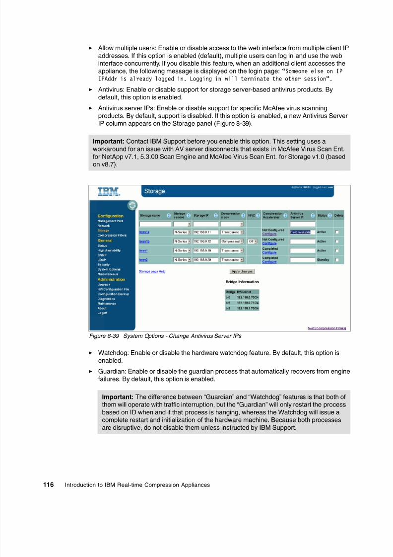
8/3/2019 Introduction to IBM Real-Time Compression Appliances
http://slidepdf.com/reader/full/introduction-to-ibm-real-time-compression-appliances 130/168
116 Introduction to IBM Real-time Compression Appliances
Allow multiple users: Enable or disable access to the web interface from multiple client IPaddresses. If this option is enabled (default), multiple users can log in and use the webinterface concurrently. If you disable this feature, when an additional client accesses theappliance, the following message is displayed on the login page: “Someone else on IPIPAddr is already logged in. Logging in will terminate the other session”.
Antivirus: Enable or disable support for storage server-based antivirus products. By
default, this option is enabled. Antivirus server IPs: Enable or disable support for specific McAfee virus scanning
products. By default, support is disabled. If this option is enabled, a new Antivirus ServerIP column appears on the Storage panel (Figure 8-39).
Figure 8-39 System Options - Change Antivirus Server IPs
Watchdog: Enable or disable the hardware watchdog feature. By default, this option isenabled.
Guardian: Enable or disable the guardian process that automatically recovers from enginefailures. By default, this option is enabled.
Important: Contact IBM Support before you enable this option. This setting uses aworkaround for an issue with AV server disconnects that exists in McAfee Virus Scan Ent.for NetApp v7.1, 5.3.00 Scan Engine and McAfee Virus Scan Ent. for Storage v1.0 (basedon v8.7).
Important: The difference between “Guardian” and “Watchdog” features is that both ofthem will operate with traffic interruption, but the “Guardian” will only restart the processbased on ID when and if that process is hanging, whereas the Watchdog will issue acomplete restart and initialization of the hardware machine. Because both processesare disruptive, do not disable them unless instructed by IBM Support.

8/3/2019 Introduction to IBM Real-Time Compression Appliances
http://slidepdf.com/reader/full/introduction-to-ibm-real-time-compression-appliances 131/168
Chapter 8. Administration117
CA Full Scan: Enable or disable the “Compression Accelerator” feature from the Storagepanel (Figure 8-39) that enables the user to compress existing data. By default, this optionis enabled. If you disable this feature you can end up with a volume both with compressedand uncompressed data. Do not disable this feature unless instructed by IBM Support.
LSM: Enable or disable the link status mirroring (LSM) feature described on Chapter 3.3.1,“Random Access Compression Engine: RACE” on page 18. By default, this feature is
enabled. Do not disable this feature unless instructed by IBM Support. Web GUI Access: Enable or disable the protocol used for GUI management. The http only
mode allows only standard HTTP (port 80) access to the web interface; https only allowsonly secured HTTP (port 443) access to the web interface; and http or https (the default)accepts either.
Task Affinity: Enable or disable the automatic tuning of CPU affinity. By default, this featureis enabled for highest performance as internal modules of the compression appliance arebalanced across the CPU cores using optimal CPU affinity. Do not disable this featureunless instructed by IBM Support.
HA gratuitous arp: Enable or disable support for passing gratuitous ARP messages.By default, this feature is enabled. Do not disable this feature unless instructed by IBMSupport.
HA arp mode refresh: Enable or disable support for high availability environments.By default, this feature is enabled. Do not disable this feature unless instructed by IBMSupport.
Extension Filters Mode: Choose Include or Exclude to configure the mode in which theextension filters are applied. By default, the extension filters that are configured and shown
at the bottom of the Compression Filters panel define which extensions are excluded fromcompression; this is the exclude mode. If Include is configured, the appliance compressesonly files with extensions that are defined in the list.
Unicast ARP Mangle: Enable or disable support for passing unicast ARP messages.By default, this feature is enabled. Do not disable this feature unless instructed by IBMSupport.
Vif Single Probe: Enable or disable support for Data ONTAP single vif configurations.By default, this feature is disabled. Do not enable this feature unless instructed by IBMSupport.
User Autosupport Scheduling: Allow or prevent the user from modifying the defaultschedule for Autosupport reports. By default, this feature is enabled.
Forced reboots: Enable or disable the forced reboots after frequent engine restarts. Thisoption is only applicable for high availability configurations (in single applianceconfigurations, frequent engine warm restarts eventually turn into cold restarts; in highavailability configurations the warm restarts will turn into forced reboots if the partnerappliance as well as its engine are up and running). By default, this option is enabled.
Tip: The web interface supports both HTTP and HTTPS. To configure HTTPScertificates, use the same procedure described in “Setting Up SSH Certificates” in theIBM Real-time Compression Appliances CLI Command Manual - Reference Version 3
Release 7 .
Tip: For more information about vif configurations, see Chapter 6, “Implementationplanning” on page 37 and Chapter 9, “NAS / N series solution design” on page 123.

8/3/2019 Introduction to IBM Real-Time Compression Appliances
http://slidepdf.com/reader/full/introduction-to-ibm-real-time-compression-appliances 132/168
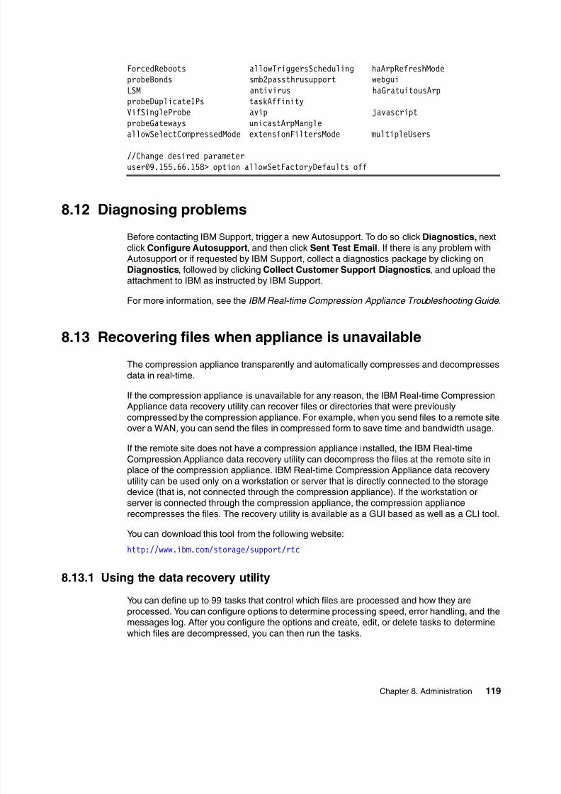
8/3/2019 Introduction to IBM Real-Time Compression Appliances
http://slidepdf.com/reader/full/introduction-to-ibm-real-time-compression-appliances 133/168
Chapter 8. Administration119
ForcedReboots allowTriggersScheduling haArpRefreshModeprobeBonds smb2passthrusupport webguiLSM antivirus haGratuitousArpprobeDuplicateIPs taskAffinityVifSingleProbe avip javascriptprobeGateways unicastArpMangle
allowSelectCompressedMode extensionFiltersMode multipleUsers//Change desired [email protected]> option allowSetFactoryDefaults off
8.12 Diagnosing problems
Before contacting IBM Support, trigger a new Autosupport. To do so click Diagnostics, nextclick Configure Autosupport, and then click Sent Test Email. If there is any problem withAutosupport or if requested by IBM Support, collect a diagnostics package by clicking onDiagnostics, followed by clicking Collect Customer Support Diagnostics, and upload the
attachment to IBM as instructed by IBM Support.
For more information, see the IBM Real-time Compression Appliance Troubleshooting Guide .
8.13 Recovering files when appliance is unavailable
The compression appliance transparently and automatically compresses and decompressesdata in real-time.
If the compression appliance is unavailable for any reason, the IBM Real-time CompressionAppliance data recovery utility can recover files or directories that were previously
compressed by the compression appliance. For example, when you send files to a remote siteover a WAN, you can send the files in compressed form to save time and bandwidth usage.
If the remote site does not have a compression appliance installed, the IBM Real-timeCompression Appliance data recovery utility can decompress the files at the remote site inplace of the compression appliance. IBM Real-time Compression Appliance data recoveryutility can be used only on a workstation or server that is directly connected to the storagedevice (that is, not connected through the compression appliance). If the workstation orserver is connected through the compression appliance, the compression appliancerecompresses the files. The recovery utility is available as a GUI based as well as a CLI tool.
You can download this tool from the following website:
http://www.ibm.com/storage/support/rtc
8.13.1 Using the data recovery utility
You can define up to 99 tasks that control which files are processed and how they areprocessed. You can configure options to determine processing speed, error handling, and themessages log. After you configure the options and create, edit, or delete tasks to determinewhich files are decompressed, you can then run the tasks.

8/3/2019 Introduction to IBM Real-Time Compression Appliances
http://slidepdf.com/reader/full/introduction-to-ibm-real-time-compression-appliances 134/168
120 Introduction to IBM Real-time Compression Appliances
IBM Real-time Compression Appliance data recovery utility options apply to all defined tasksand can be modified only when tasks are not running. For information about determiningwhether tasks are running or about stopping tasks, see “Running the data recovery utility.”
8.13.2 Recovery procedure
To perform a recovery, proceed as follows:
1. If the data recovery utility is not running, select the IBM Real-time Compression Appliancedata recovery utility from the appropriate Start menu folder (for example, Start ? Programs? Storwize ? Revert) or from the default installation directory:
c:\Program Files\IBM\Real Time Compression Appliance data recovery utility
The data recovery utility opens and by default, displays the Task List tab (Figure 8-40).
Figure 8-40 Recovery utility
Attention: You need to configure options immediately after IBM Real-time CompressionAppliance data recovery utility installation.

8/3/2019 Introduction to IBM Real-Time Compression Appliances
http://slidepdf.com/reader/full/introduction-to-ibm-real-time-compression-appliances 135/168
Chapter 8. Administration121
2. Select Options and Configuration from the menu. The Configuration window opens(see Figure 8-41).
3. Select the appropriate options according to the information. For a complete list of optionsand descriptions, see the IBM Real-time Compression Appliance Administration Guide .
Figure 8-41 RTCA recovery utility - edit task parameters
8.13.3 Creating data-recovery tasks
The data recovery utility tasks specify which files are to be decompressed as well as the orderin which they are decompressed. Creating tasks includes defining source and destinationdirectories (which files are decompressed and where they are saved), priorities (the order inwhich the tasks are run), and additional task parameters.
You can create up to nine tasks. Because finished or aborted tasks are not deletedautomatically, you can delete them to create additional tasks, if necessary. Default settingsare applied to new tasks. To customize the new task default settings, configure a task's
parameters and click Save As Defaults in the Edit Task Parameters dialog box. For example,if Copy Attributes is selected and Copy All Files is deselected in your customized default taskparameters, these options remain selected or deselected when you create a new task.

8/3/2019 Introduction to IBM Real-Time Compression Appliances
http://slidepdf.com/reader/full/introduction-to-ibm-real-time-compression-appliances 136/168
122 Introduction to IBM Real-time Compression Appliances
8.13.4 Running data-recovery tasks
When a task runs, its specified files are processed. Tasks are run in batch mode, according topriority and then task number. Tasks that have the priority “On Hold” do not run. Tasks can bestopped or resumed at any time. Information about the running tasks is displayed in theMessage Log tab, according to your configuration options.
Before running tasks, verify that you have sufficient free space on the volume, using thefollowing formula:
Number of threads (X) * the sum of the sizes of the X largest files * 3
For example, when three threads are configured and the size of the three largest files are10 GB, 15 GB, and 20 GB, the free space required for this operation is 405 GB(3*45*3=405 GB).
8.13.5 Viewing data-recovery logs
The Message Log tab displays a maximum of 300 messages. A complete list of messages is
recorded in the data recovery utility log in the IBM Real-time Compression Appliance datarecovery utility message log file.
You can use the log files to verify if your data recovery process has been performedsuccessfully.

8/3/2019 Introduction to IBM Real-Time Compression Appliances
http://slidepdf.com/reader/full/introduction-to-ibm-real-time-compression-appliances 137/168

8/3/2019 Introduction to IBM Real-Time Compression Appliances
http://slidepdf.com/reader/full/introduction-to-ibm-real-time-compression-appliances 138/168
124 Introduction to IBM Real-time Compression Appliances
9.1 Terms and definitions
As an introduction to facilitate understanding of the design examples in this chapter, we showthe port assignment of the RTCA product (STN6500) and the N series (N5000) in Figure 9-1 and Figure 9-2.
Figure 9-1 STN6500 port assignment
Figure 9-2 N series port assignment
9.2 N series single node solutions
This section focuses on solutions using a single node N series controller.
9.2.1 N series and single RTCA product
The most basic configuration consists of a single NAS storage controller connected to a
single RTCA product.
In Figure 9-3 an N series single-node system is connected by a single link (from onboard porte0a) to the RTCA eth0 port, and eth1 is connected to the network switch. The ports eth0 andeth1 are configured as a bridge (br0), with a bridge IP address in the same subnet as e0a.
Interfaces: There can be more than a single interface connected between the NASstorage controller and the RTCA product. However, in this configuration, the interfaces areindependent of each other, and not aggregated for load balancing or redundancy.

8/3/2019 Introduction to IBM Real-Time Compression Appliances
http://slidepdf.com/reader/full/introduction-to-ibm-real-time-compression-appliances 139/168
Chapter 9. NAS / N series solution design125
Being the simplest configuration possible, it does not provide any redundancy and is thereforenot desirable for production use. Any failure in the network path, be it the network switch, itsport, any of the network cables, the compression appliance ports, or the N series ports, willimpact service to users.
Figure 9-3 N series single node connected to a single RTCA product
The port connectivity that belongs to the solution in Figure 9-3 is illustrated in Table 9-1.
Table 9-1 N series single node connected to a single RTCA product - port connectivity
9.2.2 N series and single RTCA product, active/passive path
Similar to the configuration in the previous section, a single NAS controller is connected to asingle RTCA product in Figure 9-4. However, an additional link is added to provideredundancy to the networking path. The two links are aggregated into a single group. The Nseries single-node system is configured with an active/passive configuration, a single-modevirtual interface (vif).The compression appliance is configured with two active/passive bonds and a bridge thatconnects them. On the network switch side, the two ports are configured with the sameparameters, and most importantly, both must be in the same subnet.
In this configuration only one link is active at any particular time. If the NAS storage controllerdetects a fault in the active link, the standby link is activated and all traffic goes through thenewly activated link.
Switch/
port
RTCA/
port
Bond Bridge Bond RTCA/
port
NAS port
SW1/ 9
STN1/ eth1
n/a br0 n/a STN1/ eth0
NAS1 e0a

8/3/2019 Introduction to IBM Real-Time Compression Appliances
http://slidepdf.com/reader/full/introduction-to-ibm-real-time-compression-appliances 140/168
126 Introduction to IBM Real-time Compression Appliances
Figure 9-4 N series single-node, a single RTCA product, active/passive path failover
The port connectivity that belongs to the solution in Figure 10-2 is illustrated in Table 9-2.
Table 9-2 N series single-node, single RTCA product, active/passive path failover port connectivity
The N series virtual interface configuration is illustrated in Example 9-1.
Example 9-1 Active/passive path failover for single systems - N series vif configuration
NAS1> vif statusdefault: transmit 'IP Load balancing', VIF Type 'multi_mode', fail 'log'vif-s: 1 link, transmit 'none', VIF Type 'single_mode' fail 'default'
VIF Status Up Addr_setup:
e0a: state up, since 31Mar2011 18:43:52 (00:00:23)mediatype: auto-1000t-fd-upflags: enabledinput packets 13, input bytes 1062output packets 4, output bytes 168output probe packets 4, input probe packets 0strike count: 4 of 10up indications 1, broken indications 0drops (if) 0, drops (link) 0indication: up at 31Mar2011 18:43:52
consecutive 22, transitions 1
Switch/
port
RTCA/
port
Bond Bridge Bond RTCA/
port
NAS port/
vif
SW1/ 9
STN1/ eth1
bond0active/ passive
br0
bond1active/ passive
STN1/ eth0
NAS1 e0a/ vif-s
SW1/ 13
STN1/ eth5
bond0active/ passive
bond1active/ passive
STN1/ eth4
NAS1 e0c/ vif-s

8/3/2019 Introduction to IBM Real-Time Compression Appliances
http://slidepdf.com/reader/full/introduction-to-ibm-real-time-compression-appliances 141/168
Chapter 9. NAS / N series solution design127
down: e0c: state down, since 31Mar2011 18:43:52 (00:00:23)
mediatype: auto-1000t-fd-upflags: enabledinput packets 0, input bytes 0output packets 13, output bytes 570
output probe packets 4, input probe packets 0strike count: 4 of 10up indications 1, broken indications 0drops (if) 0, drops (link) 0indication: up at 31Mar2011 18:43:52
consecutive 22, transitions 1
9.2.3 N series and active/passive path, RTCA product HA pair
By building on the previous examples and adding a compression appliance to theconfiguration, a single NAS storage controller is connected to two RTCA products inFigure 9-5. The N series single-node system is configured with an active/passive
configuration, a single-mode virtual interface (vif). A primary link is connected to one RTCAproduct, and the other, the passive link, is connected to the second RTCA product. The RTCAproducts are connected with a single link each to the switch. This setup adds redundancy tothe RTCA product itself. If any problem occurs, or maintenance is required, the service canfail over from the active RTCA product to the standby RTCA product. It is possible, andactually desirable, to connect each RTCA product to a separate network switch.
Figure 9-5 N series single-node, active/passive path failover to HA pair

8/3/2019 Introduction to IBM Real-Time Compression Appliances
http://slidepdf.com/reader/full/introduction-to-ibm-real-time-compression-appliances 142/168
128 Introduction to IBM Real-time Compression Appliances
The port connectivity that belongs to the solution in Figure 9-5 is illustrated in Table 9-3.
Table 9-3 N series single-node, active/passive path failover to HA pair port connectivity
The N series virtual interface configuration is illustrated in Example 9-2.
Example 9-2 Active/passive path failover to RTCA product HA pair- N series vif configuration
NAS1> vif statusdefault: transmit 'IP Load balancing', VIF Type 'multi_mode', fail 'log'vif-s: 1 link, transmit 'none', VIF Type 'single_mode' fail 'default'
VIF Status Up Addr_set
up: e0a: state up, since 31Mar2011 18:43:52 (00:00:23)mediatype: auto-1000t-fd-upflags: enabledinput packets 13, input bytes 1062output packets 4, output bytes 168output probe packets 4, input probe packets 0strike count: 4 of 10up indications 1, broken indications 0drops (if) 0, drops (link) 0indication: up at 31Mar2011 18:43:52
consecutive 22, transitions 1down:
e0c: state down, since 31Mar2011 18:43:52 (00:00:23)mediatype: auto-1000t-fd-upflags: enabledinput packets 0, input bytes 0output packets 13, output bytes 570output probe packets 4, input probe packets 0strike count: 4 of 10up indications 1, broken indications 0drops (if) 0, drops (link) 0indication: up at 31Mar2011 18:43:52
consecutive 22, transitions 1
9.2.4 Active/passive path, RTCA product HA, EtherChannel/LACP bonds
The most common use of active/passive bonds is when they will combined with EtherChannelor LACP bonds. This provides the best combination of performance and high availability. InFigure 9-6, the N series single-node system is connected with two or more interfaces to theRTCA product—configured as a single port aggregate (virtual interface)—either anEtherChannel or 802.3ad (LACP) bond type.
Switch/
port
RTCA/
port
Bond Bridge Bond RTCA/
port
NAS port/
vif
SW1/
9
STN1/
eth1
n/a br0 n/a STN1/
eth0
NAS1 e0a/
vif-s
SW2/ 9
STN2/ eth1
n/a br0 n/a STN2/ eth0
NAS1 e0c/ vif-s
Tip: Make sure that all active links of the same link aggregation (LACP or EtherChannel)are connected to the same RTCA product.

8/3/2019 Introduction to IBM Real-Time Compression Appliances
http://slidepdf.com/reader/full/introduction-to-ibm-real-time-compression-appliances 143/168
Chapter 9. NAS / N series solution design129
Similarly, a corresponding bond in the RTCA product is connected to the network switch. Anadditional bond is connected to a standby RTCA product in the same manner, and itscorresponding bond connected to the network switch – be it the same one or another switch(Figure 9-6).
Figure 9-6 N series single-node, active/passive path failover to HA pair, EtherChannel or LACP bonds
The port connectivity that belongs to the solution in Figure 9-6 is illustrated in Table 9-4.
Table 9-4 N series single-node with EtherChannel or LACP bonds
The virtual interfaces vifa and vifb are configured as dynamic multimode vif and are groupedby creating a second layer of vif, called vif1 as a single-mode vif. Either vifa or vifb is active.In this way, data will be transmitted through one RTCA product only and not at any timethrough both concurrently. The necessary configuration entries of the /etc/rc file are shown inExample 9-3.
Example 9-3 N series or LACP port aggregation configuration entry in /etc/rc
vif create lacp vifa -b ip e0a e0cvif create lacp vifb -b ip e0b e0dvif create single vif1 vifb vifa
Switch/
port
RTCA/
port
Bond Bridge Bond RTCA/
port
NAS port/
vif
SW1/ 9
STN1/ eth1
bond0LACP
br0
bond1LACP
STN1/ eth0
NAS1 e0a/ vifa
SW1/ 13
STN1/ eth5
bond0LACP
bond1LACP
STN1/ eth4
NAS1 e0c/ vifa
SW2/ 35
STN2/ eth9
bond0LACP
br0
bond1LACP
STN2/ eth8
NAS1 e0b/ vifb
SW2/ 41
STN2/ eth13
bond0LACP
bond1LACP
STN2/ eth12
NAS1 e0d/ vifb

8/3/2019 Introduction to IBM Real-Time Compression Appliances
http://slidepdf.com/reader/full/introduction-to-ibm-real-time-compression-appliances 144/168
130 Introduction to IBM Real-time Compression Appliances
The N series virtual interface configuration is illustrated in Example 9-4.
Example 9-4 N series single-node LACP virtual interface configuration
NAS1> vif statusdefault: transmit 'IP Load balancing', VIF Type 'multi_mode', fail 'log'vifa: 2 links, transmit 'IP Load balancing', VIF Type 'lacp' fail 'default'
VIF Status Up Addr_settrunked: vif1 up: e0c: state up, since 31Mar2011 18:50:30 (6+21:18:08)
mediatype: auto-1000t-fd-upflags: enabledactive aggr, aggr port: e0ainput packets 675437, input bytes 43010404input lacp packets 19841, output lacp packets 19841output packets 122521, output bytes 7139083up indications 2, broken indications 0drops (if) 0, drops (link) 0indication: up at 31Mar2011 18:50:30
consecutive 0, transitions 2 e0a: state up, since 31Mar2011 18:50:29 (6+21:18:09)
mediatype: auto-1000t-fd-upflags: enabledactive aggr, aggr port: e0ainput packets 43968, input bytes 6839259input lacp packets 19840, output lacp packets 19841output packets 147663, output bytes 10142065up indications 2, broken indications 0drops (if) 0, drops (link) 0indication: up at 31Mar2011 18:50:29
consecutive 0, transitions 2vifb: 2 links, transmit 'IP Load balancing', VIF Type 'lacp' fail 'default'
VIF Status Up Addr_settrunked: vif1
down: e0d: state up, since 31Mar2011 18:50:29 (6+21:18:09)
mediatype: auto-1000t-fd-upflags: enabledactive aggr, aggr port: e0binput packets 26427, input bytes 4709108input lacp packets 19841, output lacp packets 19841output packets 119029, output bytes 6626180up indications 2, broken indications 0drops (if) 0, drops (link) 0
indication: up at 31Mar2011 18:50:29consecutive 0, transitions 2 e0b: state up, since 31Mar2011 18:50:29 (6+21:18:09)
mediatype: auto-1000t-fd-upflags: enabledactive aggr, aggr port: e0binput packets 659358, input bytes 41114314input lacp packets 19841, output lacp packets 19841output packets 119029, output bytes 6626180up indications 2, broken indications 0drops (if) 0, drops (link) 0
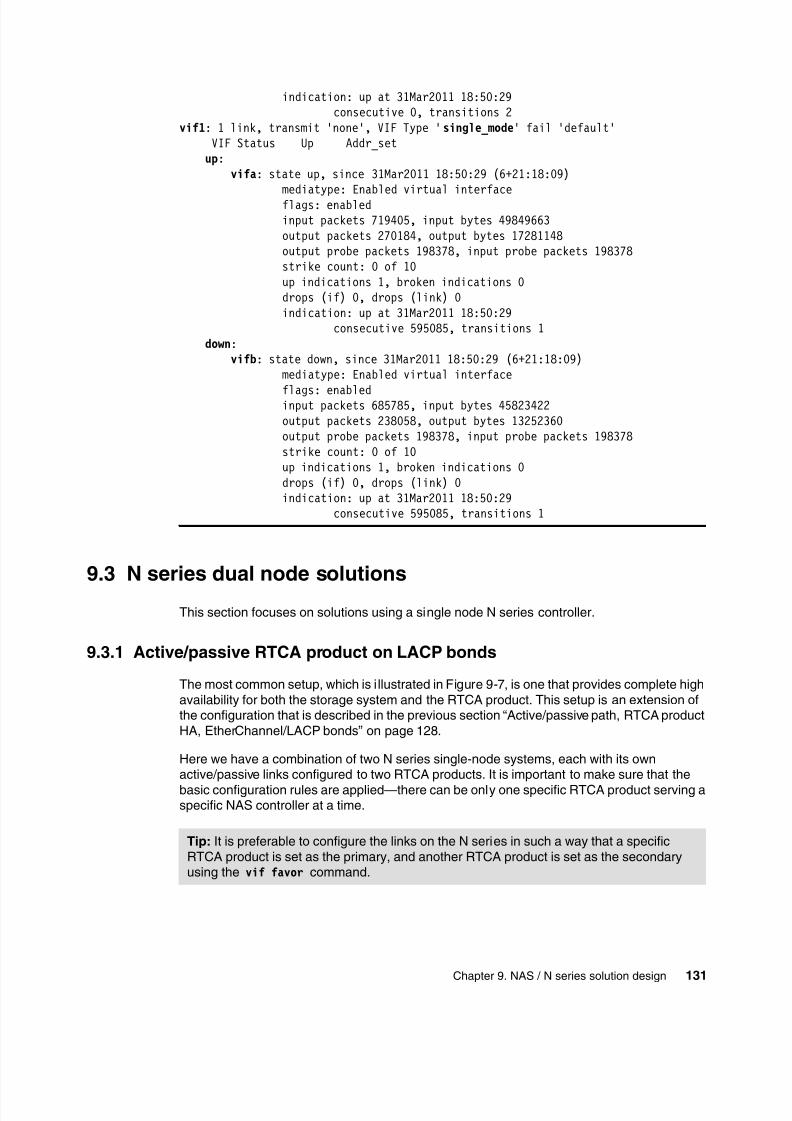
8/3/2019 Introduction to IBM Real-Time Compression Appliances
http://slidepdf.com/reader/full/introduction-to-ibm-real-time-compression-appliances 145/168
Chapter 9. NAS / N series solution design131
indication: up at 31Mar2011 18:50:29consecutive 0, transitions 2
vif1: 1 link, transmit 'none', VIF Type 'single_mode' fail 'default'VIF Status Up Addr_set
up: vifa: state up, since 31Mar2011 18:50:29 (6+21:18:09)
mediatype: Enabled virtual interfaceflags: enabledinput packets 719405, input bytes 49849663output packets 270184, output bytes 17281148output probe packets 198378, input probe packets 198378strike count: 0 of 10up indications 1, broken indications 0drops (if) 0, drops (link) 0indication: up at 31Mar2011 18:50:29
consecutive 595085, transitions 1 down: vifb: state down, since 31Mar2011 18:50:29 (6+21:18:09)
mediatype: Enabled virtual interface
flags: enabledinput packets 685785, input bytes 45823422output packets 238058, output bytes 13252360output probe packets 198378, input probe packets 198378strike count: 0 of 10up indications 1, broken indications 0drops (if) 0, drops (link) 0indication: up at 31Mar2011 18:50:29
consecutive 595085, transitions 1
9.3 N series dual node solutions
This section focuses on solutions using a single node N series controller.
9.3.1 Active/passive RTCA product on LACP bonds
The most common setup, which is illustrated in Figure 9-7, is one that provides complete highavailability for both the storage system and the RTCA product. This setup is an extension ofthe configuration that is described in the previous section “Active/passive path, RTCA productHA, EtherChannel/LACP bonds” on page 128.
Here we have a combination of two N series single-node systems, each with its ownactive/passive links configured to two RTCA products. It is important to make sure that the
basic configuration rules are applied—there can be only one specific RTCA product serving aspecific NAS controller at a time.
Tip: It is preferable to configure the links on the N series in such a way that a specificRTCA product is set as the primary, and another RTCA product is set as the secondaryusing the vif favor command.
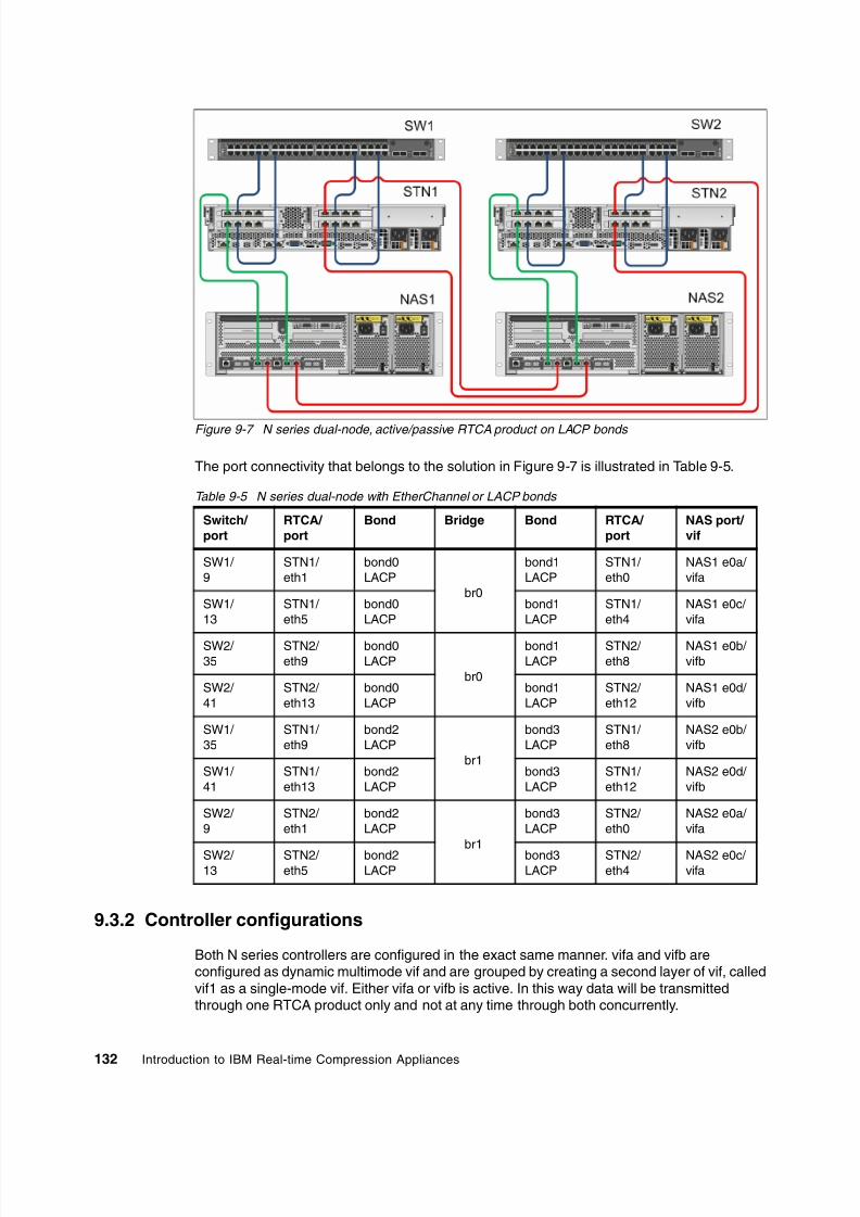
8/3/2019 Introduction to IBM Real-Time Compression Appliances
http://slidepdf.com/reader/full/introduction-to-ibm-real-time-compression-appliances 146/168
132 Introduction to IBM Real-time Compression Appliances
Figure 9-7 N series dual-node, active/passive RTCA product on LACP bonds
The port connectivity that belongs to the solution in Figure 9-7 is illustrated in Table 9-5.
Table 9-5 N series dual-node with EtherChannel or LACP bonds
9.3.2 Controller configurations
Both N series controllers are configured in the exact same manner. vifa and vifb areconfigured as dynamic multimode vif and are grouped by creating a second layer of vif, calledvif1 as a single-mode vif. Either vifa or vifb is active. In this way data will be transmittedthrough one RTCA product only and not at any time through both concurrently.
Switch/
port
RTCA/
port
Bond Bridge Bond RTCA/
port
NAS port/
vif
SW1/ 9
STN1/ eth1
bond0LACP
br0
bond1LACP
STN1/ eth0
NAS1 e0a/ vifa
SW1/ 13
STN1/ eth5
bond0LACP
bond1LACP
STN1/ eth4
NAS1 e0c/ vifa
SW2/ 35
STN2/ eth9
bond0LACP
br0
bond1LACP
STN2/ eth8
NAS1 e0b/ vifb
SW2/ 41
STN2/ eth13
bond0LACP
bond1LACP
STN2/ eth12
NAS1 e0d/ vifb
SW1/ 35
STN1/ eth9
bond2LACP
br1
bond3LACP
STN1/ eth8
NAS2 e0b/ vifb
SW1/ 41
STN1/ eth13
bond2LACP
bond3LACP
STN1/ eth12
NAS2 e0d/ vifb
SW2/ 9
STN2/ eth1
bond2LACP
br1
bond3LACP
STN2/ eth0
NAS2 e0a/ vifa
SW2/ 13
STN2/ eth5
bond2LACP
bond3LACP
STN2/ eth4
NAS2 e0c/ vifa

8/3/2019 Introduction to IBM Real-Time Compression Appliances
http://slidepdf.com/reader/full/introduction-to-ibm-real-time-compression-appliances 147/168
Chapter 9. NAS / N series solution design133
The configuration entries of the /etc/rc file of both controllers are identical as described in theprevious section “Active/passive path, RTCA product HA, EtherChannel/LACP bonds” onpage 128 and shown in Example 9-3 on page 129. Similarly, the vif configuration is describedin the previous section “Active/passive path, RTCA product HA, EtherChannel/LACP bonds”on page 128 and shown in Example 9-4 on page 130.
9.4 N series MetroCluster solutions
IBM N series MetroCluster is a synchronous replication solution for combined high availability(HA) and disaster recovery (DR), protecting against site disasters within a campus ormetropolitan area with distances up to 100 km. Usually due to cabling and installationrequirements it is not possible to connect every N series controller of the HA pair with bothRTCA products at each site to provide the best redundancy and availability.
Generally you can configure the RTCA product in N series MetroCluster environments in adifferent manner:
One RTCA product at each site to connect one RTCA product with only one N series
controller in Figure 9-8 Two RTCA products at each site to connect one N series controller redundant to two
RTCA products in Figure 9-9
In the first option it is absolute necessary to configure the N series to failover to the partnersite in case of an RTCA product failure. Additionally it is preferable to connect each RTCAproduct to more than one switch, otherwise a network switch failure will also require anN series controller failover.
Figure 9-8 Single RTCA product design for MetroCluster
Tip: To enable an automatic takeover if the N series controller detect failures in the networkinterfaces, set the option “cf.takeover.on_network_interface_failure” to “on”.

8/3/2019 Introduction to IBM Real-Time Compression Appliances
http://slidepdf.com/reader/full/introduction-to-ibm-real-time-compression-appliances 148/168
134 Introduction to IBM Real-time Compression Appliances
With the RTCA product unsynchronized, MetroCluster site failover is problematic andtherefore an HA RTCA product setup at each site with active/passive configuration ispreferable, as illustrated in Figure 9-9.
Figure 9-9 Dual RTCA product design for MetroCluster
In that architecture, STN1 and STN2 cannot see any shares of NAS1b, the remote clusterpartner of the local controller NAS1a. However it is necessary to create both storage serverobjects (for NAS1a and NAS1b) in all RTCA products at both sites. In such a configuration itis best to build a star topology for the configuration of HA Auto Sync, as you can see inFigure 9-10.
STN1 is configured as an HA pair with STN2, STN3, and STN4. The configuration ofcompression filters is performed only on one RTCA product, in this example STN1, to avoidsynchronization issues. In other words: STN1 acts as a master and is paired with STN2,STN3, and STN4. Now, you can modify the compression filter configuration and yourmodification will be replicated to all other RTCA products immediately after you apply thechanges.
If a compression filter is not defined as compressed in the compression filter list of all RTCAproducts in the same manner, data will not be accessible or corrupt after a cluster failoveroccurs and clients access the data through a logical bypass.

8/3/2019 Introduction to IBM Real-Time Compression Appliances
http://slidepdf.com/reader/full/introduction-to-ibm-real-time-compression-appliances 149/168
Chapter 9. NAS / N series solution design135
Figure 9-10 RTCA star topology
Depending on the architecture of a MetroCluster, a dual inter-site link failure can theoreticallyoccur. The Error message looks like the one shown in Figure 9-11.
Figure 9-11 Inter-site link failure, no route to partner
Important: It is not desirable to disable HA auto sync temporarily to modify a compressionfilter configuration after an inter-site link failure occurs. If you have a link problem, resolve itfirst, then add or remove compression filters.

8/3/2019 Introduction to IBM Real-Time Compression Appliances
http://slidepdf.com/reader/full/introduction-to-ibm-real-time-compression-appliances 150/168
136 Introduction to IBM Real-time Compression Appliances
In this case the HA auto synchronization will not work and the RTCA product does not let youadd or remove compression filters as shown in Figure 9-12. However, it is possible to overrideit by disabling HA auto synchronization temporarily. This will require either using manualexport/import, manual synchronization later, or performing the same task on all RTCAproducts.
Figure 9-12 RTCA products do not let you add/remove compression filters
9.5 N series with MultiStore
The N series MultiStore® feature provides the ability to configure virtual filers within aphysical N series system. This feature is fully supported by the RTCA product, with eachvirtual filer (vfiler) configured as if it was a physical storage system. In other words, a vfiler is
just another storage object in an RTCA configuration.
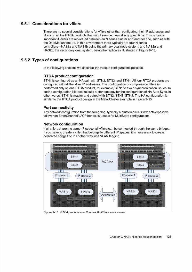
8/3/2019 Introduction to IBM Real-Time Compression Appliances
http://slidepdf.com/reader/full/introduction-to-ibm-real-time-compression-appliances 151/168
Chapter 9. NAS / N series solution design137
9.5.1 Considerations for vfilers
There are no special considerations for vfilers other than configuring their IP addresses andfilters on all the RTCA products that might service them at any given time. This is mostlyimportant if vfilers are replicated between an N series cluster and another one, such as withthe DataMotion feature. In this environment there typically are four N series
controllers—NAS1a and NAS1b being the primary dual node system, and NAS2a andNAS2b, the secondary dual system, being the replica as illustrated in Figure 9-13.
9.5.2 Types of configurations
In the following sections we describe the various configurations possible.
RTCA product configurationSTN1 is configured as an HA pair with STN2, STN3, and STN4. All four RTCA products areconfigured with all the vfiler IP addresses. The configuration of compression filters isperformed only on one RTCA product, for example, STN1 to avoid synchronization issues. Insuch a configuration it is best to build a star topology for the configuration of HA Auto Sync, in
other words: STN1 is master and paired with STN2, STN3, STN4. The HA configuration issimilar to the RTCA product design in the MetroCluster example in Figure 9-10.
Port connectivityAny network configuration from the foregoing, typically a clustered NAS with active/passivefailover on EtherChannel/LACP bonds, is usable for MultiStore configurations.
Network configurationIf all vfilers share the same IP space, all vfilers can be connected through the same bridges.If you have to create a vfiler that belongs to different IP spaces, it is necessary to creatededicated bridges or in another way, use VLAN tagging.
Figure 9-13 RTCA products in a N series MultiStore environment

8/3/2019 Introduction to IBM Real-Time Compression Appliances
http://slidepdf.com/reader/full/introduction-to-ibm-real-time-compression-appliances 152/168
138 Introduction to IBM Real-time Compression Appliances

8/3/2019 Introduction to IBM Real-Time Compression Appliances
http://slidepdf.com/reader/full/introduction-to-ibm-real-time-compression-appliances 153/168
© Copyright IBM Corp. 2011. All rights reserved.139
Chapter 10. ProtecTIER solution design
In this chapter we explain how to combine IBM ProtecTIER® and RTCA. This will enable thereader to understand the benefits of combining real-time compression and deduplicationtechnologies.
10

8/3/2019 Introduction to IBM Real-Time Compression Appliances
http://slidepdf.com/reader/full/introduction-to-ibm-real-time-compression-appliances 154/168
140 Introduction to IBM Real-time Compression Appliances
10.1 Combining RTCA and IBM ProtecTIER deduplication
To understand the benefits of combining real-time compression and deduplication, it isimportant first to understand the difference in the technologies and where they fit in the overalldata optimization landscape.
Real-time Compression is designed to work transparently in front of your primary storage andreduce the size of every file you create up to five times depending upon file type. Applicationshave random, read-write access to compressed data while the physical capacity required tostore a file, or copies and permutations of a file are significantly reduced throughout the entirelife-cycle including backup. Because less data is written to disk, overall network and storageperformance and utilization can also be significantly enhanced.
Deduplication is designed to reduce the physical storage required to store redundant data. Inthe deduplication process, duplicate data is removed and replaced with a pointer to the maincopy, leaving only one copy of the data to be stored which is why it is well suited for backupdata where you typically have multiple data sets (daily/weekly) of mostly redundant data. Themore copies of redundant data you have, the higher your effective deduplication rate.
An example of the situation just described is illustrated in Figure 10-1. Hence real-timecompression and deduplication address different problems and are applicable at differentpoints within the data life-cycle. But, most importantly the two technologies arecomplementary and in particular deploying real-time compression with a random accesscompression engine significantly enhances the value and performance of deduplication.
Figure 10-1 The Data Optimization Landscape

8/3/2019 Introduction to IBM Real-Time Compression Appliances
http://slidepdf.com/reader/full/introduction-to-ibm-real-time-compression-appliances 155/168
Chapter 10. ProtecTIER solution design141
10.2 Solution setup
For our test environment, as illustrated in Figure 10-2, the combination of the IBM Real-timeCompression and IBM ProtecTIER deduplication in an Oracle® database backupenvironment resulted in more than 96% savings on disk space and additional significant dataprotection benefits for organizations that perform regular backups of Oracle databases. While
each offers compelling benefits when implemented independently, the combination of bothtechnologies results in far greater space savings, significantly improved backup time, andresource utilization.
In the case of Oracle database backups, real-time compression provided:
82% immediate savings on initial write to disk. 96% overall data reduction when combined with deduplication Up to 71% reduction in backup time Less deduplication CPU utilization, less deduplication disk activity, and less deduplication
network traffic
The significant overall reduction in primary and backup data storage requirements coupled
with the dramatic improvement in deduplication CPU, Network and disk utilization illustratethe significant synergies between real-time compression and deduplication.
Running with RTCA compression and ProtecTier deduplication and compression reduced theused size by an additional 10%, and this is the preferable configuration.
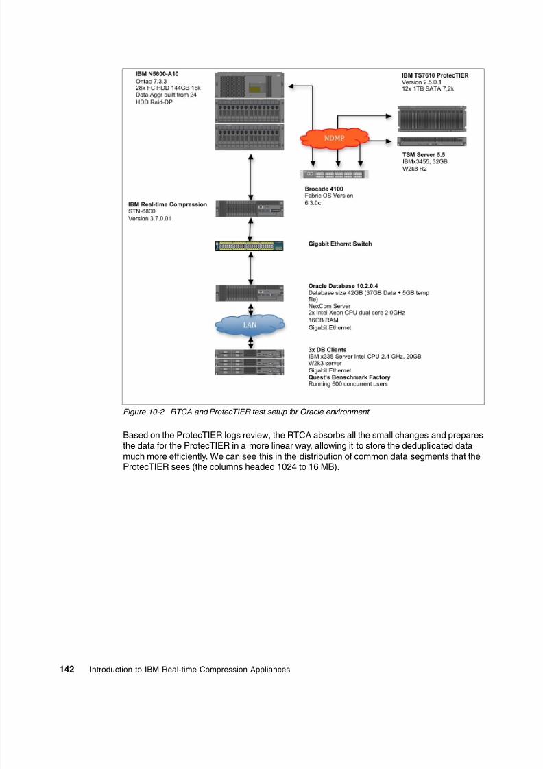
8/3/2019 Introduction to IBM Real-Time Compression Appliances
http://slidepdf.com/reader/full/introduction-to-ibm-real-time-compression-appliances 156/168
142 Introduction to IBM Real-time Compression Appliances
Figure 10-2 RTCA and ProtecTIER test setup for Oracle environment
Based on the ProtecTIER logs review, the RTCA absorbs all the small changes and preparesthe data for the ProtecTIER in a more linear way, allowing it to store the deduplicated datamuch more efficiently. We can see this in the distribution of common data segments that theProtecTIER sees (the columns headed 1024 to 16 MB).

8/3/2019 Introduction to IBM Real-Time Compression Appliances
http://slidepdf.com/reader/full/introduction-to-ibm-real-time-compression-appliances 157/168
© Copyright IBM Corp. 2011. All rights reserved.143
ACL Access Control List
CLI Command Line InterfaceDR Disaster Recovery
GUI Graphical User Interface
HA High Availability
I/O Input/Output
IBM International Business MachinesCorporation
ILM Information Life-cycle Management
IPL Initial Program Load
IT Information Technology
ITSO International Technical Support
Organization
LACP Link Aggregation Control Protocol
LDAP Lightweight Directory AccessProtocol
LSM Link Status Mirroring
MIB Management Information Base
MRM Monitoring and Reporting Manager
MTU Maximum Transmission Unit
NAS Network Attached Storage
NNC No New Compression
RACE Random Access CompressionEngine
RTCA IBM Real-time CompressionAppliance
SNMP Simple Network ManagementProtocol
UNC Uniform Naming Convention
UPM Unified Protocol Manager
Abbreviations and acronyms

8/3/2019 Introduction to IBM Real-Time Compression Appliances
http://slidepdf.com/reader/full/introduction-to-ibm-real-time-compression-appliances 158/168
144 Introduction to IBM Real-time Compression Appliances

8/3/2019 Introduction to IBM Real-Time Compression Appliances
http://slidepdf.com/reader/full/introduction-to-ibm-real-time-compression-appliances 159/168
© Copyright IBM Corp. 2011. All rights reserved.145
Related publications
The publications listed in this section are considered particularly suitable for a more detailed
discussion of the topics covered in this book.
IBM Redbooks publications
The following IBM Redbooks publications provide additional information about the topics inthis document. Note that some publications referenced in this list might be available insoftcopy only:
IBM System Storage Solutions Handbook, SG24-5250
IBM System Storage N series Software Guide, SG24-7129
Implementing IBM Storage Data Deduplication Solutions , SG24-7888
IBM System Storage N series MetroCluster, REDP-4259
IBM System Storage N series MetroCluster Planning Guide, REDP-4243
You can search for, view, or download Redbooks publications, Redpaper publications,Technotes, draft publications, and Additional materials, as well as order hardcopy Redbookspublications, at this Web site:
ibm.com/redbooks
Other publications
These publications are also relevant as further information sources:
Real-time Compression Appliances: Installation and Planning Guide, Version 3 Release 7,
GI13-1221-00
Real-time Compression Appliances: Administration Guide, Version 3 Release 7,
GI13-1221-00
Real-time Compression Appliances: CLI Command Reference, Version 3 Release 7
IBM Real-time Compression Appliances Version 3 Release 7 - Release Notes
Online resources
These Web sites are also relevant as further information sources:
IBM Real-time compression:
http://www-03.ibm.com/systems/storage/solutions/rtc/
IBM Real-time Compression Appliance STN6500:
http://www-03.ibm.com/systems/storage/network/rtc/stn6500/
IBM Real-time Compression Appliance STN6800:
http://www-03.ibm.com/systems/storage/network/rtc/stn6800/index.html

8/3/2019 Introduction to IBM Real-Time Compression Appliances
http://slidepdf.com/reader/full/introduction-to-ibm-real-time-compression-appliances 160/168
146 Introduction to IBM Real-time Compression Appliances
IBM RTCA Support overview:
http://www.ibm.com/storage/support/rtc
Reducing NAS Costs with Real-time Data Compression:
http://wikibon.org/wiki/v/Reducing_NAS_Costs_with_Real-time_Data_Compression
IBM Network attached storage (NAS):
http://www-03.ibm.com/systems/storage/network/
IBM System Storage N6000 series:
http://www-03.ibm.com/systems/storage/network/n6000/appliance/index.html
IBM ProtecTIER Deduplication Solutions:
http://www-03.ibm.com/systems/storage/tape/protectier/
Help from IBM
IBM Support and downloads:
ibm.com/support
IBM Global Services:
ibm.com/services

8/3/2019 Introduction to IBM Real-Time Compression Appliances
http://slidepdf.com/reader/full/introduction-to-ibm-real-time-compression-appliances 161/168
© Copyright IBM Corp. 2011. All rights reserved.147
Index
Numerics
10 GbE ports 282452-650 262452-680 26802.3ad 55
AAC connectors 29Active-backup 55administration 69advantages, storage 24Amount of Changes 76antivirus 42, 116architectural planning 38ARJ utility 9autosupport 117
Bbackup 109
configuration 71, 109base model 26Bond 39, 53
command 57create 54modes 55
Bridge 43, 53command 61configuration 53
create 57parameters 60
bridge 39bypass 39
Ccable lock 29cables 39cabling 48challenges
high availability 2increasing data storage 2power, cooling and floor space 2
CIFS 82, 95, 118components
back 27front 27hardware 25software 25, 31
compress mode 79, 83–84changing 85
compressed traffic 35compression 2
benefits 2
history 8in real-time 17
post-processing optimization 12ratio 35real-time 12reversible 17statistics 107use cases 3
compression accelerator 17, 72monitoring 77settings 73shares 73status 77
compression filters 79CIFS 82exclude 86
NFS 83compression modes 79configuration
base model 26configure 50
Bond 55Bridge 58compression accelerator 72DNS 107high availability 62LDAP 99management port 51network 54security 52
SNMP 97system options 114
connecting the RTCA 48connecting to the web interface 71conserving file attributes 20copper ports 28CRC 22cyclic redundancy check. see CRC
Ddata deduplication 11data efficiency 9data integrity 22
data recovery utility 119database 141DataMotion 137date and time 105deduplication 11, 140deployment 47design
considerations 15N series 123NAS 123ProtecTIER 139

8/3/2019 Introduction to IBM Real-Time Compression Appliances
http://slidepdf.com/reader/full/introduction-to-ibm-real-time-compression-appliances 162/168
148 Introduction to IBM Real-time Compression Appliances
solutions 123device information 89diagnostics 71, 119direct connection 49direct management connection 48Directories to Ignore 76DNS 107
EEasy Tier
data allocation 10Easy Tiering 10environment 30EtherChannel 55
Ffactory defaults
defaults 110Fano, Robert 8file attributes
conserving 20Flash Copy 9Free Space Threshold 76front-panel 27
Ggrowth rate 38guardian process 116
Hhardware configuration file 71
update 113
high availability 62, 78import configuration 64panel 65synchronize automatically 65synchronize manually 63upgrade 113using CLI 67
history 8hostname 91Huffman coding 17
II/O 35IBM System Storage N series. see N seriesILM 11implementation 37industry requirement 1Information Life-cycle Management. see ILMinstallation steps 47integrity
at network level 22at protocol layer 23at storage layer 23
integrity of data 22inter-site link failure handling 135
Interval Between Files 76IP addresses 44irreversible data compression 12
Llayer
protocol 23storage 23LDAP 71, 99, 107
configure 99diagnose 103parameters 99port number 101type 99
Lempel, Abraham 8Lempel-Ziv algorithm 17Linear Tape Open. see LTOLink Status Mirroring. see LSMlogical interfaces 40login 51
LSM 20, 43LTO 13LZ 19LZ78 8LZH 9LZW 8
Mmaintenance 71management port 29Maximum Total Throughput 76MetroCluster 133mode
compress 79compression disabled 81transparent 79
monitoring 88Monitoring and Reporting Manager. see MRMMorse code 8MRM 18, 20MultiStore 136
NN series 123
active/passive path, RTCA HA pair 127DataMotion 137design for MetroCluster 133
dual node solutions 131dual-node, active/passive RTCA on LACP bonds 132LACP port aggregation configuration 129MetroCluster solutions 133MultiStore 136RTCA star topology 135single node solutions 124single RTCA, active/passive path 125single-node LACP virtual interface 130solution design 123
NAS 123

8/3/2019 Introduction to IBM Real-Time Compression Appliances
http://slidepdf.com/reader/full/introduction-to-ibm-real-time-compression-appliances 163/168
Index149
solution design 123NetApp FAS 83network interface ports 44network links 44network panel 54NFS 83, 95NTP 107
Ooperating environment 30optical ports 29options 71Oracle 141
database 141database backup 141
Pparallelism 35performance
best practices 34
considerations 21requirements 34response time 34scalability 34throughput 34
physical installation 48physical specifications 29PKZIP 8port aggregation 42ports 39post-processing optimization 12power supply unit 29ProtecTIER 139
Oracle environment 142solution design 140
protocol layer 23
RRACE 13, 18
logical overview 19rack considerations 38Random Access Compression Engine. see RACEread cache 34Real-time compression 12Real-time Compression Appliance. see RTCArear-panel 27reboot 108
recovery 119logs 122procedure 120tasks 121
Redbooks Web site 145Contact us xii
remote connection 49remote management connection 49response time 34restore 109
configuration 109
restore factory defaults 110reversible data compression 12, 17RTCA 33
administration 69advantages 24approach 16bridge 39
cabling 48configure 50connecting 48design 15logical interfaces 40menu 70network terminology 39overview 16performance 33STN6500 26STN6800 26
S
scalability 34scheduling 75security 71security configuration 52serial console port 29Shannon, Claude E. 8shutdown 108SMB2 118SMTP 107snapshots 20SNMP 71, 97
devault values 98monitoring parameters 98parameters 97
status check 98software 31
installation 111upgrade 111
solution design 123space efficient 9specifications 29
physical 29technical 30
SSH 52statistics 107status 71, 89
compression 95status display 89
STN6500 26, 38, 124STN6800 26, 38storage
status monitoring 94storage layer 23storage status 94storage system interfaces 44Streaming Lossless Data Compression 13supported clients and servers 30synchronizing high availability automatically 65synchronizing high availability manually 63syslog servers

8/3/2019 Introduction to IBM Real-Time Compression Appliances
http://slidepdf.com/reader/full/introduction-to-ibm-real-time-compression-appliances 164/168
150 Introduction to IBM Real-time Compression Appliances
remote setup 106system options 114
Ttechnical specifications 29–30terminology 39
throughput 34time and date 105timeout value 107transparent mode 79–80, 84transparent traffic 35
UUnified Protocol Manager. see UPMupgrade 71, 111UPM 18, 20use cases 3
Vvirtual interfaces 40VLAN ID 59VLAN tagging 44
Wwatchdog 116web interface 70Welch, Terry 8welcome screen 50
ZZiv, Jacob 8

8/3/2019 Introduction to IBM Real-Time Compression Appliances
http://slidepdf.com/reader/full/introduction-to-ibm-real-time-compression-appliances 165/168
( 0 .2 ” s pi n e )
0 .1 7 ” <-> 0 .4 7 3 ”
9 0 <->2 4 9 p a g e s
I n t r o d u c t i o n t o
I B M R e a l - t i m e C o m p r e s s i o n A p p l i a n c e s
I n t r o d u c t i o n t o I B M R e a l - t i m e
C o m p r e
s s i o n A p p l i a n c e s
I n t r o d u
c t i o n t o I B M
R e a l - t i m e
C o m p r e s s i o n A p p l i
a n c e s
I n t r o d u c t i o n t o I B M R e a l - t i m e C o m p r e s s i o n A
p p l i a n c e s

8/3/2019 Introduction to IBM Real-Time Compression Appliances
http://slidepdf.com/reader/full/introduction-to-ibm-real-time-compression-appliances 166/168
I n t r o d u
c t i o n t o I B M
R e a l - t i m e
C o m p r e s s i o n A p p l i
a n c e s
I n t r o d u
c t i o n t o I B M
R e a l - t i m e
C o m p r e s s i o n A p p l i
a n c e s

8/3/2019 Introduction to IBM Real-Time Compression Appliances
http://slidepdf.com/reader/full/introduction-to-ibm-real-time-compression-appliances 167/168

8/3/2019 Introduction to IBM Real-Time Compression Appliances
http://slidepdf.com/reader/full/introduction-to-ibm-real-time-compression-appliances 168/168
®
INTERNATIONALTECHNICALSUPPORTORGANIZATION
BUILDING TECHNICALINFORMATION BASED OPRACTICAL EXPERIENC
Introduction to IBM
Real-time CompressionAppliances
See how seamless
compression
integrates into
storage environments
Get familiar with the
leading edge
real-time
compression solution
Continuing its commitment to developing and delivering
industry-leading storage technologies, IBM is introducing the IBM
Real-time Compression Appliances for NAS, an innovative new storage
offering that delivers essential storage efficiency technologies,
combined with exceptional ease of use and performance.
In an era when the amount of information, particularly in unstructured
files, is exploding, but budgets for storing that information are
stagnant, IBM Real-time Compression technology offers a powerful
tool for better information management, protection, and access.
IBM Real-time Compression can help slow the growth of storage
acquisition, reducing storage costs while simplifying both operations
Back cover


