29 Sept 2011 All Rights Reserved, Thomas Meyer LLC
1
Introduction to Fatigue and
Cyclic Crack Growth of Metals
29 Sept 2011 Thomas Meyer, LLC
29 Sept 2011 All Rights Reserved, Thomas Meyer LLC
2
•What is fatigue cracking & why is it important
• Fatigue Crack Formation •The basics of the process •Basic prediction methods •Complications
•Fatigue Crack Growth •The theoretical basis of fracture mechanics •Application to fatigue crack growth. •Complications
•Other practical considerations.
Introduction to Fatigue and
Cyclic Crack Growth of Metals
29 Sept 2011 All Rights Reserved, Thomas Meyer LLC
3
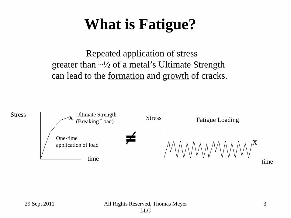
What is Fatigue?
Repeated application of stress greater than ~½ of a metal’s Ultimate Strength can lead to the formation and growth of cracks.
x Ultimate Strength (Breaking Load)
One-time application of load
Stress
time
x
Stress Fatigue Loading
time
29 Sept 2011 All Rights Reserved, Thomas Meyer LLC
4
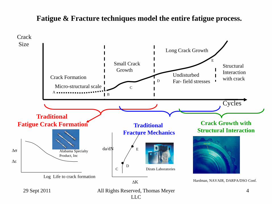
Fatigue & Fracture techniques model the entire fatigue process.
Cycles
∆σ ∆ε
Log Life to crack formation
Traditional Fatigue Crack Formation
Alabama Specialty Product, Inc
Crack Growth with Structural Interaction
Hardman, NAVAIR, DARPA/DSO Conf.
Crack Size
Small Crack Growth
Long Crack Growth
D
E
Undisturbed Far- field stresses
Structural Interaction with crack Crack Formation
Micro-structural scale A B
C
∆K
da/dN
D
E
Traditional Fracture Mechanics
Dirats Laboratories C
29 Sept 2011 All Rights Reserved, Thomas Meyer LLC
5
Why is fatigue and
fatigue analysis important?
29 Sept 2011 All Rights Reserved, Thomas Meyer LLC
6 6
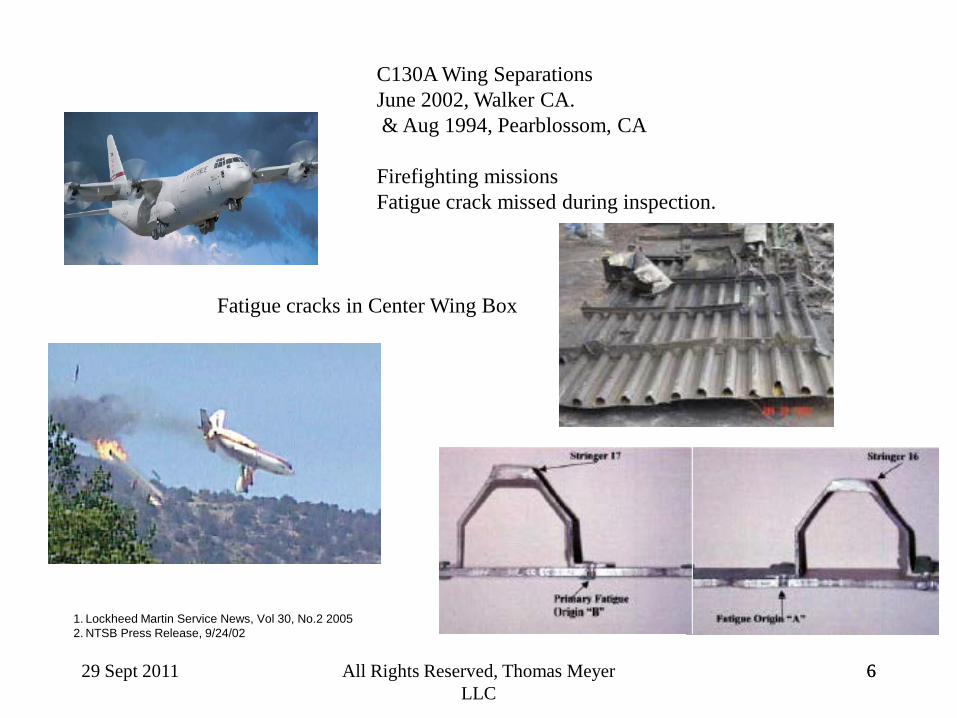
1. Lockheed Martin Service News, Vol 30, No.2 2005 2. NTSB Press Release, 9/24/02
Fatigue cracks in Center Wing Box
C130A Wing Separations June 2002, Walker CA. & Aug 1994, Pearblossom, CA Firefighting missions Fatigue crack missed during inspection.
29 Sept 2011 All Rights Reserved, Thomas Meyer LLC
7
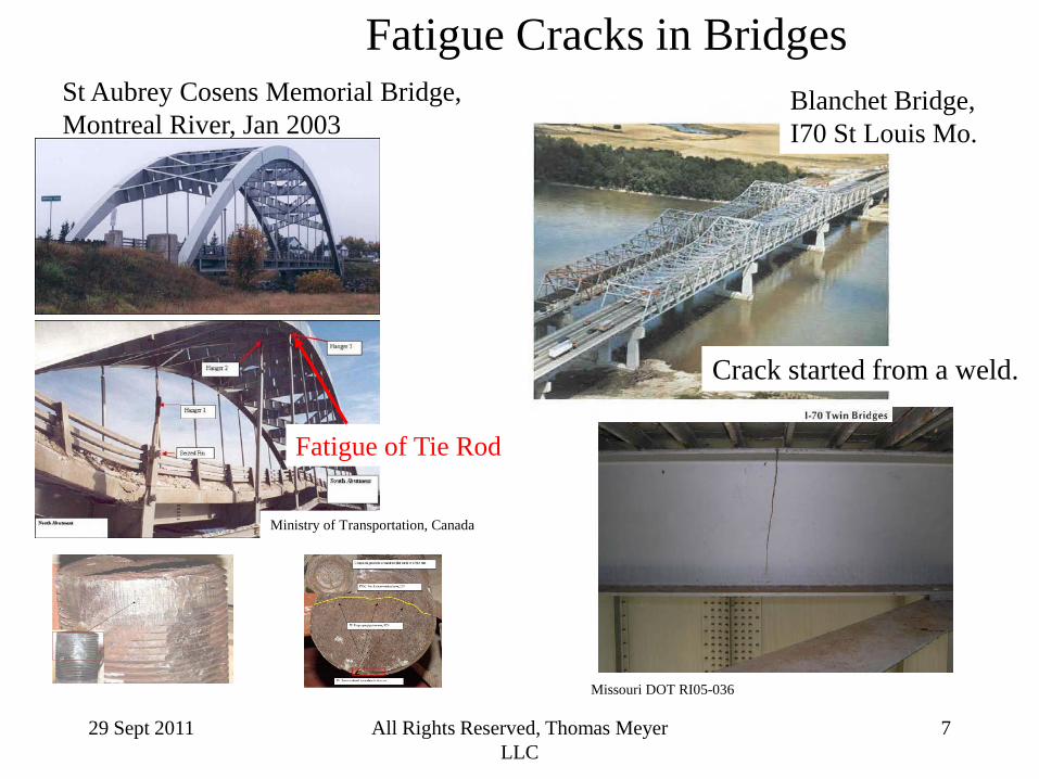
St Aubrey Cosens Memorial Bridge, Montreal River, Jan 2003
Ministry of Transportation, Canada
Fatigue Cracks in Bridges
Fatigue of Tie Rod
Missouri DOT RI05-036
Crack started from a weld.
Blanchet Bridge, I70 St Louis Mo.
29 Sept 2011 All Rights Reserved, Thomas Meyer LLC
8
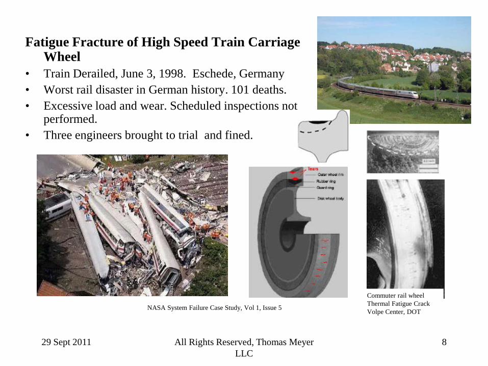
Fatigue Fracture of High Speed Train Carriage Wheel
• Train Derailed, June 3, 1998. Eschede, Germany • Worst rail disaster in German history. 101 deaths. • Excessive load and wear. Scheduled inspections not
performed. • Three engineers brought to trial and fined.
NASA System Failure Case Study, Vol 1, Issue 5
Commuter rail wheel Thermal Fatigue Crack Volpe Center, DOT

29 Sept 2011 All Rights Reserved, Thomas Meyer LLC
9
Fatigue of Electrical Connections
Danish National Consumer Agency
Circuit Board Solder Joint Fatigue Crack
Medtronic
Defibrillator Lead 5 deaths 250,000+ vulnerable
Fatigue cracking from inclusions in wire
J. Schaffer, Fort Wayne Metals Research Products Corporation & Purdue University Presented May 19th, 2006 at the 9th International Fatigue Congress, Atlanta
29 Sept 2011 All Rights Reserved, Thomas Meyer LLC
10 10
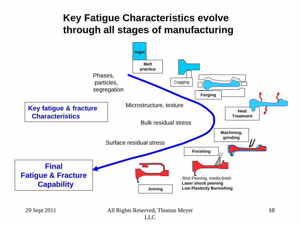
Integrated Manufacturing Models Key Fatigue Characteristics evolve through all stages of manufacturing
Key fatigue & fracture Characteristics
Forging
Heat Treatment
Machining, grinding
Finishing
Joining
Shot Peening, media finish Laser shock peening Low Plasticity Burnishing
Phases, particles, segregation
Microstructure, texture
Bulk residual stress
Surface residual stress
Cogging
Melt practice
Ingot
Final Fatigue & Fracture
Capability

29 Sept 2011 All Rights Reserved, Thomas Meyer LLC
11
Fatigue and Fracture properties are affected by many “Material Attributes”
Attributes usually controlled by a material’s specification e.g. AMS number, company standards, part drawing.
“Material” •Chemical composition •Cleanliness (e.g. commercial quality, air melt, vacuum melt, etc)
Form of the material and processing •Casting, un-HIP’d, HIP’d
– Location in the casting •Forging, Bar, Extrusion, Plate, Sheet
– Texture & cold working •Powder Metal •Microstructure, grain size ) •Overall size •Heat treatment, overall size •Hardness
Attributes usually controlled by part fabrication.
Fabrication Method • Method of shaping:
– milled, ground, turned, broached, EDM, Chem. Milled
• Stretching, Bending, Spinning • Welding • Heat treatment
Finish • Surface finish
– As-machined surface (max allowed roughness) – As-cast surface – Polished
• Special Treatments – Anodize with thickness specified – Case hardening – Plating – Cold working
29 Sept 2011 All Rights Reserved, Thomas Meyer LLC
12
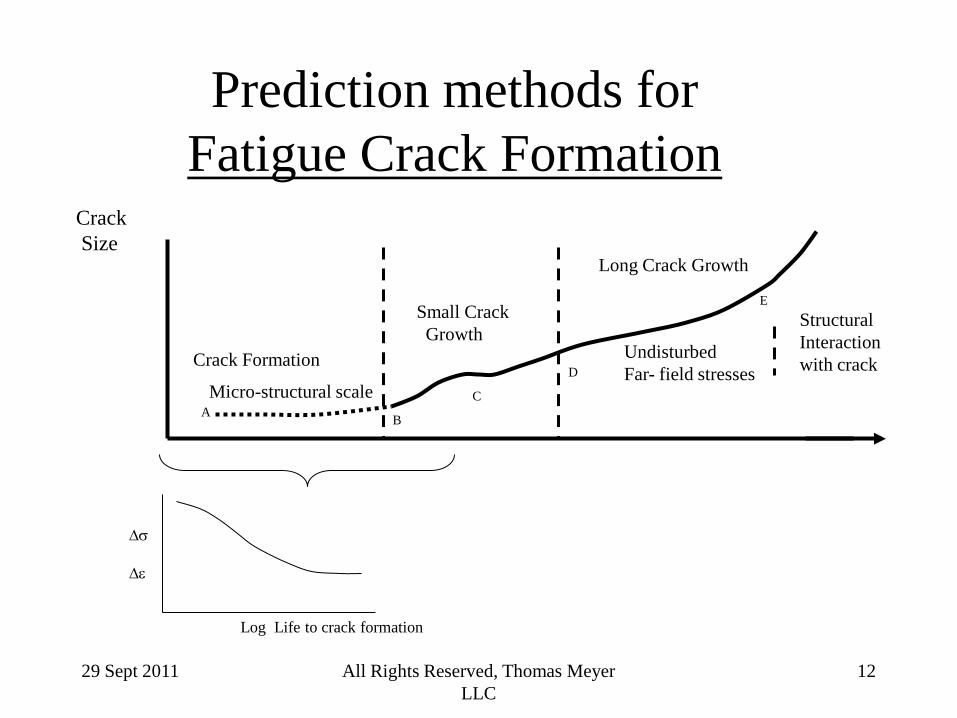
Prediction methods for
Fatigue Crack Formation Crack Size
Small Crack Growth
Long Crack Growth
D
E
Undisturbed Far- field stresses
Structural Interaction with crack Crack Formation
Micro-structural scale A B
C
∆σ ∆ε
Log Life to crack formation
29 Sept 2011 All Rights Reserved, Thomas Meyer LLC
13
Predicting Fatigue Life Is Not An Exact Science
• There are many methods for fatigue prediction. • Most work reasonably well under certain conditions. • None work well for all types of loading conditions. • None truly predict fatigue behavior from first principles:
– fatigue prediction is highly empirical .
• Understanding the stress and strain history at the site of the crack is key to good correlation of fatigue data (and to “prediction” of fatigue life in the field.)
29 Sept 2011 All Rights Reserved, Thomas Meyer LLC
14
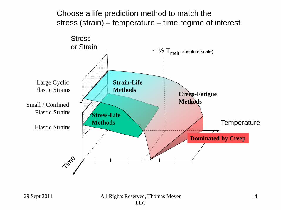
Choose a life prediction method to match the stress (strain) – temperature – time regime of interest
Stress or Strain
Temperature
~ ½ Tmelt (absolute scale)
Strain-Life Methods
Stress-Life Methods
Large Cyclic Plastic Strains
Small / Confined
Plastic Strains
Elastic Strains
Dominated by Creep
Creep-Fatigue Methods
29 Sept 2011 All Rights Reserved, Thomas Meyer LLC
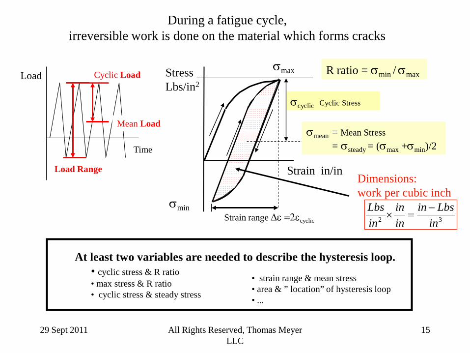
15
Strain in/in
Stress Lbs/in2
During a fatigue cycle, irreversible work is done on the material which forms cracks
σcyclic Cyclic Stress
σmean = Mean Stress
= σsteady = (σmax +σmin)/2
σmin Strain range ∆ε =2εcyclic
R ratio = σmin / σmax
Time
Load
Mean Load
Cyclic Load
Load Range
At least two variables are needed to describe the hysteresis loop. • cyclic stress & R ratio • max stress & R ratio • cyclic stress & steady stress
• strain range & mean stress • area & ” location” of hysteresis loop • ...
32 inLbsin
inin
inLbs −
=×
σmax
Dimensions: work per cubic inch
29 Sept 2011 All Rights Reserved, Thomas Meyer LLC
16
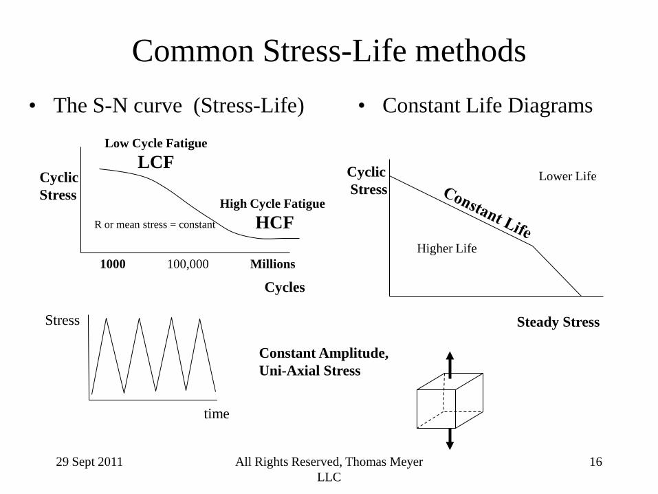
Common Stress-Life methods • The S-N curve (Stress-Life)
time
Stress
• Constant Life Diagrams
Cyclic Stress
Cycles 1000 100,000 Millions
Low Cycle Fatigue LCF
High Cycle Fatigue HCF R or mean stress = constant
Steady Stress
Cyclic Stress
Higher Life
Lower Life
Constant Amplitude, Uni-Axial Stress
29 Sept 2011 All Rights Reserved, Thomas Meyer LLC
17
0
50
100
150
1.E+03 1.E+04 1.E+05 1.E+06 1.E+07 1.E+08
Nf, cycles
cycl
ic s
tres
s, K
si
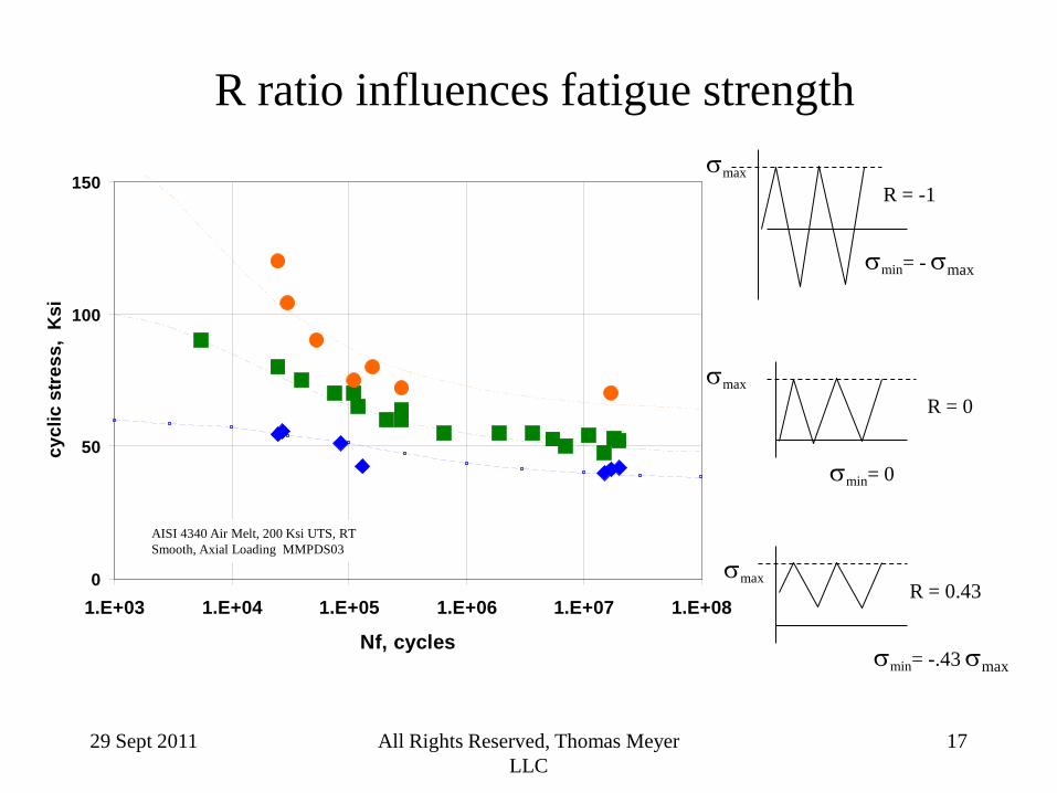
R ratio influences fatigue strength
σmin= - σmax
σmin= 0
σmax
R = 0
σmin= -.43 σmax
σmax R = 0.43
σmax
R = -1
AISI 4340 Air Melt, 200 Ksi UTS, RT Smooth, Axial Loading MMPDS03
29 Sept 2011 All Rights Reserved, Thomas Meyer LLC
18
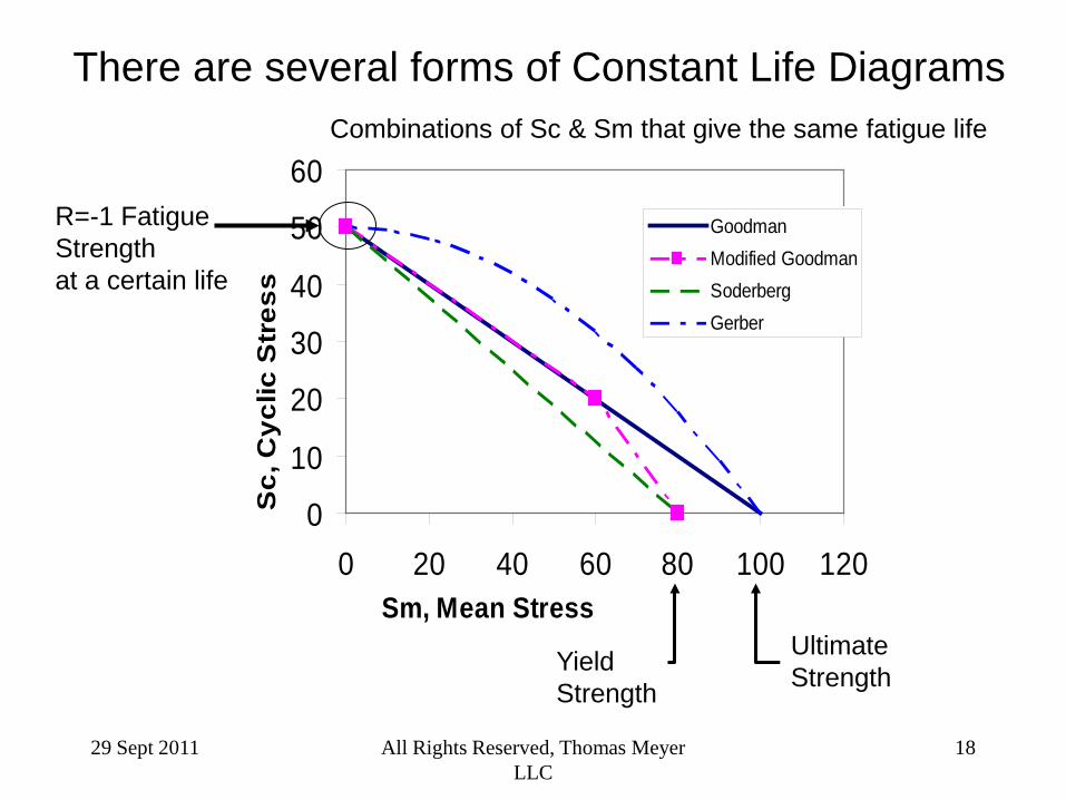
There are several forms of Constant Life Diagrams
0
10
20
30
40
50
60
0 20 40 60 80 100 120Sm, Mean Stress
Sc,
Cyc
lic S
tres
s
GoodmanModified GoodmanSoderbergGerber
R=-1 Fatigue Strength at a certain life
Yield Strength
Ultimate Strength
Combinations of Sc & Sm that give the same fatigue life
29 Sept 2011 All Rights Reserved, Thomas Meyer LLC
19
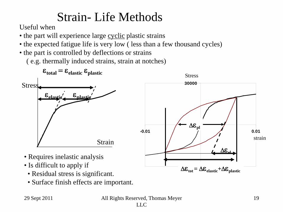
Strain- Life Methods Useful when • the part will experience large cyclic plastic strains • the expected fatigue life is very low ( less than a few thousand cycles) • the part is controlled by deflections or strains ( e.g. thermally induced strains, strain at notches)
εtotal = εelastic εplastic
Strain
Stress εplastic εelastic
-30000
0
30000
-0.01 0.01
∆εpl
∆εel
∆εtot = ∆εelastic+∆εplastic
Stress
strain
• Requires inelastic analysis • Is difficult to apply if • Residual stress is significant. • Surface finish effects are important.
29 Sept 2011 All Rights Reserved, Thomas Meyer LLC
20
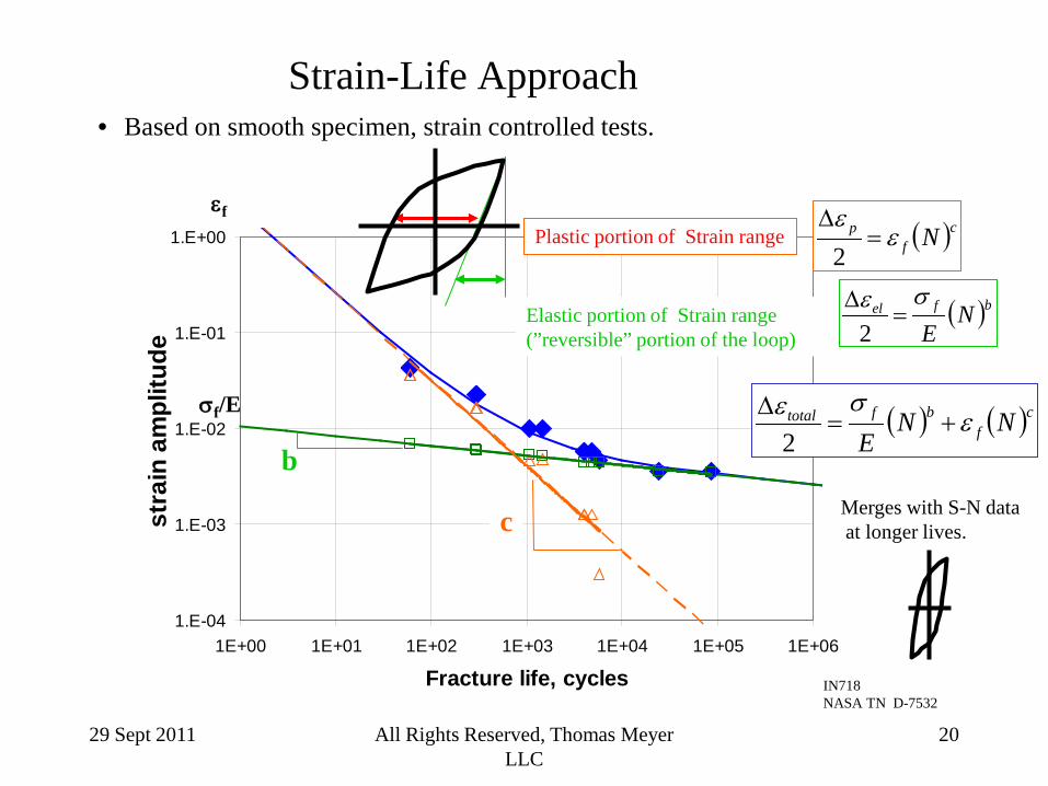
Strain-Life Approach • Based on smooth specimen, strain controlled tests.
1.E-04
1.E-03
1.E-02
1.E-01
1.E+00
1E+00 1E+01 1E+02 1E+03 1E+04 1E+05 1E+06
Fracture life, cycles
stra
in a
mpl
itude
Plastic portion of Strain range
Elastic portion of Strain range (”reversible” portion of the loop)
( ) ( )cf
bftotal NNE
εσε
+=∆
2
( )cf
p Nεε
=∆
2
( )bfel NE
σε=
∆2
σf/E
εf
c
b Merges with S-N data at longer lives.
IN718 NASA TN D-7532
29 Sept 2011 All Rights Reserved, Thomas Meyer LLC
21
Some complications in real world situations
• Spectrum of loads; not constant
amplitude • Multi-axial stresses • Non-proportional cycling • High temperature • Unique surface finishes & Processes
29 Sept 2011 All Rights Reserved, Thomas Meyer LLC
22
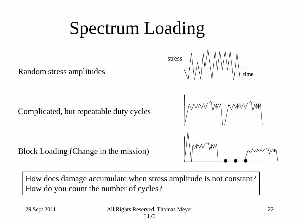
Spectrum Loading
Random stress amplitudes Complicated, but repeatable duty cycles Block Loading (Change in the mission)
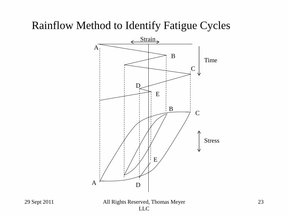
How does damage accumulate when stress amplitude is not constant? How do you count the number of cycles?
time
stress
…
29 Sept 2011 All Rights Reserved, Thomas Meyer LLC
23
Rainflow Method to Identify Fatigue Cycles Strain
Time
Stress
A B
E D
C
A
B
E
D
C
29 Sept 2011 All Rights Reserved, Thomas Meyer LLC
24
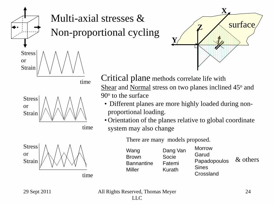
Multi-axial stresses & Non-proportional cycling
time
Stress or Strain
time
Stress or Strain
time
Stress or Strain
surface X
Y
Z
Critical plane methods correlate life with Shear and Normal stress on two planes inclined 45o and 90o to the surface • Different planes are more highly loaded during non-proportional loading.
• Orientation of the planes relative to global coordinate system may also change
Morrow Garud Papadopoulos Sines Crossland
There are many models proposed.
Wang Brown Bannantine Miller
Dang Van Socie Fatemi Kurath
& others
29 Sept 2011 All Rights Reserved, Thomas Meyer LLC
25
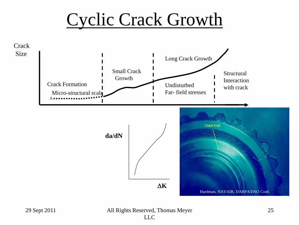
Cyclic Crack Growth Crack Size
Small Crack Growth
Long Crack Growth
Undisturbed Far- field stresses
Structural Interaction with crack Crack Formation
Micro-structural scale A
Hardman, NAVAIR, DARPA/DSO Conf. ∆K
da/dN
29 Sept 2011 All Rights Reserved, Thomas Meyer LLC
26
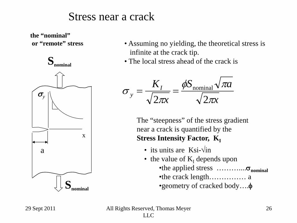
Stress near a crack
• Assuming no yielding, the theoretical stress is infinite at the crack tip. • The local stress ahead of the crack is
• its units are Ksi-√in • the value of KI depends upon
•the applied stress ………....σnominal •the crack length…………… a •geometry of cracked body….φ
The “steepness” of the stress gradient near a crack is quantified by the Stress Intensity Factor, KI
the “nominal” or “remote” stress
a
Snominal
x
σy
Snominal
xaS
xKI
y ππφ
πσ
22nominal==
29 Sept 2011 All Rights Reserved, Thomas Meyer LLC
27
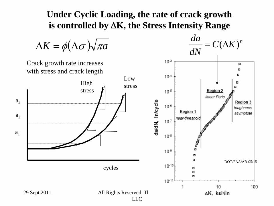
Under Cyclic Loading, the rate of crack growth is controlled by ∆K, the Stress Intensity Range
Crack growth rate increases with stress and crack length
a3 a2
a1
High stress
Low stress
( ) aK πσφ ∆=∆
cycles DOT/FAA/AR-05/15
nKCdNda )(∆=
29 Sept 2011 All Rights Reserved, Thomas Meyer LLC
28
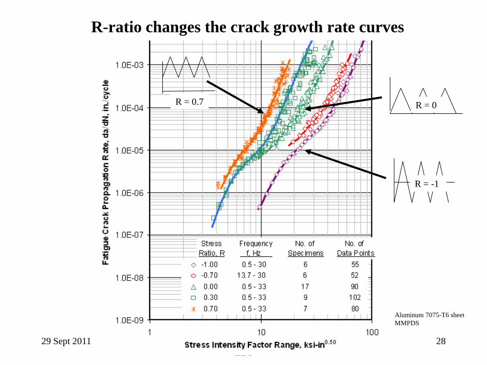
R = -1
R = 0.7 R = 0
R-ratio changes the crack growth rate curves
Aluminum 7075-T6 sheet MMPDS
29 Sept 2011 All Rights Reserved, Thomas Meyer LLC
29
Complications in fatigue crack growth:
There is significant uncertainty in the threshold region • Cracks on the same size scale as the material microstructure • Difficult to devise a test in the threshold region.
Critical crack size / fracture toughness. Crack growth in spectrum loading depends upon loading history.
• Retardation due to Overload • Crack Closure
Crack path in complicated structures is not easily known. Stress Intensity Factors in complicated structures require high degree of idealization or FEA
Influenced by the plastic zone at the crack tip
29 Sept 2011 All Rights Reserved, Thomas Meyer LLC
30
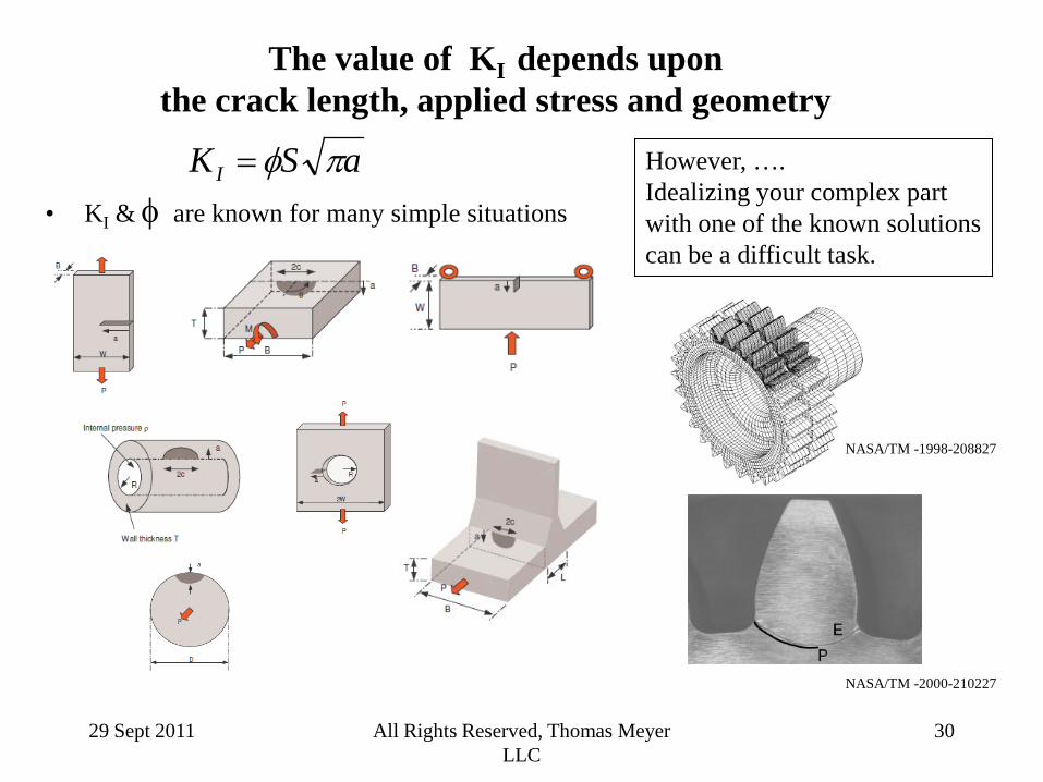
However, …. Idealizing your complex part with one of the known solutions can be a difficult task.
aSKI πφ=
NASA/TM -2000-210227
NASA/TM -1998-208827
The value of KI depends upon the crack length, applied stress and geometry
• KI & φ are known for many simple situations
29 Sept 2011 All Rights Reserved, Thomas Meyer LLC
31
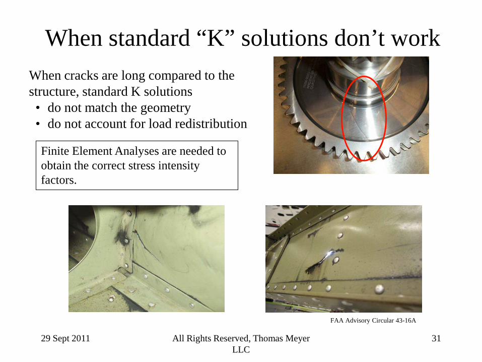
When standard “K” solutions don’t work When cracks are long compared to the structure, standard K solutions • do not match the geometry • do not account for load redistribution
Finite Element Analyses are needed to obtain the correct stress intensity factors.
FAA Advisory Circular 43-16A
29 Sept 2011 All Rights Reserved, Thomas Meyer LLC
32
Practical Consideration for preventing fatigue fractures
29 Sept 2011 All Rights Reserved, Thomas Meyer LLC
33
0
20
40
60
80
100
120
140
10 100 1,000 10,000 100,000 1,000,000 10,000,000
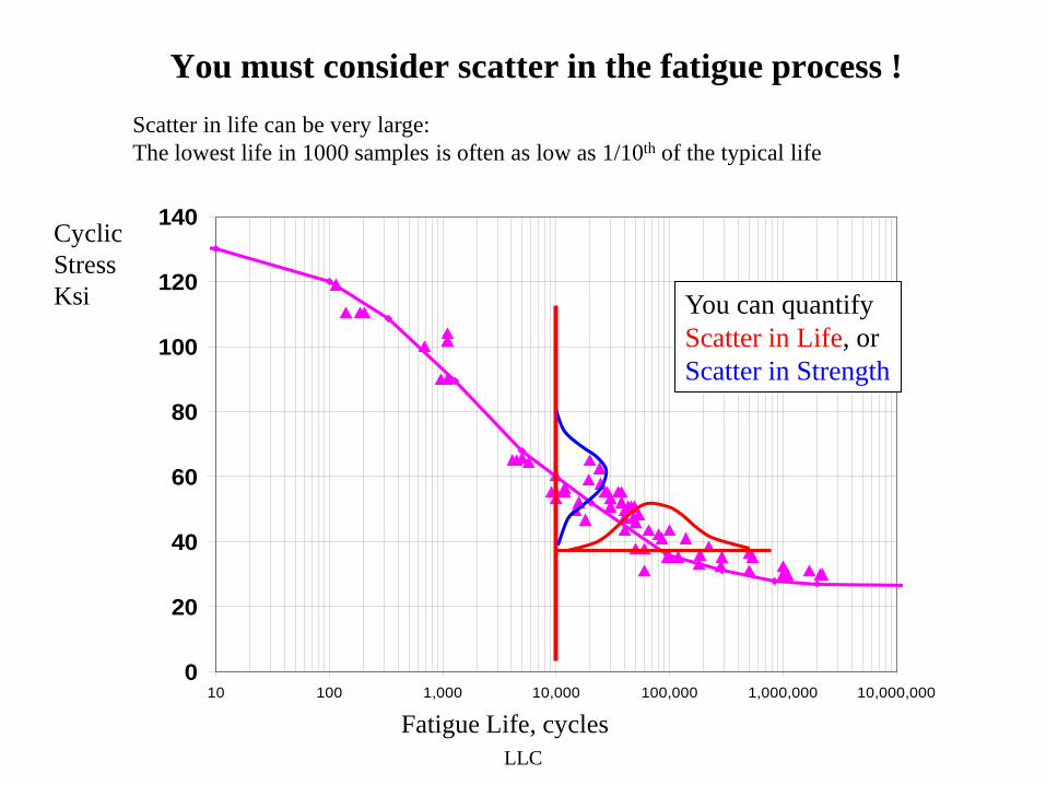
You must consider scatter in the fatigue process !
Cyclic Stress Ksi
Fatigue Life, cycles
You can quantify Scatter in Life, or Scatter in Strength
Scatter in life can be very large: The lowest life in 1000 samples is often as low as 1/10th of the typical life
29 Sept 2011 All Rights Reserved, Thomas Meyer LLC
34
0
20
40
60
80
100
120
140
10 100 1,000 10,000 100,000 1,000,000 10,000,000
K
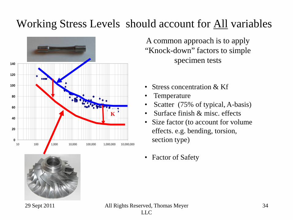
Working Stress Levels should account for All variables
• Stress concentration & Kf • Temperature • Scatter (75% of typical, A-basis) • Surface finish & misc. effects • Size factor (to account for volume
effects. e.g. bending, torsion, section type)
• Factor of Safety
A common approach is to apply “Knock-down” factors to simple
specimen tests
29 Sept 2011 All Rights Reserved, Thomas Meyer LLC
35
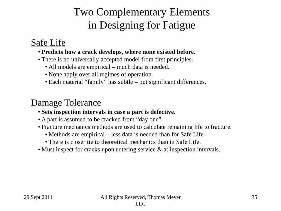
Two Complementary Elements in Designing for Fatigue
Safe Life • Predicts how a crack develops, where none existed before. • There is no universally accepted model from first principles.
• All models are empirical – much data is needed. • None apply over all regimes of operation. • Each material “family” has subtle – but significant differences.
Damage Tolerance
• Sets inspection intervals in case a part is defective. • A part is assumed to be cracked from “day one”. • Fracture mechanics methods are used to calculate remaining life to fracture.
• Methods are empirical – less data is needed than for Safe Life. • There is closer tie to theoretical mechanics than in Safe Life.
• Must inspect for cracks upon entering service & at inspection intervals.
29 Sept 2011 All Rights Reserved, Thomas Meyer LLC
36
Major Points Summary • Fatigue & fracture is important in many industries • The Form Fabrication & finish of the part is important
• There are many methods to predict fatigue crack formation
• No single method works over all regimes of loading & temperature • All methods are empirical. A data-base is needed • The key to accurate life prediction is accurate stress-strain evaluation
• Fatigue cracks have a theoretical basis for crack tip stress singularity, K
• Cyclic growth rates are related empirically to ∆K. • There are three regions of growth rate.
•Plasticity at the crack tip affects the rate curve and how a crack grows in spectrum loading •There is uncertainty in the threshold region
• The key to growth predictions is accurate determination of the stress intensity factor.
• Some Practical Considerations for Fatigue Fracture Prevention • Include factors for surface conditions, material scatter, • Consider accuracy & consistency of stress / strain prediction. Calibrate ! • Consider adding a Damage Tolerance approach
29 Sept 2011 All Rights Reserved, Thomas Meyer LLC
37
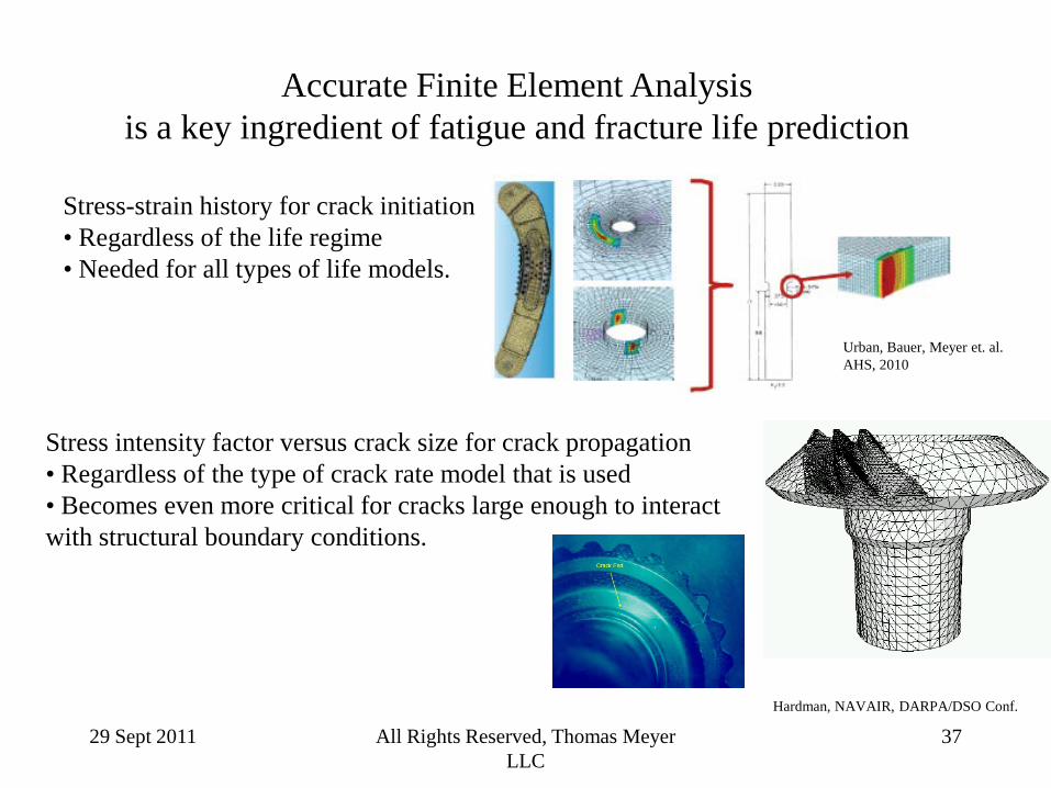
Accurate Finite Element Analysis is a key ingredient of fatigue and fracture life prediction
Stress-strain history for crack initiation • Regardless of the life regime • Needed for all types of life models.
Stress intensity factor versus crack size for crack propagation • Regardless of the type of crack rate model that is used • Becomes even more critical for cracks large enough to interact with structural boundary conditions.
Urban, Bauer, Meyer et. al. AHS, 2010
Hardman, NAVAIR, DARPA/DSO Conf.


