© 2011 ANSYS, Inc. March 21, 20121 Release 14.0
14. 0 Release
Introduction to ANSYSICEM CFD
Lecture 4 Volume Meshing
© 2011 ANSYS, Inc. March 21, 20122 Release 14.0
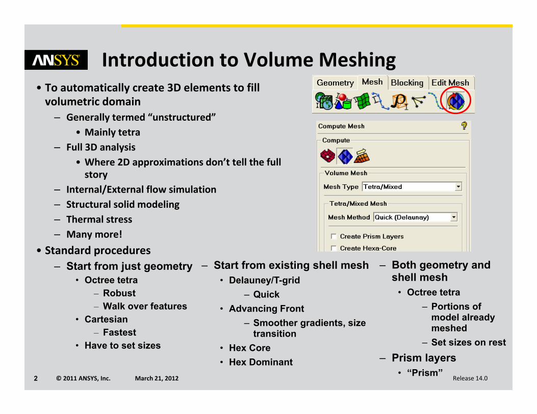
Introduction to Volume Meshing• To automatically create 3D elements to fill volumetric domain
– Generally termed “unstructured”• Mainly tetra
– Full 3D analysis• Where 2D approximations don’t tell the full story
– Internal/External flow simulation– Structural solid modeling– Thermal stress– Many more!
• Standard procedures– Start from just geometry
• Octree tetra– Robust– Walk over features
• Cartesian– Fastest
• Have to set sizes
– Start from existing shell mesh• Delauney/T-grid
– Quick• Advancing Front
– Smoother gradients, size transition
• Hex Core• Hex Dominant
– Both geometry and shell mesh
• Octree tetra– Portions of
model already meshed
– Set sizes on rest– Prism layers
• “Prism”
© 2011 ANSYS, Inc. March 21, 20123 Release 14.0
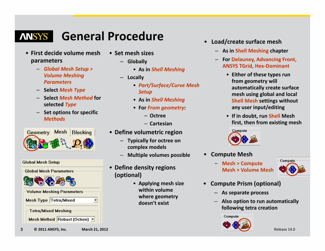
General Procedure • Load/create surface mesh– As in Shell Meshing chapter– For Delauney, Advancing Front,
ANSYS TGrid, Hex‐Dominant• Either of these types run from geometry will automatically create surface mesh using global and local Shell Mesh settings without any user input/editing
• If in doubt, run Shell Mesh first, then from existing mesh
• Compute Mesh– Mesh > Compute
Mesh > Volume Mesh• Define density regions (optional)
• Applying mesh size within volume where geometry doesn’t exist
• First decide volume mesh parameters
– Global Mesh Setup > Volume Meshing Parameters
– Select Mesh Type– Select Mesh Method for
selected Type– Set options for specific
Methods
• Set mesh sizes– Globally
• As in Shell Meshing– Locally
• Part/Surface/Curve Mesh Setup
• As in Shell Meshing• For From geometry:
– Octree– Cartesian
• Define volumetric region– Typically for octree on
complex models– Multiple volumes possible
• Compute Prism (optional)– As separate process– Also option to run automatically
following tetra creation
© 2011 ANSYS, Inc. March 21, 20124 Release 14.0
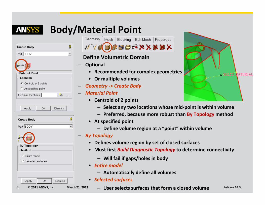
Body/Material Point
• Define Volumetric Domain– Optional
• Recommended for complex geometries• Or multiple volumes
– Geometry ‐> Create Body– Material Point
• Centroid of 2 points– Select any two locations whose mid‐point is within volume– Preferred, because more robust than By Topology method
• At specified point– Define volume region at a “point” within volume
– By Topology• Defines volume region by set of closed surfaces• Must first Build Diagnostic Topology to determine connectivity
– Will fail if gaps/holes in body• Entire model
– Automatically define all volumes• Selected surfaces
– User selects surfaces that form a closed volume
© 2011 ANSYS, Inc. March 21, 20125 Release 14.0
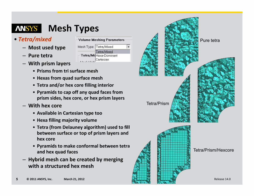
Mesh Types• Tetra/mixed
– Most used type– Pure tetra– With prism layers
• Prisms from tri surface mesh• Hexas from quad surface mesh• Tetra and/or hex core filling interior• Pyramids to cap off any quad faces from prism sides, hex core, or hex prism layers
– With hex core• Available in Cartesian type too• Hexa filling majority volume• Tetra (from Delauney algorithm) used to fill between surface or top of prism layers and hex core
• Pyramids to make conformal between tetra and hex quad faces
– Hybrid mesh can be created by merging with a structured hex mesh
Pure tetra
Tetra/Prism
Tetra/Prism/Hexcore
© 2011 ANSYS, Inc. March 21, 20126 Release 14.0
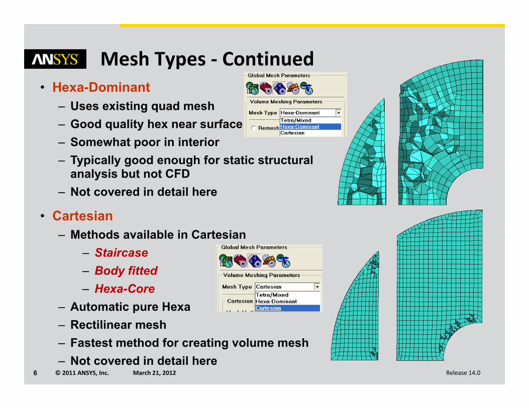
Mesh Types ‐ Continued• Hexa-Dominant
– Uses existing quad mesh– Good quality hex near surface– Somewhat poor in interior– Typically good enough for static structural
analysis but not CFD– Not covered in detail here
• Cartesian– Methods available in Cartesian
– Staircase– Body fitted– Hexa-Core
– Automatic pure Hexa– Rectilinear mesh– Fastest method for creating volume mesh– Not covered in detail here
© 2011 ANSYS, Inc. March 21, 20127 Release 14.0
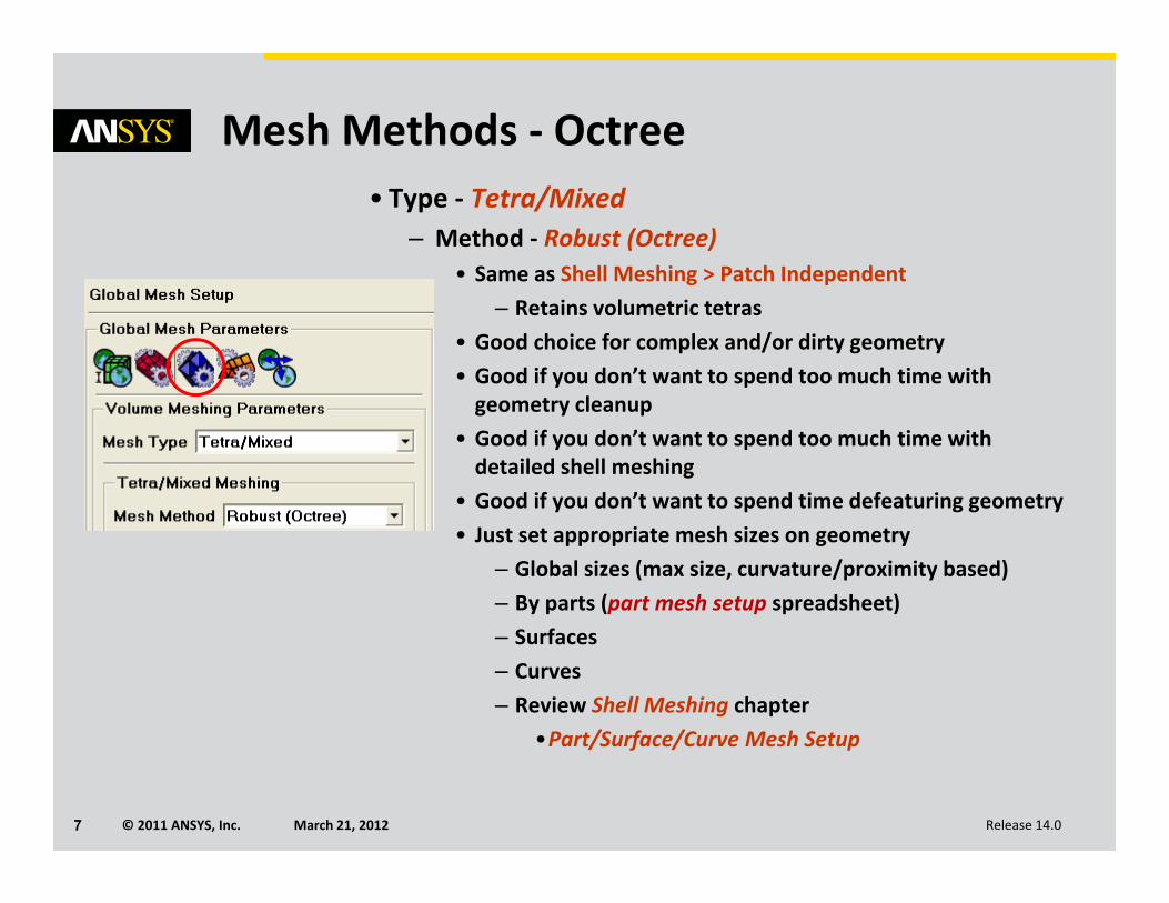
Mesh Methods ‐ Octree• Type ‐ Tetra/Mixed
– Method ‐ Robust (Octree)• Same as Shell Meshing > Patch Independent
– Retains volumetric tetras• Good choice for complex and/or dirty geometry• Good if you don’t want to spend too much time with geometry cleanup
• Good if you don’t want to spend too much time with detailed shell meshing
• Good if you don’t want to spend time defeaturing geometry• Just set appropriate mesh sizes on geometry
– Global sizes (max size, curvature/proximity based)– By parts (part mesh setup spreadsheet)– Surfaces– Curves– Review Shell Meshing chapter
•Part/Surface/Curve Mesh Setup
© 2011 ANSYS, Inc. March 21, 20128 Release 14.0
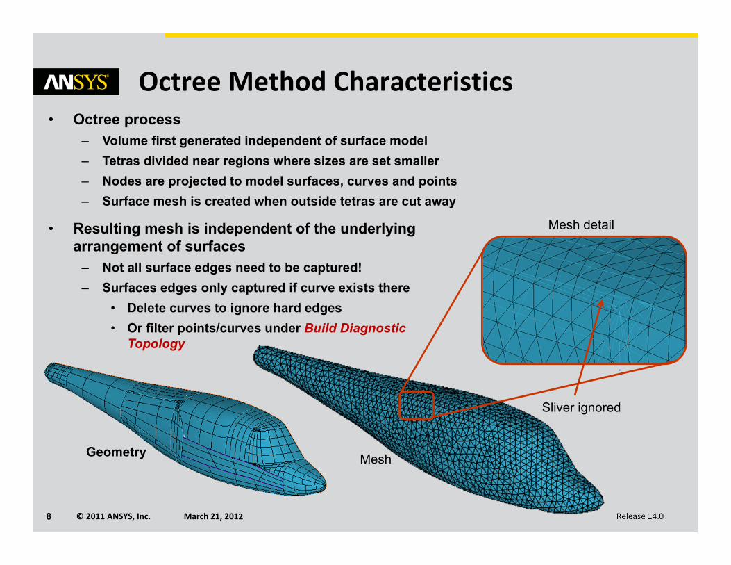
Octree Method Characteristics
Geometry
Mesh detail
Mesh
• Octree process– Volume first generated independent of surface model– Tetras divided near regions where sizes are set smaller– Nodes are projected to model surfaces, curves and points– Surface mesh is created when outside tetras are cut away
• Resulting mesh is independent of the underlying arrangement of surfaces
– Not all surface edges need to be captured!– Surfaces edges only captured if curve exists there
• Delete curves to ignore hard edges• Or filter points/curves under Build Diagnostic
Topology
Sliver ignored
© 2011 ANSYS, Inc. March 21, 20129 Release 14.0
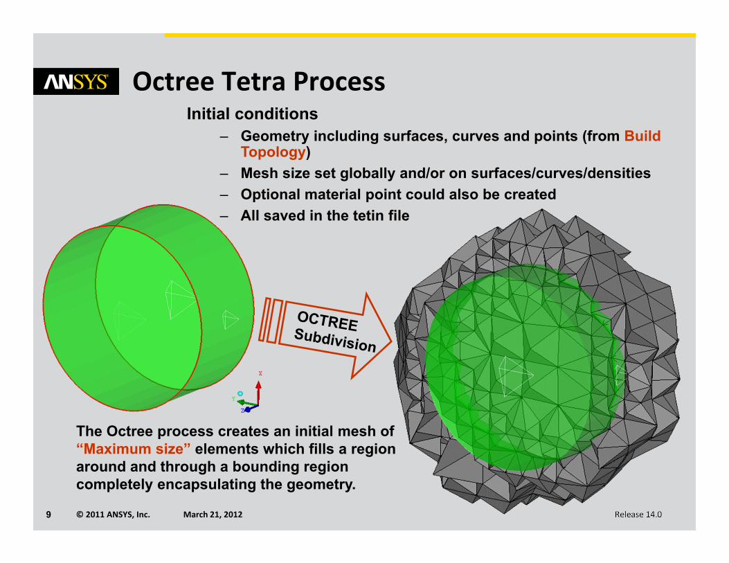
Octree Tetra Process
The Octree process creates an initial mesh of “Maximum size” elements which fills a region around and through a bounding region completely encapsulating the geometry.
Initial conditions– Geometry including surfaces, curves and points (from Build
Topology) – Mesh size set globally and/or on surfaces/curves/densities– Optional material point could also be created– All saved in the tetin file
© 2011 ANSYS, Inc. March 21, 201210 Release 14.0
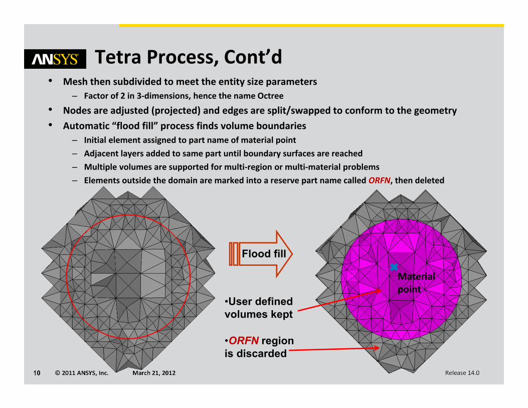
Tetra Process, Cont’d• Mesh then subdivided to meet the entity size parameters
– Factor of 2 in 3‐dimensions, hence the name Octree
• Nodes are adjusted (projected) and edges are split/swapped to conform to the geometry• Automatic “flood fill” process finds volume boundaries
– Initial element assigned to part name of material point– Adjacent layers added to same part until boundary surfaces are reached– Multiple volumes are supported for multi‐region or multi‐material problems– Elements outside the domain are marked into a reserve part name called ORFN, then deleted
Flood fill
•User defined volumes kept
•ORFN region is discarded
Material point
© 2011 ANSYS, Inc. March 21, 201211 Release 14.0
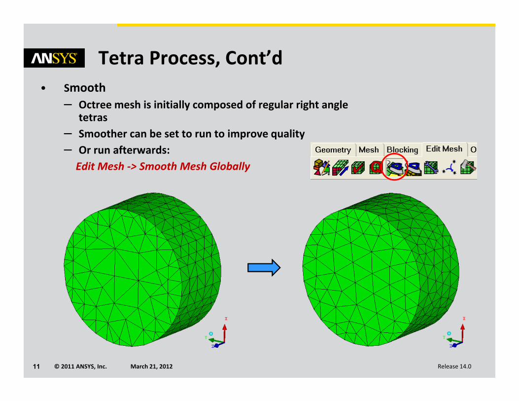
Tetra Process, Cont’d• Smooth
– Octree mesh is initially composed of regular right angle tetras
– Smoother can be set to run to improve quality– Or run afterwards: Edit Mesh ‐> Smooth Mesh Globally
© 2011 ANSYS, Inc. March 21, 201212 Release 14.0
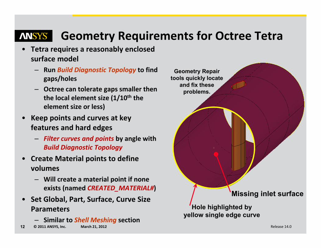
Geometry Requirements for Octree Tetra• Tetra requires a reasonably enclosed
surface model– Run Build Diagnostic Topology to find
gaps/holes– Octree can tolerate gaps smaller then
the local element size (1/10th the element size or less)
• Keep points and curves at key features and hard edges– Filter curves and points by angle with
Build Diagnostic Topology
• Create Material points to define volumes– Will create a material point if none
exists (named CREATED_MATERIAL#)
• Set Global, Part, Surface, Curve Size Parameters– Similar to Shell Meshing section
Missing inlet surface
Geometry Repair tools quickly locate
and fix these problems.
Hole highlighted by yellow single edge curve
© 2011 ANSYS, Inc. March 21, 201213 Release 14.0
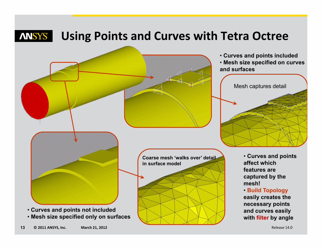
Using Points and Curves with Tetra Octree
Coarse mesh ‘walks over’ detail in surface model
Mesh captures detail
• Curves and points not included• Mesh size specified only on surfaces
• Curves and points included • Mesh size specified on curves and surfaces
• Curves and points affect which features are captured by the mesh!• Build Topologyeasily creates the necessary points and curves easily with filter by angle
© 2011 ANSYS, Inc. March 21, 201214 Release 14.0
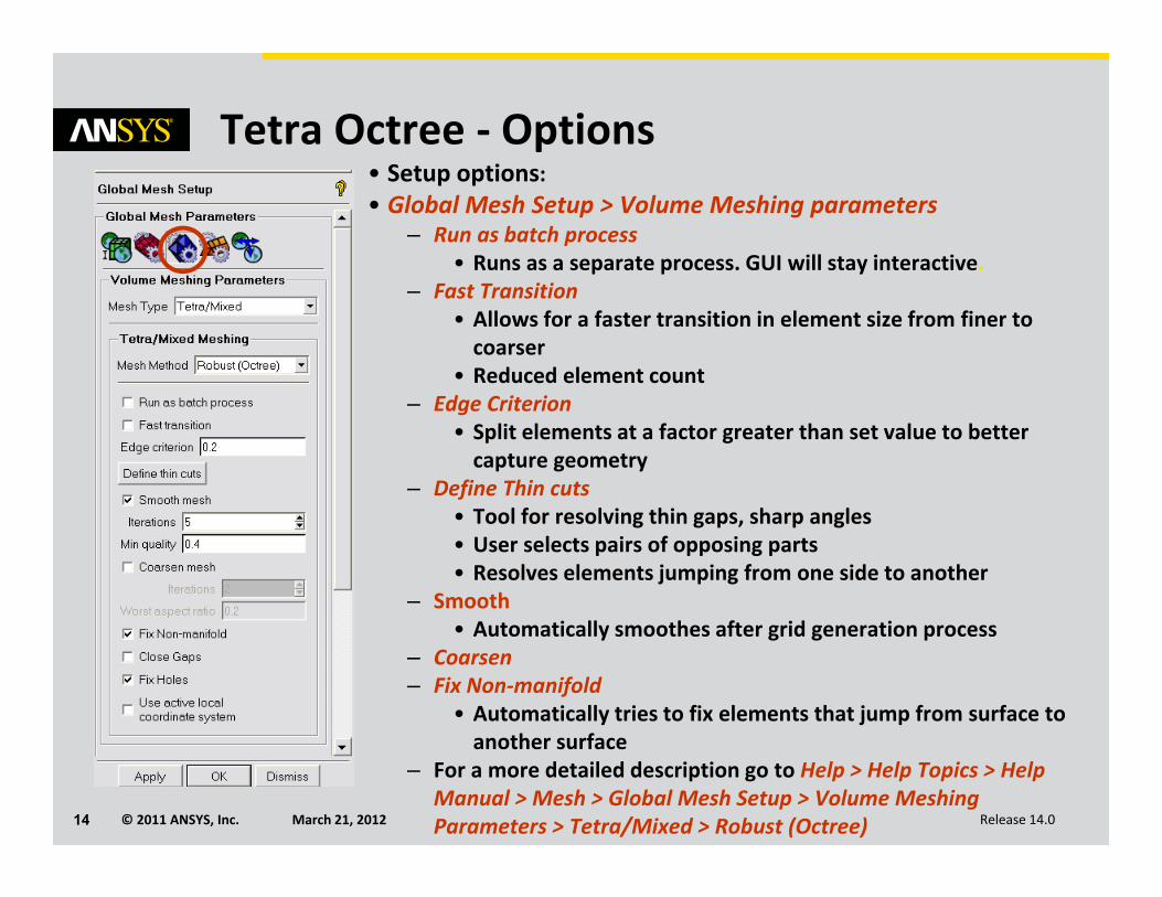
Tetra Octree ‐ Options• Setup options:• Global Mesh Setup > Volume Meshing parameters
– Run as batch process• Runs as a separate process. GUI will stay interactive.
– Fast Transition• Allows for a faster transition in element size from finer to coarser
• Reduced element count– Edge Criterion
• Split elements at a factor greater than set value to better capture geometry
– Define Thin cuts• Tool for resolving thin gaps, sharp angles• User selects pairs of opposing parts• Resolves elements jumping from one side to another
– Smooth• Automatically smoothes after grid generation process
– Coarsen– Fix Non‐manifold
• Automatically tries to fix elements that jump from surface to another surface
– For a more detailed description go to Help > Help Topics > Help Manual > Mesh > Global Mesh Setup > Volume Meshing Parameters > Tetra/Mixed > Robust (Octree)
© 2011 ANSYS, Inc. March 21, 201215 Release 14.0
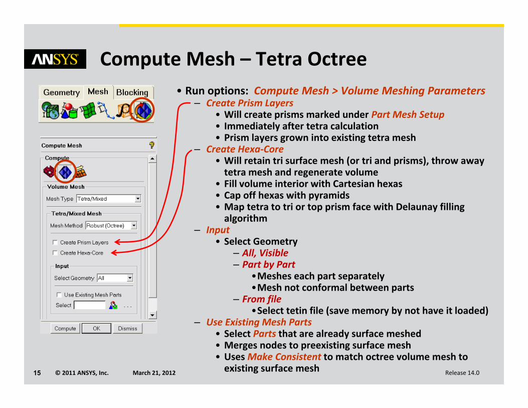
Compute Mesh – Tetra Octree• Run options: Compute Mesh > Volume Meshing Parameters
– Create Prism Layers• Will create prisms marked under Part Mesh Setup• Immediately after tetra calculation• Prism layers grown into existing tetra mesh
– Create Hexa‐Core• Will retain tri surface mesh (or tri and prisms), throw away tetra mesh and regenerate volume
• Fill volume interior with Cartesian hexas• Cap off hexas with pyramids• Map tetra to tri or top prism face with Delaunay filling algorithm
– Input• Select Geometry
– All, Visible– Part by Part
•Meshes each part separately•Mesh not conformal between parts
– From file•Select tetin file (save memory by not have it loaded)
– Use Existing Mesh Parts• Select Parts that are already surface meshed• Merges nodes to preexisting surface mesh• UsesMake Consistent to match octree volume mesh to existing surface mesh
© 2011 ANSYS, Inc. March 21, 201216 Release 14.0
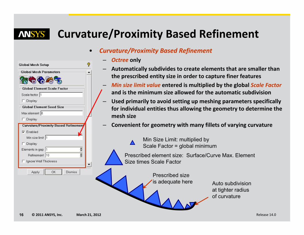
Curvature/Proximity Based Refinement• Curvature/Proximity Based Refinement
– Octree only– Automatically subdivides to create elements that are smaller than
the prescribed entity size in order to capture finer features – Min size limit value entered is multiplied by the global Scale Factor
and is the minimum size allowed for the automatic subdivision– Used primarily to avoid setting up meshing parameters specifically
for individual entities thus allowing the geometry to determine the mesh size
– Convenient for geometry with many fillets of varying curvature
Prescribed size is adequate here
Prescribed element size: Surface/Curve Max. Element Size times Scale Factor
Auto subdivision at tighter radius of curvature
Min Size Limit: multiplied by Scale Factor = global minimum
© 2011 ANSYS, Inc. March 21, 201217 Release 14.0
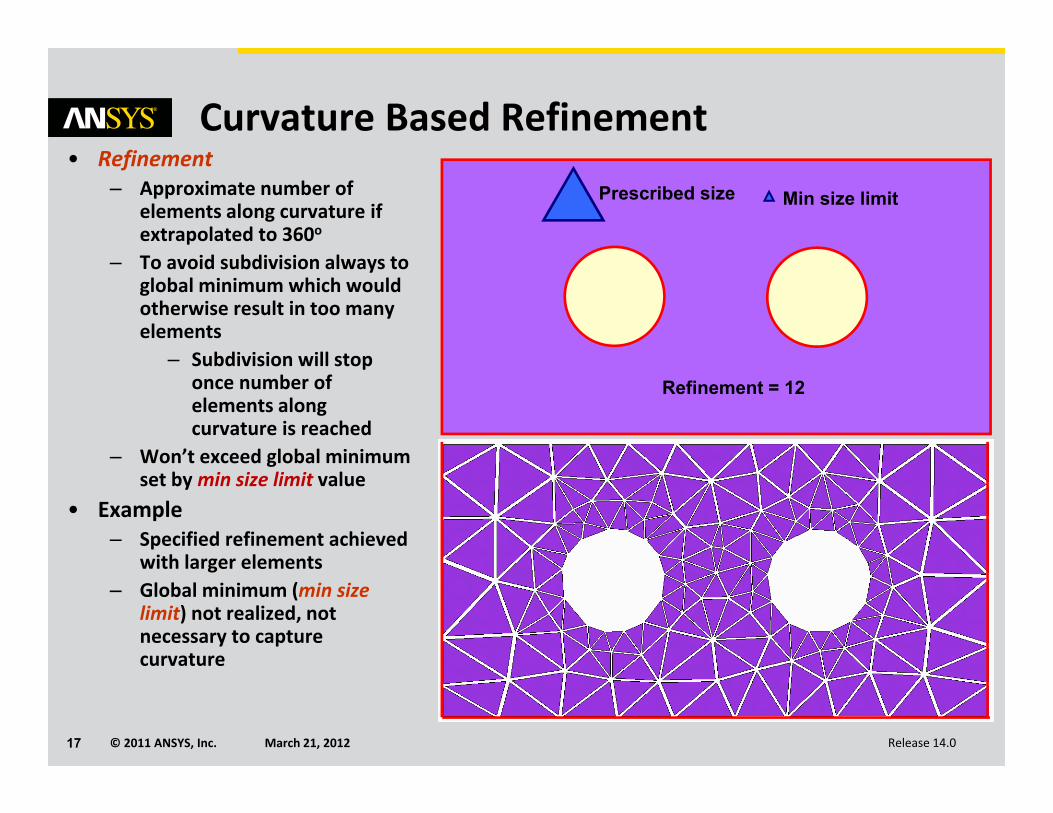
Curvature Based Refinement• Refinement
– Approximate number of elements along curvature if extrapolated to 360o
– To avoid subdivision always to global minimum which would otherwise result in too many elements
– Subdivision will stop once number of elements along curvature is reached
– Won’t exceed global minimum set by min size limit value
• Example– Specified refinement achieved
with larger elements– Global minimum (min size
limit) not realized, not necessary to capture curvature
Prescribed size Min size limit
Refinement = 12
© 2011 ANSYS, Inc. March 21, 201218 Release 14.0
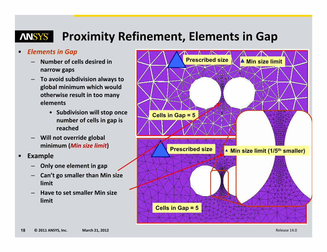
Proximity Refinement, Elements in Gap• Elements in Gap
– Number of cells desired in narrow gaps
– To avoid subdivision always to global minimum which would otherwise result in too many elements
• Subdivision will stop once number of cells in gap is reached
– Will not override global minimum (Min size limit)
• Example– Only one element in gap– Can’t go smaller than Min size
limit– Have to set smaller Min size
limit
Prescribed size Min size limit
Cells in Gap = 5
Prescribed size Min size limit (1/5th smaller)
Cells in Gap = 5
© 2011 ANSYS, Inc. March 21, 201219 Release 14.09/16/05Inventory #002281C1-19
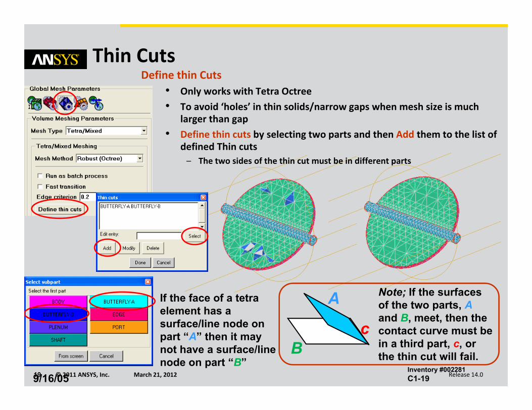
Thin Cuts
B
A
c
If the face of a tetra element has a surface/line node on part “A” then it may not have a surface/line node on part “B”
Note; If the surfaces of the two parts, Aand B, meet, then the contact curve must be in a third part, c, or the thin cut will fail.
Define thin Cuts• Only works with Tetra Octree• To avoid ‘holes’ in thin solids/narrow gaps when mesh size is much
larger than gap• Define thin cuts by selecting two parts and then Add them to the list of
defined Thin cuts– The two sides of the thin cut must be in different parts
© 2011 ANSYS, Inc. March 21, 201220 Release 14.0
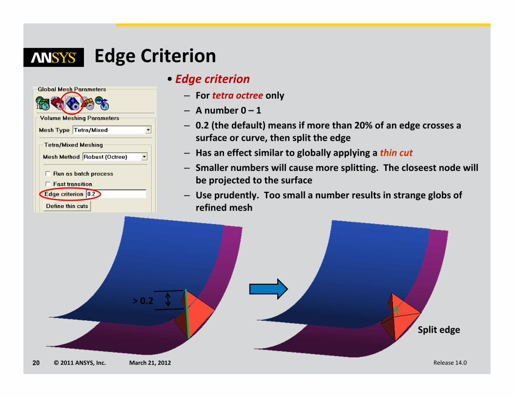
Edge Criterion• Edge criterion
– For tetra octree only– A number 0 – 1– 0.2 (the default) means if more than 20% of an edge crosses a
surface or curve, then split the edge– Has an effect similar to globally applying a thin cut– Smaller numbers will cause more splitting. The closeest node will
be projected to the surface– Use prudently. Too small a number results in strange globs of
refined mesh
> 0.2
Split edge
© 2011 ANSYS, Inc. March 21, 201221 Release 14.0
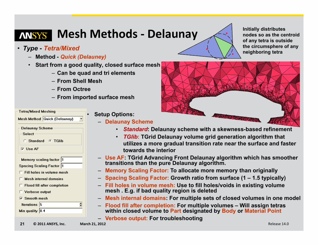
Mesh Methods ‐ Delaunay• Type - Tetra/Mixed
– Method - Quick (Delauney)• Start from a good quality, closed surface mesh
– Can be quad and tri elements– From Shell Mesh– From Octree– From imported surface mesh
• Setup Options:– Delaunay Scheme
• Standard: Delaunay scheme with a skewness-based refinement• TGlib: TGrid Delaunay volume grid generation algorithm that
utilizes a more gradual transition rate near the surface and faster towards the interior
– Use AF: TGrid Advancing Front Delaunay algorithm which has smoother transitions than the pure Delaunay algorithm.
– Memory Scaling Factor: To allocate more memory than originally– Spacing Scaling Factor: Growth ratio from surface (1 – 1.5 typically)– Fill holes in volume mesh: Use to fill holes/voids in existing volume
mesh . E.g. if bad quality region is deleted– Mesh internal domains: For multiple sets of closed volumes in one model– Flood fill after completion: For multiple volumes – Will assign tetras
within closed volume to Part designated by Body or Material Point– Verbose output: For troubleshooting
Initially distributes nodes so as the centroidof any tetra is outside the circumsphere of any neighboring tetra
© 2011 ANSYS, Inc. March 21, 201222 Release 14.0
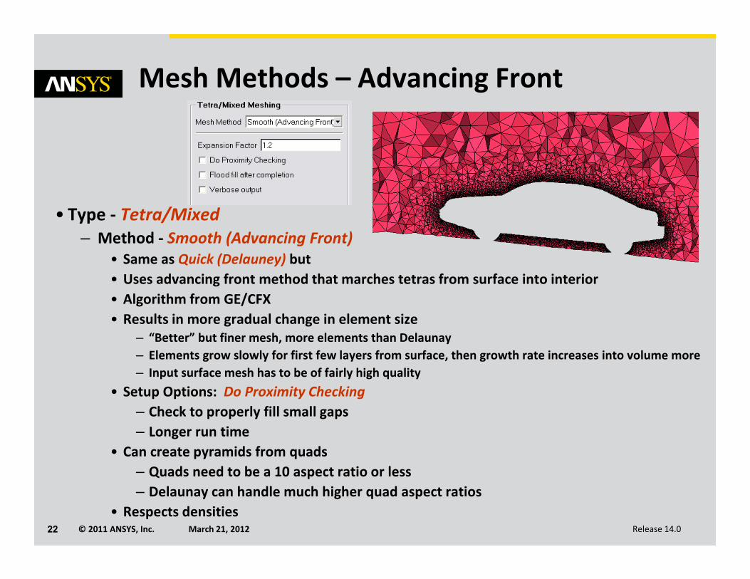
Mesh Methods – Advancing Front
• Type ‐ Tetra/Mixed– Method ‐ Smooth (Advancing Front)
• Same as Quick (Delauney) but• Uses advancing front method that marches tetras from surface into interior• Algorithm from GE/CFX• Results in more gradual change in element size
– “Better” but finer mesh, more elements than Delaunay– Elements grow slowly for first few layers from surface, then growth rate increases into volume more– Input surface mesh has to be of fairly high quality
• Setup Options: Do Proximity Checking– Check to properly fill small gaps– Longer run time
• Can create pyramids from quads– Quads need to be a 10 aspect ratio or less– Delaunay can handle much higher quad aspect ratios
• Respects densities
© 2011 ANSYS, Inc. March 21, 201223 Release 14.0
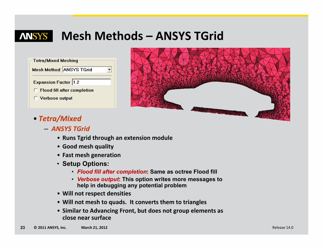
Mesh Methods – ANSYS TGrid
• Tetra/Mixed– ANSYS TGrid
• Runs Tgrid through an extension module • Good mesh quality• Fast mesh generation• Setup Options:
• Flood fill after completion: Same as octree Flood fill• Verbose output: This option writes more messages to
help in debugging any potential problem• Will not respect densities• Will not mesh to quads. It converts them to triangles• Similar to Advancing Front, but does not group elements as close near surface
© 2011 ANSYS, Inc. March 21, 201224 Release 14.0
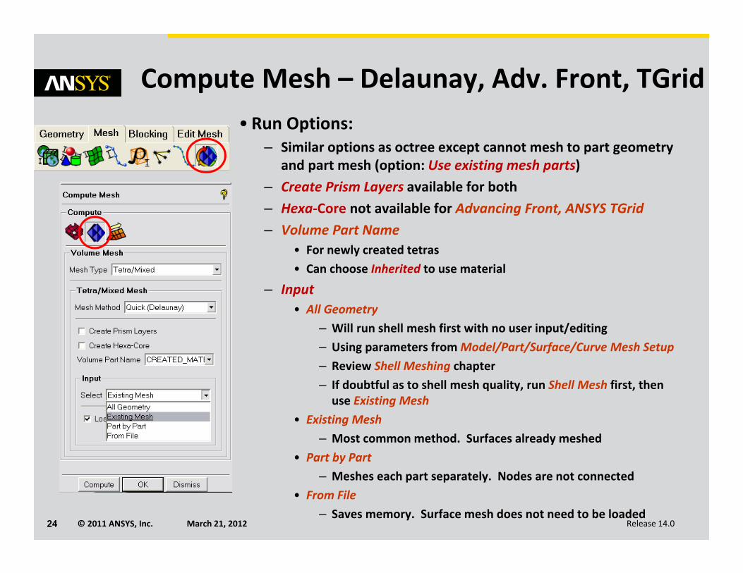
Compute Mesh – Delaunay, Adv. Front, TGrid• Run Options:
– Similar options as octree except cannot mesh to part geometry and part mesh (option: Use existing mesh parts)
– Create Prism Layers available for both– Hexa‐Core not available for Advancing Front, ANSYS TGrid– Volume Part Name
• For newly created tetras• Can choose Inherited to use material
– Input• All Geometry
– Will run shell mesh first with no user input/editing– Using parameters from Model/Part/Surface/Curve Mesh Setup– Review Shell Meshing chapter– If doubtful as to shell mesh quality, run Shell Mesh first, then use Existing Mesh
• Existing Mesh– Most common method. Surfaces already meshed
• Part by Part– Meshes each part separately. Nodes are not connected
• From File– Saves memory. Surface mesh does not need to be loaded
© 2011 ANSYS, Inc. March 21, 201225 Release 14.0
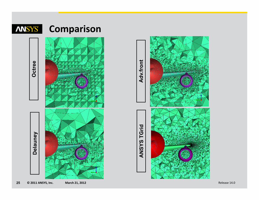
ComparisonO
ctre
eD
elau
ney
Adv
.fron
tA
NSY
S TG
rid
© 2011 ANSYS, Inc. March 21, 201226 Release 14.0
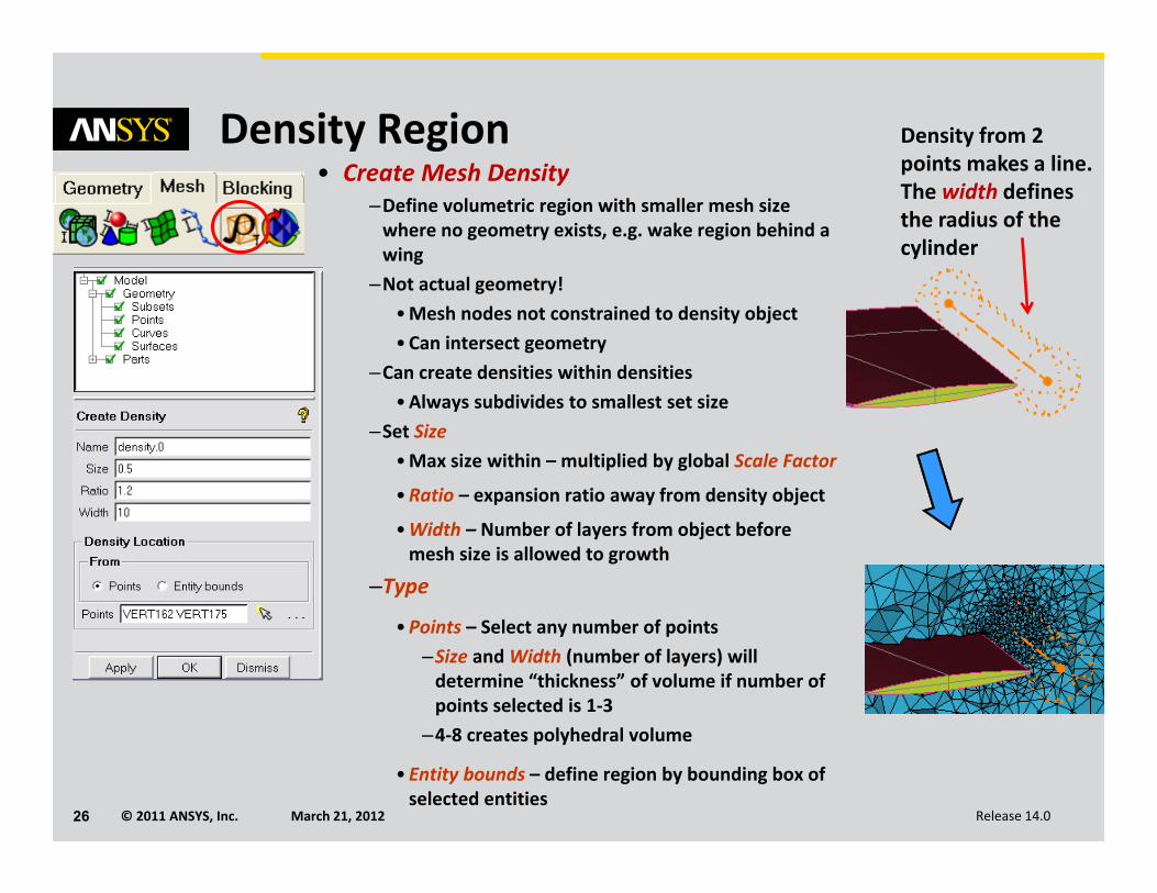
Density Region• Create Mesh Density
–Define volumetric region with smaller mesh size where no geometry exists, e.g. wake region behind a wing
–Not actual geometry!•Mesh nodes not constrained to density object•Can intersect geometry
–Can create densities within densities•Always subdivides to smallest set size
–Set Size•Max size within – multiplied by global Scale Factor
•Ratio – expansion ratio away from density object
•Width – Number of layers from object before mesh size is allowed to growth
–Type
•Points – Select any number of points–Size and Width (number of layers) will determine “thickness” of volume if number of points selected is 1‐3
–4‐8 creates polyhedral volume
•Entity bounds – define region by bounding box of selected entities
Density from 2 points makes a line.The width defines the radius of the cylinder
© 2011 ANSYS, Inc. March 21, 201227 Release 14.0
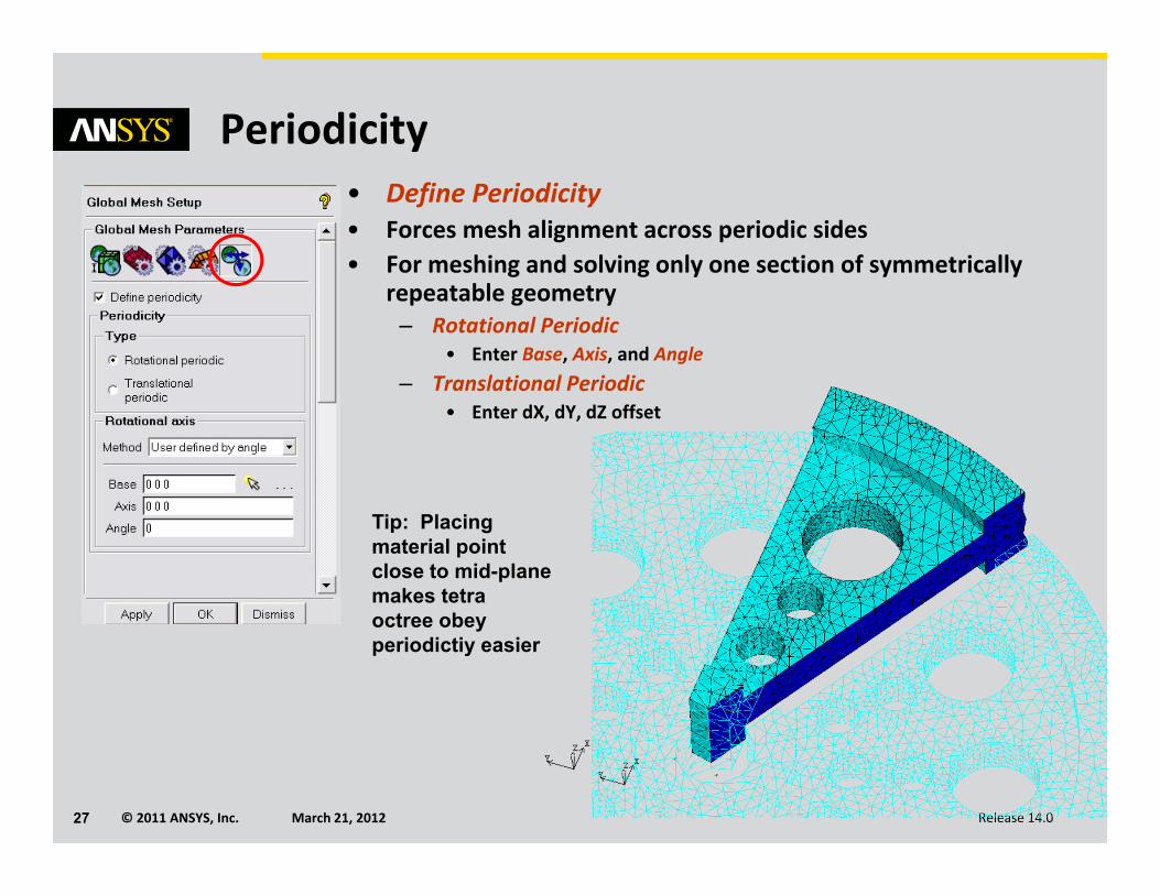
Periodicity• Define Periodicity• Forces mesh alignment across periodic sides• For meshing and solving only one section of symmetrically
repeatable geometry– Rotational Periodic
• Enter Base, Axis, and Angle– Translational Periodic
• Enter dX, dY, dZ offset
Tip: Placing material point close to mid-plane makes tetra octree obey periodictiy easier
© 2011 ANSYS, Inc. March 21, 201228 Release 14.0
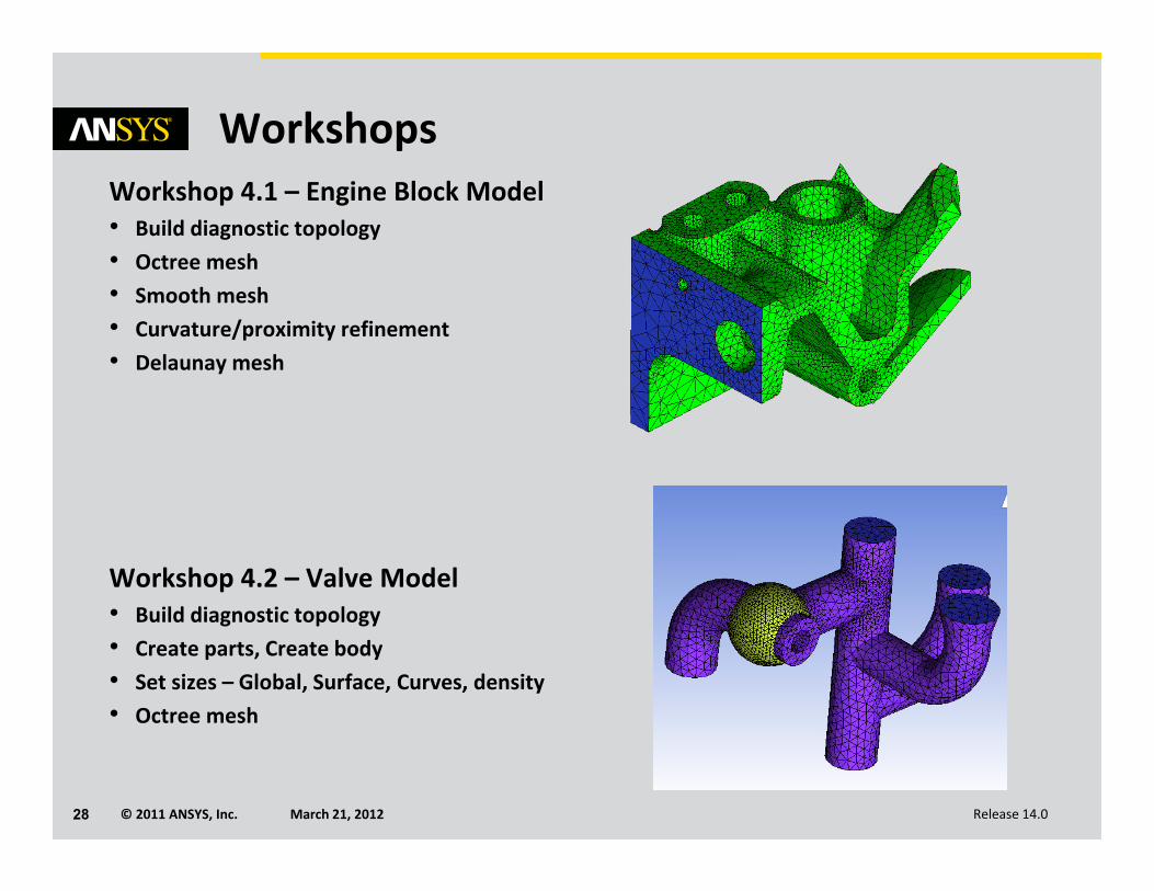
WorkshopsWorkshop 4.1 – Engine Block Model• Build diagnostic topology• Octree mesh• Smooth mesh• Curvature/proximity refinement• Delaunay mesh
Workshop 4.2 – Valve Model• Build diagnostic topology• Create parts, Create body• Set sizes – Global, Surface, Curves, density• Octree mesh
© 2011 ANSYS, Inc. March 21, 201229 Release 14.0
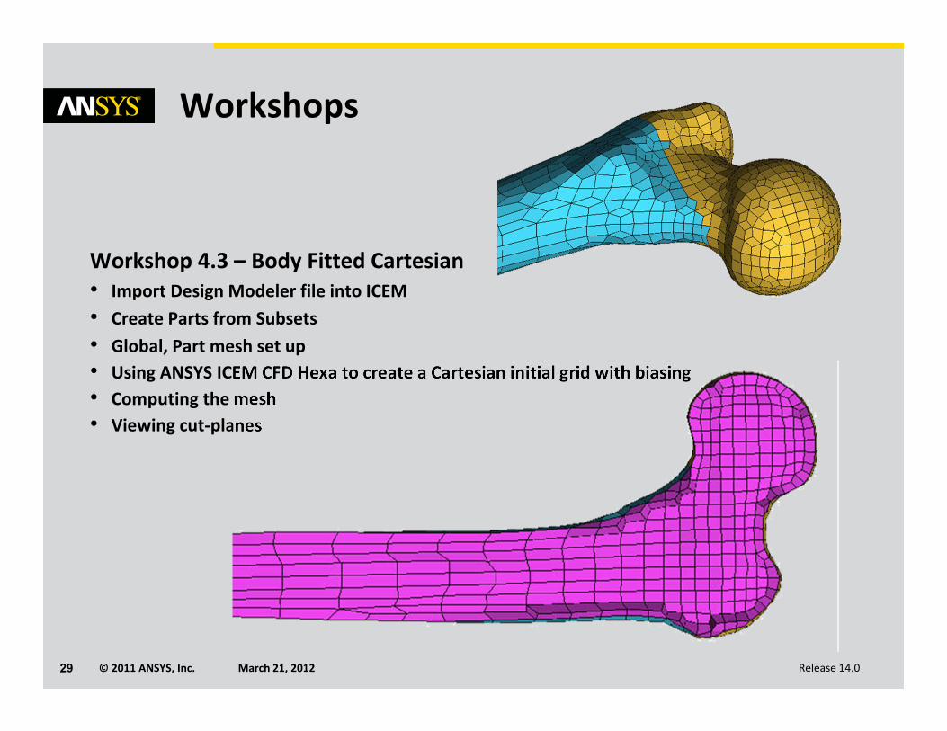
Workshops
Workshop 4.3 – Body Fitted Cartesian• Import Design Modeler file into ICEM• Create Parts from Subsets• Global, Part mesh set up• Using ANSYS ICEM CFD Hexa to create a Cartesian initial grid with biasing• Computing the mesh• Viewing cut‐planes


