
Introduction
1-1
1DT066Distributed Information Systems
Chapter 1Introduction
CHAPTER 1: OVERVIEW OF THE INTERNET
Introduction
1-2
Our goal: get context,
overview, “feel” of networking
more depth, detail later in course
approach: descriptive use Internet as
example
Overview: what’s the Internet? what’s a protocol? network edge network core Internet/ISP structure protocol layers, service
models
Chapter 1: roadmap
1.1 What is the Internet?1.2 Network edge1.3 Network core1.4 Internet structure and ISPs1.5 Protocol layers, service models
1-3
Introduction

WHAT’S THE INTERNET? Introduction
1-4
millions of connected computing devices:
hosts, end-systems PCs workstations, servers PDAs, mobile phones
running network apps
communication links
routers
local ISP
companynetwork
regional ISP
router workstation
servermobile

WHAT’S THE INTERNET? Introduction
1-5
protocols control sending, receiving of msgs e.g., TCP, IP, HTTP, FTP
Internet: “network of networks” loosely hierarchical public Internet versus
private intranet
local ISP
companynetwork
regional ISP
router workstation
servermobile

WHAT’S THE INTERNET: A SERVICE VIEW
Introduction
1-6
Q: Why do we need a network ?
WHAT’S THE INTERNET: A SERVICE VIEW
Introduction
1-7
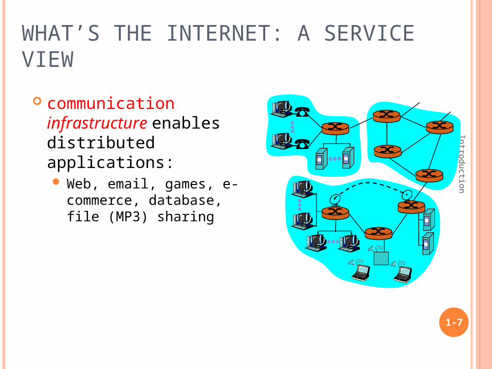
communication infrastructure enables distributed applications: Web, email, games, e-
commerce, database, file (MP3) sharing
WHAT’S A PROTOCOL: FORMAL DEF
Introduction
1-8
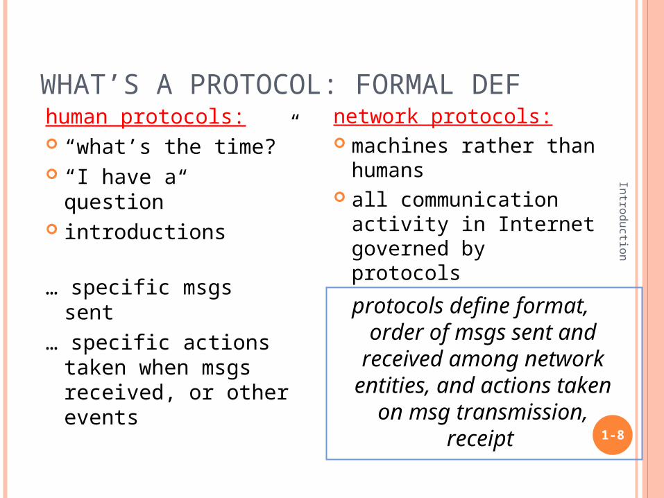
human protocols: “what’s the time?” “I have a question” introductions
… specific msgs sent… specific actions
taken when msgs received, or other events
network protocols: machines rather than
humans all communication
activity in Internet governed by protocols
protocols define format, order of msgs sent and
received among network entities, and actions taken on msg transmission, receipt
WHAT’S A PROTOCOL?
Introduction
1-9
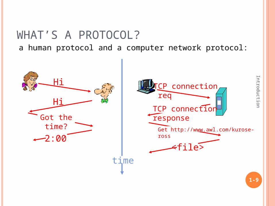
a human protocol and a computer network protocol:
Hi
Hi
Got thetime?
2:00
TCP connection req
TCP connectionresponseGet http://www.awl.com/kurose-ross
<file>time
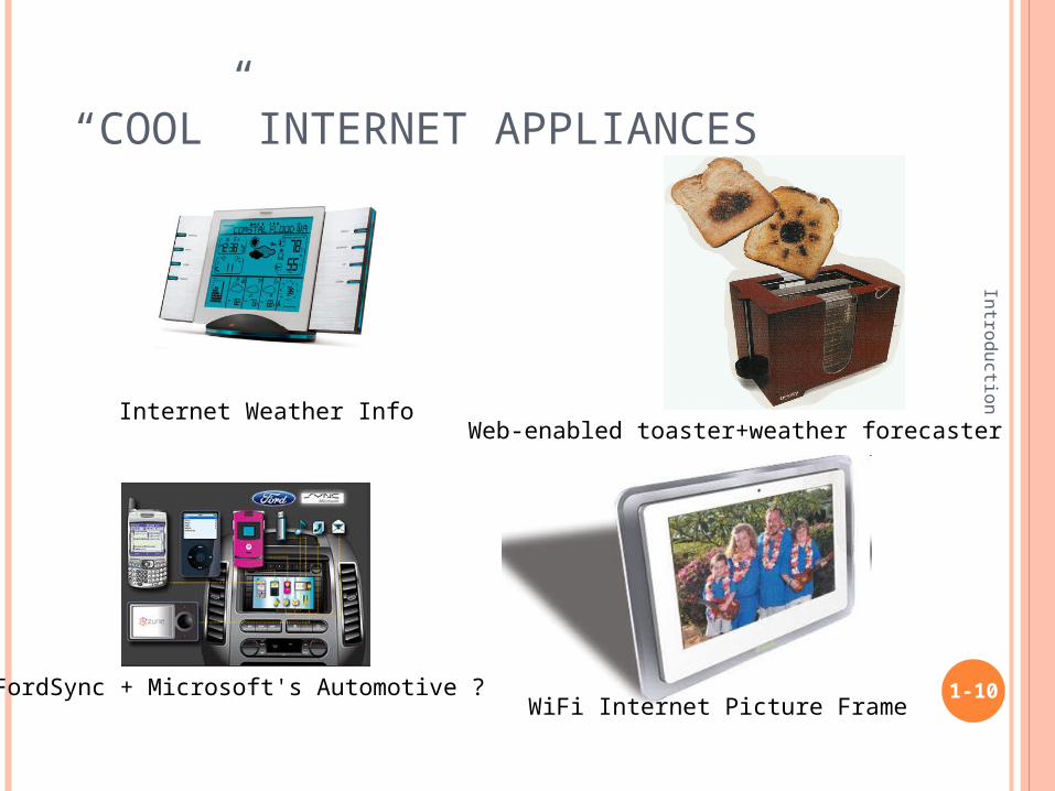
“ COOL” INTERNET APPLIANCES
Introduction
1-10FordSync + Microsoft's Automotive ?
Web-enabled toaster+weather forecaster
WiFi Internet Picture Frame
Internet Weather Info

Chapter 1: roadmap
1.1 What is the Internet?1.2 Network edge1.3 Network core1.4 Internet structure and ISPs1.5 Protocol layers, service models
1-11
Introduction

A CLOSER LOOK AT NETWORK STRUCTURE:
Introduction
1-12
network edge: applications and hosts
network core: routers network of networks
access networks, physical media: communication links

The network edge:
Introduction
1-13
end systems (hosts): run application programs e.g. Web, email at “edge of network”
client/server model client host requests, receives
service from always-on server
e.g. Web browser/server; FTP client/server
peer-peer model: minimal (or no) use of
dedicated servers e.g. Skype, BitTorrent, eMule
The network edge:
Introduction
1-14
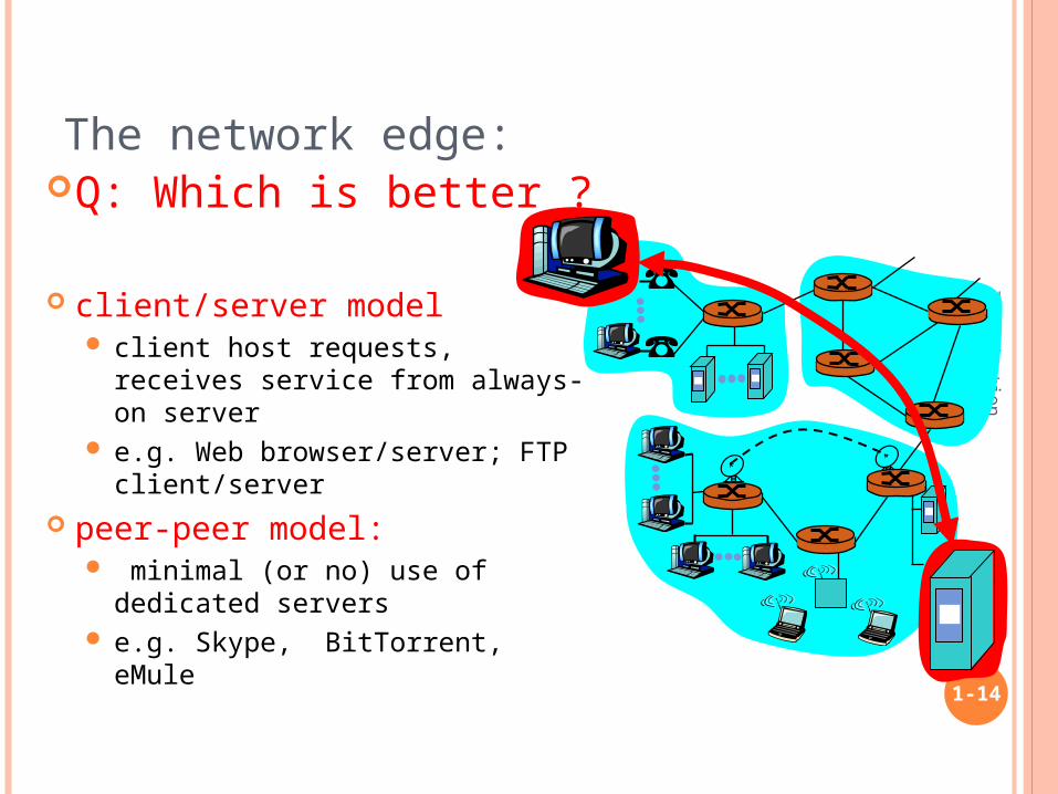
Q: Which is better ?
client/server model client host requests, receives
service from always-on server e.g. Web browser/server; FTP
client/server peer-peer model:
minimal (or no) use of dedicated servers
e.g. Skype, BitTorrent, eMule
Chapter 1: roadmap
1.1 What is the Internet?1.2 Network edge1.3 Network core1.4 Internet structure and ISPs1.5 Protocol layers, service models
1-15
Introduction

The Network Core
Introduction
1-16
mesh of interconnected routers
the fundamental question: how is data transferred through net? circuit switching:
dedicated circuit per call: telephone net
packet-switching: data sent thru net in discrete “chunks”

NETWORK CORE: CIRCUIT SWITCHING
Introduction
1-17
End-end resources reserved for “call”
link bandwidth, switch capacity
dedicated resources: no sharing
circuit-like (guaranteed) performance
call setup required
NETWORK CORE: CIRCUIT SWITCHING
Introduction
1-18
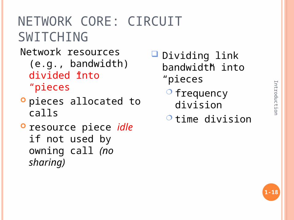
Network resources (e.g., bandwidth) divided into “pieces”
pieces allocated to calls
resource piece idle if not used by owning call (no sharing)
Dividing link bandwidth into “pieces” frequency division time division

CIRCUIT SWITCHING: FDMA AND TDMA
1-19
Introduction
FDMA
frequency
time
TDMA
frequency
time
4 users
Example:
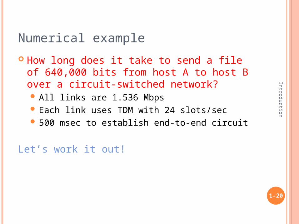
Numerical example
How long does it take to send a file of 640,000 bits from host A to host B over a circuit-switched network? All links are 1.536 Mbps Each link uses TDM with 24 slots/sec 500 msec to establish end-to-end circuit
Let’s work it out!
1-20
Introduction
NETWORK CORE: PACKET SWITCHING
Introduction
1-21
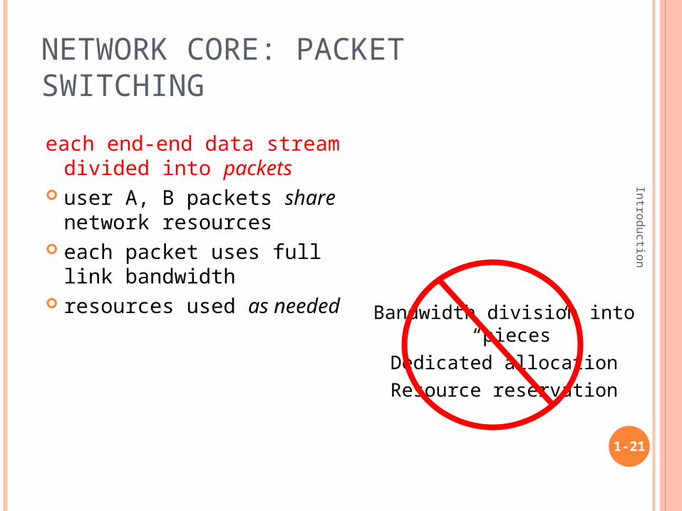
each end-end data stream divided into packets
user A, B packets share network resources
each packet uses full link bandwidth
resources used as needed
Bandwidth division into “pieces”
Dedicated allocationResource reservation
PACKET SWITCHING: STATISTICAL MULTIPLEXING
Introduction
1-22
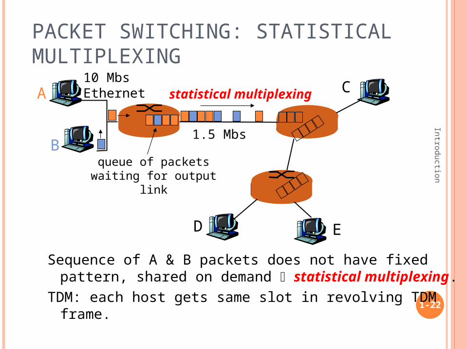
Sequence of A & B packets does not have fixed pattern, shared on demand statistical multiplexing.
TDM: each host gets same slot in revolving TDM frame.
A
B
C10 MbsEthernet
1.5 Mbs
D E
statistical multiplexing
queue of packetswaiting for output
link

Chapter 1: roadmap
1.1 What is the Internet?1.2 Network edge1.3 Network core1.4 Internet structure and ISPs1.5 Protocol layers, service models
1-23
Introduction

INTERNET STRUCTURE: NETWORK OF NETWORKS
Introduction
1-24
roughly hierarchical at center: “tier-1” ISPs (e.g., UUNet, BBN/Genuity,
Sprint, AT&T), national/international coverage treat each other as equals
Tier 1 ISP
Tier 1 ISP
Tier 1 ISP
Tier-1 providers interconnect (peer) privately
NAP
Tier-1 providers also interconnect at public network access points (NAPs)

INTERNET STRUCTURE: NETWORK OF NETWORKS
Introduction
1-25
“ Tier-2” ISPs: smaller (often regional) ISPs Connect to one or more tier-1 ISPs, possibly other tier-2 ISPs
Tier 1 ISP
Tier 1 ISP
Tier 1 ISP
NAP
Tier-2 ISPTier-2 ISP
Tier-2 ISP Tier-2 ISP
Tier-2 ISP
Tier-2 ISP pays tier-1 ISP for connectivity to rest of Internet tier-2 ISP is customer oftier-1 provider
Tier-2 ISPs also peer privately with each other, interconnect at NAP
INTERNET STRUCTURE: NETWORK OF NETWORKS
Introduction
1-26
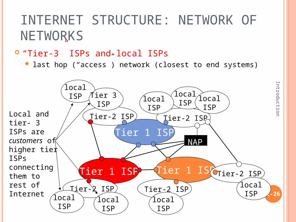
“ Tier-3” ISPs and local ISPs last hop (“access”) network (closest to end systems)
Tier 1 ISP
Tier 1 ISP
Tier 1 ISP
NAP
Tier-2 ISPTier-2 ISP
Tier-2 ISP Tier-2 ISP
Tier-2 ISP
localISPlocal
ISPlocalISP
localISP
localISP Tier 3
ISP
localISP
localISP
localISP
Local and tier- 3 ISPs are customers ofhigher tier ISPsconnecting them to rest of Internet
INTERNET STRUCTURE: NETWORK OF NETWORKS
Introduction
1-27
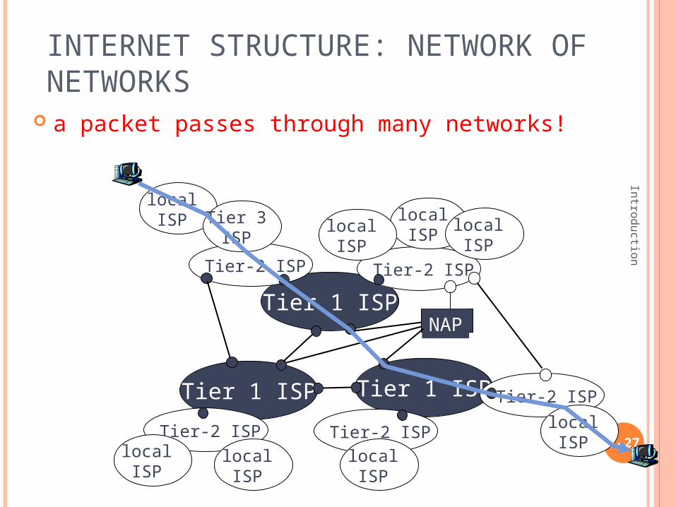
a packet passes through many networks!
Tier 1 ISP
Tier 1 ISP
Tier 1 ISP
NAP
Tier-2 ISPTier-2 ISP
Tier-2 ISP Tier-2 ISP
Tier-2 ISP
localISPlocal
ISPlocalISP
localISP
localISP Tier 3
ISP
localISP
localISP
localISP

Chapter 1: roadmap
1.1 What is the Internet?1.2 Network edge1.3 Network core1.4 Internet structure and ISPs1.5 Protocol layers, service models
1-28
Introduction
Internet protocol stack
Introduction
1-29
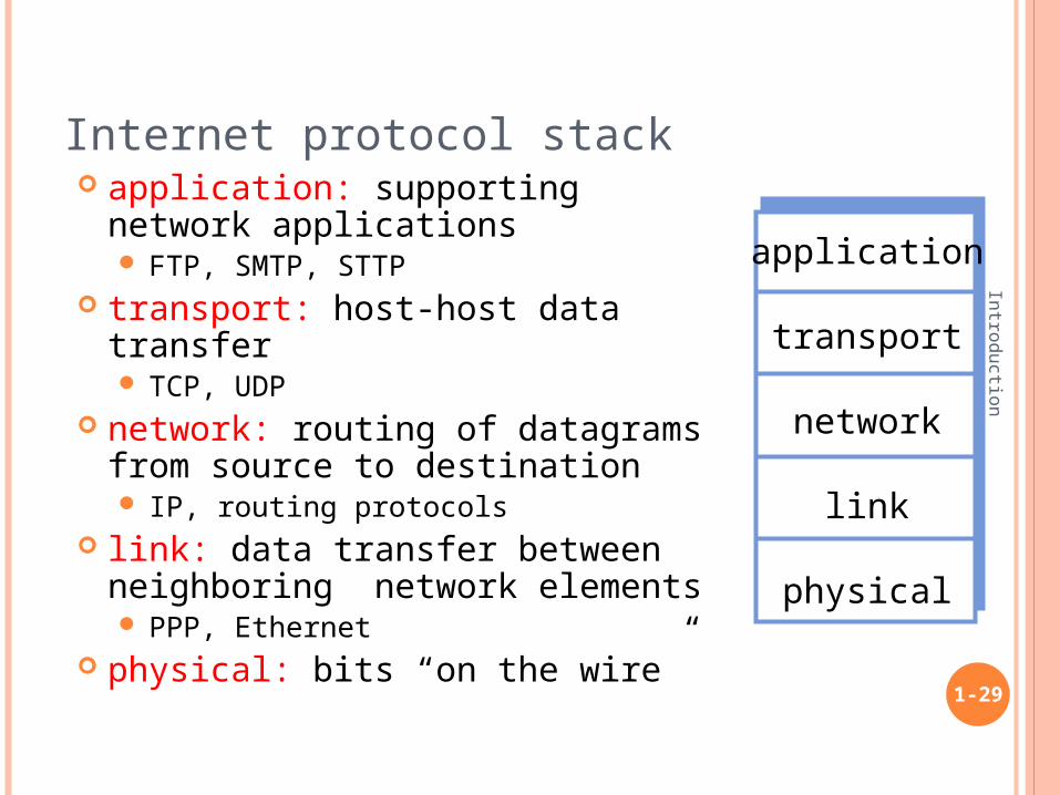
application: supporting network applications FTP, SMTP, STTP
transport: host-host data transfer TCP, UDP
network: routing of datagrams from source to destination IP, routing protocols
link: data transfer between neighboring network elements PPP, Ethernet
physical: bits “on the wire”
application
transport
network
link
physical
LAYERING: LOGICAL COMMUNICATION
Introduction
1-30
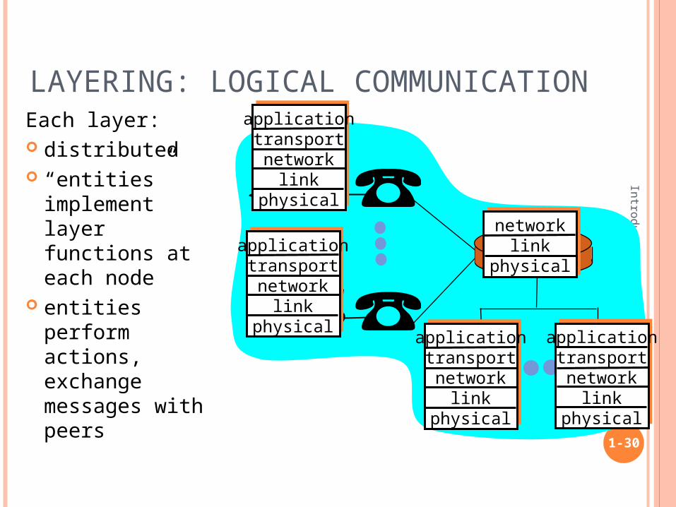
Each layer: distributed “entities”
implement layer functions at each node
entities perform actions, exchange messages with peers
applicationtransportnetwork
linkphysical
applicationtransportnetwork
linkphysical
applicationtransportnetwork
linkphysical
applicationtransportnetwork
linkphysical
networklink
physical

LAYERING: PHYSICAL COMMUNICATION
Introduction
1-31
applicationtransportnetwork
linkphysical
applicationtransportnetwork
linkphysical
applicationtransportnetwork
linkphysical
applicationtransportnetwork
linkphysical
networklink
physical
data
data
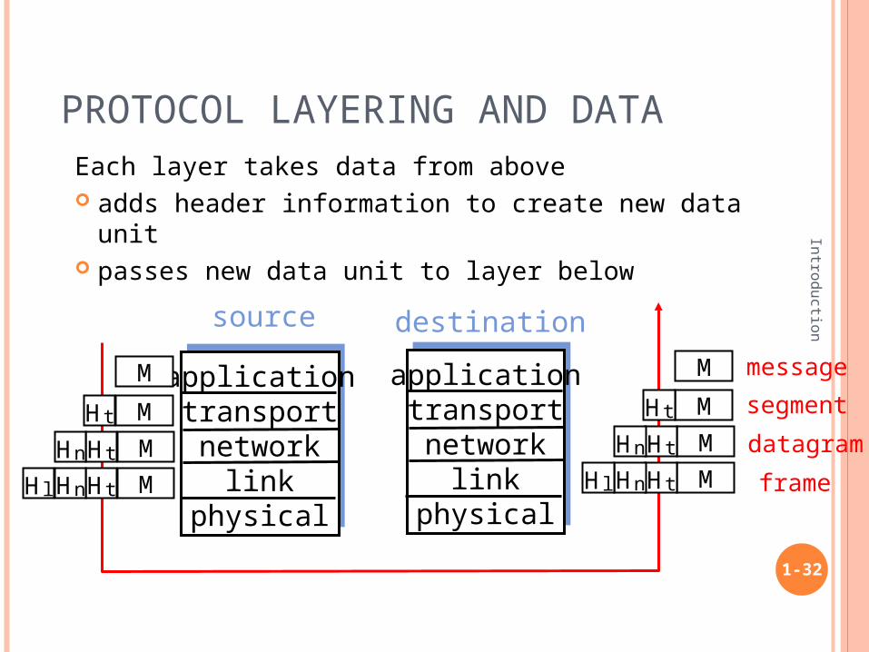
PROTOCOL LAYERING AND DATAEach layer takes data from above adds header information to create new data unit passes new data unit to layer below
1-32
Introduction
applicationtransportnetwork
linkphysical
applicationtransportnetwork
linkphysical
source destination
M
M
M
M
Ht
HtHn
HtHnHl
M
M
M
M
Ht
HtHn
HtHnHl
message
segment
datagram
frame

ISO 7-layer reference model
Introduction
1-34
application
presentation
session
application
transport
network
link
physical
Introduction: Summary
Introduction
1-35
Internet overview what’s a protocol? network edge, core,
access network packet-switching versus
circuit-switching Internet/ISP structure Internet protocol stack
You now have a “big picture”:
context, overview, “feel” of networking
PRACTICES
Log into a Unix machine (or Windows) Read the manual of ping and traceroute,
and try them on a machine1. % /bin/ping <machine_name>2. % /usr/sbin/traceroute <machine_name>
Look at the web sites of the routers you see through traceroute
1-36
Introduction


