
Introduction 1-1
1DT014/1TT821Computer Networks I
Chapter 4Network Layer

Network Layer 4-2
Chapter 4: Network Layer
4. 1 Introduction 4.2 Virtual circuit
and datagram networks
4.3 What’s inside a router
4.4 IP: Internet Protocol Datagram format IPv4 addressing ICMP IPv6
4.5 Routing algorithms Link state Distance Vector Hierarchical routing
4.6 Routing in the Internet RIP OSPF BGP
4.7 Broadcast and multicast routing

Network Layer 4-3
Network layer transport segment from sending to receiving
host on sending side encapsulates segments into
datagrams on rcving side, delivers segments to transport
layer network layer protocols in every host, router router examines header fields in all IP
datagrams passing through it
application
transportnetworkdata linkphysical
application
transportnetworkdata linkphysical
networkdata linkphysical network
data linkphysical
networkdata linkphysical
networkdata linkphysical
networkdata linkphysical
networkdata linkphysical
networkdata linkphysical
networkdata linkphysical
networkdata linkphysical
networkdata linkphysicalnetwork
data linkphysical
Network Layer 4-4
Two Key Network-Layer Functions
forwarding: move packets from router’s input to appropriate router output
routing: determine route taken by packets from source to destination.
routing algorithms

Network Layer 4-5
1
23
0111
value in arrivingpacket’s header
routing algorithm
local forwarding tableheader value output link
0100010101111001
3221
Interplay between routing and forwarding

Network Layer 4-6
Chapter 4: Network Layer
4. 1 Introduction 4.2 Virtual circuit
and datagram networks
4.3 What’s inside a router
4.4 IP: Internet Protocol Datagram format IPv4 addressing ICMP IPv6
4.5 Routing algorithms Link state Distance Vector Hierarchical routing
4.6 Routing in the Internet RIP OSPF BGP
4.7 Broadcast and multicast routing

Network Layer 4-7
Network layer connection and connection-less service
datagram network provides network-layer connectionless service
VC network provides network-layer connection service
analogous to the transport-layer services, but: service: host-to-host no choice: network provides one or the
other implementation: in network core

Network Layer 4-8
Virtual circuits
call setup, teardown for each call before data can flow each packet carries VC identifier (not destination host
address) every router on source-dest path maintains “state” for each
passing connection link, router resources (bandwidth, buffers) may be allocated
to VC (dedicated resources = predictable service)
“source-to-dest path behaves much like telephone circuit” performance-wise network actions along source-to-dest path

Network Layer 4-9
VC implementation
a VC consists of:1. path from source to destination2. VC numbers, one number for each link along
path3. entries in forwarding tables in routers along
path packet belonging to VC carries VC
number (rather than dest address) VC number can be changed on each link.
New VC number comes from forwarding table

Network Layer 4-10
Forwarding table
12 22 32
1 23
VC number
interfacenumber
Incoming interface Incoming VC # Outgoing interface Outgoing VC #
1 12 3 222 63 1 18 3 7 2 171 97 3 87… … … …
Forwarding table innorthwest router:
Routers maintain connection state information!

Network Layer 4-11
Virtual circuits: signaling protocols
used to setup, maintain teardown VC used in ATM, frame-relay, X.25 not used in today’s Internet
application
transportnetworkdata linkphysical
application
transportnetworkdata linkphysical
1. Initiate call 2. incoming call
3. Accept call4. Call connected5. Data flow begins 6. Receive data
Network Layer 4-12
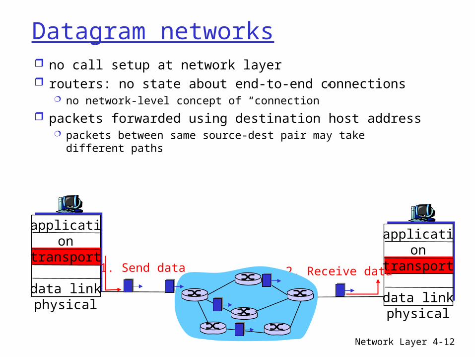
Datagram networks no call setup at network layer routers: no state about end-to-end connections
no network-level concept of “connection”
packets forwarded using destination host address packets between same source-dest pair may take
different paths
application
transportnetworkdata linkphysical
application
transportnetworkdata linkphysical
1. Send data 2. Receive data

Network Layer 4-13
Forwarding table
Destination Address Range Link Interface
11001000 00010111 00010000 00000000 through 0 11001000 00010111 00010111 11111111
11001000 00010111 00011000 00000000 through 1 11001000 00010111 00011000 11111111
11001000 00010111 00011001 00000000 through 2 11001000 00010111 00011111 11111111
otherwise 3
4 billion possible entries

Network Layer 4-14
Longest prefix matching
Prefix Match Link Interface 11001000 00010111 00010 0 11001000 00010111 00011000 1 11001000 00010111 00011 2 otherwise 3
DA: 11001000 00010111 00011000 10101010
Examples
DA: 11001000 00010111 00010110 10100001 Which interface?
Which interface?
Network Layer 4-15
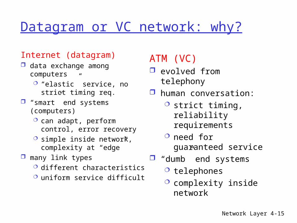
Datagram or VC network: why?
Internet (datagram) data exchange among
computers “elastic” service, no
strict timing req. “smart” end systems
(computers) can adapt, perform
control, error recovery simple inside network,
complexity at “edge” many link types
different characteristics uniform service difficult
ATM (VC) evolved from telephony human conversation:
strict timing, reliability requirements
need for guaranteed service
“dumb” end systems telephones complexity inside
network

Network Layer 4-16
Chapter 4: Network Layer
4. 1 Introduction 4.2 Virtual circuit
and datagram networks
4.3 What’s inside a router
4.4 IP: Internet Protocol Datagram format IPv4 addressing ICMP IPv6
4.5 Routing algorithms Link state Distance Vector Hierarchical routing
4.6 Routing in the Internet RIP OSPF BGP
4.7 Broadcast and multicast routing

Network Layer 4-17
Router Architecture Overview
Two key router functions: run routing algorithms/protocol (RIP, OSPF, BGP) forwarding datagrams from incoming to outgoing link

Network Layer 4-18
Input Port Functions
Decentralized switching: given datagram dest., lookup output
port using forwarding table in input port memory
goal: complete input port processing at ‘line speed’
queuing: if datagrams arrive faster than forwarding rate into switch fabric
Physical layer:bit-level reception
Data link layer:e.g., Ethernetsee chapter 5

Network Layer 4-19
Output Ports
Buffering required when datagrams arrive from fabric faster than the transmission rate
Scheduling discipline chooses among queued datagrams for transmission
Network Layer 4-20
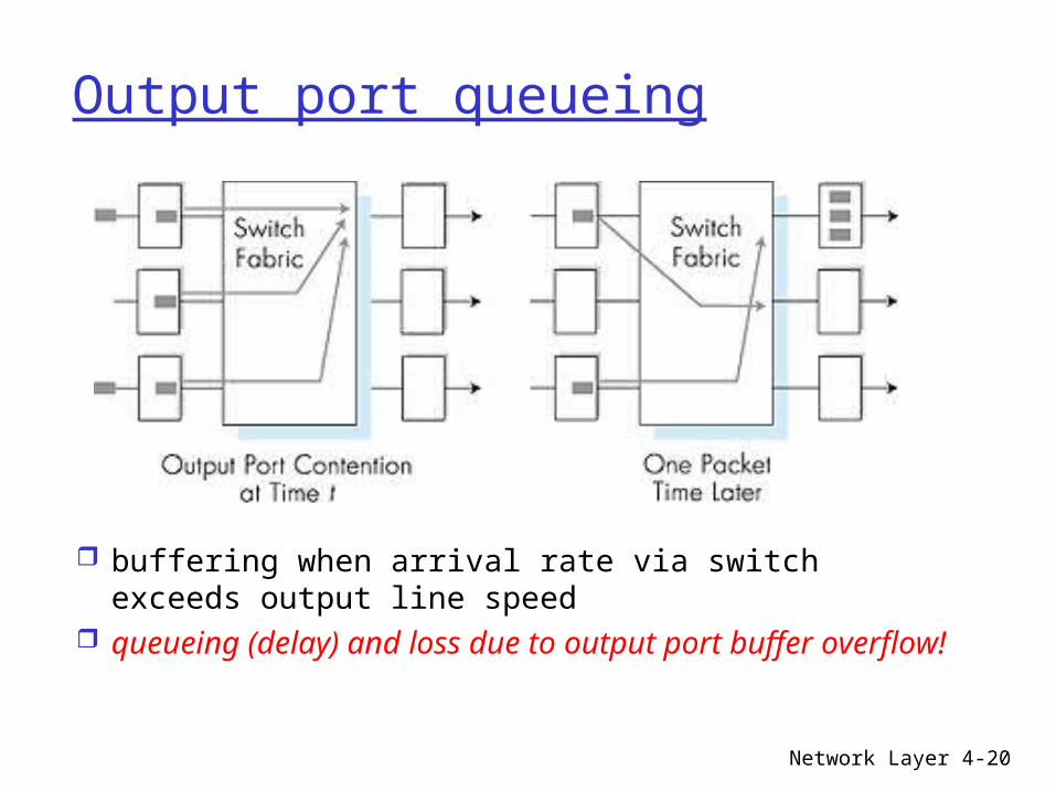
Output port queueing
buffering when arrival rate via switch exceeds output line speed
queueing (delay) and loss due to output port buffer overflow!

Network Layer 4-21
Chapter 4: Network Layer
4. 1 Introduction 4.2 Virtual circuit
and datagram networks
4.3 What’s inside a router
4.4 IP: Internet Protocol Datagram format IPv4 addressing ICMP IPv6
4.5 Routing algorithms Link state Distance Vector Hierarchical routing
4.6 Routing in the Internet RIP OSPF BGP
4.7 Broadcast and multicast routing

Network Layer 4-22
The Internet Network layer
forwardingtable
Host, router network layer functions:
Routing protocols•path selection•RIP, OSPF, BGP
IP protocol•addressing conventions•datagram format•packet handling conventions
ICMP protocol•error reporting•router “signaling”
Transport layer: TCP, UDP
Link layer
physical layer
Networklayer

Network Layer 4-23
Chapter 4: Network Layer
4. 1 Introduction 4.2 Virtual circuit
and datagram networks
4.3 What’s inside a router
4.4 IP: Internet Protocol Datagram format IPv4 addressing ICMP IPv6
4.5 Routing algorithms Link state Distance Vector Hierarchical routing
4.6 Routing in the Internet RIP OSPF BGP
4.7 Broadcast and multicast routing

Network Layer 4-24
IP datagram format
ver length
32 bits
data (variable length,typically a TCP
or UDP segment)
16-bit identifier
header checksum
time tolive
32 bit source IP address
IP protocol versionnumber
header length (bytes)
max numberremaining hops
(decremented at each router)
forfragmentation/reassembly
total datagramlength (bytes)
upper layer protocolto deliver payload to
head.len
type ofservice
“type” of data flgsfragment
offsetupper layer
32 bit destination IP address
Options (if any) E.g. timestamp,record routetaken, specifylist of routers to visit.
how much overhead with TCP?
20 bytes of TCP 20 bytes of IP = 40 bytes +
app layer overhead

Network Layer 4-25
IP Fragmentation & Reassembly network links have MTU
(max.transfer size) - largest possible link-level frame. different link types,
different MTUs large IP datagram divided
(“fragmented”) within net one datagram becomes
several datagrams “reassembled” only at
final destination IP header bits used to
identify, order related fragments
fragmentation: in: one large datagramout: 3 smaller datagrams
reassembly

Network Layer 4-26
Chapter 4: Network Layer
4. 1 Introduction 4.2 Virtual circuit
and datagram networks
4.3 What’s inside a router
4.4 IP: Internet Protocol Datagram format IPv4 addressing ICMP IPv6
4.5 Routing algorithms Link state Distance Vector Hierarchical routing
4.6 Routing in the Internet RIP OSPF BGP
4.7 Broadcast and multicast routing

Network Layer 4-27
IP Addressing: introduction IP address: 32-bit
identifier for host, router interface
interface: connection between host/router and physical link router’s typically have
multiple interfaces host typically has one
interface IP addresses
associated with each interface
223.1.1.1
223.1.1.2
223.1.1.3
223.1.1.4 223.1.2.9
223.1.2.2
223.1.2.1
223.1.3.2223.1.3.1
223.1.3.27
223.1.1.1 = 11011111 00000001 00000001 00000001
223 1 11

Network Layer 4-28
Subnets IP address:
subnet part (high order bits)
host part (low order bits)
What’s a subnet ? device interfaces
with same subnet part of IP address
can physically reach each other without intervening router
223.1.1.1
223.1.1.2
223.1.1.3
223.1.1.4 223.1.2.9
223.1.2.2
223.1.2.1
223.1.3.2223.1.3.1
223.1.3.27
network consisting of 3 subnets
subnet

Network Layer 4-29
Subnets 223.1.1.0/24223.1.2.0/24
223.1.3.0/24
Recipe To determine the
subnets, detach each interface from its host or router, creating islands of isolated networks. Each isolated network is called a subnet. Subnet mask: /24
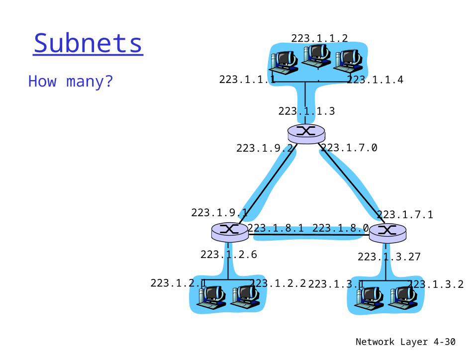
Network Layer 4-30
SubnetsHow many? 223.1.1.1
223.1.1.3
223.1.1.4
223.1.2.2223.1.2.1
223.1.2.6
223.1.3.2223.1.3.1
223.1.3.27
223.1.1.2
223.1.7.0
223.1.7.1223.1.8.0223.1.8.1
223.1.9.1
223.1.9.2
Network Layer 4-31
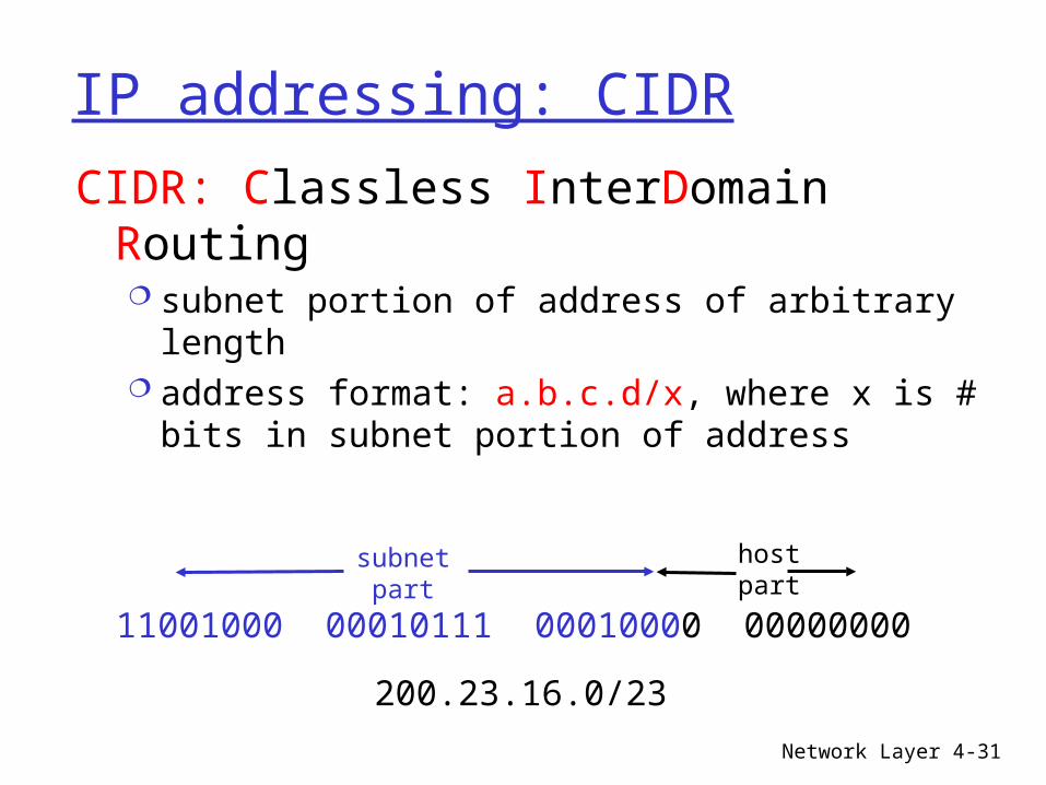
IP addressing: CIDR
CIDR: Classless InterDomain Routing subnet portion of address of arbitrary length address format: a.b.c.d/x, where x is # bits in
subnet portion of address
11001000 00010111 00010000 00000000
subnetpart
hostpart
200.23.16.0/23

Network Layer 4-32
IP addresses: how to get one?
Q: How does a host get IP address?
hard-coded by system admin in a file Windows: control-panel->network->configuration-
>tcp/ip->properties UNIX: /etc/rc.config
DHCP: Dynamic Host Configuration Protocol: dynamically get address from as server “plug-and-play”

Network Layer 4-33
DHCP: Dynamic Host Configuration Protocol
Goal: allow host to dynamically obtain its IP address from network server when it joins networkCan renew its lease on address in useAllows reuse of addresses (only hold address while connected an “on”)Support for mobile users who want to join network (more shortly)
DHCP overview: host broadcasts “DHCP discover” msg DHCP server responds with “DHCP offer” msg host requests IP address: “DHCP request” msg DHCP server sends address: “DHCP ack” msg

Network Layer 4-34
DHCP client-server scenario
223.1.1.1
223.1.1.2
223.1.1.3
223.1.1.4 223.1.2.9
223.1.2.2
223.1.2.1
223.1.3.2223.1.3.1
223.1.3.27
A
BE
DHCP server
arriving DHCP client needsaddress in thisnetwork
Network Layer 4-35
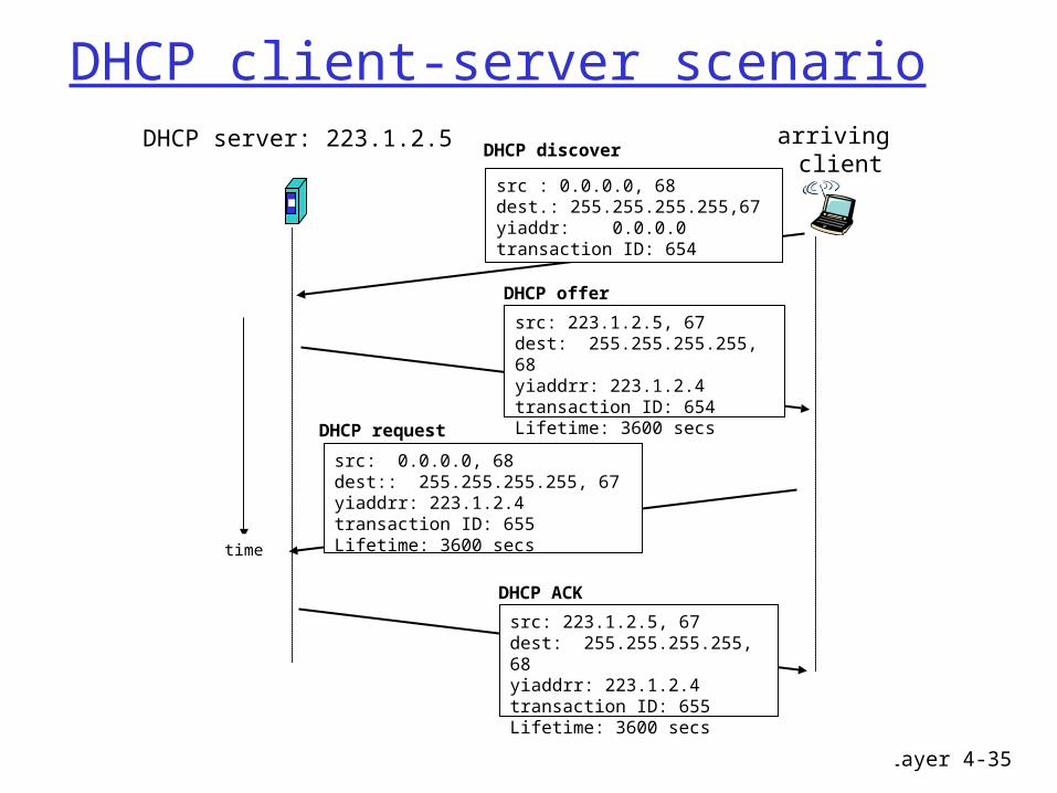
DHCP client-server scenarioDHCP server: 223.1.2.5 arriving
client
time
DHCP discover
src : 0.0.0.0, 68 dest.: 255.255.255.255,67yiaddr: 0.0.0.0transaction ID: 654
DHCP offer
src: 223.1.2.5, 67 dest: 255.255.255.255, 68yiaddrr: 223.1.2.4transaction ID: 654Lifetime: 3600 secs
DHCP request
src: 0.0.0.0, 68 dest:: 255.255.255.255, 67yiaddrr: 223.1.2.4transaction ID: 655Lifetime: 3600 secs
DHCP ACK
src: 223.1.2.5, 67 dest: 255.255.255.255, 68yiaddrr: 223.1.2.4transaction ID: 655Lifetime: 3600 secs

Network Layer 4-36
IP addresses: how to get one?
Q: How does network get subnet part of IP addr?
A: gets allocated portion of its provider ISP’s address space
ISP's block 11001000 00010111 00010000 00000000 200.23.16.0/20
Organization 0 11001000 00010111 00010000 00000000 200.23.16.0/23 Organization 1 11001000 00010111 00010010 00000000 200.23.18.0/23 Organization 2 11001000 00010111 00010100 00000000 200.23.20.0/23 ... ….. …. ….
Organization 7 11001000 00010111 00011110 00000000 200.23.30.0/23

Network Layer 4-37
Hierarchical addressing: route aggregation
“Send me anythingwith addresses beginning 200.23.16.0/20”
200.23.16.0/23
200.23.18.0/23
200.23.30.0/23
Fly-By-Night-ISP
Organization 0
Organization 7Internet
Organization 1
ISPs-R-Us“Send me anythingwith addresses beginning 199.31.0.0/16”
200.23.20.0/23Organization 2
...
...
Hierarchical addressing allows efficient advertisement of routing information:

Network Layer 4-38
IP addressing: the last word...
Q: How does an ISP get block of addresses?
A: ICANN: Internet Corporation for Assigned
Names and Numbers allocates addresses manages DNS assigns domain names, resolves disputes

Network Layer 4-39
NAT: Network Address Translation
10.0.0.1
10.0.0.2
10.0.0.3
10.0.0.4
138.76.29.7
local network(e.g., home network)
10.0.0/24
rest ofInternet
Datagrams with source or destination in this networkhave 10.0.0/24 address for
source, destination (as usual)
All datagrams leaving localnetwork have same single source
NAT IP address: 138.76.29.7,different source port numbers

Network Layer 4-40
NAT: Network Address Translation
Motivation: local network uses just one IP address as far as outside world is concerned: range of addresses not needed from ISP: just
one IP address for all devices can change addresses of devices in local network
without notifying outside world can change ISP without changing addresses of
devices in local network devices inside local net not explicitly
addressable, visible by outside world (a security plus).
Network Layer 4-41
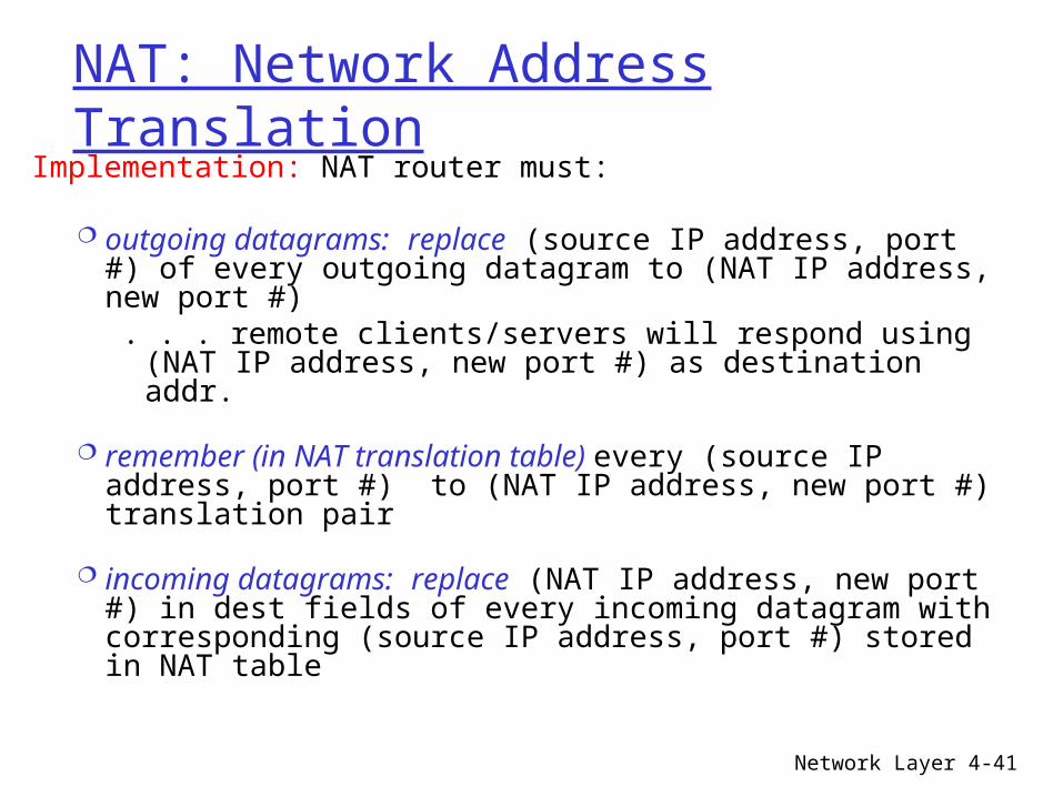
NAT: Network Address Translation
Implementation: NAT router must:
outgoing datagrams: replace (source IP address, port #) of every outgoing datagram to (NAT IP address, new port #). . . remote clients/servers will respond using (NAT IP
address, new port #) as destination addr.
remember (in NAT translation table) every (source IP address, port #) to (NAT IP address, new port #) translation pair
incoming datagrams: replace (NAT IP address, new port #) in dest fields of every incoming datagram with corresponding (source IP address, port #) stored in NAT table

Network Layer 4-42
NAT: Network Address Translation
10.0.0.1
10.0.0.2
10.0.0.3
S: 10.0.0.1, 3345D: 128.119.40.186, 80
1
10.0.0.4
138.76.29.7
1: host 10.0.0.1 sends datagram to 128.119.40.186, 80
NAT translation tableWAN side addr LAN side addr
138.76.29.7, 5001 10.0.0.1, 3345…… ……
S: 128.119.40.186, 80 D: 10.0.0.1, 3345
4
S: 138.76.29.7, 5001D: 128.119.40.186, 80
2
2: NAT routerchanges datagramsource addr from10.0.0.1, 3345 to138.76.29.7, 5001,updates table
S: 128.119.40.186, 80 D: 138.76.29.7, 5001
3
3: Reply arrives dest. address: 138.76.29.7, 5001
4: NAT routerchanges datagramdest addr from138.76.29.7, 5001 to 10.0.0.1, 3345

Network Layer 4-43
Chapter 4: Network Layer
4. 1 Introduction 4.2 Virtual circuit
and datagram networks
4.3 What’s inside a router
4.4 IP: Internet Protocol Datagram format IPv4 addressing ICMP IPv6
4.5 Routing algorithms Link state Distance Vector Hierarchical routing
4.6 Routing in the Internet RIP OSPF BGP
4.7 Broadcast and multicast routing

Network Layer 4-44
ICMP: Internet Control Message Protocol
used by hosts & routers to communicate network-level information error reporting:
unreachable host, network, port, protocol
echo request/reply (used by ping)
network-layer “above” IP: ICMP msgs carried in IP
datagrams ICMP message: type, code
plus first 8 bytes of IP datagram causing error
Type Code description0 0 echo reply (ping)3 0 dest. network unreachable3 1 dest host unreachable3 2 dest protocol unreachable3 3 dest port unreachable3 6 dest network unknown3 7 dest host unknown4 0 source quench (congestion control - not used)8 0 echo request (ping)9 0 route advertisement10 0 router discovery11 0 TTL expired12 0 bad IP header

Network Layer 4-45
Chapter 4: Network Layer
4. 1 Introduction 4.2 Virtual circuit
and datagram networks
4.3 What’s inside a router
4.4 IP: Internet Protocol Datagram format IPv4 addressing ICMP IPv6
4.5 Routing algorithms Link state Distance Vector Hierarchical routing
4.6 Routing in the Internet RIP OSPF BGP
4.7 Broadcast and multicast routing

Network Layer 4-46
IPv6 Initial motivation: 32-bit address space
soon to be completely allocated. Additional motivation:
header format helps speed processing/forwarding
header changes to facilitate QoS IPv6 datagram format: fixed-length 40 byte header no fragmentation allowed

Network Layer 4-47
IPv6 Header (Cont)Priority: identify priority among datagrams in flowFlow Label: identify datagrams in same “flow.” (concept of“flow” not well defined).Next header: identify upper layer protocol for data

Network Layer 4-48
Chapter 4: Network Layer
4. 1 Introduction 4.2 Virtual circuit
and datagram networks
4.3 What’s inside a router
4.4 IP: Internet Protocol Datagram format IPv4 addressing ICMP IPv6
4.5 Routing algorithms Link state Distance Vector Hierarchical routing
4.6 Routing in the Internet RIP OSPF BGP
4.7 Broadcast and multicast routing


