8 | P a g e
International Journal of Petroleum and Geoscience Engineering
Volume 05, Issue 01, Pages 8-23, 2017 ISSN: 2289-4713
Stability Analysis of Vertical, Directional and Horizontal wellbores using
the Three Dimensional Hoek–Brown Criterion
Mohammad Tabaeh Hayavi *, and Mohammad Abdideh
Department of Petroleum Engineering, Omidiyeh Branch, Islamic Azad University, Omidiyeh, Iran. * Corresponding author. Tel.:+98 939 183 5971
E-mail address: [email protected]
A b s t r a c t
Keywords:
Wellbore stability,
Mud pressure,
Hoek–Brown criterion,
Analytical model,
Constitutive model.
Wellbore stability is one of the crucial issues in oil and gas industries. The issues related to
instability of wells, impose significantly unwanted costs on drilling operation. Hence, in
many oil companies, wellbore stability analysis is one of the major activities in the well
design stage. The objective of this paper is to present the 3D wellbore stability prediction
models for vertical wellbores. The 3D Hoek–Brown strength criterion developed by Zhang
and Zhu in conjunction with linear poroelastic constitutive model is utilized to develop the
models. Furtheremore, safe mud pressure window required to stabilize the directional and
horizontal wellbores in different well trajectories and in-situ stress regimes during drilling
operation were determinded. The analytical model is applied to real field case in order to
verify the applicability of the developed models.
The results indicate that the decreasing of the Biot’s coefficient and increasing the UCS and
Poisson’s ratio, Young’s modulus, bulk modulus and ratio of shear wave travel time to
compressional wave travel time will increase the optimum mud pressure window. Also, in
different in-situ stress regimes, the inclination and azimuth have a significant role in
wellbore stability during drilling.
Accepted: 15 Mar 2017 © Academic Research Online Publisher. All rights reserved.
1. Introduction
When a well is drilled, the rock surrounding the
borehole must take up the load previously
supported by the rock hat has been removed. This
results in the development of a stress concentration
at the borehole wall. If the rock is not strong
enough, the wall will fail [1].
The integrity of the wellbore plays an important
role in petroleum operations. Hole failure problems
cost the petroleum industry several billions of
dollars each year. Prevention of wellbore failure
requires a strong understanding of the interaction
between formation strength, in-situ stresses, and
drilling practices. As in-situ stress and rock
strength cannot be easily controlled, adjusting the
drilling practices is the usual way to inhibit
wellbore failure [2,3].
During drilling, there are two types of mechanical
borehole failure: compressive and tensile failures.
Compressive failure occurs when the wellbore
pressure is too low compared with the rock strength
and the induced stresses. On the other hand, tensile
failure occurs when the wellbore pressure is too
high [4]. The main aspect of the wellbore stability
analysis is to mitigate these drilling problems [5].
Mohammad Tabaeh Hayavi, and Mohammad Abdideh / International Journal of Petroleum and Geoscience Engineering (IJPGE) 5 (1): 8-23, 2017
9 | P a g e
through altering the applied mud pressure and the
orientation of the borehole with respect to the in-
situ stresses. In engineering practice, a linear
poroelasticity stress model in combination with a
rock strength criterion is commonly used to
determine the minimum and maximum mud
pressures required for ensuring wellbore stability.
Therefore, a main aspect of wellbore stability
analysis is the selection of an appropriate rock
strength criterion [6,7,8,9].
Zhou [10] introduced a modified Wiebols and
Cook [11] criterion and developed a computer
program for the wellbore stability analysis. The
results indicated the importance of the intermediate
principal stress on the stability of wellbores. Ewy
developed the Modified-Lade failure criterion and
presented the advantages of this new criterion over
Mohr-Coulomb and Drucker-Prager [12].
Colmenares and Zoback evaluated seven different
rock failure criteria based on polyaxial test data,
and they concluded that the Modified Lade and the
Modified Wiebols and Cook fit best with polyaxial
test data [13].
Aadnoy [14] developed an analytical solution to
study the stability of inclined wellbores drilled into
rock formations modeled as a transversely isotropic
material. He showed that neglecting the anisotropic
effects arising from the directional elastic
properties can result in errors in the wellbore
stability analysis. Al-Ajmi and Zimmerman [15]
developed the Mogi–Coulomb failure criterion,
according to polyaxial failure data of the variety of
rocks. They concluded that Mohr–Coulomb failure
criterion is conservative in estimating of collapse
pressure during drilling and using Mogi–Coulomb
failure criterion can minimize the conservative
nature of the mud pressure predictions.
Hoek–Brown failure criterion is another well-
known criterion successfully applied to a wide
range of rocks for almost 30 years [16,17]. Zhang
and Zhu [18] developed a 3D Hoek-Brown strength
criterion for rocks. This criterion properly
considers the effect of the intermediate principal
stress. Also this criterion has the advantage over
the other 3D strength criteria in that it uses the
same input parameter as the most widely used
Hoek–Brown criterion. Zhang et al [19] compared
minimum mud weight prediction of five common
rock failure criteria. They recommended Mogi-
Coulomb and 3D Hoek-Brown to be used for
wellbore stability analysis.
In this paper, the 3D Hoek-Brown strength criterion
developed by Zhang and Zhu is used to analyze
wellbore stability. Furthermore, the analytical
models are applied to field data in order to verify
the applicability of the developed models.
2. Stress Concentration around a Wellbore at
Drilling Condition
Drilling a borehole will alter the in situ principal
stresses, the vertical stress and the maximum and
minimum horizontal stresses, in a manner so as to
maintain the rock mass in a state of equilibrium.
This leads to a stress concentration around the
wellbore [20].
The degree of stress concentration depends on the
wellbore orientation, the magnitude and orientation
of in-situ stresses, and the wellbore pressure [21].
When the elevated stress exceeds the rock strength,
the rock will fail resulting in the development of
wellbore failure [22]. If excessive, the cavings
produced by the spalling of broken materials into
the wellbore can cause drilling problems such as
pack-off, over-pulls, stuck-pipe and poor
cementing, to name a few [23].

Mohammad Tabaeh Hayavi, and Mohammad Abdideh / International Journal of Petroleum and Geoscience Engineering (IJPGE) 5 (1): 8-23, 2017
10 | P a g e
To evaluate the stability of a wellbore, a
constitutive model is required to compute the
stresses around the borehole [24]. Although
different constitutive models are available, the
linear poroelasticity stress model is commonly used
in industry practice [19].
The stress concentration around a well drilled in an
isotropic, elastic medium under anisotropic in-situ
stress condition (Maximum and minimum
horizontal stresses are different) is described by the
Kirsch equations. The general expressions for the
stresses at the wellbore wall for a deviated well in
the drilling situation are [25]:
Where and are the effective radial,
tangential and axial stresses, respectively. Pw is the
well pressure, Pp is the pore pressure, is the
Biot’s coefficient, is the Poisson’s ratio, θ is the
angular position around the wellbore circumference
and measured clockwise from the azimuth of
maximum horizontal stress.
The shear stresses at the wellbore wall are denoted
, and , while the in-situ stresses in (x, y,
z) coordinate system, denoted , , , ,
and , and they are defined as [21]:
where i is wellbore inclination and is the azimuth
angle due to the maximum horizontal stress ( )
direction (Degree) as illustrated in Fig. 1.
Fig. 1: Axes and inclination and direction angles of
the inclined well [26].
Effective induced stresses created at the borehole
wall for a vertical borehole ( ) can be
obtained from equations. 1-3 in the following [25]:
Mohammad Tabaeh Hayavi, and Mohammad Abdideh / International Journal of Petroleum and Geoscience Engineering (IJPGE) 5 (1): 8-23, 2017
11 | P a g e
According to Eqs. 13-15 the tangential and axial
stresses are functions of the angle θ. This angle
indicates the orientation of the stresses around the
wellbore circumference, and varies from 0° to 360°.
Consequently, the tangential and axial stresses will
vary sinusoidally. The tangential and radial stresses
are functions of the well pressure, but the vertical
stress is not.
Therefore, any change in the mud pressure will
only influence the tangential and radial stresses.
Inspection of these equations reveals that in the
vertical well, both tangential and axial stresses
reach a maximum value at θ = 90°, 270° and a
minimum value at θ = 0°, 180°.Therefore, the shear
failure known as breakouts is expected to happen at
the point of maximum tangential stress where the
rock is under maximum compression (at θ = 90°).
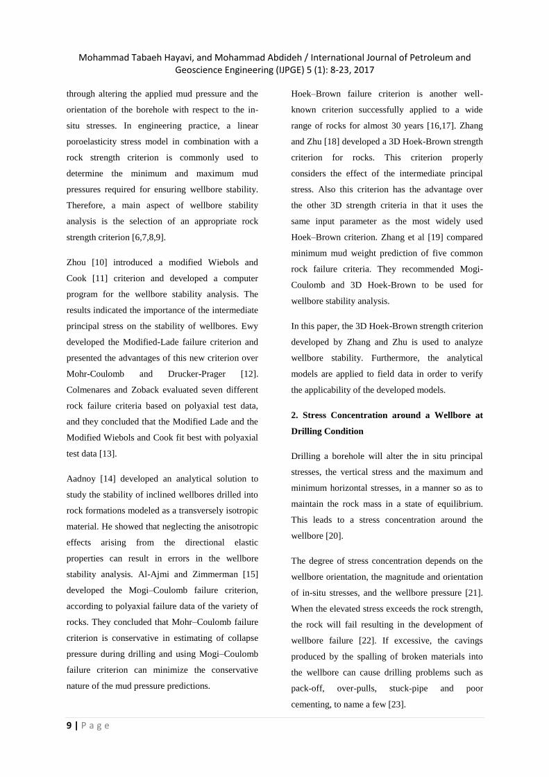
Tensile failure known as hydraulic or induced
fracture, however, is expected to occur at the point
where minimum tangential stress is applied to the
rock (at θ = 0°): an orientation 90° away from the
location of shear failures around the wellbore (Fig.
2) [24].
The magnitudes of three effective principal stresses
around the wellbore to analyze the initiation of
induced fracture can be obtained as:
Fig. 2: The location of breakout and tensile
fractures on the borehole wall [27].
For shear failure or breakouts to occur, the
magnitude of effective principal stresses around the
wellbore are estimated as
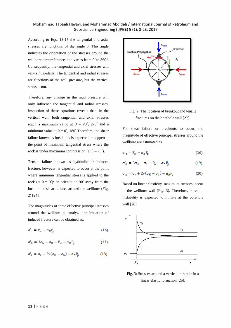
Based on linear elasticity, maximum stresses, occur
in the wellbore wall (Fig. 3). Therefore, borehole
instability is expected to initiate at the borehole
wall [28].
Fig. 3: Stresses around a vertical borehole in a
linear elastic formation [25].
Mohammad Tabaeh Hayavi, and Mohammad Abdideh / International Journal of Petroleum and Geoscience Engineering (IJPGE) 5 (1): 8-23, 2017
12 | P a g e
3. Three-Dimensional Hoek-Brown Strength
Criterion
A great number of rock strength criteria have been
proposed over the past decades. Of these different
strength criteria, the Hoek-Brown strength criterion
has been used most widely, because: (1) it has been
developed specifically for rock materials and rock
masses; (2) its input parameters can be determined
from routine unconfined compression tests,
mineralogical examination, and discontinuity
characterization; and (3) it has been applied for
over 20 years by practitioners in rock engineering,
and has been applied successfully to a wide range
of intact and fractured rock types [29]. For intact
rock, the Hoek–Brown strength criterion may be
expressed in the following form [17].
where is the Uniaxial Compressive Strength
(UCS) of intact rocks, and are respectively
the major and minor effective principal stresses,
and mi is a material constant for the intact rock,
which depends upon the rock type (texture and
mineralogy) as tabulated in Table 1.
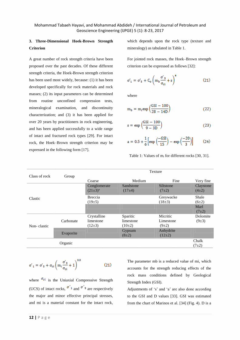
For jointed rock masses, the Hoek–Brown strength
criterion can be expressed as follows [32]:
where
Table 1: Values of mi for different rocks [30, 31].
The parameter mb is a reduced value of mi, which
accounts for the strength reducing effects of the
rock mass conditions defined by Geological
Strength Index (GSI).
Adjustments of ‘s’ and ‘a’ are also done according
to the GSI and D values [33]. GSI was estimated
from the chart of Marinos et al. [34] (Fig. 4). D is a
Class of rock Group
Coarse
Texture
Medium
Fine
Very fine
Clastic
Conglomerate
(21±3)a
Sandstone
(17±4)
Siltstone
(7±2)
Claystone
(4±2)
Breccia
(19±5)
Greywacke
(18±3)
Shale
(6±2)
Marl
(7±2)
Non- clastic
Carbonate
Crystalline
limestone
(12±3)
Sparitic
limestone
(10±2)
Micritic
Limestone
(9±2)
Dolomite
(9±3)
Evaporite Gypsum
(8±2)
Anhydrite
(12±2)
Organic
Chalk
(7±2)

Mohammad Tabaeh Hayavi, and Mohammad Abdideh / International Journal of Petroleum and Geoscience Engineering (IJPGE) 5 (1): 8-23, 2017
13 | P a g e
factor which depends upon the degree of
disturbance to which the rock mass has been
subjected by blast damage and stress relaxation.
Fig. 4: GSI chart for jointed rocks [34].
It varies from 0 for undisturbed in situ rock masses
to1 for very disturbed rock masses [32]. As can be
seen from above, the Hoek–Brown strength
criterion does not take account of the influence of
the intermediate principal stress. Much evidence,
however, has been accumulating to indicate that the
intermediate principal stress does influence the
rock strength in many instances [18,21,35,36].
Zhang and Zhu [18] proposed a 3D version of the
original Hoek–Brown strength criterion for rock
mass (Eq. (5) with a=0.5):
Where and are, respectively, the
effective mean stress and the octahedral shear
stress defined by:
Where is the intermediate effective principal
stress.
4. Building the Vertical Wellbore Stability
Prediction Models
The modes of shear and tensile failures may be
different depending on the order of magnitude of
three effective principal stresses around the
wellbore wall. These stresses are , and
presented in equations. 13-15.
When mud pressure decreases, increases
towards the compressive strength. Thus, the lower
limit of the mud pressure, Pwb, is associated with
borehole collapse, in which should be greater
than . There are three permutations of the three
principal stresses that need to be investigated in
order to determine the minimum allowable mud
pressure: (1) (2)
(3) .
Substituting each of these scenarios in the 3D
Hoek-Brown failure criterion presented in equation
21, and introducing equations 16 and 19-20, gives
Solving this equation for Pwb will give four roots.
The smallest root is the lower limit of the mud
pressure in order to avoid breakouts (collapse
pressure). The constants P4, P3, P2, P1, P0 are
shown in Appendix. If the well pressure falls below
Pwb, borehole collapse will take place.
On the other hand, when Pw increases,
decreases towards the tensile strength. Therefore,
the upper limit of the mud pressure, Pwf, is
associated with fracturing, where should be less
than . Considering this constraint and the
Mohammad Tabaeh Hayavi, and Mohammad Abdideh / International Journal of Petroleum and Geoscience Engineering (IJPGE) 5 (1): 8-23, 2017
14 | P a g e
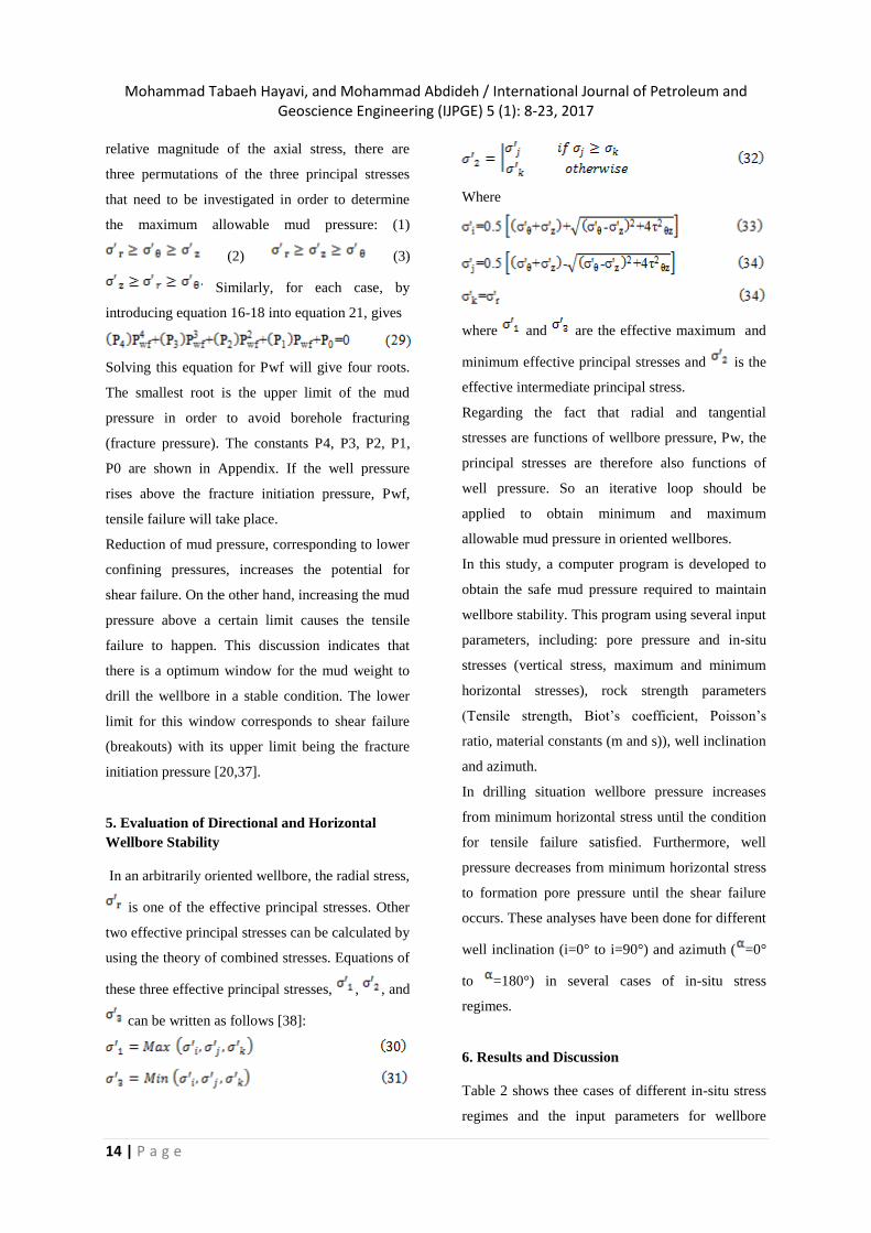
relative magnitude of the axial stress, there are
three permutations of the three principal stresses
that need to be investigated in order to determine
the maximum allowable mud pressure: (1)
(2) (3)
Similarly, for each case, by
introducing equation 16-18 into equation 21, gives
Solving this equation for Pwf will give four roots.
The smallest root is the upper limit of the mud
pressure in order to avoid borehole fracturing
(fracture pressure). The constants P4, P3, P2, P1,
P0 are shown in Appendix. If the well pressure
rises above the fracture initiation pressure, Pwf,
tensile failure will take place.
Reduction of mud pressure, corresponding to lower
confining pressures, increases the potential for
shear failure. On the other hand, increasing the mud
pressure above a certain limit causes the tensile
failure to happen. This discussion indicates that
there is a optimum window for the mud weight to
drill the wellbore in a stable condition. The lower
limit for this window corresponds to shear failure
(breakouts) with its upper limit being the fracture
initiation pressure [20,37].
5. Evaluation of Directional and Horizontal
Wellbore Stability
In an arbitrarily oriented wellbore, the radial stress,
is one of the effective principal stresses. Other
two effective principal stresses can be calculated by
using the theory of combined stresses. Equations of
these three effective principal stresses, , , and
can be written as follows [38]:
Where
where and are the effective maximum and
minimum effective principal stresses and is the
effective intermediate principal stress.
Regarding the fact that radial and tangential
stresses are functions of wellbore pressure, Pw, the
principal stresses are therefore also functions of
well pressure. So an iterative loop should be
applied to obtain minimum and maximum
allowable mud pressure in oriented wellbores.
In this study, a computer program is developed to
obtain the safe mud pressure required to maintain
wellbore stability. This program using several input
parameters, including: pore pressure and in-situ
stresses (vertical stress, maximum and minimum
horizontal stresses), rock strength parameters
(Tensile strength, Biot’s coefficient, Poisson’s
ratio, material constants (m and s)), well inclination
and azimuth.
In drilling situation wellbore pressure increases
from minimum horizontal stress until the condition
for tensile failure satisfied. Furthermore, well
pressure decreases from minimum horizontal stress
to formation pore pressure until the shear failure
occurs. These analyses have been done for different
well inclination (i=0° to i=90°) and azimuth ( =0°
to =180°) in several cases of in-situ stress
regimes.
6. Results and Discussion
Table 2 shows thee cases of different in-situ stress
regimes and the input parameters for wellbore
Mohammad Tabaeh Hayavi, and Mohammad Abdideh / International Journal of Petroleum and Geoscience Engineering (IJPGE) 5 (1): 8-23, 2017
15 | P a g e
stability analysis. According to these data
minimum and maximum bottomhole pressure that
mud weight must be provided to prevent wellbore
wall instability are determined.
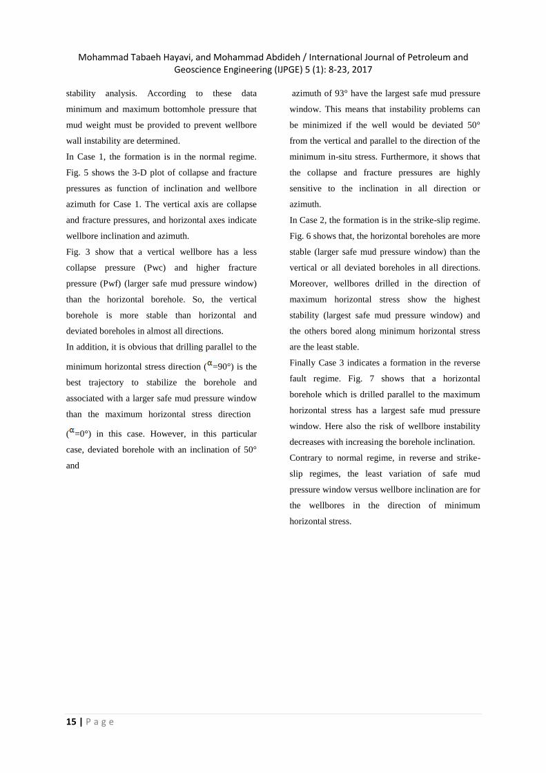
In Case 1, the formation is in the normal regime.
Fig. 5 shows the 3-D plot of collapse and fracture
pressures as function of inclination and wellbore
azimuth for Case 1. The vertical axis are collapse
and fracture pressures, and horizontal axes indicate
wellbore inclination and azimuth.
Fig. 3 show that a vertical wellbore has a less
collapse pressure (Pwc) and higher fracture
pressure (Pwf) (larger safe mud pressure window)
than the horizontal borehole. So, the vertical
borehole is more stable than horizontal and
deviated boreholes in almost all directions.
In addition, it is obvious that drilling parallel to the
minimum horizontal stress direction ( =90°) is the
best trajectory to stabilize the borehole and
associated with a larger safe mud pressure window
than the maximum horizontal stress direction
( =0°) in this case. However, in this particular
case, deviated borehole with an inclination of 50°
and
azimuth of 93° have the largest safe mud pressure
window. This means that instability problems can
be minimized if the well would be deviated 50°
from the vertical and parallel to the direction of the
minimum in-situ stress. Furthermore, it shows that
the collapse and fracture pressures are highly
sensitive to the inclination in all direction or
azimuth.
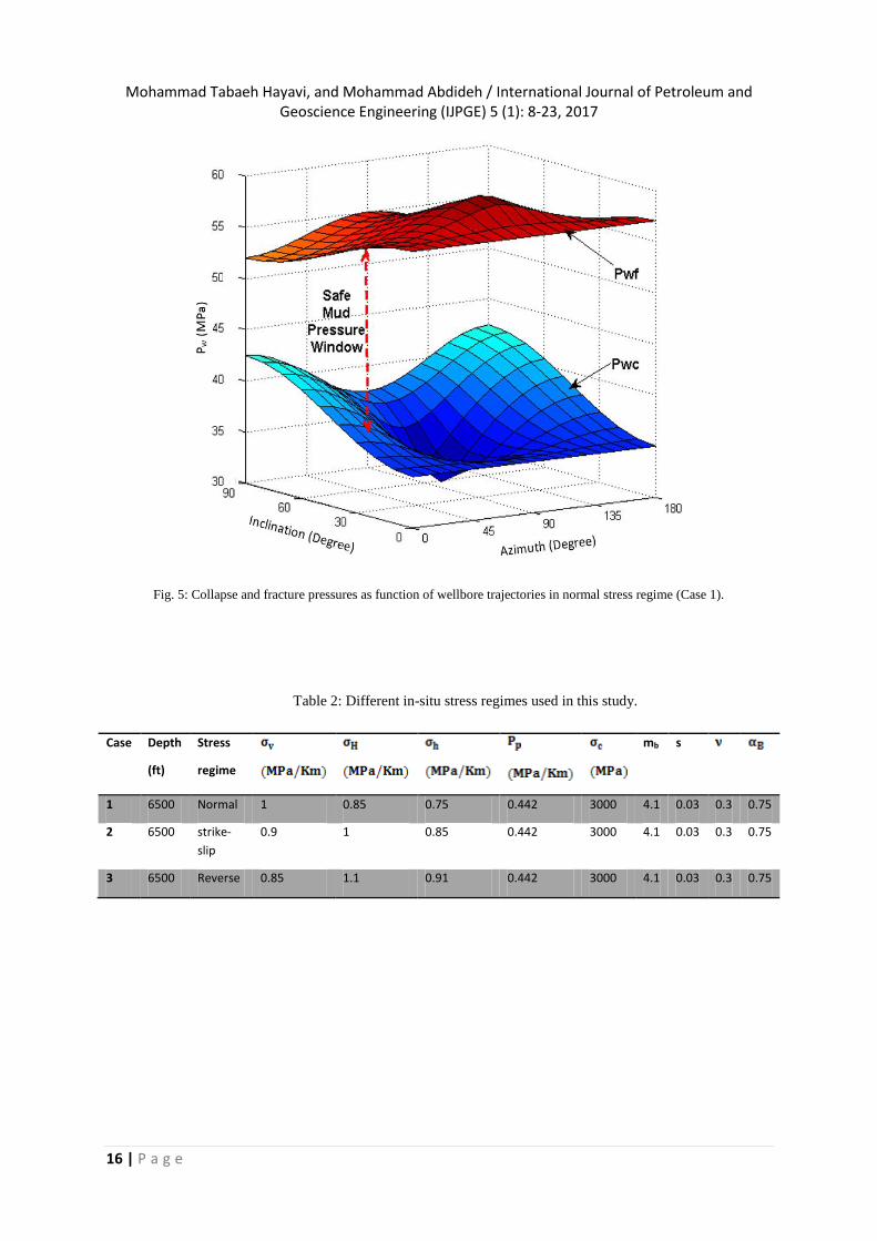
In Case 2, the formation is in the strike-slip regime.
Fig. 6 shows that, the horizontal boreholes are more
stable (larger safe mud pressure window) than the
vertical or all deviated boreholes in all directions.
Moreover, wellbores drilled in the direction of
maximum horizontal stress show the highest
stability (largest safe mud pressure window) and
the others bored along minimum horizontal stress
are the least stable.
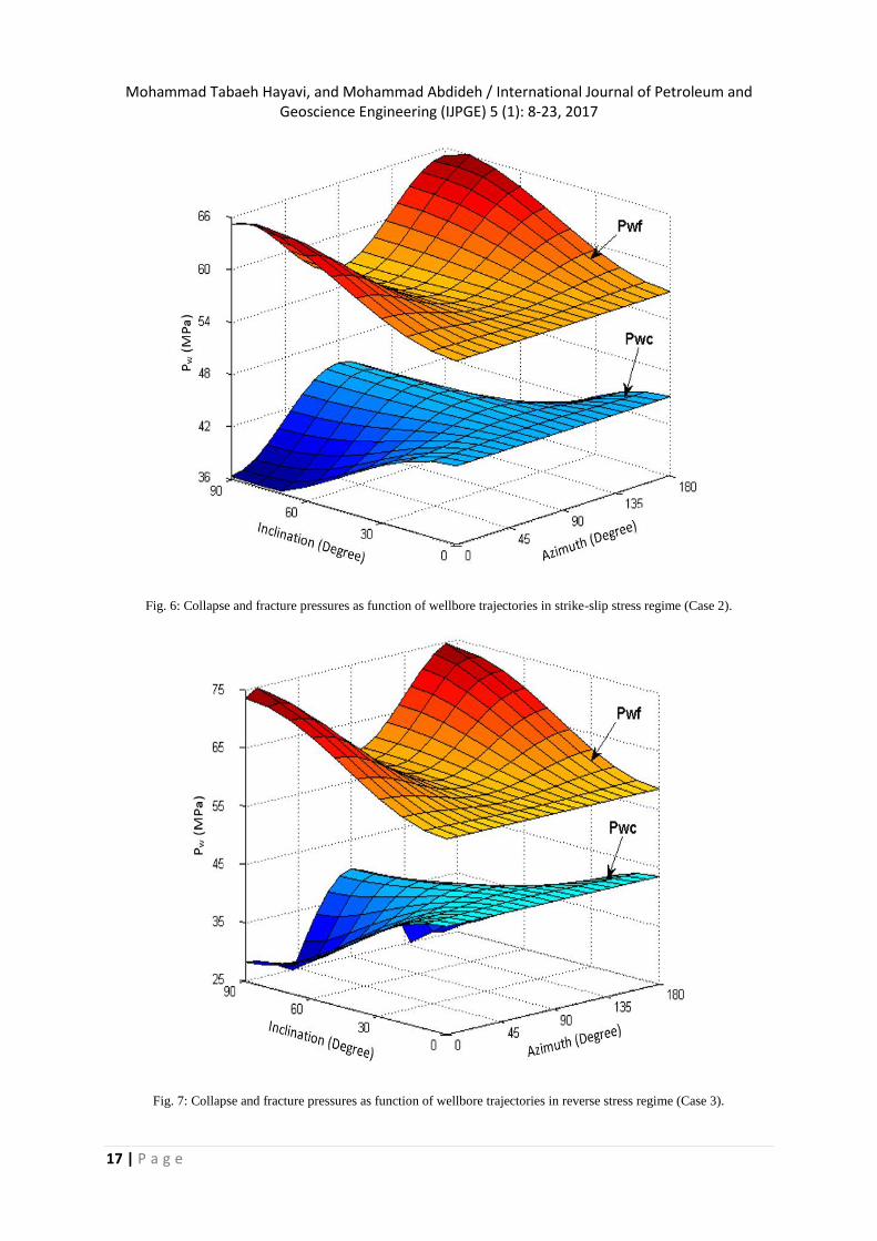
Finally Case 3 indicates a formation in the reverse
fault regime. Fig. 7 shows that a horizontal
borehole which is drilled parallel to the maximum
horizontal stress has a largest safe mud pressure
window. Here also the risk of wellbore instability
decreases with increasing the borehole inclination.
Contrary to normal regime, in reverse and strike-
slip regimes, the least variation of safe mud
pressure window versus wellbore inclination are for
the wellbores in the direction of minimum
horizontal stress.
Mohammad Tabaeh Hayavi, and Mohammad Abdideh / International Journal of Petroleum and Geoscience Engineering (IJPGE) 5 (1): 8-23, 2017
16 | P a g e
Fig. 5: Collapse and fracture pressures as function of wellbore trajectories in normal stress regime (Case 1).
Table 2: Different in-situ stress regimes used in this study.
Case Depth
(ft)
Stress
regime
mb s
1 6500 Normal 1 0.85 0.75 0.442 3000 4.1 0.03 0.3 0.75
2 6500 strike-
slip
0.9 1 0.85 0.442 3000 4.1 0.03 0.3 0.75
3 6500 Reverse 0.85 1.1 0.91 0.442 3000 4.1 0.03 0.3 0.75
Mohammad Tabaeh Hayavi, and Mohammad Abdideh / International Journal of Petroleum and Geoscience Engineering (IJPGE) 5 (1): 8-23, 2017
17 | P a g e
Fig. 6: Collapse and fracture pressures as function of wellbore trajectories in strike-slip stress regime (Case 2).
Fig. 7: Collapse and fracture pressures as function of wellbore trajectories in reverse stress regime (Case 3).
Mohammad Tabaeh Hayavi, and Mohammad Abdideh / International Journal of Petroleum and Geoscience Engineering (IJPGE) 5 (1): 8-23, 2017
18 | P a g e
7. Field Case Study
The developed analytical models will be applied to
a well (called well A) drilled in Ahwaz oilfield
(One of southern Iranian field in the Middle East)
for investigation of stability analysis during
drilling. This oil field, one of the most important
Iranian super giant oil fields, was discovered in
1956 and now has more than 450 producing wells.
This oil field has an anticline structure 72 km long
and 6 km wide with NW-SE trending symmetrical
anticlinal, located in central part of north Dezful
region. Its main reservoir is the Asmari formation
[39,40]. The big Asmari reservoir is complicated
and heterogeneous in terms of reservoir rock
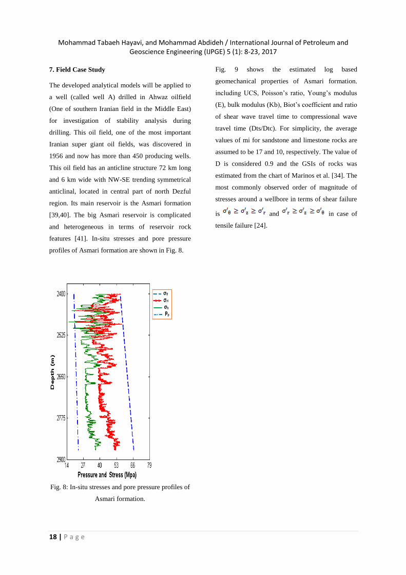
features [41]. In-situ stresses and pore pressure
profiles of Asmari formation are shown in Fig. 8.
Fig. 8: In-situ stresses and pore pressure profiles of
Asmari formation.
Fig. 9 shows the estimated log based
geomechanical properties of Asmari formation.
including UCS, Poisson’s ratio, Young’s modulus
(E), bulk modulus (Kb), Biot’s coefficient and ratio
of shear wave travel time to compressional wave
travel time (Dts/Dtc). For simplicity, the average
values of mi for sandstone and limestone rocks are
assumed to be 17 and 10, respectively. The value of
D is considered 0.9 and the GSIs of rocks was
estimated from the chart of Marinos et al. [34]. The
most commonly observed order of magnitude of
stresses around a wellbore in terms of shear failure
is and in case of
tensile failure [24].

Mohammad Tabaeh Hayavi, and Mohammad Abdideh / International Journal of Petroleum and Geoscience Engineering (IJPGE) 5 (1): 8-23, 2017
19 | P a g e
Considering this assumption and the real mud
weight that had been used to drill Well A (i.e. 1.05
gr/cm3), the calculations were carried out to
determine the potential for any shear failure
(breakouts) or tensile failure (induced fracture).
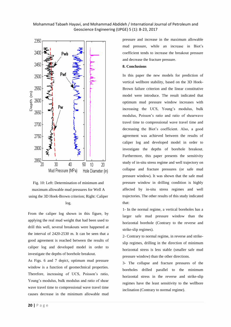
The results of such analysis and hole diameter log
(caliper log) are shown in Fig. 10.
It can be concluded that the minimum and
maximum allowable mud pressures change as a
function of depth and for well A are varied between
the 21-29 MPa and 43-49 MPa, respectively. So,
the optimum mud pressure window for this well is
29-43MPa.
Fig. 9: Geomechanical properties of Asmari formation.
Mohammad Tabaeh Hayavi, and Mohammad Abdideh / International Journal of Petroleum and Geoscience Engineering (IJPGE) 5 (1): 8-23, 2017
20 | P a g e
Fig. 10: Left: Determination of minimum and
maximum allowable mud pressures for Well A
using the 3D Hoek-Brown criterion; Right: Caliper
log.
From the caliper log shown in this figure, by
applying the real mud weight that had been used to
drill this well, several breakouts were happened at
the interval of 2420-2530 m. It can be seen that a
good agreement is reached between the results of
caliper log and developed model in order to
investigate the depths of borehole breakout.
As Figs. 6 and 7 depict, optimum mud pressure
window is a function of geomechnical properties.
Therefore, increasing of UCS, Poisson’s ratio,
Young’s modulus, bulk modulus and ratio of shear
wave travel time to compressional wave travel time
causes decrease in the minimum allowable mud
pressure and increase in the maximum allowable
mud pressure, while an increase in Biot’s
coefficient tends to increase the breakout pressure
and decrease the fracture pressure.
8. Conclusions
In this paper the new models for prediction of
vertical wellbore stability, based on the 3D Hoek-
Brown failure criterion and the linear constitutive
model were introduce. The result indicated that
optimum mud pressure window increases with
increasing the UCS, Young’s modulus, bulk
modulus, Poisson’s ratio and ratio of shearwave
travel time to compressional wave travel time and
decreasing the Biot’s coefficient. Also, a good
agreement was achieved between the results of
caliper log and developed model in order to
investigate the depths of borehole breakout.
Furthermore, this paper presents the sensitivity
study of in-situ stress regime and well trajectory on
collapse and fracture pressures (or safe mud
pressure window). It was shown that the safe mud
pressure window in drilling condition is highly
affected by in-situ stress regimes and well
trajectories. The other results of this study indicated
that:
1- In the normal regime, a vertical boreholes has a
larger safe mud pressure window than the
horizontal borehole (Contrary to the reverse and
strike-slip regimes).
2- Contrary to normal regime, in reverse and strike-
slip regimes, drilling in the direction of minimum
horizontal stress is less stable (smaller safe mud
pressure window) than the other directions.
3- The collapse and fracture pressures of the
boreholes drilled parallel to the minimum
horizontal stress in the reverse and strike-slip
regimes have the least sensitivity to the wellbore
inclination (Contrary to normal regime).
Mohammad Tabaeh Hayavi, and Mohammad Abdideh / International Journal of Petroleum and Geoscience Engineering (IJPGE) 5 (1): 8-23, 2017
21 | P a g e
4-In all stress regimes the safe mud pressure
window is highly sensitive to wellbore inclination
in the direction of maximum horizontal stress.
References
[1] Nayroy, J.F., Geomechanics applied to the
petroleum industry. Editions Technip, Paris, 2011.
[2] Gao, J., van Galen, Q., Chou, B., Nei, H.,
Soroush, H., Qutob, Z., Mahli, I., Abalioglu, A.S.,
Genel, E., Drilling Hazards Diagnosed and
Solutions Were Provided to the Northern Iraq
Fields Utilizing Geomechanics, SPE 149096, In:
Proceedings of the SPE/DGS Saudi Arabia Section
Technical Symposium and Exhibition, Al-Khobar,
Saudi Arabia, 15–18 May, 2011.
[3] Detournay, C., Chen, X., Factors governing
mud filtration and impact on well stability: In:
Proceedings of the 40th U.S.Symp. Rock Mech.
USRMS, 2005.
[4] Chowdhury, D., Skalle, P., Mechanical
Borehole Stability Analysis using Phase2. In:
Proceedings of the International Conference on
Mechanical Engineering (ICM), ICME11-AM-010.
Dhaka, Bangladesh, 18-20 December, 2011.
[5] Mirzaghorbanali, A., Afshar, M., A Mud
Weight Window Investigation Based on the Mogi-
Coulomb Failure Criterion and Elasto-Plastic
Constitutive Model. J Pet Sci Technol., 29:(2): 121-
131, 2011.
[6] Nabaei, M., Shahbazi, K., Shadravan, F., et al.
Uncertainty Analysis in Unconfined Rock
Compressive Strength Prediction. In: Proceedings
of the Deep Gas Conference, SPE-131719-MS,
Bahrain, 24-26 Jan, 2010.
[7] Elyasi, A., Goshtasbi, K., Saeidi, O., et al.
Stress determination and geomechanical stability
analysis of an oil well of Iran. Indian Academy of
Sciences (Sadhana), 39(1): 207-220, 2014.
[8] Yi, X., Ong, S., Russell, J.E. Quantifying the
effect of rock strength criteria on minimum drilling
mud weight prediction using polyaxial rock
strength test data, Int J Geomech, 6(4): 260–8,
2006.
[9] McLean, M.R., Addis, M.A., Wellbore stability:
the effect of strength criteria on mud weight
recommendations. In: Proceedings of the 65th
annual technical conference and exhibition of SPE.
New Orleans: SPE5526, 1990.
[10] Zhou, S., A. program to model the initial
shape and extent of borehole breakout. Comput
Geosci, 20: 1143–60, 1994.
[11] Wiebols, G., Cook, N., An energy criterion for
the strength of rock in polyaxial compression, Int J
Rock Mech Min Sci., (5): 529–49, 1968.
[12] Ewy, R.T., Wellbore-stability predictions by
use of a Modified Lade criterion, J. SPE Drilling &
Completion, 14: 85–91, 1999.
[13] Colmenares, L.B., Zoback, M.D., A statistical
evaluation of intact rock failure criteria constrained
by polyaxial test data for five different rocks, Int J
Rock Mech Min Sci., 39: 695–729, 2002.
[14] Aadnoy, B.S., Modeling of the stability of
highly inclined borehole in anisotropic rock
formations, SPE Drilling Eng, 3(3): 259–268,
1998.
[15] Al-Ajmi, AM., Zimmerman, R.W., Stability
analysis of vertical boreholes using the Mogi–
Coulomb failure criterion, Int. J. Rock Mech. Min.
Sci., 43(8): 1200–1211, 2006.
[16] Song, I., Haimson, B.C., Polyaxial strength
criteria and their use in estimating in situ stress
magnitudes from borehole breakout dimensions, Int
J Rock Mech Min Sci, 34: 490-498, 1997.
[17] Hoek, E., Brown, E.T., Underground
excavations in rock. The Institution of Mining and
Metallurgy, London, 1980.
[18] Zhang, L., Zhu, H., Three-dimensional Hoek–
Brown strength criterion for rocks, J Geotech
Geoenvir Eng, ASCE, 133 (9): 1128–35, 2007.
[19] Zhang, L., Cao, P., Radha, KC., Evaluation of
rock strength criteria for wellbore stability analysis,
International Int J Rock Mech Min Sci., 47(8):
1304–16, 2010.
Mohammad Tabaeh Hayavi, and Mohammad Abdideh / International Journal of Petroleum and Geoscience Engineering (IJPGE) 5 (1): 8-23, 2017
22 | P a g e
[20] Al-Ajmi, A. M., Zimmerman, R. W. Relation
between the Mogi and the Coulomb failure criteria,
Int. J. Rock Mech. Min. Sci., 42(3): 431–439, 2005.
[21] Bradely, W.B., Failure of inclined boreholes,
J. Energy Resource. Technol. Trans. ASME, 101:
232–239, 1979.
[22] Zoback, M.D., Moos, D., Mastin, L.G.,
Anderson R.N. Bore breakous and in situ stress, J.
Geophys. Res., 90: 5523–5530, 1998.
[23] Lee, H., Hong Ong, S., Azeemuddin, M.,
Goodman, H., A wellbore stability model for
formations with anisotropic rock strengths, J Petrol
Science Eng., 96-97: 109–119, 2012.
[24] Gholami, R., Moradzadeh, A., Rasouli, V.,
Hanachi, J., Practical application of failure criteria
in determining safe mud weight windows in
drilling operations, J Rock Mech Geotec Eng., 6(1):
13–25, 2014.
[25] Fjær, E., Holt, R.M., Horsrud, P., Raaen A.M,
Risn, P., Petroleum Related Rock Mechanics, 2nd
edition Elsevier, Amsterdam, 2008.
[26] Chabook, M., Al-Ajmi, A., Isae, V., The role
of rock strength criteria in wellbore stability and
trajectory optimization, Int. J. Rock Mech. & Min.
Sci, 80: 373–378, 2010.
[27] Soroush, H., Gao, H., Qutob, H., Neil, B.,
Mahli, Z., Weatherford, E., Abalioglu, I., Genel
Enerji, A.S., Geomechanical Study for UBD
Feasibility in the Northern Iraq Fields, SPE/IADC
146386. In: Proceedings of the SPE/IADC Middle
East Drilling Technology Conference and
Exhibition held in Muscat, Oman, 24–26 October
2011.
[28] Zare-Reisabadi, M.R., Kaffash, A.,
Shadizadeh, S.R., Determination of optimal well
trajectory during drilling and production based on
borehole stability, Int J Rock Mech Min Sci., 56(8):
77-87, 2012.
[29] Zhang, L., Radha, K.C., Stability Analysis of
Vertical Boreholes Using a Three-Dimensional
Hoek-Brown Strength Criterion, In Proceedings of
the GeoFlorida, West Palm Beach, Florida, 2010.
[30] Zhang, Q., Zhu, H., Zhang, L., Modification of
a generalized three-dimensional Hoek–Brown
strength criterion, J. Rock Mech. Min. Sci., 59(6):
80–96, 2013.
[31] Hoek, E., Brown, E.T., Practical estimates of
rock mass strength, Int J Rock Mech Min Sci
Geomech Abstr, 34(11): 65–86, 1997.
[32] Hoek, E., Carranza-Torres, C., Corkum, C.,
Hoek–Brown failure criterion—2002 edition. In:
Proceedings of the 5th the North American rock
mechanics society symposium. Toronto, 267–73,
2002.
[33] Eberhardt, E., The Hoek–Brown Failure
Criterion, j Rock Mech Rock Eng., 45: 981–988,
2012.
[34] Marinos, V., Marinos, P., Hoek, E., The
geological strength index: applications and
limitations, Bull Eng Geol Environ., 64(1): 55–60,
2005.
[35] Mogi, K., Fracture and flow of rocks under
high triaxial compression, J. Geophys. Res., 76 (5):
1255–1269, 1971.
[36] Pan, X. D., Hudson, J. A., A simplified three-
dimensional Hoek-Brown yield criterion. Rock
Mech Power Plants, The Netherlands, 95–103,
1998.
[37] Rahimi, R., Nygaard, R., What Difference
Does Selection of Failure Criteria Make in
Wellbore Stability Analysis?, ARMA 14-7146, In:
Proceedings of the 48th US Rock Mechanics /
Geomechanics Symposium, Minneapolis, MN,
USA, 1-4, 2014.
[38] Brady, B.H., Brown, E.T., Rock mechanics for
underground mining. 2nd ed. Dordrecht, Kluwer,
1999.
[39] Motiei, H., Petroleum geology of Zagros-1.
Geological Survey of Iran (in Farsi), 589-595,
1995.
[40] Rabbani, A.R., Bagheri Tirtashi, R.,
Hydrocarbon Source Rock Evaluation of the Super
Giant Ahwaz Oil Field, SW Iran, Australian Jl of
Basic and Appli Sci., 4(5): 673-686, 2010.
Mohammad Tabaeh Hayavi, and Mohammad Abdideh / International Journal of Petroleum and Geoscience Engineering (IJPGE) 5 (1): 8-23, 2017
23 | P a g e
[41] Abdideh, M., Fathabadi, M.R., Analysis of
stress field and determination of safe mud window,
J Petrol Explor Prod Technol, 15 (3): 105–110,
2013.
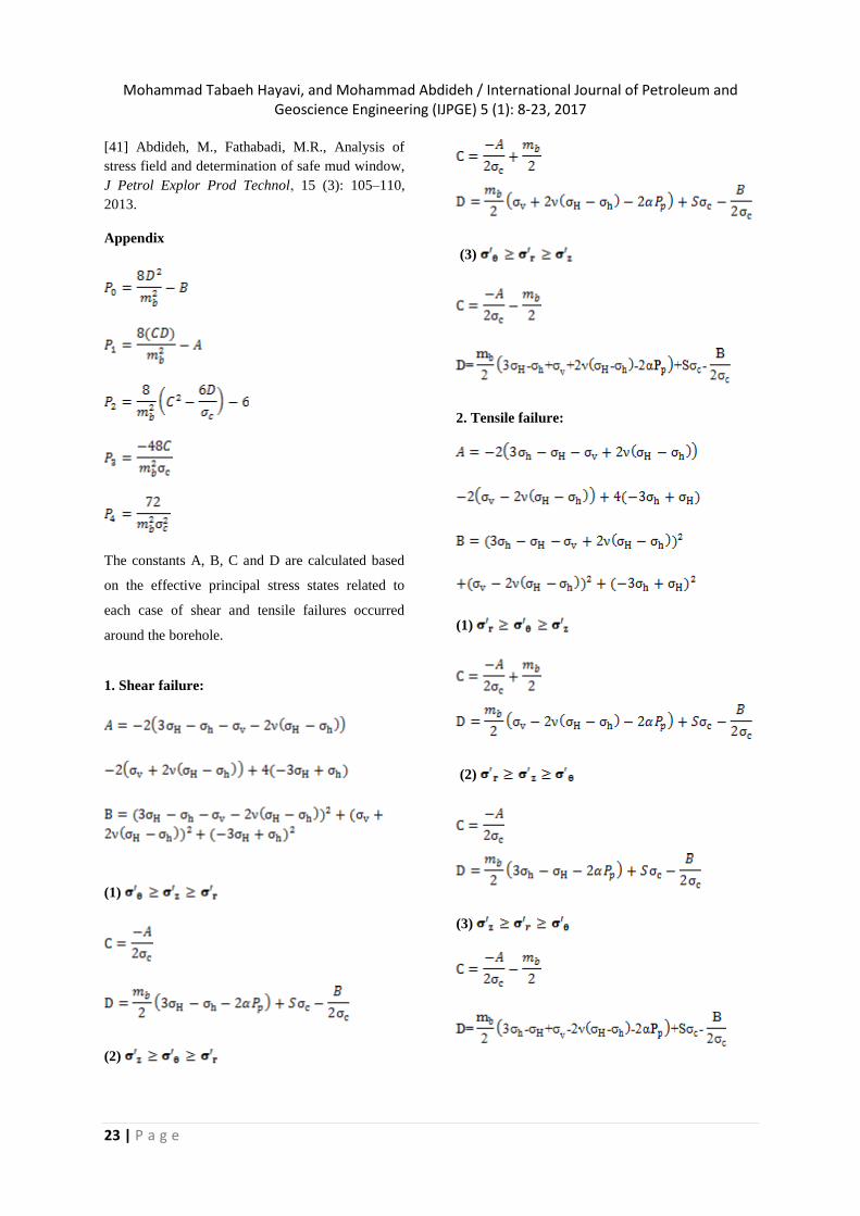
Appendix
The constants A, B, C and D are calculated based
on the effective principal stress states related to
each case of shear and tensile failures occurred
around the borehole.
1. Shear failure:
(1)
(2)
(3)
2. Tensile failure:
(1)
(2)
(3)


