
Technical report, IDE1036, 2010
Integrated Security by using MPLS-VPN
for Retail-Banking Network
(Case study Mehr bank, Iran)
Master’s Thesis in Computer Network Engineering
Sara H.Daryani & Pouria Taslimi
School of Information Science, Computer and Electrical Engineering Halmstad University
Integrated Security by using MPLS-VPN
for Retail-Banking Network
Master Thesis in Computer Network Engineering
School of Information Science, Computer and Electrical Engineering
Halmstad University
Box 823, S-301 18 Halmstad, Sweden
2010

Description of cover page figure
The figure on the cover page illustrates a connection between the IP-base physical security systems and
non IP-base physical security systems. Multi protocol label switching – virtual private network (MPLS-
VPN) mechanism is applied to forward packets among different branches of bank [2].
As shown in the figure (at the top on the left-hand side), there are two specific servers used for monitoring
and managing different branches for the entire system.
- IP-base camera server
- IP-base access control server
Note: The IP-base camera server is responsible for monitoring all cameras in the system. The IP-base
access control server is in charge of handling different scenarios for the entire system.
Fingerprint readers, card readers and pin readers are connected to their IP-base access control system.
The access control system is connected to its related server through the network switch. Fire detectors
and fire protection systems are connected to their related control device and this control device is
connected to the IP-base access control system through their non IP-base interfaces. The heating,
ventilation, and air-conditioning system (HVAC system) is connected to the fire control system through its
non IP-base interfaces. Analog cameras are connected to the IP-base camera encoder. This encoder is
connected to its related server through a network switch. Finally, this network switch is connected to a
router and a proper modem to provide connectivity for the MPLS-VPN network.
The MPLS-VPN provides flexibility and redundancy for the bank network (WAN) and it is easy to manage
and cost effective. One main feature of the MPLS-VPN network is supporting quality of service (QoS) for
different services used in the bank network.
As shown on the cover page figure there is one main data center and one backup data center. The main
data centre is responsible for making all important decisions and defining different policies (which are
explained more in detail later) and the backup data centre is responsible for backup.


Introduction
Preface
We would like to express our appreciation to Halmstad University, which provides this opportunity for
us to improve our knowledge in a proper way, and special thanks to Olga Torstensson and Tony
Larsson. In addition, many thanks to PBS-CE company in Iran, which approved us as consultant and
project designer for “Mehr-bank project.”
Sara H.Daryani & Pouria Taslimi
Halmstad University, May 2010

Integrated Security by using MPLS-VPN for retail-banking network

Introduction
Abstract
The studied application area is a private bank with different branches located in different
provinces around the country. There was not integrated security solution to provide
communication among different branches. Some of these branches could communicate
through the satellite and the others could communicate through a different technology, such as
asynchronous transfer mode (ATM).
Different bank security policies were applied and maintained for different branches
separately. In addition, the number of branches is expected to grow during coming year in
each province.
The old topology was partial mesh and it could not support enough redundancy in case of
disruption. If a connection between two branches failed, other branches might lose their
connectivity as well. In addition, it could not achieve optimum routing.
Providing integrated quality of service (QoS) for the wide area network (WAN) by using
different technologies is not easy to achieve, and it causes so many problems for the system.
The bank uses a variety of protocols for different applications, depending on its demand, so
the new applied technology should not depend on protocols, or at least should support
different protocols at a same time. In the old technology, the bank was responsible for
granting availability and connectivity maintenance. Providing proper bandwidth is an
important aspect in the bank scenario and for the old technology; supplying enough
bandwidth was costly.
As mentioned above, the old applied technology was dependent upon different protocols.
Therefore, packets in different open system interconnection layers (OSI layers) would have to
check thoroughly to find the source/ destination address, data and so on, to reach the correct
destination. This might cause security problems for entire system. In addition, processing
packet in each layer of the OSI model is time consuming.
One important aspect for the retail-banking scenario is considering all features of the security
domain, such as security policy, information security, physical security, access level control,
integrated security for the system and so on. Some features of the security domain in this
project were not covering completely, such as integrated information security, merged
security policy, and integrated physical security for the system.
In this project, all mentioned problems are solved by implementing a specific communication
technology which can overcome the problems above. This technology supports multiple
protocols, and it provides fast and secure communication. It can also cover redundancy and it
does not cost as much as previous technologies like ATM and satellite. Easy provisioning is
one feature of this technology. In this technology, the service provider is responsible for
granting availability and connectivity maintenance.
The mentioned features of the security domain, which were not covered by the old
technology, will be covered by a proper, integrated security solution. The IP-based physical
security systems provide centralized monitoring and they can define a merged security policy
for all different branches around the country. Specific, pre-defined scenarios are created for
different events in different situations.

Integrated Security by using MPLS-VPN for retail-banking network
Contents
DESCRIPTION OF COVER PAGE FIGURE ................................................................................................. III
PREFACE ...............................................................................................................................................................1
ABSTRACT ............................................................................................................................................................3
CONTENTS ............................................................................................................................................................4
1 INTRODUCTION ........................................................................................................................................7
1.1 PROBLEMS ..................................................................................................................................................7
1.2 APPROACH CHOSEN TO SOLVE THE PROBLEM .............................................................................................7
1.3 GOAL AND RESPECTED RESULTS .................................................................................................................8
2 BACKGROUND ......................................................................................................................................... 10
2.1 STATE OF THE ART .................................................................................................................................... 10
3 SOLUTION IDEA TO BE INVESTIGATED .......................................................................................... 11
3.1 SECURITY ISSUES ...................................................................................................................................... 11
3.1.1 Security domain .............................................................................................................................. 11
3.1.2 Information security ....................................................................................................................... 14
3.1.3 Threats ............................................................................................................................................ 14
3.1.4 Attacks ............................................................................................................................................ 16
3.1.5 Firewall .......................................................................................................................................... 17
3.1.6 Demilitarized zone ......................................................................................................................... 18
3.1.7 Authentication, authorization and accounting (AAA) .................................................................... 19
3.1.8 IDS and IPS .................................................................................................................................... 20
3.2 PHYSICAL SECURITY ................................................................................................................................. 20
3.2.1 IP-base physical security ................................................................................................................ 20
3.2.2 Non IP-base physical security ........................................................................................................ 21
3.3 OPERATING SYSTEM SECURITY ................................................................................................................. 21
3.4 END POINT SECURITY ................................................................................................................................ 21
3.5 MULTI PROTOCOL LABEL SWITCHING (MPLS) ......................................................................................... 22
3.5.1 MPLS advantages ........................................................................................................................... 23
3.5.2 MPLS operation ............................................................................................................................. 24
3.5.3 MPLS architecture .......................................................................................................................... 24
3.6 VIRTUAL PRIVATE NETWORK (VPN)......................................................................................................... 26
3.6.1 VPN types ...................................................................................................................................... 27

Introduction
3.6.2 Tunnelling and encryption .............................................................................................................. 27
3.7 MULTI PROTOCOL LABEL SWITCHING – VIRTUAL PRIVATE NETWORK (MPLS-VPN) ................................ 28
3.7.1 Security in MPLS-VPN .................................................................................................................. 29
3.7.2 VPN routing and forwarding table (VRF) ...................................................................................... 30
4 DETAILED DESCRIPTION OF THE INVESTIGATED SOLUTION (DESIGN SPACE) ............... 32
4.1 MPLS-VPN PROJECT DESIGN ................................................................................................................... 33
4.1.1 Huawei architecture ........................................................................................................................ 34
4.1.2 Alcatel architecture......................................................................................................................... 34
4.1.3 Patton and Tellaps architecture ...................................................................................................... 35
4.2 IP-BASE PHYSICAL SECURITY DESIGN ....................................................................................................... 35
4.2.1 IP-base camera ............................................................................................................................... 36
4.2.2 IP-base access control .................................................................................................................... 37
4.3 NON IP-BASE SYSTEM DESIGN .................................................................................................................. 37
4.3.1 Fire detection and fire fighting architecture ................................................................................... 38
4.3.2 Other non IP-base system architecture ........................................................................................... 38
4.4 FUNCTIONAL DESCRIPTION (EVENT TABLE) .............................................................................................. 39
5 RESULT AND ANALYSIS OF SOLUTION ........................................................................................... 41
5.1 END-TO-END NETWORK SECURITY ANALYSIS ........................................................................................... 41
5.2 END-TO-END PHYSICAL SECURITY ANALYSIS ............................................................................................ 43
5.3 USE-CASE DIAGRAM ANALYSIS ................................................................................................................. 44
6 CONCLUSION ........................................................................................................................................... 47
7 REFERENCES ........................................................................................................................................... 49
8 APPENDIX A .............................................................................................................................................. 50
9 APPENDIX B .............................................................................................................................................. 51
10 APPENDIX C .............................................................................................................................................. 53

Integrated Security by using MPLS-VPN for retail-banking network

Introduction
1 Introduction
The application area studied in this thesis is a private bank in Iran. The bank includes different
branches in different provinces around the country. There are 29 main branches located in 27
different provinces. The main branches in each province have many different sub branches
around the city as well, which are called “local branches”. Each main branch acts as an edge
branch to communicate with other main branches in other provinces. There is one central data
center, which is located in the capital Tehran, and another data center acts as a backup, which
is located in another city (called Isfahan). The main data center is responsible for making all
important decisions and defining different policies for different situations in different
branches. The main problem for this application area is the lack of a proper, integrated
security system for the entire bank network.
1.1 Problems
The first problem is providing communication among 29 main branches through the satellite
technology. Satellite technology is not reliable, not flexible and it is too expensive. There are
many different branches which require enough bandwidth to support different applications for
the bank. Bandwidth limitation and bandwidth instability for satellite technology decrease
system performance. Applying proper technology for real time communications is essential.
This technology should support some of the real time applications, such as video
conferencing, voice over IP (VoIP) and different bank applications. The second problem is
providing an integrated network security for all main branches. Integrated network security
means considering all security domain issues including observing threats and providing
information security in order to overcome with attacks in the wide area network. Network
security and physical security are two different, yet important, aspects of the security domain
definition, which should work in parallel in order to provide high-level security. Physical
security means controlling and monitoring all different environment events, which are caused
by different phenomena such as people, fire, intrusion, power interruption and so on.
The third problem is caused by traditional physical security systems. These traditional
systems could not connect to each other in order to discover and deal with different scenarios
made by different events in the wide area network. In addition, there was no possibility to
communicate with each other via internet protocols (IP), which means that centralized
monitoring was not possible for retail organizations situated in different locations.
The three interrelated problems studied in this thesis are:
- Providing reliable, flexible and cost effective network infrastructure for retail-
banking by using multi protocol label switching (MPLS)
- Having the entire network as integrated and secure as possible by using virtual
private network (VPN)
- Getting all physical security devices network connected and as IP enabled as
possible
1.2 Approach chosen to solve the problem
Considering multi protocol label switching - virtual private network (MPLS-VPN) parallel
with the security domain issues, covered the first and second problems. The third problem was
solved by making a connection between IP-based, and non IP-based physical security systems
through the wide area network.

Integrated Security by using MPLS-VPN for retail-banking network
MPLS-VPN is a proper solution to achieve aspects below:
- Data confidentiality
- Data integrity
- Redundancy in core MPLS-VPN
- Guarantee optimum routing
- Fast packet switching
- Service provider participates in customer routing
- Easy provisioning and additional VPN
- Support quality of service
- Cost effective for customer
Considering all aspects of the security domain is a good solution to provide high-level
security. Some factors of the security domain are listed as below:
- Security policy
- Information security arrangement
- Human resources security
- Access level control
- Physical security
Note: all the security domain factors are explained in detail in its related chapter
Applying an IP-base security system is a solution to have centralized monitoring and
management in a wide area network. Some features of IP-base security systems are listed as
follow:
- Remote monitoring/reporting
- Remote controlling
- Efficient usage of installed IP infrastructure
- Central management
- Supports multi scenarios
- Provide scalability
- Bandwidth adaptability
- Provide flexibility
- Support quality of service
- Provide reliability
- Support encryption
1.3 Goal and respected results
Implementing an integrated, end-to-end, high-level security system to execute different pre-
defined scenarios is the goal of this project. The immunity against attacks, threats, and
intrusions for retail-banking is provided by the solutions mentioned. This project is already
implemented for a private bank in Iran called “Mehr bank.” Different scenarios are executed
to test system performance and the result was successful and acceptable.

Introduction

Integrated Security by using MPLS-VPN for retail-banking network
2 Background
This project is about a private bank with different branches around the country. There are two
data centres, one as a main data centre and the other as a backup data centre. There should be
a proper solution to provide secure and stable connection among all branches and between the
data centres as well. The old technologies, like satellite communication and ATM, could not
completely support stability and security for the bank. Granting optimized QoS for these two
different technologies is more difficult than a unique technology.
Because of the critical roles which the two mentioned data centres have, physical security is
also considered.
Network security and physical security should work in parallel to provide high-level security
for data centres and all connected branches to them.
2.1 State of the art
MPLS-VPN and IP-base physical security are best practice to overcome the mentioned retail-
banking problems. MPLS-VPN is scalable technology, so it is a good solution for wide area
network communications. It also reduces the routing lookups, so it makes fast communication
between different nodes. Virtual private network technology is used in order to provide simple
management, low cost and more flexibility for this project.
IP-base physical security gives the opportunity to control and avoid intrusions into both data
centres, and also it provides security cooperation with non IP-base physical security system
involving different equipment in different branches.

Solution idea to be investigated
3 Solution idea to be investigated
Ideas proposed for this project are listed as below:
Security issues, physical security, operating system security, end point security and MPLS-
VPN.
3.1 Security issues
As the figure below illustrates, threats are divided into two categories, namely those which are
internal, and those which are external, to the system. This project is focused on eliminating
internal threats, such as unauthorized access and internal intrusions. In this chapter, important
aspects of security issues are described in detail.
Figure 1. Network threats
3.1.1 Security domain
Security domain includes different factors which are essential to provide security for different
organizations. Depending on organization’s demand, there are different priorities for applying
these factors [4]. The most important factors are listed as follow:
- Risk assessment
- Security policy
- Information security arrangement
- Property handling
- Human resources security
- Physical security
- Communication and operation management
- Access level control
- Integrated security for systems and applications
- Threat prediction and appropriate response
- Uninterrupted business manageability
- Insurance of information security
Integrated Security by using MPLS-VPN for retail-banking network
Risk assessment
A risk assessment is an essential step in risk management definition, which protects all
sources, investments, and workers. It is a process which estimates how the system can
overcome risks and will indicate which risks have the worse effect on the system, so it will
decrease the risks. Risk assessment will not eliminate all kind of risks, but it can protect
sources by minimising harm. If something causes failure in the system, workers and others
have the right to be protected.
Identifying how the equipment and workers could be harmed is the first step for the risk
assessment, and this can be achieved by asking employees, walking around workplaces and
many other activities. The second step is identifying workers who are at risk and the way that
they could come to harm, and recognising the source of risk and their possible consequences.
The next step is estimating total risk, and finding a proper way to overcome it. The last step is
making a list of findings, and reviewing and updating risks.
Security policy
Security policies are defined to specify different access level for different users. These
determine how sources can be accessed and what sources are accessible to whom. There are
different security policies depending on specific demands. Some security policy examples are
listed as below:
- Network access
- Remote access
- Encryption
- Data classification
- Password
- Backup
- Mobile devices
- Virtual private network
- Physical security policies
Information security arrangement
Internal and external information arrangements are the two major categories of information
security. For supporting internal information security arrangement, information security is
applied inside the organization. In external information security arrangements, the information
security should apply to external parties.
Property handling
The process of classification and organization of the assets or properties is one of the
important issues in the security domain, which applies for granting information about
components in the organization.

Solution idea to be investigated
Human resources security
The organization is responsible for providing security for employees and all other human
resources. In this way, all the human resources will be aware of their access level to assets to
decrease inappropriate risks.
Physical security
The physical security prevents resources from access attacks. It will deny people gaining
unauthorized access to the physical environment. Different technologies are being applied for
physical security nowadays, such as video surveillance systems (VSSs), passive infrared
(PIR) and access control systems. VSS gives the possibility to monitor events and review
them when they are needed. PIR detects motions in specific rooms to alert the administrator
and it activates cameras to record the events. Access control systems are used to permit or
deny accesses to different rooms, according to their access level.
Communication and operation management
The organization is responsible for providing secure communication. To achieve secure
communication, the organization is in charge of defining high-level security policies. These
policies should be monitored and controlled by system managers or administrators.
Access level control
This describes different access levels to specific resources for specific roles in organizations.
It enables authorized access to the resources or computer based information systems.
Integrated security for systems and applications
There should be an integrated security solution to provide and ensure the organization’s
information systems and applications have high-level security.
Threat prediction and appropriate response
This category includes intrusion detection system (IDS) and intrusion prevention system (IPS)
for organizations. If something causes failure, the system will react with a proper response.
The IDS detects threats only, but IPS detects and prevents threats.
Uninterrupted business manageability
This factor ensures long-term system availability by managing system interruption in the
organizations.
Insurance of information security
This is a procedure of ensuring compliance with information security policies and rules. It is a
procedure which ensures that information security policies and rules are not changed by
someone or some other organizations, and so it guarantees the integrity of information
security.

Integrated Security by using MPLS-VPN for retail-banking network
3.1.2 Information security
Information security is used for protecting information from unauthorized access,
modification and disruption by unauthorized and unwanted users. Three main parameters are
defined to provide secure information communication through the network:
- Confidentiality
- Integrity
- Availability
Confidentiality
This indicates that only authorized users and organizations have permission to access the
information. There are different mechanisms to provide confidentiality, such as cryptography.
Two types of the cryptography are used to provide information confidentiality, and these are
called “symmetric” and “asymmetric” cryptography. In the symmetric model, the sender and
the receiver share one key to encrypt and decrypt data. In the asymmetric model, which is also
known as “public key cryptography”, one key is used to encrypt data by the sender and the
other key used to decrypt data by the receiver. The symmetric key also provides information
integrity when this key is used in parallel with other algorithms to create message
authentication codes. The public key cryptography also provides a digital signature.
Integrity
This indicates that information can only be altered by authorized users and organizations and
ensures integrity of information, which means that the authorized users and organizations
have access to right information and no changes occur during information communication.
The information can also be modified by environmental threats, such as dust, heat, and
electrical problems. One mechanism to provide data integrity is the Hash algorithm. If one bit
is altered, then the Hash algorithm will not match and it declares data modification.
Availability
This provides information resources availability and ensures that information systems and
essential data are available when the authorized users and organizations need them. Some
mechanisms which are used to indicate availability are load balancing, network hardening,
and backup.
3.1.3 Threats
There are different threats in networks, such as, [11]:
- Viruses
- Worms
- Trojan horses
Viruses
A virus attaches itself to a program or file and spreads itself into the system and decreases the
system performance or, sometimes, in a worse case, it ruins the system totally. Almost all

Solution idea to be investigated
viruses include an executable file and this needs to be run by some malicious program to
affect the system. Viruses can not be spread without human intervention. Usually,a viruse is
sent over a network or the internet by a user, or it is carried by removable devices such as CD,
DVD and USB drive. A virus infects different files and programs on a network file system or
on a shared system to increase its spreading possibilities.
Viruses are divided into two group, according to their behaviour at their execution time, and
these are called “resident viruses” and “non-resident viruses”. Resident viruses execute
themselves immidiately into the host and pass the control to the host program, and then they
await their active mode to confront new hosts when infected files are used by other programs.
Non-resident viruses act differently around the host, when they enter to a new host, they start
to search for the other hosts to infect.
Viruses use different methods to disguise themselves from users. Some viruses will not
increase the size of the infected file and will keep the same file size. Usually, they use the free
and unused space of executable files to avoid any change in size of the infected file. Some
viruses try to stop antivirus’s functionality before the antivirus can detect the virus. Some
viruses try to keep the last modified date of an infected file unchanged to avoid detection virus
by users.
Worms
Worms like viruses have a harmful effect on the system but, unlike a virus it does not need
human intervention to activate it. The worse effect of worms are their duplication capabilities,
which means that they will duplicate themselves on the system instead of sending a single
worm each time.
Worms can make different problems for the network connection, such as wasting bandwidth
and so on. Mostly, worms are designed to travel across the network and they do not damage
the hosts but, in some cases, they try to send the user information by using the email services
or by encrypting existing data and deleting some file systems on hosts. One of the worst
features of a worm’s activity is installing the backdoors on the infected systems to let the
other applications come in to the system. In addition, the information sent by worms will be
used for some spam sending lists and they also help attackers to start their denial of service
(DoS) attacks.
At the beginning, some worms created for good reasons such as checking the updates needed
in an operating system or restarting the operating system without asking the permission from
the system owner. These actions work for more than one host in a network area.
Trojan horses
The trojan horse disguises itself as a useful software program but actually it will ruin the
system totally. Some of the Trojans can cause damage by altering information on the system,
changing a desktop’s icons and destroying information. The Trojan creates a backdoor on the
system, which means that malicious users can have access to the system.
A Trojan horse will allow the attacker to have enough access to the computer resources. The
level of the access is dependent on the user privilege or the Trojan software design. In
addition, a user can have remote connection to the infected system to change different
parameters in the Trojan software. By attacking to a computer by these software(s), an

Integrated Security by using MPLS-VPN for retail-banking network
attacker may use the computer as a spam sender, or a part of another attack called “distributed
denial of service” (DDoS). Changing the passwords, uploading or downloading of other
programs, modification or deletion of files, monitoring user activity, checking a user’s
desktop, and destroying the computer are some of the harmful possibilities resulting from this
threat. A Trojan horse threat needs to be in contact with the attacker to set different
parameters and activities, but it does not need to be spread by the attacker. Sometimes, the
attacker will search many computers through the network connection to find one installed
Trojan software on one computer. Then, the attacker will start his attacks by using the open
backdoor in the other computers.
A Trojan horse can infect a computer in different ways, as below:
- Downloading software which is infected by a Trojan horse
- Downloading software on which the Trojan horse is already installed and programmed
inside the application
- Visiting those websites on which they want to install a software, or run an ActiveX, on
the host
- Running the software that lets a Trojan install on your computer, like messengers,
browsers and so on.
3.1.4 Attacks
Attacks are divided into two main categories [11], listed as follow:
- Reconnaissance attacks
- Access attacks
Reconnaissance attacks
The user who illegally breaks into computer system needs to have some information about the
system and network topology. Methods that are used to gather such information for hackers
are called “reconnaissance attacks”. Usually, these attacks are not detectable at first sight
because they do not have any bad effects on the system and might look inoffensive at first
sight.
Different ways are available to gather information, such as ICMP ping sweeps, internet
queries, port scans, and packet sniffer. The reconnaissance attack will not cause specific
damage, but it can use information for some harmful attacks. If attackers get system
information, the system will be vulnerable by access attacks.
Access attacks
A hacker can gain access to a system if he could find system vulnerable sources. An
unauthorized access to a system called an “access attack”. Some examples of access attacks
are listed as below:
- IP address spoofing
- Denial-of-service (DoS) attack
- Man-in-the-middle attack

Solution idea to be investigated
- Password-base attack
- Port redirection
An attacker can use packet sniffer tools to get access into the user’s account information, such
as the username and password. Obtaining this information is also possible by dictionary or
brute force methods.
An IP spoofing attack is based on trust exploitation. An attacker sends a message to the target
by impersonating a trusted host. In this case, the attacker applies some methods to discover
the IP address of the trusted host and also makes some changes in the packet header to imitate
a trusted IP address.
In a denial of service attack, the attacker tries to make the computer’s resources exhausted by
flooding it with ineffective traffic. In this situation there will be no more space for normal
traffic.
In a man-in-the-middle attack, the attacker comes between two hosts and starts to eavesdrop.
In this case, the attacker makes hosts believe that they are communicating on a private
connection and no intrusion has occurred in the system.
A port redirection attack is also based on trust exploitation. The attacker uses an infected host
to pass traffic across a firewall.
3.1.5 Firewall
The border security is usually provided by using one or more “firewalls” between local
networks and internet. The usefulness of the firewall depends on different firewall policies . A
firewall prevents unauthorized access to a system and is usually applied between private and
public networks. The firewall acts like particular entrance which filters incoming traffic,
according different rules. Specific rules are defined for the firewall to accept, deny, encrypt,
decrypt or proxy traffic between different security domains. The firewall implements either in
software and hardware, or a combination of both, and it could be a device or set of devices
configured to implement defined rules. Different techniques are available for the firewall
which are listed as follow[1] :
- Packet filter
- Proxy server
- Application gateway
- Circuit level gateway
As figure 2 illustrates, proxy server or application gateway firewalls are applications that
interact between source and destination requests. They work at the application layer and,
when a host wants to send a request to the server, the proxy server and application gateway
act like the mirror of the server and respond to the host. In this type of communication, both
end systems communicate through the firewall proxy server/ application gateway. Proxy
server sometimes called as an “application layer firewall”. The firewall proxy server must be
executed for each of the internet protocol applications, such as e-mail server and HTTP
server. For example, when a host wants to send a request to an HTTP server, the request will
send to the proxy server first and the proxy server will check and send the request to the
HTTP server. In return, the HTTP server will send the requested page to the proxy server first
and then the proxy server will send it to the host. The firewall works as a central point of
requests and responds for different applications, and this is one of the benefits which make the
firewall check all the connections with more than source or destination information.

Integrated Security by using MPLS-VPN for retail-banking network
Figure 2. Proxy server
In a circuit level gateway, the firewall works at the session layer of the OSI model. This type
of firewall is useful for hiding the private network’s information. In this type of firewall, the
circuit level gateway will observe TCP handshaking between two end-hosts to be sure that the
connection is secure.
Note: a firewall’s role is completely different from the network address translation (NAT)
function but maybe these two aspects are handled in a single device.
Different applications must work smoothly and without any problems when one or more
firewalls are installed in network. This means that the firewall should act as a transparent
device in the network. All tunnelling mechanism and other features should work properly.
The firewall should protect the internal network from unauthorized connections and requests.
In this case, the firewall can accept or reject requests to work with legitimate protocol
activities by using some facilities, such as the SOCKS protocol. If the SOCKS protocol was
not available, the firewall should have a different configuration to manage different security
issues.
3.1.6 Demilitarized zone
The demiliterized zone, or demarcation zone (DMZ), resides between the internet and the
private LAN. This zone is more trusted than the internet, but less trusted than the private
LAN. It provides secure communication between the inside and the outside of the network. As
shown in figure 3, the DMZ is located between the internet and the private network. The
private network passes information through the DMZ to the internet.
In a small network, mostly servers in the DMZ area receive the user requests from outside of
the network. These servers will check their session, and other factors, and then they will send
a new request with the new session to the main servers in the local area network. The servers
in the LAN will respond to the servers in the DMZ area. The DMZ area servers will be
responsible for sending the requested information to the end user outside the network. The
DMZ servers act like proxy servers between the source and destination. Hosts send their
requests to the DMZ servers, which are mostly their web pages, but they do not have access to
the organization’s servers. In case of an attack on the servers of an organization, the attacker
can damage the DMZ servers, but not the main servers, in the local area network.

Solution idea to be investigated
Figure 3. Demilitarized zone
Commonly, all the services that users request from outside of the network can be
implemented in the DMZ area. The usual services listed as below:
- Web server
- Mail server
- FTP server
- VoIP server
- DNS server
There are different architecture models to create a DMZ area in a network, but two of them
are more common. The first model includes one firewall, which is called a “legged model”,
and second model includes two firewalls to implement the DMZ.
3.1.7 Authentication, authorization and accounting (AAA)
AAA is stands for authentication, authorization and accounting. It provides high level security
[8]. Authentication is the first step in AAA service, which is a process for identifying users. It
usually applied by username and password. Each user has unique, related information which
distinguishes him or her from other users.The next step is authorization, which is the process
of accepting or rejecting users’ access to the resources and services. The last step is
accouting, which indicates what the users did, and what they have accessed, and how long
they have been using the services. Also, the log information of accounting is used for billing,
cost allocation, auditing, capacity planning and system analysis.
Regarding the security needs for carrying data from source to destination, it is very important
that the requested message is not modified. In the multi-domain network, different hosts send
their AAA information to different AAA servers and it is important to have end-to-end
security for these communications. In some cases, information should be secure from one hop
to another hop in the network. Data encryption and/ or digital signature can be applied to all
information during the AAA processes. All of these needs can be covered by such lower level
protocols as IPSec that are capable of securing the multi connections and hop-to-hop routes of
data.

Integrated Security by using MPLS-VPN for retail-banking network
3.1.8 IDS and IPS
An intrusion detection system invistigates network traffic and detects suspicous behavior that
can cause an attack on the network from someone trying to access to the system. IDS is a
passive device, and is a software or hardware solution that listens to the network traffic. IDS
usually applies on the vulnurable interfaces. If IDS detects irregular behavior, it will inform
the network administrator by sending an alert to the system.
An intrusion prevention system can invistigate the network traffic as well as IDS, but it also
can accept or deny the traffic. IPS is an active device and it can be applied on multiple
interfaces.
There are two different architectures for IPS and IDS: The network-based architecture, and
the host-based architecture. In the network-based architecture, network sensors are
responsible for scanning the traffic that is destined for the hosts and, in the host-based
architecture, host agents are responsible for monitoring all acitivities within the operating
system.
3.2 Physical security
In this chapter, IP-base physical security and non IP-base physical security systems are
explained, [6], [7].
3.2.1 IP-base physical security
An IP-base physical security system comprises two parts, software and hardware. Specific
software and hardware physical security systems provide recording, observing, capturing,
storing and managing for different events. The physical security also protects the assets,
employees and customers. An IP-base physical security solution is a way to gain advantages
from the investment in an IT infrastructure. By using IP-base physical security, users have fast
and remote access to relevant live and recorded information across all security systems, such
as IP cameras and IP-base access controls, so they can make better decisions. With the IP-
base solution, users can have access to the real-time video, voice, and data, without
considering the user’s location.
IP-base physical security advantages listed are as follows:
- Low cost by using available infrastructures (IP-Network)
- Scalability, availability and reliability
- Integration with other IP-base and non IP-base vendors
- Provides secure and easy access to live and recorded information
Architecture models:
There are three different architecture models mentioned as below:
Campus architecture:
- More than hundred IP cameras and access controls

Solution idea to be investigated
- 24 hours video and audio recording
- 24 hours access control log system
- Motion detection and triggered action system
Examples: airports, schools, shopping centers
Branch architecture:
- Remote monitoring
- Recording and storing either remotely and locally
- Connecting to different network based security systems
Examples: universities, banks, hospitals
Mobile architecture:
- Bandwidth intelligent applications
- Remote web access
- Wireless and mobile technology growth
Examples: railways, roadways, borders controls
3.2.2 Non IP-base physical security
An integrated security solution can apply in small and large scales. It can be a small-scale
security for a single room, or it can be as large as a complex national organization. The other
reason for using a physical security system is preventing natural or human risks and making
fast and efficient decisions. For example, based on the threats, the decision-making system
should sense the intrusion and send triggers to related applications. The decision-making
system could be a stand-alone desktop application, or a hardware device that is connected to
the different inputs and outputs. Fire detection sensors, temperature sensors, vibration
detectors, leak detectors and motion detection systems, could be used as an input for the
decision making system and starting a power generator, stopping HVAC system and so on
and could be the output decision in a decision making system. Most of the security system or
related systems are unable to support IP for their communication. By using convertor devices,
or IP-base systems with analogue sensor inputs, the user can integrate non IP-base systems to
IP infrastructure.
3.3 Operating system security
One way to provide secure access for an operating system is to allocate different usernames
and passwords for different users in different levels. Another security feature for the operating
system is encrypting stored information by different users. In addition, some integrated
software is available for different operating systems to detect and prevent intrusions into the
system.
3.4 End point security
Security for endpoints is provided by installing applications like anti viruses and anti spies on
the host. Network admission control (NAC) is one of the other technologies developed for
providing security at the end points. NAC eliminates risks from worms, viruses, and
Integrated Security by using MPLS-VPN for retail-banking network
unauthorized access and it protects the assessments. NAC puts the unauthorized user into the
isolation area, or restricts their access to the resources and services.
The NAC technology can check and apply different policies on the wired or wireless users
using simple connection or VPN. It can also interact with the different switches, firewalls,
IDS and IPS available in the network infrastructure. NAC’s role is completely different from
firewalls or anti viruses and it is capable of checking the backdoors, policies and updates of
the operating system (end-point security). In some cases, NAC can change or disable the
physical port of a switch connected to a host to ensure there would not be any threat for the
other hosts in the network.
For connecting to the network, more than one factor should be considered such as:
- User authentication
- End-point security analysis
- Network equipments and environment analysis
For the user authentication, it is possible for the NAC server to send agent software and install
it on the end-point client before or after the AAA procedure. This agent software can be
removed automatically after analysing the system. In the case of using IPsec VPN tunnel by
users for connecting to the network, NAC technology does not have any separate
authentication method and it will use the same structure as IPsec VPN username and
password for user authentification. There are three different approaches which NAC applies
as below:
- Edge control
- Core control
- Client control
In the edge control approach, NAC will interact with the firewalls and it forces its authority
for the edge of the network. In the local area network (LAN), each port of the switches will
act as a NAC control port. For the wireless users which are connected to the network by
access points, the responsibility of checking the policies will be handled by the network
access points.
In the core control approach, NAC usually inserts between the core and edge switches. It can
act as an active or passive traffic analyser, too. In this way, it can gather information from
end-points and network equipment to enforce policies on them.
For the client control approach, the focus is on the end-point security and, usually, NAC
gathers the information it needs for analysing the clients by installing an application on the
host and checking all the needs and compelling them to accept the policies.
3.5 Multi protocol label switching (MPLS)
Topologies are either logical or physical. The physical sketch of a network consists of devices
and cable installations called the “physical topology”. In other words, the physical structure of
devices on a network is called the “physical topology”. MPLS is an example of network
topology. Toward a better understanding of MPLS topology, some other existing WAN
topologies, such as full mesh topology and partial mesh topology, are illustrated in figure 4:

Solution idea to be investigated
Figure 4. Partial mesh, full mesh, and MPLS topology
MPLS stands for “multi protocol label switching” and is defined by the internet engineering
task force (IETF), [2]. It is a protocol based on an idea of sending packet from source to
destination by collaborating with IP routing protocols in its forwarding mechanism based on a
fix length label which resides in a header field of a packet.
Some basic features of MPLS
MPLS reduces routing lookups in routing table since it has its own forwarding mechanism.
Packet forwarding is based on a label which has a fix length. MPLS uses 32 bits label field
between the data-link layer and network layer’s header, which called “frame mode MPLS”.
Also, MPLS uses an ATM header with a fixed length of 53 bytes, called “cell mode MPLS”
for MPLS over ATM. Labels can correspond with different parameters, such as source and
destination addresses, outgoing interface on the egress router, layer 2 circuits and layer 3 VPN
destinations and also quality of service.
Note: MPLS supports forwarding of all layer 3 protocols not just internet protocols (IPs).
3.5.1 MPLS advantages
Some advantages of MPLS are listed as below:
- Label switching mechanism can be used to support virtual private networks
- MPLS can support QoS architecture for differentiated services
- Traffic can manage by label switching mechanism
- MPLS can support different protocols
- MPLS provides more scalability
- MPLS is cost effective

Integrated Security by using MPLS-VPN for retail-banking network
- It reduces routing lookups in routing table
- MPLS provides optimal routing between sites. Customer site requires only one
connection to the MPLS service provider.
3.5.2 MPLS operation
MPLS has two different routers, called “edge label switching routers” (edge LSRs) and “core
label switching routers” (LSRs). Edge routers are responsible for performing routing lookup
while core routers are responsible for exchanging packets, based on label lookups and trade
labels. In other words, the LSR is a router that can forward packet based on a label. This
router resides in the core of the MPLS domain, and the edge LSR is a router that can add or
remove a label from the packet and it resides on edge of the MPLS domain. Labels will be
added to IP packets on their way to the MPLS domain and they will be removed when they
leave the MPLS domain. Edge LSR can forward and label the packets in four different ways,
as follow:
- Send IP packet to its destination based on the destination address as an IP packet
- Send IP packet to its destination based on the destination address as a labeled packet
- Send labeled packet and change the labels and transfer it as a labeled packet
- Send label packet and remove the label and transfer it as an IP packet
As mentioned above, notice that only edge routers should perform routing lookup while core
routers will forward packets based on their labels.
MPLS has three different routing tables as follow:
- Label information based table (LIB table)
- Label forwarding information based table (LFIB table)
- Forwarding information based table (FIB table)
Each table has a particular task. The LIB table resides in MPLS control plane and it is a
database that label distribution protocol (LDP) uses to distribute packets. The LFIB table
resides in the MPLS data plane and it is a database which is used to forward labelled-packets.
The FIB table is also in the MPLS data plane, which is a database used to forward IP-packets.
Data plane and control plane are two major components of the MPLS architecture which are
explained below in MPLS architecture chapter.
3.5.3 MPLS architecture
Two main components of MPLS architecture are control plane and data plane, [9].
Information from the control plane will be sent to the data plane. The control plane is
responsible for controlling routing information exchange and label exchange between adjacent
routers. The data plane, also called the “forwarding plane”, is responsible for controlling the
forwarding packet, based on destination addresses or labels the which has a simple forwarding
mechanism. These two planes work together to enable label switching and labelled packets
forwarding. Figure 5 illustrates MPLS architecture.

Solution idea to be investigated
Figure 5. MPLS architecture
Since routers have distinct roles in MPLS technology, defining each router’s architecture is
important. As mentioned in the MPLS operation chapter, there are two different types of
routers the called “LSRs” and “edge LSRs”. The difference between the components of these
two routers is illustrated in figure 6:
Figure 6. Edge LSR
Label assignment for frame mode MPLS
There are two different modes for MPLS, the frame mode MPLS and the cell mode MPLS.
There are 4 steps to assign and distribute labels in the frame mode MPLS environment.
The first step is building an IP routing table by IP routing protocols. The second step is
assigning labels to each destination in the IP routing table by each LSR individually. In third
step, each LSR advertises its assigned labels to other LSRs. At the end in last step, each LSR

Integrated Security by using MPLS-VPN for retail-banking network
creates a label information base table (LIB), a label forwarding information base table (LFIB)
and a forwarding information base table (FIB), according to received labels.
Note: all the label assignment procedure occurs in the service provider network, so the
customer network will not be involved with labelling.
3.6 Virtual private network (VPN)
There are three different methods to create virtual network as follow:
- Virtual private networks (VPNs)
- Virtual dial up networks
- Virtual local area networks (VLANs)
Virtual private network carries information over the public network by applying encryption
and tunnelling mechanisms. VPN should provide data integrity, user’s authentication, and
data confidentiality.
Some VPN advantages are listed as follow:
- Flexibility
- Simple management and low cost
- Applied tunnel topology
Figure 8. Virtual private network types
As figure 8 illustrates, VPNs are divided into two main categories as below:
- overlay VPN
- peer-to-peer VPN
In overlay VPN, the service provider will not participate in customer routing. The service
provider network and customer network are well quarantined. Overlay VPN for implementing
optimum routing needs full mesh topology of virtual connections and these connections (VCs)
are supplied manually. The overlay VPNs cause encapsulation overheads.
In peer-to-peer VPN, optimum routing between customer sites is guaranteed, only sites are
provisioned, and the links between them will not be provisioned. The service provider in the
Solution idea to be investigated
peer-to-peer VPN participates in customer routing and takes charge of customer convergence
and they need detailed information of IP routing.
3.6.1 VPN types
According to VPN functionality, VPN is divided into three different categories, as follow:
- Remote access VPN
- Site-to-site intranet VPN
- Site-to-site extranet VPN
In remote access VPN, VPN client software is installed on the mobile user’s personal
computer or laptop to connect the user to the VPN gateway which resides at a central site and
connectivity is possible from different locations. This type provides secure connection
between the user and the central site and it reduces cost.
In site-to-site intranet VPN, different VPN gateways located in a campus area are connected
through the secure tunnel. This type is cost-effective compared to traditional frame relay or
leased-line technologies.
In site-to-site extranet VPN, different VPN gateways are located in different campuses
connected through the secure tunnel. Organizations will have same policies, like a private
network with security, quality of service, manageability, and reliability features.
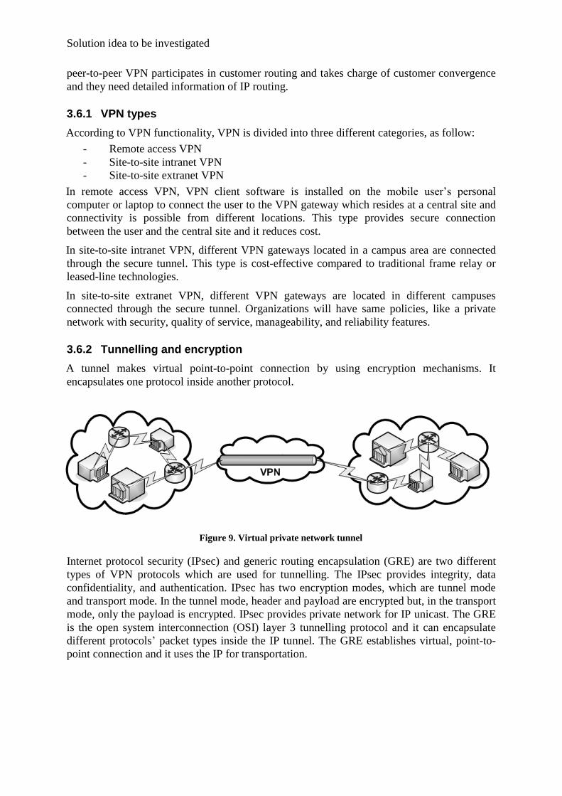
3.6.2 Tunnelling and encryption
A tunnel makes virtual point-to-point connection by using encryption mechanisms. It
encapsulates one protocol inside another protocol.
Figure 9. Virtual private network tunnel
Internet protocol security (IPsec) and generic routing encapsulation (GRE) are two different
types of VPN protocols which are used for tunnelling. The IPsec provides integrity, data
confidentiality, and authentication. IPsec has two encryption modes, which are tunnel mode
and transport mode. In the tunnel mode, header and payload are encrypted but, in the transport
mode, only the payload is encrypted. IPsec provides private network for IP unicast. The GRE
is the open system interconnection (OSI) layer 3 tunnelling protocol and it can encapsulate
different protocols’ packet types inside the IP tunnel. The GRE establishes virtual, point-to-
point connection and it uses the IP for transportation.

Integrated Security by using MPLS-VPN for retail-banking network
3.7 Multi protocol label switching – virtual private network (MPLS-VPN)
MPLS-VPN technology [10] uses the best feature of overlay VPN and peer-to-peer VPN
models. The provider edge router is present in customer routing, and it provides optimum
routing between different sites. As figure 10 illustrates, the provider edge router transports
separate groups of routes for different customers, and different customer groups can use the
same addresses scheme.
Figure 7. MPLS-VPN routing propagation information
Figure 10. MPLS-VPN
In the peer-to-peer model, the customer will send packets to the service provider (provider
edge router). Virtual private network (VPN) is used to separate different routing tables in a
single provider edge router (PE) and users can have overlap IP addressing. There is no peer-
to-peer connection between customer edge routers (CE) and there is no possibility for them to
see each other in case of connecting to one PE router. All the routes considered in the
customer’s edge router will be tagged by a label in the multi-protocol label switching
network. In addition, before sending the information of the customers to the MPLS network,
all the packets will be encapsulated with the MPLS label according to best path from the
source to destination of the packets. The next step is encapsulating this MPLS packet with the
IPSec or generic routing encapsulation (GRE) to prevent visibility from the other core routers
in MPLS backbone.
The first benefit of this model is flexibility and scalability for both customer and service
provider in case of adding different values or the same IP addressing schema. In addition, it
will separate wide area connections of different users in a same service provider network.
Connectivity of different routers is possible with a variety of connections. The important part
is the routers should be peer in the network layer. Some of these connections are PPP
connection, ATM connection, frame relay virtual circuit (VCs), ethernet, layer 2 tunnelling
protocol (L2TP), IP sec tunnel, etc.
Each customer’s site should have at least one customer edge router (CE) which is connected
to the provider edge router (PE). Generally, connectivity is possible by attachment circuit in
layer 2 of the OSI model. The other routers in the service provider network that are not
connected to the customer edge router are called “provider routers”. In some cases, a layer 2
device is connected directly to the PE router. In this case, the layer 2 device is not called as a
“CE device”. If the layer 2 device is connected to more than one CE router, it is possible to

Solution idea to be investigated
have a layer 2 connection between other PE routers by one physical circuit. Layer 2 devices
and connections are transparent between CE and PE routers.
Overlap addressing in VPNs
Two VPNs may have overlap addressing if they are not on the same site. In single VPN, it is
clear that addressing should not be the same for different hosts, but in two different VPN sites,
the same addresses can be used for single host in VPN1, and for another host in VPN2.
Routes to the same system by different VPNs
As figure below illustrates, it is possible to have different VPN connections to single site. It
means there is no need to have the same addressing to reach the destination. Imagine there are
three different hosts connected to three other sites as an extranet. All of them want to connect
to another system, which is called X. In the middle of the extranet, there is one firewall used
for checking the traffic trying to reach host X. It is possible to pass the firewall by using
another path between three mentioned host and the final destination, X.
Figure 11. Different VPN routes
3.7.1 Security in MPLS-VPN
Not all VPN connections discussed are cryptographic security enabled but, in this case, there
are still levels of security in layer 2 of the OSI model. It is like the security level which frame
relay network uses. In any situation in which a cryptographic mechanism is not configured, it
is impossible to gain access from one VPN to another VPN site. For data privacy, some
encryption may be used to ensure that data is not changed from source to destination. Security
in the data plane does not let the packets travel from one VPN to another VPN without
permissions made by policy. Also, it does not let the packets come inside a VPN from the
outside, except where the policy decisions allow.
Integrated Security by using MPLS-VPN for retail-banking network
In other conditions, if the provider router does not ensure that the labelled packets come from
a trusted system through the data link layer, then it will not be accepted. Other VPN labelled
routes will not be acceptable to the provider routers unless they make sure that they came
from trusted or reliable routing peers.
The data plane architecture in MPLS-VPN is different from the other VPNs in ATM or frame
relay. In case of missed configuration or improper configuration on the service provider side,
the packets will not be able to enter or leave the VPN without authorization.
If IPsec is not used to secure the tunnel for carrying the packets, then the techniques of the IP
address filtering at the border routers will apply, and it will be ensured that the source IP
address of the packet is not spoofed. This situation will be checked by analysing the provider
edge router (egress router). Any kind of configuration which is not secured by IPsec or GRE
must be enabled for validating the source IP address of the received packets by an egress
provider edge router.
If more than one CE router is connected to a layer 2 switch or a LAN interface, all the CE
routers should be a part of same VPN, or all of them should be tagged by related VLAN tags
before forwarding. Cryptographic security is not supported in these cases, or in ATM or frame
relay. If the customer desires to have cryptographic security, it should be applied on a CE-CE
basis.
The security of the data plane will be granted by securing the control plane. To ensure
security for the control plan, in any of the connections all the peers should be trusted. All the
protocols used in service provider network should be secured in same manner.
Security of the provider and provider edge routers
Physical security must apply for security of the data plane in provider and provider edge
routers.
3.7.2 VPN routing and forwarding table (VRF)
All PE routers have a different and separate forwarding table, which is called a “VPN routing
and forwarding table” or VRF. One of the tables in VRF is the default forwarding table. All
the PE or CE routers are attached to each other with a circuit called “VRF attached circuit”. In
the simplest form of connection between the PE routers and CE routers, ingress packet will
check the ingress VRF table to find the route information. Also, there is the egress VRF table
when a packet transfers through the provider egress router.
If the received packet over the attachment circuit does not match to any of the VRFs, then the
default forwarding table will address the packet. In this case, it does not matter that the packet
comes from the PE or provider router. It is possible to choose public routes as the default
forwarding table and private routes as the VRF table.
When a PE router receives a packet from a CE router, it will realize that the packet comes
from which attachment circuit and, then, check the packet for its VRF or set of VRFs. For this
checking, the physical port is used for receiving the packet by some aspects of packet’s layer
2 of the OSI model. As an example, if a packet comes from a frame relay network, the PE
router will check the frame relay interface and some data link connection identifier (DLCI)
field. The received packet from the attachment circuit cannot be trusted just by its interface or
DLCI, and it should be specified by a set of values of the service provider. In some cases, the
service provider may use more than one VRF to forward the packet from and to the customer
device. In this type of different VRF, different paths can be set for the connection between the

Solution idea to be investigated
source and destination addresses. In addition, some parameters can be set by the customer to
be used for choosing different paths in different packet characteristics.
For example, if one customer has different virtual sites (VLANs) and wants to send or receive
packets from the PE router, some certain values should be set to be recognised by VRFs. The
packets that are not in a predefined situation with a PE router and VLAN tags, will be
discarded. It is dependent on policies that more than one attachment circuit leading from one
PE router may map to a certain forwarding table or different forwarding tables.
Route distinguisher (RD)
Tunnelling technology in MPLS does not let the backbone routers (provider routers) accept
any packet which is labelled from any other non-backbone router. The situation of acceptance
of non-backbone labelled packet is possible only if the backbone router realizes that packet
will leave the backbone before any other packet with a lower label comes into the stack, or
that the labelled packet is distributed by the backbone router to the non-backbone router.
If tunnelling technology is not MPLS, then filtering must be done to make sure that the
labelled packet with the specific destination has a destination outside.
Route distinguisher (RD) is used in the MPLS-VPN network to separate and identify the VPN
customers who are connected to the provider edge router and it consists of 8 bytes. 2 bytes are
used for type field and 6 bytes are used for value field. At the moment, there are three
different types filed, which are 0, 1 and 2.
Type 0 includes two subfields:
- Administrator which is 2 bytes
- Assigned number which is 4 bytes
The autonomous system number (ASN) must be mentioned in the administrator subfield. The
relation between the ASN must set by the system administrator.
Type 1 includes two other subfields:
- Administrator subfield which is 4 bytes
- Assigned number subfield which is 2 bytes
An IP address must exist in the administrator subfield. An administrator should set the fields
if the IP address is a public address.
Type 2 includes two subfields:
- Administrator subfield which is 4 bytes
- Assigned number subfield which is 2 bytes
4-bytes Autonomous number (ASN) should be included in the administrator subfield. If the
ASN is from a public space, the administrator should set the parameters.

Integrated Security by using MPLS-VPN for retail-banking network
4 Detailed description of the investigated solution (design space)
Figure 12 illustrates the network design and physical security system design of a private bank
with two specific data centres (“central data centre” and “backup data centre”).
Figure 12. Connectivity architecture for data centre and backup data centre

Detailed description of the investigated solution (design space)
MPLS-VPN is used to provide a secure and reliable connection among central data centre,
backup data centre and the other main branches. In addition, some physical security systems,
such as door access controls, cameras and fire detection and protection systems are used for
two mentioned data centres. It is very important to have a remote control and monitor of
backup data centre and the other main branches from central data centre. To facilitate these
features, non IP-enabled security systems cooperate with IP-enabled systems to transfer
information through the IP network infrastructure like the MPLS-VPN.
As shown in figure below, 29 nodes spread in 27 provinces. Notice that “Tehran” has three
different nodes.
Figure 13. Braches Distribution
4.1 MPLS-VPN project design
The first step was analyzing the current state feasibilities for different branch locations. Four
available technologies are used to connect branches to the closest provider edge routers,
which are listed below:
- Huawei
- Alcatel
- Patton
- Tellaps

Integrated Security by using MPLS-VPN for retail-banking network
Note: These four technologies are installed on the provider sites. For connecting customer
sites to the provider sites, compatibility of the modems and routers is essential.
A list of different branches which have applied these technologies is available in Appendix B,
in table 2.
4.1.1 Huawei architecture
To provide connectivity between the customer edge router and the provider edge router on the
physical and data link layers for customer side, the G.SHDSL protocol is used.
The G.SHDSL is a standard for symmetric DSL introduced by the international
telecommunication union (ITU), [3] and it can provide high speed symmetrical data streams
for sending and receiving over a single pair of copper wires.
Quidway AR 18-33 features
The Quidway AR 18-33 series routers of Huawei can support G.SHDSL for physical layer
connectivity and is capable of supporting the data link and network layers. The command
lines that are used to configure Huawei routers are mentioned in the Appendix C. Some of the
system’s specifications and attributes are listed as follow:
- Processor: MPC859
- Flash: 8 MB
- Synchronous dynamic RAM: 64 MB
- Max. power: 10 W
- Interface: 4 * 10/100 Mbps Ethernet interfaces, 1 console port, 1 G.SHDSL interface
- Dimensions (W * H * D): 300 x 180 x 45 mm
- Operating temperature: 0 to 40 C
- Weight: 1 KG
- Power supply (Input): rated voltage: 100 to 240 V AC, 50 to 60 HZ, Max. tolerance:
90 to 264 V AC, 50 to 60 HZ, current: 0.5 to 1 A
- Power supply (output): voltage: 12 V DC, current: 4 A
- Relative humidity: 10 to 90%
System attributes
- Interface rate: independent receiving and transmission supported at symmetric rate
(from 192 Kbps to 2320 Kbps, changing at 8 Kbps).
- Connector: RJ 11
- Service: G.SHDSL over common telephone loops
- Interface standard: ITU-T G991.2, ITU-T G994.1 handshaking
4.1.2 Alcatel architecture
Connectivity between the customer edge router and the provider edge router on the customer
side in the physical and data link layers is implemented via G.SHDSL through the Cisco 878
router.

Detailed description of the investigated solution (design space)
Router Cisco 878 features:
The Cisco 878 router supports bridging and multiprotocol routing between its LAN and WAN
ports. Some of the main features for the Cisco 878 router are listed as below, and the
command lines that are used to configure Cisco 878 routers are mentioned in Appendix C.
- Flash: 20 MB (default)
- Synchronous dynamic RAM: 128 MB expandable to 256 MB
- Interface: 4 * 10/100 Mbps Ethernet interfaces, 1 Console port, 1 G.SHDSL
interface, 1 ISDN S/T port
- IPSec support: symmetric and public key encryptions, data compression and
authentication
- Security options: support VPNs, Cisco IOS firewalls and IPSec
4.1.3 Patton and Tellaps architecture
For connecting the provider side router to the customer side router, Patton and Tellaps
modems are needed to convert G.SHDSL line to serial/ Ethernet port. V.35 serial port is
applied for this connectivity through the Cisco 2811 router.
Router Cisco 2811 features
Some of the main features for the Cisco 2811 router are listed as below and the command
lines that are used to configure Cisco 2811 routers are mentioned in Appendix C.
- Protocols: ISDN/ RTP/ frame relay/ IP/ ATM/ QSIG
- Flash: 64 MB
- Synchronous dynamic RAM: 256 MB
- Interface: 2 * 10/100 Mbps Ethernet interfaces, 1 USB port
- Additional port: V.35 serial port
- Functionality: VoIP gateway and firewall
- Firewall: content filtering
- VPN protocol: IPSec
- Encryption: DES, 3DES
4.2 IP-base physical security design
To provide physical security in the bank data centres, cameras and access control systems are
installed and connected to their related servers for room authentication, authorization, and
monitoring. In the backup data centre, no server is defined with the main functionalities as the
central data centre, and it obeys rules from the related server in the central data centres. For
new events, updates will occur in data centre through the MPLS-VPN infrastructure, and new
rules will be defined only by servers in the central data centre.

Integrated Security by using MPLS-VPN for retail-banking network
Figure 14. Mehr Bank Data Centres
4.2.1 IP-base camera
Analogue cameras are connected to its encoder and the encoder transfers images via the
Ethernet port to the server station. Dome cameras, which are used for indoor monitoring in the
central data centre and backup data centre, support super high resolution, backlight
compensation, digital noise reduction, and record colourful, true day/night and wide dynamic
images. For outdoor monitoring, the industrial cameras are used, with super high resolution,
high sensitivity with minimum illumination, fast change over form day/night mode, electric
iris function and backlight compensation capabilities.
The encoder, which is mentioned above, has up to 16 video input/output channels and encodes
stream data into the MPEG-4 format to use H.264 protocol. This causes a reduction in the
required bit rate for a given quality setting, and it can also increase quality when there are
enough bit rates, [14].
The image comes from different encoders, and from the central data centre and backup data
centre, goes into a server in the central data centre, which includes enterprise security
software for image monitoring. This server is connected to the access control server that has
main functionality to run the different pre-defined scenarios, which is described in the event
table in Chapter 3.
Some features of the enterprise security software for image monitoring are listed as below,
[12]:
- Enhanced reliability
- Enhanced bandwidth usage
- Entity search tool
- Alarm management
- Multi-stream support
- New scheduling options
- Integration to active directory
- Video sequence protection
- Error notification log
- Storage on video servers

Detailed description of the investigated solution (design space)
- Enhanced multi-display mode
- SQL-based directory
- Enhanced performance (up to 50.000 cameras per system, manage up to 300 camera
per server)
4.2.2 IP-base access control
The contactless card readers are used for accessing rooms by authentication and authorization
process. The contactless card readers, and pin pads are needed for room entrance. There is no
need to have pin pads for exiting from rooms to control log information.
To provide high security for vital rooms, such as server rooms, fingerprint readers are used.
The readers mentioned have internal databases which enable them to make decisions. This
capability is essential in the event on an interruption to the system connectivity to its server.
All these readers are connected to the access controller boxes. They have connection with non
IP-base systems through their input/ output relay interfaces. In addition, they include Ethernet
ports for connection with switches and IP-base systems.
The information comes from readers, cameras and non IP-base security systems gathered
from the central data centre, and backup data centre, directly to the access control server, for
processing and decision-making. Then, the server decides upon different actions by sending
data to related devices for running pre-defined scenarios.
Some features of the access control server for physical security are listed as follows, [13]:
- Powerful security management tool
- Alarms management
- Intruder alarm monitoring
- Providing integrated access control and security functions
- Image identification
- Camera monitoring and event handling
- Input/ output relay interface management
- System scalability
- Flexibility
- Encrypted communication
- Minimal bandwidth usage
- TCP/IP communication protocol
- Working on LAN and WAN and internet
4.3 Non IP-base system design
Providing the connectivity between non IP-base systems is implemented through their input/
output relays and managed by different, related defined software.

Integrated Security by using MPLS-VPN for retail-banking network
4.3.1 Fire detection and fire fighting architecture
All fire detectors are connected into the fire detection main controller-device through their
related cables. The fire detection main system has the capability to divide the whole area into
different zones.
FM200 gas is used to extinguish fire in the different rooms (zones). Information from the fire-
detected zone will be sent from the fire detection system into the access control box through
their input / output relays. This action is used to instruct the access control to unlock related
doors and start image recording by the cameras.
4.3.2 Other non IP-base system architecture
The passive infrared motion detectors (PIR) and heating, ventilating and air conditioning
(HVAC), are two other non IP-base systems that should connect to other systems.
PIR is used to detect motion in different areas of the data centres and alert image monitoring
system by connecting its output relay to the image encoder’s input relay. In some cases, PIR is
connected to the access control box to inform about any movements in rooms.
HVAC is connected to the fire detection system through its input /output relays, to do a proper
act in case of fire. In this case, the HVAC system will reverse the air ventilation direction in
specific zones.

Detailed description of the investigated solution (design space)
4.4 Functional description (event table)
The table below defines physical security and entire scenarios for interacting among four
different specific systems in the different situations. The system has a centralized controlling
and monitoring capability through specific servers installed in the central data centre.
Item Cause Effect
No. Fire
Alarm
Access
Control CCTV HVAC Display
1
Access
Control
Door entrance - Report Event
recording -
Report
entrance
2 Door passing - Lock again Event
recording -
Report
lock
3 Intrusion - Alarm Event
recording -
Report
intrusion
4 Normal - - Recording 2
Frame/Sec -
Normal
report
5
Fire
Detection
and
Protection
Fire detection in
single zone
Alarm
activation –
Type 1
Doors
deactivation
Event
recording Off Report
6
Fire detection in
two zone (one
sector)
Alarm
activation –
Type 2
Doors
deactivation
Event
recording Off Report
7 Extinguishing
command
Alarm
activation –
Type 3
Doors
deactivation
Event
recording Off Report
8 After
extinguishing
Alarm
activation –
Type 4
Doors
deactivation
Event
recording Reverse Report
9 Cylinder empty Related
fault - - -
Report
10 Normal - - Recording 2
Frame / Sec On Report
Table 1. Bank data centre – cause & effect table

Integrated Security by using MPLS-VPN for retail-banking network
Description of the physical security event table
As mentioned before, main data centre is connected to the backup data centre through the
MPLS-VPN network. Two physical security servers exist in the main data centre, which
control and monitor the activity of the physical security systems. These security systems, such
as door access controls, fire alarming systems and cameras, interact with HVAC and fire
fighting systems.
There are different security scenarios that should activate the access control system and send
an instruction to the cameras to start recording. For example, when one of the doors of the
main or backup data centres is opened by an authorized person, the related cameras in that
room will start to capture video. This streaming video will be automatically transferred to its
related server in the main data centre. Another scenario is the moment that an intruder tries to
pass one of the doors without the authorization. In this case, access control sensors and
motion detection sensors will notify the access control system and cameras to do the action
described previously.
Another example for a better understanding of the event table is the eventuality that the fire
detection system in the backup data centre senses smoke. In this case, the alarms will
automatically send a signal to the main data centre through the MPLS-VPN network in
parallel with the cameras which start to capture videos. HVAC system will stop working and
the room’s doors and other exit doors will open automatically. The fire protection system also
starts to extinguish the fire in the room.

Result and analysis of solution
5 Result and analysis of solution
In a financial organization like a bank with many branches spread around the country,
providing secure connection among branches is essential. Critical areas in this scenario are
data centres, which contain vital information, e-commerce applications, and other essential
applications. In Chapter 3 (solution idea to be investigated), all data security aspects are
studied. The project task in this thesis was to implement proper communication technology
(WAN) and provide physical security for data centres.
As project result, all 29 main branches spread around the country and the main data centre and
backup data centre are connected securely through MPLS-VPN. Another major result in this
project is securing data centre and backup data centre physically, and connectivity between
IP-base and non IP-base systems are implemented in these two data centres as well.
End-to-end network security and physical security are analysed in detail as below:
5.1 End-to-end network security analysis
End-to-end network security means guaranteeing security for data transportation from source
to destination. Different criteria exist to provide end-to-end network security; the factors
mentioned below confer the required end-to-end network security for this bank:
- Data loss prevention
- Virtual private network (VPN)
- Firewall
- Threat control (IPS,IDS)
- Network admission control (NAC)
Note: In this project, according to bank’s demand, since all required security aspects are
covered by MPLS-VPN technology, there is no need to apply firewall, IPS, IDS and NAC.
Data loss prevention
Data loss prevention is one of the security features. It monitors, identifies, and protects data
from source to destination. The data loss prevention (DLP) mechanism watches over three
different types of data, which are listed below:
- Data in use
- Data in motion
- Data at rest
“Data in use” refers to data that is already being used at endpoints. Data can be either
generated or used in this level. “Data in motion” refers to data in transfer mode from sender to
receiver, or vice-versa. “Data at rest” refers to stored data.
In this project, all aspects of data loss prevention is provided by using specific servers, proper
software in data centre and implementing proper network infrastructure. In the worst case, if a
data centre failed, the backup data centre guarantees data availability.

Integrated Security by using MPLS-VPN for retail-banking network
Data loss prevention applies to end-to-end connections. In network security, end-to-end
connection means connection between two end stations, or between one end station and its
related server. In physical security for this specific bank scenario, end-to-end connection
means connection from the access control readers, or from the cameras to edge routers, which
are connected to MPLS-VPN network.
Uninterruptable power supply (UPS) prevents power interruption for data centres. Preventing
data loss for data in motion is maintained by using proper cabling (shielded/ harsh cabling).
Moreover, proper duct installation and choosing the best cabling path prevents noise
interferences for data in motion. Servers support redundancy by having extra equipment such
as CPU, random access memory, hard drive, power supply and other redundancy factors.
Software used for the access control system and camera encoder system is capable of
archiving and backing-up data with predefined schedules, automatically. The service provider
is in charge of providing data loss prevention for core MPLS-VPN network.
Virtual private network (VPN)
The VPN provides point-to-point security between customer edge routers by using IPSec
Tunnel [2]. It means that packets which are sent will be authenticated and encrypt to achieve
high-level security. By defining the multi-party security association term, instead of applying
a security tunnel between each two customer edge routers, all customer edge routers, which
participated in a particular VPN, will share the same security parameters. In this case, the
customer edge router could not be aware of who will be the next customer edge router and it
is necessary to know through which VPN data is addressed.
Firewall
Since this project does not have any unauthorized accesses to its system, and it uses virtual
private network for connectivity, there is no need to have a firewall. Notice that there is no
connection to the internet in this project.
Threat control
Two possible ways to control threats are an intrusion detection system (IDS), and an intrusion
prevention system (IPS). The IDS is responsible for monitoring the network and system
activities to find malicious events. The IPS functionality is similar to the IDS, and it can react
to block or prevent malicious activities. The IPS and IDS are in charge of identifying possible
events, logging event’s information, trying to prevent them and informing the security
administrators [5]. These features are not defined in the current project and they should be
considered for providing high-level security.
Network admission control (NAC)
The network admission control restricts access to the network according to security conditions
or identities. When the user wants to have access to the network, the NAC is responsible for
checking DNS and DHCP information, operating system patch updates, antivirus/ antispyware
version updates and also it can recognize users, devices and network roles. In unwanted cases,
it will block users, isolate, or repair their connection. This technology is not utilized in the
current project and it should be considered as a future work.

Result and analysis of solution
5.2 End-to-end physical security analysis
In two data centres (main data centre and backup data centre), it is very important to have
physical security to fulfil the security issues. The two most important servers are in the main
data centre to provide high-level security, listed as below:
- Image server
- Access control server
Image server security features
The image server software grants multiple security features to prevent tampering, distortion
and interception of the data by unauthorized access. This provides by 128-bits secure sockets
layer (SSL) encryption along with integrated digital signature that individually identifies each
image.
Access control server security features
All data transactions among controllers and server are encrypted by using 40-bits encrypted
SSL technology. This technology is similar to the internet banking transactions’ security level
and it can support 168-bit high-level encryption.
Note: the different level of system’s access is defined for the operators to have only authorized
access to their privilege mode, for both image server and access control server.

Integrated Security by using MPLS-VPN for retail-banking network
5.3 Use-case diagram analysis
Figure 15. Private network use-case diagram
As shown in figure 15, four different roles are defined for the bank’s private network. Each
person depends on its role should be approved by its related security cases. For example, if a
bank’s clerk wants to connect to the bank’s private network, he should go through all security
cases except the “system log information”.

Result and analysis of solution
Figure 16. Bank’s customer use-case diagram
Firewall and DMZ security cases are applied when a customer wants to connect to the bank’s
public network.

Integrated Security by using MPLS-VPN for retail-banking network

Conclusion
6 Conclusion
In this project, regarding the bank’s requirement for assuring a properly secured network with
integrated IP-base physical security, all the required needs were provided by implementing
security issues (mentioned in the result chapter) in parallel with the MPLS-VPN.
The multi protocol label switching- virtual private network (MPLS-VPN) technology supports
the optimum routing, data confidentiality, data integrity, fast packet switching, quality of
service(QoS) and redundancy for the network. The MPLS has its own topology, which is
more efficient than partial topology. Applying the VPN through MPLS provides a private and
secure network through a public network. In addition, the MPLS-VPN is cost efficient for
customers.
Compared to previous technologies, like satellite and asynchronous transfer mode (ATM),
which are used for the bank network, the MPLS-VPN is the best solution to fulfil all the
mentioned bank requirements.
With reference to result chapter in this report, this project needs to have an intrusion
prevention system (IPS) / intrusion detection system (IDS) and network admission control
(NAC) technologies as further work. Also, with regard to connecting the bank’s private
network to the internet, a firewall should be considered as well.

Integrated Security by using MPLS-VPN for retail-banking network

References
7 References
[1] Behavior of and requirements for internet firewalls, RFC 2979
[2] Border Gateway Protocol /Multi Protocols Label Switching – Virtual Private Network,
RFC 2547
[3] Multiprotocol Encapsulation over ATM Adaptation, RFC 2684
[4] Information technology -- Security techniques -- Code of practice for information
security management, ISO/IEC 17799:2005
[5] The Intrusion Detection Message Exchange Format (IDMEF), RFC 4765
[6] Cisco Physical Security for Retail Banking, solution_overview_c22-550743 Physical
Security, http://www.cisco.com/go/psforrb
[7] Cisco Physical Security Solution Overview, at_a_glance_c45-468316,
http://www.cisco.com/go/physicalsecurity
[8] Generic AAA Architecture, RFC 2903
[9] Multiprotocol Label Switching Architecture, RFC 3031
[10] BGP/MPLS IP Virtual Private Networks (VPNs), RFC 4364
[11] The Helminthiasis of the Internet, RFC 1135
[12] Omnicast™ Enterprise 4.2, Managed Video Services Software, Release Notes, Version
4.2 GA, June 2008, EN.100.001-V4.2GA.r1, http://www.genetec.com
[13] Cardax access control systems and products, ISO 9001:2000 certified,
http://www.cardax.com
[14] Bosch security solution, http://www.boschsecurity.com

Integrated Security by using MPLS-VPN for retail-banking network
8 Appendix A
Technologies, which used for this project, listed as below:
WAN modems:
Cisco, Huawei, Alcatel, Tellaps, Patton
Routers:
Cisco, Huawei
Analog cameras:
Bosch, Ganz
IP camera encoder:
Bosch
IP camera monitoring software:
Genetec
Access control readers:
Cardax, Sagem
IP-based access control system:
Cardax
Fire detection and fire fighting System:
Siemens
Servers:
HP

Appendix B
9 Appendix B
Item City Technology
1 Tehran node 1 Huawei
2 Tehran node 2 Huawei
3 Tehran node 3 Huawei
4 west Azerbaijan Alcatel
5 Zanjan Alcatel
6 Semnan Alcatel
7 Ghazvin Alcatel
8 Qom Alcatel
9 Yazd Alcatel
10 Sistan & Baluchistan Alcatel
11 Ilam Alcatel
12 Kordestan Alcatel
13 Khuzistan Alcatel
14 Bushehr Tellaps
15 Chahar Mahal & Bakhtiyari Tellaps
16 north Khorasan Tellaps
17 Kohgilouyeh & Boyer-Ahmadi Tellaps
18 Lorestan Tellaps
19 Hamedan Tellaps
20 Ardebil Tellaps
21 Golestan Tellaps
22 Mazandaran Tellaps
23 Kerman Tellaps
24 Gilan Tellaps
25 Kermanshah Tellaps
26 Markazi Tellaps
27 Khorasan-Razavi Tellaps
28 south Khorasan Tellaps
29 Fars Patton
Table 2. Technologies distribution in different cities

Integrated Security by using MPLS-VPN for retail-banking network

Appendix C
10 Appendix C
Command lines that used to configure Huawei routers:
<Quidway>dis cu
#
sysname Quidway
#
undo ip option source-routing
#
interface Ethernet1/0
ip address 192.168.0.1 255.255.255.0
#
interface Atm2/0
pvc 0/35
map ip inarp
ip address 172.19.0.42 255.255.255.252
#
interface NULL0
#
ip route-static 0.0.0.0 0.0.0.0 172.19.0.41 preference 60
#
user-interface con 0
user-interface vty 0 4
#
return
Command lines that used to configure Cisco 878 routers:
controller DSL 0
mode atm
line-term cpe
line-mode 2-wire line-zero
dsl-mode shdsl symmetric annex B
line-rate auto
exit
interface ATM0
ip address 10.20.90.132 255.255.255.252
atm vc-per-vp 128
pvc 52/36
cbr 1024
encapsulation aaL5snap
exit
exit
interface Vlan1
ip address 10.139.250.254 255.255.255.0
exit
ip classless
ip route 0.0.0.0 0.0.0.0 10.20.90.131

Integrated Security by using MPLS-VPN for retail-banking network
Command lines that used to configure Cisco 2811 routers:
interface fasteth 0/0
IP Add 10.139.X.254 255.255.255.0
no shut
Exit
interface serial 0/0/0
IP unnumbered fasteth 0/0
Encapsulation PPP
No shut
Exit
Ip route 0.0.0.0 0.0.0.0 serial 0/0/0
Exit


