Download - Instrumentation for Mechanics of Breathing

7/25/2019 Instrumentation for Mechanics of Breathing
http://slidepdf.com/reader/full/instrumentation-for-mechanics-of-breathing 1/59

7/25/2019 Instrumentation for Mechanics of Breathing
http://slidepdf.com/reader/full/instrumentation-for-mechanics-of-breathing 2/59
Tests
u 3 types of measurements
n Ventilation
n Distribution
n Diffusion

7/25/2019 Instrumentation for Mechanics of Breathing
http://slidepdf.com/reader/full/instrumentation-for-mechanics-of-breathing 3/59
Parameters
u Tidal Volume (TV)
u Inspiratory Reserve Volume (IRV)
u Expiratory Reserve Volume (ERV)
u Residual Volume (RV)
u Vital Capacity (VC) = IRV + ERV + TV
u Total Lung Capacity (TLC) = VC + RV
u Inspiratory Capacity (IC) = TV + IRV
u Functional Residual Capacity (FRC)n = RV + ERV
n = TLC – IC
n
Very stable

7/25/2019 Instrumentation for Mechanics of Breathing
http://slidepdf.com/reader/full/instrumentation-for-mechanics-of-breathing 4/59
Parameters
u Dead Space
u Transpulmonary pressure (PL)
n Pressure gradient across mouth (Pao) and pleuralsurface at lung (PPL)
u Transalveolar Pressure (PEL)n Pressure gradient across alveolar wall (PALV - PAL)
u Transairway Pressure (PRES)
n Pressure gradient across alveolar and mouth
u Static Elastic recoil Pressure (PST(L))
n Pressure developed in elastic fibers of lung byexpansion

7/25/2019 Instrumentation for Mechanics of Breathing
http://slidepdf.com/reader/full/instrumentation-for-mechanics-of-breathing 5/59
Dynamic parameters
u Respiratory minute volume
n Amount of air inspired during 1 min at rest
n = TV * respiratory cycles /min
u Forced breathing tests to assess muscle power and
airway resistancen Forced Vital Capacity (FVC)
n Amount of air that can be forcefully expired as quickly as
possible after deepest possible breath
n
Timed Vital Capacityn Forced Expiratory Volume (FEV)
n Maximum mid-expiratory flow rate
n Flow measurement over middle half of forced vital capacity
(25% to 75% level) [FEV25% -75%
]

7/25/2019 Instrumentation for Mechanics of Breathing
http://slidepdf.com/reader/full/instrumentation-for-mechanics-of-breathing 6/59
Maximum mid-expiratory flow rate

7/25/2019 Instrumentation for Mechanics of Breathing
http://slidepdf.com/reader/full/instrumentation-for-mechanics-of-breathing 7/59
Dynamic parameters …
u Maximal Breathing Capacity (MBC) or Maximal
Voluntary Ventilation (MVV)n 15 – 20 seconds
u Closing volume
n Detect obstruction of small airways
n Volume level at which certain zones within lungs ceaseto ventilate
u BTPS
n Measurements made a body temperature and ambientpressure, with gas saturated with water vapor
u STPD
n Standard Temperature and pressure and drymeasurement

7/25/2019 Instrumentation for Mechanics of Breathing
http://slidepdf.com/reader/full/instrumentation-for-mechanics-of-breathing 8/59
Mechanical measurements
u Direct measurement of
n Compliance of lungs and rib cage
n Resistance of all air passages

7/25/2019 Instrumentation for Mechanics of Breathing
http://slidepdf.com/reader/full/instrumentation-for-mechanics-of-breathing 9/59
Compliance of lungs and rib cage
u Volume increase in lungs per unit increase inpressuren Measurement of: volume of gas inspired or expired
and intrathoracic pressure
n 2 types: static and dynamic
n Static compliance represents pulmonary complianceduring periods without gas flow, such as during aninspiratory pause.
n Dynamic – tidal volume/ (intrathoracic pressure atend inspiratory and end expiratory)
u Not constant over respiratory cycle
n Decrease as lungs are inflated

7/25/2019 Instrumentation for Mechanics of Breathing
http://slidepdf.com/reader/full/instrumentation-for-mechanics-of-breathing 10/59
Airway Resistance
u Ratio of pressure to flow
n Intra-alveolar pressure and flow
u Not constant over respiratory cycle
n Inhalation - As pressure becomes more negative –
airways widened - airway resistance¯
n Exhalation - pressure becomes more positive –airways narrowed - airway resistance
u Measured at or near end expiratory level

7/25/2019 Instrumentation for Mechanics of Breathing
http://slidepdf.com/reader/full/instrumentation-for-mechanics-of-breathing 11/59
Instrumentation
u Basic Spirometer
n Bell volumes – 9 & 13.5 L
n Bell – little inertia
n For fast RR measurement
n
Kymograph paper speeds: 32,160,300 and 192 mm/min
u Frequency response
n Adequate to measure FEV
n No Hysteresisn Fast Response time
n Flat frequency response up to12 Hz

7/25/2019 Instrumentation for Mechanics of Breathing
http://slidepdf.com/reader/full/instrumentation-for-mechanics-of-breathing 12/59
Spirometer
u Is a Mechanical Integrator
n Input – airflow
n Output – volume displacement
n Electrical signal proportional to volumedisplacement can be obtained
n Linear motion potentiometer connected to pulley
n Signal fed to flow-volume differentiator forevaluation and recording of data
u Heavily damped systemu Not analytical
u Not completely objective

7/25/2019 Instrumentation for Mechanics of Breathing
http://slidepdf.com/reader/full/instrumentation-for-mechanics-of-breathing 13/59
Some uses
u Clinical spirography
u Cardiopulmonary function testing
u Metabolism determinations
u Direct measurements
n Basal minute volume
n Exercise ventilation
n Maximum breathing capacity
u
Calculatedn Ventilation equivalent of oxygen

7/25/2019 Instrumentation for Mechanics of Breathing
http://slidepdf.com/reader/full/instrumentation-for-mechanics-of-breathing 14/59
Waterless Spirometers
u Wedge or bellows type
u Rolling Seal or Dry Seal
u Diaphragm

7/25/2019 Instrumentation for Mechanics of Breathing
http://slidepdf.com/reader/full/instrumentation-for-mechanics-of-breathing 15/59
Wedge Spirometer
u Breathed air is held
between in a chamberenclosed by parallelmetal pans hinged toeach other on one
edgeu One metal pan is
permanently fixedn Contains pair of 5 cm
tubesu Space between two
pans is sealed airtightwith vinyl bellows

7/25/2019 Instrumentation for Mechanics of Breathing
http://slidepdf.com/reader/full/instrumentation-for-mechanics-of-breathing 16/59
Wedge Spirometer..
u Bellowsn Extremely flexible in the direction of pan motionn Offers high resistance to ‘ballooning’
n \ when pressure gradient exists betweenatmosphere and interior of wedge there will be
negligible distortion of bellowsu Volume and flow signals
n Obtained from two linear transducers
n Attached to fixed frame and coupled to edge of
moving pann One transducer produces dc signal a
displacement (volume)
n Other produces dc output a velocity (flow)

7/25/2019 Instrumentation for Mechanics of Breathing
http://slidepdf.com/reader/full/instrumentation-for-mechanics-of-breathing 17/59
Wedge Spirometer…
u Electronics unit
n Power supply, amplifier and built-calibrationnetworks
u Mechanical Read-out
u Adjustable tilt mechanism or magnetic stop –provide desired volume (resting) position
n No effect on moving pans – due to large surface areaof pans
u Calibrated using selector switch – determinesmagnitude of calibration signal

7/25/2019 Instrumentation for Mechanics of Breathing
http://slidepdf.com/reader/full/instrumentation-for-mechanics-of-breathing 18/59
Horizontal Bellows

7/25/2019 Instrumentation for Mechanics of Breathing
http://slidepdf.com/reader/full/instrumentation-for-mechanics-of-breathing 19/59
Other types of Spirometers
u Ultrasonic Spirometers
u Airflow Spirometers or Pneumotachometers
u Bronchospirometer
n Measures volumes and capacities of each lungindividually
n Used for pre-operative evaluation of oxygenconsumption of each lung

7/25/2019 Instrumentation for Mechanics of Breathing
http://slidepdf.com/reader/full/instrumentation-for-mechanics-of-breathing 20/59
Ultrasonic Spirometers
u Based on transit-time
u Frequency: 40 – 200 kHz
n >200 k Hz: absorption losses
n < 40 kHz: audible
u Pulse transit time upstream (t1)and downstream (t2) are given by:
n D: Distance between transducers
n C: velocity of sound propagation in
fluid
n v ’ : velocity of fluid vector in thepath of pulses

7/25/2019 Instrumentation for Mechanics of Breathing
http://slidepdf.com/reader/full/instrumentation-for-mechanics-of-breathing 21/59
Ultrasonic Spirometers..
u Average gas velocity : v
u Output accuracy unaffected by (since no C in
final equation):n Fluid density, temperature or viscosity
u Tube diameters: >3 cm

7/25/2019 Instrumentation for Mechanics of Breathing
http://slidepdf.com/reader/full/instrumentation-for-mechanics-of-breathing 22/59
Ultrasonic Spirometers…
u Disadvantages:
n Contamination by flowing substances
n Unwanted turbulence and moisture accumulation
n Deadspace is undesirable

7/25/2019 Instrumentation for Mechanics of Breathing
http://slidepdf.com/reader/full/instrumentation-for-mechanics-of-breathing 23/59
Pneumotachometers
u Measure instantaneous rate of volume flow
u Types: Differential Manometer and Hot-wireanemometer
u Differential Manometer:
n
Consists of a small resistance which allows flow butcauses pressure drop
n Change measured using differential pressure transducerwhich works on Poiseuille’s Law
n Assumption: Flow is Laminar
u Hot-wire anemometern Uses small heated element in the pathway of gas flow
n Current needed to maintain the element at constanttemperature is measured

7/25/2019 Instrumentation for Mechanics of Breathing
http://slidepdf.com/reader/full/instrumentation-for-mechanics-of-breathing 24/59
Pneumotachometers…
u Parameters studied:
n FEV, MMEV, peak flow
u Also used to generate flow-volume loops
u Absolute volume derived by electronically
integrating the flow rateu Conventional Spirometers have limitations of
mechanical inertia, hysteresis and CO2 build-up
u
Advantage: Non-Obstructive – continuousmonitoring possible
u Requirement – minimum resistance to breathing
n Acceptable between: 0.5 to 1 cm H2O s/l

7/25/2019 Instrumentation for Mechanics of Breathing
http://slidepdf.com/reader/full/instrumentation-for-mechanics-of-breathing 25/59
Pneumotachometers…
u Frequency components – 10 Hz
u Quick Response time
u Good zero stability
n To avoid false integration during volume
measurementsu Sometime bias flow is introduced
n Avoid rebreathing for expired air

7/25/2019 Instrumentation for Mechanics of Breathing
http://slidepdf.com/reader/full/instrumentation-for-mechanics-of-breathing 26/59
Fleisch Pneumotachometer
u Thin sheet of corrugated metal is
rolled and inserted in a metal covern These corrugations are parallel channels
and act as resistance elements
n Helps to maintain laminar flows at
higher flow ratesn Flow rate directly proportional to
pressure drop
n o/p of flow transducer is pressure drop
n A second transducer required to convert
pressure to electrical signal – Capacitive
is used
n More stable and less vibration sensitive

7/25/2019 Instrumentation for Mechanics of Breathing
http://slidepdf.com/reader/full/instrumentation-for-mechanics-of-breathing 27/59
Poiseuille’s Law
u Pressure developed across Pneumotach directly
proportional to gas viscosity
u Viscosity of mixture of gases is approximatedby:
n Where X is fraction of gas having viscosity h

7/25/2019 Instrumentation for Mechanics of Breathing
http://slidepdf.com/reader/full/instrumentation-for-mechanics-of-breathing 28/59
Fleisch Pneumotachometer
u Temperature effect – 1% change per °C
u Saturating air with water vapor – reduceoutput head by 1.2%
u Measurements done at BTPS
n To avoid condensation and maintain gases underBTPS – device maintained at 37°C

7/25/2019 Instrumentation for Mechanics of Breathing
http://slidepdf.com/reader/full/instrumentation-for-mechanics-of-breathing 29/59
Venturi-type Pneumotachometer
u Pressure drop proportional to square of
volume flow
u Open geometry – less prone to liquidaccumulation
u Disadvantagen Non-linearity of calibration
n Requirement of laminar flow
7/25/2019 Instrumentation for Mechanics of Breathing
http://slidepdf.com/reader/full/instrumentation-for-mechanics-of-breathing 30/59
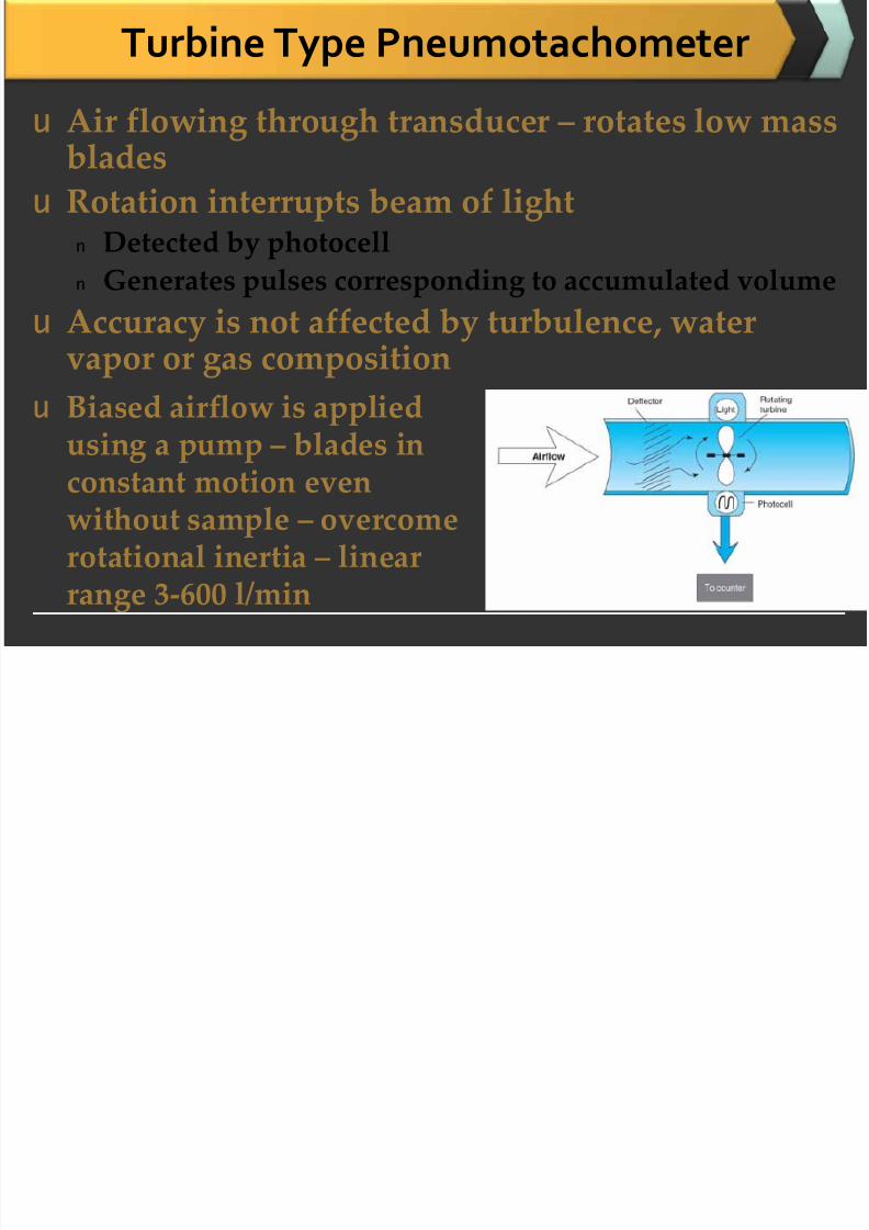
Turbine Type Pneumotachometer
u Air flowing through transducer – rotates low mass
bladesu Rotation interrupts beam of light
n Detected by photocell
n Generates pulses corresponding to accumulated volume
u Accuracy is not affected by turbulence, watervapor or gas composition
u Biased airflow is applied
using a pump – blades inconstant motion evenwithout sample – overcomerotational inertia – linear
range 3-600 l/min

7/25/2019 Instrumentation for Mechanics of Breathing
http://slidepdf.com/reader/full/instrumentation-for-mechanics-of-breathing 31/59
Measurement of volume

7/25/2019 Instrumentation for Mechanics of Breathing
http://slidepdf.com/reader/full/instrumentation-for-mechanics-of-breathing 32/59
Measurement of Volume

7/25/2019 Instrumentation for Mechanics of Breathing
http://slidepdf.com/reader/full/instrumentation-for-mechanics-of-breathing 33/59
Maximal expiratory flow- volume (MEFV) curves

7/25/2019 Instrumentation for Mechanics of Breathing
http://slidepdf.com/reader/full/instrumentation-for-mechanics-of-breathing 34/59
Nitrogen Washout Technique
u Used for indirect measurement of RV, FRC and
TLC
u Subject breaths 100% O2
u Nitrogen analyzer placed near mouth-piece
continuously monitors N2
n Decreases with each successive breath
u alveolar N2 becomes 1% and steady state is
reaches steady stateu Nitrogen washout curves
u Complete washout curves takes about 10 min
i h

7/25/2019 Instrumentation for Mechanics of Breathing
http://slidepdf.com/reader/full/instrumentation-for-mechanics-of-breathing 35/59
Nitrogen washout curve
u % N2 in expired air Vs time
u Theoretically %N2 Vs expired volume –
straight line on graph paper
u Actually not – presence of anatomic deadspace/ tidal volume ratio
u Compensation – subtract deadspace from each
breath
i l h h

7/25/2019 Instrumentation for Mechanics of Breathing
http://slidepdf.com/reader/full/instrumentation-for-mechanics-of-breathing 36/59
Single Breath N2 washout curve
u Maximal inspiration of 100%
u Exhaling VC slowly tillResidual volume
u N2 concentration plotted vsvolume
u Parameters derived from this:
n Closing volume
n the lung volume at which the flow from the lower parts of thelungs becomes severely reduced or stops duringexpiration, presumably because of airway closure; measured bythe sharp rise in expiratory concentration of a tracer gas that had
been inspired at the beginning of a breath that started fromresidual volume.
l i l

7/25/2019 Instrumentation for Mechanics of Breathing
http://slidepdf.com/reader/full/instrumentation-for-mechanics-of-breathing 37/59
Pulmonary Function Analyzers
u Completely automated for the measurement of
ventilation, distribution and diffusion
P l F i A l

7/25/2019 Instrumentation for Mechanics of Breathing
http://slidepdf.com/reader/full/instrumentation-for-mechanics-of-breathing 38/59
Pulmonary Function Analyzers…
u Pneumotach: signal proportional to airflow
u CO and He analyzers: diffusion measurements
u Linearity from 0-15 l/sn Better precision for recording flow-loop in range of high
flows and well as low flows
u Flow proportional pressure drop is fed to pressuretransducer
n Pneumatic value converted into electrical signal
n Fed to amplifier – o/p is flow
n Signal is integrated to volume by voltage to frequencyconverter
n Flow and volumes are converted into digital signal
P i E l ti d t ti f d t

7/25/2019 Instrumentation for Mechanics of Breathing
http://slidepdf.com/reader/full/instrumentation-for-mechanics-of-breathing 39/59
Processing, Evaluation and representation of data
u 8-bit microprocessor
u Program memory capacity: 46kB
n 16kB used for software
n 30kB used for measurement and organization
u Intermediate storage of data: 12kB RAMu System communication: 20-digit alphanumeric
display line
u
20-digit alphanumeric printer-plotter:hardcopy of o/p
u FEV curves: histograms also
I d P h

7/25/2019 Instrumentation for Mechanics of Breathing
http://slidepdf.com/reader/full/instrumentation-for-mechanics-of-breathing 40/59
Impedance Pneumograph
u Indirect technique for measurement of
respirationn Respiratory volume and rate is measured
n Relationship between respiratory depth andthoracic impedance change
u Advantages: no masks, tubes or flow-meters
n Do not impede respiration
n Minimal effect on Psyche of patient
n Provide continuous volumetric record of respiration
M t
7/25/2019 Instrumentation for Mechanics of Breathing
http://slidepdf.com/reader/full/instrumentation-for-mechanics-of-breathing 41/59
Measurement
u Thoracic impedance change
n AC excitation is applied to subject
n Should be independent of
n Impedance due to resting thoracic impedance and
n
Contact impedance between electrodes and skinu Optimum frequency considerations
n Excitability of various tissues between electrodes
n Nature of other recording made at same time. Ex: ECG
n Typical used: 50-100 kHzn Amplitude: 1mA p-p
n Power < 1mW
Does not stimulate tissues &Natural rejection of other
bioelectric events
Th i i d d i d h i l

7/25/2019 Instrumentation for Mechanics of Breathing
http://slidepdf.com/reader/full/instrumentation-for-mechanics-of-breathing 42/59
Thoracic impedance and impedance change signals
u Polar or Cartesian vectors used
u Respiratory signal (
Z) = change between initialimpedance (Zo) and new impedance (Z)
n Essentially a change in resistance component
n Independent of frequency – in 20-600kHz range
n Correlates well with changes in respired volume (
V)u Transthoracic impedance
n Function of frequency
n Type and size of electrodes
n Ag/AgCl electrodesn 9.5mm dia – 500-800 at 50kHz
n 4mm dia. – 1000-1500 at 50kHz
n Typical impedance change: 3 /l respiratory volume change
Di d t

7/25/2019 Instrumentation for Mechanics of Breathing
http://slidepdf.com/reader/full/instrumentation-for-mechanics-of-breathing 43/59
Disadvantages
u When absolute respiration measurements are
requiredn Conversion of impedance change to lung-volume
change is a function of
n Electrode position: generally placed eighth rib
bilaterally on midaxillary lines
n Body size
n Posture
R i t G A l

7/25/2019 Instrumentation for Mechanics of Breathing
http://slidepdf.com/reader/full/instrumentation-for-mechanics-of-breathing 44/59
Respiratory Gas Analyzers
u Qualitative and quantitative analysis of
inspired and expired airu Used in respiratory physiology, lung function
assessment and anesthesia
u Different principlesn Infrared/ ultraviolet absorption
n Paramagnetism
n Thermal conductivity
n Ratio of charge to mass of ionized molecules
u Gases monitored
n CO, CO2, Nitrous Oxide (N2O), Halothane
I f d G A l

7/25/2019 Instrumentation for Mechanics of Breathing
http://slidepdf.com/reader/full/instrumentation-for-mechanics-of-breathing 45/59
Infrared Gas Analyzers
u Some gases and vapours absorb specific wavelengths of IR
u Most commonly – CO2
u Can be used for CO, N2O and halothane
u Conventional double beam IR spectrometer
u Non-dispersive IR analysis
I f d G A l

7/25/2019 Instrumentation for Mechanics of Breathing
http://slidepdf.com/reader/full/instrumentation-for-mechanics-of-breathing 46/59
Infrared Gas Analyzers…
u Major Advantage:n Highly specificn Requires separate pick-up head
u Samplers:n Micro-catheter cell
n Used with vacuum pump to draw samples from nasalcavity or trachea
n Typical volume: 0.1ml
n Breathe-through cell
n Entire tidal volume of breath
n No vacuum assistancen Connected directly into circuit of anesthesia machine
n Response time: 0.1 s
n Sensitivity range: 0 to 10% CO2
Block diagram

7/25/2019 Instrumentation for Mechanics of Breathing
http://slidepdf.com/reader/full/instrumentation-for-mechanics-of-breathing 47/59
Block diagram
u Solid-state detector:n
PbSeu High speed chopper
n 3000 rpm
n Response time: 100ms for 90% reading
u IR source
n Temperature: 815°
Cn Collimated using parabolic reflector
n No internal reflections
u Choppern Allows IR to pass alternately through reference and sample
u Sample tube lengthn Selected according to absorption strength and concentration of gas
u Detector-filter assemblyn Narrow BP interference filter matched with absorption characteristics of gas
Paramagnetic O2 Analyzer

7/25/2019 Instrumentation for Mechanics of Breathing
http://slidepdf.com/reader/full/instrumentation-for-mechanics-of-breathing 48/59
Paramagnetic O2 Analyzer
u O2 is paramagnetic in nature
n Attracted to in magnetic fieldn NO and NO2 are also paramagnetic
u Magnetic susceptibility
n Measure of tendency of O2 molecule to become
temporarily magnetized when placed in magnetic field
Principle of operation
7/25/2019 Instrumentation for Mechanics of Breathing
http://slidepdf.com/reader/full/instrumentation-for-mechanics-of-breathing 49/59
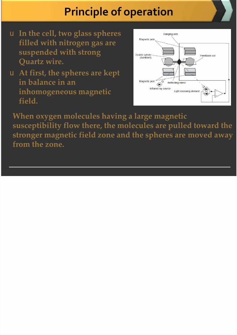
Principle of operation
u In the cell, two glass spheres
filled with nitrogen gas aresuspended with strongQuartz wire.
u At first, the spheres are kept
in balance in aninhomogeneous magneticfield.
When oxygen molecules having a large magnetic
susceptibility flow there, the molecules are pulled toward thestronger magnetic field zone and the spheres are moved awayfrom the zone.
Principle of operation

7/25/2019 Instrumentation for Mechanics of Breathing
http://slidepdf.com/reader/full/instrumentation-for-mechanics-of-breathing 50/59
Principle of operation
u Resulting deviation of the
spheres is detected with thelight source, reflecting mirrorand light receiving element, anda current is passed through the
feedback loop to control so thatthe spheres can return to theinitial balanced state.
u The current flowing through the
feedback loop is proportional tooxygen concentration.
u Thus, oxygen concentration isconverted into an electric signal.
Paramagnetic O2 Analyzer

7/25/2019 Instrumentation for Mechanics of Breathing
http://slidepdf.com/reader/full/instrumentation-for-mechanics-of-breathing 51/59
Paramagnetic O2 Analyzer
Polarographic Oxygen Analyzer

7/25/2019 Instrumentation for Mechanics of Breathing
http://slidepdf.com/reader/full/instrumentation-for-mechanics-of-breathing 52/59
Polarographic Oxygen Analyzer
u Used to measure partial pressure or percentage of
O2 inn Injected samples (or) continuous streams (or) static gas
monitoring
u Most used in respiratory and metabolic labs
u Principle:n Redox reactions in a cell with 2 noble electrodes
n When potential is applied, O2 is reduced at cathode inpresence of KCl as electrolyte
n Current will flown Cathode is covered with O2 permeable membrane
n Rate at which O2 reaches cathode is controlled bydiffusion through membrane
Polarogram

7/25/2019 Instrumentation for Mechanics of Breathing
http://slidepdf.com/reader/full/instrumentation-for-mechanics-of-breathing 53/59
Polarogram
u Voltage – current curve
u Diffusion coefficient changes with temperature
Diffusionrate limited
Proportional topO2 at giventemperature
u Temperature
coefficient –
2-4% / °C

7/25/2019 Instrumentation for Mechanics of Breathing
http://slidepdf.com/reader/full/instrumentation-for-mechanics-of-breathing 54/59
u Uses
u Portable gasdetectors
n Simplicity, low-costand light-weight
u Commercial gas
analyzersn Gold cathode
n Silver anode
n KCl electrolyte gel
n Thin membrane
u Electrical potential –750 mV
Thermal Conductivity Analyzers

7/25/2019 Instrumentation for Mechanics of Breathing
http://slidepdf.com/reader/full/instrumentation-for-mechanics-of-breathing 55/59
Thermal Conductivity Analyzers
u Thermal conductivity of
gas is defined as:n Quantity of heat (in
calories) transferred in unittime (sec) to gas between
two surfaces (1 cm2 in area)and 1 cm apart, whentemperature differencebetween two surfaces is 1°C
Principle of operation

7/25/2019 Instrumentation for Mechanics of Breathing
http://slidepdf.com/reader/full/instrumentation-for-mechanics-of-breathing 56/59
Principle of operation
u The gas analyzer sensor uses four matched filaments that
change resistance according to the thermal conductivity ofthe gas passing over it.
u These four filaments are connected in a Wheatstone Bridgeconfiguration.
u When all four resistances are the same, VOUT is zero and the bridge is considered balanced. When zeroing, the referencegas is passed over all the filaments, the resistances will bethe same (because filaments are matched) and the bridge is
balanced.
u When the sample gas is passed over half of the bridge, thenVOUT’s value correlates to the content of the sample gas inthe reference.
Principle of operation

7/25/2019 Instrumentation for Mechanics of Breathing
http://slidepdf.com/reader/full/instrumentation-for-mechanics-of-breathing 57/59
Principle of operation..
u The four elements are electronically connected in
a bridge circuit and a constant current is passedthrough the bridge to heat the elements.
u If each element is surrounded by the same
gas, then the temperature and hence theresistance of each element will be similar and the bridge circuit will be balanced.
Principle of operation

7/25/2019 Instrumentation for Mechanics of Breathing
http://slidepdf.com/reader/full/instrumentation-for-mechanics-of-breathing 58/59
Principle of operation…
u When the gas to be measured is introduced into
the sample gas stream, the two resistiveelements in this gas stream will be cooled to agreater extent than the two elements in thereference gas.
u The bridge circuit will beunbalanced, producing a signal voltage relatedto the measure gas content of the sample gas.
This relationship is non-linear.u As a result, the analyzer is calibrated at
zero, mid-span, and high span and the softwaremathematically linearises the curve.
N2 analyzer based on ionization technique

7/25/2019 Instrumentation for Mechanics of Breathing
http://slidepdf.com/reader/full/instrumentation-for-mechanics-of-breathing 59/59
N2 analyzer based on ionization technique
u Gas sample is ionized, selectively filtered, and
detected with a photocellu Presence of N2 is detected by presence of purple
color by spectrophotometer, when discharge takesplace in low pressure chamber
u Sampling head
u Ionizingchamber, filter, detector
u Discharge tube
u Power supply, amplifierand filter


