
4LZ-2.0D Combine Harvester
Instruction Manual
(Please read this manual carefully before operating)
AGCO DAFENG (YANZHOU) AGRICULTURAL MACHINERY CO.,LTD.
ADD: No.1 Dafeng Road Yanzhou City Shandong Province, China
Tel/Fax: 0086-537-3834406

PREFACE
This user guide book introduce safety points, specification basic structure, operation rules,
maintenance, lubrication and other related notes of 4LZ-2.0D combine harvester systematically.
Please read it carefully and understand the basic principle of the machine before operation it.
Must protect this book carefully for it's undividable part of the machine, it play a import role in
operating and maintaining the machine correctly and safely.
Any operator of the machine must learn this book and be familiar of its character and operation
rules, grasp the maintenance skill, It is prohibited to deform the machine by users to avoid
anything that is harmful to the machine or people.
To improve the quality, function, and safety, some parts may be changed, and we will not give
another notice. So please pay attention to the contents, pictures, illustrations and other related
things, which may be not the same as the products.

Points for Safety
I. Safety Operation
1. Only the driver has been trained in operation of the combined harvester and holds the valid
driving license issued by the agricultural machinery supervision institute can operate the
harvester.
2. When starting the combined harvester, nobody is allowed to stand 3 meters far from the front
cutting table and the sides of the machine. It is strictly prohibited to stretch hands out into
dangerous places such as the cutter, reel and straw discharge port so as to prevent injury.
3. It is strictly prohibited to enter into the grain case when the machine is running. If blockage
happens, it is strictly prohibited to dig by hands before the engine is dead so as to prevent
accident.
4. When repairing the machine and lifting the cutting table, it should take out the lock cover for
blue oil cylinder locked on the beam of the cutting table to lock the oil cylinder (mount lock pin
and cotter pin) to avoid accidentally falling of the cutting table.
5. The extinguisher is the first-choice protection tool of the operator. When the harvester is in
operation, it should carry the extinguisher which is placed in front of the cover of the engine (the
large grain case is in front of the grain case).
The application way of the extinguisher is: 1. Pull out the security lock; 2. Press down the handle.
When above 1 and 2 items are finished, aim the spray port at where extinguishing is needed, gas
in the cylinder can be sprayed to wipe out the fire.
The extinguisher should be refilled if it is opened or the pointer is lower than the green area.
The working pressure of the extinguisher (20℃): 1.2 Mpa.
The extinguishing agent: ammonium phosphate salt.
6. It should close the safety cover before starting the engine, and it is strictly prohibited to open
or take away the safety cover after the engine is started.
7. Before starting the engine, check the speed shift lever to see if it is at the neutral position, if the
work clutch and grain-discharge clutch are at off position, otherwise it is strictly prohibited to
start.
8. Look around the machine and only after confirming that everything roundabout is safe can the
engine be started.
9. When the machine is running, nobody is allowed to stand against the straw discharge port so
as to prevent injury hurt by splashing objects.
10. When transferring on the field nobody is allowed to ride except the driver.
11. If the water tank is overheated and water is boiled, it is strictly prohibited to open the cover of
the water tank, which can only be opened by wrapping it with wet rag and turning it slowly when
nobody is roundabout after it is cooled.
12. When the combined harvester is loaded on or unloaded from the truck, the one end of the
gangboard should be fastened with the side board of the platform of the truck, the other end
should be placed on the ground with the included angle between the gangboard and the ground
no larger than 30% (<16°41'=. Each piece of the gangboard should have a width 50 mm larger
than that of the track and enough strength and aims right against the track. When loading or
unloading only the driver should stay on the harvester to run forward with low speed and small
accelerator under the instruction of others. No direction turning is allowed on the gangboard.
13. The machine cannot run on the road with inclining angle between the left side and the right
side over 8°so as to avoid turnover.
14. When making welding, all straw bits and oily dirt around the welded part should be wiped
out so as to prevent catching fire.
15. It is strictly prohibited to remove trouble before the engine is dead, and to open the top cover
of the roller when the engine is not dead and still running.
16. In case the roller is blocked, stop the engine immediately and open the top cover of the roller,
it is not allowed to turn the teeth bar of the roller or to pull the belt of the roller by hands to make
repair. When turning the roller, it should use the special tool for turning threshing mechanism
directly connected behind the harvester, insert two teeth of the special tool into two holes of the
spoke of the belt pulley of the roller and turn the handle slowly.
17. In case more than two persons make repair or adjustment, they should be harmonized. If
turning the part of the machine, it should notify the other person.
18. Driver who is drunk, less slept or ill, pregnant women and minor are not allowed to operate
the machine.
II. Marks of Safety
In order to use the machine safely and avoid human injury accident, customer is pleased to
carefully understand various kinds of safety marks posted on the machine and practically
observe stipulations. Safety marks should be clean without damage and renew then if damaged.
The new safety marks can be bought from the distributors or ask for from the company by mail.
Description of Various Kinds of Marks
Description on Concerned Safety Logos and Posted Location:

1)Cutting table 2) Driving station
3) Water tank 4) Protection cover 5) Threshing roller cover
6) Bran outlet 7)Grass outlet 8) Surface of the auger 9) Grain tank

Chapter 1 General Description
Name of Product: Model 4LZ-2.0D Track Self-Walking Full-Feed Combined Harvester
The machine is a new rice/wheat dual-purpose combined harvester, compared with the former
generation product of the company it has advantages of high efficiency, low ground pressure and
good reliability, and can fulfil jobs of cutting, conveying, threshing, separating, cleaning and
grain discharging of rice and wheat (barley) in water field with soil depth of 25 cm and dry field,
and obtain grains directly. All straw and husk are spread on the field.
The machine has a series of patent technique with obvious characteristics as follows:
1. Continuously Variable Transmission, one-handle control, hydraulic steering make operation
easy and convenient.
2. Wide track and high ground clearance is much suitable for work on paddy field.
3. Hanging support wheels, dual pipe supported guide wheel and wearable driving wheel are
three high reliable lines of defense from mud.
4. The super high lifting height of cutting table is convenient for down slope and ridge cross.
5. The super wide conveying groove make conveying smooth with little noise.
6. Dual threshing case with broad diameter, vibrating screen with screen plates adjustable and
lifting/conveying re-threshing auger guarantee the small loss and high cleanness.
7. Large volume grain tank make grain collecting operation easy and convenient.
8. New model of driving platform, open-type engine cover make cleaning and repair much easier.
In a word, this machine with unique structure, beautiful outlook, easy operation, reliability and
safety, high rate of crossing paddy field, energy saving and high efficiency and stable
characteristic is the most ideal harvest machine fort the area of paddy and wheat, especially for
the paddy field.
Chapter 2 Main Technical Specifications
Section 1 Model of Product
1. Model :4LZ-2.0D
2. Product Name: 4LZ-2.0D Track Self-Walking Full-Feed Combine Harvester
Section 2 Main Technical specifications
The technical specifications of the machine are in accordance with following standards:
GB/T8097-1996 <Harvest Machines Combined Harvester Test Methods>,
GB10395.7-1999<Agriculture and Forest Tractor and Machinery Lawn and Horticulture Power
Motive Machinery Safety Mark and Danger Logos General Rules>, JB5117-1991 <General
Technical Conditions of Combined Harvester of Grain.
1. Main Specification Indices

In case of the maximum continuous feed volume, no grass on the cutting line and crops being
upright, the ratio of grain/straw of wheat is 0.6~1.2, moisture rate of grain is 12%~20%; the
ratio of grain/straw of rice is 1.0~2.4, while, moisture rate of grain is 15%~28%. The operation
feature can reach following main indices:
Item Indices (%)
Rice Wheat Cole
Total Loss Rate ≤3.0 ≤1.2 ≤8
Impurity Rate ≤2.0 ≤2.0 ≤6
Breakage Rate ≤1.5 ≤1.0 ≤0.5
Efficiency of Reliability ≥93%

2. Technical Specifications
S/N Item Unit Size
1 Structure Style / Track Self-Walking Full-Feed
2 Applicability For Crop
(Physical Height) mm
Paddy, wheat:
500-1200 Cole:601-700
3 Power Motive kw/rpm 55/2400
4 Productivity of Pure Working
Hour hm
2/h Paddy,wheat:0.2-0.47 Cole:0.1-0.3
5 Fuel Oil Consumption per Hectare kg/hm2 ≤38 ≤30
6 Outline Sizes in Working State
(L×W×H) mm 4750×2350×2360
Cole
5020×2450×2300
7 Structural Weight kg Paddy, wheat:2350 Cole: 2450
8 Cutting Width mm 2000
9 Feed Volume kg/s Paddy, wheat:2.0 Cole: 1.5
10 Minimum Gap of Off-Ground mm 240
11 Style of Swerve / Hydraulic Style
12 Shift Modality /
Automatic Mechanical Transmission +HST
Hydraulic Continuously Variable
Transmission
13 Speed of Operation Forward m/s 0~2.88, 0~4.54, 0~7.56
14 Stroke of Cutter mm II type
15 Auger Style of Cutting Table / Spiral Conveying
16 Outer Diameter of Auger of
Cutting mm Φ470
17 Style of Reel / Eccentric Style
18 Diameter of Reel mm Φ900
19 No. of Plates of Reel PCS 5
20 Conveyor Belt Style / Rake-Teeth Style
21 Threshing Roller Style / Tangential flow + Axial flow
22 Size of Threshing
Roller(O.D. ×L)
Front Roller mm Φ540×650
Rear Roller mm Φ540×1285
23 Concave Style / Grid Screen×2
24 Angle Range of Concave (°) 227°
25 Fan Style / Centrifugal
26 Diameter of Fan mm Φ328
27 Diameter of Grain Discharge
auger mm Φ123
28 Crew Distance of Grain Discharge
auger mm 105
29 Re-Threshed Style / Back to Threshing Roller directly
30 Grain Receiving Style / Manual/Hydraulic
31 Clearance between Argue of
Cutting mm 15-18
32 Track mm 400(or 450) ×90×48
Note: This machine need cole spare when harvest cole.

Chapter 3 Construction and Working Course of the Combined
Harvester
The combined harvester consists of three major parts: cutting and conveying part, threshing part
and walking part. The cutting and conveying part locates at the far front and consists of cutting
table and conveying groove; the threshing part locates at the rear side, consist of threshing and
separating device, auger grain discharge device and grain case; the walking part locates at the
lower part of the machine, consists of frame, engine, gearbox and wheels and track. In addition
there are hydraulic system, electric system and Operation system etc.
1. Lifting Auger 2. Grain Collecting Box 3. Rear Threshing Roller 4. Front Threshing Roller
5. Operation System 6. Electric System 7. Conveying Groove 8. Telescopic teeth 9. Spiral
conveyor for cutting table 10. Stand Cutter 11. Auxiliary plate 12.Reciprocal cutter 13.
Spreading box 14. Dividers 15.Reel 16.Cutter table 17. Track 18. Bear Weight Wheel
19.Lifting Auger 20. Footplate 21.Frame back 22. Footplate
Figure 1 Construction View of 4LZ-2.0D Rice/Wheat Combined Harvester
Shown as Figure 1, when the machine is in operation, the dividers (14) on both sides of the
cutting table can divide non-cutting crop from the crop to be cut, which is cut by the reciprocal
cutter (12) on the cutting table with the support of the reel (15). The ear part is pushed by the
spiral conveyor for cutting table (9) and the auxiliary plate (11) to the left side of the cutting table
and putting back by the telescopic teeth (8)and grasped by the scraper at the conveying groove(7)
and sent to the threshing roller.

1. Reciprocal Vibration Screen 2. Re-Threshed System 3. Residues Rising/Conveying Auger
4. Grain Rising/Conveying Auger 5. Rear Threshing Roller Top Cover 6. Rear Threshing
Roller 7.Rear Concave Screen 8.Fan 9. Grain Collecting Case 10. Front Threshing Roller
11.Front Threshing Roller Top Cover 12. Front Concave Screen 13. Threshing Frame
Figure 2 Threshing System of 4LZ-2.0D Rice/Wheat Combined Harvester
Shown as Figure 2, the crop is axially and spirally moved under the front threshing rollers (10)
and rear threshing roller(6), front concave screen (12) and rear concave screen(7), and front
threshing roller top cover (11) and rear threshing roller(6). During the course grains drop down
and straw is deformed. Grains are separated from some husk and short straw through the
concave under the role of the centrifugal force. Light impurities are blown off the machine by
blowing of the fail (8) as well as the role of the reciprocal vibration screen (1) while grains drop
into horizontal auger and the broken fringe drop into horizontal auger. Grains in horizontal
auger is send to the gain collecting case (9) by the lifting auger (4) while grains in horizontal
auger is re-threshed by the re-threshed roller, sent by rising/conveying auger (3) to be re-threshed
again by the rear roller. Straw and leaves that do not passed through the concave are discharged
out from the discharge port at the rear side.
Chapter 4 Application of the Combined Harvester
Section 1 Rules of Operation
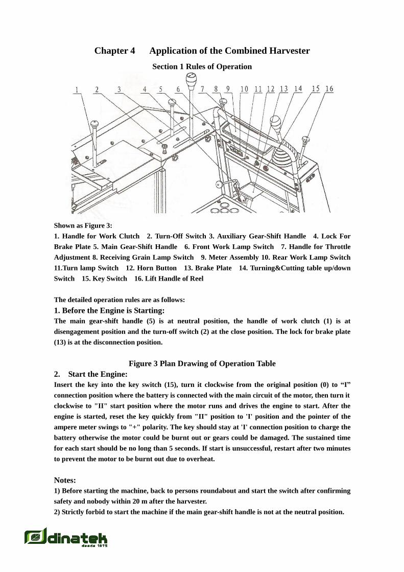
Shown as Figure 3:
1. Handle for Work Clutch 2. Turn-Off Switch 3. Auxiliary Gear-Shift Handle 4. Lock For
Brake Plate 5. Main Gear-Shift Handle 6. Front Work Lamp Switch 7. Handle for Throttle
Adjustment 8. Receiving Grain Lamp Switch 9. Meter Assembly 10. Rear Work Lamp Switch
11.Turn lamp Switch 12. Horn Button 13. Brake Plate 14. Turning&Cutting table up/down
Switch 15. Key Switch 16. Lift Handle of Reel
The detailed operation rules are as follows:
1. Before the Engine is Starting:
The main gear-shift handle (5) is at neutral position, the handle of work clutch (1) is at
disengagement position and the turn-off switch (2) at the close position. The lock for brake plate
(13) is at the disconnection position.
Figure 3 Plan Drawing of Operation Table
2. Start the Engine:
Insert the key into the key switch (15), turn it clockwise from the original position (0) to “I”
connection position where the battery is connected with the main circuit of the motor, then turn it
clockwise to "II" start position where the motor runs and drives the engine to start. After the
engine is started, reset the key quickly from "II" position to 'I' position and the pointer of the
ampere meter swings to "+" polarity. The key should stay at 'I' connection position to charge the
battery otherwise the motor could be burnt out or gears could be damaged. The sustained time
for each start should be no long than 5 seconds. If start is unsuccessful, restart after two minutes
to prevent the motor to be burnt out due to overheat.
Notes:
1) Before starting the machine, back to persons roundabout and start the switch after confirming
safety and nobody within 20 m after the harvester.
2) Strictly forbid to start the machine if the main gear-shift handle is not at the neutral position.
3. Start Walking:
Choose the Auxiliary Gear-Shift gear when the speed of the diesel engine rises up over 1800 rpm.
On the fiat ground, disconnect the brake plate lock, push forward the main gear-shift handle
slowly, the machine runs forward. More push forward, faster the machine runs forward. If
running backward is needed, pull the main gear-shift handle to the neutral position to stop
running of the machine, then press the button on the hydraulic operation handle by the thumb
and pull it back. More pull backward, faster the machine runs backward.
On the slope, trample the brake plate, disconnect the brake plate lock, push forward the main
gear-shift handle slowly, at the same set free the brake plate, the machine runs forward. One the
contrary, pull backward the main gear-shift handle at the same time set free brake plate slowly,
the machine runs backward.
Notes:
1) It is strictly prohibited to run on the field at high speed (high speed is used when walking on
plain highway) otherwise overload can badly affect the service life of the infinitive variable
gearbox.
2) For infinitive variable gear style, it is strictly prohibited to press the button on the hydraulic
operation handle and directly pull it back quickly when running at high speed so as to avoid
damage of input or output shafts of the infinitive variable gearbox.
4. Passing Through the Ridge and Ditch:
It should pass through ridge and ditch vertically. In case passing through ridge and ditch
diagonally be included angle should be larger than 70~ so as to avoid turnover of the machine or
drop of the track. It should pass ridge with large accelerator and low speed which is quite
different with the mechanical gear-shift style otherwise it cannot pass through the ridge due to
small accelerator and less power. When the gravity center of the machine moves on the ridge, it
should pull the main gear-shift handle to the neutral position (stepping the walking clutch for the
mechanical gear-shift style) to make the front half of the machine drop down by its inertia can it
continuously run, For the ridge higher than 15 cm, it should be spaded out or be padded into a
slope.
5. Turning:
When turning to left, pull the left-turning handle to disengage the left jaw. If sudden turn is
needed, continue to pull the left-turning handle to completely disengage the jaw and to press
tightly the friction disc to make one-sided brake. The size of the turning radius can be changed
by the size of pulling force. When turning to right, pull the right-turning handle.
Notes:
1) When turning or reversing look if somebody is roundabout so as to make safe operation. It is
strictly prohibited to turn at high speed.
2) Normally do not make the turning jaw disengage or engage frequently so as to reduce times of
impact, and to avoid early worn-out of the turning jaw.
6. Protect the Track
The normal service life of the rubber track is about 800-1000 hours. It should not run at high
speed on uneven road or on the field. It should be loaded on the truck if transfer distance is
longer than 4km so as to prevent early worn-out of the track. Do not run on. the road with sharp
objects to avoid scratch of the track, water penetrating and rust of steel wire of the track, early
discard of the track. Do not turn on the concave road to avoid drop of the track.
The three guarantees period is for 6 months.
7. Stop on the Slope:
Trample the brake plate (13) with the left foot, the concave groove of the brake plate lock (4)
fastened brake plate (13). (then both left and right jaws are disengaged and the brake is braked).
If continuing to run forward, please operate as the above No.3 terms content.
8. Lift Up/Down the Cutting Table:
Pull the lift handle of the cutting table (14) backward, the cutting table is rising up; push it
forward the cutting table is lowered down.
9. Lift Up/Down the Reel
Pull the lift handle of the reel (16) backward, the reel is rising up; push it forward the reel is
lowered down.
10. Reasonably Select Work Speed:
When working on wet and soft field or dry field with yield of crop over 500kg per mu, it should
take Stow I speed to work, or Fast II speed if yield of crop below 500kg per mu. When work in
mud field or when crop is lodged, it should take Slow I speed to work.
Note: High gear speeds (High HI) are strictly prohibited to use for working.
11. Some Point Specially Mentioned:
a. The combined harvester is not allowed to work continuously for over 10 hours. Normally it
should stop for 2 hours if work for 8-10 hours otherwise the oil seal shall be aged early, the
hydraulic oil shall be thinned or deteriorated or the tallow shall be melted due to high
temperature.
b. The machine can not harvest when crops is not mature enough and has dew in the morning
or at night.
c. When working the driver should concentrate his attention to hear carefully running of all
parts. If blockage is found it should be removed in time. If the engine emits black smoke under
overload, it should temporarily stop running and continue to cut until the load of threshing
becomes normal.
d. As threshing and separating consume much energy it should ensure the engine to have
enough cooling water. The impurities on the outer cover of the radiator of the engine should be
cleared out every two working hours. If the engine smokes many times, it should reduce speed to
run forward or suitably reduce the cutting width to cut only by the left side of the cutting table.
e. If abnormal sound from the thresher is heard, stop the machine in time to check if internal
parts are damaged. If so, never apply the power to make the thresher running because it can
cause major accident due to the speed of the roller of the thresher is as high as over 800 rpm.
f. When the work is finished, push all grains out from the grain discharge auger the disengage
the work clutch, shift the gear to the neutral position, close the accelerator gradually to mm off
the engine and open the switch blade of power supply.

g. When working, only one driver is allowed on the machine (one added grain receiver for the
small grain case style) and extra person is not allowed.
h. When the combined harvester transfers on the fields, the work clutch should be disengaged.
Section 2 Adjustment Before Cutting
Before making harvest of crop in fields, it should make adjustment on the harvester before
cutting.
I. Adjustment of the Cutting Height of the Cutting Table
1. Adjustment for cutting height
The cutting height of the cutting table is according as local custom. In principle, when the ear
part of cut crop has a length of 45cm-55cm under the horizontal cutting table, the synthetic result
is the best. When natural height of the crop is below 50 cm (over the use rang), we must control
the stubble below 7cm, otherwise the feeding entrance would be jammed as the cutted crop was
too short.
Figure 4 The mobile blade location adjustment for Cutter
2. Adjustment for cutting clearance
It is best that the front of the cutting clearance should be 0-0.5 mm, the rear of the cutting
clearance should be 0.5 mm-1.3mm. It is possible that the cutter can not partition the crop or
increase the cutting pressure when the front clearance of the cutter more than 1mm, so it must
readjust. Please turn over the friction disk or put one piece of flake under of the friction disk
when do the adjustment.
3. The adjustment for the mobile blade location
When leaving the factory, the mobile blade location is suitable. It maybe readjust the mobile
blade location when replace the mobile blade (2) or long pitman. The sickle uses knife
theoretically the route or distance of travel responds to between protecting two point of edge
implement (1), the bit centre being that the crank uses knife during the period of upper the dead
center going ahead responds to and the point protecting edge implement (1) right is straight face
to face, the crank bit using knife time the dead center going ahead in time centre should move the
point arriving at and protecting the edge implement (1) left to being straight.
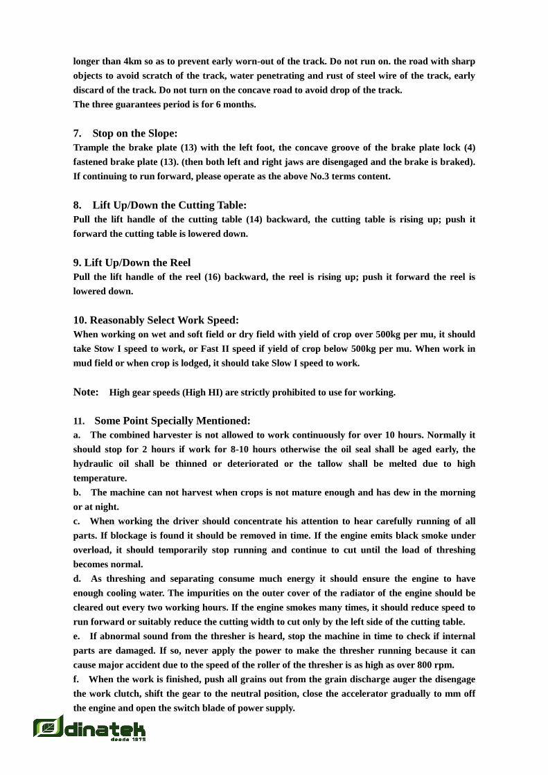
II. Adjustment of the reel, see Figure 5
Figure 5 Adjustment for reel
1. Adjust the Height of the Reel
For upright crop, turn the reel (5) to the lowest position just aiming the two thirds of the height of
crop cut by the cutter of the horizontal cutting table; for lodged crop, when turning the reel
finger to the lowest position, it shall just pass through above the cutter of the horizontal cutting
table. Pull or push the lift handle of the reel to the required position and release it, the hydraulic
valve can keep pressure locked automatically.
2. Adjust the Front or Rear Position of the Reel
Move the connection holes of the eccentric adjustment fixing seat and the suspension beam (2) on
both sides of the reel, the front or rear position of the reel can be adjusted. Usually, the reel
location is in the middle of the hole; for high straw or lodged, the reel should be put forward;
when harvest the crops under 60cm, the reel should be put backward.
3. Adjustment of Inclining Angle of the Reel Finger
When harvesting upright or slight lodged crop, the reel fingers (5) are normally downward so as
to reduce knock on ears by the reel finger. For thicker crop to add laying function, the reel
fingers can be tilting upward. When harvesting loose or lodged drop, the reel fingers can be tilted
backward to add the function to support crop.
When adjustment, loosen the connection nut of the eccentric adjustment plate (3) and the
eccentric plate to adjust suitable tilting angle of the reel finger. After adjustment tighten the bolt.
When adjusting the reel, take care that the reel finger cannot touch the cutting table and the
spiral conveyor of the cutting table.
Note: When leaving the factory, the mounting position of the reel is suitable for crop with height
of 70-90 cm. In case crop is dense and yield is high, after adjustment of front or rear position of
the reel, V-shaped driving belt should be readjusted and the tension wheel should be tensioned.
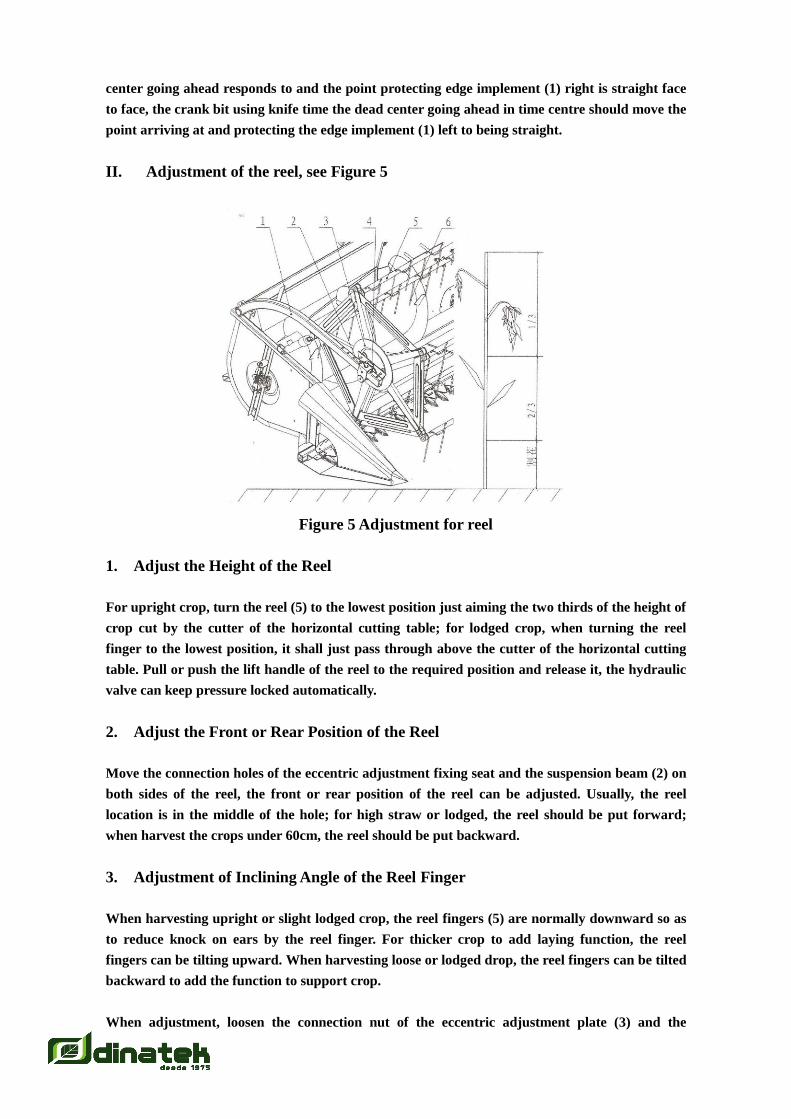
III. Adjustment of the Spiral Conveyor of the Cutting Table, see Figure 6
Figure 6 Adjustment of the Spiral Conveyor of the Cutting Table
The spiral conveyor of the cutting table has been adjusted when leaving tile factory. When the
extension lever turns to the side of the feed port of the conveyor groove, it should be retracted to
the shortest length; when turning to the side of the base plate of the cutting table it should have
a gap larger than 5 mm with the base plate. When adjustment is needed, first loosen the nut(3) on
the left support seat of the spiral conveyor move the eccentric axle adjustment block(4)to reach
the requirement then lock the nut (see Figure 6).
Before operation, check the extension lever if it can be moved freely in the nylon fixing seat, it
bolt of the fixing seat is locked and if limit screw and nut are adjusted well and locked.
IV. Adjustment of the Chain of the Conveyor Groove, see Figure 7

Figure 7 Adjustment of the Chain
After using for a period of time, the pin roils of the chain in the conveyor groove are worn out
and the chain is lengthened, when the chains are different length it should adjust the tension
support rod.
Note: When adjusting, two chains should be even and identical. After tension, the conveyor
plate (1) can not be over the plate (2) of cutting table.
V. Adjustment of the concave plate gap, see Figure 8
Figure 8 Adjustment of the concave plate gap
The machine adopts double-row toothed bar axial flow roller. Six toothed bars are symmetrically
mounted on the front and rear roller and threshing teeth are spirally arranged with 10~
backward titling angle to prevent straw to be hung up.
In order to control the gap of the finger gear and concave plate screen, the connecting plate of the
gear rod and roller plate are also designed two inner and outer holes. It fixed inner hole (2) when
the machine is leaving from the factory. It fixed outer hole (1) when the finger gear is heavily
broken-or need reduce the gap.
Note: 1 .It is prohibit to reduce the quantity of the gear rod of front and rear threshing roller.

2. After remove the gear rod, it must tighten the screws and check the balance,
otherwise it may occur some trouble.
VI. Adjustment for Convulsionary Screen, See figure 9
1.Convulsionary Screen front rubber 2.Sacking 3. Front sliding plate 4. Auger case body 5.
Grain selection Plate 6. Auger case body 7. Bolt 8. Screen Adjustment block 9. Gasket
Figure 9 Adjustment for Convulsionary Screen
This machine use tunable volume reciprocate convulsionary screen.
1. The volume adjustment of screen for Convulsionary screen
It is necessary to adjust the volume of screen when the screen surface loss too much, the auger
bear too much and too much sundries in the haversack.
1) The screen is steep (the volume is big), the loss is little but the sundries is too much, the
burthen of auger is big and fray quickly for the under convulsionary screen.
2) The screen is flat (the volume is small), the loss is large but the sundries is little, the burthen
of auger is small and fray slowly for the under convulsionary screen.
The screen volume is located at the standard place namely the right over of lock nut is aim at the
No.2 gear. (Please check with figure 9).
In actual harvesting, we may want to turn up the screen volume when we found the loss is too
much. Please at first, open the rear diversion cover, triggering the screen adjustment arm in
order to the lock nut can aim at the No. 1 gear. Contrarily, we want to turn down the screen
volume when we found the sundries is too much, triggering the screen adjustment arm in order
to the lock nut can aim at the No.3 gear. Anyway, the customer can choose different screen
volume as the above roles when he got the actual harvesting result.
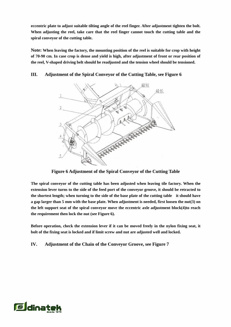
2. The way for pulling Vibration Screen
When the vibration screen has some trouble, we must pull the vibration screen out of the
machine. Please refer the following process:
1) Open the rear diversion cover
2) Loosen 2 pcs M10 bolt of the bearing seat for two side of rear axle of the vibration screen.
3) Drive up the rear of vibration screen, pull out the vibration screen by two persons.
Figure 10
3. Method of installation for vibration screen (See figure 9)
1) Rise up the vibration screen as far as possible and push it forward slowly, lock bolts.
2) Place the grain selection plate flexibly by the casing of auger
3) Place sacking well in front of and at the side of the screen.
4) Check: turn the cleaning sprocket by hand the cleaning chamber can be shaken slightly.
5) Mount items in reverse order by which they are dismounted.
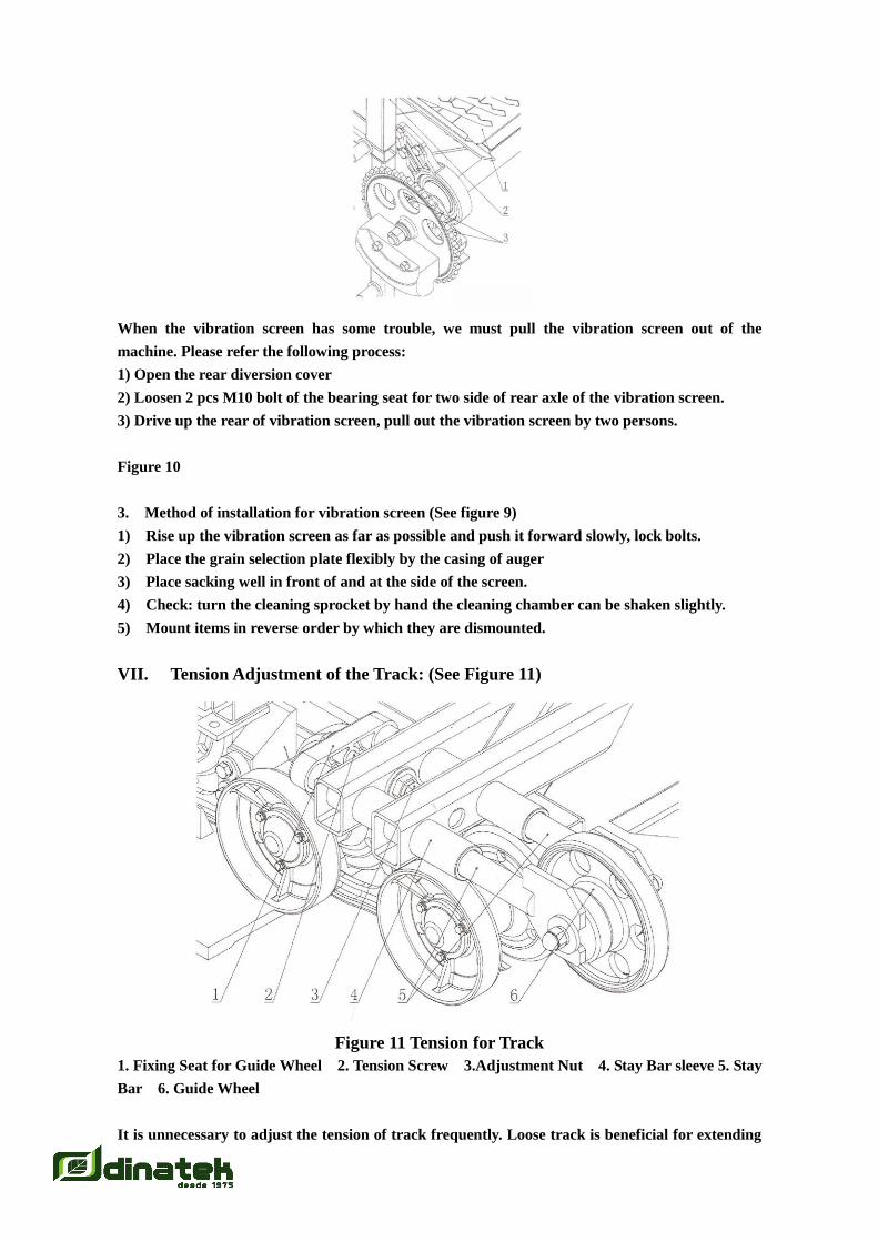
VII. Tension Adjustment of the Track: (See Figure 11)
Figure 11 Tension for Track
1. Fixing Seat for Guide Wheel 2. Tension Screw 3.Adjustment Nut 4. Stay Bar sleeve 5. Stay
Bar 6. Guide Wheel
It is unnecessary to adjust the tension of track frequently. Loose track is beneficial for extending
the track use span except the track is not digression. Tighten the adjustment nut when the track
needs tension.
If the track is digression, the reinstall method is: use the jack up digression side frame, loosen the
adjustment nut, push the guide wheel to the bottom, then use the tommy bar to reinstall the
digressed track on the wheel.
If the track reinstalled that it needs re-tension. The method is: use tommy bar pry back the guide
wheel, tighten the adjustment nut to available place.
Notes:
1. The track cannot be too tensioned and it is right only no teeth-jumping occurs.
2. Coat a bit of lubrication oil on the tension screw rod to avoid rust before the machine enters
into the field.
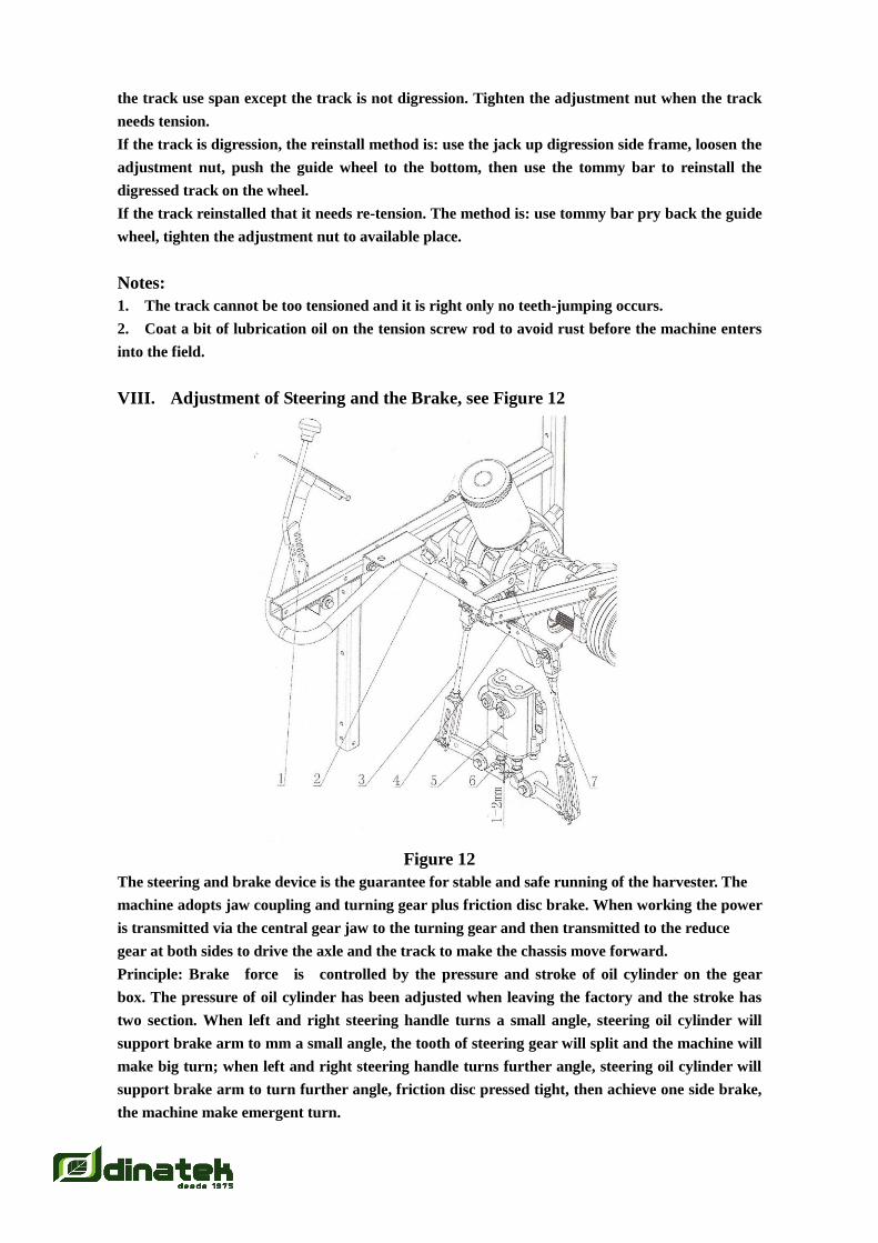
VIII. Adjustment of Steering and the Brake, see Figure 12
Figure 12
The steering and brake device is the guarantee for stable and safe running of the harvester. The
machine adopts jaw coupling and turning gear plus friction disc brake. When working the power
is transmitted via the central gear jaw to the turning gear and then transmitted to the reduce
gear at both sides to drive the axle and the track to make the chassis move forward.
Principle: Brake force is controlled by the pressure and stroke of oil cylinder on the gear
box. The pressure of oil cylinder has been adjusted when leaving the factory and the stroke has
two section. When left and right steering handle turns a small angle, steering oil cylinder will
support brake arm to mm a small angle, the tooth of steering gear will split and the machine will
make big turn; when left and right steering handle turns further angle, steering oil cylinder will
support brake arm to turn further angle, friction disc pressed tight, then achieve one side brake,
the machine make emergent turn.

Adjustment: See Fig. 12, Adjustment of Steering and the Brake is the adjustment of clearance
between Oil Cylinder and Braking Arm. Normally it is 1-2mm. When the friction disc is worn
after using for some time, the oil cylinder needs to be adjusted to be longer, i.e. the clearance
between oil cylinder and braking arm should adjust smaller. When the clearance is zero, if the
steering is still unavailable, should check whether the pressure of steering oil cylinder is sufficient
(Use the method by adding washerΦ5 on hand valve), or consider adding a piece of smooth disc
in the brake or replacing the friction disc.
IX. Emergency Brake, See Fig. 12
If the emergency brake is needed when stopping the machine on the slope or emergency needs, it
can be done by stepping on the brake pedal, which is located at the side of left foot (See Fig3).
When using, step on the brake pedal, use hand to fasten the brake pedal with lock buckle, slowly
move away foot, stop engine.
The braking theory (See Fig t2): When step on the braking pedal, the balance band iron will be
lifted up by the spring, long link fork will drive the left and right brake arm in front of the
gearbox to rotate an angle, and drive the left and right turning forks in the case to twist
simultaneously to reach the goal of braking the machine.
Attention: Before restarting the machine, firstly step on the brake pedal, unfasten the brake
pedal lock buckle, start the engine, push or pull the main gearshift lever, at the same time slowly
release brake pedal (1), the machine will move forward or backward.
X. Adjustment and Maintenance of the Driving System
In the course of application, take care of tightness of the V-shaped belt and the chain. The service
life shall be affected ifit is too tight and the driving efficiency will be affected if it is too loose. The
free flexibility of the loose edge of the chain can be determined by the central distance of two
wheels in the range of 5-10 mm and the flexibility of the V-shaped belt can be determined' by the
central distance of two wheels and by hand pressing with 6 kg in the range of 10-30 mm.
XI. Adjustment and Maintenance of the Hydraulic System (see Figure 13)

Figure 13
1. High Pressure Oil Pipe Φ10×1670
2. High Pressure Oil Pipe Φ16×1300
3. High Pressure Oil Pipe Φ16×180
4. Low Pressure Oil Pipe Φ16×170
5. High Pressure Oil Pipe Φ16×1300
6. High Pressure Oil Pipe Φ8×2500
7. High Pressure Oil Pipe Φ10×500
8. High Pressure Oil Pipe Φ16×155
9. High Pressure Oil Pipe Φ16×800
10. High Pressure Oil Pipe Φ10×1550
11. High Pressure Oil Pipe Φ8×920
12. High Pressure Oil Pipe Φ8×830
A. E310 Gear Pump
B. Hydraulic Oil Tank
C. Infinitive Variable Gear
D. Oil Radiator
E. 8MB1 Slide Valve
F. Oil Cylinder of Reel
G. 8G Slide Valve
H. Oil Cylinder of Cutting Table
I. JZXGB Steering Cylinder

The hydraulic system consists of oil tank, oil pump, combined valve for lifting up/down of the reel
and the cutting table, oil cylinders of the reel and the cutting table, high and low pressure oil
pipes, connectors and combined pad etc. The' overflow pressure of the combined valve for lifting
up/down of the reel and the cutting table has been adjusted when leaving the factory and no
further adjustment is needed. The oil for the system is special hydraulic oil which shall be better
filled to 2/3 of the height, it can be replaced with Mobil 424 or N68 low-condensation
anti-abrasion hydraulic oil, however it should be replaced at all, never replace with normal
hydraulic oil. When replacing hydraulic oil the oil filter should be replaced as well otherwise
troubles caused thereof should be born by customer himself.
Trouble in the hydraulic system normally comes from unclean hydraulic oil. Dismount the system
and clean it then mount it again troubles can be removed (lead seal cannot be moved when
dismounting).
After changing oil the oil tank should discharge air. The way is to loosen two turns of the oil
outlet nut of the hydraulic pump and the oil inlet nut of the lifting up/down oil cylinder of the
cutting table, start the engine to operate the hydraulic pump and tighten nuts until no air bubble
is found in overflow oil from the oil outlet of the hydraulic pump. When tighten nut close the
engine to ensure safety of operation.
XII. Adjustment and Maintenance of the Electric System, see Figure 14
The electric system consists of generator, voltage regulator, start motor, battery, indication
instruments, fuse case, lighting, alarm horn, control switches and connection wires. The system is
grounded with the negative polarity and the rated voltage is 12V. The electric schematic drawing
refers to Figure 14.
Special Attention: the polarities of the system cannot be connected reversely otherwise some
electric components in the circuit may be burnt out.
The wire connections are marked with their colours as per the diagram. When repairing, confirm
the location of connections by colour mark in wiring diagram (see wiring table for colour codes).
In case problem occurs in the electric system, it should make careful analysis as per the schematic
diagram, judge and find the location of trouble and make repair or maintenance.
In case trouble in the circuit occurs, first of all check the central electric control box, namely
check whether red alarm indicator lamp on driving console panel is on or off, if on, check the
corresponding circuit the indicator lamp stands for, after confirming the trouble have solved then
can replace the fuse. Only when the fuse and the battery are normal can other items in the circuit
then be checked, for example if connector is loosened, if terminal is disconnected.
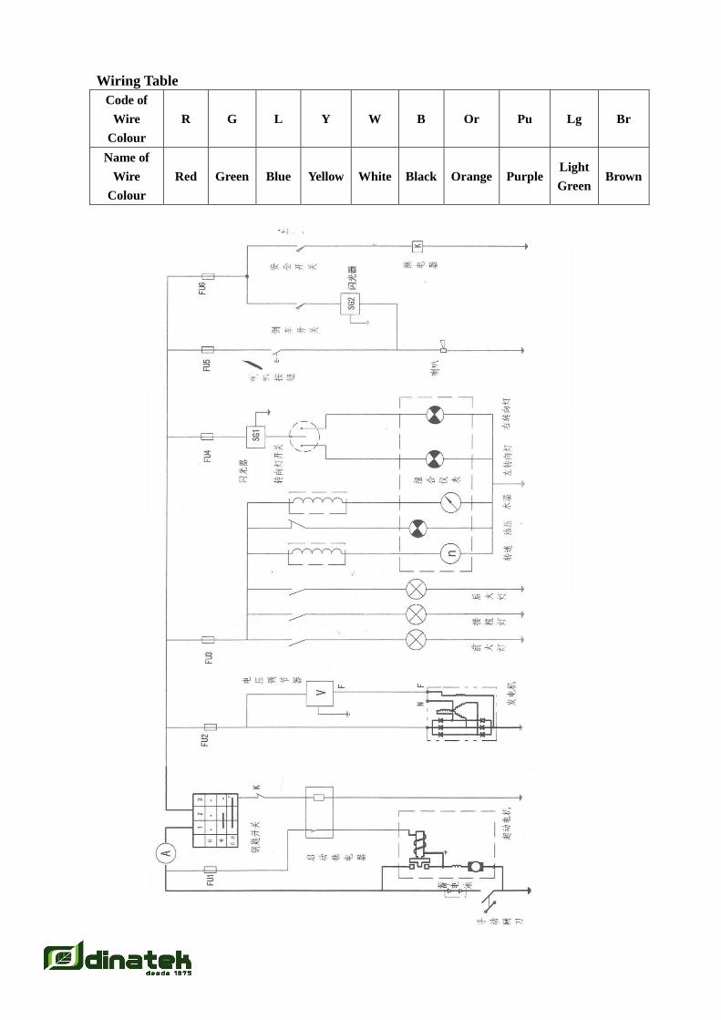
Wiring Table
Code of
Wire
Colour
R G L Y W B Or Pu Lg Br
Name of
Wire
Colour
Red Green Blue Yellow White Black Orange Purple Light
Green Brown
Fuse Arrangement
NO.1: Turning Lamp;
NO.2: Horn;
NO.3: Store;
NO.4: Head Lamp, Tail Lamp and Instrument;
NO.5: Safety Switch
NO.6: Store;
NO.7: Store;
NO.8: Store;
NO.9: Generator;
NO.10: Store;
NO.11: Store;
NO.12: Store
NO.13: Empty
NO.14: Empty
NO.15: General Power Source
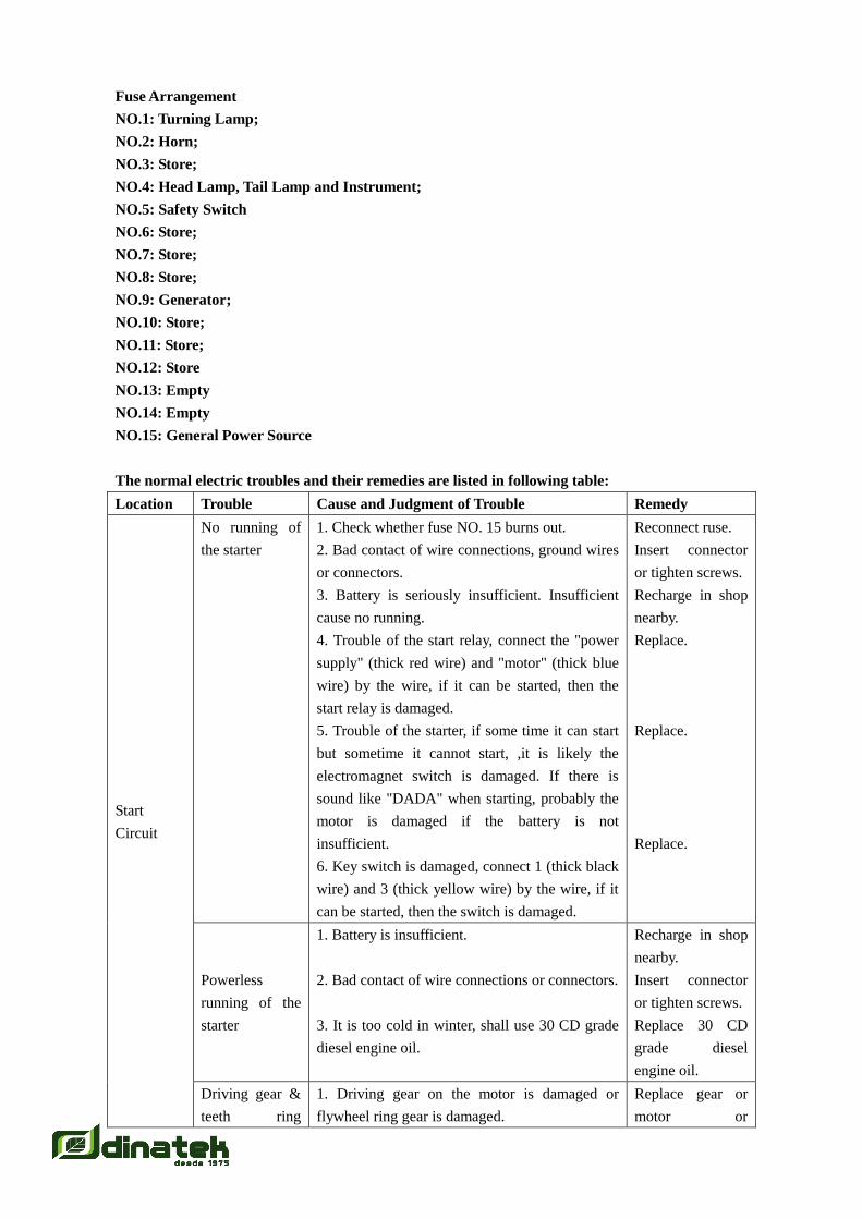
The normal electric troubles and their remedies are listed in following table:
Location Trouble Cause and Judgment of Trouble Remedy
Start
Circuit
No running of
the starter
1. Check whether fuse NO. 15 burns out.
2. Bad contact of wire connections, ground wires
or connectors.
3. Battery is seriously insufficient. Insufficient
cause no running.
4. Trouble of the start relay, connect the "power
supply" (thick red wire) and "motor" (thick blue
wire) by the wire, if it can be started, then the
start relay is damaged.
5. Trouble of the starter, if some time it can start
but sometime it cannot start, ,it is likely the
electromagnet switch is damaged. If there is
sound like "DADA" when starting, probably the
motor is damaged if the battery is not
insufficient.
6. Key switch is damaged, connect 1 (thick black
wire) and 3 (thick yellow wire) by the wire, if it
can be started, then the switch is damaged.
Reconnect ruse.
Insert connector
or tighten screws.
Recharge in shop
nearby.
Replace.
Replace.
Replace.
Powerless
running of the
starter
1. Battery is insufficient.
2. Bad contact of wire connections or connectors.
3. It is too cold in winter, shall use 30 CD grade
diesel engine oil.
Recharge in shop
nearby.
Insert connector
or tighten screws.
Replace 30 CD
grade diesel
engine oil.
Driving gear &
teeth ring
1. Driving gear on the motor is damaged or
flywheel ring gear is damaged.
Replace gear or
motor or
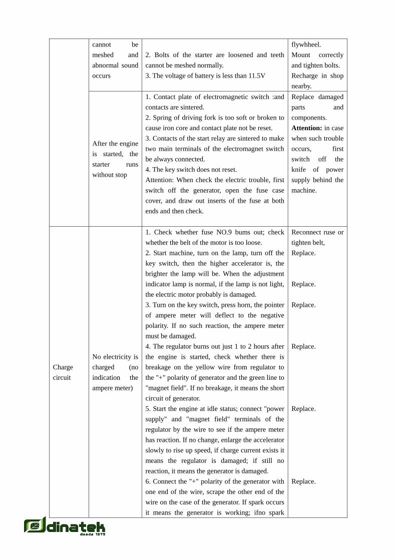
cannot be
meshed and
abnormal sound
occurs
2. Bolts of the starter are loosened and teeth
cannot be meshed normally.
3. The voltage of battery is less than 11.5V
flywhheel.
Mount correctly
and tighten bolts.
Recharge in shop
nearby.
After the engine
is started, the
starter runs
without stop
1. Contact plate of electromagnetic switch :and
contacts are sintered.
2. Spring of driving fork is too soft or broken to
cause iron core and contact plate not be reset.
3. Contacts of the start relay are sintered to make
two main terminals of the electromagnet switch
be always connected.
4. The key switch does not reset.
Attention: When check the electric trouble, first
switch off the generator, open the fuse case
cover, and draw out inserts of the fuse at both
ends and then check.
Replace damaged
parts and
components.
Attention: in case
when such trouble
occurs, first
switch off the
knife of power
supply behind the
machine.
Charge
circuit
No electricity is
charged (no
indication the
ampere meter)
1. Check whether fuse NO.9 bums out; check
whether the belt of the motor is too loose.
2. Start machine, turn on the lamp, turn off the
key switch, then the higher accelerator is, the
brighter the lamp will be. When the adjustment
indicator lamp is normal, if the lamp is not light,
the electric motor probably is damaged.
3. Turn on the key switch, press horn, the pointer
of ampere meter will deflect to the negative
polarity. If no such reaction, the ampere meter
must be damaged.
4. The regulator burns out just 1 to 2 hours after
the engine is started, check whether there is
breakage on the yellow wire from regulator to
the "+" polarity of generator and the green line to
"magnet field". If no breakage, it means the short
circuit of generator.
5. Start the engine at idle status; connect "power
supply" and "magnet field" terminals of the
regulator by the wire to see if the ampere meter
has reaction. If no change, enlarge the accelerator
slowly to rise up speed, if charge current exists it
means the regulator is damaged; if still no
reaction, it means the generator is damaged.
6. Connect the "+" polarity of the generator with
one end of the wire, scrape the other end of the
wire on the case of the generator. If spark occurs
it means the generator is working; ifno spark
Reconnect ruse or
tighten belt,
Replace.
Replace.
Replace.
Replace.
Replace.
Replace.
occurs, it means the generator is damaged.
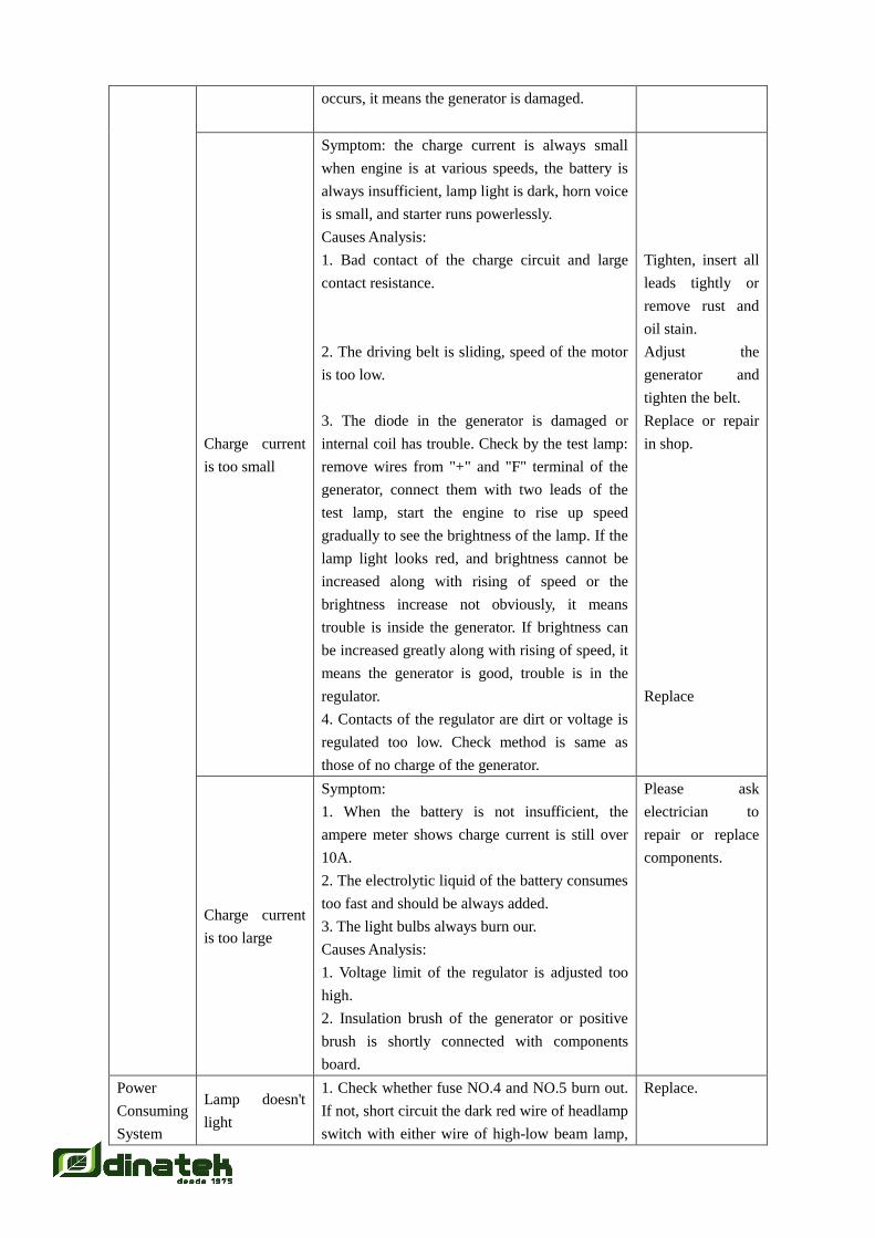
Charge current
is too small
Symptom: the charge current is always small
when engine is at various speeds, the battery is
always insufficient, lamp light is dark, horn voice
is small, and starter runs powerlessly.
Causes Analysis:
1. Bad contact of the charge circuit and large
contact resistance.
2. The driving belt is sliding, speed of the motor
is too low.
3. The diode in the generator is damaged or
internal coil has trouble. Check by the test lamp:
remove wires from "+" and "F" terminal of the
generator, connect them with two leads of the
test lamp, start the engine to rise up speed
gradually to see the brightness of the lamp. If the
lamp light looks red, and brightness cannot be
increased along with rising of speed or the
brightness increase not obviously, it means
trouble is inside the generator. If brightness can
be increased greatly along with rising of speed, it
means the generator is good, trouble is in the
regulator.
4. Contacts of the regulator are dirt or voltage is
regulated too low. Check method is same as
those of no charge of the generator.
Tighten, insert all
leads tightly or
remove rust and
oil stain.
Adjust the
generator and
tighten the belt.
Replace or repair
in shop.
Replace
Charge current
is too large
Symptom:
1. When the battery is not insufficient, the
ampere meter shows charge current is still over
10A.
2. The electrolytic liquid of the battery consumes
too fast and should be always added.
3. The light bulbs always burn our.
Causes Analysis:
1. Voltage limit of the regulator is adjusted too
high.
2. Insulation brush of the generator or positive
brush is shortly connected with components
board.
Please ask
electrician to
repair or replace
components.
Power
Consuming
System
Lamp doesn't
light
1. Check whether fuse NO.4 and NO.5 burn out.
If not, short circuit the dark red wire of headlamp
switch with either wire of high-low beam lamp,
Replace.

if headlamp doesn't light, it means the headlamp
is damaged, if lights, it means the switch is
damaged.
2. Short circuit those two wires of tail lamp, if
not light, it means the tail lamp is damaged, if
lights, it means the switch is damaged.
3. Fuse burns out immediately after turning on
the tail lamp, it means one of the tail lamp is
damaged.
4. Turning lamp can't light, it must be fuse NO.1
burns out or turning lamp is damaged.
Replace.
Replace.
Replace.
Indication
meters don't
work
1. No indication: check whether fuse NU.4 burns
out, if not, switch on the power supply and short
circuiting relative sensor, if meter has indication
it means the sensor is damaged otherwise the
meter is damaged.
2. The indication cannot be reset: switch on
power supply, the meter indicates the maximum
position and when the engine is working, still
cannot be reset, then disconnect the sensor first,
if the pointer of the meter can return to zero, it
means the sensor is shortly circuited, if off the
sensor, the pointer of the meter also cannot return
to zero, it means the meter is damaged.
Replace relative
components.
Replace relative
components.
Horn has no
sound
1. Check whether fuse NO.2 burns out, short
circuit the horn without withdrawing connectors,
if has sound, it means switch is damaged, if no
sound, it means horn is damaged.
2. Short circuit horn button, if has sound, it
means horn button is damaged, if no sound, it
means born button is damaged, if no sound, it
means horn damaged.
Repair or replace.
Replace horn.
Note: in principle the whole set of the electric staring system has no warranty and customer
should correctly operate it and take care of its maintenance.
4 Work on the Field
I. Preparation of Cutting Way, see Figure 15
This combine harvester should enter into the field from the right corner. In order to reduce loss,
an crop area of 3mx4m could be cut at the right corner manually in advance. If the ridge is lower
than 10cm. the harvester can directly enter into the field without cutting crop area. After the
combine harvester entered into the field, first of all it shall cut along the right side to the end,
then run backward 10-15 m to cut diagonally twice or three times in order to turn 90~, then cut
diagonally twice or three times as well to mm 90~ further. After that, cut the crop along another
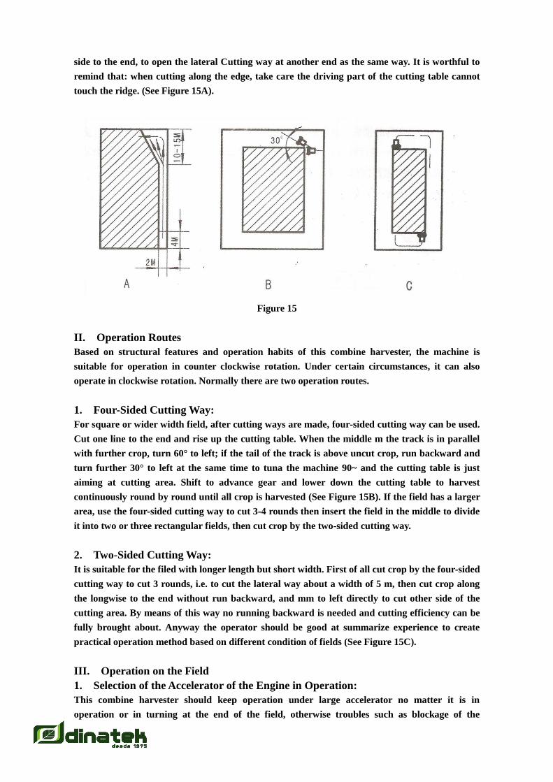
side to the end, to open the lateral Cutting way at another end as the same way. It is worthful to
remind that: when cutting along the edge, take care the driving part of the cutting table cannot
touch the ridge. (See Figure 15A).
Figure 15
II. Operation Routes
Based on structural features and operation habits of this combine harvester, the machine is
suitable for operation in counter clockwise rotation. Under certain circumstances, it can also
operate in clockwise rotation. Normally there are two operation routes.
1. Four-Sided Cutting Way:
For square or wider width field, after cutting ways are made, four-sided cutting way can be used.
Cut one line to the end and rise up the cutting table. When the middle m the track is in parallel
with further crop, turn 60° to left; if the tail of the track is above uncut crop, run backward and
turn further 30° to left at the same time to tuna the machine 90~ and the cutting table is just
aiming at cutting area. Shift to advance gear and lower down the cutting table to harvest
continuously round by round until all crop is harvested (See Figure 15B). If the field has a larger
area, use the four-sided cutting way to cut 3-4 rounds then insert the field in the middle to divide
it into two or three rectangular fields, then cut crop by the two-sided cutting way.
2. Two-Sided Cutting Way:
It is suitable for the filed with longer length but short width. First of all cut crop by the four-sided
cutting way to cut 3 rounds, i.e. to cut the lateral way about a width of 5 m, then cut crop along
the longwise to the end without run backward, and mm to left directly to cut other side of the
cutting area. By means of this way no running backward is needed and cutting efficiency can be
fully brought about. Anyway the operator should be good at summarize experience to create
practical operation method based on different condition of fields (See Figure 15C).
III. Operation on the Field
1. Selection of the Accelerator of the Engine in Operation:
This combine harvester should keep operation under large accelerator no matter it is in
operation or in turning at the end of the field, otherwise troubles such as blockage of the
vibration screen or spreading of grain could occur.
2. Running on Straight Line When Cutting as Can as Possible:
This machine should run on straight line when cutting crop as can as possible, otherwise the
rubber track could press down some uncut crop to cause manmade loss. Avoid cutting plus
turning as can as possible to cause loss of pressed crop. Those remained uncut crop at the corner
can be cut manually after crop on the large area is harvested then can be evenly spread (without
piling up) on uncut crop.
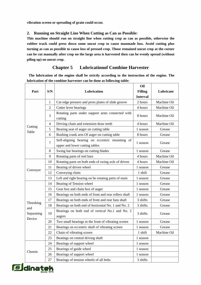
Chapter 5 Lubricationof Combine Harvester
The lubrication of the engine shall be strictly according to the instruction of the engine. The
lubrication of the combine harvester can be done as following table:
Part S/N Lubrication
Oil
Filling
Interval
Lubricant
Cutting
Table
1 Cut edge pressers and press plates of slide groove 2 hours Machine Oil
2 Cutter lever bearings 4 hours Machine Oil
3 Rotating parts under support arms connected with
cutting 8 hours Machine Oil
4 Driving chain and extension draw teeth 4 hours Machine Oil
5 Bearing seat of auger on cutting table 1 season Grease
6 Bushing crank arm Of auger on cutting table 8 hours Grease
7 Self-aligning bearing on eccentric mounting of
upper and lower cutting tables 1 season Grease
8 Swing bar bearings on cutting blades 1 season Grease
9 Rotating parts of reel bars 4 hours Machine Oil
Conveyor
10 Rotating parts on both ends of swing axle of driven 4 hours Machine Oil
11 Bearing of driven wheel 1 season Grease
12 Conveying chain 1 shift Grease
13 Left and right bearing on he rotating parts of main 1 season Grease
Threshing
and
Separating
Device
14 Bearing of Tension wheel 1 season Grease
15 Gear box and chain box of auger 1 season Grease
16 Bearings on both ends of front and rear rollers shaft 1 season Grease
17 Bearings on both ends of front and rear fans shaft 3 shifts Grease
18 Bearings on both end of horizontal No. 1 and No. 2 3 shifts Grease
19 Bearings on both end of vertical No.1 and No. 2
augers 3 shifts Grease
20 Two small bearings in the front of vibrating screen 1 season Grease
21 Bearings on eccentric shaft of vibrating screen 1 season Grease
22 Chain of vibrating screen 1 shift Machine Oil
23 Beatings on central driving shaft 1 season
Chassis
24 Bearings of support wheel 1 season
25 Bearings of guide wheel 1 season
26 Bearings of support wheel 1 season
27 Bearings of tension wheels of all belts 3 shifts

28 All articulated points of operation levers 1 shift
29 Throttle cable, stop switch wire 1 shift Machine Oil
30 Gearbox 1 season
No.68
low-condensatio
n anti-abrasion
hydraulic oil
31 Hydraulic oil tank 1 season
No.68
low-condensatio
n anti-abrasion
hydraulic oil
Note: Damage of other parts caused by damage of bearings is not covered by the warranty of the
factory.
Chapter 6 Running-In of Combine Harvester
New machine or the machine after overhaul should have running-in operation before putting into
application and running-in contents are as follows:
1. Before running-in operation, first rotate the machine manually to check all working parts.
Only everything is normal can the machine be put into unload operation.
2. Start the engine and close the work clutch, set the accelerator from small to large to listen if
abnormal sound exists. Check if lifting up/down of the cutting table is normal for 5 minutes.
3. Unload running on plain road with all shift gears for I0 minutes respectively, check adjusted
turning, engaging/disengaging and braking as well as check all fasteners if loosened, check all
welded parts if seam or off-welding occurs and solve problem in time if it is found.
4. Select the field with low yield to make running-in operation by controlling cutting width,
forward speed and light load for the time no less than one shift (8-10 hours).
5. Make full-load running-in operation on the basis of light load running-in for the time no less
than one shift.
6. After finish full-load running-in, make overall inspection, adjustment and tightening on the
machine, discharge lubricant oil from the variable gearbox, clean it with diesel oil and fill in new
lubrication oil. The hydraulic oil shall be replaced as well.
7. New engine or the engine after overhaul should have running-in operation according to
stipulations on the manual of the engine.
Chapter 7 Maintenance of Combined Harvester
1 Shift Maintenance of the Engine
Besides making maintenance according to stipulations in the manual of the diesel engine, the
engine shall have following jobs to do:
1. Remove dust and straw bits on the radiator. As the harvester works under a bad condition,
especially wheat harvester season, lots of dust and straw bits will stuff on the radiator when
harvesting and affects heat radiation of the water tank therefore it should be cleaned before
starting operation. Besides, when harvesting, always check the blockage of straw bits on the
engine cover to keep the air flow.
2. Clean the air filter. As the same reason the air filter is also easy to be ineffective. If the filter

screen is blocked, at least power of the engine shall be reduced and black smoke emitted under
large load, even worse the engine will be hardly to start, therefore it should be maintained strictly
as per the manual of the engine. If affected by wind direction or much dust, cleaning times should
be increased.
3. Check whether the water inlet of engine is broken, if there is leakage of water; Check
whether air inlet of engine has crack, if the dust can enter.
4. Check whether battery has electricity, whether the rubber bush on the battery post is broken.
2 Shift Maintenance of the Combined Harvester
1. The machine should keep good technical conditions and all parts should be adjusted well as
per technical requirement.
2. Check whether the function of handle for left and right turning, braking is in good condition.
Operate with trouble is strictly prohibited.
3. Check the lubrication system of the combine harvester and fill oil in time as per requirement.
4. Check if bolts, nuts and other fasteners are loosened.
5. Check if all welded parts have seam or off-welding, correct and repair deformed and
damaged parts.
6. Check all operation parts to see if they are flexible and reliable.
7. Make trial running before operation to see if abnormal condition exists, especially on the
driving parts of the cutting table and the vibrations screen parts.
8. Fill enough oil in the engine and enough water in the water tank, bring together the
extinguisher, accompanied tools and lubrication oil to start the machine.
Note: When welding is required by repairing, knife switch of power shall be pulled down and
all straw bits and oily dirt around the welded parts should be wiped out so as to prevent catching
fire.
3 After-Season Maintenance of the Combined Harvester
After working for a season the machine should have an overhaul so as to prolong the service life
of the machine and to make preparation for application in the next season.
1. Clean out all impurities, soil, sand and grain in the auger.
2. Fill new lubrication oil in all rotating parts, bearings and gearbox according to requirement
of lubrication.
3. Make an overall check upon the harvester and repair or replace all damaged or worn parts,
in which:
1) Check and adjust the cutter:
a. The working plane of the edge protector should be in a same plane and tile non-coplanarity of
three neighbouring working planes should be not larger than 0.5 mm.
b. When the moving blade is above the edge protector, there should be a clearance not larger than
0.5 mm at the front end of the both and a clearance of 0.3 - 1.3 mm at the rear end.
c. The clearance between the edge presser and the moving blade should be not larger than 0.5mm
and that and the blade bar not larger than 0.2 mm.
d. Check riveted moving cutter if it is loosened or has many lost teeth (the cutter with one third
lost teeth should be replaced), check if bolts of the edge protector are loosened.
e. Manually moving cutter, it should be flexible. If blocked or loosened, can adjust the edge
presser and friction disc and the friction disc on the press plate of the slide groove. Loosen the
bolt and move the edge presser, friction disc and the friction disc on the press plate of the slide
groove forward and backward to adjust front and rear clearances of the cutter. Increase or
decrease pads under the friction disc to adjust upper and lower clearances of the cutter.
f. Check the knuckle bearing of the long connecting rod if it plays due to worn-out, if the
clearance between two bearings in the blade bar holder and the friction block is larger than 0.3
mm. If so, replace immediately.
2) Check and replace conveying rake teeth.
a. Fixing bolts of conveying rake teeth should not be loosened.
b. The tightness of two conveying chain should be consistent with each other, and should fill with
grease.
c. Driving and driven wheel should work smoothly. No blockage should occur.
3) Check and replace the threshing roller as following:
a. The clearance between teeth bar of threshing roller and concave board should be 15-18mm,
(when the concave board can be judged not deformed), if the clearance is larger than 25mm,
should dismount teeth bar, install on outer holes or replace teeth bar.
b. Front and rear concave board should not be deformed or dropped seriously.
c. Vibrating screen pieces should not be split, broken and lost. Grain selecting nylon soft plate,
canvas should not be broken or lost.
4. Check whether all warning marks are clear and complete, if not, replace or add it
immediately.
5. For those parts with paint-lost or rusted, they should be repainted after removing rust.
6. Coat anti-mst grease on the cutter and chains.
7. Loosen all driving belts and conveying chain. If the machine not use for a long time, the
rubber track also should be loosened.
8. Disengage the work clutch.
9. The storage place should be dry and well-ventilated, open storage is not allowed.
10. Always make check in rainy days and wet seasons.
11. If the machine will not be used for a long term the battery should be maintained as per one
of following two ways:
1) Dry Storage Way: recharge the battery sufficiently then discharge it in 20 hours until the
final voltage is 1.75V, dump out the electrolytic liquid and soak it in distilled water for 3 hours,
dump it out again and soak again in distilled water until no acid liquid is extracted, then dump
out water from the battery and tighten the cover of the filling hole, seal the vent with wax and
store it in room. The storage place should be dry and well-ventilated with temperature constantly
between 5°~40°, over 1 m far from heat source such as sunlight or as per instruction manual of
the battery manufacturer. When using the battery in dry storage way, it shall be done as that of
new battery.
2) Wet Storage Way: charge the battery sufficiently and seal the vent on the filling hole, then
store it in dark place. Regularly check the density of electrolytic liquid and check its discharge
degree by the high rate discharge meter. If the volume is lower than 25%, it shall recharge
immediately, or make recharge once every one or two months. Normally the storage time for this
way shall be no longer than six months.
Note: when using, take out the seal from the vent otherwise the battery shall be exploded.

Chapter 8 Troubles and Remedies
Following normal troubles are mainly from operation and maintenance not according to
stipulated methods, no clearing of straw, grass or mud in time and bad adjustment of all moving
parts.
Part Trouble Causes Remedies
Cutting
Table
Cutting speed
reduced, crop
cannot be cut,
or is drawn up
with roots,
leak cutting of
crop.
1. Large clearance between blades.
2. Edge protector and moving and fixing
blades are damaged.
3. The installation position after repairing
not matches with the requirement.
4. Much feed volume or speed of the
diesel engine not enough, driving belt
loosening.
5. Much grass and soil on the cutter.
Adjust clearance of blades.
Repair or replace.
Adjust as per section 2.
Reduce speed to run
forward, enlarge accelerator
of diesel engine and tighten
driving belt.
Remove.
Cutter doesn't
work
1. Objects are between moving and fixing
blades.
2. Driving belt loosened or driving chain
broken.
Readjust clearance of blades
after repairing.
Repair or replace.
Abnormal
sound in
swinging bar
1. Knuckle bearing of long connecting rod
plays due to worn-out.
2. Clearance of two bearings in the blade
bar holder and the friction block is
larger than 0.3mm.
Replace knuckle bearing.
Reshape or replace bearings
or friction block.
Auger of the
cutting table is
blocked.
1. Much feed volume.
2. Base plate of cutting table is deformed
due to be bumped.
3. Auger is blocked.
4. Driving belt is loosened.
5. Natural height of crop is less than
500mm.
Reduce forward speed
or cutting width.
Adjust clearance between
base plate and blade of
auger.
Clear grass, fill oil in slide
block and bearing.
Tension belt.
Lower the stubble, lower
and move inside the reel
wheel or change field.
Throw straw at
the joint of
cutting table
and conveying
groove.
1. Unsuitable adjustment of reel fingers of
the auger on cutting table.
2. Much feed volume.
Adjust as per requirement of
the manual.
Reduce feed volume.
Throw straw
by the reel
1. Reel is too lower.
2. Angle of reel teeth is improperly
adjusted.
3. Adjusting nut of reel teeth is loosened.
Adjust higher.
Adjust to droop down
vertically.
Tighten after adjustment.

Middle
Conveying
Feed inlet of
conveying
groove is
blocked.
1. The place of adjusting block of auger
on cutting table is improper or driving
belt of conveying is too loose.
2. The blades of auger on cutting table is
deformed and not in the right place.
3. The crop fed in is too short.
Readjust or tighten driving
belt of conveying as per
requirement of manual.
Reshape.
Lower the stubble, lower
and move inside the reel
wheel.
Straw returns
in conveying
groove.
1. The crop fed in is iii, too soft or too
wet.
2. The straw rib on the cover of front
roller is deformed, dropped or
worn-out.
3. Bush roll with driving wheel.
4. Conveying chain is too tight.
Raise the stubble or change
field to work.
Repair or replace.
Refasten.
Adjust the conveying chain.
Grass wound
on driven
wheel holder
or on
anti-wrap
holder.
1. Crop is not mature or too wet.
2. Too soft after stem of crop get ill or
much grass.
To harvest some days later.
Change field to work.
Threshing
Roller
Blockage of
threshing
roller.
1. Stems too wet or crop is not mature.
2. The straw rib on top cover is deformed
and worn out seriously.
3. 5-in-1 belt is too loose or power of
diesel engine is insufficient.
4. Iron sheet at the grass discharge outlet
is deformed and blocked.
Select mature and dry crop.
Reshape or replace.
Tighten 5-in-1 belt or
enlarge the accelerator.
Reshape and repair.
Much grass
involved.
1. Crop is too wet, holes of concave are
blocked.
2. Low speed and insufficient power of
roller.
3. Concave board is deformed or
clearance between spike-teeth and
concave board is too large.
4. Crop is hardly to threshing or not
mature.
To harvester after it is dried.
Enlarge the accelerator to
maximum.
Reshape the concave board
or adjust the clearance of
concave board.
Change field to work.
Severe loss
from screen.
1. The opening volume of screen plates is
too small.
2. Blockage between upper screen plate
and lower screen.
3. 5-in-1 belt too loose and speed is not
enough.
4. Much feed volume.
Enlarge tile opening volume
of screen plats as per
instruction manual.
Take out and clear.
Tension 5-in-1 belt.
Slow down the forward
speed.
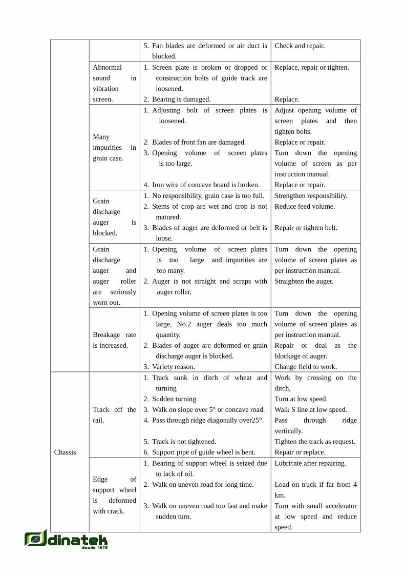
5. Fan blades are deformed or air duct is
blocked.
Check and repair.
Abnormal
sound in
vibration
screen.
1. Screen plate is broken or dropped or
construction bolts of guide track are
loosened.
2. Bearing is damaged.
Replace, repair or tighten.
Replace.
Many
impurities in
grain case.
1. Adjusting bolt of screen plates is
loosened.
2. Blades of front fan are damaged.
3. Opening volume of screen plates
is too large.
4. Iron wire of concave board is broken.
Adjust opening volume of
screen plates and then
tighten bolts.
Replace or repair.
Turn down the opening
volume of screen as per
instruction manual.
Replace or repair.
Grain
discharge
auger is
blocked.
1. No responsibility, grain case is too full.
2. Stems of crop are wet and crop is not
matured.
3. Blades of auger are deformed or belt is
loose.
Strengthen responsibility.
Reduce feed volume.
Repair or tighten belt.
Grain
discharge
auger and
auger roller
are seriously
worn out.
1. Opening volume of screen plates
is too large and impurities are
too many.
2. Auger is not straight and scraps with
auger roller.
Turn down the opening
volume of screen plates as
per instruction manual.
Straighten the auger.
Breakage rate
is increased.
1. Opening volume of screen plates is too
large, No.2 auger deals too much
quantity.
2. Blades of auger are deformed or grain
discharge auger is blocked.
3. Variety reason.
Turn down the opening
volume of screen plates as
per instruction manual.
Repair or deal as the
blockage of auger.
Change field to work.
Chassis
Track off the
rail.
1. Track sunk in ditch of wheat and
turning
2. Sudden turning.
3. Walk on slope over 5° or concave road.
4. Pass through ridge diagonally over25°.
5. Track is not tightened.
6. Support pipe of guide wheel is bent.
Work by crossing on the
ditch,
Turn at low speed.
Walk S line at low speed.
Pass through ridge
vertically.
Tighten the track as request.
Repair or replace.
Edge of
support wheel
is deformed
with crack.
1. Bearing of support wheel is seized due
to lack of oil.
2. Walk on uneven road for long time.
3. Walk on uneven road too fast and make
sudden turn.
Lubricate after repairing.
Load on truck if far from 4
km.
Turn with small accelerator
at low speed and reduce
speed.

Guide wheel,
support wheel
are badly
worn-out.
1. Bearing is seized due to no oil for long
time.
2. Screw lost and oil seal ineffective.
Fill oil and replace.
Repair and replace.
Turning out of
control.
1. 4-in-1 belt of walk clutch is loosened.
2. Turning friction disc is badly worn-out.
3. Turning fork is worn out.
4. Mud on chassis and straw gathered on
driving wheel.
5. Force of top bar of turning oil cylinder
is insufficient.
Tighten 5-in-1 belt as
request.
Readjust length of oil
cylinder or replace friction
disc.
Replace.
Clear out mud and straw.
Check pressure of combined
valve (spring force).
Walk gearbox
broken.
1. Fixing bolts between case and frame
are loosened.
2. Often bump with the ridge when
reverse.
3. Shift-gear operation with much force.
No stop in middle position.
Replace.
Replace.
Replace and change operate
habit.
Walk sliding.
1. Sunk depth over 25 cm.
2. Belt of walk clutch is loosened.
3. Chassis has much soil and straw.
Change field to work.
Tension the belt.
Clear straw and soil.
Hydraulic
System
Output shaft of
infinitive
variable gear
worn out too
fast.
1. Main gearshift lever is pulled too fast
and no stop in middle position.
When main gearshift lever
at the middle of S groove, it
should stop for 1-2 seconds
before pull it backward.
When handle
in middle
position the
cutting table
cannot stop.
1. Self-lock of valve ineffective.
2. Top bar of hydraulic control is seized
and cannot lower down.
3. Oil leak in upper screw plug, pipe
connector of oil outlet of hydraulic
assembly and connector of oil cylinder.
4. Oil leak at end of oil cylinder.
Replace steel ball. Take care
when mounting ball, press
the surface of ball by copper
bar and knock by iron
hammer one or two times;
remove screw plug and take
out top bar of hydraulic
control to clean then
remount; replace concerned
O-ring or combined
washers.
Cutting table
cannot be
lifted or can be
lifted slowly.
1. Oil pump is damaged.
2. Oil level in tank is too lower.
3. Insufficient pressure of combined valve
or pressure spring is broken.
4. Oil pipe is aged or blocked.
5. Oil temperature is too high and oil
Replace with new pump.
Fill oil to suitable height.
Add one washer or replace
spring.
Replace oil pipe, clean oil
filter and oil tank.
Cool or replace hydraulic

viscosity is insufficient. oil.
Cutting table
cannot be
lowered.
1. Check as per reasons that cutting table
cannot be risen up.
2. Top bar of hydraulic control is seized at
the lowest part.
Take relative measures to
remove troubles.
Remove screw plug and
take out top bar of hydraulic
control, clean it and then
mount it.
Noise and
powerless to
walk.
1. Oil suction pipe is deformed or oil filter
is blocked.
2. Oil temperature is too high due to oil
radiator is blocked by straw bits.
3. Oil viscosity cannot meet requirement
or oil is too dirt.
4. Oil level in the tank is too lower.
Clean and remove dirt,
replace new oil if necessary.
Note: when replacing oil,
clean oil tank and replace
oil strainer.
Clear straw bit.
Replace with No.68
low-condensation
anti-abrasion hydraulic oil
or Mobil 424 oil.
Fill oil to suitable height.
Note: troubles of the diesel engine and rubber track can refer to operation manuals of
manufacturers.
Chapter 9 Transportation of the Combined Harvester
As the machine has a lot of square pipe, angle iron and thin plate pieces, therefore it should take
care of following points when it is in transportation so as to avoid damage of machines or parts.
I. Load and Transport the Whole Machine
1. Put soft non-metal matters such as wood board or straw bag under the cutting table so as to
avoid bumping and deformation.
2. Ropes or iron wires should be fixed on round ring or square pipes on frame and not be
allowed to tie on those parts such as thin-wall piece, angle iron or the like.
3. Put wooden block or brick under the rubber track to avoid replacement of the whole
machine, tension the shift-gear lever and the brake.
4. Always check the machine if it is loosened, if off-welding or seam occurs in transportation
and take relative measures if necessary.
II. Self-Walking Transfer
1. Walk on plain road and take high or middle accelerator.
2. Walk on uneven road with lower speed.
3. Walk forward with lower shift-gear under the command of somebody when turning,
ascending or descending, load or unload on truck or steamer (those below 10 tons is strictly
prohibited).
4. No heavy weights are allowed to load on the harvester.
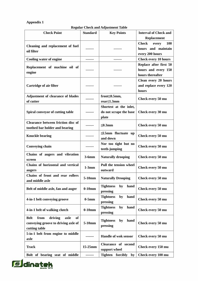
Appendix 1
Regular Check and Adjustment Table
Check Point Standard Key Points Interval of Check and
Replacement
Cleaning and replacement of fuel
oil filter ------- -------
Check every 100
hours and maintain
every 200 hours
Cooling water of engine ------- ------- Check every 10 hours
Replacement of machine oil of
engine ------- -------
Replace after first 50
hours and every 150
hours thereafter
Cartridge of air filter ------- -------
Clean every 20 hours
and replace every 120
hours
Adjustment of clearance of blades
of cutter -------
front≤0.5mm,
rear≤1.3mm Check every 50 mu
Spiral conveyor of cutting table -------
Shortest at the inlet,
do not scrape the base
plate
Check every 30 mu
Clearance between friction disc of
toothed bar holder and bearing ------- ≤0.3mm Check every 50 mu
Knuckle bearing ------- ≤l.5mm fluctuate up
and down Check every 50 mu
Conveying chain ------- Nor too tight but no
teeth-jumping Check every 50 mu
Chains of augers and vibration
screen 3-6mm Naturally drooping Check every 50 mu
Chains of horizontal and vertical
augers 1-3mm
Pull the tension wheel
outward Check every 50 mu
Chains of front and rear rollers
and middle axle 5-10mm Naturally Drooping Check every 50 mu
Belt of middle axle, fan and auger 0-10mm Tightness by hand
pressing Check every 50 mu
4-in-1 belt conveying groove 0-5mm Tightness by hand
pressing Check every 50 mu
4-in-1 belt of walking clutch 0-10mm Tightness by hand
pressing Check every 50 mu
Belt from driving axle of
conveying groove to driving axle of
cutting table
5-10mm Tightness by hand
pressing Check every 50 mu
5-in-1 belt from engine to middle
axle ------- Handle of wok sensor Check every 50 mu
Track 15-25mm Clearance of second
support wheel Check every 150 mu
Bolt of bearing seat of middle ------- Tighten forcibly by Check every 100 mu

driving axle spanner
Connecting bolt of toothed bars of
threshing roller -------
Tighten forcibly by
spanner Check every 100 mu
Bolt of bearing seat of threshing
roller -------
Tighten forcibly by
spanner Check every 100 mu
Clearance between threshing
roller and concave board 15-18mm
Measure with
measuring tape Check every 100 mu
If bolts in all parts are tightened ------- Visually view of spring
pad is loosened Check every 30 mu
Bearing of Walking wheels ------- Filling grease Check every season
If warning mark and sign fall off ------- Clear and right Check every season
All augers and auger blade Φ 125 with 2mm abrasion Check every 500 mu
and replace 1000 mu
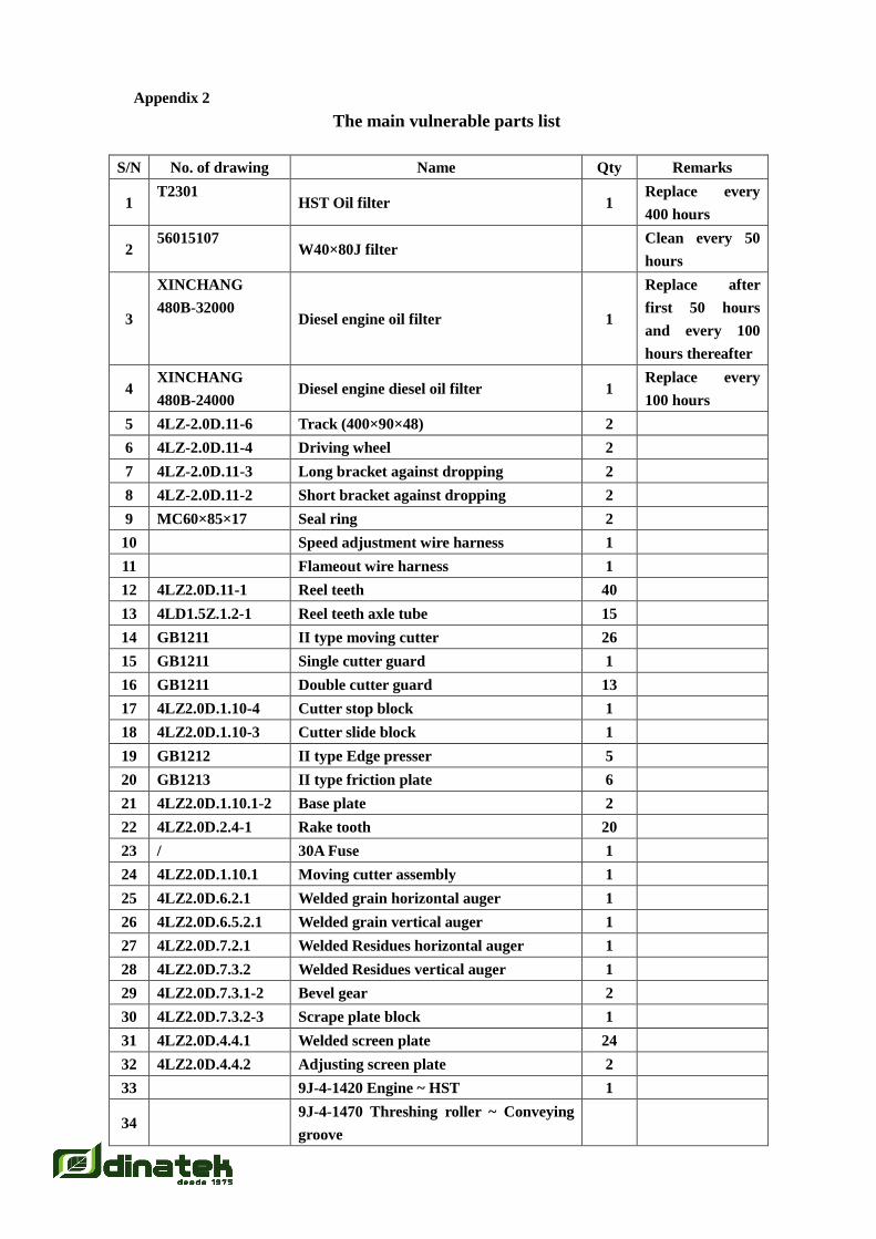
Appendix 2
The main vulnerable parts list
S/N No. of drawing Name Qty Remarks
1 T2301
HST Oil filter 1 Replace every
400 hours
2 56015107
W40×80J filter Clean every 50
hours
3
XINCHANG
480B-32000 Diesel engine oil filter 1
Replace after
first 50 hours
and every 100
hours thereafter
4 XINCHANG
480B-24000 Diesel engine diesel oil filter 1
Replace every
100 hours
5 4LZ-2.0D.11-6 Track (400×90×48) 2
6 4LZ-2.0D.11-4 Driving wheel 2
7 4LZ-2.0D.11-3 Long bracket against dropping 2
8 4LZ-2.0D.11-2 Short bracket against dropping 2
9 MC60×85×17 Seal ring 2
10 Speed adjustment wire harness 1
11 Flameout wire harness 1
12 4LZ2.0D.11-1 Reel teeth 40
13 4LD1.5Z.1.2-1 Reel teeth axle tube 15
14 GB1211 II type moving cutter 26
15 GB1211 Single cutter guard 1
16 GB1211 Double cutter guard 13
17 4LZ2.0D.1.10-4 Cutter stop block 1
18 4LZ2.0D.1.10-3 Cutter slide block 1
19 GB1212 II type Edge presser 5
20 GB1213 II type friction plate 6
21 4LZ2.0D.1.10.1-2 Base plate 2
22 4LZ2.0D.2.4-1 Rake tooth 20
23 / 30A Fuse 1
24 4LZ2.0D.1.10.1 Moving cutter assembly 1
25 4LZ2.0D.6.2.1 Welded grain horizontal auger 1
26 4LZ2.0D.6.5.2.1 Welded grain vertical auger 1
27 4LZ2.0D.7.2.1 Welded Residues horizontal auger 1
28 4LZ2.0D.7.3.2 Welded Residues vertical auger 1
29 4LZ2.0D.7.3.1-2 Bevel gear 2
30 4LZ2.0D.7.3.2-3 Scrape plate block 1
31 4LZ2.0D.4.4.1 Welded screen plate 24
32 4LZ2.0D.4.4.2 Adjusting screen plate 2
33 9J-4-1420 Engine ~ HST 1
34 9J-4-1470 Threshing roller ~ Conveying
groove

35 9J-5-1330 Engine ~ Middle axle 1
36 B3353 Conveying groove ~ Driving axle
of cutting table 2
37 B1448 Auger of cutting table ~ Reel wheel
bridge 1
38 B2311 Reel wheel bridge ~ Reel wheel 1
39 L504-AV15-1060Li Cooling fans of diesel engine 1
40 Chain C2060L-4L×80+2 2
41 Chain 08B-1×40 1
42 Chain 08B-1×92 1
43 Chain 08B-1×50 1
44 Chain 10A-1×134 1
45 Chain 12A-1×178 1
46 4LZ2.0D.1.2-2 Right eccentric bracket 1
47 4LZ2.0D.1.2-9 Left eccentric bracket 1
48 4LZ2.0D.1.2-3 Bushing block 1
49 4LD2-01-411 Guide bushing 12
50 4LZ2.0D.7.3-1 Bevel gear 1
51 4LZ2.0D.7.3.1-2 Bevel gear 1
52 4LZ2.0D.1.2-11 Extension reel teeth seat 12
53 4LZ2.0D.11.4-1 Jockey Pulley 2
54 4LZ2.0D.1.6-6 Balance staff 1
55 4LZ2.0D.1.6-5 Screw tap axle 1
56 4LZ2.0D.2-4 Nylon tension wheel 6
57 4LZ2.0D.1.3.4-1 V-belt tension wheel 2
58 4LZ2.0D.3.5.2 Welded Rear threshing roller teeth rod II 3
59 4LZ2.0D.3.5.1 Welded Rear threshing roller teeth rod I 3
60 4LZ2.0D.3.2.1 Welded Front threshing roller teeth rod I 3
61 4LZ2.0D.3.2.2 Welded Front threshing roller teeth rod
II 3
62 4LZ2.0D.3.4 Welded front threshing roller concave 1
63 4LZ2.0D.3.7 Welded rear threshing roller concave 1
64 4LZ2.0D.3-15 1
65 / All bearings
66 / All oil seal
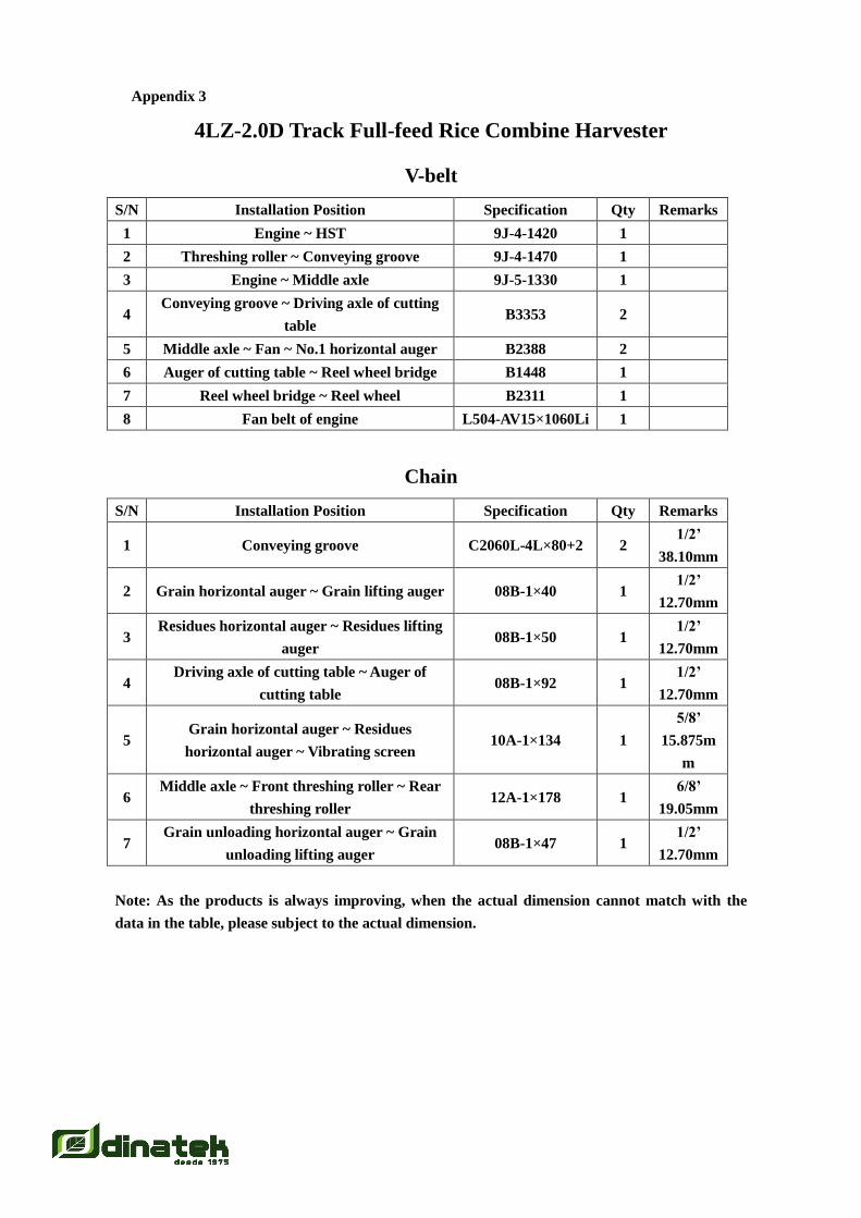
Appendix 3
4LZ-2.0D Track Full-feed Rice Combine Harvester
V-belt
S/N Installation Position Specification Qty Remarks
1 Engine ~ HST 9J-4-1420 1
2 Threshing roller ~ Conveying groove 9J-4-1470 1
3 Engine ~ Middle axle 9J-5-1330 1
4 Conveying groove ~ Driving axle of cutting
table B3353 2
5 Middle axle ~ Fan ~ No.1 horizontal auger B2388 2
6 Auger of cutting table ~ Reel wheel bridge B1448 1
7 Reel wheel bridge ~ Reel wheel B2311 1
8 Fan belt of engine L504-AV15×1060Li 1
Chain
S/N Installation Position Specification Qty Remarks
1 Conveying groove C2060L-4L×80+2 2 1/2’
38.10mm
2 Grain horizontal auger ~ Grain lifting auger 08B-1×40 1 1/2’
12.70mm
3 Residues horizontal auger ~ Residues lifting
auger 08B-1×50 1
1/2’
12.70mm
4 Driving axle of cutting table ~ Auger of
cutting table 08B-1×92 1
1/2’
12.70mm
5 Grain horizontal auger ~ Residues
horizontal auger ~ Vibrating screen 10A-1×134 1
5/8’
15.875m
m
6 Middle axle ~ Front threshing roller ~ Rear
threshing roller 12A-1×178 1
6/8’
19.05mm
7 Grain unloading horizontal auger ~ Grain
unloading lifting auger 08B-1×47 1
1/2’
12.70mm
Note: As the products is always improving, when the actual dimension cannot match with the
data in the table, please subject to the actual dimension.
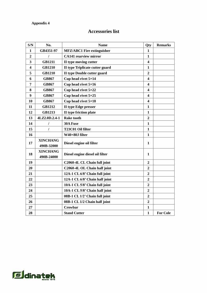
Appendix 4
Accessories list
S/N No. Name Qty Remarks
1 GB4351-97 MFZ/ABC1 Fire extinguisher 1
2 / CA141 rearview mirror 1
3 GB1211 II type moving cutter 4
4 GB1210 II type Triplicate cutter guard 1
5 GB1210 II type Double cutter guard 2
6 GB867 Cup head rivet 5×14 4
7 GB867 Cup head rivet 5×16 4
8 GB867 Cup head rivet 5×22 4
9 GB867 Cup head rivet 5×25 4
10 GB867 Cup head rivet 5×18 4
11 GB1212 II type Edge presser 1
12 GB1213 II type friction plate 1
13 4LZ2.0D.2.4-1 Rake tooth 2
14 / 30A Fuse 1
15 / T23C01 Oil filter 1
16 W40×80J filter 1
17 XINCHANG
490B-32000 Diesel engine oil filter 1
18 XINCHANG
490B-24000 Diesel engine diesel oil filter 1
19 C2060-4L CL Chain full joint 2
20 C2060-4L OL Chain half joint 2
21 12A-1 CL 6/8’ Chain full joint 2
22 12A-1 CL 6/8’ Chain half joint 2
23 10A-1 CL 5/8’ Chain full joint 2
24 10A-1 CL 5/8’ Chain half joint 2
25 08B-1 CL 1/2’ Chain full joint 2
26 08B-1 CL 1/2 Chain half joint 2
27 Crowbar 1
28 Stand Cutter 1 For Cole
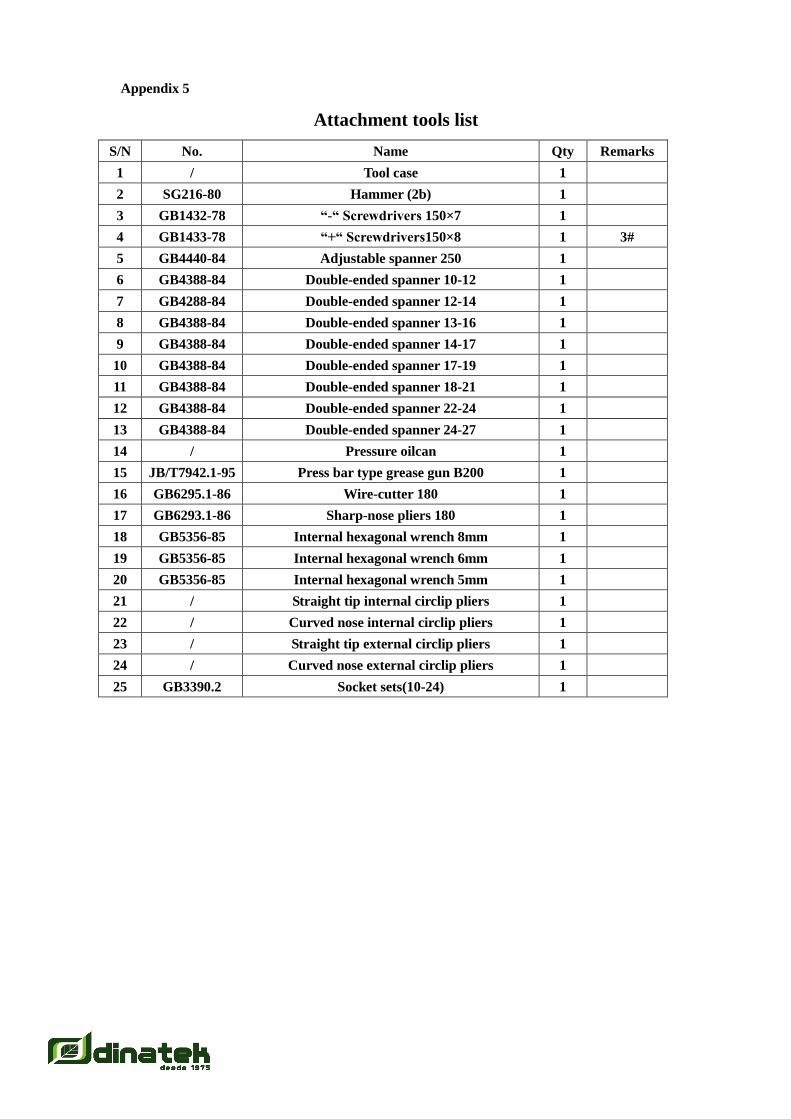
Appendix 5
Attachment tools list
S/N No. Name Qty Remarks
1 / Tool case 1
2 SG216-80 Hammer (2b) 1
3 GB1432-78 “-“ Screwdrivers 150×7 1
4 GB1433-78 “+“ Screwdrivers150×8 1 3#
5 GB4440-84 Adjustable spanner 250 1
6 GB4388-84 Double-ended spanner 10-12 1
7 GB4288-84 Double-ended spanner 12-14 1
8 GB4388-84 Double-ended spanner 13-16 1
9 GB4388-84 Double-ended spanner 14-17 1
10 GB4388-84 Double-ended spanner 17-19 1
11 GB4388-84 Double-ended spanner 18-21 1
12 GB4388-84 Double-ended spanner 22-24 1
13 GB4388-84 Double-ended spanner 24-27 1
14 / Pressure oilcan 1
15 JB/T7942.1-95 Press bar type grease gun B200 1
16 GB6295.1-86 Wire-cutter 180 1
17 GB6293.1-86 Sharp-nose pliers 180 1
18 GB5356-85 Internal hexagonal wrench 8mm 1
19 GB5356-85 Internal hexagonal wrench 6mm 1
20 GB5356-85 Internal hexagonal wrench 5mm 1
21 / Straight tip internal circlip pliers 1
22 / Curved nose internal circlip pliers 1
23 / Straight tip external circlip pliers 1
24 / Curved nose external circlip pliers 1
25 GB3390.2 Socket sets(10-24) 1


