
INSTRUCTION MANUAL
FOR
ISOLATED PULSE STIMULATOR
MODEL 2100
Serial
Date
A-M Systems Inc PO Box 850
CarlsborgWA 98324 USA
360-683-8300 bull 800-426-1306 FAX 360-683-3525
httpwwwa-msystemscom
Version 60 March 2001
Contents General Description laquo 1
Instrument Features 1 Controls and Connectors 2
Operating Instructions 6 Theory of Operation 10 Calibration Procedures 12
Inputs 14 Output Calibration 16
Specifications 19 Warranty and Service 22
Each Isolated Pulse Stimulator Is delivered complete with
Rack Mount Hardware Instructions amp Maintenance Manual
NOTE
This instrument is not intended for clinical measurements using human subjects A-M Systems Inc does not assume responsibility for injury or damage due to the misuse of this instrument
General Description
A - M S Y S T E M S HOLATID PUlraquoI STIMULATOR MODEL2100
Instrument Features The Isolated Pulse Stimulator Model 2100 is designed for a wide variety of applications It is highly flexible being capable of delivering single pulses biphasic pairs or bursts of pulses Pulses may be started manually or upon receiving a trigger signal from another instrument or computer Two non-isolated trigger outputs are available for triggering other instruments
Four sets of timing controls provide comprehensive control over all aspects of pulse generation Three digit accuracy is available over a 7 decade range for each timing function using lever wheel switches Pulse widths can be set over more than a 9 decade range from 05 fjs to 999 seconds Timing accuracy is assured through the use of a 10 MHz base rate crystal-controlled clock digitally divided to provide accurate timing over the entire range A timing overlap indicator will light if the timing controls are set inconsistently
The output may be conveniently switched between current and voltage modes Pulse and baseline amplitudes are independently presettable with lockable dials An error indicator will light if the Wocfcopy2700cannot deliver the desired signal
WARNING
The Model 2100 can produce potentially dangerous voltages up to 100 Vat the output connectors The isolated output is not connected internally to safety (earth) ground in any way Some part of the external circuit should be connected to safety ground Use caution in handling any wires connectors or electrodes which may be directly or indirectly attached to the Model 2100 output Some kinds of connectors such as BNC connectors have exposed metal parts which may float at dangerous potentials unless externally connected to safety ground For greatest safety turn the Model 2100 off before making any connections to
the instrument
131 Business Paik Loop PO Box 850 Cattsborg Wa 98324 T^aphone 80O426-1306 380683-8300 FAX 36amp683lt352S E-mail sales Oa-msyste)Tiscam Website httpywwwraquoltnsystemsco(n A-M Systems Inc 1
Controls and Connectors The controls for the Model2100 are grouped in three sections START controlling when a pulse or burst of pulses begins TIMING controlling the onoff timing of one or more pulses and OUTPUT controlling the amplitude of the output signal
Start TRIG SLOPE This switch determines whether valid triggers occur at positive or negative edges in the trigger signal
MODE This switch controls how waveforms are initiated When set to FREE RUN one timing cycle immediately follows the last When held in the MANUAL position a timing cycle starts immediately When the switch is in the center position timing cycles start when valid triggering events occur
TRIGD This LED lights up when a timing cycle is in process and continues until the burst is completed
TRIG This BNC connector allows a signal from an external source to initiate timing cycles It is set for standard TTL levels
GATE This BNC connector allows a signal from an external source to restrict the final output signal This input must be at a logical high (or open-circuited) in order for the Model2100X0 recognize either manual or automatic trigger events
Gate L Trigger |~~^
^ ~ ^
Valid triggers are represented by the arrows in the figure Note that the up arrow would apply only if TRIG SLOPE is set to + the down arrows would apply only if TRIG SLOPE is set to-
NOTE Triggers have no effect if the system has not completed Its response to a previous trigger
A-M Systems Inc 131 Business Park Loop PO Box 8S0 Carlsborg Wa 98324 Telophone 800426-1306 360683-8300 FAX 360683-352S E-mail salesfla-msystBiTiscom Website hltpywwwa-msystemscom
Timing Four sets of controls govern the timing of pulse generation Each set contains two values which are multiplied together to determine the actual timing value The rotary knob (rate selector) provides the approximate timing value and the lever wheel switch bank (MULTIPLIER) provides a time resolution of three decimal digits The following diagram shows most of the important relationships
TRAIN B U R S T W I D T H
10 10
TIMII
Output r Delay Duration
|4Periodgtj
t Burst width Trigger event
DELAY These controls set the time between the initiating trigger event and the beginning of the pulse burst If this rate selector is set to NONE or the multiplier is set to ooo there is no delay
BURST WIDTH These controls set the time period in which one or more pulses may be delivered Once started a pulse may outlast the burst width If this rate selector is set to SINGLE or to any time shorter than the pulse duration only a single pulse will occur If the BURST WIDTH is longer than the period pulses will be emitted at the PERIOD rate until the burst time ends Pulses are never truncated by a short BURST WIDTH
gtnds) INTER-PULSE
P E R I O D
DURATION These controls set the length of each pulse If this rate selector is set to SQUARE the duration is set to half of the period regardless of the MULTIPLIER setting
PERIOD These controls set the period of time between adjacent pulse events within the burst It also forces a minimum dead time between recognized input triggers following a burst of one or more pulses This can be used to prevent over stimulation of a tissue without requiring excessive delay between the triggering event and the stimulating pulse
OVERLAP
A-M Systems Inc^^ bull E-majl sale
131 Business Paik Ijoop PO Box 850 Calsboig Wa 98324 80O426-1306 360-683laquo300 - FAX 380-683^3525
E-mail sale60a-msystem3com Website httpywwwa-msystem3com
NOTE If any of these timing controls are changed while a timing cycle is in operation the results are undefined until the current cycle finishes
T I M I N G (seconds)-DTH
TIMING OVERLAP This LED will light to indicate an inconsistency in the timing cycle settings There are several ways to introduce such errors The most common way is to set the inter-pulse PERIOD to be less than the pulse DURATION
TRIG OUT (UPPER) This BNC connector provides a signal which is coincident with the internal Burst timing signal (default) This means the signal starts at the end of the Delay time and persists until the Burst time expires This output may also be set to represent the delay time-out by setting the internal jumper J510 to the right two pins instead of the left two pins (Please see the Calibration section in this manual for jumper location Directions are given as viewed from the front of the instrument)
TRIG OUT (LOWER) This BNC connector provides a signal which is coincident with the Duration timing signal which controls pulse output
NOTE Both trigger output signals slightly lead the isolated output signal
Output
PULSE SIGN This Switch sets the sign for the pulses to be generated It also allows generation of biphasic pulses thereby doubling the effective total period Warning the first pulse generated after changing the PULSE SIGN
switch may have the wrong polarity
BASELINE This switch sets the sign for the baseline signal
RANGE This rotary switch allows one of three current or two voltage ranges to be selected for the output signal
BASELINE AMPLITUDE This value IS independently set using a ten-turn counting dial The maximum baseline amplitude is one tenth the value shown on the range amplitude switch
A-M Systems Inc 131 Business Pai1( Loop PO Box 850 Caitsboig Wa 98324 Telophore 80O426-1306 bull 360683300 bull FAX 360-683-3525 E-mail salasOa-msystemscom Website httpwwwamsystemscom
PULSE AMPLITUDE This value is independently set using a ten-turn counting dial The maximum pulse amplitude is the value shown on the range amplitude switch
EVENT This LED indicates when a pulse is ongoing
ERROR This LED indicates when the internal output amplifier cannot output the pulse as desired This is usually due to a short circuit while trying to output a voltage or an open circuit while trying to output a current
The Pulse Sgfn control in the OutputsecWon directly affects waveform timing When set to the Biphasic mode a positive-going pulse is immediately followed by a negative-going pulse This effectively doubles the pulse duration If a burst of biphasic pulses is being produced the period must be at least twice the single pulse duration In the Square wave mode the baseline disappears as long as the burst persists
A B B f k _ _ laquo laquo laquo laquo 1 ^ 131 Business Paik Loop PO Box 850 CartsborgWa 98324 - | y | O V S i e m S I nC8lt=Praquo880O426-1308-360683300-FAX360683-3525
laquo E-mail salesOa-msystemscom Website httpwwwa-m3yste l O V ^ ltJ O W laquo W - t V ^ www www A n r w w w w i -w ww www w M
E-mail salesOa-msystemscom Website httpwwwa-m3ystemse0m
Operating Instructions
Examples Simple setup (and minimal instrument test)
Connect the output of the Model 2100 to an oscilloscope Before connecting the instrument it is safest to turn its power off
Set the Output controls
Range 10V Pulse Sign +
Baseline Zero Pulse Amplitude 200
Setting The Timing Controls
Delay none Burst Width single
Duration 150M0-2 Period 50010-2
Setting The Start Controls
Mode Free Run
Disconnect any cables to the TRIG or GATE inputs
Note that the green Trig and Evenf indicators turn on as Free Run is turned on (and turn off otherwise) You should observe a 15ms duration 20Hz rate pulse of 200V above a OV baseline on the oscilloscope
A-M Systems Inc 131 Business Pailt Loop PO Box 850 Carlsborg Wa 98324 Telophone 800-426-1306 bull 36Olaquo83-8300 FAX 360683-3S25 E-mail salesfla-msystemscom Website httpwwwa-msystemscom
Demonstration of Burst Mode Connect the output of the Model 2100 to an oscilloscope Before connecting the instrument it is safest to turn its power off
Set the Output controls
Range 10V Pulse Sign +
Baseline Pulse Amplitude 200
Baseline Amplitude 100
Setting The Timing Controls
Delay 88010-2 Burst Width 12010-^
Duration 15010-2 Period 50010-^
Set the START controls as follows
Mode Free Run
Disconnect any cables to the TRIG or GATE inputs
Trigger the oscilloscope from the Strsf trigger out (upper Trig Ouf connector) for a stable display In each burst (occurring every lOOms) you should observe a trio of 15ms duration starting 50ms apart Try switching the StartMode rom Free Run to the center (normal) position The pulses will no longer be produced and the Trig and Even indicators will turn off Pressing this switch once (to Manual) will cause a single burst to occur
A-M Systems Inc 131 Business PaiV Loop PO Box 850 Cai1sboraWa 98324 Telophone 800426-1306 360683-8300 FAX 380683-3S25 E-mal salesOa-msystemscom Website httpwwwa-m5ystemse0m
Problem Solving
If the instrument appears to be not working properly check all of the control settings and connections Be sure to wait at least 5-10 seconds after turning the instrument off before turning it on again The following summary of typical problems for the user (along with the most common solutions) may help
Problem CauseSolution
EVENT indicator never lights even in FREE RUN mode
bull Replace fuse check power connection bullSet DELAY or PERIOD to a shorter
interval bull Power-on too soon after power-off
OVERLAP indicator is on
ERROR indicator is on
Set DURATION gt000 DURATION is set to SQUARE but PERIOD is 000 Increase PERIOD or set DURATION independantly BURST and WIDTH are gt DURATION increase PERIOD or decrease DURATION BIPHASIC pulse output is on and PERIOD is not longer than twice the DURATION Increase PERIOD or decrease DURATION Free-run is on and BURST is lt PERIOD (BURST off) DELAY is 0 and PERIOD is lt DURATION Add delay or modify PERIOD Free-run is on and BURST is gt DURATION (BURSTON) and PERIOD is lt DURATION Increase PERIOD For VOLTAGE outputs the output is trying to drive too low a resistance or capacitance (eg a short circuit) Check by disconnecting the output It is possible (and normal) that for the fastest cycles and largest amplitudes (close to 100 V and 17S) that the ERROR indicator might always come on during repetitive pulses Fix output load or decrease amplitude as required
Time appears to be excessive Changed control in mid-cycle (resets current status)
A B B ^ J I - mdash 131 Business Park Loop RO Box 850 CaitsbotftWa 98324
gt | y | O y S i e m S |nCtradedegraquo0raquo 80O426-1306-36Olaquo8O8300-FAX36O683-3525
8 E-mail salesOa-msyaemscom bull Website httpwwwa-msystemscom
Cant seem to get a full signal out
Incoming triggers not accepted frequently enough
bull Load is not properly connected repair wiring
bull Too low a load impedance (VOLTAGE modes) or too high a load impedance (CURRENT mode)
bull PERIOD is set too long (enforces dead tinrie) followd by BURST set to SIGNAL Reduce PERIOD time
Table 10 Problem Solving
If you suspect that the Model 2100 may have completely failed we recommend checking the basic level of functionality If this fails your instrument is defective and must be repaired If this passes either your experimental setup is incompatible or inconsistent or there is a more subtle flaw in your Modei 2100
If the Model 2100 appears to be malfunctioning contact A-M Systems Inc or your dealer We will first attempt to solve the problem over the telephone so have an exact description of your problem available when you call You do not need to be within the warranty period to obtain over-the-phone assistance
A-M Systems Inc 131 Business Park Loop PO Box 850 Carfsbofg Wa 98324 Tatophone 80O426-1306 bull 360-688300 FAX 380683-3S25 E-mail salesfla-msystemscom Website httpwwwa-msystemscom
Theory of Operation
The operation of the Model 2100 is summarized in the block diagram (see the figure on Page 11) Not shown are all of the interconnections with the microcontroller The internal microcontroler plays an important role in setting the signal path but does not directly contribute to the dynamic characteristics It scans the front panel switches and sets the control values for the logic arrays It programs the internal counters which along with the other hardware achieve the necessary sub-microsecond speeds
All action starts either from an input trigger signal (from Trig In) or from an internal signal (in free Run mode only) A Delay timer counts the 10MHz clock until its count value is exhausted At this point the Burst timer starts Both Period and Duration timers are started at this time If the Burst timer has not expired by the end of the Period the Period and Duration timers are restarted If the Biphasic mode has been set the Duration timer is restarted at the end of the initial Duration and the sign of the output pulse is reversed doubling the total duration
The system state (pulse on pulse sip baseline sign [+0-]) is transmitted to the isolated section via optoisolator The baseline and pulse amplitudes are selected by an analog switch The resulting signal is amplified by a variable-power-supply discrete operational amplifier The amplifier connections and gain is modified to provide two voltage and three current ranges
Timing overlap errors are detected by a logical decision computation rather than by testing for counter collisions This provides instant feedback rather than waiting up to an hour for such a collision to occur Output errors are measured by sensing the output amplifiers differential input voltage Under normal conditions this is a negligible voltage If the amplifier fails to deliver the requested signal the window comparator testing this voltage sends this message (via optoisolator) to the logic section turning on a warning LED
A-M Systems Inc 131 Business Paik Loop PO Box 850 CailsboraWa 98324 i Q Te(ophone 800-426-1306 bull36O683laquo00FAX 360683-3525 ^ E-mail salesOa-msystemscom Website httpywwwa-m5ystemscom
GATE IN
TRIG ^ OUT
(burst)
OPTO ISOLATOR
Amplitude (Pulse)
TRIG -lt^ OUT
(pulse)
c 1
RANGE
C
Analog switch
C
)
-D^sectli OUTPUT
Baseline sign )
Amplitude (baseline) )
O H q
ill V) 5 o i^8 e e -a a fi a
bull o c
M E o ts gtraquo
lt
Calibration Procedures
The calibration intenal is the lesser of 1000 hours of operation or 6 months Somewhat greater drift can be expected in the first 100 hours of operation as the semiconductors age Adjustments should only be made after the instrument has been fully warmed up for at least 15 minutes
Full instrument calibration requires the following test equipment digital multimeter (plusmn 01 ) able to measure resistance to at least 10OMfl oscilloscope with at least 50MHz bandwidth true-rms voltmeter with 4MHz bandwidth universal counter (plusmn 001) able to measure single pulse widths and periods resistors (all plusmn 01) 2kn lOkO 1 watt 20ka 200ka alligator clip lead sets banana plugs and BNC adapters
Adjustment integrated circuit and test point locations are shown in the following figures All adjustments are on the timing board unless otherwise noted
All voltages in the non-isolated section should be measured with respect to ground at TP510 unless othenwise stated Some voltages are measured with respect to an internal isolated ground at TP650 or across the two output terminals Occasionally the voltage at an IC pin must be measured in these cases the reference designator is given with the pin number in parentheses eg U602(16) When it states within this procedure that a voltage is to be minimized this means that the adjustment should be made such that the measured voltage is as close to zero volts as possible Refer to the Specifications Section of this manual for acceptable tolerances
The sequence of this procedure is important If any adjustment is made all adjustments which follow must be made to ensure that the specifications will be met These procedures require that all controls remain as set in previous steps unless otherwise indicated
WARNING
The Model2100 has dangerous voltages throughout the instrument even with the power is off Servicing the Mode2700 should only be done by qualified service personnel Use caution in handling any wires connectors or electrodes which may be directly or indirectly attached to the instrument Do not touch exposed connections or components Disconnect power by unplugging the power cord from the receptacle
A B B ^ _ _ mdash ^ _ I raquo laquo 131SusinessParkLoopROBox850CaitsborBWa98324 -JO
E-mail S8le60a-msystemscom Website httpwwwa-msystemscam
CO
TP501 O o
a OTPsoo
U560 bull
D D D D Q ^ U510
Trig Gate
U570
OQ Q
U500
n U505
Timing
gt U520
Timing
) U530
Timing
gt U540
Q U515
Timing
U508
R503
DDID E
a
gt oo
bull U800 l O r v o w iV_X^TP510 O
U525
f
A U535
^ U550
Timing ^
Clock
U555
J510 Burst Delay
J400 bull U545
d R742^VWgh R619 o
r RZZ3 R737 an c n V - I J I S O I S ^ ^C-COMP
U620 ^ Q Q bull ^ ^ bull
J420 O ^ D^ J440 IfYYYlDfYyYYYYYYYII C Z J E X C T
Q Otrsetl I p J Vlow
L J TP645 C=) cm P650
bull bull fe elUOD
irt
PI pound A
o c
E o
0)
Power supply and bias voltages
Power supply
Controls Inputs Observations AdjustCheck
POWER ON Observe voltage at P703 power supply wire top of main board
Check for+15 plusmn 050 V
Observe voltage at P701 power supply wire top of main board
Check for-15 plusmn 050 V
Observe voltage at U505(24) Check for +5 plusmn 025 V
Isolated supply voltage
Controls Inputs Observations Adjust Check
RANGE 10 V TRIG open circuit MODE center position
Alternately observe V from high
R742 to R740 and V _ from kw
the U605(4) to U605(8)
Adjust R773 so that 110VltV lt 120 V and
high
28VltV^^lt34V
Capacitance balance
Controls Inputs Observations Adjust Check
Connect a x10 oscilloscope probe to TP650 and ground the
Adjust R737 for minimum high frequency signal
Inputs
Gate funct ion
Controls Inputs Observations AdjustCheck
Apply a 1 kHz 0 - 5 V triangle wave Verify that the voltage to GATE switches states at the Observe voltage at U510(3) proper input levels with an oscilloscope
Trigger s lope
Controls Inputs Observations Adjust Check
Apply a 1 kHz 0 - 5 V triangle wave Verify that the voltage to TRIG switches states at the Observe voltage at U510(1) proper input levels with an oscilloscope
TRIG SLOPE-I- Verify voltage is 180deg out of phase
TRIG SLOPE- Verify voltage is in phase
A-M Systems Inc 131 Business Paik Loop PO Box 850 Cailsborg Wa 98324 Tekvhone 8004201306 36O683laquo300 - FAX 360683-3S2S E-mail salesOa-msystemscom Website httpywwwa-msystemscom
14
Trigger and gate funct ion
Controls Inputs Observations
DELAY NONE BURSTWIDTH SINGLE DURATION SQUARE PERIOD 100X10-3
AdjustCheck
Apply a 1 kHz 0 -5 V triangle wave to TRIG Observe TRiGoand EVENT LEDS
TRIG disconnect all Short the GATE connector to GND Verify LEDs extinguish
MODE press to MANUAL Verify LEDs flash once
Timing
System clock frequency
Controls Inputs Observations Adjust Check
Observe the frequency of the wave Verify 1000 MHz plusmn 001 atU555(17)
Mu l t i p l i e rs (Whee l Sw i t ches )
Controls Inputs Observat ions A d j u s t C h e c k
PULSE SIGN+ MODE FREE RUN TRIG disconnect all TIMING MULTIPUERS all
Wheels set to zero except the one being tested
TIMING OVERLAP ignore
Observe the pulse width with the counter at the location specified below
Verify pulse width is correct for each wheel as it is tested independently
For each wheel of each MULTIPLIER test each position to verify that the pulse width is correct Observe the signal at the following locations DELAY U520(2) BURSTWIDTH U530(2) PERIOD U540(2) DURATION U550(2)
Rates (Rotary Switches)
Controls Inputs Observations A d j u s t C h e c k
TIMING MULTIPUERS 001 TIMING RATES all rotary
switches set to 10-4 except the one being tested
Observe the pulse width with the counter at the location specified below
Verify pulse width is correct for each rotary switch as it is tested independently
For each of the four rotary switches in TIMING test each position to verify that the pulse width is correct Observe the signal at the following locations DELAY U520(2) BURSTWIDTH U530(2) PERIOD U540(2) DURATION U550(2)
A-M Systems Inc 131 Business Paik Loop PO Box 850 Caiisborg Wa 98324 Telophone 800-428-1306 bull 3606808300 FAX 360683-3525 E-mail salesOa-msystemscom Website httpwwwa-msystemscom
15
Trigger outputs Controls
Range 10V Pulse Amplitude 500 Delay 100x10-2 Burst 100x10-2 Duration 100 xlQ-^ Period 400x10-3 Pulse sign + Trig Mode Free run Trig in open
Inputs Observations
Trigger the oscilloscope to the Burst Trig Out Observe it the Pulse Trig Out and the isolated output
AdjustCheck
Verify that the waveform consists of a burst of three 1 ms-on3ms-off pulses The burst trigger should be synchronous with the burst the pulse trigger coincident with each pulse
Output Calibration
Isolation Resistance (check) Controls Inputs Observations Adjust Check
Trig Mode center position Trig In open
Measure the resistance between ground banana jack (front panel) and black banana jack of output with DMM
Resistance read gt 10OMQ
Amplitude Switch Offset (R640) Controls InputsObservations AdjustCheck
Baseline Zero Trig Mode center position Trig In Open
Measure the voltage at TP645 vs TP650 with the DMM
Adjust R640 (AmpI Sw Offset) for minimum voltage
Output Offset (R332 front panel board) Controls InputsObservations AdjustCheck
Baseline Zero Range 10V Trig Mode center position Trig In Open
Measure the voltage across the output with the DMM
Adjust R332 (Output offset) for minimum voltage
Positive Baseline Offset (R607) Controls InputsObservations AdjustCheck
Baseline Sign + Baseline Amplitude
fully CCW (000) Range 10V Trig In open Trig Mode center position
Measure the voltage across the output with the DMM
Adjust R602 (BSLN + offset) for minimum voltage
A-M Systems Inc 131 Business Paik Loop PO Box 850 Cartsborg Wa 98324 Jelophone 8004201306 36O6834300 - FAX 380laquo83-352S E-mail salesOa-msystemscom Website httpwwwa-msystemscam
16
Negative Baseline Offset (R619)
Controls InputsObservations
Baseline Sign -Baseline Amplitude
fully CCW (000) Range 10V Trig In open Trig Mode center position
Measure the voltage across the output with the DMM
AdjustCheck
Adjust R619 (BSLN + offset) for minimum voltage
Pulse Ampl i tude Adjust (R602)
Controls InputsObservations AdjustCheck
Trig Mode Free Mode Pulse Amplitude 1000 Timing Delay =none Burst =single Duration =1001 Period =00110-4 Pulse Sign -Trig In open Range 10V
Measure the voltage across the output with the DMM
The Overlap indicator should be on Adjust R602 (Max Level) for -10OOV out
Pulse Sign Gain (check)
Controls InputsObservations AdjustCheck
Trig Mode Free Mode Pulse Amplitude 1000 Timing Delay =none Burst =single Duration =100 Is Period =001 10-4s Trig In open Range 10V
Measure the voltage at the output with the DMM for the Pulse Sign at + and - positions
The absolute values of the voltages should differ by less than 10OmV
Baseline Ampl i tudes (check)
Controls InputsObservations AdjustCheck
flange 100mA Trig Mode center position Baseline Amplitude fully CW (1000) Trig In open
Measure the voltage at the output with the DMM with Baseline Sign in + Zero and - positions
Gain the matching of current levels at = and - positions and offset current in Zero position
A-M Systems Inc 131 Business Psik Loop PO Box 850 Caiisborg Wa 98324 Telophone 800426-1306 bull 36Olaquo8raquo8300 bull FAX 360683-3525 E-mail salesOa-msystemscom Website httpwwwa-msystemsccm
17
Output Range Amplitude and Drive (check)
Controls InputsObservations
Pulse Amplitude 1000 Pulse Sign + Trig Mode Free Run Timing Delay =none Burst =single Duration =1001 Period =10010-4 Trig In open
Load the output with a 10KV 1W 01 resistor Measure the voltage at the output with DMM
Pulse Sign and Short Circuit Protection (check)
Controls
Timing Delay =none Burst =single Duration =200 10-4 Period =00110-3 Baseline Zero Pulse Amplitude 25 Range 10V Trig Mode Free Run Trig In open
InputsObservations
Measure the voltage at the output with the oscilloscope Check for Pulse Sign set to each of + - biphasic Watch for Error indicator when shorting the output
Output Transient Response (check)
Controls InputsObservations
Verify that full scale output is within specification Scale Range 100V 100V 10V 10V 100mA IV 1mA 10V 10mA 100V
AdjustCheck
Verify that pulses of approx 25V amplitude (625V for biphasic mode) of the correct sign are produced every 10ms Short output in biphasic mode Output should return when opened
AdjustCheck
Pulse Sign + Timing Delay =none Burst =single Duration =20010-4 Period =00110-3 Pulse Amplitude 250 Baseline Zero Trig Mode Free Mode Trig In open
Connect the oscilloscope to the output with a 310 attenuator probe Test both 10V and 10OV ranges
Verify that overshoot and risetime meet specifications
A-M Systems Inc 131 Business Paik Loop PO Box 850 Cailsbora Wa 98324 Tetophone 8004201306 bull 36Oeuro83-8300 bull FAX 360683-352S E-mail salasOa-msystemscom Website hitpywwwa-msystamsoom
18
Specifications
There are three classes of specifications Class A specifications tested in all units and are guaranteed Class B specifications are inherent in the design they are indirectly tested and are guaranteed Class C specifications are typical operating values which are occasionally tested- these are typical values given for your information but not guarshyanteed The class for each specification is noted in the center column of the following sections
Inputs Switching level
Hysteresis
Input equivalent circuit
Minimum duration (TTL-level signal)
A
C
C
C
16 V (plusmn 02 V)
approx 50 mV
lOOKfl to-1-5 in parallel with no more than 35pF
gt50ns
Open circuit condition B defaults to highon level
Timing and rate accuracy
Rate selector steps
Timing multiplier steps
B
B
100S to 100s in 7 steps
1 of rate selector step size Maximum value is 999 X the rate selector step size
Resolution B approx 01 of the maximum value
Timing error (second and later pulses after resetting controls)
B lt 002 of rate selector value + 015S
Timing error (first pulse after readjusting timing controls)
an additional 025s error may occur
Timing repeatability lt 001 settings-20 ns (mbnophasic)
A-M Systems Inc 131 Business Paik Loop PO Box 850 Caiisborg Wa 98324 Telophone 8004201306 3606808300 FAX 3606803S25 E-mail salesOa-msystemscom bull Website httpyy(wwaltTisystemscom
19
TRIG IN to OUTPUT delay (DELAY set to 0) output set to 2V
Timing jitter from TRIG IN to OUTPUT (for TTL trigger input with risetime lt10 ns)
Timing jitter from TRIG OUT (either BURST or PULSE) and OUTPUT
Trigger output to pulse output delay
Output characteristics Pulse level error (voltage mode open circuit current mode short circuit
Biphasic level difference IV-H-i-V-l2
Baseline level error (voltage mode A open circuit current mode short circuit)
Risetime (25 V out)
Risetime (25 V out)
Transient response
A
A
A
Output impedance (voltage mode) C
Output impedance (current mode) C
Isolation resistance A
Isolation capacitance C
approx 05 ps for a load of no more than 10 Kft in parallel with 50 pF
lt 125 ns (all rates except 100s) lt125ys (100s rate)
Less than 20 ns (all rates)
approx 350 ns
lt 03 of setting -i- 05 of r range (plus an additional 05vA in 100 ywA range)
lt 03 of range (voltage modes into open circuit current modes into short circuit)
lt 03 of setting of setting -I- 01 of range (plus an additional 05 pA in 100A range)
= 200 ns into less than 30 pF
= 15 yws into less than 30 pF
lt 8 overshoot into less than 30 pF for pulse voltages different than baseline voltage by at least 10 of range
= 50 ohms
raquo 1 0 Ga (typically 200 GD)
raquo 1 0 0 M n
= 60 pF at 100 Hz
A BB f ^ _ M 1 ^ ^ 131 Business Paik Loop ROBOx850Cai1sOorgWaW3Z4
- I V l o V S i e m S inC80Ph0trade80O42O1308-36O683-8300-FAX36O683-3525 7 bull bull bull bull ^ ^ E-maasale80a-m8vstemscomWebsitehitpjwwwaltnsyste
20 E-mai salesO a-m8ystemscom Website http jwwwa-msystemscom
Noise (differential mode)
Noise (common mode earth to isolated ground) with no signal output
Overload error indicator (low frequency short circuited voltage mode)
Overload error indicator low frequency open circuited current mode)
Overload error response time
Miscellaneous
= 1 mV rms (10 V scale 10 Hz-4 MHz)
- 8 mV rms (10 Hz-4 MHz) =laquo100mVp-p (200 Hz -10 MHz) measured withalOMn 15pF oscilloscope probe
Turns on for set amplitude at or greater than approx plusmn1 V (10 V range) or plusmn2 V (100 V range)
Turns on for set amplitude at or above approx 2 of range
Flat to approx 30 ps duration Decreasing sensitivity for shorter pulses
Power
Fuse
Operating temperature range
Storage temperature range
Operating humidity
Dimensions
Weight
approx 11 watts
1 amp 3 AG
10-30degC
0 - 50deg C
5 - 80 RH
17x475x1125 (inches) 432x121x286 cm
20 lbs (9 kg)
A-M Systems Inc 131 Business Paik Loop PO Box 850 Cartsborg Wa 98324 Tekjptwne 8004201306 bull 36Olaquo8O8300 bull FAX 360laquo8O3525 E-mail salesOa-msystemscom Website httpywwwa-msystemscom
21
Warranty and Service
What does this warranty cover A-f Systems Inc warrants to the Purchaser that the Instrument excluding cables Headstage Probes and any other accessories shipped with the Instrument (hereafter the hardware) is free from defects in workmanship or material under normal use and service for the period of one (1) year This warranty commences on the date of delivery of the hardware to the Purchaser
What are the obligations of A-M Systems Inc under this warranty During the warranty period A-M Systems Inc agrees to repair or replace at its sole option without charge to the Purchaser any defective component part of the hardware To obtain warranty service the Purchaser must return the hardware to A-l^ Systems Inc or an authorized A-M Systems Inc distributor in an adequate shipping container Any postage shipping and insurance charges incurred in shipping the hardware to A-M Systems Inc must be prepaid by the Purchaser and all risk for the hardware shall remain with purchaser until such time as A-M Systems Inc takes receipt of the hardware Upon receipt A-M Systems Inc will promptly repair or replace the defective unit and then return the hardware to the Purchaser postage shipping and insurance prepaid A-M Systems Inc may use reconditioned or like new parts or units at its sole option when repairing any hardware Repaired products shall carry the same amount of outstanding warranty as from original purchase or ninety (90) days which ever is greater Any claim under the warranty must include a dated proof of purchase of the hardware covered by this warranty In any event A-M Systems Inc liability for defective hardware is limited to repairing or replacing the hardware
What is not covered by this warranty This warranty is contingent upon proper use and maintenance of the hardware by the Purchaser and does not cover batteries Neglect misuse whether intentional or othenvise tampering with or altering the hardware damage caused by accident damage caused by unusual physical electrical chemical or electromechanical stress damage caused by failure of electrical power or damage caused during transportation are not covered by this warranty Products may not be returned to A-M Systems Inc for service whether under warranty or otherwise which are contaminated by Infectious agents radioactive compounds or other materials constituting a health hazard to employees of A-M Systems Inc
What are the limits of liability for A-M Systems Inc under this warranty A-M Systems Inc shall not be liable for loss of data profits or savings or any special incidental consequential indirect or other similar damages arising from breach of contract negligence or other legal action even if the company or its agent has been advised of the possibility of such damages or for any claim brought against you by another party THIS EQUIPMENT IS NOT INTENDED FOR CLINICAL MEASUREMENTS USING HUMAN SUBJECTS A-M SYSTEMS INC DOES NOT ASSUME RESPONSIBILITY FOR INJURY OR DAMAGE DUE TO MISUSE OF THIS EQUIPMENT Jurisdictions vary with regard to the enforceability of provisions excluding or limiting liability for incidental or consequential damages Check the provision of your local jurisdiction to find out whether the above exclusion applies to you
This warranty allocates risks of product failure between the Purchaser and A-M Systems Inc A-M Systems Inc hardware pricing reflects this allocation of ris1lt and the limitations of liability contained in this warranty The warranty set forth above is in lieu of all other express warranties whether oral or written The agents employees distributors and dealers of A-M Systems Inc are not authorized to make modifications to this warranty or additional warranties binding on the company Accordingly additional statements such as dealer advertising or presentations whether oral or written do not constitute warranties by A-M Systems Inc and should not be relied upon This warranty gives you specific legal rights You may also have other rights which vary from one jurisdiction to another
A B B J l laquo raquo ^ t3tBusinessPafkLoopPOBox850Cai1sbO(gWa98324
- | V | O V S i e m S |nCtrade042O1306-36O68O8300-FAX36O68O3525 E-mail salasOa-msvstemscom bull Website httowwwa-msvste
t3tBusinassParkLaopROBox8SOCai1sbo(gWa98324 po Telophone 8004201306 360683-8300 FAX 3606803525 ^ ^ E-maH salesOa-msystemscom Wetsite httpwwwa-msystem3e0m
mwal
INSTRUCTION MANUAL
FOR
ISOLATED PULSE STIMULATOR
MODEL 2100
Serial
Date
A-M Systems Inc
PO Box 850
Carisborg WA 98324
USA
360-683-8300 bull 800-426-1306 FAX 360-683-3525
httpwwwa-m8y8temscom
Version 50 May 1998
Contents General Description 1
Instrument Features 1 Controls and Connectors 2
Operating Instructions 6 Theory of Operation 10 Calibration Procedures 12
Inputs ii 14 Output Calibration iii i 16
Specifications i4 il u 19 Warranty and Service wi iJ iJi [ii 22
Each Isolated Pulse Stimulator Is delivered complete with
Rack Mount Hardware Instructions amp Maintenance Manual
NOTE
This instrument is not intended for clinical measurements using human subjects A-M Systems Inc does not assume msponsibility for injury or damage due to the misuse of this instrument
General bull M ^ ion
Instrument Features The Isolated Pulse Stimulator Model 2100 Is designed for a wide variety of applications It is highly flexible being capable of delivering single pulses biphasic pairs or bursts of pulses Pulses may be started manually or upon receiving a trigger signal from another instrument or computer Two non-isolated trigger outputs are available for triggering other instruments
Four sets of timing controls provide comprehensive control over all aspects of pulse generation Three digit accuracy is available over a 7 decade range for each timing function using lever wheel switches Pulse wkiths can be set over more than a 9 decade range from 05 [is to 999 seconds Timing accuracy is assured through the use of a 10 MHz base rate crystal-controlled clock digitally divided to provide accurate timing over the entire range A timing overiap indicator will light if the timing controls are set Inconsistently
The output may be conveniently switched between cun-ent and voltage modes Pulse and baseline amplitudes are independently presettable with lockable dials An error indicator will light if the Model 2100 cannoi deliver the desired signal
WARNING
The Model 2100 can produce potentially dangemus voltages up to 100 V et the output connectors The isolated output is not connected internally to safety (earth) ground in ahy way Some part of the extemal circuit should be connected to safety gmund Use caution in handling any wires connectors or electrodes which may be directly or indirectly attached to the Model 2100 output Some lltinds of connectors such as BNC connectors have exposed metal parts which may float at dangemus potentials unless extemally connected to safety gmund For greatest safety tum the Model 2100 off before making any connections to
the Instrument
131 Business Park LocfiPO Box BSOCarM)orgWa 98324 800426-1308 bull36OlaquoS3laquo300FAX 3 6 M 8 3 ^ 2 5
E-malt uiittyBQaHiByBtumaooiTi Wobsita HipJtwtiwiwftbMiAcon fl-N SystQms I n c ^ T
Controls and Connectors The controls for the Model 2100 are grouped in three sections START controlling when a pulse or burst of pulses begins TIMING controlling the onoff timing of one or more pulses and otJTPliT controlling the amplitude of the output signal
Start TRIG SLOPE This switch determines whether valid triggers occur at positive or negative edges in the trigger signal
MODE This switch controls how wavefomris are initiated When set to FREE RUN one timing cycle immediately follows the last When held in the MANUAL position a timing cycle starts immediately When the switch is in the center position timing cycles start when valid triggering events occur
TRIGD This LED lights up when a timing cycle is in process and continues until the burst is completed
TRIG This BNC connector allows a signal from an extemal source to initiate timing cycles It is set for standard TTL levels
GATE This BNC connector allows a signal from an extemal source to restrict the final output signal This input must be at a logical high (or open-circuited) in order for the Model 2100 to recognize either manual or automatic trigger events
Gate 1_ Trigger [~^ i I Valid triggers are represented by the arrows in the figure Note that the up arrow would apply only if TRIG SLOPE is set to + the down anrows would apply only if TRIG SLOPE is set to-
NOTE Triggers have no effect if the system has not completed its response to a previous trigger
fl-N SystQms I n c ^ 131 Business Park Loop PO Box 850 Cartsborg Wa 98324 600426-13063eO683laquo300FAX 360683^525
E-maB anBysQraquoinsyaleiTaconi Wsbalto h^KAvwwa-(nsys(smsoom
Timing Four sets of controls govem the timing of pulse generation Each set contains two values which are multiplied together to detennine the actual timing value The rotary knob (rate selector) provides the approximate timing value and the lever wheel switch bank (MULTIPLIER) provkles a time resolution of three decimal digits The following diagram shows most of the important relationships
Pnfe-tRAIM I B E L A V i6Molaquo
BURST WIOtH
Output r Delay
t n
Duration - ^ lt - |4Periodgt|
FLJI -^ Burst width
Trigger event
DELAY These controls set the time between the initiating trigger event and the beginning of the pulse burst If this rate selector is set to NONE or the multiplier is set to ooo there is no delay
BURSTWIDTH These controls set the time period in which one or more pulses may be delivered Once started a pulse may outlast the burst width If this rate selector is set to SINGLE or to any time shorter than the pulse duration only a single pulse will occur If the BURSTWIDTH is longer than the period pulses will be emitted at the PERIOD rate until the burst time ends Pulses are never truncated by a short BURST WIDTH
iNTpoundA-PULSiE PBRiOb
DURATION These controls set the length of each pulse If this rate selector is set to SQUARE the duration is set to half of the period regardless of the MULTIPLIER setting
PERIOD These controls set the period of time between adjacent pulse events within the burst It also forces a minimum dead time between recognized input triggers following a burst of one or more pulses This can be used to prevent over stimulation of a tissue without requiring excessive delay between the triggering event and the stimulating pulse
TlMtNQ OVERLAP
mLiHMPi
VVtJ jiwaa lasm nlaquoilaquo u
t^fi SysUms I n c ^ Elt4nsfl a m
131 Business Pofc Loop PO Box 850 Carisborg 1^98324 600-426-1306 36O6834300 FAK 360683^525
E-mai vrvysQfrflisysleraLOCniWutiailQL N^jAwwa^iByslernUiOOni
NOTE If any of these timing controls are changed while a timing cycle is in operation the results are undefined until the cunent cycle flnishes
TIMING OVERLAP This LED will light to indicate an Inconsistency in the timing cycle settings There are several ways to Introduce such errors The most common way is to set the inter-pulse PERIOD to be less than the pulse DURATION
TRIG OUT (UPPER) This BNC connector provides a signal which is coinckient with the intemal Burst timing signal (default) This means the signal starts at the end of the Delay time and persists until the Burst time expires This output may also be set to represent the delay time-out by setting the internal jumper J510 to the left two pins Instead of the right two pins (Please see the Calibration section in this manual for jumper location Directions are given as viewed from the fix)nt of the instrument)
TRIG OUT (LOWER) This BNC connector provides a signal which is coincident with the Duration timing signal which controls pulse output
NOTE Both trigger output signals slightly lead the isolated output signal
Output PULSE SIGN This Switch sets the sign for the pulses to be generated It also allows generation of biphasic pulses thereby doubling the effective total period Warning the first pulse genemted after changing the PULSE SIGN svntch may have the wmng polarity
BASELINE This switch sets the sign for the baseline signal
RANGE This rotary switch allows one of three current or two voltage ranges to be selected for the output signal
BASELINE AMPLITUDE This counting dial are independently set using ten-minute counting dials with the baseline having one tenth the range of the pulse amplitude
A-N Systlaquomslaquo Inc 131 Buskiess Partt Loop PO BoK 8S0 Cailsbarg Wa 96324 laophone 8004201306 bull36O68M300-FAX 3eolaquo8M525 E-mat bullmsysflMnsyslermoom VMaHsr Hlplhfimnmyekmoom
PULSE AMPLITUDE This counting dial
EVENTS This LED indicates when a pulse is ongoing
ERROR This LED indicates when the intemal output amplifier cannot output the pulse as desired This is usually due to a short circuit while trying to output a voltage or an open circuit while trying to output a current
One control from the Ot^uf section directly affects wavefonn timing the Pulse Sign control When set to the Biphasic mode a positive-going pulse is Immediately followed by a negative-going pulse This effectively doubles the pulse duration If a burst of biphasic pulses is being produced the period must be at least twice the single pulse duration In the Sgtan wave mode the baseline disappears as long as the burst persists
fl-N Systems Inc 131 Bushass Park locpPOBooi 850 C8ri9bcrgMS8324 IMqphona 800426-1306 bull36Olaquo83laquo3a0 FAX 360683-3529 E-nal amsyaOa4nsyatemscomWeMlK hMpJVniwa-nsygtatnscom
Operating Instructions
Examples Simple setup (and minimal Instrument tost)
Connect the output of the Model 2100 to an oscilloscope Before connecting the instrument it is safest to turn its power off
Set the Ou^uf controls
Range Pulse Sign
Baseline Pulse Amplitude
10V +
Zero 200
Setting The Timing Controls
Delay Burst Width
Duratbn Period
none single
15010-2 500102
Setting The Start Controls
Mode Free Run
Disconnect any cables to the TRIG or GATE Inputs
Note that the green Trig and Event Indicators tum on as Free Run is turned on (and tum off othenwise) You should observe a 15ms duration 20Hz rate pulse of 200V above a OV baseline on the oscilloscope i
A ^ M ^ _ _ _ A ^ _ _ _ 1 ^ 131BiiHnD8raquoParttloopPOBoxB50Car)sbcrBlaquoraquoS8324
bull P l ^ y S W n i S f |nC ltV^gt^8deglt^^2O1306380laquo8OS3a0FAX36O6BMS2S
6 E-fnflk 9n^fBOs-in9ystsni9cx]fnWDbs)tec H^ff9Nw^myStem9oom
Demonstration of Burst Mode Connect the output of the Model 2100 to an oscilloscope Before connecting the instrument it is safest to tum Its power off
Set the Output controls
Range Pulse Sign
Baseline Pulse Amplitude
Baseline Amplitude
Setting The Timing Controls
Delay Burst Width
Duration
Period
Set the START controls as follows
Mode
Disconnect any cables to the TRIG or GATE inputs
Trigger the oscilloscope from the Burst trigger out (upper Tr^ Out connector) for a stable display In each burst (occumng every lOOms) you should observe a trio of 15ms duration starting 50ms apart Try switching the StartMode from Free Run to the center (nomnal) position The pulses will no longer be produced and the Trig and Event indicators will turn off Pressing this switch once (to Manual) will cause a single burst to occur
880 120 150 500
10V +
200 100
102 102 102 102
Free Run
fleaff SySlQmSa |nCa deglgt ltlt ^ ^ deg ^ degdeg ^ ^ ^ bull E-matmia
131 Business Park LoopPO Box 850 Carisborg Vfe 86324 lUcphcna 800426-1306 36Olaquo83laquo300 FAX 36068raquo52 E-maft tfii8ysOiHn^nleiTBcom1AWisJto HSpitwraquoM^wytAtii9oom
Problem SoMng If the Instrument appears to be not worthing properiy check all of the control settings and connections Be sure to wait at least 5-10 seconds after turning the Instrument off before tuming it on again The following t6ef summary of typical problems for the user (along with the most common solutions) may help
Problem CauseSolution EVENT indicator never lights even in FREE RUN mode
bull Replace fuse check power connection bullSet DELAY or PERIOD to a shorter interval
bull Power-on too soon after power-off
OVERLAP Indicator is on
ERROR indicator is on
Time appears to be excessive
bullSet DURATION gt000 bull DURATION is set to SQUARE but PERIOD is 000 Increase PERIOD or set DURATION independantly
bull BURST and WIDTH are gt DURATION increase PERIOD or decrease
DURATION bull BIPHASIC pulse output is on and PERIOD is not longer than twice the DURATION Increase PERIOD or decrease DURATION
bull Free-run is on and BURST Is lt PERIOD (BURST off) DELAY is 0 and PERIOD is lt DURATION Add delay or modify PERIOD
bull Free-mn is on and BURST is gt DURATION (BURST ON) and PERIOD is lt DURATION Increase PERIOD
bull For VOLTAGE outputs the output Is trying to drive too low a resistance or capacitance (eg a short circuit) Check by disconnecting the output It is possible (and normal) that for the fastest cycles
and largest amplitudes (close to 100 V and 1 MS) that the ERROR Indicator might always come on during repetitive pulses Fix output load or decrease amplitude as required
bull Changed control in mid-cycle (resets cunent status)
A ^ M bull _ _ _ A ^ ^ _ _ i ^ mdash 131BuslnessPai1ltLoopPOBox850CarlsborgWamp98324
bull p i j ^ v s w m s iiic^^deglt^deg^^deglt^^^3degB3^^^deg^^^^degdeg^^^deg^^deg^^^^ E-mat iiiMOafflwstemseom WabaHe MtaffiwwtHtavsli
8 E-msft flmsjoQfrfraystGfnsoom ^WobsltiK hl^Aiwv9-fn9]nteniscom
Cant seem to get a full signal out
Incoming triggers not accepted frequently enough
bull Load is not properiy connected repair wiring
bull Too low a load impedance (VOLTAGE modes) or too high a load impedance
(CURRENT mode)
bull PERIOD is set too long (enforces dead time) followd by BURST set to SIGNAL Reduce PERIOD time
Table 10 Problem Solving
If you suspect that the Model 2100 may have completely failed we recommend checking the basic level of functionality If this fails your instrument is defective and must be repaired If this passes either your experimental setup is incompatible or inconsistent or there is a more subtle flaw in your Model 2100
If the Model 2100 appears to be malfunctioning contact A-M Systems Inc or your dealer Telephone numtgters for A-M Systems Inc listed on the front cover of this manual We will first attempt to solve the problem over the telephone so have an exact description of your problem available when you call You do not need to be within the warranty period to obtain over-the-phone assistance
A ^ M V - mdash A d B ^ K M I ^ M 131BuslnessPatfcLoopPOBox6SOCai
-PI s y s i Q m s inc-2raquolaquoa22=M^^
131 Business Parfc Loop PO Box 650 Cartsborg VM9 0S324 _ FAX36(W8a3525 E^nrt flnsysQa-ntsyttanB-oom Wsbsfte hHpiMNvwa-nnystsnisooni
9
Theory of Operation
The operation of the Model 2100 is summarized In the block diagram (see Fig 3) Not shown are all of the interconnections with the microcontroller The intemal microcontroler plays an important role in setting the signal path but does not directly
contribute to the dynamic characteristics It scans the front panel switches and sets the control values for the logic arays It programs the intemal counters which along with the other hardware achieve the necessary sub-microsecond speeds
All action starts either from an input trigger signal (from Trig In) or from an intemal signal (in free Run mode only) A Delay timer counts the 10MHz clock until its count value Is exhausted At this point the Burst timer starts Both Period and Duration timers are started at this time If the Burst timer has not expired by the end of the Period the Period and Duration timers are restarted If the Biphasic mode has been set the Duration timer is restarted at the end of the initial Duration and the sign of the output pulse Is reversed doubling the total duration
The system state (pulse on pulse sip baseline sign [+101-]) is transmitted to the isolated section via optoisolator The baseline and pulse amplitudes are selected by an analog switch The resulting signal is amplified by a variable-power-supply discrete operational amplifier The amplifier connections and gain is modified to provide two voltage and three cunent ranges
Timing overlap errors are detected by a logical decision computation rather than by testing for counter collisions This provides instant feedback rather than waiting up to an hour for such a collision to occur Output errors are measured by sensing the output amplifiers differential input voltage Under normal conditions this is a negligible voltage if the amplifier fails to deliver the requested signal the window comparator testing this voltage sends this message (via optoisolator) to the logic section turning on a warning LED
fl-N Systems Inc 131BusbnassPa(tLoopPOBox6SOCari3boigVMg8324 H n |TWoph0n880O426-13083eO6Blaquo300FMt36Olaquo8i3525 E-nnl anaysflfriinysleiiaoemWfcbslte hllphmwraquoimyatennoom
TRIG 3HJ) OUT
(burst)
TRIG ^ OUT
(pulse)
E
Ml
Calibration Procedures
The calibration interval is the lesser of 1000 hours of operation or 6 months Somewhat greater drift can be expected in the first 100 hours of operation as the semiconductors age Adjustments should only be made after the instrument has been fully warmed up for at least 15 minutes
Full instrument calibration requires the following test equipment digital multimeter (plusmn 01) able to measure resistance to at least lOOMfl oscilloscope with at least 50MHz bandwidth true-rms voltmeter with 4MHz bandwidth universal counter (plusmn 001 ) able to measure single pulse widths and periods resistors (all plusmn 01) 2kn lOkH 1 waft 20kn 200kn alligator clip lead sets banana plugs and BNC adapters
Adjustment integrated circuit and test point locations are shown in the following figures All adjustments are on the timing board unless otherwise noted
All voltages in the non-isolated section should be measured with respect to ground at TP510 unless othenvise stated Some voltages are measured with respect to an intemal isolated ground at TP650 or across the two output tenninals Occasionally the voltage at an IC pin must be measured In these cases the reference designator is given with the pin number in parentheses eg U602(16) When it states within this procedure that a voltage is to be minimized this means that the adjustment should be made such that the measured voltage is as close to zero volts as possible Refer to the Specifications Section of this manual for acceptable tolerances
The sequence of this procedure is Important If any adjustment is made all adjustments which follow must be made to ensure that the specifications will be met These procedures require that all controls remain as set in previous steps unless otherwise indicated
WARNING
The Model 2100 has dangerous voltages throughout the instrument even with the power is off Servicing the Model 2100 should only be done by qualified service personnel Use caution in handling any wires connectors or electrodes which may be directly or indirectly attached to the Instrument Do not touch exposed connections or components Disconnect power by unplugging the power cord from the receptacle
fl-N Systems I n c ^ 131BusinesaPartcLoopPOBox850CartsborgVWiB8324 4 n ^gt-mdash80O426-130638Ofl8Jlaquo300FAX36O683J52S bull E-maft BinsysQfrfn^islflnisoomVVfalislle h^KVfWMift^iisystemsoani
CO
- R503
Omg^
TPSOlQ O
OTPSOO
U560 bull
U510
DDID ^ trade E O ^ T P 5 1 0
bullnD Trig
0 ^
U570
Gate n U505
DO D
U515
Timing
Timing h_ U520
bsoo ^25SE Timing
Or r U540
I I Tmlng
[^ELIL
U535 D
U506
13 J510 Timlnff
BurfiDelay J400
i i i i i i i T r m r a
gt U550 ^
Clock
U555 U620
B a
^R^Pvhigh Rfijn O D O Vlow
o
bull U545
Fo sect737 lISOIsPjC-COMP
n r r ^ U760
J420
]]U632
Q S riuGSO
H = ) TP640^ deg I t I
II3D
J440 m i T i
U610 plusmn laquo j U O
bull bull l el
^t
O l
bull
M
I
Power supply and bias voltages
Power supply
Controls Inputs Observations Adjust Check
POWER ON Observe voltage at P703 power supply wire top of main board
Check for+15 plusmn 050 V
Observe voltage at P701 power supply wire top of main board
Check for-15 plusmn 050 V
Observe voltage at U505(24) Check for+5 plusmn 025 V
Isolated supply voltage
Controls Inputs Observations Adjust Check
RANGE 10 V TRIG open circuit MODE center position
Altemately observe V^ from R742 to R740 and V ^ from the U605(4) to U605(8)
Adjust R773 so that 110VltV^lt 120 V and
nign
28VltV^lt34V
Capacitance balance
Controls Inputs Observations AdjustCheck
Connect a x10 oscilloscope probe to TP650 and ground the
Adjust R737 for minimum high frequency signal
Inputs
Gate funct ion
Controls Inputs Observations AdjustCheck
Apply a 1 kHz 0 - 5 V triangle wave Verify that the voltage to GATE switches states at the Obsene voltage at U51G(3) proper input levels with an oscilloscope ^ ^
Trigger s lope
Controls Inputs Observations Adjust Check
Apply a 1 kHz 0 - 5 V triangle wave Verify that the voltage to TRIO switches states at the Observe voltage at US 10( 1) proper input levels with an oscilloscope
TRIG SLOPE + Verify voltage is 180 out of phase
TRIG SLOPE Verify voltage is in phase
fl-N Systems Inc ^ 131 Bushess Park Loop PO Bar 850 Carisborg Wa 98324 8004201306 3eOlaquoS3e300 FAX 3606BV352S
C-maft fliii8yBQfriii9yBlumaoamVIAibsMB hRpJhwMifi-iiiBystematxini
14
Trigger and gate funct ion
Controls Inputs Observations Adjust Check
DELA NONE BURS1WII3TH SINGLE DURATION SQUARE PERIOD 100X10-3
Apply a 1 kHz 0 - 5 V triangle wave to TRIG Obsen^e TRIOD and EVENT LEDS
TRIG disconnect all Short the GATE connector to GND Verify LEDs extinguish
MODE press to MANUAL Verify LEDs flash once
Timing
System c lock frequency
Controls Inputs Observations AdjustCheck
Observe the frequency of the wave atU555(17)
Verify 1000 MHz plusmn001
Multipl iers (Wheel Switches)
Controls Inputs Observations AdjustCheck
PULSE SIGN + MODE FREE RUN TRIG disconnect all TIMING MULTIPUERS ail
wheels set to zero except the one being tested
TnmiNG OVERLAP ^nOTB
Observe the pulse width with the counter at the location specified below
Verify pulse width Is correct for each wheel as it is tested Independently
For each wheel of each MULTIPUER test each position to verify that the pulse width is correct Observe the signal at the following locations DELAY U520(2) BURSTWIDTH U530(2) PERIOD US40(2) DURATION U550(2)
Rates (Rotary Switches)
Controls Inputs Observations AdjustCheck
TIMING MULTIPUERS 001 TIMING RATES all rotary
switches set to 10-4 except the one being tested
Observe the pulse width with the counter at the location specified below
Verify pulse width is conect for each rotary switch as it is tested independently
For each of the four rotary switches in TIMING test each position to verify that the pulse wkJth is correct Observe the signal at the following locations DELAY U520(2) BURSTWIDTH U530(2) PERIOD U540(2) DURATION U550(2)
fl-N Systems I n c ^ E-maft emfl
131 Business Parti Loop PO 809(850 Cartsborg Wta 98324 8004201306 3804806300 FAX 36068O3S25
E-maft ansysQa nvystems-oom Wobste hflp Avwwa4nsy8(Qnttoam
15
Trigger outputs Controls
Range 10V Pulse Amplitude 500 Delay 100x10 Burst 100x10^2 Duration 100 x1a Period 400x10^ Pulse sign + Trig Mode Free run Trig in open
Inputs Observations
Trigger the oscilloscope to the Burst Trig Out Observe it the Pulse Trig Out and the isolated output
Adjust Check
Verify that the waveform consists of a burst of three 1ms-on3ms-off pulses The burst trigger should be synchronous with the burst the pulse trigger coincident with each pulse
Output Calibration
Isolation Resistance (check) Controls Inputs Observations AdjustCheck
Trig Mode center position Trig In open
Measure the resistance between ground banana jack (front panel) and black banana jack of output with DMM
Resistance read gt 100MQ
Amplitude Switch Offset (R640) Controls InputsObservations AdjustCheck
Baseline Zero Trig Mode center position Trig In Open
Measure the voltage at TP645 vs TP650 with the DMM
Adjust R640 (AmpI Sw Offset) for minimum voltage
Output Offset (R332 front panel board) Controls I nputsObservatlons AdjustCheck
Baseline Zero Range 10V Trig Mode center position Trig In Open
Measure the voltage across the output with the DMM
Adjust R332 (Output offset) for minimum voltage
Positive Baseline Offset (R607) Controls InputsObservations AdjustCheck
Baseline Sign + Baseline Amplitude
fully CCW (000) Range 10V Trig In open Trig Mode center position
Measure the voltage across the output with the DMM
Adjust R602 (BSLN + offset) for minimum voltage
fl M raquo _ _ _ A laquo ^ _ i ^ ^ 131Buslnelaquo8Pari(loopPOBoK850Cart8borgWB96324
bull P I i s V S i e m S a |||Cg1Maphans80O42O130638O68O8300FAX36Olaquo8raquo^2S E-tiBft anagtraquoflwiisyagtlaquomraquoaimW6baHB hHpffii(wwraquoltnsylaquoleniieom
16
Negative Baseline Offset (R619) Controls
Baseline Sign -i Baseline Amplitude bull fully CCW (000)
Range 10V Trig In open Trig Mode center position
Measure the voltage across the output with the DMM
AdjustCheck
Adjust R619 (BSLN 4 offset) for minimum voltage
Pulse Amplitude Adjust (R602) Controls InputsObservations AdjustCheck
Trig Mode Free Mode Pulse Amplitude 1000 Timing Dialay =none Burst =single Duration =1001 Period =00110-4 Pulse Sign -Trig In open Range 10V
Measure the voltage across the output with the DMM
The Overiap indicator should be on Adjust R602 (Max Level) for -1000V out
Pulse Sign Gain (check) Controls InputsObservations AdjustCheck
Trig Mode Free Mode Pulse Amplitude 1000 Timing Delay =none Burst =single Duration =1001 s Period =00110-4s Trig In open Range 10V
Measure the voltage at the output with the DMM for the Pulse Sign at -- and - positions
The absolute values of the voltages should differ by less than lOOmV
Baseline Amplitudes (check) Controls InputsObservations
Range 100mA Trig Mode center position Baseline Amplitude fully CW (1000) Trig In open
Measure the voltage at the output with the DMM with Baseline Sign in + Zero and - positions
AdjustCheck
Gain the matching of current levels at = and - positions and offset current in Zero position
fl-N Systems Inc^^ bull E-mal am8
131 Business Partt Loop PO Box 850 Cartsborg Wa 88324 8004201306360laquo8Oe300FAX 360laquo8O362S
E-maM am8y8^o-mBy8tflmBoom WobaKo hHp Awwwo-f i iBystonuoom
17
Output Range Amplitude and Drive (check) Controls InputsObservations AdjustCheck
Pulse Amplitude 1000 Pulse Sign + Trig Mode Free Run Timing Delay =none Burst =8ingle Duration =1001 Period =10010-4 Trig In open
Load the output with a 10KV1W 01 resistor Measure the voltage at the output with DMM
Verify that full scale output is within specification Scale Range 100V 100V 10V 10V 100mA IV 1mA 10V 10mA 100V
Pulse Sign and Short Circuit Protection (check) Controls InputsObservations AdjustCheck
Timing Delay =none Burst =8ingle Duration =200 10-4 Period =00110-3 Baseline Zero Pulse Amplitude 25 Range 10V Trig Mode Free Run Trig In open
Measure the voltage at the output with the oscilloscope Check for Pulse Sign set to each of + - biphasic Watch for Error indicator when shorting the output
Verify that pulses of approx 25V amplitude (625V for biphasic mode) of the correct sign are produced every 10ms Short output in biphasic mode Output should retum when opened
Output Transient Response (check) Controls InputsObservations AdjustCheck
Pulse Sign + Timing Delay =none Burst =single Duration =20010-4 Period =00110-3 Pulse Amplitude 250 Baseline Zero Trig Mode Free Mode Trig In open
Connect the oscilloscope to the output with a 310 attenuator prolse Test boVn 10V and 100V ranges
Verify that overshoot and risetime meet specifications
fl-N Systems I n c ^ 131 Business Parte Loop PO Box 850 Cartsborg Wb 98324 8004201306 36Olaquo83O300 FAX 36O680lt352S
E-mQ0 snBy8Qs-msy8faiTiscom VWriMtte N ^ Mvww9-msy8lemscom
18
Specifications
There are three classes of specifications Class A specifications tested in all unHs and are guaranteed Class B specifications are inherent in the design they are indirectly tested and are guaranteed Class C specifications are typical operating values which are occasionally tested- these are typical values given for your infomiation but not guarshyanteed The class for each specification is noted in the center column of the following sections
Inputs Switching level
Hysteresis
Input equivalent circuit
Minimum duration (1 IL-level signal)
A
C
C
C
16V(plusmn02V)
approx 50 mV
100K ft to+5 In parallel with no more than 35pF
gt 50 ns
Open circuit condition B defaults to highon level
Timing and rate accuracy Rate selector steps
Timing multiplier steps
Resolution
Timing eror (second and later pulses after resetting controls)
B
B
B
B
lOOps to 100s In 7 steps
1 of rate selector step size Maximum value is 999 x the rate selector step size
approx 01 of the maximum value
lt 002 of rate selector value + 015 ps
Timing error (first pulse after readjusting timing controls)
an additional 025 ps error may occur
Timing repeatability lt 001 setting + 20 ns (monophasic)
fl-N Systems I nc ^ bull E-moU ams
131 Business Parti Loop PO Boot 850 Cartsborg VM 98324 80O42O130838O08O8300FAX36Olaquo8O3S2S
E-meU anByafl^iiisyslainaoomWebsHe hHpffliiwwraquomsys)emsoom
19
TRIG IN to OUTPUT delay (DELAY set to 0) output set to 2V
Timing jitter ft-om TRIG IN to OUTPUT (for TTL trigger input with risetime lt10 ns)
Timing jitter ft^om TRIG OUT (either BURST or PULSE) and OUTPUT
Trigger output to pulse output delay
Output charactsristics Pulse level enror (voltage mode open circuit cun-ent mode short circuit
Biphasic level difference |V + + V-|2
Baseline level error (voltage mode A open circuit current mode short circuit)
Risetime (25 V out)
Risetime (25 V out)
Transient response
A
A
A
Output impedance (voltage mode) C
Output impedance (current mode) C
Isolation resistance A
Isolation capacitance C
approx 05 ps for a load of no more than 10 Kft in parallel with 50 pF
lt 125 ns (all rates except 100s) lt 125 ps (100s rate)
Less than 20 ns (all rates)
approx 350 ns
lt 03 of setting + 05 of r range (plus an additional 05 pA inlOOpArenge)
lt 03 of range (voltage modes into open circuit current modes into short circuit)
lt 03 of setting of setting + 01 of range (plus an additional 05 pA in lOOpA range)
laquo 200 ns into less than 30 pF
laquo15 ps into less than 30 pF
lt 8 overshoot Into less than 30 pF for pulse voltages different than baseline voltage by at least 10 of range
laquo 50 ohms
raquo 1 0 Gft (typically 200 Gft)
raquo100Mft
laquo 60 pF at 100 Hz
fl-N Systems Inc^^ 131 Business Partt Uxip PO Box 850 Cartsborg Wa 96324 8004201308 SBOee^^SOO FAX 360laquoS3^52S
E-mat BiByraquoaiMii8ylaquoliiiiiseomWiljalteHlpJV(wwraquo4tgy8lenaoom
20
Noise (differential mode)
Noise (common mode earth to isolated ground) with no signal output
Overioad error indicator (low frequency short circuited voltage mode)
Overioad error indicator low frequency open circuited current mode)
Overioad enor response time
Miscellaneous
Power
Fuse
Operating temperature range
Storage temperature range
Operating humidity
Dimensions
Weight
laquo1 mV rms (10 V scale 10Hz-4MHz)
laquo 8 mV rms (10 Hz-4 MHz) laquo100mVp-p (200 Hz -10 MHz) measured withalOMft 15pF oscilloscope probe
Turns on for set amplitude at or greater than approx plusmn1V (10 V range) or plusmn2 V (100 V range)
Turns on for set amplitude at or above approx 2 of range
Flat to approx 30 ps duration Decreasing sensitivity for shorter pulses
approx 11 watts
1 amp 3 AG
10-30C
0 - 50deg C
5-80RH
17x475x1125 (Inches) 432x121x286 cm
20 lbs (9 kg)
fl mm bull gt _ _ _ A ^ ^ _ _ L ^ 131BusinesraquoPariltLocpPOBox850C8rtsborgWS9e324
bull p i ^ y s v e m s IIIC^^deg(^deg^Bdegltgt^^^3degdeg^deg^^deg^^^degdeg^^I^deg^deg^^^^^
21 E-mei flre^nQo 4n8yo(amscam Wsbsfle hHpAwwwe-msy8Jems-Oom
Warranty and Service
What does this warranty cover A-M Systems Inc warrants to the Purchaser that the Instrument excluding cables Headstage Probes and any other accessories shipped with the Instrument (hereafter the hardware) is free from defects in workmanship or material under normal use and service for the period of one (1) year This warranty commences on the date of delivery of the hardware to the Purchaser
What are the obligations of A-M Systems Inc under this warranty During the warranty period A-M Systems Inc agrees to repair or replace at its sole option without charge to the Purchaser any defective component part of the hardware To obtain warranty service the Purchaser must return the hardware to A-M Systems Inc or an authorized A-M Systems Inc distributor in an adequate shipping container Any postage shipping and insurance charges incurred in shipping the hardware to A-M Systems Inc must be prepaid by the Purchaser and all risk for the hardware shall remain with purchaser until such time as A-M Systems Inc takes receipt of the hardware Upon receipt A-M Systems Inc will promptly repair or replace the defective unit and then return the hardware to the Purchaser postage shipping and insurance prepaid A-M Systems Inc may use reconditioned or like new parts or units at its sole option when repairing any hardware Repaired products shall carry the same amount of outstanding wan^nty as from original purchase or ninety (90) days which ever is greater Any claim under the warranty must include a dated proof of purchase of the hardware covered by this wan-anty In any event A-M Systems Inc liability for defective hardware is limited to repairing or replacing the hardware
What is not covered by this warranty This warranty is contingent upon proper use and maintenance of the hardware by the Purchaser and does not cover batteries Neglect misuse whether intentional or otherwise tampering with or altering the hardware damage caused by accident damage caused by unusual physical electrical chemical or electromechanical stress damage caused by failure of electrical power or damage caused during transportation are not covered by this warranty Products may not be returned to A-M Systems Inc for service whether under warranty or otherwise which are contaminated by infectious agents radioactive compounds or other materials constituting a health hazard to employees of A-M Systems Inc
What are the limits of llabiiity for A-M Systems inc under this warranty A-M Systems Inc shall not be liable for loss of data profits or savings or any special incidental consequential indirect or other similar damages arising from breach of contract negligence or other legal action even if the company or its agent has been advised of the possibility of such damages or for any claim brought against you by another party THIS EQUIPMENT IS NOT INTENDED FOR CLINICAL MEASUREMENTS USING HUMAN SUBJECTS A-M SYSTEMS INC DOES NOT ASSUME RESPONSIBILITY FOR INJURY OR DAMAGE DUE TO MISUSE OF THIS EQUIPMENT Jurisdictions vary with regard to the enforceability of provisions excluding or limiting liability for incidental or consequential damages Check the provision of your local jurisdiction to find out whether the above exclusion applies to you This warranty allocates risks of product failure between the Purchaser and A-M Systems Inc A-M Systems Inc hardware pricing reflects this allocation of risk and the limitations of liability contained in this wanranty The warranty set forth above is in lieu of all other express wan^anties whether oral or written The agents employees distributors and dealers of A-M Systems Inc are not authorized to make modifications to this wan-anty or additional wan-anties binding on the company Accordingly additional statements such as dealer advertising or presentations whether oral or written do not constitute wananties by A-M Systems Inc and should not be relied upon This warranty gives you specific legal rights You may also have other rights whrch vary from one jurisdiction to another
6 mm ^ laquo _ _ A a B ^ _ 1 ^ ^ 131 Business Parti Loop PO Box 850 Cartsborg W B 98324 O O
bull P l A y S V e m S l n C T^M 8OO42OI3O6 380683-8300FAX 360 803525 ^ ^ E-msl iiiisy80iHTBy8tenisoom Wsbsito hnphwwfrimysleiiisoom
A
V ISO
INSTRUCTION MANUAL
FOR
ISOLATED PULSE STIMULATOR
MODEL 2100
Serial
Date
A-M Systems Inc
PO Box 850
Carlsborg WA 98324
USA
360-683-8300 bull 800-426-1306 FAX 360-683-3525
httpwwwa-msystemscom
Version 70 February 2002
Contents General Description 1
Instrument Features 1 Controls and Connectors 2
Operating Instructions 6 Theory of Operation 10 Calibration Procedures 12
Inputs 14 Output Calibration 16
Specifications 19 Warranty and Service 22
Each Isolated Pulse Stimulator is delivered complete with
Rack Mount Hardware Instructions amp Maintenance Manual
NOTE
This instrument is not intended for clinical measurements using human subjects A-M Systems Inc does not assume responsibility for Injury or damage due to the misuse of this instrument
General Description
Instrument Features The Isolated Pulse Stimulator Model 2100 is designed for a wide variety of applications It is highly flexible being capable of delivering single pulses biphasic pairs or bursts of pulses Pulses may be started manually or upon receiving a trigger signal from another Instrument or computer Two non-isolated trigger outputs are available for triggering other instruments
Four sets of timing controls provide comprehensive control overall aspects of pulse generation Three digit accuracy is available over a 7 decade range for each timing function using lever wheel switches Pulse widths can be set over more than a 9 decade range from 05 ps to 999 seconds Timing accuracy is assured through the use of a 10 MHz base rate crystal-controlled clock digitally divided to provide accurate timing over the entire range Atiming overiap indicator will light If the timing controls are set inconsistently
The output may be conveniently switched between current and voltage modes Pulse and baseline amplitudes are Independently presettable with lockable dials An error Indicator will light if the Mode2700 cannot deliver the desired signal
r WARNING
The Model 2100 can produce potentially dangerous voltages up to 100 V at the output connectors The isolated output is not connected internally to safety (earth) ground in any way Some part of the extemal circuit should be connected to safety ground Use caution in handling any wires connectors or electrodes which may be directly or indirectly attached to the Model 2100 output Some kinds of connectors such as BNC connectors have exposed metal parts which may float at dangerous potentials unless extemally connected to safety ground For greatest safety tum the Model 2100 off before making any connections to
the instrument
131 Business Parii Loop PO Box 850 Cartsborg Wa 98324 Telophone 800-426-1306 bull 360-68raquolaquo300 bull FAX 360683-3525 E-mal satesa-msystemsoom VVfebsite httpywwwa^nsystemscom fl-N Systems Inc 1
Controls and Connectors The controls for the Model 2100 are grouped in three sections START which controls when a pulse or burst of pulses begins TIMING which controls the onoff timing of one or more pulses and OUTPUT which controls the amplitude of the output signal
Start TRIG SLOPE Determines the polarity of valid trigger pulses (positive or negative edges in the trigger signal)
MODE Controls waveform initiation When set to FREE RUN one timing cycle immediately follows the last When momentarily placed In the MANUAL position a timing cycle starts Immediately When the switch Is In the center position timing cycles start when valid triggering events occur
TRIGD This LED lights up when a timing cycle Is in process and continues until the burst is completed
TRIG This BNC connector allows a signal from an external source to Initiate timing cycles It is set for standard TTL levels
GATE This BNC connector allows a signal from an external source to restrict the final output signal This input must be at a logical high (or open-circuited) in order for the Model 2100 to recognize either manual or automatic trigger events
Gate 1_ Trigger |~~^ i I Valid triggers (represented by the arrows in the figure) can occur only when the gate Is at logical high Note that the up arrow would apply only If TRIG SLOPE is set to + the down an-ows would apply only if TRIG SLOPE Is set to -
NOTE Triggers have no effect if the system has not completed its response to a previous trigger
fl-N Systems Inc 131 Business Park Loop PO Box 850 Cartsborg Vb 98324 TelQphQne 80O426-1306 360683-8300 FAX 360683-3525 E-mail sales^a-msystemscom Wsbsite httpywwwa-msystemscom
Timing Four sets of controls govern the timing of pulse generation Each set contains two values which are multiplied together to detemnine the actual timing value The rotary knob (rate selector) provides the approximate timing value and the lever wheel switch bank (MULTIPLIER)
provides a time resolution of three decimal digits The following diagram shows most of the Important relationships
Output r Delay Duration
|ltPeriodgtj
t Burst width
Trigger event
DELAY These controls determine the time duration between the initiating trigger event and the beginning of the pulse burst If this rate selector is set to NONE or the multiplier is set to 000 there Is no delay
BURST WIDTH These controls determine the time period in which one or more pulses may be delivered Once started a pulse may outlast the burst width If this rate selector is set to SINGLE or to any time shorter than the pulse duration only a single pulse will occur If the BURST WIDTH Is longer than the period pulses will be emitted at the PERIOD rate until the burst time ends Pulses are never truncated by a short BURSTWIDTH
inds)-PULSE
D U R A T I O N 1 0 1 0
10
INTEB-PULSE PERIOD
1 1 10
DURATION These controls determine the length of each pulse Ifthis rate selector Is set to SQUARE the duration is set to half of the period regardless of the MULTIPLIER setting
PERIOD These controls set the period of time between adjacent pulse events within the burst It also forces a minimum dead time between recognized input triggers following a burst of one or more pulses This can be used to prevent over stimulation of a tissue without requiring excessive delay between the triggering event and the stimulating pulse
TIMING OVERLAP
fl-N Systems Inc 131 Business Parti Loop RO Box 860 Carisborg Vamp 98324 |Telophone 800-426-1306 360683-8300 bull FAX 3606aW525 E-mail salearega^nsystemsoom Vfeb5ite httpAwwwa^nsyslemscam
NOTE If any of these timing controls are changed while a timing cycle is in operation the results are undefined until the current cycle finishes
TIMING OVERLAP This LED will light to Indicate an inconsistency in the timing cycle settings There are several ways to introduce such errors The most common way is to set the Inter-pulse PERIOD to be less than the pulse DURATION
T I M I N G (seconds)^
TRIG OUT (UPPER) This BNC connector provides a signal which is coincident with the Internal Burst timing signal (default) This means the signal starts at the end of the Delay time and persists until the Burst time expires This output may also be set to represent the delay time-out by setting the internal jumper J510 to the right two pins instead of the left two pins (Please see the Calibration section in this manual for jumper location Directions are given as viewed from the front of the Instrument)
TRIG OUT (LOWER) This BNC connector provides a signal which Is coincident with the Duration timing signal which controls pulse output
NOTE Both trigger output signals slightly lead the isolated output signal
Output
PULSE SIGN This switch determines the polarity of the pulses to be generated It also allows generation of biphasic pulses thereby doubling the effective total period Warning the first pulse generated after changing the PULSE
SIGN switch may have the wrong polarity
BASELINE This Switch determines the polarity ofthe baseline signal
RANGE This rotary switch determines if the output pulses will be constant current (3 ranges) or constant voltage (2 ranges)
BASELINE AMPLITUDE This value is independently set using a ten-turn counting dial The maximum baseline amplitude is one tenth the value shown on the range amplitude switch
fl-N Systems Inc 131 Business Parti Loop RO Box 8S0 Cartsborg Vfa 98324 |Tetaphone 80O426-1306 bull 360683-8300 bull FAX 3606803525 E-mail salesa-msystemscom Wbbsite http7Awwwaflnsystemscom
PULSE AMPLITUDE This value is independently set using a ten-turn counting dial The maximum pulse amplitude is the value shown on the range amplitude switch
EVENT This LED indicates when a pulse is ongoing
ERROR This LED indicates when the internal output amplifier cannot output the pulse as desired This is usually due to a short circuit while trying to output a voltage or an open circuit while trying to output a current
VOTEThe Pulse Sign control in the Oupuf section directly affects waveform timing When set to the Biphasic mode a positive-going pulse is immediately followed by a negative-going pulse This effectively doubles the pulse duration If a burst of biphasic pulses is being produced the period must be at least twice the single pulse duration In the Square wave mode the baseline disappears as long as the burst persists
fl-N Systems Inc 131 Business Parti Loop RO Box 850 Cartsboig Vte 98324 |Telophone 800426-1306 360683-8300 bull FAX 3606833525 E-mail salesa-m5ystem5 com Website httpwwwa-msystemscom
Operating Instructions
Examples Simple setup (and minimal instrument test)
Connect the output ofthe Model 2100 to an oscilloscope Before connecting the Model 2100 to any other instrument or the experimental preparation It is safest to turn Its power off
Set the Oufpuf controls
Range 10V Pulse Sign +
Baseline Zero Pulse Amplitude 200
Setting The Timing Controls
Delay Burst Width
Duration Period
none single
15010-2 50010-2
Setting The Start Controls
Mode Free Run
Disconnect any cables to the TRIG or GATE inputs
Note that the green Trig and Event Indicators turn on as Free Run is turned on (and turn off otherwise) You should observe a 15ms duration 20Hz rate pulse of 200V above a OV baseline on the oscilloscope
fl-N Systems Inc 131 BusinessPartiLoop RO Box850CarisbcxgWa98324 |Telophone 800426-1306 bull 360-683-8300 bull FW 360683-3525 E-mail salesa-msystems com VVbbsite httpywwwa-msystems com
Demonstration of Burst Mode Connect the output ofthe Model 2100 to an oscilloscope Before connecting the Model 2100 to any other instrument or the experimental preparation It Is safest to turn its power off
Set the Outpuf controls
Range 10V Pulse Sign +
Baseline Pulse Amplitude 200
Baseline Amplitude 100
Setting The Timing Controls
Delay 88010-2 Burst Width 12010-^
Duration 15010-2 Period 50010-2
Set the START controls as follows
Mode Free Run
Disconnect any cables to the TRIG or GATE inputs
fl-N Systems Inc 131 Business Parti Loop RO Box 850 Cartsborg Wa 98324 Telophooe 8004201306 360683-8300 bull FAX 360683-3525 E^naii salesa-msystems com Watjsite http7wwwa-msystemscom
Trigger the oscilloscope from the Bursf trigger out (upper Trig Out connector) for a stable display In each burst (occurring every lOOms) you should observe a trio of 15ms duration starting 50ms apart Try switching the StartMode from Free Run to the center (nonnal) position The pulses will no longer be produced and the Trig and Event Indicators will tum off Pressing this switch once (to Manual) will cause a single burst to occur
Problem Solving If the instrument appears to be not working properiy check all ofthe control settings and connections Be sure to wait at least 5-10 seconds after turning the instrument off before turning it on again The following summary of typical problems for the user (along with the most common solutions) may help
Problem CauseSolution
EVENT Indicator never lights even in FREE RUN mode
bull Replace fuse check power connection bullSet DELAY or PERIOD to a shorter interval
bull Power-on too soon after power-off
OVERLAP Indicator is on
ERROR indicator is on
bull Set DURATION gt000 bull DURATION Is set to SQUARE but
PERIOD is 000 Increase PERIOD or set DURATION independantly
bull BURST and WIDTH are gt DURATION increase PERIOD or decrease DURATION
bull BIPHASIC pulse output Is on and PERIOD is not longer than twice the DURATION Increase PERIOD or decrease DURATION
bull Free-run Is on and BURST is lt PERIOD (BURST off) DELAY is 0 and PERIOD Is lt DURATION Add delay or modify PERIOD
bull Free-run is on and BURST is gt DURATION (BURST ON) and PERIOD is lt DURATION Increase PERIOD
bull For VOLTAGE outputs the output is trying to drive too low a resistance or capacitance (eg a short circuit) Check by disconnecting the output ft is possible (and normal) that for the fastest cycles and largest amplitudes (close to 100 V
fl-N Systems Inc 131 Business PartiLoop PO Box 850 CartsborgWa 98324 iTelophone 800-42O130636O6e3-8300FAX 3606B3-3525 E-mail satesaflisyslefmcom Vfebslte http7wwwa-msyslemscom
and 1 ps) that the ERROR indicator might always come on during repetitive pulses Fix output load or decrease amplitude as required
Time appears to be excessive Changed control in mid-cycle (resets current status)
Cant seem to get a full signal out Load Is not properiy connected repair wiring Too low a load impedance (VOLTAGE modes) or too high a load impedance (CURRENT mode)
Incoming triggers not accepted frequently enough
PERIOD is set too long (enforces dead time) followd by BURST set to SIGNAL Reduce PERIOD time
Table 10 Problem Solving
If you suspect that the Model 2100 may have completely failed we recommend checking the basic level of functionality Ifthis fails your instrument Is defective and must be repaired Ifthis passes either your experimental setup is incompatible or inconsistent or there is a more subtle flaw in your Model 2100
If the Model 2100 appears to be malfunctioning contact A-M Systems Inc or your dealer We will first attempt to solve the problem over the telephone so have an exact description of your problem available when you call You do not need to be within the warranty period to obtain over-the-phone assistance
fl-N Systems Inc 131 Business Parti Loop RO Box 850 Cartsborg Wa 98324 iTetoptxme 80O426-1306 bull 360683-8300 FAX 3606803525 E-mail satesa-msystemsoomAfebsitehttpJwwwaflisystemscom
Theory of Operation
The operation ofthe Model 2100 is summarized in the block diagram (see the figure on Page 11) Not shown are all ofthe interconnections with the microcontroller The internal microcontroler plays an important role in setting the signal path but does not directly contribute to the dynamic characteristics It scans the front panel switches and sets the control values for the logic arrays It programs the internal counters which along with the other hardware achieve the necessary sub-microsecond speeds
Pulse generation starts either from an Input trigger signal (from Trig In) or an internally signal (Free Run mode) A Delay timer counts the 10MHz clock until its count value is exhausted At this point the Burst Period and Duration timers are started If the Burst timer has not expired by the end ofthe Period the Period and Duration timers are restarted If the Biphasic mode has been set the Duration timer is restarted at the end of the initial Duration and the sign ofthe output pulse is reversed doubling the total duration
The system state (pulse on pulse sign baseline sign [+0f-]) is transmitted to the isolated section via optoisolator The baseline and pulse amplitudes are selected by an analog switch The resulting signal is amplified by a variable-power-supply discrete operational amplifier The amplifier connections and gain is modified to provide two voltage and three current ranges
Timing overiap errors are detected by a logical decision computation rather than by testing for counter collisions This provides instant feedback rather than waiting up to an hour for such a collision to occur Output errors are measured by sensing the output amplifiers differential input voltage Under normal conditions this is a negligible voltage If the amplifier fails to deliver the requested signal the window comparator testing this voltage sends this message (via optoisolator) to the logic section turning on a warning LED
fl-N Systems Inc 131BusinessPart(LoopRO Box850CarisboigWa98324 4 n Tel0pri0ne80O426-130636O683^300FAX36O6833525 ^ E-mail salesaflisystBmscom V febsite http7wwwa-msystemsoom
S i
I - - ^^mdasho^M
OUTPUT i l l
TRIG ^ OUT
(burst)
TRIG 3-lt) OUT
(pulse)
til
I laquo
Calibration Procedures
The calibration interval is the lesser of 1000 hours of operation or 6 months Somewhat greater drift can be expected in the first 100 hours of operation as the semiconductors age Adjustments should only be made after the instrument has been fully warmed up for at least 15 minutes
Full instrument calibration requires the following test equipment digital multimeter (plusmn 01) able to measure resistance to at least lOOMO oscilloscope with at least 50MHz bandwidth true-mis voltmeter with 4MHz bandwidth universal counter (plusmn 001 ) able to measure single pulse widths and periods resistors (all plusmn 01) 2kn lOkH 1 watt 20kn 200kn alligator clip lead sets banana plugs and BNC adapters
Adjustment integrated circuit and test point locations are shown in the following figures All adjustments are on the timing board unless othenAise noted
All voltages in the non-isolated section should be measured with respect to ground at TP510 unless othenwise stated Some voltages are measured with respect to an internal isolated ground at TP650 or across the two output temninals Occasionally the voltage at an IC pin must be measured in these cases the reference designator is given with the pin number in parentheses eg U602(16) When it states within this procedure that a voltage is to be minimized this means that the adjustment should be made such that the measured voltage is as close to zero volts as possible Refer to the Specifications Section of this manual for acceptable tolerances
The sequence of this procedure is important If any adjustment is made all adjustments which follow must be made to ensure that the specifications will be met These procedures require that all controls remain as set in previous steps unless othenAise indicated
WARNING
The Model 2100 has dangerous voltages throughout the instrument even with the power is off Servicing the Model 2100 should only be done by qualified service personnel Use caution in handling any wires connectors or electrodes which may be directly or indirectly attached to the instrument Do not touch exposed connections or components Disconnect power by unplugging the power cord from the receptacle
H B ^ ^ S y s t e m s inc^degdegp^deg^^deg-^^^^^^^^B3^^^degdeg^^^lt^^^B^^^^ 131BusinessPartiLoopPO Box850CartsbOigWamp98324 4 9 |Telophone800-42013C6360683-8300F0lt360683-3525 ^ E-mail salesa-msystefnscom website httpwwwaflisystems com
CO
TP501 O lt0
g OTPSOO
U560 S
Trig Gate
0 -TISOS
U570
U500
Timing
p U520
Timing
K U550 Timin
gt U540
U515
o X I Timin
U508 I
J510 Timing nnn
Burst Delay J400
gt U550
R503
D D I D bull U8QQ i Q
n
oo
V P 5 1 0
b U535
^
Clock i _
U555
lt U 5 4 5
o
h d ^ O - - ^ U605
Q D
U620
O fJZ^ R737 bull ^ 1^13015 r j C - C O M P
B B nU770 ^ ^ ^ 5 ^ a
J420
a
o E
bull [ ]U632
riueso
rR742rVhigh R 6 1 9 ^
LJ TP645 O TP650
TPMOQ^QS
Vlow
CD-
CZZl
J440 bull bull tl iUDQ
I t
f i l
Power supply and bias voltages
Power supply
Controls Inputs Observations Adjust Check
POWER ON Observe voltage at P703 power supply wire top of main board
Check for+15 plusmn 050 V
Observe voltage at P701 power supply wire top of main board
Check for-15 plusmn 050 V
Observe voltage at U505(24) Check for +5 plusmn 025 V
Isolated supply voltage Controls Inputs Observations AdjustCheck
RANGE 10 V TRIG open circuit MODE center position
Alternately observe V ^ from R742 to R740 and V ^ from theU605(4)toU605(8)
Adjust R773 so that 110VltV lt 120 V and
nigh
28VltV|^lt34V
Capacitance balance Controls Inputs Observations Adjust Check
Connect a xlO oscilloscope probe to TP650 and ground the
Adjust R737 for minimum high frequency signal
Inputs
Gate function Controls Inputs Observations AdjustCheck
Apply a 1 kHz 0 - 5 V triangle wave Verify that the voltage to GATE switches states at the Observe voltage at U510(3) proper input levels with an oscilloscope
Trigger slope Controls Inputs Observations AdjustCheck
Apply a 1 kHz 0 - 5 V triangle wave Verify that the voltage to TRIG switches states at the Observe voltage at U510( 1) proper input levels with an oscilloscope
TRIG SLOPE Verify voltage is 180deg out of phase
TRIG SLOPE Verify voltage is in phase
fl-N Systems Inc 131 Business Parti Loop RO Box 860 Cartsborg Wa 98324 Jelophone 800-4201306 360683-8300 bull FM 380683-3525 E-mail salesaflTsystBfnscom bull Vtebsite httpVAirwwaflisystems com
14
Trigger and gate f unc t i on
Controls Inputs Observations Adjust Check
DELAY NONE BURS-nMDTH SINGLE DURATION SQUARE PERIOD 100X10-3
Apply a 1 kHz 0 - 5 V triangle wave to TRIG Observe TRIGD and EVENT LEDs
TRIG disconnect all Short the GATE connector to GND Verify LEDs extinguish
MODE press to MANUAL Verify LEDs flash once
Timing
System c lock f requency
Controls Inputs Observations Ad jus t Check
Observe the frequency of the wave Verify 1000 MHz plusmn 001 atU555(17)
Mul t ip l iers (Wheel Swi tches)
Controls Inputs Observations Adjust Check
PULSE SIGN-laquobull MODE FREE RUN TRIG disconnect all TIMING MULTIPUERS all
wheels set to zero except the one being tested
TIMING OVERLAP ignore
Observe the pulse width with the counter at the location specified t)elow
Verify pulse width is correct for each wheel as it is tested independently
For each wheel of each MULTIPLIER test each position to verify that the pulse width is correct Observe the signal at the following locations DELAY U520(2) BURSTWIDTH U530(2) PERIOD U540(2) DURATION U550(2)
Rates (Rotary Swi tches)
Controls Inputs Observations Adjust Check
TIMING MULTIPUERS 001 Observe the pulse width with the TIMING RATES all rotary counter at the location specified
switches set to 10-4 below except the one being tested
Verify pulse width is correct for each rotary switch as it is tested independently
For each ofthe four rotary switches in TIMING test each position to verify that the pulse width is correct Observe the signal at the following locations DELAY U520(2) BURSTWIDTH U530(2) PERIOD U540(2) DURATION U550(2)
fl-N Systems Inc 131 Business Parti Loop PO Box 850 Cartsborg Wa 98324 iTetophone 8004201306 bull 360683-8300 bull FOC 3606803525 E-mail salesa-msystemscom Wbbsite httpJwwwaflTSystemscom
15
Trigger outputs
Controls Inputs Observations Adjust Check
Range 10V Pulse Amplitude 500 Delay 100 xlO^ Burst 100 x 10 ^ Duration 100x10-^ Period 400x10-^ Pulse sign + Trig Mode Free run Trig in open
Trigger the oscilloscope to the Burst Trig Out Observe it the Pulse Trig Out and the isolated output
Verify that the waveform consists of a burst of three 1ms-on3ms-off pulses The burst trigger should be synchronous with the burst the pulse trigger coincident with each pulse
Output Calibration
Isolation Resistance (check)
Controls Inputs Observations AdjustCheck
Trig Mode center position Trig In open
Measure the resistance between ground banana jack (front panel) and black banana jack of output with DMM
Resistance read gt 100MQ
Amplitude Switch Offset (R640)
Controls InputsObservations AdjustCheck
Baseline Zero Trig Mode center position Trig In Open
Measure the voltage at TP645 vs TP650 with the DMM
Adjust R640 (AmpI Sw Offset) for minimum voltage
Output Offset (R332 front panel board) Controls InputsObservations AdjustCheck
Baseline Zero Range 10V Trig Mode center position Trig In Open
Measure the voltage across the output with the DMM
Adjust R332 (Output offset) for minimum voltage
Positive Baseline Offeet (R607) Controls InputsObservations AdjustCheck
Baseline Sign + Baseline Amplitude
fully CCW (000) Range 10V Trig In open Trig Mode center position
Measure the voltage across the outputwiththeDMM
Adjust R602 (BSLN + offset) for minimum voltage
fl-N Systems Inc 131 BusBiess Parti Loop P O Box 850 Cartsborg Wa 98324 Telophone B00-42O1306 bull 360683-8300 bull FAX 3606803525 E-mail salesaflisystemscom V^tebsite httpy^vwwa-msystems com
16
Negative Baseline Offset (R619)
Controls InputsObservations AdjustCheck
Baseline Sign -Baseline Amplitude
fully CCW (000) Range 10V Trig In open Trig Mode center position
Measure the voltage across the outputwiththeDMM
Adjust R619 (BSLN + offset) for minimum voltage
Pulse Amplitude Adjust (R602)
Controls InputsObservations AdjustCheck
Trig Mode Free Mode Pulse Amplitude 1000 Timing Delay =none Burst =single Duration =1001 Period =00110-4 Pulse Sign -Trig In open Range 10V
Measure the voltage across the output with the DMM
The Overiap indicator should be on Adjust R602 (Max Level) for -10OOV out
Pulse Sign Gain (check)
Controls InputsObservations AdjustCheck
Trig Mode Free Mode Pulse Amplitude 1000 Timing Delay =none Burst =single Duration =100 1s Period =001 10-4s Trig In open Range 10V
Measure the voltage at the output with the DMM for the Pulse Sign at + and - positions
The absolute values ofthe voltages should differ by less than lOOmV
Baseline Amplitudes (check) Controls InputsObservations AdjustCheck
Range 100mA Trig Mode center position Baseline Amplitude fully CW (1000) Trig In open
Measure the voltage at the output with the DMM with Baseline Sign in + Zero and
- positions
Gain the matching of current levels at = and - positions and offset current in Zero position
fl-N Systems Inc 131 Business Parti Loop PO Box 850 Cartsboig Wa 98324 Telophone 800-4201306 360683-8300 FkX 3606803525 E-mail salesa-msystemscom website http^^wwaflisystemsccm
17
Output Range Amplitude and Drive (check) Controls InputsObservations AdjustCheck
Pulse Amplitude 1000 Pulse Sign + Trig Mode Free Run Timing Delay =none Burst =single Duration =1001 Period =10010-4 Trig In open
Load the output with a 10KV 1W 01 resistor Measure the voltage at the output with DMM
Verify that full scale output is within specification Scale Range 100V 100V 10V 10V 100mA IV 1mA 10V 10mA 100V
Pulse Sign and Short Circuit Protection (check) Controls InputsObservations AdjustCheck
Timing Delay =none Burst =single Duration =200 10-4 Period =00110-3 Baseline Zero Pulse Amplitude 25 Range 10V Trig Mode Free Run Trig In open
Measure the voltage at the output with the oscilloscope Check for Pulse Sign set to each of + - biphasic Watch for Error indicator when shorting the output
Verify that pulses of approx 25V amplitude (625V for biphasic mode) of the correct sign are produced every 10ms Short output in biphasic mode Output should return when opened
Output Transient Response (check) Controls InputsObservations AdjustCheck
Pulse Sign + Timing Delay =none Burst =single Duration =20010-4 Period =00110-3 Pulse Amplitude 250 Baseline Zero Trig Mode Free Mode Trig In open
Connect the oscilloscope to the output with a 310 attenuator probe Test both 10V and 100V ranges
Verify that overshoot and risetime meet specifications
fl-N Systems Inc 131 Business Parti Loop RO Box 850 Cartsborg Wa 98324 Telophone 8004201306 bull 3606808300 bull Flaquo( 360laquo83ltJ525 E-mail salesa-msystemsocm V^febsite http^wwwa-msystefnscom
18
Specifications
There are three classes of specifications Class A specifications tested in all units and are guaranteed Class B specifications are inherent in the design they are indirectly tested and are guaranteed Class C specifications are typical operating values which are occasionally tested- these are typical values given for your information but not guarshyanteed The class for each specification is noted in the center column ofthe following sections
Inputs Switching level
Hysteresis
Input equivalent circuit
Minimum duration (1 IL-level signal)
A
C
C
C
16 V(plusmn 02 V)
approx 50 mV
lOOKH to+5 in parallel with no more than 35pF
gt 50 ns
Open circuit condition B defaults to highon level
Timing and rate accuracy Rate selector steps
Timing multiplier steps
B
B
lOOpsto 100s in 7 steps
1 of rate selector step size Maximum value is 999 X the rate selector step size
Resolution B approx 01 ofthe maximum value
Timing error (second and later pulses after resetting controls)
B lt 002 of rate selector value + 015 ps
Timing error (first pulse after readjusting timing controls)
an additional 025 ps error may occur
Timing repeatability lt 001 setting + 20 ns (monophasic)
fl-N Systems Inc 131 Business Ram Loop RO Box 850 Cartsborg Vfa 98324 pTelophone 8004201306 bull 360683-8300 bull FAX 360683-3525
E-mail salesraquoflisystems com Wabsite httpJAnww afl isystems com
19
TRIG IN to OUTPUT delay (DELAY set to 0) output set to 2V
Timing jitter from TRIG IN to OUTPUT (for TTL trigger input with risetime lt10 ns)
Timing jitter from TRIG OUT (either BURST or PULSE) and OUTPUT
Trigger output to pulse output delay
Output characteristics Pulse level error (voltage mode open circuit current mode short circuit
Biphasic level difference IV + - V-1 2
Baseline level error (voltage mode open circuit current mode short circuit)
Risetime (25 V out)
Risetime (25 V out)
Transient response
A
A
A
Output impedance (voltage mode) C
Output impedance (current mode) C
Isolation resistance A
Isolation capacitance C
approx 05 ps for a load of no more than 10 KH in parallel with 50 pF
lt 125 ns (all rates except 100s) lt 125 ps (100s rate)
Less than 20 ns (all rates)
approx 350 ns
lt 03 of setting + 05 of r range (plus an additional 05 pA in 100 pA range)
lt 03 of range (voltage modes into open circuit current modes into short circuit)
lt 03 of setting of setting + 01 of range (plus an additional 05 pA in lOOpA range)
= 200 ns into less than 30 pF
= 15 ps into less than 30 pF
lt 8 overshoot into less than 30 pF for pulse voltages different than baseline voltage by at least 10 of range
= 50 ohms
raquo 1 0 GH (typically 200 GO)
raquo 1 0 0 M n
= 60 pF at 100 Hz
fl-N Systems Inc 131 Business Peril Loop PO Box 850 Cartsborg V6 98324 |TelCf)hone 800-4201306 3606808300 bull FAX 360683-3525 E-mal salesaflisystefnsoom Website hnpyMVfWafllsystemsoom
20
Noise (differential mode)
Noise (common mode earth to isolated ground) with no signal output
Overload error indicator (low frequency short circuited voltage mode)
Overload error indicator low frequency open circuited current mode)
Overioad error response time
Miscellaneous
= 1 mV rms (10 V scale 10 Hz-4 MHz)
= 8 mV rms (10 Hz-4 MHz) == 100mVp-p (200 Hz -10 MHz) measured withalOMH 15pF oscilloscope probe
Turns on for set amplitude at or greater than approx plusmn1 V (10 V range) or plusmn2 V (100 V range)
Turns on for set amplitude at or above approx 2 of range
Flat to approx 30 ps duration Decreasing sensitivity for shorter pulses
Power
Fuse
Operating temperature range
Storage temperature range
Operating humidity
Dimensions
approx 11 watts
1 amp 3AG
10-30degC
0 - 50deg C
5 - 80 RH
17x475x1125 (inches) 432x121x286 cm
Weight 20 lbs (9 kg)
fl-N Systems Inc 131 Business Parti Loop RO Box 850 Cartsborg Wb 98324 |Tetcphone 8004201306 3606808300 bull FOt 360683-3525 E-mail satesamsystems comV^febsite httpywwwaflisystemscom
21
Warranty and Service
What does this warranty cover A-M Systems Inc warrants to the Purchaser that the Instrument excluding cables Headstage Probes and any other accessories shipped with the Instrument (hereafter the hardware) is free from defects in workmanship or material under normal use and service for the period of one (1) year This warranty commences on the date of delivery ofthe hardware to the Purchaser
What are the obligations of A-M Systems Inc under this warranty During the warranty period A-M Systems Inc agrees to repair or replace at its sole option without charge to the Purchaser any defective component part of the hardware To obtain warranty service the Purchaser must return the hardware to A-M Systems Inc or an authorized A-M Systems Inc distributor in an adequate shipping container Any postage shipping and insurance charges incurred in shipping the hardware to A-M Systems Inc must be prepaid by the Purchaser and all risk for the hardware shall remain with purchaser until such time as A-M Systems Inc takes receipt of the hardware Upon receipt A-M Systems Inc will promptly repair or replace the defective unit and then return the hardware to the Purchaser postage shipping and insurance prepaid A-M Systems Inc may use reconditioned or like new parts or units at its sole option when repairing any hardware Repaired products shall carry the same amount of outstanding warranty as from original purchase or ninety (90) days which ever is greater Any claim under the warranty must include a dated proof of purchase ofthe hardware covered by this warranty In any event A-M Systems Inc liability for defective hardware is limited to repairing or replacing the hardware
What is not covered by this warranty This warranty is contingent upon proper use and maintenance ofthe hardware by the Purchaser and does not cover batteries Neglect misuse whether intentional or othenwise tampering with or altering the hardware damage caused by accident damage caused by unusual physical electrical chemical or electromechanical stress damage caused by failure of electrical power or damage caused during transportation are not covered by this wan-anty Products may not be returned to A-M Systems Inc for service whether under warranty or otherwise which are contaminated by infectious agents radioactive compounds or other materials constituting a health hazard to employees of A-M Systems Inc
What are the limits of liability for A-M Systems Inc under this warranty A-M Systems Inc shall not be liable for loss of data profits or savings or any special incidental consequential indirect or other similar damages arising from breach of contract negligence or other legal action even if the company or its agent has been advised of the possibility of such damages or for any claim brought against you by another party THIS EQUIPMENT IS NOT INTENDED FOR CLINICAL MEASUREMENTS USING HUMAN SUBJECTS A-M SYSTEMS INC DOES NOT ASSUME RESPONSIBILITY FOR INJURY OR DAMAGE DUE TO MISUSE OF THIS EQUIPMENT Jurisdictions vary with regard to the enforceability of provisions excluding or limiting liability for incidental or consequential damages Check the provision of your local jurisdiction to find out whether the above exclusion applies to you
This warranty allocates risks of product failure between the Purchaser and A-M Systems Inc A-M Systems Inc hardware pricing reflects this allocation of risk and the limitations of liability contained in this warranty The warranty set forth above is in lieu of all other express warranties whether oral or written The agents employees distributors and dealers of A-M Systems Inc are not authorized to make modifications to this warranty or additional wan-anties binding on the company Accordingly additional statements such as dealer advertising or presentations whether oral or written do not constitute warranties by A-M Systems Inc and should not be relied upon This warranty gives you specific legal rights You may also have other rights which vary from one jurisdiction to another
fl-N Systems Inc 131BusinessPartiLoop RO Box850CartsbOfgWa98324 p O |Telophone 8004201306 bull 360683-8300FOC 3606830525 ^ ^ E-mail saiesaflisystefTiscom Wbbsite httpVwwwa-msystemscom

General Description
A - M S Y S T E M S HOLATID PUlraquoI STIMULATOR MODEL2100
Instrument Features The Isolated Pulse Stimulator Model 2100 is designed for a wide variety of applications It is highly flexible being capable of delivering single pulses biphasic pairs or bursts of pulses Pulses may be started manually or upon receiving a trigger signal from another instrument or computer Two non-isolated trigger outputs are available for triggering other instruments
Four sets of timing controls provide comprehensive control over all aspects of pulse generation Three digit accuracy is available over a 7 decade range for each timing function using lever wheel switches Pulse widths can be set over more than a 9 decade range from 05 fjs to 999 seconds Timing accuracy is assured through the use of a 10 MHz base rate crystal-controlled clock digitally divided to provide accurate timing over the entire range A timing overlap indicator will light if the timing controls are set inconsistently
The output may be conveniently switched between current and voltage modes Pulse and baseline amplitudes are independently presettable with lockable dials An error indicator will light if the Wocfcopy2700cannot deliver the desired signal
WARNING
The Model 2100 can produce potentially dangerous voltages up to 100 Vat the output connectors The isolated output is not connected internally to safety (earth) ground in any way Some part of the external circuit should be connected to safety ground Use caution in handling any wires connectors or electrodes which may be directly or indirectly attached to the Model 2100 output Some kinds of connectors such as BNC connectors have exposed metal parts which may float at dangerous potentials unless externally connected to safety ground For greatest safety turn the Model 2100 off before making any connections to
the instrument
131 Business Paik Loop PO Box 850 Cattsborg Wa 98324 T^aphone 80O426-1306 380683-8300 FAX 36amp683lt352S E-mail sales Oa-msyste)Tiscam Website httpywwwraquoltnsystemsco(n A-M Systems Inc 1
Controls and Connectors The controls for the Model2100 are grouped in three sections START controlling when a pulse or burst of pulses begins TIMING controlling the onoff timing of one or more pulses and OUTPUT controlling the amplitude of the output signal
Start TRIG SLOPE This switch determines whether valid triggers occur at positive or negative edges in the trigger signal
MODE This switch controls how waveforms are initiated When set to FREE RUN one timing cycle immediately follows the last When held in the MANUAL position a timing cycle starts immediately When the switch is in the center position timing cycles start when valid triggering events occur
TRIGD This LED lights up when a timing cycle is in process and continues until the burst is completed
TRIG This BNC connector allows a signal from an external source to initiate timing cycles It is set for standard TTL levels
GATE This BNC connector allows a signal from an external source to restrict the final output signal This input must be at a logical high (or open-circuited) in order for the Model2100X0 recognize either manual or automatic trigger events
Gate L Trigger |~~^
^ ~ ^
Valid triggers are represented by the arrows in the figure Note that the up arrow would apply only if TRIG SLOPE is set to + the down arrows would apply only if TRIG SLOPE is set to-
NOTE Triggers have no effect if the system has not completed Its response to a previous trigger
A-M Systems Inc 131 Business Park Loop PO Box 8S0 Carlsborg Wa 98324 Telophone 800426-1306 360683-8300 FAX 360683-352S E-mail salesfla-msystBiTiscom Website hltpywwwa-msystemscom
Timing Four sets of controls govern the timing of pulse generation Each set contains two values which are multiplied together to determine the actual timing value The rotary knob (rate selector) provides the approximate timing value and the lever wheel switch bank (MULTIPLIER) provides a time resolution of three decimal digits The following diagram shows most of the important relationships
TRAIN B U R S T W I D T H
10 10
TIMII
Output r Delay Duration
|4Periodgtj
t Burst width Trigger event
DELAY These controls set the time between the initiating trigger event and the beginning of the pulse burst If this rate selector is set to NONE or the multiplier is set to ooo there is no delay
BURST WIDTH These controls set the time period in which one or more pulses may be delivered Once started a pulse may outlast the burst width If this rate selector is set to SINGLE or to any time shorter than the pulse duration only a single pulse will occur If the BURST WIDTH is longer than the period pulses will be emitted at the PERIOD rate until the burst time ends Pulses are never truncated by a short BURST WIDTH
gtnds) INTER-PULSE
P E R I O D
DURATION These controls set the length of each pulse If this rate selector is set to SQUARE the duration is set to half of the period regardless of the MULTIPLIER setting
PERIOD These controls set the period of time between adjacent pulse events within the burst It also forces a minimum dead time between recognized input triggers following a burst of one or more pulses This can be used to prevent over stimulation of a tissue without requiring excessive delay between the triggering event and the stimulating pulse
OVERLAP
A-M Systems Inc^^ bull E-majl sale
131 Business Paik Ijoop PO Box 850 Calsboig Wa 98324 80O426-1306 360-683laquo300 - FAX 380-683^3525
E-mail sale60a-msystem3com Website httpywwwa-msystem3com
NOTE If any of these timing controls are changed while a timing cycle is in operation the results are undefined until the current cycle finishes
T I M I N G (seconds)-DTH
TIMING OVERLAP This LED will light to indicate an inconsistency in the timing cycle settings There are several ways to introduce such errors The most common way is to set the inter-pulse PERIOD to be less than the pulse DURATION
TRIG OUT (UPPER) This BNC connector provides a signal which is coincident with the internal Burst timing signal (default) This means the signal starts at the end of the Delay time and persists until the Burst time expires This output may also be set to represent the delay time-out by setting the internal jumper J510 to the right two pins instead of the left two pins (Please see the Calibration section in this manual for jumper location Directions are given as viewed from the front of the instrument)
TRIG OUT (LOWER) This BNC connector provides a signal which is coincident with the Duration timing signal which controls pulse output
NOTE Both trigger output signals slightly lead the isolated output signal
Output
PULSE SIGN This Switch sets the sign for the pulses to be generated It also allows generation of biphasic pulses thereby doubling the effective total period Warning the first pulse generated after changing the PULSE SIGN
switch may have the wrong polarity
BASELINE This switch sets the sign for the baseline signal
RANGE This rotary switch allows one of three current or two voltage ranges to be selected for the output signal
BASELINE AMPLITUDE This value IS independently set using a ten-turn counting dial The maximum baseline amplitude is one tenth the value shown on the range amplitude switch
A-M Systems Inc 131 Business Pai1( Loop PO Box 850 Caitsboig Wa 98324 Telophore 80O426-1306 bull 360683300 bull FAX 360-683-3525 E-mail salasOa-msystemscom Website httpwwwamsystemscom
PULSE AMPLITUDE This value is independently set using a ten-turn counting dial The maximum pulse amplitude is the value shown on the range amplitude switch
EVENT This LED indicates when a pulse is ongoing
ERROR This LED indicates when the internal output amplifier cannot output the pulse as desired This is usually due to a short circuit while trying to output a voltage or an open circuit while trying to output a current
The Pulse Sgfn control in the OutputsecWon directly affects waveform timing When set to the Biphasic mode a positive-going pulse is immediately followed by a negative-going pulse This effectively doubles the pulse duration If a burst of biphasic pulses is being produced the period must be at least twice the single pulse duration In the Square wave mode the baseline disappears as long as the burst persists
A B B f k _ _ laquo laquo laquo laquo 1 ^ 131 Business Paik Loop PO Box 850 CartsborgWa 98324 - | y | O V S i e m S I nC8lt=Praquo880O426-1308-360683300-FAX360683-3525
laquo E-mail salesOa-msystemscom Website httpwwwa-m3yste l O V ^ ltJ O W laquo W - t V ^ www www A n r w w w w i -w ww www w M
E-mail salesOa-msystemscom Website httpwwwa-m3ystemse0m
Operating Instructions
Examples Simple setup (and minimal instrument test)
Connect the output of the Model 2100 to an oscilloscope Before connecting the instrument it is safest to turn its power off
Set the Output controls
Range 10V Pulse Sign +
Baseline Zero Pulse Amplitude 200
Setting The Timing Controls
Delay none Burst Width single
Duration 150M0-2 Period 50010-2
Setting The Start Controls
Mode Free Run
Disconnect any cables to the TRIG or GATE inputs
Note that the green Trig and Evenf indicators turn on as Free Run is turned on (and turn off otherwise) You should observe a 15ms duration 20Hz rate pulse of 200V above a OV baseline on the oscilloscope
A-M Systems Inc 131 Business Pailt Loop PO Box 850 Carlsborg Wa 98324 Telophone 800-426-1306 bull 36Olaquo83-8300 FAX 360683-3S25 E-mail salesfla-msystemscom Website httpwwwa-msystemscom
Demonstration of Burst Mode Connect the output of the Model 2100 to an oscilloscope Before connecting the instrument it is safest to turn its power off
Set the Output controls
Range 10V Pulse Sign +
Baseline Pulse Amplitude 200
Baseline Amplitude 100
Setting The Timing Controls
Delay 88010-2 Burst Width 12010-^
Duration 15010-2 Period 50010-^
Set the START controls as follows
Mode Free Run
Disconnect any cables to the TRIG or GATE inputs
Trigger the oscilloscope from the Strsf trigger out (upper Trig Ouf connector) for a stable display In each burst (occurring every lOOms) you should observe a trio of 15ms duration starting 50ms apart Try switching the StartMode rom Free Run to the center (normal) position The pulses will no longer be produced and the Trig and Even indicators will turn off Pressing this switch once (to Manual) will cause a single burst to occur
A-M Systems Inc 131 Business PaiV Loop PO Box 850 Cai1sboraWa 98324 Telophone 800426-1306 360683-8300 FAX 380683-3S25 E-mal salesOa-msystemscom Website httpwwwa-m5ystemse0m
Problem Solving
If the instrument appears to be not working properly check all of the control settings and connections Be sure to wait at least 5-10 seconds after turning the instrument off before turning it on again The following summary of typical problems for the user (along with the most common solutions) may help
Problem CauseSolution
EVENT indicator never lights even in FREE RUN mode
bull Replace fuse check power connection bullSet DELAY or PERIOD to a shorter
interval bull Power-on too soon after power-off
OVERLAP indicator is on
ERROR indicator is on
Set DURATION gt000 DURATION is set to SQUARE but PERIOD is 000 Increase PERIOD or set DURATION independantly BURST and WIDTH are gt DURATION increase PERIOD or decrease DURATION BIPHASIC pulse output is on and PERIOD is not longer than twice the DURATION Increase PERIOD or decrease DURATION Free-run is on and BURST is lt PERIOD (BURST off) DELAY is 0 and PERIOD is lt DURATION Add delay or modify PERIOD Free-run is on and BURST is gt DURATION (BURSTON) and PERIOD is lt DURATION Increase PERIOD For VOLTAGE outputs the output is trying to drive too low a resistance or capacitance (eg a short circuit) Check by disconnecting the output It is possible (and normal) that for the fastest cycles and largest amplitudes (close to 100 V and 17S) that the ERROR indicator might always come on during repetitive pulses Fix output load or decrease amplitude as required
Time appears to be excessive Changed control in mid-cycle (resets current status)
A B B ^ J I - mdash 131 Business Park Loop RO Box 850 CaitsbotftWa 98324
gt | y | O y S i e m S |nCtradedegraquo0raquo 80O426-1306-36Olaquo8O8300-FAX36O683-3525
8 E-mail salesOa-msyaemscom bull Website httpwwwa-msystemscom
Cant seem to get a full signal out
Incoming triggers not accepted frequently enough
bull Load is not properly connected repair wiring
bull Too low a load impedance (VOLTAGE modes) or too high a load impedance (CURRENT mode)
bull PERIOD is set too long (enforces dead tinrie) followd by BURST set to SIGNAL Reduce PERIOD time
Table 10 Problem Solving
If you suspect that the Model 2100 may have completely failed we recommend checking the basic level of functionality If this fails your instrument is defective and must be repaired If this passes either your experimental setup is incompatible or inconsistent or there is a more subtle flaw in your Modei 2100
If the Model 2100 appears to be malfunctioning contact A-M Systems Inc or your dealer We will first attempt to solve the problem over the telephone so have an exact description of your problem available when you call You do not need to be within the warranty period to obtain over-the-phone assistance
A-M Systems Inc 131 Business Park Loop PO Box 850 Carfsbofg Wa 98324 Tatophone 80O426-1306 bull 360-688300 FAX 380683-3S25 E-mail salesfla-msystemscom Website httpwwwa-msystemscom
Theory of Operation
The operation of the Model 2100 is summarized in the block diagram (see the figure on Page 11) Not shown are all of the interconnections with the microcontroller The internal microcontroler plays an important role in setting the signal path but does not directly contribute to the dynamic characteristics It scans the front panel switches and sets the control values for the logic arrays It programs the internal counters which along with the other hardware achieve the necessary sub-microsecond speeds
All action starts either from an input trigger signal (from Trig In) or from an internal signal (in free Run mode only) A Delay timer counts the 10MHz clock until its count value is exhausted At this point the Burst timer starts Both Period and Duration timers are started at this time If the Burst timer has not expired by the end of the Period the Period and Duration timers are restarted If the Biphasic mode has been set the Duration timer is restarted at the end of the initial Duration and the sign of the output pulse is reversed doubling the total duration
The system state (pulse on pulse sip baseline sign [+0-]) is transmitted to the isolated section via optoisolator The baseline and pulse amplitudes are selected by an analog switch The resulting signal is amplified by a variable-power-supply discrete operational amplifier The amplifier connections and gain is modified to provide two voltage and three current ranges
Timing overlap errors are detected by a logical decision computation rather than by testing for counter collisions This provides instant feedback rather than waiting up to an hour for such a collision to occur Output errors are measured by sensing the output amplifiers differential input voltage Under normal conditions this is a negligible voltage If the amplifier fails to deliver the requested signal the window comparator testing this voltage sends this message (via optoisolator) to the logic section turning on a warning LED
A-M Systems Inc 131 Business Paik Loop PO Box 850 CailsboraWa 98324 i Q Te(ophone 800-426-1306 bull36O683laquo00FAX 360683-3525 ^ E-mail salesOa-msystemscom Website httpywwwa-m5ystemscom
GATE IN
TRIG ^ OUT
(burst)
OPTO ISOLATOR
Amplitude (Pulse)
TRIG -lt^ OUT
(pulse)
c 1
RANGE
C
Analog switch
C
)
-D^sectli OUTPUT
Baseline sign )
Amplitude (baseline) )
O H q
ill V) 5 o i^8 e e -a a fi a
bull o c
M E o ts gtraquo
lt
Calibration Procedures
The calibration intenal is the lesser of 1000 hours of operation or 6 months Somewhat greater drift can be expected in the first 100 hours of operation as the semiconductors age Adjustments should only be made after the instrument has been fully warmed up for at least 15 minutes
Full instrument calibration requires the following test equipment digital multimeter (plusmn 01 ) able to measure resistance to at least 10OMfl oscilloscope with at least 50MHz bandwidth true-rms voltmeter with 4MHz bandwidth universal counter (plusmn 001) able to measure single pulse widths and periods resistors (all plusmn 01) 2kn lOkO 1 watt 20ka 200ka alligator clip lead sets banana plugs and BNC adapters
Adjustment integrated circuit and test point locations are shown in the following figures All adjustments are on the timing board unless otherwise noted
All voltages in the non-isolated section should be measured with respect to ground at TP510 unless othenwise stated Some voltages are measured with respect to an internal isolated ground at TP650 or across the two output terminals Occasionally the voltage at an IC pin must be measured in these cases the reference designator is given with the pin number in parentheses eg U602(16) When it states within this procedure that a voltage is to be minimized this means that the adjustment should be made such that the measured voltage is as close to zero volts as possible Refer to the Specifications Section of this manual for acceptable tolerances
The sequence of this procedure is important If any adjustment is made all adjustments which follow must be made to ensure that the specifications will be met These procedures require that all controls remain as set in previous steps unless otherwise indicated
WARNING
The Model2100 has dangerous voltages throughout the instrument even with the power is off Servicing the Mode2700 should only be done by qualified service personnel Use caution in handling any wires connectors or electrodes which may be directly or indirectly attached to the instrument Do not touch exposed connections or components Disconnect power by unplugging the power cord from the receptacle
A B B ^ _ _ mdash ^ _ I raquo laquo 131SusinessParkLoopROBox850CaitsborBWa98324 -JO
E-mail S8le60a-msystemscom Website httpwwwa-msystemscam
CO
TP501 O o
a OTPsoo
U560 bull
D D D D Q ^ U510
Trig Gate
U570
OQ Q
U500
n U505
Timing
gt U520
Timing
) U530
Timing
gt U540
Q U515
Timing
U508
R503
DDID E
a
gt oo
bull U800 l O r v o w iV_X^TP510 O
U525
f
A U535
^ U550
Timing ^
Clock
U555
J510 Burst Delay
J400 bull U545
d R742^VWgh R619 o
r RZZ3 R737 an c n V - I J I S O I S ^ ^C-COMP
U620 ^ Q Q bull ^ ^ bull
J420 O ^ D^ J440 IfYYYlDfYyYYYYYYYII C Z J E X C T
Q Otrsetl I p J Vlow
L J TP645 C=) cm P650
bull bull fe elUOD
irt
PI pound A
o c
E o
0)
Power supply and bias voltages
Power supply
Controls Inputs Observations AdjustCheck
POWER ON Observe voltage at P703 power supply wire top of main board
Check for+15 plusmn 050 V
Observe voltage at P701 power supply wire top of main board
Check for-15 plusmn 050 V
Observe voltage at U505(24) Check for +5 plusmn 025 V
Isolated supply voltage
Controls Inputs Observations Adjust Check
RANGE 10 V TRIG open circuit MODE center position
Alternately observe V from high
R742 to R740 and V _ from kw
the U605(4) to U605(8)
Adjust R773 so that 110VltV lt 120 V and
high
28VltV^^lt34V
Capacitance balance
Controls Inputs Observations Adjust Check
Connect a x10 oscilloscope probe to TP650 and ground the
Adjust R737 for minimum high frequency signal
Inputs
Gate funct ion
Controls Inputs Observations AdjustCheck
Apply a 1 kHz 0 - 5 V triangle wave Verify that the voltage to GATE switches states at the Observe voltage at U510(3) proper input levels with an oscilloscope
Trigger s lope
Controls Inputs Observations Adjust Check
Apply a 1 kHz 0 - 5 V triangle wave Verify that the voltage to TRIG switches states at the Observe voltage at U510(1) proper input levels with an oscilloscope
TRIG SLOPE-I- Verify voltage is 180deg out of phase
TRIG SLOPE- Verify voltage is in phase
A-M Systems Inc 131 Business Paik Loop PO Box 850 Cailsborg Wa 98324 Tekvhone 8004201306 36O683laquo300 - FAX 360683-3S2S E-mail salesOa-msystemscom Website httpywwwa-msystemscom
14
Trigger and gate funct ion
Controls Inputs Observations
DELAY NONE BURSTWIDTH SINGLE DURATION SQUARE PERIOD 100X10-3
AdjustCheck
Apply a 1 kHz 0 -5 V triangle wave to TRIG Observe TRiGoand EVENT LEDS
TRIG disconnect all Short the GATE connector to GND Verify LEDs extinguish
MODE press to MANUAL Verify LEDs flash once
Timing
System clock frequency
Controls Inputs Observations Adjust Check
Observe the frequency of the wave Verify 1000 MHz plusmn 001 atU555(17)
Mu l t i p l i e rs (Whee l Sw i t ches )
Controls Inputs Observat ions A d j u s t C h e c k
PULSE SIGN+ MODE FREE RUN TRIG disconnect all TIMING MULTIPUERS all
Wheels set to zero except the one being tested
TIMING OVERLAP ignore
Observe the pulse width with the counter at the location specified below
Verify pulse width is correct for each wheel as it is tested independently
For each wheel of each MULTIPLIER test each position to verify that the pulse width is correct Observe the signal at the following locations DELAY U520(2) BURSTWIDTH U530(2) PERIOD U540(2) DURATION U550(2)
Rates (Rotary Switches)
Controls Inputs Observations A d j u s t C h e c k
TIMING MULTIPUERS 001 TIMING RATES all rotary
switches set to 10-4 except the one being tested
Observe the pulse width with the counter at the location specified below
Verify pulse width is correct for each rotary switch as it is tested independently
For each of the four rotary switches in TIMING test each position to verify that the pulse width is correct Observe the signal at the following locations DELAY U520(2) BURSTWIDTH U530(2) PERIOD U540(2) DURATION U550(2)
A-M Systems Inc 131 Business Paik Loop PO Box 850 Caiisborg Wa 98324 Telophone 800-428-1306 bull 3606808300 FAX 360683-3525 E-mail salesOa-msystemscom Website httpwwwa-msystemscom
15
Trigger outputs Controls
Range 10V Pulse Amplitude 500 Delay 100x10-2 Burst 100x10-2 Duration 100 xlQ-^ Period 400x10-3 Pulse sign + Trig Mode Free run Trig in open
Inputs Observations
Trigger the oscilloscope to the Burst Trig Out Observe it the Pulse Trig Out and the isolated output
AdjustCheck
Verify that the waveform consists of a burst of three 1 ms-on3ms-off pulses The burst trigger should be synchronous with the burst the pulse trigger coincident with each pulse
Output Calibration
Isolation Resistance (check) Controls Inputs Observations Adjust Check
Trig Mode center position Trig In open
Measure the resistance between ground banana jack (front panel) and black banana jack of output with DMM
Resistance read gt 10OMQ
Amplitude Switch Offset (R640) Controls InputsObservations AdjustCheck
Baseline Zero Trig Mode center position Trig In Open
Measure the voltage at TP645 vs TP650 with the DMM
Adjust R640 (AmpI Sw Offset) for minimum voltage
Output Offset (R332 front panel board) Controls InputsObservations AdjustCheck
Baseline Zero Range 10V Trig Mode center position Trig In Open
Measure the voltage across the output with the DMM
Adjust R332 (Output offset) for minimum voltage
Positive Baseline Offset (R607) Controls InputsObservations AdjustCheck
Baseline Sign + Baseline Amplitude
fully CCW (000) Range 10V Trig In open Trig Mode center position
Measure the voltage across the output with the DMM
Adjust R602 (BSLN + offset) for minimum voltage
A-M Systems Inc 131 Business Paik Loop PO Box 850 Cartsborg Wa 98324 Jelophone 8004201306 36O6834300 - FAX 380laquo83-352S E-mail salesOa-msystemscom Website httpwwwa-msystemscam
16
Negative Baseline Offset (R619)
Controls InputsObservations
Baseline Sign -Baseline Amplitude
fully CCW (000) Range 10V Trig In open Trig Mode center position
Measure the voltage across the output with the DMM
AdjustCheck
Adjust R619 (BSLN + offset) for minimum voltage
Pulse Ampl i tude Adjust (R602)
Controls InputsObservations AdjustCheck
Trig Mode Free Mode Pulse Amplitude 1000 Timing Delay =none Burst =single Duration =1001 Period =00110-4 Pulse Sign -Trig In open Range 10V
Measure the voltage across the output with the DMM
The Overlap indicator should be on Adjust R602 (Max Level) for -10OOV out
Pulse Sign Gain (check)
Controls InputsObservations AdjustCheck
Trig Mode Free Mode Pulse Amplitude 1000 Timing Delay =none Burst =single Duration =100 Is Period =001 10-4s Trig In open Range 10V
Measure the voltage at the output with the DMM for the Pulse Sign at + and - positions
The absolute values of the voltages should differ by less than 10OmV
Baseline Ampl i tudes (check)
Controls InputsObservations AdjustCheck
flange 100mA Trig Mode center position Baseline Amplitude fully CW (1000) Trig In open
Measure the voltage at the output with the DMM with Baseline Sign in + Zero and - positions
Gain the matching of current levels at = and - positions and offset current in Zero position
A-M Systems Inc 131 Business Psik Loop PO Box 850 Caiisborg Wa 98324 Telophone 800426-1306 bull 36Olaquo8raquo8300 bull FAX 360683-3525 E-mail salesOa-msystemscom Website httpwwwa-msystemsccm
17
Output Range Amplitude and Drive (check)
Controls InputsObservations
Pulse Amplitude 1000 Pulse Sign + Trig Mode Free Run Timing Delay =none Burst =single Duration =1001 Period =10010-4 Trig In open
Load the output with a 10KV 1W 01 resistor Measure the voltage at the output with DMM
Pulse Sign and Short Circuit Protection (check)
Controls
Timing Delay =none Burst =single Duration =200 10-4 Period =00110-3 Baseline Zero Pulse Amplitude 25 Range 10V Trig Mode Free Run Trig In open
InputsObservations
Measure the voltage at the output with the oscilloscope Check for Pulse Sign set to each of + - biphasic Watch for Error indicator when shorting the output
Output Transient Response (check)
Controls InputsObservations
Verify that full scale output is within specification Scale Range 100V 100V 10V 10V 100mA IV 1mA 10V 10mA 100V
AdjustCheck
Verify that pulses of approx 25V amplitude (625V for biphasic mode) of the correct sign are produced every 10ms Short output in biphasic mode Output should return when opened
AdjustCheck
Pulse Sign + Timing Delay =none Burst =single Duration =20010-4 Period =00110-3 Pulse Amplitude 250 Baseline Zero Trig Mode Free Mode Trig In open
Connect the oscilloscope to the output with a 310 attenuator probe Test both 10V and 10OV ranges
Verify that overshoot and risetime meet specifications
A-M Systems Inc 131 Business Paik Loop PO Box 850 Cailsbora Wa 98324 Tetophone 8004201306 bull 36Oeuro83-8300 bull FAX 360683-352S E-mail salasOa-msystemscom Website hitpywwwa-msystamsoom
18
Specifications
There are three classes of specifications Class A specifications tested in all units and are guaranteed Class B specifications are inherent in the design they are indirectly tested and are guaranteed Class C specifications are typical operating values which are occasionally tested- these are typical values given for your information but not guarshyanteed The class for each specification is noted in the center column of the following sections
Inputs Switching level
Hysteresis
Input equivalent circuit
Minimum duration (TTL-level signal)
A
C
C
C
16 V (plusmn 02 V)
approx 50 mV
lOOKfl to-1-5 in parallel with no more than 35pF
gt50ns
Open circuit condition B defaults to highon level
Timing and rate accuracy
Rate selector steps
Timing multiplier steps
B
B
100S to 100s in 7 steps
1 of rate selector step size Maximum value is 999 X the rate selector step size
Resolution B approx 01 of the maximum value
Timing error (second and later pulses after resetting controls)
B lt 002 of rate selector value + 015S
Timing error (first pulse after readjusting timing controls)
an additional 025s error may occur
Timing repeatability lt 001 settings-20 ns (mbnophasic)
A-M Systems Inc 131 Business Paik Loop PO Box 850 Caiisborg Wa 98324 Telophone 8004201306 3606808300 FAX 3606803S25 E-mail salesOa-msystemscom bull Website httpyy(wwaltTisystemscom
19
TRIG IN to OUTPUT delay (DELAY set to 0) output set to 2V
Timing jitter from TRIG IN to OUTPUT (for TTL trigger input with risetime lt10 ns)
Timing jitter from TRIG OUT (either BURST or PULSE) and OUTPUT
Trigger output to pulse output delay
Output characteristics Pulse level error (voltage mode open circuit current mode short circuit
Biphasic level difference IV-H-i-V-l2
Baseline level error (voltage mode A open circuit current mode short circuit)
Risetime (25 V out)
Risetime (25 V out)
Transient response
A
A
A
Output impedance (voltage mode) C
Output impedance (current mode) C
Isolation resistance A
Isolation capacitance C
approx 05 ps for a load of no more than 10 Kft in parallel with 50 pF
lt 125 ns (all rates except 100s) lt125ys (100s rate)
Less than 20 ns (all rates)
approx 350 ns
lt 03 of setting -i- 05 of r range (plus an additional 05vA in 100 ywA range)
lt 03 of range (voltage modes into open circuit current modes into short circuit)
lt 03 of setting of setting -I- 01 of range (plus an additional 05 pA in 100A range)
= 200 ns into less than 30 pF
= 15 yws into less than 30 pF
lt 8 overshoot into less than 30 pF for pulse voltages different than baseline voltage by at least 10 of range
= 50 ohms
raquo 1 0 Ga (typically 200 GD)
raquo 1 0 0 M n
= 60 pF at 100 Hz
A BB f ^ _ M 1 ^ ^ 131 Business Paik Loop ROBOx850Cai1sOorgWaW3Z4
- I V l o V S i e m S inC80Ph0trade80O42O1308-36O683-8300-FAX36O683-3525 7 bull bull bull bull ^ ^ E-maasale80a-m8vstemscomWebsitehitpjwwwaltnsyste
20 E-mai salesO a-m8ystemscom Website http jwwwa-msystemscom
Noise (differential mode)
Noise (common mode earth to isolated ground) with no signal output
Overload error indicator (low frequency short circuited voltage mode)
Overload error indicator low frequency open circuited current mode)
Overload error response time
Miscellaneous
= 1 mV rms (10 V scale 10 Hz-4 MHz)
- 8 mV rms (10 Hz-4 MHz) =laquo100mVp-p (200 Hz -10 MHz) measured withalOMn 15pF oscilloscope probe
Turns on for set amplitude at or greater than approx plusmn1 V (10 V range) or plusmn2 V (100 V range)
Turns on for set amplitude at or above approx 2 of range
Flat to approx 30 ps duration Decreasing sensitivity for shorter pulses
Power
Fuse
Operating temperature range
Storage temperature range
Operating humidity
Dimensions
Weight
approx 11 watts
1 amp 3 AG
10-30degC
0 - 50deg C
5 - 80 RH
17x475x1125 (inches) 432x121x286 cm
20 lbs (9 kg)
A-M Systems Inc 131 Business Paik Loop PO Box 850 Cartsborg Wa 98324 Tekjptwne 8004201306 bull 36Olaquo8O8300 bull FAX 360laquo8O3525 E-mail salesOa-msystemscom Website httpywwwa-msystemscom
21
Warranty and Service
What does this warranty cover A-f Systems Inc warrants to the Purchaser that the Instrument excluding cables Headstage Probes and any other accessories shipped with the Instrument (hereafter the hardware) is free from defects in workmanship or material under normal use and service for the period of one (1) year This warranty commences on the date of delivery of the hardware to the Purchaser
What are the obligations of A-M Systems Inc under this warranty During the warranty period A-M Systems Inc agrees to repair or replace at its sole option without charge to the Purchaser any defective component part of the hardware To obtain warranty service the Purchaser must return the hardware to A-l^ Systems Inc or an authorized A-M Systems Inc distributor in an adequate shipping container Any postage shipping and insurance charges incurred in shipping the hardware to A-M Systems Inc must be prepaid by the Purchaser and all risk for the hardware shall remain with purchaser until such time as A-M Systems Inc takes receipt of the hardware Upon receipt A-M Systems Inc will promptly repair or replace the defective unit and then return the hardware to the Purchaser postage shipping and insurance prepaid A-M Systems Inc may use reconditioned or like new parts or units at its sole option when repairing any hardware Repaired products shall carry the same amount of outstanding warranty as from original purchase or ninety (90) days which ever is greater Any claim under the warranty must include a dated proof of purchase of the hardware covered by this warranty In any event A-M Systems Inc liability for defective hardware is limited to repairing or replacing the hardware
What is not covered by this warranty This warranty is contingent upon proper use and maintenance of the hardware by the Purchaser and does not cover batteries Neglect misuse whether intentional or othenvise tampering with or altering the hardware damage caused by accident damage caused by unusual physical electrical chemical or electromechanical stress damage caused by failure of electrical power or damage caused during transportation are not covered by this warranty Products may not be returned to A-M Systems Inc for service whether under warranty or otherwise which are contaminated by Infectious agents radioactive compounds or other materials constituting a health hazard to employees of A-M Systems Inc
What are the limits of liability for A-M Systems Inc under this warranty A-M Systems Inc shall not be liable for loss of data profits or savings or any special incidental consequential indirect or other similar damages arising from breach of contract negligence or other legal action even if the company or its agent has been advised of the possibility of such damages or for any claim brought against you by another party THIS EQUIPMENT IS NOT INTENDED FOR CLINICAL MEASUREMENTS USING HUMAN SUBJECTS A-M SYSTEMS INC DOES NOT ASSUME RESPONSIBILITY FOR INJURY OR DAMAGE DUE TO MISUSE OF THIS EQUIPMENT Jurisdictions vary with regard to the enforceability of provisions excluding or limiting liability for incidental or consequential damages Check the provision of your local jurisdiction to find out whether the above exclusion applies to you
This warranty allocates risks of product failure between the Purchaser and A-M Systems Inc A-M Systems Inc hardware pricing reflects this allocation of ris1lt and the limitations of liability contained in this warranty The warranty set forth above is in lieu of all other express warranties whether oral or written The agents employees distributors and dealers of A-M Systems Inc are not authorized to make modifications to this warranty or additional warranties binding on the company Accordingly additional statements such as dealer advertising or presentations whether oral or written do not constitute warranties by A-M Systems Inc and should not be relied upon This warranty gives you specific legal rights You may also have other rights which vary from one jurisdiction to another
A B B J l laquo raquo ^ t3tBusinessPafkLoopPOBox850Cai1sbO(gWa98324
- | V | O V S i e m S |nCtrade042O1306-36O68O8300-FAX36O68O3525 E-mail salasOa-msvstemscom bull Website httowwwa-msvste
t3tBusinassParkLaopROBox8SOCai1sbo(gWa98324 po Telophone 8004201306 360683-8300 FAX 3606803525 ^ ^ E-maH salesOa-msystemscom Wetsite httpwwwa-msystem3e0m
mwal
INSTRUCTION MANUAL
FOR
ISOLATED PULSE STIMULATOR
MODEL 2100
Serial
Date
A-M Systems Inc
PO Box 850
Carisborg WA 98324
USA
360-683-8300 bull 800-426-1306 FAX 360-683-3525
httpwwwa-m8y8temscom
Version 50 May 1998
Contents General Description 1
Instrument Features 1 Controls and Connectors 2
Operating Instructions 6 Theory of Operation 10 Calibration Procedures 12
Inputs ii 14 Output Calibration iii i 16
Specifications i4 il u 19 Warranty and Service wi iJ iJi [ii 22
Each Isolated Pulse Stimulator Is delivered complete with
Rack Mount Hardware Instructions amp Maintenance Manual
NOTE
This instrument is not intended for clinical measurements using human subjects A-M Systems Inc does not assume msponsibility for injury or damage due to the misuse of this instrument
General bull M ^ ion
Instrument Features The Isolated Pulse Stimulator Model 2100 Is designed for a wide variety of applications It is highly flexible being capable of delivering single pulses biphasic pairs or bursts of pulses Pulses may be started manually or upon receiving a trigger signal from another instrument or computer Two non-isolated trigger outputs are available for triggering other instruments
Four sets of timing controls provide comprehensive control over all aspects of pulse generation Three digit accuracy is available over a 7 decade range for each timing function using lever wheel switches Pulse wkiths can be set over more than a 9 decade range from 05 [is to 999 seconds Timing accuracy is assured through the use of a 10 MHz base rate crystal-controlled clock digitally divided to provide accurate timing over the entire range A timing overiap indicator will light if the timing controls are set Inconsistently
The output may be conveniently switched between cun-ent and voltage modes Pulse and baseline amplitudes are independently presettable with lockable dials An error indicator will light if the Model 2100 cannoi deliver the desired signal
WARNING
The Model 2100 can produce potentially dangemus voltages up to 100 V et the output connectors The isolated output is not connected internally to safety (earth) ground in ahy way Some part of the extemal circuit should be connected to safety gmund Use caution in handling any wires connectors or electrodes which may be directly or indirectly attached to the Model 2100 output Some lltinds of connectors such as BNC connectors have exposed metal parts which may float at dangemus potentials unless extemally connected to safety gmund For greatest safety tum the Model 2100 off before making any connections to
the Instrument
131 Business Park LocfiPO Box BSOCarM)orgWa 98324 800426-1308 bull36OlaquoS3laquo300FAX 3 6 M 8 3 ^ 2 5
E-malt uiittyBQaHiByBtumaooiTi Wobsita HipJtwtiwiwftbMiAcon fl-N SystQms I n c ^ T
Controls and Connectors The controls for the Model 2100 are grouped in three sections START controlling when a pulse or burst of pulses begins TIMING controlling the onoff timing of one or more pulses and otJTPliT controlling the amplitude of the output signal
Start TRIG SLOPE This switch determines whether valid triggers occur at positive or negative edges in the trigger signal
MODE This switch controls how wavefomris are initiated When set to FREE RUN one timing cycle immediately follows the last When held in the MANUAL position a timing cycle starts immediately When the switch is in the center position timing cycles start when valid triggering events occur
TRIGD This LED lights up when a timing cycle is in process and continues until the burst is completed
TRIG This BNC connector allows a signal from an extemal source to initiate timing cycles It is set for standard TTL levels
GATE This BNC connector allows a signal from an extemal source to restrict the final output signal This input must be at a logical high (or open-circuited) in order for the Model 2100 to recognize either manual or automatic trigger events
Gate 1_ Trigger [~^ i I Valid triggers are represented by the arrows in the figure Note that the up arrow would apply only if TRIG SLOPE is set to + the down anrows would apply only if TRIG SLOPE is set to-
NOTE Triggers have no effect if the system has not completed its response to a previous trigger
fl-N SystQms I n c ^ 131 Business Park Loop PO Box 850 Cartsborg Wa 98324 600426-13063eO683laquo300FAX 360683^525
E-maB anBysQraquoinsyaleiTaconi Wsbalto h^KAvwwa-(nsys(smsoom
Timing Four sets of controls govem the timing of pulse generation Each set contains two values which are multiplied together to detennine the actual timing value The rotary knob (rate selector) provides the approximate timing value and the lever wheel switch bank (MULTIPLIER) provkles a time resolution of three decimal digits The following diagram shows most of the important relationships
Pnfe-tRAIM I B E L A V i6Molaquo
BURST WIOtH
Output r Delay
t n
Duration - ^ lt - |4Periodgt|
FLJI -^ Burst width
Trigger event
DELAY These controls set the time between the initiating trigger event and the beginning of the pulse burst If this rate selector is set to NONE or the multiplier is set to ooo there is no delay
BURSTWIDTH These controls set the time period in which one or more pulses may be delivered Once started a pulse may outlast the burst width If this rate selector is set to SINGLE or to any time shorter than the pulse duration only a single pulse will occur If the BURSTWIDTH is longer than the period pulses will be emitted at the PERIOD rate until the burst time ends Pulses are never truncated by a short BURST WIDTH
iNTpoundA-PULSiE PBRiOb
DURATION These controls set the length of each pulse If this rate selector is set to SQUARE the duration is set to half of the period regardless of the MULTIPLIER setting
PERIOD These controls set the period of time between adjacent pulse events within the burst It also forces a minimum dead time between recognized input triggers following a burst of one or more pulses This can be used to prevent over stimulation of a tissue without requiring excessive delay between the triggering event and the stimulating pulse
TlMtNQ OVERLAP
mLiHMPi
VVtJ jiwaa lasm nlaquoilaquo u
t^fi SysUms I n c ^ Elt4nsfl a m
131 Business Pofc Loop PO Box 850 Carisborg 1^98324 600-426-1306 36O6834300 FAK 360683^525
E-mai vrvysQfrflisysleraLOCniWutiailQL N^jAwwa^iByslernUiOOni
NOTE If any of these timing controls are changed while a timing cycle is in operation the results are undefined until the cunent cycle flnishes
TIMING OVERLAP This LED will light to indicate an Inconsistency in the timing cycle settings There are several ways to Introduce such errors The most common way is to set the inter-pulse PERIOD to be less than the pulse DURATION
TRIG OUT (UPPER) This BNC connector provides a signal which is coinckient with the intemal Burst timing signal (default) This means the signal starts at the end of the Delay time and persists until the Burst time expires This output may also be set to represent the delay time-out by setting the internal jumper J510 to the left two pins Instead of the right two pins (Please see the Calibration section in this manual for jumper location Directions are given as viewed from the fix)nt of the instrument)
TRIG OUT (LOWER) This BNC connector provides a signal which is coincident with the Duration timing signal which controls pulse output
NOTE Both trigger output signals slightly lead the isolated output signal
Output PULSE SIGN This Switch sets the sign for the pulses to be generated It also allows generation of biphasic pulses thereby doubling the effective total period Warning the first pulse genemted after changing the PULSE SIGN svntch may have the wmng polarity
BASELINE This switch sets the sign for the baseline signal
RANGE This rotary switch allows one of three current or two voltage ranges to be selected for the output signal
BASELINE AMPLITUDE This counting dial are independently set using ten-minute counting dials with the baseline having one tenth the range of the pulse amplitude
A-N Systlaquomslaquo Inc 131 Buskiess Partt Loop PO BoK 8S0 Cailsbarg Wa 96324 laophone 8004201306 bull36O68M300-FAX 3eolaquo8M525 E-mat bullmsysflMnsyslermoom VMaHsr Hlplhfimnmyekmoom
PULSE AMPLITUDE This counting dial
EVENTS This LED indicates when a pulse is ongoing
ERROR This LED indicates when the intemal output amplifier cannot output the pulse as desired This is usually due to a short circuit while trying to output a voltage or an open circuit while trying to output a current
One control from the Ot^uf section directly affects wavefonn timing the Pulse Sign control When set to the Biphasic mode a positive-going pulse is Immediately followed by a negative-going pulse This effectively doubles the pulse duration If a burst of biphasic pulses is being produced the period must be at least twice the single pulse duration In the Sgtan wave mode the baseline disappears as long as the burst persists
fl-N Systems Inc 131 Bushass Park locpPOBooi 850 C8ri9bcrgMS8324 IMqphona 800426-1306 bull36Olaquo83laquo3a0 FAX 360683-3529 E-nal amsyaOa4nsyatemscomWeMlK hMpJVniwa-nsygtatnscom
Operating Instructions
Examples Simple setup (and minimal Instrument tost)
Connect the output of the Model 2100 to an oscilloscope Before connecting the instrument it is safest to turn its power off
Set the Ou^uf controls
Range Pulse Sign
Baseline Pulse Amplitude
10V +
Zero 200
Setting The Timing Controls
Delay Burst Width
Duratbn Period
none single
15010-2 500102
Setting The Start Controls
Mode Free Run
Disconnect any cables to the TRIG or GATE Inputs
Note that the green Trig and Event Indicators tum on as Free Run is turned on (and tum off othenwise) You should observe a 15ms duration 20Hz rate pulse of 200V above a OV baseline on the oscilloscope i
A ^ M ^ _ _ _ A ^ _ _ _ 1 ^ 131BiiHnD8raquoParttloopPOBoxB50Car)sbcrBlaquoraquoS8324
bull P l ^ y S W n i S f |nC ltV^gt^8deglt^^2O1306380laquo8OS3a0FAX36O6BMS2S
6 E-fnflk 9n^fBOs-in9ystsni9cx]fnWDbs)tec H^ff9Nw^myStem9oom
Demonstration of Burst Mode Connect the output of the Model 2100 to an oscilloscope Before connecting the instrument it is safest to tum Its power off
Set the Output controls
Range Pulse Sign
Baseline Pulse Amplitude
Baseline Amplitude
Setting The Timing Controls
Delay Burst Width
Duration
Period
Set the START controls as follows
Mode
Disconnect any cables to the TRIG or GATE inputs
Trigger the oscilloscope from the Burst trigger out (upper Tr^ Out connector) for a stable display In each burst (occumng every lOOms) you should observe a trio of 15ms duration starting 50ms apart Try switching the StartMode from Free Run to the center (nomnal) position The pulses will no longer be produced and the Trig and Event indicators will turn off Pressing this switch once (to Manual) will cause a single burst to occur
880 120 150 500
10V +
200 100
102 102 102 102
Free Run
fleaff SySlQmSa |nCa deglgt ltlt ^ ^ deg ^ degdeg ^ ^ ^ bull E-matmia
131 Business Park LoopPO Box 850 Carisborg Vfe 86324 lUcphcna 800426-1306 36Olaquo83laquo300 FAX 36068raquo52 E-maft tfii8ysOiHn^nleiTBcom1AWisJto HSpitwraquoM^wytAtii9oom
Problem SoMng If the Instrument appears to be not worthing properiy check all of the control settings and connections Be sure to wait at least 5-10 seconds after turning the Instrument off before tuming it on again The following t6ef summary of typical problems for the user (along with the most common solutions) may help
Problem CauseSolution EVENT indicator never lights even in FREE RUN mode
bull Replace fuse check power connection bullSet DELAY or PERIOD to a shorter interval
bull Power-on too soon after power-off
OVERLAP Indicator is on
ERROR indicator is on
Time appears to be excessive
bullSet DURATION gt000 bull DURATION is set to SQUARE but PERIOD is 000 Increase PERIOD or set DURATION independantly
bull BURST and WIDTH are gt DURATION increase PERIOD or decrease
DURATION bull BIPHASIC pulse output is on and PERIOD is not longer than twice the DURATION Increase PERIOD or decrease DURATION
bull Free-run is on and BURST Is lt PERIOD (BURST off) DELAY is 0 and PERIOD is lt DURATION Add delay or modify PERIOD
bull Free-mn is on and BURST is gt DURATION (BURST ON) and PERIOD is lt DURATION Increase PERIOD
bull For VOLTAGE outputs the output Is trying to drive too low a resistance or capacitance (eg a short circuit) Check by disconnecting the output It is possible (and normal) that for the fastest cycles
and largest amplitudes (close to 100 V and 1 MS) that the ERROR Indicator might always come on during repetitive pulses Fix output load or decrease amplitude as required
bull Changed control in mid-cycle (resets cunent status)
A ^ M bull _ _ _ A ^ ^ _ _ i ^ mdash 131BuslnessPai1ltLoopPOBox850CarlsborgWamp98324
bull p i j ^ v s w m s iiic^^deglt^deg^^deglt^^^3degB3^^^deg^^^^degdeg^^^deg^^deg^^^^ E-mat iiiMOafflwstemseom WabaHe MtaffiwwtHtavsli
8 E-msft flmsjoQfrfraystGfnsoom ^WobsltiK hl^Aiwv9-fn9]nteniscom
Cant seem to get a full signal out
Incoming triggers not accepted frequently enough
bull Load is not properiy connected repair wiring
bull Too low a load impedance (VOLTAGE modes) or too high a load impedance
(CURRENT mode)
bull PERIOD is set too long (enforces dead time) followd by BURST set to SIGNAL Reduce PERIOD time
Table 10 Problem Solving
If you suspect that the Model 2100 may have completely failed we recommend checking the basic level of functionality If this fails your instrument is defective and must be repaired If this passes either your experimental setup is incompatible or inconsistent or there is a more subtle flaw in your Model 2100
If the Model 2100 appears to be malfunctioning contact A-M Systems Inc or your dealer Telephone numtgters for A-M Systems Inc listed on the front cover of this manual We will first attempt to solve the problem over the telephone so have an exact description of your problem available when you call You do not need to be within the warranty period to obtain over-the-phone assistance
A ^ M V - mdash A d B ^ K M I ^ M 131BuslnessPatfcLoopPOBox6SOCai
-PI s y s i Q m s inc-2raquolaquoa22=M^^
131 Business Parfc Loop PO Box 650 Cartsborg VM9 0S324 _ FAX36(W8a3525 E^nrt flnsysQa-ntsyttanB-oom Wsbsfte hHpiMNvwa-nnystsnisooni
9
Theory of Operation
The operation of the Model 2100 is summarized In the block diagram (see Fig 3) Not shown are all of the interconnections with the microcontroller The intemal microcontroler plays an important role in setting the signal path but does not directly
contribute to the dynamic characteristics It scans the front panel switches and sets the control values for the logic arays It programs the intemal counters which along with the other hardware achieve the necessary sub-microsecond speeds
All action starts either from an input trigger signal (from Trig In) or from an intemal signal (in free Run mode only) A Delay timer counts the 10MHz clock until its count value Is exhausted At this point the Burst timer starts Both Period and Duration timers are started at this time If the Burst timer has not expired by the end of the Period the Period and Duration timers are restarted If the Biphasic mode has been set the Duration timer is restarted at the end of the initial Duration and the sign of the output pulse Is reversed doubling the total duration
The system state (pulse on pulse sip baseline sign [+101-]) is transmitted to the isolated section via optoisolator The baseline and pulse amplitudes are selected by an analog switch The resulting signal is amplified by a variable-power-supply discrete operational amplifier The amplifier connections and gain is modified to provide two voltage and three cunent ranges
Timing overlap errors are detected by a logical decision computation rather than by testing for counter collisions This provides instant feedback rather than waiting up to an hour for such a collision to occur Output errors are measured by sensing the output amplifiers differential input voltage Under normal conditions this is a negligible voltage if the amplifier fails to deliver the requested signal the window comparator testing this voltage sends this message (via optoisolator) to the logic section turning on a warning LED
fl-N Systems Inc 131BusbnassPa(tLoopPOBox6SOCari3boigVMg8324 H n |TWoph0n880O426-13083eO6Blaquo300FMt36Olaquo8i3525 E-nnl anaysflfriinysleiiaoemWfcbslte hllphmwraquoimyatennoom
TRIG 3HJ) OUT
(burst)
TRIG ^ OUT
(pulse)
E
Ml
Calibration Procedures
The calibration interval is the lesser of 1000 hours of operation or 6 months Somewhat greater drift can be expected in the first 100 hours of operation as the semiconductors age Adjustments should only be made after the instrument has been fully warmed up for at least 15 minutes
Full instrument calibration requires the following test equipment digital multimeter (plusmn 01) able to measure resistance to at least lOOMfl oscilloscope with at least 50MHz bandwidth true-rms voltmeter with 4MHz bandwidth universal counter (plusmn 001 ) able to measure single pulse widths and periods resistors (all plusmn 01) 2kn lOkH 1 waft 20kn 200kn alligator clip lead sets banana plugs and BNC adapters
Adjustment integrated circuit and test point locations are shown in the following figures All adjustments are on the timing board unless otherwise noted
All voltages in the non-isolated section should be measured with respect to ground at TP510 unless othenvise stated Some voltages are measured with respect to an intemal isolated ground at TP650 or across the two output tenninals Occasionally the voltage at an IC pin must be measured In these cases the reference designator is given with the pin number in parentheses eg U602(16) When it states within this procedure that a voltage is to be minimized this means that the adjustment should be made such that the measured voltage is as close to zero volts as possible Refer to the Specifications Section of this manual for acceptable tolerances
The sequence of this procedure is Important If any adjustment is made all adjustments which follow must be made to ensure that the specifications will be met These procedures require that all controls remain as set in previous steps unless otherwise indicated
WARNING
The Model 2100 has dangerous voltages throughout the instrument even with the power is off Servicing the Model 2100 should only be done by qualified service personnel Use caution in handling any wires connectors or electrodes which may be directly or indirectly attached to the Instrument Do not touch exposed connections or components Disconnect power by unplugging the power cord from the receptacle
fl-N Systems I n c ^ 131BusinesaPartcLoopPOBox850CartsborgVWiB8324 4 n ^gt-mdash80O426-130638Ofl8Jlaquo300FAX36O683J52S bull E-maft BinsysQfrfn^islflnisoomVVfalislle h^KVfWMift^iisystemsoani
CO
- R503
Omg^
TPSOlQ O
OTPSOO
U560 bull
U510
DDID ^ trade E O ^ T P 5 1 0
bullnD Trig
0 ^
U570
Gate n U505
DO D
U515
Timing
Timing h_ U520
bsoo ^25SE Timing
Or r U540
I I Tmlng
[^ELIL
U535 D
U506
13 J510 Timlnff
BurfiDelay J400
i i i i i i i T r m r a
gt U550 ^
Clock
U555 U620
B a
^R^Pvhigh Rfijn O D O Vlow
o
bull U545
Fo sect737 lISOIsPjC-COMP
n r r ^ U760
J420
]]U632
Q S riuGSO
H = ) TP640^ deg I t I
II3D
J440 m i T i
U610 plusmn laquo j U O
bull bull l el
^t
O l
bull
M
I
Power supply and bias voltages
Power supply
Controls Inputs Observations Adjust Check
POWER ON Observe voltage at P703 power supply wire top of main board
Check for+15 plusmn 050 V
Observe voltage at P701 power supply wire top of main board
Check for-15 plusmn 050 V
Observe voltage at U505(24) Check for+5 plusmn 025 V
Isolated supply voltage
Controls Inputs Observations Adjust Check
RANGE 10 V TRIG open circuit MODE center position
Altemately observe V^ from R742 to R740 and V ^ from the U605(4) to U605(8)
Adjust R773 so that 110VltV^lt 120 V and
nign
28VltV^lt34V
Capacitance balance
Controls Inputs Observations AdjustCheck
Connect a x10 oscilloscope probe to TP650 and ground the
Adjust R737 for minimum high frequency signal
Inputs
Gate funct ion
Controls Inputs Observations AdjustCheck
Apply a 1 kHz 0 - 5 V triangle wave Verify that the voltage to GATE switches states at the Obsene voltage at U51G(3) proper input levels with an oscilloscope ^ ^
Trigger s lope
Controls Inputs Observations Adjust Check
Apply a 1 kHz 0 - 5 V triangle wave Verify that the voltage to TRIO switches states at the Observe voltage at US 10( 1) proper input levels with an oscilloscope
TRIG SLOPE + Verify voltage is 180 out of phase
TRIG SLOPE Verify voltage is in phase
fl-N Systems Inc ^ 131 Bushess Park Loop PO Bar 850 Carisborg Wa 98324 8004201306 3eOlaquoS3e300 FAX 3606BV352S
C-maft fliii8yBQfriii9yBlumaoamVIAibsMB hRpJhwMifi-iiiBystematxini
14
Trigger and gate funct ion
Controls Inputs Observations Adjust Check
DELA NONE BURS1WII3TH SINGLE DURATION SQUARE PERIOD 100X10-3
Apply a 1 kHz 0 - 5 V triangle wave to TRIG Obsen^e TRIOD and EVENT LEDS
TRIG disconnect all Short the GATE connector to GND Verify LEDs extinguish
MODE press to MANUAL Verify LEDs flash once
Timing
System c lock frequency
Controls Inputs Observations AdjustCheck
Observe the frequency of the wave atU555(17)
Verify 1000 MHz plusmn001
Multipl iers (Wheel Switches)
Controls Inputs Observations AdjustCheck
PULSE SIGN + MODE FREE RUN TRIG disconnect all TIMING MULTIPUERS ail
wheels set to zero except the one being tested
TnmiNG OVERLAP ^nOTB
Observe the pulse width with the counter at the location specified below
Verify pulse width Is correct for each wheel as it is tested Independently
For each wheel of each MULTIPUER test each position to verify that the pulse width is correct Observe the signal at the following locations DELAY U520(2) BURSTWIDTH U530(2) PERIOD US40(2) DURATION U550(2)
Rates (Rotary Switches)
Controls Inputs Observations AdjustCheck
TIMING MULTIPUERS 001 TIMING RATES all rotary
switches set to 10-4 except the one being tested
Observe the pulse width with the counter at the location specified below
Verify pulse width is conect for each rotary switch as it is tested independently
For each of the four rotary switches in TIMING test each position to verify that the pulse wkJth is correct Observe the signal at the following locations DELAY U520(2) BURSTWIDTH U530(2) PERIOD U540(2) DURATION U550(2)
fl-N Systems I n c ^ E-maft emfl
131 Business Parti Loop PO 809(850 Cartsborg Wta 98324 8004201306 3804806300 FAX 36068O3S25
E-maft ansysQa nvystems-oom Wobste hflp Avwwa4nsy8(Qnttoam
15
Trigger outputs Controls
Range 10V Pulse Amplitude 500 Delay 100x10 Burst 100x10^2 Duration 100 x1a Period 400x10^ Pulse sign + Trig Mode Free run Trig in open
Inputs Observations
Trigger the oscilloscope to the Burst Trig Out Observe it the Pulse Trig Out and the isolated output
Adjust Check
Verify that the waveform consists of a burst of three 1ms-on3ms-off pulses The burst trigger should be synchronous with the burst the pulse trigger coincident with each pulse
Output Calibration
Isolation Resistance (check) Controls Inputs Observations AdjustCheck
Trig Mode center position Trig In open
Measure the resistance between ground banana jack (front panel) and black banana jack of output with DMM
Resistance read gt 100MQ
Amplitude Switch Offset (R640) Controls InputsObservations AdjustCheck
Baseline Zero Trig Mode center position Trig In Open
Measure the voltage at TP645 vs TP650 with the DMM
Adjust R640 (AmpI Sw Offset) for minimum voltage
Output Offset (R332 front panel board) Controls I nputsObservatlons AdjustCheck
Baseline Zero Range 10V Trig Mode center position Trig In Open
Measure the voltage across the output with the DMM
Adjust R332 (Output offset) for minimum voltage
Positive Baseline Offset (R607) Controls InputsObservations AdjustCheck
Baseline Sign + Baseline Amplitude
fully CCW (000) Range 10V Trig In open Trig Mode center position
Measure the voltage across the output with the DMM
Adjust R602 (BSLN + offset) for minimum voltage
fl M raquo _ _ _ A laquo ^ _ i ^ ^ 131Buslnelaquo8Pari(loopPOBoK850Cart8borgWB96324
bull P I i s V S i e m S a |||Cg1Maphans80O42O130638O68O8300FAX36Olaquo8raquo^2S E-tiBft anagtraquoflwiisyagtlaquomraquoaimW6baHB hHpffii(wwraquoltnsylaquoleniieom
16
Negative Baseline Offset (R619) Controls
Baseline Sign -i Baseline Amplitude bull fully CCW (000)
Range 10V Trig In open Trig Mode center position
Measure the voltage across the output with the DMM
AdjustCheck
Adjust R619 (BSLN 4 offset) for minimum voltage
Pulse Amplitude Adjust (R602) Controls InputsObservations AdjustCheck
Trig Mode Free Mode Pulse Amplitude 1000 Timing Dialay =none Burst =single Duration =1001 Period =00110-4 Pulse Sign -Trig In open Range 10V
Measure the voltage across the output with the DMM
The Overiap indicator should be on Adjust R602 (Max Level) for -1000V out
Pulse Sign Gain (check) Controls InputsObservations AdjustCheck
Trig Mode Free Mode Pulse Amplitude 1000 Timing Delay =none Burst =single Duration =1001 s Period =00110-4s Trig In open Range 10V
Measure the voltage at the output with the DMM for the Pulse Sign at -- and - positions
The absolute values of the voltages should differ by less than lOOmV
Baseline Amplitudes (check) Controls InputsObservations
Range 100mA Trig Mode center position Baseline Amplitude fully CW (1000) Trig In open
Measure the voltage at the output with the DMM with Baseline Sign in + Zero and - positions
AdjustCheck
Gain the matching of current levels at = and - positions and offset current in Zero position
fl-N Systems Inc^^ bull E-mal am8
131 Business Partt Loop PO Box 850 Cartsborg Wa 88324 8004201306360laquo8Oe300FAX 360laquo8O362S
E-maM am8y8^o-mBy8tflmBoom WobaKo hHp Awwwo-f i iBystonuoom
17
Output Range Amplitude and Drive (check) Controls InputsObservations AdjustCheck
Pulse Amplitude 1000 Pulse Sign + Trig Mode Free Run Timing Delay =none Burst =8ingle Duration =1001 Period =10010-4 Trig In open
Load the output with a 10KV1W 01 resistor Measure the voltage at the output with DMM
Verify that full scale output is within specification Scale Range 100V 100V 10V 10V 100mA IV 1mA 10V 10mA 100V
Pulse Sign and Short Circuit Protection (check) Controls InputsObservations AdjustCheck
Timing Delay =none Burst =8ingle Duration =200 10-4 Period =00110-3 Baseline Zero Pulse Amplitude 25 Range 10V Trig Mode Free Run Trig In open
Measure the voltage at the output with the oscilloscope Check for Pulse Sign set to each of + - biphasic Watch for Error indicator when shorting the output
Verify that pulses of approx 25V amplitude (625V for biphasic mode) of the correct sign are produced every 10ms Short output in biphasic mode Output should retum when opened
Output Transient Response (check) Controls InputsObservations AdjustCheck
Pulse Sign + Timing Delay =none Burst =single Duration =20010-4 Period =00110-3 Pulse Amplitude 250 Baseline Zero Trig Mode Free Mode Trig In open
Connect the oscilloscope to the output with a 310 attenuator prolse Test boVn 10V and 100V ranges
Verify that overshoot and risetime meet specifications
fl-N Systems I n c ^ 131 Business Parte Loop PO Box 850 Cartsborg Wb 98324 8004201306 36Olaquo83O300 FAX 36O680lt352S
E-mQ0 snBy8Qs-msy8faiTiscom VWriMtte N ^ Mvww9-msy8lemscom
18
Specifications
There are three classes of specifications Class A specifications tested in all unHs and are guaranteed Class B specifications are inherent in the design they are indirectly tested and are guaranteed Class C specifications are typical operating values which are occasionally tested- these are typical values given for your infomiation but not guarshyanteed The class for each specification is noted in the center column of the following sections
Inputs Switching level
Hysteresis
Input equivalent circuit
Minimum duration (1 IL-level signal)
A
C
C
C
16V(plusmn02V)
approx 50 mV
100K ft to+5 In parallel with no more than 35pF
gt 50 ns
Open circuit condition B defaults to highon level
Timing and rate accuracy Rate selector steps
Timing multiplier steps
Resolution
Timing eror (second and later pulses after resetting controls)
B
B
B
B
lOOps to 100s In 7 steps
1 of rate selector step size Maximum value is 999 x the rate selector step size
approx 01 of the maximum value
lt 002 of rate selector value + 015 ps
Timing error (first pulse after readjusting timing controls)
an additional 025 ps error may occur
Timing repeatability lt 001 setting + 20 ns (monophasic)
fl-N Systems I nc ^ bull E-moU ams
131 Business Parti Loop PO Boot 850 Cartsborg VM 98324 80O42O130838O08O8300FAX36Olaquo8O3S2S
E-meU anByafl^iiisyslainaoomWebsHe hHpffliiwwraquomsys)emsoom
19
TRIG IN to OUTPUT delay (DELAY set to 0) output set to 2V
Timing jitter ft-om TRIG IN to OUTPUT (for TTL trigger input with risetime lt10 ns)
Timing jitter ft^om TRIG OUT (either BURST or PULSE) and OUTPUT
Trigger output to pulse output delay
Output charactsristics Pulse level enror (voltage mode open circuit cun-ent mode short circuit
Biphasic level difference |V + + V-|2
Baseline level error (voltage mode A open circuit current mode short circuit)
Risetime (25 V out)
Risetime (25 V out)
Transient response
A
A
A
Output impedance (voltage mode) C
Output impedance (current mode) C
Isolation resistance A
Isolation capacitance C
approx 05 ps for a load of no more than 10 Kft in parallel with 50 pF
lt 125 ns (all rates except 100s) lt 125 ps (100s rate)
Less than 20 ns (all rates)
approx 350 ns
lt 03 of setting + 05 of r range (plus an additional 05 pA inlOOpArenge)
lt 03 of range (voltage modes into open circuit current modes into short circuit)
lt 03 of setting of setting + 01 of range (plus an additional 05 pA in lOOpA range)
laquo 200 ns into less than 30 pF
laquo15 ps into less than 30 pF
lt 8 overshoot Into less than 30 pF for pulse voltages different than baseline voltage by at least 10 of range
laquo 50 ohms
raquo 1 0 Gft (typically 200 Gft)
raquo100Mft
laquo 60 pF at 100 Hz
fl-N Systems Inc^^ 131 Business Partt Uxip PO Box 850 Cartsborg Wa 96324 8004201308 SBOee^^SOO FAX 360laquoS3^52S
E-mat BiByraquoaiMii8ylaquoliiiiiseomWiljalteHlpJV(wwraquo4tgy8lenaoom
20
Noise (differential mode)
Noise (common mode earth to isolated ground) with no signal output
Overioad error indicator (low frequency short circuited voltage mode)
Overioad error indicator low frequency open circuited current mode)
Overioad enor response time
Miscellaneous
Power
Fuse
Operating temperature range
Storage temperature range
Operating humidity
Dimensions
Weight
laquo1 mV rms (10 V scale 10Hz-4MHz)
laquo 8 mV rms (10 Hz-4 MHz) laquo100mVp-p (200 Hz -10 MHz) measured withalOMft 15pF oscilloscope probe
Turns on for set amplitude at or greater than approx plusmn1V (10 V range) or plusmn2 V (100 V range)
Turns on for set amplitude at or above approx 2 of range
Flat to approx 30 ps duration Decreasing sensitivity for shorter pulses
approx 11 watts
1 amp 3 AG
10-30C
0 - 50deg C
5-80RH
17x475x1125 (Inches) 432x121x286 cm
20 lbs (9 kg)
fl mm bull gt _ _ _ A ^ ^ _ _ L ^ 131BusinesraquoPariltLocpPOBox850C8rtsborgWS9e324
bull p i ^ y s v e m s IIIC^^deg(^deg^Bdegltgt^^^3degdeg^deg^^deg^^^degdeg^^I^deg^deg^^^^^
21 E-mei flre^nQo 4n8yo(amscam Wsbsfle hHpAwwwe-msy8Jems-Oom
Warranty and Service
What does this warranty cover A-M Systems Inc warrants to the Purchaser that the Instrument excluding cables Headstage Probes and any other accessories shipped with the Instrument (hereafter the hardware) is free from defects in workmanship or material under normal use and service for the period of one (1) year This warranty commences on the date of delivery of the hardware to the Purchaser
What are the obligations of A-M Systems Inc under this warranty During the warranty period A-M Systems Inc agrees to repair or replace at its sole option without charge to the Purchaser any defective component part of the hardware To obtain warranty service the Purchaser must return the hardware to A-M Systems Inc or an authorized A-M Systems Inc distributor in an adequate shipping container Any postage shipping and insurance charges incurred in shipping the hardware to A-M Systems Inc must be prepaid by the Purchaser and all risk for the hardware shall remain with purchaser until such time as A-M Systems Inc takes receipt of the hardware Upon receipt A-M Systems Inc will promptly repair or replace the defective unit and then return the hardware to the Purchaser postage shipping and insurance prepaid A-M Systems Inc may use reconditioned or like new parts or units at its sole option when repairing any hardware Repaired products shall carry the same amount of outstanding wan^nty as from original purchase or ninety (90) days which ever is greater Any claim under the warranty must include a dated proof of purchase of the hardware covered by this wan-anty In any event A-M Systems Inc liability for defective hardware is limited to repairing or replacing the hardware
What is not covered by this warranty This warranty is contingent upon proper use and maintenance of the hardware by the Purchaser and does not cover batteries Neglect misuse whether intentional or otherwise tampering with or altering the hardware damage caused by accident damage caused by unusual physical electrical chemical or electromechanical stress damage caused by failure of electrical power or damage caused during transportation are not covered by this warranty Products may not be returned to A-M Systems Inc for service whether under warranty or otherwise which are contaminated by infectious agents radioactive compounds or other materials constituting a health hazard to employees of A-M Systems Inc
What are the limits of llabiiity for A-M Systems inc under this warranty A-M Systems Inc shall not be liable for loss of data profits or savings or any special incidental consequential indirect or other similar damages arising from breach of contract negligence or other legal action even if the company or its agent has been advised of the possibility of such damages or for any claim brought against you by another party THIS EQUIPMENT IS NOT INTENDED FOR CLINICAL MEASUREMENTS USING HUMAN SUBJECTS A-M SYSTEMS INC DOES NOT ASSUME RESPONSIBILITY FOR INJURY OR DAMAGE DUE TO MISUSE OF THIS EQUIPMENT Jurisdictions vary with regard to the enforceability of provisions excluding or limiting liability for incidental or consequential damages Check the provision of your local jurisdiction to find out whether the above exclusion applies to you This warranty allocates risks of product failure between the Purchaser and A-M Systems Inc A-M Systems Inc hardware pricing reflects this allocation of risk and the limitations of liability contained in this wanranty The warranty set forth above is in lieu of all other express wan^anties whether oral or written The agents employees distributors and dealers of A-M Systems Inc are not authorized to make modifications to this wan-anty or additional wan-anties binding on the company Accordingly additional statements such as dealer advertising or presentations whether oral or written do not constitute wananties by A-M Systems Inc and should not be relied upon This warranty gives you specific legal rights You may also have other rights whrch vary from one jurisdiction to another
6 mm ^ laquo _ _ A a B ^ _ 1 ^ ^ 131 Business Parti Loop PO Box 850 Cartsborg W B 98324 O O
bull P l A y S V e m S l n C T^M 8OO42OI3O6 380683-8300FAX 360 803525 ^ ^ E-msl iiiisy80iHTBy8tenisoom Wsbsito hnphwwfrimysleiiisoom
A
V ISO
INSTRUCTION MANUAL
FOR
ISOLATED PULSE STIMULATOR
MODEL 2100
Serial
Date
A-M Systems Inc
PO Box 850
Carlsborg WA 98324
USA
360-683-8300 bull 800-426-1306 FAX 360-683-3525
httpwwwa-msystemscom
Version 70 February 2002
Contents General Description 1
Instrument Features 1 Controls and Connectors 2
Operating Instructions 6 Theory of Operation 10 Calibration Procedures 12
Inputs 14 Output Calibration 16
Specifications 19 Warranty and Service 22
Each Isolated Pulse Stimulator is delivered complete with
Rack Mount Hardware Instructions amp Maintenance Manual
NOTE
This instrument is not intended for clinical measurements using human subjects A-M Systems Inc does not assume responsibility for Injury or damage due to the misuse of this instrument
General Description
Instrument Features The Isolated Pulse Stimulator Model 2100 is designed for a wide variety of applications It is highly flexible being capable of delivering single pulses biphasic pairs or bursts of pulses Pulses may be started manually or upon receiving a trigger signal from another Instrument or computer Two non-isolated trigger outputs are available for triggering other instruments
Four sets of timing controls provide comprehensive control overall aspects of pulse generation Three digit accuracy is available over a 7 decade range for each timing function using lever wheel switches Pulse widths can be set over more than a 9 decade range from 05 ps to 999 seconds Timing accuracy is assured through the use of a 10 MHz base rate crystal-controlled clock digitally divided to provide accurate timing over the entire range Atiming overiap indicator will light If the timing controls are set inconsistently
The output may be conveniently switched between current and voltage modes Pulse and baseline amplitudes are Independently presettable with lockable dials An error Indicator will light if the Mode2700 cannot deliver the desired signal
r WARNING
The Model 2100 can produce potentially dangerous voltages up to 100 V at the output connectors The isolated output is not connected internally to safety (earth) ground in any way Some part of the extemal circuit should be connected to safety ground Use caution in handling any wires connectors or electrodes which may be directly or indirectly attached to the Model 2100 output Some kinds of connectors such as BNC connectors have exposed metal parts which may float at dangerous potentials unless extemally connected to safety ground For greatest safety tum the Model 2100 off before making any connections to
the instrument
131 Business Parii Loop PO Box 850 Cartsborg Wa 98324 Telophone 800-426-1306 bull 360-68raquolaquo300 bull FAX 360683-3525 E-mal satesa-msystemsoom VVfebsite httpywwwa^nsystemscom fl-N Systems Inc 1
Controls and Connectors The controls for the Model 2100 are grouped in three sections START which controls when a pulse or burst of pulses begins TIMING which controls the onoff timing of one or more pulses and OUTPUT which controls the amplitude of the output signal
Start TRIG SLOPE Determines the polarity of valid trigger pulses (positive or negative edges in the trigger signal)
MODE Controls waveform initiation When set to FREE RUN one timing cycle immediately follows the last When momentarily placed In the MANUAL position a timing cycle starts Immediately When the switch Is In the center position timing cycles start when valid triggering events occur
TRIGD This LED lights up when a timing cycle Is in process and continues until the burst is completed
TRIG This BNC connector allows a signal from an external source to Initiate timing cycles It is set for standard TTL levels
GATE This BNC connector allows a signal from an external source to restrict the final output signal This input must be at a logical high (or open-circuited) in order for the Model 2100 to recognize either manual or automatic trigger events
Gate 1_ Trigger |~~^ i I Valid triggers (represented by the arrows in the figure) can occur only when the gate Is at logical high Note that the up arrow would apply only If TRIG SLOPE is set to + the down an-ows would apply only if TRIG SLOPE Is set to -
NOTE Triggers have no effect if the system has not completed its response to a previous trigger
fl-N Systems Inc 131 Business Park Loop PO Box 850 Cartsborg Vb 98324 TelQphQne 80O426-1306 360683-8300 FAX 360683-3525 E-mail sales^a-msystemscom Wsbsite httpywwwa-msystemscom
Timing Four sets of controls govern the timing of pulse generation Each set contains two values which are multiplied together to detemnine the actual timing value The rotary knob (rate selector) provides the approximate timing value and the lever wheel switch bank (MULTIPLIER)
provides a time resolution of three decimal digits The following diagram shows most of the Important relationships
Output r Delay Duration
|ltPeriodgtj
t Burst width
Trigger event
DELAY These controls determine the time duration between the initiating trigger event and the beginning of the pulse burst If this rate selector is set to NONE or the multiplier is set to 000 there Is no delay
BURST WIDTH These controls determine the time period in which one or more pulses may be delivered Once started a pulse may outlast the burst width If this rate selector is set to SINGLE or to any time shorter than the pulse duration only a single pulse will occur If the BURST WIDTH Is longer than the period pulses will be emitted at the PERIOD rate until the burst time ends Pulses are never truncated by a short BURSTWIDTH
inds)-PULSE
D U R A T I O N 1 0 1 0
10
INTEB-PULSE PERIOD
1 1 10
DURATION These controls determine the length of each pulse Ifthis rate selector Is set to SQUARE the duration is set to half of the period regardless of the MULTIPLIER setting
PERIOD These controls set the period of time between adjacent pulse events within the burst It also forces a minimum dead time between recognized input triggers following a burst of one or more pulses This can be used to prevent over stimulation of a tissue without requiring excessive delay between the triggering event and the stimulating pulse
TIMING OVERLAP
fl-N Systems Inc 131 Business Parti Loop RO Box 860 Carisborg Vamp 98324 |Telophone 800-426-1306 360683-8300 bull FAX 3606aW525 E-mail salearega^nsystemsoom Vfeb5ite httpAwwwa^nsyslemscam
NOTE If any of these timing controls are changed while a timing cycle is in operation the results are undefined until the current cycle finishes
TIMING OVERLAP This LED will light to Indicate an inconsistency in the timing cycle settings There are several ways to introduce such errors The most common way is to set the Inter-pulse PERIOD to be less than the pulse DURATION
T I M I N G (seconds)^
TRIG OUT (UPPER) This BNC connector provides a signal which is coincident with the Internal Burst timing signal (default) This means the signal starts at the end of the Delay time and persists until the Burst time expires This output may also be set to represent the delay time-out by setting the internal jumper J510 to the right two pins instead of the left two pins (Please see the Calibration section in this manual for jumper location Directions are given as viewed from the front of the Instrument)
TRIG OUT (LOWER) This BNC connector provides a signal which Is coincident with the Duration timing signal which controls pulse output
NOTE Both trigger output signals slightly lead the isolated output signal
Output
PULSE SIGN This switch determines the polarity of the pulses to be generated It also allows generation of biphasic pulses thereby doubling the effective total period Warning the first pulse generated after changing the PULSE
SIGN switch may have the wrong polarity
BASELINE This Switch determines the polarity ofthe baseline signal
RANGE This rotary switch determines if the output pulses will be constant current (3 ranges) or constant voltage (2 ranges)
BASELINE AMPLITUDE This value is independently set using a ten-turn counting dial The maximum baseline amplitude is one tenth the value shown on the range amplitude switch
fl-N Systems Inc 131 Business Parti Loop RO Box 8S0 Cartsborg Vfa 98324 |Tetaphone 80O426-1306 bull 360683-8300 bull FAX 3606803525 E-mail salesa-msystemscom Wbbsite http7Awwwaflnsystemscom
PULSE AMPLITUDE This value is independently set using a ten-turn counting dial The maximum pulse amplitude is the value shown on the range amplitude switch
EVENT This LED indicates when a pulse is ongoing
ERROR This LED indicates when the internal output amplifier cannot output the pulse as desired This is usually due to a short circuit while trying to output a voltage or an open circuit while trying to output a current
VOTEThe Pulse Sign control in the Oupuf section directly affects waveform timing When set to the Biphasic mode a positive-going pulse is immediately followed by a negative-going pulse This effectively doubles the pulse duration If a burst of biphasic pulses is being produced the period must be at least twice the single pulse duration In the Square wave mode the baseline disappears as long as the burst persists
fl-N Systems Inc 131 Business Parti Loop RO Box 850 Cartsboig Vte 98324 |Telophone 800426-1306 360683-8300 bull FAX 3606833525 E-mail salesa-m5ystem5 com Website httpwwwa-msystemscom
Operating Instructions
Examples Simple setup (and minimal instrument test)
Connect the output ofthe Model 2100 to an oscilloscope Before connecting the Model 2100 to any other instrument or the experimental preparation It is safest to turn Its power off
Set the Oufpuf controls
Range 10V Pulse Sign +
Baseline Zero Pulse Amplitude 200
Setting The Timing Controls
Delay Burst Width
Duration Period
none single
15010-2 50010-2
Setting The Start Controls
Mode Free Run
Disconnect any cables to the TRIG or GATE inputs
Note that the green Trig and Event Indicators turn on as Free Run is turned on (and turn off otherwise) You should observe a 15ms duration 20Hz rate pulse of 200V above a OV baseline on the oscilloscope
fl-N Systems Inc 131 BusinessPartiLoop RO Box850CarisbcxgWa98324 |Telophone 800426-1306 bull 360-683-8300 bull FW 360683-3525 E-mail salesa-msystems com VVbbsite httpywwwa-msystems com
Demonstration of Burst Mode Connect the output ofthe Model 2100 to an oscilloscope Before connecting the Model 2100 to any other instrument or the experimental preparation It Is safest to turn its power off
Set the Outpuf controls
Range 10V Pulse Sign +
Baseline Pulse Amplitude 200
Baseline Amplitude 100
Setting The Timing Controls
Delay 88010-2 Burst Width 12010-^
Duration 15010-2 Period 50010-2
Set the START controls as follows
Mode Free Run
Disconnect any cables to the TRIG or GATE inputs
fl-N Systems Inc 131 Business Parti Loop RO Box 850 Cartsborg Wa 98324 Telophooe 8004201306 360683-8300 bull FAX 360683-3525 E^naii salesa-msystems com Watjsite http7wwwa-msystemscom
Trigger the oscilloscope from the Bursf trigger out (upper Trig Out connector) for a stable display In each burst (occurring every lOOms) you should observe a trio of 15ms duration starting 50ms apart Try switching the StartMode from Free Run to the center (nonnal) position The pulses will no longer be produced and the Trig and Event Indicators will tum off Pressing this switch once (to Manual) will cause a single burst to occur
Problem Solving If the instrument appears to be not working properiy check all ofthe control settings and connections Be sure to wait at least 5-10 seconds after turning the instrument off before turning it on again The following summary of typical problems for the user (along with the most common solutions) may help
Problem CauseSolution
EVENT Indicator never lights even in FREE RUN mode
bull Replace fuse check power connection bullSet DELAY or PERIOD to a shorter interval
bull Power-on too soon after power-off
OVERLAP Indicator is on
ERROR indicator is on
bull Set DURATION gt000 bull DURATION Is set to SQUARE but
PERIOD is 000 Increase PERIOD or set DURATION independantly
bull BURST and WIDTH are gt DURATION increase PERIOD or decrease DURATION
bull BIPHASIC pulse output Is on and PERIOD is not longer than twice the DURATION Increase PERIOD or decrease DURATION
bull Free-run Is on and BURST is lt PERIOD (BURST off) DELAY is 0 and PERIOD Is lt DURATION Add delay or modify PERIOD
bull Free-run is on and BURST is gt DURATION (BURST ON) and PERIOD is lt DURATION Increase PERIOD
bull For VOLTAGE outputs the output is trying to drive too low a resistance or capacitance (eg a short circuit) Check by disconnecting the output ft is possible (and normal) that for the fastest cycles and largest amplitudes (close to 100 V
fl-N Systems Inc 131 Business PartiLoop PO Box 850 CartsborgWa 98324 iTelophone 800-42O130636O6e3-8300FAX 3606B3-3525 E-mail satesaflisyslefmcom Vfebslte http7wwwa-msyslemscom
and 1 ps) that the ERROR indicator might always come on during repetitive pulses Fix output load or decrease amplitude as required
Time appears to be excessive Changed control in mid-cycle (resets current status)
Cant seem to get a full signal out Load Is not properiy connected repair wiring Too low a load impedance (VOLTAGE modes) or too high a load impedance (CURRENT mode)
Incoming triggers not accepted frequently enough
PERIOD is set too long (enforces dead time) followd by BURST set to SIGNAL Reduce PERIOD time
Table 10 Problem Solving
If you suspect that the Model 2100 may have completely failed we recommend checking the basic level of functionality Ifthis fails your instrument Is defective and must be repaired Ifthis passes either your experimental setup is incompatible or inconsistent or there is a more subtle flaw in your Model 2100
If the Model 2100 appears to be malfunctioning contact A-M Systems Inc or your dealer We will first attempt to solve the problem over the telephone so have an exact description of your problem available when you call You do not need to be within the warranty period to obtain over-the-phone assistance
fl-N Systems Inc 131 Business Parti Loop RO Box 850 Cartsborg Wa 98324 iTetoptxme 80O426-1306 bull 360683-8300 FAX 3606803525 E-mail satesa-msystemsoomAfebsitehttpJwwwaflisystemscom
Theory of Operation
The operation ofthe Model 2100 is summarized in the block diagram (see the figure on Page 11) Not shown are all ofthe interconnections with the microcontroller The internal microcontroler plays an important role in setting the signal path but does not directly contribute to the dynamic characteristics It scans the front panel switches and sets the control values for the logic arrays It programs the internal counters which along with the other hardware achieve the necessary sub-microsecond speeds
Pulse generation starts either from an Input trigger signal (from Trig In) or an internally signal (Free Run mode) A Delay timer counts the 10MHz clock until its count value is exhausted At this point the Burst Period and Duration timers are started If the Burst timer has not expired by the end ofthe Period the Period and Duration timers are restarted If the Biphasic mode has been set the Duration timer is restarted at the end of the initial Duration and the sign ofthe output pulse is reversed doubling the total duration
The system state (pulse on pulse sign baseline sign [+0f-]) is transmitted to the isolated section via optoisolator The baseline and pulse amplitudes are selected by an analog switch The resulting signal is amplified by a variable-power-supply discrete operational amplifier The amplifier connections and gain is modified to provide two voltage and three current ranges
Timing overiap errors are detected by a logical decision computation rather than by testing for counter collisions This provides instant feedback rather than waiting up to an hour for such a collision to occur Output errors are measured by sensing the output amplifiers differential input voltage Under normal conditions this is a negligible voltage If the amplifier fails to deliver the requested signal the window comparator testing this voltage sends this message (via optoisolator) to the logic section turning on a warning LED
fl-N Systems Inc 131BusinessPart(LoopRO Box850CarisboigWa98324 4 n Tel0pri0ne80O426-130636O683^300FAX36O6833525 ^ E-mail salesaflisystBmscom V febsite http7wwwa-msystemsoom
S i
I - - ^^mdasho^M
OUTPUT i l l
TRIG ^ OUT
(burst)
TRIG 3-lt) OUT
(pulse)
til
I laquo
Calibration Procedures
The calibration interval is the lesser of 1000 hours of operation or 6 months Somewhat greater drift can be expected in the first 100 hours of operation as the semiconductors age Adjustments should only be made after the instrument has been fully warmed up for at least 15 minutes
Full instrument calibration requires the following test equipment digital multimeter (plusmn 01) able to measure resistance to at least lOOMO oscilloscope with at least 50MHz bandwidth true-mis voltmeter with 4MHz bandwidth universal counter (plusmn 001 ) able to measure single pulse widths and periods resistors (all plusmn 01) 2kn lOkH 1 watt 20kn 200kn alligator clip lead sets banana plugs and BNC adapters
Adjustment integrated circuit and test point locations are shown in the following figures All adjustments are on the timing board unless othenAise noted
All voltages in the non-isolated section should be measured with respect to ground at TP510 unless othenwise stated Some voltages are measured with respect to an internal isolated ground at TP650 or across the two output temninals Occasionally the voltage at an IC pin must be measured in these cases the reference designator is given with the pin number in parentheses eg U602(16) When it states within this procedure that a voltage is to be minimized this means that the adjustment should be made such that the measured voltage is as close to zero volts as possible Refer to the Specifications Section of this manual for acceptable tolerances
The sequence of this procedure is important If any adjustment is made all adjustments which follow must be made to ensure that the specifications will be met These procedures require that all controls remain as set in previous steps unless othenAise indicated
WARNING
The Model 2100 has dangerous voltages throughout the instrument even with the power is off Servicing the Model 2100 should only be done by qualified service personnel Use caution in handling any wires connectors or electrodes which may be directly or indirectly attached to the instrument Do not touch exposed connections or components Disconnect power by unplugging the power cord from the receptacle
H B ^ ^ S y s t e m s inc^degdegp^deg^^deg-^^^^^^^^B3^^^degdeg^^^lt^^^B^^^^ 131BusinessPartiLoopPO Box850CartsbOigWamp98324 4 9 |Telophone800-42013C6360683-8300F0lt360683-3525 ^ E-mail salesa-msystefnscom website httpwwwaflisystems com
CO
TP501 O lt0
g OTPSOO
U560 S
Trig Gate
0 -TISOS
U570
U500
Timing
p U520
Timing
K U550 Timin
gt U540
U515
o X I Timin
U508 I
J510 Timing nnn
Burst Delay J400
gt U550
R503
D D I D bull U8QQ i Q
n
oo
V P 5 1 0
b U535
^
Clock i _
U555
lt U 5 4 5
o
h d ^ O - - ^ U605
Q D
U620
O fJZ^ R737 bull ^ 1^13015 r j C - C O M P
B B nU770 ^ ^ ^ 5 ^ a
J420
a
o E
bull [ ]U632
riueso
rR742rVhigh R 6 1 9 ^
LJ TP645 O TP650
TPMOQ^QS
Vlow
CD-
CZZl
J440 bull bull tl iUDQ
I t
f i l
Power supply and bias voltages
Power supply
Controls Inputs Observations Adjust Check
POWER ON Observe voltage at P703 power supply wire top of main board
Check for+15 plusmn 050 V
Observe voltage at P701 power supply wire top of main board
Check for-15 plusmn 050 V
Observe voltage at U505(24) Check for +5 plusmn 025 V
Isolated supply voltage Controls Inputs Observations AdjustCheck
RANGE 10 V TRIG open circuit MODE center position
Alternately observe V ^ from R742 to R740 and V ^ from theU605(4)toU605(8)
Adjust R773 so that 110VltV lt 120 V and
nigh
28VltV|^lt34V
Capacitance balance Controls Inputs Observations Adjust Check
Connect a xlO oscilloscope probe to TP650 and ground the
Adjust R737 for minimum high frequency signal
Inputs
Gate function Controls Inputs Observations AdjustCheck
Apply a 1 kHz 0 - 5 V triangle wave Verify that the voltage to GATE switches states at the Observe voltage at U510(3) proper input levels with an oscilloscope
Trigger slope Controls Inputs Observations AdjustCheck
Apply a 1 kHz 0 - 5 V triangle wave Verify that the voltage to TRIG switches states at the Observe voltage at U510( 1) proper input levels with an oscilloscope
TRIG SLOPE Verify voltage is 180deg out of phase
TRIG SLOPE Verify voltage is in phase
fl-N Systems Inc 131 Business Parti Loop RO Box 860 Cartsborg Wa 98324 Jelophone 800-4201306 360683-8300 bull FM 380683-3525 E-mail salesaflTsystBfnscom bull Vtebsite httpVAirwwaflisystems com
14
Trigger and gate f unc t i on
Controls Inputs Observations Adjust Check
DELAY NONE BURS-nMDTH SINGLE DURATION SQUARE PERIOD 100X10-3
Apply a 1 kHz 0 - 5 V triangle wave to TRIG Observe TRIGD and EVENT LEDs
TRIG disconnect all Short the GATE connector to GND Verify LEDs extinguish
MODE press to MANUAL Verify LEDs flash once
Timing
System c lock f requency
Controls Inputs Observations Ad jus t Check
Observe the frequency of the wave Verify 1000 MHz plusmn 001 atU555(17)
Mul t ip l iers (Wheel Swi tches)
Controls Inputs Observations Adjust Check
PULSE SIGN-laquobull MODE FREE RUN TRIG disconnect all TIMING MULTIPUERS all
wheels set to zero except the one being tested
TIMING OVERLAP ignore
Observe the pulse width with the counter at the location specified t)elow
Verify pulse width is correct for each wheel as it is tested independently
For each wheel of each MULTIPLIER test each position to verify that the pulse width is correct Observe the signal at the following locations DELAY U520(2) BURSTWIDTH U530(2) PERIOD U540(2) DURATION U550(2)
Rates (Rotary Swi tches)
Controls Inputs Observations Adjust Check
TIMING MULTIPUERS 001 Observe the pulse width with the TIMING RATES all rotary counter at the location specified
switches set to 10-4 below except the one being tested
Verify pulse width is correct for each rotary switch as it is tested independently
For each ofthe four rotary switches in TIMING test each position to verify that the pulse width is correct Observe the signal at the following locations DELAY U520(2) BURSTWIDTH U530(2) PERIOD U540(2) DURATION U550(2)
fl-N Systems Inc 131 Business Parti Loop PO Box 850 Cartsborg Wa 98324 iTetophone 8004201306 bull 360683-8300 bull FOC 3606803525 E-mail salesa-msystemscom Wbbsite httpJwwwaflTSystemscom
15
Trigger outputs
Controls Inputs Observations Adjust Check
Range 10V Pulse Amplitude 500 Delay 100 xlO^ Burst 100 x 10 ^ Duration 100x10-^ Period 400x10-^ Pulse sign + Trig Mode Free run Trig in open
Trigger the oscilloscope to the Burst Trig Out Observe it the Pulse Trig Out and the isolated output
Verify that the waveform consists of a burst of three 1ms-on3ms-off pulses The burst trigger should be synchronous with the burst the pulse trigger coincident with each pulse
Output Calibration
Isolation Resistance (check)
Controls Inputs Observations AdjustCheck
Trig Mode center position Trig In open
Measure the resistance between ground banana jack (front panel) and black banana jack of output with DMM
Resistance read gt 100MQ
Amplitude Switch Offset (R640)
Controls InputsObservations AdjustCheck
Baseline Zero Trig Mode center position Trig In Open
Measure the voltage at TP645 vs TP650 with the DMM
Adjust R640 (AmpI Sw Offset) for minimum voltage
Output Offset (R332 front panel board) Controls InputsObservations AdjustCheck
Baseline Zero Range 10V Trig Mode center position Trig In Open
Measure the voltage across the output with the DMM
Adjust R332 (Output offset) for minimum voltage
Positive Baseline Offeet (R607) Controls InputsObservations AdjustCheck
Baseline Sign + Baseline Amplitude
fully CCW (000) Range 10V Trig In open Trig Mode center position
Measure the voltage across the outputwiththeDMM
Adjust R602 (BSLN + offset) for minimum voltage
fl-N Systems Inc 131 BusBiess Parti Loop P O Box 850 Cartsborg Wa 98324 Telophone B00-42O1306 bull 360683-8300 bull FAX 3606803525 E-mail salesaflisystemscom V^tebsite httpy^vwwa-msystems com
16
Negative Baseline Offset (R619)
Controls InputsObservations AdjustCheck
Baseline Sign -Baseline Amplitude
fully CCW (000) Range 10V Trig In open Trig Mode center position
Measure the voltage across the outputwiththeDMM
Adjust R619 (BSLN + offset) for minimum voltage
Pulse Amplitude Adjust (R602)
Controls InputsObservations AdjustCheck
Trig Mode Free Mode Pulse Amplitude 1000 Timing Delay =none Burst =single Duration =1001 Period =00110-4 Pulse Sign -Trig In open Range 10V
Measure the voltage across the output with the DMM
The Overiap indicator should be on Adjust R602 (Max Level) for -10OOV out
Pulse Sign Gain (check)
Controls InputsObservations AdjustCheck
Trig Mode Free Mode Pulse Amplitude 1000 Timing Delay =none Burst =single Duration =100 1s Period =001 10-4s Trig In open Range 10V
Measure the voltage at the output with the DMM for the Pulse Sign at + and - positions
The absolute values ofthe voltages should differ by less than lOOmV
Baseline Amplitudes (check) Controls InputsObservations AdjustCheck
Range 100mA Trig Mode center position Baseline Amplitude fully CW (1000) Trig In open
Measure the voltage at the output with the DMM with Baseline Sign in + Zero and
- positions
Gain the matching of current levels at = and - positions and offset current in Zero position
fl-N Systems Inc 131 Business Parti Loop PO Box 850 Cartsboig Wa 98324 Telophone 800-4201306 360683-8300 FkX 3606803525 E-mail salesa-msystemscom website http^^wwaflisystemsccm
17
Output Range Amplitude and Drive (check) Controls InputsObservations AdjustCheck
Pulse Amplitude 1000 Pulse Sign + Trig Mode Free Run Timing Delay =none Burst =single Duration =1001 Period =10010-4 Trig In open
Load the output with a 10KV 1W 01 resistor Measure the voltage at the output with DMM
Verify that full scale output is within specification Scale Range 100V 100V 10V 10V 100mA IV 1mA 10V 10mA 100V
Pulse Sign and Short Circuit Protection (check) Controls InputsObservations AdjustCheck
Timing Delay =none Burst =single Duration =200 10-4 Period =00110-3 Baseline Zero Pulse Amplitude 25 Range 10V Trig Mode Free Run Trig In open
Measure the voltage at the output with the oscilloscope Check for Pulse Sign set to each of + - biphasic Watch for Error indicator when shorting the output
Verify that pulses of approx 25V amplitude (625V for biphasic mode) of the correct sign are produced every 10ms Short output in biphasic mode Output should return when opened
Output Transient Response (check) Controls InputsObservations AdjustCheck
Pulse Sign + Timing Delay =none Burst =single Duration =20010-4 Period =00110-3 Pulse Amplitude 250 Baseline Zero Trig Mode Free Mode Trig In open
Connect the oscilloscope to the output with a 310 attenuator probe Test both 10V and 100V ranges
Verify that overshoot and risetime meet specifications
fl-N Systems Inc 131 Business Parti Loop RO Box 850 Cartsborg Wa 98324 Telophone 8004201306 bull 3606808300 bull Flaquo( 360laquo83ltJ525 E-mail salesa-msystemsocm V^febsite http^wwwa-msystefnscom
18
Specifications
There are three classes of specifications Class A specifications tested in all units and are guaranteed Class B specifications are inherent in the design they are indirectly tested and are guaranteed Class C specifications are typical operating values which are occasionally tested- these are typical values given for your information but not guarshyanteed The class for each specification is noted in the center column ofthe following sections
Inputs Switching level
Hysteresis
Input equivalent circuit
Minimum duration (1 IL-level signal)
A
C
C
C
16 V(plusmn 02 V)
approx 50 mV
lOOKH to+5 in parallel with no more than 35pF
gt 50 ns
Open circuit condition B defaults to highon level
Timing and rate accuracy Rate selector steps
Timing multiplier steps
B
B
lOOpsto 100s in 7 steps
1 of rate selector step size Maximum value is 999 X the rate selector step size
Resolution B approx 01 ofthe maximum value
Timing error (second and later pulses after resetting controls)
B lt 002 of rate selector value + 015 ps
Timing error (first pulse after readjusting timing controls)
an additional 025 ps error may occur
Timing repeatability lt 001 setting + 20 ns (monophasic)
fl-N Systems Inc 131 Business Ram Loop RO Box 850 Cartsborg Vfa 98324 pTelophone 8004201306 bull 360683-8300 bull FAX 360683-3525
E-mail salesraquoflisystems com Wabsite httpJAnww afl isystems com
19
TRIG IN to OUTPUT delay (DELAY set to 0) output set to 2V
Timing jitter from TRIG IN to OUTPUT (for TTL trigger input with risetime lt10 ns)
Timing jitter from TRIG OUT (either BURST or PULSE) and OUTPUT
Trigger output to pulse output delay
Output characteristics Pulse level error (voltage mode open circuit current mode short circuit
Biphasic level difference IV + - V-1 2
Baseline level error (voltage mode open circuit current mode short circuit)
Risetime (25 V out)
Risetime (25 V out)
Transient response
A
A
A
Output impedance (voltage mode) C
Output impedance (current mode) C
Isolation resistance A
Isolation capacitance C
approx 05 ps for a load of no more than 10 KH in parallel with 50 pF
lt 125 ns (all rates except 100s) lt 125 ps (100s rate)
Less than 20 ns (all rates)
approx 350 ns
lt 03 of setting + 05 of r range (plus an additional 05 pA in 100 pA range)
lt 03 of range (voltage modes into open circuit current modes into short circuit)
lt 03 of setting of setting + 01 of range (plus an additional 05 pA in lOOpA range)
= 200 ns into less than 30 pF
= 15 ps into less than 30 pF
lt 8 overshoot into less than 30 pF for pulse voltages different than baseline voltage by at least 10 of range
= 50 ohms
raquo 1 0 GH (typically 200 GO)
raquo 1 0 0 M n
= 60 pF at 100 Hz
fl-N Systems Inc 131 Business Peril Loop PO Box 850 Cartsborg V6 98324 |TelCf)hone 800-4201306 3606808300 bull FAX 360683-3525 E-mal salesaflisystefnsoom Website hnpyMVfWafllsystemsoom
20
Noise (differential mode)
Noise (common mode earth to isolated ground) with no signal output
Overload error indicator (low frequency short circuited voltage mode)
Overload error indicator low frequency open circuited current mode)
Overioad error response time
Miscellaneous
= 1 mV rms (10 V scale 10 Hz-4 MHz)
= 8 mV rms (10 Hz-4 MHz) == 100mVp-p (200 Hz -10 MHz) measured withalOMH 15pF oscilloscope probe
Turns on for set amplitude at or greater than approx plusmn1 V (10 V range) or plusmn2 V (100 V range)
Turns on for set amplitude at or above approx 2 of range
Flat to approx 30 ps duration Decreasing sensitivity for shorter pulses
Power
Fuse
Operating temperature range
Storage temperature range
Operating humidity
Dimensions
approx 11 watts
1 amp 3AG
10-30degC
0 - 50deg C
5 - 80 RH
17x475x1125 (inches) 432x121x286 cm
Weight 20 lbs (9 kg)
fl-N Systems Inc 131 Business Parti Loop RO Box 850 Cartsborg Wb 98324 |Tetcphone 8004201306 3606808300 bull FOt 360683-3525 E-mail satesamsystems comV^febsite httpywwwaflisystemscom
21
Warranty and Service
What does this warranty cover A-M Systems Inc warrants to the Purchaser that the Instrument excluding cables Headstage Probes and any other accessories shipped with the Instrument (hereafter the hardware) is free from defects in workmanship or material under normal use and service for the period of one (1) year This warranty commences on the date of delivery ofthe hardware to the Purchaser
What are the obligations of A-M Systems Inc under this warranty During the warranty period A-M Systems Inc agrees to repair or replace at its sole option without charge to the Purchaser any defective component part of the hardware To obtain warranty service the Purchaser must return the hardware to A-M Systems Inc or an authorized A-M Systems Inc distributor in an adequate shipping container Any postage shipping and insurance charges incurred in shipping the hardware to A-M Systems Inc must be prepaid by the Purchaser and all risk for the hardware shall remain with purchaser until such time as A-M Systems Inc takes receipt of the hardware Upon receipt A-M Systems Inc will promptly repair or replace the defective unit and then return the hardware to the Purchaser postage shipping and insurance prepaid A-M Systems Inc may use reconditioned or like new parts or units at its sole option when repairing any hardware Repaired products shall carry the same amount of outstanding warranty as from original purchase or ninety (90) days which ever is greater Any claim under the warranty must include a dated proof of purchase ofthe hardware covered by this warranty In any event A-M Systems Inc liability for defective hardware is limited to repairing or replacing the hardware
What is not covered by this warranty This warranty is contingent upon proper use and maintenance ofthe hardware by the Purchaser and does not cover batteries Neglect misuse whether intentional or othenwise tampering with or altering the hardware damage caused by accident damage caused by unusual physical electrical chemical or electromechanical stress damage caused by failure of electrical power or damage caused during transportation are not covered by this wan-anty Products may not be returned to A-M Systems Inc for service whether under warranty or otherwise which are contaminated by infectious agents radioactive compounds or other materials constituting a health hazard to employees of A-M Systems Inc
What are the limits of liability for A-M Systems Inc under this warranty A-M Systems Inc shall not be liable for loss of data profits or savings or any special incidental consequential indirect or other similar damages arising from breach of contract negligence or other legal action even if the company or its agent has been advised of the possibility of such damages or for any claim brought against you by another party THIS EQUIPMENT IS NOT INTENDED FOR CLINICAL MEASUREMENTS USING HUMAN SUBJECTS A-M SYSTEMS INC DOES NOT ASSUME RESPONSIBILITY FOR INJURY OR DAMAGE DUE TO MISUSE OF THIS EQUIPMENT Jurisdictions vary with regard to the enforceability of provisions excluding or limiting liability for incidental or consequential damages Check the provision of your local jurisdiction to find out whether the above exclusion applies to you
This warranty allocates risks of product failure between the Purchaser and A-M Systems Inc A-M Systems Inc hardware pricing reflects this allocation of risk and the limitations of liability contained in this warranty The warranty set forth above is in lieu of all other express warranties whether oral or written The agents employees distributors and dealers of A-M Systems Inc are not authorized to make modifications to this warranty or additional wan-anties binding on the company Accordingly additional statements such as dealer advertising or presentations whether oral or written do not constitute warranties by A-M Systems Inc and should not be relied upon This warranty gives you specific legal rights You may also have other rights which vary from one jurisdiction to another
fl-N Systems Inc 131BusinessPartiLoop RO Box850CartsbOfgWa98324 p O |Telophone 8004201306 bull 360683-8300FOC 3606830525 ^ ^ E-mail saiesaflisystefTiscom Wbbsite httpVwwwa-msystemscom

NOTE If any of these timing controls are changed while a timing cycle is in operation the results are undefined until the current cycle finishes
T I M I N G (seconds)-DTH
TIMING OVERLAP This LED will light to indicate an inconsistency in the timing cycle settings There are several ways to introduce such errors The most common way is to set the inter-pulse PERIOD to be less than the pulse DURATION
TRIG OUT (UPPER) This BNC connector provides a signal which is coincident with the internal Burst timing signal (default) This means the signal starts at the end of the Delay time and persists until the Burst time expires This output may also be set to represent the delay time-out by setting the internal jumper J510 to the right two pins instead of the left two pins (Please see the Calibration section in this manual for jumper location Directions are given as viewed from the front of the instrument)
TRIG OUT (LOWER) This BNC connector provides a signal which is coincident with the Duration timing signal which controls pulse output
NOTE Both trigger output signals slightly lead the isolated output signal
Output
PULSE SIGN This Switch sets the sign for the pulses to be generated It also allows generation of biphasic pulses thereby doubling the effective total period Warning the first pulse generated after changing the PULSE SIGN
switch may have the wrong polarity
BASELINE This switch sets the sign for the baseline signal
RANGE This rotary switch allows one of three current or two voltage ranges to be selected for the output signal
BASELINE AMPLITUDE This value IS independently set using a ten-turn counting dial The maximum baseline amplitude is one tenth the value shown on the range amplitude switch
A-M Systems Inc 131 Business Pai1( Loop PO Box 850 Caitsboig Wa 98324 Telophore 80O426-1306 bull 360683300 bull FAX 360-683-3525 E-mail salasOa-msystemscom Website httpwwwamsystemscom
PULSE AMPLITUDE This value is independently set using a ten-turn counting dial The maximum pulse amplitude is the value shown on the range amplitude switch
EVENT This LED indicates when a pulse is ongoing
ERROR This LED indicates when the internal output amplifier cannot output the pulse as desired This is usually due to a short circuit while trying to output a voltage or an open circuit while trying to output a current
The Pulse Sgfn control in the OutputsecWon directly affects waveform timing When set to the Biphasic mode a positive-going pulse is immediately followed by a negative-going pulse This effectively doubles the pulse duration If a burst of biphasic pulses is being produced the period must be at least twice the single pulse duration In the Square wave mode the baseline disappears as long as the burst persists
A B B f k _ _ laquo laquo laquo laquo 1 ^ 131 Business Paik Loop PO Box 850 CartsborgWa 98324 - | y | O V S i e m S I nC8lt=Praquo880O426-1308-360683300-FAX360683-3525
laquo E-mail salesOa-msystemscom Website httpwwwa-m3yste l O V ^ ltJ O W laquo W - t V ^ www www A n r w w w w i -w ww www w M
E-mail salesOa-msystemscom Website httpwwwa-m3ystemse0m
Operating Instructions
Examples Simple setup (and minimal instrument test)
Connect the output of the Model 2100 to an oscilloscope Before connecting the instrument it is safest to turn its power off
Set the Output controls
Range 10V Pulse Sign +
Baseline Zero Pulse Amplitude 200
Setting The Timing Controls
Delay none Burst Width single
Duration 150M0-2 Period 50010-2
Setting The Start Controls
Mode Free Run
Disconnect any cables to the TRIG or GATE inputs
Note that the green Trig and Evenf indicators turn on as Free Run is turned on (and turn off otherwise) You should observe a 15ms duration 20Hz rate pulse of 200V above a OV baseline on the oscilloscope
A-M Systems Inc 131 Business Pailt Loop PO Box 850 Carlsborg Wa 98324 Telophone 800-426-1306 bull 36Olaquo83-8300 FAX 360683-3S25 E-mail salesfla-msystemscom Website httpwwwa-msystemscom
Demonstration of Burst Mode Connect the output of the Model 2100 to an oscilloscope Before connecting the instrument it is safest to turn its power off
Set the Output controls
Range 10V Pulse Sign +
Baseline Pulse Amplitude 200
Baseline Amplitude 100
Setting The Timing Controls
Delay 88010-2 Burst Width 12010-^
Duration 15010-2 Period 50010-^
Set the START controls as follows
Mode Free Run
Disconnect any cables to the TRIG or GATE inputs
Trigger the oscilloscope from the Strsf trigger out (upper Trig Ouf connector) for a stable display In each burst (occurring every lOOms) you should observe a trio of 15ms duration starting 50ms apart Try switching the StartMode rom Free Run to the center (normal) position The pulses will no longer be produced and the Trig and Even indicators will turn off Pressing this switch once (to Manual) will cause a single burst to occur
A-M Systems Inc 131 Business PaiV Loop PO Box 850 Cai1sboraWa 98324 Telophone 800426-1306 360683-8300 FAX 380683-3S25 E-mal salesOa-msystemscom Website httpwwwa-m5ystemse0m
Problem Solving
If the instrument appears to be not working properly check all of the control settings and connections Be sure to wait at least 5-10 seconds after turning the instrument off before turning it on again The following summary of typical problems for the user (along with the most common solutions) may help
Problem CauseSolution
EVENT indicator never lights even in FREE RUN mode
bull Replace fuse check power connection bullSet DELAY or PERIOD to a shorter
interval bull Power-on too soon after power-off
OVERLAP indicator is on
ERROR indicator is on
Set DURATION gt000 DURATION is set to SQUARE but PERIOD is 000 Increase PERIOD or set DURATION independantly BURST and WIDTH are gt DURATION increase PERIOD or decrease DURATION BIPHASIC pulse output is on and PERIOD is not longer than twice the DURATION Increase PERIOD or decrease DURATION Free-run is on and BURST is lt PERIOD (BURST off) DELAY is 0 and PERIOD is lt DURATION Add delay or modify PERIOD Free-run is on and BURST is gt DURATION (BURSTON) and PERIOD is lt DURATION Increase PERIOD For VOLTAGE outputs the output is trying to drive too low a resistance or capacitance (eg a short circuit) Check by disconnecting the output It is possible (and normal) that for the fastest cycles and largest amplitudes (close to 100 V and 17S) that the ERROR indicator might always come on during repetitive pulses Fix output load or decrease amplitude as required
Time appears to be excessive Changed control in mid-cycle (resets current status)
A B B ^ J I - mdash 131 Business Park Loop RO Box 850 CaitsbotftWa 98324
gt | y | O y S i e m S |nCtradedegraquo0raquo 80O426-1306-36Olaquo8O8300-FAX36O683-3525
8 E-mail salesOa-msyaemscom bull Website httpwwwa-msystemscom
Cant seem to get a full signal out
Incoming triggers not accepted frequently enough
bull Load is not properly connected repair wiring
bull Too low a load impedance (VOLTAGE modes) or too high a load impedance (CURRENT mode)
bull PERIOD is set too long (enforces dead tinrie) followd by BURST set to SIGNAL Reduce PERIOD time
Table 10 Problem Solving
If you suspect that the Model 2100 may have completely failed we recommend checking the basic level of functionality If this fails your instrument is defective and must be repaired If this passes either your experimental setup is incompatible or inconsistent or there is a more subtle flaw in your Modei 2100
If the Model 2100 appears to be malfunctioning contact A-M Systems Inc or your dealer We will first attempt to solve the problem over the telephone so have an exact description of your problem available when you call You do not need to be within the warranty period to obtain over-the-phone assistance
A-M Systems Inc 131 Business Park Loop PO Box 850 Carfsbofg Wa 98324 Tatophone 80O426-1306 bull 360-688300 FAX 380683-3S25 E-mail salesfla-msystemscom Website httpwwwa-msystemscom
Theory of Operation
The operation of the Model 2100 is summarized in the block diagram (see the figure on Page 11) Not shown are all of the interconnections with the microcontroller The internal microcontroler plays an important role in setting the signal path but does not directly contribute to the dynamic characteristics It scans the front panel switches and sets the control values for the logic arrays It programs the internal counters which along with the other hardware achieve the necessary sub-microsecond speeds
All action starts either from an input trigger signal (from Trig In) or from an internal signal (in free Run mode only) A Delay timer counts the 10MHz clock until its count value is exhausted At this point the Burst timer starts Both Period and Duration timers are started at this time If the Burst timer has not expired by the end of the Period the Period and Duration timers are restarted If the Biphasic mode has been set the Duration timer is restarted at the end of the initial Duration and the sign of the output pulse is reversed doubling the total duration
The system state (pulse on pulse sip baseline sign [+0-]) is transmitted to the isolated section via optoisolator The baseline and pulse amplitudes are selected by an analog switch The resulting signal is amplified by a variable-power-supply discrete operational amplifier The amplifier connections and gain is modified to provide two voltage and three current ranges
Timing overlap errors are detected by a logical decision computation rather than by testing for counter collisions This provides instant feedback rather than waiting up to an hour for such a collision to occur Output errors are measured by sensing the output amplifiers differential input voltage Under normal conditions this is a negligible voltage If the amplifier fails to deliver the requested signal the window comparator testing this voltage sends this message (via optoisolator) to the logic section turning on a warning LED
A-M Systems Inc 131 Business Paik Loop PO Box 850 CailsboraWa 98324 i Q Te(ophone 800-426-1306 bull36O683laquo00FAX 360683-3525 ^ E-mail salesOa-msystemscom Website httpywwwa-m5ystemscom
GATE IN
TRIG ^ OUT
(burst)
OPTO ISOLATOR
Amplitude (Pulse)
TRIG -lt^ OUT
(pulse)
c 1
RANGE
C
Analog switch
C
)
-D^sectli OUTPUT
Baseline sign )
Amplitude (baseline) )
O H q
ill V) 5 o i^8 e e -a a fi a
bull o c
M E o ts gtraquo
lt
Calibration Procedures
The calibration intenal is the lesser of 1000 hours of operation or 6 months Somewhat greater drift can be expected in the first 100 hours of operation as the semiconductors age Adjustments should only be made after the instrument has been fully warmed up for at least 15 minutes
Full instrument calibration requires the following test equipment digital multimeter (plusmn 01 ) able to measure resistance to at least 10OMfl oscilloscope with at least 50MHz bandwidth true-rms voltmeter with 4MHz bandwidth universal counter (plusmn 001) able to measure single pulse widths and periods resistors (all plusmn 01) 2kn lOkO 1 watt 20ka 200ka alligator clip lead sets banana plugs and BNC adapters
Adjustment integrated circuit and test point locations are shown in the following figures All adjustments are on the timing board unless otherwise noted
All voltages in the non-isolated section should be measured with respect to ground at TP510 unless othenwise stated Some voltages are measured with respect to an internal isolated ground at TP650 or across the two output terminals Occasionally the voltage at an IC pin must be measured in these cases the reference designator is given with the pin number in parentheses eg U602(16) When it states within this procedure that a voltage is to be minimized this means that the adjustment should be made such that the measured voltage is as close to zero volts as possible Refer to the Specifications Section of this manual for acceptable tolerances
The sequence of this procedure is important If any adjustment is made all adjustments which follow must be made to ensure that the specifications will be met These procedures require that all controls remain as set in previous steps unless otherwise indicated
WARNING
The Model2100 has dangerous voltages throughout the instrument even with the power is off Servicing the Mode2700 should only be done by qualified service personnel Use caution in handling any wires connectors or electrodes which may be directly or indirectly attached to the instrument Do not touch exposed connections or components Disconnect power by unplugging the power cord from the receptacle
A B B ^ _ _ mdash ^ _ I raquo laquo 131SusinessParkLoopROBox850CaitsborBWa98324 -JO
E-mail S8le60a-msystemscom Website httpwwwa-msystemscam
CO
TP501 O o
a OTPsoo
U560 bull
D D D D Q ^ U510
Trig Gate
U570
OQ Q
U500
n U505
Timing
gt U520
Timing
) U530
Timing
gt U540
Q U515
Timing
U508
R503
DDID E
a
gt oo
bull U800 l O r v o w iV_X^TP510 O
U525
f
A U535
^ U550
Timing ^
Clock
U555
J510 Burst Delay
J400 bull U545
d R742^VWgh R619 o
r RZZ3 R737 an c n V - I J I S O I S ^ ^C-COMP
U620 ^ Q Q bull ^ ^ bull
J420 O ^ D^ J440 IfYYYlDfYyYYYYYYYII C Z J E X C T
Q Otrsetl I p J Vlow
L J TP645 C=) cm P650
bull bull fe elUOD
irt
PI pound A
o c
E o
0)
Power supply and bias voltages
Power supply
Controls Inputs Observations AdjustCheck
POWER ON Observe voltage at P703 power supply wire top of main board
Check for+15 plusmn 050 V
Observe voltage at P701 power supply wire top of main board
Check for-15 plusmn 050 V
Observe voltage at U505(24) Check for +5 plusmn 025 V
Isolated supply voltage
Controls Inputs Observations Adjust Check
RANGE 10 V TRIG open circuit MODE center position
Alternately observe V from high
R742 to R740 and V _ from kw
the U605(4) to U605(8)
Adjust R773 so that 110VltV lt 120 V and
high
28VltV^^lt34V
Capacitance balance
Controls Inputs Observations Adjust Check
Connect a x10 oscilloscope probe to TP650 and ground the
Adjust R737 for minimum high frequency signal
Inputs
Gate funct ion
Controls Inputs Observations AdjustCheck
Apply a 1 kHz 0 - 5 V triangle wave Verify that the voltage to GATE switches states at the Observe voltage at U510(3) proper input levels with an oscilloscope
Trigger s lope
Controls Inputs Observations Adjust Check
Apply a 1 kHz 0 - 5 V triangle wave Verify that the voltage to TRIG switches states at the Observe voltage at U510(1) proper input levels with an oscilloscope
TRIG SLOPE-I- Verify voltage is 180deg out of phase
TRIG SLOPE- Verify voltage is in phase
A-M Systems Inc 131 Business Paik Loop PO Box 850 Cailsborg Wa 98324 Tekvhone 8004201306 36O683laquo300 - FAX 360683-3S2S E-mail salesOa-msystemscom Website httpywwwa-msystemscom
14
Trigger and gate funct ion
Controls Inputs Observations
DELAY NONE BURSTWIDTH SINGLE DURATION SQUARE PERIOD 100X10-3
AdjustCheck
Apply a 1 kHz 0 -5 V triangle wave to TRIG Observe TRiGoand EVENT LEDS
TRIG disconnect all Short the GATE connector to GND Verify LEDs extinguish
MODE press to MANUAL Verify LEDs flash once
Timing
System clock frequency
Controls Inputs Observations Adjust Check
Observe the frequency of the wave Verify 1000 MHz plusmn 001 atU555(17)
Mu l t i p l i e rs (Whee l Sw i t ches )
Controls Inputs Observat ions A d j u s t C h e c k
PULSE SIGN+ MODE FREE RUN TRIG disconnect all TIMING MULTIPUERS all
Wheels set to zero except the one being tested
TIMING OVERLAP ignore
Observe the pulse width with the counter at the location specified below
Verify pulse width is correct for each wheel as it is tested independently
For each wheel of each MULTIPLIER test each position to verify that the pulse width is correct Observe the signal at the following locations DELAY U520(2) BURSTWIDTH U530(2) PERIOD U540(2) DURATION U550(2)
Rates (Rotary Switches)
Controls Inputs Observations A d j u s t C h e c k
TIMING MULTIPUERS 001 TIMING RATES all rotary
switches set to 10-4 except the one being tested
Observe the pulse width with the counter at the location specified below
Verify pulse width is correct for each rotary switch as it is tested independently
For each of the four rotary switches in TIMING test each position to verify that the pulse width is correct Observe the signal at the following locations DELAY U520(2) BURSTWIDTH U530(2) PERIOD U540(2) DURATION U550(2)
A-M Systems Inc 131 Business Paik Loop PO Box 850 Caiisborg Wa 98324 Telophone 800-428-1306 bull 3606808300 FAX 360683-3525 E-mail salesOa-msystemscom Website httpwwwa-msystemscom
15
Trigger outputs Controls
Range 10V Pulse Amplitude 500 Delay 100x10-2 Burst 100x10-2 Duration 100 xlQ-^ Period 400x10-3 Pulse sign + Trig Mode Free run Trig in open
Inputs Observations
Trigger the oscilloscope to the Burst Trig Out Observe it the Pulse Trig Out and the isolated output
AdjustCheck
Verify that the waveform consists of a burst of three 1 ms-on3ms-off pulses The burst trigger should be synchronous with the burst the pulse trigger coincident with each pulse
Output Calibration
Isolation Resistance (check) Controls Inputs Observations Adjust Check
Trig Mode center position Trig In open
Measure the resistance between ground banana jack (front panel) and black banana jack of output with DMM
Resistance read gt 10OMQ
Amplitude Switch Offset (R640) Controls InputsObservations AdjustCheck
Baseline Zero Trig Mode center position Trig In Open
Measure the voltage at TP645 vs TP650 with the DMM
Adjust R640 (AmpI Sw Offset) for minimum voltage
Output Offset (R332 front panel board) Controls InputsObservations AdjustCheck
Baseline Zero Range 10V Trig Mode center position Trig In Open
Measure the voltage across the output with the DMM
Adjust R332 (Output offset) for minimum voltage
Positive Baseline Offset (R607) Controls InputsObservations AdjustCheck
Baseline Sign + Baseline Amplitude
fully CCW (000) Range 10V Trig In open Trig Mode center position
Measure the voltage across the output with the DMM
Adjust R602 (BSLN + offset) for minimum voltage
A-M Systems Inc 131 Business Paik Loop PO Box 850 Cartsborg Wa 98324 Jelophone 8004201306 36O6834300 - FAX 380laquo83-352S E-mail salesOa-msystemscom Website httpwwwa-msystemscam
16
Negative Baseline Offset (R619)
Controls InputsObservations
Baseline Sign -Baseline Amplitude
fully CCW (000) Range 10V Trig In open Trig Mode center position
Measure the voltage across the output with the DMM
AdjustCheck
Adjust R619 (BSLN + offset) for minimum voltage
Pulse Ampl i tude Adjust (R602)
Controls InputsObservations AdjustCheck
Trig Mode Free Mode Pulse Amplitude 1000 Timing Delay =none Burst =single Duration =1001 Period =00110-4 Pulse Sign -Trig In open Range 10V
Measure the voltage across the output with the DMM
The Overlap indicator should be on Adjust R602 (Max Level) for -10OOV out
Pulse Sign Gain (check)
Controls InputsObservations AdjustCheck
Trig Mode Free Mode Pulse Amplitude 1000 Timing Delay =none Burst =single Duration =100 Is Period =001 10-4s Trig In open Range 10V
Measure the voltage at the output with the DMM for the Pulse Sign at + and - positions
The absolute values of the voltages should differ by less than 10OmV
Baseline Ampl i tudes (check)
Controls InputsObservations AdjustCheck
flange 100mA Trig Mode center position Baseline Amplitude fully CW (1000) Trig In open
Measure the voltage at the output with the DMM with Baseline Sign in + Zero and - positions
Gain the matching of current levels at = and - positions and offset current in Zero position
A-M Systems Inc 131 Business Psik Loop PO Box 850 Caiisborg Wa 98324 Telophone 800426-1306 bull 36Olaquo8raquo8300 bull FAX 360683-3525 E-mail salesOa-msystemscom Website httpwwwa-msystemsccm
17
Output Range Amplitude and Drive (check)
Controls InputsObservations
Pulse Amplitude 1000 Pulse Sign + Trig Mode Free Run Timing Delay =none Burst =single Duration =1001 Period =10010-4 Trig In open
Load the output with a 10KV 1W 01 resistor Measure the voltage at the output with DMM
Pulse Sign and Short Circuit Protection (check)
Controls
Timing Delay =none Burst =single Duration =200 10-4 Period =00110-3 Baseline Zero Pulse Amplitude 25 Range 10V Trig Mode Free Run Trig In open
InputsObservations
Measure the voltage at the output with the oscilloscope Check for Pulse Sign set to each of + - biphasic Watch for Error indicator when shorting the output
Output Transient Response (check)
Controls InputsObservations
Verify that full scale output is within specification Scale Range 100V 100V 10V 10V 100mA IV 1mA 10V 10mA 100V
AdjustCheck
Verify that pulses of approx 25V amplitude (625V for biphasic mode) of the correct sign are produced every 10ms Short output in biphasic mode Output should return when opened
AdjustCheck
Pulse Sign + Timing Delay =none Burst =single Duration =20010-4 Period =00110-3 Pulse Amplitude 250 Baseline Zero Trig Mode Free Mode Trig In open
Connect the oscilloscope to the output with a 310 attenuator probe Test both 10V and 10OV ranges
Verify that overshoot and risetime meet specifications
A-M Systems Inc 131 Business Paik Loop PO Box 850 Cailsbora Wa 98324 Tetophone 8004201306 bull 36Oeuro83-8300 bull FAX 360683-352S E-mail salasOa-msystemscom Website hitpywwwa-msystamsoom
18
Specifications
There are three classes of specifications Class A specifications tested in all units and are guaranteed Class B specifications are inherent in the design they are indirectly tested and are guaranteed Class C specifications are typical operating values which are occasionally tested- these are typical values given for your information but not guarshyanteed The class for each specification is noted in the center column of the following sections
Inputs Switching level
Hysteresis
Input equivalent circuit
Minimum duration (TTL-level signal)
A
C
C
C
16 V (plusmn 02 V)
approx 50 mV
lOOKfl to-1-5 in parallel with no more than 35pF
gt50ns
Open circuit condition B defaults to highon level
Timing and rate accuracy
Rate selector steps
Timing multiplier steps
B
B
100S to 100s in 7 steps
1 of rate selector step size Maximum value is 999 X the rate selector step size
Resolution B approx 01 of the maximum value
Timing error (second and later pulses after resetting controls)
B lt 002 of rate selector value + 015S
Timing error (first pulse after readjusting timing controls)
an additional 025s error may occur
Timing repeatability lt 001 settings-20 ns (mbnophasic)
A-M Systems Inc 131 Business Paik Loop PO Box 850 Caiisborg Wa 98324 Telophone 8004201306 3606808300 FAX 3606803S25 E-mail salesOa-msystemscom bull Website httpyy(wwaltTisystemscom
19
TRIG IN to OUTPUT delay (DELAY set to 0) output set to 2V
Timing jitter from TRIG IN to OUTPUT (for TTL trigger input with risetime lt10 ns)
Timing jitter from TRIG OUT (either BURST or PULSE) and OUTPUT
Trigger output to pulse output delay
Output characteristics Pulse level error (voltage mode open circuit current mode short circuit
Biphasic level difference IV-H-i-V-l2
Baseline level error (voltage mode A open circuit current mode short circuit)
Risetime (25 V out)
Risetime (25 V out)
Transient response
A
A
A
Output impedance (voltage mode) C
Output impedance (current mode) C
Isolation resistance A
Isolation capacitance C
approx 05 ps for a load of no more than 10 Kft in parallel with 50 pF
lt 125 ns (all rates except 100s) lt125ys (100s rate)
Less than 20 ns (all rates)
approx 350 ns
lt 03 of setting -i- 05 of r range (plus an additional 05vA in 100 ywA range)
lt 03 of range (voltage modes into open circuit current modes into short circuit)
lt 03 of setting of setting -I- 01 of range (plus an additional 05 pA in 100A range)
= 200 ns into less than 30 pF
= 15 yws into less than 30 pF
lt 8 overshoot into less than 30 pF for pulse voltages different than baseline voltage by at least 10 of range
= 50 ohms
raquo 1 0 Ga (typically 200 GD)
raquo 1 0 0 M n
= 60 pF at 100 Hz
A BB f ^ _ M 1 ^ ^ 131 Business Paik Loop ROBOx850Cai1sOorgWaW3Z4
- I V l o V S i e m S inC80Ph0trade80O42O1308-36O683-8300-FAX36O683-3525 7 bull bull bull bull ^ ^ E-maasale80a-m8vstemscomWebsitehitpjwwwaltnsyste
20 E-mai salesO a-m8ystemscom Website http jwwwa-msystemscom
Noise (differential mode)
Noise (common mode earth to isolated ground) with no signal output
Overload error indicator (low frequency short circuited voltage mode)
Overload error indicator low frequency open circuited current mode)
Overload error response time
Miscellaneous
= 1 mV rms (10 V scale 10 Hz-4 MHz)
- 8 mV rms (10 Hz-4 MHz) =laquo100mVp-p (200 Hz -10 MHz) measured withalOMn 15pF oscilloscope probe
Turns on for set amplitude at or greater than approx plusmn1 V (10 V range) or plusmn2 V (100 V range)
Turns on for set amplitude at or above approx 2 of range
Flat to approx 30 ps duration Decreasing sensitivity for shorter pulses
Power
Fuse
Operating temperature range
Storage temperature range
Operating humidity
Dimensions
Weight
approx 11 watts
1 amp 3 AG
10-30degC
0 - 50deg C
5 - 80 RH
17x475x1125 (inches) 432x121x286 cm
20 lbs (9 kg)
A-M Systems Inc 131 Business Paik Loop PO Box 850 Cartsborg Wa 98324 Tekjptwne 8004201306 bull 36Olaquo8O8300 bull FAX 360laquo8O3525 E-mail salesOa-msystemscom Website httpywwwa-msystemscom
21
Warranty and Service
What does this warranty cover A-f Systems Inc warrants to the Purchaser that the Instrument excluding cables Headstage Probes and any other accessories shipped with the Instrument (hereafter the hardware) is free from defects in workmanship or material under normal use and service for the period of one (1) year This warranty commences on the date of delivery of the hardware to the Purchaser
What are the obligations of A-M Systems Inc under this warranty During the warranty period A-M Systems Inc agrees to repair or replace at its sole option without charge to the Purchaser any defective component part of the hardware To obtain warranty service the Purchaser must return the hardware to A-l^ Systems Inc or an authorized A-M Systems Inc distributor in an adequate shipping container Any postage shipping and insurance charges incurred in shipping the hardware to A-M Systems Inc must be prepaid by the Purchaser and all risk for the hardware shall remain with purchaser until such time as A-M Systems Inc takes receipt of the hardware Upon receipt A-M Systems Inc will promptly repair or replace the defective unit and then return the hardware to the Purchaser postage shipping and insurance prepaid A-M Systems Inc may use reconditioned or like new parts or units at its sole option when repairing any hardware Repaired products shall carry the same amount of outstanding warranty as from original purchase or ninety (90) days which ever is greater Any claim under the warranty must include a dated proof of purchase of the hardware covered by this warranty In any event A-M Systems Inc liability for defective hardware is limited to repairing or replacing the hardware
What is not covered by this warranty This warranty is contingent upon proper use and maintenance of the hardware by the Purchaser and does not cover batteries Neglect misuse whether intentional or othenvise tampering with or altering the hardware damage caused by accident damage caused by unusual physical electrical chemical or electromechanical stress damage caused by failure of electrical power or damage caused during transportation are not covered by this warranty Products may not be returned to A-M Systems Inc for service whether under warranty or otherwise which are contaminated by Infectious agents radioactive compounds or other materials constituting a health hazard to employees of A-M Systems Inc
What are the limits of liability for A-M Systems Inc under this warranty A-M Systems Inc shall not be liable for loss of data profits or savings or any special incidental consequential indirect or other similar damages arising from breach of contract negligence or other legal action even if the company or its agent has been advised of the possibility of such damages or for any claim brought against you by another party THIS EQUIPMENT IS NOT INTENDED FOR CLINICAL MEASUREMENTS USING HUMAN SUBJECTS A-M SYSTEMS INC DOES NOT ASSUME RESPONSIBILITY FOR INJURY OR DAMAGE DUE TO MISUSE OF THIS EQUIPMENT Jurisdictions vary with regard to the enforceability of provisions excluding or limiting liability for incidental or consequential damages Check the provision of your local jurisdiction to find out whether the above exclusion applies to you
This warranty allocates risks of product failure between the Purchaser and A-M Systems Inc A-M Systems Inc hardware pricing reflects this allocation of ris1lt and the limitations of liability contained in this warranty The warranty set forth above is in lieu of all other express warranties whether oral or written The agents employees distributors and dealers of A-M Systems Inc are not authorized to make modifications to this warranty or additional warranties binding on the company Accordingly additional statements such as dealer advertising or presentations whether oral or written do not constitute warranties by A-M Systems Inc and should not be relied upon This warranty gives you specific legal rights You may also have other rights which vary from one jurisdiction to another
A B B J l laquo raquo ^ t3tBusinessPafkLoopPOBox850Cai1sbO(gWa98324
- | V | O V S i e m S |nCtrade042O1306-36O68O8300-FAX36O68O3525 E-mail salasOa-msvstemscom bull Website httowwwa-msvste
t3tBusinassParkLaopROBox8SOCai1sbo(gWa98324 po Telophone 8004201306 360683-8300 FAX 3606803525 ^ ^ E-maH salesOa-msystemscom Wetsite httpwwwa-msystem3e0m
mwal
INSTRUCTION MANUAL
FOR
ISOLATED PULSE STIMULATOR
MODEL 2100
Serial
Date
A-M Systems Inc
PO Box 850
Carisborg WA 98324
USA
360-683-8300 bull 800-426-1306 FAX 360-683-3525
httpwwwa-m8y8temscom
Version 50 May 1998
Contents General Description 1
Instrument Features 1 Controls and Connectors 2
Operating Instructions 6 Theory of Operation 10 Calibration Procedures 12
Inputs ii 14 Output Calibration iii i 16
Specifications i4 il u 19 Warranty and Service wi iJ iJi [ii 22
Each Isolated Pulse Stimulator Is delivered complete with
Rack Mount Hardware Instructions amp Maintenance Manual
NOTE
This instrument is not intended for clinical measurements using human subjects A-M Systems Inc does not assume msponsibility for injury or damage due to the misuse of this instrument
General bull M ^ ion
Instrument Features The Isolated Pulse Stimulator Model 2100 Is designed for a wide variety of applications It is highly flexible being capable of delivering single pulses biphasic pairs or bursts of pulses Pulses may be started manually or upon receiving a trigger signal from another instrument or computer Two non-isolated trigger outputs are available for triggering other instruments
Four sets of timing controls provide comprehensive control over all aspects of pulse generation Three digit accuracy is available over a 7 decade range for each timing function using lever wheel switches Pulse wkiths can be set over more than a 9 decade range from 05 [is to 999 seconds Timing accuracy is assured through the use of a 10 MHz base rate crystal-controlled clock digitally divided to provide accurate timing over the entire range A timing overiap indicator will light if the timing controls are set Inconsistently
The output may be conveniently switched between cun-ent and voltage modes Pulse and baseline amplitudes are independently presettable with lockable dials An error indicator will light if the Model 2100 cannoi deliver the desired signal
WARNING
The Model 2100 can produce potentially dangemus voltages up to 100 V et the output connectors The isolated output is not connected internally to safety (earth) ground in ahy way Some part of the extemal circuit should be connected to safety gmund Use caution in handling any wires connectors or electrodes which may be directly or indirectly attached to the Model 2100 output Some lltinds of connectors such as BNC connectors have exposed metal parts which may float at dangemus potentials unless extemally connected to safety gmund For greatest safety tum the Model 2100 off before making any connections to
the Instrument
131 Business Park LocfiPO Box BSOCarM)orgWa 98324 800426-1308 bull36OlaquoS3laquo300FAX 3 6 M 8 3 ^ 2 5
E-malt uiittyBQaHiByBtumaooiTi Wobsita HipJtwtiwiwftbMiAcon fl-N SystQms I n c ^ T
Controls and Connectors The controls for the Model 2100 are grouped in three sections START controlling when a pulse or burst of pulses begins TIMING controlling the onoff timing of one or more pulses and otJTPliT controlling the amplitude of the output signal
Start TRIG SLOPE This switch determines whether valid triggers occur at positive or negative edges in the trigger signal
MODE This switch controls how wavefomris are initiated When set to FREE RUN one timing cycle immediately follows the last When held in the MANUAL position a timing cycle starts immediately When the switch is in the center position timing cycles start when valid triggering events occur
TRIGD This LED lights up when a timing cycle is in process and continues until the burst is completed
TRIG This BNC connector allows a signal from an extemal source to initiate timing cycles It is set for standard TTL levels
GATE This BNC connector allows a signal from an extemal source to restrict the final output signal This input must be at a logical high (or open-circuited) in order for the Model 2100 to recognize either manual or automatic trigger events
Gate 1_ Trigger [~^ i I Valid triggers are represented by the arrows in the figure Note that the up arrow would apply only if TRIG SLOPE is set to + the down anrows would apply only if TRIG SLOPE is set to-
NOTE Triggers have no effect if the system has not completed its response to a previous trigger
fl-N SystQms I n c ^ 131 Business Park Loop PO Box 850 Cartsborg Wa 98324 600426-13063eO683laquo300FAX 360683^525
E-maB anBysQraquoinsyaleiTaconi Wsbalto h^KAvwwa-(nsys(smsoom
Timing Four sets of controls govem the timing of pulse generation Each set contains two values which are multiplied together to detennine the actual timing value The rotary knob (rate selector) provides the approximate timing value and the lever wheel switch bank (MULTIPLIER) provkles a time resolution of three decimal digits The following diagram shows most of the important relationships
Pnfe-tRAIM I B E L A V i6Molaquo
BURST WIOtH
Output r Delay
t n
Duration - ^ lt - |4Periodgt|
FLJI -^ Burst width
Trigger event
DELAY These controls set the time between the initiating trigger event and the beginning of the pulse burst If this rate selector is set to NONE or the multiplier is set to ooo there is no delay
BURSTWIDTH These controls set the time period in which one or more pulses may be delivered Once started a pulse may outlast the burst width If this rate selector is set to SINGLE or to any time shorter than the pulse duration only a single pulse will occur If the BURSTWIDTH is longer than the period pulses will be emitted at the PERIOD rate until the burst time ends Pulses are never truncated by a short BURST WIDTH
iNTpoundA-PULSiE PBRiOb
DURATION These controls set the length of each pulse If this rate selector is set to SQUARE the duration is set to half of the period regardless of the MULTIPLIER setting
PERIOD These controls set the period of time between adjacent pulse events within the burst It also forces a minimum dead time between recognized input triggers following a burst of one or more pulses This can be used to prevent over stimulation of a tissue without requiring excessive delay between the triggering event and the stimulating pulse
TlMtNQ OVERLAP
mLiHMPi
VVtJ jiwaa lasm nlaquoilaquo u
t^fi SysUms I n c ^ Elt4nsfl a m
131 Business Pofc Loop PO Box 850 Carisborg 1^98324 600-426-1306 36O6834300 FAK 360683^525
E-mai vrvysQfrflisysleraLOCniWutiailQL N^jAwwa^iByslernUiOOni
NOTE If any of these timing controls are changed while a timing cycle is in operation the results are undefined until the cunent cycle flnishes
TIMING OVERLAP This LED will light to indicate an Inconsistency in the timing cycle settings There are several ways to Introduce such errors The most common way is to set the inter-pulse PERIOD to be less than the pulse DURATION
TRIG OUT (UPPER) This BNC connector provides a signal which is coinckient with the intemal Burst timing signal (default) This means the signal starts at the end of the Delay time and persists until the Burst time expires This output may also be set to represent the delay time-out by setting the internal jumper J510 to the left two pins Instead of the right two pins (Please see the Calibration section in this manual for jumper location Directions are given as viewed from the fix)nt of the instrument)
TRIG OUT (LOWER) This BNC connector provides a signal which is coincident with the Duration timing signal which controls pulse output
NOTE Both trigger output signals slightly lead the isolated output signal
Output PULSE SIGN This Switch sets the sign for the pulses to be generated It also allows generation of biphasic pulses thereby doubling the effective total period Warning the first pulse genemted after changing the PULSE SIGN svntch may have the wmng polarity
BASELINE This switch sets the sign for the baseline signal
RANGE This rotary switch allows one of three current or two voltage ranges to be selected for the output signal
BASELINE AMPLITUDE This counting dial are independently set using ten-minute counting dials with the baseline having one tenth the range of the pulse amplitude
A-N Systlaquomslaquo Inc 131 Buskiess Partt Loop PO BoK 8S0 Cailsbarg Wa 96324 laophone 8004201306 bull36O68M300-FAX 3eolaquo8M525 E-mat bullmsysflMnsyslermoom VMaHsr Hlplhfimnmyekmoom
PULSE AMPLITUDE This counting dial
EVENTS This LED indicates when a pulse is ongoing
ERROR This LED indicates when the intemal output amplifier cannot output the pulse as desired This is usually due to a short circuit while trying to output a voltage or an open circuit while trying to output a current
One control from the Ot^uf section directly affects wavefonn timing the Pulse Sign control When set to the Biphasic mode a positive-going pulse is Immediately followed by a negative-going pulse This effectively doubles the pulse duration If a burst of biphasic pulses is being produced the period must be at least twice the single pulse duration In the Sgtan wave mode the baseline disappears as long as the burst persists
fl-N Systems Inc 131 Bushass Park locpPOBooi 850 C8ri9bcrgMS8324 IMqphona 800426-1306 bull36Olaquo83laquo3a0 FAX 360683-3529 E-nal amsyaOa4nsyatemscomWeMlK hMpJVniwa-nsygtatnscom
Operating Instructions
Examples Simple setup (and minimal Instrument tost)
Connect the output of the Model 2100 to an oscilloscope Before connecting the instrument it is safest to turn its power off
Set the Ou^uf controls
Range Pulse Sign
Baseline Pulse Amplitude
10V +
Zero 200
Setting The Timing Controls
Delay Burst Width
Duratbn Period
none single
15010-2 500102
Setting The Start Controls
Mode Free Run
Disconnect any cables to the TRIG or GATE Inputs
Note that the green Trig and Event Indicators tum on as Free Run is turned on (and tum off othenwise) You should observe a 15ms duration 20Hz rate pulse of 200V above a OV baseline on the oscilloscope i
A ^ M ^ _ _ _ A ^ _ _ _ 1 ^ 131BiiHnD8raquoParttloopPOBoxB50Car)sbcrBlaquoraquoS8324
bull P l ^ y S W n i S f |nC ltV^gt^8deglt^^2O1306380laquo8OS3a0FAX36O6BMS2S
6 E-fnflk 9n^fBOs-in9ystsni9cx]fnWDbs)tec H^ff9Nw^myStem9oom
Demonstration of Burst Mode Connect the output of the Model 2100 to an oscilloscope Before connecting the instrument it is safest to tum Its power off
Set the Output controls
Range Pulse Sign
Baseline Pulse Amplitude
Baseline Amplitude
Setting The Timing Controls
Delay Burst Width
Duration
Period
Set the START controls as follows
Mode
Disconnect any cables to the TRIG or GATE inputs
Trigger the oscilloscope from the Burst trigger out (upper Tr^ Out connector) for a stable display In each burst (occumng every lOOms) you should observe a trio of 15ms duration starting 50ms apart Try switching the StartMode from Free Run to the center (nomnal) position The pulses will no longer be produced and the Trig and Event indicators will turn off Pressing this switch once (to Manual) will cause a single burst to occur
880 120 150 500
10V +
200 100
102 102 102 102
Free Run
fleaff SySlQmSa |nCa deglgt ltlt ^ ^ deg ^ degdeg ^ ^ ^ bull E-matmia
131 Business Park LoopPO Box 850 Carisborg Vfe 86324 lUcphcna 800426-1306 36Olaquo83laquo300 FAX 36068raquo52 E-maft tfii8ysOiHn^nleiTBcom1AWisJto HSpitwraquoM^wytAtii9oom
Problem SoMng If the Instrument appears to be not worthing properiy check all of the control settings and connections Be sure to wait at least 5-10 seconds after turning the Instrument off before tuming it on again The following t6ef summary of typical problems for the user (along with the most common solutions) may help
Problem CauseSolution EVENT indicator never lights even in FREE RUN mode
bull Replace fuse check power connection bullSet DELAY or PERIOD to a shorter interval
bull Power-on too soon after power-off
OVERLAP Indicator is on
ERROR indicator is on
Time appears to be excessive
bullSet DURATION gt000 bull DURATION is set to SQUARE but PERIOD is 000 Increase PERIOD or set DURATION independantly
bull BURST and WIDTH are gt DURATION increase PERIOD or decrease
DURATION bull BIPHASIC pulse output is on and PERIOD is not longer than twice the DURATION Increase PERIOD or decrease DURATION
bull Free-run is on and BURST Is lt PERIOD (BURST off) DELAY is 0 and PERIOD is lt DURATION Add delay or modify PERIOD
bull Free-mn is on and BURST is gt DURATION (BURST ON) and PERIOD is lt DURATION Increase PERIOD
bull For VOLTAGE outputs the output Is trying to drive too low a resistance or capacitance (eg a short circuit) Check by disconnecting the output It is possible (and normal) that for the fastest cycles
and largest amplitudes (close to 100 V and 1 MS) that the ERROR Indicator might always come on during repetitive pulses Fix output load or decrease amplitude as required
bull Changed control in mid-cycle (resets cunent status)
A ^ M bull _ _ _ A ^ ^ _ _ i ^ mdash 131BuslnessPai1ltLoopPOBox850CarlsborgWamp98324
bull p i j ^ v s w m s iiic^^deglt^deg^^deglt^^^3degB3^^^deg^^^^degdeg^^^deg^^deg^^^^ E-mat iiiMOafflwstemseom WabaHe MtaffiwwtHtavsli
8 E-msft flmsjoQfrfraystGfnsoom ^WobsltiK hl^Aiwv9-fn9]nteniscom
Cant seem to get a full signal out
Incoming triggers not accepted frequently enough
bull Load is not properiy connected repair wiring
bull Too low a load impedance (VOLTAGE modes) or too high a load impedance
(CURRENT mode)
bull PERIOD is set too long (enforces dead time) followd by BURST set to SIGNAL Reduce PERIOD time
Table 10 Problem Solving
If you suspect that the Model 2100 may have completely failed we recommend checking the basic level of functionality If this fails your instrument is defective and must be repaired If this passes either your experimental setup is incompatible or inconsistent or there is a more subtle flaw in your Model 2100
If the Model 2100 appears to be malfunctioning contact A-M Systems Inc or your dealer Telephone numtgters for A-M Systems Inc listed on the front cover of this manual We will first attempt to solve the problem over the telephone so have an exact description of your problem available when you call You do not need to be within the warranty period to obtain over-the-phone assistance
A ^ M V - mdash A d B ^ K M I ^ M 131BuslnessPatfcLoopPOBox6SOCai
-PI s y s i Q m s inc-2raquolaquoa22=M^^
131 Business Parfc Loop PO Box 650 Cartsborg VM9 0S324 _ FAX36(W8a3525 E^nrt flnsysQa-ntsyttanB-oom Wsbsfte hHpiMNvwa-nnystsnisooni
9
Theory of Operation
The operation of the Model 2100 is summarized In the block diagram (see Fig 3) Not shown are all of the interconnections with the microcontroller The intemal microcontroler plays an important role in setting the signal path but does not directly
contribute to the dynamic characteristics It scans the front panel switches and sets the control values for the logic arays It programs the intemal counters which along with the other hardware achieve the necessary sub-microsecond speeds
All action starts either from an input trigger signal (from Trig In) or from an intemal signal (in free Run mode only) A Delay timer counts the 10MHz clock until its count value Is exhausted At this point the Burst timer starts Both Period and Duration timers are started at this time If the Burst timer has not expired by the end of the Period the Period and Duration timers are restarted If the Biphasic mode has been set the Duration timer is restarted at the end of the initial Duration and the sign of the output pulse Is reversed doubling the total duration
The system state (pulse on pulse sip baseline sign [+101-]) is transmitted to the isolated section via optoisolator The baseline and pulse amplitudes are selected by an analog switch The resulting signal is amplified by a variable-power-supply discrete operational amplifier The amplifier connections and gain is modified to provide two voltage and three cunent ranges
Timing overlap errors are detected by a logical decision computation rather than by testing for counter collisions This provides instant feedback rather than waiting up to an hour for such a collision to occur Output errors are measured by sensing the output amplifiers differential input voltage Under normal conditions this is a negligible voltage if the amplifier fails to deliver the requested signal the window comparator testing this voltage sends this message (via optoisolator) to the logic section turning on a warning LED
fl-N Systems Inc 131BusbnassPa(tLoopPOBox6SOCari3boigVMg8324 H n |TWoph0n880O426-13083eO6Blaquo300FMt36Olaquo8i3525 E-nnl anaysflfriinysleiiaoemWfcbslte hllphmwraquoimyatennoom
TRIG 3HJ) OUT
(burst)
TRIG ^ OUT
(pulse)
E
Ml
Calibration Procedures
The calibration interval is the lesser of 1000 hours of operation or 6 months Somewhat greater drift can be expected in the first 100 hours of operation as the semiconductors age Adjustments should only be made after the instrument has been fully warmed up for at least 15 minutes
Full instrument calibration requires the following test equipment digital multimeter (plusmn 01) able to measure resistance to at least lOOMfl oscilloscope with at least 50MHz bandwidth true-rms voltmeter with 4MHz bandwidth universal counter (plusmn 001 ) able to measure single pulse widths and periods resistors (all plusmn 01) 2kn lOkH 1 waft 20kn 200kn alligator clip lead sets banana plugs and BNC adapters
Adjustment integrated circuit and test point locations are shown in the following figures All adjustments are on the timing board unless otherwise noted
All voltages in the non-isolated section should be measured with respect to ground at TP510 unless othenvise stated Some voltages are measured with respect to an intemal isolated ground at TP650 or across the two output tenninals Occasionally the voltage at an IC pin must be measured In these cases the reference designator is given with the pin number in parentheses eg U602(16) When it states within this procedure that a voltage is to be minimized this means that the adjustment should be made such that the measured voltage is as close to zero volts as possible Refer to the Specifications Section of this manual for acceptable tolerances
The sequence of this procedure is Important If any adjustment is made all adjustments which follow must be made to ensure that the specifications will be met These procedures require that all controls remain as set in previous steps unless otherwise indicated
WARNING
The Model 2100 has dangerous voltages throughout the instrument even with the power is off Servicing the Model 2100 should only be done by qualified service personnel Use caution in handling any wires connectors or electrodes which may be directly or indirectly attached to the Instrument Do not touch exposed connections or components Disconnect power by unplugging the power cord from the receptacle
fl-N Systems I n c ^ 131BusinesaPartcLoopPOBox850CartsborgVWiB8324 4 n ^gt-mdash80O426-130638Ofl8Jlaquo300FAX36O683J52S bull E-maft BinsysQfrfn^islflnisoomVVfalislle h^KVfWMift^iisystemsoani
CO
- R503
Omg^
TPSOlQ O
OTPSOO
U560 bull
U510
DDID ^ trade E O ^ T P 5 1 0
bullnD Trig
0 ^
U570
Gate n U505
DO D
U515
Timing
Timing h_ U520
bsoo ^25SE Timing
Or r U540
I I Tmlng
[^ELIL
U535 D
U506
13 J510 Timlnff
BurfiDelay J400
i i i i i i i T r m r a
gt U550 ^
Clock
U555 U620
B a
^R^Pvhigh Rfijn O D O Vlow
o
bull U545
Fo sect737 lISOIsPjC-COMP
n r r ^ U760
J420
]]U632
Q S riuGSO
H = ) TP640^ deg I t I
II3D
J440 m i T i
U610 plusmn laquo j U O
bull bull l el
^t
O l
bull
M
I
Power supply and bias voltages
Power supply
Controls Inputs Observations Adjust Check
POWER ON Observe voltage at P703 power supply wire top of main board
Check for+15 plusmn 050 V
Observe voltage at P701 power supply wire top of main board
Check for-15 plusmn 050 V
Observe voltage at U505(24) Check for+5 plusmn 025 V
Isolated supply voltage
Controls Inputs Observations Adjust Check
RANGE 10 V TRIG open circuit MODE center position
Altemately observe V^ from R742 to R740 and V ^ from the U605(4) to U605(8)
Adjust R773 so that 110VltV^lt 120 V and
nign
28VltV^lt34V
Capacitance balance
Controls Inputs Observations AdjustCheck
Connect a x10 oscilloscope probe to TP650 and ground the
Adjust R737 for minimum high frequency signal
Inputs
Gate funct ion
Controls Inputs Observations AdjustCheck
Apply a 1 kHz 0 - 5 V triangle wave Verify that the voltage to GATE switches states at the Obsene voltage at U51G(3) proper input levels with an oscilloscope ^ ^
Trigger s lope
Controls Inputs Observations Adjust Check
Apply a 1 kHz 0 - 5 V triangle wave Verify that the voltage to TRIO switches states at the Observe voltage at US 10( 1) proper input levels with an oscilloscope
TRIG SLOPE + Verify voltage is 180 out of phase
TRIG SLOPE Verify voltage is in phase
fl-N Systems Inc ^ 131 Bushess Park Loop PO Bar 850 Carisborg Wa 98324 8004201306 3eOlaquoS3e300 FAX 3606BV352S
C-maft fliii8yBQfriii9yBlumaoamVIAibsMB hRpJhwMifi-iiiBystematxini
14
Trigger and gate funct ion
Controls Inputs Observations Adjust Check
DELA NONE BURS1WII3TH SINGLE DURATION SQUARE PERIOD 100X10-3
Apply a 1 kHz 0 - 5 V triangle wave to TRIG Obsen^e TRIOD and EVENT LEDS
TRIG disconnect all Short the GATE connector to GND Verify LEDs extinguish
MODE press to MANUAL Verify LEDs flash once
Timing
System c lock frequency
Controls Inputs Observations AdjustCheck
Observe the frequency of the wave atU555(17)
Verify 1000 MHz plusmn001
Multipl iers (Wheel Switches)
Controls Inputs Observations AdjustCheck
PULSE SIGN + MODE FREE RUN TRIG disconnect all TIMING MULTIPUERS ail
wheels set to zero except the one being tested
TnmiNG OVERLAP ^nOTB
Observe the pulse width with the counter at the location specified below
Verify pulse width Is correct for each wheel as it is tested Independently
For each wheel of each MULTIPUER test each position to verify that the pulse width is correct Observe the signal at the following locations DELAY U520(2) BURSTWIDTH U530(2) PERIOD US40(2) DURATION U550(2)
Rates (Rotary Switches)
Controls Inputs Observations AdjustCheck
TIMING MULTIPUERS 001 TIMING RATES all rotary
switches set to 10-4 except the one being tested
Observe the pulse width with the counter at the location specified below
Verify pulse width is conect for each rotary switch as it is tested independently
For each of the four rotary switches in TIMING test each position to verify that the pulse wkJth is correct Observe the signal at the following locations DELAY U520(2) BURSTWIDTH U530(2) PERIOD U540(2) DURATION U550(2)
fl-N Systems I n c ^ E-maft emfl
131 Business Parti Loop PO 809(850 Cartsborg Wta 98324 8004201306 3804806300 FAX 36068O3S25
E-maft ansysQa nvystems-oom Wobste hflp Avwwa4nsy8(Qnttoam
15
Trigger outputs Controls
Range 10V Pulse Amplitude 500 Delay 100x10 Burst 100x10^2 Duration 100 x1a Period 400x10^ Pulse sign + Trig Mode Free run Trig in open
Inputs Observations
Trigger the oscilloscope to the Burst Trig Out Observe it the Pulse Trig Out and the isolated output
Adjust Check
Verify that the waveform consists of a burst of three 1ms-on3ms-off pulses The burst trigger should be synchronous with the burst the pulse trigger coincident with each pulse
Output Calibration
Isolation Resistance (check) Controls Inputs Observations AdjustCheck
Trig Mode center position Trig In open
Measure the resistance between ground banana jack (front panel) and black banana jack of output with DMM
Resistance read gt 100MQ
Amplitude Switch Offset (R640) Controls InputsObservations AdjustCheck
Baseline Zero Trig Mode center position Trig In Open
Measure the voltage at TP645 vs TP650 with the DMM
Adjust R640 (AmpI Sw Offset) for minimum voltage
Output Offset (R332 front panel board) Controls I nputsObservatlons AdjustCheck
Baseline Zero Range 10V Trig Mode center position Trig In Open
Measure the voltage across the output with the DMM
Adjust R332 (Output offset) for minimum voltage
Positive Baseline Offset (R607) Controls InputsObservations AdjustCheck
Baseline Sign + Baseline Amplitude
fully CCW (000) Range 10V Trig In open Trig Mode center position
Measure the voltage across the output with the DMM
Adjust R602 (BSLN + offset) for minimum voltage
fl M raquo _ _ _ A laquo ^ _ i ^ ^ 131Buslnelaquo8Pari(loopPOBoK850Cart8borgWB96324
bull P I i s V S i e m S a |||Cg1Maphans80O42O130638O68O8300FAX36Olaquo8raquo^2S E-tiBft anagtraquoflwiisyagtlaquomraquoaimW6baHB hHpffii(wwraquoltnsylaquoleniieom
16
Negative Baseline Offset (R619) Controls
Baseline Sign -i Baseline Amplitude bull fully CCW (000)
Range 10V Trig In open Trig Mode center position
Measure the voltage across the output with the DMM
AdjustCheck
Adjust R619 (BSLN 4 offset) for minimum voltage
Pulse Amplitude Adjust (R602) Controls InputsObservations AdjustCheck
Trig Mode Free Mode Pulse Amplitude 1000 Timing Dialay =none Burst =single Duration =1001 Period =00110-4 Pulse Sign -Trig In open Range 10V
Measure the voltage across the output with the DMM
The Overiap indicator should be on Adjust R602 (Max Level) for -1000V out
Pulse Sign Gain (check) Controls InputsObservations AdjustCheck
Trig Mode Free Mode Pulse Amplitude 1000 Timing Delay =none Burst =single Duration =1001 s Period =00110-4s Trig In open Range 10V
Measure the voltage at the output with the DMM for the Pulse Sign at -- and - positions
The absolute values of the voltages should differ by less than lOOmV
Baseline Amplitudes (check) Controls InputsObservations
Range 100mA Trig Mode center position Baseline Amplitude fully CW (1000) Trig In open
Measure the voltage at the output with the DMM with Baseline Sign in + Zero and - positions
AdjustCheck
Gain the matching of current levels at = and - positions and offset current in Zero position
fl-N Systems Inc^^ bull E-mal am8
131 Business Partt Loop PO Box 850 Cartsborg Wa 88324 8004201306360laquo8Oe300FAX 360laquo8O362S
E-maM am8y8^o-mBy8tflmBoom WobaKo hHp Awwwo-f i iBystonuoom
17
Output Range Amplitude and Drive (check) Controls InputsObservations AdjustCheck
Pulse Amplitude 1000 Pulse Sign + Trig Mode Free Run Timing Delay =none Burst =8ingle Duration =1001 Period =10010-4 Trig In open
Load the output with a 10KV1W 01 resistor Measure the voltage at the output with DMM
Verify that full scale output is within specification Scale Range 100V 100V 10V 10V 100mA IV 1mA 10V 10mA 100V
Pulse Sign and Short Circuit Protection (check) Controls InputsObservations AdjustCheck
Timing Delay =none Burst =8ingle Duration =200 10-4 Period =00110-3 Baseline Zero Pulse Amplitude 25 Range 10V Trig Mode Free Run Trig In open
Measure the voltage at the output with the oscilloscope Check for Pulse Sign set to each of + - biphasic Watch for Error indicator when shorting the output
Verify that pulses of approx 25V amplitude (625V for biphasic mode) of the correct sign are produced every 10ms Short output in biphasic mode Output should retum when opened
Output Transient Response (check) Controls InputsObservations AdjustCheck
Pulse Sign + Timing Delay =none Burst =single Duration =20010-4 Period =00110-3 Pulse Amplitude 250 Baseline Zero Trig Mode Free Mode Trig In open
Connect the oscilloscope to the output with a 310 attenuator prolse Test boVn 10V and 100V ranges
Verify that overshoot and risetime meet specifications
fl-N Systems I n c ^ 131 Business Parte Loop PO Box 850 Cartsborg Wb 98324 8004201306 36Olaquo83O300 FAX 36O680lt352S
E-mQ0 snBy8Qs-msy8faiTiscom VWriMtte N ^ Mvww9-msy8lemscom
18
Specifications
There are three classes of specifications Class A specifications tested in all unHs and are guaranteed Class B specifications are inherent in the design they are indirectly tested and are guaranteed Class C specifications are typical operating values which are occasionally tested- these are typical values given for your infomiation but not guarshyanteed The class for each specification is noted in the center column of the following sections
Inputs Switching level
Hysteresis
Input equivalent circuit
Minimum duration (1 IL-level signal)
A
C
C
C
16V(plusmn02V)
approx 50 mV
100K ft to+5 In parallel with no more than 35pF
gt 50 ns
Open circuit condition B defaults to highon level
Timing and rate accuracy Rate selector steps
Timing multiplier steps
Resolution
Timing eror (second and later pulses after resetting controls)
B
B
B
B
lOOps to 100s In 7 steps
1 of rate selector step size Maximum value is 999 x the rate selector step size
approx 01 of the maximum value
lt 002 of rate selector value + 015 ps
Timing error (first pulse after readjusting timing controls)
an additional 025 ps error may occur
Timing repeatability lt 001 setting + 20 ns (monophasic)
fl-N Systems I nc ^ bull E-moU ams
131 Business Parti Loop PO Boot 850 Cartsborg VM 98324 80O42O130838O08O8300FAX36Olaquo8O3S2S
E-meU anByafl^iiisyslainaoomWebsHe hHpffliiwwraquomsys)emsoom
19
TRIG IN to OUTPUT delay (DELAY set to 0) output set to 2V
Timing jitter ft-om TRIG IN to OUTPUT (for TTL trigger input with risetime lt10 ns)
Timing jitter ft^om TRIG OUT (either BURST or PULSE) and OUTPUT
Trigger output to pulse output delay
Output charactsristics Pulse level enror (voltage mode open circuit cun-ent mode short circuit
Biphasic level difference |V + + V-|2
Baseline level error (voltage mode A open circuit current mode short circuit)
Risetime (25 V out)
Risetime (25 V out)
Transient response
A
A
A
Output impedance (voltage mode) C
Output impedance (current mode) C
Isolation resistance A
Isolation capacitance C
approx 05 ps for a load of no more than 10 Kft in parallel with 50 pF
lt 125 ns (all rates except 100s) lt 125 ps (100s rate)
Less than 20 ns (all rates)
approx 350 ns
lt 03 of setting + 05 of r range (plus an additional 05 pA inlOOpArenge)
lt 03 of range (voltage modes into open circuit current modes into short circuit)
lt 03 of setting of setting + 01 of range (plus an additional 05 pA in lOOpA range)
laquo 200 ns into less than 30 pF
laquo15 ps into less than 30 pF
lt 8 overshoot Into less than 30 pF for pulse voltages different than baseline voltage by at least 10 of range
laquo 50 ohms
raquo 1 0 Gft (typically 200 Gft)
raquo100Mft
laquo 60 pF at 100 Hz
fl-N Systems Inc^^ 131 Business Partt Uxip PO Box 850 Cartsborg Wa 96324 8004201308 SBOee^^SOO FAX 360laquoS3^52S
E-mat BiByraquoaiMii8ylaquoliiiiiseomWiljalteHlpJV(wwraquo4tgy8lenaoom
20
Noise (differential mode)
Noise (common mode earth to isolated ground) with no signal output
Overioad error indicator (low frequency short circuited voltage mode)
Overioad error indicator low frequency open circuited current mode)
Overioad enor response time
Miscellaneous
Power
Fuse
Operating temperature range
Storage temperature range
Operating humidity
Dimensions
Weight
laquo1 mV rms (10 V scale 10Hz-4MHz)
laquo 8 mV rms (10 Hz-4 MHz) laquo100mVp-p (200 Hz -10 MHz) measured withalOMft 15pF oscilloscope probe
Turns on for set amplitude at or greater than approx plusmn1V (10 V range) or plusmn2 V (100 V range)
Turns on for set amplitude at or above approx 2 of range
Flat to approx 30 ps duration Decreasing sensitivity for shorter pulses
approx 11 watts
1 amp 3 AG
10-30C
0 - 50deg C
5-80RH
17x475x1125 (Inches) 432x121x286 cm
20 lbs (9 kg)
fl mm bull gt _ _ _ A ^ ^ _ _ L ^ 131BusinesraquoPariltLocpPOBox850C8rtsborgWS9e324
bull p i ^ y s v e m s IIIC^^deg(^deg^Bdegltgt^^^3degdeg^deg^^deg^^^degdeg^^I^deg^deg^^^^^
21 E-mei flre^nQo 4n8yo(amscam Wsbsfle hHpAwwwe-msy8Jems-Oom
Warranty and Service
What does this warranty cover A-M Systems Inc warrants to the Purchaser that the Instrument excluding cables Headstage Probes and any other accessories shipped with the Instrument (hereafter the hardware) is free from defects in workmanship or material under normal use and service for the period of one (1) year This warranty commences on the date of delivery of the hardware to the Purchaser
What are the obligations of A-M Systems Inc under this warranty During the warranty period A-M Systems Inc agrees to repair or replace at its sole option without charge to the Purchaser any defective component part of the hardware To obtain warranty service the Purchaser must return the hardware to A-M Systems Inc or an authorized A-M Systems Inc distributor in an adequate shipping container Any postage shipping and insurance charges incurred in shipping the hardware to A-M Systems Inc must be prepaid by the Purchaser and all risk for the hardware shall remain with purchaser until such time as A-M Systems Inc takes receipt of the hardware Upon receipt A-M Systems Inc will promptly repair or replace the defective unit and then return the hardware to the Purchaser postage shipping and insurance prepaid A-M Systems Inc may use reconditioned or like new parts or units at its sole option when repairing any hardware Repaired products shall carry the same amount of outstanding wan^nty as from original purchase or ninety (90) days which ever is greater Any claim under the warranty must include a dated proof of purchase of the hardware covered by this wan-anty In any event A-M Systems Inc liability for defective hardware is limited to repairing or replacing the hardware
What is not covered by this warranty This warranty is contingent upon proper use and maintenance of the hardware by the Purchaser and does not cover batteries Neglect misuse whether intentional or otherwise tampering with or altering the hardware damage caused by accident damage caused by unusual physical electrical chemical or electromechanical stress damage caused by failure of electrical power or damage caused during transportation are not covered by this warranty Products may not be returned to A-M Systems Inc for service whether under warranty or otherwise which are contaminated by infectious agents radioactive compounds or other materials constituting a health hazard to employees of A-M Systems Inc
What are the limits of llabiiity for A-M Systems inc under this warranty A-M Systems Inc shall not be liable for loss of data profits or savings or any special incidental consequential indirect or other similar damages arising from breach of contract negligence or other legal action even if the company or its agent has been advised of the possibility of such damages or for any claim brought against you by another party THIS EQUIPMENT IS NOT INTENDED FOR CLINICAL MEASUREMENTS USING HUMAN SUBJECTS A-M SYSTEMS INC DOES NOT ASSUME RESPONSIBILITY FOR INJURY OR DAMAGE DUE TO MISUSE OF THIS EQUIPMENT Jurisdictions vary with regard to the enforceability of provisions excluding or limiting liability for incidental or consequential damages Check the provision of your local jurisdiction to find out whether the above exclusion applies to you This warranty allocates risks of product failure between the Purchaser and A-M Systems Inc A-M Systems Inc hardware pricing reflects this allocation of risk and the limitations of liability contained in this wanranty The warranty set forth above is in lieu of all other express wan^anties whether oral or written The agents employees distributors and dealers of A-M Systems Inc are not authorized to make modifications to this wan-anty or additional wan-anties binding on the company Accordingly additional statements such as dealer advertising or presentations whether oral or written do not constitute wananties by A-M Systems Inc and should not be relied upon This warranty gives you specific legal rights You may also have other rights whrch vary from one jurisdiction to another
6 mm ^ laquo _ _ A a B ^ _ 1 ^ ^ 131 Business Parti Loop PO Box 850 Cartsborg W B 98324 O O
bull P l A y S V e m S l n C T^M 8OO42OI3O6 380683-8300FAX 360 803525 ^ ^ E-msl iiiisy80iHTBy8tenisoom Wsbsito hnphwwfrimysleiiisoom
A
V ISO
INSTRUCTION MANUAL
FOR
ISOLATED PULSE STIMULATOR
MODEL 2100
Serial
Date
A-M Systems Inc
PO Box 850
Carlsborg WA 98324
USA
360-683-8300 bull 800-426-1306 FAX 360-683-3525
httpwwwa-msystemscom
Version 70 February 2002
Contents General Description 1
Instrument Features 1 Controls and Connectors 2
Operating Instructions 6 Theory of Operation 10 Calibration Procedures 12
Inputs 14 Output Calibration 16
Specifications 19 Warranty and Service 22
Each Isolated Pulse Stimulator is delivered complete with
Rack Mount Hardware Instructions amp Maintenance Manual
NOTE
This instrument is not intended for clinical measurements using human subjects A-M Systems Inc does not assume responsibility for Injury or damage due to the misuse of this instrument
General Description
Instrument Features The Isolated Pulse Stimulator Model 2100 is designed for a wide variety of applications It is highly flexible being capable of delivering single pulses biphasic pairs or bursts of pulses Pulses may be started manually or upon receiving a trigger signal from another Instrument or computer Two non-isolated trigger outputs are available for triggering other instruments
Four sets of timing controls provide comprehensive control overall aspects of pulse generation Three digit accuracy is available over a 7 decade range for each timing function using lever wheel switches Pulse widths can be set over more than a 9 decade range from 05 ps to 999 seconds Timing accuracy is assured through the use of a 10 MHz base rate crystal-controlled clock digitally divided to provide accurate timing over the entire range Atiming overiap indicator will light If the timing controls are set inconsistently
The output may be conveniently switched between current and voltage modes Pulse and baseline amplitudes are Independently presettable with lockable dials An error Indicator will light if the Mode2700 cannot deliver the desired signal
r WARNING
The Model 2100 can produce potentially dangerous voltages up to 100 V at the output connectors The isolated output is not connected internally to safety (earth) ground in any way Some part of the extemal circuit should be connected to safety ground Use caution in handling any wires connectors or electrodes which may be directly or indirectly attached to the Model 2100 output Some kinds of connectors such as BNC connectors have exposed metal parts which may float at dangerous potentials unless extemally connected to safety ground For greatest safety tum the Model 2100 off before making any connections to
the instrument
131 Business Parii Loop PO Box 850 Cartsborg Wa 98324 Telophone 800-426-1306 bull 360-68raquolaquo300 bull FAX 360683-3525 E-mal satesa-msystemsoom VVfebsite httpywwwa^nsystemscom fl-N Systems Inc 1
Controls and Connectors The controls for the Model 2100 are grouped in three sections START which controls when a pulse or burst of pulses begins TIMING which controls the onoff timing of one or more pulses and OUTPUT which controls the amplitude of the output signal
Start TRIG SLOPE Determines the polarity of valid trigger pulses (positive or negative edges in the trigger signal)
MODE Controls waveform initiation When set to FREE RUN one timing cycle immediately follows the last When momentarily placed In the MANUAL position a timing cycle starts Immediately When the switch Is In the center position timing cycles start when valid triggering events occur
TRIGD This LED lights up when a timing cycle Is in process and continues until the burst is completed
TRIG This BNC connector allows a signal from an external source to Initiate timing cycles It is set for standard TTL levels
GATE This BNC connector allows a signal from an external source to restrict the final output signal This input must be at a logical high (or open-circuited) in order for the Model 2100 to recognize either manual or automatic trigger events
Gate 1_ Trigger |~~^ i I Valid triggers (represented by the arrows in the figure) can occur only when the gate Is at logical high Note that the up arrow would apply only If TRIG SLOPE is set to + the down an-ows would apply only if TRIG SLOPE Is set to -
NOTE Triggers have no effect if the system has not completed its response to a previous trigger
fl-N Systems Inc 131 Business Park Loop PO Box 850 Cartsborg Vb 98324 TelQphQne 80O426-1306 360683-8300 FAX 360683-3525 E-mail sales^a-msystemscom Wsbsite httpywwwa-msystemscom
Timing Four sets of controls govern the timing of pulse generation Each set contains two values which are multiplied together to detemnine the actual timing value The rotary knob (rate selector) provides the approximate timing value and the lever wheel switch bank (MULTIPLIER)
provides a time resolution of three decimal digits The following diagram shows most of the Important relationships
Output r Delay Duration
|ltPeriodgtj
t Burst width
Trigger event
DELAY These controls determine the time duration between the initiating trigger event and the beginning of the pulse burst If this rate selector is set to NONE or the multiplier is set to 000 there Is no delay
BURST WIDTH These controls determine the time period in which one or more pulses may be delivered Once started a pulse may outlast the burst width If this rate selector is set to SINGLE or to any time shorter than the pulse duration only a single pulse will occur If the BURST WIDTH Is longer than the period pulses will be emitted at the PERIOD rate until the burst time ends Pulses are never truncated by a short BURSTWIDTH
inds)-PULSE
D U R A T I O N 1 0 1 0
10
INTEB-PULSE PERIOD
1 1 10
DURATION These controls determine the length of each pulse Ifthis rate selector Is set to SQUARE the duration is set to half of the period regardless of the MULTIPLIER setting
PERIOD These controls set the period of time between adjacent pulse events within the burst It also forces a minimum dead time between recognized input triggers following a burst of one or more pulses This can be used to prevent over stimulation of a tissue without requiring excessive delay between the triggering event and the stimulating pulse
TIMING OVERLAP
fl-N Systems Inc 131 Business Parti Loop RO Box 860 Carisborg Vamp 98324 |Telophone 800-426-1306 360683-8300 bull FAX 3606aW525 E-mail salearega^nsystemsoom Vfeb5ite httpAwwwa^nsyslemscam
NOTE If any of these timing controls are changed while a timing cycle is in operation the results are undefined until the current cycle finishes
TIMING OVERLAP This LED will light to Indicate an inconsistency in the timing cycle settings There are several ways to introduce such errors The most common way is to set the Inter-pulse PERIOD to be less than the pulse DURATION
T I M I N G (seconds)^
TRIG OUT (UPPER) This BNC connector provides a signal which is coincident with the Internal Burst timing signal (default) This means the signal starts at the end of the Delay time and persists until the Burst time expires This output may also be set to represent the delay time-out by setting the internal jumper J510 to the right two pins instead of the left two pins (Please see the Calibration section in this manual for jumper location Directions are given as viewed from the front of the Instrument)
TRIG OUT (LOWER) This BNC connector provides a signal which Is coincident with the Duration timing signal which controls pulse output
NOTE Both trigger output signals slightly lead the isolated output signal
Output
PULSE SIGN This switch determines the polarity of the pulses to be generated It also allows generation of biphasic pulses thereby doubling the effective total period Warning the first pulse generated after changing the PULSE
SIGN switch may have the wrong polarity
BASELINE This Switch determines the polarity ofthe baseline signal
RANGE This rotary switch determines if the output pulses will be constant current (3 ranges) or constant voltage (2 ranges)
BASELINE AMPLITUDE This value is independently set using a ten-turn counting dial The maximum baseline amplitude is one tenth the value shown on the range amplitude switch
fl-N Systems Inc 131 Business Parti Loop RO Box 8S0 Cartsborg Vfa 98324 |Tetaphone 80O426-1306 bull 360683-8300 bull FAX 3606803525 E-mail salesa-msystemscom Wbbsite http7Awwwaflnsystemscom
PULSE AMPLITUDE This value is independently set using a ten-turn counting dial The maximum pulse amplitude is the value shown on the range amplitude switch
EVENT This LED indicates when a pulse is ongoing
ERROR This LED indicates when the internal output amplifier cannot output the pulse as desired This is usually due to a short circuit while trying to output a voltage or an open circuit while trying to output a current
VOTEThe Pulse Sign control in the Oupuf section directly affects waveform timing When set to the Biphasic mode a positive-going pulse is immediately followed by a negative-going pulse This effectively doubles the pulse duration If a burst of biphasic pulses is being produced the period must be at least twice the single pulse duration In the Square wave mode the baseline disappears as long as the burst persists
fl-N Systems Inc 131 Business Parti Loop RO Box 850 Cartsboig Vte 98324 |Telophone 800426-1306 360683-8300 bull FAX 3606833525 E-mail salesa-m5ystem5 com Website httpwwwa-msystemscom
Operating Instructions
Examples Simple setup (and minimal instrument test)
Connect the output ofthe Model 2100 to an oscilloscope Before connecting the Model 2100 to any other instrument or the experimental preparation It is safest to turn Its power off
Set the Oufpuf controls
Range 10V Pulse Sign +
Baseline Zero Pulse Amplitude 200
Setting The Timing Controls
Delay Burst Width
Duration Period
none single
15010-2 50010-2
Setting The Start Controls
Mode Free Run
Disconnect any cables to the TRIG or GATE inputs
Note that the green Trig and Event Indicators turn on as Free Run is turned on (and turn off otherwise) You should observe a 15ms duration 20Hz rate pulse of 200V above a OV baseline on the oscilloscope
fl-N Systems Inc 131 BusinessPartiLoop RO Box850CarisbcxgWa98324 |Telophone 800426-1306 bull 360-683-8300 bull FW 360683-3525 E-mail salesa-msystems com VVbbsite httpywwwa-msystems com
Demonstration of Burst Mode Connect the output ofthe Model 2100 to an oscilloscope Before connecting the Model 2100 to any other instrument or the experimental preparation It Is safest to turn its power off
Set the Outpuf controls
Range 10V Pulse Sign +
Baseline Pulse Amplitude 200
Baseline Amplitude 100
Setting The Timing Controls
Delay 88010-2 Burst Width 12010-^
Duration 15010-2 Period 50010-2
Set the START controls as follows
Mode Free Run
Disconnect any cables to the TRIG or GATE inputs
fl-N Systems Inc 131 Business Parti Loop RO Box 850 Cartsborg Wa 98324 Telophooe 8004201306 360683-8300 bull FAX 360683-3525 E^naii salesa-msystems com Watjsite http7wwwa-msystemscom
Trigger the oscilloscope from the Bursf trigger out (upper Trig Out connector) for a stable display In each burst (occurring every lOOms) you should observe a trio of 15ms duration starting 50ms apart Try switching the StartMode from Free Run to the center (nonnal) position The pulses will no longer be produced and the Trig and Event Indicators will tum off Pressing this switch once (to Manual) will cause a single burst to occur
Problem Solving If the instrument appears to be not working properiy check all ofthe control settings and connections Be sure to wait at least 5-10 seconds after turning the instrument off before turning it on again The following summary of typical problems for the user (along with the most common solutions) may help
Problem CauseSolution
EVENT Indicator never lights even in FREE RUN mode
bull Replace fuse check power connection bullSet DELAY or PERIOD to a shorter interval
bull Power-on too soon after power-off
OVERLAP Indicator is on
ERROR indicator is on
bull Set DURATION gt000 bull DURATION Is set to SQUARE but
PERIOD is 000 Increase PERIOD or set DURATION independantly
bull BURST and WIDTH are gt DURATION increase PERIOD or decrease DURATION
bull BIPHASIC pulse output Is on and PERIOD is not longer than twice the DURATION Increase PERIOD or decrease DURATION
bull Free-run Is on and BURST is lt PERIOD (BURST off) DELAY is 0 and PERIOD Is lt DURATION Add delay or modify PERIOD
bull Free-run is on and BURST is gt DURATION (BURST ON) and PERIOD is lt DURATION Increase PERIOD
bull For VOLTAGE outputs the output is trying to drive too low a resistance or capacitance (eg a short circuit) Check by disconnecting the output ft is possible (and normal) that for the fastest cycles and largest amplitudes (close to 100 V
fl-N Systems Inc 131 Business PartiLoop PO Box 850 CartsborgWa 98324 iTelophone 800-42O130636O6e3-8300FAX 3606B3-3525 E-mail satesaflisyslefmcom Vfebslte http7wwwa-msyslemscom
and 1 ps) that the ERROR indicator might always come on during repetitive pulses Fix output load or decrease amplitude as required
Time appears to be excessive Changed control in mid-cycle (resets current status)
Cant seem to get a full signal out Load Is not properiy connected repair wiring Too low a load impedance (VOLTAGE modes) or too high a load impedance (CURRENT mode)
Incoming triggers not accepted frequently enough
PERIOD is set too long (enforces dead time) followd by BURST set to SIGNAL Reduce PERIOD time
Table 10 Problem Solving
If you suspect that the Model 2100 may have completely failed we recommend checking the basic level of functionality Ifthis fails your instrument Is defective and must be repaired Ifthis passes either your experimental setup is incompatible or inconsistent or there is a more subtle flaw in your Model 2100
If the Model 2100 appears to be malfunctioning contact A-M Systems Inc or your dealer We will first attempt to solve the problem over the telephone so have an exact description of your problem available when you call You do not need to be within the warranty period to obtain over-the-phone assistance
fl-N Systems Inc 131 Business Parti Loop RO Box 850 Cartsborg Wa 98324 iTetoptxme 80O426-1306 bull 360683-8300 FAX 3606803525 E-mail satesa-msystemsoomAfebsitehttpJwwwaflisystemscom
Theory of Operation
The operation ofthe Model 2100 is summarized in the block diagram (see the figure on Page 11) Not shown are all ofthe interconnections with the microcontroller The internal microcontroler plays an important role in setting the signal path but does not directly contribute to the dynamic characteristics It scans the front panel switches and sets the control values for the logic arrays It programs the internal counters which along with the other hardware achieve the necessary sub-microsecond speeds
Pulse generation starts either from an Input trigger signal (from Trig In) or an internally signal (Free Run mode) A Delay timer counts the 10MHz clock until its count value is exhausted At this point the Burst Period and Duration timers are started If the Burst timer has not expired by the end ofthe Period the Period and Duration timers are restarted If the Biphasic mode has been set the Duration timer is restarted at the end of the initial Duration and the sign ofthe output pulse is reversed doubling the total duration
The system state (pulse on pulse sign baseline sign [+0f-]) is transmitted to the isolated section via optoisolator The baseline and pulse amplitudes are selected by an analog switch The resulting signal is amplified by a variable-power-supply discrete operational amplifier The amplifier connections and gain is modified to provide two voltage and three current ranges
Timing overiap errors are detected by a logical decision computation rather than by testing for counter collisions This provides instant feedback rather than waiting up to an hour for such a collision to occur Output errors are measured by sensing the output amplifiers differential input voltage Under normal conditions this is a negligible voltage If the amplifier fails to deliver the requested signal the window comparator testing this voltage sends this message (via optoisolator) to the logic section turning on a warning LED
fl-N Systems Inc 131BusinessPart(LoopRO Box850CarisboigWa98324 4 n Tel0pri0ne80O426-130636O683^300FAX36O6833525 ^ E-mail salesaflisystBmscom V febsite http7wwwa-msystemsoom
S i
I - - ^^mdasho^M
OUTPUT i l l
TRIG ^ OUT
(burst)
TRIG 3-lt) OUT
(pulse)
til
I laquo
Calibration Procedures
The calibration interval is the lesser of 1000 hours of operation or 6 months Somewhat greater drift can be expected in the first 100 hours of operation as the semiconductors age Adjustments should only be made after the instrument has been fully warmed up for at least 15 minutes
Full instrument calibration requires the following test equipment digital multimeter (plusmn 01) able to measure resistance to at least lOOMO oscilloscope with at least 50MHz bandwidth true-mis voltmeter with 4MHz bandwidth universal counter (plusmn 001 ) able to measure single pulse widths and periods resistors (all plusmn 01) 2kn lOkH 1 watt 20kn 200kn alligator clip lead sets banana plugs and BNC adapters
Adjustment integrated circuit and test point locations are shown in the following figures All adjustments are on the timing board unless othenAise noted
All voltages in the non-isolated section should be measured with respect to ground at TP510 unless othenwise stated Some voltages are measured with respect to an internal isolated ground at TP650 or across the two output temninals Occasionally the voltage at an IC pin must be measured in these cases the reference designator is given with the pin number in parentheses eg U602(16) When it states within this procedure that a voltage is to be minimized this means that the adjustment should be made such that the measured voltage is as close to zero volts as possible Refer to the Specifications Section of this manual for acceptable tolerances
The sequence of this procedure is important If any adjustment is made all adjustments which follow must be made to ensure that the specifications will be met These procedures require that all controls remain as set in previous steps unless othenAise indicated
WARNING
The Model 2100 has dangerous voltages throughout the instrument even with the power is off Servicing the Model 2100 should only be done by qualified service personnel Use caution in handling any wires connectors or electrodes which may be directly or indirectly attached to the instrument Do not touch exposed connections or components Disconnect power by unplugging the power cord from the receptacle
H B ^ ^ S y s t e m s inc^degdegp^deg^^deg-^^^^^^^^B3^^^degdeg^^^lt^^^B^^^^ 131BusinessPartiLoopPO Box850CartsbOigWamp98324 4 9 |Telophone800-42013C6360683-8300F0lt360683-3525 ^ E-mail salesa-msystefnscom website httpwwwaflisystems com
CO
TP501 O lt0
g OTPSOO
U560 S
Trig Gate
0 -TISOS
U570
U500
Timing
p U520
Timing
K U550 Timin
gt U540
U515
o X I Timin
U508 I
J510 Timing nnn
Burst Delay J400
gt U550
R503
D D I D bull U8QQ i Q
n
oo
V P 5 1 0
b U535
^
Clock i _
U555
lt U 5 4 5
o
h d ^ O - - ^ U605
Q D
U620
O fJZ^ R737 bull ^ 1^13015 r j C - C O M P
B B nU770 ^ ^ ^ 5 ^ a
J420
a
o E
bull [ ]U632
riueso
rR742rVhigh R 6 1 9 ^
LJ TP645 O TP650
TPMOQ^QS
Vlow
CD-
CZZl
J440 bull bull tl iUDQ
I t
f i l
Power supply and bias voltages
Power supply
Controls Inputs Observations Adjust Check
POWER ON Observe voltage at P703 power supply wire top of main board
Check for+15 plusmn 050 V
Observe voltage at P701 power supply wire top of main board
Check for-15 plusmn 050 V
Observe voltage at U505(24) Check for +5 plusmn 025 V
Isolated supply voltage Controls Inputs Observations AdjustCheck
RANGE 10 V TRIG open circuit MODE center position
Alternately observe V ^ from R742 to R740 and V ^ from theU605(4)toU605(8)
Adjust R773 so that 110VltV lt 120 V and
nigh
28VltV|^lt34V
Capacitance balance Controls Inputs Observations Adjust Check
Connect a xlO oscilloscope probe to TP650 and ground the
Adjust R737 for minimum high frequency signal
Inputs
Gate function Controls Inputs Observations AdjustCheck
Apply a 1 kHz 0 - 5 V triangle wave Verify that the voltage to GATE switches states at the Observe voltage at U510(3) proper input levels with an oscilloscope
Trigger slope Controls Inputs Observations AdjustCheck
Apply a 1 kHz 0 - 5 V triangle wave Verify that the voltage to TRIG switches states at the Observe voltage at U510( 1) proper input levels with an oscilloscope
TRIG SLOPE Verify voltage is 180deg out of phase
TRIG SLOPE Verify voltage is in phase
fl-N Systems Inc 131 Business Parti Loop RO Box 860 Cartsborg Wa 98324 Jelophone 800-4201306 360683-8300 bull FM 380683-3525 E-mail salesaflTsystBfnscom bull Vtebsite httpVAirwwaflisystems com
14
Trigger and gate f unc t i on
Controls Inputs Observations Adjust Check
DELAY NONE BURS-nMDTH SINGLE DURATION SQUARE PERIOD 100X10-3
Apply a 1 kHz 0 - 5 V triangle wave to TRIG Observe TRIGD and EVENT LEDs
TRIG disconnect all Short the GATE connector to GND Verify LEDs extinguish
MODE press to MANUAL Verify LEDs flash once
Timing
System c lock f requency
Controls Inputs Observations Ad jus t Check
Observe the frequency of the wave Verify 1000 MHz plusmn 001 atU555(17)
Mul t ip l iers (Wheel Swi tches)
Controls Inputs Observations Adjust Check
PULSE SIGN-laquobull MODE FREE RUN TRIG disconnect all TIMING MULTIPUERS all
wheels set to zero except the one being tested
TIMING OVERLAP ignore
Observe the pulse width with the counter at the location specified t)elow
Verify pulse width is correct for each wheel as it is tested independently
For each wheel of each MULTIPLIER test each position to verify that the pulse width is correct Observe the signal at the following locations DELAY U520(2) BURSTWIDTH U530(2) PERIOD U540(2) DURATION U550(2)
Rates (Rotary Swi tches)
Controls Inputs Observations Adjust Check
TIMING MULTIPUERS 001 Observe the pulse width with the TIMING RATES all rotary counter at the location specified
switches set to 10-4 below except the one being tested
Verify pulse width is correct for each rotary switch as it is tested independently
For each ofthe four rotary switches in TIMING test each position to verify that the pulse width is correct Observe the signal at the following locations DELAY U520(2) BURSTWIDTH U530(2) PERIOD U540(2) DURATION U550(2)
fl-N Systems Inc 131 Business Parti Loop PO Box 850 Cartsborg Wa 98324 iTetophone 8004201306 bull 360683-8300 bull FOC 3606803525 E-mail salesa-msystemscom Wbbsite httpJwwwaflTSystemscom
15
Trigger outputs
Controls Inputs Observations Adjust Check
Range 10V Pulse Amplitude 500 Delay 100 xlO^ Burst 100 x 10 ^ Duration 100x10-^ Period 400x10-^ Pulse sign + Trig Mode Free run Trig in open
Trigger the oscilloscope to the Burst Trig Out Observe it the Pulse Trig Out and the isolated output
Verify that the waveform consists of a burst of three 1ms-on3ms-off pulses The burst trigger should be synchronous with the burst the pulse trigger coincident with each pulse
Output Calibration
Isolation Resistance (check)
Controls Inputs Observations AdjustCheck
Trig Mode center position Trig In open
Measure the resistance between ground banana jack (front panel) and black banana jack of output with DMM
Resistance read gt 100MQ
Amplitude Switch Offset (R640)
Controls InputsObservations AdjustCheck
Baseline Zero Trig Mode center position Trig In Open
Measure the voltage at TP645 vs TP650 with the DMM
Adjust R640 (AmpI Sw Offset) for minimum voltage
Output Offset (R332 front panel board) Controls InputsObservations AdjustCheck
Baseline Zero Range 10V Trig Mode center position Trig In Open
Measure the voltage across the output with the DMM
Adjust R332 (Output offset) for minimum voltage
Positive Baseline Offeet (R607) Controls InputsObservations AdjustCheck
Baseline Sign + Baseline Amplitude
fully CCW (000) Range 10V Trig In open Trig Mode center position
Measure the voltage across the outputwiththeDMM
Adjust R602 (BSLN + offset) for minimum voltage
fl-N Systems Inc 131 BusBiess Parti Loop P O Box 850 Cartsborg Wa 98324 Telophone B00-42O1306 bull 360683-8300 bull FAX 3606803525 E-mail salesaflisystemscom V^tebsite httpy^vwwa-msystems com
16
Negative Baseline Offset (R619)
Controls InputsObservations AdjustCheck
Baseline Sign -Baseline Amplitude
fully CCW (000) Range 10V Trig In open Trig Mode center position
Measure the voltage across the outputwiththeDMM
Adjust R619 (BSLN + offset) for minimum voltage
Pulse Amplitude Adjust (R602)
Controls InputsObservations AdjustCheck
Trig Mode Free Mode Pulse Amplitude 1000 Timing Delay =none Burst =single Duration =1001 Period =00110-4 Pulse Sign -Trig In open Range 10V
Measure the voltage across the output with the DMM
The Overiap indicator should be on Adjust R602 (Max Level) for -10OOV out
Pulse Sign Gain (check)
Controls InputsObservations AdjustCheck
Trig Mode Free Mode Pulse Amplitude 1000 Timing Delay =none Burst =single Duration =100 1s Period =001 10-4s Trig In open Range 10V
Measure the voltage at the output with the DMM for the Pulse Sign at + and - positions
The absolute values ofthe voltages should differ by less than lOOmV
Baseline Amplitudes (check) Controls InputsObservations AdjustCheck
Range 100mA Trig Mode center position Baseline Amplitude fully CW (1000) Trig In open
Measure the voltage at the output with the DMM with Baseline Sign in + Zero and
- positions
Gain the matching of current levels at = and - positions and offset current in Zero position
fl-N Systems Inc 131 Business Parti Loop PO Box 850 Cartsboig Wa 98324 Telophone 800-4201306 360683-8300 FkX 3606803525 E-mail salesa-msystemscom website http^^wwaflisystemsccm
17
Output Range Amplitude and Drive (check) Controls InputsObservations AdjustCheck
Pulse Amplitude 1000 Pulse Sign + Trig Mode Free Run Timing Delay =none Burst =single Duration =1001 Period =10010-4 Trig In open
Load the output with a 10KV 1W 01 resistor Measure the voltage at the output with DMM
Verify that full scale output is within specification Scale Range 100V 100V 10V 10V 100mA IV 1mA 10V 10mA 100V
Pulse Sign and Short Circuit Protection (check) Controls InputsObservations AdjustCheck
Timing Delay =none Burst =single Duration =200 10-4 Period =00110-3 Baseline Zero Pulse Amplitude 25 Range 10V Trig Mode Free Run Trig In open
Measure the voltage at the output with the oscilloscope Check for Pulse Sign set to each of + - biphasic Watch for Error indicator when shorting the output
Verify that pulses of approx 25V amplitude (625V for biphasic mode) of the correct sign are produced every 10ms Short output in biphasic mode Output should return when opened
Output Transient Response (check) Controls InputsObservations AdjustCheck
Pulse Sign + Timing Delay =none Burst =single Duration =20010-4 Period =00110-3 Pulse Amplitude 250 Baseline Zero Trig Mode Free Mode Trig In open
Connect the oscilloscope to the output with a 310 attenuator probe Test both 10V and 100V ranges
Verify that overshoot and risetime meet specifications
fl-N Systems Inc 131 Business Parti Loop RO Box 850 Cartsborg Wa 98324 Telophone 8004201306 bull 3606808300 bull Flaquo( 360laquo83ltJ525 E-mail salesa-msystemsocm V^febsite http^wwwa-msystefnscom
18
Specifications
There are three classes of specifications Class A specifications tested in all units and are guaranteed Class B specifications are inherent in the design they are indirectly tested and are guaranteed Class C specifications are typical operating values which are occasionally tested- these are typical values given for your information but not guarshyanteed The class for each specification is noted in the center column ofthe following sections
Inputs Switching level
Hysteresis
Input equivalent circuit
Minimum duration (1 IL-level signal)
A
C
C
C
16 V(plusmn 02 V)
approx 50 mV
lOOKH to+5 in parallel with no more than 35pF
gt 50 ns
Open circuit condition B defaults to highon level
Timing and rate accuracy Rate selector steps
Timing multiplier steps
B
B
lOOpsto 100s in 7 steps
1 of rate selector step size Maximum value is 999 X the rate selector step size
Resolution B approx 01 ofthe maximum value
Timing error (second and later pulses after resetting controls)
B lt 002 of rate selector value + 015 ps
Timing error (first pulse after readjusting timing controls)
an additional 025 ps error may occur
Timing repeatability lt 001 setting + 20 ns (monophasic)
fl-N Systems Inc 131 Business Ram Loop RO Box 850 Cartsborg Vfa 98324 pTelophone 8004201306 bull 360683-8300 bull FAX 360683-3525
E-mail salesraquoflisystems com Wabsite httpJAnww afl isystems com
19
TRIG IN to OUTPUT delay (DELAY set to 0) output set to 2V
Timing jitter from TRIG IN to OUTPUT (for TTL trigger input with risetime lt10 ns)
Timing jitter from TRIG OUT (either BURST or PULSE) and OUTPUT
Trigger output to pulse output delay
Output characteristics Pulse level error (voltage mode open circuit current mode short circuit
Biphasic level difference IV + - V-1 2
Baseline level error (voltage mode open circuit current mode short circuit)
Risetime (25 V out)
Risetime (25 V out)
Transient response
A
A
A
Output impedance (voltage mode) C
Output impedance (current mode) C
Isolation resistance A
Isolation capacitance C
approx 05 ps for a load of no more than 10 KH in parallel with 50 pF
lt 125 ns (all rates except 100s) lt 125 ps (100s rate)
Less than 20 ns (all rates)
approx 350 ns
lt 03 of setting + 05 of r range (plus an additional 05 pA in 100 pA range)
lt 03 of range (voltage modes into open circuit current modes into short circuit)
lt 03 of setting of setting + 01 of range (plus an additional 05 pA in lOOpA range)
= 200 ns into less than 30 pF
= 15 ps into less than 30 pF
lt 8 overshoot into less than 30 pF for pulse voltages different than baseline voltage by at least 10 of range
= 50 ohms
raquo 1 0 GH (typically 200 GO)
raquo 1 0 0 M n
= 60 pF at 100 Hz
fl-N Systems Inc 131 Business Peril Loop PO Box 850 Cartsborg V6 98324 |TelCf)hone 800-4201306 3606808300 bull FAX 360683-3525 E-mal salesaflisystefnsoom Website hnpyMVfWafllsystemsoom
20
Noise (differential mode)
Noise (common mode earth to isolated ground) with no signal output
Overload error indicator (low frequency short circuited voltage mode)
Overload error indicator low frequency open circuited current mode)
Overioad error response time
Miscellaneous
= 1 mV rms (10 V scale 10 Hz-4 MHz)
= 8 mV rms (10 Hz-4 MHz) == 100mVp-p (200 Hz -10 MHz) measured withalOMH 15pF oscilloscope probe
Turns on for set amplitude at or greater than approx plusmn1 V (10 V range) or plusmn2 V (100 V range)
Turns on for set amplitude at or above approx 2 of range
Flat to approx 30 ps duration Decreasing sensitivity for shorter pulses
Power
Fuse
Operating temperature range
Storage temperature range
Operating humidity
Dimensions
approx 11 watts
1 amp 3AG
10-30degC
0 - 50deg C
5 - 80 RH
17x475x1125 (inches) 432x121x286 cm
Weight 20 lbs (9 kg)
fl-N Systems Inc 131 Business Parti Loop RO Box 850 Cartsborg Wb 98324 |Tetcphone 8004201306 3606808300 bull FOt 360683-3525 E-mail satesamsystems comV^febsite httpywwwaflisystemscom
21
Warranty and Service
What does this warranty cover A-M Systems Inc warrants to the Purchaser that the Instrument excluding cables Headstage Probes and any other accessories shipped with the Instrument (hereafter the hardware) is free from defects in workmanship or material under normal use and service for the period of one (1) year This warranty commences on the date of delivery ofthe hardware to the Purchaser
What are the obligations of A-M Systems Inc under this warranty During the warranty period A-M Systems Inc agrees to repair or replace at its sole option without charge to the Purchaser any defective component part of the hardware To obtain warranty service the Purchaser must return the hardware to A-M Systems Inc or an authorized A-M Systems Inc distributor in an adequate shipping container Any postage shipping and insurance charges incurred in shipping the hardware to A-M Systems Inc must be prepaid by the Purchaser and all risk for the hardware shall remain with purchaser until such time as A-M Systems Inc takes receipt of the hardware Upon receipt A-M Systems Inc will promptly repair or replace the defective unit and then return the hardware to the Purchaser postage shipping and insurance prepaid A-M Systems Inc may use reconditioned or like new parts or units at its sole option when repairing any hardware Repaired products shall carry the same amount of outstanding warranty as from original purchase or ninety (90) days which ever is greater Any claim under the warranty must include a dated proof of purchase ofthe hardware covered by this warranty In any event A-M Systems Inc liability for defective hardware is limited to repairing or replacing the hardware
What is not covered by this warranty This warranty is contingent upon proper use and maintenance ofthe hardware by the Purchaser and does not cover batteries Neglect misuse whether intentional or othenwise tampering with or altering the hardware damage caused by accident damage caused by unusual physical electrical chemical or electromechanical stress damage caused by failure of electrical power or damage caused during transportation are not covered by this wan-anty Products may not be returned to A-M Systems Inc for service whether under warranty or otherwise which are contaminated by infectious agents radioactive compounds or other materials constituting a health hazard to employees of A-M Systems Inc
What are the limits of liability for A-M Systems Inc under this warranty A-M Systems Inc shall not be liable for loss of data profits or savings or any special incidental consequential indirect or other similar damages arising from breach of contract negligence or other legal action even if the company or its agent has been advised of the possibility of such damages or for any claim brought against you by another party THIS EQUIPMENT IS NOT INTENDED FOR CLINICAL MEASUREMENTS USING HUMAN SUBJECTS A-M SYSTEMS INC DOES NOT ASSUME RESPONSIBILITY FOR INJURY OR DAMAGE DUE TO MISUSE OF THIS EQUIPMENT Jurisdictions vary with regard to the enforceability of provisions excluding or limiting liability for incidental or consequential damages Check the provision of your local jurisdiction to find out whether the above exclusion applies to you
This warranty allocates risks of product failure between the Purchaser and A-M Systems Inc A-M Systems Inc hardware pricing reflects this allocation of risk and the limitations of liability contained in this warranty The warranty set forth above is in lieu of all other express warranties whether oral or written The agents employees distributors and dealers of A-M Systems Inc are not authorized to make modifications to this warranty or additional wan-anties binding on the company Accordingly additional statements such as dealer advertising or presentations whether oral or written do not constitute warranties by A-M Systems Inc and should not be relied upon This warranty gives you specific legal rights You may also have other rights which vary from one jurisdiction to another
fl-N Systems Inc 131BusinessPartiLoop RO Box850CartsbOfgWa98324 p O |Telophone 8004201306 bull 360683-8300FOC 3606830525 ^ ^ E-mail saiesaflisystefTiscom Wbbsite httpVwwwa-msystemscom

PULSE AMPLITUDE This value is independently set using a ten-turn counting dial The maximum pulse amplitude is the value shown on the range amplitude switch
EVENT This LED indicates when a pulse is ongoing
ERROR This LED indicates when the internal output amplifier cannot output the pulse as desired This is usually due to a short circuit while trying to output a voltage or an open circuit while trying to output a current
The Pulse Sgfn control in the OutputsecWon directly affects waveform timing When set to the Biphasic mode a positive-going pulse is immediately followed by a negative-going pulse This effectively doubles the pulse duration If a burst of biphasic pulses is being produced the period must be at least twice the single pulse duration In the Square wave mode the baseline disappears as long as the burst persists
A B B f k _ _ laquo laquo laquo laquo 1 ^ 131 Business Paik Loop PO Box 850 CartsborgWa 98324 - | y | O V S i e m S I nC8lt=Praquo880O426-1308-360683300-FAX360683-3525
laquo E-mail salesOa-msystemscom Website httpwwwa-m3yste l O V ^ ltJ O W laquo W - t V ^ www www A n r w w w w i -w ww www w M
E-mail salesOa-msystemscom Website httpwwwa-m3ystemse0m
Operating Instructions
Examples Simple setup (and minimal instrument test)
Connect the output of the Model 2100 to an oscilloscope Before connecting the instrument it is safest to turn its power off
Set the Output controls
Range 10V Pulse Sign +
Baseline Zero Pulse Amplitude 200
Setting The Timing Controls
Delay none Burst Width single
Duration 150M0-2 Period 50010-2
Setting The Start Controls
Mode Free Run
Disconnect any cables to the TRIG or GATE inputs
Note that the green Trig and Evenf indicators turn on as Free Run is turned on (and turn off otherwise) You should observe a 15ms duration 20Hz rate pulse of 200V above a OV baseline on the oscilloscope
A-M Systems Inc 131 Business Pailt Loop PO Box 850 Carlsborg Wa 98324 Telophone 800-426-1306 bull 36Olaquo83-8300 FAX 360683-3S25 E-mail salesfla-msystemscom Website httpwwwa-msystemscom
Demonstration of Burst Mode Connect the output of the Model 2100 to an oscilloscope Before connecting the instrument it is safest to turn its power off
Set the Output controls
Range 10V Pulse Sign +
Baseline Pulse Amplitude 200
Baseline Amplitude 100
Setting The Timing Controls
Delay 88010-2 Burst Width 12010-^
Duration 15010-2 Period 50010-^
Set the START controls as follows
Mode Free Run
Disconnect any cables to the TRIG or GATE inputs
Trigger the oscilloscope from the Strsf trigger out (upper Trig Ouf connector) for a stable display In each burst (occurring every lOOms) you should observe a trio of 15ms duration starting 50ms apart Try switching the StartMode rom Free Run to the center (normal) position The pulses will no longer be produced and the Trig and Even indicators will turn off Pressing this switch once (to Manual) will cause a single burst to occur
A-M Systems Inc 131 Business PaiV Loop PO Box 850 Cai1sboraWa 98324 Telophone 800426-1306 360683-8300 FAX 380683-3S25 E-mal salesOa-msystemscom Website httpwwwa-m5ystemse0m
Problem Solving
If the instrument appears to be not working properly check all of the control settings and connections Be sure to wait at least 5-10 seconds after turning the instrument off before turning it on again The following summary of typical problems for the user (along with the most common solutions) may help
Problem CauseSolution
EVENT indicator never lights even in FREE RUN mode
bull Replace fuse check power connection bullSet DELAY or PERIOD to a shorter
interval bull Power-on too soon after power-off
OVERLAP indicator is on
ERROR indicator is on
Set DURATION gt000 DURATION is set to SQUARE but PERIOD is 000 Increase PERIOD or set DURATION independantly BURST and WIDTH are gt DURATION increase PERIOD or decrease DURATION BIPHASIC pulse output is on and PERIOD is not longer than twice the DURATION Increase PERIOD or decrease DURATION Free-run is on and BURST is lt PERIOD (BURST off) DELAY is 0 and PERIOD is lt DURATION Add delay or modify PERIOD Free-run is on and BURST is gt DURATION (BURSTON) and PERIOD is lt DURATION Increase PERIOD For VOLTAGE outputs the output is trying to drive too low a resistance or capacitance (eg a short circuit) Check by disconnecting the output It is possible (and normal) that for the fastest cycles and largest amplitudes (close to 100 V and 17S) that the ERROR indicator might always come on during repetitive pulses Fix output load or decrease amplitude as required
Time appears to be excessive Changed control in mid-cycle (resets current status)
A B B ^ J I - mdash 131 Business Park Loop RO Box 850 CaitsbotftWa 98324
gt | y | O y S i e m S |nCtradedegraquo0raquo 80O426-1306-36Olaquo8O8300-FAX36O683-3525
8 E-mail salesOa-msyaemscom bull Website httpwwwa-msystemscom
Cant seem to get a full signal out
Incoming triggers not accepted frequently enough
bull Load is not properly connected repair wiring
bull Too low a load impedance (VOLTAGE modes) or too high a load impedance (CURRENT mode)
bull PERIOD is set too long (enforces dead tinrie) followd by BURST set to SIGNAL Reduce PERIOD time
Table 10 Problem Solving
If you suspect that the Model 2100 may have completely failed we recommend checking the basic level of functionality If this fails your instrument is defective and must be repaired If this passes either your experimental setup is incompatible or inconsistent or there is a more subtle flaw in your Modei 2100
If the Model 2100 appears to be malfunctioning contact A-M Systems Inc or your dealer We will first attempt to solve the problem over the telephone so have an exact description of your problem available when you call You do not need to be within the warranty period to obtain over-the-phone assistance
A-M Systems Inc 131 Business Park Loop PO Box 850 Carfsbofg Wa 98324 Tatophone 80O426-1306 bull 360-688300 FAX 380683-3S25 E-mail salesfla-msystemscom Website httpwwwa-msystemscom
Theory of Operation
The operation of the Model 2100 is summarized in the block diagram (see the figure on Page 11) Not shown are all of the interconnections with the microcontroller The internal microcontroler plays an important role in setting the signal path but does not directly contribute to the dynamic characteristics It scans the front panel switches and sets the control values for the logic arrays It programs the internal counters which along with the other hardware achieve the necessary sub-microsecond speeds
All action starts either from an input trigger signal (from Trig In) or from an internal signal (in free Run mode only) A Delay timer counts the 10MHz clock until its count value is exhausted At this point the Burst timer starts Both Period and Duration timers are started at this time If the Burst timer has not expired by the end of the Period the Period and Duration timers are restarted If the Biphasic mode has been set the Duration timer is restarted at the end of the initial Duration and the sign of the output pulse is reversed doubling the total duration
The system state (pulse on pulse sip baseline sign [+0-]) is transmitted to the isolated section via optoisolator The baseline and pulse amplitudes are selected by an analog switch The resulting signal is amplified by a variable-power-supply discrete operational amplifier The amplifier connections and gain is modified to provide two voltage and three current ranges
Timing overlap errors are detected by a logical decision computation rather than by testing for counter collisions This provides instant feedback rather than waiting up to an hour for such a collision to occur Output errors are measured by sensing the output amplifiers differential input voltage Under normal conditions this is a negligible voltage If the amplifier fails to deliver the requested signal the window comparator testing this voltage sends this message (via optoisolator) to the logic section turning on a warning LED
A-M Systems Inc 131 Business Paik Loop PO Box 850 CailsboraWa 98324 i Q Te(ophone 800-426-1306 bull36O683laquo00FAX 360683-3525 ^ E-mail salesOa-msystemscom Website httpywwwa-m5ystemscom
GATE IN
TRIG ^ OUT
(burst)
OPTO ISOLATOR
Amplitude (Pulse)
TRIG -lt^ OUT
(pulse)
c 1
RANGE
C
Analog switch
C
)
-D^sectli OUTPUT
Baseline sign )
Amplitude (baseline) )
O H q
ill V) 5 o i^8 e e -a a fi a
bull o c
M E o ts gtraquo
lt
Calibration Procedures
The calibration intenal is the lesser of 1000 hours of operation or 6 months Somewhat greater drift can be expected in the first 100 hours of operation as the semiconductors age Adjustments should only be made after the instrument has been fully warmed up for at least 15 minutes
Full instrument calibration requires the following test equipment digital multimeter (plusmn 01 ) able to measure resistance to at least 10OMfl oscilloscope with at least 50MHz bandwidth true-rms voltmeter with 4MHz bandwidth universal counter (plusmn 001) able to measure single pulse widths and periods resistors (all plusmn 01) 2kn lOkO 1 watt 20ka 200ka alligator clip lead sets banana plugs and BNC adapters
Adjustment integrated circuit and test point locations are shown in the following figures All adjustments are on the timing board unless otherwise noted
All voltages in the non-isolated section should be measured with respect to ground at TP510 unless othenwise stated Some voltages are measured with respect to an internal isolated ground at TP650 or across the two output terminals Occasionally the voltage at an IC pin must be measured in these cases the reference designator is given with the pin number in parentheses eg U602(16) When it states within this procedure that a voltage is to be minimized this means that the adjustment should be made such that the measured voltage is as close to zero volts as possible Refer to the Specifications Section of this manual for acceptable tolerances
The sequence of this procedure is important If any adjustment is made all adjustments which follow must be made to ensure that the specifications will be met These procedures require that all controls remain as set in previous steps unless otherwise indicated
WARNING
The Model2100 has dangerous voltages throughout the instrument even with the power is off Servicing the Mode2700 should only be done by qualified service personnel Use caution in handling any wires connectors or electrodes which may be directly or indirectly attached to the instrument Do not touch exposed connections or components Disconnect power by unplugging the power cord from the receptacle
A B B ^ _ _ mdash ^ _ I raquo laquo 131SusinessParkLoopROBox850CaitsborBWa98324 -JO
E-mail S8le60a-msystemscom Website httpwwwa-msystemscam
CO
TP501 O o
a OTPsoo
U560 bull
D D D D Q ^ U510
Trig Gate
U570
OQ Q
U500
n U505
Timing
gt U520
Timing
) U530
Timing
gt U540
Q U515
Timing
U508
R503
DDID E
a
gt oo
bull U800 l O r v o w iV_X^TP510 O
U525
f
A U535
^ U550
Timing ^
Clock
U555
J510 Burst Delay
J400 bull U545
d R742^VWgh R619 o
r RZZ3 R737 an c n V - I J I S O I S ^ ^C-COMP
U620 ^ Q Q bull ^ ^ bull
J420 O ^ D^ J440 IfYYYlDfYyYYYYYYYII C Z J E X C T
Q Otrsetl I p J Vlow
L J TP645 C=) cm P650
bull bull fe elUOD
irt
PI pound A
o c
E o
0)
Power supply and bias voltages
Power supply
Controls Inputs Observations AdjustCheck
POWER ON Observe voltage at P703 power supply wire top of main board
Check for+15 plusmn 050 V
Observe voltage at P701 power supply wire top of main board
Check for-15 plusmn 050 V
Observe voltage at U505(24) Check for +5 plusmn 025 V
Isolated supply voltage
Controls Inputs Observations Adjust Check
RANGE 10 V TRIG open circuit MODE center position
Alternately observe V from high
R742 to R740 and V _ from kw
the U605(4) to U605(8)
Adjust R773 so that 110VltV lt 120 V and
high
28VltV^^lt34V
Capacitance balance
Controls Inputs Observations Adjust Check
Connect a x10 oscilloscope probe to TP650 and ground the
Adjust R737 for minimum high frequency signal
Inputs
Gate funct ion
Controls Inputs Observations AdjustCheck
Apply a 1 kHz 0 - 5 V triangle wave Verify that the voltage to GATE switches states at the Observe voltage at U510(3) proper input levels with an oscilloscope
Trigger s lope
Controls Inputs Observations Adjust Check
Apply a 1 kHz 0 - 5 V triangle wave Verify that the voltage to TRIG switches states at the Observe voltage at U510(1) proper input levels with an oscilloscope
TRIG SLOPE-I- Verify voltage is 180deg out of phase
TRIG SLOPE- Verify voltage is in phase
A-M Systems Inc 131 Business Paik Loop PO Box 850 Cailsborg Wa 98324 Tekvhone 8004201306 36O683laquo300 - FAX 360683-3S2S E-mail salesOa-msystemscom Website httpywwwa-msystemscom
14
Trigger and gate funct ion
Controls Inputs Observations
DELAY NONE BURSTWIDTH SINGLE DURATION SQUARE PERIOD 100X10-3
AdjustCheck
Apply a 1 kHz 0 -5 V triangle wave to TRIG Observe TRiGoand EVENT LEDS
TRIG disconnect all Short the GATE connector to GND Verify LEDs extinguish
MODE press to MANUAL Verify LEDs flash once
Timing
System clock frequency
Controls Inputs Observations Adjust Check
Observe the frequency of the wave Verify 1000 MHz plusmn 001 atU555(17)
Mu l t i p l i e rs (Whee l Sw i t ches )
Controls Inputs Observat ions A d j u s t C h e c k
PULSE SIGN+ MODE FREE RUN TRIG disconnect all TIMING MULTIPUERS all
Wheels set to zero except the one being tested
TIMING OVERLAP ignore
Observe the pulse width with the counter at the location specified below
Verify pulse width is correct for each wheel as it is tested independently
For each wheel of each MULTIPLIER test each position to verify that the pulse width is correct Observe the signal at the following locations DELAY U520(2) BURSTWIDTH U530(2) PERIOD U540(2) DURATION U550(2)
Rates (Rotary Switches)
Controls Inputs Observations A d j u s t C h e c k
TIMING MULTIPUERS 001 TIMING RATES all rotary
switches set to 10-4 except the one being tested
Observe the pulse width with the counter at the location specified below
Verify pulse width is correct for each rotary switch as it is tested independently
For each of the four rotary switches in TIMING test each position to verify that the pulse width is correct Observe the signal at the following locations DELAY U520(2) BURSTWIDTH U530(2) PERIOD U540(2) DURATION U550(2)
A-M Systems Inc 131 Business Paik Loop PO Box 850 Caiisborg Wa 98324 Telophone 800-428-1306 bull 3606808300 FAX 360683-3525 E-mail salesOa-msystemscom Website httpwwwa-msystemscom
15
Trigger outputs Controls
Range 10V Pulse Amplitude 500 Delay 100x10-2 Burst 100x10-2 Duration 100 xlQ-^ Period 400x10-3 Pulse sign + Trig Mode Free run Trig in open
Inputs Observations
Trigger the oscilloscope to the Burst Trig Out Observe it the Pulse Trig Out and the isolated output
AdjustCheck
Verify that the waveform consists of a burst of three 1 ms-on3ms-off pulses The burst trigger should be synchronous with the burst the pulse trigger coincident with each pulse
Output Calibration
Isolation Resistance (check) Controls Inputs Observations Adjust Check
Trig Mode center position Trig In open
Measure the resistance between ground banana jack (front panel) and black banana jack of output with DMM
Resistance read gt 10OMQ
Amplitude Switch Offset (R640) Controls InputsObservations AdjustCheck
Baseline Zero Trig Mode center position Trig In Open
Measure the voltage at TP645 vs TP650 with the DMM
Adjust R640 (AmpI Sw Offset) for minimum voltage
Output Offset (R332 front panel board) Controls InputsObservations AdjustCheck
Baseline Zero Range 10V Trig Mode center position Trig In Open
Measure the voltage across the output with the DMM
Adjust R332 (Output offset) for minimum voltage
Positive Baseline Offset (R607) Controls InputsObservations AdjustCheck
Baseline Sign + Baseline Amplitude
fully CCW (000) Range 10V Trig In open Trig Mode center position
Measure the voltage across the output with the DMM
Adjust R602 (BSLN + offset) for minimum voltage
A-M Systems Inc 131 Business Paik Loop PO Box 850 Cartsborg Wa 98324 Jelophone 8004201306 36O6834300 - FAX 380laquo83-352S E-mail salesOa-msystemscom Website httpwwwa-msystemscam
16
Negative Baseline Offset (R619)
Controls InputsObservations
Baseline Sign -Baseline Amplitude
fully CCW (000) Range 10V Trig In open Trig Mode center position
Measure the voltage across the output with the DMM
AdjustCheck
Adjust R619 (BSLN + offset) for minimum voltage
Pulse Ampl i tude Adjust (R602)
Controls InputsObservations AdjustCheck
Trig Mode Free Mode Pulse Amplitude 1000 Timing Delay =none Burst =single Duration =1001 Period =00110-4 Pulse Sign -Trig In open Range 10V
Measure the voltage across the output with the DMM
The Overlap indicator should be on Adjust R602 (Max Level) for -10OOV out
Pulse Sign Gain (check)
Controls InputsObservations AdjustCheck
Trig Mode Free Mode Pulse Amplitude 1000 Timing Delay =none Burst =single Duration =100 Is Period =001 10-4s Trig In open Range 10V
Measure the voltage at the output with the DMM for the Pulse Sign at + and - positions
The absolute values of the voltages should differ by less than 10OmV
Baseline Ampl i tudes (check)
Controls InputsObservations AdjustCheck
flange 100mA Trig Mode center position Baseline Amplitude fully CW (1000) Trig In open
Measure the voltage at the output with the DMM with Baseline Sign in + Zero and - positions
Gain the matching of current levels at = and - positions and offset current in Zero position
A-M Systems Inc 131 Business Psik Loop PO Box 850 Caiisborg Wa 98324 Telophone 800426-1306 bull 36Olaquo8raquo8300 bull FAX 360683-3525 E-mail salesOa-msystemscom Website httpwwwa-msystemsccm
17
Output Range Amplitude and Drive (check)
Controls InputsObservations
Pulse Amplitude 1000 Pulse Sign + Trig Mode Free Run Timing Delay =none Burst =single Duration =1001 Period =10010-4 Trig In open
Load the output with a 10KV 1W 01 resistor Measure the voltage at the output with DMM
Pulse Sign and Short Circuit Protection (check)
Controls
Timing Delay =none Burst =single Duration =200 10-4 Period =00110-3 Baseline Zero Pulse Amplitude 25 Range 10V Trig Mode Free Run Trig In open
InputsObservations
Measure the voltage at the output with the oscilloscope Check for Pulse Sign set to each of + - biphasic Watch for Error indicator when shorting the output
Output Transient Response (check)
Controls InputsObservations
Verify that full scale output is within specification Scale Range 100V 100V 10V 10V 100mA IV 1mA 10V 10mA 100V
AdjustCheck
Verify that pulses of approx 25V amplitude (625V for biphasic mode) of the correct sign are produced every 10ms Short output in biphasic mode Output should return when opened
AdjustCheck
Pulse Sign + Timing Delay =none Burst =single Duration =20010-4 Period =00110-3 Pulse Amplitude 250 Baseline Zero Trig Mode Free Mode Trig In open
Connect the oscilloscope to the output with a 310 attenuator probe Test both 10V and 10OV ranges
Verify that overshoot and risetime meet specifications
A-M Systems Inc 131 Business Paik Loop PO Box 850 Cailsbora Wa 98324 Tetophone 8004201306 bull 36Oeuro83-8300 bull FAX 360683-352S E-mail salasOa-msystemscom Website hitpywwwa-msystamsoom
18
Specifications
There are three classes of specifications Class A specifications tested in all units and are guaranteed Class B specifications are inherent in the design they are indirectly tested and are guaranteed Class C specifications are typical operating values which are occasionally tested- these are typical values given for your information but not guarshyanteed The class for each specification is noted in the center column of the following sections
Inputs Switching level
Hysteresis
Input equivalent circuit
Minimum duration (TTL-level signal)
A
C
C
C
16 V (plusmn 02 V)
approx 50 mV
lOOKfl to-1-5 in parallel with no more than 35pF
gt50ns
Open circuit condition B defaults to highon level
Timing and rate accuracy
Rate selector steps
Timing multiplier steps
B
B
100S to 100s in 7 steps
1 of rate selector step size Maximum value is 999 X the rate selector step size
Resolution B approx 01 of the maximum value
Timing error (second and later pulses after resetting controls)
B lt 002 of rate selector value + 015S
Timing error (first pulse after readjusting timing controls)
an additional 025s error may occur
Timing repeatability lt 001 settings-20 ns (mbnophasic)
A-M Systems Inc 131 Business Paik Loop PO Box 850 Caiisborg Wa 98324 Telophone 8004201306 3606808300 FAX 3606803S25 E-mail salesOa-msystemscom bull Website httpyy(wwaltTisystemscom
19
TRIG IN to OUTPUT delay (DELAY set to 0) output set to 2V
Timing jitter from TRIG IN to OUTPUT (for TTL trigger input with risetime lt10 ns)
Timing jitter from TRIG OUT (either BURST or PULSE) and OUTPUT
Trigger output to pulse output delay
Output characteristics Pulse level error (voltage mode open circuit current mode short circuit
Biphasic level difference IV-H-i-V-l2
Baseline level error (voltage mode A open circuit current mode short circuit)
Risetime (25 V out)
Risetime (25 V out)
Transient response
A
A
A
Output impedance (voltage mode) C
Output impedance (current mode) C
Isolation resistance A
Isolation capacitance C
approx 05 ps for a load of no more than 10 Kft in parallel with 50 pF
lt 125 ns (all rates except 100s) lt125ys (100s rate)
Less than 20 ns (all rates)
approx 350 ns
lt 03 of setting -i- 05 of r range (plus an additional 05vA in 100 ywA range)
lt 03 of range (voltage modes into open circuit current modes into short circuit)
lt 03 of setting of setting -I- 01 of range (plus an additional 05 pA in 100A range)
= 200 ns into less than 30 pF
= 15 yws into less than 30 pF
lt 8 overshoot into less than 30 pF for pulse voltages different than baseline voltage by at least 10 of range
= 50 ohms
raquo 1 0 Ga (typically 200 GD)
raquo 1 0 0 M n
= 60 pF at 100 Hz
A BB f ^ _ M 1 ^ ^ 131 Business Paik Loop ROBOx850Cai1sOorgWaW3Z4
- I V l o V S i e m S inC80Ph0trade80O42O1308-36O683-8300-FAX36O683-3525 7 bull bull bull bull ^ ^ E-maasale80a-m8vstemscomWebsitehitpjwwwaltnsyste
20 E-mai salesO a-m8ystemscom Website http jwwwa-msystemscom
Noise (differential mode)
Noise (common mode earth to isolated ground) with no signal output
Overload error indicator (low frequency short circuited voltage mode)
Overload error indicator low frequency open circuited current mode)
Overload error response time
Miscellaneous
= 1 mV rms (10 V scale 10 Hz-4 MHz)
- 8 mV rms (10 Hz-4 MHz) =laquo100mVp-p (200 Hz -10 MHz) measured withalOMn 15pF oscilloscope probe
Turns on for set amplitude at or greater than approx plusmn1 V (10 V range) or plusmn2 V (100 V range)
Turns on for set amplitude at or above approx 2 of range
Flat to approx 30 ps duration Decreasing sensitivity for shorter pulses
Power
Fuse
Operating temperature range
Storage temperature range
Operating humidity
Dimensions
Weight
approx 11 watts
1 amp 3 AG
10-30degC
0 - 50deg C
5 - 80 RH
17x475x1125 (inches) 432x121x286 cm
20 lbs (9 kg)
A-M Systems Inc 131 Business Paik Loop PO Box 850 Cartsborg Wa 98324 Tekjptwne 8004201306 bull 36Olaquo8O8300 bull FAX 360laquo8O3525 E-mail salesOa-msystemscom Website httpywwwa-msystemscom
21
Warranty and Service
What does this warranty cover A-f Systems Inc warrants to the Purchaser that the Instrument excluding cables Headstage Probes and any other accessories shipped with the Instrument (hereafter the hardware) is free from defects in workmanship or material under normal use and service for the period of one (1) year This warranty commences on the date of delivery of the hardware to the Purchaser
What are the obligations of A-M Systems Inc under this warranty During the warranty period A-M Systems Inc agrees to repair or replace at its sole option without charge to the Purchaser any defective component part of the hardware To obtain warranty service the Purchaser must return the hardware to A-l^ Systems Inc or an authorized A-M Systems Inc distributor in an adequate shipping container Any postage shipping and insurance charges incurred in shipping the hardware to A-M Systems Inc must be prepaid by the Purchaser and all risk for the hardware shall remain with purchaser until such time as A-M Systems Inc takes receipt of the hardware Upon receipt A-M Systems Inc will promptly repair or replace the defective unit and then return the hardware to the Purchaser postage shipping and insurance prepaid A-M Systems Inc may use reconditioned or like new parts or units at its sole option when repairing any hardware Repaired products shall carry the same amount of outstanding warranty as from original purchase or ninety (90) days which ever is greater Any claim under the warranty must include a dated proof of purchase of the hardware covered by this warranty In any event A-M Systems Inc liability for defective hardware is limited to repairing or replacing the hardware
What is not covered by this warranty This warranty is contingent upon proper use and maintenance of the hardware by the Purchaser and does not cover batteries Neglect misuse whether intentional or othenvise tampering with or altering the hardware damage caused by accident damage caused by unusual physical electrical chemical or electromechanical stress damage caused by failure of electrical power or damage caused during transportation are not covered by this warranty Products may not be returned to A-M Systems Inc for service whether under warranty or otherwise which are contaminated by Infectious agents radioactive compounds or other materials constituting a health hazard to employees of A-M Systems Inc
What are the limits of liability for A-M Systems Inc under this warranty A-M Systems Inc shall not be liable for loss of data profits or savings or any special incidental consequential indirect or other similar damages arising from breach of contract negligence or other legal action even if the company or its agent has been advised of the possibility of such damages or for any claim brought against you by another party THIS EQUIPMENT IS NOT INTENDED FOR CLINICAL MEASUREMENTS USING HUMAN SUBJECTS A-M SYSTEMS INC DOES NOT ASSUME RESPONSIBILITY FOR INJURY OR DAMAGE DUE TO MISUSE OF THIS EQUIPMENT Jurisdictions vary with regard to the enforceability of provisions excluding or limiting liability for incidental or consequential damages Check the provision of your local jurisdiction to find out whether the above exclusion applies to you
This warranty allocates risks of product failure between the Purchaser and A-M Systems Inc A-M Systems Inc hardware pricing reflects this allocation of ris1lt and the limitations of liability contained in this warranty The warranty set forth above is in lieu of all other express warranties whether oral or written The agents employees distributors and dealers of A-M Systems Inc are not authorized to make modifications to this warranty or additional warranties binding on the company Accordingly additional statements such as dealer advertising or presentations whether oral or written do not constitute warranties by A-M Systems Inc and should not be relied upon This warranty gives you specific legal rights You may also have other rights which vary from one jurisdiction to another
A B B J l laquo raquo ^ t3tBusinessPafkLoopPOBox850Cai1sbO(gWa98324
- | V | O V S i e m S |nCtrade042O1306-36O68O8300-FAX36O68O3525 E-mail salasOa-msvstemscom bull Website httowwwa-msvste
t3tBusinassParkLaopROBox8SOCai1sbo(gWa98324 po Telophone 8004201306 360683-8300 FAX 3606803525 ^ ^ E-maH salesOa-msystemscom Wetsite httpwwwa-msystem3e0m
mwal
INSTRUCTION MANUAL
FOR
ISOLATED PULSE STIMULATOR
MODEL 2100
Serial
Date
A-M Systems Inc
PO Box 850
Carisborg WA 98324
USA
360-683-8300 bull 800-426-1306 FAX 360-683-3525
httpwwwa-m8y8temscom
Version 50 May 1998
Contents General Description 1
Instrument Features 1 Controls and Connectors 2
Operating Instructions 6 Theory of Operation 10 Calibration Procedures 12
Inputs ii 14 Output Calibration iii i 16
Specifications i4 il u 19 Warranty and Service wi iJ iJi [ii 22
Each Isolated Pulse Stimulator Is delivered complete with
Rack Mount Hardware Instructions amp Maintenance Manual
NOTE
This instrument is not intended for clinical measurements using human subjects A-M Systems Inc does not assume msponsibility for injury or damage due to the misuse of this instrument
General bull M ^ ion
Instrument Features The Isolated Pulse Stimulator Model 2100 Is designed for a wide variety of applications It is highly flexible being capable of delivering single pulses biphasic pairs or bursts of pulses Pulses may be started manually or upon receiving a trigger signal from another instrument or computer Two non-isolated trigger outputs are available for triggering other instruments
Four sets of timing controls provide comprehensive control over all aspects of pulse generation Three digit accuracy is available over a 7 decade range for each timing function using lever wheel switches Pulse wkiths can be set over more than a 9 decade range from 05 [is to 999 seconds Timing accuracy is assured through the use of a 10 MHz base rate crystal-controlled clock digitally divided to provide accurate timing over the entire range A timing overiap indicator will light if the timing controls are set Inconsistently
The output may be conveniently switched between cun-ent and voltage modes Pulse and baseline amplitudes are independently presettable with lockable dials An error indicator will light if the Model 2100 cannoi deliver the desired signal
WARNING
The Model 2100 can produce potentially dangemus voltages up to 100 V et the output connectors The isolated output is not connected internally to safety (earth) ground in ahy way Some part of the extemal circuit should be connected to safety gmund Use caution in handling any wires connectors or electrodes which may be directly or indirectly attached to the Model 2100 output Some lltinds of connectors such as BNC connectors have exposed metal parts which may float at dangemus potentials unless extemally connected to safety gmund For greatest safety tum the Model 2100 off before making any connections to
the Instrument
131 Business Park LocfiPO Box BSOCarM)orgWa 98324 800426-1308 bull36OlaquoS3laquo300FAX 3 6 M 8 3 ^ 2 5
E-malt uiittyBQaHiByBtumaooiTi Wobsita HipJtwtiwiwftbMiAcon fl-N SystQms I n c ^ T
Controls and Connectors The controls for the Model 2100 are grouped in three sections START controlling when a pulse or burst of pulses begins TIMING controlling the onoff timing of one or more pulses and otJTPliT controlling the amplitude of the output signal
Start TRIG SLOPE This switch determines whether valid triggers occur at positive or negative edges in the trigger signal
MODE This switch controls how wavefomris are initiated When set to FREE RUN one timing cycle immediately follows the last When held in the MANUAL position a timing cycle starts immediately When the switch is in the center position timing cycles start when valid triggering events occur
TRIGD This LED lights up when a timing cycle is in process and continues until the burst is completed
TRIG This BNC connector allows a signal from an extemal source to initiate timing cycles It is set for standard TTL levels
GATE This BNC connector allows a signal from an extemal source to restrict the final output signal This input must be at a logical high (or open-circuited) in order for the Model 2100 to recognize either manual or automatic trigger events
Gate 1_ Trigger [~^ i I Valid triggers are represented by the arrows in the figure Note that the up arrow would apply only if TRIG SLOPE is set to + the down anrows would apply only if TRIG SLOPE is set to-
NOTE Triggers have no effect if the system has not completed its response to a previous trigger
fl-N SystQms I n c ^ 131 Business Park Loop PO Box 850 Cartsborg Wa 98324 600426-13063eO683laquo300FAX 360683^525
E-maB anBysQraquoinsyaleiTaconi Wsbalto h^KAvwwa-(nsys(smsoom
Timing Four sets of controls govem the timing of pulse generation Each set contains two values which are multiplied together to detennine the actual timing value The rotary knob (rate selector) provides the approximate timing value and the lever wheel switch bank (MULTIPLIER) provkles a time resolution of three decimal digits The following diagram shows most of the important relationships
Pnfe-tRAIM I B E L A V i6Molaquo
BURST WIOtH
Output r Delay
t n
Duration - ^ lt - |4Periodgt|
FLJI -^ Burst width
Trigger event
DELAY These controls set the time between the initiating trigger event and the beginning of the pulse burst If this rate selector is set to NONE or the multiplier is set to ooo there is no delay
BURSTWIDTH These controls set the time period in which one or more pulses may be delivered Once started a pulse may outlast the burst width If this rate selector is set to SINGLE or to any time shorter than the pulse duration only a single pulse will occur If the BURSTWIDTH is longer than the period pulses will be emitted at the PERIOD rate until the burst time ends Pulses are never truncated by a short BURST WIDTH
iNTpoundA-PULSiE PBRiOb
DURATION These controls set the length of each pulse If this rate selector is set to SQUARE the duration is set to half of the period regardless of the MULTIPLIER setting
PERIOD These controls set the period of time between adjacent pulse events within the burst It also forces a minimum dead time between recognized input triggers following a burst of one or more pulses This can be used to prevent over stimulation of a tissue without requiring excessive delay between the triggering event and the stimulating pulse
TlMtNQ OVERLAP
mLiHMPi
VVtJ jiwaa lasm nlaquoilaquo u
t^fi SysUms I n c ^ Elt4nsfl a m
131 Business Pofc Loop PO Box 850 Carisborg 1^98324 600-426-1306 36O6834300 FAK 360683^525
E-mai vrvysQfrflisysleraLOCniWutiailQL N^jAwwa^iByslernUiOOni
NOTE If any of these timing controls are changed while a timing cycle is in operation the results are undefined until the cunent cycle flnishes
TIMING OVERLAP This LED will light to indicate an Inconsistency in the timing cycle settings There are several ways to Introduce such errors The most common way is to set the inter-pulse PERIOD to be less than the pulse DURATION
TRIG OUT (UPPER) This BNC connector provides a signal which is coinckient with the intemal Burst timing signal (default) This means the signal starts at the end of the Delay time and persists until the Burst time expires This output may also be set to represent the delay time-out by setting the internal jumper J510 to the left two pins Instead of the right two pins (Please see the Calibration section in this manual for jumper location Directions are given as viewed from the fix)nt of the instrument)
TRIG OUT (LOWER) This BNC connector provides a signal which is coincident with the Duration timing signal which controls pulse output
NOTE Both trigger output signals slightly lead the isolated output signal
Output PULSE SIGN This Switch sets the sign for the pulses to be generated It also allows generation of biphasic pulses thereby doubling the effective total period Warning the first pulse genemted after changing the PULSE SIGN svntch may have the wmng polarity
BASELINE This switch sets the sign for the baseline signal
RANGE This rotary switch allows one of three current or two voltage ranges to be selected for the output signal
BASELINE AMPLITUDE This counting dial are independently set using ten-minute counting dials with the baseline having one tenth the range of the pulse amplitude
A-N Systlaquomslaquo Inc 131 Buskiess Partt Loop PO BoK 8S0 Cailsbarg Wa 96324 laophone 8004201306 bull36O68M300-FAX 3eolaquo8M525 E-mat bullmsysflMnsyslermoom VMaHsr Hlplhfimnmyekmoom
PULSE AMPLITUDE This counting dial
EVENTS This LED indicates when a pulse is ongoing
ERROR This LED indicates when the intemal output amplifier cannot output the pulse as desired This is usually due to a short circuit while trying to output a voltage or an open circuit while trying to output a current
One control from the Ot^uf section directly affects wavefonn timing the Pulse Sign control When set to the Biphasic mode a positive-going pulse is Immediately followed by a negative-going pulse This effectively doubles the pulse duration If a burst of biphasic pulses is being produced the period must be at least twice the single pulse duration In the Sgtan wave mode the baseline disappears as long as the burst persists
fl-N Systems Inc 131 Bushass Park locpPOBooi 850 C8ri9bcrgMS8324 IMqphona 800426-1306 bull36Olaquo83laquo3a0 FAX 360683-3529 E-nal amsyaOa4nsyatemscomWeMlK hMpJVniwa-nsygtatnscom
Operating Instructions
Examples Simple setup (and minimal Instrument tost)
Connect the output of the Model 2100 to an oscilloscope Before connecting the instrument it is safest to turn its power off
Set the Ou^uf controls
Range Pulse Sign
Baseline Pulse Amplitude
10V +
Zero 200
Setting The Timing Controls
Delay Burst Width
Duratbn Period
none single
15010-2 500102
Setting The Start Controls
Mode Free Run
Disconnect any cables to the TRIG or GATE Inputs
Note that the green Trig and Event Indicators tum on as Free Run is turned on (and tum off othenwise) You should observe a 15ms duration 20Hz rate pulse of 200V above a OV baseline on the oscilloscope i
A ^ M ^ _ _ _ A ^ _ _ _ 1 ^ 131BiiHnD8raquoParttloopPOBoxB50Car)sbcrBlaquoraquoS8324
bull P l ^ y S W n i S f |nC ltV^gt^8deglt^^2O1306380laquo8OS3a0FAX36O6BMS2S
6 E-fnflk 9n^fBOs-in9ystsni9cx]fnWDbs)tec H^ff9Nw^myStem9oom
Demonstration of Burst Mode Connect the output of the Model 2100 to an oscilloscope Before connecting the instrument it is safest to tum Its power off
Set the Output controls
Range Pulse Sign
Baseline Pulse Amplitude
Baseline Amplitude
Setting The Timing Controls
Delay Burst Width
Duration
Period
Set the START controls as follows
Mode
Disconnect any cables to the TRIG or GATE inputs
Trigger the oscilloscope from the Burst trigger out (upper Tr^ Out connector) for a stable display In each burst (occumng every lOOms) you should observe a trio of 15ms duration starting 50ms apart Try switching the StartMode from Free Run to the center (nomnal) position The pulses will no longer be produced and the Trig and Event indicators will turn off Pressing this switch once (to Manual) will cause a single burst to occur
880 120 150 500
10V +
200 100
102 102 102 102
Free Run
fleaff SySlQmSa |nCa deglgt ltlt ^ ^ deg ^ degdeg ^ ^ ^ bull E-matmia
131 Business Park LoopPO Box 850 Carisborg Vfe 86324 lUcphcna 800426-1306 36Olaquo83laquo300 FAX 36068raquo52 E-maft tfii8ysOiHn^nleiTBcom1AWisJto HSpitwraquoM^wytAtii9oom
Problem SoMng If the Instrument appears to be not worthing properiy check all of the control settings and connections Be sure to wait at least 5-10 seconds after turning the Instrument off before tuming it on again The following t6ef summary of typical problems for the user (along with the most common solutions) may help
Problem CauseSolution EVENT indicator never lights even in FREE RUN mode
bull Replace fuse check power connection bullSet DELAY or PERIOD to a shorter interval
bull Power-on too soon after power-off
OVERLAP Indicator is on
ERROR indicator is on
Time appears to be excessive
bullSet DURATION gt000 bull DURATION is set to SQUARE but PERIOD is 000 Increase PERIOD or set DURATION independantly
bull BURST and WIDTH are gt DURATION increase PERIOD or decrease
DURATION bull BIPHASIC pulse output is on and PERIOD is not longer than twice the DURATION Increase PERIOD or decrease DURATION
bull Free-run is on and BURST Is lt PERIOD (BURST off) DELAY is 0 and PERIOD is lt DURATION Add delay or modify PERIOD
bull Free-mn is on and BURST is gt DURATION (BURST ON) and PERIOD is lt DURATION Increase PERIOD
bull For VOLTAGE outputs the output Is trying to drive too low a resistance or capacitance (eg a short circuit) Check by disconnecting the output It is possible (and normal) that for the fastest cycles
and largest amplitudes (close to 100 V and 1 MS) that the ERROR Indicator might always come on during repetitive pulses Fix output load or decrease amplitude as required
bull Changed control in mid-cycle (resets cunent status)
A ^ M bull _ _ _ A ^ ^ _ _ i ^ mdash 131BuslnessPai1ltLoopPOBox850CarlsborgWamp98324
bull p i j ^ v s w m s iiic^^deglt^deg^^deglt^^^3degB3^^^deg^^^^degdeg^^^deg^^deg^^^^ E-mat iiiMOafflwstemseom WabaHe MtaffiwwtHtavsli
8 E-msft flmsjoQfrfraystGfnsoom ^WobsltiK hl^Aiwv9-fn9]nteniscom
Cant seem to get a full signal out
Incoming triggers not accepted frequently enough
bull Load is not properiy connected repair wiring
bull Too low a load impedance (VOLTAGE modes) or too high a load impedance
(CURRENT mode)
bull PERIOD is set too long (enforces dead time) followd by BURST set to SIGNAL Reduce PERIOD time
Table 10 Problem Solving
If you suspect that the Model 2100 may have completely failed we recommend checking the basic level of functionality If this fails your instrument is defective and must be repaired If this passes either your experimental setup is incompatible or inconsistent or there is a more subtle flaw in your Model 2100
If the Model 2100 appears to be malfunctioning contact A-M Systems Inc or your dealer Telephone numtgters for A-M Systems Inc listed on the front cover of this manual We will first attempt to solve the problem over the telephone so have an exact description of your problem available when you call You do not need to be within the warranty period to obtain over-the-phone assistance
A ^ M V - mdash A d B ^ K M I ^ M 131BuslnessPatfcLoopPOBox6SOCai
-PI s y s i Q m s inc-2raquolaquoa22=M^^
131 Business Parfc Loop PO Box 650 Cartsborg VM9 0S324 _ FAX36(W8a3525 E^nrt flnsysQa-ntsyttanB-oom Wsbsfte hHpiMNvwa-nnystsnisooni
9
Theory of Operation
The operation of the Model 2100 is summarized In the block diagram (see Fig 3) Not shown are all of the interconnections with the microcontroller The intemal microcontroler plays an important role in setting the signal path but does not directly
contribute to the dynamic characteristics It scans the front panel switches and sets the control values for the logic arays It programs the intemal counters which along with the other hardware achieve the necessary sub-microsecond speeds
All action starts either from an input trigger signal (from Trig In) or from an intemal signal (in free Run mode only) A Delay timer counts the 10MHz clock until its count value Is exhausted At this point the Burst timer starts Both Period and Duration timers are started at this time If the Burst timer has not expired by the end of the Period the Period and Duration timers are restarted If the Biphasic mode has been set the Duration timer is restarted at the end of the initial Duration and the sign of the output pulse Is reversed doubling the total duration
The system state (pulse on pulse sip baseline sign [+101-]) is transmitted to the isolated section via optoisolator The baseline and pulse amplitudes are selected by an analog switch The resulting signal is amplified by a variable-power-supply discrete operational amplifier The amplifier connections and gain is modified to provide two voltage and three cunent ranges
Timing overlap errors are detected by a logical decision computation rather than by testing for counter collisions This provides instant feedback rather than waiting up to an hour for such a collision to occur Output errors are measured by sensing the output amplifiers differential input voltage Under normal conditions this is a negligible voltage if the amplifier fails to deliver the requested signal the window comparator testing this voltage sends this message (via optoisolator) to the logic section turning on a warning LED
fl-N Systems Inc 131BusbnassPa(tLoopPOBox6SOCari3boigVMg8324 H n |TWoph0n880O426-13083eO6Blaquo300FMt36Olaquo8i3525 E-nnl anaysflfriinysleiiaoemWfcbslte hllphmwraquoimyatennoom
TRIG 3HJ) OUT
(burst)
TRIG ^ OUT
(pulse)
E
Ml
Calibration Procedures
The calibration interval is the lesser of 1000 hours of operation or 6 months Somewhat greater drift can be expected in the first 100 hours of operation as the semiconductors age Adjustments should only be made after the instrument has been fully warmed up for at least 15 minutes
Full instrument calibration requires the following test equipment digital multimeter (plusmn 01) able to measure resistance to at least lOOMfl oscilloscope with at least 50MHz bandwidth true-rms voltmeter with 4MHz bandwidth universal counter (plusmn 001 ) able to measure single pulse widths and periods resistors (all plusmn 01) 2kn lOkH 1 waft 20kn 200kn alligator clip lead sets banana plugs and BNC adapters
Adjustment integrated circuit and test point locations are shown in the following figures All adjustments are on the timing board unless otherwise noted
All voltages in the non-isolated section should be measured with respect to ground at TP510 unless othenvise stated Some voltages are measured with respect to an intemal isolated ground at TP650 or across the two output tenninals Occasionally the voltage at an IC pin must be measured In these cases the reference designator is given with the pin number in parentheses eg U602(16) When it states within this procedure that a voltage is to be minimized this means that the adjustment should be made such that the measured voltage is as close to zero volts as possible Refer to the Specifications Section of this manual for acceptable tolerances
The sequence of this procedure is Important If any adjustment is made all adjustments which follow must be made to ensure that the specifications will be met These procedures require that all controls remain as set in previous steps unless otherwise indicated
WARNING
The Model 2100 has dangerous voltages throughout the instrument even with the power is off Servicing the Model 2100 should only be done by qualified service personnel Use caution in handling any wires connectors or electrodes which may be directly or indirectly attached to the Instrument Do not touch exposed connections or components Disconnect power by unplugging the power cord from the receptacle
fl-N Systems I n c ^ 131BusinesaPartcLoopPOBox850CartsborgVWiB8324 4 n ^gt-mdash80O426-130638Ofl8Jlaquo300FAX36O683J52S bull E-maft BinsysQfrfn^islflnisoomVVfalislle h^KVfWMift^iisystemsoani
CO
- R503
Omg^
TPSOlQ O
OTPSOO
U560 bull
U510
DDID ^ trade E O ^ T P 5 1 0
bullnD Trig
0 ^
U570
Gate n U505
DO D
U515
Timing
Timing h_ U520
bsoo ^25SE Timing
Or r U540
I I Tmlng
[^ELIL
U535 D
U506
13 J510 Timlnff
BurfiDelay J400
i i i i i i i T r m r a
gt U550 ^
Clock
U555 U620
B a
^R^Pvhigh Rfijn O D O Vlow
o
bull U545
Fo sect737 lISOIsPjC-COMP
n r r ^ U760
J420
]]U632
Q S riuGSO
H = ) TP640^ deg I t I
II3D
J440 m i T i
U610 plusmn laquo j U O
bull bull l el
^t
O l
bull
M
I
Power supply and bias voltages
Power supply
Controls Inputs Observations Adjust Check
POWER ON Observe voltage at P703 power supply wire top of main board
Check for+15 plusmn 050 V
Observe voltage at P701 power supply wire top of main board
Check for-15 plusmn 050 V
Observe voltage at U505(24) Check for+5 plusmn 025 V
Isolated supply voltage
Controls Inputs Observations Adjust Check
RANGE 10 V TRIG open circuit MODE center position
Altemately observe V^ from R742 to R740 and V ^ from the U605(4) to U605(8)
Adjust R773 so that 110VltV^lt 120 V and
nign
28VltV^lt34V
Capacitance balance
Controls Inputs Observations AdjustCheck
Connect a x10 oscilloscope probe to TP650 and ground the
Adjust R737 for minimum high frequency signal
Inputs
Gate funct ion
Controls Inputs Observations AdjustCheck
Apply a 1 kHz 0 - 5 V triangle wave Verify that the voltage to GATE switches states at the Obsene voltage at U51G(3) proper input levels with an oscilloscope ^ ^
Trigger s lope
Controls Inputs Observations Adjust Check
Apply a 1 kHz 0 - 5 V triangle wave Verify that the voltage to TRIO switches states at the Observe voltage at US 10( 1) proper input levels with an oscilloscope
TRIG SLOPE + Verify voltage is 180 out of phase
TRIG SLOPE Verify voltage is in phase
fl-N Systems Inc ^ 131 Bushess Park Loop PO Bar 850 Carisborg Wa 98324 8004201306 3eOlaquoS3e300 FAX 3606BV352S
C-maft fliii8yBQfriii9yBlumaoamVIAibsMB hRpJhwMifi-iiiBystematxini
14
Trigger and gate funct ion
Controls Inputs Observations Adjust Check
DELA NONE BURS1WII3TH SINGLE DURATION SQUARE PERIOD 100X10-3
Apply a 1 kHz 0 - 5 V triangle wave to TRIG Obsen^e TRIOD and EVENT LEDS
TRIG disconnect all Short the GATE connector to GND Verify LEDs extinguish
MODE press to MANUAL Verify LEDs flash once
Timing
System c lock frequency
Controls Inputs Observations AdjustCheck
Observe the frequency of the wave atU555(17)
Verify 1000 MHz plusmn001
Multipl iers (Wheel Switches)
Controls Inputs Observations AdjustCheck
PULSE SIGN + MODE FREE RUN TRIG disconnect all TIMING MULTIPUERS ail
wheels set to zero except the one being tested
TnmiNG OVERLAP ^nOTB
Observe the pulse width with the counter at the location specified below
Verify pulse width Is correct for each wheel as it is tested Independently
For each wheel of each MULTIPUER test each position to verify that the pulse width is correct Observe the signal at the following locations DELAY U520(2) BURSTWIDTH U530(2) PERIOD US40(2) DURATION U550(2)
Rates (Rotary Switches)
Controls Inputs Observations AdjustCheck
TIMING MULTIPUERS 001 TIMING RATES all rotary
switches set to 10-4 except the one being tested
Observe the pulse width with the counter at the location specified below
Verify pulse width is conect for each rotary switch as it is tested independently
For each of the four rotary switches in TIMING test each position to verify that the pulse wkJth is correct Observe the signal at the following locations DELAY U520(2) BURSTWIDTH U530(2) PERIOD U540(2) DURATION U550(2)
fl-N Systems I n c ^ E-maft emfl
131 Business Parti Loop PO 809(850 Cartsborg Wta 98324 8004201306 3804806300 FAX 36068O3S25
E-maft ansysQa nvystems-oom Wobste hflp Avwwa4nsy8(Qnttoam
15
Trigger outputs Controls
Range 10V Pulse Amplitude 500 Delay 100x10 Burst 100x10^2 Duration 100 x1a Period 400x10^ Pulse sign + Trig Mode Free run Trig in open
Inputs Observations
Trigger the oscilloscope to the Burst Trig Out Observe it the Pulse Trig Out and the isolated output
Adjust Check
Verify that the waveform consists of a burst of three 1ms-on3ms-off pulses The burst trigger should be synchronous with the burst the pulse trigger coincident with each pulse
Output Calibration
Isolation Resistance (check) Controls Inputs Observations AdjustCheck
Trig Mode center position Trig In open
Measure the resistance between ground banana jack (front panel) and black banana jack of output with DMM
Resistance read gt 100MQ
Amplitude Switch Offset (R640) Controls InputsObservations AdjustCheck
Baseline Zero Trig Mode center position Trig In Open
Measure the voltage at TP645 vs TP650 with the DMM
Adjust R640 (AmpI Sw Offset) for minimum voltage
Output Offset (R332 front panel board) Controls I nputsObservatlons AdjustCheck
Baseline Zero Range 10V Trig Mode center position Trig In Open
Measure the voltage across the output with the DMM
Adjust R332 (Output offset) for minimum voltage
Positive Baseline Offset (R607) Controls InputsObservations AdjustCheck
Baseline Sign + Baseline Amplitude
fully CCW (000) Range 10V Trig In open Trig Mode center position
Measure the voltage across the output with the DMM
Adjust R602 (BSLN + offset) for minimum voltage
fl M raquo _ _ _ A laquo ^ _ i ^ ^ 131Buslnelaquo8Pari(loopPOBoK850Cart8borgWB96324
bull P I i s V S i e m S a |||Cg1Maphans80O42O130638O68O8300FAX36Olaquo8raquo^2S E-tiBft anagtraquoflwiisyagtlaquomraquoaimW6baHB hHpffii(wwraquoltnsylaquoleniieom
16
Negative Baseline Offset (R619) Controls
Baseline Sign -i Baseline Amplitude bull fully CCW (000)
Range 10V Trig In open Trig Mode center position
Measure the voltage across the output with the DMM
AdjustCheck
Adjust R619 (BSLN 4 offset) for minimum voltage
Pulse Amplitude Adjust (R602) Controls InputsObservations AdjustCheck
Trig Mode Free Mode Pulse Amplitude 1000 Timing Dialay =none Burst =single Duration =1001 Period =00110-4 Pulse Sign -Trig In open Range 10V
Measure the voltage across the output with the DMM
The Overiap indicator should be on Adjust R602 (Max Level) for -1000V out
Pulse Sign Gain (check) Controls InputsObservations AdjustCheck
Trig Mode Free Mode Pulse Amplitude 1000 Timing Delay =none Burst =single Duration =1001 s Period =00110-4s Trig In open Range 10V
Measure the voltage at the output with the DMM for the Pulse Sign at -- and - positions
The absolute values of the voltages should differ by less than lOOmV
Baseline Amplitudes (check) Controls InputsObservations
Range 100mA Trig Mode center position Baseline Amplitude fully CW (1000) Trig In open
Measure the voltage at the output with the DMM with Baseline Sign in + Zero and - positions
AdjustCheck
Gain the matching of current levels at = and - positions and offset current in Zero position
fl-N Systems Inc^^ bull E-mal am8
131 Business Partt Loop PO Box 850 Cartsborg Wa 88324 8004201306360laquo8Oe300FAX 360laquo8O362S
E-maM am8y8^o-mBy8tflmBoom WobaKo hHp Awwwo-f i iBystonuoom
17
Output Range Amplitude and Drive (check) Controls InputsObservations AdjustCheck
Pulse Amplitude 1000 Pulse Sign + Trig Mode Free Run Timing Delay =none Burst =8ingle Duration =1001 Period =10010-4 Trig In open
Load the output with a 10KV1W 01 resistor Measure the voltage at the output with DMM
Verify that full scale output is within specification Scale Range 100V 100V 10V 10V 100mA IV 1mA 10V 10mA 100V
Pulse Sign and Short Circuit Protection (check) Controls InputsObservations AdjustCheck
Timing Delay =none Burst =8ingle Duration =200 10-4 Period =00110-3 Baseline Zero Pulse Amplitude 25 Range 10V Trig Mode Free Run Trig In open
Measure the voltage at the output with the oscilloscope Check for Pulse Sign set to each of + - biphasic Watch for Error indicator when shorting the output
Verify that pulses of approx 25V amplitude (625V for biphasic mode) of the correct sign are produced every 10ms Short output in biphasic mode Output should retum when opened
Output Transient Response (check) Controls InputsObservations AdjustCheck
Pulse Sign + Timing Delay =none Burst =single Duration =20010-4 Period =00110-3 Pulse Amplitude 250 Baseline Zero Trig Mode Free Mode Trig In open
Connect the oscilloscope to the output with a 310 attenuator prolse Test boVn 10V and 100V ranges
Verify that overshoot and risetime meet specifications
fl-N Systems I n c ^ 131 Business Parte Loop PO Box 850 Cartsborg Wb 98324 8004201306 36Olaquo83O300 FAX 36O680lt352S
E-mQ0 snBy8Qs-msy8faiTiscom VWriMtte N ^ Mvww9-msy8lemscom
18
Specifications
There are three classes of specifications Class A specifications tested in all unHs and are guaranteed Class B specifications are inherent in the design they are indirectly tested and are guaranteed Class C specifications are typical operating values which are occasionally tested- these are typical values given for your infomiation but not guarshyanteed The class for each specification is noted in the center column of the following sections
Inputs Switching level
Hysteresis
Input equivalent circuit
Minimum duration (1 IL-level signal)
A
C
C
C
16V(plusmn02V)
approx 50 mV
100K ft to+5 In parallel with no more than 35pF
gt 50 ns
Open circuit condition B defaults to highon level
Timing and rate accuracy Rate selector steps
Timing multiplier steps
Resolution
Timing eror (second and later pulses after resetting controls)
B
B
B
B
lOOps to 100s In 7 steps
1 of rate selector step size Maximum value is 999 x the rate selector step size
approx 01 of the maximum value
lt 002 of rate selector value + 015 ps
Timing error (first pulse after readjusting timing controls)
an additional 025 ps error may occur
Timing repeatability lt 001 setting + 20 ns (monophasic)
fl-N Systems I nc ^ bull E-moU ams
131 Business Parti Loop PO Boot 850 Cartsborg VM 98324 80O42O130838O08O8300FAX36Olaquo8O3S2S
E-meU anByafl^iiisyslainaoomWebsHe hHpffliiwwraquomsys)emsoom
19
TRIG IN to OUTPUT delay (DELAY set to 0) output set to 2V
Timing jitter ft-om TRIG IN to OUTPUT (for TTL trigger input with risetime lt10 ns)
Timing jitter ft^om TRIG OUT (either BURST or PULSE) and OUTPUT
Trigger output to pulse output delay
Output charactsristics Pulse level enror (voltage mode open circuit cun-ent mode short circuit
Biphasic level difference |V + + V-|2
Baseline level error (voltage mode A open circuit current mode short circuit)
Risetime (25 V out)
Risetime (25 V out)
Transient response
A
A
A
Output impedance (voltage mode) C
Output impedance (current mode) C
Isolation resistance A
Isolation capacitance C
approx 05 ps for a load of no more than 10 Kft in parallel with 50 pF
lt 125 ns (all rates except 100s) lt 125 ps (100s rate)
Less than 20 ns (all rates)
approx 350 ns
lt 03 of setting + 05 of r range (plus an additional 05 pA inlOOpArenge)
lt 03 of range (voltage modes into open circuit current modes into short circuit)
lt 03 of setting of setting + 01 of range (plus an additional 05 pA in lOOpA range)
laquo 200 ns into less than 30 pF
laquo15 ps into less than 30 pF
lt 8 overshoot Into less than 30 pF for pulse voltages different than baseline voltage by at least 10 of range
laquo 50 ohms
raquo 1 0 Gft (typically 200 Gft)
raquo100Mft
laquo 60 pF at 100 Hz
fl-N Systems Inc^^ 131 Business Partt Uxip PO Box 850 Cartsborg Wa 96324 8004201308 SBOee^^SOO FAX 360laquoS3^52S
E-mat BiByraquoaiMii8ylaquoliiiiiseomWiljalteHlpJV(wwraquo4tgy8lenaoom
20
Noise (differential mode)
Noise (common mode earth to isolated ground) with no signal output
Overioad error indicator (low frequency short circuited voltage mode)
Overioad error indicator low frequency open circuited current mode)
Overioad enor response time
Miscellaneous
Power
Fuse
Operating temperature range
Storage temperature range
Operating humidity
Dimensions
Weight
laquo1 mV rms (10 V scale 10Hz-4MHz)
laquo 8 mV rms (10 Hz-4 MHz) laquo100mVp-p (200 Hz -10 MHz) measured withalOMft 15pF oscilloscope probe
Turns on for set amplitude at or greater than approx plusmn1V (10 V range) or plusmn2 V (100 V range)
Turns on for set amplitude at or above approx 2 of range
Flat to approx 30 ps duration Decreasing sensitivity for shorter pulses
approx 11 watts
1 amp 3 AG
10-30C
0 - 50deg C
5-80RH
17x475x1125 (Inches) 432x121x286 cm
20 lbs (9 kg)
fl mm bull gt _ _ _ A ^ ^ _ _ L ^ 131BusinesraquoPariltLocpPOBox850C8rtsborgWS9e324
bull p i ^ y s v e m s IIIC^^deg(^deg^Bdegltgt^^^3degdeg^deg^^deg^^^degdeg^^I^deg^deg^^^^^
21 E-mei flre^nQo 4n8yo(amscam Wsbsfle hHpAwwwe-msy8Jems-Oom
Warranty and Service
What does this warranty cover A-M Systems Inc warrants to the Purchaser that the Instrument excluding cables Headstage Probes and any other accessories shipped with the Instrument (hereafter the hardware) is free from defects in workmanship or material under normal use and service for the period of one (1) year This warranty commences on the date of delivery of the hardware to the Purchaser
What are the obligations of A-M Systems Inc under this warranty During the warranty period A-M Systems Inc agrees to repair or replace at its sole option without charge to the Purchaser any defective component part of the hardware To obtain warranty service the Purchaser must return the hardware to A-M Systems Inc or an authorized A-M Systems Inc distributor in an adequate shipping container Any postage shipping and insurance charges incurred in shipping the hardware to A-M Systems Inc must be prepaid by the Purchaser and all risk for the hardware shall remain with purchaser until such time as A-M Systems Inc takes receipt of the hardware Upon receipt A-M Systems Inc will promptly repair or replace the defective unit and then return the hardware to the Purchaser postage shipping and insurance prepaid A-M Systems Inc may use reconditioned or like new parts or units at its sole option when repairing any hardware Repaired products shall carry the same amount of outstanding wan^nty as from original purchase or ninety (90) days which ever is greater Any claim under the warranty must include a dated proof of purchase of the hardware covered by this wan-anty In any event A-M Systems Inc liability for defective hardware is limited to repairing or replacing the hardware
What is not covered by this warranty This warranty is contingent upon proper use and maintenance of the hardware by the Purchaser and does not cover batteries Neglect misuse whether intentional or otherwise tampering with or altering the hardware damage caused by accident damage caused by unusual physical electrical chemical or electromechanical stress damage caused by failure of electrical power or damage caused during transportation are not covered by this warranty Products may not be returned to A-M Systems Inc for service whether under warranty or otherwise which are contaminated by infectious agents radioactive compounds or other materials constituting a health hazard to employees of A-M Systems Inc
What are the limits of llabiiity for A-M Systems inc under this warranty A-M Systems Inc shall not be liable for loss of data profits or savings or any special incidental consequential indirect or other similar damages arising from breach of contract negligence or other legal action even if the company or its agent has been advised of the possibility of such damages or for any claim brought against you by another party THIS EQUIPMENT IS NOT INTENDED FOR CLINICAL MEASUREMENTS USING HUMAN SUBJECTS A-M SYSTEMS INC DOES NOT ASSUME RESPONSIBILITY FOR INJURY OR DAMAGE DUE TO MISUSE OF THIS EQUIPMENT Jurisdictions vary with regard to the enforceability of provisions excluding or limiting liability for incidental or consequential damages Check the provision of your local jurisdiction to find out whether the above exclusion applies to you This warranty allocates risks of product failure between the Purchaser and A-M Systems Inc A-M Systems Inc hardware pricing reflects this allocation of risk and the limitations of liability contained in this wanranty The warranty set forth above is in lieu of all other express wan^anties whether oral or written The agents employees distributors and dealers of A-M Systems Inc are not authorized to make modifications to this wan-anty or additional wan-anties binding on the company Accordingly additional statements such as dealer advertising or presentations whether oral or written do not constitute wananties by A-M Systems Inc and should not be relied upon This warranty gives you specific legal rights You may also have other rights whrch vary from one jurisdiction to another
6 mm ^ laquo _ _ A a B ^ _ 1 ^ ^ 131 Business Parti Loop PO Box 850 Cartsborg W B 98324 O O
bull P l A y S V e m S l n C T^M 8OO42OI3O6 380683-8300FAX 360 803525 ^ ^ E-msl iiiisy80iHTBy8tenisoom Wsbsito hnphwwfrimysleiiisoom
A
V ISO
INSTRUCTION MANUAL
FOR
ISOLATED PULSE STIMULATOR
MODEL 2100
Serial
Date
A-M Systems Inc
PO Box 850
Carlsborg WA 98324
USA
360-683-8300 bull 800-426-1306 FAX 360-683-3525
httpwwwa-msystemscom
Version 70 February 2002
Contents General Description 1
Instrument Features 1 Controls and Connectors 2
Operating Instructions 6 Theory of Operation 10 Calibration Procedures 12
Inputs 14 Output Calibration 16
Specifications 19 Warranty and Service 22
Each Isolated Pulse Stimulator is delivered complete with
Rack Mount Hardware Instructions amp Maintenance Manual
NOTE
This instrument is not intended for clinical measurements using human subjects A-M Systems Inc does not assume responsibility for Injury or damage due to the misuse of this instrument
General Description
Instrument Features The Isolated Pulse Stimulator Model 2100 is designed for a wide variety of applications It is highly flexible being capable of delivering single pulses biphasic pairs or bursts of pulses Pulses may be started manually or upon receiving a trigger signal from another Instrument or computer Two non-isolated trigger outputs are available for triggering other instruments
Four sets of timing controls provide comprehensive control overall aspects of pulse generation Three digit accuracy is available over a 7 decade range for each timing function using lever wheel switches Pulse widths can be set over more than a 9 decade range from 05 ps to 999 seconds Timing accuracy is assured through the use of a 10 MHz base rate crystal-controlled clock digitally divided to provide accurate timing over the entire range Atiming overiap indicator will light If the timing controls are set inconsistently
The output may be conveniently switched between current and voltage modes Pulse and baseline amplitudes are Independently presettable with lockable dials An error Indicator will light if the Mode2700 cannot deliver the desired signal
r WARNING
The Model 2100 can produce potentially dangerous voltages up to 100 V at the output connectors The isolated output is not connected internally to safety (earth) ground in any way Some part of the extemal circuit should be connected to safety ground Use caution in handling any wires connectors or electrodes which may be directly or indirectly attached to the Model 2100 output Some kinds of connectors such as BNC connectors have exposed metal parts which may float at dangerous potentials unless extemally connected to safety ground For greatest safety tum the Model 2100 off before making any connections to
the instrument
131 Business Parii Loop PO Box 850 Cartsborg Wa 98324 Telophone 800-426-1306 bull 360-68raquolaquo300 bull FAX 360683-3525 E-mal satesa-msystemsoom VVfebsite httpywwwa^nsystemscom fl-N Systems Inc 1
Controls and Connectors The controls for the Model 2100 are grouped in three sections START which controls when a pulse or burst of pulses begins TIMING which controls the onoff timing of one or more pulses and OUTPUT which controls the amplitude of the output signal
Start TRIG SLOPE Determines the polarity of valid trigger pulses (positive or negative edges in the trigger signal)
MODE Controls waveform initiation When set to FREE RUN one timing cycle immediately follows the last When momentarily placed In the MANUAL position a timing cycle starts Immediately When the switch Is In the center position timing cycles start when valid triggering events occur
TRIGD This LED lights up when a timing cycle Is in process and continues until the burst is completed
TRIG This BNC connector allows a signal from an external source to Initiate timing cycles It is set for standard TTL levels
GATE This BNC connector allows a signal from an external source to restrict the final output signal This input must be at a logical high (or open-circuited) in order for the Model 2100 to recognize either manual or automatic trigger events
Gate 1_ Trigger |~~^ i I Valid triggers (represented by the arrows in the figure) can occur only when the gate Is at logical high Note that the up arrow would apply only If TRIG SLOPE is set to + the down an-ows would apply only if TRIG SLOPE Is set to -
NOTE Triggers have no effect if the system has not completed its response to a previous trigger
fl-N Systems Inc 131 Business Park Loop PO Box 850 Cartsborg Vb 98324 TelQphQne 80O426-1306 360683-8300 FAX 360683-3525 E-mail sales^a-msystemscom Wsbsite httpywwwa-msystemscom
Timing Four sets of controls govern the timing of pulse generation Each set contains two values which are multiplied together to detemnine the actual timing value The rotary knob (rate selector) provides the approximate timing value and the lever wheel switch bank (MULTIPLIER)
provides a time resolution of three decimal digits The following diagram shows most of the Important relationships
Output r Delay Duration
|ltPeriodgtj
t Burst width
Trigger event
DELAY These controls determine the time duration between the initiating trigger event and the beginning of the pulse burst If this rate selector is set to NONE or the multiplier is set to 000 there Is no delay
BURST WIDTH These controls determine the time period in which one or more pulses may be delivered Once started a pulse may outlast the burst width If this rate selector is set to SINGLE or to any time shorter than the pulse duration only a single pulse will occur If the BURST WIDTH Is longer than the period pulses will be emitted at the PERIOD rate until the burst time ends Pulses are never truncated by a short BURSTWIDTH
inds)-PULSE
D U R A T I O N 1 0 1 0
10
INTEB-PULSE PERIOD
1 1 10
DURATION These controls determine the length of each pulse Ifthis rate selector Is set to SQUARE the duration is set to half of the period regardless of the MULTIPLIER setting
PERIOD These controls set the period of time between adjacent pulse events within the burst It also forces a minimum dead time between recognized input triggers following a burst of one or more pulses This can be used to prevent over stimulation of a tissue without requiring excessive delay between the triggering event and the stimulating pulse
TIMING OVERLAP
fl-N Systems Inc 131 Business Parti Loop RO Box 860 Carisborg Vamp 98324 |Telophone 800-426-1306 360683-8300 bull FAX 3606aW525 E-mail salearega^nsystemsoom Vfeb5ite httpAwwwa^nsyslemscam
NOTE If any of these timing controls are changed while a timing cycle is in operation the results are undefined until the current cycle finishes
TIMING OVERLAP This LED will light to Indicate an inconsistency in the timing cycle settings There are several ways to introduce such errors The most common way is to set the Inter-pulse PERIOD to be less than the pulse DURATION
T I M I N G (seconds)^
TRIG OUT (UPPER) This BNC connector provides a signal which is coincident with the Internal Burst timing signal (default) This means the signal starts at the end of the Delay time and persists until the Burst time expires This output may also be set to represent the delay time-out by setting the internal jumper J510 to the right two pins instead of the left two pins (Please see the Calibration section in this manual for jumper location Directions are given as viewed from the front of the Instrument)
TRIG OUT (LOWER) This BNC connector provides a signal which Is coincident with the Duration timing signal which controls pulse output
NOTE Both trigger output signals slightly lead the isolated output signal
Output
PULSE SIGN This switch determines the polarity of the pulses to be generated It also allows generation of biphasic pulses thereby doubling the effective total period Warning the first pulse generated after changing the PULSE
SIGN switch may have the wrong polarity
BASELINE This Switch determines the polarity ofthe baseline signal
RANGE This rotary switch determines if the output pulses will be constant current (3 ranges) or constant voltage (2 ranges)
BASELINE AMPLITUDE This value is independently set using a ten-turn counting dial The maximum baseline amplitude is one tenth the value shown on the range amplitude switch
fl-N Systems Inc 131 Business Parti Loop RO Box 8S0 Cartsborg Vfa 98324 |Tetaphone 80O426-1306 bull 360683-8300 bull FAX 3606803525 E-mail salesa-msystemscom Wbbsite http7Awwwaflnsystemscom
PULSE AMPLITUDE This value is independently set using a ten-turn counting dial The maximum pulse amplitude is the value shown on the range amplitude switch
EVENT This LED indicates when a pulse is ongoing
ERROR This LED indicates when the internal output amplifier cannot output the pulse as desired This is usually due to a short circuit while trying to output a voltage or an open circuit while trying to output a current
VOTEThe Pulse Sign control in the Oupuf section directly affects waveform timing When set to the Biphasic mode a positive-going pulse is immediately followed by a negative-going pulse This effectively doubles the pulse duration If a burst of biphasic pulses is being produced the period must be at least twice the single pulse duration In the Square wave mode the baseline disappears as long as the burst persists
fl-N Systems Inc 131 Business Parti Loop RO Box 850 Cartsboig Vte 98324 |Telophone 800426-1306 360683-8300 bull FAX 3606833525 E-mail salesa-m5ystem5 com Website httpwwwa-msystemscom
Operating Instructions
Examples Simple setup (and minimal instrument test)
Connect the output ofthe Model 2100 to an oscilloscope Before connecting the Model 2100 to any other instrument or the experimental preparation It is safest to turn Its power off
Set the Oufpuf controls
Range 10V Pulse Sign +
Baseline Zero Pulse Amplitude 200
Setting The Timing Controls
Delay Burst Width
Duration Period
none single
15010-2 50010-2
Setting The Start Controls
Mode Free Run
Disconnect any cables to the TRIG or GATE inputs
Note that the green Trig and Event Indicators turn on as Free Run is turned on (and turn off otherwise) You should observe a 15ms duration 20Hz rate pulse of 200V above a OV baseline on the oscilloscope
fl-N Systems Inc 131 BusinessPartiLoop RO Box850CarisbcxgWa98324 |Telophone 800426-1306 bull 360-683-8300 bull FW 360683-3525 E-mail salesa-msystems com VVbbsite httpywwwa-msystems com
Demonstration of Burst Mode Connect the output ofthe Model 2100 to an oscilloscope Before connecting the Model 2100 to any other instrument or the experimental preparation It Is safest to turn its power off
Set the Outpuf controls
Range 10V Pulse Sign +
Baseline Pulse Amplitude 200
Baseline Amplitude 100
Setting The Timing Controls
Delay 88010-2 Burst Width 12010-^
Duration 15010-2 Period 50010-2
Set the START controls as follows
Mode Free Run
Disconnect any cables to the TRIG or GATE inputs
fl-N Systems Inc 131 Business Parti Loop RO Box 850 Cartsborg Wa 98324 Telophooe 8004201306 360683-8300 bull FAX 360683-3525 E^naii salesa-msystems com Watjsite http7wwwa-msystemscom
Trigger the oscilloscope from the Bursf trigger out (upper Trig Out connector) for a stable display In each burst (occurring every lOOms) you should observe a trio of 15ms duration starting 50ms apart Try switching the StartMode from Free Run to the center (nonnal) position The pulses will no longer be produced and the Trig and Event Indicators will tum off Pressing this switch once (to Manual) will cause a single burst to occur
Problem Solving If the instrument appears to be not working properiy check all ofthe control settings and connections Be sure to wait at least 5-10 seconds after turning the instrument off before turning it on again The following summary of typical problems for the user (along with the most common solutions) may help
Problem CauseSolution
EVENT Indicator never lights even in FREE RUN mode
bull Replace fuse check power connection bullSet DELAY or PERIOD to a shorter interval
bull Power-on too soon after power-off
OVERLAP Indicator is on
ERROR indicator is on
bull Set DURATION gt000 bull DURATION Is set to SQUARE but
PERIOD is 000 Increase PERIOD or set DURATION independantly
bull BURST and WIDTH are gt DURATION increase PERIOD or decrease DURATION
bull BIPHASIC pulse output Is on and PERIOD is not longer than twice the DURATION Increase PERIOD or decrease DURATION
bull Free-run Is on and BURST is lt PERIOD (BURST off) DELAY is 0 and PERIOD Is lt DURATION Add delay or modify PERIOD
bull Free-run is on and BURST is gt DURATION (BURST ON) and PERIOD is lt DURATION Increase PERIOD
bull For VOLTAGE outputs the output is trying to drive too low a resistance or capacitance (eg a short circuit) Check by disconnecting the output ft is possible (and normal) that for the fastest cycles and largest amplitudes (close to 100 V
fl-N Systems Inc 131 Business PartiLoop PO Box 850 CartsborgWa 98324 iTelophone 800-42O130636O6e3-8300FAX 3606B3-3525 E-mail satesaflisyslefmcom Vfebslte http7wwwa-msyslemscom
and 1 ps) that the ERROR indicator might always come on during repetitive pulses Fix output load or decrease amplitude as required
Time appears to be excessive Changed control in mid-cycle (resets current status)
Cant seem to get a full signal out Load Is not properiy connected repair wiring Too low a load impedance (VOLTAGE modes) or too high a load impedance (CURRENT mode)
Incoming triggers not accepted frequently enough
PERIOD is set too long (enforces dead time) followd by BURST set to SIGNAL Reduce PERIOD time
Table 10 Problem Solving
If you suspect that the Model 2100 may have completely failed we recommend checking the basic level of functionality Ifthis fails your instrument Is defective and must be repaired Ifthis passes either your experimental setup is incompatible or inconsistent or there is a more subtle flaw in your Model 2100
If the Model 2100 appears to be malfunctioning contact A-M Systems Inc or your dealer We will first attempt to solve the problem over the telephone so have an exact description of your problem available when you call You do not need to be within the warranty period to obtain over-the-phone assistance
fl-N Systems Inc 131 Business Parti Loop RO Box 850 Cartsborg Wa 98324 iTetoptxme 80O426-1306 bull 360683-8300 FAX 3606803525 E-mail satesa-msystemsoomAfebsitehttpJwwwaflisystemscom
Theory of Operation
The operation ofthe Model 2100 is summarized in the block diagram (see the figure on Page 11) Not shown are all ofthe interconnections with the microcontroller The internal microcontroler plays an important role in setting the signal path but does not directly contribute to the dynamic characteristics It scans the front panel switches and sets the control values for the logic arrays It programs the internal counters which along with the other hardware achieve the necessary sub-microsecond speeds
Pulse generation starts either from an Input trigger signal (from Trig In) or an internally signal (Free Run mode) A Delay timer counts the 10MHz clock until its count value is exhausted At this point the Burst Period and Duration timers are started If the Burst timer has not expired by the end ofthe Period the Period and Duration timers are restarted If the Biphasic mode has been set the Duration timer is restarted at the end of the initial Duration and the sign ofthe output pulse is reversed doubling the total duration
The system state (pulse on pulse sign baseline sign [+0f-]) is transmitted to the isolated section via optoisolator The baseline and pulse amplitudes are selected by an analog switch The resulting signal is amplified by a variable-power-supply discrete operational amplifier The amplifier connections and gain is modified to provide two voltage and three current ranges
Timing overiap errors are detected by a logical decision computation rather than by testing for counter collisions This provides instant feedback rather than waiting up to an hour for such a collision to occur Output errors are measured by sensing the output amplifiers differential input voltage Under normal conditions this is a negligible voltage If the amplifier fails to deliver the requested signal the window comparator testing this voltage sends this message (via optoisolator) to the logic section turning on a warning LED
fl-N Systems Inc 131BusinessPart(LoopRO Box850CarisboigWa98324 4 n Tel0pri0ne80O426-130636O683^300FAX36O6833525 ^ E-mail salesaflisystBmscom V febsite http7wwwa-msystemsoom
S i
I - - ^^mdasho^M
OUTPUT i l l
TRIG ^ OUT
(burst)
TRIG 3-lt) OUT
(pulse)
til
I laquo
Calibration Procedures
The calibration interval is the lesser of 1000 hours of operation or 6 months Somewhat greater drift can be expected in the first 100 hours of operation as the semiconductors age Adjustments should only be made after the instrument has been fully warmed up for at least 15 minutes
Full instrument calibration requires the following test equipment digital multimeter (plusmn 01) able to measure resistance to at least lOOMO oscilloscope with at least 50MHz bandwidth true-mis voltmeter with 4MHz bandwidth universal counter (plusmn 001 ) able to measure single pulse widths and periods resistors (all plusmn 01) 2kn lOkH 1 watt 20kn 200kn alligator clip lead sets banana plugs and BNC adapters
Adjustment integrated circuit and test point locations are shown in the following figures All adjustments are on the timing board unless othenAise noted
All voltages in the non-isolated section should be measured with respect to ground at TP510 unless othenwise stated Some voltages are measured with respect to an internal isolated ground at TP650 or across the two output temninals Occasionally the voltage at an IC pin must be measured in these cases the reference designator is given with the pin number in parentheses eg U602(16) When it states within this procedure that a voltage is to be minimized this means that the adjustment should be made such that the measured voltage is as close to zero volts as possible Refer to the Specifications Section of this manual for acceptable tolerances
The sequence of this procedure is important If any adjustment is made all adjustments which follow must be made to ensure that the specifications will be met These procedures require that all controls remain as set in previous steps unless othenAise indicated
WARNING
The Model 2100 has dangerous voltages throughout the instrument even with the power is off Servicing the Model 2100 should only be done by qualified service personnel Use caution in handling any wires connectors or electrodes which may be directly or indirectly attached to the instrument Do not touch exposed connections or components Disconnect power by unplugging the power cord from the receptacle
H B ^ ^ S y s t e m s inc^degdegp^deg^^deg-^^^^^^^^B3^^^degdeg^^^lt^^^B^^^^ 131BusinessPartiLoopPO Box850CartsbOigWamp98324 4 9 |Telophone800-42013C6360683-8300F0lt360683-3525 ^ E-mail salesa-msystefnscom website httpwwwaflisystems com
CO
TP501 O lt0
g OTPSOO
U560 S
Trig Gate
0 -TISOS
U570
U500
Timing
p U520
Timing
K U550 Timin
gt U540
U515
o X I Timin
U508 I
J510 Timing nnn
Burst Delay J400
gt U550
R503
D D I D bull U8QQ i Q
n
oo
V P 5 1 0
b U535
^
Clock i _
U555
lt U 5 4 5
o
h d ^ O - - ^ U605
Q D
U620
O fJZ^ R737 bull ^ 1^13015 r j C - C O M P
B B nU770 ^ ^ ^ 5 ^ a
J420
a
o E
bull [ ]U632
riueso
rR742rVhigh R 6 1 9 ^
LJ TP645 O TP650
TPMOQ^QS
Vlow
CD-
CZZl
J440 bull bull tl iUDQ
I t
f i l
Power supply and bias voltages
Power supply
Controls Inputs Observations Adjust Check
POWER ON Observe voltage at P703 power supply wire top of main board
Check for+15 plusmn 050 V
Observe voltage at P701 power supply wire top of main board
Check for-15 plusmn 050 V
Observe voltage at U505(24) Check for +5 plusmn 025 V
Isolated supply voltage Controls Inputs Observations AdjustCheck
RANGE 10 V TRIG open circuit MODE center position
Alternately observe V ^ from R742 to R740 and V ^ from theU605(4)toU605(8)
Adjust R773 so that 110VltV lt 120 V and
nigh
28VltV|^lt34V
Capacitance balance Controls Inputs Observations Adjust Check
Connect a xlO oscilloscope probe to TP650 and ground the
Adjust R737 for minimum high frequency signal
Inputs
Gate function Controls Inputs Observations AdjustCheck
Apply a 1 kHz 0 - 5 V triangle wave Verify that the voltage to GATE switches states at the Observe voltage at U510(3) proper input levels with an oscilloscope
Trigger slope Controls Inputs Observations AdjustCheck
Apply a 1 kHz 0 - 5 V triangle wave Verify that the voltage to TRIG switches states at the Observe voltage at U510( 1) proper input levels with an oscilloscope
TRIG SLOPE Verify voltage is 180deg out of phase
TRIG SLOPE Verify voltage is in phase
fl-N Systems Inc 131 Business Parti Loop RO Box 860 Cartsborg Wa 98324 Jelophone 800-4201306 360683-8300 bull FM 380683-3525 E-mail salesaflTsystBfnscom bull Vtebsite httpVAirwwaflisystems com
14
Trigger and gate f unc t i on
Controls Inputs Observations Adjust Check
DELAY NONE BURS-nMDTH SINGLE DURATION SQUARE PERIOD 100X10-3
Apply a 1 kHz 0 - 5 V triangle wave to TRIG Observe TRIGD and EVENT LEDs
TRIG disconnect all Short the GATE connector to GND Verify LEDs extinguish
MODE press to MANUAL Verify LEDs flash once
Timing
System c lock f requency
Controls Inputs Observations Ad jus t Check
Observe the frequency of the wave Verify 1000 MHz plusmn 001 atU555(17)
Mul t ip l iers (Wheel Swi tches)
Controls Inputs Observations Adjust Check
PULSE SIGN-laquobull MODE FREE RUN TRIG disconnect all TIMING MULTIPUERS all
wheels set to zero except the one being tested
TIMING OVERLAP ignore
Observe the pulse width with the counter at the location specified t)elow
Verify pulse width is correct for each wheel as it is tested independently
For each wheel of each MULTIPLIER test each position to verify that the pulse width is correct Observe the signal at the following locations DELAY U520(2) BURSTWIDTH U530(2) PERIOD U540(2) DURATION U550(2)
Rates (Rotary Swi tches)
Controls Inputs Observations Adjust Check
TIMING MULTIPUERS 001 Observe the pulse width with the TIMING RATES all rotary counter at the location specified
switches set to 10-4 below except the one being tested
Verify pulse width is correct for each rotary switch as it is tested independently
For each ofthe four rotary switches in TIMING test each position to verify that the pulse width is correct Observe the signal at the following locations DELAY U520(2) BURSTWIDTH U530(2) PERIOD U540(2) DURATION U550(2)
fl-N Systems Inc 131 Business Parti Loop PO Box 850 Cartsborg Wa 98324 iTetophone 8004201306 bull 360683-8300 bull FOC 3606803525 E-mail salesa-msystemscom Wbbsite httpJwwwaflTSystemscom
15
Trigger outputs
Controls Inputs Observations Adjust Check
Range 10V Pulse Amplitude 500 Delay 100 xlO^ Burst 100 x 10 ^ Duration 100x10-^ Period 400x10-^ Pulse sign + Trig Mode Free run Trig in open
Trigger the oscilloscope to the Burst Trig Out Observe it the Pulse Trig Out and the isolated output
Verify that the waveform consists of a burst of three 1ms-on3ms-off pulses The burst trigger should be synchronous with the burst the pulse trigger coincident with each pulse
Output Calibration
Isolation Resistance (check)
Controls Inputs Observations AdjustCheck
Trig Mode center position Trig In open
Measure the resistance between ground banana jack (front panel) and black banana jack of output with DMM
Resistance read gt 100MQ
Amplitude Switch Offset (R640)
Controls InputsObservations AdjustCheck
Baseline Zero Trig Mode center position Trig In Open
Measure the voltage at TP645 vs TP650 with the DMM
Adjust R640 (AmpI Sw Offset) for minimum voltage
Output Offset (R332 front panel board) Controls InputsObservations AdjustCheck
Baseline Zero Range 10V Trig Mode center position Trig In Open
Measure the voltage across the output with the DMM
Adjust R332 (Output offset) for minimum voltage
Positive Baseline Offeet (R607) Controls InputsObservations AdjustCheck
Baseline Sign + Baseline Amplitude
fully CCW (000) Range 10V Trig In open Trig Mode center position
Measure the voltage across the outputwiththeDMM
Adjust R602 (BSLN + offset) for minimum voltage
fl-N Systems Inc 131 BusBiess Parti Loop P O Box 850 Cartsborg Wa 98324 Telophone B00-42O1306 bull 360683-8300 bull FAX 3606803525 E-mail salesaflisystemscom V^tebsite httpy^vwwa-msystems com
16
Negative Baseline Offset (R619)
Controls InputsObservations AdjustCheck
Baseline Sign -Baseline Amplitude
fully CCW (000) Range 10V Trig In open Trig Mode center position
Measure the voltage across the outputwiththeDMM
Adjust R619 (BSLN + offset) for minimum voltage
Pulse Amplitude Adjust (R602)
Controls InputsObservations AdjustCheck
Trig Mode Free Mode Pulse Amplitude 1000 Timing Delay =none Burst =single Duration =1001 Period =00110-4 Pulse Sign -Trig In open Range 10V
Measure the voltage across the output with the DMM
The Overiap indicator should be on Adjust R602 (Max Level) for -10OOV out
Pulse Sign Gain (check)
Controls InputsObservations AdjustCheck
Trig Mode Free Mode Pulse Amplitude 1000 Timing Delay =none Burst =single Duration =100 1s Period =001 10-4s Trig In open Range 10V
Measure the voltage at the output with the DMM for the Pulse Sign at + and - positions
The absolute values ofthe voltages should differ by less than lOOmV
Baseline Amplitudes (check) Controls InputsObservations AdjustCheck
Range 100mA Trig Mode center position Baseline Amplitude fully CW (1000) Trig In open
Measure the voltage at the output with the DMM with Baseline Sign in + Zero and
- positions
Gain the matching of current levels at = and - positions and offset current in Zero position
fl-N Systems Inc 131 Business Parti Loop PO Box 850 Cartsboig Wa 98324 Telophone 800-4201306 360683-8300 FkX 3606803525 E-mail salesa-msystemscom website http^^wwaflisystemsccm
17
Output Range Amplitude and Drive (check) Controls InputsObservations AdjustCheck
Pulse Amplitude 1000 Pulse Sign + Trig Mode Free Run Timing Delay =none Burst =single Duration =1001 Period =10010-4 Trig In open
Load the output with a 10KV 1W 01 resistor Measure the voltage at the output with DMM
Verify that full scale output is within specification Scale Range 100V 100V 10V 10V 100mA IV 1mA 10V 10mA 100V
Pulse Sign and Short Circuit Protection (check) Controls InputsObservations AdjustCheck
Timing Delay =none Burst =single Duration =200 10-4 Period =00110-3 Baseline Zero Pulse Amplitude 25 Range 10V Trig Mode Free Run Trig In open
Measure the voltage at the output with the oscilloscope Check for Pulse Sign set to each of + - biphasic Watch for Error indicator when shorting the output
Verify that pulses of approx 25V amplitude (625V for biphasic mode) of the correct sign are produced every 10ms Short output in biphasic mode Output should return when opened
Output Transient Response (check) Controls InputsObservations AdjustCheck
Pulse Sign + Timing Delay =none Burst =single Duration =20010-4 Period =00110-3 Pulse Amplitude 250 Baseline Zero Trig Mode Free Mode Trig In open
Connect the oscilloscope to the output with a 310 attenuator probe Test both 10V and 100V ranges
Verify that overshoot and risetime meet specifications
fl-N Systems Inc 131 Business Parti Loop RO Box 850 Cartsborg Wa 98324 Telophone 8004201306 bull 3606808300 bull Flaquo( 360laquo83ltJ525 E-mail salesa-msystemsocm V^febsite http^wwwa-msystefnscom
18
Specifications
There are three classes of specifications Class A specifications tested in all units and are guaranteed Class B specifications are inherent in the design they are indirectly tested and are guaranteed Class C specifications are typical operating values which are occasionally tested- these are typical values given for your information but not guarshyanteed The class for each specification is noted in the center column ofthe following sections
Inputs Switching level
Hysteresis
Input equivalent circuit
Minimum duration (1 IL-level signal)
A
C
C
C
16 V(plusmn 02 V)
approx 50 mV
lOOKH to+5 in parallel with no more than 35pF
gt 50 ns
Open circuit condition B defaults to highon level
Timing and rate accuracy Rate selector steps
Timing multiplier steps
B
B
lOOpsto 100s in 7 steps
1 of rate selector step size Maximum value is 999 X the rate selector step size
Resolution B approx 01 ofthe maximum value
Timing error (second and later pulses after resetting controls)
B lt 002 of rate selector value + 015 ps
Timing error (first pulse after readjusting timing controls)
an additional 025 ps error may occur
Timing repeatability lt 001 setting + 20 ns (monophasic)
fl-N Systems Inc 131 Business Ram Loop RO Box 850 Cartsborg Vfa 98324 pTelophone 8004201306 bull 360683-8300 bull FAX 360683-3525
E-mail salesraquoflisystems com Wabsite httpJAnww afl isystems com
19
TRIG IN to OUTPUT delay (DELAY set to 0) output set to 2V
Timing jitter from TRIG IN to OUTPUT (for TTL trigger input with risetime lt10 ns)
Timing jitter from TRIG OUT (either BURST or PULSE) and OUTPUT
Trigger output to pulse output delay
Output characteristics Pulse level error (voltage mode open circuit current mode short circuit
Biphasic level difference IV + - V-1 2
Baseline level error (voltage mode open circuit current mode short circuit)
Risetime (25 V out)
Risetime (25 V out)
Transient response
A
A
A
Output impedance (voltage mode) C
Output impedance (current mode) C
Isolation resistance A
Isolation capacitance C
approx 05 ps for a load of no more than 10 KH in parallel with 50 pF
lt 125 ns (all rates except 100s) lt 125 ps (100s rate)
Less than 20 ns (all rates)
approx 350 ns
lt 03 of setting + 05 of r range (plus an additional 05 pA in 100 pA range)
lt 03 of range (voltage modes into open circuit current modes into short circuit)
lt 03 of setting of setting + 01 of range (plus an additional 05 pA in lOOpA range)
= 200 ns into less than 30 pF
= 15 ps into less than 30 pF
lt 8 overshoot into less than 30 pF for pulse voltages different than baseline voltage by at least 10 of range
= 50 ohms
raquo 1 0 GH (typically 200 GO)
raquo 1 0 0 M n
= 60 pF at 100 Hz
fl-N Systems Inc 131 Business Peril Loop PO Box 850 Cartsborg V6 98324 |TelCf)hone 800-4201306 3606808300 bull FAX 360683-3525 E-mal salesaflisystefnsoom Website hnpyMVfWafllsystemsoom
20
Noise (differential mode)
Noise (common mode earth to isolated ground) with no signal output
Overload error indicator (low frequency short circuited voltage mode)
Overload error indicator low frequency open circuited current mode)
Overioad error response time
Miscellaneous
= 1 mV rms (10 V scale 10 Hz-4 MHz)
= 8 mV rms (10 Hz-4 MHz) == 100mVp-p (200 Hz -10 MHz) measured withalOMH 15pF oscilloscope probe
Turns on for set amplitude at or greater than approx plusmn1 V (10 V range) or plusmn2 V (100 V range)
Turns on for set amplitude at or above approx 2 of range
Flat to approx 30 ps duration Decreasing sensitivity for shorter pulses
Power
Fuse
Operating temperature range
Storage temperature range
Operating humidity
Dimensions
approx 11 watts
1 amp 3AG
10-30degC
0 - 50deg C
5 - 80 RH
17x475x1125 (inches) 432x121x286 cm
Weight 20 lbs (9 kg)
fl-N Systems Inc 131 Business Parti Loop RO Box 850 Cartsborg Wb 98324 |Tetcphone 8004201306 3606808300 bull FOt 360683-3525 E-mail satesamsystems comV^febsite httpywwwaflisystemscom
21
Warranty and Service
What does this warranty cover A-M Systems Inc warrants to the Purchaser that the Instrument excluding cables Headstage Probes and any other accessories shipped with the Instrument (hereafter the hardware) is free from defects in workmanship or material under normal use and service for the period of one (1) year This warranty commences on the date of delivery ofthe hardware to the Purchaser
What are the obligations of A-M Systems Inc under this warranty During the warranty period A-M Systems Inc agrees to repair or replace at its sole option without charge to the Purchaser any defective component part of the hardware To obtain warranty service the Purchaser must return the hardware to A-M Systems Inc or an authorized A-M Systems Inc distributor in an adequate shipping container Any postage shipping and insurance charges incurred in shipping the hardware to A-M Systems Inc must be prepaid by the Purchaser and all risk for the hardware shall remain with purchaser until such time as A-M Systems Inc takes receipt of the hardware Upon receipt A-M Systems Inc will promptly repair or replace the defective unit and then return the hardware to the Purchaser postage shipping and insurance prepaid A-M Systems Inc may use reconditioned or like new parts or units at its sole option when repairing any hardware Repaired products shall carry the same amount of outstanding warranty as from original purchase or ninety (90) days which ever is greater Any claim under the warranty must include a dated proof of purchase ofthe hardware covered by this warranty In any event A-M Systems Inc liability for defective hardware is limited to repairing or replacing the hardware
What is not covered by this warranty This warranty is contingent upon proper use and maintenance ofthe hardware by the Purchaser and does not cover batteries Neglect misuse whether intentional or othenwise tampering with or altering the hardware damage caused by accident damage caused by unusual physical electrical chemical or electromechanical stress damage caused by failure of electrical power or damage caused during transportation are not covered by this wan-anty Products may not be returned to A-M Systems Inc for service whether under warranty or otherwise which are contaminated by infectious agents radioactive compounds or other materials constituting a health hazard to employees of A-M Systems Inc
What are the limits of liability for A-M Systems Inc under this warranty A-M Systems Inc shall not be liable for loss of data profits or savings or any special incidental consequential indirect or other similar damages arising from breach of contract negligence or other legal action even if the company or its agent has been advised of the possibility of such damages or for any claim brought against you by another party THIS EQUIPMENT IS NOT INTENDED FOR CLINICAL MEASUREMENTS USING HUMAN SUBJECTS A-M SYSTEMS INC DOES NOT ASSUME RESPONSIBILITY FOR INJURY OR DAMAGE DUE TO MISUSE OF THIS EQUIPMENT Jurisdictions vary with regard to the enforceability of provisions excluding or limiting liability for incidental or consequential damages Check the provision of your local jurisdiction to find out whether the above exclusion applies to you
This warranty allocates risks of product failure between the Purchaser and A-M Systems Inc A-M Systems Inc hardware pricing reflects this allocation of risk and the limitations of liability contained in this warranty The warranty set forth above is in lieu of all other express warranties whether oral or written The agents employees distributors and dealers of A-M Systems Inc are not authorized to make modifications to this warranty or additional wan-anties binding on the company Accordingly additional statements such as dealer advertising or presentations whether oral or written do not constitute warranties by A-M Systems Inc and should not be relied upon This warranty gives you specific legal rights You may also have other rights which vary from one jurisdiction to another
fl-N Systems Inc 131BusinessPartiLoop RO Box850CartsbOfgWa98324 p O |Telophone 8004201306 bull 360683-8300FOC 3606830525 ^ ^ E-mail saiesaflisystefTiscom Wbbsite httpVwwwa-msystemscom
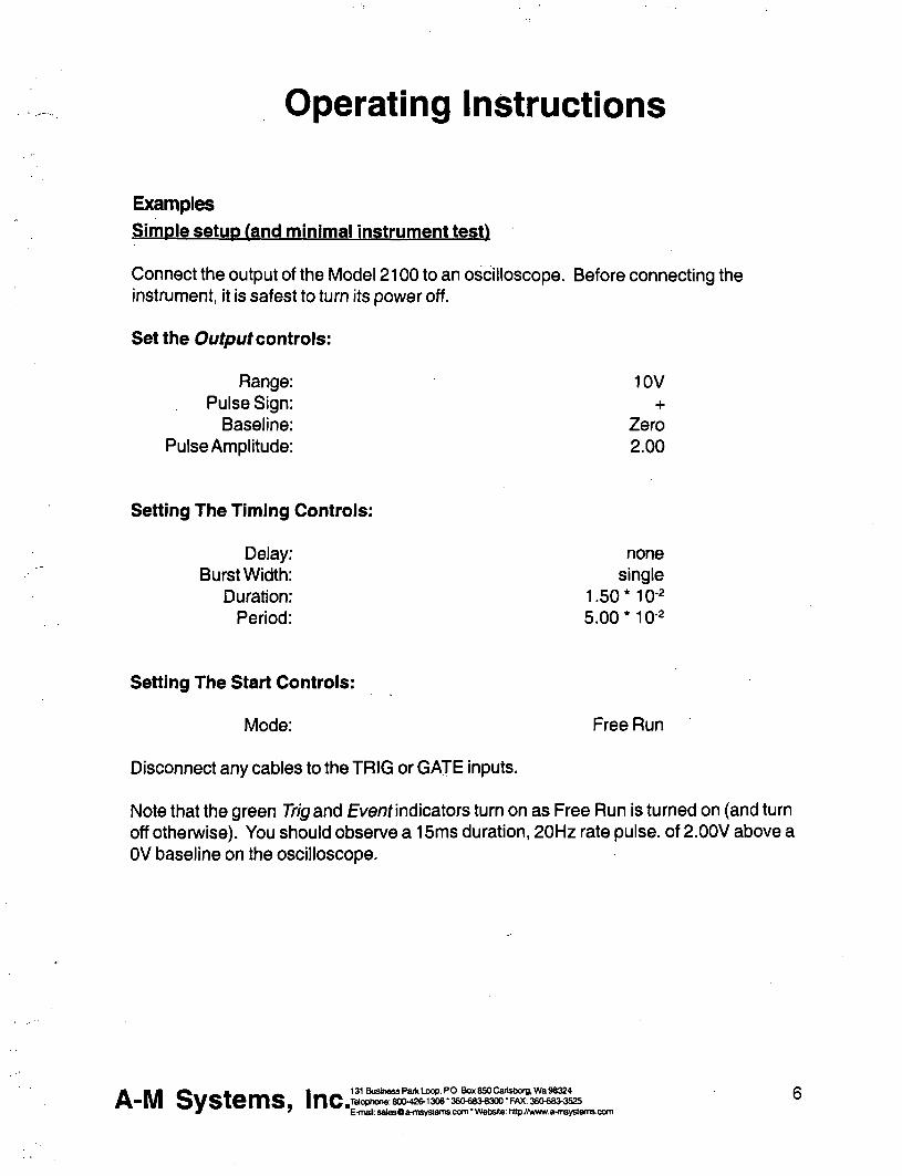
Operating Instructions
Examples Simple setup (and minimal instrument test)
Connect the output of the Model 2100 to an oscilloscope Before connecting the instrument it is safest to turn its power off
Set the Output controls
Range 10V Pulse Sign +
Baseline Zero Pulse Amplitude 200
Setting The Timing Controls
Delay none Burst Width single
Duration 150M0-2 Period 50010-2
Setting The Start Controls
Mode Free Run
Disconnect any cables to the TRIG or GATE inputs
Note that the green Trig and Evenf indicators turn on as Free Run is turned on (and turn off otherwise) You should observe a 15ms duration 20Hz rate pulse of 200V above a OV baseline on the oscilloscope
A-M Systems Inc 131 Business Pailt Loop PO Box 850 Carlsborg Wa 98324 Telophone 800-426-1306 bull 36Olaquo83-8300 FAX 360683-3S25 E-mail salesfla-msystemscom Website httpwwwa-msystemscom
Demonstration of Burst Mode Connect the output of the Model 2100 to an oscilloscope Before connecting the instrument it is safest to turn its power off
Set the Output controls
Range 10V Pulse Sign +
Baseline Pulse Amplitude 200
Baseline Amplitude 100
Setting The Timing Controls
Delay 88010-2 Burst Width 12010-^
Duration 15010-2 Period 50010-^
Set the START controls as follows
Mode Free Run
Disconnect any cables to the TRIG or GATE inputs
Trigger the oscilloscope from the Strsf trigger out (upper Trig Ouf connector) for a stable display In each burst (occurring every lOOms) you should observe a trio of 15ms duration starting 50ms apart Try switching the StartMode rom Free Run to the center (normal) position The pulses will no longer be produced and the Trig and Even indicators will turn off Pressing this switch once (to Manual) will cause a single burst to occur
A-M Systems Inc 131 Business PaiV Loop PO Box 850 Cai1sboraWa 98324 Telophone 800426-1306 360683-8300 FAX 380683-3S25 E-mal salesOa-msystemscom Website httpwwwa-m5ystemse0m
Problem Solving
If the instrument appears to be not working properly check all of the control settings and connections Be sure to wait at least 5-10 seconds after turning the instrument off before turning it on again The following summary of typical problems for the user (along with the most common solutions) may help
Problem CauseSolution
EVENT indicator never lights even in FREE RUN mode
bull Replace fuse check power connection bullSet DELAY or PERIOD to a shorter
interval bull Power-on too soon after power-off
OVERLAP indicator is on
ERROR indicator is on
Set DURATION gt000 DURATION is set to SQUARE but PERIOD is 000 Increase PERIOD or set DURATION independantly BURST and WIDTH are gt DURATION increase PERIOD or decrease DURATION BIPHASIC pulse output is on and PERIOD is not longer than twice the DURATION Increase PERIOD or decrease DURATION Free-run is on and BURST is lt PERIOD (BURST off) DELAY is 0 and PERIOD is lt DURATION Add delay or modify PERIOD Free-run is on and BURST is gt DURATION (BURSTON) and PERIOD is lt DURATION Increase PERIOD For VOLTAGE outputs the output is trying to drive too low a resistance or capacitance (eg a short circuit) Check by disconnecting the output It is possible (and normal) that for the fastest cycles and largest amplitudes (close to 100 V and 17S) that the ERROR indicator might always come on during repetitive pulses Fix output load or decrease amplitude as required
Time appears to be excessive Changed control in mid-cycle (resets current status)
A B B ^ J I - mdash 131 Business Park Loop RO Box 850 CaitsbotftWa 98324
gt | y | O y S i e m S |nCtradedegraquo0raquo 80O426-1306-36Olaquo8O8300-FAX36O683-3525
8 E-mail salesOa-msyaemscom bull Website httpwwwa-msystemscom
Cant seem to get a full signal out
Incoming triggers not accepted frequently enough
bull Load is not properly connected repair wiring
bull Too low a load impedance (VOLTAGE modes) or too high a load impedance (CURRENT mode)
bull PERIOD is set too long (enforces dead tinrie) followd by BURST set to SIGNAL Reduce PERIOD time
Table 10 Problem Solving
If you suspect that the Model 2100 may have completely failed we recommend checking the basic level of functionality If this fails your instrument is defective and must be repaired If this passes either your experimental setup is incompatible or inconsistent or there is a more subtle flaw in your Modei 2100
If the Model 2100 appears to be malfunctioning contact A-M Systems Inc or your dealer We will first attempt to solve the problem over the telephone so have an exact description of your problem available when you call You do not need to be within the warranty period to obtain over-the-phone assistance
A-M Systems Inc 131 Business Park Loop PO Box 850 Carfsbofg Wa 98324 Tatophone 80O426-1306 bull 360-688300 FAX 380683-3S25 E-mail salesfla-msystemscom Website httpwwwa-msystemscom
Theory of Operation
The operation of the Model 2100 is summarized in the block diagram (see the figure on Page 11) Not shown are all of the interconnections with the microcontroller The internal microcontroler plays an important role in setting the signal path but does not directly contribute to the dynamic characteristics It scans the front panel switches and sets the control values for the logic arrays It programs the internal counters which along with the other hardware achieve the necessary sub-microsecond speeds
All action starts either from an input trigger signal (from Trig In) or from an internal signal (in free Run mode only) A Delay timer counts the 10MHz clock until its count value is exhausted At this point the Burst timer starts Both Period and Duration timers are started at this time If the Burst timer has not expired by the end of the Period the Period and Duration timers are restarted If the Biphasic mode has been set the Duration timer is restarted at the end of the initial Duration and the sign of the output pulse is reversed doubling the total duration
The system state (pulse on pulse sip baseline sign [+0-]) is transmitted to the isolated section via optoisolator The baseline and pulse amplitudes are selected by an analog switch The resulting signal is amplified by a variable-power-supply discrete operational amplifier The amplifier connections and gain is modified to provide two voltage and three current ranges
Timing overlap errors are detected by a logical decision computation rather than by testing for counter collisions This provides instant feedback rather than waiting up to an hour for such a collision to occur Output errors are measured by sensing the output amplifiers differential input voltage Under normal conditions this is a negligible voltage If the amplifier fails to deliver the requested signal the window comparator testing this voltage sends this message (via optoisolator) to the logic section turning on a warning LED
A-M Systems Inc 131 Business Paik Loop PO Box 850 CailsboraWa 98324 i Q Te(ophone 800-426-1306 bull36O683laquo00FAX 360683-3525 ^ E-mail salesOa-msystemscom Website httpywwwa-m5ystemscom
GATE IN
TRIG ^ OUT
(burst)
OPTO ISOLATOR
Amplitude (Pulse)
TRIG -lt^ OUT
(pulse)
c 1
RANGE
C
Analog switch
C
)
-D^sectli OUTPUT
Baseline sign )
Amplitude (baseline) )
O H q
ill V) 5 o i^8 e e -a a fi a
bull o c
M E o ts gtraquo
lt
Calibration Procedures
The calibration intenal is the lesser of 1000 hours of operation or 6 months Somewhat greater drift can be expected in the first 100 hours of operation as the semiconductors age Adjustments should only be made after the instrument has been fully warmed up for at least 15 minutes
Full instrument calibration requires the following test equipment digital multimeter (plusmn 01 ) able to measure resistance to at least 10OMfl oscilloscope with at least 50MHz bandwidth true-rms voltmeter with 4MHz bandwidth universal counter (plusmn 001) able to measure single pulse widths and periods resistors (all plusmn 01) 2kn lOkO 1 watt 20ka 200ka alligator clip lead sets banana plugs and BNC adapters
Adjustment integrated circuit and test point locations are shown in the following figures All adjustments are on the timing board unless otherwise noted
All voltages in the non-isolated section should be measured with respect to ground at TP510 unless othenwise stated Some voltages are measured with respect to an internal isolated ground at TP650 or across the two output terminals Occasionally the voltage at an IC pin must be measured in these cases the reference designator is given with the pin number in parentheses eg U602(16) When it states within this procedure that a voltage is to be minimized this means that the adjustment should be made such that the measured voltage is as close to zero volts as possible Refer to the Specifications Section of this manual for acceptable tolerances
The sequence of this procedure is important If any adjustment is made all adjustments which follow must be made to ensure that the specifications will be met These procedures require that all controls remain as set in previous steps unless otherwise indicated
WARNING
The Model2100 has dangerous voltages throughout the instrument even with the power is off Servicing the Mode2700 should only be done by qualified service personnel Use caution in handling any wires connectors or electrodes which may be directly or indirectly attached to the instrument Do not touch exposed connections or components Disconnect power by unplugging the power cord from the receptacle
A B B ^ _ _ mdash ^ _ I raquo laquo 131SusinessParkLoopROBox850CaitsborBWa98324 -JO
E-mail S8le60a-msystemscom Website httpwwwa-msystemscam
CO
TP501 O o
a OTPsoo
U560 bull
D D D D Q ^ U510
Trig Gate
U570
OQ Q
U500
n U505
Timing
gt U520
Timing
) U530
Timing
gt U540
Q U515
Timing
U508
R503
DDID E
a
gt oo
bull U800 l O r v o w iV_X^TP510 O
U525
f
A U535
^ U550
Timing ^
Clock
U555
J510 Burst Delay
J400 bull U545
d R742^VWgh R619 o
r RZZ3 R737 an c n V - I J I S O I S ^ ^C-COMP
U620 ^ Q Q bull ^ ^ bull
J420 O ^ D^ J440 IfYYYlDfYyYYYYYYYII C Z J E X C T
Q Otrsetl I p J Vlow
L J TP645 C=) cm P650
bull bull fe elUOD
irt
PI pound A
o c
E o
0)
Power supply and bias voltages
Power supply
Controls Inputs Observations AdjustCheck
POWER ON Observe voltage at P703 power supply wire top of main board
Check for+15 plusmn 050 V
Observe voltage at P701 power supply wire top of main board
Check for-15 plusmn 050 V
Observe voltage at U505(24) Check for +5 plusmn 025 V
Isolated supply voltage
Controls Inputs Observations Adjust Check
RANGE 10 V TRIG open circuit MODE center position
Alternately observe V from high
R742 to R740 and V _ from kw
the U605(4) to U605(8)
Adjust R773 so that 110VltV lt 120 V and
high
28VltV^^lt34V
Capacitance balance
Controls Inputs Observations Adjust Check
Connect a x10 oscilloscope probe to TP650 and ground the
Adjust R737 for minimum high frequency signal
Inputs
Gate funct ion
Controls Inputs Observations AdjustCheck
Apply a 1 kHz 0 - 5 V triangle wave Verify that the voltage to GATE switches states at the Observe voltage at U510(3) proper input levels with an oscilloscope
Trigger s lope
Controls Inputs Observations Adjust Check
Apply a 1 kHz 0 - 5 V triangle wave Verify that the voltage to TRIG switches states at the Observe voltage at U510(1) proper input levels with an oscilloscope
TRIG SLOPE-I- Verify voltage is 180deg out of phase
TRIG SLOPE- Verify voltage is in phase
A-M Systems Inc 131 Business Paik Loop PO Box 850 Cailsborg Wa 98324 Tekvhone 8004201306 36O683laquo300 - FAX 360683-3S2S E-mail salesOa-msystemscom Website httpywwwa-msystemscom
14
Trigger and gate funct ion
Controls Inputs Observations
DELAY NONE BURSTWIDTH SINGLE DURATION SQUARE PERIOD 100X10-3
AdjustCheck
Apply a 1 kHz 0 -5 V triangle wave to TRIG Observe TRiGoand EVENT LEDS
TRIG disconnect all Short the GATE connector to GND Verify LEDs extinguish
MODE press to MANUAL Verify LEDs flash once
Timing
System clock frequency
Controls Inputs Observations Adjust Check
Observe the frequency of the wave Verify 1000 MHz plusmn 001 atU555(17)
Mu l t i p l i e rs (Whee l Sw i t ches )
Controls Inputs Observat ions A d j u s t C h e c k
PULSE SIGN+ MODE FREE RUN TRIG disconnect all TIMING MULTIPUERS all
Wheels set to zero except the one being tested
TIMING OVERLAP ignore
Observe the pulse width with the counter at the location specified below
Verify pulse width is correct for each wheel as it is tested independently
For each wheel of each MULTIPLIER test each position to verify that the pulse width is correct Observe the signal at the following locations DELAY U520(2) BURSTWIDTH U530(2) PERIOD U540(2) DURATION U550(2)
Rates (Rotary Switches)
Controls Inputs Observations A d j u s t C h e c k
TIMING MULTIPUERS 001 TIMING RATES all rotary
switches set to 10-4 except the one being tested
Observe the pulse width with the counter at the location specified below
Verify pulse width is correct for each rotary switch as it is tested independently
For each of the four rotary switches in TIMING test each position to verify that the pulse width is correct Observe the signal at the following locations DELAY U520(2) BURSTWIDTH U530(2) PERIOD U540(2) DURATION U550(2)
A-M Systems Inc 131 Business Paik Loop PO Box 850 Caiisborg Wa 98324 Telophone 800-428-1306 bull 3606808300 FAX 360683-3525 E-mail salesOa-msystemscom Website httpwwwa-msystemscom
15
Trigger outputs Controls
Range 10V Pulse Amplitude 500 Delay 100x10-2 Burst 100x10-2 Duration 100 xlQ-^ Period 400x10-3 Pulse sign + Trig Mode Free run Trig in open
Inputs Observations
Trigger the oscilloscope to the Burst Trig Out Observe it the Pulse Trig Out and the isolated output
AdjustCheck
Verify that the waveform consists of a burst of three 1 ms-on3ms-off pulses The burst trigger should be synchronous with the burst the pulse trigger coincident with each pulse
Output Calibration
Isolation Resistance (check) Controls Inputs Observations Adjust Check
Trig Mode center position Trig In open
Measure the resistance between ground banana jack (front panel) and black banana jack of output with DMM
Resistance read gt 10OMQ
Amplitude Switch Offset (R640) Controls InputsObservations AdjustCheck
Baseline Zero Trig Mode center position Trig In Open
Measure the voltage at TP645 vs TP650 with the DMM
Adjust R640 (AmpI Sw Offset) for minimum voltage
Output Offset (R332 front panel board) Controls InputsObservations AdjustCheck
Baseline Zero Range 10V Trig Mode center position Trig In Open
Measure the voltage across the output with the DMM
Adjust R332 (Output offset) for minimum voltage
Positive Baseline Offset (R607) Controls InputsObservations AdjustCheck
Baseline Sign + Baseline Amplitude
fully CCW (000) Range 10V Trig In open Trig Mode center position
Measure the voltage across the output with the DMM
Adjust R602 (BSLN + offset) for minimum voltage
A-M Systems Inc 131 Business Paik Loop PO Box 850 Cartsborg Wa 98324 Jelophone 8004201306 36O6834300 - FAX 380laquo83-352S E-mail salesOa-msystemscom Website httpwwwa-msystemscam
16
Negative Baseline Offset (R619)
Controls InputsObservations
Baseline Sign -Baseline Amplitude
fully CCW (000) Range 10V Trig In open Trig Mode center position
Measure the voltage across the output with the DMM
AdjustCheck
Adjust R619 (BSLN + offset) for minimum voltage
Pulse Ampl i tude Adjust (R602)
Controls InputsObservations AdjustCheck
Trig Mode Free Mode Pulse Amplitude 1000 Timing Delay =none Burst =single Duration =1001 Period =00110-4 Pulse Sign -Trig In open Range 10V
Measure the voltage across the output with the DMM
The Overlap indicator should be on Adjust R602 (Max Level) for -10OOV out
Pulse Sign Gain (check)
Controls InputsObservations AdjustCheck
Trig Mode Free Mode Pulse Amplitude 1000 Timing Delay =none Burst =single Duration =100 Is Period =001 10-4s Trig In open Range 10V
Measure the voltage at the output with the DMM for the Pulse Sign at + and - positions
The absolute values of the voltages should differ by less than 10OmV
Baseline Ampl i tudes (check)
Controls InputsObservations AdjustCheck
flange 100mA Trig Mode center position Baseline Amplitude fully CW (1000) Trig In open
Measure the voltage at the output with the DMM with Baseline Sign in + Zero and - positions
Gain the matching of current levels at = and - positions and offset current in Zero position
A-M Systems Inc 131 Business Psik Loop PO Box 850 Caiisborg Wa 98324 Telophone 800426-1306 bull 36Olaquo8raquo8300 bull FAX 360683-3525 E-mail salesOa-msystemscom Website httpwwwa-msystemsccm
17
Output Range Amplitude and Drive (check)
Controls InputsObservations
Pulse Amplitude 1000 Pulse Sign + Trig Mode Free Run Timing Delay =none Burst =single Duration =1001 Period =10010-4 Trig In open
Load the output with a 10KV 1W 01 resistor Measure the voltage at the output with DMM
Pulse Sign and Short Circuit Protection (check)
Controls
Timing Delay =none Burst =single Duration =200 10-4 Period =00110-3 Baseline Zero Pulse Amplitude 25 Range 10V Trig Mode Free Run Trig In open
InputsObservations
Measure the voltage at the output with the oscilloscope Check for Pulse Sign set to each of + - biphasic Watch for Error indicator when shorting the output
Output Transient Response (check)
Controls InputsObservations
Verify that full scale output is within specification Scale Range 100V 100V 10V 10V 100mA IV 1mA 10V 10mA 100V
AdjustCheck
Verify that pulses of approx 25V amplitude (625V for biphasic mode) of the correct sign are produced every 10ms Short output in biphasic mode Output should return when opened
AdjustCheck
Pulse Sign + Timing Delay =none Burst =single Duration =20010-4 Period =00110-3 Pulse Amplitude 250 Baseline Zero Trig Mode Free Mode Trig In open
Connect the oscilloscope to the output with a 310 attenuator probe Test both 10V and 10OV ranges
Verify that overshoot and risetime meet specifications
A-M Systems Inc 131 Business Paik Loop PO Box 850 Cailsbora Wa 98324 Tetophone 8004201306 bull 36Oeuro83-8300 bull FAX 360683-352S E-mail salasOa-msystemscom Website hitpywwwa-msystamsoom
18
Specifications
There are three classes of specifications Class A specifications tested in all units and are guaranteed Class B specifications are inherent in the design they are indirectly tested and are guaranteed Class C specifications are typical operating values which are occasionally tested- these are typical values given for your information but not guarshyanteed The class for each specification is noted in the center column of the following sections
Inputs Switching level
Hysteresis
Input equivalent circuit
Minimum duration (TTL-level signal)
A
C
C
C
16 V (plusmn 02 V)
approx 50 mV
lOOKfl to-1-5 in parallel with no more than 35pF
gt50ns
Open circuit condition B defaults to highon level
Timing and rate accuracy
Rate selector steps
Timing multiplier steps
B
B
100S to 100s in 7 steps
1 of rate selector step size Maximum value is 999 X the rate selector step size
Resolution B approx 01 of the maximum value
Timing error (second and later pulses after resetting controls)
B lt 002 of rate selector value + 015S
Timing error (first pulse after readjusting timing controls)
an additional 025s error may occur
Timing repeatability lt 001 settings-20 ns (mbnophasic)
A-M Systems Inc 131 Business Paik Loop PO Box 850 Caiisborg Wa 98324 Telophone 8004201306 3606808300 FAX 3606803S25 E-mail salesOa-msystemscom bull Website httpyy(wwaltTisystemscom
19
TRIG IN to OUTPUT delay (DELAY set to 0) output set to 2V
Timing jitter from TRIG IN to OUTPUT (for TTL trigger input with risetime lt10 ns)
Timing jitter from TRIG OUT (either BURST or PULSE) and OUTPUT
Trigger output to pulse output delay
Output characteristics Pulse level error (voltage mode open circuit current mode short circuit
Biphasic level difference IV-H-i-V-l2
Baseline level error (voltage mode A open circuit current mode short circuit)
Risetime (25 V out)
Risetime (25 V out)
Transient response
A
A
A
Output impedance (voltage mode) C
Output impedance (current mode) C
Isolation resistance A
Isolation capacitance C
approx 05 ps for a load of no more than 10 Kft in parallel with 50 pF
lt 125 ns (all rates except 100s) lt125ys (100s rate)
Less than 20 ns (all rates)
approx 350 ns
lt 03 of setting -i- 05 of r range (plus an additional 05vA in 100 ywA range)
lt 03 of range (voltage modes into open circuit current modes into short circuit)
lt 03 of setting of setting -I- 01 of range (plus an additional 05 pA in 100A range)
= 200 ns into less than 30 pF
= 15 yws into less than 30 pF
lt 8 overshoot into less than 30 pF for pulse voltages different than baseline voltage by at least 10 of range
= 50 ohms
raquo 1 0 Ga (typically 200 GD)
raquo 1 0 0 M n
= 60 pF at 100 Hz
A BB f ^ _ M 1 ^ ^ 131 Business Paik Loop ROBOx850Cai1sOorgWaW3Z4
- I V l o V S i e m S inC80Ph0trade80O42O1308-36O683-8300-FAX36O683-3525 7 bull bull bull bull ^ ^ E-maasale80a-m8vstemscomWebsitehitpjwwwaltnsyste
20 E-mai salesO a-m8ystemscom Website http jwwwa-msystemscom
Noise (differential mode)
Noise (common mode earth to isolated ground) with no signal output
Overload error indicator (low frequency short circuited voltage mode)
Overload error indicator low frequency open circuited current mode)
Overload error response time
Miscellaneous
= 1 mV rms (10 V scale 10 Hz-4 MHz)
- 8 mV rms (10 Hz-4 MHz) =laquo100mVp-p (200 Hz -10 MHz) measured withalOMn 15pF oscilloscope probe
Turns on for set amplitude at or greater than approx plusmn1 V (10 V range) or plusmn2 V (100 V range)
Turns on for set amplitude at or above approx 2 of range
Flat to approx 30 ps duration Decreasing sensitivity for shorter pulses
Power
Fuse
Operating temperature range
Storage temperature range
Operating humidity
Dimensions
Weight
approx 11 watts
1 amp 3 AG
10-30degC
0 - 50deg C
5 - 80 RH
17x475x1125 (inches) 432x121x286 cm
20 lbs (9 kg)
A-M Systems Inc 131 Business Paik Loop PO Box 850 Cartsborg Wa 98324 Tekjptwne 8004201306 bull 36Olaquo8O8300 bull FAX 360laquo8O3525 E-mail salesOa-msystemscom Website httpywwwa-msystemscom
21
Warranty and Service
What does this warranty cover A-f Systems Inc warrants to the Purchaser that the Instrument excluding cables Headstage Probes and any other accessories shipped with the Instrument (hereafter the hardware) is free from defects in workmanship or material under normal use and service for the period of one (1) year This warranty commences on the date of delivery of the hardware to the Purchaser
What are the obligations of A-M Systems Inc under this warranty During the warranty period A-M Systems Inc agrees to repair or replace at its sole option without charge to the Purchaser any defective component part of the hardware To obtain warranty service the Purchaser must return the hardware to A-l^ Systems Inc or an authorized A-M Systems Inc distributor in an adequate shipping container Any postage shipping and insurance charges incurred in shipping the hardware to A-M Systems Inc must be prepaid by the Purchaser and all risk for the hardware shall remain with purchaser until such time as A-M Systems Inc takes receipt of the hardware Upon receipt A-M Systems Inc will promptly repair or replace the defective unit and then return the hardware to the Purchaser postage shipping and insurance prepaid A-M Systems Inc may use reconditioned or like new parts or units at its sole option when repairing any hardware Repaired products shall carry the same amount of outstanding warranty as from original purchase or ninety (90) days which ever is greater Any claim under the warranty must include a dated proof of purchase of the hardware covered by this warranty In any event A-M Systems Inc liability for defective hardware is limited to repairing or replacing the hardware
What is not covered by this warranty This warranty is contingent upon proper use and maintenance of the hardware by the Purchaser and does not cover batteries Neglect misuse whether intentional or othenvise tampering with or altering the hardware damage caused by accident damage caused by unusual physical electrical chemical or electromechanical stress damage caused by failure of electrical power or damage caused during transportation are not covered by this warranty Products may not be returned to A-M Systems Inc for service whether under warranty or otherwise which are contaminated by Infectious agents radioactive compounds or other materials constituting a health hazard to employees of A-M Systems Inc
What are the limits of liability for A-M Systems Inc under this warranty A-M Systems Inc shall not be liable for loss of data profits or savings or any special incidental consequential indirect or other similar damages arising from breach of contract negligence or other legal action even if the company or its agent has been advised of the possibility of such damages or for any claim brought against you by another party THIS EQUIPMENT IS NOT INTENDED FOR CLINICAL MEASUREMENTS USING HUMAN SUBJECTS A-M SYSTEMS INC DOES NOT ASSUME RESPONSIBILITY FOR INJURY OR DAMAGE DUE TO MISUSE OF THIS EQUIPMENT Jurisdictions vary with regard to the enforceability of provisions excluding or limiting liability for incidental or consequential damages Check the provision of your local jurisdiction to find out whether the above exclusion applies to you
This warranty allocates risks of product failure between the Purchaser and A-M Systems Inc A-M Systems Inc hardware pricing reflects this allocation of ris1lt and the limitations of liability contained in this warranty The warranty set forth above is in lieu of all other express warranties whether oral or written The agents employees distributors and dealers of A-M Systems Inc are not authorized to make modifications to this warranty or additional warranties binding on the company Accordingly additional statements such as dealer advertising or presentations whether oral or written do not constitute warranties by A-M Systems Inc and should not be relied upon This warranty gives you specific legal rights You may also have other rights which vary from one jurisdiction to another
A B B J l laquo raquo ^ t3tBusinessPafkLoopPOBox850Cai1sbO(gWa98324
- | V | O V S i e m S |nCtrade042O1306-36O68O8300-FAX36O68O3525 E-mail salasOa-msvstemscom bull Website httowwwa-msvste
t3tBusinassParkLaopROBox8SOCai1sbo(gWa98324 po Telophone 8004201306 360683-8300 FAX 3606803525 ^ ^ E-maH salesOa-msystemscom Wetsite httpwwwa-msystem3e0m
mwal
INSTRUCTION MANUAL
FOR
ISOLATED PULSE STIMULATOR
MODEL 2100
Serial
Date
A-M Systems Inc
PO Box 850
Carisborg WA 98324
USA
360-683-8300 bull 800-426-1306 FAX 360-683-3525
httpwwwa-m8y8temscom
Version 50 May 1998
Contents General Description 1
Instrument Features 1 Controls and Connectors 2
Operating Instructions 6 Theory of Operation 10 Calibration Procedures 12
Inputs ii 14 Output Calibration iii i 16
Specifications i4 il u 19 Warranty and Service wi iJ iJi [ii 22
Each Isolated Pulse Stimulator Is delivered complete with
Rack Mount Hardware Instructions amp Maintenance Manual
NOTE
This instrument is not intended for clinical measurements using human subjects A-M Systems Inc does not assume msponsibility for injury or damage due to the misuse of this instrument
General bull M ^ ion
Instrument Features The Isolated Pulse Stimulator Model 2100 Is designed for a wide variety of applications It is highly flexible being capable of delivering single pulses biphasic pairs or bursts of pulses Pulses may be started manually or upon receiving a trigger signal from another instrument or computer Two non-isolated trigger outputs are available for triggering other instruments
Four sets of timing controls provide comprehensive control over all aspects of pulse generation Three digit accuracy is available over a 7 decade range for each timing function using lever wheel switches Pulse wkiths can be set over more than a 9 decade range from 05 [is to 999 seconds Timing accuracy is assured through the use of a 10 MHz base rate crystal-controlled clock digitally divided to provide accurate timing over the entire range A timing overiap indicator will light if the timing controls are set Inconsistently
The output may be conveniently switched between cun-ent and voltage modes Pulse and baseline amplitudes are independently presettable with lockable dials An error indicator will light if the Model 2100 cannoi deliver the desired signal
WARNING
The Model 2100 can produce potentially dangemus voltages up to 100 V et the output connectors The isolated output is not connected internally to safety (earth) ground in ahy way Some part of the extemal circuit should be connected to safety gmund Use caution in handling any wires connectors or electrodes which may be directly or indirectly attached to the Model 2100 output Some lltinds of connectors such as BNC connectors have exposed metal parts which may float at dangemus potentials unless extemally connected to safety gmund For greatest safety tum the Model 2100 off before making any connections to
the Instrument
131 Business Park LocfiPO Box BSOCarM)orgWa 98324 800426-1308 bull36OlaquoS3laquo300FAX 3 6 M 8 3 ^ 2 5
E-malt uiittyBQaHiByBtumaooiTi Wobsita HipJtwtiwiwftbMiAcon fl-N SystQms I n c ^ T
Controls and Connectors The controls for the Model 2100 are grouped in three sections START controlling when a pulse or burst of pulses begins TIMING controlling the onoff timing of one or more pulses and otJTPliT controlling the amplitude of the output signal
Start TRIG SLOPE This switch determines whether valid triggers occur at positive or negative edges in the trigger signal
MODE This switch controls how wavefomris are initiated When set to FREE RUN one timing cycle immediately follows the last When held in the MANUAL position a timing cycle starts immediately When the switch is in the center position timing cycles start when valid triggering events occur
TRIGD This LED lights up when a timing cycle is in process and continues until the burst is completed
TRIG This BNC connector allows a signal from an extemal source to initiate timing cycles It is set for standard TTL levels
GATE This BNC connector allows a signal from an extemal source to restrict the final output signal This input must be at a logical high (or open-circuited) in order for the Model 2100 to recognize either manual or automatic trigger events
Gate 1_ Trigger [~^ i I Valid triggers are represented by the arrows in the figure Note that the up arrow would apply only if TRIG SLOPE is set to + the down anrows would apply only if TRIG SLOPE is set to-
NOTE Triggers have no effect if the system has not completed its response to a previous trigger
fl-N SystQms I n c ^ 131 Business Park Loop PO Box 850 Cartsborg Wa 98324 600426-13063eO683laquo300FAX 360683^525
E-maB anBysQraquoinsyaleiTaconi Wsbalto h^KAvwwa-(nsys(smsoom
Timing Four sets of controls govem the timing of pulse generation Each set contains two values which are multiplied together to detennine the actual timing value The rotary knob (rate selector) provides the approximate timing value and the lever wheel switch bank (MULTIPLIER) provkles a time resolution of three decimal digits The following diagram shows most of the important relationships
Pnfe-tRAIM I B E L A V i6Molaquo
BURST WIOtH
Output r Delay
t n
Duration - ^ lt - |4Periodgt|
FLJI -^ Burst width
Trigger event
DELAY These controls set the time between the initiating trigger event and the beginning of the pulse burst If this rate selector is set to NONE or the multiplier is set to ooo there is no delay
BURSTWIDTH These controls set the time period in which one or more pulses may be delivered Once started a pulse may outlast the burst width If this rate selector is set to SINGLE or to any time shorter than the pulse duration only a single pulse will occur If the BURSTWIDTH is longer than the period pulses will be emitted at the PERIOD rate until the burst time ends Pulses are never truncated by a short BURST WIDTH
iNTpoundA-PULSiE PBRiOb
DURATION These controls set the length of each pulse If this rate selector is set to SQUARE the duration is set to half of the period regardless of the MULTIPLIER setting
PERIOD These controls set the period of time between adjacent pulse events within the burst It also forces a minimum dead time between recognized input triggers following a burst of one or more pulses This can be used to prevent over stimulation of a tissue without requiring excessive delay between the triggering event and the stimulating pulse
TlMtNQ OVERLAP
mLiHMPi
VVtJ jiwaa lasm nlaquoilaquo u
t^fi SysUms I n c ^ Elt4nsfl a m
131 Business Pofc Loop PO Box 850 Carisborg 1^98324 600-426-1306 36O6834300 FAK 360683^525
E-mai vrvysQfrflisysleraLOCniWutiailQL N^jAwwa^iByslernUiOOni
NOTE If any of these timing controls are changed while a timing cycle is in operation the results are undefined until the cunent cycle flnishes
TIMING OVERLAP This LED will light to indicate an Inconsistency in the timing cycle settings There are several ways to Introduce such errors The most common way is to set the inter-pulse PERIOD to be less than the pulse DURATION
TRIG OUT (UPPER) This BNC connector provides a signal which is coinckient with the intemal Burst timing signal (default) This means the signal starts at the end of the Delay time and persists until the Burst time expires This output may also be set to represent the delay time-out by setting the internal jumper J510 to the left two pins Instead of the right two pins (Please see the Calibration section in this manual for jumper location Directions are given as viewed from the fix)nt of the instrument)
TRIG OUT (LOWER) This BNC connector provides a signal which is coincident with the Duration timing signal which controls pulse output
NOTE Both trigger output signals slightly lead the isolated output signal
Output PULSE SIGN This Switch sets the sign for the pulses to be generated It also allows generation of biphasic pulses thereby doubling the effective total period Warning the first pulse genemted after changing the PULSE SIGN svntch may have the wmng polarity
BASELINE This switch sets the sign for the baseline signal
RANGE This rotary switch allows one of three current or two voltage ranges to be selected for the output signal
BASELINE AMPLITUDE This counting dial are independently set using ten-minute counting dials with the baseline having one tenth the range of the pulse amplitude
A-N Systlaquomslaquo Inc 131 Buskiess Partt Loop PO BoK 8S0 Cailsbarg Wa 96324 laophone 8004201306 bull36O68M300-FAX 3eolaquo8M525 E-mat bullmsysflMnsyslermoom VMaHsr Hlplhfimnmyekmoom
PULSE AMPLITUDE This counting dial
EVENTS This LED indicates when a pulse is ongoing
ERROR This LED indicates when the intemal output amplifier cannot output the pulse as desired This is usually due to a short circuit while trying to output a voltage or an open circuit while trying to output a current
One control from the Ot^uf section directly affects wavefonn timing the Pulse Sign control When set to the Biphasic mode a positive-going pulse is Immediately followed by a negative-going pulse This effectively doubles the pulse duration If a burst of biphasic pulses is being produced the period must be at least twice the single pulse duration In the Sgtan wave mode the baseline disappears as long as the burst persists
fl-N Systems Inc 131 Bushass Park locpPOBooi 850 C8ri9bcrgMS8324 IMqphona 800426-1306 bull36Olaquo83laquo3a0 FAX 360683-3529 E-nal amsyaOa4nsyatemscomWeMlK hMpJVniwa-nsygtatnscom
Operating Instructions
Examples Simple setup (and minimal Instrument tost)
Connect the output of the Model 2100 to an oscilloscope Before connecting the instrument it is safest to turn its power off
Set the Ou^uf controls
Range Pulse Sign
Baseline Pulse Amplitude
10V +
Zero 200
Setting The Timing Controls
Delay Burst Width
Duratbn Period
none single
15010-2 500102
Setting The Start Controls
Mode Free Run
Disconnect any cables to the TRIG or GATE Inputs
Note that the green Trig and Event Indicators tum on as Free Run is turned on (and tum off othenwise) You should observe a 15ms duration 20Hz rate pulse of 200V above a OV baseline on the oscilloscope i
A ^ M ^ _ _ _ A ^ _ _ _ 1 ^ 131BiiHnD8raquoParttloopPOBoxB50Car)sbcrBlaquoraquoS8324
bull P l ^ y S W n i S f |nC ltV^gt^8deglt^^2O1306380laquo8OS3a0FAX36O6BMS2S
6 E-fnflk 9n^fBOs-in9ystsni9cx]fnWDbs)tec H^ff9Nw^myStem9oom
Demonstration of Burst Mode Connect the output of the Model 2100 to an oscilloscope Before connecting the instrument it is safest to tum Its power off
Set the Output controls
Range Pulse Sign
Baseline Pulse Amplitude
Baseline Amplitude
Setting The Timing Controls
Delay Burst Width
Duration
Period
Set the START controls as follows
Mode
Disconnect any cables to the TRIG or GATE inputs
Trigger the oscilloscope from the Burst trigger out (upper Tr^ Out connector) for a stable display In each burst (occumng every lOOms) you should observe a trio of 15ms duration starting 50ms apart Try switching the StartMode from Free Run to the center (nomnal) position The pulses will no longer be produced and the Trig and Event indicators will turn off Pressing this switch once (to Manual) will cause a single burst to occur
880 120 150 500
10V +
200 100
102 102 102 102
Free Run
fleaff SySlQmSa |nCa deglgt ltlt ^ ^ deg ^ degdeg ^ ^ ^ bull E-matmia
131 Business Park LoopPO Box 850 Carisborg Vfe 86324 lUcphcna 800426-1306 36Olaquo83laquo300 FAX 36068raquo52 E-maft tfii8ysOiHn^nleiTBcom1AWisJto HSpitwraquoM^wytAtii9oom
Problem SoMng If the Instrument appears to be not worthing properiy check all of the control settings and connections Be sure to wait at least 5-10 seconds after turning the Instrument off before tuming it on again The following t6ef summary of typical problems for the user (along with the most common solutions) may help
Problem CauseSolution EVENT indicator never lights even in FREE RUN mode
bull Replace fuse check power connection bullSet DELAY or PERIOD to a shorter interval
bull Power-on too soon after power-off
OVERLAP Indicator is on
ERROR indicator is on
Time appears to be excessive
bullSet DURATION gt000 bull DURATION is set to SQUARE but PERIOD is 000 Increase PERIOD or set DURATION independantly
bull BURST and WIDTH are gt DURATION increase PERIOD or decrease
DURATION bull BIPHASIC pulse output is on and PERIOD is not longer than twice the DURATION Increase PERIOD or decrease DURATION
bull Free-run is on and BURST Is lt PERIOD (BURST off) DELAY is 0 and PERIOD is lt DURATION Add delay or modify PERIOD
bull Free-mn is on and BURST is gt DURATION (BURST ON) and PERIOD is lt DURATION Increase PERIOD
bull For VOLTAGE outputs the output Is trying to drive too low a resistance or capacitance (eg a short circuit) Check by disconnecting the output It is possible (and normal) that for the fastest cycles
and largest amplitudes (close to 100 V and 1 MS) that the ERROR Indicator might always come on during repetitive pulses Fix output load or decrease amplitude as required
bull Changed control in mid-cycle (resets cunent status)
A ^ M bull _ _ _ A ^ ^ _ _ i ^ mdash 131BuslnessPai1ltLoopPOBox850CarlsborgWamp98324
bull p i j ^ v s w m s iiic^^deglt^deg^^deglt^^^3degB3^^^deg^^^^degdeg^^^deg^^deg^^^^ E-mat iiiMOafflwstemseom WabaHe MtaffiwwtHtavsli
8 E-msft flmsjoQfrfraystGfnsoom ^WobsltiK hl^Aiwv9-fn9]nteniscom
Cant seem to get a full signal out
Incoming triggers not accepted frequently enough
bull Load is not properiy connected repair wiring
bull Too low a load impedance (VOLTAGE modes) or too high a load impedance
(CURRENT mode)
bull PERIOD is set too long (enforces dead time) followd by BURST set to SIGNAL Reduce PERIOD time
Table 10 Problem Solving
If you suspect that the Model 2100 may have completely failed we recommend checking the basic level of functionality If this fails your instrument is defective and must be repaired If this passes either your experimental setup is incompatible or inconsistent or there is a more subtle flaw in your Model 2100
If the Model 2100 appears to be malfunctioning contact A-M Systems Inc or your dealer Telephone numtgters for A-M Systems Inc listed on the front cover of this manual We will first attempt to solve the problem over the telephone so have an exact description of your problem available when you call You do not need to be within the warranty period to obtain over-the-phone assistance
A ^ M V - mdash A d B ^ K M I ^ M 131BuslnessPatfcLoopPOBox6SOCai
-PI s y s i Q m s inc-2raquolaquoa22=M^^
131 Business Parfc Loop PO Box 650 Cartsborg VM9 0S324 _ FAX36(W8a3525 E^nrt flnsysQa-ntsyttanB-oom Wsbsfte hHpiMNvwa-nnystsnisooni
9
Theory of Operation
The operation of the Model 2100 is summarized In the block diagram (see Fig 3) Not shown are all of the interconnections with the microcontroller The intemal microcontroler plays an important role in setting the signal path but does not directly
contribute to the dynamic characteristics It scans the front panel switches and sets the control values for the logic arays It programs the intemal counters which along with the other hardware achieve the necessary sub-microsecond speeds
All action starts either from an input trigger signal (from Trig In) or from an intemal signal (in free Run mode only) A Delay timer counts the 10MHz clock until its count value Is exhausted At this point the Burst timer starts Both Period and Duration timers are started at this time If the Burst timer has not expired by the end of the Period the Period and Duration timers are restarted If the Biphasic mode has been set the Duration timer is restarted at the end of the initial Duration and the sign of the output pulse Is reversed doubling the total duration
The system state (pulse on pulse sip baseline sign [+101-]) is transmitted to the isolated section via optoisolator The baseline and pulse amplitudes are selected by an analog switch The resulting signal is amplified by a variable-power-supply discrete operational amplifier The amplifier connections and gain is modified to provide two voltage and three cunent ranges
Timing overlap errors are detected by a logical decision computation rather than by testing for counter collisions This provides instant feedback rather than waiting up to an hour for such a collision to occur Output errors are measured by sensing the output amplifiers differential input voltage Under normal conditions this is a negligible voltage if the amplifier fails to deliver the requested signal the window comparator testing this voltage sends this message (via optoisolator) to the logic section turning on a warning LED
fl-N Systems Inc 131BusbnassPa(tLoopPOBox6SOCari3boigVMg8324 H n |TWoph0n880O426-13083eO6Blaquo300FMt36Olaquo8i3525 E-nnl anaysflfriinysleiiaoemWfcbslte hllphmwraquoimyatennoom
TRIG 3HJ) OUT
(burst)
TRIG ^ OUT
(pulse)
E
Ml
Calibration Procedures
The calibration interval is the lesser of 1000 hours of operation or 6 months Somewhat greater drift can be expected in the first 100 hours of operation as the semiconductors age Adjustments should only be made after the instrument has been fully warmed up for at least 15 minutes
Full instrument calibration requires the following test equipment digital multimeter (plusmn 01) able to measure resistance to at least lOOMfl oscilloscope with at least 50MHz bandwidth true-rms voltmeter with 4MHz bandwidth universal counter (plusmn 001 ) able to measure single pulse widths and periods resistors (all plusmn 01) 2kn lOkH 1 waft 20kn 200kn alligator clip lead sets banana plugs and BNC adapters
Adjustment integrated circuit and test point locations are shown in the following figures All adjustments are on the timing board unless otherwise noted
All voltages in the non-isolated section should be measured with respect to ground at TP510 unless othenvise stated Some voltages are measured with respect to an intemal isolated ground at TP650 or across the two output tenninals Occasionally the voltage at an IC pin must be measured In these cases the reference designator is given with the pin number in parentheses eg U602(16) When it states within this procedure that a voltage is to be minimized this means that the adjustment should be made such that the measured voltage is as close to zero volts as possible Refer to the Specifications Section of this manual for acceptable tolerances
The sequence of this procedure is Important If any adjustment is made all adjustments which follow must be made to ensure that the specifications will be met These procedures require that all controls remain as set in previous steps unless otherwise indicated
WARNING
The Model 2100 has dangerous voltages throughout the instrument even with the power is off Servicing the Model 2100 should only be done by qualified service personnel Use caution in handling any wires connectors or electrodes which may be directly or indirectly attached to the Instrument Do not touch exposed connections or components Disconnect power by unplugging the power cord from the receptacle
fl-N Systems I n c ^ 131BusinesaPartcLoopPOBox850CartsborgVWiB8324 4 n ^gt-mdash80O426-130638Ofl8Jlaquo300FAX36O683J52S bull E-maft BinsysQfrfn^islflnisoomVVfalislle h^KVfWMift^iisystemsoani
CO
- R503
Omg^
TPSOlQ O
OTPSOO
U560 bull
U510
DDID ^ trade E O ^ T P 5 1 0
bullnD Trig
0 ^
U570
Gate n U505
DO D
U515
Timing
Timing h_ U520
bsoo ^25SE Timing
Or r U540
I I Tmlng
[^ELIL
U535 D
U506
13 J510 Timlnff
BurfiDelay J400
i i i i i i i T r m r a
gt U550 ^
Clock
U555 U620
B a
^R^Pvhigh Rfijn O D O Vlow
o
bull U545
Fo sect737 lISOIsPjC-COMP
n r r ^ U760
J420
]]U632
Q S riuGSO
H = ) TP640^ deg I t I
II3D
J440 m i T i
U610 plusmn laquo j U O
bull bull l el
^t
O l
bull
M
I
Power supply and bias voltages
Power supply
Controls Inputs Observations Adjust Check
POWER ON Observe voltage at P703 power supply wire top of main board
Check for+15 plusmn 050 V
Observe voltage at P701 power supply wire top of main board
Check for-15 plusmn 050 V
Observe voltage at U505(24) Check for+5 plusmn 025 V
Isolated supply voltage
Controls Inputs Observations Adjust Check
RANGE 10 V TRIG open circuit MODE center position
Altemately observe V^ from R742 to R740 and V ^ from the U605(4) to U605(8)
Adjust R773 so that 110VltV^lt 120 V and
nign
28VltV^lt34V
Capacitance balance
Controls Inputs Observations AdjustCheck
Connect a x10 oscilloscope probe to TP650 and ground the
Adjust R737 for minimum high frequency signal
Inputs
Gate funct ion
Controls Inputs Observations AdjustCheck
Apply a 1 kHz 0 - 5 V triangle wave Verify that the voltage to GATE switches states at the Obsene voltage at U51G(3) proper input levels with an oscilloscope ^ ^
Trigger s lope
Controls Inputs Observations Adjust Check
Apply a 1 kHz 0 - 5 V triangle wave Verify that the voltage to TRIO switches states at the Observe voltage at US 10( 1) proper input levels with an oscilloscope
TRIG SLOPE + Verify voltage is 180 out of phase
TRIG SLOPE Verify voltage is in phase
fl-N Systems Inc ^ 131 Bushess Park Loop PO Bar 850 Carisborg Wa 98324 8004201306 3eOlaquoS3e300 FAX 3606BV352S
C-maft fliii8yBQfriii9yBlumaoamVIAibsMB hRpJhwMifi-iiiBystematxini
14
Trigger and gate funct ion
Controls Inputs Observations Adjust Check
DELA NONE BURS1WII3TH SINGLE DURATION SQUARE PERIOD 100X10-3
Apply a 1 kHz 0 - 5 V triangle wave to TRIG Obsen^e TRIOD and EVENT LEDS
TRIG disconnect all Short the GATE connector to GND Verify LEDs extinguish
MODE press to MANUAL Verify LEDs flash once
Timing
System c lock frequency
Controls Inputs Observations AdjustCheck
Observe the frequency of the wave atU555(17)
Verify 1000 MHz plusmn001
Multipl iers (Wheel Switches)
Controls Inputs Observations AdjustCheck
PULSE SIGN + MODE FREE RUN TRIG disconnect all TIMING MULTIPUERS ail
wheels set to zero except the one being tested
TnmiNG OVERLAP ^nOTB
Observe the pulse width with the counter at the location specified below
Verify pulse width Is correct for each wheel as it is tested Independently
For each wheel of each MULTIPUER test each position to verify that the pulse width is correct Observe the signal at the following locations DELAY U520(2) BURSTWIDTH U530(2) PERIOD US40(2) DURATION U550(2)
Rates (Rotary Switches)
Controls Inputs Observations AdjustCheck
TIMING MULTIPUERS 001 TIMING RATES all rotary
switches set to 10-4 except the one being tested
Observe the pulse width with the counter at the location specified below
Verify pulse width is conect for each rotary switch as it is tested independently
For each of the four rotary switches in TIMING test each position to verify that the pulse wkJth is correct Observe the signal at the following locations DELAY U520(2) BURSTWIDTH U530(2) PERIOD U540(2) DURATION U550(2)
fl-N Systems I n c ^ E-maft emfl
131 Business Parti Loop PO 809(850 Cartsborg Wta 98324 8004201306 3804806300 FAX 36068O3S25
E-maft ansysQa nvystems-oom Wobste hflp Avwwa4nsy8(Qnttoam
15
Trigger outputs Controls
Range 10V Pulse Amplitude 500 Delay 100x10 Burst 100x10^2 Duration 100 x1a Period 400x10^ Pulse sign + Trig Mode Free run Trig in open
Inputs Observations
Trigger the oscilloscope to the Burst Trig Out Observe it the Pulse Trig Out and the isolated output
Adjust Check
Verify that the waveform consists of a burst of three 1ms-on3ms-off pulses The burst trigger should be synchronous with the burst the pulse trigger coincident with each pulse
Output Calibration
Isolation Resistance (check) Controls Inputs Observations AdjustCheck
Trig Mode center position Trig In open
Measure the resistance between ground banana jack (front panel) and black banana jack of output with DMM
Resistance read gt 100MQ
Amplitude Switch Offset (R640) Controls InputsObservations AdjustCheck
Baseline Zero Trig Mode center position Trig In Open
Measure the voltage at TP645 vs TP650 with the DMM
Adjust R640 (AmpI Sw Offset) for minimum voltage
Output Offset (R332 front panel board) Controls I nputsObservatlons AdjustCheck
Baseline Zero Range 10V Trig Mode center position Trig In Open
Measure the voltage across the output with the DMM
Adjust R332 (Output offset) for minimum voltage
Positive Baseline Offset (R607) Controls InputsObservations AdjustCheck
Baseline Sign + Baseline Amplitude
fully CCW (000) Range 10V Trig In open Trig Mode center position
Measure the voltage across the output with the DMM
Adjust R602 (BSLN + offset) for minimum voltage
fl M raquo _ _ _ A laquo ^ _ i ^ ^ 131Buslnelaquo8Pari(loopPOBoK850Cart8borgWB96324
bull P I i s V S i e m S a |||Cg1Maphans80O42O130638O68O8300FAX36Olaquo8raquo^2S E-tiBft anagtraquoflwiisyagtlaquomraquoaimW6baHB hHpffii(wwraquoltnsylaquoleniieom
16
Negative Baseline Offset (R619) Controls
Baseline Sign -i Baseline Amplitude bull fully CCW (000)
Range 10V Trig In open Trig Mode center position
Measure the voltage across the output with the DMM
AdjustCheck
Adjust R619 (BSLN 4 offset) for minimum voltage
Pulse Amplitude Adjust (R602) Controls InputsObservations AdjustCheck
Trig Mode Free Mode Pulse Amplitude 1000 Timing Dialay =none Burst =single Duration =1001 Period =00110-4 Pulse Sign -Trig In open Range 10V
Measure the voltage across the output with the DMM
The Overiap indicator should be on Adjust R602 (Max Level) for -1000V out
Pulse Sign Gain (check) Controls InputsObservations AdjustCheck
Trig Mode Free Mode Pulse Amplitude 1000 Timing Delay =none Burst =single Duration =1001 s Period =00110-4s Trig In open Range 10V
Measure the voltage at the output with the DMM for the Pulse Sign at -- and - positions
The absolute values of the voltages should differ by less than lOOmV
Baseline Amplitudes (check) Controls InputsObservations
Range 100mA Trig Mode center position Baseline Amplitude fully CW (1000) Trig In open
Measure the voltage at the output with the DMM with Baseline Sign in + Zero and - positions
AdjustCheck
Gain the matching of current levels at = and - positions and offset current in Zero position
fl-N Systems Inc^^ bull E-mal am8
131 Business Partt Loop PO Box 850 Cartsborg Wa 88324 8004201306360laquo8Oe300FAX 360laquo8O362S
E-maM am8y8^o-mBy8tflmBoom WobaKo hHp Awwwo-f i iBystonuoom
17
Output Range Amplitude and Drive (check) Controls InputsObservations AdjustCheck
Pulse Amplitude 1000 Pulse Sign + Trig Mode Free Run Timing Delay =none Burst =8ingle Duration =1001 Period =10010-4 Trig In open
Load the output with a 10KV1W 01 resistor Measure the voltage at the output with DMM
Verify that full scale output is within specification Scale Range 100V 100V 10V 10V 100mA IV 1mA 10V 10mA 100V
Pulse Sign and Short Circuit Protection (check) Controls InputsObservations AdjustCheck
Timing Delay =none Burst =8ingle Duration =200 10-4 Period =00110-3 Baseline Zero Pulse Amplitude 25 Range 10V Trig Mode Free Run Trig In open
Measure the voltage at the output with the oscilloscope Check for Pulse Sign set to each of + - biphasic Watch for Error indicator when shorting the output
Verify that pulses of approx 25V amplitude (625V for biphasic mode) of the correct sign are produced every 10ms Short output in biphasic mode Output should retum when opened
Output Transient Response (check) Controls InputsObservations AdjustCheck
Pulse Sign + Timing Delay =none Burst =single Duration =20010-4 Period =00110-3 Pulse Amplitude 250 Baseline Zero Trig Mode Free Mode Trig In open
Connect the oscilloscope to the output with a 310 attenuator prolse Test boVn 10V and 100V ranges
Verify that overshoot and risetime meet specifications
fl-N Systems I n c ^ 131 Business Parte Loop PO Box 850 Cartsborg Wb 98324 8004201306 36Olaquo83O300 FAX 36O680lt352S
E-mQ0 snBy8Qs-msy8faiTiscom VWriMtte N ^ Mvww9-msy8lemscom
18
Specifications
There are three classes of specifications Class A specifications tested in all unHs and are guaranteed Class B specifications are inherent in the design they are indirectly tested and are guaranteed Class C specifications are typical operating values which are occasionally tested- these are typical values given for your infomiation but not guarshyanteed The class for each specification is noted in the center column of the following sections
Inputs Switching level
Hysteresis
Input equivalent circuit
Minimum duration (1 IL-level signal)
A
C
C
C
16V(plusmn02V)
approx 50 mV
100K ft to+5 In parallel with no more than 35pF
gt 50 ns
Open circuit condition B defaults to highon level
Timing and rate accuracy Rate selector steps
Timing multiplier steps
Resolution
Timing eror (second and later pulses after resetting controls)
B
B
B
B
lOOps to 100s In 7 steps
1 of rate selector step size Maximum value is 999 x the rate selector step size
approx 01 of the maximum value
lt 002 of rate selector value + 015 ps
Timing error (first pulse after readjusting timing controls)
an additional 025 ps error may occur
Timing repeatability lt 001 setting + 20 ns (monophasic)
fl-N Systems I nc ^ bull E-moU ams
131 Business Parti Loop PO Boot 850 Cartsborg VM 98324 80O42O130838O08O8300FAX36Olaquo8O3S2S
E-meU anByafl^iiisyslainaoomWebsHe hHpffliiwwraquomsys)emsoom
19
TRIG IN to OUTPUT delay (DELAY set to 0) output set to 2V
Timing jitter ft-om TRIG IN to OUTPUT (for TTL trigger input with risetime lt10 ns)
Timing jitter ft^om TRIG OUT (either BURST or PULSE) and OUTPUT
Trigger output to pulse output delay
Output charactsristics Pulse level enror (voltage mode open circuit cun-ent mode short circuit
Biphasic level difference |V + + V-|2
Baseline level error (voltage mode A open circuit current mode short circuit)
Risetime (25 V out)
Risetime (25 V out)
Transient response
A
A
A
Output impedance (voltage mode) C
Output impedance (current mode) C
Isolation resistance A
Isolation capacitance C
approx 05 ps for a load of no more than 10 Kft in parallel with 50 pF
lt 125 ns (all rates except 100s) lt 125 ps (100s rate)
Less than 20 ns (all rates)
approx 350 ns
lt 03 of setting + 05 of r range (plus an additional 05 pA inlOOpArenge)
lt 03 of range (voltage modes into open circuit current modes into short circuit)
lt 03 of setting of setting + 01 of range (plus an additional 05 pA in lOOpA range)
laquo 200 ns into less than 30 pF
laquo15 ps into less than 30 pF
lt 8 overshoot Into less than 30 pF for pulse voltages different than baseline voltage by at least 10 of range
laquo 50 ohms
raquo 1 0 Gft (typically 200 Gft)
raquo100Mft
laquo 60 pF at 100 Hz
fl-N Systems Inc^^ 131 Business Partt Uxip PO Box 850 Cartsborg Wa 96324 8004201308 SBOee^^SOO FAX 360laquoS3^52S
E-mat BiByraquoaiMii8ylaquoliiiiiseomWiljalteHlpJV(wwraquo4tgy8lenaoom
20
Noise (differential mode)
Noise (common mode earth to isolated ground) with no signal output
Overioad error indicator (low frequency short circuited voltage mode)
Overioad error indicator low frequency open circuited current mode)
Overioad enor response time
Miscellaneous
Power
Fuse
Operating temperature range
Storage temperature range
Operating humidity
Dimensions
Weight
laquo1 mV rms (10 V scale 10Hz-4MHz)
laquo 8 mV rms (10 Hz-4 MHz) laquo100mVp-p (200 Hz -10 MHz) measured withalOMft 15pF oscilloscope probe
Turns on for set amplitude at or greater than approx plusmn1V (10 V range) or plusmn2 V (100 V range)
Turns on for set amplitude at or above approx 2 of range
Flat to approx 30 ps duration Decreasing sensitivity for shorter pulses
approx 11 watts
1 amp 3 AG
10-30C
0 - 50deg C
5-80RH
17x475x1125 (Inches) 432x121x286 cm
20 lbs (9 kg)
fl mm bull gt _ _ _ A ^ ^ _ _ L ^ 131BusinesraquoPariltLocpPOBox850C8rtsborgWS9e324
bull p i ^ y s v e m s IIIC^^deg(^deg^Bdegltgt^^^3degdeg^deg^^deg^^^degdeg^^I^deg^deg^^^^^
21 E-mei flre^nQo 4n8yo(amscam Wsbsfle hHpAwwwe-msy8Jems-Oom
Warranty and Service
What does this warranty cover A-M Systems Inc warrants to the Purchaser that the Instrument excluding cables Headstage Probes and any other accessories shipped with the Instrument (hereafter the hardware) is free from defects in workmanship or material under normal use and service for the period of one (1) year This warranty commences on the date of delivery of the hardware to the Purchaser
What are the obligations of A-M Systems Inc under this warranty During the warranty period A-M Systems Inc agrees to repair or replace at its sole option without charge to the Purchaser any defective component part of the hardware To obtain warranty service the Purchaser must return the hardware to A-M Systems Inc or an authorized A-M Systems Inc distributor in an adequate shipping container Any postage shipping and insurance charges incurred in shipping the hardware to A-M Systems Inc must be prepaid by the Purchaser and all risk for the hardware shall remain with purchaser until such time as A-M Systems Inc takes receipt of the hardware Upon receipt A-M Systems Inc will promptly repair or replace the defective unit and then return the hardware to the Purchaser postage shipping and insurance prepaid A-M Systems Inc may use reconditioned or like new parts or units at its sole option when repairing any hardware Repaired products shall carry the same amount of outstanding wan^nty as from original purchase or ninety (90) days which ever is greater Any claim under the warranty must include a dated proof of purchase of the hardware covered by this wan-anty In any event A-M Systems Inc liability for defective hardware is limited to repairing or replacing the hardware
What is not covered by this warranty This warranty is contingent upon proper use and maintenance of the hardware by the Purchaser and does not cover batteries Neglect misuse whether intentional or otherwise tampering with or altering the hardware damage caused by accident damage caused by unusual physical electrical chemical or electromechanical stress damage caused by failure of electrical power or damage caused during transportation are not covered by this warranty Products may not be returned to A-M Systems Inc for service whether under warranty or otherwise which are contaminated by infectious agents radioactive compounds or other materials constituting a health hazard to employees of A-M Systems Inc
What are the limits of llabiiity for A-M Systems inc under this warranty A-M Systems Inc shall not be liable for loss of data profits or savings or any special incidental consequential indirect or other similar damages arising from breach of contract negligence or other legal action even if the company or its agent has been advised of the possibility of such damages or for any claim brought against you by another party THIS EQUIPMENT IS NOT INTENDED FOR CLINICAL MEASUREMENTS USING HUMAN SUBJECTS A-M SYSTEMS INC DOES NOT ASSUME RESPONSIBILITY FOR INJURY OR DAMAGE DUE TO MISUSE OF THIS EQUIPMENT Jurisdictions vary with regard to the enforceability of provisions excluding or limiting liability for incidental or consequential damages Check the provision of your local jurisdiction to find out whether the above exclusion applies to you This warranty allocates risks of product failure between the Purchaser and A-M Systems Inc A-M Systems Inc hardware pricing reflects this allocation of risk and the limitations of liability contained in this wanranty The warranty set forth above is in lieu of all other express wan^anties whether oral or written The agents employees distributors and dealers of A-M Systems Inc are not authorized to make modifications to this wan-anty or additional wan-anties binding on the company Accordingly additional statements such as dealer advertising or presentations whether oral or written do not constitute wananties by A-M Systems Inc and should not be relied upon This warranty gives you specific legal rights You may also have other rights whrch vary from one jurisdiction to another
6 mm ^ laquo _ _ A a B ^ _ 1 ^ ^ 131 Business Parti Loop PO Box 850 Cartsborg W B 98324 O O
bull P l A y S V e m S l n C T^M 8OO42OI3O6 380683-8300FAX 360 803525 ^ ^ E-msl iiiisy80iHTBy8tenisoom Wsbsito hnphwwfrimysleiiisoom
A
V ISO
INSTRUCTION MANUAL
FOR
ISOLATED PULSE STIMULATOR
MODEL 2100
Serial
Date
A-M Systems Inc
PO Box 850
Carlsborg WA 98324
USA
360-683-8300 bull 800-426-1306 FAX 360-683-3525
httpwwwa-msystemscom
Version 70 February 2002
Contents General Description 1
Instrument Features 1 Controls and Connectors 2
Operating Instructions 6 Theory of Operation 10 Calibration Procedures 12
Inputs 14 Output Calibration 16
Specifications 19 Warranty and Service 22
Each Isolated Pulse Stimulator is delivered complete with
Rack Mount Hardware Instructions amp Maintenance Manual
NOTE
This instrument is not intended for clinical measurements using human subjects A-M Systems Inc does not assume responsibility for Injury or damage due to the misuse of this instrument
General Description
Instrument Features The Isolated Pulse Stimulator Model 2100 is designed for a wide variety of applications It is highly flexible being capable of delivering single pulses biphasic pairs or bursts of pulses Pulses may be started manually or upon receiving a trigger signal from another Instrument or computer Two non-isolated trigger outputs are available for triggering other instruments
Four sets of timing controls provide comprehensive control overall aspects of pulse generation Three digit accuracy is available over a 7 decade range for each timing function using lever wheel switches Pulse widths can be set over more than a 9 decade range from 05 ps to 999 seconds Timing accuracy is assured through the use of a 10 MHz base rate crystal-controlled clock digitally divided to provide accurate timing over the entire range Atiming overiap indicator will light If the timing controls are set inconsistently
The output may be conveniently switched between current and voltage modes Pulse and baseline amplitudes are Independently presettable with lockable dials An error Indicator will light if the Mode2700 cannot deliver the desired signal
r WARNING
The Model 2100 can produce potentially dangerous voltages up to 100 V at the output connectors The isolated output is not connected internally to safety (earth) ground in any way Some part of the extemal circuit should be connected to safety ground Use caution in handling any wires connectors or electrodes which may be directly or indirectly attached to the Model 2100 output Some kinds of connectors such as BNC connectors have exposed metal parts which may float at dangerous potentials unless extemally connected to safety ground For greatest safety tum the Model 2100 off before making any connections to
the instrument
131 Business Parii Loop PO Box 850 Cartsborg Wa 98324 Telophone 800-426-1306 bull 360-68raquolaquo300 bull FAX 360683-3525 E-mal satesa-msystemsoom VVfebsite httpywwwa^nsystemscom fl-N Systems Inc 1
Controls and Connectors The controls for the Model 2100 are grouped in three sections START which controls when a pulse or burst of pulses begins TIMING which controls the onoff timing of one or more pulses and OUTPUT which controls the amplitude of the output signal
Start TRIG SLOPE Determines the polarity of valid trigger pulses (positive or negative edges in the trigger signal)
MODE Controls waveform initiation When set to FREE RUN one timing cycle immediately follows the last When momentarily placed In the MANUAL position a timing cycle starts Immediately When the switch Is In the center position timing cycles start when valid triggering events occur
TRIGD This LED lights up when a timing cycle Is in process and continues until the burst is completed
TRIG This BNC connector allows a signal from an external source to Initiate timing cycles It is set for standard TTL levels
GATE This BNC connector allows a signal from an external source to restrict the final output signal This input must be at a logical high (or open-circuited) in order for the Model 2100 to recognize either manual or automatic trigger events
Gate 1_ Trigger |~~^ i I Valid triggers (represented by the arrows in the figure) can occur only when the gate Is at logical high Note that the up arrow would apply only If TRIG SLOPE is set to + the down an-ows would apply only if TRIG SLOPE Is set to -
NOTE Triggers have no effect if the system has not completed its response to a previous trigger
fl-N Systems Inc 131 Business Park Loop PO Box 850 Cartsborg Vb 98324 TelQphQne 80O426-1306 360683-8300 FAX 360683-3525 E-mail sales^a-msystemscom Wsbsite httpywwwa-msystemscom
Timing Four sets of controls govern the timing of pulse generation Each set contains two values which are multiplied together to detemnine the actual timing value The rotary knob (rate selector) provides the approximate timing value and the lever wheel switch bank (MULTIPLIER)
provides a time resolution of three decimal digits The following diagram shows most of the Important relationships
Output r Delay Duration
|ltPeriodgtj
t Burst width
Trigger event
DELAY These controls determine the time duration between the initiating trigger event and the beginning of the pulse burst If this rate selector is set to NONE or the multiplier is set to 000 there Is no delay
BURST WIDTH These controls determine the time period in which one or more pulses may be delivered Once started a pulse may outlast the burst width If this rate selector is set to SINGLE or to any time shorter than the pulse duration only a single pulse will occur If the BURST WIDTH Is longer than the period pulses will be emitted at the PERIOD rate until the burst time ends Pulses are never truncated by a short BURSTWIDTH
inds)-PULSE
D U R A T I O N 1 0 1 0
10
INTEB-PULSE PERIOD
1 1 10
DURATION These controls determine the length of each pulse Ifthis rate selector Is set to SQUARE the duration is set to half of the period regardless of the MULTIPLIER setting
PERIOD These controls set the period of time between adjacent pulse events within the burst It also forces a minimum dead time between recognized input triggers following a burst of one or more pulses This can be used to prevent over stimulation of a tissue without requiring excessive delay between the triggering event and the stimulating pulse
TIMING OVERLAP
fl-N Systems Inc 131 Business Parti Loop RO Box 860 Carisborg Vamp 98324 |Telophone 800-426-1306 360683-8300 bull FAX 3606aW525 E-mail salearega^nsystemsoom Vfeb5ite httpAwwwa^nsyslemscam
NOTE If any of these timing controls are changed while a timing cycle is in operation the results are undefined until the current cycle finishes
TIMING OVERLAP This LED will light to Indicate an inconsistency in the timing cycle settings There are several ways to introduce such errors The most common way is to set the Inter-pulse PERIOD to be less than the pulse DURATION
T I M I N G (seconds)^
TRIG OUT (UPPER) This BNC connector provides a signal which is coincident with the Internal Burst timing signal (default) This means the signal starts at the end of the Delay time and persists until the Burst time expires This output may also be set to represent the delay time-out by setting the internal jumper J510 to the right two pins instead of the left two pins (Please see the Calibration section in this manual for jumper location Directions are given as viewed from the front of the Instrument)
TRIG OUT (LOWER) This BNC connector provides a signal which Is coincident with the Duration timing signal which controls pulse output
NOTE Both trigger output signals slightly lead the isolated output signal
Output
PULSE SIGN This switch determines the polarity of the pulses to be generated It also allows generation of biphasic pulses thereby doubling the effective total period Warning the first pulse generated after changing the PULSE
SIGN switch may have the wrong polarity
BASELINE This Switch determines the polarity ofthe baseline signal
RANGE This rotary switch determines if the output pulses will be constant current (3 ranges) or constant voltage (2 ranges)
BASELINE AMPLITUDE This value is independently set using a ten-turn counting dial The maximum baseline amplitude is one tenth the value shown on the range amplitude switch
fl-N Systems Inc 131 Business Parti Loop RO Box 8S0 Cartsborg Vfa 98324 |Tetaphone 80O426-1306 bull 360683-8300 bull FAX 3606803525 E-mail salesa-msystemscom Wbbsite http7Awwwaflnsystemscom
PULSE AMPLITUDE This value is independently set using a ten-turn counting dial The maximum pulse amplitude is the value shown on the range amplitude switch
EVENT This LED indicates when a pulse is ongoing
ERROR This LED indicates when the internal output amplifier cannot output the pulse as desired This is usually due to a short circuit while trying to output a voltage or an open circuit while trying to output a current
VOTEThe Pulse Sign control in the Oupuf section directly affects waveform timing When set to the Biphasic mode a positive-going pulse is immediately followed by a negative-going pulse This effectively doubles the pulse duration If a burst of biphasic pulses is being produced the period must be at least twice the single pulse duration In the Square wave mode the baseline disappears as long as the burst persists
fl-N Systems Inc 131 Business Parti Loop RO Box 850 Cartsboig Vte 98324 |Telophone 800426-1306 360683-8300 bull FAX 3606833525 E-mail salesa-m5ystem5 com Website httpwwwa-msystemscom
Operating Instructions
Examples Simple setup (and minimal instrument test)
Connect the output ofthe Model 2100 to an oscilloscope Before connecting the Model 2100 to any other instrument or the experimental preparation It is safest to turn Its power off
Set the Oufpuf controls
Range 10V Pulse Sign +
Baseline Zero Pulse Amplitude 200
Setting The Timing Controls
Delay Burst Width
Duration Period
none single
15010-2 50010-2
Setting The Start Controls
Mode Free Run
Disconnect any cables to the TRIG or GATE inputs
Note that the green Trig and Event Indicators turn on as Free Run is turned on (and turn off otherwise) You should observe a 15ms duration 20Hz rate pulse of 200V above a OV baseline on the oscilloscope
fl-N Systems Inc 131 BusinessPartiLoop RO Box850CarisbcxgWa98324 |Telophone 800426-1306 bull 360-683-8300 bull FW 360683-3525 E-mail salesa-msystems com VVbbsite httpywwwa-msystems com
Demonstration of Burst Mode Connect the output ofthe Model 2100 to an oscilloscope Before connecting the Model 2100 to any other instrument or the experimental preparation It Is safest to turn its power off
Set the Outpuf controls
Range 10V Pulse Sign +
Baseline Pulse Amplitude 200
Baseline Amplitude 100
Setting The Timing Controls
Delay 88010-2 Burst Width 12010-^
Duration 15010-2 Period 50010-2
Set the START controls as follows
Mode Free Run
Disconnect any cables to the TRIG or GATE inputs
fl-N Systems Inc 131 Business Parti Loop RO Box 850 Cartsborg Wa 98324 Telophooe 8004201306 360683-8300 bull FAX 360683-3525 E^naii salesa-msystems com Watjsite http7wwwa-msystemscom
Trigger the oscilloscope from the Bursf trigger out (upper Trig Out connector) for a stable display In each burst (occurring every lOOms) you should observe a trio of 15ms duration starting 50ms apart Try switching the StartMode from Free Run to the center (nonnal) position The pulses will no longer be produced and the Trig and Event Indicators will tum off Pressing this switch once (to Manual) will cause a single burst to occur
Problem Solving If the instrument appears to be not working properiy check all ofthe control settings and connections Be sure to wait at least 5-10 seconds after turning the instrument off before turning it on again The following summary of typical problems for the user (along with the most common solutions) may help
Problem CauseSolution
EVENT Indicator never lights even in FREE RUN mode
bull Replace fuse check power connection bullSet DELAY or PERIOD to a shorter interval
bull Power-on too soon after power-off
OVERLAP Indicator is on
ERROR indicator is on
bull Set DURATION gt000 bull DURATION Is set to SQUARE but
PERIOD is 000 Increase PERIOD or set DURATION independantly
bull BURST and WIDTH are gt DURATION increase PERIOD or decrease DURATION
bull BIPHASIC pulse output Is on and PERIOD is not longer than twice the DURATION Increase PERIOD or decrease DURATION
bull Free-run Is on and BURST is lt PERIOD (BURST off) DELAY is 0 and PERIOD Is lt DURATION Add delay or modify PERIOD
bull Free-run is on and BURST is gt DURATION (BURST ON) and PERIOD is lt DURATION Increase PERIOD
bull For VOLTAGE outputs the output is trying to drive too low a resistance or capacitance (eg a short circuit) Check by disconnecting the output ft is possible (and normal) that for the fastest cycles and largest amplitudes (close to 100 V
fl-N Systems Inc 131 Business PartiLoop PO Box 850 CartsborgWa 98324 iTelophone 800-42O130636O6e3-8300FAX 3606B3-3525 E-mail satesaflisyslefmcom Vfebslte http7wwwa-msyslemscom
and 1 ps) that the ERROR indicator might always come on during repetitive pulses Fix output load or decrease amplitude as required
Time appears to be excessive Changed control in mid-cycle (resets current status)
Cant seem to get a full signal out Load Is not properiy connected repair wiring Too low a load impedance (VOLTAGE modes) or too high a load impedance (CURRENT mode)
Incoming triggers not accepted frequently enough
PERIOD is set too long (enforces dead time) followd by BURST set to SIGNAL Reduce PERIOD time
Table 10 Problem Solving
If you suspect that the Model 2100 may have completely failed we recommend checking the basic level of functionality Ifthis fails your instrument Is defective and must be repaired Ifthis passes either your experimental setup is incompatible or inconsistent or there is a more subtle flaw in your Model 2100
If the Model 2100 appears to be malfunctioning contact A-M Systems Inc or your dealer We will first attempt to solve the problem over the telephone so have an exact description of your problem available when you call You do not need to be within the warranty period to obtain over-the-phone assistance
fl-N Systems Inc 131 Business Parti Loop RO Box 850 Cartsborg Wa 98324 iTetoptxme 80O426-1306 bull 360683-8300 FAX 3606803525 E-mail satesa-msystemsoomAfebsitehttpJwwwaflisystemscom
Theory of Operation
The operation ofthe Model 2100 is summarized in the block diagram (see the figure on Page 11) Not shown are all ofthe interconnections with the microcontroller The internal microcontroler plays an important role in setting the signal path but does not directly contribute to the dynamic characteristics It scans the front panel switches and sets the control values for the logic arrays It programs the internal counters which along with the other hardware achieve the necessary sub-microsecond speeds
Pulse generation starts either from an Input trigger signal (from Trig In) or an internally signal (Free Run mode) A Delay timer counts the 10MHz clock until its count value is exhausted At this point the Burst Period and Duration timers are started If the Burst timer has not expired by the end ofthe Period the Period and Duration timers are restarted If the Biphasic mode has been set the Duration timer is restarted at the end of the initial Duration and the sign ofthe output pulse is reversed doubling the total duration
The system state (pulse on pulse sign baseline sign [+0f-]) is transmitted to the isolated section via optoisolator The baseline and pulse amplitudes are selected by an analog switch The resulting signal is amplified by a variable-power-supply discrete operational amplifier The amplifier connections and gain is modified to provide two voltage and three current ranges
Timing overiap errors are detected by a logical decision computation rather than by testing for counter collisions This provides instant feedback rather than waiting up to an hour for such a collision to occur Output errors are measured by sensing the output amplifiers differential input voltage Under normal conditions this is a negligible voltage If the amplifier fails to deliver the requested signal the window comparator testing this voltage sends this message (via optoisolator) to the logic section turning on a warning LED
fl-N Systems Inc 131BusinessPart(LoopRO Box850CarisboigWa98324 4 n Tel0pri0ne80O426-130636O683^300FAX36O6833525 ^ E-mail salesaflisystBmscom V febsite http7wwwa-msystemsoom
S i
I - - ^^mdasho^M
OUTPUT i l l
TRIG ^ OUT
(burst)
TRIG 3-lt) OUT
(pulse)
til
I laquo
Calibration Procedures
The calibration interval is the lesser of 1000 hours of operation or 6 months Somewhat greater drift can be expected in the first 100 hours of operation as the semiconductors age Adjustments should only be made after the instrument has been fully warmed up for at least 15 minutes
Full instrument calibration requires the following test equipment digital multimeter (plusmn 01) able to measure resistance to at least lOOMO oscilloscope with at least 50MHz bandwidth true-mis voltmeter with 4MHz bandwidth universal counter (plusmn 001 ) able to measure single pulse widths and periods resistors (all plusmn 01) 2kn lOkH 1 watt 20kn 200kn alligator clip lead sets banana plugs and BNC adapters
Adjustment integrated circuit and test point locations are shown in the following figures All adjustments are on the timing board unless othenAise noted
All voltages in the non-isolated section should be measured with respect to ground at TP510 unless othenwise stated Some voltages are measured with respect to an internal isolated ground at TP650 or across the two output temninals Occasionally the voltage at an IC pin must be measured in these cases the reference designator is given with the pin number in parentheses eg U602(16) When it states within this procedure that a voltage is to be minimized this means that the adjustment should be made such that the measured voltage is as close to zero volts as possible Refer to the Specifications Section of this manual for acceptable tolerances
The sequence of this procedure is important If any adjustment is made all adjustments which follow must be made to ensure that the specifications will be met These procedures require that all controls remain as set in previous steps unless othenAise indicated
WARNING
The Model 2100 has dangerous voltages throughout the instrument even with the power is off Servicing the Model 2100 should only be done by qualified service personnel Use caution in handling any wires connectors or electrodes which may be directly or indirectly attached to the instrument Do not touch exposed connections or components Disconnect power by unplugging the power cord from the receptacle
H B ^ ^ S y s t e m s inc^degdegp^deg^^deg-^^^^^^^^B3^^^degdeg^^^lt^^^B^^^^ 131BusinessPartiLoopPO Box850CartsbOigWamp98324 4 9 |Telophone800-42013C6360683-8300F0lt360683-3525 ^ E-mail salesa-msystefnscom website httpwwwaflisystems com
CO
TP501 O lt0
g OTPSOO
U560 S
Trig Gate
0 -TISOS
U570
U500
Timing
p U520
Timing
K U550 Timin
gt U540
U515
o X I Timin
U508 I
J510 Timing nnn
Burst Delay J400
gt U550
R503
D D I D bull U8QQ i Q
n
oo
V P 5 1 0
b U535
^
Clock i _
U555
lt U 5 4 5
o
h d ^ O - - ^ U605
Q D
U620
O fJZ^ R737 bull ^ 1^13015 r j C - C O M P
B B nU770 ^ ^ ^ 5 ^ a
J420
a
o E
bull [ ]U632
riueso
rR742rVhigh R 6 1 9 ^
LJ TP645 O TP650
TPMOQ^QS
Vlow
CD-
CZZl
J440 bull bull tl iUDQ
I t
f i l
Power supply and bias voltages
Power supply
Controls Inputs Observations Adjust Check
POWER ON Observe voltage at P703 power supply wire top of main board
Check for+15 plusmn 050 V
Observe voltage at P701 power supply wire top of main board
Check for-15 plusmn 050 V
Observe voltage at U505(24) Check for +5 plusmn 025 V
Isolated supply voltage Controls Inputs Observations AdjustCheck
RANGE 10 V TRIG open circuit MODE center position
Alternately observe V ^ from R742 to R740 and V ^ from theU605(4)toU605(8)
Adjust R773 so that 110VltV lt 120 V and
nigh
28VltV|^lt34V
Capacitance balance Controls Inputs Observations Adjust Check
Connect a xlO oscilloscope probe to TP650 and ground the
Adjust R737 for minimum high frequency signal
Inputs
Gate function Controls Inputs Observations AdjustCheck
Apply a 1 kHz 0 - 5 V triangle wave Verify that the voltage to GATE switches states at the Observe voltage at U510(3) proper input levels with an oscilloscope
Trigger slope Controls Inputs Observations AdjustCheck
Apply a 1 kHz 0 - 5 V triangle wave Verify that the voltage to TRIG switches states at the Observe voltage at U510( 1) proper input levels with an oscilloscope
TRIG SLOPE Verify voltage is 180deg out of phase
TRIG SLOPE Verify voltage is in phase
fl-N Systems Inc 131 Business Parti Loop RO Box 860 Cartsborg Wa 98324 Jelophone 800-4201306 360683-8300 bull FM 380683-3525 E-mail salesaflTsystBfnscom bull Vtebsite httpVAirwwaflisystems com
14
Trigger and gate f unc t i on
Controls Inputs Observations Adjust Check
DELAY NONE BURS-nMDTH SINGLE DURATION SQUARE PERIOD 100X10-3
Apply a 1 kHz 0 - 5 V triangle wave to TRIG Observe TRIGD and EVENT LEDs
TRIG disconnect all Short the GATE connector to GND Verify LEDs extinguish
MODE press to MANUAL Verify LEDs flash once
Timing
System c lock f requency
Controls Inputs Observations Ad jus t Check
Observe the frequency of the wave Verify 1000 MHz plusmn 001 atU555(17)
Mul t ip l iers (Wheel Swi tches)
Controls Inputs Observations Adjust Check
PULSE SIGN-laquobull MODE FREE RUN TRIG disconnect all TIMING MULTIPUERS all
wheels set to zero except the one being tested
TIMING OVERLAP ignore
Observe the pulse width with the counter at the location specified t)elow
Verify pulse width is correct for each wheel as it is tested independently
For each wheel of each MULTIPLIER test each position to verify that the pulse width is correct Observe the signal at the following locations DELAY U520(2) BURSTWIDTH U530(2) PERIOD U540(2) DURATION U550(2)
Rates (Rotary Swi tches)
Controls Inputs Observations Adjust Check
TIMING MULTIPUERS 001 Observe the pulse width with the TIMING RATES all rotary counter at the location specified
switches set to 10-4 below except the one being tested
Verify pulse width is correct for each rotary switch as it is tested independently
For each ofthe four rotary switches in TIMING test each position to verify that the pulse width is correct Observe the signal at the following locations DELAY U520(2) BURSTWIDTH U530(2) PERIOD U540(2) DURATION U550(2)
fl-N Systems Inc 131 Business Parti Loop PO Box 850 Cartsborg Wa 98324 iTetophone 8004201306 bull 360683-8300 bull FOC 3606803525 E-mail salesa-msystemscom Wbbsite httpJwwwaflTSystemscom
15
Trigger outputs
Controls Inputs Observations Adjust Check
Range 10V Pulse Amplitude 500 Delay 100 xlO^ Burst 100 x 10 ^ Duration 100x10-^ Period 400x10-^ Pulse sign + Trig Mode Free run Trig in open
Trigger the oscilloscope to the Burst Trig Out Observe it the Pulse Trig Out and the isolated output
Verify that the waveform consists of a burst of three 1ms-on3ms-off pulses The burst trigger should be synchronous with the burst the pulse trigger coincident with each pulse
Output Calibration
Isolation Resistance (check)
Controls Inputs Observations AdjustCheck
Trig Mode center position Trig In open
Measure the resistance between ground banana jack (front panel) and black banana jack of output with DMM
Resistance read gt 100MQ
Amplitude Switch Offset (R640)
Controls InputsObservations AdjustCheck
Baseline Zero Trig Mode center position Trig In Open
Measure the voltage at TP645 vs TP650 with the DMM
Adjust R640 (AmpI Sw Offset) for minimum voltage
Output Offset (R332 front panel board) Controls InputsObservations AdjustCheck
Baseline Zero Range 10V Trig Mode center position Trig In Open
Measure the voltage across the output with the DMM
Adjust R332 (Output offset) for minimum voltage
Positive Baseline Offeet (R607) Controls InputsObservations AdjustCheck
Baseline Sign + Baseline Amplitude
fully CCW (000) Range 10V Trig In open Trig Mode center position
Measure the voltage across the outputwiththeDMM
Adjust R602 (BSLN + offset) for minimum voltage
fl-N Systems Inc 131 BusBiess Parti Loop P O Box 850 Cartsborg Wa 98324 Telophone B00-42O1306 bull 360683-8300 bull FAX 3606803525 E-mail salesaflisystemscom V^tebsite httpy^vwwa-msystems com
16
Negative Baseline Offset (R619)
Controls InputsObservations AdjustCheck
Baseline Sign -Baseline Amplitude
fully CCW (000) Range 10V Trig In open Trig Mode center position
Measure the voltage across the outputwiththeDMM
Adjust R619 (BSLN + offset) for minimum voltage
Pulse Amplitude Adjust (R602)
Controls InputsObservations AdjustCheck
Trig Mode Free Mode Pulse Amplitude 1000 Timing Delay =none Burst =single Duration =1001 Period =00110-4 Pulse Sign -Trig In open Range 10V
Measure the voltage across the output with the DMM
The Overiap indicator should be on Adjust R602 (Max Level) for -10OOV out
Pulse Sign Gain (check)
Controls InputsObservations AdjustCheck
Trig Mode Free Mode Pulse Amplitude 1000 Timing Delay =none Burst =single Duration =100 1s Period =001 10-4s Trig In open Range 10V
Measure the voltage at the output with the DMM for the Pulse Sign at + and - positions
The absolute values ofthe voltages should differ by less than lOOmV
Baseline Amplitudes (check) Controls InputsObservations AdjustCheck
Range 100mA Trig Mode center position Baseline Amplitude fully CW (1000) Trig In open
Measure the voltage at the output with the DMM with Baseline Sign in + Zero and
- positions
Gain the matching of current levels at = and - positions and offset current in Zero position
fl-N Systems Inc 131 Business Parti Loop PO Box 850 Cartsboig Wa 98324 Telophone 800-4201306 360683-8300 FkX 3606803525 E-mail salesa-msystemscom website http^^wwaflisystemsccm
17
Output Range Amplitude and Drive (check) Controls InputsObservations AdjustCheck
Pulse Amplitude 1000 Pulse Sign + Trig Mode Free Run Timing Delay =none Burst =single Duration =1001 Period =10010-4 Trig In open
Load the output with a 10KV 1W 01 resistor Measure the voltage at the output with DMM
Verify that full scale output is within specification Scale Range 100V 100V 10V 10V 100mA IV 1mA 10V 10mA 100V
Pulse Sign and Short Circuit Protection (check) Controls InputsObservations AdjustCheck
Timing Delay =none Burst =single Duration =200 10-4 Period =00110-3 Baseline Zero Pulse Amplitude 25 Range 10V Trig Mode Free Run Trig In open
Measure the voltage at the output with the oscilloscope Check for Pulse Sign set to each of + - biphasic Watch for Error indicator when shorting the output
Verify that pulses of approx 25V amplitude (625V for biphasic mode) of the correct sign are produced every 10ms Short output in biphasic mode Output should return when opened
Output Transient Response (check) Controls InputsObservations AdjustCheck
Pulse Sign + Timing Delay =none Burst =single Duration =20010-4 Period =00110-3 Pulse Amplitude 250 Baseline Zero Trig Mode Free Mode Trig In open
Connect the oscilloscope to the output with a 310 attenuator probe Test both 10V and 100V ranges
Verify that overshoot and risetime meet specifications
fl-N Systems Inc 131 Business Parti Loop RO Box 850 Cartsborg Wa 98324 Telophone 8004201306 bull 3606808300 bull Flaquo( 360laquo83ltJ525 E-mail salesa-msystemsocm V^febsite http^wwwa-msystefnscom
18
Specifications
There are three classes of specifications Class A specifications tested in all units and are guaranteed Class B specifications are inherent in the design they are indirectly tested and are guaranteed Class C specifications are typical operating values which are occasionally tested- these are typical values given for your information but not guarshyanteed The class for each specification is noted in the center column ofthe following sections
Inputs Switching level
Hysteresis
Input equivalent circuit
Minimum duration (1 IL-level signal)
A
C
C
C
16 V(plusmn 02 V)
approx 50 mV
lOOKH to+5 in parallel with no more than 35pF
gt 50 ns
Open circuit condition B defaults to highon level
Timing and rate accuracy Rate selector steps
Timing multiplier steps
B
B
lOOpsto 100s in 7 steps
1 of rate selector step size Maximum value is 999 X the rate selector step size
Resolution B approx 01 ofthe maximum value
Timing error (second and later pulses after resetting controls)
B lt 002 of rate selector value + 015 ps
Timing error (first pulse after readjusting timing controls)
an additional 025 ps error may occur
Timing repeatability lt 001 setting + 20 ns (monophasic)
fl-N Systems Inc 131 Business Ram Loop RO Box 850 Cartsborg Vfa 98324 pTelophone 8004201306 bull 360683-8300 bull FAX 360683-3525
E-mail salesraquoflisystems com Wabsite httpJAnww afl isystems com
19
TRIG IN to OUTPUT delay (DELAY set to 0) output set to 2V
Timing jitter from TRIG IN to OUTPUT (for TTL trigger input with risetime lt10 ns)
Timing jitter from TRIG OUT (either BURST or PULSE) and OUTPUT
Trigger output to pulse output delay
Output characteristics Pulse level error (voltage mode open circuit current mode short circuit
Biphasic level difference IV + - V-1 2
Baseline level error (voltage mode open circuit current mode short circuit)
Risetime (25 V out)
Risetime (25 V out)
Transient response
A
A
A
Output impedance (voltage mode) C
Output impedance (current mode) C
Isolation resistance A
Isolation capacitance C
approx 05 ps for a load of no more than 10 KH in parallel with 50 pF
lt 125 ns (all rates except 100s) lt 125 ps (100s rate)
Less than 20 ns (all rates)
approx 350 ns
lt 03 of setting + 05 of r range (plus an additional 05 pA in 100 pA range)
lt 03 of range (voltage modes into open circuit current modes into short circuit)
lt 03 of setting of setting + 01 of range (plus an additional 05 pA in lOOpA range)
= 200 ns into less than 30 pF
= 15 ps into less than 30 pF
lt 8 overshoot into less than 30 pF for pulse voltages different than baseline voltage by at least 10 of range
= 50 ohms
raquo 1 0 GH (typically 200 GO)
raquo 1 0 0 M n
= 60 pF at 100 Hz
fl-N Systems Inc 131 Business Peril Loop PO Box 850 Cartsborg V6 98324 |TelCf)hone 800-4201306 3606808300 bull FAX 360683-3525 E-mal salesaflisystefnsoom Website hnpyMVfWafllsystemsoom
20
Noise (differential mode)
Noise (common mode earth to isolated ground) with no signal output
Overload error indicator (low frequency short circuited voltage mode)
Overload error indicator low frequency open circuited current mode)
Overioad error response time
Miscellaneous
= 1 mV rms (10 V scale 10 Hz-4 MHz)
= 8 mV rms (10 Hz-4 MHz) == 100mVp-p (200 Hz -10 MHz) measured withalOMH 15pF oscilloscope probe
Turns on for set amplitude at or greater than approx plusmn1 V (10 V range) or plusmn2 V (100 V range)
Turns on for set amplitude at or above approx 2 of range
Flat to approx 30 ps duration Decreasing sensitivity for shorter pulses
Power
Fuse
Operating temperature range
Storage temperature range
Operating humidity
Dimensions
approx 11 watts
1 amp 3AG
10-30degC
0 - 50deg C
5 - 80 RH
17x475x1125 (inches) 432x121x286 cm
Weight 20 lbs (9 kg)
fl-N Systems Inc 131 Business Parti Loop RO Box 850 Cartsborg Wb 98324 |Tetcphone 8004201306 3606808300 bull FOt 360683-3525 E-mail satesamsystems comV^febsite httpywwwaflisystemscom
21
Warranty and Service
What does this warranty cover A-M Systems Inc warrants to the Purchaser that the Instrument excluding cables Headstage Probes and any other accessories shipped with the Instrument (hereafter the hardware) is free from defects in workmanship or material under normal use and service for the period of one (1) year This warranty commences on the date of delivery ofthe hardware to the Purchaser
What are the obligations of A-M Systems Inc under this warranty During the warranty period A-M Systems Inc agrees to repair or replace at its sole option without charge to the Purchaser any defective component part of the hardware To obtain warranty service the Purchaser must return the hardware to A-M Systems Inc or an authorized A-M Systems Inc distributor in an adequate shipping container Any postage shipping and insurance charges incurred in shipping the hardware to A-M Systems Inc must be prepaid by the Purchaser and all risk for the hardware shall remain with purchaser until such time as A-M Systems Inc takes receipt of the hardware Upon receipt A-M Systems Inc will promptly repair or replace the defective unit and then return the hardware to the Purchaser postage shipping and insurance prepaid A-M Systems Inc may use reconditioned or like new parts or units at its sole option when repairing any hardware Repaired products shall carry the same amount of outstanding warranty as from original purchase or ninety (90) days which ever is greater Any claim under the warranty must include a dated proof of purchase ofthe hardware covered by this warranty In any event A-M Systems Inc liability for defective hardware is limited to repairing or replacing the hardware
What is not covered by this warranty This warranty is contingent upon proper use and maintenance ofthe hardware by the Purchaser and does not cover batteries Neglect misuse whether intentional or othenwise tampering with or altering the hardware damage caused by accident damage caused by unusual physical electrical chemical or electromechanical stress damage caused by failure of electrical power or damage caused during transportation are not covered by this wan-anty Products may not be returned to A-M Systems Inc for service whether under warranty or otherwise which are contaminated by infectious agents radioactive compounds or other materials constituting a health hazard to employees of A-M Systems Inc
What are the limits of liability for A-M Systems Inc under this warranty A-M Systems Inc shall not be liable for loss of data profits or savings or any special incidental consequential indirect or other similar damages arising from breach of contract negligence or other legal action even if the company or its agent has been advised of the possibility of such damages or for any claim brought against you by another party THIS EQUIPMENT IS NOT INTENDED FOR CLINICAL MEASUREMENTS USING HUMAN SUBJECTS A-M SYSTEMS INC DOES NOT ASSUME RESPONSIBILITY FOR INJURY OR DAMAGE DUE TO MISUSE OF THIS EQUIPMENT Jurisdictions vary with regard to the enforceability of provisions excluding or limiting liability for incidental or consequential damages Check the provision of your local jurisdiction to find out whether the above exclusion applies to you
This warranty allocates risks of product failure between the Purchaser and A-M Systems Inc A-M Systems Inc hardware pricing reflects this allocation of risk and the limitations of liability contained in this warranty The warranty set forth above is in lieu of all other express warranties whether oral or written The agents employees distributors and dealers of A-M Systems Inc are not authorized to make modifications to this warranty or additional wan-anties binding on the company Accordingly additional statements such as dealer advertising or presentations whether oral or written do not constitute warranties by A-M Systems Inc and should not be relied upon This warranty gives you specific legal rights You may also have other rights which vary from one jurisdiction to another
fl-N Systems Inc 131BusinessPartiLoop RO Box850CartsbOfgWa98324 p O |Telophone 8004201306 bull 360683-8300FOC 3606830525 ^ ^ E-mail saiesaflisystefTiscom Wbbsite httpVwwwa-msystemscom

Cant seem to get a full signal out
Incoming triggers not accepted frequently enough
bull Load is not properly connected repair wiring
bull Too low a load impedance (VOLTAGE modes) or too high a load impedance (CURRENT mode)
bull PERIOD is set too long (enforces dead tinrie) followd by BURST set to SIGNAL Reduce PERIOD time
Table 10 Problem Solving
If you suspect that the Model 2100 may have completely failed we recommend checking the basic level of functionality If this fails your instrument is defective and must be repaired If this passes either your experimental setup is incompatible or inconsistent or there is a more subtle flaw in your Modei 2100
If the Model 2100 appears to be malfunctioning contact A-M Systems Inc or your dealer We will first attempt to solve the problem over the telephone so have an exact description of your problem available when you call You do not need to be within the warranty period to obtain over-the-phone assistance
A-M Systems Inc 131 Business Park Loop PO Box 850 Carfsbofg Wa 98324 Tatophone 80O426-1306 bull 360-688300 FAX 380683-3S25 E-mail salesfla-msystemscom Website httpwwwa-msystemscom
Theory of Operation
The operation of the Model 2100 is summarized in the block diagram (see the figure on Page 11) Not shown are all of the interconnections with the microcontroller The internal microcontroler plays an important role in setting the signal path but does not directly contribute to the dynamic characteristics It scans the front panel switches and sets the control values for the logic arrays It programs the internal counters which along with the other hardware achieve the necessary sub-microsecond speeds
All action starts either from an input trigger signal (from Trig In) or from an internal signal (in free Run mode only) A Delay timer counts the 10MHz clock until its count value is exhausted At this point the Burst timer starts Both Period and Duration timers are started at this time If the Burst timer has not expired by the end of the Period the Period and Duration timers are restarted If the Biphasic mode has been set the Duration timer is restarted at the end of the initial Duration and the sign of the output pulse is reversed doubling the total duration
The system state (pulse on pulse sip baseline sign [+0-]) is transmitted to the isolated section via optoisolator The baseline and pulse amplitudes are selected by an analog switch The resulting signal is amplified by a variable-power-supply discrete operational amplifier The amplifier connections and gain is modified to provide two voltage and three current ranges
Timing overlap errors are detected by a logical decision computation rather than by testing for counter collisions This provides instant feedback rather than waiting up to an hour for such a collision to occur Output errors are measured by sensing the output amplifiers differential input voltage Under normal conditions this is a negligible voltage If the amplifier fails to deliver the requested signal the window comparator testing this voltage sends this message (via optoisolator) to the logic section turning on a warning LED
A-M Systems Inc 131 Business Paik Loop PO Box 850 CailsboraWa 98324 i Q Te(ophone 800-426-1306 bull36O683laquo00FAX 360683-3525 ^ E-mail salesOa-msystemscom Website httpywwwa-m5ystemscom
GATE IN
TRIG ^ OUT
(burst)
OPTO ISOLATOR
Amplitude (Pulse)
TRIG -lt^ OUT
(pulse)
c 1
RANGE
C
Analog switch
C
)
-D^sectli OUTPUT
Baseline sign )
Amplitude (baseline) )
O H q
ill V) 5 o i^8 e e -a a fi a
bull o c
M E o ts gtraquo
lt
Calibration Procedures
The calibration intenal is the lesser of 1000 hours of operation or 6 months Somewhat greater drift can be expected in the first 100 hours of operation as the semiconductors age Adjustments should only be made after the instrument has been fully warmed up for at least 15 minutes
Full instrument calibration requires the following test equipment digital multimeter (plusmn 01 ) able to measure resistance to at least 10OMfl oscilloscope with at least 50MHz bandwidth true-rms voltmeter with 4MHz bandwidth universal counter (plusmn 001) able to measure single pulse widths and periods resistors (all plusmn 01) 2kn lOkO 1 watt 20ka 200ka alligator clip lead sets banana plugs and BNC adapters
Adjustment integrated circuit and test point locations are shown in the following figures All adjustments are on the timing board unless otherwise noted
All voltages in the non-isolated section should be measured with respect to ground at TP510 unless othenwise stated Some voltages are measured with respect to an internal isolated ground at TP650 or across the two output terminals Occasionally the voltage at an IC pin must be measured in these cases the reference designator is given with the pin number in parentheses eg U602(16) When it states within this procedure that a voltage is to be minimized this means that the adjustment should be made such that the measured voltage is as close to zero volts as possible Refer to the Specifications Section of this manual for acceptable tolerances
The sequence of this procedure is important If any adjustment is made all adjustments which follow must be made to ensure that the specifications will be met These procedures require that all controls remain as set in previous steps unless otherwise indicated
WARNING
The Model2100 has dangerous voltages throughout the instrument even with the power is off Servicing the Mode2700 should only be done by qualified service personnel Use caution in handling any wires connectors or electrodes which may be directly or indirectly attached to the instrument Do not touch exposed connections or components Disconnect power by unplugging the power cord from the receptacle
A B B ^ _ _ mdash ^ _ I raquo laquo 131SusinessParkLoopROBox850CaitsborBWa98324 -JO
E-mail S8le60a-msystemscom Website httpwwwa-msystemscam
CO
TP501 O o
a OTPsoo
U560 bull
D D D D Q ^ U510
Trig Gate
U570
OQ Q
U500
n U505
Timing
gt U520
Timing
) U530
Timing
gt U540
Q U515
Timing
U508
R503
DDID E
a
gt oo
bull U800 l O r v o w iV_X^TP510 O
U525
f
A U535
^ U550
Timing ^
Clock
U555
J510 Burst Delay
J400 bull U545
d R742^VWgh R619 o
r RZZ3 R737 an c n V - I J I S O I S ^ ^C-COMP
U620 ^ Q Q bull ^ ^ bull
J420 O ^ D^ J440 IfYYYlDfYyYYYYYYYII C Z J E X C T
Q Otrsetl I p J Vlow
L J TP645 C=) cm P650
bull bull fe elUOD
irt
PI pound A
o c
E o
0)
Power supply and bias voltages
Power supply
Controls Inputs Observations AdjustCheck
POWER ON Observe voltage at P703 power supply wire top of main board
Check for+15 plusmn 050 V
Observe voltage at P701 power supply wire top of main board
Check for-15 plusmn 050 V
Observe voltage at U505(24) Check for +5 plusmn 025 V
Isolated supply voltage
Controls Inputs Observations Adjust Check
RANGE 10 V TRIG open circuit MODE center position
Alternately observe V from high
R742 to R740 and V _ from kw
the U605(4) to U605(8)
Adjust R773 so that 110VltV lt 120 V and
high
28VltV^^lt34V
Capacitance balance
Controls Inputs Observations Adjust Check
Connect a x10 oscilloscope probe to TP650 and ground the
Adjust R737 for minimum high frequency signal
Inputs
Gate funct ion
Controls Inputs Observations AdjustCheck
Apply a 1 kHz 0 - 5 V triangle wave Verify that the voltage to GATE switches states at the Observe voltage at U510(3) proper input levels with an oscilloscope
Trigger s lope
Controls Inputs Observations Adjust Check
Apply a 1 kHz 0 - 5 V triangle wave Verify that the voltage to TRIG switches states at the Observe voltage at U510(1) proper input levels with an oscilloscope
TRIG SLOPE-I- Verify voltage is 180deg out of phase
TRIG SLOPE- Verify voltage is in phase
A-M Systems Inc 131 Business Paik Loop PO Box 850 Cailsborg Wa 98324 Tekvhone 8004201306 36O683laquo300 - FAX 360683-3S2S E-mail salesOa-msystemscom Website httpywwwa-msystemscom
14
Trigger and gate funct ion
Controls Inputs Observations
DELAY NONE BURSTWIDTH SINGLE DURATION SQUARE PERIOD 100X10-3
AdjustCheck
Apply a 1 kHz 0 -5 V triangle wave to TRIG Observe TRiGoand EVENT LEDS
TRIG disconnect all Short the GATE connector to GND Verify LEDs extinguish
MODE press to MANUAL Verify LEDs flash once
Timing
System clock frequency
Controls Inputs Observations Adjust Check
Observe the frequency of the wave Verify 1000 MHz plusmn 001 atU555(17)
Mu l t i p l i e rs (Whee l Sw i t ches )
Controls Inputs Observat ions A d j u s t C h e c k
PULSE SIGN+ MODE FREE RUN TRIG disconnect all TIMING MULTIPUERS all
Wheels set to zero except the one being tested
TIMING OVERLAP ignore
Observe the pulse width with the counter at the location specified below
Verify pulse width is correct for each wheel as it is tested independently
For each wheel of each MULTIPLIER test each position to verify that the pulse width is correct Observe the signal at the following locations DELAY U520(2) BURSTWIDTH U530(2) PERIOD U540(2) DURATION U550(2)
Rates (Rotary Switches)
Controls Inputs Observations A d j u s t C h e c k
TIMING MULTIPUERS 001 TIMING RATES all rotary
switches set to 10-4 except the one being tested
Observe the pulse width with the counter at the location specified below
Verify pulse width is correct for each rotary switch as it is tested independently
For each of the four rotary switches in TIMING test each position to verify that the pulse width is correct Observe the signal at the following locations DELAY U520(2) BURSTWIDTH U530(2) PERIOD U540(2) DURATION U550(2)
A-M Systems Inc 131 Business Paik Loop PO Box 850 Caiisborg Wa 98324 Telophone 800-428-1306 bull 3606808300 FAX 360683-3525 E-mail salesOa-msystemscom Website httpwwwa-msystemscom
15
Trigger outputs Controls
Range 10V Pulse Amplitude 500 Delay 100x10-2 Burst 100x10-2 Duration 100 xlQ-^ Period 400x10-3 Pulse sign + Trig Mode Free run Trig in open
Inputs Observations
Trigger the oscilloscope to the Burst Trig Out Observe it the Pulse Trig Out and the isolated output
AdjustCheck
Verify that the waveform consists of a burst of three 1 ms-on3ms-off pulses The burst trigger should be synchronous with the burst the pulse trigger coincident with each pulse
Output Calibration
Isolation Resistance (check) Controls Inputs Observations Adjust Check
Trig Mode center position Trig In open
Measure the resistance between ground banana jack (front panel) and black banana jack of output with DMM
Resistance read gt 10OMQ
Amplitude Switch Offset (R640) Controls InputsObservations AdjustCheck
Baseline Zero Trig Mode center position Trig In Open
Measure the voltage at TP645 vs TP650 with the DMM
Adjust R640 (AmpI Sw Offset) for minimum voltage
Output Offset (R332 front panel board) Controls InputsObservations AdjustCheck
Baseline Zero Range 10V Trig Mode center position Trig In Open
Measure the voltage across the output with the DMM
Adjust R332 (Output offset) for minimum voltage
Positive Baseline Offset (R607) Controls InputsObservations AdjustCheck
Baseline Sign + Baseline Amplitude
fully CCW (000) Range 10V Trig In open Trig Mode center position
Measure the voltage across the output with the DMM
Adjust R602 (BSLN + offset) for minimum voltage
A-M Systems Inc 131 Business Paik Loop PO Box 850 Cartsborg Wa 98324 Jelophone 8004201306 36O6834300 - FAX 380laquo83-352S E-mail salesOa-msystemscom Website httpwwwa-msystemscam
16
Negative Baseline Offset (R619)
Controls InputsObservations
Baseline Sign -Baseline Amplitude
fully CCW (000) Range 10V Trig In open Trig Mode center position
Measure the voltage across the output with the DMM
AdjustCheck
Adjust R619 (BSLN + offset) for minimum voltage
Pulse Ampl i tude Adjust (R602)
Controls InputsObservations AdjustCheck
Trig Mode Free Mode Pulse Amplitude 1000 Timing Delay =none Burst =single Duration =1001 Period =00110-4 Pulse Sign -Trig In open Range 10V
Measure the voltage across the output with the DMM
The Overlap indicator should be on Adjust R602 (Max Level) for -10OOV out
Pulse Sign Gain (check)
Controls InputsObservations AdjustCheck
Trig Mode Free Mode Pulse Amplitude 1000 Timing Delay =none Burst =single Duration =100 Is Period =001 10-4s Trig In open Range 10V
Measure the voltage at the output with the DMM for the Pulse Sign at + and - positions
The absolute values of the voltages should differ by less than 10OmV
Baseline Ampl i tudes (check)
Controls InputsObservations AdjustCheck
flange 100mA Trig Mode center position Baseline Amplitude fully CW (1000) Trig In open
Measure the voltage at the output with the DMM with Baseline Sign in + Zero and - positions
Gain the matching of current levels at = and - positions and offset current in Zero position
A-M Systems Inc 131 Business Psik Loop PO Box 850 Caiisborg Wa 98324 Telophone 800426-1306 bull 36Olaquo8raquo8300 bull FAX 360683-3525 E-mail salesOa-msystemscom Website httpwwwa-msystemsccm
17
Output Range Amplitude and Drive (check)
Controls InputsObservations
Pulse Amplitude 1000 Pulse Sign + Trig Mode Free Run Timing Delay =none Burst =single Duration =1001 Period =10010-4 Trig In open
Load the output with a 10KV 1W 01 resistor Measure the voltage at the output with DMM
Pulse Sign and Short Circuit Protection (check)
Controls
Timing Delay =none Burst =single Duration =200 10-4 Period =00110-3 Baseline Zero Pulse Amplitude 25 Range 10V Trig Mode Free Run Trig In open
InputsObservations
Measure the voltage at the output with the oscilloscope Check for Pulse Sign set to each of + - biphasic Watch for Error indicator when shorting the output
Output Transient Response (check)
Controls InputsObservations
Verify that full scale output is within specification Scale Range 100V 100V 10V 10V 100mA IV 1mA 10V 10mA 100V
AdjustCheck
Verify that pulses of approx 25V amplitude (625V for biphasic mode) of the correct sign are produced every 10ms Short output in biphasic mode Output should return when opened
AdjustCheck
Pulse Sign + Timing Delay =none Burst =single Duration =20010-4 Period =00110-3 Pulse Amplitude 250 Baseline Zero Trig Mode Free Mode Trig In open
Connect the oscilloscope to the output with a 310 attenuator probe Test both 10V and 10OV ranges
Verify that overshoot and risetime meet specifications
A-M Systems Inc 131 Business Paik Loop PO Box 850 Cailsbora Wa 98324 Tetophone 8004201306 bull 36Oeuro83-8300 bull FAX 360683-352S E-mail salasOa-msystemscom Website hitpywwwa-msystamsoom
18
Specifications
There are three classes of specifications Class A specifications tested in all units and are guaranteed Class B specifications are inherent in the design they are indirectly tested and are guaranteed Class C specifications are typical operating values which are occasionally tested- these are typical values given for your information but not guarshyanteed The class for each specification is noted in the center column of the following sections
Inputs Switching level
Hysteresis
Input equivalent circuit
Minimum duration (TTL-level signal)
A
C
C
C
16 V (plusmn 02 V)
approx 50 mV
lOOKfl to-1-5 in parallel with no more than 35pF
gt50ns
Open circuit condition B defaults to highon level
Timing and rate accuracy
Rate selector steps
Timing multiplier steps
B
B
100S to 100s in 7 steps
1 of rate selector step size Maximum value is 999 X the rate selector step size
Resolution B approx 01 of the maximum value
Timing error (second and later pulses after resetting controls)
B lt 002 of rate selector value + 015S
Timing error (first pulse after readjusting timing controls)
an additional 025s error may occur
Timing repeatability lt 001 settings-20 ns (mbnophasic)
A-M Systems Inc 131 Business Paik Loop PO Box 850 Caiisborg Wa 98324 Telophone 8004201306 3606808300 FAX 3606803S25 E-mail salesOa-msystemscom bull Website httpyy(wwaltTisystemscom
19
TRIG IN to OUTPUT delay (DELAY set to 0) output set to 2V
Timing jitter from TRIG IN to OUTPUT (for TTL trigger input with risetime lt10 ns)
Timing jitter from TRIG OUT (either BURST or PULSE) and OUTPUT
Trigger output to pulse output delay
Output characteristics Pulse level error (voltage mode open circuit current mode short circuit
Biphasic level difference IV-H-i-V-l2
Baseline level error (voltage mode A open circuit current mode short circuit)
Risetime (25 V out)
Risetime (25 V out)
Transient response
A
A
A
Output impedance (voltage mode) C
Output impedance (current mode) C
Isolation resistance A
Isolation capacitance C
approx 05 ps for a load of no more than 10 Kft in parallel with 50 pF
lt 125 ns (all rates except 100s) lt125ys (100s rate)
Less than 20 ns (all rates)
approx 350 ns
lt 03 of setting -i- 05 of r range (plus an additional 05vA in 100 ywA range)
lt 03 of range (voltage modes into open circuit current modes into short circuit)
lt 03 of setting of setting -I- 01 of range (plus an additional 05 pA in 100A range)
= 200 ns into less than 30 pF
= 15 yws into less than 30 pF
lt 8 overshoot into less than 30 pF for pulse voltages different than baseline voltage by at least 10 of range
= 50 ohms
raquo 1 0 Ga (typically 200 GD)
raquo 1 0 0 M n
= 60 pF at 100 Hz
A BB f ^ _ M 1 ^ ^ 131 Business Paik Loop ROBOx850Cai1sOorgWaW3Z4
- I V l o V S i e m S inC80Ph0trade80O42O1308-36O683-8300-FAX36O683-3525 7 bull bull bull bull ^ ^ E-maasale80a-m8vstemscomWebsitehitpjwwwaltnsyste
20 E-mai salesO a-m8ystemscom Website http jwwwa-msystemscom
Noise (differential mode)
Noise (common mode earth to isolated ground) with no signal output
Overload error indicator (low frequency short circuited voltage mode)
Overload error indicator low frequency open circuited current mode)
Overload error response time
Miscellaneous
= 1 mV rms (10 V scale 10 Hz-4 MHz)
- 8 mV rms (10 Hz-4 MHz) =laquo100mVp-p (200 Hz -10 MHz) measured withalOMn 15pF oscilloscope probe
Turns on for set amplitude at or greater than approx plusmn1 V (10 V range) or plusmn2 V (100 V range)
Turns on for set amplitude at or above approx 2 of range
Flat to approx 30 ps duration Decreasing sensitivity for shorter pulses
Power
Fuse
Operating temperature range
Storage temperature range
Operating humidity
Dimensions
Weight
approx 11 watts
1 amp 3 AG
10-30degC
0 - 50deg C
5 - 80 RH
17x475x1125 (inches) 432x121x286 cm
20 lbs (9 kg)
A-M Systems Inc 131 Business Paik Loop PO Box 850 Cartsborg Wa 98324 Tekjptwne 8004201306 bull 36Olaquo8O8300 bull FAX 360laquo8O3525 E-mail salesOa-msystemscom Website httpywwwa-msystemscom
21
Warranty and Service
What does this warranty cover A-f Systems Inc warrants to the Purchaser that the Instrument excluding cables Headstage Probes and any other accessories shipped with the Instrument (hereafter the hardware) is free from defects in workmanship or material under normal use and service for the period of one (1) year This warranty commences on the date of delivery of the hardware to the Purchaser
What are the obligations of A-M Systems Inc under this warranty During the warranty period A-M Systems Inc agrees to repair or replace at its sole option without charge to the Purchaser any defective component part of the hardware To obtain warranty service the Purchaser must return the hardware to A-l^ Systems Inc or an authorized A-M Systems Inc distributor in an adequate shipping container Any postage shipping and insurance charges incurred in shipping the hardware to A-M Systems Inc must be prepaid by the Purchaser and all risk for the hardware shall remain with purchaser until such time as A-M Systems Inc takes receipt of the hardware Upon receipt A-M Systems Inc will promptly repair or replace the defective unit and then return the hardware to the Purchaser postage shipping and insurance prepaid A-M Systems Inc may use reconditioned or like new parts or units at its sole option when repairing any hardware Repaired products shall carry the same amount of outstanding warranty as from original purchase or ninety (90) days which ever is greater Any claim under the warranty must include a dated proof of purchase of the hardware covered by this warranty In any event A-M Systems Inc liability for defective hardware is limited to repairing or replacing the hardware
What is not covered by this warranty This warranty is contingent upon proper use and maintenance of the hardware by the Purchaser and does not cover batteries Neglect misuse whether intentional or othenvise tampering with or altering the hardware damage caused by accident damage caused by unusual physical electrical chemical or electromechanical stress damage caused by failure of electrical power or damage caused during transportation are not covered by this warranty Products may not be returned to A-M Systems Inc for service whether under warranty or otherwise which are contaminated by Infectious agents radioactive compounds or other materials constituting a health hazard to employees of A-M Systems Inc
What are the limits of liability for A-M Systems Inc under this warranty A-M Systems Inc shall not be liable for loss of data profits or savings or any special incidental consequential indirect or other similar damages arising from breach of contract negligence or other legal action even if the company or its agent has been advised of the possibility of such damages or for any claim brought against you by another party THIS EQUIPMENT IS NOT INTENDED FOR CLINICAL MEASUREMENTS USING HUMAN SUBJECTS A-M SYSTEMS INC DOES NOT ASSUME RESPONSIBILITY FOR INJURY OR DAMAGE DUE TO MISUSE OF THIS EQUIPMENT Jurisdictions vary with regard to the enforceability of provisions excluding or limiting liability for incidental or consequential damages Check the provision of your local jurisdiction to find out whether the above exclusion applies to you
This warranty allocates risks of product failure between the Purchaser and A-M Systems Inc A-M Systems Inc hardware pricing reflects this allocation of ris1lt and the limitations of liability contained in this warranty The warranty set forth above is in lieu of all other express warranties whether oral or written The agents employees distributors and dealers of A-M Systems Inc are not authorized to make modifications to this warranty or additional warranties binding on the company Accordingly additional statements such as dealer advertising or presentations whether oral or written do not constitute warranties by A-M Systems Inc and should not be relied upon This warranty gives you specific legal rights You may also have other rights which vary from one jurisdiction to another
A B B J l laquo raquo ^ t3tBusinessPafkLoopPOBox850Cai1sbO(gWa98324
- | V | O V S i e m S |nCtrade042O1306-36O68O8300-FAX36O68O3525 E-mail salasOa-msvstemscom bull Website httowwwa-msvste
t3tBusinassParkLaopROBox8SOCai1sbo(gWa98324 po Telophone 8004201306 360683-8300 FAX 3606803525 ^ ^ E-maH salesOa-msystemscom Wetsite httpwwwa-msystem3e0m
mwal
INSTRUCTION MANUAL
FOR
ISOLATED PULSE STIMULATOR
MODEL 2100
Serial
Date
A-M Systems Inc
PO Box 850
Carisborg WA 98324
USA
360-683-8300 bull 800-426-1306 FAX 360-683-3525
httpwwwa-m8y8temscom
Version 50 May 1998
Contents General Description 1
Instrument Features 1 Controls and Connectors 2
Operating Instructions 6 Theory of Operation 10 Calibration Procedures 12
Inputs ii 14 Output Calibration iii i 16
Specifications i4 il u 19 Warranty and Service wi iJ iJi [ii 22
Each Isolated Pulse Stimulator Is delivered complete with
Rack Mount Hardware Instructions amp Maintenance Manual
NOTE
This instrument is not intended for clinical measurements using human subjects A-M Systems Inc does not assume msponsibility for injury or damage due to the misuse of this instrument
General bull M ^ ion
Instrument Features The Isolated Pulse Stimulator Model 2100 Is designed for a wide variety of applications It is highly flexible being capable of delivering single pulses biphasic pairs or bursts of pulses Pulses may be started manually or upon receiving a trigger signal from another instrument or computer Two non-isolated trigger outputs are available for triggering other instruments
Four sets of timing controls provide comprehensive control over all aspects of pulse generation Three digit accuracy is available over a 7 decade range for each timing function using lever wheel switches Pulse wkiths can be set over more than a 9 decade range from 05 [is to 999 seconds Timing accuracy is assured through the use of a 10 MHz base rate crystal-controlled clock digitally divided to provide accurate timing over the entire range A timing overiap indicator will light if the timing controls are set Inconsistently
The output may be conveniently switched between cun-ent and voltage modes Pulse and baseline amplitudes are independently presettable with lockable dials An error indicator will light if the Model 2100 cannoi deliver the desired signal
WARNING
The Model 2100 can produce potentially dangemus voltages up to 100 V et the output connectors The isolated output is not connected internally to safety (earth) ground in ahy way Some part of the extemal circuit should be connected to safety gmund Use caution in handling any wires connectors or electrodes which may be directly or indirectly attached to the Model 2100 output Some lltinds of connectors such as BNC connectors have exposed metal parts which may float at dangemus potentials unless extemally connected to safety gmund For greatest safety tum the Model 2100 off before making any connections to
the Instrument
131 Business Park LocfiPO Box BSOCarM)orgWa 98324 800426-1308 bull36OlaquoS3laquo300FAX 3 6 M 8 3 ^ 2 5
E-malt uiittyBQaHiByBtumaooiTi Wobsita HipJtwtiwiwftbMiAcon fl-N SystQms I n c ^ T
Controls and Connectors The controls for the Model 2100 are grouped in three sections START controlling when a pulse or burst of pulses begins TIMING controlling the onoff timing of one or more pulses and otJTPliT controlling the amplitude of the output signal
Start TRIG SLOPE This switch determines whether valid triggers occur at positive or negative edges in the trigger signal
MODE This switch controls how wavefomris are initiated When set to FREE RUN one timing cycle immediately follows the last When held in the MANUAL position a timing cycle starts immediately When the switch is in the center position timing cycles start when valid triggering events occur
TRIGD This LED lights up when a timing cycle is in process and continues until the burst is completed
TRIG This BNC connector allows a signal from an extemal source to initiate timing cycles It is set for standard TTL levels
GATE This BNC connector allows a signal from an extemal source to restrict the final output signal This input must be at a logical high (or open-circuited) in order for the Model 2100 to recognize either manual or automatic trigger events
Gate 1_ Trigger [~^ i I Valid triggers are represented by the arrows in the figure Note that the up arrow would apply only if TRIG SLOPE is set to + the down anrows would apply only if TRIG SLOPE is set to-
NOTE Triggers have no effect if the system has not completed its response to a previous trigger
fl-N SystQms I n c ^ 131 Business Park Loop PO Box 850 Cartsborg Wa 98324 600426-13063eO683laquo300FAX 360683^525
E-maB anBysQraquoinsyaleiTaconi Wsbalto h^KAvwwa-(nsys(smsoom
Timing Four sets of controls govem the timing of pulse generation Each set contains two values which are multiplied together to detennine the actual timing value The rotary knob (rate selector) provides the approximate timing value and the lever wheel switch bank (MULTIPLIER) provkles a time resolution of three decimal digits The following diagram shows most of the important relationships
Pnfe-tRAIM I B E L A V i6Molaquo
BURST WIOtH
Output r Delay
t n
Duration - ^ lt - |4Periodgt|
FLJI -^ Burst width
Trigger event
DELAY These controls set the time between the initiating trigger event and the beginning of the pulse burst If this rate selector is set to NONE or the multiplier is set to ooo there is no delay
BURSTWIDTH These controls set the time period in which one or more pulses may be delivered Once started a pulse may outlast the burst width If this rate selector is set to SINGLE or to any time shorter than the pulse duration only a single pulse will occur If the BURSTWIDTH is longer than the period pulses will be emitted at the PERIOD rate until the burst time ends Pulses are never truncated by a short BURST WIDTH
iNTpoundA-PULSiE PBRiOb
DURATION These controls set the length of each pulse If this rate selector is set to SQUARE the duration is set to half of the period regardless of the MULTIPLIER setting
PERIOD These controls set the period of time between adjacent pulse events within the burst It also forces a minimum dead time between recognized input triggers following a burst of one or more pulses This can be used to prevent over stimulation of a tissue without requiring excessive delay between the triggering event and the stimulating pulse
TlMtNQ OVERLAP
mLiHMPi
VVtJ jiwaa lasm nlaquoilaquo u
t^fi SysUms I n c ^ Elt4nsfl a m
131 Business Pofc Loop PO Box 850 Carisborg 1^98324 600-426-1306 36O6834300 FAK 360683^525
E-mai vrvysQfrflisysleraLOCniWutiailQL N^jAwwa^iByslernUiOOni
NOTE If any of these timing controls are changed while a timing cycle is in operation the results are undefined until the cunent cycle flnishes
TIMING OVERLAP This LED will light to indicate an Inconsistency in the timing cycle settings There are several ways to Introduce such errors The most common way is to set the inter-pulse PERIOD to be less than the pulse DURATION
TRIG OUT (UPPER) This BNC connector provides a signal which is coinckient with the intemal Burst timing signal (default) This means the signal starts at the end of the Delay time and persists until the Burst time expires This output may also be set to represent the delay time-out by setting the internal jumper J510 to the left two pins Instead of the right two pins (Please see the Calibration section in this manual for jumper location Directions are given as viewed from the fix)nt of the instrument)
TRIG OUT (LOWER) This BNC connector provides a signal which is coincident with the Duration timing signal which controls pulse output
NOTE Both trigger output signals slightly lead the isolated output signal
Output PULSE SIGN This Switch sets the sign for the pulses to be generated It also allows generation of biphasic pulses thereby doubling the effective total period Warning the first pulse genemted after changing the PULSE SIGN svntch may have the wmng polarity
BASELINE This switch sets the sign for the baseline signal
RANGE This rotary switch allows one of three current or two voltage ranges to be selected for the output signal
BASELINE AMPLITUDE This counting dial are independently set using ten-minute counting dials with the baseline having one tenth the range of the pulse amplitude
A-N Systlaquomslaquo Inc 131 Buskiess Partt Loop PO BoK 8S0 Cailsbarg Wa 96324 laophone 8004201306 bull36O68M300-FAX 3eolaquo8M525 E-mat bullmsysflMnsyslermoom VMaHsr Hlplhfimnmyekmoom
PULSE AMPLITUDE This counting dial
EVENTS This LED indicates when a pulse is ongoing
ERROR This LED indicates when the intemal output amplifier cannot output the pulse as desired This is usually due to a short circuit while trying to output a voltage or an open circuit while trying to output a current
One control from the Ot^uf section directly affects wavefonn timing the Pulse Sign control When set to the Biphasic mode a positive-going pulse is Immediately followed by a negative-going pulse This effectively doubles the pulse duration If a burst of biphasic pulses is being produced the period must be at least twice the single pulse duration In the Sgtan wave mode the baseline disappears as long as the burst persists
fl-N Systems Inc 131 Bushass Park locpPOBooi 850 C8ri9bcrgMS8324 IMqphona 800426-1306 bull36Olaquo83laquo3a0 FAX 360683-3529 E-nal amsyaOa4nsyatemscomWeMlK hMpJVniwa-nsygtatnscom
Operating Instructions
Examples Simple setup (and minimal Instrument tost)
Connect the output of the Model 2100 to an oscilloscope Before connecting the instrument it is safest to turn its power off
Set the Ou^uf controls
Range Pulse Sign
Baseline Pulse Amplitude
10V +
Zero 200
Setting The Timing Controls
Delay Burst Width
Duratbn Period
none single
15010-2 500102
Setting The Start Controls
Mode Free Run
Disconnect any cables to the TRIG or GATE Inputs
Note that the green Trig and Event Indicators tum on as Free Run is turned on (and tum off othenwise) You should observe a 15ms duration 20Hz rate pulse of 200V above a OV baseline on the oscilloscope i
A ^ M ^ _ _ _ A ^ _ _ _ 1 ^ 131BiiHnD8raquoParttloopPOBoxB50Car)sbcrBlaquoraquoS8324
bull P l ^ y S W n i S f |nC ltV^gt^8deglt^^2O1306380laquo8OS3a0FAX36O6BMS2S
6 E-fnflk 9n^fBOs-in9ystsni9cx]fnWDbs)tec H^ff9Nw^myStem9oom
Demonstration of Burst Mode Connect the output of the Model 2100 to an oscilloscope Before connecting the instrument it is safest to tum Its power off
Set the Output controls
Range Pulse Sign
Baseline Pulse Amplitude
Baseline Amplitude
Setting The Timing Controls
Delay Burst Width
Duration
Period
Set the START controls as follows
Mode
Disconnect any cables to the TRIG or GATE inputs
Trigger the oscilloscope from the Burst trigger out (upper Tr^ Out connector) for a stable display In each burst (occumng every lOOms) you should observe a trio of 15ms duration starting 50ms apart Try switching the StartMode from Free Run to the center (nomnal) position The pulses will no longer be produced and the Trig and Event indicators will turn off Pressing this switch once (to Manual) will cause a single burst to occur
880 120 150 500
10V +
200 100
102 102 102 102
Free Run
fleaff SySlQmSa |nCa deglgt ltlt ^ ^ deg ^ degdeg ^ ^ ^ bull E-matmia
131 Business Park LoopPO Box 850 Carisborg Vfe 86324 lUcphcna 800426-1306 36Olaquo83laquo300 FAX 36068raquo52 E-maft tfii8ysOiHn^nleiTBcom1AWisJto HSpitwraquoM^wytAtii9oom
Problem SoMng If the Instrument appears to be not worthing properiy check all of the control settings and connections Be sure to wait at least 5-10 seconds after turning the Instrument off before tuming it on again The following t6ef summary of typical problems for the user (along with the most common solutions) may help
Problem CauseSolution EVENT indicator never lights even in FREE RUN mode
bull Replace fuse check power connection bullSet DELAY or PERIOD to a shorter interval
bull Power-on too soon after power-off
OVERLAP Indicator is on
ERROR indicator is on
Time appears to be excessive
bullSet DURATION gt000 bull DURATION is set to SQUARE but PERIOD is 000 Increase PERIOD or set DURATION independantly
bull BURST and WIDTH are gt DURATION increase PERIOD or decrease
DURATION bull BIPHASIC pulse output is on and PERIOD is not longer than twice the DURATION Increase PERIOD or decrease DURATION
bull Free-run is on and BURST Is lt PERIOD (BURST off) DELAY is 0 and PERIOD is lt DURATION Add delay or modify PERIOD
bull Free-mn is on and BURST is gt DURATION (BURST ON) and PERIOD is lt DURATION Increase PERIOD
bull For VOLTAGE outputs the output Is trying to drive too low a resistance or capacitance (eg a short circuit) Check by disconnecting the output It is possible (and normal) that for the fastest cycles
and largest amplitudes (close to 100 V and 1 MS) that the ERROR Indicator might always come on during repetitive pulses Fix output load or decrease amplitude as required
bull Changed control in mid-cycle (resets cunent status)
A ^ M bull _ _ _ A ^ ^ _ _ i ^ mdash 131BuslnessPai1ltLoopPOBox850CarlsborgWamp98324
bull p i j ^ v s w m s iiic^^deglt^deg^^deglt^^^3degB3^^^deg^^^^degdeg^^^deg^^deg^^^^ E-mat iiiMOafflwstemseom WabaHe MtaffiwwtHtavsli
8 E-msft flmsjoQfrfraystGfnsoom ^WobsltiK hl^Aiwv9-fn9]nteniscom
Cant seem to get a full signal out
Incoming triggers not accepted frequently enough
bull Load is not properiy connected repair wiring
bull Too low a load impedance (VOLTAGE modes) or too high a load impedance
(CURRENT mode)
bull PERIOD is set too long (enforces dead time) followd by BURST set to SIGNAL Reduce PERIOD time
Table 10 Problem Solving
If you suspect that the Model 2100 may have completely failed we recommend checking the basic level of functionality If this fails your instrument is defective and must be repaired If this passes either your experimental setup is incompatible or inconsistent or there is a more subtle flaw in your Model 2100
If the Model 2100 appears to be malfunctioning contact A-M Systems Inc or your dealer Telephone numtgters for A-M Systems Inc listed on the front cover of this manual We will first attempt to solve the problem over the telephone so have an exact description of your problem available when you call You do not need to be within the warranty period to obtain over-the-phone assistance
A ^ M V - mdash A d B ^ K M I ^ M 131BuslnessPatfcLoopPOBox6SOCai
-PI s y s i Q m s inc-2raquolaquoa22=M^^
131 Business Parfc Loop PO Box 650 Cartsborg VM9 0S324 _ FAX36(W8a3525 E^nrt flnsysQa-ntsyttanB-oom Wsbsfte hHpiMNvwa-nnystsnisooni
9
Theory of Operation
The operation of the Model 2100 is summarized In the block diagram (see Fig 3) Not shown are all of the interconnections with the microcontroller The intemal microcontroler plays an important role in setting the signal path but does not directly
contribute to the dynamic characteristics It scans the front panel switches and sets the control values for the logic arays It programs the intemal counters which along with the other hardware achieve the necessary sub-microsecond speeds
All action starts either from an input trigger signal (from Trig In) or from an intemal signal (in free Run mode only) A Delay timer counts the 10MHz clock until its count value Is exhausted At this point the Burst timer starts Both Period and Duration timers are started at this time If the Burst timer has not expired by the end of the Period the Period and Duration timers are restarted If the Biphasic mode has been set the Duration timer is restarted at the end of the initial Duration and the sign of the output pulse Is reversed doubling the total duration
The system state (pulse on pulse sip baseline sign [+101-]) is transmitted to the isolated section via optoisolator The baseline and pulse amplitudes are selected by an analog switch The resulting signal is amplified by a variable-power-supply discrete operational amplifier The amplifier connections and gain is modified to provide two voltage and three cunent ranges
Timing overlap errors are detected by a logical decision computation rather than by testing for counter collisions This provides instant feedback rather than waiting up to an hour for such a collision to occur Output errors are measured by sensing the output amplifiers differential input voltage Under normal conditions this is a negligible voltage if the amplifier fails to deliver the requested signal the window comparator testing this voltage sends this message (via optoisolator) to the logic section turning on a warning LED
fl-N Systems Inc 131BusbnassPa(tLoopPOBox6SOCari3boigVMg8324 H n |TWoph0n880O426-13083eO6Blaquo300FMt36Olaquo8i3525 E-nnl anaysflfriinysleiiaoemWfcbslte hllphmwraquoimyatennoom
TRIG 3HJ) OUT
(burst)
TRIG ^ OUT
(pulse)
E
Ml
Calibration Procedures
The calibration interval is the lesser of 1000 hours of operation or 6 months Somewhat greater drift can be expected in the first 100 hours of operation as the semiconductors age Adjustments should only be made after the instrument has been fully warmed up for at least 15 minutes
Full instrument calibration requires the following test equipment digital multimeter (plusmn 01) able to measure resistance to at least lOOMfl oscilloscope with at least 50MHz bandwidth true-rms voltmeter with 4MHz bandwidth universal counter (plusmn 001 ) able to measure single pulse widths and periods resistors (all plusmn 01) 2kn lOkH 1 waft 20kn 200kn alligator clip lead sets banana plugs and BNC adapters
Adjustment integrated circuit and test point locations are shown in the following figures All adjustments are on the timing board unless otherwise noted
All voltages in the non-isolated section should be measured with respect to ground at TP510 unless othenvise stated Some voltages are measured with respect to an intemal isolated ground at TP650 or across the two output tenninals Occasionally the voltage at an IC pin must be measured In these cases the reference designator is given with the pin number in parentheses eg U602(16) When it states within this procedure that a voltage is to be minimized this means that the adjustment should be made such that the measured voltage is as close to zero volts as possible Refer to the Specifications Section of this manual for acceptable tolerances
The sequence of this procedure is Important If any adjustment is made all adjustments which follow must be made to ensure that the specifications will be met These procedures require that all controls remain as set in previous steps unless otherwise indicated
WARNING
The Model 2100 has dangerous voltages throughout the instrument even with the power is off Servicing the Model 2100 should only be done by qualified service personnel Use caution in handling any wires connectors or electrodes which may be directly or indirectly attached to the Instrument Do not touch exposed connections or components Disconnect power by unplugging the power cord from the receptacle
fl-N Systems I n c ^ 131BusinesaPartcLoopPOBox850CartsborgVWiB8324 4 n ^gt-mdash80O426-130638Ofl8Jlaquo300FAX36O683J52S bull E-maft BinsysQfrfn^islflnisoomVVfalislle h^KVfWMift^iisystemsoani
CO
- R503
Omg^
TPSOlQ O
OTPSOO
U560 bull
U510
DDID ^ trade E O ^ T P 5 1 0
bullnD Trig
0 ^
U570
Gate n U505
DO D
U515
Timing
Timing h_ U520
bsoo ^25SE Timing
Or r U540
I I Tmlng
[^ELIL
U535 D
U506
13 J510 Timlnff
BurfiDelay J400
i i i i i i i T r m r a
gt U550 ^
Clock
U555 U620
B a
^R^Pvhigh Rfijn O D O Vlow
o
bull U545
Fo sect737 lISOIsPjC-COMP
n r r ^ U760
J420
]]U632
Q S riuGSO
H = ) TP640^ deg I t I
II3D
J440 m i T i
U610 plusmn laquo j U O
bull bull l el
^t
O l
bull
M
I
Power supply and bias voltages
Power supply
Controls Inputs Observations Adjust Check
POWER ON Observe voltage at P703 power supply wire top of main board
Check for+15 plusmn 050 V
Observe voltage at P701 power supply wire top of main board
Check for-15 plusmn 050 V
Observe voltage at U505(24) Check for+5 plusmn 025 V
Isolated supply voltage
Controls Inputs Observations Adjust Check
RANGE 10 V TRIG open circuit MODE center position
Altemately observe V^ from R742 to R740 and V ^ from the U605(4) to U605(8)
Adjust R773 so that 110VltV^lt 120 V and
nign
28VltV^lt34V
Capacitance balance
Controls Inputs Observations AdjustCheck
Connect a x10 oscilloscope probe to TP650 and ground the
Adjust R737 for minimum high frequency signal
Inputs
Gate funct ion
Controls Inputs Observations AdjustCheck
Apply a 1 kHz 0 - 5 V triangle wave Verify that the voltage to GATE switches states at the Obsene voltage at U51G(3) proper input levels with an oscilloscope ^ ^
Trigger s lope
Controls Inputs Observations Adjust Check
Apply a 1 kHz 0 - 5 V triangle wave Verify that the voltage to TRIO switches states at the Observe voltage at US 10( 1) proper input levels with an oscilloscope
TRIG SLOPE + Verify voltage is 180 out of phase
TRIG SLOPE Verify voltage is in phase
fl-N Systems Inc ^ 131 Bushess Park Loop PO Bar 850 Carisborg Wa 98324 8004201306 3eOlaquoS3e300 FAX 3606BV352S
C-maft fliii8yBQfriii9yBlumaoamVIAibsMB hRpJhwMifi-iiiBystematxini
14
Trigger and gate funct ion
Controls Inputs Observations Adjust Check
DELA NONE BURS1WII3TH SINGLE DURATION SQUARE PERIOD 100X10-3
Apply a 1 kHz 0 - 5 V triangle wave to TRIG Obsen^e TRIOD and EVENT LEDS
TRIG disconnect all Short the GATE connector to GND Verify LEDs extinguish
MODE press to MANUAL Verify LEDs flash once
Timing
System c lock frequency
Controls Inputs Observations AdjustCheck
Observe the frequency of the wave atU555(17)
Verify 1000 MHz plusmn001
Multipl iers (Wheel Switches)
Controls Inputs Observations AdjustCheck
PULSE SIGN + MODE FREE RUN TRIG disconnect all TIMING MULTIPUERS ail
wheels set to zero except the one being tested
TnmiNG OVERLAP ^nOTB
Observe the pulse width with the counter at the location specified below
Verify pulse width Is correct for each wheel as it is tested Independently
For each wheel of each MULTIPUER test each position to verify that the pulse width is correct Observe the signal at the following locations DELAY U520(2) BURSTWIDTH U530(2) PERIOD US40(2) DURATION U550(2)
Rates (Rotary Switches)
Controls Inputs Observations AdjustCheck
TIMING MULTIPUERS 001 TIMING RATES all rotary
switches set to 10-4 except the one being tested
Observe the pulse width with the counter at the location specified below
Verify pulse width is conect for each rotary switch as it is tested independently
For each of the four rotary switches in TIMING test each position to verify that the pulse wkJth is correct Observe the signal at the following locations DELAY U520(2) BURSTWIDTH U530(2) PERIOD U540(2) DURATION U550(2)
fl-N Systems I n c ^ E-maft emfl
131 Business Parti Loop PO 809(850 Cartsborg Wta 98324 8004201306 3804806300 FAX 36068O3S25
E-maft ansysQa nvystems-oom Wobste hflp Avwwa4nsy8(Qnttoam
15
Trigger outputs Controls
Range 10V Pulse Amplitude 500 Delay 100x10 Burst 100x10^2 Duration 100 x1a Period 400x10^ Pulse sign + Trig Mode Free run Trig in open
Inputs Observations
Trigger the oscilloscope to the Burst Trig Out Observe it the Pulse Trig Out and the isolated output
Adjust Check
Verify that the waveform consists of a burst of three 1ms-on3ms-off pulses The burst trigger should be synchronous with the burst the pulse trigger coincident with each pulse
Output Calibration
Isolation Resistance (check) Controls Inputs Observations AdjustCheck
Trig Mode center position Trig In open
Measure the resistance between ground banana jack (front panel) and black banana jack of output with DMM
Resistance read gt 100MQ
Amplitude Switch Offset (R640) Controls InputsObservations AdjustCheck
Baseline Zero Trig Mode center position Trig In Open
Measure the voltage at TP645 vs TP650 with the DMM
Adjust R640 (AmpI Sw Offset) for minimum voltage
Output Offset (R332 front panel board) Controls I nputsObservatlons AdjustCheck
Baseline Zero Range 10V Trig Mode center position Trig In Open
Measure the voltage across the output with the DMM
Adjust R332 (Output offset) for minimum voltage
Positive Baseline Offset (R607) Controls InputsObservations AdjustCheck
Baseline Sign + Baseline Amplitude
fully CCW (000) Range 10V Trig In open Trig Mode center position
Measure the voltage across the output with the DMM
Adjust R602 (BSLN + offset) for minimum voltage
fl M raquo _ _ _ A laquo ^ _ i ^ ^ 131Buslnelaquo8Pari(loopPOBoK850Cart8borgWB96324
bull P I i s V S i e m S a |||Cg1Maphans80O42O130638O68O8300FAX36Olaquo8raquo^2S E-tiBft anagtraquoflwiisyagtlaquomraquoaimW6baHB hHpffii(wwraquoltnsylaquoleniieom
16
Negative Baseline Offset (R619) Controls
Baseline Sign -i Baseline Amplitude bull fully CCW (000)
Range 10V Trig In open Trig Mode center position
Measure the voltage across the output with the DMM
AdjustCheck
Adjust R619 (BSLN 4 offset) for minimum voltage
Pulse Amplitude Adjust (R602) Controls InputsObservations AdjustCheck
Trig Mode Free Mode Pulse Amplitude 1000 Timing Dialay =none Burst =single Duration =1001 Period =00110-4 Pulse Sign -Trig In open Range 10V
Measure the voltage across the output with the DMM
The Overiap indicator should be on Adjust R602 (Max Level) for -1000V out
Pulse Sign Gain (check) Controls InputsObservations AdjustCheck
Trig Mode Free Mode Pulse Amplitude 1000 Timing Delay =none Burst =single Duration =1001 s Period =00110-4s Trig In open Range 10V
Measure the voltage at the output with the DMM for the Pulse Sign at -- and - positions
The absolute values of the voltages should differ by less than lOOmV
Baseline Amplitudes (check) Controls InputsObservations
Range 100mA Trig Mode center position Baseline Amplitude fully CW (1000) Trig In open
Measure the voltage at the output with the DMM with Baseline Sign in + Zero and - positions
AdjustCheck
Gain the matching of current levels at = and - positions and offset current in Zero position
fl-N Systems Inc^^ bull E-mal am8
131 Business Partt Loop PO Box 850 Cartsborg Wa 88324 8004201306360laquo8Oe300FAX 360laquo8O362S
E-maM am8y8^o-mBy8tflmBoom WobaKo hHp Awwwo-f i iBystonuoom
17
Output Range Amplitude and Drive (check) Controls InputsObservations AdjustCheck
Pulse Amplitude 1000 Pulse Sign + Trig Mode Free Run Timing Delay =none Burst =8ingle Duration =1001 Period =10010-4 Trig In open
Load the output with a 10KV1W 01 resistor Measure the voltage at the output with DMM
Verify that full scale output is within specification Scale Range 100V 100V 10V 10V 100mA IV 1mA 10V 10mA 100V
Pulse Sign and Short Circuit Protection (check) Controls InputsObservations AdjustCheck
Timing Delay =none Burst =8ingle Duration =200 10-4 Period =00110-3 Baseline Zero Pulse Amplitude 25 Range 10V Trig Mode Free Run Trig In open
Measure the voltage at the output with the oscilloscope Check for Pulse Sign set to each of + - biphasic Watch for Error indicator when shorting the output
Verify that pulses of approx 25V amplitude (625V for biphasic mode) of the correct sign are produced every 10ms Short output in biphasic mode Output should retum when opened
Output Transient Response (check) Controls InputsObservations AdjustCheck
Pulse Sign + Timing Delay =none Burst =single Duration =20010-4 Period =00110-3 Pulse Amplitude 250 Baseline Zero Trig Mode Free Mode Trig In open
Connect the oscilloscope to the output with a 310 attenuator prolse Test boVn 10V and 100V ranges
Verify that overshoot and risetime meet specifications
fl-N Systems I n c ^ 131 Business Parte Loop PO Box 850 Cartsborg Wb 98324 8004201306 36Olaquo83O300 FAX 36O680lt352S
E-mQ0 snBy8Qs-msy8faiTiscom VWriMtte N ^ Mvww9-msy8lemscom
18
Specifications
There are three classes of specifications Class A specifications tested in all unHs and are guaranteed Class B specifications are inherent in the design they are indirectly tested and are guaranteed Class C specifications are typical operating values which are occasionally tested- these are typical values given for your infomiation but not guarshyanteed The class for each specification is noted in the center column of the following sections
Inputs Switching level
Hysteresis
Input equivalent circuit
Minimum duration (1 IL-level signal)
A
C
C
C
16V(plusmn02V)
approx 50 mV
100K ft to+5 In parallel with no more than 35pF
gt 50 ns
Open circuit condition B defaults to highon level
Timing and rate accuracy Rate selector steps
Timing multiplier steps
Resolution
Timing eror (second and later pulses after resetting controls)
B
B
B
B
lOOps to 100s In 7 steps
1 of rate selector step size Maximum value is 999 x the rate selector step size
approx 01 of the maximum value
lt 002 of rate selector value + 015 ps
Timing error (first pulse after readjusting timing controls)
an additional 025 ps error may occur
Timing repeatability lt 001 setting + 20 ns (monophasic)
fl-N Systems I nc ^ bull E-moU ams
131 Business Parti Loop PO Boot 850 Cartsborg VM 98324 80O42O130838O08O8300FAX36Olaquo8O3S2S
E-meU anByafl^iiisyslainaoomWebsHe hHpffliiwwraquomsys)emsoom
19
TRIG IN to OUTPUT delay (DELAY set to 0) output set to 2V
Timing jitter ft-om TRIG IN to OUTPUT (for TTL trigger input with risetime lt10 ns)
Timing jitter ft^om TRIG OUT (either BURST or PULSE) and OUTPUT
Trigger output to pulse output delay
Output charactsristics Pulse level enror (voltage mode open circuit cun-ent mode short circuit
Biphasic level difference |V + + V-|2
Baseline level error (voltage mode A open circuit current mode short circuit)
Risetime (25 V out)
Risetime (25 V out)
Transient response
A
A
A
Output impedance (voltage mode) C
Output impedance (current mode) C
Isolation resistance A
Isolation capacitance C
approx 05 ps for a load of no more than 10 Kft in parallel with 50 pF
lt 125 ns (all rates except 100s) lt 125 ps (100s rate)
Less than 20 ns (all rates)
approx 350 ns
lt 03 of setting + 05 of r range (plus an additional 05 pA inlOOpArenge)
lt 03 of range (voltage modes into open circuit current modes into short circuit)
lt 03 of setting of setting + 01 of range (plus an additional 05 pA in lOOpA range)
laquo 200 ns into less than 30 pF
laquo15 ps into less than 30 pF
lt 8 overshoot Into less than 30 pF for pulse voltages different than baseline voltage by at least 10 of range
laquo 50 ohms
raquo 1 0 Gft (typically 200 Gft)
raquo100Mft
laquo 60 pF at 100 Hz
fl-N Systems Inc^^ 131 Business Partt Uxip PO Box 850 Cartsborg Wa 96324 8004201308 SBOee^^SOO FAX 360laquoS3^52S
E-mat BiByraquoaiMii8ylaquoliiiiiseomWiljalteHlpJV(wwraquo4tgy8lenaoom
20
Noise (differential mode)
Noise (common mode earth to isolated ground) with no signal output
Overioad error indicator (low frequency short circuited voltage mode)
Overioad error indicator low frequency open circuited current mode)
Overioad enor response time
Miscellaneous
Power
Fuse
Operating temperature range
Storage temperature range
Operating humidity
Dimensions
Weight
laquo1 mV rms (10 V scale 10Hz-4MHz)
laquo 8 mV rms (10 Hz-4 MHz) laquo100mVp-p (200 Hz -10 MHz) measured withalOMft 15pF oscilloscope probe
Turns on for set amplitude at or greater than approx plusmn1V (10 V range) or plusmn2 V (100 V range)
Turns on for set amplitude at or above approx 2 of range
Flat to approx 30 ps duration Decreasing sensitivity for shorter pulses
approx 11 watts
1 amp 3 AG
10-30C
0 - 50deg C
5-80RH
17x475x1125 (Inches) 432x121x286 cm
20 lbs (9 kg)
fl mm bull gt _ _ _ A ^ ^ _ _ L ^ 131BusinesraquoPariltLocpPOBox850C8rtsborgWS9e324
bull p i ^ y s v e m s IIIC^^deg(^deg^Bdegltgt^^^3degdeg^deg^^deg^^^degdeg^^I^deg^deg^^^^^
21 E-mei flre^nQo 4n8yo(amscam Wsbsfle hHpAwwwe-msy8Jems-Oom
Warranty and Service
What does this warranty cover A-M Systems Inc warrants to the Purchaser that the Instrument excluding cables Headstage Probes and any other accessories shipped with the Instrument (hereafter the hardware) is free from defects in workmanship or material under normal use and service for the period of one (1) year This warranty commences on the date of delivery of the hardware to the Purchaser
What are the obligations of A-M Systems Inc under this warranty During the warranty period A-M Systems Inc agrees to repair or replace at its sole option without charge to the Purchaser any defective component part of the hardware To obtain warranty service the Purchaser must return the hardware to A-M Systems Inc or an authorized A-M Systems Inc distributor in an adequate shipping container Any postage shipping and insurance charges incurred in shipping the hardware to A-M Systems Inc must be prepaid by the Purchaser and all risk for the hardware shall remain with purchaser until such time as A-M Systems Inc takes receipt of the hardware Upon receipt A-M Systems Inc will promptly repair or replace the defective unit and then return the hardware to the Purchaser postage shipping and insurance prepaid A-M Systems Inc may use reconditioned or like new parts or units at its sole option when repairing any hardware Repaired products shall carry the same amount of outstanding wan^nty as from original purchase or ninety (90) days which ever is greater Any claim under the warranty must include a dated proof of purchase of the hardware covered by this wan-anty In any event A-M Systems Inc liability for defective hardware is limited to repairing or replacing the hardware
What is not covered by this warranty This warranty is contingent upon proper use and maintenance of the hardware by the Purchaser and does not cover batteries Neglect misuse whether intentional or otherwise tampering with or altering the hardware damage caused by accident damage caused by unusual physical electrical chemical or electromechanical stress damage caused by failure of electrical power or damage caused during transportation are not covered by this warranty Products may not be returned to A-M Systems Inc for service whether under warranty or otherwise which are contaminated by infectious agents radioactive compounds or other materials constituting a health hazard to employees of A-M Systems Inc
What are the limits of llabiiity for A-M Systems inc under this warranty A-M Systems Inc shall not be liable for loss of data profits or savings or any special incidental consequential indirect or other similar damages arising from breach of contract negligence or other legal action even if the company or its agent has been advised of the possibility of such damages or for any claim brought against you by another party THIS EQUIPMENT IS NOT INTENDED FOR CLINICAL MEASUREMENTS USING HUMAN SUBJECTS A-M SYSTEMS INC DOES NOT ASSUME RESPONSIBILITY FOR INJURY OR DAMAGE DUE TO MISUSE OF THIS EQUIPMENT Jurisdictions vary with regard to the enforceability of provisions excluding or limiting liability for incidental or consequential damages Check the provision of your local jurisdiction to find out whether the above exclusion applies to you This warranty allocates risks of product failure between the Purchaser and A-M Systems Inc A-M Systems Inc hardware pricing reflects this allocation of risk and the limitations of liability contained in this wanranty The warranty set forth above is in lieu of all other express wan^anties whether oral or written The agents employees distributors and dealers of A-M Systems Inc are not authorized to make modifications to this wan-anty or additional wan-anties binding on the company Accordingly additional statements such as dealer advertising or presentations whether oral or written do not constitute wananties by A-M Systems Inc and should not be relied upon This warranty gives you specific legal rights You may also have other rights whrch vary from one jurisdiction to another
6 mm ^ laquo _ _ A a B ^ _ 1 ^ ^ 131 Business Parti Loop PO Box 850 Cartsborg W B 98324 O O
bull P l A y S V e m S l n C T^M 8OO42OI3O6 380683-8300FAX 360 803525 ^ ^ E-msl iiiisy80iHTBy8tenisoom Wsbsito hnphwwfrimysleiiisoom
A
V ISO
INSTRUCTION MANUAL
FOR
ISOLATED PULSE STIMULATOR
MODEL 2100
Serial
Date
A-M Systems Inc
PO Box 850
Carlsborg WA 98324
USA
360-683-8300 bull 800-426-1306 FAX 360-683-3525
httpwwwa-msystemscom
Version 70 February 2002
Contents General Description 1
Instrument Features 1 Controls and Connectors 2
Operating Instructions 6 Theory of Operation 10 Calibration Procedures 12
Inputs 14 Output Calibration 16
Specifications 19 Warranty and Service 22
Each Isolated Pulse Stimulator is delivered complete with
Rack Mount Hardware Instructions amp Maintenance Manual
NOTE
This instrument is not intended for clinical measurements using human subjects A-M Systems Inc does not assume responsibility for Injury or damage due to the misuse of this instrument
General Description
Instrument Features The Isolated Pulse Stimulator Model 2100 is designed for a wide variety of applications It is highly flexible being capable of delivering single pulses biphasic pairs or bursts of pulses Pulses may be started manually or upon receiving a trigger signal from another Instrument or computer Two non-isolated trigger outputs are available for triggering other instruments
Four sets of timing controls provide comprehensive control overall aspects of pulse generation Three digit accuracy is available over a 7 decade range for each timing function using lever wheel switches Pulse widths can be set over more than a 9 decade range from 05 ps to 999 seconds Timing accuracy is assured through the use of a 10 MHz base rate crystal-controlled clock digitally divided to provide accurate timing over the entire range Atiming overiap indicator will light If the timing controls are set inconsistently
The output may be conveniently switched between current and voltage modes Pulse and baseline amplitudes are Independently presettable with lockable dials An error Indicator will light if the Mode2700 cannot deliver the desired signal
r WARNING
The Model 2100 can produce potentially dangerous voltages up to 100 V at the output connectors The isolated output is not connected internally to safety (earth) ground in any way Some part of the extemal circuit should be connected to safety ground Use caution in handling any wires connectors or electrodes which may be directly or indirectly attached to the Model 2100 output Some kinds of connectors such as BNC connectors have exposed metal parts which may float at dangerous potentials unless extemally connected to safety ground For greatest safety tum the Model 2100 off before making any connections to
the instrument
131 Business Parii Loop PO Box 850 Cartsborg Wa 98324 Telophone 800-426-1306 bull 360-68raquolaquo300 bull FAX 360683-3525 E-mal satesa-msystemsoom VVfebsite httpywwwa^nsystemscom fl-N Systems Inc 1
Controls and Connectors The controls for the Model 2100 are grouped in three sections START which controls when a pulse or burst of pulses begins TIMING which controls the onoff timing of one or more pulses and OUTPUT which controls the amplitude of the output signal
Start TRIG SLOPE Determines the polarity of valid trigger pulses (positive or negative edges in the trigger signal)
MODE Controls waveform initiation When set to FREE RUN one timing cycle immediately follows the last When momentarily placed In the MANUAL position a timing cycle starts Immediately When the switch Is In the center position timing cycles start when valid triggering events occur
TRIGD This LED lights up when a timing cycle Is in process and continues until the burst is completed
TRIG This BNC connector allows a signal from an external source to Initiate timing cycles It is set for standard TTL levels
GATE This BNC connector allows a signal from an external source to restrict the final output signal This input must be at a logical high (or open-circuited) in order for the Model 2100 to recognize either manual or automatic trigger events
Gate 1_ Trigger |~~^ i I Valid triggers (represented by the arrows in the figure) can occur only when the gate Is at logical high Note that the up arrow would apply only If TRIG SLOPE is set to + the down an-ows would apply only if TRIG SLOPE Is set to -
NOTE Triggers have no effect if the system has not completed its response to a previous trigger
fl-N Systems Inc 131 Business Park Loop PO Box 850 Cartsborg Vb 98324 TelQphQne 80O426-1306 360683-8300 FAX 360683-3525 E-mail sales^a-msystemscom Wsbsite httpywwwa-msystemscom
Timing Four sets of controls govern the timing of pulse generation Each set contains two values which are multiplied together to detemnine the actual timing value The rotary knob (rate selector) provides the approximate timing value and the lever wheel switch bank (MULTIPLIER)
provides a time resolution of three decimal digits The following diagram shows most of the Important relationships
Output r Delay Duration
|ltPeriodgtj
t Burst width
Trigger event
DELAY These controls determine the time duration between the initiating trigger event and the beginning of the pulse burst If this rate selector is set to NONE or the multiplier is set to 000 there Is no delay
BURST WIDTH These controls determine the time period in which one or more pulses may be delivered Once started a pulse may outlast the burst width If this rate selector is set to SINGLE or to any time shorter than the pulse duration only a single pulse will occur If the BURST WIDTH Is longer than the period pulses will be emitted at the PERIOD rate until the burst time ends Pulses are never truncated by a short BURSTWIDTH
inds)-PULSE
D U R A T I O N 1 0 1 0
10
INTEB-PULSE PERIOD
1 1 10
DURATION These controls determine the length of each pulse Ifthis rate selector Is set to SQUARE the duration is set to half of the period regardless of the MULTIPLIER setting
PERIOD These controls set the period of time between adjacent pulse events within the burst It also forces a minimum dead time between recognized input triggers following a burst of one or more pulses This can be used to prevent over stimulation of a tissue without requiring excessive delay between the triggering event and the stimulating pulse
TIMING OVERLAP
fl-N Systems Inc 131 Business Parti Loop RO Box 860 Carisborg Vamp 98324 |Telophone 800-426-1306 360683-8300 bull FAX 3606aW525 E-mail salearega^nsystemsoom Vfeb5ite httpAwwwa^nsyslemscam
NOTE If any of these timing controls are changed while a timing cycle is in operation the results are undefined until the current cycle finishes
TIMING OVERLAP This LED will light to Indicate an inconsistency in the timing cycle settings There are several ways to introduce such errors The most common way is to set the Inter-pulse PERIOD to be less than the pulse DURATION
T I M I N G (seconds)^
TRIG OUT (UPPER) This BNC connector provides a signal which is coincident with the Internal Burst timing signal (default) This means the signal starts at the end of the Delay time and persists until the Burst time expires This output may also be set to represent the delay time-out by setting the internal jumper J510 to the right two pins instead of the left two pins (Please see the Calibration section in this manual for jumper location Directions are given as viewed from the front of the Instrument)
TRIG OUT (LOWER) This BNC connector provides a signal which Is coincident with the Duration timing signal which controls pulse output
NOTE Both trigger output signals slightly lead the isolated output signal
Output
PULSE SIGN This switch determines the polarity of the pulses to be generated It also allows generation of biphasic pulses thereby doubling the effective total period Warning the first pulse generated after changing the PULSE
SIGN switch may have the wrong polarity
BASELINE This Switch determines the polarity ofthe baseline signal
RANGE This rotary switch determines if the output pulses will be constant current (3 ranges) or constant voltage (2 ranges)
BASELINE AMPLITUDE This value is independently set using a ten-turn counting dial The maximum baseline amplitude is one tenth the value shown on the range amplitude switch
fl-N Systems Inc 131 Business Parti Loop RO Box 8S0 Cartsborg Vfa 98324 |Tetaphone 80O426-1306 bull 360683-8300 bull FAX 3606803525 E-mail salesa-msystemscom Wbbsite http7Awwwaflnsystemscom
PULSE AMPLITUDE This value is independently set using a ten-turn counting dial The maximum pulse amplitude is the value shown on the range amplitude switch
EVENT This LED indicates when a pulse is ongoing
ERROR This LED indicates when the internal output amplifier cannot output the pulse as desired This is usually due to a short circuit while trying to output a voltage or an open circuit while trying to output a current
VOTEThe Pulse Sign control in the Oupuf section directly affects waveform timing When set to the Biphasic mode a positive-going pulse is immediately followed by a negative-going pulse This effectively doubles the pulse duration If a burst of biphasic pulses is being produced the period must be at least twice the single pulse duration In the Square wave mode the baseline disappears as long as the burst persists
fl-N Systems Inc 131 Business Parti Loop RO Box 850 Cartsboig Vte 98324 |Telophone 800426-1306 360683-8300 bull FAX 3606833525 E-mail salesa-m5ystem5 com Website httpwwwa-msystemscom
Operating Instructions
Examples Simple setup (and minimal instrument test)
Connect the output ofthe Model 2100 to an oscilloscope Before connecting the Model 2100 to any other instrument or the experimental preparation It is safest to turn Its power off
Set the Oufpuf controls
Range 10V Pulse Sign +
Baseline Zero Pulse Amplitude 200
Setting The Timing Controls
Delay Burst Width
Duration Period
none single
15010-2 50010-2
Setting The Start Controls
Mode Free Run
Disconnect any cables to the TRIG or GATE inputs
Note that the green Trig and Event Indicators turn on as Free Run is turned on (and turn off otherwise) You should observe a 15ms duration 20Hz rate pulse of 200V above a OV baseline on the oscilloscope
fl-N Systems Inc 131 BusinessPartiLoop RO Box850CarisbcxgWa98324 |Telophone 800426-1306 bull 360-683-8300 bull FW 360683-3525 E-mail salesa-msystems com VVbbsite httpywwwa-msystems com
Demonstration of Burst Mode Connect the output ofthe Model 2100 to an oscilloscope Before connecting the Model 2100 to any other instrument or the experimental preparation It Is safest to turn its power off
Set the Outpuf controls
Range 10V Pulse Sign +
Baseline Pulse Amplitude 200
Baseline Amplitude 100
Setting The Timing Controls
Delay 88010-2 Burst Width 12010-^
Duration 15010-2 Period 50010-2
Set the START controls as follows
Mode Free Run
Disconnect any cables to the TRIG or GATE inputs
fl-N Systems Inc 131 Business Parti Loop RO Box 850 Cartsborg Wa 98324 Telophooe 8004201306 360683-8300 bull FAX 360683-3525 E^naii salesa-msystems com Watjsite http7wwwa-msystemscom
Trigger the oscilloscope from the Bursf trigger out (upper Trig Out connector) for a stable display In each burst (occurring every lOOms) you should observe a trio of 15ms duration starting 50ms apart Try switching the StartMode from Free Run to the center (nonnal) position The pulses will no longer be produced and the Trig and Event Indicators will tum off Pressing this switch once (to Manual) will cause a single burst to occur
Problem Solving If the instrument appears to be not working properiy check all ofthe control settings and connections Be sure to wait at least 5-10 seconds after turning the instrument off before turning it on again The following summary of typical problems for the user (along with the most common solutions) may help
Problem CauseSolution
EVENT Indicator never lights even in FREE RUN mode
bull Replace fuse check power connection bullSet DELAY or PERIOD to a shorter interval
bull Power-on too soon after power-off
OVERLAP Indicator is on
ERROR indicator is on
bull Set DURATION gt000 bull DURATION Is set to SQUARE but
PERIOD is 000 Increase PERIOD or set DURATION independantly
bull BURST and WIDTH are gt DURATION increase PERIOD or decrease DURATION
bull BIPHASIC pulse output Is on and PERIOD is not longer than twice the DURATION Increase PERIOD or decrease DURATION
bull Free-run Is on and BURST is lt PERIOD (BURST off) DELAY is 0 and PERIOD Is lt DURATION Add delay or modify PERIOD
bull Free-run is on and BURST is gt DURATION (BURST ON) and PERIOD is lt DURATION Increase PERIOD
bull For VOLTAGE outputs the output is trying to drive too low a resistance or capacitance (eg a short circuit) Check by disconnecting the output ft is possible (and normal) that for the fastest cycles and largest amplitudes (close to 100 V
fl-N Systems Inc 131 Business PartiLoop PO Box 850 CartsborgWa 98324 iTelophone 800-42O130636O6e3-8300FAX 3606B3-3525 E-mail satesaflisyslefmcom Vfebslte http7wwwa-msyslemscom
and 1 ps) that the ERROR indicator might always come on during repetitive pulses Fix output load or decrease amplitude as required
Time appears to be excessive Changed control in mid-cycle (resets current status)
Cant seem to get a full signal out Load Is not properiy connected repair wiring Too low a load impedance (VOLTAGE modes) or too high a load impedance (CURRENT mode)
Incoming triggers not accepted frequently enough
PERIOD is set too long (enforces dead time) followd by BURST set to SIGNAL Reduce PERIOD time
Table 10 Problem Solving
If you suspect that the Model 2100 may have completely failed we recommend checking the basic level of functionality Ifthis fails your instrument Is defective and must be repaired Ifthis passes either your experimental setup is incompatible or inconsistent or there is a more subtle flaw in your Model 2100
If the Model 2100 appears to be malfunctioning contact A-M Systems Inc or your dealer We will first attempt to solve the problem over the telephone so have an exact description of your problem available when you call You do not need to be within the warranty period to obtain over-the-phone assistance
fl-N Systems Inc 131 Business Parti Loop RO Box 850 Cartsborg Wa 98324 iTetoptxme 80O426-1306 bull 360683-8300 FAX 3606803525 E-mail satesa-msystemsoomAfebsitehttpJwwwaflisystemscom
Theory of Operation
The operation ofthe Model 2100 is summarized in the block diagram (see the figure on Page 11) Not shown are all ofthe interconnections with the microcontroller The internal microcontroler plays an important role in setting the signal path but does not directly contribute to the dynamic characteristics It scans the front panel switches and sets the control values for the logic arrays It programs the internal counters which along with the other hardware achieve the necessary sub-microsecond speeds
Pulse generation starts either from an Input trigger signal (from Trig In) or an internally signal (Free Run mode) A Delay timer counts the 10MHz clock until its count value is exhausted At this point the Burst Period and Duration timers are started If the Burst timer has not expired by the end ofthe Period the Period and Duration timers are restarted If the Biphasic mode has been set the Duration timer is restarted at the end of the initial Duration and the sign ofthe output pulse is reversed doubling the total duration
The system state (pulse on pulse sign baseline sign [+0f-]) is transmitted to the isolated section via optoisolator The baseline and pulse amplitudes are selected by an analog switch The resulting signal is amplified by a variable-power-supply discrete operational amplifier The amplifier connections and gain is modified to provide two voltage and three current ranges
Timing overiap errors are detected by a logical decision computation rather than by testing for counter collisions This provides instant feedback rather than waiting up to an hour for such a collision to occur Output errors are measured by sensing the output amplifiers differential input voltage Under normal conditions this is a negligible voltage If the amplifier fails to deliver the requested signal the window comparator testing this voltage sends this message (via optoisolator) to the logic section turning on a warning LED
fl-N Systems Inc 131BusinessPart(LoopRO Box850CarisboigWa98324 4 n Tel0pri0ne80O426-130636O683^300FAX36O6833525 ^ E-mail salesaflisystBmscom V febsite http7wwwa-msystemsoom
S i
I - - ^^mdasho^M
OUTPUT i l l
TRIG ^ OUT
(burst)
TRIG 3-lt) OUT
(pulse)
til
I laquo
Calibration Procedures
The calibration interval is the lesser of 1000 hours of operation or 6 months Somewhat greater drift can be expected in the first 100 hours of operation as the semiconductors age Adjustments should only be made after the instrument has been fully warmed up for at least 15 minutes
Full instrument calibration requires the following test equipment digital multimeter (plusmn 01) able to measure resistance to at least lOOMO oscilloscope with at least 50MHz bandwidth true-mis voltmeter with 4MHz bandwidth universal counter (plusmn 001 ) able to measure single pulse widths and periods resistors (all plusmn 01) 2kn lOkH 1 watt 20kn 200kn alligator clip lead sets banana plugs and BNC adapters
Adjustment integrated circuit and test point locations are shown in the following figures All adjustments are on the timing board unless othenAise noted
All voltages in the non-isolated section should be measured with respect to ground at TP510 unless othenwise stated Some voltages are measured with respect to an internal isolated ground at TP650 or across the two output temninals Occasionally the voltage at an IC pin must be measured in these cases the reference designator is given with the pin number in parentheses eg U602(16) When it states within this procedure that a voltage is to be minimized this means that the adjustment should be made such that the measured voltage is as close to zero volts as possible Refer to the Specifications Section of this manual for acceptable tolerances
The sequence of this procedure is important If any adjustment is made all adjustments which follow must be made to ensure that the specifications will be met These procedures require that all controls remain as set in previous steps unless othenAise indicated
WARNING
The Model 2100 has dangerous voltages throughout the instrument even with the power is off Servicing the Model 2100 should only be done by qualified service personnel Use caution in handling any wires connectors or electrodes which may be directly or indirectly attached to the instrument Do not touch exposed connections or components Disconnect power by unplugging the power cord from the receptacle
H B ^ ^ S y s t e m s inc^degdegp^deg^^deg-^^^^^^^^B3^^^degdeg^^^lt^^^B^^^^ 131BusinessPartiLoopPO Box850CartsbOigWamp98324 4 9 |Telophone800-42013C6360683-8300F0lt360683-3525 ^ E-mail salesa-msystefnscom website httpwwwaflisystems com
CO
TP501 O lt0
g OTPSOO
U560 S
Trig Gate
0 -TISOS
U570
U500
Timing
p U520
Timing
K U550 Timin
gt U540
U515
o X I Timin
U508 I
J510 Timing nnn
Burst Delay J400
gt U550
R503
D D I D bull U8QQ i Q
n
oo
V P 5 1 0
b U535
^
Clock i _
U555
lt U 5 4 5
o
h d ^ O - - ^ U605
Q D
U620
O fJZ^ R737 bull ^ 1^13015 r j C - C O M P
B B nU770 ^ ^ ^ 5 ^ a
J420
a
o E
bull [ ]U632
riueso
rR742rVhigh R 6 1 9 ^
LJ TP645 O TP650
TPMOQ^QS
Vlow
CD-
CZZl
J440 bull bull tl iUDQ
I t
f i l
Power supply and bias voltages
Power supply
Controls Inputs Observations Adjust Check
POWER ON Observe voltage at P703 power supply wire top of main board
Check for+15 plusmn 050 V
Observe voltage at P701 power supply wire top of main board
Check for-15 plusmn 050 V
Observe voltage at U505(24) Check for +5 plusmn 025 V
Isolated supply voltage Controls Inputs Observations AdjustCheck
RANGE 10 V TRIG open circuit MODE center position
Alternately observe V ^ from R742 to R740 and V ^ from theU605(4)toU605(8)
Adjust R773 so that 110VltV lt 120 V and
nigh
28VltV|^lt34V
Capacitance balance Controls Inputs Observations Adjust Check
Connect a xlO oscilloscope probe to TP650 and ground the
Adjust R737 for minimum high frequency signal
Inputs
Gate function Controls Inputs Observations AdjustCheck
Apply a 1 kHz 0 - 5 V triangle wave Verify that the voltage to GATE switches states at the Observe voltage at U510(3) proper input levels with an oscilloscope
Trigger slope Controls Inputs Observations AdjustCheck
Apply a 1 kHz 0 - 5 V triangle wave Verify that the voltage to TRIG switches states at the Observe voltage at U510( 1) proper input levels with an oscilloscope
TRIG SLOPE Verify voltage is 180deg out of phase
TRIG SLOPE Verify voltage is in phase
fl-N Systems Inc 131 Business Parti Loop RO Box 860 Cartsborg Wa 98324 Jelophone 800-4201306 360683-8300 bull FM 380683-3525 E-mail salesaflTsystBfnscom bull Vtebsite httpVAirwwaflisystems com
14
Trigger and gate f unc t i on
Controls Inputs Observations Adjust Check
DELAY NONE BURS-nMDTH SINGLE DURATION SQUARE PERIOD 100X10-3
Apply a 1 kHz 0 - 5 V triangle wave to TRIG Observe TRIGD and EVENT LEDs
TRIG disconnect all Short the GATE connector to GND Verify LEDs extinguish
MODE press to MANUAL Verify LEDs flash once
Timing
System c lock f requency
Controls Inputs Observations Ad jus t Check
Observe the frequency of the wave Verify 1000 MHz plusmn 001 atU555(17)
Mul t ip l iers (Wheel Swi tches)
Controls Inputs Observations Adjust Check
PULSE SIGN-laquobull MODE FREE RUN TRIG disconnect all TIMING MULTIPUERS all
wheels set to zero except the one being tested
TIMING OVERLAP ignore
Observe the pulse width with the counter at the location specified t)elow
Verify pulse width is correct for each wheel as it is tested independently
For each wheel of each MULTIPLIER test each position to verify that the pulse width is correct Observe the signal at the following locations DELAY U520(2) BURSTWIDTH U530(2) PERIOD U540(2) DURATION U550(2)
Rates (Rotary Swi tches)
Controls Inputs Observations Adjust Check
TIMING MULTIPUERS 001 Observe the pulse width with the TIMING RATES all rotary counter at the location specified
switches set to 10-4 below except the one being tested
Verify pulse width is correct for each rotary switch as it is tested independently
For each ofthe four rotary switches in TIMING test each position to verify that the pulse width is correct Observe the signal at the following locations DELAY U520(2) BURSTWIDTH U530(2) PERIOD U540(2) DURATION U550(2)
fl-N Systems Inc 131 Business Parti Loop PO Box 850 Cartsborg Wa 98324 iTetophone 8004201306 bull 360683-8300 bull FOC 3606803525 E-mail salesa-msystemscom Wbbsite httpJwwwaflTSystemscom
15
Trigger outputs
Controls Inputs Observations Adjust Check
Range 10V Pulse Amplitude 500 Delay 100 xlO^ Burst 100 x 10 ^ Duration 100x10-^ Period 400x10-^ Pulse sign + Trig Mode Free run Trig in open
Trigger the oscilloscope to the Burst Trig Out Observe it the Pulse Trig Out and the isolated output
Verify that the waveform consists of a burst of three 1ms-on3ms-off pulses The burst trigger should be synchronous with the burst the pulse trigger coincident with each pulse
Output Calibration
Isolation Resistance (check)
Controls Inputs Observations AdjustCheck
Trig Mode center position Trig In open
Measure the resistance between ground banana jack (front panel) and black banana jack of output with DMM
Resistance read gt 100MQ
Amplitude Switch Offset (R640)
Controls InputsObservations AdjustCheck
Baseline Zero Trig Mode center position Trig In Open
Measure the voltage at TP645 vs TP650 with the DMM
Adjust R640 (AmpI Sw Offset) for minimum voltage
Output Offset (R332 front panel board) Controls InputsObservations AdjustCheck
Baseline Zero Range 10V Trig Mode center position Trig In Open
Measure the voltage across the output with the DMM
Adjust R332 (Output offset) for minimum voltage
Positive Baseline Offeet (R607) Controls InputsObservations AdjustCheck
Baseline Sign + Baseline Amplitude
fully CCW (000) Range 10V Trig In open Trig Mode center position
Measure the voltage across the outputwiththeDMM
Adjust R602 (BSLN + offset) for minimum voltage
fl-N Systems Inc 131 BusBiess Parti Loop P O Box 850 Cartsborg Wa 98324 Telophone B00-42O1306 bull 360683-8300 bull FAX 3606803525 E-mail salesaflisystemscom V^tebsite httpy^vwwa-msystems com
16
Negative Baseline Offset (R619)
Controls InputsObservations AdjustCheck
Baseline Sign -Baseline Amplitude
fully CCW (000) Range 10V Trig In open Trig Mode center position
Measure the voltage across the outputwiththeDMM
Adjust R619 (BSLN + offset) for minimum voltage
Pulse Amplitude Adjust (R602)
Controls InputsObservations AdjustCheck
Trig Mode Free Mode Pulse Amplitude 1000 Timing Delay =none Burst =single Duration =1001 Period =00110-4 Pulse Sign -Trig In open Range 10V
Measure the voltage across the output with the DMM
The Overiap indicator should be on Adjust R602 (Max Level) for -10OOV out
Pulse Sign Gain (check)
Controls InputsObservations AdjustCheck
Trig Mode Free Mode Pulse Amplitude 1000 Timing Delay =none Burst =single Duration =100 1s Period =001 10-4s Trig In open Range 10V
Measure the voltage at the output with the DMM for the Pulse Sign at + and - positions
The absolute values ofthe voltages should differ by less than lOOmV
Baseline Amplitudes (check) Controls InputsObservations AdjustCheck
Range 100mA Trig Mode center position Baseline Amplitude fully CW (1000) Trig In open
Measure the voltage at the output with the DMM with Baseline Sign in + Zero and
- positions
Gain the matching of current levels at = and - positions and offset current in Zero position
fl-N Systems Inc 131 Business Parti Loop PO Box 850 Cartsboig Wa 98324 Telophone 800-4201306 360683-8300 FkX 3606803525 E-mail salesa-msystemscom website http^^wwaflisystemsccm
17
Output Range Amplitude and Drive (check) Controls InputsObservations AdjustCheck
Pulse Amplitude 1000 Pulse Sign + Trig Mode Free Run Timing Delay =none Burst =single Duration =1001 Period =10010-4 Trig In open
Load the output with a 10KV 1W 01 resistor Measure the voltage at the output with DMM
Verify that full scale output is within specification Scale Range 100V 100V 10V 10V 100mA IV 1mA 10V 10mA 100V
Pulse Sign and Short Circuit Protection (check) Controls InputsObservations AdjustCheck
Timing Delay =none Burst =single Duration =200 10-4 Period =00110-3 Baseline Zero Pulse Amplitude 25 Range 10V Trig Mode Free Run Trig In open
Measure the voltage at the output with the oscilloscope Check for Pulse Sign set to each of + - biphasic Watch for Error indicator when shorting the output
Verify that pulses of approx 25V amplitude (625V for biphasic mode) of the correct sign are produced every 10ms Short output in biphasic mode Output should return when opened
Output Transient Response (check) Controls InputsObservations AdjustCheck
Pulse Sign + Timing Delay =none Burst =single Duration =20010-4 Period =00110-3 Pulse Amplitude 250 Baseline Zero Trig Mode Free Mode Trig In open
Connect the oscilloscope to the output with a 310 attenuator probe Test both 10V and 100V ranges
Verify that overshoot and risetime meet specifications
fl-N Systems Inc 131 Business Parti Loop RO Box 850 Cartsborg Wa 98324 Telophone 8004201306 bull 3606808300 bull Flaquo( 360laquo83ltJ525 E-mail salesa-msystemsocm V^febsite http^wwwa-msystefnscom
18
Specifications
There are three classes of specifications Class A specifications tested in all units and are guaranteed Class B specifications are inherent in the design they are indirectly tested and are guaranteed Class C specifications are typical operating values which are occasionally tested- these are typical values given for your information but not guarshyanteed The class for each specification is noted in the center column ofthe following sections
Inputs Switching level
Hysteresis
Input equivalent circuit
Minimum duration (1 IL-level signal)
A
C
C
C
16 V(plusmn 02 V)
approx 50 mV
lOOKH to+5 in parallel with no more than 35pF
gt 50 ns
Open circuit condition B defaults to highon level
Timing and rate accuracy Rate selector steps
Timing multiplier steps
B
B
lOOpsto 100s in 7 steps
1 of rate selector step size Maximum value is 999 X the rate selector step size
Resolution B approx 01 ofthe maximum value
Timing error (second and later pulses after resetting controls)
B lt 002 of rate selector value + 015 ps
Timing error (first pulse after readjusting timing controls)
an additional 025 ps error may occur
Timing repeatability lt 001 setting + 20 ns (monophasic)
fl-N Systems Inc 131 Business Ram Loop RO Box 850 Cartsborg Vfa 98324 pTelophone 8004201306 bull 360683-8300 bull FAX 360683-3525
E-mail salesraquoflisystems com Wabsite httpJAnww afl isystems com
19
TRIG IN to OUTPUT delay (DELAY set to 0) output set to 2V
Timing jitter from TRIG IN to OUTPUT (for TTL trigger input with risetime lt10 ns)
Timing jitter from TRIG OUT (either BURST or PULSE) and OUTPUT
Trigger output to pulse output delay
Output characteristics Pulse level error (voltage mode open circuit current mode short circuit
Biphasic level difference IV + - V-1 2
Baseline level error (voltage mode open circuit current mode short circuit)
Risetime (25 V out)
Risetime (25 V out)
Transient response
A
A
A
Output impedance (voltage mode) C
Output impedance (current mode) C
Isolation resistance A
Isolation capacitance C
approx 05 ps for a load of no more than 10 KH in parallel with 50 pF
lt 125 ns (all rates except 100s) lt 125 ps (100s rate)
Less than 20 ns (all rates)
approx 350 ns
lt 03 of setting + 05 of r range (plus an additional 05 pA in 100 pA range)
lt 03 of range (voltage modes into open circuit current modes into short circuit)
lt 03 of setting of setting + 01 of range (plus an additional 05 pA in lOOpA range)
= 200 ns into less than 30 pF
= 15 ps into less than 30 pF
lt 8 overshoot into less than 30 pF for pulse voltages different than baseline voltage by at least 10 of range
= 50 ohms
raquo 1 0 GH (typically 200 GO)
raquo 1 0 0 M n
= 60 pF at 100 Hz
fl-N Systems Inc 131 Business Peril Loop PO Box 850 Cartsborg V6 98324 |TelCf)hone 800-4201306 3606808300 bull FAX 360683-3525 E-mal salesaflisystefnsoom Website hnpyMVfWafllsystemsoom
20
Noise (differential mode)
Noise (common mode earth to isolated ground) with no signal output
Overload error indicator (low frequency short circuited voltage mode)
Overload error indicator low frequency open circuited current mode)
Overioad error response time
Miscellaneous
= 1 mV rms (10 V scale 10 Hz-4 MHz)
= 8 mV rms (10 Hz-4 MHz) == 100mVp-p (200 Hz -10 MHz) measured withalOMH 15pF oscilloscope probe
Turns on for set amplitude at or greater than approx plusmn1 V (10 V range) or plusmn2 V (100 V range)
Turns on for set amplitude at or above approx 2 of range
Flat to approx 30 ps duration Decreasing sensitivity for shorter pulses
Power
Fuse
Operating temperature range
Storage temperature range
Operating humidity
Dimensions
approx 11 watts
1 amp 3AG
10-30degC
0 - 50deg C
5 - 80 RH
17x475x1125 (inches) 432x121x286 cm
Weight 20 lbs (9 kg)
fl-N Systems Inc 131 Business Parti Loop RO Box 850 Cartsborg Wb 98324 |Tetcphone 8004201306 3606808300 bull FOt 360683-3525 E-mail satesamsystems comV^febsite httpywwwaflisystemscom
21
Warranty and Service
What does this warranty cover A-M Systems Inc warrants to the Purchaser that the Instrument excluding cables Headstage Probes and any other accessories shipped with the Instrument (hereafter the hardware) is free from defects in workmanship or material under normal use and service for the period of one (1) year This warranty commences on the date of delivery ofthe hardware to the Purchaser
What are the obligations of A-M Systems Inc under this warranty During the warranty period A-M Systems Inc agrees to repair or replace at its sole option without charge to the Purchaser any defective component part of the hardware To obtain warranty service the Purchaser must return the hardware to A-M Systems Inc or an authorized A-M Systems Inc distributor in an adequate shipping container Any postage shipping and insurance charges incurred in shipping the hardware to A-M Systems Inc must be prepaid by the Purchaser and all risk for the hardware shall remain with purchaser until such time as A-M Systems Inc takes receipt of the hardware Upon receipt A-M Systems Inc will promptly repair or replace the defective unit and then return the hardware to the Purchaser postage shipping and insurance prepaid A-M Systems Inc may use reconditioned or like new parts or units at its sole option when repairing any hardware Repaired products shall carry the same amount of outstanding warranty as from original purchase or ninety (90) days which ever is greater Any claim under the warranty must include a dated proof of purchase ofthe hardware covered by this warranty In any event A-M Systems Inc liability for defective hardware is limited to repairing or replacing the hardware
What is not covered by this warranty This warranty is contingent upon proper use and maintenance ofthe hardware by the Purchaser and does not cover batteries Neglect misuse whether intentional or othenwise tampering with or altering the hardware damage caused by accident damage caused by unusual physical electrical chemical or electromechanical stress damage caused by failure of electrical power or damage caused during transportation are not covered by this wan-anty Products may not be returned to A-M Systems Inc for service whether under warranty or otherwise which are contaminated by infectious agents radioactive compounds or other materials constituting a health hazard to employees of A-M Systems Inc
What are the limits of liability for A-M Systems Inc under this warranty A-M Systems Inc shall not be liable for loss of data profits or savings or any special incidental consequential indirect or other similar damages arising from breach of contract negligence or other legal action even if the company or its agent has been advised of the possibility of such damages or for any claim brought against you by another party THIS EQUIPMENT IS NOT INTENDED FOR CLINICAL MEASUREMENTS USING HUMAN SUBJECTS A-M SYSTEMS INC DOES NOT ASSUME RESPONSIBILITY FOR INJURY OR DAMAGE DUE TO MISUSE OF THIS EQUIPMENT Jurisdictions vary with regard to the enforceability of provisions excluding or limiting liability for incidental or consequential damages Check the provision of your local jurisdiction to find out whether the above exclusion applies to you
This warranty allocates risks of product failure between the Purchaser and A-M Systems Inc A-M Systems Inc hardware pricing reflects this allocation of risk and the limitations of liability contained in this warranty The warranty set forth above is in lieu of all other express warranties whether oral or written The agents employees distributors and dealers of A-M Systems Inc are not authorized to make modifications to this warranty or additional wan-anties binding on the company Accordingly additional statements such as dealer advertising or presentations whether oral or written do not constitute warranties by A-M Systems Inc and should not be relied upon This warranty gives you specific legal rights You may also have other rights which vary from one jurisdiction to another
fl-N Systems Inc 131BusinessPartiLoop RO Box850CartsbOfgWa98324 p O |Telophone 8004201306 bull 360683-8300FOC 3606830525 ^ ^ E-mail saiesaflisystefTiscom Wbbsite httpVwwwa-msystemscom

Theory of Operation
The operation of the Model 2100 is summarized in the block diagram (see the figure on Page 11) Not shown are all of the interconnections with the microcontroller The internal microcontroler plays an important role in setting the signal path but does not directly contribute to the dynamic characteristics It scans the front panel switches and sets the control values for the logic arrays It programs the internal counters which along with the other hardware achieve the necessary sub-microsecond speeds
All action starts either from an input trigger signal (from Trig In) or from an internal signal (in free Run mode only) A Delay timer counts the 10MHz clock until its count value is exhausted At this point the Burst timer starts Both Period and Duration timers are started at this time If the Burst timer has not expired by the end of the Period the Period and Duration timers are restarted If the Biphasic mode has been set the Duration timer is restarted at the end of the initial Duration and the sign of the output pulse is reversed doubling the total duration
The system state (pulse on pulse sip baseline sign [+0-]) is transmitted to the isolated section via optoisolator The baseline and pulse amplitudes are selected by an analog switch The resulting signal is amplified by a variable-power-supply discrete operational amplifier The amplifier connections and gain is modified to provide two voltage and three current ranges
Timing overlap errors are detected by a logical decision computation rather than by testing for counter collisions This provides instant feedback rather than waiting up to an hour for such a collision to occur Output errors are measured by sensing the output amplifiers differential input voltage Under normal conditions this is a negligible voltage If the amplifier fails to deliver the requested signal the window comparator testing this voltage sends this message (via optoisolator) to the logic section turning on a warning LED
A-M Systems Inc 131 Business Paik Loop PO Box 850 CailsboraWa 98324 i Q Te(ophone 800-426-1306 bull36O683laquo00FAX 360683-3525 ^ E-mail salesOa-msystemscom Website httpywwwa-m5ystemscom
GATE IN
TRIG ^ OUT
(burst)
OPTO ISOLATOR
Amplitude (Pulse)
TRIG -lt^ OUT
(pulse)
c 1
RANGE
C
Analog switch
C
)
-D^sectli OUTPUT
Baseline sign )
Amplitude (baseline) )
O H q
ill V) 5 o i^8 e e -a a fi a
bull o c
M E o ts gtraquo
lt
Calibration Procedures
The calibration intenal is the lesser of 1000 hours of operation or 6 months Somewhat greater drift can be expected in the first 100 hours of operation as the semiconductors age Adjustments should only be made after the instrument has been fully warmed up for at least 15 minutes
Full instrument calibration requires the following test equipment digital multimeter (plusmn 01 ) able to measure resistance to at least 10OMfl oscilloscope with at least 50MHz bandwidth true-rms voltmeter with 4MHz bandwidth universal counter (plusmn 001) able to measure single pulse widths and periods resistors (all plusmn 01) 2kn lOkO 1 watt 20ka 200ka alligator clip lead sets banana plugs and BNC adapters
Adjustment integrated circuit and test point locations are shown in the following figures All adjustments are on the timing board unless otherwise noted
All voltages in the non-isolated section should be measured with respect to ground at TP510 unless othenwise stated Some voltages are measured with respect to an internal isolated ground at TP650 or across the two output terminals Occasionally the voltage at an IC pin must be measured in these cases the reference designator is given with the pin number in parentheses eg U602(16) When it states within this procedure that a voltage is to be minimized this means that the adjustment should be made such that the measured voltage is as close to zero volts as possible Refer to the Specifications Section of this manual for acceptable tolerances
The sequence of this procedure is important If any adjustment is made all adjustments which follow must be made to ensure that the specifications will be met These procedures require that all controls remain as set in previous steps unless otherwise indicated
WARNING
The Model2100 has dangerous voltages throughout the instrument even with the power is off Servicing the Mode2700 should only be done by qualified service personnel Use caution in handling any wires connectors or electrodes which may be directly or indirectly attached to the instrument Do not touch exposed connections or components Disconnect power by unplugging the power cord from the receptacle
A B B ^ _ _ mdash ^ _ I raquo laquo 131SusinessParkLoopROBox850CaitsborBWa98324 -JO
E-mail S8le60a-msystemscom Website httpwwwa-msystemscam
CO
TP501 O o
a OTPsoo
U560 bull
D D D D Q ^ U510
Trig Gate
U570
OQ Q
U500
n U505
Timing
gt U520
Timing
) U530
Timing
gt U540
Q U515
Timing
U508
R503
DDID E
a
gt oo
bull U800 l O r v o w iV_X^TP510 O
U525
f
A U535
^ U550
Timing ^
Clock
U555
J510 Burst Delay
J400 bull U545
d R742^VWgh R619 o
r RZZ3 R737 an c n V - I J I S O I S ^ ^C-COMP
U620 ^ Q Q bull ^ ^ bull
J420 O ^ D^ J440 IfYYYlDfYyYYYYYYYII C Z J E X C T
Q Otrsetl I p J Vlow
L J TP645 C=) cm P650
bull bull fe elUOD
irt
PI pound A
o c
E o
0)
Power supply and bias voltages
Power supply
Controls Inputs Observations AdjustCheck
POWER ON Observe voltage at P703 power supply wire top of main board
Check for+15 plusmn 050 V
Observe voltage at P701 power supply wire top of main board
Check for-15 plusmn 050 V
Observe voltage at U505(24) Check for +5 plusmn 025 V
Isolated supply voltage
Controls Inputs Observations Adjust Check
RANGE 10 V TRIG open circuit MODE center position
Alternately observe V from high
R742 to R740 and V _ from kw
the U605(4) to U605(8)
Adjust R773 so that 110VltV lt 120 V and
high
28VltV^^lt34V
Capacitance balance
Controls Inputs Observations Adjust Check
Connect a x10 oscilloscope probe to TP650 and ground the
Adjust R737 for minimum high frequency signal
Inputs
Gate funct ion
Controls Inputs Observations AdjustCheck
Apply a 1 kHz 0 - 5 V triangle wave Verify that the voltage to GATE switches states at the Observe voltage at U510(3) proper input levels with an oscilloscope
Trigger s lope
Controls Inputs Observations Adjust Check
Apply a 1 kHz 0 - 5 V triangle wave Verify that the voltage to TRIG switches states at the Observe voltage at U510(1) proper input levels with an oscilloscope
TRIG SLOPE-I- Verify voltage is 180deg out of phase
TRIG SLOPE- Verify voltage is in phase
A-M Systems Inc 131 Business Paik Loop PO Box 850 Cailsborg Wa 98324 Tekvhone 8004201306 36O683laquo300 - FAX 360683-3S2S E-mail salesOa-msystemscom Website httpywwwa-msystemscom
14
Trigger and gate funct ion
Controls Inputs Observations
DELAY NONE BURSTWIDTH SINGLE DURATION SQUARE PERIOD 100X10-3
AdjustCheck
Apply a 1 kHz 0 -5 V triangle wave to TRIG Observe TRiGoand EVENT LEDS
TRIG disconnect all Short the GATE connector to GND Verify LEDs extinguish
MODE press to MANUAL Verify LEDs flash once
Timing
System clock frequency
Controls Inputs Observations Adjust Check
Observe the frequency of the wave Verify 1000 MHz plusmn 001 atU555(17)
Mu l t i p l i e rs (Whee l Sw i t ches )
Controls Inputs Observat ions A d j u s t C h e c k
PULSE SIGN+ MODE FREE RUN TRIG disconnect all TIMING MULTIPUERS all
Wheels set to zero except the one being tested
TIMING OVERLAP ignore
Observe the pulse width with the counter at the location specified below
Verify pulse width is correct for each wheel as it is tested independently
For each wheel of each MULTIPLIER test each position to verify that the pulse width is correct Observe the signal at the following locations DELAY U520(2) BURSTWIDTH U530(2) PERIOD U540(2) DURATION U550(2)
Rates (Rotary Switches)
Controls Inputs Observations A d j u s t C h e c k
TIMING MULTIPUERS 001 TIMING RATES all rotary
switches set to 10-4 except the one being tested
Observe the pulse width with the counter at the location specified below
Verify pulse width is correct for each rotary switch as it is tested independently
For each of the four rotary switches in TIMING test each position to verify that the pulse width is correct Observe the signal at the following locations DELAY U520(2) BURSTWIDTH U530(2) PERIOD U540(2) DURATION U550(2)
A-M Systems Inc 131 Business Paik Loop PO Box 850 Caiisborg Wa 98324 Telophone 800-428-1306 bull 3606808300 FAX 360683-3525 E-mail salesOa-msystemscom Website httpwwwa-msystemscom
15
Trigger outputs Controls
Range 10V Pulse Amplitude 500 Delay 100x10-2 Burst 100x10-2 Duration 100 xlQ-^ Period 400x10-3 Pulse sign + Trig Mode Free run Trig in open
Inputs Observations
Trigger the oscilloscope to the Burst Trig Out Observe it the Pulse Trig Out and the isolated output
AdjustCheck
Verify that the waveform consists of a burst of three 1 ms-on3ms-off pulses The burst trigger should be synchronous with the burst the pulse trigger coincident with each pulse
Output Calibration
Isolation Resistance (check) Controls Inputs Observations Adjust Check
Trig Mode center position Trig In open
Measure the resistance between ground banana jack (front panel) and black banana jack of output with DMM
Resistance read gt 10OMQ
Amplitude Switch Offset (R640) Controls InputsObservations AdjustCheck
Baseline Zero Trig Mode center position Trig In Open
Measure the voltage at TP645 vs TP650 with the DMM
Adjust R640 (AmpI Sw Offset) for minimum voltage
Output Offset (R332 front panel board) Controls InputsObservations AdjustCheck
Baseline Zero Range 10V Trig Mode center position Trig In Open
Measure the voltage across the output with the DMM
Adjust R332 (Output offset) for minimum voltage
Positive Baseline Offset (R607) Controls InputsObservations AdjustCheck
Baseline Sign + Baseline Amplitude
fully CCW (000) Range 10V Trig In open Trig Mode center position
Measure the voltage across the output with the DMM
Adjust R602 (BSLN + offset) for minimum voltage
A-M Systems Inc 131 Business Paik Loop PO Box 850 Cartsborg Wa 98324 Jelophone 8004201306 36O6834300 - FAX 380laquo83-352S E-mail salesOa-msystemscom Website httpwwwa-msystemscam
16
Negative Baseline Offset (R619)
Controls InputsObservations
Baseline Sign -Baseline Amplitude
fully CCW (000) Range 10V Trig In open Trig Mode center position
Measure the voltage across the output with the DMM
AdjustCheck
Adjust R619 (BSLN + offset) for minimum voltage
Pulse Ampl i tude Adjust (R602)
Controls InputsObservations AdjustCheck
Trig Mode Free Mode Pulse Amplitude 1000 Timing Delay =none Burst =single Duration =1001 Period =00110-4 Pulse Sign -Trig In open Range 10V
Measure the voltage across the output with the DMM
The Overlap indicator should be on Adjust R602 (Max Level) for -10OOV out
Pulse Sign Gain (check)
Controls InputsObservations AdjustCheck
Trig Mode Free Mode Pulse Amplitude 1000 Timing Delay =none Burst =single Duration =100 Is Period =001 10-4s Trig In open Range 10V
Measure the voltage at the output with the DMM for the Pulse Sign at + and - positions
The absolute values of the voltages should differ by less than 10OmV
Baseline Ampl i tudes (check)
Controls InputsObservations AdjustCheck
flange 100mA Trig Mode center position Baseline Amplitude fully CW (1000) Trig In open
Measure the voltage at the output with the DMM with Baseline Sign in + Zero and - positions
Gain the matching of current levels at = and - positions and offset current in Zero position
A-M Systems Inc 131 Business Psik Loop PO Box 850 Caiisborg Wa 98324 Telophone 800426-1306 bull 36Olaquo8raquo8300 bull FAX 360683-3525 E-mail salesOa-msystemscom Website httpwwwa-msystemsccm
17
Output Range Amplitude and Drive (check)
Controls InputsObservations
Pulse Amplitude 1000 Pulse Sign + Trig Mode Free Run Timing Delay =none Burst =single Duration =1001 Period =10010-4 Trig In open
Load the output with a 10KV 1W 01 resistor Measure the voltage at the output with DMM
Pulse Sign and Short Circuit Protection (check)
Controls
Timing Delay =none Burst =single Duration =200 10-4 Period =00110-3 Baseline Zero Pulse Amplitude 25 Range 10V Trig Mode Free Run Trig In open
InputsObservations
Measure the voltage at the output with the oscilloscope Check for Pulse Sign set to each of + - biphasic Watch for Error indicator when shorting the output
Output Transient Response (check)
Controls InputsObservations
Verify that full scale output is within specification Scale Range 100V 100V 10V 10V 100mA IV 1mA 10V 10mA 100V
AdjustCheck
Verify that pulses of approx 25V amplitude (625V for biphasic mode) of the correct sign are produced every 10ms Short output in biphasic mode Output should return when opened
AdjustCheck
Pulse Sign + Timing Delay =none Burst =single Duration =20010-4 Period =00110-3 Pulse Amplitude 250 Baseline Zero Trig Mode Free Mode Trig In open
Connect the oscilloscope to the output with a 310 attenuator probe Test both 10V and 10OV ranges
Verify that overshoot and risetime meet specifications
A-M Systems Inc 131 Business Paik Loop PO Box 850 Cailsbora Wa 98324 Tetophone 8004201306 bull 36Oeuro83-8300 bull FAX 360683-352S E-mail salasOa-msystemscom Website hitpywwwa-msystamsoom
18
Specifications
There are three classes of specifications Class A specifications tested in all units and are guaranteed Class B specifications are inherent in the design they are indirectly tested and are guaranteed Class C specifications are typical operating values which are occasionally tested- these are typical values given for your information but not guarshyanteed The class for each specification is noted in the center column of the following sections
Inputs Switching level
Hysteresis
Input equivalent circuit
Minimum duration (TTL-level signal)
A
C
C
C
16 V (plusmn 02 V)
approx 50 mV
lOOKfl to-1-5 in parallel with no more than 35pF
gt50ns
Open circuit condition B defaults to highon level
Timing and rate accuracy
Rate selector steps
Timing multiplier steps
B
B
100S to 100s in 7 steps
1 of rate selector step size Maximum value is 999 X the rate selector step size
Resolution B approx 01 of the maximum value
Timing error (second and later pulses after resetting controls)
B lt 002 of rate selector value + 015S
Timing error (first pulse after readjusting timing controls)
an additional 025s error may occur
Timing repeatability lt 001 settings-20 ns (mbnophasic)
A-M Systems Inc 131 Business Paik Loop PO Box 850 Caiisborg Wa 98324 Telophone 8004201306 3606808300 FAX 3606803S25 E-mail salesOa-msystemscom bull Website httpyy(wwaltTisystemscom
19
TRIG IN to OUTPUT delay (DELAY set to 0) output set to 2V
Timing jitter from TRIG IN to OUTPUT (for TTL trigger input with risetime lt10 ns)
Timing jitter from TRIG OUT (either BURST or PULSE) and OUTPUT
Trigger output to pulse output delay
Output characteristics Pulse level error (voltage mode open circuit current mode short circuit
Biphasic level difference IV-H-i-V-l2
Baseline level error (voltage mode A open circuit current mode short circuit)
Risetime (25 V out)
Risetime (25 V out)
Transient response
A
A
A
Output impedance (voltage mode) C
Output impedance (current mode) C
Isolation resistance A
Isolation capacitance C
approx 05 ps for a load of no more than 10 Kft in parallel with 50 pF
lt 125 ns (all rates except 100s) lt125ys (100s rate)
Less than 20 ns (all rates)
approx 350 ns
lt 03 of setting -i- 05 of r range (plus an additional 05vA in 100 ywA range)
lt 03 of range (voltage modes into open circuit current modes into short circuit)
lt 03 of setting of setting -I- 01 of range (plus an additional 05 pA in 100A range)
= 200 ns into less than 30 pF
= 15 yws into less than 30 pF
lt 8 overshoot into less than 30 pF for pulse voltages different than baseline voltage by at least 10 of range
= 50 ohms
raquo 1 0 Ga (typically 200 GD)
raquo 1 0 0 M n
= 60 pF at 100 Hz
A BB f ^ _ M 1 ^ ^ 131 Business Paik Loop ROBOx850Cai1sOorgWaW3Z4
- I V l o V S i e m S inC80Ph0trade80O42O1308-36O683-8300-FAX36O683-3525 7 bull bull bull bull ^ ^ E-maasale80a-m8vstemscomWebsitehitpjwwwaltnsyste
20 E-mai salesO a-m8ystemscom Website http jwwwa-msystemscom
Noise (differential mode)
Noise (common mode earth to isolated ground) with no signal output
Overload error indicator (low frequency short circuited voltage mode)
Overload error indicator low frequency open circuited current mode)
Overload error response time
Miscellaneous
= 1 mV rms (10 V scale 10 Hz-4 MHz)
- 8 mV rms (10 Hz-4 MHz) =laquo100mVp-p (200 Hz -10 MHz) measured withalOMn 15pF oscilloscope probe
Turns on for set amplitude at or greater than approx plusmn1 V (10 V range) or plusmn2 V (100 V range)
Turns on for set amplitude at or above approx 2 of range
Flat to approx 30 ps duration Decreasing sensitivity for shorter pulses
Power
Fuse
Operating temperature range
Storage temperature range
Operating humidity
Dimensions
Weight
approx 11 watts
1 amp 3 AG
10-30degC
0 - 50deg C
5 - 80 RH
17x475x1125 (inches) 432x121x286 cm
20 lbs (9 kg)
A-M Systems Inc 131 Business Paik Loop PO Box 850 Cartsborg Wa 98324 Tekjptwne 8004201306 bull 36Olaquo8O8300 bull FAX 360laquo8O3525 E-mail salesOa-msystemscom Website httpywwwa-msystemscom
21
Warranty and Service
What does this warranty cover A-f Systems Inc warrants to the Purchaser that the Instrument excluding cables Headstage Probes and any other accessories shipped with the Instrument (hereafter the hardware) is free from defects in workmanship or material under normal use and service for the period of one (1) year This warranty commences on the date of delivery of the hardware to the Purchaser
What are the obligations of A-M Systems Inc under this warranty During the warranty period A-M Systems Inc agrees to repair or replace at its sole option without charge to the Purchaser any defective component part of the hardware To obtain warranty service the Purchaser must return the hardware to A-l^ Systems Inc or an authorized A-M Systems Inc distributor in an adequate shipping container Any postage shipping and insurance charges incurred in shipping the hardware to A-M Systems Inc must be prepaid by the Purchaser and all risk for the hardware shall remain with purchaser until such time as A-M Systems Inc takes receipt of the hardware Upon receipt A-M Systems Inc will promptly repair or replace the defective unit and then return the hardware to the Purchaser postage shipping and insurance prepaid A-M Systems Inc may use reconditioned or like new parts or units at its sole option when repairing any hardware Repaired products shall carry the same amount of outstanding warranty as from original purchase or ninety (90) days which ever is greater Any claim under the warranty must include a dated proof of purchase of the hardware covered by this warranty In any event A-M Systems Inc liability for defective hardware is limited to repairing or replacing the hardware
What is not covered by this warranty This warranty is contingent upon proper use and maintenance of the hardware by the Purchaser and does not cover batteries Neglect misuse whether intentional or othenvise tampering with or altering the hardware damage caused by accident damage caused by unusual physical electrical chemical or electromechanical stress damage caused by failure of electrical power or damage caused during transportation are not covered by this warranty Products may not be returned to A-M Systems Inc for service whether under warranty or otherwise which are contaminated by Infectious agents radioactive compounds or other materials constituting a health hazard to employees of A-M Systems Inc
What are the limits of liability for A-M Systems Inc under this warranty A-M Systems Inc shall not be liable for loss of data profits or savings or any special incidental consequential indirect or other similar damages arising from breach of contract negligence or other legal action even if the company or its agent has been advised of the possibility of such damages or for any claim brought against you by another party THIS EQUIPMENT IS NOT INTENDED FOR CLINICAL MEASUREMENTS USING HUMAN SUBJECTS A-M SYSTEMS INC DOES NOT ASSUME RESPONSIBILITY FOR INJURY OR DAMAGE DUE TO MISUSE OF THIS EQUIPMENT Jurisdictions vary with regard to the enforceability of provisions excluding or limiting liability for incidental or consequential damages Check the provision of your local jurisdiction to find out whether the above exclusion applies to you
This warranty allocates risks of product failure between the Purchaser and A-M Systems Inc A-M Systems Inc hardware pricing reflects this allocation of ris1lt and the limitations of liability contained in this warranty The warranty set forth above is in lieu of all other express warranties whether oral or written The agents employees distributors and dealers of A-M Systems Inc are not authorized to make modifications to this warranty or additional warranties binding on the company Accordingly additional statements such as dealer advertising or presentations whether oral or written do not constitute warranties by A-M Systems Inc and should not be relied upon This warranty gives you specific legal rights You may also have other rights which vary from one jurisdiction to another
A B B J l laquo raquo ^ t3tBusinessPafkLoopPOBox850Cai1sbO(gWa98324
- | V | O V S i e m S |nCtrade042O1306-36O68O8300-FAX36O68O3525 E-mail salasOa-msvstemscom bull Website httowwwa-msvste
t3tBusinassParkLaopROBox8SOCai1sbo(gWa98324 po Telophone 8004201306 360683-8300 FAX 3606803525 ^ ^ E-maH salesOa-msystemscom Wetsite httpwwwa-msystem3e0m
mwal
INSTRUCTION MANUAL
FOR
ISOLATED PULSE STIMULATOR
MODEL 2100
Serial
Date
A-M Systems Inc
PO Box 850
Carisborg WA 98324
USA
360-683-8300 bull 800-426-1306 FAX 360-683-3525
httpwwwa-m8y8temscom
Version 50 May 1998
Contents General Description 1
Instrument Features 1 Controls and Connectors 2
Operating Instructions 6 Theory of Operation 10 Calibration Procedures 12
Inputs ii 14 Output Calibration iii i 16
Specifications i4 il u 19 Warranty and Service wi iJ iJi [ii 22
Each Isolated Pulse Stimulator Is delivered complete with
Rack Mount Hardware Instructions amp Maintenance Manual
NOTE
This instrument is not intended for clinical measurements using human subjects A-M Systems Inc does not assume msponsibility for injury or damage due to the misuse of this instrument
General bull M ^ ion
Instrument Features The Isolated Pulse Stimulator Model 2100 Is designed for a wide variety of applications It is highly flexible being capable of delivering single pulses biphasic pairs or bursts of pulses Pulses may be started manually or upon receiving a trigger signal from another instrument or computer Two non-isolated trigger outputs are available for triggering other instruments
Four sets of timing controls provide comprehensive control over all aspects of pulse generation Three digit accuracy is available over a 7 decade range for each timing function using lever wheel switches Pulse wkiths can be set over more than a 9 decade range from 05 [is to 999 seconds Timing accuracy is assured through the use of a 10 MHz base rate crystal-controlled clock digitally divided to provide accurate timing over the entire range A timing overiap indicator will light if the timing controls are set Inconsistently
The output may be conveniently switched between cun-ent and voltage modes Pulse and baseline amplitudes are independently presettable with lockable dials An error indicator will light if the Model 2100 cannoi deliver the desired signal
WARNING
The Model 2100 can produce potentially dangemus voltages up to 100 V et the output connectors The isolated output is not connected internally to safety (earth) ground in ahy way Some part of the extemal circuit should be connected to safety gmund Use caution in handling any wires connectors or electrodes which may be directly or indirectly attached to the Model 2100 output Some lltinds of connectors such as BNC connectors have exposed metal parts which may float at dangemus potentials unless extemally connected to safety gmund For greatest safety tum the Model 2100 off before making any connections to
the Instrument
131 Business Park LocfiPO Box BSOCarM)orgWa 98324 800426-1308 bull36OlaquoS3laquo300FAX 3 6 M 8 3 ^ 2 5
E-malt uiittyBQaHiByBtumaooiTi Wobsita HipJtwtiwiwftbMiAcon fl-N SystQms I n c ^ T
Controls and Connectors The controls for the Model 2100 are grouped in three sections START controlling when a pulse or burst of pulses begins TIMING controlling the onoff timing of one or more pulses and otJTPliT controlling the amplitude of the output signal
Start TRIG SLOPE This switch determines whether valid triggers occur at positive or negative edges in the trigger signal
MODE This switch controls how wavefomris are initiated When set to FREE RUN one timing cycle immediately follows the last When held in the MANUAL position a timing cycle starts immediately When the switch is in the center position timing cycles start when valid triggering events occur
TRIGD This LED lights up when a timing cycle is in process and continues until the burst is completed
TRIG This BNC connector allows a signal from an extemal source to initiate timing cycles It is set for standard TTL levels
GATE This BNC connector allows a signal from an extemal source to restrict the final output signal This input must be at a logical high (or open-circuited) in order for the Model 2100 to recognize either manual or automatic trigger events
Gate 1_ Trigger [~^ i I Valid triggers are represented by the arrows in the figure Note that the up arrow would apply only if TRIG SLOPE is set to + the down anrows would apply only if TRIG SLOPE is set to-
NOTE Triggers have no effect if the system has not completed its response to a previous trigger
fl-N SystQms I n c ^ 131 Business Park Loop PO Box 850 Cartsborg Wa 98324 600426-13063eO683laquo300FAX 360683^525
E-maB anBysQraquoinsyaleiTaconi Wsbalto h^KAvwwa-(nsys(smsoom
Timing Four sets of controls govem the timing of pulse generation Each set contains two values which are multiplied together to detennine the actual timing value The rotary knob (rate selector) provides the approximate timing value and the lever wheel switch bank (MULTIPLIER) provkles a time resolution of three decimal digits The following diagram shows most of the important relationships
Pnfe-tRAIM I B E L A V i6Molaquo
BURST WIOtH
Output r Delay
t n
Duration - ^ lt - |4Periodgt|
FLJI -^ Burst width
Trigger event
DELAY These controls set the time between the initiating trigger event and the beginning of the pulse burst If this rate selector is set to NONE or the multiplier is set to ooo there is no delay
BURSTWIDTH These controls set the time period in which one or more pulses may be delivered Once started a pulse may outlast the burst width If this rate selector is set to SINGLE or to any time shorter than the pulse duration only a single pulse will occur If the BURSTWIDTH is longer than the period pulses will be emitted at the PERIOD rate until the burst time ends Pulses are never truncated by a short BURST WIDTH
iNTpoundA-PULSiE PBRiOb
DURATION These controls set the length of each pulse If this rate selector is set to SQUARE the duration is set to half of the period regardless of the MULTIPLIER setting
PERIOD These controls set the period of time between adjacent pulse events within the burst It also forces a minimum dead time between recognized input triggers following a burst of one or more pulses This can be used to prevent over stimulation of a tissue without requiring excessive delay between the triggering event and the stimulating pulse
TlMtNQ OVERLAP
mLiHMPi
VVtJ jiwaa lasm nlaquoilaquo u
t^fi SysUms I n c ^ Elt4nsfl a m
131 Business Pofc Loop PO Box 850 Carisborg 1^98324 600-426-1306 36O6834300 FAK 360683^525
E-mai vrvysQfrflisysleraLOCniWutiailQL N^jAwwa^iByslernUiOOni
NOTE If any of these timing controls are changed while a timing cycle is in operation the results are undefined until the cunent cycle flnishes
TIMING OVERLAP This LED will light to indicate an Inconsistency in the timing cycle settings There are several ways to Introduce such errors The most common way is to set the inter-pulse PERIOD to be less than the pulse DURATION
TRIG OUT (UPPER) This BNC connector provides a signal which is coinckient with the intemal Burst timing signal (default) This means the signal starts at the end of the Delay time and persists until the Burst time expires This output may also be set to represent the delay time-out by setting the internal jumper J510 to the left two pins Instead of the right two pins (Please see the Calibration section in this manual for jumper location Directions are given as viewed from the fix)nt of the instrument)
TRIG OUT (LOWER) This BNC connector provides a signal which is coincident with the Duration timing signal which controls pulse output
NOTE Both trigger output signals slightly lead the isolated output signal
Output PULSE SIGN This Switch sets the sign for the pulses to be generated It also allows generation of biphasic pulses thereby doubling the effective total period Warning the first pulse genemted after changing the PULSE SIGN svntch may have the wmng polarity
BASELINE This switch sets the sign for the baseline signal
RANGE This rotary switch allows one of three current or two voltage ranges to be selected for the output signal
BASELINE AMPLITUDE This counting dial are independently set using ten-minute counting dials with the baseline having one tenth the range of the pulse amplitude
A-N Systlaquomslaquo Inc 131 Buskiess Partt Loop PO BoK 8S0 Cailsbarg Wa 96324 laophone 8004201306 bull36O68M300-FAX 3eolaquo8M525 E-mat bullmsysflMnsyslermoom VMaHsr Hlplhfimnmyekmoom
PULSE AMPLITUDE This counting dial
EVENTS This LED indicates when a pulse is ongoing
ERROR This LED indicates when the intemal output amplifier cannot output the pulse as desired This is usually due to a short circuit while trying to output a voltage or an open circuit while trying to output a current
One control from the Ot^uf section directly affects wavefonn timing the Pulse Sign control When set to the Biphasic mode a positive-going pulse is Immediately followed by a negative-going pulse This effectively doubles the pulse duration If a burst of biphasic pulses is being produced the period must be at least twice the single pulse duration In the Sgtan wave mode the baseline disappears as long as the burst persists
fl-N Systems Inc 131 Bushass Park locpPOBooi 850 C8ri9bcrgMS8324 IMqphona 800426-1306 bull36Olaquo83laquo3a0 FAX 360683-3529 E-nal amsyaOa4nsyatemscomWeMlK hMpJVniwa-nsygtatnscom
Operating Instructions
Examples Simple setup (and minimal Instrument tost)
Connect the output of the Model 2100 to an oscilloscope Before connecting the instrument it is safest to turn its power off
Set the Ou^uf controls
Range Pulse Sign
Baseline Pulse Amplitude
10V +
Zero 200
Setting The Timing Controls
Delay Burst Width
Duratbn Period
none single
15010-2 500102
Setting The Start Controls
Mode Free Run
Disconnect any cables to the TRIG or GATE Inputs
Note that the green Trig and Event Indicators tum on as Free Run is turned on (and tum off othenwise) You should observe a 15ms duration 20Hz rate pulse of 200V above a OV baseline on the oscilloscope i
A ^ M ^ _ _ _ A ^ _ _ _ 1 ^ 131BiiHnD8raquoParttloopPOBoxB50Car)sbcrBlaquoraquoS8324
bull P l ^ y S W n i S f |nC ltV^gt^8deglt^^2O1306380laquo8OS3a0FAX36O6BMS2S
6 E-fnflk 9n^fBOs-in9ystsni9cx]fnWDbs)tec H^ff9Nw^myStem9oom
Demonstration of Burst Mode Connect the output of the Model 2100 to an oscilloscope Before connecting the instrument it is safest to tum Its power off
Set the Output controls
Range Pulse Sign
Baseline Pulse Amplitude
Baseline Amplitude
Setting The Timing Controls
Delay Burst Width
Duration
Period
Set the START controls as follows
Mode
Disconnect any cables to the TRIG or GATE inputs
Trigger the oscilloscope from the Burst trigger out (upper Tr^ Out connector) for a stable display In each burst (occumng every lOOms) you should observe a trio of 15ms duration starting 50ms apart Try switching the StartMode from Free Run to the center (nomnal) position The pulses will no longer be produced and the Trig and Event indicators will turn off Pressing this switch once (to Manual) will cause a single burst to occur
880 120 150 500
10V +
200 100
102 102 102 102
Free Run
fleaff SySlQmSa |nCa deglgt ltlt ^ ^ deg ^ degdeg ^ ^ ^ bull E-matmia
131 Business Park LoopPO Box 850 Carisborg Vfe 86324 lUcphcna 800426-1306 36Olaquo83laquo300 FAX 36068raquo52 E-maft tfii8ysOiHn^nleiTBcom1AWisJto HSpitwraquoM^wytAtii9oom
Problem SoMng If the Instrument appears to be not worthing properiy check all of the control settings and connections Be sure to wait at least 5-10 seconds after turning the Instrument off before tuming it on again The following t6ef summary of typical problems for the user (along with the most common solutions) may help
Problem CauseSolution EVENT indicator never lights even in FREE RUN mode
bull Replace fuse check power connection bullSet DELAY or PERIOD to a shorter interval
bull Power-on too soon after power-off
OVERLAP Indicator is on
ERROR indicator is on
Time appears to be excessive
bullSet DURATION gt000 bull DURATION is set to SQUARE but PERIOD is 000 Increase PERIOD or set DURATION independantly
bull BURST and WIDTH are gt DURATION increase PERIOD or decrease
DURATION bull BIPHASIC pulse output is on and PERIOD is not longer than twice the DURATION Increase PERIOD or decrease DURATION
bull Free-run is on and BURST Is lt PERIOD (BURST off) DELAY is 0 and PERIOD is lt DURATION Add delay or modify PERIOD
bull Free-mn is on and BURST is gt DURATION (BURST ON) and PERIOD is lt DURATION Increase PERIOD
bull For VOLTAGE outputs the output Is trying to drive too low a resistance or capacitance (eg a short circuit) Check by disconnecting the output It is possible (and normal) that for the fastest cycles
and largest amplitudes (close to 100 V and 1 MS) that the ERROR Indicator might always come on during repetitive pulses Fix output load or decrease amplitude as required
bull Changed control in mid-cycle (resets cunent status)
A ^ M bull _ _ _ A ^ ^ _ _ i ^ mdash 131BuslnessPai1ltLoopPOBox850CarlsborgWamp98324
bull p i j ^ v s w m s iiic^^deglt^deg^^deglt^^^3degB3^^^deg^^^^degdeg^^^deg^^deg^^^^ E-mat iiiMOafflwstemseom WabaHe MtaffiwwtHtavsli
8 E-msft flmsjoQfrfraystGfnsoom ^WobsltiK hl^Aiwv9-fn9]nteniscom
Cant seem to get a full signal out
Incoming triggers not accepted frequently enough
bull Load is not properiy connected repair wiring
bull Too low a load impedance (VOLTAGE modes) or too high a load impedance
(CURRENT mode)
bull PERIOD is set too long (enforces dead time) followd by BURST set to SIGNAL Reduce PERIOD time
Table 10 Problem Solving
If you suspect that the Model 2100 may have completely failed we recommend checking the basic level of functionality If this fails your instrument is defective and must be repaired If this passes either your experimental setup is incompatible or inconsistent or there is a more subtle flaw in your Model 2100
If the Model 2100 appears to be malfunctioning contact A-M Systems Inc or your dealer Telephone numtgters for A-M Systems Inc listed on the front cover of this manual We will first attempt to solve the problem over the telephone so have an exact description of your problem available when you call You do not need to be within the warranty period to obtain over-the-phone assistance
A ^ M V - mdash A d B ^ K M I ^ M 131BuslnessPatfcLoopPOBox6SOCai
-PI s y s i Q m s inc-2raquolaquoa22=M^^
131 Business Parfc Loop PO Box 650 Cartsborg VM9 0S324 _ FAX36(W8a3525 E^nrt flnsysQa-ntsyttanB-oom Wsbsfte hHpiMNvwa-nnystsnisooni
9
Theory of Operation
The operation of the Model 2100 is summarized In the block diagram (see Fig 3) Not shown are all of the interconnections with the microcontroller The intemal microcontroler plays an important role in setting the signal path but does not directly
contribute to the dynamic characteristics It scans the front panel switches and sets the control values for the logic arays It programs the intemal counters which along with the other hardware achieve the necessary sub-microsecond speeds
All action starts either from an input trigger signal (from Trig In) or from an intemal signal (in free Run mode only) A Delay timer counts the 10MHz clock until its count value Is exhausted At this point the Burst timer starts Both Period and Duration timers are started at this time If the Burst timer has not expired by the end of the Period the Period and Duration timers are restarted If the Biphasic mode has been set the Duration timer is restarted at the end of the initial Duration and the sign of the output pulse Is reversed doubling the total duration
The system state (pulse on pulse sip baseline sign [+101-]) is transmitted to the isolated section via optoisolator The baseline and pulse amplitudes are selected by an analog switch The resulting signal is amplified by a variable-power-supply discrete operational amplifier The amplifier connections and gain is modified to provide two voltage and three cunent ranges
Timing overlap errors are detected by a logical decision computation rather than by testing for counter collisions This provides instant feedback rather than waiting up to an hour for such a collision to occur Output errors are measured by sensing the output amplifiers differential input voltage Under normal conditions this is a negligible voltage if the amplifier fails to deliver the requested signal the window comparator testing this voltage sends this message (via optoisolator) to the logic section turning on a warning LED
fl-N Systems Inc 131BusbnassPa(tLoopPOBox6SOCari3boigVMg8324 H n |TWoph0n880O426-13083eO6Blaquo300FMt36Olaquo8i3525 E-nnl anaysflfriinysleiiaoemWfcbslte hllphmwraquoimyatennoom
TRIG 3HJ) OUT
(burst)
TRIG ^ OUT
(pulse)
E
Ml
Calibration Procedures
The calibration interval is the lesser of 1000 hours of operation or 6 months Somewhat greater drift can be expected in the first 100 hours of operation as the semiconductors age Adjustments should only be made after the instrument has been fully warmed up for at least 15 minutes
Full instrument calibration requires the following test equipment digital multimeter (plusmn 01) able to measure resistance to at least lOOMfl oscilloscope with at least 50MHz bandwidth true-rms voltmeter with 4MHz bandwidth universal counter (plusmn 001 ) able to measure single pulse widths and periods resistors (all plusmn 01) 2kn lOkH 1 waft 20kn 200kn alligator clip lead sets banana plugs and BNC adapters
Adjustment integrated circuit and test point locations are shown in the following figures All adjustments are on the timing board unless otherwise noted
All voltages in the non-isolated section should be measured with respect to ground at TP510 unless othenvise stated Some voltages are measured with respect to an intemal isolated ground at TP650 or across the two output tenninals Occasionally the voltage at an IC pin must be measured In these cases the reference designator is given with the pin number in parentheses eg U602(16) When it states within this procedure that a voltage is to be minimized this means that the adjustment should be made such that the measured voltage is as close to zero volts as possible Refer to the Specifications Section of this manual for acceptable tolerances
The sequence of this procedure is Important If any adjustment is made all adjustments which follow must be made to ensure that the specifications will be met These procedures require that all controls remain as set in previous steps unless otherwise indicated
WARNING
The Model 2100 has dangerous voltages throughout the instrument even with the power is off Servicing the Model 2100 should only be done by qualified service personnel Use caution in handling any wires connectors or electrodes which may be directly or indirectly attached to the Instrument Do not touch exposed connections or components Disconnect power by unplugging the power cord from the receptacle
fl-N Systems I n c ^ 131BusinesaPartcLoopPOBox850CartsborgVWiB8324 4 n ^gt-mdash80O426-130638Ofl8Jlaquo300FAX36O683J52S bull E-maft BinsysQfrfn^islflnisoomVVfalislle h^KVfWMift^iisystemsoani
CO
- R503
Omg^
TPSOlQ O
OTPSOO
U560 bull
U510
DDID ^ trade E O ^ T P 5 1 0
bullnD Trig
0 ^
U570
Gate n U505
DO D
U515
Timing
Timing h_ U520
bsoo ^25SE Timing
Or r U540
I I Tmlng
[^ELIL
U535 D
U506
13 J510 Timlnff
BurfiDelay J400
i i i i i i i T r m r a
gt U550 ^
Clock
U555 U620
B a
^R^Pvhigh Rfijn O D O Vlow
o
bull U545
Fo sect737 lISOIsPjC-COMP
n r r ^ U760
J420
]]U632
Q S riuGSO
H = ) TP640^ deg I t I
II3D
J440 m i T i
U610 plusmn laquo j U O
bull bull l el
^t
O l
bull
M
I
Power supply and bias voltages
Power supply
Controls Inputs Observations Adjust Check
POWER ON Observe voltage at P703 power supply wire top of main board
Check for+15 plusmn 050 V
Observe voltage at P701 power supply wire top of main board
Check for-15 plusmn 050 V
Observe voltage at U505(24) Check for+5 plusmn 025 V
Isolated supply voltage
Controls Inputs Observations Adjust Check
RANGE 10 V TRIG open circuit MODE center position
Altemately observe V^ from R742 to R740 and V ^ from the U605(4) to U605(8)
Adjust R773 so that 110VltV^lt 120 V and
nign
28VltV^lt34V
Capacitance balance
Controls Inputs Observations AdjustCheck
Connect a x10 oscilloscope probe to TP650 and ground the
Adjust R737 for minimum high frequency signal
Inputs
Gate funct ion
Controls Inputs Observations AdjustCheck
Apply a 1 kHz 0 - 5 V triangle wave Verify that the voltage to GATE switches states at the Obsene voltage at U51G(3) proper input levels with an oscilloscope ^ ^
Trigger s lope
Controls Inputs Observations Adjust Check
Apply a 1 kHz 0 - 5 V triangle wave Verify that the voltage to TRIO switches states at the Observe voltage at US 10( 1) proper input levels with an oscilloscope
TRIG SLOPE + Verify voltage is 180 out of phase
TRIG SLOPE Verify voltage is in phase
fl-N Systems Inc ^ 131 Bushess Park Loop PO Bar 850 Carisborg Wa 98324 8004201306 3eOlaquoS3e300 FAX 3606BV352S
C-maft fliii8yBQfriii9yBlumaoamVIAibsMB hRpJhwMifi-iiiBystematxini
14
Trigger and gate funct ion
Controls Inputs Observations Adjust Check
DELA NONE BURS1WII3TH SINGLE DURATION SQUARE PERIOD 100X10-3
Apply a 1 kHz 0 - 5 V triangle wave to TRIG Obsen^e TRIOD and EVENT LEDS
TRIG disconnect all Short the GATE connector to GND Verify LEDs extinguish
MODE press to MANUAL Verify LEDs flash once
Timing
System c lock frequency
Controls Inputs Observations AdjustCheck
Observe the frequency of the wave atU555(17)
Verify 1000 MHz plusmn001
Multipl iers (Wheel Switches)
Controls Inputs Observations AdjustCheck
PULSE SIGN + MODE FREE RUN TRIG disconnect all TIMING MULTIPUERS ail
wheels set to zero except the one being tested
TnmiNG OVERLAP ^nOTB
Observe the pulse width with the counter at the location specified below
Verify pulse width Is correct for each wheel as it is tested Independently
For each wheel of each MULTIPUER test each position to verify that the pulse width is correct Observe the signal at the following locations DELAY U520(2) BURSTWIDTH U530(2) PERIOD US40(2) DURATION U550(2)
Rates (Rotary Switches)
Controls Inputs Observations AdjustCheck
TIMING MULTIPUERS 001 TIMING RATES all rotary
switches set to 10-4 except the one being tested
Observe the pulse width with the counter at the location specified below
Verify pulse width is conect for each rotary switch as it is tested independently
For each of the four rotary switches in TIMING test each position to verify that the pulse wkJth is correct Observe the signal at the following locations DELAY U520(2) BURSTWIDTH U530(2) PERIOD U540(2) DURATION U550(2)
fl-N Systems I n c ^ E-maft emfl
131 Business Parti Loop PO 809(850 Cartsborg Wta 98324 8004201306 3804806300 FAX 36068O3S25
E-maft ansysQa nvystems-oom Wobste hflp Avwwa4nsy8(Qnttoam
15
Trigger outputs Controls
Range 10V Pulse Amplitude 500 Delay 100x10 Burst 100x10^2 Duration 100 x1a Period 400x10^ Pulse sign + Trig Mode Free run Trig in open
Inputs Observations
Trigger the oscilloscope to the Burst Trig Out Observe it the Pulse Trig Out and the isolated output
Adjust Check
Verify that the waveform consists of a burst of three 1ms-on3ms-off pulses The burst trigger should be synchronous with the burst the pulse trigger coincident with each pulse
Output Calibration
Isolation Resistance (check) Controls Inputs Observations AdjustCheck
Trig Mode center position Trig In open
Measure the resistance between ground banana jack (front panel) and black banana jack of output with DMM
Resistance read gt 100MQ
Amplitude Switch Offset (R640) Controls InputsObservations AdjustCheck
Baseline Zero Trig Mode center position Trig In Open
Measure the voltage at TP645 vs TP650 with the DMM
Adjust R640 (AmpI Sw Offset) for minimum voltage
Output Offset (R332 front panel board) Controls I nputsObservatlons AdjustCheck
Baseline Zero Range 10V Trig Mode center position Trig In Open
Measure the voltage across the output with the DMM
Adjust R332 (Output offset) for minimum voltage
Positive Baseline Offset (R607) Controls InputsObservations AdjustCheck
Baseline Sign + Baseline Amplitude
fully CCW (000) Range 10V Trig In open Trig Mode center position
Measure the voltage across the output with the DMM
Adjust R602 (BSLN + offset) for minimum voltage
fl M raquo _ _ _ A laquo ^ _ i ^ ^ 131Buslnelaquo8Pari(loopPOBoK850Cart8borgWB96324
bull P I i s V S i e m S a |||Cg1Maphans80O42O130638O68O8300FAX36Olaquo8raquo^2S E-tiBft anagtraquoflwiisyagtlaquomraquoaimW6baHB hHpffii(wwraquoltnsylaquoleniieom
16
Negative Baseline Offset (R619) Controls
Baseline Sign -i Baseline Amplitude bull fully CCW (000)
Range 10V Trig In open Trig Mode center position
Measure the voltage across the output with the DMM
AdjustCheck
Adjust R619 (BSLN 4 offset) for minimum voltage
Pulse Amplitude Adjust (R602) Controls InputsObservations AdjustCheck
Trig Mode Free Mode Pulse Amplitude 1000 Timing Dialay =none Burst =single Duration =1001 Period =00110-4 Pulse Sign -Trig In open Range 10V
Measure the voltage across the output with the DMM
The Overiap indicator should be on Adjust R602 (Max Level) for -1000V out
Pulse Sign Gain (check) Controls InputsObservations AdjustCheck
Trig Mode Free Mode Pulse Amplitude 1000 Timing Delay =none Burst =single Duration =1001 s Period =00110-4s Trig In open Range 10V
Measure the voltage at the output with the DMM for the Pulse Sign at -- and - positions
The absolute values of the voltages should differ by less than lOOmV
Baseline Amplitudes (check) Controls InputsObservations
Range 100mA Trig Mode center position Baseline Amplitude fully CW (1000) Trig In open
Measure the voltage at the output with the DMM with Baseline Sign in + Zero and - positions
AdjustCheck
Gain the matching of current levels at = and - positions and offset current in Zero position
fl-N Systems Inc^^ bull E-mal am8
131 Business Partt Loop PO Box 850 Cartsborg Wa 88324 8004201306360laquo8Oe300FAX 360laquo8O362S
E-maM am8y8^o-mBy8tflmBoom WobaKo hHp Awwwo-f i iBystonuoom
17
Output Range Amplitude and Drive (check) Controls InputsObservations AdjustCheck
Pulse Amplitude 1000 Pulse Sign + Trig Mode Free Run Timing Delay =none Burst =8ingle Duration =1001 Period =10010-4 Trig In open
Load the output with a 10KV1W 01 resistor Measure the voltage at the output with DMM
Verify that full scale output is within specification Scale Range 100V 100V 10V 10V 100mA IV 1mA 10V 10mA 100V
Pulse Sign and Short Circuit Protection (check) Controls InputsObservations AdjustCheck
Timing Delay =none Burst =8ingle Duration =200 10-4 Period =00110-3 Baseline Zero Pulse Amplitude 25 Range 10V Trig Mode Free Run Trig In open
Measure the voltage at the output with the oscilloscope Check for Pulse Sign set to each of + - biphasic Watch for Error indicator when shorting the output
Verify that pulses of approx 25V amplitude (625V for biphasic mode) of the correct sign are produced every 10ms Short output in biphasic mode Output should retum when opened
Output Transient Response (check) Controls InputsObservations AdjustCheck
Pulse Sign + Timing Delay =none Burst =single Duration =20010-4 Period =00110-3 Pulse Amplitude 250 Baseline Zero Trig Mode Free Mode Trig In open
Connect the oscilloscope to the output with a 310 attenuator prolse Test boVn 10V and 100V ranges
Verify that overshoot and risetime meet specifications
fl-N Systems I n c ^ 131 Business Parte Loop PO Box 850 Cartsborg Wb 98324 8004201306 36Olaquo83O300 FAX 36O680lt352S
E-mQ0 snBy8Qs-msy8faiTiscom VWriMtte N ^ Mvww9-msy8lemscom
18
Specifications
There are three classes of specifications Class A specifications tested in all unHs and are guaranteed Class B specifications are inherent in the design they are indirectly tested and are guaranteed Class C specifications are typical operating values which are occasionally tested- these are typical values given for your infomiation but not guarshyanteed The class for each specification is noted in the center column of the following sections
Inputs Switching level
Hysteresis
Input equivalent circuit
Minimum duration (1 IL-level signal)
A
C
C
C
16V(plusmn02V)
approx 50 mV
100K ft to+5 In parallel with no more than 35pF
gt 50 ns
Open circuit condition B defaults to highon level
Timing and rate accuracy Rate selector steps
Timing multiplier steps
Resolution
Timing eror (second and later pulses after resetting controls)
B
B
B
B
lOOps to 100s In 7 steps
1 of rate selector step size Maximum value is 999 x the rate selector step size
approx 01 of the maximum value
lt 002 of rate selector value + 015 ps
Timing error (first pulse after readjusting timing controls)
an additional 025 ps error may occur
Timing repeatability lt 001 setting + 20 ns (monophasic)
fl-N Systems I nc ^ bull E-moU ams
131 Business Parti Loop PO Boot 850 Cartsborg VM 98324 80O42O130838O08O8300FAX36Olaquo8O3S2S
E-meU anByafl^iiisyslainaoomWebsHe hHpffliiwwraquomsys)emsoom
19
TRIG IN to OUTPUT delay (DELAY set to 0) output set to 2V
Timing jitter ft-om TRIG IN to OUTPUT (for TTL trigger input with risetime lt10 ns)
Timing jitter ft^om TRIG OUT (either BURST or PULSE) and OUTPUT
Trigger output to pulse output delay
Output charactsristics Pulse level enror (voltage mode open circuit cun-ent mode short circuit
Biphasic level difference |V + + V-|2
Baseline level error (voltage mode A open circuit current mode short circuit)
Risetime (25 V out)
Risetime (25 V out)
Transient response
A
A
A
Output impedance (voltage mode) C
Output impedance (current mode) C
Isolation resistance A
Isolation capacitance C
approx 05 ps for a load of no more than 10 Kft in parallel with 50 pF
lt 125 ns (all rates except 100s) lt 125 ps (100s rate)
Less than 20 ns (all rates)
approx 350 ns
lt 03 of setting + 05 of r range (plus an additional 05 pA inlOOpArenge)
lt 03 of range (voltage modes into open circuit current modes into short circuit)
lt 03 of setting of setting + 01 of range (plus an additional 05 pA in lOOpA range)
laquo 200 ns into less than 30 pF
laquo15 ps into less than 30 pF
lt 8 overshoot Into less than 30 pF for pulse voltages different than baseline voltage by at least 10 of range
laquo 50 ohms
raquo 1 0 Gft (typically 200 Gft)
raquo100Mft
laquo 60 pF at 100 Hz
fl-N Systems Inc^^ 131 Business Partt Uxip PO Box 850 Cartsborg Wa 96324 8004201308 SBOee^^SOO FAX 360laquoS3^52S
E-mat BiByraquoaiMii8ylaquoliiiiiseomWiljalteHlpJV(wwraquo4tgy8lenaoom
20
Noise (differential mode)
Noise (common mode earth to isolated ground) with no signal output
Overioad error indicator (low frequency short circuited voltage mode)
Overioad error indicator low frequency open circuited current mode)
Overioad enor response time
Miscellaneous
Power
Fuse
Operating temperature range
Storage temperature range
Operating humidity
Dimensions
Weight
laquo1 mV rms (10 V scale 10Hz-4MHz)
laquo 8 mV rms (10 Hz-4 MHz) laquo100mVp-p (200 Hz -10 MHz) measured withalOMft 15pF oscilloscope probe
Turns on for set amplitude at or greater than approx plusmn1V (10 V range) or plusmn2 V (100 V range)
Turns on for set amplitude at or above approx 2 of range
Flat to approx 30 ps duration Decreasing sensitivity for shorter pulses
approx 11 watts
1 amp 3 AG
10-30C
0 - 50deg C
5-80RH
17x475x1125 (Inches) 432x121x286 cm
20 lbs (9 kg)
fl mm bull gt _ _ _ A ^ ^ _ _ L ^ 131BusinesraquoPariltLocpPOBox850C8rtsborgWS9e324
bull p i ^ y s v e m s IIIC^^deg(^deg^Bdegltgt^^^3degdeg^deg^^deg^^^degdeg^^I^deg^deg^^^^^
21 E-mei flre^nQo 4n8yo(amscam Wsbsfle hHpAwwwe-msy8Jems-Oom
Warranty and Service
What does this warranty cover A-M Systems Inc warrants to the Purchaser that the Instrument excluding cables Headstage Probes and any other accessories shipped with the Instrument (hereafter the hardware) is free from defects in workmanship or material under normal use and service for the period of one (1) year This warranty commences on the date of delivery of the hardware to the Purchaser
What are the obligations of A-M Systems Inc under this warranty During the warranty period A-M Systems Inc agrees to repair or replace at its sole option without charge to the Purchaser any defective component part of the hardware To obtain warranty service the Purchaser must return the hardware to A-M Systems Inc or an authorized A-M Systems Inc distributor in an adequate shipping container Any postage shipping and insurance charges incurred in shipping the hardware to A-M Systems Inc must be prepaid by the Purchaser and all risk for the hardware shall remain with purchaser until such time as A-M Systems Inc takes receipt of the hardware Upon receipt A-M Systems Inc will promptly repair or replace the defective unit and then return the hardware to the Purchaser postage shipping and insurance prepaid A-M Systems Inc may use reconditioned or like new parts or units at its sole option when repairing any hardware Repaired products shall carry the same amount of outstanding wan^nty as from original purchase or ninety (90) days which ever is greater Any claim under the warranty must include a dated proof of purchase of the hardware covered by this wan-anty In any event A-M Systems Inc liability for defective hardware is limited to repairing or replacing the hardware
What is not covered by this warranty This warranty is contingent upon proper use and maintenance of the hardware by the Purchaser and does not cover batteries Neglect misuse whether intentional or otherwise tampering with or altering the hardware damage caused by accident damage caused by unusual physical electrical chemical or electromechanical stress damage caused by failure of electrical power or damage caused during transportation are not covered by this warranty Products may not be returned to A-M Systems Inc for service whether under warranty or otherwise which are contaminated by infectious agents radioactive compounds or other materials constituting a health hazard to employees of A-M Systems Inc
What are the limits of llabiiity for A-M Systems inc under this warranty A-M Systems Inc shall not be liable for loss of data profits or savings or any special incidental consequential indirect or other similar damages arising from breach of contract negligence or other legal action even if the company or its agent has been advised of the possibility of such damages or for any claim brought against you by another party THIS EQUIPMENT IS NOT INTENDED FOR CLINICAL MEASUREMENTS USING HUMAN SUBJECTS A-M SYSTEMS INC DOES NOT ASSUME RESPONSIBILITY FOR INJURY OR DAMAGE DUE TO MISUSE OF THIS EQUIPMENT Jurisdictions vary with regard to the enforceability of provisions excluding or limiting liability for incidental or consequential damages Check the provision of your local jurisdiction to find out whether the above exclusion applies to you This warranty allocates risks of product failure between the Purchaser and A-M Systems Inc A-M Systems Inc hardware pricing reflects this allocation of risk and the limitations of liability contained in this wanranty The warranty set forth above is in lieu of all other express wan^anties whether oral or written The agents employees distributors and dealers of A-M Systems Inc are not authorized to make modifications to this wan-anty or additional wan-anties binding on the company Accordingly additional statements such as dealer advertising or presentations whether oral or written do not constitute wananties by A-M Systems Inc and should not be relied upon This warranty gives you specific legal rights You may also have other rights whrch vary from one jurisdiction to another
6 mm ^ laquo _ _ A a B ^ _ 1 ^ ^ 131 Business Parti Loop PO Box 850 Cartsborg W B 98324 O O
bull P l A y S V e m S l n C T^M 8OO42OI3O6 380683-8300FAX 360 803525 ^ ^ E-msl iiiisy80iHTBy8tenisoom Wsbsito hnphwwfrimysleiiisoom
A
V ISO
INSTRUCTION MANUAL
FOR
ISOLATED PULSE STIMULATOR
MODEL 2100
Serial
Date
A-M Systems Inc
PO Box 850
Carlsborg WA 98324
USA
360-683-8300 bull 800-426-1306 FAX 360-683-3525
httpwwwa-msystemscom
Version 70 February 2002
Contents General Description 1
Instrument Features 1 Controls and Connectors 2
Operating Instructions 6 Theory of Operation 10 Calibration Procedures 12
Inputs 14 Output Calibration 16
Specifications 19 Warranty and Service 22
Each Isolated Pulse Stimulator is delivered complete with
Rack Mount Hardware Instructions amp Maintenance Manual
NOTE
This instrument is not intended for clinical measurements using human subjects A-M Systems Inc does not assume responsibility for Injury or damage due to the misuse of this instrument
General Description
Instrument Features The Isolated Pulse Stimulator Model 2100 is designed for a wide variety of applications It is highly flexible being capable of delivering single pulses biphasic pairs or bursts of pulses Pulses may be started manually or upon receiving a trigger signal from another Instrument or computer Two non-isolated trigger outputs are available for triggering other instruments
Four sets of timing controls provide comprehensive control overall aspects of pulse generation Three digit accuracy is available over a 7 decade range for each timing function using lever wheel switches Pulse widths can be set over more than a 9 decade range from 05 ps to 999 seconds Timing accuracy is assured through the use of a 10 MHz base rate crystal-controlled clock digitally divided to provide accurate timing over the entire range Atiming overiap indicator will light If the timing controls are set inconsistently
The output may be conveniently switched between current and voltage modes Pulse and baseline amplitudes are Independently presettable with lockable dials An error Indicator will light if the Mode2700 cannot deliver the desired signal
r WARNING
The Model 2100 can produce potentially dangerous voltages up to 100 V at the output connectors The isolated output is not connected internally to safety (earth) ground in any way Some part of the extemal circuit should be connected to safety ground Use caution in handling any wires connectors or electrodes which may be directly or indirectly attached to the Model 2100 output Some kinds of connectors such as BNC connectors have exposed metal parts which may float at dangerous potentials unless extemally connected to safety ground For greatest safety tum the Model 2100 off before making any connections to
the instrument
131 Business Parii Loop PO Box 850 Cartsborg Wa 98324 Telophone 800-426-1306 bull 360-68raquolaquo300 bull FAX 360683-3525 E-mal satesa-msystemsoom VVfebsite httpywwwa^nsystemscom fl-N Systems Inc 1
Controls and Connectors The controls for the Model 2100 are grouped in three sections START which controls when a pulse or burst of pulses begins TIMING which controls the onoff timing of one or more pulses and OUTPUT which controls the amplitude of the output signal
Start TRIG SLOPE Determines the polarity of valid trigger pulses (positive or negative edges in the trigger signal)
MODE Controls waveform initiation When set to FREE RUN one timing cycle immediately follows the last When momentarily placed In the MANUAL position a timing cycle starts Immediately When the switch Is In the center position timing cycles start when valid triggering events occur
TRIGD This LED lights up when a timing cycle Is in process and continues until the burst is completed
TRIG This BNC connector allows a signal from an external source to Initiate timing cycles It is set for standard TTL levels
GATE This BNC connector allows a signal from an external source to restrict the final output signal This input must be at a logical high (or open-circuited) in order for the Model 2100 to recognize either manual or automatic trigger events
Gate 1_ Trigger |~~^ i I Valid triggers (represented by the arrows in the figure) can occur only when the gate Is at logical high Note that the up arrow would apply only If TRIG SLOPE is set to + the down an-ows would apply only if TRIG SLOPE Is set to -
NOTE Triggers have no effect if the system has not completed its response to a previous trigger
fl-N Systems Inc 131 Business Park Loop PO Box 850 Cartsborg Vb 98324 TelQphQne 80O426-1306 360683-8300 FAX 360683-3525 E-mail sales^a-msystemscom Wsbsite httpywwwa-msystemscom
Timing Four sets of controls govern the timing of pulse generation Each set contains two values which are multiplied together to detemnine the actual timing value The rotary knob (rate selector) provides the approximate timing value and the lever wheel switch bank (MULTIPLIER)
provides a time resolution of three decimal digits The following diagram shows most of the Important relationships
Output r Delay Duration
|ltPeriodgtj
t Burst width
Trigger event
DELAY These controls determine the time duration between the initiating trigger event and the beginning of the pulse burst If this rate selector is set to NONE or the multiplier is set to 000 there Is no delay
BURST WIDTH These controls determine the time period in which one or more pulses may be delivered Once started a pulse may outlast the burst width If this rate selector is set to SINGLE or to any time shorter than the pulse duration only a single pulse will occur If the BURST WIDTH Is longer than the period pulses will be emitted at the PERIOD rate until the burst time ends Pulses are never truncated by a short BURSTWIDTH
inds)-PULSE
D U R A T I O N 1 0 1 0
10
INTEB-PULSE PERIOD
1 1 10
DURATION These controls determine the length of each pulse Ifthis rate selector Is set to SQUARE the duration is set to half of the period regardless of the MULTIPLIER setting
PERIOD These controls set the period of time between adjacent pulse events within the burst It also forces a minimum dead time between recognized input triggers following a burst of one or more pulses This can be used to prevent over stimulation of a tissue without requiring excessive delay between the triggering event and the stimulating pulse
TIMING OVERLAP
fl-N Systems Inc 131 Business Parti Loop RO Box 860 Carisborg Vamp 98324 |Telophone 800-426-1306 360683-8300 bull FAX 3606aW525 E-mail salearega^nsystemsoom Vfeb5ite httpAwwwa^nsyslemscam
NOTE If any of these timing controls are changed while a timing cycle is in operation the results are undefined until the current cycle finishes
TIMING OVERLAP This LED will light to Indicate an inconsistency in the timing cycle settings There are several ways to introduce such errors The most common way is to set the Inter-pulse PERIOD to be less than the pulse DURATION
T I M I N G (seconds)^
TRIG OUT (UPPER) This BNC connector provides a signal which is coincident with the Internal Burst timing signal (default) This means the signal starts at the end of the Delay time and persists until the Burst time expires This output may also be set to represent the delay time-out by setting the internal jumper J510 to the right two pins instead of the left two pins (Please see the Calibration section in this manual for jumper location Directions are given as viewed from the front of the Instrument)
TRIG OUT (LOWER) This BNC connector provides a signal which Is coincident with the Duration timing signal which controls pulse output
NOTE Both trigger output signals slightly lead the isolated output signal
Output
PULSE SIGN This switch determines the polarity of the pulses to be generated It also allows generation of biphasic pulses thereby doubling the effective total period Warning the first pulse generated after changing the PULSE
SIGN switch may have the wrong polarity
BASELINE This Switch determines the polarity ofthe baseline signal
RANGE This rotary switch determines if the output pulses will be constant current (3 ranges) or constant voltage (2 ranges)
BASELINE AMPLITUDE This value is independently set using a ten-turn counting dial The maximum baseline amplitude is one tenth the value shown on the range amplitude switch
fl-N Systems Inc 131 Business Parti Loop RO Box 8S0 Cartsborg Vfa 98324 |Tetaphone 80O426-1306 bull 360683-8300 bull FAX 3606803525 E-mail salesa-msystemscom Wbbsite http7Awwwaflnsystemscom
PULSE AMPLITUDE This value is independently set using a ten-turn counting dial The maximum pulse amplitude is the value shown on the range amplitude switch
EVENT This LED indicates when a pulse is ongoing
ERROR This LED indicates when the internal output amplifier cannot output the pulse as desired This is usually due to a short circuit while trying to output a voltage or an open circuit while trying to output a current
VOTEThe Pulse Sign control in the Oupuf section directly affects waveform timing When set to the Biphasic mode a positive-going pulse is immediately followed by a negative-going pulse This effectively doubles the pulse duration If a burst of biphasic pulses is being produced the period must be at least twice the single pulse duration In the Square wave mode the baseline disappears as long as the burst persists
fl-N Systems Inc 131 Business Parti Loop RO Box 850 Cartsboig Vte 98324 |Telophone 800426-1306 360683-8300 bull FAX 3606833525 E-mail salesa-m5ystem5 com Website httpwwwa-msystemscom
Operating Instructions
Examples Simple setup (and minimal instrument test)
Connect the output ofthe Model 2100 to an oscilloscope Before connecting the Model 2100 to any other instrument or the experimental preparation It is safest to turn Its power off
Set the Oufpuf controls
Range 10V Pulse Sign +
Baseline Zero Pulse Amplitude 200
Setting The Timing Controls
Delay Burst Width
Duration Period
none single
15010-2 50010-2
Setting The Start Controls
Mode Free Run
Disconnect any cables to the TRIG or GATE inputs
Note that the green Trig and Event Indicators turn on as Free Run is turned on (and turn off otherwise) You should observe a 15ms duration 20Hz rate pulse of 200V above a OV baseline on the oscilloscope
fl-N Systems Inc 131 BusinessPartiLoop RO Box850CarisbcxgWa98324 |Telophone 800426-1306 bull 360-683-8300 bull FW 360683-3525 E-mail salesa-msystems com VVbbsite httpywwwa-msystems com
Demonstration of Burst Mode Connect the output ofthe Model 2100 to an oscilloscope Before connecting the Model 2100 to any other instrument or the experimental preparation It Is safest to turn its power off
Set the Outpuf controls
Range 10V Pulse Sign +
Baseline Pulse Amplitude 200
Baseline Amplitude 100
Setting The Timing Controls
Delay 88010-2 Burst Width 12010-^
Duration 15010-2 Period 50010-2
Set the START controls as follows
Mode Free Run
Disconnect any cables to the TRIG or GATE inputs
fl-N Systems Inc 131 Business Parti Loop RO Box 850 Cartsborg Wa 98324 Telophooe 8004201306 360683-8300 bull FAX 360683-3525 E^naii salesa-msystems com Watjsite http7wwwa-msystemscom
Trigger the oscilloscope from the Bursf trigger out (upper Trig Out connector) for a stable display In each burst (occurring every lOOms) you should observe a trio of 15ms duration starting 50ms apart Try switching the StartMode from Free Run to the center (nonnal) position The pulses will no longer be produced and the Trig and Event Indicators will tum off Pressing this switch once (to Manual) will cause a single burst to occur
Problem Solving If the instrument appears to be not working properiy check all ofthe control settings and connections Be sure to wait at least 5-10 seconds after turning the instrument off before turning it on again The following summary of typical problems for the user (along with the most common solutions) may help
Problem CauseSolution
EVENT Indicator never lights even in FREE RUN mode
bull Replace fuse check power connection bullSet DELAY or PERIOD to a shorter interval
bull Power-on too soon after power-off
OVERLAP Indicator is on
ERROR indicator is on
bull Set DURATION gt000 bull DURATION Is set to SQUARE but
PERIOD is 000 Increase PERIOD or set DURATION independantly
bull BURST and WIDTH are gt DURATION increase PERIOD or decrease DURATION
bull BIPHASIC pulse output Is on and PERIOD is not longer than twice the DURATION Increase PERIOD or decrease DURATION
bull Free-run Is on and BURST is lt PERIOD (BURST off) DELAY is 0 and PERIOD Is lt DURATION Add delay or modify PERIOD
bull Free-run is on and BURST is gt DURATION (BURST ON) and PERIOD is lt DURATION Increase PERIOD
bull For VOLTAGE outputs the output is trying to drive too low a resistance or capacitance (eg a short circuit) Check by disconnecting the output ft is possible (and normal) that for the fastest cycles and largest amplitudes (close to 100 V
fl-N Systems Inc 131 Business PartiLoop PO Box 850 CartsborgWa 98324 iTelophone 800-42O130636O6e3-8300FAX 3606B3-3525 E-mail satesaflisyslefmcom Vfebslte http7wwwa-msyslemscom
and 1 ps) that the ERROR indicator might always come on during repetitive pulses Fix output load or decrease amplitude as required
Time appears to be excessive Changed control in mid-cycle (resets current status)
Cant seem to get a full signal out Load Is not properiy connected repair wiring Too low a load impedance (VOLTAGE modes) or too high a load impedance (CURRENT mode)
Incoming triggers not accepted frequently enough
PERIOD is set too long (enforces dead time) followd by BURST set to SIGNAL Reduce PERIOD time
Table 10 Problem Solving
If you suspect that the Model 2100 may have completely failed we recommend checking the basic level of functionality Ifthis fails your instrument Is defective and must be repaired Ifthis passes either your experimental setup is incompatible or inconsistent or there is a more subtle flaw in your Model 2100
If the Model 2100 appears to be malfunctioning contact A-M Systems Inc or your dealer We will first attempt to solve the problem over the telephone so have an exact description of your problem available when you call You do not need to be within the warranty period to obtain over-the-phone assistance
fl-N Systems Inc 131 Business Parti Loop RO Box 850 Cartsborg Wa 98324 iTetoptxme 80O426-1306 bull 360683-8300 FAX 3606803525 E-mail satesa-msystemsoomAfebsitehttpJwwwaflisystemscom
Theory of Operation
The operation ofthe Model 2100 is summarized in the block diagram (see the figure on Page 11) Not shown are all ofthe interconnections with the microcontroller The internal microcontroler plays an important role in setting the signal path but does not directly contribute to the dynamic characteristics It scans the front panel switches and sets the control values for the logic arrays It programs the internal counters which along with the other hardware achieve the necessary sub-microsecond speeds
Pulse generation starts either from an Input trigger signal (from Trig In) or an internally signal (Free Run mode) A Delay timer counts the 10MHz clock until its count value is exhausted At this point the Burst Period and Duration timers are started If the Burst timer has not expired by the end ofthe Period the Period and Duration timers are restarted If the Biphasic mode has been set the Duration timer is restarted at the end of the initial Duration and the sign ofthe output pulse is reversed doubling the total duration
The system state (pulse on pulse sign baseline sign [+0f-]) is transmitted to the isolated section via optoisolator The baseline and pulse amplitudes are selected by an analog switch The resulting signal is amplified by a variable-power-supply discrete operational amplifier The amplifier connections and gain is modified to provide two voltage and three current ranges
Timing overiap errors are detected by a logical decision computation rather than by testing for counter collisions This provides instant feedback rather than waiting up to an hour for such a collision to occur Output errors are measured by sensing the output amplifiers differential input voltage Under normal conditions this is a negligible voltage If the amplifier fails to deliver the requested signal the window comparator testing this voltage sends this message (via optoisolator) to the logic section turning on a warning LED
fl-N Systems Inc 131BusinessPart(LoopRO Box850CarisboigWa98324 4 n Tel0pri0ne80O426-130636O683^300FAX36O6833525 ^ E-mail salesaflisystBmscom V febsite http7wwwa-msystemsoom
S i
I - - ^^mdasho^M
OUTPUT i l l
TRIG ^ OUT
(burst)
TRIG 3-lt) OUT
(pulse)
til
I laquo
Calibration Procedures
The calibration interval is the lesser of 1000 hours of operation or 6 months Somewhat greater drift can be expected in the first 100 hours of operation as the semiconductors age Adjustments should only be made after the instrument has been fully warmed up for at least 15 minutes
Full instrument calibration requires the following test equipment digital multimeter (plusmn 01) able to measure resistance to at least lOOMO oscilloscope with at least 50MHz bandwidth true-mis voltmeter with 4MHz bandwidth universal counter (plusmn 001 ) able to measure single pulse widths and periods resistors (all plusmn 01) 2kn lOkH 1 watt 20kn 200kn alligator clip lead sets banana plugs and BNC adapters
Adjustment integrated circuit and test point locations are shown in the following figures All adjustments are on the timing board unless othenAise noted
All voltages in the non-isolated section should be measured with respect to ground at TP510 unless othenwise stated Some voltages are measured with respect to an internal isolated ground at TP650 or across the two output temninals Occasionally the voltage at an IC pin must be measured in these cases the reference designator is given with the pin number in parentheses eg U602(16) When it states within this procedure that a voltage is to be minimized this means that the adjustment should be made such that the measured voltage is as close to zero volts as possible Refer to the Specifications Section of this manual for acceptable tolerances
The sequence of this procedure is important If any adjustment is made all adjustments which follow must be made to ensure that the specifications will be met These procedures require that all controls remain as set in previous steps unless othenAise indicated
WARNING
The Model 2100 has dangerous voltages throughout the instrument even with the power is off Servicing the Model 2100 should only be done by qualified service personnel Use caution in handling any wires connectors or electrodes which may be directly or indirectly attached to the instrument Do not touch exposed connections or components Disconnect power by unplugging the power cord from the receptacle
H B ^ ^ S y s t e m s inc^degdegp^deg^^deg-^^^^^^^^B3^^^degdeg^^^lt^^^B^^^^ 131BusinessPartiLoopPO Box850CartsbOigWamp98324 4 9 |Telophone800-42013C6360683-8300F0lt360683-3525 ^ E-mail salesa-msystefnscom website httpwwwaflisystems com
CO
TP501 O lt0
g OTPSOO
U560 S
Trig Gate
0 -TISOS
U570
U500
Timing
p U520
Timing
K U550 Timin
gt U540
U515
o X I Timin
U508 I
J510 Timing nnn
Burst Delay J400
gt U550
R503
D D I D bull U8QQ i Q
n
oo
V P 5 1 0
b U535
^
Clock i _
U555
lt U 5 4 5
o
h d ^ O - - ^ U605
Q D
U620
O fJZ^ R737 bull ^ 1^13015 r j C - C O M P
B B nU770 ^ ^ ^ 5 ^ a
J420
a
o E
bull [ ]U632
riueso
rR742rVhigh R 6 1 9 ^
LJ TP645 O TP650
TPMOQ^QS
Vlow
CD-
CZZl
J440 bull bull tl iUDQ
I t
f i l
Power supply and bias voltages
Power supply
Controls Inputs Observations Adjust Check
POWER ON Observe voltage at P703 power supply wire top of main board
Check for+15 plusmn 050 V
Observe voltage at P701 power supply wire top of main board
Check for-15 plusmn 050 V
Observe voltage at U505(24) Check for +5 plusmn 025 V
Isolated supply voltage Controls Inputs Observations AdjustCheck
RANGE 10 V TRIG open circuit MODE center position
Alternately observe V ^ from R742 to R740 and V ^ from theU605(4)toU605(8)
Adjust R773 so that 110VltV lt 120 V and
nigh
28VltV|^lt34V
Capacitance balance Controls Inputs Observations Adjust Check
Connect a xlO oscilloscope probe to TP650 and ground the
Adjust R737 for minimum high frequency signal
Inputs
Gate function Controls Inputs Observations AdjustCheck
Apply a 1 kHz 0 - 5 V triangle wave Verify that the voltage to GATE switches states at the Observe voltage at U510(3) proper input levels with an oscilloscope
Trigger slope Controls Inputs Observations AdjustCheck
Apply a 1 kHz 0 - 5 V triangle wave Verify that the voltage to TRIG switches states at the Observe voltage at U510( 1) proper input levels with an oscilloscope
TRIG SLOPE Verify voltage is 180deg out of phase
TRIG SLOPE Verify voltage is in phase
fl-N Systems Inc 131 Business Parti Loop RO Box 860 Cartsborg Wa 98324 Jelophone 800-4201306 360683-8300 bull FM 380683-3525 E-mail salesaflTsystBfnscom bull Vtebsite httpVAirwwaflisystems com
14
Trigger and gate f unc t i on
Controls Inputs Observations Adjust Check
DELAY NONE BURS-nMDTH SINGLE DURATION SQUARE PERIOD 100X10-3
Apply a 1 kHz 0 - 5 V triangle wave to TRIG Observe TRIGD and EVENT LEDs
TRIG disconnect all Short the GATE connector to GND Verify LEDs extinguish
MODE press to MANUAL Verify LEDs flash once
Timing
System c lock f requency
Controls Inputs Observations Ad jus t Check
Observe the frequency of the wave Verify 1000 MHz plusmn 001 atU555(17)
Mul t ip l iers (Wheel Swi tches)
Controls Inputs Observations Adjust Check
PULSE SIGN-laquobull MODE FREE RUN TRIG disconnect all TIMING MULTIPUERS all
wheels set to zero except the one being tested
TIMING OVERLAP ignore
Observe the pulse width with the counter at the location specified t)elow
Verify pulse width is correct for each wheel as it is tested independently
For each wheel of each MULTIPLIER test each position to verify that the pulse width is correct Observe the signal at the following locations DELAY U520(2) BURSTWIDTH U530(2) PERIOD U540(2) DURATION U550(2)
Rates (Rotary Swi tches)
Controls Inputs Observations Adjust Check
TIMING MULTIPUERS 001 Observe the pulse width with the TIMING RATES all rotary counter at the location specified
switches set to 10-4 below except the one being tested
Verify pulse width is correct for each rotary switch as it is tested independently
For each ofthe four rotary switches in TIMING test each position to verify that the pulse width is correct Observe the signal at the following locations DELAY U520(2) BURSTWIDTH U530(2) PERIOD U540(2) DURATION U550(2)
fl-N Systems Inc 131 Business Parti Loop PO Box 850 Cartsborg Wa 98324 iTetophone 8004201306 bull 360683-8300 bull FOC 3606803525 E-mail salesa-msystemscom Wbbsite httpJwwwaflTSystemscom
15
Trigger outputs
Controls Inputs Observations Adjust Check
Range 10V Pulse Amplitude 500 Delay 100 xlO^ Burst 100 x 10 ^ Duration 100x10-^ Period 400x10-^ Pulse sign + Trig Mode Free run Trig in open
Trigger the oscilloscope to the Burst Trig Out Observe it the Pulse Trig Out and the isolated output
Verify that the waveform consists of a burst of three 1ms-on3ms-off pulses The burst trigger should be synchronous with the burst the pulse trigger coincident with each pulse
Output Calibration
Isolation Resistance (check)
Controls Inputs Observations AdjustCheck
Trig Mode center position Trig In open
Measure the resistance between ground banana jack (front panel) and black banana jack of output with DMM
Resistance read gt 100MQ
Amplitude Switch Offset (R640)
Controls InputsObservations AdjustCheck
Baseline Zero Trig Mode center position Trig In Open
Measure the voltage at TP645 vs TP650 with the DMM
Adjust R640 (AmpI Sw Offset) for minimum voltage
Output Offset (R332 front panel board) Controls InputsObservations AdjustCheck
Baseline Zero Range 10V Trig Mode center position Trig In Open
Measure the voltage across the output with the DMM
Adjust R332 (Output offset) for minimum voltage
Positive Baseline Offeet (R607) Controls InputsObservations AdjustCheck
Baseline Sign + Baseline Amplitude
fully CCW (000) Range 10V Trig In open Trig Mode center position
Measure the voltage across the outputwiththeDMM
Adjust R602 (BSLN + offset) for minimum voltage
fl-N Systems Inc 131 BusBiess Parti Loop P O Box 850 Cartsborg Wa 98324 Telophone B00-42O1306 bull 360683-8300 bull FAX 3606803525 E-mail salesaflisystemscom V^tebsite httpy^vwwa-msystems com
16
Negative Baseline Offset (R619)
Controls InputsObservations AdjustCheck
Baseline Sign -Baseline Amplitude
fully CCW (000) Range 10V Trig In open Trig Mode center position
Measure the voltage across the outputwiththeDMM
Adjust R619 (BSLN + offset) for minimum voltage
Pulse Amplitude Adjust (R602)
Controls InputsObservations AdjustCheck
Trig Mode Free Mode Pulse Amplitude 1000 Timing Delay =none Burst =single Duration =1001 Period =00110-4 Pulse Sign -Trig In open Range 10V
Measure the voltage across the output with the DMM
The Overiap indicator should be on Adjust R602 (Max Level) for -10OOV out
Pulse Sign Gain (check)
Controls InputsObservations AdjustCheck
Trig Mode Free Mode Pulse Amplitude 1000 Timing Delay =none Burst =single Duration =100 1s Period =001 10-4s Trig In open Range 10V
Measure the voltage at the output with the DMM for the Pulse Sign at + and - positions
The absolute values ofthe voltages should differ by less than lOOmV
Baseline Amplitudes (check) Controls InputsObservations AdjustCheck
Range 100mA Trig Mode center position Baseline Amplitude fully CW (1000) Trig In open
Measure the voltage at the output with the DMM with Baseline Sign in + Zero and
- positions
Gain the matching of current levels at = and - positions and offset current in Zero position
fl-N Systems Inc 131 Business Parti Loop PO Box 850 Cartsboig Wa 98324 Telophone 800-4201306 360683-8300 FkX 3606803525 E-mail salesa-msystemscom website http^^wwaflisystemsccm
17
Output Range Amplitude and Drive (check) Controls InputsObservations AdjustCheck
Pulse Amplitude 1000 Pulse Sign + Trig Mode Free Run Timing Delay =none Burst =single Duration =1001 Period =10010-4 Trig In open
Load the output with a 10KV 1W 01 resistor Measure the voltage at the output with DMM
Verify that full scale output is within specification Scale Range 100V 100V 10V 10V 100mA IV 1mA 10V 10mA 100V
Pulse Sign and Short Circuit Protection (check) Controls InputsObservations AdjustCheck
Timing Delay =none Burst =single Duration =200 10-4 Period =00110-3 Baseline Zero Pulse Amplitude 25 Range 10V Trig Mode Free Run Trig In open
Measure the voltage at the output with the oscilloscope Check for Pulse Sign set to each of + - biphasic Watch for Error indicator when shorting the output
Verify that pulses of approx 25V amplitude (625V for biphasic mode) of the correct sign are produced every 10ms Short output in biphasic mode Output should return when opened
Output Transient Response (check) Controls InputsObservations AdjustCheck
Pulse Sign + Timing Delay =none Burst =single Duration =20010-4 Period =00110-3 Pulse Amplitude 250 Baseline Zero Trig Mode Free Mode Trig In open
Connect the oscilloscope to the output with a 310 attenuator probe Test both 10V and 100V ranges
Verify that overshoot and risetime meet specifications
fl-N Systems Inc 131 Business Parti Loop RO Box 850 Cartsborg Wa 98324 Telophone 8004201306 bull 3606808300 bull Flaquo( 360laquo83ltJ525 E-mail salesa-msystemsocm V^febsite http^wwwa-msystefnscom
18
Specifications
There are three classes of specifications Class A specifications tested in all units and are guaranteed Class B specifications are inherent in the design they are indirectly tested and are guaranteed Class C specifications are typical operating values which are occasionally tested- these are typical values given for your information but not guarshyanteed The class for each specification is noted in the center column ofthe following sections
Inputs Switching level
Hysteresis
Input equivalent circuit
Minimum duration (1 IL-level signal)
A
C
C
C
16 V(plusmn 02 V)
approx 50 mV
lOOKH to+5 in parallel with no more than 35pF
gt 50 ns
Open circuit condition B defaults to highon level
Timing and rate accuracy Rate selector steps
Timing multiplier steps
B
B
lOOpsto 100s in 7 steps
1 of rate selector step size Maximum value is 999 X the rate selector step size
Resolution B approx 01 ofthe maximum value
Timing error (second and later pulses after resetting controls)
B lt 002 of rate selector value + 015 ps
Timing error (first pulse after readjusting timing controls)
an additional 025 ps error may occur
Timing repeatability lt 001 setting + 20 ns (monophasic)
fl-N Systems Inc 131 Business Ram Loop RO Box 850 Cartsborg Vfa 98324 pTelophone 8004201306 bull 360683-8300 bull FAX 360683-3525
E-mail salesraquoflisystems com Wabsite httpJAnww afl isystems com
19
TRIG IN to OUTPUT delay (DELAY set to 0) output set to 2V
Timing jitter from TRIG IN to OUTPUT (for TTL trigger input with risetime lt10 ns)
Timing jitter from TRIG OUT (either BURST or PULSE) and OUTPUT
Trigger output to pulse output delay
Output characteristics Pulse level error (voltage mode open circuit current mode short circuit
Biphasic level difference IV + - V-1 2
Baseline level error (voltage mode open circuit current mode short circuit)
Risetime (25 V out)
Risetime (25 V out)
Transient response
A
A
A
Output impedance (voltage mode) C
Output impedance (current mode) C
Isolation resistance A
Isolation capacitance C
approx 05 ps for a load of no more than 10 KH in parallel with 50 pF
lt 125 ns (all rates except 100s) lt 125 ps (100s rate)
Less than 20 ns (all rates)
approx 350 ns
lt 03 of setting + 05 of r range (plus an additional 05 pA in 100 pA range)
lt 03 of range (voltage modes into open circuit current modes into short circuit)
lt 03 of setting of setting + 01 of range (plus an additional 05 pA in lOOpA range)
= 200 ns into less than 30 pF
= 15 ps into less than 30 pF
lt 8 overshoot into less than 30 pF for pulse voltages different than baseline voltage by at least 10 of range
= 50 ohms
raquo 1 0 GH (typically 200 GO)
raquo 1 0 0 M n
= 60 pF at 100 Hz
fl-N Systems Inc 131 Business Peril Loop PO Box 850 Cartsborg V6 98324 |TelCf)hone 800-4201306 3606808300 bull FAX 360683-3525 E-mal salesaflisystefnsoom Website hnpyMVfWafllsystemsoom
20
Noise (differential mode)
Noise (common mode earth to isolated ground) with no signal output
Overload error indicator (low frequency short circuited voltage mode)
Overload error indicator low frequency open circuited current mode)
Overioad error response time
Miscellaneous
= 1 mV rms (10 V scale 10 Hz-4 MHz)
= 8 mV rms (10 Hz-4 MHz) == 100mVp-p (200 Hz -10 MHz) measured withalOMH 15pF oscilloscope probe
Turns on for set amplitude at or greater than approx plusmn1 V (10 V range) or plusmn2 V (100 V range)
Turns on for set amplitude at or above approx 2 of range
Flat to approx 30 ps duration Decreasing sensitivity for shorter pulses
Power
Fuse
Operating temperature range
Storage temperature range
Operating humidity
Dimensions
approx 11 watts
1 amp 3AG
10-30degC
0 - 50deg C
5 - 80 RH
17x475x1125 (inches) 432x121x286 cm
Weight 20 lbs (9 kg)
fl-N Systems Inc 131 Business Parti Loop RO Box 850 Cartsborg Wb 98324 |Tetcphone 8004201306 3606808300 bull FOt 360683-3525 E-mail satesamsystems comV^febsite httpywwwaflisystemscom
21
Warranty and Service
What does this warranty cover A-M Systems Inc warrants to the Purchaser that the Instrument excluding cables Headstage Probes and any other accessories shipped with the Instrument (hereafter the hardware) is free from defects in workmanship or material under normal use and service for the period of one (1) year This warranty commences on the date of delivery ofthe hardware to the Purchaser
What are the obligations of A-M Systems Inc under this warranty During the warranty period A-M Systems Inc agrees to repair or replace at its sole option without charge to the Purchaser any defective component part of the hardware To obtain warranty service the Purchaser must return the hardware to A-M Systems Inc or an authorized A-M Systems Inc distributor in an adequate shipping container Any postage shipping and insurance charges incurred in shipping the hardware to A-M Systems Inc must be prepaid by the Purchaser and all risk for the hardware shall remain with purchaser until such time as A-M Systems Inc takes receipt of the hardware Upon receipt A-M Systems Inc will promptly repair or replace the defective unit and then return the hardware to the Purchaser postage shipping and insurance prepaid A-M Systems Inc may use reconditioned or like new parts or units at its sole option when repairing any hardware Repaired products shall carry the same amount of outstanding warranty as from original purchase or ninety (90) days which ever is greater Any claim under the warranty must include a dated proof of purchase ofthe hardware covered by this warranty In any event A-M Systems Inc liability for defective hardware is limited to repairing or replacing the hardware
What is not covered by this warranty This warranty is contingent upon proper use and maintenance ofthe hardware by the Purchaser and does not cover batteries Neglect misuse whether intentional or othenwise tampering with or altering the hardware damage caused by accident damage caused by unusual physical electrical chemical or electromechanical stress damage caused by failure of electrical power or damage caused during transportation are not covered by this wan-anty Products may not be returned to A-M Systems Inc for service whether under warranty or otherwise which are contaminated by infectious agents radioactive compounds or other materials constituting a health hazard to employees of A-M Systems Inc
What are the limits of liability for A-M Systems Inc under this warranty A-M Systems Inc shall not be liable for loss of data profits or savings or any special incidental consequential indirect or other similar damages arising from breach of contract negligence or other legal action even if the company or its agent has been advised of the possibility of such damages or for any claim brought against you by another party THIS EQUIPMENT IS NOT INTENDED FOR CLINICAL MEASUREMENTS USING HUMAN SUBJECTS A-M SYSTEMS INC DOES NOT ASSUME RESPONSIBILITY FOR INJURY OR DAMAGE DUE TO MISUSE OF THIS EQUIPMENT Jurisdictions vary with regard to the enforceability of provisions excluding or limiting liability for incidental or consequential damages Check the provision of your local jurisdiction to find out whether the above exclusion applies to you
This warranty allocates risks of product failure between the Purchaser and A-M Systems Inc A-M Systems Inc hardware pricing reflects this allocation of risk and the limitations of liability contained in this warranty The warranty set forth above is in lieu of all other express warranties whether oral or written The agents employees distributors and dealers of A-M Systems Inc are not authorized to make modifications to this warranty or additional wan-anties binding on the company Accordingly additional statements such as dealer advertising or presentations whether oral or written do not constitute warranties by A-M Systems Inc and should not be relied upon This warranty gives you specific legal rights You may also have other rights which vary from one jurisdiction to another
fl-N Systems Inc 131BusinessPartiLoop RO Box850CartsbOfgWa98324 p O |Telophone 8004201306 bull 360683-8300FOC 3606830525 ^ ^ E-mail saiesaflisystefTiscom Wbbsite httpVwwwa-msystemscom

Calibration Procedures
The calibration intenal is the lesser of 1000 hours of operation or 6 months Somewhat greater drift can be expected in the first 100 hours of operation as the semiconductors age Adjustments should only be made after the instrument has been fully warmed up for at least 15 minutes
Full instrument calibration requires the following test equipment digital multimeter (plusmn 01 ) able to measure resistance to at least 10OMfl oscilloscope with at least 50MHz bandwidth true-rms voltmeter with 4MHz bandwidth universal counter (plusmn 001) able to measure single pulse widths and periods resistors (all plusmn 01) 2kn lOkO 1 watt 20ka 200ka alligator clip lead sets banana plugs and BNC adapters
Adjustment integrated circuit and test point locations are shown in the following figures All adjustments are on the timing board unless otherwise noted
All voltages in the non-isolated section should be measured with respect to ground at TP510 unless othenwise stated Some voltages are measured with respect to an internal isolated ground at TP650 or across the two output terminals Occasionally the voltage at an IC pin must be measured in these cases the reference designator is given with the pin number in parentheses eg U602(16) When it states within this procedure that a voltage is to be minimized this means that the adjustment should be made such that the measured voltage is as close to zero volts as possible Refer to the Specifications Section of this manual for acceptable tolerances
The sequence of this procedure is important If any adjustment is made all adjustments which follow must be made to ensure that the specifications will be met These procedures require that all controls remain as set in previous steps unless otherwise indicated
WARNING
The Model2100 has dangerous voltages throughout the instrument even with the power is off Servicing the Mode2700 should only be done by qualified service personnel Use caution in handling any wires connectors or electrodes which may be directly or indirectly attached to the instrument Do not touch exposed connections or components Disconnect power by unplugging the power cord from the receptacle
A B B ^ _ _ mdash ^ _ I raquo laquo 131SusinessParkLoopROBox850CaitsborBWa98324 -JO
E-mail S8le60a-msystemscom Website httpwwwa-msystemscam
CO
TP501 O o
a OTPsoo
U560 bull
D D D D Q ^ U510
Trig Gate
U570
OQ Q
U500
n U505
Timing
gt U520
Timing
) U530
Timing
gt U540
Q U515
Timing
U508
R503
DDID E
a
gt oo
bull U800 l O r v o w iV_X^TP510 O
U525
f
A U535
^ U550
Timing ^
Clock
U555
J510 Burst Delay
J400 bull U545
d R742^VWgh R619 o
r RZZ3 R737 an c n V - I J I S O I S ^ ^C-COMP
U620 ^ Q Q bull ^ ^ bull
J420 O ^ D^ J440 IfYYYlDfYyYYYYYYYII C Z J E X C T
Q Otrsetl I p J Vlow
L J TP645 C=) cm P650
bull bull fe elUOD
irt
PI pound A
o c
E o
0)
Power supply and bias voltages
Power supply
Controls Inputs Observations AdjustCheck
POWER ON Observe voltage at P703 power supply wire top of main board
Check for+15 plusmn 050 V
Observe voltage at P701 power supply wire top of main board
Check for-15 plusmn 050 V
Observe voltage at U505(24) Check for +5 plusmn 025 V
Isolated supply voltage
Controls Inputs Observations Adjust Check
RANGE 10 V TRIG open circuit MODE center position
Alternately observe V from high
R742 to R740 and V _ from kw
the U605(4) to U605(8)
Adjust R773 so that 110VltV lt 120 V and
high
28VltV^^lt34V
Capacitance balance
Controls Inputs Observations Adjust Check
Connect a x10 oscilloscope probe to TP650 and ground the
Adjust R737 for minimum high frequency signal
Inputs
Gate funct ion
Controls Inputs Observations AdjustCheck
Apply a 1 kHz 0 - 5 V triangle wave Verify that the voltage to GATE switches states at the Observe voltage at U510(3) proper input levels with an oscilloscope
Trigger s lope
Controls Inputs Observations Adjust Check
Apply a 1 kHz 0 - 5 V triangle wave Verify that the voltage to TRIG switches states at the Observe voltage at U510(1) proper input levels with an oscilloscope
TRIG SLOPE-I- Verify voltage is 180deg out of phase
TRIG SLOPE- Verify voltage is in phase
A-M Systems Inc 131 Business Paik Loop PO Box 850 Cailsborg Wa 98324 Tekvhone 8004201306 36O683laquo300 - FAX 360683-3S2S E-mail salesOa-msystemscom Website httpywwwa-msystemscom
14
Trigger and gate funct ion
Controls Inputs Observations
DELAY NONE BURSTWIDTH SINGLE DURATION SQUARE PERIOD 100X10-3
AdjustCheck
Apply a 1 kHz 0 -5 V triangle wave to TRIG Observe TRiGoand EVENT LEDS
TRIG disconnect all Short the GATE connector to GND Verify LEDs extinguish
MODE press to MANUAL Verify LEDs flash once
Timing
System clock frequency
Controls Inputs Observations Adjust Check
Observe the frequency of the wave Verify 1000 MHz plusmn 001 atU555(17)
Mu l t i p l i e rs (Whee l Sw i t ches )
Controls Inputs Observat ions A d j u s t C h e c k
PULSE SIGN+ MODE FREE RUN TRIG disconnect all TIMING MULTIPUERS all
Wheels set to zero except the one being tested
TIMING OVERLAP ignore
Observe the pulse width with the counter at the location specified below
Verify pulse width is correct for each wheel as it is tested independently
For each wheel of each MULTIPLIER test each position to verify that the pulse width is correct Observe the signal at the following locations DELAY U520(2) BURSTWIDTH U530(2) PERIOD U540(2) DURATION U550(2)
Rates (Rotary Switches)
Controls Inputs Observations A d j u s t C h e c k
TIMING MULTIPUERS 001 TIMING RATES all rotary
switches set to 10-4 except the one being tested
Observe the pulse width with the counter at the location specified below
Verify pulse width is correct for each rotary switch as it is tested independently
For each of the four rotary switches in TIMING test each position to verify that the pulse width is correct Observe the signal at the following locations DELAY U520(2) BURSTWIDTH U530(2) PERIOD U540(2) DURATION U550(2)
A-M Systems Inc 131 Business Paik Loop PO Box 850 Caiisborg Wa 98324 Telophone 800-428-1306 bull 3606808300 FAX 360683-3525 E-mail salesOa-msystemscom Website httpwwwa-msystemscom
15
Trigger outputs Controls
Range 10V Pulse Amplitude 500 Delay 100x10-2 Burst 100x10-2 Duration 100 xlQ-^ Period 400x10-3 Pulse sign + Trig Mode Free run Trig in open
Inputs Observations
Trigger the oscilloscope to the Burst Trig Out Observe it the Pulse Trig Out and the isolated output
AdjustCheck
Verify that the waveform consists of a burst of three 1 ms-on3ms-off pulses The burst trigger should be synchronous with the burst the pulse trigger coincident with each pulse
Output Calibration
Isolation Resistance (check) Controls Inputs Observations Adjust Check
Trig Mode center position Trig In open
Measure the resistance between ground banana jack (front panel) and black banana jack of output with DMM
Resistance read gt 10OMQ
Amplitude Switch Offset (R640) Controls InputsObservations AdjustCheck
Baseline Zero Trig Mode center position Trig In Open
Measure the voltage at TP645 vs TP650 with the DMM
Adjust R640 (AmpI Sw Offset) for minimum voltage
Output Offset (R332 front panel board) Controls InputsObservations AdjustCheck
Baseline Zero Range 10V Trig Mode center position Trig In Open
Measure the voltage across the output with the DMM
Adjust R332 (Output offset) for minimum voltage
Positive Baseline Offset (R607) Controls InputsObservations AdjustCheck
Baseline Sign + Baseline Amplitude
fully CCW (000) Range 10V Trig In open Trig Mode center position
Measure the voltage across the output with the DMM
Adjust R602 (BSLN + offset) for minimum voltage
A-M Systems Inc 131 Business Paik Loop PO Box 850 Cartsborg Wa 98324 Jelophone 8004201306 36O6834300 - FAX 380laquo83-352S E-mail salesOa-msystemscom Website httpwwwa-msystemscam
16
Negative Baseline Offset (R619)
Controls InputsObservations
Baseline Sign -Baseline Amplitude
fully CCW (000) Range 10V Trig In open Trig Mode center position
Measure the voltage across the output with the DMM
AdjustCheck
Adjust R619 (BSLN + offset) for minimum voltage
Pulse Ampl i tude Adjust (R602)
Controls InputsObservations AdjustCheck
Trig Mode Free Mode Pulse Amplitude 1000 Timing Delay =none Burst =single Duration =1001 Period =00110-4 Pulse Sign -Trig In open Range 10V
Measure the voltage across the output with the DMM
The Overlap indicator should be on Adjust R602 (Max Level) for -10OOV out
Pulse Sign Gain (check)
Controls InputsObservations AdjustCheck
Trig Mode Free Mode Pulse Amplitude 1000 Timing Delay =none Burst =single Duration =100 Is Period =001 10-4s Trig In open Range 10V
Measure the voltage at the output with the DMM for the Pulse Sign at + and - positions
The absolute values of the voltages should differ by less than 10OmV
Baseline Ampl i tudes (check)
Controls InputsObservations AdjustCheck
flange 100mA Trig Mode center position Baseline Amplitude fully CW (1000) Trig In open
Measure the voltage at the output with the DMM with Baseline Sign in + Zero and - positions
Gain the matching of current levels at = and - positions and offset current in Zero position
A-M Systems Inc 131 Business Psik Loop PO Box 850 Caiisborg Wa 98324 Telophone 800426-1306 bull 36Olaquo8raquo8300 bull FAX 360683-3525 E-mail salesOa-msystemscom Website httpwwwa-msystemsccm
17
Output Range Amplitude and Drive (check)
Controls InputsObservations
Pulse Amplitude 1000 Pulse Sign + Trig Mode Free Run Timing Delay =none Burst =single Duration =1001 Period =10010-4 Trig In open
Load the output with a 10KV 1W 01 resistor Measure the voltage at the output with DMM
Pulse Sign and Short Circuit Protection (check)
Controls
Timing Delay =none Burst =single Duration =200 10-4 Period =00110-3 Baseline Zero Pulse Amplitude 25 Range 10V Trig Mode Free Run Trig In open
InputsObservations
Measure the voltage at the output with the oscilloscope Check for Pulse Sign set to each of + - biphasic Watch for Error indicator when shorting the output
Output Transient Response (check)
Controls InputsObservations
Verify that full scale output is within specification Scale Range 100V 100V 10V 10V 100mA IV 1mA 10V 10mA 100V
AdjustCheck
Verify that pulses of approx 25V amplitude (625V for biphasic mode) of the correct sign are produced every 10ms Short output in biphasic mode Output should return when opened
AdjustCheck
Pulse Sign + Timing Delay =none Burst =single Duration =20010-4 Period =00110-3 Pulse Amplitude 250 Baseline Zero Trig Mode Free Mode Trig In open
Connect the oscilloscope to the output with a 310 attenuator probe Test both 10V and 10OV ranges
Verify that overshoot and risetime meet specifications
A-M Systems Inc 131 Business Paik Loop PO Box 850 Cailsbora Wa 98324 Tetophone 8004201306 bull 36Oeuro83-8300 bull FAX 360683-352S E-mail salasOa-msystemscom Website hitpywwwa-msystamsoom
18
Specifications
There are three classes of specifications Class A specifications tested in all units and are guaranteed Class B specifications are inherent in the design they are indirectly tested and are guaranteed Class C specifications are typical operating values which are occasionally tested- these are typical values given for your information but not guarshyanteed The class for each specification is noted in the center column of the following sections
Inputs Switching level
Hysteresis
Input equivalent circuit
Minimum duration (TTL-level signal)
A
C
C
C
16 V (plusmn 02 V)
approx 50 mV
lOOKfl to-1-5 in parallel with no more than 35pF
gt50ns
Open circuit condition B defaults to highon level
Timing and rate accuracy
Rate selector steps
Timing multiplier steps
B
B
100S to 100s in 7 steps
1 of rate selector step size Maximum value is 999 X the rate selector step size
Resolution B approx 01 of the maximum value
Timing error (second and later pulses after resetting controls)
B lt 002 of rate selector value + 015S
Timing error (first pulse after readjusting timing controls)
an additional 025s error may occur
Timing repeatability lt 001 settings-20 ns (mbnophasic)
A-M Systems Inc 131 Business Paik Loop PO Box 850 Caiisborg Wa 98324 Telophone 8004201306 3606808300 FAX 3606803S25 E-mail salesOa-msystemscom bull Website httpyy(wwaltTisystemscom
19
TRIG IN to OUTPUT delay (DELAY set to 0) output set to 2V
Timing jitter from TRIG IN to OUTPUT (for TTL trigger input with risetime lt10 ns)
Timing jitter from TRIG OUT (either BURST or PULSE) and OUTPUT
Trigger output to pulse output delay
Output characteristics Pulse level error (voltage mode open circuit current mode short circuit
Biphasic level difference IV-H-i-V-l2
Baseline level error (voltage mode A open circuit current mode short circuit)
Risetime (25 V out)
Risetime (25 V out)
Transient response
A
A
A
Output impedance (voltage mode) C
Output impedance (current mode) C
Isolation resistance A
Isolation capacitance C
approx 05 ps for a load of no more than 10 Kft in parallel with 50 pF
lt 125 ns (all rates except 100s) lt125ys (100s rate)
Less than 20 ns (all rates)
approx 350 ns
lt 03 of setting -i- 05 of r range (plus an additional 05vA in 100 ywA range)
lt 03 of range (voltage modes into open circuit current modes into short circuit)
lt 03 of setting of setting -I- 01 of range (plus an additional 05 pA in 100A range)
= 200 ns into less than 30 pF
= 15 yws into less than 30 pF
lt 8 overshoot into less than 30 pF for pulse voltages different than baseline voltage by at least 10 of range
= 50 ohms
raquo 1 0 Ga (typically 200 GD)
raquo 1 0 0 M n
= 60 pF at 100 Hz
A BB f ^ _ M 1 ^ ^ 131 Business Paik Loop ROBOx850Cai1sOorgWaW3Z4
- I V l o V S i e m S inC80Ph0trade80O42O1308-36O683-8300-FAX36O683-3525 7 bull bull bull bull ^ ^ E-maasale80a-m8vstemscomWebsitehitpjwwwaltnsyste
20 E-mai salesO a-m8ystemscom Website http jwwwa-msystemscom
Noise (differential mode)
Noise (common mode earth to isolated ground) with no signal output
Overload error indicator (low frequency short circuited voltage mode)
Overload error indicator low frequency open circuited current mode)
Overload error response time
Miscellaneous
= 1 mV rms (10 V scale 10 Hz-4 MHz)
- 8 mV rms (10 Hz-4 MHz) =laquo100mVp-p (200 Hz -10 MHz) measured withalOMn 15pF oscilloscope probe
Turns on for set amplitude at or greater than approx plusmn1 V (10 V range) or plusmn2 V (100 V range)
Turns on for set amplitude at or above approx 2 of range
Flat to approx 30 ps duration Decreasing sensitivity for shorter pulses
Power
Fuse
Operating temperature range
Storage temperature range
Operating humidity
Dimensions
Weight
approx 11 watts
1 amp 3 AG
10-30degC
0 - 50deg C
5 - 80 RH
17x475x1125 (inches) 432x121x286 cm
20 lbs (9 kg)
A-M Systems Inc 131 Business Paik Loop PO Box 850 Cartsborg Wa 98324 Tekjptwne 8004201306 bull 36Olaquo8O8300 bull FAX 360laquo8O3525 E-mail salesOa-msystemscom Website httpywwwa-msystemscom
21
Warranty and Service
What does this warranty cover A-f Systems Inc warrants to the Purchaser that the Instrument excluding cables Headstage Probes and any other accessories shipped with the Instrument (hereafter the hardware) is free from defects in workmanship or material under normal use and service for the period of one (1) year This warranty commences on the date of delivery of the hardware to the Purchaser
What are the obligations of A-M Systems Inc under this warranty During the warranty period A-M Systems Inc agrees to repair or replace at its sole option without charge to the Purchaser any defective component part of the hardware To obtain warranty service the Purchaser must return the hardware to A-l^ Systems Inc or an authorized A-M Systems Inc distributor in an adequate shipping container Any postage shipping and insurance charges incurred in shipping the hardware to A-M Systems Inc must be prepaid by the Purchaser and all risk for the hardware shall remain with purchaser until such time as A-M Systems Inc takes receipt of the hardware Upon receipt A-M Systems Inc will promptly repair or replace the defective unit and then return the hardware to the Purchaser postage shipping and insurance prepaid A-M Systems Inc may use reconditioned or like new parts or units at its sole option when repairing any hardware Repaired products shall carry the same amount of outstanding warranty as from original purchase or ninety (90) days which ever is greater Any claim under the warranty must include a dated proof of purchase of the hardware covered by this warranty In any event A-M Systems Inc liability for defective hardware is limited to repairing or replacing the hardware
What is not covered by this warranty This warranty is contingent upon proper use and maintenance of the hardware by the Purchaser and does not cover batteries Neglect misuse whether intentional or othenvise tampering with or altering the hardware damage caused by accident damage caused by unusual physical electrical chemical or electromechanical stress damage caused by failure of electrical power or damage caused during transportation are not covered by this warranty Products may not be returned to A-M Systems Inc for service whether under warranty or otherwise which are contaminated by Infectious agents radioactive compounds or other materials constituting a health hazard to employees of A-M Systems Inc
What are the limits of liability for A-M Systems Inc under this warranty A-M Systems Inc shall not be liable for loss of data profits or savings or any special incidental consequential indirect or other similar damages arising from breach of contract negligence or other legal action even if the company or its agent has been advised of the possibility of such damages or for any claim brought against you by another party THIS EQUIPMENT IS NOT INTENDED FOR CLINICAL MEASUREMENTS USING HUMAN SUBJECTS A-M SYSTEMS INC DOES NOT ASSUME RESPONSIBILITY FOR INJURY OR DAMAGE DUE TO MISUSE OF THIS EQUIPMENT Jurisdictions vary with regard to the enforceability of provisions excluding or limiting liability for incidental or consequential damages Check the provision of your local jurisdiction to find out whether the above exclusion applies to you
This warranty allocates risks of product failure between the Purchaser and A-M Systems Inc A-M Systems Inc hardware pricing reflects this allocation of ris1lt and the limitations of liability contained in this warranty The warranty set forth above is in lieu of all other express warranties whether oral or written The agents employees distributors and dealers of A-M Systems Inc are not authorized to make modifications to this warranty or additional warranties binding on the company Accordingly additional statements such as dealer advertising or presentations whether oral or written do not constitute warranties by A-M Systems Inc and should not be relied upon This warranty gives you specific legal rights You may also have other rights which vary from one jurisdiction to another
A B B J l laquo raquo ^ t3tBusinessPafkLoopPOBox850Cai1sbO(gWa98324
- | V | O V S i e m S |nCtrade042O1306-36O68O8300-FAX36O68O3525 E-mail salasOa-msvstemscom bull Website httowwwa-msvste
t3tBusinassParkLaopROBox8SOCai1sbo(gWa98324 po Telophone 8004201306 360683-8300 FAX 3606803525 ^ ^ E-maH salesOa-msystemscom Wetsite httpwwwa-msystem3e0m
mwal
INSTRUCTION MANUAL
FOR
ISOLATED PULSE STIMULATOR
MODEL 2100
Serial
Date
A-M Systems Inc
PO Box 850
Carisborg WA 98324
USA
360-683-8300 bull 800-426-1306 FAX 360-683-3525
httpwwwa-m8y8temscom
Version 50 May 1998
Contents General Description 1
Instrument Features 1 Controls and Connectors 2
Operating Instructions 6 Theory of Operation 10 Calibration Procedures 12
Inputs ii 14 Output Calibration iii i 16
Specifications i4 il u 19 Warranty and Service wi iJ iJi [ii 22
Each Isolated Pulse Stimulator Is delivered complete with
Rack Mount Hardware Instructions amp Maintenance Manual
NOTE
This instrument is not intended for clinical measurements using human subjects A-M Systems Inc does not assume msponsibility for injury or damage due to the misuse of this instrument
General bull M ^ ion
Instrument Features The Isolated Pulse Stimulator Model 2100 Is designed for a wide variety of applications It is highly flexible being capable of delivering single pulses biphasic pairs or bursts of pulses Pulses may be started manually or upon receiving a trigger signal from another instrument or computer Two non-isolated trigger outputs are available for triggering other instruments
Four sets of timing controls provide comprehensive control over all aspects of pulse generation Three digit accuracy is available over a 7 decade range for each timing function using lever wheel switches Pulse wkiths can be set over more than a 9 decade range from 05 [is to 999 seconds Timing accuracy is assured through the use of a 10 MHz base rate crystal-controlled clock digitally divided to provide accurate timing over the entire range A timing overiap indicator will light if the timing controls are set Inconsistently
The output may be conveniently switched between cun-ent and voltage modes Pulse and baseline amplitudes are independently presettable with lockable dials An error indicator will light if the Model 2100 cannoi deliver the desired signal
WARNING
The Model 2100 can produce potentially dangemus voltages up to 100 V et the output connectors The isolated output is not connected internally to safety (earth) ground in ahy way Some part of the extemal circuit should be connected to safety gmund Use caution in handling any wires connectors or electrodes which may be directly or indirectly attached to the Model 2100 output Some lltinds of connectors such as BNC connectors have exposed metal parts which may float at dangemus potentials unless extemally connected to safety gmund For greatest safety tum the Model 2100 off before making any connections to
the Instrument
131 Business Park LocfiPO Box BSOCarM)orgWa 98324 800426-1308 bull36OlaquoS3laquo300FAX 3 6 M 8 3 ^ 2 5
E-malt uiittyBQaHiByBtumaooiTi Wobsita HipJtwtiwiwftbMiAcon fl-N SystQms I n c ^ T
Controls and Connectors The controls for the Model 2100 are grouped in three sections START controlling when a pulse or burst of pulses begins TIMING controlling the onoff timing of one or more pulses and otJTPliT controlling the amplitude of the output signal
Start TRIG SLOPE This switch determines whether valid triggers occur at positive or negative edges in the trigger signal
MODE This switch controls how wavefomris are initiated When set to FREE RUN one timing cycle immediately follows the last When held in the MANUAL position a timing cycle starts immediately When the switch is in the center position timing cycles start when valid triggering events occur
TRIGD This LED lights up when a timing cycle is in process and continues until the burst is completed
TRIG This BNC connector allows a signal from an extemal source to initiate timing cycles It is set for standard TTL levels
GATE This BNC connector allows a signal from an extemal source to restrict the final output signal This input must be at a logical high (or open-circuited) in order for the Model 2100 to recognize either manual or automatic trigger events
Gate 1_ Trigger [~^ i I Valid triggers are represented by the arrows in the figure Note that the up arrow would apply only if TRIG SLOPE is set to + the down anrows would apply only if TRIG SLOPE is set to-
NOTE Triggers have no effect if the system has not completed its response to a previous trigger
fl-N SystQms I n c ^ 131 Business Park Loop PO Box 850 Cartsborg Wa 98324 600426-13063eO683laquo300FAX 360683^525
E-maB anBysQraquoinsyaleiTaconi Wsbalto h^KAvwwa-(nsys(smsoom
Timing Four sets of controls govem the timing of pulse generation Each set contains two values which are multiplied together to detennine the actual timing value The rotary knob (rate selector) provides the approximate timing value and the lever wheel switch bank (MULTIPLIER) provkles a time resolution of three decimal digits The following diagram shows most of the important relationships
Pnfe-tRAIM I B E L A V i6Molaquo
BURST WIOtH
Output r Delay
t n
Duration - ^ lt - |4Periodgt|
FLJI -^ Burst width
Trigger event
DELAY These controls set the time between the initiating trigger event and the beginning of the pulse burst If this rate selector is set to NONE or the multiplier is set to ooo there is no delay
BURSTWIDTH These controls set the time period in which one or more pulses may be delivered Once started a pulse may outlast the burst width If this rate selector is set to SINGLE or to any time shorter than the pulse duration only a single pulse will occur If the BURSTWIDTH is longer than the period pulses will be emitted at the PERIOD rate until the burst time ends Pulses are never truncated by a short BURST WIDTH
iNTpoundA-PULSiE PBRiOb
DURATION These controls set the length of each pulse If this rate selector is set to SQUARE the duration is set to half of the period regardless of the MULTIPLIER setting
PERIOD These controls set the period of time between adjacent pulse events within the burst It also forces a minimum dead time between recognized input triggers following a burst of one or more pulses This can be used to prevent over stimulation of a tissue without requiring excessive delay between the triggering event and the stimulating pulse
TlMtNQ OVERLAP
mLiHMPi
VVtJ jiwaa lasm nlaquoilaquo u
t^fi SysUms I n c ^ Elt4nsfl a m
131 Business Pofc Loop PO Box 850 Carisborg 1^98324 600-426-1306 36O6834300 FAK 360683^525
E-mai vrvysQfrflisysleraLOCniWutiailQL N^jAwwa^iByslernUiOOni
NOTE If any of these timing controls are changed while a timing cycle is in operation the results are undefined until the cunent cycle flnishes
TIMING OVERLAP This LED will light to indicate an Inconsistency in the timing cycle settings There are several ways to Introduce such errors The most common way is to set the inter-pulse PERIOD to be less than the pulse DURATION
TRIG OUT (UPPER) This BNC connector provides a signal which is coinckient with the intemal Burst timing signal (default) This means the signal starts at the end of the Delay time and persists until the Burst time expires This output may also be set to represent the delay time-out by setting the internal jumper J510 to the left two pins Instead of the right two pins (Please see the Calibration section in this manual for jumper location Directions are given as viewed from the fix)nt of the instrument)
TRIG OUT (LOWER) This BNC connector provides a signal which is coincident with the Duration timing signal which controls pulse output
NOTE Both trigger output signals slightly lead the isolated output signal
Output PULSE SIGN This Switch sets the sign for the pulses to be generated It also allows generation of biphasic pulses thereby doubling the effective total period Warning the first pulse genemted after changing the PULSE SIGN svntch may have the wmng polarity
BASELINE This switch sets the sign for the baseline signal
RANGE This rotary switch allows one of three current or two voltage ranges to be selected for the output signal
BASELINE AMPLITUDE This counting dial are independently set using ten-minute counting dials with the baseline having one tenth the range of the pulse amplitude
A-N Systlaquomslaquo Inc 131 Buskiess Partt Loop PO BoK 8S0 Cailsbarg Wa 96324 laophone 8004201306 bull36O68M300-FAX 3eolaquo8M525 E-mat bullmsysflMnsyslermoom VMaHsr Hlplhfimnmyekmoom
PULSE AMPLITUDE This counting dial
EVENTS This LED indicates when a pulse is ongoing
ERROR This LED indicates when the intemal output amplifier cannot output the pulse as desired This is usually due to a short circuit while trying to output a voltage or an open circuit while trying to output a current
One control from the Ot^uf section directly affects wavefonn timing the Pulse Sign control When set to the Biphasic mode a positive-going pulse is Immediately followed by a negative-going pulse This effectively doubles the pulse duration If a burst of biphasic pulses is being produced the period must be at least twice the single pulse duration In the Sgtan wave mode the baseline disappears as long as the burst persists
fl-N Systems Inc 131 Bushass Park locpPOBooi 850 C8ri9bcrgMS8324 IMqphona 800426-1306 bull36Olaquo83laquo3a0 FAX 360683-3529 E-nal amsyaOa4nsyatemscomWeMlK hMpJVniwa-nsygtatnscom
Operating Instructions
Examples Simple setup (and minimal Instrument tost)
Connect the output of the Model 2100 to an oscilloscope Before connecting the instrument it is safest to turn its power off
Set the Ou^uf controls
Range Pulse Sign
Baseline Pulse Amplitude
10V +
Zero 200
Setting The Timing Controls
Delay Burst Width
Duratbn Period
none single
15010-2 500102
Setting The Start Controls
Mode Free Run
Disconnect any cables to the TRIG or GATE Inputs
Note that the green Trig and Event Indicators tum on as Free Run is turned on (and tum off othenwise) You should observe a 15ms duration 20Hz rate pulse of 200V above a OV baseline on the oscilloscope i
A ^ M ^ _ _ _ A ^ _ _ _ 1 ^ 131BiiHnD8raquoParttloopPOBoxB50Car)sbcrBlaquoraquoS8324
bull P l ^ y S W n i S f |nC ltV^gt^8deglt^^2O1306380laquo8OS3a0FAX36O6BMS2S
6 E-fnflk 9n^fBOs-in9ystsni9cx]fnWDbs)tec H^ff9Nw^myStem9oom
Demonstration of Burst Mode Connect the output of the Model 2100 to an oscilloscope Before connecting the instrument it is safest to tum Its power off
Set the Output controls
Range Pulse Sign
Baseline Pulse Amplitude
Baseline Amplitude
Setting The Timing Controls
Delay Burst Width
Duration
Period
Set the START controls as follows
Mode
Disconnect any cables to the TRIG or GATE inputs
Trigger the oscilloscope from the Burst trigger out (upper Tr^ Out connector) for a stable display In each burst (occumng every lOOms) you should observe a trio of 15ms duration starting 50ms apart Try switching the StartMode from Free Run to the center (nomnal) position The pulses will no longer be produced and the Trig and Event indicators will turn off Pressing this switch once (to Manual) will cause a single burst to occur
880 120 150 500
10V +
200 100
102 102 102 102
Free Run
fleaff SySlQmSa |nCa deglgt ltlt ^ ^ deg ^ degdeg ^ ^ ^ bull E-matmia
131 Business Park LoopPO Box 850 Carisborg Vfe 86324 lUcphcna 800426-1306 36Olaquo83laquo300 FAX 36068raquo52 E-maft tfii8ysOiHn^nleiTBcom1AWisJto HSpitwraquoM^wytAtii9oom
Problem SoMng If the Instrument appears to be not worthing properiy check all of the control settings and connections Be sure to wait at least 5-10 seconds after turning the Instrument off before tuming it on again The following t6ef summary of typical problems for the user (along with the most common solutions) may help
Problem CauseSolution EVENT indicator never lights even in FREE RUN mode
bull Replace fuse check power connection bullSet DELAY or PERIOD to a shorter interval
bull Power-on too soon after power-off
OVERLAP Indicator is on
ERROR indicator is on
Time appears to be excessive
bullSet DURATION gt000 bull DURATION is set to SQUARE but PERIOD is 000 Increase PERIOD or set DURATION independantly
bull BURST and WIDTH are gt DURATION increase PERIOD or decrease
DURATION bull BIPHASIC pulse output is on and PERIOD is not longer than twice the DURATION Increase PERIOD or decrease DURATION
bull Free-run is on and BURST Is lt PERIOD (BURST off) DELAY is 0 and PERIOD is lt DURATION Add delay or modify PERIOD
bull Free-mn is on and BURST is gt DURATION (BURST ON) and PERIOD is lt DURATION Increase PERIOD
bull For VOLTAGE outputs the output Is trying to drive too low a resistance or capacitance (eg a short circuit) Check by disconnecting the output It is possible (and normal) that for the fastest cycles
and largest amplitudes (close to 100 V and 1 MS) that the ERROR Indicator might always come on during repetitive pulses Fix output load or decrease amplitude as required
bull Changed control in mid-cycle (resets cunent status)
A ^ M bull _ _ _ A ^ ^ _ _ i ^ mdash 131BuslnessPai1ltLoopPOBox850CarlsborgWamp98324
bull p i j ^ v s w m s iiic^^deglt^deg^^deglt^^^3degB3^^^deg^^^^degdeg^^^deg^^deg^^^^ E-mat iiiMOafflwstemseom WabaHe MtaffiwwtHtavsli
8 E-msft flmsjoQfrfraystGfnsoom ^WobsltiK hl^Aiwv9-fn9]nteniscom
Cant seem to get a full signal out
Incoming triggers not accepted frequently enough
bull Load is not properiy connected repair wiring
bull Too low a load impedance (VOLTAGE modes) or too high a load impedance
(CURRENT mode)
bull PERIOD is set too long (enforces dead time) followd by BURST set to SIGNAL Reduce PERIOD time
Table 10 Problem Solving
If you suspect that the Model 2100 may have completely failed we recommend checking the basic level of functionality If this fails your instrument is defective and must be repaired If this passes either your experimental setup is incompatible or inconsistent or there is a more subtle flaw in your Model 2100
If the Model 2100 appears to be malfunctioning contact A-M Systems Inc or your dealer Telephone numtgters for A-M Systems Inc listed on the front cover of this manual We will first attempt to solve the problem over the telephone so have an exact description of your problem available when you call You do not need to be within the warranty period to obtain over-the-phone assistance
A ^ M V - mdash A d B ^ K M I ^ M 131BuslnessPatfcLoopPOBox6SOCai
-PI s y s i Q m s inc-2raquolaquoa22=M^^
131 Business Parfc Loop PO Box 650 Cartsborg VM9 0S324 _ FAX36(W8a3525 E^nrt flnsysQa-ntsyttanB-oom Wsbsfte hHpiMNvwa-nnystsnisooni
9
Theory of Operation
The operation of the Model 2100 is summarized In the block diagram (see Fig 3) Not shown are all of the interconnections with the microcontroller The intemal microcontroler plays an important role in setting the signal path but does not directly
contribute to the dynamic characteristics It scans the front panel switches and sets the control values for the logic arays It programs the intemal counters which along with the other hardware achieve the necessary sub-microsecond speeds
All action starts either from an input trigger signal (from Trig In) or from an intemal signal (in free Run mode only) A Delay timer counts the 10MHz clock until its count value Is exhausted At this point the Burst timer starts Both Period and Duration timers are started at this time If the Burst timer has not expired by the end of the Period the Period and Duration timers are restarted If the Biphasic mode has been set the Duration timer is restarted at the end of the initial Duration and the sign of the output pulse Is reversed doubling the total duration
The system state (pulse on pulse sip baseline sign [+101-]) is transmitted to the isolated section via optoisolator The baseline and pulse amplitudes are selected by an analog switch The resulting signal is amplified by a variable-power-supply discrete operational amplifier The amplifier connections and gain is modified to provide two voltage and three cunent ranges
Timing overlap errors are detected by a logical decision computation rather than by testing for counter collisions This provides instant feedback rather than waiting up to an hour for such a collision to occur Output errors are measured by sensing the output amplifiers differential input voltage Under normal conditions this is a negligible voltage if the amplifier fails to deliver the requested signal the window comparator testing this voltage sends this message (via optoisolator) to the logic section turning on a warning LED
fl-N Systems Inc 131BusbnassPa(tLoopPOBox6SOCari3boigVMg8324 H n |TWoph0n880O426-13083eO6Blaquo300FMt36Olaquo8i3525 E-nnl anaysflfriinysleiiaoemWfcbslte hllphmwraquoimyatennoom
TRIG 3HJ) OUT
(burst)
TRIG ^ OUT
(pulse)
E
Ml
Calibration Procedures
The calibration interval is the lesser of 1000 hours of operation or 6 months Somewhat greater drift can be expected in the first 100 hours of operation as the semiconductors age Adjustments should only be made after the instrument has been fully warmed up for at least 15 minutes
Full instrument calibration requires the following test equipment digital multimeter (plusmn 01) able to measure resistance to at least lOOMfl oscilloscope with at least 50MHz bandwidth true-rms voltmeter with 4MHz bandwidth universal counter (plusmn 001 ) able to measure single pulse widths and periods resistors (all plusmn 01) 2kn lOkH 1 waft 20kn 200kn alligator clip lead sets banana plugs and BNC adapters
Adjustment integrated circuit and test point locations are shown in the following figures All adjustments are on the timing board unless otherwise noted
All voltages in the non-isolated section should be measured with respect to ground at TP510 unless othenvise stated Some voltages are measured with respect to an intemal isolated ground at TP650 or across the two output tenninals Occasionally the voltage at an IC pin must be measured In these cases the reference designator is given with the pin number in parentheses eg U602(16) When it states within this procedure that a voltage is to be minimized this means that the adjustment should be made such that the measured voltage is as close to zero volts as possible Refer to the Specifications Section of this manual for acceptable tolerances
The sequence of this procedure is Important If any adjustment is made all adjustments which follow must be made to ensure that the specifications will be met These procedures require that all controls remain as set in previous steps unless otherwise indicated
WARNING
The Model 2100 has dangerous voltages throughout the instrument even with the power is off Servicing the Model 2100 should only be done by qualified service personnel Use caution in handling any wires connectors or electrodes which may be directly or indirectly attached to the Instrument Do not touch exposed connections or components Disconnect power by unplugging the power cord from the receptacle
fl-N Systems I n c ^ 131BusinesaPartcLoopPOBox850CartsborgVWiB8324 4 n ^gt-mdash80O426-130638Ofl8Jlaquo300FAX36O683J52S bull E-maft BinsysQfrfn^islflnisoomVVfalislle h^KVfWMift^iisystemsoani
CO
- R503
Omg^
TPSOlQ O
OTPSOO
U560 bull
U510
DDID ^ trade E O ^ T P 5 1 0
bullnD Trig
0 ^
U570
Gate n U505
DO D
U515
Timing
Timing h_ U520
bsoo ^25SE Timing
Or r U540
I I Tmlng
[^ELIL
U535 D
U506
13 J510 Timlnff
BurfiDelay J400
i i i i i i i T r m r a
gt U550 ^
Clock
U555 U620
B a
^R^Pvhigh Rfijn O D O Vlow
o
bull U545
Fo sect737 lISOIsPjC-COMP
n r r ^ U760
J420
]]U632
Q S riuGSO
H = ) TP640^ deg I t I
II3D
J440 m i T i
U610 plusmn laquo j U O
bull bull l el
^t
O l
bull
M
I
Power supply and bias voltages
Power supply
Controls Inputs Observations Adjust Check
POWER ON Observe voltage at P703 power supply wire top of main board
Check for+15 plusmn 050 V
Observe voltage at P701 power supply wire top of main board
Check for-15 plusmn 050 V
Observe voltage at U505(24) Check for+5 plusmn 025 V
Isolated supply voltage
Controls Inputs Observations Adjust Check
RANGE 10 V TRIG open circuit MODE center position
Altemately observe V^ from R742 to R740 and V ^ from the U605(4) to U605(8)
Adjust R773 so that 110VltV^lt 120 V and
nign
28VltV^lt34V
Capacitance balance
Controls Inputs Observations AdjustCheck
Connect a x10 oscilloscope probe to TP650 and ground the
Adjust R737 for minimum high frequency signal
Inputs
Gate funct ion
Controls Inputs Observations AdjustCheck
Apply a 1 kHz 0 - 5 V triangle wave Verify that the voltage to GATE switches states at the Obsene voltage at U51G(3) proper input levels with an oscilloscope ^ ^
Trigger s lope
Controls Inputs Observations Adjust Check
Apply a 1 kHz 0 - 5 V triangle wave Verify that the voltage to TRIO switches states at the Observe voltage at US 10( 1) proper input levels with an oscilloscope
TRIG SLOPE + Verify voltage is 180 out of phase
TRIG SLOPE Verify voltage is in phase
fl-N Systems Inc ^ 131 Bushess Park Loop PO Bar 850 Carisborg Wa 98324 8004201306 3eOlaquoS3e300 FAX 3606BV352S
C-maft fliii8yBQfriii9yBlumaoamVIAibsMB hRpJhwMifi-iiiBystematxini
14
Trigger and gate funct ion
Controls Inputs Observations Adjust Check
DELA NONE BURS1WII3TH SINGLE DURATION SQUARE PERIOD 100X10-3
Apply a 1 kHz 0 - 5 V triangle wave to TRIG Obsen^e TRIOD and EVENT LEDS
TRIG disconnect all Short the GATE connector to GND Verify LEDs extinguish
MODE press to MANUAL Verify LEDs flash once
Timing
System c lock frequency
Controls Inputs Observations AdjustCheck
Observe the frequency of the wave atU555(17)
Verify 1000 MHz plusmn001
Multipl iers (Wheel Switches)
Controls Inputs Observations AdjustCheck
PULSE SIGN + MODE FREE RUN TRIG disconnect all TIMING MULTIPUERS ail
wheels set to zero except the one being tested
TnmiNG OVERLAP ^nOTB
Observe the pulse width with the counter at the location specified below
Verify pulse width Is correct for each wheel as it is tested Independently
For each wheel of each MULTIPUER test each position to verify that the pulse width is correct Observe the signal at the following locations DELAY U520(2) BURSTWIDTH U530(2) PERIOD US40(2) DURATION U550(2)
Rates (Rotary Switches)
Controls Inputs Observations AdjustCheck
TIMING MULTIPUERS 001 TIMING RATES all rotary
switches set to 10-4 except the one being tested
Observe the pulse width with the counter at the location specified below
Verify pulse width is conect for each rotary switch as it is tested independently
For each of the four rotary switches in TIMING test each position to verify that the pulse wkJth is correct Observe the signal at the following locations DELAY U520(2) BURSTWIDTH U530(2) PERIOD U540(2) DURATION U550(2)
fl-N Systems I n c ^ E-maft emfl
131 Business Parti Loop PO 809(850 Cartsborg Wta 98324 8004201306 3804806300 FAX 36068O3S25
E-maft ansysQa nvystems-oom Wobste hflp Avwwa4nsy8(Qnttoam
15
Trigger outputs Controls
Range 10V Pulse Amplitude 500 Delay 100x10 Burst 100x10^2 Duration 100 x1a Period 400x10^ Pulse sign + Trig Mode Free run Trig in open
Inputs Observations
Trigger the oscilloscope to the Burst Trig Out Observe it the Pulse Trig Out and the isolated output
Adjust Check
Verify that the waveform consists of a burst of three 1ms-on3ms-off pulses The burst trigger should be synchronous with the burst the pulse trigger coincident with each pulse
Output Calibration
Isolation Resistance (check) Controls Inputs Observations AdjustCheck
Trig Mode center position Trig In open
Measure the resistance between ground banana jack (front panel) and black banana jack of output with DMM
Resistance read gt 100MQ
Amplitude Switch Offset (R640) Controls InputsObservations AdjustCheck
Baseline Zero Trig Mode center position Trig In Open
Measure the voltage at TP645 vs TP650 with the DMM
Adjust R640 (AmpI Sw Offset) for minimum voltage
Output Offset (R332 front panel board) Controls I nputsObservatlons AdjustCheck
Baseline Zero Range 10V Trig Mode center position Trig In Open
Measure the voltage across the output with the DMM
Adjust R332 (Output offset) for minimum voltage
Positive Baseline Offset (R607) Controls InputsObservations AdjustCheck
Baseline Sign + Baseline Amplitude
fully CCW (000) Range 10V Trig In open Trig Mode center position
Measure the voltage across the output with the DMM
Adjust R602 (BSLN + offset) for minimum voltage
fl M raquo _ _ _ A laquo ^ _ i ^ ^ 131Buslnelaquo8Pari(loopPOBoK850Cart8borgWB96324
bull P I i s V S i e m S a |||Cg1Maphans80O42O130638O68O8300FAX36Olaquo8raquo^2S E-tiBft anagtraquoflwiisyagtlaquomraquoaimW6baHB hHpffii(wwraquoltnsylaquoleniieom
16
Negative Baseline Offset (R619) Controls
Baseline Sign -i Baseline Amplitude bull fully CCW (000)
Range 10V Trig In open Trig Mode center position
Measure the voltage across the output with the DMM
AdjustCheck
Adjust R619 (BSLN 4 offset) for minimum voltage
Pulse Amplitude Adjust (R602) Controls InputsObservations AdjustCheck
Trig Mode Free Mode Pulse Amplitude 1000 Timing Dialay =none Burst =single Duration =1001 Period =00110-4 Pulse Sign -Trig In open Range 10V
Measure the voltage across the output with the DMM
The Overiap indicator should be on Adjust R602 (Max Level) for -1000V out
Pulse Sign Gain (check) Controls InputsObservations AdjustCheck
Trig Mode Free Mode Pulse Amplitude 1000 Timing Delay =none Burst =single Duration =1001 s Period =00110-4s Trig In open Range 10V
Measure the voltage at the output with the DMM for the Pulse Sign at -- and - positions
The absolute values of the voltages should differ by less than lOOmV
Baseline Amplitudes (check) Controls InputsObservations
Range 100mA Trig Mode center position Baseline Amplitude fully CW (1000) Trig In open
Measure the voltage at the output with the DMM with Baseline Sign in + Zero and - positions
AdjustCheck
Gain the matching of current levels at = and - positions and offset current in Zero position
fl-N Systems Inc^^ bull E-mal am8
131 Business Partt Loop PO Box 850 Cartsborg Wa 88324 8004201306360laquo8Oe300FAX 360laquo8O362S
E-maM am8y8^o-mBy8tflmBoom WobaKo hHp Awwwo-f i iBystonuoom
17
Output Range Amplitude and Drive (check) Controls InputsObservations AdjustCheck
Pulse Amplitude 1000 Pulse Sign + Trig Mode Free Run Timing Delay =none Burst =8ingle Duration =1001 Period =10010-4 Trig In open
Load the output with a 10KV1W 01 resistor Measure the voltage at the output with DMM
Verify that full scale output is within specification Scale Range 100V 100V 10V 10V 100mA IV 1mA 10V 10mA 100V
Pulse Sign and Short Circuit Protection (check) Controls InputsObservations AdjustCheck
Timing Delay =none Burst =8ingle Duration =200 10-4 Period =00110-3 Baseline Zero Pulse Amplitude 25 Range 10V Trig Mode Free Run Trig In open
Measure the voltage at the output with the oscilloscope Check for Pulse Sign set to each of + - biphasic Watch for Error indicator when shorting the output
Verify that pulses of approx 25V amplitude (625V for biphasic mode) of the correct sign are produced every 10ms Short output in biphasic mode Output should retum when opened
Output Transient Response (check) Controls InputsObservations AdjustCheck
Pulse Sign + Timing Delay =none Burst =single Duration =20010-4 Period =00110-3 Pulse Amplitude 250 Baseline Zero Trig Mode Free Mode Trig In open
Connect the oscilloscope to the output with a 310 attenuator prolse Test boVn 10V and 100V ranges
Verify that overshoot and risetime meet specifications
fl-N Systems I n c ^ 131 Business Parte Loop PO Box 850 Cartsborg Wb 98324 8004201306 36Olaquo83O300 FAX 36O680lt352S
E-mQ0 snBy8Qs-msy8faiTiscom VWriMtte N ^ Mvww9-msy8lemscom
18
Specifications
There are three classes of specifications Class A specifications tested in all unHs and are guaranteed Class B specifications are inherent in the design they are indirectly tested and are guaranteed Class C specifications are typical operating values which are occasionally tested- these are typical values given for your infomiation but not guarshyanteed The class for each specification is noted in the center column of the following sections
Inputs Switching level
Hysteresis
Input equivalent circuit
Minimum duration (1 IL-level signal)
A
C
C
C
16V(plusmn02V)
approx 50 mV
100K ft to+5 In parallel with no more than 35pF
gt 50 ns
Open circuit condition B defaults to highon level
Timing and rate accuracy Rate selector steps
Timing multiplier steps
Resolution
Timing eror (second and later pulses after resetting controls)
B
B
B
B
lOOps to 100s In 7 steps
1 of rate selector step size Maximum value is 999 x the rate selector step size
approx 01 of the maximum value
lt 002 of rate selector value + 015 ps
Timing error (first pulse after readjusting timing controls)
an additional 025 ps error may occur
Timing repeatability lt 001 setting + 20 ns (monophasic)
fl-N Systems I nc ^ bull E-moU ams
131 Business Parti Loop PO Boot 850 Cartsborg VM 98324 80O42O130838O08O8300FAX36Olaquo8O3S2S
E-meU anByafl^iiisyslainaoomWebsHe hHpffliiwwraquomsys)emsoom
19
TRIG IN to OUTPUT delay (DELAY set to 0) output set to 2V
Timing jitter ft-om TRIG IN to OUTPUT (for TTL trigger input with risetime lt10 ns)
Timing jitter ft^om TRIG OUT (either BURST or PULSE) and OUTPUT
Trigger output to pulse output delay
Output charactsristics Pulse level enror (voltage mode open circuit cun-ent mode short circuit
Biphasic level difference |V + + V-|2
Baseline level error (voltage mode A open circuit current mode short circuit)
Risetime (25 V out)
Risetime (25 V out)
Transient response
A
A
A
Output impedance (voltage mode) C
Output impedance (current mode) C
Isolation resistance A
Isolation capacitance C
approx 05 ps for a load of no more than 10 Kft in parallel with 50 pF
lt 125 ns (all rates except 100s) lt 125 ps (100s rate)
Less than 20 ns (all rates)
approx 350 ns
lt 03 of setting + 05 of r range (plus an additional 05 pA inlOOpArenge)
lt 03 of range (voltage modes into open circuit current modes into short circuit)
lt 03 of setting of setting + 01 of range (plus an additional 05 pA in lOOpA range)
laquo 200 ns into less than 30 pF
laquo15 ps into less than 30 pF
lt 8 overshoot Into less than 30 pF for pulse voltages different than baseline voltage by at least 10 of range
laquo 50 ohms
raquo 1 0 Gft (typically 200 Gft)
raquo100Mft
laquo 60 pF at 100 Hz
fl-N Systems Inc^^ 131 Business Partt Uxip PO Box 850 Cartsborg Wa 96324 8004201308 SBOee^^SOO FAX 360laquoS3^52S
E-mat BiByraquoaiMii8ylaquoliiiiiseomWiljalteHlpJV(wwraquo4tgy8lenaoom
20
Noise (differential mode)
Noise (common mode earth to isolated ground) with no signal output
Overioad error indicator (low frequency short circuited voltage mode)
Overioad error indicator low frequency open circuited current mode)
Overioad enor response time
Miscellaneous
Power
Fuse
Operating temperature range
Storage temperature range
Operating humidity
Dimensions
Weight
laquo1 mV rms (10 V scale 10Hz-4MHz)
laquo 8 mV rms (10 Hz-4 MHz) laquo100mVp-p (200 Hz -10 MHz) measured withalOMft 15pF oscilloscope probe
Turns on for set amplitude at or greater than approx plusmn1V (10 V range) or plusmn2 V (100 V range)
Turns on for set amplitude at or above approx 2 of range
Flat to approx 30 ps duration Decreasing sensitivity for shorter pulses
approx 11 watts
1 amp 3 AG
10-30C
0 - 50deg C
5-80RH
17x475x1125 (Inches) 432x121x286 cm
20 lbs (9 kg)
fl mm bull gt _ _ _ A ^ ^ _ _ L ^ 131BusinesraquoPariltLocpPOBox850C8rtsborgWS9e324
bull p i ^ y s v e m s IIIC^^deg(^deg^Bdegltgt^^^3degdeg^deg^^deg^^^degdeg^^I^deg^deg^^^^^
21 E-mei flre^nQo 4n8yo(amscam Wsbsfle hHpAwwwe-msy8Jems-Oom
Warranty and Service
What does this warranty cover A-M Systems Inc warrants to the Purchaser that the Instrument excluding cables Headstage Probes and any other accessories shipped with the Instrument (hereafter the hardware) is free from defects in workmanship or material under normal use and service for the period of one (1) year This warranty commences on the date of delivery of the hardware to the Purchaser
What are the obligations of A-M Systems Inc under this warranty During the warranty period A-M Systems Inc agrees to repair or replace at its sole option without charge to the Purchaser any defective component part of the hardware To obtain warranty service the Purchaser must return the hardware to A-M Systems Inc or an authorized A-M Systems Inc distributor in an adequate shipping container Any postage shipping and insurance charges incurred in shipping the hardware to A-M Systems Inc must be prepaid by the Purchaser and all risk for the hardware shall remain with purchaser until such time as A-M Systems Inc takes receipt of the hardware Upon receipt A-M Systems Inc will promptly repair or replace the defective unit and then return the hardware to the Purchaser postage shipping and insurance prepaid A-M Systems Inc may use reconditioned or like new parts or units at its sole option when repairing any hardware Repaired products shall carry the same amount of outstanding wan^nty as from original purchase or ninety (90) days which ever is greater Any claim under the warranty must include a dated proof of purchase of the hardware covered by this wan-anty In any event A-M Systems Inc liability for defective hardware is limited to repairing or replacing the hardware
What is not covered by this warranty This warranty is contingent upon proper use and maintenance of the hardware by the Purchaser and does not cover batteries Neglect misuse whether intentional or otherwise tampering with or altering the hardware damage caused by accident damage caused by unusual physical electrical chemical or electromechanical stress damage caused by failure of electrical power or damage caused during transportation are not covered by this warranty Products may not be returned to A-M Systems Inc for service whether under warranty or otherwise which are contaminated by infectious agents radioactive compounds or other materials constituting a health hazard to employees of A-M Systems Inc
What are the limits of llabiiity for A-M Systems inc under this warranty A-M Systems Inc shall not be liable for loss of data profits or savings or any special incidental consequential indirect or other similar damages arising from breach of contract negligence or other legal action even if the company or its agent has been advised of the possibility of such damages or for any claim brought against you by another party THIS EQUIPMENT IS NOT INTENDED FOR CLINICAL MEASUREMENTS USING HUMAN SUBJECTS A-M SYSTEMS INC DOES NOT ASSUME RESPONSIBILITY FOR INJURY OR DAMAGE DUE TO MISUSE OF THIS EQUIPMENT Jurisdictions vary with regard to the enforceability of provisions excluding or limiting liability for incidental or consequential damages Check the provision of your local jurisdiction to find out whether the above exclusion applies to you This warranty allocates risks of product failure between the Purchaser and A-M Systems Inc A-M Systems Inc hardware pricing reflects this allocation of risk and the limitations of liability contained in this wanranty The warranty set forth above is in lieu of all other express wan^anties whether oral or written The agents employees distributors and dealers of A-M Systems Inc are not authorized to make modifications to this wan-anty or additional wan-anties binding on the company Accordingly additional statements such as dealer advertising or presentations whether oral or written do not constitute wananties by A-M Systems Inc and should not be relied upon This warranty gives you specific legal rights You may also have other rights whrch vary from one jurisdiction to another
6 mm ^ laquo _ _ A a B ^ _ 1 ^ ^ 131 Business Parti Loop PO Box 850 Cartsborg W B 98324 O O
bull P l A y S V e m S l n C T^M 8OO42OI3O6 380683-8300FAX 360 803525 ^ ^ E-msl iiiisy80iHTBy8tenisoom Wsbsito hnphwwfrimysleiiisoom
A
V ISO
INSTRUCTION MANUAL
FOR
ISOLATED PULSE STIMULATOR
MODEL 2100
Serial
Date
A-M Systems Inc
PO Box 850
Carlsborg WA 98324
USA
360-683-8300 bull 800-426-1306 FAX 360-683-3525
httpwwwa-msystemscom
Version 70 February 2002
Contents General Description 1
Instrument Features 1 Controls and Connectors 2
Operating Instructions 6 Theory of Operation 10 Calibration Procedures 12
Inputs 14 Output Calibration 16
Specifications 19 Warranty and Service 22
Each Isolated Pulse Stimulator is delivered complete with
Rack Mount Hardware Instructions amp Maintenance Manual
NOTE
This instrument is not intended for clinical measurements using human subjects A-M Systems Inc does not assume responsibility for Injury or damage due to the misuse of this instrument
General Description
Instrument Features The Isolated Pulse Stimulator Model 2100 is designed for a wide variety of applications It is highly flexible being capable of delivering single pulses biphasic pairs or bursts of pulses Pulses may be started manually or upon receiving a trigger signal from another Instrument or computer Two non-isolated trigger outputs are available for triggering other instruments
Four sets of timing controls provide comprehensive control overall aspects of pulse generation Three digit accuracy is available over a 7 decade range for each timing function using lever wheel switches Pulse widths can be set over more than a 9 decade range from 05 ps to 999 seconds Timing accuracy is assured through the use of a 10 MHz base rate crystal-controlled clock digitally divided to provide accurate timing over the entire range Atiming overiap indicator will light If the timing controls are set inconsistently
The output may be conveniently switched between current and voltage modes Pulse and baseline amplitudes are Independently presettable with lockable dials An error Indicator will light if the Mode2700 cannot deliver the desired signal
r WARNING
The Model 2100 can produce potentially dangerous voltages up to 100 V at the output connectors The isolated output is not connected internally to safety (earth) ground in any way Some part of the extemal circuit should be connected to safety ground Use caution in handling any wires connectors or electrodes which may be directly or indirectly attached to the Model 2100 output Some kinds of connectors such as BNC connectors have exposed metal parts which may float at dangerous potentials unless extemally connected to safety ground For greatest safety tum the Model 2100 off before making any connections to
the instrument
131 Business Parii Loop PO Box 850 Cartsborg Wa 98324 Telophone 800-426-1306 bull 360-68raquolaquo300 bull FAX 360683-3525 E-mal satesa-msystemsoom VVfebsite httpywwwa^nsystemscom fl-N Systems Inc 1
Controls and Connectors The controls for the Model 2100 are grouped in three sections START which controls when a pulse or burst of pulses begins TIMING which controls the onoff timing of one or more pulses and OUTPUT which controls the amplitude of the output signal
Start TRIG SLOPE Determines the polarity of valid trigger pulses (positive or negative edges in the trigger signal)
MODE Controls waveform initiation When set to FREE RUN one timing cycle immediately follows the last When momentarily placed In the MANUAL position a timing cycle starts Immediately When the switch Is In the center position timing cycles start when valid triggering events occur
TRIGD This LED lights up when a timing cycle Is in process and continues until the burst is completed
TRIG This BNC connector allows a signal from an external source to Initiate timing cycles It is set for standard TTL levels
GATE This BNC connector allows a signal from an external source to restrict the final output signal This input must be at a logical high (or open-circuited) in order for the Model 2100 to recognize either manual or automatic trigger events
Gate 1_ Trigger |~~^ i I Valid triggers (represented by the arrows in the figure) can occur only when the gate Is at logical high Note that the up arrow would apply only If TRIG SLOPE is set to + the down an-ows would apply only if TRIG SLOPE Is set to -
NOTE Triggers have no effect if the system has not completed its response to a previous trigger
fl-N Systems Inc 131 Business Park Loop PO Box 850 Cartsborg Vb 98324 TelQphQne 80O426-1306 360683-8300 FAX 360683-3525 E-mail sales^a-msystemscom Wsbsite httpywwwa-msystemscom
Timing Four sets of controls govern the timing of pulse generation Each set contains two values which are multiplied together to detemnine the actual timing value The rotary knob (rate selector) provides the approximate timing value and the lever wheel switch bank (MULTIPLIER)
provides a time resolution of three decimal digits The following diagram shows most of the Important relationships
Output r Delay Duration
|ltPeriodgtj
t Burst width
Trigger event
DELAY These controls determine the time duration between the initiating trigger event and the beginning of the pulse burst If this rate selector is set to NONE or the multiplier is set to 000 there Is no delay
BURST WIDTH These controls determine the time period in which one or more pulses may be delivered Once started a pulse may outlast the burst width If this rate selector is set to SINGLE or to any time shorter than the pulse duration only a single pulse will occur If the BURST WIDTH Is longer than the period pulses will be emitted at the PERIOD rate until the burst time ends Pulses are never truncated by a short BURSTWIDTH
inds)-PULSE
D U R A T I O N 1 0 1 0
10
INTEB-PULSE PERIOD
1 1 10
DURATION These controls determine the length of each pulse Ifthis rate selector Is set to SQUARE the duration is set to half of the period regardless of the MULTIPLIER setting
PERIOD These controls set the period of time between adjacent pulse events within the burst It also forces a minimum dead time between recognized input triggers following a burst of one or more pulses This can be used to prevent over stimulation of a tissue without requiring excessive delay between the triggering event and the stimulating pulse
TIMING OVERLAP
fl-N Systems Inc 131 Business Parti Loop RO Box 860 Carisborg Vamp 98324 |Telophone 800-426-1306 360683-8300 bull FAX 3606aW525 E-mail salearega^nsystemsoom Vfeb5ite httpAwwwa^nsyslemscam
NOTE If any of these timing controls are changed while a timing cycle is in operation the results are undefined until the current cycle finishes
TIMING OVERLAP This LED will light to Indicate an inconsistency in the timing cycle settings There are several ways to introduce such errors The most common way is to set the Inter-pulse PERIOD to be less than the pulse DURATION
T I M I N G (seconds)^
TRIG OUT (UPPER) This BNC connector provides a signal which is coincident with the Internal Burst timing signal (default) This means the signal starts at the end of the Delay time and persists until the Burst time expires This output may also be set to represent the delay time-out by setting the internal jumper J510 to the right two pins instead of the left two pins (Please see the Calibration section in this manual for jumper location Directions are given as viewed from the front of the Instrument)
TRIG OUT (LOWER) This BNC connector provides a signal which Is coincident with the Duration timing signal which controls pulse output
NOTE Both trigger output signals slightly lead the isolated output signal
Output
PULSE SIGN This switch determines the polarity of the pulses to be generated It also allows generation of biphasic pulses thereby doubling the effective total period Warning the first pulse generated after changing the PULSE
SIGN switch may have the wrong polarity
BASELINE This Switch determines the polarity ofthe baseline signal
RANGE This rotary switch determines if the output pulses will be constant current (3 ranges) or constant voltage (2 ranges)
BASELINE AMPLITUDE This value is independently set using a ten-turn counting dial The maximum baseline amplitude is one tenth the value shown on the range amplitude switch
fl-N Systems Inc 131 Business Parti Loop RO Box 8S0 Cartsborg Vfa 98324 |Tetaphone 80O426-1306 bull 360683-8300 bull FAX 3606803525 E-mail salesa-msystemscom Wbbsite http7Awwwaflnsystemscom
PULSE AMPLITUDE This value is independently set using a ten-turn counting dial The maximum pulse amplitude is the value shown on the range amplitude switch
EVENT This LED indicates when a pulse is ongoing
ERROR This LED indicates when the internal output amplifier cannot output the pulse as desired This is usually due to a short circuit while trying to output a voltage or an open circuit while trying to output a current
VOTEThe Pulse Sign control in the Oupuf section directly affects waveform timing When set to the Biphasic mode a positive-going pulse is immediately followed by a negative-going pulse This effectively doubles the pulse duration If a burst of biphasic pulses is being produced the period must be at least twice the single pulse duration In the Square wave mode the baseline disappears as long as the burst persists
fl-N Systems Inc 131 Business Parti Loop RO Box 850 Cartsboig Vte 98324 |Telophone 800426-1306 360683-8300 bull FAX 3606833525 E-mail salesa-m5ystem5 com Website httpwwwa-msystemscom
Operating Instructions
Examples Simple setup (and minimal instrument test)
Connect the output ofthe Model 2100 to an oscilloscope Before connecting the Model 2100 to any other instrument or the experimental preparation It is safest to turn Its power off
Set the Oufpuf controls
Range 10V Pulse Sign +
Baseline Zero Pulse Amplitude 200
Setting The Timing Controls
Delay Burst Width
Duration Period
none single
15010-2 50010-2
Setting The Start Controls
Mode Free Run
Disconnect any cables to the TRIG or GATE inputs
Note that the green Trig and Event Indicators turn on as Free Run is turned on (and turn off otherwise) You should observe a 15ms duration 20Hz rate pulse of 200V above a OV baseline on the oscilloscope
fl-N Systems Inc 131 BusinessPartiLoop RO Box850CarisbcxgWa98324 |Telophone 800426-1306 bull 360-683-8300 bull FW 360683-3525 E-mail salesa-msystems com VVbbsite httpywwwa-msystems com
Demonstration of Burst Mode Connect the output ofthe Model 2100 to an oscilloscope Before connecting the Model 2100 to any other instrument or the experimental preparation It Is safest to turn its power off
Set the Outpuf controls
Range 10V Pulse Sign +
Baseline Pulse Amplitude 200
Baseline Amplitude 100
Setting The Timing Controls
Delay 88010-2 Burst Width 12010-^
Duration 15010-2 Period 50010-2
Set the START controls as follows
Mode Free Run
Disconnect any cables to the TRIG or GATE inputs
fl-N Systems Inc 131 Business Parti Loop RO Box 850 Cartsborg Wa 98324 Telophooe 8004201306 360683-8300 bull FAX 360683-3525 E^naii salesa-msystems com Watjsite http7wwwa-msystemscom
Trigger the oscilloscope from the Bursf trigger out (upper Trig Out connector) for a stable display In each burst (occurring every lOOms) you should observe a trio of 15ms duration starting 50ms apart Try switching the StartMode from Free Run to the center (nonnal) position The pulses will no longer be produced and the Trig and Event Indicators will tum off Pressing this switch once (to Manual) will cause a single burst to occur
Problem Solving If the instrument appears to be not working properiy check all ofthe control settings and connections Be sure to wait at least 5-10 seconds after turning the instrument off before turning it on again The following summary of typical problems for the user (along with the most common solutions) may help
Problem CauseSolution
EVENT Indicator never lights even in FREE RUN mode
bull Replace fuse check power connection bullSet DELAY or PERIOD to a shorter interval
bull Power-on too soon after power-off
OVERLAP Indicator is on
ERROR indicator is on
bull Set DURATION gt000 bull DURATION Is set to SQUARE but
PERIOD is 000 Increase PERIOD or set DURATION independantly
bull BURST and WIDTH are gt DURATION increase PERIOD or decrease DURATION
bull BIPHASIC pulse output Is on and PERIOD is not longer than twice the DURATION Increase PERIOD or decrease DURATION
bull Free-run Is on and BURST is lt PERIOD (BURST off) DELAY is 0 and PERIOD Is lt DURATION Add delay or modify PERIOD
bull Free-run is on and BURST is gt DURATION (BURST ON) and PERIOD is lt DURATION Increase PERIOD
bull For VOLTAGE outputs the output is trying to drive too low a resistance or capacitance (eg a short circuit) Check by disconnecting the output ft is possible (and normal) that for the fastest cycles and largest amplitudes (close to 100 V
fl-N Systems Inc 131 Business PartiLoop PO Box 850 CartsborgWa 98324 iTelophone 800-42O130636O6e3-8300FAX 3606B3-3525 E-mail satesaflisyslefmcom Vfebslte http7wwwa-msyslemscom
and 1 ps) that the ERROR indicator might always come on during repetitive pulses Fix output load or decrease amplitude as required
Time appears to be excessive Changed control in mid-cycle (resets current status)
Cant seem to get a full signal out Load Is not properiy connected repair wiring Too low a load impedance (VOLTAGE modes) or too high a load impedance (CURRENT mode)
Incoming triggers not accepted frequently enough
PERIOD is set too long (enforces dead time) followd by BURST set to SIGNAL Reduce PERIOD time
Table 10 Problem Solving
If you suspect that the Model 2100 may have completely failed we recommend checking the basic level of functionality Ifthis fails your instrument Is defective and must be repaired Ifthis passes either your experimental setup is incompatible or inconsistent or there is a more subtle flaw in your Model 2100
If the Model 2100 appears to be malfunctioning contact A-M Systems Inc or your dealer We will first attempt to solve the problem over the telephone so have an exact description of your problem available when you call You do not need to be within the warranty period to obtain over-the-phone assistance
fl-N Systems Inc 131 Business Parti Loop RO Box 850 Cartsborg Wa 98324 iTetoptxme 80O426-1306 bull 360683-8300 FAX 3606803525 E-mail satesa-msystemsoomAfebsitehttpJwwwaflisystemscom
Theory of Operation
The operation ofthe Model 2100 is summarized in the block diagram (see the figure on Page 11) Not shown are all ofthe interconnections with the microcontroller The internal microcontroler plays an important role in setting the signal path but does not directly contribute to the dynamic characteristics It scans the front panel switches and sets the control values for the logic arrays It programs the internal counters which along with the other hardware achieve the necessary sub-microsecond speeds
Pulse generation starts either from an Input trigger signal (from Trig In) or an internally signal (Free Run mode) A Delay timer counts the 10MHz clock until its count value is exhausted At this point the Burst Period and Duration timers are started If the Burst timer has not expired by the end ofthe Period the Period and Duration timers are restarted If the Biphasic mode has been set the Duration timer is restarted at the end of the initial Duration and the sign ofthe output pulse is reversed doubling the total duration
The system state (pulse on pulse sign baseline sign [+0f-]) is transmitted to the isolated section via optoisolator The baseline and pulse amplitudes are selected by an analog switch The resulting signal is amplified by a variable-power-supply discrete operational amplifier The amplifier connections and gain is modified to provide two voltage and three current ranges
Timing overiap errors are detected by a logical decision computation rather than by testing for counter collisions This provides instant feedback rather than waiting up to an hour for such a collision to occur Output errors are measured by sensing the output amplifiers differential input voltage Under normal conditions this is a negligible voltage If the amplifier fails to deliver the requested signal the window comparator testing this voltage sends this message (via optoisolator) to the logic section turning on a warning LED
fl-N Systems Inc 131BusinessPart(LoopRO Box850CarisboigWa98324 4 n Tel0pri0ne80O426-130636O683^300FAX36O6833525 ^ E-mail salesaflisystBmscom V febsite http7wwwa-msystemsoom
S i
I - - ^^mdasho^M
OUTPUT i l l
TRIG ^ OUT
(burst)
TRIG 3-lt) OUT
(pulse)
til
I laquo
Calibration Procedures
The calibration interval is the lesser of 1000 hours of operation or 6 months Somewhat greater drift can be expected in the first 100 hours of operation as the semiconductors age Adjustments should only be made after the instrument has been fully warmed up for at least 15 minutes
Full instrument calibration requires the following test equipment digital multimeter (plusmn 01) able to measure resistance to at least lOOMO oscilloscope with at least 50MHz bandwidth true-mis voltmeter with 4MHz bandwidth universal counter (plusmn 001 ) able to measure single pulse widths and periods resistors (all plusmn 01) 2kn lOkH 1 watt 20kn 200kn alligator clip lead sets banana plugs and BNC adapters
Adjustment integrated circuit and test point locations are shown in the following figures All adjustments are on the timing board unless othenAise noted
All voltages in the non-isolated section should be measured with respect to ground at TP510 unless othenwise stated Some voltages are measured with respect to an internal isolated ground at TP650 or across the two output temninals Occasionally the voltage at an IC pin must be measured in these cases the reference designator is given with the pin number in parentheses eg U602(16) When it states within this procedure that a voltage is to be minimized this means that the adjustment should be made such that the measured voltage is as close to zero volts as possible Refer to the Specifications Section of this manual for acceptable tolerances
The sequence of this procedure is important If any adjustment is made all adjustments which follow must be made to ensure that the specifications will be met These procedures require that all controls remain as set in previous steps unless othenAise indicated
WARNING
The Model 2100 has dangerous voltages throughout the instrument even with the power is off Servicing the Model 2100 should only be done by qualified service personnel Use caution in handling any wires connectors or electrodes which may be directly or indirectly attached to the instrument Do not touch exposed connections or components Disconnect power by unplugging the power cord from the receptacle
H B ^ ^ S y s t e m s inc^degdegp^deg^^deg-^^^^^^^^B3^^^degdeg^^^lt^^^B^^^^ 131BusinessPartiLoopPO Box850CartsbOigWamp98324 4 9 |Telophone800-42013C6360683-8300F0lt360683-3525 ^ E-mail salesa-msystefnscom website httpwwwaflisystems com
CO
TP501 O lt0
g OTPSOO
U560 S
Trig Gate
0 -TISOS
U570
U500
Timing
p U520
Timing
K U550 Timin
gt U540
U515
o X I Timin
U508 I
J510 Timing nnn
Burst Delay J400
gt U550
R503
D D I D bull U8QQ i Q
n
oo
V P 5 1 0
b U535
^
Clock i _
U555
lt U 5 4 5
o
h d ^ O - - ^ U605
Q D
U620
O fJZ^ R737 bull ^ 1^13015 r j C - C O M P
B B nU770 ^ ^ ^ 5 ^ a
J420
a
o E
bull [ ]U632
riueso
rR742rVhigh R 6 1 9 ^
LJ TP645 O TP650
TPMOQ^QS
Vlow
CD-
CZZl
J440 bull bull tl iUDQ
I t
f i l
Power supply and bias voltages
Power supply
Controls Inputs Observations Adjust Check
POWER ON Observe voltage at P703 power supply wire top of main board
Check for+15 plusmn 050 V
Observe voltage at P701 power supply wire top of main board
Check for-15 plusmn 050 V
Observe voltage at U505(24) Check for +5 plusmn 025 V
Isolated supply voltage Controls Inputs Observations AdjustCheck
RANGE 10 V TRIG open circuit MODE center position
Alternately observe V ^ from R742 to R740 and V ^ from theU605(4)toU605(8)
Adjust R773 so that 110VltV lt 120 V and
nigh
28VltV|^lt34V
Capacitance balance Controls Inputs Observations Adjust Check
Connect a xlO oscilloscope probe to TP650 and ground the
Adjust R737 for minimum high frequency signal
Inputs
Gate function Controls Inputs Observations AdjustCheck
Apply a 1 kHz 0 - 5 V triangle wave Verify that the voltage to GATE switches states at the Observe voltage at U510(3) proper input levels with an oscilloscope
Trigger slope Controls Inputs Observations AdjustCheck
Apply a 1 kHz 0 - 5 V triangle wave Verify that the voltage to TRIG switches states at the Observe voltage at U510( 1) proper input levels with an oscilloscope
TRIG SLOPE Verify voltage is 180deg out of phase
TRIG SLOPE Verify voltage is in phase
fl-N Systems Inc 131 Business Parti Loop RO Box 860 Cartsborg Wa 98324 Jelophone 800-4201306 360683-8300 bull FM 380683-3525 E-mail salesaflTsystBfnscom bull Vtebsite httpVAirwwaflisystems com
14
Trigger and gate f unc t i on
Controls Inputs Observations Adjust Check
DELAY NONE BURS-nMDTH SINGLE DURATION SQUARE PERIOD 100X10-3
Apply a 1 kHz 0 - 5 V triangle wave to TRIG Observe TRIGD and EVENT LEDs
TRIG disconnect all Short the GATE connector to GND Verify LEDs extinguish
MODE press to MANUAL Verify LEDs flash once
Timing
System c lock f requency
Controls Inputs Observations Ad jus t Check
Observe the frequency of the wave Verify 1000 MHz plusmn 001 atU555(17)
Mul t ip l iers (Wheel Swi tches)
Controls Inputs Observations Adjust Check
PULSE SIGN-laquobull MODE FREE RUN TRIG disconnect all TIMING MULTIPUERS all
wheels set to zero except the one being tested
TIMING OVERLAP ignore
Observe the pulse width with the counter at the location specified t)elow
Verify pulse width is correct for each wheel as it is tested independently
For each wheel of each MULTIPLIER test each position to verify that the pulse width is correct Observe the signal at the following locations DELAY U520(2) BURSTWIDTH U530(2) PERIOD U540(2) DURATION U550(2)
Rates (Rotary Swi tches)
Controls Inputs Observations Adjust Check
TIMING MULTIPUERS 001 Observe the pulse width with the TIMING RATES all rotary counter at the location specified
switches set to 10-4 below except the one being tested
Verify pulse width is correct for each rotary switch as it is tested independently
For each ofthe four rotary switches in TIMING test each position to verify that the pulse width is correct Observe the signal at the following locations DELAY U520(2) BURSTWIDTH U530(2) PERIOD U540(2) DURATION U550(2)
fl-N Systems Inc 131 Business Parti Loop PO Box 850 Cartsborg Wa 98324 iTetophone 8004201306 bull 360683-8300 bull FOC 3606803525 E-mail salesa-msystemscom Wbbsite httpJwwwaflTSystemscom
15
Trigger outputs
Controls Inputs Observations Adjust Check
Range 10V Pulse Amplitude 500 Delay 100 xlO^ Burst 100 x 10 ^ Duration 100x10-^ Period 400x10-^ Pulse sign + Trig Mode Free run Trig in open
Trigger the oscilloscope to the Burst Trig Out Observe it the Pulse Trig Out and the isolated output
Verify that the waveform consists of a burst of three 1ms-on3ms-off pulses The burst trigger should be synchronous with the burst the pulse trigger coincident with each pulse
Output Calibration
Isolation Resistance (check)
Controls Inputs Observations AdjustCheck
Trig Mode center position Trig In open
Measure the resistance between ground banana jack (front panel) and black banana jack of output with DMM
Resistance read gt 100MQ
Amplitude Switch Offset (R640)
Controls InputsObservations AdjustCheck
Baseline Zero Trig Mode center position Trig In Open
Measure the voltage at TP645 vs TP650 with the DMM
Adjust R640 (AmpI Sw Offset) for minimum voltage
Output Offset (R332 front panel board) Controls InputsObservations AdjustCheck
Baseline Zero Range 10V Trig Mode center position Trig In Open
Measure the voltage across the output with the DMM
Adjust R332 (Output offset) for minimum voltage
Positive Baseline Offeet (R607) Controls InputsObservations AdjustCheck
Baseline Sign + Baseline Amplitude
fully CCW (000) Range 10V Trig In open Trig Mode center position
Measure the voltage across the outputwiththeDMM
Adjust R602 (BSLN + offset) for minimum voltage
fl-N Systems Inc 131 BusBiess Parti Loop P O Box 850 Cartsborg Wa 98324 Telophone B00-42O1306 bull 360683-8300 bull FAX 3606803525 E-mail salesaflisystemscom V^tebsite httpy^vwwa-msystems com
16
Negative Baseline Offset (R619)
Controls InputsObservations AdjustCheck
Baseline Sign -Baseline Amplitude
fully CCW (000) Range 10V Trig In open Trig Mode center position
Measure the voltage across the outputwiththeDMM
Adjust R619 (BSLN + offset) for minimum voltage
Pulse Amplitude Adjust (R602)
Controls InputsObservations AdjustCheck
Trig Mode Free Mode Pulse Amplitude 1000 Timing Delay =none Burst =single Duration =1001 Period =00110-4 Pulse Sign -Trig In open Range 10V
Measure the voltage across the output with the DMM
The Overiap indicator should be on Adjust R602 (Max Level) for -10OOV out
Pulse Sign Gain (check)
Controls InputsObservations AdjustCheck
Trig Mode Free Mode Pulse Amplitude 1000 Timing Delay =none Burst =single Duration =100 1s Period =001 10-4s Trig In open Range 10V
Measure the voltage at the output with the DMM for the Pulse Sign at + and - positions
The absolute values ofthe voltages should differ by less than lOOmV
Baseline Amplitudes (check) Controls InputsObservations AdjustCheck
Range 100mA Trig Mode center position Baseline Amplitude fully CW (1000) Trig In open
Measure the voltage at the output with the DMM with Baseline Sign in + Zero and
- positions
Gain the matching of current levels at = and - positions and offset current in Zero position
fl-N Systems Inc 131 Business Parti Loop PO Box 850 Cartsboig Wa 98324 Telophone 800-4201306 360683-8300 FkX 3606803525 E-mail salesa-msystemscom website http^^wwaflisystemsccm
17
Output Range Amplitude and Drive (check) Controls InputsObservations AdjustCheck
Pulse Amplitude 1000 Pulse Sign + Trig Mode Free Run Timing Delay =none Burst =single Duration =1001 Period =10010-4 Trig In open
Load the output with a 10KV 1W 01 resistor Measure the voltage at the output with DMM
Verify that full scale output is within specification Scale Range 100V 100V 10V 10V 100mA IV 1mA 10V 10mA 100V
Pulse Sign and Short Circuit Protection (check) Controls InputsObservations AdjustCheck
Timing Delay =none Burst =single Duration =200 10-4 Period =00110-3 Baseline Zero Pulse Amplitude 25 Range 10V Trig Mode Free Run Trig In open
Measure the voltage at the output with the oscilloscope Check for Pulse Sign set to each of + - biphasic Watch for Error indicator when shorting the output
Verify that pulses of approx 25V amplitude (625V for biphasic mode) of the correct sign are produced every 10ms Short output in biphasic mode Output should return when opened
Output Transient Response (check) Controls InputsObservations AdjustCheck
Pulse Sign + Timing Delay =none Burst =single Duration =20010-4 Period =00110-3 Pulse Amplitude 250 Baseline Zero Trig Mode Free Mode Trig In open
Connect the oscilloscope to the output with a 310 attenuator probe Test both 10V and 100V ranges
Verify that overshoot and risetime meet specifications
fl-N Systems Inc 131 Business Parti Loop RO Box 850 Cartsborg Wa 98324 Telophone 8004201306 bull 3606808300 bull Flaquo( 360laquo83ltJ525 E-mail salesa-msystemsocm V^febsite http^wwwa-msystefnscom
18
Specifications
There are three classes of specifications Class A specifications tested in all units and are guaranteed Class B specifications are inherent in the design they are indirectly tested and are guaranteed Class C specifications are typical operating values which are occasionally tested- these are typical values given for your information but not guarshyanteed The class for each specification is noted in the center column ofthe following sections
Inputs Switching level
Hysteresis
Input equivalent circuit
Minimum duration (1 IL-level signal)
A
C
C
C
16 V(plusmn 02 V)
approx 50 mV
lOOKH to+5 in parallel with no more than 35pF
gt 50 ns
Open circuit condition B defaults to highon level
Timing and rate accuracy Rate selector steps
Timing multiplier steps
B
B
lOOpsto 100s in 7 steps
1 of rate selector step size Maximum value is 999 X the rate selector step size
Resolution B approx 01 ofthe maximum value
Timing error (second and later pulses after resetting controls)
B lt 002 of rate selector value + 015 ps
Timing error (first pulse after readjusting timing controls)
an additional 025 ps error may occur
Timing repeatability lt 001 setting + 20 ns (monophasic)
fl-N Systems Inc 131 Business Ram Loop RO Box 850 Cartsborg Vfa 98324 pTelophone 8004201306 bull 360683-8300 bull FAX 360683-3525
E-mail salesraquoflisystems com Wabsite httpJAnww afl isystems com
19
TRIG IN to OUTPUT delay (DELAY set to 0) output set to 2V
Timing jitter from TRIG IN to OUTPUT (for TTL trigger input with risetime lt10 ns)
Timing jitter from TRIG OUT (either BURST or PULSE) and OUTPUT
Trigger output to pulse output delay
Output characteristics Pulse level error (voltage mode open circuit current mode short circuit
Biphasic level difference IV + - V-1 2
Baseline level error (voltage mode open circuit current mode short circuit)
Risetime (25 V out)
Risetime (25 V out)
Transient response
A
A
A
Output impedance (voltage mode) C
Output impedance (current mode) C
Isolation resistance A
Isolation capacitance C
approx 05 ps for a load of no more than 10 KH in parallel with 50 pF
lt 125 ns (all rates except 100s) lt 125 ps (100s rate)
Less than 20 ns (all rates)
approx 350 ns
lt 03 of setting + 05 of r range (plus an additional 05 pA in 100 pA range)
lt 03 of range (voltage modes into open circuit current modes into short circuit)
lt 03 of setting of setting + 01 of range (plus an additional 05 pA in lOOpA range)
= 200 ns into less than 30 pF
= 15 ps into less than 30 pF
lt 8 overshoot into less than 30 pF for pulse voltages different than baseline voltage by at least 10 of range
= 50 ohms
raquo 1 0 GH (typically 200 GO)
raquo 1 0 0 M n
= 60 pF at 100 Hz
fl-N Systems Inc 131 Business Peril Loop PO Box 850 Cartsborg V6 98324 |TelCf)hone 800-4201306 3606808300 bull FAX 360683-3525 E-mal salesaflisystefnsoom Website hnpyMVfWafllsystemsoom
20
Noise (differential mode)
Noise (common mode earth to isolated ground) with no signal output
Overload error indicator (low frequency short circuited voltage mode)
Overload error indicator low frequency open circuited current mode)
Overioad error response time
Miscellaneous
= 1 mV rms (10 V scale 10 Hz-4 MHz)
= 8 mV rms (10 Hz-4 MHz) == 100mVp-p (200 Hz -10 MHz) measured withalOMH 15pF oscilloscope probe
Turns on for set amplitude at or greater than approx plusmn1 V (10 V range) or plusmn2 V (100 V range)
Turns on for set amplitude at or above approx 2 of range
Flat to approx 30 ps duration Decreasing sensitivity for shorter pulses
Power
Fuse
Operating temperature range
Storage temperature range
Operating humidity
Dimensions
approx 11 watts
1 amp 3AG
10-30degC
0 - 50deg C
5 - 80 RH
17x475x1125 (inches) 432x121x286 cm
Weight 20 lbs (9 kg)
fl-N Systems Inc 131 Business Parti Loop RO Box 850 Cartsborg Wb 98324 |Tetcphone 8004201306 3606808300 bull FOt 360683-3525 E-mail satesamsystems comV^febsite httpywwwaflisystemscom
21
Warranty and Service
What does this warranty cover A-M Systems Inc warrants to the Purchaser that the Instrument excluding cables Headstage Probes and any other accessories shipped with the Instrument (hereafter the hardware) is free from defects in workmanship or material under normal use and service for the period of one (1) year This warranty commences on the date of delivery ofthe hardware to the Purchaser
What are the obligations of A-M Systems Inc under this warranty During the warranty period A-M Systems Inc agrees to repair or replace at its sole option without charge to the Purchaser any defective component part of the hardware To obtain warranty service the Purchaser must return the hardware to A-M Systems Inc or an authorized A-M Systems Inc distributor in an adequate shipping container Any postage shipping and insurance charges incurred in shipping the hardware to A-M Systems Inc must be prepaid by the Purchaser and all risk for the hardware shall remain with purchaser until such time as A-M Systems Inc takes receipt of the hardware Upon receipt A-M Systems Inc will promptly repair or replace the defective unit and then return the hardware to the Purchaser postage shipping and insurance prepaid A-M Systems Inc may use reconditioned or like new parts or units at its sole option when repairing any hardware Repaired products shall carry the same amount of outstanding warranty as from original purchase or ninety (90) days which ever is greater Any claim under the warranty must include a dated proof of purchase ofthe hardware covered by this warranty In any event A-M Systems Inc liability for defective hardware is limited to repairing or replacing the hardware
What is not covered by this warranty This warranty is contingent upon proper use and maintenance ofthe hardware by the Purchaser and does not cover batteries Neglect misuse whether intentional or othenwise tampering with or altering the hardware damage caused by accident damage caused by unusual physical electrical chemical or electromechanical stress damage caused by failure of electrical power or damage caused during transportation are not covered by this wan-anty Products may not be returned to A-M Systems Inc for service whether under warranty or otherwise which are contaminated by infectious agents radioactive compounds or other materials constituting a health hazard to employees of A-M Systems Inc
What are the limits of liability for A-M Systems Inc under this warranty A-M Systems Inc shall not be liable for loss of data profits or savings or any special incidental consequential indirect or other similar damages arising from breach of contract negligence or other legal action even if the company or its agent has been advised of the possibility of such damages or for any claim brought against you by another party THIS EQUIPMENT IS NOT INTENDED FOR CLINICAL MEASUREMENTS USING HUMAN SUBJECTS A-M SYSTEMS INC DOES NOT ASSUME RESPONSIBILITY FOR INJURY OR DAMAGE DUE TO MISUSE OF THIS EQUIPMENT Jurisdictions vary with regard to the enforceability of provisions excluding or limiting liability for incidental or consequential damages Check the provision of your local jurisdiction to find out whether the above exclusion applies to you
This warranty allocates risks of product failure between the Purchaser and A-M Systems Inc A-M Systems Inc hardware pricing reflects this allocation of risk and the limitations of liability contained in this warranty The warranty set forth above is in lieu of all other express warranties whether oral or written The agents employees distributors and dealers of A-M Systems Inc are not authorized to make modifications to this warranty or additional wan-anties binding on the company Accordingly additional statements such as dealer advertising or presentations whether oral or written do not constitute warranties by A-M Systems Inc and should not be relied upon This warranty gives you specific legal rights You may also have other rights which vary from one jurisdiction to another
fl-N Systems Inc 131BusinessPartiLoop RO Box850CartsbOfgWa98324 p O |Telophone 8004201306 bull 360683-8300FOC 3606830525 ^ ^ E-mail saiesaflisystefTiscom Wbbsite httpVwwwa-msystemscom

CO
TP501 O o
a OTPsoo
U560 bull
D D D D Q ^ U510
Trig Gate
U570
OQ Q
U500
n U505
Timing
gt U520
Timing
) U530
Timing
gt U540
Q U515
Timing
U508
R503
DDID E
a
gt oo
bull U800 l O r v o w iV_X^TP510 O
U525
f
A U535
^ U550
Timing ^
Clock
U555
J510 Burst Delay
J400 bull U545
d R742^VWgh R619 o
r RZZ3 R737 an c n V - I J I S O I S ^ ^C-COMP
U620 ^ Q Q bull ^ ^ bull
J420 O ^ D^ J440 IfYYYlDfYyYYYYYYYII C Z J E X C T
Q Otrsetl I p J Vlow
L J TP645 C=) cm P650
bull bull fe elUOD
irt
PI pound A
o c
E o
0)
Power supply and bias voltages
Power supply
Controls Inputs Observations AdjustCheck
POWER ON Observe voltage at P703 power supply wire top of main board
Check for+15 plusmn 050 V
Observe voltage at P701 power supply wire top of main board
Check for-15 plusmn 050 V
Observe voltage at U505(24) Check for +5 plusmn 025 V
Isolated supply voltage
Controls Inputs Observations Adjust Check
RANGE 10 V TRIG open circuit MODE center position
Alternately observe V from high
R742 to R740 and V _ from kw
the U605(4) to U605(8)
Adjust R773 so that 110VltV lt 120 V and
high
28VltV^^lt34V
Capacitance balance
Controls Inputs Observations Adjust Check
Connect a x10 oscilloscope probe to TP650 and ground the
Adjust R737 for minimum high frequency signal
Inputs
Gate funct ion
Controls Inputs Observations AdjustCheck
Apply a 1 kHz 0 - 5 V triangle wave Verify that the voltage to GATE switches states at the Observe voltage at U510(3) proper input levels with an oscilloscope
Trigger s lope
Controls Inputs Observations Adjust Check
Apply a 1 kHz 0 - 5 V triangle wave Verify that the voltage to TRIG switches states at the Observe voltage at U510(1) proper input levels with an oscilloscope
TRIG SLOPE-I- Verify voltage is 180deg out of phase
TRIG SLOPE- Verify voltage is in phase
A-M Systems Inc 131 Business Paik Loop PO Box 850 Cailsborg Wa 98324 Tekvhone 8004201306 36O683laquo300 - FAX 360683-3S2S E-mail salesOa-msystemscom Website httpywwwa-msystemscom
14
Trigger and gate funct ion
Controls Inputs Observations
DELAY NONE BURSTWIDTH SINGLE DURATION SQUARE PERIOD 100X10-3
AdjustCheck
Apply a 1 kHz 0 -5 V triangle wave to TRIG Observe TRiGoand EVENT LEDS
TRIG disconnect all Short the GATE connector to GND Verify LEDs extinguish
MODE press to MANUAL Verify LEDs flash once
Timing
System clock frequency
Controls Inputs Observations Adjust Check
Observe the frequency of the wave Verify 1000 MHz plusmn 001 atU555(17)
Mu l t i p l i e rs (Whee l Sw i t ches )
Controls Inputs Observat ions A d j u s t C h e c k
PULSE SIGN+ MODE FREE RUN TRIG disconnect all TIMING MULTIPUERS all
Wheels set to zero except the one being tested
TIMING OVERLAP ignore
Observe the pulse width with the counter at the location specified below
Verify pulse width is correct for each wheel as it is tested independently
For each wheel of each MULTIPLIER test each position to verify that the pulse width is correct Observe the signal at the following locations DELAY U520(2) BURSTWIDTH U530(2) PERIOD U540(2) DURATION U550(2)
Rates (Rotary Switches)
Controls Inputs Observations A d j u s t C h e c k
TIMING MULTIPUERS 001 TIMING RATES all rotary
switches set to 10-4 except the one being tested
Observe the pulse width with the counter at the location specified below
Verify pulse width is correct for each rotary switch as it is tested independently
For each of the four rotary switches in TIMING test each position to verify that the pulse width is correct Observe the signal at the following locations DELAY U520(2) BURSTWIDTH U530(2) PERIOD U540(2) DURATION U550(2)
A-M Systems Inc 131 Business Paik Loop PO Box 850 Caiisborg Wa 98324 Telophone 800-428-1306 bull 3606808300 FAX 360683-3525 E-mail salesOa-msystemscom Website httpwwwa-msystemscom
15
Trigger outputs Controls
Range 10V Pulse Amplitude 500 Delay 100x10-2 Burst 100x10-2 Duration 100 xlQ-^ Period 400x10-3 Pulse sign + Trig Mode Free run Trig in open
Inputs Observations
Trigger the oscilloscope to the Burst Trig Out Observe it the Pulse Trig Out and the isolated output
AdjustCheck
Verify that the waveform consists of a burst of three 1 ms-on3ms-off pulses The burst trigger should be synchronous with the burst the pulse trigger coincident with each pulse
Output Calibration
Isolation Resistance (check) Controls Inputs Observations Adjust Check
Trig Mode center position Trig In open
Measure the resistance between ground banana jack (front panel) and black banana jack of output with DMM
Resistance read gt 10OMQ
Amplitude Switch Offset (R640) Controls InputsObservations AdjustCheck
Baseline Zero Trig Mode center position Trig In Open
Measure the voltage at TP645 vs TP650 with the DMM
Adjust R640 (AmpI Sw Offset) for minimum voltage
Output Offset (R332 front panel board) Controls InputsObservations AdjustCheck
Baseline Zero Range 10V Trig Mode center position Trig In Open
Measure the voltage across the output with the DMM
Adjust R332 (Output offset) for minimum voltage
Positive Baseline Offset (R607) Controls InputsObservations AdjustCheck
Baseline Sign + Baseline Amplitude
fully CCW (000) Range 10V Trig In open Trig Mode center position
Measure the voltage across the output with the DMM
Adjust R602 (BSLN + offset) for minimum voltage
A-M Systems Inc 131 Business Paik Loop PO Box 850 Cartsborg Wa 98324 Jelophone 8004201306 36O6834300 - FAX 380laquo83-352S E-mail salesOa-msystemscom Website httpwwwa-msystemscam
16
Negative Baseline Offset (R619)
Controls InputsObservations
Baseline Sign -Baseline Amplitude
fully CCW (000) Range 10V Trig In open Trig Mode center position
Measure the voltage across the output with the DMM
AdjustCheck
Adjust R619 (BSLN + offset) for minimum voltage
Pulse Ampl i tude Adjust (R602)
Controls InputsObservations AdjustCheck
Trig Mode Free Mode Pulse Amplitude 1000 Timing Delay =none Burst =single Duration =1001 Period =00110-4 Pulse Sign -Trig In open Range 10V
Measure the voltage across the output with the DMM
The Overlap indicator should be on Adjust R602 (Max Level) for -10OOV out
Pulse Sign Gain (check)
Controls InputsObservations AdjustCheck
Trig Mode Free Mode Pulse Amplitude 1000 Timing Delay =none Burst =single Duration =100 Is Period =001 10-4s Trig In open Range 10V
Measure the voltage at the output with the DMM for the Pulse Sign at + and - positions
The absolute values of the voltages should differ by less than 10OmV
Baseline Ampl i tudes (check)
Controls InputsObservations AdjustCheck
flange 100mA Trig Mode center position Baseline Amplitude fully CW (1000) Trig In open
Measure the voltage at the output with the DMM with Baseline Sign in + Zero and - positions
Gain the matching of current levels at = and - positions and offset current in Zero position
A-M Systems Inc 131 Business Psik Loop PO Box 850 Caiisborg Wa 98324 Telophone 800426-1306 bull 36Olaquo8raquo8300 bull FAX 360683-3525 E-mail salesOa-msystemscom Website httpwwwa-msystemsccm
17
Output Range Amplitude and Drive (check)
Controls InputsObservations
Pulse Amplitude 1000 Pulse Sign + Trig Mode Free Run Timing Delay =none Burst =single Duration =1001 Period =10010-4 Trig In open
Load the output with a 10KV 1W 01 resistor Measure the voltage at the output with DMM
Pulse Sign and Short Circuit Protection (check)
Controls
Timing Delay =none Burst =single Duration =200 10-4 Period =00110-3 Baseline Zero Pulse Amplitude 25 Range 10V Trig Mode Free Run Trig In open
InputsObservations
Measure the voltage at the output with the oscilloscope Check for Pulse Sign set to each of + - biphasic Watch for Error indicator when shorting the output
Output Transient Response (check)
Controls InputsObservations
Verify that full scale output is within specification Scale Range 100V 100V 10V 10V 100mA IV 1mA 10V 10mA 100V
AdjustCheck
Verify that pulses of approx 25V amplitude (625V for biphasic mode) of the correct sign are produced every 10ms Short output in biphasic mode Output should return when opened
AdjustCheck
Pulse Sign + Timing Delay =none Burst =single Duration =20010-4 Period =00110-3 Pulse Amplitude 250 Baseline Zero Trig Mode Free Mode Trig In open
Connect the oscilloscope to the output with a 310 attenuator probe Test both 10V and 10OV ranges
Verify that overshoot and risetime meet specifications
A-M Systems Inc 131 Business Paik Loop PO Box 850 Cailsbora Wa 98324 Tetophone 8004201306 bull 36Oeuro83-8300 bull FAX 360683-352S E-mail salasOa-msystemscom Website hitpywwwa-msystamsoom
18
Specifications
There are three classes of specifications Class A specifications tested in all units and are guaranteed Class B specifications are inherent in the design they are indirectly tested and are guaranteed Class C specifications are typical operating values which are occasionally tested- these are typical values given for your information but not guarshyanteed The class for each specification is noted in the center column of the following sections
Inputs Switching level
Hysteresis
Input equivalent circuit
Minimum duration (TTL-level signal)
A
C
C
C
16 V (plusmn 02 V)
approx 50 mV
lOOKfl to-1-5 in parallel with no more than 35pF
gt50ns
Open circuit condition B defaults to highon level
Timing and rate accuracy
Rate selector steps
Timing multiplier steps
B
B
100S to 100s in 7 steps
1 of rate selector step size Maximum value is 999 X the rate selector step size
Resolution B approx 01 of the maximum value
Timing error (second and later pulses after resetting controls)
B lt 002 of rate selector value + 015S
Timing error (first pulse after readjusting timing controls)
an additional 025s error may occur
Timing repeatability lt 001 settings-20 ns (mbnophasic)
A-M Systems Inc 131 Business Paik Loop PO Box 850 Caiisborg Wa 98324 Telophone 8004201306 3606808300 FAX 3606803S25 E-mail salesOa-msystemscom bull Website httpyy(wwaltTisystemscom
19
TRIG IN to OUTPUT delay (DELAY set to 0) output set to 2V
Timing jitter from TRIG IN to OUTPUT (for TTL trigger input with risetime lt10 ns)
Timing jitter from TRIG OUT (either BURST or PULSE) and OUTPUT
Trigger output to pulse output delay
Output characteristics Pulse level error (voltage mode open circuit current mode short circuit
Biphasic level difference IV-H-i-V-l2
Baseline level error (voltage mode A open circuit current mode short circuit)
Risetime (25 V out)
Risetime (25 V out)
Transient response
A
A
A
Output impedance (voltage mode) C
Output impedance (current mode) C
Isolation resistance A
Isolation capacitance C
approx 05 ps for a load of no more than 10 Kft in parallel with 50 pF
lt 125 ns (all rates except 100s) lt125ys (100s rate)
Less than 20 ns (all rates)
approx 350 ns
lt 03 of setting -i- 05 of r range (plus an additional 05vA in 100 ywA range)
lt 03 of range (voltage modes into open circuit current modes into short circuit)
lt 03 of setting of setting -I- 01 of range (plus an additional 05 pA in 100A range)
= 200 ns into less than 30 pF
= 15 yws into less than 30 pF
lt 8 overshoot into less than 30 pF for pulse voltages different than baseline voltage by at least 10 of range
= 50 ohms
raquo 1 0 Ga (typically 200 GD)
raquo 1 0 0 M n
= 60 pF at 100 Hz
A BB f ^ _ M 1 ^ ^ 131 Business Paik Loop ROBOx850Cai1sOorgWaW3Z4
- I V l o V S i e m S inC80Ph0trade80O42O1308-36O683-8300-FAX36O683-3525 7 bull bull bull bull ^ ^ E-maasale80a-m8vstemscomWebsitehitpjwwwaltnsyste
20 E-mai salesO a-m8ystemscom Website http jwwwa-msystemscom
Noise (differential mode)
Noise (common mode earth to isolated ground) with no signal output
Overload error indicator (low frequency short circuited voltage mode)
Overload error indicator low frequency open circuited current mode)
Overload error response time
Miscellaneous
= 1 mV rms (10 V scale 10 Hz-4 MHz)
- 8 mV rms (10 Hz-4 MHz) =laquo100mVp-p (200 Hz -10 MHz) measured withalOMn 15pF oscilloscope probe
Turns on for set amplitude at or greater than approx plusmn1 V (10 V range) or plusmn2 V (100 V range)
Turns on for set amplitude at or above approx 2 of range
Flat to approx 30 ps duration Decreasing sensitivity for shorter pulses
Power
Fuse
Operating temperature range
Storage temperature range
Operating humidity
Dimensions
Weight
approx 11 watts
1 amp 3 AG
10-30degC
0 - 50deg C
5 - 80 RH
17x475x1125 (inches) 432x121x286 cm
20 lbs (9 kg)
A-M Systems Inc 131 Business Paik Loop PO Box 850 Cartsborg Wa 98324 Tekjptwne 8004201306 bull 36Olaquo8O8300 bull FAX 360laquo8O3525 E-mail salesOa-msystemscom Website httpywwwa-msystemscom
21
Warranty and Service
What does this warranty cover A-f Systems Inc warrants to the Purchaser that the Instrument excluding cables Headstage Probes and any other accessories shipped with the Instrument (hereafter the hardware) is free from defects in workmanship or material under normal use and service for the period of one (1) year This warranty commences on the date of delivery of the hardware to the Purchaser
What are the obligations of A-M Systems Inc under this warranty During the warranty period A-M Systems Inc agrees to repair or replace at its sole option without charge to the Purchaser any defective component part of the hardware To obtain warranty service the Purchaser must return the hardware to A-l^ Systems Inc or an authorized A-M Systems Inc distributor in an adequate shipping container Any postage shipping and insurance charges incurred in shipping the hardware to A-M Systems Inc must be prepaid by the Purchaser and all risk for the hardware shall remain with purchaser until such time as A-M Systems Inc takes receipt of the hardware Upon receipt A-M Systems Inc will promptly repair or replace the defective unit and then return the hardware to the Purchaser postage shipping and insurance prepaid A-M Systems Inc may use reconditioned or like new parts or units at its sole option when repairing any hardware Repaired products shall carry the same amount of outstanding warranty as from original purchase or ninety (90) days which ever is greater Any claim under the warranty must include a dated proof of purchase of the hardware covered by this warranty In any event A-M Systems Inc liability for defective hardware is limited to repairing or replacing the hardware
What is not covered by this warranty This warranty is contingent upon proper use and maintenance of the hardware by the Purchaser and does not cover batteries Neglect misuse whether intentional or othenvise tampering with or altering the hardware damage caused by accident damage caused by unusual physical electrical chemical or electromechanical stress damage caused by failure of electrical power or damage caused during transportation are not covered by this warranty Products may not be returned to A-M Systems Inc for service whether under warranty or otherwise which are contaminated by Infectious agents radioactive compounds or other materials constituting a health hazard to employees of A-M Systems Inc
What are the limits of liability for A-M Systems Inc under this warranty A-M Systems Inc shall not be liable for loss of data profits or savings or any special incidental consequential indirect or other similar damages arising from breach of contract negligence or other legal action even if the company or its agent has been advised of the possibility of such damages or for any claim brought against you by another party THIS EQUIPMENT IS NOT INTENDED FOR CLINICAL MEASUREMENTS USING HUMAN SUBJECTS A-M SYSTEMS INC DOES NOT ASSUME RESPONSIBILITY FOR INJURY OR DAMAGE DUE TO MISUSE OF THIS EQUIPMENT Jurisdictions vary with regard to the enforceability of provisions excluding or limiting liability for incidental or consequential damages Check the provision of your local jurisdiction to find out whether the above exclusion applies to you
This warranty allocates risks of product failure between the Purchaser and A-M Systems Inc A-M Systems Inc hardware pricing reflects this allocation of ris1lt and the limitations of liability contained in this warranty The warranty set forth above is in lieu of all other express warranties whether oral or written The agents employees distributors and dealers of A-M Systems Inc are not authorized to make modifications to this warranty or additional warranties binding on the company Accordingly additional statements such as dealer advertising or presentations whether oral or written do not constitute warranties by A-M Systems Inc and should not be relied upon This warranty gives you specific legal rights You may also have other rights which vary from one jurisdiction to another
A B B J l laquo raquo ^ t3tBusinessPafkLoopPOBox850Cai1sbO(gWa98324
- | V | O V S i e m S |nCtrade042O1306-36O68O8300-FAX36O68O3525 E-mail salasOa-msvstemscom bull Website httowwwa-msvste
t3tBusinassParkLaopROBox8SOCai1sbo(gWa98324 po Telophone 8004201306 360683-8300 FAX 3606803525 ^ ^ E-maH salesOa-msystemscom Wetsite httpwwwa-msystem3e0m
mwal
INSTRUCTION MANUAL
FOR
ISOLATED PULSE STIMULATOR
MODEL 2100
Serial
Date
A-M Systems Inc
PO Box 850
Carisborg WA 98324
USA
360-683-8300 bull 800-426-1306 FAX 360-683-3525
httpwwwa-m8y8temscom
Version 50 May 1998
Contents General Description 1
Instrument Features 1 Controls and Connectors 2
Operating Instructions 6 Theory of Operation 10 Calibration Procedures 12
Inputs ii 14 Output Calibration iii i 16
Specifications i4 il u 19 Warranty and Service wi iJ iJi [ii 22
Each Isolated Pulse Stimulator Is delivered complete with
Rack Mount Hardware Instructions amp Maintenance Manual
NOTE
This instrument is not intended for clinical measurements using human subjects A-M Systems Inc does not assume msponsibility for injury or damage due to the misuse of this instrument
General bull M ^ ion
Instrument Features The Isolated Pulse Stimulator Model 2100 Is designed for a wide variety of applications It is highly flexible being capable of delivering single pulses biphasic pairs or bursts of pulses Pulses may be started manually or upon receiving a trigger signal from another instrument or computer Two non-isolated trigger outputs are available for triggering other instruments
Four sets of timing controls provide comprehensive control over all aspects of pulse generation Three digit accuracy is available over a 7 decade range for each timing function using lever wheel switches Pulse wkiths can be set over more than a 9 decade range from 05 [is to 999 seconds Timing accuracy is assured through the use of a 10 MHz base rate crystal-controlled clock digitally divided to provide accurate timing over the entire range A timing overiap indicator will light if the timing controls are set Inconsistently
The output may be conveniently switched between cun-ent and voltage modes Pulse and baseline amplitudes are independently presettable with lockable dials An error indicator will light if the Model 2100 cannoi deliver the desired signal
WARNING
The Model 2100 can produce potentially dangemus voltages up to 100 V et the output connectors The isolated output is not connected internally to safety (earth) ground in ahy way Some part of the extemal circuit should be connected to safety gmund Use caution in handling any wires connectors or electrodes which may be directly or indirectly attached to the Model 2100 output Some lltinds of connectors such as BNC connectors have exposed metal parts which may float at dangemus potentials unless extemally connected to safety gmund For greatest safety tum the Model 2100 off before making any connections to
the Instrument
131 Business Park LocfiPO Box BSOCarM)orgWa 98324 800426-1308 bull36OlaquoS3laquo300FAX 3 6 M 8 3 ^ 2 5
E-malt uiittyBQaHiByBtumaooiTi Wobsita HipJtwtiwiwftbMiAcon fl-N SystQms I n c ^ T
Controls and Connectors The controls for the Model 2100 are grouped in three sections START controlling when a pulse or burst of pulses begins TIMING controlling the onoff timing of one or more pulses and otJTPliT controlling the amplitude of the output signal
Start TRIG SLOPE This switch determines whether valid triggers occur at positive or negative edges in the trigger signal
MODE This switch controls how wavefomris are initiated When set to FREE RUN one timing cycle immediately follows the last When held in the MANUAL position a timing cycle starts immediately When the switch is in the center position timing cycles start when valid triggering events occur
TRIGD This LED lights up when a timing cycle is in process and continues until the burst is completed
TRIG This BNC connector allows a signal from an extemal source to initiate timing cycles It is set for standard TTL levels
GATE This BNC connector allows a signal from an extemal source to restrict the final output signal This input must be at a logical high (or open-circuited) in order for the Model 2100 to recognize either manual or automatic trigger events
Gate 1_ Trigger [~^ i I Valid triggers are represented by the arrows in the figure Note that the up arrow would apply only if TRIG SLOPE is set to + the down anrows would apply only if TRIG SLOPE is set to-
NOTE Triggers have no effect if the system has not completed its response to a previous trigger
fl-N SystQms I n c ^ 131 Business Park Loop PO Box 850 Cartsborg Wa 98324 600426-13063eO683laquo300FAX 360683^525
E-maB anBysQraquoinsyaleiTaconi Wsbalto h^KAvwwa-(nsys(smsoom
Timing Four sets of controls govem the timing of pulse generation Each set contains two values which are multiplied together to detennine the actual timing value The rotary knob (rate selector) provides the approximate timing value and the lever wheel switch bank (MULTIPLIER) provkles a time resolution of three decimal digits The following diagram shows most of the important relationships
Pnfe-tRAIM I B E L A V i6Molaquo
BURST WIOtH
Output r Delay
t n
Duration - ^ lt - |4Periodgt|
FLJI -^ Burst width
Trigger event
DELAY These controls set the time between the initiating trigger event and the beginning of the pulse burst If this rate selector is set to NONE or the multiplier is set to ooo there is no delay
BURSTWIDTH These controls set the time period in which one or more pulses may be delivered Once started a pulse may outlast the burst width If this rate selector is set to SINGLE or to any time shorter than the pulse duration only a single pulse will occur If the BURSTWIDTH is longer than the period pulses will be emitted at the PERIOD rate until the burst time ends Pulses are never truncated by a short BURST WIDTH
iNTpoundA-PULSiE PBRiOb
DURATION These controls set the length of each pulse If this rate selector is set to SQUARE the duration is set to half of the period regardless of the MULTIPLIER setting
PERIOD These controls set the period of time between adjacent pulse events within the burst It also forces a minimum dead time between recognized input triggers following a burst of one or more pulses This can be used to prevent over stimulation of a tissue without requiring excessive delay between the triggering event and the stimulating pulse
TlMtNQ OVERLAP
mLiHMPi
VVtJ jiwaa lasm nlaquoilaquo u
t^fi SysUms I n c ^ Elt4nsfl a m
131 Business Pofc Loop PO Box 850 Carisborg 1^98324 600-426-1306 36O6834300 FAK 360683^525
E-mai vrvysQfrflisysleraLOCniWutiailQL N^jAwwa^iByslernUiOOni
NOTE If any of these timing controls are changed while a timing cycle is in operation the results are undefined until the cunent cycle flnishes
TIMING OVERLAP This LED will light to indicate an Inconsistency in the timing cycle settings There are several ways to Introduce such errors The most common way is to set the inter-pulse PERIOD to be less than the pulse DURATION
TRIG OUT (UPPER) This BNC connector provides a signal which is coinckient with the intemal Burst timing signal (default) This means the signal starts at the end of the Delay time and persists until the Burst time expires This output may also be set to represent the delay time-out by setting the internal jumper J510 to the left two pins Instead of the right two pins (Please see the Calibration section in this manual for jumper location Directions are given as viewed from the fix)nt of the instrument)
TRIG OUT (LOWER) This BNC connector provides a signal which is coincident with the Duration timing signal which controls pulse output
NOTE Both trigger output signals slightly lead the isolated output signal
Output PULSE SIGN This Switch sets the sign for the pulses to be generated It also allows generation of biphasic pulses thereby doubling the effective total period Warning the first pulse genemted after changing the PULSE SIGN svntch may have the wmng polarity
BASELINE This switch sets the sign for the baseline signal
RANGE This rotary switch allows one of three current or two voltage ranges to be selected for the output signal
BASELINE AMPLITUDE This counting dial are independently set using ten-minute counting dials with the baseline having one tenth the range of the pulse amplitude
A-N Systlaquomslaquo Inc 131 Buskiess Partt Loop PO BoK 8S0 Cailsbarg Wa 96324 laophone 8004201306 bull36O68M300-FAX 3eolaquo8M525 E-mat bullmsysflMnsyslermoom VMaHsr Hlplhfimnmyekmoom
PULSE AMPLITUDE This counting dial
EVENTS This LED indicates when a pulse is ongoing
ERROR This LED indicates when the intemal output amplifier cannot output the pulse as desired This is usually due to a short circuit while trying to output a voltage or an open circuit while trying to output a current
One control from the Ot^uf section directly affects wavefonn timing the Pulse Sign control When set to the Biphasic mode a positive-going pulse is Immediately followed by a negative-going pulse This effectively doubles the pulse duration If a burst of biphasic pulses is being produced the period must be at least twice the single pulse duration In the Sgtan wave mode the baseline disappears as long as the burst persists
fl-N Systems Inc 131 Bushass Park locpPOBooi 850 C8ri9bcrgMS8324 IMqphona 800426-1306 bull36Olaquo83laquo3a0 FAX 360683-3529 E-nal amsyaOa4nsyatemscomWeMlK hMpJVniwa-nsygtatnscom
Operating Instructions
Examples Simple setup (and minimal Instrument tost)
Connect the output of the Model 2100 to an oscilloscope Before connecting the instrument it is safest to turn its power off
Set the Ou^uf controls
Range Pulse Sign
Baseline Pulse Amplitude
10V +
Zero 200
Setting The Timing Controls
Delay Burst Width
Duratbn Period
none single
15010-2 500102
Setting The Start Controls
Mode Free Run
Disconnect any cables to the TRIG or GATE Inputs
Note that the green Trig and Event Indicators tum on as Free Run is turned on (and tum off othenwise) You should observe a 15ms duration 20Hz rate pulse of 200V above a OV baseline on the oscilloscope i
A ^ M ^ _ _ _ A ^ _ _ _ 1 ^ 131BiiHnD8raquoParttloopPOBoxB50Car)sbcrBlaquoraquoS8324
bull P l ^ y S W n i S f |nC ltV^gt^8deglt^^2O1306380laquo8OS3a0FAX36O6BMS2S
6 E-fnflk 9n^fBOs-in9ystsni9cx]fnWDbs)tec H^ff9Nw^myStem9oom
Demonstration of Burst Mode Connect the output of the Model 2100 to an oscilloscope Before connecting the instrument it is safest to tum Its power off
Set the Output controls
Range Pulse Sign
Baseline Pulse Amplitude
Baseline Amplitude
Setting The Timing Controls
Delay Burst Width
Duration
Period
Set the START controls as follows
Mode
Disconnect any cables to the TRIG or GATE inputs
Trigger the oscilloscope from the Burst trigger out (upper Tr^ Out connector) for a stable display In each burst (occumng every lOOms) you should observe a trio of 15ms duration starting 50ms apart Try switching the StartMode from Free Run to the center (nomnal) position The pulses will no longer be produced and the Trig and Event indicators will turn off Pressing this switch once (to Manual) will cause a single burst to occur
880 120 150 500
10V +
200 100
102 102 102 102
Free Run
fleaff SySlQmSa |nCa deglgt ltlt ^ ^ deg ^ degdeg ^ ^ ^ bull E-matmia
131 Business Park LoopPO Box 850 Carisborg Vfe 86324 lUcphcna 800426-1306 36Olaquo83laquo300 FAX 36068raquo52 E-maft tfii8ysOiHn^nleiTBcom1AWisJto HSpitwraquoM^wytAtii9oom
Problem SoMng If the Instrument appears to be not worthing properiy check all of the control settings and connections Be sure to wait at least 5-10 seconds after turning the Instrument off before tuming it on again The following t6ef summary of typical problems for the user (along with the most common solutions) may help
Problem CauseSolution EVENT indicator never lights even in FREE RUN mode
bull Replace fuse check power connection bullSet DELAY or PERIOD to a shorter interval
bull Power-on too soon after power-off
OVERLAP Indicator is on
ERROR indicator is on
Time appears to be excessive
bullSet DURATION gt000 bull DURATION is set to SQUARE but PERIOD is 000 Increase PERIOD or set DURATION independantly
bull BURST and WIDTH are gt DURATION increase PERIOD or decrease
DURATION bull BIPHASIC pulse output is on and PERIOD is not longer than twice the DURATION Increase PERIOD or decrease DURATION
bull Free-run is on and BURST Is lt PERIOD (BURST off) DELAY is 0 and PERIOD is lt DURATION Add delay or modify PERIOD
bull Free-mn is on and BURST is gt DURATION (BURST ON) and PERIOD is lt DURATION Increase PERIOD
bull For VOLTAGE outputs the output Is trying to drive too low a resistance or capacitance (eg a short circuit) Check by disconnecting the output It is possible (and normal) that for the fastest cycles
and largest amplitudes (close to 100 V and 1 MS) that the ERROR Indicator might always come on during repetitive pulses Fix output load or decrease amplitude as required
bull Changed control in mid-cycle (resets cunent status)
A ^ M bull _ _ _ A ^ ^ _ _ i ^ mdash 131BuslnessPai1ltLoopPOBox850CarlsborgWamp98324
bull p i j ^ v s w m s iiic^^deglt^deg^^deglt^^^3degB3^^^deg^^^^degdeg^^^deg^^deg^^^^ E-mat iiiMOafflwstemseom WabaHe MtaffiwwtHtavsli
8 E-msft flmsjoQfrfraystGfnsoom ^WobsltiK hl^Aiwv9-fn9]nteniscom
Cant seem to get a full signal out
Incoming triggers not accepted frequently enough
bull Load is not properiy connected repair wiring
bull Too low a load impedance (VOLTAGE modes) or too high a load impedance
(CURRENT mode)
bull PERIOD is set too long (enforces dead time) followd by BURST set to SIGNAL Reduce PERIOD time
Table 10 Problem Solving
If you suspect that the Model 2100 may have completely failed we recommend checking the basic level of functionality If this fails your instrument is defective and must be repaired If this passes either your experimental setup is incompatible or inconsistent or there is a more subtle flaw in your Model 2100
If the Model 2100 appears to be malfunctioning contact A-M Systems Inc or your dealer Telephone numtgters for A-M Systems Inc listed on the front cover of this manual We will first attempt to solve the problem over the telephone so have an exact description of your problem available when you call You do not need to be within the warranty period to obtain over-the-phone assistance
A ^ M V - mdash A d B ^ K M I ^ M 131BuslnessPatfcLoopPOBox6SOCai
-PI s y s i Q m s inc-2raquolaquoa22=M^^
131 Business Parfc Loop PO Box 650 Cartsborg VM9 0S324 _ FAX36(W8a3525 E^nrt flnsysQa-ntsyttanB-oom Wsbsfte hHpiMNvwa-nnystsnisooni
9
Theory of Operation
The operation of the Model 2100 is summarized In the block diagram (see Fig 3) Not shown are all of the interconnections with the microcontroller The intemal microcontroler plays an important role in setting the signal path but does not directly
contribute to the dynamic characteristics It scans the front panel switches and sets the control values for the logic arays It programs the intemal counters which along with the other hardware achieve the necessary sub-microsecond speeds
All action starts either from an input trigger signal (from Trig In) or from an intemal signal (in free Run mode only) A Delay timer counts the 10MHz clock until its count value Is exhausted At this point the Burst timer starts Both Period and Duration timers are started at this time If the Burst timer has not expired by the end of the Period the Period and Duration timers are restarted If the Biphasic mode has been set the Duration timer is restarted at the end of the initial Duration and the sign of the output pulse Is reversed doubling the total duration
The system state (pulse on pulse sip baseline sign [+101-]) is transmitted to the isolated section via optoisolator The baseline and pulse amplitudes are selected by an analog switch The resulting signal is amplified by a variable-power-supply discrete operational amplifier The amplifier connections and gain is modified to provide two voltage and three cunent ranges
Timing overlap errors are detected by a logical decision computation rather than by testing for counter collisions This provides instant feedback rather than waiting up to an hour for such a collision to occur Output errors are measured by sensing the output amplifiers differential input voltage Under normal conditions this is a negligible voltage if the amplifier fails to deliver the requested signal the window comparator testing this voltage sends this message (via optoisolator) to the logic section turning on a warning LED
fl-N Systems Inc 131BusbnassPa(tLoopPOBox6SOCari3boigVMg8324 H n |TWoph0n880O426-13083eO6Blaquo300FMt36Olaquo8i3525 E-nnl anaysflfriinysleiiaoemWfcbslte hllphmwraquoimyatennoom
TRIG 3HJ) OUT
(burst)
TRIG ^ OUT
(pulse)
E
Ml
Calibration Procedures
The calibration interval is the lesser of 1000 hours of operation or 6 months Somewhat greater drift can be expected in the first 100 hours of operation as the semiconductors age Adjustments should only be made after the instrument has been fully warmed up for at least 15 minutes
Full instrument calibration requires the following test equipment digital multimeter (plusmn 01) able to measure resistance to at least lOOMfl oscilloscope with at least 50MHz bandwidth true-rms voltmeter with 4MHz bandwidth universal counter (plusmn 001 ) able to measure single pulse widths and periods resistors (all plusmn 01) 2kn lOkH 1 waft 20kn 200kn alligator clip lead sets banana plugs and BNC adapters
Adjustment integrated circuit and test point locations are shown in the following figures All adjustments are on the timing board unless otherwise noted
All voltages in the non-isolated section should be measured with respect to ground at TP510 unless othenvise stated Some voltages are measured with respect to an intemal isolated ground at TP650 or across the two output tenninals Occasionally the voltage at an IC pin must be measured In these cases the reference designator is given with the pin number in parentheses eg U602(16) When it states within this procedure that a voltage is to be minimized this means that the adjustment should be made such that the measured voltage is as close to zero volts as possible Refer to the Specifications Section of this manual for acceptable tolerances
The sequence of this procedure is Important If any adjustment is made all adjustments which follow must be made to ensure that the specifications will be met These procedures require that all controls remain as set in previous steps unless otherwise indicated
WARNING
The Model 2100 has dangerous voltages throughout the instrument even with the power is off Servicing the Model 2100 should only be done by qualified service personnel Use caution in handling any wires connectors or electrodes which may be directly or indirectly attached to the Instrument Do not touch exposed connections or components Disconnect power by unplugging the power cord from the receptacle
fl-N Systems I n c ^ 131BusinesaPartcLoopPOBox850CartsborgVWiB8324 4 n ^gt-mdash80O426-130638Ofl8Jlaquo300FAX36O683J52S bull E-maft BinsysQfrfn^islflnisoomVVfalislle h^KVfWMift^iisystemsoani
CO
- R503
Omg^
TPSOlQ O
OTPSOO
U560 bull
U510
DDID ^ trade E O ^ T P 5 1 0
bullnD Trig
0 ^
U570
Gate n U505
DO D
U515
Timing
Timing h_ U520
bsoo ^25SE Timing
Or r U540
I I Tmlng
[^ELIL
U535 D
U506
13 J510 Timlnff
BurfiDelay J400
i i i i i i i T r m r a
gt U550 ^
Clock
U555 U620
B a
^R^Pvhigh Rfijn O D O Vlow
o
bull U545
Fo sect737 lISOIsPjC-COMP
n r r ^ U760
J420
]]U632
Q S riuGSO
H = ) TP640^ deg I t I
II3D
J440 m i T i
U610 plusmn laquo j U O
bull bull l el
^t
O l
bull
M
I
Power supply and bias voltages
Power supply
Controls Inputs Observations Adjust Check
POWER ON Observe voltage at P703 power supply wire top of main board
Check for+15 plusmn 050 V
Observe voltage at P701 power supply wire top of main board
Check for-15 plusmn 050 V
Observe voltage at U505(24) Check for+5 plusmn 025 V
Isolated supply voltage
Controls Inputs Observations Adjust Check
RANGE 10 V TRIG open circuit MODE center position
Altemately observe V^ from R742 to R740 and V ^ from the U605(4) to U605(8)
Adjust R773 so that 110VltV^lt 120 V and
nign
28VltV^lt34V
Capacitance balance
Controls Inputs Observations AdjustCheck
Connect a x10 oscilloscope probe to TP650 and ground the
Adjust R737 for minimum high frequency signal
Inputs
Gate funct ion
Controls Inputs Observations AdjustCheck
Apply a 1 kHz 0 - 5 V triangle wave Verify that the voltage to GATE switches states at the Obsene voltage at U51G(3) proper input levels with an oscilloscope ^ ^
Trigger s lope
Controls Inputs Observations Adjust Check
Apply a 1 kHz 0 - 5 V triangle wave Verify that the voltage to TRIO switches states at the Observe voltage at US 10( 1) proper input levels with an oscilloscope
TRIG SLOPE + Verify voltage is 180 out of phase
TRIG SLOPE Verify voltage is in phase
fl-N Systems Inc ^ 131 Bushess Park Loop PO Bar 850 Carisborg Wa 98324 8004201306 3eOlaquoS3e300 FAX 3606BV352S
C-maft fliii8yBQfriii9yBlumaoamVIAibsMB hRpJhwMifi-iiiBystematxini
14
Trigger and gate funct ion
Controls Inputs Observations Adjust Check
DELA NONE BURS1WII3TH SINGLE DURATION SQUARE PERIOD 100X10-3
Apply a 1 kHz 0 - 5 V triangle wave to TRIG Obsen^e TRIOD and EVENT LEDS
TRIG disconnect all Short the GATE connector to GND Verify LEDs extinguish
MODE press to MANUAL Verify LEDs flash once
Timing
System c lock frequency
Controls Inputs Observations AdjustCheck
Observe the frequency of the wave atU555(17)
Verify 1000 MHz plusmn001
Multipl iers (Wheel Switches)
Controls Inputs Observations AdjustCheck
PULSE SIGN + MODE FREE RUN TRIG disconnect all TIMING MULTIPUERS ail
wheels set to zero except the one being tested
TnmiNG OVERLAP ^nOTB
Observe the pulse width with the counter at the location specified below
Verify pulse width Is correct for each wheel as it is tested Independently
For each wheel of each MULTIPUER test each position to verify that the pulse width is correct Observe the signal at the following locations DELAY U520(2) BURSTWIDTH U530(2) PERIOD US40(2) DURATION U550(2)
Rates (Rotary Switches)
Controls Inputs Observations AdjustCheck
TIMING MULTIPUERS 001 TIMING RATES all rotary
switches set to 10-4 except the one being tested
Observe the pulse width with the counter at the location specified below
Verify pulse width is conect for each rotary switch as it is tested independently
For each of the four rotary switches in TIMING test each position to verify that the pulse wkJth is correct Observe the signal at the following locations DELAY U520(2) BURSTWIDTH U530(2) PERIOD U540(2) DURATION U550(2)
fl-N Systems I n c ^ E-maft emfl
131 Business Parti Loop PO 809(850 Cartsborg Wta 98324 8004201306 3804806300 FAX 36068O3S25
E-maft ansysQa nvystems-oom Wobste hflp Avwwa4nsy8(Qnttoam
15
Trigger outputs Controls
Range 10V Pulse Amplitude 500 Delay 100x10 Burst 100x10^2 Duration 100 x1a Period 400x10^ Pulse sign + Trig Mode Free run Trig in open
Inputs Observations
Trigger the oscilloscope to the Burst Trig Out Observe it the Pulse Trig Out and the isolated output
Adjust Check
Verify that the waveform consists of a burst of three 1ms-on3ms-off pulses The burst trigger should be synchronous with the burst the pulse trigger coincident with each pulse
Output Calibration
Isolation Resistance (check) Controls Inputs Observations AdjustCheck
Trig Mode center position Trig In open
Measure the resistance between ground banana jack (front panel) and black banana jack of output with DMM
Resistance read gt 100MQ
Amplitude Switch Offset (R640) Controls InputsObservations AdjustCheck
Baseline Zero Trig Mode center position Trig In Open
Measure the voltage at TP645 vs TP650 with the DMM
Adjust R640 (AmpI Sw Offset) for minimum voltage
Output Offset (R332 front panel board) Controls I nputsObservatlons AdjustCheck
Baseline Zero Range 10V Trig Mode center position Trig In Open
Measure the voltage across the output with the DMM
Adjust R332 (Output offset) for minimum voltage
Positive Baseline Offset (R607) Controls InputsObservations AdjustCheck
Baseline Sign + Baseline Amplitude
fully CCW (000) Range 10V Trig In open Trig Mode center position
Measure the voltage across the output with the DMM
Adjust R602 (BSLN + offset) for minimum voltage
fl M raquo _ _ _ A laquo ^ _ i ^ ^ 131Buslnelaquo8Pari(loopPOBoK850Cart8borgWB96324
bull P I i s V S i e m S a |||Cg1Maphans80O42O130638O68O8300FAX36Olaquo8raquo^2S E-tiBft anagtraquoflwiisyagtlaquomraquoaimW6baHB hHpffii(wwraquoltnsylaquoleniieom
16
Negative Baseline Offset (R619) Controls
Baseline Sign -i Baseline Amplitude bull fully CCW (000)
Range 10V Trig In open Trig Mode center position
Measure the voltage across the output with the DMM
AdjustCheck
Adjust R619 (BSLN 4 offset) for minimum voltage
Pulse Amplitude Adjust (R602) Controls InputsObservations AdjustCheck
Trig Mode Free Mode Pulse Amplitude 1000 Timing Dialay =none Burst =single Duration =1001 Period =00110-4 Pulse Sign -Trig In open Range 10V
Measure the voltage across the output with the DMM
The Overiap indicator should be on Adjust R602 (Max Level) for -1000V out
Pulse Sign Gain (check) Controls InputsObservations AdjustCheck
Trig Mode Free Mode Pulse Amplitude 1000 Timing Delay =none Burst =single Duration =1001 s Period =00110-4s Trig In open Range 10V
Measure the voltage at the output with the DMM for the Pulse Sign at -- and - positions
The absolute values of the voltages should differ by less than lOOmV
Baseline Amplitudes (check) Controls InputsObservations
Range 100mA Trig Mode center position Baseline Amplitude fully CW (1000) Trig In open
Measure the voltage at the output with the DMM with Baseline Sign in + Zero and - positions
AdjustCheck
Gain the matching of current levels at = and - positions and offset current in Zero position
fl-N Systems Inc^^ bull E-mal am8
131 Business Partt Loop PO Box 850 Cartsborg Wa 88324 8004201306360laquo8Oe300FAX 360laquo8O362S
E-maM am8y8^o-mBy8tflmBoom WobaKo hHp Awwwo-f i iBystonuoom
17
Output Range Amplitude and Drive (check) Controls InputsObservations AdjustCheck
Pulse Amplitude 1000 Pulse Sign + Trig Mode Free Run Timing Delay =none Burst =8ingle Duration =1001 Period =10010-4 Trig In open
Load the output with a 10KV1W 01 resistor Measure the voltage at the output with DMM
Verify that full scale output is within specification Scale Range 100V 100V 10V 10V 100mA IV 1mA 10V 10mA 100V
Pulse Sign and Short Circuit Protection (check) Controls InputsObservations AdjustCheck
Timing Delay =none Burst =8ingle Duration =200 10-4 Period =00110-3 Baseline Zero Pulse Amplitude 25 Range 10V Trig Mode Free Run Trig In open
Measure the voltage at the output with the oscilloscope Check for Pulse Sign set to each of + - biphasic Watch for Error indicator when shorting the output
Verify that pulses of approx 25V amplitude (625V for biphasic mode) of the correct sign are produced every 10ms Short output in biphasic mode Output should retum when opened
Output Transient Response (check) Controls InputsObservations AdjustCheck
Pulse Sign + Timing Delay =none Burst =single Duration =20010-4 Period =00110-3 Pulse Amplitude 250 Baseline Zero Trig Mode Free Mode Trig In open
Connect the oscilloscope to the output with a 310 attenuator prolse Test boVn 10V and 100V ranges
Verify that overshoot and risetime meet specifications
fl-N Systems I n c ^ 131 Business Parte Loop PO Box 850 Cartsborg Wb 98324 8004201306 36Olaquo83O300 FAX 36O680lt352S
E-mQ0 snBy8Qs-msy8faiTiscom VWriMtte N ^ Mvww9-msy8lemscom
18
Specifications
There are three classes of specifications Class A specifications tested in all unHs and are guaranteed Class B specifications are inherent in the design they are indirectly tested and are guaranteed Class C specifications are typical operating values which are occasionally tested- these are typical values given for your infomiation but not guarshyanteed The class for each specification is noted in the center column of the following sections
Inputs Switching level
Hysteresis
Input equivalent circuit
Minimum duration (1 IL-level signal)
A
C
C
C
16V(plusmn02V)
approx 50 mV
100K ft to+5 In parallel with no more than 35pF
gt 50 ns
Open circuit condition B defaults to highon level
Timing and rate accuracy Rate selector steps
Timing multiplier steps
Resolution
Timing eror (second and later pulses after resetting controls)
B
B
B
B
lOOps to 100s In 7 steps
1 of rate selector step size Maximum value is 999 x the rate selector step size
approx 01 of the maximum value
lt 002 of rate selector value + 015 ps
Timing error (first pulse after readjusting timing controls)
an additional 025 ps error may occur
Timing repeatability lt 001 setting + 20 ns (monophasic)
fl-N Systems I nc ^ bull E-moU ams
131 Business Parti Loop PO Boot 850 Cartsborg VM 98324 80O42O130838O08O8300FAX36Olaquo8O3S2S
E-meU anByafl^iiisyslainaoomWebsHe hHpffliiwwraquomsys)emsoom
19
TRIG IN to OUTPUT delay (DELAY set to 0) output set to 2V
Timing jitter ft-om TRIG IN to OUTPUT (for TTL trigger input with risetime lt10 ns)
Timing jitter ft^om TRIG OUT (either BURST or PULSE) and OUTPUT
Trigger output to pulse output delay
Output charactsristics Pulse level enror (voltage mode open circuit cun-ent mode short circuit
Biphasic level difference |V + + V-|2
Baseline level error (voltage mode A open circuit current mode short circuit)
Risetime (25 V out)
Risetime (25 V out)
Transient response
A
A
A
Output impedance (voltage mode) C
Output impedance (current mode) C
Isolation resistance A
Isolation capacitance C
approx 05 ps for a load of no more than 10 Kft in parallel with 50 pF
lt 125 ns (all rates except 100s) lt 125 ps (100s rate)
Less than 20 ns (all rates)
approx 350 ns
lt 03 of setting + 05 of r range (plus an additional 05 pA inlOOpArenge)
lt 03 of range (voltage modes into open circuit current modes into short circuit)
lt 03 of setting of setting + 01 of range (plus an additional 05 pA in lOOpA range)
laquo 200 ns into less than 30 pF
laquo15 ps into less than 30 pF
lt 8 overshoot Into less than 30 pF for pulse voltages different than baseline voltage by at least 10 of range
laquo 50 ohms
raquo 1 0 Gft (typically 200 Gft)
raquo100Mft
laquo 60 pF at 100 Hz
fl-N Systems Inc^^ 131 Business Partt Uxip PO Box 850 Cartsborg Wa 96324 8004201308 SBOee^^SOO FAX 360laquoS3^52S
E-mat BiByraquoaiMii8ylaquoliiiiiseomWiljalteHlpJV(wwraquo4tgy8lenaoom
20
Noise (differential mode)
Noise (common mode earth to isolated ground) with no signal output
Overioad error indicator (low frequency short circuited voltage mode)
Overioad error indicator low frequency open circuited current mode)
Overioad enor response time
Miscellaneous
Power
Fuse
Operating temperature range
Storage temperature range
Operating humidity
Dimensions
Weight
laquo1 mV rms (10 V scale 10Hz-4MHz)
laquo 8 mV rms (10 Hz-4 MHz) laquo100mVp-p (200 Hz -10 MHz) measured withalOMft 15pF oscilloscope probe
Turns on for set amplitude at or greater than approx plusmn1V (10 V range) or plusmn2 V (100 V range)
Turns on for set amplitude at or above approx 2 of range
Flat to approx 30 ps duration Decreasing sensitivity for shorter pulses
approx 11 watts
1 amp 3 AG
10-30C
0 - 50deg C
5-80RH
17x475x1125 (Inches) 432x121x286 cm
20 lbs (9 kg)
fl mm bull gt _ _ _ A ^ ^ _ _ L ^ 131BusinesraquoPariltLocpPOBox850C8rtsborgWS9e324
bull p i ^ y s v e m s IIIC^^deg(^deg^Bdegltgt^^^3degdeg^deg^^deg^^^degdeg^^I^deg^deg^^^^^
21 E-mei flre^nQo 4n8yo(amscam Wsbsfle hHpAwwwe-msy8Jems-Oom
Warranty and Service
What does this warranty cover A-M Systems Inc warrants to the Purchaser that the Instrument excluding cables Headstage Probes and any other accessories shipped with the Instrument (hereafter the hardware) is free from defects in workmanship or material under normal use and service for the period of one (1) year This warranty commences on the date of delivery of the hardware to the Purchaser
What are the obligations of A-M Systems Inc under this warranty During the warranty period A-M Systems Inc agrees to repair or replace at its sole option without charge to the Purchaser any defective component part of the hardware To obtain warranty service the Purchaser must return the hardware to A-M Systems Inc or an authorized A-M Systems Inc distributor in an adequate shipping container Any postage shipping and insurance charges incurred in shipping the hardware to A-M Systems Inc must be prepaid by the Purchaser and all risk for the hardware shall remain with purchaser until such time as A-M Systems Inc takes receipt of the hardware Upon receipt A-M Systems Inc will promptly repair or replace the defective unit and then return the hardware to the Purchaser postage shipping and insurance prepaid A-M Systems Inc may use reconditioned or like new parts or units at its sole option when repairing any hardware Repaired products shall carry the same amount of outstanding wan^nty as from original purchase or ninety (90) days which ever is greater Any claim under the warranty must include a dated proof of purchase of the hardware covered by this wan-anty In any event A-M Systems Inc liability for defective hardware is limited to repairing or replacing the hardware
What is not covered by this warranty This warranty is contingent upon proper use and maintenance of the hardware by the Purchaser and does not cover batteries Neglect misuse whether intentional or otherwise tampering with or altering the hardware damage caused by accident damage caused by unusual physical electrical chemical or electromechanical stress damage caused by failure of electrical power or damage caused during transportation are not covered by this warranty Products may not be returned to A-M Systems Inc for service whether under warranty or otherwise which are contaminated by infectious agents radioactive compounds or other materials constituting a health hazard to employees of A-M Systems Inc
What are the limits of llabiiity for A-M Systems inc under this warranty A-M Systems Inc shall not be liable for loss of data profits or savings or any special incidental consequential indirect or other similar damages arising from breach of contract negligence or other legal action even if the company or its agent has been advised of the possibility of such damages or for any claim brought against you by another party THIS EQUIPMENT IS NOT INTENDED FOR CLINICAL MEASUREMENTS USING HUMAN SUBJECTS A-M SYSTEMS INC DOES NOT ASSUME RESPONSIBILITY FOR INJURY OR DAMAGE DUE TO MISUSE OF THIS EQUIPMENT Jurisdictions vary with regard to the enforceability of provisions excluding or limiting liability for incidental or consequential damages Check the provision of your local jurisdiction to find out whether the above exclusion applies to you This warranty allocates risks of product failure between the Purchaser and A-M Systems Inc A-M Systems Inc hardware pricing reflects this allocation of risk and the limitations of liability contained in this wanranty The warranty set forth above is in lieu of all other express wan^anties whether oral or written The agents employees distributors and dealers of A-M Systems Inc are not authorized to make modifications to this wan-anty or additional wan-anties binding on the company Accordingly additional statements such as dealer advertising or presentations whether oral or written do not constitute wananties by A-M Systems Inc and should not be relied upon This warranty gives you specific legal rights You may also have other rights whrch vary from one jurisdiction to another
6 mm ^ laquo _ _ A a B ^ _ 1 ^ ^ 131 Business Parti Loop PO Box 850 Cartsborg W B 98324 O O
bull P l A y S V e m S l n C T^M 8OO42OI3O6 380683-8300FAX 360 803525 ^ ^ E-msl iiiisy80iHTBy8tenisoom Wsbsito hnphwwfrimysleiiisoom
A
V ISO
INSTRUCTION MANUAL
FOR
ISOLATED PULSE STIMULATOR
MODEL 2100
Serial
Date
A-M Systems Inc
PO Box 850
Carlsborg WA 98324
USA
360-683-8300 bull 800-426-1306 FAX 360-683-3525
httpwwwa-msystemscom
Version 70 February 2002
Contents General Description 1
Instrument Features 1 Controls and Connectors 2
Operating Instructions 6 Theory of Operation 10 Calibration Procedures 12
Inputs 14 Output Calibration 16
Specifications 19 Warranty and Service 22
Each Isolated Pulse Stimulator is delivered complete with
Rack Mount Hardware Instructions amp Maintenance Manual
NOTE
This instrument is not intended for clinical measurements using human subjects A-M Systems Inc does not assume responsibility for Injury or damage due to the misuse of this instrument
General Description
Instrument Features The Isolated Pulse Stimulator Model 2100 is designed for a wide variety of applications It is highly flexible being capable of delivering single pulses biphasic pairs or bursts of pulses Pulses may be started manually or upon receiving a trigger signal from another Instrument or computer Two non-isolated trigger outputs are available for triggering other instruments
Four sets of timing controls provide comprehensive control overall aspects of pulse generation Three digit accuracy is available over a 7 decade range for each timing function using lever wheel switches Pulse widths can be set over more than a 9 decade range from 05 ps to 999 seconds Timing accuracy is assured through the use of a 10 MHz base rate crystal-controlled clock digitally divided to provide accurate timing over the entire range Atiming overiap indicator will light If the timing controls are set inconsistently
The output may be conveniently switched between current and voltage modes Pulse and baseline amplitudes are Independently presettable with lockable dials An error Indicator will light if the Mode2700 cannot deliver the desired signal
r WARNING
The Model 2100 can produce potentially dangerous voltages up to 100 V at the output connectors The isolated output is not connected internally to safety (earth) ground in any way Some part of the extemal circuit should be connected to safety ground Use caution in handling any wires connectors or electrodes which may be directly or indirectly attached to the Model 2100 output Some kinds of connectors such as BNC connectors have exposed metal parts which may float at dangerous potentials unless extemally connected to safety ground For greatest safety tum the Model 2100 off before making any connections to
the instrument
131 Business Parii Loop PO Box 850 Cartsborg Wa 98324 Telophone 800-426-1306 bull 360-68raquolaquo300 bull FAX 360683-3525 E-mal satesa-msystemsoom VVfebsite httpywwwa^nsystemscom fl-N Systems Inc 1
Controls and Connectors The controls for the Model 2100 are grouped in three sections START which controls when a pulse or burst of pulses begins TIMING which controls the onoff timing of one or more pulses and OUTPUT which controls the amplitude of the output signal
Start TRIG SLOPE Determines the polarity of valid trigger pulses (positive or negative edges in the trigger signal)
MODE Controls waveform initiation When set to FREE RUN one timing cycle immediately follows the last When momentarily placed In the MANUAL position a timing cycle starts Immediately When the switch Is In the center position timing cycles start when valid triggering events occur
TRIGD This LED lights up when a timing cycle Is in process and continues until the burst is completed
TRIG This BNC connector allows a signal from an external source to Initiate timing cycles It is set for standard TTL levels
GATE This BNC connector allows a signal from an external source to restrict the final output signal This input must be at a logical high (or open-circuited) in order for the Model 2100 to recognize either manual or automatic trigger events
Gate 1_ Trigger |~~^ i I Valid triggers (represented by the arrows in the figure) can occur only when the gate Is at logical high Note that the up arrow would apply only If TRIG SLOPE is set to + the down an-ows would apply only if TRIG SLOPE Is set to -
NOTE Triggers have no effect if the system has not completed its response to a previous trigger
fl-N Systems Inc 131 Business Park Loop PO Box 850 Cartsborg Vb 98324 TelQphQne 80O426-1306 360683-8300 FAX 360683-3525 E-mail sales^a-msystemscom Wsbsite httpywwwa-msystemscom
Timing Four sets of controls govern the timing of pulse generation Each set contains two values which are multiplied together to detemnine the actual timing value The rotary knob (rate selector) provides the approximate timing value and the lever wheel switch bank (MULTIPLIER)
provides a time resolution of three decimal digits The following diagram shows most of the Important relationships
Output r Delay Duration
|ltPeriodgtj
t Burst width
Trigger event
DELAY These controls determine the time duration between the initiating trigger event and the beginning of the pulse burst If this rate selector is set to NONE or the multiplier is set to 000 there Is no delay
BURST WIDTH These controls determine the time period in which one or more pulses may be delivered Once started a pulse may outlast the burst width If this rate selector is set to SINGLE or to any time shorter than the pulse duration only a single pulse will occur If the BURST WIDTH Is longer than the period pulses will be emitted at the PERIOD rate until the burst time ends Pulses are never truncated by a short BURSTWIDTH
inds)-PULSE
D U R A T I O N 1 0 1 0
10
INTEB-PULSE PERIOD
1 1 10
DURATION These controls determine the length of each pulse Ifthis rate selector Is set to SQUARE the duration is set to half of the period regardless of the MULTIPLIER setting
PERIOD These controls set the period of time between adjacent pulse events within the burst It also forces a minimum dead time between recognized input triggers following a burst of one or more pulses This can be used to prevent over stimulation of a tissue without requiring excessive delay between the triggering event and the stimulating pulse
TIMING OVERLAP
fl-N Systems Inc 131 Business Parti Loop RO Box 860 Carisborg Vamp 98324 |Telophone 800-426-1306 360683-8300 bull FAX 3606aW525 E-mail salearega^nsystemsoom Vfeb5ite httpAwwwa^nsyslemscam
NOTE If any of these timing controls are changed while a timing cycle is in operation the results are undefined until the current cycle finishes
TIMING OVERLAP This LED will light to Indicate an inconsistency in the timing cycle settings There are several ways to introduce such errors The most common way is to set the Inter-pulse PERIOD to be less than the pulse DURATION
T I M I N G (seconds)^
TRIG OUT (UPPER) This BNC connector provides a signal which is coincident with the Internal Burst timing signal (default) This means the signal starts at the end of the Delay time and persists until the Burst time expires This output may also be set to represent the delay time-out by setting the internal jumper J510 to the right two pins instead of the left two pins (Please see the Calibration section in this manual for jumper location Directions are given as viewed from the front of the Instrument)
TRIG OUT (LOWER) This BNC connector provides a signal which Is coincident with the Duration timing signal which controls pulse output
NOTE Both trigger output signals slightly lead the isolated output signal
Output
PULSE SIGN This switch determines the polarity of the pulses to be generated It also allows generation of biphasic pulses thereby doubling the effective total period Warning the first pulse generated after changing the PULSE
SIGN switch may have the wrong polarity
BASELINE This Switch determines the polarity ofthe baseline signal
RANGE This rotary switch determines if the output pulses will be constant current (3 ranges) or constant voltage (2 ranges)
BASELINE AMPLITUDE This value is independently set using a ten-turn counting dial The maximum baseline amplitude is one tenth the value shown on the range amplitude switch
fl-N Systems Inc 131 Business Parti Loop RO Box 8S0 Cartsborg Vfa 98324 |Tetaphone 80O426-1306 bull 360683-8300 bull FAX 3606803525 E-mail salesa-msystemscom Wbbsite http7Awwwaflnsystemscom
PULSE AMPLITUDE This value is independently set using a ten-turn counting dial The maximum pulse amplitude is the value shown on the range amplitude switch
EVENT This LED indicates when a pulse is ongoing
ERROR This LED indicates when the internal output amplifier cannot output the pulse as desired This is usually due to a short circuit while trying to output a voltage or an open circuit while trying to output a current
VOTEThe Pulse Sign control in the Oupuf section directly affects waveform timing When set to the Biphasic mode a positive-going pulse is immediately followed by a negative-going pulse This effectively doubles the pulse duration If a burst of biphasic pulses is being produced the period must be at least twice the single pulse duration In the Square wave mode the baseline disappears as long as the burst persists
fl-N Systems Inc 131 Business Parti Loop RO Box 850 Cartsboig Vte 98324 |Telophone 800426-1306 360683-8300 bull FAX 3606833525 E-mail salesa-m5ystem5 com Website httpwwwa-msystemscom
Operating Instructions
Examples Simple setup (and minimal instrument test)
Connect the output ofthe Model 2100 to an oscilloscope Before connecting the Model 2100 to any other instrument or the experimental preparation It is safest to turn Its power off
Set the Oufpuf controls
Range 10V Pulse Sign +
Baseline Zero Pulse Amplitude 200
Setting The Timing Controls
Delay Burst Width
Duration Period
none single
15010-2 50010-2
Setting The Start Controls
Mode Free Run
Disconnect any cables to the TRIG or GATE inputs
Note that the green Trig and Event Indicators turn on as Free Run is turned on (and turn off otherwise) You should observe a 15ms duration 20Hz rate pulse of 200V above a OV baseline on the oscilloscope
fl-N Systems Inc 131 BusinessPartiLoop RO Box850CarisbcxgWa98324 |Telophone 800426-1306 bull 360-683-8300 bull FW 360683-3525 E-mail salesa-msystems com VVbbsite httpywwwa-msystems com
Demonstration of Burst Mode Connect the output ofthe Model 2100 to an oscilloscope Before connecting the Model 2100 to any other instrument or the experimental preparation It Is safest to turn its power off
Set the Outpuf controls
Range 10V Pulse Sign +
Baseline Pulse Amplitude 200
Baseline Amplitude 100
Setting The Timing Controls
Delay 88010-2 Burst Width 12010-^
Duration 15010-2 Period 50010-2
Set the START controls as follows
Mode Free Run
Disconnect any cables to the TRIG or GATE inputs
fl-N Systems Inc 131 Business Parti Loop RO Box 850 Cartsborg Wa 98324 Telophooe 8004201306 360683-8300 bull FAX 360683-3525 E^naii salesa-msystems com Watjsite http7wwwa-msystemscom
Trigger the oscilloscope from the Bursf trigger out (upper Trig Out connector) for a stable display In each burst (occurring every lOOms) you should observe a trio of 15ms duration starting 50ms apart Try switching the StartMode from Free Run to the center (nonnal) position The pulses will no longer be produced and the Trig and Event Indicators will tum off Pressing this switch once (to Manual) will cause a single burst to occur
Problem Solving If the instrument appears to be not working properiy check all ofthe control settings and connections Be sure to wait at least 5-10 seconds after turning the instrument off before turning it on again The following summary of typical problems for the user (along with the most common solutions) may help
Problem CauseSolution
EVENT Indicator never lights even in FREE RUN mode
bull Replace fuse check power connection bullSet DELAY or PERIOD to a shorter interval
bull Power-on too soon after power-off
OVERLAP Indicator is on
ERROR indicator is on
bull Set DURATION gt000 bull DURATION Is set to SQUARE but
PERIOD is 000 Increase PERIOD or set DURATION independantly
bull BURST and WIDTH are gt DURATION increase PERIOD or decrease DURATION
bull BIPHASIC pulse output Is on and PERIOD is not longer than twice the DURATION Increase PERIOD or decrease DURATION
bull Free-run Is on and BURST is lt PERIOD (BURST off) DELAY is 0 and PERIOD Is lt DURATION Add delay or modify PERIOD
bull Free-run is on and BURST is gt DURATION (BURST ON) and PERIOD is lt DURATION Increase PERIOD
bull For VOLTAGE outputs the output is trying to drive too low a resistance or capacitance (eg a short circuit) Check by disconnecting the output ft is possible (and normal) that for the fastest cycles and largest amplitudes (close to 100 V
fl-N Systems Inc 131 Business PartiLoop PO Box 850 CartsborgWa 98324 iTelophone 800-42O130636O6e3-8300FAX 3606B3-3525 E-mail satesaflisyslefmcom Vfebslte http7wwwa-msyslemscom
and 1 ps) that the ERROR indicator might always come on during repetitive pulses Fix output load or decrease amplitude as required
Time appears to be excessive Changed control in mid-cycle (resets current status)
Cant seem to get a full signal out Load Is not properiy connected repair wiring Too low a load impedance (VOLTAGE modes) or too high a load impedance (CURRENT mode)
Incoming triggers not accepted frequently enough
PERIOD is set too long (enforces dead time) followd by BURST set to SIGNAL Reduce PERIOD time
Table 10 Problem Solving
If you suspect that the Model 2100 may have completely failed we recommend checking the basic level of functionality Ifthis fails your instrument Is defective and must be repaired Ifthis passes either your experimental setup is incompatible or inconsistent or there is a more subtle flaw in your Model 2100
If the Model 2100 appears to be malfunctioning contact A-M Systems Inc or your dealer We will first attempt to solve the problem over the telephone so have an exact description of your problem available when you call You do not need to be within the warranty period to obtain over-the-phone assistance
fl-N Systems Inc 131 Business Parti Loop RO Box 850 Cartsborg Wa 98324 iTetoptxme 80O426-1306 bull 360683-8300 FAX 3606803525 E-mail satesa-msystemsoomAfebsitehttpJwwwaflisystemscom
Theory of Operation
The operation ofthe Model 2100 is summarized in the block diagram (see the figure on Page 11) Not shown are all ofthe interconnections with the microcontroller The internal microcontroler plays an important role in setting the signal path but does not directly contribute to the dynamic characteristics It scans the front panel switches and sets the control values for the logic arrays It programs the internal counters which along with the other hardware achieve the necessary sub-microsecond speeds
Pulse generation starts either from an Input trigger signal (from Trig In) or an internally signal (Free Run mode) A Delay timer counts the 10MHz clock until its count value is exhausted At this point the Burst Period and Duration timers are started If the Burst timer has not expired by the end ofthe Period the Period and Duration timers are restarted If the Biphasic mode has been set the Duration timer is restarted at the end of the initial Duration and the sign ofthe output pulse is reversed doubling the total duration
The system state (pulse on pulse sign baseline sign [+0f-]) is transmitted to the isolated section via optoisolator The baseline and pulse amplitudes are selected by an analog switch The resulting signal is amplified by a variable-power-supply discrete operational amplifier The amplifier connections and gain is modified to provide two voltage and three current ranges
Timing overiap errors are detected by a logical decision computation rather than by testing for counter collisions This provides instant feedback rather than waiting up to an hour for such a collision to occur Output errors are measured by sensing the output amplifiers differential input voltage Under normal conditions this is a negligible voltage If the amplifier fails to deliver the requested signal the window comparator testing this voltage sends this message (via optoisolator) to the logic section turning on a warning LED
fl-N Systems Inc 131BusinessPart(LoopRO Box850CarisboigWa98324 4 n Tel0pri0ne80O426-130636O683^300FAX36O6833525 ^ E-mail salesaflisystBmscom V febsite http7wwwa-msystemsoom
S i
I - - ^^mdasho^M
OUTPUT i l l
TRIG ^ OUT
(burst)
TRIG 3-lt) OUT
(pulse)
til
I laquo
Calibration Procedures
The calibration interval is the lesser of 1000 hours of operation or 6 months Somewhat greater drift can be expected in the first 100 hours of operation as the semiconductors age Adjustments should only be made after the instrument has been fully warmed up for at least 15 minutes
Full instrument calibration requires the following test equipment digital multimeter (plusmn 01) able to measure resistance to at least lOOMO oscilloscope with at least 50MHz bandwidth true-mis voltmeter with 4MHz bandwidth universal counter (plusmn 001 ) able to measure single pulse widths and periods resistors (all plusmn 01) 2kn lOkH 1 watt 20kn 200kn alligator clip lead sets banana plugs and BNC adapters
Adjustment integrated circuit and test point locations are shown in the following figures All adjustments are on the timing board unless othenAise noted
All voltages in the non-isolated section should be measured with respect to ground at TP510 unless othenwise stated Some voltages are measured with respect to an internal isolated ground at TP650 or across the two output temninals Occasionally the voltage at an IC pin must be measured in these cases the reference designator is given with the pin number in parentheses eg U602(16) When it states within this procedure that a voltage is to be minimized this means that the adjustment should be made such that the measured voltage is as close to zero volts as possible Refer to the Specifications Section of this manual for acceptable tolerances
The sequence of this procedure is important If any adjustment is made all adjustments which follow must be made to ensure that the specifications will be met These procedures require that all controls remain as set in previous steps unless othenAise indicated
WARNING
The Model 2100 has dangerous voltages throughout the instrument even with the power is off Servicing the Model 2100 should only be done by qualified service personnel Use caution in handling any wires connectors or electrodes which may be directly or indirectly attached to the instrument Do not touch exposed connections or components Disconnect power by unplugging the power cord from the receptacle
H B ^ ^ S y s t e m s inc^degdegp^deg^^deg-^^^^^^^^B3^^^degdeg^^^lt^^^B^^^^ 131BusinessPartiLoopPO Box850CartsbOigWamp98324 4 9 |Telophone800-42013C6360683-8300F0lt360683-3525 ^ E-mail salesa-msystefnscom website httpwwwaflisystems com
CO
TP501 O lt0
g OTPSOO
U560 S
Trig Gate
0 -TISOS
U570
U500
Timing
p U520
Timing
K U550 Timin
gt U540
U515
o X I Timin
U508 I
J510 Timing nnn
Burst Delay J400
gt U550
R503
D D I D bull U8QQ i Q
n
oo
V P 5 1 0
b U535
^
Clock i _
U555
lt U 5 4 5
o
h d ^ O - - ^ U605
Q D
U620
O fJZ^ R737 bull ^ 1^13015 r j C - C O M P
B B nU770 ^ ^ ^ 5 ^ a
J420
a
o E
bull [ ]U632
riueso
rR742rVhigh R 6 1 9 ^
LJ TP645 O TP650
TPMOQ^QS
Vlow
CD-
CZZl
J440 bull bull tl iUDQ
I t
f i l
Power supply and bias voltages
Power supply
Controls Inputs Observations Adjust Check
POWER ON Observe voltage at P703 power supply wire top of main board
Check for+15 plusmn 050 V
Observe voltage at P701 power supply wire top of main board
Check for-15 plusmn 050 V
Observe voltage at U505(24) Check for +5 plusmn 025 V
Isolated supply voltage Controls Inputs Observations AdjustCheck
RANGE 10 V TRIG open circuit MODE center position
Alternately observe V ^ from R742 to R740 and V ^ from theU605(4)toU605(8)
Adjust R773 so that 110VltV lt 120 V and
nigh
28VltV|^lt34V
Capacitance balance Controls Inputs Observations Adjust Check
Connect a xlO oscilloscope probe to TP650 and ground the
Adjust R737 for minimum high frequency signal
Inputs
Gate function Controls Inputs Observations AdjustCheck
Apply a 1 kHz 0 - 5 V triangle wave Verify that the voltage to GATE switches states at the Observe voltage at U510(3) proper input levels with an oscilloscope
Trigger slope Controls Inputs Observations AdjustCheck
Apply a 1 kHz 0 - 5 V triangle wave Verify that the voltage to TRIG switches states at the Observe voltage at U510( 1) proper input levels with an oscilloscope
TRIG SLOPE Verify voltage is 180deg out of phase
TRIG SLOPE Verify voltage is in phase
fl-N Systems Inc 131 Business Parti Loop RO Box 860 Cartsborg Wa 98324 Jelophone 800-4201306 360683-8300 bull FM 380683-3525 E-mail salesaflTsystBfnscom bull Vtebsite httpVAirwwaflisystems com
14
Trigger and gate f unc t i on
Controls Inputs Observations Adjust Check
DELAY NONE BURS-nMDTH SINGLE DURATION SQUARE PERIOD 100X10-3
Apply a 1 kHz 0 - 5 V triangle wave to TRIG Observe TRIGD and EVENT LEDs
TRIG disconnect all Short the GATE connector to GND Verify LEDs extinguish
MODE press to MANUAL Verify LEDs flash once
Timing
System c lock f requency
Controls Inputs Observations Ad jus t Check
Observe the frequency of the wave Verify 1000 MHz plusmn 001 atU555(17)
Mul t ip l iers (Wheel Swi tches)
Controls Inputs Observations Adjust Check
PULSE SIGN-laquobull MODE FREE RUN TRIG disconnect all TIMING MULTIPUERS all
wheels set to zero except the one being tested
TIMING OVERLAP ignore
Observe the pulse width with the counter at the location specified t)elow
Verify pulse width is correct for each wheel as it is tested independently
For each wheel of each MULTIPLIER test each position to verify that the pulse width is correct Observe the signal at the following locations DELAY U520(2) BURSTWIDTH U530(2) PERIOD U540(2) DURATION U550(2)
Rates (Rotary Swi tches)
Controls Inputs Observations Adjust Check
TIMING MULTIPUERS 001 Observe the pulse width with the TIMING RATES all rotary counter at the location specified
switches set to 10-4 below except the one being tested
Verify pulse width is correct for each rotary switch as it is tested independently
For each ofthe four rotary switches in TIMING test each position to verify that the pulse width is correct Observe the signal at the following locations DELAY U520(2) BURSTWIDTH U530(2) PERIOD U540(2) DURATION U550(2)
fl-N Systems Inc 131 Business Parti Loop PO Box 850 Cartsborg Wa 98324 iTetophone 8004201306 bull 360683-8300 bull FOC 3606803525 E-mail salesa-msystemscom Wbbsite httpJwwwaflTSystemscom
15
Trigger outputs
Controls Inputs Observations Adjust Check
Range 10V Pulse Amplitude 500 Delay 100 xlO^ Burst 100 x 10 ^ Duration 100x10-^ Period 400x10-^ Pulse sign + Trig Mode Free run Trig in open
Trigger the oscilloscope to the Burst Trig Out Observe it the Pulse Trig Out and the isolated output
Verify that the waveform consists of a burst of three 1ms-on3ms-off pulses The burst trigger should be synchronous with the burst the pulse trigger coincident with each pulse
Output Calibration
Isolation Resistance (check)
Controls Inputs Observations AdjustCheck
Trig Mode center position Trig In open
Measure the resistance between ground banana jack (front panel) and black banana jack of output with DMM
Resistance read gt 100MQ
Amplitude Switch Offset (R640)
Controls InputsObservations AdjustCheck
Baseline Zero Trig Mode center position Trig In Open
Measure the voltage at TP645 vs TP650 with the DMM
Adjust R640 (AmpI Sw Offset) for minimum voltage
Output Offset (R332 front panel board) Controls InputsObservations AdjustCheck
Baseline Zero Range 10V Trig Mode center position Trig In Open
Measure the voltage across the output with the DMM
Adjust R332 (Output offset) for minimum voltage
Positive Baseline Offeet (R607) Controls InputsObservations AdjustCheck
Baseline Sign + Baseline Amplitude
fully CCW (000) Range 10V Trig In open Trig Mode center position
Measure the voltage across the outputwiththeDMM
Adjust R602 (BSLN + offset) for minimum voltage
fl-N Systems Inc 131 BusBiess Parti Loop P O Box 850 Cartsborg Wa 98324 Telophone B00-42O1306 bull 360683-8300 bull FAX 3606803525 E-mail salesaflisystemscom V^tebsite httpy^vwwa-msystems com
16
Negative Baseline Offset (R619)
Controls InputsObservations AdjustCheck
Baseline Sign -Baseline Amplitude
fully CCW (000) Range 10V Trig In open Trig Mode center position
Measure the voltage across the outputwiththeDMM
Adjust R619 (BSLN + offset) for minimum voltage
Pulse Amplitude Adjust (R602)
Controls InputsObservations AdjustCheck
Trig Mode Free Mode Pulse Amplitude 1000 Timing Delay =none Burst =single Duration =1001 Period =00110-4 Pulse Sign -Trig In open Range 10V
Measure the voltage across the output with the DMM
The Overiap indicator should be on Adjust R602 (Max Level) for -10OOV out
Pulse Sign Gain (check)
Controls InputsObservations AdjustCheck
Trig Mode Free Mode Pulse Amplitude 1000 Timing Delay =none Burst =single Duration =100 1s Period =001 10-4s Trig In open Range 10V
Measure the voltage at the output with the DMM for the Pulse Sign at + and - positions
The absolute values ofthe voltages should differ by less than lOOmV
Baseline Amplitudes (check) Controls InputsObservations AdjustCheck
Range 100mA Trig Mode center position Baseline Amplitude fully CW (1000) Trig In open
Measure the voltage at the output with the DMM with Baseline Sign in + Zero and
- positions
Gain the matching of current levels at = and - positions and offset current in Zero position
fl-N Systems Inc 131 Business Parti Loop PO Box 850 Cartsboig Wa 98324 Telophone 800-4201306 360683-8300 FkX 3606803525 E-mail salesa-msystemscom website http^^wwaflisystemsccm
17
Output Range Amplitude and Drive (check) Controls InputsObservations AdjustCheck
Pulse Amplitude 1000 Pulse Sign + Trig Mode Free Run Timing Delay =none Burst =single Duration =1001 Period =10010-4 Trig In open
Load the output with a 10KV 1W 01 resistor Measure the voltage at the output with DMM
Verify that full scale output is within specification Scale Range 100V 100V 10V 10V 100mA IV 1mA 10V 10mA 100V
Pulse Sign and Short Circuit Protection (check) Controls InputsObservations AdjustCheck
Timing Delay =none Burst =single Duration =200 10-4 Period =00110-3 Baseline Zero Pulse Amplitude 25 Range 10V Trig Mode Free Run Trig In open
Measure the voltage at the output with the oscilloscope Check for Pulse Sign set to each of + - biphasic Watch for Error indicator when shorting the output
Verify that pulses of approx 25V amplitude (625V for biphasic mode) of the correct sign are produced every 10ms Short output in biphasic mode Output should return when opened
Output Transient Response (check) Controls InputsObservations AdjustCheck
Pulse Sign + Timing Delay =none Burst =single Duration =20010-4 Period =00110-3 Pulse Amplitude 250 Baseline Zero Trig Mode Free Mode Trig In open
Connect the oscilloscope to the output with a 310 attenuator probe Test both 10V and 100V ranges
Verify that overshoot and risetime meet specifications
fl-N Systems Inc 131 Business Parti Loop RO Box 850 Cartsborg Wa 98324 Telophone 8004201306 bull 3606808300 bull Flaquo( 360laquo83ltJ525 E-mail salesa-msystemsocm V^febsite http^wwwa-msystefnscom
18
Specifications
There are three classes of specifications Class A specifications tested in all units and are guaranteed Class B specifications are inherent in the design they are indirectly tested and are guaranteed Class C specifications are typical operating values which are occasionally tested- these are typical values given for your information but not guarshyanteed The class for each specification is noted in the center column ofthe following sections
Inputs Switching level
Hysteresis
Input equivalent circuit
Minimum duration (1 IL-level signal)
A
C
C
C
16 V(plusmn 02 V)
approx 50 mV
lOOKH to+5 in parallel with no more than 35pF
gt 50 ns
Open circuit condition B defaults to highon level
Timing and rate accuracy Rate selector steps
Timing multiplier steps
B
B
lOOpsto 100s in 7 steps
1 of rate selector step size Maximum value is 999 X the rate selector step size
Resolution B approx 01 ofthe maximum value
Timing error (second and later pulses after resetting controls)
B lt 002 of rate selector value + 015 ps
Timing error (first pulse after readjusting timing controls)
an additional 025 ps error may occur
Timing repeatability lt 001 setting + 20 ns (monophasic)
fl-N Systems Inc 131 Business Ram Loop RO Box 850 Cartsborg Vfa 98324 pTelophone 8004201306 bull 360683-8300 bull FAX 360683-3525
E-mail salesraquoflisystems com Wabsite httpJAnww afl isystems com
19
TRIG IN to OUTPUT delay (DELAY set to 0) output set to 2V
Timing jitter from TRIG IN to OUTPUT (for TTL trigger input with risetime lt10 ns)
Timing jitter from TRIG OUT (either BURST or PULSE) and OUTPUT
Trigger output to pulse output delay
Output characteristics Pulse level error (voltage mode open circuit current mode short circuit
Biphasic level difference IV + - V-1 2
Baseline level error (voltage mode open circuit current mode short circuit)
Risetime (25 V out)
Risetime (25 V out)
Transient response
A
A
A
Output impedance (voltage mode) C
Output impedance (current mode) C
Isolation resistance A
Isolation capacitance C
approx 05 ps for a load of no more than 10 KH in parallel with 50 pF
lt 125 ns (all rates except 100s) lt 125 ps (100s rate)
Less than 20 ns (all rates)
approx 350 ns
lt 03 of setting + 05 of r range (plus an additional 05 pA in 100 pA range)
lt 03 of range (voltage modes into open circuit current modes into short circuit)
lt 03 of setting of setting + 01 of range (plus an additional 05 pA in lOOpA range)
= 200 ns into less than 30 pF
= 15 ps into less than 30 pF
lt 8 overshoot into less than 30 pF for pulse voltages different than baseline voltage by at least 10 of range
= 50 ohms
raquo 1 0 GH (typically 200 GO)
raquo 1 0 0 M n
= 60 pF at 100 Hz
fl-N Systems Inc 131 Business Peril Loop PO Box 850 Cartsborg V6 98324 |TelCf)hone 800-4201306 3606808300 bull FAX 360683-3525 E-mal salesaflisystefnsoom Website hnpyMVfWafllsystemsoom
20
Noise (differential mode)
Noise (common mode earth to isolated ground) with no signal output
Overload error indicator (low frequency short circuited voltage mode)
Overload error indicator low frequency open circuited current mode)
Overioad error response time
Miscellaneous
= 1 mV rms (10 V scale 10 Hz-4 MHz)
= 8 mV rms (10 Hz-4 MHz) == 100mVp-p (200 Hz -10 MHz) measured withalOMH 15pF oscilloscope probe
Turns on for set amplitude at or greater than approx plusmn1 V (10 V range) or plusmn2 V (100 V range)
Turns on for set amplitude at or above approx 2 of range
Flat to approx 30 ps duration Decreasing sensitivity for shorter pulses
Power
Fuse
Operating temperature range
Storage temperature range
Operating humidity
Dimensions
approx 11 watts
1 amp 3AG
10-30degC
0 - 50deg C
5 - 80 RH
17x475x1125 (inches) 432x121x286 cm
Weight 20 lbs (9 kg)
fl-N Systems Inc 131 Business Parti Loop RO Box 850 Cartsborg Wb 98324 |Tetcphone 8004201306 3606808300 bull FOt 360683-3525 E-mail satesamsystems comV^febsite httpywwwaflisystemscom
21
Warranty and Service
What does this warranty cover A-M Systems Inc warrants to the Purchaser that the Instrument excluding cables Headstage Probes and any other accessories shipped with the Instrument (hereafter the hardware) is free from defects in workmanship or material under normal use and service for the period of one (1) year This warranty commences on the date of delivery ofthe hardware to the Purchaser
What are the obligations of A-M Systems Inc under this warranty During the warranty period A-M Systems Inc agrees to repair or replace at its sole option without charge to the Purchaser any defective component part of the hardware To obtain warranty service the Purchaser must return the hardware to A-M Systems Inc or an authorized A-M Systems Inc distributor in an adequate shipping container Any postage shipping and insurance charges incurred in shipping the hardware to A-M Systems Inc must be prepaid by the Purchaser and all risk for the hardware shall remain with purchaser until such time as A-M Systems Inc takes receipt of the hardware Upon receipt A-M Systems Inc will promptly repair or replace the defective unit and then return the hardware to the Purchaser postage shipping and insurance prepaid A-M Systems Inc may use reconditioned or like new parts or units at its sole option when repairing any hardware Repaired products shall carry the same amount of outstanding warranty as from original purchase or ninety (90) days which ever is greater Any claim under the warranty must include a dated proof of purchase ofthe hardware covered by this warranty In any event A-M Systems Inc liability for defective hardware is limited to repairing or replacing the hardware
What is not covered by this warranty This warranty is contingent upon proper use and maintenance ofthe hardware by the Purchaser and does not cover batteries Neglect misuse whether intentional or othenwise tampering with or altering the hardware damage caused by accident damage caused by unusual physical electrical chemical or electromechanical stress damage caused by failure of electrical power or damage caused during transportation are not covered by this wan-anty Products may not be returned to A-M Systems Inc for service whether under warranty or otherwise which are contaminated by infectious agents radioactive compounds or other materials constituting a health hazard to employees of A-M Systems Inc
What are the limits of liability for A-M Systems Inc under this warranty A-M Systems Inc shall not be liable for loss of data profits or savings or any special incidental consequential indirect or other similar damages arising from breach of contract negligence or other legal action even if the company or its agent has been advised of the possibility of such damages or for any claim brought against you by another party THIS EQUIPMENT IS NOT INTENDED FOR CLINICAL MEASUREMENTS USING HUMAN SUBJECTS A-M SYSTEMS INC DOES NOT ASSUME RESPONSIBILITY FOR INJURY OR DAMAGE DUE TO MISUSE OF THIS EQUIPMENT Jurisdictions vary with regard to the enforceability of provisions excluding or limiting liability for incidental or consequential damages Check the provision of your local jurisdiction to find out whether the above exclusion applies to you
This warranty allocates risks of product failure between the Purchaser and A-M Systems Inc A-M Systems Inc hardware pricing reflects this allocation of risk and the limitations of liability contained in this warranty The warranty set forth above is in lieu of all other express warranties whether oral or written The agents employees distributors and dealers of A-M Systems Inc are not authorized to make modifications to this warranty or additional wan-anties binding on the company Accordingly additional statements such as dealer advertising or presentations whether oral or written do not constitute warranties by A-M Systems Inc and should not be relied upon This warranty gives you specific legal rights You may also have other rights which vary from one jurisdiction to another
fl-N Systems Inc 131BusinessPartiLoop RO Box850CartsbOfgWa98324 p O |Telophone 8004201306 bull 360683-8300FOC 3606830525 ^ ^ E-mail saiesaflisystefTiscom Wbbsite httpVwwwa-msystemscom
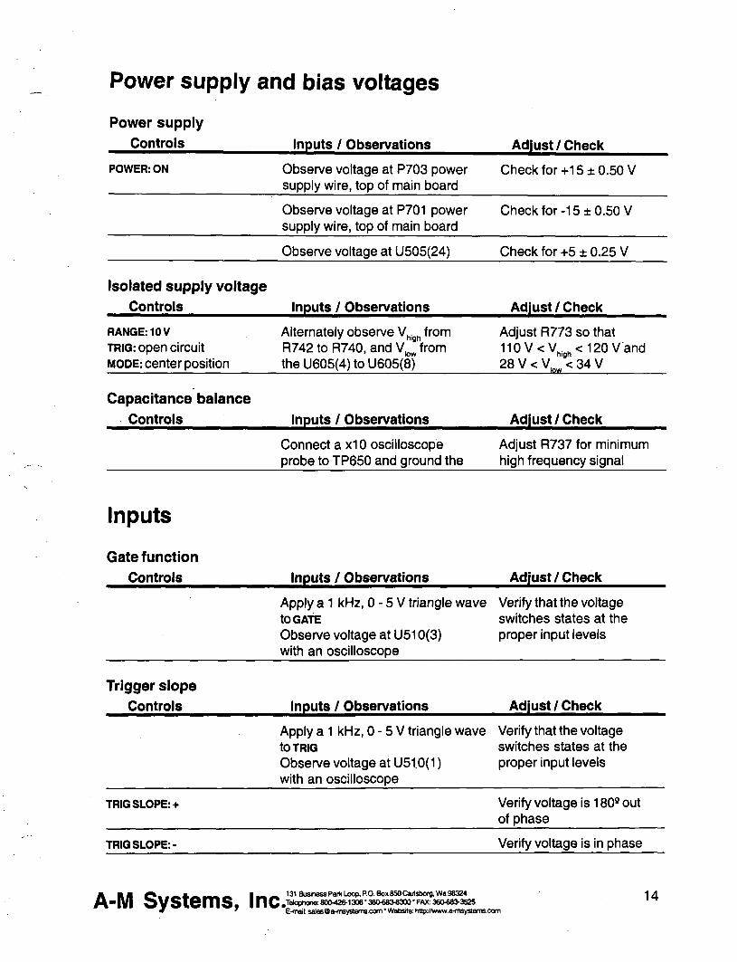
Power supply and bias voltages
Power supply
Controls Inputs Observations AdjustCheck
POWER ON Observe voltage at P703 power supply wire top of main board
Check for+15 plusmn 050 V
Observe voltage at P701 power supply wire top of main board
Check for-15 plusmn 050 V
Observe voltage at U505(24) Check for +5 plusmn 025 V
Isolated supply voltage
Controls Inputs Observations Adjust Check
RANGE 10 V TRIG open circuit MODE center position
Alternately observe V from high
R742 to R740 and V _ from kw
the U605(4) to U605(8)
Adjust R773 so that 110VltV lt 120 V and
high
28VltV^^lt34V
Capacitance balance
Controls Inputs Observations Adjust Check
Connect a x10 oscilloscope probe to TP650 and ground the
Adjust R737 for minimum high frequency signal
Inputs
Gate funct ion
Controls Inputs Observations AdjustCheck
Apply a 1 kHz 0 - 5 V triangle wave Verify that the voltage to GATE switches states at the Observe voltage at U510(3) proper input levels with an oscilloscope
Trigger s lope
Controls Inputs Observations Adjust Check
Apply a 1 kHz 0 - 5 V triangle wave Verify that the voltage to TRIG switches states at the Observe voltage at U510(1) proper input levels with an oscilloscope
TRIG SLOPE-I- Verify voltage is 180deg out of phase
TRIG SLOPE- Verify voltage is in phase
A-M Systems Inc 131 Business Paik Loop PO Box 850 Cailsborg Wa 98324 Tekvhone 8004201306 36O683laquo300 - FAX 360683-3S2S E-mail salesOa-msystemscom Website httpywwwa-msystemscom
14
Trigger and gate funct ion
Controls Inputs Observations
DELAY NONE BURSTWIDTH SINGLE DURATION SQUARE PERIOD 100X10-3
AdjustCheck
Apply a 1 kHz 0 -5 V triangle wave to TRIG Observe TRiGoand EVENT LEDS
TRIG disconnect all Short the GATE connector to GND Verify LEDs extinguish
MODE press to MANUAL Verify LEDs flash once
Timing
System clock frequency
Controls Inputs Observations Adjust Check
Observe the frequency of the wave Verify 1000 MHz plusmn 001 atU555(17)
Mu l t i p l i e rs (Whee l Sw i t ches )
Controls Inputs Observat ions A d j u s t C h e c k
PULSE SIGN+ MODE FREE RUN TRIG disconnect all TIMING MULTIPUERS all
Wheels set to zero except the one being tested
TIMING OVERLAP ignore
Observe the pulse width with the counter at the location specified below
Verify pulse width is correct for each wheel as it is tested independently
For each wheel of each MULTIPLIER test each position to verify that the pulse width is correct Observe the signal at the following locations DELAY U520(2) BURSTWIDTH U530(2) PERIOD U540(2) DURATION U550(2)
Rates (Rotary Switches)
Controls Inputs Observations A d j u s t C h e c k
TIMING MULTIPUERS 001 TIMING RATES all rotary
switches set to 10-4 except the one being tested
Observe the pulse width with the counter at the location specified below
Verify pulse width is correct for each rotary switch as it is tested independently
For each of the four rotary switches in TIMING test each position to verify that the pulse width is correct Observe the signal at the following locations DELAY U520(2) BURSTWIDTH U530(2) PERIOD U540(2) DURATION U550(2)
A-M Systems Inc 131 Business Paik Loop PO Box 850 Caiisborg Wa 98324 Telophone 800-428-1306 bull 3606808300 FAX 360683-3525 E-mail salesOa-msystemscom Website httpwwwa-msystemscom
15
Trigger outputs Controls
Range 10V Pulse Amplitude 500 Delay 100x10-2 Burst 100x10-2 Duration 100 xlQ-^ Period 400x10-3 Pulse sign + Trig Mode Free run Trig in open
Inputs Observations
Trigger the oscilloscope to the Burst Trig Out Observe it the Pulse Trig Out and the isolated output
AdjustCheck
Verify that the waveform consists of a burst of three 1 ms-on3ms-off pulses The burst trigger should be synchronous with the burst the pulse trigger coincident with each pulse
Output Calibration
Isolation Resistance (check) Controls Inputs Observations Adjust Check
Trig Mode center position Trig In open
Measure the resistance between ground banana jack (front panel) and black banana jack of output with DMM
Resistance read gt 10OMQ
Amplitude Switch Offset (R640) Controls InputsObservations AdjustCheck
Baseline Zero Trig Mode center position Trig In Open
Measure the voltage at TP645 vs TP650 with the DMM
Adjust R640 (AmpI Sw Offset) for minimum voltage
Output Offset (R332 front panel board) Controls InputsObservations AdjustCheck
Baseline Zero Range 10V Trig Mode center position Trig In Open
Measure the voltage across the output with the DMM
Adjust R332 (Output offset) for minimum voltage
Positive Baseline Offset (R607) Controls InputsObservations AdjustCheck
Baseline Sign + Baseline Amplitude
fully CCW (000) Range 10V Trig In open Trig Mode center position
Measure the voltage across the output with the DMM
Adjust R602 (BSLN + offset) for minimum voltage
A-M Systems Inc 131 Business Paik Loop PO Box 850 Cartsborg Wa 98324 Jelophone 8004201306 36O6834300 - FAX 380laquo83-352S E-mail salesOa-msystemscom Website httpwwwa-msystemscam
16
Negative Baseline Offset (R619)
Controls InputsObservations
Baseline Sign -Baseline Amplitude
fully CCW (000) Range 10V Trig In open Trig Mode center position
Measure the voltage across the output with the DMM
AdjustCheck
Adjust R619 (BSLN + offset) for minimum voltage
Pulse Ampl i tude Adjust (R602)
Controls InputsObservations AdjustCheck
Trig Mode Free Mode Pulse Amplitude 1000 Timing Delay =none Burst =single Duration =1001 Period =00110-4 Pulse Sign -Trig In open Range 10V
Measure the voltage across the output with the DMM
The Overlap indicator should be on Adjust R602 (Max Level) for -10OOV out
Pulse Sign Gain (check)
Controls InputsObservations AdjustCheck
Trig Mode Free Mode Pulse Amplitude 1000 Timing Delay =none Burst =single Duration =100 Is Period =001 10-4s Trig In open Range 10V
Measure the voltage at the output with the DMM for the Pulse Sign at + and - positions
The absolute values of the voltages should differ by less than 10OmV
Baseline Ampl i tudes (check)
Controls InputsObservations AdjustCheck
flange 100mA Trig Mode center position Baseline Amplitude fully CW (1000) Trig In open
Measure the voltage at the output with the DMM with Baseline Sign in + Zero and - positions
Gain the matching of current levels at = and - positions and offset current in Zero position
A-M Systems Inc 131 Business Psik Loop PO Box 850 Caiisborg Wa 98324 Telophone 800426-1306 bull 36Olaquo8raquo8300 bull FAX 360683-3525 E-mail salesOa-msystemscom Website httpwwwa-msystemsccm
17
Output Range Amplitude and Drive (check)
Controls InputsObservations
Pulse Amplitude 1000 Pulse Sign + Trig Mode Free Run Timing Delay =none Burst =single Duration =1001 Period =10010-4 Trig In open
Load the output with a 10KV 1W 01 resistor Measure the voltage at the output with DMM
Pulse Sign and Short Circuit Protection (check)
Controls
Timing Delay =none Burst =single Duration =200 10-4 Period =00110-3 Baseline Zero Pulse Amplitude 25 Range 10V Trig Mode Free Run Trig In open
InputsObservations
Measure the voltage at the output with the oscilloscope Check for Pulse Sign set to each of + - biphasic Watch for Error indicator when shorting the output
Output Transient Response (check)
Controls InputsObservations
Verify that full scale output is within specification Scale Range 100V 100V 10V 10V 100mA IV 1mA 10V 10mA 100V
AdjustCheck
Verify that pulses of approx 25V amplitude (625V for biphasic mode) of the correct sign are produced every 10ms Short output in biphasic mode Output should return when opened
AdjustCheck
Pulse Sign + Timing Delay =none Burst =single Duration =20010-4 Period =00110-3 Pulse Amplitude 250 Baseline Zero Trig Mode Free Mode Trig In open
Connect the oscilloscope to the output with a 310 attenuator probe Test both 10V and 10OV ranges
Verify that overshoot and risetime meet specifications
A-M Systems Inc 131 Business Paik Loop PO Box 850 Cailsbora Wa 98324 Tetophone 8004201306 bull 36Oeuro83-8300 bull FAX 360683-352S E-mail salasOa-msystemscom Website hitpywwwa-msystamsoom
18
Specifications
There are three classes of specifications Class A specifications tested in all units and are guaranteed Class B specifications are inherent in the design they are indirectly tested and are guaranteed Class C specifications are typical operating values which are occasionally tested- these are typical values given for your information but not guarshyanteed The class for each specification is noted in the center column of the following sections
Inputs Switching level
Hysteresis
Input equivalent circuit
Minimum duration (TTL-level signal)
A
C
C
C
16 V (plusmn 02 V)
approx 50 mV
lOOKfl to-1-5 in parallel with no more than 35pF
gt50ns
Open circuit condition B defaults to highon level
Timing and rate accuracy
Rate selector steps
Timing multiplier steps
B
B
100S to 100s in 7 steps
1 of rate selector step size Maximum value is 999 X the rate selector step size
Resolution B approx 01 of the maximum value
Timing error (second and later pulses after resetting controls)
B lt 002 of rate selector value + 015S
Timing error (first pulse after readjusting timing controls)
an additional 025s error may occur
Timing repeatability lt 001 settings-20 ns (mbnophasic)
A-M Systems Inc 131 Business Paik Loop PO Box 850 Caiisborg Wa 98324 Telophone 8004201306 3606808300 FAX 3606803S25 E-mail salesOa-msystemscom bull Website httpyy(wwaltTisystemscom
19
TRIG IN to OUTPUT delay (DELAY set to 0) output set to 2V
Timing jitter from TRIG IN to OUTPUT (for TTL trigger input with risetime lt10 ns)
Timing jitter from TRIG OUT (either BURST or PULSE) and OUTPUT
Trigger output to pulse output delay
Output characteristics Pulse level error (voltage mode open circuit current mode short circuit
Biphasic level difference IV-H-i-V-l2
Baseline level error (voltage mode A open circuit current mode short circuit)
Risetime (25 V out)
Risetime (25 V out)
Transient response
A
A
A
Output impedance (voltage mode) C
Output impedance (current mode) C
Isolation resistance A
Isolation capacitance C
approx 05 ps for a load of no more than 10 Kft in parallel with 50 pF
lt 125 ns (all rates except 100s) lt125ys (100s rate)
Less than 20 ns (all rates)
approx 350 ns
lt 03 of setting -i- 05 of r range (plus an additional 05vA in 100 ywA range)
lt 03 of range (voltage modes into open circuit current modes into short circuit)
lt 03 of setting of setting -I- 01 of range (plus an additional 05 pA in 100A range)
= 200 ns into less than 30 pF
= 15 yws into less than 30 pF
lt 8 overshoot into less than 30 pF for pulse voltages different than baseline voltage by at least 10 of range
= 50 ohms
raquo 1 0 Ga (typically 200 GD)
raquo 1 0 0 M n
= 60 pF at 100 Hz
A BB f ^ _ M 1 ^ ^ 131 Business Paik Loop ROBOx850Cai1sOorgWaW3Z4
- I V l o V S i e m S inC80Ph0trade80O42O1308-36O683-8300-FAX36O683-3525 7 bull bull bull bull ^ ^ E-maasale80a-m8vstemscomWebsitehitpjwwwaltnsyste
20 E-mai salesO a-m8ystemscom Website http jwwwa-msystemscom
Noise (differential mode)
Noise (common mode earth to isolated ground) with no signal output
Overload error indicator (low frequency short circuited voltage mode)
Overload error indicator low frequency open circuited current mode)
Overload error response time
Miscellaneous
= 1 mV rms (10 V scale 10 Hz-4 MHz)
- 8 mV rms (10 Hz-4 MHz) =laquo100mVp-p (200 Hz -10 MHz) measured withalOMn 15pF oscilloscope probe
Turns on for set amplitude at or greater than approx plusmn1 V (10 V range) or plusmn2 V (100 V range)
Turns on for set amplitude at or above approx 2 of range
Flat to approx 30 ps duration Decreasing sensitivity for shorter pulses
Power
Fuse
Operating temperature range
Storage temperature range
Operating humidity
Dimensions
Weight
approx 11 watts
1 amp 3 AG
10-30degC
0 - 50deg C
5 - 80 RH
17x475x1125 (inches) 432x121x286 cm
20 lbs (9 kg)
A-M Systems Inc 131 Business Paik Loop PO Box 850 Cartsborg Wa 98324 Tekjptwne 8004201306 bull 36Olaquo8O8300 bull FAX 360laquo8O3525 E-mail salesOa-msystemscom Website httpywwwa-msystemscom
21
Warranty and Service
What does this warranty cover A-f Systems Inc warrants to the Purchaser that the Instrument excluding cables Headstage Probes and any other accessories shipped with the Instrument (hereafter the hardware) is free from defects in workmanship or material under normal use and service for the period of one (1) year This warranty commences on the date of delivery of the hardware to the Purchaser
What are the obligations of A-M Systems Inc under this warranty During the warranty period A-M Systems Inc agrees to repair or replace at its sole option without charge to the Purchaser any defective component part of the hardware To obtain warranty service the Purchaser must return the hardware to A-l^ Systems Inc or an authorized A-M Systems Inc distributor in an adequate shipping container Any postage shipping and insurance charges incurred in shipping the hardware to A-M Systems Inc must be prepaid by the Purchaser and all risk for the hardware shall remain with purchaser until such time as A-M Systems Inc takes receipt of the hardware Upon receipt A-M Systems Inc will promptly repair or replace the defective unit and then return the hardware to the Purchaser postage shipping and insurance prepaid A-M Systems Inc may use reconditioned or like new parts or units at its sole option when repairing any hardware Repaired products shall carry the same amount of outstanding warranty as from original purchase or ninety (90) days which ever is greater Any claim under the warranty must include a dated proof of purchase of the hardware covered by this warranty In any event A-M Systems Inc liability for defective hardware is limited to repairing or replacing the hardware
What is not covered by this warranty This warranty is contingent upon proper use and maintenance of the hardware by the Purchaser and does not cover batteries Neglect misuse whether intentional or othenvise tampering with or altering the hardware damage caused by accident damage caused by unusual physical electrical chemical or electromechanical stress damage caused by failure of electrical power or damage caused during transportation are not covered by this warranty Products may not be returned to A-M Systems Inc for service whether under warranty or otherwise which are contaminated by Infectious agents radioactive compounds or other materials constituting a health hazard to employees of A-M Systems Inc
What are the limits of liability for A-M Systems Inc under this warranty A-M Systems Inc shall not be liable for loss of data profits or savings or any special incidental consequential indirect or other similar damages arising from breach of contract negligence or other legal action even if the company or its agent has been advised of the possibility of such damages or for any claim brought against you by another party THIS EQUIPMENT IS NOT INTENDED FOR CLINICAL MEASUREMENTS USING HUMAN SUBJECTS A-M SYSTEMS INC DOES NOT ASSUME RESPONSIBILITY FOR INJURY OR DAMAGE DUE TO MISUSE OF THIS EQUIPMENT Jurisdictions vary with regard to the enforceability of provisions excluding or limiting liability for incidental or consequential damages Check the provision of your local jurisdiction to find out whether the above exclusion applies to you
This warranty allocates risks of product failure between the Purchaser and A-M Systems Inc A-M Systems Inc hardware pricing reflects this allocation of ris1lt and the limitations of liability contained in this warranty The warranty set forth above is in lieu of all other express warranties whether oral or written The agents employees distributors and dealers of A-M Systems Inc are not authorized to make modifications to this warranty or additional warranties binding on the company Accordingly additional statements such as dealer advertising or presentations whether oral or written do not constitute warranties by A-M Systems Inc and should not be relied upon This warranty gives you specific legal rights You may also have other rights which vary from one jurisdiction to another
A B B J l laquo raquo ^ t3tBusinessPafkLoopPOBox850Cai1sbO(gWa98324
- | V | O V S i e m S |nCtrade042O1306-36O68O8300-FAX36O68O3525 E-mail salasOa-msvstemscom bull Website httowwwa-msvste
t3tBusinassParkLaopROBox8SOCai1sbo(gWa98324 po Telophone 8004201306 360683-8300 FAX 3606803525 ^ ^ E-maH salesOa-msystemscom Wetsite httpwwwa-msystem3e0m
mwal
INSTRUCTION MANUAL
FOR
ISOLATED PULSE STIMULATOR
MODEL 2100
Serial
Date
A-M Systems Inc
PO Box 850
Carisborg WA 98324
USA
360-683-8300 bull 800-426-1306 FAX 360-683-3525
httpwwwa-m8y8temscom
Version 50 May 1998
Contents General Description 1
Instrument Features 1 Controls and Connectors 2
Operating Instructions 6 Theory of Operation 10 Calibration Procedures 12
Inputs ii 14 Output Calibration iii i 16
Specifications i4 il u 19 Warranty and Service wi iJ iJi [ii 22
Each Isolated Pulse Stimulator Is delivered complete with
Rack Mount Hardware Instructions amp Maintenance Manual
NOTE
This instrument is not intended for clinical measurements using human subjects A-M Systems Inc does not assume msponsibility for injury or damage due to the misuse of this instrument
General bull M ^ ion
Instrument Features The Isolated Pulse Stimulator Model 2100 Is designed for a wide variety of applications It is highly flexible being capable of delivering single pulses biphasic pairs or bursts of pulses Pulses may be started manually or upon receiving a trigger signal from another instrument or computer Two non-isolated trigger outputs are available for triggering other instruments
Four sets of timing controls provide comprehensive control over all aspects of pulse generation Three digit accuracy is available over a 7 decade range for each timing function using lever wheel switches Pulse wkiths can be set over more than a 9 decade range from 05 [is to 999 seconds Timing accuracy is assured through the use of a 10 MHz base rate crystal-controlled clock digitally divided to provide accurate timing over the entire range A timing overiap indicator will light if the timing controls are set Inconsistently
The output may be conveniently switched between cun-ent and voltage modes Pulse and baseline amplitudes are independently presettable with lockable dials An error indicator will light if the Model 2100 cannoi deliver the desired signal
WARNING
The Model 2100 can produce potentially dangemus voltages up to 100 V et the output connectors The isolated output is not connected internally to safety (earth) ground in ahy way Some part of the extemal circuit should be connected to safety gmund Use caution in handling any wires connectors or electrodes which may be directly or indirectly attached to the Model 2100 output Some lltinds of connectors such as BNC connectors have exposed metal parts which may float at dangemus potentials unless extemally connected to safety gmund For greatest safety tum the Model 2100 off before making any connections to
the Instrument
131 Business Park LocfiPO Box BSOCarM)orgWa 98324 800426-1308 bull36OlaquoS3laquo300FAX 3 6 M 8 3 ^ 2 5
E-malt uiittyBQaHiByBtumaooiTi Wobsita HipJtwtiwiwftbMiAcon fl-N SystQms I n c ^ T
Controls and Connectors The controls for the Model 2100 are grouped in three sections START controlling when a pulse or burst of pulses begins TIMING controlling the onoff timing of one or more pulses and otJTPliT controlling the amplitude of the output signal
Start TRIG SLOPE This switch determines whether valid triggers occur at positive or negative edges in the trigger signal
MODE This switch controls how wavefomris are initiated When set to FREE RUN one timing cycle immediately follows the last When held in the MANUAL position a timing cycle starts immediately When the switch is in the center position timing cycles start when valid triggering events occur
TRIGD This LED lights up when a timing cycle is in process and continues until the burst is completed
TRIG This BNC connector allows a signal from an extemal source to initiate timing cycles It is set for standard TTL levels
GATE This BNC connector allows a signal from an extemal source to restrict the final output signal This input must be at a logical high (or open-circuited) in order for the Model 2100 to recognize either manual or automatic trigger events
Gate 1_ Trigger [~^ i I Valid triggers are represented by the arrows in the figure Note that the up arrow would apply only if TRIG SLOPE is set to + the down anrows would apply only if TRIG SLOPE is set to-
NOTE Triggers have no effect if the system has not completed its response to a previous trigger
fl-N SystQms I n c ^ 131 Business Park Loop PO Box 850 Cartsborg Wa 98324 600426-13063eO683laquo300FAX 360683^525
E-maB anBysQraquoinsyaleiTaconi Wsbalto h^KAvwwa-(nsys(smsoom
Timing Four sets of controls govem the timing of pulse generation Each set contains two values which are multiplied together to detennine the actual timing value The rotary knob (rate selector) provides the approximate timing value and the lever wheel switch bank (MULTIPLIER) provkles a time resolution of three decimal digits The following diagram shows most of the important relationships
Pnfe-tRAIM I B E L A V i6Molaquo
BURST WIOtH
Output r Delay
t n
Duration - ^ lt - |4Periodgt|
FLJI -^ Burst width
Trigger event
DELAY These controls set the time between the initiating trigger event and the beginning of the pulse burst If this rate selector is set to NONE or the multiplier is set to ooo there is no delay
BURSTWIDTH These controls set the time period in which one or more pulses may be delivered Once started a pulse may outlast the burst width If this rate selector is set to SINGLE or to any time shorter than the pulse duration only a single pulse will occur If the BURSTWIDTH is longer than the period pulses will be emitted at the PERIOD rate until the burst time ends Pulses are never truncated by a short BURST WIDTH
iNTpoundA-PULSiE PBRiOb
DURATION These controls set the length of each pulse If this rate selector is set to SQUARE the duration is set to half of the period regardless of the MULTIPLIER setting
PERIOD These controls set the period of time between adjacent pulse events within the burst It also forces a minimum dead time between recognized input triggers following a burst of one or more pulses This can be used to prevent over stimulation of a tissue without requiring excessive delay between the triggering event and the stimulating pulse
TlMtNQ OVERLAP
mLiHMPi
VVtJ jiwaa lasm nlaquoilaquo u
t^fi SysUms I n c ^ Elt4nsfl a m
131 Business Pofc Loop PO Box 850 Carisborg 1^98324 600-426-1306 36O6834300 FAK 360683^525
E-mai vrvysQfrflisysleraLOCniWutiailQL N^jAwwa^iByslernUiOOni
NOTE If any of these timing controls are changed while a timing cycle is in operation the results are undefined until the cunent cycle flnishes
TIMING OVERLAP This LED will light to indicate an Inconsistency in the timing cycle settings There are several ways to Introduce such errors The most common way is to set the inter-pulse PERIOD to be less than the pulse DURATION
TRIG OUT (UPPER) This BNC connector provides a signal which is coinckient with the intemal Burst timing signal (default) This means the signal starts at the end of the Delay time and persists until the Burst time expires This output may also be set to represent the delay time-out by setting the internal jumper J510 to the left two pins Instead of the right two pins (Please see the Calibration section in this manual for jumper location Directions are given as viewed from the fix)nt of the instrument)
TRIG OUT (LOWER) This BNC connector provides a signal which is coincident with the Duration timing signal which controls pulse output
NOTE Both trigger output signals slightly lead the isolated output signal
Output PULSE SIGN This Switch sets the sign for the pulses to be generated It also allows generation of biphasic pulses thereby doubling the effective total period Warning the first pulse genemted after changing the PULSE SIGN svntch may have the wmng polarity
BASELINE This switch sets the sign for the baseline signal
RANGE This rotary switch allows one of three current or two voltage ranges to be selected for the output signal
BASELINE AMPLITUDE This counting dial are independently set using ten-minute counting dials with the baseline having one tenth the range of the pulse amplitude
A-N Systlaquomslaquo Inc 131 Buskiess Partt Loop PO BoK 8S0 Cailsbarg Wa 96324 laophone 8004201306 bull36O68M300-FAX 3eolaquo8M525 E-mat bullmsysflMnsyslermoom VMaHsr Hlplhfimnmyekmoom
PULSE AMPLITUDE This counting dial
EVENTS This LED indicates when a pulse is ongoing
ERROR This LED indicates when the intemal output amplifier cannot output the pulse as desired This is usually due to a short circuit while trying to output a voltage or an open circuit while trying to output a current
One control from the Ot^uf section directly affects wavefonn timing the Pulse Sign control When set to the Biphasic mode a positive-going pulse is Immediately followed by a negative-going pulse This effectively doubles the pulse duration If a burst of biphasic pulses is being produced the period must be at least twice the single pulse duration In the Sgtan wave mode the baseline disappears as long as the burst persists
fl-N Systems Inc 131 Bushass Park locpPOBooi 850 C8ri9bcrgMS8324 IMqphona 800426-1306 bull36Olaquo83laquo3a0 FAX 360683-3529 E-nal amsyaOa4nsyatemscomWeMlK hMpJVniwa-nsygtatnscom
Operating Instructions
Examples Simple setup (and minimal Instrument tost)
Connect the output of the Model 2100 to an oscilloscope Before connecting the instrument it is safest to turn its power off
Set the Ou^uf controls
Range Pulse Sign
Baseline Pulse Amplitude
10V +
Zero 200
Setting The Timing Controls
Delay Burst Width
Duratbn Period
none single
15010-2 500102
Setting The Start Controls
Mode Free Run
Disconnect any cables to the TRIG or GATE Inputs
Note that the green Trig and Event Indicators tum on as Free Run is turned on (and tum off othenwise) You should observe a 15ms duration 20Hz rate pulse of 200V above a OV baseline on the oscilloscope i
A ^ M ^ _ _ _ A ^ _ _ _ 1 ^ 131BiiHnD8raquoParttloopPOBoxB50Car)sbcrBlaquoraquoS8324
bull P l ^ y S W n i S f |nC ltV^gt^8deglt^^2O1306380laquo8OS3a0FAX36O6BMS2S
6 E-fnflk 9n^fBOs-in9ystsni9cx]fnWDbs)tec H^ff9Nw^myStem9oom
Demonstration of Burst Mode Connect the output of the Model 2100 to an oscilloscope Before connecting the instrument it is safest to tum Its power off
Set the Output controls
Range Pulse Sign
Baseline Pulse Amplitude
Baseline Amplitude
Setting The Timing Controls
Delay Burst Width
Duration
Period
Set the START controls as follows
Mode
Disconnect any cables to the TRIG or GATE inputs
Trigger the oscilloscope from the Burst trigger out (upper Tr^ Out connector) for a stable display In each burst (occumng every lOOms) you should observe a trio of 15ms duration starting 50ms apart Try switching the StartMode from Free Run to the center (nomnal) position The pulses will no longer be produced and the Trig and Event indicators will turn off Pressing this switch once (to Manual) will cause a single burst to occur
880 120 150 500
10V +
200 100
102 102 102 102
Free Run
fleaff SySlQmSa |nCa deglgt ltlt ^ ^ deg ^ degdeg ^ ^ ^ bull E-matmia
131 Business Park LoopPO Box 850 Carisborg Vfe 86324 lUcphcna 800426-1306 36Olaquo83laquo300 FAX 36068raquo52 E-maft tfii8ysOiHn^nleiTBcom1AWisJto HSpitwraquoM^wytAtii9oom
Problem SoMng If the Instrument appears to be not worthing properiy check all of the control settings and connections Be sure to wait at least 5-10 seconds after turning the Instrument off before tuming it on again The following t6ef summary of typical problems for the user (along with the most common solutions) may help
Problem CauseSolution EVENT indicator never lights even in FREE RUN mode
bull Replace fuse check power connection bullSet DELAY or PERIOD to a shorter interval
bull Power-on too soon after power-off
OVERLAP Indicator is on
ERROR indicator is on
Time appears to be excessive
bullSet DURATION gt000 bull DURATION is set to SQUARE but PERIOD is 000 Increase PERIOD or set DURATION independantly
bull BURST and WIDTH are gt DURATION increase PERIOD or decrease
DURATION bull BIPHASIC pulse output is on and PERIOD is not longer than twice the DURATION Increase PERIOD or decrease DURATION
bull Free-run is on and BURST Is lt PERIOD (BURST off) DELAY is 0 and PERIOD is lt DURATION Add delay or modify PERIOD
bull Free-mn is on and BURST is gt DURATION (BURST ON) and PERIOD is lt DURATION Increase PERIOD
bull For VOLTAGE outputs the output Is trying to drive too low a resistance or capacitance (eg a short circuit) Check by disconnecting the output It is possible (and normal) that for the fastest cycles
and largest amplitudes (close to 100 V and 1 MS) that the ERROR Indicator might always come on during repetitive pulses Fix output load or decrease amplitude as required
bull Changed control in mid-cycle (resets cunent status)
A ^ M bull _ _ _ A ^ ^ _ _ i ^ mdash 131BuslnessPai1ltLoopPOBox850CarlsborgWamp98324
bull p i j ^ v s w m s iiic^^deglt^deg^^deglt^^^3degB3^^^deg^^^^degdeg^^^deg^^deg^^^^ E-mat iiiMOafflwstemseom WabaHe MtaffiwwtHtavsli
8 E-msft flmsjoQfrfraystGfnsoom ^WobsltiK hl^Aiwv9-fn9]nteniscom
Cant seem to get a full signal out
Incoming triggers not accepted frequently enough
bull Load is not properiy connected repair wiring
bull Too low a load impedance (VOLTAGE modes) or too high a load impedance
(CURRENT mode)
bull PERIOD is set too long (enforces dead time) followd by BURST set to SIGNAL Reduce PERIOD time
Table 10 Problem Solving
If you suspect that the Model 2100 may have completely failed we recommend checking the basic level of functionality If this fails your instrument is defective and must be repaired If this passes either your experimental setup is incompatible or inconsistent or there is a more subtle flaw in your Model 2100
If the Model 2100 appears to be malfunctioning contact A-M Systems Inc or your dealer Telephone numtgters for A-M Systems Inc listed on the front cover of this manual We will first attempt to solve the problem over the telephone so have an exact description of your problem available when you call You do not need to be within the warranty period to obtain over-the-phone assistance
A ^ M V - mdash A d B ^ K M I ^ M 131BuslnessPatfcLoopPOBox6SOCai
-PI s y s i Q m s inc-2raquolaquoa22=M^^
131 Business Parfc Loop PO Box 650 Cartsborg VM9 0S324 _ FAX36(W8a3525 E^nrt flnsysQa-ntsyttanB-oom Wsbsfte hHpiMNvwa-nnystsnisooni
9
Theory of Operation
The operation of the Model 2100 is summarized In the block diagram (see Fig 3) Not shown are all of the interconnections with the microcontroller The intemal microcontroler plays an important role in setting the signal path but does not directly
contribute to the dynamic characteristics It scans the front panel switches and sets the control values for the logic arays It programs the intemal counters which along with the other hardware achieve the necessary sub-microsecond speeds
All action starts either from an input trigger signal (from Trig In) or from an intemal signal (in free Run mode only) A Delay timer counts the 10MHz clock until its count value Is exhausted At this point the Burst timer starts Both Period and Duration timers are started at this time If the Burst timer has not expired by the end of the Period the Period and Duration timers are restarted If the Biphasic mode has been set the Duration timer is restarted at the end of the initial Duration and the sign of the output pulse Is reversed doubling the total duration
The system state (pulse on pulse sip baseline sign [+101-]) is transmitted to the isolated section via optoisolator The baseline and pulse amplitudes are selected by an analog switch The resulting signal is amplified by a variable-power-supply discrete operational amplifier The amplifier connections and gain is modified to provide two voltage and three cunent ranges
Timing overlap errors are detected by a logical decision computation rather than by testing for counter collisions This provides instant feedback rather than waiting up to an hour for such a collision to occur Output errors are measured by sensing the output amplifiers differential input voltage Under normal conditions this is a negligible voltage if the amplifier fails to deliver the requested signal the window comparator testing this voltage sends this message (via optoisolator) to the logic section turning on a warning LED
fl-N Systems Inc 131BusbnassPa(tLoopPOBox6SOCari3boigVMg8324 H n |TWoph0n880O426-13083eO6Blaquo300FMt36Olaquo8i3525 E-nnl anaysflfriinysleiiaoemWfcbslte hllphmwraquoimyatennoom
TRIG 3HJ) OUT
(burst)
TRIG ^ OUT
(pulse)
E
Ml
Calibration Procedures
The calibration interval is the lesser of 1000 hours of operation or 6 months Somewhat greater drift can be expected in the first 100 hours of operation as the semiconductors age Adjustments should only be made after the instrument has been fully warmed up for at least 15 minutes
Full instrument calibration requires the following test equipment digital multimeter (plusmn 01) able to measure resistance to at least lOOMfl oscilloscope with at least 50MHz bandwidth true-rms voltmeter with 4MHz bandwidth universal counter (plusmn 001 ) able to measure single pulse widths and periods resistors (all plusmn 01) 2kn lOkH 1 waft 20kn 200kn alligator clip lead sets banana plugs and BNC adapters
Adjustment integrated circuit and test point locations are shown in the following figures All adjustments are on the timing board unless otherwise noted
All voltages in the non-isolated section should be measured with respect to ground at TP510 unless othenvise stated Some voltages are measured with respect to an intemal isolated ground at TP650 or across the two output tenninals Occasionally the voltage at an IC pin must be measured In these cases the reference designator is given with the pin number in parentheses eg U602(16) When it states within this procedure that a voltage is to be minimized this means that the adjustment should be made such that the measured voltage is as close to zero volts as possible Refer to the Specifications Section of this manual for acceptable tolerances
The sequence of this procedure is Important If any adjustment is made all adjustments which follow must be made to ensure that the specifications will be met These procedures require that all controls remain as set in previous steps unless otherwise indicated
WARNING
The Model 2100 has dangerous voltages throughout the instrument even with the power is off Servicing the Model 2100 should only be done by qualified service personnel Use caution in handling any wires connectors or electrodes which may be directly or indirectly attached to the Instrument Do not touch exposed connections or components Disconnect power by unplugging the power cord from the receptacle
fl-N Systems I n c ^ 131BusinesaPartcLoopPOBox850CartsborgVWiB8324 4 n ^gt-mdash80O426-130638Ofl8Jlaquo300FAX36O683J52S bull E-maft BinsysQfrfn^islflnisoomVVfalislle h^KVfWMift^iisystemsoani
CO
- R503
Omg^
TPSOlQ O
OTPSOO
U560 bull
U510
DDID ^ trade E O ^ T P 5 1 0
bullnD Trig
0 ^
U570
Gate n U505
DO D
U515
Timing
Timing h_ U520
bsoo ^25SE Timing
Or r U540
I I Tmlng
[^ELIL
U535 D
U506
13 J510 Timlnff
BurfiDelay J400
i i i i i i i T r m r a
gt U550 ^
Clock
U555 U620
B a
^R^Pvhigh Rfijn O D O Vlow
o
bull U545
Fo sect737 lISOIsPjC-COMP
n r r ^ U760
J420
]]U632
Q S riuGSO
H = ) TP640^ deg I t I
II3D
J440 m i T i
U610 plusmn laquo j U O
bull bull l el
^t
O l
bull
M
I
Power supply and bias voltages
Power supply
Controls Inputs Observations Adjust Check
POWER ON Observe voltage at P703 power supply wire top of main board
Check for+15 plusmn 050 V
Observe voltage at P701 power supply wire top of main board
Check for-15 plusmn 050 V
Observe voltage at U505(24) Check for+5 plusmn 025 V
Isolated supply voltage
Controls Inputs Observations Adjust Check
RANGE 10 V TRIG open circuit MODE center position
Altemately observe V^ from R742 to R740 and V ^ from the U605(4) to U605(8)
Adjust R773 so that 110VltV^lt 120 V and
nign
28VltV^lt34V
Capacitance balance
Controls Inputs Observations AdjustCheck
Connect a x10 oscilloscope probe to TP650 and ground the
Adjust R737 for minimum high frequency signal
Inputs
Gate funct ion
Controls Inputs Observations AdjustCheck
Apply a 1 kHz 0 - 5 V triangle wave Verify that the voltage to GATE switches states at the Obsene voltage at U51G(3) proper input levels with an oscilloscope ^ ^
Trigger s lope
Controls Inputs Observations Adjust Check
Apply a 1 kHz 0 - 5 V triangle wave Verify that the voltage to TRIO switches states at the Observe voltage at US 10( 1) proper input levels with an oscilloscope
TRIG SLOPE + Verify voltage is 180 out of phase
TRIG SLOPE Verify voltage is in phase
fl-N Systems Inc ^ 131 Bushess Park Loop PO Bar 850 Carisborg Wa 98324 8004201306 3eOlaquoS3e300 FAX 3606BV352S
C-maft fliii8yBQfriii9yBlumaoamVIAibsMB hRpJhwMifi-iiiBystematxini
14
Trigger and gate funct ion
Controls Inputs Observations Adjust Check
DELA NONE BURS1WII3TH SINGLE DURATION SQUARE PERIOD 100X10-3
Apply a 1 kHz 0 - 5 V triangle wave to TRIG Obsen^e TRIOD and EVENT LEDS
TRIG disconnect all Short the GATE connector to GND Verify LEDs extinguish
MODE press to MANUAL Verify LEDs flash once
Timing
System c lock frequency
Controls Inputs Observations AdjustCheck
Observe the frequency of the wave atU555(17)
Verify 1000 MHz plusmn001
Multipl iers (Wheel Switches)
Controls Inputs Observations AdjustCheck
PULSE SIGN + MODE FREE RUN TRIG disconnect all TIMING MULTIPUERS ail
wheels set to zero except the one being tested
TnmiNG OVERLAP ^nOTB
Observe the pulse width with the counter at the location specified below
Verify pulse width Is correct for each wheel as it is tested Independently
For each wheel of each MULTIPUER test each position to verify that the pulse width is correct Observe the signal at the following locations DELAY U520(2) BURSTWIDTH U530(2) PERIOD US40(2) DURATION U550(2)
Rates (Rotary Switches)
Controls Inputs Observations AdjustCheck
TIMING MULTIPUERS 001 TIMING RATES all rotary
switches set to 10-4 except the one being tested
Observe the pulse width with the counter at the location specified below
Verify pulse width is conect for each rotary switch as it is tested independently
For each of the four rotary switches in TIMING test each position to verify that the pulse wkJth is correct Observe the signal at the following locations DELAY U520(2) BURSTWIDTH U530(2) PERIOD U540(2) DURATION U550(2)
fl-N Systems I n c ^ E-maft emfl
131 Business Parti Loop PO 809(850 Cartsborg Wta 98324 8004201306 3804806300 FAX 36068O3S25
E-maft ansysQa nvystems-oom Wobste hflp Avwwa4nsy8(Qnttoam
15
Trigger outputs Controls
Range 10V Pulse Amplitude 500 Delay 100x10 Burst 100x10^2 Duration 100 x1a Period 400x10^ Pulse sign + Trig Mode Free run Trig in open
Inputs Observations
Trigger the oscilloscope to the Burst Trig Out Observe it the Pulse Trig Out and the isolated output
Adjust Check
Verify that the waveform consists of a burst of three 1ms-on3ms-off pulses The burst trigger should be synchronous with the burst the pulse trigger coincident with each pulse
Output Calibration
Isolation Resistance (check) Controls Inputs Observations AdjustCheck
Trig Mode center position Trig In open
Measure the resistance between ground banana jack (front panel) and black banana jack of output with DMM
Resistance read gt 100MQ
Amplitude Switch Offset (R640) Controls InputsObservations AdjustCheck
Baseline Zero Trig Mode center position Trig In Open
Measure the voltage at TP645 vs TP650 with the DMM
Adjust R640 (AmpI Sw Offset) for minimum voltage
Output Offset (R332 front panel board) Controls I nputsObservatlons AdjustCheck
Baseline Zero Range 10V Trig Mode center position Trig In Open
Measure the voltage across the output with the DMM
Adjust R332 (Output offset) for minimum voltage
Positive Baseline Offset (R607) Controls InputsObservations AdjustCheck
Baseline Sign + Baseline Amplitude
fully CCW (000) Range 10V Trig In open Trig Mode center position
Measure the voltage across the output with the DMM
Adjust R602 (BSLN + offset) for minimum voltage
fl M raquo _ _ _ A laquo ^ _ i ^ ^ 131Buslnelaquo8Pari(loopPOBoK850Cart8borgWB96324
bull P I i s V S i e m S a |||Cg1Maphans80O42O130638O68O8300FAX36Olaquo8raquo^2S E-tiBft anagtraquoflwiisyagtlaquomraquoaimW6baHB hHpffii(wwraquoltnsylaquoleniieom
16
Negative Baseline Offset (R619) Controls
Baseline Sign -i Baseline Amplitude bull fully CCW (000)
Range 10V Trig In open Trig Mode center position
Measure the voltage across the output with the DMM
AdjustCheck
Adjust R619 (BSLN 4 offset) for minimum voltage
Pulse Amplitude Adjust (R602) Controls InputsObservations AdjustCheck
Trig Mode Free Mode Pulse Amplitude 1000 Timing Dialay =none Burst =single Duration =1001 Period =00110-4 Pulse Sign -Trig In open Range 10V
Measure the voltage across the output with the DMM
The Overiap indicator should be on Adjust R602 (Max Level) for -1000V out
Pulse Sign Gain (check) Controls InputsObservations AdjustCheck
Trig Mode Free Mode Pulse Amplitude 1000 Timing Delay =none Burst =single Duration =1001 s Period =00110-4s Trig In open Range 10V
Measure the voltage at the output with the DMM for the Pulse Sign at -- and - positions
The absolute values of the voltages should differ by less than lOOmV
Baseline Amplitudes (check) Controls InputsObservations
Range 100mA Trig Mode center position Baseline Amplitude fully CW (1000) Trig In open
Measure the voltage at the output with the DMM with Baseline Sign in + Zero and - positions
AdjustCheck
Gain the matching of current levels at = and - positions and offset current in Zero position
fl-N Systems Inc^^ bull E-mal am8
131 Business Partt Loop PO Box 850 Cartsborg Wa 88324 8004201306360laquo8Oe300FAX 360laquo8O362S
E-maM am8y8^o-mBy8tflmBoom WobaKo hHp Awwwo-f i iBystonuoom
17
Output Range Amplitude and Drive (check) Controls InputsObservations AdjustCheck
Pulse Amplitude 1000 Pulse Sign + Trig Mode Free Run Timing Delay =none Burst =8ingle Duration =1001 Period =10010-4 Trig In open
Load the output with a 10KV1W 01 resistor Measure the voltage at the output with DMM
Verify that full scale output is within specification Scale Range 100V 100V 10V 10V 100mA IV 1mA 10V 10mA 100V
Pulse Sign and Short Circuit Protection (check) Controls InputsObservations AdjustCheck
Timing Delay =none Burst =8ingle Duration =200 10-4 Period =00110-3 Baseline Zero Pulse Amplitude 25 Range 10V Trig Mode Free Run Trig In open
Measure the voltage at the output with the oscilloscope Check for Pulse Sign set to each of + - biphasic Watch for Error indicator when shorting the output
Verify that pulses of approx 25V amplitude (625V for biphasic mode) of the correct sign are produced every 10ms Short output in biphasic mode Output should retum when opened
Output Transient Response (check) Controls InputsObservations AdjustCheck
Pulse Sign + Timing Delay =none Burst =single Duration =20010-4 Period =00110-3 Pulse Amplitude 250 Baseline Zero Trig Mode Free Mode Trig In open
Connect the oscilloscope to the output with a 310 attenuator prolse Test boVn 10V and 100V ranges
Verify that overshoot and risetime meet specifications
fl-N Systems I n c ^ 131 Business Parte Loop PO Box 850 Cartsborg Wb 98324 8004201306 36Olaquo83O300 FAX 36O680lt352S
E-mQ0 snBy8Qs-msy8faiTiscom VWriMtte N ^ Mvww9-msy8lemscom
18
Specifications
There are three classes of specifications Class A specifications tested in all unHs and are guaranteed Class B specifications are inherent in the design they are indirectly tested and are guaranteed Class C specifications are typical operating values which are occasionally tested- these are typical values given for your infomiation but not guarshyanteed The class for each specification is noted in the center column of the following sections
Inputs Switching level
Hysteresis
Input equivalent circuit
Minimum duration (1 IL-level signal)
A
C
C
C
16V(plusmn02V)
approx 50 mV
100K ft to+5 In parallel with no more than 35pF
gt 50 ns
Open circuit condition B defaults to highon level
Timing and rate accuracy Rate selector steps
Timing multiplier steps
Resolution
Timing eror (second and later pulses after resetting controls)
B
B
B
B
lOOps to 100s In 7 steps
1 of rate selector step size Maximum value is 999 x the rate selector step size
approx 01 of the maximum value
lt 002 of rate selector value + 015 ps
Timing error (first pulse after readjusting timing controls)
an additional 025 ps error may occur
Timing repeatability lt 001 setting + 20 ns (monophasic)
fl-N Systems I nc ^ bull E-moU ams
131 Business Parti Loop PO Boot 850 Cartsborg VM 98324 80O42O130838O08O8300FAX36Olaquo8O3S2S
E-meU anByafl^iiisyslainaoomWebsHe hHpffliiwwraquomsys)emsoom
19
TRIG IN to OUTPUT delay (DELAY set to 0) output set to 2V
Timing jitter ft-om TRIG IN to OUTPUT (for TTL trigger input with risetime lt10 ns)
Timing jitter ft^om TRIG OUT (either BURST or PULSE) and OUTPUT
Trigger output to pulse output delay
Output charactsristics Pulse level enror (voltage mode open circuit cun-ent mode short circuit
Biphasic level difference |V + + V-|2
Baseline level error (voltage mode A open circuit current mode short circuit)
Risetime (25 V out)
Risetime (25 V out)
Transient response
A
A
A
Output impedance (voltage mode) C
Output impedance (current mode) C
Isolation resistance A
Isolation capacitance C
approx 05 ps for a load of no more than 10 Kft in parallel with 50 pF
lt 125 ns (all rates except 100s) lt 125 ps (100s rate)
Less than 20 ns (all rates)
approx 350 ns
lt 03 of setting + 05 of r range (plus an additional 05 pA inlOOpArenge)
lt 03 of range (voltage modes into open circuit current modes into short circuit)
lt 03 of setting of setting + 01 of range (plus an additional 05 pA in lOOpA range)
laquo 200 ns into less than 30 pF
laquo15 ps into less than 30 pF
lt 8 overshoot Into less than 30 pF for pulse voltages different than baseline voltage by at least 10 of range
laquo 50 ohms
raquo 1 0 Gft (typically 200 Gft)
raquo100Mft
laquo 60 pF at 100 Hz
fl-N Systems Inc^^ 131 Business Partt Uxip PO Box 850 Cartsborg Wa 96324 8004201308 SBOee^^SOO FAX 360laquoS3^52S
E-mat BiByraquoaiMii8ylaquoliiiiiseomWiljalteHlpJV(wwraquo4tgy8lenaoom
20
Noise (differential mode)
Noise (common mode earth to isolated ground) with no signal output
Overioad error indicator (low frequency short circuited voltage mode)
Overioad error indicator low frequency open circuited current mode)
Overioad enor response time
Miscellaneous
Power
Fuse
Operating temperature range
Storage temperature range
Operating humidity
Dimensions
Weight
laquo1 mV rms (10 V scale 10Hz-4MHz)
laquo 8 mV rms (10 Hz-4 MHz) laquo100mVp-p (200 Hz -10 MHz) measured withalOMft 15pF oscilloscope probe
Turns on for set amplitude at or greater than approx plusmn1V (10 V range) or plusmn2 V (100 V range)
Turns on for set amplitude at or above approx 2 of range
Flat to approx 30 ps duration Decreasing sensitivity for shorter pulses
approx 11 watts
1 amp 3 AG
10-30C
0 - 50deg C
5-80RH
17x475x1125 (Inches) 432x121x286 cm
20 lbs (9 kg)
fl mm bull gt _ _ _ A ^ ^ _ _ L ^ 131BusinesraquoPariltLocpPOBox850C8rtsborgWS9e324
bull p i ^ y s v e m s IIIC^^deg(^deg^Bdegltgt^^^3degdeg^deg^^deg^^^degdeg^^I^deg^deg^^^^^
21 E-mei flre^nQo 4n8yo(amscam Wsbsfle hHpAwwwe-msy8Jems-Oom
Warranty and Service
What does this warranty cover A-M Systems Inc warrants to the Purchaser that the Instrument excluding cables Headstage Probes and any other accessories shipped with the Instrument (hereafter the hardware) is free from defects in workmanship or material under normal use and service for the period of one (1) year This warranty commences on the date of delivery of the hardware to the Purchaser
What are the obligations of A-M Systems Inc under this warranty During the warranty period A-M Systems Inc agrees to repair or replace at its sole option without charge to the Purchaser any defective component part of the hardware To obtain warranty service the Purchaser must return the hardware to A-M Systems Inc or an authorized A-M Systems Inc distributor in an adequate shipping container Any postage shipping and insurance charges incurred in shipping the hardware to A-M Systems Inc must be prepaid by the Purchaser and all risk for the hardware shall remain with purchaser until such time as A-M Systems Inc takes receipt of the hardware Upon receipt A-M Systems Inc will promptly repair or replace the defective unit and then return the hardware to the Purchaser postage shipping and insurance prepaid A-M Systems Inc may use reconditioned or like new parts or units at its sole option when repairing any hardware Repaired products shall carry the same amount of outstanding wan^nty as from original purchase or ninety (90) days which ever is greater Any claim under the warranty must include a dated proof of purchase of the hardware covered by this wan-anty In any event A-M Systems Inc liability for defective hardware is limited to repairing or replacing the hardware
What is not covered by this warranty This warranty is contingent upon proper use and maintenance of the hardware by the Purchaser and does not cover batteries Neglect misuse whether intentional or otherwise tampering with or altering the hardware damage caused by accident damage caused by unusual physical electrical chemical or electromechanical stress damage caused by failure of electrical power or damage caused during transportation are not covered by this warranty Products may not be returned to A-M Systems Inc for service whether under warranty or otherwise which are contaminated by infectious agents radioactive compounds or other materials constituting a health hazard to employees of A-M Systems Inc
What are the limits of llabiiity for A-M Systems inc under this warranty A-M Systems Inc shall not be liable for loss of data profits or savings or any special incidental consequential indirect or other similar damages arising from breach of contract negligence or other legal action even if the company or its agent has been advised of the possibility of such damages or for any claim brought against you by another party THIS EQUIPMENT IS NOT INTENDED FOR CLINICAL MEASUREMENTS USING HUMAN SUBJECTS A-M SYSTEMS INC DOES NOT ASSUME RESPONSIBILITY FOR INJURY OR DAMAGE DUE TO MISUSE OF THIS EQUIPMENT Jurisdictions vary with regard to the enforceability of provisions excluding or limiting liability for incidental or consequential damages Check the provision of your local jurisdiction to find out whether the above exclusion applies to you This warranty allocates risks of product failure between the Purchaser and A-M Systems Inc A-M Systems Inc hardware pricing reflects this allocation of risk and the limitations of liability contained in this wanranty The warranty set forth above is in lieu of all other express wan^anties whether oral or written The agents employees distributors and dealers of A-M Systems Inc are not authorized to make modifications to this wan-anty or additional wan-anties binding on the company Accordingly additional statements such as dealer advertising or presentations whether oral or written do not constitute wananties by A-M Systems Inc and should not be relied upon This warranty gives you specific legal rights You may also have other rights whrch vary from one jurisdiction to another
6 mm ^ laquo _ _ A a B ^ _ 1 ^ ^ 131 Business Parti Loop PO Box 850 Cartsborg W B 98324 O O
bull P l A y S V e m S l n C T^M 8OO42OI3O6 380683-8300FAX 360 803525 ^ ^ E-msl iiiisy80iHTBy8tenisoom Wsbsito hnphwwfrimysleiiisoom
A
V ISO
INSTRUCTION MANUAL
FOR
ISOLATED PULSE STIMULATOR
MODEL 2100
Serial
Date
A-M Systems Inc
PO Box 850
Carlsborg WA 98324
USA
360-683-8300 bull 800-426-1306 FAX 360-683-3525
httpwwwa-msystemscom
Version 70 February 2002
Contents General Description 1
Instrument Features 1 Controls and Connectors 2
Operating Instructions 6 Theory of Operation 10 Calibration Procedures 12
Inputs 14 Output Calibration 16
Specifications 19 Warranty and Service 22
Each Isolated Pulse Stimulator is delivered complete with
Rack Mount Hardware Instructions amp Maintenance Manual
NOTE
This instrument is not intended for clinical measurements using human subjects A-M Systems Inc does not assume responsibility for Injury or damage due to the misuse of this instrument
General Description
Instrument Features The Isolated Pulse Stimulator Model 2100 is designed for a wide variety of applications It is highly flexible being capable of delivering single pulses biphasic pairs or bursts of pulses Pulses may be started manually or upon receiving a trigger signal from another Instrument or computer Two non-isolated trigger outputs are available for triggering other instruments
Four sets of timing controls provide comprehensive control overall aspects of pulse generation Three digit accuracy is available over a 7 decade range for each timing function using lever wheel switches Pulse widths can be set over more than a 9 decade range from 05 ps to 999 seconds Timing accuracy is assured through the use of a 10 MHz base rate crystal-controlled clock digitally divided to provide accurate timing over the entire range Atiming overiap indicator will light If the timing controls are set inconsistently
The output may be conveniently switched between current and voltage modes Pulse and baseline amplitudes are Independently presettable with lockable dials An error Indicator will light if the Mode2700 cannot deliver the desired signal
r WARNING
The Model 2100 can produce potentially dangerous voltages up to 100 V at the output connectors The isolated output is not connected internally to safety (earth) ground in any way Some part of the extemal circuit should be connected to safety ground Use caution in handling any wires connectors or electrodes which may be directly or indirectly attached to the Model 2100 output Some kinds of connectors such as BNC connectors have exposed metal parts which may float at dangerous potentials unless extemally connected to safety ground For greatest safety tum the Model 2100 off before making any connections to
the instrument
131 Business Parii Loop PO Box 850 Cartsborg Wa 98324 Telophone 800-426-1306 bull 360-68raquolaquo300 bull FAX 360683-3525 E-mal satesa-msystemsoom VVfebsite httpywwwa^nsystemscom fl-N Systems Inc 1
Controls and Connectors The controls for the Model 2100 are grouped in three sections START which controls when a pulse or burst of pulses begins TIMING which controls the onoff timing of one or more pulses and OUTPUT which controls the amplitude of the output signal
Start TRIG SLOPE Determines the polarity of valid trigger pulses (positive or negative edges in the trigger signal)
MODE Controls waveform initiation When set to FREE RUN one timing cycle immediately follows the last When momentarily placed In the MANUAL position a timing cycle starts Immediately When the switch Is In the center position timing cycles start when valid triggering events occur
TRIGD This LED lights up when a timing cycle Is in process and continues until the burst is completed
TRIG This BNC connector allows a signal from an external source to Initiate timing cycles It is set for standard TTL levels
GATE This BNC connector allows a signal from an external source to restrict the final output signal This input must be at a logical high (or open-circuited) in order for the Model 2100 to recognize either manual or automatic trigger events
Gate 1_ Trigger |~~^ i I Valid triggers (represented by the arrows in the figure) can occur only when the gate Is at logical high Note that the up arrow would apply only If TRIG SLOPE is set to + the down an-ows would apply only if TRIG SLOPE Is set to -
NOTE Triggers have no effect if the system has not completed its response to a previous trigger
fl-N Systems Inc 131 Business Park Loop PO Box 850 Cartsborg Vb 98324 TelQphQne 80O426-1306 360683-8300 FAX 360683-3525 E-mail sales^a-msystemscom Wsbsite httpywwwa-msystemscom
Timing Four sets of controls govern the timing of pulse generation Each set contains two values which are multiplied together to detemnine the actual timing value The rotary knob (rate selector) provides the approximate timing value and the lever wheel switch bank (MULTIPLIER)
provides a time resolution of three decimal digits The following diagram shows most of the Important relationships
Output r Delay Duration
|ltPeriodgtj
t Burst width
Trigger event
DELAY These controls determine the time duration between the initiating trigger event and the beginning of the pulse burst If this rate selector is set to NONE or the multiplier is set to 000 there Is no delay
BURST WIDTH These controls determine the time period in which one or more pulses may be delivered Once started a pulse may outlast the burst width If this rate selector is set to SINGLE or to any time shorter than the pulse duration only a single pulse will occur If the BURST WIDTH Is longer than the period pulses will be emitted at the PERIOD rate until the burst time ends Pulses are never truncated by a short BURSTWIDTH
inds)-PULSE
D U R A T I O N 1 0 1 0
10
INTEB-PULSE PERIOD
1 1 10
DURATION These controls determine the length of each pulse Ifthis rate selector Is set to SQUARE the duration is set to half of the period regardless of the MULTIPLIER setting
PERIOD These controls set the period of time between adjacent pulse events within the burst It also forces a minimum dead time between recognized input triggers following a burst of one or more pulses This can be used to prevent over stimulation of a tissue without requiring excessive delay between the triggering event and the stimulating pulse
TIMING OVERLAP
fl-N Systems Inc 131 Business Parti Loop RO Box 860 Carisborg Vamp 98324 |Telophone 800-426-1306 360683-8300 bull FAX 3606aW525 E-mail salearega^nsystemsoom Vfeb5ite httpAwwwa^nsyslemscam
NOTE If any of these timing controls are changed while a timing cycle is in operation the results are undefined until the current cycle finishes
TIMING OVERLAP This LED will light to Indicate an inconsistency in the timing cycle settings There are several ways to introduce such errors The most common way is to set the Inter-pulse PERIOD to be less than the pulse DURATION
T I M I N G (seconds)^
TRIG OUT (UPPER) This BNC connector provides a signal which is coincident with the Internal Burst timing signal (default) This means the signal starts at the end of the Delay time and persists until the Burst time expires This output may also be set to represent the delay time-out by setting the internal jumper J510 to the right two pins instead of the left two pins (Please see the Calibration section in this manual for jumper location Directions are given as viewed from the front of the Instrument)
TRIG OUT (LOWER) This BNC connector provides a signal which Is coincident with the Duration timing signal which controls pulse output
NOTE Both trigger output signals slightly lead the isolated output signal
Output
PULSE SIGN This switch determines the polarity of the pulses to be generated It also allows generation of biphasic pulses thereby doubling the effective total period Warning the first pulse generated after changing the PULSE
SIGN switch may have the wrong polarity
BASELINE This Switch determines the polarity ofthe baseline signal
RANGE This rotary switch determines if the output pulses will be constant current (3 ranges) or constant voltage (2 ranges)
BASELINE AMPLITUDE This value is independently set using a ten-turn counting dial The maximum baseline amplitude is one tenth the value shown on the range amplitude switch
fl-N Systems Inc 131 Business Parti Loop RO Box 8S0 Cartsborg Vfa 98324 |Tetaphone 80O426-1306 bull 360683-8300 bull FAX 3606803525 E-mail salesa-msystemscom Wbbsite http7Awwwaflnsystemscom
PULSE AMPLITUDE This value is independently set using a ten-turn counting dial The maximum pulse amplitude is the value shown on the range amplitude switch
EVENT This LED indicates when a pulse is ongoing
ERROR This LED indicates when the internal output amplifier cannot output the pulse as desired This is usually due to a short circuit while trying to output a voltage or an open circuit while trying to output a current
VOTEThe Pulse Sign control in the Oupuf section directly affects waveform timing When set to the Biphasic mode a positive-going pulse is immediately followed by a negative-going pulse This effectively doubles the pulse duration If a burst of biphasic pulses is being produced the period must be at least twice the single pulse duration In the Square wave mode the baseline disappears as long as the burst persists
fl-N Systems Inc 131 Business Parti Loop RO Box 850 Cartsboig Vte 98324 |Telophone 800426-1306 360683-8300 bull FAX 3606833525 E-mail salesa-m5ystem5 com Website httpwwwa-msystemscom
Operating Instructions
Examples Simple setup (and minimal instrument test)
Connect the output ofthe Model 2100 to an oscilloscope Before connecting the Model 2100 to any other instrument or the experimental preparation It is safest to turn Its power off
Set the Oufpuf controls
Range 10V Pulse Sign +
Baseline Zero Pulse Amplitude 200
Setting The Timing Controls
Delay Burst Width
Duration Period
none single
15010-2 50010-2
Setting The Start Controls
Mode Free Run
Disconnect any cables to the TRIG or GATE inputs
Note that the green Trig and Event Indicators turn on as Free Run is turned on (and turn off otherwise) You should observe a 15ms duration 20Hz rate pulse of 200V above a OV baseline on the oscilloscope
fl-N Systems Inc 131 BusinessPartiLoop RO Box850CarisbcxgWa98324 |Telophone 800426-1306 bull 360-683-8300 bull FW 360683-3525 E-mail salesa-msystems com VVbbsite httpywwwa-msystems com
Demonstration of Burst Mode Connect the output ofthe Model 2100 to an oscilloscope Before connecting the Model 2100 to any other instrument or the experimental preparation It Is safest to turn its power off
Set the Outpuf controls
Range 10V Pulse Sign +
Baseline Pulse Amplitude 200
Baseline Amplitude 100
Setting The Timing Controls
Delay 88010-2 Burst Width 12010-^
Duration 15010-2 Period 50010-2
Set the START controls as follows
Mode Free Run
Disconnect any cables to the TRIG or GATE inputs
fl-N Systems Inc 131 Business Parti Loop RO Box 850 Cartsborg Wa 98324 Telophooe 8004201306 360683-8300 bull FAX 360683-3525 E^naii salesa-msystems com Watjsite http7wwwa-msystemscom
Trigger the oscilloscope from the Bursf trigger out (upper Trig Out connector) for a stable display In each burst (occurring every lOOms) you should observe a trio of 15ms duration starting 50ms apart Try switching the StartMode from Free Run to the center (nonnal) position The pulses will no longer be produced and the Trig and Event Indicators will tum off Pressing this switch once (to Manual) will cause a single burst to occur
Problem Solving If the instrument appears to be not working properiy check all ofthe control settings and connections Be sure to wait at least 5-10 seconds after turning the instrument off before turning it on again The following summary of typical problems for the user (along with the most common solutions) may help
Problem CauseSolution
EVENT Indicator never lights even in FREE RUN mode
bull Replace fuse check power connection bullSet DELAY or PERIOD to a shorter interval
bull Power-on too soon after power-off
OVERLAP Indicator is on
ERROR indicator is on
bull Set DURATION gt000 bull DURATION Is set to SQUARE but
PERIOD is 000 Increase PERIOD or set DURATION independantly
bull BURST and WIDTH are gt DURATION increase PERIOD or decrease DURATION
bull BIPHASIC pulse output Is on and PERIOD is not longer than twice the DURATION Increase PERIOD or decrease DURATION
bull Free-run Is on and BURST is lt PERIOD (BURST off) DELAY is 0 and PERIOD Is lt DURATION Add delay or modify PERIOD
bull Free-run is on and BURST is gt DURATION (BURST ON) and PERIOD is lt DURATION Increase PERIOD
bull For VOLTAGE outputs the output is trying to drive too low a resistance or capacitance (eg a short circuit) Check by disconnecting the output ft is possible (and normal) that for the fastest cycles and largest amplitudes (close to 100 V
fl-N Systems Inc 131 Business PartiLoop PO Box 850 CartsborgWa 98324 iTelophone 800-42O130636O6e3-8300FAX 3606B3-3525 E-mail satesaflisyslefmcom Vfebslte http7wwwa-msyslemscom
and 1 ps) that the ERROR indicator might always come on during repetitive pulses Fix output load or decrease amplitude as required
Time appears to be excessive Changed control in mid-cycle (resets current status)
Cant seem to get a full signal out Load Is not properiy connected repair wiring Too low a load impedance (VOLTAGE modes) or too high a load impedance (CURRENT mode)
Incoming triggers not accepted frequently enough
PERIOD is set too long (enforces dead time) followd by BURST set to SIGNAL Reduce PERIOD time
Table 10 Problem Solving
If you suspect that the Model 2100 may have completely failed we recommend checking the basic level of functionality Ifthis fails your instrument Is defective and must be repaired Ifthis passes either your experimental setup is incompatible or inconsistent or there is a more subtle flaw in your Model 2100
If the Model 2100 appears to be malfunctioning contact A-M Systems Inc or your dealer We will first attempt to solve the problem over the telephone so have an exact description of your problem available when you call You do not need to be within the warranty period to obtain over-the-phone assistance
fl-N Systems Inc 131 Business Parti Loop RO Box 850 Cartsborg Wa 98324 iTetoptxme 80O426-1306 bull 360683-8300 FAX 3606803525 E-mail satesa-msystemsoomAfebsitehttpJwwwaflisystemscom
Theory of Operation
The operation ofthe Model 2100 is summarized in the block diagram (see the figure on Page 11) Not shown are all ofthe interconnections with the microcontroller The internal microcontroler plays an important role in setting the signal path but does not directly contribute to the dynamic characteristics It scans the front panel switches and sets the control values for the logic arrays It programs the internal counters which along with the other hardware achieve the necessary sub-microsecond speeds
Pulse generation starts either from an Input trigger signal (from Trig In) or an internally signal (Free Run mode) A Delay timer counts the 10MHz clock until its count value is exhausted At this point the Burst Period and Duration timers are started If the Burst timer has not expired by the end ofthe Period the Period and Duration timers are restarted If the Biphasic mode has been set the Duration timer is restarted at the end of the initial Duration and the sign ofthe output pulse is reversed doubling the total duration
The system state (pulse on pulse sign baseline sign [+0f-]) is transmitted to the isolated section via optoisolator The baseline and pulse amplitudes are selected by an analog switch The resulting signal is amplified by a variable-power-supply discrete operational amplifier The amplifier connections and gain is modified to provide two voltage and three current ranges
Timing overiap errors are detected by a logical decision computation rather than by testing for counter collisions This provides instant feedback rather than waiting up to an hour for such a collision to occur Output errors are measured by sensing the output amplifiers differential input voltage Under normal conditions this is a negligible voltage If the amplifier fails to deliver the requested signal the window comparator testing this voltage sends this message (via optoisolator) to the logic section turning on a warning LED
fl-N Systems Inc 131BusinessPart(LoopRO Box850CarisboigWa98324 4 n Tel0pri0ne80O426-130636O683^300FAX36O6833525 ^ E-mail salesaflisystBmscom V febsite http7wwwa-msystemsoom
S i
I - - ^^mdasho^M
OUTPUT i l l
TRIG ^ OUT
(burst)
TRIG 3-lt) OUT
(pulse)
til
I laquo
Calibration Procedures
The calibration interval is the lesser of 1000 hours of operation or 6 months Somewhat greater drift can be expected in the first 100 hours of operation as the semiconductors age Adjustments should only be made after the instrument has been fully warmed up for at least 15 minutes
Full instrument calibration requires the following test equipment digital multimeter (plusmn 01) able to measure resistance to at least lOOMO oscilloscope with at least 50MHz bandwidth true-mis voltmeter with 4MHz bandwidth universal counter (plusmn 001 ) able to measure single pulse widths and periods resistors (all plusmn 01) 2kn lOkH 1 watt 20kn 200kn alligator clip lead sets banana plugs and BNC adapters
Adjustment integrated circuit and test point locations are shown in the following figures All adjustments are on the timing board unless othenAise noted
All voltages in the non-isolated section should be measured with respect to ground at TP510 unless othenwise stated Some voltages are measured with respect to an internal isolated ground at TP650 or across the two output temninals Occasionally the voltage at an IC pin must be measured in these cases the reference designator is given with the pin number in parentheses eg U602(16) When it states within this procedure that a voltage is to be minimized this means that the adjustment should be made such that the measured voltage is as close to zero volts as possible Refer to the Specifications Section of this manual for acceptable tolerances
The sequence of this procedure is important If any adjustment is made all adjustments which follow must be made to ensure that the specifications will be met These procedures require that all controls remain as set in previous steps unless othenAise indicated
WARNING
The Model 2100 has dangerous voltages throughout the instrument even with the power is off Servicing the Model 2100 should only be done by qualified service personnel Use caution in handling any wires connectors or electrodes which may be directly or indirectly attached to the instrument Do not touch exposed connections or components Disconnect power by unplugging the power cord from the receptacle
H B ^ ^ S y s t e m s inc^degdegp^deg^^deg-^^^^^^^^B3^^^degdeg^^^lt^^^B^^^^ 131BusinessPartiLoopPO Box850CartsbOigWamp98324 4 9 |Telophone800-42013C6360683-8300F0lt360683-3525 ^ E-mail salesa-msystefnscom website httpwwwaflisystems com
CO
TP501 O lt0
g OTPSOO
U560 S
Trig Gate
0 -TISOS
U570
U500
Timing
p U520
Timing
K U550 Timin
gt U540
U515
o X I Timin
U508 I
J510 Timing nnn
Burst Delay J400
gt U550
R503
D D I D bull U8QQ i Q
n
oo
V P 5 1 0
b U535
^
Clock i _
U555
lt U 5 4 5
o
h d ^ O - - ^ U605
Q D
U620
O fJZ^ R737 bull ^ 1^13015 r j C - C O M P
B B nU770 ^ ^ ^ 5 ^ a
J420
a
o E
bull [ ]U632
riueso
rR742rVhigh R 6 1 9 ^
LJ TP645 O TP650
TPMOQ^QS
Vlow
CD-
CZZl
J440 bull bull tl iUDQ
I t
f i l
Power supply and bias voltages
Power supply
Controls Inputs Observations Adjust Check
POWER ON Observe voltage at P703 power supply wire top of main board
Check for+15 plusmn 050 V
Observe voltage at P701 power supply wire top of main board
Check for-15 plusmn 050 V
Observe voltage at U505(24) Check for +5 plusmn 025 V
Isolated supply voltage Controls Inputs Observations AdjustCheck
RANGE 10 V TRIG open circuit MODE center position
Alternately observe V ^ from R742 to R740 and V ^ from theU605(4)toU605(8)
Adjust R773 so that 110VltV lt 120 V and
nigh
28VltV|^lt34V
Capacitance balance Controls Inputs Observations Adjust Check
Connect a xlO oscilloscope probe to TP650 and ground the
Adjust R737 for minimum high frequency signal
Inputs
Gate function Controls Inputs Observations AdjustCheck
Apply a 1 kHz 0 - 5 V triangle wave Verify that the voltage to GATE switches states at the Observe voltage at U510(3) proper input levels with an oscilloscope
Trigger slope Controls Inputs Observations AdjustCheck
Apply a 1 kHz 0 - 5 V triangle wave Verify that the voltage to TRIG switches states at the Observe voltage at U510( 1) proper input levels with an oscilloscope
TRIG SLOPE Verify voltage is 180deg out of phase
TRIG SLOPE Verify voltage is in phase
fl-N Systems Inc 131 Business Parti Loop RO Box 860 Cartsborg Wa 98324 Jelophone 800-4201306 360683-8300 bull FM 380683-3525 E-mail salesaflTsystBfnscom bull Vtebsite httpVAirwwaflisystems com
14
Trigger and gate f unc t i on
Controls Inputs Observations Adjust Check
DELAY NONE BURS-nMDTH SINGLE DURATION SQUARE PERIOD 100X10-3
Apply a 1 kHz 0 - 5 V triangle wave to TRIG Observe TRIGD and EVENT LEDs
TRIG disconnect all Short the GATE connector to GND Verify LEDs extinguish
MODE press to MANUAL Verify LEDs flash once
Timing
System c lock f requency
Controls Inputs Observations Ad jus t Check
Observe the frequency of the wave Verify 1000 MHz plusmn 001 atU555(17)
Mul t ip l iers (Wheel Swi tches)
Controls Inputs Observations Adjust Check
PULSE SIGN-laquobull MODE FREE RUN TRIG disconnect all TIMING MULTIPUERS all
wheels set to zero except the one being tested
TIMING OVERLAP ignore
Observe the pulse width with the counter at the location specified t)elow
Verify pulse width is correct for each wheel as it is tested independently
For each wheel of each MULTIPLIER test each position to verify that the pulse width is correct Observe the signal at the following locations DELAY U520(2) BURSTWIDTH U530(2) PERIOD U540(2) DURATION U550(2)
Rates (Rotary Swi tches)
Controls Inputs Observations Adjust Check
TIMING MULTIPUERS 001 Observe the pulse width with the TIMING RATES all rotary counter at the location specified
switches set to 10-4 below except the one being tested
Verify pulse width is correct for each rotary switch as it is tested independently
For each ofthe four rotary switches in TIMING test each position to verify that the pulse width is correct Observe the signal at the following locations DELAY U520(2) BURSTWIDTH U530(2) PERIOD U540(2) DURATION U550(2)
fl-N Systems Inc 131 Business Parti Loop PO Box 850 Cartsborg Wa 98324 iTetophone 8004201306 bull 360683-8300 bull FOC 3606803525 E-mail salesa-msystemscom Wbbsite httpJwwwaflTSystemscom
15
Trigger outputs
Controls Inputs Observations Adjust Check
Range 10V Pulse Amplitude 500 Delay 100 xlO^ Burst 100 x 10 ^ Duration 100x10-^ Period 400x10-^ Pulse sign + Trig Mode Free run Trig in open
Trigger the oscilloscope to the Burst Trig Out Observe it the Pulse Trig Out and the isolated output
Verify that the waveform consists of a burst of three 1ms-on3ms-off pulses The burst trigger should be synchronous with the burst the pulse trigger coincident with each pulse
Output Calibration
Isolation Resistance (check)
Controls Inputs Observations AdjustCheck
Trig Mode center position Trig In open
Measure the resistance between ground banana jack (front panel) and black banana jack of output with DMM
Resistance read gt 100MQ
Amplitude Switch Offset (R640)
Controls InputsObservations AdjustCheck
Baseline Zero Trig Mode center position Trig In Open
Measure the voltage at TP645 vs TP650 with the DMM
Adjust R640 (AmpI Sw Offset) for minimum voltage
Output Offset (R332 front panel board) Controls InputsObservations AdjustCheck
Baseline Zero Range 10V Trig Mode center position Trig In Open
Measure the voltage across the output with the DMM
Adjust R332 (Output offset) for minimum voltage
Positive Baseline Offeet (R607) Controls InputsObservations AdjustCheck
Baseline Sign + Baseline Amplitude
fully CCW (000) Range 10V Trig In open Trig Mode center position
Measure the voltage across the outputwiththeDMM
Adjust R602 (BSLN + offset) for minimum voltage
fl-N Systems Inc 131 BusBiess Parti Loop P O Box 850 Cartsborg Wa 98324 Telophone B00-42O1306 bull 360683-8300 bull FAX 3606803525 E-mail salesaflisystemscom V^tebsite httpy^vwwa-msystems com
16
Negative Baseline Offset (R619)
Controls InputsObservations AdjustCheck
Baseline Sign -Baseline Amplitude
fully CCW (000) Range 10V Trig In open Trig Mode center position
Measure the voltage across the outputwiththeDMM
Adjust R619 (BSLN + offset) for minimum voltage
Pulse Amplitude Adjust (R602)
Controls InputsObservations AdjustCheck
Trig Mode Free Mode Pulse Amplitude 1000 Timing Delay =none Burst =single Duration =1001 Period =00110-4 Pulse Sign -Trig In open Range 10V
Measure the voltage across the output with the DMM
The Overiap indicator should be on Adjust R602 (Max Level) for -10OOV out
Pulse Sign Gain (check)
Controls InputsObservations AdjustCheck
Trig Mode Free Mode Pulse Amplitude 1000 Timing Delay =none Burst =single Duration =100 1s Period =001 10-4s Trig In open Range 10V
Measure the voltage at the output with the DMM for the Pulse Sign at + and - positions
The absolute values ofthe voltages should differ by less than lOOmV
Baseline Amplitudes (check) Controls InputsObservations AdjustCheck
Range 100mA Trig Mode center position Baseline Amplitude fully CW (1000) Trig In open
Measure the voltage at the output with the DMM with Baseline Sign in + Zero and
- positions
Gain the matching of current levels at = and - positions and offset current in Zero position
fl-N Systems Inc 131 Business Parti Loop PO Box 850 Cartsboig Wa 98324 Telophone 800-4201306 360683-8300 FkX 3606803525 E-mail salesa-msystemscom website http^^wwaflisystemsccm
17
Output Range Amplitude and Drive (check) Controls InputsObservations AdjustCheck
Pulse Amplitude 1000 Pulse Sign + Trig Mode Free Run Timing Delay =none Burst =single Duration =1001 Period =10010-4 Trig In open
Load the output with a 10KV 1W 01 resistor Measure the voltage at the output with DMM
Verify that full scale output is within specification Scale Range 100V 100V 10V 10V 100mA IV 1mA 10V 10mA 100V
Pulse Sign and Short Circuit Protection (check) Controls InputsObservations AdjustCheck
Timing Delay =none Burst =single Duration =200 10-4 Period =00110-3 Baseline Zero Pulse Amplitude 25 Range 10V Trig Mode Free Run Trig In open
Measure the voltage at the output with the oscilloscope Check for Pulse Sign set to each of + - biphasic Watch for Error indicator when shorting the output
Verify that pulses of approx 25V amplitude (625V for biphasic mode) of the correct sign are produced every 10ms Short output in biphasic mode Output should return when opened
Output Transient Response (check) Controls InputsObservations AdjustCheck
Pulse Sign + Timing Delay =none Burst =single Duration =20010-4 Period =00110-3 Pulse Amplitude 250 Baseline Zero Trig Mode Free Mode Trig In open
Connect the oscilloscope to the output with a 310 attenuator probe Test both 10V and 100V ranges
Verify that overshoot and risetime meet specifications
fl-N Systems Inc 131 Business Parti Loop RO Box 850 Cartsborg Wa 98324 Telophone 8004201306 bull 3606808300 bull Flaquo( 360laquo83ltJ525 E-mail salesa-msystemsocm V^febsite http^wwwa-msystefnscom
18
Specifications
There are three classes of specifications Class A specifications tested in all units and are guaranteed Class B specifications are inherent in the design they are indirectly tested and are guaranteed Class C specifications are typical operating values which are occasionally tested- these are typical values given for your information but not guarshyanteed The class for each specification is noted in the center column ofthe following sections
Inputs Switching level
Hysteresis
Input equivalent circuit
Minimum duration (1 IL-level signal)
A
C
C
C
16 V(plusmn 02 V)
approx 50 mV
lOOKH to+5 in parallel with no more than 35pF
gt 50 ns
Open circuit condition B defaults to highon level
Timing and rate accuracy Rate selector steps
Timing multiplier steps
B
B
lOOpsto 100s in 7 steps
1 of rate selector step size Maximum value is 999 X the rate selector step size
Resolution B approx 01 ofthe maximum value
Timing error (second and later pulses after resetting controls)
B lt 002 of rate selector value + 015 ps
Timing error (first pulse after readjusting timing controls)
an additional 025 ps error may occur
Timing repeatability lt 001 setting + 20 ns (monophasic)
fl-N Systems Inc 131 Business Ram Loop RO Box 850 Cartsborg Vfa 98324 pTelophone 8004201306 bull 360683-8300 bull FAX 360683-3525
E-mail salesraquoflisystems com Wabsite httpJAnww afl isystems com
19
TRIG IN to OUTPUT delay (DELAY set to 0) output set to 2V
Timing jitter from TRIG IN to OUTPUT (for TTL trigger input with risetime lt10 ns)
Timing jitter from TRIG OUT (either BURST or PULSE) and OUTPUT
Trigger output to pulse output delay
Output characteristics Pulse level error (voltage mode open circuit current mode short circuit
Biphasic level difference IV + - V-1 2
Baseline level error (voltage mode open circuit current mode short circuit)
Risetime (25 V out)
Risetime (25 V out)
Transient response
A
A
A
Output impedance (voltage mode) C
Output impedance (current mode) C
Isolation resistance A
Isolation capacitance C
approx 05 ps for a load of no more than 10 KH in parallel with 50 pF
lt 125 ns (all rates except 100s) lt 125 ps (100s rate)
Less than 20 ns (all rates)
approx 350 ns
lt 03 of setting + 05 of r range (plus an additional 05 pA in 100 pA range)
lt 03 of range (voltage modes into open circuit current modes into short circuit)
lt 03 of setting of setting + 01 of range (plus an additional 05 pA in lOOpA range)
= 200 ns into less than 30 pF
= 15 ps into less than 30 pF
lt 8 overshoot into less than 30 pF for pulse voltages different than baseline voltage by at least 10 of range
= 50 ohms
raquo 1 0 GH (typically 200 GO)
raquo 1 0 0 M n
= 60 pF at 100 Hz
fl-N Systems Inc 131 Business Peril Loop PO Box 850 Cartsborg V6 98324 |TelCf)hone 800-4201306 3606808300 bull FAX 360683-3525 E-mal salesaflisystefnsoom Website hnpyMVfWafllsystemsoom
20
Noise (differential mode)
Noise (common mode earth to isolated ground) with no signal output
Overload error indicator (low frequency short circuited voltage mode)
Overload error indicator low frequency open circuited current mode)
Overioad error response time
Miscellaneous
= 1 mV rms (10 V scale 10 Hz-4 MHz)
= 8 mV rms (10 Hz-4 MHz) == 100mVp-p (200 Hz -10 MHz) measured withalOMH 15pF oscilloscope probe
Turns on for set amplitude at or greater than approx plusmn1 V (10 V range) or plusmn2 V (100 V range)
Turns on for set amplitude at or above approx 2 of range
Flat to approx 30 ps duration Decreasing sensitivity for shorter pulses
Power
Fuse
Operating temperature range
Storage temperature range
Operating humidity
Dimensions
approx 11 watts
1 amp 3AG
10-30degC
0 - 50deg C
5 - 80 RH
17x475x1125 (inches) 432x121x286 cm
Weight 20 lbs (9 kg)
fl-N Systems Inc 131 Business Parti Loop RO Box 850 Cartsborg Wb 98324 |Tetcphone 8004201306 3606808300 bull FOt 360683-3525 E-mail satesamsystems comV^febsite httpywwwaflisystemscom
21
Warranty and Service
What does this warranty cover A-M Systems Inc warrants to the Purchaser that the Instrument excluding cables Headstage Probes and any other accessories shipped with the Instrument (hereafter the hardware) is free from defects in workmanship or material under normal use and service for the period of one (1) year This warranty commences on the date of delivery ofthe hardware to the Purchaser
What are the obligations of A-M Systems Inc under this warranty During the warranty period A-M Systems Inc agrees to repair or replace at its sole option without charge to the Purchaser any defective component part of the hardware To obtain warranty service the Purchaser must return the hardware to A-M Systems Inc or an authorized A-M Systems Inc distributor in an adequate shipping container Any postage shipping and insurance charges incurred in shipping the hardware to A-M Systems Inc must be prepaid by the Purchaser and all risk for the hardware shall remain with purchaser until such time as A-M Systems Inc takes receipt of the hardware Upon receipt A-M Systems Inc will promptly repair or replace the defective unit and then return the hardware to the Purchaser postage shipping and insurance prepaid A-M Systems Inc may use reconditioned or like new parts or units at its sole option when repairing any hardware Repaired products shall carry the same amount of outstanding warranty as from original purchase or ninety (90) days which ever is greater Any claim under the warranty must include a dated proof of purchase ofthe hardware covered by this warranty In any event A-M Systems Inc liability for defective hardware is limited to repairing or replacing the hardware
What is not covered by this warranty This warranty is contingent upon proper use and maintenance ofthe hardware by the Purchaser and does not cover batteries Neglect misuse whether intentional or othenwise tampering with or altering the hardware damage caused by accident damage caused by unusual physical electrical chemical or electromechanical stress damage caused by failure of electrical power or damage caused during transportation are not covered by this wan-anty Products may not be returned to A-M Systems Inc for service whether under warranty or otherwise which are contaminated by infectious agents radioactive compounds or other materials constituting a health hazard to employees of A-M Systems Inc
What are the limits of liability for A-M Systems Inc under this warranty A-M Systems Inc shall not be liable for loss of data profits or savings or any special incidental consequential indirect or other similar damages arising from breach of contract negligence or other legal action even if the company or its agent has been advised of the possibility of such damages or for any claim brought against you by another party THIS EQUIPMENT IS NOT INTENDED FOR CLINICAL MEASUREMENTS USING HUMAN SUBJECTS A-M SYSTEMS INC DOES NOT ASSUME RESPONSIBILITY FOR INJURY OR DAMAGE DUE TO MISUSE OF THIS EQUIPMENT Jurisdictions vary with regard to the enforceability of provisions excluding or limiting liability for incidental or consequential damages Check the provision of your local jurisdiction to find out whether the above exclusion applies to you
This warranty allocates risks of product failure between the Purchaser and A-M Systems Inc A-M Systems Inc hardware pricing reflects this allocation of risk and the limitations of liability contained in this warranty The warranty set forth above is in lieu of all other express warranties whether oral or written The agents employees distributors and dealers of A-M Systems Inc are not authorized to make modifications to this warranty or additional wan-anties binding on the company Accordingly additional statements such as dealer advertising or presentations whether oral or written do not constitute warranties by A-M Systems Inc and should not be relied upon This warranty gives you specific legal rights You may also have other rights which vary from one jurisdiction to another
fl-N Systems Inc 131BusinessPartiLoop RO Box850CartsbOfgWa98324 p O |Telophone 8004201306 bull 360683-8300FOC 3606830525 ^ ^ E-mail saiesaflisystefTiscom Wbbsite httpVwwwa-msystemscom

Trigger and gate funct ion
Controls Inputs Observations
DELAY NONE BURSTWIDTH SINGLE DURATION SQUARE PERIOD 100X10-3
AdjustCheck
Apply a 1 kHz 0 -5 V triangle wave to TRIG Observe TRiGoand EVENT LEDS
TRIG disconnect all Short the GATE connector to GND Verify LEDs extinguish
MODE press to MANUAL Verify LEDs flash once
Timing
System clock frequency
Controls Inputs Observations Adjust Check
Observe the frequency of the wave Verify 1000 MHz plusmn 001 atU555(17)
Mu l t i p l i e rs (Whee l Sw i t ches )
Controls Inputs Observat ions A d j u s t C h e c k
PULSE SIGN+ MODE FREE RUN TRIG disconnect all TIMING MULTIPUERS all
Wheels set to zero except the one being tested
TIMING OVERLAP ignore
Observe the pulse width with the counter at the location specified below
Verify pulse width is correct for each wheel as it is tested independently
For each wheel of each MULTIPLIER test each position to verify that the pulse width is correct Observe the signal at the following locations DELAY U520(2) BURSTWIDTH U530(2) PERIOD U540(2) DURATION U550(2)
Rates (Rotary Switches)
Controls Inputs Observations A d j u s t C h e c k
TIMING MULTIPUERS 001 TIMING RATES all rotary
switches set to 10-4 except the one being tested
Observe the pulse width with the counter at the location specified below
Verify pulse width is correct for each rotary switch as it is tested independently
For each of the four rotary switches in TIMING test each position to verify that the pulse width is correct Observe the signal at the following locations DELAY U520(2) BURSTWIDTH U530(2) PERIOD U540(2) DURATION U550(2)
A-M Systems Inc 131 Business Paik Loop PO Box 850 Caiisborg Wa 98324 Telophone 800-428-1306 bull 3606808300 FAX 360683-3525 E-mail salesOa-msystemscom Website httpwwwa-msystemscom
15
Trigger outputs Controls
Range 10V Pulse Amplitude 500 Delay 100x10-2 Burst 100x10-2 Duration 100 xlQ-^ Period 400x10-3 Pulse sign + Trig Mode Free run Trig in open
Inputs Observations
Trigger the oscilloscope to the Burst Trig Out Observe it the Pulse Trig Out and the isolated output
AdjustCheck
Verify that the waveform consists of a burst of three 1 ms-on3ms-off pulses The burst trigger should be synchronous with the burst the pulse trigger coincident with each pulse
Output Calibration
Isolation Resistance (check) Controls Inputs Observations Adjust Check
Trig Mode center position Trig In open
Measure the resistance between ground banana jack (front panel) and black banana jack of output with DMM
Resistance read gt 10OMQ
Amplitude Switch Offset (R640) Controls InputsObservations AdjustCheck
Baseline Zero Trig Mode center position Trig In Open
Measure the voltage at TP645 vs TP650 with the DMM
Adjust R640 (AmpI Sw Offset) for minimum voltage
Output Offset (R332 front panel board) Controls InputsObservations AdjustCheck
Baseline Zero Range 10V Trig Mode center position Trig In Open
Measure the voltage across the output with the DMM
Adjust R332 (Output offset) for minimum voltage
Positive Baseline Offset (R607) Controls InputsObservations AdjustCheck
Baseline Sign + Baseline Amplitude
fully CCW (000) Range 10V Trig In open Trig Mode center position
Measure the voltage across the output with the DMM
Adjust R602 (BSLN + offset) for minimum voltage
A-M Systems Inc 131 Business Paik Loop PO Box 850 Cartsborg Wa 98324 Jelophone 8004201306 36O6834300 - FAX 380laquo83-352S E-mail salesOa-msystemscom Website httpwwwa-msystemscam
16
Negative Baseline Offset (R619)
Controls InputsObservations
Baseline Sign -Baseline Amplitude
fully CCW (000) Range 10V Trig In open Trig Mode center position
Measure the voltage across the output with the DMM
AdjustCheck
Adjust R619 (BSLN + offset) for minimum voltage
Pulse Ampl i tude Adjust (R602)
Controls InputsObservations AdjustCheck
Trig Mode Free Mode Pulse Amplitude 1000 Timing Delay =none Burst =single Duration =1001 Period =00110-4 Pulse Sign -Trig In open Range 10V
Measure the voltage across the output with the DMM
The Overlap indicator should be on Adjust R602 (Max Level) for -10OOV out
Pulse Sign Gain (check)
Controls InputsObservations AdjustCheck
Trig Mode Free Mode Pulse Amplitude 1000 Timing Delay =none Burst =single Duration =100 Is Period =001 10-4s Trig In open Range 10V
Measure the voltage at the output with the DMM for the Pulse Sign at + and - positions
The absolute values of the voltages should differ by less than 10OmV
Baseline Ampl i tudes (check)
Controls InputsObservations AdjustCheck
flange 100mA Trig Mode center position Baseline Amplitude fully CW (1000) Trig In open
Measure the voltage at the output with the DMM with Baseline Sign in + Zero and - positions
Gain the matching of current levels at = and - positions and offset current in Zero position
A-M Systems Inc 131 Business Psik Loop PO Box 850 Caiisborg Wa 98324 Telophone 800426-1306 bull 36Olaquo8raquo8300 bull FAX 360683-3525 E-mail salesOa-msystemscom Website httpwwwa-msystemsccm
17
Output Range Amplitude and Drive (check)
Controls InputsObservations
Pulse Amplitude 1000 Pulse Sign + Trig Mode Free Run Timing Delay =none Burst =single Duration =1001 Period =10010-4 Trig In open
Load the output with a 10KV 1W 01 resistor Measure the voltage at the output with DMM
Pulse Sign and Short Circuit Protection (check)
Controls
Timing Delay =none Burst =single Duration =200 10-4 Period =00110-3 Baseline Zero Pulse Amplitude 25 Range 10V Trig Mode Free Run Trig In open
InputsObservations
Measure the voltage at the output with the oscilloscope Check for Pulse Sign set to each of + - biphasic Watch for Error indicator when shorting the output
Output Transient Response (check)
Controls InputsObservations
Verify that full scale output is within specification Scale Range 100V 100V 10V 10V 100mA IV 1mA 10V 10mA 100V
AdjustCheck
Verify that pulses of approx 25V amplitude (625V for biphasic mode) of the correct sign are produced every 10ms Short output in biphasic mode Output should return when opened
AdjustCheck
Pulse Sign + Timing Delay =none Burst =single Duration =20010-4 Period =00110-3 Pulse Amplitude 250 Baseline Zero Trig Mode Free Mode Trig In open
Connect the oscilloscope to the output with a 310 attenuator probe Test both 10V and 10OV ranges
Verify that overshoot and risetime meet specifications
A-M Systems Inc 131 Business Paik Loop PO Box 850 Cailsbora Wa 98324 Tetophone 8004201306 bull 36Oeuro83-8300 bull FAX 360683-352S E-mail salasOa-msystemscom Website hitpywwwa-msystamsoom
18
Specifications
There are three classes of specifications Class A specifications tested in all units and are guaranteed Class B specifications are inherent in the design they are indirectly tested and are guaranteed Class C specifications are typical operating values which are occasionally tested- these are typical values given for your information but not guarshyanteed The class for each specification is noted in the center column of the following sections
Inputs Switching level
Hysteresis
Input equivalent circuit
Minimum duration (TTL-level signal)
A
C
C
C
16 V (plusmn 02 V)
approx 50 mV
lOOKfl to-1-5 in parallel with no more than 35pF
gt50ns
Open circuit condition B defaults to highon level
Timing and rate accuracy
Rate selector steps
Timing multiplier steps
B
B
100S to 100s in 7 steps
1 of rate selector step size Maximum value is 999 X the rate selector step size
Resolution B approx 01 of the maximum value
Timing error (second and later pulses after resetting controls)
B lt 002 of rate selector value + 015S
Timing error (first pulse after readjusting timing controls)
an additional 025s error may occur
Timing repeatability lt 001 settings-20 ns (mbnophasic)
A-M Systems Inc 131 Business Paik Loop PO Box 850 Caiisborg Wa 98324 Telophone 8004201306 3606808300 FAX 3606803S25 E-mail salesOa-msystemscom bull Website httpyy(wwaltTisystemscom
19
TRIG IN to OUTPUT delay (DELAY set to 0) output set to 2V
Timing jitter from TRIG IN to OUTPUT (for TTL trigger input with risetime lt10 ns)
Timing jitter from TRIG OUT (either BURST or PULSE) and OUTPUT
Trigger output to pulse output delay
Output characteristics Pulse level error (voltage mode open circuit current mode short circuit
Biphasic level difference IV-H-i-V-l2
Baseline level error (voltage mode A open circuit current mode short circuit)
Risetime (25 V out)
Risetime (25 V out)
Transient response
A
A
A
Output impedance (voltage mode) C
Output impedance (current mode) C
Isolation resistance A
Isolation capacitance C
approx 05 ps for a load of no more than 10 Kft in parallel with 50 pF
lt 125 ns (all rates except 100s) lt125ys (100s rate)
Less than 20 ns (all rates)
approx 350 ns
lt 03 of setting -i- 05 of r range (plus an additional 05vA in 100 ywA range)
lt 03 of range (voltage modes into open circuit current modes into short circuit)
lt 03 of setting of setting -I- 01 of range (plus an additional 05 pA in 100A range)
= 200 ns into less than 30 pF
= 15 yws into less than 30 pF
lt 8 overshoot into less than 30 pF for pulse voltages different than baseline voltage by at least 10 of range
= 50 ohms
raquo 1 0 Ga (typically 200 GD)
raquo 1 0 0 M n
= 60 pF at 100 Hz
A BB f ^ _ M 1 ^ ^ 131 Business Paik Loop ROBOx850Cai1sOorgWaW3Z4
- I V l o V S i e m S inC80Ph0trade80O42O1308-36O683-8300-FAX36O683-3525 7 bull bull bull bull ^ ^ E-maasale80a-m8vstemscomWebsitehitpjwwwaltnsyste
20 E-mai salesO a-m8ystemscom Website http jwwwa-msystemscom
Noise (differential mode)
Noise (common mode earth to isolated ground) with no signal output
Overload error indicator (low frequency short circuited voltage mode)
Overload error indicator low frequency open circuited current mode)
Overload error response time
Miscellaneous
= 1 mV rms (10 V scale 10 Hz-4 MHz)
- 8 mV rms (10 Hz-4 MHz) =laquo100mVp-p (200 Hz -10 MHz) measured withalOMn 15pF oscilloscope probe
Turns on for set amplitude at or greater than approx plusmn1 V (10 V range) or plusmn2 V (100 V range)
Turns on for set amplitude at or above approx 2 of range
Flat to approx 30 ps duration Decreasing sensitivity for shorter pulses
Power
Fuse
Operating temperature range
Storage temperature range
Operating humidity
Dimensions
Weight
approx 11 watts
1 amp 3 AG
10-30degC
0 - 50deg C
5 - 80 RH
17x475x1125 (inches) 432x121x286 cm
20 lbs (9 kg)
A-M Systems Inc 131 Business Paik Loop PO Box 850 Cartsborg Wa 98324 Tekjptwne 8004201306 bull 36Olaquo8O8300 bull FAX 360laquo8O3525 E-mail salesOa-msystemscom Website httpywwwa-msystemscom
21
Warranty and Service
What does this warranty cover A-f Systems Inc warrants to the Purchaser that the Instrument excluding cables Headstage Probes and any other accessories shipped with the Instrument (hereafter the hardware) is free from defects in workmanship or material under normal use and service for the period of one (1) year This warranty commences on the date of delivery of the hardware to the Purchaser
What are the obligations of A-M Systems Inc under this warranty During the warranty period A-M Systems Inc agrees to repair or replace at its sole option without charge to the Purchaser any defective component part of the hardware To obtain warranty service the Purchaser must return the hardware to A-l^ Systems Inc or an authorized A-M Systems Inc distributor in an adequate shipping container Any postage shipping and insurance charges incurred in shipping the hardware to A-M Systems Inc must be prepaid by the Purchaser and all risk for the hardware shall remain with purchaser until such time as A-M Systems Inc takes receipt of the hardware Upon receipt A-M Systems Inc will promptly repair or replace the defective unit and then return the hardware to the Purchaser postage shipping and insurance prepaid A-M Systems Inc may use reconditioned or like new parts or units at its sole option when repairing any hardware Repaired products shall carry the same amount of outstanding warranty as from original purchase or ninety (90) days which ever is greater Any claim under the warranty must include a dated proof of purchase of the hardware covered by this warranty In any event A-M Systems Inc liability for defective hardware is limited to repairing or replacing the hardware
What is not covered by this warranty This warranty is contingent upon proper use and maintenance of the hardware by the Purchaser and does not cover batteries Neglect misuse whether intentional or othenvise tampering with or altering the hardware damage caused by accident damage caused by unusual physical electrical chemical or electromechanical stress damage caused by failure of electrical power or damage caused during transportation are not covered by this warranty Products may not be returned to A-M Systems Inc for service whether under warranty or otherwise which are contaminated by Infectious agents radioactive compounds or other materials constituting a health hazard to employees of A-M Systems Inc
What are the limits of liability for A-M Systems Inc under this warranty A-M Systems Inc shall not be liable for loss of data profits or savings or any special incidental consequential indirect or other similar damages arising from breach of contract negligence or other legal action even if the company or its agent has been advised of the possibility of such damages or for any claim brought against you by another party THIS EQUIPMENT IS NOT INTENDED FOR CLINICAL MEASUREMENTS USING HUMAN SUBJECTS A-M SYSTEMS INC DOES NOT ASSUME RESPONSIBILITY FOR INJURY OR DAMAGE DUE TO MISUSE OF THIS EQUIPMENT Jurisdictions vary with regard to the enforceability of provisions excluding or limiting liability for incidental or consequential damages Check the provision of your local jurisdiction to find out whether the above exclusion applies to you
This warranty allocates risks of product failure between the Purchaser and A-M Systems Inc A-M Systems Inc hardware pricing reflects this allocation of ris1lt and the limitations of liability contained in this warranty The warranty set forth above is in lieu of all other express warranties whether oral or written The agents employees distributors and dealers of A-M Systems Inc are not authorized to make modifications to this warranty or additional warranties binding on the company Accordingly additional statements such as dealer advertising or presentations whether oral or written do not constitute warranties by A-M Systems Inc and should not be relied upon This warranty gives you specific legal rights You may also have other rights which vary from one jurisdiction to another
A B B J l laquo raquo ^ t3tBusinessPafkLoopPOBox850Cai1sbO(gWa98324
- | V | O V S i e m S |nCtrade042O1306-36O68O8300-FAX36O68O3525 E-mail salasOa-msvstemscom bull Website httowwwa-msvste
t3tBusinassParkLaopROBox8SOCai1sbo(gWa98324 po Telophone 8004201306 360683-8300 FAX 3606803525 ^ ^ E-maH salesOa-msystemscom Wetsite httpwwwa-msystem3e0m
mwal
INSTRUCTION MANUAL
FOR
ISOLATED PULSE STIMULATOR
MODEL 2100
Serial
Date
A-M Systems Inc
PO Box 850
Carisborg WA 98324
USA
360-683-8300 bull 800-426-1306 FAX 360-683-3525
httpwwwa-m8y8temscom
Version 50 May 1998
Contents General Description 1
Instrument Features 1 Controls and Connectors 2
Operating Instructions 6 Theory of Operation 10 Calibration Procedures 12
Inputs ii 14 Output Calibration iii i 16
Specifications i4 il u 19 Warranty and Service wi iJ iJi [ii 22
Each Isolated Pulse Stimulator Is delivered complete with
Rack Mount Hardware Instructions amp Maintenance Manual
NOTE
This instrument is not intended for clinical measurements using human subjects A-M Systems Inc does not assume msponsibility for injury or damage due to the misuse of this instrument
General bull M ^ ion
Instrument Features The Isolated Pulse Stimulator Model 2100 Is designed for a wide variety of applications It is highly flexible being capable of delivering single pulses biphasic pairs or bursts of pulses Pulses may be started manually or upon receiving a trigger signal from another instrument or computer Two non-isolated trigger outputs are available for triggering other instruments
Four sets of timing controls provide comprehensive control over all aspects of pulse generation Three digit accuracy is available over a 7 decade range for each timing function using lever wheel switches Pulse wkiths can be set over more than a 9 decade range from 05 [is to 999 seconds Timing accuracy is assured through the use of a 10 MHz base rate crystal-controlled clock digitally divided to provide accurate timing over the entire range A timing overiap indicator will light if the timing controls are set Inconsistently
The output may be conveniently switched between cun-ent and voltage modes Pulse and baseline amplitudes are independently presettable with lockable dials An error indicator will light if the Model 2100 cannoi deliver the desired signal
WARNING
The Model 2100 can produce potentially dangemus voltages up to 100 V et the output connectors The isolated output is not connected internally to safety (earth) ground in ahy way Some part of the extemal circuit should be connected to safety gmund Use caution in handling any wires connectors or electrodes which may be directly or indirectly attached to the Model 2100 output Some lltinds of connectors such as BNC connectors have exposed metal parts which may float at dangemus potentials unless extemally connected to safety gmund For greatest safety tum the Model 2100 off before making any connections to
the Instrument
131 Business Park LocfiPO Box BSOCarM)orgWa 98324 800426-1308 bull36OlaquoS3laquo300FAX 3 6 M 8 3 ^ 2 5
E-malt uiittyBQaHiByBtumaooiTi Wobsita HipJtwtiwiwftbMiAcon fl-N SystQms I n c ^ T
Controls and Connectors The controls for the Model 2100 are grouped in three sections START controlling when a pulse or burst of pulses begins TIMING controlling the onoff timing of one or more pulses and otJTPliT controlling the amplitude of the output signal
Start TRIG SLOPE This switch determines whether valid triggers occur at positive or negative edges in the trigger signal
MODE This switch controls how wavefomris are initiated When set to FREE RUN one timing cycle immediately follows the last When held in the MANUAL position a timing cycle starts immediately When the switch is in the center position timing cycles start when valid triggering events occur
TRIGD This LED lights up when a timing cycle is in process and continues until the burst is completed
TRIG This BNC connector allows a signal from an extemal source to initiate timing cycles It is set for standard TTL levels
GATE This BNC connector allows a signal from an extemal source to restrict the final output signal This input must be at a logical high (or open-circuited) in order for the Model 2100 to recognize either manual or automatic trigger events
Gate 1_ Trigger [~^ i I Valid triggers are represented by the arrows in the figure Note that the up arrow would apply only if TRIG SLOPE is set to + the down anrows would apply only if TRIG SLOPE is set to-
NOTE Triggers have no effect if the system has not completed its response to a previous trigger
fl-N SystQms I n c ^ 131 Business Park Loop PO Box 850 Cartsborg Wa 98324 600426-13063eO683laquo300FAX 360683^525
E-maB anBysQraquoinsyaleiTaconi Wsbalto h^KAvwwa-(nsys(smsoom
Timing Four sets of controls govem the timing of pulse generation Each set contains two values which are multiplied together to detennine the actual timing value The rotary knob (rate selector) provides the approximate timing value and the lever wheel switch bank (MULTIPLIER) provkles a time resolution of three decimal digits The following diagram shows most of the important relationships
Pnfe-tRAIM I B E L A V i6Molaquo
BURST WIOtH
Output r Delay
t n
Duration - ^ lt - |4Periodgt|
FLJI -^ Burst width
Trigger event
DELAY These controls set the time between the initiating trigger event and the beginning of the pulse burst If this rate selector is set to NONE or the multiplier is set to ooo there is no delay
BURSTWIDTH These controls set the time period in which one or more pulses may be delivered Once started a pulse may outlast the burst width If this rate selector is set to SINGLE or to any time shorter than the pulse duration only a single pulse will occur If the BURSTWIDTH is longer than the period pulses will be emitted at the PERIOD rate until the burst time ends Pulses are never truncated by a short BURST WIDTH
iNTpoundA-PULSiE PBRiOb
DURATION These controls set the length of each pulse If this rate selector is set to SQUARE the duration is set to half of the period regardless of the MULTIPLIER setting
PERIOD These controls set the period of time between adjacent pulse events within the burst It also forces a minimum dead time between recognized input triggers following a burst of one or more pulses This can be used to prevent over stimulation of a tissue without requiring excessive delay between the triggering event and the stimulating pulse
TlMtNQ OVERLAP
mLiHMPi
VVtJ jiwaa lasm nlaquoilaquo u
t^fi SysUms I n c ^ Elt4nsfl a m
131 Business Pofc Loop PO Box 850 Carisborg 1^98324 600-426-1306 36O6834300 FAK 360683^525
E-mai vrvysQfrflisysleraLOCniWutiailQL N^jAwwa^iByslernUiOOni
NOTE If any of these timing controls are changed while a timing cycle is in operation the results are undefined until the cunent cycle flnishes
TIMING OVERLAP This LED will light to indicate an Inconsistency in the timing cycle settings There are several ways to Introduce such errors The most common way is to set the inter-pulse PERIOD to be less than the pulse DURATION
TRIG OUT (UPPER) This BNC connector provides a signal which is coinckient with the intemal Burst timing signal (default) This means the signal starts at the end of the Delay time and persists until the Burst time expires This output may also be set to represent the delay time-out by setting the internal jumper J510 to the left two pins Instead of the right two pins (Please see the Calibration section in this manual for jumper location Directions are given as viewed from the fix)nt of the instrument)
TRIG OUT (LOWER) This BNC connector provides a signal which is coincident with the Duration timing signal which controls pulse output
NOTE Both trigger output signals slightly lead the isolated output signal
Output PULSE SIGN This Switch sets the sign for the pulses to be generated It also allows generation of biphasic pulses thereby doubling the effective total period Warning the first pulse genemted after changing the PULSE SIGN svntch may have the wmng polarity
BASELINE This switch sets the sign for the baseline signal
RANGE This rotary switch allows one of three current or two voltage ranges to be selected for the output signal
BASELINE AMPLITUDE This counting dial are independently set using ten-minute counting dials with the baseline having one tenth the range of the pulse amplitude
A-N Systlaquomslaquo Inc 131 Buskiess Partt Loop PO BoK 8S0 Cailsbarg Wa 96324 laophone 8004201306 bull36O68M300-FAX 3eolaquo8M525 E-mat bullmsysflMnsyslermoom VMaHsr Hlplhfimnmyekmoom
PULSE AMPLITUDE This counting dial
EVENTS This LED indicates when a pulse is ongoing
ERROR This LED indicates when the intemal output amplifier cannot output the pulse as desired This is usually due to a short circuit while trying to output a voltage or an open circuit while trying to output a current
One control from the Ot^uf section directly affects wavefonn timing the Pulse Sign control When set to the Biphasic mode a positive-going pulse is Immediately followed by a negative-going pulse This effectively doubles the pulse duration If a burst of biphasic pulses is being produced the period must be at least twice the single pulse duration In the Sgtan wave mode the baseline disappears as long as the burst persists
fl-N Systems Inc 131 Bushass Park locpPOBooi 850 C8ri9bcrgMS8324 IMqphona 800426-1306 bull36Olaquo83laquo3a0 FAX 360683-3529 E-nal amsyaOa4nsyatemscomWeMlK hMpJVniwa-nsygtatnscom
Operating Instructions
Examples Simple setup (and minimal Instrument tost)
Connect the output of the Model 2100 to an oscilloscope Before connecting the instrument it is safest to turn its power off
Set the Ou^uf controls
Range Pulse Sign
Baseline Pulse Amplitude
10V +
Zero 200
Setting The Timing Controls
Delay Burst Width
Duratbn Period
none single
15010-2 500102
Setting The Start Controls
Mode Free Run
Disconnect any cables to the TRIG or GATE Inputs
Note that the green Trig and Event Indicators tum on as Free Run is turned on (and tum off othenwise) You should observe a 15ms duration 20Hz rate pulse of 200V above a OV baseline on the oscilloscope i
A ^ M ^ _ _ _ A ^ _ _ _ 1 ^ 131BiiHnD8raquoParttloopPOBoxB50Car)sbcrBlaquoraquoS8324
bull P l ^ y S W n i S f |nC ltV^gt^8deglt^^2O1306380laquo8OS3a0FAX36O6BMS2S
6 E-fnflk 9n^fBOs-in9ystsni9cx]fnWDbs)tec H^ff9Nw^myStem9oom
Demonstration of Burst Mode Connect the output of the Model 2100 to an oscilloscope Before connecting the instrument it is safest to tum Its power off
Set the Output controls
Range Pulse Sign
Baseline Pulse Amplitude
Baseline Amplitude
Setting The Timing Controls
Delay Burst Width
Duration
Period
Set the START controls as follows
Mode
Disconnect any cables to the TRIG or GATE inputs
Trigger the oscilloscope from the Burst trigger out (upper Tr^ Out connector) for a stable display In each burst (occumng every lOOms) you should observe a trio of 15ms duration starting 50ms apart Try switching the StartMode from Free Run to the center (nomnal) position The pulses will no longer be produced and the Trig and Event indicators will turn off Pressing this switch once (to Manual) will cause a single burst to occur
880 120 150 500
10V +
200 100
102 102 102 102
Free Run
fleaff SySlQmSa |nCa deglgt ltlt ^ ^ deg ^ degdeg ^ ^ ^ bull E-matmia
131 Business Park LoopPO Box 850 Carisborg Vfe 86324 lUcphcna 800426-1306 36Olaquo83laquo300 FAX 36068raquo52 E-maft tfii8ysOiHn^nleiTBcom1AWisJto HSpitwraquoM^wytAtii9oom
Problem SoMng If the Instrument appears to be not worthing properiy check all of the control settings and connections Be sure to wait at least 5-10 seconds after turning the Instrument off before tuming it on again The following t6ef summary of typical problems for the user (along with the most common solutions) may help
Problem CauseSolution EVENT indicator never lights even in FREE RUN mode
bull Replace fuse check power connection bullSet DELAY or PERIOD to a shorter interval
bull Power-on too soon after power-off
OVERLAP Indicator is on
ERROR indicator is on
Time appears to be excessive
bullSet DURATION gt000 bull DURATION is set to SQUARE but PERIOD is 000 Increase PERIOD or set DURATION independantly
bull BURST and WIDTH are gt DURATION increase PERIOD or decrease
DURATION bull BIPHASIC pulse output is on and PERIOD is not longer than twice the DURATION Increase PERIOD or decrease DURATION
bull Free-run is on and BURST Is lt PERIOD (BURST off) DELAY is 0 and PERIOD is lt DURATION Add delay or modify PERIOD
bull Free-mn is on and BURST is gt DURATION (BURST ON) and PERIOD is lt DURATION Increase PERIOD
bull For VOLTAGE outputs the output Is trying to drive too low a resistance or capacitance (eg a short circuit) Check by disconnecting the output It is possible (and normal) that for the fastest cycles
and largest amplitudes (close to 100 V and 1 MS) that the ERROR Indicator might always come on during repetitive pulses Fix output load or decrease amplitude as required
bull Changed control in mid-cycle (resets cunent status)
A ^ M bull _ _ _ A ^ ^ _ _ i ^ mdash 131BuslnessPai1ltLoopPOBox850CarlsborgWamp98324
bull p i j ^ v s w m s iiic^^deglt^deg^^deglt^^^3degB3^^^deg^^^^degdeg^^^deg^^deg^^^^ E-mat iiiMOafflwstemseom WabaHe MtaffiwwtHtavsli
8 E-msft flmsjoQfrfraystGfnsoom ^WobsltiK hl^Aiwv9-fn9]nteniscom
Cant seem to get a full signal out
Incoming triggers not accepted frequently enough
bull Load is not properiy connected repair wiring
bull Too low a load impedance (VOLTAGE modes) or too high a load impedance
(CURRENT mode)
bull PERIOD is set too long (enforces dead time) followd by BURST set to SIGNAL Reduce PERIOD time
Table 10 Problem Solving
If you suspect that the Model 2100 may have completely failed we recommend checking the basic level of functionality If this fails your instrument is defective and must be repaired If this passes either your experimental setup is incompatible or inconsistent or there is a more subtle flaw in your Model 2100
If the Model 2100 appears to be malfunctioning contact A-M Systems Inc or your dealer Telephone numtgters for A-M Systems Inc listed on the front cover of this manual We will first attempt to solve the problem over the telephone so have an exact description of your problem available when you call You do not need to be within the warranty period to obtain over-the-phone assistance
A ^ M V - mdash A d B ^ K M I ^ M 131BuslnessPatfcLoopPOBox6SOCai
-PI s y s i Q m s inc-2raquolaquoa22=M^^
131 Business Parfc Loop PO Box 650 Cartsborg VM9 0S324 _ FAX36(W8a3525 E^nrt flnsysQa-ntsyttanB-oom Wsbsfte hHpiMNvwa-nnystsnisooni
9
Theory of Operation
The operation of the Model 2100 is summarized In the block diagram (see Fig 3) Not shown are all of the interconnections with the microcontroller The intemal microcontroler plays an important role in setting the signal path but does not directly
contribute to the dynamic characteristics It scans the front panel switches and sets the control values for the logic arays It programs the intemal counters which along with the other hardware achieve the necessary sub-microsecond speeds
All action starts either from an input trigger signal (from Trig In) or from an intemal signal (in free Run mode only) A Delay timer counts the 10MHz clock until its count value Is exhausted At this point the Burst timer starts Both Period and Duration timers are started at this time If the Burst timer has not expired by the end of the Period the Period and Duration timers are restarted If the Biphasic mode has been set the Duration timer is restarted at the end of the initial Duration and the sign of the output pulse Is reversed doubling the total duration
The system state (pulse on pulse sip baseline sign [+101-]) is transmitted to the isolated section via optoisolator The baseline and pulse amplitudes are selected by an analog switch The resulting signal is amplified by a variable-power-supply discrete operational amplifier The amplifier connections and gain is modified to provide two voltage and three cunent ranges
Timing overlap errors are detected by a logical decision computation rather than by testing for counter collisions This provides instant feedback rather than waiting up to an hour for such a collision to occur Output errors are measured by sensing the output amplifiers differential input voltage Under normal conditions this is a negligible voltage if the amplifier fails to deliver the requested signal the window comparator testing this voltage sends this message (via optoisolator) to the logic section turning on a warning LED
fl-N Systems Inc 131BusbnassPa(tLoopPOBox6SOCari3boigVMg8324 H n |TWoph0n880O426-13083eO6Blaquo300FMt36Olaquo8i3525 E-nnl anaysflfriinysleiiaoemWfcbslte hllphmwraquoimyatennoom
TRIG 3HJ) OUT
(burst)
TRIG ^ OUT
(pulse)
E
Ml
Calibration Procedures
The calibration interval is the lesser of 1000 hours of operation or 6 months Somewhat greater drift can be expected in the first 100 hours of operation as the semiconductors age Adjustments should only be made after the instrument has been fully warmed up for at least 15 minutes
Full instrument calibration requires the following test equipment digital multimeter (plusmn 01) able to measure resistance to at least lOOMfl oscilloscope with at least 50MHz bandwidth true-rms voltmeter with 4MHz bandwidth universal counter (plusmn 001 ) able to measure single pulse widths and periods resistors (all plusmn 01) 2kn lOkH 1 waft 20kn 200kn alligator clip lead sets banana plugs and BNC adapters
Adjustment integrated circuit and test point locations are shown in the following figures All adjustments are on the timing board unless otherwise noted
All voltages in the non-isolated section should be measured with respect to ground at TP510 unless othenvise stated Some voltages are measured with respect to an intemal isolated ground at TP650 or across the two output tenninals Occasionally the voltage at an IC pin must be measured In these cases the reference designator is given with the pin number in parentheses eg U602(16) When it states within this procedure that a voltage is to be minimized this means that the adjustment should be made such that the measured voltage is as close to zero volts as possible Refer to the Specifications Section of this manual for acceptable tolerances
The sequence of this procedure is Important If any adjustment is made all adjustments which follow must be made to ensure that the specifications will be met These procedures require that all controls remain as set in previous steps unless otherwise indicated
WARNING
The Model 2100 has dangerous voltages throughout the instrument even with the power is off Servicing the Model 2100 should only be done by qualified service personnel Use caution in handling any wires connectors or electrodes which may be directly or indirectly attached to the Instrument Do not touch exposed connections or components Disconnect power by unplugging the power cord from the receptacle
fl-N Systems I n c ^ 131BusinesaPartcLoopPOBox850CartsborgVWiB8324 4 n ^gt-mdash80O426-130638Ofl8Jlaquo300FAX36O683J52S bull E-maft BinsysQfrfn^islflnisoomVVfalislle h^KVfWMift^iisystemsoani
CO
- R503
Omg^
TPSOlQ O
OTPSOO
U560 bull
U510
DDID ^ trade E O ^ T P 5 1 0
bullnD Trig
0 ^
U570
Gate n U505
DO D
U515
Timing
Timing h_ U520
bsoo ^25SE Timing
Or r U540
I I Tmlng
[^ELIL
U535 D
U506
13 J510 Timlnff
BurfiDelay J400
i i i i i i i T r m r a
gt U550 ^
Clock
U555 U620
B a
^R^Pvhigh Rfijn O D O Vlow
o
bull U545
Fo sect737 lISOIsPjC-COMP
n r r ^ U760
J420
]]U632
Q S riuGSO
H = ) TP640^ deg I t I
II3D
J440 m i T i
U610 plusmn laquo j U O
bull bull l el
^t
O l
bull
M
I
Power supply and bias voltages
Power supply
Controls Inputs Observations Adjust Check
POWER ON Observe voltage at P703 power supply wire top of main board
Check for+15 plusmn 050 V
Observe voltage at P701 power supply wire top of main board
Check for-15 plusmn 050 V
Observe voltage at U505(24) Check for+5 plusmn 025 V
Isolated supply voltage
Controls Inputs Observations Adjust Check
RANGE 10 V TRIG open circuit MODE center position
Altemately observe V^ from R742 to R740 and V ^ from the U605(4) to U605(8)
Adjust R773 so that 110VltV^lt 120 V and
nign
28VltV^lt34V
Capacitance balance
Controls Inputs Observations AdjustCheck
Connect a x10 oscilloscope probe to TP650 and ground the
Adjust R737 for minimum high frequency signal
Inputs
Gate funct ion
Controls Inputs Observations AdjustCheck
Apply a 1 kHz 0 - 5 V triangle wave Verify that the voltage to GATE switches states at the Obsene voltage at U51G(3) proper input levels with an oscilloscope ^ ^
Trigger s lope
Controls Inputs Observations Adjust Check
Apply a 1 kHz 0 - 5 V triangle wave Verify that the voltage to TRIO switches states at the Observe voltage at US 10( 1) proper input levels with an oscilloscope
TRIG SLOPE + Verify voltage is 180 out of phase
TRIG SLOPE Verify voltage is in phase
fl-N Systems Inc ^ 131 Bushess Park Loop PO Bar 850 Carisborg Wa 98324 8004201306 3eOlaquoS3e300 FAX 3606BV352S
C-maft fliii8yBQfriii9yBlumaoamVIAibsMB hRpJhwMifi-iiiBystematxini
14
Trigger and gate funct ion
Controls Inputs Observations Adjust Check
DELA NONE BURS1WII3TH SINGLE DURATION SQUARE PERIOD 100X10-3
Apply a 1 kHz 0 - 5 V triangle wave to TRIG Obsen^e TRIOD and EVENT LEDS
TRIG disconnect all Short the GATE connector to GND Verify LEDs extinguish
MODE press to MANUAL Verify LEDs flash once
Timing
System c lock frequency
Controls Inputs Observations AdjustCheck
Observe the frequency of the wave atU555(17)
Verify 1000 MHz plusmn001
Multipl iers (Wheel Switches)
Controls Inputs Observations AdjustCheck
PULSE SIGN + MODE FREE RUN TRIG disconnect all TIMING MULTIPUERS ail
wheels set to zero except the one being tested
TnmiNG OVERLAP ^nOTB
Observe the pulse width with the counter at the location specified below
Verify pulse width Is correct for each wheel as it is tested Independently
For each wheel of each MULTIPUER test each position to verify that the pulse width is correct Observe the signal at the following locations DELAY U520(2) BURSTWIDTH U530(2) PERIOD US40(2) DURATION U550(2)
Rates (Rotary Switches)
Controls Inputs Observations AdjustCheck
TIMING MULTIPUERS 001 TIMING RATES all rotary
switches set to 10-4 except the one being tested
Observe the pulse width with the counter at the location specified below
Verify pulse width is conect for each rotary switch as it is tested independently
For each of the four rotary switches in TIMING test each position to verify that the pulse wkJth is correct Observe the signal at the following locations DELAY U520(2) BURSTWIDTH U530(2) PERIOD U540(2) DURATION U550(2)
fl-N Systems I n c ^ E-maft emfl
131 Business Parti Loop PO 809(850 Cartsborg Wta 98324 8004201306 3804806300 FAX 36068O3S25
E-maft ansysQa nvystems-oom Wobste hflp Avwwa4nsy8(Qnttoam
15
Trigger outputs Controls
Range 10V Pulse Amplitude 500 Delay 100x10 Burst 100x10^2 Duration 100 x1a Period 400x10^ Pulse sign + Trig Mode Free run Trig in open
Inputs Observations
Trigger the oscilloscope to the Burst Trig Out Observe it the Pulse Trig Out and the isolated output
Adjust Check
Verify that the waveform consists of a burst of three 1ms-on3ms-off pulses The burst trigger should be synchronous with the burst the pulse trigger coincident with each pulse
Output Calibration
Isolation Resistance (check) Controls Inputs Observations AdjustCheck
Trig Mode center position Trig In open
Measure the resistance between ground banana jack (front panel) and black banana jack of output with DMM
Resistance read gt 100MQ
Amplitude Switch Offset (R640) Controls InputsObservations AdjustCheck
Baseline Zero Trig Mode center position Trig In Open
Measure the voltage at TP645 vs TP650 with the DMM
Adjust R640 (AmpI Sw Offset) for minimum voltage
Output Offset (R332 front panel board) Controls I nputsObservatlons AdjustCheck
Baseline Zero Range 10V Trig Mode center position Trig In Open
Measure the voltage across the output with the DMM
Adjust R332 (Output offset) for minimum voltage
Positive Baseline Offset (R607) Controls InputsObservations AdjustCheck
Baseline Sign + Baseline Amplitude
fully CCW (000) Range 10V Trig In open Trig Mode center position
Measure the voltage across the output with the DMM
Adjust R602 (BSLN + offset) for minimum voltage
fl M raquo _ _ _ A laquo ^ _ i ^ ^ 131Buslnelaquo8Pari(loopPOBoK850Cart8borgWB96324
bull P I i s V S i e m S a |||Cg1Maphans80O42O130638O68O8300FAX36Olaquo8raquo^2S E-tiBft anagtraquoflwiisyagtlaquomraquoaimW6baHB hHpffii(wwraquoltnsylaquoleniieom
16
Negative Baseline Offset (R619) Controls
Baseline Sign -i Baseline Amplitude bull fully CCW (000)
Range 10V Trig In open Trig Mode center position
Measure the voltage across the output with the DMM
AdjustCheck
Adjust R619 (BSLN 4 offset) for minimum voltage
Pulse Amplitude Adjust (R602) Controls InputsObservations AdjustCheck
Trig Mode Free Mode Pulse Amplitude 1000 Timing Dialay =none Burst =single Duration =1001 Period =00110-4 Pulse Sign -Trig In open Range 10V
Measure the voltage across the output with the DMM
The Overiap indicator should be on Adjust R602 (Max Level) for -1000V out
Pulse Sign Gain (check) Controls InputsObservations AdjustCheck
Trig Mode Free Mode Pulse Amplitude 1000 Timing Delay =none Burst =single Duration =1001 s Period =00110-4s Trig In open Range 10V
Measure the voltage at the output with the DMM for the Pulse Sign at -- and - positions
The absolute values of the voltages should differ by less than lOOmV
Baseline Amplitudes (check) Controls InputsObservations
Range 100mA Trig Mode center position Baseline Amplitude fully CW (1000) Trig In open
Measure the voltage at the output with the DMM with Baseline Sign in + Zero and - positions
AdjustCheck
Gain the matching of current levels at = and - positions and offset current in Zero position
fl-N Systems Inc^^ bull E-mal am8
131 Business Partt Loop PO Box 850 Cartsborg Wa 88324 8004201306360laquo8Oe300FAX 360laquo8O362S
E-maM am8y8^o-mBy8tflmBoom WobaKo hHp Awwwo-f i iBystonuoom
17
Output Range Amplitude and Drive (check) Controls InputsObservations AdjustCheck
Pulse Amplitude 1000 Pulse Sign + Trig Mode Free Run Timing Delay =none Burst =8ingle Duration =1001 Period =10010-4 Trig In open
Load the output with a 10KV1W 01 resistor Measure the voltage at the output with DMM
Verify that full scale output is within specification Scale Range 100V 100V 10V 10V 100mA IV 1mA 10V 10mA 100V
Pulse Sign and Short Circuit Protection (check) Controls InputsObservations AdjustCheck
Timing Delay =none Burst =8ingle Duration =200 10-4 Period =00110-3 Baseline Zero Pulse Amplitude 25 Range 10V Trig Mode Free Run Trig In open
Measure the voltage at the output with the oscilloscope Check for Pulse Sign set to each of + - biphasic Watch for Error indicator when shorting the output
Verify that pulses of approx 25V amplitude (625V for biphasic mode) of the correct sign are produced every 10ms Short output in biphasic mode Output should retum when opened
Output Transient Response (check) Controls InputsObservations AdjustCheck
Pulse Sign + Timing Delay =none Burst =single Duration =20010-4 Period =00110-3 Pulse Amplitude 250 Baseline Zero Trig Mode Free Mode Trig In open
Connect the oscilloscope to the output with a 310 attenuator prolse Test boVn 10V and 100V ranges
Verify that overshoot and risetime meet specifications
fl-N Systems I n c ^ 131 Business Parte Loop PO Box 850 Cartsborg Wb 98324 8004201306 36Olaquo83O300 FAX 36O680lt352S
E-mQ0 snBy8Qs-msy8faiTiscom VWriMtte N ^ Mvww9-msy8lemscom
18
Specifications
There are three classes of specifications Class A specifications tested in all unHs and are guaranteed Class B specifications are inherent in the design they are indirectly tested and are guaranteed Class C specifications are typical operating values which are occasionally tested- these are typical values given for your infomiation but not guarshyanteed The class for each specification is noted in the center column of the following sections
Inputs Switching level
Hysteresis
Input equivalent circuit
Minimum duration (1 IL-level signal)
A
C
C
C
16V(plusmn02V)
approx 50 mV
100K ft to+5 In parallel with no more than 35pF
gt 50 ns
Open circuit condition B defaults to highon level
Timing and rate accuracy Rate selector steps
Timing multiplier steps
Resolution
Timing eror (second and later pulses after resetting controls)
B
B
B
B
lOOps to 100s In 7 steps
1 of rate selector step size Maximum value is 999 x the rate selector step size
approx 01 of the maximum value
lt 002 of rate selector value + 015 ps
Timing error (first pulse after readjusting timing controls)
an additional 025 ps error may occur
Timing repeatability lt 001 setting + 20 ns (monophasic)
fl-N Systems I nc ^ bull E-moU ams
131 Business Parti Loop PO Boot 850 Cartsborg VM 98324 80O42O130838O08O8300FAX36Olaquo8O3S2S
E-meU anByafl^iiisyslainaoomWebsHe hHpffliiwwraquomsys)emsoom
19
TRIG IN to OUTPUT delay (DELAY set to 0) output set to 2V
Timing jitter ft-om TRIG IN to OUTPUT (for TTL trigger input with risetime lt10 ns)
Timing jitter ft^om TRIG OUT (either BURST or PULSE) and OUTPUT
Trigger output to pulse output delay
Output charactsristics Pulse level enror (voltage mode open circuit cun-ent mode short circuit
Biphasic level difference |V + + V-|2
Baseline level error (voltage mode A open circuit current mode short circuit)
Risetime (25 V out)
Risetime (25 V out)
Transient response
A
A
A
Output impedance (voltage mode) C
Output impedance (current mode) C
Isolation resistance A
Isolation capacitance C
approx 05 ps for a load of no more than 10 Kft in parallel with 50 pF
lt 125 ns (all rates except 100s) lt 125 ps (100s rate)
Less than 20 ns (all rates)
approx 350 ns
lt 03 of setting + 05 of r range (plus an additional 05 pA inlOOpArenge)
lt 03 of range (voltage modes into open circuit current modes into short circuit)
lt 03 of setting of setting + 01 of range (plus an additional 05 pA in lOOpA range)
laquo 200 ns into less than 30 pF
laquo15 ps into less than 30 pF
lt 8 overshoot Into less than 30 pF for pulse voltages different than baseline voltage by at least 10 of range
laquo 50 ohms
raquo 1 0 Gft (typically 200 Gft)
raquo100Mft
laquo 60 pF at 100 Hz
fl-N Systems Inc^^ 131 Business Partt Uxip PO Box 850 Cartsborg Wa 96324 8004201308 SBOee^^SOO FAX 360laquoS3^52S
E-mat BiByraquoaiMii8ylaquoliiiiiseomWiljalteHlpJV(wwraquo4tgy8lenaoom
20
Noise (differential mode)
Noise (common mode earth to isolated ground) with no signal output
Overioad error indicator (low frequency short circuited voltage mode)
Overioad error indicator low frequency open circuited current mode)
Overioad enor response time
Miscellaneous
Power
Fuse
Operating temperature range
Storage temperature range
Operating humidity
Dimensions
Weight
laquo1 mV rms (10 V scale 10Hz-4MHz)
laquo 8 mV rms (10 Hz-4 MHz) laquo100mVp-p (200 Hz -10 MHz) measured withalOMft 15pF oscilloscope probe
Turns on for set amplitude at or greater than approx plusmn1V (10 V range) or plusmn2 V (100 V range)
Turns on for set amplitude at or above approx 2 of range
Flat to approx 30 ps duration Decreasing sensitivity for shorter pulses
approx 11 watts
1 amp 3 AG
10-30C
0 - 50deg C
5-80RH
17x475x1125 (Inches) 432x121x286 cm
20 lbs (9 kg)
fl mm bull gt _ _ _ A ^ ^ _ _ L ^ 131BusinesraquoPariltLocpPOBox850C8rtsborgWS9e324
bull p i ^ y s v e m s IIIC^^deg(^deg^Bdegltgt^^^3degdeg^deg^^deg^^^degdeg^^I^deg^deg^^^^^
21 E-mei flre^nQo 4n8yo(amscam Wsbsfle hHpAwwwe-msy8Jems-Oom
Warranty and Service
What does this warranty cover A-M Systems Inc warrants to the Purchaser that the Instrument excluding cables Headstage Probes and any other accessories shipped with the Instrument (hereafter the hardware) is free from defects in workmanship or material under normal use and service for the period of one (1) year This warranty commences on the date of delivery of the hardware to the Purchaser
What are the obligations of A-M Systems Inc under this warranty During the warranty period A-M Systems Inc agrees to repair or replace at its sole option without charge to the Purchaser any defective component part of the hardware To obtain warranty service the Purchaser must return the hardware to A-M Systems Inc or an authorized A-M Systems Inc distributor in an adequate shipping container Any postage shipping and insurance charges incurred in shipping the hardware to A-M Systems Inc must be prepaid by the Purchaser and all risk for the hardware shall remain with purchaser until such time as A-M Systems Inc takes receipt of the hardware Upon receipt A-M Systems Inc will promptly repair or replace the defective unit and then return the hardware to the Purchaser postage shipping and insurance prepaid A-M Systems Inc may use reconditioned or like new parts or units at its sole option when repairing any hardware Repaired products shall carry the same amount of outstanding wan^nty as from original purchase or ninety (90) days which ever is greater Any claim under the warranty must include a dated proof of purchase of the hardware covered by this wan-anty In any event A-M Systems Inc liability for defective hardware is limited to repairing or replacing the hardware
What is not covered by this warranty This warranty is contingent upon proper use and maintenance of the hardware by the Purchaser and does not cover batteries Neglect misuse whether intentional or otherwise tampering with or altering the hardware damage caused by accident damage caused by unusual physical electrical chemical or electromechanical stress damage caused by failure of electrical power or damage caused during transportation are not covered by this warranty Products may not be returned to A-M Systems Inc for service whether under warranty or otherwise which are contaminated by infectious agents radioactive compounds or other materials constituting a health hazard to employees of A-M Systems Inc
What are the limits of llabiiity for A-M Systems inc under this warranty A-M Systems Inc shall not be liable for loss of data profits or savings or any special incidental consequential indirect or other similar damages arising from breach of contract negligence or other legal action even if the company or its agent has been advised of the possibility of such damages or for any claim brought against you by another party THIS EQUIPMENT IS NOT INTENDED FOR CLINICAL MEASUREMENTS USING HUMAN SUBJECTS A-M SYSTEMS INC DOES NOT ASSUME RESPONSIBILITY FOR INJURY OR DAMAGE DUE TO MISUSE OF THIS EQUIPMENT Jurisdictions vary with regard to the enforceability of provisions excluding or limiting liability for incidental or consequential damages Check the provision of your local jurisdiction to find out whether the above exclusion applies to you This warranty allocates risks of product failure between the Purchaser and A-M Systems Inc A-M Systems Inc hardware pricing reflects this allocation of risk and the limitations of liability contained in this wanranty The warranty set forth above is in lieu of all other express wan^anties whether oral or written The agents employees distributors and dealers of A-M Systems Inc are not authorized to make modifications to this wan-anty or additional wan-anties binding on the company Accordingly additional statements such as dealer advertising or presentations whether oral or written do not constitute wananties by A-M Systems Inc and should not be relied upon This warranty gives you specific legal rights You may also have other rights whrch vary from one jurisdiction to another
6 mm ^ laquo _ _ A a B ^ _ 1 ^ ^ 131 Business Parti Loop PO Box 850 Cartsborg W B 98324 O O
bull P l A y S V e m S l n C T^M 8OO42OI3O6 380683-8300FAX 360 803525 ^ ^ E-msl iiiisy80iHTBy8tenisoom Wsbsito hnphwwfrimysleiiisoom
A
V ISO
INSTRUCTION MANUAL
FOR
ISOLATED PULSE STIMULATOR
MODEL 2100
Serial
Date
A-M Systems Inc
PO Box 850
Carlsborg WA 98324
USA
360-683-8300 bull 800-426-1306 FAX 360-683-3525
httpwwwa-msystemscom
Version 70 February 2002
Contents General Description 1
Instrument Features 1 Controls and Connectors 2
Operating Instructions 6 Theory of Operation 10 Calibration Procedures 12
Inputs 14 Output Calibration 16
Specifications 19 Warranty and Service 22
Each Isolated Pulse Stimulator is delivered complete with
Rack Mount Hardware Instructions amp Maintenance Manual
NOTE
This instrument is not intended for clinical measurements using human subjects A-M Systems Inc does not assume responsibility for Injury or damage due to the misuse of this instrument
General Description
Instrument Features The Isolated Pulse Stimulator Model 2100 is designed for a wide variety of applications It is highly flexible being capable of delivering single pulses biphasic pairs or bursts of pulses Pulses may be started manually or upon receiving a trigger signal from another Instrument or computer Two non-isolated trigger outputs are available for triggering other instruments
Four sets of timing controls provide comprehensive control overall aspects of pulse generation Three digit accuracy is available over a 7 decade range for each timing function using lever wheel switches Pulse widths can be set over more than a 9 decade range from 05 ps to 999 seconds Timing accuracy is assured through the use of a 10 MHz base rate crystal-controlled clock digitally divided to provide accurate timing over the entire range Atiming overiap indicator will light If the timing controls are set inconsistently
The output may be conveniently switched between current and voltage modes Pulse and baseline amplitudes are Independently presettable with lockable dials An error Indicator will light if the Mode2700 cannot deliver the desired signal
r WARNING
The Model 2100 can produce potentially dangerous voltages up to 100 V at the output connectors The isolated output is not connected internally to safety (earth) ground in any way Some part of the extemal circuit should be connected to safety ground Use caution in handling any wires connectors or electrodes which may be directly or indirectly attached to the Model 2100 output Some kinds of connectors such as BNC connectors have exposed metal parts which may float at dangerous potentials unless extemally connected to safety ground For greatest safety tum the Model 2100 off before making any connections to
the instrument
131 Business Parii Loop PO Box 850 Cartsborg Wa 98324 Telophone 800-426-1306 bull 360-68raquolaquo300 bull FAX 360683-3525 E-mal satesa-msystemsoom VVfebsite httpywwwa^nsystemscom fl-N Systems Inc 1
Controls and Connectors The controls for the Model 2100 are grouped in three sections START which controls when a pulse or burst of pulses begins TIMING which controls the onoff timing of one or more pulses and OUTPUT which controls the amplitude of the output signal
Start TRIG SLOPE Determines the polarity of valid trigger pulses (positive or negative edges in the trigger signal)
MODE Controls waveform initiation When set to FREE RUN one timing cycle immediately follows the last When momentarily placed In the MANUAL position a timing cycle starts Immediately When the switch Is In the center position timing cycles start when valid triggering events occur
TRIGD This LED lights up when a timing cycle Is in process and continues until the burst is completed
TRIG This BNC connector allows a signal from an external source to Initiate timing cycles It is set for standard TTL levels
GATE This BNC connector allows a signal from an external source to restrict the final output signal This input must be at a logical high (or open-circuited) in order for the Model 2100 to recognize either manual or automatic trigger events
Gate 1_ Trigger |~~^ i I Valid triggers (represented by the arrows in the figure) can occur only when the gate Is at logical high Note that the up arrow would apply only If TRIG SLOPE is set to + the down an-ows would apply only if TRIG SLOPE Is set to -
NOTE Triggers have no effect if the system has not completed its response to a previous trigger
fl-N Systems Inc 131 Business Park Loop PO Box 850 Cartsborg Vb 98324 TelQphQne 80O426-1306 360683-8300 FAX 360683-3525 E-mail sales^a-msystemscom Wsbsite httpywwwa-msystemscom
Timing Four sets of controls govern the timing of pulse generation Each set contains two values which are multiplied together to detemnine the actual timing value The rotary knob (rate selector) provides the approximate timing value and the lever wheel switch bank (MULTIPLIER)
provides a time resolution of three decimal digits The following diagram shows most of the Important relationships
Output r Delay Duration
|ltPeriodgtj
t Burst width
Trigger event
DELAY These controls determine the time duration between the initiating trigger event and the beginning of the pulse burst If this rate selector is set to NONE or the multiplier is set to 000 there Is no delay
BURST WIDTH These controls determine the time period in which one or more pulses may be delivered Once started a pulse may outlast the burst width If this rate selector is set to SINGLE or to any time shorter than the pulse duration only a single pulse will occur If the BURST WIDTH Is longer than the period pulses will be emitted at the PERIOD rate until the burst time ends Pulses are never truncated by a short BURSTWIDTH
inds)-PULSE
D U R A T I O N 1 0 1 0
10
INTEB-PULSE PERIOD
1 1 10
DURATION These controls determine the length of each pulse Ifthis rate selector Is set to SQUARE the duration is set to half of the period regardless of the MULTIPLIER setting
PERIOD These controls set the period of time between adjacent pulse events within the burst It also forces a minimum dead time between recognized input triggers following a burst of one or more pulses This can be used to prevent over stimulation of a tissue without requiring excessive delay between the triggering event and the stimulating pulse
TIMING OVERLAP
fl-N Systems Inc 131 Business Parti Loop RO Box 860 Carisborg Vamp 98324 |Telophone 800-426-1306 360683-8300 bull FAX 3606aW525 E-mail salearega^nsystemsoom Vfeb5ite httpAwwwa^nsyslemscam
NOTE If any of these timing controls are changed while a timing cycle is in operation the results are undefined until the current cycle finishes
TIMING OVERLAP This LED will light to Indicate an inconsistency in the timing cycle settings There are several ways to introduce such errors The most common way is to set the Inter-pulse PERIOD to be less than the pulse DURATION
T I M I N G (seconds)^
TRIG OUT (UPPER) This BNC connector provides a signal which is coincident with the Internal Burst timing signal (default) This means the signal starts at the end of the Delay time and persists until the Burst time expires This output may also be set to represent the delay time-out by setting the internal jumper J510 to the right two pins instead of the left two pins (Please see the Calibration section in this manual for jumper location Directions are given as viewed from the front of the Instrument)
TRIG OUT (LOWER) This BNC connector provides a signal which Is coincident with the Duration timing signal which controls pulse output
NOTE Both trigger output signals slightly lead the isolated output signal
Output
PULSE SIGN This switch determines the polarity of the pulses to be generated It also allows generation of biphasic pulses thereby doubling the effective total period Warning the first pulse generated after changing the PULSE
SIGN switch may have the wrong polarity
BASELINE This Switch determines the polarity ofthe baseline signal
RANGE This rotary switch determines if the output pulses will be constant current (3 ranges) or constant voltage (2 ranges)
BASELINE AMPLITUDE This value is independently set using a ten-turn counting dial The maximum baseline amplitude is one tenth the value shown on the range amplitude switch
fl-N Systems Inc 131 Business Parti Loop RO Box 8S0 Cartsborg Vfa 98324 |Tetaphone 80O426-1306 bull 360683-8300 bull FAX 3606803525 E-mail salesa-msystemscom Wbbsite http7Awwwaflnsystemscom
PULSE AMPLITUDE This value is independently set using a ten-turn counting dial The maximum pulse amplitude is the value shown on the range amplitude switch
EVENT This LED indicates when a pulse is ongoing
ERROR This LED indicates when the internal output amplifier cannot output the pulse as desired This is usually due to a short circuit while trying to output a voltage or an open circuit while trying to output a current
VOTEThe Pulse Sign control in the Oupuf section directly affects waveform timing When set to the Biphasic mode a positive-going pulse is immediately followed by a negative-going pulse This effectively doubles the pulse duration If a burst of biphasic pulses is being produced the period must be at least twice the single pulse duration In the Square wave mode the baseline disappears as long as the burst persists
fl-N Systems Inc 131 Business Parti Loop RO Box 850 Cartsboig Vte 98324 |Telophone 800426-1306 360683-8300 bull FAX 3606833525 E-mail salesa-m5ystem5 com Website httpwwwa-msystemscom
Operating Instructions
Examples Simple setup (and minimal instrument test)
Connect the output ofthe Model 2100 to an oscilloscope Before connecting the Model 2100 to any other instrument or the experimental preparation It is safest to turn Its power off
Set the Oufpuf controls
Range 10V Pulse Sign +
Baseline Zero Pulse Amplitude 200
Setting The Timing Controls
Delay Burst Width
Duration Period
none single
15010-2 50010-2
Setting The Start Controls
Mode Free Run
Disconnect any cables to the TRIG or GATE inputs
Note that the green Trig and Event Indicators turn on as Free Run is turned on (and turn off otherwise) You should observe a 15ms duration 20Hz rate pulse of 200V above a OV baseline on the oscilloscope
fl-N Systems Inc 131 BusinessPartiLoop RO Box850CarisbcxgWa98324 |Telophone 800426-1306 bull 360-683-8300 bull FW 360683-3525 E-mail salesa-msystems com VVbbsite httpywwwa-msystems com
Demonstration of Burst Mode Connect the output ofthe Model 2100 to an oscilloscope Before connecting the Model 2100 to any other instrument or the experimental preparation It Is safest to turn its power off
Set the Outpuf controls
Range 10V Pulse Sign +
Baseline Pulse Amplitude 200
Baseline Amplitude 100
Setting The Timing Controls
Delay 88010-2 Burst Width 12010-^
Duration 15010-2 Period 50010-2
Set the START controls as follows
Mode Free Run
Disconnect any cables to the TRIG or GATE inputs
fl-N Systems Inc 131 Business Parti Loop RO Box 850 Cartsborg Wa 98324 Telophooe 8004201306 360683-8300 bull FAX 360683-3525 E^naii salesa-msystems com Watjsite http7wwwa-msystemscom
Trigger the oscilloscope from the Bursf trigger out (upper Trig Out connector) for a stable display In each burst (occurring every lOOms) you should observe a trio of 15ms duration starting 50ms apart Try switching the StartMode from Free Run to the center (nonnal) position The pulses will no longer be produced and the Trig and Event Indicators will tum off Pressing this switch once (to Manual) will cause a single burst to occur
Problem Solving If the instrument appears to be not working properiy check all ofthe control settings and connections Be sure to wait at least 5-10 seconds after turning the instrument off before turning it on again The following summary of typical problems for the user (along with the most common solutions) may help
Problem CauseSolution
EVENT Indicator never lights even in FREE RUN mode
bull Replace fuse check power connection bullSet DELAY or PERIOD to a shorter interval
bull Power-on too soon after power-off
OVERLAP Indicator is on
ERROR indicator is on
bull Set DURATION gt000 bull DURATION Is set to SQUARE but
PERIOD is 000 Increase PERIOD or set DURATION independantly
bull BURST and WIDTH are gt DURATION increase PERIOD or decrease DURATION
bull BIPHASIC pulse output Is on and PERIOD is not longer than twice the DURATION Increase PERIOD or decrease DURATION
bull Free-run Is on and BURST is lt PERIOD (BURST off) DELAY is 0 and PERIOD Is lt DURATION Add delay or modify PERIOD
bull Free-run is on and BURST is gt DURATION (BURST ON) and PERIOD is lt DURATION Increase PERIOD
bull For VOLTAGE outputs the output is trying to drive too low a resistance or capacitance (eg a short circuit) Check by disconnecting the output ft is possible (and normal) that for the fastest cycles and largest amplitudes (close to 100 V
fl-N Systems Inc 131 Business PartiLoop PO Box 850 CartsborgWa 98324 iTelophone 800-42O130636O6e3-8300FAX 3606B3-3525 E-mail satesaflisyslefmcom Vfebslte http7wwwa-msyslemscom
and 1 ps) that the ERROR indicator might always come on during repetitive pulses Fix output load or decrease amplitude as required
Time appears to be excessive Changed control in mid-cycle (resets current status)
Cant seem to get a full signal out Load Is not properiy connected repair wiring Too low a load impedance (VOLTAGE modes) or too high a load impedance (CURRENT mode)
Incoming triggers not accepted frequently enough
PERIOD is set too long (enforces dead time) followd by BURST set to SIGNAL Reduce PERIOD time
Table 10 Problem Solving
If you suspect that the Model 2100 may have completely failed we recommend checking the basic level of functionality Ifthis fails your instrument Is defective and must be repaired Ifthis passes either your experimental setup is incompatible or inconsistent or there is a more subtle flaw in your Model 2100
If the Model 2100 appears to be malfunctioning contact A-M Systems Inc or your dealer We will first attempt to solve the problem over the telephone so have an exact description of your problem available when you call You do not need to be within the warranty period to obtain over-the-phone assistance
fl-N Systems Inc 131 Business Parti Loop RO Box 850 Cartsborg Wa 98324 iTetoptxme 80O426-1306 bull 360683-8300 FAX 3606803525 E-mail satesa-msystemsoomAfebsitehttpJwwwaflisystemscom
Theory of Operation
The operation ofthe Model 2100 is summarized in the block diagram (see the figure on Page 11) Not shown are all ofthe interconnections with the microcontroller The internal microcontroler plays an important role in setting the signal path but does not directly contribute to the dynamic characteristics It scans the front panel switches and sets the control values for the logic arrays It programs the internal counters which along with the other hardware achieve the necessary sub-microsecond speeds
Pulse generation starts either from an Input trigger signal (from Trig In) or an internally signal (Free Run mode) A Delay timer counts the 10MHz clock until its count value is exhausted At this point the Burst Period and Duration timers are started If the Burst timer has not expired by the end ofthe Period the Period and Duration timers are restarted If the Biphasic mode has been set the Duration timer is restarted at the end of the initial Duration and the sign ofthe output pulse is reversed doubling the total duration
The system state (pulse on pulse sign baseline sign [+0f-]) is transmitted to the isolated section via optoisolator The baseline and pulse amplitudes are selected by an analog switch The resulting signal is amplified by a variable-power-supply discrete operational amplifier The amplifier connections and gain is modified to provide two voltage and three current ranges
Timing overiap errors are detected by a logical decision computation rather than by testing for counter collisions This provides instant feedback rather than waiting up to an hour for such a collision to occur Output errors are measured by sensing the output amplifiers differential input voltage Under normal conditions this is a negligible voltage If the amplifier fails to deliver the requested signal the window comparator testing this voltage sends this message (via optoisolator) to the logic section turning on a warning LED
fl-N Systems Inc 131BusinessPart(LoopRO Box850CarisboigWa98324 4 n Tel0pri0ne80O426-130636O683^300FAX36O6833525 ^ E-mail salesaflisystBmscom V febsite http7wwwa-msystemsoom
S i
I - - ^^mdasho^M
OUTPUT i l l
TRIG ^ OUT
(burst)
TRIG 3-lt) OUT
(pulse)
til
I laquo
Calibration Procedures
The calibration interval is the lesser of 1000 hours of operation or 6 months Somewhat greater drift can be expected in the first 100 hours of operation as the semiconductors age Adjustments should only be made after the instrument has been fully warmed up for at least 15 minutes
Full instrument calibration requires the following test equipment digital multimeter (plusmn 01) able to measure resistance to at least lOOMO oscilloscope with at least 50MHz bandwidth true-mis voltmeter with 4MHz bandwidth universal counter (plusmn 001 ) able to measure single pulse widths and periods resistors (all plusmn 01) 2kn lOkH 1 watt 20kn 200kn alligator clip lead sets banana plugs and BNC adapters
Adjustment integrated circuit and test point locations are shown in the following figures All adjustments are on the timing board unless othenAise noted
All voltages in the non-isolated section should be measured with respect to ground at TP510 unless othenwise stated Some voltages are measured with respect to an internal isolated ground at TP650 or across the two output temninals Occasionally the voltage at an IC pin must be measured in these cases the reference designator is given with the pin number in parentheses eg U602(16) When it states within this procedure that a voltage is to be minimized this means that the adjustment should be made such that the measured voltage is as close to zero volts as possible Refer to the Specifications Section of this manual for acceptable tolerances
The sequence of this procedure is important If any adjustment is made all adjustments which follow must be made to ensure that the specifications will be met These procedures require that all controls remain as set in previous steps unless othenAise indicated
WARNING
The Model 2100 has dangerous voltages throughout the instrument even with the power is off Servicing the Model 2100 should only be done by qualified service personnel Use caution in handling any wires connectors or electrodes which may be directly or indirectly attached to the instrument Do not touch exposed connections or components Disconnect power by unplugging the power cord from the receptacle
H B ^ ^ S y s t e m s inc^degdegp^deg^^deg-^^^^^^^^B3^^^degdeg^^^lt^^^B^^^^ 131BusinessPartiLoopPO Box850CartsbOigWamp98324 4 9 |Telophone800-42013C6360683-8300F0lt360683-3525 ^ E-mail salesa-msystefnscom website httpwwwaflisystems com
CO
TP501 O lt0
g OTPSOO
U560 S
Trig Gate
0 -TISOS
U570
U500
Timing
p U520
Timing
K U550 Timin
gt U540
U515
o X I Timin
U508 I
J510 Timing nnn
Burst Delay J400
gt U550
R503
D D I D bull U8QQ i Q
n
oo
V P 5 1 0
b U535
^
Clock i _
U555
lt U 5 4 5
o
h d ^ O - - ^ U605
Q D
U620
O fJZ^ R737 bull ^ 1^13015 r j C - C O M P
B B nU770 ^ ^ ^ 5 ^ a
J420
a
o E
bull [ ]U632
riueso
rR742rVhigh R 6 1 9 ^
LJ TP645 O TP650
TPMOQ^QS
Vlow
CD-
CZZl
J440 bull bull tl iUDQ
I t
f i l
Power supply and bias voltages
Power supply
Controls Inputs Observations Adjust Check
POWER ON Observe voltage at P703 power supply wire top of main board
Check for+15 plusmn 050 V
Observe voltage at P701 power supply wire top of main board
Check for-15 plusmn 050 V
Observe voltage at U505(24) Check for +5 plusmn 025 V
Isolated supply voltage Controls Inputs Observations AdjustCheck
RANGE 10 V TRIG open circuit MODE center position
Alternately observe V ^ from R742 to R740 and V ^ from theU605(4)toU605(8)
Adjust R773 so that 110VltV lt 120 V and
nigh
28VltV|^lt34V
Capacitance balance Controls Inputs Observations Adjust Check
Connect a xlO oscilloscope probe to TP650 and ground the
Adjust R737 for minimum high frequency signal
Inputs
Gate function Controls Inputs Observations AdjustCheck
Apply a 1 kHz 0 - 5 V triangle wave Verify that the voltage to GATE switches states at the Observe voltage at U510(3) proper input levels with an oscilloscope
Trigger slope Controls Inputs Observations AdjustCheck
Apply a 1 kHz 0 - 5 V triangle wave Verify that the voltage to TRIG switches states at the Observe voltage at U510( 1) proper input levels with an oscilloscope
TRIG SLOPE Verify voltage is 180deg out of phase
TRIG SLOPE Verify voltage is in phase
fl-N Systems Inc 131 Business Parti Loop RO Box 860 Cartsborg Wa 98324 Jelophone 800-4201306 360683-8300 bull FM 380683-3525 E-mail salesaflTsystBfnscom bull Vtebsite httpVAirwwaflisystems com
14
Trigger and gate f unc t i on
Controls Inputs Observations Adjust Check
DELAY NONE BURS-nMDTH SINGLE DURATION SQUARE PERIOD 100X10-3
Apply a 1 kHz 0 - 5 V triangle wave to TRIG Observe TRIGD and EVENT LEDs
TRIG disconnect all Short the GATE connector to GND Verify LEDs extinguish
MODE press to MANUAL Verify LEDs flash once
Timing
System c lock f requency
Controls Inputs Observations Ad jus t Check
Observe the frequency of the wave Verify 1000 MHz plusmn 001 atU555(17)
Mul t ip l iers (Wheel Swi tches)
Controls Inputs Observations Adjust Check
PULSE SIGN-laquobull MODE FREE RUN TRIG disconnect all TIMING MULTIPUERS all
wheels set to zero except the one being tested
TIMING OVERLAP ignore
Observe the pulse width with the counter at the location specified t)elow
Verify pulse width is correct for each wheel as it is tested independently
For each wheel of each MULTIPLIER test each position to verify that the pulse width is correct Observe the signal at the following locations DELAY U520(2) BURSTWIDTH U530(2) PERIOD U540(2) DURATION U550(2)
Rates (Rotary Swi tches)
Controls Inputs Observations Adjust Check
TIMING MULTIPUERS 001 Observe the pulse width with the TIMING RATES all rotary counter at the location specified
switches set to 10-4 below except the one being tested
Verify pulse width is correct for each rotary switch as it is tested independently
For each ofthe four rotary switches in TIMING test each position to verify that the pulse width is correct Observe the signal at the following locations DELAY U520(2) BURSTWIDTH U530(2) PERIOD U540(2) DURATION U550(2)
fl-N Systems Inc 131 Business Parti Loop PO Box 850 Cartsborg Wa 98324 iTetophone 8004201306 bull 360683-8300 bull FOC 3606803525 E-mail salesa-msystemscom Wbbsite httpJwwwaflTSystemscom
15
Trigger outputs
Controls Inputs Observations Adjust Check
Range 10V Pulse Amplitude 500 Delay 100 xlO^ Burst 100 x 10 ^ Duration 100x10-^ Period 400x10-^ Pulse sign + Trig Mode Free run Trig in open
Trigger the oscilloscope to the Burst Trig Out Observe it the Pulse Trig Out and the isolated output
Verify that the waveform consists of a burst of three 1ms-on3ms-off pulses The burst trigger should be synchronous with the burst the pulse trigger coincident with each pulse
Output Calibration
Isolation Resistance (check)
Controls Inputs Observations AdjustCheck
Trig Mode center position Trig In open
Measure the resistance between ground banana jack (front panel) and black banana jack of output with DMM
Resistance read gt 100MQ
Amplitude Switch Offset (R640)
Controls InputsObservations AdjustCheck
Baseline Zero Trig Mode center position Trig In Open
Measure the voltage at TP645 vs TP650 with the DMM
Adjust R640 (AmpI Sw Offset) for minimum voltage
Output Offset (R332 front panel board) Controls InputsObservations AdjustCheck
Baseline Zero Range 10V Trig Mode center position Trig In Open
Measure the voltage across the output with the DMM
Adjust R332 (Output offset) for minimum voltage
Positive Baseline Offeet (R607) Controls InputsObservations AdjustCheck
Baseline Sign + Baseline Amplitude
fully CCW (000) Range 10V Trig In open Trig Mode center position
Measure the voltage across the outputwiththeDMM
Adjust R602 (BSLN + offset) for minimum voltage
fl-N Systems Inc 131 BusBiess Parti Loop P O Box 850 Cartsborg Wa 98324 Telophone B00-42O1306 bull 360683-8300 bull FAX 3606803525 E-mail salesaflisystemscom V^tebsite httpy^vwwa-msystems com
16
Negative Baseline Offset (R619)
Controls InputsObservations AdjustCheck
Baseline Sign -Baseline Amplitude
fully CCW (000) Range 10V Trig In open Trig Mode center position
Measure the voltage across the outputwiththeDMM
Adjust R619 (BSLN + offset) for minimum voltage
Pulse Amplitude Adjust (R602)
Controls InputsObservations AdjustCheck
Trig Mode Free Mode Pulse Amplitude 1000 Timing Delay =none Burst =single Duration =1001 Period =00110-4 Pulse Sign -Trig In open Range 10V
Measure the voltage across the output with the DMM
The Overiap indicator should be on Adjust R602 (Max Level) for -10OOV out
Pulse Sign Gain (check)
Controls InputsObservations AdjustCheck
Trig Mode Free Mode Pulse Amplitude 1000 Timing Delay =none Burst =single Duration =100 1s Period =001 10-4s Trig In open Range 10V
Measure the voltage at the output with the DMM for the Pulse Sign at + and - positions
The absolute values ofthe voltages should differ by less than lOOmV
Baseline Amplitudes (check) Controls InputsObservations AdjustCheck
Range 100mA Trig Mode center position Baseline Amplitude fully CW (1000) Trig In open
Measure the voltage at the output with the DMM with Baseline Sign in + Zero and
- positions
Gain the matching of current levels at = and - positions and offset current in Zero position
fl-N Systems Inc 131 Business Parti Loop PO Box 850 Cartsboig Wa 98324 Telophone 800-4201306 360683-8300 FkX 3606803525 E-mail salesa-msystemscom website http^^wwaflisystemsccm
17
Output Range Amplitude and Drive (check) Controls InputsObservations AdjustCheck
Pulse Amplitude 1000 Pulse Sign + Trig Mode Free Run Timing Delay =none Burst =single Duration =1001 Period =10010-4 Trig In open
Load the output with a 10KV 1W 01 resistor Measure the voltage at the output with DMM
Verify that full scale output is within specification Scale Range 100V 100V 10V 10V 100mA IV 1mA 10V 10mA 100V
Pulse Sign and Short Circuit Protection (check) Controls InputsObservations AdjustCheck
Timing Delay =none Burst =single Duration =200 10-4 Period =00110-3 Baseline Zero Pulse Amplitude 25 Range 10V Trig Mode Free Run Trig In open
Measure the voltage at the output with the oscilloscope Check for Pulse Sign set to each of + - biphasic Watch for Error indicator when shorting the output
Verify that pulses of approx 25V amplitude (625V for biphasic mode) of the correct sign are produced every 10ms Short output in biphasic mode Output should return when opened
Output Transient Response (check) Controls InputsObservations AdjustCheck
Pulse Sign + Timing Delay =none Burst =single Duration =20010-4 Period =00110-3 Pulse Amplitude 250 Baseline Zero Trig Mode Free Mode Trig In open
Connect the oscilloscope to the output with a 310 attenuator probe Test both 10V and 100V ranges
Verify that overshoot and risetime meet specifications
fl-N Systems Inc 131 Business Parti Loop RO Box 850 Cartsborg Wa 98324 Telophone 8004201306 bull 3606808300 bull Flaquo( 360laquo83ltJ525 E-mail salesa-msystemsocm V^febsite http^wwwa-msystefnscom
18
Specifications
There are three classes of specifications Class A specifications tested in all units and are guaranteed Class B specifications are inherent in the design they are indirectly tested and are guaranteed Class C specifications are typical operating values which are occasionally tested- these are typical values given for your information but not guarshyanteed The class for each specification is noted in the center column ofthe following sections
Inputs Switching level
Hysteresis
Input equivalent circuit
Minimum duration (1 IL-level signal)
A
C
C
C
16 V(plusmn 02 V)
approx 50 mV
lOOKH to+5 in parallel with no more than 35pF
gt 50 ns
Open circuit condition B defaults to highon level
Timing and rate accuracy Rate selector steps
Timing multiplier steps
B
B
lOOpsto 100s in 7 steps
1 of rate selector step size Maximum value is 999 X the rate selector step size
Resolution B approx 01 ofthe maximum value
Timing error (second and later pulses after resetting controls)
B lt 002 of rate selector value + 015 ps
Timing error (first pulse after readjusting timing controls)
an additional 025 ps error may occur
Timing repeatability lt 001 setting + 20 ns (monophasic)
fl-N Systems Inc 131 Business Ram Loop RO Box 850 Cartsborg Vfa 98324 pTelophone 8004201306 bull 360683-8300 bull FAX 360683-3525
E-mail salesraquoflisystems com Wabsite httpJAnww afl isystems com
19
TRIG IN to OUTPUT delay (DELAY set to 0) output set to 2V
Timing jitter from TRIG IN to OUTPUT (for TTL trigger input with risetime lt10 ns)
Timing jitter from TRIG OUT (either BURST or PULSE) and OUTPUT
Trigger output to pulse output delay
Output characteristics Pulse level error (voltage mode open circuit current mode short circuit
Biphasic level difference IV + - V-1 2
Baseline level error (voltage mode open circuit current mode short circuit)
Risetime (25 V out)
Risetime (25 V out)
Transient response
A
A
A
Output impedance (voltage mode) C
Output impedance (current mode) C
Isolation resistance A
Isolation capacitance C
approx 05 ps for a load of no more than 10 KH in parallel with 50 pF
lt 125 ns (all rates except 100s) lt 125 ps (100s rate)
Less than 20 ns (all rates)
approx 350 ns
lt 03 of setting + 05 of r range (plus an additional 05 pA in 100 pA range)
lt 03 of range (voltage modes into open circuit current modes into short circuit)
lt 03 of setting of setting + 01 of range (plus an additional 05 pA in lOOpA range)
= 200 ns into less than 30 pF
= 15 ps into less than 30 pF
lt 8 overshoot into less than 30 pF for pulse voltages different than baseline voltage by at least 10 of range
= 50 ohms
raquo 1 0 GH (typically 200 GO)
raquo 1 0 0 M n
= 60 pF at 100 Hz
fl-N Systems Inc 131 Business Peril Loop PO Box 850 Cartsborg V6 98324 |TelCf)hone 800-4201306 3606808300 bull FAX 360683-3525 E-mal salesaflisystefnsoom Website hnpyMVfWafllsystemsoom
20
Noise (differential mode)
Noise (common mode earth to isolated ground) with no signal output
Overload error indicator (low frequency short circuited voltage mode)
Overload error indicator low frequency open circuited current mode)
Overioad error response time
Miscellaneous
= 1 mV rms (10 V scale 10 Hz-4 MHz)
= 8 mV rms (10 Hz-4 MHz) == 100mVp-p (200 Hz -10 MHz) measured withalOMH 15pF oscilloscope probe
Turns on for set amplitude at or greater than approx plusmn1 V (10 V range) or plusmn2 V (100 V range)
Turns on for set amplitude at or above approx 2 of range
Flat to approx 30 ps duration Decreasing sensitivity for shorter pulses
Power
Fuse
Operating temperature range
Storage temperature range
Operating humidity
Dimensions
approx 11 watts
1 amp 3AG
10-30degC
0 - 50deg C
5 - 80 RH
17x475x1125 (inches) 432x121x286 cm
Weight 20 lbs (9 kg)
fl-N Systems Inc 131 Business Parti Loop RO Box 850 Cartsborg Wb 98324 |Tetcphone 8004201306 3606808300 bull FOt 360683-3525 E-mail satesamsystems comV^febsite httpywwwaflisystemscom
21
Warranty and Service
What does this warranty cover A-M Systems Inc warrants to the Purchaser that the Instrument excluding cables Headstage Probes and any other accessories shipped with the Instrument (hereafter the hardware) is free from defects in workmanship or material under normal use and service for the period of one (1) year This warranty commences on the date of delivery ofthe hardware to the Purchaser
What are the obligations of A-M Systems Inc under this warranty During the warranty period A-M Systems Inc agrees to repair or replace at its sole option without charge to the Purchaser any defective component part of the hardware To obtain warranty service the Purchaser must return the hardware to A-M Systems Inc or an authorized A-M Systems Inc distributor in an adequate shipping container Any postage shipping and insurance charges incurred in shipping the hardware to A-M Systems Inc must be prepaid by the Purchaser and all risk for the hardware shall remain with purchaser until such time as A-M Systems Inc takes receipt of the hardware Upon receipt A-M Systems Inc will promptly repair or replace the defective unit and then return the hardware to the Purchaser postage shipping and insurance prepaid A-M Systems Inc may use reconditioned or like new parts or units at its sole option when repairing any hardware Repaired products shall carry the same amount of outstanding warranty as from original purchase or ninety (90) days which ever is greater Any claim under the warranty must include a dated proof of purchase ofthe hardware covered by this warranty In any event A-M Systems Inc liability for defective hardware is limited to repairing or replacing the hardware
What is not covered by this warranty This warranty is contingent upon proper use and maintenance ofthe hardware by the Purchaser and does not cover batteries Neglect misuse whether intentional or othenwise tampering with or altering the hardware damage caused by accident damage caused by unusual physical electrical chemical or electromechanical stress damage caused by failure of electrical power or damage caused during transportation are not covered by this wan-anty Products may not be returned to A-M Systems Inc for service whether under warranty or otherwise which are contaminated by infectious agents radioactive compounds or other materials constituting a health hazard to employees of A-M Systems Inc
What are the limits of liability for A-M Systems Inc under this warranty A-M Systems Inc shall not be liable for loss of data profits or savings or any special incidental consequential indirect or other similar damages arising from breach of contract negligence or other legal action even if the company or its agent has been advised of the possibility of such damages or for any claim brought against you by another party THIS EQUIPMENT IS NOT INTENDED FOR CLINICAL MEASUREMENTS USING HUMAN SUBJECTS A-M SYSTEMS INC DOES NOT ASSUME RESPONSIBILITY FOR INJURY OR DAMAGE DUE TO MISUSE OF THIS EQUIPMENT Jurisdictions vary with regard to the enforceability of provisions excluding or limiting liability for incidental or consequential damages Check the provision of your local jurisdiction to find out whether the above exclusion applies to you
This warranty allocates risks of product failure between the Purchaser and A-M Systems Inc A-M Systems Inc hardware pricing reflects this allocation of risk and the limitations of liability contained in this warranty The warranty set forth above is in lieu of all other express warranties whether oral or written The agents employees distributors and dealers of A-M Systems Inc are not authorized to make modifications to this warranty or additional wan-anties binding on the company Accordingly additional statements such as dealer advertising or presentations whether oral or written do not constitute warranties by A-M Systems Inc and should not be relied upon This warranty gives you specific legal rights You may also have other rights which vary from one jurisdiction to another
fl-N Systems Inc 131BusinessPartiLoop RO Box850CartsbOfgWa98324 p O |Telophone 8004201306 bull 360683-8300FOC 3606830525 ^ ^ E-mail saiesaflisystefTiscom Wbbsite httpVwwwa-msystemscom

Trigger outputs Controls
Range 10V Pulse Amplitude 500 Delay 100x10-2 Burst 100x10-2 Duration 100 xlQ-^ Period 400x10-3 Pulse sign + Trig Mode Free run Trig in open
Inputs Observations
Trigger the oscilloscope to the Burst Trig Out Observe it the Pulse Trig Out and the isolated output
AdjustCheck
Verify that the waveform consists of a burst of three 1 ms-on3ms-off pulses The burst trigger should be synchronous with the burst the pulse trigger coincident with each pulse
Output Calibration
Isolation Resistance (check) Controls Inputs Observations Adjust Check
Trig Mode center position Trig In open
Measure the resistance between ground banana jack (front panel) and black banana jack of output with DMM
Resistance read gt 10OMQ
Amplitude Switch Offset (R640) Controls InputsObservations AdjustCheck
Baseline Zero Trig Mode center position Trig In Open
Measure the voltage at TP645 vs TP650 with the DMM
Adjust R640 (AmpI Sw Offset) for minimum voltage
Output Offset (R332 front panel board) Controls InputsObservations AdjustCheck
Baseline Zero Range 10V Trig Mode center position Trig In Open
Measure the voltage across the output with the DMM
Adjust R332 (Output offset) for minimum voltage
Positive Baseline Offset (R607) Controls InputsObservations AdjustCheck
Baseline Sign + Baseline Amplitude
fully CCW (000) Range 10V Trig In open Trig Mode center position
Measure the voltage across the output with the DMM
Adjust R602 (BSLN + offset) for minimum voltage
A-M Systems Inc 131 Business Paik Loop PO Box 850 Cartsborg Wa 98324 Jelophone 8004201306 36O6834300 - FAX 380laquo83-352S E-mail salesOa-msystemscom Website httpwwwa-msystemscam
16
Negative Baseline Offset (R619)
Controls InputsObservations
Baseline Sign -Baseline Amplitude
fully CCW (000) Range 10V Trig In open Trig Mode center position
Measure the voltage across the output with the DMM
AdjustCheck
Adjust R619 (BSLN + offset) for minimum voltage
Pulse Ampl i tude Adjust (R602)
Controls InputsObservations AdjustCheck
Trig Mode Free Mode Pulse Amplitude 1000 Timing Delay =none Burst =single Duration =1001 Period =00110-4 Pulse Sign -Trig In open Range 10V
Measure the voltage across the output with the DMM
The Overlap indicator should be on Adjust R602 (Max Level) for -10OOV out
Pulse Sign Gain (check)
Controls InputsObservations AdjustCheck
Trig Mode Free Mode Pulse Amplitude 1000 Timing Delay =none Burst =single Duration =100 Is Period =001 10-4s Trig In open Range 10V
Measure the voltage at the output with the DMM for the Pulse Sign at + and - positions
The absolute values of the voltages should differ by less than 10OmV
Baseline Ampl i tudes (check)
Controls InputsObservations AdjustCheck
flange 100mA Trig Mode center position Baseline Amplitude fully CW (1000) Trig In open
Measure the voltage at the output with the DMM with Baseline Sign in + Zero and - positions
Gain the matching of current levels at = and - positions and offset current in Zero position
A-M Systems Inc 131 Business Psik Loop PO Box 850 Caiisborg Wa 98324 Telophone 800426-1306 bull 36Olaquo8raquo8300 bull FAX 360683-3525 E-mail salesOa-msystemscom Website httpwwwa-msystemsccm
17
Output Range Amplitude and Drive (check)
Controls InputsObservations
Pulse Amplitude 1000 Pulse Sign + Trig Mode Free Run Timing Delay =none Burst =single Duration =1001 Period =10010-4 Trig In open
Load the output with a 10KV 1W 01 resistor Measure the voltage at the output with DMM
Pulse Sign and Short Circuit Protection (check)
Controls
Timing Delay =none Burst =single Duration =200 10-4 Period =00110-3 Baseline Zero Pulse Amplitude 25 Range 10V Trig Mode Free Run Trig In open
InputsObservations
Measure the voltage at the output with the oscilloscope Check for Pulse Sign set to each of + - biphasic Watch for Error indicator when shorting the output
Output Transient Response (check)
Controls InputsObservations
Verify that full scale output is within specification Scale Range 100V 100V 10V 10V 100mA IV 1mA 10V 10mA 100V
AdjustCheck
Verify that pulses of approx 25V amplitude (625V for biphasic mode) of the correct sign are produced every 10ms Short output in biphasic mode Output should return when opened
AdjustCheck
Pulse Sign + Timing Delay =none Burst =single Duration =20010-4 Period =00110-3 Pulse Amplitude 250 Baseline Zero Trig Mode Free Mode Trig In open
Connect the oscilloscope to the output with a 310 attenuator probe Test both 10V and 10OV ranges
Verify that overshoot and risetime meet specifications
A-M Systems Inc 131 Business Paik Loop PO Box 850 Cailsbora Wa 98324 Tetophone 8004201306 bull 36Oeuro83-8300 bull FAX 360683-352S E-mail salasOa-msystemscom Website hitpywwwa-msystamsoom
18
Specifications
There are three classes of specifications Class A specifications tested in all units and are guaranteed Class B specifications are inherent in the design they are indirectly tested and are guaranteed Class C specifications are typical operating values which are occasionally tested- these are typical values given for your information but not guarshyanteed The class for each specification is noted in the center column of the following sections
Inputs Switching level
Hysteresis
Input equivalent circuit
Minimum duration (TTL-level signal)
A
C
C
C
16 V (plusmn 02 V)
approx 50 mV
lOOKfl to-1-5 in parallel with no more than 35pF
gt50ns
Open circuit condition B defaults to highon level
Timing and rate accuracy
Rate selector steps
Timing multiplier steps
B
B
100S to 100s in 7 steps
1 of rate selector step size Maximum value is 999 X the rate selector step size
Resolution B approx 01 of the maximum value
Timing error (second and later pulses after resetting controls)
B lt 002 of rate selector value + 015S
Timing error (first pulse after readjusting timing controls)
an additional 025s error may occur
Timing repeatability lt 001 settings-20 ns (mbnophasic)
A-M Systems Inc 131 Business Paik Loop PO Box 850 Caiisborg Wa 98324 Telophone 8004201306 3606808300 FAX 3606803S25 E-mail salesOa-msystemscom bull Website httpyy(wwaltTisystemscom
19
TRIG IN to OUTPUT delay (DELAY set to 0) output set to 2V
Timing jitter from TRIG IN to OUTPUT (for TTL trigger input with risetime lt10 ns)
Timing jitter from TRIG OUT (either BURST or PULSE) and OUTPUT
Trigger output to pulse output delay
Output characteristics Pulse level error (voltage mode open circuit current mode short circuit
Biphasic level difference IV-H-i-V-l2
Baseline level error (voltage mode A open circuit current mode short circuit)
Risetime (25 V out)
Risetime (25 V out)
Transient response
A
A
A
Output impedance (voltage mode) C
Output impedance (current mode) C
Isolation resistance A
Isolation capacitance C
approx 05 ps for a load of no more than 10 Kft in parallel with 50 pF
lt 125 ns (all rates except 100s) lt125ys (100s rate)
Less than 20 ns (all rates)
approx 350 ns
lt 03 of setting -i- 05 of r range (plus an additional 05vA in 100 ywA range)
lt 03 of range (voltage modes into open circuit current modes into short circuit)
lt 03 of setting of setting -I- 01 of range (plus an additional 05 pA in 100A range)
= 200 ns into less than 30 pF
= 15 yws into less than 30 pF
lt 8 overshoot into less than 30 pF for pulse voltages different than baseline voltage by at least 10 of range
= 50 ohms
raquo 1 0 Ga (typically 200 GD)
raquo 1 0 0 M n
= 60 pF at 100 Hz
A BB f ^ _ M 1 ^ ^ 131 Business Paik Loop ROBOx850Cai1sOorgWaW3Z4
- I V l o V S i e m S inC80Ph0trade80O42O1308-36O683-8300-FAX36O683-3525 7 bull bull bull bull ^ ^ E-maasale80a-m8vstemscomWebsitehitpjwwwaltnsyste
20 E-mai salesO a-m8ystemscom Website http jwwwa-msystemscom
Noise (differential mode)
Noise (common mode earth to isolated ground) with no signal output
Overload error indicator (low frequency short circuited voltage mode)
Overload error indicator low frequency open circuited current mode)
Overload error response time
Miscellaneous
= 1 mV rms (10 V scale 10 Hz-4 MHz)
- 8 mV rms (10 Hz-4 MHz) =laquo100mVp-p (200 Hz -10 MHz) measured withalOMn 15pF oscilloscope probe
Turns on for set amplitude at or greater than approx plusmn1 V (10 V range) or plusmn2 V (100 V range)
Turns on for set amplitude at or above approx 2 of range
Flat to approx 30 ps duration Decreasing sensitivity for shorter pulses
Power
Fuse
Operating temperature range
Storage temperature range
Operating humidity
Dimensions
Weight
approx 11 watts
1 amp 3 AG
10-30degC
0 - 50deg C
5 - 80 RH
17x475x1125 (inches) 432x121x286 cm
20 lbs (9 kg)
A-M Systems Inc 131 Business Paik Loop PO Box 850 Cartsborg Wa 98324 Tekjptwne 8004201306 bull 36Olaquo8O8300 bull FAX 360laquo8O3525 E-mail salesOa-msystemscom Website httpywwwa-msystemscom
21
Warranty and Service
What does this warranty cover A-f Systems Inc warrants to the Purchaser that the Instrument excluding cables Headstage Probes and any other accessories shipped with the Instrument (hereafter the hardware) is free from defects in workmanship or material under normal use and service for the period of one (1) year This warranty commences on the date of delivery of the hardware to the Purchaser
What are the obligations of A-M Systems Inc under this warranty During the warranty period A-M Systems Inc agrees to repair or replace at its sole option without charge to the Purchaser any defective component part of the hardware To obtain warranty service the Purchaser must return the hardware to A-l^ Systems Inc or an authorized A-M Systems Inc distributor in an adequate shipping container Any postage shipping and insurance charges incurred in shipping the hardware to A-M Systems Inc must be prepaid by the Purchaser and all risk for the hardware shall remain with purchaser until such time as A-M Systems Inc takes receipt of the hardware Upon receipt A-M Systems Inc will promptly repair or replace the defective unit and then return the hardware to the Purchaser postage shipping and insurance prepaid A-M Systems Inc may use reconditioned or like new parts or units at its sole option when repairing any hardware Repaired products shall carry the same amount of outstanding warranty as from original purchase or ninety (90) days which ever is greater Any claim under the warranty must include a dated proof of purchase of the hardware covered by this warranty In any event A-M Systems Inc liability for defective hardware is limited to repairing or replacing the hardware
What is not covered by this warranty This warranty is contingent upon proper use and maintenance of the hardware by the Purchaser and does not cover batteries Neglect misuse whether intentional or othenvise tampering with or altering the hardware damage caused by accident damage caused by unusual physical electrical chemical or electromechanical stress damage caused by failure of electrical power or damage caused during transportation are not covered by this warranty Products may not be returned to A-M Systems Inc for service whether under warranty or otherwise which are contaminated by Infectious agents radioactive compounds or other materials constituting a health hazard to employees of A-M Systems Inc
What are the limits of liability for A-M Systems Inc under this warranty A-M Systems Inc shall not be liable for loss of data profits or savings or any special incidental consequential indirect or other similar damages arising from breach of contract negligence or other legal action even if the company or its agent has been advised of the possibility of such damages or for any claim brought against you by another party THIS EQUIPMENT IS NOT INTENDED FOR CLINICAL MEASUREMENTS USING HUMAN SUBJECTS A-M SYSTEMS INC DOES NOT ASSUME RESPONSIBILITY FOR INJURY OR DAMAGE DUE TO MISUSE OF THIS EQUIPMENT Jurisdictions vary with regard to the enforceability of provisions excluding or limiting liability for incidental or consequential damages Check the provision of your local jurisdiction to find out whether the above exclusion applies to you
This warranty allocates risks of product failure between the Purchaser and A-M Systems Inc A-M Systems Inc hardware pricing reflects this allocation of ris1lt and the limitations of liability contained in this warranty The warranty set forth above is in lieu of all other express warranties whether oral or written The agents employees distributors and dealers of A-M Systems Inc are not authorized to make modifications to this warranty or additional warranties binding on the company Accordingly additional statements such as dealer advertising or presentations whether oral or written do not constitute warranties by A-M Systems Inc and should not be relied upon This warranty gives you specific legal rights You may also have other rights which vary from one jurisdiction to another
A B B J l laquo raquo ^ t3tBusinessPafkLoopPOBox850Cai1sbO(gWa98324
- | V | O V S i e m S |nCtrade042O1306-36O68O8300-FAX36O68O3525 E-mail salasOa-msvstemscom bull Website httowwwa-msvste
t3tBusinassParkLaopROBox8SOCai1sbo(gWa98324 po Telophone 8004201306 360683-8300 FAX 3606803525 ^ ^ E-maH salesOa-msystemscom Wetsite httpwwwa-msystem3e0m
mwal
INSTRUCTION MANUAL
FOR
ISOLATED PULSE STIMULATOR
MODEL 2100
Serial
Date
A-M Systems Inc
PO Box 850
Carisborg WA 98324
USA
360-683-8300 bull 800-426-1306 FAX 360-683-3525
httpwwwa-m8y8temscom
Version 50 May 1998
Contents General Description 1
Instrument Features 1 Controls and Connectors 2
Operating Instructions 6 Theory of Operation 10 Calibration Procedures 12
Inputs ii 14 Output Calibration iii i 16
Specifications i4 il u 19 Warranty and Service wi iJ iJi [ii 22
Each Isolated Pulse Stimulator Is delivered complete with
Rack Mount Hardware Instructions amp Maintenance Manual
NOTE
This instrument is not intended for clinical measurements using human subjects A-M Systems Inc does not assume msponsibility for injury or damage due to the misuse of this instrument
General bull M ^ ion
Instrument Features The Isolated Pulse Stimulator Model 2100 Is designed for a wide variety of applications It is highly flexible being capable of delivering single pulses biphasic pairs or bursts of pulses Pulses may be started manually or upon receiving a trigger signal from another instrument or computer Two non-isolated trigger outputs are available for triggering other instruments
Four sets of timing controls provide comprehensive control over all aspects of pulse generation Three digit accuracy is available over a 7 decade range for each timing function using lever wheel switches Pulse wkiths can be set over more than a 9 decade range from 05 [is to 999 seconds Timing accuracy is assured through the use of a 10 MHz base rate crystal-controlled clock digitally divided to provide accurate timing over the entire range A timing overiap indicator will light if the timing controls are set Inconsistently
The output may be conveniently switched between cun-ent and voltage modes Pulse and baseline amplitudes are independently presettable with lockable dials An error indicator will light if the Model 2100 cannoi deliver the desired signal
WARNING
The Model 2100 can produce potentially dangemus voltages up to 100 V et the output connectors The isolated output is not connected internally to safety (earth) ground in ahy way Some part of the extemal circuit should be connected to safety gmund Use caution in handling any wires connectors or electrodes which may be directly or indirectly attached to the Model 2100 output Some lltinds of connectors such as BNC connectors have exposed metal parts which may float at dangemus potentials unless extemally connected to safety gmund For greatest safety tum the Model 2100 off before making any connections to
the Instrument
131 Business Park LocfiPO Box BSOCarM)orgWa 98324 800426-1308 bull36OlaquoS3laquo300FAX 3 6 M 8 3 ^ 2 5
E-malt uiittyBQaHiByBtumaooiTi Wobsita HipJtwtiwiwftbMiAcon fl-N SystQms I n c ^ T
Controls and Connectors The controls for the Model 2100 are grouped in three sections START controlling when a pulse or burst of pulses begins TIMING controlling the onoff timing of one or more pulses and otJTPliT controlling the amplitude of the output signal
Start TRIG SLOPE This switch determines whether valid triggers occur at positive or negative edges in the trigger signal
MODE This switch controls how wavefomris are initiated When set to FREE RUN one timing cycle immediately follows the last When held in the MANUAL position a timing cycle starts immediately When the switch is in the center position timing cycles start when valid triggering events occur
TRIGD This LED lights up when a timing cycle is in process and continues until the burst is completed
TRIG This BNC connector allows a signal from an extemal source to initiate timing cycles It is set for standard TTL levels
GATE This BNC connector allows a signal from an extemal source to restrict the final output signal This input must be at a logical high (or open-circuited) in order for the Model 2100 to recognize either manual or automatic trigger events
Gate 1_ Trigger [~^ i I Valid triggers are represented by the arrows in the figure Note that the up arrow would apply only if TRIG SLOPE is set to + the down anrows would apply only if TRIG SLOPE is set to-
NOTE Triggers have no effect if the system has not completed its response to a previous trigger
fl-N SystQms I n c ^ 131 Business Park Loop PO Box 850 Cartsborg Wa 98324 600426-13063eO683laquo300FAX 360683^525
E-maB anBysQraquoinsyaleiTaconi Wsbalto h^KAvwwa-(nsys(smsoom
Timing Four sets of controls govem the timing of pulse generation Each set contains two values which are multiplied together to detennine the actual timing value The rotary knob (rate selector) provides the approximate timing value and the lever wheel switch bank (MULTIPLIER) provkles a time resolution of three decimal digits The following diagram shows most of the important relationships
Pnfe-tRAIM I B E L A V i6Molaquo
BURST WIOtH
Output r Delay
t n
Duration - ^ lt - |4Periodgt|
FLJI -^ Burst width
Trigger event
DELAY These controls set the time between the initiating trigger event and the beginning of the pulse burst If this rate selector is set to NONE or the multiplier is set to ooo there is no delay
BURSTWIDTH These controls set the time period in which one or more pulses may be delivered Once started a pulse may outlast the burst width If this rate selector is set to SINGLE or to any time shorter than the pulse duration only a single pulse will occur If the BURSTWIDTH is longer than the period pulses will be emitted at the PERIOD rate until the burst time ends Pulses are never truncated by a short BURST WIDTH
iNTpoundA-PULSiE PBRiOb
DURATION These controls set the length of each pulse If this rate selector is set to SQUARE the duration is set to half of the period regardless of the MULTIPLIER setting
PERIOD These controls set the period of time between adjacent pulse events within the burst It also forces a minimum dead time between recognized input triggers following a burst of one or more pulses This can be used to prevent over stimulation of a tissue without requiring excessive delay between the triggering event and the stimulating pulse
TlMtNQ OVERLAP
mLiHMPi
VVtJ jiwaa lasm nlaquoilaquo u
t^fi SysUms I n c ^ Elt4nsfl a m
131 Business Pofc Loop PO Box 850 Carisborg 1^98324 600-426-1306 36O6834300 FAK 360683^525
E-mai vrvysQfrflisysleraLOCniWutiailQL N^jAwwa^iByslernUiOOni
NOTE If any of these timing controls are changed while a timing cycle is in operation the results are undefined until the cunent cycle flnishes
TIMING OVERLAP This LED will light to indicate an Inconsistency in the timing cycle settings There are several ways to Introduce such errors The most common way is to set the inter-pulse PERIOD to be less than the pulse DURATION
TRIG OUT (UPPER) This BNC connector provides a signal which is coinckient with the intemal Burst timing signal (default) This means the signal starts at the end of the Delay time and persists until the Burst time expires This output may also be set to represent the delay time-out by setting the internal jumper J510 to the left two pins Instead of the right two pins (Please see the Calibration section in this manual for jumper location Directions are given as viewed from the fix)nt of the instrument)
TRIG OUT (LOWER) This BNC connector provides a signal which is coincident with the Duration timing signal which controls pulse output
NOTE Both trigger output signals slightly lead the isolated output signal
Output PULSE SIGN This Switch sets the sign for the pulses to be generated It also allows generation of biphasic pulses thereby doubling the effective total period Warning the first pulse genemted after changing the PULSE SIGN svntch may have the wmng polarity
BASELINE This switch sets the sign for the baseline signal
RANGE This rotary switch allows one of three current or two voltage ranges to be selected for the output signal
BASELINE AMPLITUDE This counting dial are independently set using ten-minute counting dials with the baseline having one tenth the range of the pulse amplitude
A-N Systlaquomslaquo Inc 131 Buskiess Partt Loop PO BoK 8S0 Cailsbarg Wa 96324 laophone 8004201306 bull36O68M300-FAX 3eolaquo8M525 E-mat bullmsysflMnsyslermoom VMaHsr Hlplhfimnmyekmoom
PULSE AMPLITUDE This counting dial
EVENTS This LED indicates when a pulse is ongoing
ERROR This LED indicates when the intemal output amplifier cannot output the pulse as desired This is usually due to a short circuit while trying to output a voltage or an open circuit while trying to output a current
One control from the Ot^uf section directly affects wavefonn timing the Pulse Sign control When set to the Biphasic mode a positive-going pulse is Immediately followed by a negative-going pulse This effectively doubles the pulse duration If a burst of biphasic pulses is being produced the period must be at least twice the single pulse duration In the Sgtan wave mode the baseline disappears as long as the burst persists
fl-N Systems Inc 131 Bushass Park locpPOBooi 850 C8ri9bcrgMS8324 IMqphona 800426-1306 bull36Olaquo83laquo3a0 FAX 360683-3529 E-nal amsyaOa4nsyatemscomWeMlK hMpJVniwa-nsygtatnscom
Operating Instructions
Examples Simple setup (and minimal Instrument tost)
Connect the output of the Model 2100 to an oscilloscope Before connecting the instrument it is safest to turn its power off
Set the Ou^uf controls
Range Pulse Sign
Baseline Pulse Amplitude
10V +
Zero 200
Setting The Timing Controls
Delay Burst Width
Duratbn Period
none single
15010-2 500102
Setting The Start Controls
Mode Free Run
Disconnect any cables to the TRIG or GATE Inputs
Note that the green Trig and Event Indicators tum on as Free Run is turned on (and tum off othenwise) You should observe a 15ms duration 20Hz rate pulse of 200V above a OV baseline on the oscilloscope i
A ^ M ^ _ _ _ A ^ _ _ _ 1 ^ 131BiiHnD8raquoParttloopPOBoxB50Car)sbcrBlaquoraquoS8324
bull P l ^ y S W n i S f |nC ltV^gt^8deglt^^2O1306380laquo8OS3a0FAX36O6BMS2S
6 E-fnflk 9n^fBOs-in9ystsni9cx]fnWDbs)tec H^ff9Nw^myStem9oom
Demonstration of Burst Mode Connect the output of the Model 2100 to an oscilloscope Before connecting the instrument it is safest to tum Its power off
Set the Output controls
Range Pulse Sign
Baseline Pulse Amplitude
Baseline Amplitude
Setting The Timing Controls
Delay Burst Width
Duration
Period
Set the START controls as follows
Mode
Disconnect any cables to the TRIG or GATE inputs
Trigger the oscilloscope from the Burst trigger out (upper Tr^ Out connector) for a stable display In each burst (occumng every lOOms) you should observe a trio of 15ms duration starting 50ms apart Try switching the StartMode from Free Run to the center (nomnal) position The pulses will no longer be produced and the Trig and Event indicators will turn off Pressing this switch once (to Manual) will cause a single burst to occur
880 120 150 500
10V +
200 100
102 102 102 102
Free Run
fleaff SySlQmSa |nCa deglgt ltlt ^ ^ deg ^ degdeg ^ ^ ^ bull E-matmia
131 Business Park LoopPO Box 850 Carisborg Vfe 86324 lUcphcna 800426-1306 36Olaquo83laquo300 FAX 36068raquo52 E-maft tfii8ysOiHn^nleiTBcom1AWisJto HSpitwraquoM^wytAtii9oom
Problem SoMng If the Instrument appears to be not worthing properiy check all of the control settings and connections Be sure to wait at least 5-10 seconds after turning the Instrument off before tuming it on again The following t6ef summary of typical problems for the user (along with the most common solutions) may help
Problem CauseSolution EVENT indicator never lights even in FREE RUN mode
bull Replace fuse check power connection bullSet DELAY or PERIOD to a shorter interval
bull Power-on too soon after power-off
OVERLAP Indicator is on
ERROR indicator is on
Time appears to be excessive
bullSet DURATION gt000 bull DURATION is set to SQUARE but PERIOD is 000 Increase PERIOD or set DURATION independantly
bull BURST and WIDTH are gt DURATION increase PERIOD or decrease
DURATION bull BIPHASIC pulse output is on and PERIOD is not longer than twice the DURATION Increase PERIOD or decrease DURATION
bull Free-run is on and BURST Is lt PERIOD (BURST off) DELAY is 0 and PERIOD is lt DURATION Add delay or modify PERIOD
bull Free-mn is on and BURST is gt DURATION (BURST ON) and PERIOD is lt DURATION Increase PERIOD
bull For VOLTAGE outputs the output Is trying to drive too low a resistance or capacitance (eg a short circuit) Check by disconnecting the output It is possible (and normal) that for the fastest cycles
and largest amplitudes (close to 100 V and 1 MS) that the ERROR Indicator might always come on during repetitive pulses Fix output load or decrease amplitude as required
bull Changed control in mid-cycle (resets cunent status)
A ^ M bull _ _ _ A ^ ^ _ _ i ^ mdash 131BuslnessPai1ltLoopPOBox850CarlsborgWamp98324
bull p i j ^ v s w m s iiic^^deglt^deg^^deglt^^^3degB3^^^deg^^^^degdeg^^^deg^^deg^^^^ E-mat iiiMOafflwstemseom WabaHe MtaffiwwtHtavsli
8 E-msft flmsjoQfrfraystGfnsoom ^WobsltiK hl^Aiwv9-fn9]nteniscom
Cant seem to get a full signal out
Incoming triggers not accepted frequently enough
bull Load is not properiy connected repair wiring
bull Too low a load impedance (VOLTAGE modes) or too high a load impedance
(CURRENT mode)
bull PERIOD is set too long (enforces dead time) followd by BURST set to SIGNAL Reduce PERIOD time
Table 10 Problem Solving
If you suspect that the Model 2100 may have completely failed we recommend checking the basic level of functionality If this fails your instrument is defective and must be repaired If this passes either your experimental setup is incompatible or inconsistent or there is a more subtle flaw in your Model 2100
If the Model 2100 appears to be malfunctioning contact A-M Systems Inc or your dealer Telephone numtgters for A-M Systems Inc listed on the front cover of this manual We will first attempt to solve the problem over the telephone so have an exact description of your problem available when you call You do not need to be within the warranty period to obtain over-the-phone assistance
A ^ M V - mdash A d B ^ K M I ^ M 131BuslnessPatfcLoopPOBox6SOCai
-PI s y s i Q m s inc-2raquolaquoa22=M^^
131 Business Parfc Loop PO Box 650 Cartsborg VM9 0S324 _ FAX36(W8a3525 E^nrt flnsysQa-ntsyttanB-oom Wsbsfte hHpiMNvwa-nnystsnisooni
9
Theory of Operation
The operation of the Model 2100 is summarized In the block diagram (see Fig 3) Not shown are all of the interconnections with the microcontroller The intemal microcontroler plays an important role in setting the signal path but does not directly
contribute to the dynamic characteristics It scans the front panel switches and sets the control values for the logic arays It programs the intemal counters which along with the other hardware achieve the necessary sub-microsecond speeds
All action starts either from an input trigger signal (from Trig In) or from an intemal signal (in free Run mode only) A Delay timer counts the 10MHz clock until its count value Is exhausted At this point the Burst timer starts Both Period and Duration timers are started at this time If the Burst timer has not expired by the end of the Period the Period and Duration timers are restarted If the Biphasic mode has been set the Duration timer is restarted at the end of the initial Duration and the sign of the output pulse Is reversed doubling the total duration
The system state (pulse on pulse sip baseline sign [+101-]) is transmitted to the isolated section via optoisolator The baseline and pulse amplitudes are selected by an analog switch The resulting signal is amplified by a variable-power-supply discrete operational amplifier The amplifier connections and gain is modified to provide two voltage and three cunent ranges
Timing overlap errors are detected by a logical decision computation rather than by testing for counter collisions This provides instant feedback rather than waiting up to an hour for such a collision to occur Output errors are measured by sensing the output amplifiers differential input voltage Under normal conditions this is a negligible voltage if the amplifier fails to deliver the requested signal the window comparator testing this voltage sends this message (via optoisolator) to the logic section turning on a warning LED
fl-N Systems Inc 131BusbnassPa(tLoopPOBox6SOCari3boigVMg8324 H n |TWoph0n880O426-13083eO6Blaquo300FMt36Olaquo8i3525 E-nnl anaysflfriinysleiiaoemWfcbslte hllphmwraquoimyatennoom
TRIG 3HJ) OUT
(burst)
TRIG ^ OUT
(pulse)
E
Ml
Calibration Procedures
The calibration interval is the lesser of 1000 hours of operation or 6 months Somewhat greater drift can be expected in the first 100 hours of operation as the semiconductors age Adjustments should only be made after the instrument has been fully warmed up for at least 15 minutes
Full instrument calibration requires the following test equipment digital multimeter (plusmn 01) able to measure resistance to at least lOOMfl oscilloscope with at least 50MHz bandwidth true-rms voltmeter with 4MHz bandwidth universal counter (plusmn 001 ) able to measure single pulse widths and periods resistors (all plusmn 01) 2kn lOkH 1 waft 20kn 200kn alligator clip lead sets banana plugs and BNC adapters
Adjustment integrated circuit and test point locations are shown in the following figures All adjustments are on the timing board unless otherwise noted
All voltages in the non-isolated section should be measured with respect to ground at TP510 unless othenvise stated Some voltages are measured with respect to an intemal isolated ground at TP650 or across the two output tenninals Occasionally the voltage at an IC pin must be measured In these cases the reference designator is given with the pin number in parentheses eg U602(16) When it states within this procedure that a voltage is to be minimized this means that the adjustment should be made such that the measured voltage is as close to zero volts as possible Refer to the Specifications Section of this manual for acceptable tolerances
The sequence of this procedure is Important If any adjustment is made all adjustments which follow must be made to ensure that the specifications will be met These procedures require that all controls remain as set in previous steps unless otherwise indicated
WARNING
The Model 2100 has dangerous voltages throughout the instrument even with the power is off Servicing the Model 2100 should only be done by qualified service personnel Use caution in handling any wires connectors or electrodes which may be directly or indirectly attached to the Instrument Do not touch exposed connections or components Disconnect power by unplugging the power cord from the receptacle
fl-N Systems I n c ^ 131BusinesaPartcLoopPOBox850CartsborgVWiB8324 4 n ^gt-mdash80O426-130638Ofl8Jlaquo300FAX36O683J52S bull E-maft BinsysQfrfn^islflnisoomVVfalislle h^KVfWMift^iisystemsoani
CO
- R503
Omg^
TPSOlQ O
OTPSOO
U560 bull
U510
DDID ^ trade E O ^ T P 5 1 0
bullnD Trig
0 ^
U570
Gate n U505
DO D
U515
Timing
Timing h_ U520
bsoo ^25SE Timing
Or r U540
I I Tmlng
[^ELIL
U535 D
U506
13 J510 Timlnff
BurfiDelay J400
i i i i i i i T r m r a
gt U550 ^
Clock
U555 U620
B a
^R^Pvhigh Rfijn O D O Vlow
o
bull U545
Fo sect737 lISOIsPjC-COMP
n r r ^ U760
J420
]]U632
Q S riuGSO
H = ) TP640^ deg I t I
II3D
J440 m i T i
U610 plusmn laquo j U O
bull bull l el
^t
O l
bull
M
I
Power supply and bias voltages
Power supply
Controls Inputs Observations Adjust Check
POWER ON Observe voltage at P703 power supply wire top of main board
Check for+15 plusmn 050 V
Observe voltage at P701 power supply wire top of main board
Check for-15 plusmn 050 V
Observe voltage at U505(24) Check for+5 plusmn 025 V
Isolated supply voltage
Controls Inputs Observations Adjust Check
RANGE 10 V TRIG open circuit MODE center position
Altemately observe V^ from R742 to R740 and V ^ from the U605(4) to U605(8)
Adjust R773 so that 110VltV^lt 120 V and
nign
28VltV^lt34V
Capacitance balance
Controls Inputs Observations AdjustCheck
Connect a x10 oscilloscope probe to TP650 and ground the
Adjust R737 for minimum high frequency signal
Inputs
Gate funct ion
Controls Inputs Observations AdjustCheck
Apply a 1 kHz 0 - 5 V triangle wave Verify that the voltage to GATE switches states at the Obsene voltage at U51G(3) proper input levels with an oscilloscope ^ ^
Trigger s lope
Controls Inputs Observations Adjust Check
Apply a 1 kHz 0 - 5 V triangle wave Verify that the voltage to TRIO switches states at the Observe voltage at US 10( 1) proper input levels with an oscilloscope
TRIG SLOPE + Verify voltage is 180 out of phase
TRIG SLOPE Verify voltage is in phase
fl-N Systems Inc ^ 131 Bushess Park Loop PO Bar 850 Carisborg Wa 98324 8004201306 3eOlaquoS3e300 FAX 3606BV352S
C-maft fliii8yBQfriii9yBlumaoamVIAibsMB hRpJhwMifi-iiiBystematxini
14
Trigger and gate funct ion
Controls Inputs Observations Adjust Check
DELA NONE BURS1WII3TH SINGLE DURATION SQUARE PERIOD 100X10-3
Apply a 1 kHz 0 - 5 V triangle wave to TRIG Obsen^e TRIOD and EVENT LEDS
TRIG disconnect all Short the GATE connector to GND Verify LEDs extinguish
MODE press to MANUAL Verify LEDs flash once
Timing
System c lock frequency
Controls Inputs Observations AdjustCheck
Observe the frequency of the wave atU555(17)
Verify 1000 MHz plusmn001
Multipl iers (Wheel Switches)
Controls Inputs Observations AdjustCheck
PULSE SIGN + MODE FREE RUN TRIG disconnect all TIMING MULTIPUERS ail
wheels set to zero except the one being tested
TnmiNG OVERLAP ^nOTB
Observe the pulse width with the counter at the location specified below
Verify pulse width Is correct for each wheel as it is tested Independently
For each wheel of each MULTIPUER test each position to verify that the pulse width is correct Observe the signal at the following locations DELAY U520(2) BURSTWIDTH U530(2) PERIOD US40(2) DURATION U550(2)
Rates (Rotary Switches)
Controls Inputs Observations AdjustCheck
TIMING MULTIPUERS 001 TIMING RATES all rotary
switches set to 10-4 except the one being tested
Observe the pulse width with the counter at the location specified below
Verify pulse width is conect for each rotary switch as it is tested independently
For each of the four rotary switches in TIMING test each position to verify that the pulse wkJth is correct Observe the signal at the following locations DELAY U520(2) BURSTWIDTH U530(2) PERIOD U540(2) DURATION U550(2)
fl-N Systems I n c ^ E-maft emfl
131 Business Parti Loop PO 809(850 Cartsborg Wta 98324 8004201306 3804806300 FAX 36068O3S25
E-maft ansysQa nvystems-oom Wobste hflp Avwwa4nsy8(Qnttoam
15
Trigger outputs Controls
Range 10V Pulse Amplitude 500 Delay 100x10 Burst 100x10^2 Duration 100 x1a Period 400x10^ Pulse sign + Trig Mode Free run Trig in open
Inputs Observations
Trigger the oscilloscope to the Burst Trig Out Observe it the Pulse Trig Out and the isolated output
Adjust Check
Verify that the waveform consists of a burst of three 1ms-on3ms-off pulses The burst trigger should be synchronous with the burst the pulse trigger coincident with each pulse
Output Calibration
Isolation Resistance (check) Controls Inputs Observations AdjustCheck
Trig Mode center position Trig In open
Measure the resistance between ground banana jack (front panel) and black banana jack of output with DMM
Resistance read gt 100MQ
Amplitude Switch Offset (R640) Controls InputsObservations AdjustCheck
Baseline Zero Trig Mode center position Trig In Open
Measure the voltage at TP645 vs TP650 with the DMM
Adjust R640 (AmpI Sw Offset) for minimum voltage
Output Offset (R332 front panel board) Controls I nputsObservatlons AdjustCheck
Baseline Zero Range 10V Trig Mode center position Trig In Open
Measure the voltage across the output with the DMM
Adjust R332 (Output offset) for minimum voltage
Positive Baseline Offset (R607) Controls InputsObservations AdjustCheck
Baseline Sign + Baseline Amplitude
fully CCW (000) Range 10V Trig In open Trig Mode center position
Measure the voltage across the output with the DMM
Adjust R602 (BSLN + offset) for minimum voltage
fl M raquo _ _ _ A laquo ^ _ i ^ ^ 131Buslnelaquo8Pari(loopPOBoK850Cart8borgWB96324
bull P I i s V S i e m S a |||Cg1Maphans80O42O130638O68O8300FAX36Olaquo8raquo^2S E-tiBft anagtraquoflwiisyagtlaquomraquoaimW6baHB hHpffii(wwraquoltnsylaquoleniieom
16
Negative Baseline Offset (R619) Controls
Baseline Sign -i Baseline Amplitude bull fully CCW (000)
Range 10V Trig In open Trig Mode center position
Measure the voltage across the output with the DMM
AdjustCheck
Adjust R619 (BSLN 4 offset) for minimum voltage
Pulse Amplitude Adjust (R602) Controls InputsObservations AdjustCheck
Trig Mode Free Mode Pulse Amplitude 1000 Timing Dialay =none Burst =single Duration =1001 Period =00110-4 Pulse Sign -Trig In open Range 10V
Measure the voltage across the output with the DMM
The Overiap indicator should be on Adjust R602 (Max Level) for -1000V out
Pulse Sign Gain (check) Controls InputsObservations AdjustCheck
Trig Mode Free Mode Pulse Amplitude 1000 Timing Delay =none Burst =single Duration =1001 s Period =00110-4s Trig In open Range 10V
Measure the voltage at the output with the DMM for the Pulse Sign at -- and - positions
The absolute values of the voltages should differ by less than lOOmV
Baseline Amplitudes (check) Controls InputsObservations
Range 100mA Trig Mode center position Baseline Amplitude fully CW (1000) Trig In open
Measure the voltage at the output with the DMM with Baseline Sign in + Zero and - positions
AdjustCheck
Gain the matching of current levels at = and - positions and offset current in Zero position
fl-N Systems Inc^^ bull E-mal am8
131 Business Partt Loop PO Box 850 Cartsborg Wa 88324 8004201306360laquo8Oe300FAX 360laquo8O362S
E-maM am8y8^o-mBy8tflmBoom WobaKo hHp Awwwo-f i iBystonuoom
17
Output Range Amplitude and Drive (check) Controls InputsObservations AdjustCheck
Pulse Amplitude 1000 Pulse Sign + Trig Mode Free Run Timing Delay =none Burst =8ingle Duration =1001 Period =10010-4 Trig In open
Load the output with a 10KV1W 01 resistor Measure the voltage at the output with DMM
Verify that full scale output is within specification Scale Range 100V 100V 10V 10V 100mA IV 1mA 10V 10mA 100V
Pulse Sign and Short Circuit Protection (check) Controls InputsObservations AdjustCheck
Timing Delay =none Burst =8ingle Duration =200 10-4 Period =00110-3 Baseline Zero Pulse Amplitude 25 Range 10V Trig Mode Free Run Trig In open
Measure the voltage at the output with the oscilloscope Check for Pulse Sign set to each of + - biphasic Watch for Error indicator when shorting the output
Verify that pulses of approx 25V amplitude (625V for biphasic mode) of the correct sign are produced every 10ms Short output in biphasic mode Output should retum when opened
Output Transient Response (check) Controls InputsObservations AdjustCheck
Pulse Sign + Timing Delay =none Burst =single Duration =20010-4 Period =00110-3 Pulse Amplitude 250 Baseline Zero Trig Mode Free Mode Trig In open
Connect the oscilloscope to the output with a 310 attenuator prolse Test boVn 10V and 100V ranges
Verify that overshoot and risetime meet specifications
fl-N Systems I n c ^ 131 Business Parte Loop PO Box 850 Cartsborg Wb 98324 8004201306 36Olaquo83O300 FAX 36O680lt352S
E-mQ0 snBy8Qs-msy8faiTiscom VWriMtte N ^ Mvww9-msy8lemscom
18
Specifications
There are three classes of specifications Class A specifications tested in all unHs and are guaranteed Class B specifications are inherent in the design they are indirectly tested and are guaranteed Class C specifications are typical operating values which are occasionally tested- these are typical values given for your infomiation but not guarshyanteed The class for each specification is noted in the center column of the following sections
Inputs Switching level
Hysteresis
Input equivalent circuit
Minimum duration (1 IL-level signal)
A
C
C
C
16V(plusmn02V)
approx 50 mV
100K ft to+5 In parallel with no more than 35pF
gt 50 ns
Open circuit condition B defaults to highon level
Timing and rate accuracy Rate selector steps
Timing multiplier steps
Resolution
Timing eror (second and later pulses after resetting controls)
B
B
B
B
lOOps to 100s In 7 steps
1 of rate selector step size Maximum value is 999 x the rate selector step size
approx 01 of the maximum value
lt 002 of rate selector value + 015 ps
Timing error (first pulse after readjusting timing controls)
an additional 025 ps error may occur
Timing repeatability lt 001 setting + 20 ns (monophasic)
fl-N Systems I nc ^ bull E-moU ams
131 Business Parti Loop PO Boot 850 Cartsborg VM 98324 80O42O130838O08O8300FAX36Olaquo8O3S2S
E-meU anByafl^iiisyslainaoomWebsHe hHpffliiwwraquomsys)emsoom
19
TRIG IN to OUTPUT delay (DELAY set to 0) output set to 2V
Timing jitter ft-om TRIG IN to OUTPUT (for TTL trigger input with risetime lt10 ns)
Timing jitter ft^om TRIG OUT (either BURST or PULSE) and OUTPUT
Trigger output to pulse output delay
Output charactsristics Pulse level enror (voltage mode open circuit cun-ent mode short circuit
Biphasic level difference |V + + V-|2
Baseline level error (voltage mode A open circuit current mode short circuit)
Risetime (25 V out)
Risetime (25 V out)
Transient response
A
A
A
Output impedance (voltage mode) C
Output impedance (current mode) C
Isolation resistance A
Isolation capacitance C
approx 05 ps for a load of no more than 10 Kft in parallel with 50 pF
lt 125 ns (all rates except 100s) lt 125 ps (100s rate)
Less than 20 ns (all rates)
approx 350 ns
lt 03 of setting + 05 of r range (plus an additional 05 pA inlOOpArenge)
lt 03 of range (voltage modes into open circuit current modes into short circuit)
lt 03 of setting of setting + 01 of range (plus an additional 05 pA in lOOpA range)
laquo 200 ns into less than 30 pF
laquo15 ps into less than 30 pF
lt 8 overshoot Into less than 30 pF for pulse voltages different than baseline voltage by at least 10 of range
laquo 50 ohms
raquo 1 0 Gft (typically 200 Gft)
raquo100Mft
laquo 60 pF at 100 Hz
fl-N Systems Inc^^ 131 Business Partt Uxip PO Box 850 Cartsborg Wa 96324 8004201308 SBOee^^SOO FAX 360laquoS3^52S
E-mat BiByraquoaiMii8ylaquoliiiiiseomWiljalteHlpJV(wwraquo4tgy8lenaoom
20
Noise (differential mode)
Noise (common mode earth to isolated ground) with no signal output
Overioad error indicator (low frequency short circuited voltage mode)
Overioad error indicator low frequency open circuited current mode)
Overioad enor response time
Miscellaneous
Power
Fuse
Operating temperature range
Storage temperature range
Operating humidity
Dimensions
Weight
laquo1 mV rms (10 V scale 10Hz-4MHz)
laquo 8 mV rms (10 Hz-4 MHz) laquo100mVp-p (200 Hz -10 MHz) measured withalOMft 15pF oscilloscope probe
Turns on for set amplitude at or greater than approx plusmn1V (10 V range) or plusmn2 V (100 V range)
Turns on for set amplitude at or above approx 2 of range
Flat to approx 30 ps duration Decreasing sensitivity for shorter pulses
approx 11 watts
1 amp 3 AG
10-30C
0 - 50deg C
5-80RH
17x475x1125 (Inches) 432x121x286 cm
20 lbs (9 kg)
fl mm bull gt _ _ _ A ^ ^ _ _ L ^ 131BusinesraquoPariltLocpPOBox850C8rtsborgWS9e324
bull p i ^ y s v e m s IIIC^^deg(^deg^Bdegltgt^^^3degdeg^deg^^deg^^^degdeg^^I^deg^deg^^^^^
21 E-mei flre^nQo 4n8yo(amscam Wsbsfle hHpAwwwe-msy8Jems-Oom
Warranty and Service
What does this warranty cover A-M Systems Inc warrants to the Purchaser that the Instrument excluding cables Headstage Probes and any other accessories shipped with the Instrument (hereafter the hardware) is free from defects in workmanship or material under normal use and service for the period of one (1) year This warranty commences on the date of delivery of the hardware to the Purchaser
What are the obligations of A-M Systems Inc under this warranty During the warranty period A-M Systems Inc agrees to repair or replace at its sole option without charge to the Purchaser any defective component part of the hardware To obtain warranty service the Purchaser must return the hardware to A-M Systems Inc or an authorized A-M Systems Inc distributor in an adequate shipping container Any postage shipping and insurance charges incurred in shipping the hardware to A-M Systems Inc must be prepaid by the Purchaser and all risk for the hardware shall remain with purchaser until such time as A-M Systems Inc takes receipt of the hardware Upon receipt A-M Systems Inc will promptly repair or replace the defective unit and then return the hardware to the Purchaser postage shipping and insurance prepaid A-M Systems Inc may use reconditioned or like new parts or units at its sole option when repairing any hardware Repaired products shall carry the same amount of outstanding wan^nty as from original purchase or ninety (90) days which ever is greater Any claim under the warranty must include a dated proof of purchase of the hardware covered by this wan-anty In any event A-M Systems Inc liability for defective hardware is limited to repairing or replacing the hardware
What is not covered by this warranty This warranty is contingent upon proper use and maintenance of the hardware by the Purchaser and does not cover batteries Neglect misuse whether intentional or otherwise tampering with or altering the hardware damage caused by accident damage caused by unusual physical electrical chemical or electromechanical stress damage caused by failure of electrical power or damage caused during transportation are not covered by this warranty Products may not be returned to A-M Systems Inc for service whether under warranty or otherwise which are contaminated by infectious agents radioactive compounds or other materials constituting a health hazard to employees of A-M Systems Inc
What are the limits of llabiiity for A-M Systems inc under this warranty A-M Systems Inc shall not be liable for loss of data profits or savings or any special incidental consequential indirect or other similar damages arising from breach of contract negligence or other legal action even if the company or its agent has been advised of the possibility of such damages or for any claim brought against you by another party THIS EQUIPMENT IS NOT INTENDED FOR CLINICAL MEASUREMENTS USING HUMAN SUBJECTS A-M SYSTEMS INC DOES NOT ASSUME RESPONSIBILITY FOR INJURY OR DAMAGE DUE TO MISUSE OF THIS EQUIPMENT Jurisdictions vary with regard to the enforceability of provisions excluding or limiting liability for incidental or consequential damages Check the provision of your local jurisdiction to find out whether the above exclusion applies to you This warranty allocates risks of product failure between the Purchaser and A-M Systems Inc A-M Systems Inc hardware pricing reflects this allocation of risk and the limitations of liability contained in this wanranty The warranty set forth above is in lieu of all other express wan^anties whether oral or written The agents employees distributors and dealers of A-M Systems Inc are not authorized to make modifications to this wan-anty or additional wan-anties binding on the company Accordingly additional statements such as dealer advertising or presentations whether oral or written do not constitute wananties by A-M Systems Inc and should not be relied upon This warranty gives you specific legal rights You may also have other rights whrch vary from one jurisdiction to another
6 mm ^ laquo _ _ A a B ^ _ 1 ^ ^ 131 Business Parti Loop PO Box 850 Cartsborg W B 98324 O O
bull P l A y S V e m S l n C T^M 8OO42OI3O6 380683-8300FAX 360 803525 ^ ^ E-msl iiiisy80iHTBy8tenisoom Wsbsito hnphwwfrimysleiiisoom
A
V ISO
INSTRUCTION MANUAL
FOR
ISOLATED PULSE STIMULATOR
MODEL 2100
Serial
Date
A-M Systems Inc
PO Box 850
Carlsborg WA 98324
USA
360-683-8300 bull 800-426-1306 FAX 360-683-3525
httpwwwa-msystemscom
Version 70 February 2002
Contents General Description 1
Instrument Features 1 Controls and Connectors 2
Operating Instructions 6 Theory of Operation 10 Calibration Procedures 12
Inputs 14 Output Calibration 16
Specifications 19 Warranty and Service 22
Each Isolated Pulse Stimulator is delivered complete with
Rack Mount Hardware Instructions amp Maintenance Manual
NOTE
This instrument is not intended for clinical measurements using human subjects A-M Systems Inc does not assume responsibility for Injury or damage due to the misuse of this instrument
General Description
Instrument Features The Isolated Pulse Stimulator Model 2100 is designed for a wide variety of applications It is highly flexible being capable of delivering single pulses biphasic pairs or bursts of pulses Pulses may be started manually or upon receiving a trigger signal from another Instrument or computer Two non-isolated trigger outputs are available for triggering other instruments
Four sets of timing controls provide comprehensive control overall aspects of pulse generation Three digit accuracy is available over a 7 decade range for each timing function using lever wheel switches Pulse widths can be set over more than a 9 decade range from 05 ps to 999 seconds Timing accuracy is assured through the use of a 10 MHz base rate crystal-controlled clock digitally divided to provide accurate timing over the entire range Atiming overiap indicator will light If the timing controls are set inconsistently
The output may be conveniently switched between current and voltage modes Pulse and baseline amplitudes are Independently presettable with lockable dials An error Indicator will light if the Mode2700 cannot deliver the desired signal
r WARNING
The Model 2100 can produce potentially dangerous voltages up to 100 V at the output connectors The isolated output is not connected internally to safety (earth) ground in any way Some part of the extemal circuit should be connected to safety ground Use caution in handling any wires connectors or electrodes which may be directly or indirectly attached to the Model 2100 output Some kinds of connectors such as BNC connectors have exposed metal parts which may float at dangerous potentials unless extemally connected to safety ground For greatest safety tum the Model 2100 off before making any connections to
the instrument
131 Business Parii Loop PO Box 850 Cartsborg Wa 98324 Telophone 800-426-1306 bull 360-68raquolaquo300 bull FAX 360683-3525 E-mal satesa-msystemsoom VVfebsite httpywwwa^nsystemscom fl-N Systems Inc 1
Controls and Connectors The controls for the Model 2100 are grouped in three sections START which controls when a pulse or burst of pulses begins TIMING which controls the onoff timing of one or more pulses and OUTPUT which controls the amplitude of the output signal
Start TRIG SLOPE Determines the polarity of valid trigger pulses (positive or negative edges in the trigger signal)
MODE Controls waveform initiation When set to FREE RUN one timing cycle immediately follows the last When momentarily placed In the MANUAL position a timing cycle starts Immediately When the switch Is In the center position timing cycles start when valid triggering events occur
TRIGD This LED lights up when a timing cycle Is in process and continues until the burst is completed
TRIG This BNC connector allows a signal from an external source to Initiate timing cycles It is set for standard TTL levels
GATE This BNC connector allows a signal from an external source to restrict the final output signal This input must be at a logical high (or open-circuited) in order for the Model 2100 to recognize either manual or automatic trigger events
Gate 1_ Trigger |~~^ i I Valid triggers (represented by the arrows in the figure) can occur only when the gate Is at logical high Note that the up arrow would apply only If TRIG SLOPE is set to + the down an-ows would apply only if TRIG SLOPE Is set to -
NOTE Triggers have no effect if the system has not completed its response to a previous trigger
fl-N Systems Inc 131 Business Park Loop PO Box 850 Cartsborg Vb 98324 TelQphQne 80O426-1306 360683-8300 FAX 360683-3525 E-mail sales^a-msystemscom Wsbsite httpywwwa-msystemscom
Timing Four sets of controls govern the timing of pulse generation Each set contains two values which are multiplied together to detemnine the actual timing value The rotary knob (rate selector) provides the approximate timing value and the lever wheel switch bank (MULTIPLIER)
provides a time resolution of three decimal digits The following diagram shows most of the Important relationships
Output r Delay Duration
|ltPeriodgtj
t Burst width
Trigger event
DELAY These controls determine the time duration between the initiating trigger event and the beginning of the pulse burst If this rate selector is set to NONE or the multiplier is set to 000 there Is no delay
BURST WIDTH These controls determine the time period in which one or more pulses may be delivered Once started a pulse may outlast the burst width If this rate selector is set to SINGLE or to any time shorter than the pulse duration only a single pulse will occur If the BURST WIDTH Is longer than the period pulses will be emitted at the PERIOD rate until the burst time ends Pulses are never truncated by a short BURSTWIDTH
inds)-PULSE
D U R A T I O N 1 0 1 0
10
INTEB-PULSE PERIOD
1 1 10
DURATION These controls determine the length of each pulse Ifthis rate selector Is set to SQUARE the duration is set to half of the period regardless of the MULTIPLIER setting
PERIOD These controls set the period of time between adjacent pulse events within the burst It also forces a minimum dead time between recognized input triggers following a burst of one or more pulses This can be used to prevent over stimulation of a tissue without requiring excessive delay between the triggering event and the stimulating pulse
TIMING OVERLAP
fl-N Systems Inc 131 Business Parti Loop RO Box 860 Carisborg Vamp 98324 |Telophone 800-426-1306 360683-8300 bull FAX 3606aW525 E-mail salearega^nsystemsoom Vfeb5ite httpAwwwa^nsyslemscam
NOTE If any of these timing controls are changed while a timing cycle is in operation the results are undefined until the current cycle finishes
TIMING OVERLAP This LED will light to Indicate an inconsistency in the timing cycle settings There are several ways to introduce such errors The most common way is to set the Inter-pulse PERIOD to be less than the pulse DURATION
T I M I N G (seconds)^
TRIG OUT (UPPER) This BNC connector provides a signal which is coincident with the Internal Burst timing signal (default) This means the signal starts at the end of the Delay time and persists until the Burst time expires This output may also be set to represent the delay time-out by setting the internal jumper J510 to the right two pins instead of the left two pins (Please see the Calibration section in this manual for jumper location Directions are given as viewed from the front of the Instrument)
TRIG OUT (LOWER) This BNC connector provides a signal which Is coincident with the Duration timing signal which controls pulse output
NOTE Both trigger output signals slightly lead the isolated output signal
Output
PULSE SIGN This switch determines the polarity of the pulses to be generated It also allows generation of biphasic pulses thereby doubling the effective total period Warning the first pulse generated after changing the PULSE
SIGN switch may have the wrong polarity
BASELINE This Switch determines the polarity ofthe baseline signal
RANGE This rotary switch determines if the output pulses will be constant current (3 ranges) or constant voltage (2 ranges)
BASELINE AMPLITUDE This value is independently set using a ten-turn counting dial The maximum baseline amplitude is one tenth the value shown on the range amplitude switch
fl-N Systems Inc 131 Business Parti Loop RO Box 8S0 Cartsborg Vfa 98324 |Tetaphone 80O426-1306 bull 360683-8300 bull FAX 3606803525 E-mail salesa-msystemscom Wbbsite http7Awwwaflnsystemscom
PULSE AMPLITUDE This value is independently set using a ten-turn counting dial The maximum pulse amplitude is the value shown on the range amplitude switch
EVENT This LED indicates when a pulse is ongoing
ERROR This LED indicates when the internal output amplifier cannot output the pulse as desired This is usually due to a short circuit while trying to output a voltage or an open circuit while trying to output a current
VOTEThe Pulse Sign control in the Oupuf section directly affects waveform timing When set to the Biphasic mode a positive-going pulse is immediately followed by a negative-going pulse This effectively doubles the pulse duration If a burst of biphasic pulses is being produced the period must be at least twice the single pulse duration In the Square wave mode the baseline disappears as long as the burst persists
fl-N Systems Inc 131 Business Parti Loop RO Box 850 Cartsboig Vte 98324 |Telophone 800426-1306 360683-8300 bull FAX 3606833525 E-mail salesa-m5ystem5 com Website httpwwwa-msystemscom
Operating Instructions
Examples Simple setup (and minimal instrument test)
Connect the output ofthe Model 2100 to an oscilloscope Before connecting the Model 2100 to any other instrument or the experimental preparation It is safest to turn Its power off
Set the Oufpuf controls
Range 10V Pulse Sign +
Baseline Zero Pulse Amplitude 200
Setting The Timing Controls
Delay Burst Width
Duration Period
none single
15010-2 50010-2
Setting The Start Controls
Mode Free Run
Disconnect any cables to the TRIG or GATE inputs
Note that the green Trig and Event Indicators turn on as Free Run is turned on (and turn off otherwise) You should observe a 15ms duration 20Hz rate pulse of 200V above a OV baseline on the oscilloscope
fl-N Systems Inc 131 BusinessPartiLoop RO Box850CarisbcxgWa98324 |Telophone 800426-1306 bull 360-683-8300 bull FW 360683-3525 E-mail salesa-msystems com VVbbsite httpywwwa-msystems com
Demonstration of Burst Mode Connect the output ofthe Model 2100 to an oscilloscope Before connecting the Model 2100 to any other instrument or the experimental preparation It Is safest to turn its power off
Set the Outpuf controls
Range 10V Pulse Sign +
Baseline Pulse Amplitude 200
Baseline Amplitude 100
Setting The Timing Controls
Delay 88010-2 Burst Width 12010-^
Duration 15010-2 Period 50010-2
Set the START controls as follows
Mode Free Run
Disconnect any cables to the TRIG or GATE inputs
fl-N Systems Inc 131 Business Parti Loop RO Box 850 Cartsborg Wa 98324 Telophooe 8004201306 360683-8300 bull FAX 360683-3525 E^naii salesa-msystems com Watjsite http7wwwa-msystemscom
Trigger the oscilloscope from the Bursf trigger out (upper Trig Out connector) for a stable display In each burst (occurring every lOOms) you should observe a trio of 15ms duration starting 50ms apart Try switching the StartMode from Free Run to the center (nonnal) position The pulses will no longer be produced and the Trig and Event Indicators will tum off Pressing this switch once (to Manual) will cause a single burst to occur
Problem Solving If the instrument appears to be not working properiy check all ofthe control settings and connections Be sure to wait at least 5-10 seconds after turning the instrument off before turning it on again The following summary of typical problems for the user (along with the most common solutions) may help
Problem CauseSolution
EVENT Indicator never lights even in FREE RUN mode
bull Replace fuse check power connection bullSet DELAY or PERIOD to a shorter interval
bull Power-on too soon after power-off
OVERLAP Indicator is on
ERROR indicator is on
bull Set DURATION gt000 bull DURATION Is set to SQUARE but
PERIOD is 000 Increase PERIOD or set DURATION independantly
bull BURST and WIDTH are gt DURATION increase PERIOD or decrease DURATION
bull BIPHASIC pulse output Is on and PERIOD is not longer than twice the DURATION Increase PERIOD or decrease DURATION
bull Free-run Is on and BURST is lt PERIOD (BURST off) DELAY is 0 and PERIOD Is lt DURATION Add delay or modify PERIOD
bull Free-run is on and BURST is gt DURATION (BURST ON) and PERIOD is lt DURATION Increase PERIOD
bull For VOLTAGE outputs the output is trying to drive too low a resistance or capacitance (eg a short circuit) Check by disconnecting the output ft is possible (and normal) that for the fastest cycles and largest amplitudes (close to 100 V
fl-N Systems Inc 131 Business PartiLoop PO Box 850 CartsborgWa 98324 iTelophone 800-42O130636O6e3-8300FAX 3606B3-3525 E-mail satesaflisyslefmcom Vfebslte http7wwwa-msyslemscom
and 1 ps) that the ERROR indicator might always come on during repetitive pulses Fix output load or decrease amplitude as required
Time appears to be excessive Changed control in mid-cycle (resets current status)
Cant seem to get a full signal out Load Is not properiy connected repair wiring Too low a load impedance (VOLTAGE modes) or too high a load impedance (CURRENT mode)
Incoming triggers not accepted frequently enough
PERIOD is set too long (enforces dead time) followd by BURST set to SIGNAL Reduce PERIOD time
Table 10 Problem Solving
If you suspect that the Model 2100 may have completely failed we recommend checking the basic level of functionality Ifthis fails your instrument Is defective and must be repaired Ifthis passes either your experimental setup is incompatible or inconsistent or there is a more subtle flaw in your Model 2100
If the Model 2100 appears to be malfunctioning contact A-M Systems Inc or your dealer We will first attempt to solve the problem over the telephone so have an exact description of your problem available when you call You do not need to be within the warranty period to obtain over-the-phone assistance
fl-N Systems Inc 131 Business Parti Loop RO Box 850 Cartsborg Wa 98324 iTetoptxme 80O426-1306 bull 360683-8300 FAX 3606803525 E-mail satesa-msystemsoomAfebsitehttpJwwwaflisystemscom
Theory of Operation
The operation ofthe Model 2100 is summarized in the block diagram (see the figure on Page 11) Not shown are all ofthe interconnections with the microcontroller The internal microcontroler plays an important role in setting the signal path but does not directly contribute to the dynamic characteristics It scans the front panel switches and sets the control values for the logic arrays It programs the internal counters which along with the other hardware achieve the necessary sub-microsecond speeds
Pulse generation starts either from an Input trigger signal (from Trig In) or an internally signal (Free Run mode) A Delay timer counts the 10MHz clock until its count value is exhausted At this point the Burst Period and Duration timers are started If the Burst timer has not expired by the end ofthe Period the Period and Duration timers are restarted If the Biphasic mode has been set the Duration timer is restarted at the end of the initial Duration and the sign ofthe output pulse is reversed doubling the total duration
The system state (pulse on pulse sign baseline sign [+0f-]) is transmitted to the isolated section via optoisolator The baseline and pulse amplitudes are selected by an analog switch The resulting signal is amplified by a variable-power-supply discrete operational amplifier The amplifier connections and gain is modified to provide two voltage and three current ranges
Timing overiap errors are detected by a logical decision computation rather than by testing for counter collisions This provides instant feedback rather than waiting up to an hour for such a collision to occur Output errors are measured by sensing the output amplifiers differential input voltage Under normal conditions this is a negligible voltage If the amplifier fails to deliver the requested signal the window comparator testing this voltage sends this message (via optoisolator) to the logic section turning on a warning LED
fl-N Systems Inc 131BusinessPart(LoopRO Box850CarisboigWa98324 4 n Tel0pri0ne80O426-130636O683^300FAX36O6833525 ^ E-mail salesaflisystBmscom V febsite http7wwwa-msystemsoom
S i
I - - ^^mdasho^M
OUTPUT i l l
TRIG ^ OUT
(burst)
TRIG 3-lt) OUT
(pulse)
til
I laquo
Calibration Procedures
The calibration interval is the lesser of 1000 hours of operation or 6 months Somewhat greater drift can be expected in the first 100 hours of operation as the semiconductors age Adjustments should only be made after the instrument has been fully warmed up for at least 15 minutes
Full instrument calibration requires the following test equipment digital multimeter (plusmn 01) able to measure resistance to at least lOOMO oscilloscope with at least 50MHz bandwidth true-mis voltmeter with 4MHz bandwidth universal counter (plusmn 001 ) able to measure single pulse widths and periods resistors (all plusmn 01) 2kn lOkH 1 watt 20kn 200kn alligator clip lead sets banana plugs and BNC adapters
Adjustment integrated circuit and test point locations are shown in the following figures All adjustments are on the timing board unless othenAise noted
All voltages in the non-isolated section should be measured with respect to ground at TP510 unless othenwise stated Some voltages are measured with respect to an internal isolated ground at TP650 or across the two output temninals Occasionally the voltage at an IC pin must be measured in these cases the reference designator is given with the pin number in parentheses eg U602(16) When it states within this procedure that a voltage is to be minimized this means that the adjustment should be made such that the measured voltage is as close to zero volts as possible Refer to the Specifications Section of this manual for acceptable tolerances
The sequence of this procedure is important If any adjustment is made all adjustments which follow must be made to ensure that the specifications will be met These procedures require that all controls remain as set in previous steps unless othenAise indicated
WARNING
The Model 2100 has dangerous voltages throughout the instrument even with the power is off Servicing the Model 2100 should only be done by qualified service personnel Use caution in handling any wires connectors or electrodes which may be directly or indirectly attached to the instrument Do not touch exposed connections or components Disconnect power by unplugging the power cord from the receptacle
H B ^ ^ S y s t e m s inc^degdegp^deg^^deg-^^^^^^^^B3^^^degdeg^^^lt^^^B^^^^ 131BusinessPartiLoopPO Box850CartsbOigWamp98324 4 9 |Telophone800-42013C6360683-8300F0lt360683-3525 ^ E-mail salesa-msystefnscom website httpwwwaflisystems com
CO
TP501 O lt0
g OTPSOO
U560 S
Trig Gate
0 -TISOS
U570
U500
Timing
p U520
Timing
K U550 Timin
gt U540
U515
o X I Timin
U508 I
J510 Timing nnn
Burst Delay J400
gt U550
R503
D D I D bull U8QQ i Q
n
oo
V P 5 1 0
b U535
^
Clock i _
U555
lt U 5 4 5
o
h d ^ O - - ^ U605
Q D
U620
O fJZ^ R737 bull ^ 1^13015 r j C - C O M P
B B nU770 ^ ^ ^ 5 ^ a
J420
a
o E
bull [ ]U632
riueso
rR742rVhigh R 6 1 9 ^
LJ TP645 O TP650
TPMOQ^QS
Vlow
CD-
CZZl
J440 bull bull tl iUDQ
I t
f i l
Power supply and bias voltages
Power supply
Controls Inputs Observations Adjust Check
POWER ON Observe voltage at P703 power supply wire top of main board
Check for+15 plusmn 050 V
Observe voltage at P701 power supply wire top of main board
Check for-15 plusmn 050 V
Observe voltage at U505(24) Check for +5 plusmn 025 V
Isolated supply voltage Controls Inputs Observations AdjustCheck
RANGE 10 V TRIG open circuit MODE center position
Alternately observe V ^ from R742 to R740 and V ^ from theU605(4)toU605(8)
Adjust R773 so that 110VltV lt 120 V and
nigh
28VltV|^lt34V
Capacitance balance Controls Inputs Observations Adjust Check
Connect a xlO oscilloscope probe to TP650 and ground the
Adjust R737 for minimum high frequency signal
Inputs
Gate function Controls Inputs Observations AdjustCheck
Apply a 1 kHz 0 - 5 V triangle wave Verify that the voltage to GATE switches states at the Observe voltage at U510(3) proper input levels with an oscilloscope
Trigger slope Controls Inputs Observations AdjustCheck
Apply a 1 kHz 0 - 5 V triangle wave Verify that the voltage to TRIG switches states at the Observe voltage at U510( 1) proper input levels with an oscilloscope
TRIG SLOPE Verify voltage is 180deg out of phase
TRIG SLOPE Verify voltage is in phase
fl-N Systems Inc 131 Business Parti Loop RO Box 860 Cartsborg Wa 98324 Jelophone 800-4201306 360683-8300 bull FM 380683-3525 E-mail salesaflTsystBfnscom bull Vtebsite httpVAirwwaflisystems com
14
Trigger and gate f unc t i on
Controls Inputs Observations Adjust Check
DELAY NONE BURS-nMDTH SINGLE DURATION SQUARE PERIOD 100X10-3
Apply a 1 kHz 0 - 5 V triangle wave to TRIG Observe TRIGD and EVENT LEDs
TRIG disconnect all Short the GATE connector to GND Verify LEDs extinguish
MODE press to MANUAL Verify LEDs flash once
Timing
System c lock f requency
Controls Inputs Observations Ad jus t Check
Observe the frequency of the wave Verify 1000 MHz plusmn 001 atU555(17)
Mul t ip l iers (Wheel Swi tches)
Controls Inputs Observations Adjust Check
PULSE SIGN-laquobull MODE FREE RUN TRIG disconnect all TIMING MULTIPUERS all
wheels set to zero except the one being tested
TIMING OVERLAP ignore
Observe the pulse width with the counter at the location specified t)elow
Verify pulse width is correct for each wheel as it is tested independently
For each wheel of each MULTIPLIER test each position to verify that the pulse width is correct Observe the signal at the following locations DELAY U520(2) BURSTWIDTH U530(2) PERIOD U540(2) DURATION U550(2)
Rates (Rotary Swi tches)
Controls Inputs Observations Adjust Check
TIMING MULTIPUERS 001 Observe the pulse width with the TIMING RATES all rotary counter at the location specified
switches set to 10-4 below except the one being tested
Verify pulse width is correct for each rotary switch as it is tested independently
For each ofthe four rotary switches in TIMING test each position to verify that the pulse width is correct Observe the signal at the following locations DELAY U520(2) BURSTWIDTH U530(2) PERIOD U540(2) DURATION U550(2)
fl-N Systems Inc 131 Business Parti Loop PO Box 850 Cartsborg Wa 98324 iTetophone 8004201306 bull 360683-8300 bull FOC 3606803525 E-mail salesa-msystemscom Wbbsite httpJwwwaflTSystemscom
15
Trigger outputs
Controls Inputs Observations Adjust Check
Range 10V Pulse Amplitude 500 Delay 100 xlO^ Burst 100 x 10 ^ Duration 100x10-^ Period 400x10-^ Pulse sign + Trig Mode Free run Trig in open
Trigger the oscilloscope to the Burst Trig Out Observe it the Pulse Trig Out and the isolated output
Verify that the waveform consists of a burst of three 1ms-on3ms-off pulses The burst trigger should be synchronous with the burst the pulse trigger coincident with each pulse
Output Calibration
Isolation Resistance (check)
Controls Inputs Observations AdjustCheck
Trig Mode center position Trig In open
Measure the resistance between ground banana jack (front panel) and black banana jack of output with DMM
Resistance read gt 100MQ
Amplitude Switch Offset (R640)
Controls InputsObservations AdjustCheck
Baseline Zero Trig Mode center position Trig In Open
Measure the voltage at TP645 vs TP650 with the DMM
Adjust R640 (AmpI Sw Offset) for minimum voltage
Output Offset (R332 front panel board) Controls InputsObservations AdjustCheck
Baseline Zero Range 10V Trig Mode center position Trig In Open
Measure the voltage across the output with the DMM
Adjust R332 (Output offset) for minimum voltage
Positive Baseline Offeet (R607) Controls InputsObservations AdjustCheck
Baseline Sign + Baseline Amplitude
fully CCW (000) Range 10V Trig In open Trig Mode center position
Measure the voltage across the outputwiththeDMM
Adjust R602 (BSLN + offset) for minimum voltage
fl-N Systems Inc 131 BusBiess Parti Loop P O Box 850 Cartsborg Wa 98324 Telophone B00-42O1306 bull 360683-8300 bull FAX 3606803525 E-mail salesaflisystemscom V^tebsite httpy^vwwa-msystems com
16
Negative Baseline Offset (R619)
Controls InputsObservations AdjustCheck
Baseline Sign -Baseline Amplitude
fully CCW (000) Range 10V Trig In open Trig Mode center position
Measure the voltage across the outputwiththeDMM
Adjust R619 (BSLN + offset) for minimum voltage
Pulse Amplitude Adjust (R602)
Controls InputsObservations AdjustCheck
Trig Mode Free Mode Pulse Amplitude 1000 Timing Delay =none Burst =single Duration =1001 Period =00110-4 Pulse Sign -Trig In open Range 10V
Measure the voltage across the output with the DMM
The Overiap indicator should be on Adjust R602 (Max Level) for -10OOV out
Pulse Sign Gain (check)
Controls InputsObservations AdjustCheck
Trig Mode Free Mode Pulse Amplitude 1000 Timing Delay =none Burst =single Duration =100 1s Period =001 10-4s Trig In open Range 10V
Measure the voltage at the output with the DMM for the Pulse Sign at + and - positions
The absolute values ofthe voltages should differ by less than lOOmV
Baseline Amplitudes (check) Controls InputsObservations AdjustCheck
Range 100mA Trig Mode center position Baseline Amplitude fully CW (1000) Trig In open
Measure the voltage at the output with the DMM with Baseline Sign in + Zero and
- positions
Gain the matching of current levels at = and - positions and offset current in Zero position
fl-N Systems Inc 131 Business Parti Loop PO Box 850 Cartsboig Wa 98324 Telophone 800-4201306 360683-8300 FkX 3606803525 E-mail salesa-msystemscom website http^^wwaflisystemsccm
17
Output Range Amplitude and Drive (check) Controls InputsObservations AdjustCheck
Pulse Amplitude 1000 Pulse Sign + Trig Mode Free Run Timing Delay =none Burst =single Duration =1001 Period =10010-4 Trig In open
Load the output with a 10KV 1W 01 resistor Measure the voltage at the output with DMM
Verify that full scale output is within specification Scale Range 100V 100V 10V 10V 100mA IV 1mA 10V 10mA 100V
Pulse Sign and Short Circuit Protection (check) Controls InputsObservations AdjustCheck
Timing Delay =none Burst =single Duration =200 10-4 Period =00110-3 Baseline Zero Pulse Amplitude 25 Range 10V Trig Mode Free Run Trig In open
Measure the voltage at the output with the oscilloscope Check for Pulse Sign set to each of + - biphasic Watch for Error indicator when shorting the output
Verify that pulses of approx 25V amplitude (625V for biphasic mode) of the correct sign are produced every 10ms Short output in biphasic mode Output should return when opened
Output Transient Response (check) Controls InputsObservations AdjustCheck
Pulse Sign + Timing Delay =none Burst =single Duration =20010-4 Period =00110-3 Pulse Amplitude 250 Baseline Zero Trig Mode Free Mode Trig In open
Connect the oscilloscope to the output with a 310 attenuator probe Test both 10V and 100V ranges
Verify that overshoot and risetime meet specifications
fl-N Systems Inc 131 Business Parti Loop RO Box 850 Cartsborg Wa 98324 Telophone 8004201306 bull 3606808300 bull Flaquo( 360laquo83ltJ525 E-mail salesa-msystemsocm V^febsite http^wwwa-msystefnscom
18
Specifications
There are three classes of specifications Class A specifications tested in all units and are guaranteed Class B specifications are inherent in the design they are indirectly tested and are guaranteed Class C specifications are typical operating values which are occasionally tested- these are typical values given for your information but not guarshyanteed The class for each specification is noted in the center column ofthe following sections
Inputs Switching level
Hysteresis
Input equivalent circuit
Minimum duration (1 IL-level signal)
A
C
C
C
16 V(plusmn 02 V)
approx 50 mV
lOOKH to+5 in parallel with no more than 35pF
gt 50 ns
Open circuit condition B defaults to highon level
Timing and rate accuracy Rate selector steps
Timing multiplier steps
B
B
lOOpsto 100s in 7 steps
1 of rate selector step size Maximum value is 999 X the rate selector step size
Resolution B approx 01 ofthe maximum value
Timing error (second and later pulses after resetting controls)
B lt 002 of rate selector value + 015 ps
Timing error (first pulse after readjusting timing controls)
an additional 025 ps error may occur
Timing repeatability lt 001 setting + 20 ns (monophasic)
fl-N Systems Inc 131 Business Ram Loop RO Box 850 Cartsborg Vfa 98324 pTelophone 8004201306 bull 360683-8300 bull FAX 360683-3525
E-mail salesraquoflisystems com Wabsite httpJAnww afl isystems com
19
TRIG IN to OUTPUT delay (DELAY set to 0) output set to 2V
Timing jitter from TRIG IN to OUTPUT (for TTL trigger input with risetime lt10 ns)
Timing jitter from TRIG OUT (either BURST or PULSE) and OUTPUT
Trigger output to pulse output delay
Output characteristics Pulse level error (voltage mode open circuit current mode short circuit
Biphasic level difference IV + - V-1 2
Baseline level error (voltage mode open circuit current mode short circuit)
Risetime (25 V out)
Risetime (25 V out)
Transient response
A
A
A
Output impedance (voltage mode) C
Output impedance (current mode) C
Isolation resistance A
Isolation capacitance C
approx 05 ps for a load of no more than 10 KH in parallel with 50 pF
lt 125 ns (all rates except 100s) lt 125 ps (100s rate)
Less than 20 ns (all rates)
approx 350 ns
lt 03 of setting + 05 of r range (plus an additional 05 pA in 100 pA range)
lt 03 of range (voltage modes into open circuit current modes into short circuit)
lt 03 of setting of setting + 01 of range (plus an additional 05 pA in lOOpA range)
= 200 ns into less than 30 pF
= 15 ps into less than 30 pF
lt 8 overshoot into less than 30 pF for pulse voltages different than baseline voltage by at least 10 of range
= 50 ohms
raquo 1 0 GH (typically 200 GO)
raquo 1 0 0 M n
= 60 pF at 100 Hz
fl-N Systems Inc 131 Business Peril Loop PO Box 850 Cartsborg V6 98324 |TelCf)hone 800-4201306 3606808300 bull FAX 360683-3525 E-mal salesaflisystefnsoom Website hnpyMVfWafllsystemsoom
20
Noise (differential mode)
Noise (common mode earth to isolated ground) with no signal output
Overload error indicator (low frequency short circuited voltage mode)
Overload error indicator low frequency open circuited current mode)
Overioad error response time
Miscellaneous
= 1 mV rms (10 V scale 10 Hz-4 MHz)
= 8 mV rms (10 Hz-4 MHz) == 100mVp-p (200 Hz -10 MHz) measured withalOMH 15pF oscilloscope probe
Turns on for set amplitude at or greater than approx plusmn1 V (10 V range) or plusmn2 V (100 V range)
Turns on for set amplitude at or above approx 2 of range
Flat to approx 30 ps duration Decreasing sensitivity for shorter pulses
Power
Fuse
Operating temperature range
Storage temperature range
Operating humidity
Dimensions
approx 11 watts
1 amp 3AG
10-30degC
0 - 50deg C
5 - 80 RH
17x475x1125 (inches) 432x121x286 cm
Weight 20 lbs (9 kg)
fl-N Systems Inc 131 Business Parti Loop RO Box 850 Cartsborg Wb 98324 |Tetcphone 8004201306 3606808300 bull FOt 360683-3525 E-mail satesamsystems comV^febsite httpywwwaflisystemscom
21
Warranty and Service
What does this warranty cover A-M Systems Inc warrants to the Purchaser that the Instrument excluding cables Headstage Probes and any other accessories shipped with the Instrument (hereafter the hardware) is free from defects in workmanship or material under normal use and service for the period of one (1) year This warranty commences on the date of delivery ofthe hardware to the Purchaser
What are the obligations of A-M Systems Inc under this warranty During the warranty period A-M Systems Inc agrees to repair or replace at its sole option without charge to the Purchaser any defective component part of the hardware To obtain warranty service the Purchaser must return the hardware to A-M Systems Inc or an authorized A-M Systems Inc distributor in an adequate shipping container Any postage shipping and insurance charges incurred in shipping the hardware to A-M Systems Inc must be prepaid by the Purchaser and all risk for the hardware shall remain with purchaser until such time as A-M Systems Inc takes receipt of the hardware Upon receipt A-M Systems Inc will promptly repair or replace the defective unit and then return the hardware to the Purchaser postage shipping and insurance prepaid A-M Systems Inc may use reconditioned or like new parts or units at its sole option when repairing any hardware Repaired products shall carry the same amount of outstanding warranty as from original purchase or ninety (90) days which ever is greater Any claim under the warranty must include a dated proof of purchase ofthe hardware covered by this warranty In any event A-M Systems Inc liability for defective hardware is limited to repairing or replacing the hardware
What is not covered by this warranty This warranty is contingent upon proper use and maintenance ofthe hardware by the Purchaser and does not cover batteries Neglect misuse whether intentional or othenwise tampering with or altering the hardware damage caused by accident damage caused by unusual physical electrical chemical or electromechanical stress damage caused by failure of electrical power or damage caused during transportation are not covered by this wan-anty Products may not be returned to A-M Systems Inc for service whether under warranty or otherwise which are contaminated by infectious agents radioactive compounds or other materials constituting a health hazard to employees of A-M Systems Inc
What are the limits of liability for A-M Systems Inc under this warranty A-M Systems Inc shall not be liable for loss of data profits or savings or any special incidental consequential indirect or other similar damages arising from breach of contract negligence or other legal action even if the company or its agent has been advised of the possibility of such damages or for any claim brought against you by another party THIS EQUIPMENT IS NOT INTENDED FOR CLINICAL MEASUREMENTS USING HUMAN SUBJECTS A-M SYSTEMS INC DOES NOT ASSUME RESPONSIBILITY FOR INJURY OR DAMAGE DUE TO MISUSE OF THIS EQUIPMENT Jurisdictions vary with regard to the enforceability of provisions excluding or limiting liability for incidental or consequential damages Check the provision of your local jurisdiction to find out whether the above exclusion applies to you
This warranty allocates risks of product failure between the Purchaser and A-M Systems Inc A-M Systems Inc hardware pricing reflects this allocation of risk and the limitations of liability contained in this warranty The warranty set forth above is in lieu of all other express warranties whether oral or written The agents employees distributors and dealers of A-M Systems Inc are not authorized to make modifications to this warranty or additional wan-anties binding on the company Accordingly additional statements such as dealer advertising or presentations whether oral or written do not constitute warranties by A-M Systems Inc and should not be relied upon This warranty gives you specific legal rights You may also have other rights which vary from one jurisdiction to another
fl-N Systems Inc 131BusinessPartiLoop RO Box850CartsbOfgWa98324 p O |Telophone 8004201306 bull 360683-8300FOC 3606830525 ^ ^ E-mail saiesaflisystefTiscom Wbbsite httpVwwwa-msystemscom

Negative Baseline Offset (R619)
Controls InputsObservations
Baseline Sign -Baseline Amplitude
fully CCW (000) Range 10V Trig In open Trig Mode center position
Measure the voltage across the output with the DMM
AdjustCheck
Adjust R619 (BSLN + offset) for minimum voltage
Pulse Ampl i tude Adjust (R602)
Controls InputsObservations AdjustCheck
Trig Mode Free Mode Pulse Amplitude 1000 Timing Delay =none Burst =single Duration =1001 Period =00110-4 Pulse Sign -Trig In open Range 10V
Measure the voltage across the output with the DMM
The Overlap indicator should be on Adjust R602 (Max Level) for -10OOV out
Pulse Sign Gain (check)
Controls InputsObservations AdjustCheck
Trig Mode Free Mode Pulse Amplitude 1000 Timing Delay =none Burst =single Duration =100 Is Period =001 10-4s Trig In open Range 10V
Measure the voltage at the output with the DMM for the Pulse Sign at + and - positions
The absolute values of the voltages should differ by less than 10OmV
Baseline Ampl i tudes (check)
Controls InputsObservations AdjustCheck
flange 100mA Trig Mode center position Baseline Amplitude fully CW (1000) Trig In open
Measure the voltage at the output with the DMM with Baseline Sign in + Zero and - positions
Gain the matching of current levels at = and - positions and offset current in Zero position
A-M Systems Inc 131 Business Psik Loop PO Box 850 Caiisborg Wa 98324 Telophone 800426-1306 bull 36Olaquo8raquo8300 bull FAX 360683-3525 E-mail salesOa-msystemscom Website httpwwwa-msystemsccm
17
Output Range Amplitude and Drive (check)
Controls InputsObservations
Pulse Amplitude 1000 Pulse Sign + Trig Mode Free Run Timing Delay =none Burst =single Duration =1001 Period =10010-4 Trig In open
Load the output with a 10KV 1W 01 resistor Measure the voltage at the output with DMM
Pulse Sign and Short Circuit Protection (check)
Controls
Timing Delay =none Burst =single Duration =200 10-4 Period =00110-3 Baseline Zero Pulse Amplitude 25 Range 10V Trig Mode Free Run Trig In open
InputsObservations
Measure the voltage at the output with the oscilloscope Check for Pulse Sign set to each of + - biphasic Watch for Error indicator when shorting the output
Output Transient Response (check)
Controls InputsObservations
Verify that full scale output is within specification Scale Range 100V 100V 10V 10V 100mA IV 1mA 10V 10mA 100V
AdjustCheck
Verify that pulses of approx 25V amplitude (625V for biphasic mode) of the correct sign are produced every 10ms Short output in biphasic mode Output should return when opened
AdjustCheck
Pulse Sign + Timing Delay =none Burst =single Duration =20010-4 Period =00110-3 Pulse Amplitude 250 Baseline Zero Trig Mode Free Mode Trig In open
Connect the oscilloscope to the output with a 310 attenuator probe Test both 10V and 10OV ranges
Verify that overshoot and risetime meet specifications
A-M Systems Inc 131 Business Paik Loop PO Box 850 Cailsbora Wa 98324 Tetophone 8004201306 bull 36Oeuro83-8300 bull FAX 360683-352S E-mail salasOa-msystemscom Website hitpywwwa-msystamsoom
18
Specifications
There are three classes of specifications Class A specifications tested in all units and are guaranteed Class B specifications are inherent in the design they are indirectly tested and are guaranteed Class C specifications are typical operating values which are occasionally tested- these are typical values given for your information but not guarshyanteed The class for each specification is noted in the center column of the following sections
Inputs Switching level
Hysteresis
Input equivalent circuit
Minimum duration (TTL-level signal)
A
C
C
C
16 V (plusmn 02 V)
approx 50 mV
lOOKfl to-1-5 in parallel with no more than 35pF
gt50ns
Open circuit condition B defaults to highon level
Timing and rate accuracy
Rate selector steps
Timing multiplier steps
B
B
100S to 100s in 7 steps
1 of rate selector step size Maximum value is 999 X the rate selector step size
Resolution B approx 01 of the maximum value
Timing error (second and later pulses after resetting controls)
B lt 002 of rate selector value + 015S
Timing error (first pulse after readjusting timing controls)
an additional 025s error may occur
Timing repeatability lt 001 settings-20 ns (mbnophasic)
A-M Systems Inc 131 Business Paik Loop PO Box 850 Caiisborg Wa 98324 Telophone 8004201306 3606808300 FAX 3606803S25 E-mail salesOa-msystemscom bull Website httpyy(wwaltTisystemscom
19
TRIG IN to OUTPUT delay (DELAY set to 0) output set to 2V
Timing jitter from TRIG IN to OUTPUT (for TTL trigger input with risetime lt10 ns)
Timing jitter from TRIG OUT (either BURST or PULSE) and OUTPUT
Trigger output to pulse output delay
Output characteristics Pulse level error (voltage mode open circuit current mode short circuit
Biphasic level difference IV-H-i-V-l2
Baseline level error (voltage mode A open circuit current mode short circuit)
Risetime (25 V out)
Risetime (25 V out)
Transient response
A
A
A
Output impedance (voltage mode) C
Output impedance (current mode) C
Isolation resistance A
Isolation capacitance C
approx 05 ps for a load of no more than 10 Kft in parallel with 50 pF
lt 125 ns (all rates except 100s) lt125ys (100s rate)
Less than 20 ns (all rates)
approx 350 ns
lt 03 of setting -i- 05 of r range (plus an additional 05vA in 100 ywA range)
lt 03 of range (voltage modes into open circuit current modes into short circuit)
lt 03 of setting of setting -I- 01 of range (plus an additional 05 pA in 100A range)
= 200 ns into less than 30 pF
= 15 yws into less than 30 pF
lt 8 overshoot into less than 30 pF for pulse voltages different than baseline voltage by at least 10 of range
= 50 ohms
raquo 1 0 Ga (typically 200 GD)
raquo 1 0 0 M n
= 60 pF at 100 Hz
A BB f ^ _ M 1 ^ ^ 131 Business Paik Loop ROBOx850Cai1sOorgWaW3Z4
- I V l o V S i e m S inC80Ph0trade80O42O1308-36O683-8300-FAX36O683-3525 7 bull bull bull bull ^ ^ E-maasale80a-m8vstemscomWebsitehitpjwwwaltnsyste
20 E-mai salesO a-m8ystemscom Website http jwwwa-msystemscom
Noise (differential mode)
Noise (common mode earth to isolated ground) with no signal output
Overload error indicator (low frequency short circuited voltage mode)
Overload error indicator low frequency open circuited current mode)
Overload error response time
Miscellaneous
= 1 mV rms (10 V scale 10 Hz-4 MHz)
- 8 mV rms (10 Hz-4 MHz) =laquo100mVp-p (200 Hz -10 MHz) measured withalOMn 15pF oscilloscope probe
Turns on for set amplitude at or greater than approx plusmn1 V (10 V range) or plusmn2 V (100 V range)
Turns on for set amplitude at or above approx 2 of range
Flat to approx 30 ps duration Decreasing sensitivity for shorter pulses
Power
Fuse
Operating temperature range
Storage temperature range
Operating humidity
Dimensions
Weight
approx 11 watts
1 amp 3 AG
10-30degC
0 - 50deg C
5 - 80 RH
17x475x1125 (inches) 432x121x286 cm
20 lbs (9 kg)
A-M Systems Inc 131 Business Paik Loop PO Box 850 Cartsborg Wa 98324 Tekjptwne 8004201306 bull 36Olaquo8O8300 bull FAX 360laquo8O3525 E-mail salesOa-msystemscom Website httpywwwa-msystemscom
21
Warranty and Service
What does this warranty cover A-f Systems Inc warrants to the Purchaser that the Instrument excluding cables Headstage Probes and any other accessories shipped with the Instrument (hereafter the hardware) is free from defects in workmanship or material under normal use and service for the period of one (1) year This warranty commences on the date of delivery of the hardware to the Purchaser
What are the obligations of A-M Systems Inc under this warranty During the warranty period A-M Systems Inc agrees to repair or replace at its sole option without charge to the Purchaser any defective component part of the hardware To obtain warranty service the Purchaser must return the hardware to A-l^ Systems Inc or an authorized A-M Systems Inc distributor in an adequate shipping container Any postage shipping and insurance charges incurred in shipping the hardware to A-M Systems Inc must be prepaid by the Purchaser and all risk for the hardware shall remain with purchaser until such time as A-M Systems Inc takes receipt of the hardware Upon receipt A-M Systems Inc will promptly repair or replace the defective unit and then return the hardware to the Purchaser postage shipping and insurance prepaid A-M Systems Inc may use reconditioned or like new parts or units at its sole option when repairing any hardware Repaired products shall carry the same amount of outstanding warranty as from original purchase or ninety (90) days which ever is greater Any claim under the warranty must include a dated proof of purchase of the hardware covered by this warranty In any event A-M Systems Inc liability for defective hardware is limited to repairing or replacing the hardware
What is not covered by this warranty This warranty is contingent upon proper use and maintenance of the hardware by the Purchaser and does not cover batteries Neglect misuse whether intentional or othenvise tampering with or altering the hardware damage caused by accident damage caused by unusual physical electrical chemical or electromechanical stress damage caused by failure of electrical power or damage caused during transportation are not covered by this warranty Products may not be returned to A-M Systems Inc for service whether under warranty or otherwise which are contaminated by Infectious agents radioactive compounds or other materials constituting a health hazard to employees of A-M Systems Inc
What are the limits of liability for A-M Systems Inc under this warranty A-M Systems Inc shall not be liable for loss of data profits or savings or any special incidental consequential indirect or other similar damages arising from breach of contract negligence or other legal action even if the company or its agent has been advised of the possibility of such damages or for any claim brought against you by another party THIS EQUIPMENT IS NOT INTENDED FOR CLINICAL MEASUREMENTS USING HUMAN SUBJECTS A-M SYSTEMS INC DOES NOT ASSUME RESPONSIBILITY FOR INJURY OR DAMAGE DUE TO MISUSE OF THIS EQUIPMENT Jurisdictions vary with regard to the enforceability of provisions excluding or limiting liability for incidental or consequential damages Check the provision of your local jurisdiction to find out whether the above exclusion applies to you
This warranty allocates risks of product failure between the Purchaser and A-M Systems Inc A-M Systems Inc hardware pricing reflects this allocation of ris1lt and the limitations of liability contained in this warranty The warranty set forth above is in lieu of all other express warranties whether oral or written The agents employees distributors and dealers of A-M Systems Inc are not authorized to make modifications to this warranty or additional warranties binding on the company Accordingly additional statements such as dealer advertising or presentations whether oral or written do not constitute warranties by A-M Systems Inc and should not be relied upon This warranty gives you specific legal rights You may also have other rights which vary from one jurisdiction to another
A B B J l laquo raquo ^ t3tBusinessPafkLoopPOBox850Cai1sbO(gWa98324
- | V | O V S i e m S |nCtrade042O1306-36O68O8300-FAX36O68O3525 E-mail salasOa-msvstemscom bull Website httowwwa-msvste
t3tBusinassParkLaopROBox8SOCai1sbo(gWa98324 po Telophone 8004201306 360683-8300 FAX 3606803525 ^ ^ E-maH salesOa-msystemscom Wetsite httpwwwa-msystem3e0m
mwal
INSTRUCTION MANUAL
FOR
ISOLATED PULSE STIMULATOR
MODEL 2100
Serial
Date
A-M Systems Inc
PO Box 850
Carisborg WA 98324
USA
360-683-8300 bull 800-426-1306 FAX 360-683-3525
httpwwwa-m8y8temscom
Version 50 May 1998
Contents General Description 1
Instrument Features 1 Controls and Connectors 2
Operating Instructions 6 Theory of Operation 10 Calibration Procedures 12
Inputs ii 14 Output Calibration iii i 16
Specifications i4 il u 19 Warranty and Service wi iJ iJi [ii 22
Each Isolated Pulse Stimulator Is delivered complete with
Rack Mount Hardware Instructions amp Maintenance Manual
NOTE
This instrument is not intended for clinical measurements using human subjects A-M Systems Inc does not assume msponsibility for injury or damage due to the misuse of this instrument
General bull M ^ ion
Instrument Features The Isolated Pulse Stimulator Model 2100 Is designed for a wide variety of applications It is highly flexible being capable of delivering single pulses biphasic pairs or bursts of pulses Pulses may be started manually or upon receiving a trigger signal from another instrument or computer Two non-isolated trigger outputs are available for triggering other instruments
Four sets of timing controls provide comprehensive control over all aspects of pulse generation Three digit accuracy is available over a 7 decade range for each timing function using lever wheel switches Pulse wkiths can be set over more than a 9 decade range from 05 [is to 999 seconds Timing accuracy is assured through the use of a 10 MHz base rate crystal-controlled clock digitally divided to provide accurate timing over the entire range A timing overiap indicator will light if the timing controls are set Inconsistently
The output may be conveniently switched between cun-ent and voltage modes Pulse and baseline amplitudes are independently presettable with lockable dials An error indicator will light if the Model 2100 cannoi deliver the desired signal
WARNING
The Model 2100 can produce potentially dangemus voltages up to 100 V et the output connectors The isolated output is not connected internally to safety (earth) ground in ahy way Some part of the extemal circuit should be connected to safety gmund Use caution in handling any wires connectors or electrodes which may be directly or indirectly attached to the Model 2100 output Some lltinds of connectors such as BNC connectors have exposed metal parts which may float at dangemus potentials unless extemally connected to safety gmund For greatest safety tum the Model 2100 off before making any connections to
the Instrument
131 Business Park LocfiPO Box BSOCarM)orgWa 98324 800426-1308 bull36OlaquoS3laquo300FAX 3 6 M 8 3 ^ 2 5
E-malt uiittyBQaHiByBtumaooiTi Wobsita HipJtwtiwiwftbMiAcon fl-N SystQms I n c ^ T
Controls and Connectors The controls for the Model 2100 are grouped in three sections START controlling when a pulse or burst of pulses begins TIMING controlling the onoff timing of one or more pulses and otJTPliT controlling the amplitude of the output signal
Start TRIG SLOPE This switch determines whether valid triggers occur at positive or negative edges in the trigger signal
MODE This switch controls how wavefomris are initiated When set to FREE RUN one timing cycle immediately follows the last When held in the MANUAL position a timing cycle starts immediately When the switch is in the center position timing cycles start when valid triggering events occur
TRIGD This LED lights up when a timing cycle is in process and continues until the burst is completed
TRIG This BNC connector allows a signal from an extemal source to initiate timing cycles It is set for standard TTL levels
GATE This BNC connector allows a signal from an extemal source to restrict the final output signal This input must be at a logical high (or open-circuited) in order for the Model 2100 to recognize either manual or automatic trigger events
Gate 1_ Trigger [~^ i I Valid triggers are represented by the arrows in the figure Note that the up arrow would apply only if TRIG SLOPE is set to + the down anrows would apply only if TRIG SLOPE is set to-
NOTE Triggers have no effect if the system has not completed its response to a previous trigger
fl-N SystQms I n c ^ 131 Business Park Loop PO Box 850 Cartsborg Wa 98324 600426-13063eO683laquo300FAX 360683^525
E-maB anBysQraquoinsyaleiTaconi Wsbalto h^KAvwwa-(nsys(smsoom
Timing Four sets of controls govem the timing of pulse generation Each set contains two values which are multiplied together to detennine the actual timing value The rotary knob (rate selector) provides the approximate timing value and the lever wheel switch bank (MULTIPLIER) provkles a time resolution of three decimal digits The following diagram shows most of the important relationships
Pnfe-tRAIM I B E L A V i6Molaquo
BURST WIOtH
Output r Delay
t n
Duration - ^ lt - |4Periodgt|
FLJI -^ Burst width
Trigger event
DELAY These controls set the time between the initiating trigger event and the beginning of the pulse burst If this rate selector is set to NONE or the multiplier is set to ooo there is no delay
BURSTWIDTH These controls set the time period in which one or more pulses may be delivered Once started a pulse may outlast the burst width If this rate selector is set to SINGLE or to any time shorter than the pulse duration only a single pulse will occur If the BURSTWIDTH is longer than the period pulses will be emitted at the PERIOD rate until the burst time ends Pulses are never truncated by a short BURST WIDTH
iNTpoundA-PULSiE PBRiOb
DURATION These controls set the length of each pulse If this rate selector is set to SQUARE the duration is set to half of the period regardless of the MULTIPLIER setting
PERIOD These controls set the period of time between adjacent pulse events within the burst It also forces a minimum dead time between recognized input triggers following a burst of one or more pulses This can be used to prevent over stimulation of a tissue without requiring excessive delay between the triggering event and the stimulating pulse
TlMtNQ OVERLAP
mLiHMPi
VVtJ jiwaa lasm nlaquoilaquo u
t^fi SysUms I n c ^ Elt4nsfl a m
131 Business Pofc Loop PO Box 850 Carisborg 1^98324 600-426-1306 36O6834300 FAK 360683^525
E-mai vrvysQfrflisysleraLOCniWutiailQL N^jAwwa^iByslernUiOOni
NOTE If any of these timing controls are changed while a timing cycle is in operation the results are undefined until the cunent cycle flnishes
TIMING OVERLAP This LED will light to indicate an Inconsistency in the timing cycle settings There are several ways to Introduce such errors The most common way is to set the inter-pulse PERIOD to be less than the pulse DURATION
TRIG OUT (UPPER) This BNC connector provides a signal which is coinckient with the intemal Burst timing signal (default) This means the signal starts at the end of the Delay time and persists until the Burst time expires This output may also be set to represent the delay time-out by setting the internal jumper J510 to the left two pins Instead of the right two pins (Please see the Calibration section in this manual for jumper location Directions are given as viewed from the fix)nt of the instrument)
TRIG OUT (LOWER) This BNC connector provides a signal which is coincident with the Duration timing signal which controls pulse output
NOTE Both trigger output signals slightly lead the isolated output signal
Output PULSE SIGN This Switch sets the sign for the pulses to be generated It also allows generation of biphasic pulses thereby doubling the effective total period Warning the first pulse genemted after changing the PULSE SIGN svntch may have the wmng polarity
BASELINE This switch sets the sign for the baseline signal
RANGE This rotary switch allows one of three current or two voltage ranges to be selected for the output signal
BASELINE AMPLITUDE This counting dial are independently set using ten-minute counting dials with the baseline having one tenth the range of the pulse amplitude
A-N Systlaquomslaquo Inc 131 Buskiess Partt Loop PO BoK 8S0 Cailsbarg Wa 96324 laophone 8004201306 bull36O68M300-FAX 3eolaquo8M525 E-mat bullmsysflMnsyslermoom VMaHsr Hlplhfimnmyekmoom
PULSE AMPLITUDE This counting dial
EVENTS This LED indicates when a pulse is ongoing
ERROR This LED indicates when the intemal output amplifier cannot output the pulse as desired This is usually due to a short circuit while trying to output a voltage or an open circuit while trying to output a current
One control from the Ot^uf section directly affects wavefonn timing the Pulse Sign control When set to the Biphasic mode a positive-going pulse is Immediately followed by a negative-going pulse This effectively doubles the pulse duration If a burst of biphasic pulses is being produced the period must be at least twice the single pulse duration In the Sgtan wave mode the baseline disappears as long as the burst persists
fl-N Systems Inc 131 Bushass Park locpPOBooi 850 C8ri9bcrgMS8324 IMqphona 800426-1306 bull36Olaquo83laquo3a0 FAX 360683-3529 E-nal amsyaOa4nsyatemscomWeMlK hMpJVniwa-nsygtatnscom
Operating Instructions
Examples Simple setup (and minimal Instrument tost)
Connect the output of the Model 2100 to an oscilloscope Before connecting the instrument it is safest to turn its power off
Set the Ou^uf controls
Range Pulse Sign
Baseline Pulse Amplitude
10V +
Zero 200
Setting The Timing Controls
Delay Burst Width
Duratbn Period
none single
15010-2 500102
Setting The Start Controls
Mode Free Run
Disconnect any cables to the TRIG or GATE Inputs
Note that the green Trig and Event Indicators tum on as Free Run is turned on (and tum off othenwise) You should observe a 15ms duration 20Hz rate pulse of 200V above a OV baseline on the oscilloscope i
A ^ M ^ _ _ _ A ^ _ _ _ 1 ^ 131BiiHnD8raquoParttloopPOBoxB50Car)sbcrBlaquoraquoS8324
bull P l ^ y S W n i S f |nC ltV^gt^8deglt^^2O1306380laquo8OS3a0FAX36O6BMS2S
6 E-fnflk 9n^fBOs-in9ystsni9cx]fnWDbs)tec H^ff9Nw^myStem9oom
Demonstration of Burst Mode Connect the output of the Model 2100 to an oscilloscope Before connecting the instrument it is safest to tum Its power off
Set the Output controls
Range Pulse Sign
Baseline Pulse Amplitude
Baseline Amplitude
Setting The Timing Controls
Delay Burst Width
Duration
Period
Set the START controls as follows
Mode
Disconnect any cables to the TRIG or GATE inputs
Trigger the oscilloscope from the Burst trigger out (upper Tr^ Out connector) for a stable display In each burst (occumng every lOOms) you should observe a trio of 15ms duration starting 50ms apart Try switching the StartMode from Free Run to the center (nomnal) position The pulses will no longer be produced and the Trig and Event indicators will turn off Pressing this switch once (to Manual) will cause a single burst to occur
880 120 150 500
10V +
200 100
102 102 102 102
Free Run
fleaff SySlQmSa |nCa deglgt ltlt ^ ^ deg ^ degdeg ^ ^ ^ bull E-matmia
131 Business Park LoopPO Box 850 Carisborg Vfe 86324 lUcphcna 800426-1306 36Olaquo83laquo300 FAX 36068raquo52 E-maft tfii8ysOiHn^nleiTBcom1AWisJto HSpitwraquoM^wytAtii9oom
Problem SoMng If the Instrument appears to be not worthing properiy check all of the control settings and connections Be sure to wait at least 5-10 seconds after turning the Instrument off before tuming it on again The following t6ef summary of typical problems for the user (along with the most common solutions) may help
Problem CauseSolution EVENT indicator never lights even in FREE RUN mode
bull Replace fuse check power connection bullSet DELAY or PERIOD to a shorter interval
bull Power-on too soon after power-off
OVERLAP Indicator is on
ERROR indicator is on
Time appears to be excessive
bullSet DURATION gt000 bull DURATION is set to SQUARE but PERIOD is 000 Increase PERIOD or set DURATION independantly
bull BURST and WIDTH are gt DURATION increase PERIOD or decrease
DURATION bull BIPHASIC pulse output is on and PERIOD is not longer than twice the DURATION Increase PERIOD or decrease DURATION
bull Free-run is on and BURST Is lt PERIOD (BURST off) DELAY is 0 and PERIOD is lt DURATION Add delay or modify PERIOD
bull Free-mn is on and BURST is gt DURATION (BURST ON) and PERIOD is lt DURATION Increase PERIOD
bull For VOLTAGE outputs the output Is trying to drive too low a resistance or capacitance (eg a short circuit) Check by disconnecting the output It is possible (and normal) that for the fastest cycles
and largest amplitudes (close to 100 V and 1 MS) that the ERROR Indicator might always come on during repetitive pulses Fix output load or decrease amplitude as required
bull Changed control in mid-cycle (resets cunent status)
A ^ M bull _ _ _ A ^ ^ _ _ i ^ mdash 131BuslnessPai1ltLoopPOBox850CarlsborgWamp98324
bull p i j ^ v s w m s iiic^^deglt^deg^^deglt^^^3degB3^^^deg^^^^degdeg^^^deg^^deg^^^^ E-mat iiiMOafflwstemseom WabaHe MtaffiwwtHtavsli
8 E-msft flmsjoQfrfraystGfnsoom ^WobsltiK hl^Aiwv9-fn9]nteniscom
Cant seem to get a full signal out
Incoming triggers not accepted frequently enough
bull Load is not properiy connected repair wiring
bull Too low a load impedance (VOLTAGE modes) or too high a load impedance
(CURRENT mode)
bull PERIOD is set too long (enforces dead time) followd by BURST set to SIGNAL Reduce PERIOD time
Table 10 Problem Solving
If you suspect that the Model 2100 may have completely failed we recommend checking the basic level of functionality If this fails your instrument is defective and must be repaired If this passes either your experimental setup is incompatible or inconsistent or there is a more subtle flaw in your Model 2100
If the Model 2100 appears to be malfunctioning contact A-M Systems Inc or your dealer Telephone numtgters for A-M Systems Inc listed on the front cover of this manual We will first attempt to solve the problem over the telephone so have an exact description of your problem available when you call You do not need to be within the warranty period to obtain over-the-phone assistance
A ^ M V - mdash A d B ^ K M I ^ M 131BuslnessPatfcLoopPOBox6SOCai
-PI s y s i Q m s inc-2raquolaquoa22=M^^
131 Business Parfc Loop PO Box 650 Cartsborg VM9 0S324 _ FAX36(W8a3525 E^nrt flnsysQa-ntsyttanB-oom Wsbsfte hHpiMNvwa-nnystsnisooni
9
Theory of Operation
The operation of the Model 2100 is summarized In the block diagram (see Fig 3) Not shown are all of the interconnections with the microcontroller The intemal microcontroler plays an important role in setting the signal path but does not directly
contribute to the dynamic characteristics It scans the front panel switches and sets the control values for the logic arays It programs the intemal counters which along with the other hardware achieve the necessary sub-microsecond speeds
All action starts either from an input trigger signal (from Trig In) or from an intemal signal (in free Run mode only) A Delay timer counts the 10MHz clock until its count value Is exhausted At this point the Burst timer starts Both Period and Duration timers are started at this time If the Burst timer has not expired by the end of the Period the Period and Duration timers are restarted If the Biphasic mode has been set the Duration timer is restarted at the end of the initial Duration and the sign of the output pulse Is reversed doubling the total duration
The system state (pulse on pulse sip baseline sign [+101-]) is transmitted to the isolated section via optoisolator The baseline and pulse amplitudes are selected by an analog switch The resulting signal is amplified by a variable-power-supply discrete operational amplifier The amplifier connections and gain is modified to provide two voltage and three cunent ranges
Timing overlap errors are detected by a logical decision computation rather than by testing for counter collisions This provides instant feedback rather than waiting up to an hour for such a collision to occur Output errors are measured by sensing the output amplifiers differential input voltage Under normal conditions this is a negligible voltage if the amplifier fails to deliver the requested signal the window comparator testing this voltage sends this message (via optoisolator) to the logic section turning on a warning LED
fl-N Systems Inc 131BusbnassPa(tLoopPOBox6SOCari3boigVMg8324 H n |TWoph0n880O426-13083eO6Blaquo300FMt36Olaquo8i3525 E-nnl anaysflfriinysleiiaoemWfcbslte hllphmwraquoimyatennoom
TRIG 3HJ) OUT
(burst)
TRIG ^ OUT
(pulse)
E
Ml
Calibration Procedures
The calibration interval is the lesser of 1000 hours of operation or 6 months Somewhat greater drift can be expected in the first 100 hours of operation as the semiconductors age Adjustments should only be made after the instrument has been fully warmed up for at least 15 minutes
Full instrument calibration requires the following test equipment digital multimeter (plusmn 01) able to measure resistance to at least lOOMfl oscilloscope with at least 50MHz bandwidth true-rms voltmeter with 4MHz bandwidth universal counter (plusmn 001 ) able to measure single pulse widths and periods resistors (all plusmn 01) 2kn lOkH 1 waft 20kn 200kn alligator clip lead sets banana plugs and BNC adapters
Adjustment integrated circuit and test point locations are shown in the following figures All adjustments are on the timing board unless otherwise noted
All voltages in the non-isolated section should be measured with respect to ground at TP510 unless othenvise stated Some voltages are measured with respect to an intemal isolated ground at TP650 or across the two output tenninals Occasionally the voltage at an IC pin must be measured In these cases the reference designator is given with the pin number in parentheses eg U602(16) When it states within this procedure that a voltage is to be minimized this means that the adjustment should be made such that the measured voltage is as close to zero volts as possible Refer to the Specifications Section of this manual for acceptable tolerances
The sequence of this procedure is Important If any adjustment is made all adjustments which follow must be made to ensure that the specifications will be met These procedures require that all controls remain as set in previous steps unless otherwise indicated
WARNING
The Model 2100 has dangerous voltages throughout the instrument even with the power is off Servicing the Model 2100 should only be done by qualified service personnel Use caution in handling any wires connectors or electrodes which may be directly or indirectly attached to the Instrument Do not touch exposed connections or components Disconnect power by unplugging the power cord from the receptacle
fl-N Systems I n c ^ 131BusinesaPartcLoopPOBox850CartsborgVWiB8324 4 n ^gt-mdash80O426-130638Ofl8Jlaquo300FAX36O683J52S bull E-maft BinsysQfrfn^islflnisoomVVfalislle h^KVfWMift^iisystemsoani
CO
- R503
Omg^
TPSOlQ O
OTPSOO
U560 bull
U510
DDID ^ trade E O ^ T P 5 1 0
bullnD Trig
0 ^
U570
Gate n U505
DO D
U515
Timing
Timing h_ U520
bsoo ^25SE Timing
Or r U540
I I Tmlng
[^ELIL
U535 D
U506
13 J510 Timlnff
BurfiDelay J400
i i i i i i i T r m r a
gt U550 ^
Clock
U555 U620
B a
^R^Pvhigh Rfijn O D O Vlow
o
bull U545
Fo sect737 lISOIsPjC-COMP
n r r ^ U760
J420
]]U632
Q S riuGSO
H = ) TP640^ deg I t I
II3D
J440 m i T i
U610 plusmn laquo j U O
bull bull l el
^t
O l
bull
M
I
Power supply and bias voltages
Power supply
Controls Inputs Observations Adjust Check
POWER ON Observe voltage at P703 power supply wire top of main board
Check for+15 plusmn 050 V
Observe voltage at P701 power supply wire top of main board
Check for-15 plusmn 050 V
Observe voltage at U505(24) Check for+5 plusmn 025 V
Isolated supply voltage
Controls Inputs Observations Adjust Check
RANGE 10 V TRIG open circuit MODE center position
Altemately observe V^ from R742 to R740 and V ^ from the U605(4) to U605(8)
Adjust R773 so that 110VltV^lt 120 V and
nign
28VltV^lt34V
Capacitance balance
Controls Inputs Observations AdjustCheck
Connect a x10 oscilloscope probe to TP650 and ground the
Adjust R737 for minimum high frequency signal
Inputs
Gate funct ion
Controls Inputs Observations AdjustCheck
Apply a 1 kHz 0 - 5 V triangle wave Verify that the voltage to GATE switches states at the Obsene voltage at U51G(3) proper input levels with an oscilloscope ^ ^
Trigger s lope
Controls Inputs Observations Adjust Check
Apply a 1 kHz 0 - 5 V triangle wave Verify that the voltage to TRIO switches states at the Observe voltage at US 10( 1) proper input levels with an oscilloscope
TRIG SLOPE + Verify voltage is 180 out of phase
TRIG SLOPE Verify voltage is in phase
fl-N Systems Inc ^ 131 Bushess Park Loop PO Bar 850 Carisborg Wa 98324 8004201306 3eOlaquoS3e300 FAX 3606BV352S
C-maft fliii8yBQfriii9yBlumaoamVIAibsMB hRpJhwMifi-iiiBystematxini
14
Trigger and gate funct ion
Controls Inputs Observations Adjust Check
DELA NONE BURS1WII3TH SINGLE DURATION SQUARE PERIOD 100X10-3
Apply a 1 kHz 0 - 5 V triangle wave to TRIG Obsen^e TRIOD and EVENT LEDS
TRIG disconnect all Short the GATE connector to GND Verify LEDs extinguish
MODE press to MANUAL Verify LEDs flash once
Timing
System c lock frequency
Controls Inputs Observations AdjustCheck
Observe the frequency of the wave atU555(17)
Verify 1000 MHz plusmn001
Multipl iers (Wheel Switches)
Controls Inputs Observations AdjustCheck
PULSE SIGN + MODE FREE RUN TRIG disconnect all TIMING MULTIPUERS ail
wheels set to zero except the one being tested
TnmiNG OVERLAP ^nOTB
Observe the pulse width with the counter at the location specified below
Verify pulse width Is correct for each wheel as it is tested Independently
For each wheel of each MULTIPUER test each position to verify that the pulse width is correct Observe the signal at the following locations DELAY U520(2) BURSTWIDTH U530(2) PERIOD US40(2) DURATION U550(2)
Rates (Rotary Switches)
Controls Inputs Observations AdjustCheck
TIMING MULTIPUERS 001 TIMING RATES all rotary
switches set to 10-4 except the one being tested
Observe the pulse width with the counter at the location specified below
Verify pulse width is conect for each rotary switch as it is tested independently
For each of the four rotary switches in TIMING test each position to verify that the pulse wkJth is correct Observe the signal at the following locations DELAY U520(2) BURSTWIDTH U530(2) PERIOD U540(2) DURATION U550(2)
fl-N Systems I n c ^ E-maft emfl
131 Business Parti Loop PO 809(850 Cartsborg Wta 98324 8004201306 3804806300 FAX 36068O3S25
E-maft ansysQa nvystems-oom Wobste hflp Avwwa4nsy8(Qnttoam
15
Trigger outputs Controls
Range 10V Pulse Amplitude 500 Delay 100x10 Burst 100x10^2 Duration 100 x1a Period 400x10^ Pulse sign + Trig Mode Free run Trig in open
Inputs Observations
Trigger the oscilloscope to the Burst Trig Out Observe it the Pulse Trig Out and the isolated output
Adjust Check
Verify that the waveform consists of a burst of three 1ms-on3ms-off pulses The burst trigger should be synchronous with the burst the pulse trigger coincident with each pulse
Output Calibration
Isolation Resistance (check) Controls Inputs Observations AdjustCheck
Trig Mode center position Trig In open
Measure the resistance between ground banana jack (front panel) and black banana jack of output with DMM
Resistance read gt 100MQ
Amplitude Switch Offset (R640) Controls InputsObservations AdjustCheck
Baseline Zero Trig Mode center position Trig In Open
Measure the voltage at TP645 vs TP650 with the DMM
Adjust R640 (AmpI Sw Offset) for minimum voltage
Output Offset (R332 front panel board) Controls I nputsObservatlons AdjustCheck
Baseline Zero Range 10V Trig Mode center position Trig In Open
Measure the voltage across the output with the DMM
Adjust R332 (Output offset) for minimum voltage
Positive Baseline Offset (R607) Controls InputsObservations AdjustCheck
Baseline Sign + Baseline Amplitude
fully CCW (000) Range 10V Trig In open Trig Mode center position
Measure the voltage across the output with the DMM
Adjust R602 (BSLN + offset) for minimum voltage
fl M raquo _ _ _ A laquo ^ _ i ^ ^ 131Buslnelaquo8Pari(loopPOBoK850Cart8borgWB96324
bull P I i s V S i e m S a |||Cg1Maphans80O42O130638O68O8300FAX36Olaquo8raquo^2S E-tiBft anagtraquoflwiisyagtlaquomraquoaimW6baHB hHpffii(wwraquoltnsylaquoleniieom
16
Negative Baseline Offset (R619) Controls
Baseline Sign -i Baseline Amplitude bull fully CCW (000)
Range 10V Trig In open Trig Mode center position
Measure the voltage across the output with the DMM
AdjustCheck
Adjust R619 (BSLN 4 offset) for minimum voltage
Pulse Amplitude Adjust (R602) Controls InputsObservations AdjustCheck
Trig Mode Free Mode Pulse Amplitude 1000 Timing Dialay =none Burst =single Duration =1001 Period =00110-4 Pulse Sign -Trig In open Range 10V
Measure the voltage across the output with the DMM
The Overiap indicator should be on Adjust R602 (Max Level) for -1000V out
Pulse Sign Gain (check) Controls InputsObservations AdjustCheck
Trig Mode Free Mode Pulse Amplitude 1000 Timing Delay =none Burst =single Duration =1001 s Period =00110-4s Trig In open Range 10V
Measure the voltage at the output with the DMM for the Pulse Sign at -- and - positions
The absolute values of the voltages should differ by less than lOOmV
Baseline Amplitudes (check) Controls InputsObservations
Range 100mA Trig Mode center position Baseline Amplitude fully CW (1000) Trig In open
Measure the voltage at the output with the DMM with Baseline Sign in + Zero and - positions
AdjustCheck
Gain the matching of current levels at = and - positions and offset current in Zero position
fl-N Systems Inc^^ bull E-mal am8
131 Business Partt Loop PO Box 850 Cartsborg Wa 88324 8004201306360laquo8Oe300FAX 360laquo8O362S
E-maM am8y8^o-mBy8tflmBoom WobaKo hHp Awwwo-f i iBystonuoom
17
Output Range Amplitude and Drive (check) Controls InputsObservations AdjustCheck
Pulse Amplitude 1000 Pulse Sign + Trig Mode Free Run Timing Delay =none Burst =8ingle Duration =1001 Period =10010-4 Trig In open
Load the output with a 10KV1W 01 resistor Measure the voltage at the output with DMM
Verify that full scale output is within specification Scale Range 100V 100V 10V 10V 100mA IV 1mA 10V 10mA 100V
Pulse Sign and Short Circuit Protection (check) Controls InputsObservations AdjustCheck
Timing Delay =none Burst =8ingle Duration =200 10-4 Period =00110-3 Baseline Zero Pulse Amplitude 25 Range 10V Trig Mode Free Run Trig In open
Measure the voltage at the output with the oscilloscope Check for Pulse Sign set to each of + - biphasic Watch for Error indicator when shorting the output
Verify that pulses of approx 25V amplitude (625V for biphasic mode) of the correct sign are produced every 10ms Short output in biphasic mode Output should retum when opened
Output Transient Response (check) Controls InputsObservations AdjustCheck
Pulse Sign + Timing Delay =none Burst =single Duration =20010-4 Period =00110-3 Pulse Amplitude 250 Baseline Zero Trig Mode Free Mode Trig In open
Connect the oscilloscope to the output with a 310 attenuator prolse Test boVn 10V and 100V ranges
Verify that overshoot and risetime meet specifications
fl-N Systems I n c ^ 131 Business Parte Loop PO Box 850 Cartsborg Wb 98324 8004201306 36Olaquo83O300 FAX 36O680lt352S
E-mQ0 snBy8Qs-msy8faiTiscom VWriMtte N ^ Mvww9-msy8lemscom
18
Specifications
There are three classes of specifications Class A specifications tested in all unHs and are guaranteed Class B specifications are inherent in the design they are indirectly tested and are guaranteed Class C specifications are typical operating values which are occasionally tested- these are typical values given for your infomiation but not guarshyanteed The class for each specification is noted in the center column of the following sections
Inputs Switching level
Hysteresis
Input equivalent circuit
Minimum duration (1 IL-level signal)
A
C
C
C
16V(plusmn02V)
approx 50 mV
100K ft to+5 In parallel with no more than 35pF
gt 50 ns
Open circuit condition B defaults to highon level
Timing and rate accuracy Rate selector steps
Timing multiplier steps
Resolution
Timing eror (second and later pulses after resetting controls)
B
B
B
B
lOOps to 100s In 7 steps
1 of rate selector step size Maximum value is 999 x the rate selector step size
approx 01 of the maximum value
lt 002 of rate selector value + 015 ps
Timing error (first pulse after readjusting timing controls)
an additional 025 ps error may occur
Timing repeatability lt 001 setting + 20 ns (monophasic)
fl-N Systems I nc ^ bull E-moU ams
131 Business Parti Loop PO Boot 850 Cartsborg VM 98324 80O42O130838O08O8300FAX36Olaquo8O3S2S
E-meU anByafl^iiisyslainaoomWebsHe hHpffliiwwraquomsys)emsoom
19
TRIG IN to OUTPUT delay (DELAY set to 0) output set to 2V
Timing jitter ft-om TRIG IN to OUTPUT (for TTL trigger input with risetime lt10 ns)
Timing jitter ft^om TRIG OUT (either BURST or PULSE) and OUTPUT
Trigger output to pulse output delay
Output charactsristics Pulse level enror (voltage mode open circuit cun-ent mode short circuit
Biphasic level difference |V + + V-|2
Baseline level error (voltage mode A open circuit current mode short circuit)
Risetime (25 V out)
Risetime (25 V out)
Transient response
A
A
A
Output impedance (voltage mode) C
Output impedance (current mode) C
Isolation resistance A
Isolation capacitance C
approx 05 ps for a load of no more than 10 Kft in parallel with 50 pF
lt 125 ns (all rates except 100s) lt 125 ps (100s rate)
Less than 20 ns (all rates)
approx 350 ns
lt 03 of setting + 05 of r range (plus an additional 05 pA inlOOpArenge)
lt 03 of range (voltage modes into open circuit current modes into short circuit)
lt 03 of setting of setting + 01 of range (plus an additional 05 pA in lOOpA range)
laquo 200 ns into less than 30 pF
laquo15 ps into less than 30 pF
lt 8 overshoot Into less than 30 pF for pulse voltages different than baseline voltage by at least 10 of range
laquo 50 ohms
raquo 1 0 Gft (typically 200 Gft)
raquo100Mft
laquo 60 pF at 100 Hz
fl-N Systems Inc^^ 131 Business Partt Uxip PO Box 850 Cartsborg Wa 96324 8004201308 SBOee^^SOO FAX 360laquoS3^52S
E-mat BiByraquoaiMii8ylaquoliiiiiseomWiljalteHlpJV(wwraquo4tgy8lenaoom
20
Noise (differential mode)
Noise (common mode earth to isolated ground) with no signal output
Overioad error indicator (low frequency short circuited voltage mode)
Overioad error indicator low frequency open circuited current mode)
Overioad enor response time
Miscellaneous
Power
Fuse
Operating temperature range
Storage temperature range
Operating humidity
Dimensions
Weight
laquo1 mV rms (10 V scale 10Hz-4MHz)
laquo 8 mV rms (10 Hz-4 MHz) laquo100mVp-p (200 Hz -10 MHz) measured withalOMft 15pF oscilloscope probe
Turns on for set amplitude at or greater than approx plusmn1V (10 V range) or plusmn2 V (100 V range)
Turns on for set amplitude at or above approx 2 of range
Flat to approx 30 ps duration Decreasing sensitivity for shorter pulses
approx 11 watts
1 amp 3 AG
10-30C
0 - 50deg C
5-80RH
17x475x1125 (Inches) 432x121x286 cm
20 lbs (9 kg)
fl mm bull gt _ _ _ A ^ ^ _ _ L ^ 131BusinesraquoPariltLocpPOBox850C8rtsborgWS9e324
bull p i ^ y s v e m s IIIC^^deg(^deg^Bdegltgt^^^3degdeg^deg^^deg^^^degdeg^^I^deg^deg^^^^^
21 E-mei flre^nQo 4n8yo(amscam Wsbsfle hHpAwwwe-msy8Jems-Oom
Warranty and Service
What does this warranty cover A-M Systems Inc warrants to the Purchaser that the Instrument excluding cables Headstage Probes and any other accessories shipped with the Instrument (hereafter the hardware) is free from defects in workmanship or material under normal use and service for the period of one (1) year This warranty commences on the date of delivery of the hardware to the Purchaser
What are the obligations of A-M Systems Inc under this warranty During the warranty period A-M Systems Inc agrees to repair or replace at its sole option without charge to the Purchaser any defective component part of the hardware To obtain warranty service the Purchaser must return the hardware to A-M Systems Inc or an authorized A-M Systems Inc distributor in an adequate shipping container Any postage shipping and insurance charges incurred in shipping the hardware to A-M Systems Inc must be prepaid by the Purchaser and all risk for the hardware shall remain with purchaser until such time as A-M Systems Inc takes receipt of the hardware Upon receipt A-M Systems Inc will promptly repair or replace the defective unit and then return the hardware to the Purchaser postage shipping and insurance prepaid A-M Systems Inc may use reconditioned or like new parts or units at its sole option when repairing any hardware Repaired products shall carry the same amount of outstanding wan^nty as from original purchase or ninety (90) days which ever is greater Any claim under the warranty must include a dated proof of purchase of the hardware covered by this wan-anty In any event A-M Systems Inc liability for defective hardware is limited to repairing or replacing the hardware
What is not covered by this warranty This warranty is contingent upon proper use and maintenance of the hardware by the Purchaser and does not cover batteries Neglect misuse whether intentional or otherwise tampering with or altering the hardware damage caused by accident damage caused by unusual physical electrical chemical or electromechanical stress damage caused by failure of electrical power or damage caused during transportation are not covered by this warranty Products may not be returned to A-M Systems Inc for service whether under warranty or otherwise which are contaminated by infectious agents radioactive compounds or other materials constituting a health hazard to employees of A-M Systems Inc
What are the limits of llabiiity for A-M Systems inc under this warranty A-M Systems Inc shall not be liable for loss of data profits or savings or any special incidental consequential indirect or other similar damages arising from breach of contract negligence or other legal action even if the company or its agent has been advised of the possibility of such damages or for any claim brought against you by another party THIS EQUIPMENT IS NOT INTENDED FOR CLINICAL MEASUREMENTS USING HUMAN SUBJECTS A-M SYSTEMS INC DOES NOT ASSUME RESPONSIBILITY FOR INJURY OR DAMAGE DUE TO MISUSE OF THIS EQUIPMENT Jurisdictions vary with regard to the enforceability of provisions excluding or limiting liability for incidental or consequential damages Check the provision of your local jurisdiction to find out whether the above exclusion applies to you This warranty allocates risks of product failure between the Purchaser and A-M Systems Inc A-M Systems Inc hardware pricing reflects this allocation of risk and the limitations of liability contained in this wanranty The warranty set forth above is in lieu of all other express wan^anties whether oral or written The agents employees distributors and dealers of A-M Systems Inc are not authorized to make modifications to this wan-anty or additional wan-anties binding on the company Accordingly additional statements such as dealer advertising or presentations whether oral or written do not constitute wananties by A-M Systems Inc and should not be relied upon This warranty gives you specific legal rights You may also have other rights whrch vary from one jurisdiction to another
6 mm ^ laquo _ _ A a B ^ _ 1 ^ ^ 131 Business Parti Loop PO Box 850 Cartsborg W B 98324 O O
bull P l A y S V e m S l n C T^M 8OO42OI3O6 380683-8300FAX 360 803525 ^ ^ E-msl iiiisy80iHTBy8tenisoom Wsbsito hnphwwfrimysleiiisoom
A
V ISO
INSTRUCTION MANUAL
FOR
ISOLATED PULSE STIMULATOR
MODEL 2100
Serial
Date
A-M Systems Inc
PO Box 850
Carlsborg WA 98324
USA
360-683-8300 bull 800-426-1306 FAX 360-683-3525
httpwwwa-msystemscom
Version 70 February 2002
Contents General Description 1
Instrument Features 1 Controls and Connectors 2
Operating Instructions 6 Theory of Operation 10 Calibration Procedures 12
Inputs 14 Output Calibration 16
Specifications 19 Warranty and Service 22
Each Isolated Pulse Stimulator is delivered complete with
Rack Mount Hardware Instructions amp Maintenance Manual
NOTE
This instrument is not intended for clinical measurements using human subjects A-M Systems Inc does not assume responsibility for Injury or damage due to the misuse of this instrument
General Description
Instrument Features The Isolated Pulse Stimulator Model 2100 is designed for a wide variety of applications It is highly flexible being capable of delivering single pulses biphasic pairs or bursts of pulses Pulses may be started manually or upon receiving a trigger signal from another Instrument or computer Two non-isolated trigger outputs are available for triggering other instruments
Four sets of timing controls provide comprehensive control overall aspects of pulse generation Three digit accuracy is available over a 7 decade range for each timing function using lever wheel switches Pulse widths can be set over more than a 9 decade range from 05 ps to 999 seconds Timing accuracy is assured through the use of a 10 MHz base rate crystal-controlled clock digitally divided to provide accurate timing over the entire range Atiming overiap indicator will light If the timing controls are set inconsistently
The output may be conveniently switched between current and voltage modes Pulse and baseline amplitudes are Independently presettable with lockable dials An error Indicator will light if the Mode2700 cannot deliver the desired signal
r WARNING
The Model 2100 can produce potentially dangerous voltages up to 100 V at the output connectors The isolated output is not connected internally to safety (earth) ground in any way Some part of the extemal circuit should be connected to safety ground Use caution in handling any wires connectors or electrodes which may be directly or indirectly attached to the Model 2100 output Some kinds of connectors such as BNC connectors have exposed metal parts which may float at dangerous potentials unless extemally connected to safety ground For greatest safety tum the Model 2100 off before making any connections to
the instrument
131 Business Parii Loop PO Box 850 Cartsborg Wa 98324 Telophone 800-426-1306 bull 360-68raquolaquo300 bull FAX 360683-3525 E-mal satesa-msystemsoom VVfebsite httpywwwa^nsystemscom fl-N Systems Inc 1
Controls and Connectors The controls for the Model 2100 are grouped in three sections START which controls when a pulse or burst of pulses begins TIMING which controls the onoff timing of one or more pulses and OUTPUT which controls the amplitude of the output signal
Start TRIG SLOPE Determines the polarity of valid trigger pulses (positive or negative edges in the trigger signal)
MODE Controls waveform initiation When set to FREE RUN one timing cycle immediately follows the last When momentarily placed In the MANUAL position a timing cycle starts Immediately When the switch Is In the center position timing cycles start when valid triggering events occur
TRIGD This LED lights up when a timing cycle Is in process and continues until the burst is completed
TRIG This BNC connector allows a signal from an external source to Initiate timing cycles It is set for standard TTL levels
GATE This BNC connector allows a signal from an external source to restrict the final output signal This input must be at a logical high (or open-circuited) in order for the Model 2100 to recognize either manual or automatic trigger events
Gate 1_ Trigger |~~^ i I Valid triggers (represented by the arrows in the figure) can occur only when the gate Is at logical high Note that the up arrow would apply only If TRIG SLOPE is set to + the down an-ows would apply only if TRIG SLOPE Is set to -
NOTE Triggers have no effect if the system has not completed its response to a previous trigger
fl-N Systems Inc 131 Business Park Loop PO Box 850 Cartsborg Vb 98324 TelQphQne 80O426-1306 360683-8300 FAX 360683-3525 E-mail sales^a-msystemscom Wsbsite httpywwwa-msystemscom
Timing Four sets of controls govern the timing of pulse generation Each set contains two values which are multiplied together to detemnine the actual timing value The rotary knob (rate selector) provides the approximate timing value and the lever wheel switch bank (MULTIPLIER)
provides a time resolution of three decimal digits The following diagram shows most of the Important relationships
Output r Delay Duration
|ltPeriodgtj
t Burst width
Trigger event
DELAY These controls determine the time duration between the initiating trigger event and the beginning of the pulse burst If this rate selector is set to NONE or the multiplier is set to 000 there Is no delay
BURST WIDTH These controls determine the time period in which one or more pulses may be delivered Once started a pulse may outlast the burst width If this rate selector is set to SINGLE or to any time shorter than the pulse duration only a single pulse will occur If the BURST WIDTH Is longer than the period pulses will be emitted at the PERIOD rate until the burst time ends Pulses are never truncated by a short BURSTWIDTH
inds)-PULSE
D U R A T I O N 1 0 1 0
10
INTEB-PULSE PERIOD
1 1 10
DURATION These controls determine the length of each pulse Ifthis rate selector Is set to SQUARE the duration is set to half of the period regardless of the MULTIPLIER setting
PERIOD These controls set the period of time between adjacent pulse events within the burst It also forces a minimum dead time between recognized input triggers following a burst of one or more pulses This can be used to prevent over stimulation of a tissue without requiring excessive delay between the triggering event and the stimulating pulse
TIMING OVERLAP
fl-N Systems Inc 131 Business Parti Loop RO Box 860 Carisborg Vamp 98324 |Telophone 800-426-1306 360683-8300 bull FAX 3606aW525 E-mail salearega^nsystemsoom Vfeb5ite httpAwwwa^nsyslemscam
NOTE If any of these timing controls are changed while a timing cycle is in operation the results are undefined until the current cycle finishes
TIMING OVERLAP This LED will light to Indicate an inconsistency in the timing cycle settings There are several ways to introduce such errors The most common way is to set the Inter-pulse PERIOD to be less than the pulse DURATION
T I M I N G (seconds)^
TRIG OUT (UPPER) This BNC connector provides a signal which is coincident with the Internal Burst timing signal (default) This means the signal starts at the end of the Delay time and persists until the Burst time expires This output may also be set to represent the delay time-out by setting the internal jumper J510 to the right two pins instead of the left two pins (Please see the Calibration section in this manual for jumper location Directions are given as viewed from the front of the Instrument)
TRIG OUT (LOWER) This BNC connector provides a signal which Is coincident with the Duration timing signal which controls pulse output
NOTE Both trigger output signals slightly lead the isolated output signal
Output
PULSE SIGN This switch determines the polarity of the pulses to be generated It also allows generation of biphasic pulses thereby doubling the effective total period Warning the first pulse generated after changing the PULSE
SIGN switch may have the wrong polarity
BASELINE This Switch determines the polarity ofthe baseline signal
RANGE This rotary switch determines if the output pulses will be constant current (3 ranges) or constant voltage (2 ranges)
BASELINE AMPLITUDE This value is independently set using a ten-turn counting dial The maximum baseline amplitude is one tenth the value shown on the range amplitude switch
fl-N Systems Inc 131 Business Parti Loop RO Box 8S0 Cartsborg Vfa 98324 |Tetaphone 80O426-1306 bull 360683-8300 bull FAX 3606803525 E-mail salesa-msystemscom Wbbsite http7Awwwaflnsystemscom
PULSE AMPLITUDE This value is independently set using a ten-turn counting dial The maximum pulse amplitude is the value shown on the range amplitude switch
EVENT This LED indicates when a pulse is ongoing
ERROR This LED indicates when the internal output amplifier cannot output the pulse as desired This is usually due to a short circuit while trying to output a voltage or an open circuit while trying to output a current
VOTEThe Pulse Sign control in the Oupuf section directly affects waveform timing When set to the Biphasic mode a positive-going pulse is immediately followed by a negative-going pulse This effectively doubles the pulse duration If a burst of biphasic pulses is being produced the period must be at least twice the single pulse duration In the Square wave mode the baseline disappears as long as the burst persists
fl-N Systems Inc 131 Business Parti Loop RO Box 850 Cartsboig Vte 98324 |Telophone 800426-1306 360683-8300 bull FAX 3606833525 E-mail salesa-m5ystem5 com Website httpwwwa-msystemscom
Operating Instructions
Examples Simple setup (and minimal instrument test)
Connect the output ofthe Model 2100 to an oscilloscope Before connecting the Model 2100 to any other instrument or the experimental preparation It is safest to turn Its power off
Set the Oufpuf controls
Range 10V Pulse Sign +
Baseline Zero Pulse Amplitude 200
Setting The Timing Controls
Delay Burst Width
Duration Period
none single
15010-2 50010-2
Setting The Start Controls
Mode Free Run
Disconnect any cables to the TRIG or GATE inputs
Note that the green Trig and Event Indicators turn on as Free Run is turned on (and turn off otherwise) You should observe a 15ms duration 20Hz rate pulse of 200V above a OV baseline on the oscilloscope
fl-N Systems Inc 131 BusinessPartiLoop RO Box850CarisbcxgWa98324 |Telophone 800426-1306 bull 360-683-8300 bull FW 360683-3525 E-mail salesa-msystems com VVbbsite httpywwwa-msystems com
Demonstration of Burst Mode Connect the output ofthe Model 2100 to an oscilloscope Before connecting the Model 2100 to any other instrument or the experimental preparation It Is safest to turn its power off
Set the Outpuf controls
Range 10V Pulse Sign +
Baseline Pulse Amplitude 200
Baseline Amplitude 100
Setting The Timing Controls
Delay 88010-2 Burst Width 12010-^
Duration 15010-2 Period 50010-2
Set the START controls as follows
Mode Free Run
Disconnect any cables to the TRIG or GATE inputs
fl-N Systems Inc 131 Business Parti Loop RO Box 850 Cartsborg Wa 98324 Telophooe 8004201306 360683-8300 bull FAX 360683-3525 E^naii salesa-msystems com Watjsite http7wwwa-msystemscom
Trigger the oscilloscope from the Bursf trigger out (upper Trig Out connector) for a stable display In each burst (occurring every lOOms) you should observe a trio of 15ms duration starting 50ms apart Try switching the StartMode from Free Run to the center (nonnal) position The pulses will no longer be produced and the Trig and Event Indicators will tum off Pressing this switch once (to Manual) will cause a single burst to occur
Problem Solving If the instrument appears to be not working properiy check all ofthe control settings and connections Be sure to wait at least 5-10 seconds after turning the instrument off before turning it on again The following summary of typical problems for the user (along with the most common solutions) may help
Problem CauseSolution
EVENT Indicator never lights even in FREE RUN mode
bull Replace fuse check power connection bullSet DELAY or PERIOD to a shorter interval
bull Power-on too soon after power-off
OVERLAP Indicator is on
ERROR indicator is on
bull Set DURATION gt000 bull DURATION Is set to SQUARE but
PERIOD is 000 Increase PERIOD or set DURATION independantly
bull BURST and WIDTH are gt DURATION increase PERIOD or decrease DURATION
bull BIPHASIC pulse output Is on and PERIOD is not longer than twice the DURATION Increase PERIOD or decrease DURATION
bull Free-run Is on and BURST is lt PERIOD (BURST off) DELAY is 0 and PERIOD Is lt DURATION Add delay or modify PERIOD
bull Free-run is on and BURST is gt DURATION (BURST ON) and PERIOD is lt DURATION Increase PERIOD
bull For VOLTAGE outputs the output is trying to drive too low a resistance or capacitance (eg a short circuit) Check by disconnecting the output ft is possible (and normal) that for the fastest cycles and largest amplitudes (close to 100 V
fl-N Systems Inc 131 Business PartiLoop PO Box 850 CartsborgWa 98324 iTelophone 800-42O130636O6e3-8300FAX 3606B3-3525 E-mail satesaflisyslefmcom Vfebslte http7wwwa-msyslemscom
and 1 ps) that the ERROR indicator might always come on during repetitive pulses Fix output load or decrease amplitude as required
Time appears to be excessive Changed control in mid-cycle (resets current status)
Cant seem to get a full signal out Load Is not properiy connected repair wiring Too low a load impedance (VOLTAGE modes) or too high a load impedance (CURRENT mode)
Incoming triggers not accepted frequently enough
PERIOD is set too long (enforces dead time) followd by BURST set to SIGNAL Reduce PERIOD time
Table 10 Problem Solving
If you suspect that the Model 2100 may have completely failed we recommend checking the basic level of functionality Ifthis fails your instrument Is defective and must be repaired Ifthis passes either your experimental setup is incompatible or inconsistent or there is a more subtle flaw in your Model 2100
If the Model 2100 appears to be malfunctioning contact A-M Systems Inc or your dealer We will first attempt to solve the problem over the telephone so have an exact description of your problem available when you call You do not need to be within the warranty period to obtain over-the-phone assistance
fl-N Systems Inc 131 Business Parti Loop RO Box 850 Cartsborg Wa 98324 iTetoptxme 80O426-1306 bull 360683-8300 FAX 3606803525 E-mail satesa-msystemsoomAfebsitehttpJwwwaflisystemscom
Theory of Operation
The operation ofthe Model 2100 is summarized in the block diagram (see the figure on Page 11) Not shown are all ofthe interconnections with the microcontroller The internal microcontroler plays an important role in setting the signal path but does not directly contribute to the dynamic characteristics It scans the front panel switches and sets the control values for the logic arrays It programs the internal counters which along with the other hardware achieve the necessary sub-microsecond speeds
Pulse generation starts either from an Input trigger signal (from Trig In) or an internally signal (Free Run mode) A Delay timer counts the 10MHz clock until its count value is exhausted At this point the Burst Period and Duration timers are started If the Burst timer has not expired by the end ofthe Period the Period and Duration timers are restarted If the Biphasic mode has been set the Duration timer is restarted at the end of the initial Duration and the sign ofthe output pulse is reversed doubling the total duration
The system state (pulse on pulse sign baseline sign [+0f-]) is transmitted to the isolated section via optoisolator The baseline and pulse amplitudes are selected by an analog switch The resulting signal is amplified by a variable-power-supply discrete operational amplifier The amplifier connections and gain is modified to provide two voltage and three current ranges
Timing overiap errors are detected by a logical decision computation rather than by testing for counter collisions This provides instant feedback rather than waiting up to an hour for such a collision to occur Output errors are measured by sensing the output amplifiers differential input voltage Under normal conditions this is a negligible voltage If the amplifier fails to deliver the requested signal the window comparator testing this voltage sends this message (via optoisolator) to the logic section turning on a warning LED
fl-N Systems Inc 131BusinessPart(LoopRO Box850CarisboigWa98324 4 n Tel0pri0ne80O426-130636O683^300FAX36O6833525 ^ E-mail salesaflisystBmscom V febsite http7wwwa-msystemsoom
S i
I - - ^^mdasho^M
OUTPUT i l l
TRIG ^ OUT
(burst)
TRIG 3-lt) OUT
(pulse)
til
I laquo
Calibration Procedures
The calibration interval is the lesser of 1000 hours of operation or 6 months Somewhat greater drift can be expected in the first 100 hours of operation as the semiconductors age Adjustments should only be made after the instrument has been fully warmed up for at least 15 minutes
Full instrument calibration requires the following test equipment digital multimeter (plusmn 01) able to measure resistance to at least lOOMO oscilloscope with at least 50MHz bandwidth true-mis voltmeter with 4MHz bandwidth universal counter (plusmn 001 ) able to measure single pulse widths and periods resistors (all plusmn 01) 2kn lOkH 1 watt 20kn 200kn alligator clip lead sets banana plugs and BNC adapters
Adjustment integrated circuit and test point locations are shown in the following figures All adjustments are on the timing board unless othenAise noted
All voltages in the non-isolated section should be measured with respect to ground at TP510 unless othenwise stated Some voltages are measured with respect to an internal isolated ground at TP650 or across the two output temninals Occasionally the voltage at an IC pin must be measured in these cases the reference designator is given with the pin number in parentheses eg U602(16) When it states within this procedure that a voltage is to be minimized this means that the adjustment should be made such that the measured voltage is as close to zero volts as possible Refer to the Specifications Section of this manual for acceptable tolerances
The sequence of this procedure is important If any adjustment is made all adjustments which follow must be made to ensure that the specifications will be met These procedures require that all controls remain as set in previous steps unless othenAise indicated
WARNING
The Model 2100 has dangerous voltages throughout the instrument even with the power is off Servicing the Model 2100 should only be done by qualified service personnel Use caution in handling any wires connectors or electrodes which may be directly or indirectly attached to the instrument Do not touch exposed connections or components Disconnect power by unplugging the power cord from the receptacle
H B ^ ^ S y s t e m s inc^degdegp^deg^^deg-^^^^^^^^B3^^^degdeg^^^lt^^^B^^^^ 131BusinessPartiLoopPO Box850CartsbOigWamp98324 4 9 |Telophone800-42013C6360683-8300F0lt360683-3525 ^ E-mail salesa-msystefnscom website httpwwwaflisystems com
CO
TP501 O lt0
g OTPSOO
U560 S
Trig Gate
0 -TISOS
U570
U500
Timing
p U520
Timing
K U550 Timin
gt U540
U515
o X I Timin
U508 I
J510 Timing nnn
Burst Delay J400
gt U550
R503
D D I D bull U8QQ i Q
n
oo
V P 5 1 0
b U535
^
Clock i _
U555
lt U 5 4 5
o
h d ^ O - - ^ U605
Q D
U620
O fJZ^ R737 bull ^ 1^13015 r j C - C O M P
B B nU770 ^ ^ ^ 5 ^ a
J420
a
o E
bull [ ]U632
riueso
rR742rVhigh R 6 1 9 ^
LJ TP645 O TP650
TPMOQ^QS
Vlow
CD-
CZZl
J440 bull bull tl iUDQ
I t
f i l
Power supply and bias voltages
Power supply
Controls Inputs Observations Adjust Check
POWER ON Observe voltage at P703 power supply wire top of main board
Check for+15 plusmn 050 V
Observe voltage at P701 power supply wire top of main board
Check for-15 plusmn 050 V
Observe voltage at U505(24) Check for +5 plusmn 025 V
Isolated supply voltage Controls Inputs Observations AdjustCheck
RANGE 10 V TRIG open circuit MODE center position
Alternately observe V ^ from R742 to R740 and V ^ from theU605(4)toU605(8)
Adjust R773 so that 110VltV lt 120 V and
nigh
28VltV|^lt34V
Capacitance balance Controls Inputs Observations Adjust Check
Connect a xlO oscilloscope probe to TP650 and ground the
Adjust R737 for minimum high frequency signal
Inputs
Gate function Controls Inputs Observations AdjustCheck
Apply a 1 kHz 0 - 5 V triangle wave Verify that the voltage to GATE switches states at the Observe voltage at U510(3) proper input levels with an oscilloscope
Trigger slope Controls Inputs Observations AdjustCheck
Apply a 1 kHz 0 - 5 V triangle wave Verify that the voltage to TRIG switches states at the Observe voltage at U510( 1) proper input levels with an oscilloscope
TRIG SLOPE Verify voltage is 180deg out of phase
TRIG SLOPE Verify voltage is in phase
fl-N Systems Inc 131 Business Parti Loop RO Box 860 Cartsborg Wa 98324 Jelophone 800-4201306 360683-8300 bull FM 380683-3525 E-mail salesaflTsystBfnscom bull Vtebsite httpVAirwwaflisystems com
14
Trigger and gate f unc t i on
Controls Inputs Observations Adjust Check
DELAY NONE BURS-nMDTH SINGLE DURATION SQUARE PERIOD 100X10-3
Apply a 1 kHz 0 - 5 V triangle wave to TRIG Observe TRIGD and EVENT LEDs
TRIG disconnect all Short the GATE connector to GND Verify LEDs extinguish
MODE press to MANUAL Verify LEDs flash once
Timing
System c lock f requency
Controls Inputs Observations Ad jus t Check
Observe the frequency of the wave Verify 1000 MHz plusmn 001 atU555(17)
Mul t ip l iers (Wheel Swi tches)
Controls Inputs Observations Adjust Check
PULSE SIGN-laquobull MODE FREE RUN TRIG disconnect all TIMING MULTIPUERS all
wheels set to zero except the one being tested
TIMING OVERLAP ignore
Observe the pulse width with the counter at the location specified t)elow
Verify pulse width is correct for each wheel as it is tested independently
For each wheel of each MULTIPLIER test each position to verify that the pulse width is correct Observe the signal at the following locations DELAY U520(2) BURSTWIDTH U530(2) PERIOD U540(2) DURATION U550(2)
Rates (Rotary Swi tches)
Controls Inputs Observations Adjust Check
TIMING MULTIPUERS 001 Observe the pulse width with the TIMING RATES all rotary counter at the location specified
switches set to 10-4 below except the one being tested
Verify pulse width is correct for each rotary switch as it is tested independently
For each ofthe four rotary switches in TIMING test each position to verify that the pulse width is correct Observe the signal at the following locations DELAY U520(2) BURSTWIDTH U530(2) PERIOD U540(2) DURATION U550(2)
fl-N Systems Inc 131 Business Parti Loop PO Box 850 Cartsborg Wa 98324 iTetophone 8004201306 bull 360683-8300 bull FOC 3606803525 E-mail salesa-msystemscom Wbbsite httpJwwwaflTSystemscom
15
Trigger outputs
Controls Inputs Observations Adjust Check
Range 10V Pulse Amplitude 500 Delay 100 xlO^ Burst 100 x 10 ^ Duration 100x10-^ Period 400x10-^ Pulse sign + Trig Mode Free run Trig in open
Trigger the oscilloscope to the Burst Trig Out Observe it the Pulse Trig Out and the isolated output
Verify that the waveform consists of a burst of three 1ms-on3ms-off pulses The burst trigger should be synchronous with the burst the pulse trigger coincident with each pulse
Output Calibration
Isolation Resistance (check)
Controls Inputs Observations AdjustCheck
Trig Mode center position Trig In open
Measure the resistance between ground banana jack (front panel) and black banana jack of output with DMM
Resistance read gt 100MQ
Amplitude Switch Offset (R640)
Controls InputsObservations AdjustCheck
Baseline Zero Trig Mode center position Trig In Open
Measure the voltage at TP645 vs TP650 with the DMM
Adjust R640 (AmpI Sw Offset) for minimum voltage
Output Offset (R332 front panel board) Controls InputsObservations AdjustCheck
Baseline Zero Range 10V Trig Mode center position Trig In Open
Measure the voltage across the output with the DMM
Adjust R332 (Output offset) for minimum voltage
Positive Baseline Offeet (R607) Controls InputsObservations AdjustCheck
Baseline Sign + Baseline Amplitude
fully CCW (000) Range 10V Trig In open Trig Mode center position
Measure the voltage across the outputwiththeDMM
Adjust R602 (BSLN + offset) for minimum voltage
fl-N Systems Inc 131 BusBiess Parti Loop P O Box 850 Cartsborg Wa 98324 Telophone B00-42O1306 bull 360683-8300 bull FAX 3606803525 E-mail salesaflisystemscom V^tebsite httpy^vwwa-msystems com
16
Negative Baseline Offset (R619)
Controls InputsObservations AdjustCheck
Baseline Sign -Baseline Amplitude
fully CCW (000) Range 10V Trig In open Trig Mode center position
Measure the voltage across the outputwiththeDMM
Adjust R619 (BSLN + offset) for minimum voltage
Pulse Amplitude Adjust (R602)
Controls InputsObservations AdjustCheck
Trig Mode Free Mode Pulse Amplitude 1000 Timing Delay =none Burst =single Duration =1001 Period =00110-4 Pulse Sign -Trig In open Range 10V
Measure the voltage across the output with the DMM
The Overiap indicator should be on Adjust R602 (Max Level) for -10OOV out
Pulse Sign Gain (check)
Controls InputsObservations AdjustCheck
Trig Mode Free Mode Pulse Amplitude 1000 Timing Delay =none Burst =single Duration =100 1s Period =001 10-4s Trig In open Range 10V
Measure the voltage at the output with the DMM for the Pulse Sign at + and - positions
The absolute values ofthe voltages should differ by less than lOOmV
Baseline Amplitudes (check) Controls InputsObservations AdjustCheck
Range 100mA Trig Mode center position Baseline Amplitude fully CW (1000) Trig In open
Measure the voltage at the output with the DMM with Baseline Sign in + Zero and
- positions
Gain the matching of current levels at = and - positions and offset current in Zero position
fl-N Systems Inc 131 Business Parti Loop PO Box 850 Cartsboig Wa 98324 Telophone 800-4201306 360683-8300 FkX 3606803525 E-mail salesa-msystemscom website http^^wwaflisystemsccm
17
Output Range Amplitude and Drive (check) Controls InputsObservations AdjustCheck
Pulse Amplitude 1000 Pulse Sign + Trig Mode Free Run Timing Delay =none Burst =single Duration =1001 Period =10010-4 Trig In open
Load the output with a 10KV 1W 01 resistor Measure the voltage at the output with DMM
Verify that full scale output is within specification Scale Range 100V 100V 10V 10V 100mA IV 1mA 10V 10mA 100V
Pulse Sign and Short Circuit Protection (check) Controls InputsObservations AdjustCheck
Timing Delay =none Burst =single Duration =200 10-4 Period =00110-3 Baseline Zero Pulse Amplitude 25 Range 10V Trig Mode Free Run Trig In open
Measure the voltage at the output with the oscilloscope Check for Pulse Sign set to each of + - biphasic Watch for Error indicator when shorting the output
Verify that pulses of approx 25V amplitude (625V for biphasic mode) of the correct sign are produced every 10ms Short output in biphasic mode Output should return when opened
Output Transient Response (check) Controls InputsObservations AdjustCheck
Pulse Sign + Timing Delay =none Burst =single Duration =20010-4 Period =00110-3 Pulse Amplitude 250 Baseline Zero Trig Mode Free Mode Trig In open
Connect the oscilloscope to the output with a 310 attenuator probe Test both 10V and 100V ranges
Verify that overshoot and risetime meet specifications
fl-N Systems Inc 131 Business Parti Loop RO Box 850 Cartsborg Wa 98324 Telophone 8004201306 bull 3606808300 bull Flaquo( 360laquo83ltJ525 E-mail salesa-msystemsocm V^febsite http^wwwa-msystefnscom
18
Specifications
There are three classes of specifications Class A specifications tested in all units and are guaranteed Class B specifications are inherent in the design they are indirectly tested and are guaranteed Class C specifications are typical operating values which are occasionally tested- these are typical values given for your information but not guarshyanteed The class for each specification is noted in the center column ofthe following sections
Inputs Switching level
Hysteresis
Input equivalent circuit
Minimum duration (1 IL-level signal)
A
C
C
C
16 V(plusmn 02 V)
approx 50 mV
lOOKH to+5 in parallel with no more than 35pF
gt 50 ns
Open circuit condition B defaults to highon level
Timing and rate accuracy Rate selector steps
Timing multiplier steps
B
B
lOOpsto 100s in 7 steps
1 of rate selector step size Maximum value is 999 X the rate selector step size
Resolution B approx 01 ofthe maximum value
Timing error (second and later pulses after resetting controls)
B lt 002 of rate selector value + 015 ps
Timing error (first pulse after readjusting timing controls)
an additional 025 ps error may occur
Timing repeatability lt 001 setting + 20 ns (monophasic)
fl-N Systems Inc 131 Business Ram Loop RO Box 850 Cartsborg Vfa 98324 pTelophone 8004201306 bull 360683-8300 bull FAX 360683-3525
E-mail salesraquoflisystems com Wabsite httpJAnww afl isystems com
19
TRIG IN to OUTPUT delay (DELAY set to 0) output set to 2V
Timing jitter from TRIG IN to OUTPUT (for TTL trigger input with risetime lt10 ns)
Timing jitter from TRIG OUT (either BURST or PULSE) and OUTPUT
Trigger output to pulse output delay
Output characteristics Pulse level error (voltage mode open circuit current mode short circuit
Biphasic level difference IV + - V-1 2
Baseline level error (voltage mode open circuit current mode short circuit)
Risetime (25 V out)
Risetime (25 V out)
Transient response
A
A
A
Output impedance (voltage mode) C
Output impedance (current mode) C
Isolation resistance A
Isolation capacitance C
approx 05 ps for a load of no more than 10 KH in parallel with 50 pF
lt 125 ns (all rates except 100s) lt 125 ps (100s rate)
Less than 20 ns (all rates)
approx 350 ns
lt 03 of setting + 05 of r range (plus an additional 05 pA in 100 pA range)
lt 03 of range (voltage modes into open circuit current modes into short circuit)
lt 03 of setting of setting + 01 of range (plus an additional 05 pA in lOOpA range)
= 200 ns into less than 30 pF
= 15 ps into less than 30 pF
lt 8 overshoot into less than 30 pF for pulse voltages different than baseline voltage by at least 10 of range
= 50 ohms
raquo 1 0 GH (typically 200 GO)
raquo 1 0 0 M n
= 60 pF at 100 Hz
fl-N Systems Inc 131 Business Peril Loop PO Box 850 Cartsborg V6 98324 |TelCf)hone 800-4201306 3606808300 bull FAX 360683-3525 E-mal salesaflisystefnsoom Website hnpyMVfWafllsystemsoom
20
Noise (differential mode)
Noise (common mode earth to isolated ground) with no signal output
Overload error indicator (low frequency short circuited voltage mode)
Overload error indicator low frequency open circuited current mode)
Overioad error response time
Miscellaneous
= 1 mV rms (10 V scale 10 Hz-4 MHz)
= 8 mV rms (10 Hz-4 MHz) == 100mVp-p (200 Hz -10 MHz) measured withalOMH 15pF oscilloscope probe
Turns on for set amplitude at or greater than approx plusmn1 V (10 V range) or plusmn2 V (100 V range)
Turns on for set amplitude at or above approx 2 of range
Flat to approx 30 ps duration Decreasing sensitivity for shorter pulses
Power
Fuse
Operating temperature range
Storage temperature range
Operating humidity
Dimensions
approx 11 watts
1 amp 3AG
10-30degC
0 - 50deg C
5 - 80 RH
17x475x1125 (inches) 432x121x286 cm
Weight 20 lbs (9 kg)
fl-N Systems Inc 131 Business Parti Loop RO Box 850 Cartsborg Wb 98324 |Tetcphone 8004201306 3606808300 bull FOt 360683-3525 E-mail satesamsystems comV^febsite httpywwwaflisystemscom
21
Warranty and Service
What does this warranty cover A-M Systems Inc warrants to the Purchaser that the Instrument excluding cables Headstage Probes and any other accessories shipped with the Instrument (hereafter the hardware) is free from defects in workmanship or material under normal use and service for the period of one (1) year This warranty commences on the date of delivery ofthe hardware to the Purchaser
What are the obligations of A-M Systems Inc under this warranty During the warranty period A-M Systems Inc agrees to repair or replace at its sole option without charge to the Purchaser any defective component part of the hardware To obtain warranty service the Purchaser must return the hardware to A-M Systems Inc or an authorized A-M Systems Inc distributor in an adequate shipping container Any postage shipping and insurance charges incurred in shipping the hardware to A-M Systems Inc must be prepaid by the Purchaser and all risk for the hardware shall remain with purchaser until such time as A-M Systems Inc takes receipt of the hardware Upon receipt A-M Systems Inc will promptly repair or replace the defective unit and then return the hardware to the Purchaser postage shipping and insurance prepaid A-M Systems Inc may use reconditioned or like new parts or units at its sole option when repairing any hardware Repaired products shall carry the same amount of outstanding warranty as from original purchase or ninety (90) days which ever is greater Any claim under the warranty must include a dated proof of purchase ofthe hardware covered by this warranty In any event A-M Systems Inc liability for defective hardware is limited to repairing or replacing the hardware
What is not covered by this warranty This warranty is contingent upon proper use and maintenance ofthe hardware by the Purchaser and does not cover batteries Neglect misuse whether intentional or othenwise tampering with or altering the hardware damage caused by accident damage caused by unusual physical electrical chemical or electromechanical stress damage caused by failure of electrical power or damage caused during transportation are not covered by this wan-anty Products may not be returned to A-M Systems Inc for service whether under warranty or otherwise which are contaminated by infectious agents radioactive compounds or other materials constituting a health hazard to employees of A-M Systems Inc
What are the limits of liability for A-M Systems Inc under this warranty A-M Systems Inc shall not be liable for loss of data profits or savings or any special incidental consequential indirect or other similar damages arising from breach of contract negligence or other legal action even if the company or its agent has been advised of the possibility of such damages or for any claim brought against you by another party THIS EQUIPMENT IS NOT INTENDED FOR CLINICAL MEASUREMENTS USING HUMAN SUBJECTS A-M SYSTEMS INC DOES NOT ASSUME RESPONSIBILITY FOR INJURY OR DAMAGE DUE TO MISUSE OF THIS EQUIPMENT Jurisdictions vary with regard to the enforceability of provisions excluding or limiting liability for incidental or consequential damages Check the provision of your local jurisdiction to find out whether the above exclusion applies to you
This warranty allocates risks of product failure between the Purchaser and A-M Systems Inc A-M Systems Inc hardware pricing reflects this allocation of risk and the limitations of liability contained in this warranty The warranty set forth above is in lieu of all other express warranties whether oral or written The agents employees distributors and dealers of A-M Systems Inc are not authorized to make modifications to this warranty or additional wan-anties binding on the company Accordingly additional statements such as dealer advertising or presentations whether oral or written do not constitute warranties by A-M Systems Inc and should not be relied upon This warranty gives you specific legal rights You may also have other rights which vary from one jurisdiction to another
fl-N Systems Inc 131BusinessPartiLoop RO Box850CartsbOfgWa98324 p O |Telophone 8004201306 bull 360683-8300FOC 3606830525 ^ ^ E-mail saiesaflisystefTiscom Wbbsite httpVwwwa-msystemscom

Specifications
There are three classes of specifications Class A specifications tested in all units and are guaranteed Class B specifications are inherent in the design they are indirectly tested and are guaranteed Class C specifications are typical operating values which are occasionally tested- these are typical values given for your information but not guarshyanteed The class for each specification is noted in the center column of the following sections
Inputs Switching level
Hysteresis
Input equivalent circuit
Minimum duration (TTL-level signal)
A
C
C
C
16 V (plusmn 02 V)
approx 50 mV
lOOKfl to-1-5 in parallel with no more than 35pF
gt50ns
Open circuit condition B defaults to highon level
Timing and rate accuracy
Rate selector steps
Timing multiplier steps
B
B
100S to 100s in 7 steps
1 of rate selector step size Maximum value is 999 X the rate selector step size
Resolution B approx 01 of the maximum value
Timing error (second and later pulses after resetting controls)
B lt 002 of rate selector value + 015S
Timing error (first pulse after readjusting timing controls)
an additional 025s error may occur
Timing repeatability lt 001 settings-20 ns (mbnophasic)
A-M Systems Inc 131 Business Paik Loop PO Box 850 Caiisborg Wa 98324 Telophone 8004201306 3606808300 FAX 3606803S25 E-mail salesOa-msystemscom bull Website httpyy(wwaltTisystemscom
19
TRIG IN to OUTPUT delay (DELAY set to 0) output set to 2V
Timing jitter from TRIG IN to OUTPUT (for TTL trigger input with risetime lt10 ns)
Timing jitter from TRIG OUT (either BURST or PULSE) and OUTPUT
Trigger output to pulse output delay
Output characteristics Pulse level error (voltage mode open circuit current mode short circuit
Biphasic level difference IV-H-i-V-l2
Baseline level error (voltage mode A open circuit current mode short circuit)
Risetime (25 V out)
Risetime (25 V out)
Transient response
A
A
A
Output impedance (voltage mode) C
Output impedance (current mode) C
Isolation resistance A
Isolation capacitance C
approx 05 ps for a load of no more than 10 Kft in parallel with 50 pF
lt 125 ns (all rates except 100s) lt125ys (100s rate)
Less than 20 ns (all rates)
approx 350 ns
lt 03 of setting -i- 05 of r range (plus an additional 05vA in 100 ywA range)
lt 03 of range (voltage modes into open circuit current modes into short circuit)
lt 03 of setting of setting -I- 01 of range (plus an additional 05 pA in 100A range)
= 200 ns into less than 30 pF
= 15 yws into less than 30 pF
lt 8 overshoot into less than 30 pF for pulse voltages different than baseline voltage by at least 10 of range
= 50 ohms
raquo 1 0 Ga (typically 200 GD)
raquo 1 0 0 M n
= 60 pF at 100 Hz
A BB f ^ _ M 1 ^ ^ 131 Business Paik Loop ROBOx850Cai1sOorgWaW3Z4
- I V l o V S i e m S inC80Ph0trade80O42O1308-36O683-8300-FAX36O683-3525 7 bull bull bull bull ^ ^ E-maasale80a-m8vstemscomWebsitehitpjwwwaltnsyste
20 E-mai salesO a-m8ystemscom Website http jwwwa-msystemscom
Noise (differential mode)
Noise (common mode earth to isolated ground) with no signal output
Overload error indicator (low frequency short circuited voltage mode)
Overload error indicator low frequency open circuited current mode)
Overload error response time
Miscellaneous
= 1 mV rms (10 V scale 10 Hz-4 MHz)
- 8 mV rms (10 Hz-4 MHz) =laquo100mVp-p (200 Hz -10 MHz) measured withalOMn 15pF oscilloscope probe
Turns on for set amplitude at or greater than approx plusmn1 V (10 V range) or plusmn2 V (100 V range)
Turns on for set amplitude at or above approx 2 of range
Flat to approx 30 ps duration Decreasing sensitivity for shorter pulses
Power
Fuse
Operating temperature range
Storage temperature range
Operating humidity
Dimensions
Weight
approx 11 watts
1 amp 3 AG
10-30degC
0 - 50deg C
5 - 80 RH
17x475x1125 (inches) 432x121x286 cm
20 lbs (9 kg)
A-M Systems Inc 131 Business Paik Loop PO Box 850 Cartsborg Wa 98324 Tekjptwne 8004201306 bull 36Olaquo8O8300 bull FAX 360laquo8O3525 E-mail salesOa-msystemscom Website httpywwwa-msystemscom
21
Warranty and Service
What does this warranty cover A-f Systems Inc warrants to the Purchaser that the Instrument excluding cables Headstage Probes and any other accessories shipped with the Instrument (hereafter the hardware) is free from defects in workmanship or material under normal use and service for the period of one (1) year This warranty commences on the date of delivery of the hardware to the Purchaser
What are the obligations of A-M Systems Inc under this warranty During the warranty period A-M Systems Inc agrees to repair or replace at its sole option without charge to the Purchaser any defective component part of the hardware To obtain warranty service the Purchaser must return the hardware to A-l^ Systems Inc or an authorized A-M Systems Inc distributor in an adequate shipping container Any postage shipping and insurance charges incurred in shipping the hardware to A-M Systems Inc must be prepaid by the Purchaser and all risk for the hardware shall remain with purchaser until such time as A-M Systems Inc takes receipt of the hardware Upon receipt A-M Systems Inc will promptly repair or replace the defective unit and then return the hardware to the Purchaser postage shipping and insurance prepaid A-M Systems Inc may use reconditioned or like new parts or units at its sole option when repairing any hardware Repaired products shall carry the same amount of outstanding warranty as from original purchase or ninety (90) days which ever is greater Any claim under the warranty must include a dated proof of purchase of the hardware covered by this warranty In any event A-M Systems Inc liability for defective hardware is limited to repairing or replacing the hardware
What is not covered by this warranty This warranty is contingent upon proper use and maintenance of the hardware by the Purchaser and does not cover batteries Neglect misuse whether intentional or othenvise tampering with or altering the hardware damage caused by accident damage caused by unusual physical electrical chemical or electromechanical stress damage caused by failure of electrical power or damage caused during transportation are not covered by this warranty Products may not be returned to A-M Systems Inc for service whether under warranty or otherwise which are contaminated by Infectious agents radioactive compounds or other materials constituting a health hazard to employees of A-M Systems Inc
What are the limits of liability for A-M Systems Inc under this warranty A-M Systems Inc shall not be liable for loss of data profits or savings or any special incidental consequential indirect or other similar damages arising from breach of contract negligence or other legal action even if the company or its agent has been advised of the possibility of such damages or for any claim brought against you by another party THIS EQUIPMENT IS NOT INTENDED FOR CLINICAL MEASUREMENTS USING HUMAN SUBJECTS A-M SYSTEMS INC DOES NOT ASSUME RESPONSIBILITY FOR INJURY OR DAMAGE DUE TO MISUSE OF THIS EQUIPMENT Jurisdictions vary with regard to the enforceability of provisions excluding or limiting liability for incidental or consequential damages Check the provision of your local jurisdiction to find out whether the above exclusion applies to you
This warranty allocates risks of product failure between the Purchaser and A-M Systems Inc A-M Systems Inc hardware pricing reflects this allocation of ris1lt and the limitations of liability contained in this warranty The warranty set forth above is in lieu of all other express warranties whether oral or written The agents employees distributors and dealers of A-M Systems Inc are not authorized to make modifications to this warranty or additional warranties binding on the company Accordingly additional statements such as dealer advertising or presentations whether oral or written do not constitute warranties by A-M Systems Inc and should not be relied upon This warranty gives you specific legal rights You may also have other rights which vary from one jurisdiction to another
A B B J l laquo raquo ^ t3tBusinessPafkLoopPOBox850Cai1sbO(gWa98324
- | V | O V S i e m S |nCtrade042O1306-36O68O8300-FAX36O68O3525 E-mail salasOa-msvstemscom bull Website httowwwa-msvste
t3tBusinassParkLaopROBox8SOCai1sbo(gWa98324 po Telophone 8004201306 360683-8300 FAX 3606803525 ^ ^ E-maH salesOa-msystemscom Wetsite httpwwwa-msystem3e0m
mwal
INSTRUCTION MANUAL
FOR
ISOLATED PULSE STIMULATOR
MODEL 2100
Serial
Date
A-M Systems Inc
PO Box 850
Carisborg WA 98324
USA
360-683-8300 bull 800-426-1306 FAX 360-683-3525
httpwwwa-m8y8temscom
Version 50 May 1998
Contents General Description 1
Instrument Features 1 Controls and Connectors 2
Operating Instructions 6 Theory of Operation 10 Calibration Procedures 12
Inputs ii 14 Output Calibration iii i 16
Specifications i4 il u 19 Warranty and Service wi iJ iJi [ii 22
Each Isolated Pulse Stimulator Is delivered complete with
Rack Mount Hardware Instructions amp Maintenance Manual
NOTE
This instrument is not intended for clinical measurements using human subjects A-M Systems Inc does not assume msponsibility for injury or damage due to the misuse of this instrument
General bull M ^ ion
Instrument Features The Isolated Pulse Stimulator Model 2100 Is designed for a wide variety of applications It is highly flexible being capable of delivering single pulses biphasic pairs or bursts of pulses Pulses may be started manually or upon receiving a trigger signal from another instrument or computer Two non-isolated trigger outputs are available for triggering other instruments
Four sets of timing controls provide comprehensive control over all aspects of pulse generation Three digit accuracy is available over a 7 decade range for each timing function using lever wheel switches Pulse wkiths can be set over more than a 9 decade range from 05 [is to 999 seconds Timing accuracy is assured through the use of a 10 MHz base rate crystal-controlled clock digitally divided to provide accurate timing over the entire range A timing overiap indicator will light if the timing controls are set Inconsistently
The output may be conveniently switched between cun-ent and voltage modes Pulse and baseline amplitudes are independently presettable with lockable dials An error indicator will light if the Model 2100 cannoi deliver the desired signal
WARNING
The Model 2100 can produce potentially dangemus voltages up to 100 V et the output connectors The isolated output is not connected internally to safety (earth) ground in ahy way Some part of the extemal circuit should be connected to safety gmund Use caution in handling any wires connectors or electrodes which may be directly or indirectly attached to the Model 2100 output Some lltinds of connectors such as BNC connectors have exposed metal parts which may float at dangemus potentials unless extemally connected to safety gmund For greatest safety tum the Model 2100 off before making any connections to
the Instrument
131 Business Park LocfiPO Box BSOCarM)orgWa 98324 800426-1308 bull36OlaquoS3laquo300FAX 3 6 M 8 3 ^ 2 5
E-malt uiittyBQaHiByBtumaooiTi Wobsita HipJtwtiwiwftbMiAcon fl-N SystQms I n c ^ T
Controls and Connectors The controls for the Model 2100 are grouped in three sections START controlling when a pulse or burst of pulses begins TIMING controlling the onoff timing of one or more pulses and otJTPliT controlling the amplitude of the output signal
Start TRIG SLOPE This switch determines whether valid triggers occur at positive or negative edges in the trigger signal
MODE This switch controls how wavefomris are initiated When set to FREE RUN one timing cycle immediately follows the last When held in the MANUAL position a timing cycle starts immediately When the switch is in the center position timing cycles start when valid triggering events occur
TRIGD This LED lights up when a timing cycle is in process and continues until the burst is completed
TRIG This BNC connector allows a signal from an extemal source to initiate timing cycles It is set for standard TTL levels
GATE This BNC connector allows a signal from an extemal source to restrict the final output signal This input must be at a logical high (or open-circuited) in order for the Model 2100 to recognize either manual or automatic trigger events
Gate 1_ Trigger [~^ i I Valid triggers are represented by the arrows in the figure Note that the up arrow would apply only if TRIG SLOPE is set to + the down anrows would apply only if TRIG SLOPE is set to-
NOTE Triggers have no effect if the system has not completed its response to a previous trigger
fl-N SystQms I n c ^ 131 Business Park Loop PO Box 850 Cartsborg Wa 98324 600426-13063eO683laquo300FAX 360683^525
E-maB anBysQraquoinsyaleiTaconi Wsbalto h^KAvwwa-(nsys(smsoom
Timing Four sets of controls govem the timing of pulse generation Each set contains two values which are multiplied together to detennine the actual timing value The rotary knob (rate selector) provides the approximate timing value and the lever wheel switch bank (MULTIPLIER) provkles a time resolution of three decimal digits The following diagram shows most of the important relationships
Pnfe-tRAIM I B E L A V i6Molaquo
BURST WIOtH
Output r Delay
t n
Duration - ^ lt - |4Periodgt|
FLJI -^ Burst width
Trigger event
DELAY These controls set the time between the initiating trigger event and the beginning of the pulse burst If this rate selector is set to NONE or the multiplier is set to ooo there is no delay
BURSTWIDTH These controls set the time period in which one or more pulses may be delivered Once started a pulse may outlast the burst width If this rate selector is set to SINGLE or to any time shorter than the pulse duration only a single pulse will occur If the BURSTWIDTH is longer than the period pulses will be emitted at the PERIOD rate until the burst time ends Pulses are never truncated by a short BURST WIDTH
iNTpoundA-PULSiE PBRiOb
DURATION These controls set the length of each pulse If this rate selector is set to SQUARE the duration is set to half of the period regardless of the MULTIPLIER setting
PERIOD These controls set the period of time between adjacent pulse events within the burst It also forces a minimum dead time between recognized input triggers following a burst of one or more pulses This can be used to prevent over stimulation of a tissue without requiring excessive delay between the triggering event and the stimulating pulse
TlMtNQ OVERLAP
mLiHMPi
VVtJ jiwaa lasm nlaquoilaquo u
t^fi SysUms I n c ^ Elt4nsfl a m
131 Business Pofc Loop PO Box 850 Carisborg 1^98324 600-426-1306 36O6834300 FAK 360683^525
E-mai vrvysQfrflisysleraLOCniWutiailQL N^jAwwa^iByslernUiOOni
NOTE If any of these timing controls are changed while a timing cycle is in operation the results are undefined until the cunent cycle flnishes
TIMING OVERLAP This LED will light to indicate an Inconsistency in the timing cycle settings There are several ways to Introduce such errors The most common way is to set the inter-pulse PERIOD to be less than the pulse DURATION
TRIG OUT (UPPER) This BNC connector provides a signal which is coinckient with the intemal Burst timing signal (default) This means the signal starts at the end of the Delay time and persists until the Burst time expires This output may also be set to represent the delay time-out by setting the internal jumper J510 to the left two pins Instead of the right two pins (Please see the Calibration section in this manual for jumper location Directions are given as viewed from the fix)nt of the instrument)
TRIG OUT (LOWER) This BNC connector provides a signal which is coincident with the Duration timing signal which controls pulse output
NOTE Both trigger output signals slightly lead the isolated output signal
Output PULSE SIGN This Switch sets the sign for the pulses to be generated It also allows generation of biphasic pulses thereby doubling the effective total period Warning the first pulse genemted after changing the PULSE SIGN svntch may have the wmng polarity
BASELINE This switch sets the sign for the baseline signal
RANGE This rotary switch allows one of three current or two voltage ranges to be selected for the output signal
BASELINE AMPLITUDE This counting dial are independently set using ten-minute counting dials with the baseline having one tenth the range of the pulse amplitude
A-N Systlaquomslaquo Inc 131 Buskiess Partt Loop PO BoK 8S0 Cailsbarg Wa 96324 laophone 8004201306 bull36O68M300-FAX 3eolaquo8M525 E-mat bullmsysflMnsyslermoom VMaHsr Hlplhfimnmyekmoom
PULSE AMPLITUDE This counting dial
EVENTS This LED indicates when a pulse is ongoing
ERROR This LED indicates when the intemal output amplifier cannot output the pulse as desired This is usually due to a short circuit while trying to output a voltage or an open circuit while trying to output a current
One control from the Ot^uf section directly affects wavefonn timing the Pulse Sign control When set to the Biphasic mode a positive-going pulse is Immediately followed by a negative-going pulse This effectively doubles the pulse duration If a burst of biphasic pulses is being produced the period must be at least twice the single pulse duration In the Sgtan wave mode the baseline disappears as long as the burst persists
fl-N Systems Inc 131 Bushass Park locpPOBooi 850 C8ri9bcrgMS8324 IMqphona 800426-1306 bull36Olaquo83laquo3a0 FAX 360683-3529 E-nal amsyaOa4nsyatemscomWeMlK hMpJVniwa-nsygtatnscom
Operating Instructions
Examples Simple setup (and minimal Instrument tost)
Connect the output of the Model 2100 to an oscilloscope Before connecting the instrument it is safest to turn its power off
Set the Ou^uf controls
Range Pulse Sign
Baseline Pulse Amplitude
10V +
Zero 200
Setting The Timing Controls
Delay Burst Width
Duratbn Period
none single
15010-2 500102
Setting The Start Controls
Mode Free Run
Disconnect any cables to the TRIG or GATE Inputs
Note that the green Trig and Event Indicators tum on as Free Run is turned on (and tum off othenwise) You should observe a 15ms duration 20Hz rate pulse of 200V above a OV baseline on the oscilloscope i
A ^ M ^ _ _ _ A ^ _ _ _ 1 ^ 131BiiHnD8raquoParttloopPOBoxB50Car)sbcrBlaquoraquoS8324
bull P l ^ y S W n i S f |nC ltV^gt^8deglt^^2O1306380laquo8OS3a0FAX36O6BMS2S
6 E-fnflk 9n^fBOs-in9ystsni9cx]fnWDbs)tec H^ff9Nw^myStem9oom
Demonstration of Burst Mode Connect the output of the Model 2100 to an oscilloscope Before connecting the instrument it is safest to tum Its power off
Set the Output controls
Range Pulse Sign
Baseline Pulse Amplitude
Baseline Amplitude
Setting The Timing Controls
Delay Burst Width
Duration
Period
Set the START controls as follows
Mode
Disconnect any cables to the TRIG or GATE inputs
Trigger the oscilloscope from the Burst trigger out (upper Tr^ Out connector) for a stable display In each burst (occumng every lOOms) you should observe a trio of 15ms duration starting 50ms apart Try switching the StartMode from Free Run to the center (nomnal) position The pulses will no longer be produced and the Trig and Event indicators will turn off Pressing this switch once (to Manual) will cause a single burst to occur
880 120 150 500
10V +
200 100
102 102 102 102
Free Run
fleaff SySlQmSa |nCa deglgt ltlt ^ ^ deg ^ degdeg ^ ^ ^ bull E-matmia
131 Business Park LoopPO Box 850 Carisborg Vfe 86324 lUcphcna 800426-1306 36Olaquo83laquo300 FAX 36068raquo52 E-maft tfii8ysOiHn^nleiTBcom1AWisJto HSpitwraquoM^wytAtii9oom
Problem SoMng If the Instrument appears to be not worthing properiy check all of the control settings and connections Be sure to wait at least 5-10 seconds after turning the Instrument off before tuming it on again The following t6ef summary of typical problems for the user (along with the most common solutions) may help
Problem CauseSolution EVENT indicator never lights even in FREE RUN mode
bull Replace fuse check power connection bullSet DELAY or PERIOD to a shorter interval
bull Power-on too soon after power-off
OVERLAP Indicator is on
ERROR indicator is on
Time appears to be excessive
bullSet DURATION gt000 bull DURATION is set to SQUARE but PERIOD is 000 Increase PERIOD or set DURATION independantly
bull BURST and WIDTH are gt DURATION increase PERIOD or decrease
DURATION bull BIPHASIC pulse output is on and PERIOD is not longer than twice the DURATION Increase PERIOD or decrease DURATION
bull Free-run is on and BURST Is lt PERIOD (BURST off) DELAY is 0 and PERIOD is lt DURATION Add delay or modify PERIOD
bull Free-mn is on and BURST is gt DURATION (BURST ON) and PERIOD is lt DURATION Increase PERIOD
bull For VOLTAGE outputs the output Is trying to drive too low a resistance or capacitance (eg a short circuit) Check by disconnecting the output It is possible (and normal) that for the fastest cycles
and largest amplitudes (close to 100 V and 1 MS) that the ERROR Indicator might always come on during repetitive pulses Fix output load or decrease amplitude as required
bull Changed control in mid-cycle (resets cunent status)
A ^ M bull _ _ _ A ^ ^ _ _ i ^ mdash 131BuslnessPai1ltLoopPOBox850CarlsborgWamp98324
bull p i j ^ v s w m s iiic^^deglt^deg^^deglt^^^3degB3^^^deg^^^^degdeg^^^deg^^deg^^^^ E-mat iiiMOafflwstemseom WabaHe MtaffiwwtHtavsli
8 E-msft flmsjoQfrfraystGfnsoom ^WobsltiK hl^Aiwv9-fn9]nteniscom
Cant seem to get a full signal out
Incoming triggers not accepted frequently enough
bull Load is not properiy connected repair wiring
bull Too low a load impedance (VOLTAGE modes) or too high a load impedance
(CURRENT mode)
bull PERIOD is set too long (enforces dead time) followd by BURST set to SIGNAL Reduce PERIOD time
Table 10 Problem Solving
If you suspect that the Model 2100 may have completely failed we recommend checking the basic level of functionality If this fails your instrument is defective and must be repaired If this passes either your experimental setup is incompatible or inconsistent or there is a more subtle flaw in your Model 2100
If the Model 2100 appears to be malfunctioning contact A-M Systems Inc or your dealer Telephone numtgters for A-M Systems Inc listed on the front cover of this manual We will first attempt to solve the problem over the telephone so have an exact description of your problem available when you call You do not need to be within the warranty period to obtain over-the-phone assistance
A ^ M V - mdash A d B ^ K M I ^ M 131BuslnessPatfcLoopPOBox6SOCai
-PI s y s i Q m s inc-2raquolaquoa22=M^^
131 Business Parfc Loop PO Box 650 Cartsborg VM9 0S324 _ FAX36(W8a3525 E^nrt flnsysQa-ntsyttanB-oom Wsbsfte hHpiMNvwa-nnystsnisooni
9
Theory of Operation
The operation of the Model 2100 is summarized In the block diagram (see Fig 3) Not shown are all of the interconnections with the microcontroller The intemal microcontroler plays an important role in setting the signal path but does not directly
contribute to the dynamic characteristics It scans the front panel switches and sets the control values for the logic arays It programs the intemal counters which along with the other hardware achieve the necessary sub-microsecond speeds
All action starts either from an input trigger signal (from Trig In) or from an intemal signal (in free Run mode only) A Delay timer counts the 10MHz clock until its count value Is exhausted At this point the Burst timer starts Both Period and Duration timers are started at this time If the Burst timer has not expired by the end of the Period the Period and Duration timers are restarted If the Biphasic mode has been set the Duration timer is restarted at the end of the initial Duration and the sign of the output pulse Is reversed doubling the total duration
The system state (pulse on pulse sip baseline sign [+101-]) is transmitted to the isolated section via optoisolator The baseline and pulse amplitudes are selected by an analog switch The resulting signal is amplified by a variable-power-supply discrete operational amplifier The amplifier connections and gain is modified to provide two voltage and three cunent ranges
Timing overlap errors are detected by a logical decision computation rather than by testing for counter collisions This provides instant feedback rather than waiting up to an hour for such a collision to occur Output errors are measured by sensing the output amplifiers differential input voltage Under normal conditions this is a negligible voltage if the amplifier fails to deliver the requested signal the window comparator testing this voltage sends this message (via optoisolator) to the logic section turning on a warning LED
fl-N Systems Inc 131BusbnassPa(tLoopPOBox6SOCari3boigVMg8324 H n |TWoph0n880O426-13083eO6Blaquo300FMt36Olaquo8i3525 E-nnl anaysflfriinysleiiaoemWfcbslte hllphmwraquoimyatennoom
TRIG 3HJ) OUT
(burst)
TRIG ^ OUT
(pulse)
E
Ml
Calibration Procedures
The calibration interval is the lesser of 1000 hours of operation or 6 months Somewhat greater drift can be expected in the first 100 hours of operation as the semiconductors age Adjustments should only be made after the instrument has been fully warmed up for at least 15 minutes
Full instrument calibration requires the following test equipment digital multimeter (plusmn 01) able to measure resistance to at least lOOMfl oscilloscope with at least 50MHz bandwidth true-rms voltmeter with 4MHz bandwidth universal counter (plusmn 001 ) able to measure single pulse widths and periods resistors (all plusmn 01) 2kn lOkH 1 waft 20kn 200kn alligator clip lead sets banana plugs and BNC adapters
Adjustment integrated circuit and test point locations are shown in the following figures All adjustments are on the timing board unless otherwise noted
All voltages in the non-isolated section should be measured with respect to ground at TP510 unless othenvise stated Some voltages are measured with respect to an intemal isolated ground at TP650 or across the two output tenninals Occasionally the voltage at an IC pin must be measured In these cases the reference designator is given with the pin number in parentheses eg U602(16) When it states within this procedure that a voltage is to be minimized this means that the adjustment should be made such that the measured voltage is as close to zero volts as possible Refer to the Specifications Section of this manual for acceptable tolerances
The sequence of this procedure is Important If any adjustment is made all adjustments which follow must be made to ensure that the specifications will be met These procedures require that all controls remain as set in previous steps unless otherwise indicated
WARNING
The Model 2100 has dangerous voltages throughout the instrument even with the power is off Servicing the Model 2100 should only be done by qualified service personnel Use caution in handling any wires connectors or electrodes which may be directly or indirectly attached to the Instrument Do not touch exposed connections or components Disconnect power by unplugging the power cord from the receptacle
fl-N Systems I n c ^ 131BusinesaPartcLoopPOBox850CartsborgVWiB8324 4 n ^gt-mdash80O426-130638Ofl8Jlaquo300FAX36O683J52S bull E-maft BinsysQfrfn^islflnisoomVVfalislle h^KVfWMift^iisystemsoani
CO
- R503
Omg^
TPSOlQ O
OTPSOO
U560 bull
U510
DDID ^ trade E O ^ T P 5 1 0
bullnD Trig
0 ^
U570
Gate n U505
DO D
U515
Timing
Timing h_ U520
bsoo ^25SE Timing
Or r U540
I I Tmlng
[^ELIL
U535 D
U506
13 J510 Timlnff
BurfiDelay J400
i i i i i i i T r m r a
gt U550 ^
Clock
U555 U620
B a
^R^Pvhigh Rfijn O D O Vlow
o
bull U545
Fo sect737 lISOIsPjC-COMP
n r r ^ U760
J420
]]U632
Q S riuGSO
H = ) TP640^ deg I t I
II3D
J440 m i T i
U610 plusmn laquo j U O
bull bull l el
^t
O l
bull
M
I
Power supply and bias voltages
Power supply
Controls Inputs Observations Adjust Check
POWER ON Observe voltage at P703 power supply wire top of main board
Check for+15 plusmn 050 V
Observe voltage at P701 power supply wire top of main board
Check for-15 plusmn 050 V
Observe voltage at U505(24) Check for+5 plusmn 025 V
Isolated supply voltage
Controls Inputs Observations Adjust Check
RANGE 10 V TRIG open circuit MODE center position
Altemately observe V^ from R742 to R740 and V ^ from the U605(4) to U605(8)
Adjust R773 so that 110VltV^lt 120 V and
nign
28VltV^lt34V
Capacitance balance
Controls Inputs Observations AdjustCheck
Connect a x10 oscilloscope probe to TP650 and ground the
Adjust R737 for minimum high frequency signal
Inputs
Gate funct ion
Controls Inputs Observations AdjustCheck
Apply a 1 kHz 0 - 5 V triangle wave Verify that the voltage to GATE switches states at the Obsene voltage at U51G(3) proper input levels with an oscilloscope ^ ^
Trigger s lope
Controls Inputs Observations Adjust Check
Apply a 1 kHz 0 - 5 V triangle wave Verify that the voltage to TRIO switches states at the Observe voltage at US 10( 1) proper input levels with an oscilloscope
TRIG SLOPE + Verify voltage is 180 out of phase
TRIG SLOPE Verify voltage is in phase
fl-N Systems Inc ^ 131 Bushess Park Loop PO Bar 850 Carisborg Wa 98324 8004201306 3eOlaquoS3e300 FAX 3606BV352S
C-maft fliii8yBQfriii9yBlumaoamVIAibsMB hRpJhwMifi-iiiBystematxini
14
Trigger and gate funct ion
Controls Inputs Observations Adjust Check
DELA NONE BURS1WII3TH SINGLE DURATION SQUARE PERIOD 100X10-3
Apply a 1 kHz 0 - 5 V triangle wave to TRIG Obsen^e TRIOD and EVENT LEDS
TRIG disconnect all Short the GATE connector to GND Verify LEDs extinguish
MODE press to MANUAL Verify LEDs flash once
Timing
System c lock frequency
Controls Inputs Observations AdjustCheck
Observe the frequency of the wave atU555(17)
Verify 1000 MHz plusmn001
Multipl iers (Wheel Switches)
Controls Inputs Observations AdjustCheck
PULSE SIGN + MODE FREE RUN TRIG disconnect all TIMING MULTIPUERS ail
wheels set to zero except the one being tested
TnmiNG OVERLAP ^nOTB
Observe the pulse width with the counter at the location specified below
Verify pulse width Is correct for each wheel as it is tested Independently
For each wheel of each MULTIPUER test each position to verify that the pulse width is correct Observe the signal at the following locations DELAY U520(2) BURSTWIDTH U530(2) PERIOD US40(2) DURATION U550(2)
Rates (Rotary Switches)
Controls Inputs Observations AdjustCheck
TIMING MULTIPUERS 001 TIMING RATES all rotary
switches set to 10-4 except the one being tested
Observe the pulse width with the counter at the location specified below
Verify pulse width is conect for each rotary switch as it is tested independently
For each of the four rotary switches in TIMING test each position to verify that the pulse wkJth is correct Observe the signal at the following locations DELAY U520(2) BURSTWIDTH U530(2) PERIOD U540(2) DURATION U550(2)
fl-N Systems I n c ^ E-maft emfl
131 Business Parti Loop PO 809(850 Cartsborg Wta 98324 8004201306 3804806300 FAX 36068O3S25
E-maft ansysQa nvystems-oom Wobste hflp Avwwa4nsy8(Qnttoam
15
Trigger outputs Controls
Range 10V Pulse Amplitude 500 Delay 100x10 Burst 100x10^2 Duration 100 x1a Period 400x10^ Pulse sign + Trig Mode Free run Trig in open
Inputs Observations
Trigger the oscilloscope to the Burst Trig Out Observe it the Pulse Trig Out and the isolated output
Adjust Check
Verify that the waveform consists of a burst of three 1ms-on3ms-off pulses The burst trigger should be synchronous with the burst the pulse trigger coincident with each pulse
Output Calibration
Isolation Resistance (check) Controls Inputs Observations AdjustCheck
Trig Mode center position Trig In open
Measure the resistance between ground banana jack (front panel) and black banana jack of output with DMM
Resistance read gt 100MQ
Amplitude Switch Offset (R640) Controls InputsObservations AdjustCheck
Baseline Zero Trig Mode center position Trig In Open
Measure the voltage at TP645 vs TP650 with the DMM
Adjust R640 (AmpI Sw Offset) for minimum voltage
Output Offset (R332 front panel board) Controls I nputsObservatlons AdjustCheck
Baseline Zero Range 10V Trig Mode center position Trig In Open
Measure the voltage across the output with the DMM
Adjust R332 (Output offset) for minimum voltage
Positive Baseline Offset (R607) Controls InputsObservations AdjustCheck
Baseline Sign + Baseline Amplitude
fully CCW (000) Range 10V Trig In open Trig Mode center position
Measure the voltage across the output with the DMM
Adjust R602 (BSLN + offset) for minimum voltage
fl M raquo _ _ _ A laquo ^ _ i ^ ^ 131Buslnelaquo8Pari(loopPOBoK850Cart8borgWB96324
bull P I i s V S i e m S a |||Cg1Maphans80O42O130638O68O8300FAX36Olaquo8raquo^2S E-tiBft anagtraquoflwiisyagtlaquomraquoaimW6baHB hHpffii(wwraquoltnsylaquoleniieom
16
Negative Baseline Offset (R619) Controls
Baseline Sign -i Baseline Amplitude bull fully CCW (000)
Range 10V Trig In open Trig Mode center position
Measure the voltage across the output with the DMM
AdjustCheck
Adjust R619 (BSLN 4 offset) for minimum voltage
Pulse Amplitude Adjust (R602) Controls InputsObservations AdjustCheck
Trig Mode Free Mode Pulse Amplitude 1000 Timing Dialay =none Burst =single Duration =1001 Period =00110-4 Pulse Sign -Trig In open Range 10V
Measure the voltage across the output with the DMM
The Overiap indicator should be on Adjust R602 (Max Level) for -1000V out
Pulse Sign Gain (check) Controls InputsObservations AdjustCheck
Trig Mode Free Mode Pulse Amplitude 1000 Timing Delay =none Burst =single Duration =1001 s Period =00110-4s Trig In open Range 10V
Measure the voltage at the output with the DMM for the Pulse Sign at -- and - positions
The absolute values of the voltages should differ by less than lOOmV
Baseline Amplitudes (check) Controls InputsObservations
Range 100mA Trig Mode center position Baseline Amplitude fully CW (1000) Trig In open
Measure the voltage at the output with the DMM with Baseline Sign in + Zero and - positions
AdjustCheck
Gain the matching of current levels at = and - positions and offset current in Zero position
fl-N Systems Inc^^ bull E-mal am8
131 Business Partt Loop PO Box 850 Cartsborg Wa 88324 8004201306360laquo8Oe300FAX 360laquo8O362S
E-maM am8y8^o-mBy8tflmBoom WobaKo hHp Awwwo-f i iBystonuoom
17
Output Range Amplitude and Drive (check) Controls InputsObservations AdjustCheck
Pulse Amplitude 1000 Pulse Sign + Trig Mode Free Run Timing Delay =none Burst =8ingle Duration =1001 Period =10010-4 Trig In open
Load the output with a 10KV1W 01 resistor Measure the voltage at the output with DMM
Verify that full scale output is within specification Scale Range 100V 100V 10V 10V 100mA IV 1mA 10V 10mA 100V
Pulse Sign and Short Circuit Protection (check) Controls InputsObservations AdjustCheck
Timing Delay =none Burst =8ingle Duration =200 10-4 Period =00110-3 Baseline Zero Pulse Amplitude 25 Range 10V Trig Mode Free Run Trig In open
Measure the voltage at the output with the oscilloscope Check for Pulse Sign set to each of + - biphasic Watch for Error indicator when shorting the output
Verify that pulses of approx 25V amplitude (625V for biphasic mode) of the correct sign are produced every 10ms Short output in biphasic mode Output should retum when opened
Output Transient Response (check) Controls InputsObservations AdjustCheck
Pulse Sign + Timing Delay =none Burst =single Duration =20010-4 Period =00110-3 Pulse Amplitude 250 Baseline Zero Trig Mode Free Mode Trig In open
Connect the oscilloscope to the output with a 310 attenuator prolse Test boVn 10V and 100V ranges
Verify that overshoot and risetime meet specifications
fl-N Systems I n c ^ 131 Business Parte Loop PO Box 850 Cartsborg Wb 98324 8004201306 36Olaquo83O300 FAX 36O680lt352S
E-mQ0 snBy8Qs-msy8faiTiscom VWriMtte N ^ Mvww9-msy8lemscom
18
Specifications
There are three classes of specifications Class A specifications tested in all unHs and are guaranteed Class B specifications are inherent in the design they are indirectly tested and are guaranteed Class C specifications are typical operating values which are occasionally tested- these are typical values given for your infomiation but not guarshyanteed The class for each specification is noted in the center column of the following sections
Inputs Switching level
Hysteresis
Input equivalent circuit
Minimum duration (1 IL-level signal)
A
C
C
C
16V(plusmn02V)
approx 50 mV
100K ft to+5 In parallel with no more than 35pF
gt 50 ns
Open circuit condition B defaults to highon level
Timing and rate accuracy Rate selector steps
Timing multiplier steps
Resolution
Timing eror (second and later pulses after resetting controls)
B
B
B
B
lOOps to 100s In 7 steps
1 of rate selector step size Maximum value is 999 x the rate selector step size
approx 01 of the maximum value
lt 002 of rate selector value + 015 ps
Timing error (first pulse after readjusting timing controls)
an additional 025 ps error may occur
Timing repeatability lt 001 setting + 20 ns (monophasic)
fl-N Systems I nc ^ bull E-moU ams
131 Business Parti Loop PO Boot 850 Cartsborg VM 98324 80O42O130838O08O8300FAX36Olaquo8O3S2S
E-meU anByafl^iiisyslainaoomWebsHe hHpffliiwwraquomsys)emsoom
19
TRIG IN to OUTPUT delay (DELAY set to 0) output set to 2V
Timing jitter ft-om TRIG IN to OUTPUT (for TTL trigger input with risetime lt10 ns)
Timing jitter ft^om TRIG OUT (either BURST or PULSE) and OUTPUT
Trigger output to pulse output delay
Output charactsristics Pulse level enror (voltage mode open circuit cun-ent mode short circuit
Biphasic level difference |V + + V-|2
Baseline level error (voltage mode A open circuit current mode short circuit)
Risetime (25 V out)
Risetime (25 V out)
Transient response
A
A
A
Output impedance (voltage mode) C
Output impedance (current mode) C
Isolation resistance A
Isolation capacitance C
approx 05 ps for a load of no more than 10 Kft in parallel with 50 pF
lt 125 ns (all rates except 100s) lt 125 ps (100s rate)
Less than 20 ns (all rates)
approx 350 ns
lt 03 of setting + 05 of r range (plus an additional 05 pA inlOOpArenge)
lt 03 of range (voltage modes into open circuit current modes into short circuit)
lt 03 of setting of setting + 01 of range (plus an additional 05 pA in lOOpA range)
laquo 200 ns into less than 30 pF
laquo15 ps into less than 30 pF
lt 8 overshoot Into less than 30 pF for pulse voltages different than baseline voltage by at least 10 of range
laquo 50 ohms
raquo 1 0 Gft (typically 200 Gft)
raquo100Mft
laquo 60 pF at 100 Hz
fl-N Systems Inc^^ 131 Business Partt Uxip PO Box 850 Cartsborg Wa 96324 8004201308 SBOee^^SOO FAX 360laquoS3^52S
E-mat BiByraquoaiMii8ylaquoliiiiiseomWiljalteHlpJV(wwraquo4tgy8lenaoom
20
Noise (differential mode)
Noise (common mode earth to isolated ground) with no signal output
Overioad error indicator (low frequency short circuited voltage mode)
Overioad error indicator low frequency open circuited current mode)
Overioad enor response time
Miscellaneous
Power
Fuse
Operating temperature range
Storage temperature range
Operating humidity
Dimensions
Weight
laquo1 mV rms (10 V scale 10Hz-4MHz)
laquo 8 mV rms (10 Hz-4 MHz) laquo100mVp-p (200 Hz -10 MHz) measured withalOMft 15pF oscilloscope probe
Turns on for set amplitude at or greater than approx plusmn1V (10 V range) or plusmn2 V (100 V range)
Turns on for set amplitude at or above approx 2 of range
Flat to approx 30 ps duration Decreasing sensitivity for shorter pulses
approx 11 watts
1 amp 3 AG
10-30C
0 - 50deg C
5-80RH
17x475x1125 (Inches) 432x121x286 cm
20 lbs (9 kg)
fl mm bull gt _ _ _ A ^ ^ _ _ L ^ 131BusinesraquoPariltLocpPOBox850C8rtsborgWS9e324
bull p i ^ y s v e m s IIIC^^deg(^deg^Bdegltgt^^^3degdeg^deg^^deg^^^degdeg^^I^deg^deg^^^^^
21 E-mei flre^nQo 4n8yo(amscam Wsbsfle hHpAwwwe-msy8Jems-Oom
Warranty and Service
What does this warranty cover A-M Systems Inc warrants to the Purchaser that the Instrument excluding cables Headstage Probes and any other accessories shipped with the Instrument (hereafter the hardware) is free from defects in workmanship or material under normal use and service for the period of one (1) year This warranty commences on the date of delivery of the hardware to the Purchaser
What are the obligations of A-M Systems Inc under this warranty During the warranty period A-M Systems Inc agrees to repair or replace at its sole option without charge to the Purchaser any defective component part of the hardware To obtain warranty service the Purchaser must return the hardware to A-M Systems Inc or an authorized A-M Systems Inc distributor in an adequate shipping container Any postage shipping and insurance charges incurred in shipping the hardware to A-M Systems Inc must be prepaid by the Purchaser and all risk for the hardware shall remain with purchaser until such time as A-M Systems Inc takes receipt of the hardware Upon receipt A-M Systems Inc will promptly repair or replace the defective unit and then return the hardware to the Purchaser postage shipping and insurance prepaid A-M Systems Inc may use reconditioned or like new parts or units at its sole option when repairing any hardware Repaired products shall carry the same amount of outstanding wan^nty as from original purchase or ninety (90) days which ever is greater Any claim under the warranty must include a dated proof of purchase of the hardware covered by this wan-anty In any event A-M Systems Inc liability for defective hardware is limited to repairing or replacing the hardware
What is not covered by this warranty This warranty is contingent upon proper use and maintenance of the hardware by the Purchaser and does not cover batteries Neglect misuse whether intentional or otherwise tampering with or altering the hardware damage caused by accident damage caused by unusual physical electrical chemical or electromechanical stress damage caused by failure of electrical power or damage caused during transportation are not covered by this warranty Products may not be returned to A-M Systems Inc for service whether under warranty or otherwise which are contaminated by infectious agents radioactive compounds or other materials constituting a health hazard to employees of A-M Systems Inc
What are the limits of llabiiity for A-M Systems inc under this warranty A-M Systems Inc shall not be liable for loss of data profits or savings or any special incidental consequential indirect or other similar damages arising from breach of contract negligence or other legal action even if the company or its agent has been advised of the possibility of such damages or for any claim brought against you by another party THIS EQUIPMENT IS NOT INTENDED FOR CLINICAL MEASUREMENTS USING HUMAN SUBJECTS A-M SYSTEMS INC DOES NOT ASSUME RESPONSIBILITY FOR INJURY OR DAMAGE DUE TO MISUSE OF THIS EQUIPMENT Jurisdictions vary with regard to the enforceability of provisions excluding or limiting liability for incidental or consequential damages Check the provision of your local jurisdiction to find out whether the above exclusion applies to you This warranty allocates risks of product failure between the Purchaser and A-M Systems Inc A-M Systems Inc hardware pricing reflects this allocation of risk and the limitations of liability contained in this wanranty The warranty set forth above is in lieu of all other express wan^anties whether oral or written The agents employees distributors and dealers of A-M Systems Inc are not authorized to make modifications to this wan-anty or additional wan-anties binding on the company Accordingly additional statements such as dealer advertising or presentations whether oral or written do not constitute wananties by A-M Systems Inc and should not be relied upon This warranty gives you specific legal rights You may also have other rights whrch vary from one jurisdiction to another
6 mm ^ laquo _ _ A a B ^ _ 1 ^ ^ 131 Business Parti Loop PO Box 850 Cartsborg W B 98324 O O
bull P l A y S V e m S l n C T^M 8OO42OI3O6 380683-8300FAX 360 803525 ^ ^ E-msl iiiisy80iHTBy8tenisoom Wsbsito hnphwwfrimysleiiisoom
A
V ISO
INSTRUCTION MANUAL
FOR
ISOLATED PULSE STIMULATOR
MODEL 2100
Serial
Date
A-M Systems Inc
PO Box 850
Carlsborg WA 98324
USA
360-683-8300 bull 800-426-1306 FAX 360-683-3525
httpwwwa-msystemscom
Version 70 February 2002
Contents General Description 1
Instrument Features 1 Controls and Connectors 2
Operating Instructions 6 Theory of Operation 10 Calibration Procedures 12
Inputs 14 Output Calibration 16
Specifications 19 Warranty and Service 22
Each Isolated Pulse Stimulator is delivered complete with
Rack Mount Hardware Instructions amp Maintenance Manual
NOTE
This instrument is not intended for clinical measurements using human subjects A-M Systems Inc does not assume responsibility for Injury or damage due to the misuse of this instrument
General Description
Instrument Features The Isolated Pulse Stimulator Model 2100 is designed for a wide variety of applications It is highly flexible being capable of delivering single pulses biphasic pairs or bursts of pulses Pulses may be started manually or upon receiving a trigger signal from another Instrument or computer Two non-isolated trigger outputs are available for triggering other instruments
Four sets of timing controls provide comprehensive control overall aspects of pulse generation Three digit accuracy is available over a 7 decade range for each timing function using lever wheel switches Pulse widths can be set over more than a 9 decade range from 05 ps to 999 seconds Timing accuracy is assured through the use of a 10 MHz base rate crystal-controlled clock digitally divided to provide accurate timing over the entire range Atiming overiap indicator will light If the timing controls are set inconsistently
The output may be conveniently switched between current and voltage modes Pulse and baseline amplitudes are Independently presettable with lockable dials An error Indicator will light if the Mode2700 cannot deliver the desired signal
r WARNING
The Model 2100 can produce potentially dangerous voltages up to 100 V at the output connectors The isolated output is not connected internally to safety (earth) ground in any way Some part of the extemal circuit should be connected to safety ground Use caution in handling any wires connectors or electrodes which may be directly or indirectly attached to the Model 2100 output Some kinds of connectors such as BNC connectors have exposed metal parts which may float at dangerous potentials unless extemally connected to safety ground For greatest safety tum the Model 2100 off before making any connections to
the instrument
131 Business Parii Loop PO Box 850 Cartsborg Wa 98324 Telophone 800-426-1306 bull 360-68raquolaquo300 bull FAX 360683-3525 E-mal satesa-msystemsoom VVfebsite httpywwwa^nsystemscom fl-N Systems Inc 1
Controls and Connectors The controls for the Model 2100 are grouped in three sections START which controls when a pulse or burst of pulses begins TIMING which controls the onoff timing of one or more pulses and OUTPUT which controls the amplitude of the output signal
Start TRIG SLOPE Determines the polarity of valid trigger pulses (positive or negative edges in the trigger signal)
MODE Controls waveform initiation When set to FREE RUN one timing cycle immediately follows the last When momentarily placed In the MANUAL position a timing cycle starts Immediately When the switch Is In the center position timing cycles start when valid triggering events occur
TRIGD This LED lights up when a timing cycle Is in process and continues until the burst is completed
TRIG This BNC connector allows a signal from an external source to Initiate timing cycles It is set for standard TTL levels
GATE This BNC connector allows a signal from an external source to restrict the final output signal This input must be at a logical high (or open-circuited) in order for the Model 2100 to recognize either manual or automatic trigger events
Gate 1_ Trigger |~~^ i I Valid triggers (represented by the arrows in the figure) can occur only when the gate Is at logical high Note that the up arrow would apply only If TRIG SLOPE is set to + the down an-ows would apply only if TRIG SLOPE Is set to -
NOTE Triggers have no effect if the system has not completed its response to a previous trigger
fl-N Systems Inc 131 Business Park Loop PO Box 850 Cartsborg Vb 98324 TelQphQne 80O426-1306 360683-8300 FAX 360683-3525 E-mail sales^a-msystemscom Wsbsite httpywwwa-msystemscom
Timing Four sets of controls govern the timing of pulse generation Each set contains two values which are multiplied together to detemnine the actual timing value The rotary knob (rate selector) provides the approximate timing value and the lever wheel switch bank (MULTIPLIER)
provides a time resolution of three decimal digits The following diagram shows most of the Important relationships
Output r Delay Duration
|ltPeriodgtj
t Burst width
Trigger event
DELAY These controls determine the time duration between the initiating trigger event and the beginning of the pulse burst If this rate selector is set to NONE or the multiplier is set to 000 there Is no delay
BURST WIDTH These controls determine the time period in which one or more pulses may be delivered Once started a pulse may outlast the burst width If this rate selector is set to SINGLE or to any time shorter than the pulse duration only a single pulse will occur If the BURST WIDTH Is longer than the period pulses will be emitted at the PERIOD rate until the burst time ends Pulses are never truncated by a short BURSTWIDTH
inds)-PULSE
D U R A T I O N 1 0 1 0
10
INTEB-PULSE PERIOD
1 1 10
DURATION These controls determine the length of each pulse Ifthis rate selector Is set to SQUARE the duration is set to half of the period regardless of the MULTIPLIER setting
PERIOD These controls set the period of time between adjacent pulse events within the burst It also forces a minimum dead time between recognized input triggers following a burst of one or more pulses This can be used to prevent over stimulation of a tissue without requiring excessive delay between the triggering event and the stimulating pulse
TIMING OVERLAP
fl-N Systems Inc 131 Business Parti Loop RO Box 860 Carisborg Vamp 98324 |Telophone 800-426-1306 360683-8300 bull FAX 3606aW525 E-mail salearega^nsystemsoom Vfeb5ite httpAwwwa^nsyslemscam
NOTE If any of these timing controls are changed while a timing cycle is in operation the results are undefined until the current cycle finishes
TIMING OVERLAP This LED will light to Indicate an inconsistency in the timing cycle settings There are several ways to introduce such errors The most common way is to set the Inter-pulse PERIOD to be less than the pulse DURATION
T I M I N G (seconds)^
TRIG OUT (UPPER) This BNC connector provides a signal which is coincident with the Internal Burst timing signal (default) This means the signal starts at the end of the Delay time and persists until the Burst time expires This output may also be set to represent the delay time-out by setting the internal jumper J510 to the right two pins instead of the left two pins (Please see the Calibration section in this manual for jumper location Directions are given as viewed from the front of the Instrument)
TRIG OUT (LOWER) This BNC connector provides a signal which Is coincident with the Duration timing signal which controls pulse output
NOTE Both trigger output signals slightly lead the isolated output signal
Output
PULSE SIGN This switch determines the polarity of the pulses to be generated It also allows generation of biphasic pulses thereby doubling the effective total period Warning the first pulse generated after changing the PULSE
SIGN switch may have the wrong polarity
BASELINE This Switch determines the polarity ofthe baseline signal
RANGE This rotary switch determines if the output pulses will be constant current (3 ranges) or constant voltage (2 ranges)
BASELINE AMPLITUDE This value is independently set using a ten-turn counting dial The maximum baseline amplitude is one tenth the value shown on the range amplitude switch
fl-N Systems Inc 131 Business Parti Loop RO Box 8S0 Cartsborg Vfa 98324 |Tetaphone 80O426-1306 bull 360683-8300 bull FAX 3606803525 E-mail salesa-msystemscom Wbbsite http7Awwwaflnsystemscom
PULSE AMPLITUDE This value is independently set using a ten-turn counting dial The maximum pulse amplitude is the value shown on the range amplitude switch
EVENT This LED indicates when a pulse is ongoing
ERROR This LED indicates when the internal output amplifier cannot output the pulse as desired This is usually due to a short circuit while trying to output a voltage or an open circuit while trying to output a current
VOTEThe Pulse Sign control in the Oupuf section directly affects waveform timing When set to the Biphasic mode a positive-going pulse is immediately followed by a negative-going pulse This effectively doubles the pulse duration If a burst of biphasic pulses is being produced the period must be at least twice the single pulse duration In the Square wave mode the baseline disappears as long as the burst persists
fl-N Systems Inc 131 Business Parti Loop RO Box 850 Cartsboig Vte 98324 |Telophone 800426-1306 360683-8300 bull FAX 3606833525 E-mail salesa-m5ystem5 com Website httpwwwa-msystemscom
Operating Instructions
Examples Simple setup (and minimal instrument test)
Connect the output ofthe Model 2100 to an oscilloscope Before connecting the Model 2100 to any other instrument or the experimental preparation It is safest to turn Its power off
Set the Oufpuf controls
Range 10V Pulse Sign +
Baseline Zero Pulse Amplitude 200
Setting The Timing Controls
Delay Burst Width
Duration Period
none single
15010-2 50010-2
Setting The Start Controls
Mode Free Run
Disconnect any cables to the TRIG or GATE inputs
Note that the green Trig and Event Indicators turn on as Free Run is turned on (and turn off otherwise) You should observe a 15ms duration 20Hz rate pulse of 200V above a OV baseline on the oscilloscope
fl-N Systems Inc 131 BusinessPartiLoop RO Box850CarisbcxgWa98324 |Telophone 800426-1306 bull 360-683-8300 bull FW 360683-3525 E-mail salesa-msystems com VVbbsite httpywwwa-msystems com
Demonstration of Burst Mode Connect the output ofthe Model 2100 to an oscilloscope Before connecting the Model 2100 to any other instrument or the experimental preparation It Is safest to turn its power off
Set the Outpuf controls
Range 10V Pulse Sign +
Baseline Pulse Amplitude 200
Baseline Amplitude 100
Setting The Timing Controls
Delay 88010-2 Burst Width 12010-^
Duration 15010-2 Period 50010-2
Set the START controls as follows
Mode Free Run
Disconnect any cables to the TRIG or GATE inputs
fl-N Systems Inc 131 Business Parti Loop RO Box 850 Cartsborg Wa 98324 Telophooe 8004201306 360683-8300 bull FAX 360683-3525 E^naii salesa-msystems com Watjsite http7wwwa-msystemscom
Trigger the oscilloscope from the Bursf trigger out (upper Trig Out connector) for a stable display In each burst (occurring every lOOms) you should observe a trio of 15ms duration starting 50ms apart Try switching the StartMode from Free Run to the center (nonnal) position The pulses will no longer be produced and the Trig and Event Indicators will tum off Pressing this switch once (to Manual) will cause a single burst to occur
Problem Solving If the instrument appears to be not working properiy check all ofthe control settings and connections Be sure to wait at least 5-10 seconds after turning the instrument off before turning it on again The following summary of typical problems for the user (along with the most common solutions) may help
Problem CauseSolution
EVENT Indicator never lights even in FREE RUN mode
bull Replace fuse check power connection bullSet DELAY or PERIOD to a shorter interval
bull Power-on too soon after power-off
OVERLAP Indicator is on
ERROR indicator is on
bull Set DURATION gt000 bull DURATION Is set to SQUARE but
PERIOD is 000 Increase PERIOD or set DURATION independantly
bull BURST and WIDTH are gt DURATION increase PERIOD or decrease DURATION
bull BIPHASIC pulse output Is on and PERIOD is not longer than twice the DURATION Increase PERIOD or decrease DURATION
bull Free-run Is on and BURST is lt PERIOD (BURST off) DELAY is 0 and PERIOD Is lt DURATION Add delay or modify PERIOD
bull Free-run is on and BURST is gt DURATION (BURST ON) and PERIOD is lt DURATION Increase PERIOD
bull For VOLTAGE outputs the output is trying to drive too low a resistance or capacitance (eg a short circuit) Check by disconnecting the output ft is possible (and normal) that for the fastest cycles and largest amplitudes (close to 100 V
fl-N Systems Inc 131 Business PartiLoop PO Box 850 CartsborgWa 98324 iTelophone 800-42O130636O6e3-8300FAX 3606B3-3525 E-mail satesaflisyslefmcom Vfebslte http7wwwa-msyslemscom
and 1 ps) that the ERROR indicator might always come on during repetitive pulses Fix output load or decrease amplitude as required
Time appears to be excessive Changed control in mid-cycle (resets current status)
Cant seem to get a full signal out Load Is not properiy connected repair wiring Too low a load impedance (VOLTAGE modes) or too high a load impedance (CURRENT mode)
Incoming triggers not accepted frequently enough
PERIOD is set too long (enforces dead time) followd by BURST set to SIGNAL Reduce PERIOD time
Table 10 Problem Solving
If you suspect that the Model 2100 may have completely failed we recommend checking the basic level of functionality Ifthis fails your instrument Is defective and must be repaired Ifthis passes either your experimental setup is incompatible or inconsistent or there is a more subtle flaw in your Model 2100
If the Model 2100 appears to be malfunctioning contact A-M Systems Inc or your dealer We will first attempt to solve the problem over the telephone so have an exact description of your problem available when you call You do not need to be within the warranty period to obtain over-the-phone assistance
fl-N Systems Inc 131 Business Parti Loop RO Box 850 Cartsborg Wa 98324 iTetoptxme 80O426-1306 bull 360683-8300 FAX 3606803525 E-mail satesa-msystemsoomAfebsitehttpJwwwaflisystemscom
Theory of Operation
The operation ofthe Model 2100 is summarized in the block diagram (see the figure on Page 11) Not shown are all ofthe interconnections with the microcontroller The internal microcontroler plays an important role in setting the signal path but does not directly contribute to the dynamic characteristics It scans the front panel switches and sets the control values for the logic arrays It programs the internal counters which along with the other hardware achieve the necessary sub-microsecond speeds
Pulse generation starts either from an Input trigger signal (from Trig In) or an internally signal (Free Run mode) A Delay timer counts the 10MHz clock until its count value is exhausted At this point the Burst Period and Duration timers are started If the Burst timer has not expired by the end ofthe Period the Period and Duration timers are restarted If the Biphasic mode has been set the Duration timer is restarted at the end of the initial Duration and the sign ofthe output pulse is reversed doubling the total duration
The system state (pulse on pulse sign baseline sign [+0f-]) is transmitted to the isolated section via optoisolator The baseline and pulse amplitudes are selected by an analog switch The resulting signal is amplified by a variable-power-supply discrete operational amplifier The amplifier connections and gain is modified to provide two voltage and three current ranges
Timing overiap errors are detected by a logical decision computation rather than by testing for counter collisions This provides instant feedback rather than waiting up to an hour for such a collision to occur Output errors are measured by sensing the output amplifiers differential input voltage Under normal conditions this is a negligible voltage If the amplifier fails to deliver the requested signal the window comparator testing this voltage sends this message (via optoisolator) to the logic section turning on a warning LED
fl-N Systems Inc 131BusinessPart(LoopRO Box850CarisboigWa98324 4 n Tel0pri0ne80O426-130636O683^300FAX36O6833525 ^ E-mail salesaflisystBmscom V febsite http7wwwa-msystemsoom
S i
I - - ^^mdasho^M
OUTPUT i l l
TRIG ^ OUT
(burst)
TRIG 3-lt) OUT
(pulse)
til
I laquo
Calibration Procedures
The calibration interval is the lesser of 1000 hours of operation or 6 months Somewhat greater drift can be expected in the first 100 hours of operation as the semiconductors age Adjustments should only be made after the instrument has been fully warmed up for at least 15 minutes
Full instrument calibration requires the following test equipment digital multimeter (plusmn 01) able to measure resistance to at least lOOMO oscilloscope with at least 50MHz bandwidth true-mis voltmeter with 4MHz bandwidth universal counter (plusmn 001 ) able to measure single pulse widths and periods resistors (all plusmn 01) 2kn lOkH 1 watt 20kn 200kn alligator clip lead sets banana plugs and BNC adapters
Adjustment integrated circuit and test point locations are shown in the following figures All adjustments are on the timing board unless othenAise noted
All voltages in the non-isolated section should be measured with respect to ground at TP510 unless othenwise stated Some voltages are measured with respect to an internal isolated ground at TP650 or across the two output temninals Occasionally the voltage at an IC pin must be measured in these cases the reference designator is given with the pin number in parentheses eg U602(16) When it states within this procedure that a voltage is to be minimized this means that the adjustment should be made such that the measured voltage is as close to zero volts as possible Refer to the Specifications Section of this manual for acceptable tolerances
The sequence of this procedure is important If any adjustment is made all adjustments which follow must be made to ensure that the specifications will be met These procedures require that all controls remain as set in previous steps unless othenAise indicated
WARNING
The Model 2100 has dangerous voltages throughout the instrument even with the power is off Servicing the Model 2100 should only be done by qualified service personnel Use caution in handling any wires connectors or electrodes which may be directly or indirectly attached to the instrument Do not touch exposed connections or components Disconnect power by unplugging the power cord from the receptacle
H B ^ ^ S y s t e m s inc^degdegp^deg^^deg-^^^^^^^^B3^^^degdeg^^^lt^^^B^^^^ 131BusinessPartiLoopPO Box850CartsbOigWamp98324 4 9 |Telophone800-42013C6360683-8300F0lt360683-3525 ^ E-mail salesa-msystefnscom website httpwwwaflisystems com
CO
TP501 O lt0
g OTPSOO
U560 S
Trig Gate
0 -TISOS
U570
U500
Timing
p U520
Timing
K U550 Timin
gt U540
U515
o X I Timin
U508 I
J510 Timing nnn
Burst Delay J400
gt U550
R503
D D I D bull U8QQ i Q
n
oo
V P 5 1 0
b U535
^
Clock i _
U555
lt U 5 4 5
o
h d ^ O - - ^ U605
Q D
U620
O fJZ^ R737 bull ^ 1^13015 r j C - C O M P
B B nU770 ^ ^ ^ 5 ^ a
J420
a
o E
bull [ ]U632
riueso
rR742rVhigh R 6 1 9 ^
LJ TP645 O TP650
TPMOQ^QS
Vlow
CD-
CZZl
J440 bull bull tl iUDQ
I t
f i l
Power supply and bias voltages
Power supply
Controls Inputs Observations Adjust Check
POWER ON Observe voltage at P703 power supply wire top of main board
Check for+15 plusmn 050 V
Observe voltage at P701 power supply wire top of main board
Check for-15 plusmn 050 V
Observe voltage at U505(24) Check for +5 plusmn 025 V
Isolated supply voltage Controls Inputs Observations AdjustCheck
RANGE 10 V TRIG open circuit MODE center position
Alternately observe V ^ from R742 to R740 and V ^ from theU605(4)toU605(8)
Adjust R773 so that 110VltV lt 120 V and
nigh
28VltV|^lt34V
Capacitance balance Controls Inputs Observations Adjust Check
Connect a xlO oscilloscope probe to TP650 and ground the
Adjust R737 for minimum high frequency signal
Inputs
Gate function Controls Inputs Observations AdjustCheck
Apply a 1 kHz 0 - 5 V triangle wave Verify that the voltage to GATE switches states at the Observe voltage at U510(3) proper input levels with an oscilloscope
Trigger slope Controls Inputs Observations AdjustCheck
Apply a 1 kHz 0 - 5 V triangle wave Verify that the voltage to TRIG switches states at the Observe voltage at U510( 1) proper input levels with an oscilloscope
TRIG SLOPE Verify voltage is 180deg out of phase
TRIG SLOPE Verify voltage is in phase
fl-N Systems Inc 131 Business Parti Loop RO Box 860 Cartsborg Wa 98324 Jelophone 800-4201306 360683-8300 bull FM 380683-3525 E-mail salesaflTsystBfnscom bull Vtebsite httpVAirwwaflisystems com
14
Trigger and gate f unc t i on
Controls Inputs Observations Adjust Check
DELAY NONE BURS-nMDTH SINGLE DURATION SQUARE PERIOD 100X10-3
Apply a 1 kHz 0 - 5 V triangle wave to TRIG Observe TRIGD and EVENT LEDs
TRIG disconnect all Short the GATE connector to GND Verify LEDs extinguish
MODE press to MANUAL Verify LEDs flash once
Timing
System c lock f requency
Controls Inputs Observations Ad jus t Check
Observe the frequency of the wave Verify 1000 MHz plusmn 001 atU555(17)
Mul t ip l iers (Wheel Swi tches)
Controls Inputs Observations Adjust Check
PULSE SIGN-laquobull MODE FREE RUN TRIG disconnect all TIMING MULTIPUERS all
wheels set to zero except the one being tested
TIMING OVERLAP ignore
Observe the pulse width with the counter at the location specified t)elow
Verify pulse width is correct for each wheel as it is tested independently
For each wheel of each MULTIPLIER test each position to verify that the pulse width is correct Observe the signal at the following locations DELAY U520(2) BURSTWIDTH U530(2) PERIOD U540(2) DURATION U550(2)
Rates (Rotary Swi tches)
Controls Inputs Observations Adjust Check
TIMING MULTIPUERS 001 Observe the pulse width with the TIMING RATES all rotary counter at the location specified
switches set to 10-4 below except the one being tested
Verify pulse width is correct for each rotary switch as it is tested independently
For each ofthe four rotary switches in TIMING test each position to verify that the pulse width is correct Observe the signal at the following locations DELAY U520(2) BURSTWIDTH U530(2) PERIOD U540(2) DURATION U550(2)
fl-N Systems Inc 131 Business Parti Loop PO Box 850 Cartsborg Wa 98324 iTetophone 8004201306 bull 360683-8300 bull FOC 3606803525 E-mail salesa-msystemscom Wbbsite httpJwwwaflTSystemscom
15
Trigger outputs
Controls Inputs Observations Adjust Check
Range 10V Pulse Amplitude 500 Delay 100 xlO^ Burst 100 x 10 ^ Duration 100x10-^ Period 400x10-^ Pulse sign + Trig Mode Free run Trig in open
Trigger the oscilloscope to the Burst Trig Out Observe it the Pulse Trig Out and the isolated output
Verify that the waveform consists of a burst of three 1ms-on3ms-off pulses The burst trigger should be synchronous with the burst the pulse trigger coincident with each pulse
Output Calibration
Isolation Resistance (check)
Controls Inputs Observations AdjustCheck
Trig Mode center position Trig In open
Measure the resistance between ground banana jack (front panel) and black banana jack of output with DMM
Resistance read gt 100MQ
Amplitude Switch Offset (R640)
Controls InputsObservations AdjustCheck
Baseline Zero Trig Mode center position Trig In Open
Measure the voltage at TP645 vs TP650 with the DMM
Adjust R640 (AmpI Sw Offset) for minimum voltage
Output Offset (R332 front panel board) Controls InputsObservations AdjustCheck
Baseline Zero Range 10V Trig Mode center position Trig In Open
Measure the voltage across the output with the DMM
Adjust R332 (Output offset) for minimum voltage
Positive Baseline Offeet (R607) Controls InputsObservations AdjustCheck
Baseline Sign + Baseline Amplitude
fully CCW (000) Range 10V Trig In open Trig Mode center position
Measure the voltage across the outputwiththeDMM
Adjust R602 (BSLN + offset) for minimum voltage
fl-N Systems Inc 131 BusBiess Parti Loop P O Box 850 Cartsborg Wa 98324 Telophone B00-42O1306 bull 360683-8300 bull FAX 3606803525 E-mail salesaflisystemscom V^tebsite httpy^vwwa-msystems com
16
Negative Baseline Offset (R619)
Controls InputsObservations AdjustCheck
Baseline Sign -Baseline Amplitude
fully CCW (000) Range 10V Trig In open Trig Mode center position
Measure the voltage across the outputwiththeDMM
Adjust R619 (BSLN + offset) for minimum voltage
Pulse Amplitude Adjust (R602)
Controls InputsObservations AdjustCheck
Trig Mode Free Mode Pulse Amplitude 1000 Timing Delay =none Burst =single Duration =1001 Period =00110-4 Pulse Sign -Trig In open Range 10V
Measure the voltage across the output with the DMM
The Overiap indicator should be on Adjust R602 (Max Level) for -10OOV out
Pulse Sign Gain (check)
Controls InputsObservations AdjustCheck
Trig Mode Free Mode Pulse Amplitude 1000 Timing Delay =none Burst =single Duration =100 1s Period =001 10-4s Trig In open Range 10V
Measure the voltage at the output with the DMM for the Pulse Sign at + and - positions
The absolute values ofthe voltages should differ by less than lOOmV
Baseline Amplitudes (check) Controls InputsObservations AdjustCheck
Range 100mA Trig Mode center position Baseline Amplitude fully CW (1000) Trig In open
Measure the voltage at the output with the DMM with Baseline Sign in + Zero and
- positions
Gain the matching of current levels at = and - positions and offset current in Zero position
fl-N Systems Inc 131 Business Parti Loop PO Box 850 Cartsboig Wa 98324 Telophone 800-4201306 360683-8300 FkX 3606803525 E-mail salesa-msystemscom website http^^wwaflisystemsccm
17
Output Range Amplitude and Drive (check) Controls InputsObservations AdjustCheck
Pulse Amplitude 1000 Pulse Sign + Trig Mode Free Run Timing Delay =none Burst =single Duration =1001 Period =10010-4 Trig In open
Load the output with a 10KV 1W 01 resistor Measure the voltage at the output with DMM
Verify that full scale output is within specification Scale Range 100V 100V 10V 10V 100mA IV 1mA 10V 10mA 100V
Pulse Sign and Short Circuit Protection (check) Controls InputsObservations AdjustCheck
Timing Delay =none Burst =single Duration =200 10-4 Period =00110-3 Baseline Zero Pulse Amplitude 25 Range 10V Trig Mode Free Run Trig In open
Measure the voltage at the output with the oscilloscope Check for Pulse Sign set to each of + - biphasic Watch for Error indicator when shorting the output
Verify that pulses of approx 25V amplitude (625V for biphasic mode) of the correct sign are produced every 10ms Short output in biphasic mode Output should return when opened
Output Transient Response (check) Controls InputsObservations AdjustCheck
Pulse Sign + Timing Delay =none Burst =single Duration =20010-4 Period =00110-3 Pulse Amplitude 250 Baseline Zero Trig Mode Free Mode Trig In open
Connect the oscilloscope to the output with a 310 attenuator probe Test both 10V and 100V ranges
Verify that overshoot and risetime meet specifications
fl-N Systems Inc 131 Business Parti Loop RO Box 850 Cartsborg Wa 98324 Telophone 8004201306 bull 3606808300 bull Flaquo( 360laquo83ltJ525 E-mail salesa-msystemsocm V^febsite http^wwwa-msystefnscom
18
Specifications
There are three classes of specifications Class A specifications tested in all units and are guaranteed Class B specifications are inherent in the design they are indirectly tested and are guaranteed Class C specifications are typical operating values which are occasionally tested- these are typical values given for your information but not guarshyanteed The class for each specification is noted in the center column ofthe following sections
Inputs Switching level
Hysteresis
Input equivalent circuit
Minimum duration (1 IL-level signal)
A
C
C
C
16 V(plusmn 02 V)
approx 50 mV
lOOKH to+5 in parallel with no more than 35pF
gt 50 ns
Open circuit condition B defaults to highon level
Timing and rate accuracy Rate selector steps
Timing multiplier steps
B
B
lOOpsto 100s in 7 steps
1 of rate selector step size Maximum value is 999 X the rate selector step size
Resolution B approx 01 ofthe maximum value
Timing error (second and later pulses after resetting controls)
B lt 002 of rate selector value + 015 ps
Timing error (first pulse after readjusting timing controls)
an additional 025 ps error may occur
Timing repeatability lt 001 setting + 20 ns (monophasic)
fl-N Systems Inc 131 Business Ram Loop RO Box 850 Cartsborg Vfa 98324 pTelophone 8004201306 bull 360683-8300 bull FAX 360683-3525
E-mail salesraquoflisystems com Wabsite httpJAnww afl isystems com
19
TRIG IN to OUTPUT delay (DELAY set to 0) output set to 2V
Timing jitter from TRIG IN to OUTPUT (for TTL trigger input with risetime lt10 ns)
Timing jitter from TRIG OUT (either BURST or PULSE) and OUTPUT
Trigger output to pulse output delay
Output characteristics Pulse level error (voltage mode open circuit current mode short circuit
Biphasic level difference IV + - V-1 2
Baseline level error (voltage mode open circuit current mode short circuit)
Risetime (25 V out)
Risetime (25 V out)
Transient response
A
A
A
Output impedance (voltage mode) C
Output impedance (current mode) C
Isolation resistance A
Isolation capacitance C
approx 05 ps for a load of no more than 10 KH in parallel with 50 pF
lt 125 ns (all rates except 100s) lt 125 ps (100s rate)
Less than 20 ns (all rates)
approx 350 ns
lt 03 of setting + 05 of r range (plus an additional 05 pA in 100 pA range)
lt 03 of range (voltage modes into open circuit current modes into short circuit)
lt 03 of setting of setting + 01 of range (plus an additional 05 pA in lOOpA range)
= 200 ns into less than 30 pF
= 15 ps into less than 30 pF
lt 8 overshoot into less than 30 pF for pulse voltages different than baseline voltage by at least 10 of range
= 50 ohms
raquo 1 0 GH (typically 200 GO)
raquo 1 0 0 M n
= 60 pF at 100 Hz
fl-N Systems Inc 131 Business Peril Loop PO Box 850 Cartsborg V6 98324 |TelCf)hone 800-4201306 3606808300 bull FAX 360683-3525 E-mal salesaflisystefnsoom Website hnpyMVfWafllsystemsoom
20
Noise (differential mode)
Noise (common mode earth to isolated ground) with no signal output
Overload error indicator (low frequency short circuited voltage mode)
Overload error indicator low frequency open circuited current mode)
Overioad error response time
Miscellaneous
= 1 mV rms (10 V scale 10 Hz-4 MHz)
= 8 mV rms (10 Hz-4 MHz) == 100mVp-p (200 Hz -10 MHz) measured withalOMH 15pF oscilloscope probe
Turns on for set amplitude at or greater than approx plusmn1 V (10 V range) or plusmn2 V (100 V range)
Turns on for set amplitude at or above approx 2 of range
Flat to approx 30 ps duration Decreasing sensitivity for shorter pulses
Power
Fuse
Operating temperature range
Storage temperature range
Operating humidity
Dimensions
approx 11 watts
1 amp 3AG
10-30degC
0 - 50deg C
5 - 80 RH
17x475x1125 (inches) 432x121x286 cm
Weight 20 lbs (9 kg)
fl-N Systems Inc 131 Business Parti Loop RO Box 850 Cartsborg Wb 98324 |Tetcphone 8004201306 3606808300 bull FOt 360683-3525 E-mail satesamsystems comV^febsite httpywwwaflisystemscom
21
Warranty and Service
What does this warranty cover A-M Systems Inc warrants to the Purchaser that the Instrument excluding cables Headstage Probes and any other accessories shipped with the Instrument (hereafter the hardware) is free from defects in workmanship or material under normal use and service for the period of one (1) year This warranty commences on the date of delivery ofthe hardware to the Purchaser
What are the obligations of A-M Systems Inc under this warranty During the warranty period A-M Systems Inc agrees to repair or replace at its sole option without charge to the Purchaser any defective component part of the hardware To obtain warranty service the Purchaser must return the hardware to A-M Systems Inc or an authorized A-M Systems Inc distributor in an adequate shipping container Any postage shipping and insurance charges incurred in shipping the hardware to A-M Systems Inc must be prepaid by the Purchaser and all risk for the hardware shall remain with purchaser until such time as A-M Systems Inc takes receipt of the hardware Upon receipt A-M Systems Inc will promptly repair or replace the defective unit and then return the hardware to the Purchaser postage shipping and insurance prepaid A-M Systems Inc may use reconditioned or like new parts or units at its sole option when repairing any hardware Repaired products shall carry the same amount of outstanding warranty as from original purchase or ninety (90) days which ever is greater Any claim under the warranty must include a dated proof of purchase ofthe hardware covered by this warranty In any event A-M Systems Inc liability for defective hardware is limited to repairing or replacing the hardware
What is not covered by this warranty This warranty is contingent upon proper use and maintenance ofthe hardware by the Purchaser and does not cover batteries Neglect misuse whether intentional or othenwise tampering with or altering the hardware damage caused by accident damage caused by unusual physical electrical chemical or electromechanical stress damage caused by failure of electrical power or damage caused during transportation are not covered by this wan-anty Products may not be returned to A-M Systems Inc for service whether under warranty or otherwise which are contaminated by infectious agents radioactive compounds or other materials constituting a health hazard to employees of A-M Systems Inc
What are the limits of liability for A-M Systems Inc under this warranty A-M Systems Inc shall not be liable for loss of data profits or savings or any special incidental consequential indirect or other similar damages arising from breach of contract negligence or other legal action even if the company or its agent has been advised of the possibility of such damages or for any claim brought against you by another party THIS EQUIPMENT IS NOT INTENDED FOR CLINICAL MEASUREMENTS USING HUMAN SUBJECTS A-M SYSTEMS INC DOES NOT ASSUME RESPONSIBILITY FOR INJURY OR DAMAGE DUE TO MISUSE OF THIS EQUIPMENT Jurisdictions vary with regard to the enforceability of provisions excluding or limiting liability for incidental or consequential damages Check the provision of your local jurisdiction to find out whether the above exclusion applies to you
This warranty allocates risks of product failure between the Purchaser and A-M Systems Inc A-M Systems Inc hardware pricing reflects this allocation of risk and the limitations of liability contained in this warranty The warranty set forth above is in lieu of all other express warranties whether oral or written The agents employees distributors and dealers of A-M Systems Inc are not authorized to make modifications to this warranty or additional wan-anties binding on the company Accordingly additional statements such as dealer advertising or presentations whether oral or written do not constitute warranties by A-M Systems Inc and should not be relied upon This warranty gives you specific legal rights You may also have other rights which vary from one jurisdiction to another
fl-N Systems Inc 131BusinessPartiLoop RO Box850CartsbOfgWa98324 p O |Telophone 8004201306 bull 360683-8300FOC 3606830525 ^ ^ E-mail saiesaflisystefTiscom Wbbsite httpVwwwa-msystemscom

TRIG IN to OUTPUT delay (DELAY set to 0) output set to 2V
Timing jitter from TRIG IN to OUTPUT (for TTL trigger input with risetime lt10 ns)
Timing jitter from TRIG OUT (either BURST or PULSE) and OUTPUT
Trigger output to pulse output delay
Output characteristics Pulse level error (voltage mode open circuit current mode short circuit
Biphasic level difference IV-H-i-V-l2
Baseline level error (voltage mode A open circuit current mode short circuit)
Risetime (25 V out)
Risetime (25 V out)
Transient response
A
A
A
Output impedance (voltage mode) C
Output impedance (current mode) C
Isolation resistance A
Isolation capacitance C
approx 05 ps for a load of no more than 10 Kft in parallel with 50 pF
lt 125 ns (all rates except 100s) lt125ys (100s rate)
Less than 20 ns (all rates)
approx 350 ns
lt 03 of setting -i- 05 of r range (plus an additional 05vA in 100 ywA range)
lt 03 of range (voltage modes into open circuit current modes into short circuit)
lt 03 of setting of setting -I- 01 of range (plus an additional 05 pA in 100A range)
= 200 ns into less than 30 pF
= 15 yws into less than 30 pF
lt 8 overshoot into less than 30 pF for pulse voltages different than baseline voltage by at least 10 of range
= 50 ohms
raquo 1 0 Ga (typically 200 GD)
raquo 1 0 0 M n
= 60 pF at 100 Hz
A BB f ^ _ M 1 ^ ^ 131 Business Paik Loop ROBOx850Cai1sOorgWaW3Z4
- I V l o V S i e m S inC80Ph0trade80O42O1308-36O683-8300-FAX36O683-3525 7 bull bull bull bull ^ ^ E-maasale80a-m8vstemscomWebsitehitpjwwwaltnsyste
20 E-mai salesO a-m8ystemscom Website http jwwwa-msystemscom
Noise (differential mode)
Noise (common mode earth to isolated ground) with no signal output
Overload error indicator (low frequency short circuited voltage mode)
Overload error indicator low frequency open circuited current mode)
Overload error response time
Miscellaneous
= 1 mV rms (10 V scale 10 Hz-4 MHz)
- 8 mV rms (10 Hz-4 MHz) =laquo100mVp-p (200 Hz -10 MHz) measured withalOMn 15pF oscilloscope probe
Turns on for set amplitude at or greater than approx plusmn1 V (10 V range) or plusmn2 V (100 V range)
Turns on for set amplitude at or above approx 2 of range
Flat to approx 30 ps duration Decreasing sensitivity for shorter pulses
Power
Fuse
Operating temperature range
Storage temperature range
Operating humidity
Dimensions
Weight
approx 11 watts
1 amp 3 AG
10-30degC
0 - 50deg C
5 - 80 RH
17x475x1125 (inches) 432x121x286 cm
20 lbs (9 kg)
A-M Systems Inc 131 Business Paik Loop PO Box 850 Cartsborg Wa 98324 Tekjptwne 8004201306 bull 36Olaquo8O8300 bull FAX 360laquo8O3525 E-mail salesOa-msystemscom Website httpywwwa-msystemscom
21
Warranty and Service
What does this warranty cover A-f Systems Inc warrants to the Purchaser that the Instrument excluding cables Headstage Probes and any other accessories shipped with the Instrument (hereafter the hardware) is free from defects in workmanship or material under normal use and service for the period of one (1) year This warranty commences on the date of delivery of the hardware to the Purchaser
What are the obligations of A-M Systems Inc under this warranty During the warranty period A-M Systems Inc agrees to repair or replace at its sole option without charge to the Purchaser any defective component part of the hardware To obtain warranty service the Purchaser must return the hardware to A-l^ Systems Inc or an authorized A-M Systems Inc distributor in an adequate shipping container Any postage shipping and insurance charges incurred in shipping the hardware to A-M Systems Inc must be prepaid by the Purchaser and all risk for the hardware shall remain with purchaser until such time as A-M Systems Inc takes receipt of the hardware Upon receipt A-M Systems Inc will promptly repair or replace the defective unit and then return the hardware to the Purchaser postage shipping and insurance prepaid A-M Systems Inc may use reconditioned or like new parts or units at its sole option when repairing any hardware Repaired products shall carry the same amount of outstanding warranty as from original purchase or ninety (90) days which ever is greater Any claim under the warranty must include a dated proof of purchase of the hardware covered by this warranty In any event A-M Systems Inc liability for defective hardware is limited to repairing or replacing the hardware
What is not covered by this warranty This warranty is contingent upon proper use and maintenance of the hardware by the Purchaser and does not cover batteries Neglect misuse whether intentional or othenvise tampering with or altering the hardware damage caused by accident damage caused by unusual physical electrical chemical or electromechanical stress damage caused by failure of electrical power or damage caused during transportation are not covered by this warranty Products may not be returned to A-M Systems Inc for service whether under warranty or otherwise which are contaminated by Infectious agents radioactive compounds or other materials constituting a health hazard to employees of A-M Systems Inc
What are the limits of liability for A-M Systems Inc under this warranty A-M Systems Inc shall not be liable for loss of data profits or savings or any special incidental consequential indirect or other similar damages arising from breach of contract negligence or other legal action even if the company or its agent has been advised of the possibility of such damages or for any claim brought against you by another party THIS EQUIPMENT IS NOT INTENDED FOR CLINICAL MEASUREMENTS USING HUMAN SUBJECTS A-M SYSTEMS INC DOES NOT ASSUME RESPONSIBILITY FOR INJURY OR DAMAGE DUE TO MISUSE OF THIS EQUIPMENT Jurisdictions vary with regard to the enforceability of provisions excluding or limiting liability for incidental or consequential damages Check the provision of your local jurisdiction to find out whether the above exclusion applies to you
This warranty allocates risks of product failure between the Purchaser and A-M Systems Inc A-M Systems Inc hardware pricing reflects this allocation of ris1lt and the limitations of liability contained in this warranty The warranty set forth above is in lieu of all other express warranties whether oral or written The agents employees distributors and dealers of A-M Systems Inc are not authorized to make modifications to this warranty or additional warranties binding on the company Accordingly additional statements such as dealer advertising or presentations whether oral or written do not constitute warranties by A-M Systems Inc and should not be relied upon This warranty gives you specific legal rights You may also have other rights which vary from one jurisdiction to another
A B B J l laquo raquo ^ t3tBusinessPafkLoopPOBox850Cai1sbO(gWa98324
- | V | O V S i e m S |nCtrade042O1306-36O68O8300-FAX36O68O3525 E-mail salasOa-msvstemscom bull Website httowwwa-msvste
t3tBusinassParkLaopROBox8SOCai1sbo(gWa98324 po Telophone 8004201306 360683-8300 FAX 3606803525 ^ ^ E-maH salesOa-msystemscom Wetsite httpwwwa-msystem3e0m
mwal
INSTRUCTION MANUAL
FOR
ISOLATED PULSE STIMULATOR
MODEL 2100
Serial
Date
A-M Systems Inc
PO Box 850
Carisborg WA 98324
USA
360-683-8300 bull 800-426-1306 FAX 360-683-3525
httpwwwa-m8y8temscom
Version 50 May 1998
Contents General Description 1
Instrument Features 1 Controls and Connectors 2
Operating Instructions 6 Theory of Operation 10 Calibration Procedures 12
Inputs ii 14 Output Calibration iii i 16
Specifications i4 il u 19 Warranty and Service wi iJ iJi [ii 22
Each Isolated Pulse Stimulator Is delivered complete with
Rack Mount Hardware Instructions amp Maintenance Manual
NOTE
This instrument is not intended for clinical measurements using human subjects A-M Systems Inc does not assume msponsibility for injury or damage due to the misuse of this instrument
General bull M ^ ion
Instrument Features The Isolated Pulse Stimulator Model 2100 Is designed for a wide variety of applications It is highly flexible being capable of delivering single pulses biphasic pairs or bursts of pulses Pulses may be started manually or upon receiving a trigger signal from another instrument or computer Two non-isolated trigger outputs are available for triggering other instruments
Four sets of timing controls provide comprehensive control over all aspects of pulse generation Three digit accuracy is available over a 7 decade range for each timing function using lever wheel switches Pulse wkiths can be set over more than a 9 decade range from 05 [is to 999 seconds Timing accuracy is assured through the use of a 10 MHz base rate crystal-controlled clock digitally divided to provide accurate timing over the entire range A timing overiap indicator will light if the timing controls are set Inconsistently
The output may be conveniently switched between cun-ent and voltage modes Pulse and baseline amplitudes are independently presettable with lockable dials An error indicator will light if the Model 2100 cannoi deliver the desired signal
WARNING
The Model 2100 can produce potentially dangemus voltages up to 100 V et the output connectors The isolated output is not connected internally to safety (earth) ground in ahy way Some part of the extemal circuit should be connected to safety gmund Use caution in handling any wires connectors or electrodes which may be directly or indirectly attached to the Model 2100 output Some lltinds of connectors such as BNC connectors have exposed metal parts which may float at dangemus potentials unless extemally connected to safety gmund For greatest safety tum the Model 2100 off before making any connections to
the Instrument
131 Business Park LocfiPO Box BSOCarM)orgWa 98324 800426-1308 bull36OlaquoS3laquo300FAX 3 6 M 8 3 ^ 2 5
E-malt uiittyBQaHiByBtumaooiTi Wobsita HipJtwtiwiwftbMiAcon fl-N SystQms I n c ^ T
Controls and Connectors The controls for the Model 2100 are grouped in three sections START controlling when a pulse or burst of pulses begins TIMING controlling the onoff timing of one or more pulses and otJTPliT controlling the amplitude of the output signal
Start TRIG SLOPE This switch determines whether valid triggers occur at positive or negative edges in the trigger signal
MODE This switch controls how wavefomris are initiated When set to FREE RUN one timing cycle immediately follows the last When held in the MANUAL position a timing cycle starts immediately When the switch is in the center position timing cycles start when valid triggering events occur
TRIGD This LED lights up when a timing cycle is in process and continues until the burst is completed
TRIG This BNC connector allows a signal from an extemal source to initiate timing cycles It is set for standard TTL levels
GATE This BNC connector allows a signal from an extemal source to restrict the final output signal This input must be at a logical high (or open-circuited) in order for the Model 2100 to recognize either manual or automatic trigger events
Gate 1_ Trigger [~^ i I Valid triggers are represented by the arrows in the figure Note that the up arrow would apply only if TRIG SLOPE is set to + the down anrows would apply only if TRIG SLOPE is set to-
NOTE Triggers have no effect if the system has not completed its response to a previous trigger
fl-N SystQms I n c ^ 131 Business Park Loop PO Box 850 Cartsborg Wa 98324 600426-13063eO683laquo300FAX 360683^525
E-maB anBysQraquoinsyaleiTaconi Wsbalto h^KAvwwa-(nsys(smsoom
Timing Four sets of controls govem the timing of pulse generation Each set contains two values which are multiplied together to detennine the actual timing value The rotary knob (rate selector) provides the approximate timing value and the lever wheel switch bank (MULTIPLIER) provkles a time resolution of three decimal digits The following diagram shows most of the important relationships
Pnfe-tRAIM I B E L A V i6Molaquo
BURST WIOtH
Output r Delay
t n
Duration - ^ lt - |4Periodgt|
FLJI -^ Burst width
Trigger event
DELAY These controls set the time between the initiating trigger event and the beginning of the pulse burst If this rate selector is set to NONE or the multiplier is set to ooo there is no delay
BURSTWIDTH These controls set the time period in which one or more pulses may be delivered Once started a pulse may outlast the burst width If this rate selector is set to SINGLE or to any time shorter than the pulse duration only a single pulse will occur If the BURSTWIDTH is longer than the period pulses will be emitted at the PERIOD rate until the burst time ends Pulses are never truncated by a short BURST WIDTH
iNTpoundA-PULSiE PBRiOb
DURATION These controls set the length of each pulse If this rate selector is set to SQUARE the duration is set to half of the period regardless of the MULTIPLIER setting
PERIOD These controls set the period of time between adjacent pulse events within the burst It also forces a minimum dead time between recognized input triggers following a burst of one or more pulses This can be used to prevent over stimulation of a tissue without requiring excessive delay between the triggering event and the stimulating pulse
TlMtNQ OVERLAP
mLiHMPi
VVtJ jiwaa lasm nlaquoilaquo u
t^fi SysUms I n c ^ Elt4nsfl a m
131 Business Pofc Loop PO Box 850 Carisborg 1^98324 600-426-1306 36O6834300 FAK 360683^525
E-mai vrvysQfrflisysleraLOCniWutiailQL N^jAwwa^iByslernUiOOni
NOTE If any of these timing controls are changed while a timing cycle is in operation the results are undefined until the cunent cycle flnishes
TIMING OVERLAP This LED will light to indicate an Inconsistency in the timing cycle settings There are several ways to Introduce such errors The most common way is to set the inter-pulse PERIOD to be less than the pulse DURATION
TRIG OUT (UPPER) This BNC connector provides a signal which is coinckient with the intemal Burst timing signal (default) This means the signal starts at the end of the Delay time and persists until the Burst time expires This output may also be set to represent the delay time-out by setting the internal jumper J510 to the left two pins Instead of the right two pins (Please see the Calibration section in this manual for jumper location Directions are given as viewed from the fix)nt of the instrument)
TRIG OUT (LOWER) This BNC connector provides a signal which is coincident with the Duration timing signal which controls pulse output
NOTE Both trigger output signals slightly lead the isolated output signal
Output PULSE SIGN This Switch sets the sign for the pulses to be generated It also allows generation of biphasic pulses thereby doubling the effective total period Warning the first pulse genemted after changing the PULSE SIGN svntch may have the wmng polarity
BASELINE This switch sets the sign for the baseline signal
RANGE This rotary switch allows one of three current or two voltage ranges to be selected for the output signal
BASELINE AMPLITUDE This counting dial are independently set using ten-minute counting dials with the baseline having one tenth the range of the pulse amplitude
A-N Systlaquomslaquo Inc 131 Buskiess Partt Loop PO BoK 8S0 Cailsbarg Wa 96324 laophone 8004201306 bull36O68M300-FAX 3eolaquo8M525 E-mat bullmsysflMnsyslermoom VMaHsr Hlplhfimnmyekmoom
PULSE AMPLITUDE This counting dial
EVENTS This LED indicates when a pulse is ongoing
ERROR This LED indicates when the intemal output amplifier cannot output the pulse as desired This is usually due to a short circuit while trying to output a voltage or an open circuit while trying to output a current
One control from the Ot^uf section directly affects wavefonn timing the Pulse Sign control When set to the Biphasic mode a positive-going pulse is Immediately followed by a negative-going pulse This effectively doubles the pulse duration If a burst of biphasic pulses is being produced the period must be at least twice the single pulse duration In the Sgtan wave mode the baseline disappears as long as the burst persists
fl-N Systems Inc 131 Bushass Park locpPOBooi 850 C8ri9bcrgMS8324 IMqphona 800426-1306 bull36Olaquo83laquo3a0 FAX 360683-3529 E-nal amsyaOa4nsyatemscomWeMlK hMpJVniwa-nsygtatnscom
Operating Instructions
Examples Simple setup (and minimal Instrument tost)
Connect the output of the Model 2100 to an oscilloscope Before connecting the instrument it is safest to turn its power off
Set the Ou^uf controls
Range Pulse Sign
Baseline Pulse Amplitude
10V +
Zero 200
Setting The Timing Controls
Delay Burst Width
Duratbn Period
none single
15010-2 500102
Setting The Start Controls
Mode Free Run
Disconnect any cables to the TRIG or GATE Inputs
Note that the green Trig and Event Indicators tum on as Free Run is turned on (and tum off othenwise) You should observe a 15ms duration 20Hz rate pulse of 200V above a OV baseline on the oscilloscope i
A ^ M ^ _ _ _ A ^ _ _ _ 1 ^ 131BiiHnD8raquoParttloopPOBoxB50Car)sbcrBlaquoraquoS8324
bull P l ^ y S W n i S f |nC ltV^gt^8deglt^^2O1306380laquo8OS3a0FAX36O6BMS2S
6 E-fnflk 9n^fBOs-in9ystsni9cx]fnWDbs)tec H^ff9Nw^myStem9oom
Demonstration of Burst Mode Connect the output of the Model 2100 to an oscilloscope Before connecting the instrument it is safest to tum Its power off
Set the Output controls
Range Pulse Sign
Baseline Pulse Amplitude
Baseline Amplitude
Setting The Timing Controls
Delay Burst Width
Duration
Period
Set the START controls as follows
Mode
Disconnect any cables to the TRIG or GATE inputs
Trigger the oscilloscope from the Burst trigger out (upper Tr^ Out connector) for a stable display In each burst (occumng every lOOms) you should observe a trio of 15ms duration starting 50ms apart Try switching the StartMode from Free Run to the center (nomnal) position The pulses will no longer be produced and the Trig and Event indicators will turn off Pressing this switch once (to Manual) will cause a single burst to occur
880 120 150 500
10V +
200 100
102 102 102 102
Free Run
fleaff SySlQmSa |nCa deglgt ltlt ^ ^ deg ^ degdeg ^ ^ ^ bull E-matmia
131 Business Park LoopPO Box 850 Carisborg Vfe 86324 lUcphcna 800426-1306 36Olaquo83laquo300 FAX 36068raquo52 E-maft tfii8ysOiHn^nleiTBcom1AWisJto HSpitwraquoM^wytAtii9oom
Problem SoMng If the Instrument appears to be not worthing properiy check all of the control settings and connections Be sure to wait at least 5-10 seconds after turning the Instrument off before tuming it on again The following t6ef summary of typical problems for the user (along with the most common solutions) may help
Problem CauseSolution EVENT indicator never lights even in FREE RUN mode
bull Replace fuse check power connection bullSet DELAY or PERIOD to a shorter interval
bull Power-on too soon after power-off
OVERLAP Indicator is on
ERROR indicator is on
Time appears to be excessive
bullSet DURATION gt000 bull DURATION is set to SQUARE but PERIOD is 000 Increase PERIOD or set DURATION independantly
bull BURST and WIDTH are gt DURATION increase PERIOD or decrease
DURATION bull BIPHASIC pulse output is on and PERIOD is not longer than twice the DURATION Increase PERIOD or decrease DURATION
bull Free-run is on and BURST Is lt PERIOD (BURST off) DELAY is 0 and PERIOD is lt DURATION Add delay or modify PERIOD
bull Free-mn is on and BURST is gt DURATION (BURST ON) and PERIOD is lt DURATION Increase PERIOD
bull For VOLTAGE outputs the output Is trying to drive too low a resistance or capacitance (eg a short circuit) Check by disconnecting the output It is possible (and normal) that for the fastest cycles
and largest amplitudes (close to 100 V and 1 MS) that the ERROR Indicator might always come on during repetitive pulses Fix output load or decrease amplitude as required
bull Changed control in mid-cycle (resets cunent status)
A ^ M bull _ _ _ A ^ ^ _ _ i ^ mdash 131BuslnessPai1ltLoopPOBox850CarlsborgWamp98324
bull p i j ^ v s w m s iiic^^deglt^deg^^deglt^^^3degB3^^^deg^^^^degdeg^^^deg^^deg^^^^ E-mat iiiMOafflwstemseom WabaHe MtaffiwwtHtavsli
8 E-msft flmsjoQfrfraystGfnsoom ^WobsltiK hl^Aiwv9-fn9]nteniscom
Cant seem to get a full signal out
Incoming triggers not accepted frequently enough
bull Load is not properiy connected repair wiring
bull Too low a load impedance (VOLTAGE modes) or too high a load impedance
(CURRENT mode)
bull PERIOD is set too long (enforces dead time) followd by BURST set to SIGNAL Reduce PERIOD time
Table 10 Problem Solving
If you suspect that the Model 2100 may have completely failed we recommend checking the basic level of functionality If this fails your instrument is defective and must be repaired If this passes either your experimental setup is incompatible or inconsistent or there is a more subtle flaw in your Model 2100
If the Model 2100 appears to be malfunctioning contact A-M Systems Inc or your dealer Telephone numtgters for A-M Systems Inc listed on the front cover of this manual We will first attempt to solve the problem over the telephone so have an exact description of your problem available when you call You do not need to be within the warranty period to obtain over-the-phone assistance
A ^ M V - mdash A d B ^ K M I ^ M 131BuslnessPatfcLoopPOBox6SOCai
-PI s y s i Q m s inc-2raquolaquoa22=M^^
131 Business Parfc Loop PO Box 650 Cartsborg VM9 0S324 _ FAX36(W8a3525 E^nrt flnsysQa-ntsyttanB-oom Wsbsfte hHpiMNvwa-nnystsnisooni
9
Theory of Operation
The operation of the Model 2100 is summarized In the block diagram (see Fig 3) Not shown are all of the interconnections with the microcontroller The intemal microcontroler plays an important role in setting the signal path but does not directly
contribute to the dynamic characteristics It scans the front panel switches and sets the control values for the logic arays It programs the intemal counters which along with the other hardware achieve the necessary sub-microsecond speeds
All action starts either from an input trigger signal (from Trig In) or from an intemal signal (in free Run mode only) A Delay timer counts the 10MHz clock until its count value Is exhausted At this point the Burst timer starts Both Period and Duration timers are started at this time If the Burst timer has not expired by the end of the Period the Period and Duration timers are restarted If the Biphasic mode has been set the Duration timer is restarted at the end of the initial Duration and the sign of the output pulse Is reversed doubling the total duration
The system state (pulse on pulse sip baseline sign [+101-]) is transmitted to the isolated section via optoisolator The baseline and pulse amplitudes are selected by an analog switch The resulting signal is amplified by a variable-power-supply discrete operational amplifier The amplifier connections and gain is modified to provide two voltage and three cunent ranges
Timing overlap errors are detected by a logical decision computation rather than by testing for counter collisions This provides instant feedback rather than waiting up to an hour for such a collision to occur Output errors are measured by sensing the output amplifiers differential input voltage Under normal conditions this is a negligible voltage if the amplifier fails to deliver the requested signal the window comparator testing this voltage sends this message (via optoisolator) to the logic section turning on a warning LED
fl-N Systems Inc 131BusbnassPa(tLoopPOBox6SOCari3boigVMg8324 H n |TWoph0n880O426-13083eO6Blaquo300FMt36Olaquo8i3525 E-nnl anaysflfriinysleiiaoemWfcbslte hllphmwraquoimyatennoom
TRIG 3HJ) OUT
(burst)
TRIG ^ OUT
(pulse)
E
Ml
Calibration Procedures
The calibration interval is the lesser of 1000 hours of operation or 6 months Somewhat greater drift can be expected in the first 100 hours of operation as the semiconductors age Adjustments should only be made after the instrument has been fully warmed up for at least 15 minutes
Full instrument calibration requires the following test equipment digital multimeter (plusmn 01) able to measure resistance to at least lOOMfl oscilloscope with at least 50MHz bandwidth true-rms voltmeter with 4MHz bandwidth universal counter (plusmn 001 ) able to measure single pulse widths and periods resistors (all plusmn 01) 2kn lOkH 1 waft 20kn 200kn alligator clip lead sets banana plugs and BNC adapters
Adjustment integrated circuit and test point locations are shown in the following figures All adjustments are on the timing board unless otherwise noted
All voltages in the non-isolated section should be measured with respect to ground at TP510 unless othenvise stated Some voltages are measured with respect to an intemal isolated ground at TP650 or across the two output tenninals Occasionally the voltage at an IC pin must be measured In these cases the reference designator is given with the pin number in parentheses eg U602(16) When it states within this procedure that a voltage is to be minimized this means that the adjustment should be made such that the measured voltage is as close to zero volts as possible Refer to the Specifications Section of this manual for acceptable tolerances
The sequence of this procedure is Important If any adjustment is made all adjustments which follow must be made to ensure that the specifications will be met These procedures require that all controls remain as set in previous steps unless otherwise indicated
WARNING
The Model 2100 has dangerous voltages throughout the instrument even with the power is off Servicing the Model 2100 should only be done by qualified service personnel Use caution in handling any wires connectors or electrodes which may be directly or indirectly attached to the Instrument Do not touch exposed connections or components Disconnect power by unplugging the power cord from the receptacle
fl-N Systems I n c ^ 131BusinesaPartcLoopPOBox850CartsborgVWiB8324 4 n ^gt-mdash80O426-130638Ofl8Jlaquo300FAX36O683J52S bull E-maft BinsysQfrfn^islflnisoomVVfalislle h^KVfWMift^iisystemsoani
CO
- R503
Omg^
TPSOlQ O
OTPSOO
U560 bull
U510
DDID ^ trade E O ^ T P 5 1 0
bullnD Trig
0 ^
U570
Gate n U505
DO D
U515
Timing
Timing h_ U520
bsoo ^25SE Timing
Or r U540
I I Tmlng
[^ELIL
U535 D
U506
13 J510 Timlnff
BurfiDelay J400
i i i i i i i T r m r a
gt U550 ^
Clock
U555 U620
B a
^R^Pvhigh Rfijn O D O Vlow
o
bull U545
Fo sect737 lISOIsPjC-COMP
n r r ^ U760
J420
]]U632
Q S riuGSO
H = ) TP640^ deg I t I
II3D
J440 m i T i
U610 plusmn laquo j U O
bull bull l el
^t
O l
bull
M
I
Power supply and bias voltages
Power supply
Controls Inputs Observations Adjust Check
POWER ON Observe voltage at P703 power supply wire top of main board
Check for+15 plusmn 050 V
Observe voltage at P701 power supply wire top of main board
Check for-15 plusmn 050 V
Observe voltage at U505(24) Check for+5 plusmn 025 V
Isolated supply voltage
Controls Inputs Observations Adjust Check
RANGE 10 V TRIG open circuit MODE center position
Altemately observe V^ from R742 to R740 and V ^ from the U605(4) to U605(8)
Adjust R773 so that 110VltV^lt 120 V and
nign
28VltV^lt34V
Capacitance balance
Controls Inputs Observations AdjustCheck
Connect a x10 oscilloscope probe to TP650 and ground the
Adjust R737 for minimum high frequency signal
Inputs
Gate funct ion
Controls Inputs Observations AdjustCheck
Apply a 1 kHz 0 - 5 V triangle wave Verify that the voltage to GATE switches states at the Obsene voltage at U51G(3) proper input levels with an oscilloscope ^ ^
Trigger s lope
Controls Inputs Observations Adjust Check
Apply a 1 kHz 0 - 5 V triangle wave Verify that the voltage to TRIO switches states at the Observe voltage at US 10( 1) proper input levels with an oscilloscope
TRIG SLOPE + Verify voltage is 180 out of phase
TRIG SLOPE Verify voltage is in phase
fl-N Systems Inc ^ 131 Bushess Park Loop PO Bar 850 Carisborg Wa 98324 8004201306 3eOlaquoS3e300 FAX 3606BV352S
C-maft fliii8yBQfriii9yBlumaoamVIAibsMB hRpJhwMifi-iiiBystematxini
14
Trigger and gate funct ion
Controls Inputs Observations Adjust Check
DELA NONE BURS1WII3TH SINGLE DURATION SQUARE PERIOD 100X10-3
Apply a 1 kHz 0 - 5 V triangle wave to TRIG Obsen^e TRIOD and EVENT LEDS
TRIG disconnect all Short the GATE connector to GND Verify LEDs extinguish
MODE press to MANUAL Verify LEDs flash once
Timing
System c lock frequency
Controls Inputs Observations AdjustCheck
Observe the frequency of the wave atU555(17)
Verify 1000 MHz plusmn001
Multipl iers (Wheel Switches)
Controls Inputs Observations AdjustCheck
PULSE SIGN + MODE FREE RUN TRIG disconnect all TIMING MULTIPUERS ail
wheels set to zero except the one being tested
TnmiNG OVERLAP ^nOTB
Observe the pulse width with the counter at the location specified below
Verify pulse width Is correct for each wheel as it is tested Independently
For each wheel of each MULTIPUER test each position to verify that the pulse width is correct Observe the signal at the following locations DELAY U520(2) BURSTWIDTH U530(2) PERIOD US40(2) DURATION U550(2)
Rates (Rotary Switches)
Controls Inputs Observations AdjustCheck
TIMING MULTIPUERS 001 TIMING RATES all rotary
switches set to 10-4 except the one being tested
Observe the pulse width with the counter at the location specified below
Verify pulse width is conect for each rotary switch as it is tested independently
For each of the four rotary switches in TIMING test each position to verify that the pulse wkJth is correct Observe the signal at the following locations DELAY U520(2) BURSTWIDTH U530(2) PERIOD U540(2) DURATION U550(2)
fl-N Systems I n c ^ E-maft emfl
131 Business Parti Loop PO 809(850 Cartsborg Wta 98324 8004201306 3804806300 FAX 36068O3S25
E-maft ansysQa nvystems-oom Wobste hflp Avwwa4nsy8(Qnttoam
15
Trigger outputs Controls
Range 10V Pulse Amplitude 500 Delay 100x10 Burst 100x10^2 Duration 100 x1a Period 400x10^ Pulse sign + Trig Mode Free run Trig in open
Inputs Observations
Trigger the oscilloscope to the Burst Trig Out Observe it the Pulse Trig Out and the isolated output
Adjust Check
Verify that the waveform consists of a burst of three 1ms-on3ms-off pulses The burst trigger should be synchronous with the burst the pulse trigger coincident with each pulse
Output Calibration
Isolation Resistance (check) Controls Inputs Observations AdjustCheck
Trig Mode center position Trig In open
Measure the resistance between ground banana jack (front panel) and black banana jack of output with DMM
Resistance read gt 100MQ
Amplitude Switch Offset (R640) Controls InputsObservations AdjustCheck
Baseline Zero Trig Mode center position Trig In Open
Measure the voltage at TP645 vs TP650 with the DMM
Adjust R640 (AmpI Sw Offset) for minimum voltage
Output Offset (R332 front panel board) Controls I nputsObservatlons AdjustCheck
Baseline Zero Range 10V Trig Mode center position Trig In Open
Measure the voltage across the output with the DMM
Adjust R332 (Output offset) for minimum voltage
Positive Baseline Offset (R607) Controls InputsObservations AdjustCheck
Baseline Sign + Baseline Amplitude
fully CCW (000) Range 10V Trig In open Trig Mode center position
Measure the voltage across the output with the DMM
Adjust R602 (BSLN + offset) for minimum voltage
fl M raquo _ _ _ A laquo ^ _ i ^ ^ 131Buslnelaquo8Pari(loopPOBoK850Cart8borgWB96324
bull P I i s V S i e m S a |||Cg1Maphans80O42O130638O68O8300FAX36Olaquo8raquo^2S E-tiBft anagtraquoflwiisyagtlaquomraquoaimW6baHB hHpffii(wwraquoltnsylaquoleniieom
16
Negative Baseline Offset (R619) Controls
Baseline Sign -i Baseline Amplitude bull fully CCW (000)
Range 10V Trig In open Trig Mode center position
Measure the voltage across the output with the DMM
AdjustCheck
Adjust R619 (BSLN 4 offset) for minimum voltage
Pulse Amplitude Adjust (R602) Controls InputsObservations AdjustCheck
Trig Mode Free Mode Pulse Amplitude 1000 Timing Dialay =none Burst =single Duration =1001 Period =00110-4 Pulse Sign -Trig In open Range 10V
Measure the voltage across the output with the DMM
The Overiap indicator should be on Adjust R602 (Max Level) for -1000V out
Pulse Sign Gain (check) Controls InputsObservations AdjustCheck
Trig Mode Free Mode Pulse Amplitude 1000 Timing Delay =none Burst =single Duration =1001 s Period =00110-4s Trig In open Range 10V
Measure the voltage at the output with the DMM for the Pulse Sign at -- and - positions
The absolute values of the voltages should differ by less than lOOmV
Baseline Amplitudes (check) Controls InputsObservations
Range 100mA Trig Mode center position Baseline Amplitude fully CW (1000) Trig In open
Measure the voltage at the output with the DMM with Baseline Sign in + Zero and - positions
AdjustCheck
Gain the matching of current levels at = and - positions and offset current in Zero position
fl-N Systems Inc^^ bull E-mal am8
131 Business Partt Loop PO Box 850 Cartsborg Wa 88324 8004201306360laquo8Oe300FAX 360laquo8O362S
E-maM am8y8^o-mBy8tflmBoom WobaKo hHp Awwwo-f i iBystonuoom
17
Output Range Amplitude and Drive (check) Controls InputsObservations AdjustCheck
Pulse Amplitude 1000 Pulse Sign + Trig Mode Free Run Timing Delay =none Burst =8ingle Duration =1001 Period =10010-4 Trig In open
Load the output with a 10KV1W 01 resistor Measure the voltage at the output with DMM
Verify that full scale output is within specification Scale Range 100V 100V 10V 10V 100mA IV 1mA 10V 10mA 100V
Pulse Sign and Short Circuit Protection (check) Controls InputsObservations AdjustCheck
Timing Delay =none Burst =8ingle Duration =200 10-4 Period =00110-3 Baseline Zero Pulse Amplitude 25 Range 10V Trig Mode Free Run Trig In open
Measure the voltage at the output with the oscilloscope Check for Pulse Sign set to each of + - biphasic Watch for Error indicator when shorting the output
Verify that pulses of approx 25V amplitude (625V for biphasic mode) of the correct sign are produced every 10ms Short output in biphasic mode Output should retum when opened
Output Transient Response (check) Controls InputsObservations AdjustCheck
Pulse Sign + Timing Delay =none Burst =single Duration =20010-4 Period =00110-3 Pulse Amplitude 250 Baseline Zero Trig Mode Free Mode Trig In open
Connect the oscilloscope to the output with a 310 attenuator prolse Test boVn 10V and 100V ranges
Verify that overshoot and risetime meet specifications
fl-N Systems I n c ^ 131 Business Parte Loop PO Box 850 Cartsborg Wb 98324 8004201306 36Olaquo83O300 FAX 36O680lt352S
E-mQ0 snBy8Qs-msy8faiTiscom VWriMtte N ^ Mvww9-msy8lemscom
18
Specifications
There are three classes of specifications Class A specifications tested in all unHs and are guaranteed Class B specifications are inherent in the design they are indirectly tested and are guaranteed Class C specifications are typical operating values which are occasionally tested- these are typical values given for your infomiation but not guarshyanteed The class for each specification is noted in the center column of the following sections
Inputs Switching level
Hysteresis
Input equivalent circuit
Minimum duration (1 IL-level signal)
A
C
C
C
16V(plusmn02V)
approx 50 mV
100K ft to+5 In parallel with no more than 35pF
gt 50 ns
Open circuit condition B defaults to highon level
Timing and rate accuracy Rate selector steps
Timing multiplier steps
Resolution
Timing eror (second and later pulses after resetting controls)
B
B
B
B
lOOps to 100s In 7 steps
1 of rate selector step size Maximum value is 999 x the rate selector step size
approx 01 of the maximum value
lt 002 of rate selector value + 015 ps
Timing error (first pulse after readjusting timing controls)
an additional 025 ps error may occur
Timing repeatability lt 001 setting + 20 ns (monophasic)
fl-N Systems I nc ^ bull E-moU ams
131 Business Parti Loop PO Boot 850 Cartsborg VM 98324 80O42O130838O08O8300FAX36Olaquo8O3S2S
E-meU anByafl^iiisyslainaoomWebsHe hHpffliiwwraquomsys)emsoom
19
TRIG IN to OUTPUT delay (DELAY set to 0) output set to 2V
Timing jitter ft-om TRIG IN to OUTPUT (for TTL trigger input with risetime lt10 ns)
Timing jitter ft^om TRIG OUT (either BURST or PULSE) and OUTPUT
Trigger output to pulse output delay
Output charactsristics Pulse level enror (voltage mode open circuit cun-ent mode short circuit
Biphasic level difference |V + + V-|2
Baseline level error (voltage mode A open circuit current mode short circuit)
Risetime (25 V out)
Risetime (25 V out)
Transient response
A
A
A
Output impedance (voltage mode) C
Output impedance (current mode) C
Isolation resistance A
Isolation capacitance C
approx 05 ps for a load of no more than 10 Kft in parallel with 50 pF
lt 125 ns (all rates except 100s) lt 125 ps (100s rate)
Less than 20 ns (all rates)
approx 350 ns
lt 03 of setting + 05 of r range (plus an additional 05 pA inlOOpArenge)
lt 03 of range (voltage modes into open circuit current modes into short circuit)
lt 03 of setting of setting + 01 of range (plus an additional 05 pA in lOOpA range)
laquo 200 ns into less than 30 pF
laquo15 ps into less than 30 pF
lt 8 overshoot Into less than 30 pF for pulse voltages different than baseline voltage by at least 10 of range
laquo 50 ohms
raquo 1 0 Gft (typically 200 Gft)
raquo100Mft
laquo 60 pF at 100 Hz
fl-N Systems Inc^^ 131 Business Partt Uxip PO Box 850 Cartsborg Wa 96324 8004201308 SBOee^^SOO FAX 360laquoS3^52S
E-mat BiByraquoaiMii8ylaquoliiiiiseomWiljalteHlpJV(wwraquo4tgy8lenaoom
20
Noise (differential mode)
Noise (common mode earth to isolated ground) with no signal output
Overioad error indicator (low frequency short circuited voltage mode)
Overioad error indicator low frequency open circuited current mode)
Overioad enor response time
Miscellaneous
Power
Fuse
Operating temperature range
Storage temperature range
Operating humidity
Dimensions
Weight
laquo1 mV rms (10 V scale 10Hz-4MHz)
laquo 8 mV rms (10 Hz-4 MHz) laquo100mVp-p (200 Hz -10 MHz) measured withalOMft 15pF oscilloscope probe
Turns on for set amplitude at or greater than approx plusmn1V (10 V range) or plusmn2 V (100 V range)
Turns on for set amplitude at or above approx 2 of range
Flat to approx 30 ps duration Decreasing sensitivity for shorter pulses
approx 11 watts
1 amp 3 AG
10-30C
0 - 50deg C
5-80RH
17x475x1125 (Inches) 432x121x286 cm
20 lbs (9 kg)
fl mm bull gt _ _ _ A ^ ^ _ _ L ^ 131BusinesraquoPariltLocpPOBox850C8rtsborgWS9e324
bull p i ^ y s v e m s IIIC^^deg(^deg^Bdegltgt^^^3degdeg^deg^^deg^^^degdeg^^I^deg^deg^^^^^
21 E-mei flre^nQo 4n8yo(amscam Wsbsfle hHpAwwwe-msy8Jems-Oom
Warranty and Service
What does this warranty cover A-M Systems Inc warrants to the Purchaser that the Instrument excluding cables Headstage Probes and any other accessories shipped with the Instrument (hereafter the hardware) is free from defects in workmanship or material under normal use and service for the period of one (1) year This warranty commences on the date of delivery of the hardware to the Purchaser
What are the obligations of A-M Systems Inc under this warranty During the warranty period A-M Systems Inc agrees to repair or replace at its sole option without charge to the Purchaser any defective component part of the hardware To obtain warranty service the Purchaser must return the hardware to A-M Systems Inc or an authorized A-M Systems Inc distributor in an adequate shipping container Any postage shipping and insurance charges incurred in shipping the hardware to A-M Systems Inc must be prepaid by the Purchaser and all risk for the hardware shall remain with purchaser until such time as A-M Systems Inc takes receipt of the hardware Upon receipt A-M Systems Inc will promptly repair or replace the defective unit and then return the hardware to the Purchaser postage shipping and insurance prepaid A-M Systems Inc may use reconditioned or like new parts or units at its sole option when repairing any hardware Repaired products shall carry the same amount of outstanding wan^nty as from original purchase or ninety (90) days which ever is greater Any claim under the warranty must include a dated proof of purchase of the hardware covered by this wan-anty In any event A-M Systems Inc liability for defective hardware is limited to repairing or replacing the hardware
What is not covered by this warranty This warranty is contingent upon proper use and maintenance of the hardware by the Purchaser and does not cover batteries Neglect misuse whether intentional or otherwise tampering with or altering the hardware damage caused by accident damage caused by unusual physical electrical chemical or electromechanical stress damage caused by failure of electrical power or damage caused during transportation are not covered by this warranty Products may not be returned to A-M Systems Inc for service whether under warranty or otherwise which are contaminated by infectious agents radioactive compounds or other materials constituting a health hazard to employees of A-M Systems Inc
What are the limits of llabiiity for A-M Systems inc under this warranty A-M Systems Inc shall not be liable for loss of data profits or savings or any special incidental consequential indirect or other similar damages arising from breach of contract negligence or other legal action even if the company or its agent has been advised of the possibility of such damages or for any claim brought against you by another party THIS EQUIPMENT IS NOT INTENDED FOR CLINICAL MEASUREMENTS USING HUMAN SUBJECTS A-M SYSTEMS INC DOES NOT ASSUME RESPONSIBILITY FOR INJURY OR DAMAGE DUE TO MISUSE OF THIS EQUIPMENT Jurisdictions vary with regard to the enforceability of provisions excluding or limiting liability for incidental or consequential damages Check the provision of your local jurisdiction to find out whether the above exclusion applies to you This warranty allocates risks of product failure between the Purchaser and A-M Systems Inc A-M Systems Inc hardware pricing reflects this allocation of risk and the limitations of liability contained in this wanranty The warranty set forth above is in lieu of all other express wan^anties whether oral or written The agents employees distributors and dealers of A-M Systems Inc are not authorized to make modifications to this wan-anty or additional wan-anties binding on the company Accordingly additional statements such as dealer advertising or presentations whether oral or written do not constitute wananties by A-M Systems Inc and should not be relied upon This warranty gives you specific legal rights You may also have other rights whrch vary from one jurisdiction to another
6 mm ^ laquo _ _ A a B ^ _ 1 ^ ^ 131 Business Parti Loop PO Box 850 Cartsborg W B 98324 O O
bull P l A y S V e m S l n C T^M 8OO42OI3O6 380683-8300FAX 360 803525 ^ ^ E-msl iiiisy80iHTBy8tenisoom Wsbsito hnphwwfrimysleiiisoom
A
V ISO
INSTRUCTION MANUAL
FOR
ISOLATED PULSE STIMULATOR
MODEL 2100
Serial
Date
A-M Systems Inc
PO Box 850
Carlsborg WA 98324
USA
360-683-8300 bull 800-426-1306 FAX 360-683-3525
httpwwwa-msystemscom
Version 70 February 2002
Contents General Description 1
Instrument Features 1 Controls and Connectors 2
Operating Instructions 6 Theory of Operation 10 Calibration Procedures 12
Inputs 14 Output Calibration 16
Specifications 19 Warranty and Service 22
Each Isolated Pulse Stimulator is delivered complete with
Rack Mount Hardware Instructions amp Maintenance Manual
NOTE
This instrument is not intended for clinical measurements using human subjects A-M Systems Inc does not assume responsibility for Injury or damage due to the misuse of this instrument
General Description
Instrument Features The Isolated Pulse Stimulator Model 2100 is designed for a wide variety of applications It is highly flexible being capable of delivering single pulses biphasic pairs or bursts of pulses Pulses may be started manually or upon receiving a trigger signal from another Instrument or computer Two non-isolated trigger outputs are available for triggering other instruments
Four sets of timing controls provide comprehensive control overall aspects of pulse generation Three digit accuracy is available over a 7 decade range for each timing function using lever wheel switches Pulse widths can be set over more than a 9 decade range from 05 ps to 999 seconds Timing accuracy is assured through the use of a 10 MHz base rate crystal-controlled clock digitally divided to provide accurate timing over the entire range Atiming overiap indicator will light If the timing controls are set inconsistently
The output may be conveniently switched between current and voltage modes Pulse and baseline amplitudes are Independently presettable with lockable dials An error Indicator will light if the Mode2700 cannot deliver the desired signal
r WARNING
The Model 2100 can produce potentially dangerous voltages up to 100 V at the output connectors The isolated output is not connected internally to safety (earth) ground in any way Some part of the extemal circuit should be connected to safety ground Use caution in handling any wires connectors or electrodes which may be directly or indirectly attached to the Model 2100 output Some kinds of connectors such as BNC connectors have exposed metal parts which may float at dangerous potentials unless extemally connected to safety ground For greatest safety tum the Model 2100 off before making any connections to
the instrument
131 Business Parii Loop PO Box 850 Cartsborg Wa 98324 Telophone 800-426-1306 bull 360-68raquolaquo300 bull FAX 360683-3525 E-mal satesa-msystemsoom VVfebsite httpywwwa^nsystemscom fl-N Systems Inc 1
Controls and Connectors The controls for the Model 2100 are grouped in three sections START which controls when a pulse or burst of pulses begins TIMING which controls the onoff timing of one or more pulses and OUTPUT which controls the amplitude of the output signal
Start TRIG SLOPE Determines the polarity of valid trigger pulses (positive or negative edges in the trigger signal)
MODE Controls waveform initiation When set to FREE RUN one timing cycle immediately follows the last When momentarily placed In the MANUAL position a timing cycle starts Immediately When the switch Is In the center position timing cycles start when valid triggering events occur
TRIGD This LED lights up when a timing cycle Is in process and continues until the burst is completed
TRIG This BNC connector allows a signal from an external source to Initiate timing cycles It is set for standard TTL levels
GATE This BNC connector allows a signal from an external source to restrict the final output signal This input must be at a logical high (or open-circuited) in order for the Model 2100 to recognize either manual or automatic trigger events
Gate 1_ Trigger |~~^ i I Valid triggers (represented by the arrows in the figure) can occur only when the gate Is at logical high Note that the up arrow would apply only If TRIG SLOPE is set to + the down an-ows would apply only if TRIG SLOPE Is set to -
NOTE Triggers have no effect if the system has not completed its response to a previous trigger
fl-N Systems Inc 131 Business Park Loop PO Box 850 Cartsborg Vb 98324 TelQphQne 80O426-1306 360683-8300 FAX 360683-3525 E-mail sales^a-msystemscom Wsbsite httpywwwa-msystemscom
Timing Four sets of controls govern the timing of pulse generation Each set contains two values which are multiplied together to detemnine the actual timing value The rotary knob (rate selector) provides the approximate timing value and the lever wheel switch bank (MULTIPLIER)
provides a time resolution of three decimal digits The following diagram shows most of the Important relationships
Output r Delay Duration
|ltPeriodgtj
t Burst width
Trigger event
DELAY These controls determine the time duration between the initiating trigger event and the beginning of the pulse burst If this rate selector is set to NONE or the multiplier is set to 000 there Is no delay
BURST WIDTH These controls determine the time period in which one or more pulses may be delivered Once started a pulse may outlast the burst width If this rate selector is set to SINGLE or to any time shorter than the pulse duration only a single pulse will occur If the BURST WIDTH Is longer than the period pulses will be emitted at the PERIOD rate until the burst time ends Pulses are never truncated by a short BURSTWIDTH
inds)-PULSE
D U R A T I O N 1 0 1 0
10
INTEB-PULSE PERIOD
1 1 10
DURATION These controls determine the length of each pulse Ifthis rate selector Is set to SQUARE the duration is set to half of the period regardless of the MULTIPLIER setting
PERIOD These controls set the period of time between adjacent pulse events within the burst It also forces a minimum dead time between recognized input triggers following a burst of one or more pulses This can be used to prevent over stimulation of a tissue without requiring excessive delay between the triggering event and the stimulating pulse
TIMING OVERLAP
fl-N Systems Inc 131 Business Parti Loop RO Box 860 Carisborg Vamp 98324 |Telophone 800-426-1306 360683-8300 bull FAX 3606aW525 E-mail salearega^nsystemsoom Vfeb5ite httpAwwwa^nsyslemscam
NOTE If any of these timing controls are changed while a timing cycle is in operation the results are undefined until the current cycle finishes
TIMING OVERLAP This LED will light to Indicate an inconsistency in the timing cycle settings There are several ways to introduce such errors The most common way is to set the Inter-pulse PERIOD to be less than the pulse DURATION
T I M I N G (seconds)^
TRIG OUT (UPPER) This BNC connector provides a signal which is coincident with the Internal Burst timing signal (default) This means the signal starts at the end of the Delay time and persists until the Burst time expires This output may also be set to represent the delay time-out by setting the internal jumper J510 to the right two pins instead of the left two pins (Please see the Calibration section in this manual for jumper location Directions are given as viewed from the front of the Instrument)
TRIG OUT (LOWER) This BNC connector provides a signal which Is coincident with the Duration timing signal which controls pulse output
NOTE Both trigger output signals slightly lead the isolated output signal
Output
PULSE SIGN This switch determines the polarity of the pulses to be generated It also allows generation of biphasic pulses thereby doubling the effective total period Warning the first pulse generated after changing the PULSE
SIGN switch may have the wrong polarity
BASELINE This Switch determines the polarity ofthe baseline signal
RANGE This rotary switch determines if the output pulses will be constant current (3 ranges) or constant voltage (2 ranges)
BASELINE AMPLITUDE This value is independently set using a ten-turn counting dial The maximum baseline amplitude is one tenth the value shown on the range amplitude switch
fl-N Systems Inc 131 Business Parti Loop RO Box 8S0 Cartsborg Vfa 98324 |Tetaphone 80O426-1306 bull 360683-8300 bull FAX 3606803525 E-mail salesa-msystemscom Wbbsite http7Awwwaflnsystemscom
PULSE AMPLITUDE This value is independently set using a ten-turn counting dial The maximum pulse amplitude is the value shown on the range amplitude switch
EVENT This LED indicates when a pulse is ongoing
ERROR This LED indicates when the internal output amplifier cannot output the pulse as desired This is usually due to a short circuit while trying to output a voltage or an open circuit while trying to output a current
VOTEThe Pulse Sign control in the Oupuf section directly affects waveform timing When set to the Biphasic mode a positive-going pulse is immediately followed by a negative-going pulse This effectively doubles the pulse duration If a burst of biphasic pulses is being produced the period must be at least twice the single pulse duration In the Square wave mode the baseline disappears as long as the burst persists
fl-N Systems Inc 131 Business Parti Loop RO Box 850 Cartsboig Vte 98324 |Telophone 800426-1306 360683-8300 bull FAX 3606833525 E-mail salesa-m5ystem5 com Website httpwwwa-msystemscom
Operating Instructions
Examples Simple setup (and minimal instrument test)
Connect the output ofthe Model 2100 to an oscilloscope Before connecting the Model 2100 to any other instrument or the experimental preparation It is safest to turn Its power off
Set the Oufpuf controls
Range 10V Pulse Sign +
Baseline Zero Pulse Amplitude 200
Setting The Timing Controls
Delay Burst Width
Duration Period
none single
15010-2 50010-2
Setting The Start Controls
Mode Free Run
Disconnect any cables to the TRIG or GATE inputs
Note that the green Trig and Event Indicators turn on as Free Run is turned on (and turn off otherwise) You should observe a 15ms duration 20Hz rate pulse of 200V above a OV baseline on the oscilloscope
fl-N Systems Inc 131 BusinessPartiLoop RO Box850CarisbcxgWa98324 |Telophone 800426-1306 bull 360-683-8300 bull FW 360683-3525 E-mail salesa-msystems com VVbbsite httpywwwa-msystems com
Demonstration of Burst Mode Connect the output ofthe Model 2100 to an oscilloscope Before connecting the Model 2100 to any other instrument or the experimental preparation It Is safest to turn its power off
Set the Outpuf controls
Range 10V Pulse Sign +
Baseline Pulse Amplitude 200
Baseline Amplitude 100
Setting The Timing Controls
Delay 88010-2 Burst Width 12010-^
Duration 15010-2 Period 50010-2
Set the START controls as follows
Mode Free Run
Disconnect any cables to the TRIG or GATE inputs
fl-N Systems Inc 131 Business Parti Loop RO Box 850 Cartsborg Wa 98324 Telophooe 8004201306 360683-8300 bull FAX 360683-3525 E^naii salesa-msystems com Watjsite http7wwwa-msystemscom
Trigger the oscilloscope from the Bursf trigger out (upper Trig Out connector) for a stable display In each burst (occurring every lOOms) you should observe a trio of 15ms duration starting 50ms apart Try switching the StartMode from Free Run to the center (nonnal) position The pulses will no longer be produced and the Trig and Event Indicators will tum off Pressing this switch once (to Manual) will cause a single burst to occur
Problem Solving If the instrument appears to be not working properiy check all ofthe control settings and connections Be sure to wait at least 5-10 seconds after turning the instrument off before turning it on again The following summary of typical problems for the user (along with the most common solutions) may help
Problem CauseSolution
EVENT Indicator never lights even in FREE RUN mode
bull Replace fuse check power connection bullSet DELAY or PERIOD to a shorter interval
bull Power-on too soon after power-off
OVERLAP Indicator is on
ERROR indicator is on
bull Set DURATION gt000 bull DURATION Is set to SQUARE but
PERIOD is 000 Increase PERIOD or set DURATION independantly
bull BURST and WIDTH are gt DURATION increase PERIOD or decrease DURATION
bull BIPHASIC pulse output Is on and PERIOD is not longer than twice the DURATION Increase PERIOD or decrease DURATION
bull Free-run Is on and BURST is lt PERIOD (BURST off) DELAY is 0 and PERIOD Is lt DURATION Add delay or modify PERIOD
bull Free-run is on and BURST is gt DURATION (BURST ON) and PERIOD is lt DURATION Increase PERIOD
bull For VOLTAGE outputs the output is trying to drive too low a resistance or capacitance (eg a short circuit) Check by disconnecting the output ft is possible (and normal) that for the fastest cycles and largest amplitudes (close to 100 V
fl-N Systems Inc 131 Business PartiLoop PO Box 850 CartsborgWa 98324 iTelophone 800-42O130636O6e3-8300FAX 3606B3-3525 E-mail satesaflisyslefmcom Vfebslte http7wwwa-msyslemscom
and 1 ps) that the ERROR indicator might always come on during repetitive pulses Fix output load or decrease amplitude as required
Time appears to be excessive Changed control in mid-cycle (resets current status)
Cant seem to get a full signal out Load Is not properiy connected repair wiring Too low a load impedance (VOLTAGE modes) or too high a load impedance (CURRENT mode)
Incoming triggers not accepted frequently enough
PERIOD is set too long (enforces dead time) followd by BURST set to SIGNAL Reduce PERIOD time
Table 10 Problem Solving
If you suspect that the Model 2100 may have completely failed we recommend checking the basic level of functionality Ifthis fails your instrument Is defective and must be repaired Ifthis passes either your experimental setup is incompatible or inconsistent or there is a more subtle flaw in your Model 2100
If the Model 2100 appears to be malfunctioning contact A-M Systems Inc or your dealer We will first attempt to solve the problem over the telephone so have an exact description of your problem available when you call You do not need to be within the warranty period to obtain over-the-phone assistance
fl-N Systems Inc 131 Business Parti Loop RO Box 850 Cartsborg Wa 98324 iTetoptxme 80O426-1306 bull 360683-8300 FAX 3606803525 E-mail satesa-msystemsoomAfebsitehttpJwwwaflisystemscom
Theory of Operation
The operation ofthe Model 2100 is summarized in the block diagram (see the figure on Page 11) Not shown are all ofthe interconnections with the microcontroller The internal microcontroler plays an important role in setting the signal path but does not directly contribute to the dynamic characteristics It scans the front panel switches and sets the control values for the logic arrays It programs the internal counters which along with the other hardware achieve the necessary sub-microsecond speeds
Pulse generation starts either from an Input trigger signal (from Trig In) or an internally signal (Free Run mode) A Delay timer counts the 10MHz clock until its count value is exhausted At this point the Burst Period and Duration timers are started If the Burst timer has not expired by the end ofthe Period the Period and Duration timers are restarted If the Biphasic mode has been set the Duration timer is restarted at the end of the initial Duration and the sign ofthe output pulse is reversed doubling the total duration
The system state (pulse on pulse sign baseline sign [+0f-]) is transmitted to the isolated section via optoisolator The baseline and pulse amplitudes are selected by an analog switch The resulting signal is amplified by a variable-power-supply discrete operational amplifier The amplifier connections and gain is modified to provide two voltage and three current ranges
Timing overiap errors are detected by a logical decision computation rather than by testing for counter collisions This provides instant feedback rather than waiting up to an hour for such a collision to occur Output errors are measured by sensing the output amplifiers differential input voltage Under normal conditions this is a negligible voltage If the amplifier fails to deliver the requested signal the window comparator testing this voltage sends this message (via optoisolator) to the logic section turning on a warning LED
fl-N Systems Inc 131BusinessPart(LoopRO Box850CarisboigWa98324 4 n Tel0pri0ne80O426-130636O683^300FAX36O6833525 ^ E-mail salesaflisystBmscom V febsite http7wwwa-msystemsoom
S i
I - - ^^mdasho^M
OUTPUT i l l
TRIG ^ OUT
(burst)
TRIG 3-lt) OUT
(pulse)
til
I laquo
Calibration Procedures
The calibration interval is the lesser of 1000 hours of operation or 6 months Somewhat greater drift can be expected in the first 100 hours of operation as the semiconductors age Adjustments should only be made after the instrument has been fully warmed up for at least 15 minutes
Full instrument calibration requires the following test equipment digital multimeter (plusmn 01) able to measure resistance to at least lOOMO oscilloscope with at least 50MHz bandwidth true-mis voltmeter with 4MHz bandwidth universal counter (plusmn 001 ) able to measure single pulse widths and periods resistors (all plusmn 01) 2kn lOkH 1 watt 20kn 200kn alligator clip lead sets banana plugs and BNC adapters
Adjustment integrated circuit and test point locations are shown in the following figures All adjustments are on the timing board unless othenAise noted
All voltages in the non-isolated section should be measured with respect to ground at TP510 unless othenwise stated Some voltages are measured with respect to an internal isolated ground at TP650 or across the two output temninals Occasionally the voltage at an IC pin must be measured in these cases the reference designator is given with the pin number in parentheses eg U602(16) When it states within this procedure that a voltage is to be minimized this means that the adjustment should be made such that the measured voltage is as close to zero volts as possible Refer to the Specifications Section of this manual for acceptable tolerances
The sequence of this procedure is important If any adjustment is made all adjustments which follow must be made to ensure that the specifications will be met These procedures require that all controls remain as set in previous steps unless othenAise indicated
WARNING
The Model 2100 has dangerous voltages throughout the instrument even with the power is off Servicing the Model 2100 should only be done by qualified service personnel Use caution in handling any wires connectors or electrodes which may be directly or indirectly attached to the instrument Do not touch exposed connections or components Disconnect power by unplugging the power cord from the receptacle
H B ^ ^ S y s t e m s inc^degdegp^deg^^deg-^^^^^^^^B3^^^degdeg^^^lt^^^B^^^^ 131BusinessPartiLoopPO Box850CartsbOigWamp98324 4 9 |Telophone800-42013C6360683-8300F0lt360683-3525 ^ E-mail salesa-msystefnscom website httpwwwaflisystems com
CO
TP501 O lt0
g OTPSOO
U560 S
Trig Gate
0 -TISOS
U570
U500
Timing
p U520
Timing
K U550 Timin
gt U540
U515
o X I Timin
U508 I
J510 Timing nnn
Burst Delay J400
gt U550
R503
D D I D bull U8QQ i Q
n
oo
V P 5 1 0
b U535
^
Clock i _
U555
lt U 5 4 5
o
h d ^ O - - ^ U605
Q D
U620
O fJZ^ R737 bull ^ 1^13015 r j C - C O M P
B B nU770 ^ ^ ^ 5 ^ a
J420
a
o E
bull [ ]U632
riueso
rR742rVhigh R 6 1 9 ^
LJ TP645 O TP650
TPMOQ^QS
Vlow
CD-
CZZl
J440 bull bull tl iUDQ
I t
f i l
Power supply and bias voltages
Power supply
Controls Inputs Observations Adjust Check
POWER ON Observe voltage at P703 power supply wire top of main board
Check for+15 plusmn 050 V
Observe voltage at P701 power supply wire top of main board
Check for-15 plusmn 050 V
Observe voltage at U505(24) Check for +5 plusmn 025 V
Isolated supply voltage Controls Inputs Observations AdjustCheck
RANGE 10 V TRIG open circuit MODE center position
Alternately observe V ^ from R742 to R740 and V ^ from theU605(4)toU605(8)
Adjust R773 so that 110VltV lt 120 V and
nigh
28VltV|^lt34V
Capacitance balance Controls Inputs Observations Adjust Check
Connect a xlO oscilloscope probe to TP650 and ground the
Adjust R737 for minimum high frequency signal
Inputs
Gate function Controls Inputs Observations AdjustCheck
Apply a 1 kHz 0 - 5 V triangle wave Verify that the voltage to GATE switches states at the Observe voltage at U510(3) proper input levels with an oscilloscope
Trigger slope Controls Inputs Observations AdjustCheck
Apply a 1 kHz 0 - 5 V triangle wave Verify that the voltage to TRIG switches states at the Observe voltage at U510( 1) proper input levels with an oscilloscope
TRIG SLOPE Verify voltage is 180deg out of phase
TRIG SLOPE Verify voltage is in phase
fl-N Systems Inc 131 Business Parti Loop RO Box 860 Cartsborg Wa 98324 Jelophone 800-4201306 360683-8300 bull FM 380683-3525 E-mail salesaflTsystBfnscom bull Vtebsite httpVAirwwaflisystems com
14
Trigger and gate f unc t i on
Controls Inputs Observations Adjust Check
DELAY NONE BURS-nMDTH SINGLE DURATION SQUARE PERIOD 100X10-3
Apply a 1 kHz 0 - 5 V triangle wave to TRIG Observe TRIGD and EVENT LEDs
TRIG disconnect all Short the GATE connector to GND Verify LEDs extinguish
MODE press to MANUAL Verify LEDs flash once
Timing
System c lock f requency
Controls Inputs Observations Ad jus t Check
Observe the frequency of the wave Verify 1000 MHz plusmn 001 atU555(17)
Mul t ip l iers (Wheel Swi tches)
Controls Inputs Observations Adjust Check
PULSE SIGN-laquobull MODE FREE RUN TRIG disconnect all TIMING MULTIPUERS all
wheels set to zero except the one being tested
TIMING OVERLAP ignore
Observe the pulse width with the counter at the location specified t)elow
Verify pulse width is correct for each wheel as it is tested independently
For each wheel of each MULTIPLIER test each position to verify that the pulse width is correct Observe the signal at the following locations DELAY U520(2) BURSTWIDTH U530(2) PERIOD U540(2) DURATION U550(2)
Rates (Rotary Swi tches)
Controls Inputs Observations Adjust Check
TIMING MULTIPUERS 001 Observe the pulse width with the TIMING RATES all rotary counter at the location specified
switches set to 10-4 below except the one being tested
Verify pulse width is correct for each rotary switch as it is tested independently
For each ofthe four rotary switches in TIMING test each position to verify that the pulse width is correct Observe the signal at the following locations DELAY U520(2) BURSTWIDTH U530(2) PERIOD U540(2) DURATION U550(2)
fl-N Systems Inc 131 Business Parti Loop PO Box 850 Cartsborg Wa 98324 iTetophone 8004201306 bull 360683-8300 bull FOC 3606803525 E-mail salesa-msystemscom Wbbsite httpJwwwaflTSystemscom
15
Trigger outputs
Controls Inputs Observations Adjust Check
Range 10V Pulse Amplitude 500 Delay 100 xlO^ Burst 100 x 10 ^ Duration 100x10-^ Period 400x10-^ Pulse sign + Trig Mode Free run Trig in open
Trigger the oscilloscope to the Burst Trig Out Observe it the Pulse Trig Out and the isolated output
Verify that the waveform consists of a burst of three 1ms-on3ms-off pulses The burst trigger should be synchronous with the burst the pulse trigger coincident with each pulse
Output Calibration
Isolation Resistance (check)
Controls Inputs Observations AdjustCheck
Trig Mode center position Trig In open
Measure the resistance between ground banana jack (front panel) and black banana jack of output with DMM
Resistance read gt 100MQ
Amplitude Switch Offset (R640)
Controls InputsObservations AdjustCheck
Baseline Zero Trig Mode center position Trig In Open
Measure the voltage at TP645 vs TP650 with the DMM
Adjust R640 (AmpI Sw Offset) for minimum voltage
Output Offset (R332 front panel board) Controls InputsObservations AdjustCheck
Baseline Zero Range 10V Trig Mode center position Trig In Open
Measure the voltage across the output with the DMM
Adjust R332 (Output offset) for minimum voltage
Positive Baseline Offeet (R607) Controls InputsObservations AdjustCheck
Baseline Sign + Baseline Amplitude
fully CCW (000) Range 10V Trig In open Trig Mode center position
Measure the voltage across the outputwiththeDMM
Adjust R602 (BSLN + offset) for minimum voltage
fl-N Systems Inc 131 BusBiess Parti Loop P O Box 850 Cartsborg Wa 98324 Telophone B00-42O1306 bull 360683-8300 bull FAX 3606803525 E-mail salesaflisystemscom V^tebsite httpy^vwwa-msystems com
16
Negative Baseline Offset (R619)
Controls InputsObservations AdjustCheck
Baseline Sign -Baseline Amplitude
fully CCW (000) Range 10V Trig In open Trig Mode center position
Measure the voltage across the outputwiththeDMM
Adjust R619 (BSLN + offset) for minimum voltage
Pulse Amplitude Adjust (R602)
Controls InputsObservations AdjustCheck
Trig Mode Free Mode Pulse Amplitude 1000 Timing Delay =none Burst =single Duration =1001 Period =00110-4 Pulse Sign -Trig In open Range 10V
Measure the voltage across the output with the DMM
The Overiap indicator should be on Adjust R602 (Max Level) for -10OOV out
Pulse Sign Gain (check)
Controls InputsObservations AdjustCheck
Trig Mode Free Mode Pulse Amplitude 1000 Timing Delay =none Burst =single Duration =100 1s Period =001 10-4s Trig In open Range 10V
Measure the voltage at the output with the DMM for the Pulse Sign at + and - positions
The absolute values ofthe voltages should differ by less than lOOmV
Baseline Amplitudes (check) Controls InputsObservations AdjustCheck
Range 100mA Trig Mode center position Baseline Amplitude fully CW (1000) Trig In open
Measure the voltage at the output with the DMM with Baseline Sign in + Zero and
- positions
Gain the matching of current levels at = and - positions and offset current in Zero position
fl-N Systems Inc 131 Business Parti Loop PO Box 850 Cartsboig Wa 98324 Telophone 800-4201306 360683-8300 FkX 3606803525 E-mail salesa-msystemscom website http^^wwaflisystemsccm
17
Output Range Amplitude and Drive (check) Controls InputsObservations AdjustCheck
Pulse Amplitude 1000 Pulse Sign + Trig Mode Free Run Timing Delay =none Burst =single Duration =1001 Period =10010-4 Trig In open
Load the output with a 10KV 1W 01 resistor Measure the voltage at the output with DMM
Verify that full scale output is within specification Scale Range 100V 100V 10V 10V 100mA IV 1mA 10V 10mA 100V
Pulse Sign and Short Circuit Protection (check) Controls InputsObservations AdjustCheck
Timing Delay =none Burst =single Duration =200 10-4 Period =00110-3 Baseline Zero Pulse Amplitude 25 Range 10V Trig Mode Free Run Trig In open
Measure the voltage at the output with the oscilloscope Check for Pulse Sign set to each of + - biphasic Watch for Error indicator when shorting the output
Verify that pulses of approx 25V amplitude (625V for biphasic mode) of the correct sign are produced every 10ms Short output in biphasic mode Output should return when opened
Output Transient Response (check) Controls InputsObservations AdjustCheck
Pulse Sign + Timing Delay =none Burst =single Duration =20010-4 Period =00110-3 Pulse Amplitude 250 Baseline Zero Trig Mode Free Mode Trig In open
Connect the oscilloscope to the output with a 310 attenuator probe Test both 10V and 100V ranges
Verify that overshoot and risetime meet specifications
fl-N Systems Inc 131 Business Parti Loop RO Box 850 Cartsborg Wa 98324 Telophone 8004201306 bull 3606808300 bull Flaquo( 360laquo83ltJ525 E-mail salesa-msystemsocm V^febsite http^wwwa-msystefnscom
18
Specifications
There are three classes of specifications Class A specifications tested in all units and are guaranteed Class B specifications are inherent in the design they are indirectly tested and are guaranteed Class C specifications are typical operating values which are occasionally tested- these are typical values given for your information but not guarshyanteed The class for each specification is noted in the center column ofthe following sections
Inputs Switching level
Hysteresis
Input equivalent circuit
Minimum duration (1 IL-level signal)
A
C
C
C
16 V(plusmn 02 V)
approx 50 mV
lOOKH to+5 in parallel with no more than 35pF
gt 50 ns
Open circuit condition B defaults to highon level
Timing and rate accuracy Rate selector steps
Timing multiplier steps
B
B
lOOpsto 100s in 7 steps
1 of rate selector step size Maximum value is 999 X the rate selector step size
Resolution B approx 01 ofthe maximum value
Timing error (second and later pulses after resetting controls)
B lt 002 of rate selector value + 015 ps
Timing error (first pulse after readjusting timing controls)
an additional 025 ps error may occur
Timing repeatability lt 001 setting + 20 ns (monophasic)
fl-N Systems Inc 131 Business Ram Loop RO Box 850 Cartsborg Vfa 98324 pTelophone 8004201306 bull 360683-8300 bull FAX 360683-3525
E-mail salesraquoflisystems com Wabsite httpJAnww afl isystems com
19
TRIG IN to OUTPUT delay (DELAY set to 0) output set to 2V
Timing jitter from TRIG IN to OUTPUT (for TTL trigger input with risetime lt10 ns)
Timing jitter from TRIG OUT (either BURST or PULSE) and OUTPUT
Trigger output to pulse output delay
Output characteristics Pulse level error (voltage mode open circuit current mode short circuit
Biphasic level difference IV + - V-1 2
Baseline level error (voltage mode open circuit current mode short circuit)
Risetime (25 V out)
Risetime (25 V out)
Transient response
A
A
A
Output impedance (voltage mode) C
Output impedance (current mode) C
Isolation resistance A
Isolation capacitance C
approx 05 ps for a load of no more than 10 KH in parallel with 50 pF
lt 125 ns (all rates except 100s) lt 125 ps (100s rate)
Less than 20 ns (all rates)
approx 350 ns
lt 03 of setting + 05 of r range (plus an additional 05 pA in 100 pA range)
lt 03 of range (voltage modes into open circuit current modes into short circuit)
lt 03 of setting of setting + 01 of range (plus an additional 05 pA in lOOpA range)
= 200 ns into less than 30 pF
= 15 ps into less than 30 pF
lt 8 overshoot into less than 30 pF for pulse voltages different than baseline voltage by at least 10 of range
= 50 ohms
raquo 1 0 GH (typically 200 GO)
raquo 1 0 0 M n
= 60 pF at 100 Hz
fl-N Systems Inc 131 Business Peril Loop PO Box 850 Cartsborg V6 98324 |TelCf)hone 800-4201306 3606808300 bull FAX 360683-3525 E-mal salesaflisystefnsoom Website hnpyMVfWafllsystemsoom
20
Noise (differential mode)
Noise (common mode earth to isolated ground) with no signal output
Overload error indicator (low frequency short circuited voltage mode)
Overload error indicator low frequency open circuited current mode)
Overioad error response time
Miscellaneous
= 1 mV rms (10 V scale 10 Hz-4 MHz)
= 8 mV rms (10 Hz-4 MHz) == 100mVp-p (200 Hz -10 MHz) measured withalOMH 15pF oscilloscope probe
Turns on for set amplitude at or greater than approx plusmn1 V (10 V range) or plusmn2 V (100 V range)
Turns on for set amplitude at or above approx 2 of range
Flat to approx 30 ps duration Decreasing sensitivity for shorter pulses
Power
Fuse
Operating temperature range
Storage temperature range
Operating humidity
Dimensions
approx 11 watts
1 amp 3AG
10-30degC
0 - 50deg C
5 - 80 RH
17x475x1125 (inches) 432x121x286 cm
Weight 20 lbs (9 kg)
fl-N Systems Inc 131 Business Parti Loop RO Box 850 Cartsborg Wb 98324 |Tetcphone 8004201306 3606808300 bull FOt 360683-3525 E-mail satesamsystems comV^febsite httpywwwaflisystemscom
21
Warranty and Service
What does this warranty cover A-M Systems Inc warrants to the Purchaser that the Instrument excluding cables Headstage Probes and any other accessories shipped with the Instrument (hereafter the hardware) is free from defects in workmanship or material under normal use and service for the period of one (1) year This warranty commences on the date of delivery ofthe hardware to the Purchaser
What are the obligations of A-M Systems Inc under this warranty During the warranty period A-M Systems Inc agrees to repair or replace at its sole option without charge to the Purchaser any defective component part of the hardware To obtain warranty service the Purchaser must return the hardware to A-M Systems Inc or an authorized A-M Systems Inc distributor in an adequate shipping container Any postage shipping and insurance charges incurred in shipping the hardware to A-M Systems Inc must be prepaid by the Purchaser and all risk for the hardware shall remain with purchaser until such time as A-M Systems Inc takes receipt of the hardware Upon receipt A-M Systems Inc will promptly repair or replace the defective unit and then return the hardware to the Purchaser postage shipping and insurance prepaid A-M Systems Inc may use reconditioned or like new parts or units at its sole option when repairing any hardware Repaired products shall carry the same amount of outstanding warranty as from original purchase or ninety (90) days which ever is greater Any claim under the warranty must include a dated proof of purchase ofthe hardware covered by this warranty In any event A-M Systems Inc liability for defective hardware is limited to repairing or replacing the hardware
What is not covered by this warranty This warranty is contingent upon proper use and maintenance ofthe hardware by the Purchaser and does not cover batteries Neglect misuse whether intentional or othenwise tampering with or altering the hardware damage caused by accident damage caused by unusual physical electrical chemical or electromechanical stress damage caused by failure of electrical power or damage caused during transportation are not covered by this wan-anty Products may not be returned to A-M Systems Inc for service whether under warranty or otherwise which are contaminated by infectious agents radioactive compounds or other materials constituting a health hazard to employees of A-M Systems Inc
What are the limits of liability for A-M Systems Inc under this warranty A-M Systems Inc shall not be liable for loss of data profits or savings or any special incidental consequential indirect or other similar damages arising from breach of contract negligence or other legal action even if the company or its agent has been advised of the possibility of such damages or for any claim brought against you by another party THIS EQUIPMENT IS NOT INTENDED FOR CLINICAL MEASUREMENTS USING HUMAN SUBJECTS A-M SYSTEMS INC DOES NOT ASSUME RESPONSIBILITY FOR INJURY OR DAMAGE DUE TO MISUSE OF THIS EQUIPMENT Jurisdictions vary with regard to the enforceability of provisions excluding or limiting liability for incidental or consequential damages Check the provision of your local jurisdiction to find out whether the above exclusion applies to you
This warranty allocates risks of product failure between the Purchaser and A-M Systems Inc A-M Systems Inc hardware pricing reflects this allocation of risk and the limitations of liability contained in this warranty The warranty set forth above is in lieu of all other express warranties whether oral or written The agents employees distributors and dealers of A-M Systems Inc are not authorized to make modifications to this warranty or additional wan-anties binding on the company Accordingly additional statements such as dealer advertising or presentations whether oral or written do not constitute warranties by A-M Systems Inc and should not be relied upon This warranty gives you specific legal rights You may also have other rights which vary from one jurisdiction to another
fl-N Systems Inc 131BusinessPartiLoop RO Box850CartsbOfgWa98324 p O |Telophone 8004201306 bull 360683-8300FOC 3606830525 ^ ^ E-mail saiesaflisystefTiscom Wbbsite httpVwwwa-msystemscom
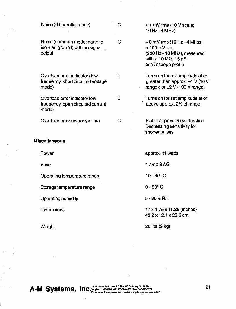
Noise (differential mode)
Noise (common mode earth to isolated ground) with no signal output
Overload error indicator (low frequency short circuited voltage mode)
Overload error indicator low frequency open circuited current mode)
Overload error response time
Miscellaneous
= 1 mV rms (10 V scale 10 Hz-4 MHz)
- 8 mV rms (10 Hz-4 MHz) =laquo100mVp-p (200 Hz -10 MHz) measured withalOMn 15pF oscilloscope probe
Turns on for set amplitude at or greater than approx plusmn1 V (10 V range) or plusmn2 V (100 V range)
Turns on for set amplitude at or above approx 2 of range
Flat to approx 30 ps duration Decreasing sensitivity for shorter pulses
Power
Fuse
Operating temperature range
Storage temperature range
Operating humidity
Dimensions
Weight
approx 11 watts
1 amp 3 AG
10-30degC
0 - 50deg C
5 - 80 RH
17x475x1125 (inches) 432x121x286 cm
20 lbs (9 kg)
A-M Systems Inc 131 Business Paik Loop PO Box 850 Cartsborg Wa 98324 Tekjptwne 8004201306 bull 36Olaquo8O8300 bull FAX 360laquo8O3525 E-mail salesOa-msystemscom Website httpywwwa-msystemscom
21
Warranty and Service
What does this warranty cover A-f Systems Inc warrants to the Purchaser that the Instrument excluding cables Headstage Probes and any other accessories shipped with the Instrument (hereafter the hardware) is free from defects in workmanship or material under normal use and service for the period of one (1) year This warranty commences on the date of delivery of the hardware to the Purchaser
What are the obligations of A-M Systems Inc under this warranty During the warranty period A-M Systems Inc agrees to repair or replace at its sole option without charge to the Purchaser any defective component part of the hardware To obtain warranty service the Purchaser must return the hardware to A-l^ Systems Inc or an authorized A-M Systems Inc distributor in an adequate shipping container Any postage shipping and insurance charges incurred in shipping the hardware to A-M Systems Inc must be prepaid by the Purchaser and all risk for the hardware shall remain with purchaser until such time as A-M Systems Inc takes receipt of the hardware Upon receipt A-M Systems Inc will promptly repair or replace the defective unit and then return the hardware to the Purchaser postage shipping and insurance prepaid A-M Systems Inc may use reconditioned or like new parts or units at its sole option when repairing any hardware Repaired products shall carry the same amount of outstanding warranty as from original purchase or ninety (90) days which ever is greater Any claim under the warranty must include a dated proof of purchase of the hardware covered by this warranty In any event A-M Systems Inc liability for defective hardware is limited to repairing or replacing the hardware
What is not covered by this warranty This warranty is contingent upon proper use and maintenance of the hardware by the Purchaser and does not cover batteries Neglect misuse whether intentional or othenvise tampering with or altering the hardware damage caused by accident damage caused by unusual physical electrical chemical or electromechanical stress damage caused by failure of electrical power or damage caused during transportation are not covered by this warranty Products may not be returned to A-M Systems Inc for service whether under warranty or otherwise which are contaminated by Infectious agents radioactive compounds or other materials constituting a health hazard to employees of A-M Systems Inc
What are the limits of liability for A-M Systems Inc under this warranty A-M Systems Inc shall not be liable for loss of data profits or savings or any special incidental consequential indirect or other similar damages arising from breach of contract negligence or other legal action even if the company or its agent has been advised of the possibility of such damages or for any claim brought against you by another party THIS EQUIPMENT IS NOT INTENDED FOR CLINICAL MEASUREMENTS USING HUMAN SUBJECTS A-M SYSTEMS INC DOES NOT ASSUME RESPONSIBILITY FOR INJURY OR DAMAGE DUE TO MISUSE OF THIS EQUIPMENT Jurisdictions vary with regard to the enforceability of provisions excluding or limiting liability for incidental or consequential damages Check the provision of your local jurisdiction to find out whether the above exclusion applies to you
This warranty allocates risks of product failure between the Purchaser and A-M Systems Inc A-M Systems Inc hardware pricing reflects this allocation of ris1lt and the limitations of liability contained in this warranty The warranty set forth above is in lieu of all other express warranties whether oral or written The agents employees distributors and dealers of A-M Systems Inc are not authorized to make modifications to this warranty or additional warranties binding on the company Accordingly additional statements such as dealer advertising or presentations whether oral or written do not constitute warranties by A-M Systems Inc and should not be relied upon This warranty gives you specific legal rights You may also have other rights which vary from one jurisdiction to another
A B B J l laquo raquo ^ t3tBusinessPafkLoopPOBox850Cai1sbO(gWa98324
- | V | O V S i e m S |nCtrade042O1306-36O68O8300-FAX36O68O3525 E-mail salasOa-msvstemscom bull Website httowwwa-msvste
t3tBusinassParkLaopROBox8SOCai1sbo(gWa98324 po Telophone 8004201306 360683-8300 FAX 3606803525 ^ ^ E-maH salesOa-msystemscom Wetsite httpwwwa-msystem3e0m
mwal
INSTRUCTION MANUAL
FOR
ISOLATED PULSE STIMULATOR
MODEL 2100
Serial
Date
A-M Systems Inc
PO Box 850
Carisborg WA 98324
USA
360-683-8300 bull 800-426-1306 FAX 360-683-3525
httpwwwa-m8y8temscom
Version 50 May 1998
Contents General Description 1
Instrument Features 1 Controls and Connectors 2
Operating Instructions 6 Theory of Operation 10 Calibration Procedures 12
Inputs ii 14 Output Calibration iii i 16
Specifications i4 il u 19 Warranty and Service wi iJ iJi [ii 22
Each Isolated Pulse Stimulator Is delivered complete with
Rack Mount Hardware Instructions amp Maintenance Manual
NOTE
This instrument is not intended for clinical measurements using human subjects A-M Systems Inc does not assume msponsibility for injury or damage due to the misuse of this instrument
General bull M ^ ion
Instrument Features The Isolated Pulse Stimulator Model 2100 Is designed for a wide variety of applications It is highly flexible being capable of delivering single pulses biphasic pairs or bursts of pulses Pulses may be started manually or upon receiving a trigger signal from another instrument or computer Two non-isolated trigger outputs are available for triggering other instruments
Four sets of timing controls provide comprehensive control over all aspects of pulse generation Three digit accuracy is available over a 7 decade range for each timing function using lever wheel switches Pulse wkiths can be set over more than a 9 decade range from 05 [is to 999 seconds Timing accuracy is assured through the use of a 10 MHz base rate crystal-controlled clock digitally divided to provide accurate timing over the entire range A timing overiap indicator will light if the timing controls are set Inconsistently
The output may be conveniently switched between cun-ent and voltage modes Pulse and baseline amplitudes are independently presettable with lockable dials An error indicator will light if the Model 2100 cannoi deliver the desired signal
WARNING
The Model 2100 can produce potentially dangemus voltages up to 100 V et the output connectors The isolated output is not connected internally to safety (earth) ground in ahy way Some part of the extemal circuit should be connected to safety gmund Use caution in handling any wires connectors or electrodes which may be directly or indirectly attached to the Model 2100 output Some lltinds of connectors such as BNC connectors have exposed metal parts which may float at dangemus potentials unless extemally connected to safety gmund For greatest safety tum the Model 2100 off before making any connections to
the Instrument
131 Business Park LocfiPO Box BSOCarM)orgWa 98324 800426-1308 bull36OlaquoS3laquo300FAX 3 6 M 8 3 ^ 2 5
E-malt uiittyBQaHiByBtumaooiTi Wobsita HipJtwtiwiwftbMiAcon fl-N SystQms I n c ^ T
Controls and Connectors The controls for the Model 2100 are grouped in three sections START controlling when a pulse or burst of pulses begins TIMING controlling the onoff timing of one or more pulses and otJTPliT controlling the amplitude of the output signal
Start TRIG SLOPE This switch determines whether valid triggers occur at positive or negative edges in the trigger signal
MODE This switch controls how wavefomris are initiated When set to FREE RUN one timing cycle immediately follows the last When held in the MANUAL position a timing cycle starts immediately When the switch is in the center position timing cycles start when valid triggering events occur
TRIGD This LED lights up when a timing cycle is in process and continues until the burst is completed
TRIG This BNC connector allows a signal from an extemal source to initiate timing cycles It is set for standard TTL levels
GATE This BNC connector allows a signal from an extemal source to restrict the final output signal This input must be at a logical high (or open-circuited) in order for the Model 2100 to recognize either manual or automatic trigger events
Gate 1_ Trigger [~^ i I Valid triggers are represented by the arrows in the figure Note that the up arrow would apply only if TRIG SLOPE is set to + the down anrows would apply only if TRIG SLOPE is set to-
NOTE Triggers have no effect if the system has not completed its response to a previous trigger
fl-N SystQms I n c ^ 131 Business Park Loop PO Box 850 Cartsborg Wa 98324 600426-13063eO683laquo300FAX 360683^525
E-maB anBysQraquoinsyaleiTaconi Wsbalto h^KAvwwa-(nsys(smsoom
Timing Four sets of controls govem the timing of pulse generation Each set contains two values which are multiplied together to detennine the actual timing value The rotary knob (rate selector) provides the approximate timing value and the lever wheel switch bank (MULTIPLIER) provkles a time resolution of three decimal digits The following diagram shows most of the important relationships
Pnfe-tRAIM I B E L A V i6Molaquo
BURST WIOtH
Output r Delay
t n
Duration - ^ lt - |4Periodgt|
FLJI -^ Burst width
Trigger event
DELAY These controls set the time between the initiating trigger event and the beginning of the pulse burst If this rate selector is set to NONE or the multiplier is set to ooo there is no delay
BURSTWIDTH These controls set the time period in which one or more pulses may be delivered Once started a pulse may outlast the burst width If this rate selector is set to SINGLE or to any time shorter than the pulse duration only a single pulse will occur If the BURSTWIDTH is longer than the period pulses will be emitted at the PERIOD rate until the burst time ends Pulses are never truncated by a short BURST WIDTH
iNTpoundA-PULSiE PBRiOb
DURATION These controls set the length of each pulse If this rate selector is set to SQUARE the duration is set to half of the period regardless of the MULTIPLIER setting
PERIOD These controls set the period of time between adjacent pulse events within the burst It also forces a minimum dead time between recognized input triggers following a burst of one or more pulses This can be used to prevent over stimulation of a tissue without requiring excessive delay between the triggering event and the stimulating pulse
TlMtNQ OVERLAP
mLiHMPi
VVtJ jiwaa lasm nlaquoilaquo u
t^fi SysUms I n c ^ Elt4nsfl a m
131 Business Pofc Loop PO Box 850 Carisborg 1^98324 600-426-1306 36O6834300 FAK 360683^525
E-mai vrvysQfrflisysleraLOCniWutiailQL N^jAwwa^iByslernUiOOni
NOTE If any of these timing controls are changed while a timing cycle is in operation the results are undefined until the cunent cycle flnishes
TIMING OVERLAP This LED will light to indicate an Inconsistency in the timing cycle settings There are several ways to Introduce such errors The most common way is to set the inter-pulse PERIOD to be less than the pulse DURATION
TRIG OUT (UPPER) This BNC connector provides a signal which is coinckient with the intemal Burst timing signal (default) This means the signal starts at the end of the Delay time and persists until the Burst time expires This output may also be set to represent the delay time-out by setting the internal jumper J510 to the left two pins Instead of the right two pins (Please see the Calibration section in this manual for jumper location Directions are given as viewed from the fix)nt of the instrument)
TRIG OUT (LOWER) This BNC connector provides a signal which is coincident with the Duration timing signal which controls pulse output
NOTE Both trigger output signals slightly lead the isolated output signal
Output PULSE SIGN This Switch sets the sign for the pulses to be generated It also allows generation of biphasic pulses thereby doubling the effective total period Warning the first pulse genemted after changing the PULSE SIGN svntch may have the wmng polarity
BASELINE This switch sets the sign for the baseline signal
RANGE This rotary switch allows one of three current or two voltage ranges to be selected for the output signal
BASELINE AMPLITUDE This counting dial are independently set using ten-minute counting dials with the baseline having one tenth the range of the pulse amplitude
A-N Systlaquomslaquo Inc 131 Buskiess Partt Loop PO BoK 8S0 Cailsbarg Wa 96324 laophone 8004201306 bull36O68M300-FAX 3eolaquo8M525 E-mat bullmsysflMnsyslermoom VMaHsr Hlplhfimnmyekmoom
PULSE AMPLITUDE This counting dial
EVENTS This LED indicates when a pulse is ongoing
ERROR This LED indicates when the intemal output amplifier cannot output the pulse as desired This is usually due to a short circuit while trying to output a voltage or an open circuit while trying to output a current
One control from the Ot^uf section directly affects wavefonn timing the Pulse Sign control When set to the Biphasic mode a positive-going pulse is Immediately followed by a negative-going pulse This effectively doubles the pulse duration If a burst of biphasic pulses is being produced the period must be at least twice the single pulse duration In the Sgtan wave mode the baseline disappears as long as the burst persists
fl-N Systems Inc 131 Bushass Park locpPOBooi 850 C8ri9bcrgMS8324 IMqphona 800426-1306 bull36Olaquo83laquo3a0 FAX 360683-3529 E-nal amsyaOa4nsyatemscomWeMlK hMpJVniwa-nsygtatnscom
Operating Instructions
Examples Simple setup (and minimal Instrument tost)
Connect the output of the Model 2100 to an oscilloscope Before connecting the instrument it is safest to turn its power off
Set the Ou^uf controls
Range Pulse Sign
Baseline Pulse Amplitude
10V +
Zero 200
Setting The Timing Controls
Delay Burst Width
Duratbn Period
none single
15010-2 500102
Setting The Start Controls
Mode Free Run
Disconnect any cables to the TRIG or GATE Inputs
Note that the green Trig and Event Indicators tum on as Free Run is turned on (and tum off othenwise) You should observe a 15ms duration 20Hz rate pulse of 200V above a OV baseline on the oscilloscope i
A ^ M ^ _ _ _ A ^ _ _ _ 1 ^ 131BiiHnD8raquoParttloopPOBoxB50Car)sbcrBlaquoraquoS8324
bull P l ^ y S W n i S f |nC ltV^gt^8deglt^^2O1306380laquo8OS3a0FAX36O6BMS2S
6 E-fnflk 9n^fBOs-in9ystsni9cx]fnWDbs)tec H^ff9Nw^myStem9oom
Demonstration of Burst Mode Connect the output of the Model 2100 to an oscilloscope Before connecting the instrument it is safest to tum Its power off
Set the Output controls
Range Pulse Sign
Baseline Pulse Amplitude
Baseline Amplitude
Setting The Timing Controls
Delay Burst Width
Duration
Period
Set the START controls as follows
Mode
Disconnect any cables to the TRIG or GATE inputs
Trigger the oscilloscope from the Burst trigger out (upper Tr^ Out connector) for a stable display In each burst (occumng every lOOms) you should observe a trio of 15ms duration starting 50ms apart Try switching the StartMode from Free Run to the center (nomnal) position The pulses will no longer be produced and the Trig and Event indicators will turn off Pressing this switch once (to Manual) will cause a single burst to occur
880 120 150 500
10V +
200 100
102 102 102 102
Free Run
fleaff SySlQmSa |nCa deglgt ltlt ^ ^ deg ^ degdeg ^ ^ ^ bull E-matmia
131 Business Park LoopPO Box 850 Carisborg Vfe 86324 lUcphcna 800426-1306 36Olaquo83laquo300 FAX 36068raquo52 E-maft tfii8ysOiHn^nleiTBcom1AWisJto HSpitwraquoM^wytAtii9oom
Problem SoMng If the Instrument appears to be not worthing properiy check all of the control settings and connections Be sure to wait at least 5-10 seconds after turning the Instrument off before tuming it on again The following t6ef summary of typical problems for the user (along with the most common solutions) may help
Problem CauseSolution EVENT indicator never lights even in FREE RUN mode
bull Replace fuse check power connection bullSet DELAY or PERIOD to a shorter interval
bull Power-on too soon after power-off
OVERLAP Indicator is on
ERROR indicator is on
Time appears to be excessive
bullSet DURATION gt000 bull DURATION is set to SQUARE but PERIOD is 000 Increase PERIOD or set DURATION independantly
bull BURST and WIDTH are gt DURATION increase PERIOD or decrease
DURATION bull BIPHASIC pulse output is on and PERIOD is not longer than twice the DURATION Increase PERIOD or decrease DURATION
bull Free-run is on and BURST Is lt PERIOD (BURST off) DELAY is 0 and PERIOD is lt DURATION Add delay or modify PERIOD
bull Free-mn is on and BURST is gt DURATION (BURST ON) and PERIOD is lt DURATION Increase PERIOD
bull For VOLTAGE outputs the output Is trying to drive too low a resistance or capacitance (eg a short circuit) Check by disconnecting the output It is possible (and normal) that for the fastest cycles
and largest amplitudes (close to 100 V and 1 MS) that the ERROR Indicator might always come on during repetitive pulses Fix output load or decrease amplitude as required
bull Changed control in mid-cycle (resets cunent status)
A ^ M bull _ _ _ A ^ ^ _ _ i ^ mdash 131BuslnessPai1ltLoopPOBox850CarlsborgWamp98324
bull p i j ^ v s w m s iiic^^deglt^deg^^deglt^^^3degB3^^^deg^^^^degdeg^^^deg^^deg^^^^ E-mat iiiMOafflwstemseom WabaHe MtaffiwwtHtavsli
8 E-msft flmsjoQfrfraystGfnsoom ^WobsltiK hl^Aiwv9-fn9]nteniscom
Cant seem to get a full signal out
Incoming triggers not accepted frequently enough
bull Load is not properiy connected repair wiring
bull Too low a load impedance (VOLTAGE modes) or too high a load impedance
(CURRENT mode)
bull PERIOD is set too long (enforces dead time) followd by BURST set to SIGNAL Reduce PERIOD time
Table 10 Problem Solving
If you suspect that the Model 2100 may have completely failed we recommend checking the basic level of functionality If this fails your instrument is defective and must be repaired If this passes either your experimental setup is incompatible or inconsistent or there is a more subtle flaw in your Model 2100
If the Model 2100 appears to be malfunctioning contact A-M Systems Inc or your dealer Telephone numtgters for A-M Systems Inc listed on the front cover of this manual We will first attempt to solve the problem over the telephone so have an exact description of your problem available when you call You do not need to be within the warranty period to obtain over-the-phone assistance
A ^ M V - mdash A d B ^ K M I ^ M 131BuslnessPatfcLoopPOBox6SOCai
-PI s y s i Q m s inc-2raquolaquoa22=M^^
131 Business Parfc Loop PO Box 650 Cartsborg VM9 0S324 _ FAX36(W8a3525 E^nrt flnsysQa-ntsyttanB-oom Wsbsfte hHpiMNvwa-nnystsnisooni
9
Theory of Operation
The operation of the Model 2100 is summarized In the block diagram (see Fig 3) Not shown are all of the interconnections with the microcontroller The intemal microcontroler plays an important role in setting the signal path but does not directly
contribute to the dynamic characteristics It scans the front panel switches and sets the control values for the logic arays It programs the intemal counters which along with the other hardware achieve the necessary sub-microsecond speeds
All action starts either from an input trigger signal (from Trig In) or from an intemal signal (in free Run mode only) A Delay timer counts the 10MHz clock until its count value Is exhausted At this point the Burst timer starts Both Period and Duration timers are started at this time If the Burst timer has not expired by the end of the Period the Period and Duration timers are restarted If the Biphasic mode has been set the Duration timer is restarted at the end of the initial Duration and the sign of the output pulse Is reversed doubling the total duration
The system state (pulse on pulse sip baseline sign [+101-]) is transmitted to the isolated section via optoisolator The baseline and pulse amplitudes are selected by an analog switch The resulting signal is amplified by a variable-power-supply discrete operational amplifier The amplifier connections and gain is modified to provide two voltage and three cunent ranges
Timing overlap errors are detected by a logical decision computation rather than by testing for counter collisions This provides instant feedback rather than waiting up to an hour for such a collision to occur Output errors are measured by sensing the output amplifiers differential input voltage Under normal conditions this is a negligible voltage if the amplifier fails to deliver the requested signal the window comparator testing this voltage sends this message (via optoisolator) to the logic section turning on a warning LED
fl-N Systems Inc 131BusbnassPa(tLoopPOBox6SOCari3boigVMg8324 H n |TWoph0n880O426-13083eO6Blaquo300FMt36Olaquo8i3525 E-nnl anaysflfriinysleiiaoemWfcbslte hllphmwraquoimyatennoom
TRIG 3HJ) OUT
(burst)
TRIG ^ OUT
(pulse)
E
Ml
Calibration Procedures
The calibration interval is the lesser of 1000 hours of operation or 6 months Somewhat greater drift can be expected in the first 100 hours of operation as the semiconductors age Adjustments should only be made after the instrument has been fully warmed up for at least 15 minutes
Full instrument calibration requires the following test equipment digital multimeter (plusmn 01) able to measure resistance to at least lOOMfl oscilloscope with at least 50MHz bandwidth true-rms voltmeter with 4MHz bandwidth universal counter (plusmn 001 ) able to measure single pulse widths and periods resistors (all plusmn 01) 2kn lOkH 1 waft 20kn 200kn alligator clip lead sets banana plugs and BNC adapters
Adjustment integrated circuit and test point locations are shown in the following figures All adjustments are on the timing board unless otherwise noted
All voltages in the non-isolated section should be measured with respect to ground at TP510 unless othenvise stated Some voltages are measured with respect to an intemal isolated ground at TP650 or across the two output tenninals Occasionally the voltage at an IC pin must be measured In these cases the reference designator is given with the pin number in parentheses eg U602(16) When it states within this procedure that a voltage is to be minimized this means that the adjustment should be made such that the measured voltage is as close to zero volts as possible Refer to the Specifications Section of this manual for acceptable tolerances
The sequence of this procedure is Important If any adjustment is made all adjustments which follow must be made to ensure that the specifications will be met These procedures require that all controls remain as set in previous steps unless otherwise indicated
WARNING
The Model 2100 has dangerous voltages throughout the instrument even with the power is off Servicing the Model 2100 should only be done by qualified service personnel Use caution in handling any wires connectors or electrodes which may be directly or indirectly attached to the Instrument Do not touch exposed connections or components Disconnect power by unplugging the power cord from the receptacle
fl-N Systems I n c ^ 131BusinesaPartcLoopPOBox850CartsborgVWiB8324 4 n ^gt-mdash80O426-130638Ofl8Jlaquo300FAX36O683J52S bull E-maft BinsysQfrfn^islflnisoomVVfalislle h^KVfWMift^iisystemsoani
CO
- R503
Omg^
TPSOlQ O
OTPSOO
U560 bull
U510
DDID ^ trade E O ^ T P 5 1 0
bullnD Trig
0 ^
U570
Gate n U505
DO D
U515
Timing
Timing h_ U520
bsoo ^25SE Timing
Or r U540
I I Tmlng
[^ELIL
U535 D
U506
13 J510 Timlnff
BurfiDelay J400
i i i i i i i T r m r a
gt U550 ^
Clock
U555 U620
B a
^R^Pvhigh Rfijn O D O Vlow
o
bull U545
Fo sect737 lISOIsPjC-COMP
n r r ^ U760
J420
]]U632
Q S riuGSO
H = ) TP640^ deg I t I
II3D
J440 m i T i
U610 plusmn laquo j U O
bull bull l el
^t
O l
bull
M
I
Power supply and bias voltages
Power supply
Controls Inputs Observations Adjust Check
POWER ON Observe voltage at P703 power supply wire top of main board
Check for+15 plusmn 050 V
Observe voltage at P701 power supply wire top of main board
Check for-15 plusmn 050 V
Observe voltage at U505(24) Check for+5 plusmn 025 V
Isolated supply voltage
Controls Inputs Observations Adjust Check
RANGE 10 V TRIG open circuit MODE center position
Altemately observe V^ from R742 to R740 and V ^ from the U605(4) to U605(8)
Adjust R773 so that 110VltV^lt 120 V and
nign
28VltV^lt34V
Capacitance balance
Controls Inputs Observations AdjustCheck
Connect a x10 oscilloscope probe to TP650 and ground the
Adjust R737 for minimum high frequency signal
Inputs
Gate funct ion
Controls Inputs Observations AdjustCheck
Apply a 1 kHz 0 - 5 V triangle wave Verify that the voltage to GATE switches states at the Obsene voltage at U51G(3) proper input levels with an oscilloscope ^ ^
Trigger s lope
Controls Inputs Observations Adjust Check
Apply a 1 kHz 0 - 5 V triangle wave Verify that the voltage to TRIO switches states at the Observe voltage at US 10( 1) proper input levels with an oscilloscope
TRIG SLOPE + Verify voltage is 180 out of phase
TRIG SLOPE Verify voltage is in phase
fl-N Systems Inc ^ 131 Bushess Park Loop PO Bar 850 Carisborg Wa 98324 8004201306 3eOlaquoS3e300 FAX 3606BV352S
C-maft fliii8yBQfriii9yBlumaoamVIAibsMB hRpJhwMifi-iiiBystematxini
14
Trigger and gate funct ion
Controls Inputs Observations Adjust Check
DELA NONE BURS1WII3TH SINGLE DURATION SQUARE PERIOD 100X10-3
Apply a 1 kHz 0 - 5 V triangle wave to TRIG Obsen^e TRIOD and EVENT LEDS
TRIG disconnect all Short the GATE connector to GND Verify LEDs extinguish
MODE press to MANUAL Verify LEDs flash once
Timing
System c lock frequency
Controls Inputs Observations AdjustCheck
Observe the frequency of the wave atU555(17)
Verify 1000 MHz plusmn001
Multipl iers (Wheel Switches)
Controls Inputs Observations AdjustCheck
PULSE SIGN + MODE FREE RUN TRIG disconnect all TIMING MULTIPUERS ail
wheels set to zero except the one being tested
TnmiNG OVERLAP ^nOTB
Observe the pulse width with the counter at the location specified below
Verify pulse width Is correct for each wheel as it is tested Independently
For each wheel of each MULTIPUER test each position to verify that the pulse width is correct Observe the signal at the following locations DELAY U520(2) BURSTWIDTH U530(2) PERIOD US40(2) DURATION U550(2)
Rates (Rotary Switches)
Controls Inputs Observations AdjustCheck
TIMING MULTIPUERS 001 TIMING RATES all rotary
switches set to 10-4 except the one being tested
Observe the pulse width with the counter at the location specified below
Verify pulse width is conect for each rotary switch as it is tested independently
For each of the four rotary switches in TIMING test each position to verify that the pulse wkJth is correct Observe the signal at the following locations DELAY U520(2) BURSTWIDTH U530(2) PERIOD U540(2) DURATION U550(2)
fl-N Systems I n c ^ E-maft emfl
131 Business Parti Loop PO 809(850 Cartsborg Wta 98324 8004201306 3804806300 FAX 36068O3S25
E-maft ansysQa nvystems-oom Wobste hflp Avwwa4nsy8(Qnttoam
15
Trigger outputs Controls
Range 10V Pulse Amplitude 500 Delay 100x10 Burst 100x10^2 Duration 100 x1a Period 400x10^ Pulse sign + Trig Mode Free run Trig in open
Inputs Observations
Trigger the oscilloscope to the Burst Trig Out Observe it the Pulse Trig Out and the isolated output
Adjust Check
Verify that the waveform consists of a burst of three 1ms-on3ms-off pulses The burst trigger should be synchronous with the burst the pulse trigger coincident with each pulse
Output Calibration
Isolation Resistance (check) Controls Inputs Observations AdjustCheck
Trig Mode center position Trig In open
Measure the resistance between ground banana jack (front panel) and black banana jack of output with DMM
Resistance read gt 100MQ
Amplitude Switch Offset (R640) Controls InputsObservations AdjustCheck
Baseline Zero Trig Mode center position Trig In Open
Measure the voltage at TP645 vs TP650 with the DMM
Adjust R640 (AmpI Sw Offset) for minimum voltage
Output Offset (R332 front panel board) Controls I nputsObservatlons AdjustCheck
Baseline Zero Range 10V Trig Mode center position Trig In Open
Measure the voltage across the output with the DMM
Adjust R332 (Output offset) for minimum voltage
Positive Baseline Offset (R607) Controls InputsObservations AdjustCheck
Baseline Sign + Baseline Amplitude
fully CCW (000) Range 10V Trig In open Trig Mode center position
Measure the voltage across the output with the DMM
Adjust R602 (BSLN + offset) for minimum voltage
fl M raquo _ _ _ A laquo ^ _ i ^ ^ 131Buslnelaquo8Pari(loopPOBoK850Cart8borgWB96324
bull P I i s V S i e m S a |||Cg1Maphans80O42O130638O68O8300FAX36Olaquo8raquo^2S E-tiBft anagtraquoflwiisyagtlaquomraquoaimW6baHB hHpffii(wwraquoltnsylaquoleniieom
16
Negative Baseline Offset (R619) Controls
Baseline Sign -i Baseline Amplitude bull fully CCW (000)
Range 10V Trig In open Trig Mode center position
Measure the voltage across the output with the DMM
AdjustCheck
Adjust R619 (BSLN 4 offset) for minimum voltage
Pulse Amplitude Adjust (R602) Controls InputsObservations AdjustCheck
Trig Mode Free Mode Pulse Amplitude 1000 Timing Dialay =none Burst =single Duration =1001 Period =00110-4 Pulse Sign -Trig In open Range 10V
Measure the voltage across the output with the DMM
The Overiap indicator should be on Adjust R602 (Max Level) for -1000V out
Pulse Sign Gain (check) Controls InputsObservations AdjustCheck
Trig Mode Free Mode Pulse Amplitude 1000 Timing Delay =none Burst =single Duration =1001 s Period =00110-4s Trig In open Range 10V
Measure the voltage at the output with the DMM for the Pulse Sign at -- and - positions
The absolute values of the voltages should differ by less than lOOmV
Baseline Amplitudes (check) Controls InputsObservations
Range 100mA Trig Mode center position Baseline Amplitude fully CW (1000) Trig In open
Measure the voltage at the output with the DMM with Baseline Sign in + Zero and - positions
AdjustCheck
Gain the matching of current levels at = and - positions and offset current in Zero position
fl-N Systems Inc^^ bull E-mal am8
131 Business Partt Loop PO Box 850 Cartsborg Wa 88324 8004201306360laquo8Oe300FAX 360laquo8O362S
E-maM am8y8^o-mBy8tflmBoom WobaKo hHp Awwwo-f i iBystonuoom
17
Output Range Amplitude and Drive (check) Controls InputsObservations AdjustCheck
Pulse Amplitude 1000 Pulse Sign + Trig Mode Free Run Timing Delay =none Burst =8ingle Duration =1001 Period =10010-4 Trig In open
Load the output with a 10KV1W 01 resistor Measure the voltage at the output with DMM
Verify that full scale output is within specification Scale Range 100V 100V 10V 10V 100mA IV 1mA 10V 10mA 100V
Pulse Sign and Short Circuit Protection (check) Controls InputsObservations AdjustCheck
Timing Delay =none Burst =8ingle Duration =200 10-4 Period =00110-3 Baseline Zero Pulse Amplitude 25 Range 10V Trig Mode Free Run Trig In open
Measure the voltage at the output with the oscilloscope Check for Pulse Sign set to each of + - biphasic Watch for Error indicator when shorting the output
Verify that pulses of approx 25V amplitude (625V for biphasic mode) of the correct sign are produced every 10ms Short output in biphasic mode Output should retum when opened
Output Transient Response (check) Controls InputsObservations AdjustCheck
Pulse Sign + Timing Delay =none Burst =single Duration =20010-4 Period =00110-3 Pulse Amplitude 250 Baseline Zero Trig Mode Free Mode Trig In open
Connect the oscilloscope to the output with a 310 attenuator prolse Test boVn 10V and 100V ranges
Verify that overshoot and risetime meet specifications
fl-N Systems I n c ^ 131 Business Parte Loop PO Box 850 Cartsborg Wb 98324 8004201306 36Olaquo83O300 FAX 36O680lt352S
E-mQ0 snBy8Qs-msy8faiTiscom VWriMtte N ^ Mvww9-msy8lemscom
18
Specifications
There are three classes of specifications Class A specifications tested in all unHs and are guaranteed Class B specifications are inherent in the design they are indirectly tested and are guaranteed Class C specifications are typical operating values which are occasionally tested- these are typical values given for your infomiation but not guarshyanteed The class for each specification is noted in the center column of the following sections
Inputs Switching level
Hysteresis
Input equivalent circuit
Minimum duration (1 IL-level signal)
A
C
C
C
16V(plusmn02V)
approx 50 mV
100K ft to+5 In parallel with no more than 35pF
gt 50 ns
Open circuit condition B defaults to highon level
Timing and rate accuracy Rate selector steps
Timing multiplier steps
Resolution
Timing eror (second and later pulses after resetting controls)
B
B
B
B
lOOps to 100s In 7 steps
1 of rate selector step size Maximum value is 999 x the rate selector step size
approx 01 of the maximum value
lt 002 of rate selector value + 015 ps
Timing error (first pulse after readjusting timing controls)
an additional 025 ps error may occur
Timing repeatability lt 001 setting + 20 ns (monophasic)
fl-N Systems I nc ^ bull E-moU ams
131 Business Parti Loop PO Boot 850 Cartsborg VM 98324 80O42O130838O08O8300FAX36Olaquo8O3S2S
E-meU anByafl^iiisyslainaoomWebsHe hHpffliiwwraquomsys)emsoom
19
TRIG IN to OUTPUT delay (DELAY set to 0) output set to 2V
Timing jitter ft-om TRIG IN to OUTPUT (for TTL trigger input with risetime lt10 ns)
Timing jitter ft^om TRIG OUT (either BURST or PULSE) and OUTPUT
Trigger output to pulse output delay
Output charactsristics Pulse level enror (voltage mode open circuit cun-ent mode short circuit
Biphasic level difference |V + + V-|2
Baseline level error (voltage mode A open circuit current mode short circuit)
Risetime (25 V out)
Risetime (25 V out)
Transient response
A
A
A
Output impedance (voltage mode) C
Output impedance (current mode) C
Isolation resistance A
Isolation capacitance C
approx 05 ps for a load of no more than 10 Kft in parallel with 50 pF
lt 125 ns (all rates except 100s) lt 125 ps (100s rate)
Less than 20 ns (all rates)
approx 350 ns
lt 03 of setting + 05 of r range (plus an additional 05 pA inlOOpArenge)
lt 03 of range (voltage modes into open circuit current modes into short circuit)
lt 03 of setting of setting + 01 of range (plus an additional 05 pA in lOOpA range)
laquo 200 ns into less than 30 pF
laquo15 ps into less than 30 pF
lt 8 overshoot Into less than 30 pF for pulse voltages different than baseline voltage by at least 10 of range
laquo 50 ohms
raquo 1 0 Gft (typically 200 Gft)
raquo100Mft
laquo 60 pF at 100 Hz
fl-N Systems Inc^^ 131 Business Partt Uxip PO Box 850 Cartsborg Wa 96324 8004201308 SBOee^^SOO FAX 360laquoS3^52S
E-mat BiByraquoaiMii8ylaquoliiiiiseomWiljalteHlpJV(wwraquo4tgy8lenaoom
20
Noise (differential mode)
Noise (common mode earth to isolated ground) with no signal output
Overioad error indicator (low frequency short circuited voltage mode)
Overioad error indicator low frequency open circuited current mode)
Overioad enor response time
Miscellaneous
Power
Fuse
Operating temperature range
Storage temperature range
Operating humidity
Dimensions
Weight
laquo1 mV rms (10 V scale 10Hz-4MHz)
laquo 8 mV rms (10 Hz-4 MHz) laquo100mVp-p (200 Hz -10 MHz) measured withalOMft 15pF oscilloscope probe
Turns on for set amplitude at or greater than approx plusmn1V (10 V range) or plusmn2 V (100 V range)
Turns on for set amplitude at or above approx 2 of range
Flat to approx 30 ps duration Decreasing sensitivity for shorter pulses
approx 11 watts
1 amp 3 AG
10-30C
0 - 50deg C
5-80RH
17x475x1125 (Inches) 432x121x286 cm
20 lbs (9 kg)
fl mm bull gt _ _ _ A ^ ^ _ _ L ^ 131BusinesraquoPariltLocpPOBox850C8rtsborgWS9e324
bull p i ^ y s v e m s IIIC^^deg(^deg^Bdegltgt^^^3degdeg^deg^^deg^^^degdeg^^I^deg^deg^^^^^
21 E-mei flre^nQo 4n8yo(amscam Wsbsfle hHpAwwwe-msy8Jems-Oom
Warranty and Service
What does this warranty cover A-M Systems Inc warrants to the Purchaser that the Instrument excluding cables Headstage Probes and any other accessories shipped with the Instrument (hereafter the hardware) is free from defects in workmanship or material under normal use and service for the period of one (1) year This warranty commences on the date of delivery of the hardware to the Purchaser
What are the obligations of A-M Systems Inc under this warranty During the warranty period A-M Systems Inc agrees to repair or replace at its sole option without charge to the Purchaser any defective component part of the hardware To obtain warranty service the Purchaser must return the hardware to A-M Systems Inc or an authorized A-M Systems Inc distributor in an adequate shipping container Any postage shipping and insurance charges incurred in shipping the hardware to A-M Systems Inc must be prepaid by the Purchaser and all risk for the hardware shall remain with purchaser until such time as A-M Systems Inc takes receipt of the hardware Upon receipt A-M Systems Inc will promptly repair or replace the defective unit and then return the hardware to the Purchaser postage shipping and insurance prepaid A-M Systems Inc may use reconditioned or like new parts or units at its sole option when repairing any hardware Repaired products shall carry the same amount of outstanding wan^nty as from original purchase or ninety (90) days which ever is greater Any claim under the warranty must include a dated proof of purchase of the hardware covered by this wan-anty In any event A-M Systems Inc liability for defective hardware is limited to repairing or replacing the hardware
What is not covered by this warranty This warranty is contingent upon proper use and maintenance of the hardware by the Purchaser and does not cover batteries Neglect misuse whether intentional or otherwise tampering with or altering the hardware damage caused by accident damage caused by unusual physical electrical chemical or electromechanical stress damage caused by failure of electrical power or damage caused during transportation are not covered by this warranty Products may not be returned to A-M Systems Inc for service whether under warranty or otherwise which are contaminated by infectious agents radioactive compounds or other materials constituting a health hazard to employees of A-M Systems Inc
What are the limits of llabiiity for A-M Systems inc under this warranty A-M Systems Inc shall not be liable for loss of data profits or savings or any special incidental consequential indirect or other similar damages arising from breach of contract negligence or other legal action even if the company or its agent has been advised of the possibility of such damages or for any claim brought against you by another party THIS EQUIPMENT IS NOT INTENDED FOR CLINICAL MEASUREMENTS USING HUMAN SUBJECTS A-M SYSTEMS INC DOES NOT ASSUME RESPONSIBILITY FOR INJURY OR DAMAGE DUE TO MISUSE OF THIS EQUIPMENT Jurisdictions vary with regard to the enforceability of provisions excluding or limiting liability for incidental or consequential damages Check the provision of your local jurisdiction to find out whether the above exclusion applies to you This warranty allocates risks of product failure between the Purchaser and A-M Systems Inc A-M Systems Inc hardware pricing reflects this allocation of risk and the limitations of liability contained in this wanranty The warranty set forth above is in lieu of all other express wan^anties whether oral or written The agents employees distributors and dealers of A-M Systems Inc are not authorized to make modifications to this wan-anty or additional wan-anties binding on the company Accordingly additional statements such as dealer advertising or presentations whether oral or written do not constitute wananties by A-M Systems Inc and should not be relied upon This warranty gives you specific legal rights You may also have other rights whrch vary from one jurisdiction to another
6 mm ^ laquo _ _ A a B ^ _ 1 ^ ^ 131 Business Parti Loop PO Box 850 Cartsborg W B 98324 O O
bull P l A y S V e m S l n C T^M 8OO42OI3O6 380683-8300FAX 360 803525 ^ ^ E-msl iiiisy80iHTBy8tenisoom Wsbsito hnphwwfrimysleiiisoom
A
V ISO
INSTRUCTION MANUAL
FOR
ISOLATED PULSE STIMULATOR
MODEL 2100
Serial
Date
A-M Systems Inc
PO Box 850
Carlsborg WA 98324
USA
360-683-8300 bull 800-426-1306 FAX 360-683-3525
httpwwwa-msystemscom
Version 70 February 2002
Contents General Description 1
Instrument Features 1 Controls and Connectors 2
Operating Instructions 6 Theory of Operation 10 Calibration Procedures 12
Inputs 14 Output Calibration 16
Specifications 19 Warranty and Service 22
Each Isolated Pulse Stimulator is delivered complete with
Rack Mount Hardware Instructions amp Maintenance Manual
NOTE
This instrument is not intended for clinical measurements using human subjects A-M Systems Inc does not assume responsibility for Injury or damage due to the misuse of this instrument
General Description
Instrument Features The Isolated Pulse Stimulator Model 2100 is designed for a wide variety of applications It is highly flexible being capable of delivering single pulses biphasic pairs or bursts of pulses Pulses may be started manually or upon receiving a trigger signal from another Instrument or computer Two non-isolated trigger outputs are available for triggering other instruments
Four sets of timing controls provide comprehensive control overall aspects of pulse generation Three digit accuracy is available over a 7 decade range for each timing function using lever wheel switches Pulse widths can be set over more than a 9 decade range from 05 ps to 999 seconds Timing accuracy is assured through the use of a 10 MHz base rate crystal-controlled clock digitally divided to provide accurate timing over the entire range Atiming overiap indicator will light If the timing controls are set inconsistently
The output may be conveniently switched between current and voltage modes Pulse and baseline amplitudes are Independently presettable with lockable dials An error Indicator will light if the Mode2700 cannot deliver the desired signal
r WARNING
The Model 2100 can produce potentially dangerous voltages up to 100 V at the output connectors The isolated output is not connected internally to safety (earth) ground in any way Some part of the extemal circuit should be connected to safety ground Use caution in handling any wires connectors or electrodes which may be directly or indirectly attached to the Model 2100 output Some kinds of connectors such as BNC connectors have exposed metal parts which may float at dangerous potentials unless extemally connected to safety ground For greatest safety tum the Model 2100 off before making any connections to
the instrument
131 Business Parii Loop PO Box 850 Cartsborg Wa 98324 Telophone 800-426-1306 bull 360-68raquolaquo300 bull FAX 360683-3525 E-mal satesa-msystemsoom VVfebsite httpywwwa^nsystemscom fl-N Systems Inc 1
Controls and Connectors The controls for the Model 2100 are grouped in three sections START which controls when a pulse or burst of pulses begins TIMING which controls the onoff timing of one or more pulses and OUTPUT which controls the amplitude of the output signal
Start TRIG SLOPE Determines the polarity of valid trigger pulses (positive or negative edges in the trigger signal)
MODE Controls waveform initiation When set to FREE RUN one timing cycle immediately follows the last When momentarily placed In the MANUAL position a timing cycle starts Immediately When the switch Is In the center position timing cycles start when valid triggering events occur
TRIGD This LED lights up when a timing cycle Is in process and continues until the burst is completed
TRIG This BNC connector allows a signal from an external source to Initiate timing cycles It is set for standard TTL levels
GATE This BNC connector allows a signal from an external source to restrict the final output signal This input must be at a logical high (or open-circuited) in order for the Model 2100 to recognize either manual or automatic trigger events
Gate 1_ Trigger |~~^ i I Valid triggers (represented by the arrows in the figure) can occur only when the gate Is at logical high Note that the up arrow would apply only If TRIG SLOPE is set to + the down an-ows would apply only if TRIG SLOPE Is set to -
NOTE Triggers have no effect if the system has not completed its response to a previous trigger
fl-N Systems Inc 131 Business Park Loop PO Box 850 Cartsborg Vb 98324 TelQphQne 80O426-1306 360683-8300 FAX 360683-3525 E-mail sales^a-msystemscom Wsbsite httpywwwa-msystemscom
Timing Four sets of controls govern the timing of pulse generation Each set contains two values which are multiplied together to detemnine the actual timing value The rotary knob (rate selector) provides the approximate timing value and the lever wheel switch bank (MULTIPLIER)
provides a time resolution of three decimal digits The following diagram shows most of the Important relationships
Output r Delay Duration
|ltPeriodgtj
t Burst width
Trigger event
DELAY These controls determine the time duration between the initiating trigger event and the beginning of the pulse burst If this rate selector is set to NONE or the multiplier is set to 000 there Is no delay
BURST WIDTH These controls determine the time period in which one or more pulses may be delivered Once started a pulse may outlast the burst width If this rate selector is set to SINGLE or to any time shorter than the pulse duration only a single pulse will occur If the BURST WIDTH Is longer than the period pulses will be emitted at the PERIOD rate until the burst time ends Pulses are never truncated by a short BURSTWIDTH
inds)-PULSE
D U R A T I O N 1 0 1 0
10
INTEB-PULSE PERIOD
1 1 10
DURATION These controls determine the length of each pulse Ifthis rate selector Is set to SQUARE the duration is set to half of the period regardless of the MULTIPLIER setting
PERIOD These controls set the period of time between adjacent pulse events within the burst It also forces a minimum dead time between recognized input triggers following a burst of one or more pulses This can be used to prevent over stimulation of a tissue without requiring excessive delay between the triggering event and the stimulating pulse
TIMING OVERLAP
fl-N Systems Inc 131 Business Parti Loop RO Box 860 Carisborg Vamp 98324 |Telophone 800-426-1306 360683-8300 bull FAX 3606aW525 E-mail salearega^nsystemsoom Vfeb5ite httpAwwwa^nsyslemscam
NOTE If any of these timing controls are changed while a timing cycle is in operation the results are undefined until the current cycle finishes
TIMING OVERLAP This LED will light to Indicate an inconsistency in the timing cycle settings There are several ways to introduce such errors The most common way is to set the Inter-pulse PERIOD to be less than the pulse DURATION
T I M I N G (seconds)^
TRIG OUT (UPPER) This BNC connector provides a signal which is coincident with the Internal Burst timing signal (default) This means the signal starts at the end of the Delay time and persists until the Burst time expires This output may also be set to represent the delay time-out by setting the internal jumper J510 to the right two pins instead of the left two pins (Please see the Calibration section in this manual for jumper location Directions are given as viewed from the front of the Instrument)
TRIG OUT (LOWER) This BNC connector provides a signal which Is coincident with the Duration timing signal which controls pulse output
NOTE Both trigger output signals slightly lead the isolated output signal
Output
PULSE SIGN This switch determines the polarity of the pulses to be generated It also allows generation of biphasic pulses thereby doubling the effective total period Warning the first pulse generated after changing the PULSE
SIGN switch may have the wrong polarity
BASELINE This Switch determines the polarity ofthe baseline signal
RANGE This rotary switch determines if the output pulses will be constant current (3 ranges) or constant voltage (2 ranges)
BASELINE AMPLITUDE This value is independently set using a ten-turn counting dial The maximum baseline amplitude is one tenth the value shown on the range amplitude switch
fl-N Systems Inc 131 Business Parti Loop RO Box 8S0 Cartsborg Vfa 98324 |Tetaphone 80O426-1306 bull 360683-8300 bull FAX 3606803525 E-mail salesa-msystemscom Wbbsite http7Awwwaflnsystemscom
PULSE AMPLITUDE This value is independently set using a ten-turn counting dial The maximum pulse amplitude is the value shown on the range amplitude switch
EVENT This LED indicates when a pulse is ongoing
ERROR This LED indicates when the internal output amplifier cannot output the pulse as desired This is usually due to a short circuit while trying to output a voltage or an open circuit while trying to output a current
VOTEThe Pulse Sign control in the Oupuf section directly affects waveform timing When set to the Biphasic mode a positive-going pulse is immediately followed by a negative-going pulse This effectively doubles the pulse duration If a burst of biphasic pulses is being produced the period must be at least twice the single pulse duration In the Square wave mode the baseline disappears as long as the burst persists
fl-N Systems Inc 131 Business Parti Loop RO Box 850 Cartsboig Vte 98324 |Telophone 800426-1306 360683-8300 bull FAX 3606833525 E-mail salesa-m5ystem5 com Website httpwwwa-msystemscom
Operating Instructions
Examples Simple setup (and minimal instrument test)
Connect the output ofthe Model 2100 to an oscilloscope Before connecting the Model 2100 to any other instrument or the experimental preparation It is safest to turn Its power off
Set the Oufpuf controls
Range 10V Pulse Sign +
Baseline Zero Pulse Amplitude 200
Setting The Timing Controls
Delay Burst Width
Duration Period
none single
15010-2 50010-2
Setting The Start Controls
Mode Free Run
Disconnect any cables to the TRIG or GATE inputs
Note that the green Trig and Event Indicators turn on as Free Run is turned on (and turn off otherwise) You should observe a 15ms duration 20Hz rate pulse of 200V above a OV baseline on the oscilloscope
fl-N Systems Inc 131 BusinessPartiLoop RO Box850CarisbcxgWa98324 |Telophone 800426-1306 bull 360-683-8300 bull FW 360683-3525 E-mail salesa-msystems com VVbbsite httpywwwa-msystems com
Demonstration of Burst Mode Connect the output ofthe Model 2100 to an oscilloscope Before connecting the Model 2100 to any other instrument or the experimental preparation It Is safest to turn its power off
Set the Outpuf controls
Range 10V Pulse Sign +
Baseline Pulse Amplitude 200
Baseline Amplitude 100
Setting The Timing Controls
Delay 88010-2 Burst Width 12010-^
Duration 15010-2 Period 50010-2
Set the START controls as follows
Mode Free Run
Disconnect any cables to the TRIG or GATE inputs
fl-N Systems Inc 131 Business Parti Loop RO Box 850 Cartsborg Wa 98324 Telophooe 8004201306 360683-8300 bull FAX 360683-3525 E^naii salesa-msystems com Watjsite http7wwwa-msystemscom
Trigger the oscilloscope from the Bursf trigger out (upper Trig Out connector) for a stable display In each burst (occurring every lOOms) you should observe a trio of 15ms duration starting 50ms apart Try switching the StartMode from Free Run to the center (nonnal) position The pulses will no longer be produced and the Trig and Event Indicators will tum off Pressing this switch once (to Manual) will cause a single burst to occur
Problem Solving If the instrument appears to be not working properiy check all ofthe control settings and connections Be sure to wait at least 5-10 seconds after turning the instrument off before turning it on again The following summary of typical problems for the user (along with the most common solutions) may help
Problem CauseSolution
EVENT Indicator never lights even in FREE RUN mode
bull Replace fuse check power connection bullSet DELAY or PERIOD to a shorter interval
bull Power-on too soon after power-off
OVERLAP Indicator is on
ERROR indicator is on
bull Set DURATION gt000 bull DURATION Is set to SQUARE but
PERIOD is 000 Increase PERIOD or set DURATION independantly
bull BURST and WIDTH are gt DURATION increase PERIOD or decrease DURATION
bull BIPHASIC pulse output Is on and PERIOD is not longer than twice the DURATION Increase PERIOD or decrease DURATION
bull Free-run Is on and BURST is lt PERIOD (BURST off) DELAY is 0 and PERIOD Is lt DURATION Add delay or modify PERIOD
bull Free-run is on and BURST is gt DURATION (BURST ON) and PERIOD is lt DURATION Increase PERIOD
bull For VOLTAGE outputs the output is trying to drive too low a resistance or capacitance (eg a short circuit) Check by disconnecting the output ft is possible (and normal) that for the fastest cycles and largest amplitudes (close to 100 V
fl-N Systems Inc 131 Business PartiLoop PO Box 850 CartsborgWa 98324 iTelophone 800-42O130636O6e3-8300FAX 3606B3-3525 E-mail satesaflisyslefmcom Vfebslte http7wwwa-msyslemscom
and 1 ps) that the ERROR indicator might always come on during repetitive pulses Fix output load or decrease amplitude as required
Time appears to be excessive Changed control in mid-cycle (resets current status)
Cant seem to get a full signal out Load Is not properiy connected repair wiring Too low a load impedance (VOLTAGE modes) or too high a load impedance (CURRENT mode)
Incoming triggers not accepted frequently enough
PERIOD is set too long (enforces dead time) followd by BURST set to SIGNAL Reduce PERIOD time
Table 10 Problem Solving
If you suspect that the Model 2100 may have completely failed we recommend checking the basic level of functionality Ifthis fails your instrument Is defective and must be repaired Ifthis passes either your experimental setup is incompatible or inconsistent or there is a more subtle flaw in your Model 2100
If the Model 2100 appears to be malfunctioning contact A-M Systems Inc or your dealer We will first attempt to solve the problem over the telephone so have an exact description of your problem available when you call You do not need to be within the warranty period to obtain over-the-phone assistance
fl-N Systems Inc 131 Business Parti Loop RO Box 850 Cartsborg Wa 98324 iTetoptxme 80O426-1306 bull 360683-8300 FAX 3606803525 E-mail satesa-msystemsoomAfebsitehttpJwwwaflisystemscom
Theory of Operation
The operation ofthe Model 2100 is summarized in the block diagram (see the figure on Page 11) Not shown are all ofthe interconnections with the microcontroller The internal microcontroler plays an important role in setting the signal path but does not directly contribute to the dynamic characteristics It scans the front panel switches and sets the control values for the logic arrays It programs the internal counters which along with the other hardware achieve the necessary sub-microsecond speeds
Pulse generation starts either from an Input trigger signal (from Trig In) or an internally signal (Free Run mode) A Delay timer counts the 10MHz clock until its count value is exhausted At this point the Burst Period and Duration timers are started If the Burst timer has not expired by the end ofthe Period the Period and Duration timers are restarted If the Biphasic mode has been set the Duration timer is restarted at the end of the initial Duration and the sign ofthe output pulse is reversed doubling the total duration
The system state (pulse on pulse sign baseline sign [+0f-]) is transmitted to the isolated section via optoisolator The baseline and pulse amplitudes are selected by an analog switch The resulting signal is amplified by a variable-power-supply discrete operational amplifier The amplifier connections and gain is modified to provide two voltage and three current ranges
Timing overiap errors are detected by a logical decision computation rather than by testing for counter collisions This provides instant feedback rather than waiting up to an hour for such a collision to occur Output errors are measured by sensing the output amplifiers differential input voltage Under normal conditions this is a negligible voltage If the amplifier fails to deliver the requested signal the window comparator testing this voltage sends this message (via optoisolator) to the logic section turning on a warning LED
fl-N Systems Inc 131BusinessPart(LoopRO Box850CarisboigWa98324 4 n Tel0pri0ne80O426-130636O683^300FAX36O6833525 ^ E-mail salesaflisystBmscom V febsite http7wwwa-msystemsoom
S i
I - - ^^mdasho^M
OUTPUT i l l
TRIG ^ OUT
(burst)
TRIG 3-lt) OUT
(pulse)
til
I laquo
Calibration Procedures
The calibration interval is the lesser of 1000 hours of operation or 6 months Somewhat greater drift can be expected in the first 100 hours of operation as the semiconductors age Adjustments should only be made after the instrument has been fully warmed up for at least 15 minutes
Full instrument calibration requires the following test equipment digital multimeter (plusmn 01) able to measure resistance to at least lOOMO oscilloscope with at least 50MHz bandwidth true-mis voltmeter with 4MHz bandwidth universal counter (plusmn 001 ) able to measure single pulse widths and periods resistors (all plusmn 01) 2kn lOkH 1 watt 20kn 200kn alligator clip lead sets banana plugs and BNC adapters
Adjustment integrated circuit and test point locations are shown in the following figures All adjustments are on the timing board unless othenAise noted
All voltages in the non-isolated section should be measured with respect to ground at TP510 unless othenwise stated Some voltages are measured with respect to an internal isolated ground at TP650 or across the two output temninals Occasionally the voltage at an IC pin must be measured in these cases the reference designator is given with the pin number in parentheses eg U602(16) When it states within this procedure that a voltage is to be minimized this means that the adjustment should be made such that the measured voltage is as close to zero volts as possible Refer to the Specifications Section of this manual for acceptable tolerances
The sequence of this procedure is important If any adjustment is made all adjustments which follow must be made to ensure that the specifications will be met These procedures require that all controls remain as set in previous steps unless othenAise indicated
WARNING
The Model 2100 has dangerous voltages throughout the instrument even with the power is off Servicing the Model 2100 should only be done by qualified service personnel Use caution in handling any wires connectors or electrodes which may be directly or indirectly attached to the instrument Do not touch exposed connections or components Disconnect power by unplugging the power cord from the receptacle
H B ^ ^ S y s t e m s inc^degdegp^deg^^deg-^^^^^^^^B3^^^degdeg^^^lt^^^B^^^^ 131BusinessPartiLoopPO Box850CartsbOigWamp98324 4 9 |Telophone800-42013C6360683-8300F0lt360683-3525 ^ E-mail salesa-msystefnscom website httpwwwaflisystems com
CO
TP501 O lt0
g OTPSOO
U560 S
Trig Gate
0 -TISOS
U570
U500
Timing
p U520
Timing
K U550 Timin
gt U540
U515
o X I Timin
U508 I
J510 Timing nnn
Burst Delay J400
gt U550
R503
D D I D bull U8QQ i Q
n
oo
V P 5 1 0
b U535
^
Clock i _
U555
lt U 5 4 5
o
h d ^ O - - ^ U605
Q D
U620
O fJZ^ R737 bull ^ 1^13015 r j C - C O M P
B B nU770 ^ ^ ^ 5 ^ a
J420
a
o E
bull [ ]U632
riueso
rR742rVhigh R 6 1 9 ^
LJ TP645 O TP650
TPMOQ^QS
Vlow
CD-
CZZl
J440 bull bull tl iUDQ
I t
f i l
Power supply and bias voltages
Power supply
Controls Inputs Observations Adjust Check
POWER ON Observe voltage at P703 power supply wire top of main board
Check for+15 plusmn 050 V
Observe voltage at P701 power supply wire top of main board
Check for-15 plusmn 050 V
Observe voltage at U505(24) Check for +5 plusmn 025 V
Isolated supply voltage Controls Inputs Observations AdjustCheck
RANGE 10 V TRIG open circuit MODE center position
Alternately observe V ^ from R742 to R740 and V ^ from theU605(4)toU605(8)
Adjust R773 so that 110VltV lt 120 V and
nigh
28VltV|^lt34V
Capacitance balance Controls Inputs Observations Adjust Check
Connect a xlO oscilloscope probe to TP650 and ground the
Adjust R737 for minimum high frequency signal
Inputs
Gate function Controls Inputs Observations AdjustCheck
Apply a 1 kHz 0 - 5 V triangle wave Verify that the voltage to GATE switches states at the Observe voltage at U510(3) proper input levels with an oscilloscope
Trigger slope Controls Inputs Observations AdjustCheck
Apply a 1 kHz 0 - 5 V triangle wave Verify that the voltage to TRIG switches states at the Observe voltage at U510( 1) proper input levels with an oscilloscope
TRIG SLOPE Verify voltage is 180deg out of phase
TRIG SLOPE Verify voltage is in phase
fl-N Systems Inc 131 Business Parti Loop RO Box 860 Cartsborg Wa 98324 Jelophone 800-4201306 360683-8300 bull FM 380683-3525 E-mail salesaflTsystBfnscom bull Vtebsite httpVAirwwaflisystems com
14
Trigger and gate f unc t i on
Controls Inputs Observations Adjust Check
DELAY NONE BURS-nMDTH SINGLE DURATION SQUARE PERIOD 100X10-3
Apply a 1 kHz 0 - 5 V triangle wave to TRIG Observe TRIGD and EVENT LEDs
TRIG disconnect all Short the GATE connector to GND Verify LEDs extinguish
MODE press to MANUAL Verify LEDs flash once
Timing
System c lock f requency
Controls Inputs Observations Ad jus t Check
Observe the frequency of the wave Verify 1000 MHz plusmn 001 atU555(17)
Mul t ip l iers (Wheel Swi tches)
Controls Inputs Observations Adjust Check
PULSE SIGN-laquobull MODE FREE RUN TRIG disconnect all TIMING MULTIPUERS all
wheels set to zero except the one being tested
TIMING OVERLAP ignore
Observe the pulse width with the counter at the location specified t)elow
Verify pulse width is correct for each wheel as it is tested independently
For each wheel of each MULTIPLIER test each position to verify that the pulse width is correct Observe the signal at the following locations DELAY U520(2) BURSTWIDTH U530(2) PERIOD U540(2) DURATION U550(2)
Rates (Rotary Swi tches)
Controls Inputs Observations Adjust Check
TIMING MULTIPUERS 001 Observe the pulse width with the TIMING RATES all rotary counter at the location specified
switches set to 10-4 below except the one being tested
Verify pulse width is correct for each rotary switch as it is tested independently
For each ofthe four rotary switches in TIMING test each position to verify that the pulse width is correct Observe the signal at the following locations DELAY U520(2) BURSTWIDTH U530(2) PERIOD U540(2) DURATION U550(2)
fl-N Systems Inc 131 Business Parti Loop PO Box 850 Cartsborg Wa 98324 iTetophone 8004201306 bull 360683-8300 bull FOC 3606803525 E-mail salesa-msystemscom Wbbsite httpJwwwaflTSystemscom
15
Trigger outputs
Controls Inputs Observations Adjust Check
Range 10V Pulse Amplitude 500 Delay 100 xlO^ Burst 100 x 10 ^ Duration 100x10-^ Period 400x10-^ Pulse sign + Trig Mode Free run Trig in open
Trigger the oscilloscope to the Burst Trig Out Observe it the Pulse Trig Out and the isolated output
Verify that the waveform consists of a burst of three 1ms-on3ms-off pulses The burst trigger should be synchronous with the burst the pulse trigger coincident with each pulse
Output Calibration
Isolation Resistance (check)
Controls Inputs Observations AdjustCheck
Trig Mode center position Trig In open
Measure the resistance between ground banana jack (front panel) and black banana jack of output with DMM
Resistance read gt 100MQ
Amplitude Switch Offset (R640)
Controls InputsObservations AdjustCheck
Baseline Zero Trig Mode center position Trig In Open
Measure the voltage at TP645 vs TP650 with the DMM
Adjust R640 (AmpI Sw Offset) for minimum voltage
Output Offset (R332 front panel board) Controls InputsObservations AdjustCheck
Baseline Zero Range 10V Trig Mode center position Trig In Open
Measure the voltage across the output with the DMM
Adjust R332 (Output offset) for minimum voltage
Positive Baseline Offeet (R607) Controls InputsObservations AdjustCheck
Baseline Sign + Baseline Amplitude
fully CCW (000) Range 10V Trig In open Trig Mode center position
Measure the voltage across the outputwiththeDMM
Adjust R602 (BSLN + offset) for minimum voltage
fl-N Systems Inc 131 BusBiess Parti Loop P O Box 850 Cartsborg Wa 98324 Telophone B00-42O1306 bull 360683-8300 bull FAX 3606803525 E-mail salesaflisystemscom V^tebsite httpy^vwwa-msystems com
16
Negative Baseline Offset (R619)
Controls InputsObservations AdjustCheck
Baseline Sign -Baseline Amplitude
fully CCW (000) Range 10V Trig In open Trig Mode center position
Measure the voltage across the outputwiththeDMM
Adjust R619 (BSLN + offset) for minimum voltage
Pulse Amplitude Adjust (R602)
Controls InputsObservations AdjustCheck
Trig Mode Free Mode Pulse Amplitude 1000 Timing Delay =none Burst =single Duration =1001 Period =00110-4 Pulse Sign -Trig In open Range 10V
Measure the voltage across the output with the DMM
The Overiap indicator should be on Adjust R602 (Max Level) for -10OOV out
Pulse Sign Gain (check)
Controls InputsObservations AdjustCheck
Trig Mode Free Mode Pulse Amplitude 1000 Timing Delay =none Burst =single Duration =100 1s Period =001 10-4s Trig In open Range 10V
Measure the voltage at the output with the DMM for the Pulse Sign at + and - positions
The absolute values ofthe voltages should differ by less than lOOmV
Baseline Amplitudes (check) Controls InputsObservations AdjustCheck
Range 100mA Trig Mode center position Baseline Amplitude fully CW (1000) Trig In open
Measure the voltage at the output with the DMM with Baseline Sign in + Zero and
- positions
Gain the matching of current levels at = and - positions and offset current in Zero position
fl-N Systems Inc 131 Business Parti Loop PO Box 850 Cartsboig Wa 98324 Telophone 800-4201306 360683-8300 FkX 3606803525 E-mail salesa-msystemscom website http^^wwaflisystemsccm
17
Output Range Amplitude and Drive (check) Controls InputsObservations AdjustCheck
Pulse Amplitude 1000 Pulse Sign + Trig Mode Free Run Timing Delay =none Burst =single Duration =1001 Period =10010-4 Trig In open
Load the output with a 10KV 1W 01 resistor Measure the voltage at the output with DMM
Verify that full scale output is within specification Scale Range 100V 100V 10V 10V 100mA IV 1mA 10V 10mA 100V
Pulse Sign and Short Circuit Protection (check) Controls InputsObservations AdjustCheck
Timing Delay =none Burst =single Duration =200 10-4 Period =00110-3 Baseline Zero Pulse Amplitude 25 Range 10V Trig Mode Free Run Trig In open
Measure the voltage at the output with the oscilloscope Check for Pulse Sign set to each of + - biphasic Watch for Error indicator when shorting the output
Verify that pulses of approx 25V amplitude (625V for biphasic mode) of the correct sign are produced every 10ms Short output in biphasic mode Output should return when opened
Output Transient Response (check) Controls InputsObservations AdjustCheck
Pulse Sign + Timing Delay =none Burst =single Duration =20010-4 Period =00110-3 Pulse Amplitude 250 Baseline Zero Trig Mode Free Mode Trig In open
Connect the oscilloscope to the output with a 310 attenuator probe Test both 10V and 100V ranges
Verify that overshoot and risetime meet specifications
fl-N Systems Inc 131 Business Parti Loop RO Box 850 Cartsborg Wa 98324 Telophone 8004201306 bull 3606808300 bull Flaquo( 360laquo83ltJ525 E-mail salesa-msystemsocm V^febsite http^wwwa-msystefnscom
18
Specifications
There are three classes of specifications Class A specifications tested in all units and are guaranteed Class B specifications are inherent in the design they are indirectly tested and are guaranteed Class C specifications are typical operating values which are occasionally tested- these are typical values given for your information but not guarshyanteed The class for each specification is noted in the center column ofthe following sections
Inputs Switching level
Hysteresis
Input equivalent circuit
Minimum duration (1 IL-level signal)
A
C
C
C
16 V(plusmn 02 V)
approx 50 mV
lOOKH to+5 in parallel with no more than 35pF
gt 50 ns
Open circuit condition B defaults to highon level
Timing and rate accuracy Rate selector steps
Timing multiplier steps
B
B
lOOpsto 100s in 7 steps
1 of rate selector step size Maximum value is 999 X the rate selector step size
Resolution B approx 01 ofthe maximum value
Timing error (second and later pulses after resetting controls)
B lt 002 of rate selector value + 015 ps
Timing error (first pulse after readjusting timing controls)
an additional 025 ps error may occur
Timing repeatability lt 001 setting + 20 ns (monophasic)
fl-N Systems Inc 131 Business Ram Loop RO Box 850 Cartsborg Vfa 98324 pTelophone 8004201306 bull 360683-8300 bull FAX 360683-3525
E-mail salesraquoflisystems com Wabsite httpJAnww afl isystems com
19
TRIG IN to OUTPUT delay (DELAY set to 0) output set to 2V
Timing jitter from TRIG IN to OUTPUT (for TTL trigger input with risetime lt10 ns)
Timing jitter from TRIG OUT (either BURST or PULSE) and OUTPUT
Trigger output to pulse output delay
Output characteristics Pulse level error (voltage mode open circuit current mode short circuit
Biphasic level difference IV + - V-1 2
Baseline level error (voltage mode open circuit current mode short circuit)
Risetime (25 V out)
Risetime (25 V out)
Transient response
A
A
A
Output impedance (voltage mode) C
Output impedance (current mode) C
Isolation resistance A
Isolation capacitance C
approx 05 ps for a load of no more than 10 KH in parallel with 50 pF
lt 125 ns (all rates except 100s) lt 125 ps (100s rate)
Less than 20 ns (all rates)
approx 350 ns
lt 03 of setting + 05 of r range (plus an additional 05 pA in 100 pA range)
lt 03 of range (voltage modes into open circuit current modes into short circuit)
lt 03 of setting of setting + 01 of range (plus an additional 05 pA in lOOpA range)
= 200 ns into less than 30 pF
= 15 ps into less than 30 pF
lt 8 overshoot into less than 30 pF for pulse voltages different than baseline voltage by at least 10 of range
= 50 ohms
raquo 1 0 GH (typically 200 GO)
raquo 1 0 0 M n
= 60 pF at 100 Hz
fl-N Systems Inc 131 Business Peril Loop PO Box 850 Cartsborg V6 98324 |TelCf)hone 800-4201306 3606808300 bull FAX 360683-3525 E-mal salesaflisystefnsoom Website hnpyMVfWafllsystemsoom
20
Noise (differential mode)
Noise (common mode earth to isolated ground) with no signal output
Overload error indicator (low frequency short circuited voltage mode)
Overload error indicator low frequency open circuited current mode)
Overioad error response time
Miscellaneous
= 1 mV rms (10 V scale 10 Hz-4 MHz)
= 8 mV rms (10 Hz-4 MHz) == 100mVp-p (200 Hz -10 MHz) measured withalOMH 15pF oscilloscope probe
Turns on for set amplitude at or greater than approx plusmn1 V (10 V range) or plusmn2 V (100 V range)
Turns on for set amplitude at or above approx 2 of range
Flat to approx 30 ps duration Decreasing sensitivity for shorter pulses
Power
Fuse
Operating temperature range
Storage temperature range
Operating humidity
Dimensions
approx 11 watts
1 amp 3AG
10-30degC
0 - 50deg C
5 - 80 RH
17x475x1125 (inches) 432x121x286 cm
Weight 20 lbs (9 kg)
fl-N Systems Inc 131 Business Parti Loop RO Box 850 Cartsborg Wb 98324 |Tetcphone 8004201306 3606808300 bull FOt 360683-3525 E-mail satesamsystems comV^febsite httpywwwaflisystemscom
21
Warranty and Service
What does this warranty cover A-M Systems Inc warrants to the Purchaser that the Instrument excluding cables Headstage Probes and any other accessories shipped with the Instrument (hereafter the hardware) is free from defects in workmanship or material under normal use and service for the period of one (1) year This warranty commences on the date of delivery ofthe hardware to the Purchaser
What are the obligations of A-M Systems Inc under this warranty During the warranty period A-M Systems Inc agrees to repair or replace at its sole option without charge to the Purchaser any defective component part of the hardware To obtain warranty service the Purchaser must return the hardware to A-M Systems Inc or an authorized A-M Systems Inc distributor in an adequate shipping container Any postage shipping and insurance charges incurred in shipping the hardware to A-M Systems Inc must be prepaid by the Purchaser and all risk for the hardware shall remain with purchaser until such time as A-M Systems Inc takes receipt of the hardware Upon receipt A-M Systems Inc will promptly repair or replace the defective unit and then return the hardware to the Purchaser postage shipping and insurance prepaid A-M Systems Inc may use reconditioned or like new parts or units at its sole option when repairing any hardware Repaired products shall carry the same amount of outstanding warranty as from original purchase or ninety (90) days which ever is greater Any claim under the warranty must include a dated proof of purchase ofthe hardware covered by this warranty In any event A-M Systems Inc liability for defective hardware is limited to repairing or replacing the hardware
What is not covered by this warranty This warranty is contingent upon proper use and maintenance ofthe hardware by the Purchaser and does not cover batteries Neglect misuse whether intentional or othenwise tampering with or altering the hardware damage caused by accident damage caused by unusual physical electrical chemical or electromechanical stress damage caused by failure of electrical power or damage caused during transportation are not covered by this wan-anty Products may not be returned to A-M Systems Inc for service whether under warranty or otherwise which are contaminated by infectious agents radioactive compounds or other materials constituting a health hazard to employees of A-M Systems Inc
What are the limits of liability for A-M Systems Inc under this warranty A-M Systems Inc shall not be liable for loss of data profits or savings or any special incidental consequential indirect or other similar damages arising from breach of contract negligence or other legal action even if the company or its agent has been advised of the possibility of such damages or for any claim brought against you by another party THIS EQUIPMENT IS NOT INTENDED FOR CLINICAL MEASUREMENTS USING HUMAN SUBJECTS A-M SYSTEMS INC DOES NOT ASSUME RESPONSIBILITY FOR INJURY OR DAMAGE DUE TO MISUSE OF THIS EQUIPMENT Jurisdictions vary with regard to the enforceability of provisions excluding or limiting liability for incidental or consequential damages Check the provision of your local jurisdiction to find out whether the above exclusion applies to you
This warranty allocates risks of product failure between the Purchaser and A-M Systems Inc A-M Systems Inc hardware pricing reflects this allocation of risk and the limitations of liability contained in this warranty The warranty set forth above is in lieu of all other express warranties whether oral or written The agents employees distributors and dealers of A-M Systems Inc are not authorized to make modifications to this warranty or additional wan-anties binding on the company Accordingly additional statements such as dealer advertising or presentations whether oral or written do not constitute warranties by A-M Systems Inc and should not be relied upon This warranty gives you specific legal rights You may also have other rights which vary from one jurisdiction to another
fl-N Systems Inc 131BusinessPartiLoop RO Box850CartsbOfgWa98324 p O |Telophone 8004201306 bull 360683-8300FOC 3606830525 ^ ^ E-mail saiesaflisystefTiscom Wbbsite httpVwwwa-msystemscom

Warranty and Service
What does this warranty cover A-f Systems Inc warrants to the Purchaser that the Instrument excluding cables Headstage Probes and any other accessories shipped with the Instrument (hereafter the hardware) is free from defects in workmanship or material under normal use and service for the period of one (1) year This warranty commences on the date of delivery of the hardware to the Purchaser
What are the obligations of A-M Systems Inc under this warranty During the warranty period A-M Systems Inc agrees to repair or replace at its sole option without charge to the Purchaser any defective component part of the hardware To obtain warranty service the Purchaser must return the hardware to A-l^ Systems Inc or an authorized A-M Systems Inc distributor in an adequate shipping container Any postage shipping and insurance charges incurred in shipping the hardware to A-M Systems Inc must be prepaid by the Purchaser and all risk for the hardware shall remain with purchaser until such time as A-M Systems Inc takes receipt of the hardware Upon receipt A-M Systems Inc will promptly repair or replace the defective unit and then return the hardware to the Purchaser postage shipping and insurance prepaid A-M Systems Inc may use reconditioned or like new parts or units at its sole option when repairing any hardware Repaired products shall carry the same amount of outstanding warranty as from original purchase or ninety (90) days which ever is greater Any claim under the warranty must include a dated proof of purchase of the hardware covered by this warranty In any event A-M Systems Inc liability for defective hardware is limited to repairing or replacing the hardware
What is not covered by this warranty This warranty is contingent upon proper use and maintenance of the hardware by the Purchaser and does not cover batteries Neglect misuse whether intentional or othenvise tampering with or altering the hardware damage caused by accident damage caused by unusual physical electrical chemical or electromechanical stress damage caused by failure of electrical power or damage caused during transportation are not covered by this warranty Products may not be returned to A-M Systems Inc for service whether under warranty or otherwise which are contaminated by Infectious agents radioactive compounds or other materials constituting a health hazard to employees of A-M Systems Inc
What are the limits of liability for A-M Systems Inc under this warranty A-M Systems Inc shall not be liable for loss of data profits or savings or any special incidental consequential indirect or other similar damages arising from breach of contract negligence or other legal action even if the company or its agent has been advised of the possibility of such damages or for any claim brought against you by another party THIS EQUIPMENT IS NOT INTENDED FOR CLINICAL MEASUREMENTS USING HUMAN SUBJECTS A-M SYSTEMS INC DOES NOT ASSUME RESPONSIBILITY FOR INJURY OR DAMAGE DUE TO MISUSE OF THIS EQUIPMENT Jurisdictions vary with regard to the enforceability of provisions excluding or limiting liability for incidental or consequential damages Check the provision of your local jurisdiction to find out whether the above exclusion applies to you
This warranty allocates risks of product failure between the Purchaser and A-M Systems Inc A-M Systems Inc hardware pricing reflects this allocation of ris1lt and the limitations of liability contained in this warranty The warranty set forth above is in lieu of all other express warranties whether oral or written The agents employees distributors and dealers of A-M Systems Inc are not authorized to make modifications to this warranty or additional warranties binding on the company Accordingly additional statements such as dealer advertising or presentations whether oral or written do not constitute warranties by A-M Systems Inc and should not be relied upon This warranty gives you specific legal rights You may also have other rights which vary from one jurisdiction to another
A B B J l laquo raquo ^ t3tBusinessPafkLoopPOBox850Cai1sbO(gWa98324
- | V | O V S i e m S |nCtrade042O1306-36O68O8300-FAX36O68O3525 E-mail salasOa-msvstemscom bull Website httowwwa-msvste
t3tBusinassParkLaopROBox8SOCai1sbo(gWa98324 po Telophone 8004201306 360683-8300 FAX 3606803525 ^ ^ E-maH salesOa-msystemscom Wetsite httpwwwa-msystem3e0m
mwal
INSTRUCTION MANUAL
FOR
ISOLATED PULSE STIMULATOR
MODEL 2100
Serial
Date
A-M Systems Inc
PO Box 850
Carisborg WA 98324
USA
360-683-8300 bull 800-426-1306 FAX 360-683-3525
httpwwwa-m8y8temscom
Version 50 May 1998
Contents General Description 1
Instrument Features 1 Controls and Connectors 2
Operating Instructions 6 Theory of Operation 10 Calibration Procedures 12
Inputs ii 14 Output Calibration iii i 16
Specifications i4 il u 19 Warranty and Service wi iJ iJi [ii 22
Each Isolated Pulse Stimulator Is delivered complete with
Rack Mount Hardware Instructions amp Maintenance Manual
NOTE
This instrument is not intended for clinical measurements using human subjects A-M Systems Inc does not assume msponsibility for injury or damage due to the misuse of this instrument
General bull M ^ ion
Instrument Features The Isolated Pulse Stimulator Model 2100 Is designed for a wide variety of applications It is highly flexible being capable of delivering single pulses biphasic pairs or bursts of pulses Pulses may be started manually or upon receiving a trigger signal from another instrument or computer Two non-isolated trigger outputs are available for triggering other instruments
Four sets of timing controls provide comprehensive control over all aspects of pulse generation Three digit accuracy is available over a 7 decade range for each timing function using lever wheel switches Pulse wkiths can be set over more than a 9 decade range from 05 [is to 999 seconds Timing accuracy is assured through the use of a 10 MHz base rate crystal-controlled clock digitally divided to provide accurate timing over the entire range A timing overiap indicator will light if the timing controls are set Inconsistently
The output may be conveniently switched between cun-ent and voltage modes Pulse and baseline amplitudes are independently presettable with lockable dials An error indicator will light if the Model 2100 cannoi deliver the desired signal
WARNING
The Model 2100 can produce potentially dangemus voltages up to 100 V et the output connectors The isolated output is not connected internally to safety (earth) ground in ahy way Some part of the extemal circuit should be connected to safety gmund Use caution in handling any wires connectors or electrodes which may be directly or indirectly attached to the Model 2100 output Some lltinds of connectors such as BNC connectors have exposed metal parts which may float at dangemus potentials unless extemally connected to safety gmund For greatest safety tum the Model 2100 off before making any connections to
the Instrument
131 Business Park LocfiPO Box BSOCarM)orgWa 98324 800426-1308 bull36OlaquoS3laquo300FAX 3 6 M 8 3 ^ 2 5
E-malt uiittyBQaHiByBtumaooiTi Wobsita HipJtwtiwiwftbMiAcon fl-N SystQms I n c ^ T
Controls and Connectors The controls for the Model 2100 are grouped in three sections START controlling when a pulse or burst of pulses begins TIMING controlling the onoff timing of one or more pulses and otJTPliT controlling the amplitude of the output signal
Start TRIG SLOPE This switch determines whether valid triggers occur at positive or negative edges in the trigger signal
MODE This switch controls how wavefomris are initiated When set to FREE RUN one timing cycle immediately follows the last When held in the MANUAL position a timing cycle starts immediately When the switch is in the center position timing cycles start when valid triggering events occur
TRIGD This LED lights up when a timing cycle is in process and continues until the burst is completed
TRIG This BNC connector allows a signal from an extemal source to initiate timing cycles It is set for standard TTL levels
GATE This BNC connector allows a signal from an extemal source to restrict the final output signal This input must be at a logical high (or open-circuited) in order for the Model 2100 to recognize either manual or automatic trigger events
Gate 1_ Trigger [~^ i I Valid triggers are represented by the arrows in the figure Note that the up arrow would apply only if TRIG SLOPE is set to + the down anrows would apply only if TRIG SLOPE is set to-
NOTE Triggers have no effect if the system has not completed its response to a previous trigger
fl-N SystQms I n c ^ 131 Business Park Loop PO Box 850 Cartsborg Wa 98324 600426-13063eO683laquo300FAX 360683^525
E-maB anBysQraquoinsyaleiTaconi Wsbalto h^KAvwwa-(nsys(smsoom
Timing Four sets of controls govem the timing of pulse generation Each set contains two values which are multiplied together to detennine the actual timing value The rotary knob (rate selector) provides the approximate timing value and the lever wheel switch bank (MULTIPLIER) provkles a time resolution of three decimal digits The following diagram shows most of the important relationships
Pnfe-tRAIM I B E L A V i6Molaquo
BURST WIOtH
Output r Delay
t n
Duration - ^ lt - |4Periodgt|
FLJI -^ Burst width
Trigger event
DELAY These controls set the time between the initiating trigger event and the beginning of the pulse burst If this rate selector is set to NONE or the multiplier is set to ooo there is no delay
BURSTWIDTH These controls set the time period in which one or more pulses may be delivered Once started a pulse may outlast the burst width If this rate selector is set to SINGLE or to any time shorter than the pulse duration only a single pulse will occur If the BURSTWIDTH is longer than the period pulses will be emitted at the PERIOD rate until the burst time ends Pulses are never truncated by a short BURST WIDTH
iNTpoundA-PULSiE PBRiOb
DURATION These controls set the length of each pulse If this rate selector is set to SQUARE the duration is set to half of the period regardless of the MULTIPLIER setting
PERIOD These controls set the period of time between adjacent pulse events within the burst It also forces a minimum dead time between recognized input triggers following a burst of one or more pulses This can be used to prevent over stimulation of a tissue without requiring excessive delay between the triggering event and the stimulating pulse
TlMtNQ OVERLAP
mLiHMPi
VVtJ jiwaa lasm nlaquoilaquo u
t^fi SysUms I n c ^ Elt4nsfl a m
131 Business Pofc Loop PO Box 850 Carisborg 1^98324 600-426-1306 36O6834300 FAK 360683^525
E-mai vrvysQfrflisysleraLOCniWutiailQL N^jAwwa^iByslernUiOOni
NOTE If any of these timing controls are changed while a timing cycle is in operation the results are undefined until the cunent cycle flnishes
TIMING OVERLAP This LED will light to indicate an Inconsistency in the timing cycle settings There are several ways to Introduce such errors The most common way is to set the inter-pulse PERIOD to be less than the pulse DURATION
TRIG OUT (UPPER) This BNC connector provides a signal which is coinckient with the intemal Burst timing signal (default) This means the signal starts at the end of the Delay time and persists until the Burst time expires This output may also be set to represent the delay time-out by setting the internal jumper J510 to the left two pins Instead of the right two pins (Please see the Calibration section in this manual for jumper location Directions are given as viewed from the fix)nt of the instrument)
TRIG OUT (LOWER) This BNC connector provides a signal which is coincident with the Duration timing signal which controls pulse output
NOTE Both trigger output signals slightly lead the isolated output signal
Output PULSE SIGN This Switch sets the sign for the pulses to be generated It also allows generation of biphasic pulses thereby doubling the effective total period Warning the first pulse genemted after changing the PULSE SIGN svntch may have the wmng polarity
BASELINE This switch sets the sign for the baseline signal
RANGE This rotary switch allows one of three current or two voltage ranges to be selected for the output signal
BASELINE AMPLITUDE This counting dial are independently set using ten-minute counting dials with the baseline having one tenth the range of the pulse amplitude
A-N Systlaquomslaquo Inc 131 Buskiess Partt Loop PO BoK 8S0 Cailsbarg Wa 96324 laophone 8004201306 bull36O68M300-FAX 3eolaquo8M525 E-mat bullmsysflMnsyslermoom VMaHsr Hlplhfimnmyekmoom
PULSE AMPLITUDE This counting dial
EVENTS This LED indicates when a pulse is ongoing
ERROR This LED indicates when the intemal output amplifier cannot output the pulse as desired This is usually due to a short circuit while trying to output a voltage or an open circuit while trying to output a current
One control from the Ot^uf section directly affects wavefonn timing the Pulse Sign control When set to the Biphasic mode a positive-going pulse is Immediately followed by a negative-going pulse This effectively doubles the pulse duration If a burst of biphasic pulses is being produced the period must be at least twice the single pulse duration In the Sgtan wave mode the baseline disappears as long as the burst persists
fl-N Systems Inc 131 Bushass Park locpPOBooi 850 C8ri9bcrgMS8324 IMqphona 800426-1306 bull36Olaquo83laquo3a0 FAX 360683-3529 E-nal amsyaOa4nsyatemscomWeMlK hMpJVniwa-nsygtatnscom
Operating Instructions
Examples Simple setup (and minimal Instrument tost)
Connect the output of the Model 2100 to an oscilloscope Before connecting the instrument it is safest to turn its power off
Set the Ou^uf controls
Range Pulse Sign
Baseline Pulse Amplitude
10V +
Zero 200
Setting The Timing Controls
Delay Burst Width
Duratbn Period
none single
15010-2 500102
Setting The Start Controls
Mode Free Run
Disconnect any cables to the TRIG or GATE Inputs
Note that the green Trig and Event Indicators tum on as Free Run is turned on (and tum off othenwise) You should observe a 15ms duration 20Hz rate pulse of 200V above a OV baseline on the oscilloscope i
A ^ M ^ _ _ _ A ^ _ _ _ 1 ^ 131BiiHnD8raquoParttloopPOBoxB50Car)sbcrBlaquoraquoS8324
bull P l ^ y S W n i S f |nC ltV^gt^8deglt^^2O1306380laquo8OS3a0FAX36O6BMS2S
6 E-fnflk 9n^fBOs-in9ystsni9cx]fnWDbs)tec H^ff9Nw^myStem9oom
Demonstration of Burst Mode Connect the output of the Model 2100 to an oscilloscope Before connecting the instrument it is safest to tum Its power off
Set the Output controls
Range Pulse Sign
Baseline Pulse Amplitude
Baseline Amplitude
Setting The Timing Controls
Delay Burst Width
Duration
Period
Set the START controls as follows
Mode
Disconnect any cables to the TRIG or GATE inputs
Trigger the oscilloscope from the Burst trigger out (upper Tr^ Out connector) for a stable display In each burst (occumng every lOOms) you should observe a trio of 15ms duration starting 50ms apart Try switching the StartMode from Free Run to the center (nomnal) position The pulses will no longer be produced and the Trig and Event indicators will turn off Pressing this switch once (to Manual) will cause a single burst to occur
880 120 150 500
10V +
200 100
102 102 102 102
Free Run
fleaff SySlQmSa |nCa deglgt ltlt ^ ^ deg ^ degdeg ^ ^ ^ bull E-matmia
131 Business Park LoopPO Box 850 Carisborg Vfe 86324 lUcphcna 800426-1306 36Olaquo83laquo300 FAX 36068raquo52 E-maft tfii8ysOiHn^nleiTBcom1AWisJto HSpitwraquoM^wytAtii9oom
Problem SoMng If the Instrument appears to be not worthing properiy check all of the control settings and connections Be sure to wait at least 5-10 seconds after turning the Instrument off before tuming it on again The following t6ef summary of typical problems for the user (along with the most common solutions) may help
Problem CauseSolution EVENT indicator never lights even in FREE RUN mode
bull Replace fuse check power connection bullSet DELAY or PERIOD to a shorter interval
bull Power-on too soon after power-off
OVERLAP Indicator is on
ERROR indicator is on
Time appears to be excessive
bullSet DURATION gt000 bull DURATION is set to SQUARE but PERIOD is 000 Increase PERIOD or set DURATION independantly
bull BURST and WIDTH are gt DURATION increase PERIOD or decrease
DURATION bull BIPHASIC pulse output is on and PERIOD is not longer than twice the DURATION Increase PERIOD or decrease DURATION
bull Free-run is on and BURST Is lt PERIOD (BURST off) DELAY is 0 and PERIOD is lt DURATION Add delay or modify PERIOD
bull Free-mn is on and BURST is gt DURATION (BURST ON) and PERIOD is lt DURATION Increase PERIOD
bull For VOLTAGE outputs the output Is trying to drive too low a resistance or capacitance (eg a short circuit) Check by disconnecting the output It is possible (and normal) that for the fastest cycles
and largest amplitudes (close to 100 V and 1 MS) that the ERROR Indicator might always come on during repetitive pulses Fix output load or decrease amplitude as required
bull Changed control in mid-cycle (resets cunent status)
A ^ M bull _ _ _ A ^ ^ _ _ i ^ mdash 131BuslnessPai1ltLoopPOBox850CarlsborgWamp98324
bull p i j ^ v s w m s iiic^^deglt^deg^^deglt^^^3degB3^^^deg^^^^degdeg^^^deg^^deg^^^^ E-mat iiiMOafflwstemseom WabaHe MtaffiwwtHtavsli
8 E-msft flmsjoQfrfraystGfnsoom ^WobsltiK hl^Aiwv9-fn9]nteniscom
Cant seem to get a full signal out
Incoming triggers not accepted frequently enough
bull Load is not properiy connected repair wiring
bull Too low a load impedance (VOLTAGE modes) or too high a load impedance
(CURRENT mode)
bull PERIOD is set too long (enforces dead time) followd by BURST set to SIGNAL Reduce PERIOD time
Table 10 Problem Solving
If you suspect that the Model 2100 may have completely failed we recommend checking the basic level of functionality If this fails your instrument is defective and must be repaired If this passes either your experimental setup is incompatible or inconsistent or there is a more subtle flaw in your Model 2100
If the Model 2100 appears to be malfunctioning contact A-M Systems Inc or your dealer Telephone numtgters for A-M Systems Inc listed on the front cover of this manual We will first attempt to solve the problem over the telephone so have an exact description of your problem available when you call You do not need to be within the warranty period to obtain over-the-phone assistance
A ^ M V - mdash A d B ^ K M I ^ M 131BuslnessPatfcLoopPOBox6SOCai
-PI s y s i Q m s inc-2raquolaquoa22=M^^
131 Business Parfc Loop PO Box 650 Cartsborg VM9 0S324 _ FAX36(W8a3525 E^nrt flnsysQa-ntsyttanB-oom Wsbsfte hHpiMNvwa-nnystsnisooni
9
Theory of Operation
The operation of the Model 2100 is summarized In the block diagram (see Fig 3) Not shown are all of the interconnections with the microcontroller The intemal microcontroler plays an important role in setting the signal path but does not directly
contribute to the dynamic characteristics It scans the front panel switches and sets the control values for the logic arays It programs the intemal counters which along with the other hardware achieve the necessary sub-microsecond speeds
All action starts either from an input trigger signal (from Trig In) or from an intemal signal (in free Run mode only) A Delay timer counts the 10MHz clock until its count value Is exhausted At this point the Burst timer starts Both Period and Duration timers are started at this time If the Burst timer has not expired by the end of the Period the Period and Duration timers are restarted If the Biphasic mode has been set the Duration timer is restarted at the end of the initial Duration and the sign of the output pulse Is reversed doubling the total duration
The system state (pulse on pulse sip baseline sign [+101-]) is transmitted to the isolated section via optoisolator The baseline and pulse amplitudes are selected by an analog switch The resulting signal is amplified by a variable-power-supply discrete operational amplifier The amplifier connections and gain is modified to provide two voltage and three cunent ranges
Timing overlap errors are detected by a logical decision computation rather than by testing for counter collisions This provides instant feedback rather than waiting up to an hour for such a collision to occur Output errors are measured by sensing the output amplifiers differential input voltage Under normal conditions this is a negligible voltage if the amplifier fails to deliver the requested signal the window comparator testing this voltage sends this message (via optoisolator) to the logic section turning on a warning LED
fl-N Systems Inc 131BusbnassPa(tLoopPOBox6SOCari3boigVMg8324 H n |TWoph0n880O426-13083eO6Blaquo300FMt36Olaquo8i3525 E-nnl anaysflfriinysleiiaoemWfcbslte hllphmwraquoimyatennoom
TRIG 3HJ) OUT
(burst)
TRIG ^ OUT
(pulse)
E
Ml
Calibration Procedures
The calibration interval is the lesser of 1000 hours of operation or 6 months Somewhat greater drift can be expected in the first 100 hours of operation as the semiconductors age Adjustments should only be made after the instrument has been fully warmed up for at least 15 minutes
Full instrument calibration requires the following test equipment digital multimeter (plusmn 01) able to measure resistance to at least lOOMfl oscilloscope with at least 50MHz bandwidth true-rms voltmeter with 4MHz bandwidth universal counter (plusmn 001 ) able to measure single pulse widths and periods resistors (all plusmn 01) 2kn lOkH 1 waft 20kn 200kn alligator clip lead sets banana plugs and BNC adapters
Adjustment integrated circuit and test point locations are shown in the following figures All adjustments are on the timing board unless otherwise noted
All voltages in the non-isolated section should be measured with respect to ground at TP510 unless othenvise stated Some voltages are measured with respect to an intemal isolated ground at TP650 or across the two output tenninals Occasionally the voltage at an IC pin must be measured In these cases the reference designator is given with the pin number in parentheses eg U602(16) When it states within this procedure that a voltage is to be minimized this means that the adjustment should be made such that the measured voltage is as close to zero volts as possible Refer to the Specifications Section of this manual for acceptable tolerances
The sequence of this procedure is Important If any adjustment is made all adjustments which follow must be made to ensure that the specifications will be met These procedures require that all controls remain as set in previous steps unless otherwise indicated
WARNING
The Model 2100 has dangerous voltages throughout the instrument even with the power is off Servicing the Model 2100 should only be done by qualified service personnel Use caution in handling any wires connectors or electrodes which may be directly or indirectly attached to the Instrument Do not touch exposed connections or components Disconnect power by unplugging the power cord from the receptacle
fl-N Systems I n c ^ 131BusinesaPartcLoopPOBox850CartsborgVWiB8324 4 n ^gt-mdash80O426-130638Ofl8Jlaquo300FAX36O683J52S bull E-maft BinsysQfrfn^islflnisoomVVfalislle h^KVfWMift^iisystemsoani
CO
- R503
Omg^
TPSOlQ O
OTPSOO
U560 bull
U510
DDID ^ trade E O ^ T P 5 1 0
bullnD Trig
0 ^
U570
Gate n U505
DO D
U515
Timing
Timing h_ U520
bsoo ^25SE Timing
Or r U540
I I Tmlng
[^ELIL
U535 D
U506
13 J510 Timlnff
BurfiDelay J400
i i i i i i i T r m r a
gt U550 ^
Clock
U555 U620
B a
^R^Pvhigh Rfijn O D O Vlow
o
bull U545
Fo sect737 lISOIsPjC-COMP
n r r ^ U760
J420
]]U632
Q S riuGSO
H = ) TP640^ deg I t I
II3D
J440 m i T i
U610 plusmn laquo j U O
bull bull l el
^t
O l
bull
M
I
Power supply and bias voltages
Power supply
Controls Inputs Observations Adjust Check
POWER ON Observe voltage at P703 power supply wire top of main board
Check for+15 plusmn 050 V
Observe voltage at P701 power supply wire top of main board
Check for-15 plusmn 050 V
Observe voltage at U505(24) Check for+5 plusmn 025 V
Isolated supply voltage
Controls Inputs Observations Adjust Check
RANGE 10 V TRIG open circuit MODE center position
Altemately observe V^ from R742 to R740 and V ^ from the U605(4) to U605(8)
Adjust R773 so that 110VltV^lt 120 V and
nign
28VltV^lt34V
Capacitance balance
Controls Inputs Observations AdjustCheck
Connect a x10 oscilloscope probe to TP650 and ground the
Adjust R737 for minimum high frequency signal
Inputs
Gate funct ion
Controls Inputs Observations AdjustCheck
Apply a 1 kHz 0 - 5 V triangle wave Verify that the voltage to GATE switches states at the Obsene voltage at U51G(3) proper input levels with an oscilloscope ^ ^
Trigger s lope
Controls Inputs Observations Adjust Check
Apply a 1 kHz 0 - 5 V triangle wave Verify that the voltage to TRIO switches states at the Observe voltage at US 10( 1) proper input levels with an oscilloscope
TRIG SLOPE + Verify voltage is 180 out of phase
TRIG SLOPE Verify voltage is in phase
fl-N Systems Inc ^ 131 Bushess Park Loop PO Bar 850 Carisborg Wa 98324 8004201306 3eOlaquoS3e300 FAX 3606BV352S
C-maft fliii8yBQfriii9yBlumaoamVIAibsMB hRpJhwMifi-iiiBystematxini
14
Trigger and gate funct ion
Controls Inputs Observations Adjust Check
DELA NONE BURS1WII3TH SINGLE DURATION SQUARE PERIOD 100X10-3
Apply a 1 kHz 0 - 5 V triangle wave to TRIG Obsen^e TRIOD and EVENT LEDS
TRIG disconnect all Short the GATE connector to GND Verify LEDs extinguish
MODE press to MANUAL Verify LEDs flash once
Timing
System c lock frequency
Controls Inputs Observations AdjustCheck
Observe the frequency of the wave atU555(17)
Verify 1000 MHz plusmn001
Multipl iers (Wheel Switches)
Controls Inputs Observations AdjustCheck
PULSE SIGN + MODE FREE RUN TRIG disconnect all TIMING MULTIPUERS ail
wheels set to zero except the one being tested
TnmiNG OVERLAP ^nOTB
Observe the pulse width with the counter at the location specified below
Verify pulse width Is correct for each wheel as it is tested Independently
For each wheel of each MULTIPUER test each position to verify that the pulse width is correct Observe the signal at the following locations DELAY U520(2) BURSTWIDTH U530(2) PERIOD US40(2) DURATION U550(2)
Rates (Rotary Switches)
Controls Inputs Observations AdjustCheck
TIMING MULTIPUERS 001 TIMING RATES all rotary
switches set to 10-4 except the one being tested
Observe the pulse width with the counter at the location specified below
Verify pulse width is conect for each rotary switch as it is tested independently
For each of the four rotary switches in TIMING test each position to verify that the pulse wkJth is correct Observe the signal at the following locations DELAY U520(2) BURSTWIDTH U530(2) PERIOD U540(2) DURATION U550(2)
fl-N Systems I n c ^ E-maft emfl
131 Business Parti Loop PO 809(850 Cartsborg Wta 98324 8004201306 3804806300 FAX 36068O3S25
E-maft ansysQa nvystems-oom Wobste hflp Avwwa4nsy8(Qnttoam
15
Trigger outputs Controls
Range 10V Pulse Amplitude 500 Delay 100x10 Burst 100x10^2 Duration 100 x1a Period 400x10^ Pulse sign + Trig Mode Free run Trig in open
Inputs Observations
Trigger the oscilloscope to the Burst Trig Out Observe it the Pulse Trig Out and the isolated output
Adjust Check
Verify that the waveform consists of a burst of three 1ms-on3ms-off pulses The burst trigger should be synchronous with the burst the pulse trigger coincident with each pulse
Output Calibration
Isolation Resistance (check) Controls Inputs Observations AdjustCheck
Trig Mode center position Trig In open
Measure the resistance between ground banana jack (front panel) and black banana jack of output with DMM
Resistance read gt 100MQ
Amplitude Switch Offset (R640) Controls InputsObservations AdjustCheck
Baseline Zero Trig Mode center position Trig In Open
Measure the voltage at TP645 vs TP650 with the DMM
Adjust R640 (AmpI Sw Offset) for minimum voltage
Output Offset (R332 front panel board) Controls I nputsObservatlons AdjustCheck
Baseline Zero Range 10V Trig Mode center position Trig In Open
Measure the voltage across the output with the DMM
Adjust R332 (Output offset) for minimum voltage
Positive Baseline Offset (R607) Controls InputsObservations AdjustCheck
Baseline Sign + Baseline Amplitude
fully CCW (000) Range 10V Trig In open Trig Mode center position
Measure the voltage across the output with the DMM
Adjust R602 (BSLN + offset) for minimum voltage
fl M raquo _ _ _ A laquo ^ _ i ^ ^ 131Buslnelaquo8Pari(loopPOBoK850Cart8borgWB96324
bull P I i s V S i e m S a |||Cg1Maphans80O42O130638O68O8300FAX36Olaquo8raquo^2S E-tiBft anagtraquoflwiisyagtlaquomraquoaimW6baHB hHpffii(wwraquoltnsylaquoleniieom
16
Negative Baseline Offset (R619) Controls
Baseline Sign -i Baseline Amplitude bull fully CCW (000)
Range 10V Trig In open Trig Mode center position
Measure the voltage across the output with the DMM
AdjustCheck
Adjust R619 (BSLN 4 offset) for minimum voltage
Pulse Amplitude Adjust (R602) Controls InputsObservations AdjustCheck
Trig Mode Free Mode Pulse Amplitude 1000 Timing Dialay =none Burst =single Duration =1001 Period =00110-4 Pulse Sign -Trig In open Range 10V
Measure the voltage across the output with the DMM
The Overiap indicator should be on Adjust R602 (Max Level) for -1000V out
Pulse Sign Gain (check) Controls InputsObservations AdjustCheck
Trig Mode Free Mode Pulse Amplitude 1000 Timing Delay =none Burst =single Duration =1001 s Period =00110-4s Trig In open Range 10V
Measure the voltage at the output with the DMM for the Pulse Sign at -- and - positions
The absolute values of the voltages should differ by less than lOOmV
Baseline Amplitudes (check) Controls InputsObservations
Range 100mA Trig Mode center position Baseline Amplitude fully CW (1000) Trig In open
Measure the voltage at the output with the DMM with Baseline Sign in + Zero and - positions
AdjustCheck
Gain the matching of current levels at = and - positions and offset current in Zero position
fl-N Systems Inc^^ bull E-mal am8
131 Business Partt Loop PO Box 850 Cartsborg Wa 88324 8004201306360laquo8Oe300FAX 360laquo8O362S
E-maM am8y8^o-mBy8tflmBoom WobaKo hHp Awwwo-f i iBystonuoom
17
Output Range Amplitude and Drive (check) Controls InputsObservations AdjustCheck
Pulse Amplitude 1000 Pulse Sign + Trig Mode Free Run Timing Delay =none Burst =8ingle Duration =1001 Period =10010-4 Trig In open
Load the output with a 10KV1W 01 resistor Measure the voltage at the output with DMM
Verify that full scale output is within specification Scale Range 100V 100V 10V 10V 100mA IV 1mA 10V 10mA 100V
Pulse Sign and Short Circuit Protection (check) Controls InputsObservations AdjustCheck
Timing Delay =none Burst =8ingle Duration =200 10-4 Period =00110-3 Baseline Zero Pulse Amplitude 25 Range 10V Trig Mode Free Run Trig In open
Measure the voltage at the output with the oscilloscope Check for Pulse Sign set to each of + - biphasic Watch for Error indicator when shorting the output
Verify that pulses of approx 25V amplitude (625V for biphasic mode) of the correct sign are produced every 10ms Short output in biphasic mode Output should retum when opened
Output Transient Response (check) Controls InputsObservations AdjustCheck
Pulse Sign + Timing Delay =none Burst =single Duration =20010-4 Period =00110-3 Pulse Amplitude 250 Baseline Zero Trig Mode Free Mode Trig In open
Connect the oscilloscope to the output with a 310 attenuator prolse Test boVn 10V and 100V ranges
Verify that overshoot and risetime meet specifications
fl-N Systems I n c ^ 131 Business Parte Loop PO Box 850 Cartsborg Wb 98324 8004201306 36Olaquo83O300 FAX 36O680lt352S
E-mQ0 snBy8Qs-msy8faiTiscom VWriMtte N ^ Mvww9-msy8lemscom
18
Specifications
There are three classes of specifications Class A specifications tested in all unHs and are guaranteed Class B specifications are inherent in the design they are indirectly tested and are guaranteed Class C specifications are typical operating values which are occasionally tested- these are typical values given for your infomiation but not guarshyanteed The class for each specification is noted in the center column of the following sections
Inputs Switching level
Hysteresis
Input equivalent circuit
Minimum duration (1 IL-level signal)
A
C
C
C
16V(plusmn02V)
approx 50 mV
100K ft to+5 In parallel with no more than 35pF
gt 50 ns
Open circuit condition B defaults to highon level
Timing and rate accuracy Rate selector steps
Timing multiplier steps
Resolution
Timing eror (second and later pulses after resetting controls)
B
B
B
B
lOOps to 100s In 7 steps
1 of rate selector step size Maximum value is 999 x the rate selector step size
approx 01 of the maximum value
lt 002 of rate selector value + 015 ps
Timing error (first pulse after readjusting timing controls)
an additional 025 ps error may occur
Timing repeatability lt 001 setting + 20 ns (monophasic)
fl-N Systems I nc ^ bull E-moU ams
131 Business Parti Loop PO Boot 850 Cartsborg VM 98324 80O42O130838O08O8300FAX36Olaquo8O3S2S
E-meU anByafl^iiisyslainaoomWebsHe hHpffliiwwraquomsys)emsoom
19
TRIG IN to OUTPUT delay (DELAY set to 0) output set to 2V
Timing jitter ft-om TRIG IN to OUTPUT (for TTL trigger input with risetime lt10 ns)
Timing jitter ft^om TRIG OUT (either BURST or PULSE) and OUTPUT
Trigger output to pulse output delay
Output charactsristics Pulse level enror (voltage mode open circuit cun-ent mode short circuit
Biphasic level difference |V + + V-|2
Baseline level error (voltage mode A open circuit current mode short circuit)
Risetime (25 V out)
Risetime (25 V out)
Transient response
A
A
A
Output impedance (voltage mode) C
Output impedance (current mode) C
Isolation resistance A
Isolation capacitance C
approx 05 ps for a load of no more than 10 Kft in parallel with 50 pF
lt 125 ns (all rates except 100s) lt 125 ps (100s rate)
Less than 20 ns (all rates)
approx 350 ns
lt 03 of setting + 05 of r range (plus an additional 05 pA inlOOpArenge)
lt 03 of range (voltage modes into open circuit current modes into short circuit)
lt 03 of setting of setting + 01 of range (plus an additional 05 pA in lOOpA range)
laquo 200 ns into less than 30 pF
laquo15 ps into less than 30 pF
lt 8 overshoot Into less than 30 pF for pulse voltages different than baseline voltage by at least 10 of range
laquo 50 ohms
raquo 1 0 Gft (typically 200 Gft)
raquo100Mft
laquo 60 pF at 100 Hz
fl-N Systems Inc^^ 131 Business Partt Uxip PO Box 850 Cartsborg Wa 96324 8004201308 SBOee^^SOO FAX 360laquoS3^52S
E-mat BiByraquoaiMii8ylaquoliiiiiseomWiljalteHlpJV(wwraquo4tgy8lenaoom
20
Noise (differential mode)
Noise (common mode earth to isolated ground) with no signal output
Overioad error indicator (low frequency short circuited voltage mode)
Overioad error indicator low frequency open circuited current mode)
Overioad enor response time
Miscellaneous
Power
Fuse
Operating temperature range
Storage temperature range
Operating humidity
Dimensions
Weight
laquo1 mV rms (10 V scale 10Hz-4MHz)
laquo 8 mV rms (10 Hz-4 MHz) laquo100mVp-p (200 Hz -10 MHz) measured withalOMft 15pF oscilloscope probe
Turns on for set amplitude at or greater than approx plusmn1V (10 V range) or plusmn2 V (100 V range)
Turns on for set amplitude at or above approx 2 of range
Flat to approx 30 ps duration Decreasing sensitivity for shorter pulses
approx 11 watts
1 amp 3 AG
10-30C
0 - 50deg C
5-80RH
17x475x1125 (Inches) 432x121x286 cm
20 lbs (9 kg)
fl mm bull gt _ _ _ A ^ ^ _ _ L ^ 131BusinesraquoPariltLocpPOBox850C8rtsborgWS9e324
bull p i ^ y s v e m s IIIC^^deg(^deg^Bdegltgt^^^3degdeg^deg^^deg^^^degdeg^^I^deg^deg^^^^^
21 E-mei flre^nQo 4n8yo(amscam Wsbsfle hHpAwwwe-msy8Jems-Oom
Warranty and Service
What does this warranty cover A-M Systems Inc warrants to the Purchaser that the Instrument excluding cables Headstage Probes and any other accessories shipped with the Instrument (hereafter the hardware) is free from defects in workmanship or material under normal use and service for the period of one (1) year This warranty commences on the date of delivery of the hardware to the Purchaser
What are the obligations of A-M Systems Inc under this warranty During the warranty period A-M Systems Inc agrees to repair or replace at its sole option without charge to the Purchaser any defective component part of the hardware To obtain warranty service the Purchaser must return the hardware to A-M Systems Inc or an authorized A-M Systems Inc distributor in an adequate shipping container Any postage shipping and insurance charges incurred in shipping the hardware to A-M Systems Inc must be prepaid by the Purchaser and all risk for the hardware shall remain with purchaser until such time as A-M Systems Inc takes receipt of the hardware Upon receipt A-M Systems Inc will promptly repair or replace the defective unit and then return the hardware to the Purchaser postage shipping and insurance prepaid A-M Systems Inc may use reconditioned or like new parts or units at its sole option when repairing any hardware Repaired products shall carry the same amount of outstanding wan^nty as from original purchase or ninety (90) days which ever is greater Any claim under the warranty must include a dated proof of purchase of the hardware covered by this wan-anty In any event A-M Systems Inc liability for defective hardware is limited to repairing or replacing the hardware
What is not covered by this warranty This warranty is contingent upon proper use and maintenance of the hardware by the Purchaser and does not cover batteries Neglect misuse whether intentional or otherwise tampering with or altering the hardware damage caused by accident damage caused by unusual physical electrical chemical or electromechanical stress damage caused by failure of electrical power or damage caused during transportation are not covered by this warranty Products may not be returned to A-M Systems Inc for service whether under warranty or otherwise which are contaminated by infectious agents radioactive compounds or other materials constituting a health hazard to employees of A-M Systems Inc
What are the limits of llabiiity for A-M Systems inc under this warranty A-M Systems Inc shall not be liable for loss of data profits or savings or any special incidental consequential indirect or other similar damages arising from breach of contract negligence or other legal action even if the company or its agent has been advised of the possibility of such damages or for any claim brought against you by another party THIS EQUIPMENT IS NOT INTENDED FOR CLINICAL MEASUREMENTS USING HUMAN SUBJECTS A-M SYSTEMS INC DOES NOT ASSUME RESPONSIBILITY FOR INJURY OR DAMAGE DUE TO MISUSE OF THIS EQUIPMENT Jurisdictions vary with regard to the enforceability of provisions excluding or limiting liability for incidental or consequential damages Check the provision of your local jurisdiction to find out whether the above exclusion applies to you This warranty allocates risks of product failure between the Purchaser and A-M Systems Inc A-M Systems Inc hardware pricing reflects this allocation of risk and the limitations of liability contained in this wanranty The warranty set forth above is in lieu of all other express wan^anties whether oral or written The agents employees distributors and dealers of A-M Systems Inc are not authorized to make modifications to this wan-anty or additional wan-anties binding on the company Accordingly additional statements such as dealer advertising or presentations whether oral or written do not constitute wananties by A-M Systems Inc and should not be relied upon This warranty gives you specific legal rights You may also have other rights whrch vary from one jurisdiction to another
6 mm ^ laquo _ _ A a B ^ _ 1 ^ ^ 131 Business Parti Loop PO Box 850 Cartsborg W B 98324 O O
bull P l A y S V e m S l n C T^M 8OO42OI3O6 380683-8300FAX 360 803525 ^ ^ E-msl iiiisy80iHTBy8tenisoom Wsbsito hnphwwfrimysleiiisoom
A
V ISO
INSTRUCTION MANUAL
FOR
ISOLATED PULSE STIMULATOR
MODEL 2100
Serial
Date
A-M Systems Inc
PO Box 850
Carlsborg WA 98324
USA
360-683-8300 bull 800-426-1306 FAX 360-683-3525
httpwwwa-msystemscom
Version 70 February 2002
Contents General Description 1
Instrument Features 1 Controls and Connectors 2
Operating Instructions 6 Theory of Operation 10 Calibration Procedures 12
Inputs 14 Output Calibration 16
Specifications 19 Warranty and Service 22
Each Isolated Pulse Stimulator is delivered complete with
Rack Mount Hardware Instructions amp Maintenance Manual
NOTE
This instrument is not intended for clinical measurements using human subjects A-M Systems Inc does not assume responsibility for Injury or damage due to the misuse of this instrument
General Description
Instrument Features The Isolated Pulse Stimulator Model 2100 is designed for a wide variety of applications It is highly flexible being capable of delivering single pulses biphasic pairs or bursts of pulses Pulses may be started manually or upon receiving a trigger signal from another Instrument or computer Two non-isolated trigger outputs are available for triggering other instruments
Four sets of timing controls provide comprehensive control overall aspects of pulse generation Three digit accuracy is available over a 7 decade range for each timing function using lever wheel switches Pulse widths can be set over more than a 9 decade range from 05 ps to 999 seconds Timing accuracy is assured through the use of a 10 MHz base rate crystal-controlled clock digitally divided to provide accurate timing over the entire range Atiming overiap indicator will light If the timing controls are set inconsistently
The output may be conveniently switched between current and voltage modes Pulse and baseline amplitudes are Independently presettable with lockable dials An error Indicator will light if the Mode2700 cannot deliver the desired signal
r WARNING
The Model 2100 can produce potentially dangerous voltages up to 100 V at the output connectors The isolated output is not connected internally to safety (earth) ground in any way Some part of the extemal circuit should be connected to safety ground Use caution in handling any wires connectors or electrodes which may be directly or indirectly attached to the Model 2100 output Some kinds of connectors such as BNC connectors have exposed metal parts which may float at dangerous potentials unless extemally connected to safety ground For greatest safety tum the Model 2100 off before making any connections to
the instrument
131 Business Parii Loop PO Box 850 Cartsborg Wa 98324 Telophone 800-426-1306 bull 360-68raquolaquo300 bull FAX 360683-3525 E-mal satesa-msystemsoom VVfebsite httpywwwa^nsystemscom fl-N Systems Inc 1
Controls and Connectors The controls for the Model 2100 are grouped in three sections START which controls when a pulse or burst of pulses begins TIMING which controls the onoff timing of one or more pulses and OUTPUT which controls the amplitude of the output signal
Start TRIG SLOPE Determines the polarity of valid trigger pulses (positive or negative edges in the trigger signal)
MODE Controls waveform initiation When set to FREE RUN one timing cycle immediately follows the last When momentarily placed In the MANUAL position a timing cycle starts Immediately When the switch Is In the center position timing cycles start when valid triggering events occur
TRIGD This LED lights up when a timing cycle Is in process and continues until the burst is completed
TRIG This BNC connector allows a signal from an external source to Initiate timing cycles It is set for standard TTL levels
GATE This BNC connector allows a signal from an external source to restrict the final output signal This input must be at a logical high (or open-circuited) in order for the Model 2100 to recognize either manual or automatic trigger events
Gate 1_ Trigger |~~^ i I Valid triggers (represented by the arrows in the figure) can occur only when the gate Is at logical high Note that the up arrow would apply only If TRIG SLOPE is set to + the down an-ows would apply only if TRIG SLOPE Is set to -
NOTE Triggers have no effect if the system has not completed its response to a previous trigger
fl-N Systems Inc 131 Business Park Loop PO Box 850 Cartsborg Vb 98324 TelQphQne 80O426-1306 360683-8300 FAX 360683-3525 E-mail sales^a-msystemscom Wsbsite httpywwwa-msystemscom
Timing Four sets of controls govern the timing of pulse generation Each set contains two values which are multiplied together to detemnine the actual timing value The rotary knob (rate selector) provides the approximate timing value and the lever wheel switch bank (MULTIPLIER)
provides a time resolution of three decimal digits The following diagram shows most of the Important relationships
Output r Delay Duration
|ltPeriodgtj
t Burst width
Trigger event
DELAY These controls determine the time duration between the initiating trigger event and the beginning of the pulse burst If this rate selector is set to NONE or the multiplier is set to 000 there Is no delay
BURST WIDTH These controls determine the time period in which one or more pulses may be delivered Once started a pulse may outlast the burst width If this rate selector is set to SINGLE or to any time shorter than the pulse duration only a single pulse will occur If the BURST WIDTH Is longer than the period pulses will be emitted at the PERIOD rate until the burst time ends Pulses are never truncated by a short BURSTWIDTH
inds)-PULSE
D U R A T I O N 1 0 1 0
10
INTEB-PULSE PERIOD
1 1 10
DURATION These controls determine the length of each pulse Ifthis rate selector Is set to SQUARE the duration is set to half of the period regardless of the MULTIPLIER setting
PERIOD These controls set the period of time between adjacent pulse events within the burst It also forces a minimum dead time between recognized input triggers following a burst of one or more pulses This can be used to prevent over stimulation of a tissue without requiring excessive delay between the triggering event and the stimulating pulse
TIMING OVERLAP
fl-N Systems Inc 131 Business Parti Loop RO Box 860 Carisborg Vamp 98324 |Telophone 800-426-1306 360683-8300 bull FAX 3606aW525 E-mail salearega^nsystemsoom Vfeb5ite httpAwwwa^nsyslemscam
NOTE If any of these timing controls are changed while a timing cycle is in operation the results are undefined until the current cycle finishes
TIMING OVERLAP This LED will light to Indicate an inconsistency in the timing cycle settings There are several ways to introduce such errors The most common way is to set the Inter-pulse PERIOD to be less than the pulse DURATION
T I M I N G (seconds)^
TRIG OUT (UPPER) This BNC connector provides a signal which is coincident with the Internal Burst timing signal (default) This means the signal starts at the end of the Delay time and persists until the Burst time expires This output may also be set to represent the delay time-out by setting the internal jumper J510 to the right two pins instead of the left two pins (Please see the Calibration section in this manual for jumper location Directions are given as viewed from the front of the Instrument)
TRIG OUT (LOWER) This BNC connector provides a signal which Is coincident with the Duration timing signal which controls pulse output
NOTE Both trigger output signals slightly lead the isolated output signal
Output
PULSE SIGN This switch determines the polarity of the pulses to be generated It also allows generation of biphasic pulses thereby doubling the effective total period Warning the first pulse generated after changing the PULSE
SIGN switch may have the wrong polarity
BASELINE This Switch determines the polarity ofthe baseline signal
RANGE This rotary switch determines if the output pulses will be constant current (3 ranges) or constant voltage (2 ranges)
BASELINE AMPLITUDE This value is independently set using a ten-turn counting dial The maximum baseline amplitude is one tenth the value shown on the range amplitude switch
fl-N Systems Inc 131 Business Parti Loop RO Box 8S0 Cartsborg Vfa 98324 |Tetaphone 80O426-1306 bull 360683-8300 bull FAX 3606803525 E-mail salesa-msystemscom Wbbsite http7Awwwaflnsystemscom
PULSE AMPLITUDE This value is independently set using a ten-turn counting dial The maximum pulse amplitude is the value shown on the range amplitude switch
EVENT This LED indicates when a pulse is ongoing
ERROR This LED indicates when the internal output amplifier cannot output the pulse as desired This is usually due to a short circuit while trying to output a voltage or an open circuit while trying to output a current
VOTEThe Pulse Sign control in the Oupuf section directly affects waveform timing When set to the Biphasic mode a positive-going pulse is immediately followed by a negative-going pulse This effectively doubles the pulse duration If a burst of biphasic pulses is being produced the period must be at least twice the single pulse duration In the Square wave mode the baseline disappears as long as the burst persists
fl-N Systems Inc 131 Business Parti Loop RO Box 850 Cartsboig Vte 98324 |Telophone 800426-1306 360683-8300 bull FAX 3606833525 E-mail salesa-m5ystem5 com Website httpwwwa-msystemscom
Operating Instructions
Examples Simple setup (and minimal instrument test)
Connect the output ofthe Model 2100 to an oscilloscope Before connecting the Model 2100 to any other instrument or the experimental preparation It is safest to turn Its power off
Set the Oufpuf controls
Range 10V Pulse Sign +
Baseline Zero Pulse Amplitude 200
Setting The Timing Controls
Delay Burst Width
Duration Period
none single
15010-2 50010-2
Setting The Start Controls
Mode Free Run
Disconnect any cables to the TRIG or GATE inputs
Note that the green Trig and Event Indicators turn on as Free Run is turned on (and turn off otherwise) You should observe a 15ms duration 20Hz rate pulse of 200V above a OV baseline on the oscilloscope
fl-N Systems Inc 131 BusinessPartiLoop RO Box850CarisbcxgWa98324 |Telophone 800426-1306 bull 360-683-8300 bull FW 360683-3525 E-mail salesa-msystems com VVbbsite httpywwwa-msystems com
Demonstration of Burst Mode Connect the output ofthe Model 2100 to an oscilloscope Before connecting the Model 2100 to any other instrument or the experimental preparation It Is safest to turn its power off
Set the Outpuf controls
Range 10V Pulse Sign +
Baseline Pulse Amplitude 200
Baseline Amplitude 100
Setting The Timing Controls
Delay 88010-2 Burst Width 12010-^
Duration 15010-2 Period 50010-2
Set the START controls as follows
Mode Free Run
Disconnect any cables to the TRIG or GATE inputs
fl-N Systems Inc 131 Business Parti Loop RO Box 850 Cartsborg Wa 98324 Telophooe 8004201306 360683-8300 bull FAX 360683-3525 E^naii salesa-msystems com Watjsite http7wwwa-msystemscom
Trigger the oscilloscope from the Bursf trigger out (upper Trig Out connector) for a stable display In each burst (occurring every lOOms) you should observe a trio of 15ms duration starting 50ms apart Try switching the StartMode from Free Run to the center (nonnal) position The pulses will no longer be produced and the Trig and Event Indicators will tum off Pressing this switch once (to Manual) will cause a single burst to occur
Problem Solving If the instrument appears to be not working properiy check all ofthe control settings and connections Be sure to wait at least 5-10 seconds after turning the instrument off before turning it on again The following summary of typical problems for the user (along with the most common solutions) may help
Problem CauseSolution
EVENT Indicator never lights even in FREE RUN mode
bull Replace fuse check power connection bullSet DELAY or PERIOD to a shorter interval
bull Power-on too soon after power-off
OVERLAP Indicator is on
ERROR indicator is on
bull Set DURATION gt000 bull DURATION Is set to SQUARE but
PERIOD is 000 Increase PERIOD or set DURATION independantly
bull BURST and WIDTH are gt DURATION increase PERIOD or decrease DURATION
bull BIPHASIC pulse output Is on and PERIOD is not longer than twice the DURATION Increase PERIOD or decrease DURATION
bull Free-run Is on and BURST is lt PERIOD (BURST off) DELAY is 0 and PERIOD Is lt DURATION Add delay or modify PERIOD
bull Free-run is on and BURST is gt DURATION (BURST ON) and PERIOD is lt DURATION Increase PERIOD
bull For VOLTAGE outputs the output is trying to drive too low a resistance or capacitance (eg a short circuit) Check by disconnecting the output ft is possible (and normal) that for the fastest cycles and largest amplitudes (close to 100 V
fl-N Systems Inc 131 Business PartiLoop PO Box 850 CartsborgWa 98324 iTelophone 800-42O130636O6e3-8300FAX 3606B3-3525 E-mail satesaflisyslefmcom Vfebslte http7wwwa-msyslemscom
and 1 ps) that the ERROR indicator might always come on during repetitive pulses Fix output load or decrease amplitude as required
Time appears to be excessive Changed control in mid-cycle (resets current status)
Cant seem to get a full signal out Load Is not properiy connected repair wiring Too low a load impedance (VOLTAGE modes) or too high a load impedance (CURRENT mode)
Incoming triggers not accepted frequently enough
PERIOD is set too long (enforces dead time) followd by BURST set to SIGNAL Reduce PERIOD time
Table 10 Problem Solving
If you suspect that the Model 2100 may have completely failed we recommend checking the basic level of functionality Ifthis fails your instrument Is defective and must be repaired Ifthis passes either your experimental setup is incompatible or inconsistent or there is a more subtle flaw in your Model 2100
If the Model 2100 appears to be malfunctioning contact A-M Systems Inc or your dealer We will first attempt to solve the problem over the telephone so have an exact description of your problem available when you call You do not need to be within the warranty period to obtain over-the-phone assistance
fl-N Systems Inc 131 Business Parti Loop RO Box 850 Cartsborg Wa 98324 iTetoptxme 80O426-1306 bull 360683-8300 FAX 3606803525 E-mail satesa-msystemsoomAfebsitehttpJwwwaflisystemscom
Theory of Operation
The operation ofthe Model 2100 is summarized in the block diagram (see the figure on Page 11) Not shown are all ofthe interconnections with the microcontroller The internal microcontroler plays an important role in setting the signal path but does not directly contribute to the dynamic characteristics It scans the front panel switches and sets the control values for the logic arrays It programs the internal counters which along with the other hardware achieve the necessary sub-microsecond speeds
Pulse generation starts either from an Input trigger signal (from Trig In) or an internally signal (Free Run mode) A Delay timer counts the 10MHz clock until its count value is exhausted At this point the Burst Period and Duration timers are started If the Burst timer has not expired by the end ofthe Period the Period and Duration timers are restarted If the Biphasic mode has been set the Duration timer is restarted at the end of the initial Duration and the sign ofthe output pulse is reversed doubling the total duration
The system state (pulse on pulse sign baseline sign [+0f-]) is transmitted to the isolated section via optoisolator The baseline and pulse amplitudes are selected by an analog switch The resulting signal is amplified by a variable-power-supply discrete operational amplifier The amplifier connections and gain is modified to provide two voltage and three current ranges
Timing overiap errors are detected by a logical decision computation rather than by testing for counter collisions This provides instant feedback rather than waiting up to an hour for such a collision to occur Output errors are measured by sensing the output amplifiers differential input voltage Under normal conditions this is a negligible voltage If the amplifier fails to deliver the requested signal the window comparator testing this voltage sends this message (via optoisolator) to the logic section turning on a warning LED
fl-N Systems Inc 131BusinessPart(LoopRO Box850CarisboigWa98324 4 n Tel0pri0ne80O426-130636O683^300FAX36O6833525 ^ E-mail salesaflisystBmscom V febsite http7wwwa-msystemsoom
S i
I - - ^^mdasho^M
OUTPUT i l l
TRIG ^ OUT
(burst)
TRIG 3-lt) OUT
(pulse)
til
I laquo
Calibration Procedures
The calibration interval is the lesser of 1000 hours of operation or 6 months Somewhat greater drift can be expected in the first 100 hours of operation as the semiconductors age Adjustments should only be made after the instrument has been fully warmed up for at least 15 minutes
Full instrument calibration requires the following test equipment digital multimeter (plusmn 01) able to measure resistance to at least lOOMO oscilloscope with at least 50MHz bandwidth true-mis voltmeter with 4MHz bandwidth universal counter (plusmn 001 ) able to measure single pulse widths and periods resistors (all plusmn 01) 2kn lOkH 1 watt 20kn 200kn alligator clip lead sets banana plugs and BNC adapters
Adjustment integrated circuit and test point locations are shown in the following figures All adjustments are on the timing board unless othenAise noted
All voltages in the non-isolated section should be measured with respect to ground at TP510 unless othenwise stated Some voltages are measured with respect to an internal isolated ground at TP650 or across the two output temninals Occasionally the voltage at an IC pin must be measured in these cases the reference designator is given with the pin number in parentheses eg U602(16) When it states within this procedure that a voltage is to be minimized this means that the adjustment should be made such that the measured voltage is as close to zero volts as possible Refer to the Specifications Section of this manual for acceptable tolerances
The sequence of this procedure is important If any adjustment is made all adjustments which follow must be made to ensure that the specifications will be met These procedures require that all controls remain as set in previous steps unless othenAise indicated
WARNING
The Model 2100 has dangerous voltages throughout the instrument even with the power is off Servicing the Model 2100 should only be done by qualified service personnel Use caution in handling any wires connectors or electrodes which may be directly or indirectly attached to the instrument Do not touch exposed connections or components Disconnect power by unplugging the power cord from the receptacle
H B ^ ^ S y s t e m s inc^degdegp^deg^^deg-^^^^^^^^B3^^^degdeg^^^lt^^^B^^^^ 131BusinessPartiLoopPO Box850CartsbOigWamp98324 4 9 |Telophone800-42013C6360683-8300F0lt360683-3525 ^ E-mail salesa-msystefnscom website httpwwwaflisystems com
CO
TP501 O lt0
g OTPSOO
U560 S
Trig Gate
0 -TISOS
U570
U500
Timing
p U520
Timing
K U550 Timin
gt U540
U515
o X I Timin
U508 I
J510 Timing nnn
Burst Delay J400
gt U550
R503
D D I D bull U8QQ i Q
n
oo
V P 5 1 0
b U535
^
Clock i _
U555
lt U 5 4 5
o
h d ^ O - - ^ U605
Q D
U620
O fJZ^ R737 bull ^ 1^13015 r j C - C O M P
B B nU770 ^ ^ ^ 5 ^ a
J420
a
o E
bull [ ]U632
riueso
rR742rVhigh R 6 1 9 ^
LJ TP645 O TP650
TPMOQ^QS
Vlow
CD-
CZZl
J440 bull bull tl iUDQ
I t
f i l
Power supply and bias voltages
Power supply
Controls Inputs Observations Adjust Check
POWER ON Observe voltage at P703 power supply wire top of main board
Check for+15 plusmn 050 V
Observe voltage at P701 power supply wire top of main board
Check for-15 plusmn 050 V
Observe voltage at U505(24) Check for +5 plusmn 025 V
Isolated supply voltage Controls Inputs Observations AdjustCheck
RANGE 10 V TRIG open circuit MODE center position
Alternately observe V ^ from R742 to R740 and V ^ from theU605(4)toU605(8)
Adjust R773 so that 110VltV lt 120 V and
nigh
28VltV|^lt34V
Capacitance balance Controls Inputs Observations Adjust Check
Connect a xlO oscilloscope probe to TP650 and ground the
Adjust R737 for minimum high frequency signal
Inputs
Gate function Controls Inputs Observations AdjustCheck
Apply a 1 kHz 0 - 5 V triangle wave Verify that the voltage to GATE switches states at the Observe voltage at U510(3) proper input levels with an oscilloscope
Trigger slope Controls Inputs Observations AdjustCheck
Apply a 1 kHz 0 - 5 V triangle wave Verify that the voltage to TRIG switches states at the Observe voltage at U510( 1) proper input levels with an oscilloscope
TRIG SLOPE Verify voltage is 180deg out of phase
TRIG SLOPE Verify voltage is in phase
fl-N Systems Inc 131 Business Parti Loop RO Box 860 Cartsborg Wa 98324 Jelophone 800-4201306 360683-8300 bull FM 380683-3525 E-mail salesaflTsystBfnscom bull Vtebsite httpVAirwwaflisystems com
14
Trigger and gate f unc t i on
Controls Inputs Observations Adjust Check
DELAY NONE BURS-nMDTH SINGLE DURATION SQUARE PERIOD 100X10-3
Apply a 1 kHz 0 - 5 V triangle wave to TRIG Observe TRIGD and EVENT LEDs
TRIG disconnect all Short the GATE connector to GND Verify LEDs extinguish
MODE press to MANUAL Verify LEDs flash once
Timing
System c lock f requency
Controls Inputs Observations Ad jus t Check
Observe the frequency of the wave Verify 1000 MHz plusmn 001 atU555(17)
Mul t ip l iers (Wheel Swi tches)
Controls Inputs Observations Adjust Check
PULSE SIGN-laquobull MODE FREE RUN TRIG disconnect all TIMING MULTIPUERS all
wheels set to zero except the one being tested
TIMING OVERLAP ignore
Observe the pulse width with the counter at the location specified t)elow
Verify pulse width is correct for each wheel as it is tested independently
For each wheel of each MULTIPLIER test each position to verify that the pulse width is correct Observe the signal at the following locations DELAY U520(2) BURSTWIDTH U530(2) PERIOD U540(2) DURATION U550(2)
Rates (Rotary Swi tches)
Controls Inputs Observations Adjust Check
TIMING MULTIPUERS 001 Observe the pulse width with the TIMING RATES all rotary counter at the location specified
switches set to 10-4 below except the one being tested
Verify pulse width is correct for each rotary switch as it is tested independently
For each ofthe four rotary switches in TIMING test each position to verify that the pulse width is correct Observe the signal at the following locations DELAY U520(2) BURSTWIDTH U530(2) PERIOD U540(2) DURATION U550(2)
fl-N Systems Inc 131 Business Parti Loop PO Box 850 Cartsborg Wa 98324 iTetophone 8004201306 bull 360683-8300 bull FOC 3606803525 E-mail salesa-msystemscom Wbbsite httpJwwwaflTSystemscom
15
Trigger outputs
Controls Inputs Observations Adjust Check
Range 10V Pulse Amplitude 500 Delay 100 xlO^ Burst 100 x 10 ^ Duration 100x10-^ Period 400x10-^ Pulse sign + Trig Mode Free run Trig in open
Trigger the oscilloscope to the Burst Trig Out Observe it the Pulse Trig Out and the isolated output
Verify that the waveform consists of a burst of three 1ms-on3ms-off pulses The burst trigger should be synchronous with the burst the pulse trigger coincident with each pulse
Output Calibration
Isolation Resistance (check)
Controls Inputs Observations AdjustCheck
Trig Mode center position Trig In open
Measure the resistance between ground banana jack (front panel) and black banana jack of output with DMM
Resistance read gt 100MQ
Amplitude Switch Offset (R640)
Controls InputsObservations AdjustCheck
Baseline Zero Trig Mode center position Trig In Open
Measure the voltage at TP645 vs TP650 with the DMM
Adjust R640 (AmpI Sw Offset) for minimum voltage
Output Offset (R332 front panel board) Controls InputsObservations AdjustCheck
Baseline Zero Range 10V Trig Mode center position Trig In Open
Measure the voltage across the output with the DMM
Adjust R332 (Output offset) for minimum voltage
Positive Baseline Offeet (R607) Controls InputsObservations AdjustCheck
Baseline Sign + Baseline Amplitude
fully CCW (000) Range 10V Trig In open Trig Mode center position
Measure the voltage across the outputwiththeDMM
Adjust R602 (BSLN + offset) for minimum voltage
fl-N Systems Inc 131 BusBiess Parti Loop P O Box 850 Cartsborg Wa 98324 Telophone B00-42O1306 bull 360683-8300 bull FAX 3606803525 E-mail salesaflisystemscom V^tebsite httpy^vwwa-msystems com
16
Negative Baseline Offset (R619)
Controls InputsObservations AdjustCheck
Baseline Sign -Baseline Amplitude
fully CCW (000) Range 10V Trig In open Trig Mode center position
Measure the voltage across the outputwiththeDMM
Adjust R619 (BSLN + offset) for minimum voltage
Pulse Amplitude Adjust (R602)
Controls InputsObservations AdjustCheck
Trig Mode Free Mode Pulse Amplitude 1000 Timing Delay =none Burst =single Duration =1001 Period =00110-4 Pulse Sign -Trig In open Range 10V
Measure the voltage across the output with the DMM
The Overiap indicator should be on Adjust R602 (Max Level) for -10OOV out
Pulse Sign Gain (check)
Controls InputsObservations AdjustCheck
Trig Mode Free Mode Pulse Amplitude 1000 Timing Delay =none Burst =single Duration =100 1s Period =001 10-4s Trig In open Range 10V
Measure the voltage at the output with the DMM for the Pulse Sign at + and - positions
The absolute values ofthe voltages should differ by less than lOOmV
Baseline Amplitudes (check) Controls InputsObservations AdjustCheck
Range 100mA Trig Mode center position Baseline Amplitude fully CW (1000) Trig In open
Measure the voltage at the output with the DMM with Baseline Sign in + Zero and
- positions
Gain the matching of current levels at = and - positions and offset current in Zero position
fl-N Systems Inc 131 Business Parti Loop PO Box 850 Cartsboig Wa 98324 Telophone 800-4201306 360683-8300 FkX 3606803525 E-mail salesa-msystemscom website http^^wwaflisystemsccm
17
Output Range Amplitude and Drive (check) Controls InputsObservations AdjustCheck
Pulse Amplitude 1000 Pulse Sign + Trig Mode Free Run Timing Delay =none Burst =single Duration =1001 Period =10010-4 Trig In open
Load the output with a 10KV 1W 01 resistor Measure the voltage at the output with DMM
Verify that full scale output is within specification Scale Range 100V 100V 10V 10V 100mA IV 1mA 10V 10mA 100V
Pulse Sign and Short Circuit Protection (check) Controls InputsObservations AdjustCheck
Timing Delay =none Burst =single Duration =200 10-4 Period =00110-3 Baseline Zero Pulse Amplitude 25 Range 10V Trig Mode Free Run Trig In open
Measure the voltage at the output with the oscilloscope Check for Pulse Sign set to each of + - biphasic Watch for Error indicator when shorting the output
Verify that pulses of approx 25V amplitude (625V for biphasic mode) of the correct sign are produced every 10ms Short output in biphasic mode Output should return when opened
Output Transient Response (check) Controls InputsObservations AdjustCheck
Pulse Sign + Timing Delay =none Burst =single Duration =20010-4 Period =00110-3 Pulse Amplitude 250 Baseline Zero Trig Mode Free Mode Trig In open
Connect the oscilloscope to the output with a 310 attenuator probe Test both 10V and 100V ranges
Verify that overshoot and risetime meet specifications
fl-N Systems Inc 131 Business Parti Loop RO Box 850 Cartsborg Wa 98324 Telophone 8004201306 bull 3606808300 bull Flaquo( 360laquo83ltJ525 E-mail salesa-msystemsocm V^febsite http^wwwa-msystefnscom
18
Specifications
There are three classes of specifications Class A specifications tested in all units and are guaranteed Class B specifications are inherent in the design they are indirectly tested and are guaranteed Class C specifications are typical operating values which are occasionally tested- these are typical values given for your information but not guarshyanteed The class for each specification is noted in the center column ofthe following sections
Inputs Switching level
Hysteresis
Input equivalent circuit
Minimum duration (1 IL-level signal)
A
C
C
C
16 V(plusmn 02 V)
approx 50 mV
lOOKH to+5 in parallel with no more than 35pF
gt 50 ns
Open circuit condition B defaults to highon level
Timing and rate accuracy Rate selector steps
Timing multiplier steps
B
B
lOOpsto 100s in 7 steps
1 of rate selector step size Maximum value is 999 X the rate selector step size
Resolution B approx 01 ofthe maximum value
Timing error (second and later pulses after resetting controls)
B lt 002 of rate selector value + 015 ps
Timing error (first pulse after readjusting timing controls)
an additional 025 ps error may occur
Timing repeatability lt 001 setting + 20 ns (monophasic)
fl-N Systems Inc 131 Business Ram Loop RO Box 850 Cartsborg Vfa 98324 pTelophone 8004201306 bull 360683-8300 bull FAX 360683-3525
E-mail salesraquoflisystems com Wabsite httpJAnww afl isystems com
19
TRIG IN to OUTPUT delay (DELAY set to 0) output set to 2V
Timing jitter from TRIG IN to OUTPUT (for TTL trigger input with risetime lt10 ns)
Timing jitter from TRIG OUT (either BURST or PULSE) and OUTPUT
Trigger output to pulse output delay
Output characteristics Pulse level error (voltage mode open circuit current mode short circuit
Biphasic level difference IV + - V-1 2
Baseline level error (voltage mode open circuit current mode short circuit)
Risetime (25 V out)
Risetime (25 V out)
Transient response
A
A
A
Output impedance (voltage mode) C
Output impedance (current mode) C
Isolation resistance A
Isolation capacitance C
approx 05 ps for a load of no more than 10 KH in parallel with 50 pF
lt 125 ns (all rates except 100s) lt 125 ps (100s rate)
Less than 20 ns (all rates)
approx 350 ns
lt 03 of setting + 05 of r range (plus an additional 05 pA in 100 pA range)
lt 03 of range (voltage modes into open circuit current modes into short circuit)
lt 03 of setting of setting + 01 of range (plus an additional 05 pA in lOOpA range)
= 200 ns into less than 30 pF
= 15 ps into less than 30 pF
lt 8 overshoot into less than 30 pF for pulse voltages different than baseline voltage by at least 10 of range
= 50 ohms
raquo 1 0 GH (typically 200 GO)
raquo 1 0 0 M n
= 60 pF at 100 Hz
fl-N Systems Inc 131 Business Peril Loop PO Box 850 Cartsborg V6 98324 |TelCf)hone 800-4201306 3606808300 bull FAX 360683-3525 E-mal salesaflisystefnsoom Website hnpyMVfWafllsystemsoom
20
Noise (differential mode)
Noise (common mode earth to isolated ground) with no signal output
Overload error indicator (low frequency short circuited voltage mode)
Overload error indicator low frequency open circuited current mode)
Overioad error response time
Miscellaneous
= 1 mV rms (10 V scale 10 Hz-4 MHz)
= 8 mV rms (10 Hz-4 MHz) == 100mVp-p (200 Hz -10 MHz) measured withalOMH 15pF oscilloscope probe
Turns on for set amplitude at or greater than approx plusmn1 V (10 V range) or plusmn2 V (100 V range)
Turns on for set amplitude at or above approx 2 of range
Flat to approx 30 ps duration Decreasing sensitivity for shorter pulses
Power
Fuse
Operating temperature range
Storage temperature range
Operating humidity
Dimensions
approx 11 watts
1 amp 3AG
10-30degC
0 - 50deg C
5 - 80 RH
17x475x1125 (inches) 432x121x286 cm
Weight 20 lbs (9 kg)
fl-N Systems Inc 131 Business Parti Loop RO Box 850 Cartsborg Wb 98324 |Tetcphone 8004201306 3606808300 bull FOt 360683-3525 E-mail satesamsystems comV^febsite httpywwwaflisystemscom
21
Warranty and Service
What does this warranty cover A-M Systems Inc warrants to the Purchaser that the Instrument excluding cables Headstage Probes and any other accessories shipped with the Instrument (hereafter the hardware) is free from defects in workmanship or material under normal use and service for the period of one (1) year This warranty commences on the date of delivery ofthe hardware to the Purchaser
What are the obligations of A-M Systems Inc under this warranty During the warranty period A-M Systems Inc agrees to repair or replace at its sole option without charge to the Purchaser any defective component part of the hardware To obtain warranty service the Purchaser must return the hardware to A-M Systems Inc or an authorized A-M Systems Inc distributor in an adequate shipping container Any postage shipping and insurance charges incurred in shipping the hardware to A-M Systems Inc must be prepaid by the Purchaser and all risk for the hardware shall remain with purchaser until such time as A-M Systems Inc takes receipt of the hardware Upon receipt A-M Systems Inc will promptly repair or replace the defective unit and then return the hardware to the Purchaser postage shipping and insurance prepaid A-M Systems Inc may use reconditioned or like new parts or units at its sole option when repairing any hardware Repaired products shall carry the same amount of outstanding warranty as from original purchase or ninety (90) days which ever is greater Any claim under the warranty must include a dated proof of purchase ofthe hardware covered by this warranty In any event A-M Systems Inc liability for defective hardware is limited to repairing or replacing the hardware
What is not covered by this warranty This warranty is contingent upon proper use and maintenance ofthe hardware by the Purchaser and does not cover batteries Neglect misuse whether intentional or othenwise tampering with or altering the hardware damage caused by accident damage caused by unusual physical electrical chemical or electromechanical stress damage caused by failure of electrical power or damage caused during transportation are not covered by this wan-anty Products may not be returned to A-M Systems Inc for service whether under warranty or otherwise which are contaminated by infectious agents radioactive compounds or other materials constituting a health hazard to employees of A-M Systems Inc
What are the limits of liability for A-M Systems Inc under this warranty A-M Systems Inc shall not be liable for loss of data profits or savings or any special incidental consequential indirect or other similar damages arising from breach of contract negligence or other legal action even if the company or its agent has been advised of the possibility of such damages or for any claim brought against you by another party THIS EQUIPMENT IS NOT INTENDED FOR CLINICAL MEASUREMENTS USING HUMAN SUBJECTS A-M SYSTEMS INC DOES NOT ASSUME RESPONSIBILITY FOR INJURY OR DAMAGE DUE TO MISUSE OF THIS EQUIPMENT Jurisdictions vary with regard to the enforceability of provisions excluding or limiting liability for incidental or consequential damages Check the provision of your local jurisdiction to find out whether the above exclusion applies to you
This warranty allocates risks of product failure between the Purchaser and A-M Systems Inc A-M Systems Inc hardware pricing reflects this allocation of risk and the limitations of liability contained in this warranty The warranty set forth above is in lieu of all other express warranties whether oral or written The agents employees distributors and dealers of A-M Systems Inc are not authorized to make modifications to this warranty or additional wan-anties binding on the company Accordingly additional statements such as dealer advertising or presentations whether oral or written do not constitute warranties by A-M Systems Inc and should not be relied upon This warranty gives you specific legal rights You may also have other rights which vary from one jurisdiction to another
fl-N Systems Inc 131BusinessPartiLoop RO Box850CartsbOfgWa98324 p O |Telophone 8004201306 bull 360683-8300FOC 3606830525 ^ ^ E-mail saiesaflisystefTiscom Wbbsite httpVwwwa-msystemscom

INSTRUCTION MANUAL
FOR
ISOLATED PULSE STIMULATOR
MODEL 2100
Serial
Date
A-M Systems Inc
PO Box 850
Carisborg WA 98324
USA
360-683-8300 bull 800-426-1306 FAX 360-683-3525
httpwwwa-m8y8temscom
Version 50 May 1998
Contents General Description 1
Instrument Features 1 Controls and Connectors 2
Operating Instructions 6 Theory of Operation 10 Calibration Procedures 12
Inputs ii 14 Output Calibration iii i 16
Specifications i4 il u 19 Warranty and Service wi iJ iJi [ii 22
Each Isolated Pulse Stimulator Is delivered complete with
Rack Mount Hardware Instructions amp Maintenance Manual
NOTE
This instrument is not intended for clinical measurements using human subjects A-M Systems Inc does not assume msponsibility for injury or damage due to the misuse of this instrument
General bull M ^ ion
Instrument Features The Isolated Pulse Stimulator Model 2100 Is designed for a wide variety of applications It is highly flexible being capable of delivering single pulses biphasic pairs or bursts of pulses Pulses may be started manually or upon receiving a trigger signal from another instrument or computer Two non-isolated trigger outputs are available for triggering other instruments
Four sets of timing controls provide comprehensive control over all aspects of pulse generation Three digit accuracy is available over a 7 decade range for each timing function using lever wheel switches Pulse wkiths can be set over more than a 9 decade range from 05 [is to 999 seconds Timing accuracy is assured through the use of a 10 MHz base rate crystal-controlled clock digitally divided to provide accurate timing over the entire range A timing overiap indicator will light if the timing controls are set Inconsistently
The output may be conveniently switched between cun-ent and voltage modes Pulse and baseline amplitudes are independently presettable with lockable dials An error indicator will light if the Model 2100 cannoi deliver the desired signal
WARNING
The Model 2100 can produce potentially dangemus voltages up to 100 V et the output connectors The isolated output is not connected internally to safety (earth) ground in ahy way Some part of the extemal circuit should be connected to safety gmund Use caution in handling any wires connectors or electrodes which may be directly or indirectly attached to the Model 2100 output Some lltinds of connectors such as BNC connectors have exposed metal parts which may float at dangemus potentials unless extemally connected to safety gmund For greatest safety tum the Model 2100 off before making any connections to
the Instrument
131 Business Park LocfiPO Box BSOCarM)orgWa 98324 800426-1308 bull36OlaquoS3laquo300FAX 3 6 M 8 3 ^ 2 5
E-malt uiittyBQaHiByBtumaooiTi Wobsita HipJtwtiwiwftbMiAcon fl-N SystQms I n c ^ T
Controls and Connectors The controls for the Model 2100 are grouped in three sections START controlling when a pulse or burst of pulses begins TIMING controlling the onoff timing of one or more pulses and otJTPliT controlling the amplitude of the output signal
Start TRIG SLOPE This switch determines whether valid triggers occur at positive or negative edges in the trigger signal
MODE This switch controls how wavefomris are initiated When set to FREE RUN one timing cycle immediately follows the last When held in the MANUAL position a timing cycle starts immediately When the switch is in the center position timing cycles start when valid triggering events occur
TRIGD This LED lights up when a timing cycle is in process and continues until the burst is completed
TRIG This BNC connector allows a signal from an extemal source to initiate timing cycles It is set for standard TTL levels
GATE This BNC connector allows a signal from an extemal source to restrict the final output signal This input must be at a logical high (or open-circuited) in order for the Model 2100 to recognize either manual or automatic trigger events
Gate 1_ Trigger [~^ i I Valid triggers are represented by the arrows in the figure Note that the up arrow would apply only if TRIG SLOPE is set to + the down anrows would apply only if TRIG SLOPE is set to-
NOTE Triggers have no effect if the system has not completed its response to a previous trigger
fl-N SystQms I n c ^ 131 Business Park Loop PO Box 850 Cartsborg Wa 98324 600426-13063eO683laquo300FAX 360683^525
E-maB anBysQraquoinsyaleiTaconi Wsbalto h^KAvwwa-(nsys(smsoom
Timing Four sets of controls govem the timing of pulse generation Each set contains two values which are multiplied together to detennine the actual timing value The rotary knob (rate selector) provides the approximate timing value and the lever wheel switch bank (MULTIPLIER) provkles a time resolution of three decimal digits The following diagram shows most of the important relationships
Pnfe-tRAIM I B E L A V i6Molaquo
BURST WIOtH
Output r Delay
t n
Duration - ^ lt - |4Periodgt|
FLJI -^ Burst width
Trigger event
DELAY These controls set the time between the initiating trigger event and the beginning of the pulse burst If this rate selector is set to NONE or the multiplier is set to ooo there is no delay
BURSTWIDTH These controls set the time period in which one or more pulses may be delivered Once started a pulse may outlast the burst width If this rate selector is set to SINGLE or to any time shorter than the pulse duration only a single pulse will occur If the BURSTWIDTH is longer than the period pulses will be emitted at the PERIOD rate until the burst time ends Pulses are never truncated by a short BURST WIDTH
iNTpoundA-PULSiE PBRiOb
DURATION These controls set the length of each pulse If this rate selector is set to SQUARE the duration is set to half of the period regardless of the MULTIPLIER setting
PERIOD These controls set the period of time between adjacent pulse events within the burst It also forces a minimum dead time between recognized input triggers following a burst of one or more pulses This can be used to prevent over stimulation of a tissue without requiring excessive delay between the triggering event and the stimulating pulse
TlMtNQ OVERLAP
mLiHMPi
VVtJ jiwaa lasm nlaquoilaquo u
t^fi SysUms I n c ^ Elt4nsfl a m
131 Business Pofc Loop PO Box 850 Carisborg 1^98324 600-426-1306 36O6834300 FAK 360683^525
E-mai vrvysQfrflisysleraLOCniWutiailQL N^jAwwa^iByslernUiOOni
NOTE If any of these timing controls are changed while a timing cycle is in operation the results are undefined until the cunent cycle flnishes
TIMING OVERLAP This LED will light to indicate an Inconsistency in the timing cycle settings There are several ways to Introduce such errors The most common way is to set the inter-pulse PERIOD to be less than the pulse DURATION
TRIG OUT (UPPER) This BNC connector provides a signal which is coinckient with the intemal Burst timing signal (default) This means the signal starts at the end of the Delay time and persists until the Burst time expires This output may also be set to represent the delay time-out by setting the internal jumper J510 to the left two pins Instead of the right two pins (Please see the Calibration section in this manual for jumper location Directions are given as viewed from the fix)nt of the instrument)
TRIG OUT (LOWER) This BNC connector provides a signal which is coincident with the Duration timing signal which controls pulse output
NOTE Both trigger output signals slightly lead the isolated output signal
Output PULSE SIGN This Switch sets the sign for the pulses to be generated It also allows generation of biphasic pulses thereby doubling the effective total period Warning the first pulse genemted after changing the PULSE SIGN svntch may have the wmng polarity
BASELINE This switch sets the sign for the baseline signal
RANGE This rotary switch allows one of three current or two voltage ranges to be selected for the output signal
BASELINE AMPLITUDE This counting dial are independently set using ten-minute counting dials with the baseline having one tenth the range of the pulse amplitude
A-N Systlaquomslaquo Inc 131 Buskiess Partt Loop PO BoK 8S0 Cailsbarg Wa 96324 laophone 8004201306 bull36O68M300-FAX 3eolaquo8M525 E-mat bullmsysflMnsyslermoom VMaHsr Hlplhfimnmyekmoom
PULSE AMPLITUDE This counting dial
EVENTS This LED indicates when a pulse is ongoing
ERROR This LED indicates when the intemal output amplifier cannot output the pulse as desired This is usually due to a short circuit while trying to output a voltage or an open circuit while trying to output a current
One control from the Ot^uf section directly affects wavefonn timing the Pulse Sign control When set to the Biphasic mode a positive-going pulse is Immediately followed by a negative-going pulse This effectively doubles the pulse duration If a burst of biphasic pulses is being produced the period must be at least twice the single pulse duration In the Sgtan wave mode the baseline disappears as long as the burst persists
fl-N Systems Inc 131 Bushass Park locpPOBooi 850 C8ri9bcrgMS8324 IMqphona 800426-1306 bull36Olaquo83laquo3a0 FAX 360683-3529 E-nal amsyaOa4nsyatemscomWeMlK hMpJVniwa-nsygtatnscom
Operating Instructions
Examples Simple setup (and minimal Instrument tost)
Connect the output of the Model 2100 to an oscilloscope Before connecting the instrument it is safest to turn its power off
Set the Ou^uf controls
Range Pulse Sign
Baseline Pulse Amplitude
10V +
Zero 200
Setting The Timing Controls
Delay Burst Width
Duratbn Period
none single
15010-2 500102
Setting The Start Controls
Mode Free Run
Disconnect any cables to the TRIG or GATE Inputs
Note that the green Trig and Event Indicators tum on as Free Run is turned on (and tum off othenwise) You should observe a 15ms duration 20Hz rate pulse of 200V above a OV baseline on the oscilloscope i
A ^ M ^ _ _ _ A ^ _ _ _ 1 ^ 131BiiHnD8raquoParttloopPOBoxB50Car)sbcrBlaquoraquoS8324
bull P l ^ y S W n i S f |nC ltV^gt^8deglt^^2O1306380laquo8OS3a0FAX36O6BMS2S
6 E-fnflk 9n^fBOs-in9ystsni9cx]fnWDbs)tec H^ff9Nw^myStem9oom
Demonstration of Burst Mode Connect the output of the Model 2100 to an oscilloscope Before connecting the instrument it is safest to tum Its power off
Set the Output controls
Range Pulse Sign
Baseline Pulse Amplitude
Baseline Amplitude
Setting The Timing Controls
Delay Burst Width
Duration
Period
Set the START controls as follows
Mode
Disconnect any cables to the TRIG or GATE inputs
Trigger the oscilloscope from the Burst trigger out (upper Tr^ Out connector) for a stable display In each burst (occumng every lOOms) you should observe a trio of 15ms duration starting 50ms apart Try switching the StartMode from Free Run to the center (nomnal) position The pulses will no longer be produced and the Trig and Event indicators will turn off Pressing this switch once (to Manual) will cause a single burst to occur
880 120 150 500
10V +
200 100
102 102 102 102
Free Run
fleaff SySlQmSa |nCa deglgt ltlt ^ ^ deg ^ degdeg ^ ^ ^ bull E-matmia
131 Business Park LoopPO Box 850 Carisborg Vfe 86324 lUcphcna 800426-1306 36Olaquo83laquo300 FAX 36068raquo52 E-maft tfii8ysOiHn^nleiTBcom1AWisJto HSpitwraquoM^wytAtii9oom
Problem SoMng If the Instrument appears to be not worthing properiy check all of the control settings and connections Be sure to wait at least 5-10 seconds after turning the Instrument off before tuming it on again The following t6ef summary of typical problems for the user (along with the most common solutions) may help
Problem CauseSolution EVENT indicator never lights even in FREE RUN mode
bull Replace fuse check power connection bullSet DELAY or PERIOD to a shorter interval
bull Power-on too soon after power-off
OVERLAP Indicator is on
ERROR indicator is on
Time appears to be excessive
bullSet DURATION gt000 bull DURATION is set to SQUARE but PERIOD is 000 Increase PERIOD or set DURATION independantly
bull BURST and WIDTH are gt DURATION increase PERIOD or decrease
DURATION bull BIPHASIC pulse output is on and PERIOD is not longer than twice the DURATION Increase PERIOD or decrease DURATION
bull Free-run is on and BURST Is lt PERIOD (BURST off) DELAY is 0 and PERIOD is lt DURATION Add delay or modify PERIOD
bull Free-mn is on and BURST is gt DURATION (BURST ON) and PERIOD is lt DURATION Increase PERIOD
bull For VOLTAGE outputs the output Is trying to drive too low a resistance or capacitance (eg a short circuit) Check by disconnecting the output It is possible (and normal) that for the fastest cycles
and largest amplitudes (close to 100 V and 1 MS) that the ERROR Indicator might always come on during repetitive pulses Fix output load or decrease amplitude as required
bull Changed control in mid-cycle (resets cunent status)
A ^ M bull _ _ _ A ^ ^ _ _ i ^ mdash 131BuslnessPai1ltLoopPOBox850CarlsborgWamp98324
bull p i j ^ v s w m s iiic^^deglt^deg^^deglt^^^3degB3^^^deg^^^^degdeg^^^deg^^deg^^^^ E-mat iiiMOafflwstemseom WabaHe MtaffiwwtHtavsli
8 E-msft flmsjoQfrfraystGfnsoom ^WobsltiK hl^Aiwv9-fn9]nteniscom
Cant seem to get a full signal out
Incoming triggers not accepted frequently enough
bull Load is not properiy connected repair wiring
bull Too low a load impedance (VOLTAGE modes) or too high a load impedance
(CURRENT mode)
bull PERIOD is set too long (enforces dead time) followd by BURST set to SIGNAL Reduce PERIOD time
Table 10 Problem Solving
If you suspect that the Model 2100 may have completely failed we recommend checking the basic level of functionality If this fails your instrument is defective and must be repaired If this passes either your experimental setup is incompatible or inconsistent or there is a more subtle flaw in your Model 2100
If the Model 2100 appears to be malfunctioning contact A-M Systems Inc or your dealer Telephone numtgters for A-M Systems Inc listed on the front cover of this manual We will first attempt to solve the problem over the telephone so have an exact description of your problem available when you call You do not need to be within the warranty period to obtain over-the-phone assistance
A ^ M V - mdash A d B ^ K M I ^ M 131BuslnessPatfcLoopPOBox6SOCai
-PI s y s i Q m s inc-2raquolaquoa22=M^^
131 Business Parfc Loop PO Box 650 Cartsborg VM9 0S324 _ FAX36(W8a3525 E^nrt flnsysQa-ntsyttanB-oom Wsbsfte hHpiMNvwa-nnystsnisooni
9
Theory of Operation
The operation of the Model 2100 is summarized In the block diagram (see Fig 3) Not shown are all of the interconnections with the microcontroller The intemal microcontroler plays an important role in setting the signal path but does not directly
contribute to the dynamic characteristics It scans the front panel switches and sets the control values for the logic arays It programs the intemal counters which along with the other hardware achieve the necessary sub-microsecond speeds
All action starts either from an input trigger signal (from Trig In) or from an intemal signal (in free Run mode only) A Delay timer counts the 10MHz clock until its count value Is exhausted At this point the Burst timer starts Both Period and Duration timers are started at this time If the Burst timer has not expired by the end of the Period the Period and Duration timers are restarted If the Biphasic mode has been set the Duration timer is restarted at the end of the initial Duration and the sign of the output pulse Is reversed doubling the total duration
The system state (pulse on pulse sip baseline sign [+101-]) is transmitted to the isolated section via optoisolator The baseline and pulse amplitudes are selected by an analog switch The resulting signal is amplified by a variable-power-supply discrete operational amplifier The amplifier connections and gain is modified to provide two voltage and three cunent ranges
Timing overlap errors are detected by a logical decision computation rather than by testing for counter collisions This provides instant feedback rather than waiting up to an hour for such a collision to occur Output errors are measured by sensing the output amplifiers differential input voltage Under normal conditions this is a negligible voltage if the amplifier fails to deliver the requested signal the window comparator testing this voltage sends this message (via optoisolator) to the logic section turning on a warning LED
fl-N Systems Inc 131BusbnassPa(tLoopPOBox6SOCari3boigVMg8324 H n |TWoph0n880O426-13083eO6Blaquo300FMt36Olaquo8i3525 E-nnl anaysflfriinysleiiaoemWfcbslte hllphmwraquoimyatennoom
TRIG 3HJ) OUT
(burst)
TRIG ^ OUT
(pulse)
E
Ml
Calibration Procedures
The calibration interval is the lesser of 1000 hours of operation or 6 months Somewhat greater drift can be expected in the first 100 hours of operation as the semiconductors age Adjustments should only be made after the instrument has been fully warmed up for at least 15 minutes
Full instrument calibration requires the following test equipment digital multimeter (plusmn 01) able to measure resistance to at least lOOMfl oscilloscope with at least 50MHz bandwidth true-rms voltmeter with 4MHz bandwidth universal counter (plusmn 001 ) able to measure single pulse widths and periods resistors (all plusmn 01) 2kn lOkH 1 waft 20kn 200kn alligator clip lead sets banana plugs and BNC adapters
Adjustment integrated circuit and test point locations are shown in the following figures All adjustments are on the timing board unless otherwise noted
All voltages in the non-isolated section should be measured with respect to ground at TP510 unless othenvise stated Some voltages are measured with respect to an intemal isolated ground at TP650 or across the two output tenninals Occasionally the voltage at an IC pin must be measured In these cases the reference designator is given with the pin number in parentheses eg U602(16) When it states within this procedure that a voltage is to be minimized this means that the adjustment should be made such that the measured voltage is as close to zero volts as possible Refer to the Specifications Section of this manual for acceptable tolerances
The sequence of this procedure is Important If any adjustment is made all adjustments which follow must be made to ensure that the specifications will be met These procedures require that all controls remain as set in previous steps unless otherwise indicated
WARNING
The Model 2100 has dangerous voltages throughout the instrument even with the power is off Servicing the Model 2100 should only be done by qualified service personnel Use caution in handling any wires connectors or electrodes which may be directly or indirectly attached to the Instrument Do not touch exposed connections or components Disconnect power by unplugging the power cord from the receptacle
fl-N Systems I n c ^ 131BusinesaPartcLoopPOBox850CartsborgVWiB8324 4 n ^gt-mdash80O426-130638Ofl8Jlaquo300FAX36O683J52S bull E-maft BinsysQfrfn^islflnisoomVVfalislle h^KVfWMift^iisystemsoani
CO
- R503
Omg^
TPSOlQ O
OTPSOO
U560 bull
U510
DDID ^ trade E O ^ T P 5 1 0
bullnD Trig
0 ^
U570
Gate n U505
DO D
U515
Timing
Timing h_ U520
bsoo ^25SE Timing
Or r U540
I I Tmlng
[^ELIL
U535 D
U506
13 J510 Timlnff
BurfiDelay J400
i i i i i i i T r m r a
gt U550 ^
Clock
U555 U620
B a
^R^Pvhigh Rfijn O D O Vlow
o
bull U545
Fo sect737 lISOIsPjC-COMP
n r r ^ U760
J420
]]U632
Q S riuGSO
H = ) TP640^ deg I t I
II3D
J440 m i T i
U610 plusmn laquo j U O
bull bull l el
^t
O l
bull
M
I
Power supply and bias voltages
Power supply
Controls Inputs Observations Adjust Check
POWER ON Observe voltage at P703 power supply wire top of main board
Check for+15 plusmn 050 V
Observe voltage at P701 power supply wire top of main board
Check for-15 plusmn 050 V
Observe voltage at U505(24) Check for+5 plusmn 025 V
Isolated supply voltage
Controls Inputs Observations Adjust Check
RANGE 10 V TRIG open circuit MODE center position
Altemately observe V^ from R742 to R740 and V ^ from the U605(4) to U605(8)
Adjust R773 so that 110VltV^lt 120 V and
nign
28VltV^lt34V
Capacitance balance
Controls Inputs Observations AdjustCheck
Connect a x10 oscilloscope probe to TP650 and ground the
Adjust R737 for minimum high frequency signal
Inputs
Gate funct ion
Controls Inputs Observations AdjustCheck
Apply a 1 kHz 0 - 5 V triangle wave Verify that the voltage to GATE switches states at the Obsene voltage at U51G(3) proper input levels with an oscilloscope ^ ^
Trigger s lope
Controls Inputs Observations Adjust Check
Apply a 1 kHz 0 - 5 V triangle wave Verify that the voltage to TRIO switches states at the Observe voltage at US 10( 1) proper input levels with an oscilloscope
TRIG SLOPE + Verify voltage is 180 out of phase
TRIG SLOPE Verify voltage is in phase
fl-N Systems Inc ^ 131 Bushess Park Loop PO Bar 850 Carisborg Wa 98324 8004201306 3eOlaquoS3e300 FAX 3606BV352S
C-maft fliii8yBQfriii9yBlumaoamVIAibsMB hRpJhwMifi-iiiBystematxini
14
Trigger and gate funct ion
Controls Inputs Observations Adjust Check
DELA NONE BURS1WII3TH SINGLE DURATION SQUARE PERIOD 100X10-3
Apply a 1 kHz 0 - 5 V triangle wave to TRIG Obsen^e TRIOD and EVENT LEDS
TRIG disconnect all Short the GATE connector to GND Verify LEDs extinguish
MODE press to MANUAL Verify LEDs flash once
Timing
System c lock frequency
Controls Inputs Observations AdjustCheck
Observe the frequency of the wave atU555(17)
Verify 1000 MHz plusmn001
Multipl iers (Wheel Switches)
Controls Inputs Observations AdjustCheck
PULSE SIGN + MODE FREE RUN TRIG disconnect all TIMING MULTIPUERS ail
wheels set to zero except the one being tested
TnmiNG OVERLAP ^nOTB
Observe the pulse width with the counter at the location specified below
Verify pulse width Is correct for each wheel as it is tested Independently
For each wheel of each MULTIPUER test each position to verify that the pulse width is correct Observe the signal at the following locations DELAY U520(2) BURSTWIDTH U530(2) PERIOD US40(2) DURATION U550(2)
Rates (Rotary Switches)
Controls Inputs Observations AdjustCheck
TIMING MULTIPUERS 001 TIMING RATES all rotary
switches set to 10-4 except the one being tested
Observe the pulse width with the counter at the location specified below
Verify pulse width is conect for each rotary switch as it is tested independently
For each of the four rotary switches in TIMING test each position to verify that the pulse wkJth is correct Observe the signal at the following locations DELAY U520(2) BURSTWIDTH U530(2) PERIOD U540(2) DURATION U550(2)
fl-N Systems I n c ^ E-maft emfl
131 Business Parti Loop PO 809(850 Cartsborg Wta 98324 8004201306 3804806300 FAX 36068O3S25
E-maft ansysQa nvystems-oom Wobste hflp Avwwa4nsy8(Qnttoam
15
Trigger outputs Controls
Range 10V Pulse Amplitude 500 Delay 100x10 Burst 100x10^2 Duration 100 x1a Period 400x10^ Pulse sign + Trig Mode Free run Trig in open
Inputs Observations
Trigger the oscilloscope to the Burst Trig Out Observe it the Pulse Trig Out and the isolated output
Adjust Check
Verify that the waveform consists of a burst of three 1ms-on3ms-off pulses The burst trigger should be synchronous with the burst the pulse trigger coincident with each pulse
Output Calibration
Isolation Resistance (check) Controls Inputs Observations AdjustCheck
Trig Mode center position Trig In open
Measure the resistance between ground banana jack (front panel) and black banana jack of output with DMM
Resistance read gt 100MQ
Amplitude Switch Offset (R640) Controls InputsObservations AdjustCheck
Baseline Zero Trig Mode center position Trig In Open
Measure the voltage at TP645 vs TP650 with the DMM
Adjust R640 (AmpI Sw Offset) for minimum voltage
Output Offset (R332 front panel board) Controls I nputsObservatlons AdjustCheck
Baseline Zero Range 10V Trig Mode center position Trig In Open
Measure the voltage across the output with the DMM
Adjust R332 (Output offset) for minimum voltage
Positive Baseline Offset (R607) Controls InputsObservations AdjustCheck
Baseline Sign + Baseline Amplitude
fully CCW (000) Range 10V Trig In open Trig Mode center position
Measure the voltage across the output with the DMM
Adjust R602 (BSLN + offset) for minimum voltage
fl M raquo _ _ _ A laquo ^ _ i ^ ^ 131Buslnelaquo8Pari(loopPOBoK850Cart8borgWB96324
bull P I i s V S i e m S a |||Cg1Maphans80O42O130638O68O8300FAX36Olaquo8raquo^2S E-tiBft anagtraquoflwiisyagtlaquomraquoaimW6baHB hHpffii(wwraquoltnsylaquoleniieom
16
Negative Baseline Offset (R619) Controls
Baseline Sign -i Baseline Amplitude bull fully CCW (000)
Range 10V Trig In open Trig Mode center position
Measure the voltage across the output with the DMM
AdjustCheck
Adjust R619 (BSLN 4 offset) for minimum voltage
Pulse Amplitude Adjust (R602) Controls InputsObservations AdjustCheck
Trig Mode Free Mode Pulse Amplitude 1000 Timing Dialay =none Burst =single Duration =1001 Period =00110-4 Pulse Sign -Trig In open Range 10V
Measure the voltage across the output with the DMM
The Overiap indicator should be on Adjust R602 (Max Level) for -1000V out
Pulse Sign Gain (check) Controls InputsObservations AdjustCheck
Trig Mode Free Mode Pulse Amplitude 1000 Timing Delay =none Burst =single Duration =1001 s Period =00110-4s Trig In open Range 10V
Measure the voltage at the output with the DMM for the Pulse Sign at -- and - positions
The absolute values of the voltages should differ by less than lOOmV
Baseline Amplitudes (check) Controls InputsObservations
Range 100mA Trig Mode center position Baseline Amplitude fully CW (1000) Trig In open
Measure the voltage at the output with the DMM with Baseline Sign in + Zero and - positions
AdjustCheck
Gain the matching of current levels at = and - positions and offset current in Zero position
fl-N Systems Inc^^ bull E-mal am8
131 Business Partt Loop PO Box 850 Cartsborg Wa 88324 8004201306360laquo8Oe300FAX 360laquo8O362S
E-maM am8y8^o-mBy8tflmBoom WobaKo hHp Awwwo-f i iBystonuoom
17
Output Range Amplitude and Drive (check) Controls InputsObservations AdjustCheck
Pulse Amplitude 1000 Pulse Sign + Trig Mode Free Run Timing Delay =none Burst =8ingle Duration =1001 Period =10010-4 Trig In open
Load the output with a 10KV1W 01 resistor Measure the voltage at the output with DMM
Verify that full scale output is within specification Scale Range 100V 100V 10V 10V 100mA IV 1mA 10V 10mA 100V
Pulse Sign and Short Circuit Protection (check) Controls InputsObservations AdjustCheck
Timing Delay =none Burst =8ingle Duration =200 10-4 Period =00110-3 Baseline Zero Pulse Amplitude 25 Range 10V Trig Mode Free Run Trig In open
Measure the voltage at the output with the oscilloscope Check for Pulse Sign set to each of + - biphasic Watch for Error indicator when shorting the output
Verify that pulses of approx 25V amplitude (625V for biphasic mode) of the correct sign are produced every 10ms Short output in biphasic mode Output should retum when opened
Output Transient Response (check) Controls InputsObservations AdjustCheck
Pulse Sign + Timing Delay =none Burst =single Duration =20010-4 Period =00110-3 Pulse Amplitude 250 Baseline Zero Trig Mode Free Mode Trig In open
Connect the oscilloscope to the output with a 310 attenuator prolse Test boVn 10V and 100V ranges
Verify that overshoot and risetime meet specifications
fl-N Systems I n c ^ 131 Business Parte Loop PO Box 850 Cartsborg Wb 98324 8004201306 36Olaquo83O300 FAX 36O680lt352S
E-mQ0 snBy8Qs-msy8faiTiscom VWriMtte N ^ Mvww9-msy8lemscom
18
Specifications
There are three classes of specifications Class A specifications tested in all unHs and are guaranteed Class B specifications are inherent in the design they are indirectly tested and are guaranteed Class C specifications are typical operating values which are occasionally tested- these are typical values given for your infomiation but not guarshyanteed The class for each specification is noted in the center column of the following sections
Inputs Switching level
Hysteresis
Input equivalent circuit
Minimum duration (1 IL-level signal)
A
C
C
C
16V(plusmn02V)
approx 50 mV
100K ft to+5 In parallel with no more than 35pF
gt 50 ns
Open circuit condition B defaults to highon level
Timing and rate accuracy Rate selector steps
Timing multiplier steps
Resolution
Timing eror (second and later pulses after resetting controls)
B
B
B
B
lOOps to 100s In 7 steps
1 of rate selector step size Maximum value is 999 x the rate selector step size
approx 01 of the maximum value
lt 002 of rate selector value + 015 ps
Timing error (first pulse after readjusting timing controls)
an additional 025 ps error may occur
Timing repeatability lt 001 setting + 20 ns (monophasic)
fl-N Systems I nc ^ bull E-moU ams
131 Business Parti Loop PO Boot 850 Cartsborg VM 98324 80O42O130838O08O8300FAX36Olaquo8O3S2S
E-meU anByafl^iiisyslainaoomWebsHe hHpffliiwwraquomsys)emsoom
19
TRIG IN to OUTPUT delay (DELAY set to 0) output set to 2V
Timing jitter ft-om TRIG IN to OUTPUT (for TTL trigger input with risetime lt10 ns)
Timing jitter ft^om TRIG OUT (either BURST or PULSE) and OUTPUT
Trigger output to pulse output delay
Output charactsristics Pulse level enror (voltage mode open circuit cun-ent mode short circuit
Biphasic level difference |V + + V-|2
Baseline level error (voltage mode A open circuit current mode short circuit)
Risetime (25 V out)
Risetime (25 V out)
Transient response
A
A
A
Output impedance (voltage mode) C
Output impedance (current mode) C
Isolation resistance A
Isolation capacitance C
approx 05 ps for a load of no more than 10 Kft in parallel with 50 pF
lt 125 ns (all rates except 100s) lt 125 ps (100s rate)
Less than 20 ns (all rates)
approx 350 ns
lt 03 of setting + 05 of r range (plus an additional 05 pA inlOOpArenge)
lt 03 of range (voltage modes into open circuit current modes into short circuit)
lt 03 of setting of setting + 01 of range (plus an additional 05 pA in lOOpA range)
laquo 200 ns into less than 30 pF
laquo15 ps into less than 30 pF
lt 8 overshoot Into less than 30 pF for pulse voltages different than baseline voltage by at least 10 of range
laquo 50 ohms
raquo 1 0 Gft (typically 200 Gft)
raquo100Mft
laquo 60 pF at 100 Hz
fl-N Systems Inc^^ 131 Business Partt Uxip PO Box 850 Cartsborg Wa 96324 8004201308 SBOee^^SOO FAX 360laquoS3^52S
E-mat BiByraquoaiMii8ylaquoliiiiiseomWiljalteHlpJV(wwraquo4tgy8lenaoom
20
Noise (differential mode)
Noise (common mode earth to isolated ground) with no signal output
Overioad error indicator (low frequency short circuited voltage mode)
Overioad error indicator low frequency open circuited current mode)
Overioad enor response time
Miscellaneous
Power
Fuse
Operating temperature range
Storage temperature range
Operating humidity
Dimensions
Weight
laquo1 mV rms (10 V scale 10Hz-4MHz)
laquo 8 mV rms (10 Hz-4 MHz) laquo100mVp-p (200 Hz -10 MHz) measured withalOMft 15pF oscilloscope probe
Turns on for set amplitude at or greater than approx plusmn1V (10 V range) or plusmn2 V (100 V range)
Turns on for set amplitude at or above approx 2 of range
Flat to approx 30 ps duration Decreasing sensitivity for shorter pulses
approx 11 watts
1 amp 3 AG
10-30C
0 - 50deg C
5-80RH
17x475x1125 (Inches) 432x121x286 cm
20 lbs (9 kg)
fl mm bull gt _ _ _ A ^ ^ _ _ L ^ 131BusinesraquoPariltLocpPOBox850C8rtsborgWS9e324
bull p i ^ y s v e m s IIIC^^deg(^deg^Bdegltgt^^^3degdeg^deg^^deg^^^degdeg^^I^deg^deg^^^^^
21 E-mei flre^nQo 4n8yo(amscam Wsbsfle hHpAwwwe-msy8Jems-Oom
Warranty and Service
What does this warranty cover A-M Systems Inc warrants to the Purchaser that the Instrument excluding cables Headstage Probes and any other accessories shipped with the Instrument (hereafter the hardware) is free from defects in workmanship or material under normal use and service for the period of one (1) year This warranty commences on the date of delivery of the hardware to the Purchaser
What are the obligations of A-M Systems Inc under this warranty During the warranty period A-M Systems Inc agrees to repair or replace at its sole option without charge to the Purchaser any defective component part of the hardware To obtain warranty service the Purchaser must return the hardware to A-M Systems Inc or an authorized A-M Systems Inc distributor in an adequate shipping container Any postage shipping and insurance charges incurred in shipping the hardware to A-M Systems Inc must be prepaid by the Purchaser and all risk for the hardware shall remain with purchaser until such time as A-M Systems Inc takes receipt of the hardware Upon receipt A-M Systems Inc will promptly repair or replace the defective unit and then return the hardware to the Purchaser postage shipping and insurance prepaid A-M Systems Inc may use reconditioned or like new parts or units at its sole option when repairing any hardware Repaired products shall carry the same amount of outstanding wan^nty as from original purchase or ninety (90) days which ever is greater Any claim under the warranty must include a dated proof of purchase of the hardware covered by this wan-anty In any event A-M Systems Inc liability for defective hardware is limited to repairing or replacing the hardware
What is not covered by this warranty This warranty is contingent upon proper use and maintenance of the hardware by the Purchaser and does not cover batteries Neglect misuse whether intentional or otherwise tampering with or altering the hardware damage caused by accident damage caused by unusual physical electrical chemical or electromechanical stress damage caused by failure of electrical power or damage caused during transportation are not covered by this warranty Products may not be returned to A-M Systems Inc for service whether under warranty or otherwise which are contaminated by infectious agents radioactive compounds or other materials constituting a health hazard to employees of A-M Systems Inc
What are the limits of llabiiity for A-M Systems inc under this warranty A-M Systems Inc shall not be liable for loss of data profits or savings or any special incidental consequential indirect or other similar damages arising from breach of contract negligence or other legal action even if the company or its agent has been advised of the possibility of such damages or for any claim brought against you by another party THIS EQUIPMENT IS NOT INTENDED FOR CLINICAL MEASUREMENTS USING HUMAN SUBJECTS A-M SYSTEMS INC DOES NOT ASSUME RESPONSIBILITY FOR INJURY OR DAMAGE DUE TO MISUSE OF THIS EQUIPMENT Jurisdictions vary with regard to the enforceability of provisions excluding or limiting liability for incidental or consequential damages Check the provision of your local jurisdiction to find out whether the above exclusion applies to you This warranty allocates risks of product failure between the Purchaser and A-M Systems Inc A-M Systems Inc hardware pricing reflects this allocation of risk and the limitations of liability contained in this wanranty The warranty set forth above is in lieu of all other express wan^anties whether oral or written The agents employees distributors and dealers of A-M Systems Inc are not authorized to make modifications to this wan-anty or additional wan-anties binding on the company Accordingly additional statements such as dealer advertising or presentations whether oral or written do not constitute wananties by A-M Systems Inc and should not be relied upon This warranty gives you specific legal rights You may also have other rights whrch vary from one jurisdiction to another
6 mm ^ laquo _ _ A a B ^ _ 1 ^ ^ 131 Business Parti Loop PO Box 850 Cartsborg W B 98324 O O
bull P l A y S V e m S l n C T^M 8OO42OI3O6 380683-8300FAX 360 803525 ^ ^ E-msl iiiisy80iHTBy8tenisoom Wsbsito hnphwwfrimysleiiisoom
A
V ISO
INSTRUCTION MANUAL
FOR
ISOLATED PULSE STIMULATOR
MODEL 2100
Serial
Date
A-M Systems Inc
PO Box 850
Carlsborg WA 98324
USA
360-683-8300 bull 800-426-1306 FAX 360-683-3525
httpwwwa-msystemscom
Version 70 February 2002
Contents General Description 1
Instrument Features 1 Controls and Connectors 2
Operating Instructions 6 Theory of Operation 10 Calibration Procedures 12
Inputs 14 Output Calibration 16
Specifications 19 Warranty and Service 22
Each Isolated Pulse Stimulator is delivered complete with
Rack Mount Hardware Instructions amp Maintenance Manual
NOTE
This instrument is not intended for clinical measurements using human subjects A-M Systems Inc does not assume responsibility for Injury or damage due to the misuse of this instrument
General Description
Instrument Features The Isolated Pulse Stimulator Model 2100 is designed for a wide variety of applications It is highly flexible being capable of delivering single pulses biphasic pairs or bursts of pulses Pulses may be started manually or upon receiving a trigger signal from another Instrument or computer Two non-isolated trigger outputs are available for triggering other instruments
Four sets of timing controls provide comprehensive control overall aspects of pulse generation Three digit accuracy is available over a 7 decade range for each timing function using lever wheel switches Pulse widths can be set over more than a 9 decade range from 05 ps to 999 seconds Timing accuracy is assured through the use of a 10 MHz base rate crystal-controlled clock digitally divided to provide accurate timing over the entire range Atiming overiap indicator will light If the timing controls are set inconsistently
The output may be conveniently switched between current and voltage modes Pulse and baseline amplitudes are Independently presettable with lockable dials An error Indicator will light if the Mode2700 cannot deliver the desired signal
r WARNING
The Model 2100 can produce potentially dangerous voltages up to 100 V at the output connectors The isolated output is not connected internally to safety (earth) ground in any way Some part of the extemal circuit should be connected to safety ground Use caution in handling any wires connectors or electrodes which may be directly or indirectly attached to the Model 2100 output Some kinds of connectors such as BNC connectors have exposed metal parts which may float at dangerous potentials unless extemally connected to safety ground For greatest safety tum the Model 2100 off before making any connections to
the instrument
131 Business Parii Loop PO Box 850 Cartsborg Wa 98324 Telophone 800-426-1306 bull 360-68raquolaquo300 bull FAX 360683-3525 E-mal satesa-msystemsoom VVfebsite httpywwwa^nsystemscom fl-N Systems Inc 1
Controls and Connectors The controls for the Model 2100 are grouped in three sections START which controls when a pulse or burst of pulses begins TIMING which controls the onoff timing of one or more pulses and OUTPUT which controls the amplitude of the output signal
Start TRIG SLOPE Determines the polarity of valid trigger pulses (positive or negative edges in the trigger signal)
MODE Controls waveform initiation When set to FREE RUN one timing cycle immediately follows the last When momentarily placed In the MANUAL position a timing cycle starts Immediately When the switch Is In the center position timing cycles start when valid triggering events occur
TRIGD This LED lights up when a timing cycle Is in process and continues until the burst is completed
TRIG This BNC connector allows a signal from an external source to Initiate timing cycles It is set for standard TTL levels
GATE This BNC connector allows a signal from an external source to restrict the final output signal This input must be at a logical high (or open-circuited) in order for the Model 2100 to recognize either manual or automatic trigger events
Gate 1_ Trigger |~~^ i I Valid triggers (represented by the arrows in the figure) can occur only when the gate Is at logical high Note that the up arrow would apply only If TRIG SLOPE is set to + the down an-ows would apply only if TRIG SLOPE Is set to -
NOTE Triggers have no effect if the system has not completed its response to a previous trigger
fl-N Systems Inc 131 Business Park Loop PO Box 850 Cartsborg Vb 98324 TelQphQne 80O426-1306 360683-8300 FAX 360683-3525 E-mail sales^a-msystemscom Wsbsite httpywwwa-msystemscom
Timing Four sets of controls govern the timing of pulse generation Each set contains two values which are multiplied together to detemnine the actual timing value The rotary knob (rate selector) provides the approximate timing value and the lever wheel switch bank (MULTIPLIER)
provides a time resolution of three decimal digits The following diagram shows most of the Important relationships
Output r Delay Duration
|ltPeriodgtj
t Burst width
Trigger event
DELAY These controls determine the time duration between the initiating trigger event and the beginning of the pulse burst If this rate selector is set to NONE or the multiplier is set to 000 there Is no delay
BURST WIDTH These controls determine the time period in which one or more pulses may be delivered Once started a pulse may outlast the burst width If this rate selector is set to SINGLE or to any time shorter than the pulse duration only a single pulse will occur If the BURST WIDTH Is longer than the period pulses will be emitted at the PERIOD rate until the burst time ends Pulses are never truncated by a short BURSTWIDTH
inds)-PULSE
D U R A T I O N 1 0 1 0
10
INTEB-PULSE PERIOD
1 1 10
DURATION These controls determine the length of each pulse Ifthis rate selector Is set to SQUARE the duration is set to half of the period regardless of the MULTIPLIER setting
PERIOD These controls set the period of time between adjacent pulse events within the burst It also forces a minimum dead time between recognized input triggers following a burst of one or more pulses This can be used to prevent over stimulation of a tissue without requiring excessive delay between the triggering event and the stimulating pulse
TIMING OVERLAP
fl-N Systems Inc 131 Business Parti Loop RO Box 860 Carisborg Vamp 98324 |Telophone 800-426-1306 360683-8300 bull FAX 3606aW525 E-mail salearega^nsystemsoom Vfeb5ite httpAwwwa^nsyslemscam
NOTE If any of these timing controls are changed while a timing cycle is in operation the results are undefined until the current cycle finishes
TIMING OVERLAP This LED will light to Indicate an inconsistency in the timing cycle settings There are several ways to introduce such errors The most common way is to set the Inter-pulse PERIOD to be less than the pulse DURATION
T I M I N G (seconds)^
TRIG OUT (UPPER) This BNC connector provides a signal which is coincident with the Internal Burst timing signal (default) This means the signal starts at the end of the Delay time and persists until the Burst time expires This output may also be set to represent the delay time-out by setting the internal jumper J510 to the right two pins instead of the left two pins (Please see the Calibration section in this manual for jumper location Directions are given as viewed from the front of the Instrument)
TRIG OUT (LOWER) This BNC connector provides a signal which Is coincident with the Duration timing signal which controls pulse output
NOTE Both trigger output signals slightly lead the isolated output signal
Output
PULSE SIGN This switch determines the polarity of the pulses to be generated It also allows generation of biphasic pulses thereby doubling the effective total period Warning the first pulse generated after changing the PULSE
SIGN switch may have the wrong polarity
BASELINE This Switch determines the polarity ofthe baseline signal
RANGE This rotary switch determines if the output pulses will be constant current (3 ranges) or constant voltage (2 ranges)
BASELINE AMPLITUDE This value is independently set using a ten-turn counting dial The maximum baseline amplitude is one tenth the value shown on the range amplitude switch
fl-N Systems Inc 131 Business Parti Loop RO Box 8S0 Cartsborg Vfa 98324 |Tetaphone 80O426-1306 bull 360683-8300 bull FAX 3606803525 E-mail salesa-msystemscom Wbbsite http7Awwwaflnsystemscom
PULSE AMPLITUDE This value is independently set using a ten-turn counting dial The maximum pulse amplitude is the value shown on the range amplitude switch
EVENT This LED indicates when a pulse is ongoing
ERROR This LED indicates when the internal output amplifier cannot output the pulse as desired This is usually due to a short circuit while trying to output a voltage or an open circuit while trying to output a current
VOTEThe Pulse Sign control in the Oupuf section directly affects waveform timing When set to the Biphasic mode a positive-going pulse is immediately followed by a negative-going pulse This effectively doubles the pulse duration If a burst of biphasic pulses is being produced the period must be at least twice the single pulse duration In the Square wave mode the baseline disappears as long as the burst persists
fl-N Systems Inc 131 Business Parti Loop RO Box 850 Cartsboig Vte 98324 |Telophone 800426-1306 360683-8300 bull FAX 3606833525 E-mail salesa-m5ystem5 com Website httpwwwa-msystemscom
Operating Instructions
Examples Simple setup (and minimal instrument test)
Connect the output ofthe Model 2100 to an oscilloscope Before connecting the Model 2100 to any other instrument or the experimental preparation It is safest to turn Its power off
Set the Oufpuf controls
Range 10V Pulse Sign +
Baseline Zero Pulse Amplitude 200
Setting The Timing Controls
Delay Burst Width
Duration Period
none single
15010-2 50010-2
Setting The Start Controls
Mode Free Run
Disconnect any cables to the TRIG or GATE inputs
Note that the green Trig and Event Indicators turn on as Free Run is turned on (and turn off otherwise) You should observe a 15ms duration 20Hz rate pulse of 200V above a OV baseline on the oscilloscope
fl-N Systems Inc 131 BusinessPartiLoop RO Box850CarisbcxgWa98324 |Telophone 800426-1306 bull 360-683-8300 bull FW 360683-3525 E-mail salesa-msystems com VVbbsite httpywwwa-msystems com
Demonstration of Burst Mode Connect the output ofthe Model 2100 to an oscilloscope Before connecting the Model 2100 to any other instrument or the experimental preparation It Is safest to turn its power off
Set the Outpuf controls
Range 10V Pulse Sign +
Baseline Pulse Amplitude 200
Baseline Amplitude 100
Setting The Timing Controls
Delay 88010-2 Burst Width 12010-^
Duration 15010-2 Period 50010-2
Set the START controls as follows
Mode Free Run
Disconnect any cables to the TRIG or GATE inputs
fl-N Systems Inc 131 Business Parti Loop RO Box 850 Cartsborg Wa 98324 Telophooe 8004201306 360683-8300 bull FAX 360683-3525 E^naii salesa-msystems com Watjsite http7wwwa-msystemscom
Trigger the oscilloscope from the Bursf trigger out (upper Trig Out connector) for a stable display In each burst (occurring every lOOms) you should observe a trio of 15ms duration starting 50ms apart Try switching the StartMode from Free Run to the center (nonnal) position The pulses will no longer be produced and the Trig and Event Indicators will tum off Pressing this switch once (to Manual) will cause a single burst to occur
Problem Solving If the instrument appears to be not working properiy check all ofthe control settings and connections Be sure to wait at least 5-10 seconds after turning the instrument off before turning it on again The following summary of typical problems for the user (along with the most common solutions) may help
Problem CauseSolution
EVENT Indicator never lights even in FREE RUN mode
bull Replace fuse check power connection bullSet DELAY or PERIOD to a shorter interval
bull Power-on too soon after power-off
OVERLAP Indicator is on
ERROR indicator is on
bull Set DURATION gt000 bull DURATION Is set to SQUARE but
PERIOD is 000 Increase PERIOD or set DURATION independantly
bull BURST and WIDTH are gt DURATION increase PERIOD or decrease DURATION
bull BIPHASIC pulse output Is on and PERIOD is not longer than twice the DURATION Increase PERIOD or decrease DURATION
bull Free-run Is on and BURST is lt PERIOD (BURST off) DELAY is 0 and PERIOD Is lt DURATION Add delay or modify PERIOD
bull Free-run is on and BURST is gt DURATION (BURST ON) and PERIOD is lt DURATION Increase PERIOD
bull For VOLTAGE outputs the output is trying to drive too low a resistance or capacitance (eg a short circuit) Check by disconnecting the output ft is possible (and normal) that for the fastest cycles and largest amplitudes (close to 100 V
fl-N Systems Inc 131 Business PartiLoop PO Box 850 CartsborgWa 98324 iTelophone 800-42O130636O6e3-8300FAX 3606B3-3525 E-mail satesaflisyslefmcom Vfebslte http7wwwa-msyslemscom
and 1 ps) that the ERROR indicator might always come on during repetitive pulses Fix output load or decrease amplitude as required
Time appears to be excessive Changed control in mid-cycle (resets current status)
Cant seem to get a full signal out Load Is not properiy connected repair wiring Too low a load impedance (VOLTAGE modes) or too high a load impedance (CURRENT mode)
Incoming triggers not accepted frequently enough
PERIOD is set too long (enforces dead time) followd by BURST set to SIGNAL Reduce PERIOD time
Table 10 Problem Solving
If you suspect that the Model 2100 may have completely failed we recommend checking the basic level of functionality Ifthis fails your instrument Is defective and must be repaired Ifthis passes either your experimental setup is incompatible or inconsistent or there is a more subtle flaw in your Model 2100
If the Model 2100 appears to be malfunctioning contact A-M Systems Inc or your dealer We will first attempt to solve the problem over the telephone so have an exact description of your problem available when you call You do not need to be within the warranty period to obtain over-the-phone assistance
fl-N Systems Inc 131 Business Parti Loop RO Box 850 Cartsborg Wa 98324 iTetoptxme 80O426-1306 bull 360683-8300 FAX 3606803525 E-mail satesa-msystemsoomAfebsitehttpJwwwaflisystemscom
Theory of Operation
The operation ofthe Model 2100 is summarized in the block diagram (see the figure on Page 11) Not shown are all ofthe interconnections with the microcontroller The internal microcontroler plays an important role in setting the signal path but does not directly contribute to the dynamic characteristics It scans the front panel switches and sets the control values for the logic arrays It programs the internal counters which along with the other hardware achieve the necessary sub-microsecond speeds
Pulse generation starts either from an Input trigger signal (from Trig In) or an internally signal (Free Run mode) A Delay timer counts the 10MHz clock until its count value is exhausted At this point the Burst Period and Duration timers are started If the Burst timer has not expired by the end ofthe Period the Period and Duration timers are restarted If the Biphasic mode has been set the Duration timer is restarted at the end of the initial Duration and the sign ofthe output pulse is reversed doubling the total duration
The system state (pulse on pulse sign baseline sign [+0f-]) is transmitted to the isolated section via optoisolator The baseline and pulse amplitudes are selected by an analog switch The resulting signal is amplified by a variable-power-supply discrete operational amplifier The amplifier connections and gain is modified to provide two voltage and three current ranges
Timing overiap errors are detected by a logical decision computation rather than by testing for counter collisions This provides instant feedback rather than waiting up to an hour for such a collision to occur Output errors are measured by sensing the output amplifiers differential input voltage Under normal conditions this is a negligible voltage If the amplifier fails to deliver the requested signal the window comparator testing this voltage sends this message (via optoisolator) to the logic section turning on a warning LED
fl-N Systems Inc 131BusinessPart(LoopRO Box850CarisboigWa98324 4 n Tel0pri0ne80O426-130636O683^300FAX36O6833525 ^ E-mail salesaflisystBmscom V febsite http7wwwa-msystemsoom
S i
I - - ^^mdasho^M
OUTPUT i l l
TRIG ^ OUT
(burst)
TRIG 3-lt) OUT
(pulse)
til
I laquo
Calibration Procedures
The calibration interval is the lesser of 1000 hours of operation or 6 months Somewhat greater drift can be expected in the first 100 hours of operation as the semiconductors age Adjustments should only be made after the instrument has been fully warmed up for at least 15 minutes
Full instrument calibration requires the following test equipment digital multimeter (plusmn 01) able to measure resistance to at least lOOMO oscilloscope with at least 50MHz bandwidth true-mis voltmeter with 4MHz bandwidth universal counter (plusmn 001 ) able to measure single pulse widths and periods resistors (all plusmn 01) 2kn lOkH 1 watt 20kn 200kn alligator clip lead sets banana plugs and BNC adapters
Adjustment integrated circuit and test point locations are shown in the following figures All adjustments are on the timing board unless othenAise noted
All voltages in the non-isolated section should be measured with respect to ground at TP510 unless othenwise stated Some voltages are measured with respect to an internal isolated ground at TP650 or across the two output temninals Occasionally the voltage at an IC pin must be measured in these cases the reference designator is given with the pin number in parentheses eg U602(16) When it states within this procedure that a voltage is to be minimized this means that the adjustment should be made such that the measured voltage is as close to zero volts as possible Refer to the Specifications Section of this manual for acceptable tolerances
The sequence of this procedure is important If any adjustment is made all adjustments which follow must be made to ensure that the specifications will be met These procedures require that all controls remain as set in previous steps unless othenAise indicated
WARNING
The Model 2100 has dangerous voltages throughout the instrument even with the power is off Servicing the Model 2100 should only be done by qualified service personnel Use caution in handling any wires connectors or electrodes which may be directly or indirectly attached to the instrument Do not touch exposed connections or components Disconnect power by unplugging the power cord from the receptacle
H B ^ ^ S y s t e m s inc^degdegp^deg^^deg-^^^^^^^^B3^^^degdeg^^^lt^^^B^^^^ 131BusinessPartiLoopPO Box850CartsbOigWamp98324 4 9 |Telophone800-42013C6360683-8300F0lt360683-3525 ^ E-mail salesa-msystefnscom website httpwwwaflisystems com
CO
TP501 O lt0
g OTPSOO
U560 S
Trig Gate
0 -TISOS
U570
U500
Timing
p U520
Timing
K U550 Timin
gt U540
U515
o X I Timin
U508 I
J510 Timing nnn
Burst Delay J400
gt U550
R503
D D I D bull U8QQ i Q
n
oo
V P 5 1 0
b U535
^
Clock i _
U555
lt U 5 4 5
o
h d ^ O - - ^ U605
Q D
U620
O fJZ^ R737 bull ^ 1^13015 r j C - C O M P
B B nU770 ^ ^ ^ 5 ^ a
J420
a
o E
bull [ ]U632
riueso
rR742rVhigh R 6 1 9 ^
LJ TP645 O TP650
TPMOQ^QS
Vlow
CD-
CZZl
J440 bull bull tl iUDQ
I t
f i l
Power supply and bias voltages
Power supply
Controls Inputs Observations Adjust Check
POWER ON Observe voltage at P703 power supply wire top of main board
Check for+15 plusmn 050 V
Observe voltage at P701 power supply wire top of main board
Check for-15 plusmn 050 V
Observe voltage at U505(24) Check for +5 plusmn 025 V
Isolated supply voltage Controls Inputs Observations AdjustCheck
RANGE 10 V TRIG open circuit MODE center position
Alternately observe V ^ from R742 to R740 and V ^ from theU605(4)toU605(8)
Adjust R773 so that 110VltV lt 120 V and
nigh
28VltV|^lt34V
Capacitance balance Controls Inputs Observations Adjust Check
Connect a xlO oscilloscope probe to TP650 and ground the
Adjust R737 for minimum high frequency signal
Inputs
Gate function Controls Inputs Observations AdjustCheck
Apply a 1 kHz 0 - 5 V triangle wave Verify that the voltage to GATE switches states at the Observe voltage at U510(3) proper input levels with an oscilloscope
Trigger slope Controls Inputs Observations AdjustCheck
Apply a 1 kHz 0 - 5 V triangle wave Verify that the voltage to TRIG switches states at the Observe voltage at U510( 1) proper input levels with an oscilloscope
TRIG SLOPE Verify voltage is 180deg out of phase
TRIG SLOPE Verify voltage is in phase
fl-N Systems Inc 131 Business Parti Loop RO Box 860 Cartsborg Wa 98324 Jelophone 800-4201306 360683-8300 bull FM 380683-3525 E-mail salesaflTsystBfnscom bull Vtebsite httpVAirwwaflisystems com
14
Trigger and gate f unc t i on
Controls Inputs Observations Adjust Check
DELAY NONE BURS-nMDTH SINGLE DURATION SQUARE PERIOD 100X10-3
Apply a 1 kHz 0 - 5 V triangle wave to TRIG Observe TRIGD and EVENT LEDs
TRIG disconnect all Short the GATE connector to GND Verify LEDs extinguish
MODE press to MANUAL Verify LEDs flash once
Timing
System c lock f requency
Controls Inputs Observations Ad jus t Check
Observe the frequency of the wave Verify 1000 MHz plusmn 001 atU555(17)
Mul t ip l iers (Wheel Swi tches)
Controls Inputs Observations Adjust Check
PULSE SIGN-laquobull MODE FREE RUN TRIG disconnect all TIMING MULTIPUERS all
wheels set to zero except the one being tested
TIMING OVERLAP ignore
Observe the pulse width with the counter at the location specified t)elow
Verify pulse width is correct for each wheel as it is tested independently
For each wheel of each MULTIPLIER test each position to verify that the pulse width is correct Observe the signal at the following locations DELAY U520(2) BURSTWIDTH U530(2) PERIOD U540(2) DURATION U550(2)
Rates (Rotary Swi tches)
Controls Inputs Observations Adjust Check
TIMING MULTIPUERS 001 Observe the pulse width with the TIMING RATES all rotary counter at the location specified
switches set to 10-4 below except the one being tested
Verify pulse width is correct for each rotary switch as it is tested independently
For each ofthe four rotary switches in TIMING test each position to verify that the pulse width is correct Observe the signal at the following locations DELAY U520(2) BURSTWIDTH U530(2) PERIOD U540(2) DURATION U550(2)
fl-N Systems Inc 131 Business Parti Loop PO Box 850 Cartsborg Wa 98324 iTetophone 8004201306 bull 360683-8300 bull FOC 3606803525 E-mail salesa-msystemscom Wbbsite httpJwwwaflTSystemscom
15
Trigger outputs
Controls Inputs Observations Adjust Check
Range 10V Pulse Amplitude 500 Delay 100 xlO^ Burst 100 x 10 ^ Duration 100x10-^ Period 400x10-^ Pulse sign + Trig Mode Free run Trig in open
Trigger the oscilloscope to the Burst Trig Out Observe it the Pulse Trig Out and the isolated output
Verify that the waveform consists of a burst of three 1ms-on3ms-off pulses The burst trigger should be synchronous with the burst the pulse trigger coincident with each pulse
Output Calibration
Isolation Resistance (check)
Controls Inputs Observations AdjustCheck
Trig Mode center position Trig In open
Measure the resistance between ground banana jack (front panel) and black banana jack of output with DMM
Resistance read gt 100MQ
Amplitude Switch Offset (R640)
Controls InputsObservations AdjustCheck
Baseline Zero Trig Mode center position Trig In Open
Measure the voltage at TP645 vs TP650 with the DMM
Adjust R640 (AmpI Sw Offset) for minimum voltage
Output Offset (R332 front panel board) Controls InputsObservations AdjustCheck
Baseline Zero Range 10V Trig Mode center position Trig In Open
Measure the voltage across the output with the DMM
Adjust R332 (Output offset) for minimum voltage
Positive Baseline Offeet (R607) Controls InputsObservations AdjustCheck
Baseline Sign + Baseline Amplitude
fully CCW (000) Range 10V Trig In open Trig Mode center position
Measure the voltage across the outputwiththeDMM
Adjust R602 (BSLN + offset) for minimum voltage
fl-N Systems Inc 131 BusBiess Parti Loop P O Box 850 Cartsborg Wa 98324 Telophone B00-42O1306 bull 360683-8300 bull FAX 3606803525 E-mail salesaflisystemscom V^tebsite httpy^vwwa-msystems com
16
Negative Baseline Offset (R619)
Controls InputsObservations AdjustCheck
Baseline Sign -Baseline Amplitude
fully CCW (000) Range 10V Trig In open Trig Mode center position
Measure the voltage across the outputwiththeDMM
Adjust R619 (BSLN + offset) for minimum voltage
Pulse Amplitude Adjust (R602)
Controls InputsObservations AdjustCheck
Trig Mode Free Mode Pulse Amplitude 1000 Timing Delay =none Burst =single Duration =1001 Period =00110-4 Pulse Sign -Trig In open Range 10V
Measure the voltage across the output with the DMM
The Overiap indicator should be on Adjust R602 (Max Level) for -10OOV out
Pulse Sign Gain (check)
Controls InputsObservations AdjustCheck
Trig Mode Free Mode Pulse Amplitude 1000 Timing Delay =none Burst =single Duration =100 1s Period =001 10-4s Trig In open Range 10V
Measure the voltage at the output with the DMM for the Pulse Sign at + and - positions
The absolute values ofthe voltages should differ by less than lOOmV
Baseline Amplitudes (check) Controls InputsObservations AdjustCheck
Range 100mA Trig Mode center position Baseline Amplitude fully CW (1000) Trig In open
Measure the voltage at the output with the DMM with Baseline Sign in + Zero and
- positions
Gain the matching of current levels at = and - positions and offset current in Zero position
fl-N Systems Inc 131 Business Parti Loop PO Box 850 Cartsboig Wa 98324 Telophone 800-4201306 360683-8300 FkX 3606803525 E-mail salesa-msystemscom website http^^wwaflisystemsccm
17
Output Range Amplitude and Drive (check) Controls InputsObservations AdjustCheck
Pulse Amplitude 1000 Pulse Sign + Trig Mode Free Run Timing Delay =none Burst =single Duration =1001 Period =10010-4 Trig In open
Load the output with a 10KV 1W 01 resistor Measure the voltage at the output with DMM
Verify that full scale output is within specification Scale Range 100V 100V 10V 10V 100mA IV 1mA 10V 10mA 100V
Pulse Sign and Short Circuit Protection (check) Controls InputsObservations AdjustCheck
Timing Delay =none Burst =single Duration =200 10-4 Period =00110-3 Baseline Zero Pulse Amplitude 25 Range 10V Trig Mode Free Run Trig In open
Measure the voltage at the output with the oscilloscope Check for Pulse Sign set to each of + - biphasic Watch for Error indicator when shorting the output
Verify that pulses of approx 25V amplitude (625V for biphasic mode) of the correct sign are produced every 10ms Short output in biphasic mode Output should return when opened
Output Transient Response (check) Controls InputsObservations AdjustCheck
Pulse Sign + Timing Delay =none Burst =single Duration =20010-4 Period =00110-3 Pulse Amplitude 250 Baseline Zero Trig Mode Free Mode Trig In open
Connect the oscilloscope to the output with a 310 attenuator probe Test both 10V and 100V ranges
Verify that overshoot and risetime meet specifications
fl-N Systems Inc 131 Business Parti Loop RO Box 850 Cartsborg Wa 98324 Telophone 8004201306 bull 3606808300 bull Flaquo( 360laquo83ltJ525 E-mail salesa-msystemsocm V^febsite http^wwwa-msystefnscom
18
Specifications
There are three classes of specifications Class A specifications tested in all units and are guaranteed Class B specifications are inherent in the design they are indirectly tested and are guaranteed Class C specifications are typical operating values which are occasionally tested- these are typical values given for your information but not guarshyanteed The class for each specification is noted in the center column ofthe following sections
Inputs Switching level
Hysteresis
Input equivalent circuit
Minimum duration (1 IL-level signal)
A
C
C
C
16 V(plusmn 02 V)
approx 50 mV
lOOKH to+5 in parallel with no more than 35pF
gt 50 ns
Open circuit condition B defaults to highon level
Timing and rate accuracy Rate selector steps
Timing multiplier steps
B
B
lOOpsto 100s in 7 steps
1 of rate selector step size Maximum value is 999 X the rate selector step size
Resolution B approx 01 ofthe maximum value
Timing error (second and later pulses after resetting controls)
B lt 002 of rate selector value + 015 ps
Timing error (first pulse after readjusting timing controls)
an additional 025 ps error may occur
Timing repeatability lt 001 setting + 20 ns (monophasic)
fl-N Systems Inc 131 Business Ram Loop RO Box 850 Cartsborg Vfa 98324 pTelophone 8004201306 bull 360683-8300 bull FAX 360683-3525
E-mail salesraquoflisystems com Wabsite httpJAnww afl isystems com
19
TRIG IN to OUTPUT delay (DELAY set to 0) output set to 2V
Timing jitter from TRIG IN to OUTPUT (for TTL trigger input with risetime lt10 ns)
Timing jitter from TRIG OUT (either BURST or PULSE) and OUTPUT
Trigger output to pulse output delay
Output characteristics Pulse level error (voltage mode open circuit current mode short circuit
Biphasic level difference IV + - V-1 2
Baseline level error (voltage mode open circuit current mode short circuit)
Risetime (25 V out)
Risetime (25 V out)
Transient response
A
A
A
Output impedance (voltage mode) C
Output impedance (current mode) C
Isolation resistance A
Isolation capacitance C
approx 05 ps for a load of no more than 10 KH in parallel with 50 pF
lt 125 ns (all rates except 100s) lt 125 ps (100s rate)
Less than 20 ns (all rates)
approx 350 ns
lt 03 of setting + 05 of r range (plus an additional 05 pA in 100 pA range)
lt 03 of range (voltage modes into open circuit current modes into short circuit)
lt 03 of setting of setting + 01 of range (plus an additional 05 pA in lOOpA range)
= 200 ns into less than 30 pF
= 15 ps into less than 30 pF
lt 8 overshoot into less than 30 pF for pulse voltages different than baseline voltage by at least 10 of range
= 50 ohms
raquo 1 0 GH (typically 200 GO)
raquo 1 0 0 M n
= 60 pF at 100 Hz
fl-N Systems Inc 131 Business Peril Loop PO Box 850 Cartsborg V6 98324 |TelCf)hone 800-4201306 3606808300 bull FAX 360683-3525 E-mal salesaflisystefnsoom Website hnpyMVfWafllsystemsoom
20
Noise (differential mode)
Noise (common mode earth to isolated ground) with no signal output
Overload error indicator (low frequency short circuited voltage mode)
Overload error indicator low frequency open circuited current mode)
Overioad error response time
Miscellaneous
= 1 mV rms (10 V scale 10 Hz-4 MHz)
= 8 mV rms (10 Hz-4 MHz) == 100mVp-p (200 Hz -10 MHz) measured withalOMH 15pF oscilloscope probe
Turns on for set amplitude at or greater than approx plusmn1 V (10 V range) or plusmn2 V (100 V range)
Turns on for set amplitude at or above approx 2 of range
Flat to approx 30 ps duration Decreasing sensitivity for shorter pulses
Power
Fuse
Operating temperature range
Storage temperature range
Operating humidity
Dimensions
approx 11 watts
1 amp 3AG
10-30degC
0 - 50deg C
5 - 80 RH
17x475x1125 (inches) 432x121x286 cm
Weight 20 lbs (9 kg)
fl-N Systems Inc 131 Business Parti Loop RO Box 850 Cartsborg Wb 98324 |Tetcphone 8004201306 3606808300 bull FOt 360683-3525 E-mail satesamsystems comV^febsite httpywwwaflisystemscom
21
Warranty and Service
What does this warranty cover A-M Systems Inc warrants to the Purchaser that the Instrument excluding cables Headstage Probes and any other accessories shipped with the Instrument (hereafter the hardware) is free from defects in workmanship or material under normal use and service for the period of one (1) year This warranty commences on the date of delivery ofthe hardware to the Purchaser
What are the obligations of A-M Systems Inc under this warranty During the warranty period A-M Systems Inc agrees to repair or replace at its sole option without charge to the Purchaser any defective component part of the hardware To obtain warranty service the Purchaser must return the hardware to A-M Systems Inc or an authorized A-M Systems Inc distributor in an adequate shipping container Any postage shipping and insurance charges incurred in shipping the hardware to A-M Systems Inc must be prepaid by the Purchaser and all risk for the hardware shall remain with purchaser until such time as A-M Systems Inc takes receipt of the hardware Upon receipt A-M Systems Inc will promptly repair or replace the defective unit and then return the hardware to the Purchaser postage shipping and insurance prepaid A-M Systems Inc may use reconditioned or like new parts or units at its sole option when repairing any hardware Repaired products shall carry the same amount of outstanding warranty as from original purchase or ninety (90) days which ever is greater Any claim under the warranty must include a dated proof of purchase ofthe hardware covered by this warranty In any event A-M Systems Inc liability for defective hardware is limited to repairing or replacing the hardware
What is not covered by this warranty This warranty is contingent upon proper use and maintenance ofthe hardware by the Purchaser and does not cover batteries Neglect misuse whether intentional or othenwise tampering with or altering the hardware damage caused by accident damage caused by unusual physical electrical chemical or electromechanical stress damage caused by failure of electrical power or damage caused during transportation are not covered by this wan-anty Products may not be returned to A-M Systems Inc for service whether under warranty or otherwise which are contaminated by infectious agents radioactive compounds or other materials constituting a health hazard to employees of A-M Systems Inc
What are the limits of liability for A-M Systems Inc under this warranty A-M Systems Inc shall not be liable for loss of data profits or savings or any special incidental consequential indirect or other similar damages arising from breach of contract negligence or other legal action even if the company or its agent has been advised of the possibility of such damages or for any claim brought against you by another party THIS EQUIPMENT IS NOT INTENDED FOR CLINICAL MEASUREMENTS USING HUMAN SUBJECTS A-M SYSTEMS INC DOES NOT ASSUME RESPONSIBILITY FOR INJURY OR DAMAGE DUE TO MISUSE OF THIS EQUIPMENT Jurisdictions vary with regard to the enforceability of provisions excluding or limiting liability for incidental or consequential damages Check the provision of your local jurisdiction to find out whether the above exclusion applies to you
This warranty allocates risks of product failure between the Purchaser and A-M Systems Inc A-M Systems Inc hardware pricing reflects this allocation of risk and the limitations of liability contained in this warranty The warranty set forth above is in lieu of all other express warranties whether oral or written The agents employees distributors and dealers of A-M Systems Inc are not authorized to make modifications to this warranty or additional wan-anties binding on the company Accordingly additional statements such as dealer advertising or presentations whether oral or written do not constitute warranties by A-M Systems Inc and should not be relied upon This warranty gives you specific legal rights You may also have other rights which vary from one jurisdiction to another
fl-N Systems Inc 131BusinessPartiLoop RO Box850CartsbOfgWa98324 p O |Telophone 8004201306 bull 360683-8300FOC 3606830525 ^ ^ E-mail saiesaflisystefTiscom Wbbsite httpVwwwa-msystemscom

Contents General Description 1
Instrument Features 1 Controls and Connectors 2
Operating Instructions 6 Theory of Operation 10 Calibration Procedures 12
Inputs ii 14 Output Calibration iii i 16
Specifications i4 il u 19 Warranty and Service wi iJ iJi [ii 22
Each Isolated Pulse Stimulator Is delivered complete with
Rack Mount Hardware Instructions amp Maintenance Manual
NOTE
This instrument is not intended for clinical measurements using human subjects A-M Systems Inc does not assume msponsibility for injury or damage due to the misuse of this instrument
General bull M ^ ion
Instrument Features The Isolated Pulse Stimulator Model 2100 Is designed for a wide variety of applications It is highly flexible being capable of delivering single pulses biphasic pairs or bursts of pulses Pulses may be started manually or upon receiving a trigger signal from another instrument or computer Two non-isolated trigger outputs are available for triggering other instruments
Four sets of timing controls provide comprehensive control over all aspects of pulse generation Three digit accuracy is available over a 7 decade range for each timing function using lever wheel switches Pulse wkiths can be set over more than a 9 decade range from 05 [is to 999 seconds Timing accuracy is assured through the use of a 10 MHz base rate crystal-controlled clock digitally divided to provide accurate timing over the entire range A timing overiap indicator will light if the timing controls are set Inconsistently
The output may be conveniently switched between cun-ent and voltage modes Pulse and baseline amplitudes are independently presettable with lockable dials An error indicator will light if the Model 2100 cannoi deliver the desired signal
WARNING
The Model 2100 can produce potentially dangemus voltages up to 100 V et the output connectors The isolated output is not connected internally to safety (earth) ground in ahy way Some part of the extemal circuit should be connected to safety gmund Use caution in handling any wires connectors or electrodes which may be directly or indirectly attached to the Model 2100 output Some lltinds of connectors such as BNC connectors have exposed metal parts which may float at dangemus potentials unless extemally connected to safety gmund For greatest safety tum the Model 2100 off before making any connections to
the Instrument
131 Business Park LocfiPO Box BSOCarM)orgWa 98324 800426-1308 bull36OlaquoS3laquo300FAX 3 6 M 8 3 ^ 2 5
E-malt uiittyBQaHiByBtumaooiTi Wobsita HipJtwtiwiwftbMiAcon fl-N SystQms I n c ^ T
Controls and Connectors The controls for the Model 2100 are grouped in three sections START controlling when a pulse or burst of pulses begins TIMING controlling the onoff timing of one or more pulses and otJTPliT controlling the amplitude of the output signal
Start TRIG SLOPE This switch determines whether valid triggers occur at positive or negative edges in the trigger signal
MODE This switch controls how wavefomris are initiated When set to FREE RUN one timing cycle immediately follows the last When held in the MANUAL position a timing cycle starts immediately When the switch is in the center position timing cycles start when valid triggering events occur
TRIGD This LED lights up when a timing cycle is in process and continues until the burst is completed
TRIG This BNC connector allows a signal from an extemal source to initiate timing cycles It is set for standard TTL levels
GATE This BNC connector allows a signal from an extemal source to restrict the final output signal This input must be at a logical high (or open-circuited) in order for the Model 2100 to recognize either manual or automatic trigger events
Gate 1_ Trigger [~^ i I Valid triggers are represented by the arrows in the figure Note that the up arrow would apply only if TRIG SLOPE is set to + the down anrows would apply only if TRIG SLOPE is set to-
NOTE Triggers have no effect if the system has not completed its response to a previous trigger
fl-N SystQms I n c ^ 131 Business Park Loop PO Box 850 Cartsborg Wa 98324 600426-13063eO683laquo300FAX 360683^525
E-maB anBysQraquoinsyaleiTaconi Wsbalto h^KAvwwa-(nsys(smsoom
Timing Four sets of controls govem the timing of pulse generation Each set contains two values which are multiplied together to detennine the actual timing value The rotary knob (rate selector) provides the approximate timing value and the lever wheel switch bank (MULTIPLIER) provkles a time resolution of three decimal digits The following diagram shows most of the important relationships
Pnfe-tRAIM I B E L A V i6Molaquo
BURST WIOtH
Output r Delay
t n
Duration - ^ lt - |4Periodgt|
FLJI -^ Burst width
Trigger event
DELAY These controls set the time between the initiating trigger event and the beginning of the pulse burst If this rate selector is set to NONE or the multiplier is set to ooo there is no delay
BURSTWIDTH These controls set the time period in which one or more pulses may be delivered Once started a pulse may outlast the burst width If this rate selector is set to SINGLE or to any time shorter than the pulse duration only a single pulse will occur If the BURSTWIDTH is longer than the period pulses will be emitted at the PERIOD rate until the burst time ends Pulses are never truncated by a short BURST WIDTH
iNTpoundA-PULSiE PBRiOb
DURATION These controls set the length of each pulse If this rate selector is set to SQUARE the duration is set to half of the period regardless of the MULTIPLIER setting
PERIOD These controls set the period of time between adjacent pulse events within the burst It also forces a minimum dead time between recognized input triggers following a burst of one or more pulses This can be used to prevent over stimulation of a tissue without requiring excessive delay between the triggering event and the stimulating pulse
TlMtNQ OVERLAP
mLiHMPi
VVtJ jiwaa lasm nlaquoilaquo u
t^fi SysUms I n c ^ Elt4nsfl a m
131 Business Pofc Loop PO Box 850 Carisborg 1^98324 600-426-1306 36O6834300 FAK 360683^525
E-mai vrvysQfrflisysleraLOCniWutiailQL N^jAwwa^iByslernUiOOni
NOTE If any of these timing controls are changed while a timing cycle is in operation the results are undefined until the cunent cycle flnishes
TIMING OVERLAP This LED will light to indicate an Inconsistency in the timing cycle settings There are several ways to Introduce such errors The most common way is to set the inter-pulse PERIOD to be less than the pulse DURATION
TRIG OUT (UPPER) This BNC connector provides a signal which is coinckient with the intemal Burst timing signal (default) This means the signal starts at the end of the Delay time and persists until the Burst time expires This output may also be set to represent the delay time-out by setting the internal jumper J510 to the left two pins Instead of the right two pins (Please see the Calibration section in this manual for jumper location Directions are given as viewed from the fix)nt of the instrument)
TRIG OUT (LOWER) This BNC connector provides a signal which is coincident with the Duration timing signal which controls pulse output
NOTE Both trigger output signals slightly lead the isolated output signal
Output PULSE SIGN This Switch sets the sign for the pulses to be generated It also allows generation of biphasic pulses thereby doubling the effective total period Warning the first pulse genemted after changing the PULSE SIGN svntch may have the wmng polarity
BASELINE This switch sets the sign for the baseline signal
RANGE This rotary switch allows one of three current or two voltage ranges to be selected for the output signal
BASELINE AMPLITUDE This counting dial are independently set using ten-minute counting dials with the baseline having one tenth the range of the pulse amplitude
A-N Systlaquomslaquo Inc 131 Buskiess Partt Loop PO BoK 8S0 Cailsbarg Wa 96324 laophone 8004201306 bull36O68M300-FAX 3eolaquo8M525 E-mat bullmsysflMnsyslermoom VMaHsr Hlplhfimnmyekmoom
PULSE AMPLITUDE This counting dial
EVENTS This LED indicates when a pulse is ongoing
ERROR This LED indicates when the intemal output amplifier cannot output the pulse as desired This is usually due to a short circuit while trying to output a voltage or an open circuit while trying to output a current
One control from the Ot^uf section directly affects wavefonn timing the Pulse Sign control When set to the Biphasic mode a positive-going pulse is Immediately followed by a negative-going pulse This effectively doubles the pulse duration If a burst of biphasic pulses is being produced the period must be at least twice the single pulse duration In the Sgtan wave mode the baseline disappears as long as the burst persists
fl-N Systems Inc 131 Bushass Park locpPOBooi 850 C8ri9bcrgMS8324 IMqphona 800426-1306 bull36Olaquo83laquo3a0 FAX 360683-3529 E-nal amsyaOa4nsyatemscomWeMlK hMpJVniwa-nsygtatnscom
Operating Instructions
Examples Simple setup (and minimal Instrument tost)
Connect the output of the Model 2100 to an oscilloscope Before connecting the instrument it is safest to turn its power off
Set the Ou^uf controls
Range Pulse Sign
Baseline Pulse Amplitude
10V +
Zero 200
Setting The Timing Controls
Delay Burst Width
Duratbn Period
none single
15010-2 500102
Setting The Start Controls
Mode Free Run
Disconnect any cables to the TRIG or GATE Inputs
Note that the green Trig and Event Indicators tum on as Free Run is turned on (and tum off othenwise) You should observe a 15ms duration 20Hz rate pulse of 200V above a OV baseline on the oscilloscope i
A ^ M ^ _ _ _ A ^ _ _ _ 1 ^ 131BiiHnD8raquoParttloopPOBoxB50Car)sbcrBlaquoraquoS8324
bull P l ^ y S W n i S f |nC ltV^gt^8deglt^^2O1306380laquo8OS3a0FAX36O6BMS2S
6 E-fnflk 9n^fBOs-in9ystsni9cx]fnWDbs)tec H^ff9Nw^myStem9oom
Demonstration of Burst Mode Connect the output of the Model 2100 to an oscilloscope Before connecting the instrument it is safest to tum Its power off
Set the Output controls
Range Pulse Sign
Baseline Pulse Amplitude
Baseline Amplitude
Setting The Timing Controls
Delay Burst Width
Duration
Period
Set the START controls as follows
Mode
Disconnect any cables to the TRIG or GATE inputs
Trigger the oscilloscope from the Burst trigger out (upper Tr^ Out connector) for a stable display In each burst (occumng every lOOms) you should observe a trio of 15ms duration starting 50ms apart Try switching the StartMode from Free Run to the center (nomnal) position The pulses will no longer be produced and the Trig and Event indicators will turn off Pressing this switch once (to Manual) will cause a single burst to occur
880 120 150 500
10V +
200 100
102 102 102 102
Free Run
fleaff SySlQmSa |nCa deglgt ltlt ^ ^ deg ^ degdeg ^ ^ ^ bull E-matmia
131 Business Park LoopPO Box 850 Carisborg Vfe 86324 lUcphcna 800426-1306 36Olaquo83laquo300 FAX 36068raquo52 E-maft tfii8ysOiHn^nleiTBcom1AWisJto HSpitwraquoM^wytAtii9oom
Problem SoMng If the Instrument appears to be not worthing properiy check all of the control settings and connections Be sure to wait at least 5-10 seconds after turning the Instrument off before tuming it on again The following t6ef summary of typical problems for the user (along with the most common solutions) may help
Problem CauseSolution EVENT indicator never lights even in FREE RUN mode
bull Replace fuse check power connection bullSet DELAY or PERIOD to a shorter interval
bull Power-on too soon after power-off
OVERLAP Indicator is on
ERROR indicator is on
Time appears to be excessive
bullSet DURATION gt000 bull DURATION is set to SQUARE but PERIOD is 000 Increase PERIOD or set DURATION independantly
bull BURST and WIDTH are gt DURATION increase PERIOD or decrease
DURATION bull BIPHASIC pulse output is on and PERIOD is not longer than twice the DURATION Increase PERIOD or decrease DURATION
bull Free-run is on and BURST Is lt PERIOD (BURST off) DELAY is 0 and PERIOD is lt DURATION Add delay or modify PERIOD
bull Free-mn is on and BURST is gt DURATION (BURST ON) and PERIOD is lt DURATION Increase PERIOD
bull For VOLTAGE outputs the output Is trying to drive too low a resistance or capacitance (eg a short circuit) Check by disconnecting the output It is possible (and normal) that for the fastest cycles
and largest amplitudes (close to 100 V and 1 MS) that the ERROR Indicator might always come on during repetitive pulses Fix output load or decrease amplitude as required
bull Changed control in mid-cycle (resets cunent status)
A ^ M bull _ _ _ A ^ ^ _ _ i ^ mdash 131BuslnessPai1ltLoopPOBox850CarlsborgWamp98324
bull p i j ^ v s w m s iiic^^deglt^deg^^deglt^^^3degB3^^^deg^^^^degdeg^^^deg^^deg^^^^ E-mat iiiMOafflwstemseom WabaHe MtaffiwwtHtavsli
8 E-msft flmsjoQfrfraystGfnsoom ^WobsltiK hl^Aiwv9-fn9]nteniscom
Cant seem to get a full signal out
Incoming triggers not accepted frequently enough
bull Load is not properiy connected repair wiring
bull Too low a load impedance (VOLTAGE modes) or too high a load impedance
(CURRENT mode)
bull PERIOD is set too long (enforces dead time) followd by BURST set to SIGNAL Reduce PERIOD time
Table 10 Problem Solving
If you suspect that the Model 2100 may have completely failed we recommend checking the basic level of functionality If this fails your instrument is defective and must be repaired If this passes either your experimental setup is incompatible or inconsistent or there is a more subtle flaw in your Model 2100
If the Model 2100 appears to be malfunctioning contact A-M Systems Inc or your dealer Telephone numtgters for A-M Systems Inc listed on the front cover of this manual We will first attempt to solve the problem over the telephone so have an exact description of your problem available when you call You do not need to be within the warranty period to obtain over-the-phone assistance
A ^ M V - mdash A d B ^ K M I ^ M 131BuslnessPatfcLoopPOBox6SOCai
-PI s y s i Q m s inc-2raquolaquoa22=M^^
131 Business Parfc Loop PO Box 650 Cartsborg VM9 0S324 _ FAX36(W8a3525 E^nrt flnsysQa-ntsyttanB-oom Wsbsfte hHpiMNvwa-nnystsnisooni
9
Theory of Operation
The operation of the Model 2100 is summarized In the block diagram (see Fig 3) Not shown are all of the interconnections with the microcontroller The intemal microcontroler plays an important role in setting the signal path but does not directly
contribute to the dynamic characteristics It scans the front panel switches and sets the control values for the logic arays It programs the intemal counters which along with the other hardware achieve the necessary sub-microsecond speeds
All action starts either from an input trigger signal (from Trig In) or from an intemal signal (in free Run mode only) A Delay timer counts the 10MHz clock until its count value Is exhausted At this point the Burst timer starts Both Period and Duration timers are started at this time If the Burst timer has not expired by the end of the Period the Period and Duration timers are restarted If the Biphasic mode has been set the Duration timer is restarted at the end of the initial Duration and the sign of the output pulse Is reversed doubling the total duration
The system state (pulse on pulse sip baseline sign [+101-]) is transmitted to the isolated section via optoisolator The baseline and pulse amplitudes are selected by an analog switch The resulting signal is amplified by a variable-power-supply discrete operational amplifier The amplifier connections and gain is modified to provide two voltage and three cunent ranges
Timing overlap errors are detected by a logical decision computation rather than by testing for counter collisions This provides instant feedback rather than waiting up to an hour for such a collision to occur Output errors are measured by sensing the output amplifiers differential input voltage Under normal conditions this is a negligible voltage if the amplifier fails to deliver the requested signal the window comparator testing this voltage sends this message (via optoisolator) to the logic section turning on a warning LED
fl-N Systems Inc 131BusbnassPa(tLoopPOBox6SOCari3boigVMg8324 H n |TWoph0n880O426-13083eO6Blaquo300FMt36Olaquo8i3525 E-nnl anaysflfriinysleiiaoemWfcbslte hllphmwraquoimyatennoom
TRIG 3HJ) OUT
(burst)
TRIG ^ OUT
(pulse)
E
Ml
Calibration Procedures
The calibration interval is the lesser of 1000 hours of operation or 6 months Somewhat greater drift can be expected in the first 100 hours of operation as the semiconductors age Adjustments should only be made after the instrument has been fully warmed up for at least 15 minutes
Full instrument calibration requires the following test equipment digital multimeter (plusmn 01) able to measure resistance to at least lOOMfl oscilloscope with at least 50MHz bandwidth true-rms voltmeter with 4MHz bandwidth universal counter (plusmn 001 ) able to measure single pulse widths and periods resistors (all plusmn 01) 2kn lOkH 1 waft 20kn 200kn alligator clip lead sets banana plugs and BNC adapters
Adjustment integrated circuit and test point locations are shown in the following figures All adjustments are on the timing board unless otherwise noted
All voltages in the non-isolated section should be measured with respect to ground at TP510 unless othenvise stated Some voltages are measured with respect to an intemal isolated ground at TP650 or across the two output tenninals Occasionally the voltage at an IC pin must be measured In these cases the reference designator is given with the pin number in parentheses eg U602(16) When it states within this procedure that a voltage is to be minimized this means that the adjustment should be made such that the measured voltage is as close to zero volts as possible Refer to the Specifications Section of this manual for acceptable tolerances
The sequence of this procedure is Important If any adjustment is made all adjustments which follow must be made to ensure that the specifications will be met These procedures require that all controls remain as set in previous steps unless otherwise indicated
WARNING
The Model 2100 has dangerous voltages throughout the instrument even with the power is off Servicing the Model 2100 should only be done by qualified service personnel Use caution in handling any wires connectors or electrodes which may be directly or indirectly attached to the Instrument Do not touch exposed connections or components Disconnect power by unplugging the power cord from the receptacle
fl-N Systems I n c ^ 131BusinesaPartcLoopPOBox850CartsborgVWiB8324 4 n ^gt-mdash80O426-130638Ofl8Jlaquo300FAX36O683J52S bull E-maft BinsysQfrfn^islflnisoomVVfalislle h^KVfWMift^iisystemsoani
CO
- R503
Omg^
TPSOlQ O
OTPSOO
U560 bull
U510
DDID ^ trade E O ^ T P 5 1 0
bullnD Trig
0 ^
U570
Gate n U505
DO D
U515
Timing
Timing h_ U520
bsoo ^25SE Timing
Or r U540
I I Tmlng
[^ELIL
U535 D
U506
13 J510 Timlnff
BurfiDelay J400
i i i i i i i T r m r a
gt U550 ^
Clock
U555 U620
B a
^R^Pvhigh Rfijn O D O Vlow
o
bull U545
Fo sect737 lISOIsPjC-COMP
n r r ^ U760
J420
]]U632
Q S riuGSO
H = ) TP640^ deg I t I
II3D
J440 m i T i
U610 plusmn laquo j U O
bull bull l el
^t
O l
bull
M
I
Power supply and bias voltages
Power supply
Controls Inputs Observations Adjust Check
POWER ON Observe voltage at P703 power supply wire top of main board
Check for+15 plusmn 050 V
Observe voltage at P701 power supply wire top of main board
Check for-15 plusmn 050 V
Observe voltage at U505(24) Check for+5 plusmn 025 V
Isolated supply voltage
Controls Inputs Observations Adjust Check
RANGE 10 V TRIG open circuit MODE center position
Altemately observe V^ from R742 to R740 and V ^ from the U605(4) to U605(8)
Adjust R773 so that 110VltV^lt 120 V and
nign
28VltV^lt34V
Capacitance balance
Controls Inputs Observations AdjustCheck
Connect a x10 oscilloscope probe to TP650 and ground the
Adjust R737 for minimum high frequency signal
Inputs
Gate funct ion
Controls Inputs Observations AdjustCheck
Apply a 1 kHz 0 - 5 V triangle wave Verify that the voltage to GATE switches states at the Obsene voltage at U51G(3) proper input levels with an oscilloscope ^ ^
Trigger s lope
Controls Inputs Observations Adjust Check
Apply a 1 kHz 0 - 5 V triangle wave Verify that the voltage to TRIO switches states at the Observe voltage at US 10( 1) proper input levels with an oscilloscope
TRIG SLOPE + Verify voltage is 180 out of phase
TRIG SLOPE Verify voltage is in phase
fl-N Systems Inc ^ 131 Bushess Park Loop PO Bar 850 Carisborg Wa 98324 8004201306 3eOlaquoS3e300 FAX 3606BV352S
C-maft fliii8yBQfriii9yBlumaoamVIAibsMB hRpJhwMifi-iiiBystematxini
14
Trigger and gate funct ion
Controls Inputs Observations Adjust Check
DELA NONE BURS1WII3TH SINGLE DURATION SQUARE PERIOD 100X10-3
Apply a 1 kHz 0 - 5 V triangle wave to TRIG Obsen^e TRIOD and EVENT LEDS
TRIG disconnect all Short the GATE connector to GND Verify LEDs extinguish
MODE press to MANUAL Verify LEDs flash once
Timing
System c lock frequency
Controls Inputs Observations AdjustCheck
Observe the frequency of the wave atU555(17)
Verify 1000 MHz plusmn001
Multipl iers (Wheel Switches)
Controls Inputs Observations AdjustCheck
PULSE SIGN + MODE FREE RUN TRIG disconnect all TIMING MULTIPUERS ail
wheels set to zero except the one being tested
TnmiNG OVERLAP ^nOTB
Observe the pulse width with the counter at the location specified below
Verify pulse width Is correct for each wheel as it is tested Independently
For each wheel of each MULTIPUER test each position to verify that the pulse width is correct Observe the signal at the following locations DELAY U520(2) BURSTWIDTH U530(2) PERIOD US40(2) DURATION U550(2)
Rates (Rotary Switches)
Controls Inputs Observations AdjustCheck
TIMING MULTIPUERS 001 TIMING RATES all rotary
switches set to 10-4 except the one being tested
Observe the pulse width with the counter at the location specified below
Verify pulse width is conect for each rotary switch as it is tested independently
For each of the four rotary switches in TIMING test each position to verify that the pulse wkJth is correct Observe the signal at the following locations DELAY U520(2) BURSTWIDTH U530(2) PERIOD U540(2) DURATION U550(2)
fl-N Systems I n c ^ E-maft emfl
131 Business Parti Loop PO 809(850 Cartsborg Wta 98324 8004201306 3804806300 FAX 36068O3S25
E-maft ansysQa nvystems-oom Wobste hflp Avwwa4nsy8(Qnttoam
15
Trigger outputs Controls
Range 10V Pulse Amplitude 500 Delay 100x10 Burst 100x10^2 Duration 100 x1a Period 400x10^ Pulse sign + Trig Mode Free run Trig in open
Inputs Observations
Trigger the oscilloscope to the Burst Trig Out Observe it the Pulse Trig Out and the isolated output
Adjust Check
Verify that the waveform consists of a burst of three 1ms-on3ms-off pulses The burst trigger should be synchronous with the burst the pulse trigger coincident with each pulse
Output Calibration
Isolation Resistance (check) Controls Inputs Observations AdjustCheck
Trig Mode center position Trig In open
Measure the resistance between ground banana jack (front panel) and black banana jack of output with DMM
Resistance read gt 100MQ
Amplitude Switch Offset (R640) Controls InputsObservations AdjustCheck
Baseline Zero Trig Mode center position Trig In Open
Measure the voltage at TP645 vs TP650 with the DMM
Adjust R640 (AmpI Sw Offset) for minimum voltage
Output Offset (R332 front panel board) Controls I nputsObservatlons AdjustCheck
Baseline Zero Range 10V Trig Mode center position Trig In Open
Measure the voltage across the output with the DMM
Adjust R332 (Output offset) for minimum voltage
Positive Baseline Offset (R607) Controls InputsObservations AdjustCheck
Baseline Sign + Baseline Amplitude
fully CCW (000) Range 10V Trig In open Trig Mode center position
Measure the voltage across the output with the DMM
Adjust R602 (BSLN + offset) for minimum voltage
fl M raquo _ _ _ A laquo ^ _ i ^ ^ 131Buslnelaquo8Pari(loopPOBoK850Cart8borgWB96324
bull P I i s V S i e m S a |||Cg1Maphans80O42O130638O68O8300FAX36Olaquo8raquo^2S E-tiBft anagtraquoflwiisyagtlaquomraquoaimW6baHB hHpffii(wwraquoltnsylaquoleniieom
16
Negative Baseline Offset (R619) Controls
Baseline Sign -i Baseline Amplitude bull fully CCW (000)
Range 10V Trig In open Trig Mode center position
Measure the voltage across the output with the DMM
AdjustCheck
Adjust R619 (BSLN 4 offset) for minimum voltage
Pulse Amplitude Adjust (R602) Controls InputsObservations AdjustCheck
Trig Mode Free Mode Pulse Amplitude 1000 Timing Dialay =none Burst =single Duration =1001 Period =00110-4 Pulse Sign -Trig In open Range 10V
Measure the voltage across the output with the DMM
The Overiap indicator should be on Adjust R602 (Max Level) for -1000V out
Pulse Sign Gain (check) Controls InputsObservations AdjustCheck
Trig Mode Free Mode Pulse Amplitude 1000 Timing Delay =none Burst =single Duration =1001 s Period =00110-4s Trig In open Range 10V
Measure the voltage at the output with the DMM for the Pulse Sign at -- and - positions
The absolute values of the voltages should differ by less than lOOmV
Baseline Amplitudes (check) Controls InputsObservations
Range 100mA Trig Mode center position Baseline Amplitude fully CW (1000) Trig In open
Measure the voltage at the output with the DMM with Baseline Sign in + Zero and - positions
AdjustCheck
Gain the matching of current levels at = and - positions and offset current in Zero position
fl-N Systems Inc^^ bull E-mal am8
131 Business Partt Loop PO Box 850 Cartsborg Wa 88324 8004201306360laquo8Oe300FAX 360laquo8O362S
E-maM am8y8^o-mBy8tflmBoom WobaKo hHp Awwwo-f i iBystonuoom
17
Output Range Amplitude and Drive (check) Controls InputsObservations AdjustCheck
Pulse Amplitude 1000 Pulse Sign + Trig Mode Free Run Timing Delay =none Burst =8ingle Duration =1001 Period =10010-4 Trig In open
Load the output with a 10KV1W 01 resistor Measure the voltage at the output with DMM
Verify that full scale output is within specification Scale Range 100V 100V 10V 10V 100mA IV 1mA 10V 10mA 100V
Pulse Sign and Short Circuit Protection (check) Controls InputsObservations AdjustCheck
Timing Delay =none Burst =8ingle Duration =200 10-4 Period =00110-3 Baseline Zero Pulse Amplitude 25 Range 10V Trig Mode Free Run Trig In open
Measure the voltage at the output with the oscilloscope Check for Pulse Sign set to each of + - biphasic Watch for Error indicator when shorting the output
Verify that pulses of approx 25V amplitude (625V for biphasic mode) of the correct sign are produced every 10ms Short output in biphasic mode Output should retum when opened
Output Transient Response (check) Controls InputsObservations AdjustCheck
Pulse Sign + Timing Delay =none Burst =single Duration =20010-4 Period =00110-3 Pulse Amplitude 250 Baseline Zero Trig Mode Free Mode Trig In open
Connect the oscilloscope to the output with a 310 attenuator prolse Test boVn 10V and 100V ranges
Verify that overshoot and risetime meet specifications
fl-N Systems I n c ^ 131 Business Parte Loop PO Box 850 Cartsborg Wb 98324 8004201306 36Olaquo83O300 FAX 36O680lt352S
E-mQ0 snBy8Qs-msy8faiTiscom VWriMtte N ^ Mvww9-msy8lemscom
18
Specifications
There are three classes of specifications Class A specifications tested in all unHs and are guaranteed Class B specifications are inherent in the design they are indirectly tested and are guaranteed Class C specifications are typical operating values which are occasionally tested- these are typical values given for your infomiation but not guarshyanteed The class for each specification is noted in the center column of the following sections
Inputs Switching level
Hysteresis
Input equivalent circuit
Minimum duration (1 IL-level signal)
A
C
C
C
16V(plusmn02V)
approx 50 mV
100K ft to+5 In parallel with no more than 35pF
gt 50 ns
Open circuit condition B defaults to highon level
Timing and rate accuracy Rate selector steps
Timing multiplier steps
Resolution
Timing eror (second and later pulses after resetting controls)
B
B
B
B
lOOps to 100s In 7 steps
1 of rate selector step size Maximum value is 999 x the rate selector step size
approx 01 of the maximum value
lt 002 of rate selector value + 015 ps
Timing error (first pulse after readjusting timing controls)
an additional 025 ps error may occur
Timing repeatability lt 001 setting + 20 ns (monophasic)
fl-N Systems I nc ^ bull E-moU ams
131 Business Parti Loop PO Boot 850 Cartsborg VM 98324 80O42O130838O08O8300FAX36Olaquo8O3S2S
E-meU anByafl^iiisyslainaoomWebsHe hHpffliiwwraquomsys)emsoom
19
TRIG IN to OUTPUT delay (DELAY set to 0) output set to 2V
Timing jitter ft-om TRIG IN to OUTPUT (for TTL trigger input with risetime lt10 ns)
Timing jitter ft^om TRIG OUT (either BURST or PULSE) and OUTPUT
Trigger output to pulse output delay
Output charactsristics Pulse level enror (voltage mode open circuit cun-ent mode short circuit
Biphasic level difference |V + + V-|2
Baseline level error (voltage mode A open circuit current mode short circuit)
Risetime (25 V out)
Risetime (25 V out)
Transient response
A
A
A
Output impedance (voltage mode) C
Output impedance (current mode) C
Isolation resistance A
Isolation capacitance C
approx 05 ps for a load of no more than 10 Kft in parallel with 50 pF
lt 125 ns (all rates except 100s) lt 125 ps (100s rate)
Less than 20 ns (all rates)
approx 350 ns
lt 03 of setting + 05 of r range (plus an additional 05 pA inlOOpArenge)
lt 03 of range (voltage modes into open circuit current modes into short circuit)
lt 03 of setting of setting + 01 of range (plus an additional 05 pA in lOOpA range)
laquo 200 ns into less than 30 pF
laquo15 ps into less than 30 pF
lt 8 overshoot Into less than 30 pF for pulse voltages different than baseline voltage by at least 10 of range
laquo 50 ohms
raquo 1 0 Gft (typically 200 Gft)
raquo100Mft
laquo 60 pF at 100 Hz
fl-N Systems Inc^^ 131 Business Partt Uxip PO Box 850 Cartsborg Wa 96324 8004201308 SBOee^^SOO FAX 360laquoS3^52S
E-mat BiByraquoaiMii8ylaquoliiiiiseomWiljalteHlpJV(wwraquo4tgy8lenaoom
20
Noise (differential mode)
Noise (common mode earth to isolated ground) with no signal output
Overioad error indicator (low frequency short circuited voltage mode)
Overioad error indicator low frequency open circuited current mode)
Overioad enor response time
Miscellaneous
Power
Fuse
Operating temperature range
Storage temperature range
Operating humidity
Dimensions
Weight
laquo1 mV rms (10 V scale 10Hz-4MHz)
laquo 8 mV rms (10 Hz-4 MHz) laquo100mVp-p (200 Hz -10 MHz) measured withalOMft 15pF oscilloscope probe
Turns on for set amplitude at or greater than approx plusmn1V (10 V range) or plusmn2 V (100 V range)
Turns on for set amplitude at or above approx 2 of range
Flat to approx 30 ps duration Decreasing sensitivity for shorter pulses
approx 11 watts
1 amp 3 AG
10-30C
0 - 50deg C
5-80RH
17x475x1125 (Inches) 432x121x286 cm
20 lbs (9 kg)
fl mm bull gt _ _ _ A ^ ^ _ _ L ^ 131BusinesraquoPariltLocpPOBox850C8rtsborgWS9e324
bull p i ^ y s v e m s IIIC^^deg(^deg^Bdegltgt^^^3degdeg^deg^^deg^^^degdeg^^I^deg^deg^^^^^
21 E-mei flre^nQo 4n8yo(amscam Wsbsfle hHpAwwwe-msy8Jems-Oom
Warranty and Service
What does this warranty cover A-M Systems Inc warrants to the Purchaser that the Instrument excluding cables Headstage Probes and any other accessories shipped with the Instrument (hereafter the hardware) is free from defects in workmanship or material under normal use and service for the period of one (1) year This warranty commences on the date of delivery of the hardware to the Purchaser
What are the obligations of A-M Systems Inc under this warranty During the warranty period A-M Systems Inc agrees to repair or replace at its sole option without charge to the Purchaser any defective component part of the hardware To obtain warranty service the Purchaser must return the hardware to A-M Systems Inc or an authorized A-M Systems Inc distributor in an adequate shipping container Any postage shipping and insurance charges incurred in shipping the hardware to A-M Systems Inc must be prepaid by the Purchaser and all risk for the hardware shall remain with purchaser until such time as A-M Systems Inc takes receipt of the hardware Upon receipt A-M Systems Inc will promptly repair or replace the defective unit and then return the hardware to the Purchaser postage shipping and insurance prepaid A-M Systems Inc may use reconditioned or like new parts or units at its sole option when repairing any hardware Repaired products shall carry the same amount of outstanding wan^nty as from original purchase or ninety (90) days which ever is greater Any claim under the warranty must include a dated proof of purchase of the hardware covered by this wan-anty In any event A-M Systems Inc liability for defective hardware is limited to repairing or replacing the hardware
What is not covered by this warranty This warranty is contingent upon proper use and maintenance of the hardware by the Purchaser and does not cover batteries Neglect misuse whether intentional or otherwise tampering with or altering the hardware damage caused by accident damage caused by unusual physical electrical chemical or electromechanical stress damage caused by failure of electrical power or damage caused during transportation are not covered by this warranty Products may not be returned to A-M Systems Inc for service whether under warranty or otherwise which are contaminated by infectious agents radioactive compounds or other materials constituting a health hazard to employees of A-M Systems Inc
What are the limits of llabiiity for A-M Systems inc under this warranty A-M Systems Inc shall not be liable for loss of data profits or savings or any special incidental consequential indirect or other similar damages arising from breach of contract negligence or other legal action even if the company or its agent has been advised of the possibility of such damages or for any claim brought against you by another party THIS EQUIPMENT IS NOT INTENDED FOR CLINICAL MEASUREMENTS USING HUMAN SUBJECTS A-M SYSTEMS INC DOES NOT ASSUME RESPONSIBILITY FOR INJURY OR DAMAGE DUE TO MISUSE OF THIS EQUIPMENT Jurisdictions vary with regard to the enforceability of provisions excluding or limiting liability for incidental or consequential damages Check the provision of your local jurisdiction to find out whether the above exclusion applies to you This warranty allocates risks of product failure between the Purchaser and A-M Systems Inc A-M Systems Inc hardware pricing reflects this allocation of risk and the limitations of liability contained in this wanranty The warranty set forth above is in lieu of all other express wan^anties whether oral or written The agents employees distributors and dealers of A-M Systems Inc are not authorized to make modifications to this wan-anty or additional wan-anties binding on the company Accordingly additional statements such as dealer advertising or presentations whether oral or written do not constitute wananties by A-M Systems Inc and should not be relied upon This warranty gives you specific legal rights You may also have other rights whrch vary from one jurisdiction to another
6 mm ^ laquo _ _ A a B ^ _ 1 ^ ^ 131 Business Parti Loop PO Box 850 Cartsborg W B 98324 O O
bull P l A y S V e m S l n C T^M 8OO42OI3O6 380683-8300FAX 360 803525 ^ ^ E-msl iiiisy80iHTBy8tenisoom Wsbsito hnphwwfrimysleiiisoom
A
V ISO
INSTRUCTION MANUAL
FOR
ISOLATED PULSE STIMULATOR
MODEL 2100
Serial
Date
A-M Systems Inc
PO Box 850
Carlsborg WA 98324
USA
360-683-8300 bull 800-426-1306 FAX 360-683-3525
httpwwwa-msystemscom
Version 70 February 2002
Contents General Description 1
Instrument Features 1 Controls and Connectors 2
Operating Instructions 6 Theory of Operation 10 Calibration Procedures 12
Inputs 14 Output Calibration 16
Specifications 19 Warranty and Service 22
Each Isolated Pulse Stimulator is delivered complete with
Rack Mount Hardware Instructions amp Maintenance Manual
NOTE
This instrument is not intended for clinical measurements using human subjects A-M Systems Inc does not assume responsibility for Injury or damage due to the misuse of this instrument
General Description
Instrument Features The Isolated Pulse Stimulator Model 2100 is designed for a wide variety of applications It is highly flexible being capable of delivering single pulses biphasic pairs or bursts of pulses Pulses may be started manually or upon receiving a trigger signal from another Instrument or computer Two non-isolated trigger outputs are available for triggering other instruments
Four sets of timing controls provide comprehensive control overall aspects of pulse generation Three digit accuracy is available over a 7 decade range for each timing function using lever wheel switches Pulse widths can be set over more than a 9 decade range from 05 ps to 999 seconds Timing accuracy is assured through the use of a 10 MHz base rate crystal-controlled clock digitally divided to provide accurate timing over the entire range Atiming overiap indicator will light If the timing controls are set inconsistently
The output may be conveniently switched between current and voltage modes Pulse and baseline amplitudes are Independently presettable with lockable dials An error Indicator will light if the Mode2700 cannot deliver the desired signal
r WARNING
The Model 2100 can produce potentially dangerous voltages up to 100 V at the output connectors The isolated output is not connected internally to safety (earth) ground in any way Some part of the extemal circuit should be connected to safety ground Use caution in handling any wires connectors or electrodes which may be directly or indirectly attached to the Model 2100 output Some kinds of connectors such as BNC connectors have exposed metal parts which may float at dangerous potentials unless extemally connected to safety ground For greatest safety tum the Model 2100 off before making any connections to
the instrument
131 Business Parii Loop PO Box 850 Cartsborg Wa 98324 Telophone 800-426-1306 bull 360-68raquolaquo300 bull FAX 360683-3525 E-mal satesa-msystemsoom VVfebsite httpywwwa^nsystemscom fl-N Systems Inc 1
Controls and Connectors The controls for the Model 2100 are grouped in three sections START which controls when a pulse or burst of pulses begins TIMING which controls the onoff timing of one or more pulses and OUTPUT which controls the amplitude of the output signal
Start TRIG SLOPE Determines the polarity of valid trigger pulses (positive or negative edges in the trigger signal)
MODE Controls waveform initiation When set to FREE RUN one timing cycle immediately follows the last When momentarily placed In the MANUAL position a timing cycle starts Immediately When the switch Is In the center position timing cycles start when valid triggering events occur
TRIGD This LED lights up when a timing cycle Is in process and continues until the burst is completed
TRIG This BNC connector allows a signal from an external source to Initiate timing cycles It is set for standard TTL levels
GATE This BNC connector allows a signal from an external source to restrict the final output signal This input must be at a logical high (or open-circuited) in order for the Model 2100 to recognize either manual or automatic trigger events
Gate 1_ Trigger |~~^ i I Valid triggers (represented by the arrows in the figure) can occur only when the gate Is at logical high Note that the up arrow would apply only If TRIG SLOPE is set to + the down an-ows would apply only if TRIG SLOPE Is set to -
NOTE Triggers have no effect if the system has not completed its response to a previous trigger
fl-N Systems Inc 131 Business Park Loop PO Box 850 Cartsborg Vb 98324 TelQphQne 80O426-1306 360683-8300 FAX 360683-3525 E-mail sales^a-msystemscom Wsbsite httpywwwa-msystemscom
Timing Four sets of controls govern the timing of pulse generation Each set contains two values which are multiplied together to detemnine the actual timing value The rotary knob (rate selector) provides the approximate timing value and the lever wheel switch bank (MULTIPLIER)
provides a time resolution of three decimal digits The following diagram shows most of the Important relationships
Output r Delay Duration
|ltPeriodgtj
t Burst width
Trigger event
DELAY These controls determine the time duration between the initiating trigger event and the beginning of the pulse burst If this rate selector is set to NONE or the multiplier is set to 000 there Is no delay
BURST WIDTH These controls determine the time period in which one or more pulses may be delivered Once started a pulse may outlast the burst width If this rate selector is set to SINGLE or to any time shorter than the pulse duration only a single pulse will occur If the BURST WIDTH Is longer than the period pulses will be emitted at the PERIOD rate until the burst time ends Pulses are never truncated by a short BURSTWIDTH
inds)-PULSE
D U R A T I O N 1 0 1 0
10
INTEB-PULSE PERIOD
1 1 10
DURATION These controls determine the length of each pulse Ifthis rate selector Is set to SQUARE the duration is set to half of the period regardless of the MULTIPLIER setting
PERIOD These controls set the period of time between adjacent pulse events within the burst It also forces a minimum dead time between recognized input triggers following a burst of one or more pulses This can be used to prevent over stimulation of a tissue without requiring excessive delay between the triggering event and the stimulating pulse
TIMING OVERLAP
fl-N Systems Inc 131 Business Parti Loop RO Box 860 Carisborg Vamp 98324 |Telophone 800-426-1306 360683-8300 bull FAX 3606aW525 E-mail salearega^nsystemsoom Vfeb5ite httpAwwwa^nsyslemscam
NOTE If any of these timing controls are changed while a timing cycle is in operation the results are undefined until the current cycle finishes
TIMING OVERLAP This LED will light to Indicate an inconsistency in the timing cycle settings There are several ways to introduce such errors The most common way is to set the Inter-pulse PERIOD to be less than the pulse DURATION
T I M I N G (seconds)^
TRIG OUT (UPPER) This BNC connector provides a signal which is coincident with the Internal Burst timing signal (default) This means the signal starts at the end of the Delay time and persists until the Burst time expires This output may also be set to represent the delay time-out by setting the internal jumper J510 to the right two pins instead of the left two pins (Please see the Calibration section in this manual for jumper location Directions are given as viewed from the front of the Instrument)
TRIG OUT (LOWER) This BNC connector provides a signal which Is coincident with the Duration timing signal which controls pulse output
NOTE Both trigger output signals slightly lead the isolated output signal
Output
PULSE SIGN This switch determines the polarity of the pulses to be generated It also allows generation of biphasic pulses thereby doubling the effective total period Warning the first pulse generated after changing the PULSE
SIGN switch may have the wrong polarity
BASELINE This Switch determines the polarity ofthe baseline signal
RANGE This rotary switch determines if the output pulses will be constant current (3 ranges) or constant voltage (2 ranges)
BASELINE AMPLITUDE This value is independently set using a ten-turn counting dial The maximum baseline amplitude is one tenth the value shown on the range amplitude switch
fl-N Systems Inc 131 Business Parti Loop RO Box 8S0 Cartsborg Vfa 98324 |Tetaphone 80O426-1306 bull 360683-8300 bull FAX 3606803525 E-mail salesa-msystemscom Wbbsite http7Awwwaflnsystemscom
PULSE AMPLITUDE This value is independently set using a ten-turn counting dial The maximum pulse amplitude is the value shown on the range amplitude switch
EVENT This LED indicates when a pulse is ongoing
ERROR This LED indicates when the internal output amplifier cannot output the pulse as desired This is usually due to a short circuit while trying to output a voltage or an open circuit while trying to output a current
VOTEThe Pulse Sign control in the Oupuf section directly affects waveform timing When set to the Biphasic mode a positive-going pulse is immediately followed by a negative-going pulse This effectively doubles the pulse duration If a burst of biphasic pulses is being produced the period must be at least twice the single pulse duration In the Square wave mode the baseline disappears as long as the burst persists
fl-N Systems Inc 131 Business Parti Loop RO Box 850 Cartsboig Vte 98324 |Telophone 800426-1306 360683-8300 bull FAX 3606833525 E-mail salesa-m5ystem5 com Website httpwwwa-msystemscom
Operating Instructions
Examples Simple setup (and minimal instrument test)
Connect the output ofthe Model 2100 to an oscilloscope Before connecting the Model 2100 to any other instrument or the experimental preparation It is safest to turn Its power off
Set the Oufpuf controls
Range 10V Pulse Sign +
Baseline Zero Pulse Amplitude 200
Setting The Timing Controls
Delay Burst Width
Duration Period
none single
15010-2 50010-2
Setting The Start Controls
Mode Free Run
Disconnect any cables to the TRIG or GATE inputs
Note that the green Trig and Event Indicators turn on as Free Run is turned on (and turn off otherwise) You should observe a 15ms duration 20Hz rate pulse of 200V above a OV baseline on the oscilloscope
fl-N Systems Inc 131 BusinessPartiLoop RO Box850CarisbcxgWa98324 |Telophone 800426-1306 bull 360-683-8300 bull FW 360683-3525 E-mail salesa-msystems com VVbbsite httpywwwa-msystems com
Demonstration of Burst Mode Connect the output ofthe Model 2100 to an oscilloscope Before connecting the Model 2100 to any other instrument or the experimental preparation It Is safest to turn its power off
Set the Outpuf controls
Range 10V Pulse Sign +
Baseline Pulse Amplitude 200
Baseline Amplitude 100
Setting The Timing Controls
Delay 88010-2 Burst Width 12010-^
Duration 15010-2 Period 50010-2
Set the START controls as follows
Mode Free Run
Disconnect any cables to the TRIG or GATE inputs
fl-N Systems Inc 131 Business Parti Loop RO Box 850 Cartsborg Wa 98324 Telophooe 8004201306 360683-8300 bull FAX 360683-3525 E^naii salesa-msystems com Watjsite http7wwwa-msystemscom
Trigger the oscilloscope from the Bursf trigger out (upper Trig Out connector) for a stable display In each burst (occurring every lOOms) you should observe a trio of 15ms duration starting 50ms apart Try switching the StartMode from Free Run to the center (nonnal) position The pulses will no longer be produced and the Trig and Event Indicators will tum off Pressing this switch once (to Manual) will cause a single burst to occur
Problem Solving If the instrument appears to be not working properiy check all ofthe control settings and connections Be sure to wait at least 5-10 seconds after turning the instrument off before turning it on again The following summary of typical problems for the user (along with the most common solutions) may help
Problem CauseSolution
EVENT Indicator never lights even in FREE RUN mode
bull Replace fuse check power connection bullSet DELAY or PERIOD to a shorter interval
bull Power-on too soon after power-off
OVERLAP Indicator is on
ERROR indicator is on
bull Set DURATION gt000 bull DURATION Is set to SQUARE but
PERIOD is 000 Increase PERIOD or set DURATION independantly
bull BURST and WIDTH are gt DURATION increase PERIOD or decrease DURATION
bull BIPHASIC pulse output Is on and PERIOD is not longer than twice the DURATION Increase PERIOD or decrease DURATION
bull Free-run Is on and BURST is lt PERIOD (BURST off) DELAY is 0 and PERIOD Is lt DURATION Add delay or modify PERIOD
bull Free-run is on and BURST is gt DURATION (BURST ON) and PERIOD is lt DURATION Increase PERIOD
bull For VOLTAGE outputs the output is trying to drive too low a resistance or capacitance (eg a short circuit) Check by disconnecting the output ft is possible (and normal) that for the fastest cycles and largest amplitudes (close to 100 V
fl-N Systems Inc 131 Business PartiLoop PO Box 850 CartsborgWa 98324 iTelophone 800-42O130636O6e3-8300FAX 3606B3-3525 E-mail satesaflisyslefmcom Vfebslte http7wwwa-msyslemscom
and 1 ps) that the ERROR indicator might always come on during repetitive pulses Fix output load or decrease amplitude as required
Time appears to be excessive Changed control in mid-cycle (resets current status)
Cant seem to get a full signal out Load Is not properiy connected repair wiring Too low a load impedance (VOLTAGE modes) or too high a load impedance (CURRENT mode)
Incoming triggers not accepted frequently enough
PERIOD is set too long (enforces dead time) followd by BURST set to SIGNAL Reduce PERIOD time
Table 10 Problem Solving
If you suspect that the Model 2100 may have completely failed we recommend checking the basic level of functionality Ifthis fails your instrument Is defective and must be repaired Ifthis passes either your experimental setup is incompatible or inconsistent or there is a more subtle flaw in your Model 2100
If the Model 2100 appears to be malfunctioning contact A-M Systems Inc or your dealer We will first attempt to solve the problem over the telephone so have an exact description of your problem available when you call You do not need to be within the warranty period to obtain over-the-phone assistance
fl-N Systems Inc 131 Business Parti Loop RO Box 850 Cartsborg Wa 98324 iTetoptxme 80O426-1306 bull 360683-8300 FAX 3606803525 E-mail satesa-msystemsoomAfebsitehttpJwwwaflisystemscom
Theory of Operation
The operation ofthe Model 2100 is summarized in the block diagram (see the figure on Page 11) Not shown are all ofthe interconnections with the microcontroller The internal microcontroler plays an important role in setting the signal path but does not directly contribute to the dynamic characteristics It scans the front panel switches and sets the control values for the logic arrays It programs the internal counters which along with the other hardware achieve the necessary sub-microsecond speeds
Pulse generation starts either from an Input trigger signal (from Trig In) or an internally signal (Free Run mode) A Delay timer counts the 10MHz clock until its count value is exhausted At this point the Burst Period and Duration timers are started If the Burst timer has not expired by the end ofthe Period the Period and Duration timers are restarted If the Biphasic mode has been set the Duration timer is restarted at the end of the initial Duration and the sign ofthe output pulse is reversed doubling the total duration
The system state (pulse on pulse sign baseline sign [+0f-]) is transmitted to the isolated section via optoisolator The baseline and pulse amplitudes are selected by an analog switch The resulting signal is amplified by a variable-power-supply discrete operational amplifier The amplifier connections and gain is modified to provide two voltage and three current ranges
Timing overiap errors are detected by a logical decision computation rather than by testing for counter collisions This provides instant feedback rather than waiting up to an hour for such a collision to occur Output errors are measured by sensing the output amplifiers differential input voltage Under normal conditions this is a negligible voltage If the amplifier fails to deliver the requested signal the window comparator testing this voltage sends this message (via optoisolator) to the logic section turning on a warning LED
fl-N Systems Inc 131BusinessPart(LoopRO Box850CarisboigWa98324 4 n Tel0pri0ne80O426-130636O683^300FAX36O6833525 ^ E-mail salesaflisystBmscom V febsite http7wwwa-msystemsoom
S i
I - - ^^mdasho^M
OUTPUT i l l
TRIG ^ OUT
(burst)
TRIG 3-lt) OUT
(pulse)
til
I laquo
Calibration Procedures
The calibration interval is the lesser of 1000 hours of operation or 6 months Somewhat greater drift can be expected in the first 100 hours of operation as the semiconductors age Adjustments should only be made after the instrument has been fully warmed up for at least 15 minutes
Full instrument calibration requires the following test equipment digital multimeter (plusmn 01) able to measure resistance to at least lOOMO oscilloscope with at least 50MHz bandwidth true-mis voltmeter with 4MHz bandwidth universal counter (plusmn 001 ) able to measure single pulse widths and periods resistors (all plusmn 01) 2kn lOkH 1 watt 20kn 200kn alligator clip lead sets banana plugs and BNC adapters
Adjustment integrated circuit and test point locations are shown in the following figures All adjustments are on the timing board unless othenAise noted
All voltages in the non-isolated section should be measured with respect to ground at TP510 unless othenwise stated Some voltages are measured with respect to an internal isolated ground at TP650 or across the two output temninals Occasionally the voltage at an IC pin must be measured in these cases the reference designator is given with the pin number in parentheses eg U602(16) When it states within this procedure that a voltage is to be minimized this means that the adjustment should be made such that the measured voltage is as close to zero volts as possible Refer to the Specifications Section of this manual for acceptable tolerances
The sequence of this procedure is important If any adjustment is made all adjustments which follow must be made to ensure that the specifications will be met These procedures require that all controls remain as set in previous steps unless othenAise indicated
WARNING
The Model 2100 has dangerous voltages throughout the instrument even with the power is off Servicing the Model 2100 should only be done by qualified service personnel Use caution in handling any wires connectors or electrodes which may be directly or indirectly attached to the instrument Do not touch exposed connections or components Disconnect power by unplugging the power cord from the receptacle
H B ^ ^ S y s t e m s inc^degdegp^deg^^deg-^^^^^^^^B3^^^degdeg^^^lt^^^B^^^^ 131BusinessPartiLoopPO Box850CartsbOigWamp98324 4 9 |Telophone800-42013C6360683-8300F0lt360683-3525 ^ E-mail salesa-msystefnscom website httpwwwaflisystems com
CO
TP501 O lt0
g OTPSOO
U560 S
Trig Gate
0 -TISOS
U570
U500
Timing
p U520
Timing
K U550 Timin
gt U540
U515
o X I Timin
U508 I
J510 Timing nnn
Burst Delay J400
gt U550
R503
D D I D bull U8QQ i Q
n
oo
V P 5 1 0
b U535
^
Clock i _
U555
lt U 5 4 5
o
h d ^ O - - ^ U605
Q D
U620
O fJZ^ R737 bull ^ 1^13015 r j C - C O M P
B B nU770 ^ ^ ^ 5 ^ a
J420
a
o E
bull [ ]U632
riueso
rR742rVhigh R 6 1 9 ^
LJ TP645 O TP650
TPMOQ^QS
Vlow
CD-
CZZl
J440 bull bull tl iUDQ
I t
f i l
Power supply and bias voltages
Power supply
Controls Inputs Observations Adjust Check
POWER ON Observe voltage at P703 power supply wire top of main board
Check for+15 plusmn 050 V
Observe voltage at P701 power supply wire top of main board
Check for-15 plusmn 050 V
Observe voltage at U505(24) Check for +5 plusmn 025 V
Isolated supply voltage Controls Inputs Observations AdjustCheck
RANGE 10 V TRIG open circuit MODE center position
Alternately observe V ^ from R742 to R740 and V ^ from theU605(4)toU605(8)
Adjust R773 so that 110VltV lt 120 V and
nigh
28VltV|^lt34V
Capacitance balance Controls Inputs Observations Adjust Check
Connect a xlO oscilloscope probe to TP650 and ground the
Adjust R737 for minimum high frequency signal
Inputs
Gate function Controls Inputs Observations AdjustCheck
Apply a 1 kHz 0 - 5 V triangle wave Verify that the voltage to GATE switches states at the Observe voltage at U510(3) proper input levels with an oscilloscope
Trigger slope Controls Inputs Observations AdjustCheck
Apply a 1 kHz 0 - 5 V triangle wave Verify that the voltage to TRIG switches states at the Observe voltage at U510( 1) proper input levels with an oscilloscope
TRIG SLOPE Verify voltage is 180deg out of phase
TRIG SLOPE Verify voltage is in phase
fl-N Systems Inc 131 Business Parti Loop RO Box 860 Cartsborg Wa 98324 Jelophone 800-4201306 360683-8300 bull FM 380683-3525 E-mail salesaflTsystBfnscom bull Vtebsite httpVAirwwaflisystems com
14
Trigger and gate f unc t i on
Controls Inputs Observations Adjust Check
DELAY NONE BURS-nMDTH SINGLE DURATION SQUARE PERIOD 100X10-3
Apply a 1 kHz 0 - 5 V triangle wave to TRIG Observe TRIGD and EVENT LEDs
TRIG disconnect all Short the GATE connector to GND Verify LEDs extinguish
MODE press to MANUAL Verify LEDs flash once
Timing
System c lock f requency
Controls Inputs Observations Ad jus t Check
Observe the frequency of the wave Verify 1000 MHz plusmn 001 atU555(17)
Mul t ip l iers (Wheel Swi tches)
Controls Inputs Observations Adjust Check
PULSE SIGN-laquobull MODE FREE RUN TRIG disconnect all TIMING MULTIPUERS all
wheels set to zero except the one being tested
TIMING OVERLAP ignore
Observe the pulse width with the counter at the location specified t)elow
Verify pulse width is correct for each wheel as it is tested independently
For each wheel of each MULTIPLIER test each position to verify that the pulse width is correct Observe the signal at the following locations DELAY U520(2) BURSTWIDTH U530(2) PERIOD U540(2) DURATION U550(2)
Rates (Rotary Swi tches)
Controls Inputs Observations Adjust Check
TIMING MULTIPUERS 001 Observe the pulse width with the TIMING RATES all rotary counter at the location specified
switches set to 10-4 below except the one being tested
Verify pulse width is correct for each rotary switch as it is tested independently
For each ofthe four rotary switches in TIMING test each position to verify that the pulse width is correct Observe the signal at the following locations DELAY U520(2) BURSTWIDTH U530(2) PERIOD U540(2) DURATION U550(2)
fl-N Systems Inc 131 Business Parti Loop PO Box 850 Cartsborg Wa 98324 iTetophone 8004201306 bull 360683-8300 bull FOC 3606803525 E-mail salesa-msystemscom Wbbsite httpJwwwaflTSystemscom
15
Trigger outputs
Controls Inputs Observations Adjust Check
Range 10V Pulse Amplitude 500 Delay 100 xlO^ Burst 100 x 10 ^ Duration 100x10-^ Period 400x10-^ Pulse sign + Trig Mode Free run Trig in open
Trigger the oscilloscope to the Burst Trig Out Observe it the Pulse Trig Out and the isolated output
Verify that the waveform consists of a burst of three 1ms-on3ms-off pulses The burst trigger should be synchronous with the burst the pulse trigger coincident with each pulse
Output Calibration
Isolation Resistance (check)
Controls Inputs Observations AdjustCheck
Trig Mode center position Trig In open
Measure the resistance between ground banana jack (front panel) and black banana jack of output with DMM
Resistance read gt 100MQ
Amplitude Switch Offset (R640)
Controls InputsObservations AdjustCheck
Baseline Zero Trig Mode center position Trig In Open
Measure the voltage at TP645 vs TP650 with the DMM
Adjust R640 (AmpI Sw Offset) for minimum voltage
Output Offset (R332 front panel board) Controls InputsObservations AdjustCheck
Baseline Zero Range 10V Trig Mode center position Trig In Open
Measure the voltage across the output with the DMM
Adjust R332 (Output offset) for minimum voltage
Positive Baseline Offeet (R607) Controls InputsObservations AdjustCheck
Baseline Sign + Baseline Amplitude
fully CCW (000) Range 10V Trig In open Trig Mode center position
Measure the voltage across the outputwiththeDMM
Adjust R602 (BSLN + offset) for minimum voltage
fl-N Systems Inc 131 BusBiess Parti Loop P O Box 850 Cartsborg Wa 98324 Telophone B00-42O1306 bull 360683-8300 bull FAX 3606803525 E-mail salesaflisystemscom V^tebsite httpy^vwwa-msystems com
16
Negative Baseline Offset (R619)
Controls InputsObservations AdjustCheck
Baseline Sign -Baseline Amplitude
fully CCW (000) Range 10V Trig In open Trig Mode center position
Measure the voltage across the outputwiththeDMM
Adjust R619 (BSLN + offset) for minimum voltage
Pulse Amplitude Adjust (R602)
Controls InputsObservations AdjustCheck
Trig Mode Free Mode Pulse Amplitude 1000 Timing Delay =none Burst =single Duration =1001 Period =00110-4 Pulse Sign -Trig In open Range 10V
Measure the voltage across the output with the DMM
The Overiap indicator should be on Adjust R602 (Max Level) for -10OOV out
Pulse Sign Gain (check)
Controls InputsObservations AdjustCheck
Trig Mode Free Mode Pulse Amplitude 1000 Timing Delay =none Burst =single Duration =100 1s Period =001 10-4s Trig In open Range 10V
Measure the voltage at the output with the DMM for the Pulse Sign at + and - positions
The absolute values ofthe voltages should differ by less than lOOmV
Baseline Amplitudes (check) Controls InputsObservations AdjustCheck
Range 100mA Trig Mode center position Baseline Amplitude fully CW (1000) Trig In open
Measure the voltage at the output with the DMM with Baseline Sign in + Zero and
- positions
Gain the matching of current levels at = and - positions and offset current in Zero position
fl-N Systems Inc 131 Business Parti Loop PO Box 850 Cartsboig Wa 98324 Telophone 800-4201306 360683-8300 FkX 3606803525 E-mail salesa-msystemscom website http^^wwaflisystemsccm
17
Output Range Amplitude and Drive (check) Controls InputsObservations AdjustCheck
Pulse Amplitude 1000 Pulse Sign + Trig Mode Free Run Timing Delay =none Burst =single Duration =1001 Period =10010-4 Trig In open
Load the output with a 10KV 1W 01 resistor Measure the voltage at the output with DMM
Verify that full scale output is within specification Scale Range 100V 100V 10V 10V 100mA IV 1mA 10V 10mA 100V
Pulse Sign and Short Circuit Protection (check) Controls InputsObservations AdjustCheck
Timing Delay =none Burst =single Duration =200 10-4 Period =00110-3 Baseline Zero Pulse Amplitude 25 Range 10V Trig Mode Free Run Trig In open
Measure the voltage at the output with the oscilloscope Check for Pulse Sign set to each of + - biphasic Watch for Error indicator when shorting the output
Verify that pulses of approx 25V amplitude (625V for biphasic mode) of the correct sign are produced every 10ms Short output in biphasic mode Output should return when opened
Output Transient Response (check) Controls InputsObservations AdjustCheck
Pulse Sign + Timing Delay =none Burst =single Duration =20010-4 Period =00110-3 Pulse Amplitude 250 Baseline Zero Trig Mode Free Mode Trig In open
Connect the oscilloscope to the output with a 310 attenuator probe Test both 10V and 100V ranges
Verify that overshoot and risetime meet specifications
fl-N Systems Inc 131 Business Parti Loop RO Box 850 Cartsborg Wa 98324 Telophone 8004201306 bull 3606808300 bull Flaquo( 360laquo83ltJ525 E-mail salesa-msystemsocm V^febsite http^wwwa-msystefnscom
18
Specifications
There are three classes of specifications Class A specifications tested in all units and are guaranteed Class B specifications are inherent in the design they are indirectly tested and are guaranteed Class C specifications are typical operating values which are occasionally tested- these are typical values given for your information but not guarshyanteed The class for each specification is noted in the center column ofthe following sections
Inputs Switching level
Hysteresis
Input equivalent circuit
Minimum duration (1 IL-level signal)
A
C
C
C
16 V(plusmn 02 V)
approx 50 mV
lOOKH to+5 in parallel with no more than 35pF
gt 50 ns
Open circuit condition B defaults to highon level
Timing and rate accuracy Rate selector steps
Timing multiplier steps
B
B
lOOpsto 100s in 7 steps
1 of rate selector step size Maximum value is 999 X the rate selector step size
Resolution B approx 01 ofthe maximum value
Timing error (second and later pulses after resetting controls)
B lt 002 of rate selector value + 015 ps
Timing error (first pulse after readjusting timing controls)
an additional 025 ps error may occur
Timing repeatability lt 001 setting + 20 ns (monophasic)
fl-N Systems Inc 131 Business Ram Loop RO Box 850 Cartsborg Vfa 98324 pTelophone 8004201306 bull 360683-8300 bull FAX 360683-3525
E-mail salesraquoflisystems com Wabsite httpJAnww afl isystems com
19
TRIG IN to OUTPUT delay (DELAY set to 0) output set to 2V
Timing jitter from TRIG IN to OUTPUT (for TTL trigger input with risetime lt10 ns)
Timing jitter from TRIG OUT (either BURST or PULSE) and OUTPUT
Trigger output to pulse output delay
Output characteristics Pulse level error (voltage mode open circuit current mode short circuit
Biphasic level difference IV + - V-1 2
Baseline level error (voltage mode open circuit current mode short circuit)
Risetime (25 V out)
Risetime (25 V out)
Transient response
A
A
A
Output impedance (voltage mode) C
Output impedance (current mode) C
Isolation resistance A
Isolation capacitance C
approx 05 ps for a load of no more than 10 KH in parallel with 50 pF
lt 125 ns (all rates except 100s) lt 125 ps (100s rate)
Less than 20 ns (all rates)
approx 350 ns
lt 03 of setting + 05 of r range (plus an additional 05 pA in 100 pA range)
lt 03 of range (voltage modes into open circuit current modes into short circuit)
lt 03 of setting of setting + 01 of range (plus an additional 05 pA in lOOpA range)
= 200 ns into less than 30 pF
= 15 ps into less than 30 pF
lt 8 overshoot into less than 30 pF for pulse voltages different than baseline voltage by at least 10 of range
= 50 ohms
raquo 1 0 GH (typically 200 GO)
raquo 1 0 0 M n
= 60 pF at 100 Hz
fl-N Systems Inc 131 Business Peril Loop PO Box 850 Cartsborg V6 98324 |TelCf)hone 800-4201306 3606808300 bull FAX 360683-3525 E-mal salesaflisystefnsoom Website hnpyMVfWafllsystemsoom
20
Noise (differential mode)
Noise (common mode earth to isolated ground) with no signal output
Overload error indicator (low frequency short circuited voltage mode)
Overload error indicator low frequency open circuited current mode)
Overioad error response time
Miscellaneous
= 1 mV rms (10 V scale 10 Hz-4 MHz)
= 8 mV rms (10 Hz-4 MHz) == 100mVp-p (200 Hz -10 MHz) measured withalOMH 15pF oscilloscope probe
Turns on for set amplitude at or greater than approx plusmn1 V (10 V range) or plusmn2 V (100 V range)
Turns on for set amplitude at or above approx 2 of range
Flat to approx 30 ps duration Decreasing sensitivity for shorter pulses
Power
Fuse
Operating temperature range
Storage temperature range
Operating humidity
Dimensions
approx 11 watts
1 amp 3AG
10-30degC
0 - 50deg C
5 - 80 RH
17x475x1125 (inches) 432x121x286 cm
Weight 20 lbs (9 kg)
fl-N Systems Inc 131 Business Parti Loop RO Box 850 Cartsborg Wb 98324 |Tetcphone 8004201306 3606808300 bull FOt 360683-3525 E-mail satesamsystems comV^febsite httpywwwaflisystemscom
21
Warranty and Service
What does this warranty cover A-M Systems Inc warrants to the Purchaser that the Instrument excluding cables Headstage Probes and any other accessories shipped with the Instrument (hereafter the hardware) is free from defects in workmanship or material under normal use and service for the period of one (1) year This warranty commences on the date of delivery ofthe hardware to the Purchaser
What are the obligations of A-M Systems Inc under this warranty During the warranty period A-M Systems Inc agrees to repair or replace at its sole option without charge to the Purchaser any defective component part of the hardware To obtain warranty service the Purchaser must return the hardware to A-M Systems Inc or an authorized A-M Systems Inc distributor in an adequate shipping container Any postage shipping and insurance charges incurred in shipping the hardware to A-M Systems Inc must be prepaid by the Purchaser and all risk for the hardware shall remain with purchaser until such time as A-M Systems Inc takes receipt of the hardware Upon receipt A-M Systems Inc will promptly repair or replace the defective unit and then return the hardware to the Purchaser postage shipping and insurance prepaid A-M Systems Inc may use reconditioned or like new parts or units at its sole option when repairing any hardware Repaired products shall carry the same amount of outstanding warranty as from original purchase or ninety (90) days which ever is greater Any claim under the warranty must include a dated proof of purchase ofthe hardware covered by this warranty In any event A-M Systems Inc liability for defective hardware is limited to repairing or replacing the hardware
What is not covered by this warranty This warranty is contingent upon proper use and maintenance ofthe hardware by the Purchaser and does not cover batteries Neglect misuse whether intentional or othenwise tampering with or altering the hardware damage caused by accident damage caused by unusual physical electrical chemical or electromechanical stress damage caused by failure of electrical power or damage caused during transportation are not covered by this wan-anty Products may not be returned to A-M Systems Inc for service whether under warranty or otherwise which are contaminated by infectious agents radioactive compounds or other materials constituting a health hazard to employees of A-M Systems Inc
What are the limits of liability for A-M Systems Inc under this warranty A-M Systems Inc shall not be liable for loss of data profits or savings or any special incidental consequential indirect or other similar damages arising from breach of contract negligence or other legal action even if the company or its agent has been advised of the possibility of such damages or for any claim brought against you by another party THIS EQUIPMENT IS NOT INTENDED FOR CLINICAL MEASUREMENTS USING HUMAN SUBJECTS A-M SYSTEMS INC DOES NOT ASSUME RESPONSIBILITY FOR INJURY OR DAMAGE DUE TO MISUSE OF THIS EQUIPMENT Jurisdictions vary with regard to the enforceability of provisions excluding or limiting liability for incidental or consequential damages Check the provision of your local jurisdiction to find out whether the above exclusion applies to you
This warranty allocates risks of product failure between the Purchaser and A-M Systems Inc A-M Systems Inc hardware pricing reflects this allocation of risk and the limitations of liability contained in this warranty The warranty set forth above is in lieu of all other express warranties whether oral or written The agents employees distributors and dealers of A-M Systems Inc are not authorized to make modifications to this warranty or additional wan-anties binding on the company Accordingly additional statements such as dealer advertising or presentations whether oral or written do not constitute warranties by A-M Systems Inc and should not be relied upon This warranty gives you specific legal rights You may also have other rights which vary from one jurisdiction to another
fl-N Systems Inc 131BusinessPartiLoop RO Box850CartsbOfgWa98324 p O |Telophone 8004201306 bull 360683-8300FOC 3606830525 ^ ^ E-mail saiesaflisystefTiscom Wbbsite httpVwwwa-msystemscom
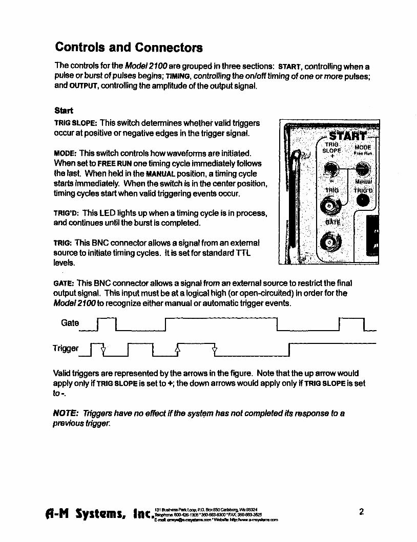
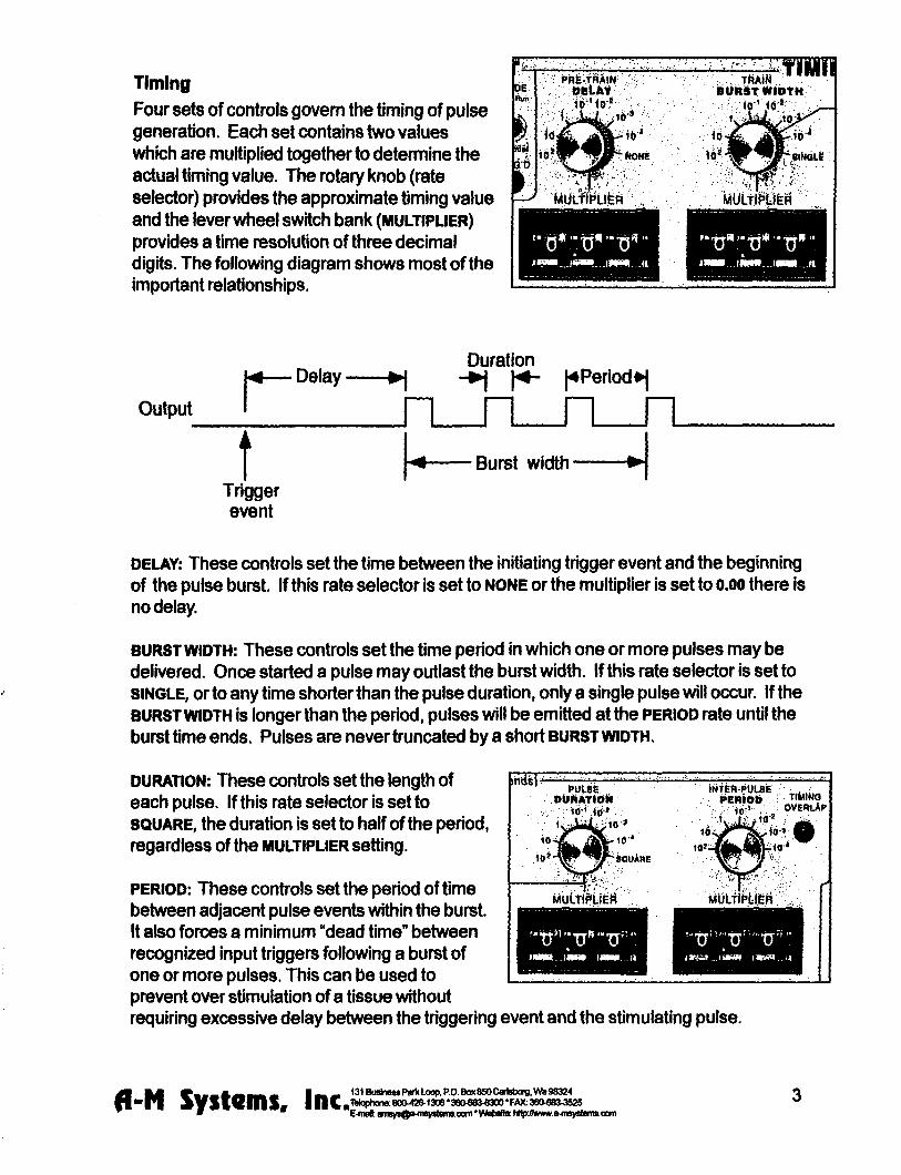
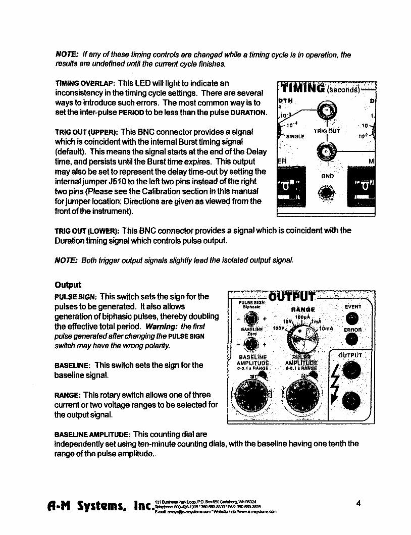

Operating Instructions
Examples Simple setup (and minimal Instrument tost)
Connect the output of the Model 2100 to an oscilloscope Before connecting the instrument it is safest to turn its power off
Set the Ou^uf controls
Range Pulse Sign
Baseline Pulse Amplitude
10V +
Zero 200
Setting The Timing Controls
Delay Burst Width
Duratbn Period
none single
15010-2 500102
Setting The Start Controls
Mode Free Run
Disconnect any cables to the TRIG or GATE Inputs
Note that the green Trig and Event Indicators tum on as Free Run is turned on (and tum off othenwise) You should observe a 15ms duration 20Hz rate pulse of 200V above a OV baseline on the oscilloscope i
A ^ M ^ _ _ _ A ^ _ _ _ 1 ^ 131BiiHnD8raquoParttloopPOBoxB50Car)sbcrBlaquoraquoS8324
bull P l ^ y S W n i S f |nC ltV^gt^8deglt^^2O1306380laquo8OS3a0FAX36O6BMS2S
6 E-fnflk 9n^fBOs-in9ystsni9cx]fnWDbs)tec H^ff9Nw^myStem9oom
Demonstration of Burst Mode Connect the output of the Model 2100 to an oscilloscope Before connecting the instrument it is safest to tum Its power off
Set the Output controls
Range Pulse Sign
Baseline Pulse Amplitude
Baseline Amplitude
Setting The Timing Controls
Delay Burst Width
Duration
Period
Set the START controls as follows
Mode
Disconnect any cables to the TRIG or GATE inputs
Trigger the oscilloscope from the Burst trigger out (upper Tr^ Out connector) for a stable display In each burst (occumng every lOOms) you should observe a trio of 15ms duration starting 50ms apart Try switching the StartMode from Free Run to the center (nomnal) position The pulses will no longer be produced and the Trig and Event indicators will turn off Pressing this switch once (to Manual) will cause a single burst to occur
880 120 150 500
10V +
200 100
102 102 102 102
Free Run
fleaff SySlQmSa |nCa deglgt ltlt ^ ^ deg ^ degdeg ^ ^ ^ bull E-matmia
131 Business Park LoopPO Box 850 Carisborg Vfe 86324 lUcphcna 800426-1306 36Olaquo83laquo300 FAX 36068raquo52 E-maft tfii8ysOiHn^nleiTBcom1AWisJto HSpitwraquoM^wytAtii9oom
Problem SoMng If the Instrument appears to be not worthing properiy check all of the control settings and connections Be sure to wait at least 5-10 seconds after turning the Instrument off before tuming it on again The following t6ef summary of typical problems for the user (along with the most common solutions) may help
Problem CauseSolution EVENT indicator never lights even in FREE RUN mode
bull Replace fuse check power connection bullSet DELAY or PERIOD to a shorter interval
bull Power-on too soon after power-off
OVERLAP Indicator is on
ERROR indicator is on
Time appears to be excessive
bullSet DURATION gt000 bull DURATION is set to SQUARE but PERIOD is 000 Increase PERIOD or set DURATION independantly
bull BURST and WIDTH are gt DURATION increase PERIOD or decrease
DURATION bull BIPHASIC pulse output is on and PERIOD is not longer than twice the DURATION Increase PERIOD or decrease DURATION
bull Free-run is on and BURST Is lt PERIOD (BURST off) DELAY is 0 and PERIOD is lt DURATION Add delay or modify PERIOD
bull Free-mn is on and BURST is gt DURATION (BURST ON) and PERIOD is lt DURATION Increase PERIOD
bull For VOLTAGE outputs the output Is trying to drive too low a resistance or capacitance (eg a short circuit) Check by disconnecting the output It is possible (and normal) that for the fastest cycles
and largest amplitudes (close to 100 V and 1 MS) that the ERROR Indicator might always come on during repetitive pulses Fix output load or decrease amplitude as required
bull Changed control in mid-cycle (resets cunent status)
A ^ M bull _ _ _ A ^ ^ _ _ i ^ mdash 131BuslnessPai1ltLoopPOBox850CarlsborgWamp98324
bull p i j ^ v s w m s iiic^^deglt^deg^^deglt^^^3degB3^^^deg^^^^degdeg^^^deg^^deg^^^^ E-mat iiiMOafflwstemseom WabaHe MtaffiwwtHtavsli
8 E-msft flmsjoQfrfraystGfnsoom ^WobsltiK hl^Aiwv9-fn9]nteniscom
Cant seem to get a full signal out
Incoming triggers not accepted frequently enough
bull Load is not properiy connected repair wiring
bull Too low a load impedance (VOLTAGE modes) or too high a load impedance
(CURRENT mode)
bull PERIOD is set too long (enforces dead time) followd by BURST set to SIGNAL Reduce PERIOD time
Table 10 Problem Solving
If you suspect that the Model 2100 may have completely failed we recommend checking the basic level of functionality If this fails your instrument is defective and must be repaired If this passes either your experimental setup is incompatible or inconsistent or there is a more subtle flaw in your Model 2100
If the Model 2100 appears to be malfunctioning contact A-M Systems Inc or your dealer Telephone numtgters for A-M Systems Inc listed on the front cover of this manual We will first attempt to solve the problem over the telephone so have an exact description of your problem available when you call You do not need to be within the warranty period to obtain over-the-phone assistance
A ^ M V - mdash A d B ^ K M I ^ M 131BuslnessPatfcLoopPOBox6SOCai
-PI s y s i Q m s inc-2raquolaquoa22=M^^
131 Business Parfc Loop PO Box 650 Cartsborg VM9 0S324 _ FAX36(W8a3525 E^nrt flnsysQa-ntsyttanB-oom Wsbsfte hHpiMNvwa-nnystsnisooni
9
Theory of Operation
The operation of the Model 2100 is summarized In the block diagram (see Fig 3) Not shown are all of the interconnections with the microcontroller The intemal microcontroler plays an important role in setting the signal path but does not directly
contribute to the dynamic characteristics It scans the front panel switches and sets the control values for the logic arays It programs the intemal counters which along with the other hardware achieve the necessary sub-microsecond speeds
All action starts either from an input trigger signal (from Trig In) or from an intemal signal (in free Run mode only) A Delay timer counts the 10MHz clock until its count value Is exhausted At this point the Burst timer starts Both Period and Duration timers are started at this time If the Burst timer has not expired by the end of the Period the Period and Duration timers are restarted If the Biphasic mode has been set the Duration timer is restarted at the end of the initial Duration and the sign of the output pulse Is reversed doubling the total duration
The system state (pulse on pulse sip baseline sign [+101-]) is transmitted to the isolated section via optoisolator The baseline and pulse amplitudes are selected by an analog switch The resulting signal is amplified by a variable-power-supply discrete operational amplifier The amplifier connections and gain is modified to provide two voltage and three cunent ranges
Timing overlap errors are detected by a logical decision computation rather than by testing for counter collisions This provides instant feedback rather than waiting up to an hour for such a collision to occur Output errors are measured by sensing the output amplifiers differential input voltage Under normal conditions this is a negligible voltage if the amplifier fails to deliver the requested signal the window comparator testing this voltage sends this message (via optoisolator) to the logic section turning on a warning LED
fl-N Systems Inc 131BusbnassPa(tLoopPOBox6SOCari3boigVMg8324 H n |TWoph0n880O426-13083eO6Blaquo300FMt36Olaquo8i3525 E-nnl anaysflfriinysleiiaoemWfcbslte hllphmwraquoimyatennoom
TRIG 3HJ) OUT
(burst)
TRIG ^ OUT
(pulse)
E
Ml
Calibration Procedures
The calibration interval is the lesser of 1000 hours of operation or 6 months Somewhat greater drift can be expected in the first 100 hours of operation as the semiconductors age Adjustments should only be made after the instrument has been fully warmed up for at least 15 minutes
Full instrument calibration requires the following test equipment digital multimeter (plusmn 01) able to measure resistance to at least lOOMfl oscilloscope with at least 50MHz bandwidth true-rms voltmeter with 4MHz bandwidth universal counter (plusmn 001 ) able to measure single pulse widths and periods resistors (all plusmn 01) 2kn lOkH 1 waft 20kn 200kn alligator clip lead sets banana plugs and BNC adapters
Adjustment integrated circuit and test point locations are shown in the following figures All adjustments are on the timing board unless otherwise noted
All voltages in the non-isolated section should be measured with respect to ground at TP510 unless othenvise stated Some voltages are measured with respect to an intemal isolated ground at TP650 or across the two output tenninals Occasionally the voltage at an IC pin must be measured In these cases the reference designator is given with the pin number in parentheses eg U602(16) When it states within this procedure that a voltage is to be minimized this means that the adjustment should be made such that the measured voltage is as close to zero volts as possible Refer to the Specifications Section of this manual for acceptable tolerances
The sequence of this procedure is Important If any adjustment is made all adjustments which follow must be made to ensure that the specifications will be met These procedures require that all controls remain as set in previous steps unless otherwise indicated
WARNING
The Model 2100 has dangerous voltages throughout the instrument even with the power is off Servicing the Model 2100 should only be done by qualified service personnel Use caution in handling any wires connectors or electrodes which may be directly or indirectly attached to the Instrument Do not touch exposed connections or components Disconnect power by unplugging the power cord from the receptacle
fl-N Systems I n c ^ 131BusinesaPartcLoopPOBox850CartsborgVWiB8324 4 n ^gt-mdash80O426-130638Ofl8Jlaquo300FAX36O683J52S bull E-maft BinsysQfrfn^islflnisoomVVfalislle h^KVfWMift^iisystemsoani
CO
- R503
Omg^
TPSOlQ O
OTPSOO
U560 bull
U510
DDID ^ trade E O ^ T P 5 1 0
bullnD Trig
0 ^
U570
Gate n U505
DO D
U515
Timing
Timing h_ U520
bsoo ^25SE Timing
Or r U540
I I Tmlng
[^ELIL
U535 D
U506
13 J510 Timlnff
BurfiDelay J400
i i i i i i i T r m r a
gt U550 ^
Clock
U555 U620
B a
^R^Pvhigh Rfijn O D O Vlow
o
bull U545
Fo sect737 lISOIsPjC-COMP
n r r ^ U760
J420
]]U632
Q S riuGSO
H = ) TP640^ deg I t I
II3D
J440 m i T i
U610 plusmn laquo j U O
bull bull l el
^t
O l
bull
M
I
Power supply and bias voltages
Power supply
Controls Inputs Observations Adjust Check
POWER ON Observe voltage at P703 power supply wire top of main board
Check for+15 plusmn 050 V
Observe voltage at P701 power supply wire top of main board
Check for-15 plusmn 050 V
Observe voltage at U505(24) Check for+5 plusmn 025 V
Isolated supply voltage
Controls Inputs Observations Adjust Check
RANGE 10 V TRIG open circuit MODE center position
Altemately observe V^ from R742 to R740 and V ^ from the U605(4) to U605(8)
Adjust R773 so that 110VltV^lt 120 V and
nign
28VltV^lt34V
Capacitance balance
Controls Inputs Observations AdjustCheck
Connect a x10 oscilloscope probe to TP650 and ground the
Adjust R737 for minimum high frequency signal
Inputs
Gate funct ion
Controls Inputs Observations AdjustCheck
Apply a 1 kHz 0 - 5 V triangle wave Verify that the voltage to GATE switches states at the Obsene voltage at U51G(3) proper input levels with an oscilloscope ^ ^
Trigger s lope
Controls Inputs Observations Adjust Check
Apply a 1 kHz 0 - 5 V triangle wave Verify that the voltage to TRIO switches states at the Observe voltage at US 10( 1) proper input levels with an oscilloscope
TRIG SLOPE + Verify voltage is 180 out of phase
TRIG SLOPE Verify voltage is in phase
fl-N Systems Inc ^ 131 Bushess Park Loop PO Bar 850 Carisborg Wa 98324 8004201306 3eOlaquoS3e300 FAX 3606BV352S
C-maft fliii8yBQfriii9yBlumaoamVIAibsMB hRpJhwMifi-iiiBystematxini
14
Trigger and gate funct ion
Controls Inputs Observations Adjust Check
DELA NONE BURS1WII3TH SINGLE DURATION SQUARE PERIOD 100X10-3
Apply a 1 kHz 0 - 5 V triangle wave to TRIG Obsen^e TRIOD and EVENT LEDS
TRIG disconnect all Short the GATE connector to GND Verify LEDs extinguish
MODE press to MANUAL Verify LEDs flash once
Timing
System c lock frequency
Controls Inputs Observations AdjustCheck
Observe the frequency of the wave atU555(17)
Verify 1000 MHz plusmn001
Multipl iers (Wheel Switches)
Controls Inputs Observations AdjustCheck
PULSE SIGN + MODE FREE RUN TRIG disconnect all TIMING MULTIPUERS ail
wheels set to zero except the one being tested
TnmiNG OVERLAP ^nOTB
Observe the pulse width with the counter at the location specified below
Verify pulse width Is correct for each wheel as it is tested Independently
For each wheel of each MULTIPUER test each position to verify that the pulse width is correct Observe the signal at the following locations DELAY U520(2) BURSTWIDTH U530(2) PERIOD US40(2) DURATION U550(2)
Rates (Rotary Switches)
Controls Inputs Observations AdjustCheck
TIMING MULTIPUERS 001 TIMING RATES all rotary
switches set to 10-4 except the one being tested
Observe the pulse width with the counter at the location specified below
Verify pulse width is conect for each rotary switch as it is tested independently
For each of the four rotary switches in TIMING test each position to verify that the pulse wkJth is correct Observe the signal at the following locations DELAY U520(2) BURSTWIDTH U530(2) PERIOD U540(2) DURATION U550(2)
fl-N Systems I n c ^ E-maft emfl
131 Business Parti Loop PO 809(850 Cartsborg Wta 98324 8004201306 3804806300 FAX 36068O3S25
E-maft ansysQa nvystems-oom Wobste hflp Avwwa4nsy8(Qnttoam
15
Trigger outputs Controls
Range 10V Pulse Amplitude 500 Delay 100x10 Burst 100x10^2 Duration 100 x1a Period 400x10^ Pulse sign + Trig Mode Free run Trig in open
Inputs Observations
Trigger the oscilloscope to the Burst Trig Out Observe it the Pulse Trig Out and the isolated output
Adjust Check
Verify that the waveform consists of a burst of three 1ms-on3ms-off pulses The burst trigger should be synchronous with the burst the pulse trigger coincident with each pulse
Output Calibration
Isolation Resistance (check) Controls Inputs Observations AdjustCheck
Trig Mode center position Trig In open
Measure the resistance between ground banana jack (front panel) and black banana jack of output with DMM
Resistance read gt 100MQ
Amplitude Switch Offset (R640) Controls InputsObservations AdjustCheck
Baseline Zero Trig Mode center position Trig In Open
Measure the voltage at TP645 vs TP650 with the DMM
Adjust R640 (AmpI Sw Offset) for minimum voltage
Output Offset (R332 front panel board) Controls I nputsObservatlons AdjustCheck
Baseline Zero Range 10V Trig Mode center position Trig In Open
Measure the voltage across the output with the DMM
Adjust R332 (Output offset) for minimum voltage
Positive Baseline Offset (R607) Controls InputsObservations AdjustCheck
Baseline Sign + Baseline Amplitude
fully CCW (000) Range 10V Trig In open Trig Mode center position
Measure the voltage across the output with the DMM
Adjust R602 (BSLN + offset) for minimum voltage
fl M raquo _ _ _ A laquo ^ _ i ^ ^ 131Buslnelaquo8Pari(loopPOBoK850Cart8borgWB96324
bull P I i s V S i e m S a |||Cg1Maphans80O42O130638O68O8300FAX36Olaquo8raquo^2S E-tiBft anagtraquoflwiisyagtlaquomraquoaimW6baHB hHpffii(wwraquoltnsylaquoleniieom
16
Negative Baseline Offset (R619) Controls
Baseline Sign -i Baseline Amplitude bull fully CCW (000)
Range 10V Trig In open Trig Mode center position
Measure the voltage across the output with the DMM
AdjustCheck
Adjust R619 (BSLN 4 offset) for minimum voltage
Pulse Amplitude Adjust (R602) Controls InputsObservations AdjustCheck
Trig Mode Free Mode Pulse Amplitude 1000 Timing Dialay =none Burst =single Duration =1001 Period =00110-4 Pulse Sign -Trig In open Range 10V
Measure the voltage across the output with the DMM
The Overiap indicator should be on Adjust R602 (Max Level) for -1000V out
Pulse Sign Gain (check) Controls InputsObservations AdjustCheck
Trig Mode Free Mode Pulse Amplitude 1000 Timing Delay =none Burst =single Duration =1001 s Period =00110-4s Trig In open Range 10V
Measure the voltage at the output with the DMM for the Pulse Sign at -- and - positions
The absolute values of the voltages should differ by less than lOOmV
Baseline Amplitudes (check) Controls InputsObservations
Range 100mA Trig Mode center position Baseline Amplitude fully CW (1000) Trig In open
Measure the voltage at the output with the DMM with Baseline Sign in + Zero and - positions
AdjustCheck
Gain the matching of current levels at = and - positions and offset current in Zero position
fl-N Systems Inc^^ bull E-mal am8
131 Business Partt Loop PO Box 850 Cartsborg Wa 88324 8004201306360laquo8Oe300FAX 360laquo8O362S
E-maM am8y8^o-mBy8tflmBoom WobaKo hHp Awwwo-f i iBystonuoom
17
Output Range Amplitude and Drive (check) Controls InputsObservations AdjustCheck
Pulse Amplitude 1000 Pulse Sign + Trig Mode Free Run Timing Delay =none Burst =8ingle Duration =1001 Period =10010-4 Trig In open
Load the output with a 10KV1W 01 resistor Measure the voltage at the output with DMM
Verify that full scale output is within specification Scale Range 100V 100V 10V 10V 100mA IV 1mA 10V 10mA 100V
Pulse Sign and Short Circuit Protection (check) Controls InputsObservations AdjustCheck
Timing Delay =none Burst =8ingle Duration =200 10-4 Period =00110-3 Baseline Zero Pulse Amplitude 25 Range 10V Trig Mode Free Run Trig In open
Measure the voltage at the output with the oscilloscope Check for Pulse Sign set to each of + - biphasic Watch for Error indicator when shorting the output
Verify that pulses of approx 25V amplitude (625V for biphasic mode) of the correct sign are produced every 10ms Short output in biphasic mode Output should retum when opened
Output Transient Response (check) Controls InputsObservations AdjustCheck
Pulse Sign + Timing Delay =none Burst =single Duration =20010-4 Period =00110-3 Pulse Amplitude 250 Baseline Zero Trig Mode Free Mode Trig In open
Connect the oscilloscope to the output with a 310 attenuator prolse Test boVn 10V and 100V ranges
Verify that overshoot and risetime meet specifications
fl-N Systems I n c ^ 131 Business Parte Loop PO Box 850 Cartsborg Wb 98324 8004201306 36Olaquo83O300 FAX 36O680lt352S
E-mQ0 snBy8Qs-msy8faiTiscom VWriMtte N ^ Mvww9-msy8lemscom
18
Specifications
There are three classes of specifications Class A specifications tested in all unHs and are guaranteed Class B specifications are inherent in the design they are indirectly tested and are guaranteed Class C specifications are typical operating values which are occasionally tested- these are typical values given for your infomiation but not guarshyanteed The class for each specification is noted in the center column of the following sections
Inputs Switching level
Hysteresis
Input equivalent circuit
Minimum duration (1 IL-level signal)
A
C
C
C
16V(plusmn02V)
approx 50 mV
100K ft to+5 In parallel with no more than 35pF
gt 50 ns
Open circuit condition B defaults to highon level
Timing and rate accuracy Rate selector steps
Timing multiplier steps
Resolution
Timing eror (second and later pulses after resetting controls)
B
B
B
B
lOOps to 100s In 7 steps
1 of rate selector step size Maximum value is 999 x the rate selector step size
approx 01 of the maximum value
lt 002 of rate selector value + 015 ps
Timing error (first pulse after readjusting timing controls)
an additional 025 ps error may occur
Timing repeatability lt 001 setting + 20 ns (monophasic)
fl-N Systems I nc ^ bull E-moU ams
131 Business Parti Loop PO Boot 850 Cartsborg VM 98324 80O42O130838O08O8300FAX36Olaquo8O3S2S
E-meU anByafl^iiisyslainaoomWebsHe hHpffliiwwraquomsys)emsoom
19
TRIG IN to OUTPUT delay (DELAY set to 0) output set to 2V
Timing jitter ft-om TRIG IN to OUTPUT (for TTL trigger input with risetime lt10 ns)
Timing jitter ft^om TRIG OUT (either BURST or PULSE) and OUTPUT
Trigger output to pulse output delay
Output charactsristics Pulse level enror (voltage mode open circuit cun-ent mode short circuit
Biphasic level difference |V + + V-|2
Baseline level error (voltage mode A open circuit current mode short circuit)
Risetime (25 V out)
Risetime (25 V out)
Transient response
A
A
A
Output impedance (voltage mode) C
Output impedance (current mode) C
Isolation resistance A
Isolation capacitance C
approx 05 ps for a load of no more than 10 Kft in parallel with 50 pF
lt 125 ns (all rates except 100s) lt 125 ps (100s rate)
Less than 20 ns (all rates)
approx 350 ns
lt 03 of setting + 05 of r range (plus an additional 05 pA inlOOpArenge)
lt 03 of range (voltage modes into open circuit current modes into short circuit)
lt 03 of setting of setting + 01 of range (plus an additional 05 pA in lOOpA range)
laquo 200 ns into less than 30 pF
laquo15 ps into less than 30 pF
lt 8 overshoot Into less than 30 pF for pulse voltages different than baseline voltage by at least 10 of range
laquo 50 ohms
raquo 1 0 Gft (typically 200 Gft)
raquo100Mft
laquo 60 pF at 100 Hz
fl-N Systems Inc^^ 131 Business Partt Uxip PO Box 850 Cartsborg Wa 96324 8004201308 SBOee^^SOO FAX 360laquoS3^52S
E-mat BiByraquoaiMii8ylaquoliiiiiseomWiljalteHlpJV(wwraquo4tgy8lenaoom
20
Noise (differential mode)
Noise (common mode earth to isolated ground) with no signal output
Overioad error indicator (low frequency short circuited voltage mode)
Overioad error indicator low frequency open circuited current mode)
Overioad enor response time
Miscellaneous
Power
Fuse
Operating temperature range
Storage temperature range
Operating humidity
Dimensions
Weight
laquo1 mV rms (10 V scale 10Hz-4MHz)
laquo 8 mV rms (10 Hz-4 MHz) laquo100mVp-p (200 Hz -10 MHz) measured withalOMft 15pF oscilloscope probe
Turns on for set amplitude at or greater than approx plusmn1V (10 V range) or plusmn2 V (100 V range)
Turns on for set amplitude at or above approx 2 of range
Flat to approx 30 ps duration Decreasing sensitivity for shorter pulses
approx 11 watts
1 amp 3 AG
10-30C
0 - 50deg C
5-80RH
17x475x1125 (Inches) 432x121x286 cm
20 lbs (9 kg)
fl mm bull gt _ _ _ A ^ ^ _ _ L ^ 131BusinesraquoPariltLocpPOBox850C8rtsborgWS9e324
bull p i ^ y s v e m s IIIC^^deg(^deg^Bdegltgt^^^3degdeg^deg^^deg^^^degdeg^^I^deg^deg^^^^^
21 E-mei flre^nQo 4n8yo(amscam Wsbsfle hHpAwwwe-msy8Jems-Oom
Warranty and Service
What does this warranty cover A-M Systems Inc warrants to the Purchaser that the Instrument excluding cables Headstage Probes and any other accessories shipped with the Instrument (hereafter the hardware) is free from defects in workmanship or material under normal use and service for the period of one (1) year This warranty commences on the date of delivery of the hardware to the Purchaser
What are the obligations of A-M Systems Inc under this warranty During the warranty period A-M Systems Inc agrees to repair or replace at its sole option without charge to the Purchaser any defective component part of the hardware To obtain warranty service the Purchaser must return the hardware to A-M Systems Inc or an authorized A-M Systems Inc distributor in an adequate shipping container Any postage shipping and insurance charges incurred in shipping the hardware to A-M Systems Inc must be prepaid by the Purchaser and all risk for the hardware shall remain with purchaser until such time as A-M Systems Inc takes receipt of the hardware Upon receipt A-M Systems Inc will promptly repair or replace the defective unit and then return the hardware to the Purchaser postage shipping and insurance prepaid A-M Systems Inc may use reconditioned or like new parts or units at its sole option when repairing any hardware Repaired products shall carry the same amount of outstanding wan^nty as from original purchase or ninety (90) days which ever is greater Any claim under the warranty must include a dated proof of purchase of the hardware covered by this wan-anty In any event A-M Systems Inc liability for defective hardware is limited to repairing or replacing the hardware
What is not covered by this warranty This warranty is contingent upon proper use and maintenance of the hardware by the Purchaser and does not cover batteries Neglect misuse whether intentional or otherwise tampering with or altering the hardware damage caused by accident damage caused by unusual physical electrical chemical or electromechanical stress damage caused by failure of electrical power or damage caused during transportation are not covered by this warranty Products may not be returned to A-M Systems Inc for service whether under warranty or otherwise which are contaminated by infectious agents radioactive compounds or other materials constituting a health hazard to employees of A-M Systems Inc
What are the limits of llabiiity for A-M Systems inc under this warranty A-M Systems Inc shall not be liable for loss of data profits or savings or any special incidental consequential indirect or other similar damages arising from breach of contract negligence or other legal action even if the company or its agent has been advised of the possibility of such damages or for any claim brought against you by another party THIS EQUIPMENT IS NOT INTENDED FOR CLINICAL MEASUREMENTS USING HUMAN SUBJECTS A-M SYSTEMS INC DOES NOT ASSUME RESPONSIBILITY FOR INJURY OR DAMAGE DUE TO MISUSE OF THIS EQUIPMENT Jurisdictions vary with regard to the enforceability of provisions excluding or limiting liability for incidental or consequential damages Check the provision of your local jurisdiction to find out whether the above exclusion applies to you This warranty allocates risks of product failure between the Purchaser and A-M Systems Inc A-M Systems Inc hardware pricing reflects this allocation of risk and the limitations of liability contained in this wanranty The warranty set forth above is in lieu of all other express wan^anties whether oral or written The agents employees distributors and dealers of A-M Systems Inc are not authorized to make modifications to this wan-anty or additional wan-anties binding on the company Accordingly additional statements such as dealer advertising or presentations whether oral or written do not constitute wananties by A-M Systems Inc and should not be relied upon This warranty gives you specific legal rights You may also have other rights whrch vary from one jurisdiction to another
6 mm ^ laquo _ _ A a B ^ _ 1 ^ ^ 131 Business Parti Loop PO Box 850 Cartsborg W B 98324 O O
bull P l A y S V e m S l n C T^M 8OO42OI3O6 380683-8300FAX 360 803525 ^ ^ E-msl iiiisy80iHTBy8tenisoom Wsbsito hnphwwfrimysleiiisoom
A
V ISO
INSTRUCTION MANUAL
FOR
ISOLATED PULSE STIMULATOR
MODEL 2100
Serial
Date
A-M Systems Inc
PO Box 850
Carlsborg WA 98324
USA
360-683-8300 bull 800-426-1306 FAX 360-683-3525
httpwwwa-msystemscom
Version 70 February 2002
Contents General Description 1
Instrument Features 1 Controls and Connectors 2
Operating Instructions 6 Theory of Operation 10 Calibration Procedures 12
Inputs 14 Output Calibration 16
Specifications 19 Warranty and Service 22
Each Isolated Pulse Stimulator is delivered complete with
Rack Mount Hardware Instructions amp Maintenance Manual
NOTE
This instrument is not intended for clinical measurements using human subjects A-M Systems Inc does not assume responsibility for Injury or damage due to the misuse of this instrument
General Description
Instrument Features The Isolated Pulse Stimulator Model 2100 is designed for a wide variety of applications It is highly flexible being capable of delivering single pulses biphasic pairs or bursts of pulses Pulses may be started manually or upon receiving a trigger signal from another Instrument or computer Two non-isolated trigger outputs are available for triggering other instruments
Four sets of timing controls provide comprehensive control overall aspects of pulse generation Three digit accuracy is available over a 7 decade range for each timing function using lever wheel switches Pulse widths can be set over more than a 9 decade range from 05 ps to 999 seconds Timing accuracy is assured through the use of a 10 MHz base rate crystal-controlled clock digitally divided to provide accurate timing over the entire range Atiming overiap indicator will light If the timing controls are set inconsistently
The output may be conveniently switched between current and voltage modes Pulse and baseline amplitudes are Independently presettable with lockable dials An error Indicator will light if the Mode2700 cannot deliver the desired signal
r WARNING
The Model 2100 can produce potentially dangerous voltages up to 100 V at the output connectors The isolated output is not connected internally to safety (earth) ground in any way Some part of the extemal circuit should be connected to safety ground Use caution in handling any wires connectors or electrodes which may be directly or indirectly attached to the Model 2100 output Some kinds of connectors such as BNC connectors have exposed metal parts which may float at dangerous potentials unless extemally connected to safety ground For greatest safety tum the Model 2100 off before making any connections to
the instrument
131 Business Parii Loop PO Box 850 Cartsborg Wa 98324 Telophone 800-426-1306 bull 360-68raquolaquo300 bull FAX 360683-3525 E-mal satesa-msystemsoom VVfebsite httpywwwa^nsystemscom fl-N Systems Inc 1
Controls and Connectors The controls for the Model 2100 are grouped in three sections START which controls when a pulse or burst of pulses begins TIMING which controls the onoff timing of one or more pulses and OUTPUT which controls the amplitude of the output signal
Start TRIG SLOPE Determines the polarity of valid trigger pulses (positive or negative edges in the trigger signal)
MODE Controls waveform initiation When set to FREE RUN one timing cycle immediately follows the last When momentarily placed In the MANUAL position a timing cycle starts Immediately When the switch Is In the center position timing cycles start when valid triggering events occur
TRIGD This LED lights up when a timing cycle Is in process and continues until the burst is completed
TRIG This BNC connector allows a signal from an external source to Initiate timing cycles It is set for standard TTL levels
GATE This BNC connector allows a signal from an external source to restrict the final output signal This input must be at a logical high (or open-circuited) in order for the Model 2100 to recognize either manual or automatic trigger events
Gate 1_ Trigger |~~^ i I Valid triggers (represented by the arrows in the figure) can occur only when the gate Is at logical high Note that the up arrow would apply only If TRIG SLOPE is set to + the down an-ows would apply only if TRIG SLOPE Is set to -
NOTE Triggers have no effect if the system has not completed its response to a previous trigger
fl-N Systems Inc 131 Business Park Loop PO Box 850 Cartsborg Vb 98324 TelQphQne 80O426-1306 360683-8300 FAX 360683-3525 E-mail sales^a-msystemscom Wsbsite httpywwwa-msystemscom
Timing Four sets of controls govern the timing of pulse generation Each set contains two values which are multiplied together to detemnine the actual timing value The rotary knob (rate selector) provides the approximate timing value and the lever wheel switch bank (MULTIPLIER)
provides a time resolution of three decimal digits The following diagram shows most of the Important relationships
Output r Delay Duration
|ltPeriodgtj
t Burst width
Trigger event
DELAY These controls determine the time duration between the initiating trigger event and the beginning of the pulse burst If this rate selector is set to NONE or the multiplier is set to 000 there Is no delay
BURST WIDTH These controls determine the time period in which one or more pulses may be delivered Once started a pulse may outlast the burst width If this rate selector is set to SINGLE or to any time shorter than the pulse duration only a single pulse will occur If the BURST WIDTH Is longer than the period pulses will be emitted at the PERIOD rate until the burst time ends Pulses are never truncated by a short BURSTWIDTH
inds)-PULSE
D U R A T I O N 1 0 1 0
10
INTEB-PULSE PERIOD
1 1 10
DURATION These controls determine the length of each pulse Ifthis rate selector Is set to SQUARE the duration is set to half of the period regardless of the MULTIPLIER setting
PERIOD These controls set the period of time between adjacent pulse events within the burst It also forces a minimum dead time between recognized input triggers following a burst of one or more pulses This can be used to prevent over stimulation of a tissue without requiring excessive delay between the triggering event and the stimulating pulse
TIMING OVERLAP
fl-N Systems Inc 131 Business Parti Loop RO Box 860 Carisborg Vamp 98324 |Telophone 800-426-1306 360683-8300 bull FAX 3606aW525 E-mail salearega^nsystemsoom Vfeb5ite httpAwwwa^nsyslemscam
NOTE If any of these timing controls are changed while a timing cycle is in operation the results are undefined until the current cycle finishes
TIMING OVERLAP This LED will light to Indicate an inconsistency in the timing cycle settings There are several ways to introduce such errors The most common way is to set the Inter-pulse PERIOD to be less than the pulse DURATION
T I M I N G (seconds)^
TRIG OUT (UPPER) This BNC connector provides a signal which is coincident with the Internal Burst timing signal (default) This means the signal starts at the end of the Delay time and persists until the Burst time expires This output may also be set to represent the delay time-out by setting the internal jumper J510 to the right two pins instead of the left two pins (Please see the Calibration section in this manual for jumper location Directions are given as viewed from the front of the Instrument)
TRIG OUT (LOWER) This BNC connector provides a signal which Is coincident with the Duration timing signal which controls pulse output
NOTE Both trigger output signals slightly lead the isolated output signal
Output
PULSE SIGN This switch determines the polarity of the pulses to be generated It also allows generation of biphasic pulses thereby doubling the effective total period Warning the first pulse generated after changing the PULSE
SIGN switch may have the wrong polarity
BASELINE This Switch determines the polarity ofthe baseline signal
RANGE This rotary switch determines if the output pulses will be constant current (3 ranges) or constant voltage (2 ranges)
BASELINE AMPLITUDE This value is independently set using a ten-turn counting dial The maximum baseline amplitude is one tenth the value shown on the range amplitude switch
fl-N Systems Inc 131 Business Parti Loop RO Box 8S0 Cartsborg Vfa 98324 |Tetaphone 80O426-1306 bull 360683-8300 bull FAX 3606803525 E-mail salesa-msystemscom Wbbsite http7Awwwaflnsystemscom
PULSE AMPLITUDE This value is independently set using a ten-turn counting dial The maximum pulse amplitude is the value shown on the range amplitude switch
EVENT This LED indicates when a pulse is ongoing
ERROR This LED indicates when the internal output amplifier cannot output the pulse as desired This is usually due to a short circuit while trying to output a voltage or an open circuit while trying to output a current
VOTEThe Pulse Sign control in the Oupuf section directly affects waveform timing When set to the Biphasic mode a positive-going pulse is immediately followed by a negative-going pulse This effectively doubles the pulse duration If a burst of biphasic pulses is being produced the period must be at least twice the single pulse duration In the Square wave mode the baseline disappears as long as the burst persists
fl-N Systems Inc 131 Business Parti Loop RO Box 850 Cartsboig Vte 98324 |Telophone 800426-1306 360683-8300 bull FAX 3606833525 E-mail salesa-m5ystem5 com Website httpwwwa-msystemscom
Operating Instructions
Examples Simple setup (and minimal instrument test)
Connect the output ofthe Model 2100 to an oscilloscope Before connecting the Model 2100 to any other instrument or the experimental preparation It is safest to turn Its power off
Set the Oufpuf controls
Range 10V Pulse Sign +
Baseline Zero Pulse Amplitude 200
Setting The Timing Controls
Delay Burst Width
Duration Period
none single
15010-2 50010-2
Setting The Start Controls
Mode Free Run
Disconnect any cables to the TRIG or GATE inputs
Note that the green Trig and Event Indicators turn on as Free Run is turned on (and turn off otherwise) You should observe a 15ms duration 20Hz rate pulse of 200V above a OV baseline on the oscilloscope
fl-N Systems Inc 131 BusinessPartiLoop RO Box850CarisbcxgWa98324 |Telophone 800426-1306 bull 360-683-8300 bull FW 360683-3525 E-mail salesa-msystems com VVbbsite httpywwwa-msystems com
Demonstration of Burst Mode Connect the output ofthe Model 2100 to an oscilloscope Before connecting the Model 2100 to any other instrument or the experimental preparation It Is safest to turn its power off
Set the Outpuf controls
Range 10V Pulse Sign +
Baseline Pulse Amplitude 200
Baseline Amplitude 100
Setting The Timing Controls
Delay 88010-2 Burst Width 12010-^
Duration 15010-2 Period 50010-2
Set the START controls as follows
Mode Free Run
Disconnect any cables to the TRIG or GATE inputs
fl-N Systems Inc 131 Business Parti Loop RO Box 850 Cartsborg Wa 98324 Telophooe 8004201306 360683-8300 bull FAX 360683-3525 E^naii salesa-msystems com Watjsite http7wwwa-msystemscom
Trigger the oscilloscope from the Bursf trigger out (upper Trig Out connector) for a stable display In each burst (occurring every lOOms) you should observe a trio of 15ms duration starting 50ms apart Try switching the StartMode from Free Run to the center (nonnal) position The pulses will no longer be produced and the Trig and Event Indicators will tum off Pressing this switch once (to Manual) will cause a single burst to occur
Problem Solving If the instrument appears to be not working properiy check all ofthe control settings and connections Be sure to wait at least 5-10 seconds after turning the instrument off before turning it on again The following summary of typical problems for the user (along with the most common solutions) may help
Problem CauseSolution
EVENT Indicator never lights even in FREE RUN mode
bull Replace fuse check power connection bullSet DELAY or PERIOD to a shorter interval
bull Power-on too soon after power-off
OVERLAP Indicator is on
ERROR indicator is on
bull Set DURATION gt000 bull DURATION Is set to SQUARE but
PERIOD is 000 Increase PERIOD or set DURATION independantly
bull BURST and WIDTH are gt DURATION increase PERIOD or decrease DURATION
bull BIPHASIC pulse output Is on and PERIOD is not longer than twice the DURATION Increase PERIOD or decrease DURATION
bull Free-run Is on and BURST is lt PERIOD (BURST off) DELAY is 0 and PERIOD Is lt DURATION Add delay or modify PERIOD
bull Free-run is on and BURST is gt DURATION (BURST ON) and PERIOD is lt DURATION Increase PERIOD
bull For VOLTAGE outputs the output is trying to drive too low a resistance or capacitance (eg a short circuit) Check by disconnecting the output ft is possible (and normal) that for the fastest cycles and largest amplitudes (close to 100 V
fl-N Systems Inc 131 Business PartiLoop PO Box 850 CartsborgWa 98324 iTelophone 800-42O130636O6e3-8300FAX 3606B3-3525 E-mail satesaflisyslefmcom Vfebslte http7wwwa-msyslemscom
and 1 ps) that the ERROR indicator might always come on during repetitive pulses Fix output load or decrease amplitude as required
Time appears to be excessive Changed control in mid-cycle (resets current status)
Cant seem to get a full signal out Load Is not properiy connected repair wiring Too low a load impedance (VOLTAGE modes) or too high a load impedance (CURRENT mode)
Incoming triggers not accepted frequently enough
PERIOD is set too long (enforces dead time) followd by BURST set to SIGNAL Reduce PERIOD time
Table 10 Problem Solving
If you suspect that the Model 2100 may have completely failed we recommend checking the basic level of functionality Ifthis fails your instrument Is defective and must be repaired Ifthis passes either your experimental setup is incompatible or inconsistent or there is a more subtle flaw in your Model 2100
If the Model 2100 appears to be malfunctioning contact A-M Systems Inc or your dealer We will first attempt to solve the problem over the telephone so have an exact description of your problem available when you call You do not need to be within the warranty period to obtain over-the-phone assistance
fl-N Systems Inc 131 Business Parti Loop RO Box 850 Cartsborg Wa 98324 iTetoptxme 80O426-1306 bull 360683-8300 FAX 3606803525 E-mail satesa-msystemsoomAfebsitehttpJwwwaflisystemscom
Theory of Operation
The operation ofthe Model 2100 is summarized in the block diagram (see the figure on Page 11) Not shown are all ofthe interconnections with the microcontroller The internal microcontroler plays an important role in setting the signal path but does not directly contribute to the dynamic characteristics It scans the front panel switches and sets the control values for the logic arrays It programs the internal counters which along with the other hardware achieve the necessary sub-microsecond speeds
Pulse generation starts either from an Input trigger signal (from Trig In) or an internally signal (Free Run mode) A Delay timer counts the 10MHz clock until its count value is exhausted At this point the Burst Period and Duration timers are started If the Burst timer has not expired by the end ofthe Period the Period and Duration timers are restarted If the Biphasic mode has been set the Duration timer is restarted at the end of the initial Duration and the sign ofthe output pulse is reversed doubling the total duration
The system state (pulse on pulse sign baseline sign [+0f-]) is transmitted to the isolated section via optoisolator The baseline and pulse amplitudes are selected by an analog switch The resulting signal is amplified by a variable-power-supply discrete operational amplifier The amplifier connections and gain is modified to provide two voltage and three current ranges
Timing overiap errors are detected by a logical decision computation rather than by testing for counter collisions This provides instant feedback rather than waiting up to an hour for such a collision to occur Output errors are measured by sensing the output amplifiers differential input voltage Under normal conditions this is a negligible voltage If the amplifier fails to deliver the requested signal the window comparator testing this voltage sends this message (via optoisolator) to the logic section turning on a warning LED
fl-N Systems Inc 131BusinessPart(LoopRO Box850CarisboigWa98324 4 n Tel0pri0ne80O426-130636O683^300FAX36O6833525 ^ E-mail salesaflisystBmscom V febsite http7wwwa-msystemsoom
S i
I - - ^^mdasho^M
OUTPUT i l l
TRIG ^ OUT
(burst)
TRIG 3-lt) OUT
(pulse)
til
I laquo
Calibration Procedures
The calibration interval is the lesser of 1000 hours of operation or 6 months Somewhat greater drift can be expected in the first 100 hours of operation as the semiconductors age Adjustments should only be made after the instrument has been fully warmed up for at least 15 minutes
Full instrument calibration requires the following test equipment digital multimeter (plusmn 01) able to measure resistance to at least lOOMO oscilloscope with at least 50MHz bandwidth true-mis voltmeter with 4MHz bandwidth universal counter (plusmn 001 ) able to measure single pulse widths and periods resistors (all plusmn 01) 2kn lOkH 1 watt 20kn 200kn alligator clip lead sets banana plugs and BNC adapters
Adjustment integrated circuit and test point locations are shown in the following figures All adjustments are on the timing board unless othenAise noted
All voltages in the non-isolated section should be measured with respect to ground at TP510 unless othenwise stated Some voltages are measured with respect to an internal isolated ground at TP650 or across the two output temninals Occasionally the voltage at an IC pin must be measured in these cases the reference designator is given with the pin number in parentheses eg U602(16) When it states within this procedure that a voltage is to be minimized this means that the adjustment should be made such that the measured voltage is as close to zero volts as possible Refer to the Specifications Section of this manual for acceptable tolerances
The sequence of this procedure is important If any adjustment is made all adjustments which follow must be made to ensure that the specifications will be met These procedures require that all controls remain as set in previous steps unless othenAise indicated
WARNING
The Model 2100 has dangerous voltages throughout the instrument even with the power is off Servicing the Model 2100 should only be done by qualified service personnel Use caution in handling any wires connectors or electrodes which may be directly or indirectly attached to the instrument Do not touch exposed connections or components Disconnect power by unplugging the power cord from the receptacle
H B ^ ^ S y s t e m s inc^degdegp^deg^^deg-^^^^^^^^B3^^^degdeg^^^lt^^^B^^^^ 131BusinessPartiLoopPO Box850CartsbOigWamp98324 4 9 |Telophone800-42013C6360683-8300F0lt360683-3525 ^ E-mail salesa-msystefnscom website httpwwwaflisystems com
CO
TP501 O lt0
g OTPSOO
U560 S
Trig Gate
0 -TISOS
U570
U500
Timing
p U520
Timing
K U550 Timin
gt U540
U515
o X I Timin
U508 I
J510 Timing nnn
Burst Delay J400
gt U550
R503
D D I D bull U8QQ i Q
n
oo
V P 5 1 0
b U535
^
Clock i _
U555
lt U 5 4 5
o
h d ^ O - - ^ U605
Q D
U620
O fJZ^ R737 bull ^ 1^13015 r j C - C O M P
B B nU770 ^ ^ ^ 5 ^ a
J420
a
o E
bull [ ]U632
riueso
rR742rVhigh R 6 1 9 ^
LJ TP645 O TP650
TPMOQ^QS
Vlow
CD-
CZZl
J440 bull bull tl iUDQ
I t
f i l
Power supply and bias voltages
Power supply
Controls Inputs Observations Adjust Check
POWER ON Observe voltage at P703 power supply wire top of main board
Check for+15 plusmn 050 V
Observe voltage at P701 power supply wire top of main board
Check for-15 plusmn 050 V
Observe voltage at U505(24) Check for +5 plusmn 025 V
Isolated supply voltage Controls Inputs Observations AdjustCheck
RANGE 10 V TRIG open circuit MODE center position
Alternately observe V ^ from R742 to R740 and V ^ from theU605(4)toU605(8)
Adjust R773 so that 110VltV lt 120 V and
nigh
28VltV|^lt34V
Capacitance balance Controls Inputs Observations Adjust Check
Connect a xlO oscilloscope probe to TP650 and ground the
Adjust R737 for minimum high frequency signal
Inputs
Gate function Controls Inputs Observations AdjustCheck
Apply a 1 kHz 0 - 5 V triangle wave Verify that the voltage to GATE switches states at the Observe voltage at U510(3) proper input levels with an oscilloscope
Trigger slope Controls Inputs Observations AdjustCheck
Apply a 1 kHz 0 - 5 V triangle wave Verify that the voltage to TRIG switches states at the Observe voltage at U510( 1) proper input levels with an oscilloscope
TRIG SLOPE Verify voltage is 180deg out of phase
TRIG SLOPE Verify voltage is in phase
fl-N Systems Inc 131 Business Parti Loop RO Box 860 Cartsborg Wa 98324 Jelophone 800-4201306 360683-8300 bull FM 380683-3525 E-mail salesaflTsystBfnscom bull Vtebsite httpVAirwwaflisystems com
14
Trigger and gate f unc t i on
Controls Inputs Observations Adjust Check
DELAY NONE BURS-nMDTH SINGLE DURATION SQUARE PERIOD 100X10-3
Apply a 1 kHz 0 - 5 V triangle wave to TRIG Observe TRIGD and EVENT LEDs
TRIG disconnect all Short the GATE connector to GND Verify LEDs extinguish
MODE press to MANUAL Verify LEDs flash once
Timing
System c lock f requency
Controls Inputs Observations Ad jus t Check
Observe the frequency of the wave Verify 1000 MHz plusmn 001 atU555(17)
Mul t ip l iers (Wheel Swi tches)
Controls Inputs Observations Adjust Check
PULSE SIGN-laquobull MODE FREE RUN TRIG disconnect all TIMING MULTIPUERS all
wheels set to zero except the one being tested
TIMING OVERLAP ignore
Observe the pulse width with the counter at the location specified t)elow
Verify pulse width is correct for each wheel as it is tested independently
For each wheel of each MULTIPLIER test each position to verify that the pulse width is correct Observe the signal at the following locations DELAY U520(2) BURSTWIDTH U530(2) PERIOD U540(2) DURATION U550(2)
Rates (Rotary Swi tches)
Controls Inputs Observations Adjust Check
TIMING MULTIPUERS 001 Observe the pulse width with the TIMING RATES all rotary counter at the location specified
switches set to 10-4 below except the one being tested
Verify pulse width is correct for each rotary switch as it is tested independently
For each ofthe four rotary switches in TIMING test each position to verify that the pulse width is correct Observe the signal at the following locations DELAY U520(2) BURSTWIDTH U530(2) PERIOD U540(2) DURATION U550(2)
fl-N Systems Inc 131 Business Parti Loop PO Box 850 Cartsborg Wa 98324 iTetophone 8004201306 bull 360683-8300 bull FOC 3606803525 E-mail salesa-msystemscom Wbbsite httpJwwwaflTSystemscom
15
Trigger outputs
Controls Inputs Observations Adjust Check
Range 10V Pulse Amplitude 500 Delay 100 xlO^ Burst 100 x 10 ^ Duration 100x10-^ Period 400x10-^ Pulse sign + Trig Mode Free run Trig in open
Trigger the oscilloscope to the Burst Trig Out Observe it the Pulse Trig Out and the isolated output
Verify that the waveform consists of a burst of three 1ms-on3ms-off pulses The burst trigger should be synchronous with the burst the pulse trigger coincident with each pulse
Output Calibration
Isolation Resistance (check)
Controls Inputs Observations AdjustCheck
Trig Mode center position Trig In open
Measure the resistance between ground banana jack (front panel) and black banana jack of output with DMM
Resistance read gt 100MQ
Amplitude Switch Offset (R640)
Controls InputsObservations AdjustCheck
Baseline Zero Trig Mode center position Trig In Open
Measure the voltage at TP645 vs TP650 with the DMM
Adjust R640 (AmpI Sw Offset) for minimum voltage
Output Offset (R332 front panel board) Controls InputsObservations AdjustCheck
Baseline Zero Range 10V Trig Mode center position Trig In Open
Measure the voltage across the output with the DMM
Adjust R332 (Output offset) for minimum voltage
Positive Baseline Offeet (R607) Controls InputsObservations AdjustCheck
Baseline Sign + Baseline Amplitude
fully CCW (000) Range 10V Trig In open Trig Mode center position
Measure the voltage across the outputwiththeDMM
Adjust R602 (BSLN + offset) for minimum voltage
fl-N Systems Inc 131 BusBiess Parti Loop P O Box 850 Cartsborg Wa 98324 Telophone B00-42O1306 bull 360683-8300 bull FAX 3606803525 E-mail salesaflisystemscom V^tebsite httpy^vwwa-msystems com
16
Negative Baseline Offset (R619)
Controls InputsObservations AdjustCheck
Baseline Sign -Baseline Amplitude
fully CCW (000) Range 10V Trig In open Trig Mode center position
Measure the voltage across the outputwiththeDMM
Adjust R619 (BSLN + offset) for minimum voltage
Pulse Amplitude Adjust (R602)
Controls InputsObservations AdjustCheck
Trig Mode Free Mode Pulse Amplitude 1000 Timing Delay =none Burst =single Duration =1001 Period =00110-4 Pulse Sign -Trig In open Range 10V
Measure the voltage across the output with the DMM
The Overiap indicator should be on Adjust R602 (Max Level) for -10OOV out
Pulse Sign Gain (check)
Controls InputsObservations AdjustCheck
Trig Mode Free Mode Pulse Amplitude 1000 Timing Delay =none Burst =single Duration =100 1s Period =001 10-4s Trig In open Range 10V
Measure the voltage at the output with the DMM for the Pulse Sign at + and - positions
The absolute values ofthe voltages should differ by less than lOOmV
Baseline Amplitudes (check) Controls InputsObservations AdjustCheck
Range 100mA Trig Mode center position Baseline Amplitude fully CW (1000) Trig In open
Measure the voltage at the output with the DMM with Baseline Sign in + Zero and
- positions
Gain the matching of current levels at = and - positions and offset current in Zero position
fl-N Systems Inc 131 Business Parti Loop PO Box 850 Cartsboig Wa 98324 Telophone 800-4201306 360683-8300 FkX 3606803525 E-mail salesa-msystemscom website http^^wwaflisystemsccm
17
Output Range Amplitude and Drive (check) Controls InputsObservations AdjustCheck
Pulse Amplitude 1000 Pulse Sign + Trig Mode Free Run Timing Delay =none Burst =single Duration =1001 Period =10010-4 Trig In open
Load the output with a 10KV 1W 01 resistor Measure the voltage at the output with DMM
Verify that full scale output is within specification Scale Range 100V 100V 10V 10V 100mA IV 1mA 10V 10mA 100V
Pulse Sign and Short Circuit Protection (check) Controls InputsObservations AdjustCheck
Timing Delay =none Burst =single Duration =200 10-4 Period =00110-3 Baseline Zero Pulse Amplitude 25 Range 10V Trig Mode Free Run Trig In open
Measure the voltage at the output with the oscilloscope Check for Pulse Sign set to each of + - biphasic Watch for Error indicator when shorting the output
Verify that pulses of approx 25V amplitude (625V for biphasic mode) of the correct sign are produced every 10ms Short output in biphasic mode Output should return when opened
Output Transient Response (check) Controls InputsObservations AdjustCheck
Pulse Sign + Timing Delay =none Burst =single Duration =20010-4 Period =00110-3 Pulse Amplitude 250 Baseline Zero Trig Mode Free Mode Trig In open
Connect the oscilloscope to the output with a 310 attenuator probe Test both 10V and 100V ranges
Verify that overshoot and risetime meet specifications
fl-N Systems Inc 131 Business Parti Loop RO Box 850 Cartsborg Wa 98324 Telophone 8004201306 bull 3606808300 bull Flaquo( 360laquo83ltJ525 E-mail salesa-msystemsocm V^febsite http^wwwa-msystefnscom
18
Specifications
There are three classes of specifications Class A specifications tested in all units and are guaranteed Class B specifications are inherent in the design they are indirectly tested and are guaranteed Class C specifications are typical operating values which are occasionally tested- these are typical values given for your information but not guarshyanteed The class for each specification is noted in the center column ofthe following sections
Inputs Switching level
Hysteresis
Input equivalent circuit
Minimum duration (1 IL-level signal)
A
C
C
C
16 V(plusmn 02 V)
approx 50 mV
lOOKH to+5 in parallel with no more than 35pF
gt 50 ns
Open circuit condition B defaults to highon level
Timing and rate accuracy Rate selector steps
Timing multiplier steps
B
B
lOOpsto 100s in 7 steps
1 of rate selector step size Maximum value is 999 X the rate selector step size
Resolution B approx 01 ofthe maximum value
Timing error (second and later pulses after resetting controls)
B lt 002 of rate selector value + 015 ps
Timing error (first pulse after readjusting timing controls)
an additional 025 ps error may occur
Timing repeatability lt 001 setting + 20 ns (monophasic)
fl-N Systems Inc 131 Business Ram Loop RO Box 850 Cartsborg Vfa 98324 pTelophone 8004201306 bull 360683-8300 bull FAX 360683-3525
E-mail salesraquoflisystems com Wabsite httpJAnww afl isystems com
19
TRIG IN to OUTPUT delay (DELAY set to 0) output set to 2V
Timing jitter from TRIG IN to OUTPUT (for TTL trigger input with risetime lt10 ns)
Timing jitter from TRIG OUT (either BURST or PULSE) and OUTPUT
Trigger output to pulse output delay
Output characteristics Pulse level error (voltage mode open circuit current mode short circuit
Biphasic level difference IV + - V-1 2
Baseline level error (voltage mode open circuit current mode short circuit)
Risetime (25 V out)
Risetime (25 V out)
Transient response
A
A
A
Output impedance (voltage mode) C
Output impedance (current mode) C
Isolation resistance A
Isolation capacitance C
approx 05 ps for a load of no more than 10 KH in parallel with 50 pF
lt 125 ns (all rates except 100s) lt 125 ps (100s rate)
Less than 20 ns (all rates)
approx 350 ns
lt 03 of setting + 05 of r range (plus an additional 05 pA in 100 pA range)
lt 03 of range (voltage modes into open circuit current modes into short circuit)
lt 03 of setting of setting + 01 of range (plus an additional 05 pA in lOOpA range)
= 200 ns into less than 30 pF
= 15 ps into less than 30 pF
lt 8 overshoot into less than 30 pF for pulse voltages different than baseline voltage by at least 10 of range
= 50 ohms
raquo 1 0 GH (typically 200 GO)
raquo 1 0 0 M n
= 60 pF at 100 Hz
fl-N Systems Inc 131 Business Peril Loop PO Box 850 Cartsborg V6 98324 |TelCf)hone 800-4201306 3606808300 bull FAX 360683-3525 E-mal salesaflisystefnsoom Website hnpyMVfWafllsystemsoom
20
Noise (differential mode)
Noise (common mode earth to isolated ground) with no signal output
Overload error indicator (low frequency short circuited voltage mode)
Overload error indicator low frequency open circuited current mode)
Overioad error response time
Miscellaneous
= 1 mV rms (10 V scale 10 Hz-4 MHz)
= 8 mV rms (10 Hz-4 MHz) == 100mVp-p (200 Hz -10 MHz) measured withalOMH 15pF oscilloscope probe
Turns on for set amplitude at or greater than approx plusmn1 V (10 V range) or plusmn2 V (100 V range)
Turns on for set amplitude at or above approx 2 of range
Flat to approx 30 ps duration Decreasing sensitivity for shorter pulses
Power
Fuse
Operating temperature range
Storage temperature range
Operating humidity
Dimensions
approx 11 watts
1 amp 3AG
10-30degC
0 - 50deg C
5 - 80 RH
17x475x1125 (inches) 432x121x286 cm
Weight 20 lbs (9 kg)
fl-N Systems Inc 131 Business Parti Loop RO Box 850 Cartsborg Wb 98324 |Tetcphone 8004201306 3606808300 bull FOt 360683-3525 E-mail satesamsystems comV^febsite httpywwwaflisystemscom
21
Warranty and Service
What does this warranty cover A-M Systems Inc warrants to the Purchaser that the Instrument excluding cables Headstage Probes and any other accessories shipped with the Instrument (hereafter the hardware) is free from defects in workmanship or material under normal use and service for the period of one (1) year This warranty commences on the date of delivery ofthe hardware to the Purchaser
What are the obligations of A-M Systems Inc under this warranty During the warranty period A-M Systems Inc agrees to repair or replace at its sole option without charge to the Purchaser any defective component part of the hardware To obtain warranty service the Purchaser must return the hardware to A-M Systems Inc or an authorized A-M Systems Inc distributor in an adequate shipping container Any postage shipping and insurance charges incurred in shipping the hardware to A-M Systems Inc must be prepaid by the Purchaser and all risk for the hardware shall remain with purchaser until such time as A-M Systems Inc takes receipt of the hardware Upon receipt A-M Systems Inc will promptly repair or replace the defective unit and then return the hardware to the Purchaser postage shipping and insurance prepaid A-M Systems Inc may use reconditioned or like new parts or units at its sole option when repairing any hardware Repaired products shall carry the same amount of outstanding warranty as from original purchase or ninety (90) days which ever is greater Any claim under the warranty must include a dated proof of purchase ofthe hardware covered by this warranty In any event A-M Systems Inc liability for defective hardware is limited to repairing or replacing the hardware
What is not covered by this warranty This warranty is contingent upon proper use and maintenance ofthe hardware by the Purchaser and does not cover batteries Neglect misuse whether intentional or othenwise tampering with or altering the hardware damage caused by accident damage caused by unusual physical electrical chemical or electromechanical stress damage caused by failure of electrical power or damage caused during transportation are not covered by this wan-anty Products may not be returned to A-M Systems Inc for service whether under warranty or otherwise which are contaminated by infectious agents radioactive compounds or other materials constituting a health hazard to employees of A-M Systems Inc
What are the limits of liability for A-M Systems Inc under this warranty A-M Systems Inc shall not be liable for loss of data profits or savings or any special incidental consequential indirect or other similar damages arising from breach of contract negligence or other legal action even if the company or its agent has been advised of the possibility of such damages or for any claim brought against you by another party THIS EQUIPMENT IS NOT INTENDED FOR CLINICAL MEASUREMENTS USING HUMAN SUBJECTS A-M SYSTEMS INC DOES NOT ASSUME RESPONSIBILITY FOR INJURY OR DAMAGE DUE TO MISUSE OF THIS EQUIPMENT Jurisdictions vary with regard to the enforceability of provisions excluding or limiting liability for incidental or consequential damages Check the provision of your local jurisdiction to find out whether the above exclusion applies to you
This warranty allocates risks of product failure between the Purchaser and A-M Systems Inc A-M Systems Inc hardware pricing reflects this allocation of risk and the limitations of liability contained in this warranty The warranty set forth above is in lieu of all other express warranties whether oral or written The agents employees distributors and dealers of A-M Systems Inc are not authorized to make modifications to this warranty or additional wan-anties binding on the company Accordingly additional statements such as dealer advertising or presentations whether oral or written do not constitute warranties by A-M Systems Inc and should not be relied upon This warranty gives you specific legal rights You may also have other rights which vary from one jurisdiction to another
fl-N Systems Inc 131BusinessPartiLoop RO Box850CartsbOfgWa98324 p O |Telophone 8004201306 bull 360683-8300FOC 3606830525 ^ ^ E-mail saiesaflisystefTiscom Wbbsite httpVwwwa-msystemscom
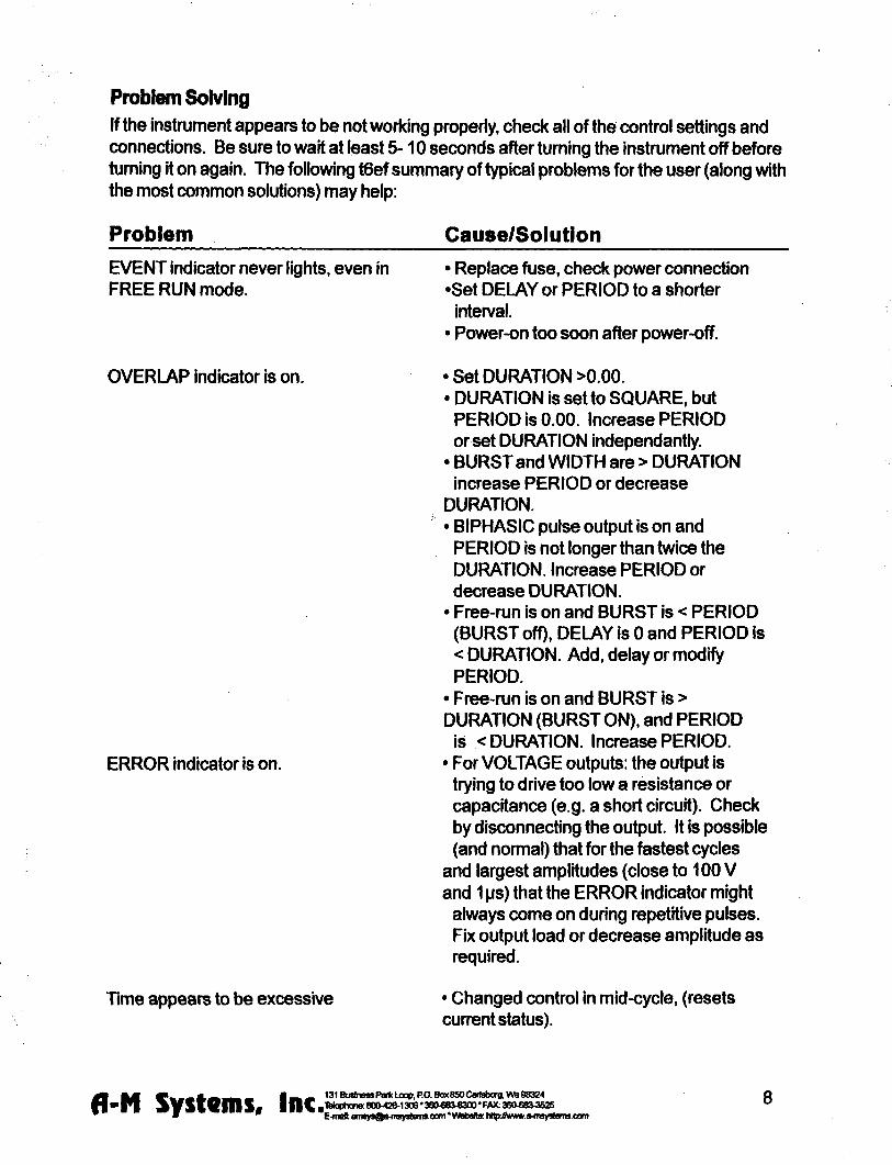
Theory of Operation
The operation of the Model 2100 is summarized In the block diagram (see Fig 3) Not shown are all of the interconnections with the microcontroller The intemal microcontroler plays an important role in setting the signal path but does not directly
contribute to the dynamic characteristics It scans the front panel switches and sets the control values for the logic arays It programs the intemal counters which along with the other hardware achieve the necessary sub-microsecond speeds
All action starts either from an input trigger signal (from Trig In) or from an intemal signal (in free Run mode only) A Delay timer counts the 10MHz clock until its count value Is exhausted At this point the Burst timer starts Both Period and Duration timers are started at this time If the Burst timer has not expired by the end of the Period the Period and Duration timers are restarted If the Biphasic mode has been set the Duration timer is restarted at the end of the initial Duration and the sign of the output pulse Is reversed doubling the total duration
The system state (pulse on pulse sip baseline sign [+101-]) is transmitted to the isolated section via optoisolator The baseline and pulse amplitudes are selected by an analog switch The resulting signal is amplified by a variable-power-supply discrete operational amplifier The amplifier connections and gain is modified to provide two voltage and three cunent ranges
Timing overlap errors are detected by a logical decision computation rather than by testing for counter collisions This provides instant feedback rather than waiting up to an hour for such a collision to occur Output errors are measured by sensing the output amplifiers differential input voltage Under normal conditions this is a negligible voltage if the amplifier fails to deliver the requested signal the window comparator testing this voltage sends this message (via optoisolator) to the logic section turning on a warning LED
fl-N Systems Inc 131BusbnassPa(tLoopPOBox6SOCari3boigVMg8324 H n |TWoph0n880O426-13083eO6Blaquo300FMt36Olaquo8i3525 E-nnl anaysflfriinysleiiaoemWfcbslte hllphmwraquoimyatennoom
TRIG 3HJ) OUT
(burst)
TRIG ^ OUT
(pulse)
E
Ml
Calibration Procedures
The calibration interval is the lesser of 1000 hours of operation or 6 months Somewhat greater drift can be expected in the first 100 hours of operation as the semiconductors age Adjustments should only be made after the instrument has been fully warmed up for at least 15 minutes
Full instrument calibration requires the following test equipment digital multimeter (plusmn 01) able to measure resistance to at least lOOMfl oscilloscope with at least 50MHz bandwidth true-rms voltmeter with 4MHz bandwidth universal counter (plusmn 001 ) able to measure single pulse widths and periods resistors (all plusmn 01) 2kn lOkH 1 waft 20kn 200kn alligator clip lead sets banana plugs and BNC adapters
Adjustment integrated circuit and test point locations are shown in the following figures All adjustments are on the timing board unless otherwise noted
All voltages in the non-isolated section should be measured with respect to ground at TP510 unless othenvise stated Some voltages are measured with respect to an intemal isolated ground at TP650 or across the two output tenninals Occasionally the voltage at an IC pin must be measured In these cases the reference designator is given with the pin number in parentheses eg U602(16) When it states within this procedure that a voltage is to be minimized this means that the adjustment should be made such that the measured voltage is as close to zero volts as possible Refer to the Specifications Section of this manual for acceptable tolerances
The sequence of this procedure is Important If any adjustment is made all adjustments which follow must be made to ensure that the specifications will be met These procedures require that all controls remain as set in previous steps unless otherwise indicated
WARNING
The Model 2100 has dangerous voltages throughout the instrument even with the power is off Servicing the Model 2100 should only be done by qualified service personnel Use caution in handling any wires connectors or electrodes which may be directly or indirectly attached to the Instrument Do not touch exposed connections or components Disconnect power by unplugging the power cord from the receptacle
fl-N Systems I n c ^ 131BusinesaPartcLoopPOBox850CartsborgVWiB8324 4 n ^gt-mdash80O426-130638Ofl8Jlaquo300FAX36O683J52S bull E-maft BinsysQfrfn^islflnisoomVVfalislle h^KVfWMift^iisystemsoani
CO
- R503
Omg^
TPSOlQ O
OTPSOO
U560 bull
U510
DDID ^ trade E O ^ T P 5 1 0
bullnD Trig
0 ^
U570
Gate n U505
DO D
U515
Timing
Timing h_ U520
bsoo ^25SE Timing
Or r U540
I I Tmlng
[^ELIL
U535 D
U506
13 J510 Timlnff
BurfiDelay J400
i i i i i i i T r m r a
gt U550 ^
Clock
U555 U620
B a
^R^Pvhigh Rfijn O D O Vlow
o
bull U545
Fo sect737 lISOIsPjC-COMP
n r r ^ U760
J420
]]U632
Q S riuGSO
H = ) TP640^ deg I t I
II3D
J440 m i T i
U610 plusmn laquo j U O
bull bull l el
^t
O l
bull
M
I
Power supply and bias voltages
Power supply
Controls Inputs Observations Adjust Check
POWER ON Observe voltage at P703 power supply wire top of main board
Check for+15 plusmn 050 V
Observe voltage at P701 power supply wire top of main board
Check for-15 plusmn 050 V
Observe voltage at U505(24) Check for+5 plusmn 025 V
Isolated supply voltage
Controls Inputs Observations Adjust Check
RANGE 10 V TRIG open circuit MODE center position
Altemately observe V^ from R742 to R740 and V ^ from the U605(4) to U605(8)
Adjust R773 so that 110VltV^lt 120 V and
nign
28VltV^lt34V
Capacitance balance
Controls Inputs Observations AdjustCheck
Connect a x10 oscilloscope probe to TP650 and ground the
Adjust R737 for minimum high frequency signal
Inputs
Gate funct ion
Controls Inputs Observations AdjustCheck
Apply a 1 kHz 0 - 5 V triangle wave Verify that the voltage to GATE switches states at the Obsene voltage at U51G(3) proper input levels with an oscilloscope ^ ^
Trigger s lope
Controls Inputs Observations Adjust Check
Apply a 1 kHz 0 - 5 V triangle wave Verify that the voltage to TRIO switches states at the Observe voltage at US 10( 1) proper input levels with an oscilloscope
TRIG SLOPE + Verify voltage is 180 out of phase
TRIG SLOPE Verify voltage is in phase
fl-N Systems Inc ^ 131 Bushess Park Loop PO Bar 850 Carisborg Wa 98324 8004201306 3eOlaquoS3e300 FAX 3606BV352S
C-maft fliii8yBQfriii9yBlumaoamVIAibsMB hRpJhwMifi-iiiBystematxini
14
Trigger and gate funct ion
Controls Inputs Observations Adjust Check
DELA NONE BURS1WII3TH SINGLE DURATION SQUARE PERIOD 100X10-3
Apply a 1 kHz 0 - 5 V triangle wave to TRIG Obsen^e TRIOD and EVENT LEDS
TRIG disconnect all Short the GATE connector to GND Verify LEDs extinguish
MODE press to MANUAL Verify LEDs flash once
Timing
System c lock frequency
Controls Inputs Observations AdjustCheck
Observe the frequency of the wave atU555(17)
Verify 1000 MHz plusmn001
Multipl iers (Wheel Switches)
Controls Inputs Observations AdjustCheck
PULSE SIGN + MODE FREE RUN TRIG disconnect all TIMING MULTIPUERS ail
wheels set to zero except the one being tested
TnmiNG OVERLAP ^nOTB
Observe the pulse width with the counter at the location specified below
Verify pulse width Is correct for each wheel as it is tested Independently
For each wheel of each MULTIPUER test each position to verify that the pulse width is correct Observe the signal at the following locations DELAY U520(2) BURSTWIDTH U530(2) PERIOD US40(2) DURATION U550(2)
Rates (Rotary Switches)
Controls Inputs Observations AdjustCheck
TIMING MULTIPUERS 001 TIMING RATES all rotary
switches set to 10-4 except the one being tested
Observe the pulse width with the counter at the location specified below
Verify pulse width is conect for each rotary switch as it is tested independently
For each of the four rotary switches in TIMING test each position to verify that the pulse wkJth is correct Observe the signal at the following locations DELAY U520(2) BURSTWIDTH U530(2) PERIOD U540(2) DURATION U550(2)
fl-N Systems I n c ^ E-maft emfl
131 Business Parti Loop PO 809(850 Cartsborg Wta 98324 8004201306 3804806300 FAX 36068O3S25
E-maft ansysQa nvystems-oom Wobste hflp Avwwa4nsy8(Qnttoam
15
Trigger outputs Controls
Range 10V Pulse Amplitude 500 Delay 100x10 Burst 100x10^2 Duration 100 x1a Period 400x10^ Pulse sign + Trig Mode Free run Trig in open
Inputs Observations
Trigger the oscilloscope to the Burst Trig Out Observe it the Pulse Trig Out and the isolated output
Adjust Check
Verify that the waveform consists of a burst of three 1ms-on3ms-off pulses The burst trigger should be synchronous with the burst the pulse trigger coincident with each pulse
Output Calibration
Isolation Resistance (check) Controls Inputs Observations AdjustCheck
Trig Mode center position Trig In open
Measure the resistance between ground banana jack (front panel) and black banana jack of output with DMM
Resistance read gt 100MQ
Amplitude Switch Offset (R640) Controls InputsObservations AdjustCheck
Baseline Zero Trig Mode center position Trig In Open
Measure the voltage at TP645 vs TP650 with the DMM
Adjust R640 (AmpI Sw Offset) for minimum voltage
Output Offset (R332 front panel board) Controls I nputsObservatlons AdjustCheck
Baseline Zero Range 10V Trig Mode center position Trig In Open
Measure the voltage across the output with the DMM
Adjust R332 (Output offset) for minimum voltage
Positive Baseline Offset (R607) Controls InputsObservations AdjustCheck
Baseline Sign + Baseline Amplitude
fully CCW (000) Range 10V Trig In open Trig Mode center position
Measure the voltage across the output with the DMM
Adjust R602 (BSLN + offset) for minimum voltage
fl M raquo _ _ _ A laquo ^ _ i ^ ^ 131Buslnelaquo8Pari(loopPOBoK850Cart8borgWB96324
bull P I i s V S i e m S a |||Cg1Maphans80O42O130638O68O8300FAX36Olaquo8raquo^2S E-tiBft anagtraquoflwiisyagtlaquomraquoaimW6baHB hHpffii(wwraquoltnsylaquoleniieom
16
Negative Baseline Offset (R619) Controls
Baseline Sign -i Baseline Amplitude bull fully CCW (000)
Range 10V Trig In open Trig Mode center position
Measure the voltage across the output with the DMM
AdjustCheck
Adjust R619 (BSLN 4 offset) for minimum voltage
Pulse Amplitude Adjust (R602) Controls InputsObservations AdjustCheck
Trig Mode Free Mode Pulse Amplitude 1000 Timing Dialay =none Burst =single Duration =1001 Period =00110-4 Pulse Sign -Trig In open Range 10V
Measure the voltage across the output with the DMM
The Overiap indicator should be on Adjust R602 (Max Level) for -1000V out
Pulse Sign Gain (check) Controls InputsObservations AdjustCheck
Trig Mode Free Mode Pulse Amplitude 1000 Timing Delay =none Burst =single Duration =1001 s Period =00110-4s Trig In open Range 10V
Measure the voltage at the output with the DMM for the Pulse Sign at -- and - positions
The absolute values of the voltages should differ by less than lOOmV
Baseline Amplitudes (check) Controls InputsObservations
Range 100mA Trig Mode center position Baseline Amplitude fully CW (1000) Trig In open
Measure the voltage at the output with the DMM with Baseline Sign in + Zero and - positions
AdjustCheck
Gain the matching of current levels at = and - positions and offset current in Zero position
fl-N Systems Inc^^ bull E-mal am8
131 Business Partt Loop PO Box 850 Cartsborg Wa 88324 8004201306360laquo8Oe300FAX 360laquo8O362S
E-maM am8y8^o-mBy8tflmBoom WobaKo hHp Awwwo-f i iBystonuoom
17
Output Range Amplitude and Drive (check) Controls InputsObservations AdjustCheck
Pulse Amplitude 1000 Pulse Sign + Trig Mode Free Run Timing Delay =none Burst =8ingle Duration =1001 Period =10010-4 Trig In open
Load the output with a 10KV1W 01 resistor Measure the voltage at the output with DMM
Verify that full scale output is within specification Scale Range 100V 100V 10V 10V 100mA IV 1mA 10V 10mA 100V
Pulse Sign and Short Circuit Protection (check) Controls InputsObservations AdjustCheck
Timing Delay =none Burst =8ingle Duration =200 10-4 Period =00110-3 Baseline Zero Pulse Amplitude 25 Range 10V Trig Mode Free Run Trig In open
Measure the voltage at the output with the oscilloscope Check for Pulse Sign set to each of + - biphasic Watch for Error indicator when shorting the output
Verify that pulses of approx 25V amplitude (625V for biphasic mode) of the correct sign are produced every 10ms Short output in biphasic mode Output should retum when opened
Output Transient Response (check) Controls InputsObservations AdjustCheck
Pulse Sign + Timing Delay =none Burst =single Duration =20010-4 Period =00110-3 Pulse Amplitude 250 Baseline Zero Trig Mode Free Mode Trig In open
Connect the oscilloscope to the output with a 310 attenuator prolse Test boVn 10V and 100V ranges
Verify that overshoot and risetime meet specifications
fl-N Systems I n c ^ 131 Business Parte Loop PO Box 850 Cartsborg Wb 98324 8004201306 36Olaquo83O300 FAX 36O680lt352S
E-mQ0 snBy8Qs-msy8faiTiscom VWriMtte N ^ Mvww9-msy8lemscom
18
Specifications
There are three classes of specifications Class A specifications tested in all unHs and are guaranteed Class B specifications are inherent in the design they are indirectly tested and are guaranteed Class C specifications are typical operating values which are occasionally tested- these are typical values given for your infomiation but not guarshyanteed The class for each specification is noted in the center column of the following sections
Inputs Switching level
Hysteresis
Input equivalent circuit
Minimum duration (1 IL-level signal)
A
C
C
C
16V(plusmn02V)
approx 50 mV
100K ft to+5 In parallel with no more than 35pF
gt 50 ns
Open circuit condition B defaults to highon level
Timing and rate accuracy Rate selector steps
Timing multiplier steps
Resolution
Timing eror (second and later pulses after resetting controls)
B
B
B
B
lOOps to 100s In 7 steps
1 of rate selector step size Maximum value is 999 x the rate selector step size
approx 01 of the maximum value
lt 002 of rate selector value + 015 ps
Timing error (first pulse after readjusting timing controls)
an additional 025 ps error may occur
Timing repeatability lt 001 setting + 20 ns (monophasic)
fl-N Systems I nc ^ bull E-moU ams
131 Business Parti Loop PO Boot 850 Cartsborg VM 98324 80O42O130838O08O8300FAX36Olaquo8O3S2S
E-meU anByafl^iiisyslainaoomWebsHe hHpffliiwwraquomsys)emsoom
19
TRIG IN to OUTPUT delay (DELAY set to 0) output set to 2V
Timing jitter ft-om TRIG IN to OUTPUT (for TTL trigger input with risetime lt10 ns)
Timing jitter ft^om TRIG OUT (either BURST or PULSE) and OUTPUT
Trigger output to pulse output delay
Output charactsristics Pulse level enror (voltage mode open circuit cun-ent mode short circuit
Biphasic level difference |V + + V-|2
Baseline level error (voltage mode A open circuit current mode short circuit)
Risetime (25 V out)
Risetime (25 V out)
Transient response
A
A
A
Output impedance (voltage mode) C
Output impedance (current mode) C
Isolation resistance A
Isolation capacitance C
approx 05 ps for a load of no more than 10 Kft in parallel with 50 pF
lt 125 ns (all rates except 100s) lt 125 ps (100s rate)
Less than 20 ns (all rates)
approx 350 ns
lt 03 of setting + 05 of r range (plus an additional 05 pA inlOOpArenge)
lt 03 of range (voltage modes into open circuit current modes into short circuit)
lt 03 of setting of setting + 01 of range (plus an additional 05 pA in lOOpA range)
laquo 200 ns into less than 30 pF
laquo15 ps into less than 30 pF
lt 8 overshoot Into less than 30 pF for pulse voltages different than baseline voltage by at least 10 of range
laquo 50 ohms
raquo 1 0 Gft (typically 200 Gft)
raquo100Mft
laquo 60 pF at 100 Hz
fl-N Systems Inc^^ 131 Business Partt Uxip PO Box 850 Cartsborg Wa 96324 8004201308 SBOee^^SOO FAX 360laquoS3^52S
E-mat BiByraquoaiMii8ylaquoliiiiiseomWiljalteHlpJV(wwraquo4tgy8lenaoom
20
Noise (differential mode)
Noise (common mode earth to isolated ground) with no signal output
Overioad error indicator (low frequency short circuited voltage mode)
Overioad error indicator low frequency open circuited current mode)
Overioad enor response time
Miscellaneous
Power
Fuse
Operating temperature range
Storage temperature range
Operating humidity
Dimensions
Weight
laquo1 mV rms (10 V scale 10Hz-4MHz)
laquo 8 mV rms (10 Hz-4 MHz) laquo100mVp-p (200 Hz -10 MHz) measured withalOMft 15pF oscilloscope probe
Turns on for set amplitude at or greater than approx plusmn1V (10 V range) or plusmn2 V (100 V range)
Turns on for set amplitude at or above approx 2 of range
Flat to approx 30 ps duration Decreasing sensitivity for shorter pulses
approx 11 watts
1 amp 3 AG
10-30C
0 - 50deg C
5-80RH
17x475x1125 (Inches) 432x121x286 cm
20 lbs (9 kg)
fl mm bull gt _ _ _ A ^ ^ _ _ L ^ 131BusinesraquoPariltLocpPOBox850C8rtsborgWS9e324
bull p i ^ y s v e m s IIIC^^deg(^deg^Bdegltgt^^^3degdeg^deg^^deg^^^degdeg^^I^deg^deg^^^^^
21 E-mei flre^nQo 4n8yo(amscam Wsbsfle hHpAwwwe-msy8Jems-Oom
Warranty and Service
What does this warranty cover A-M Systems Inc warrants to the Purchaser that the Instrument excluding cables Headstage Probes and any other accessories shipped with the Instrument (hereafter the hardware) is free from defects in workmanship or material under normal use and service for the period of one (1) year This warranty commences on the date of delivery of the hardware to the Purchaser
What are the obligations of A-M Systems Inc under this warranty During the warranty period A-M Systems Inc agrees to repair or replace at its sole option without charge to the Purchaser any defective component part of the hardware To obtain warranty service the Purchaser must return the hardware to A-M Systems Inc or an authorized A-M Systems Inc distributor in an adequate shipping container Any postage shipping and insurance charges incurred in shipping the hardware to A-M Systems Inc must be prepaid by the Purchaser and all risk for the hardware shall remain with purchaser until such time as A-M Systems Inc takes receipt of the hardware Upon receipt A-M Systems Inc will promptly repair or replace the defective unit and then return the hardware to the Purchaser postage shipping and insurance prepaid A-M Systems Inc may use reconditioned or like new parts or units at its sole option when repairing any hardware Repaired products shall carry the same amount of outstanding wan^nty as from original purchase or ninety (90) days which ever is greater Any claim under the warranty must include a dated proof of purchase of the hardware covered by this wan-anty In any event A-M Systems Inc liability for defective hardware is limited to repairing or replacing the hardware
What is not covered by this warranty This warranty is contingent upon proper use and maintenance of the hardware by the Purchaser and does not cover batteries Neglect misuse whether intentional or otherwise tampering with or altering the hardware damage caused by accident damage caused by unusual physical electrical chemical or electromechanical stress damage caused by failure of electrical power or damage caused during transportation are not covered by this warranty Products may not be returned to A-M Systems Inc for service whether under warranty or otherwise which are contaminated by infectious agents radioactive compounds or other materials constituting a health hazard to employees of A-M Systems Inc
What are the limits of llabiiity for A-M Systems inc under this warranty A-M Systems Inc shall not be liable for loss of data profits or savings or any special incidental consequential indirect or other similar damages arising from breach of contract negligence or other legal action even if the company or its agent has been advised of the possibility of such damages or for any claim brought against you by another party THIS EQUIPMENT IS NOT INTENDED FOR CLINICAL MEASUREMENTS USING HUMAN SUBJECTS A-M SYSTEMS INC DOES NOT ASSUME RESPONSIBILITY FOR INJURY OR DAMAGE DUE TO MISUSE OF THIS EQUIPMENT Jurisdictions vary with regard to the enforceability of provisions excluding or limiting liability for incidental or consequential damages Check the provision of your local jurisdiction to find out whether the above exclusion applies to you This warranty allocates risks of product failure between the Purchaser and A-M Systems Inc A-M Systems Inc hardware pricing reflects this allocation of risk and the limitations of liability contained in this wanranty The warranty set forth above is in lieu of all other express wan^anties whether oral or written The agents employees distributors and dealers of A-M Systems Inc are not authorized to make modifications to this wan-anty or additional wan-anties binding on the company Accordingly additional statements such as dealer advertising or presentations whether oral or written do not constitute wananties by A-M Systems Inc and should not be relied upon This warranty gives you specific legal rights You may also have other rights whrch vary from one jurisdiction to another
6 mm ^ laquo _ _ A a B ^ _ 1 ^ ^ 131 Business Parti Loop PO Box 850 Cartsborg W B 98324 O O
bull P l A y S V e m S l n C T^M 8OO42OI3O6 380683-8300FAX 360 803525 ^ ^ E-msl iiiisy80iHTBy8tenisoom Wsbsito hnphwwfrimysleiiisoom
A
V ISO
INSTRUCTION MANUAL
FOR
ISOLATED PULSE STIMULATOR
MODEL 2100
Serial
Date
A-M Systems Inc
PO Box 850
Carlsborg WA 98324
USA
360-683-8300 bull 800-426-1306 FAX 360-683-3525
httpwwwa-msystemscom
Version 70 February 2002
Contents General Description 1
Instrument Features 1 Controls and Connectors 2
Operating Instructions 6 Theory of Operation 10 Calibration Procedures 12
Inputs 14 Output Calibration 16
Specifications 19 Warranty and Service 22
Each Isolated Pulse Stimulator is delivered complete with
Rack Mount Hardware Instructions amp Maintenance Manual
NOTE
This instrument is not intended for clinical measurements using human subjects A-M Systems Inc does not assume responsibility for Injury or damage due to the misuse of this instrument
General Description
Instrument Features The Isolated Pulse Stimulator Model 2100 is designed for a wide variety of applications It is highly flexible being capable of delivering single pulses biphasic pairs or bursts of pulses Pulses may be started manually or upon receiving a trigger signal from another Instrument or computer Two non-isolated trigger outputs are available for triggering other instruments
Four sets of timing controls provide comprehensive control overall aspects of pulse generation Three digit accuracy is available over a 7 decade range for each timing function using lever wheel switches Pulse widths can be set over more than a 9 decade range from 05 ps to 999 seconds Timing accuracy is assured through the use of a 10 MHz base rate crystal-controlled clock digitally divided to provide accurate timing over the entire range Atiming overiap indicator will light If the timing controls are set inconsistently
The output may be conveniently switched between current and voltage modes Pulse and baseline amplitudes are Independently presettable with lockable dials An error Indicator will light if the Mode2700 cannot deliver the desired signal
r WARNING
The Model 2100 can produce potentially dangerous voltages up to 100 V at the output connectors The isolated output is not connected internally to safety (earth) ground in any way Some part of the extemal circuit should be connected to safety ground Use caution in handling any wires connectors or electrodes which may be directly or indirectly attached to the Model 2100 output Some kinds of connectors such as BNC connectors have exposed metal parts which may float at dangerous potentials unless extemally connected to safety ground For greatest safety tum the Model 2100 off before making any connections to
the instrument
131 Business Parii Loop PO Box 850 Cartsborg Wa 98324 Telophone 800-426-1306 bull 360-68raquolaquo300 bull FAX 360683-3525 E-mal satesa-msystemsoom VVfebsite httpywwwa^nsystemscom fl-N Systems Inc 1
Controls and Connectors The controls for the Model 2100 are grouped in three sections START which controls when a pulse or burst of pulses begins TIMING which controls the onoff timing of one or more pulses and OUTPUT which controls the amplitude of the output signal
Start TRIG SLOPE Determines the polarity of valid trigger pulses (positive or negative edges in the trigger signal)
MODE Controls waveform initiation When set to FREE RUN one timing cycle immediately follows the last When momentarily placed In the MANUAL position a timing cycle starts Immediately When the switch Is In the center position timing cycles start when valid triggering events occur
TRIGD This LED lights up when a timing cycle Is in process and continues until the burst is completed
TRIG This BNC connector allows a signal from an external source to Initiate timing cycles It is set for standard TTL levels
GATE This BNC connector allows a signal from an external source to restrict the final output signal This input must be at a logical high (or open-circuited) in order for the Model 2100 to recognize either manual or automatic trigger events
Gate 1_ Trigger |~~^ i I Valid triggers (represented by the arrows in the figure) can occur only when the gate Is at logical high Note that the up arrow would apply only If TRIG SLOPE is set to + the down an-ows would apply only if TRIG SLOPE Is set to -
NOTE Triggers have no effect if the system has not completed its response to a previous trigger
fl-N Systems Inc 131 Business Park Loop PO Box 850 Cartsborg Vb 98324 TelQphQne 80O426-1306 360683-8300 FAX 360683-3525 E-mail sales^a-msystemscom Wsbsite httpywwwa-msystemscom
Timing Four sets of controls govern the timing of pulse generation Each set contains two values which are multiplied together to detemnine the actual timing value The rotary knob (rate selector) provides the approximate timing value and the lever wheel switch bank (MULTIPLIER)
provides a time resolution of three decimal digits The following diagram shows most of the Important relationships
Output r Delay Duration
|ltPeriodgtj
t Burst width
Trigger event
DELAY These controls determine the time duration between the initiating trigger event and the beginning of the pulse burst If this rate selector is set to NONE or the multiplier is set to 000 there Is no delay
BURST WIDTH These controls determine the time period in which one or more pulses may be delivered Once started a pulse may outlast the burst width If this rate selector is set to SINGLE or to any time shorter than the pulse duration only a single pulse will occur If the BURST WIDTH Is longer than the period pulses will be emitted at the PERIOD rate until the burst time ends Pulses are never truncated by a short BURSTWIDTH
inds)-PULSE
D U R A T I O N 1 0 1 0
10
INTEB-PULSE PERIOD
1 1 10
DURATION These controls determine the length of each pulse Ifthis rate selector Is set to SQUARE the duration is set to half of the period regardless of the MULTIPLIER setting
PERIOD These controls set the period of time between adjacent pulse events within the burst It also forces a minimum dead time between recognized input triggers following a burst of one or more pulses This can be used to prevent over stimulation of a tissue without requiring excessive delay between the triggering event and the stimulating pulse
TIMING OVERLAP
fl-N Systems Inc 131 Business Parti Loop RO Box 860 Carisborg Vamp 98324 |Telophone 800-426-1306 360683-8300 bull FAX 3606aW525 E-mail salearega^nsystemsoom Vfeb5ite httpAwwwa^nsyslemscam
NOTE If any of these timing controls are changed while a timing cycle is in operation the results are undefined until the current cycle finishes
TIMING OVERLAP This LED will light to Indicate an inconsistency in the timing cycle settings There are several ways to introduce such errors The most common way is to set the Inter-pulse PERIOD to be less than the pulse DURATION
T I M I N G (seconds)^
TRIG OUT (UPPER) This BNC connector provides a signal which is coincident with the Internal Burst timing signal (default) This means the signal starts at the end of the Delay time and persists until the Burst time expires This output may also be set to represent the delay time-out by setting the internal jumper J510 to the right two pins instead of the left two pins (Please see the Calibration section in this manual for jumper location Directions are given as viewed from the front of the Instrument)
TRIG OUT (LOWER) This BNC connector provides a signal which Is coincident with the Duration timing signal which controls pulse output
NOTE Both trigger output signals slightly lead the isolated output signal
Output
PULSE SIGN This switch determines the polarity of the pulses to be generated It also allows generation of biphasic pulses thereby doubling the effective total period Warning the first pulse generated after changing the PULSE
SIGN switch may have the wrong polarity
BASELINE This Switch determines the polarity ofthe baseline signal
RANGE This rotary switch determines if the output pulses will be constant current (3 ranges) or constant voltage (2 ranges)
BASELINE AMPLITUDE This value is independently set using a ten-turn counting dial The maximum baseline amplitude is one tenth the value shown on the range amplitude switch
fl-N Systems Inc 131 Business Parti Loop RO Box 8S0 Cartsborg Vfa 98324 |Tetaphone 80O426-1306 bull 360683-8300 bull FAX 3606803525 E-mail salesa-msystemscom Wbbsite http7Awwwaflnsystemscom
PULSE AMPLITUDE This value is independently set using a ten-turn counting dial The maximum pulse amplitude is the value shown on the range amplitude switch
EVENT This LED indicates when a pulse is ongoing
ERROR This LED indicates when the internal output amplifier cannot output the pulse as desired This is usually due to a short circuit while trying to output a voltage or an open circuit while trying to output a current
VOTEThe Pulse Sign control in the Oupuf section directly affects waveform timing When set to the Biphasic mode a positive-going pulse is immediately followed by a negative-going pulse This effectively doubles the pulse duration If a burst of biphasic pulses is being produced the period must be at least twice the single pulse duration In the Square wave mode the baseline disappears as long as the burst persists
fl-N Systems Inc 131 Business Parti Loop RO Box 850 Cartsboig Vte 98324 |Telophone 800426-1306 360683-8300 bull FAX 3606833525 E-mail salesa-m5ystem5 com Website httpwwwa-msystemscom
Operating Instructions
Examples Simple setup (and minimal instrument test)
Connect the output ofthe Model 2100 to an oscilloscope Before connecting the Model 2100 to any other instrument or the experimental preparation It is safest to turn Its power off
Set the Oufpuf controls
Range 10V Pulse Sign +
Baseline Zero Pulse Amplitude 200
Setting The Timing Controls
Delay Burst Width
Duration Period
none single
15010-2 50010-2
Setting The Start Controls
Mode Free Run
Disconnect any cables to the TRIG or GATE inputs
Note that the green Trig and Event Indicators turn on as Free Run is turned on (and turn off otherwise) You should observe a 15ms duration 20Hz rate pulse of 200V above a OV baseline on the oscilloscope
fl-N Systems Inc 131 BusinessPartiLoop RO Box850CarisbcxgWa98324 |Telophone 800426-1306 bull 360-683-8300 bull FW 360683-3525 E-mail salesa-msystems com VVbbsite httpywwwa-msystems com
Demonstration of Burst Mode Connect the output ofthe Model 2100 to an oscilloscope Before connecting the Model 2100 to any other instrument or the experimental preparation It Is safest to turn its power off
Set the Outpuf controls
Range 10V Pulse Sign +
Baseline Pulse Amplitude 200
Baseline Amplitude 100
Setting The Timing Controls
Delay 88010-2 Burst Width 12010-^
Duration 15010-2 Period 50010-2
Set the START controls as follows
Mode Free Run
Disconnect any cables to the TRIG or GATE inputs
fl-N Systems Inc 131 Business Parti Loop RO Box 850 Cartsborg Wa 98324 Telophooe 8004201306 360683-8300 bull FAX 360683-3525 E^naii salesa-msystems com Watjsite http7wwwa-msystemscom
Trigger the oscilloscope from the Bursf trigger out (upper Trig Out connector) for a stable display In each burst (occurring every lOOms) you should observe a trio of 15ms duration starting 50ms apart Try switching the StartMode from Free Run to the center (nonnal) position The pulses will no longer be produced and the Trig and Event Indicators will tum off Pressing this switch once (to Manual) will cause a single burst to occur
Problem Solving If the instrument appears to be not working properiy check all ofthe control settings and connections Be sure to wait at least 5-10 seconds after turning the instrument off before turning it on again The following summary of typical problems for the user (along with the most common solutions) may help
Problem CauseSolution
EVENT Indicator never lights even in FREE RUN mode
bull Replace fuse check power connection bullSet DELAY or PERIOD to a shorter interval
bull Power-on too soon after power-off
OVERLAP Indicator is on
ERROR indicator is on
bull Set DURATION gt000 bull DURATION Is set to SQUARE but
PERIOD is 000 Increase PERIOD or set DURATION independantly
bull BURST and WIDTH are gt DURATION increase PERIOD or decrease DURATION
bull BIPHASIC pulse output Is on and PERIOD is not longer than twice the DURATION Increase PERIOD or decrease DURATION
bull Free-run Is on and BURST is lt PERIOD (BURST off) DELAY is 0 and PERIOD Is lt DURATION Add delay or modify PERIOD
bull Free-run is on and BURST is gt DURATION (BURST ON) and PERIOD is lt DURATION Increase PERIOD
bull For VOLTAGE outputs the output is trying to drive too low a resistance or capacitance (eg a short circuit) Check by disconnecting the output ft is possible (and normal) that for the fastest cycles and largest amplitudes (close to 100 V
fl-N Systems Inc 131 Business PartiLoop PO Box 850 CartsborgWa 98324 iTelophone 800-42O130636O6e3-8300FAX 3606B3-3525 E-mail satesaflisyslefmcom Vfebslte http7wwwa-msyslemscom
and 1 ps) that the ERROR indicator might always come on during repetitive pulses Fix output load or decrease amplitude as required
Time appears to be excessive Changed control in mid-cycle (resets current status)
Cant seem to get a full signal out Load Is not properiy connected repair wiring Too low a load impedance (VOLTAGE modes) or too high a load impedance (CURRENT mode)
Incoming triggers not accepted frequently enough
PERIOD is set too long (enforces dead time) followd by BURST set to SIGNAL Reduce PERIOD time
Table 10 Problem Solving
If you suspect that the Model 2100 may have completely failed we recommend checking the basic level of functionality Ifthis fails your instrument Is defective and must be repaired Ifthis passes either your experimental setup is incompatible or inconsistent or there is a more subtle flaw in your Model 2100
If the Model 2100 appears to be malfunctioning contact A-M Systems Inc or your dealer We will first attempt to solve the problem over the telephone so have an exact description of your problem available when you call You do not need to be within the warranty period to obtain over-the-phone assistance
fl-N Systems Inc 131 Business Parti Loop RO Box 850 Cartsborg Wa 98324 iTetoptxme 80O426-1306 bull 360683-8300 FAX 3606803525 E-mail satesa-msystemsoomAfebsitehttpJwwwaflisystemscom
Theory of Operation
The operation ofthe Model 2100 is summarized in the block diagram (see the figure on Page 11) Not shown are all ofthe interconnections with the microcontroller The internal microcontroler plays an important role in setting the signal path but does not directly contribute to the dynamic characteristics It scans the front panel switches and sets the control values for the logic arrays It programs the internal counters which along with the other hardware achieve the necessary sub-microsecond speeds
Pulse generation starts either from an Input trigger signal (from Trig In) or an internally signal (Free Run mode) A Delay timer counts the 10MHz clock until its count value is exhausted At this point the Burst Period and Duration timers are started If the Burst timer has not expired by the end ofthe Period the Period and Duration timers are restarted If the Biphasic mode has been set the Duration timer is restarted at the end of the initial Duration and the sign ofthe output pulse is reversed doubling the total duration
The system state (pulse on pulse sign baseline sign [+0f-]) is transmitted to the isolated section via optoisolator The baseline and pulse amplitudes are selected by an analog switch The resulting signal is amplified by a variable-power-supply discrete operational amplifier The amplifier connections and gain is modified to provide two voltage and three current ranges
Timing overiap errors are detected by a logical decision computation rather than by testing for counter collisions This provides instant feedback rather than waiting up to an hour for such a collision to occur Output errors are measured by sensing the output amplifiers differential input voltage Under normal conditions this is a negligible voltage If the amplifier fails to deliver the requested signal the window comparator testing this voltage sends this message (via optoisolator) to the logic section turning on a warning LED
fl-N Systems Inc 131BusinessPart(LoopRO Box850CarisboigWa98324 4 n Tel0pri0ne80O426-130636O683^300FAX36O6833525 ^ E-mail salesaflisystBmscom V febsite http7wwwa-msystemsoom
S i
I - - ^^mdasho^M
OUTPUT i l l
TRIG ^ OUT
(burst)
TRIG 3-lt) OUT
(pulse)
til
I laquo
Calibration Procedures
The calibration interval is the lesser of 1000 hours of operation or 6 months Somewhat greater drift can be expected in the first 100 hours of operation as the semiconductors age Adjustments should only be made after the instrument has been fully warmed up for at least 15 minutes
Full instrument calibration requires the following test equipment digital multimeter (plusmn 01) able to measure resistance to at least lOOMO oscilloscope with at least 50MHz bandwidth true-mis voltmeter with 4MHz bandwidth universal counter (plusmn 001 ) able to measure single pulse widths and periods resistors (all plusmn 01) 2kn lOkH 1 watt 20kn 200kn alligator clip lead sets banana plugs and BNC adapters
Adjustment integrated circuit and test point locations are shown in the following figures All adjustments are on the timing board unless othenAise noted
All voltages in the non-isolated section should be measured with respect to ground at TP510 unless othenwise stated Some voltages are measured with respect to an internal isolated ground at TP650 or across the two output temninals Occasionally the voltage at an IC pin must be measured in these cases the reference designator is given with the pin number in parentheses eg U602(16) When it states within this procedure that a voltage is to be minimized this means that the adjustment should be made such that the measured voltage is as close to zero volts as possible Refer to the Specifications Section of this manual for acceptable tolerances
The sequence of this procedure is important If any adjustment is made all adjustments which follow must be made to ensure that the specifications will be met These procedures require that all controls remain as set in previous steps unless othenAise indicated
WARNING
The Model 2100 has dangerous voltages throughout the instrument even with the power is off Servicing the Model 2100 should only be done by qualified service personnel Use caution in handling any wires connectors or electrodes which may be directly or indirectly attached to the instrument Do not touch exposed connections or components Disconnect power by unplugging the power cord from the receptacle
H B ^ ^ S y s t e m s inc^degdegp^deg^^deg-^^^^^^^^B3^^^degdeg^^^lt^^^B^^^^ 131BusinessPartiLoopPO Box850CartsbOigWamp98324 4 9 |Telophone800-42013C6360683-8300F0lt360683-3525 ^ E-mail salesa-msystefnscom website httpwwwaflisystems com
CO
TP501 O lt0
g OTPSOO
U560 S
Trig Gate
0 -TISOS
U570
U500
Timing
p U520
Timing
K U550 Timin
gt U540
U515
o X I Timin
U508 I
J510 Timing nnn
Burst Delay J400
gt U550
R503
D D I D bull U8QQ i Q
n
oo
V P 5 1 0
b U535
^
Clock i _
U555
lt U 5 4 5
o
h d ^ O - - ^ U605
Q D
U620
O fJZ^ R737 bull ^ 1^13015 r j C - C O M P
B B nU770 ^ ^ ^ 5 ^ a
J420
a
o E
bull [ ]U632
riueso
rR742rVhigh R 6 1 9 ^
LJ TP645 O TP650
TPMOQ^QS
Vlow
CD-
CZZl
J440 bull bull tl iUDQ
I t
f i l
Power supply and bias voltages
Power supply
Controls Inputs Observations Adjust Check
POWER ON Observe voltage at P703 power supply wire top of main board
Check for+15 plusmn 050 V
Observe voltage at P701 power supply wire top of main board
Check for-15 plusmn 050 V
Observe voltage at U505(24) Check for +5 plusmn 025 V
Isolated supply voltage Controls Inputs Observations AdjustCheck
RANGE 10 V TRIG open circuit MODE center position
Alternately observe V ^ from R742 to R740 and V ^ from theU605(4)toU605(8)
Adjust R773 so that 110VltV lt 120 V and
nigh
28VltV|^lt34V
Capacitance balance Controls Inputs Observations Adjust Check
Connect a xlO oscilloscope probe to TP650 and ground the
Adjust R737 for minimum high frequency signal
Inputs
Gate function Controls Inputs Observations AdjustCheck
Apply a 1 kHz 0 - 5 V triangle wave Verify that the voltage to GATE switches states at the Observe voltage at U510(3) proper input levels with an oscilloscope
Trigger slope Controls Inputs Observations AdjustCheck
Apply a 1 kHz 0 - 5 V triangle wave Verify that the voltage to TRIG switches states at the Observe voltage at U510( 1) proper input levels with an oscilloscope
TRIG SLOPE Verify voltage is 180deg out of phase
TRIG SLOPE Verify voltage is in phase
fl-N Systems Inc 131 Business Parti Loop RO Box 860 Cartsborg Wa 98324 Jelophone 800-4201306 360683-8300 bull FM 380683-3525 E-mail salesaflTsystBfnscom bull Vtebsite httpVAirwwaflisystems com
14
Trigger and gate f unc t i on
Controls Inputs Observations Adjust Check
DELAY NONE BURS-nMDTH SINGLE DURATION SQUARE PERIOD 100X10-3
Apply a 1 kHz 0 - 5 V triangle wave to TRIG Observe TRIGD and EVENT LEDs
TRIG disconnect all Short the GATE connector to GND Verify LEDs extinguish
MODE press to MANUAL Verify LEDs flash once
Timing
System c lock f requency
Controls Inputs Observations Ad jus t Check
Observe the frequency of the wave Verify 1000 MHz plusmn 001 atU555(17)
Mul t ip l iers (Wheel Swi tches)
Controls Inputs Observations Adjust Check
PULSE SIGN-laquobull MODE FREE RUN TRIG disconnect all TIMING MULTIPUERS all
wheels set to zero except the one being tested
TIMING OVERLAP ignore
Observe the pulse width with the counter at the location specified t)elow
Verify pulse width is correct for each wheel as it is tested independently
For each wheel of each MULTIPLIER test each position to verify that the pulse width is correct Observe the signal at the following locations DELAY U520(2) BURSTWIDTH U530(2) PERIOD U540(2) DURATION U550(2)
Rates (Rotary Swi tches)
Controls Inputs Observations Adjust Check
TIMING MULTIPUERS 001 Observe the pulse width with the TIMING RATES all rotary counter at the location specified
switches set to 10-4 below except the one being tested
Verify pulse width is correct for each rotary switch as it is tested independently
For each ofthe four rotary switches in TIMING test each position to verify that the pulse width is correct Observe the signal at the following locations DELAY U520(2) BURSTWIDTH U530(2) PERIOD U540(2) DURATION U550(2)
fl-N Systems Inc 131 Business Parti Loop PO Box 850 Cartsborg Wa 98324 iTetophone 8004201306 bull 360683-8300 bull FOC 3606803525 E-mail salesa-msystemscom Wbbsite httpJwwwaflTSystemscom
15
Trigger outputs
Controls Inputs Observations Adjust Check
Range 10V Pulse Amplitude 500 Delay 100 xlO^ Burst 100 x 10 ^ Duration 100x10-^ Period 400x10-^ Pulse sign + Trig Mode Free run Trig in open
Trigger the oscilloscope to the Burst Trig Out Observe it the Pulse Trig Out and the isolated output
Verify that the waveform consists of a burst of three 1ms-on3ms-off pulses The burst trigger should be synchronous with the burst the pulse trigger coincident with each pulse
Output Calibration
Isolation Resistance (check)
Controls Inputs Observations AdjustCheck
Trig Mode center position Trig In open
Measure the resistance between ground banana jack (front panel) and black banana jack of output with DMM
Resistance read gt 100MQ
Amplitude Switch Offset (R640)
Controls InputsObservations AdjustCheck
Baseline Zero Trig Mode center position Trig In Open
Measure the voltage at TP645 vs TP650 with the DMM
Adjust R640 (AmpI Sw Offset) for minimum voltage
Output Offset (R332 front panel board) Controls InputsObservations AdjustCheck
Baseline Zero Range 10V Trig Mode center position Trig In Open
Measure the voltage across the output with the DMM
Adjust R332 (Output offset) for minimum voltage
Positive Baseline Offeet (R607) Controls InputsObservations AdjustCheck
Baseline Sign + Baseline Amplitude
fully CCW (000) Range 10V Trig In open Trig Mode center position
Measure the voltage across the outputwiththeDMM
Adjust R602 (BSLN + offset) for minimum voltage
fl-N Systems Inc 131 BusBiess Parti Loop P O Box 850 Cartsborg Wa 98324 Telophone B00-42O1306 bull 360683-8300 bull FAX 3606803525 E-mail salesaflisystemscom V^tebsite httpy^vwwa-msystems com
16
Negative Baseline Offset (R619)
Controls InputsObservations AdjustCheck
Baseline Sign -Baseline Amplitude
fully CCW (000) Range 10V Trig In open Trig Mode center position
Measure the voltage across the outputwiththeDMM
Adjust R619 (BSLN + offset) for minimum voltage
Pulse Amplitude Adjust (R602)
Controls InputsObservations AdjustCheck
Trig Mode Free Mode Pulse Amplitude 1000 Timing Delay =none Burst =single Duration =1001 Period =00110-4 Pulse Sign -Trig In open Range 10V
Measure the voltage across the output with the DMM
The Overiap indicator should be on Adjust R602 (Max Level) for -10OOV out
Pulse Sign Gain (check)
Controls InputsObservations AdjustCheck
Trig Mode Free Mode Pulse Amplitude 1000 Timing Delay =none Burst =single Duration =100 1s Period =001 10-4s Trig In open Range 10V
Measure the voltage at the output with the DMM for the Pulse Sign at + and - positions
The absolute values ofthe voltages should differ by less than lOOmV
Baseline Amplitudes (check) Controls InputsObservations AdjustCheck
Range 100mA Trig Mode center position Baseline Amplitude fully CW (1000) Trig In open
Measure the voltage at the output with the DMM with Baseline Sign in + Zero and
- positions
Gain the matching of current levels at = and - positions and offset current in Zero position
fl-N Systems Inc 131 Business Parti Loop PO Box 850 Cartsboig Wa 98324 Telophone 800-4201306 360683-8300 FkX 3606803525 E-mail salesa-msystemscom website http^^wwaflisystemsccm
17
Output Range Amplitude and Drive (check) Controls InputsObservations AdjustCheck
Pulse Amplitude 1000 Pulse Sign + Trig Mode Free Run Timing Delay =none Burst =single Duration =1001 Period =10010-4 Trig In open
Load the output with a 10KV 1W 01 resistor Measure the voltage at the output with DMM
Verify that full scale output is within specification Scale Range 100V 100V 10V 10V 100mA IV 1mA 10V 10mA 100V
Pulse Sign and Short Circuit Protection (check) Controls InputsObservations AdjustCheck
Timing Delay =none Burst =single Duration =200 10-4 Period =00110-3 Baseline Zero Pulse Amplitude 25 Range 10V Trig Mode Free Run Trig In open
Measure the voltage at the output with the oscilloscope Check for Pulse Sign set to each of + - biphasic Watch for Error indicator when shorting the output
Verify that pulses of approx 25V amplitude (625V for biphasic mode) of the correct sign are produced every 10ms Short output in biphasic mode Output should return when opened
Output Transient Response (check) Controls InputsObservations AdjustCheck
Pulse Sign + Timing Delay =none Burst =single Duration =20010-4 Period =00110-3 Pulse Amplitude 250 Baseline Zero Trig Mode Free Mode Trig In open
Connect the oscilloscope to the output with a 310 attenuator probe Test both 10V and 100V ranges
Verify that overshoot and risetime meet specifications
fl-N Systems Inc 131 Business Parti Loop RO Box 850 Cartsborg Wa 98324 Telophone 8004201306 bull 3606808300 bull Flaquo( 360laquo83ltJ525 E-mail salesa-msystemsocm V^febsite http^wwwa-msystefnscom
18
Specifications
There are three classes of specifications Class A specifications tested in all units and are guaranteed Class B specifications are inherent in the design they are indirectly tested and are guaranteed Class C specifications are typical operating values which are occasionally tested- these are typical values given for your information but not guarshyanteed The class for each specification is noted in the center column ofthe following sections
Inputs Switching level
Hysteresis
Input equivalent circuit
Minimum duration (1 IL-level signal)
A
C
C
C
16 V(plusmn 02 V)
approx 50 mV
lOOKH to+5 in parallel with no more than 35pF
gt 50 ns
Open circuit condition B defaults to highon level
Timing and rate accuracy Rate selector steps
Timing multiplier steps
B
B
lOOpsto 100s in 7 steps
1 of rate selector step size Maximum value is 999 X the rate selector step size
Resolution B approx 01 ofthe maximum value
Timing error (second and later pulses after resetting controls)
B lt 002 of rate selector value + 015 ps
Timing error (first pulse after readjusting timing controls)
an additional 025 ps error may occur
Timing repeatability lt 001 setting + 20 ns (monophasic)
fl-N Systems Inc 131 Business Ram Loop RO Box 850 Cartsborg Vfa 98324 pTelophone 8004201306 bull 360683-8300 bull FAX 360683-3525
E-mail salesraquoflisystems com Wabsite httpJAnww afl isystems com
19
TRIG IN to OUTPUT delay (DELAY set to 0) output set to 2V
Timing jitter from TRIG IN to OUTPUT (for TTL trigger input with risetime lt10 ns)
Timing jitter from TRIG OUT (either BURST or PULSE) and OUTPUT
Trigger output to pulse output delay
Output characteristics Pulse level error (voltage mode open circuit current mode short circuit
Biphasic level difference IV + - V-1 2
Baseline level error (voltage mode open circuit current mode short circuit)
Risetime (25 V out)
Risetime (25 V out)
Transient response
A
A
A
Output impedance (voltage mode) C
Output impedance (current mode) C
Isolation resistance A
Isolation capacitance C
approx 05 ps for a load of no more than 10 KH in parallel with 50 pF
lt 125 ns (all rates except 100s) lt 125 ps (100s rate)
Less than 20 ns (all rates)
approx 350 ns
lt 03 of setting + 05 of r range (plus an additional 05 pA in 100 pA range)
lt 03 of range (voltage modes into open circuit current modes into short circuit)
lt 03 of setting of setting + 01 of range (plus an additional 05 pA in lOOpA range)
= 200 ns into less than 30 pF
= 15 ps into less than 30 pF
lt 8 overshoot into less than 30 pF for pulse voltages different than baseline voltage by at least 10 of range
= 50 ohms
raquo 1 0 GH (typically 200 GO)
raquo 1 0 0 M n
= 60 pF at 100 Hz
fl-N Systems Inc 131 Business Peril Loop PO Box 850 Cartsborg V6 98324 |TelCf)hone 800-4201306 3606808300 bull FAX 360683-3525 E-mal salesaflisystefnsoom Website hnpyMVfWafllsystemsoom
20
Noise (differential mode)
Noise (common mode earth to isolated ground) with no signal output
Overload error indicator (low frequency short circuited voltage mode)
Overload error indicator low frequency open circuited current mode)
Overioad error response time
Miscellaneous
= 1 mV rms (10 V scale 10 Hz-4 MHz)
= 8 mV rms (10 Hz-4 MHz) == 100mVp-p (200 Hz -10 MHz) measured withalOMH 15pF oscilloscope probe
Turns on for set amplitude at or greater than approx plusmn1 V (10 V range) or plusmn2 V (100 V range)
Turns on for set amplitude at or above approx 2 of range
Flat to approx 30 ps duration Decreasing sensitivity for shorter pulses
Power
Fuse
Operating temperature range
Storage temperature range
Operating humidity
Dimensions
approx 11 watts
1 amp 3AG
10-30degC
0 - 50deg C
5 - 80 RH
17x475x1125 (inches) 432x121x286 cm
Weight 20 lbs (9 kg)
fl-N Systems Inc 131 Business Parti Loop RO Box 850 Cartsborg Wb 98324 |Tetcphone 8004201306 3606808300 bull FOt 360683-3525 E-mail satesamsystems comV^febsite httpywwwaflisystemscom
21
Warranty and Service
What does this warranty cover A-M Systems Inc warrants to the Purchaser that the Instrument excluding cables Headstage Probes and any other accessories shipped with the Instrument (hereafter the hardware) is free from defects in workmanship or material under normal use and service for the period of one (1) year This warranty commences on the date of delivery ofthe hardware to the Purchaser
What are the obligations of A-M Systems Inc under this warranty During the warranty period A-M Systems Inc agrees to repair or replace at its sole option without charge to the Purchaser any defective component part of the hardware To obtain warranty service the Purchaser must return the hardware to A-M Systems Inc or an authorized A-M Systems Inc distributor in an adequate shipping container Any postage shipping and insurance charges incurred in shipping the hardware to A-M Systems Inc must be prepaid by the Purchaser and all risk for the hardware shall remain with purchaser until such time as A-M Systems Inc takes receipt of the hardware Upon receipt A-M Systems Inc will promptly repair or replace the defective unit and then return the hardware to the Purchaser postage shipping and insurance prepaid A-M Systems Inc may use reconditioned or like new parts or units at its sole option when repairing any hardware Repaired products shall carry the same amount of outstanding warranty as from original purchase or ninety (90) days which ever is greater Any claim under the warranty must include a dated proof of purchase ofthe hardware covered by this warranty In any event A-M Systems Inc liability for defective hardware is limited to repairing or replacing the hardware
What is not covered by this warranty This warranty is contingent upon proper use and maintenance ofthe hardware by the Purchaser and does not cover batteries Neglect misuse whether intentional or othenwise tampering with or altering the hardware damage caused by accident damage caused by unusual physical electrical chemical or electromechanical stress damage caused by failure of electrical power or damage caused during transportation are not covered by this wan-anty Products may not be returned to A-M Systems Inc for service whether under warranty or otherwise which are contaminated by infectious agents radioactive compounds or other materials constituting a health hazard to employees of A-M Systems Inc
What are the limits of liability for A-M Systems Inc under this warranty A-M Systems Inc shall not be liable for loss of data profits or savings or any special incidental consequential indirect or other similar damages arising from breach of contract negligence or other legal action even if the company or its agent has been advised of the possibility of such damages or for any claim brought against you by another party THIS EQUIPMENT IS NOT INTENDED FOR CLINICAL MEASUREMENTS USING HUMAN SUBJECTS A-M SYSTEMS INC DOES NOT ASSUME RESPONSIBILITY FOR INJURY OR DAMAGE DUE TO MISUSE OF THIS EQUIPMENT Jurisdictions vary with regard to the enforceability of provisions excluding or limiting liability for incidental or consequential damages Check the provision of your local jurisdiction to find out whether the above exclusion applies to you
This warranty allocates risks of product failure between the Purchaser and A-M Systems Inc A-M Systems Inc hardware pricing reflects this allocation of risk and the limitations of liability contained in this warranty The warranty set forth above is in lieu of all other express warranties whether oral or written The agents employees distributors and dealers of A-M Systems Inc are not authorized to make modifications to this warranty or additional wan-anties binding on the company Accordingly additional statements such as dealer advertising or presentations whether oral or written do not constitute warranties by A-M Systems Inc and should not be relied upon This warranty gives you specific legal rights You may also have other rights which vary from one jurisdiction to another
fl-N Systems Inc 131BusinessPartiLoop RO Box850CartsbOfgWa98324 p O |Telophone 8004201306 bull 360683-8300FOC 3606830525 ^ ^ E-mail saiesaflisystefTiscom Wbbsite httpVwwwa-msystemscom
Calibration Procedures
The calibration interval is the lesser of 1000 hours of operation or 6 months Somewhat greater drift can be expected in the first 100 hours of operation as the semiconductors age Adjustments should only be made after the instrument has been fully warmed up for at least 15 minutes
Full instrument calibration requires the following test equipment digital multimeter (plusmn 01) able to measure resistance to at least lOOMfl oscilloscope with at least 50MHz bandwidth true-rms voltmeter with 4MHz bandwidth universal counter (plusmn 001 ) able to measure single pulse widths and periods resistors (all plusmn 01) 2kn lOkH 1 waft 20kn 200kn alligator clip lead sets banana plugs and BNC adapters
Adjustment integrated circuit and test point locations are shown in the following figures All adjustments are on the timing board unless otherwise noted
All voltages in the non-isolated section should be measured with respect to ground at TP510 unless othenvise stated Some voltages are measured with respect to an intemal isolated ground at TP650 or across the two output tenninals Occasionally the voltage at an IC pin must be measured In these cases the reference designator is given with the pin number in parentheses eg U602(16) When it states within this procedure that a voltage is to be minimized this means that the adjustment should be made such that the measured voltage is as close to zero volts as possible Refer to the Specifications Section of this manual for acceptable tolerances
The sequence of this procedure is Important If any adjustment is made all adjustments which follow must be made to ensure that the specifications will be met These procedures require that all controls remain as set in previous steps unless otherwise indicated
WARNING
The Model 2100 has dangerous voltages throughout the instrument even with the power is off Servicing the Model 2100 should only be done by qualified service personnel Use caution in handling any wires connectors or electrodes which may be directly or indirectly attached to the Instrument Do not touch exposed connections or components Disconnect power by unplugging the power cord from the receptacle
fl-N Systems I n c ^ 131BusinesaPartcLoopPOBox850CartsborgVWiB8324 4 n ^gt-mdash80O426-130638Ofl8Jlaquo300FAX36O683J52S bull E-maft BinsysQfrfn^islflnisoomVVfalislle h^KVfWMift^iisystemsoani
CO
- R503
Omg^
TPSOlQ O
OTPSOO
U560 bull
U510
DDID ^ trade E O ^ T P 5 1 0
bullnD Trig
0 ^
U570
Gate n U505
DO D
U515
Timing
Timing h_ U520
bsoo ^25SE Timing
Or r U540
I I Tmlng
[^ELIL
U535 D
U506
13 J510 Timlnff
BurfiDelay J400
i i i i i i i T r m r a
gt U550 ^
Clock
U555 U620
B a
^R^Pvhigh Rfijn O D O Vlow
o
bull U545
Fo sect737 lISOIsPjC-COMP
n r r ^ U760
J420
]]U632
Q S riuGSO
H = ) TP640^ deg I t I
II3D
J440 m i T i
U610 plusmn laquo j U O
bull bull l el
^t
O l
bull
M
I
Power supply and bias voltages
Power supply
Controls Inputs Observations Adjust Check
POWER ON Observe voltage at P703 power supply wire top of main board
Check for+15 plusmn 050 V
Observe voltage at P701 power supply wire top of main board
Check for-15 plusmn 050 V
Observe voltage at U505(24) Check for+5 plusmn 025 V
Isolated supply voltage
Controls Inputs Observations Adjust Check
RANGE 10 V TRIG open circuit MODE center position
Altemately observe V^ from R742 to R740 and V ^ from the U605(4) to U605(8)
Adjust R773 so that 110VltV^lt 120 V and
nign
28VltV^lt34V
Capacitance balance
Controls Inputs Observations AdjustCheck
Connect a x10 oscilloscope probe to TP650 and ground the
Adjust R737 for minimum high frequency signal
Inputs
Gate funct ion
Controls Inputs Observations AdjustCheck
Apply a 1 kHz 0 - 5 V triangle wave Verify that the voltage to GATE switches states at the Obsene voltage at U51G(3) proper input levels with an oscilloscope ^ ^
Trigger s lope
Controls Inputs Observations Adjust Check
Apply a 1 kHz 0 - 5 V triangle wave Verify that the voltage to TRIO switches states at the Observe voltage at US 10( 1) proper input levels with an oscilloscope
TRIG SLOPE + Verify voltage is 180 out of phase
TRIG SLOPE Verify voltage is in phase
fl-N Systems Inc ^ 131 Bushess Park Loop PO Bar 850 Carisborg Wa 98324 8004201306 3eOlaquoS3e300 FAX 3606BV352S
C-maft fliii8yBQfriii9yBlumaoamVIAibsMB hRpJhwMifi-iiiBystematxini
14
Trigger and gate funct ion
Controls Inputs Observations Adjust Check
DELA NONE BURS1WII3TH SINGLE DURATION SQUARE PERIOD 100X10-3
Apply a 1 kHz 0 - 5 V triangle wave to TRIG Obsen^e TRIOD and EVENT LEDS
TRIG disconnect all Short the GATE connector to GND Verify LEDs extinguish
MODE press to MANUAL Verify LEDs flash once
Timing
System c lock frequency
Controls Inputs Observations AdjustCheck
Observe the frequency of the wave atU555(17)
Verify 1000 MHz plusmn001
Multipl iers (Wheel Switches)
Controls Inputs Observations AdjustCheck
PULSE SIGN + MODE FREE RUN TRIG disconnect all TIMING MULTIPUERS ail
wheels set to zero except the one being tested
TnmiNG OVERLAP ^nOTB
Observe the pulse width with the counter at the location specified below
Verify pulse width Is correct for each wheel as it is tested Independently
For each wheel of each MULTIPUER test each position to verify that the pulse width is correct Observe the signal at the following locations DELAY U520(2) BURSTWIDTH U530(2) PERIOD US40(2) DURATION U550(2)
Rates (Rotary Switches)
Controls Inputs Observations AdjustCheck
TIMING MULTIPUERS 001 TIMING RATES all rotary
switches set to 10-4 except the one being tested
Observe the pulse width with the counter at the location specified below
Verify pulse width is conect for each rotary switch as it is tested independently
For each of the four rotary switches in TIMING test each position to verify that the pulse wkJth is correct Observe the signal at the following locations DELAY U520(2) BURSTWIDTH U530(2) PERIOD U540(2) DURATION U550(2)
fl-N Systems I n c ^ E-maft emfl
131 Business Parti Loop PO 809(850 Cartsborg Wta 98324 8004201306 3804806300 FAX 36068O3S25
E-maft ansysQa nvystems-oom Wobste hflp Avwwa4nsy8(Qnttoam
15
Trigger outputs Controls
Range 10V Pulse Amplitude 500 Delay 100x10 Burst 100x10^2 Duration 100 x1a Period 400x10^ Pulse sign + Trig Mode Free run Trig in open
Inputs Observations
Trigger the oscilloscope to the Burst Trig Out Observe it the Pulse Trig Out and the isolated output
Adjust Check
Verify that the waveform consists of a burst of three 1ms-on3ms-off pulses The burst trigger should be synchronous with the burst the pulse trigger coincident with each pulse
Output Calibration
Isolation Resistance (check) Controls Inputs Observations AdjustCheck
Trig Mode center position Trig In open
Measure the resistance between ground banana jack (front panel) and black banana jack of output with DMM
Resistance read gt 100MQ
Amplitude Switch Offset (R640) Controls InputsObservations AdjustCheck
Baseline Zero Trig Mode center position Trig In Open
Measure the voltage at TP645 vs TP650 with the DMM
Adjust R640 (AmpI Sw Offset) for minimum voltage
Output Offset (R332 front panel board) Controls I nputsObservatlons AdjustCheck
Baseline Zero Range 10V Trig Mode center position Trig In Open
Measure the voltage across the output with the DMM
Adjust R332 (Output offset) for minimum voltage
Positive Baseline Offset (R607) Controls InputsObservations AdjustCheck
Baseline Sign + Baseline Amplitude
fully CCW (000) Range 10V Trig In open Trig Mode center position
Measure the voltage across the output with the DMM
Adjust R602 (BSLN + offset) for minimum voltage
fl M raquo _ _ _ A laquo ^ _ i ^ ^ 131Buslnelaquo8Pari(loopPOBoK850Cart8borgWB96324
bull P I i s V S i e m S a |||Cg1Maphans80O42O130638O68O8300FAX36Olaquo8raquo^2S E-tiBft anagtraquoflwiisyagtlaquomraquoaimW6baHB hHpffii(wwraquoltnsylaquoleniieom
16
Negative Baseline Offset (R619) Controls
Baseline Sign -i Baseline Amplitude bull fully CCW (000)
Range 10V Trig In open Trig Mode center position
Measure the voltage across the output with the DMM
AdjustCheck
Adjust R619 (BSLN 4 offset) for minimum voltage
Pulse Amplitude Adjust (R602) Controls InputsObservations AdjustCheck
Trig Mode Free Mode Pulse Amplitude 1000 Timing Dialay =none Burst =single Duration =1001 Period =00110-4 Pulse Sign -Trig In open Range 10V
Measure the voltage across the output with the DMM
The Overiap indicator should be on Adjust R602 (Max Level) for -1000V out
Pulse Sign Gain (check) Controls InputsObservations AdjustCheck
Trig Mode Free Mode Pulse Amplitude 1000 Timing Delay =none Burst =single Duration =1001 s Period =00110-4s Trig In open Range 10V
Measure the voltage at the output with the DMM for the Pulse Sign at -- and - positions
The absolute values of the voltages should differ by less than lOOmV
Baseline Amplitudes (check) Controls InputsObservations
Range 100mA Trig Mode center position Baseline Amplitude fully CW (1000) Trig In open
Measure the voltage at the output with the DMM with Baseline Sign in + Zero and - positions
AdjustCheck
Gain the matching of current levels at = and - positions and offset current in Zero position
fl-N Systems Inc^^ bull E-mal am8
131 Business Partt Loop PO Box 850 Cartsborg Wa 88324 8004201306360laquo8Oe300FAX 360laquo8O362S
E-maM am8y8^o-mBy8tflmBoom WobaKo hHp Awwwo-f i iBystonuoom
17
Output Range Amplitude and Drive (check) Controls InputsObservations AdjustCheck
Pulse Amplitude 1000 Pulse Sign + Trig Mode Free Run Timing Delay =none Burst =8ingle Duration =1001 Period =10010-4 Trig In open
Load the output with a 10KV1W 01 resistor Measure the voltage at the output with DMM
Verify that full scale output is within specification Scale Range 100V 100V 10V 10V 100mA IV 1mA 10V 10mA 100V
Pulse Sign and Short Circuit Protection (check) Controls InputsObservations AdjustCheck
Timing Delay =none Burst =8ingle Duration =200 10-4 Period =00110-3 Baseline Zero Pulse Amplitude 25 Range 10V Trig Mode Free Run Trig In open
Measure the voltage at the output with the oscilloscope Check for Pulse Sign set to each of + - biphasic Watch for Error indicator when shorting the output
Verify that pulses of approx 25V amplitude (625V for biphasic mode) of the correct sign are produced every 10ms Short output in biphasic mode Output should retum when opened
Output Transient Response (check) Controls InputsObservations AdjustCheck
Pulse Sign + Timing Delay =none Burst =single Duration =20010-4 Period =00110-3 Pulse Amplitude 250 Baseline Zero Trig Mode Free Mode Trig In open
Connect the oscilloscope to the output with a 310 attenuator prolse Test boVn 10V and 100V ranges
Verify that overshoot and risetime meet specifications
fl-N Systems I n c ^ 131 Business Parte Loop PO Box 850 Cartsborg Wb 98324 8004201306 36Olaquo83O300 FAX 36O680lt352S
E-mQ0 snBy8Qs-msy8faiTiscom VWriMtte N ^ Mvww9-msy8lemscom
18
Specifications
There are three classes of specifications Class A specifications tested in all unHs and are guaranteed Class B specifications are inherent in the design they are indirectly tested and are guaranteed Class C specifications are typical operating values which are occasionally tested- these are typical values given for your infomiation but not guarshyanteed The class for each specification is noted in the center column of the following sections
Inputs Switching level
Hysteresis
Input equivalent circuit
Minimum duration (1 IL-level signal)
A
C
C
C
16V(plusmn02V)
approx 50 mV
100K ft to+5 In parallel with no more than 35pF
gt 50 ns
Open circuit condition B defaults to highon level
Timing and rate accuracy Rate selector steps
Timing multiplier steps
Resolution
Timing eror (second and later pulses after resetting controls)
B
B
B
B
lOOps to 100s In 7 steps
1 of rate selector step size Maximum value is 999 x the rate selector step size
approx 01 of the maximum value
lt 002 of rate selector value + 015 ps
Timing error (first pulse after readjusting timing controls)
an additional 025 ps error may occur
Timing repeatability lt 001 setting + 20 ns (monophasic)
fl-N Systems I nc ^ bull E-moU ams
131 Business Parti Loop PO Boot 850 Cartsborg VM 98324 80O42O130838O08O8300FAX36Olaquo8O3S2S
E-meU anByafl^iiisyslainaoomWebsHe hHpffliiwwraquomsys)emsoom
19
TRIG IN to OUTPUT delay (DELAY set to 0) output set to 2V
Timing jitter ft-om TRIG IN to OUTPUT (for TTL trigger input with risetime lt10 ns)
Timing jitter ft^om TRIG OUT (either BURST or PULSE) and OUTPUT
Trigger output to pulse output delay
Output charactsristics Pulse level enror (voltage mode open circuit cun-ent mode short circuit
Biphasic level difference |V + + V-|2
Baseline level error (voltage mode A open circuit current mode short circuit)
Risetime (25 V out)
Risetime (25 V out)
Transient response
A
A
A
Output impedance (voltage mode) C
Output impedance (current mode) C
Isolation resistance A
Isolation capacitance C
approx 05 ps for a load of no more than 10 Kft in parallel with 50 pF
lt 125 ns (all rates except 100s) lt 125 ps (100s rate)
Less than 20 ns (all rates)
approx 350 ns
lt 03 of setting + 05 of r range (plus an additional 05 pA inlOOpArenge)
lt 03 of range (voltage modes into open circuit current modes into short circuit)
lt 03 of setting of setting + 01 of range (plus an additional 05 pA in lOOpA range)
laquo 200 ns into less than 30 pF
laquo15 ps into less than 30 pF
lt 8 overshoot Into less than 30 pF for pulse voltages different than baseline voltage by at least 10 of range
laquo 50 ohms
raquo 1 0 Gft (typically 200 Gft)
raquo100Mft
laquo 60 pF at 100 Hz
fl-N Systems Inc^^ 131 Business Partt Uxip PO Box 850 Cartsborg Wa 96324 8004201308 SBOee^^SOO FAX 360laquoS3^52S
E-mat BiByraquoaiMii8ylaquoliiiiiseomWiljalteHlpJV(wwraquo4tgy8lenaoom
20
Noise (differential mode)
Noise (common mode earth to isolated ground) with no signal output
Overioad error indicator (low frequency short circuited voltage mode)
Overioad error indicator low frequency open circuited current mode)
Overioad enor response time
Miscellaneous
Power
Fuse
Operating temperature range
Storage temperature range
Operating humidity
Dimensions
Weight
laquo1 mV rms (10 V scale 10Hz-4MHz)
laquo 8 mV rms (10 Hz-4 MHz) laquo100mVp-p (200 Hz -10 MHz) measured withalOMft 15pF oscilloscope probe
Turns on for set amplitude at or greater than approx plusmn1V (10 V range) or plusmn2 V (100 V range)
Turns on for set amplitude at or above approx 2 of range
Flat to approx 30 ps duration Decreasing sensitivity for shorter pulses
approx 11 watts
1 amp 3 AG
10-30C
0 - 50deg C
5-80RH
17x475x1125 (Inches) 432x121x286 cm
20 lbs (9 kg)
fl mm bull gt _ _ _ A ^ ^ _ _ L ^ 131BusinesraquoPariltLocpPOBox850C8rtsborgWS9e324
bull p i ^ y s v e m s IIIC^^deg(^deg^Bdegltgt^^^3degdeg^deg^^deg^^^degdeg^^I^deg^deg^^^^^
21 E-mei flre^nQo 4n8yo(amscam Wsbsfle hHpAwwwe-msy8Jems-Oom
Warranty and Service
What does this warranty cover A-M Systems Inc warrants to the Purchaser that the Instrument excluding cables Headstage Probes and any other accessories shipped with the Instrument (hereafter the hardware) is free from defects in workmanship or material under normal use and service for the period of one (1) year This warranty commences on the date of delivery of the hardware to the Purchaser
What are the obligations of A-M Systems Inc under this warranty During the warranty period A-M Systems Inc agrees to repair or replace at its sole option without charge to the Purchaser any defective component part of the hardware To obtain warranty service the Purchaser must return the hardware to A-M Systems Inc or an authorized A-M Systems Inc distributor in an adequate shipping container Any postage shipping and insurance charges incurred in shipping the hardware to A-M Systems Inc must be prepaid by the Purchaser and all risk for the hardware shall remain with purchaser until such time as A-M Systems Inc takes receipt of the hardware Upon receipt A-M Systems Inc will promptly repair or replace the defective unit and then return the hardware to the Purchaser postage shipping and insurance prepaid A-M Systems Inc may use reconditioned or like new parts or units at its sole option when repairing any hardware Repaired products shall carry the same amount of outstanding wan^nty as from original purchase or ninety (90) days which ever is greater Any claim under the warranty must include a dated proof of purchase of the hardware covered by this wan-anty In any event A-M Systems Inc liability for defective hardware is limited to repairing or replacing the hardware
What is not covered by this warranty This warranty is contingent upon proper use and maintenance of the hardware by the Purchaser and does not cover batteries Neglect misuse whether intentional or otherwise tampering with or altering the hardware damage caused by accident damage caused by unusual physical electrical chemical or electromechanical stress damage caused by failure of electrical power or damage caused during transportation are not covered by this warranty Products may not be returned to A-M Systems Inc for service whether under warranty or otherwise which are contaminated by infectious agents radioactive compounds or other materials constituting a health hazard to employees of A-M Systems Inc
What are the limits of llabiiity for A-M Systems inc under this warranty A-M Systems Inc shall not be liable for loss of data profits or savings or any special incidental consequential indirect or other similar damages arising from breach of contract negligence or other legal action even if the company or its agent has been advised of the possibility of such damages or for any claim brought against you by another party THIS EQUIPMENT IS NOT INTENDED FOR CLINICAL MEASUREMENTS USING HUMAN SUBJECTS A-M SYSTEMS INC DOES NOT ASSUME RESPONSIBILITY FOR INJURY OR DAMAGE DUE TO MISUSE OF THIS EQUIPMENT Jurisdictions vary with regard to the enforceability of provisions excluding or limiting liability for incidental or consequential damages Check the provision of your local jurisdiction to find out whether the above exclusion applies to you This warranty allocates risks of product failure between the Purchaser and A-M Systems Inc A-M Systems Inc hardware pricing reflects this allocation of risk and the limitations of liability contained in this wanranty The warranty set forth above is in lieu of all other express wan^anties whether oral or written The agents employees distributors and dealers of A-M Systems Inc are not authorized to make modifications to this wan-anty or additional wan-anties binding on the company Accordingly additional statements such as dealer advertising or presentations whether oral or written do not constitute wananties by A-M Systems Inc and should not be relied upon This warranty gives you specific legal rights You may also have other rights whrch vary from one jurisdiction to another
6 mm ^ laquo _ _ A a B ^ _ 1 ^ ^ 131 Business Parti Loop PO Box 850 Cartsborg W B 98324 O O
bull P l A y S V e m S l n C T^M 8OO42OI3O6 380683-8300FAX 360 803525 ^ ^ E-msl iiiisy80iHTBy8tenisoom Wsbsito hnphwwfrimysleiiisoom
A
V ISO
INSTRUCTION MANUAL
FOR
ISOLATED PULSE STIMULATOR
MODEL 2100
Serial
Date
A-M Systems Inc
PO Box 850
Carlsborg WA 98324
USA
360-683-8300 bull 800-426-1306 FAX 360-683-3525
httpwwwa-msystemscom
Version 70 February 2002
Contents General Description 1
Instrument Features 1 Controls and Connectors 2
Operating Instructions 6 Theory of Operation 10 Calibration Procedures 12
Inputs 14 Output Calibration 16
Specifications 19 Warranty and Service 22
Each Isolated Pulse Stimulator is delivered complete with
Rack Mount Hardware Instructions amp Maintenance Manual
NOTE
This instrument is not intended for clinical measurements using human subjects A-M Systems Inc does not assume responsibility for Injury or damage due to the misuse of this instrument
General Description
Instrument Features The Isolated Pulse Stimulator Model 2100 is designed for a wide variety of applications It is highly flexible being capable of delivering single pulses biphasic pairs or bursts of pulses Pulses may be started manually or upon receiving a trigger signal from another Instrument or computer Two non-isolated trigger outputs are available for triggering other instruments
Four sets of timing controls provide comprehensive control overall aspects of pulse generation Three digit accuracy is available over a 7 decade range for each timing function using lever wheel switches Pulse widths can be set over more than a 9 decade range from 05 ps to 999 seconds Timing accuracy is assured through the use of a 10 MHz base rate crystal-controlled clock digitally divided to provide accurate timing over the entire range Atiming overiap indicator will light If the timing controls are set inconsistently
The output may be conveniently switched between current and voltage modes Pulse and baseline amplitudes are Independently presettable with lockable dials An error Indicator will light if the Mode2700 cannot deliver the desired signal
r WARNING
The Model 2100 can produce potentially dangerous voltages up to 100 V at the output connectors The isolated output is not connected internally to safety (earth) ground in any way Some part of the extemal circuit should be connected to safety ground Use caution in handling any wires connectors or electrodes which may be directly or indirectly attached to the Model 2100 output Some kinds of connectors such as BNC connectors have exposed metal parts which may float at dangerous potentials unless extemally connected to safety ground For greatest safety tum the Model 2100 off before making any connections to
the instrument
131 Business Parii Loop PO Box 850 Cartsborg Wa 98324 Telophone 800-426-1306 bull 360-68raquolaquo300 bull FAX 360683-3525 E-mal satesa-msystemsoom VVfebsite httpywwwa^nsystemscom fl-N Systems Inc 1
Controls and Connectors The controls for the Model 2100 are grouped in three sections START which controls when a pulse or burst of pulses begins TIMING which controls the onoff timing of one or more pulses and OUTPUT which controls the amplitude of the output signal
Start TRIG SLOPE Determines the polarity of valid trigger pulses (positive or negative edges in the trigger signal)
MODE Controls waveform initiation When set to FREE RUN one timing cycle immediately follows the last When momentarily placed In the MANUAL position a timing cycle starts Immediately When the switch Is In the center position timing cycles start when valid triggering events occur
TRIGD This LED lights up when a timing cycle Is in process and continues until the burst is completed
TRIG This BNC connector allows a signal from an external source to Initiate timing cycles It is set for standard TTL levels
GATE This BNC connector allows a signal from an external source to restrict the final output signal This input must be at a logical high (or open-circuited) in order for the Model 2100 to recognize either manual or automatic trigger events
Gate 1_ Trigger |~~^ i I Valid triggers (represented by the arrows in the figure) can occur only when the gate Is at logical high Note that the up arrow would apply only If TRIG SLOPE is set to + the down an-ows would apply only if TRIG SLOPE Is set to -
NOTE Triggers have no effect if the system has not completed its response to a previous trigger
fl-N Systems Inc 131 Business Park Loop PO Box 850 Cartsborg Vb 98324 TelQphQne 80O426-1306 360683-8300 FAX 360683-3525 E-mail sales^a-msystemscom Wsbsite httpywwwa-msystemscom
Timing Four sets of controls govern the timing of pulse generation Each set contains two values which are multiplied together to detemnine the actual timing value The rotary knob (rate selector) provides the approximate timing value and the lever wheel switch bank (MULTIPLIER)
provides a time resolution of three decimal digits The following diagram shows most of the Important relationships
Output r Delay Duration
|ltPeriodgtj
t Burst width
Trigger event
DELAY These controls determine the time duration between the initiating trigger event and the beginning of the pulse burst If this rate selector is set to NONE or the multiplier is set to 000 there Is no delay
BURST WIDTH These controls determine the time period in which one or more pulses may be delivered Once started a pulse may outlast the burst width If this rate selector is set to SINGLE or to any time shorter than the pulse duration only a single pulse will occur If the BURST WIDTH Is longer than the period pulses will be emitted at the PERIOD rate until the burst time ends Pulses are never truncated by a short BURSTWIDTH
inds)-PULSE
D U R A T I O N 1 0 1 0
10
INTEB-PULSE PERIOD
1 1 10
DURATION These controls determine the length of each pulse Ifthis rate selector Is set to SQUARE the duration is set to half of the period regardless of the MULTIPLIER setting
PERIOD These controls set the period of time between adjacent pulse events within the burst It also forces a minimum dead time between recognized input triggers following a burst of one or more pulses This can be used to prevent over stimulation of a tissue without requiring excessive delay between the triggering event and the stimulating pulse
TIMING OVERLAP
fl-N Systems Inc 131 Business Parti Loop RO Box 860 Carisborg Vamp 98324 |Telophone 800-426-1306 360683-8300 bull FAX 3606aW525 E-mail salearega^nsystemsoom Vfeb5ite httpAwwwa^nsyslemscam
NOTE If any of these timing controls are changed while a timing cycle is in operation the results are undefined until the current cycle finishes
TIMING OVERLAP This LED will light to Indicate an inconsistency in the timing cycle settings There are several ways to introduce such errors The most common way is to set the Inter-pulse PERIOD to be less than the pulse DURATION
T I M I N G (seconds)^
TRIG OUT (UPPER) This BNC connector provides a signal which is coincident with the Internal Burst timing signal (default) This means the signal starts at the end of the Delay time and persists until the Burst time expires This output may also be set to represent the delay time-out by setting the internal jumper J510 to the right two pins instead of the left two pins (Please see the Calibration section in this manual for jumper location Directions are given as viewed from the front of the Instrument)
TRIG OUT (LOWER) This BNC connector provides a signal which Is coincident with the Duration timing signal which controls pulse output
NOTE Both trigger output signals slightly lead the isolated output signal
Output
PULSE SIGN This switch determines the polarity of the pulses to be generated It also allows generation of biphasic pulses thereby doubling the effective total period Warning the first pulse generated after changing the PULSE
SIGN switch may have the wrong polarity
BASELINE This Switch determines the polarity ofthe baseline signal
RANGE This rotary switch determines if the output pulses will be constant current (3 ranges) or constant voltage (2 ranges)
BASELINE AMPLITUDE This value is independently set using a ten-turn counting dial The maximum baseline amplitude is one tenth the value shown on the range amplitude switch
fl-N Systems Inc 131 Business Parti Loop RO Box 8S0 Cartsborg Vfa 98324 |Tetaphone 80O426-1306 bull 360683-8300 bull FAX 3606803525 E-mail salesa-msystemscom Wbbsite http7Awwwaflnsystemscom
PULSE AMPLITUDE This value is independently set using a ten-turn counting dial The maximum pulse amplitude is the value shown on the range amplitude switch
EVENT This LED indicates when a pulse is ongoing
ERROR This LED indicates when the internal output amplifier cannot output the pulse as desired This is usually due to a short circuit while trying to output a voltage or an open circuit while trying to output a current
VOTEThe Pulse Sign control in the Oupuf section directly affects waveform timing When set to the Biphasic mode a positive-going pulse is immediately followed by a negative-going pulse This effectively doubles the pulse duration If a burst of biphasic pulses is being produced the period must be at least twice the single pulse duration In the Square wave mode the baseline disappears as long as the burst persists
fl-N Systems Inc 131 Business Parti Loop RO Box 850 Cartsboig Vte 98324 |Telophone 800426-1306 360683-8300 bull FAX 3606833525 E-mail salesa-m5ystem5 com Website httpwwwa-msystemscom
Operating Instructions
Examples Simple setup (and minimal instrument test)
Connect the output ofthe Model 2100 to an oscilloscope Before connecting the Model 2100 to any other instrument or the experimental preparation It is safest to turn Its power off
Set the Oufpuf controls
Range 10V Pulse Sign +
Baseline Zero Pulse Amplitude 200
Setting The Timing Controls
Delay Burst Width
Duration Period
none single
15010-2 50010-2
Setting The Start Controls
Mode Free Run
Disconnect any cables to the TRIG or GATE inputs
Note that the green Trig and Event Indicators turn on as Free Run is turned on (and turn off otherwise) You should observe a 15ms duration 20Hz rate pulse of 200V above a OV baseline on the oscilloscope
fl-N Systems Inc 131 BusinessPartiLoop RO Box850CarisbcxgWa98324 |Telophone 800426-1306 bull 360-683-8300 bull FW 360683-3525 E-mail salesa-msystems com VVbbsite httpywwwa-msystems com
Demonstration of Burst Mode Connect the output ofthe Model 2100 to an oscilloscope Before connecting the Model 2100 to any other instrument or the experimental preparation It Is safest to turn its power off
Set the Outpuf controls
Range 10V Pulse Sign +
Baseline Pulse Amplitude 200
Baseline Amplitude 100
Setting The Timing Controls
Delay 88010-2 Burst Width 12010-^
Duration 15010-2 Period 50010-2
Set the START controls as follows
Mode Free Run
Disconnect any cables to the TRIG or GATE inputs
fl-N Systems Inc 131 Business Parti Loop RO Box 850 Cartsborg Wa 98324 Telophooe 8004201306 360683-8300 bull FAX 360683-3525 E^naii salesa-msystems com Watjsite http7wwwa-msystemscom
Trigger the oscilloscope from the Bursf trigger out (upper Trig Out connector) for a stable display In each burst (occurring every lOOms) you should observe a trio of 15ms duration starting 50ms apart Try switching the StartMode from Free Run to the center (nonnal) position The pulses will no longer be produced and the Trig and Event Indicators will tum off Pressing this switch once (to Manual) will cause a single burst to occur
Problem Solving If the instrument appears to be not working properiy check all ofthe control settings and connections Be sure to wait at least 5-10 seconds after turning the instrument off before turning it on again The following summary of typical problems for the user (along with the most common solutions) may help
Problem CauseSolution
EVENT Indicator never lights even in FREE RUN mode
bull Replace fuse check power connection bullSet DELAY or PERIOD to a shorter interval
bull Power-on too soon after power-off
OVERLAP Indicator is on
ERROR indicator is on
bull Set DURATION gt000 bull DURATION Is set to SQUARE but
PERIOD is 000 Increase PERIOD or set DURATION independantly
bull BURST and WIDTH are gt DURATION increase PERIOD or decrease DURATION
bull BIPHASIC pulse output Is on and PERIOD is not longer than twice the DURATION Increase PERIOD or decrease DURATION
bull Free-run Is on and BURST is lt PERIOD (BURST off) DELAY is 0 and PERIOD Is lt DURATION Add delay or modify PERIOD
bull Free-run is on and BURST is gt DURATION (BURST ON) and PERIOD is lt DURATION Increase PERIOD
bull For VOLTAGE outputs the output is trying to drive too low a resistance or capacitance (eg a short circuit) Check by disconnecting the output ft is possible (and normal) that for the fastest cycles and largest amplitudes (close to 100 V
fl-N Systems Inc 131 Business PartiLoop PO Box 850 CartsborgWa 98324 iTelophone 800-42O130636O6e3-8300FAX 3606B3-3525 E-mail satesaflisyslefmcom Vfebslte http7wwwa-msyslemscom
and 1 ps) that the ERROR indicator might always come on during repetitive pulses Fix output load or decrease amplitude as required
Time appears to be excessive Changed control in mid-cycle (resets current status)
Cant seem to get a full signal out Load Is not properiy connected repair wiring Too low a load impedance (VOLTAGE modes) or too high a load impedance (CURRENT mode)
Incoming triggers not accepted frequently enough
PERIOD is set too long (enforces dead time) followd by BURST set to SIGNAL Reduce PERIOD time
Table 10 Problem Solving
If you suspect that the Model 2100 may have completely failed we recommend checking the basic level of functionality Ifthis fails your instrument Is defective and must be repaired Ifthis passes either your experimental setup is incompatible or inconsistent or there is a more subtle flaw in your Model 2100
If the Model 2100 appears to be malfunctioning contact A-M Systems Inc or your dealer We will first attempt to solve the problem over the telephone so have an exact description of your problem available when you call You do not need to be within the warranty period to obtain over-the-phone assistance
fl-N Systems Inc 131 Business Parti Loop RO Box 850 Cartsborg Wa 98324 iTetoptxme 80O426-1306 bull 360683-8300 FAX 3606803525 E-mail satesa-msystemsoomAfebsitehttpJwwwaflisystemscom
Theory of Operation
The operation ofthe Model 2100 is summarized in the block diagram (see the figure on Page 11) Not shown are all ofthe interconnections with the microcontroller The internal microcontroler plays an important role in setting the signal path but does not directly contribute to the dynamic characteristics It scans the front panel switches and sets the control values for the logic arrays It programs the internal counters which along with the other hardware achieve the necessary sub-microsecond speeds
Pulse generation starts either from an Input trigger signal (from Trig In) or an internally signal (Free Run mode) A Delay timer counts the 10MHz clock until its count value is exhausted At this point the Burst Period and Duration timers are started If the Burst timer has not expired by the end ofthe Period the Period and Duration timers are restarted If the Biphasic mode has been set the Duration timer is restarted at the end of the initial Duration and the sign ofthe output pulse is reversed doubling the total duration
The system state (pulse on pulse sign baseline sign [+0f-]) is transmitted to the isolated section via optoisolator The baseline and pulse amplitudes are selected by an analog switch The resulting signal is amplified by a variable-power-supply discrete operational amplifier The amplifier connections and gain is modified to provide two voltage and three current ranges
Timing overiap errors are detected by a logical decision computation rather than by testing for counter collisions This provides instant feedback rather than waiting up to an hour for such a collision to occur Output errors are measured by sensing the output amplifiers differential input voltage Under normal conditions this is a negligible voltage If the amplifier fails to deliver the requested signal the window comparator testing this voltage sends this message (via optoisolator) to the logic section turning on a warning LED
fl-N Systems Inc 131BusinessPart(LoopRO Box850CarisboigWa98324 4 n Tel0pri0ne80O426-130636O683^300FAX36O6833525 ^ E-mail salesaflisystBmscom V febsite http7wwwa-msystemsoom
S i
I - - ^^mdasho^M
OUTPUT i l l
TRIG ^ OUT
(burst)
TRIG 3-lt) OUT
(pulse)
til
I laquo
Calibration Procedures
The calibration interval is the lesser of 1000 hours of operation or 6 months Somewhat greater drift can be expected in the first 100 hours of operation as the semiconductors age Adjustments should only be made after the instrument has been fully warmed up for at least 15 minutes
Full instrument calibration requires the following test equipment digital multimeter (plusmn 01) able to measure resistance to at least lOOMO oscilloscope with at least 50MHz bandwidth true-mis voltmeter with 4MHz bandwidth universal counter (plusmn 001 ) able to measure single pulse widths and periods resistors (all plusmn 01) 2kn lOkH 1 watt 20kn 200kn alligator clip lead sets banana plugs and BNC adapters
Adjustment integrated circuit and test point locations are shown in the following figures All adjustments are on the timing board unless othenAise noted
All voltages in the non-isolated section should be measured with respect to ground at TP510 unless othenwise stated Some voltages are measured with respect to an internal isolated ground at TP650 or across the two output temninals Occasionally the voltage at an IC pin must be measured in these cases the reference designator is given with the pin number in parentheses eg U602(16) When it states within this procedure that a voltage is to be minimized this means that the adjustment should be made such that the measured voltage is as close to zero volts as possible Refer to the Specifications Section of this manual for acceptable tolerances
The sequence of this procedure is important If any adjustment is made all adjustments which follow must be made to ensure that the specifications will be met These procedures require that all controls remain as set in previous steps unless othenAise indicated
WARNING
The Model 2100 has dangerous voltages throughout the instrument even with the power is off Servicing the Model 2100 should only be done by qualified service personnel Use caution in handling any wires connectors or electrodes which may be directly or indirectly attached to the instrument Do not touch exposed connections or components Disconnect power by unplugging the power cord from the receptacle
H B ^ ^ S y s t e m s inc^degdegp^deg^^deg-^^^^^^^^B3^^^degdeg^^^lt^^^B^^^^ 131BusinessPartiLoopPO Box850CartsbOigWamp98324 4 9 |Telophone800-42013C6360683-8300F0lt360683-3525 ^ E-mail salesa-msystefnscom website httpwwwaflisystems com
CO
TP501 O lt0
g OTPSOO
U560 S
Trig Gate
0 -TISOS
U570
U500
Timing
p U520
Timing
K U550 Timin
gt U540
U515
o X I Timin
U508 I
J510 Timing nnn
Burst Delay J400
gt U550
R503
D D I D bull U8QQ i Q
n
oo
V P 5 1 0
b U535
^
Clock i _
U555
lt U 5 4 5
o
h d ^ O - - ^ U605
Q D
U620
O fJZ^ R737 bull ^ 1^13015 r j C - C O M P
B B nU770 ^ ^ ^ 5 ^ a
J420
a
o E
bull [ ]U632
riueso
rR742rVhigh R 6 1 9 ^
LJ TP645 O TP650
TPMOQ^QS
Vlow
CD-
CZZl
J440 bull bull tl iUDQ
I t
f i l
Power supply and bias voltages
Power supply
Controls Inputs Observations Adjust Check
POWER ON Observe voltage at P703 power supply wire top of main board
Check for+15 plusmn 050 V
Observe voltage at P701 power supply wire top of main board
Check for-15 plusmn 050 V
Observe voltage at U505(24) Check for +5 plusmn 025 V
Isolated supply voltage Controls Inputs Observations AdjustCheck
RANGE 10 V TRIG open circuit MODE center position
Alternately observe V ^ from R742 to R740 and V ^ from theU605(4)toU605(8)
Adjust R773 so that 110VltV lt 120 V and
nigh
28VltV|^lt34V
Capacitance balance Controls Inputs Observations Adjust Check
Connect a xlO oscilloscope probe to TP650 and ground the
Adjust R737 for minimum high frequency signal
Inputs
Gate function Controls Inputs Observations AdjustCheck
Apply a 1 kHz 0 - 5 V triangle wave Verify that the voltage to GATE switches states at the Observe voltage at U510(3) proper input levels with an oscilloscope
Trigger slope Controls Inputs Observations AdjustCheck
Apply a 1 kHz 0 - 5 V triangle wave Verify that the voltage to TRIG switches states at the Observe voltage at U510( 1) proper input levels with an oscilloscope
TRIG SLOPE Verify voltage is 180deg out of phase
TRIG SLOPE Verify voltage is in phase
fl-N Systems Inc 131 Business Parti Loop RO Box 860 Cartsborg Wa 98324 Jelophone 800-4201306 360683-8300 bull FM 380683-3525 E-mail salesaflTsystBfnscom bull Vtebsite httpVAirwwaflisystems com
14
Trigger and gate f unc t i on
Controls Inputs Observations Adjust Check
DELAY NONE BURS-nMDTH SINGLE DURATION SQUARE PERIOD 100X10-3
Apply a 1 kHz 0 - 5 V triangle wave to TRIG Observe TRIGD and EVENT LEDs
TRIG disconnect all Short the GATE connector to GND Verify LEDs extinguish
MODE press to MANUAL Verify LEDs flash once
Timing
System c lock f requency
Controls Inputs Observations Ad jus t Check
Observe the frequency of the wave Verify 1000 MHz plusmn 001 atU555(17)
Mul t ip l iers (Wheel Swi tches)
Controls Inputs Observations Adjust Check
PULSE SIGN-laquobull MODE FREE RUN TRIG disconnect all TIMING MULTIPUERS all
wheels set to zero except the one being tested
TIMING OVERLAP ignore
Observe the pulse width with the counter at the location specified t)elow
Verify pulse width is correct for each wheel as it is tested independently
For each wheel of each MULTIPLIER test each position to verify that the pulse width is correct Observe the signal at the following locations DELAY U520(2) BURSTWIDTH U530(2) PERIOD U540(2) DURATION U550(2)
Rates (Rotary Swi tches)
Controls Inputs Observations Adjust Check
TIMING MULTIPUERS 001 Observe the pulse width with the TIMING RATES all rotary counter at the location specified
switches set to 10-4 below except the one being tested
Verify pulse width is correct for each rotary switch as it is tested independently
For each ofthe four rotary switches in TIMING test each position to verify that the pulse width is correct Observe the signal at the following locations DELAY U520(2) BURSTWIDTH U530(2) PERIOD U540(2) DURATION U550(2)
fl-N Systems Inc 131 Business Parti Loop PO Box 850 Cartsborg Wa 98324 iTetophone 8004201306 bull 360683-8300 bull FOC 3606803525 E-mail salesa-msystemscom Wbbsite httpJwwwaflTSystemscom
15
Trigger outputs
Controls Inputs Observations Adjust Check
Range 10V Pulse Amplitude 500 Delay 100 xlO^ Burst 100 x 10 ^ Duration 100x10-^ Period 400x10-^ Pulse sign + Trig Mode Free run Trig in open
Trigger the oscilloscope to the Burst Trig Out Observe it the Pulse Trig Out and the isolated output
Verify that the waveform consists of a burst of three 1ms-on3ms-off pulses The burst trigger should be synchronous with the burst the pulse trigger coincident with each pulse
Output Calibration
Isolation Resistance (check)
Controls Inputs Observations AdjustCheck
Trig Mode center position Trig In open
Measure the resistance between ground banana jack (front panel) and black banana jack of output with DMM
Resistance read gt 100MQ
Amplitude Switch Offset (R640)
Controls InputsObservations AdjustCheck
Baseline Zero Trig Mode center position Trig In Open
Measure the voltage at TP645 vs TP650 with the DMM
Adjust R640 (AmpI Sw Offset) for minimum voltage
Output Offset (R332 front panel board) Controls InputsObservations AdjustCheck
Baseline Zero Range 10V Trig Mode center position Trig In Open
Measure the voltage across the output with the DMM
Adjust R332 (Output offset) for minimum voltage
Positive Baseline Offeet (R607) Controls InputsObservations AdjustCheck
Baseline Sign + Baseline Amplitude
fully CCW (000) Range 10V Trig In open Trig Mode center position
Measure the voltage across the outputwiththeDMM
Adjust R602 (BSLN + offset) for minimum voltage
fl-N Systems Inc 131 BusBiess Parti Loop P O Box 850 Cartsborg Wa 98324 Telophone B00-42O1306 bull 360683-8300 bull FAX 3606803525 E-mail salesaflisystemscom V^tebsite httpy^vwwa-msystems com
16
Negative Baseline Offset (R619)
Controls InputsObservations AdjustCheck
Baseline Sign -Baseline Amplitude
fully CCW (000) Range 10V Trig In open Trig Mode center position
Measure the voltage across the outputwiththeDMM
Adjust R619 (BSLN + offset) for minimum voltage
Pulse Amplitude Adjust (R602)
Controls InputsObservations AdjustCheck
Trig Mode Free Mode Pulse Amplitude 1000 Timing Delay =none Burst =single Duration =1001 Period =00110-4 Pulse Sign -Trig In open Range 10V
Measure the voltage across the output with the DMM
The Overiap indicator should be on Adjust R602 (Max Level) for -10OOV out
Pulse Sign Gain (check)
Controls InputsObservations AdjustCheck
Trig Mode Free Mode Pulse Amplitude 1000 Timing Delay =none Burst =single Duration =100 1s Period =001 10-4s Trig In open Range 10V
Measure the voltage at the output with the DMM for the Pulse Sign at + and - positions
The absolute values ofthe voltages should differ by less than lOOmV
Baseline Amplitudes (check) Controls InputsObservations AdjustCheck
Range 100mA Trig Mode center position Baseline Amplitude fully CW (1000) Trig In open
Measure the voltage at the output with the DMM with Baseline Sign in + Zero and
- positions
Gain the matching of current levels at = and - positions and offset current in Zero position
fl-N Systems Inc 131 Business Parti Loop PO Box 850 Cartsboig Wa 98324 Telophone 800-4201306 360683-8300 FkX 3606803525 E-mail salesa-msystemscom website http^^wwaflisystemsccm
17
Output Range Amplitude and Drive (check) Controls InputsObservations AdjustCheck
Pulse Amplitude 1000 Pulse Sign + Trig Mode Free Run Timing Delay =none Burst =single Duration =1001 Period =10010-4 Trig In open
Load the output with a 10KV 1W 01 resistor Measure the voltage at the output with DMM
Verify that full scale output is within specification Scale Range 100V 100V 10V 10V 100mA IV 1mA 10V 10mA 100V
Pulse Sign and Short Circuit Protection (check) Controls InputsObservations AdjustCheck
Timing Delay =none Burst =single Duration =200 10-4 Period =00110-3 Baseline Zero Pulse Amplitude 25 Range 10V Trig Mode Free Run Trig In open
Measure the voltage at the output with the oscilloscope Check for Pulse Sign set to each of + - biphasic Watch for Error indicator when shorting the output
Verify that pulses of approx 25V amplitude (625V for biphasic mode) of the correct sign are produced every 10ms Short output in biphasic mode Output should return when opened
Output Transient Response (check) Controls InputsObservations AdjustCheck
Pulse Sign + Timing Delay =none Burst =single Duration =20010-4 Period =00110-3 Pulse Amplitude 250 Baseline Zero Trig Mode Free Mode Trig In open
Connect the oscilloscope to the output with a 310 attenuator probe Test both 10V and 100V ranges
Verify that overshoot and risetime meet specifications
fl-N Systems Inc 131 Business Parti Loop RO Box 850 Cartsborg Wa 98324 Telophone 8004201306 bull 3606808300 bull Flaquo( 360laquo83ltJ525 E-mail salesa-msystemsocm V^febsite http^wwwa-msystefnscom
18
Specifications
There are three classes of specifications Class A specifications tested in all units and are guaranteed Class B specifications are inherent in the design they are indirectly tested and are guaranteed Class C specifications are typical operating values which are occasionally tested- these are typical values given for your information but not guarshyanteed The class for each specification is noted in the center column ofthe following sections
Inputs Switching level
Hysteresis
Input equivalent circuit
Minimum duration (1 IL-level signal)
A
C
C
C
16 V(plusmn 02 V)
approx 50 mV
lOOKH to+5 in parallel with no more than 35pF
gt 50 ns
Open circuit condition B defaults to highon level
Timing and rate accuracy Rate selector steps
Timing multiplier steps
B
B
lOOpsto 100s in 7 steps
1 of rate selector step size Maximum value is 999 X the rate selector step size
Resolution B approx 01 ofthe maximum value
Timing error (second and later pulses after resetting controls)
B lt 002 of rate selector value + 015 ps
Timing error (first pulse after readjusting timing controls)
an additional 025 ps error may occur
Timing repeatability lt 001 setting + 20 ns (monophasic)
fl-N Systems Inc 131 Business Ram Loop RO Box 850 Cartsborg Vfa 98324 pTelophone 8004201306 bull 360683-8300 bull FAX 360683-3525
E-mail salesraquoflisystems com Wabsite httpJAnww afl isystems com
19
TRIG IN to OUTPUT delay (DELAY set to 0) output set to 2V
Timing jitter from TRIG IN to OUTPUT (for TTL trigger input with risetime lt10 ns)
Timing jitter from TRIG OUT (either BURST or PULSE) and OUTPUT
Trigger output to pulse output delay
Output characteristics Pulse level error (voltage mode open circuit current mode short circuit
Biphasic level difference IV + - V-1 2
Baseline level error (voltage mode open circuit current mode short circuit)
Risetime (25 V out)
Risetime (25 V out)
Transient response
A
A
A
Output impedance (voltage mode) C
Output impedance (current mode) C
Isolation resistance A
Isolation capacitance C
approx 05 ps for a load of no more than 10 KH in parallel with 50 pF
lt 125 ns (all rates except 100s) lt 125 ps (100s rate)
Less than 20 ns (all rates)
approx 350 ns
lt 03 of setting + 05 of r range (plus an additional 05 pA in 100 pA range)
lt 03 of range (voltage modes into open circuit current modes into short circuit)
lt 03 of setting of setting + 01 of range (plus an additional 05 pA in lOOpA range)
= 200 ns into less than 30 pF
= 15 ps into less than 30 pF
lt 8 overshoot into less than 30 pF for pulse voltages different than baseline voltage by at least 10 of range
= 50 ohms
raquo 1 0 GH (typically 200 GO)
raquo 1 0 0 M n
= 60 pF at 100 Hz
fl-N Systems Inc 131 Business Peril Loop PO Box 850 Cartsborg V6 98324 |TelCf)hone 800-4201306 3606808300 bull FAX 360683-3525 E-mal salesaflisystefnsoom Website hnpyMVfWafllsystemsoom
20
Noise (differential mode)
Noise (common mode earth to isolated ground) with no signal output
Overload error indicator (low frequency short circuited voltage mode)
Overload error indicator low frequency open circuited current mode)
Overioad error response time
Miscellaneous
= 1 mV rms (10 V scale 10 Hz-4 MHz)
= 8 mV rms (10 Hz-4 MHz) == 100mVp-p (200 Hz -10 MHz) measured withalOMH 15pF oscilloscope probe
Turns on for set amplitude at or greater than approx plusmn1 V (10 V range) or plusmn2 V (100 V range)
Turns on for set amplitude at or above approx 2 of range
Flat to approx 30 ps duration Decreasing sensitivity for shorter pulses
Power
Fuse
Operating temperature range
Storage temperature range
Operating humidity
Dimensions
approx 11 watts
1 amp 3AG
10-30degC
0 - 50deg C
5 - 80 RH
17x475x1125 (inches) 432x121x286 cm
Weight 20 lbs (9 kg)
fl-N Systems Inc 131 Business Parti Loop RO Box 850 Cartsborg Wb 98324 |Tetcphone 8004201306 3606808300 bull FOt 360683-3525 E-mail satesamsystems comV^febsite httpywwwaflisystemscom
21
Warranty and Service
What does this warranty cover A-M Systems Inc warrants to the Purchaser that the Instrument excluding cables Headstage Probes and any other accessories shipped with the Instrument (hereafter the hardware) is free from defects in workmanship or material under normal use and service for the period of one (1) year This warranty commences on the date of delivery ofthe hardware to the Purchaser
What are the obligations of A-M Systems Inc under this warranty During the warranty period A-M Systems Inc agrees to repair or replace at its sole option without charge to the Purchaser any defective component part of the hardware To obtain warranty service the Purchaser must return the hardware to A-M Systems Inc or an authorized A-M Systems Inc distributor in an adequate shipping container Any postage shipping and insurance charges incurred in shipping the hardware to A-M Systems Inc must be prepaid by the Purchaser and all risk for the hardware shall remain with purchaser until such time as A-M Systems Inc takes receipt of the hardware Upon receipt A-M Systems Inc will promptly repair or replace the defective unit and then return the hardware to the Purchaser postage shipping and insurance prepaid A-M Systems Inc may use reconditioned or like new parts or units at its sole option when repairing any hardware Repaired products shall carry the same amount of outstanding warranty as from original purchase or ninety (90) days which ever is greater Any claim under the warranty must include a dated proof of purchase ofthe hardware covered by this warranty In any event A-M Systems Inc liability for defective hardware is limited to repairing or replacing the hardware
What is not covered by this warranty This warranty is contingent upon proper use and maintenance ofthe hardware by the Purchaser and does not cover batteries Neglect misuse whether intentional or othenwise tampering with or altering the hardware damage caused by accident damage caused by unusual physical electrical chemical or electromechanical stress damage caused by failure of electrical power or damage caused during transportation are not covered by this wan-anty Products may not be returned to A-M Systems Inc for service whether under warranty or otherwise which are contaminated by infectious agents radioactive compounds or other materials constituting a health hazard to employees of A-M Systems Inc
What are the limits of liability for A-M Systems Inc under this warranty A-M Systems Inc shall not be liable for loss of data profits or savings or any special incidental consequential indirect or other similar damages arising from breach of contract negligence or other legal action even if the company or its agent has been advised of the possibility of such damages or for any claim brought against you by another party THIS EQUIPMENT IS NOT INTENDED FOR CLINICAL MEASUREMENTS USING HUMAN SUBJECTS A-M SYSTEMS INC DOES NOT ASSUME RESPONSIBILITY FOR INJURY OR DAMAGE DUE TO MISUSE OF THIS EQUIPMENT Jurisdictions vary with regard to the enforceability of provisions excluding or limiting liability for incidental or consequential damages Check the provision of your local jurisdiction to find out whether the above exclusion applies to you
This warranty allocates risks of product failure between the Purchaser and A-M Systems Inc A-M Systems Inc hardware pricing reflects this allocation of risk and the limitations of liability contained in this warranty The warranty set forth above is in lieu of all other express warranties whether oral or written The agents employees distributors and dealers of A-M Systems Inc are not authorized to make modifications to this warranty or additional wan-anties binding on the company Accordingly additional statements such as dealer advertising or presentations whether oral or written do not constitute warranties by A-M Systems Inc and should not be relied upon This warranty gives you specific legal rights You may also have other rights which vary from one jurisdiction to another
fl-N Systems Inc 131BusinessPartiLoop RO Box850CartsbOfgWa98324 p O |Telophone 8004201306 bull 360683-8300FOC 3606830525 ^ ^ E-mail saiesaflisystefTiscom Wbbsite httpVwwwa-msystemscom

CO
- R503
Omg^
TPSOlQ O
OTPSOO
U560 bull
U510
DDID ^ trade E O ^ T P 5 1 0
bullnD Trig
0 ^
U570
Gate n U505
DO D
U515
Timing
Timing h_ U520
bsoo ^25SE Timing
Or r U540
I I Tmlng
[^ELIL
U535 D
U506
13 J510 Timlnff
BurfiDelay J400
i i i i i i i T r m r a
gt U550 ^
Clock
U555 U620
B a
^R^Pvhigh Rfijn O D O Vlow
o
bull U545
Fo sect737 lISOIsPjC-COMP
n r r ^ U760
J420
]]U632
Q S riuGSO
H = ) TP640^ deg I t I
II3D
J440 m i T i
U610 plusmn laquo j U O
bull bull l el
^t
O l
bull
M
I
Power supply and bias voltages
Power supply
Controls Inputs Observations Adjust Check
POWER ON Observe voltage at P703 power supply wire top of main board
Check for+15 plusmn 050 V
Observe voltage at P701 power supply wire top of main board
Check for-15 plusmn 050 V
Observe voltage at U505(24) Check for+5 plusmn 025 V
Isolated supply voltage
Controls Inputs Observations Adjust Check
RANGE 10 V TRIG open circuit MODE center position
Altemately observe V^ from R742 to R740 and V ^ from the U605(4) to U605(8)
Adjust R773 so that 110VltV^lt 120 V and
nign
28VltV^lt34V
Capacitance balance
Controls Inputs Observations AdjustCheck
Connect a x10 oscilloscope probe to TP650 and ground the
Adjust R737 for minimum high frequency signal
Inputs
Gate funct ion
Controls Inputs Observations AdjustCheck
Apply a 1 kHz 0 - 5 V triangle wave Verify that the voltage to GATE switches states at the Obsene voltage at U51G(3) proper input levels with an oscilloscope ^ ^
Trigger s lope
Controls Inputs Observations Adjust Check
Apply a 1 kHz 0 - 5 V triangle wave Verify that the voltage to TRIO switches states at the Observe voltage at US 10( 1) proper input levels with an oscilloscope
TRIG SLOPE + Verify voltage is 180 out of phase
TRIG SLOPE Verify voltage is in phase
fl-N Systems Inc ^ 131 Bushess Park Loop PO Bar 850 Carisborg Wa 98324 8004201306 3eOlaquoS3e300 FAX 3606BV352S
C-maft fliii8yBQfriii9yBlumaoamVIAibsMB hRpJhwMifi-iiiBystematxini
14
Trigger and gate funct ion
Controls Inputs Observations Adjust Check
DELA NONE BURS1WII3TH SINGLE DURATION SQUARE PERIOD 100X10-3
Apply a 1 kHz 0 - 5 V triangle wave to TRIG Obsen^e TRIOD and EVENT LEDS
TRIG disconnect all Short the GATE connector to GND Verify LEDs extinguish
MODE press to MANUAL Verify LEDs flash once
Timing
System c lock frequency
Controls Inputs Observations AdjustCheck
Observe the frequency of the wave atU555(17)
Verify 1000 MHz plusmn001
Multipl iers (Wheel Switches)
Controls Inputs Observations AdjustCheck
PULSE SIGN + MODE FREE RUN TRIG disconnect all TIMING MULTIPUERS ail
wheels set to zero except the one being tested
TnmiNG OVERLAP ^nOTB
Observe the pulse width with the counter at the location specified below
Verify pulse width Is correct for each wheel as it is tested Independently
For each wheel of each MULTIPUER test each position to verify that the pulse width is correct Observe the signal at the following locations DELAY U520(2) BURSTWIDTH U530(2) PERIOD US40(2) DURATION U550(2)
Rates (Rotary Switches)
Controls Inputs Observations AdjustCheck
TIMING MULTIPUERS 001 TIMING RATES all rotary
switches set to 10-4 except the one being tested
Observe the pulse width with the counter at the location specified below
Verify pulse width is conect for each rotary switch as it is tested independently
For each of the four rotary switches in TIMING test each position to verify that the pulse wkJth is correct Observe the signal at the following locations DELAY U520(2) BURSTWIDTH U530(2) PERIOD U540(2) DURATION U550(2)
fl-N Systems I n c ^ E-maft emfl
131 Business Parti Loop PO 809(850 Cartsborg Wta 98324 8004201306 3804806300 FAX 36068O3S25
E-maft ansysQa nvystems-oom Wobste hflp Avwwa4nsy8(Qnttoam
15
Trigger outputs Controls
Range 10V Pulse Amplitude 500 Delay 100x10 Burst 100x10^2 Duration 100 x1a Period 400x10^ Pulse sign + Trig Mode Free run Trig in open
Inputs Observations
Trigger the oscilloscope to the Burst Trig Out Observe it the Pulse Trig Out and the isolated output
Adjust Check
Verify that the waveform consists of a burst of three 1ms-on3ms-off pulses The burst trigger should be synchronous with the burst the pulse trigger coincident with each pulse
Output Calibration
Isolation Resistance (check) Controls Inputs Observations AdjustCheck
Trig Mode center position Trig In open
Measure the resistance between ground banana jack (front panel) and black banana jack of output with DMM
Resistance read gt 100MQ
Amplitude Switch Offset (R640) Controls InputsObservations AdjustCheck
Baseline Zero Trig Mode center position Trig In Open
Measure the voltage at TP645 vs TP650 with the DMM
Adjust R640 (AmpI Sw Offset) for minimum voltage
Output Offset (R332 front panel board) Controls I nputsObservatlons AdjustCheck
Baseline Zero Range 10V Trig Mode center position Trig In Open
Measure the voltage across the output with the DMM
Adjust R332 (Output offset) for minimum voltage
Positive Baseline Offset (R607) Controls InputsObservations AdjustCheck
Baseline Sign + Baseline Amplitude
fully CCW (000) Range 10V Trig In open Trig Mode center position
Measure the voltage across the output with the DMM
Adjust R602 (BSLN + offset) for minimum voltage
fl M raquo _ _ _ A laquo ^ _ i ^ ^ 131Buslnelaquo8Pari(loopPOBoK850Cart8borgWB96324
bull P I i s V S i e m S a |||Cg1Maphans80O42O130638O68O8300FAX36Olaquo8raquo^2S E-tiBft anagtraquoflwiisyagtlaquomraquoaimW6baHB hHpffii(wwraquoltnsylaquoleniieom
16
Negative Baseline Offset (R619) Controls
Baseline Sign -i Baseline Amplitude bull fully CCW (000)
Range 10V Trig In open Trig Mode center position
Measure the voltage across the output with the DMM
AdjustCheck
Adjust R619 (BSLN 4 offset) for minimum voltage
Pulse Amplitude Adjust (R602) Controls InputsObservations AdjustCheck
Trig Mode Free Mode Pulse Amplitude 1000 Timing Dialay =none Burst =single Duration =1001 Period =00110-4 Pulse Sign -Trig In open Range 10V
Measure the voltage across the output with the DMM
The Overiap indicator should be on Adjust R602 (Max Level) for -1000V out
Pulse Sign Gain (check) Controls InputsObservations AdjustCheck
Trig Mode Free Mode Pulse Amplitude 1000 Timing Delay =none Burst =single Duration =1001 s Period =00110-4s Trig In open Range 10V
Measure the voltage at the output with the DMM for the Pulse Sign at -- and - positions
The absolute values of the voltages should differ by less than lOOmV
Baseline Amplitudes (check) Controls InputsObservations
Range 100mA Trig Mode center position Baseline Amplitude fully CW (1000) Trig In open
Measure the voltage at the output with the DMM with Baseline Sign in + Zero and - positions
AdjustCheck
Gain the matching of current levels at = and - positions and offset current in Zero position
fl-N Systems Inc^^ bull E-mal am8
131 Business Partt Loop PO Box 850 Cartsborg Wa 88324 8004201306360laquo8Oe300FAX 360laquo8O362S
E-maM am8y8^o-mBy8tflmBoom WobaKo hHp Awwwo-f i iBystonuoom
17
Output Range Amplitude and Drive (check) Controls InputsObservations AdjustCheck
Pulse Amplitude 1000 Pulse Sign + Trig Mode Free Run Timing Delay =none Burst =8ingle Duration =1001 Period =10010-4 Trig In open
Load the output with a 10KV1W 01 resistor Measure the voltage at the output with DMM
Verify that full scale output is within specification Scale Range 100V 100V 10V 10V 100mA IV 1mA 10V 10mA 100V
Pulse Sign and Short Circuit Protection (check) Controls InputsObservations AdjustCheck
Timing Delay =none Burst =8ingle Duration =200 10-4 Period =00110-3 Baseline Zero Pulse Amplitude 25 Range 10V Trig Mode Free Run Trig In open
Measure the voltage at the output with the oscilloscope Check for Pulse Sign set to each of + - biphasic Watch for Error indicator when shorting the output
Verify that pulses of approx 25V amplitude (625V for biphasic mode) of the correct sign are produced every 10ms Short output in biphasic mode Output should retum when opened
Output Transient Response (check) Controls InputsObservations AdjustCheck
Pulse Sign + Timing Delay =none Burst =single Duration =20010-4 Period =00110-3 Pulse Amplitude 250 Baseline Zero Trig Mode Free Mode Trig In open
Connect the oscilloscope to the output with a 310 attenuator prolse Test boVn 10V and 100V ranges
Verify that overshoot and risetime meet specifications
fl-N Systems I n c ^ 131 Business Parte Loop PO Box 850 Cartsborg Wb 98324 8004201306 36Olaquo83O300 FAX 36O680lt352S
E-mQ0 snBy8Qs-msy8faiTiscom VWriMtte N ^ Mvww9-msy8lemscom
18
Specifications
There are three classes of specifications Class A specifications tested in all unHs and are guaranteed Class B specifications are inherent in the design they are indirectly tested and are guaranteed Class C specifications are typical operating values which are occasionally tested- these are typical values given for your infomiation but not guarshyanteed The class for each specification is noted in the center column of the following sections
Inputs Switching level
Hysteresis
Input equivalent circuit
Minimum duration (1 IL-level signal)
A
C
C
C
16V(plusmn02V)
approx 50 mV
100K ft to+5 In parallel with no more than 35pF
gt 50 ns
Open circuit condition B defaults to highon level
Timing and rate accuracy Rate selector steps
Timing multiplier steps
Resolution
Timing eror (second and later pulses after resetting controls)
B
B
B
B
lOOps to 100s In 7 steps
1 of rate selector step size Maximum value is 999 x the rate selector step size
approx 01 of the maximum value
lt 002 of rate selector value + 015 ps
Timing error (first pulse after readjusting timing controls)
an additional 025 ps error may occur
Timing repeatability lt 001 setting + 20 ns (monophasic)
fl-N Systems I nc ^ bull E-moU ams
131 Business Parti Loop PO Boot 850 Cartsborg VM 98324 80O42O130838O08O8300FAX36Olaquo8O3S2S
E-meU anByafl^iiisyslainaoomWebsHe hHpffliiwwraquomsys)emsoom
19
TRIG IN to OUTPUT delay (DELAY set to 0) output set to 2V
Timing jitter ft-om TRIG IN to OUTPUT (for TTL trigger input with risetime lt10 ns)
Timing jitter ft^om TRIG OUT (either BURST or PULSE) and OUTPUT
Trigger output to pulse output delay
Output charactsristics Pulse level enror (voltage mode open circuit cun-ent mode short circuit
Biphasic level difference |V + + V-|2
Baseline level error (voltage mode A open circuit current mode short circuit)
Risetime (25 V out)
Risetime (25 V out)
Transient response
A
A
A
Output impedance (voltage mode) C
Output impedance (current mode) C
Isolation resistance A
Isolation capacitance C
approx 05 ps for a load of no more than 10 Kft in parallel with 50 pF
lt 125 ns (all rates except 100s) lt 125 ps (100s rate)
Less than 20 ns (all rates)
approx 350 ns
lt 03 of setting + 05 of r range (plus an additional 05 pA inlOOpArenge)
lt 03 of range (voltage modes into open circuit current modes into short circuit)
lt 03 of setting of setting + 01 of range (plus an additional 05 pA in lOOpA range)
laquo 200 ns into less than 30 pF
laquo15 ps into less than 30 pF
lt 8 overshoot Into less than 30 pF for pulse voltages different than baseline voltage by at least 10 of range
laquo 50 ohms
raquo 1 0 Gft (typically 200 Gft)
raquo100Mft
laquo 60 pF at 100 Hz
fl-N Systems Inc^^ 131 Business Partt Uxip PO Box 850 Cartsborg Wa 96324 8004201308 SBOee^^SOO FAX 360laquoS3^52S
E-mat BiByraquoaiMii8ylaquoliiiiiseomWiljalteHlpJV(wwraquo4tgy8lenaoom
20
Noise (differential mode)
Noise (common mode earth to isolated ground) with no signal output
Overioad error indicator (low frequency short circuited voltage mode)
Overioad error indicator low frequency open circuited current mode)
Overioad enor response time
Miscellaneous
Power
Fuse
Operating temperature range
Storage temperature range
Operating humidity
Dimensions
Weight
laquo1 mV rms (10 V scale 10Hz-4MHz)
laquo 8 mV rms (10 Hz-4 MHz) laquo100mVp-p (200 Hz -10 MHz) measured withalOMft 15pF oscilloscope probe
Turns on for set amplitude at or greater than approx plusmn1V (10 V range) or plusmn2 V (100 V range)
Turns on for set amplitude at or above approx 2 of range
Flat to approx 30 ps duration Decreasing sensitivity for shorter pulses
approx 11 watts
1 amp 3 AG
10-30C
0 - 50deg C
5-80RH
17x475x1125 (Inches) 432x121x286 cm
20 lbs (9 kg)
fl mm bull gt _ _ _ A ^ ^ _ _ L ^ 131BusinesraquoPariltLocpPOBox850C8rtsborgWS9e324
bull p i ^ y s v e m s IIIC^^deg(^deg^Bdegltgt^^^3degdeg^deg^^deg^^^degdeg^^I^deg^deg^^^^^
21 E-mei flre^nQo 4n8yo(amscam Wsbsfle hHpAwwwe-msy8Jems-Oom
Warranty and Service
What does this warranty cover A-M Systems Inc warrants to the Purchaser that the Instrument excluding cables Headstage Probes and any other accessories shipped with the Instrument (hereafter the hardware) is free from defects in workmanship or material under normal use and service for the period of one (1) year This warranty commences on the date of delivery of the hardware to the Purchaser
What are the obligations of A-M Systems Inc under this warranty During the warranty period A-M Systems Inc agrees to repair or replace at its sole option without charge to the Purchaser any defective component part of the hardware To obtain warranty service the Purchaser must return the hardware to A-M Systems Inc or an authorized A-M Systems Inc distributor in an adequate shipping container Any postage shipping and insurance charges incurred in shipping the hardware to A-M Systems Inc must be prepaid by the Purchaser and all risk for the hardware shall remain with purchaser until such time as A-M Systems Inc takes receipt of the hardware Upon receipt A-M Systems Inc will promptly repair or replace the defective unit and then return the hardware to the Purchaser postage shipping and insurance prepaid A-M Systems Inc may use reconditioned or like new parts or units at its sole option when repairing any hardware Repaired products shall carry the same amount of outstanding wan^nty as from original purchase or ninety (90) days which ever is greater Any claim under the warranty must include a dated proof of purchase of the hardware covered by this wan-anty In any event A-M Systems Inc liability for defective hardware is limited to repairing or replacing the hardware
What is not covered by this warranty This warranty is contingent upon proper use and maintenance of the hardware by the Purchaser and does not cover batteries Neglect misuse whether intentional or otherwise tampering with or altering the hardware damage caused by accident damage caused by unusual physical electrical chemical or electromechanical stress damage caused by failure of electrical power or damage caused during transportation are not covered by this warranty Products may not be returned to A-M Systems Inc for service whether under warranty or otherwise which are contaminated by infectious agents radioactive compounds or other materials constituting a health hazard to employees of A-M Systems Inc
What are the limits of llabiiity for A-M Systems inc under this warranty A-M Systems Inc shall not be liable for loss of data profits or savings or any special incidental consequential indirect or other similar damages arising from breach of contract negligence or other legal action even if the company or its agent has been advised of the possibility of such damages or for any claim brought against you by another party THIS EQUIPMENT IS NOT INTENDED FOR CLINICAL MEASUREMENTS USING HUMAN SUBJECTS A-M SYSTEMS INC DOES NOT ASSUME RESPONSIBILITY FOR INJURY OR DAMAGE DUE TO MISUSE OF THIS EQUIPMENT Jurisdictions vary with regard to the enforceability of provisions excluding or limiting liability for incidental or consequential damages Check the provision of your local jurisdiction to find out whether the above exclusion applies to you This warranty allocates risks of product failure between the Purchaser and A-M Systems Inc A-M Systems Inc hardware pricing reflects this allocation of risk and the limitations of liability contained in this wanranty The warranty set forth above is in lieu of all other express wan^anties whether oral or written The agents employees distributors and dealers of A-M Systems Inc are not authorized to make modifications to this wan-anty or additional wan-anties binding on the company Accordingly additional statements such as dealer advertising or presentations whether oral or written do not constitute wananties by A-M Systems Inc and should not be relied upon This warranty gives you specific legal rights You may also have other rights whrch vary from one jurisdiction to another
6 mm ^ laquo _ _ A a B ^ _ 1 ^ ^ 131 Business Parti Loop PO Box 850 Cartsborg W B 98324 O O
bull P l A y S V e m S l n C T^M 8OO42OI3O6 380683-8300FAX 360 803525 ^ ^ E-msl iiiisy80iHTBy8tenisoom Wsbsito hnphwwfrimysleiiisoom
A
V ISO
INSTRUCTION MANUAL
FOR
ISOLATED PULSE STIMULATOR
MODEL 2100
Serial
Date
A-M Systems Inc
PO Box 850
Carlsborg WA 98324
USA
360-683-8300 bull 800-426-1306 FAX 360-683-3525
httpwwwa-msystemscom
Version 70 February 2002
Contents General Description 1
Instrument Features 1 Controls and Connectors 2
Operating Instructions 6 Theory of Operation 10 Calibration Procedures 12
Inputs 14 Output Calibration 16
Specifications 19 Warranty and Service 22
Each Isolated Pulse Stimulator is delivered complete with
Rack Mount Hardware Instructions amp Maintenance Manual
NOTE
This instrument is not intended for clinical measurements using human subjects A-M Systems Inc does not assume responsibility for Injury or damage due to the misuse of this instrument
General Description
Instrument Features The Isolated Pulse Stimulator Model 2100 is designed for a wide variety of applications It is highly flexible being capable of delivering single pulses biphasic pairs or bursts of pulses Pulses may be started manually or upon receiving a trigger signal from another Instrument or computer Two non-isolated trigger outputs are available for triggering other instruments
Four sets of timing controls provide comprehensive control overall aspects of pulse generation Three digit accuracy is available over a 7 decade range for each timing function using lever wheel switches Pulse widths can be set over more than a 9 decade range from 05 ps to 999 seconds Timing accuracy is assured through the use of a 10 MHz base rate crystal-controlled clock digitally divided to provide accurate timing over the entire range Atiming overiap indicator will light If the timing controls are set inconsistently
The output may be conveniently switched between current and voltage modes Pulse and baseline amplitudes are Independently presettable with lockable dials An error Indicator will light if the Mode2700 cannot deliver the desired signal
r WARNING
The Model 2100 can produce potentially dangerous voltages up to 100 V at the output connectors The isolated output is not connected internally to safety (earth) ground in any way Some part of the extemal circuit should be connected to safety ground Use caution in handling any wires connectors or electrodes which may be directly or indirectly attached to the Model 2100 output Some kinds of connectors such as BNC connectors have exposed metal parts which may float at dangerous potentials unless extemally connected to safety ground For greatest safety tum the Model 2100 off before making any connections to
the instrument
131 Business Parii Loop PO Box 850 Cartsborg Wa 98324 Telophone 800-426-1306 bull 360-68raquolaquo300 bull FAX 360683-3525 E-mal satesa-msystemsoom VVfebsite httpywwwa^nsystemscom fl-N Systems Inc 1
Controls and Connectors The controls for the Model 2100 are grouped in three sections START which controls when a pulse or burst of pulses begins TIMING which controls the onoff timing of one or more pulses and OUTPUT which controls the amplitude of the output signal
Start TRIG SLOPE Determines the polarity of valid trigger pulses (positive or negative edges in the trigger signal)
MODE Controls waveform initiation When set to FREE RUN one timing cycle immediately follows the last When momentarily placed In the MANUAL position a timing cycle starts Immediately When the switch Is In the center position timing cycles start when valid triggering events occur
TRIGD This LED lights up when a timing cycle Is in process and continues until the burst is completed
TRIG This BNC connector allows a signal from an external source to Initiate timing cycles It is set for standard TTL levels
GATE This BNC connector allows a signal from an external source to restrict the final output signal This input must be at a logical high (or open-circuited) in order for the Model 2100 to recognize either manual or automatic trigger events
Gate 1_ Trigger |~~^ i I Valid triggers (represented by the arrows in the figure) can occur only when the gate Is at logical high Note that the up arrow would apply only If TRIG SLOPE is set to + the down an-ows would apply only if TRIG SLOPE Is set to -
NOTE Triggers have no effect if the system has not completed its response to a previous trigger
fl-N Systems Inc 131 Business Park Loop PO Box 850 Cartsborg Vb 98324 TelQphQne 80O426-1306 360683-8300 FAX 360683-3525 E-mail sales^a-msystemscom Wsbsite httpywwwa-msystemscom
Timing Four sets of controls govern the timing of pulse generation Each set contains two values which are multiplied together to detemnine the actual timing value The rotary knob (rate selector) provides the approximate timing value and the lever wheel switch bank (MULTIPLIER)
provides a time resolution of three decimal digits The following diagram shows most of the Important relationships
Output r Delay Duration
|ltPeriodgtj
t Burst width
Trigger event
DELAY These controls determine the time duration between the initiating trigger event and the beginning of the pulse burst If this rate selector is set to NONE or the multiplier is set to 000 there Is no delay
BURST WIDTH These controls determine the time period in which one or more pulses may be delivered Once started a pulse may outlast the burst width If this rate selector is set to SINGLE or to any time shorter than the pulse duration only a single pulse will occur If the BURST WIDTH Is longer than the period pulses will be emitted at the PERIOD rate until the burst time ends Pulses are never truncated by a short BURSTWIDTH
inds)-PULSE
D U R A T I O N 1 0 1 0
10
INTEB-PULSE PERIOD
1 1 10
DURATION These controls determine the length of each pulse Ifthis rate selector Is set to SQUARE the duration is set to half of the period regardless of the MULTIPLIER setting
PERIOD These controls set the period of time between adjacent pulse events within the burst It also forces a minimum dead time between recognized input triggers following a burst of one or more pulses This can be used to prevent over stimulation of a tissue without requiring excessive delay between the triggering event and the stimulating pulse
TIMING OVERLAP
fl-N Systems Inc 131 Business Parti Loop RO Box 860 Carisborg Vamp 98324 |Telophone 800-426-1306 360683-8300 bull FAX 3606aW525 E-mail salearega^nsystemsoom Vfeb5ite httpAwwwa^nsyslemscam
NOTE If any of these timing controls are changed while a timing cycle is in operation the results are undefined until the current cycle finishes
TIMING OVERLAP This LED will light to Indicate an inconsistency in the timing cycle settings There are several ways to introduce such errors The most common way is to set the Inter-pulse PERIOD to be less than the pulse DURATION
T I M I N G (seconds)^
TRIG OUT (UPPER) This BNC connector provides a signal which is coincident with the Internal Burst timing signal (default) This means the signal starts at the end of the Delay time and persists until the Burst time expires This output may also be set to represent the delay time-out by setting the internal jumper J510 to the right two pins instead of the left two pins (Please see the Calibration section in this manual for jumper location Directions are given as viewed from the front of the Instrument)
TRIG OUT (LOWER) This BNC connector provides a signal which Is coincident with the Duration timing signal which controls pulse output
NOTE Both trigger output signals slightly lead the isolated output signal
Output
PULSE SIGN This switch determines the polarity of the pulses to be generated It also allows generation of biphasic pulses thereby doubling the effective total period Warning the first pulse generated after changing the PULSE
SIGN switch may have the wrong polarity
BASELINE This Switch determines the polarity ofthe baseline signal
RANGE This rotary switch determines if the output pulses will be constant current (3 ranges) or constant voltage (2 ranges)
BASELINE AMPLITUDE This value is independently set using a ten-turn counting dial The maximum baseline amplitude is one tenth the value shown on the range amplitude switch
fl-N Systems Inc 131 Business Parti Loop RO Box 8S0 Cartsborg Vfa 98324 |Tetaphone 80O426-1306 bull 360683-8300 bull FAX 3606803525 E-mail salesa-msystemscom Wbbsite http7Awwwaflnsystemscom
PULSE AMPLITUDE This value is independently set using a ten-turn counting dial The maximum pulse amplitude is the value shown on the range amplitude switch
EVENT This LED indicates when a pulse is ongoing
ERROR This LED indicates when the internal output amplifier cannot output the pulse as desired This is usually due to a short circuit while trying to output a voltage or an open circuit while trying to output a current
VOTEThe Pulse Sign control in the Oupuf section directly affects waveform timing When set to the Biphasic mode a positive-going pulse is immediately followed by a negative-going pulse This effectively doubles the pulse duration If a burst of biphasic pulses is being produced the period must be at least twice the single pulse duration In the Square wave mode the baseline disappears as long as the burst persists
fl-N Systems Inc 131 Business Parti Loop RO Box 850 Cartsboig Vte 98324 |Telophone 800426-1306 360683-8300 bull FAX 3606833525 E-mail salesa-m5ystem5 com Website httpwwwa-msystemscom
Operating Instructions
Examples Simple setup (and minimal instrument test)
Connect the output ofthe Model 2100 to an oscilloscope Before connecting the Model 2100 to any other instrument or the experimental preparation It is safest to turn Its power off
Set the Oufpuf controls
Range 10V Pulse Sign +
Baseline Zero Pulse Amplitude 200
Setting The Timing Controls
Delay Burst Width
Duration Period
none single
15010-2 50010-2
Setting The Start Controls
Mode Free Run
Disconnect any cables to the TRIG or GATE inputs
Note that the green Trig and Event Indicators turn on as Free Run is turned on (and turn off otherwise) You should observe a 15ms duration 20Hz rate pulse of 200V above a OV baseline on the oscilloscope
fl-N Systems Inc 131 BusinessPartiLoop RO Box850CarisbcxgWa98324 |Telophone 800426-1306 bull 360-683-8300 bull FW 360683-3525 E-mail salesa-msystems com VVbbsite httpywwwa-msystems com
Demonstration of Burst Mode Connect the output ofthe Model 2100 to an oscilloscope Before connecting the Model 2100 to any other instrument or the experimental preparation It Is safest to turn its power off
Set the Outpuf controls
Range 10V Pulse Sign +
Baseline Pulse Amplitude 200
Baseline Amplitude 100
Setting The Timing Controls
Delay 88010-2 Burst Width 12010-^
Duration 15010-2 Period 50010-2
Set the START controls as follows
Mode Free Run
Disconnect any cables to the TRIG or GATE inputs
fl-N Systems Inc 131 Business Parti Loop RO Box 850 Cartsborg Wa 98324 Telophooe 8004201306 360683-8300 bull FAX 360683-3525 E^naii salesa-msystems com Watjsite http7wwwa-msystemscom
Trigger the oscilloscope from the Bursf trigger out (upper Trig Out connector) for a stable display In each burst (occurring every lOOms) you should observe a trio of 15ms duration starting 50ms apart Try switching the StartMode from Free Run to the center (nonnal) position The pulses will no longer be produced and the Trig and Event Indicators will tum off Pressing this switch once (to Manual) will cause a single burst to occur
Problem Solving If the instrument appears to be not working properiy check all ofthe control settings and connections Be sure to wait at least 5-10 seconds after turning the instrument off before turning it on again The following summary of typical problems for the user (along with the most common solutions) may help
Problem CauseSolution
EVENT Indicator never lights even in FREE RUN mode
bull Replace fuse check power connection bullSet DELAY or PERIOD to a shorter interval
bull Power-on too soon after power-off
OVERLAP Indicator is on
ERROR indicator is on
bull Set DURATION gt000 bull DURATION Is set to SQUARE but
PERIOD is 000 Increase PERIOD or set DURATION independantly
bull BURST and WIDTH are gt DURATION increase PERIOD or decrease DURATION
bull BIPHASIC pulse output Is on and PERIOD is not longer than twice the DURATION Increase PERIOD or decrease DURATION
bull Free-run Is on and BURST is lt PERIOD (BURST off) DELAY is 0 and PERIOD Is lt DURATION Add delay or modify PERIOD
bull Free-run is on and BURST is gt DURATION (BURST ON) and PERIOD is lt DURATION Increase PERIOD
bull For VOLTAGE outputs the output is trying to drive too low a resistance or capacitance (eg a short circuit) Check by disconnecting the output ft is possible (and normal) that for the fastest cycles and largest amplitudes (close to 100 V
fl-N Systems Inc 131 Business PartiLoop PO Box 850 CartsborgWa 98324 iTelophone 800-42O130636O6e3-8300FAX 3606B3-3525 E-mail satesaflisyslefmcom Vfebslte http7wwwa-msyslemscom
and 1 ps) that the ERROR indicator might always come on during repetitive pulses Fix output load or decrease amplitude as required
Time appears to be excessive Changed control in mid-cycle (resets current status)
Cant seem to get a full signal out Load Is not properiy connected repair wiring Too low a load impedance (VOLTAGE modes) or too high a load impedance (CURRENT mode)
Incoming triggers not accepted frequently enough
PERIOD is set too long (enforces dead time) followd by BURST set to SIGNAL Reduce PERIOD time
Table 10 Problem Solving
If you suspect that the Model 2100 may have completely failed we recommend checking the basic level of functionality Ifthis fails your instrument Is defective and must be repaired Ifthis passes either your experimental setup is incompatible or inconsistent or there is a more subtle flaw in your Model 2100
If the Model 2100 appears to be malfunctioning contact A-M Systems Inc or your dealer We will first attempt to solve the problem over the telephone so have an exact description of your problem available when you call You do not need to be within the warranty period to obtain over-the-phone assistance
fl-N Systems Inc 131 Business Parti Loop RO Box 850 Cartsborg Wa 98324 iTetoptxme 80O426-1306 bull 360683-8300 FAX 3606803525 E-mail satesa-msystemsoomAfebsitehttpJwwwaflisystemscom
Theory of Operation
The operation ofthe Model 2100 is summarized in the block diagram (see the figure on Page 11) Not shown are all ofthe interconnections with the microcontroller The internal microcontroler plays an important role in setting the signal path but does not directly contribute to the dynamic characteristics It scans the front panel switches and sets the control values for the logic arrays It programs the internal counters which along with the other hardware achieve the necessary sub-microsecond speeds
Pulse generation starts either from an Input trigger signal (from Trig In) or an internally signal (Free Run mode) A Delay timer counts the 10MHz clock until its count value is exhausted At this point the Burst Period and Duration timers are started If the Burst timer has not expired by the end ofthe Period the Period and Duration timers are restarted If the Biphasic mode has been set the Duration timer is restarted at the end of the initial Duration and the sign ofthe output pulse is reversed doubling the total duration
The system state (pulse on pulse sign baseline sign [+0f-]) is transmitted to the isolated section via optoisolator The baseline and pulse amplitudes are selected by an analog switch The resulting signal is amplified by a variable-power-supply discrete operational amplifier The amplifier connections and gain is modified to provide two voltage and three current ranges
Timing overiap errors are detected by a logical decision computation rather than by testing for counter collisions This provides instant feedback rather than waiting up to an hour for such a collision to occur Output errors are measured by sensing the output amplifiers differential input voltage Under normal conditions this is a negligible voltage If the amplifier fails to deliver the requested signal the window comparator testing this voltage sends this message (via optoisolator) to the logic section turning on a warning LED
fl-N Systems Inc 131BusinessPart(LoopRO Box850CarisboigWa98324 4 n Tel0pri0ne80O426-130636O683^300FAX36O6833525 ^ E-mail salesaflisystBmscom V febsite http7wwwa-msystemsoom
S i
I - - ^^mdasho^M
OUTPUT i l l
TRIG ^ OUT
(burst)
TRIG 3-lt) OUT
(pulse)
til
I laquo
Calibration Procedures
The calibration interval is the lesser of 1000 hours of operation or 6 months Somewhat greater drift can be expected in the first 100 hours of operation as the semiconductors age Adjustments should only be made after the instrument has been fully warmed up for at least 15 minutes
Full instrument calibration requires the following test equipment digital multimeter (plusmn 01) able to measure resistance to at least lOOMO oscilloscope with at least 50MHz bandwidth true-mis voltmeter with 4MHz bandwidth universal counter (plusmn 001 ) able to measure single pulse widths and periods resistors (all plusmn 01) 2kn lOkH 1 watt 20kn 200kn alligator clip lead sets banana plugs and BNC adapters
Adjustment integrated circuit and test point locations are shown in the following figures All adjustments are on the timing board unless othenAise noted
All voltages in the non-isolated section should be measured with respect to ground at TP510 unless othenwise stated Some voltages are measured with respect to an internal isolated ground at TP650 or across the two output temninals Occasionally the voltage at an IC pin must be measured in these cases the reference designator is given with the pin number in parentheses eg U602(16) When it states within this procedure that a voltage is to be minimized this means that the adjustment should be made such that the measured voltage is as close to zero volts as possible Refer to the Specifications Section of this manual for acceptable tolerances
The sequence of this procedure is important If any adjustment is made all adjustments which follow must be made to ensure that the specifications will be met These procedures require that all controls remain as set in previous steps unless othenAise indicated
WARNING
The Model 2100 has dangerous voltages throughout the instrument even with the power is off Servicing the Model 2100 should only be done by qualified service personnel Use caution in handling any wires connectors or electrodes which may be directly or indirectly attached to the instrument Do not touch exposed connections or components Disconnect power by unplugging the power cord from the receptacle
H B ^ ^ S y s t e m s inc^degdegp^deg^^deg-^^^^^^^^B3^^^degdeg^^^lt^^^B^^^^ 131BusinessPartiLoopPO Box850CartsbOigWamp98324 4 9 |Telophone800-42013C6360683-8300F0lt360683-3525 ^ E-mail salesa-msystefnscom website httpwwwaflisystems com
CO
TP501 O lt0
g OTPSOO
U560 S
Trig Gate
0 -TISOS
U570
U500
Timing
p U520
Timing
K U550 Timin
gt U540
U515
o X I Timin
U508 I
J510 Timing nnn
Burst Delay J400
gt U550
R503
D D I D bull U8QQ i Q
n
oo
V P 5 1 0
b U535
^
Clock i _
U555
lt U 5 4 5
o
h d ^ O - - ^ U605
Q D
U620
O fJZ^ R737 bull ^ 1^13015 r j C - C O M P
B B nU770 ^ ^ ^ 5 ^ a
J420
a
o E
bull [ ]U632
riueso
rR742rVhigh R 6 1 9 ^
LJ TP645 O TP650
TPMOQ^QS
Vlow
CD-
CZZl
J440 bull bull tl iUDQ
I t
f i l
Power supply and bias voltages
Power supply
Controls Inputs Observations Adjust Check
POWER ON Observe voltage at P703 power supply wire top of main board
Check for+15 plusmn 050 V
Observe voltage at P701 power supply wire top of main board
Check for-15 plusmn 050 V
Observe voltage at U505(24) Check for +5 plusmn 025 V
Isolated supply voltage Controls Inputs Observations AdjustCheck
RANGE 10 V TRIG open circuit MODE center position
Alternately observe V ^ from R742 to R740 and V ^ from theU605(4)toU605(8)
Adjust R773 so that 110VltV lt 120 V and
nigh
28VltV|^lt34V
Capacitance balance Controls Inputs Observations Adjust Check
Connect a xlO oscilloscope probe to TP650 and ground the
Adjust R737 for minimum high frequency signal
Inputs
Gate function Controls Inputs Observations AdjustCheck
Apply a 1 kHz 0 - 5 V triangle wave Verify that the voltage to GATE switches states at the Observe voltage at U510(3) proper input levels with an oscilloscope
Trigger slope Controls Inputs Observations AdjustCheck
Apply a 1 kHz 0 - 5 V triangle wave Verify that the voltage to TRIG switches states at the Observe voltage at U510( 1) proper input levels with an oscilloscope
TRIG SLOPE Verify voltage is 180deg out of phase
TRIG SLOPE Verify voltage is in phase
fl-N Systems Inc 131 Business Parti Loop RO Box 860 Cartsborg Wa 98324 Jelophone 800-4201306 360683-8300 bull FM 380683-3525 E-mail salesaflTsystBfnscom bull Vtebsite httpVAirwwaflisystems com
14
Trigger and gate f unc t i on
Controls Inputs Observations Adjust Check
DELAY NONE BURS-nMDTH SINGLE DURATION SQUARE PERIOD 100X10-3
Apply a 1 kHz 0 - 5 V triangle wave to TRIG Observe TRIGD and EVENT LEDs
TRIG disconnect all Short the GATE connector to GND Verify LEDs extinguish
MODE press to MANUAL Verify LEDs flash once
Timing
System c lock f requency
Controls Inputs Observations Ad jus t Check
Observe the frequency of the wave Verify 1000 MHz plusmn 001 atU555(17)
Mul t ip l iers (Wheel Swi tches)
Controls Inputs Observations Adjust Check
PULSE SIGN-laquobull MODE FREE RUN TRIG disconnect all TIMING MULTIPUERS all
wheels set to zero except the one being tested
TIMING OVERLAP ignore
Observe the pulse width with the counter at the location specified t)elow
Verify pulse width is correct for each wheel as it is tested independently
For each wheel of each MULTIPLIER test each position to verify that the pulse width is correct Observe the signal at the following locations DELAY U520(2) BURSTWIDTH U530(2) PERIOD U540(2) DURATION U550(2)
Rates (Rotary Swi tches)
Controls Inputs Observations Adjust Check
TIMING MULTIPUERS 001 Observe the pulse width with the TIMING RATES all rotary counter at the location specified
switches set to 10-4 below except the one being tested
Verify pulse width is correct for each rotary switch as it is tested independently
For each ofthe four rotary switches in TIMING test each position to verify that the pulse width is correct Observe the signal at the following locations DELAY U520(2) BURSTWIDTH U530(2) PERIOD U540(2) DURATION U550(2)
fl-N Systems Inc 131 Business Parti Loop PO Box 850 Cartsborg Wa 98324 iTetophone 8004201306 bull 360683-8300 bull FOC 3606803525 E-mail salesa-msystemscom Wbbsite httpJwwwaflTSystemscom
15
Trigger outputs
Controls Inputs Observations Adjust Check
Range 10V Pulse Amplitude 500 Delay 100 xlO^ Burst 100 x 10 ^ Duration 100x10-^ Period 400x10-^ Pulse sign + Trig Mode Free run Trig in open
Trigger the oscilloscope to the Burst Trig Out Observe it the Pulse Trig Out and the isolated output
Verify that the waveform consists of a burst of three 1ms-on3ms-off pulses The burst trigger should be synchronous with the burst the pulse trigger coincident with each pulse
Output Calibration
Isolation Resistance (check)
Controls Inputs Observations AdjustCheck
Trig Mode center position Trig In open
Measure the resistance between ground banana jack (front panel) and black banana jack of output with DMM
Resistance read gt 100MQ
Amplitude Switch Offset (R640)
Controls InputsObservations AdjustCheck
Baseline Zero Trig Mode center position Trig In Open
Measure the voltage at TP645 vs TP650 with the DMM
Adjust R640 (AmpI Sw Offset) for minimum voltage
Output Offset (R332 front panel board) Controls InputsObservations AdjustCheck
Baseline Zero Range 10V Trig Mode center position Trig In Open
Measure the voltage across the output with the DMM
Adjust R332 (Output offset) for minimum voltage
Positive Baseline Offeet (R607) Controls InputsObservations AdjustCheck
Baseline Sign + Baseline Amplitude
fully CCW (000) Range 10V Trig In open Trig Mode center position
Measure the voltage across the outputwiththeDMM
Adjust R602 (BSLN + offset) for minimum voltage
fl-N Systems Inc 131 BusBiess Parti Loop P O Box 850 Cartsborg Wa 98324 Telophone B00-42O1306 bull 360683-8300 bull FAX 3606803525 E-mail salesaflisystemscom V^tebsite httpy^vwwa-msystems com
16
Negative Baseline Offset (R619)
Controls InputsObservations AdjustCheck
Baseline Sign -Baseline Amplitude
fully CCW (000) Range 10V Trig In open Trig Mode center position
Measure the voltage across the outputwiththeDMM
Adjust R619 (BSLN + offset) for minimum voltage
Pulse Amplitude Adjust (R602)
Controls InputsObservations AdjustCheck
Trig Mode Free Mode Pulse Amplitude 1000 Timing Delay =none Burst =single Duration =1001 Period =00110-4 Pulse Sign -Trig In open Range 10V
Measure the voltage across the output with the DMM
The Overiap indicator should be on Adjust R602 (Max Level) for -10OOV out
Pulse Sign Gain (check)
Controls InputsObservations AdjustCheck
Trig Mode Free Mode Pulse Amplitude 1000 Timing Delay =none Burst =single Duration =100 1s Period =001 10-4s Trig In open Range 10V
Measure the voltage at the output with the DMM for the Pulse Sign at + and - positions
The absolute values ofthe voltages should differ by less than lOOmV
Baseline Amplitudes (check) Controls InputsObservations AdjustCheck
Range 100mA Trig Mode center position Baseline Amplitude fully CW (1000) Trig In open
Measure the voltage at the output with the DMM with Baseline Sign in + Zero and
- positions
Gain the matching of current levels at = and - positions and offset current in Zero position
fl-N Systems Inc 131 Business Parti Loop PO Box 850 Cartsboig Wa 98324 Telophone 800-4201306 360683-8300 FkX 3606803525 E-mail salesa-msystemscom website http^^wwaflisystemsccm
17
Output Range Amplitude and Drive (check) Controls InputsObservations AdjustCheck
Pulse Amplitude 1000 Pulse Sign + Trig Mode Free Run Timing Delay =none Burst =single Duration =1001 Period =10010-4 Trig In open
Load the output with a 10KV 1W 01 resistor Measure the voltage at the output with DMM
Verify that full scale output is within specification Scale Range 100V 100V 10V 10V 100mA IV 1mA 10V 10mA 100V
Pulse Sign and Short Circuit Protection (check) Controls InputsObservations AdjustCheck
Timing Delay =none Burst =single Duration =200 10-4 Period =00110-3 Baseline Zero Pulse Amplitude 25 Range 10V Trig Mode Free Run Trig In open
Measure the voltage at the output with the oscilloscope Check for Pulse Sign set to each of + - biphasic Watch for Error indicator when shorting the output
Verify that pulses of approx 25V amplitude (625V for biphasic mode) of the correct sign are produced every 10ms Short output in biphasic mode Output should return when opened
Output Transient Response (check) Controls InputsObservations AdjustCheck
Pulse Sign + Timing Delay =none Burst =single Duration =20010-4 Period =00110-3 Pulse Amplitude 250 Baseline Zero Trig Mode Free Mode Trig In open
Connect the oscilloscope to the output with a 310 attenuator probe Test both 10V and 100V ranges
Verify that overshoot and risetime meet specifications
fl-N Systems Inc 131 Business Parti Loop RO Box 850 Cartsborg Wa 98324 Telophone 8004201306 bull 3606808300 bull Flaquo( 360laquo83ltJ525 E-mail salesa-msystemsocm V^febsite http^wwwa-msystefnscom
18
Specifications
There are three classes of specifications Class A specifications tested in all units and are guaranteed Class B specifications are inherent in the design they are indirectly tested and are guaranteed Class C specifications are typical operating values which are occasionally tested- these are typical values given for your information but not guarshyanteed The class for each specification is noted in the center column ofthe following sections
Inputs Switching level
Hysteresis
Input equivalent circuit
Minimum duration (1 IL-level signal)
A
C
C
C
16 V(plusmn 02 V)
approx 50 mV
lOOKH to+5 in parallel with no more than 35pF
gt 50 ns
Open circuit condition B defaults to highon level
Timing and rate accuracy Rate selector steps
Timing multiplier steps
B
B
lOOpsto 100s in 7 steps
1 of rate selector step size Maximum value is 999 X the rate selector step size
Resolution B approx 01 ofthe maximum value
Timing error (second and later pulses after resetting controls)
B lt 002 of rate selector value + 015 ps
Timing error (first pulse after readjusting timing controls)
an additional 025 ps error may occur
Timing repeatability lt 001 setting + 20 ns (monophasic)
fl-N Systems Inc 131 Business Ram Loop RO Box 850 Cartsborg Vfa 98324 pTelophone 8004201306 bull 360683-8300 bull FAX 360683-3525
E-mail salesraquoflisystems com Wabsite httpJAnww afl isystems com
19
TRIG IN to OUTPUT delay (DELAY set to 0) output set to 2V
Timing jitter from TRIG IN to OUTPUT (for TTL trigger input with risetime lt10 ns)
Timing jitter from TRIG OUT (either BURST or PULSE) and OUTPUT
Trigger output to pulse output delay
Output characteristics Pulse level error (voltage mode open circuit current mode short circuit
Biphasic level difference IV + - V-1 2
Baseline level error (voltage mode open circuit current mode short circuit)
Risetime (25 V out)
Risetime (25 V out)
Transient response
A
A
A
Output impedance (voltage mode) C
Output impedance (current mode) C
Isolation resistance A
Isolation capacitance C
approx 05 ps for a load of no more than 10 KH in parallel with 50 pF
lt 125 ns (all rates except 100s) lt 125 ps (100s rate)
Less than 20 ns (all rates)
approx 350 ns
lt 03 of setting + 05 of r range (plus an additional 05 pA in 100 pA range)
lt 03 of range (voltage modes into open circuit current modes into short circuit)
lt 03 of setting of setting + 01 of range (plus an additional 05 pA in lOOpA range)
= 200 ns into less than 30 pF
= 15 ps into less than 30 pF
lt 8 overshoot into less than 30 pF for pulse voltages different than baseline voltage by at least 10 of range
= 50 ohms
raquo 1 0 GH (typically 200 GO)
raquo 1 0 0 M n
= 60 pF at 100 Hz
fl-N Systems Inc 131 Business Peril Loop PO Box 850 Cartsborg V6 98324 |TelCf)hone 800-4201306 3606808300 bull FAX 360683-3525 E-mal salesaflisystefnsoom Website hnpyMVfWafllsystemsoom
20
Noise (differential mode)
Noise (common mode earth to isolated ground) with no signal output
Overload error indicator (low frequency short circuited voltage mode)
Overload error indicator low frequency open circuited current mode)
Overioad error response time
Miscellaneous
= 1 mV rms (10 V scale 10 Hz-4 MHz)
= 8 mV rms (10 Hz-4 MHz) == 100mVp-p (200 Hz -10 MHz) measured withalOMH 15pF oscilloscope probe
Turns on for set amplitude at or greater than approx plusmn1 V (10 V range) or plusmn2 V (100 V range)
Turns on for set amplitude at or above approx 2 of range
Flat to approx 30 ps duration Decreasing sensitivity for shorter pulses
Power
Fuse
Operating temperature range
Storage temperature range
Operating humidity
Dimensions
approx 11 watts
1 amp 3AG
10-30degC
0 - 50deg C
5 - 80 RH
17x475x1125 (inches) 432x121x286 cm
Weight 20 lbs (9 kg)
fl-N Systems Inc 131 Business Parti Loop RO Box 850 Cartsborg Wb 98324 |Tetcphone 8004201306 3606808300 bull FOt 360683-3525 E-mail satesamsystems comV^febsite httpywwwaflisystemscom
21
Warranty and Service
What does this warranty cover A-M Systems Inc warrants to the Purchaser that the Instrument excluding cables Headstage Probes and any other accessories shipped with the Instrument (hereafter the hardware) is free from defects in workmanship or material under normal use and service for the period of one (1) year This warranty commences on the date of delivery ofthe hardware to the Purchaser
What are the obligations of A-M Systems Inc under this warranty During the warranty period A-M Systems Inc agrees to repair or replace at its sole option without charge to the Purchaser any defective component part of the hardware To obtain warranty service the Purchaser must return the hardware to A-M Systems Inc or an authorized A-M Systems Inc distributor in an adequate shipping container Any postage shipping and insurance charges incurred in shipping the hardware to A-M Systems Inc must be prepaid by the Purchaser and all risk for the hardware shall remain with purchaser until such time as A-M Systems Inc takes receipt of the hardware Upon receipt A-M Systems Inc will promptly repair or replace the defective unit and then return the hardware to the Purchaser postage shipping and insurance prepaid A-M Systems Inc may use reconditioned or like new parts or units at its sole option when repairing any hardware Repaired products shall carry the same amount of outstanding warranty as from original purchase or ninety (90) days which ever is greater Any claim under the warranty must include a dated proof of purchase ofthe hardware covered by this warranty In any event A-M Systems Inc liability for defective hardware is limited to repairing or replacing the hardware
What is not covered by this warranty This warranty is contingent upon proper use and maintenance ofthe hardware by the Purchaser and does not cover batteries Neglect misuse whether intentional or othenwise tampering with or altering the hardware damage caused by accident damage caused by unusual physical electrical chemical or electromechanical stress damage caused by failure of electrical power or damage caused during transportation are not covered by this wan-anty Products may not be returned to A-M Systems Inc for service whether under warranty or otherwise which are contaminated by infectious agents radioactive compounds or other materials constituting a health hazard to employees of A-M Systems Inc
What are the limits of liability for A-M Systems Inc under this warranty A-M Systems Inc shall not be liable for loss of data profits or savings or any special incidental consequential indirect or other similar damages arising from breach of contract negligence or other legal action even if the company or its agent has been advised of the possibility of such damages or for any claim brought against you by another party THIS EQUIPMENT IS NOT INTENDED FOR CLINICAL MEASUREMENTS USING HUMAN SUBJECTS A-M SYSTEMS INC DOES NOT ASSUME RESPONSIBILITY FOR INJURY OR DAMAGE DUE TO MISUSE OF THIS EQUIPMENT Jurisdictions vary with regard to the enforceability of provisions excluding or limiting liability for incidental or consequential damages Check the provision of your local jurisdiction to find out whether the above exclusion applies to you
This warranty allocates risks of product failure between the Purchaser and A-M Systems Inc A-M Systems Inc hardware pricing reflects this allocation of risk and the limitations of liability contained in this warranty The warranty set forth above is in lieu of all other express warranties whether oral or written The agents employees distributors and dealers of A-M Systems Inc are not authorized to make modifications to this warranty or additional wan-anties binding on the company Accordingly additional statements such as dealer advertising or presentations whether oral or written do not constitute warranties by A-M Systems Inc and should not be relied upon This warranty gives you specific legal rights You may also have other rights which vary from one jurisdiction to another
fl-N Systems Inc 131BusinessPartiLoop RO Box850CartsbOfgWa98324 p O |Telophone 8004201306 bull 360683-8300FOC 3606830525 ^ ^ E-mail saiesaflisystefTiscom Wbbsite httpVwwwa-msystemscom

Power supply and bias voltages
Power supply
Controls Inputs Observations Adjust Check
POWER ON Observe voltage at P703 power supply wire top of main board
Check for+15 plusmn 050 V
Observe voltage at P701 power supply wire top of main board
Check for-15 plusmn 050 V
Observe voltage at U505(24) Check for+5 plusmn 025 V
Isolated supply voltage
Controls Inputs Observations Adjust Check
RANGE 10 V TRIG open circuit MODE center position
Altemately observe V^ from R742 to R740 and V ^ from the U605(4) to U605(8)
Adjust R773 so that 110VltV^lt 120 V and
nign
28VltV^lt34V
Capacitance balance
Controls Inputs Observations AdjustCheck
Connect a x10 oscilloscope probe to TP650 and ground the
Adjust R737 for minimum high frequency signal
Inputs
Gate funct ion
Controls Inputs Observations AdjustCheck
Apply a 1 kHz 0 - 5 V triangle wave Verify that the voltage to GATE switches states at the Obsene voltage at U51G(3) proper input levels with an oscilloscope ^ ^
Trigger s lope
Controls Inputs Observations Adjust Check
Apply a 1 kHz 0 - 5 V triangle wave Verify that the voltage to TRIO switches states at the Observe voltage at US 10( 1) proper input levels with an oscilloscope
TRIG SLOPE + Verify voltage is 180 out of phase
TRIG SLOPE Verify voltage is in phase
fl-N Systems Inc ^ 131 Bushess Park Loop PO Bar 850 Carisborg Wa 98324 8004201306 3eOlaquoS3e300 FAX 3606BV352S
C-maft fliii8yBQfriii9yBlumaoamVIAibsMB hRpJhwMifi-iiiBystematxini
14
Trigger and gate funct ion
Controls Inputs Observations Adjust Check
DELA NONE BURS1WII3TH SINGLE DURATION SQUARE PERIOD 100X10-3
Apply a 1 kHz 0 - 5 V triangle wave to TRIG Obsen^e TRIOD and EVENT LEDS
TRIG disconnect all Short the GATE connector to GND Verify LEDs extinguish
MODE press to MANUAL Verify LEDs flash once
Timing
System c lock frequency
Controls Inputs Observations AdjustCheck
Observe the frequency of the wave atU555(17)
Verify 1000 MHz plusmn001
Multipl iers (Wheel Switches)
Controls Inputs Observations AdjustCheck
PULSE SIGN + MODE FREE RUN TRIG disconnect all TIMING MULTIPUERS ail
wheels set to zero except the one being tested
TnmiNG OVERLAP ^nOTB
Observe the pulse width with the counter at the location specified below
Verify pulse width Is correct for each wheel as it is tested Independently
For each wheel of each MULTIPUER test each position to verify that the pulse width is correct Observe the signal at the following locations DELAY U520(2) BURSTWIDTH U530(2) PERIOD US40(2) DURATION U550(2)
Rates (Rotary Switches)
Controls Inputs Observations AdjustCheck
TIMING MULTIPUERS 001 TIMING RATES all rotary
switches set to 10-4 except the one being tested
Observe the pulse width with the counter at the location specified below
Verify pulse width is conect for each rotary switch as it is tested independently
For each of the four rotary switches in TIMING test each position to verify that the pulse wkJth is correct Observe the signal at the following locations DELAY U520(2) BURSTWIDTH U530(2) PERIOD U540(2) DURATION U550(2)
fl-N Systems I n c ^ E-maft emfl
131 Business Parti Loop PO 809(850 Cartsborg Wta 98324 8004201306 3804806300 FAX 36068O3S25
E-maft ansysQa nvystems-oom Wobste hflp Avwwa4nsy8(Qnttoam
15
Trigger outputs Controls
Range 10V Pulse Amplitude 500 Delay 100x10 Burst 100x10^2 Duration 100 x1a Period 400x10^ Pulse sign + Trig Mode Free run Trig in open
Inputs Observations
Trigger the oscilloscope to the Burst Trig Out Observe it the Pulse Trig Out and the isolated output
Adjust Check
Verify that the waveform consists of a burst of three 1ms-on3ms-off pulses The burst trigger should be synchronous with the burst the pulse trigger coincident with each pulse
Output Calibration
Isolation Resistance (check) Controls Inputs Observations AdjustCheck
Trig Mode center position Trig In open
Measure the resistance between ground banana jack (front panel) and black banana jack of output with DMM
Resistance read gt 100MQ
Amplitude Switch Offset (R640) Controls InputsObservations AdjustCheck
Baseline Zero Trig Mode center position Trig In Open
Measure the voltage at TP645 vs TP650 with the DMM
Adjust R640 (AmpI Sw Offset) for minimum voltage
Output Offset (R332 front panel board) Controls I nputsObservatlons AdjustCheck
Baseline Zero Range 10V Trig Mode center position Trig In Open
Measure the voltage across the output with the DMM
Adjust R332 (Output offset) for minimum voltage
Positive Baseline Offset (R607) Controls InputsObservations AdjustCheck
Baseline Sign + Baseline Amplitude
fully CCW (000) Range 10V Trig In open Trig Mode center position
Measure the voltage across the output with the DMM
Adjust R602 (BSLN + offset) for minimum voltage
fl M raquo _ _ _ A laquo ^ _ i ^ ^ 131Buslnelaquo8Pari(loopPOBoK850Cart8borgWB96324
bull P I i s V S i e m S a |||Cg1Maphans80O42O130638O68O8300FAX36Olaquo8raquo^2S E-tiBft anagtraquoflwiisyagtlaquomraquoaimW6baHB hHpffii(wwraquoltnsylaquoleniieom
16
Negative Baseline Offset (R619) Controls
Baseline Sign -i Baseline Amplitude bull fully CCW (000)
Range 10V Trig In open Trig Mode center position
Measure the voltage across the output with the DMM
AdjustCheck
Adjust R619 (BSLN 4 offset) for minimum voltage
Pulse Amplitude Adjust (R602) Controls InputsObservations AdjustCheck
Trig Mode Free Mode Pulse Amplitude 1000 Timing Dialay =none Burst =single Duration =1001 Period =00110-4 Pulse Sign -Trig In open Range 10V
Measure the voltage across the output with the DMM
The Overiap indicator should be on Adjust R602 (Max Level) for -1000V out
Pulse Sign Gain (check) Controls InputsObservations AdjustCheck
Trig Mode Free Mode Pulse Amplitude 1000 Timing Delay =none Burst =single Duration =1001 s Period =00110-4s Trig In open Range 10V
Measure the voltage at the output with the DMM for the Pulse Sign at -- and - positions
The absolute values of the voltages should differ by less than lOOmV
Baseline Amplitudes (check) Controls InputsObservations
Range 100mA Trig Mode center position Baseline Amplitude fully CW (1000) Trig In open
Measure the voltage at the output with the DMM with Baseline Sign in + Zero and - positions
AdjustCheck
Gain the matching of current levels at = and - positions and offset current in Zero position
fl-N Systems Inc^^ bull E-mal am8
131 Business Partt Loop PO Box 850 Cartsborg Wa 88324 8004201306360laquo8Oe300FAX 360laquo8O362S
E-maM am8y8^o-mBy8tflmBoom WobaKo hHp Awwwo-f i iBystonuoom
17
Output Range Amplitude and Drive (check) Controls InputsObservations AdjustCheck
Pulse Amplitude 1000 Pulse Sign + Trig Mode Free Run Timing Delay =none Burst =8ingle Duration =1001 Period =10010-4 Trig In open
Load the output with a 10KV1W 01 resistor Measure the voltage at the output with DMM
Verify that full scale output is within specification Scale Range 100V 100V 10V 10V 100mA IV 1mA 10V 10mA 100V
Pulse Sign and Short Circuit Protection (check) Controls InputsObservations AdjustCheck
Timing Delay =none Burst =8ingle Duration =200 10-4 Period =00110-3 Baseline Zero Pulse Amplitude 25 Range 10V Trig Mode Free Run Trig In open
Measure the voltage at the output with the oscilloscope Check for Pulse Sign set to each of + - biphasic Watch for Error indicator when shorting the output
Verify that pulses of approx 25V amplitude (625V for biphasic mode) of the correct sign are produced every 10ms Short output in biphasic mode Output should retum when opened
Output Transient Response (check) Controls InputsObservations AdjustCheck
Pulse Sign + Timing Delay =none Burst =single Duration =20010-4 Period =00110-3 Pulse Amplitude 250 Baseline Zero Trig Mode Free Mode Trig In open
Connect the oscilloscope to the output with a 310 attenuator prolse Test boVn 10V and 100V ranges
Verify that overshoot and risetime meet specifications
fl-N Systems I n c ^ 131 Business Parte Loop PO Box 850 Cartsborg Wb 98324 8004201306 36Olaquo83O300 FAX 36O680lt352S
E-mQ0 snBy8Qs-msy8faiTiscom VWriMtte N ^ Mvww9-msy8lemscom
18
Specifications
There are three classes of specifications Class A specifications tested in all unHs and are guaranteed Class B specifications are inherent in the design they are indirectly tested and are guaranteed Class C specifications are typical operating values which are occasionally tested- these are typical values given for your infomiation but not guarshyanteed The class for each specification is noted in the center column of the following sections
Inputs Switching level
Hysteresis
Input equivalent circuit
Minimum duration (1 IL-level signal)
A
C
C
C
16V(plusmn02V)
approx 50 mV
100K ft to+5 In parallel with no more than 35pF
gt 50 ns
Open circuit condition B defaults to highon level
Timing and rate accuracy Rate selector steps
Timing multiplier steps
Resolution
Timing eror (second and later pulses after resetting controls)
B
B
B
B
lOOps to 100s In 7 steps
1 of rate selector step size Maximum value is 999 x the rate selector step size
approx 01 of the maximum value
lt 002 of rate selector value + 015 ps
Timing error (first pulse after readjusting timing controls)
an additional 025 ps error may occur
Timing repeatability lt 001 setting + 20 ns (monophasic)
fl-N Systems I nc ^ bull E-moU ams
131 Business Parti Loop PO Boot 850 Cartsborg VM 98324 80O42O130838O08O8300FAX36Olaquo8O3S2S
E-meU anByafl^iiisyslainaoomWebsHe hHpffliiwwraquomsys)emsoom
19
TRIG IN to OUTPUT delay (DELAY set to 0) output set to 2V
Timing jitter ft-om TRIG IN to OUTPUT (for TTL trigger input with risetime lt10 ns)
Timing jitter ft^om TRIG OUT (either BURST or PULSE) and OUTPUT
Trigger output to pulse output delay
Output charactsristics Pulse level enror (voltage mode open circuit cun-ent mode short circuit
Biphasic level difference |V + + V-|2
Baseline level error (voltage mode A open circuit current mode short circuit)
Risetime (25 V out)
Risetime (25 V out)
Transient response
A
A
A
Output impedance (voltage mode) C
Output impedance (current mode) C
Isolation resistance A
Isolation capacitance C
approx 05 ps for a load of no more than 10 Kft in parallel with 50 pF
lt 125 ns (all rates except 100s) lt 125 ps (100s rate)
Less than 20 ns (all rates)
approx 350 ns
lt 03 of setting + 05 of r range (plus an additional 05 pA inlOOpArenge)
lt 03 of range (voltage modes into open circuit current modes into short circuit)
lt 03 of setting of setting + 01 of range (plus an additional 05 pA in lOOpA range)
laquo 200 ns into less than 30 pF
laquo15 ps into less than 30 pF
lt 8 overshoot Into less than 30 pF for pulse voltages different than baseline voltage by at least 10 of range
laquo 50 ohms
raquo 1 0 Gft (typically 200 Gft)
raquo100Mft
laquo 60 pF at 100 Hz
fl-N Systems Inc^^ 131 Business Partt Uxip PO Box 850 Cartsborg Wa 96324 8004201308 SBOee^^SOO FAX 360laquoS3^52S
E-mat BiByraquoaiMii8ylaquoliiiiiseomWiljalteHlpJV(wwraquo4tgy8lenaoom
20
Noise (differential mode)
Noise (common mode earth to isolated ground) with no signal output
Overioad error indicator (low frequency short circuited voltage mode)
Overioad error indicator low frequency open circuited current mode)
Overioad enor response time
Miscellaneous
Power
Fuse
Operating temperature range
Storage temperature range
Operating humidity
Dimensions
Weight
laquo1 mV rms (10 V scale 10Hz-4MHz)
laquo 8 mV rms (10 Hz-4 MHz) laquo100mVp-p (200 Hz -10 MHz) measured withalOMft 15pF oscilloscope probe
Turns on for set amplitude at or greater than approx plusmn1V (10 V range) or plusmn2 V (100 V range)
Turns on for set amplitude at or above approx 2 of range
Flat to approx 30 ps duration Decreasing sensitivity for shorter pulses
approx 11 watts
1 amp 3 AG
10-30C
0 - 50deg C
5-80RH
17x475x1125 (Inches) 432x121x286 cm
20 lbs (9 kg)
fl mm bull gt _ _ _ A ^ ^ _ _ L ^ 131BusinesraquoPariltLocpPOBox850C8rtsborgWS9e324
bull p i ^ y s v e m s IIIC^^deg(^deg^Bdegltgt^^^3degdeg^deg^^deg^^^degdeg^^I^deg^deg^^^^^
21 E-mei flre^nQo 4n8yo(amscam Wsbsfle hHpAwwwe-msy8Jems-Oom
Warranty and Service
What does this warranty cover A-M Systems Inc warrants to the Purchaser that the Instrument excluding cables Headstage Probes and any other accessories shipped with the Instrument (hereafter the hardware) is free from defects in workmanship or material under normal use and service for the period of one (1) year This warranty commences on the date of delivery of the hardware to the Purchaser
What are the obligations of A-M Systems Inc under this warranty During the warranty period A-M Systems Inc agrees to repair or replace at its sole option without charge to the Purchaser any defective component part of the hardware To obtain warranty service the Purchaser must return the hardware to A-M Systems Inc or an authorized A-M Systems Inc distributor in an adequate shipping container Any postage shipping and insurance charges incurred in shipping the hardware to A-M Systems Inc must be prepaid by the Purchaser and all risk for the hardware shall remain with purchaser until such time as A-M Systems Inc takes receipt of the hardware Upon receipt A-M Systems Inc will promptly repair or replace the defective unit and then return the hardware to the Purchaser postage shipping and insurance prepaid A-M Systems Inc may use reconditioned or like new parts or units at its sole option when repairing any hardware Repaired products shall carry the same amount of outstanding wan^nty as from original purchase or ninety (90) days which ever is greater Any claim under the warranty must include a dated proof of purchase of the hardware covered by this wan-anty In any event A-M Systems Inc liability for defective hardware is limited to repairing or replacing the hardware
What is not covered by this warranty This warranty is contingent upon proper use and maintenance of the hardware by the Purchaser and does not cover batteries Neglect misuse whether intentional or otherwise tampering with or altering the hardware damage caused by accident damage caused by unusual physical electrical chemical or electromechanical stress damage caused by failure of electrical power or damage caused during transportation are not covered by this warranty Products may not be returned to A-M Systems Inc for service whether under warranty or otherwise which are contaminated by infectious agents radioactive compounds or other materials constituting a health hazard to employees of A-M Systems Inc
What are the limits of llabiiity for A-M Systems inc under this warranty A-M Systems Inc shall not be liable for loss of data profits or savings or any special incidental consequential indirect or other similar damages arising from breach of contract negligence or other legal action even if the company or its agent has been advised of the possibility of such damages or for any claim brought against you by another party THIS EQUIPMENT IS NOT INTENDED FOR CLINICAL MEASUREMENTS USING HUMAN SUBJECTS A-M SYSTEMS INC DOES NOT ASSUME RESPONSIBILITY FOR INJURY OR DAMAGE DUE TO MISUSE OF THIS EQUIPMENT Jurisdictions vary with regard to the enforceability of provisions excluding or limiting liability for incidental or consequential damages Check the provision of your local jurisdiction to find out whether the above exclusion applies to you This warranty allocates risks of product failure between the Purchaser and A-M Systems Inc A-M Systems Inc hardware pricing reflects this allocation of risk and the limitations of liability contained in this wanranty The warranty set forth above is in lieu of all other express wan^anties whether oral or written The agents employees distributors and dealers of A-M Systems Inc are not authorized to make modifications to this wan-anty or additional wan-anties binding on the company Accordingly additional statements such as dealer advertising or presentations whether oral or written do not constitute wananties by A-M Systems Inc and should not be relied upon This warranty gives you specific legal rights You may also have other rights whrch vary from one jurisdiction to another
6 mm ^ laquo _ _ A a B ^ _ 1 ^ ^ 131 Business Parti Loop PO Box 850 Cartsborg W B 98324 O O
bull P l A y S V e m S l n C T^M 8OO42OI3O6 380683-8300FAX 360 803525 ^ ^ E-msl iiiisy80iHTBy8tenisoom Wsbsito hnphwwfrimysleiiisoom
A
V ISO
INSTRUCTION MANUAL
FOR
ISOLATED PULSE STIMULATOR
MODEL 2100
Serial
Date
A-M Systems Inc
PO Box 850
Carlsborg WA 98324
USA
360-683-8300 bull 800-426-1306 FAX 360-683-3525
httpwwwa-msystemscom
Version 70 February 2002
Contents General Description 1
Instrument Features 1 Controls and Connectors 2
Operating Instructions 6 Theory of Operation 10 Calibration Procedures 12
Inputs 14 Output Calibration 16
Specifications 19 Warranty and Service 22
Each Isolated Pulse Stimulator is delivered complete with
Rack Mount Hardware Instructions amp Maintenance Manual
NOTE
This instrument is not intended for clinical measurements using human subjects A-M Systems Inc does not assume responsibility for Injury or damage due to the misuse of this instrument
General Description
Instrument Features The Isolated Pulse Stimulator Model 2100 is designed for a wide variety of applications It is highly flexible being capable of delivering single pulses biphasic pairs or bursts of pulses Pulses may be started manually or upon receiving a trigger signal from another Instrument or computer Two non-isolated trigger outputs are available for triggering other instruments
Four sets of timing controls provide comprehensive control overall aspects of pulse generation Three digit accuracy is available over a 7 decade range for each timing function using lever wheel switches Pulse widths can be set over more than a 9 decade range from 05 ps to 999 seconds Timing accuracy is assured through the use of a 10 MHz base rate crystal-controlled clock digitally divided to provide accurate timing over the entire range Atiming overiap indicator will light If the timing controls are set inconsistently
The output may be conveniently switched between current and voltage modes Pulse and baseline amplitudes are Independently presettable with lockable dials An error Indicator will light if the Mode2700 cannot deliver the desired signal
r WARNING
The Model 2100 can produce potentially dangerous voltages up to 100 V at the output connectors The isolated output is not connected internally to safety (earth) ground in any way Some part of the extemal circuit should be connected to safety ground Use caution in handling any wires connectors or electrodes which may be directly or indirectly attached to the Model 2100 output Some kinds of connectors such as BNC connectors have exposed metal parts which may float at dangerous potentials unless extemally connected to safety ground For greatest safety tum the Model 2100 off before making any connections to
the instrument
131 Business Parii Loop PO Box 850 Cartsborg Wa 98324 Telophone 800-426-1306 bull 360-68raquolaquo300 bull FAX 360683-3525 E-mal satesa-msystemsoom VVfebsite httpywwwa^nsystemscom fl-N Systems Inc 1
Controls and Connectors The controls for the Model 2100 are grouped in three sections START which controls when a pulse or burst of pulses begins TIMING which controls the onoff timing of one or more pulses and OUTPUT which controls the amplitude of the output signal
Start TRIG SLOPE Determines the polarity of valid trigger pulses (positive or negative edges in the trigger signal)
MODE Controls waveform initiation When set to FREE RUN one timing cycle immediately follows the last When momentarily placed In the MANUAL position a timing cycle starts Immediately When the switch Is In the center position timing cycles start when valid triggering events occur
TRIGD This LED lights up when a timing cycle Is in process and continues until the burst is completed
TRIG This BNC connector allows a signal from an external source to Initiate timing cycles It is set for standard TTL levels
GATE This BNC connector allows a signal from an external source to restrict the final output signal This input must be at a logical high (or open-circuited) in order for the Model 2100 to recognize either manual or automatic trigger events
Gate 1_ Trigger |~~^ i I Valid triggers (represented by the arrows in the figure) can occur only when the gate Is at logical high Note that the up arrow would apply only If TRIG SLOPE is set to + the down an-ows would apply only if TRIG SLOPE Is set to -
NOTE Triggers have no effect if the system has not completed its response to a previous trigger
fl-N Systems Inc 131 Business Park Loop PO Box 850 Cartsborg Vb 98324 TelQphQne 80O426-1306 360683-8300 FAX 360683-3525 E-mail sales^a-msystemscom Wsbsite httpywwwa-msystemscom
Timing Four sets of controls govern the timing of pulse generation Each set contains two values which are multiplied together to detemnine the actual timing value The rotary knob (rate selector) provides the approximate timing value and the lever wheel switch bank (MULTIPLIER)
provides a time resolution of three decimal digits The following diagram shows most of the Important relationships
Output r Delay Duration
|ltPeriodgtj
t Burst width
Trigger event
DELAY These controls determine the time duration between the initiating trigger event and the beginning of the pulse burst If this rate selector is set to NONE or the multiplier is set to 000 there Is no delay
BURST WIDTH These controls determine the time period in which one or more pulses may be delivered Once started a pulse may outlast the burst width If this rate selector is set to SINGLE or to any time shorter than the pulse duration only a single pulse will occur If the BURST WIDTH Is longer than the period pulses will be emitted at the PERIOD rate until the burst time ends Pulses are never truncated by a short BURSTWIDTH
inds)-PULSE
D U R A T I O N 1 0 1 0
10
INTEB-PULSE PERIOD
1 1 10
DURATION These controls determine the length of each pulse Ifthis rate selector Is set to SQUARE the duration is set to half of the period regardless of the MULTIPLIER setting
PERIOD These controls set the period of time between adjacent pulse events within the burst It also forces a minimum dead time between recognized input triggers following a burst of one or more pulses This can be used to prevent over stimulation of a tissue without requiring excessive delay between the triggering event and the stimulating pulse
TIMING OVERLAP
fl-N Systems Inc 131 Business Parti Loop RO Box 860 Carisborg Vamp 98324 |Telophone 800-426-1306 360683-8300 bull FAX 3606aW525 E-mail salearega^nsystemsoom Vfeb5ite httpAwwwa^nsyslemscam
NOTE If any of these timing controls are changed while a timing cycle is in operation the results are undefined until the current cycle finishes
TIMING OVERLAP This LED will light to Indicate an inconsistency in the timing cycle settings There are several ways to introduce such errors The most common way is to set the Inter-pulse PERIOD to be less than the pulse DURATION
T I M I N G (seconds)^
TRIG OUT (UPPER) This BNC connector provides a signal which is coincident with the Internal Burst timing signal (default) This means the signal starts at the end of the Delay time and persists until the Burst time expires This output may also be set to represent the delay time-out by setting the internal jumper J510 to the right two pins instead of the left two pins (Please see the Calibration section in this manual for jumper location Directions are given as viewed from the front of the Instrument)
TRIG OUT (LOWER) This BNC connector provides a signal which Is coincident with the Duration timing signal which controls pulse output
NOTE Both trigger output signals slightly lead the isolated output signal
Output
PULSE SIGN This switch determines the polarity of the pulses to be generated It also allows generation of biphasic pulses thereby doubling the effective total period Warning the first pulse generated after changing the PULSE
SIGN switch may have the wrong polarity
BASELINE This Switch determines the polarity ofthe baseline signal
RANGE This rotary switch determines if the output pulses will be constant current (3 ranges) or constant voltage (2 ranges)
BASELINE AMPLITUDE This value is independently set using a ten-turn counting dial The maximum baseline amplitude is one tenth the value shown on the range amplitude switch
fl-N Systems Inc 131 Business Parti Loop RO Box 8S0 Cartsborg Vfa 98324 |Tetaphone 80O426-1306 bull 360683-8300 bull FAX 3606803525 E-mail salesa-msystemscom Wbbsite http7Awwwaflnsystemscom
PULSE AMPLITUDE This value is independently set using a ten-turn counting dial The maximum pulse amplitude is the value shown on the range amplitude switch
EVENT This LED indicates when a pulse is ongoing
ERROR This LED indicates when the internal output amplifier cannot output the pulse as desired This is usually due to a short circuit while trying to output a voltage or an open circuit while trying to output a current
VOTEThe Pulse Sign control in the Oupuf section directly affects waveform timing When set to the Biphasic mode a positive-going pulse is immediately followed by a negative-going pulse This effectively doubles the pulse duration If a burst of biphasic pulses is being produced the period must be at least twice the single pulse duration In the Square wave mode the baseline disappears as long as the burst persists
fl-N Systems Inc 131 Business Parti Loop RO Box 850 Cartsboig Vte 98324 |Telophone 800426-1306 360683-8300 bull FAX 3606833525 E-mail salesa-m5ystem5 com Website httpwwwa-msystemscom
Operating Instructions
Examples Simple setup (and minimal instrument test)
Connect the output ofthe Model 2100 to an oscilloscope Before connecting the Model 2100 to any other instrument or the experimental preparation It is safest to turn Its power off
Set the Oufpuf controls
Range 10V Pulse Sign +
Baseline Zero Pulse Amplitude 200
Setting The Timing Controls
Delay Burst Width
Duration Period
none single
15010-2 50010-2
Setting The Start Controls
Mode Free Run
Disconnect any cables to the TRIG or GATE inputs
Note that the green Trig and Event Indicators turn on as Free Run is turned on (and turn off otherwise) You should observe a 15ms duration 20Hz rate pulse of 200V above a OV baseline on the oscilloscope
fl-N Systems Inc 131 BusinessPartiLoop RO Box850CarisbcxgWa98324 |Telophone 800426-1306 bull 360-683-8300 bull FW 360683-3525 E-mail salesa-msystems com VVbbsite httpywwwa-msystems com
Demonstration of Burst Mode Connect the output ofthe Model 2100 to an oscilloscope Before connecting the Model 2100 to any other instrument or the experimental preparation It Is safest to turn its power off
Set the Outpuf controls
Range 10V Pulse Sign +
Baseline Pulse Amplitude 200
Baseline Amplitude 100
Setting The Timing Controls
Delay 88010-2 Burst Width 12010-^
Duration 15010-2 Period 50010-2
Set the START controls as follows
Mode Free Run
Disconnect any cables to the TRIG or GATE inputs
fl-N Systems Inc 131 Business Parti Loop RO Box 850 Cartsborg Wa 98324 Telophooe 8004201306 360683-8300 bull FAX 360683-3525 E^naii salesa-msystems com Watjsite http7wwwa-msystemscom
Trigger the oscilloscope from the Bursf trigger out (upper Trig Out connector) for a stable display In each burst (occurring every lOOms) you should observe a trio of 15ms duration starting 50ms apart Try switching the StartMode from Free Run to the center (nonnal) position The pulses will no longer be produced and the Trig and Event Indicators will tum off Pressing this switch once (to Manual) will cause a single burst to occur
Problem Solving If the instrument appears to be not working properiy check all ofthe control settings and connections Be sure to wait at least 5-10 seconds after turning the instrument off before turning it on again The following summary of typical problems for the user (along with the most common solutions) may help
Problem CauseSolution
EVENT Indicator never lights even in FREE RUN mode
bull Replace fuse check power connection bullSet DELAY or PERIOD to a shorter interval
bull Power-on too soon after power-off
OVERLAP Indicator is on
ERROR indicator is on
bull Set DURATION gt000 bull DURATION Is set to SQUARE but
PERIOD is 000 Increase PERIOD or set DURATION independantly
bull BURST and WIDTH are gt DURATION increase PERIOD or decrease DURATION
bull BIPHASIC pulse output Is on and PERIOD is not longer than twice the DURATION Increase PERIOD or decrease DURATION
bull Free-run Is on and BURST is lt PERIOD (BURST off) DELAY is 0 and PERIOD Is lt DURATION Add delay or modify PERIOD
bull Free-run is on and BURST is gt DURATION (BURST ON) and PERIOD is lt DURATION Increase PERIOD
bull For VOLTAGE outputs the output is trying to drive too low a resistance or capacitance (eg a short circuit) Check by disconnecting the output ft is possible (and normal) that for the fastest cycles and largest amplitudes (close to 100 V
fl-N Systems Inc 131 Business PartiLoop PO Box 850 CartsborgWa 98324 iTelophone 800-42O130636O6e3-8300FAX 3606B3-3525 E-mail satesaflisyslefmcom Vfebslte http7wwwa-msyslemscom
and 1 ps) that the ERROR indicator might always come on during repetitive pulses Fix output load or decrease amplitude as required
Time appears to be excessive Changed control in mid-cycle (resets current status)
Cant seem to get a full signal out Load Is not properiy connected repair wiring Too low a load impedance (VOLTAGE modes) or too high a load impedance (CURRENT mode)
Incoming triggers not accepted frequently enough
PERIOD is set too long (enforces dead time) followd by BURST set to SIGNAL Reduce PERIOD time
Table 10 Problem Solving
If you suspect that the Model 2100 may have completely failed we recommend checking the basic level of functionality Ifthis fails your instrument Is defective and must be repaired Ifthis passes either your experimental setup is incompatible or inconsistent or there is a more subtle flaw in your Model 2100
If the Model 2100 appears to be malfunctioning contact A-M Systems Inc or your dealer We will first attempt to solve the problem over the telephone so have an exact description of your problem available when you call You do not need to be within the warranty period to obtain over-the-phone assistance
fl-N Systems Inc 131 Business Parti Loop RO Box 850 Cartsborg Wa 98324 iTetoptxme 80O426-1306 bull 360683-8300 FAX 3606803525 E-mail satesa-msystemsoomAfebsitehttpJwwwaflisystemscom
Theory of Operation
The operation ofthe Model 2100 is summarized in the block diagram (see the figure on Page 11) Not shown are all ofthe interconnections with the microcontroller The internal microcontroler plays an important role in setting the signal path but does not directly contribute to the dynamic characteristics It scans the front panel switches and sets the control values for the logic arrays It programs the internal counters which along with the other hardware achieve the necessary sub-microsecond speeds
Pulse generation starts either from an Input trigger signal (from Trig In) or an internally signal (Free Run mode) A Delay timer counts the 10MHz clock until its count value is exhausted At this point the Burst Period and Duration timers are started If the Burst timer has not expired by the end ofthe Period the Period and Duration timers are restarted If the Biphasic mode has been set the Duration timer is restarted at the end of the initial Duration and the sign ofthe output pulse is reversed doubling the total duration
The system state (pulse on pulse sign baseline sign [+0f-]) is transmitted to the isolated section via optoisolator The baseline and pulse amplitudes are selected by an analog switch The resulting signal is amplified by a variable-power-supply discrete operational amplifier The amplifier connections and gain is modified to provide two voltage and three current ranges
Timing overiap errors are detected by a logical decision computation rather than by testing for counter collisions This provides instant feedback rather than waiting up to an hour for such a collision to occur Output errors are measured by sensing the output amplifiers differential input voltage Under normal conditions this is a negligible voltage If the amplifier fails to deliver the requested signal the window comparator testing this voltage sends this message (via optoisolator) to the logic section turning on a warning LED
fl-N Systems Inc 131BusinessPart(LoopRO Box850CarisboigWa98324 4 n Tel0pri0ne80O426-130636O683^300FAX36O6833525 ^ E-mail salesaflisystBmscom V febsite http7wwwa-msystemsoom
S i
I - - ^^mdasho^M
OUTPUT i l l
TRIG ^ OUT
(burst)
TRIG 3-lt) OUT
(pulse)
til
I laquo
Calibration Procedures
The calibration interval is the lesser of 1000 hours of operation or 6 months Somewhat greater drift can be expected in the first 100 hours of operation as the semiconductors age Adjustments should only be made after the instrument has been fully warmed up for at least 15 minutes
Full instrument calibration requires the following test equipment digital multimeter (plusmn 01) able to measure resistance to at least lOOMO oscilloscope with at least 50MHz bandwidth true-mis voltmeter with 4MHz bandwidth universal counter (plusmn 001 ) able to measure single pulse widths and periods resistors (all plusmn 01) 2kn lOkH 1 watt 20kn 200kn alligator clip lead sets banana plugs and BNC adapters
Adjustment integrated circuit and test point locations are shown in the following figures All adjustments are on the timing board unless othenAise noted
All voltages in the non-isolated section should be measured with respect to ground at TP510 unless othenwise stated Some voltages are measured with respect to an internal isolated ground at TP650 or across the two output temninals Occasionally the voltage at an IC pin must be measured in these cases the reference designator is given with the pin number in parentheses eg U602(16) When it states within this procedure that a voltage is to be minimized this means that the adjustment should be made such that the measured voltage is as close to zero volts as possible Refer to the Specifications Section of this manual for acceptable tolerances
The sequence of this procedure is important If any adjustment is made all adjustments which follow must be made to ensure that the specifications will be met These procedures require that all controls remain as set in previous steps unless othenAise indicated
WARNING
The Model 2100 has dangerous voltages throughout the instrument even with the power is off Servicing the Model 2100 should only be done by qualified service personnel Use caution in handling any wires connectors or electrodes which may be directly or indirectly attached to the instrument Do not touch exposed connections or components Disconnect power by unplugging the power cord from the receptacle
H B ^ ^ S y s t e m s inc^degdegp^deg^^deg-^^^^^^^^B3^^^degdeg^^^lt^^^B^^^^ 131BusinessPartiLoopPO Box850CartsbOigWamp98324 4 9 |Telophone800-42013C6360683-8300F0lt360683-3525 ^ E-mail salesa-msystefnscom website httpwwwaflisystems com
CO
TP501 O lt0
g OTPSOO
U560 S
Trig Gate
0 -TISOS
U570
U500
Timing
p U520
Timing
K U550 Timin
gt U540
U515
o X I Timin
U508 I
J510 Timing nnn
Burst Delay J400
gt U550
R503
D D I D bull U8QQ i Q
n
oo
V P 5 1 0
b U535
^
Clock i _
U555
lt U 5 4 5
o
h d ^ O - - ^ U605
Q D
U620
O fJZ^ R737 bull ^ 1^13015 r j C - C O M P
B B nU770 ^ ^ ^ 5 ^ a
J420
a
o E
bull [ ]U632
riueso
rR742rVhigh R 6 1 9 ^
LJ TP645 O TP650
TPMOQ^QS
Vlow
CD-
CZZl
J440 bull bull tl iUDQ
I t
f i l
Power supply and bias voltages
Power supply
Controls Inputs Observations Adjust Check
POWER ON Observe voltage at P703 power supply wire top of main board
Check for+15 plusmn 050 V
Observe voltage at P701 power supply wire top of main board
Check for-15 plusmn 050 V
Observe voltage at U505(24) Check for +5 plusmn 025 V
Isolated supply voltage Controls Inputs Observations AdjustCheck
RANGE 10 V TRIG open circuit MODE center position
Alternately observe V ^ from R742 to R740 and V ^ from theU605(4)toU605(8)
Adjust R773 so that 110VltV lt 120 V and
nigh
28VltV|^lt34V
Capacitance balance Controls Inputs Observations Adjust Check
Connect a xlO oscilloscope probe to TP650 and ground the
Adjust R737 for minimum high frequency signal
Inputs
Gate function Controls Inputs Observations AdjustCheck
Apply a 1 kHz 0 - 5 V triangle wave Verify that the voltage to GATE switches states at the Observe voltage at U510(3) proper input levels with an oscilloscope
Trigger slope Controls Inputs Observations AdjustCheck
Apply a 1 kHz 0 - 5 V triangle wave Verify that the voltage to TRIG switches states at the Observe voltage at U510( 1) proper input levels with an oscilloscope
TRIG SLOPE Verify voltage is 180deg out of phase
TRIG SLOPE Verify voltage is in phase
fl-N Systems Inc 131 Business Parti Loop RO Box 860 Cartsborg Wa 98324 Jelophone 800-4201306 360683-8300 bull FM 380683-3525 E-mail salesaflTsystBfnscom bull Vtebsite httpVAirwwaflisystems com
14
Trigger and gate f unc t i on
Controls Inputs Observations Adjust Check
DELAY NONE BURS-nMDTH SINGLE DURATION SQUARE PERIOD 100X10-3
Apply a 1 kHz 0 - 5 V triangle wave to TRIG Observe TRIGD and EVENT LEDs
TRIG disconnect all Short the GATE connector to GND Verify LEDs extinguish
MODE press to MANUAL Verify LEDs flash once
Timing
System c lock f requency
Controls Inputs Observations Ad jus t Check
Observe the frequency of the wave Verify 1000 MHz plusmn 001 atU555(17)
Mul t ip l iers (Wheel Swi tches)
Controls Inputs Observations Adjust Check
PULSE SIGN-laquobull MODE FREE RUN TRIG disconnect all TIMING MULTIPUERS all
wheels set to zero except the one being tested
TIMING OVERLAP ignore
Observe the pulse width with the counter at the location specified t)elow
Verify pulse width is correct for each wheel as it is tested independently
For each wheel of each MULTIPLIER test each position to verify that the pulse width is correct Observe the signal at the following locations DELAY U520(2) BURSTWIDTH U530(2) PERIOD U540(2) DURATION U550(2)
Rates (Rotary Swi tches)
Controls Inputs Observations Adjust Check
TIMING MULTIPUERS 001 Observe the pulse width with the TIMING RATES all rotary counter at the location specified
switches set to 10-4 below except the one being tested
Verify pulse width is correct for each rotary switch as it is tested independently
For each ofthe four rotary switches in TIMING test each position to verify that the pulse width is correct Observe the signal at the following locations DELAY U520(2) BURSTWIDTH U530(2) PERIOD U540(2) DURATION U550(2)
fl-N Systems Inc 131 Business Parti Loop PO Box 850 Cartsborg Wa 98324 iTetophone 8004201306 bull 360683-8300 bull FOC 3606803525 E-mail salesa-msystemscom Wbbsite httpJwwwaflTSystemscom
15
Trigger outputs
Controls Inputs Observations Adjust Check
Range 10V Pulse Amplitude 500 Delay 100 xlO^ Burst 100 x 10 ^ Duration 100x10-^ Period 400x10-^ Pulse sign + Trig Mode Free run Trig in open
Trigger the oscilloscope to the Burst Trig Out Observe it the Pulse Trig Out and the isolated output
Verify that the waveform consists of a burst of three 1ms-on3ms-off pulses The burst trigger should be synchronous with the burst the pulse trigger coincident with each pulse
Output Calibration
Isolation Resistance (check)
Controls Inputs Observations AdjustCheck
Trig Mode center position Trig In open
Measure the resistance between ground banana jack (front panel) and black banana jack of output with DMM
Resistance read gt 100MQ
Amplitude Switch Offset (R640)
Controls InputsObservations AdjustCheck
Baseline Zero Trig Mode center position Trig In Open
Measure the voltage at TP645 vs TP650 with the DMM
Adjust R640 (AmpI Sw Offset) for minimum voltage
Output Offset (R332 front panel board) Controls InputsObservations AdjustCheck
Baseline Zero Range 10V Trig Mode center position Trig In Open
Measure the voltage across the output with the DMM
Adjust R332 (Output offset) for minimum voltage
Positive Baseline Offeet (R607) Controls InputsObservations AdjustCheck
Baseline Sign + Baseline Amplitude
fully CCW (000) Range 10V Trig In open Trig Mode center position
Measure the voltage across the outputwiththeDMM
Adjust R602 (BSLN + offset) for minimum voltage
fl-N Systems Inc 131 BusBiess Parti Loop P O Box 850 Cartsborg Wa 98324 Telophone B00-42O1306 bull 360683-8300 bull FAX 3606803525 E-mail salesaflisystemscom V^tebsite httpy^vwwa-msystems com
16
Negative Baseline Offset (R619)
Controls InputsObservations AdjustCheck
Baseline Sign -Baseline Amplitude
fully CCW (000) Range 10V Trig In open Trig Mode center position
Measure the voltage across the outputwiththeDMM
Adjust R619 (BSLN + offset) for minimum voltage
Pulse Amplitude Adjust (R602)
Controls InputsObservations AdjustCheck
Trig Mode Free Mode Pulse Amplitude 1000 Timing Delay =none Burst =single Duration =1001 Period =00110-4 Pulse Sign -Trig In open Range 10V
Measure the voltage across the output with the DMM
The Overiap indicator should be on Adjust R602 (Max Level) for -10OOV out
Pulse Sign Gain (check)
Controls InputsObservations AdjustCheck
Trig Mode Free Mode Pulse Amplitude 1000 Timing Delay =none Burst =single Duration =100 1s Period =001 10-4s Trig In open Range 10V
Measure the voltage at the output with the DMM for the Pulse Sign at + and - positions
The absolute values ofthe voltages should differ by less than lOOmV
Baseline Amplitudes (check) Controls InputsObservations AdjustCheck
Range 100mA Trig Mode center position Baseline Amplitude fully CW (1000) Trig In open
Measure the voltage at the output with the DMM with Baseline Sign in + Zero and
- positions
Gain the matching of current levels at = and - positions and offset current in Zero position
fl-N Systems Inc 131 Business Parti Loop PO Box 850 Cartsboig Wa 98324 Telophone 800-4201306 360683-8300 FkX 3606803525 E-mail salesa-msystemscom website http^^wwaflisystemsccm
17
Output Range Amplitude and Drive (check) Controls InputsObservations AdjustCheck
Pulse Amplitude 1000 Pulse Sign + Trig Mode Free Run Timing Delay =none Burst =single Duration =1001 Period =10010-4 Trig In open
Load the output with a 10KV 1W 01 resistor Measure the voltage at the output with DMM
Verify that full scale output is within specification Scale Range 100V 100V 10V 10V 100mA IV 1mA 10V 10mA 100V
Pulse Sign and Short Circuit Protection (check) Controls InputsObservations AdjustCheck
Timing Delay =none Burst =single Duration =200 10-4 Period =00110-3 Baseline Zero Pulse Amplitude 25 Range 10V Trig Mode Free Run Trig In open
Measure the voltage at the output with the oscilloscope Check for Pulse Sign set to each of + - biphasic Watch for Error indicator when shorting the output
Verify that pulses of approx 25V amplitude (625V for biphasic mode) of the correct sign are produced every 10ms Short output in biphasic mode Output should return when opened
Output Transient Response (check) Controls InputsObservations AdjustCheck
Pulse Sign + Timing Delay =none Burst =single Duration =20010-4 Period =00110-3 Pulse Amplitude 250 Baseline Zero Trig Mode Free Mode Trig In open
Connect the oscilloscope to the output with a 310 attenuator probe Test both 10V and 100V ranges
Verify that overshoot and risetime meet specifications
fl-N Systems Inc 131 Business Parti Loop RO Box 850 Cartsborg Wa 98324 Telophone 8004201306 bull 3606808300 bull Flaquo( 360laquo83ltJ525 E-mail salesa-msystemsocm V^febsite http^wwwa-msystefnscom
18
Specifications
There are three classes of specifications Class A specifications tested in all units and are guaranteed Class B specifications are inherent in the design they are indirectly tested and are guaranteed Class C specifications are typical operating values which are occasionally tested- these are typical values given for your information but not guarshyanteed The class for each specification is noted in the center column ofthe following sections
Inputs Switching level
Hysteresis
Input equivalent circuit
Minimum duration (1 IL-level signal)
A
C
C
C
16 V(plusmn 02 V)
approx 50 mV
lOOKH to+5 in parallel with no more than 35pF
gt 50 ns
Open circuit condition B defaults to highon level
Timing and rate accuracy Rate selector steps
Timing multiplier steps
B
B
lOOpsto 100s in 7 steps
1 of rate selector step size Maximum value is 999 X the rate selector step size
Resolution B approx 01 ofthe maximum value
Timing error (second and later pulses after resetting controls)
B lt 002 of rate selector value + 015 ps
Timing error (first pulse after readjusting timing controls)
an additional 025 ps error may occur
Timing repeatability lt 001 setting + 20 ns (monophasic)
fl-N Systems Inc 131 Business Ram Loop RO Box 850 Cartsborg Vfa 98324 pTelophone 8004201306 bull 360683-8300 bull FAX 360683-3525
E-mail salesraquoflisystems com Wabsite httpJAnww afl isystems com
19
TRIG IN to OUTPUT delay (DELAY set to 0) output set to 2V
Timing jitter from TRIG IN to OUTPUT (for TTL trigger input with risetime lt10 ns)
Timing jitter from TRIG OUT (either BURST or PULSE) and OUTPUT
Trigger output to pulse output delay
Output characteristics Pulse level error (voltage mode open circuit current mode short circuit
Biphasic level difference IV + - V-1 2
Baseline level error (voltage mode open circuit current mode short circuit)
Risetime (25 V out)
Risetime (25 V out)
Transient response
A
A
A
Output impedance (voltage mode) C
Output impedance (current mode) C
Isolation resistance A
Isolation capacitance C
approx 05 ps for a load of no more than 10 KH in parallel with 50 pF
lt 125 ns (all rates except 100s) lt 125 ps (100s rate)
Less than 20 ns (all rates)
approx 350 ns
lt 03 of setting + 05 of r range (plus an additional 05 pA in 100 pA range)
lt 03 of range (voltage modes into open circuit current modes into short circuit)
lt 03 of setting of setting + 01 of range (plus an additional 05 pA in lOOpA range)
= 200 ns into less than 30 pF
= 15 ps into less than 30 pF
lt 8 overshoot into less than 30 pF for pulse voltages different than baseline voltage by at least 10 of range
= 50 ohms
raquo 1 0 GH (typically 200 GO)
raquo 1 0 0 M n
= 60 pF at 100 Hz
fl-N Systems Inc 131 Business Peril Loop PO Box 850 Cartsborg V6 98324 |TelCf)hone 800-4201306 3606808300 bull FAX 360683-3525 E-mal salesaflisystefnsoom Website hnpyMVfWafllsystemsoom
20
Noise (differential mode)
Noise (common mode earth to isolated ground) with no signal output
Overload error indicator (low frequency short circuited voltage mode)
Overload error indicator low frequency open circuited current mode)
Overioad error response time
Miscellaneous
= 1 mV rms (10 V scale 10 Hz-4 MHz)
= 8 mV rms (10 Hz-4 MHz) == 100mVp-p (200 Hz -10 MHz) measured withalOMH 15pF oscilloscope probe
Turns on for set amplitude at or greater than approx plusmn1 V (10 V range) or plusmn2 V (100 V range)
Turns on for set amplitude at or above approx 2 of range
Flat to approx 30 ps duration Decreasing sensitivity for shorter pulses
Power
Fuse
Operating temperature range
Storage temperature range
Operating humidity
Dimensions
approx 11 watts
1 amp 3AG
10-30degC
0 - 50deg C
5 - 80 RH
17x475x1125 (inches) 432x121x286 cm
Weight 20 lbs (9 kg)
fl-N Systems Inc 131 Business Parti Loop RO Box 850 Cartsborg Wb 98324 |Tetcphone 8004201306 3606808300 bull FOt 360683-3525 E-mail satesamsystems comV^febsite httpywwwaflisystemscom
21
Warranty and Service
What does this warranty cover A-M Systems Inc warrants to the Purchaser that the Instrument excluding cables Headstage Probes and any other accessories shipped with the Instrument (hereafter the hardware) is free from defects in workmanship or material under normal use and service for the period of one (1) year This warranty commences on the date of delivery ofthe hardware to the Purchaser
What are the obligations of A-M Systems Inc under this warranty During the warranty period A-M Systems Inc agrees to repair or replace at its sole option without charge to the Purchaser any defective component part of the hardware To obtain warranty service the Purchaser must return the hardware to A-M Systems Inc or an authorized A-M Systems Inc distributor in an adequate shipping container Any postage shipping and insurance charges incurred in shipping the hardware to A-M Systems Inc must be prepaid by the Purchaser and all risk for the hardware shall remain with purchaser until such time as A-M Systems Inc takes receipt of the hardware Upon receipt A-M Systems Inc will promptly repair or replace the defective unit and then return the hardware to the Purchaser postage shipping and insurance prepaid A-M Systems Inc may use reconditioned or like new parts or units at its sole option when repairing any hardware Repaired products shall carry the same amount of outstanding warranty as from original purchase or ninety (90) days which ever is greater Any claim under the warranty must include a dated proof of purchase ofthe hardware covered by this warranty In any event A-M Systems Inc liability for defective hardware is limited to repairing or replacing the hardware
What is not covered by this warranty This warranty is contingent upon proper use and maintenance ofthe hardware by the Purchaser and does not cover batteries Neglect misuse whether intentional or othenwise tampering with or altering the hardware damage caused by accident damage caused by unusual physical electrical chemical or electromechanical stress damage caused by failure of electrical power or damage caused during transportation are not covered by this wan-anty Products may not be returned to A-M Systems Inc for service whether under warranty or otherwise which are contaminated by infectious agents radioactive compounds or other materials constituting a health hazard to employees of A-M Systems Inc
What are the limits of liability for A-M Systems Inc under this warranty A-M Systems Inc shall not be liable for loss of data profits or savings or any special incidental consequential indirect or other similar damages arising from breach of contract negligence or other legal action even if the company or its agent has been advised of the possibility of such damages or for any claim brought against you by another party THIS EQUIPMENT IS NOT INTENDED FOR CLINICAL MEASUREMENTS USING HUMAN SUBJECTS A-M SYSTEMS INC DOES NOT ASSUME RESPONSIBILITY FOR INJURY OR DAMAGE DUE TO MISUSE OF THIS EQUIPMENT Jurisdictions vary with regard to the enforceability of provisions excluding or limiting liability for incidental or consequential damages Check the provision of your local jurisdiction to find out whether the above exclusion applies to you
This warranty allocates risks of product failure between the Purchaser and A-M Systems Inc A-M Systems Inc hardware pricing reflects this allocation of risk and the limitations of liability contained in this warranty The warranty set forth above is in lieu of all other express warranties whether oral or written The agents employees distributors and dealers of A-M Systems Inc are not authorized to make modifications to this warranty or additional wan-anties binding on the company Accordingly additional statements such as dealer advertising or presentations whether oral or written do not constitute warranties by A-M Systems Inc and should not be relied upon This warranty gives you specific legal rights You may also have other rights which vary from one jurisdiction to another
fl-N Systems Inc 131BusinessPartiLoop RO Box850CartsbOfgWa98324 p O |Telophone 8004201306 bull 360683-8300FOC 3606830525 ^ ^ E-mail saiesaflisystefTiscom Wbbsite httpVwwwa-msystemscom

Output Range Amplitude and Drive (check) Controls InputsObservations AdjustCheck
Pulse Amplitude 1000 Pulse Sign + Trig Mode Free Run Timing Delay =none Burst =8ingle Duration =1001 Period =10010-4 Trig In open
Load the output with a 10KV1W 01 resistor Measure the voltage at the output with DMM
Verify that full scale output is within specification Scale Range 100V 100V 10V 10V 100mA IV 1mA 10V 10mA 100V
Pulse Sign and Short Circuit Protection (check) Controls InputsObservations AdjustCheck
Timing Delay =none Burst =8ingle Duration =200 10-4 Period =00110-3 Baseline Zero Pulse Amplitude 25 Range 10V Trig Mode Free Run Trig In open
Measure the voltage at the output with the oscilloscope Check for Pulse Sign set to each of + - biphasic Watch for Error indicator when shorting the output
Verify that pulses of approx 25V amplitude (625V for biphasic mode) of the correct sign are produced every 10ms Short output in biphasic mode Output should retum when opened
Output Transient Response (check) Controls InputsObservations AdjustCheck
Pulse Sign + Timing Delay =none Burst =single Duration =20010-4 Period =00110-3 Pulse Amplitude 250 Baseline Zero Trig Mode Free Mode Trig In open
Connect the oscilloscope to the output with a 310 attenuator prolse Test boVn 10V and 100V ranges
Verify that overshoot and risetime meet specifications
fl-N Systems I n c ^ 131 Business Parte Loop PO Box 850 Cartsborg Wb 98324 8004201306 36Olaquo83O300 FAX 36O680lt352S
E-mQ0 snBy8Qs-msy8faiTiscom VWriMtte N ^ Mvww9-msy8lemscom
18
Specifications
There are three classes of specifications Class A specifications tested in all unHs and are guaranteed Class B specifications are inherent in the design they are indirectly tested and are guaranteed Class C specifications are typical operating values which are occasionally tested- these are typical values given for your infomiation but not guarshyanteed The class for each specification is noted in the center column of the following sections
Inputs Switching level
Hysteresis
Input equivalent circuit
Minimum duration (1 IL-level signal)
A
C
C
C
16V(plusmn02V)
approx 50 mV
100K ft to+5 In parallel with no more than 35pF
gt 50 ns
Open circuit condition B defaults to highon level
Timing and rate accuracy Rate selector steps
Timing multiplier steps
Resolution
Timing eror (second and later pulses after resetting controls)
B
B
B
B
lOOps to 100s In 7 steps
1 of rate selector step size Maximum value is 999 x the rate selector step size
approx 01 of the maximum value
lt 002 of rate selector value + 015 ps
Timing error (first pulse after readjusting timing controls)
an additional 025 ps error may occur
Timing repeatability lt 001 setting + 20 ns (monophasic)
fl-N Systems I nc ^ bull E-moU ams
131 Business Parti Loop PO Boot 850 Cartsborg VM 98324 80O42O130838O08O8300FAX36Olaquo8O3S2S
E-meU anByafl^iiisyslainaoomWebsHe hHpffliiwwraquomsys)emsoom
19
TRIG IN to OUTPUT delay (DELAY set to 0) output set to 2V
Timing jitter ft-om TRIG IN to OUTPUT (for TTL trigger input with risetime lt10 ns)
Timing jitter ft^om TRIG OUT (either BURST or PULSE) and OUTPUT
Trigger output to pulse output delay
Output charactsristics Pulse level enror (voltage mode open circuit cun-ent mode short circuit
Biphasic level difference |V + + V-|2
Baseline level error (voltage mode A open circuit current mode short circuit)
Risetime (25 V out)
Risetime (25 V out)
Transient response
A
A
A
Output impedance (voltage mode) C
Output impedance (current mode) C
Isolation resistance A
Isolation capacitance C
approx 05 ps for a load of no more than 10 Kft in parallel with 50 pF
lt 125 ns (all rates except 100s) lt 125 ps (100s rate)
Less than 20 ns (all rates)
approx 350 ns
lt 03 of setting + 05 of r range (plus an additional 05 pA inlOOpArenge)
lt 03 of range (voltage modes into open circuit current modes into short circuit)
lt 03 of setting of setting + 01 of range (plus an additional 05 pA in lOOpA range)
laquo 200 ns into less than 30 pF
laquo15 ps into less than 30 pF
lt 8 overshoot Into less than 30 pF for pulse voltages different than baseline voltage by at least 10 of range
laquo 50 ohms
raquo 1 0 Gft (typically 200 Gft)
raquo100Mft
laquo 60 pF at 100 Hz
fl-N Systems Inc^^ 131 Business Partt Uxip PO Box 850 Cartsborg Wa 96324 8004201308 SBOee^^SOO FAX 360laquoS3^52S
E-mat BiByraquoaiMii8ylaquoliiiiiseomWiljalteHlpJV(wwraquo4tgy8lenaoom
20
Noise (differential mode)
Noise (common mode earth to isolated ground) with no signal output
Overioad error indicator (low frequency short circuited voltage mode)
Overioad error indicator low frequency open circuited current mode)
Overioad enor response time
Miscellaneous
Power
Fuse
Operating temperature range
Storage temperature range
Operating humidity
Dimensions
Weight
laquo1 mV rms (10 V scale 10Hz-4MHz)
laquo 8 mV rms (10 Hz-4 MHz) laquo100mVp-p (200 Hz -10 MHz) measured withalOMft 15pF oscilloscope probe
Turns on for set amplitude at or greater than approx plusmn1V (10 V range) or plusmn2 V (100 V range)
Turns on for set amplitude at or above approx 2 of range
Flat to approx 30 ps duration Decreasing sensitivity for shorter pulses
approx 11 watts
1 amp 3 AG
10-30C
0 - 50deg C
5-80RH
17x475x1125 (Inches) 432x121x286 cm
20 lbs (9 kg)
fl mm bull gt _ _ _ A ^ ^ _ _ L ^ 131BusinesraquoPariltLocpPOBox850C8rtsborgWS9e324
bull p i ^ y s v e m s IIIC^^deg(^deg^Bdegltgt^^^3degdeg^deg^^deg^^^degdeg^^I^deg^deg^^^^^
21 E-mei flre^nQo 4n8yo(amscam Wsbsfle hHpAwwwe-msy8Jems-Oom
Warranty and Service
What does this warranty cover A-M Systems Inc warrants to the Purchaser that the Instrument excluding cables Headstage Probes and any other accessories shipped with the Instrument (hereafter the hardware) is free from defects in workmanship or material under normal use and service for the period of one (1) year This warranty commences on the date of delivery of the hardware to the Purchaser
What are the obligations of A-M Systems Inc under this warranty During the warranty period A-M Systems Inc agrees to repair or replace at its sole option without charge to the Purchaser any defective component part of the hardware To obtain warranty service the Purchaser must return the hardware to A-M Systems Inc or an authorized A-M Systems Inc distributor in an adequate shipping container Any postage shipping and insurance charges incurred in shipping the hardware to A-M Systems Inc must be prepaid by the Purchaser and all risk for the hardware shall remain with purchaser until such time as A-M Systems Inc takes receipt of the hardware Upon receipt A-M Systems Inc will promptly repair or replace the defective unit and then return the hardware to the Purchaser postage shipping and insurance prepaid A-M Systems Inc may use reconditioned or like new parts or units at its sole option when repairing any hardware Repaired products shall carry the same amount of outstanding wan^nty as from original purchase or ninety (90) days which ever is greater Any claim under the warranty must include a dated proof of purchase of the hardware covered by this wan-anty In any event A-M Systems Inc liability for defective hardware is limited to repairing or replacing the hardware
What is not covered by this warranty This warranty is contingent upon proper use and maintenance of the hardware by the Purchaser and does not cover batteries Neglect misuse whether intentional or otherwise tampering with or altering the hardware damage caused by accident damage caused by unusual physical electrical chemical or electromechanical stress damage caused by failure of electrical power or damage caused during transportation are not covered by this warranty Products may not be returned to A-M Systems Inc for service whether under warranty or otherwise which are contaminated by infectious agents radioactive compounds or other materials constituting a health hazard to employees of A-M Systems Inc
What are the limits of llabiiity for A-M Systems inc under this warranty A-M Systems Inc shall not be liable for loss of data profits or savings or any special incidental consequential indirect or other similar damages arising from breach of contract negligence or other legal action even if the company or its agent has been advised of the possibility of such damages or for any claim brought against you by another party THIS EQUIPMENT IS NOT INTENDED FOR CLINICAL MEASUREMENTS USING HUMAN SUBJECTS A-M SYSTEMS INC DOES NOT ASSUME RESPONSIBILITY FOR INJURY OR DAMAGE DUE TO MISUSE OF THIS EQUIPMENT Jurisdictions vary with regard to the enforceability of provisions excluding or limiting liability for incidental or consequential damages Check the provision of your local jurisdiction to find out whether the above exclusion applies to you This warranty allocates risks of product failure between the Purchaser and A-M Systems Inc A-M Systems Inc hardware pricing reflects this allocation of risk and the limitations of liability contained in this wanranty The warranty set forth above is in lieu of all other express wan^anties whether oral or written The agents employees distributors and dealers of A-M Systems Inc are not authorized to make modifications to this wan-anty or additional wan-anties binding on the company Accordingly additional statements such as dealer advertising or presentations whether oral or written do not constitute wananties by A-M Systems Inc and should not be relied upon This warranty gives you specific legal rights You may also have other rights whrch vary from one jurisdiction to another
6 mm ^ laquo _ _ A a B ^ _ 1 ^ ^ 131 Business Parti Loop PO Box 850 Cartsborg W B 98324 O O
bull P l A y S V e m S l n C T^M 8OO42OI3O6 380683-8300FAX 360 803525 ^ ^ E-msl iiiisy80iHTBy8tenisoom Wsbsito hnphwwfrimysleiiisoom
A
V ISO
INSTRUCTION MANUAL
FOR
ISOLATED PULSE STIMULATOR
MODEL 2100
Serial
Date
A-M Systems Inc
PO Box 850
Carlsborg WA 98324
USA
360-683-8300 bull 800-426-1306 FAX 360-683-3525
httpwwwa-msystemscom
Version 70 February 2002
Contents General Description 1
Instrument Features 1 Controls and Connectors 2
Operating Instructions 6 Theory of Operation 10 Calibration Procedures 12
Inputs 14 Output Calibration 16
Specifications 19 Warranty and Service 22
Each Isolated Pulse Stimulator is delivered complete with
Rack Mount Hardware Instructions amp Maintenance Manual
NOTE
This instrument is not intended for clinical measurements using human subjects A-M Systems Inc does not assume responsibility for Injury or damage due to the misuse of this instrument
General Description
Instrument Features The Isolated Pulse Stimulator Model 2100 is designed for a wide variety of applications It is highly flexible being capable of delivering single pulses biphasic pairs or bursts of pulses Pulses may be started manually or upon receiving a trigger signal from another Instrument or computer Two non-isolated trigger outputs are available for triggering other instruments
Four sets of timing controls provide comprehensive control overall aspects of pulse generation Three digit accuracy is available over a 7 decade range for each timing function using lever wheel switches Pulse widths can be set over more than a 9 decade range from 05 ps to 999 seconds Timing accuracy is assured through the use of a 10 MHz base rate crystal-controlled clock digitally divided to provide accurate timing over the entire range Atiming overiap indicator will light If the timing controls are set inconsistently
The output may be conveniently switched between current and voltage modes Pulse and baseline amplitudes are Independently presettable with lockable dials An error Indicator will light if the Mode2700 cannot deliver the desired signal
r WARNING
The Model 2100 can produce potentially dangerous voltages up to 100 V at the output connectors The isolated output is not connected internally to safety (earth) ground in any way Some part of the extemal circuit should be connected to safety ground Use caution in handling any wires connectors or electrodes which may be directly or indirectly attached to the Model 2100 output Some kinds of connectors such as BNC connectors have exposed metal parts which may float at dangerous potentials unless extemally connected to safety ground For greatest safety tum the Model 2100 off before making any connections to
the instrument
131 Business Parii Loop PO Box 850 Cartsborg Wa 98324 Telophone 800-426-1306 bull 360-68raquolaquo300 bull FAX 360683-3525 E-mal satesa-msystemsoom VVfebsite httpywwwa^nsystemscom fl-N Systems Inc 1
Controls and Connectors The controls for the Model 2100 are grouped in three sections START which controls when a pulse or burst of pulses begins TIMING which controls the onoff timing of one or more pulses and OUTPUT which controls the amplitude of the output signal
Start TRIG SLOPE Determines the polarity of valid trigger pulses (positive or negative edges in the trigger signal)
MODE Controls waveform initiation When set to FREE RUN one timing cycle immediately follows the last When momentarily placed In the MANUAL position a timing cycle starts Immediately When the switch Is In the center position timing cycles start when valid triggering events occur
TRIGD This LED lights up when a timing cycle Is in process and continues until the burst is completed
TRIG This BNC connector allows a signal from an external source to Initiate timing cycles It is set for standard TTL levels
GATE This BNC connector allows a signal from an external source to restrict the final output signal This input must be at a logical high (or open-circuited) in order for the Model 2100 to recognize either manual or automatic trigger events
Gate 1_ Trigger |~~^ i I Valid triggers (represented by the arrows in the figure) can occur only when the gate Is at logical high Note that the up arrow would apply only If TRIG SLOPE is set to + the down an-ows would apply only if TRIG SLOPE Is set to -
NOTE Triggers have no effect if the system has not completed its response to a previous trigger
fl-N Systems Inc 131 Business Park Loop PO Box 850 Cartsborg Vb 98324 TelQphQne 80O426-1306 360683-8300 FAX 360683-3525 E-mail sales^a-msystemscom Wsbsite httpywwwa-msystemscom
Timing Four sets of controls govern the timing of pulse generation Each set contains two values which are multiplied together to detemnine the actual timing value The rotary knob (rate selector) provides the approximate timing value and the lever wheel switch bank (MULTIPLIER)
provides a time resolution of three decimal digits The following diagram shows most of the Important relationships
Output r Delay Duration
|ltPeriodgtj
t Burst width
Trigger event
DELAY These controls determine the time duration between the initiating trigger event and the beginning of the pulse burst If this rate selector is set to NONE or the multiplier is set to 000 there Is no delay
BURST WIDTH These controls determine the time period in which one or more pulses may be delivered Once started a pulse may outlast the burst width If this rate selector is set to SINGLE or to any time shorter than the pulse duration only a single pulse will occur If the BURST WIDTH Is longer than the period pulses will be emitted at the PERIOD rate until the burst time ends Pulses are never truncated by a short BURSTWIDTH
inds)-PULSE
D U R A T I O N 1 0 1 0
10
INTEB-PULSE PERIOD
1 1 10
DURATION These controls determine the length of each pulse Ifthis rate selector Is set to SQUARE the duration is set to half of the period regardless of the MULTIPLIER setting
PERIOD These controls set the period of time between adjacent pulse events within the burst It also forces a minimum dead time between recognized input triggers following a burst of one or more pulses This can be used to prevent over stimulation of a tissue without requiring excessive delay between the triggering event and the stimulating pulse
TIMING OVERLAP
fl-N Systems Inc 131 Business Parti Loop RO Box 860 Carisborg Vamp 98324 |Telophone 800-426-1306 360683-8300 bull FAX 3606aW525 E-mail salearega^nsystemsoom Vfeb5ite httpAwwwa^nsyslemscam
NOTE If any of these timing controls are changed while a timing cycle is in operation the results are undefined until the current cycle finishes
TIMING OVERLAP This LED will light to Indicate an inconsistency in the timing cycle settings There are several ways to introduce such errors The most common way is to set the Inter-pulse PERIOD to be less than the pulse DURATION
T I M I N G (seconds)^
TRIG OUT (UPPER) This BNC connector provides a signal which is coincident with the Internal Burst timing signal (default) This means the signal starts at the end of the Delay time and persists until the Burst time expires This output may also be set to represent the delay time-out by setting the internal jumper J510 to the right two pins instead of the left two pins (Please see the Calibration section in this manual for jumper location Directions are given as viewed from the front of the Instrument)
TRIG OUT (LOWER) This BNC connector provides a signal which Is coincident with the Duration timing signal which controls pulse output
NOTE Both trigger output signals slightly lead the isolated output signal
Output
PULSE SIGN This switch determines the polarity of the pulses to be generated It also allows generation of biphasic pulses thereby doubling the effective total period Warning the first pulse generated after changing the PULSE
SIGN switch may have the wrong polarity
BASELINE This Switch determines the polarity ofthe baseline signal
RANGE This rotary switch determines if the output pulses will be constant current (3 ranges) or constant voltage (2 ranges)
BASELINE AMPLITUDE This value is independently set using a ten-turn counting dial The maximum baseline amplitude is one tenth the value shown on the range amplitude switch
fl-N Systems Inc 131 Business Parti Loop RO Box 8S0 Cartsborg Vfa 98324 |Tetaphone 80O426-1306 bull 360683-8300 bull FAX 3606803525 E-mail salesa-msystemscom Wbbsite http7Awwwaflnsystemscom
PULSE AMPLITUDE This value is independently set using a ten-turn counting dial The maximum pulse amplitude is the value shown on the range amplitude switch
EVENT This LED indicates when a pulse is ongoing
ERROR This LED indicates when the internal output amplifier cannot output the pulse as desired This is usually due to a short circuit while trying to output a voltage or an open circuit while trying to output a current
VOTEThe Pulse Sign control in the Oupuf section directly affects waveform timing When set to the Biphasic mode a positive-going pulse is immediately followed by a negative-going pulse This effectively doubles the pulse duration If a burst of biphasic pulses is being produced the period must be at least twice the single pulse duration In the Square wave mode the baseline disappears as long as the burst persists
fl-N Systems Inc 131 Business Parti Loop RO Box 850 Cartsboig Vte 98324 |Telophone 800426-1306 360683-8300 bull FAX 3606833525 E-mail salesa-m5ystem5 com Website httpwwwa-msystemscom
Operating Instructions
Examples Simple setup (and minimal instrument test)
Connect the output ofthe Model 2100 to an oscilloscope Before connecting the Model 2100 to any other instrument or the experimental preparation It is safest to turn Its power off
Set the Oufpuf controls
Range 10V Pulse Sign +
Baseline Zero Pulse Amplitude 200
Setting The Timing Controls
Delay Burst Width
Duration Period
none single
15010-2 50010-2
Setting The Start Controls
Mode Free Run
Disconnect any cables to the TRIG or GATE inputs
Note that the green Trig and Event Indicators turn on as Free Run is turned on (and turn off otherwise) You should observe a 15ms duration 20Hz rate pulse of 200V above a OV baseline on the oscilloscope
fl-N Systems Inc 131 BusinessPartiLoop RO Box850CarisbcxgWa98324 |Telophone 800426-1306 bull 360-683-8300 bull FW 360683-3525 E-mail salesa-msystems com VVbbsite httpywwwa-msystems com
Demonstration of Burst Mode Connect the output ofthe Model 2100 to an oscilloscope Before connecting the Model 2100 to any other instrument or the experimental preparation It Is safest to turn its power off
Set the Outpuf controls
Range 10V Pulse Sign +
Baseline Pulse Amplitude 200
Baseline Amplitude 100
Setting The Timing Controls
Delay 88010-2 Burst Width 12010-^
Duration 15010-2 Period 50010-2
Set the START controls as follows
Mode Free Run
Disconnect any cables to the TRIG or GATE inputs
fl-N Systems Inc 131 Business Parti Loop RO Box 850 Cartsborg Wa 98324 Telophooe 8004201306 360683-8300 bull FAX 360683-3525 E^naii salesa-msystems com Watjsite http7wwwa-msystemscom
Trigger the oscilloscope from the Bursf trigger out (upper Trig Out connector) for a stable display In each burst (occurring every lOOms) you should observe a trio of 15ms duration starting 50ms apart Try switching the StartMode from Free Run to the center (nonnal) position The pulses will no longer be produced and the Trig and Event Indicators will tum off Pressing this switch once (to Manual) will cause a single burst to occur
Problem Solving If the instrument appears to be not working properiy check all ofthe control settings and connections Be sure to wait at least 5-10 seconds after turning the instrument off before turning it on again The following summary of typical problems for the user (along with the most common solutions) may help
Problem CauseSolution
EVENT Indicator never lights even in FREE RUN mode
bull Replace fuse check power connection bullSet DELAY or PERIOD to a shorter interval
bull Power-on too soon after power-off
OVERLAP Indicator is on
ERROR indicator is on
bull Set DURATION gt000 bull DURATION Is set to SQUARE but
PERIOD is 000 Increase PERIOD or set DURATION independantly
bull BURST and WIDTH are gt DURATION increase PERIOD or decrease DURATION
bull BIPHASIC pulse output Is on and PERIOD is not longer than twice the DURATION Increase PERIOD or decrease DURATION
bull Free-run Is on and BURST is lt PERIOD (BURST off) DELAY is 0 and PERIOD Is lt DURATION Add delay or modify PERIOD
bull Free-run is on and BURST is gt DURATION (BURST ON) and PERIOD is lt DURATION Increase PERIOD
bull For VOLTAGE outputs the output is trying to drive too low a resistance or capacitance (eg a short circuit) Check by disconnecting the output ft is possible (and normal) that for the fastest cycles and largest amplitudes (close to 100 V
fl-N Systems Inc 131 Business PartiLoop PO Box 850 CartsborgWa 98324 iTelophone 800-42O130636O6e3-8300FAX 3606B3-3525 E-mail satesaflisyslefmcom Vfebslte http7wwwa-msyslemscom
and 1 ps) that the ERROR indicator might always come on during repetitive pulses Fix output load or decrease amplitude as required
Time appears to be excessive Changed control in mid-cycle (resets current status)
Cant seem to get a full signal out Load Is not properiy connected repair wiring Too low a load impedance (VOLTAGE modes) or too high a load impedance (CURRENT mode)
Incoming triggers not accepted frequently enough
PERIOD is set too long (enforces dead time) followd by BURST set to SIGNAL Reduce PERIOD time
Table 10 Problem Solving
If you suspect that the Model 2100 may have completely failed we recommend checking the basic level of functionality Ifthis fails your instrument Is defective and must be repaired Ifthis passes either your experimental setup is incompatible or inconsistent or there is a more subtle flaw in your Model 2100
If the Model 2100 appears to be malfunctioning contact A-M Systems Inc or your dealer We will first attempt to solve the problem over the telephone so have an exact description of your problem available when you call You do not need to be within the warranty period to obtain over-the-phone assistance
fl-N Systems Inc 131 Business Parti Loop RO Box 850 Cartsborg Wa 98324 iTetoptxme 80O426-1306 bull 360683-8300 FAX 3606803525 E-mail satesa-msystemsoomAfebsitehttpJwwwaflisystemscom
Theory of Operation
The operation ofthe Model 2100 is summarized in the block diagram (see the figure on Page 11) Not shown are all ofthe interconnections with the microcontroller The internal microcontroler plays an important role in setting the signal path but does not directly contribute to the dynamic characteristics It scans the front panel switches and sets the control values for the logic arrays It programs the internal counters which along with the other hardware achieve the necessary sub-microsecond speeds
Pulse generation starts either from an Input trigger signal (from Trig In) or an internally signal (Free Run mode) A Delay timer counts the 10MHz clock until its count value is exhausted At this point the Burst Period and Duration timers are started If the Burst timer has not expired by the end ofthe Period the Period and Duration timers are restarted If the Biphasic mode has been set the Duration timer is restarted at the end of the initial Duration and the sign ofthe output pulse is reversed doubling the total duration
The system state (pulse on pulse sign baseline sign [+0f-]) is transmitted to the isolated section via optoisolator The baseline and pulse amplitudes are selected by an analog switch The resulting signal is amplified by a variable-power-supply discrete operational amplifier The amplifier connections and gain is modified to provide two voltage and three current ranges
Timing overiap errors are detected by a logical decision computation rather than by testing for counter collisions This provides instant feedback rather than waiting up to an hour for such a collision to occur Output errors are measured by sensing the output amplifiers differential input voltage Under normal conditions this is a negligible voltage If the amplifier fails to deliver the requested signal the window comparator testing this voltage sends this message (via optoisolator) to the logic section turning on a warning LED
fl-N Systems Inc 131BusinessPart(LoopRO Box850CarisboigWa98324 4 n Tel0pri0ne80O426-130636O683^300FAX36O6833525 ^ E-mail salesaflisystBmscom V febsite http7wwwa-msystemsoom
S i
I - - ^^mdasho^M
OUTPUT i l l
TRIG ^ OUT
(burst)
TRIG 3-lt) OUT
(pulse)
til
I laquo
Calibration Procedures
The calibration interval is the lesser of 1000 hours of operation or 6 months Somewhat greater drift can be expected in the first 100 hours of operation as the semiconductors age Adjustments should only be made after the instrument has been fully warmed up for at least 15 minutes
Full instrument calibration requires the following test equipment digital multimeter (plusmn 01) able to measure resistance to at least lOOMO oscilloscope with at least 50MHz bandwidth true-mis voltmeter with 4MHz bandwidth universal counter (plusmn 001 ) able to measure single pulse widths and periods resistors (all plusmn 01) 2kn lOkH 1 watt 20kn 200kn alligator clip lead sets banana plugs and BNC adapters
Adjustment integrated circuit and test point locations are shown in the following figures All adjustments are on the timing board unless othenAise noted
All voltages in the non-isolated section should be measured with respect to ground at TP510 unless othenwise stated Some voltages are measured with respect to an internal isolated ground at TP650 or across the two output temninals Occasionally the voltage at an IC pin must be measured in these cases the reference designator is given with the pin number in parentheses eg U602(16) When it states within this procedure that a voltage is to be minimized this means that the adjustment should be made such that the measured voltage is as close to zero volts as possible Refer to the Specifications Section of this manual for acceptable tolerances
The sequence of this procedure is important If any adjustment is made all adjustments which follow must be made to ensure that the specifications will be met These procedures require that all controls remain as set in previous steps unless othenAise indicated
WARNING
The Model 2100 has dangerous voltages throughout the instrument even with the power is off Servicing the Model 2100 should only be done by qualified service personnel Use caution in handling any wires connectors or electrodes which may be directly or indirectly attached to the instrument Do not touch exposed connections or components Disconnect power by unplugging the power cord from the receptacle
H B ^ ^ S y s t e m s inc^degdegp^deg^^deg-^^^^^^^^B3^^^degdeg^^^lt^^^B^^^^ 131BusinessPartiLoopPO Box850CartsbOigWamp98324 4 9 |Telophone800-42013C6360683-8300F0lt360683-3525 ^ E-mail salesa-msystefnscom website httpwwwaflisystems com
CO
TP501 O lt0
g OTPSOO
U560 S
Trig Gate
0 -TISOS
U570
U500
Timing
p U520
Timing
K U550 Timin
gt U540
U515
o X I Timin
U508 I
J510 Timing nnn
Burst Delay J400
gt U550
R503
D D I D bull U8QQ i Q
n
oo
V P 5 1 0
b U535
^
Clock i _
U555
lt U 5 4 5
o
h d ^ O - - ^ U605
Q D
U620
O fJZ^ R737 bull ^ 1^13015 r j C - C O M P
B B nU770 ^ ^ ^ 5 ^ a
J420
a
o E
bull [ ]U632
riueso
rR742rVhigh R 6 1 9 ^
LJ TP645 O TP650
TPMOQ^QS
Vlow
CD-
CZZl
J440 bull bull tl iUDQ
I t
f i l
Power supply and bias voltages
Power supply
Controls Inputs Observations Adjust Check
POWER ON Observe voltage at P703 power supply wire top of main board
Check for+15 plusmn 050 V
Observe voltage at P701 power supply wire top of main board
Check for-15 plusmn 050 V
Observe voltage at U505(24) Check for +5 plusmn 025 V
Isolated supply voltage Controls Inputs Observations AdjustCheck
RANGE 10 V TRIG open circuit MODE center position
Alternately observe V ^ from R742 to R740 and V ^ from theU605(4)toU605(8)
Adjust R773 so that 110VltV lt 120 V and
nigh
28VltV|^lt34V
Capacitance balance Controls Inputs Observations Adjust Check
Connect a xlO oscilloscope probe to TP650 and ground the
Adjust R737 for minimum high frequency signal
Inputs
Gate function Controls Inputs Observations AdjustCheck
Apply a 1 kHz 0 - 5 V triangle wave Verify that the voltage to GATE switches states at the Observe voltage at U510(3) proper input levels with an oscilloscope
Trigger slope Controls Inputs Observations AdjustCheck
Apply a 1 kHz 0 - 5 V triangle wave Verify that the voltage to TRIG switches states at the Observe voltage at U510( 1) proper input levels with an oscilloscope
TRIG SLOPE Verify voltage is 180deg out of phase
TRIG SLOPE Verify voltage is in phase
fl-N Systems Inc 131 Business Parti Loop RO Box 860 Cartsborg Wa 98324 Jelophone 800-4201306 360683-8300 bull FM 380683-3525 E-mail salesaflTsystBfnscom bull Vtebsite httpVAirwwaflisystems com
14
Trigger and gate f unc t i on
Controls Inputs Observations Adjust Check
DELAY NONE BURS-nMDTH SINGLE DURATION SQUARE PERIOD 100X10-3
Apply a 1 kHz 0 - 5 V triangle wave to TRIG Observe TRIGD and EVENT LEDs
TRIG disconnect all Short the GATE connector to GND Verify LEDs extinguish
MODE press to MANUAL Verify LEDs flash once
Timing
System c lock f requency
Controls Inputs Observations Ad jus t Check
Observe the frequency of the wave Verify 1000 MHz plusmn 001 atU555(17)
Mul t ip l iers (Wheel Swi tches)
Controls Inputs Observations Adjust Check
PULSE SIGN-laquobull MODE FREE RUN TRIG disconnect all TIMING MULTIPUERS all
wheels set to zero except the one being tested
TIMING OVERLAP ignore
Observe the pulse width with the counter at the location specified t)elow
Verify pulse width is correct for each wheel as it is tested independently
For each wheel of each MULTIPLIER test each position to verify that the pulse width is correct Observe the signal at the following locations DELAY U520(2) BURSTWIDTH U530(2) PERIOD U540(2) DURATION U550(2)
Rates (Rotary Swi tches)
Controls Inputs Observations Adjust Check
TIMING MULTIPUERS 001 Observe the pulse width with the TIMING RATES all rotary counter at the location specified
switches set to 10-4 below except the one being tested
Verify pulse width is correct for each rotary switch as it is tested independently
For each ofthe four rotary switches in TIMING test each position to verify that the pulse width is correct Observe the signal at the following locations DELAY U520(2) BURSTWIDTH U530(2) PERIOD U540(2) DURATION U550(2)
fl-N Systems Inc 131 Business Parti Loop PO Box 850 Cartsborg Wa 98324 iTetophone 8004201306 bull 360683-8300 bull FOC 3606803525 E-mail salesa-msystemscom Wbbsite httpJwwwaflTSystemscom
15
Trigger outputs
Controls Inputs Observations Adjust Check
Range 10V Pulse Amplitude 500 Delay 100 xlO^ Burst 100 x 10 ^ Duration 100x10-^ Period 400x10-^ Pulse sign + Trig Mode Free run Trig in open
Trigger the oscilloscope to the Burst Trig Out Observe it the Pulse Trig Out and the isolated output
Verify that the waveform consists of a burst of three 1ms-on3ms-off pulses The burst trigger should be synchronous with the burst the pulse trigger coincident with each pulse
Output Calibration
Isolation Resistance (check)
Controls Inputs Observations AdjustCheck
Trig Mode center position Trig In open
Measure the resistance between ground banana jack (front panel) and black banana jack of output with DMM
Resistance read gt 100MQ
Amplitude Switch Offset (R640)
Controls InputsObservations AdjustCheck
Baseline Zero Trig Mode center position Trig In Open
Measure the voltage at TP645 vs TP650 with the DMM
Adjust R640 (AmpI Sw Offset) for minimum voltage
Output Offset (R332 front panel board) Controls InputsObservations AdjustCheck
Baseline Zero Range 10V Trig Mode center position Trig In Open
Measure the voltage across the output with the DMM
Adjust R332 (Output offset) for minimum voltage
Positive Baseline Offeet (R607) Controls InputsObservations AdjustCheck
Baseline Sign + Baseline Amplitude
fully CCW (000) Range 10V Trig In open Trig Mode center position
Measure the voltage across the outputwiththeDMM
Adjust R602 (BSLN + offset) for minimum voltage
fl-N Systems Inc 131 BusBiess Parti Loop P O Box 850 Cartsborg Wa 98324 Telophone B00-42O1306 bull 360683-8300 bull FAX 3606803525 E-mail salesaflisystemscom V^tebsite httpy^vwwa-msystems com
16
Negative Baseline Offset (R619)
Controls InputsObservations AdjustCheck
Baseline Sign -Baseline Amplitude
fully CCW (000) Range 10V Trig In open Trig Mode center position
Measure the voltage across the outputwiththeDMM
Adjust R619 (BSLN + offset) for minimum voltage
Pulse Amplitude Adjust (R602)
Controls InputsObservations AdjustCheck
Trig Mode Free Mode Pulse Amplitude 1000 Timing Delay =none Burst =single Duration =1001 Period =00110-4 Pulse Sign -Trig In open Range 10V
Measure the voltage across the output with the DMM
The Overiap indicator should be on Adjust R602 (Max Level) for -10OOV out
Pulse Sign Gain (check)
Controls InputsObservations AdjustCheck
Trig Mode Free Mode Pulse Amplitude 1000 Timing Delay =none Burst =single Duration =100 1s Period =001 10-4s Trig In open Range 10V
Measure the voltage at the output with the DMM for the Pulse Sign at + and - positions
The absolute values ofthe voltages should differ by less than lOOmV
Baseline Amplitudes (check) Controls InputsObservations AdjustCheck
Range 100mA Trig Mode center position Baseline Amplitude fully CW (1000) Trig In open
Measure the voltage at the output with the DMM with Baseline Sign in + Zero and
- positions
Gain the matching of current levels at = and - positions and offset current in Zero position
fl-N Systems Inc 131 Business Parti Loop PO Box 850 Cartsboig Wa 98324 Telophone 800-4201306 360683-8300 FkX 3606803525 E-mail salesa-msystemscom website http^^wwaflisystemsccm
17
Output Range Amplitude and Drive (check) Controls InputsObservations AdjustCheck
Pulse Amplitude 1000 Pulse Sign + Trig Mode Free Run Timing Delay =none Burst =single Duration =1001 Period =10010-4 Trig In open
Load the output with a 10KV 1W 01 resistor Measure the voltage at the output with DMM
Verify that full scale output is within specification Scale Range 100V 100V 10V 10V 100mA IV 1mA 10V 10mA 100V
Pulse Sign and Short Circuit Protection (check) Controls InputsObservations AdjustCheck
Timing Delay =none Burst =single Duration =200 10-4 Period =00110-3 Baseline Zero Pulse Amplitude 25 Range 10V Trig Mode Free Run Trig In open
Measure the voltage at the output with the oscilloscope Check for Pulse Sign set to each of + - biphasic Watch for Error indicator when shorting the output
Verify that pulses of approx 25V amplitude (625V for biphasic mode) of the correct sign are produced every 10ms Short output in biphasic mode Output should return when opened
Output Transient Response (check) Controls InputsObservations AdjustCheck
Pulse Sign + Timing Delay =none Burst =single Duration =20010-4 Period =00110-3 Pulse Amplitude 250 Baseline Zero Trig Mode Free Mode Trig In open
Connect the oscilloscope to the output with a 310 attenuator probe Test both 10V and 100V ranges
Verify that overshoot and risetime meet specifications
fl-N Systems Inc 131 Business Parti Loop RO Box 850 Cartsborg Wa 98324 Telophone 8004201306 bull 3606808300 bull Flaquo( 360laquo83ltJ525 E-mail salesa-msystemsocm V^febsite http^wwwa-msystefnscom
18
Specifications
There are three classes of specifications Class A specifications tested in all units and are guaranteed Class B specifications are inherent in the design they are indirectly tested and are guaranteed Class C specifications are typical operating values which are occasionally tested- these are typical values given for your information but not guarshyanteed The class for each specification is noted in the center column ofthe following sections
Inputs Switching level
Hysteresis
Input equivalent circuit
Minimum duration (1 IL-level signal)
A
C
C
C
16 V(plusmn 02 V)
approx 50 mV
lOOKH to+5 in parallel with no more than 35pF
gt 50 ns
Open circuit condition B defaults to highon level
Timing and rate accuracy Rate selector steps
Timing multiplier steps
B
B
lOOpsto 100s in 7 steps
1 of rate selector step size Maximum value is 999 X the rate selector step size
Resolution B approx 01 ofthe maximum value
Timing error (second and later pulses after resetting controls)
B lt 002 of rate selector value + 015 ps
Timing error (first pulse after readjusting timing controls)
an additional 025 ps error may occur
Timing repeatability lt 001 setting + 20 ns (monophasic)
fl-N Systems Inc 131 Business Ram Loop RO Box 850 Cartsborg Vfa 98324 pTelophone 8004201306 bull 360683-8300 bull FAX 360683-3525
E-mail salesraquoflisystems com Wabsite httpJAnww afl isystems com
19
TRIG IN to OUTPUT delay (DELAY set to 0) output set to 2V
Timing jitter from TRIG IN to OUTPUT (for TTL trigger input with risetime lt10 ns)
Timing jitter from TRIG OUT (either BURST or PULSE) and OUTPUT
Trigger output to pulse output delay
Output characteristics Pulse level error (voltage mode open circuit current mode short circuit
Biphasic level difference IV + - V-1 2
Baseline level error (voltage mode open circuit current mode short circuit)
Risetime (25 V out)
Risetime (25 V out)
Transient response
A
A
A
Output impedance (voltage mode) C
Output impedance (current mode) C
Isolation resistance A
Isolation capacitance C
approx 05 ps for a load of no more than 10 KH in parallel with 50 pF
lt 125 ns (all rates except 100s) lt 125 ps (100s rate)
Less than 20 ns (all rates)
approx 350 ns
lt 03 of setting + 05 of r range (plus an additional 05 pA in 100 pA range)
lt 03 of range (voltage modes into open circuit current modes into short circuit)
lt 03 of setting of setting + 01 of range (plus an additional 05 pA in lOOpA range)
= 200 ns into less than 30 pF
= 15 ps into less than 30 pF
lt 8 overshoot into less than 30 pF for pulse voltages different than baseline voltage by at least 10 of range
= 50 ohms
raquo 1 0 GH (typically 200 GO)
raquo 1 0 0 M n
= 60 pF at 100 Hz
fl-N Systems Inc 131 Business Peril Loop PO Box 850 Cartsborg V6 98324 |TelCf)hone 800-4201306 3606808300 bull FAX 360683-3525 E-mal salesaflisystefnsoom Website hnpyMVfWafllsystemsoom
20
Noise (differential mode)
Noise (common mode earth to isolated ground) with no signal output
Overload error indicator (low frequency short circuited voltage mode)
Overload error indicator low frequency open circuited current mode)
Overioad error response time
Miscellaneous
= 1 mV rms (10 V scale 10 Hz-4 MHz)
= 8 mV rms (10 Hz-4 MHz) == 100mVp-p (200 Hz -10 MHz) measured withalOMH 15pF oscilloscope probe
Turns on for set amplitude at or greater than approx plusmn1 V (10 V range) or plusmn2 V (100 V range)
Turns on for set amplitude at or above approx 2 of range
Flat to approx 30 ps duration Decreasing sensitivity for shorter pulses
Power
Fuse
Operating temperature range
Storage temperature range
Operating humidity
Dimensions
approx 11 watts
1 amp 3AG
10-30degC
0 - 50deg C
5 - 80 RH
17x475x1125 (inches) 432x121x286 cm
Weight 20 lbs (9 kg)
fl-N Systems Inc 131 Business Parti Loop RO Box 850 Cartsborg Wb 98324 |Tetcphone 8004201306 3606808300 bull FOt 360683-3525 E-mail satesamsystems comV^febsite httpywwwaflisystemscom
21
Warranty and Service
What does this warranty cover A-M Systems Inc warrants to the Purchaser that the Instrument excluding cables Headstage Probes and any other accessories shipped with the Instrument (hereafter the hardware) is free from defects in workmanship or material under normal use and service for the period of one (1) year This warranty commences on the date of delivery ofthe hardware to the Purchaser
What are the obligations of A-M Systems Inc under this warranty During the warranty period A-M Systems Inc agrees to repair or replace at its sole option without charge to the Purchaser any defective component part of the hardware To obtain warranty service the Purchaser must return the hardware to A-M Systems Inc or an authorized A-M Systems Inc distributor in an adequate shipping container Any postage shipping and insurance charges incurred in shipping the hardware to A-M Systems Inc must be prepaid by the Purchaser and all risk for the hardware shall remain with purchaser until such time as A-M Systems Inc takes receipt of the hardware Upon receipt A-M Systems Inc will promptly repair or replace the defective unit and then return the hardware to the Purchaser postage shipping and insurance prepaid A-M Systems Inc may use reconditioned or like new parts or units at its sole option when repairing any hardware Repaired products shall carry the same amount of outstanding warranty as from original purchase or ninety (90) days which ever is greater Any claim under the warranty must include a dated proof of purchase ofthe hardware covered by this warranty In any event A-M Systems Inc liability for defective hardware is limited to repairing or replacing the hardware
What is not covered by this warranty This warranty is contingent upon proper use and maintenance ofthe hardware by the Purchaser and does not cover batteries Neglect misuse whether intentional or othenwise tampering with or altering the hardware damage caused by accident damage caused by unusual physical electrical chemical or electromechanical stress damage caused by failure of electrical power or damage caused during transportation are not covered by this wan-anty Products may not be returned to A-M Systems Inc for service whether under warranty or otherwise which are contaminated by infectious agents radioactive compounds or other materials constituting a health hazard to employees of A-M Systems Inc
What are the limits of liability for A-M Systems Inc under this warranty A-M Systems Inc shall not be liable for loss of data profits or savings or any special incidental consequential indirect or other similar damages arising from breach of contract negligence or other legal action even if the company or its agent has been advised of the possibility of such damages or for any claim brought against you by another party THIS EQUIPMENT IS NOT INTENDED FOR CLINICAL MEASUREMENTS USING HUMAN SUBJECTS A-M SYSTEMS INC DOES NOT ASSUME RESPONSIBILITY FOR INJURY OR DAMAGE DUE TO MISUSE OF THIS EQUIPMENT Jurisdictions vary with regard to the enforceability of provisions excluding or limiting liability for incidental or consequential damages Check the provision of your local jurisdiction to find out whether the above exclusion applies to you
This warranty allocates risks of product failure between the Purchaser and A-M Systems Inc A-M Systems Inc hardware pricing reflects this allocation of risk and the limitations of liability contained in this warranty The warranty set forth above is in lieu of all other express warranties whether oral or written The agents employees distributors and dealers of A-M Systems Inc are not authorized to make modifications to this warranty or additional wan-anties binding on the company Accordingly additional statements such as dealer advertising or presentations whether oral or written do not constitute warranties by A-M Systems Inc and should not be relied upon This warranty gives you specific legal rights You may also have other rights which vary from one jurisdiction to another
fl-N Systems Inc 131BusinessPartiLoop RO Box850CartsbOfgWa98324 p O |Telophone 8004201306 bull 360683-8300FOC 3606830525 ^ ^ E-mail saiesaflisystefTiscom Wbbsite httpVwwwa-msystemscom

Specifications
There are three classes of specifications Class A specifications tested in all unHs and are guaranteed Class B specifications are inherent in the design they are indirectly tested and are guaranteed Class C specifications are typical operating values which are occasionally tested- these are typical values given for your infomiation but not guarshyanteed The class for each specification is noted in the center column of the following sections
Inputs Switching level
Hysteresis
Input equivalent circuit
Minimum duration (1 IL-level signal)
A
C
C
C
16V(plusmn02V)
approx 50 mV
100K ft to+5 In parallel with no more than 35pF
gt 50 ns
Open circuit condition B defaults to highon level
Timing and rate accuracy Rate selector steps
Timing multiplier steps
Resolution
Timing eror (second and later pulses after resetting controls)
B
B
B
B
lOOps to 100s In 7 steps
1 of rate selector step size Maximum value is 999 x the rate selector step size
approx 01 of the maximum value
lt 002 of rate selector value + 015 ps
Timing error (first pulse after readjusting timing controls)
an additional 025 ps error may occur
Timing repeatability lt 001 setting + 20 ns (monophasic)
fl-N Systems I nc ^ bull E-moU ams
131 Business Parti Loop PO Boot 850 Cartsborg VM 98324 80O42O130838O08O8300FAX36Olaquo8O3S2S
E-meU anByafl^iiisyslainaoomWebsHe hHpffliiwwraquomsys)emsoom
19
TRIG IN to OUTPUT delay (DELAY set to 0) output set to 2V
Timing jitter ft-om TRIG IN to OUTPUT (for TTL trigger input with risetime lt10 ns)
Timing jitter ft^om TRIG OUT (either BURST or PULSE) and OUTPUT
Trigger output to pulse output delay
Output charactsristics Pulse level enror (voltage mode open circuit cun-ent mode short circuit
Biphasic level difference |V + + V-|2
Baseline level error (voltage mode A open circuit current mode short circuit)
Risetime (25 V out)
Risetime (25 V out)
Transient response
A
A
A
Output impedance (voltage mode) C
Output impedance (current mode) C
Isolation resistance A
Isolation capacitance C
approx 05 ps for a load of no more than 10 Kft in parallel with 50 pF
lt 125 ns (all rates except 100s) lt 125 ps (100s rate)
Less than 20 ns (all rates)
approx 350 ns
lt 03 of setting + 05 of r range (plus an additional 05 pA inlOOpArenge)
lt 03 of range (voltage modes into open circuit current modes into short circuit)
lt 03 of setting of setting + 01 of range (plus an additional 05 pA in lOOpA range)
laquo 200 ns into less than 30 pF
laquo15 ps into less than 30 pF
lt 8 overshoot Into less than 30 pF for pulse voltages different than baseline voltage by at least 10 of range
laquo 50 ohms
raquo 1 0 Gft (typically 200 Gft)
raquo100Mft
laquo 60 pF at 100 Hz
fl-N Systems Inc^^ 131 Business Partt Uxip PO Box 850 Cartsborg Wa 96324 8004201308 SBOee^^SOO FAX 360laquoS3^52S
E-mat BiByraquoaiMii8ylaquoliiiiiseomWiljalteHlpJV(wwraquo4tgy8lenaoom
20
Noise (differential mode)
Noise (common mode earth to isolated ground) with no signal output
Overioad error indicator (low frequency short circuited voltage mode)
Overioad error indicator low frequency open circuited current mode)
Overioad enor response time
Miscellaneous
Power
Fuse
Operating temperature range
Storage temperature range
Operating humidity
Dimensions
Weight
laquo1 mV rms (10 V scale 10Hz-4MHz)
laquo 8 mV rms (10 Hz-4 MHz) laquo100mVp-p (200 Hz -10 MHz) measured withalOMft 15pF oscilloscope probe
Turns on for set amplitude at or greater than approx plusmn1V (10 V range) or plusmn2 V (100 V range)
Turns on for set amplitude at or above approx 2 of range
Flat to approx 30 ps duration Decreasing sensitivity for shorter pulses
approx 11 watts
1 amp 3 AG
10-30C
0 - 50deg C
5-80RH
17x475x1125 (Inches) 432x121x286 cm
20 lbs (9 kg)
fl mm bull gt _ _ _ A ^ ^ _ _ L ^ 131BusinesraquoPariltLocpPOBox850C8rtsborgWS9e324
bull p i ^ y s v e m s IIIC^^deg(^deg^Bdegltgt^^^3degdeg^deg^^deg^^^degdeg^^I^deg^deg^^^^^
21 E-mei flre^nQo 4n8yo(amscam Wsbsfle hHpAwwwe-msy8Jems-Oom
Warranty and Service
What does this warranty cover A-M Systems Inc warrants to the Purchaser that the Instrument excluding cables Headstage Probes and any other accessories shipped with the Instrument (hereafter the hardware) is free from defects in workmanship or material under normal use and service for the period of one (1) year This warranty commences on the date of delivery of the hardware to the Purchaser
What are the obligations of A-M Systems Inc under this warranty During the warranty period A-M Systems Inc agrees to repair or replace at its sole option without charge to the Purchaser any defective component part of the hardware To obtain warranty service the Purchaser must return the hardware to A-M Systems Inc or an authorized A-M Systems Inc distributor in an adequate shipping container Any postage shipping and insurance charges incurred in shipping the hardware to A-M Systems Inc must be prepaid by the Purchaser and all risk for the hardware shall remain with purchaser until such time as A-M Systems Inc takes receipt of the hardware Upon receipt A-M Systems Inc will promptly repair or replace the defective unit and then return the hardware to the Purchaser postage shipping and insurance prepaid A-M Systems Inc may use reconditioned or like new parts or units at its sole option when repairing any hardware Repaired products shall carry the same amount of outstanding wan^nty as from original purchase or ninety (90) days which ever is greater Any claim under the warranty must include a dated proof of purchase of the hardware covered by this wan-anty In any event A-M Systems Inc liability for defective hardware is limited to repairing or replacing the hardware
What is not covered by this warranty This warranty is contingent upon proper use and maintenance of the hardware by the Purchaser and does not cover batteries Neglect misuse whether intentional or otherwise tampering with or altering the hardware damage caused by accident damage caused by unusual physical electrical chemical or electromechanical stress damage caused by failure of electrical power or damage caused during transportation are not covered by this warranty Products may not be returned to A-M Systems Inc for service whether under warranty or otherwise which are contaminated by infectious agents radioactive compounds or other materials constituting a health hazard to employees of A-M Systems Inc
What are the limits of llabiiity for A-M Systems inc under this warranty A-M Systems Inc shall not be liable for loss of data profits or savings or any special incidental consequential indirect or other similar damages arising from breach of contract negligence or other legal action even if the company or its agent has been advised of the possibility of such damages or for any claim brought against you by another party THIS EQUIPMENT IS NOT INTENDED FOR CLINICAL MEASUREMENTS USING HUMAN SUBJECTS A-M SYSTEMS INC DOES NOT ASSUME RESPONSIBILITY FOR INJURY OR DAMAGE DUE TO MISUSE OF THIS EQUIPMENT Jurisdictions vary with regard to the enforceability of provisions excluding or limiting liability for incidental or consequential damages Check the provision of your local jurisdiction to find out whether the above exclusion applies to you This warranty allocates risks of product failure between the Purchaser and A-M Systems Inc A-M Systems Inc hardware pricing reflects this allocation of risk and the limitations of liability contained in this wanranty The warranty set forth above is in lieu of all other express wan^anties whether oral or written The agents employees distributors and dealers of A-M Systems Inc are not authorized to make modifications to this wan-anty or additional wan-anties binding on the company Accordingly additional statements such as dealer advertising or presentations whether oral or written do not constitute wananties by A-M Systems Inc and should not be relied upon This warranty gives you specific legal rights You may also have other rights whrch vary from one jurisdiction to another
6 mm ^ laquo _ _ A a B ^ _ 1 ^ ^ 131 Business Parti Loop PO Box 850 Cartsborg W B 98324 O O
bull P l A y S V e m S l n C T^M 8OO42OI3O6 380683-8300FAX 360 803525 ^ ^ E-msl iiiisy80iHTBy8tenisoom Wsbsito hnphwwfrimysleiiisoom
A
V ISO
INSTRUCTION MANUAL
FOR
ISOLATED PULSE STIMULATOR
MODEL 2100
Serial
Date
A-M Systems Inc
PO Box 850
Carlsborg WA 98324
USA
360-683-8300 bull 800-426-1306 FAX 360-683-3525
httpwwwa-msystemscom
Version 70 February 2002
Contents General Description 1
Instrument Features 1 Controls and Connectors 2
Operating Instructions 6 Theory of Operation 10 Calibration Procedures 12
Inputs 14 Output Calibration 16
Specifications 19 Warranty and Service 22
Each Isolated Pulse Stimulator is delivered complete with
Rack Mount Hardware Instructions amp Maintenance Manual
NOTE
This instrument is not intended for clinical measurements using human subjects A-M Systems Inc does not assume responsibility for Injury or damage due to the misuse of this instrument
General Description
Instrument Features The Isolated Pulse Stimulator Model 2100 is designed for a wide variety of applications It is highly flexible being capable of delivering single pulses biphasic pairs or bursts of pulses Pulses may be started manually or upon receiving a trigger signal from another Instrument or computer Two non-isolated trigger outputs are available for triggering other instruments
Four sets of timing controls provide comprehensive control overall aspects of pulse generation Three digit accuracy is available over a 7 decade range for each timing function using lever wheel switches Pulse widths can be set over more than a 9 decade range from 05 ps to 999 seconds Timing accuracy is assured through the use of a 10 MHz base rate crystal-controlled clock digitally divided to provide accurate timing over the entire range Atiming overiap indicator will light If the timing controls are set inconsistently
The output may be conveniently switched between current and voltage modes Pulse and baseline amplitudes are Independently presettable with lockable dials An error Indicator will light if the Mode2700 cannot deliver the desired signal
r WARNING
The Model 2100 can produce potentially dangerous voltages up to 100 V at the output connectors The isolated output is not connected internally to safety (earth) ground in any way Some part of the extemal circuit should be connected to safety ground Use caution in handling any wires connectors or electrodes which may be directly or indirectly attached to the Model 2100 output Some kinds of connectors such as BNC connectors have exposed metal parts which may float at dangerous potentials unless extemally connected to safety ground For greatest safety tum the Model 2100 off before making any connections to
the instrument
131 Business Parii Loop PO Box 850 Cartsborg Wa 98324 Telophone 800-426-1306 bull 360-68raquolaquo300 bull FAX 360683-3525 E-mal satesa-msystemsoom VVfebsite httpywwwa^nsystemscom fl-N Systems Inc 1
Controls and Connectors The controls for the Model 2100 are grouped in three sections START which controls when a pulse or burst of pulses begins TIMING which controls the onoff timing of one or more pulses and OUTPUT which controls the amplitude of the output signal
Start TRIG SLOPE Determines the polarity of valid trigger pulses (positive or negative edges in the trigger signal)
MODE Controls waveform initiation When set to FREE RUN one timing cycle immediately follows the last When momentarily placed In the MANUAL position a timing cycle starts Immediately When the switch Is In the center position timing cycles start when valid triggering events occur
TRIGD This LED lights up when a timing cycle Is in process and continues until the burst is completed
TRIG This BNC connector allows a signal from an external source to Initiate timing cycles It is set for standard TTL levels
GATE This BNC connector allows a signal from an external source to restrict the final output signal This input must be at a logical high (or open-circuited) in order for the Model 2100 to recognize either manual or automatic trigger events
Gate 1_ Trigger |~~^ i I Valid triggers (represented by the arrows in the figure) can occur only when the gate Is at logical high Note that the up arrow would apply only If TRIG SLOPE is set to + the down an-ows would apply only if TRIG SLOPE Is set to -
NOTE Triggers have no effect if the system has not completed its response to a previous trigger
fl-N Systems Inc 131 Business Park Loop PO Box 850 Cartsborg Vb 98324 TelQphQne 80O426-1306 360683-8300 FAX 360683-3525 E-mail sales^a-msystemscom Wsbsite httpywwwa-msystemscom
Timing Four sets of controls govern the timing of pulse generation Each set contains two values which are multiplied together to detemnine the actual timing value The rotary knob (rate selector) provides the approximate timing value and the lever wheel switch bank (MULTIPLIER)
provides a time resolution of three decimal digits The following diagram shows most of the Important relationships
Output r Delay Duration
|ltPeriodgtj
t Burst width
Trigger event
DELAY These controls determine the time duration between the initiating trigger event and the beginning of the pulse burst If this rate selector is set to NONE or the multiplier is set to 000 there Is no delay
BURST WIDTH These controls determine the time period in which one or more pulses may be delivered Once started a pulse may outlast the burst width If this rate selector is set to SINGLE or to any time shorter than the pulse duration only a single pulse will occur If the BURST WIDTH Is longer than the period pulses will be emitted at the PERIOD rate until the burst time ends Pulses are never truncated by a short BURSTWIDTH
inds)-PULSE
D U R A T I O N 1 0 1 0
10
INTEB-PULSE PERIOD
1 1 10
DURATION These controls determine the length of each pulse Ifthis rate selector Is set to SQUARE the duration is set to half of the period regardless of the MULTIPLIER setting
PERIOD These controls set the period of time between adjacent pulse events within the burst It also forces a minimum dead time between recognized input triggers following a burst of one or more pulses This can be used to prevent over stimulation of a tissue without requiring excessive delay between the triggering event and the stimulating pulse
TIMING OVERLAP
fl-N Systems Inc 131 Business Parti Loop RO Box 860 Carisborg Vamp 98324 |Telophone 800-426-1306 360683-8300 bull FAX 3606aW525 E-mail salearega^nsystemsoom Vfeb5ite httpAwwwa^nsyslemscam
NOTE If any of these timing controls are changed while a timing cycle is in operation the results are undefined until the current cycle finishes
TIMING OVERLAP This LED will light to Indicate an inconsistency in the timing cycle settings There are several ways to introduce such errors The most common way is to set the Inter-pulse PERIOD to be less than the pulse DURATION
T I M I N G (seconds)^
TRIG OUT (UPPER) This BNC connector provides a signal which is coincident with the Internal Burst timing signal (default) This means the signal starts at the end of the Delay time and persists until the Burst time expires This output may also be set to represent the delay time-out by setting the internal jumper J510 to the right two pins instead of the left two pins (Please see the Calibration section in this manual for jumper location Directions are given as viewed from the front of the Instrument)
TRIG OUT (LOWER) This BNC connector provides a signal which Is coincident with the Duration timing signal which controls pulse output
NOTE Both trigger output signals slightly lead the isolated output signal
Output
PULSE SIGN This switch determines the polarity of the pulses to be generated It also allows generation of biphasic pulses thereby doubling the effective total period Warning the first pulse generated after changing the PULSE
SIGN switch may have the wrong polarity
BASELINE This Switch determines the polarity ofthe baseline signal
RANGE This rotary switch determines if the output pulses will be constant current (3 ranges) or constant voltage (2 ranges)
BASELINE AMPLITUDE This value is independently set using a ten-turn counting dial The maximum baseline amplitude is one tenth the value shown on the range amplitude switch
fl-N Systems Inc 131 Business Parti Loop RO Box 8S0 Cartsborg Vfa 98324 |Tetaphone 80O426-1306 bull 360683-8300 bull FAX 3606803525 E-mail salesa-msystemscom Wbbsite http7Awwwaflnsystemscom
PULSE AMPLITUDE This value is independently set using a ten-turn counting dial The maximum pulse amplitude is the value shown on the range amplitude switch
EVENT This LED indicates when a pulse is ongoing
ERROR This LED indicates when the internal output amplifier cannot output the pulse as desired This is usually due to a short circuit while trying to output a voltage or an open circuit while trying to output a current
VOTEThe Pulse Sign control in the Oupuf section directly affects waveform timing When set to the Biphasic mode a positive-going pulse is immediately followed by a negative-going pulse This effectively doubles the pulse duration If a burst of biphasic pulses is being produced the period must be at least twice the single pulse duration In the Square wave mode the baseline disappears as long as the burst persists
fl-N Systems Inc 131 Business Parti Loop RO Box 850 Cartsboig Vte 98324 |Telophone 800426-1306 360683-8300 bull FAX 3606833525 E-mail salesa-m5ystem5 com Website httpwwwa-msystemscom
Operating Instructions
Examples Simple setup (and minimal instrument test)
Connect the output ofthe Model 2100 to an oscilloscope Before connecting the Model 2100 to any other instrument or the experimental preparation It is safest to turn Its power off
Set the Oufpuf controls
Range 10V Pulse Sign +
Baseline Zero Pulse Amplitude 200
Setting The Timing Controls
Delay Burst Width
Duration Period
none single
15010-2 50010-2
Setting The Start Controls
Mode Free Run
Disconnect any cables to the TRIG or GATE inputs
Note that the green Trig and Event Indicators turn on as Free Run is turned on (and turn off otherwise) You should observe a 15ms duration 20Hz rate pulse of 200V above a OV baseline on the oscilloscope
fl-N Systems Inc 131 BusinessPartiLoop RO Box850CarisbcxgWa98324 |Telophone 800426-1306 bull 360-683-8300 bull FW 360683-3525 E-mail salesa-msystems com VVbbsite httpywwwa-msystems com
Demonstration of Burst Mode Connect the output ofthe Model 2100 to an oscilloscope Before connecting the Model 2100 to any other instrument or the experimental preparation It Is safest to turn its power off
Set the Outpuf controls
Range 10V Pulse Sign +
Baseline Pulse Amplitude 200
Baseline Amplitude 100
Setting The Timing Controls
Delay 88010-2 Burst Width 12010-^
Duration 15010-2 Period 50010-2
Set the START controls as follows
Mode Free Run
Disconnect any cables to the TRIG or GATE inputs
fl-N Systems Inc 131 Business Parti Loop RO Box 850 Cartsborg Wa 98324 Telophooe 8004201306 360683-8300 bull FAX 360683-3525 E^naii salesa-msystems com Watjsite http7wwwa-msystemscom
Trigger the oscilloscope from the Bursf trigger out (upper Trig Out connector) for a stable display In each burst (occurring every lOOms) you should observe a trio of 15ms duration starting 50ms apart Try switching the StartMode from Free Run to the center (nonnal) position The pulses will no longer be produced and the Trig and Event Indicators will tum off Pressing this switch once (to Manual) will cause a single burst to occur
Problem Solving If the instrument appears to be not working properiy check all ofthe control settings and connections Be sure to wait at least 5-10 seconds after turning the instrument off before turning it on again The following summary of typical problems for the user (along with the most common solutions) may help
Problem CauseSolution
EVENT Indicator never lights even in FREE RUN mode
bull Replace fuse check power connection bullSet DELAY or PERIOD to a shorter interval
bull Power-on too soon after power-off
OVERLAP Indicator is on
ERROR indicator is on
bull Set DURATION gt000 bull DURATION Is set to SQUARE but
PERIOD is 000 Increase PERIOD or set DURATION independantly
bull BURST and WIDTH are gt DURATION increase PERIOD or decrease DURATION
bull BIPHASIC pulse output Is on and PERIOD is not longer than twice the DURATION Increase PERIOD or decrease DURATION
bull Free-run Is on and BURST is lt PERIOD (BURST off) DELAY is 0 and PERIOD Is lt DURATION Add delay or modify PERIOD
bull Free-run is on and BURST is gt DURATION (BURST ON) and PERIOD is lt DURATION Increase PERIOD
bull For VOLTAGE outputs the output is trying to drive too low a resistance or capacitance (eg a short circuit) Check by disconnecting the output ft is possible (and normal) that for the fastest cycles and largest amplitudes (close to 100 V
fl-N Systems Inc 131 Business PartiLoop PO Box 850 CartsborgWa 98324 iTelophone 800-42O130636O6e3-8300FAX 3606B3-3525 E-mail satesaflisyslefmcom Vfebslte http7wwwa-msyslemscom
and 1 ps) that the ERROR indicator might always come on during repetitive pulses Fix output load or decrease amplitude as required
Time appears to be excessive Changed control in mid-cycle (resets current status)
Cant seem to get a full signal out Load Is not properiy connected repair wiring Too low a load impedance (VOLTAGE modes) or too high a load impedance (CURRENT mode)
Incoming triggers not accepted frequently enough
PERIOD is set too long (enforces dead time) followd by BURST set to SIGNAL Reduce PERIOD time
Table 10 Problem Solving
If you suspect that the Model 2100 may have completely failed we recommend checking the basic level of functionality Ifthis fails your instrument Is defective and must be repaired Ifthis passes either your experimental setup is incompatible or inconsistent or there is a more subtle flaw in your Model 2100
If the Model 2100 appears to be malfunctioning contact A-M Systems Inc or your dealer We will first attempt to solve the problem over the telephone so have an exact description of your problem available when you call You do not need to be within the warranty period to obtain over-the-phone assistance
fl-N Systems Inc 131 Business Parti Loop RO Box 850 Cartsborg Wa 98324 iTetoptxme 80O426-1306 bull 360683-8300 FAX 3606803525 E-mail satesa-msystemsoomAfebsitehttpJwwwaflisystemscom
Theory of Operation
The operation ofthe Model 2100 is summarized in the block diagram (see the figure on Page 11) Not shown are all ofthe interconnections with the microcontroller The internal microcontroler plays an important role in setting the signal path but does not directly contribute to the dynamic characteristics It scans the front panel switches and sets the control values for the logic arrays It programs the internal counters which along with the other hardware achieve the necessary sub-microsecond speeds
Pulse generation starts either from an Input trigger signal (from Trig In) or an internally signal (Free Run mode) A Delay timer counts the 10MHz clock until its count value is exhausted At this point the Burst Period and Duration timers are started If the Burst timer has not expired by the end ofthe Period the Period and Duration timers are restarted If the Biphasic mode has been set the Duration timer is restarted at the end of the initial Duration and the sign ofthe output pulse is reversed doubling the total duration
The system state (pulse on pulse sign baseline sign [+0f-]) is transmitted to the isolated section via optoisolator The baseline and pulse amplitudes are selected by an analog switch The resulting signal is amplified by a variable-power-supply discrete operational amplifier The amplifier connections and gain is modified to provide two voltage and three current ranges
Timing overiap errors are detected by a logical decision computation rather than by testing for counter collisions This provides instant feedback rather than waiting up to an hour for such a collision to occur Output errors are measured by sensing the output amplifiers differential input voltage Under normal conditions this is a negligible voltage If the amplifier fails to deliver the requested signal the window comparator testing this voltage sends this message (via optoisolator) to the logic section turning on a warning LED
fl-N Systems Inc 131BusinessPart(LoopRO Box850CarisboigWa98324 4 n Tel0pri0ne80O426-130636O683^300FAX36O6833525 ^ E-mail salesaflisystBmscom V febsite http7wwwa-msystemsoom
S i
I - - ^^mdasho^M
OUTPUT i l l
TRIG ^ OUT
(burst)
TRIG 3-lt) OUT
(pulse)
til
I laquo
Calibration Procedures
The calibration interval is the lesser of 1000 hours of operation or 6 months Somewhat greater drift can be expected in the first 100 hours of operation as the semiconductors age Adjustments should only be made after the instrument has been fully warmed up for at least 15 minutes
Full instrument calibration requires the following test equipment digital multimeter (plusmn 01) able to measure resistance to at least lOOMO oscilloscope with at least 50MHz bandwidth true-mis voltmeter with 4MHz bandwidth universal counter (plusmn 001 ) able to measure single pulse widths and periods resistors (all plusmn 01) 2kn lOkH 1 watt 20kn 200kn alligator clip lead sets banana plugs and BNC adapters
Adjustment integrated circuit and test point locations are shown in the following figures All adjustments are on the timing board unless othenAise noted
All voltages in the non-isolated section should be measured with respect to ground at TP510 unless othenwise stated Some voltages are measured with respect to an internal isolated ground at TP650 or across the two output temninals Occasionally the voltage at an IC pin must be measured in these cases the reference designator is given with the pin number in parentheses eg U602(16) When it states within this procedure that a voltage is to be minimized this means that the adjustment should be made such that the measured voltage is as close to zero volts as possible Refer to the Specifications Section of this manual for acceptable tolerances
The sequence of this procedure is important If any adjustment is made all adjustments which follow must be made to ensure that the specifications will be met These procedures require that all controls remain as set in previous steps unless othenAise indicated
WARNING
The Model 2100 has dangerous voltages throughout the instrument even with the power is off Servicing the Model 2100 should only be done by qualified service personnel Use caution in handling any wires connectors or electrodes which may be directly or indirectly attached to the instrument Do not touch exposed connections or components Disconnect power by unplugging the power cord from the receptacle
H B ^ ^ S y s t e m s inc^degdegp^deg^^deg-^^^^^^^^B3^^^degdeg^^^lt^^^B^^^^ 131BusinessPartiLoopPO Box850CartsbOigWamp98324 4 9 |Telophone800-42013C6360683-8300F0lt360683-3525 ^ E-mail salesa-msystefnscom website httpwwwaflisystems com
CO
TP501 O lt0
g OTPSOO
U560 S
Trig Gate
0 -TISOS
U570
U500
Timing
p U520
Timing
K U550 Timin
gt U540
U515
o X I Timin
U508 I
J510 Timing nnn
Burst Delay J400
gt U550
R503
D D I D bull U8QQ i Q
n
oo
V P 5 1 0
b U535
^
Clock i _
U555
lt U 5 4 5
o
h d ^ O - - ^ U605
Q D
U620
O fJZ^ R737 bull ^ 1^13015 r j C - C O M P
B B nU770 ^ ^ ^ 5 ^ a
J420
a
o E
bull [ ]U632
riueso
rR742rVhigh R 6 1 9 ^
LJ TP645 O TP650
TPMOQ^QS
Vlow
CD-
CZZl
J440 bull bull tl iUDQ
I t
f i l
Power supply and bias voltages
Power supply
Controls Inputs Observations Adjust Check
POWER ON Observe voltage at P703 power supply wire top of main board
Check for+15 plusmn 050 V
Observe voltage at P701 power supply wire top of main board
Check for-15 plusmn 050 V
Observe voltage at U505(24) Check for +5 plusmn 025 V
Isolated supply voltage Controls Inputs Observations AdjustCheck
RANGE 10 V TRIG open circuit MODE center position
Alternately observe V ^ from R742 to R740 and V ^ from theU605(4)toU605(8)
Adjust R773 so that 110VltV lt 120 V and
nigh
28VltV|^lt34V
Capacitance balance Controls Inputs Observations Adjust Check
Connect a xlO oscilloscope probe to TP650 and ground the
Adjust R737 for minimum high frequency signal
Inputs
Gate function Controls Inputs Observations AdjustCheck
Apply a 1 kHz 0 - 5 V triangle wave Verify that the voltage to GATE switches states at the Observe voltage at U510(3) proper input levels with an oscilloscope
Trigger slope Controls Inputs Observations AdjustCheck
Apply a 1 kHz 0 - 5 V triangle wave Verify that the voltage to TRIG switches states at the Observe voltage at U510( 1) proper input levels with an oscilloscope
TRIG SLOPE Verify voltage is 180deg out of phase
TRIG SLOPE Verify voltage is in phase
fl-N Systems Inc 131 Business Parti Loop RO Box 860 Cartsborg Wa 98324 Jelophone 800-4201306 360683-8300 bull FM 380683-3525 E-mail salesaflTsystBfnscom bull Vtebsite httpVAirwwaflisystems com
14
Trigger and gate f unc t i on
Controls Inputs Observations Adjust Check
DELAY NONE BURS-nMDTH SINGLE DURATION SQUARE PERIOD 100X10-3
Apply a 1 kHz 0 - 5 V triangle wave to TRIG Observe TRIGD and EVENT LEDs
TRIG disconnect all Short the GATE connector to GND Verify LEDs extinguish
MODE press to MANUAL Verify LEDs flash once
Timing
System c lock f requency
Controls Inputs Observations Ad jus t Check
Observe the frequency of the wave Verify 1000 MHz plusmn 001 atU555(17)
Mul t ip l iers (Wheel Swi tches)
Controls Inputs Observations Adjust Check
PULSE SIGN-laquobull MODE FREE RUN TRIG disconnect all TIMING MULTIPUERS all
wheels set to zero except the one being tested
TIMING OVERLAP ignore
Observe the pulse width with the counter at the location specified t)elow
Verify pulse width is correct for each wheel as it is tested independently
For each wheel of each MULTIPLIER test each position to verify that the pulse width is correct Observe the signal at the following locations DELAY U520(2) BURSTWIDTH U530(2) PERIOD U540(2) DURATION U550(2)
Rates (Rotary Swi tches)
Controls Inputs Observations Adjust Check
TIMING MULTIPUERS 001 Observe the pulse width with the TIMING RATES all rotary counter at the location specified
switches set to 10-4 below except the one being tested
Verify pulse width is correct for each rotary switch as it is tested independently
For each ofthe four rotary switches in TIMING test each position to verify that the pulse width is correct Observe the signal at the following locations DELAY U520(2) BURSTWIDTH U530(2) PERIOD U540(2) DURATION U550(2)
fl-N Systems Inc 131 Business Parti Loop PO Box 850 Cartsborg Wa 98324 iTetophone 8004201306 bull 360683-8300 bull FOC 3606803525 E-mail salesa-msystemscom Wbbsite httpJwwwaflTSystemscom
15
Trigger outputs
Controls Inputs Observations Adjust Check
Range 10V Pulse Amplitude 500 Delay 100 xlO^ Burst 100 x 10 ^ Duration 100x10-^ Period 400x10-^ Pulse sign + Trig Mode Free run Trig in open
Trigger the oscilloscope to the Burst Trig Out Observe it the Pulse Trig Out and the isolated output
Verify that the waveform consists of a burst of three 1ms-on3ms-off pulses The burst trigger should be synchronous with the burst the pulse trigger coincident with each pulse
Output Calibration
Isolation Resistance (check)
Controls Inputs Observations AdjustCheck
Trig Mode center position Trig In open
Measure the resistance between ground banana jack (front panel) and black banana jack of output with DMM
Resistance read gt 100MQ
Amplitude Switch Offset (R640)
Controls InputsObservations AdjustCheck
Baseline Zero Trig Mode center position Trig In Open
Measure the voltage at TP645 vs TP650 with the DMM
Adjust R640 (AmpI Sw Offset) for minimum voltage
Output Offset (R332 front panel board) Controls InputsObservations AdjustCheck
Baseline Zero Range 10V Trig Mode center position Trig In Open
Measure the voltage across the output with the DMM
Adjust R332 (Output offset) for minimum voltage
Positive Baseline Offeet (R607) Controls InputsObservations AdjustCheck
Baseline Sign + Baseline Amplitude
fully CCW (000) Range 10V Trig In open Trig Mode center position
Measure the voltage across the outputwiththeDMM
Adjust R602 (BSLN + offset) for minimum voltage
fl-N Systems Inc 131 BusBiess Parti Loop P O Box 850 Cartsborg Wa 98324 Telophone B00-42O1306 bull 360683-8300 bull FAX 3606803525 E-mail salesaflisystemscom V^tebsite httpy^vwwa-msystems com
16
Negative Baseline Offset (R619)
Controls InputsObservations AdjustCheck
Baseline Sign -Baseline Amplitude
fully CCW (000) Range 10V Trig In open Trig Mode center position
Measure the voltage across the outputwiththeDMM
Adjust R619 (BSLN + offset) for minimum voltage
Pulse Amplitude Adjust (R602)
Controls InputsObservations AdjustCheck
Trig Mode Free Mode Pulse Amplitude 1000 Timing Delay =none Burst =single Duration =1001 Period =00110-4 Pulse Sign -Trig In open Range 10V
Measure the voltage across the output with the DMM
The Overiap indicator should be on Adjust R602 (Max Level) for -10OOV out
Pulse Sign Gain (check)
Controls InputsObservations AdjustCheck
Trig Mode Free Mode Pulse Amplitude 1000 Timing Delay =none Burst =single Duration =100 1s Period =001 10-4s Trig In open Range 10V
Measure the voltage at the output with the DMM for the Pulse Sign at + and - positions
The absolute values ofthe voltages should differ by less than lOOmV
Baseline Amplitudes (check) Controls InputsObservations AdjustCheck
Range 100mA Trig Mode center position Baseline Amplitude fully CW (1000) Trig In open
Measure the voltage at the output with the DMM with Baseline Sign in + Zero and
- positions
Gain the matching of current levels at = and - positions and offset current in Zero position
fl-N Systems Inc 131 Business Parti Loop PO Box 850 Cartsboig Wa 98324 Telophone 800-4201306 360683-8300 FkX 3606803525 E-mail salesa-msystemscom website http^^wwaflisystemsccm
17
Output Range Amplitude and Drive (check) Controls InputsObservations AdjustCheck
Pulse Amplitude 1000 Pulse Sign + Trig Mode Free Run Timing Delay =none Burst =single Duration =1001 Period =10010-4 Trig In open
Load the output with a 10KV 1W 01 resistor Measure the voltage at the output with DMM
Verify that full scale output is within specification Scale Range 100V 100V 10V 10V 100mA IV 1mA 10V 10mA 100V
Pulse Sign and Short Circuit Protection (check) Controls InputsObservations AdjustCheck
Timing Delay =none Burst =single Duration =200 10-4 Period =00110-3 Baseline Zero Pulse Amplitude 25 Range 10V Trig Mode Free Run Trig In open
Measure the voltage at the output with the oscilloscope Check for Pulse Sign set to each of + - biphasic Watch for Error indicator when shorting the output
Verify that pulses of approx 25V amplitude (625V for biphasic mode) of the correct sign are produced every 10ms Short output in biphasic mode Output should return when opened
Output Transient Response (check) Controls InputsObservations AdjustCheck
Pulse Sign + Timing Delay =none Burst =single Duration =20010-4 Period =00110-3 Pulse Amplitude 250 Baseline Zero Trig Mode Free Mode Trig In open
Connect the oscilloscope to the output with a 310 attenuator probe Test both 10V and 100V ranges
Verify that overshoot and risetime meet specifications
fl-N Systems Inc 131 Business Parti Loop RO Box 850 Cartsborg Wa 98324 Telophone 8004201306 bull 3606808300 bull Flaquo( 360laquo83ltJ525 E-mail salesa-msystemsocm V^febsite http^wwwa-msystefnscom
18
Specifications
There are three classes of specifications Class A specifications tested in all units and are guaranteed Class B specifications are inherent in the design they are indirectly tested and are guaranteed Class C specifications are typical operating values which are occasionally tested- these are typical values given for your information but not guarshyanteed The class for each specification is noted in the center column ofthe following sections
Inputs Switching level
Hysteresis
Input equivalent circuit
Minimum duration (1 IL-level signal)
A
C
C
C
16 V(plusmn 02 V)
approx 50 mV
lOOKH to+5 in parallel with no more than 35pF
gt 50 ns
Open circuit condition B defaults to highon level
Timing and rate accuracy Rate selector steps
Timing multiplier steps
B
B
lOOpsto 100s in 7 steps
1 of rate selector step size Maximum value is 999 X the rate selector step size
Resolution B approx 01 ofthe maximum value
Timing error (second and later pulses after resetting controls)
B lt 002 of rate selector value + 015 ps
Timing error (first pulse after readjusting timing controls)
an additional 025 ps error may occur
Timing repeatability lt 001 setting + 20 ns (monophasic)
fl-N Systems Inc 131 Business Ram Loop RO Box 850 Cartsborg Vfa 98324 pTelophone 8004201306 bull 360683-8300 bull FAX 360683-3525
E-mail salesraquoflisystems com Wabsite httpJAnww afl isystems com
19
TRIG IN to OUTPUT delay (DELAY set to 0) output set to 2V
Timing jitter from TRIG IN to OUTPUT (for TTL trigger input with risetime lt10 ns)
Timing jitter from TRIG OUT (either BURST or PULSE) and OUTPUT
Trigger output to pulse output delay
Output characteristics Pulse level error (voltage mode open circuit current mode short circuit
Biphasic level difference IV + - V-1 2
Baseline level error (voltage mode open circuit current mode short circuit)
Risetime (25 V out)
Risetime (25 V out)
Transient response
A
A
A
Output impedance (voltage mode) C
Output impedance (current mode) C
Isolation resistance A
Isolation capacitance C
approx 05 ps for a load of no more than 10 KH in parallel with 50 pF
lt 125 ns (all rates except 100s) lt 125 ps (100s rate)
Less than 20 ns (all rates)
approx 350 ns
lt 03 of setting + 05 of r range (plus an additional 05 pA in 100 pA range)
lt 03 of range (voltage modes into open circuit current modes into short circuit)
lt 03 of setting of setting + 01 of range (plus an additional 05 pA in lOOpA range)
= 200 ns into less than 30 pF
= 15 ps into less than 30 pF
lt 8 overshoot into less than 30 pF for pulse voltages different than baseline voltage by at least 10 of range
= 50 ohms
raquo 1 0 GH (typically 200 GO)
raquo 1 0 0 M n
= 60 pF at 100 Hz
fl-N Systems Inc 131 Business Peril Loop PO Box 850 Cartsborg V6 98324 |TelCf)hone 800-4201306 3606808300 bull FAX 360683-3525 E-mal salesaflisystefnsoom Website hnpyMVfWafllsystemsoom
20
Noise (differential mode)
Noise (common mode earth to isolated ground) with no signal output
Overload error indicator (low frequency short circuited voltage mode)
Overload error indicator low frequency open circuited current mode)
Overioad error response time
Miscellaneous
= 1 mV rms (10 V scale 10 Hz-4 MHz)
= 8 mV rms (10 Hz-4 MHz) == 100mVp-p (200 Hz -10 MHz) measured withalOMH 15pF oscilloscope probe
Turns on for set amplitude at or greater than approx plusmn1 V (10 V range) or plusmn2 V (100 V range)
Turns on for set amplitude at or above approx 2 of range
Flat to approx 30 ps duration Decreasing sensitivity for shorter pulses
Power
Fuse
Operating temperature range
Storage temperature range
Operating humidity
Dimensions
approx 11 watts
1 amp 3AG
10-30degC
0 - 50deg C
5 - 80 RH
17x475x1125 (inches) 432x121x286 cm
Weight 20 lbs (9 kg)
fl-N Systems Inc 131 Business Parti Loop RO Box 850 Cartsborg Wb 98324 |Tetcphone 8004201306 3606808300 bull FOt 360683-3525 E-mail satesamsystems comV^febsite httpywwwaflisystemscom
21
Warranty and Service
What does this warranty cover A-M Systems Inc warrants to the Purchaser that the Instrument excluding cables Headstage Probes and any other accessories shipped with the Instrument (hereafter the hardware) is free from defects in workmanship or material under normal use and service for the period of one (1) year This warranty commences on the date of delivery ofthe hardware to the Purchaser
What are the obligations of A-M Systems Inc under this warranty During the warranty period A-M Systems Inc agrees to repair or replace at its sole option without charge to the Purchaser any defective component part of the hardware To obtain warranty service the Purchaser must return the hardware to A-M Systems Inc or an authorized A-M Systems Inc distributor in an adequate shipping container Any postage shipping and insurance charges incurred in shipping the hardware to A-M Systems Inc must be prepaid by the Purchaser and all risk for the hardware shall remain with purchaser until such time as A-M Systems Inc takes receipt of the hardware Upon receipt A-M Systems Inc will promptly repair or replace the defective unit and then return the hardware to the Purchaser postage shipping and insurance prepaid A-M Systems Inc may use reconditioned or like new parts or units at its sole option when repairing any hardware Repaired products shall carry the same amount of outstanding warranty as from original purchase or ninety (90) days which ever is greater Any claim under the warranty must include a dated proof of purchase ofthe hardware covered by this warranty In any event A-M Systems Inc liability for defective hardware is limited to repairing or replacing the hardware
What is not covered by this warranty This warranty is contingent upon proper use and maintenance ofthe hardware by the Purchaser and does not cover batteries Neglect misuse whether intentional or othenwise tampering with or altering the hardware damage caused by accident damage caused by unusual physical electrical chemical or electromechanical stress damage caused by failure of electrical power or damage caused during transportation are not covered by this wan-anty Products may not be returned to A-M Systems Inc for service whether under warranty or otherwise which are contaminated by infectious agents radioactive compounds or other materials constituting a health hazard to employees of A-M Systems Inc
What are the limits of liability for A-M Systems Inc under this warranty A-M Systems Inc shall not be liable for loss of data profits or savings or any special incidental consequential indirect or other similar damages arising from breach of contract negligence or other legal action even if the company or its agent has been advised of the possibility of such damages or for any claim brought against you by another party THIS EQUIPMENT IS NOT INTENDED FOR CLINICAL MEASUREMENTS USING HUMAN SUBJECTS A-M SYSTEMS INC DOES NOT ASSUME RESPONSIBILITY FOR INJURY OR DAMAGE DUE TO MISUSE OF THIS EQUIPMENT Jurisdictions vary with regard to the enforceability of provisions excluding or limiting liability for incidental or consequential damages Check the provision of your local jurisdiction to find out whether the above exclusion applies to you
This warranty allocates risks of product failure between the Purchaser and A-M Systems Inc A-M Systems Inc hardware pricing reflects this allocation of risk and the limitations of liability contained in this warranty The warranty set forth above is in lieu of all other express warranties whether oral or written The agents employees distributors and dealers of A-M Systems Inc are not authorized to make modifications to this warranty or additional wan-anties binding on the company Accordingly additional statements such as dealer advertising or presentations whether oral or written do not constitute warranties by A-M Systems Inc and should not be relied upon This warranty gives you specific legal rights You may also have other rights which vary from one jurisdiction to another
fl-N Systems Inc 131BusinessPartiLoop RO Box850CartsbOfgWa98324 p O |Telophone 8004201306 bull 360683-8300FOC 3606830525 ^ ^ E-mail saiesaflisystefTiscom Wbbsite httpVwwwa-msystemscom

TRIG IN to OUTPUT delay (DELAY set to 0) output set to 2V
Timing jitter ft-om TRIG IN to OUTPUT (for TTL trigger input with risetime lt10 ns)
Timing jitter ft^om TRIG OUT (either BURST or PULSE) and OUTPUT
Trigger output to pulse output delay
Output charactsristics Pulse level enror (voltage mode open circuit cun-ent mode short circuit
Biphasic level difference |V + + V-|2
Baseline level error (voltage mode A open circuit current mode short circuit)
Risetime (25 V out)
Risetime (25 V out)
Transient response
A
A
A
Output impedance (voltage mode) C
Output impedance (current mode) C
Isolation resistance A
Isolation capacitance C
approx 05 ps for a load of no more than 10 Kft in parallel with 50 pF
lt 125 ns (all rates except 100s) lt 125 ps (100s rate)
Less than 20 ns (all rates)
approx 350 ns
lt 03 of setting + 05 of r range (plus an additional 05 pA inlOOpArenge)
lt 03 of range (voltage modes into open circuit current modes into short circuit)
lt 03 of setting of setting + 01 of range (plus an additional 05 pA in lOOpA range)
laquo 200 ns into less than 30 pF
laquo15 ps into less than 30 pF
lt 8 overshoot Into less than 30 pF for pulse voltages different than baseline voltage by at least 10 of range
laquo 50 ohms
raquo 1 0 Gft (typically 200 Gft)
raquo100Mft
laquo 60 pF at 100 Hz
fl-N Systems Inc^^ 131 Business Partt Uxip PO Box 850 Cartsborg Wa 96324 8004201308 SBOee^^SOO FAX 360laquoS3^52S
E-mat BiByraquoaiMii8ylaquoliiiiiseomWiljalteHlpJV(wwraquo4tgy8lenaoom
20
Noise (differential mode)
Noise (common mode earth to isolated ground) with no signal output
Overioad error indicator (low frequency short circuited voltage mode)
Overioad error indicator low frequency open circuited current mode)
Overioad enor response time
Miscellaneous
Power
Fuse
Operating temperature range
Storage temperature range
Operating humidity
Dimensions
Weight
laquo1 mV rms (10 V scale 10Hz-4MHz)
laquo 8 mV rms (10 Hz-4 MHz) laquo100mVp-p (200 Hz -10 MHz) measured withalOMft 15pF oscilloscope probe
Turns on for set amplitude at or greater than approx plusmn1V (10 V range) or plusmn2 V (100 V range)
Turns on for set amplitude at or above approx 2 of range
Flat to approx 30 ps duration Decreasing sensitivity for shorter pulses
approx 11 watts
1 amp 3 AG
10-30C
0 - 50deg C
5-80RH
17x475x1125 (Inches) 432x121x286 cm
20 lbs (9 kg)
fl mm bull gt _ _ _ A ^ ^ _ _ L ^ 131BusinesraquoPariltLocpPOBox850C8rtsborgWS9e324
bull p i ^ y s v e m s IIIC^^deg(^deg^Bdegltgt^^^3degdeg^deg^^deg^^^degdeg^^I^deg^deg^^^^^
21 E-mei flre^nQo 4n8yo(amscam Wsbsfle hHpAwwwe-msy8Jems-Oom
Warranty and Service
What does this warranty cover A-M Systems Inc warrants to the Purchaser that the Instrument excluding cables Headstage Probes and any other accessories shipped with the Instrument (hereafter the hardware) is free from defects in workmanship or material under normal use and service for the period of one (1) year This warranty commences on the date of delivery of the hardware to the Purchaser
What are the obligations of A-M Systems Inc under this warranty During the warranty period A-M Systems Inc agrees to repair or replace at its sole option without charge to the Purchaser any defective component part of the hardware To obtain warranty service the Purchaser must return the hardware to A-M Systems Inc or an authorized A-M Systems Inc distributor in an adequate shipping container Any postage shipping and insurance charges incurred in shipping the hardware to A-M Systems Inc must be prepaid by the Purchaser and all risk for the hardware shall remain with purchaser until such time as A-M Systems Inc takes receipt of the hardware Upon receipt A-M Systems Inc will promptly repair or replace the defective unit and then return the hardware to the Purchaser postage shipping and insurance prepaid A-M Systems Inc may use reconditioned or like new parts or units at its sole option when repairing any hardware Repaired products shall carry the same amount of outstanding wan^nty as from original purchase or ninety (90) days which ever is greater Any claim under the warranty must include a dated proof of purchase of the hardware covered by this wan-anty In any event A-M Systems Inc liability for defective hardware is limited to repairing or replacing the hardware
What is not covered by this warranty This warranty is contingent upon proper use and maintenance of the hardware by the Purchaser and does not cover batteries Neglect misuse whether intentional or otherwise tampering with or altering the hardware damage caused by accident damage caused by unusual physical electrical chemical or electromechanical stress damage caused by failure of electrical power or damage caused during transportation are not covered by this warranty Products may not be returned to A-M Systems Inc for service whether under warranty or otherwise which are contaminated by infectious agents radioactive compounds or other materials constituting a health hazard to employees of A-M Systems Inc
What are the limits of llabiiity for A-M Systems inc under this warranty A-M Systems Inc shall not be liable for loss of data profits or savings or any special incidental consequential indirect or other similar damages arising from breach of contract negligence or other legal action even if the company or its agent has been advised of the possibility of such damages or for any claim brought against you by another party THIS EQUIPMENT IS NOT INTENDED FOR CLINICAL MEASUREMENTS USING HUMAN SUBJECTS A-M SYSTEMS INC DOES NOT ASSUME RESPONSIBILITY FOR INJURY OR DAMAGE DUE TO MISUSE OF THIS EQUIPMENT Jurisdictions vary with regard to the enforceability of provisions excluding or limiting liability for incidental or consequential damages Check the provision of your local jurisdiction to find out whether the above exclusion applies to you This warranty allocates risks of product failure between the Purchaser and A-M Systems Inc A-M Systems Inc hardware pricing reflects this allocation of risk and the limitations of liability contained in this wanranty The warranty set forth above is in lieu of all other express wan^anties whether oral or written The agents employees distributors and dealers of A-M Systems Inc are not authorized to make modifications to this wan-anty or additional wan-anties binding on the company Accordingly additional statements such as dealer advertising or presentations whether oral or written do not constitute wananties by A-M Systems Inc and should not be relied upon This warranty gives you specific legal rights You may also have other rights whrch vary from one jurisdiction to another
6 mm ^ laquo _ _ A a B ^ _ 1 ^ ^ 131 Business Parti Loop PO Box 850 Cartsborg W B 98324 O O
bull P l A y S V e m S l n C T^M 8OO42OI3O6 380683-8300FAX 360 803525 ^ ^ E-msl iiiisy80iHTBy8tenisoom Wsbsito hnphwwfrimysleiiisoom
A
V ISO
INSTRUCTION MANUAL
FOR
ISOLATED PULSE STIMULATOR
MODEL 2100
Serial
Date
A-M Systems Inc
PO Box 850
Carlsborg WA 98324
USA
360-683-8300 bull 800-426-1306 FAX 360-683-3525
httpwwwa-msystemscom
Version 70 February 2002
Contents General Description 1
Instrument Features 1 Controls and Connectors 2
Operating Instructions 6 Theory of Operation 10 Calibration Procedures 12
Inputs 14 Output Calibration 16
Specifications 19 Warranty and Service 22
Each Isolated Pulse Stimulator is delivered complete with
Rack Mount Hardware Instructions amp Maintenance Manual
NOTE
This instrument is not intended for clinical measurements using human subjects A-M Systems Inc does not assume responsibility for Injury or damage due to the misuse of this instrument
General Description
Instrument Features The Isolated Pulse Stimulator Model 2100 is designed for a wide variety of applications It is highly flexible being capable of delivering single pulses biphasic pairs or bursts of pulses Pulses may be started manually or upon receiving a trigger signal from another Instrument or computer Two non-isolated trigger outputs are available for triggering other instruments
Four sets of timing controls provide comprehensive control overall aspects of pulse generation Three digit accuracy is available over a 7 decade range for each timing function using lever wheel switches Pulse widths can be set over more than a 9 decade range from 05 ps to 999 seconds Timing accuracy is assured through the use of a 10 MHz base rate crystal-controlled clock digitally divided to provide accurate timing over the entire range Atiming overiap indicator will light If the timing controls are set inconsistently
The output may be conveniently switched between current and voltage modes Pulse and baseline amplitudes are Independently presettable with lockable dials An error Indicator will light if the Mode2700 cannot deliver the desired signal
r WARNING
The Model 2100 can produce potentially dangerous voltages up to 100 V at the output connectors The isolated output is not connected internally to safety (earth) ground in any way Some part of the extemal circuit should be connected to safety ground Use caution in handling any wires connectors or electrodes which may be directly or indirectly attached to the Model 2100 output Some kinds of connectors such as BNC connectors have exposed metal parts which may float at dangerous potentials unless extemally connected to safety ground For greatest safety tum the Model 2100 off before making any connections to
the instrument
131 Business Parii Loop PO Box 850 Cartsborg Wa 98324 Telophone 800-426-1306 bull 360-68raquolaquo300 bull FAX 360683-3525 E-mal satesa-msystemsoom VVfebsite httpywwwa^nsystemscom fl-N Systems Inc 1
Controls and Connectors The controls for the Model 2100 are grouped in three sections START which controls when a pulse or burst of pulses begins TIMING which controls the onoff timing of one or more pulses and OUTPUT which controls the amplitude of the output signal
Start TRIG SLOPE Determines the polarity of valid trigger pulses (positive or negative edges in the trigger signal)
MODE Controls waveform initiation When set to FREE RUN one timing cycle immediately follows the last When momentarily placed In the MANUAL position a timing cycle starts Immediately When the switch Is In the center position timing cycles start when valid triggering events occur
TRIGD This LED lights up when a timing cycle Is in process and continues until the burst is completed
TRIG This BNC connector allows a signal from an external source to Initiate timing cycles It is set for standard TTL levels
GATE This BNC connector allows a signal from an external source to restrict the final output signal This input must be at a logical high (or open-circuited) in order for the Model 2100 to recognize either manual or automatic trigger events
Gate 1_ Trigger |~~^ i I Valid triggers (represented by the arrows in the figure) can occur only when the gate Is at logical high Note that the up arrow would apply only If TRIG SLOPE is set to + the down an-ows would apply only if TRIG SLOPE Is set to -
NOTE Triggers have no effect if the system has not completed its response to a previous trigger
fl-N Systems Inc 131 Business Park Loop PO Box 850 Cartsborg Vb 98324 TelQphQne 80O426-1306 360683-8300 FAX 360683-3525 E-mail sales^a-msystemscom Wsbsite httpywwwa-msystemscom
Timing Four sets of controls govern the timing of pulse generation Each set contains two values which are multiplied together to detemnine the actual timing value The rotary knob (rate selector) provides the approximate timing value and the lever wheel switch bank (MULTIPLIER)
provides a time resolution of three decimal digits The following diagram shows most of the Important relationships
Output r Delay Duration
|ltPeriodgtj
t Burst width
Trigger event
DELAY These controls determine the time duration between the initiating trigger event and the beginning of the pulse burst If this rate selector is set to NONE or the multiplier is set to 000 there Is no delay
BURST WIDTH These controls determine the time period in which one or more pulses may be delivered Once started a pulse may outlast the burst width If this rate selector is set to SINGLE or to any time shorter than the pulse duration only a single pulse will occur If the BURST WIDTH Is longer than the period pulses will be emitted at the PERIOD rate until the burst time ends Pulses are never truncated by a short BURSTWIDTH
inds)-PULSE
D U R A T I O N 1 0 1 0
10
INTEB-PULSE PERIOD
1 1 10
DURATION These controls determine the length of each pulse Ifthis rate selector Is set to SQUARE the duration is set to half of the period regardless of the MULTIPLIER setting
PERIOD These controls set the period of time between adjacent pulse events within the burst It also forces a minimum dead time between recognized input triggers following a burst of one or more pulses This can be used to prevent over stimulation of a tissue without requiring excessive delay between the triggering event and the stimulating pulse
TIMING OVERLAP
fl-N Systems Inc 131 Business Parti Loop RO Box 860 Carisborg Vamp 98324 |Telophone 800-426-1306 360683-8300 bull FAX 3606aW525 E-mail salearega^nsystemsoom Vfeb5ite httpAwwwa^nsyslemscam
NOTE If any of these timing controls are changed while a timing cycle is in operation the results are undefined until the current cycle finishes
TIMING OVERLAP This LED will light to Indicate an inconsistency in the timing cycle settings There are several ways to introduce such errors The most common way is to set the Inter-pulse PERIOD to be less than the pulse DURATION
T I M I N G (seconds)^
TRIG OUT (UPPER) This BNC connector provides a signal which is coincident with the Internal Burst timing signal (default) This means the signal starts at the end of the Delay time and persists until the Burst time expires This output may also be set to represent the delay time-out by setting the internal jumper J510 to the right two pins instead of the left two pins (Please see the Calibration section in this manual for jumper location Directions are given as viewed from the front of the Instrument)
TRIG OUT (LOWER) This BNC connector provides a signal which Is coincident with the Duration timing signal which controls pulse output
NOTE Both trigger output signals slightly lead the isolated output signal
Output
PULSE SIGN This switch determines the polarity of the pulses to be generated It also allows generation of biphasic pulses thereby doubling the effective total period Warning the first pulse generated after changing the PULSE
SIGN switch may have the wrong polarity
BASELINE This Switch determines the polarity ofthe baseline signal
RANGE This rotary switch determines if the output pulses will be constant current (3 ranges) or constant voltage (2 ranges)
BASELINE AMPLITUDE This value is independently set using a ten-turn counting dial The maximum baseline amplitude is one tenth the value shown on the range amplitude switch
fl-N Systems Inc 131 Business Parti Loop RO Box 8S0 Cartsborg Vfa 98324 |Tetaphone 80O426-1306 bull 360683-8300 bull FAX 3606803525 E-mail salesa-msystemscom Wbbsite http7Awwwaflnsystemscom
PULSE AMPLITUDE This value is independently set using a ten-turn counting dial The maximum pulse amplitude is the value shown on the range amplitude switch
EVENT This LED indicates when a pulse is ongoing
ERROR This LED indicates when the internal output amplifier cannot output the pulse as desired This is usually due to a short circuit while trying to output a voltage or an open circuit while trying to output a current
VOTEThe Pulse Sign control in the Oupuf section directly affects waveform timing When set to the Biphasic mode a positive-going pulse is immediately followed by a negative-going pulse This effectively doubles the pulse duration If a burst of biphasic pulses is being produced the period must be at least twice the single pulse duration In the Square wave mode the baseline disappears as long as the burst persists
fl-N Systems Inc 131 Business Parti Loop RO Box 850 Cartsboig Vte 98324 |Telophone 800426-1306 360683-8300 bull FAX 3606833525 E-mail salesa-m5ystem5 com Website httpwwwa-msystemscom
Operating Instructions
Examples Simple setup (and minimal instrument test)
Connect the output ofthe Model 2100 to an oscilloscope Before connecting the Model 2100 to any other instrument or the experimental preparation It is safest to turn Its power off
Set the Oufpuf controls
Range 10V Pulse Sign +
Baseline Zero Pulse Amplitude 200
Setting The Timing Controls
Delay Burst Width
Duration Period
none single
15010-2 50010-2
Setting The Start Controls
Mode Free Run
Disconnect any cables to the TRIG or GATE inputs
Note that the green Trig and Event Indicators turn on as Free Run is turned on (and turn off otherwise) You should observe a 15ms duration 20Hz rate pulse of 200V above a OV baseline on the oscilloscope
fl-N Systems Inc 131 BusinessPartiLoop RO Box850CarisbcxgWa98324 |Telophone 800426-1306 bull 360-683-8300 bull FW 360683-3525 E-mail salesa-msystems com VVbbsite httpywwwa-msystems com
Demonstration of Burst Mode Connect the output ofthe Model 2100 to an oscilloscope Before connecting the Model 2100 to any other instrument or the experimental preparation It Is safest to turn its power off
Set the Outpuf controls
Range 10V Pulse Sign +
Baseline Pulse Amplitude 200
Baseline Amplitude 100
Setting The Timing Controls
Delay 88010-2 Burst Width 12010-^
Duration 15010-2 Period 50010-2
Set the START controls as follows
Mode Free Run
Disconnect any cables to the TRIG or GATE inputs
fl-N Systems Inc 131 Business Parti Loop RO Box 850 Cartsborg Wa 98324 Telophooe 8004201306 360683-8300 bull FAX 360683-3525 E^naii salesa-msystems com Watjsite http7wwwa-msystemscom
Trigger the oscilloscope from the Bursf trigger out (upper Trig Out connector) for a stable display In each burst (occurring every lOOms) you should observe a trio of 15ms duration starting 50ms apart Try switching the StartMode from Free Run to the center (nonnal) position The pulses will no longer be produced and the Trig and Event Indicators will tum off Pressing this switch once (to Manual) will cause a single burst to occur
Problem Solving If the instrument appears to be not working properiy check all ofthe control settings and connections Be sure to wait at least 5-10 seconds after turning the instrument off before turning it on again The following summary of typical problems for the user (along with the most common solutions) may help
Problem CauseSolution
EVENT Indicator never lights even in FREE RUN mode
bull Replace fuse check power connection bullSet DELAY or PERIOD to a shorter interval
bull Power-on too soon after power-off
OVERLAP Indicator is on
ERROR indicator is on
bull Set DURATION gt000 bull DURATION Is set to SQUARE but
PERIOD is 000 Increase PERIOD or set DURATION independantly
bull BURST and WIDTH are gt DURATION increase PERIOD or decrease DURATION
bull BIPHASIC pulse output Is on and PERIOD is not longer than twice the DURATION Increase PERIOD or decrease DURATION
bull Free-run Is on and BURST is lt PERIOD (BURST off) DELAY is 0 and PERIOD Is lt DURATION Add delay or modify PERIOD
bull Free-run is on and BURST is gt DURATION (BURST ON) and PERIOD is lt DURATION Increase PERIOD
bull For VOLTAGE outputs the output is trying to drive too low a resistance or capacitance (eg a short circuit) Check by disconnecting the output ft is possible (and normal) that for the fastest cycles and largest amplitudes (close to 100 V
fl-N Systems Inc 131 Business PartiLoop PO Box 850 CartsborgWa 98324 iTelophone 800-42O130636O6e3-8300FAX 3606B3-3525 E-mail satesaflisyslefmcom Vfebslte http7wwwa-msyslemscom
and 1 ps) that the ERROR indicator might always come on during repetitive pulses Fix output load or decrease amplitude as required
Time appears to be excessive Changed control in mid-cycle (resets current status)
Cant seem to get a full signal out Load Is not properiy connected repair wiring Too low a load impedance (VOLTAGE modes) or too high a load impedance (CURRENT mode)
Incoming triggers not accepted frequently enough
PERIOD is set too long (enforces dead time) followd by BURST set to SIGNAL Reduce PERIOD time
Table 10 Problem Solving
If you suspect that the Model 2100 may have completely failed we recommend checking the basic level of functionality Ifthis fails your instrument Is defective and must be repaired Ifthis passes either your experimental setup is incompatible or inconsistent or there is a more subtle flaw in your Model 2100
If the Model 2100 appears to be malfunctioning contact A-M Systems Inc or your dealer We will first attempt to solve the problem over the telephone so have an exact description of your problem available when you call You do not need to be within the warranty period to obtain over-the-phone assistance
fl-N Systems Inc 131 Business Parti Loop RO Box 850 Cartsborg Wa 98324 iTetoptxme 80O426-1306 bull 360683-8300 FAX 3606803525 E-mail satesa-msystemsoomAfebsitehttpJwwwaflisystemscom
Theory of Operation
The operation ofthe Model 2100 is summarized in the block diagram (see the figure on Page 11) Not shown are all ofthe interconnections with the microcontroller The internal microcontroler plays an important role in setting the signal path but does not directly contribute to the dynamic characteristics It scans the front panel switches and sets the control values for the logic arrays It programs the internal counters which along with the other hardware achieve the necessary sub-microsecond speeds
Pulse generation starts either from an Input trigger signal (from Trig In) or an internally signal (Free Run mode) A Delay timer counts the 10MHz clock until its count value is exhausted At this point the Burst Period and Duration timers are started If the Burst timer has not expired by the end ofthe Period the Period and Duration timers are restarted If the Biphasic mode has been set the Duration timer is restarted at the end of the initial Duration and the sign ofthe output pulse is reversed doubling the total duration
The system state (pulse on pulse sign baseline sign [+0f-]) is transmitted to the isolated section via optoisolator The baseline and pulse amplitudes are selected by an analog switch The resulting signal is amplified by a variable-power-supply discrete operational amplifier The amplifier connections and gain is modified to provide two voltage and three current ranges
Timing overiap errors are detected by a logical decision computation rather than by testing for counter collisions This provides instant feedback rather than waiting up to an hour for such a collision to occur Output errors are measured by sensing the output amplifiers differential input voltage Under normal conditions this is a negligible voltage If the amplifier fails to deliver the requested signal the window comparator testing this voltage sends this message (via optoisolator) to the logic section turning on a warning LED
fl-N Systems Inc 131BusinessPart(LoopRO Box850CarisboigWa98324 4 n Tel0pri0ne80O426-130636O683^300FAX36O6833525 ^ E-mail salesaflisystBmscom V febsite http7wwwa-msystemsoom
S i
I - - ^^mdasho^M
OUTPUT i l l
TRIG ^ OUT
(burst)
TRIG 3-lt) OUT
(pulse)
til
I laquo
Calibration Procedures
The calibration interval is the lesser of 1000 hours of operation or 6 months Somewhat greater drift can be expected in the first 100 hours of operation as the semiconductors age Adjustments should only be made after the instrument has been fully warmed up for at least 15 minutes
Full instrument calibration requires the following test equipment digital multimeter (plusmn 01) able to measure resistance to at least lOOMO oscilloscope with at least 50MHz bandwidth true-mis voltmeter with 4MHz bandwidth universal counter (plusmn 001 ) able to measure single pulse widths and periods resistors (all plusmn 01) 2kn lOkH 1 watt 20kn 200kn alligator clip lead sets banana plugs and BNC adapters
Adjustment integrated circuit and test point locations are shown in the following figures All adjustments are on the timing board unless othenAise noted
All voltages in the non-isolated section should be measured with respect to ground at TP510 unless othenwise stated Some voltages are measured with respect to an internal isolated ground at TP650 or across the two output temninals Occasionally the voltage at an IC pin must be measured in these cases the reference designator is given with the pin number in parentheses eg U602(16) When it states within this procedure that a voltage is to be minimized this means that the adjustment should be made such that the measured voltage is as close to zero volts as possible Refer to the Specifications Section of this manual for acceptable tolerances
The sequence of this procedure is important If any adjustment is made all adjustments which follow must be made to ensure that the specifications will be met These procedures require that all controls remain as set in previous steps unless othenAise indicated
WARNING
The Model 2100 has dangerous voltages throughout the instrument even with the power is off Servicing the Model 2100 should only be done by qualified service personnel Use caution in handling any wires connectors or electrodes which may be directly or indirectly attached to the instrument Do not touch exposed connections or components Disconnect power by unplugging the power cord from the receptacle
H B ^ ^ S y s t e m s inc^degdegp^deg^^deg-^^^^^^^^B3^^^degdeg^^^lt^^^B^^^^ 131BusinessPartiLoopPO Box850CartsbOigWamp98324 4 9 |Telophone800-42013C6360683-8300F0lt360683-3525 ^ E-mail salesa-msystefnscom website httpwwwaflisystems com
CO
TP501 O lt0
g OTPSOO
U560 S
Trig Gate
0 -TISOS
U570
U500
Timing
p U520
Timing
K U550 Timin
gt U540
U515
o X I Timin
U508 I
J510 Timing nnn
Burst Delay J400
gt U550
R503
D D I D bull U8QQ i Q
n
oo
V P 5 1 0
b U535
^
Clock i _
U555
lt U 5 4 5
o
h d ^ O - - ^ U605
Q D
U620
O fJZ^ R737 bull ^ 1^13015 r j C - C O M P
B B nU770 ^ ^ ^ 5 ^ a
J420
a
o E
bull [ ]U632
riueso
rR742rVhigh R 6 1 9 ^
LJ TP645 O TP650
TPMOQ^QS
Vlow
CD-
CZZl
J440 bull bull tl iUDQ
I t
f i l
Power supply and bias voltages
Power supply
Controls Inputs Observations Adjust Check
POWER ON Observe voltage at P703 power supply wire top of main board
Check for+15 plusmn 050 V
Observe voltage at P701 power supply wire top of main board
Check for-15 plusmn 050 V
Observe voltage at U505(24) Check for +5 plusmn 025 V
Isolated supply voltage Controls Inputs Observations AdjustCheck
RANGE 10 V TRIG open circuit MODE center position
Alternately observe V ^ from R742 to R740 and V ^ from theU605(4)toU605(8)
Adjust R773 so that 110VltV lt 120 V and
nigh
28VltV|^lt34V
Capacitance balance Controls Inputs Observations Adjust Check
Connect a xlO oscilloscope probe to TP650 and ground the
Adjust R737 for minimum high frequency signal
Inputs
Gate function Controls Inputs Observations AdjustCheck
Apply a 1 kHz 0 - 5 V triangle wave Verify that the voltage to GATE switches states at the Observe voltage at U510(3) proper input levels with an oscilloscope
Trigger slope Controls Inputs Observations AdjustCheck
Apply a 1 kHz 0 - 5 V triangle wave Verify that the voltage to TRIG switches states at the Observe voltage at U510( 1) proper input levels with an oscilloscope
TRIG SLOPE Verify voltage is 180deg out of phase
TRIG SLOPE Verify voltage is in phase
fl-N Systems Inc 131 Business Parti Loop RO Box 860 Cartsborg Wa 98324 Jelophone 800-4201306 360683-8300 bull FM 380683-3525 E-mail salesaflTsystBfnscom bull Vtebsite httpVAirwwaflisystems com
14
Trigger and gate f unc t i on
Controls Inputs Observations Adjust Check
DELAY NONE BURS-nMDTH SINGLE DURATION SQUARE PERIOD 100X10-3
Apply a 1 kHz 0 - 5 V triangle wave to TRIG Observe TRIGD and EVENT LEDs
TRIG disconnect all Short the GATE connector to GND Verify LEDs extinguish
MODE press to MANUAL Verify LEDs flash once
Timing
System c lock f requency
Controls Inputs Observations Ad jus t Check
Observe the frequency of the wave Verify 1000 MHz plusmn 001 atU555(17)
Mul t ip l iers (Wheel Swi tches)
Controls Inputs Observations Adjust Check
PULSE SIGN-laquobull MODE FREE RUN TRIG disconnect all TIMING MULTIPUERS all
wheels set to zero except the one being tested
TIMING OVERLAP ignore
Observe the pulse width with the counter at the location specified t)elow
Verify pulse width is correct for each wheel as it is tested independently
For each wheel of each MULTIPLIER test each position to verify that the pulse width is correct Observe the signal at the following locations DELAY U520(2) BURSTWIDTH U530(2) PERIOD U540(2) DURATION U550(2)
Rates (Rotary Swi tches)
Controls Inputs Observations Adjust Check
TIMING MULTIPUERS 001 Observe the pulse width with the TIMING RATES all rotary counter at the location specified
switches set to 10-4 below except the one being tested
Verify pulse width is correct for each rotary switch as it is tested independently
For each ofthe four rotary switches in TIMING test each position to verify that the pulse width is correct Observe the signal at the following locations DELAY U520(2) BURSTWIDTH U530(2) PERIOD U540(2) DURATION U550(2)
fl-N Systems Inc 131 Business Parti Loop PO Box 850 Cartsborg Wa 98324 iTetophone 8004201306 bull 360683-8300 bull FOC 3606803525 E-mail salesa-msystemscom Wbbsite httpJwwwaflTSystemscom
15
Trigger outputs
Controls Inputs Observations Adjust Check
Range 10V Pulse Amplitude 500 Delay 100 xlO^ Burst 100 x 10 ^ Duration 100x10-^ Period 400x10-^ Pulse sign + Trig Mode Free run Trig in open
Trigger the oscilloscope to the Burst Trig Out Observe it the Pulse Trig Out and the isolated output
Verify that the waveform consists of a burst of three 1ms-on3ms-off pulses The burst trigger should be synchronous with the burst the pulse trigger coincident with each pulse
Output Calibration
Isolation Resistance (check)
Controls Inputs Observations AdjustCheck
Trig Mode center position Trig In open
Measure the resistance between ground banana jack (front panel) and black banana jack of output with DMM
Resistance read gt 100MQ
Amplitude Switch Offset (R640)
Controls InputsObservations AdjustCheck
Baseline Zero Trig Mode center position Trig In Open
Measure the voltage at TP645 vs TP650 with the DMM
Adjust R640 (AmpI Sw Offset) for minimum voltage
Output Offset (R332 front panel board) Controls InputsObservations AdjustCheck
Baseline Zero Range 10V Trig Mode center position Trig In Open
Measure the voltage across the output with the DMM
Adjust R332 (Output offset) for minimum voltage
Positive Baseline Offeet (R607) Controls InputsObservations AdjustCheck
Baseline Sign + Baseline Amplitude
fully CCW (000) Range 10V Trig In open Trig Mode center position
Measure the voltage across the outputwiththeDMM
Adjust R602 (BSLN + offset) for minimum voltage
fl-N Systems Inc 131 BusBiess Parti Loop P O Box 850 Cartsborg Wa 98324 Telophone B00-42O1306 bull 360683-8300 bull FAX 3606803525 E-mail salesaflisystemscom V^tebsite httpy^vwwa-msystems com
16
Negative Baseline Offset (R619)
Controls InputsObservations AdjustCheck
Baseline Sign -Baseline Amplitude
fully CCW (000) Range 10V Trig In open Trig Mode center position
Measure the voltage across the outputwiththeDMM
Adjust R619 (BSLN + offset) for minimum voltage
Pulse Amplitude Adjust (R602)
Controls InputsObservations AdjustCheck
Trig Mode Free Mode Pulse Amplitude 1000 Timing Delay =none Burst =single Duration =1001 Period =00110-4 Pulse Sign -Trig In open Range 10V
Measure the voltage across the output with the DMM
The Overiap indicator should be on Adjust R602 (Max Level) for -10OOV out
Pulse Sign Gain (check)
Controls InputsObservations AdjustCheck
Trig Mode Free Mode Pulse Amplitude 1000 Timing Delay =none Burst =single Duration =100 1s Period =001 10-4s Trig In open Range 10V
Measure the voltage at the output with the DMM for the Pulse Sign at + and - positions
The absolute values ofthe voltages should differ by less than lOOmV
Baseline Amplitudes (check) Controls InputsObservations AdjustCheck
Range 100mA Trig Mode center position Baseline Amplitude fully CW (1000) Trig In open
Measure the voltage at the output with the DMM with Baseline Sign in + Zero and
- positions
Gain the matching of current levels at = and - positions and offset current in Zero position
fl-N Systems Inc 131 Business Parti Loop PO Box 850 Cartsboig Wa 98324 Telophone 800-4201306 360683-8300 FkX 3606803525 E-mail salesa-msystemscom website http^^wwaflisystemsccm
17
Output Range Amplitude and Drive (check) Controls InputsObservations AdjustCheck
Pulse Amplitude 1000 Pulse Sign + Trig Mode Free Run Timing Delay =none Burst =single Duration =1001 Period =10010-4 Trig In open
Load the output with a 10KV 1W 01 resistor Measure the voltage at the output with DMM
Verify that full scale output is within specification Scale Range 100V 100V 10V 10V 100mA IV 1mA 10V 10mA 100V
Pulse Sign and Short Circuit Protection (check) Controls InputsObservations AdjustCheck
Timing Delay =none Burst =single Duration =200 10-4 Period =00110-3 Baseline Zero Pulse Amplitude 25 Range 10V Trig Mode Free Run Trig In open
Measure the voltage at the output with the oscilloscope Check for Pulse Sign set to each of + - biphasic Watch for Error indicator when shorting the output
Verify that pulses of approx 25V amplitude (625V for biphasic mode) of the correct sign are produced every 10ms Short output in biphasic mode Output should return when opened
Output Transient Response (check) Controls InputsObservations AdjustCheck
Pulse Sign + Timing Delay =none Burst =single Duration =20010-4 Period =00110-3 Pulse Amplitude 250 Baseline Zero Trig Mode Free Mode Trig In open
Connect the oscilloscope to the output with a 310 attenuator probe Test both 10V and 100V ranges
Verify that overshoot and risetime meet specifications
fl-N Systems Inc 131 Business Parti Loop RO Box 850 Cartsborg Wa 98324 Telophone 8004201306 bull 3606808300 bull Flaquo( 360laquo83ltJ525 E-mail salesa-msystemsocm V^febsite http^wwwa-msystefnscom
18
Specifications
There are three classes of specifications Class A specifications tested in all units and are guaranteed Class B specifications are inherent in the design they are indirectly tested and are guaranteed Class C specifications are typical operating values which are occasionally tested- these are typical values given for your information but not guarshyanteed The class for each specification is noted in the center column ofthe following sections
Inputs Switching level
Hysteresis
Input equivalent circuit
Minimum duration (1 IL-level signal)
A
C
C
C
16 V(plusmn 02 V)
approx 50 mV
lOOKH to+5 in parallel with no more than 35pF
gt 50 ns
Open circuit condition B defaults to highon level
Timing and rate accuracy Rate selector steps
Timing multiplier steps
B
B
lOOpsto 100s in 7 steps
1 of rate selector step size Maximum value is 999 X the rate selector step size
Resolution B approx 01 ofthe maximum value
Timing error (second and later pulses after resetting controls)
B lt 002 of rate selector value + 015 ps
Timing error (first pulse after readjusting timing controls)
an additional 025 ps error may occur
Timing repeatability lt 001 setting + 20 ns (monophasic)
fl-N Systems Inc 131 Business Ram Loop RO Box 850 Cartsborg Vfa 98324 pTelophone 8004201306 bull 360683-8300 bull FAX 360683-3525
E-mail salesraquoflisystems com Wabsite httpJAnww afl isystems com
19
TRIG IN to OUTPUT delay (DELAY set to 0) output set to 2V
Timing jitter from TRIG IN to OUTPUT (for TTL trigger input with risetime lt10 ns)
Timing jitter from TRIG OUT (either BURST or PULSE) and OUTPUT
Trigger output to pulse output delay
Output characteristics Pulse level error (voltage mode open circuit current mode short circuit
Biphasic level difference IV + - V-1 2
Baseline level error (voltage mode open circuit current mode short circuit)
Risetime (25 V out)
Risetime (25 V out)
Transient response
A
A
A
Output impedance (voltage mode) C
Output impedance (current mode) C
Isolation resistance A
Isolation capacitance C
approx 05 ps for a load of no more than 10 KH in parallel with 50 pF
lt 125 ns (all rates except 100s) lt 125 ps (100s rate)
Less than 20 ns (all rates)
approx 350 ns
lt 03 of setting + 05 of r range (plus an additional 05 pA in 100 pA range)
lt 03 of range (voltage modes into open circuit current modes into short circuit)
lt 03 of setting of setting + 01 of range (plus an additional 05 pA in lOOpA range)
= 200 ns into less than 30 pF
= 15 ps into less than 30 pF
lt 8 overshoot into less than 30 pF for pulse voltages different than baseline voltage by at least 10 of range
= 50 ohms
raquo 1 0 GH (typically 200 GO)
raquo 1 0 0 M n
= 60 pF at 100 Hz
fl-N Systems Inc 131 Business Peril Loop PO Box 850 Cartsborg V6 98324 |TelCf)hone 800-4201306 3606808300 bull FAX 360683-3525 E-mal salesaflisystefnsoom Website hnpyMVfWafllsystemsoom
20
Noise (differential mode)
Noise (common mode earth to isolated ground) with no signal output
Overload error indicator (low frequency short circuited voltage mode)
Overload error indicator low frequency open circuited current mode)
Overioad error response time
Miscellaneous
= 1 mV rms (10 V scale 10 Hz-4 MHz)
= 8 mV rms (10 Hz-4 MHz) == 100mVp-p (200 Hz -10 MHz) measured withalOMH 15pF oscilloscope probe
Turns on for set amplitude at or greater than approx plusmn1 V (10 V range) or plusmn2 V (100 V range)
Turns on for set amplitude at or above approx 2 of range
Flat to approx 30 ps duration Decreasing sensitivity for shorter pulses
Power
Fuse
Operating temperature range
Storage temperature range
Operating humidity
Dimensions
approx 11 watts
1 amp 3AG
10-30degC
0 - 50deg C
5 - 80 RH
17x475x1125 (inches) 432x121x286 cm
Weight 20 lbs (9 kg)
fl-N Systems Inc 131 Business Parti Loop RO Box 850 Cartsborg Wb 98324 |Tetcphone 8004201306 3606808300 bull FOt 360683-3525 E-mail satesamsystems comV^febsite httpywwwaflisystemscom
21
Warranty and Service
What does this warranty cover A-M Systems Inc warrants to the Purchaser that the Instrument excluding cables Headstage Probes and any other accessories shipped with the Instrument (hereafter the hardware) is free from defects in workmanship or material under normal use and service for the period of one (1) year This warranty commences on the date of delivery ofthe hardware to the Purchaser
What are the obligations of A-M Systems Inc under this warranty During the warranty period A-M Systems Inc agrees to repair or replace at its sole option without charge to the Purchaser any defective component part of the hardware To obtain warranty service the Purchaser must return the hardware to A-M Systems Inc or an authorized A-M Systems Inc distributor in an adequate shipping container Any postage shipping and insurance charges incurred in shipping the hardware to A-M Systems Inc must be prepaid by the Purchaser and all risk for the hardware shall remain with purchaser until such time as A-M Systems Inc takes receipt of the hardware Upon receipt A-M Systems Inc will promptly repair or replace the defective unit and then return the hardware to the Purchaser postage shipping and insurance prepaid A-M Systems Inc may use reconditioned or like new parts or units at its sole option when repairing any hardware Repaired products shall carry the same amount of outstanding warranty as from original purchase or ninety (90) days which ever is greater Any claim under the warranty must include a dated proof of purchase ofthe hardware covered by this warranty In any event A-M Systems Inc liability for defective hardware is limited to repairing or replacing the hardware
What is not covered by this warranty This warranty is contingent upon proper use and maintenance ofthe hardware by the Purchaser and does not cover batteries Neglect misuse whether intentional or othenwise tampering with or altering the hardware damage caused by accident damage caused by unusual physical electrical chemical or electromechanical stress damage caused by failure of electrical power or damage caused during transportation are not covered by this wan-anty Products may not be returned to A-M Systems Inc for service whether under warranty or otherwise which are contaminated by infectious agents radioactive compounds or other materials constituting a health hazard to employees of A-M Systems Inc
What are the limits of liability for A-M Systems Inc under this warranty A-M Systems Inc shall not be liable for loss of data profits or savings or any special incidental consequential indirect or other similar damages arising from breach of contract negligence or other legal action even if the company or its agent has been advised of the possibility of such damages or for any claim brought against you by another party THIS EQUIPMENT IS NOT INTENDED FOR CLINICAL MEASUREMENTS USING HUMAN SUBJECTS A-M SYSTEMS INC DOES NOT ASSUME RESPONSIBILITY FOR INJURY OR DAMAGE DUE TO MISUSE OF THIS EQUIPMENT Jurisdictions vary with regard to the enforceability of provisions excluding or limiting liability for incidental or consequential damages Check the provision of your local jurisdiction to find out whether the above exclusion applies to you
This warranty allocates risks of product failure between the Purchaser and A-M Systems Inc A-M Systems Inc hardware pricing reflects this allocation of risk and the limitations of liability contained in this warranty The warranty set forth above is in lieu of all other express warranties whether oral or written The agents employees distributors and dealers of A-M Systems Inc are not authorized to make modifications to this warranty or additional wan-anties binding on the company Accordingly additional statements such as dealer advertising or presentations whether oral or written do not constitute warranties by A-M Systems Inc and should not be relied upon This warranty gives you specific legal rights You may also have other rights which vary from one jurisdiction to another
fl-N Systems Inc 131BusinessPartiLoop RO Box850CartsbOfgWa98324 p O |Telophone 8004201306 bull 360683-8300FOC 3606830525 ^ ^ E-mail saiesaflisystefTiscom Wbbsite httpVwwwa-msystemscom
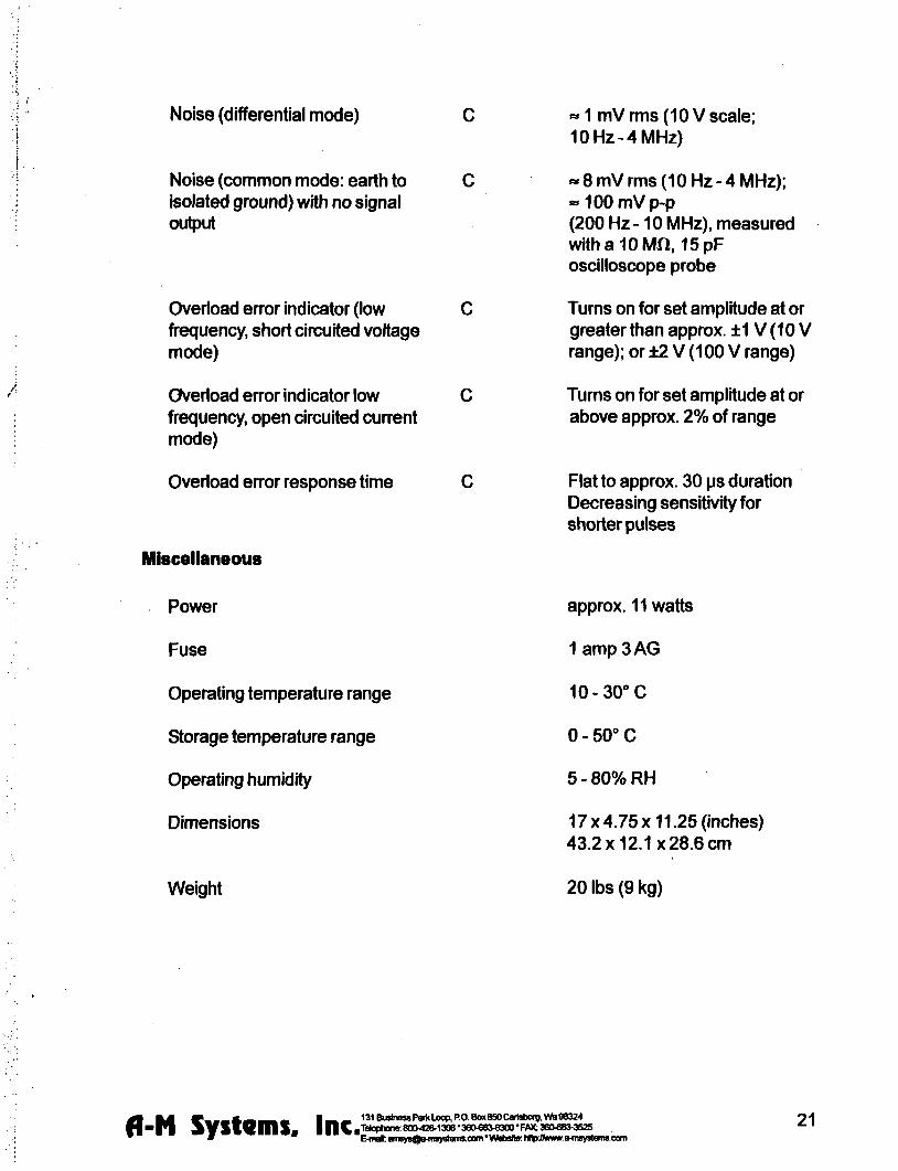
Noise (differential mode)
Noise (common mode earth to isolated ground) with no signal output
Overioad error indicator (low frequency short circuited voltage mode)
Overioad error indicator low frequency open circuited current mode)
Overioad enor response time
Miscellaneous
Power
Fuse
Operating temperature range
Storage temperature range
Operating humidity
Dimensions
Weight
laquo1 mV rms (10 V scale 10Hz-4MHz)
laquo 8 mV rms (10 Hz-4 MHz) laquo100mVp-p (200 Hz -10 MHz) measured withalOMft 15pF oscilloscope probe
Turns on for set amplitude at or greater than approx plusmn1V (10 V range) or plusmn2 V (100 V range)
Turns on for set amplitude at or above approx 2 of range
Flat to approx 30 ps duration Decreasing sensitivity for shorter pulses
approx 11 watts
1 amp 3 AG
10-30C
0 - 50deg C
5-80RH
17x475x1125 (Inches) 432x121x286 cm
20 lbs (9 kg)
fl mm bull gt _ _ _ A ^ ^ _ _ L ^ 131BusinesraquoPariltLocpPOBox850C8rtsborgWS9e324
bull p i ^ y s v e m s IIIC^^deg(^deg^Bdegltgt^^^3degdeg^deg^^deg^^^degdeg^^I^deg^deg^^^^^
21 E-mei flre^nQo 4n8yo(amscam Wsbsfle hHpAwwwe-msy8Jems-Oom
Warranty and Service
What does this warranty cover A-M Systems Inc warrants to the Purchaser that the Instrument excluding cables Headstage Probes and any other accessories shipped with the Instrument (hereafter the hardware) is free from defects in workmanship or material under normal use and service for the period of one (1) year This warranty commences on the date of delivery of the hardware to the Purchaser
What are the obligations of A-M Systems Inc under this warranty During the warranty period A-M Systems Inc agrees to repair or replace at its sole option without charge to the Purchaser any defective component part of the hardware To obtain warranty service the Purchaser must return the hardware to A-M Systems Inc or an authorized A-M Systems Inc distributor in an adequate shipping container Any postage shipping and insurance charges incurred in shipping the hardware to A-M Systems Inc must be prepaid by the Purchaser and all risk for the hardware shall remain with purchaser until such time as A-M Systems Inc takes receipt of the hardware Upon receipt A-M Systems Inc will promptly repair or replace the defective unit and then return the hardware to the Purchaser postage shipping and insurance prepaid A-M Systems Inc may use reconditioned or like new parts or units at its sole option when repairing any hardware Repaired products shall carry the same amount of outstanding wan^nty as from original purchase or ninety (90) days which ever is greater Any claim under the warranty must include a dated proof of purchase of the hardware covered by this wan-anty In any event A-M Systems Inc liability for defective hardware is limited to repairing or replacing the hardware
What is not covered by this warranty This warranty is contingent upon proper use and maintenance of the hardware by the Purchaser and does not cover batteries Neglect misuse whether intentional or otherwise tampering with or altering the hardware damage caused by accident damage caused by unusual physical electrical chemical or electromechanical stress damage caused by failure of electrical power or damage caused during transportation are not covered by this warranty Products may not be returned to A-M Systems Inc for service whether under warranty or otherwise which are contaminated by infectious agents radioactive compounds or other materials constituting a health hazard to employees of A-M Systems Inc
What are the limits of llabiiity for A-M Systems inc under this warranty A-M Systems Inc shall not be liable for loss of data profits or savings or any special incidental consequential indirect or other similar damages arising from breach of contract negligence or other legal action even if the company or its agent has been advised of the possibility of such damages or for any claim brought against you by another party THIS EQUIPMENT IS NOT INTENDED FOR CLINICAL MEASUREMENTS USING HUMAN SUBJECTS A-M SYSTEMS INC DOES NOT ASSUME RESPONSIBILITY FOR INJURY OR DAMAGE DUE TO MISUSE OF THIS EQUIPMENT Jurisdictions vary with regard to the enforceability of provisions excluding or limiting liability for incidental or consequential damages Check the provision of your local jurisdiction to find out whether the above exclusion applies to you This warranty allocates risks of product failure between the Purchaser and A-M Systems Inc A-M Systems Inc hardware pricing reflects this allocation of risk and the limitations of liability contained in this wanranty The warranty set forth above is in lieu of all other express wan^anties whether oral or written The agents employees distributors and dealers of A-M Systems Inc are not authorized to make modifications to this wan-anty or additional wan-anties binding on the company Accordingly additional statements such as dealer advertising or presentations whether oral or written do not constitute wananties by A-M Systems Inc and should not be relied upon This warranty gives you specific legal rights You may also have other rights whrch vary from one jurisdiction to another
6 mm ^ laquo _ _ A a B ^ _ 1 ^ ^ 131 Business Parti Loop PO Box 850 Cartsborg W B 98324 O O
bull P l A y S V e m S l n C T^M 8OO42OI3O6 380683-8300FAX 360 803525 ^ ^ E-msl iiiisy80iHTBy8tenisoom Wsbsito hnphwwfrimysleiiisoom
A
V ISO
INSTRUCTION MANUAL
FOR
ISOLATED PULSE STIMULATOR
MODEL 2100
Serial
Date
A-M Systems Inc
PO Box 850
Carlsborg WA 98324
USA
360-683-8300 bull 800-426-1306 FAX 360-683-3525
httpwwwa-msystemscom
Version 70 February 2002
Contents General Description 1
Instrument Features 1 Controls and Connectors 2
Operating Instructions 6 Theory of Operation 10 Calibration Procedures 12
Inputs 14 Output Calibration 16
Specifications 19 Warranty and Service 22
Each Isolated Pulse Stimulator is delivered complete with
Rack Mount Hardware Instructions amp Maintenance Manual
NOTE
This instrument is not intended for clinical measurements using human subjects A-M Systems Inc does not assume responsibility for Injury or damage due to the misuse of this instrument
General Description
Instrument Features The Isolated Pulse Stimulator Model 2100 is designed for a wide variety of applications It is highly flexible being capable of delivering single pulses biphasic pairs or bursts of pulses Pulses may be started manually or upon receiving a trigger signal from another Instrument or computer Two non-isolated trigger outputs are available for triggering other instruments
Four sets of timing controls provide comprehensive control overall aspects of pulse generation Three digit accuracy is available over a 7 decade range for each timing function using lever wheel switches Pulse widths can be set over more than a 9 decade range from 05 ps to 999 seconds Timing accuracy is assured through the use of a 10 MHz base rate crystal-controlled clock digitally divided to provide accurate timing over the entire range Atiming overiap indicator will light If the timing controls are set inconsistently
The output may be conveniently switched between current and voltage modes Pulse and baseline amplitudes are Independently presettable with lockable dials An error Indicator will light if the Mode2700 cannot deliver the desired signal
r WARNING
The Model 2100 can produce potentially dangerous voltages up to 100 V at the output connectors The isolated output is not connected internally to safety (earth) ground in any way Some part of the extemal circuit should be connected to safety ground Use caution in handling any wires connectors or electrodes which may be directly or indirectly attached to the Model 2100 output Some kinds of connectors such as BNC connectors have exposed metal parts which may float at dangerous potentials unless extemally connected to safety ground For greatest safety tum the Model 2100 off before making any connections to
the instrument
131 Business Parii Loop PO Box 850 Cartsborg Wa 98324 Telophone 800-426-1306 bull 360-68raquolaquo300 bull FAX 360683-3525 E-mal satesa-msystemsoom VVfebsite httpywwwa^nsystemscom fl-N Systems Inc 1
Controls and Connectors The controls for the Model 2100 are grouped in three sections START which controls when a pulse or burst of pulses begins TIMING which controls the onoff timing of one or more pulses and OUTPUT which controls the amplitude of the output signal
Start TRIG SLOPE Determines the polarity of valid trigger pulses (positive or negative edges in the trigger signal)
MODE Controls waveform initiation When set to FREE RUN one timing cycle immediately follows the last When momentarily placed In the MANUAL position a timing cycle starts Immediately When the switch Is In the center position timing cycles start when valid triggering events occur
TRIGD This LED lights up when a timing cycle Is in process and continues until the burst is completed
TRIG This BNC connector allows a signal from an external source to Initiate timing cycles It is set for standard TTL levels
GATE This BNC connector allows a signal from an external source to restrict the final output signal This input must be at a logical high (or open-circuited) in order for the Model 2100 to recognize either manual or automatic trigger events
Gate 1_ Trigger |~~^ i I Valid triggers (represented by the arrows in the figure) can occur only when the gate Is at logical high Note that the up arrow would apply only If TRIG SLOPE is set to + the down an-ows would apply only if TRIG SLOPE Is set to -
NOTE Triggers have no effect if the system has not completed its response to a previous trigger
fl-N Systems Inc 131 Business Park Loop PO Box 850 Cartsborg Vb 98324 TelQphQne 80O426-1306 360683-8300 FAX 360683-3525 E-mail sales^a-msystemscom Wsbsite httpywwwa-msystemscom
Timing Four sets of controls govern the timing of pulse generation Each set contains two values which are multiplied together to detemnine the actual timing value The rotary knob (rate selector) provides the approximate timing value and the lever wheel switch bank (MULTIPLIER)
provides a time resolution of three decimal digits The following diagram shows most of the Important relationships
Output r Delay Duration
|ltPeriodgtj
t Burst width
Trigger event
DELAY These controls determine the time duration between the initiating trigger event and the beginning of the pulse burst If this rate selector is set to NONE or the multiplier is set to 000 there Is no delay
BURST WIDTH These controls determine the time period in which one or more pulses may be delivered Once started a pulse may outlast the burst width If this rate selector is set to SINGLE or to any time shorter than the pulse duration only a single pulse will occur If the BURST WIDTH Is longer than the period pulses will be emitted at the PERIOD rate until the burst time ends Pulses are never truncated by a short BURSTWIDTH
inds)-PULSE
D U R A T I O N 1 0 1 0
10
INTEB-PULSE PERIOD
1 1 10
DURATION These controls determine the length of each pulse Ifthis rate selector Is set to SQUARE the duration is set to half of the period regardless of the MULTIPLIER setting
PERIOD These controls set the period of time between adjacent pulse events within the burst It also forces a minimum dead time between recognized input triggers following a burst of one or more pulses This can be used to prevent over stimulation of a tissue without requiring excessive delay between the triggering event and the stimulating pulse
TIMING OVERLAP
fl-N Systems Inc 131 Business Parti Loop RO Box 860 Carisborg Vamp 98324 |Telophone 800-426-1306 360683-8300 bull FAX 3606aW525 E-mail salearega^nsystemsoom Vfeb5ite httpAwwwa^nsyslemscam
NOTE If any of these timing controls are changed while a timing cycle is in operation the results are undefined until the current cycle finishes
TIMING OVERLAP This LED will light to Indicate an inconsistency in the timing cycle settings There are several ways to introduce such errors The most common way is to set the Inter-pulse PERIOD to be less than the pulse DURATION
T I M I N G (seconds)^
TRIG OUT (UPPER) This BNC connector provides a signal which is coincident with the Internal Burst timing signal (default) This means the signal starts at the end of the Delay time and persists until the Burst time expires This output may also be set to represent the delay time-out by setting the internal jumper J510 to the right two pins instead of the left two pins (Please see the Calibration section in this manual for jumper location Directions are given as viewed from the front of the Instrument)
TRIG OUT (LOWER) This BNC connector provides a signal which Is coincident with the Duration timing signal which controls pulse output
NOTE Both trigger output signals slightly lead the isolated output signal
Output
PULSE SIGN This switch determines the polarity of the pulses to be generated It also allows generation of biphasic pulses thereby doubling the effective total period Warning the first pulse generated after changing the PULSE
SIGN switch may have the wrong polarity
BASELINE This Switch determines the polarity ofthe baseline signal
RANGE This rotary switch determines if the output pulses will be constant current (3 ranges) or constant voltage (2 ranges)
BASELINE AMPLITUDE This value is independently set using a ten-turn counting dial The maximum baseline amplitude is one tenth the value shown on the range amplitude switch
fl-N Systems Inc 131 Business Parti Loop RO Box 8S0 Cartsborg Vfa 98324 |Tetaphone 80O426-1306 bull 360683-8300 bull FAX 3606803525 E-mail salesa-msystemscom Wbbsite http7Awwwaflnsystemscom
PULSE AMPLITUDE This value is independently set using a ten-turn counting dial The maximum pulse amplitude is the value shown on the range amplitude switch
EVENT This LED indicates when a pulse is ongoing
ERROR This LED indicates when the internal output amplifier cannot output the pulse as desired This is usually due to a short circuit while trying to output a voltage or an open circuit while trying to output a current
VOTEThe Pulse Sign control in the Oupuf section directly affects waveform timing When set to the Biphasic mode a positive-going pulse is immediately followed by a negative-going pulse This effectively doubles the pulse duration If a burst of biphasic pulses is being produced the period must be at least twice the single pulse duration In the Square wave mode the baseline disappears as long as the burst persists
fl-N Systems Inc 131 Business Parti Loop RO Box 850 Cartsboig Vte 98324 |Telophone 800426-1306 360683-8300 bull FAX 3606833525 E-mail salesa-m5ystem5 com Website httpwwwa-msystemscom
Operating Instructions
Examples Simple setup (and minimal instrument test)
Connect the output ofthe Model 2100 to an oscilloscope Before connecting the Model 2100 to any other instrument or the experimental preparation It is safest to turn Its power off
Set the Oufpuf controls
Range 10V Pulse Sign +
Baseline Zero Pulse Amplitude 200
Setting The Timing Controls
Delay Burst Width
Duration Period
none single
15010-2 50010-2
Setting The Start Controls
Mode Free Run
Disconnect any cables to the TRIG or GATE inputs
Note that the green Trig and Event Indicators turn on as Free Run is turned on (and turn off otherwise) You should observe a 15ms duration 20Hz rate pulse of 200V above a OV baseline on the oscilloscope
fl-N Systems Inc 131 BusinessPartiLoop RO Box850CarisbcxgWa98324 |Telophone 800426-1306 bull 360-683-8300 bull FW 360683-3525 E-mail salesa-msystems com VVbbsite httpywwwa-msystems com
Demonstration of Burst Mode Connect the output ofthe Model 2100 to an oscilloscope Before connecting the Model 2100 to any other instrument or the experimental preparation It Is safest to turn its power off
Set the Outpuf controls
Range 10V Pulse Sign +
Baseline Pulse Amplitude 200
Baseline Amplitude 100
Setting The Timing Controls
Delay 88010-2 Burst Width 12010-^
Duration 15010-2 Period 50010-2
Set the START controls as follows
Mode Free Run
Disconnect any cables to the TRIG or GATE inputs
fl-N Systems Inc 131 Business Parti Loop RO Box 850 Cartsborg Wa 98324 Telophooe 8004201306 360683-8300 bull FAX 360683-3525 E^naii salesa-msystems com Watjsite http7wwwa-msystemscom
Trigger the oscilloscope from the Bursf trigger out (upper Trig Out connector) for a stable display In each burst (occurring every lOOms) you should observe a trio of 15ms duration starting 50ms apart Try switching the StartMode from Free Run to the center (nonnal) position The pulses will no longer be produced and the Trig and Event Indicators will tum off Pressing this switch once (to Manual) will cause a single burst to occur
Problem Solving If the instrument appears to be not working properiy check all ofthe control settings and connections Be sure to wait at least 5-10 seconds after turning the instrument off before turning it on again The following summary of typical problems for the user (along with the most common solutions) may help
Problem CauseSolution
EVENT Indicator never lights even in FREE RUN mode
bull Replace fuse check power connection bullSet DELAY or PERIOD to a shorter interval
bull Power-on too soon after power-off
OVERLAP Indicator is on
ERROR indicator is on
bull Set DURATION gt000 bull DURATION Is set to SQUARE but
PERIOD is 000 Increase PERIOD or set DURATION independantly
bull BURST and WIDTH are gt DURATION increase PERIOD or decrease DURATION
bull BIPHASIC pulse output Is on and PERIOD is not longer than twice the DURATION Increase PERIOD or decrease DURATION
bull Free-run Is on and BURST is lt PERIOD (BURST off) DELAY is 0 and PERIOD Is lt DURATION Add delay or modify PERIOD
bull Free-run is on and BURST is gt DURATION (BURST ON) and PERIOD is lt DURATION Increase PERIOD
bull For VOLTAGE outputs the output is trying to drive too low a resistance or capacitance (eg a short circuit) Check by disconnecting the output ft is possible (and normal) that for the fastest cycles and largest amplitudes (close to 100 V
fl-N Systems Inc 131 Business PartiLoop PO Box 850 CartsborgWa 98324 iTelophone 800-42O130636O6e3-8300FAX 3606B3-3525 E-mail satesaflisyslefmcom Vfebslte http7wwwa-msyslemscom
and 1 ps) that the ERROR indicator might always come on during repetitive pulses Fix output load or decrease amplitude as required
Time appears to be excessive Changed control in mid-cycle (resets current status)
Cant seem to get a full signal out Load Is not properiy connected repair wiring Too low a load impedance (VOLTAGE modes) or too high a load impedance (CURRENT mode)
Incoming triggers not accepted frequently enough
PERIOD is set too long (enforces dead time) followd by BURST set to SIGNAL Reduce PERIOD time
Table 10 Problem Solving
If you suspect that the Model 2100 may have completely failed we recommend checking the basic level of functionality Ifthis fails your instrument Is defective and must be repaired Ifthis passes either your experimental setup is incompatible or inconsistent or there is a more subtle flaw in your Model 2100
If the Model 2100 appears to be malfunctioning contact A-M Systems Inc or your dealer We will first attempt to solve the problem over the telephone so have an exact description of your problem available when you call You do not need to be within the warranty period to obtain over-the-phone assistance
fl-N Systems Inc 131 Business Parti Loop RO Box 850 Cartsborg Wa 98324 iTetoptxme 80O426-1306 bull 360683-8300 FAX 3606803525 E-mail satesa-msystemsoomAfebsitehttpJwwwaflisystemscom
Theory of Operation
The operation ofthe Model 2100 is summarized in the block diagram (see the figure on Page 11) Not shown are all ofthe interconnections with the microcontroller The internal microcontroler plays an important role in setting the signal path but does not directly contribute to the dynamic characteristics It scans the front panel switches and sets the control values for the logic arrays It programs the internal counters which along with the other hardware achieve the necessary sub-microsecond speeds
Pulse generation starts either from an Input trigger signal (from Trig In) or an internally signal (Free Run mode) A Delay timer counts the 10MHz clock until its count value is exhausted At this point the Burst Period and Duration timers are started If the Burst timer has not expired by the end ofthe Period the Period and Duration timers are restarted If the Biphasic mode has been set the Duration timer is restarted at the end of the initial Duration and the sign ofthe output pulse is reversed doubling the total duration
The system state (pulse on pulse sign baseline sign [+0f-]) is transmitted to the isolated section via optoisolator The baseline and pulse amplitudes are selected by an analog switch The resulting signal is amplified by a variable-power-supply discrete operational amplifier The amplifier connections and gain is modified to provide two voltage and three current ranges
Timing overiap errors are detected by a logical decision computation rather than by testing for counter collisions This provides instant feedback rather than waiting up to an hour for such a collision to occur Output errors are measured by sensing the output amplifiers differential input voltage Under normal conditions this is a negligible voltage If the amplifier fails to deliver the requested signal the window comparator testing this voltage sends this message (via optoisolator) to the logic section turning on a warning LED
fl-N Systems Inc 131BusinessPart(LoopRO Box850CarisboigWa98324 4 n Tel0pri0ne80O426-130636O683^300FAX36O6833525 ^ E-mail salesaflisystBmscom V febsite http7wwwa-msystemsoom
S i
I - - ^^mdasho^M
OUTPUT i l l
TRIG ^ OUT
(burst)
TRIG 3-lt) OUT
(pulse)
til
I laquo
Calibration Procedures
The calibration interval is the lesser of 1000 hours of operation or 6 months Somewhat greater drift can be expected in the first 100 hours of operation as the semiconductors age Adjustments should only be made after the instrument has been fully warmed up for at least 15 minutes
Full instrument calibration requires the following test equipment digital multimeter (plusmn 01) able to measure resistance to at least lOOMO oscilloscope with at least 50MHz bandwidth true-mis voltmeter with 4MHz bandwidth universal counter (plusmn 001 ) able to measure single pulse widths and periods resistors (all plusmn 01) 2kn lOkH 1 watt 20kn 200kn alligator clip lead sets banana plugs and BNC adapters
Adjustment integrated circuit and test point locations are shown in the following figures All adjustments are on the timing board unless othenAise noted
All voltages in the non-isolated section should be measured with respect to ground at TP510 unless othenwise stated Some voltages are measured with respect to an internal isolated ground at TP650 or across the two output temninals Occasionally the voltage at an IC pin must be measured in these cases the reference designator is given with the pin number in parentheses eg U602(16) When it states within this procedure that a voltage is to be minimized this means that the adjustment should be made such that the measured voltage is as close to zero volts as possible Refer to the Specifications Section of this manual for acceptable tolerances
The sequence of this procedure is important If any adjustment is made all adjustments which follow must be made to ensure that the specifications will be met These procedures require that all controls remain as set in previous steps unless othenAise indicated
WARNING
The Model 2100 has dangerous voltages throughout the instrument even with the power is off Servicing the Model 2100 should only be done by qualified service personnel Use caution in handling any wires connectors or electrodes which may be directly or indirectly attached to the instrument Do not touch exposed connections or components Disconnect power by unplugging the power cord from the receptacle
H B ^ ^ S y s t e m s inc^degdegp^deg^^deg-^^^^^^^^B3^^^degdeg^^^lt^^^B^^^^ 131BusinessPartiLoopPO Box850CartsbOigWamp98324 4 9 |Telophone800-42013C6360683-8300F0lt360683-3525 ^ E-mail salesa-msystefnscom website httpwwwaflisystems com
CO
TP501 O lt0
g OTPSOO
U560 S
Trig Gate
0 -TISOS
U570
U500
Timing
p U520
Timing
K U550 Timin
gt U540
U515
o X I Timin
U508 I
J510 Timing nnn
Burst Delay J400
gt U550
R503
D D I D bull U8QQ i Q
n
oo
V P 5 1 0
b U535
^
Clock i _
U555
lt U 5 4 5
o
h d ^ O - - ^ U605
Q D
U620
O fJZ^ R737 bull ^ 1^13015 r j C - C O M P
B B nU770 ^ ^ ^ 5 ^ a
J420
a
o E
bull [ ]U632
riueso
rR742rVhigh R 6 1 9 ^
LJ TP645 O TP650
TPMOQ^QS
Vlow
CD-
CZZl
J440 bull bull tl iUDQ
I t
f i l
Power supply and bias voltages
Power supply
Controls Inputs Observations Adjust Check
POWER ON Observe voltage at P703 power supply wire top of main board
Check for+15 plusmn 050 V
Observe voltage at P701 power supply wire top of main board
Check for-15 plusmn 050 V
Observe voltage at U505(24) Check for +5 plusmn 025 V
Isolated supply voltage Controls Inputs Observations AdjustCheck
RANGE 10 V TRIG open circuit MODE center position
Alternately observe V ^ from R742 to R740 and V ^ from theU605(4)toU605(8)
Adjust R773 so that 110VltV lt 120 V and
nigh
28VltV|^lt34V
Capacitance balance Controls Inputs Observations Adjust Check
Connect a xlO oscilloscope probe to TP650 and ground the
Adjust R737 for minimum high frequency signal
Inputs
Gate function Controls Inputs Observations AdjustCheck
Apply a 1 kHz 0 - 5 V triangle wave Verify that the voltage to GATE switches states at the Observe voltage at U510(3) proper input levels with an oscilloscope
Trigger slope Controls Inputs Observations AdjustCheck
Apply a 1 kHz 0 - 5 V triangle wave Verify that the voltage to TRIG switches states at the Observe voltage at U510( 1) proper input levels with an oscilloscope
TRIG SLOPE Verify voltage is 180deg out of phase
TRIG SLOPE Verify voltage is in phase
fl-N Systems Inc 131 Business Parti Loop RO Box 860 Cartsborg Wa 98324 Jelophone 800-4201306 360683-8300 bull FM 380683-3525 E-mail salesaflTsystBfnscom bull Vtebsite httpVAirwwaflisystems com
14
Trigger and gate f unc t i on
Controls Inputs Observations Adjust Check
DELAY NONE BURS-nMDTH SINGLE DURATION SQUARE PERIOD 100X10-3
Apply a 1 kHz 0 - 5 V triangle wave to TRIG Observe TRIGD and EVENT LEDs
TRIG disconnect all Short the GATE connector to GND Verify LEDs extinguish
MODE press to MANUAL Verify LEDs flash once
Timing
System c lock f requency
Controls Inputs Observations Ad jus t Check
Observe the frequency of the wave Verify 1000 MHz plusmn 001 atU555(17)
Mul t ip l iers (Wheel Swi tches)
Controls Inputs Observations Adjust Check
PULSE SIGN-laquobull MODE FREE RUN TRIG disconnect all TIMING MULTIPUERS all
wheels set to zero except the one being tested
TIMING OVERLAP ignore
Observe the pulse width with the counter at the location specified t)elow
Verify pulse width is correct for each wheel as it is tested independently
For each wheel of each MULTIPLIER test each position to verify that the pulse width is correct Observe the signal at the following locations DELAY U520(2) BURSTWIDTH U530(2) PERIOD U540(2) DURATION U550(2)
Rates (Rotary Swi tches)
Controls Inputs Observations Adjust Check
TIMING MULTIPUERS 001 Observe the pulse width with the TIMING RATES all rotary counter at the location specified
switches set to 10-4 below except the one being tested
Verify pulse width is correct for each rotary switch as it is tested independently
For each ofthe four rotary switches in TIMING test each position to verify that the pulse width is correct Observe the signal at the following locations DELAY U520(2) BURSTWIDTH U530(2) PERIOD U540(2) DURATION U550(2)
fl-N Systems Inc 131 Business Parti Loop PO Box 850 Cartsborg Wa 98324 iTetophone 8004201306 bull 360683-8300 bull FOC 3606803525 E-mail salesa-msystemscom Wbbsite httpJwwwaflTSystemscom
15
Trigger outputs
Controls Inputs Observations Adjust Check
Range 10V Pulse Amplitude 500 Delay 100 xlO^ Burst 100 x 10 ^ Duration 100x10-^ Period 400x10-^ Pulse sign + Trig Mode Free run Trig in open
Trigger the oscilloscope to the Burst Trig Out Observe it the Pulse Trig Out and the isolated output
Verify that the waveform consists of a burst of three 1ms-on3ms-off pulses The burst trigger should be synchronous with the burst the pulse trigger coincident with each pulse
Output Calibration
Isolation Resistance (check)
Controls Inputs Observations AdjustCheck
Trig Mode center position Trig In open
Measure the resistance between ground banana jack (front panel) and black banana jack of output with DMM
Resistance read gt 100MQ
Amplitude Switch Offset (R640)
Controls InputsObservations AdjustCheck
Baseline Zero Trig Mode center position Trig In Open
Measure the voltage at TP645 vs TP650 with the DMM
Adjust R640 (AmpI Sw Offset) for minimum voltage
Output Offset (R332 front panel board) Controls InputsObservations AdjustCheck
Baseline Zero Range 10V Trig Mode center position Trig In Open
Measure the voltage across the output with the DMM
Adjust R332 (Output offset) for minimum voltage
Positive Baseline Offeet (R607) Controls InputsObservations AdjustCheck
Baseline Sign + Baseline Amplitude
fully CCW (000) Range 10V Trig In open Trig Mode center position
Measure the voltage across the outputwiththeDMM
Adjust R602 (BSLN + offset) for minimum voltage
fl-N Systems Inc 131 BusBiess Parti Loop P O Box 850 Cartsborg Wa 98324 Telophone B00-42O1306 bull 360683-8300 bull FAX 3606803525 E-mail salesaflisystemscom V^tebsite httpy^vwwa-msystems com
16
Negative Baseline Offset (R619)
Controls InputsObservations AdjustCheck
Baseline Sign -Baseline Amplitude
fully CCW (000) Range 10V Trig In open Trig Mode center position
Measure the voltage across the outputwiththeDMM
Adjust R619 (BSLN + offset) for minimum voltage
Pulse Amplitude Adjust (R602)
Controls InputsObservations AdjustCheck
Trig Mode Free Mode Pulse Amplitude 1000 Timing Delay =none Burst =single Duration =1001 Period =00110-4 Pulse Sign -Trig In open Range 10V
Measure the voltage across the output with the DMM
The Overiap indicator should be on Adjust R602 (Max Level) for -10OOV out
Pulse Sign Gain (check)
Controls InputsObservations AdjustCheck
Trig Mode Free Mode Pulse Amplitude 1000 Timing Delay =none Burst =single Duration =100 1s Period =001 10-4s Trig In open Range 10V
Measure the voltage at the output with the DMM for the Pulse Sign at + and - positions
The absolute values ofthe voltages should differ by less than lOOmV
Baseline Amplitudes (check) Controls InputsObservations AdjustCheck
Range 100mA Trig Mode center position Baseline Amplitude fully CW (1000) Trig In open
Measure the voltage at the output with the DMM with Baseline Sign in + Zero and
- positions
Gain the matching of current levels at = and - positions and offset current in Zero position
fl-N Systems Inc 131 Business Parti Loop PO Box 850 Cartsboig Wa 98324 Telophone 800-4201306 360683-8300 FkX 3606803525 E-mail salesa-msystemscom website http^^wwaflisystemsccm
17
Output Range Amplitude and Drive (check) Controls InputsObservations AdjustCheck
Pulse Amplitude 1000 Pulse Sign + Trig Mode Free Run Timing Delay =none Burst =single Duration =1001 Period =10010-4 Trig In open
Load the output with a 10KV 1W 01 resistor Measure the voltage at the output with DMM
Verify that full scale output is within specification Scale Range 100V 100V 10V 10V 100mA IV 1mA 10V 10mA 100V
Pulse Sign and Short Circuit Protection (check) Controls InputsObservations AdjustCheck
Timing Delay =none Burst =single Duration =200 10-4 Period =00110-3 Baseline Zero Pulse Amplitude 25 Range 10V Trig Mode Free Run Trig In open
Measure the voltage at the output with the oscilloscope Check for Pulse Sign set to each of + - biphasic Watch for Error indicator when shorting the output
Verify that pulses of approx 25V amplitude (625V for biphasic mode) of the correct sign are produced every 10ms Short output in biphasic mode Output should return when opened
Output Transient Response (check) Controls InputsObservations AdjustCheck
Pulse Sign + Timing Delay =none Burst =single Duration =20010-4 Period =00110-3 Pulse Amplitude 250 Baseline Zero Trig Mode Free Mode Trig In open
Connect the oscilloscope to the output with a 310 attenuator probe Test both 10V and 100V ranges
Verify that overshoot and risetime meet specifications
fl-N Systems Inc 131 Business Parti Loop RO Box 850 Cartsborg Wa 98324 Telophone 8004201306 bull 3606808300 bull Flaquo( 360laquo83ltJ525 E-mail salesa-msystemsocm V^febsite http^wwwa-msystefnscom
18
Specifications
There are three classes of specifications Class A specifications tested in all units and are guaranteed Class B specifications are inherent in the design they are indirectly tested and are guaranteed Class C specifications are typical operating values which are occasionally tested- these are typical values given for your information but not guarshyanteed The class for each specification is noted in the center column ofthe following sections
Inputs Switching level
Hysteresis
Input equivalent circuit
Minimum duration (1 IL-level signal)
A
C
C
C
16 V(plusmn 02 V)
approx 50 mV
lOOKH to+5 in parallel with no more than 35pF
gt 50 ns
Open circuit condition B defaults to highon level
Timing and rate accuracy Rate selector steps
Timing multiplier steps
B
B
lOOpsto 100s in 7 steps
1 of rate selector step size Maximum value is 999 X the rate selector step size
Resolution B approx 01 ofthe maximum value
Timing error (second and later pulses after resetting controls)
B lt 002 of rate selector value + 015 ps
Timing error (first pulse after readjusting timing controls)
an additional 025 ps error may occur
Timing repeatability lt 001 setting + 20 ns (monophasic)
fl-N Systems Inc 131 Business Ram Loop RO Box 850 Cartsborg Vfa 98324 pTelophone 8004201306 bull 360683-8300 bull FAX 360683-3525
E-mail salesraquoflisystems com Wabsite httpJAnww afl isystems com
19
TRIG IN to OUTPUT delay (DELAY set to 0) output set to 2V
Timing jitter from TRIG IN to OUTPUT (for TTL trigger input with risetime lt10 ns)
Timing jitter from TRIG OUT (either BURST or PULSE) and OUTPUT
Trigger output to pulse output delay
Output characteristics Pulse level error (voltage mode open circuit current mode short circuit
Biphasic level difference IV + - V-1 2
Baseline level error (voltage mode open circuit current mode short circuit)
Risetime (25 V out)
Risetime (25 V out)
Transient response
A
A
A
Output impedance (voltage mode) C
Output impedance (current mode) C
Isolation resistance A
Isolation capacitance C
approx 05 ps for a load of no more than 10 KH in parallel with 50 pF
lt 125 ns (all rates except 100s) lt 125 ps (100s rate)
Less than 20 ns (all rates)
approx 350 ns
lt 03 of setting + 05 of r range (plus an additional 05 pA in 100 pA range)
lt 03 of range (voltage modes into open circuit current modes into short circuit)
lt 03 of setting of setting + 01 of range (plus an additional 05 pA in lOOpA range)
= 200 ns into less than 30 pF
= 15 ps into less than 30 pF
lt 8 overshoot into less than 30 pF for pulse voltages different than baseline voltage by at least 10 of range
= 50 ohms
raquo 1 0 GH (typically 200 GO)
raquo 1 0 0 M n
= 60 pF at 100 Hz
fl-N Systems Inc 131 Business Peril Loop PO Box 850 Cartsborg V6 98324 |TelCf)hone 800-4201306 3606808300 bull FAX 360683-3525 E-mal salesaflisystefnsoom Website hnpyMVfWafllsystemsoom
20
Noise (differential mode)
Noise (common mode earth to isolated ground) with no signal output
Overload error indicator (low frequency short circuited voltage mode)
Overload error indicator low frequency open circuited current mode)
Overioad error response time
Miscellaneous
= 1 mV rms (10 V scale 10 Hz-4 MHz)
= 8 mV rms (10 Hz-4 MHz) == 100mVp-p (200 Hz -10 MHz) measured withalOMH 15pF oscilloscope probe
Turns on for set amplitude at or greater than approx plusmn1 V (10 V range) or plusmn2 V (100 V range)
Turns on for set amplitude at or above approx 2 of range
Flat to approx 30 ps duration Decreasing sensitivity for shorter pulses
Power
Fuse
Operating temperature range
Storage temperature range
Operating humidity
Dimensions
approx 11 watts
1 amp 3AG
10-30degC
0 - 50deg C
5 - 80 RH
17x475x1125 (inches) 432x121x286 cm
Weight 20 lbs (9 kg)
fl-N Systems Inc 131 Business Parti Loop RO Box 850 Cartsborg Wb 98324 |Tetcphone 8004201306 3606808300 bull FOt 360683-3525 E-mail satesamsystems comV^febsite httpywwwaflisystemscom
21
Warranty and Service
What does this warranty cover A-M Systems Inc warrants to the Purchaser that the Instrument excluding cables Headstage Probes and any other accessories shipped with the Instrument (hereafter the hardware) is free from defects in workmanship or material under normal use and service for the period of one (1) year This warranty commences on the date of delivery ofthe hardware to the Purchaser
What are the obligations of A-M Systems Inc under this warranty During the warranty period A-M Systems Inc agrees to repair or replace at its sole option without charge to the Purchaser any defective component part of the hardware To obtain warranty service the Purchaser must return the hardware to A-M Systems Inc or an authorized A-M Systems Inc distributor in an adequate shipping container Any postage shipping and insurance charges incurred in shipping the hardware to A-M Systems Inc must be prepaid by the Purchaser and all risk for the hardware shall remain with purchaser until such time as A-M Systems Inc takes receipt of the hardware Upon receipt A-M Systems Inc will promptly repair or replace the defective unit and then return the hardware to the Purchaser postage shipping and insurance prepaid A-M Systems Inc may use reconditioned or like new parts or units at its sole option when repairing any hardware Repaired products shall carry the same amount of outstanding warranty as from original purchase or ninety (90) days which ever is greater Any claim under the warranty must include a dated proof of purchase ofthe hardware covered by this warranty In any event A-M Systems Inc liability for defective hardware is limited to repairing or replacing the hardware
What is not covered by this warranty This warranty is contingent upon proper use and maintenance ofthe hardware by the Purchaser and does not cover batteries Neglect misuse whether intentional or othenwise tampering with or altering the hardware damage caused by accident damage caused by unusual physical electrical chemical or electromechanical stress damage caused by failure of electrical power or damage caused during transportation are not covered by this wan-anty Products may not be returned to A-M Systems Inc for service whether under warranty or otherwise which are contaminated by infectious agents radioactive compounds or other materials constituting a health hazard to employees of A-M Systems Inc
What are the limits of liability for A-M Systems Inc under this warranty A-M Systems Inc shall not be liable for loss of data profits or savings or any special incidental consequential indirect or other similar damages arising from breach of contract negligence or other legal action even if the company or its agent has been advised of the possibility of such damages or for any claim brought against you by another party THIS EQUIPMENT IS NOT INTENDED FOR CLINICAL MEASUREMENTS USING HUMAN SUBJECTS A-M SYSTEMS INC DOES NOT ASSUME RESPONSIBILITY FOR INJURY OR DAMAGE DUE TO MISUSE OF THIS EQUIPMENT Jurisdictions vary with regard to the enforceability of provisions excluding or limiting liability for incidental or consequential damages Check the provision of your local jurisdiction to find out whether the above exclusion applies to you
This warranty allocates risks of product failure between the Purchaser and A-M Systems Inc A-M Systems Inc hardware pricing reflects this allocation of risk and the limitations of liability contained in this warranty The warranty set forth above is in lieu of all other express warranties whether oral or written The agents employees distributors and dealers of A-M Systems Inc are not authorized to make modifications to this warranty or additional wan-anties binding on the company Accordingly additional statements such as dealer advertising or presentations whether oral or written do not constitute warranties by A-M Systems Inc and should not be relied upon This warranty gives you specific legal rights You may also have other rights which vary from one jurisdiction to another
fl-N Systems Inc 131BusinessPartiLoop RO Box850CartsbOfgWa98324 p O |Telophone 8004201306 bull 360683-8300FOC 3606830525 ^ ^ E-mail saiesaflisystefTiscom Wbbsite httpVwwwa-msystemscom

Warranty and Service
What does this warranty cover A-M Systems Inc warrants to the Purchaser that the Instrument excluding cables Headstage Probes and any other accessories shipped with the Instrument (hereafter the hardware) is free from defects in workmanship or material under normal use and service for the period of one (1) year This warranty commences on the date of delivery of the hardware to the Purchaser
What are the obligations of A-M Systems Inc under this warranty During the warranty period A-M Systems Inc agrees to repair or replace at its sole option without charge to the Purchaser any defective component part of the hardware To obtain warranty service the Purchaser must return the hardware to A-M Systems Inc or an authorized A-M Systems Inc distributor in an adequate shipping container Any postage shipping and insurance charges incurred in shipping the hardware to A-M Systems Inc must be prepaid by the Purchaser and all risk for the hardware shall remain with purchaser until such time as A-M Systems Inc takes receipt of the hardware Upon receipt A-M Systems Inc will promptly repair or replace the defective unit and then return the hardware to the Purchaser postage shipping and insurance prepaid A-M Systems Inc may use reconditioned or like new parts or units at its sole option when repairing any hardware Repaired products shall carry the same amount of outstanding wan^nty as from original purchase or ninety (90) days which ever is greater Any claim under the warranty must include a dated proof of purchase of the hardware covered by this wan-anty In any event A-M Systems Inc liability for defective hardware is limited to repairing or replacing the hardware
What is not covered by this warranty This warranty is contingent upon proper use and maintenance of the hardware by the Purchaser and does not cover batteries Neglect misuse whether intentional or otherwise tampering with or altering the hardware damage caused by accident damage caused by unusual physical electrical chemical or electromechanical stress damage caused by failure of electrical power or damage caused during transportation are not covered by this warranty Products may not be returned to A-M Systems Inc for service whether under warranty or otherwise which are contaminated by infectious agents radioactive compounds or other materials constituting a health hazard to employees of A-M Systems Inc
What are the limits of llabiiity for A-M Systems inc under this warranty A-M Systems Inc shall not be liable for loss of data profits or savings or any special incidental consequential indirect or other similar damages arising from breach of contract negligence or other legal action even if the company or its agent has been advised of the possibility of such damages or for any claim brought against you by another party THIS EQUIPMENT IS NOT INTENDED FOR CLINICAL MEASUREMENTS USING HUMAN SUBJECTS A-M SYSTEMS INC DOES NOT ASSUME RESPONSIBILITY FOR INJURY OR DAMAGE DUE TO MISUSE OF THIS EQUIPMENT Jurisdictions vary with regard to the enforceability of provisions excluding or limiting liability for incidental or consequential damages Check the provision of your local jurisdiction to find out whether the above exclusion applies to you This warranty allocates risks of product failure between the Purchaser and A-M Systems Inc A-M Systems Inc hardware pricing reflects this allocation of risk and the limitations of liability contained in this wanranty The warranty set forth above is in lieu of all other express wan^anties whether oral or written The agents employees distributors and dealers of A-M Systems Inc are not authorized to make modifications to this wan-anty or additional wan-anties binding on the company Accordingly additional statements such as dealer advertising or presentations whether oral or written do not constitute wananties by A-M Systems Inc and should not be relied upon This warranty gives you specific legal rights You may also have other rights whrch vary from one jurisdiction to another
6 mm ^ laquo _ _ A a B ^ _ 1 ^ ^ 131 Business Parti Loop PO Box 850 Cartsborg W B 98324 O O
bull P l A y S V e m S l n C T^M 8OO42OI3O6 380683-8300FAX 360 803525 ^ ^ E-msl iiiisy80iHTBy8tenisoom Wsbsito hnphwwfrimysleiiisoom
A
V ISO
INSTRUCTION MANUAL
FOR
ISOLATED PULSE STIMULATOR
MODEL 2100
Serial
Date
A-M Systems Inc
PO Box 850
Carlsborg WA 98324
USA
360-683-8300 bull 800-426-1306 FAX 360-683-3525
httpwwwa-msystemscom
Version 70 February 2002
Contents General Description 1
Instrument Features 1 Controls and Connectors 2
Operating Instructions 6 Theory of Operation 10 Calibration Procedures 12
Inputs 14 Output Calibration 16
Specifications 19 Warranty and Service 22
Each Isolated Pulse Stimulator is delivered complete with
Rack Mount Hardware Instructions amp Maintenance Manual
NOTE
This instrument is not intended for clinical measurements using human subjects A-M Systems Inc does not assume responsibility for Injury or damage due to the misuse of this instrument
General Description
Instrument Features The Isolated Pulse Stimulator Model 2100 is designed for a wide variety of applications It is highly flexible being capable of delivering single pulses biphasic pairs or bursts of pulses Pulses may be started manually or upon receiving a trigger signal from another Instrument or computer Two non-isolated trigger outputs are available for triggering other instruments
Four sets of timing controls provide comprehensive control overall aspects of pulse generation Three digit accuracy is available over a 7 decade range for each timing function using lever wheel switches Pulse widths can be set over more than a 9 decade range from 05 ps to 999 seconds Timing accuracy is assured through the use of a 10 MHz base rate crystal-controlled clock digitally divided to provide accurate timing over the entire range Atiming overiap indicator will light If the timing controls are set inconsistently
The output may be conveniently switched between current and voltage modes Pulse and baseline amplitudes are Independently presettable with lockable dials An error Indicator will light if the Mode2700 cannot deliver the desired signal
r WARNING
The Model 2100 can produce potentially dangerous voltages up to 100 V at the output connectors The isolated output is not connected internally to safety (earth) ground in any way Some part of the extemal circuit should be connected to safety ground Use caution in handling any wires connectors or electrodes which may be directly or indirectly attached to the Model 2100 output Some kinds of connectors such as BNC connectors have exposed metal parts which may float at dangerous potentials unless extemally connected to safety ground For greatest safety tum the Model 2100 off before making any connections to
the instrument
131 Business Parii Loop PO Box 850 Cartsborg Wa 98324 Telophone 800-426-1306 bull 360-68raquolaquo300 bull FAX 360683-3525 E-mal satesa-msystemsoom VVfebsite httpywwwa^nsystemscom fl-N Systems Inc 1
Controls and Connectors The controls for the Model 2100 are grouped in three sections START which controls when a pulse or burst of pulses begins TIMING which controls the onoff timing of one or more pulses and OUTPUT which controls the amplitude of the output signal
Start TRIG SLOPE Determines the polarity of valid trigger pulses (positive or negative edges in the trigger signal)
MODE Controls waveform initiation When set to FREE RUN one timing cycle immediately follows the last When momentarily placed In the MANUAL position a timing cycle starts Immediately When the switch Is In the center position timing cycles start when valid triggering events occur
TRIGD This LED lights up when a timing cycle Is in process and continues until the burst is completed
TRIG This BNC connector allows a signal from an external source to Initiate timing cycles It is set for standard TTL levels
GATE This BNC connector allows a signal from an external source to restrict the final output signal This input must be at a logical high (or open-circuited) in order for the Model 2100 to recognize either manual or automatic trigger events
Gate 1_ Trigger |~~^ i I Valid triggers (represented by the arrows in the figure) can occur only when the gate Is at logical high Note that the up arrow would apply only If TRIG SLOPE is set to + the down an-ows would apply only if TRIG SLOPE Is set to -
NOTE Triggers have no effect if the system has not completed its response to a previous trigger
fl-N Systems Inc 131 Business Park Loop PO Box 850 Cartsborg Vb 98324 TelQphQne 80O426-1306 360683-8300 FAX 360683-3525 E-mail sales^a-msystemscom Wsbsite httpywwwa-msystemscom
Timing Four sets of controls govern the timing of pulse generation Each set contains two values which are multiplied together to detemnine the actual timing value The rotary knob (rate selector) provides the approximate timing value and the lever wheel switch bank (MULTIPLIER)
provides a time resolution of three decimal digits The following diagram shows most of the Important relationships
Output r Delay Duration
|ltPeriodgtj
t Burst width
Trigger event
DELAY These controls determine the time duration between the initiating trigger event and the beginning of the pulse burst If this rate selector is set to NONE or the multiplier is set to 000 there Is no delay
BURST WIDTH These controls determine the time period in which one or more pulses may be delivered Once started a pulse may outlast the burst width If this rate selector is set to SINGLE or to any time shorter than the pulse duration only a single pulse will occur If the BURST WIDTH Is longer than the period pulses will be emitted at the PERIOD rate until the burst time ends Pulses are never truncated by a short BURSTWIDTH
inds)-PULSE
D U R A T I O N 1 0 1 0
10
INTEB-PULSE PERIOD
1 1 10
DURATION These controls determine the length of each pulse Ifthis rate selector Is set to SQUARE the duration is set to half of the period regardless of the MULTIPLIER setting
PERIOD These controls set the period of time between adjacent pulse events within the burst It also forces a minimum dead time between recognized input triggers following a burst of one or more pulses This can be used to prevent over stimulation of a tissue without requiring excessive delay between the triggering event and the stimulating pulse
TIMING OVERLAP
fl-N Systems Inc 131 Business Parti Loop RO Box 860 Carisborg Vamp 98324 |Telophone 800-426-1306 360683-8300 bull FAX 3606aW525 E-mail salearega^nsystemsoom Vfeb5ite httpAwwwa^nsyslemscam
NOTE If any of these timing controls are changed while a timing cycle is in operation the results are undefined until the current cycle finishes
TIMING OVERLAP This LED will light to Indicate an inconsistency in the timing cycle settings There are several ways to introduce such errors The most common way is to set the Inter-pulse PERIOD to be less than the pulse DURATION
T I M I N G (seconds)^
TRIG OUT (UPPER) This BNC connector provides a signal which is coincident with the Internal Burst timing signal (default) This means the signal starts at the end of the Delay time and persists until the Burst time expires This output may also be set to represent the delay time-out by setting the internal jumper J510 to the right two pins instead of the left two pins (Please see the Calibration section in this manual for jumper location Directions are given as viewed from the front of the Instrument)
TRIG OUT (LOWER) This BNC connector provides a signal which Is coincident with the Duration timing signal which controls pulse output
NOTE Both trigger output signals slightly lead the isolated output signal
Output
PULSE SIGN This switch determines the polarity of the pulses to be generated It also allows generation of biphasic pulses thereby doubling the effective total period Warning the first pulse generated after changing the PULSE
SIGN switch may have the wrong polarity
BASELINE This Switch determines the polarity ofthe baseline signal
RANGE This rotary switch determines if the output pulses will be constant current (3 ranges) or constant voltage (2 ranges)
BASELINE AMPLITUDE This value is independently set using a ten-turn counting dial The maximum baseline amplitude is one tenth the value shown on the range amplitude switch
fl-N Systems Inc 131 Business Parti Loop RO Box 8S0 Cartsborg Vfa 98324 |Tetaphone 80O426-1306 bull 360683-8300 bull FAX 3606803525 E-mail salesa-msystemscom Wbbsite http7Awwwaflnsystemscom
PULSE AMPLITUDE This value is independently set using a ten-turn counting dial The maximum pulse amplitude is the value shown on the range amplitude switch
EVENT This LED indicates when a pulse is ongoing
ERROR This LED indicates when the internal output amplifier cannot output the pulse as desired This is usually due to a short circuit while trying to output a voltage or an open circuit while trying to output a current
VOTEThe Pulse Sign control in the Oupuf section directly affects waveform timing When set to the Biphasic mode a positive-going pulse is immediately followed by a negative-going pulse This effectively doubles the pulse duration If a burst of biphasic pulses is being produced the period must be at least twice the single pulse duration In the Square wave mode the baseline disappears as long as the burst persists
fl-N Systems Inc 131 Business Parti Loop RO Box 850 Cartsboig Vte 98324 |Telophone 800426-1306 360683-8300 bull FAX 3606833525 E-mail salesa-m5ystem5 com Website httpwwwa-msystemscom
Operating Instructions
Examples Simple setup (and minimal instrument test)
Connect the output ofthe Model 2100 to an oscilloscope Before connecting the Model 2100 to any other instrument or the experimental preparation It is safest to turn Its power off
Set the Oufpuf controls
Range 10V Pulse Sign +
Baseline Zero Pulse Amplitude 200
Setting The Timing Controls
Delay Burst Width
Duration Period
none single
15010-2 50010-2
Setting The Start Controls
Mode Free Run
Disconnect any cables to the TRIG or GATE inputs
Note that the green Trig and Event Indicators turn on as Free Run is turned on (and turn off otherwise) You should observe a 15ms duration 20Hz rate pulse of 200V above a OV baseline on the oscilloscope
fl-N Systems Inc 131 BusinessPartiLoop RO Box850CarisbcxgWa98324 |Telophone 800426-1306 bull 360-683-8300 bull FW 360683-3525 E-mail salesa-msystems com VVbbsite httpywwwa-msystems com
Demonstration of Burst Mode Connect the output ofthe Model 2100 to an oscilloscope Before connecting the Model 2100 to any other instrument or the experimental preparation It Is safest to turn its power off
Set the Outpuf controls
Range 10V Pulse Sign +
Baseline Pulse Amplitude 200
Baseline Amplitude 100
Setting The Timing Controls
Delay 88010-2 Burst Width 12010-^
Duration 15010-2 Period 50010-2
Set the START controls as follows
Mode Free Run
Disconnect any cables to the TRIG or GATE inputs
fl-N Systems Inc 131 Business Parti Loop RO Box 850 Cartsborg Wa 98324 Telophooe 8004201306 360683-8300 bull FAX 360683-3525 E^naii salesa-msystems com Watjsite http7wwwa-msystemscom
Trigger the oscilloscope from the Bursf trigger out (upper Trig Out connector) for a stable display In each burst (occurring every lOOms) you should observe a trio of 15ms duration starting 50ms apart Try switching the StartMode from Free Run to the center (nonnal) position The pulses will no longer be produced and the Trig and Event Indicators will tum off Pressing this switch once (to Manual) will cause a single burst to occur
Problem Solving If the instrument appears to be not working properiy check all ofthe control settings and connections Be sure to wait at least 5-10 seconds after turning the instrument off before turning it on again The following summary of typical problems for the user (along with the most common solutions) may help
Problem CauseSolution
EVENT Indicator never lights even in FREE RUN mode
bull Replace fuse check power connection bullSet DELAY or PERIOD to a shorter interval
bull Power-on too soon after power-off
OVERLAP Indicator is on
ERROR indicator is on
bull Set DURATION gt000 bull DURATION Is set to SQUARE but
PERIOD is 000 Increase PERIOD or set DURATION independantly
bull BURST and WIDTH are gt DURATION increase PERIOD or decrease DURATION
bull BIPHASIC pulse output Is on and PERIOD is not longer than twice the DURATION Increase PERIOD or decrease DURATION
bull Free-run Is on and BURST is lt PERIOD (BURST off) DELAY is 0 and PERIOD Is lt DURATION Add delay or modify PERIOD
bull Free-run is on and BURST is gt DURATION (BURST ON) and PERIOD is lt DURATION Increase PERIOD
bull For VOLTAGE outputs the output is trying to drive too low a resistance or capacitance (eg a short circuit) Check by disconnecting the output ft is possible (and normal) that for the fastest cycles and largest amplitudes (close to 100 V
fl-N Systems Inc 131 Business PartiLoop PO Box 850 CartsborgWa 98324 iTelophone 800-42O130636O6e3-8300FAX 3606B3-3525 E-mail satesaflisyslefmcom Vfebslte http7wwwa-msyslemscom
and 1 ps) that the ERROR indicator might always come on during repetitive pulses Fix output load or decrease amplitude as required
Time appears to be excessive Changed control in mid-cycle (resets current status)
Cant seem to get a full signal out Load Is not properiy connected repair wiring Too low a load impedance (VOLTAGE modes) or too high a load impedance (CURRENT mode)
Incoming triggers not accepted frequently enough
PERIOD is set too long (enforces dead time) followd by BURST set to SIGNAL Reduce PERIOD time
Table 10 Problem Solving
If you suspect that the Model 2100 may have completely failed we recommend checking the basic level of functionality Ifthis fails your instrument Is defective and must be repaired Ifthis passes either your experimental setup is incompatible or inconsistent or there is a more subtle flaw in your Model 2100
If the Model 2100 appears to be malfunctioning contact A-M Systems Inc or your dealer We will first attempt to solve the problem over the telephone so have an exact description of your problem available when you call You do not need to be within the warranty period to obtain over-the-phone assistance
fl-N Systems Inc 131 Business Parti Loop RO Box 850 Cartsborg Wa 98324 iTetoptxme 80O426-1306 bull 360683-8300 FAX 3606803525 E-mail satesa-msystemsoomAfebsitehttpJwwwaflisystemscom
Theory of Operation
The operation ofthe Model 2100 is summarized in the block diagram (see the figure on Page 11) Not shown are all ofthe interconnections with the microcontroller The internal microcontroler plays an important role in setting the signal path but does not directly contribute to the dynamic characteristics It scans the front panel switches and sets the control values for the logic arrays It programs the internal counters which along with the other hardware achieve the necessary sub-microsecond speeds
Pulse generation starts either from an Input trigger signal (from Trig In) or an internally signal (Free Run mode) A Delay timer counts the 10MHz clock until its count value is exhausted At this point the Burst Period and Duration timers are started If the Burst timer has not expired by the end ofthe Period the Period and Duration timers are restarted If the Biphasic mode has been set the Duration timer is restarted at the end of the initial Duration and the sign ofthe output pulse is reversed doubling the total duration
The system state (pulse on pulse sign baseline sign [+0f-]) is transmitted to the isolated section via optoisolator The baseline and pulse amplitudes are selected by an analog switch The resulting signal is amplified by a variable-power-supply discrete operational amplifier The amplifier connections and gain is modified to provide two voltage and three current ranges
Timing overiap errors are detected by a logical decision computation rather than by testing for counter collisions This provides instant feedback rather than waiting up to an hour for such a collision to occur Output errors are measured by sensing the output amplifiers differential input voltage Under normal conditions this is a negligible voltage If the amplifier fails to deliver the requested signal the window comparator testing this voltage sends this message (via optoisolator) to the logic section turning on a warning LED
fl-N Systems Inc 131BusinessPart(LoopRO Box850CarisboigWa98324 4 n Tel0pri0ne80O426-130636O683^300FAX36O6833525 ^ E-mail salesaflisystBmscom V febsite http7wwwa-msystemsoom
S i
I - - ^^mdasho^M
OUTPUT i l l
TRIG ^ OUT
(burst)
TRIG 3-lt) OUT
(pulse)
til
I laquo
Calibration Procedures
The calibration interval is the lesser of 1000 hours of operation or 6 months Somewhat greater drift can be expected in the first 100 hours of operation as the semiconductors age Adjustments should only be made after the instrument has been fully warmed up for at least 15 minutes
Full instrument calibration requires the following test equipment digital multimeter (plusmn 01) able to measure resistance to at least lOOMO oscilloscope with at least 50MHz bandwidth true-mis voltmeter with 4MHz bandwidth universal counter (plusmn 001 ) able to measure single pulse widths and periods resistors (all plusmn 01) 2kn lOkH 1 watt 20kn 200kn alligator clip lead sets banana plugs and BNC adapters
Adjustment integrated circuit and test point locations are shown in the following figures All adjustments are on the timing board unless othenAise noted
All voltages in the non-isolated section should be measured with respect to ground at TP510 unless othenwise stated Some voltages are measured with respect to an internal isolated ground at TP650 or across the two output temninals Occasionally the voltage at an IC pin must be measured in these cases the reference designator is given with the pin number in parentheses eg U602(16) When it states within this procedure that a voltage is to be minimized this means that the adjustment should be made such that the measured voltage is as close to zero volts as possible Refer to the Specifications Section of this manual for acceptable tolerances
The sequence of this procedure is important If any adjustment is made all adjustments which follow must be made to ensure that the specifications will be met These procedures require that all controls remain as set in previous steps unless othenAise indicated
WARNING
The Model 2100 has dangerous voltages throughout the instrument even with the power is off Servicing the Model 2100 should only be done by qualified service personnel Use caution in handling any wires connectors or electrodes which may be directly or indirectly attached to the instrument Do not touch exposed connections or components Disconnect power by unplugging the power cord from the receptacle
H B ^ ^ S y s t e m s inc^degdegp^deg^^deg-^^^^^^^^B3^^^degdeg^^^lt^^^B^^^^ 131BusinessPartiLoopPO Box850CartsbOigWamp98324 4 9 |Telophone800-42013C6360683-8300F0lt360683-3525 ^ E-mail salesa-msystefnscom website httpwwwaflisystems com
CO
TP501 O lt0
g OTPSOO
U560 S
Trig Gate
0 -TISOS
U570
U500
Timing
p U520
Timing
K U550 Timin
gt U540
U515
o X I Timin
U508 I
J510 Timing nnn
Burst Delay J400
gt U550
R503
D D I D bull U8QQ i Q
n
oo
V P 5 1 0
b U535
^
Clock i _
U555
lt U 5 4 5
o
h d ^ O - - ^ U605
Q D
U620
O fJZ^ R737 bull ^ 1^13015 r j C - C O M P
B B nU770 ^ ^ ^ 5 ^ a
J420
a
o E
bull [ ]U632
riueso
rR742rVhigh R 6 1 9 ^
LJ TP645 O TP650
TPMOQ^QS
Vlow
CD-
CZZl
J440 bull bull tl iUDQ
I t
f i l
Power supply and bias voltages
Power supply
Controls Inputs Observations Adjust Check
POWER ON Observe voltage at P703 power supply wire top of main board
Check for+15 plusmn 050 V
Observe voltage at P701 power supply wire top of main board
Check for-15 plusmn 050 V
Observe voltage at U505(24) Check for +5 plusmn 025 V
Isolated supply voltage Controls Inputs Observations AdjustCheck
RANGE 10 V TRIG open circuit MODE center position
Alternately observe V ^ from R742 to R740 and V ^ from theU605(4)toU605(8)
Adjust R773 so that 110VltV lt 120 V and
nigh
28VltV|^lt34V
Capacitance balance Controls Inputs Observations Adjust Check
Connect a xlO oscilloscope probe to TP650 and ground the
Adjust R737 for minimum high frequency signal
Inputs
Gate function Controls Inputs Observations AdjustCheck
Apply a 1 kHz 0 - 5 V triangle wave Verify that the voltage to GATE switches states at the Observe voltage at U510(3) proper input levels with an oscilloscope
Trigger slope Controls Inputs Observations AdjustCheck
Apply a 1 kHz 0 - 5 V triangle wave Verify that the voltage to TRIG switches states at the Observe voltage at U510( 1) proper input levels with an oscilloscope
TRIG SLOPE Verify voltage is 180deg out of phase
TRIG SLOPE Verify voltage is in phase
fl-N Systems Inc 131 Business Parti Loop RO Box 860 Cartsborg Wa 98324 Jelophone 800-4201306 360683-8300 bull FM 380683-3525 E-mail salesaflTsystBfnscom bull Vtebsite httpVAirwwaflisystems com
14
Trigger and gate f unc t i on
Controls Inputs Observations Adjust Check
DELAY NONE BURS-nMDTH SINGLE DURATION SQUARE PERIOD 100X10-3
Apply a 1 kHz 0 - 5 V triangle wave to TRIG Observe TRIGD and EVENT LEDs
TRIG disconnect all Short the GATE connector to GND Verify LEDs extinguish
MODE press to MANUAL Verify LEDs flash once
Timing
System c lock f requency
Controls Inputs Observations Ad jus t Check
Observe the frequency of the wave Verify 1000 MHz plusmn 001 atU555(17)
Mul t ip l iers (Wheel Swi tches)
Controls Inputs Observations Adjust Check
PULSE SIGN-laquobull MODE FREE RUN TRIG disconnect all TIMING MULTIPUERS all
wheels set to zero except the one being tested
TIMING OVERLAP ignore
Observe the pulse width with the counter at the location specified t)elow
Verify pulse width is correct for each wheel as it is tested independently
For each wheel of each MULTIPLIER test each position to verify that the pulse width is correct Observe the signal at the following locations DELAY U520(2) BURSTWIDTH U530(2) PERIOD U540(2) DURATION U550(2)
Rates (Rotary Swi tches)
Controls Inputs Observations Adjust Check
TIMING MULTIPUERS 001 Observe the pulse width with the TIMING RATES all rotary counter at the location specified
switches set to 10-4 below except the one being tested
Verify pulse width is correct for each rotary switch as it is tested independently
For each ofthe four rotary switches in TIMING test each position to verify that the pulse width is correct Observe the signal at the following locations DELAY U520(2) BURSTWIDTH U530(2) PERIOD U540(2) DURATION U550(2)
fl-N Systems Inc 131 Business Parti Loop PO Box 850 Cartsborg Wa 98324 iTetophone 8004201306 bull 360683-8300 bull FOC 3606803525 E-mail salesa-msystemscom Wbbsite httpJwwwaflTSystemscom
15
Trigger outputs
Controls Inputs Observations Adjust Check
Range 10V Pulse Amplitude 500 Delay 100 xlO^ Burst 100 x 10 ^ Duration 100x10-^ Period 400x10-^ Pulse sign + Trig Mode Free run Trig in open
Trigger the oscilloscope to the Burst Trig Out Observe it the Pulse Trig Out and the isolated output
Verify that the waveform consists of a burst of three 1ms-on3ms-off pulses The burst trigger should be synchronous with the burst the pulse trigger coincident with each pulse
Output Calibration
Isolation Resistance (check)
Controls Inputs Observations AdjustCheck
Trig Mode center position Trig In open
Measure the resistance between ground banana jack (front panel) and black banana jack of output with DMM
Resistance read gt 100MQ
Amplitude Switch Offset (R640)
Controls InputsObservations AdjustCheck
Baseline Zero Trig Mode center position Trig In Open
Measure the voltage at TP645 vs TP650 with the DMM
Adjust R640 (AmpI Sw Offset) for minimum voltage
Output Offset (R332 front panel board) Controls InputsObservations AdjustCheck
Baseline Zero Range 10V Trig Mode center position Trig In Open
Measure the voltage across the output with the DMM
Adjust R332 (Output offset) for minimum voltage
Positive Baseline Offeet (R607) Controls InputsObservations AdjustCheck
Baseline Sign + Baseline Amplitude
fully CCW (000) Range 10V Trig In open Trig Mode center position
Measure the voltage across the outputwiththeDMM
Adjust R602 (BSLN + offset) for minimum voltage
fl-N Systems Inc 131 BusBiess Parti Loop P O Box 850 Cartsborg Wa 98324 Telophone B00-42O1306 bull 360683-8300 bull FAX 3606803525 E-mail salesaflisystemscom V^tebsite httpy^vwwa-msystems com
16
Negative Baseline Offset (R619)
Controls InputsObservations AdjustCheck
Baseline Sign -Baseline Amplitude
fully CCW (000) Range 10V Trig In open Trig Mode center position
Measure the voltage across the outputwiththeDMM
Adjust R619 (BSLN + offset) for minimum voltage
Pulse Amplitude Adjust (R602)
Controls InputsObservations AdjustCheck
Trig Mode Free Mode Pulse Amplitude 1000 Timing Delay =none Burst =single Duration =1001 Period =00110-4 Pulse Sign -Trig In open Range 10V
Measure the voltage across the output with the DMM
The Overiap indicator should be on Adjust R602 (Max Level) for -10OOV out
Pulse Sign Gain (check)
Controls InputsObservations AdjustCheck
Trig Mode Free Mode Pulse Amplitude 1000 Timing Delay =none Burst =single Duration =100 1s Period =001 10-4s Trig In open Range 10V
Measure the voltage at the output with the DMM for the Pulse Sign at + and - positions
The absolute values ofthe voltages should differ by less than lOOmV
Baseline Amplitudes (check) Controls InputsObservations AdjustCheck
Range 100mA Trig Mode center position Baseline Amplitude fully CW (1000) Trig In open
Measure the voltage at the output with the DMM with Baseline Sign in + Zero and
- positions
Gain the matching of current levels at = and - positions and offset current in Zero position
fl-N Systems Inc 131 Business Parti Loop PO Box 850 Cartsboig Wa 98324 Telophone 800-4201306 360683-8300 FkX 3606803525 E-mail salesa-msystemscom website http^^wwaflisystemsccm
17
Output Range Amplitude and Drive (check) Controls InputsObservations AdjustCheck
Pulse Amplitude 1000 Pulse Sign + Trig Mode Free Run Timing Delay =none Burst =single Duration =1001 Period =10010-4 Trig In open
Load the output with a 10KV 1W 01 resistor Measure the voltage at the output with DMM
Verify that full scale output is within specification Scale Range 100V 100V 10V 10V 100mA IV 1mA 10V 10mA 100V
Pulse Sign and Short Circuit Protection (check) Controls InputsObservations AdjustCheck
Timing Delay =none Burst =single Duration =200 10-4 Period =00110-3 Baseline Zero Pulse Amplitude 25 Range 10V Trig Mode Free Run Trig In open
Measure the voltage at the output with the oscilloscope Check for Pulse Sign set to each of + - biphasic Watch for Error indicator when shorting the output
Verify that pulses of approx 25V amplitude (625V for biphasic mode) of the correct sign are produced every 10ms Short output in biphasic mode Output should return when opened
Output Transient Response (check) Controls InputsObservations AdjustCheck
Pulse Sign + Timing Delay =none Burst =single Duration =20010-4 Period =00110-3 Pulse Amplitude 250 Baseline Zero Trig Mode Free Mode Trig In open
Connect the oscilloscope to the output with a 310 attenuator probe Test both 10V and 100V ranges
Verify that overshoot and risetime meet specifications
fl-N Systems Inc 131 Business Parti Loop RO Box 850 Cartsborg Wa 98324 Telophone 8004201306 bull 3606808300 bull Flaquo( 360laquo83ltJ525 E-mail salesa-msystemsocm V^febsite http^wwwa-msystefnscom
18
Specifications
There are three classes of specifications Class A specifications tested in all units and are guaranteed Class B specifications are inherent in the design they are indirectly tested and are guaranteed Class C specifications are typical operating values which are occasionally tested- these are typical values given for your information but not guarshyanteed The class for each specification is noted in the center column ofthe following sections
Inputs Switching level
Hysteresis
Input equivalent circuit
Minimum duration (1 IL-level signal)
A
C
C
C
16 V(plusmn 02 V)
approx 50 mV
lOOKH to+5 in parallel with no more than 35pF
gt 50 ns
Open circuit condition B defaults to highon level
Timing and rate accuracy Rate selector steps
Timing multiplier steps
B
B
lOOpsto 100s in 7 steps
1 of rate selector step size Maximum value is 999 X the rate selector step size
Resolution B approx 01 ofthe maximum value
Timing error (second and later pulses after resetting controls)
B lt 002 of rate selector value + 015 ps
Timing error (first pulse after readjusting timing controls)
an additional 025 ps error may occur
Timing repeatability lt 001 setting + 20 ns (monophasic)
fl-N Systems Inc 131 Business Ram Loop RO Box 850 Cartsborg Vfa 98324 pTelophone 8004201306 bull 360683-8300 bull FAX 360683-3525
E-mail salesraquoflisystems com Wabsite httpJAnww afl isystems com
19
TRIG IN to OUTPUT delay (DELAY set to 0) output set to 2V
Timing jitter from TRIG IN to OUTPUT (for TTL trigger input with risetime lt10 ns)
Timing jitter from TRIG OUT (either BURST or PULSE) and OUTPUT
Trigger output to pulse output delay
Output characteristics Pulse level error (voltage mode open circuit current mode short circuit
Biphasic level difference IV + - V-1 2
Baseline level error (voltage mode open circuit current mode short circuit)
Risetime (25 V out)
Risetime (25 V out)
Transient response
A
A
A
Output impedance (voltage mode) C
Output impedance (current mode) C
Isolation resistance A
Isolation capacitance C
approx 05 ps for a load of no more than 10 KH in parallel with 50 pF
lt 125 ns (all rates except 100s) lt 125 ps (100s rate)
Less than 20 ns (all rates)
approx 350 ns
lt 03 of setting + 05 of r range (plus an additional 05 pA in 100 pA range)
lt 03 of range (voltage modes into open circuit current modes into short circuit)
lt 03 of setting of setting + 01 of range (plus an additional 05 pA in lOOpA range)
= 200 ns into less than 30 pF
= 15 ps into less than 30 pF
lt 8 overshoot into less than 30 pF for pulse voltages different than baseline voltage by at least 10 of range
= 50 ohms
raquo 1 0 GH (typically 200 GO)
raquo 1 0 0 M n
= 60 pF at 100 Hz
fl-N Systems Inc 131 Business Peril Loop PO Box 850 Cartsborg V6 98324 |TelCf)hone 800-4201306 3606808300 bull FAX 360683-3525 E-mal salesaflisystefnsoom Website hnpyMVfWafllsystemsoom
20
Noise (differential mode)
Noise (common mode earth to isolated ground) with no signal output
Overload error indicator (low frequency short circuited voltage mode)
Overload error indicator low frequency open circuited current mode)
Overioad error response time
Miscellaneous
= 1 mV rms (10 V scale 10 Hz-4 MHz)
= 8 mV rms (10 Hz-4 MHz) == 100mVp-p (200 Hz -10 MHz) measured withalOMH 15pF oscilloscope probe
Turns on for set amplitude at or greater than approx plusmn1 V (10 V range) or plusmn2 V (100 V range)
Turns on for set amplitude at or above approx 2 of range
Flat to approx 30 ps duration Decreasing sensitivity for shorter pulses
Power
Fuse
Operating temperature range
Storage temperature range
Operating humidity
Dimensions
approx 11 watts
1 amp 3AG
10-30degC
0 - 50deg C
5 - 80 RH
17x475x1125 (inches) 432x121x286 cm
Weight 20 lbs (9 kg)
fl-N Systems Inc 131 Business Parti Loop RO Box 850 Cartsborg Wb 98324 |Tetcphone 8004201306 3606808300 bull FOt 360683-3525 E-mail satesamsystems comV^febsite httpywwwaflisystemscom
21
Warranty and Service
What does this warranty cover A-M Systems Inc warrants to the Purchaser that the Instrument excluding cables Headstage Probes and any other accessories shipped with the Instrument (hereafter the hardware) is free from defects in workmanship or material under normal use and service for the period of one (1) year This warranty commences on the date of delivery ofthe hardware to the Purchaser
What are the obligations of A-M Systems Inc under this warranty During the warranty period A-M Systems Inc agrees to repair or replace at its sole option without charge to the Purchaser any defective component part of the hardware To obtain warranty service the Purchaser must return the hardware to A-M Systems Inc or an authorized A-M Systems Inc distributor in an adequate shipping container Any postage shipping and insurance charges incurred in shipping the hardware to A-M Systems Inc must be prepaid by the Purchaser and all risk for the hardware shall remain with purchaser until such time as A-M Systems Inc takes receipt of the hardware Upon receipt A-M Systems Inc will promptly repair or replace the defective unit and then return the hardware to the Purchaser postage shipping and insurance prepaid A-M Systems Inc may use reconditioned or like new parts or units at its sole option when repairing any hardware Repaired products shall carry the same amount of outstanding warranty as from original purchase or ninety (90) days which ever is greater Any claim under the warranty must include a dated proof of purchase ofthe hardware covered by this warranty In any event A-M Systems Inc liability for defective hardware is limited to repairing or replacing the hardware
What is not covered by this warranty This warranty is contingent upon proper use and maintenance ofthe hardware by the Purchaser and does not cover batteries Neglect misuse whether intentional or othenwise tampering with or altering the hardware damage caused by accident damage caused by unusual physical electrical chemical or electromechanical stress damage caused by failure of electrical power or damage caused during transportation are not covered by this wan-anty Products may not be returned to A-M Systems Inc for service whether under warranty or otherwise which are contaminated by infectious agents radioactive compounds or other materials constituting a health hazard to employees of A-M Systems Inc
What are the limits of liability for A-M Systems Inc under this warranty A-M Systems Inc shall not be liable for loss of data profits or savings or any special incidental consequential indirect or other similar damages arising from breach of contract negligence or other legal action even if the company or its agent has been advised of the possibility of such damages or for any claim brought against you by another party THIS EQUIPMENT IS NOT INTENDED FOR CLINICAL MEASUREMENTS USING HUMAN SUBJECTS A-M SYSTEMS INC DOES NOT ASSUME RESPONSIBILITY FOR INJURY OR DAMAGE DUE TO MISUSE OF THIS EQUIPMENT Jurisdictions vary with regard to the enforceability of provisions excluding or limiting liability for incidental or consequential damages Check the provision of your local jurisdiction to find out whether the above exclusion applies to you
This warranty allocates risks of product failure between the Purchaser and A-M Systems Inc A-M Systems Inc hardware pricing reflects this allocation of risk and the limitations of liability contained in this warranty The warranty set forth above is in lieu of all other express warranties whether oral or written The agents employees distributors and dealers of A-M Systems Inc are not authorized to make modifications to this warranty or additional wan-anties binding on the company Accordingly additional statements such as dealer advertising or presentations whether oral or written do not constitute warranties by A-M Systems Inc and should not be relied upon This warranty gives you specific legal rights You may also have other rights which vary from one jurisdiction to another
fl-N Systems Inc 131BusinessPartiLoop RO Box850CartsbOfgWa98324 p O |Telophone 8004201306 bull 360683-8300FOC 3606830525 ^ ^ E-mail saiesaflisystefTiscom Wbbsite httpVwwwa-msystemscom

A
V ISO
INSTRUCTION MANUAL
FOR
ISOLATED PULSE STIMULATOR
MODEL 2100
Serial
Date
A-M Systems Inc
PO Box 850
Carlsborg WA 98324
USA
360-683-8300 bull 800-426-1306 FAX 360-683-3525
httpwwwa-msystemscom
Version 70 February 2002
Contents General Description 1
Instrument Features 1 Controls and Connectors 2
Operating Instructions 6 Theory of Operation 10 Calibration Procedures 12
Inputs 14 Output Calibration 16
Specifications 19 Warranty and Service 22
Each Isolated Pulse Stimulator is delivered complete with
Rack Mount Hardware Instructions amp Maintenance Manual
NOTE
This instrument is not intended for clinical measurements using human subjects A-M Systems Inc does not assume responsibility for Injury or damage due to the misuse of this instrument
General Description
Instrument Features The Isolated Pulse Stimulator Model 2100 is designed for a wide variety of applications It is highly flexible being capable of delivering single pulses biphasic pairs or bursts of pulses Pulses may be started manually or upon receiving a trigger signal from another Instrument or computer Two non-isolated trigger outputs are available for triggering other instruments
Four sets of timing controls provide comprehensive control overall aspects of pulse generation Three digit accuracy is available over a 7 decade range for each timing function using lever wheel switches Pulse widths can be set over more than a 9 decade range from 05 ps to 999 seconds Timing accuracy is assured through the use of a 10 MHz base rate crystal-controlled clock digitally divided to provide accurate timing over the entire range Atiming overiap indicator will light If the timing controls are set inconsistently
The output may be conveniently switched between current and voltage modes Pulse and baseline amplitudes are Independently presettable with lockable dials An error Indicator will light if the Mode2700 cannot deliver the desired signal
r WARNING
The Model 2100 can produce potentially dangerous voltages up to 100 V at the output connectors The isolated output is not connected internally to safety (earth) ground in any way Some part of the extemal circuit should be connected to safety ground Use caution in handling any wires connectors or electrodes which may be directly or indirectly attached to the Model 2100 output Some kinds of connectors such as BNC connectors have exposed metal parts which may float at dangerous potentials unless extemally connected to safety ground For greatest safety tum the Model 2100 off before making any connections to
the instrument
131 Business Parii Loop PO Box 850 Cartsborg Wa 98324 Telophone 800-426-1306 bull 360-68raquolaquo300 bull FAX 360683-3525 E-mal satesa-msystemsoom VVfebsite httpywwwa^nsystemscom fl-N Systems Inc 1
Controls and Connectors The controls for the Model 2100 are grouped in three sections START which controls when a pulse or burst of pulses begins TIMING which controls the onoff timing of one or more pulses and OUTPUT which controls the amplitude of the output signal
Start TRIG SLOPE Determines the polarity of valid trigger pulses (positive or negative edges in the trigger signal)
MODE Controls waveform initiation When set to FREE RUN one timing cycle immediately follows the last When momentarily placed In the MANUAL position a timing cycle starts Immediately When the switch Is In the center position timing cycles start when valid triggering events occur
TRIGD This LED lights up when a timing cycle Is in process and continues until the burst is completed
TRIG This BNC connector allows a signal from an external source to Initiate timing cycles It is set for standard TTL levels
GATE This BNC connector allows a signal from an external source to restrict the final output signal This input must be at a logical high (or open-circuited) in order for the Model 2100 to recognize either manual or automatic trigger events
Gate 1_ Trigger |~~^ i I Valid triggers (represented by the arrows in the figure) can occur only when the gate Is at logical high Note that the up arrow would apply only If TRIG SLOPE is set to + the down an-ows would apply only if TRIG SLOPE Is set to -
NOTE Triggers have no effect if the system has not completed its response to a previous trigger
fl-N Systems Inc 131 Business Park Loop PO Box 850 Cartsborg Vb 98324 TelQphQne 80O426-1306 360683-8300 FAX 360683-3525 E-mail sales^a-msystemscom Wsbsite httpywwwa-msystemscom
Timing Four sets of controls govern the timing of pulse generation Each set contains two values which are multiplied together to detemnine the actual timing value The rotary knob (rate selector) provides the approximate timing value and the lever wheel switch bank (MULTIPLIER)
provides a time resolution of three decimal digits The following diagram shows most of the Important relationships
Output r Delay Duration
|ltPeriodgtj
t Burst width
Trigger event
DELAY These controls determine the time duration between the initiating trigger event and the beginning of the pulse burst If this rate selector is set to NONE or the multiplier is set to 000 there Is no delay
BURST WIDTH These controls determine the time period in which one or more pulses may be delivered Once started a pulse may outlast the burst width If this rate selector is set to SINGLE or to any time shorter than the pulse duration only a single pulse will occur If the BURST WIDTH Is longer than the period pulses will be emitted at the PERIOD rate until the burst time ends Pulses are never truncated by a short BURSTWIDTH
inds)-PULSE
D U R A T I O N 1 0 1 0
10
INTEB-PULSE PERIOD
1 1 10
DURATION These controls determine the length of each pulse Ifthis rate selector Is set to SQUARE the duration is set to half of the period regardless of the MULTIPLIER setting
PERIOD These controls set the period of time between adjacent pulse events within the burst It also forces a minimum dead time between recognized input triggers following a burst of one or more pulses This can be used to prevent over stimulation of a tissue without requiring excessive delay between the triggering event and the stimulating pulse
TIMING OVERLAP
fl-N Systems Inc 131 Business Parti Loop RO Box 860 Carisborg Vamp 98324 |Telophone 800-426-1306 360683-8300 bull FAX 3606aW525 E-mail salearega^nsystemsoom Vfeb5ite httpAwwwa^nsyslemscam
NOTE If any of these timing controls are changed while a timing cycle is in operation the results are undefined until the current cycle finishes
TIMING OVERLAP This LED will light to Indicate an inconsistency in the timing cycle settings There are several ways to introduce such errors The most common way is to set the Inter-pulse PERIOD to be less than the pulse DURATION
T I M I N G (seconds)^
TRIG OUT (UPPER) This BNC connector provides a signal which is coincident with the Internal Burst timing signal (default) This means the signal starts at the end of the Delay time and persists until the Burst time expires This output may also be set to represent the delay time-out by setting the internal jumper J510 to the right two pins instead of the left two pins (Please see the Calibration section in this manual for jumper location Directions are given as viewed from the front of the Instrument)
TRIG OUT (LOWER) This BNC connector provides a signal which Is coincident with the Duration timing signal which controls pulse output
NOTE Both trigger output signals slightly lead the isolated output signal
Output
PULSE SIGN This switch determines the polarity of the pulses to be generated It also allows generation of biphasic pulses thereby doubling the effective total period Warning the first pulse generated after changing the PULSE
SIGN switch may have the wrong polarity
BASELINE This Switch determines the polarity ofthe baseline signal
RANGE This rotary switch determines if the output pulses will be constant current (3 ranges) or constant voltage (2 ranges)
BASELINE AMPLITUDE This value is independently set using a ten-turn counting dial The maximum baseline amplitude is one tenth the value shown on the range amplitude switch
fl-N Systems Inc 131 Business Parti Loop RO Box 8S0 Cartsborg Vfa 98324 |Tetaphone 80O426-1306 bull 360683-8300 bull FAX 3606803525 E-mail salesa-msystemscom Wbbsite http7Awwwaflnsystemscom
PULSE AMPLITUDE This value is independently set using a ten-turn counting dial The maximum pulse amplitude is the value shown on the range amplitude switch
EVENT This LED indicates when a pulse is ongoing
ERROR This LED indicates when the internal output amplifier cannot output the pulse as desired This is usually due to a short circuit while trying to output a voltage or an open circuit while trying to output a current
VOTEThe Pulse Sign control in the Oupuf section directly affects waveform timing When set to the Biphasic mode a positive-going pulse is immediately followed by a negative-going pulse This effectively doubles the pulse duration If a burst of biphasic pulses is being produced the period must be at least twice the single pulse duration In the Square wave mode the baseline disappears as long as the burst persists
fl-N Systems Inc 131 Business Parti Loop RO Box 850 Cartsboig Vte 98324 |Telophone 800426-1306 360683-8300 bull FAX 3606833525 E-mail salesa-m5ystem5 com Website httpwwwa-msystemscom
Operating Instructions
Examples Simple setup (and minimal instrument test)
Connect the output ofthe Model 2100 to an oscilloscope Before connecting the Model 2100 to any other instrument or the experimental preparation It is safest to turn Its power off
Set the Oufpuf controls
Range 10V Pulse Sign +
Baseline Zero Pulse Amplitude 200
Setting The Timing Controls
Delay Burst Width
Duration Period
none single
15010-2 50010-2
Setting The Start Controls
Mode Free Run
Disconnect any cables to the TRIG or GATE inputs
Note that the green Trig and Event Indicators turn on as Free Run is turned on (and turn off otherwise) You should observe a 15ms duration 20Hz rate pulse of 200V above a OV baseline on the oscilloscope
fl-N Systems Inc 131 BusinessPartiLoop RO Box850CarisbcxgWa98324 |Telophone 800426-1306 bull 360-683-8300 bull FW 360683-3525 E-mail salesa-msystems com VVbbsite httpywwwa-msystems com
Demonstration of Burst Mode Connect the output ofthe Model 2100 to an oscilloscope Before connecting the Model 2100 to any other instrument or the experimental preparation It Is safest to turn its power off
Set the Outpuf controls
Range 10V Pulse Sign +
Baseline Pulse Amplitude 200
Baseline Amplitude 100
Setting The Timing Controls
Delay 88010-2 Burst Width 12010-^
Duration 15010-2 Period 50010-2
Set the START controls as follows
Mode Free Run
Disconnect any cables to the TRIG or GATE inputs
fl-N Systems Inc 131 Business Parti Loop RO Box 850 Cartsborg Wa 98324 Telophooe 8004201306 360683-8300 bull FAX 360683-3525 E^naii salesa-msystems com Watjsite http7wwwa-msystemscom
Trigger the oscilloscope from the Bursf trigger out (upper Trig Out connector) for a stable display In each burst (occurring every lOOms) you should observe a trio of 15ms duration starting 50ms apart Try switching the StartMode from Free Run to the center (nonnal) position The pulses will no longer be produced and the Trig and Event Indicators will tum off Pressing this switch once (to Manual) will cause a single burst to occur
Problem Solving If the instrument appears to be not working properiy check all ofthe control settings and connections Be sure to wait at least 5-10 seconds after turning the instrument off before turning it on again The following summary of typical problems for the user (along with the most common solutions) may help
Problem CauseSolution
EVENT Indicator never lights even in FREE RUN mode
bull Replace fuse check power connection bullSet DELAY or PERIOD to a shorter interval
bull Power-on too soon after power-off
OVERLAP Indicator is on
ERROR indicator is on
bull Set DURATION gt000 bull DURATION Is set to SQUARE but
PERIOD is 000 Increase PERIOD or set DURATION independantly
bull BURST and WIDTH are gt DURATION increase PERIOD or decrease DURATION
bull BIPHASIC pulse output Is on and PERIOD is not longer than twice the DURATION Increase PERIOD or decrease DURATION
bull Free-run Is on and BURST is lt PERIOD (BURST off) DELAY is 0 and PERIOD Is lt DURATION Add delay or modify PERIOD
bull Free-run is on and BURST is gt DURATION (BURST ON) and PERIOD is lt DURATION Increase PERIOD
bull For VOLTAGE outputs the output is trying to drive too low a resistance or capacitance (eg a short circuit) Check by disconnecting the output ft is possible (and normal) that for the fastest cycles and largest amplitudes (close to 100 V
fl-N Systems Inc 131 Business PartiLoop PO Box 850 CartsborgWa 98324 iTelophone 800-42O130636O6e3-8300FAX 3606B3-3525 E-mail satesaflisyslefmcom Vfebslte http7wwwa-msyslemscom
and 1 ps) that the ERROR indicator might always come on during repetitive pulses Fix output load or decrease amplitude as required
Time appears to be excessive Changed control in mid-cycle (resets current status)
Cant seem to get a full signal out Load Is not properiy connected repair wiring Too low a load impedance (VOLTAGE modes) or too high a load impedance (CURRENT mode)
Incoming triggers not accepted frequently enough
PERIOD is set too long (enforces dead time) followd by BURST set to SIGNAL Reduce PERIOD time
Table 10 Problem Solving
If you suspect that the Model 2100 may have completely failed we recommend checking the basic level of functionality Ifthis fails your instrument Is defective and must be repaired Ifthis passes either your experimental setup is incompatible or inconsistent or there is a more subtle flaw in your Model 2100
If the Model 2100 appears to be malfunctioning contact A-M Systems Inc or your dealer We will first attempt to solve the problem over the telephone so have an exact description of your problem available when you call You do not need to be within the warranty period to obtain over-the-phone assistance
fl-N Systems Inc 131 Business Parti Loop RO Box 850 Cartsborg Wa 98324 iTetoptxme 80O426-1306 bull 360683-8300 FAX 3606803525 E-mail satesa-msystemsoomAfebsitehttpJwwwaflisystemscom
Theory of Operation
The operation ofthe Model 2100 is summarized in the block diagram (see the figure on Page 11) Not shown are all ofthe interconnections with the microcontroller The internal microcontroler plays an important role in setting the signal path but does not directly contribute to the dynamic characteristics It scans the front panel switches and sets the control values for the logic arrays It programs the internal counters which along with the other hardware achieve the necessary sub-microsecond speeds
Pulse generation starts either from an Input trigger signal (from Trig In) or an internally signal (Free Run mode) A Delay timer counts the 10MHz clock until its count value is exhausted At this point the Burst Period and Duration timers are started If the Burst timer has not expired by the end ofthe Period the Period and Duration timers are restarted If the Biphasic mode has been set the Duration timer is restarted at the end of the initial Duration and the sign ofthe output pulse is reversed doubling the total duration
The system state (pulse on pulse sign baseline sign [+0f-]) is transmitted to the isolated section via optoisolator The baseline and pulse amplitudes are selected by an analog switch The resulting signal is amplified by a variable-power-supply discrete operational amplifier The amplifier connections and gain is modified to provide two voltage and three current ranges
Timing overiap errors are detected by a logical decision computation rather than by testing for counter collisions This provides instant feedback rather than waiting up to an hour for such a collision to occur Output errors are measured by sensing the output amplifiers differential input voltage Under normal conditions this is a negligible voltage If the amplifier fails to deliver the requested signal the window comparator testing this voltage sends this message (via optoisolator) to the logic section turning on a warning LED
fl-N Systems Inc 131BusinessPart(LoopRO Box850CarisboigWa98324 4 n Tel0pri0ne80O426-130636O683^300FAX36O6833525 ^ E-mail salesaflisystBmscom V febsite http7wwwa-msystemsoom
S i
I - - ^^mdasho^M
OUTPUT i l l
TRIG ^ OUT
(burst)
TRIG 3-lt) OUT
(pulse)
til
I laquo
Calibration Procedures
The calibration interval is the lesser of 1000 hours of operation or 6 months Somewhat greater drift can be expected in the first 100 hours of operation as the semiconductors age Adjustments should only be made after the instrument has been fully warmed up for at least 15 minutes
Full instrument calibration requires the following test equipment digital multimeter (plusmn 01) able to measure resistance to at least lOOMO oscilloscope with at least 50MHz bandwidth true-mis voltmeter with 4MHz bandwidth universal counter (plusmn 001 ) able to measure single pulse widths and periods resistors (all plusmn 01) 2kn lOkH 1 watt 20kn 200kn alligator clip lead sets banana plugs and BNC adapters
Adjustment integrated circuit and test point locations are shown in the following figures All adjustments are on the timing board unless othenAise noted
All voltages in the non-isolated section should be measured with respect to ground at TP510 unless othenwise stated Some voltages are measured with respect to an internal isolated ground at TP650 or across the two output temninals Occasionally the voltage at an IC pin must be measured in these cases the reference designator is given with the pin number in parentheses eg U602(16) When it states within this procedure that a voltage is to be minimized this means that the adjustment should be made such that the measured voltage is as close to zero volts as possible Refer to the Specifications Section of this manual for acceptable tolerances
The sequence of this procedure is important If any adjustment is made all adjustments which follow must be made to ensure that the specifications will be met These procedures require that all controls remain as set in previous steps unless othenAise indicated
WARNING
The Model 2100 has dangerous voltages throughout the instrument even with the power is off Servicing the Model 2100 should only be done by qualified service personnel Use caution in handling any wires connectors or electrodes which may be directly or indirectly attached to the instrument Do not touch exposed connections or components Disconnect power by unplugging the power cord from the receptacle
H B ^ ^ S y s t e m s inc^degdegp^deg^^deg-^^^^^^^^B3^^^degdeg^^^lt^^^B^^^^ 131BusinessPartiLoopPO Box850CartsbOigWamp98324 4 9 |Telophone800-42013C6360683-8300F0lt360683-3525 ^ E-mail salesa-msystefnscom website httpwwwaflisystems com
CO
TP501 O lt0
g OTPSOO
U560 S
Trig Gate
0 -TISOS
U570
U500
Timing
p U520
Timing
K U550 Timin
gt U540
U515
o X I Timin
U508 I
J510 Timing nnn
Burst Delay J400
gt U550
R503
D D I D bull U8QQ i Q
n
oo
V P 5 1 0
b U535
^
Clock i _
U555
lt U 5 4 5
o
h d ^ O - - ^ U605
Q D
U620
O fJZ^ R737 bull ^ 1^13015 r j C - C O M P
B B nU770 ^ ^ ^ 5 ^ a
J420
a
o E
bull [ ]U632
riueso
rR742rVhigh R 6 1 9 ^
LJ TP645 O TP650
TPMOQ^QS
Vlow
CD-
CZZl
J440 bull bull tl iUDQ
I t
f i l
Power supply and bias voltages
Power supply
Controls Inputs Observations Adjust Check
POWER ON Observe voltage at P703 power supply wire top of main board
Check for+15 plusmn 050 V
Observe voltage at P701 power supply wire top of main board
Check for-15 plusmn 050 V
Observe voltage at U505(24) Check for +5 plusmn 025 V
Isolated supply voltage Controls Inputs Observations AdjustCheck
RANGE 10 V TRIG open circuit MODE center position
Alternately observe V ^ from R742 to R740 and V ^ from theU605(4)toU605(8)
Adjust R773 so that 110VltV lt 120 V and
nigh
28VltV|^lt34V
Capacitance balance Controls Inputs Observations Adjust Check
Connect a xlO oscilloscope probe to TP650 and ground the
Adjust R737 for minimum high frequency signal
Inputs
Gate function Controls Inputs Observations AdjustCheck
Apply a 1 kHz 0 - 5 V triangle wave Verify that the voltage to GATE switches states at the Observe voltage at U510(3) proper input levels with an oscilloscope
Trigger slope Controls Inputs Observations AdjustCheck
Apply a 1 kHz 0 - 5 V triangle wave Verify that the voltage to TRIG switches states at the Observe voltage at U510( 1) proper input levels with an oscilloscope
TRIG SLOPE Verify voltage is 180deg out of phase
TRIG SLOPE Verify voltage is in phase
fl-N Systems Inc 131 Business Parti Loop RO Box 860 Cartsborg Wa 98324 Jelophone 800-4201306 360683-8300 bull FM 380683-3525 E-mail salesaflTsystBfnscom bull Vtebsite httpVAirwwaflisystems com
14
Trigger and gate f unc t i on
Controls Inputs Observations Adjust Check
DELAY NONE BURS-nMDTH SINGLE DURATION SQUARE PERIOD 100X10-3
Apply a 1 kHz 0 - 5 V triangle wave to TRIG Observe TRIGD and EVENT LEDs
TRIG disconnect all Short the GATE connector to GND Verify LEDs extinguish
MODE press to MANUAL Verify LEDs flash once
Timing
System c lock f requency
Controls Inputs Observations Ad jus t Check
Observe the frequency of the wave Verify 1000 MHz plusmn 001 atU555(17)
Mul t ip l iers (Wheel Swi tches)
Controls Inputs Observations Adjust Check
PULSE SIGN-laquobull MODE FREE RUN TRIG disconnect all TIMING MULTIPUERS all
wheels set to zero except the one being tested
TIMING OVERLAP ignore
Observe the pulse width with the counter at the location specified t)elow
Verify pulse width is correct for each wheel as it is tested independently
For each wheel of each MULTIPLIER test each position to verify that the pulse width is correct Observe the signal at the following locations DELAY U520(2) BURSTWIDTH U530(2) PERIOD U540(2) DURATION U550(2)
Rates (Rotary Swi tches)
Controls Inputs Observations Adjust Check
TIMING MULTIPUERS 001 Observe the pulse width with the TIMING RATES all rotary counter at the location specified
switches set to 10-4 below except the one being tested
Verify pulse width is correct for each rotary switch as it is tested independently
For each ofthe four rotary switches in TIMING test each position to verify that the pulse width is correct Observe the signal at the following locations DELAY U520(2) BURSTWIDTH U530(2) PERIOD U540(2) DURATION U550(2)
fl-N Systems Inc 131 Business Parti Loop PO Box 850 Cartsborg Wa 98324 iTetophone 8004201306 bull 360683-8300 bull FOC 3606803525 E-mail salesa-msystemscom Wbbsite httpJwwwaflTSystemscom
15
Trigger outputs
Controls Inputs Observations Adjust Check
Range 10V Pulse Amplitude 500 Delay 100 xlO^ Burst 100 x 10 ^ Duration 100x10-^ Period 400x10-^ Pulse sign + Trig Mode Free run Trig in open
Trigger the oscilloscope to the Burst Trig Out Observe it the Pulse Trig Out and the isolated output
Verify that the waveform consists of a burst of three 1ms-on3ms-off pulses The burst trigger should be synchronous with the burst the pulse trigger coincident with each pulse
Output Calibration
Isolation Resistance (check)
Controls Inputs Observations AdjustCheck
Trig Mode center position Trig In open
Measure the resistance between ground banana jack (front panel) and black banana jack of output with DMM
Resistance read gt 100MQ
Amplitude Switch Offset (R640)
Controls InputsObservations AdjustCheck
Baseline Zero Trig Mode center position Trig In Open
Measure the voltage at TP645 vs TP650 with the DMM
Adjust R640 (AmpI Sw Offset) for minimum voltage
Output Offset (R332 front panel board) Controls InputsObservations AdjustCheck
Baseline Zero Range 10V Trig Mode center position Trig In Open
Measure the voltage across the output with the DMM
Adjust R332 (Output offset) for minimum voltage
Positive Baseline Offeet (R607) Controls InputsObservations AdjustCheck
Baseline Sign + Baseline Amplitude
fully CCW (000) Range 10V Trig In open Trig Mode center position
Measure the voltage across the outputwiththeDMM
Adjust R602 (BSLN + offset) for minimum voltage
fl-N Systems Inc 131 BusBiess Parti Loop P O Box 850 Cartsborg Wa 98324 Telophone B00-42O1306 bull 360683-8300 bull FAX 3606803525 E-mail salesaflisystemscom V^tebsite httpy^vwwa-msystems com
16
Negative Baseline Offset (R619)
Controls InputsObservations AdjustCheck
Baseline Sign -Baseline Amplitude
fully CCW (000) Range 10V Trig In open Trig Mode center position
Measure the voltage across the outputwiththeDMM
Adjust R619 (BSLN + offset) for minimum voltage
Pulse Amplitude Adjust (R602)
Controls InputsObservations AdjustCheck
Trig Mode Free Mode Pulse Amplitude 1000 Timing Delay =none Burst =single Duration =1001 Period =00110-4 Pulse Sign -Trig In open Range 10V
Measure the voltage across the output with the DMM
The Overiap indicator should be on Adjust R602 (Max Level) for -10OOV out
Pulse Sign Gain (check)
Controls InputsObservations AdjustCheck
Trig Mode Free Mode Pulse Amplitude 1000 Timing Delay =none Burst =single Duration =100 1s Period =001 10-4s Trig In open Range 10V
Measure the voltage at the output with the DMM for the Pulse Sign at + and - positions
The absolute values ofthe voltages should differ by less than lOOmV
Baseline Amplitudes (check) Controls InputsObservations AdjustCheck
Range 100mA Trig Mode center position Baseline Amplitude fully CW (1000) Trig In open
Measure the voltage at the output with the DMM with Baseline Sign in + Zero and
- positions
Gain the matching of current levels at = and - positions and offset current in Zero position
fl-N Systems Inc 131 Business Parti Loop PO Box 850 Cartsboig Wa 98324 Telophone 800-4201306 360683-8300 FkX 3606803525 E-mail salesa-msystemscom website http^^wwaflisystemsccm
17
Output Range Amplitude and Drive (check) Controls InputsObservations AdjustCheck
Pulse Amplitude 1000 Pulse Sign + Trig Mode Free Run Timing Delay =none Burst =single Duration =1001 Period =10010-4 Trig In open
Load the output with a 10KV 1W 01 resistor Measure the voltage at the output with DMM
Verify that full scale output is within specification Scale Range 100V 100V 10V 10V 100mA IV 1mA 10V 10mA 100V
Pulse Sign and Short Circuit Protection (check) Controls InputsObservations AdjustCheck
Timing Delay =none Burst =single Duration =200 10-4 Period =00110-3 Baseline Zero Pulse Amplitude 25 Range 10V Trig Mode Free Run Trig In open
Measure the voltage at the output with the oscilloscope Check for Pulse Sign set to each of + - biphasic Watch for Error indicator when shorting the output
Verify that pulses of approx 25V amplitude (625V for biphasic mode) of the correct sign are produced every 10ms Short output in biphasic mode Output should return when opened
Output Transient Response (check) Controls InputsObservations AdjustCheck
Pulse Sign + Timing Delay =none Burst =single Duration =20010-4 Period =00110-3 Pulse Amplitude 250 Baseline Zero Trig Mode Free Mode Trig In open
Connect the oscilloscope to the output with a 310 attenuator probe Test both 10V and 100V ranges
Verify that overshoot and risetime meet specifications
fl-N Systems Inc 131 Business Parti Loop RO Box 850 Cartsborg Wa 98324 Telophone 8004201306 bull 3606808300 bull Flaquo( 360laquo83ltJ525 E-mail salesa-msystemsocm V^febsite http^wwwa-msystefnscom
18
Specifications
There are three classes of specifications Class A specifications tested in all units and are guaranteed Class B specifications are inherent in the design they are indirectly tested and are guaranteed Class C specifications are typical operating values which are occasionally tested- these are typical values given for your information but not guarshyanteed The class for each specification is noted in the center column ofthe following sections
Inputs Switching level
Hysteresis
Input equivalent circuit
Minimum duration (1 IL-level signal)
A
C
C
C
16 V(plusmn 02 V)
approx 50 mV
lOOKH to+5 in parallel with no more than 35pF
gt 50 ns
Open circuit condition B defaults to highon level
Timing and rate accuracy Rate selector steps
Timing multiplier steps
B
B
lOOpsto 100s in 7 steps
1 of rate selector step size Maximum value is 999 X the rate selector step size
Resolution B approx 01 ofthe maximum value
Timing error (second and later pulses after resetting controls)
B lt 002 of rate selector value + 015 ps
Timing error (first pulse after readjusting timing controls)
an additional 025 ps error may occur
Timing repeatability lt 001 setting + 20 ns (monophasic)
fl-N Systems Inc 131 Business Ram Loop RO Box 850 Cartsborg Vfa 98324 pTelophone 8004201306 bull 360683-8300 bull FAX 360683-3525
E-mail salesraquoflisystems com Wabsite httpJAnww afl isystems com
19
TRIG IN to OUTPUT delay (DELAY set to 0) output set to 2V
Timing jitter from TRIG IN to OUTPUT (for TTL trigger input with risetime lt10 ns)
Timing jitter from TRIG OUT (either BURST or PULSE) and OUTPUT
Trigger output to pulse output delay
Output characteristics Pulse level error (voltage mode open circuit current mode short circuit
Biphasic level difference IV + - V-1 2
Baseline level error (voltage mode open circuit current mode short circuit)
Risetime (25 V out)
Risetime (25 V out)
Transient response
A
A
A
Output impedance (voltage mode) C
Output impedance (current mode) C
Isolation resistance A
Isolation capacitance C
approx 05 ps for a load of no more than 10 KH in parallel with 50 pF
lt 125 ns (all rates except 100s) lt 125 ps (100s rate)
Less than 20 ns (all rates)
approx 350 ns
lt 03 of setting + 05 of r range (plus an additional 05 pA in 100 pA range)
lt 03 of range (voltage modes into open circuit current modes into short circuit)
lt 03 of setting of setting + 01 of range (plus an additional 05 pA in lOOpA range)
= 200 ns into less than 30 pF
= 15 ps into less than 30 pF
lt 8 overshoot into less than 30 pF for pulse voltages different than baseline voltage by at least 10 of range
= 50 ohms
raquo 1 0 GH (typically 200 GO)
raquo 1 0 0 M n
= 60 pF at 100 Hz
fl-N Systems Inc 131 Business Peril Loop PO Box 850 Cartsborg V6 98324 |TelCf)hone 800-4201306 3606808300 bull FAX 360683-3525 E-mal salesaflisystefnsoom Website hnpyMVfWafllsystemsoom
20
Noise (differential mode)
Noise (common mode earth to isolated ground) with no signal output
Overload error indicator (low frequency short circuited voltage mode)
Overload error indicator low frequency open circuited current mode)
Overioad error response time
Miscellaneous
= 1 mV rms (10 V scale 10 Hz-4 MHz)
= 8 mV rms (10 Hz-4 MHz) == 100mVp-p (200 Hz -10 MHz) measured withalOMH 15pF oscilloscope probe
Turns on for set amplitude at or greater than approx plusmn1 V (10 V range) or plusmn2 V (100 V range)
Turns on for set amplitude at or above approx 2 of range
Flat to approx 30 ps duration Decreasing sensitivity for shorter pulses
Power
Fuse
Operating temperature range
Storage temperature range
Operating humidity
Dimensions
approx 11 watts
1 amp 3AG
10-30degC
0 - 50deg C
5 - 80 RH
17x475x1125 (inches) 432x121x286 cm
Weight 20 lbs (9 kg)
fl-N Systems Inc 131 Business Parti Loop RO Box 850 Cartsborg Wb 98324 |Tetcphone 8004201306 3606808300 bull FOt 360683-3525 E-mail satesamsystems comV^febsite httpywwwaflisystemscom
21
Warranty and Service
What does this warranty cover A-M Systems Inc warrants to the Purchaser that the Instrument excluding cables Headstage Probes and any other accessories shipped with the Instrument (hereafter the hardware) is free from defects in workmanship or material under normal use and service for the period of one (1) year This warranty commences on the date of delivery ofthe hardware to the Purchaser
What are the obligations of A-M Systems Inc under this warranty During the warranty period A-M Systems Inc agrees to repair or replace at its sole option without charge to the Purchaser any defective component part of the hardware To obtain warranty service the Purchaser must return the hardware to A-M Systems Inc or an authorized A-M Systems Inc distributor in an adequate shipping container Any postage shipping and insurance charges incurred in shipping the hardware to A-M Systems Inc must be prepaid by the Purchaser and all risk for the hardware shall remain with purchaser until such time as A-M Systems Inc takes receipt of the hardware Upon receipt A-M Systems Inc will promptly repair or replace the defective unit and then return the hardware to the Purchaser postage shipping and insurance prepaid A-M Systems Inc may use reconditioned or like new parts or units at its sole option when repairing any hardware Repaired products shall carry the same amount of outstanding warranty as from original purchase or ninety (90) days which ever is greater Any claim under the warranty must include a dated proof of purchase ofthe hardware covered by this warranty In any event A-M Systems Inc liability for defective hardware is limited to repairing or replacing the hardware
What is not covered by this warranty This warranty is contingent upon proper use and maintenance ofthe hardware by the Purchaser and does not cover batteries Neglect misuse whether intentional or othenwise tampering with or altering the hardware damage caused by accident damage caused by unusual physical electrical chemical or electromechanical stress damage caused by failure of electrical power or damage caused during transportation are not covered by this wan-anty Products may not be returned to A-M Systems Inc for service whether under warranty or otherwise which are contaminated by infectious agents radioactive compounds or other materials constituting a health hazard to employees of A-M Systems Inc
What are the limits of liability for A-M Systems Inc under this warranty A-M Systems Inc shall not be liable for loss of data profits or savings or any special incidental consequential indirect or other similar damages arising from breach of contract negligence or other legal action even if the company or its agent has been advised of the possibility of such damages or for any claim brought against you by another party THIS EQUIPMENT IS NOT INTENDED FOR CLINICAL MEASUREMENTS USING HUMAN SUBJECTS A-M SYSTEMS INC DOES NOT ASSUME RESPONSIBILITY FOR INJURY OR DAMAGE DUE TO MISUSE OF THIS EQUIPMENT Jurisdictions vary with regard to the enforceability of provisions excluding or limiting liability for incidental or consequential damages Check the provision of your local jurisdiction to find out whether the above exclusion applies to you
This warranty allocates risks of product failure between the Purchaser and A-M Systems Inc A-M Systems Inc hardware pricing reflects this allocation of risk and the limitations of liability contained in this warranty The warranty set forth above is in lieu of all other express warranties whether oral or written The agents employees distributors and dealers of A-M Systems Inc are not authorized to make modifications to this warranty or additional wan-anties binding on the company Accordingly additional statements such as dealer advertising or presentations whether oral or written do not constitute warranties by A-M Systems Inc and should not be relied upon This warranty gives you specific legal rights You may also have other rights which vary from one jurisdiction to another
fl-N Systems Inc 131BusinessPartiLoop RO Box850CartsbOfgWa98324 p O |Telophone 8004201306 bull 360683-8300FOC 3606830525 ^ ^ E-mail saiesaflisystefTiscom Wbbsite httpVwwwa-msystemscom
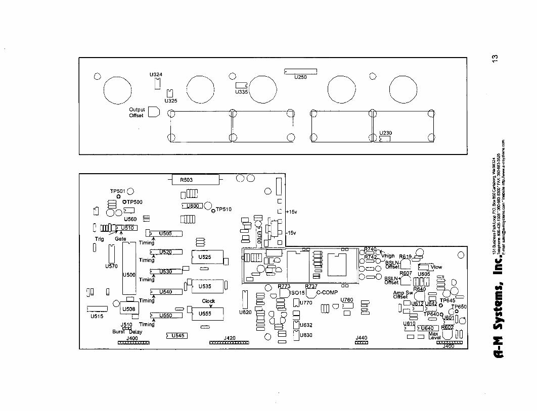
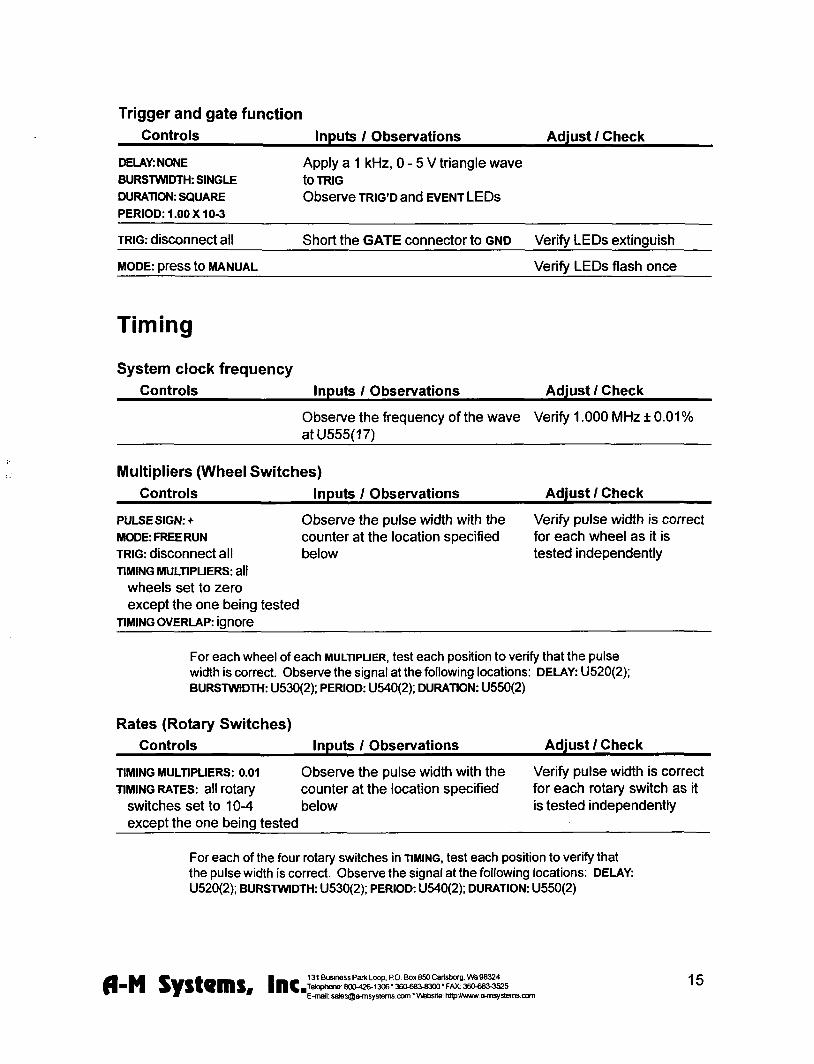
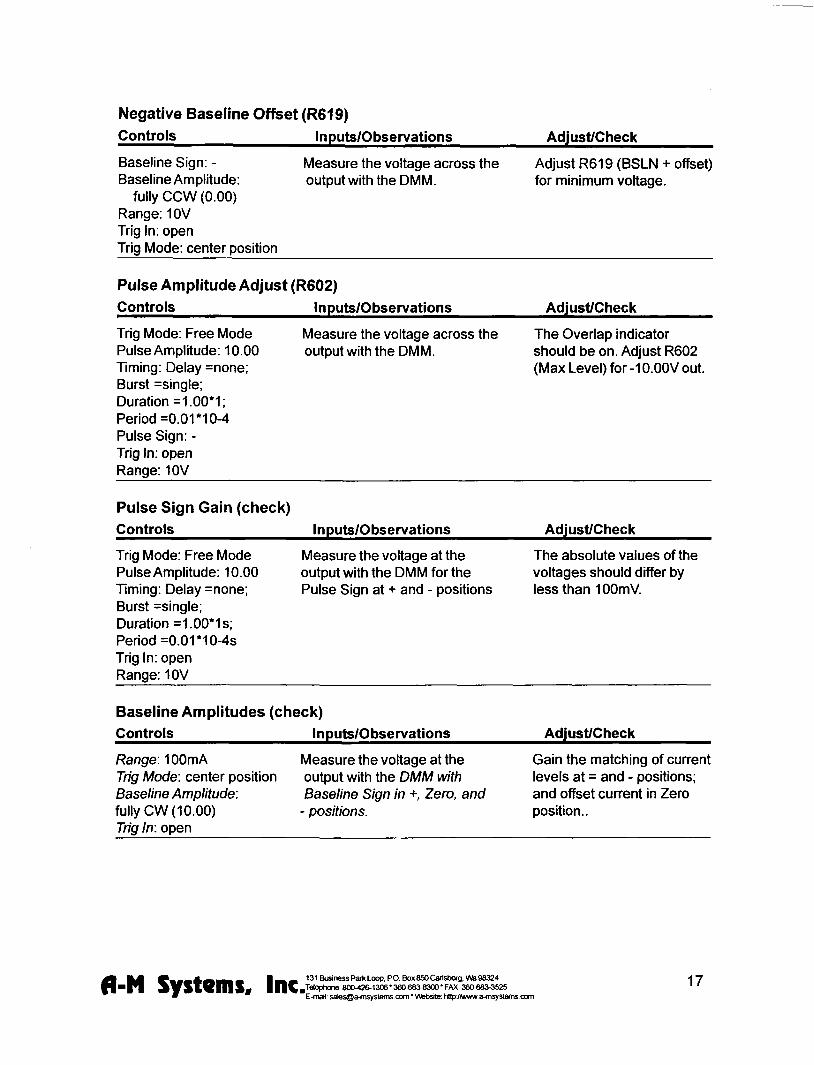
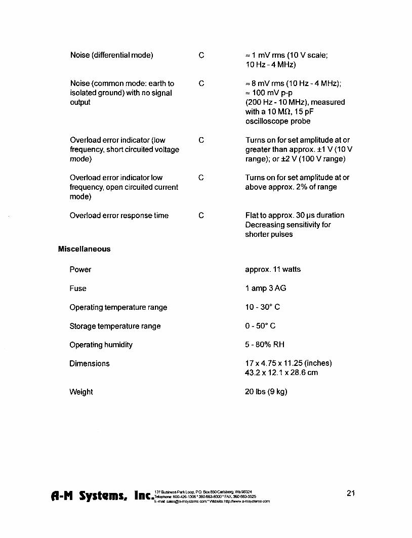


