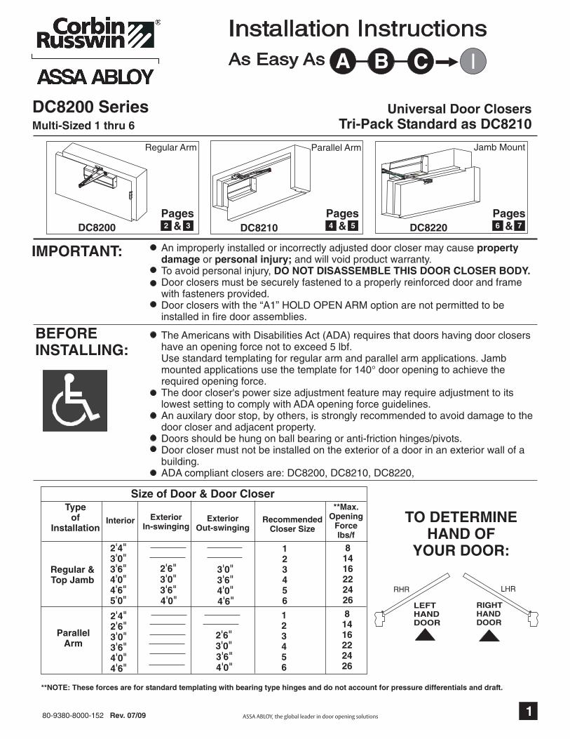
DC8200 Series
IMPORTANT:
BEFOREINSTALLING:
TO DETERMINEHAND OF
YOUR DOOR:
An improperly installed or incorrectly adjusted door closer may causeor and will void product warranty.
To avoid personal injury,
propertydamage personal injury;
DO NOT DISASSEMBLE THIS DOOR CLOSER BODY.Door closers must be securely fastened to a properly reinforced door and framewith fasteners provided.Door closers with the “A1” HOLD OPEN ARM option are not permitted to beinstalled in fire door assemblies.
LEFTHANDDOOR
RIGHTHANDDOOR
The Americans with Disabilities Act (ADA) requires that doors having door closershave an opening force not to exceed 5 lbf.Use standard templating for regular arm and parallel arm applications. Jambmounted applications use the template for 140° door opening to achieve therequired opening force.The door closer's power size adjustment feature may require adjustment to itslowest setting to comply with ADA opening force guidelines.An auxilary door stop, by others, is strongly recommended to avoid damage to thedoor closer and adjacent property.Doors should be hung on ball bearing or anti-friction hinges/pivots.Door closer must not be installed on the exterior of a door in an exterior wall of abuilding.ADA compliant closers are: DC8200, DC8210, DC8220,
Size of Door & Door CloserType
ofInstallation
Interior ExteriorIn-swinging
ExteriorOut-swinging
RecommendedCloser Size
**Max.Opening
Forcelbs/f
2 43 03 64 04 65 0
' "' "' "' "' "' "
2 42 63 03 64 04 6
' "' "' "' "' "' "
2 63 03 64 0
' "' "' "' "
2 63 03 64 0
' "' "' "' "
3 03 64 04 6
' "' "' "' "
123456
8141622242681416222426
123456
Regular &Top Jamb
ParallelArm
Universal Door ClosersTri-Pack Standard as DC8210
RHR LHR
Multi-Sized 1 thru 6
Regular Arm
DC8200
Parallel Arm
DC8210
Jamb Mount
DC8220
80-9380-8000-152 Rev. 07/09 1
7Pages
&65Pages
&4
As Easy As A CB I
Installation Instructions
3Pages
&2
**NOTE: These forces are for standard templating with bearing type hinges and do not account for pressure differentials and draft.
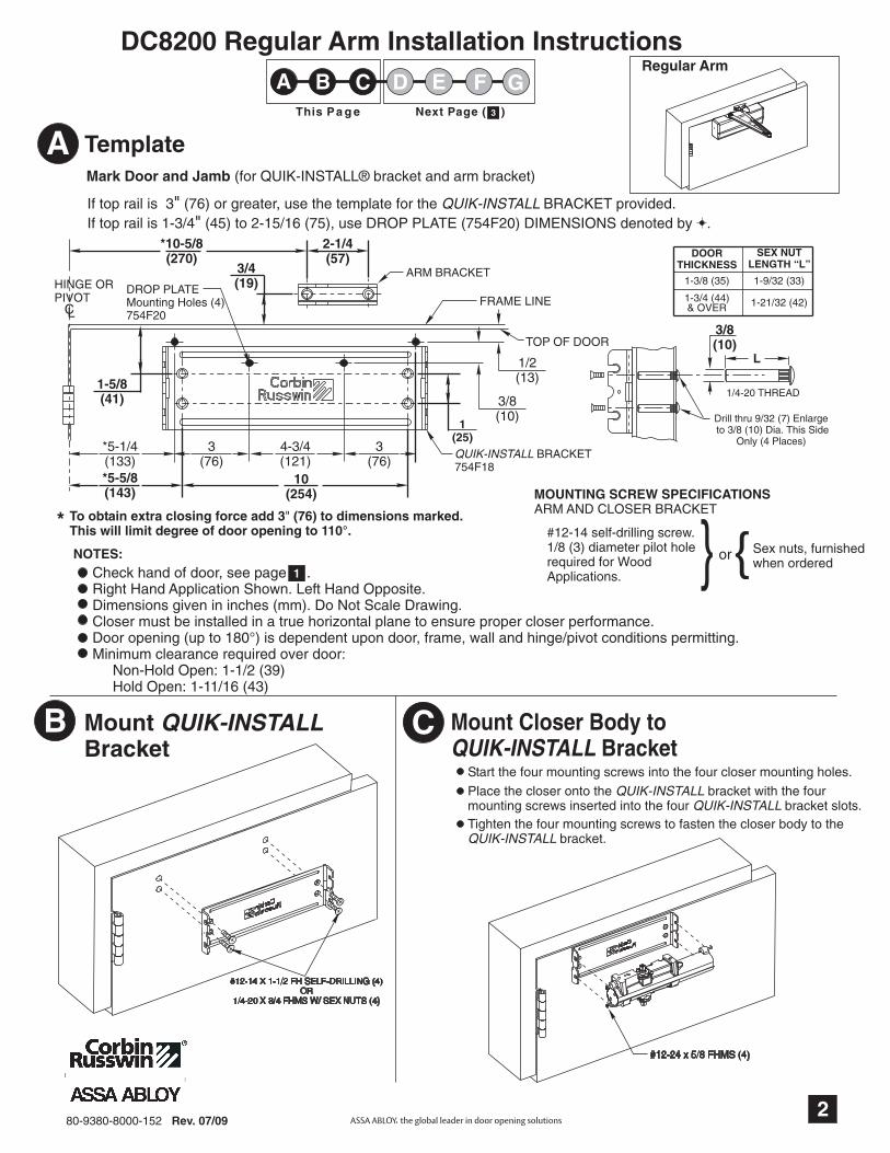
DC8200 Regular Arm Installation Instructions
Mark Door and Jamb (for QUIK-INSTALL® bracket and arm bracket)
If top rail is 3 (76) or greater, use the template for the BRACKET provided.If top rail is 1-3/4 (45) to 2-15/16 (75), use DROP PLATE (754F20) DIMENSIONS denoted by .
QUIK-INSTALL""
Template
MountBracket
QUIK-INSTALL Mount Closer Body toBracketQUIK-INSTALL
Drill thru 9/32 (7) Enlargeto 3/8 (10) Dia. This Side
Only (4 Places)
80-9380-8000-152 Rev. 07/09
2-1/4(57)
*10-5/8(270)
CL
HINGE ORPIVOT
*5-5/8(143)
FRAME LINE
ARM BRACKET
QUIK-INSTALL BRACKET754F18
TOP OF DOOR
10(254)
1(25)
3/4(19)
1/2(13)
Regular Arm
MOUNTING SCREW SPECIFICATIONSARM AND CLOSER BRACKET
} or{Sex nuts, furnishedwhen ordered
#12-14 self-drilling screw.1/8 (3) diameter pilot holerequired for WoodApplications.
To obtain extra closing force add 3 (76) to dimensions marked.This will limit degree of door opening to 110°.
"*
L
3/8(10)
1/4-20 THREAD
#12-24 x 5/8 FHMS (4)
*5-1/4(133)
3(76)
4-3/4(121)
3(76)
1-5/8(41) 3/8
(10)
A
CB
2
NOTES:Check hand of door, see page .Right Hand Application Shown. Left Hand Opposite.Dimensions given in inches (mm). Do Not Scale Drawing.Closer must be installed in a true horizontal plane to ensure proper closer performance.Door opening (up to 180°) is dependent upon door, frame, wall and hinge/pivot conditions permitting.Minimum clearance required over door:
Non-Hold Open: 1-1/2 (39)Hold Open: 1-11/16 (43)
1
A CB FE GDThis Pa g e Next Page ( 3 )3
DROP PLATEMounting Holes (4)754F20
DOORTHICKNESS
SEX NUTLENGTH “L”
1-3/8 (35)
1-3/4 (44)& OVER
1-9/32 (33)
1-21/32 (42)
Start the four mounting screws into the four closer mounting holes.
Place the closer onto the bracket with the fourmounting screws inserted into the four bracket slots.
QUIK-INSTALLQUIK-INSTALL
Tighten the four mounting screws to fasten the closer body to thebracket.QUIK-INSTALL
#12-14 X 1-1/2 FH SELF-DRILLING (4)OR
1/4-20 X 3/4 FHMS W/ SEX NUTS (4)

NON-HOLD OPEN ARM ONLY:
Normal mounting position.Position with pivot pointaway from hinge.
Away fromhinge
Attach Arm Bracket to Frame
For Additional 15% Closing ForceReposition arm mounting bracket so thatpivot point is toward hinge.
FOR MAXIMUMPOWER FOR REGULAR
POWER
Hinge
Standard Position
HOLD OPEN ARM (A1 OPTION ONLY):
HOLD OPEN ARM:Position so that dialscrew is onUNDERSIDE of bracket
Position Arm on Closer
Main arm projects straight out at 90° angle to door.Install and tighten arm screw & washer assembly.
Main arm projects straight out at 90° angle to door.Remove arm screw and washer from elbow joint anddisassemble arm. Thread the rod into the ArmBracket as shown below. Install and tighten armscrew & washer.
NON-HOLD OPEN ARM ONLY:
HOLD OPEN ARM ONLY:
Preload and Adjust ArmOpen door and slide arm rod into arm loop. Close door, swing armsso adjusting arm is 90° to frame. With 7/16 wrench INSTALL andTIGHTEN SCREW SECURELY.
"
Extended Maintenance
NOTE:DO NOT
Lubricate Arm periodicallywith a drop or
two of appropriate lubricant.When lubricating a
Hold Open Arm,use any lubricant on theHolding Surface components.
atshaded points
NON-HOLD OPEN ARM ONLY:While door is closed, adjust the Threaded Arm in the Arm Bracketuntil the bearing fits back onto the elbow joint on the Main Arm at 90as shown below.
°RE-INSTALL AND TIGHTEN SCREW SECURELY.
HOLD OPEN ARM ONLY:
DIALSCREW
80-9380-8000-152 Rev. 07/09
Pivot (away from hinge)
MAIN ARM
ARMTUBE
ARM ROD
SCREW
90°
MAIN ARM
THREADEDROD
ARMBRACKET
THREADEDARM
SCREW90°
MAIN ARM
E
D
F
Adjust Door Closer: See PageG3
DC8200 Regular Arm Installation Instructions
Previous Page ( 2 ) This Page
A CB FE GD2
8
#12-14 X 1-1/2 FH SELF-DRILLING (2)
5/16 HEX HEADSCREW & WASHERASSEMBLY

L
3/8(10)
1/4-20 THREAD
Drill thru 9/32 (7) Enlarge to3/8 (10) Dia. This Side Only
(4 Places)
Mark Door and Jamb (for QUIK-INSTALL and adapter plate)®
Template
80-9380-8000-152 Rev. 07/09
5/8(16)
REF.
DOOR
FRAME
ADAPTERPLATE
SPACER BLOCK(When required)
NOTES:Check hand of door, see page 1
Right Hand Application Shown. Left HandOpposite.
Dimensions given in inches (mm). Do NotScale Drawing.
Closer must be installed in a true horizontalplane to ensure proper closer performance.
Door opening (up to 180°) is dependentupon door, frame, wall and hinge/pivotconditions permitting.
CountersunkHoles (x4)
#12-24 x 5/8 FHMS (4)
To obtain extra closing force add 3 (77) to dimensions marked.This will limit degree of door opening to 110°.
*
Parallel Arm
HINGEOR
PIVOT
CL
*3-1/2(89)
FRAME STOP PA ADAPTERPLATE
QUIK-INSTALL BRACKET754F18
TOP OF DOOR
10(254)
1(25)
3-1/16(78)
CL
5/8(16)
DOOR
FRAME STOP
2-3/4(70)
5/8(16)
1-1/2(38)1/4
(6)
*8-1/8(206)
1/2(13)
*3-1/8(79)
3(76)
4-3/4(121)
3(76)
3/8(10)
If top rail is 5-1/4 (133) or greater, use the template for the BRACKET provided.If top rail is 1-3/4 (44) to 5-1/8 (130), use DROP PLATE (754F25) DIMENSIONS denoted by .
QUIK-INSTALL
A
CMountBracket
QUIK-INSTALLB
4
1
DC8210 Parallel Arm Installation Instructions
A CB FE GDThis Pa g e Next Page ( 5 )
IH5
DOORTHICKNESS
SEX NUTLENGTH “L”
1-3/8 (35)
1-3/4 (44)& OVER
1-9/32 (33)
1-21/32 (42)
Mount Closer Body toBracketQUIK-INSTALL
Start the four mounting screws into the four closer mounting holes.
Place the closer onto the bracket with the fourmounting screws inserted into the four bracket slots.
QUIK-INSTALLQUIK-INSTALL
Tighten the four mounting screws to fasten the closer body to thebracket.QUIK-INSTALL
MOUNTING SCREW SPECIFICATIONSARM AND CLOSER BRACKET
} or{Sex nuts, furnishedwhen ordered
#12-14 self-drilling screw.1/8 (3) diameter pilot holerequired for WoodApplications.
#12-14 X 1-1/2 FH SELF-DRILLING (4)OR
1/4-20 X 3/4 FHMS W/ SEX NUTS (4)

Mount Adapter PlateBracket on Jamb
Mount Arm BracketNON-HOLD OPEN ARM: HOLD OPEN ARM ONLY (A1 Option)
Connect and Position ArmsOpen door and slide arm rod into arm loop. Closedoor, swing arms so that they form a “V” position,as in Step 8. With 7/16 wrench, INSTALL ANDTIGHTEN SCREW SECURELY.
"
HOLD OPEN ONLY
RE-INSTALL AND TIGHTEN SCREW SECURELY.
Remove main arm screw from elbow joint and disassemblearm. Thread the rod into the Arm Bracket as shown below.While door is closed, adjust the Threaded Arm in the ArmBracket until the bearing fits back onto the elbow joint onthe Main Arm and forms a "V" as shown below.
Position Arm onto CloserUsing hex wrench provided, turn closing speed and latching speedvalves clockwise until completely closed. DO NOT OVER TIGHTEN.Using wrench, turn under side of spindle 45° toward the closertube until it reaches the diamond position (fig. 2). Immediatelyplace arm on spindle so that it is parallel to the closer body.Install and tighten arm screw and washer assembly.Reopen valves.
Fig. 1 Fig. 2Square position
At restDiamond position
Rotated 45°
Install with dialscrew facing down.
DIAL SCREW
80-9380-8000-152 Rev. 07/09
Pivot point mustbe AWAY from hingeedge of door.
3-0(76)
MAX.
MINIMUMPOWER
ARM TUBE
ARM ROD
Power AdjustmentTo increase the power of the closer, re-adjust the arm soit is nearer the door. To decrease power, re-adjust the armso it is farther away from the door and then secure screwin arm loop (non-hold open) or elbow joint (hold open).
Extended Maintenance
TONOD:ETON
Lubricate Arm periodically with a dropor two of appropriate lubricant.
When lubricating a Hold Open Arm, useany lubricant on the Holding Surface components.
at shaded points
SCREW
THREADEDARM
ARMBRACKET
MAIN ARM
1-1/2(38)
MIN. MAXIMUMPOWER
AWAY FROM HINGE EDGE OF DOOR
5/16 Hex HeadScrew & Washer Assembly
Rotate 45°
Closer Tube
ED
G
Adjust Door Closer: See PageI
F
H
Using holes spotted on soffit or stop inStep mount adapter plate bracket.A
5
DC8210 Parallel Arm Installation Instructions
Previous Page ( 4 ) This Page
A CB FE GD H I4
8
1/4-20 X 1/2 POHMS WITH PATCH (2)
#12-14 X 1-1/2 FH SELF-DRILLING (4)
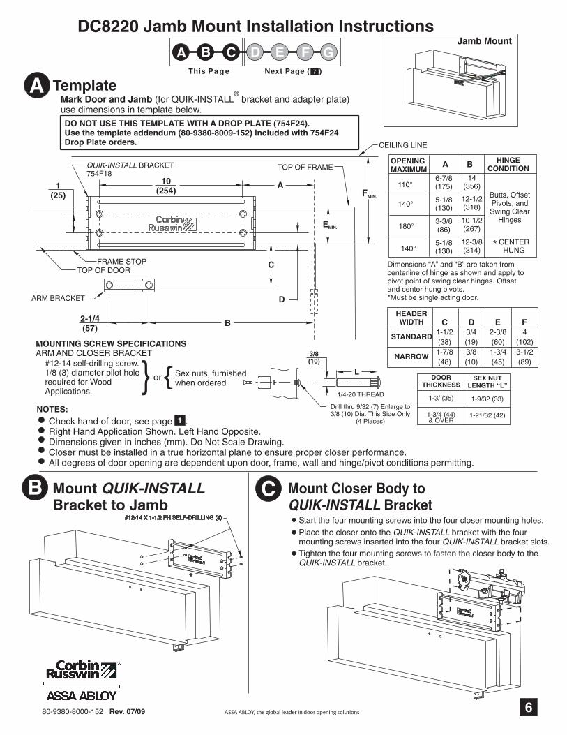
NARROW
E2-3/8(60)1-3/4(45)
C1-1/2(38)1-7/8(48)
D3/4(19)3/8(10)
F4
(102)3-1/2(89)
STANDARD
HEADERWIDTH
L
3/8(10)
1/4-20 THREAD
Drill thru 9/32 (7) Enlarge to3/8 (10) Dia. This Side Only
(4 Places)
DOORTHICKNESS
SEX NUTLENGTH “L”
1-3/ (35)
1-3/4 (44)& OVER
1-9/32 (33)
1-21/32 (42)
Mark Door and Jamb (for QUIK-INSTALL bracket and adapter plate)use dimensions in template below.
®Template
B
14(356)
HINGECONDITION
5-1/8(130)
12-1/2(318)
5-1/8(130)
12-3/8(314)
3-3/8(86)
10-1/2(267)
Butts, OffsetPivots, andSwing Clear
Hinges
110°
140°
180°
140°CENTER
HUNG*
Dimensions “A” and “B” are taken fromcenterline of hinge as shown and apply topivot point of swing clear hinges. Offsetand center hung pivots.*Must be single acting door.
MountBracket to Jamb
QUIK-INSTALL
80-9380-8000-152 Rev. 07/09
FMIN.
A
FRAME STOP
ARM BRACKET
QUIK-INSTALL BRACKET754F18
TOP OF DOOR
10(254)1
(25)
D
2-1/4(57)
B
C
CEILING LINE
EMIN.
TOP OF FRAME
Jamb Mount
A
6-7/8(175)
OPENINGMAXIMUM
6
A
B
NOTES:Check hand of door, see page .Right Hand Application Shown. Left Hand Opposite.Dimensions given in inches (mm). Do Not Scale Drawing.Closer must be installed in a true horizontal plane to ensure proper closer performance.All degrees of door opening are dependent upon door, frame, wall and hinge/pivot conditions permitting.
1
DC8220 Jamb Mount Installation Instructions
A CB FE GDThis Pa g e Next Page ( 7 )7
DO NOT USE THIS TEMPLATE WITH A DROP PLATE (754F24).Use the template addendum (80-9380-8009-152) included with 754F24Drop Plate orders.
C Mount Closer Body toBracketQUIK-INSTALL
Start the four mounting screws into the four closer mounting holes.
Place the closer onto the bracket with the fourmounting screws inserted into the four bracket slots.
QUIK-INSTALLQUIK-INSTALL
Tighten the four mounting screws to fasten the closer body to thebracket.QUIK-INSTALL
MOUNTING SCREW SPECIFICATIONSARM AND CLOSER BRACKET
} or{Sex nuts, furnishedwhen ordered
#12-14 self-drilling screw.1/8 (3) diameter pilot holerequired for WoodApplications.
#12-14 X 1-1/2 FH SELF-DRILLING (4)

Normal mounting position.Position with pivot pointaway from hinge.
For Additional 15% Closing ForceReposition arm mounting bracket so thatpivot point is toward hinge.
Standard Position
NON-HOLD OPEN ARM ONLY:Attach Arm Bracket to Door
HOLD OPEN ARM (A1 Option):
Adjust Door Closer: See Page
FOR MAXIMUMPOWER
FOR REGULARPOWER
Hinge
Pivot (away from Hinge)
80-9380-8000-152 Rev. 07/09
Away from hinge
Install with dial screwfacing down
DIALSCREW
FRAME STOP
90°
ARMBRACKET
THREADEDARM
SCREW
MAIN ARM
ARM ROD
SCREW
ARMLOOP
90°
MAIN ARMTHREADEDROD
ARMBRACKET
MAIN ARM
Position Arm on Closer
Preload and Adjust Arm
Open door and slide arm rod into arm loop. Close door,swing arms so adjusting arm is 90° to frame. With 7/16wrench, INSTALL and TIGHTEN SCREW SECURELY.
"
Main arm projectsstraight out at 90° angleto door. Install andtighten arm screw &washer assembly.
Extended Maintenance
NOTE:DO NOT
Lubricate Arm periodicallywith a drop or
two of appropriate lubricant.When lubricating a
Hold Open Arm,use any lubricant on theHolding Surface components.
atshaded points
Main arm projects straightout at 90° angle to door.
Remove main arm screwfrom elbow joint anddisassemble arm. Threadthe rod into the Arm Bracketas shown below.
Install and tighten armscrew & washer assembly.
While door is closed, adjust the Threaded Arm inthe Arm Bracket until the bearing fits back onto theelbow joint on the Main Arm at 90 as shown below.°RE-INSTALL and TIGHTEN SCREW SECURELY.
NON-HOLD OPEN ARM ONLY:
HOLD OPEN ARM ONLY (A1 Option):
NON-HOLD OPEN ARM ONLY:HOLD OPEN ARM ONLY (A1 Option):
7
E
D
F
G
DC8200 Jamb Mount Installation Instructions
Previous Page ( 6 ) This Page
A CB FE GD6
8
#12-14 X 1-1/2 FH SELF-DRILLING (2)OR
1/4-20 X 3/4 FHMS W/ SEX NUTS (2)
5/16 HEX HEADSCREW & WASHERASSEMBLY5/16 HEX HEAD
SCREW & WASHERASSEMBLY

Interior ExteriorIn
Swing
ExteriorOut
Swing
LATCHINGSPEED VALVE BACKCHECK
INTENSITY VALVE
CLOSINGSPEED VALVE
SPRING POWER ADJUSTER(1/4 ALLEN WRENCH)"
Size of Door
Regular &TJ Mounting (Approx.)
EquivalentCloser Size
DC8200 SPRING POWER ADJUSTMENT CHART2 4 (712)
2 6 (764)
3 0 (915)
3 6 (1067)
' "' "' "' "
1-5
5-8
8-13
13-15
3
4
5
62 6 (764)
3 0 (915)
' "' "
2 6 (764)
3 0 (915)
3 6 (1067)
4 0 (1219)
' "' "' "' "
Spring Power Adjustment
DC8200 Size 1 thru 6 Adjustment See Chart
All DC8200 closers are factory set at an approximateAdjust closer as necessary for door size using this chart.Readjustment may be required to suit prevailing conditions.
Size 3.
Locate spring power adjuster from Illustration below
Backcheck Intensity ValveTurn valve COUNTER-CLOCKWISE to reduce backcheckor CLOCKWISE to increase backcheck. (Backcheck shouldbe set to give a soft cushioning action, not a sudden stop.)
To Adjust Hold Open (A1 Option)Open the door to desired position and tighten the hold openscrew firmly (For RH application, turn screw on undersideCLOCKWISE. For LH application, turn screw COUNTER-CLOCKWISE.) Place the hold open dial over the hex headof the bracket screw so that one of the slots in the dial isdirectly over small screw hole tapped in bracket. Seat thedial tightly over the bracket. INSERT DIAL SCREW ANDTIGHTEN SECURELY.
Latching Speed ValveAfter closing speed has been obtained, turn latching speed valveCLOCKWISE to SLOW latching or COUNTER-CLOCKWISE toSPEED latching for last 2 to 5 of door travel.NOTE: Set combination of CLOSING and LATCHING speeds to
between 3 and 7 seconds Use of door by handicapped,elderly or small children may require even greaterclosing time.
" "
Closing Speed ValveTo adjust speed of door closing from fully open to a position2 to 5 from closed, turn Closing Speed Valve CLOCKWISEto SLOW closing, COUNTER-CLOCKWISE to SPEEDclosing.
" "
Delayed Action ValveTurn valve CLOCKWISE to SLOW closing, COUNTER-CLOCKWISE to SPEED closing. Delayed action may beadjusted from 20 seconds to 90 seconds, depending ondegree of door swing. Delay occurs at the beginning of thedoor closing cycle from fully open down to 70°, where theclosing speed valve then begins its control.
Latc
h
Clo
sing
Sp
eed
BackcheckDelayedActionOptionM71
Plastic Cover(Standard)
(1/8 Allen Wrench Provided)
(1/8 Allen Wrench Provided)
(1/8 Allen Wrench Provided)
Date Stamp(on end of closer)MM-YY
HOLD OPENSCREWDIAL
DIALSCREW
80-9380-8000-152 Rev. 07/09
OPTION M71DELAYEDACTION VALVE
Insert is removable.Place in unused opening.
2-7
7-11
11-15
15-17
Spring Power AdjustmentNo. Full Turns Clockwise
Parallel ArmMounting
8
MM = MonthYY = Year
DC8000 Installation Instructions - Closer Adjustment
Slip cover over closer.Hold tightly against QUIK-INSTALL® Bracket surface.Secure on each side with 6-32 x 1/4 PBHMS screws."
Installing Cover
Copyright © 2006, 2009, Corbin Russwin, Inc., an ASSA ABLOY Group company. All rights reserved. Reproduction in whole or in part without the express written permission
of Corbin Russwin, Inc. is prohibited.


