Newgate (Newark) LimitedNewgate (Newark) LimitedNewgate (Newark) LimitedNewgate (Newark) Limited
Brunel DriveBrunel DriveBrunel DriveBrunel Drive
Newark NG24 2DENewark NG24 2DENewark NG24 2DENewark NG24 2DE
NottinghamshireNottinghamshireNottinghamshireNottinghamshire
United KingdomUnited KingdomUnited KingdomUnited Kingdom
www.newgate.uk.comwww.newgate.uk.comwww.newgate.uk.comwww.newgate.uk.com
Head Head Head Head Office:Office:Office:Office: Service Department:Service Department:Service Department:Service Department:
Phone:Phone:Phone:Phone: +44 +44 +44 +44 ((((0000))))1636 700 1721636 700 1721636 700 1721636 700 172 Phone:Phone:Phone:Phone: +44 +44 +44 +44 ((((0000))))1636 704 0001636 704 0001636 704 0001636 704 000
Fax:Fax:Fax:Fax: +44+44+44+44 ((((0000))))1636 605 4001636 605 4001636 605 4001636 605 400 Fax:Fax:Fax:Fax: +44 +44 +44 +44 ((((0000))))1636 605 9571636 605 9571636 605 9571636 605 957
Email:Email:Email:Email: [email protected]@[email protected]@newgate.uk.com Email:[email protected]:[email protected]:[email protected]:[email protected] (Out of Hours): +44 01636 653 302(Out of Hours): +44 01636 653 302(Out of Hours): +44 01636 653 302(Out of Hours): +44 01636 653 302
INSTALLATION, COMISSIONING & INSTALLATION, COMISSIONING & INSTALLATION, COMISSIONING & INSTALLATION, COMISSIONING &
MAINTENANCE MANUALMAINTENANCE MANUALMAINTENANCE MANUALMAINTENANCE MANUAL
MANUALMANUALMANUALMANUAL RISING ARM BARRIERRISING ARM BARRIERRISING ARM BARRIERRISING ARM BARRIER

INSTALLATION, INSTALLATION, INSTALLATION, INSTALLATION, COMMISSIONINGCOMMISSIONINGCOMMISSIONINGCOMMISSIONING
AND MAINTENANCE AND MAINTENANCE AND MAINTENANCE AND MAINTENANCE
MANUALMANUALMANUALMANUAL
1
Newgate (Newark) LtdNewgate (Newark) LtdNewgate (Newark) LtdNewgate (Newark) Ltd
Manual Rising Arm BarrierManual Rising Arm BarrierManual Rising Arm BarrierManual Rising Arm Barrier----Rev 1.0Rev 1.0Rev 1.0Rev 1.0
INDEXINDEXINDEXINDEX PPPPage Noage Noage Noage No::::
1.1.1.1. SAFETY INFORMATIONSAFETY INFORMATIONSAFETY INFORMATIONSAFETY INFORMATION 02
2.2.2.2. TTTTECHNICAL DATAECHNICAL DATAECHNICAL DATAECHNICAL DATA 03
3.3.3.3. GGGGENERAL SAFETY STANDARDSENERAL SAFETY STANDARDSENERAL SAFETY STANDARDSENERAL SAFETY STANDARDS 04
4.4.4.4. GGGGENERAL DESCRIPTIONENERAL DESCRIPTIONENERAL DESCRIPTIONENERAL DESCRIPTION 05
4.1. BASIC DESIGN 05
5.5.5.5. HHHHANDLINGANDLINGANDLINGANDLING 06
5.1. TRANSPORTING 06
5.2. LIFTING 06
6.6.6.6. IIIINSTALLATIONNSTALLATIONNSTALLATIONNSTALLATION 07
6.1. FOUNDATIONS 07
6.2. BARRIER 08
7.7.7.7. MMMMECHANICAL ADJUSTMENTSECHANICAL ADJUSTMENTSECHANICAL ADJUSTMENTSECHANICAL ADJUSTMENTS 09
7.1. BALANCE WEIGHT ADJUSTMENT 09
7.2. STOP SCREW ADJUSTMENT 10
8.8.8.8. CCCCOMISSIONINGOMISSIONINGOMISSIONINGOMISSIONING 11
9.9.9.9. OOOOPERATIONPERATIONPERATIONPERATION 12
10.10.10.10. MANUAL TRAFFIC BARRIER MANUAL TRAFFIC BARRIER MANUAL TRAFFIC BARRIER MANUAL TRAFFIC BARRIER –––– GENERAL ASSEMBLYGENERAL ASSEMBLYGENERAL ASSEMBLYGENERAL ASSEMBLY 13
10.1. MANUAL TRAFFIC BARRIER – EXPLODED DIAGRAMS 13
10.2. MANUAL TRAFFIC BARRIER – PARTS LIST 15
11.11.11.11. MAINTENANCEMAINTENANCEMAINTENANCEMAINTENANCE 16
11.1. BEFORE CARRYING OUT MAINTENANCE 16
11.2. WHILST CARRYING OUT MAINTENANCE 16
11.3. AFTER CARRYING OUT MAINTENANCE 16
11.4. ORDERING SPARE PARTS 16
11.5. SERVICE SCHEDULE 16
11.6. REPLACING POLE ARMS 17
11.7. REPLACING POLE ARM ADAPTORS 18
11.8. METHOD STATEMENT 19
11.9. RISK ASSESSMENT 20
11.10. LUBRICATION 21
11.11. VARIATIONS 22
12.12.12.12. CE DECLARATION OF CONFORMITYCE DECLARATION OF CONFORMITYCE DECLARATION OF CONFORMITYCE DECLARATION OF CONFORMITY 23
13.13.13.13. RRRREVISION RECORDEVISION RECORDEVISION RECORDEVISION RECORD 24
14.14.14.14. SSSSERVICE ERVICE ERVICE ERVICE –––– REPAIR LOGREPAIR LOGREPAIR LOGREPAIR LOG 25
15.15.15.15. APPENDIXAPPENDIXAPPENDIXAPPENDIX 26

INSTALLATION, INSTALLATION, INSTALLATION, INSTALLATION, COMMISSIONINGCOMMISSIONINGCOMMISSIONINGCOMMISSIONING
AND MAINTENANCE AND MAINTENANCE AND MAINTENANCE AND MAINTENANCE
MANUALMANUALMANUALMANUAL
2
Newgate (Newark) LtdNewgate (Newark) LtdNewgate (Newark) LtdNewgate (Newark) Ltd
Manual Rising Arm BarrierManual Rising Arm BarrierManual Rising Arm BarrierManual Rising Arm Barrier----Rev 1.0Rev 1.0Rev 1.0Rev 1.0
1.1.1.1. SAFETY INFORMATIONSAFETY INFORMATIONSAFETY INFORMATIONSAFETY INFORMATION
SAFETY NOTICE:SAFETY NOTICE:SAFETY NOTICE:SAFETY NOTICE:
Vehicle Control Barriers are designed to control the flow of Motor Vehicles and
Motor Cyclists. It is dangerous to permit pedestrians, cyclists and equestrians to
pass and travel through the Traffic Barrier when it is in motion.
It is recommended that easy alternative routes arIt is recommended that easy alternative routes arIt is recommended that easy alternative routes arIt is recommended that easy alternative routes are provided for none provided for none provided for none provided for non----vehicular traffic vehicular traffic vehicular traffic vehicular traffic
and that suitable warning and direction signs are placed on either and that suitable warning and direction signs are placed on either and that suitable warning and direction signs are placed on either and that suitable warning and direction signs are placed on either side of the Traffic side of the Traffic side of the Traffic side of the Traffic
BarrierBarrierBarrierBarrier....
IMPORTANT NOTE:IMPORTANT NOTE:IMPORTANT NOTE:IMPORTANT NOTE:
Only competent and skilled personnel should carry out procedures detailed in this
manual.
INSTALLATION, INSTALLATION, INSTALLATION, INSTALLATION, COMMISSIONINGCOMMISSIONINGCOMMISSIONINGCOMMISSIONING
AND MAINTENANCE AND MAINTENANCE AND MAINTENANCE AND MAINTENANCE
MANUALMANUALMANUALMANUAL
3
Newgate (Newark) LtdNewgate (Newark) LtdNewgate (Newark) LtdNewgate (Newark) Ltd
Manual Rising Arm BarrierManual Rising Arm BarrierManual Rising Arm BarrierManual Rising Arm Barrier----Rev 1.0Rev 1.0Rev 1.0Rev 1.0
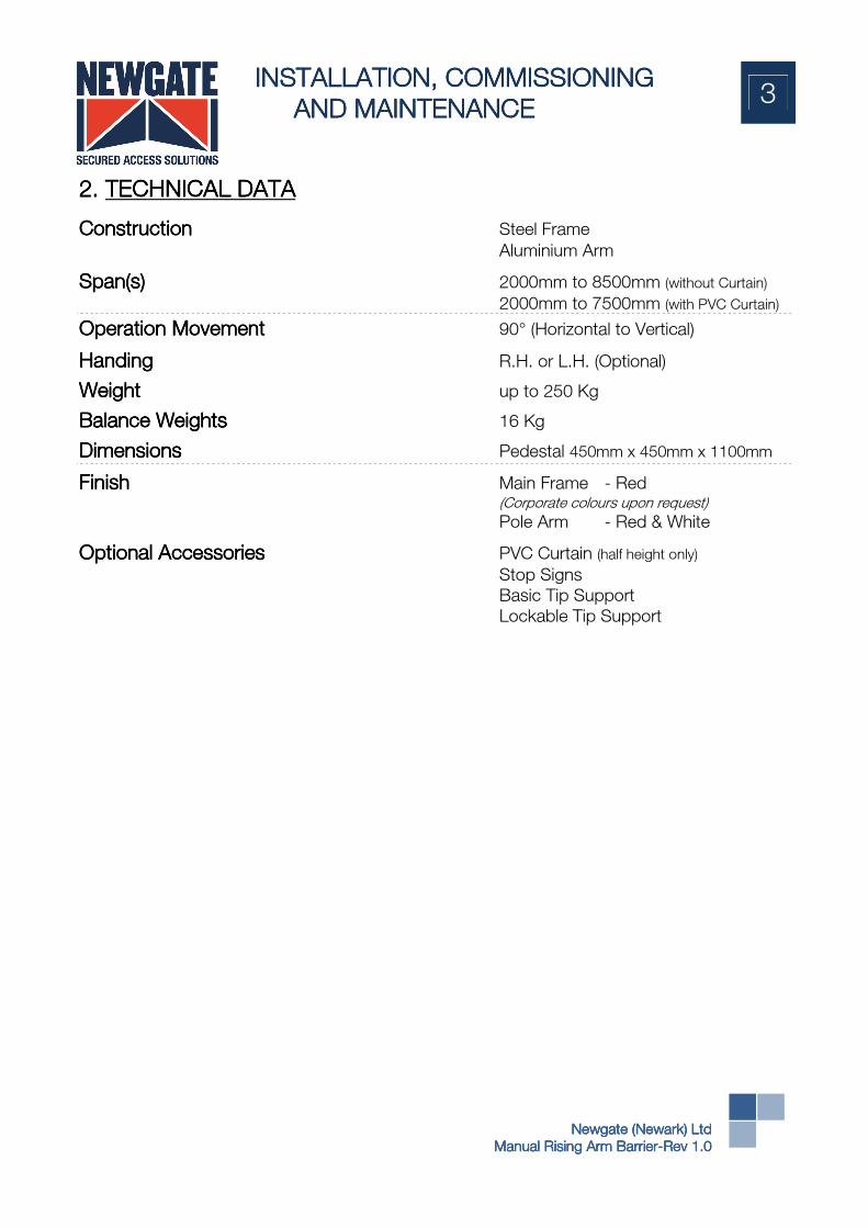
2.2.2.2. TECHNICAL TECHNICAL TECHNICAL TECHNICAL DATADATADATADATA
ConstructionConstructionConstructionConstruction Steel Frame
Aluminium Arm
SpanSpanSpanSpan(s)(s)(s)(s) 2000mm to 8500mm (without Curtain)
2000mm to 7500mm (with PVC Curtain)
Operation MovementOperation MovementOperation MovementOperation Movement 90° (Horizontal to Vertical)
HandingHandingHandingHanding R.H. or L.H. (Optional)
WeightWeightWeightWeight up to 250 Kg
Balance WeightsBalance WeightsBalance WeightsBalance Weights 16 Kg
DimensionsDimensionsDimensionsDimensions Pedestal 450mm x 450mm x 1100mm
FinishFinishFinishFinish Main Frame - Red (Corporate colours upon request)
Pole Arm - Red & White
Optional AccessoriesOptional AccessoriesOptional AccessoriesOptional Accessories PVC Curtain (half height only)
Stop Signs
Basic Tip Support
Lockable Tip Support

INSTALLATION, INSTALLATION, INSTALLATION, INSTALLATION, COMMISSIONINGCOMMISSIONINGCOMMISSIONINGCOMMISSIONING
AND MAINTENANCE AND MAINTENANCE AND MAINTENANCE AND MAINTENANCE
MANUALMANUALMANUALMANUAL
4
Newgate (Newark) LtdNewgate (Newark) LtdNewgate (Newark) LtdNewgate (Newark) Ltd
Manual Rising Arm BarrierManual Rising Arm BarrierManual Rising Arm BarrierManual Rising Arm Barrier----Rev 1.0Rev 1.0Rev 1.0Rev 1.0
3.3.3.3. GENERAL SAFETY STANDARDSGENERAL SAFETY STANDARDSGENERAL SAFETY STANDARDSGENERAL SAFETY STANDARDS
SAFETY WARNING:SAFETY WARNING:SAFETY WARNING:SAFETY WARNING:
Before attempting to install and maintain the Newgate Manual Rising Arm Barrier, it
is important that the following notes are read and understood. Competent and
skilled persons should always carry out any work. Keep these instructions for future
use.
IMIMIMIMPORTANT NOTE:PORTANT NOTE:PORTANT NOTE:PORTANT NOTE:
The Traffic Barrier is essentially a barrier designed for entry/exit for motorised
vehicles and is NOT DESIGNED for Pedestrian use. Any other usage will be
deemed improper and dangerous. Therefore, it is recommended that suitable
signage is erected warning pedestrians not to walk under the Traffic Barrier and
separate access is provided for pedestrians.
The traffic barrier is fundamentally a manually driven arm, rising and falling across
an access route, and whilst every precaution is taken to make the equipment as
functionally as safe as possible, both operators and users should take sensible
precautions not to abuse such a traffic control system. To this end, the barrier arm
is fitted with a “Fracture Segment” to minimise any vehicular damage in the event of
an accidental impact.
It is also strongly recommended that a Maintenance Contract be taken out to
ensure that the hinge mechanism, mounted pins and barrier foundation bolts are
operating correctly and secure.
Newgate (Newark) Ltd does not accept any responsibility for injury or damage if the
Rising Arm Barrier has not been secured or is operated incorrectly.
Employers have a responsibility under Sect 2 of the Health and Safety at Work Act Employers have a responsibility under Sect 2 of the Health and Safety at Work Act Employers have a responsibility under Sect 2 of the Health and Safety at Work Act Employers have a responsibility under Sect 2 of the Health and Safety at Work Act
1974 to1974 to1974 to1974 to ensure as is reasonably practicable the health and safety of employees ensure as is reasonably practicable the health and safety of employees ensure as is reasonably practicable the health and safety of employees ensure as is reasonably practicable the health and safety of employees
and other persons who may be affected by work activities. The Management of and other persons who may be affected by work activities. The Management of and other persons who may be affected by work activities. The Management of and other persons who may be affected by work activities. The Management of
Health and Safety at Work Regulations 1999 further imposes a specific duty upon Health and Safety at Work Regulations 1999 further imposes a specific duty upon Health and Safety at Work Regulations 1999 further imposes a specific duty upon Health and Safety at Work Regulations 1999 further imposes a specific duty upon
employers to carry out suitaemployers to carry out suitaemployers to carry out suitaemployers to carry out suitable and sufficient Risk Assessment of all risks to health ble and sufficient Risk Assessment of all risks to health ble and sufficient Risk Assessment of all risks to health ble and sufficient Risk Assessment of all risks to health
and safety of employees and others. Therefore it is recommended a Risk and safety of employees and others. Therefore it is recommended a Risk and safety of employees and others. Therefore it is recommended a Risk and safety of employees and others. Therefore it is recommended a Risk
Assessment be carried out by a competent person in accordance with Regulation Assessment be carried out by a competent person in accordance with Regulation Assessment be carried out by a competent person in accordance with Regulation Assessment be carried out by a competent person in accordance with Regulation
3 (I) Management of Health and Safety at Work Reg3 (I) Management of Health and Safety at Work Reg3 (I) Management of Health and Safety at Work Reg3 (I) Management of Health and Safety at Work Regulations 1999.ulations 1999.ulations 1999.ulations 1999.
INSTALLATION, INSTALLATION, INSTALLATION, INSTALLATION, COMMISSIONINGCOMMISSIONINGCOMMISSIONINGCOMMISSIONING
AND MAINTENANCE AND MAINTENANCE AND MAINTENANCE AND MAINTENANCE
MANUALMANUALMANUALMANUAL
5
Newgate (Newark) LtdNewgate (Newark) LtdNewgate (Newark) LtdNewgate (Newark) Ltd
Manual Rising Arm BarrierManual Rising Arm BarrierManual Rising Arm BarrierManual Rising Arm Barrier----Rev 1.0Rev 1.0Rev 1.0Rev 1.0
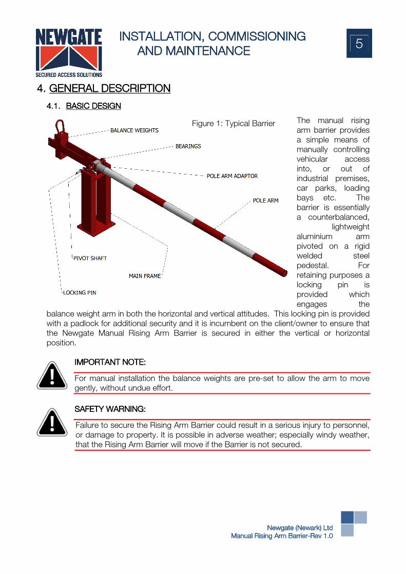
4.4.4.4. GENERALGENERALGENERALGENERAL DESCRIPTIONDESCRIPTIONDESCRIPTIONDESCRIPTION
4.1.4.1.4.1.4.1. BBBBASIC DESIGNASIC DESIGNASIC DESIGNASIC DESIGN
The manual rising
arm barrier provides
a simple means of
manually controlling
vehicular access
into, or out of
industrial premises,
car parks, loading
bays etc. The
barrier is essentially
a counterbalanced,
lightweight
aluminium arm
pivoted on a rigid
welded steel
pedestal. For
retaining purposes a
locking pin is
provided which
engages the
balance weight arm in both the horizontal and vertical attitudes. This locking pin is provided
with a padlock for additional security and it is incumbent on the client/owner to ensure that
the Newgate Manual Rising Arm Barrier is secured in either the vertical or horizontal
position.
IMIMIMIMPORTANT NOTE:PORTANT NOTE:PORTANT NOTE:PORTANT NOTE:
For manual installation the balance weights are pre-set to allow the arm to move
gently, without undue effort.
SAFETY WARNINGSAFETY WARNINGSAFETY WARNINGSAFETY WARNING::::
Failure to secure the Rising Arm Barrier could result in a serious injury to personnel,
or damage to property. It is possible in adverse weather; especially windy weather,
that the Rising Arm Barrier will move if the Barrier is not secured.
Figure 1: Typical Barrier

INSTALLATION, INSTALLATION, INSTALLATION, INSTALLATION, COMMISSIONINGCOMMISSIONINGCOMMISSIONINGCOMMISSIONING
AND MAINTENANCE AND MAINTENANCE AND MAINTENANCE AND MAINTENANCE
MANUALMANUALMANUALMANUAL
6
Newgate (Newark) LtdNewgate (Newark) LtdNewgate (Newark) LtdNewgate (Newark) Ltd
Manual Rising Arm BarrierManual Rising Arm BarrierManual Rising Arm BarrierManual Rising Arm Barrier----Rev 1.0Rev 1.0Rev 1.0Rev 1.0
5.5.5.5. HANDLINGHANDLINGHANDLINGHANDLING
5.1.5.1.5.1.5.1. TTTTRANSPORTINGRANSPORTINGRANSPORTINGRANSPORTING
For transportation purposes, Newgate manual
barriers are always despatched with the pole
removed and the pedestal supplied with its
balance weight arms locked in the vertical
position, for maximum stability.
No specialised equipment is necessary for the
lifting and transportation of a barrier other than
an overhead lifting device, i.e. small crane, block
and tackle or forklift truck, and also a simple two
wheel sack truck, or similar.
5.2.5.2.5.2.5.2. LLLLIFTINGIFTINGIFTINGIFTING
For offloading purposes, it is recommended that nylon slings be attached to the top pivot
shaft between the bearings and lowered from the delivery vehicle to the ground by
whatever suitable appliance is available i.e. fork lift truck or crane. Movement to the desired
location can then be made simply by using a basic two-wheeled sack truck located
underneath the base plate.
Figure 2A: Transporting
Figure 2B: Lifting

INSTALLATION, INSTALLATION, INSTALLATION, INSTALLATION, COMMISSIONINGCOMMISSIONINGCOMMISSIONINGCOMMISSIONING
AND MAINTENANCE AND MAINTENANCE AND MAINTENANCE AND MAINTENANCE
MANUALMANUALMANUALMANUAL
7
Newgate (Newark) LtdNewgate (Newark) LtdNewgate (Newark) LtdNewgate (Newark) Ltd
Manual Rising Arm BarrierManual Rising Arm BarrierManual Rising Arm BarrierManual Rising Arm Barrier----Rev 1.0Rev 1.0Rev 1.0Rev 1.0
6.6.6.6. INSTALLATIONINSTALLATIONINSTALLATIONINSTALLATION
6.1.6.1.6.1.6.1. FFFFOUNDATIOOUNDATIOOUNDATIOOUNDATIONNNNSSSS
If details of the base have not
been specified, we
recommend a concrete mix to
BS EN 206-1:2000 “Concrete
specification, Performance,
Production and Conformity” to
type C32/40, which is equally
suitable for external and
internal environments.
Alternative types of base
construction may be
acceptable, subject to
discussions with our Contract
Engineering Department. It is
notnotnotnot necessary to pre-drill the
base to receive the equipment;
the drilling is carried out when
the equipment is erected. We recommend a minimum of 7 to 10 days for the concrete to
cure, depending on climate. This time can be reduced if additive agents are used.
IMPORTANT NOTE:IMPORTANT NOTE:IMPORTANT NOTE:IMPORTANT NOTE:
Where a tip support is required or if two barrier arms are to meet in the centre of
the road, then bothbothbothboth bases must be at the same level.
When ancillary equipment requires post mounting, (example: card reader, intercom,
keypad etc.) the notes above can be applied. Drawings showing recommended
positions of the equipment and foundation requirements can be supplied with the
relevant data sheets.
Careful consideration should be made when deciding the location of the barrier to
avoid overhead obstructions such as power cables, telephone cables, building
canopies, trees and similar likely constructions, so as not to restrict the barrier arm
in the vertical position.
Accessibility around the whole of the barrier pedestal should be maintained to a
minimum of 1000mm to allow sufficient room for installation, subsequent
maintenance and hand-wind operation.
IMPORTANT NOTE:IMPORTANT NOTE:IMPORTANT NOTE:IMPORTANT NOTE:
Newgate should be consulted immediately should any possible restrictions occur
Figure 3 - Foundation Detail

INSTALLATION, INSTALLATION, INSTALLATION, INSTALLATION, COMMISSIONINGCOMMISSIONINGCOMMISSIONINGCOMMISSIONING
AND MAINTENANCE AND MAINTENANCE AND MAINTENANCE AND MAINTENANCE
MANUALMANUALMANUALMANUAL
8
Newgate (Newark) LtdNewgate (Newark) LtdNewgate (Newark) LtdNewgate (Newark) Ltd
Manual Rising Arm BarrierManual Rising Arm BarrierManual Rising Arm BarrierManual Rising Arm Barrier----Rev 1.0Rev 1.0Rev 1.0Rev 1.0
6.2.6.2.6.2.6.2. BBBBARRIERARRIERARRIERARRIER
It is preferable that installation takes place when expected through traffic is at a minimum.
Position the barrier pedestal, still in its vertical position, onto its prepared concrete base.
The locking pin should be at the rear and the stop bracket at the front (facing the road).
Approximately align the pedestal, so that its centre line is in the position across the road
where it is anticipated the pole will be when in the down position.
Using a 20mm heavy duty masonry bit in a suitable percussion drill, drill through one of the
front (road side) holes in the base plate to a minimum depth of 180mm taking care to keep
the holes free of excessive dust. A 20mm x 160mm long expansion bolt can now be
hammered into the prepared hole, (keeping the nuts in the highest possible position).
Tighten down the single nut so that the barrier is firmly fixed.
Remove the padlock and withdraw the locking pin and raise the balance weight assembly
until it is horizontal and re-insert the locking pin. The pole can now be slid onto the pole
adaptor and secured with the fixing bolts. With the pole now mounted, a check can be
made regarding the alignment of the barrier across the road and adjustment made as
required.
SAFETY WARNINGSAFETY WARNINGSAFETY WARNINGSAFETY WARNING::::
It is strongly recommended, particularly on longer span barriers, to seek assistance
in this operation due to the weight been lifted. The balance weights weigh 16kg
therefore, in some cases it is advisable to remove the counter balance weights before fitting
the pole. Once the pole has been fitted the weights can be reassembled.
Complete the bolting down operation by drilling the three remaining foundation holes and
bolting down as previously described.
Before tightening up the nuts, check that the barrier is vertical, packing as necessary.
Tighten down all four (4) foundation bolts. Cut or Grind off the surplus thread from the bolts
for a neat finish and cap the nut. If levelling is necessary between the base and foundation
ensure any gaps are grouted in using either Chemifix or Standard Cement.
If a tip support is being installed, this can now be positioned, using the pole as a positional
reference, and bolted down in a similar manner using 12mm x 150mm expansion bolts.
If a strainer wire assembly kit is provided, this should now be bolted on and tensioned to
remove any visible “sag” of the barrier arm.
IMPORTANT NOTE:IMPORTANT NOTE:IMPORTANT NOTE:IMPORTANT NOTE:
Always wear safety goggles/ visors when drilling/ hammering into concrete.

INSTALLATION, INSTALLATION, INSTALLATION, INSTALLATION, COMMISSIONINGCOMMISSIONINGCOMMISSIONINGCOMMISSIONING
AND MAINTENANCE AND MAINTENANCE AND MAINTENANCE AND MAINTENANCE
MANUALMANUALMANUALMANUAL
9
Newgate (Newark) LtdNewgate (Newark) LtdNewgate (Newark) LtdNewgate (Newark) Ltd
Manual Rising Arm BarrierManual Rising Arm BarrierManual Rising Arm BarrierManual Rising Arm Barrier----Rev 1.0Rev 1.0Rev 1.0Rev 1.0
7.7.7.7. MECHANICAL ADJUSTMENTSMECHANICAL ADJUSTMENTSMECHANICAL ADJUSTMENTSMECHANICAL ADJUSTMENTS
7.1.7.1.7.1.7.1. BALANCE WEIGHTBALANCE WEIGHTBALANCE WEIGHTBALANCE WEIGHT ADJUSTMENTADJUSTMENTADJUSTMENTADJUSTMENT
Before despatch; the balance weights
are pre-set to balance the pole as
supplied and therefore, should require
no further adjustment. However,
should it be necessary to shorten the
pole from the length supplied due to
unforeseen circumstances, it may be
necessary to adjust the balance
weights accordingly.
This can be achieved by slackening the tie bolt nuts holding the balance weights in position
and carefully tapping the weights in or out as required, so that balance is achieved just
sufficient to prevent the arm lifting on its own. Care should always to be taken when
handling these weights.
IMPORTANT NOTE:IMPORTANT NOTE:IMPORTANT NOTE:IMPORTANT NOTE:
This operation should only be carried out with the barrier restricted in its horizontal
position.
Figure 4: Balance Weight Adjustment
INSTALLATION, INSTALLATION, INSTALLATION, INSTALLATION, COMMISSIONINGCOMMISSIONINGCOMMISSIONINGCOMMISSIONING
AND MAINTENANCE AND MAINTENANCE AND MAINTENANCE AND MAINTENANCE
MANUALMANUALMANUALMANUAL
10
Newgate (Newark) LtdNewgate (Newark) LtdNewgate (Newark) LtdNewgate (Newark) Ltd
Manual Rising Arm BarrierManual Rising Arm BarrierManual Rising Arm BarrierManual Rising Arm Barrier----Rev 1.0Rev 1.0Rev 1.0Rev 1.0
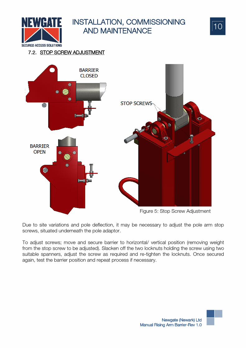
7.2.7.2.7.2.7.2. STOP SCREWSTOP SCREWSTOP SCREWSTOP SCREW ADJUSTMENTADJUSTMENTADJUSTMENTADJUSTMENT
Due to site variations and pole deflection, it may be necessary to adjust the pole arm stop
screws, situated underneath the pole adaptor.
To adjust screws; move and secure barrier to horizontal/ vertical position (removing weight
from the stop screw to be adjusted). Slacken off the two locknuts holding the screw using two
suitable spanners, adjust the screw as required and re-tighten the locknuts. Once secured
again, test the barrier position and repeat process if necessary.
Figure 5: Stop Screw Adjustment

INSTALLATION, INSTALLATION, INSTALLATION, INSTALLATION, COMMISSIONINGCOMMISSIONINGCOMMISSIONINGCOMMISSIONING
AND MAINTENANCE AND MAINTENANCE AND MAINTENANCE AND MAINTENANCE
MANUALMANUALMANUALMANUAL
11
Newgate (Newark) LtdNewgate (Newark) LtdNewgate (Newark) LtdNewgate (Newark) Ltd
Manual Rising Arm BarrierManual Rising Arm BarrierManual Rising Arm BarrierManual Rising Arm Barrier----Rev 1.0Rev 1.0Rev 1.0Rev 1.0
8.8.8.8. COMMISSIONINGCOMMISSIONINGCOMMISSIONINGCOMMISSIONING
It is preferable that both the installation and commissioning take place when expected through
traffic is at a minimum to avoid disruption.
SAFETY SAFETY SAFETY SAFETY NOTICE:NOTICE:NOTICE:NOTICE:
DO NOT place your hands/ fingers inside the barrier when the operating.
INSTALLATION, INSTALLATION, INSTALLATION, INSTALLATION, COMMISSIONINGCOMMISSIONINGCOMMISSIONINGCOMMISSIONING
AND MAINTENANCE AND MAINTENANCE AND MAINTENANCE AND MAINTENANCE
MANUALMANUALMANUALMANUAL
12
Newgate (Newark) LtdNewgate (Newark) LtdNewgate (Newark) LtdNewgate (Newark) Ltd
Manual Rising Arm BarrierManual Rising Arm BarrierManual Rising Arm BarrierManual Rising Arm Barrier----Rev 1.0Rev 1.0Rev 1.0Rev 1.0
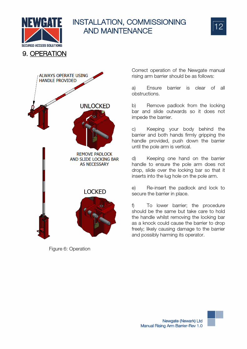
9.9.9.9. OPERATIONOPERATIONOPERATIONOPERATION
Correct operation of the Newgate manual
rising arm barrier should be as follows:
a) Ensure barrier is clear of all
obstructions.
b) Remove padlock from the locking
bar and slide outwards so it does not
impede the barrier.
c) Keeping your body behind the
barrier and both hands firmly gripping the
handle provided, push down the barrier
until the pole arm is vertical.
d) Keeping one hand on the barrier
handle to ensure the pole arm does not
drop, slide over the locking bar so that it
inserts into the lug hole on the pole arm.
e) Re-insert the padlock and lock to
secure the barrier in place.
f) To lower barrier; the procedure
should be the same but take care to hold
the handle whilst removing the locking bar
as a knock could cause the barrier to drop
freely; likely causing damage to the barrier
and possibly harming its operator.
Figure 6: Operation

INSTALLATION, INSTALLATION, INSTALLATION, INSTALLATION, COMMISSIONINGCOMMISSIONINGCOMMISSIONINGCOMMISSIONING
AND MAINTENANCE AND MAINTENANCE AND MAINTENANCE AND MAINTENANCE
MANUALMANUALMANUALMANUAL
13
Newgate (Newark) LtdNewgate (Newark) LtdNewgate (Newark) LtdNewgate (Newark) Ltd
Manual Rising Arm BarrierManual Rising Arm BarrierManual Rising Arm BarrierManual Rising Arm Barrier----Rev 1.0Rev 1.0Rev 1.0Rev 1.0
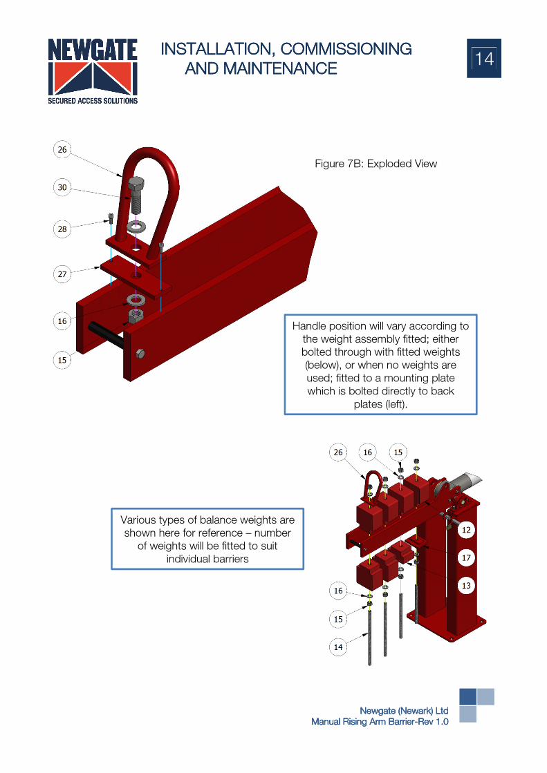
10.10.10.10. MANUAL TRAFFIC MANUAL TRAFFIC MANUAL TRAFFIC MANUAL TRAFFIC BARRIER BARRIER BARRIER BARRIER –––– GENERAL ASSEMBLYGENERAL ASSEMBLYGENERAL ASSEMBLYGENERAL ASSEMBLY
10.1.10.1.10.1.10.1. MANUALMANUALMANUALMANUAL TRAFFIC BARRIER TRAFFIC BARRIER TRAFFIC BARRIER TRAFFIC BARRIER –––– EXPLODED DIAGRAMSEXPLODED DIAGRAMSEXPLODED DIAGRAMSEXPLODED DIAGRAMS
Figure 7A: Exploded View
INSTALLATION, INSTALLATION, INSTALLATION, INSTALLATION, COMMISSIONINGCOMMISSIONINGCOMMISSIONINGCOMMISSIONING
AND MAINTENANCE AND MAINTENANCE AND MAINTENANCE AND MAINTENANCE
MANUALMANUALMANUALMANUAL
14
Newgate (Newark) LtdNewgate (Newark) LtdNewgate (Newark) LtdNewgate (Newark) Ltd
Manual Rising Arm BarrierManual Rising Arm BarrierManual Rising Arm BarrierManual Rising Arm Barrier----Rev 1.0Rev 1.0Rev 1.0Rev 1.0
Handle position will vary according to
the weight assembly fitted; either
bolted through with fitted weights
(below), or when no weights are
used; fitted to a mounting plate
which is bolted directly to back
plates (left).
Various types of balance weights are
shown here for reference – number
of weights will be fitted to suit
individual barriers
Figure 7B: Exploded View

INSTALLATION, INSTALLATION, INSTALLATION, INSTALLATION, COMMISSIONINGCOMMISSIONINGCOMMISSIONINGCOMMISSIONING
AND MAINTENANCE AND MAINTENANCE AND MAINTENANCE AND MAINTENANCE
MANUALMANUALMANUALMANUAL
15
Newgate (Newark) LtdNewgate (Newark) LtdNewgate (Newark) LtdNewgate (Newark) Ltd
Manual Rising Arm BarrierManual Rising Arm BarrierManual Rising Arm BarrierManual Rising Arm Barrier----Rev 1.0Rev 1.0Rev 1.0Rev 1.0
10.2.10.2.10.2.10.2. MANUALMANUALMANUALMANUAL TRAFFIC BARRIER TRAFFIC BARRIER TRAFFIC BARRIER TRAFFIC BARRIER –––– SPARE PARTSSPARE PARTSSPARE PARTSSPARE PARTS
ItemItemItemItem DescriptionDescriptionDescriptionDescription Part NumberPart NumberPart NumberPart Number (3” Pole)(3” Pole)(3” Pole)(3” Pole) Part NumberPart NumberPart NumberPart Number (4” Pole(4” Pole(4” Pole(4” Pole)))) 01 Main frame 305/02/10161 305/02/10161
02 Pole arm adaptor 652/03/10088 655/03/10162
03 Back plate (with Lug) 405/03/10167 405/03/10165
04 Back plate (without Lug) 405/03/10166 405/03/10164
05 Spacer 605/03/10168 Not Used
06 Pivot shaft 605/03/10169 605/03/10169
07 Bearing 550/04/10330 550/04/10330
08 M12 Nyloc nut 914/00/12000 914/00/12000
09 M12 Round Washer 915/00/12000 915/00/12000
10 M12 x 40 Hex Hd. bolt 910/00/12040 910/00/12040
11 M12 x 150/160 Hex Hd. bolt 910/00/12150 910/00/12160
12 Balance weight (Full) 805/03/10170/00 805/03/10170/00
13 Balance weight (Half) 805/03/10170/01 805/03/10170/01
14 M20 Screwed rod 918/30/03000 918/30/03000
15 M20 Nyloc nut 914/00/20000 914/00/20000
16 M20 Washer 915/00/20000 915/00/20000
17 Blank make up piece 305/03/10173 305/03/10173
18 Spacer tube 605/03/10174 605/03/10174
19 Roll pin (Stainless steel) 941/00/03024 941/00/03024
20 Roll pin 941/04/08040 941/04/08040
21 M12 Hex nut 912/00/12000 912/00/12000
22 M12 x 55 Hex screw 911/00/12055 911/00/12055
23 Pole arm 984/30/00000/000 984/30/00000/000
24 Locking pin 605/03/10175 605/03/10175
25 Padlock 000/-/00000/049 000/-/00000/049
26 Manual handle 305/03/24228 305/03/24228
27 Handle mounting plate 405/03/24810 405/03/24810
28 M6 x 16 Skt. Cap screw 919/00/06016 919/00/06016
29 Ferrule Ø18 Type ‘D’ 803/04/22912 Not Used
30 M20 x 65 Hex Hd. bolt 910/00/20065 910/00/20065
INSTALLATION, INSTALLATION, INSTALLATION, INSTALLATION, COMMISSIONINGCOMMISSIONINGCOMMISSIONINGCOMMISSIONING
AND MAINTENANCE AND MAINTENANCE AND MAINTENANCE AND MAINTENANCE
MANUALMANUALMANUALMANUAL
16
Newgate (Newark) LtdNewgate (Newark) LtdNewgate (Newark) LtdNewgate (Newark) Ltd
Manual Rising Arm BarrierManual Rising Arm BarrierManual Rising Arm BarrierManual Rising Arm Barrier----Rev 1.0Rev 1.0Rev 1.0Rev 1.0
11.11.11.11. MAINTENANCEMAINTENANCEMAINTENANCEMAINTENANCE
11.1.11.1.11.1.11.1. BEFORE CARRYING OUT MAINTENANCEBEFORE CARRYING OUT MAINTENANCEBEFORE CARRYING OUT MAINTENANCEBEFORE CARRYING OUT MAINTENANCE
The following must all be completed before starting maintenance of gate;
i. Obtain a Work Permit.
ii. Area to be cordoned off (using warning signs).
iii. Complete Risk Assessment for maintenance task (for example risk assessment see
13. Risk Assessment (Example)
11.2.11.2.11.2.11.2. WHILST CARRYING OUT MAINTENANCEWHILST CARRYING OUT MAINTENANCEWHILST CARRYING OUT MAINTENANCEWHILST CARRYING OUT MAINTENANCE
The following must all be adhered to whilst carrying out maintenance of gate;
i. The site Health & Safety Rules and Regulations are to be adhered to and observed
at all times.
ii. Personal Protective Equipment is to be worn at all times whilst on site (i.e. Hi-Vis
clothing, safety boots, safety glasses, ear defenders, gloves etc.)
11.3.11.3.11.3.11.3. AFTER CARRYING OUT MAINTENANCEAFTER CARRYING OUT MAINTENANCEAFTER CARRYING OUT MAINTENANCEAFTER CARRYING OUT MAINTENANCE
The following must all be completed after completing maintenance of gate;
i. Remove cordoned off area.
ii. Depart the site leaving the area clean and tidy.
11.4.11.4.11.4.11.4. ORDERING SPARE PARTSORDERING SPARE PARTSORDERING SPARE PARTSORDERING SPARE PARTS
SAFETY WARNING:SAFETY WARNING:SAFETY WARNING:SAFETY WARNING:
By using non-genuine Newgate parts you are potentially compromising the
machine, causing risk to all those using the barrier.
Spare parts can be obtained by contacting Newgate parts department, for typical spare
parts see ’12.7 Spare Parts’.
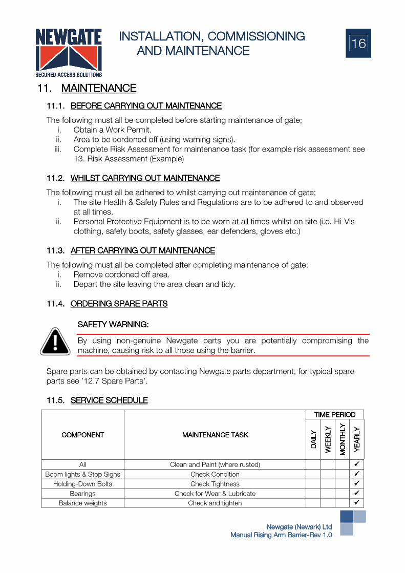
11.5.11.5.11.5.11.5. SERVICE SERVICE SERVICE SERVICE SCHEDULESCHEDULESCHEDULESCHEDULE
COMPONENTCOMPONENTCOMPONENTCOMPONENT MAINTENANCE TASKMAINTENANCE TASKMAINTENANCE TASKMAINTENANCE TASK
TIME PERIODTIME PERIODTIME PERIODTIME PERIOD
DAILY
DAILY
DAILY
DAILY
WEEKLY
WEEKLY
WEEKLY
WEEKLY
MONTHLY
MONTHLY
MONTHLY
MONTHLY
YEARLY
YEARLY
YEARLY
YEARLY
All Clean and Paint (where rusted) ����
Boom lights & Stop Signs Check Condition ����
Holding-Down Bolts Check Tightness ����
Bearings Check for Wear & Lubricate ����
Balance weights Check and tighten ����
INSTALLATION, INSTALLATION, INSTALLATION, INSTALLATION, COMMISSIONINGCOMMISSIONINGCOMMISSIONINGCOMMISSIONING
AND MAINTENANCE AND MAINTENANCE AND MAINTENANCE AND MAINTENANCE
MANUALMANUALMANUALMANUAL
17
Newgate (Newark) LtdNewgate (Newark) LtdNewgate (Newark) LtdNewgate (Newark) Ltd
Manual Rising Arm BarrierManual Rising Arm BarrierManual Rising Arm BarrierManual Rising Arm Barrier----Rev 1.0Rev 1.0Rev 1.0Rev 1.0
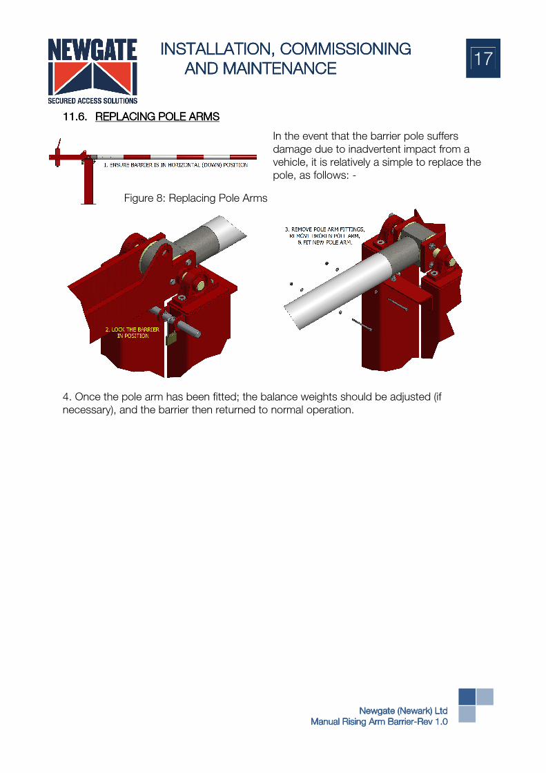
11.6.11.6.11.6.11.6. REPLACING POLE ARMSREPLACING POLE ARMSREPLACING POLE ARMSREPLACING POLE ARMS
In the event that the barrier pole suffers
damage due to inadvertent impact from a
vehicle, it is relatively a simple to replace the
pole, as follows: -
4. Once the pole arm has been fitted; the balance weights should be adjusted (if
necessary), and the barrier then returned to normal operation.
Figure 8: Replacing Pole Arms
INSTALLATION, INSTALLATION, INSTALLATION, INSTALLATION, COMMISSIONINGCOMMISSIONINGCOMMISSIONINGCOMMISSIONING
AND MAINTENANCE AND MAINTENANCE AND MAINTENANCE AND MAINTENANCE
MANUALMANUALMANUALMANUAL
18
Newgate (Newark) LtdNewgate (Newark) LtdNewgate (Newark) LtdNewgate (Newark) Ltd
Manual Rising Arm BarrierManual Rising Arm BarrierManual Rising Arm BarrierManual Rising Arm Barrier----Rev 1.0Rev 1.0Rev 1.0Rev 1.0
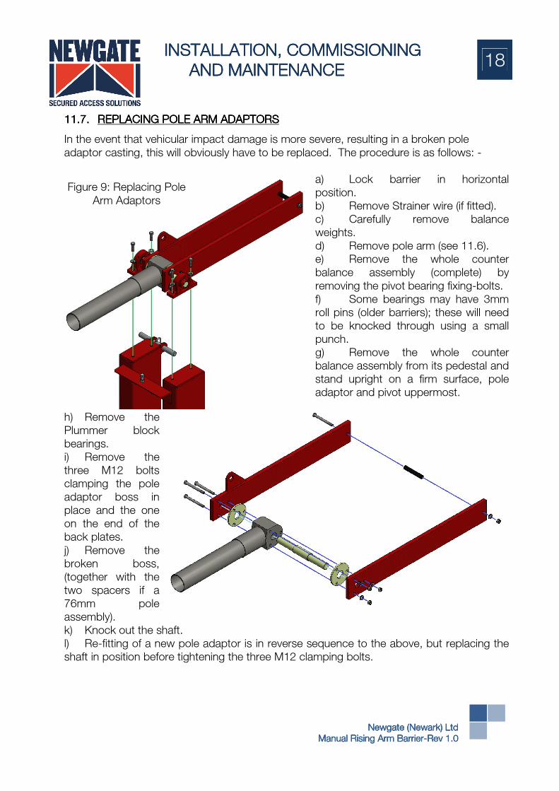
11.7.11.7.11.7.11.7. REPLACING POLE ARM ADAPTORSREPLACING POLE ARM ADAPTORSREPLACING POLE ARM ADAPTORSREPLACING POLE ARM ADAPTORS
In the event that vehicular impact damage is more severe, resulting in a broken pole
adaptor casting, this will obviously have to be replaced. The procedure is as follows: -
a) Lock barrier in horizontal
position.
b) Remove Strainer wire (if fitted).
c) Carefully remove balance
weights.
d) Remove pole arm (see 11.6).
e) Remove the whole counter
balance assembly (complete) by
removing the pivot bearing fixing-bolts.
f) Some bearings may have 3mm
roll pins (older barriers); these will need
to be knocked through using a small
punch.
g) Remove the whole counter
balance assembly from its pedestal and
stand upright on a firm surface, pole
adaptor and pivot uppermost.
h) Remove the
Plummer block
bearings.
i) Remove the
three M12 bolts
clamping the pole
adaptor boss in
place and the one
on the end of the
back plates.
j) Remove the
broken boss,
(together with the
two spacers if a
76mm pole
assembly).
k) Knock out the shaft.
l) Re-fitting of a new pole adaptor is in reverse sequence to the above, but replacing the
shaft in position before tightening the three M12 clamping bolts.
Figure 9: Replacing Pole
Arm Adaptors

INSTALLATION, INSTALLATION, INSTALLATION, INSTALLATION, COMMISSIONINGCOMMISSIONINGCOMMISSIONINGCOMMISSIONING
AND MAINTENANCE AND MAINTENANCE AND MAINTENANCE AND MAINTENANCE
MANUALMANUALMANUALMANUAL
19
Newgate (Newark) LtdNewgate (Newark) LtdNewgate (Newark) LtdNewgate (Newark) Ltd
Manual Rising Arm BarrierManual Rising Arm BarrierManual Rising Arm BarrierManual Rising Arm Barrier----Rev 1.0Rev 1.0Rev 1.0Rev 1.0
11.8.11.8.11.8.11.8. METHOD STATEMENTMETHOD STATEMENTMETHOD STATEMENTMETHOD STATEMENT
MAINTENANCE OF A MANUAL RISING ARM BARRIER
1. On arrive on site report Works Engineer/Security/Reception for Induction/Briefing.
2. Obtain a Work Permit.
3. Cordon off area off. (using Warning Signs)
4. Wear Personal Protective Equipment as and when required. ( Hard Hat, Safety Glasses,
High Vis Jackets, Gloves , Safety Boots)
5. Check for damage.
6. Check Mounting bolts to the pedestal frame.
7. Check the Tip Support Frame for damage.
8. If Fitted check the strainer wire for tension
9. Check the Counter Balance Weights are secure.
10. Check the Pivot Shaft and bearings. 11. Check the Locking Mechanism
12. Wipe down and clean the Manual Barrier
13. Test 14. Remove cordoned off area
15. Inform client on completion, test and demonstrate if required.
16. Depart the site leaving the area clean and tidy.

INSTALLATION, INSTALLATION, INSTALLATION, INSTALLATION, COMMISSIONINGCOMMISSIONINGCOMMISSIONINGCOMMISSIONING
AND MAINTENANCE AND MAINTENANCE AND MAINTENANCE AND MAINTENANCE
MANUALMANUALMANUALMANUAL
20
Newgate (Newark) LtdNewgate (Newark) LtdNewgate (Newark) LtdNewgate (Newark) Ltd
Manual Rising Arm BarrierManual Rising Arm BarrierManual Rising Arm BarrierManual Rising Arm Barrier----Rev 1.0Rev 1.0Rev 1.0Rev 1.0
11.9.11.9.11.9.11.9. RRRRISK ASSESSMENTISK ASSESSMENTISK ASSESSMENTISK ASSESSMENT
MAINTENANCE OF A MANUAL RISING ARM BARRIER
HAZARDS WHICH CAN BE FORESEEN:
1. Tripping hazards eg cables, extension leads, stored materials on site
2. Injuries due to lifting heavy objects.
3. Contact with hazardous substances
4. Oncoming vehicular traffic
5. Other Contractors working nearby.
6. Pedestrians
7. Hand entrapment.
CONTROLS IN PLACE TO MINIMISE THE RISK:
1. Operators trained and conversant with the mechanics of the barrier operating system.
2. Correct Manual Handling Training techniques to be adhered to at all times.
3. Care is to be exercised to reduce tripping hazards, e.g. removing such hazards away
from the working area.
4. Working area to be cordoned off prior to commencing work.
5. Operators to wear Hi Vis Coats/Waistcoats/Waterproofs.
6. PPE to be worn as and when required and in line with Newgate (Newark) Ltd Policy. .
(Hard Hat, Safety Glasses, High Vis Jackets, Gloves, Safety Boots)
7. COSHH Regulations to be observed at all times.
8. Operatives are to be made aware of the clients Health and Safety Procedure and
Emergency Action Plan.
9. Cuts. All vehicle carry First Aid kits.
10. Fire. All vehicles carry Fire Extinguishers

INSTALLATION, INSTALLATION, INSTALLATION, INSTALLATION, COMMISSIONINGCOMMISSIONINGCOMMISSIONINGCOMMISSIONING
AND MAINTENANCE AND MAINTENANCE AND MAINTENANCE AND MAINTENANCE
MANUALMANUALMANUALMANUAL
21
Newgate (Newark) LtdNewgate (Newark) LtdNewgate (Newark) LtdNewgate (Newark) Ltd
Manual Rising Arm BarrierManual Rising Arm BarrierManual Rising Arm BarrierManual Rising Arm Barrier----Rev 1.0Rev 1.0Rev 1.0Rev 1.0
11.10.11.10.11.10.11.10. LUBRICATIONLUBRICATIONLUBRICATIONLUBRICATION
The only moving component on a Newgate Manual Rising Arm Barrier is the pivot shaft and
bearings. The bearings are “Sealed for Life” Plummer Blocks however, it is recommended
that routine maintenance is carried out throughout the life of the equipment to inspect the
Pivot Shaft, Bearings and other components e.g. Barrier Pole, Balance Weights and Plinth
Bolts
For further assistance, our Technical Department (Tel: 01636 700172) or Services
Department (Tel: 01636 704000) should be consulted.

INSTALLATION, INSTALLATION, INSTALLATION, INSTALLATION, COMMISSIONINGCOMMISSIONINGCOMMISSIONINGCOMMISSIONING
AND MAINTENANCE AND MAINTENANCE AND MAINTENANCE AND MAINTENANCE
MANUALMANUALMANUALMANUAL
22
Newgate (Newark) LtdNewgate (Newark) LtdNewgate (Newark) LtdNewgate (Newark) Ltd
Manual Rising Arm BarrierManual Rising Arm BarrierManual Rising Arm BarrierManual Rising Arm Barrier----Rev 1.0Rev 1.0Rev 1.0Rev 1.0
11.11.11.11.11.11.11.11. VARIATIONSVARIATIONSVARIATIONSVARIATIONS
The Newgate manual rising arm barrier is also ideal for sequentially controlling vehicular
traffic in hazardous areas, such as tanker loading bays, whereby certain operations have to
take place in a predetermined and interlocked sequence. For this type of application, a
special dead bolt is incorporated to replace the normal padlock, engaging in a modified
locking pin, together with a modified backplate, which only allows the barrier to be fully
locked, and permit key removal in the lowered position.
The type of lock fitted for this purpose is “Fortress Interlock” model H 31Q or H31Q2,
(single or double key unit) or a castell K6.35.
The locking bar is modified to replace the padlock hole with a notch, to be engaged by the
interlock, the bar is also spring loaded. This means that the barrier can only be restrained in
the raised position but
cannot be locked; to
engage the locking one
must release the
interlock using a special
key that may only be
removed once the
interlock has locked the
bar again.
Figure 10: Deadlock Interlocks
INSTALLATION, INSTALLATION, INSTALLATION, INSTALLATION, COMMISSIONINGCOMMISSIONINGCOMMISSIONINGCOMMISSIONING
AND MAINTENANCE AND MAINTENANCE AND MAINTENANCE AND MAINTENANCE
MANUALMANUALMANUALMANUAL
23
Newgate (Newark) LtdNewgate (Newark) LtdNewgate (Newark) LtdNewgate (Newark) Ltd
Manual Rising Arm BarrierManual Rising Arm BarrierManual Rising Arm BarrierManual Rising Arm Barrier----Rev 1.0Rev 1.0Rev 1.0Rev 1.0
12.12.12.12. EC DECLARATION OF CONFORMITYEC DECLARATION OF CONFORMITYEC DECLARATION OF CONFORMITYEC DECLARATION OF CONFORMITY
INSTALLATION, INSTALLATION, INSTALLATION, INSTALLATION, COMMISSIONINGCOMMISSIONINGCOMMISSIONINGCOMMISSIONING
AND MAINTENANCE AND MAINTENANCE AND MAINTENANCE AND MAINTENANCE
MANUALMANUALMANUALMANUAL
24
Newgate (Newark) LtdNewgate (Newark) LtdNewgate (Newark) LtdNewgate (Newark) Ltd
Manual Rising Arm BarrierManual Rising Arm BarrierManual Rising Arm BarrierManual Rising Arm Barrier----Rev 1.0Rev 1.0Rev 1.0Rev 1.0
13.13.13.13. REVISION RECORDREVISION RECORDREVISION RECORDREVISION RECORD
Rev. Rev. Rev. Rev.
No.No.No.No.
Revision DescriptionRevision DescriptionRevision DescriptionRevision Description DateDateDateDate
1.0 Original Issue 30-08-13

INSTALLATION, INSTALLATION, INSTALLATION, INSTALLATION, COMMISSIONINGCOMMISSIONINGCOMMISSIONINGCOMMISSIONING
AND MAINTENANCE AND MAINTENANCE AND MAINTENANCE AND MAINTENANCE
MANUALMANUALMANUALMANUAL
25
Newgate (Newark) LtdNewgate (Newark) LtdNewgate (Newark) LtdNewgate (Newark) Ltd
Manual Rising Arm BarrierManual Rising Arm BarrierManual Rising Arm BarrierManual Rising Arm Barrier----Rev 1.0Rev 1.0Rev 1.0Rev 1.0
14.14.14.14. SERVICE SERVICE SERVICE SERVICE –––– REPAIR REPAIR REPAIR REPAIR LOGLOGLOGLOG
DATEDATEDATEDATE REPAIR No.REPAIR No.REPAIR No.REPAIR No. SERVICESERVICESERVICESERVICE NEXT DUENEXT DUENEXT DUENEXT DUE
01-01-2010 123456 Annual Service 01-01-2011

INSTALLATION, INSTALLATION, INSTALLATION, INSTALLATION, COMMISSIONINGCOMMISSIONINGCOMMISSIONINGCOMMISSIONING
AND MAINTENANCE AND MAINTENANCE AND MAINTENANCE AND MAINTENANCE
MANUALMANUALMANUALMANUAL
26
Newgate (Newark) LtdNewgate (Newark) LtdNewgate (Newark) LtdNewgate (Newark) Ltd
Manual Rising Arm BarrierManual Rising Arm BarrierManual Rising Arm BarrierManual Rising Arm Barrier----Rev 1.0Rev 1.0Rev 1.0Rev 1.0
15.15.15.15. APPENDIX 1APPENDIX 1APPENDIX 1APPENDIX 1


