R
MOS GB 0538-1 511351FIGHTER 360P
INSTALLATION AND MAINTENANCE INSTRUCTIONS
FIGHTER 360P230 V
LEK
+20-2
A B A B A BI II III I II I II

LE
K
Fighter 310PFighter 310P
LE
K
Fighter 310PFighter 310P
1
2
LE
K
Fighter 310PFighter 310P
LE
K
Fighter 310PFighter 310P
3
4
5

Contents 1
FIGHTER 360P
For Home Owners
General information for the installerTransport and storage .......................................... 10Handling .............................................................. 10Lifting straps ........................................................ 10Erecting the heat pump ........................................ 11Hard water areas .................................................. 11Maximum boiler and radiator volumes ................ 11Inspection of the installation ................................ 11Electric boiler mode .............................................. 11
Pipe connectionsGeneral ................................................................ 12Tap water connection .......................................... 13Expansion vessel, tap water ................................ 13Pump and pressure drop diagrams........................13
Ventilation connectionVentilation flow .................................................... 14Kitchen duct ........................................................ 14Adjustment .......................................................... 14Duct installation .................................................... 14Fan diagram ........................................................ 14
Electrical connectionsConnection .......................................................... 15Output as set at the factory .................................. 15Resetting the temperature limiter ........................ 15Immersion heater ................................................ 15Max current .......................................................... 16Connecting the outside sensor ............................ 16Access to the lower electrical connections .......... 16Centralised load control ...................................... 17External contacts ................................................ 18Alarm/alarm outputs ............................................ 19
Commissioning and adjustingPreparations ........................................................ 20Filling the water heater and the heating system .... 20Venting the heating system .................................. 20Starting ................................................................ 20Setting the ventilation .......................................... 21Readjustment ...................................................... 21Setting the fan capacity ...................................... 21Draining the heating system ................................ 21Cleaning the system / Flushing out of the
water heater and central heating system .......... 21Opening the front panel ........................................ 22
Setting the automatic heating controlsOffset heating curve -2 ........................................ 23Offset heating curve 0 .......................................... 23Offset heating curve +2 ........................................ 23Setting with diagrams .......................................... 23
ControlChanging parameters .......................................... 24Menu tree ............................................................ 25Main menus .......................................................... 291.0 Temp. HW-sensor .......................................... 302.0 Flow temperature .......................................... 303.0 Flow temperature 2 ........................................ 314.0 Outdoor temperature ...................................... 325.0 Evaporating temperature ................................337.0 Clock .............................................................. 348.0 Other settings ................................................ 369.0 Service menu ................................................ 39
Actions with operating disturbancesLow temperature or a lack of hot water ................ 44Low or a lack of ventilation .................................. 44Low room temperature ........................................ 44High room temperature ........................................ 44Switch position “ ” .......................................... 44Cleaning the fan .................................................. 44Alarm indications on the display .......................... 45Resetting the temperature limiter ........................ 46Resetting the high pressure switch ...................... 46Resetting the miniature circuit breakers .............. 46High extract air temperature ................................ 46
ServiceHelping the circulation pump to start .................... 47Cleaning the circulation pump .............................. 47
Component positionsComponent locations .......................................... 48
List of componentsList of components .............................................. 49
Circuit diagramCircuit diagram .................................................... 50
SensorsSensor placement ................................................ 51Temperature sensor data .................................... 51
DimensionsDimensions and setting-out coordinates .............. 52Measuring principle .............................................. 52
Technical specificationsTechnical specifications ...................................... 53Enclosed kit .......................................................... 53
AccessoriesAccessories .......................................................... 54
GeneralConcise product description ................................ 2Setting table ........................................................ 2
System descriptionPrinciple of operation .......................................... 3System diagram .................................................. 3
Front panelLayout .................................................................. 4Explanation .......................................................... 4
Room temperatureAutomatic heating control system ........................ 6Basic setting.......................................................... 7Changing the room temperature .......................... 7
Maintenance routinesCleaning the air filter ............................................ 8Cleaning the ventilation devices .......................... 8Checking the safety valves .................................. 9Pressure gauge .................................................. 9Extract air temperature ........................................ 9
For the Installer

General
FIGHTER 360P
2
Installation date
Installer
The serial number (103), should always be stated with
all correspondence with NIBE.
089_ _ _ _ _ _ _ _ _ _ _
Chosen output, immersion heater
Pre-pressure in the expansion vessel (0.5 bar on delivery)
Circulation pump setting
Selected fan curve, normal speed
Selected fan curve, speed I
Selected fan curve, speed II
Setting Heating curve selection
Setting Offset heating curve
To be filled in when the heat pump has beeninstalled
In order to get the ultimate benefit from your heat pump FIGHTER 360P you should readthrough this Installation and Maintenance Instruction.
FIGHTER 360P is an exhaust air heat pump. This means that it collects the energy in the ventilation air and uses it for hot water and room heating.
Microprocessors ensure that the heat pump always works efficiently.
FIGHTER 360P is a Swedish-made quality product which will last a long time and run reli-ably without unpleasant surprises.
For the installation engineer: Please, hand over to the home owner his manual afterfinalised installation.
For Home Owners
Maxiumum water supply pressure
Immersion heater R50 / 8000W / 230 V
Expansion vessel, tap water, 3,5 barcharge pressure
Expansion vessel, heating water, 0,5 barcharge pressure
Pressure reduction valve, setting 3,5 bar
Mass, unit, filled with water 435 kg
Manufacter:NIBE ABBox 14 Järnvägsgatan 40285 21 MARKARYDSWEDEN
Operating pressure, tap water
Volume, water heater 170 litres
Maximum primary working pressure (heating side)
Set opening pressure of temperature and pressure valve
Set opening pressure relief valve 6 bar
Set opening, temperature limiter, immersion heater
Heating up time from 15 °C to stop temperature ... h ... minfor compressor
Re-heating time, 70 % of total volume (only ... h ... mincompressor working)
Set opening, temperature limiter, compressor
16 bar
6 bar
7 bar
2,5 bar
88 °C
88 °C

System description 3For Home Owners
FIGHTER 360P
FIGHTER 360P comprises an electric boiler with acopper lined water heater and a heat pump whichrecovers energy from the ventilation air. The recov-ered energy is supplied to the heat pump. The heatpump must be installed in a ventilation system intend-ed for mechanical exhaust air.
The output of the immersion heater is max 8.0 kW(Supplied output of 6.0 kW).
When the exhaust air at room temperature passesthrough the evaporator, the refrigerant evaporatesbecause of its low boiling point. In this way the heat inthe room air is transferred to the refrigerant.
The refrigerant is then compressed in a compressor,causing the temperature to rise considerably.
The warm refrigerant is fed to the condenser, which isin the boiler water. Here the refrigerant gives off itsheat to the boiler water, so that its temperature dropsand the refrigerant changes state from gas to liquid.
The refrigerant then goes via filters to the expansionvalve, where the pressure and temperature are furtherreduced.
The refrigerant has now completed its circulation andreturns to the evaporator.
FrånluftAvluft
Förångare
Expansionsventil
Kompressor
Frånluftsfläkt
Kondensor
Elpatron
LEK
When the room air haspassed through the heatpump it is discharged. Thetemperature of the air hasbeen significantly reducedas the heat pump hasextracted the energy in theroom air.
The air from thekitchen fan goesdirectly out into aseparate duct.
The warm roomair is fed toFIGHTER 360P
FIGHTER 360P suppliesthe house with both hotwater and room heating.
Outdoor air is drawninto the house.
The warm room air isdrawn into the air ductsystem.
Air is transportedfrom rooms withoutdoor air devices torooms with exhaustair devices.
Principle of operation
System diagram
Extract air
Evaporator
Expansion valve
Exhaust air
Compressor
Immersionheater
Exhaust air fan
Condenser
Front panel
FIGHTER 360P
For Home Owners
4
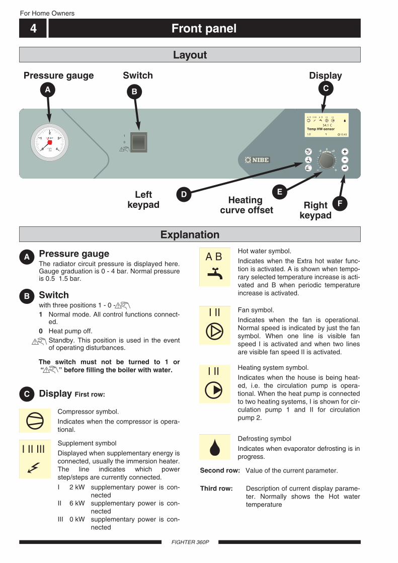
Pressure gauge The radiator circuit pressure is displayed here.Gauge graduation is 0 - 4 bar. Normal pressureis 0.5 1.5 bar.
Display
2
1 b a r 3
0 4
A B A BI II III I II I II
54.1 CTemp. VV-givare
1.0 13.43
SwitchPressure gauge
A
B
C
Left keypad Heating
curve offset
Switchwith three positions 1 - 0 -1 Normal mode. All control functions connect-
ed. 0 Heat pump off.
Standby. This position is used in the eventof operating disturbances.
Display First row:
Layout
Explanation
A CB
D E
Right keypad
F
I II III
A B
I II
I II
Compressor symbol.
Indicates when the compressor is opera-tional.
The switch must not be turned to 1 or “ ” before filling the boiler with water.
Supplement symbol
Displayed when supplementary energy isconnected, usually the immersion heater.The line indicates which powerstep/steps are currently connected.
I 2 kW supplementary power is con-nected
II 6 kW supplementary power is con-nected
III 0 kW supplementary power is con-nected
Hot water symbol.
Indicates when the Extra hot water func-tion is activated. A is shown when tempo-rary selected temperature increase is acti-vated and B when periodic temperatureincrease is activated.
Fan symbol.
Indicates when the fan is operational.Normal speed is indicated by just the fansymbol. When one line is visible fanspeed I is activated and when two linesare visible fan speed II is activated.
Heating system symbol.
Indicates when the house is being heat-ed, i.e. the circulation pump is opera-tional. When the heat pump is connectedto two heating systems, I is shown for cir-culation pump 1 and II for circulationpump 2.
Defrosting symbol
Indicates when evaporator defrosting is inprogress.
Value of the current parameter.Second row:
Description of current display parame-ter. Normally shows the Hot watertemperature
Third row:
Temp HW-sensor

Front panel 5For Home Owners
FIGHTER 360P
Show the current menu number.Fourth row:
Left keypad
Right keypad
Offset heating curveE
D
F
Operating modeThis button is used to set the requiredoperating mode with regard to permit-ting/blocking the circulation pump andsupplementary energy.
The different operating modes are:
Winter mode:The circulation pump is operational.Operation of the immersion heater is permitted whenthere is a need.
Summer mode: The circulation pump and immersionheater are blocked. However, when Extra hot water isactivated the immersion heater is connected. The cir-culation pump is automatically exercised twice a day.
Spring/Autumn mode:The circulation pump is opera-tional. The immersion heater is disabled. However,when Extra hot water is activated the immersionheater is connected.
The current operating mode is shown on the displaywhen the button is pressed and the mode changeswhen you continue to press the button. The displayreturns to the normal display mode once the enter but-ton is pressed.
Extra hot water The Extra hot water function is activatedusing this button.
24 hours: Means that the hot water tem-perature is increased to 60 °C during 24 hours. Thetemperature then returns to the normal value.
Periodic: Means that the hot water temperature isincreased to 60°C at regular intervals. The interval isset in the menu 8.4.1, Interval per. XHW. The value isadjustable from 1 to 90 days.
Not selected: Pressing the button again deactivatesthe Extra hot water function.
The current function is shown on the display when thebutton is pressed and the mode changes when youcontinue to press the button. The display returns tothe normal display mode once the enter button ispressed.
Fan speed:This button is used to change the fanspeed. Return to normal speed occursautomatically (Does not apply howeverin the Off position).
Plus buttonThis button is used to scroll through themenu system (forwards) or increase thevalue of the selected parameter.
See the section, Control Menu system.
Minus buttonThis button is used to scroll through themenu system (backwards) or lower thevalue of the selected parameter.
See the section, Control Menu system.
Enter buttonThis button is used to select a lowermenu in the menu system, to activate aparameter change as well as confirm aparameter change.
See the section, Control Menu system.
This knob is used to change the heatingcurve's parallel offset and in doing sothe room temperature. Turning clock-wise increases the room temperature.When the knob is turned menu 2.0 isshown on the display screen and the
value for the calculated supply temperature changes.
Speed II: A choice is made during installation whetherthis should be a reducing or forced mode. A return tonormal speed occurs after a specific time. This time isset under the menu 8.4.2, Return-time speed II. Thetime can be set from 1 to 10 hours.
Off: Means that the fan stops and hence no ventilationis obtained. Note that the compressor is then blockedtoo, which means no recovery is obtained. NOTE! Inthe Off position there is no automatic return to normalspeed.
Speed I You can choose whether this should be areducing or forced mode during installation. A return tonormal speed occurs after a specific time. This time isadjustable under menu 7.12, Return-time speed I. Thetime can be set from 1 to 10 hours or 1 to 16 days.
Normal: Normal fan speed.
The current function is shown on the display when thebutton is pressed and the mode changes when youcontinue to press the button. The display returns tothe normal display mode once the enter button ispressed.
A key lock can be activated in the mainmenus by simultaneously pressing thePlus and the Minus buttons. The keysymbol will then be shown on the display.The same procedure is used to deactivatethe key lock.

Room temperature
FIGHTER 360P
For Home Owners
6
Automatic heating control systemThe indoor temperature depends on several factors.During the hot season, solar radiation and heat givenoff by people and equipment are sufficient to keep thehouse warm. When it gets colder outside, the heatingsystem must be started. The colder its gets, the hotterthe radiators must be.
This adjustment is made automatically, however thebasic settings must first be made on the boiler, see thesection Room temperature — Default setting.
Room temperature 7For Home Owners
FIGHTER 360P
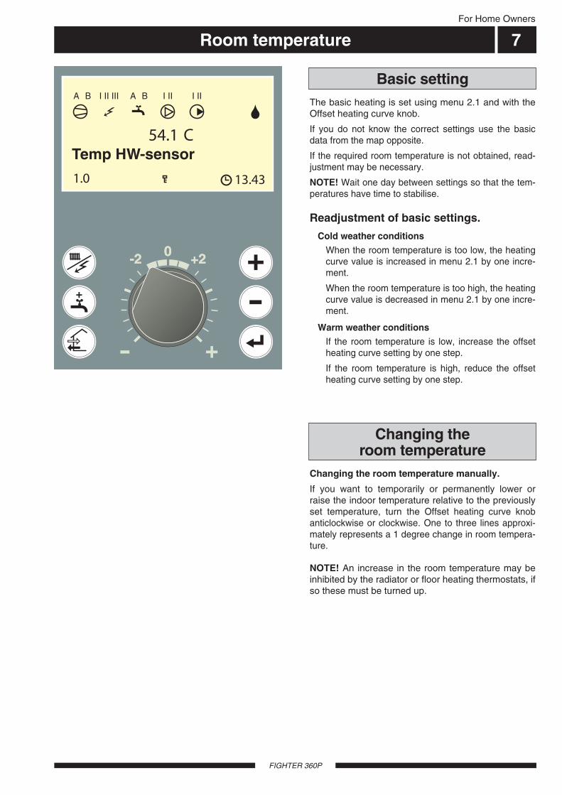
The basic heating is set using menu 2.1 and with theOffset heating curve knob.
If you do not know the correct settings use the basicdata from the map opposite.
If the required room temperature is not obtained, read-justment may be necessary.
NOTE! Wait one day between settings so that the tem-peratures have time to stabilise.
Readjustment of basic settings.
Cold weather conditionsWhen the room temperature is too low, the heatingcurve value is increased in menu 2.1 by one incre-ment.
When the room temperature is too high, the heatingcurve value is decreased in menu 2.1 by one incre-ment.
Warm weather conditionsIf the room temperature is low, increase the offsetheating curve setting by one step.
If the room temperature is high, reduce the offsetheating curve setting by one step.
Changing the room temperature manually.
If you want to temporarily or permanently lower orraise the indoor temperature relative to the previouslyset temperature, turn the Offset heating curve knobanticlockwise or clockwise. One to three lines approxi-mately represents a 1 degree change in room tempera-ture.
NOTE! An increase in the room temperature may beinhibited by the radiator or floor heating thermostats, ifso these must be turned up.
Basic setting
Changing the room temperature
A B A BI II III I II I II
54.1 CTemp. VV-givare
1.0 13.43
Temp HW-sensor

Maintenance routines
FIGHTER 360P
For Home Owners
8
The building’s ventilation devices should be cleanedregularly with a small brush to keep the correct venti-lation.
The device settings must not be changed.
NOTE! If you take down more than one ventilationdevice for cleaning, do not mix them up.
Check that the ventilation opening (84), behind thelower front cover, is not blocked. Clean if necessary.
The heat pump's air filter needs to be cleaned regular-ly (approximately 4 — 5 times per year). The intervalbetween cleaning operations varies and depends onthe amount of dust in the exhaust air.
Set the switch to “0”.
Open the upper front cover by pulling it out by thelower edge, then lifting it up.
Pull out the holder (78).
Take out the filter and shake off any dirt.
Check that the filter is not damaged. New originalfilters can be ordered from NIBE.
Assembly takes place in the reverse order.
The cleaning time intervals vary depending on theamount of dust in the exhaust air.
Also see the section, Alarm indications in the display,FILTER MONITOR.
The heat pump and its ventilation ducting requiresome regular maintenance when the following pointsshould be checked.
The numbers in brackets refer to the section Compo-nent locations.
Cleaning the air filter
Cleaning the ventilation devices
Warning to the user!Do not remove or adjust any
component part of this unvented waterheater: Contact the installer.
Warning to the user!If this unvented water heater develops
a fault, such as a flow of hot waterfrom the discharge pipe, switch theheater off and contact the installer.
Maintenance routines 9For Home Owners
FIGHTER 360P
LEK
+20-2
A B A B A BI II III I II I II
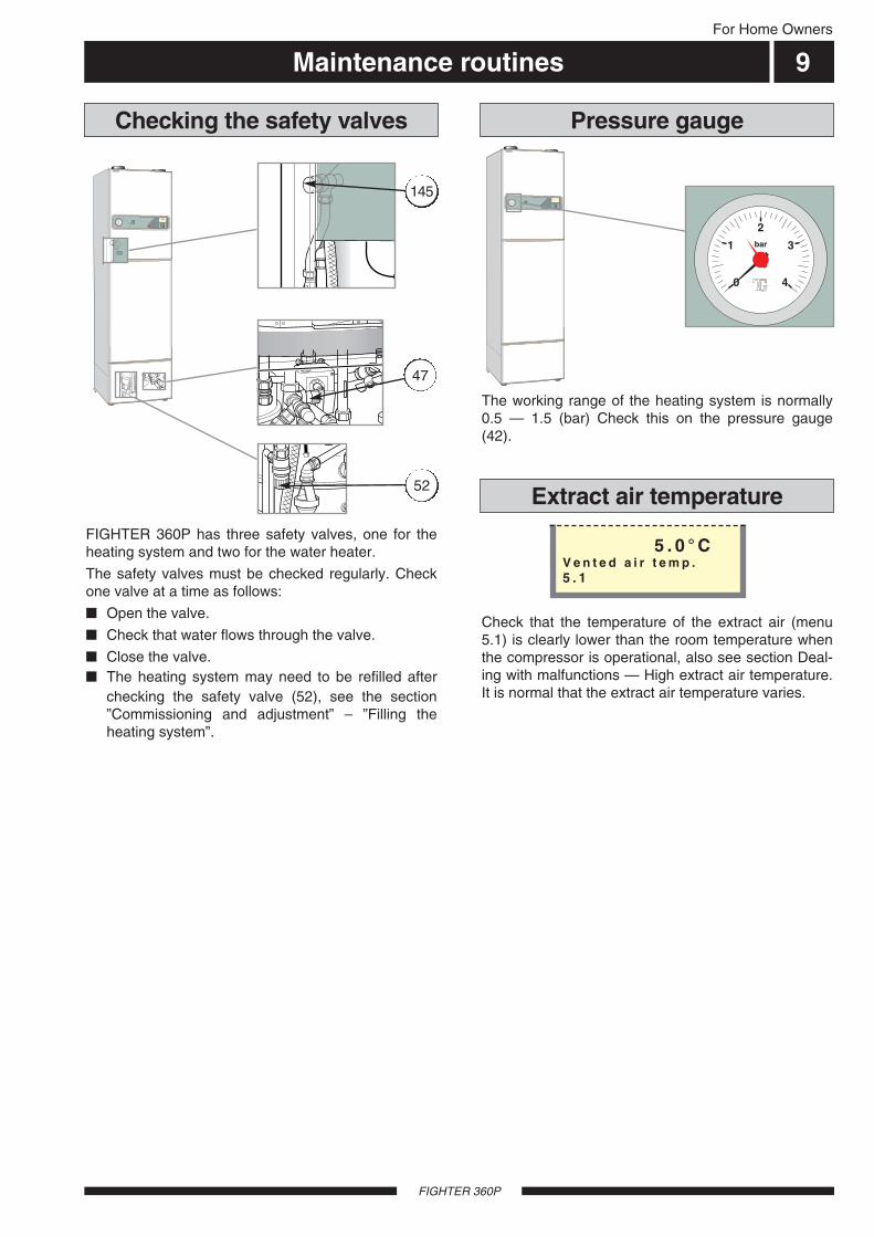
Check that the temperature of the extract air (menu5.1) is clearly lower than the room temperature whenthe compressor is operational, also see section Deal-ing with malfunctions — High extract air temperature.It is normal that the extract air temperature varies.
The working range of the heating system is normally0.5 — 1.5 (bar) Check this on the pressure gauge(42).
FIGHTER 360P has three safety valves, one for theheating system and two for the water heater.
The safety valves must be checked regularly. Checkone valve at a time as follows:
Open the valve.
Check that water flows through the valve.
Close the valve. The heating system may need to be refilled after
checking the safety valve (52), see the section”Commissioning and adjustment” – ”Filling theheating system”.
Pressure gauge
Extract air temperature
2
1 bar 3
0 4
Checking the safety valves
5 . 0 ° CV e n t e d a i r t e m p .5 . 1
LEK
+20-2
A B A B A BI II III I II I II
52
47
145

General information for the installer
FIGHTER 360P
For the Installer
10
NOTE!Work on the refrigerant system must be
done by authorised personnel inaccordance with the relevant legislation
on refrigerants, supplemented byadditional requirements for flammablegas, for example, product knowledge as
well as service instruction on gassystems with flammable gases.
FIGHTER 360P should be transported and stored ver-tically in the dry. The FIGHTER 360P may however becarefully laid on its back when being moved into abuilding.
The heat pump contains highly inflam-mable refrigerant. Special care should beexercised during handling, installation,service, cleaning and scrapping to avoiddamage to the refrigerant system and indoing so reduce the risk of leakage.
Transport and storage
Handling
NOTE!The transport guard around the compressor
must be removed before starting.
Åter-ledningradiatorerk.v.v.v.
Blaha blaha
och annattrams
Blaha blahaoch annat
trams
Fram-ledningradiatorer
Art.nr. 611827
2
1 bar 3
0 4
LEK
011007
LE
K
The lifting straps on top of the heat pump should beremoved before starting as these can otherwise causeincreased sound levels. These are removed by firstcutting with a knife and then pulling them out.
Lifting straps
Mora kniv
1 2
General information for the installer 11
FIGHTER 360P
Current regulations require the heating installation tobe inspected before it is commissioned. The inspec-tion must be carried out by a suitably qualified person.The above applies to installations with a closedexpansion vessel. A new inspection must be madewhen changing the heat pump or the expansion ves-sel.
Inspection of the installation
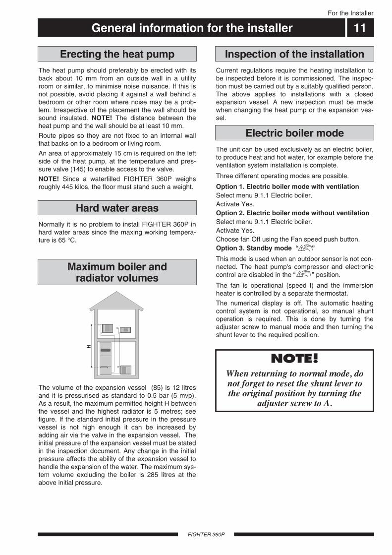
The volume of the expansion vessel (85) is 12 litresand it is pressurised as standard to 0.5 bar (5 mvp).As a result, the maximum permitted height H betweenthe vessel and the highest radiator is 5 metres; seefigure. If the standard initial pressure in the pressurevessel is not high enough it can be increased byadding air via the valve in the expansion vessel. Theinitial pressure of the expansion vessel must be statedin the inspection document. Any change in the initialpressure affects the ability of the expansion vessel tohandle the expansion of the water. The maximum sys-tem volume excluding the boiler is 285 litres at theabove initial pressure.
Maximum boiler and radiator volumes
H
For the Installer
The unit can be used exclusively as an electric boiler,to produce heat and hot water, for example before theventilation system installation is complete.
Three different operating modes are possible.
Option 1. Electric boiler mode with ventilationSelect menu 9.1.1 Electric boiler. Activate Yes.Option 2. Electric boiler mode without ventilationSelect menu 9.1.1 Electric boiler. Activate Yes.Choose fan Off using the Fan speed push button.Option 3. Standby mode “ ”
This mode is used when an outdoor sensor is not con-nected. The heat pump's compressor and electroniccontrol are disabled in the “ ” position.
The fan is operational (speed I) and the immersionheater is controlled by a separate thermostat.
The numerical display is off. The automatic heatingcontrol system is not operational, so manual shuntoperation is required. This is done by turning theadjuster screw to manual mode and then turning theshunt lever to the required position.
NOTE! When returning to normal mode, donot forget to reset the shunt lever tothe original position by turning the
adjuster screw to A.
The heat pump should preferably be erected with itsback about 10 mm from an outside wall in a utilityroom or similar, to minimise noise nuisance. If this isnot possible, avoid placing it against a wall behind abedroom or other room where noise may be a prob-lem. Irrespective of the placement the wall should besound insulated. NOTE! The distance between theheat pump and the wall should be at least 10 mm.
Route pipes so they are not fixed to an internal wallthat backs on to a bedroom or living room.
An area of approximately 15 cm is required on the leftside of the heat pump, at the temperature and pres-sure valve (145) to enable access to the valve.
NOTE! Since a waterfilled FIGHTER 360P weighsroughly 445 kilos, the floor must stand such a weight.
Erecting the heat pump
Normally it is no problem to install FIGHTER 360P inhard water areas since the maxing working tempera-ture is 65 °C.
Hard water areas
Electric boiler mode
Pipe connections
FIGHTER 360P
12For the Installer
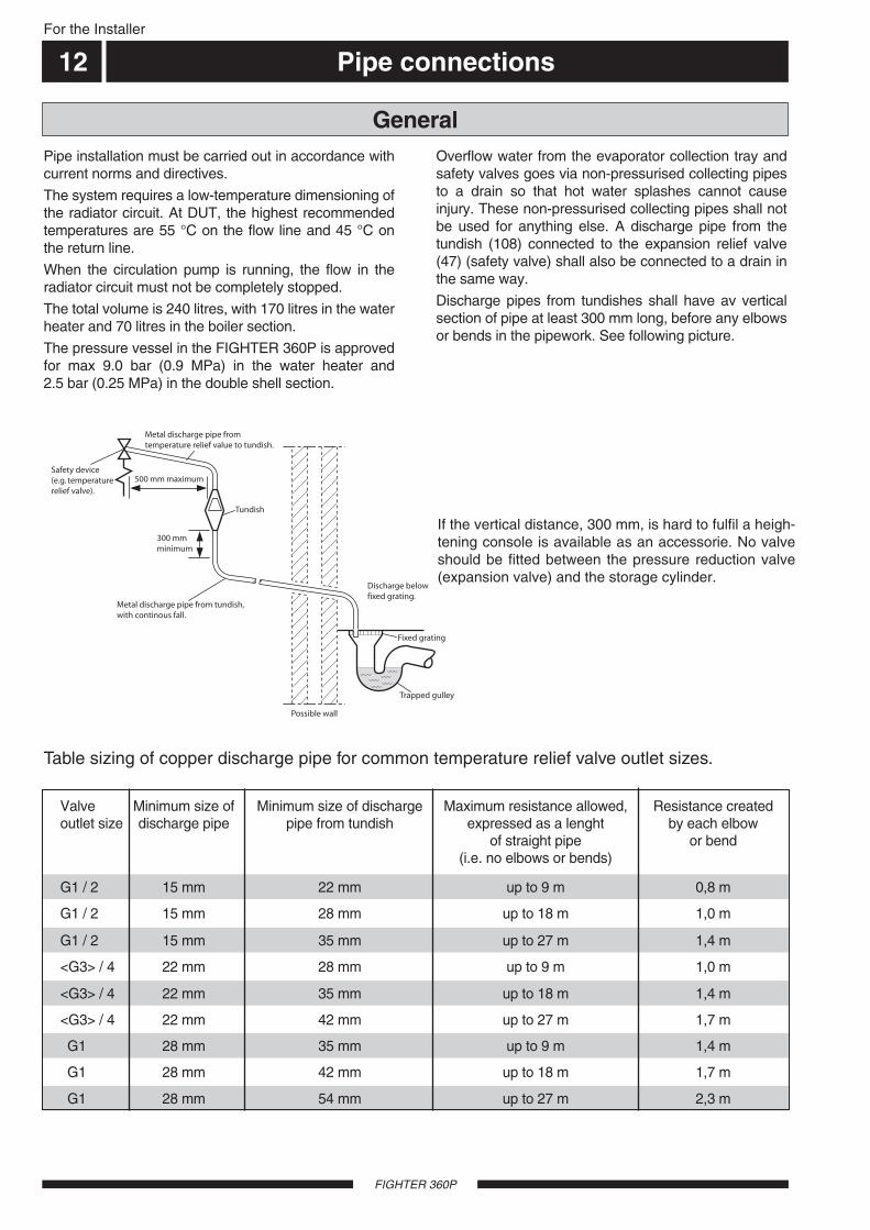
If the vertical distance, 300 mm, is hard to fulfil a heigh-tening console is available as an accessorie. No valveshould be fitted between the pressure reduction valve(expansion valve) and the storage cylinder.
500 mm maximum
300 mm minimum
Tundish
Metal discharge pipe fromtemperature relief value to tundish.
Metal discharge pipe from tundish,with continous fall.
Discharge belowfixed grating.
Fixed grating
Trapped gulley
Possible wall
Safety device(e.g. temperaturerelief valve).
<G3> / 4 22 mm 28 mm up to 9 m 1,0 m
G1 / 2 15 mm 35 mm up to 27 m 1,4 m
<G3> / 4 22 mm 42 mm up to 27 m 1,7 m
<G3> / 4 22 mm 35 mm up to 18 m 1,4 m
G1 28 mm 42 mm up to 18 m 1,7 m
G1 28 mm 35 mm up to 9 m 1,4 m
Valve Minimum size of Minimum size of discharge Maximum resistance allowed, Resistance createdoutlet size discharge pipe pipe from tundish expressed as a lenght by each elbow
of straight pipe or bend (i.e. no elbows or bends)
G1 28 mm 54 mm up to 27 m 2,3 m
G1 / 2 15 mm 28 mm up to 18 m 1,0 m
G1 / 2 15 mm 22 mm up to 9 m 0,8 m
Table sizing of copper discharge pipe for common temperature relief valve outlet sizes.
Pipe installation must be carried out in accordance withcurrent norms and directives.
The system requires a low-temperature dimensioning ofthe radiator circuit. At DUT, the highest recommendedtemperatures are 55 °C on the flow line and 45 °C onthe return line.
When the circulation pump is running, the flow in theradiator circuit must not be completely stopped.
The total volume is 240 litres, with 170 litres in the waterheater and 70 litres in the boiler section.
The pressure vessel in the FIGHTER 360P is approvedfor max 9.0 bar (0.9 MPa) in the water heater and2.5 bar (0.25 MPa) in the double shell section.
Overflow water from the evaporator collection tray andsafety valves goes via non-pressurised collecting pipesto a drain so that hot water splashes cannot causeinjury. These non-pressurised collecting pipes shall notbe used for anything else. A discharge pipe from thetundish (108) connected to the expansion relief valve(47) (safety valve) shall also be connected to a drain inthe same way.
Discharge pipes from tundishes shall have av verticalsection of pipe at least 300 mm long, before any elbowsor bends in the pipework. See following picture.
General
Pipe connections 13For the Installer
FIGHTER 360P
Pump and pressure drop diagrams
Flöde
Till
gäng
ligt t
ryck
, kP
a
kPa
l/h
10
2000
0
20
400
30
600
40
800
50
1000
60
1200
70
1400 1600 1800 2000
l/s0,50,40,30,20,10
Max flöde: 1700 l/h
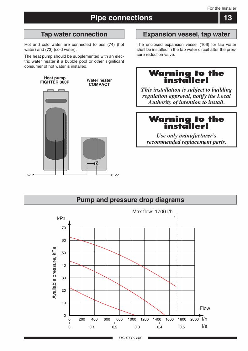
Hot and cold water are connected to pos (74) (hotwater) and (73) (cold water).
The heat pump should be supplemented with an elec-tric water heater if a bubble pool or other significantconsumer of hot water is installed.
Tap water connection
KV VV
Water heaterCOMPACT
Heat pumpFIGHTER 360P
Max flow: 1700 l/h
Flow
l/hl/s
kPa
Ava
ilabl
e pr
essu
re, k
Pa
The enclosed expansion vessel (106) for tap watershall be installed in the tap water circuit after the pres-sure reduction valve.
Expansion vessel, tap water
Warning to theinstaller!
This installation is subject to buildingregulation approval, notify the Local
Authority of intention to install.
Warning to theinstaller!
Use only manufacturersrecommended replacement parts.
Ventilation connection
FIGHTER 360
For the Installer
14
FIGHTER 360P is connected so that all ventilation airexcept the kitchen fan passes the evaporator (62) inthe heat pump. The lowest ventilation flow accordingto current standards is 0.35 l/s per m2 floor area. Foroptimum heat pump performance the ventilation flowshould not be less than 110 m3/h. (31 l/s).
The heat pump's installation area should be ventilatedby at least 36 m3/h (10 l/s).
FIGHTER 360P is equipped with a ventilationopening in the base. As a result, an air flow of about 5m3/h (1,4 l/s) is taken directly from the room where theheat pump is installed.
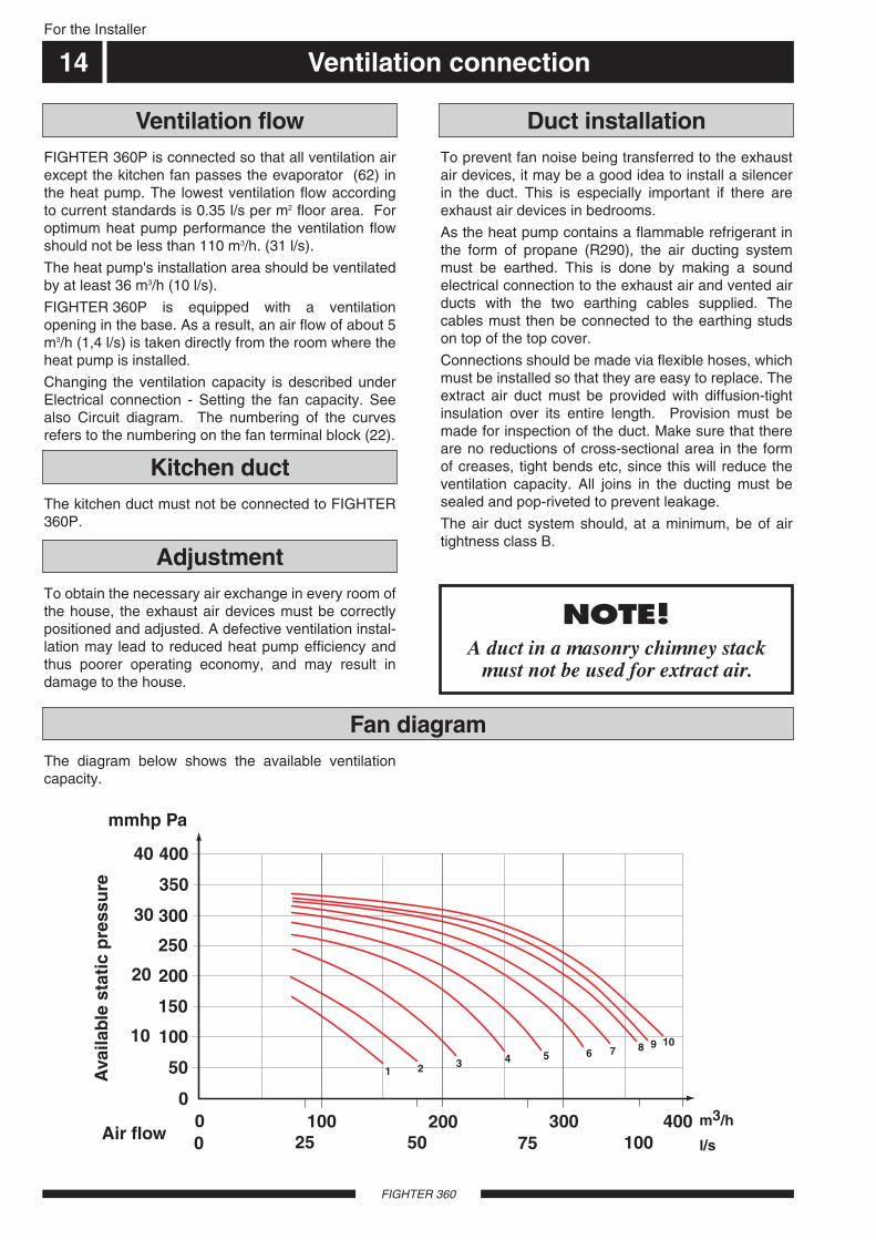
Changing the ventilation capacity is described underElectrical connection - Setting the fan capacity. Seealso Circuit diagram. The numbering of the curvesrefers to the numbering on the fan terminal block (22).
To obtain the necessary air exchange in every room ofthe house, the exhaust air devices must be correctlypositioned and adjusted. A defective ventilation instal-lation may lead to reduced heat pump efficiency andthus poorer operating economy, and may result indamage to the house.
NOTE!A duct in a masonry chimney stack
must not be used for extract air.
To prevent fan noise being transferred to the exhaustair devices, it may be a good idea to install a silencerin the duct. This is especially important if there areexhaust air devices in bedrooms.
As the heat pump contains a flammable refrigerant inthe form of propane (R290), the air ducting systemmust be earthed. This is done by making a soundelectrical connection to the exhaust air and vented airducts with the two earthing cables supplied. Thecables must then be connected to the earthing studson top of the top cover.
Connections should be made via flexible hoses, whichmust be installed so that they are easy to replace. Theextract air duct must be provided with diffusion-tightinsulation over its entire length. Provision must bemade for inspection of the duct. Make sure that thereare no reductions of cross-sectional area in the formof creases, tight bends etc, since this will reduce theventilation capacity. All joins in the ducting must besealed and pop-riveted to prevent leakage.
The air duct system should, at a minimum, be of airtightness class B.
The diagram below shows the available ventilation capacity.
Fan diagram
Ventilation flow Duct installation
Adjustment
400
350
300
250
200
150
100
50
00 100 200 300 400
Luftflöde
Till
gän
glig
t st
atis
kt t
ryck
1 2 3 4 5 6 7 8 9 10
m3/h0 25 50 75 100 l/s
Pammvp
40
30
10
20
The kitchen duct must not be connected to FIGHTER360P.
Kitchen duct
mmhp Pa
Ava
ilab
le s
tati
c p
ress
ure
Air flowm3/h
l/s
Electrical connection 15For the Installer
FIGHTER 360
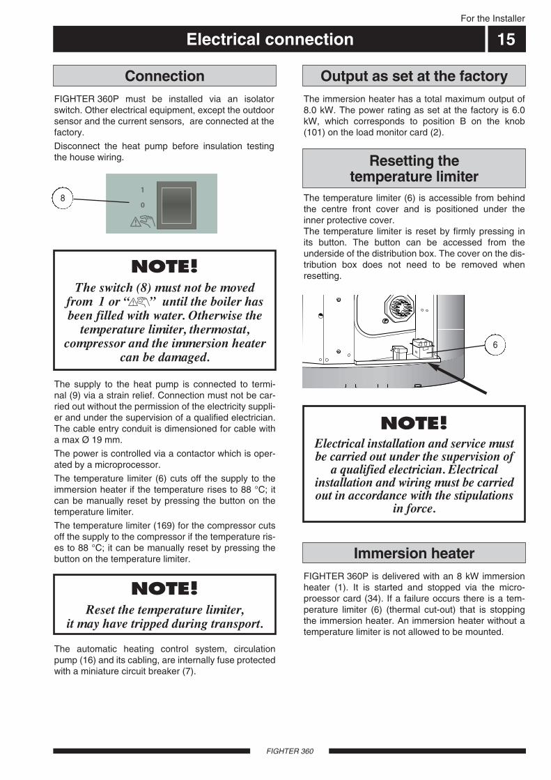
FIGHTER 360P must be installed via an isolatorswitch. Other electrical equipment, except the outdoorsensor and the current sensors, are connected at thefactory.
Disconnect the heat pump before insulation testingthe house wiring.
The immersion heater has a total maximum output of8.0 kW. The power rating as set at the factory is 6.0kW, which corresponds to position B on the knob(101) on the load monitor card (2).
Connection Output as set at the factory
NOTE!Reset the temperature limiter,
it may have tripped during transport.
NOTE! The switch (8) must not be moved
from 1 or until the boiler hasbeen filled with water. Otherwise the
temperature limiter, thermostat,compressor and the immersion heater
can be damaged.
The automatic heating control system, circulationpump (16) and its cabling, are internally fuse protectedwith a miniature circuit breaker (7).
NOTE! Electrical installation and service mustbe carried out under the supervision of
a qualified electrician. Electricalinstallation and wiring must be carriedout in accordance with the stipulations
in force.
The supply to the heat pump is connected to termi-nal (9) via a strain relief. Connection must not be car-ried out without the permission of the electricity suppli-er and under the supervision of a qualified electrician.The cable entry conduit is dimensioned for cable witha max Ø 19 mm.
The power is controlled via a contactor which is oper-ated by a microprocessor.
The temperature limiter (6) cuts off the supply to theimmersion heater if the temperature rises to 88 °C; itcan be manually reset by pressing the button on thetemperature limiter.
The temperature limiter (169) for the compressor cutsoff the supply to the compressor if the temperature ris-es to 88 °C; it can be manually reset by pressing thebutton on the temperature limiter.
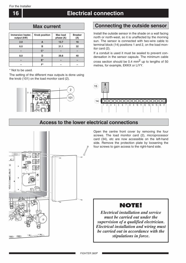
8 The temperature limiter (6) is accessible from behindthe centre front cover and is positioned under theinner protective cover.The temperature limiter is reset by firmly pressing inits button. The button can be accessed from theunderside of the distribution box. The cover on the dis-tribution box does not need to be removed whenresetting.
Resetting the temperature limiter
6
FIGHTER 360P is delivered with an 8 kW immersionheater (1). It is started and stopped via the micro-proessor card (34). If a failure occurs there is a tem-perature limiter (6) (thermal cut-out) that is stoppingthe immersion heater. An immersion heater without atemperature limiter is not allowed to be mounted.
Immersion heater
– F* – –
– E* – –
Electrical connection
FIGHTER 360P
For the Installer
16
Max current
1 2 3 4 5 6 7 8
15
149 10 11 12 13 14 15 16 17
Connecting the outside sensor
* Not to be used.
The setting of the different max outputs is done usingthe knob (101) on the load monitor card (2).
Install the outside sensor in the shade on a wall facingnorth or north-west, so it is unaffected by the morningsun. The sensor is connected with two-wire cable toterminal block (14) positions 1 and 2, on the load mon-itor card (2).
If a conduit is used it must be sealed to prevent con-densation in the sensor capsule. The minimum cable
cross section should be 0.4 mm2 up to lengths of 50metres, for example, EKKX or LiYY.
– C* – –
2.0 A 13.7 16
Immersion heater, Knob position Max load Breakeroutput (kW) phase (A) (A)
6.0 B 31.1 32
8.0 D 39.8 40
101
2
Access to the lower electrical connections
Open the centre front cover by removing the fourscrews. The load monitor card (2), microprocessorcard (34), etc are now accessible on the left-handside. Remove the protection plate by loosening thefour screws to gain access to the right-hand side.
Åter-ledningradiatorerk.v.v.v.
Blaha blahaoch annat
trams
Fram-ledningradiatorer
011007
10
10
VAN
AD
IUM
No. 7
CH
RO
ME
NOTE! Electrical installation and service
must be carried out under thesupervision of a qualified electrician.
Electrical installation and wiring mustbe carried out in accordance with the
stipulations in force.

Electrical connection 17
FIGHTER 360P
For the Installer
Centralised load control/TariffIn those cases centralised load control or tariff controlis used this can be connected to the terminal block(14) on the load monitor card (2), which is positionedbehind the centre front cover.
When parts of the electrical output (how much is deter-mined by the max output) are to be disconnected, apotential free contact function is connected between 5and 7 on terminal block (14).
When the complete electrical output is to be discon-nected, a potential free contact function is connectedbetween 6 and 7 on terminal block (14).
Centralised load control
1 2 3 4 5 6 7 814
9 10 11 12 13 14 15 16 17
Electrical connection
FIGHTER 360P
18For the Installer
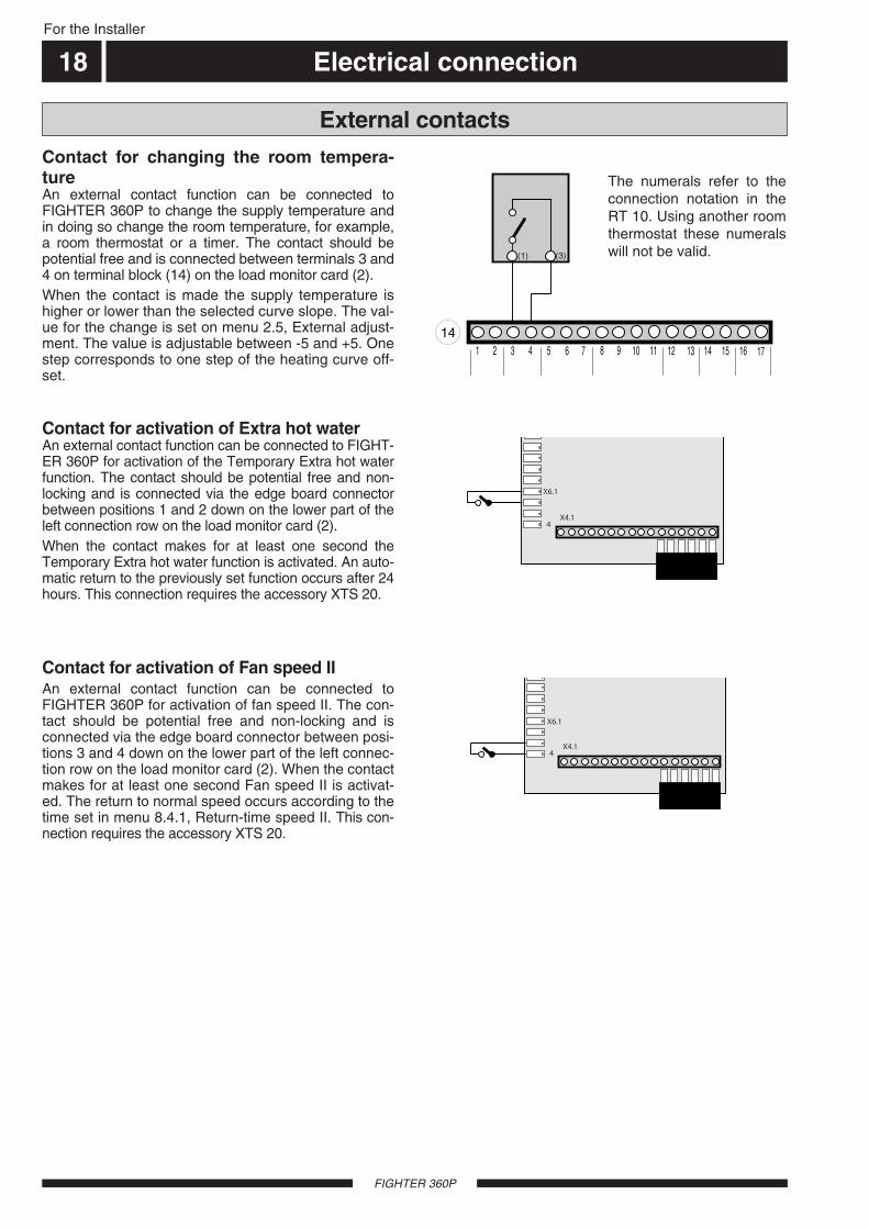
Contact for changing the room tempera-tureAn external contact function can be connected toFIGHTER 360P to change the supply temperature andin doing so change the room temperature, for example,a room thermostat or a timer. The contact should bepotential free and is connected between terminals 3 and4 on terminal block (14) on the load monitor card (2).When the contact is made the supply temperature ishigher or lower than the selected curve slope. The val-ue for the change is set on menu 2.5, External adjust-ment. The value is adjustable between -5 and +5. Onestep corresponds to one step of the heating curve off-set.
Contact for activation of Extra hot waterAn external contact function can be connected to FIGHT-ER 360P for activation of the Temporary Extra hot waterfunction. The contact should be potential free and non-locking and is connected via the edge board connectorbetween positions 1 and 2 down on the lower part of theleft connection row on the load monitor card (2).When the contact makes for at least one second theTemporary Extra hot water function is activated. An auto-matic return to the previously set function occurs after 24hours. This connection requires the accessory XTS 20.
Contact for activation of Fan speed IIAn external contact function can be connected toFIGHTER 360P for activation of fan speed II. The con-tact should be potential free and non-locking and isconnected via the edge board connector between posi-tions 3 and 4 down on the lower part of the left connec-tion row on the load monitor card (2). When the contactmakes for at least one second Fan speed II is activat-ed. The return to normal speed occurs according to thetime set in menu 8.4.1, Return-time speed II. This con-nection requires the accessory XTS 20.
External contacts
1 2 3 4 5 6 7 814
9 10 11 12 13 14 15 16 17
(3)(1)
4X4.1
X6.1
4X4.1
X6.1
The numerals refer to theconnection notation in theRT 10. Using another roomthermostat these numeralswill not be valid.
Electrical connection 19
FIGHTER 360P
For the Installer
Low priority alarmsThe following give a low priority alarm:Filter monitor, the air filter needs to be cleaned threetimes a year. This is indicated as a low priority alarmand the operation of FIGHTER 360P is not generallydisturbed by this.Sensor alarm, fault on the low priority sensor gives alow priority alarm and the operating mode is switchedto winter and any automatic operations are disabled.Low priority sensors are as follows:Outdoor sensor-Evaporation sensor-Return sensor-Extract air sensor-Exhaust air sensor.
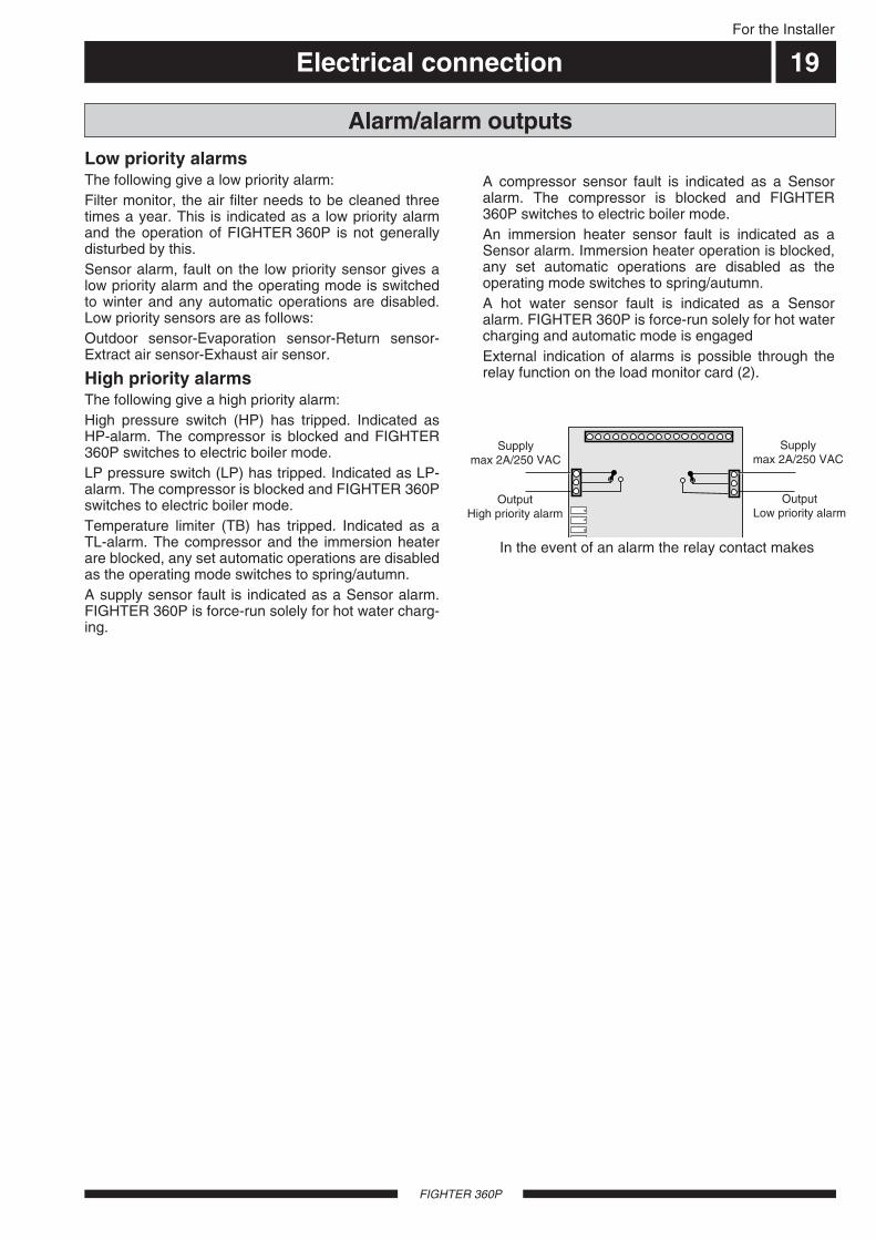
High priority alarmsThe following give a high priority alarm:High pressure switch (HP) has tripped. Indicated asHP-alarm. The compressor is blocked and FIGHTER360P switches to electric boiler mode.LP pressure switch (LP) has tripped. Indicated as LP-alarm. The compressor is blocked and FIGHTER 360Pswitches to electric boiler mode.Temperature limiter (TB) has tripped. Indicated as aTL-alarm. The compressor and the immersion heaterare blocked, any set automatic operations are disabledas the operating mode switches to spring/autumn.A supply sensor fault is indicated as a Sensor alarm.FIGHTER 360P is force-run solely for hot water charg-ing.
Alarm/alarm outputs
MatningMax 2A/250 VAC
UtgångHögprioriterat larm
MatningMax 2A/250 VAC
UtgångLågprioriterat larm
A compressor sensor fault is indicated as a Sensoralarm. The compressor is blocked and FIGHTER360P switches to electric boiler mode.An immersion heater sensor fault is indicated as aSensor alarm. Immersion heater operation is blocked,any set automatic operations are disabled as theoperating mode switches to spring/autumn.A hot water sensor fault is indicated as a Sensoralarm. FIGHTER 360P is force-run solely for hot watercharging and automatic mode is engagedExternal indication of alarms is possible through therelay function on the load monitor card (2).
In the event of an alarm the relay contact makes
Supplymax 2A/250 VAC
OutputHigh priority alarm
OutputLow priority alarm
Supplymax 2A/250 VAC
Commissioning and adjusting
FIGHTER 360P
20
Åter-ledningradiatorerk.v.v.v.
Blaha blaha
och annattrams
Blaha blahaoch annat
trams
Fram-ledningradiatorer
LEK 44
44
98
50
97
52
104
150152151149
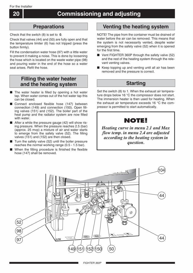
NOTE! The pipe from the container must be drained ofwater before the air can be removed. This means thatthe system is not necessarily vented, despite wateremerging from the safety valve (52) when it is openedfor the first time.
Vent FIGHTER 360P through the safety valve (52)and the rest of the heating system through the rele-vant venting valves.
Keep topping up and venting until all air has beenremoved and the pressure is correct.
Check that the switch (8) is set to 0.
Check that valves (44) and (50) are fully open and thatthe temperature limiter (6) has not tripped (press thebutton firmly).
Fill the condensation water hose (97) with a little waterto prevent it making a noise. This is done by looseningthe hose which is located on the waste water pipe (98)and pouring water in the end of the hose so a waterseal arises. Refit the hose.
Venting the heating systemPreparations
The water heater is filled by opening a hot watertap. When water comes out of the hot water tap thiscan be closed.
Connect enclosed flexible hose (147) betweenconnection (149) and connection (150). Open fill-ing valves (151) and (152). The boiler part of theheat pump and the radiator system are now filledwith water.
After a while the pressure gauge (42) will show ris-ing pressure. When the pressure reaches 2.5 (bar)(approx. 25 mvp) a mixture of air and water startsto emerge from the safety valve (52). The fillingvalves (151) and (152) are then closed.
Turn the safety valve (52) until the boiler pressurereaches the normal working range (0.5 - 1.5 bar).
When the filling procedure is finished the flexiblehose (147) shall be removed.
Filling the water heater and the heating system
Set the switch (8) to 1. When the exhaust air tempera-ture drops below 16 °C the compressor does not start.The immersion heater is then used for heating. Whenthe exhaust air temperature exceeds 16 °C the com-pressor is permitted to start automatically.
For the Installer
NOTE!Heating curve in menu 2.1 and Maxflow temp. in menu 2.4 are adjustedaccording to the heating system in
question.
Starting

Commissioning and adjusting 21
FIGHTER 360P
For the Installer
Air is initially released from the hot water and ventingmay be necessary. If bubbling sounds can be heardfrom the heat pump, the entire system requires furtherventing. NOTE! Safety valve (52) also acts as a man-ual venting valve. Operate it with care, since it opensquickly. When the system is stable (correct pressureand all air eliminated) the automatic heating controlsystem can be set as required. See the section Roomtemperature - Setting the Automatic heating controlsystem and Front panel.
ReadjustmentThe ventilation flow and correct outlet on the fan termi-nal block (22) are set out on the ventilation drawing.
Change the fan capacity by moving the grey cableon the fan terminal block (22) if necessary. Use thelowest possible output to obtain the lowest noiselevels.
Make sure that all outdoor air devices are fullyopen.
Set correct ventilation flows on the exhaust airdevices.
Now move the white and brown cables to obtain therequired exhaust air flow for fan speeds I and II. Thewhite cable corresponds to position I and the brownposition II. Note however that the exhaust air flowmust never fall below 110 m3/h (31 l/s).
Setting the ventilation
The ventilation capacity is selected by moving thebrown, grey and white cables to an appropriate outleton the terminal block (22). See the section, Ventilationconnection - Fan diagram to choose appropriate con-nections.
The grey cable corresponds to the fan speed in nor-mal mode. The white cable corresponds to speed I. The brown cable corresponds to speed II.Example:Normal: Lowest possible fan speed is chosen to
obtain the planned ventilation flow (greycable).
Speed II: Highest possible fan speed is chosen, (forced) however consider ventilation noise (brown
cable).Speed I Lowest possible fan speed is chosen (reducing) where the min flow is maintained (white
cable).
Outlet Voltage (V)1 1002 1103 1254 1405 1556 1707 1858 2009 21510 230
Setting the fan capacity
22
5 6 7 8 9 103 41 2
GråVit Brun
In those cases the cable for normal mode is connect-ed to terminal 10 on terminal block (22) a forced fanspeed cannot be obtained. Two different reducingmodes should then be chosen.
whi
te
grey
brow
n
The heating water can be drained off through drainvalve (51) using an R15 (1/2") hose coupling. Removethe cover (80) from the valve. Now screw on the hosecoupling and open valve (51).
Open safety valve (52) to let air into the system.
Draining the heating system
When the tap water and the central heating systemhave been filled up, the unit shall be running at maxi-mal, normal temperature during minimum one hour.After that the systems shall be flushed out and re-filledagain.
Cleaning the system / Flushing out of the hot waterand central heating system
Commissioning and adjusting
FIGHTER 360P
For the Installer
22
LE
K54
57
28
22
29
13
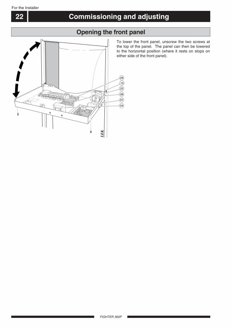
To lower the front panel, unscrew the two screws atthe top of the panel. The panel can then be loweredto the horizontal position (where it rests on stops oneither side of the front panel).
Opening the front panel
Setting the heating controls 23For the Installer
FIGHTER 360P
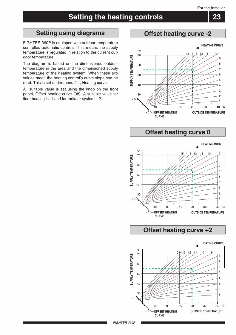
FIGHTER 360P is equipped with outdoor temperaturecontrolled automatic controls. This means the supplytemperature is regulated in relation to the current out-door temperature.
The diagram is based on the dimensioned outdoortemperature in the area and the dimensioned supplytemperature of the heating system. When these twovalues meet, the heating control’s curve slope can beread. This is set under menu 2.1, Heating curve.
A suitable value is set using the knob on the frontpanel, Offset heating curve (38). A suitable value forfloor heating is -1 and for radiator systems -2.
30
40
50
60
70°C
FR
AM
LED
NIN
GS
TE
MP
ER
AT
UR
- 40 °C
UTETEMPERATUR
- 10010 - 20 - 30
15 14 13 12 11 10 9
8
7
6
5
4
3
2
1
VÄRMEKURVA
- 5
+ 5
FÖRSKJUTNINGVÄRMEKURVA (0)
15 14 13 12 11 10
9
8
7
6
5
4
3
2
1
- 40 °C
UTETEMPERATUR
- 10010
- 5
+ 5
30
40
50
60
70°C
FR
AM
LED
NIN
GS
TE
MP
ER
AT
UR
- 20 - 30
FÖRSKJUTNINGVÄRMEKURVA (-2)
VÄRMEKURVA
1514 13 12 11 108
7
6
5
4
3
2
1
- 40 °C
UTETEMPERATUR
- 10010
- 5
+ 5
30
40
50
60
70°C
FR
AM
LED
NIN
GS
TE
MP
ER
AT
UR
- 20 - 30
FÖRSKJUTNING
9
VÄRMEKURVA
Offset heating curve 0
Offset heating curve -2Setting using diagrams
Offset heating curve +2
HEATING CURVE
HEATING CURVE
HEATING CURVE
OFFSET HEATING CURVE
OFFSET HEATING CURVE
SUPP
LY T
EMPE
RA
TUR
ESU
PPLY
TEM
PER
ATU
RE
SUPP
LY T
EMPE
RA
TUR
E
OUTSIDE TEMPERATURE
OUTSIDE TEMPERATURE
OUTSIDE TEMPERATUREOFFSET HEATING CURVE

ControlFor the Installer
24
FIGHTER 360P
The display screen shows information about the sta-tus of the heat pump.
The Plus and Minus buttons and the Enter button areused to scroll through the menu system as well as tochange the set value in some menus.
The Plus button is used to move forward to the nextmenu on the current menu level and to increase thevalue of the parameter in menus where this is possi-ble.
The Minus button is used to move back to the previ-ous menu on the current menu level and to decreasethe value of the parameter in menus where this is pos-sible.
The Enter button is used to select submenus of thecurrent menu, to permit parameters to be changedand confirm any changes to parameters. When themenu number ends with a zero this indicates there is asubmenu.
Changing a parameter (value):
Access the required menu.
Press the Enter button, the numerical value starts toflash.
Increase or decrease the value with the Plus/Minusbuttons.
Confirm by pressing the Enter button.
Menu 1.0 is automatically displayed again 30 sec-onds after pressing the last button.
ExampleChanging the Menu type/Service mode menu 8.1.1. The starting point is menu 1.0
Press the plus button to move to menu 8.0
Press the enter button to move to menu 8.1.0
Press the enter button to move to menu 8.1.1
Press the enter button to allow the value to bechanged.
Change the value using the plus or the minus button.
Confirm the chosen value by pressing the enter button.
Press the minus button to move to menu 8.1.5
Press the enter button to move to menu 8.1.0
Press the minus button to move to menu 8.4
Press the enter button to move to menu 8.0
Press the plus button to move to menu 1.0
Changing parameters
8.1.0Display settings
8.2.0Operating mode sett.
8.3.0Load monitor
8.4.0Fan settings
8.5.0Night coolness
8.6Return to 8.0
8.0Other settings
↵↵
8.1.1Menu type
8.1.2Language
8.1.3Display contrast
8.1.4Backlight display
8.1.5Return to 8.1.0
↵↵
8.2.1Auto Operating mode
8.2.2Stop circ.pump
8.2.3Stop el. heater
8.2.4Return to 8.2.0 ↵↵
8.4.1Return-time speed II
8.4.2Return-time speed I
8.4.3Return to 8.4.0 ↵↵
8.5.1Night coolness
8.5.2Start temp. coolness
8.5.3Min. diff. coolness
8.5.4Return to 8.5.0 ↵↵
↵↵
↵↵
↵↵8.3.1Fuse size
8.3.2Max. el. power
8.3.3 – 8.3.5Current phase 1 – 3
8.3.6Ratio of transf. EBV
8.3.7Tariff status
8.3.8Return to 8.3.0 ↵↵
↵↵↵↵
↵↵
↵↵
For the Installer
Control
FIGHTER 360P
25
1.1Temp. compr.sensor
1.2Temp. el. heat.sens.
1.3Interval per. XHW
1.4Stop temperature XHW
1.5Return to 1.0
1.0Temp. HW-sensor
2.1Heating curve
2.2Offset heating curve
2.3Min. flow temp.
2.4Max. flow temp.
2.5External adjustment
2.6Return temperature
2.7Return to 2.0
2.0Flow temperature
3.0Flow temperature 2*
3.1Heating curve 2
3.2Offset heat. curve 2
3.3Min. flow temp. 2
3.4Max. flow temp. 2
3.5External adjustment2
3.6Return temperature 2
3.7Return to 3.0
↵↵4.0Outdoor temp.
4.1Medium outdoor temp.
4.2Return to 4.0 ↵↵
↵↵
↵↵
↵↵ ↵↵
↵↵↵↵
A B A BI II III I II I II
54.1 CTemp. VV-givare
1.0 13.43
* Only shown when Shunt group 2 is On in menu 9.1.2.
Temp HW-sensor
For the Installer
Control
FIGHTER 360P
26
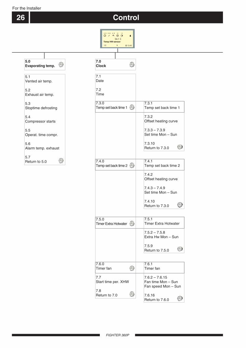
5.1Vented air temp.
5.2Exhaust air temp.
5.3Stoptime defrosting
5.4Compressor starts
5.5Operat. time compr.
5.6Alarm temp. exhaust
5.7Return to 5.0
5.0Evaporating temp.
7.0Clock
7.1Date
7.2Time
7.3.0Temp set back time 1
7.4.0Temp set back time 2
7.5.0Timer Extra Hotwater
7.6.0Timer fan
7.7Start time per. XHW
7.8Return to 7.0
↵↵
↵↵
↵↵
↵↵
A B A BI II III I II I II
54.1 CTemp. VV-givare
1.0 13.43
7.3.1Temp set back time 1
7.3.2Offset heating curve
7.3.3 – 7.3.9Set time Mon – Sun
7.3.10Return to 7.3.0 ↵↵
7.4.1Temp set back time 2
7.4.2Offset heating curve
7.4.3 – 7.4.9Set time Mon – Sun
7.4.10Return to 7.3.0 ↵↵
7.5.1Timer Extra Hotwater
7.5.2 – 7.5.8Extra Hw Mon – Sun
7.5.9Return to 7.5.0 ↵↵
7.6.1Timer fan
7.6.2 – 7.6.15Fan time Mon – SunFan speed Mon – Sun
7.6.16Return to 7.6.0 ↵↵
↵↵
↵↵
↵↵
↵↵
Temp HW-sensor
For the Installer
Control
FIGHTER 360P
27
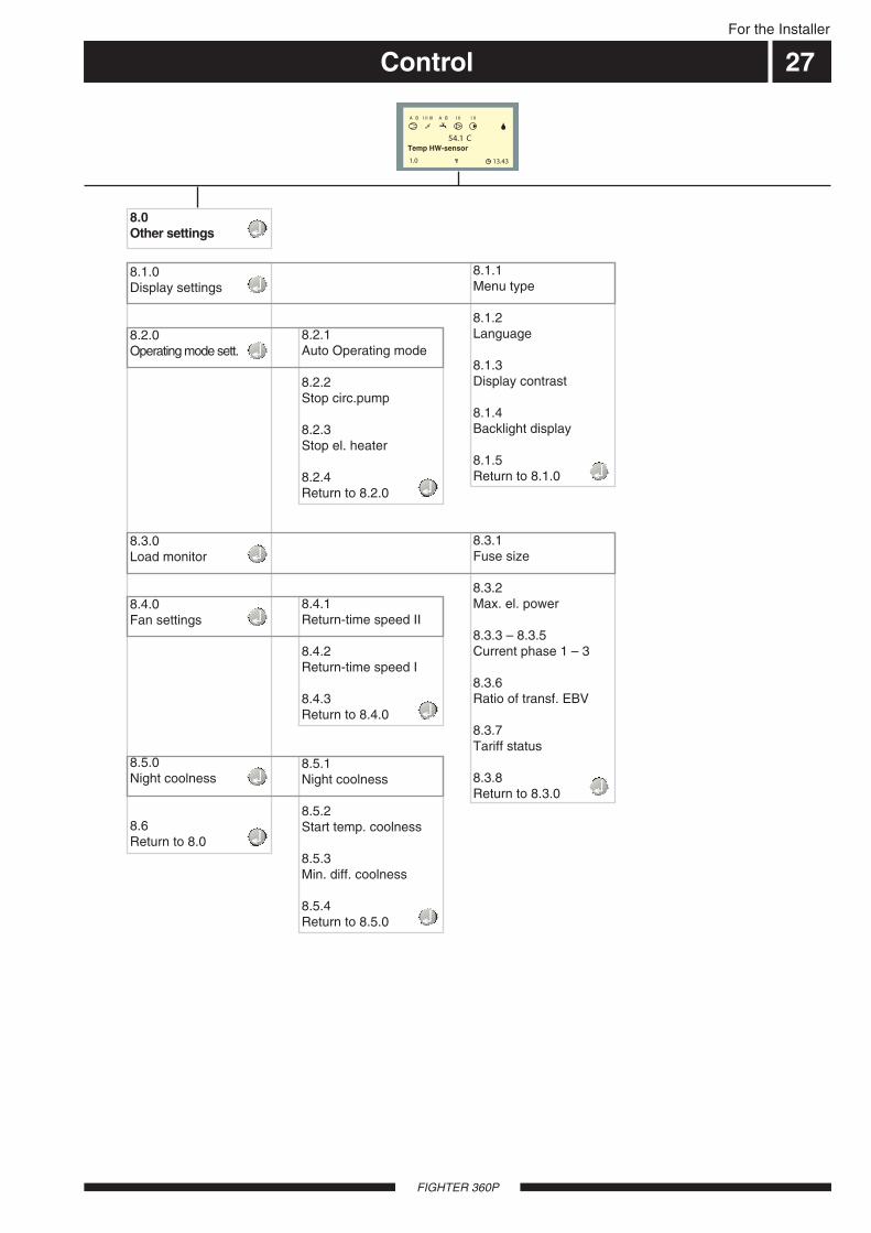
8.1.0Display settings
8.2.0Operating mode sett.
8.3.0Load monitor
8.4.0Fan settings
8.5.0Night coolness
8.6Return to 8.0
8.0Other settings
↵↵
↵↵
A B A BI II III I II I II
54.1 CTemp. VV-givare
1.0 13.43
↵↵8.1.1Menu type
8.1.2Language
8.1.3Display contrast
8.1.4Backlight display
8.1.5Return to 8.1.0 ↵↵
↵↵8.2.1Auto Operating mode
8.2.2Stop circ.pump
8.2.3Stop el. heater
8.2.4Return to 8.2.0 ↵↵
8.4.1Return-time speed II
8.4.2Return-time speed I
8.4.3Return to 8.4.0 ↵↵
8.5.1Night coolness
8.5.2Start temp. coolness
8.5.3Min. diff. coolness
8.5.4Return to 8.5.0 ↵↵
↵↵
↵↵
↵↵
8.3.1Fuse size
8.3.2Max. el. power
8.3.3 – 8.3.5Current phase 1 – 3
8.3.6Ratio of transf. EBV
8.3.7Tariff status
8.3.8Return to 8.3.0 ↵↵
Temp HW-sensor
ControlFor the Installer
FIGHTER 360P
28
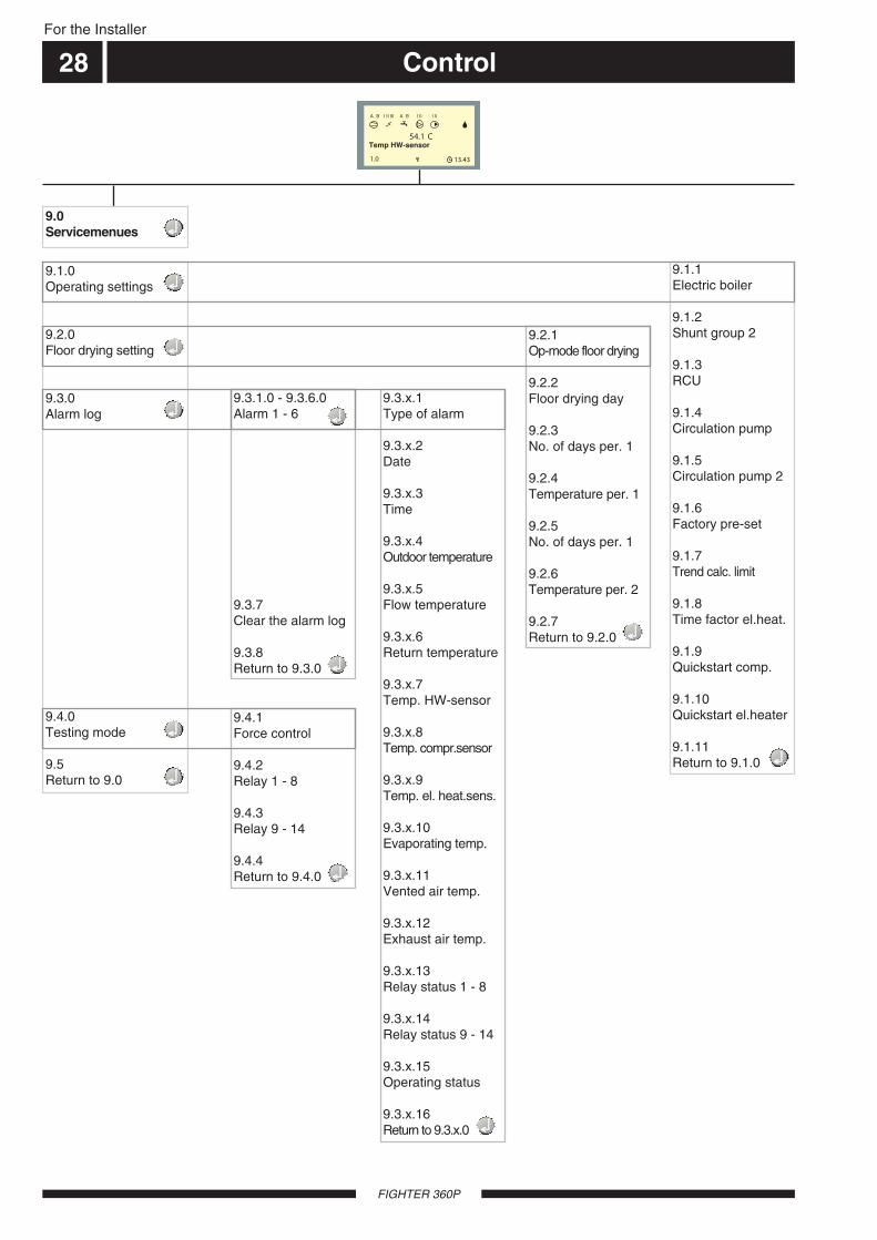
9.1.0Operating settings
9.2.0Floor drying setting
9.3.0Alarm log
9.4.0Testing mode
9.5Return to 9.0
9.0Servicemenues ↵↵
A B A BI II III I II I II
54.1 CTemp. VV-givare
1.0 13.43
↵↵
↵↵
9.1.1Electric boiler
9.1.2Shunt group 2
9.1.3RCU
9.1.4Circulation pump
9.1.5Circulation pump 2
9.1.6Factory pre-set
9.1.7Trend calc. limit
9.1.8Time factor el.heat.
9.1.9Quickstart comp.
9.1.10Quickstart el.heater
9.1.11Return to 9.1.0 ↵↵
↵↵
↵↵
↵↵
9.2.1Op-mode floor drying
9.2.2Floor drying day
9.2.3No. of days per. 1
9.2.4Temperature per. 1
9.2.5No. of days per. 1
9.2.6Temperature per. 2
9.2.7Return to 9.2.0
9.3.1.0 - 9.3.6.0Alarm 1 - 6
9.3.7Clear the alarm log
9.3.8Return to 9.3.0
9.4.1Force control
9.4.2Relay 1 - 8
9.4.3Relay 9 - 14
9.4.4Return to 9.4.0
9.3.x.1Type of alarm
9.3.x.2Date
9.3.x.3Time
9.3.x.4Outdoor temperature
9.3.x.5Flow temperature
9.3.x.6Return temperature
9.3.x.7Temp. HW-sensor
9.3.x.8Temp. compr.sensor
9.3.x.9Temp. el. heat.sens.
9.3.x.10Evaporating temp.
9.3.x.11Vented air temp.
9.3.x.12Exhaust air temp.
9.3.x.13Relay status 1 - 8
9.3.x.14Relay status 9 - 14
9.3.x.15Operating status
9.3.x.16Return to 9.3.x.0
↵↵
↵↵
↵↵
↵↵
↵↵
Temp HW-sensor

For the Installer
Control
FIGHTER 360P
29
Main menus
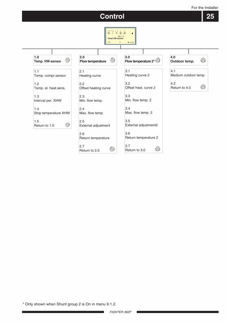
Menu 1.0 Temp HW-sensorThe current water temperature (83) in the outer jacketroughly level with the water heater’s lower end-plate isshown here. Note that the hot water temperature atthe top of the tank is usually higher.
Settings and readings regarding hot water chargingare made on the sub-menus to this menu.
Menu 2.0 Flow temperatureThe current supply temperature (89) for the heatingsystem is shown here with the calculated supply tem-perature in brackets.
Settings and readings regarding the heating systemare set on the sub-menus to this menu 1.
Menu 4.0 Outdoor temperatureThe current outdoor temperature on the outdoor sen-sor (15) is shown here.The outdoor, daily average temperature can be readfrom this sub-menu.
Menu 7.0 ClockSettings regarding the date and time are made in thesub-menus of this menu. Even different temperaturereductions and increases at selected times are setfrom this menu.
Menu 8.0 Other settingsSettings regarding the menu type, language, operat-ing settings and load monitor readings are made in thesub-menus of this menu.
5 2 . 0 ° CT e m p . H W - s e n s o r1 . 0
4 5 . 0 ( 4 6 ) ° CF l o w t e m p e r a t u r e2 . 0
Menu 3.0 Flow temperature 2The current supply temperature (FG2) for the heatingsystem is shown here with the calculated supply tem-perature in brackets.Settings and readings regarding the heating systemare set on the sub-menus to this menu 2.Only shown when shunt group 2 is in the “On” positionin menu 9.1.2.
3 5 . 0 ( 3 6 ) ° CF l o w t e m p e r a t u r e 23 . 0
C l o c k7 . 0
O t h e r s e t t i n g s8 . 0
Menu 5.0 Evaporating temp.The current evaporation temperature is shown here.This is the temperature of the refrigerant when thishas passed the expansion valve. Measured by sensor(86).
Temperatures can be read and settings made for thecompressor from these sub-menus.
2 . 3 ° CE v a p o r a t i n g t e m p .5 . 0
- 4 . 1 ° CO u t d o o r t e m p e r a t u r e4 . 0
Menu 9.0 Service menuThis menu and its sub-menus are only shown on thedisplay screen when access has been selected inmenu 8.1.1.
Values can be read and various settings can be madefrom these sub-menus. NOTE! These settings shouldonly be made by persons with the necessary exper-tise.
S e r v i c e m e n u9 . 0
S
N
N
N
N
N
N
N
Normal menus
Expanded menus
Service menus
Menu type is changed in menu 8.1.1.
N
U
S
For the Installer
Control
FIGHTER 360P
30
1.0 Temp. HW-sensor 2.0 Flow temperature
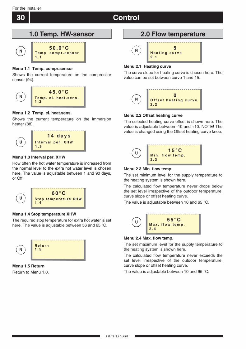
Menu 1.1 Temp. compr.sensorShows the current temperature on the compressorsensor (94).
Menu 1.2 Temp. el. heat.sens.Shows the current temperature on the immersionheater (88).
5 0 . 0 ° CT e m p . c o m p r . s e n s o r1 . 1
4 5 . 0 ° CT e m p . e l . h e a t . s e n s .1 . 2
Menu 1.3 Interval per. XHWHow often the hot water temperature is increased fromthe normal level to the extra hot water level is chosenhere. The value is adjustable between 1 and 90 days,or Off.
Menu 1.4 Stop temperature XHWThe required stop temperature for extra hot water is sethere. The value is adjustable between 56 and 65 °C.
1 4 d a y sI n t e r v a l p e r . X H W1 . 3
6 0 ° CS t o p t e m p e r a t u r e X H W1 . 4
Menu 1.5 ReturnReturn to Menu 1.0.
R e t u r n1 . 5
Menu 2.4 Max. flow temp.The set maximum level for the supply temperature tothe heating system is shown here.
The calculated flow temperature never exceeds theset level irrespective of the outdoor temperature,curve slope or offset heating curve.
The value is adjustable between 10 and 65 °C.
Menu 2.1 Heating curveThe curve slope for heating curve is chosen here. Thevalue can be set between curve 1 and 15.
Menu 2.2 Offset heating curveThe selected heating curve offset is shown here. Thevalue is adjustable between -10 and +10. NOTE! Thevalue is changed using the Offset heating curve knob.
Menu 2.3 Min. flow temp.The set minimum level for the supply temperature tothe heating system is shown here.
The calculated flow temperature never drops belowthe set level irrespective of the outdoor temperature,curve slope or offset heating curve.
The value is adjustable between 10 and 65 °C.
5 5 ° CM a x . f l o w t e m p .2 . 4
5H e a t i n g c u r v e2 . 1
0O f f s e t h e a t i n g c u r v e2 . 2
1 5 ° CM i n . f l o w t e m p .2 . 3
U
U
N
NN
N
N
U
U

Control
FIGHTER 360P
31For the Installer
3.0 Flow temperature 22.0 Flow temperature
Menu 2.5 External adjustmentConnecting an external contact, see Electrical con-nections - External contacts, for example, a room ther-mostat (RT10, accessory) or a timer allows you totemporarily or periodically raise or lower the roomtemperature. When the external contact is made, theheating curve offset is changed by the number ofsteps shown here. The value is adjustable between -10 and +10.
0E x t e r n a l a d j u s t m e n t2 . 5
U
Menu 2.6 Return temperatureThe current temperature of the return water from theheating system on the sensor (93) is shown here.
3 2 . 4 ° CR e t u r n t e m p e r a t u r e2 . 7
U
Menu 2.7 ReturnReturn to Menu 2.0.
R e t u r n2 . 7
Menu 3.4 Max. flow temp. 2The set maximum level for flow temperature 2 to theheating system is shown here.
The calculated flow temperature never exceeds theset level irrespective of the outdoor temperature,curve slope or offset heating curve.
The value is adjustable between 10 and 65 °C.
Menu 3.1 Heating curve 2The curve slope for heating curve 2 is chosen here.The value can be set between curve 1 and 15.
Menu 3.2 Offset heat. curve 2The offset heating curve 2 is chosen here. The valueis adjustable between -10 and +10.
Menu 3.3 Min. flow temp. 2The set minimum level for flow temperature 2 to theheating system is shown here.
The calculated flow temperature never drops belowthe set level irrespective of the outdoor temperature,curve slope or offset heating curve.
The value is adjustable between 10 and 65 °C.
5 5 ° CM a x . f l o w t e m p . 23 . 4
5H e a t i n g c u r v e 23 . 1
0O f f s e t h e a t . c u r v e 23 . 2
1 5 ° CM i n . f l o w t e m p . 23 . 3
U
U
N
N
N

For the Installer
Control
FIGHTER 360P
32
3.0 Flow temperature 2
Menu 3.5 External adjustment2Connecting an external contact, see Electrical con-nections - External contacts, for example, a room ther-mostat (RT10, accessory) or a timer allows you totemporarily or periodically raise or lower the roomtemperature. When the external contact is made, theheating curve 2 offset is changed by the number ofsteps chosen. The value is adjustable between -10and +10.
0E x t e r n a l a d j u s t m e n t 23 . 5
U
Menu 3.6 Return temperature 2The current temperature of the return water from heat-ing system 2 is shown here.
3 2 . 4 ° CR e t u r n t e m p e r a t u r e 22 . 7
U
Menu 3.7 ReturnReturn to Menu 3.0.
R e t u r n3 . 7
4.0 Outdoor temperature
Menu 4.2 ReturnReturn to Menu 4.0.
Menu 4.1 Medium outdoor temp.The average outdoor temperature over the last 24hours.
R e t u r n4 . 2
7 . 4 ° CM e d i u m o u t d o o r t e m p .4 . 1
N
N
N
FIGHTER 360P
For the Installer
Control 33
5.0 Evaporating temperature
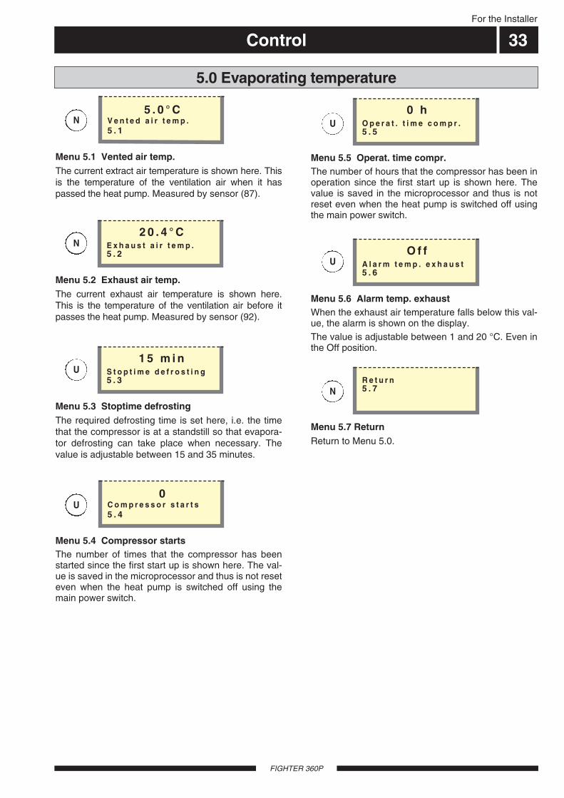
Menu 5.1 Vented air temp.The current extract air temperature is shown here. Thisis the temperature of the ventilation air when it haspassed the heat pump. Measured by sensor (87).
Menu 5.2 Exhaust air temp.The current exhaust air temperature is shown here.This is the temperature of the ventilation air before itpasses the heat pump. Measured by sensor (92).
5 . 0 ° CV e n t e d a i r t e m p .5 . 1
2 0 . 4 ° CE x h a u s t a i r t e m p .5 . 2
Menu 5.3 Stoptime defrostingThe required defrosting time is set here, i.e. the timethat the compressor is at a standstill so that evapora-tor defrosting can take place when necessary. Thevalue is adjustable between 15 and 35 minutes.
1 5 m i nS t o p t i m e d e f r o s t i n g5 . 3
Menu 5.4 Compressor startsThe number of times that the compressor has beenstarted since the first start up is shown here. The val-ue is saved in the microprocessor and thus is not reseteven when the heat pump is switched off using themain power switch.
Menu 5.5 Operat. time compr.The number of hours that the compressor has been inoperation since the first start up is shown here. Thevalue is saved in the microprocessor and thus is notreset even when the heat pump is switched off usingthe main power switch.
0C o m p r e s s o r s t a r t s5 . 4
0 hO p e r a t . t i m e c o m p r .5 . 5
Menu 5.6 Alarm temp. exhaustWhen the exhaust air temperature falls below this val-ue, the alarm is shown on the display.The value is adjustable between 1 and 20 °C. Even inthe Off position.
O f fA l a r m t e m p . e x h a u s t5 . 6
Menu 5.7 ReturnReturn to Menu 5.0.
R e t u r n5 . 7
N
N
U
U
U
U
N
Control
FIGHTER 360P
For the Installer
34
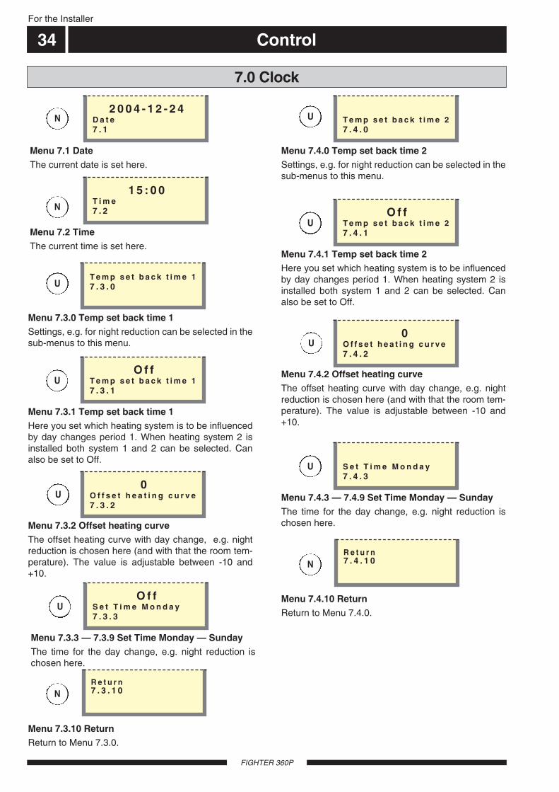
Menu 7.1 DateThe current date is set here.
Menu 7.3.0 Temp set back time 1Settings, e.g. for night reduction can be selected in thesub-menus to this menu.
2 0 0 4 - 1 2 - 2 4D a t e7 . 1
T e m p s e t b a c k t i m e 17 . 3 . 0
Menu 7.3.1 Temp set back time 1Here you set which heating system is to be influencedby day changes period 1. When heating system 2 isinstalled both system 1 and 2 can be selected. Canalso be set to Off.
O f f T e m p s e t b a c k t i m e 17 . 3 . 1
Menu 7.3.2 Offset heating curveThe offset heating curve with day change, e.g. nightreduction is chosen here (and with that the room tem-perature). The value is adjustable between -10 and+10.
0O f f s e t h e a t i n g c u r v e7 . 3 . 2
Menu 7.2 TimeThe current time is set here.
1 5 : 0 0T i m e7 . 2
7.0 Clock
U
U
Menu 7.3.3 — 7.3.9 Set Time Monday — SundayThe time for the day change, e.g. night reduction ischosen here.
O f fS e t T i m e M o n d a y7 . 3 . 3
U
N
N
N
U
Menu 7.3.10 ReturnReturn to Menu 7.3.0.
R e t u r n7 . 3 . 1 0
Menu 7.4.0 Temp set back time 2Settings, e.g. for night reduction can be selected in thesub-menus to this menu.
T e m p s e t b a c k t i m e 27 . 4 . 0
Menu 7.4.1 Temp set back time 2Here you set which heating system is to be influencedby day changes period 1. When heating system 2 isinstalled both system 1 and 2 can be selected. Canalso be set to Off.
O f fT e m p s e t b a c k t i m e 27 . 4 . 1
Menu 7.4.2 Offset heating curveThe offset heating curve with day change, e.g. nightreduction is chosen here (and with that the room tem-perature). The value is adjustable between -10 and+10.
0O f f s e t h e a t i n g c u r v e7 . 4 . 2
U
U
Menu 7.4.3 — 7.4.9 Set Time Monday — SundayThe time for the day change, e.g. night reduction ischosen here.
S e t T i m e M o n d a y7 . 4 . 3
U
N
U
Menu 7.4.10 ReturnReturn to Menu 7.4.0.
R e t u r n7 . 4 . 1 0
Control 35For the Installer
FIGHTER 360P
7.0 Clock
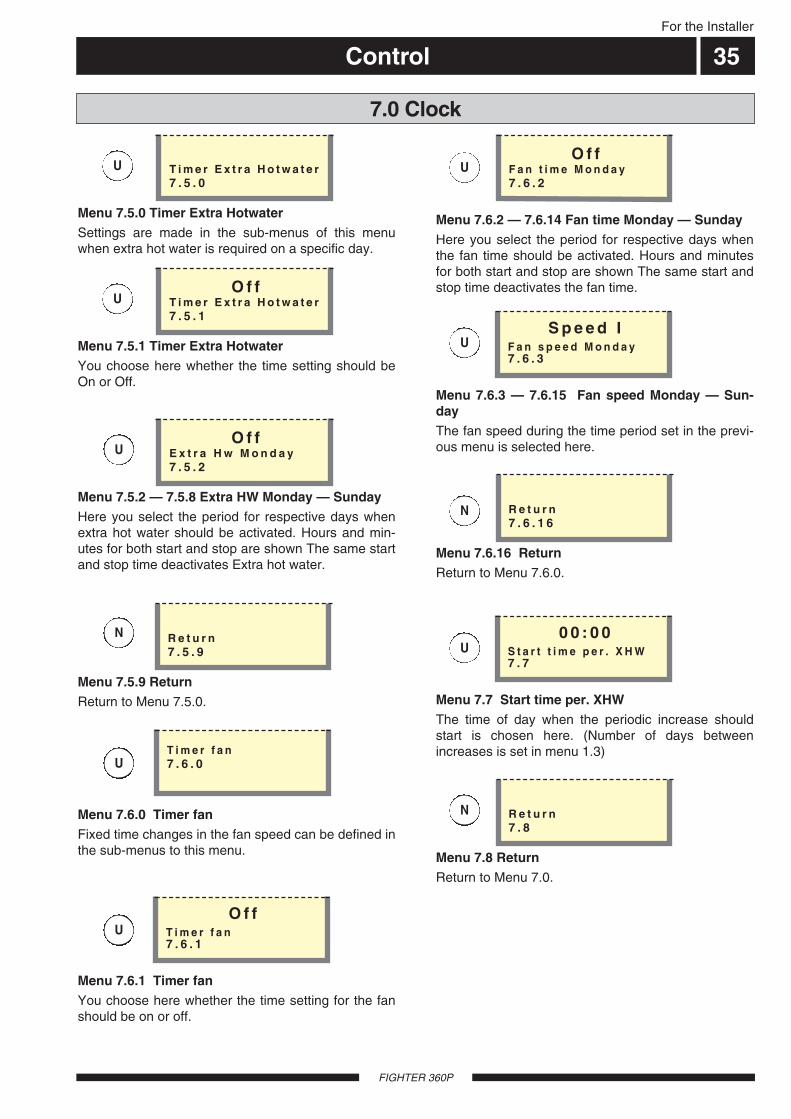
Menu 7.5.0 Timer Extra HotwaterSettings are made in the sub-menus of this menuwhen extra hot water is required on a specific day.
T i m e r E x t r a H o t w a t e r7 . 5 . 0
Menu 7.5.2 — 7.5.8 Extra HW Monday — SundayHere you select the period for respective days whenextra hot water should be activated. Hours and min-utes for both start and stop are shown The same startand stop time deactivates Extra hot water.
O f fE x t r a H w M o n d a y7 . 5 . 2
Menu 7.5.9 ReturnReturn to Menu 7.5.0.
R e t u r n7 . 5 . 9
U
U
U
N
U
Menu 7.5.1 Timer Extra HotwaterYou choose here whether the time setting should beOn or Off.
O f fT i m e r E x t r a H o t w a t e r7 . 5 . 1
U
Menu 7.6.0 Timer fanFixed time changes in the fan speed can be defined inthe sub-menus to this menu.
Menu 7.6.1 Timer fanYou choose here whether the time setting for the fanshould be on or off.
T i m e r f a n7 . 6 . 0
O f fT i m e r f a n7 . 6 . 1
Menu 7.6.2 — 7.6.14 Fan time Monday — SundayHere you select the period for respective days whenthe fan time should be activated. Hours and minutesfor both start and stop are shown The same start andstop time deactivates the fan time.
Menu 7.6.3 — 7.6.15 Fan speed Monday — Sun-dayThe fan speed during the time period set in the previ-ous menu is selected here.
O f fF a n t i m e M o n d a y7 . 6 . 2
S p e e d IF a n s p e e d M o n d a y7 . 6 . 3
Menu 7.6.16 ReturnReturn to Menu 7.6.0.
R e t u r n7 . 6 . 1 6
Menu 7.7 Start time per. XHWThe time of day when the periodic increase shouldstart is chosen here. (Number of days betweenincreases is set in menu 1.3)
0 0 : 0 0S t a r t t i m e p e r . X H W7 . 7
Menu 7.8 ReturnReturn to Menu 7.0.
R e t u r n7 . 8
U
U
N
U
N
Control
FIGHTER 360P
For the installer
36
8.0 Other settings
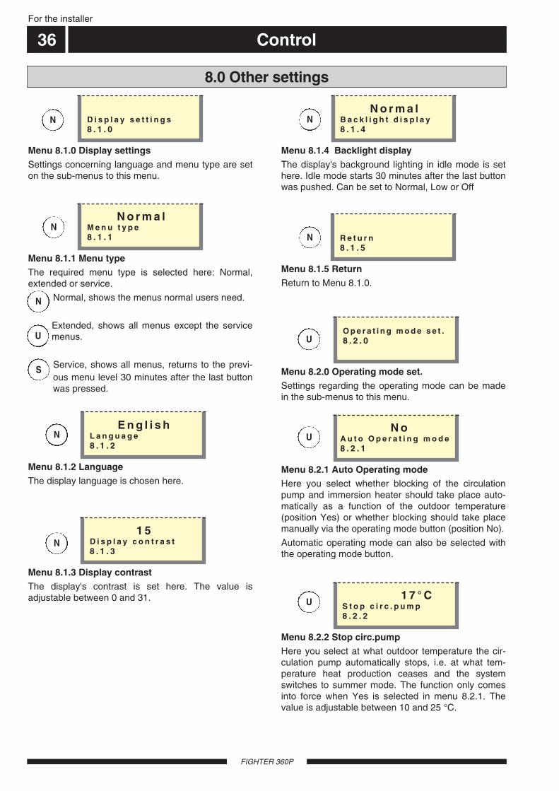
Menu 8.2.0 Operating mode set.Settings regarding the operating mode can be madein the sub-menus to this menu.
O p e r a t i n g m o d e s e t .8 . 2 . 0
Menu 8.2.2 Stop circ.pumpHere you select at what outdoor temperature the cir-culation pump automatically stops, i.e. at what tem-perature heat production ceases and the systemswitches to summer mode. The function only comesinto force when Yes is selected in menu 8.2.1. Thevalue is adjustable between 10 and 25 °C.
1 7 ° CS t o p c i r c . p u m p8 . 2 . 2
Menu 8.2.1 Auto Operating modeHere you select whether blocking of the circulationpump and immersion heater should take place auto-matically as a function of the outdoor temperature(position Yes) or whether blocking should take placemanually via the operating mode button (position No).
Automatic operating mode can also be selected withthe operating mode button.
N oA u t o O p e r a t i n g m o d e8 . 2 . 1
U
U
U
Menu 8.1.0 Display settingsSettings concerning language and menu type are seton the sub-menus to this menu.
D i s p l a y s e t t i n g s8 . 1 . 0
Menu 8.1.1 Menu typeThe required menu type is selected here: Normal,extended or service.
Normal, shows the menus normal users need.
Extended, shows all menus except the servicemenus.
Service, shows all menus, returns to the previ-ous menu level 30 minutes after the last buttonwas pressed.
N o r m a lM e n u t y p e8 . 1 . 1
Menu 8.1.5 ReturnReturn to Menu 8.1.0.
R e t u r n8 . 1 . 5
Menu 8.1.2 LanguageThe display language is chosen here.
E n g l i s hL a n g u a g e8 . 1 . 2
Menu 8.1.4 Backlight displayThe display's background lighting in idle mode is sethere. Idle mode starts 30 minutes after the last buttonwas pushed. Can be set to Normal, Low or Off
N o r m a lB a c k l i g h t d i s p l a y8 . 1 . 4
Menu 8.1.3 Display contrastThe display's contrast is set here. The value isadjustable between 0 and 31.
1 5D i s p l a y c o n t r a s t8 . 1 . 3
N
N
N
N
N
N
N
U
S
Control 37For the Installer
FIGHTER 360P
8.0 Other settings
Menu 8.2.3 Stop el. heaterHere you select the outdoor temperature that auto-matically blocks the immersion heater, i.e. the temper-ature when additional energy is not used and the sys-tem should switch to spring/autumn mode. The func-tion only comes into force when Yes is selected inmenu 8.2.1. The value is adjustable between -5 °Cand set value for the circulation pump (10 – 25 °C)from the menu 8.2.2.
1 2 ° CS t o p e l . h e a t e r8 . 2 . 3
U
N
Menu 8.2.4 ReturnReturn to Menu 8.2.0.
R e t u r n8 . 2 . 4
Menu 8.3.0 Load monitorSettings and readings regarding the load monitor areset on the sub-menus to this menu.
L o a d m o n i t o r8 . 3 . 0
Menu 8.3.8 ReturnReturn to Menu 8.3.0.
R e t u r n8 . 3 . 8
Menu 8.3.3 Current phase 1Shows the measured current from phase 1. If the val-ue falls below 2.0 A Low is shown.
3 . 5 AC u r r e n t p h a s e 18 . 3 . 3
Menu 8.3.4 Current Phase 2Shows the measured current from phase 2. If the val-ue falls below 2.0 A Low is shown.
3 . 3 AC u r r e n t p h a s e 28 . 3 . 4
Menu 8.3.5 Current Phase 3Shows the measured current from phase 3. If the val-ue falls below 2.0 A Low is shown.
3 . 3 AC u r r e n t p h a s e 38 . 3 . 5
Menu 8.3.6 Ratio of transf. EBVThe transfer value must be defined depending on thecurrent transformers used for the EBV card. The valueis adjustable between 100 and 900 in increments of10. The setting 300 applies for the supplied currenttransformers.
3 0 0R a t i o o f t r a n s f . E B V8 . 3 . 6
U
U
U
U
U
Menu 8.3.7 Tariff statusShows the current tariff status.
O f fT a r i f f s t a t u s8 . 3 . 7
U
N
Menu 8.3.1 Fuse sizeThe setting selected on the EBV card (2) knob (100) isshown here.
1 6 AF u s e s i z e8 . 3 . 1
U
Menu 8.3.2 Max. el. powerThe setting selected on the EBV card (2) knob (101) isshown here.
9 . 0 k WM a x . e l . p o w e r8 . 3 . 2
U
Control
FIGHTER 360P
For the installer
38
8.0 Other settings
Menu 8.4.0 Fan settingsSettings and readings regarding fan speed are madeon the sub-menus to this menu.
F a n s e t t i n g s8 . 4 . 0
Menu 8.5.4 ReturnReturn to Menu 8.5.0.
R e t u r n8 . 5 . 4
Menu 8.6 ReturnReturn to Menu 8.0.
R e t u r n8 . 6
Menu 8.4.3 ReturnReturn to Menu 8.4.0.
R e t u r n8 . 4 . 3
Menu 8.5.0 Night coolnessPressing the enter button takes you to sub-menuswhere readings and settings concerning night cool-ness are made. When the temperature in the house ishigh and the outdoor air temperature is lower, a cool-ing effect can be obtained by forcing the fan speed.
N i g h t c o o l n e s s8 . 5 . 0U
N
U
Menu 8.5.1 Night coolnessThe night coolness is set On or Off here.
O f fN i g h t c o o l n e s s8 . 5 . 1
U
Menu 8.5.2 Start temp. coolnessAt what temperature on the exhaust air sensor (92)should night cooling start.
2 5 ° CS t a r t t e m p . c o o l n e s s8 . 5 . 2
U
Menu 8.5.3 Min. diff. coolnessThe minimum difference between the exhaust air tem-perature and the outdoor air temperature for nightcooling to be activated is chosen here.
6 ° CM i n . d i f f . c o o l n e s s8 . 5 . 3
U
N
N
Menu 8.4.1 Return-time speed IIHere you select the time that should apply for fanspeed II when activated using the Fan speed button,i.e. when the return to normal fan speed should takeplace. The value can be set from 1 to 10 hours.
4 hR e t u r n - t i m e s p e e d I I8 . 4 . 1
U
Menu 8.4.2 Return-time speed IHere you select the time that should apply for fanspeed I when activated using the Fan speed button,i.e. when the return to normal fan speed should takeplace. The value can be set within the ranges 1 to 10hours or 1 to 16 days.
4 hR e t u r n - t i m e s p e e d I8 . 4 . 2
U

Control 39For the Installer
FIGHTER 360P
9.0 Service menu
Menu 9.1.8 Time factor el.heat.The time factor of the immersion heater since first startup is shown here. The value is saved in the micro-processor and thus is not reset even when the heatpump is switched off using the main power switch.
0T i m e f a c t o r e l . h e a t .9 . 1 . 8
Menu 9.1.6 Factory pre-setSelect Yes and press the enter button to restore theheat pump to the factory settings.
Once the factory settings have been restored the heatpump returns to Menu 1.0.
N oF a c t o r y p r e - s e t9 . 1 . 6
S
Menu 9.1.7 Trend calc. limitAt what outdoor temperature trend calculating ceasesis selected here. Below this limit trend calculating isnot used to enable the additional heat. The value isadjustable between 0 and 20 °C.
5 ° CT r e n d c a l c . l i m i t9 . 1 . 7
S
S
Menu 9.1.0 Operating settingsSettings regarding additional heat, floor drying and areturn to the factory settings can be made on the sub-menus in this menu.
O p e r a t i n g s e t t i n g s9 . 1 . 0
Menu 9.1.1 Electric boilerThe heat pump can be set in electric boiler mode fromhere. This mode means the compressor is blocked,but all other components function as normal. Thismode can be activated if a fault is discovered on thecompressor or any other component in the cooling cir-cuit. Note no energy savings are made in this mode.Once the fault has been rectified the heat pumpshould be switched to normal mode again. The elec-tric boiler mode is activated when Yes is shown on thedisplay screen, otherwise No is shown. When theelectric boiler mode is activated, the immersion heaterrespective circulation pump cannot be blocked withthe operating mode button.
N oE l e c t r i c b o i l e r9 . 1 . 1
S
S
O f fS h u n t g r o u p 29 . 2 . 2
S
Menu 9.1.3 RCUThe RCU (accessory) is set On or Off here.
O f fR C U9 . 1 . 3
S
Menu 9.1.4 Circulation pumpThe operating mode of the circulation pump for theheating system can be force controlled from thismenu. When On is selected the circulation pump runsconstantly. When Off is selected the circulation pumpis blocked. Note however that a change in the operat-ing mode using the operating mode button disablesthe change made in this menu.
O f fC i r c u l a t i o n p u m p9 . 1 . 4
S
Menu 9.1.5 Circulation pump 2The operating mode for circulation pump 2 for theheating system can be force-controlled from thismenu. When On is selected the circulation pump runsconstantly. When Off is selected the circulation pumpis blocked. Note however that a change in the operat-ing mode using the operating mode button disablesthe change made in this menu.
O f fC i r c u l a t i o n p u m p 29 . 1 . 5
S
Menu 9.1.2 Shunt group 2Here you select whether shunt group 2 is connected.NOTE! Requires accessories.
Control
FIGHTER 360P
For the installer
40
Menu 9.1.9 Quickstart comp.Select Yes in order to reduce the pressure-compen-sating time to 0 and in doing so permit a quick start ofthe compressor.
NOTE! The setting returns to No as soon as the heatpump has implemented the action.
N oQ u i c k s t a r t c o m p .9 . 1 . 9
Menu 9.2.0 Floor drying settingPressing the enter button takes you to sub-menus forthe floor drying settings.
F l o o r d r y i n g s e t t i n g9 . 2 . 0
Menu 9.2.1 Op-mode floor dryingThe operating mode for the floor drying function is sethere. Selectable modes are:Off: Normal operation, i.e. the floor drying function isswitched off.Own program: Two fixed temperatures in two periodsare adjustable in menu 9.2.3 to 9.2.6.Fixed program: The flow temperature starts day 0 at20 degrees and increases each day by 5 degrees.Day 5 the temperature has reached 45 degrees,which is maintained on days 6 and 7. The program isended on days 8 to 12 with the temperature droppingby 5 degrees each day.
O f fO p - m o d e f l o o r d r y i n g9 . 2 . 1
Menu 9.2.2 Floor drying dayHere you can see which day the floor drying functionis on. It is also possible here to enter the floor dryingprogram by changing this value. The value isadjustable from 0 to 20 days. The factory setting is 0.
0F l o o r d r y i n g d a y9 . 2 . 2
Menu 9.2.3 No. of days per. 1Here you set the number of days that the flow temper-ature shall maintain the temperature in menu 9.2.4when Own program in menu 9.2.1 is selected. Thevalue is adjustable between 1 and 10 days.
5N o . o f d a y s p e r . 19 . 2 . 3
Menu 9.2.4 Temperature per. 1Here you set the temperature to be maintained on theflow line sensor (FG) during period 1 when Own pro-gram is selected in menu 9.2.1. The value isadjustable between 15 and 50 °C.
2 5 ° CT e m p e r a t u r e p e r . 19 . 2 . 4
Menu 9.1.10 Quickstart el.heaterNormally the electrical output of the immersionheaters is limited to a maximum of 6 kW for the firsttwo hours after the heat pump has been started, i.e.after the main power switch has been set to 1.
Selecting Yes in this menu disengages the two-hourdelay.
NOTE! The setting returns to No as soon as the heatpump has implemented the action.
N oQ u i c k s t a r t e l . h e a t e r9 . 1 . 1 0
Menu 9.1.11 ReturnReturn to Menu 9.1.0.
R e t u r n9 . 1 . 1 1
9.0 Service menu
S
S
S
S
S
S
S
S
Control 41For the Installer
FIGHTER 360P
Menu 9.2.5 No. of days per. 2Here you set the number of days that the flow temper-ature shall maintain the temperature in menu 9.2.6when Own program in menu 9.2.1 is selected. Thevalue is adjustable between 1 and 10 days.
5N o . o f d a y s p e r . 29 . 2 . 5
Menu 9.2.6 Temperature per. 2Here you set the temperature to be maintained on theflow line sensor (FG) during period 2 when Own pro-gram is selected in menu 9.2.1. The value isadjustable between 15 and 50 °C.
3 5 ° CT e m p e r a t u r e p e r . 29 . 2 . 6
Menu 9.2.7 ReturnReturn to Menu 9.2.0.
R e t u r n9 . 2 . 7
Menu 9.3.0 Alarm logPressing the enter button takes you to sub-menuswhere all operating disturbances and the heat pump'sstatus are logged.
A l a r m l o g9 . 3 . 0
Menu 9.3.x.1 Type of alarmShows which alarm has occurred, for example, HP-alarm / TB-alarm, etc.
H P - a l a r mT y p e o f a l a r m9 . 3 . 1 . 1
Menu 9.3.x.2 DateShows the date when the current alarm tripped.
2 0 0 5 - 0 1 - 2 5D a t e9 . 3 . 1 . 2
Menu 9.3.x.3 TimeShows the time when the current alarm tripped.
1 0 : 3 6T i m e9 . 3 . 1 . 3
Menu 9.3.x.4 Outdoor temperatureShows the outdoor temperature on the sensor (15)when the current alarm tripped.
4 . 3 ° CO u t d o o r t e m p e r a t u r e9 . 3 . 1 . 4
Menu 9.3.x.5 Flow temperatureShows the flow temperature on the sensor (89) whenthe current alarm tripped.
3 5 . 2 ° CF l o w t e m p e r a t u r e9 . 3 . 1 . 5
Menu 9.3.1.0 Alarm 1 — 6Pressing the enter button takes you to sub-menuswhere the status is shown for the heat pump when thedifferent operating disturbances have occurred. Thealarms are sorted chronologically, which means alarm1 is always the most recent. (When there are noalarms stored, pressing enter has no effect.)
x in the following menus represents the alarm number.
A l a r m 19 . 3 . 1 . 0
9.0 Service menu
Menu 9.3.x.6 Return temperatureShows the return temperature on the sensor (93) whenthe current alarm tripped.
3 1 . 0 ° CR e t u r n t e m p e r a t u r e9 . 3 . 1 . 6
S
S
S
S
S
S
S
S
S
S
S
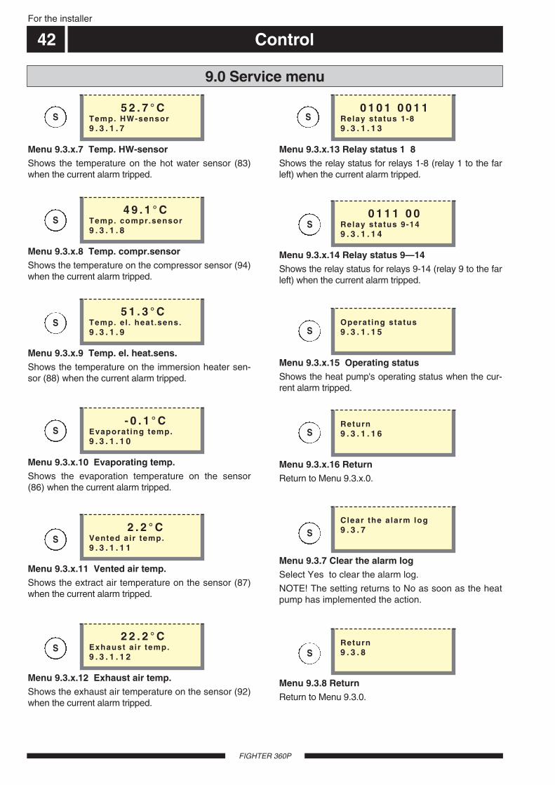
Control
FIGHTER 360P
For the installer
42
Menu 9.3.x.7 Temp. HW-sensorShows the temperature on the hot water sensor (83)when the current alarm tripped.
5 2 . 7 ° CTemp. HW-sensor9 . 3 . 1 . 7
Menu 9.3.x.8 Temp. compr.sensorShows the temperature on the compressor sensor (94)when the current alarm tripped.
4 9 . 1 ° CTemp. compr.sensor9 . 3 . 1 . 8
Menu 9.3.x.9 Temp. el. heat.sens.Shows the temperature on the immersion heater sen-sor (88) when the current alarm tripped.
5 1 . 3 ° CTemp. el . heat .sens.9 . 3 . 1 . 9
Menu 9.3.x.10 Evaporating temp.Shows the evaporation temperature on the sensor(86) when the current alarm tripped.
- 0 . 1 ° CEvaporat ing temp.9 . 3 . 1 . 1 0
Menu 9.3.x.11 Vented air temp.Shows the extract air temperature on the sensor (87)when the current alarm tripped.
2 . 2 ° CVented air temp.9 . 3 . 1 . 1 1
Menu 9.3.x.12 Exhaust air temp.Shows the exhaust air temperature on the sensor (92)when the current alarm tripped.
2 2 . 2 ° CExhaust a ir temp.9 . 3 . 1 . 1 2
Menu 9.3.x.13 Relay status 1 8Shows the relay status for relays 1-8 (relay 1 to the farleft) when the current alarm tripped.
0 1 0 1 0 0 1 1Relay status 1-89 . 3 . 1 . 1 3
Menu 9.3.x.14 Relay status 9—14Shows the relay status for relays 9-14 (relay 9 to the farleft) when the current alarm tripped.
0 1 1 1 0 0Relay status 9-149 . 3 . 1 . 1 4
Menu 9.3.x.15 Operating statusShows the heat pump's operating status when the cur-rent alarm tripped.
Operat ing status9 . 3 . 1 . 1 5
Menu 9.3.x.16 ReturnReturn to Menu 9.3.x.0.
Return9 . 3 . 1 . 1 6
Menu 9.3.7 Clear the alarm logSelect Yes to clear the alarm log.
NOTE! The setting returns to No as soon as the heatpump has implemented the action.
Clear the alarm log9 . 3 . 7
9.0 Service menu
Menu 9.3.8 ReturnReturn to Menu 9.3.0.
Return9 . 3 . 8
S
S
S
S
S
S
S
S
S
S
S
S
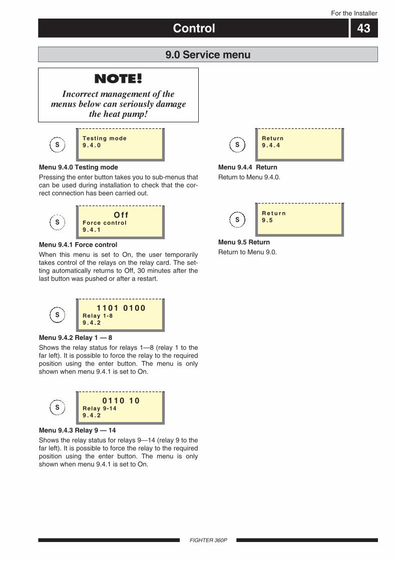
Control 43For the Installer
FIGHTER 360P
Menu 9.5 ReturnReturn to Menu 9.0.
R e t u r n9 . 5
9.0 Service menu
Menu 9.4.0 Testing modePressing the enter button takes you to sub-menus thatcan be used during installation to check that the cor-rect connection has been carried out.
Test ing mode9 . 4 . 0
Menu 9.4.1 Force controlWhen this menu is set to On, the user temporarilytakes control of the relays on the relay card. The set-ting automatically returns to Off, 30 minutes after thelast button was pushed or after a restart.
O f fForce control9 . 4 . 1
Menu 9.4.2 Relay 1 — 8Shows the relay status for relays 1—8 (relay 1 to thefar left). It is possible to force the relay to the requiredposition using the enter button. The menu is onlyshown when menu 9.4.1 is set to On.
1 1 0 1 0 1 0 0Relay 1-89 . 4 . 2
Menu 9.4.3 Relay 9 — 14Shows the relay status for relays 9—14 (relay 9 to thefar left). It is possible to force the relay to the requiredposition using the enter button. The menu is onlyshown when menu 9.4.1 is set to On.
0 1 1 0 1 0Relay 9-149 . 4 . 2
Menu 9.4.4 ReturnReturn to Menu 9.4.0.
Return9 . 4 . 4
NOTE!Incorrect management of the
menus below can seriously damage the heat pump!
S
S
S
S
S
S
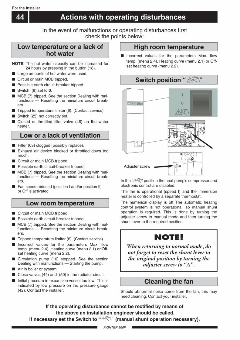
Adjuster screw
For the Installer
Actions with operating disturbances
FIGHTER 360P
In the “ ” position the heat pump's compressor andelectronic control are disabled.
The fan is operational (speed I) and the immersionheater is controlled by a separate thermostat.
The numerical display is off The automatic heatingcontrol system is not operational, so manual shuntoperation is required. This is done by turning theadjuster screw to manual mode and then turning theshunt lever to the required position.
Switch position “ ”
If the operating disturbance cannot be rectified by means ofthe above an installation engineer should be called.
If necessary set the Switch to “ ” (manual shunt operation necessary).
Incorrect values for the parameters Max. flowtemp. (menu 2.4), Heating curve (menu 2.1) or Off-set heating curve (menu 2.2).
High room temperature
NOTE! The hot water capacity can be increased for24 hours by pressing in the button (18).
Large amounts of hot water were used. Circuit or main MCB tripped. Possible earth circuit-breaker tripped. Switch (8) set to 0. MCB (7) tripped. See the section Dealing with mal-
functions — Resetting the miniature circuit break-ers.
Tripped temperature limiter (6). (Contact service) Switch (25) not correctly set. Closed or throttled filler valve (46) on the water
heater.
Low temperature or a lack ofhot water
Circuit or main MCB tripped. Possible earth circuit-breaker tripped. MCB (7) tripped. See the section Dealing with mal-
functions — Resetting the miniature circuit break-ers.
Tripped temperature limiter (6). (Contact service). Incorrect values for the parameters Max. flow
temp. (menu 2.4), Heating curve (menu 2.1) or Off-set heating curve (menu 2.2).
Circulation pump (16) stopped. See the sectionDealing with malfunctions — Starting the pump.
Air in boiler or system. Close valves (44) and (50) in the radiator circuit.
Initial pressure in expansion vessel too low. This isindicated by low pressure on the pressure gauge(42). Contact the installer.
Filter (63) clogged (possibly replace). Exhaust air device blocked or throttled down too
much. Circuit or main MCB tripped. Possible earth circuit-breaker tripped. MCB (7) tripped. See the section Dealing with mal-
functions — Resetting the miniature circuit break-ers.
Fan speed reduced (position I and/or position II) or Off is activated.
Low room temperature
Low or a lack of ventilation
In the event of malfunctions or operating disturbances first check the points below:
NOTE! When returning to normal mode, donot forget to reset the shunt lever tothe original position by turning the
adjuster screw to A.
LEK
+20-2
A B A B A BI II III I II I II
44
Should abnormal noise come from the fan, this mayneed cleaning. Contact your installer.
Cleaning the fan

For the Installer
Actions with operating disturbances
FIGHTER 360P
NOTE! The products serial number
should always be stated with allcorrespondence with NIBE.
089_ _ _ _ _ _ _ _ _ _ _
FILTER-ALARMThis information is shown every three months and is acall for the air filter to be cleaned, see the sectionMaintenance routines — Cleaning the air filter. Theinformation disappears when the filter has beencleaned and the main power switch is set to 1 again.
LP-ALARMThis information is shown when the low pressureswitch in the cooling circuit has tripped. This may becaused by a too low ventilation flow or too little refrig-erant. The information disappears when the pressureswitch resets (automatically) and the main powerswitch is set to 1 again.
SENSOR-ALARMThis information is shown when one of the tempera-ture sensor malfunctions, for example, a broken cableor a short circuit. The information disappears when thecause of the fault has been rectified and the mainpower switch is set to 1 again.
Alarm indications on the displayOther information can also be shown on the displaybesides the standard information. This applies withmalfunctions or for calls to take action. This type ofinformation is only shown in menu 1.0 (The displayalways automatically returns to menu 1.0 approxi-mately 30 minutes after the last button was pressed).This information alternates with menu 1.0’s standardinformation. At the same time the display’s back-ground lighting flashes.
The following information can be shown.
45
F I L T E R - A L A R M1 . 0
L P - A L A R M1 . 0
S E N S O R - A L A R M1 . 0
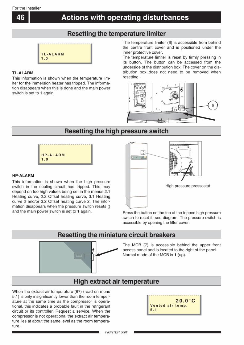
For the Installer
Actions with operating disturbances
When the extract air temperature (87) (read on menu5.1) is only insignificantly lower than the room temper-ature at the same time as the compressor is opera-tional, this indicates a probable fault in the refrigerantcircuit or its controller. Request a service. When thecompressor is not operational the extract air tempera-ture lies at about the same level as the room tempera-ture.
High extract air temperature
The MCB (7) is accessible behind the upper frontaccess panel and is located to the right of the panel.Normal mode of the MCB is 1 (up).
Resetting the miniature circuit breakers
Press the button on the top of the tripped high pressureswitch to reset it; see diagram. The pressure switch isaccessible by opening the filter cover.
High pressure pressostat
Resetting the high pressure switch
LEK
+20-2
A B A B A BI II III I II I II
HP-ALARMThis information is shown when the high pressureswitch in the cooling circuit has tripped. This maydepend on too high values being set in the menus 2.1Heating curve, 2.2 Offset heating curve, 3.1 Heatingcurve 2 and/or 3.2 Offset heating curve 2. The infor-mation disappears when the pressure switch resets ()and the main power switch is set to 1 again.
TL-ALARMThis information is shown when the temperature lim-iter for the immersion heater has tripped. The informa-tion disappears when this is done and the main powerswitch is set to 1 again.
The temperature limiter (6) is accessible from behindthe centre front cover and is positioned under theinner protective cover.The temperature limiter is reset by firmly pressing inits button. The button can be accessed from theunderside of the distribution box. The cover on the dis-tribution box does not need to be removed whenresetting.
Resetting the temperature limiter
6
46
FIGHTER 360P
T L - A L A R M1 . 0
H P - A L A R M1 . 0
2 0 . 0 ° CV e n t e d a i r t e m p .5 . 1

Service
FIGHTER 360P
Shut down FIGHTER 360P by turning the switch(8) to 0.
Remove the lower front cover.
Loosen the air screw with a screwdriver. Hold acloth around the screwdriver blade as a certainamount of hot water may run out.
Insert a screwdriver and turn the pump rotor.
Screw in the air screw.
Start FIGHTER 360P and check whether the circu-lation pump runs.
It is usually easier to start the circulation pump withFIGHTER 360P running, switch (8) set to 1. If helpingthe circulation pump to start is performed with FIGHT-ER 360P running, be prepared for the screwdriver tojerk when the pump starts.
Helping the circulation pump to start
Venting screw
16
LE
K
GR
UN
DFO
SType
UP
S25 -
60
130
P/N
:59526447
230V
-
HE
JS
AN
PC
;0017N
IBD
K50H
z
IP 44
TF
110
Cla
ss H
Max. 1
0bar
2.5
uF
45
0.2
065
0.3
090
0.4
0
1m(A
)P,
(W)
For the Installer
Rotor unit
Drive sideA
LEK
GR
UN
DFO
STyp
eU
PS
25
- 6
01
30
P/N
:59
52
64
47
23
0V
-
HE
JS
AN
PC
;00
17
NIB
DK
50
Hz
IP
44
TF
1
10
Cla
ss
HM
ax. 1
0b
ar
2.5
uF
45
0.2
06
50
.30
90
0.4
0
1m(A
)P,
(W)
B
LEK
C
LEKD
Set the switch (8) to 0.
Close the shut-off valves before and after the cir-culation pump.
Loosen the venting screw.
Remove the connection cover.
Loosen the power cable.
Remove the drive side from the pump housing byloosening the screws. Now dismantle the drive side(fig. A).
Remove the rotor unit (including pump housing) bycarefully pulling the pump rotor. If it sits firmly, itcan be loosened by knocking the rear of the shaft(fig. B).
Clean inside the stator can using a cleaning agent(fig. C).
Also clean the rotor unit using the cleaning agentand lubricate the O-ring with, for example, a soapsolution (fig. D).
Refit the rotor unit.
Re-assemble the drive side (the flat packing is bestplaced on the pump housing).
Connect the power cable.
Open the shut-off valves.
Set the switch (8) to 1.
Cleaning the circulation pump
47

For the Installer
Component placement
FIGHTER 360P
Åter-ledningradiatorerk.v.v.v.
Blaha blaha
och annattrams
Blaha blahaoch annat
trams
Fram-ledningradiatorer
Art.nr. 611827
2
1 bar 3
0 4
LEK
011007
94
1
88
43
86
Fram-ledning
radiatorer
16
17
44
70
44
78
27
36
33
98
96
97
8
62
48
63
87
65
14
Åter-ledning
radiatorer
k.v.v.v.
41
3551807150667499 73
84
85
42
108
145
61
103
92
83
100
101
2
93
47
3
6
10
69
7
18
30
38
25
32
68
102
34
53
20
52
105
104
67
12
11
9
95
108 151149 150152 148
19
89
48
Hw. Cw. Radiatorsystem inlet
Radiatorsystem outlet

For the Installer
List of components
FIGHTER 360P
Connection Setting out dimensionsA B C
70 Supply line, radiator circuit ............................................... Compression ring Ø 22 mm 100 . 465 ...... 9071 Return line, radiator circuit ............................................... Compression ring Ø 22 mm 130 .. 465 ...... 19073 Cold water connection ...................................................... Compression ring Ø 22 mm 260 .. 465 ...... 29074 Hot water outlet from water heater ................................... Compression ring Ø 22 mm 290 .. 465 ...... 34578 Filter cover80 Drain connection, heating system .................................... R 15 male83 Temperature sensor, hot water84 Ventilation opening85 Expansion vessel86 Temperature sensor, evaporator87 Temperature sensor, extract air (concealed)88 Temperature sensor, immersion heater operation89 Temperature sensor, supply line90 Ventilation connection exhaust air ................................... Ø 125 mm .................... 2095 ...... 295 ...... 16091 Ventilation connection extract air ..................................... Ø 125 mm .................... 2095 ...... 295 ...... 48592 Temperature sensor, exhaust air (hidden)93 Temperature sensor, return94 Temperature sensor, compressor operation95 Overflow pipe, safety valve water heater96 Overflow pipe, safety valve heating97 Condensation water outlet, fan box98 Overflow water discharge ................................................. PVC-pipe Ø 32 mm (outside diameter)99 Collection funnel, waste water
100 Knob, setting Fuse 101 Knob, setting Max electrical output102 No function103 Type plate104 Venting, heating medium105 Communication, RCU106 Expansion vessel, tap water108 Tundish from temperature relief valve109 Tundish from pressure valve145 Temperature and pressure valve147 Filling hose148 Pressure reduction valve149 Connection for flexible hose to CW-side
1 Immersion heater 8 kW2 Load monitor card3 Operating thermostat, backup heating6 Temperature limiter7 Miniature circuit-breaker8 Switch, position 1 - 0 - 9 Terminal block, power supply
10 Contactor, step 111 Terminal block, docking12 Terminal block, docking13 Terminal block, capacitor14 Terminal block15 Outside sensor16 Circulation pump17 Air screw, circulation pump18 Pushbutton, Extra hot water19 Shunt motor with handwheel20 Connector, fan22 Terminal block for fan speed25 Push button, Operating mode26 Motor protection, compressor27 Compressor28 Operating capacitor, compressor 29 Relay card with power supply unit30 Push button, Fan speed32 Display unit
33 High pressure pressostat34 Central unit35 Capacity setting, circulation pump36 Fan, exhaust air38 Knob, Offset heating curve41 Low pressure pressostat42 Pressure gauge, boiler43 Shunt valve44 Shutoff valve, pump and supply radiator circuit46 Filler valve, water heater47 Safety valve, water heater48 Expansion valve50 Shutoff valve, return line radiator circuit51 Drain valve, heating system52 Safety valve, heating system53 Vacuum valve (hidden)54 Fan transformer57 Starter capacitor, exhaust air fan61 Docking connection, requires special pipe from NIBE62 Evaporator63 Air filter (Filter type G2)65 Drying filter with tank66 Rating plate67 Contactor, step 268 Compressor heater69 Contactor, step 3
49
150 Connection for flexible hose to heating-side151 Filling valve, heating system (CW-side)152 Filling valve, heating system (heating-side)169 Temperature limiter, compressor

For the Installer
Circuit diagram
FIGHTER 360P
Re3
Re2
Re11
Re1
Re4
Re5
Re6
Re8
Re9
Re10
X29
X29NX29
1A
3A2A
4B
6B5B
R01
T
X20aX20b X29
X29
M
68
X29
9X22
X29
5X29
4
X29
7
6
5
4
3
2
7
8
9
10
1
X29
T
14
13
642
1 3 5
642
1 3 5
White2 kW
Brown (Red)6 kW
X11
2
X11
3
6
7
8
16
10
67
43
3
54
57
28
35X29
34
X29
33
X29
31X29
32
X12
4
X12
6
1 1
X13
L 10
X13bX13a
N N
F2
F1
X12
5
X12
1
X29
30
X11
1
X12
3
X12
2
13
X29
12
X29
14
X29
17
X29
18 X29
19
X29
29
X11
5
X11
6
X11
4
X9L
X9L
X9L
X9N
X9N
PE
X29
46
X29
20
X20X20 X29
2b 2a 1
X20bX20aX29
2 N N
36
X20aX20b
PE PE
X29
36
67
1
10
X29
45
26
C
S
R
27
22
X29
26
X29
27
K67
14
X29
28
T
169
50
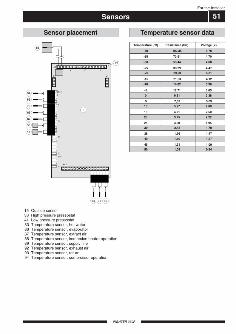
For the Installer
Sensors
FIGHTER 360P
15 Outside sensor33 High pressure pressostat41 Low pressure pressostat83 Temperature sensor, hot water86 Temperature sensor, evaporator87 Temperature sensor, extract air 88 Temperature sensor, immersion heater operation89 Temperature sensor, supply line92 Temperature sensor, exhaust air 93 Temperature sensor, return94 Temperature sensor, compressor operation
Temperature sensor dataSensor placement
-30 53,44 4,60
-20 29,20 4,31
-10 16,62 3,90
-40 102,35 4,78
Temperature (°C) Resistance (kΩ) Voltage (V)
-35 73,51 4,70
-25 39,29 4,47
-15 21,93 4,12
-5 12,71 3,65
0 9,81 3,38
5 7,62 3,09
10 5,97 2,80
15 4,71 2,50
20 3,75 2,22
25 3,00 1,95
30 2,42 1,70
35 1,96 1,47
40 1,60 1,27
45 1,31 1,09
50 1,08 0,94
4X4.1
X6.1
X11 5 10 15
X2 X3
83 93 89
X5.1
5
10
15
20
94
88
92
86
87
33
41
2
14
15
51
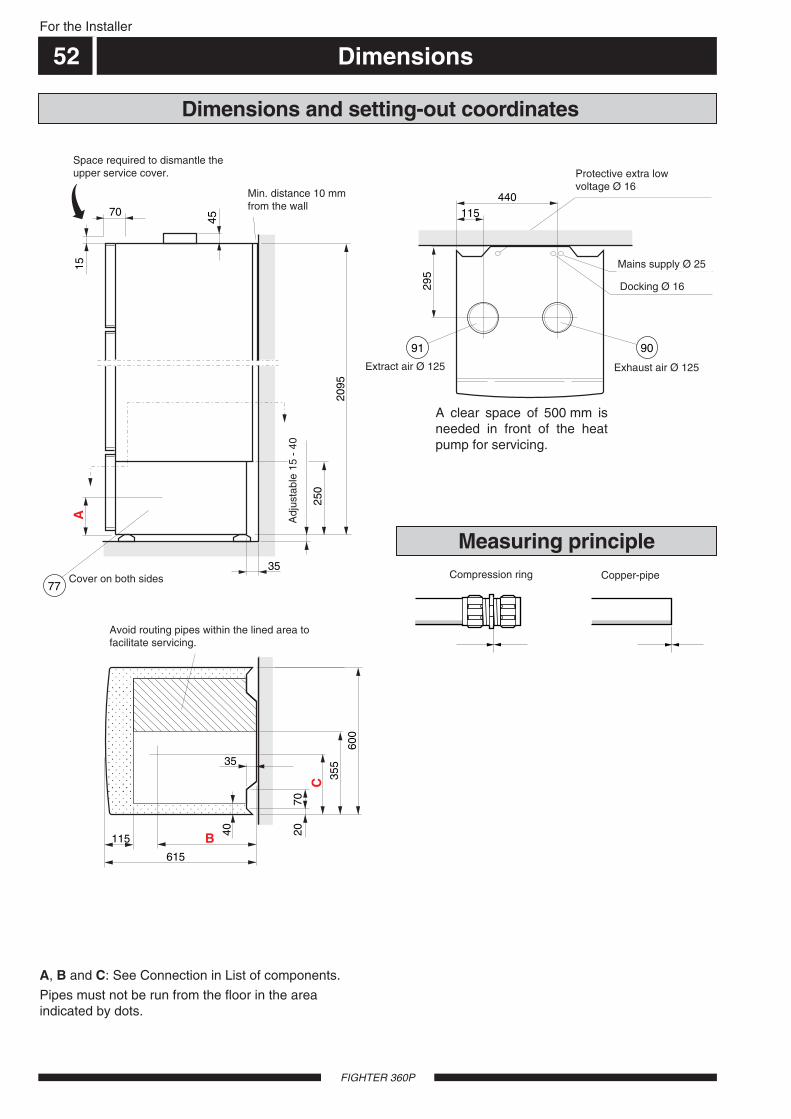
For the Installer
Dimensions
FIGHTER 360P
Dimensions and setting-out coordinates
Undvik rördragning inom streckmarkeratområde för att underlätta service
A15
Stä
llbar
15
– 40
250
45
Min avstånd10 mm från vägg
Lucka på båda sidor
Erforderligt utrymme för demontering av övre frontlucka
77
B615
115
C 355
600
2095
70
35
40 20
35
70
A, B and C: See Connection in List of components.
Pipes must not be run from the floor in the areaindicated by dots.
A clear space of 500 mm isneeded in front of the heatpump for servicing.
Measuring principle
Klämring Cu-rör
Skyddsklenspänning Ø 16
Frånluft Ø 125Avluft Ø 125
Elektriskmatning Ø 25
Dockning Ø 16
91 90
440115
295
52
Space required to dismantle theupper service cover.
Min. distance 10 mmfrom the wall
Protective extra low voltage Ø 16
Exhaust air Ø 125Extract air Ø 125
Docking Ø 16
Mains supply Ø 25
Cover on both sides Compression ring Copper-pipe
Avoid routing pipes within the lined area tofacilitate servicing.
Adj
usta
ble
15 -
40
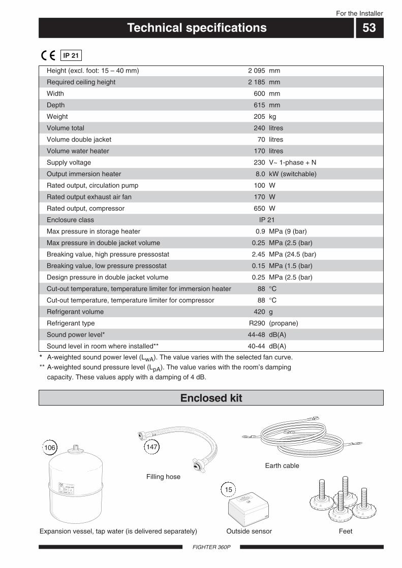
For the Installer
Technical specifications 53
FIGHTER 360P
Enclosure class IP 21
Required ceiling height 2 185 mm
Depth 615 mm
Volume total 240 litres
Volume water heater 170 litres
Output immersion heater 8.0 kW (switchable)
Rated output exhaust air fan 170 W
Max pressure in double jacket volume 0.25 MPa (2.5 (bar)
Breaking value, low pressure pressostat 0.15 MPa (1.5 (bar)
Cut-out temperature, temperature limiter for immersion heater 88 °C
Refrigerant volume 420 g
IP 21
Height (excl. foot: 15 – 40 mm) 2 095 mm
Width 600 mm
Weight 205 kg
Volume double jacket 70 litres
Supply voltage 230 V~ 1-phase + N
Rated output, circulation pump 100 W
Rated output, compressor 650 W
Max pressure in storage heater 0.9 MPa (9 (bar)
Breaking value, high pressure pressostat 2.45 MPa (24.5 (bar)
Design pressure in double jacket volume 0.25 MPa (2.5 (bar)
Cut-out temperature, temperature limiter for compressor 88 °C
Refrigerant type R290 (propane)
Sound power level* 44-48 dB(A)
Sound level in room where installed** 40-44 dB(A)
* A-weighted sound power level (LwA). The value varies with the selected fan curve.
** A-weighted sound pressure level (LpA). The value varies with the room’s damping
capacity. These values apply with a damping of 4 dB.
Enclosed kit
LEK
NIBE AB
Utetemperatur givare
Outdoor temperature sensor
Aussentemperatur fühler
Artikel 018764
Outside sensor Feet
Earth cable
Filling hose
LEK
147
15
Expansion vessel, tap water (is delivered separately)
LEK
106
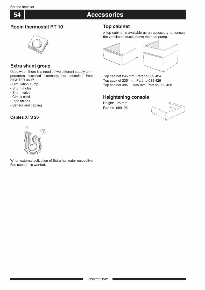
FIGHTER 360P
For the Installer
Accessories
LEK
10
15 20
2530°C
Room thermostat RT 10
Extra shunt groupUsed when there is a need of two different supply tem-peratures. Installed externally, but controlled fromFIGHTER 360P- Circulation pump- Shunt motor- Shunt valve- Circuit card- Pipe fittings- Sensor and cabling
54
When external activation of Extra hot water respectiveFan speed II is wanted.
Cables XTS 20
Top cabinetA top cabinet is available as an accessory to concealthe ventilation ducts above the heat pump.
Top cabinet 245 mm. Part no 089 424Top cabinet 335 mm. Part no 089 426Top cabinet 385 — 535 mm. Part no 089 428
LEK
LEK
LEK
Heightening consoleHeight: 125 mmPart no 089195

55
FIGHTER 360P

FIGHTER 360P
56


NIBE ABSWEDEN
R
Tel: +46 - (0)433 - 73 000Fax: +46 - (0)433 - 73 190E-mail: [email protected]
Box 14Järnvägsgatan 40SE-285 21 MARKARYD


