© Australian Rail Track Corporation Limited 2009
Disclaimer: This document has been prepared by ARTC for internal use and may not be relied on by any other party without ARTC’s prior written consent. Use
of this document shall be subject to the terms of the relevant contract with ARTC.
ARTC and its employees shall have no liability to unauthorised users of the information for any loss, damage, cost or expense incurred or arising by reason of an unauthorised user using or relying upon the information in this document, whether caused by error, negligence, omission or
misrepresentation in this document.
This document is uncontrolled when printed. Authorised users of this document should visit ARTC’s intranet or extranet (www.artc.com.au) to access the latest version of this document.
Discipline: Engineering (Signalling) Category: Standard
Inspection and Testing of Signalling – Inspection and
Testing Principles ESC-21-03
Applicability
ARTC Network Wide CRIA (NSW CRN)
Primary Source
SCP 08, SCP 09, SCP 10, SCP 12
Document Status
Version Date Reviewed Prepared by Reviewed by Endorsed Approved
1.2 13 August 2010 Standards Stakeholders Chief Operating Officer
Risk & Safety Committee 09/06/2009
Amendment Record
Version Date Reviewed Clause Description of Amendment
1.0 28 Apr 09 First issue. Supersedes NSW Standard SCP 08 v1.2, SCP 09 v1.2, SCP 10 v1.3 and SCP 12 v1.2
1.1 07 Oct 09 Disclaimer updated as per Risk & Safety Committee 14/09/2009
1.2 13 August 2010 All Issued as final.

Engineering (Signalling) Standard ESC-21-03 Inspection and Testing of Signalling – Inspection and Testing Principles Contents
Version 1.2 Date of last revision: 13 August 2010 Page 2 of 123 This document is uncontrolled when printed. See ARTC Intranet for latest version.
Contents
1 Introduction ......................................................................................... 10 1.1 General ......................................................................................... 10 1.2 Definitions ..................................................................................... 10 1.3 Applicable Documents...................................................................... 10
2 General Inspection and Testing Requirements ..................................... 11 2.1 Inspection and Testing Activities ....................................................... 11 2.2 Inspection and Testing Requirements................................................. 13 2.3 Table of Typical Inspections & Tests to Verify Physical & Functional
Compliance .................................................................................... 14 2.4 Order of Inspection and Testing ........................................................ 15 2.5 General Apparatus Inspection ........................................................... 16 2.6 Circuit Inspection and Testing........................................................... 16 2.7 Apparatus Function Testing .............................................................. 17 2.8 Mechanical Interlocking Testing......................................................... 17 2.9 Function Test to Control Tables ......................................................... 18 2.10 Aspect Sequence Testing and Points Correspondence Testing ................ 18 2.11 Principle Test.................................................................................. 18 2.12 Illustrations.................................................................................... 18
3 Insulation Testing................................................................................. 22 3.1 General ......................................................................................... 22
3.1.1 Megger Test Instrument ......................................................... 22 3.1.2 Regularly Test Instrument and Earth ........................................ 22 3.1.3 Insulation Test Conditions ...................................................... 22 3.1.4 Insulation Tests: Circuits ........................................................ 22 3.1.5 Lightning Protection Devices ................................................... 23 3.1.6 Removal of Solid State Devices ............................................... 23 3.1.7 Rotary Contacts .................................................................... 23 3.1.8 Equipment Case Earths .......................................................... 23 3.1.9 Transformers ........................................................................ 23
3.2 Insulation Testing of Cables.............................................................. 23 3.2.1 General................................................................................ 23 3.2.2 Continuity Test Cable............................................................. 24 3.2.3 Conductor Insulation Testing................................................... 24
3.3 Insulation Testing of Complete Circuits............................................... 25 3.4 Testing Busbar Voltage Leak to Earth................................................. 26 3.5 Localisation of Earth Leakage Faults................................................... 26
Engineering (Signalling) Standard ESC-21-03 Inspection and Testing of Signalling – Inspection and Testing Principles Contents
Version 1.2 Date of last revision: 13 August 2010 Page 3 of 123 This document is uncontrolled when printed. See ARTC Intranet for latest version.
3.5.1 Busbar Voltage Leak to Earth Measurements ............................. 27 3.6 Testing Earth Leakage Detectors ....................................................... 28 3.7 Power Supply Isolation Test.............................................................. 28
4 Bell Continuity Test............................................................................... 29 4.1 General ......................................................................................... 29 4.2 Bell Continuity Test Procedure .......................................................... 29 4.3 Example of Bell Continuity Test ......................................................... 30
5 Wire Count, Null Count and Relay Inspection ....................................... 31 5.1 General ......................................................................................... 31 5.2 Wire Count..................................................................................... 31 5.3 Null Count...................................................................................... 32 5.4 Relay Inspection ............................................................................. 32
6 Circuit Function Tests ........................................................................... 33 6.1 General ......................................................................................... 33 6.2 Circuit Function Test Procedure ......................................................... 33
7 Circuit Strap and Function Test............................................................. 35 7.1 Circuit Strap and Function Test Procedure........................................... 35
7.1.1 Procedure ............................................................................ 35 7.1.2 Manually opening contacts...................................................... 36 7.1.3 Disconnection of wires ........................................................... 36 7.1.4 False Feeds .......................................................................... 36 7.1.5 Test Straps........................................................................... 36 7.1.6 Plug-in Relays....................................................................... 36
7.2 Example of Circuit Strap and Function Testing..................................... 37
8 Through Function Tests ........................................................................ 42 8.1 General ......................................................................................... 42 8.2 Through Circuit Function Test Procedure............................................. 42 8.3 Through Function Test ..................................................................... 43
9 Points Correspondence Test ................................................................. 44
10 Aspect Sequence Test ........................................................................... 46 10.1 General ......................................................................................... 46 10.2 Aspect Sequence Test Procedure ....................................................... 46
11 Mechanical Interlocking Test ................................................................ 48
12 Design Integrity Test/Function Test to Control Table ........................... 49 12.1 General ......................................................................................... 49
Engineering (Signalling) Standard ESC-21-03 Inspection and Testing of Signalling – Inspection and Testing Principles Contents
Version 1.2 Date of last revision: 13 August 2010 Page 4 of 123 This document is uncontrolled when printed. See ARTC Intranet for latest version.
12.1.1 Function Testing works where Control Tables are not Provided..... 49 12.1.2 Function Testing to follow Sign Off of Design Checking................ 49 12.1.3 Function Testing for Operational Purposes................................. 49
12.2 Marking and Signing off the Control Table........................................... 50 12.3 Temporary Test Panel to Simulate the Operation of Trackside Apparatus. 50 12.4 Testing from a Control Console/Indicator Diagram ............................... 51 12.5 Control Table Function Tests............................................................. 52
13 Inspection & Testing – Communication Protocol .................................. 55
14 CBI Equipment...................................................................................... 56 14.1 General ......................................................................................... 56
14.1.1 Introduction ......................................................................... 56 14.1.2 Scope .................................................................................. 56 14.1.3 Test Precautions - IMPORTANT ................................................ 56 14.1.4 Test Equipment..................................................................... 57
14.2 Pre-Site Design Checking and Function Testing.................................... 57 14.2.1 General................................................................................ 57 14.2.2 Configuration Management and Version Control ......................... 57 14.2.3 Initial Testing ....................................................................... 57 14.2.4 Simulator Testing .................................................................. 57
14.3 Control Centre - Site Testing ............................................................ 58 14.4 On site testing................................................................................ 58
14.4.1 General................................................................................ 58 14.4.2 Insulation and Bell Testing...................................................... 58 14.4.3 Isolation from Trackside Equipment ......................................... 58 14.4.4 Initial Testing ....................................................................... 58 14.4.5 Communication Link Testing ................................................... 58 14.4.6 Through Testing.................................................................... 59
14.5 Testing Alterations to a Working Installation ....................................... 59 14.5.1 General................................................................................ 59 14.5.2 Application Data.................................................................... 59 14.5.3 Control/Indication Panel ......................................................... 59 14.5.4 Through Testing.................................................................... 59
14.6 Documentation and Certification........................................................ 60 14.6.1 General................................................................................ 60 14.6.2 Recording Tests .................................................................... 60 14.6.3 Interlocking Status Record...................................................... 60 14.6.4 Equipment or System Failures ................................................. 60
Engineering (Signalling) Standard ESC-21-03 Inspection and Testing of Signalling – Inspection and Testing Principles Contents
Version 1.2 Date of last revision: 13 August 2010 Page 5 of 123 This document is uncontrolled when printed. See ARTC Intranet for latest version.
15 Signals.................................................................................................. 75 15.1 Apparatus Inspection....................................................................... 75 15.2 Circuit Test .................................................................................... 75 15.3 Apparatus Function Tests ................................................................. 75 15.4 System Function Test ...................................................................... 76 15.5 Signals Test Certificates................................................................... 76
16 Points Machines.................................................................................... 77 16.1 Points Machine Apparatus Inspection: Electric ..................................... 77 16.2 Points Machine - Circuit Test: Electric................................................. 77 16.3 Points Machine - Apparatus Function Test: Electric.............................. 77 16.4 Points Machine - Facing Point Lock and Detection Test: Electric ............. 78 16.5 Points Machine - System Function Test: Electric.................................. 78 16.6 Points Machine - Test Certificates: Electric ......................................... 78 16.7 Points Apparatus Inspection: Mechanical ............................................ 78 16.8 Points Circuit Test: Mechanical .......................................................... 78 16.9 Points Apparatus Function Test: Mechanical ....................................... 78 16.10 Points - Facing Point Lock and Detection Test: Mechanical ........... 79 16.11 Points Test Certificates: Mechanical.......................................... 79
17 Ground Frames and Electric Releases ................................................... 79 17.1 Ground Frames and Electric Releases Apparatus Inspection................... 79 17.2 Ground Frames and Electric Releases Circuit Test ................................ 80 17.3 Ground Frames and Electric Releases Apparatus Function Test............... 80 17.4 Ground Frames and Electric Releases System Function Test .................. 80 17.5 Ground Frames and Electric Releases Test Certificates.......................... 80
18 Track Circuits........................................................................................ 80 18.1 Track Circuit Apparatus Inspection .................................................... 80 18.2 Track Circuit - Circuit Test ................................................................ 81 18.3 Track Circuit Apparatus Function Test ................................................ 81 18.4 Track Circuit System Function Test .................................................... 81 18.5 Track Circuit Test Certificates ........................................................... 82
19 Level Crossing Equipment..................................................................... 82 19.1 Level Crossing Equipment Apparatus Inspection .................................. 82 19.2 Level Crossing Equipment Circuit Testing............................................ 82 19.3 Level Crossing Equipment Apparatus Function Tests............................. 82 19.4 Level Crossing Equipment System Function Test.................................. 83 19.5 Level Crossing Equipment Test Certificates ......................................... 83
20 Power Supplies ..................................................................................... 83
Engineering (Signalling) Standard ESC-21-03 Inspection and Testing of Signalling – Inspection and Testing Principles Contents
Version 1.2 Date of last revision: 13 August 2010 Page 6 of 123 This document is uncontrolled when printed. See ARTC Intranet for latest version.
20.1 Power Supplies Apparatus Inspection ................................................. 83 20.2 Power Supplies Circuit Testing .......................................................... 84 20.3 Power Supplies Apparatus Function Test............................................. 84 20.4 Power Supplies Test Certificates ........................................................ 84
21 Diesel Generators (Mains failure plant) ................................................ 84 21.1 Diesel Generators Apparatus Inspection ............................................. 84 21.2 Diesel Generators Apparatus Function Test ......................................... 85
21.2.1 Initialisation of plant .............................................................. 85 21.3 Testing sequence ............................................................................ 85 21.4 Diesel Generator Test Certificate ....................................................... 85
22 Earthing for Surge Protection ............................................................... 87 22.1 Earthing Apparatus Inspection .......................................................... 87 22.2 Earthing Apparatus Circuit Testing..................................................... 87 22.3 Earthing Apparatus Function Test ...................................................... 87 22.4 Earthing for Surge Protection Test Certificates..................................... 87
23 Relays................................................................................................... 88 23.1 Relays Apparatus Inspection............................................................. 88 23.2 Relays Circuit Testing ...................................................................... 88 23.3 Relays Apparatus Function Test......................................................... 88 23.4 Relays System Function Test ............................................................ 88 23.5 Relays Test Certificates.................................................................... 88
24 Wires, Cables and Terminals................................................................. 89 24.1 Wires, Cables, and Terminals Apparatus Inspection.............................. 89 24.2 Wires, Cable and Terminals Circuit Test.............................................. 89 24.3 Wire, Cable and Terminals Test Certificates......................................... 89
25 Half Pilot Staff, Pilotmans Locks, Duplex Locks, Emergency Releasing Locks, Staff Contact Boxes.................................................................... 90 25.1 Apparatus Inspection....................................................................... 90 25.2 Circuit Test .................................................................................... 90 25.3 Apparatus Function Test................................................................... 90 25.4 System Function Test ...................................................................... 90 25.5 Test Certificate ............................................................................... 90
26 Warning Lights, Guards Indicators, Buffer Stop Lights and Illuminated Notice Boards, Banner Signals and Point Indicators ............................. 91 26.1 Apparatus Inspection....................................................................... 91 26.2 Circuit Test .................................................................................... 91 26.3 Apparatus Function Test................................................................... 91
Engineering (Signalling) Standard ESC-21-03 Inspection and Testing of Signalling – Inspection and Testing Principles Contents
Version 1.2 Date of last revision: 13 August 2010 Page 7 of 123 This document is uncontrolled when printed. See ARTC Intranet for latest version.
26.4 Test Certificates.............................................................................. 91
27 Telephones ........................................................................................... 91 27.1 Telephones Apparatus Inspection ...................................................... 91 27.2 Telephones Apparatus Function Test. ................................................. 91 27.3 Telephones Test Certificates ............................................................. 92
28 Telemetry and Panel Processor Testing ................................................ 92 28.1 General ......................................................................................... 92 28.2 Physical Configuration Audit ............................................................. 92 28.3 Start-up/Shut-down tests................................................................. 92 28.4 Disruption Tests.............................................................................. 92 28.5 Arbitration Tests ............................................................................. 92 28.6 Correspondence Tests...................................................................... 92 28.7 Maintenance Facilities ...................................................................... 92 28.8 Fault Finding Procedure Test............................................................. 93 28.9 General System Requirements .......................................................... 93 28.10 Test Certificates .................................................................... 93
29 Control Console and Indicator Diagram ................................................ 93 29.1 Control Console/Indicator Diagram Apparatus Inspection ...................... 93 29.2 Control Console/Indicator Diagram Circuit Testing ............................... 93 29.3 Control Console/Indicator Diagram Apparatus Function Test.................. 93 29.4 Control Console/Indicator Diagram System Function Test ..................... 94 29.5 Test Certificates.............................................................................. 94
30 Location Cases and Relay Rooms .......................................................... 94 30.1 Location Case/Relay Room General Apparatus Inspection...................... 94 30.2 Circuit Testing ................................................................................ 95 30.3 Test Certificates.............................................................................. 95
31 Computer Based Systems ..................................................................... 95 31.1 General ......................................................................................... 95 31.2 Aspects to be tested........................................................................ 95 31.3 Testing of modified installations ........................................................ 96 31.4 Test Certificates.............................................................................. 96 31.5 General Requirements to be checked ................................................. 96
32 General Requirements for Alterations................................................... 97 32.1 General ......................................................................................... 97 32.2 Alterations and new Interfaces.......................................................... 98 32.3 Authority for Alterations to Existing Installation ................................... 98

Engineering (Signalling) Standard ESC-21-03 Inspection and Testing of Signalling – Inspection and Testing Principles Contents
Version 1.2 Date of last revision: 13 August 2010 Page 8 of 123 This document is uncontrolled when printed. See ARTC Intranet for latest version.
32.4 Approval to Commence Alterations .................................................... 99 32.5 Interface Coordination Plan .............................................................. 99
32.5.1 Site Integrity Agreement ........................................................ 99 32.5.2 Precautions to be Agreed...................................................... 100 32.5.3 Alterations of Signal Indication Conversions from Incandescent to LED
........................................................................................ 101 32.5.4 Alterations to Signalling Apparatus involving new Mechanical
Arrangements..................................................................... 102 32.6 Off Site Work – Inspection and Testing Requirements......................... 102
33 Interface Requirements...................................................................... 103 33.1 Requirements for Assurance of Safety.............................................. 103 33.2 Temporary Work, Stagework and Interfaces...................................... 103 33.3 Connections at Interfaces............................................................... 104 33.4 Security of Signalling Apparatus and Locations .................................. 105 33.5 Interface Environment and Cleanliness............................................. 105 33.6 Tagging of Vital Wiring at Termination Points .................................... 105 33.7 Labelling of Stagework................................................................... 106 33.8 Temporary Wiring ......................................................................... 106
33.8.1 Temporary Stagework Wiring ................................................ 106 33.8.2 Temporary Testing Wiring..................................................... 106 33.8.3 Display colour code at Locations ............................................ 106 33.8.4 Control and Removal of Temporary Wiring .............................. 106
33.9 Termination or securing of Spare Wires ............................................ 106 33.10 Out of Use Equipment .......................................................... 106
33.10.1 Use of Adhesive Insulation Tape........................................ 107 33.10.2 Trackside Equipment Isolation .......................................... 107
33.11 Use of Spares or Re-use of Existing Equipment ........................ 107 33.12 Test Wiring and Pre-Commissioning Modifications .................... 107
33.12.1 Non commissioned work, False feeds, Test straps and Test Equipment.......................................................................... 107
33.12.2 Modifications to installed, non commissioned wiring ............. 108 33.13 Testing / Crimping Equipment ............................................... 109
34 Modifications to Non-Vital Applications, System Software or Site Specific Data.................................................................................................... 110
35 Procedures for Alterations.................................................................. 110 35.1 Existing Circuit to be Correlation Checked, before Alteration................ 111 35.2 Precautions when modifying portion of a Circuit - Documentation and Null
Count Check................................................................................. 112 35.2.1 Documentation Check .......................................................... 112
Engineering (Signalling) Standard ESC-21-03 Inspection and Testing of Signalling – Inspection and Testing Principles Contents
Version 1.2 Date of last revision: 13 August 2010 Page 9 of 123 This document is uncontrolled when printed. See ARTC Intranet for latest version.
35.2.2 Null Count Check................................................................. 112 35.3 Label points of disconnection, redundant wiring and connection ........... 113 35.4 Build up New Circuitry ................................................................... 113 35.5 Changeover ................................................................................. 113 35.6 Redundant Wiring and Relays to be Removed.................................... 113 35.7 Inspection and Testing Circuit Alterations ......................................... 114
36 Modifications on a Large Scale............................................................ 115 36.1 Procedures for Planning and Implementation of Staged Circuit Change-Over
and Testing during Pre-Commissioning Phases in Working Installations. 115 36.1.1 Introduction ....................................................................... 115 36.1.2 General.............................................................................. 116 36.1.3 Staged Commissioning Planning ............................................ 116 36.1.4 Pre-Changeover Preparation ................................................. 116 36.1.5 Pre Commissioning Changeover Implementation...................... 117 36.1.6 Pre-Commissioning Changeover Information for Maintenance
Personnel........................................................................... 117 36.1.7 Commissioning Phase .......................................................... 118
37 Appendix 1 – Staged Commissioning Plan .......................................... 119 37.1 Cover sheet ................................................................................. 120 37.2 New relays required ...................................................................... 121 37.3 Stage wiring details for relays or circuits .......................................... 122 37.4 Staged commissioning changeover sheets ........................................ 123
Engineering (Signalling) Standard ESC-21-03 Inspection and Testing of Signalling – Inspection and Testing Principles Introduction
Version 1.2 Date of last revision: 13 August 2010 Page 10 of 123 This document is uncontrolled when printed. See ARTC Intranet for latest version.
1 Introduction
1.1 General This Standard sets out the principles required for the planning, implementation and evaluation of the inspection, testing and certification of signalling works.
1.2 Definitions Signalling definitions are contained in the Glossary of Signalling Terms. Additionally, definitions from ESC-21-02 Inspection and Testing of Signalling - Plans, Programs, Documentation and Packages apply to this Standard.
1.3 Applicable Documents This Standard shall be read in conjunction with the ARTC standards, procedures and work instructions.
This Standard shall be read in conjunction with companion ARTC Engineering (Signalling) Standards:
• ESC-21-01 Inspection and Testing of Signalling - Roles, Responsibilities and Authorities,
• ESC-21-02 Inspection and Testing of Signalling - Plans, Programs, Documentation and Packages,
• ESC 21 04 Standard Forms,
• Glossary of Signalling Terms.
This Standard shall be read in conjunction with ARTC Engineering (Signalling) Standards for Equipment and Construction:
• As published on the Engineering pages of the ARTC Intranet.
Training and Competency Procedures as follows:
• Personnel training, certification and logbook documents
Signal Engineering Instructions and Guidelines:
• As issued from time to time and published on the Engineering pages of the ARTC Intranet.
Engineering (Signalling) Standard ESC-21-03 Inspection and Testing of Signalling – Inspection and Testing Principles General Inspection and Testing Requirements
Version 1.2 Date of last revision: 13 August 2010 Page 11 of 123 This document is uncontrolled when printed. See ARTC Intranet for latest version.
2 General Inspection and Testing Requirements Each New and altered works project shall be planned and programmed in accordance with the provisions included in ESC-21-02 Inspection and Testing of Signalling - Plans, Programs, Documentation and Packages.
Works projects for signalling installations involve the following activities:
• An operational requirements specification
• A signalling functional specification
• Detailed design of the signalling system
• Procurement of system components
• Manufacture of system components
• Progressive construction quality inspections and testing
• Site installation of system components
• Interconnection of system components
• Powering up and setting to work system separable parts
• Certification inspection and testing of the signalling system
• Commissioning
2.1 Inspection and Testing Activities Inspection and testing activities for New and altered works shall include:
1) Design Control activities such as:
• Design Correlation with existing Signalling
• Design Documentation Control
• Design Documentation Certification
2) Interface Coordination Plan
3) Quality Assurance of Supplied Equipment including Type Approvals
4) General Apparatus Inspection including inspection of the following:
• Workmanship
• Condition
• Geographic positioning to check System Configuration, Component Layout, Clearance, Secureness
• Profile
• Labelling, Inscription
• Type and rating
• Wards, indexing, pin coding, plugs/obturation fittings
• Security keys and locks
• Protection from and impact on operating environment hazards
• Temporary wiring/redundant equipment removed/made safe.
• Null tests
5) Circuit Testing including:
• Bell Continuity Tests
• Wire Count/Null Count

Engineering (Signalling) Standard ESC-21-03 Inspection and Testing of Signalling – Inspection and Testing Principles General Inspection and Testing Requirements
Version 1.2 Date of last revision: 13 August 2010 Page 12 of 123 This document is uncontrolled when printed. See ARTC Intranet for latest version.
• Insulation Tests
• Circuit Function Tests
6) Apparatus Function Testing including:
• Operation
• Adjustment
• Correspondence to controls and indications
7) System Function Testing including:
• Mechanical interlocking tests
• Electrical interlocking and control tests (Control Table)
• Operational requirements tests
• Design integrity tests
• Through System function tests eg. Aspect Sequence, Points Correspondence)
8) Signalling Equipment to be inspected and tested
The inspection and testing activities shall cover all items of vital signalling equipment and include the following:
a) Trackside Apparatus:
• Signals
• Trainstops
• Points operating/locking mechanisms and detectors
• Track circuits
• Ground frames and releasing switches
• Level crossing lights and booms
• Telephones
• Notice boards
• Mechanical locks and keys
• Warning Lights and Guard’s Indicators
b) Trackside Locations:
• Local control and indicating contactors, relays and modules
• Local power supplies
c) Central Interlocking and Control Room:
• Interlocking, control and indicating relays, computer interlocking
• Main power supplies
• Mechanical interlocking machines
• Electric lever locks
• Mechanical locks and keys
d) Operator's Control Console and Indicator Diagram:
• Panel processors,
• Keyboards, pushbuttons, switches, levers
• V.D.Us, lamps, audible alarms, train descriptions,
• Block instruments
• Staff instruments
Engineering (Signalling) Standard ESC-21-03 Inspection and Testing of Signalling – Inspection and Testing Principles General Inspection and Testing Requirements
Version 1.2 Date of last revision: 13 August 2010 Page 13 of 123 This document is uncontrolled when printed. See ARTC Intranet for latest version.
e) Power supplies and connecting local and main cables and/or mechanical rodding and signal wire, Remote control and indicating systems.
The inspection and testing activities shall be planned and programmed to meet the inspection and testing requirement of the particular works.
2.2 Inspection and Testing Requirements Certification inspection and testing is required to verify that the installation is
• physically in accordance with the designs and specifications,
• functionally in accordance with the design and specifications,
• fail-safe,
Not all fail-safe features are functionally tested and there is reliance on the inclusion of these features (eg. back proving of relays) in the design, as checked and approved, and on associated apparatus inspections, bell continuity tests, wire counts and equipment contact proving tests.
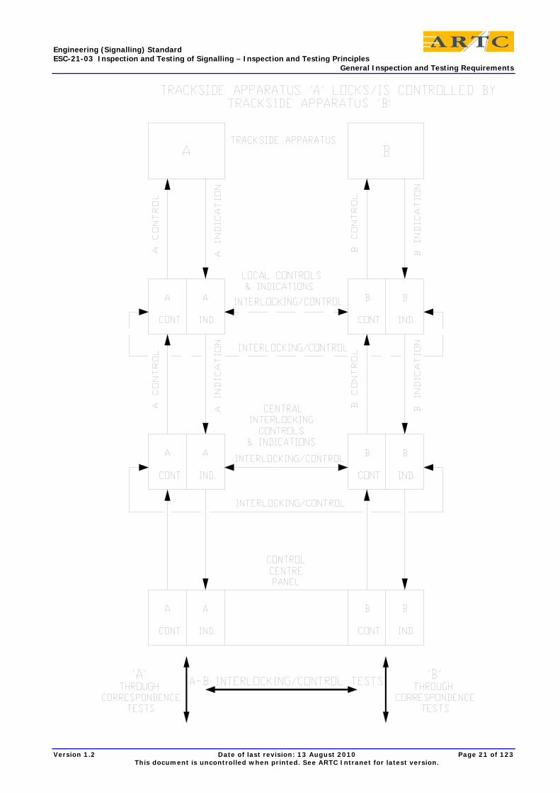
Certification testing is required to verify that each item of trackside signalling apparatus operates safely in relation to other items of trackside signalling apparatus, and also operates safely in the presence of a train, in accordance with the design.
The control to an item of trackside apparatus operates over the indications of other items of trackside apparatus. Test and certify the interlocking between these controls and indications.
Perform certification tests to verify correspondence between each item of trackside apparatus and its individual controls and indications, both locally and centrally. Prove the non-vital link to the operator's control console and indicator diagram.
Where an electrical contact indicates the position of an item of trackside apparatus, perform contact proving tests to verify that the contact electrically opens and closes when the trackside apparatus operates, and that it electrically opens and closes all indicating and/or repeat relays in correspondence with the apparatus.
When one item of trackside apparatus locks or is released by another then interlocking tests are required to verify the inability of each item to operate when the other item is in the conflicting state.
When one item of trackside apparatus is controlled by another then control tests are required to verify that the item returns correctly to the non-operated position when the status of the other is changed.
Where the item of trackside apparatus is controlled by another that has separate normal and reverse indications, it should also be tested to return to the non-operated position when the wrong control indication is made.
Certification tests are also required to verify that trackside apparatus for train detection reliably detects the presence of a train.
For safety related aspects, the inspection and testing is required to ensure that:
1) Equipment and materials are correctly manufactured to specification
2) Equipment is correctly located and secured in position, correctly labelled and correctly indexed in accordance with the design
3) Equipment is correctly interconnected in accordance with the design
4) Equipment correctly operates, indicates and interlocks in accordance with the design
5) Equipment is correctly isolated and insulated from false operation, secured against improper movement, and protected against interference, damage, and deterioration, to specification and standards
6) Redundant equipment is made inoperative and removed
7) False feeds, temporary wiring, and any extraneous items are removed
8) Accurate records and certification of all of the above activities are produced and maintained for handover to the nominated officers
Engineering (Signalling) Standard ESC-21-03 Inspection and Testing of Signalling – Inspection and Testing Principles General Inspection and Testing Requirements
Version 1.2 Date of last revision: 13 August 2010 Page 14 of 123 This document is uncontrolled when printed. See ARTC Intranet for latest version.
9) Inspections and tests shall verify detailed conformance to the particular vital signalling design drawings, compliance with the applicable signalling standards for safety and reliability, and in the process establish correspondence between controls and indications and trackside apparatus, and correct interlocking between conflicting routes, and correct control of routes by train detection and point detection equipment.
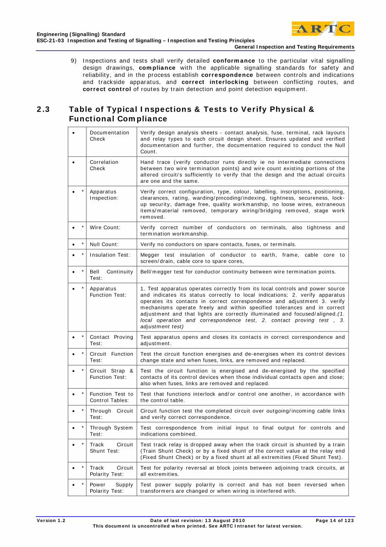
2.3 Table of Typical Inspections & Tests to Verify Physical & Functional Compliance
• Documentation Check
Verify design analysis sheets - contact analysis, fuse, terminal, rack layouts and relay types to each circuit design sheet. Ensures updated and verified documentation and further, the documentation required to conduct the Null Count.
• Correlation Check
Hand trace (verify conductor runs directly ie no intermediate connections between two wire termination points) and wire count existing portions of the altered circuit/s sufficiently to verify that the design and the actual circuits are one and the same.
• * Apparatus Inspection:
Verify correct configuration, type, colour, labelling, inscriptions, positioning, clearances, rating, warding/pincoding/indexing, tightness, secureness, lock-up security, damage free, quality workmanship, no loose wires, extraneous items/material removed, temporary wiring/bridging removed, stage work removed.
• * Wire Count: Verify correct number of conductors on terminals, also tightness and termination workmanship.
• * Null Count: Verify no conductors on spare contacts, fuses, or terminals.
• * Insulation Test: Megger test insulation of conductor to earth, frame, cable core to screen/drain, cable core to spare cores,
• * Bell Continuity Test:
Bell/megger test for conductor continuity between wire termination points.
• * Apparatus Function Test:
1. Test apparatus operates correctly from its local controls and power source and indicates its status correctly to local indications; 2. verify apparatus operates its contacts in correct correspondence and adjustment 3. verify mechanisms operate freely and within specified tolerances and in correct adjustment and that lights are correctly illuminated and focused/aligned.(1. local operation and correspondence test, 2. contact proving test , 3. adjustment test)
• * Contact Proving Test:
Test apparatus opens and closes its contacts in correct correspondence and adjustment.
• * Circuit Function Test:
Test the circuit function energises and de-energises when its control devices change state and when fuses, links, are removed and replaced.
• * Circuit Strap & Function Test:
Test the circuit function is energised and de-energised by the specified contacts of its control devices when those individual contacts open and close; also when fuses, links are removed and replaced.
• * Function Test to Control Tables:
Test that functions interlock and/or control one another, in accordance with the control table.
• * Through Circuit Test:
Circuit function test the completed circuit over outgoing/incoming cable links and verify correct correspondence.
• * Through System Test:
Test correspondence from initial input to final output for controls and indications combined.
• * Track Circuit Shunt Test:
Test track relay is dropped away when the track circuit is shunted by a train (Train Shunt Check) or by a fixed shunt of the correct value at the relay end (Fixed Shunt Check) or by a fixed shunt at all extremities (Fixed Shunt Test).
• * Track Circuit Polarity Test:
Test for polarity reversal at block joints between adjoining track circuits, at all extremities.
• * Power Supply Polarity Test:
Test power supply polarity is correct and has not been reversed when transformers are changed or when wiring is interfered with.
Engineering (Signalling) Standard ESC-21-03 Inspection and Testing of Signalling – Inspection and Testing Principles General Inspection and Testing Requirements
Version 1.2 Date of last revision: 13 August 2010 Page 15 of 123 This document is uncontrolled when printed. See ARTC Intranet for latest version.
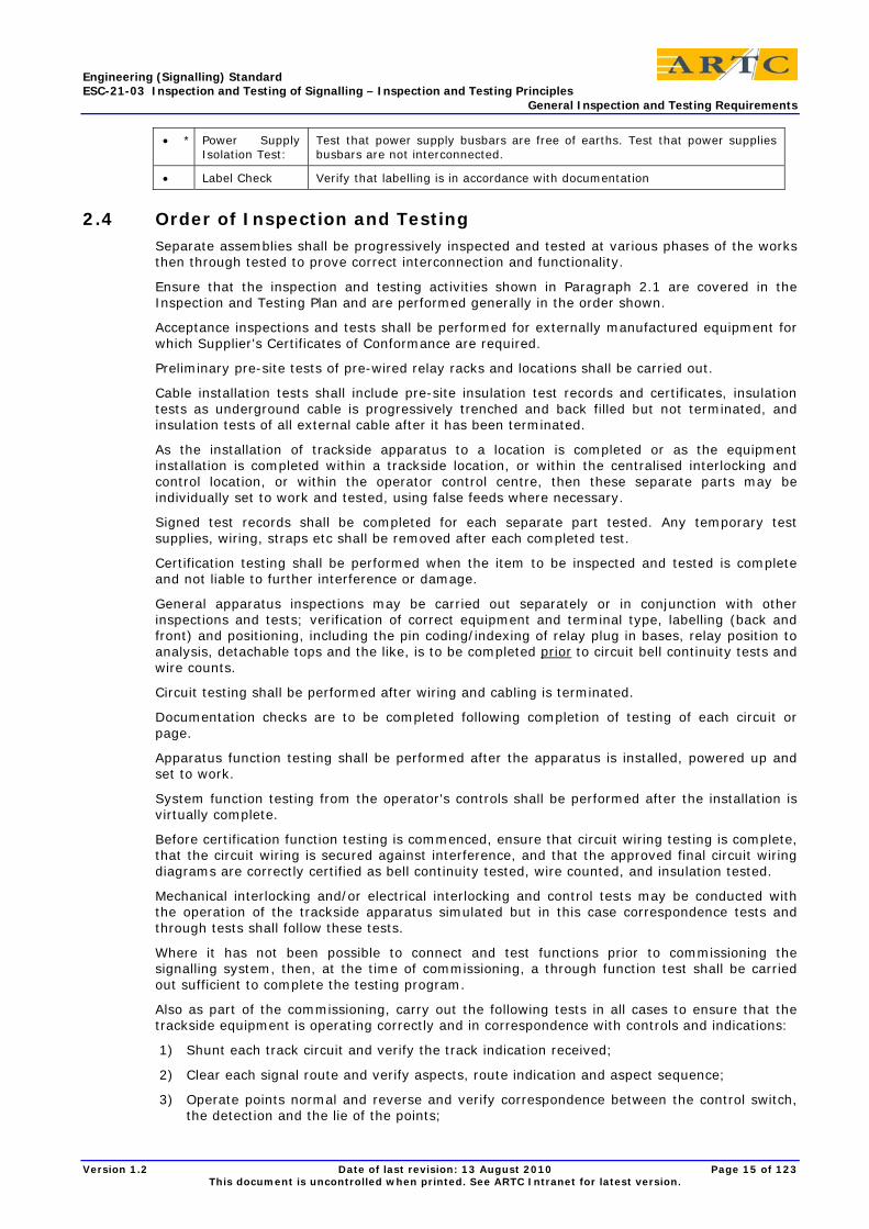
• * Power Supply Isolation Test:
Test that power supply busbars are free of earths. Test that power supplies busbars are not interconnected.
• Label Check Verify that labelling is in accordance with documentation
2.4 Order of Inspection and Testing Separate assemblies shall be progressively inspected and tested at various phases of the works then through tested to prove correct interconnection and functionality.
Ensure that the inspection and testing activities shown in Paragraph 2.1 are covered in the Inspection and Testing Plan and are performed generally in the order shown.
Acceptance inspections and tests shall be performed for externally manufactured equipment for which Supplier's Certificates of Conformance are required.
Preliminary pre-site tests of pre-wired relay racks and locations shall be carried out.
Cable installation tests shall include pre-site insulation test records and certificates, insulation tests as underground cable is progressively trenched and back filled but not terminated, and insulation tests of all external cable after it has been terminated.
As the installation of trackside apparatus to a location is completed or as the equipment installation is completed within a trackside location, or within the centralised interlocking and control location, or within the operator control centre, then these separate parts may be individually set to work and tested, using false feeds where necessary.
Signed test records shall be completed for each separate part tested. Any temporary test supplies, wiring, straps etc shall be removed after each completed test.
Certification testing shall be performed when the item to be inspected and tested is complete and not liable to further interference or damage.
General apparatus inspections may be carried out separately or in conjunction with other inspections and tests; verification of correct equipment and terminal type, labelling (back and front) and positioning, including the pin coding/indexing of relay plug in bases, relay position to analysis, detachable tops and the like, is to be completed prior to circuit bell continuity tests and wire counts.
Circuit testing shall be performed after wiring and cabling is terminated.
Documentation checks are to be completed following completion of testing of each circuit or page.
Apparatus function testing shall be performed after the apparatus is installed, powered up and set to work.
System function testing from the operator's controls shall be performed after the installation is virtually complete.
Before certification function testing is commenced, ensure that circuit wiring testing is complete, that the circuit wiring is secured against interference, and that the approved final circuit wiring diagrams are correctly certified as bell continuity tested, wire counted, and insulation tested.
Mechanical interlocking and/or electrical interlocking and control tests may be conducted with the operation of the trackside apparatus simulated but in this case correspondence tests and through tests shall follow these tests.
Where it has not been possible to connect and test functions prior to commissioning the signalling system, then, at the time of commissioning, a through function test shall be carried out sufficient to complete the testing program.
Also as part of the commissioning, carry out the following tests in all cases to ensure that the trackside equipment is operating correctly and in correspondence with controls and indications:
1) Shunt each track circuit and verify the track indication received;
2) Clear each signal route and verify aspects, route indication and aspect sequence;
3) Operate points normal and reverse and verify correspondence between the control switch, the detection and the lie of the points;
Engineering (Signalling) Standard ESC-21-03 Inspection and Testing of Signalling – Inspection and Testing Principles General Inspection and Testing Requirements
Version 1.2 Date of last revision: 13 August 2010 Page 16 of 123 This document is uncontrolled when printed. See ARTC Intranet for latest version.
4) Release and operate each ground frame;
5) Operate emergency switch machine / emergency operation) locks and verify point detection is lost and interlocked signals return to stop;
6) Any other inspections and tests deemed necessary by the Commissioning manager.
If deficiencies are discovered in interlocking or controls during commissioning then all functions affected must be considered as defective and be rectified and retested.
2.5 General Apparatus Inspection Inspections for particular apparatus are found in ESC-21-05 Typical Inspections and Tests for Signalling Apparatus.
Further to a check of workmanship and of the condition of the installed equipment and operating environment, the general apparatus inspection is an analysis check of the equipment type, rating, labelling, indexing, location etc to verify conformance with the issued designs.
The following requirements are for the inspection of signalling apparatus generally:
1) Check that the design documents and standards are the latest approved versions including all amendments and modifications
2) Check that configuration and positioning of trackside apparatus conforms to the Signalling Plan, Track Insulation Plan, and Working Sketch plans. Check structure gauge clearances, clearances to overhead and under track crossings, access ways, point clearance, etc
3) Check that track circuit connections, track circuit bonding, traction bonding, electrolysis bonding, spark gap connections etc conform to the Track Insulation Plan. Check that the polarity of each rail of DC track circuits and Impulse track circuits is as shown on the Track Insulation Plan.
4) Check that signals physically conform with the Signalling Plan, Circuit Book and Signal Sighting Forms
5) Check that the layout of trackside apparatus conforms with standards and layout drawings
6) Check that the equipment mounting layout conforms with the profile drawing
7) Check that identification numbers etc marked on the front of location cases, etc conform with the location numbers on the design drawings
8) Check that installed equipment items are the correct type, rating, and labelling, and are correctly warded, indexed, pin coded, etc where applicable eg: relay base analysis checks
9) Check Buffer Stop lights for correct location, quantity, installation, and lights
10) Check Notice boards for correct inscription, location, illumination, and visibility
11) Check that telephones are correctly installed
12) Check that signalling apparatus is fitted with the correct security lock.
2.6 Circuit Inspection and Testing Before a New or altered circuit is brought into use it must be inspected and tested to the satisfaction of the Commissioning manager. Testing must be documented to certify that it is installed in accordance with the circuit wiring diagram and that it fulfils the requirements for which it was designed.
Circuit Tests must ensure that:
1) Every contact, terminal, wire, and functional item shown on the circuit diagram is actually in the circuit exactly as shown ( Bell Continuity Test and Wire Count)
2) Each contact is electrically opened and closed by operation of its controlling device and is correctly adjusted (Circuit Strap and Function Test or Contact Proving Test).
3) Each contact, fuse, and link effectively opens and closes the circuit under test (Circuit Strap and Function Test or Circuit Function Test)
Engineering (Signalling) Standard ESC-21-03 Inspection and Testing of Signalling – Inspection and Testing Principles General Inspection and Testing Requirements
Version 1.2 Date of last revision: 13 August 2010 Page 17 of 123 This document is uncontrolled when printed. See ARTC Intranet for latest version.
4) The circuit does not include any contact, terminal, or wires not shown in the circuit diagram (Wire Count and Null Count)
5) The insulation of the circuit is satisfactory (Insulation Test)
The circuit as a whole is function tested before the test is regarded as complete (Through Circuit Function Test or Circuit Function Test)
The Circuit Strap and Function Test (as different to the Circuit Function Test) may be deleted on new circuits with the approval of the Commissioning manager provided that other tests prove the control contacts, when operated by the control device, effectively open and close the circuit (Contact Proving Tests together with Circuit Function Tests). The plug-in relay and its contacts are to be proven in a standard plug-in relay test panel.
The Circuit Strap and Function Test are to be retained for shelf relay installations and for testing circuit alterations.
For New and altered works with plug-in relays it is usual to delete the Circuit Strap and Function Test and rely on the other circuit and function testing.
The Contact Proving Test involves apparatus inspection and testing to prove that equipment contacts are the correct type, are correctly adjusted, and are correctly operated by the operating mechanism to electrically open and close.
Elements of contact proving are incorporated in other inspections and tests such as general apparatus inspections, insulation tests, circuit strap and function tests, apparatus function tests and relay inspection and operation in test panels. The test copy circuit book shall be suitably marked up to include details of how contact proving tests were achieved.
For other mechanisms, such as rotary controllers, point detectors, Annett locks etc, contact proving would involve a general apparatus inspection and apparatus function tests to check that the mechanism electrically opens and closes the contact in correct adjustment.
2.7 Apparatus Function Testing Perform Apparatus Function Tests to prove that the equipment operates in accordance with specified requirements such as the following, where relevant:
1) Correct energisation and de-energisation levels
2) Correct operating and release times
3) Correct movement, limits of travel and clearances
4) Correct display of aspects, etc
5) Correct fit and interlocking between parts
6) Correct tension, or compression between parts
7) Correct power supply values
8) Correct correspondence with controls and indications
9) Correct adjustment of contacts to correctly indicate the apparatus position with all contacts for the same position closing and opening simultaneously and with all contacts insulated from one another and from 'earth,' both when stationary and throughout movement.
Generally the Apparatus Function Test shall be carried out on installed equipment by providing power of the correct value and polarity to the local controls to set to work the apparatus.
2.8 Mechanical Interlocking Testing Perform a Mechanical Interlocking Test to ensure that the mechanical interlocking items such as interlocking frames, releasing switch locks, electric locks, releasing keys, Annett locks, pilotman's locks, half pilot staff locks, staff instruments, staff contact boxes, bolt locks, bracket locks, mechanical detectors/selectors, train-bars, emergency switch machine locks etc work correctly in accordance with Locking Tables, Locking Diagrams and Working Sketches.
Engineering (Signalling) Standard ESC-21-03 Inspection and Testing of Signalling – Inspection and Testing Principles General Inspection and Testing Requirements
Version 1.2 Date of last revision: 13 August 2010 Page 18 of 123 This document is uncontrolled when printed. See ARTC Intranet for latest version.
2.9 Function Test to Control Tables Perform function Testing to Control Tables by operation of the equipment from the control panel, keyboard, levers, switches, or visual display unit to verify that the system operates safely in accordance with the electrical interlocking and controls incorporated in the Control Tables.
Control Table Function Tests shall be carried out after certification testing of related circuits to the circuit diagrams. To facilitate the testing, track circuit operation shall be simulated by switching track relays or track repeat relays. If necessary, point and signal operation may also be simulated by turning around outgoing controls to provide respective indications, utilising a specially wired test panel. In such cases, apparatus correspondence and system through function tests are to follow.
Where non-vital interlocking exists in the operator's control console of the transmission equipment, then special measures shall be taken to ensure the vital interlocking and controls are tested.
2.10 Aspect Sequence Testing and Points Correspondence Testing Carry out through system function tests at commissioning and after all the trackside apparatus has been finally connected through the interlocking to the Operator's controls and indications; they are final verifications of correspondences and controls of signals/train stops and points.
Finally verify track circuit correspondence tests together with any other trackside apparatus connected or interfered with at the time of commissioning.
2.11 Principle Test This is the same as the function test to the control tables and the aspect sequence test except that it is conducted by a accredited, senior, experienced signal engineer who does not test from the Control Tables or from Aspect Sequence Charts but from the Operational requirements Specification and the Signalling Plan to verify that the signalling operates functionally and safely in accordance with standard signalling design principles.
The test is performed based on the engineer’s extensive knowledge of signalling principles and practices, but is marked off by an assistant on the Design Integrity Test Plan / Control Tables and/or Aspect Sequence Charts.
The test would include simulating train movements for parallel routes, attaching and detaching, and long and short train lengths.
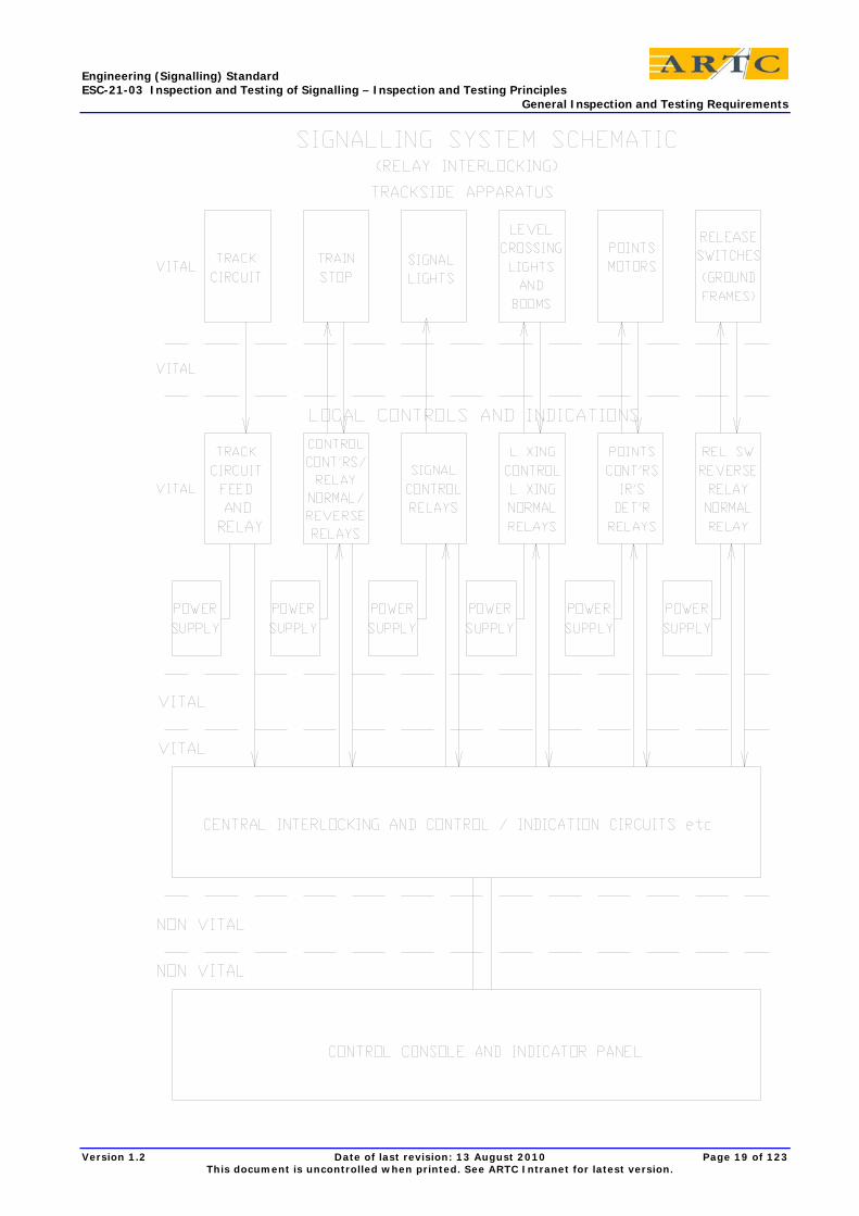
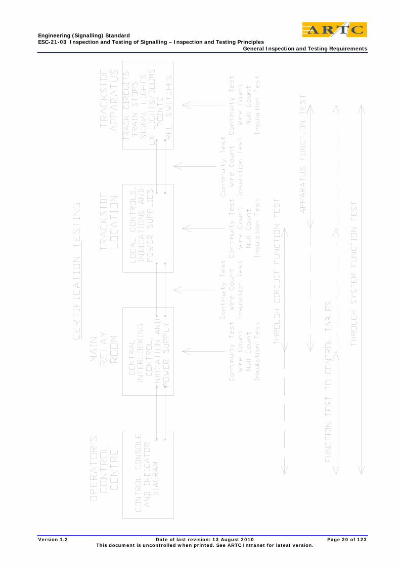
2.12 Illustrations The following illustrations follow:
• Signalling System Schematic,
• Certification Testing Schematic,
• Through Correspondence Test and Interlocking/Control Schematic.
Engineering (Signalling) Standard ESC-21-03 Inspection and Testing of Signalling – Inspection and Testing Principles General Inspection and Testing Requirements
Version 1.2 Date of last revision: 13 August 2010 Page 19 of 123 This document is uncontrolled when printed. See ARTC Intranet for latest version.
Engineering (Signalling) Standard ESC-21-03 Inspection and Testing of Signalling – Inspection and Testing Principles General Inspection and Testing Requirements
Version 1.2 Date of last revision: 13 August 2010 Page 20 of 123 This document is uncontrolled when printed. See ARTC Intranet for latest version.
Engineering (Signalling) Standard ESC-21-03 Inspection and Testing of Signalling – Inspection and Testing Principles General Inspection and Testing Requirements
Version 1.2 Date of last revision: 13 August 2010 Page 21 of 123 This document is uncontrolled when printed. See ARTC Intranet for latest version.
Engineering (Signalling) Standard ESC-21-03 Inspection and Testing of Signalling – Inspection and Testing Principles Insulation Testing
Version 1.2 Date of last revision: 13 August 2010 Page 22 of 123 This document is uncontrolled when printed. See ARTC Intranet for latest version.
3 Insulation Testing
3.1 General The aim of insulation testing is to ensure that electrical circuits are adequately insulated from one another and from earths so that circuit functions are not liable to incorrect energisation by electrical leakage currents.
Circuit electric leakage paths to earth can be detected by the use of earth leakage detectors, voltage tests to earth, and insulation test instruments. Visual inspections also assist in detecting damage or deterioration of insulation.
Deterioration in the insulation of circuits from earth or from one another may occur due to ageing, cracking, abrasion or other damage to the insulation, entry of moisture into cables or across insulating surfaces, build up of dirt and grit etc. on or across insulating surfaces, distortion or movement of components affecting the clearance between metallic conductor parts, terminal lugs or wire strands shifting into contact with frames, breakdown of surge arresters, line wires coming into contact with trees, deposits caused by rotary contact wear etc.
Perform Insulation Testing to determine the following:
1) Insulation resistance to earth of electrical equipment, wire conductors, cable cores, and cable sheaths,
2) Insulation resistance between cable cores,
3) Insulation resistance between each cable core and the cable sheath.
3.1.1 Megger Test Instrument
The insulation testing of all wiring and equipment associated with signalling installations must be carried out prior to bringing into use any new work and thereafter at regular intervals with a type approved 'Megger' type tester with a voltage output of 500 volts D.C. and a current output of no more than 3 milli-amps. This can be of the hand generator type or the electronic version. The instrument shall be type approved.
3.1.2 Regularly Test Instrument and Earth
Test the instrument to ensure correct operation and voltage and current output before commencing the tests and at regular intervals.
Test the test earth immediately prior to performing a series of tests and immediately after the last of the series of tests. Retest if disturbed at any time.
Where a combined bell tester/insulation tester is approved regularly test the insulation tester to ensure it detects an insulation resistance to earth below the stipulated value.
3.1.3 Insulation Test Conditions
Insulation testing involving external wiring / equipment should be carried out in wet / damp conditions wherever practical
Record weather conditions at time of test and enter on test certificate.
3.1.4 Insulation Tests: Circuits
When insulation testing circuits, it is desirable to test the complete circuit as a single test. Refer to Paragraph 3.3.
In approved cases, insulation testing of circuit internal wiring may be done at the same time as the bell continuity test, one wire at a time, using an approved combined bell continuity/insulation tester.
Engineering (Signalling) Standard ESC-21-03 Inspection and Testing of Signalling – Inspection and Testing Principles Insulation Testing
Version 1.2 Date of last revision: 13 August 2010 Page 23 of 123 This document is uncontrolled when printed. See ARTC Intranet for latest version.
When performed in conjunction with bell continuity tests, any insulation to earth defects in plug-in relays and some other equipment will not be detected as these are removed for the bell continuity tests.
Similarly any insulation breakdown to the equipment case or to frame, but not earth, will not be detected.
This needs to be covered by other means, e.g. earth leakage detection tests on busbars during circuit function tests, individual equipment insulation tests, equipment acceptance tests, or a later test of the complete circuit.
Testing of a complete circuit, with all other circuits connected and working, has the added advantage of possibly detecting an insulation breakdown directly between circuits and not via earth.
3.1.5 Lightning Protection Devices
Prior to testing, all lightning protection devices must be removed or disconnected to avoid incorrect or misleading readings.
3.1.6 Removal of Solid State Devices
To avoid damage from the 500-volt output of the 'Megger' all solid state devices (electronic timers, flashing relays, rectifiers etc.) must be disconnected or removed prior to testing.
3.1.7 Rotary Contacts
When testing circuits containing rotary contacts or other contacts with bridging segments, the test must be made with the contact closed to ensure that the segment or bridging piece is in circuit. Faults have occurred where the screw holding the segment to a wooden contact roller has been short-circuited to frame.
3.1.8 Equipment Case Earths
Point mechanisms and trainstops may be mounted on timbers and insulated from the rails and therefore isolated from earth. All circuits passing through the point machine must therefore be tested to the case of the mechanism as well as to earth.
Circuits through signal mechanisms, releasing switches, rotary arm contacts etc. must be similarly tested.
3.1.9 Transformers
When testing circuits containing transformers the primary and secondary wiring must be individually insulation tested.
3.2 Insulation Testing of Cables
3.2.1 General
Cables are to be tested when terminated at both ends; it being of equal importance that the terminal is free of earth fault, as is the cable.
In a section of open aerial wires, the cable connecting the locations to the aerial at each end of the section, together with the aerials themselves may be treated as a continuous cable.
Similarly, a series of power cables connecting several successive locations, may be switched (or linked) through in each location, and the continuity and insulation tests performed as if the cables were one. On new or altered work the polarity shall be proved separately at each location.
Minimum cable insulation values for new cables shall be 60 Megohm/km conductor to earth, 5 Megohm/km sheath to earth and 60 Megohm/km conductor to conductor.

Engineering (Signalling) Standard ESC-21-03 Inspection and Testing of Signalling – Inspection and Testing Principles Insulation Testing
Version 1.2 Date of last revision: 13 August 2010 Page 24 of 123 This document is uncontrolled when printed. See ARTC Intranet for latest version.
Any failure to attain minimum values for new cables shall be regarded as a fault condition.
Insulation resistance values for cables have been specified at 20C. The measured value of insulation resistance is temperature dependent, and, if the measured value is taken at a different temperature, it must be corrected to 20C. Temperature correction factors for common insulating materials are tabulated in ESA-11-01 Cables for Railway Signalling Applications – General Requirements.
When the term sheath is used this also refers to the “drain” wire when used in lieu of the sheath.
The tests shall be carried out in the following order:
• Verify sheath arrestors correctly installed and remove prior to tests,
• Verify correct cable conductor size and cable insulation has been installed,
• Prove integrity of "Test Earth",
• Test continuity of each conductor being insulation tested,
• Test Insulation between each conductor and all other conductors in the cable and the cable sheath,
• Test Insulation between each conductor to earth,
• Test Insulation between sheath to earth,
• Check correct polarity of all power cables.
3.2.2 Continuity Test Cable
Continuity must be checked before Insulation Testing to ensure that the correct wire or cable is being tested, has been correctly terminated and to validate the results of the Insulation Tests, since, if the continuity is not complete, then the insulation tests results will not be correct.
When continuity tests are made on multi-core cables, ensure that each cable core is connected to the correct termination by connecting cable core No. 1 sequentially to every other cable conductor at one end and similarly the continuity tester at the other end.
A low voltage continuity tester is preferable to utilising the Megger insulation tester for continuity testing, as high resistances may not be detected by the Megger insulation tester.
All details of tests including loop resistance are to be noted on the appropriate cable insulation test sheets and signed by the person conducting the testing.
3.2.3 Conductor Insulation Testing
3.2.3.1 Single Series of Tests
With proper preparation, all insulation resistance measurements on a multi-core cable can be completed in a single series of tests:
1) Ensure that the cable is terminated at both ends, on standard disconnect terminals, and that all links are open at both ends,
2) Connect the earth terminal of the megger tester to a suitable Test Earth,
3) At the end of the cable nearest the Test Earth, connect all conductor cores together on the cable side of the termination links with, for example, a 'daisy-chain' of 4mm plugs looped together,
4) Prove the continuity of the daisy-chain by checking that each plug meggers short-circuit to the No.1 plug,
5) Alternatively the following tests may be carried out as individual tests for each conductor core, without linking the cores.
Engineering (Signalling) Standard ESC-21-03 Inspection and Testing of Signalling – Inspection and Testing Principles Insulation Testing
Version 1.2 Date of last revision: 13 August 2010 Page 25 of 123 This document is uncontrolled when printed. See ARTC Intranet for latest version.
3.2.3.2 Individual Tests
3.2.3.2.1 Prove integrity of Test Earth
Connect the insulation tester, one leg to the test earth, the other leg to one conductor, or to the conductors linked together.
At the remote end of the cable, apply a second earth to the same conductor or conductors.
Prove the test earth by observing a low resistance whenever the remote earth is applied.
Remove the remote earth.
3.2.3.2.2 Insulation Test, Conductor to Earth
Measure the insulation resistance between all conductors linked together and the test earth. If the measured value is too low, megger from each conductor individually to the test earth, to identify any faulty conductor or terminal. Record the value. This should be 100 Megohm or at least 60 Megohm/km for a cable longer then 500 metres.
3.2.3.2.3 Insulation Test, Conductor to Sheath
Measure the insulation resistance between all conductors linked together and the metallic screen (sheath). If the measured value is too low, megger from each conductor individually to the sheath, to identify any faulty conductor. Record the value. This should be 100 Megohm or at least 60 Megohm/km for a cable longer than 500 metres.
3.2.3.2.4 Insulation Test, Sheath to Earth
Measure the insulation resistance between the cable sheath and the test earth. Record the value. This should be greater than 10 Megohms, or at least 5 Megohm/km for a cable longer than 500 metres.
3.2.3.2.5 Insulation Test between Conductors
Insulate each conductor in turn from the daisy chain, and measure the insulation resistance between it and all the other conductors linked together. Record the resistance value obtained. This should be greater then 100 Megohm, or at least 60 Megohm/km for a cable longer than 500 metres.
3.3 Insulation Testing of Complete Circuits When testing, it is desirable to test the complete circuit in a single test. As an example, the following procedure would be adopted:
1) Test the 'Megger' - when the handle is turned (or the button pushed on an electronic megger) with both leads together a zero reading should be obtained. When the Megger is operated with the leads separated an infinity reading should be obtained. Check the battery condition on electronic types,
2) Connect one lead of the Megger to a suitable known earth. The earth should be tested by connecting the other lead to another earth and operating the Megger and obtaining a zero reading. The second earth could be obtained by using a screwdriver pushed into the ground,
3) Carry out necessary Network Rules and Procedures and Signalling Safeworking Procedures before interfering with the signalling,
4) Check that circuit is completely closed and that all parallel paths are closed,
5) Remove the fuse and disconnect the negative/common from the bus bar,
6) Test by immediately connecting the Megger lead to the active/positive end of the circuit, operating the Megger and noting the reading,
7) As a check to ensure that the circuit is still complete, tap the negative/common onto a suitable earth connection while operating the Megger. A zero reading will be obtained,
Engineering (Signalling) Standard ESC-21-03 Inspection and Testing of Signalling – Inspection and Testing Principles Insulation Testing
Version 1.2 Date of last revision: 13 August 2010 Page 26 of 123 This document is uncontrolled when printed. See ARTC Intranet for latest version.
8) Insulation test between the signal arm contacts and wiring and the signal arm case, between the relay wiring and the relay racks, between points wiring and the points mechanism case, between release switch wiring and the release switch case etc,
9) If the test reading is below the minimum requirement then the circuit must be broken up and each individual wire tested until the defect is located. To simplify the testing the circuit could first be broken up into internal and external components. When the defective part of the circuit has been found it is then only a matter of breaking up that part of the circuit,
10) Similarly, if it is not practical to close the complete circuit for testing, then the circuit shall be wholly tested in separate parts.
3.4 Testing Busbar Voltage Leak to Earth A busbar voltage test to earth consists of measuring the voltage from each leg of a supply bus, individually, to earth. Comparison of the result obtained with the nominal bus voltage gives an indication of whether any leakage exists, and on which leg of the bus (positive or negative, active or common) it is.
In each case, a significant reading obtained on one leg indicates an earth leakage fault on the opposite leg. The magnitude of the voltage reading, referred to the bus voltage, indicates the degree of the earth leakage fault.
The accuracy of the equivalent earth leakage indicated by the test for each leg of the supply busbar relies on the other leg being at a high resistance to earth.
The measurement must be carried out with the earth test voltmeters built into normal relay room switchboards, or by using a Fluke multimeter with a 20 k-ohm test shunt in parallel with its input terminals. These provide a suitable reference resistance against which any earth leakage is compared.
The use of a Fluke meter directly, without the 20 k-ohm test shunt, will lead to misleading results due to the extremely high input impedance of the Fluke meter.
The test is also misleading if both legs of the busbar have a lower resistance to earth than the meter resistance.
The test will only indicate a leak to earth in circuit wiring and equipment that, at the time of the test, is closed through to the busbar.
If there were no the discrete earth leakage points, voltage leak to earth readings would depend on the amount and distribution of circuit wiring connected to each busbar, with alternating current circuits also reflecting capacitive coupling to earth.
Busbar voltage leak to earth tests are most useful where readings are taken and recorded regularly and any significant change investigated. Maintenance publications stipulate required testing frequencies.
3.5 Localisation of Earth Leakage Faults When an earth leakage fault on a busbar is detected isolate the circuits on the bus in turn, until the fault clears, in order to find the faulty circuit. Then further isolate sections of the faulty circuit to find the faulty component.
This method is time consuming, and involves serious disruptions to working circuits that are in perfectly good order.
An alternative method involves the use of an approved earth 'locater'. (VIGIDI) This injects a low frequency signal between the faulty bus and earth without disruption of the working equipment. A current clip ring, tuned to the injected frequency, is then used to track the injected fault current from the bus to the earth fault point, without any circuit, even the faulty one, being disconnected.
Engineering (Signalling) Standard ESC-21-03 Inspection and Testing of Signalling – Inspection and Testing Principles Insulation Testing
Version 1.2 Date of last revision: 13 August 2010 Page 27 of 123 This document is uncontrolled when printed. See ARTC Intranet for latest version.
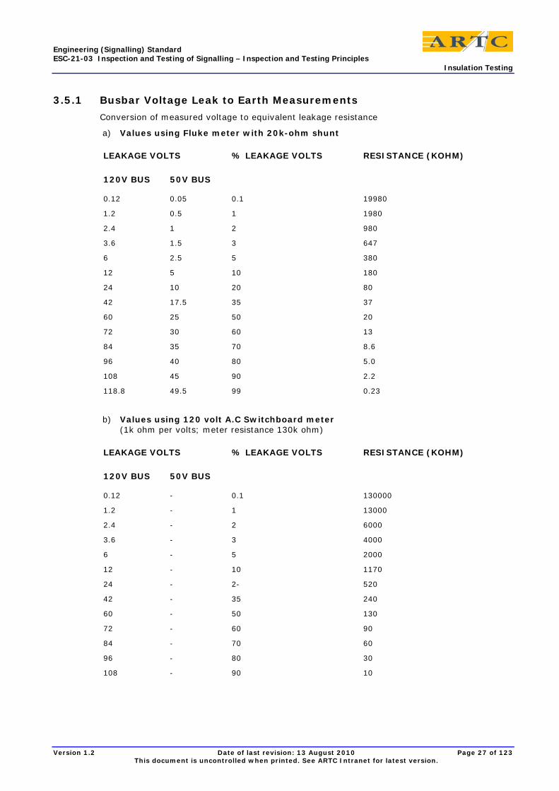
3.5.1 Busbar Voltage Leak to Earth Measurements
Conversion of measured voltage to equivalent leakage resistance
a) Values using Fluke meter with 20k-ohm shunt
LEAKAGE VOLTS % LEAKAGE VOLTS RESISTANCE (KOHM)
120V BUS 50V BUS
0.12 0.05 0.1 19980
1.2 0.5 1 1980
2.4 1 2 980
3.6 1.5 3 647
6 2.5 5 380
12 5 10 180
24 10 20 80
42 17.5 35 37
60 25 50 20
72 30 60 13
84 35 70 8.6
96 40 80 5.0
108 45 90 2.2
118.8 49.5 99 0.23
b) Values using 120 volt A.C Switchboard meter (1k ohm per volts; meter resistance 130k ohm)
LEAKAGE VOLTS % LEAKAGE VOLTS RESISTANCE (KOHM)
120V BUS 50V BUS
0.12 - 0.1 130000
1.2 - 1 13000
2.4 - 2 6000
3.6 - 3 4000
6 - 5 2000
12 - 10 1170
24 - 2- 520
42 - 35 240
60 - 50 130
72 - 60 90
84 - 70 60
96 - 80 30
108 - 90 10
Engineering (Signalling) Standard ESC-21-03 Inspection and Testing of Signalling – Inspection and Testing Principles Insulation Testing
Version 1.2 Date of last revision: 13 August 2010 Page 28 of 123 This document is uncontrolled when printed. See ARTC Intranet for latest version.
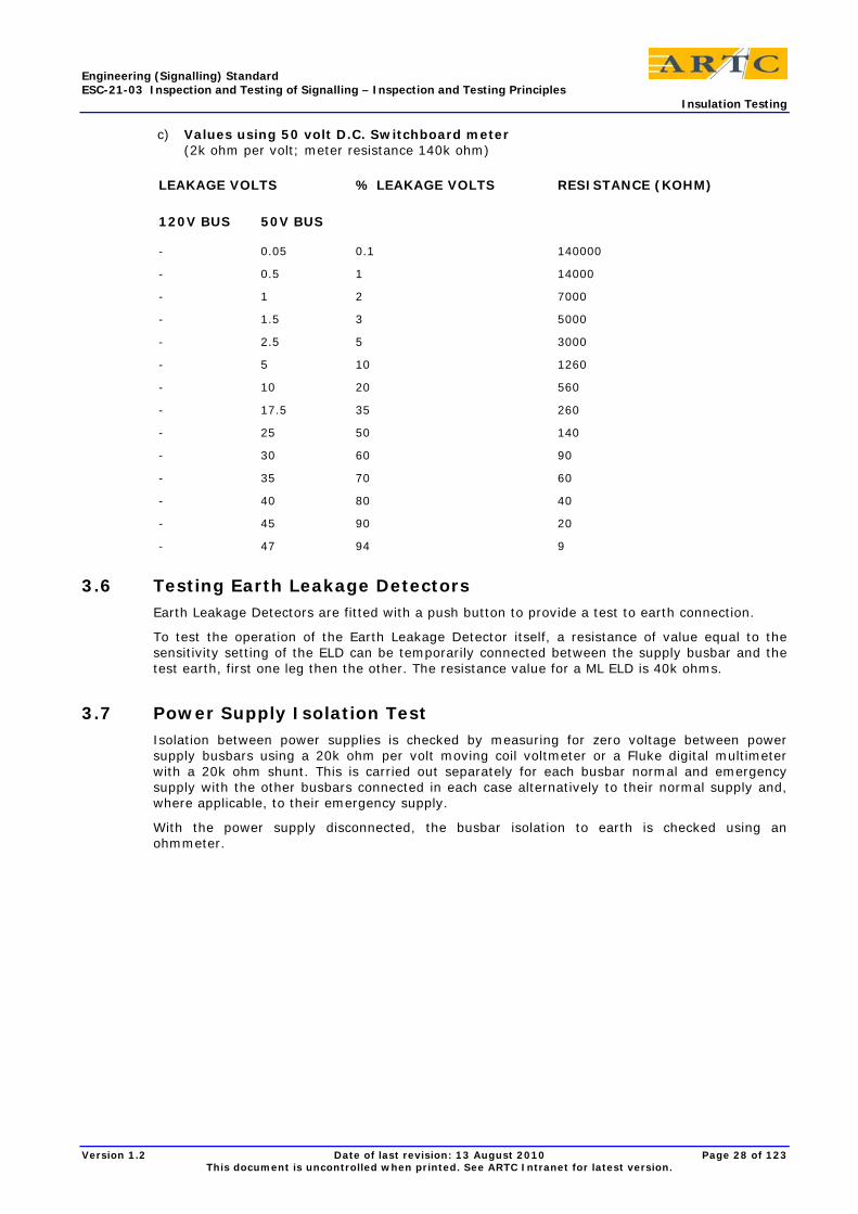
c) Values using 50 volt D.C. Switchboard meter (2k ohm per volt; meter resistance 140k ohm)
LEAKAGE VOLTS % LEAKAGE VOLTS RESISTANCE (KOHM)
120V BUS 50V BUS
- 0.05 0.1 140000
- 0.5 1 14000
- 1 2 7000
- 1.5 3 5000
- 2.5 5 3000
- 5 10 1260
- 10 20 560
- 17.5 35 260
- 25 50 140
- 30 60 90
- 35 70 60
- 40 80 40
- 45 90 20
- 47 94 9
3.6 Testing Earth Leakage Detectors Earth Leakage Detectors are fitted with a push button to provide a test to earth connection.
To test the operation of the Earth Leakage Detector itself, a resistance of value equal to the sensitivity setting of the ELD can be temporarily connected between the supply busbar and the test earth, first one leg then the other. The resistance value for a ML ELD is 40k ohms.
3.7 Power Supply Isolation Test Isolation between power supplies is checked by measuring for zero voltage between power supply busbars using a 20k ohm per volt moving coil voltmeter or a Fluke digital multimeter with a 20k ohm shunt. This is carried out separately for each busbar normal and emergency supply with the other busbars connected in each case alternatively to their normal supply and, where applicable, to their emergency supply.
With the power supply disconnected, the busbar isolation to earth is checked using an ohmmeter.
Engineering (Signalling) Standard ESC-21-03 Inspection and Testing of Signalling – Inspection and Testing Principles Bell Continuity Test
Version 1.2 Date of last revision: 13 August 2010 Page 29 of 123 This document is uncontrolled when printed. See ARTC Intranet for latest version.
4 Bell Continuity Test
4.1 General A bell continuity and correspondence test is carried out on each installed wire from termination point to termination point in accordance with the circuit-wiring diagram.
The bell continuity test will not necessarily prove that the wiring takes the path shown or prove the absence of any incorrect intermediate connections that might provide a false feed or bridge out a function, therefore a Wire Count and a Null Count must also be carried out to reveal any wiring anomalies. Otherwise hand tracing of each wire would be needed to verify internal wiring.
4.2 Bell Continuity Test Procedure Before a bell continuity test is conducted all wiring is to be terminated and all contacts, fuses, links, etc are to be opened to ensure no alternative paths exist. All plug-in relay connectors are to be locked into their relay base positions.
In the case of shelf type relays that do not have detachable tops, removal of the relay is not practical and the bell continuity test is carried out with the relays de-energised for front contacts and energised for back contacts to ensure that each end of the wire under test is open circuit.
The seals of shelf type relays must not be broken nor the relay case opened.
The shelf type relays would be de-energised with all fuses and links removed. To energise a shelf relay for a bell continuity test of wiring to a back contact of that relay, a temporary false feed may be used directly across the relay coil terminals provided that the relay and all circuits through the relay are disconnected and out of use. Refer to Clause 7.1.4 of this Standard "False feeds". Alternatively the wire may be temporarily removed from the terminal but the disconnection; test and reconnection of the wire shall be done as single, uninterrupted activity.
The bell tester shall be a low voltage audible alarm that shall sound when the bell tester leads are connected across a short circuit wire. The bell tester shall have its own independent power supply. A high resistance or open circuit between the terminated ends of the wire under test shall prevent the alarm sounding.
1) Place the bell continuity tester leads onto the terminal studs of equipment or into the wire entry side of plug-in relay bases etc, thus enabling the wire count to be made at the same time as the continuity test.
2) Start at a logical point eg, the fuse end of a circuit. Place the first lead of the bell continuity tester at that terminal point. The second lead is to be placed on the terminal at the other end of the wire being tested. An output from the bell continuity tester indicates wire continuity between the two terminals. Where the circuit extends with 2 wires on each termination point, the test may be conducted staying on the first single wire and moving one probe through the series chain to the single termination at the end.
3) Proceed systematically, bell continuity testing each individual wire through the circuit, including all parallel paths, until the entire circuit or part circuit has been tested, while also counting the wires on each individual terminal and contact point.
4) The method of indicating on the circuit wiring diagrams that the tests have been successfully carried out is shown in ESC-21-02 Inspection and Testing of Signalling - Plans, Programs, Documentation and Packages.
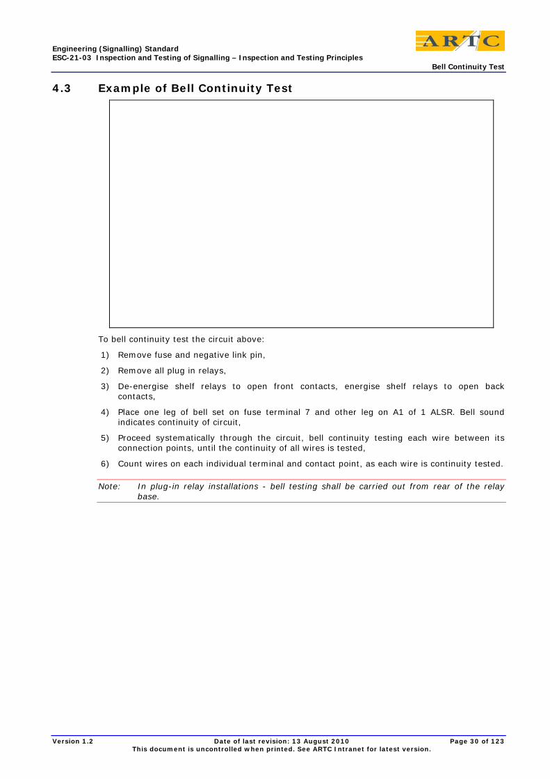
Engineering (Signalling) Standard ESC-21-03 Inspection and Testing of Signalling – Inspection and Testing Principles Bell Continuity Test
Version 1.2 Date of last revision: 13 August 2010 Page 30 of 123 This document is uncontrolled when printed. See ARTC Intranet for latest version.
4.3 Example of Bell Continuity Test
To bell continuity test the circuit above:
1) Remove fuse and negative link pin,
2) Remove all plug in relays,
3) De-energise shelf relays to open front contacts, energise shelf relays to open back contacts,
4) Place one leg of bell set on fuse terminal 7 and other leg on A1 of 1 ALSR. Bell sound indicates continuity of circuit,
5) Proceed systematically through the circuit, bell continuity testing each wire between its connection points, until the continuity of all wires is tested,
6) Count wires on each individual terminal and contact point, as each wire is continuity tested.
Note: In plug-in relay installations - bell testing shall be carried out from rear of the relay base.

Engineering (Signalling) Standard ESC-21-03 Inspection and Testing of Signalling – Inspection and Testing Principles Wire Count, Null Count and Relay Inspection
Version 1.2 Date of last revision: 13 August 2010 Page 31 of 123 This document is uncontrolled when printed. See ARTC Intranet for latest version.
5 Wire Count, Null Count and Relay Inspection
5.1 General As the bell continuity test will not necessarily prove that the wiring takes the path shown or prove the absence of any incorrect intermediate connections that might provide a false feed or bridge out a function, a Wire Count and a Null Count must also be carried out to reveal any wiring anomalies. A Relay Inspection should be carried out to verify conformance with the circuit book.
5.2 Wire Count The Wire Count is generally carried out at the same time as the bell continuity test by the same person who is inserting the lead of the bell continuity tester. It may be carried out as a separate exercise.
Examine the apparatus and the corresponding circuit wiring diagram and analysis sheets:
• Verify the number of conductors terminated at a particular point is as shown on the circuit wiring diagram,
• There should normally be no more than two wires attached to any single termination point in the case of a plug in relay and one wire in the case of a clamp type terminal,
• The wire count shall include verification of all conductors connecting to a terminal, whether wires, busbars, links or other strapping. Rail mounted fuses should be closely checked to verify the presence or absence of common connections,
• Verify the wiring identification labels correctly identify the termination point of the wire,
• Check terminations and crimps are correctly made, wires are not trapped under adjacent terminals and spade type crimps are correctly locked into plug boards or terminal blocks,
• Prior to proceeding with the next test the person who is marking up the circuit books is to complete a documentation check to cross relate the circuit to the information contained in the documentation (contact analysis/fuse/terminal analysis etc.),
• Once it has been verified that the circuits and analysis documentation are correct and in agreement then testing may proceed,
• The method of indicating on the wiring diagrams and analysis sheets that the tests have been successfully carried out is shown in ESC-21-02 Inspection and Testing of Signalling - Plans, Programs, Documentation and Packages.
When internal parts of a circuit are tested separately from the external part of a circuit the wire count on both sides of the external cable termination link shall be performed by every person who tests the circuit either side of the cable termination link. That is, by the persons doing circuit testing of the internal wiring, by persons doing circuit testing of the external wiring, and by persons doing through circuit tests.
The wire count on both sides of the external cable termination link shall be recorded on the circuit diagram in the standard manner by the person conducting the circuit testing of the internal wiring and verified by the person conducting the through testing in accordance with Clause 7.2 iii).
The person responsible for testing the circuit shall check all wires in vital signalling circuits to be shown as wire counted on the testing copy of the circuit diagram.
When wire counting, all conductors connecting to a terminal shall be checked including bridging, busbars and links.
Wire counts, bell continuity tests, and insulation tests shall include the external wiring run to signal head transformer terminal or lamp terminals, to point machine terminals, to trainstop terminals, to releasing switch terminals, to electric lock terminals, to level crossing mechanism terminals, to highway and boom lights terminals and to all operating mechanisms and contact terminals of operating mechanisms.
Engineering (Signalling) Standard ESC-21-03 Inspection and Testing of Signalling – Inspection and Testing Principles Wire Count, Null Count and Relay Inspection
Version 1.2 Date of last revision: 13 August 2010 Page 32 of 123 This document is uncontrolled when printed. See ARTC Intranet for latest version.
Wire counts, bell continuity testing and insulation testing of the internal wiring within equipment mechanisms may be carried out in pre-site tests and factory acceptance tests. Certificates are required.
5.3 Null Count The Null Count is carried out after the Bell Continuity Test and Wire Count has verified the wiring connecting to the respective terminals.
The documentation to be used shall be the relevant completed analysis sheets that were checked / marked up from the documentation check.
Examine relay bases, other operating equipment terminal assemblies, and fuse and terminal racks and the corresponding analysis sheets:
• Verify that there is no conductor connecting to terminals shown as spare in the contact/fuse/terminal analysis sheets in the circuit book,
• Verify that there are no contacts/fuses/terminals shown in use in the circuit book analysis sheets that are spare and without connected wires,
• On the analysis sheets mark the spare contact, fuse or terminal with a tick to indicate the test is successfully completed.
In conjunction with the Bell Continuity Test and the Wire Count, the Null Count, if carried out over the whole installation, provides assurance that there are no 'rogue' connections in the circuits. Null Counts on portion of the equipment in a circuit control area will provide less assurance.
5.4 Relay Inspection The Relay Inspection can be carried out at any time prior to the circuit function tests. The relay inspection should verify conformance of relays to Circuit Book details and analysis sheets, inclusive of the following:
• Relays and bases: Correctly positioned and labelled on the rack
• Relays: Correct type, contact configuration, operating voltage and coil resistance
• Relay labels: Secure, details completed, signed by manufacturers' tester.
• Relay bases: Correctly drilled for indexing pins. Relay indexing pins correct for relay type and in correspondence with manufacturer's label
• Detachable tops for shelf relays: Correct type and correctly coded
• Relay bases: Correct strapping for time limit relays
• Relay cases: Undamaged and relay internally free of foreign matter
• Vane relays: Examine in accordance with maintenance manuals
Engineering (Signalling) Standard ESC-21-03 Inspection and Testing of Signalling – Inspection and Testing Principles Circuit Function Tests
Version 1.2 Date of last revision: 13 August 2010 Page 33 of 123 This document is uncontrolled when printed. See ARTC Intranet for latest version.
6 Circuit Function Tests
6.1 General The Circuit Function Test is supplementary to the Bell Test and Wire Count and is performed to verify that the fuses, links and controlling devices are effective in controlling the circuit function.
Circuit Function Tests involve energisation of the circuit then energising or de-energising (or removing and replacing) in turn each control device and observing the de-energisation of the circuit function. Specific control contacts are not individually proved.
The fuses and links are also disconnected and reconnected and the circuit function observed.
Part circuits in separate locations can be separately function tested using a voltmeter and a Through Circuit Function Test performed when the parts are interconnected over external cables.
With parallel paths, there can be several combinations of the minimum number of contact closures needed to close the circuit, as well as several combinations of the minimum number of contact openings needed to open the circuit. Rather than test every such combination it is sufficient, in conjunction with a Wire Count, to function test the controls in each and every series path with all other parallel paths open.
The Circuit Function Test will not, in itself, prove that a specific contact is actually in the circuit, particularly if the controlling device has a second contact in another position in the circuit (double switching) or if the controlling device also switches another device that opens the circuit function under test.
A Bell Continuity Test and a Wire Count are therefore also necessary to prove compliance with the circuit wiring diagrams.
Even so, these tests will not necessarily prove that the control device contacts are the correct type (back, front, normal, reverse etc) and will not necessarily prove that they are not shorted out or qualified irregularly.
This additional verification shall be achieved by separately testing that the specific control contacts are electrically opened and closed by operation of the control device and by inspection that they are the correct types. Eg, plug-in relays tested in a relay test panel and checked against the contact analysis sheets. This is called a Contact Proving Test.
Instead of a Circuit Function Test and separate Contact Proving Test, a Circuit Strap and Function Test can be used to prove that the specific contacts of control devices are effective in controlling the circuit function in accordance with the circuit wiring diagram.
Circuit Function tests, inclusive of Circuit Strap and Function tests, will not prove that series contacts are wired in the correct sequence or the correct way around (point-armature). The bell continuity test is necessary for this.
The Circuit Function Test Procedure is the same as for the Circuit Strap and Function Test, except that the specific control contacts are not proved by strapping or manual disconnection.
6.2 Circuit Function Test Procedure 1) Connect a voltmeter across the end function, or the terminals of any outgoing "part circuit".
2) Test with other circuits energised to provide a high probability of detecting the presence of any false voltages in the circuit under test.
3) Apply voltage to the ends of the circuit either by inserting the relevant fuses and links or by applying a fused false feed of the correct voltage to the terminals of an incoming "part circuit". The Tester in Charge shall keep records of any such false feed applied.
Note: If part of a circuit that does not include the circuit function, is being circuit function tested then a through circuit test is also required to prove that "part circuit" is in the circuit of the function concerned.
Engineering (Signalling) Standard ESC-21-03 Inspection and Testing of Signalling – Inspection and Testing Principles Circuit Function Tests
Version 1.2 Date of last revision: 13 August 2010 Page 34 of 123 This document is uncontrolled when printed. See ARTC Intranet for latest version.
4) Make the circuit operative by energising or de-energising relevant relays and other control devices to close the complete circuit over the specific contacts involved. This may involve temporary false feeds to the control relays and these must be recorded and strictly controlled.
5) Open and close in turn each fuse, link and control contact verifying the operation of the circuit under test by observation of the voltmeter and, except for outgoing part circuits, the end function.
De-energise (or energise for back contacts) the respective controlling device to open the control contact and check that the end function de-energises and the voltmeter reading drops to zero.
6) Where controls are wired in parallel, each and every series path through the complete circuit shall be selected in turn and the contacts in that path tested with all alternative paths broken. In each case the controlling contact, fuse or link on either side of the parallel path shall be broken and proved.
Parallel paths may emanate from fuses, links or looping.
The texts of Paragraph 7.1.3 "Disconnection of Wires" and Paragraph 7.1.4 "False Feeds" also apply to Circuit Function Tests.

Engineering (Signalling) Standard ESC-21-03 Inspection and Testing of Signalling – Inspection and Testing Principles Circuit Strap and Function Test
Version 1.2 Date of last revision: 13 August 2010 Page 35 of 123 This document is uncontrolled when printed. See ARTC Intranet for latest version.
7 Circuit Strap and Function Test The Circuit Strap and Function Test is the same as the Circuit Function Test except that it is extended to individually prove the specific contact of the control device is effective in the circuit.
The strap and function test of a circuit assumes that the contacts and terminals shown are the only ones in the circuit; it verifies the wiring arrangements of these contacts by:
• Closing each full series path in turn through the circuit with all other contacts open, to energise the function proving that none of the open contacts are in that series path.
• Opening each contact in turn in the series path to de-energise the function proving that the contact being opened is in the circuit and not in parallel with any other closed contact in that series path.
If each and every other contact in the location were open during the strap and function test of a circuit, or part of a circuit, than the tests would also verify that no other contacts were in series within the circuit path being tested.
If each and every other contact in the location were closed during the strap and function test of a circuit, or part of a circuit, then the tests would also verify that no other contacts were in parallel with any contacts within the circuit path being tested.
The procedure sets out the preferred method of opening and closing each specific control contact during function testing to the circuit wiring diagrams.
Where earth leakage detectors are available connect a temporary audible alarm for the duration of the tests.
7.1 Circuit Strap and Function Test Procedure
7.1.1 Procedure
1) Carry out Network Rules and Procedures and Signalling Safeworking Procedures and ensue that any and all trackside apparatus affected by the tests are disconnected and booked out of use,
2) Connect a voltmeter across the end function, or the terminals of any outgoing "part circuit",
3) Test with other circuits energised to provide a high probability of detecting the presence of any false voltages in the circuit under test,
4) Apply voltage to the ends of the circuit either by inserting the relevant fuses and links or by applying a fused false feed of the correct voltage to the terminals of an incoming "part circuit". Records of any such false feed applied shall be kept by the Tester in Charge.
Note: If part of a circuit, that does not include the circuit function, is being strap and function tested then a through circuit test is also required to prove that "part circuit" is in the circuit of the function concerned.
5) Make the circuit operative by energising or de-energising relevant relays and other control devices to close the complete circuit over the specific contacts involved. This may involve temporary false feeds to control relays and these must be recorded and strictly controlled;
6) Open and close in turn each fuse, link and control contact verifying the operation of the circuit under test by observation of the voltmeter and, except for outgoing part circuits, the end function;
De-energise (or energise for back contacts) the respective controlling device to open the control contact and check that the end function de-energises and the voltmeter reading drops to zero;
Bridge the specific control contact with a test strap to test the presence of that specific contact in the circuit by observing the end function re-energise and the voltmeter reading register the correct voltage.
Engineering (Signalling) Standard ESC-21-03 Inspection and Testing of Signalling – Inspection and Testing Principles Circuit Strap and Function Test
Version 1.2 Date of last revision: 13 August 2010 Page 36 of 123 This document is uncontrolled when printed. See ARTC Intranet for latest version.
7) Where controls are wired in parallel, each and every series path through the complete circuit shall be selected in turn and the contacts in that path tested with all alternative paths broken. In each case the controlling contact, fuse or link in series on each side of the parallel path shall be broken and proved.
Parallel paths may emanate from fuses, links or looping.
7.1.2 Manually opening contacts
The seals of relays shall not be broken on site nor shall contact fingers be broken by inserting an insulation piece eg, strip of paper or cardboard or a persons finger, within the relay case.
In the case of accessible individual contacts (eg. rotary contacts, etc) the tests may be done by manually breaking the specific contact (eg. separating the contact finger from the band) during the strap and function test.
Care must be taken to ensure that this action does not damage, introduce dirt or grease, or upset the adjustment of the contact.
If this method of opening the contact is used it must be also be proved that the control device when operated will electrically open and close the specific contact.
7.1.3 Disconnection of wires
After certification bell continuity tests and wire counts, wires shall not be removed from contact terminals for function testing except as absolutely necessary.
In such a case the removal, test and reconnection must be done one terminal at a time by the Tester in Charge.
Wires shall be correctly labelled with the terminal number etc. before removal.
7.1.4 False Feeds
Where temporary false feeds have been applied to carry out this testing they shall be removed at the conclusion of the test and signed for on the record of false feeds applied (see Paragraph 7 v) by the Tester in Charge. Temporary wiring shall be distinctively coloured and labelled. Only registered test staps are permitted on site.
When testing near working circuits, strict care must be taken to ensure that any false feed cannot accidentally or inadvertently be applied to affect the working circuits.
Where practical and relevant, additional security can be obtained using a false feed isolated from any signalling supply in use through a separate transformer or transformer rectifier unit.
7.1.5 Test Straps
• Must be no less than 450mm long
• Must have brightly coloured insulation, preferably orange
• Must be numbered in sets
• Must be kept in a locked box. The Tester in Charge must ensure the safe custody of this box
• Must be counted and recorded before the start and at the end of each days testing work to ensure that no straps have been inadvertently left in position.
7.1.6 Plug-in Relays
With plug-in relays, if the relays are removed and straps placed in the relay base from the front to bridge the control contact terminals, the circuit can be closed to energise the end function.
If the straps are opened and closed in turn to correspondingly open and close the circuit function then the contact terminals can be proved to be in circuit. (Proof of the contact terminals would have been covered by the circuit bell continuity test.)

Engineering (Signalling) Standard ESC-21-03 Inspection and Testing of Signalling – Inspection and Testing Principles Circuit Strap and Function Test
Version 1.2 Date of last revision: 13 August 2010 Page 37 of 123 This document is uncontrolled when printed. See ARTC Intranet for latest version.
This test with straps in the front of the relay base is NOT a proper circuit strap and function test, as the contact type (back or front) is not proved and it will not detect any internally missing, wrong or short-circuited contact.
The plug-in relay must therefore also be tested in a relay test panel to prove that it electrically operates the contacts and that the specific contact concerned is the right type. (Contact Proving Test)
Contact Proving Tests of plug-in relays also involve an inspection of the relay for any signs of damage, foreign matter or defective operation. A signed and dated sticker affixed to the relay case shall signify that the relay has been proved in the relay test panel.
7.2 Example of Circuit Strap and Function Testing Referring to the worked examples at the end of this Clause, the circuits, have three logic paths and would be strap and function tested in the following manner. A wire count must also be done.
• Carry out the necessary Network Rules and Procedures and Signalling Safeworking Procedures.
• Ensure that the approach stick relay and all relays in the circuit are energised (except 71u CONTROL) and that 71 and 84 signals are at stop so that all contacts and links in all paths of the circuit are closed.
• Use a Voltmeter to observe the correct operating voltage across the approach stick relay when energised and zero voltage when de-energised.
• Remove and replace No.7 fuse three times noting the approach stick relay energise and de-energise accordingly. Check that it is the correct busbar supply.
• Disconnect and reconnect No.7 common wire at the busbar three times noting the approach stick relay energises and de-energises accordingly. Check that it is the correct busbar supply.
ALL PATHS CLOSED
• Open and close No.2 contact on 84u banner signal three times noting the approach stick relay de-energise and energise accordingly. If it is not possible to open No.2 contact only on 84u signal, open all contacts and use a bridge to strap No.2 contact.
• Open and close link terminal LC1 three times noting the approach stick relay energise and de-energise accordingly.
• Energise 71u Control relay and bridge No.2 back contact three times noting the approach stick relay energises and de-energises accordingly. De-energise 71u control relay.
PATH 1 CLOSED
• De-energise 54 and 55 Normal Detector relays and open the stick finger contact (No.1) of the approach stick relay by disconnecting the wire on the point or armature terminal. Path No.1 is now closed and all other contacts in paths No.2 and No.3 are fully opened.
• De-energise M11.65A INDG relay and bridge No. 10 contact three times noting the approach stick relay energise and de-energise accordingly. Re-energise M11.65A INDG relay.
• Follow the same procedure in turn for the following contacts in path No.1, S11.70A INDG (No.7), S11.65A INDG (No.4), and S11.65B INDG (No.4).
PATH 2 CLOSED
• De-energise M11.65A INDG relay, leave the approach stick finger opened. Energise 55 Normal Detector relay leaving 54 Normal Detector relay de-energised.
• Test path No.2 by bridging No.2 contact on 54 Normal Detector relay three times noting the approach stick relay energise and de-energise accordingly. Re-energise 54 Normal Detector relay.
• Follow the same procedure in turn for the following contacts in path No.2, 55 Normal Detector (No.5), S11.65A INDG (No.4), S11.65B INDG (No.4).
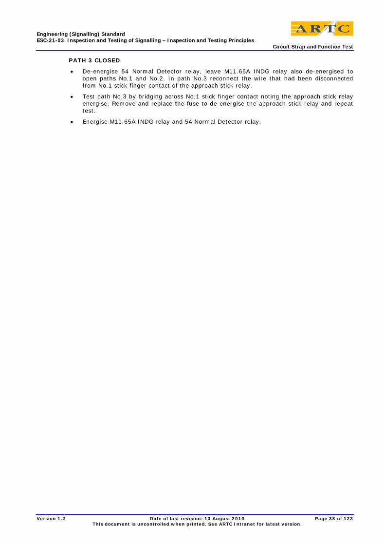
Engineering (Signalling) Standard ESC-21-03 Inspection and Testing of Signalling – Inspection and Testing Principles Circuit Strap and Function Test
Version 1.2 Date of last revision: 13 August 2010 Page 38 of 123 This document is uncontrolled when printed. See ARTC Intranet for latest version.
PATH 3 CLOSED
• De-energise 54 Normal Detector relay, leave M11.65A INDG relay also de-energised to open paths No.1 and No.2. In path No.3 reconnect the wire that had been disconnected from No.1 stick finger contact of the approach stick relay.
• Test path No.3 by bridging across No.1 stick finger contact noting the approach stick relay energise. Remove and replace the fuse to de-energise the approach stick relay and repeat test.
• Energise M11.65A INDG relay and 54 Normal Detector relay.
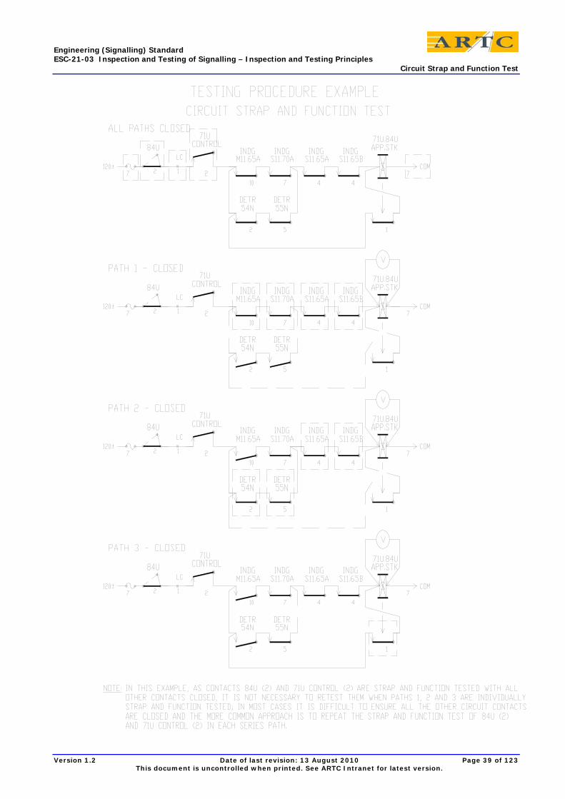
Engineering (Signalling) Standard ESC-21-03 Inspection and Testing of Signalling – Inspection and Testing Principles Circuit Strap and Function Test
Version 1.2 Date of last revision: 13 August 2010 Page 39 of 123 This document is uncontrolled when printed. See ARTC Intranet for latest version.
Engineering (Signalling) Standard ESC-21-03 Inspection and Testing of Signalling – Inspection and Testing Principles Circuit Strap and Function Test
Version 1.2 Date of last revision: 13 August 2010 Page 40 of 123 This document is uncontrolled when printed. See ARTC Intranet for latest version.
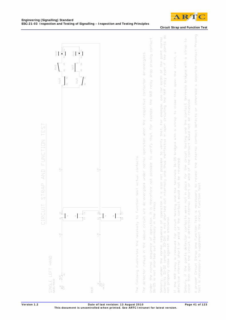
Engineering (Signalling) Standard ESC-21-03 Inspection and Testing of Signalling – Inspection and Testing Principles Circuit Strap and Function Test
Version 1.2 Date of last revision: 13 August 2010 Page 41 of 123 This document is uncontrolled when printed. See ARTC Intranet for latest version.
Engineering (Signalling) Standard ESC-21-03 Inspection and Testing of Signalling – Inspection and Testing Principles Through Function Tests
Version 1.2 Date of last revision: 13 August 2010 Page 42 of 123 This document is uncontrolled when printed. See ARTC Intranet for latest version.
8 Through Function Tests
8.1 General Through function tests are carried out to prove correct correspondence where circuits extend between locations.
The Through Circuit Function Test is carried out on circuits that operate between locations to prove:
1) The end function operates as intended through the complete circuit when the correct voltage of the correct polarity is applied to the ends of the circuit,
2) The circuit internal wiring has been correctly connected to the respective external cables where both have been separately continuity tested, wire counted and insulation tested,
3) De-energisation of and zero residual voltage across the circuit function when the circuit is opened in turn at the fuse, each link and at each intermediate relay. The test is performed with as many other circuits energised as practical to provide a high probability of detecting the presence of any false voltages in the circuit,
4) All repeat, indicating and intermediate relays correspond and operate correctly,
5) Diagram indicators, repeaters and detectors respond correctly.
Through Function Tests of the System are also carried out to prove correspondence from the operator's control to operation of the trackside apparatus and from the operation of the trackside apparatus back to the operator's indicator panel.
8.2 Through Circuit Function Test Procedure After circuits internal to locations and the external interconnecting cables have been separately tested, a through test shall be carried out on complete circuits, ie circuits that operate between separate locations.
Where earth leakage detectors are available, temporarily connect an audible alarm for the duration of the tests.
This test shall operate and verify the equipment and complete circuit from end to end in a functional manner and shall be carried out for both control and indication circuits as follows:
1) Energise the circuit to pick up the final control relay and any intermediate relays,
2) At all the locations involved, disconnect and replace in turn the feed fuse and every link in the circuit, including at the power supply busbar, observing that all relays in the circuit and all indications respond in each case by correctly changing status,
3) Verify the wire count at the fuse and on each side of disconnection links and record on the circuit diagrams,
4) For polarised circuits the test shall be carried out for each polarity,
5) Place a meter across the relay coils and observe correct working voltages. Investigate any non zero voltage when the circuit is opened,
6) Where circuits are in cascade (such as cut sections for AC traction immunisation or for volt-drop purposes) the intermediate relay circuits must also be similarly tested, the final relay under test being observed to respond,
7) For FDM and TDM systems, prove that each output corresponds with its relevant input,
8) Where possible and relevant, carry out tests for each through circuit as a single operation from the point of control to the point of operation and from the point of operation to the point of indication,
9) The method of indicating on the circuit diagrams that the through circuit test has been successfully completed at each fuse and disconnection link is shown in ESC-21-02 Inspection and Testing of Signalling - Plans, Programs, Documentation and Packages.
Engineering (Signalling) Standard ESC-21-03 Inspection and Testing of Signalling – Inspection and Testing Principles Through Function Tests
Version 1.2 Date of last revision: 13 August 2010 Page 43 of 123 This document is uncontrolled when printed. See ARTC Intranet for latest version.
8.3 Through Function Test A Through Function Test of the system shall ensure that when there is a control operated at the control centre it is correctly relayed throughout the system and operates the trackside apparatus, and when there is an indication from the trackside apparatus that it is correctly relayed throughout the system to the control centre. Each relay in the chain and each indication shall be observed to change status in correct correspondence.
Each relay in a chain shall be removed and replaced and the affected relays and indications observed to correctly change status from energised to de-energised to energised.
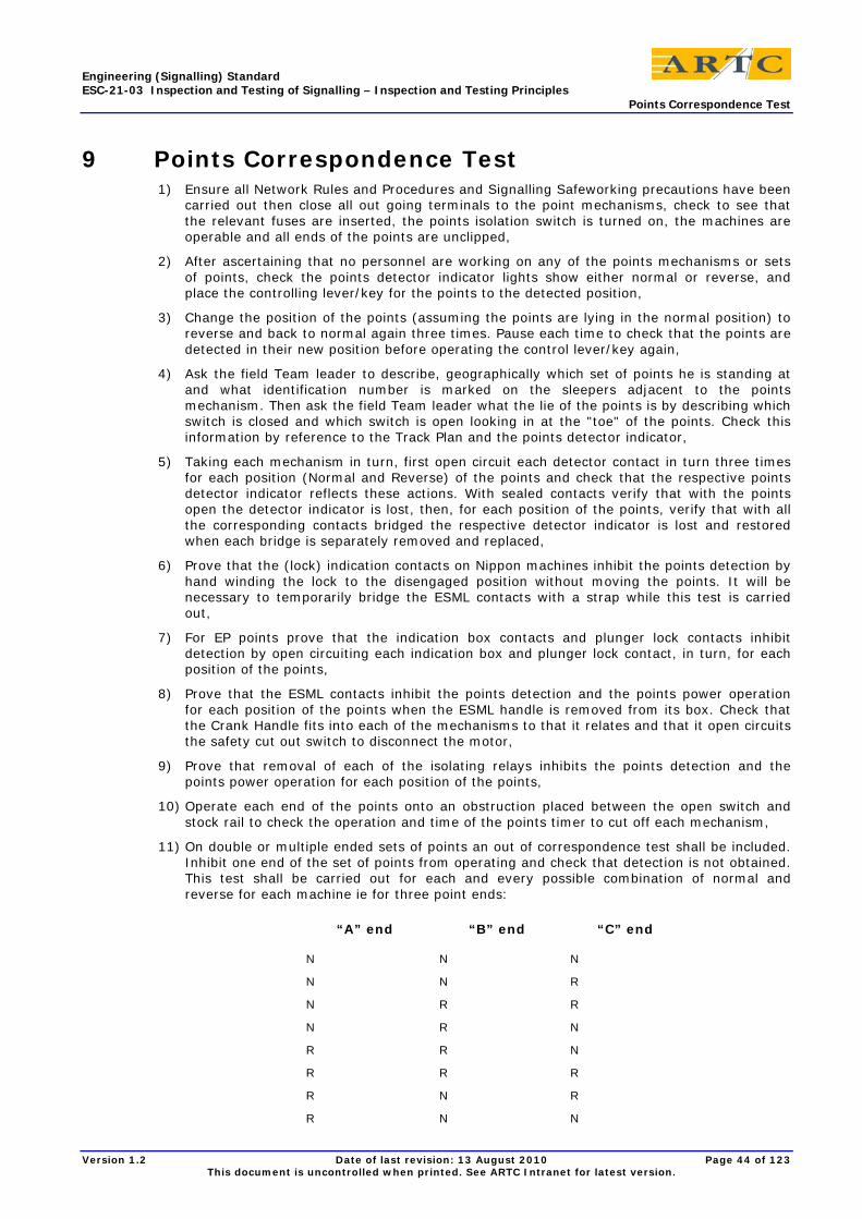
Engineering (Signalling) Standard ESC-21-03 Inspection and Testing of Signalling – Inspection and Testing Principles Points Correspondence Test
Version 1.2 Date of last revision: 13 August 2010 Page 44 of 123 This document is uncontrolled when printed. See ARTC Intranet for latest version.
9 Points Correspondence Test 1) Ensure all Network Rules and Procedures and Signalling Safeworking precautions have been
carried out then close all out going terminals to the point mechanisms, check to see that the relevant fuses are inserted, the points isolation switch is turned on, the machines are operable and all ends of the points are unclipped,
2) After ascertaining that no personnel are working on any of the points mechanisms or sets of points, check the points detector indicator lights show either normal or reverse, and place the controlling lever/key for the points to the detected position,
3) Change the position of the points (assuming the points are lying in the normal position) to reverse and back to normal again three times. Pause each time to check that the points are detected in their new position before operating the control lever/key again,
4) Ask the field Team leader to describe, geographically which set of points he is standing at and what identification number is marked on the sleepers adjacent to the points mechanism. Then ask the field Team leader what the lie of the points is by describing which switch is closed and which switch is open looking in at the "toe" of the points. Check this information by reference to the Track Plan and the points detector indicator,
5) Taking each mechanism in turn, first open circuit each detector contact in turn three times for each position (Normal and Reverse) of the points and check that the respective points detector indicator reflects these actions. With sealed contacts verify that with the points open the detector indicator is lost, then, for each position of the points, verify that with all the corresponding contacts bridged the respective detector indicator is lost and restored when each bridge is separately removed and replaced,
6) Prove that the (lock) indication contacts on Nippon machines inhibit the points detection by hand winding the lock to the disengaged position without moving the points. It will be necessary to temporarily bridge the ESML contacts with a strap while this test is carried out,
7) For EP points prove that the indication box contacts and plunger lock contacts inhibit detection by open circuiting each indication box and plunger lock contact, in turn, for each position of the points,
8) Prove that the ESML contacts inhibit the points detection and the points power operation for each position of the points when the ESML handle is removed from its box. Check that the Crank Handle fits into each of the mechanisms to that it relates and that it open circuits the safety cut out switch to disconnect the motor,
9) Prove that removal of each of the isolating relays inhibits the points detection and the points power operation for each position of the points,
10) Operate each end of the points onto an obstruction placed between the open switch and stock rail to check the operation and time of the points timer to cut off each mechanism,
11) On double or multiple ended sets of points an out of correspondence test shall be included. Inhibit one end of the set of points from operating and check that detection is not obtained. This test shall be carried out for each and every possible combination of normal and reverse for each machine ie for three point ends:
“A” end “B” end “C” end
N N N
N N R
N R R
N R N
R R N
R R R
R N R
R N N
Engineering (Signalling) Standard ESC-21-03 Inspection and Testing of Signalling – Inspection and Testing Principles Points Correspondence Test
Version 1.2 Date of last revision: 13 August 2010 Page 45 of 123 This document is uncontrolled when printed. See ARTC Intranet for latest version.
Note: On CBI installations where separate inputs for each end of points detection are used, then the out of correspondence test may be omitted.
12) The successful completion of each of the tests shall be recorded and signed for in a Work instruction or Design Integrity Test Plan by the Tester in Charge.
Engineering (Signalling) Standard ESC-21-03 Inspection and Testing of Signalling – Inspection and Testing Principles Aspect Sequence Test
Version 1.2 Date of last revision: 13 August 2010 Page 46 of 123 This document is uncontrolled when printed. See ARTC Intranet for latest version.
10 Aspect Sequence Test
10.1 General Aspect Sequence Testing shall check that signal lamps, and signal repeaters at control stations, assume the correct colours for various operational sequences and failure conditions.
The aspect sequence testing shall be performed in accordance with Track Plans that provide details of potential routes through the area of track under test, and with any special Aspect Sequence Charts drawn up specifically for the purpose of carrying out this test.
The Engineer conducting the testing shall locate observers at signal locations and a competent officer at the operation control. The Testing engineer shall direct the Aspect test by Radio etc., by having the control centre officer set specified routes and by having the signal observers report the colour aspect of relevant signal lamps. The Test engineer shall judge the correctness of the responses by reference to the Track Plans and Aspect Sequence Charts.
Lamp Failure conditions shall be simulated.
The Testing engineer must maintain tight control of the communications and ensure that there is no confusion caused by other radios.
The communications must also be conducted in accordance with pre-established Question and Answer formats. Noise and talk within the test control centre shall be kept to a minimum while the tests are in progress and the aspect reports in the centre should be on a separate loud speaker.
10.2 Aspect Sequence Test Procedure The aspect test is carried out from the control console/signal box by the Testing engineer whilst the field test team observe the aspects/indications exhibited to the driver. During the aspect test the diagram signal repeater shall be observed for correct indications.
The field test team shall be positioned so that each signal in the full aspect sequence can be observed and reported back to the control console/signal box for each test in the sequence.
The method of reporting aspects from the field shall be in a vertical manner from the top aspect downwards e.g:
"Signal Number ...., Red over Red over small Green with train stop up", in the case of a double light type of signal.
or
"Signal Number ...., Red over Red marker over small Green with train stop up", in the case of a single light signal.
The Test engineer shall repeat the signal indication report back to the field and obtain acknowledgment prior to marking the test form.
The use of the words Stop, Caution, Clear, etc is not permissible.
The reporting of stencil type route indicators shall also include the positional relationship of the indication to the signal.
The reporting of position light and dwarf colour light type of shunting signals shall include the positional relationship of the indications.
The description of turn out indicators in single light indication areas shall include the number of lamps alight and the direction of inclination.
For each route under test, the exit signal must be cleared to each possible aspect for all routes. The entrance and exit signals and any repeater or co-acting signals must be continually observed to ensure that only the correct aspect sequence is displayed.
Where the entrance signal is located at a junction all exit signals must be cleared to each possible aspect from which a sequence can be derived.
Engineering (Signalling) Standard ESC-21-03 Inspection and Testing of Signalling – Inspection and Testing Principles Aspect Sequence Test
Version 1.2 Date of last revision: 13 August 2010 Page 47 of 123 This document is uncontrolled when printed. See ARTC Intranet for latest version.
In single light areas remove the illuminated yellow or green lamp of the signal under test and check that the signal in rear can show no higher aspect than yellow. Check that the lamp proving circuits function correctly and lamp failure is given at the indicator device.
By using a test lamp (ie one that has had the main filament deactivated) observe that the changeover relay in the signal head operates correctly and that a filament fail indication is given at the control point.
Test the operation of the train stop proving relay (VCSR) and its control of the signal in rear. Firstly clear the signal and the signal in the rear, shunt the 'A' track to place the signals to stop but prevent the trainstop arm returning full normal, remove the shunt from the 'A' track and place a shunt on the 'B' track and observe signal in rear held at stop until the obstruction is removed and the trainstop arm goes to the full normal position. This test is facilitated by use of a locomotive for aspect sequence testing.
Place signal at stop and obstruct trainstop arm from normal position and verify that the signal repeater does not indicate normal until the obstruction is removed.
Similarly operate the signal but prevent the trainstop arm from attaining the reverse position and verify that the diagram signal repeater does not indicate clear until the trainstop obstruction is removed.
Check that, at night there are no confusing reflections of signals off structures, eg. Stainless steel cases.
Tests are to be made to prove correct operation of associated equipment eg. Guard's Indicators, Warning lights.
In automatic signal sections the aspect sequence test is to include the verification that each track circuit up to the clearance point replaces the signal to its most restrictive aspect when occupied. With the signal at clear each track circuit shall be shunted then cleared and the automatic signal observed to change from green to red to green aspects accordingly.
The successful completion of each of the tests shall be recorded and signed for as nominated in ESC-21-02 Inspection and Testing of Signalling - Plans, Programs, Documentation and Packages.
Engineering (Signalling) Standard ESC-21-03 Inspection and Testing of Signalling – Inspection and Testing Principles Mechanical Interlocking Test
Version 1.2 Date of last revision: 13 August 2010 Page 48 of 123 This document is uncontrolled when printed. See ARTC Intranet for latest version.
11 Mechanical Interlocking Test On each occasion that work is carried out on interlocking frames a mechanical interlocking test shall be carried out on all interlocking associated with locking that has been disturbed in addition to testing the alterations.
The interlocking tests shall ensure that all interlocking between conflicting signals, points, etc is in accordance with the Locking Tables and Locking Diagrams, and shall encompass procedures that test the relevant locks, releases, conditions, and their respective converses.
On new works and major alterations the testing of mechanical interlocking frames should be carried out as a design integrity test working from the track layout plan with an assistant marking off the tests on the locking table. Test engineers must be suitably licensed by being in possession of the appropriate Interlocking Certificate issued by the Chief Engineer Signals.
Where the Testing engineer is assisted by other personnel pulling the levers, they shall be closely supervised to ensure the correct lever has been tried or moved.
The Test engineer shall also check:
1) The box diagram is correct to the working sketch,
2) The pulling list is correct to the locking table,
3) Lever name plates are correctly inscribed and fitted,
4) Catch-rod contacts and lever rotaries operate correctly,
5) Electric lever locks lock and release tappets effectively,
6) Inscriptions and wards on all Annett keys, lock faces, etc are correct,
7) Annett keys are held captive in Annett locks until releasing arrangements are satisfied,
8) Annett keys correctly release external locks and are held captive in those locks when the apparatus is operated,
9) Mechanical detectors/selectors operate and interlock equipment correctly,
10) Emergency switch machine locks operate and interlock apparatus correctly,
11) Bolt locks, bracket locks operate and interlock apparatus correctly,
12) Train bars, clearance bars, facing point lock-bars operate and interlock apparatus correctly,
13) Cranks, channel iron rodding and signal wire routes are correctly installed and operate correctly,
14) Mechanical points and signals respond correctly,
15) Locking covers secured in place prior to interlocking test,
16) Lever sleeves available and effective,
17) Redundant locking and keys made inoperative and recovered,
18) Dummy locking bars are fitted in interlocking boxes where required.
19) The Inspection and Testing shall be documented on the respective design document/s and on Signalling Forms ESM0501F-01 and ESM0501F-02.
Engineering (Signalling) Standard ESC-21-03 Inspection and Testing of Signalling – Inspection and Testing Principles Design Integrity Test/Function Test to Control Table
Version 1.2 Date of last revision: 13 August 2010 Page 49 of 123 This document is uncontrolled when printed. See ARTC Intranet for latest version.
12 Design Integrity Test/Function Test to Control Table
12.1 General This testing is carried out after circuit testing and the null counting has been completed and certified.
A Function Test to the Control Tables is a function test of the installed interlocking and controls against the prepared design as set out in the control tables. Operational train movements are set up using the passage of trains, or specially arranged light engines, or by progressively dropping track circuits to simulate a train. The test engineer works from the control tables and marks off each successful test.
A Design Integrity Test is a function test of the design to signalling principles and practices. It covers all the operational train movements and all the interlocking and controls that should be listed in the control tables; the integrity test should reveal any deficiency in the control tables.
The design integrity test engineer is a suitably experienced and knowledgeable person who works to the track plan and the operational requirements while an assisting engineer separately marks off each successful test on the control tables.
The Design Integrity Test is exactly the same as the Function Test to the Control Tables except that the test engineer does not reference the control tables.
The engineer performing a design integrity test must initiate each test without referring to the control table. The test proposed should be announced to the assistant so that there is a clear understanding of what is being tested. Once each function has been tested, the engineer assisting must mark off the control table.
The assisting engineer marking off the control table must satisfy himself/herself that the function test carried out by the engineer performing the design integrity test is exactly what is written in the control table.
12.1.1 Function Testing works where Control Tables are not Provided
For simple new works or alterations where a control table does not exist a design integrity test is required to verify that, with train movements, the signalling operates safely to fundamental signalling principles and practices. In these simple cases, the roles of Commissioning Engineer and Tester in Charge are generally amalgamated. In more complex cases an authorised signal design engineer who is suitably licensed, experienced and competent carries out the role of Tester in Charge for the design integrity test.
Testing shall be checked off to an approved / independently checked Design Integrity Test Plan.
12.1.2 Function Testing to follow Sign Off of Design Checking
The extent of function testing outlined herein is based on the knowledge that the design has been carried out to tried and proven standard circuit constructions (or data constructions) etc. and has been independently checked in detail. The breadth and depth of testing would need to be greater for untried or unproven design.
Function testing verifies that the interlocking, control and releasing are as specified in the control tables but is difficult to prove that there is no rogue qualification of locking or of controls and this aspect relies on the independent checking of designs to proven Standards and the physical inspection and testing of the installation of the designs.
12.1.3 Function Testing for Operational Purposes
The function testing procedures described herein are directed at verifying the safety of the signalling system in meeting the operating requirements.
Engineering (Signalling) Standard ESC-21-03 Inspection and Testing of Signalling – Inspection and Testing Principles Design Integrity Test/Function Test to Control Table
Version 1.2 Date of last revision: 13 August 2010 Page 50 of 123 This document is uncontrolled when printed. See ARTC Intranet for latest version.
The Tester in Charge should include additional operational tests to check the functionality of the design for all required train movements, including parallel and closely following movements involving more than one train, and to check that no movements are unintentionally locked out or unable to be released, particularly those involving long trains. These operational tests are not described herein.
12.2 Marking and Signing off the Control Table Coloured highlighter pens and indelible pens are to be used for marking off the test copy of the Control Tables.
Where there are to be multiple function test engineers, each is to be allocated a different colour at the outset of a testing program.
Each test engineer’s name is to be printed in a unique designated colour on the front sheet of the Control Tables.
As each function is tested, the test engineer is to colour in with the highlighter the locked function to record that it has been satisfactorily tested, thus:
445 L (807 W 466 R or 474B R or 819 R) Highlight when satisfactorily tested.
When the detection is tested for points that are "set and locked and detected", then the locked function (already highlighted to designate that it has been tested as "set and locked") is to be marked with an oblique stroke, using an indelible pen in the test engineer’s colour, to designate that it has been tested as "detected" thus:
(807 W 466 R or 474B R or 819 R)
Additional oblique strokes may be needed for some cases.
Each page of the control table is to be signed off by the test engineer/s conducting tests on that page, using their designated colour.
All sign offs are to be dated.
When the function test to control table/design integrity test is completed, the senior signal design engineer must ensure that each and every function has been recorded as tested and each page has been signed off.
The Tester in Charge is to initial each page and sign off the front page of the control tables to attest that all tests have been satisfactorily completed and that no tests have been missed.
The Tester in Charge of the function testing is to complete, sign and date the ESM0501F-03 certificate.
The signed off test copy of the control tables is to be stored with the signed off test copies of the circuit books and signalling plans.
12.3 Temporary Test Panel to Simulate the Operation of Trackside Apparatus Function testing to the control table is normally carried out from the signaller's control console/diagrams that may comprise keyboards, levers, switches/keys or pushbutton controls.
For works of a minor nature the function testing will normally be conducted with the external equipment connected to the relay room, the simulation of train movements being effected by test personnel disconnecting and reconnecting links, etc. As this activity is likely to be conducted under ATP (As Traffic Permits) conditions, close cooperation with the appropriate network operations representative must be observed and the safe passage of trains throughout the work area is of paramount importance at all times. Signals and points under test are to be booked out of use and are only to be operated for testing when it is guaranteed that no trains could be affected. The Network Rules and Procedures and Signalling Safeworking Procedures must be followed.
With major new works, i.e. new Interlockings / signal boxes, the function testing will normally be done as a simulation process. Before the new controls are connected to the external functions such as signals, points and train stops, they may be "turned around" onto incoming indications on the cable terminating links, to simulate the operation of the external equipment
Engineering (Signalling) Standard ESC-21-03 Inspection and Testing of Signalling – Inspection and Testing Principles Design Integrity Test/Function Test to Control Table
Version 1.2 Date of last revision: 13 August 2010 Page 51 of 123 This document is uncontrolled when printed. See ARTC Intranet for latest version.
by using a temporary test panel with switches wired up for the purpose. These simulated indications shall provide correspondence of track indications, point indications, signal and route indications, trainstop indications, etc.
The circuit design for the temporary test panel shall be checked and approved by the Signal Design Office.
Where the controls are "turned around" it should be noted that the final control equipment should be operated wherever possible, signal HR relays, trainstop VR contractors, point N&R contactors etc;
• The actual indication circuits should be used for the returning indications,
• Trainstop VNR/VRR relays should be operated from the VR control contractor by temporary wiring, and points NKR/RKR relays should be operated from the points normal and reverse contactors by temporary wiring and centrally located switches,
• Local cables to the external apparatus must be securely open-circuited.
The procedures to be adopted when using temporary wiring such as the wiring used for "turn around" functions are described in this document Interface Requirements and Procedures for Alterations under temporary stagework wiring. The installation, testing and removal shall be documented in testing copies of the stagework design provided for that purpose.
When function testing is carried out by simulating the operation of the trackside apparatus then correspondence testing is required when the apparatus is connected.
Aspect sequence tests are part of Design integrity testing/function testing to Control tables, but, as the higher aspects are not individually indicated to the operating panel, these tests are normally carried out also at this later stage, with persons observing the actual signal indications on site.
12.4 Testing from a Control Console/Indicator Diagram Testing from a control console/indicator diagram relies on observing the correct diagram indications in response to controls initiated by the test engineer. The test engineer must be alert to any irregular indications on the console or diagram while the testing is in progress.
Correspondence must first be proved between each of the signals controls and indications and the respective trackside function.
Where verification of locking relies on the absence of a change to the status in response to a test from the control console then the test should be applied at least twice to minimise the possibility of a lack of response due to faulty manipulation or a momentary failure of the non vital equipment to properly register the control or indication.
Operate keys and buttons slowly and deliberately and, when operating point keys, pause in the centre position for a sufficient time to allow the point free relays to be energised.
It is important for test engineers to ensure that for any specific locking being tested there is no other condition in effect that would cause locking of the function under test, including any non-vital locking. For example, when testing route holding, ensure that there is no approach locking also being applied.
The locking of points by another function may be verified to be in effect by observing, with the points key in the centre position, that the points free light becomes extinguished and by attempting, without success, to set the points by operating the points key to the opposite position to that in which the points are lying.
The locking of signal routes by another function may be verified to be in effect by attempting, without success, to set the route and clear the signal.
The test engineer is to test that each specific element of locking is applied when it should be and is released when all the releasing conditions are satisfied (and not when only some of the release conditions are satisfied).
The test engineer is to be alert for any indication of locking additional to that shown in the control tables (as this could mask the lack of other locking), and for any conditions that could allow premature or false release of interlocking or false clearance of signals.
Engineering (Signalling) Standard ESC-21-03 Inspection and Testing of Signalling – Inspection and Testing Principles Design Integrity Test/Function Test to Control Table
Version 1.2 Date of last revision: 13 August 2010 Page 52 of 123 This document is uncontrolled when printed. See ARTC Intranet for latest version.
The test engineer is also to be watchful for any condition that incorrectly puts signals back to stop, even momentarily.
The test engineer should also be watchful for any track circuit direct locking that should only be applied after a signal has been reversed (approach locking, route holding) or for a given direction of train movements.
Points, and Ground Frame releases, are operated individually and checked for the existence of:
• Direct track locking,
• Locking by signal route,
• Route holding,
• Any other forms of locking,
• Non storage requirements.
Controlled signal routes are cleared in turn and checked against the control tables for:
• Point setting, locking and detection,
• Interlocking with other signal routes,
• Track circuit control of the aspect including the lever stick feature,
• Inhibition of the signal lever stick feature when auto working has been selected,
• Points sequencing and availability to ensure a new safe overlap is available to an already set and cleared signal when setting a route that changes an already set and established overlap. A check shall be made that previously clear aspects do not have their status changed as overlap swinging is taking place,
• Aspect sequence (part of the simulation testing of CBI installations but part of the testing on commissioning for relay based Interlockings).
Approach locking is checked for all conditions, ie. Initiation (when cleared or comprehensive), normal release path (passage of train) and timed release path.
In testing large relay installations it may be arranged to "time down" the release timer to approximately 15 seconds to aid the progress of the testing. The process of checking the time release on each of the approach locking relays, in turn, is done towards the end of the function testing phase and the temporary straps used to achieve this are removed and certified as being removed by the Tester in Charge.
Checks are made on route holding and sectional release. It is desirable to simulate the worst case situation with the route being held by one track occupied only and never more than two occupied at any one time by the simulated movement of a train.
When checking the release of opposing route holding and the release of overlap points holding, first prove the holding is effective and that it is held until a simulated movement of a train fulfils the release condition. When checking timed releases firstly ensure that the release functions with only the timing track occupied and then repeat the test with all the route holding track circuits occupied.
This ensures the release will function in the case of a long train occupying more than one-track circuit at a time.
As in the case of the approach locking timers it may be arranged to "time down" the release timer relay to approximately 15 seconds provided the process of time checking and certification that these straps have been removed is as stated above.
It is essential that all conditional locking and converses be checked.
Further checks are carried out to satisfy any special conditions of the control tables for example: intermediate shunt signals, over riding, automatic route normalising. When testing automatic normalising check that it is inhibited when auto working has been selected.
12.5 Control Table Function Tests. The procedures for control table function testing is as follows:
Engineering (Signalling) Standard ESC-21-03 Inspection and Testing of Signalling – Inspection and Testing Principles Design Integrity Test/Function Test to Control Table
Version 1.2 Date of last revision: 13 August 2010 Page 53 of 123 This document is uncontrolled when printed. See ARTC Intranet for latest version.
1) Operate all points individually and verify track circuit, point to point, and any other dead locking controls, together with the non-storage feature,
2) Operate all ground frame and similar releases individually and verify track circuit, ground frame to point/ground frame and any other dead locking controls together with the non storage feature where the ground frame is in a controlled signal area,
3) For each controlled signal route in turn :
a) In turn, release each ground frame that conflicts with the route and verify that the route cannot be set. Conversely with the route set prove that all ground frames are locked,
b) In turn, set and lock each set of points in the route and its overlaps to conflict with the route and verify that the route cannot be set and the points do not move. Conversely with the route set prove that all points are locked,
c) Set all points in conflict and return point keys to the centre position then set the route and verify that points move to the required position as the route sets,
d) Ensure that signal clears under correct conditions eg. approach control and/or main aspect lamp proving where applicable,
e) Verify track circuit, signal replacement, point and ground frame detection, lamp of signal ahead and other direct controls,
f) Verify the lever stick feature and suppression of this feature for auto working where this is provided and operated,
g) Verify the approach locking, and approach releasing by the operation of the relevant track circuits and by the relevant time delay,
h) Verify the controls required for automatic route normalisation of routes, where applicable,
i) Verify the route holding and sectional route releasing of points in the route:
• By the sequential operation of the track circuits to simulate a train passing through the route and by operating the relevant point/ground frame keys ensure that the points/ground frames are locked until they are sectionally released by the rear of the train reaching the clearance point. The relevant point/ground frame keys must be turned from the centre to the conflicting position as each track circuit is operated.
j) Verify the route holding and release of directly opposing signals:
• Set each directly opposing route in turn and check that as each track circuit is operated the locking of signals is not released until the simulated movement of a train through the route has fulfilled the release conditions.
k) When carrying out tests on signal routes containing swinging overlaps ensure that each overlap sets in accordance with the lie of the facing points in the overlap when that is available or otherwise to an alternative available overlap:
• Verify that all overlap controls and route locking and releasing are in accordance with the control tables for each possible position of the overlap and during swinging,
• Verify that the overlap can be swung by setting all relevant other routes and by operating the facing point key(s), and verify all controls required for moving from one position to another,
• Verify signals are not put to stop when overlap points are swinging.
l) Ensure for all overlaps, the overlap is maintained ahead of a train in the route until correct release conditions apply.
m) Verify automatic setting of overlap facing points to an unoccupied overlap is prevented when the points key is not in the centre position.
n) When carrying out tests on signal routes containing preferred overlaps verify that any special controls on setting or swinging the overlap are observed.
Engineering (Signalling) Standard ESC-21-03 Inspection and Testing of Signalling – Inspection and Testing Principles Design Integrity Test/Function Test to Control Table
Version 1.2 Date of last revision: 13 August 2010 Page 54 of 123 This document is uncontrolled when printed. See ARTC Intranet for latest version.
o) When carrying out tests on signal routes containing intermediate shunt signals verify all the special requirements for setting up the route, clearing, replacing and re-clearing the signals, and releasing the route.
p) Verify the interlocking, controls and indications for signal routes with level crossing protection.
q) Verify the conditions for automatic normalisation of points, where applicable.
r) Verify the conditions for trainstop suppression in both way signalling, where applicable.
4) For each automatic and semi-automatic signal verify all controls including the operation of replacement facilities from the control panel where applicable.
5) Verify the controls for repeating signals, indicator signals and guards 'right away' indicators.
6) Verify the controls for level crossing protection.
7) For all signals with route indicators, verify that the correct route indication is displayed for each route.
8) Verify correct aspect sequence.
9) Verify any blocking controls for signals, tracks, or points.
10) Verify emergency half-pilot controls or any staff control on signals.
Note: Additional testing may be required for British Rail SSI interlocking.

Engineering (Signalling) Standard ESC-21-03 Inspection and Testing of Signalling – Inspection and Testing Principles Inspection & Testing – Communication Protocol
Version 1.2 Date of last revision: 13 August 2010 Page 55 of 123 This document is uncontrolled when printed. See ARTC Intranet for latest version.
13 Inspection & Testing – Communication Protocol Persons conducting inspections and tests with other personnel must ensure:
• That all persons communicating inspection or testing messages use agreed terms and pre-established question and answer formats that are unambiguous and clearly understood by those involved,
• The status of Contacts should be referred to as 'front' or 'back', 'open' or 'closed',
• The status of Relays should be referred to as 'up' or 'down', or 'energised' or 'de-energised',
• The status of Points should be referred to as 'left hand switch closed', 'right hand switch closed' looking in from the toe of the points,
• The status of Trainstops should be referred to as 'up' or 'down',
• The status of Signals should be referred to as the colour of the lights displayed from the top down,
• The status of Track Circuits should be referred to as 'clear', or 'occupied',
• That the identity of persons communicating inspection and testing messages is clearly established on each occasion,
• That results are not recorded until after clear confirmation is received (do not anticipate),
• That testing telecommunications channels are dedicated where practical, and are tightly controlled without confusion from other radio channels,
• That noise and disturbances at the inspection and test control centre are kept to a minimum,
• That requests for information are not phrased in a leading manner and the responses repeat the identification details with the result. For example:
• Ask non – leading questions:
Q. What relay is located in grid position C2B11?
A. Relay 77ATPR is located in grid position C2B11.
Q. How many wires are there on A2 terminal, 77ATPR relay?
A. Two wires on A2 terminal, 77ATPR relay.
• Do not ask leading questions:
Q. Are there two wires on A2 terminal 77ATPR relay?
A. Yes.
Engineering (Signalling) Standard ESC-21-03 Inspection and Testing of Signalling – Inspection and Testing Principles CBI Equipment
Version 1.2 Date of last revision: 13 August 2010 Page 56 of 123 This document is uncontrolled when printed. See ARTC Intranet for latest version.
14 CBI Equipment
14.1 General
14.1.1 Introduction
This part of the document covers the inspection, testing and commissioning procedures that are CBI specific and in addition to the inspection and testing requirements specified in the other sections of this Standard.
For the inspection and testing requirements for a CBI signalling installation refer to this section for the added CBI equipment specific requirements and to the other sections for the conventional requirements.
This Standard has been written for generalised CBI equipment. Equipment specific test processes are detailed in other Engineering Work Instructions. Each type of CBI equipment should be tested and commissioned in accordance with the manufacturer’s requirements.
14.1.2 Scope
It should be noted that a CBI performs all the interlocking and control functions required by that interlocking, including aspect sequencing and signal lamp controls for both controlled and automatic signals, with the exception of local fringe area controls, local ground frame controls, local level crossing controls etc. The CBI will cater for any interlinking necessary between the functions that it controls and the functions controlled locally.
This section specifies the procedures specific to CBI equipment that are to be adopted to check, test, and commission a new, or alter an existing, CBI installation.
This chapter does NOT cover the following items:
1) Factory acceptance tests of CBI equipment.
2) Testing of ancillary systems such as computer based VDU signal control systems.
3) Detailed setting up and operating procedures for the specialised test equipment.
4) The inspections and tests common to signalling systems with other types of interlocking.
14.1.3 Test Precautions - IMPORTANT
CBI devices contain semi-conductor components and can therefore be easily damaged by wrong connections or high voltages.
Before CBI devices are plugged in, it is essential that all connections and power supply voltages are tested and verified as correct.
It is also essential to ensure that no high voltages are applied to modules during testing, eg. Megger testing.
False feeds must not be applied to the inputs or outputs of CBI devices.
Before connecting or disconnecting a plug coupler from any CBI device the power should be removed either by external fuse or by the switch on the device, if present.
CBI equipment may be affected by radio transmissions. Prior to the commencement of testing, the requirements for low power mobile phones and their effect on the operation of the CBI equipment must be determined for the specific type of equipment. Generally they shall not be used within 1 metre of the equipment racks. Higher power portable radios may have a greater affect on the equipment. Generally these shall not be used within and equipment location or within 2.5 metres of the equipment rack.
Engineering (Signalling) Standard ESC-21-03 Inspection and Testing of Signalling – Inspection and Testing Principles CBI Equipment
Version 1.2 Date of last revision: 13 August 2010 Page 57 of 123 This document is uncontrolled when printed. See ARTC Intranet for latest version.
14.1.4 Test Equipment
In addition to normal electrical test instruments CBI specific test equipment may also be required.
The test equipment used will vary with the type of CBI equipment to be tested and is covered in the corresponding Engineering Work Instructions.
14.2 Pre-Site Design Checking and Function Testing
14.2.1 General
As the operation of a CBI system is determined by its programming it is possible to complete the bulk of the functional testing through the use of simulators prior to site installation.
The different types of CBI equipment used require different simulation methodologies that are covered in the corresponding Engineering Work Instructions.
A formal set of tests shall be conducted prior to the equipment being installed on-site. These tests shall fully test the CBI system hardware and software. Only those aspects that are dependent on equipment only available on-site and not practical to simulate will be exempt.
14.2.2 Configuration Management and Version Control
As the operation of a CBI system is determined by its programming it is necessary to establish configuration management and version control of all software and hardware used for the CBI system, Design System (including any compilers and analysis software used), Simulator, maintenance/technician’s terminal, event logger and test equipment.
Software and hardware versions should be checked and verified against the relevant type approval documentation with particular note made that the intended application complies with all of the listed conditions of approval.
14.2.3 Initial Testing
Initial pre-site testing shall cover the following:
• the physical system is installed and configured in accordance with the design documentation, using accepted system software and hardware versions with the correct version of the application data,
• All equipment is labelled in accordance with the design documentation and is in good physical order,
• application data has undergone a complete inspection and test with backup copies made of all versions of the data for future reference,
• the application data loaded into the CBI system and onto any spare media has been confirmed by means of checksums as identical to that of the tested application data,
• soak testing.
The test procedures should be automated as far as practicable.
14.2.4 Simulator Testing
Complete control table tests shall be carried out by means of a Simulator. The pre-site simulator testing shall include the following:
• Cross boundary tests to adjacent interlockings,
• All controls in the computer based interlocking area,
• Simulation of all vital and non-vital inputs and outputs,
• Simulation of faults, alarms and event logging,
• Total system monitoring of commands and controls implemented by the system.
Engineering (Signalling) Standard ESC-21-03 Inspection and Testing of Signalling – Inspection and Testing Principles CBI Equipment
Version 1.2 Date of last revision: 13 August 2010 Page 58 of 123 This document is uncontrolled when printed. See ARTC Intranet for latest version.
During the simulator testing, all the interlocking and controls shall be function tested to the control tables in accordance with the testing procedure outlined in Section 12 of this document using simulated inputs and outputs.
A permanent record, on tape or hard disk, shall be kept by the system of all tests carried out. This record shall be available in hard copy for future reference and archive purposes.
14.3 Control Centre - Site Testing As for conventional Interlockings.
It is important that testing correctly proves the item or function being tested. Many computer based VDU signal control systems include “Pre-Test” functions within the signal control system that prevent a signal command being issued to the field based CBI equipment. This may mask the testing of that function within the CBI equipment. The Test plan shall clearly indicate if this is the case and how the function in the field CBI equipment may be tested.
14.4 On site testing
14.4.1 General
During the pre-site testing all the interlocking and controls performed by each interlocking have been functionally tested and THERE IS NO NEED TO REPEAT ALL THIS TESTING ON SITE. However, sufficient testing should be undertaken to ensure that each signal and point control is functioning.
The purpose of the on-site testing is therefore to verify that all on-site installation work has been carried out correctly, that the complete system functions correctly within the Control Centre and from the Control Centre to the lineside equipment, and the correct operation of all local fringe area controls that are not included in the Central Interlockings.
14.4.2 Insulation and Bell Testing
When performing insulation and bell testing of the CBI installation it is important to follow the restrictions outlined in Section 14.1.3 to avoid damage to the CBI equipment.
14.4.3 Isolation from Trackside Equipment
Prior to powering up the CBI system on site it should be isolated from all trackside equipment and trackside locations by opening and positively securing the links of the relevant cabling.
Communication paths to other interlockings that are connected to trackside equipment must also be isolated.
14.4.4 Initial Testing
After checking power supply voltages and polarities the CBI system should be powered on. A check should then be made that all of the components have initialised correctly and the correct visual indications are illuminated. These indications should reflect that the system has been isolated from other interlockings.
As much of the CBI system as possible should remain operating after first power on so that it may be monitored for failures or unexpected behaviour.
14.4.5 Communication Link Testing
If the adjacent CBI installations can be isolated from all trackside equipment the communication links between the interlockings can be connected and tested. If the adjacent interlockings are currently in service the communication link testing will need to be performed under a local possession.
Engineering (Signalling) Standard ESC-21-03 Inspection and Testing of Signalling – Inspection and Testing Principles CBI Equipment
Version 1.2 Date of last revision: 13 August 2010 Page 59 of 123 This document is uncontrolled when printed. See ARTC Intranet for latest version.
Where duplicated communications links are used communications should be tested with each of the links individually disabled in turn to prove that the failure of a link does not effect operation.
14.4.6 Through Testing
On completion of the above tests the CBI system may be connected to the trackside equipment under a local possession where it is safe to do so. For new interlockings the CBI system can then be through tested from the control centre or control/indication panel to the trackside equipment.
14.5 Testing Alterations to a Working Installation
14.5.1 General
The methods adopted to carry out alterations to a working CBI installation will depend on the scope and nature of the work involved and the type of CBI system used. The following sections are therefore intended to specify the requirements for the principal elements involved and variations may be required to cater for local conditions.
A special case arises when an installation is to be commissioned in stages. At each intermediate stage it will be necessary to interlink with an existing signal box or boxes. The Interlockings concerned should first be designed to perform their final functions and tested in accordance with the pre-site tests in Section 14.2 and, as far as practicable, the on-site tests in Section 14.4. The alterations necessary to accommodate the stagework can then be dealt with in a manner similar to that used for alterations to a working installation as specified in this section. As the interlocking where the stagework is required will not normally already have been commissioned then the requirements can be relaxed accordingly such that alterations may be carried out and tested prior to commissioning.
When the stagework is removed the final application data will be installed to replace the stagework application data. Commissioning test requirements will then apply to that section of the installation that was not previously working plus those areas amended to cater for the stagework.
Where a working installation is being modified with the installation of an additional CBI location, this must not be connected to the communication links until commissioning. The communication link tests described in Section 14.4.5 must then be carried out as part of the commissioning, together with tests on the alterations to the working Interlockings.
14.5.2 Application Data
From the original source code for each CBI system prepare a revised set of application data to reflect the modifications required. Then carry out a comparison of the original and edited source codes to identify the areas that need to be checked and re-tested.
The revised application data must contain an updated version number.
14.5.3 Control/Indication Panel
The method adopted to alter the control/indication panel will depend on the type of panel and the complexity of the amendments but the problems will be similar to those encountered with a conventional interlocking. Any new internal panel wiring can be tested prior to commissioning but alterations to the functions allocated to the panel multiplex controls and indications can only be carried out at commissioning.
14.5.4 Through Testing
It is generally not possible to undertake complete through testing on an altered working installation prior to commissioning due to the need to update the application data for the CBI interlocking system.
Engineering (Signalling) Standard ESC-21-03 Inspection and Testing of Signalling – Inspection and Testing Principles CBI Equipment
Version 1.2 Date of last revision: 13 August 2010 Page 60 of 123 This document is uncontrolled when printed. See ARTC Intranet for latest version.
Limited testing may be possible from trackside indications to the maintenance/technician’s terminals depending upon the CBI equipment used.
Any through testing not completed prior to commissioning must be completed during the commissioning.
14.6 Documentation and Certification
14.6.1 General
A complete set of approved and independently checked documents for the work to be tested shall be provided for the exclusive use of testing personnel. It shall be printed on paper of a distinctive colour or marked by colour patch. All changes, additions and deletions must be indicated on the documents.
The set of documents will usually consist of:
• Signalling Plan/Location Plan
• Control Tables
• Sub-route/overlap Plans
• Central Interlocking Status Record (CISR)
• Case/Rack Wiring Diagrams
• Cable Schematic Diagrams
• Communications Network Plan and schedules
• Panel Multiplex Allocation Schedules (if present)
• Panel Faceplate and associated Wiring Diagrams (if present)
• Installed Software Record
• Additional documentation specific to the CBI technology used
14.6.2 Recording Tests
The test copy of the Control Tables, Circuit Diagrams and Schedules will normally be used to record tests.
All other inspection and testing not recorded on such sheets will be recorded on documents as described in the corresponding Engineering Work Instructions.
14.6.3 Interlocking Status Record
The Tester in Charge must be in possession of the relevant Interlocking Status Record(s) with the Progress Record signed to confirm that the data is ready for testing before commencing pre-site or on-site testing of the interlocking. This shall apply to the initial testing and to any subsequent testing that may be required for corrections or alterations.
The test engineer shall add his own details to the Identification Of Initials Section of the Record and then fill in the relevant sections of the Progress Record as tests are completed.
14.6.4 Equipment or System Failures
During testing note and report any odd or erratic system behaviour, it could be very important.
Make sure that the event logger is functioning correctly.
Always fill in the failure report form for EVERY failure and add relevant comments in the remarks space since this may provide valuable information to help identify the fault.

Engineering (Signalling) Standard ESC-21-03 Inspection and Testing of Signalling – Inspection and Testing Principles CBI Equipment
Version 1.2 Date of last revision: 13 August 2010 Page 61 of 123 This document is uncontrolled when printed. See ARTC Intranet for latest version.
CBI TESTING FLOWCHART
SCHEME PLAN – CHECKED CONTROL TABLES – CHECKED
COMMUNICATIONS NETWORK PLAN AND SCHEDULES – CHECKED
LOCATIONS INTERLOCKINGS
Location area plans - checked Location wiring diagrams - checked
Sub-route/overlap plans - checked. Map search plans - checked. Communications network plan and schedules - checked. Panel multiplex allocation schedules and wiring diagrams– checked (if used).
PRE-SITE TESTING
Visual examination of equipment.
Wire count.
Null Count.
Relay Inspection.
Bell Continuity Test.
As for a relay installation
Equivalent to relay room and signal box wiring diagrams plus any signal controls in locations.
Application Data - checked.
Software and Hardware versions – checked.
Soak Testing
Equivalent to proving a test rig.
Use simulator system to: Exercise all controls and indications.
Perform cross-boundary tests
Test all inputs and outputs
Test faults, alarms and event logging
Functional Test of all interlocking and controls to the control tables and signalling plans.
ON-SITE TESTING
Megger Test all cables for earth and continuity.
Visual examination of case and equipment.
Wire count of all external and inter-case cable terminations.
Bell continuity test of all inter-case wires.
Check bus bars are free from earths.
Disconnect all CBI Devices.
As for a relay installation.
Isolate CBI system from trackside equipment and other interlockings connected to trackside equipment.
Check power supply voltages and polarities and turn power on.
Communication Link Testing
For duplicated links, prove that communication is possible with each link in turn disconnected.
Equivalent to a through functional test from the control/indication panel to the end function.
Under a local possession connect the CBI system to the trackside equipment and through test from control centre or control/indication panel to the trackside equipment.
Test all functions which cross interlocking boundaries.
Engineering (Signalling) Standard ESC-21-03 Inspection and Testing of Signalling – Inspection and Testing Principles CBI Equipment
Version 1.2 Date of last revision: 13 August 2010 Page 62 of 123 This document is uncontrolled when printed. See ARTC Intranet for latest version.
COMMISSIONING
Complete the through functional tests where it was not possible to test prior to commissioning.
In all cases tests should be carried out to ensure that all trackside equipment is operating correctly e.g., set all signal routes and verify that the correct aspects and route indications are displayed. Set all points normal and reverse and check correspondence between the detection and correct lie of the points on site, shunt each track circuit at each extremity and verify the indication, release and operate each ground frame, etc.
As for a relay installation.
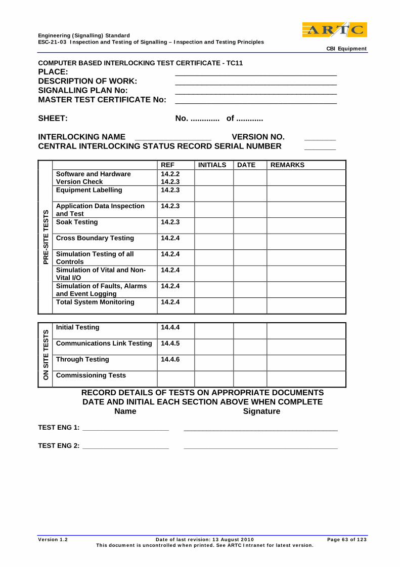
Engineering (Signalling) Standard ESC-21-03 Inspection and Testing of Signalling – Inspection and Testing Principles CBI Equipment
Version 1.2 Date of last revision: 13 August 2010 Page 63 of 123 This document is uncontrolled when printed. See ARTC Intranet for latest version.
COMPUTER BASED INTERLOCKING TEST CERTIFICATE - TC11 PLACE: ____________________________________ DESCRIPTION OF WORK: ____________________________________ SIGNALLING PLAN No: ____________________________________ MASTER TEST CERTIFICATE No: ____________________________________ SHEET: No. ............. of ............ INTERLOCKING NAME _________________ VERSION NO. _______ CENTRAL INTERLOCKING STATUS RECORD SERIAL NUMBER _______
REF INITIALS DATE REMARKS Software and Hardware Version Check
14.2.2 14.2.3
Equipment Labelling 14.2.3
Application Data Inspection and Test
14.2.3
Soak Testing 14.2.3
Cross Boundary Testing 14.2.4
Simulation Testing of all Controls
14.2.4
Simulation of Vital and Non-Vital I/O
14.2.4
Simulation of Faults, Alarms and Event Logging
14.2.4
PRE-
SITE
TES
TS
Total System Monitoring 14.2.4
Initial Testing
14.4.4
Communications Link Testing 14.4.5
Through Testing 14.4.6
ON
SIT
E TE
STS
Commissioning Tests
RECORD DETAILS OF TESTS ON APPROPRIATE DOCUMENTS DATE AND INITIAL EACH SECTION ABOVE WHEN COMPLETE
Name Signature TEST ENG 1: _______________________
_________________________________________
TEST ENG 2: _______________________
_________________________________________
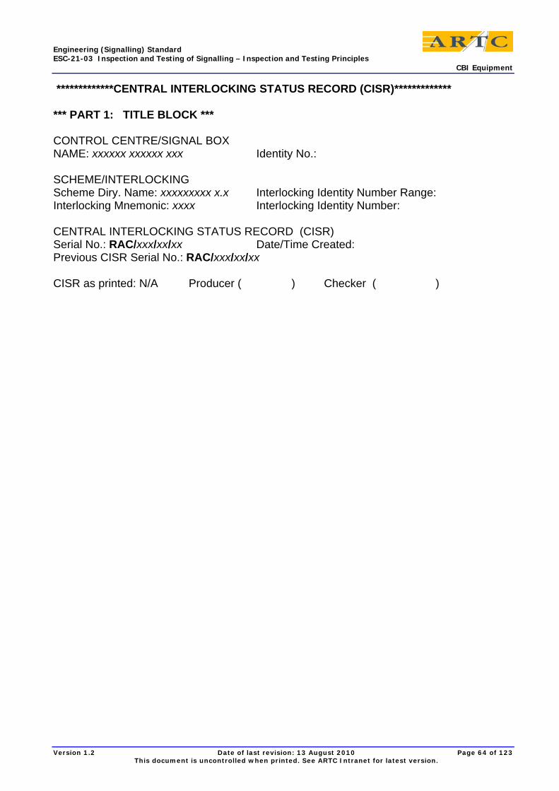
Engineering (Signalling) Standard ESC-21-03 Inspection and Testing of Signalling – Inspection and Testing Principles CBI Equipment
Version 1.2 Date of last revision: 13 August 2010 Page 64 of 123 This document is uncontrolled when printed. See ARTC Intranet for latest version.
*************CENTRAL INTERLOCKING STATUS RECORD (CISR)*************
*** PART 1: TITLE BLOCK *** CONTROL CENTRE/SIGNAL BOX NAME: xxxxxx xxxxxx xxx Identity No.: SCHEME/INTERLOCKING Scheme Diry. Name: xxxxxxxxx x.x Interlocking Identity Number Range: Interlocking Mnemonic: xxxx Interlocking Identity Number: CENTRAL INTERLOCKING STATUS RECORD (CISR) Serial No.: RAC/xxx/xx/xx Date/Time Created: Previous CISR Serial No.: RAC/xxx/xx/xx CISR as printed: N/A Producer ( ) Checker ( )
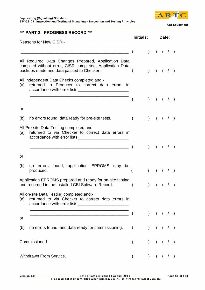
Engineering (Signalling) Standard ESC-21-03 Inspection and Testing of Signalling – Inspection and Testing Principles CBI Equipment
Version 1.2 Date of last revision: 13 August 2010 Page 65 of 123 This document is uncontrolled when printed. See ARTC Intranet for latest version.
*** PART 2: PROGRESS RECORD *** Initials: Date: Reasons for New CISR:- ___________________________ _______________________________________________ _______________________________________________ ( ) ( / / ) All Required Data Changes Prepared, Application Data compiled without error, CISR completed, Application Data backups made and data passed to Checker. ( ) ( / / ) All Independent Data Checks completed and:- (a) returned to Producer to correct data errors in
accordance with error lists ______________________ ___________________________________________ ___________________________________________ ( ) ( / / )
or (b) no errors found, data ready for pre-site tests. ( ) ( / / ) All Pre-site Data Testing completed and:- (a) returned to via Checker to correct data errors in
accordance with error lists ______________________ ___________________________________________ ___________________________________________ ( ) ( / / )
or (b) no errors found, application EPROMS may be
produced. ( ) ( / / ) Application EPROMS prepared and ready for on-site testing and recorded in the Installed CBI Software Record. ( ) ( / / ) All on-site Data Testing completed and:- (a) returned to via Checker to correct data errors in
accordance with error lists ______________________ ___________________________________________ ___________________________________________ ( ) ( / / )
or (b) no errors found, and data ready for commissioning. ( ) ( / / ) Commissioned ( ) ( / / ) Withdrawn From Service. ( ) ( / / )
Engineering (Signalling) Standard ESC-21-03 Inspection and Testing of Signalling – Inspection and Testing Principles CBI Equipment
Version 1.2 Date of last revision: 13 August 2010 Page 66 of 123 This document is uncontrolled when printed. See ARTC Intranet for latest version.
*** PART 3: VERSION DETAILS & PRODUCTION/CHECKING RECORD *** OBJECT CODE DETAILS Type of data: Date/Time: Identifier: Compiler/Device
Checksum: APPLICATION DATA FILES File: Date/Time: Produced: Checked: DESIGN SOFTWARE USED TO CREATE CISR Software Iss/Rev:
Engineering (Signalling) Standard ESC-21-03 Inspection and Testing of Signalling – Inspection and Testing Principles CBI Equipment
Version 1.2 Date of last revision: 13 August 2010 Page 67 of 123 This document is uncontrolled when printed. See ARTC Intranet for latest version.
*** PART 4: NON SCHEME SPECIFIC SOURCE DOCUMENTS *** DESIGN STANDARDS AND CODES OF PRACTICE USED Document: Date of Issue Revision Producer: Checker:
Engineering (Signalling) Standard ESC-21-03 Inspection and Testing of Signalling – Inspection and Testing Principles CBI Equipment
Version 1.2 Date of last revision: 13 August 2010 Page 68 of 123 This document is uncontrolled when printed. See ARTC Intranet for latest version.
*** PART 5: SCHEME SPECIFIC SOURCE DOCUMENTS *** Document: Date of Issue Revision Producer: Checker: Scheme Plan
Scheme Plan Overlays
Numbering Plan
Location Plan
Communications Network Plan
Power Cable Plans
Control Tables
Sub-route/Sub-overlap Plans
Error List from Data Checking
Error List from Pre-Site Testing
Error List from On-Site Testing
Engineering (Signalling) Standard ESC-21-03 Inspection and Testing of Signalling – Inspection and Testing Principles CBI Equipment
Version 1.2 Date of last revision: 13 August 2010 Page 69 of 123 This document is uncontrolled when printed. See ARTC Intranet for latest version.
*** PART 6: CBI OPERATING SOFTWARE *** Device/Software: Reference/Version
Checked Against Type Approval Documentation Producer: Checker: Document Reference: ( ) ( )

Engineering (Signalling) Standard ESC-21-03 Inspection and Testing of Signalling – Inspection and Testing Principles CBI Equipment
Version 1.2 Date of last revision: 13 August 2010 Page 70 of 123 This document is uncontrolled when printed. See ARTC Intranet for latest version.
*** PART 7: COMPATABILITY OF RELATED SYSTEMS *** System: Issue/Version Producer: Checker: Adjacent Central Interlockings:
Fringe Signal Boxes:
Control Centre:
Level Crossings:
Ground Frames:
Other Systems:

Engineering (Signalling) Standard ESC-21-03 Inspection and Testing of Signalling – Inspection and Testing Principles CBI Equipment
Version 1.2 Date of last revision: 13 August 2010 Page 71 of 123 This document is uncontrolled when printed. See ARTC Intranet for latest version.
*** PART 8: APPENDIX FOR COMMENTS AND ADDITIONAL ITEMS ***
Engineering (Signalling) Standard ESC-21-03 Inspection and Testing of Signalling – Inspection and Testing Principles CBI Equipment
Version 1.2 Date of last revision: 13 August 2010 Page 72 of 123 This document is uncontrolled when printed. See ARTC Intranet for latest version.
*** PART 9: IDENTIFICATION OF INITIALS *** Initials Name Signature IWMP/Contractor Location
Engineering (Signalling) Standard ESC-21-03 Inspection and Testing of Signalling – Inspection and Testing Principles CBI Equipment
Version 1.2 Date of last revision: 13 August 2010 Page 73 of 123 This document is uncontrolled when printed. See ARTC Intranet for latest version.
CBI HARDWARE RECORD CONTROL CENTRE : ...................................................................................... INTERLOCKING NAME : ...................................................................................... DEVICE DETAILS
DEVICE: SERIAL NO. : MODIFICATION STATE : DATE INSTALLED : LOCATION INSTALLED : MODULE ADDRESS :
....................................................................................................................................................................................................................................................................................................................................................................................................................................................................................................................................
FAILURE RECORD
DATE OF FAILURE : FAILURE DETAILS : DATE REMOVED : REPLACED BY SERIAL NO. : DATE SENT FOR REPAIR : DATE RETURNED FROM REPAIR :
..................................................................................................................................................................................................................................................................................................................................................................................................................................................................................................................................................................................................................................................................................................................................................................................................................................................................................................................................................................................
MODIFICATIONS ...................................................................................................................................................................................................................................................................................................................................................................................................................................................................................................................................................................................................................................................................................................................................................................................

Engineering (Signalling) Standard ESC-21-03 Inspection and Testing of Signalling – Inspection and Testing Principles CBI Equipment
Version 1.2 Date of last revision: 13 August 2010 Page 74 of 123 This document is uncontrolled when printed. See ARTC Intranet for latest version.
INSTALLED CBI SOFTWARE RECORD (ICSR)
CONTROL CENTRE:
.............................
CISR/ICSR SERIAL NO:
............................
INTERLOCKING NAME (MNEMONIC):
.............................
INTERLOCKING IDENTITY NO:
............................
CONTROL CENTRE IDENTITY NO:
............................
INSTALLED EPROM DETAILS EPROM FOR
REFERENCE NO
Checksum Quantity Inc Spares
Serial Numbers Installer Checker
DATA MASTERS HELD BY : ........................................................................................ RECORD PREPARED BY : ............................ CHECKED BY : ............................. AT OFFICE : ..................................................... DATE : ......... / ......... / .......... INSTALLATION CHECK OF # ITEMS : CHECKED BY : ........................................................... DATE : ......... / ......... / ..........
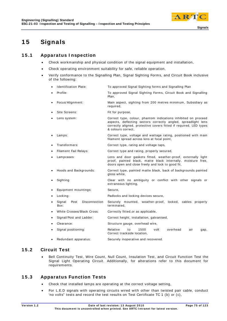
Engineering (Signalling) Standard ESC-21-03 Inspection and Testing of Signalling – Inspection and Testing Principles Signals
Version 1.2 Date of last revision: 13 August 2010 Page 75 of 123 This document is uncontrolled when printed. See ARTC Intranet for latest version.
15 Signals
15.1 Apparatus Inspection • Check workmanship and physical condition of the signal equipment and installation,
• Check operating environment suitability for safe, reliable operation,
• Verify conformance to the Signalling Plan, Signal Sighting Forms, and Circuit Book inclusive of the following:
• Identification Plate: To approved Signal Sighting forms and Signalling Plan
• Profile: To approved Signal Sighting Forms, Circuit Book and Signalling Plan,
• Focus/Alignment: Main aspect, sighting from 200 metres minimum, Subsidiary as required,
• Site Screens: Fit for purpose,
• Lens system: Correct type, colour, phantom indications inhibited on proceed aspects, deflecting sectors correctly angled, spreadlight lens correctly aligned, protective covers fitted if required, LED types & colours correct,
• Lamps: Correct type, voltage and wattage rating, positioned with main filament spread across lens at focal point,
• Transformers: Correct type, rating and voltage taps,
• Filament Fail Relays: Correct type and rating, properly secured,
• Lampcases: Lens and door gaskets fitted, weather-proof, externally light proof, painted black, matte black internally, moisture free, doors open and close freely and lock to good fit,
• Hoods and Backgrounds: Correct type, painted matte black, back of backgrounds painted gloss white,
• Sighting Clear with no ambiguity or conflict with other signals or extraneous lighting,
• Equipment mountings: Secure,
• Locking: Padlocks and locking devices secure,
• Signal Post Disconnection Box:
Securely mounted, weather-proof, locked, cables properly terminated,
• White Crosses/Black Cross: Correctly fitted,or as applicable,
• Signal/Post and Ladder: Correct height, installation, galvanised,
• Clearance: Structure gauge, overhead wire,
• Signal positioning: Relative to 1500 volt overhead air gap, Correct trackside location,
• Redundant apparatus: Securely inoperative and recovered.
15.2 Circuit Test • Bell Continuity Test, Wire Count, Null Count, Insulation Test, and Circuit Function Test the
Signal Light Operating Circuit. Additionally, for alterations refer to this document for requirements.
15.3 Apparatus Function Tests • Check that installed lamps are operating at the correct voltage setting,
• For L.E.D signals with operating circuits wired with other than twisted pair cable, conduct ‘no volts” tests and record the test results on Test Certificate TC 1 (b) or (c),

Engineering (Signalling) Standard ESC-21-03 Inspection and Testing of Signalling – Inspection and Testing Principles Signals
Version 1.2 Date of last revision: 13 August 2010 Page 76 of 123 This document is uncontrolled when printed. See ARTC Intranet for latest version.
• Signals fitted with dual filament lamps: test to ensure that a failure of the main filament de-energises the filament change-over relay and operates the auxiliary filament,
• Signals fitted with a lamp proving relay: test to ensure relay is energised except when both lamp filaments have failed, ensure relay adjusted to drop effectively with lamp totally out, but pick effectively with main filament out, auxiliary filament on,
• Signals fitted with Marker Light: Test to ensure marker light operates with main signal lamps out or at red,
• Check flash rate correct for flashing and pulsating aspects.
15.4 System Function Test Complete remaining tests described under Aspect Sequence test in Clause 9 of this document. Record the result of the aspect sequence test as described in ESC-21-02 Clause 3.6.
15.5 Signals Test Certificates Record the results of apparatus inspection and testing as nominated in ESC-21-02 Inspection and Testing of Signalling – Plans, Programs, Documentation and Packages with tailored Work Instructions developed from ITF Checklist 13/1 (a or b) and complete the Test Certificate (TC 1a, 1b or 1c) as applicable provided in ESC-21-04 Inspection and Testing of Signalling - Standard Forms.
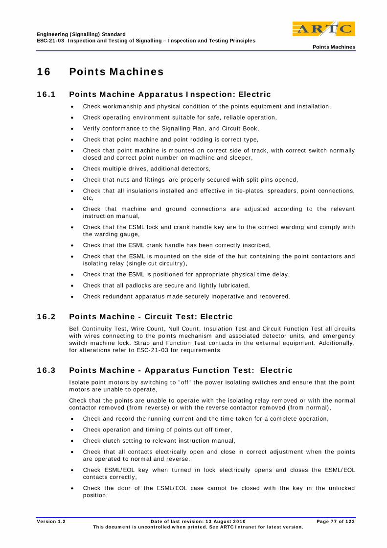
Engineering (Signalling) Standard ESC-21-03 Inspection and Testing of Signalling – Inspection and Testing Principles Points Machines
Version 1.2 Date of last revision: 13 August 2010 Page 77 of 123 This document is uncontrolled when printed. See ARTC Intranet for latest version.
16 Points Machines
16.1 Points Machine Apparatus Inspection: Electric • Check workmanship and physical condition of the points equipment and installation,
• Check operating environment suitable for safe, reliable operation,
• Verify conformance to the Signalling Plan, and Circuit Book,
• Check that point machine and point rodding is correct type,
• Check that point machine is mounted on correct side of track, with correct switch normally closed and correct point number on machine and sleeper,
• Check multiple drives, additional detectors,
• Check that nuts and fittings are properly secured with split pins opened,
• Check that all insulations installed and effective in tie-plates, spreaders, point connections, etc,
• Check that machine and ground connections are adjusted according to the relevant instruction manual,
• Check that the ESML lock and crank handle key are to the correct warding and comply with the warding gauge,
• Check that the ESML crank handle has been correctly inscribed,
• Check that the ESML is mounted on the side of the hut containing the point contactors and isolating relay (single cut circuitry),
• Check that the ESML is positioned for appropriate physical time delay,
• Check that all padlocks are secure and lightly lubricated,
• Check redundant apparatus made securely inoperative and recovered.
16.2 Points Machine - Circuit Test: Electric Bell Continuity Test, Wire Count, Null Count, Insulation Test and Circuit Function Test all circuits with wires connecting to the points mechanism and associated detector units, and emergency switch machine lock. Strap and Function Test contacts in the external equipment. Additionally, for alterations refer to ESC-21-03 for requirements.
16.3 Points Machine - Apparatus Function Test: Electric Isolate point motors by switching to "off" the power isolating switches and ensure that the point motors are unable to operate,
Check that the points are unable to operate with the isolating relay removed or with the normal contactor removed (from reverse) or with the reverse contactor removed (from normal),
• Check and record the running current and the time taken for a complete operation,
• Check operation and timing of points cut off timer,
• Check clutch setting to relevant instruction manual,
• Check that all contacts electrically open and close in correct adjustment when the points are operated to normal and reverse,
• Check ESML/EOL key when turned in lock electrically opens and closes the ESML/EOL contacts correctly,
• Check the door of the ESML/EOL case cannot be closed with the key in the unlocked position,
Engineering (Signalling) Standard ESC-21-03 Inspection and Testing of Signalling – Inspection and Testing Principles Points Machines
Version 1.2 Date of last revision: 13 August 2010 Page 78 of 123 This document is uncontrolled when printed. See ARTC Intranet for latest version.
• Check ESML/EOL operating handle operates the point machine safety cut out switch, disconnecting the points motor,
• Check points operate easily under emergency manual operation.
16.4 Points Machine - Facing Point Lock and Detection Test: Electric See ESM-06-01 Facing Point Lock and Detection Testing
16.5 Points Machine - System Function Test: Electric Complete tests described in "Point Correspondence Tests", Clause 9 of this document.
16.6 Points Machine - Test Certificates: Electric Record the results of Points Machine Tests on the Point Operating Test Certificate (TC-6) provided in ESC-21-04 Standard Forms.
16.7 Points Apparatus Inspection: Mechanical • Check the workmanship, physical condition, and installation of the points equipment,
channel rodding drive, and ground frame,
• Check that the operating environment is suitable for safe, reliable operation,
• Verify conformance to Signalling Plan, Working Sketch, and Circuit Book,
• Check that leading off timbers and cranks are secure (where applicable),
• Check that the ground frame is correctly located relative to the points (where applicable),
• Check that the ground frame is of the correct type and size (where applicable),
• Check that the channel rodding stands and crank stands are secure in the ground and that the run is straight (or evenly curved) and level,
• Check that cranks are "on centre" and that compensators are correctly located in the run,
• Check that bolts and pins are properly secured and split pins spread,
• Check that the FPL casting is secure and cannot move on the sleeper,
• Check that "spring", FPL, and detection are correctly adjusted,
• Check that the points are not excessively heavy to pull.
16.8 Points Circuit Test: Mechanical Bell Continuity Test, Wire Count, Null Count, Insulation Test and Circuit Function Test detection circuits. Strap and Function Test the contacts within the detector. Additionally, for alterations refer to ESC-21-03 for requirements.
16.9 Points Apparatus Function Test: Mechanical • Ensure that there is no more than 20mm escapement available between bobbin and cradle,
• Test that the facing point lock plunger travel is at least 190mm and that the plunger clears the lock rod by 15 to 20mm when withdrawn,
• Test that movement of the cross slide will break detection before the plunger disengages from the lock rod ie., at approximately half plunger stroke,
• Check that the effort required on the points lever is similar for normal to reverse and reverse to normal.
Engineering (Signalling) Standard ESC-21-03 Inspection and Testing of Signalling – Inspection and Testing Principles Ground Frames and Electric Releases
Version 1.2 Date of last revision: 13 August 2010 Page 79 of 123 This document is uncontrolled when printed. See ARTC Intranet for latest version.
16.10 Points - Facing Point Lock and Detection Test: Mechanical Operate the points and:
• Verify that when a gauge 4.8mm thick is held between the switch and stock rail at a point approximately 75mm back from the tip of the switch, the detector contacts are visibly open. With sealed micro-switches, the detector contacts shall be verified to be electrically open with a gauge of 4mm. Verify that the detector contacts are made with a gauge of 3.2mm. Detectors fitted on multiple drives should be coarsely adjusted at 6 to 7mm to prove that the switch has responded to the movement of the drive mechanisms,
• Verify that a gauge of 3.2 mm inch thick held between the switch and stock rail at a point approximately 75mm back from the tip of the switch, prevents the locking dog entering the notch in the locking stretcher; verify that a gauge of 1.6 mm allows the locking dog to enter the notch and lock the points,
• Verify that the open switch opens to 114 mm +2mm -0mm,
Note: With a switch opening of 114 mm a mechanical lock will fail to enter, or just bump in, with 1.6mm between switch and stockrail. For mechanical points, switch openings may be increased slightly up to 116mm but must never be less that 114mm.
16.11 Points Test Certificates: Mechanical Record the results of apparatus inspection and testing as nominated in ESC-21-02 Inspection and Testing of Signalling – Plans, Programs, Documentation and Packages with tailored Work Instructions developed from ITF Checklist 13/2 –13/3 and complete the Test Certificate (TC 6) as applicable provided in ESC-21-04 Inspection and Testing of Signalling - Standard Forms.
17 Ground Frames and Electric Releases
17.1 Ground Frames and Electric Releases Apparatus Inspection • Check workmanship and physical condition of the ground frame or electric releasing switch
equipment and installation,
• Check operating environment suitable for safe reliable operation,
• Verify conformance with the Signalling Plan, Circuit Books, Locking Tables and Locking Diagrams,
• Check positioning of release switch in relation to ground frame particularly where a physical time delay is required,
• Check release switch type, rating and labelling,
• Check electric lever lock type, rating and labelling,
• Check release switch, electric lever lock for correct voltage, lock positions and force down, where applicable,
• Check indicators, repeaters for correct type, rating and labelling,
• Check Annett keys and lock faces are correctly warded and keys correctly inscribed,
• Check the lever nameplates on the mechanical levers,
• Check covers secured on mechanical interlocking,
• Check redundant apparatus made securely inoperative and recovered.
• TOW Operated locks
Engineering (Signalling) Standard ESC-21-03 Inspection and Testing of Signalling – Inspection and Testing Principles Track Circuits
Version 1.2 Date of last revision: 13 August 2010 Page 80 of 123 This document is uncontrolled when printed. See ARTC Intranet for latest version.
17.2 Ground Frames and Electric Releases Circuit Test Bell Continuity Test, Wire Count, Null Count, Insulation Test and Circuit Function Test all circuits connecting to the release switch and/or ground frame. Strap and Function Test contacts in the external equipment. Additionally, for alterations refer to ESC-21-03 for requirements.
17.3 Ground Frames and Electric Releases Apparatus Function Test • Check adjustment of catch handle contacts, lever rotary contacts, electric lever lock and
release switch normal and reverse contacts to electrically open and close at the correct relative position of the lever,
• Check Annett lock contacts electrically open and close correctly when the Annett key is turned in the lock,
• Operate release switches and electric lever locks and ensure that the lock drops and securely locks the lever when de-energised and that the lock proving contact only closes when the lever is locked, physically move around the locking dog to ensure that the locking dog will not ledge on the lock slide,
• Check that release switch lock corresponds with the lever controls and operates the release switch normal relay correctly,
• Ensure that with the key removed the release switch cannot be normalised,
• Check that release switch door cannot close with lever in the release position.
17.4 Ground Frames and Electric Releases System Function Test • Test the mechanical interlocking in the ground frame,
• Operate the release switch and frame from the control centre and observe the correct indications on the indicator diagram.
17.5 Ground Frames and Electric Releases Test Certificates Record the results of apparatus inspection and testing as nominated in ESC-21-02 Inspection and Testing of Signalling – Plans, Programs, Documentation and Packages with tailored Work Instructions developed from ITF Checklist 13/2 –13/3 and complete the Test Certificate (TC 6) as applicable provided in ESC-21-04 Inspection and Testing of Signalling - Standard Forms.
18 Track Circuits
18.1 Track Circuit Apparatus Inspection • Check workmanship and physical condition of track circuit equipment and installation,
• Check operating environment suitable for safe, reliable operation. Where applicable - terminals insulated or shrouded: for touch and accidental short circuits,
• Verify conformance to the Signalling Plan, Track Insulation Plan and Circuit Diagrams inclusive of the following:
• Check length and limits of track circuit, position of insulated joints, fouling point clearance, point and other insulations, traction bonds, electrolysis bonds. Check polarity of each rail of D.C. track circuits and Impulse track circuits is as shown on the Track Insulation Plan,
• Check track circuit connections, spark gap arrestor connections, track circuit bonding, traction bonding, electrolysis bonding, including series bonds, parallel bonds, rail joints bonds and bonds in points, crossing and check rails,
• Check loop arrangements and length of track circuit leads,
• Check type, rating, and labelling of track circuit equipment items.
Engineering (Signalling) Standard ESC-21-03 Inspection and Testing of Signalling – Inspection and Testing Principles Track Circuits
Version 1.2 Date of last revision: 13 August 2010 Page 81 of 123 This document is uncontrolled when printed. See ARTC Intranet for latest version.
• Check that connections to rail secured and terminated,
• Check disconnection boxes and track side equipment associated with special track circuits for corrosion and other physical damage, secure mount, and that cables are wired neatly and securely terminated,
• Check that insulated rails are free from spurious bonds or earths,
• Check fishplates and track fastenings are not bridging out the insulated joint,
• Check, on special vertical racking for track circuit equipment, every vacant module position above or below a unit of installed equipment is fitted with all obturation fittings and coding plugs to prevent incorrect insertion of the unit,
• Check redundant apparatus made securely inoperative and recovered.
18.2 Track Circuit - Circuit Test Bell Continuity Test, Wire Count, Null Count, Insulation Test, and Circuit Function test the track circuit. Additionally, for alterations refer to ESC-21-03 for requirements.
18.3 Track Circuit Apparatus Function Test • Check that all surge protection and earthing arrangements are installed and connected
prior to certification testing.
• Record track circuit voltages, currents, and adjustment settings, and check against normal values for the applicable track parameters,
• Check double rail alternating current track circuits (50Hz, audio frequency) for equal current in each rail,
• Remove the track circuit feed primary fuse and check the track relay for de-energisation and zero voltage,
Note: Residual voltages across the relay or across the rails shall be further investigated and irregular sources rectified. Some residual traction d.c. and traction harmonics would be expected with single rail track circuits, as would some circulating current from other single rail track circuits in the vicinity. Residual voltages could be caused by unbalance in the track circuit under test or in other track circuits in the vicinity, or by false voltage. Unbalance in track circuits could be caused by high resistance rail connections, rail bonds or "earthy" spark gap connections. On DC tracks any residual voltage must be less than 30% of the release voltage of the track relay,
• Check that structure spark gap connections are open circuit,
• Check rail connections and rail bonds for low resistance volt drop,
• Check polarity reversal at block-joints between adjacent track circuits at all extremities, where applicable, using a voltmeter. With AC double rail tracks circuits - additionally bridge one block-joint and observe the track relay pull down (not just release.),
• Conduct drop shunt tests at relay/receiver extremity of the track circuit and fixed minimum shunt tests at all other extremities and at regular intermediate points for compliance with specification shunt values, including between the tuned loops on a jointless track circuit and including all parallel bonded sections. Use non-inductive shunt resistors with rail clamp connections. Shunt tests should be done when the track circuit ballast is dry. Record lowest value on the Track Circuit History Card.
18.4 Track Circuit System Function Test • De-energise the track relay and observe all corresponding track indicating and repeat
relays drop away and the track indicator display occupied. Observe track time limit relay energise after set time delay,
Engineering (Signalling) Standard ESC-21-03 Inspection and Testing of Signalling – Inspection and Testing Principles Level Crossing Equipment
Version 1.2 Date of last revision: 13 August 2010 Page 82 of 123 This document is uncontrolled when printed. See ARTC Intranet for latest version.
• Energise the track relay and observe the converse.
18.5 Track Circuit Test Certificates Record the results of apparatus inspection and testing as nominated in the relevant Set to Work and Test and Certify Manual, complete the required Track Circuit Commissioning Master Sheets and Track Circuit History Cards. Further, the requirements set out in ESC-21-02 Inspection and Testing of Signalling – Plan, Programs, Documentation and Packages with tailored Work Instructions developed from ITF Checklist 13/5 provided in ESC-21-04 Inspection and Testing of Signalling - Standard Forms.
19 Level Crossing Equipment
19.1 Level Crossing Equipment Apparatus Inspection • Check workmanship and physical condition of level crossing equipment and installation,
• Check operating environment suitable for safe, reliable operation. Terminals insulated or shrouded: for touch and accidental short circuits,
• Verify conformance to the Signalling Plan, Circuit Diagrams and Level Crossing Site Plan, inclusive of the following:
Measure approach distances from warning initiation point to the edge of the road and check calculated warning times at line speed.
Road signs, road markings, train driver warning boards, penalty notice boards:
Fitted correctly
Lights, booms, and bells: Fitted correctly
Test and Emergency keys: Identification tags correctly inscribed
Equipment: Type, rating, and labelling correct
Battery and battery charger: Type and rating correct. Ensure batteries fully charged.
Focus: Check near side signals focus and far side signals focus as required by the road traffic approaches
Padlocks: Correct type on emergency box.
Speed Boards Check installed and correct, where applicable
Redundant apparatus: Securely inoperative and recovered
19.2 Level Crossing Equipment Circuit Testing Bell Continuity Test, Wire Count, Null Count, Insulation Test and Circuit Function Test all circuits connecting to the highway signals, booms and bells. Strap and Function Test contacts in external equipment. Additionally, for alterations refer to ESC-21-03 for requirements.
19.3 Level Crossing Equipment Apparatus Function Tests • Operate equipment,
• Check boom ascend and descend times and record,
• Check boom gate delay time after initiation of lights and bells operation and record,
• Check audible warnings sound when protection initiated and that one cuts out when booms have descended, as per actual design.
• Check operating voltage at bell,
• Check 10v 25w lamps operate at 9.6 volts measured at the pole (temporarily bridge out the flasher contacts for this check),
Engineering (Signalling) Standard ESC-21-03 Inspection and Testing of Signalling – Inspection and Testing Principles Power Supplies
Version 1.2 Date of last revision: 13 August 2010 Page 83 of 123 This document is uncontrolled when printed. See ARTC Intranet for latest version.
• Check operation of test and emergency keys,
• Test low voltage alarms operate at the correct voltage setting and illuminate/extinguish the power supply indicators where applicable,
• Check test switch operates protection and disconnects the A.C. power supply from the battery charger where applicable,
• Check protection operates on batteries alone as well as with battery charger by opening the Test Switch and observing operation and power supply indicators for two minutes,
• Check booms fall when power lost.
• Check voltage on LEDs measured at pol;e.
• Check operation of Level Crossing Monitor
19.4 Level Crossing Equipment System Function Test • De-energise track circuits individually and ensure protection operates,
• De-energise tracks in sequential order to simulate a train and ensure protection operates,
• Ensure departure tracks do not operate protection and protection clears when the level crossing track is cleared,
• Where interlocked signals protect the level crossing, ensure protection is not cleared until the replaced signal has been at stop for the time limit set,
• With approach track circuit occupied ensure qualifying signal at stop will not clear until the level crossing protection has operated for the time set,
• Check direction sticks operate correctly,
• Check proving of direction sticks in electric train staff line, section control or as otherwise provided by direction stick time limit relays,
• Check remote testing or monitoring equipment operates correctly.
• Check all alarms and operations at Signal Control Centre
19.5 Level Crossing Equipment Test Certificates Record the results of apparatus inspection and testing as nominated in ESC-21-02 Inspection and Testing of Signalling – Plans, Programs, Documentation and Packages with tailored Work Instructions developed from ITF Checklist 13/6 and complete the Test Certificate (TC 10) as applicable provided in ESC-21-04 Inspection and Testing of Signalling - Standard Forms.
20 Power Supplies
20.1 Power Supplies Apparatus Inspection • Check workmanship and physical condition of power supply equipment and installation,
• Check operating environment suitable for safe reliable operation,
• Verify conformance to Signalling Plans and Circuit Diagrams inclusive of the following:
• Fuses, circuit breakers, surge gas discharge units and varistors: Correct type, rating, and labelling,
• Transformers, rectifiers, resistors and capacitors: Correct type, voltage, and current rating; adjustment arrangements; and labelling,
• Busbars, mains cables, power supply wiring, terminals: Correct type, rating, and labelling,
• Battery: Correct type, capacity, number of cells, state of charge,
• Terminals insulated or shrouded: for touch and accidental short circuits.

Engineering (Signalling) Standard ESC-21-03 Inspection and Testing of Signalling – Inspection and Testing Principles Diesel Generators (Mains failure plant)
Version 1.2 Date of last revision: 13 August 2010 Page 84 of 123 This document is uncontrolled when printed. See ARTC Intranet for latest version.
• Check manufacturer's test certificates and acceptance test certificates for manufactured equipment, where applicable.
20.2 Power Supplies Circuit Testing Bell Continuity Test, Wire Count, Null Count, Insulation Test. Additionally, for alterations refer to ESC-21-03 for requirements.
20.3 Power Supplies Apparatus Function Test • Test power supplies to operate correctly providing the correct voltage value, polarity, and
voltage regulation over the range of operating conditions. Record values,
• Test voltage drop over power supply mains and circuit wires for maximum operating load,
• Test each channel of dual power supplies to individually supply the load,
• Test un-interruptable power supplies to supply the load conditions when mains power is interrupted,
• Test mains failure plants to start up, provide correct voltage and frequency, supply the load, shut down and indicate correctly,
• Test battery chargers for correct operation and charging adjustment,
• Test batteries for polarity, voltage, state of charge,
• Test emergency changeover arrangements operate correctly,
• Test power supply indicators and alarms, local and remote, to operate correctly,
• Test power supply busbars to be isolated from any other power supply,
• Test power supply busbars to be free from earths. Record bus-bar voltage leak to earth,
• Test earth leakage detectors connected to power supply busbars to operate correctly,
• Check phase relationship between normal and emergency supplies, where applicable.
20.4 Power Supplies Test Certificates Record the results of apparatus inspection and testing as nominated in ESC-21-02 Inspection and Testing of Signalling – Plans, Programs, Documentation and Packages with tailored Work Instructions developed from ITF Checklist 13/7 and complete the Test Certificate (TC 7 and TC 9) as applicable provided in ESC-21-04 Inspection and Testing of Signalling - Standard Forms.
21 Diesel Generators (Mains failure plant)
21.1 Diesel Generators Apparatus Inspection • Check workmanship and physical condition of the mains failure plant equipment and
installation,
• Check operating environment suitable for safe reliable operation,
• Inspection Detail,
• Check that the unit is supplied with the manufacturer's test certificate, and at least one complete copy of the manual, including operating and maintenance instructions and circuit diagrams,
• Check that the generating plant is securely fixed to its mounting base, and that mains and indication cables are correctly terminated to the control panel,
• On a non-portable system, check that fuel tank and control panel are securely mounted, fuel lines are properly run and connected to tank and engine, and cabling between control panel and motor/alternator is wired according to the manufacturer's wiring diagram,
Engineering (Signalling) Standard ESC-21-03 Inspection and Testing of Signalling – Inspection and Testing Principles Diesel Generators (Mains failure plant)
Version 1.2 Date of last revision: 13 August 2010 Page 85 of 123 This document is uncontrolled when printed. See ARTC Intranet for latest version.
• Check that the fuel tank is full, the starter battery is properly connected and fully charged, and normal mains supply to the control panel is 'on'.
21.2 Diesel Generators Apparatus Function Test
21.2.1 Initialisation of plant
• Select Function switch 'OFF' position,
• Close Normal mains Circuit Breaker,
• Select function switch 'Auto' position,
21.3 Testing sequence • Check mains failure function:
a) Open Normal mains Circuit Breaker,
b) Check that after normal delay, motor cranks and starts, runs up to speed, then Emergency contractor closes and Emergency mains supply is available,
• Adjust alternator output voltage to equal, as near as possible, the measured Normal supply voltage,
• Check normal shutdown function:
a) Close Normal mains Circuit Breaker,
b) Check that after normal delay, Normal contactor closes, mains supply is available, and after a delay the diesel motor stops.
• Check fail to start function:
a) Disconnect lead to engine fuel solenoid,
b) Open Normal mains Circuit Breaker,
c) Check that engine tries to start 3 times, cranking for about 10 seconds each time, then 'Fail To Start' alarm is displayed,
d) Restore fuel solenoid` connection, reset alarm and initialise panel,
• Check emergency shutdown function,
For each of the following conditions, with the mains failure plant operating, apply the test condition, observe that the plant shuts down and that the correct alarm is displayed, then reset alarm and initialise the control panel:
a) Bridge 'low fuel' contact on fuel tank,
b) Bridge 'engine temperature' contact,
c) Bridge 'engine oil pressure' contact,
d) Open generator output Circuit Breaker.
• Check remote test function:
a) If the plant is fitted for remote test operation, check that operation and cancellation of the 'remote test' control starts and shuts down the plant as required.
b) Test Alarms to Remote Signal Control Centre.
c) Test Generator with full load points, signals etc opperating.
21.4 Diesel Generator Test Certificate Record the results of apparatus inspection and testing as nominated in ESC-21-02 Inspection and Testing of Signalling – Plans, Programs, Documentation and Packages with tailored Work

Engineering (Signalling) Standard ESC-21-03 Inspection and Testing of Signalling – Inspection and Testing Principles Diesel Generators (Mains failure plant)
Version 1.2 Date of last revision: 13 August 2010 Page 86 of 123 This document is uncontrolled when printed. See ARTC Intranet for latest version.
Instructions developed from ITF Checklist 13/7 and complete the Test Certificate (TC 7, 8 & 9) as applicable provided in ESC-21-04 Inspection and Testing of Signalling - Standard Forms.
Engineering (Signalling) Standard ESC-21-03 Inspection and Testing of Signalling – Inspection and Testing Principles Earthing for Surge Protection
Version 1.2 Date of last revision: 13 August 2010 Page 87 of 123 This document is uncontrolled when printed. See ARTC Intranet for latest version.
22 Earthing for Surge Protection
22.1 Earthing Apparatus Inspection • Check the workmanship and physical condition of the earth protection equipment and
installation,
• Check operating environment suitable for safe, reliable operation,
• Verify conformance to Signalling Plans, Circuit books, and compliance to the Signalling Surge Protection Guidelines, inclusive of the following:
• Check earth stakes are correct type and correctly installed around buildings,
• Check earth cables are correct type and rating, and correctly labelled, securely terminated, and with a minimum bending radius of 30 cm,
• Check that all earth wiring is isolated from signalling/power cables inside equipment housings (relay rooms/locations),
• Check that required physical separations are provided between protected and unprotected wiring,
• Check that all earth busbars are remote from other signalling equipment and installed as close as possible to the point where the cables enter the equipment housing (relay rooms/locations). Each earth cable is to be attached separately to the busbar,
• Ensure earths are not connected except as specified,
• Check surge protection equipment type, rating and labelling,
• Check redundant apparatus made securely inoperative and recovered.
22.2 Earthing Apparatus Circuit Testing Bell Continuity Test, Wire Count, Null Count, Insulation Test. Additionally, for alterations refer to ESC-21-03 for requirements.
22.3 Earthing Apparatus Function Test Check that all earths meet the requirements of the Signalling Surge Protection Guidelines. (Standard location earth – 10 ohms. Main Relay Room (and Locations with CBI or Telemetry) earth busbars -5 ohms. External location earth busbars -10 ohms. Trackside equipment – 75 ohms).
22.4 Earthing for Surge Protection Test Certificates Record the results of apparatus inspection and testing as nominated in ESC-21-02 Inspection and Testing of Signalling – Plans, Programs, Documentation and Packages and with tailored Work Instructions developed from ITF Checklist 13/7 and complete the Test Certificate (TC 4) as applicable provided in ESC-21-04 Inspection and Testing of Signalling - Standard Forms.
Engineering (Signalling) Standard ESC-21-03 Inspection and Testing of Signalling – Inspection and Testing Principles Relays
Version 1.2 Date of last revision: 13 August 2010 Page 88 of 123 This document is uncontrolled when printed. See ARTC Intranet for latest version.
23 Relays
23.1 Relays Apparatus Inspection • Check the workmanship and physical condition of relays and installation,
• Check operation environment suitable for safe, reliable operation,
• Verify conformance of relays to Circuit Book details and analysis sheets, inclusive of the following:
Relays and bases: Correctly positioned and labelled on the rack,
Relays: Correct type, contact configuration, operating voltage and coil resistance,
Relay labels: Secure, details completed, signed by manufacturers' tester. Overhauled shelf relays also labelled as cycled tested,
Relay bases: Correctly drilled for indexing pins. Relay indexing pins correct for relay type and in correspondence with manufacturer's label,
Detachable tops for shelf relays: Correct type and correctly coded,
Relay base: Correct strapping for time limit relays,
Relay case: Undamaged and relay internally free of foreign matter,
Vane relays: Examine in accordance with maintenance manuals,
All wiring: Properly terminated and secure.
23.2 Relays Circuit Testing Bell Continuity Test, Wire Count, Null Count, Insulation Test and Circuit Function Test all circuits with wires connecting to the relay. The includes a check of the relay base strapping for time limit or time delay relays. Strap and Function Test contacts in shelf relays.
23.3 Relays Apparatus Function Test • Test plug-in relays in an approved relay test panel and fix a signed and dated sticker as
nominated to document the contact proving test or apply correct power to shelf relays,.
• Examine operating movement for correct energisation and de-energisation,
• Check contacts electrically open and close in accordance with nameplate contact configuration, when the relay is energised and de-energised,
• Test and record pick up, drop away, and working currents on Signal Branch D.C. shelf relays,
• Also check time limit relays and time delay relays for correct timing in the relay test panel.
23.4 Relays System Function Test Further test time releasing achieved in circuit only with the conditions for correct operation set up.
23.5 Relays Test Certificates Record the results of apparatus inspection and testing as nominated in ESC-21-02 Inspection and Testing of Signalling – Plans, Programs, Documentation and Packages with tailored Work Instructions developed including ITF Checklist 13/10 if applicable provided in ESC-21-04 Inspection and Testing of Signalling - Standard Forms.

Engineering (Signalling) Standard ESC-21-03 Inspection and Testing of Signalling – Inspection and Testing Principles Wires, Cables and Terminals
Version 1.2 Date of last revision: 13 August 2010 Page 89 of 123 This document is uncontrolled when printed. See ARTC Intranet for latest version.
24 Wires, Cables and Terminals
24.1 Wires, Cables, and Terminals Apparatus Inspection • Check workmanship and physical condition of wires, cables, and terminal equipment and
installation,
• Check operating environment suitable for safe, reliable operation,
• Verify conformance of wires, cables, and terminations with details in the circuit books and verify compliance with equipment specifications including the following:
• Check manufacturer's test certificates and acceptance test certificates for manufactured equipment where applicable,
• Check wires and cables for correct conductor size, insulation type, and labelling,
• Check terminals for correct type, rating, and labelling,
• Check that terminals are insulated with appropriate covers,
• Check that wires and cables are neatly run, with insulation undamaged and correctly protected,
• Check that wires are not trapped under adjacent terminals,
• Check that wires and cables are held clear or doubly insulated from metallic surfaces and that all protective grommets in entry holes are fitted correctly,
• Check that wiring runways and cable routes are installed to standard and wires and cables are not under tension, have no tight radius bends, are not bearing heavily on sharp corners, and are not chaffing,
• Check that wire terminating lugs and pins are the correct type,
• Check that all crimped and soldered connections are mechanically sound and that there are no exposed strands of wire,
• Check that terminations are mechanically sound, nuts and screws are tight and that spade type crimps are correctly locked into plug boards or terminal blocks,
• Check that there are no loose, unterminated cables, or wires with exposed conductors,
• Check that cables are correctly supported with cable clamps,
• Check that wiring is tied neatly into looms, where applicable,
• Check that buried cable routes emerge within one metre of the trackside equipment,
• Check that redundant wires, cables, and terminals are made securely inoperative and recovered,
• Check the availability of spare cores and wires, as specified.
• Check Fibre Optic Cables.
24.2 Wires, Cable and Terminals Circuit Test Bell Continuity Test, Wire Count, Null Count, Insulation Test all signalling wires, cables and terminals.
24.3 Wire, Cable and Terminals Test Certificates Record the results of apparatus inspection and testing as nominated in ESC-21-02 Inspection and Testing of Signalling – Plans, Programs, Documentation and Packages with tailored Work Instructions developed from ITF Checklist 13/11 and completed the Test Certificate (TC 2A, 2B, 2C) as applicable provided in ESC-21-04 Inspection and Testing of Signalling - Standard Forms.
Engineering (Signalling) Standard ESC-21-03 Inspection and Testing of Signalling – Inspection and Testing Principles Half Pilot Staff, Pilotmans Locks, Duplex Locks, Emergency Releasing Locks, Staff Contact Boxes
Version 1.2 Date of last revision: 13 August 2010 Page 90 of 123 This document is uncontrolled when printed. See ARTC Intranet for latest version.
25 Half Pilot Staff, Pilotmans Locks, Duplex Locks, Emergency Releasing Locks, Staff Contact Boxes
25.1 Apparatus Inspection • Check workmanship and physical condition of equipment and installation,
• Check operating environment suitable for safe, reliable operation,
• Verify conformance with the Signalling Plan, Circuit Book, Working Sketch, Locking Table, Locking Diagram including the following:
• Equipment: Correct type and labelling,
• Keys, staffs, and lock faces etc: Correctly warded and inscribed,
• Redundant apparatus:
• All Tow Equipment
Securely inoperative and recovered.
25.2 Circuit Test Bell Continuity Test, Wire Count, Null Count, Insulation Test and Circuit Function test all circuits connecting to the apparatus. Strap and Function Test contacts in the external equipment. Additionally, for alterations refer to ESC-21-03 for requirements.
25.3 Apparatus Function Test Check adjustment of contacts to electrically open and close correctly in relation to the position of the key or staff.
Check that keys and staff when operating locks and lock contacts are captive in the lock.
25.4 System Function Test Check that keys and staffs when withdrawn correctly lock respective function.
25.5 Test Certificate Record the results of apparatus inspection and testing as nominated in ESC-21-02 Inspection and Testing of Signalling – Plans, Programs, Documentation and Packages, develop tailored Work Instructions in the style of ITF Checklists and completed the Test Certificates (TC) as generally shown in ESC-21-04 Inspection and Testing of Signalling - Standard Forms.
Engineering (Signalling) Standard ESC-21-03 Inspection and Testing of Signalling – Inspection and Testing Principles Warning Lights, Guards Indicators, Buffer Stop Lights and Illuminated Notice Boards, Banner Signals and Point Indicators
Version 1.2 Date of last revision: 13 August 2010 Page 91 of 123 This document is uncontrolled when printed. See ARTC Intranet for latest version.
26 Warning Lights, Guards Indicators, Buffer Stop Lights and Illuminated Notice Boards, Banner Signals and Point Indicators
26.1 Apparatus Inspection • Check workmanship and physical condition of equipment and installation,
• Check operating environment suitable for safe, reliable operation,
• Verify conformance with Signalling Plan and Circuit Book including the following:
• Check standard clearances and secure mounting
• Equipment type: Rating and labelling,
• Lamp: Type, rating and labelling,
• Lamp: Voltage,
• Lamp focus: Colour, visibility and illumination,
• Redundant apparatus: Securely inoperative and recovered.
26.2 Circuit Test Bell Continuity Test, Wire Count, Null Count, Insulation Test and Circuit Function Test all circuits connecting to the apparatus. Additionally, for alterations refer to ESC-21-03 for requirements.
26.3 Apparatus Function Test Check operation.
26.4 Test Certificates Record the results of apparatus inspection and testing as nominated in ESC-21-02 Inspection and Testing of Signalling – Plans, Programs, Documentation and Packages, develop tailored Work Instructions in the style of ITF Checklist 13/1 (a or b) and complete the Test Certificate (TC 1a, 1b or 1c) as applicable provided in ESC-21-04 Inspection and Testing of Signalling - Standard Forms.
27 Telephones
27.1 Telephones Apparatus Inspection • Check workmanship and condition of telephone equipment and installation,
• Check operating environment suitable for reliable operation,
• Check vandal resistant installation,
• Check telephone type and labelling,
• Check padlock where provided,
• Check operational notices fitted, where applicable.
27.2 Telephones Apparatus Function Test. Check telephone operational over its circuit.
Engineering (Signalling) Standard ESC-21-03 Inspection and Testing of Signalling – Inspection and Testing Principles Telemetry and Panel Processor Testing
Version 1.2 Date of last revision: 13 August 2010 Page 92 of 123 This document is uncontrolled when printed. See ARTC Intranet for latest version.
27.3 Telephones Test Certificates Record the results of Telephone Testing on appropriate Test Certificates with tailored Work Instructions developed in the style of ITF Checklists and Test Certificates (TC) as applicable provided in ESC-21-04 Standard Forms.
28 Telemetry and Panel Processor Testing
28.1 General Testing of Telemetry and Panel Processor systems shall be in accordance with the Test plan requirements The testing shall include the tests identified in the following sub-sections.
28.2 Physical Configuration Audit • Check drawings against as-built system,
• Check for correct versions of hardware and software,
• Check that all hardware (including spares), software, firmware, and documentation has been installed and/or delivered to the appropriate person,
28.3 Start-up/Shut-down tests • Check that the system starts up correctly, reliably, without errors, and without manual
intervention, and in the time specified.
• Check that the system can be shut-down without harm.
• With the system powered down check that there is an indication that the system is not operational and that all indications and controls are off.
28.4 Disruption Tests Disrupt power, disrupt communications lines, reset modules, cause a normal/emergency power change-ever etc to determine if the system is likely to require maintenance intervention to restore the system to normal operation. Maintenance intervention should not be required due to events that could be reasonably expected to occur during normal operation.
Check that the system indicates a warning or failure as appropriate during each disruption.
28.5 Arbitration Tests For dual systems check manual and automatic change-over for correct operation. Check that there is a seamless change-over.
For dual systems check that the standby system does not store indications or controls that are no longer current.
28.6 Correspondence Tests • For dual systems correspondence tests shall be conducted on both sides unless a well
documented justification can be supplied as to why it is not necessary,
• Perform a 100% correspondence of all inputs and outputs. Where processing of Inputs/Outputs is performed by the system then the functionality of the processing shall be tested.
28.7 Maintenance Facilities Check each of the maintenance facilities provided for correct operation.

Engineering (Signalling) Standard ESC-21-03 Inspection and Testing of Signalling – Inspection and Testing Principles Control Console and Indicator Diagram
Version 1.2 Date of last revision: 13 August 2010 Page 93 of 123 This document is uncontrolled when printed. See ARTC Intranet for latest version.
28.8 Fault Finding Procedure Test Assume or simulate a failure of the system. Then use the fault finding procedure to find and correct the failure.
28.9 General System Requirements • Measure each of the performance parameter (indication, control, control and indication,
start up, recovery) response times and confirm that they are in accordance with the design requirements.
• Check the self-test and failed module isolation facilities,
• Check that the system operates for a 24 hour period without any systems errors and a maximum of 2 data communications errors.
28.10 Test Certificates Record the results of apparatus inspection and testing as nominated in ESC-21-02 Inspection and Testing of Signalling – Plans, Programs, Documentation and Packages with tailored Work Instructions developed from ITF Checklist 13/15 and on the appropriate test documentation similar to the Test Certificates (TC) as applicable provided in ESC-21-04 Inspection and Testing of Signalling - Standard Forms.
29 Control Console and Indicator Diagram
29.1 Control Console/Indicator Diagram Apparatus Inspection • Check workmanship and physical condition of panel, wiring, fittings, and finish,
• Check face-plate layout, inscriptions, colours, fittings correct to design,
• Check positioning of console/diagram is geographically and ergonomically correct,
• Check doors, hinged sections, drawers are free moving and properly secured,
• Check internal equipment and wiring secured,
• Check type, size, colour, rating and labelling of all fittings, equipment and wiring correct to specification,
• Check Manufacturers Test Certificates and Acceptance Test Certificates for manufactured equipment, where applicable.
• Check Signal name against name plates of signal in field
29.2 Control Console/Indicator Diagram Circuit Testing Bell Continuity Test, Wire Count, Insulation Test and Circuit Function Test all wiring, electrical switches, indicators and alarms within the console/diagram. Additionally, for alterations refer to ESC-21-03 for requirements.
29.3 Control Console/Indicator Diagram Apparatus Function Test • Check all lamps, LED's, LCD's, CRT's and alarms operate correctly when energised at the
correct voltage and polarity, including flashing supplies,
• Check all pushbuttons, keys etc electrically open and close correctly when operated,
• Check cooling system operates effectively, where provided.
Engineering (Signalling) Standard ESC-21-03 Inspection and Testing of Signalling – Inspection and Testing Principles Location Cases and Relay Rooms
Version 1.2 Date of last revision: 13 August 2010 Page 94 of 123 This document is uncontrolled when printed. See ARTC Intranet for latest version.
29.4 Control Console/Indicator Diagram System Function Test Test all controls, indications and alarms operate correctly in correspondence with the signalling apparatus.
29.5 Test Certificates Record the results of apparatus inspection and testing as nominated in ESC-21-02 Inspection and Testing of Signalling – Plans, Programs, Documentation and Packages with tailored Work Instructions developed from ITF Checklist 13/16 and on the appropriate test documentation similar to the Test Certificates (TC) as applicable provided in ESC-21-04 Inspection and Testing of Signalling - Standard Forms.
30 Location Cases and Relay Rooms The apparatus within disconnection boxes, location cases, walk-in huts, and relay rooms is inspected and tested as shown on other sheets for those individual items of equipment and circuits.
30.1 Location Case/Relay Room General Apparatus Inspection • Check workmanship and physical condition of the structure and installation, including the
foundation,
• Check operating environment for safe, reliable operation of housed equipment,
• Verify conformance to Specification and to Signalling Plan and Circuit Book,
• Check identification plates on locations correspond with the Signalling Plan and Circuit Diagrams and other relevant drawings,
• Check positioning, alignment in accordance with Signalling Plan, Detailed Site Surveys and clear of the alignment of catchpoints, derails and non-interlocked points,
• Check retaining wall, if required,
• Check handrails, ladder cages, if required,
• Check rubbish or combustible material can not accumulate at the location,
• Check clear of watercourses, drains, roadways. Check access is clear,
• Check protective rails or posts provided, where required,
• Check protected against corrosion as specified,
• Check structure clearance including when doors are open,
• Check doors move freely and door stops and fasteners work correctly,
• Check that location is water proof, dust proof, fire proof and vandal resistant,
• Check cable entry and exit to specification and check cables properly clamped,
• Check insect/rodent screening effectively installed,
• Check ventilation is adequate,
• Check heat sensitive equipment is not mounted above heat producing equipment,
• Check rack mounting secure and equipment securely mounted,
• Check equipment layout agrees with profile drawing,
• Check all rack positions and equipment correctly labelled,
• Check that all terminals and wiring is insulated, properly shrouded, and labelled,
• Check documents to remain in the location are available and in good order,
• Check the fire rating is as specified and that the fire detection and fire fighting equipment installed as specified,
Engineering (Signalling) Standard ESC-21-03 Inspection and Testing of Signalling – Inspection and Testing Principles Computer Based Systems
Version 1.2 Date of last revision: 13 August 2010 Page 95 of 123 This document is uncontrolled when printed. See ARTC Intranet for latest version.
• Check that there are no sharp edges or protrusions that could cause injury,
• Check that correct locks are properly fitted,
• Check in-built test equipment,
• Check that all equipment is installed,
• Check equipment accessibility for maintenance,
• Check spare space to accommodate additional equipment,
• Check lighting effectiveness,
• Check clear of train driver's line of sight to signals and, at level crossings, clear of road vehicle driver's line of sight of approaching trains.
30.2 Circuit Testing Bell Continuity Test, Wire Count, Null Count, Insulation Test. Additionally, for alterations refer to ESC-21-03 for requirements.
30.3 Test Certificates Record the results of apparatus inspection and testing as nominated in ESC-21-02 Inspection and Testing of Signalling – Plans, Programs, Documentation and Packages with tailored Work Instructions developed from ITF Checklist 13/17 and on the appropriate test documentation similar to the Test Certificates (TC7, 9) as applicable provided in ESC-21-04 Testing and Inspection of Signalling - Standard Forms.
31 Computer Based Systems
31.1 General The particular requirements for the inspection and testing of computer based systems, interfaces and associated telecommunications systems shall be developed, documented and agreed at the Inspection and Testing Planning phase of the Works.
Testing of Computer Based Systems has two separate aspects. Firstly the Signalling functionality, and secondly the technical aspects of the system. This section is intended to cover the second aspect. Testing of the Signalling functionality is covered elsewhere in this Standard.
The technical aspects of Computer Based Systems shall be tested in accordance with the relevant technical standards. The testing shall include the testing identified in the following sub-sections.
Manufacturers of Computer Based Systems will already have their own inspection and test plan and testing procedures, which shall be accepted by the Manager Standards as providing the same level of testing, as required by this Standard.
31.2 Aspects to be tested The testing of Computer-Based systems shall ensure that the following aspects are covered:
a) The system has been validated as suitable for its intended use,
b) The particular use of the system does not exceed any of its design limits,
c) The physical configuration design is correct,
d) The physical system is installed and configured in accordance with the particular design, using accepted system software and, hardware versions with the correct version of the application data,
e) The system interfaces (both internal and external) have been fully considered, and tested, including failure modes,
Engineering (Signalling) Standard ESC-21-03 Inspection and Testing of Signalling – Inspection and Testing Principles Signalling Design Checking
Version 1.2 Date of last revision: 13 August 2010 Page 96 of 123 This document is uncontrolled when printed. See ARTC Intranet for latest version.
f) Application data has undergone a complete integrity test by an independent person,
g) The application data has undergone a complete inspection by an independent person,
h) Each hardware module has been tested,
i) Vital communications link error rates,
j) Event logger operation and functionality,
k) Non Standard interfaces,
l) Electromagnetic compatibility, and immunity,
m) Surge protection,
n) Vital Blocking,
o) Reliability,
p) Maintainability,
q) Correspondence testing,
r) Through testing,
Response time and performance criteria have been met.
31.3 Testing of modified installations • Hardware modifications (or replacements) When Hardware modifications (or
replacements) are made the system shall be inspected and tested to confirm that it is correctly configured and the correct version of the application data is installed,
• The system shall then be retested in accordance with the manufacturer’s written recommendation as approved,
• System Software modifications When System Software modifications are made the system shall be retested in accordance with the manufacturer’s written recommendation as approved,
• Application data modifications When Application data modifications are made the changes to the applications shall be identified and documented. The impact of the changes on those parts of the system that will not change (with special attention paid to any interfaces) shall be analysed and documented.
31.4 Test Certificates The changes and any impacted aspects of the system shall be fully tested.
The system shall be then tested in accordance with the manufacturers written recommendations, as approved.
Record the results of apparatus inspection and testing adapted from the manufacturers requirements or as nominated in ESC-21-02 Inspection and Testing of Signalling – Plans, Programs, Documentation and Packages with tailored Work Instructions developed in the style of ITF Checklist 13/18 and on the appropriate test documentation similar to the Test Certificates (TC) as applicable provided in ESC-21-04 Inspection and Testing of Signalling - Standard Forms.
32 Signalling Design Checking
32.1 General Requirements to be checked • Signals positioned to protect risks and clearly visible to train drivers,
• Adequate braking distances for longest braking trains from warning signal indications to stop signals and to restricted speed turnout points,

Engineering (Signalling) Standard ESC-21-03 Inspection and Testing of Signalling – Inspection and Testing Principles General Requirements for Alterations
Version 1.2 Date of last revision: 13 August 2010 Page 97 of 123 This document is uncontrolled when printed. See ARTC Intranet for latest version.
• Signal indications stepping in appropriate sequence approaching stop signals and turnout signals,
• Appropriate overlap distances beyond stop signals to clearance points,
• Adequate level crossing warning distances for fastest train,
• Track circuit lengths greater than longest wheelbase and track circuit 'dead zones' shorter than the shortest wheelbase,
• Point and plunger detection of facing points and trap points in signal controls,
• Indication locking,
• Track control extending to clearance points, including insulated joints clear of points and crossovers,
• Track locking (approach locking and route holding)(overlap maintenance),
• Interlocking between conflicting signals, points, and level crossings,
• Correctly determined time limits (on stop signals and/or track circuits) for releasing track locking, conditionally clearing trainstops, conditionally reducing overlaps,
• Correct release arrangements, (not activated by power supply interruptions, bobbing track circuits, intermittent defects, failed track repeat relays),
• Correct positioning of release equipment (eg. release switches, EOL’s, ESML's, duplex locks), where reliance is placed on a physical delay time between obtaining the release and operating points equipment,
• All interlocked signals replaced and held at stop by points emergency operating facilities,
• Fail safe, high reliability design of vital equipment and circuits, with appropriate back proving,
• Correct separation between vital and non-vital equipment and circuits,
• Reliable power supplies to colour light signals and to level crossing highway signals,
• Correct track circuit and traction bonding design including polarity reversal,
• Trainstops as required,
• Wiring to Standard Circuit Designs,
• Correct discrimination of fuse sizes, circuit breaker ratings,
• Operational Requirements satisfied,
• Integrity, reliability and maintainability aspects at all interfaces eg. impulse tracks on poor ballast, new type less tolerant point machines on old points layouts, computer based interlocking interfaces to relay Interlockings (timing aspects), power supply changeovers,
• Traffic patterns, to ensure track circuits in all signal routes will be traversed frequently to keep the rail surfaces clean,
• Circuit design to ensure no relay race, lock out, back e.m.f. problems, and no circuit paths through other functions in series if open circuits occur in normal return paths,
• Adequate protection and/or immunity from electromagnetic or electrostatic interference, lightning and power surges, earth leakage, overheating, external power supply polarity/phasing changes.
33 General Requirements for Alterations
33.1 General Inspection, testing, certification and documentation of alterations to existing vital signalling shall be based on the inspection, testing and certification principles and procedures applying to New and Altered Works as nominated in these ARTC Engineering (Signalling) Standards.
Engineering (Signalling) Standard ESC-21-03 Inspection and Testing of Signalling – Inspection and Testing Principles General Requirements for Alterations
Version 1.2 Date of last revision: 13 August 2010 Page 98 of 123 This document is uncontrolled when printed. See ARTC Intranet for latest version.
33.2 Alterations and new Interfaces Where vital signalling equipment and/or circuits are altered or renewed there may be a risk that the functionality or availability of the signalling could be affected. It is therefore necessary to ensure that all changes are inspected, tested and certified to function correctly and to conform to the approved designs.
The testing necessary shall mitigate any risk involved by detailed planning and adherence to these alteration procedures and practices.
Refer to the relevant section of the Signalling Maintenance Procedures for the requirements related to like for like renewals or repairs.
The Regional signal representative shall nominate details of any other signal works at the location for which the submission of “Certified Commissioning Copies” (CCC) is outstanding in the Site Integrity Agreement portion of the Interface Coordination Plan.
When more than one signalling alteration is being performed in a location, the Regional signal representative is to ensure that the accountability for all the work in that location is clearly allocated to one Commissioning manager. The nominated Commissioning manager is to ensure that clear separation exists between the signalling jobs. Should a clear interface not exist (ie one job is affecting the same circuits as the other) then the process for changeover is to be confirmed with the Manager Standards to determine any staging arrangements required. New design may be necessary if the sequence of work envisaged by the design is altered.
The Regional signal representative and the Commissioning manager are to ensure that any changes are managed and accountabilities remain clear for all alterations.
Where an analysis of the work identifies the presence of overlaps or interfaces and prior to a construction team with a different Commissioning manager being given access to the location;
1) The Regional signal representative shall ensure that the preceding work has reached completion and,
2) The C.C.C has been returned to and considered by the design office before the new design was issued.
Alternatively, initiate a joint investigation with the design office and the new Commissioning manager to determine all overlaps, interfaces and risks. Document the agreed risk mitigation strategies in the Site Integrity Agreement.
Where previously unplanned stagework is necessary to implement a portion of design issued as a complete job eg a sequence of signal conversions from incandescent to LED, the Manager Standards shall be consulted and the work shall not proceed unless (there is agreement or) new design is issued to include any previously unplanned stagework.
As for all removals and new works, alterations that result in a change to any physical or operational interface with signallers or train drivers shall be published in the Safe Notice/Train Notice. Published at least one-week prior to the implementation of the changes.
33.3 Authority for Alterations to Existing Installation The Engineering Authority for signal design for new and altered signalling installations is delegated to the Manager Standards. Engineering site design authority shall be as delegated by the Manager Standards. Unless otherwise approved, the authority for changes shall be in the form of approved design documentation.
Alterations include the following:
• Alterations to electrical or mechanical configuration e.g. Circuit wiring; mechanical locking or point mechanical.
• Changing items of equipment to a different type, make or model eg, converting an incandescent signal to L.E.D.
• Field personnel shall ensure that Version control of issued design are promptly updated and they shall keep each copy properly bound, secure and in good condition. Certified Commissioning Copies (C.C.C’s) shall be checked, updated, signed and returned to the Manager Standards no later than 28 days following the bringing into use of the alteration.
Engineering (Signalling) Standard ESC-21-03 Inspection and Testing of Signalling – Inspection and Testing Principles General Requirements for Alterations
Version 1.2 Date of last revision: 13 August 2010 Page 99 of 123 This document is uncontrolled when printed. See ARTC Intranet for latest version.
Personnel performing alterations shall be appropriately accredited and experienced.
33.4 Approval to Commence Alterations Authorised new and altered signalling works shall proceed pursuant to a Project Work Interface Agreement and Interface Coordination Plan, Inspection and Testing Plan, Installation, Commissioning and Handover Documentation Work Packages or Minor Works Package.
33.5 Interface Coordination Plan The Regional signal representative shall ensure that an Interface Coordination Plan and a Project Work Interface Agreement are agreed with all Regional stakeholders prior to authorising site work to commence. ARTC Engineering (Signalling) Standard ESC-21-04 Inspection and Testing of Signalling - Standard Forms contains a template for a standard Interface Coordination Plan. The agreement shall detail and document the following:
• Nomination of personnel and roles,
• Schedule of Notification, Witness and Hold Points,
• Interface Identification,
• Site Integrity Agreement and Site Assessment,
• Planned Stagework,
• Signalling access arrangements,
• Operational issues arising from the works,
• Regional representative responsibility,
• Training Requirements,
• Configuration Control,
• Type approvals, trials and waivers,
• Commissioning the works – requirements,
• Pre – existing safety issues,
• Signalling Maintenance responsibility,
• Maintenance documentation,
• Documentation and Handover schedule,
• Checklist of requirements from Inspection and Testing Standards,
• Interface management plan - signalling and train control systems,
• Interface management plan – Others,
• Interface Coordination Plan Agreement.
Where the new and altered signalling work is associated with scope included in a Project Work Interface Agreement agreed between the Region and another project manager eg. Track, civil, electrical or other 3rd party, the agreement shall include development and implementation of a signalling specific Interface Coordination Plan.
The Regional signal representative and the Commissioning manager are responsible for updating the Interface Coordination Plan during the project lifecycle.
33.5.1 Site Integrity Agreement
Prior to any alteration, addition, renewal of wiring, or a relay change program commencing, a detailed site assessment of the condition of the location and the ability of the existing wiring and equipment to withstand disturbance is be carried out. Further, any existing signalling infrastructure proposed to be used as part of the works (eg, equipment / cable route to be reused, existing cable cores to be utilised) shall be documented by the Commissioning manager,
Engineering (Signalling) Standard ESC-21-03 Inspection and Testing of Signalling – Inspection and Testing Principles General Requirements for Alterations
Version 1.2 Date of last revision: 13 August 2010 Page 100 of 123 This document is uncontrolled when printed. See ARTC Intranet for latest version.
condition assessed and agreed by the Regional signal representative and the Signalling Manager.
The assessment may also include requirements for track, civil or electrical infrastructure particularly associated with access, reliability and or maintainability of the new or altered signalling infrastructure.
This agreement is documented in the Site Integrity Agreement section of the Interface Coordination Plan.
The Commissioning manager shall document the site conditions by digital photography and produce text files associated with each file describing the location, equipment and relevant details. Photographs shall also be taken showing the status of any infrastructure that may be affected by the new work, particularly the level of dilapidation of fencing and structures. The photographs and text files shall be organised into descriptive sub folders and burnt onto a CDROM filed on site. At the completion of the project the CDROM/s and all other photographs taken shall be included in the archived records for the project.
33.5.2 Precautions to be Agreed
All precautions to minimise disturbance to the existing equipment and damage to buried cables are to be agreed between the Regional signal representative, the Signal manager and the Commissioning manager and documented in the Site Integrity Agreement. The agreement shall also clearly define any transfer of responsibilities from the region associated with authority to excavate, supervision, provision and maintenance of signalling, communications and services search information.
The parties are to assess the condition of all interface locations and signalling equipment in the vicinity of the work including an “electrical work” risk assessment. They are to agree on preparatory work needed, precautions to be adopted, and the systems of work that will ensure that the integrity of the existing signalling system is not compromised by the project works, particularly where the wire insulation or equipment may be old or fragile, where labelling is not adequate, where the accuracy of the circuit book is not certain or any other vulnerable situation. Details of insulation records are to be advised by the region, particularly known defects.
Where the work is to alter signals (eg. Incandescent signals to L.E.D) the joint inspection of the work is to review any sighting or read through issues that may result from the works or staged introduction of the works. Any requirements for focussing or sighting screens are to be documented and incorporated into the scope and inspection and testing plan for the works. Stage or temporary work shall be arranged as nominated in Clause 33.2
Prior to work commencing they are to ensure that any employee safety issues, risks and mitigation strategies used by maintenance personnel are communicated and incorporated in the planning and site safety management system utilised by the construction group. The location is in a clean and tidy condition, that there are no loose wires or connections, that any unterminated wires are cut back and insulated, and that there are no pieces of wire, bits of metal, loose washers or other extraneous objects etc, in the location. The parties shall agree on who will carry out the preparatory work required to remove any potential hazards. The location or relay room is to be earth tested prior to the commencement of each work shift and at the completion of each work shift. The results are to be recorded on the site diary and signed.
The Regional signal representative authorises work to commence in the location.
Once project work starts in a location the project team becomes accountable for conditions that arise resulting partly or wholly from their work; from that time, maintenance personnel are not to carry out any work in the location that interferes with the equipment or wiring, except in emergency or as agreed between the Regional signal representative, Commissioning manager and the Signalling manager. Details of such work are to be recorded or updated in the Site Integrity Agreement by the Regional signal representative
Project personnel shall work within the agreements and will be accountable for ensuring that the existing signalling system is not endangered by work in the location.
Engineering (Signalling) Standard ESC-21-03 Inspection and Testing of Signalling – Inspection and Testing Principles General Requirements for Alterations
Version 1.2 Date of last revision: 13 August 2010 Page 101 of 123 This document is uncontrolled when printed. See ARTC Intranet for latest version.
33.5.3 Alterations of Signal Indication Conversions from Incandescent to LED
Plan the work to provide the required possession configuration and coordination with “other work” to provide the necessary opportunities to enable final aspect testing,
The certification of alterations involving the replacement of incandescent lamps with Light Emitting Diode (LED) arrays shall include the following:
• Completion of the Inspection and Testing Checklist for LED Colour Light signal from ESC-21-04 Standard Forms 13.1 (B) and Test Certificate – TC1 (b) or TC1(c),
• Insulation testing of the completed operating circuit shall be conducted to certify that the work has not introduced any insulation defects also the absence of any pre-existing insulation defects,
• Where LED's are fitted with surge protection an IR test of the operating circuit and cables with the aspects in circuit is required. Core to core tests across each connected LED will result in a low reading however, the surge protection should ensure that the LED will not be damaged.
When the work occurs during periods where normal rail traffic is excluded (track possession) and the persistent presence of “other work” interferes with the normal operation of the signalling ie. Delayed completions, unplanned possession rail traffic, possession configuration interfaces or restrictions imposed by the Safe Notice and it is not possible to complete a full aspect sequence test:
• Implement the provisions of Clause 33.12.1 of this Standard and conduct a simulation test of the signal operation using controlled bridges to manipulate the control relays to simulate all aspects. Each aspect combination shall be observed with emphasis on checking that any incorrect LED’s are not lit or partially lit,
For lamp proving and filament failure circuits - circuit function test the controls to the signal in the rear and any alarm/warning indications at the signal box.
To ensure the absence of induced voltages in the cabling where existing signals wired with non-twisted pair cables are being converted to LED, conduct and record the results of a no-volts test on unlit aspects. The results of these tests shall be recorded on Test & Certification form TC 1(b) or TC 1(c) from ESC-21-04 Inspection and Testing of Signalling - Standard Forms.
Test the function of the operating circuit fuse for each signal aspect by checking for loss of voltage at the LED.
Special care shall be taken to ensure that Co-acting signals are converted concurrently.
Prior to booking into use, field check for optimal focussing whilst ensuring the work has not introduced any potential “read through” between new and existing signals. Check the signal for situations that may give rise to complaints of excessive brightness (particularly where the signal is viewed for long periods at close range eg. Stations at night) some possible remedies include:
• Tilting the signal head downward by 5 degrees, by aiming the signal at a point 50 metres from the signal, at sleeper level, and 2 metres out from the running rail,
• Fitting a reducing filter inside the LED module, between the outer lens cover and the internal lens unit. The filter is a disk of Shinkolite neutral grey, 80% transmission,
• In either case the visibility of the signals should be rechecked in full daylight, to ensure that the medium-range sighting (at 200 to 400 metres) is still acceptable.
As soon as practically possible following the booking back into use:
• Check the operation and aspects displayed for each signal route simulation tested as above,
• Conduct an on-board train inspection of the altered work and any existing signals to check the adequacy of focussing and any sighting screens. Further, check that the work has not created any unforeseen “read through” situations that may become prominent at other times of the day. This not required with LED signals.
Engineering (Signalling) Standard ESC-21-03 Inspection and Testing of Signalling – Inspection and Testing Principles General Requirements for Alterations
Version 1.2 Date of last revision: 13 August 2010 Page 102 of 123 This document is uncontrolled when printed. See ARTC Intranet for latest version.
33.5.4 Alterations to Signalling Apparatus involving new Mechanical Arrangements
The certification of alterations involving the replacement of mechanical arrangements to Standard Drawings shall be conducted in accordance with the ARTC Engineering (Signalling) Standards.
Additionally, if the alteration involves the replacement of mechanical arrangements to non-standard equipment eg. New points rodding for a non- standard layout the certification shall include:
• Approved design for the fabrication of the components,
• Approved design for the new configuration,
• Type approval to ARTC requirements for Signalling Systems and Equipment,
• Delivery inspection & testing of the new components and spares by a mechanical engineer with relevant engineering authority,
• Approval by a person with specific delegated engineering authority to drill any new holes required in rails, switches or bearers,
• Certification of the as-built layout and adjustment of the new arrangements prior to bringing into use,
• Provision of adjustment and maintenance instructions to regional signal personnel from the Manager Standards or delegate.
Where the alteration involves changes to the mechanical arrangements as shown on any Signalling Plan or Working Sketch/ Locking diagram the work shall be certified by the Commissioning manager and shall be issued to the Signalling manager. For these alterations the Commissioning manager (or delegate) shall be in possession of a (full or restricted) Interlocking Certificate issued by the Manager Standards.
33.6 Off Site Work – Inspection and Testing Requirements Equipment cabinets, location cases, signals, relay racks or equipment racks that are wholly or partly pre-wired off site - shall be inspected and Pre-site tested prior to delivery following the completion of the fitting out and wiring.
The inspection and testing shall include Documentation check, General Apparatus Inspection; Bell Continuity Test; Insulation Test; Wire Count and Null Count.
Due to the various risks associated with transportation, interference by unauthorised persons and on-site installation e.g. Water damage, vibration, physical damage to rack mounted equipment - wiring, terminations and insulation. Pre –site inspection and testing shall only be done as a quality control check, not a certification inspection and test.
Pre–Site testing shall be carried out, recorded, inspected and tested in the standard manner but using the “approved for construction” design drawings. The drawings used to conduct the testing shall be clearly marked as “Pre–Site Test Copy”.
Once all Pre-site testing has been completed and all the drawing sheets have been signed as an indication that all testing has been completed, hand over the marked up design drawings to the Commissioning manager as a record of work completed prior to on-site installation and testing.
Also complete a copy of the respective standard Pre-site test certificate (TC5 from ESC-21-04 Inspection and Testing of Signalling - Standard Forms) and submit the Pre-site test certificate to the Commissioning manager prior to dispatch of the equipment to site. A copy of this Pre-site test certificate is to be attached to the equipment.
If any part of the certificate cannot be completed due to it being incomplete, equipment or wiring then these deficiencies must be listed on the respective drawing and on the Pre-site test certificate. Agreement with the Commissioning manager is required where Pre-site testing is proposed on incomplete work.
In exceptional cases, where risk mitigation strategies are agreed with the Commissioning manager the Pre-site inspection and testing may be accepted as the certification inspection and testing. The competency assessed testing engineer shall conduct and mark up the testing on
Engineering (Signalling) Standard ESC-21-03 Inspection and Testing of Signalling – Inspection and Testing Principles Interface Requirements
Version 1.2 Date of last revision: 13 August 2010 Page 103 of 123 This document is uncontrolled when printed. See ARTC Intranet for latest version.
“Approved for testing” copies of the design drawings. In such cases the equipment and circuits shall be wholly completed without defects or omissions, adequately secured and protected (until commissioned) from the possibility of alteration by installation crews or persons not fully aware of the certified conditions. In addition, the equipment and circuits shall be protected from the possibility of damage, degradation or other condition that could impair their certified integrity. In these cases, mark the Pre-site test certificate as the “Certification test certificate”.
34 Interface Requirements Interfaces between new and altered work and the existing signalling system require careful planning from the concept stage of the project. A major issue for interface planning is to minimise work in and around existing operational signalling apparatus thus reducing access requirements and risks affecting reliability, accidental damage or interference.
The design, program, work practices and inspection and testing shall be arranged to maximise compliance with this requirement.
34.1 Requirements for Assurance of Safety In order to ensure the safety of the new and the existing signalling system the Commissioning manager shall ensure that there is a clear definition and understanding of the work and the division of responsibilities at interfaces. These requirements are documented in an Interface Coordination Plan, Inspection and Testing Plan and Work Package for the work and stage work.
Temporary work and stage work shall be carried out to standards that will not compromise the safety of any operating part of the signalling system. Where the minimum standards for temporary or stage works are not laid down in this or any other Standard, the minimum standards to be employed shall be to “as new” Standards or otherwise only as agreed in the Site Integrity Agreement.
Alterations (including stagework and temporary work) shall be implemented in accordance with this Standard.
34.2 Temporary Work, Stagework and Interfaces The Works Program, Inspection and Testing Plan and installation methodologies shall consider requirements associated with the scope of work at interfaces, stagework and temporary work including:
• Collaboration with the Regional signal representative and Manager Standards as to the scope, timing, maintenance and design requirements,
• Collaboration with the Regional signal representative regarding possession requirements,
• Minimising the scope that requires track possession to commission by completing all possible construction and inspection and testing prior to the track possession,
• Ensuring that at interfaces details of the required inspection and testing activities are nominated. Also details of the changeover strategy are included in the Inspection and Testing Plan,
• The inspection and testing plan, work program, design, materials for, and implementation of stagework, temporary work or interfacing work, and the production of documentation shall clearly identify the scope of the works to be carried out, new equipment to be commissioned and old equipment to be removed or placed out of use,
• Incorporating equipment that will form part of the works and is installed by others but is required to be inoperative and by-passed until commissioning to allow the existing system to operate, making provision for such works by others. Also arranging for the removal of any temporary bridging during commissioning,
• Where necessary for the progress of the works, carry out any alteration, relocation, adjustment, re-configuration or protection of existing infrastructure,
• Inspecting and testing, any alteration, relocation, adjustment or re -configuration to existing equipment before certifying its suitability to be restored to use,
Engineering (Signalling) Standard ESC-21-03 Inspection and Testing of Signalling – Inspection and Testing Principles Interface Requirements
Version 1.2 Date of last revision: 13 August 2010 Page 104 of 123 This document is uncontrolled when printed. See ARTC Intranet for latest version.
• Coordinating stage work and interface designs so that there is a minimum of interference to existing equipment or wiring, in particular within relay rooms, huts or locations,
• For temporary work and interfaces, minimising the amount of equipment temporarily mounted within, and work carried out within an existing location using, where practicable provide temporary enclosures mounted adjacent to the existing location.
• Arranging positive identification between commissioned items of equipment, circuits situated in housings with other items of equipment, or circuits that have not yet been commissioned,
• Arranging positive identification of trackside equipment installed and not yet “bought into use” or removed by the provision of secure covers and “X” on signals as per Network Rules.
• Identifying all temporary work in such, in a manner that is immediately clear and obvious to any interested observer,
• As soon as temporary work is no longer required, restoring the situation to the condition applying before the temporary work was carried out, or to the satisfaction of the Regional signal representative.
At final interfaces between the works and the existing installation providing:
• All of the materials, equipment and work, including inspection and testing, necessary to complete the interface irrespective of the percentage of work outside the defined renewal area,
• All track circuit equipment necessary for alteration to any existing track circuit adjacent to the renewal area to ensure compatibility of track feeds/relays, power mains phasing, traction tie-ins etc at and over the interface,
• Control of stagework design,
• Handover to the Region.
34.3 Connections at Interfaces Existing signalling equipment or circuits shall only be interfered with, disconnected or connected in accordance with the provisions of Signalling Maintenance Procedures.
Existing signalling equipment and circuits shall be taken to mean any installed and commissioned equipment and circuits whether “in use” or “booked out of use”.
Any new wiring that is run within or into an existing location or item of signalling apparatus shall be:
• Only connected into or disconnected from vital signalling circuits when the affected signalling apparatus is disconnected and formally booked out of use,
EXCEPTION: Work planned, and implemented in accordance with the provisions for Modifications on a large scale, Clause 5 of this Standard.
• Effectively secured to ensure there is no possibility (under any circumstances) by physical movement that an electrical connection can occur between the new wiring and the existing working wiring or terminals and also no possibility of mistaken connection,
• Suitable insulating devices shall be used to securely insulate the exposed ends of loose wiring by the application of secured insulation tubes over “Q” crimps or blind pre insulated crimp connectors, but, where practical and permissible, the wiring should be terminated on terminals isolated for the purpose.
All such new wiring shall be fully tested, results recorded, and it shall be clearly and distinctly identified and labelled as being new work yet to be commissioned.
Any existing spare terminals shall be confirmed to be voltage free and isolated from the working signalling system before being used to terminate new wiring.
New wiring shall not be connected to spare terminals of existing items of signalling operating or processing equipment unless the item and all connected circuits are disconnected and booked out of use. The existing item may be restored to use after the connection to the spare terminal is securely made and prior to commissioning the new wiring, but only provided each new wire is
Engineering (Signalling) Standard ESC-21-03 Inspection and Testing of Signalling – Inspection and Testing Principles Interface Requirements
Version 1.2 Date of last revision: 13 August 2010 Page 105 of 123 This document is uncontrolled when printed. See ARTC Intranet for latest version.
properly insulated and clearly and reliably isolated at its other end until the new circuit is commissioned.
Where applicable, existing items of signalling equipment must also be mechanically disconnected by suitably accredited personnel to prevent its movement before any electrical connections are made.
New wiring may be connected to spare terminals of link terminations for cable or wiring runs provided the terminals are proved spare and are clearly and reliably isolated with the link securely disconnected or removed entirely.
Existing traction bonding shall not be disconnected unless or until:
• The new traction bonding is installed ready for changeover and is a direct like for like replacement of the old and /or approved stagework or final bonding design is installed, ready for changeover and it is safe to do so, and,
• The track circuits concerned have been disconnected and booked out of use, and if required, the traction overhead power has been isolated and a “permit to work” has been issued.
34.4 Security of Signalling Apparatus and Locations All precautions shall be taken to ensure that working circuits cannot be mistakenly interfered with, accidentally damaged, or shorted out by loose unterminated wiring, tools, metal drilling swarf, bunches of keys, loose relay nuts, washers, bits of wire, etc. Special care shall be taken to protect from the lodgement of any metal filings, chips and slithers of metal drilling swarf on or near signalling equipment. Further, all necessary precautions to ensure that all such material is cleaned up and disposed of, such that none remains on either the floor or any surface where it could possibly transferred to a working signalling circuit. Of particular concern is the placement of new or removed plug-in relays on these surfaces and the risk of picking up the material on the contacts. Prior to insertion of any plug-in relay it and its base shall be closely examined for and cleaned of any contamination. All vital equipment and locations shall be fitted with locks and be locked when unattended.
Before closing up equipment or locations, persons shall check that everything is in order and properly connected and that nothing has been left loose, foul of standard clearances, or in a potentially unsafe condition.
Only persons who are suitably accredited, instructed and authorised by the Commissioning manager are permitted to work without close supervision by suitably accredited and authorised personnel in equipment locations and relay rooms.
Only persons who are suitably accredited, or closely supervised by a suitably accredited person are permitted to interfere with signalling working circuits or equipment.
34.5 Interface Environment and Cleanliness Signalling equipment buildings, relay rooms and signal control centres shall be considered clean areas. These areas shall:
• Be maintained free of rubbish and debris at all times,
• Processes that may potentially activate fire detection systems (smoke or dust) shall not be used.
34.6 Tagging of Vital Wiring at Termination Points At stud termination points (shelf relays and trackside equipment) where new wiring is to be connected to working circuits, or where old wiring is to be disconnected from working circuits;
• The wire shall be fitted with a tag clearly identifying the circuit and terminal to that it applies and the terminal to which it runs; the other end of any such wire it is to be similarly tagged.

Engineering (Signalling) Standard ESC-21-03 Inspection and Testing of Signalling – Inspection and Testing Principles Interface Requirements
Version 1.2 Date of last revision: 13 August 2010 Page 106 of 123 This document is uncontrolled when printed. See ARTC Intranet for latest version.
• For plug-in relay bases and screw terminals in relay rooms the new wire shall be insulated and secured in or near to its final position and be fitted with the wiring beads to designate the terminal / fuse number or relay base position.
34.7 Labelling of Stagework Wiring to be commissioned or de-commissioned in stages shall be clearly labelled as to what stage it is to be commissioned or de-commissioned. On changeover, the stage labelling shall be removed, the correct labelling applied and the arrangements made permanent. To clearly designate and identify stagework in progress at a location. Document the work team responsible and distinguishing colours for wiring and display it at each location affected.
34.8 Temporary Wiring
34.8.1 Temporary Stagework Wiring
Temporary stagework wiring shall be of a distinctive colouring (usually orange). Where there are a number of different stagework wiring stages at the same location then the stagework wire for each stage is to be of a different colour for ease of identification. The site manager in consultaion with the tester in charge and the Signal Maintenance Manager shall approve all subsequent colours. The nominated colour for tempory stagework is “blue”. Where it has been the custom to use an alternate colour this shall be phased out at the completion of the project.
34.8.2 Temporary Testing Wiring
Temporary wiring for testing purposes is to be of a distinctive type and colour.
34.8.3 Display colour code at Locations
To clearly designate and identify work in progress at a location. Document the work team responsible and distinguishing colours for temporary wiring and display it at each location affected.
34.8.4 Control and Removal of Temporary Wiring
The use of temporary wiring must be strictly controlled; it must be disconnected/removed as soon as it has served its purpose.
34.9 Termination or securing of Spare Wires Spare wires in equipment locations shall be terminated on spare terminals on termination racks; spare wires within trackside apparatus shall be effectively secured for it’s whole length and have the ends insulated - if there are no spare terminals available to terminate them and cannot be fitted.
34.10 Out of Use Equipment Equipment not in use and disconnected from the interlocking shall be securely open circuited and labelled accordingly.
It shall not be sufficient to only remove a fuse or open a link or remove a signal lamp etc ie, situations where someone could mistakenly insert a fuse or connect a link or insert a lamp etc and cause a potentially unsafe situation. The equipment shall be securely open-circuited in two places where practical, and measures applied to prevent accidental or mistaken connection at both places.
Engineering (Signalling) Standard ESC-21-03 Inspection and Testing of Signalling – Inspection and Testing Principles Interface Requirements
Version 1.2 Date of last revision: 13 August 2010 Page 107 of 123 This document is uncontrolled when printed. See ARTC Intranet for latest version.
34.10.1 Use of Adhesive Insulation Tape
Insulating tape or adhesive devices shall not be reused; new insulating materials are required on each occasion.
Adhesive insulating tape should not be used directly on prepared conductor ends or on terminal lugs or pins etc, that are intended to be brought into use subsequently, as the adhesive may cause unreliable contact resistance.
Check that the insulation method and application is effective.
34.10.2 Trackside Equipment Isolation
Ensure that installed trackside equipment is not connected to the power source except at commissioning and when required during testing.
Busbar fuses and links in circuits to external equipment shall be removed and cable links to external equipment shall be opened immediately testing is completed for the day.
Institute measures to ensure new external equipment cannot be inadvertently or mistakenly operated.
Secure all equipment enclosures with unique locks when unattended.
34.11 Use of Spares or Re-use of Existing Equipment Any use of pre-existing spares shall be as documented in the Signal Design and/or Interface Coordination Plan, redundant or existing wires, cable cores, contacts, or other items of equipment in new circuits or in altered parts of existing circuits must first be inspected and tested to ensure that:
• They are spare without any connection at any point with other conductors, contacts, power supplies, or other equipment,
• Their condition complies with the required standard,
• They are properly insulated without any leak or potential leak of current to or from frame, sheath, other cores, earth or other circuits.
Special attention must be paid to ensure that terminals are not connected together by jumper bars or other bridging.
The results of the wire count, bell continuity test and insulation tests of the new circuit or altered parts of existing circuits, inclusive of the spare or reused items and apparatus, shall be recorded and certified in the test copy circuit book.
34.12 Test Wiring and Pre-Commissioning Modifications
34.12.1 Non commissioned work, False feeds, Test straps and Test Equipment
Connection of false feeds to existing working circuits must be in accordance with the provisions set out in Signalling Maintenance Procedures - Bridging and false feeding of signalling circuits.
For testing purposes on non-commissioned work, The Commissioning manager shall authorise the type of contents, length, wire colour and specific use of registered test straps. The straps and register shall be secured in a locked box with access limited to those responsible for the use of the box contents. Keep a record of any false feeds applied - preferably with the use of a work instruction.
The record shall indicate where the false feed is applied and shall be endorsed when the false feed has been removed. A check, after set to work testing has been completed, shall then be made to ensure that all such false feeds have in fact been removed.
Test straps used for verifying individual correctness of contacts etc shall be limited in number and be pink colour tagged for ease of identification. They shall be approximately 500mm long for single ended leads and 1000mm long for double ended leads individually numbered in sets and kept under lock and key.
Engineering (Signalling) Standard ESC-21-03 Inspection and Testing of Signalling – Inspection and Testing Principles Interface Requirements
Version 1.2 Date of last revision: 13 August 2010 Page 108 of 123 This document is uncontrolled when printed. See ARTC Intranet for latest version.
Collect and count test straps where used to carry out testing at the end of each individual circuit test. In addition for each day's testing count out and log in and sign in and out all test straps except as follows:
• Test straps used for turn around of control functions to create indications, or for test panel frig wiring or for timer straps, may be left in position until testing is complete.
• Timer straps shall be logged separately and colour coded in a different colour; ensure that these straps are removed during timer relay set up procedures.
Ensure all instruments and apparatus used to carry out inspections and tests are fit for purpose, in good order, calibrated and where appropriate bear the certificate of a recognised authority as to their accuracy.
34.12.2 Modifications to installed, non commissioned wiring
Where corrective vital or non-vital modifications, or stagework wiring alterations, are to be undertaken and are to cut into newly installed non-commissioned vital circuits during any phase of the testing or commissioning, the following installation practice must be adhered to at all times:
1) Undertake modifications only upon receipt of the duly completed and signed copies of the respective Design drawing or Modification Instruction Form.
EXCEPTION: New wiring for modifications can be commenced prior to receipt of the approved drawings and / or signed modification where:
• no wires are terminated,
• all ends of wires are suitably insulated.
2) Upon receipt of the design drawing or modification instruction form, carry out a documentation check and wire count for each relay contact, fuse, and termination point utilised to generate the new modified circuit against the pink / yellow testing copy of the circuit diagrams and the contact analysis/documentation sheets.
This wire count checks that, where contacts, fuses, and termination points have already been utilised to generate other circuits, the wiring at these points has been installed in accordance with the pink / yellow circuit diagrams (excluding the modification). If any error in the installed wiring is found then do not implement the modification until such time as the Commissioning manager has been advised of the error and that the error has been rectified to the satisfaction of the Commissioning manager.
3) Once the installed wiring has been verified the modification wiring can be connected into the circuit.
4) Identify the modification wire that has to be connected into the circuit against the relevant circuit book diagram and check the wire bead against the circuit book contact allocation.
5) Remove the installed crimp from the relay base, fuse, or termination point and check it's wire beading before cutting the installed crimp from the wiring. Where two connections are in the installed crimp identify the wire that has to be reconnected with the new wire by tracing or bell continuity testing. Label with a tag the installed wire that is to remain. Bell continuity test the wire that is no longer required, disconnect and cut off both ends, and cover them with a grey insulating marker for subsequent removal. After checking the labelling beads crimp and insert the new and the installed wires into the correct position in the existing relay base. When inserting the new wire (or new and previously installed wires) carry out another wire count against the modification as drawn on the circuit diagram.
6) Test the circuit alterations to one “clean” termination point - contact, fuse or terminal on each side of the alteration.
7) Indicate that the changeover has been completed by highlighting the cut-in wires on the modification circuit diagram with the designated test colour and record all tests.
8) Remove the wires that are no longer required from the wire ways. If a wire was connected to a fuse point, also remove the fuse and if connected to a link, disconnect the link.
Engineering (Signalling) Standard ESC-21-03 Inspection and Testing of Signalling – Inspection and Testing Principles Interface Requirements
Version 1.2 Date of last revision: 13 August 2010 Page 109 of 123 This document is uncontrolled when printed. See ARTC Intranet for latest version.
Wires that do not constitute a part of the working system shall not remain connected to any terminals and, unless impractical, shall be removed from the racks or wire ways. Advise the Commissioning manager immediately if circumstances occur that prevent removal being achieved.
9) Complete the testing (bell continuity test, wire count, insulation test, null count and function test) for the modification and sign the design drawings / modification instruction forms accordingly.
34.13 Testing / Crimping Equipment Approved test equipment only shall be connected to signalling circuits and equipment.
Test lamps shall not be used as they may provide a significant leakage path for circuit currents.
Test equipment / crimpers shall be subject to calibration checks taken and recorded at the specified intervals.
Electrical test instruments shall have insulated prods, etc.

Engineering (Signalling) Standard ESC-21-03 Inspection and Testing of Signalling – Inspection and Testing Principles Modifications to Non-Vital Applications, System Software or Site Specific Data
Version 1.2 Date of last revision: 13 August 2010 Page 110 of 123 This document is uncontrolled when printed. See ARTC Intranet for latest version.
35 Modifications to Non-Vital Applications, System Software or Site Specific Data In non-vital applications, should modifications to software be required due to errors or changes of scope then the following procedures shall be observed.
1) Locate the master copy of the source code of the system software or site specific data software, as applicable, and confirm that it is the current version of the source code or site specific data. This should be by comparing the identification of the master copy and the installed copy. If there is any doubt, a byte for byte comparison shall be performed to confirm that the correct master copy has been located.
2) Ensure that an archive copy of the current master copy is kept.
3) Identify the changes required. Define and document a process that will ensure that only the intended changes are made and all such changes are tested. If this is not possible then a complete re-test of the system shall be performed. In the case of changes to the system software, additionally perform an investigation to determine those areas of the system operation that may be affected and produce a reasoned justification as to why the testing should be limited to the affected areas.
4) Perform alterations in accordance with the documented process and generate a new executable version of the system software or site specific data software.
5) Install and test the alterations only, provided that there is confirmation that only the intended alterations were made, otherwise re-test the whole system.
6) Perform a system confidence test by checking that each system function is operating correctly and observe the system operation looking for any errors or anomalies. Observation period shall be at least 30 minutes in the case of changes to the system software or for at least 15 minutes in the case of changes to the site specific data software.
7) Update the identification of the new master copy, and installed copy. Then make the back-up copy of the master.
36 Procedures for Alterations When modifications to circuits are carried out the utmost care is necessary to ensure that the altered circuit is in accordance with the design. Taking particular care to ensure / verify that:
• Separate circuits are not wrongly interconnected,
• Existing terminals or contacts in the circuit are not wrongly removed,
• Existing terminals or contacts in the circuit are not wrongly bridged.
The risk of introducing functional discrepancies is increased if the existing circuit is not in accordance with the circuit design diagrams, eg contacts not in the circuit order shown; contacts connected with the point and armature opposite to that shown; different contacts, fuses or links to the numbers shown; etc. Discrepancies could have come about because of original wiring errors; wiring transfers from defective contacts or cable cores; drawing errors in the design office; certified copies not forwarded or not received; or maintenance copies not updated; etc.
The risk of not identifying circuit discrepancies is increased if persons involved do not identify the contacts or terminals correctly. Persons involved must be suitably accredited and experienced and if considered appropriate able to demonstrate their competence in this regard prior to starting the work. Identification risks are reduced significantly when a “No Bell” check is conducted as follows:
Following a successful bell and wire count of a wire, the person on the probe goes to the other side of the contact and tests to ensure a “no bell” then calls back “No Bell on relay / contact and wire count”. This provides a double check of wire counts and also checks for any parallel paths. Investigate the reason for each situation where the test bells to both sides of a contact – terminal or open circuited link terminal etc.
Engineering (Signalling) Standard ESC-21-03 Inspection and Testing of Signalling – Inspection and Testing Principles Procedures for Alterations
Version 1.2 Date of last revision: 13 August 2010 Page 111 of 123 This document is uncontrolled when printed. See ARTC Intranet for latest version.
A completely new circuit would be fully bell continuity tested, insulation, wire / null counted and operationally function tested, to the control tables or Design Integrity Test Plan prior to commissioning. In comparison, an altered circuit could be fully bell continuity tested only if it were practical to remove all relays and equipment items and open all links in the location; additionally a wire count to one “clean” termination point (contact, terminal, fuse) from the alteration and operational function test to the control table or Design Integrity Test Plan would be required.
Alternatively the complete circuit could be strap and function tested throughout after the alterations, in conjunction with the wire count and operational function test to the design Integrity Test Plan or the Control Tables. This alternative may also be impracticable and the following procedures are to be followed as a minimum.
36.1 Existing Circuit to be Correlation Checked, before Alteration Correlation check is defined as a hand trace of wiring including a wire count of all termination points of a circuit. To avoid the risk of physical damage to wiring hand tracing must not be attempted at locations where the condition of the wiring is poor or difficult, such as wiring in overloaded trays or where the wiring is tight and restricted at pinch points or bends.
Inspection and testing planning must ensure that all possible preparatory work is completed in sufficient time to allow the prior resolution of any design issues, apparatus or insulation defects prior to any change over work commencing. If for any reason this cannot occur then the appropriate contingencies shall be planned for and available for the duration of the bringing into use the new and altered work. Typical procedure as follows:
• Correlation check or bell test / wire count to verify the altered portion of the circuit to one “clean” termination point - contact, fuse or terminal on each side of the alteration to ensure that it is wired exactly in accordance with the circuit diagrams,
If there are any functional discrepancies found then conduct a correlation check on the whole of the circuit. Alternatively, a bell test / wire count shall be conducted prior to advising the design office. Additionally, the Regional signal representative is to be advised of the details. To enable an assessment and possible rectification of the issued design refer the details of any verified functional discrepancies to the Manager Standards before the modifications are made,
• Schematic circuits such as signal-operating circuits often lack full detail of the “as constructed” termination details for signal heads, junction boxes and common side jumpering. Alterations to these circuits must be planned and carried out using site-verified detail added to the testing copy of the approved wiring diagram. Where possible details including the planning of the required changes are to be checked on site prior to the alteration proceeding. The site investigation to determine actual details may require apparatus inspection, correlation checking, wire / null count, bell continuity, insulation and apparatus function testing. Using this detailed wiring diagram plan the requirements and preparation of the particular changeovers including:
• Any amendments required to existing wiring diagrams required ie, Signal base or head diagrams affixed to the apparatus,
• Methodology for the changeover showing wires to be removed and wires to be connected,
• Ensure availability of all necessary equipment ie. cable, wire marker beads, lugs and terminal bridges,
• New apparatus is the correct model, type ,size configuration / colour,
• Physical arrangements such as mounting centres, aspect spacing on signals;
• That a safe system of work has been planned and communicated for the required processes.
Engineering (Signalling) Standard ESC-21-03 Inspection and Testing of Signalling – Inspection and Testing Principles Procedures for Alterations
Version 1.2 Date of last revision: 13 August 2010 Page 112 of 123 This document is uncontrolled when printed. See ARTC Intranet for latest version.
36.2 Precautions when modifying portion of a Circuit - Documentation and Null Count Check
36.2.1 Documentation Check
The purpose of a documentation check is to ensure that any approved design analysis sheets affected by the alteration are verified and updated during the progress of the work (including modifications) and therefore suitable for checking / updating the COC. Further, it provides a check that the equipment ie. Relay names and types, as shown in the circuit design match the types shown in the rack layout and as installed on the racks (eg. 8F / 8B in the circuits 12F / 4B on the rack layout).
Documentation checked analysis sheets are necessary to verify their status for use as the reference source for the null count check. Typical procedure as follows:
• Prior to commencing apparatus inspection, conduct a documentation check between the relay contact / fuse / termination analysis and the rack layout drawings to confirm equipment and relay names and types,
• Following completion or during the progress of the bell test/wire count, conduct documentation checks from the as tested circuit to the contact, fuse and terminal analysis including details of spare contacts, terminals and fuses,
• If the design for an alteration is found to include double allocations, the as-built status of the pre-existing installation is not reflected in the approved circuit design / analysis sheets eg, wires pre-exist in positions that were presumed to be spare and have been included for use in the alteration design. To enable an assessment and rectification of the issued design refer the details of any verified functional discrepancies to the Manager Standards before the modifications are made. Update all circuits and analysis sheets to reflect any altered design issued.
If the undocumented wiring is not involved with the alteration the analysis sheet/s (for the purpose of null counting) shall highlight the presence of the wiring as “Status Unknown” and each of these discrepancies shall be immediately advised to the Regional signal representative for his investigation and dealing. Where the design does not include all of the required analysis sheets or when the design for the alteration includes schematic circuits for which no analysis is provided eg signal-operating circuits. Produce an analysis check sheet for each contact/fuse/terminal involved in the alteration.
36.2.2 Null Count Check
Following the completion of the bell continuity /wire count testing and prior to the booking into use the alteration conduct a null count of the particular apparatus involved in the alteration.
The purpose of a Null count check is to:
• Verify that there is no conductors connecting to terminals shown as spare in the contact/fuse/terminal analysis in the circuit book;
• Verify that there are no contacts/fuses/terminals shown in use in the circuit book analysis sheets that are spare and without connected wires. Typical procedure as follows:
• Using the prepared or design analysis sheets that have been checked to “as-built” and updated to include any modifications examine relay bases, other operating equipment terminal assemblies, and fuse and terminal racks and check the status of the spare and used contacts/fuses/terminals following the alteration. This is conducted by the calling back the spare contact/fuse/terminals positions. All discrepancies are investigated and dealt with.
• On large alterations where it is not possible due to time constraints to complete disconnection of all redundant wiring and where it has been agreed and documented in the site integrity agreement to complete a portion of the wire disconnection’s following the booking into use, the check is to ensure that any wires remaining in future spare positions have been identified previously during the correlation check and are marked for removal.

Engineering (Signalling) Standard ESC-21-03 Inspection and Testing of Signalling – Inspection and Testing Principles Procedures for Alterations
Version 1.2 Date of last revision: 13 August 2010 Page 113 of 123 This document is uncontrolled when printed. See ARTC Intranet for latest version.
• Every effort is to be made to disconnect, secure and insulate all redundant wiring from any connection prior to null counting and booking into use.
36.3 Label points of disconnection, redundant wiring and connection For shelf relay installations identify each and every wire that will become redundant in the altered circuit (hand trace where practical otherwise bell continuity test) and fit each end with a secure label (paper tag) clearly identifying the terminal to that it is connected, the terminal to which it runs, the circuit concerned and clearly marked as to its future status. Paper tagging in all other cases is not necessary provided that the new wiring is secured unambiguously into its final wiring tree position, and securely fitted with the correct wiring beads to designate its final termination point.
For plug-in relay or computer based Interlockings affix on each wire red (or other agreed colour) insulation tape to distinguish the wires that will become redundant and subsequently removed during the changeover.
36.4 Build up New Circuitry Pre-bell / Wire count / Insulation test all the new wiring, checking wiring beads are correct for the final termination point and secured against interference.
Following development of the Null count analysis sheets, insert and wire count any new wires into the bases of relays where the new contact is available. Connections to power supply fuses and busbars shall only occur at changeover or secured against insertion of fuses / pins.
36.5 Changeover Changeovers may be conducted and bell tested / wire counted progressively from the circuit book or by prepared and checked wire changeover lists followed by a bell test wire count from the circuit book.
Alternatively, the Test engineer may conduct the changeover of pre-tested wiring from the circuit book and directly observe each wire being correctly removed from and/or connected to its terminal.
Where assistance is required to observe each wire changeover, select a suitably qualified, competent person who can identify contacts / terminals correctly but not persons who did the actual preparation work they are required to verify.
Where assistance is not available to observe and the person conducting the changeover activities cannot directly observe the changeover, the person doing the changeover will verify the changeover to be conducted by calling out the relay name contact or terminal number, the number of existing wires to be removed and new wires to go on. Following the changeovers a wire count is then independently completed on the terminal by a person who is not the person who carried out the changeover.
36.6 Redundant Wiring and Relays to be Removed On changeover, disconnect each and every redundant wire at both ends, cut cleanly off and collect the terminal lugs/exposed wires and blind crimp or securely turn back and tape the ends (with labels still intact).
Remove redundant wiring from the wire runways etc., where practical before commissioning; removal of internal redundant wiring provides a further check that there are no intermediate terminations or contacts (not shown in that circuit order in the circuit diagrams) that might otherwise be inadvertently removed from circuit.
For large alterations when it is not possible to disconnect / remove all wiring for circuits that become totally redundant during the commissioning period. The minimum requirement is to disconnect and insulate the wiring of the redundant circuit at all fuses and negative / common busbars, also all redundant relays are to be removed from racks prior to integrity testing commencing.
Engineering (Signalling) Standard ESC-21-03 Inspection and Testing of Signalling – Inspection and Testing Principles Procedures for Alterations
Version 1.2 Date of last revision: 13 August 2010 Page 114 of 123 This document is uncontrolled when printed. See ARTC Intranet for latest version.
Where alterations occur within a circuit that otherwise would be totally removed (ie part reuse of a otherwise redundant circuit) then the redundant wiring at all interfaces of the reuse to one clear contact shall be removed prior to booking into use.
All vital circuit redundant wire removals shall be completed within 2 weeks of the commissioning. Waivers are required from the Signal Standards Engineer to extend this period.
36.7 Inspection and Testing Circuit Alterations Each alteration shall be inspected, tested and certified in accordance with the Standards for Inspection and testing of new and altered work, the signalling construction Standards and as approved in the Inspection and Testing Plan for the works.
A controlled “bell test” copy of the approved design including any detailed wiring diagrams developed for the implementation of alterations where they occur on schematic design shall be utilised for the testing of the alteration.
Any detailed wiring diagrams developed for the work where the circuits were shown schematically in the circuit book shall be included in the C.C.C for the job. Where practicable Signal Design may consider providing detailed wiring diagrams in the Maintenance Copy issue of the circuit book
The altered circuit comprises the new work, the contact, fuse or link at the point of connection and all parallel paths to the new work. Typical procedure as follows:
a) When alterations to the circuit are complete, perform the following:
• A Bell test / Wire Count and Null Count over the circuit alterations and on the top or base of all relays and equipment items that were to have wires connected or disconnected. (Compare against the alteration circuit diagrams and against the wire and null count record);
• A Circuit Strap and Function Test over the alterations inclusive of the “clean” termination point - contact, fuse or terminal adjacent to each side of the alteration, however;
The Strap and Function test (intended to verify that internal contacts in apparatus are the correct configuration - back or front, and are not internally shorted / welded) may be deleted where the alteration is confined within “Q” relay circuits provided that:
A separate contact proving test of all new and existing relays in a relay test panel is conducted,
A documentation check (see 4.2.1) is completed and checked prior to bringing into use,
A design integrity test is conducted that proves the functionality of the alteration,
Strap and function testing however shall be retained on all other alterations including shelf relays.
b) A circuit function test to check trackside apparatus operation, adjustment and correspondence to indications and controls, of all apparatus included in the alterations including:
• Where the contacts in a double-switched circuit are within a sealed unit, ie point detection contacts, each contact shall be proved separately with the other contact temporarily bridged.
c) A function test to control tables or design integrity test plan of vital interlocking or controls, if these are altered by the modifications;
d) Operational check the principal functions affected by the alteration are working.
The Commissioning manager may in the planning stage investigate any proposed variations to these requirements. After analysing the particular situation to ensure that all testing requirements to prove safety are included, may draft a proposal for a Signal Engineering Waiver in accordance with Engineering Waivers procedure.
Engineering (Signalling) Standard ESC-21-03 Inspection and Testing of Signalling – Inspection and Testing Principles Modifications on a Large Scale
Version 1.2 Date of last revision: 13 August 2010 Page 115 of 123 This document is uncontrolled when printed. See ARTC Intranet for latest version.
The Inspection and Testing Plan shall clearly document all risk assessments and any approved deviations / Waivers from Standards as approved by the Signal Standards Engineer All testing copies of approved design utilised for any inspection and testing activity or task shall be attested to and retained for archiving.
37 Modifications on a Large Scale Where there are many and/or complex modifications to existing circuits the Commissioning manager shall analyse the potential for error using risk analysis techniques. The probability of human error in performing multiple tasks increases with the number of repetitions and is influenced by the rigour and application of the testing methods, by the testing personnel's experience, alertness, awareness of the potential sources or error, sense of accountability, state of fitness and whether the environment is favourable or adverse to the chances of an error free process.
The Commissioning manager shall consult with the Regional signal representative and with the Signal Standards Engineer on the breadth, depth and detail of the inspection and testing required to ensure the integrity of the modified installation and these determinations and any resultant Waivers / Procedures shall be fully documented. Step by step procedures (work instructions) for critical activities shall be fully documented and communicated to all personnel concerned in the testing. These detailed procedures are to be included in an Inspection and Testing Plan, Installation and Commissioning Work Packages.
The following procedure may be utilised in complex large-scale projects where it is necessary due to time restraints to commence controlled circuit changeovers in the pre-commissioning period. The Commissioning manager shall for each project or stage where it is proposed to use of this procedure obtain written approval from the Signal Standards Engineer.
37.1 Procedures for Planning and Implementation of Staged Circuit Change-Over and Testing during Pre-Commissioning Phases in Working Installations
37.1.1 Introduction
Where specifically approved by the Signal Standards Engineer, the principles included in the following procedures that were developed to address particular issues and restrictions during large alterations may be included in the inspection and testing planning by the Commissioning manager and utilised as follows;
The time required for completion of circuit alterations and testing in a working signalling environment often exceeds the time allocated for the commissioning period.
This is particularly the case in large complex Interlockings where a large percentage of the time allowed is required for the Signal Principales Tester to conduct their Design integrity testing.
Commissioning of new and/or altered signalling projects at existing signalling locations are planned to accommodate the following activities: -
• Circuit changeovers
• External trackside alterations
• Circuit testing
• Design Integrity testing.
In planning the work, enough time must be allowed for each activity within the allotted time for the commissioning period.
It is desirable that the bulk of the circuit changeover work and testing activities be completed prior to the commissioning period, so as to allow maximum time for the signal design personnel to carry out their testing. This must take into account the consequences of possible design modifications and general fault finding and corrections. This will also allow signal design the opportunity of carrying out some testing during the Pre-Commissioning phase should it be possible.
Engineering (Signalling) Standard ESC-21-03 Inspection and Testing of Signalling – Inspection and Testing Principles Modifications on a Large Scale
Version 1.2 Date of last revision: 13 August 2010 Page 116 of 123 This document is uncontrolled when printed. See ARTC Intranet for latest version.
37.1.2 General
These procedures are developed to address the following: -
• Main aim is to safely achieve maximum wire changeover and testing of circuits in a working signalling environment, prior to the Commissioning Phase.
• A staged commissioning plan (Appendix 1) to be prepared by a suitably competent and experienced Design engineer accredited by the Manager Standards. The engineer must also be capable of acquiring a good understanding of train movements and operational requirements in the affected area, so that the impact of circuit alteration work on train running can properly be assessed and controlled.
• The staged commissioning plan is to be coordinated with the Commissioning manager for inclusion in the inspection and testing planning.
37.1.3 Staged Commissioning Planning
The Design engineer will carry out the following activities: -
a) Review and become familiar with the signalling plan of the affected area, taking into account the signalling infrastructure changes and train movements in the area.
b) Review the circuit changes to become familiar with the size and complexity of the work, in order to prepare the staged commissioning plan within the constraints of the project time-scale and in accordance with these procedures.
c) Identify circuits and portions of circuits, that cannot be changed over until the final commissioning period. This will apply mainly to changes, that would impact on safety and operational integrity, or infrastructure changes that require advertising in a weekly notice.
d) Identify circuits, that can be changed over prior to the commissioning period. These circuits would then be further sub-categorised as follows:-
• Circuits, that can be changed over at any time and will not affect train operation. These circuits will be classified as “DAY”.
• Circuits, that can be changed over during a normal day shift, but will impact on train operations. This will be carried “as traffic permits” (ATP) and will require equipment to be booked in and out of use in accordance with the Network Rules and Procedures (see exception below). These circuits will be classified as “ATP DAY”.
• Circuits that can only be changed over at a time of minimum traffic density. (Midnight to Dawn or track possession). This will also require equipment to be booked in and out of use in accordance with the Network Rules and Procedures (see exception below). These circuits will be classified as “ATP MIDNIGHT – DAWN”.
• EXCEPTION: In exception to the above, where the work is of a duration that may be performed between trains, an IBA Form may not be used for ‘ATP DAY’ and ‘ATP MIDNIGHT – DAWN’ changeovers where the route integrity of the signal indications and/or points detection are maintained throughout the procedure. The Design engineer must be at the affected control panel and ensure that blocking facilities are applied correctly to prevent trains approaching the affected signalling until the changeover, circuit testing and operational testing is completed and the blocking removed. Train movements may only be permitted following circuit changeover and testing but prior to the completion of the operational test in circumstances where the route integrity is not compromised and it is deemed safe by the Design engineer. For added protection any points affected are keyed and locked in the correct position and blocking facilities applied. This blocking shall to remain in place for the passage of any train/s until the operational test/s are completed.
37.1.4 Pre-Changeover Preparation
An approved “commissioning yellow” copy of the final circuit book(s) (signal design office copy or dedicated staged commissioning copy) will be used by the Design engineer to produce the staged commissioning plan. After the circuits for the pre-commissioning changeover are identified, they will be further analysed to determine any required preparatory work.
Engineering (Signalling) Standard ESC-21-03 Inspection and Testing of Signalling – Inspection and Testing Principles Modifications on a Large Scale
Version 1.2 Date of last revision: 13 August 2010 Page 117 of 123 This document is uncontrolled when printed. See ARTC Intranet for latest version.
It is essential that this work be sequenced in the correct order, to ensure circuit operational integrity, prior to the commencement of the changeover work.
Preparation work will therefore identify the following: -
• New relays required to be inserted and energised (by provision of false feeding) or de-energised.
• Existing relays required to be energised (by provision of false feeding) or de-energised.
• New circuits required to be made operational.
• Temporary stage wiring required to maintain circuit operational integrity.
The Design engineer will prepare the staged commissioning plan utilising the approved forms. The Design engineer will prepare circuit modification sheets for each instance where relays are to be temporarily false fed or circuits stage-wired. All modification sheets shall reference the “item number” applicable from the staged commissioning plan.
The Design engineer will submit the final verified and approved staged commissioning plan and prepared modification sheets to the Commissioning manager. The Commissioning manager prepares the detailed inspection and testing plan for the implementation. The required number of commissioning copy circuit book/s are to locally designated “Staged Commissioning Copy” and “Interim Maintenance Copy” as agreed with the Regional signal representative.
The Commissioning manager shall ensure that correlation checking is completed prior to the changeovers.
37.1.5 Pre Commissioning Changeover Implementation.
Reliable communications shall be established and the Design engineer shall be kept informed as to the progress of the changeover
Changeovers shall only be conducted to the circuit book and /or modification sheets under the explicit direction of the Design engineer.
The Signal engineer marks up and signs the staged commissioning circuit book for the change overs and testing, progressively updates the Interim maintenance circuit book to show which portions of the circuits have been changed over. The mark up includes drawing in any modified circuits including the modification number or attaching a copy of the completed modification sheet whilst highlighting the affected area and nominating the modification sheet applicable Following advice of completion of each modification the Design engineer will ensure that the circuit is operationally correct and sign off accordingly on the staged commissioning plan.
Note: In most cases this is not a test for Design Integrity as normally, no changes to the interlocking have taken place)
If for any reason temporary bridging is required a new modification sheet would preferably be issued, however if required the Commissioning manager shall control the process using “Authority for Temporary Bridging of Contacts” in accordance with the provisions of the Signalling Safeworking Procedures Manual J.
The procedures for alterations shall be in accordance with this Standard; Inspection and testing procedures shall be conducted in accordance with the relevant Standards.
37.1.6 Pre-Commissioning Changeover Information for Maintenance Personnel
During the Pre-Commissioning Changeover phase, an Interim maintenance copy of the staged commissioning circuit book indicating clearly which part of the circuits have been brought into use will be left for the information of the maintenance personnel. This will also include all temporary yellow stage wire false feeds and strapping.
Engineering (Signalling) Standard ESC-21-03 Inspection and Testing of Signalling – Inspection and Testing Principles Modifications on a Large Scale
Version 1.2 Date of last revision: 13 August 2010 Page 118 of 123 This document is uncontrolled when printed. See ARTC Intranet for latest version.
37.1.7 Commissioning Phase
During the Commissioning Phase, all remaining circuits identified for changeover will be changed over and tested and all temporary relay false feeds / circuit modifications / stagework removed. All Removals shall be marked up in the “Staged Commissioning Circuit Book”.
Engineering (Signalling) Standard ESC-21-03 Inspection and Testing of Signalling – Inspection and Testing Principles Appendix 1 – Staged Commissioning Plan
Version 1.2 Date of last revision: 13 August 2010 Page 119 of 123 This document is uncontrolled when printed. See ARTC Intranet for latest version.
38 Appendix 1 – Staged Commissioning Plan
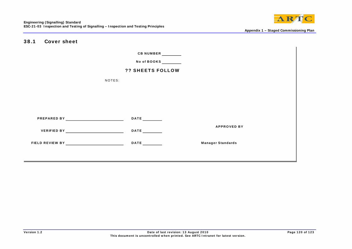
Engineering (Signalling) Standard ESC-21-03 Inspection and Testing of Signalling – Inspection and Testing Principles Appendix 1 – Staged Commissioning Plan
Version 1.2 Date of last revision: 13 August 2010 Page 120 of 123 This document is uncontrolled when printed. See ARTC Intranet for latest version.
38.1 Cover sheet
C B N U M B ER
N o o f B O O K S
?? S H E E T S FO LLO W
N O T ES:
PR EPAR ED B Y D AT E
APPR O VED B YVER IF IED B Y D AT E
F IELD R EVIEW B Y D AT E M anager S tandards
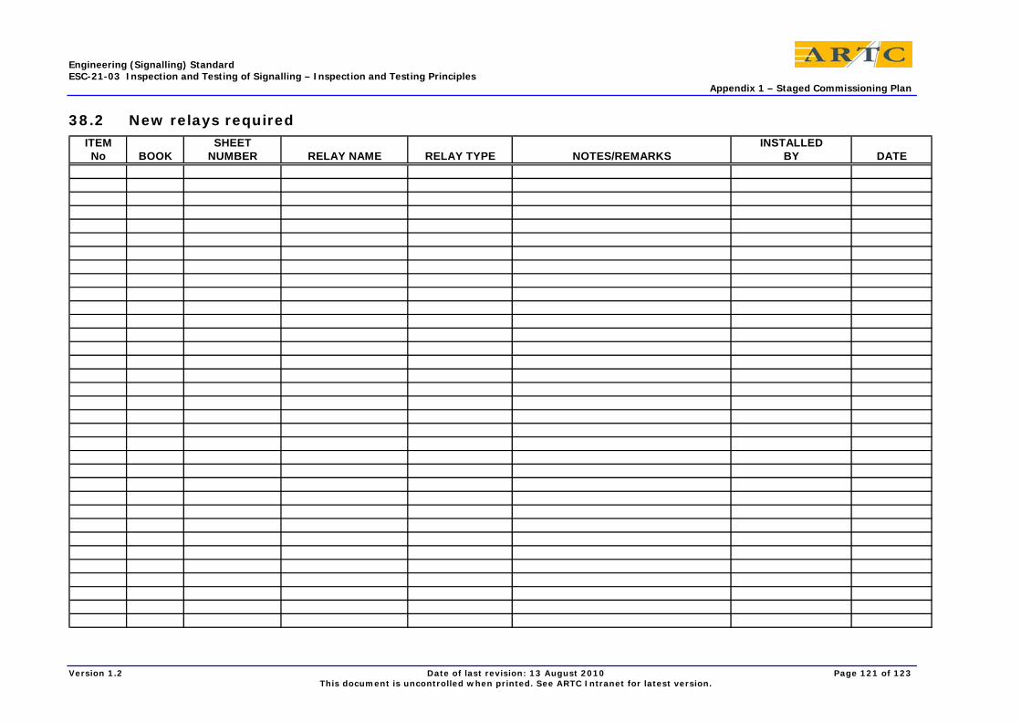
Engineering (Signalling) Standard ESC-21-03 Inspection and Testing of Signalling – Inspection and Testing Principles Appendix 1 – Staged Commissioning Plan
Version 1.2 Date of last revision: 13 August 2010 Page 121 of 123 This document is uncontrolled when printed. See ARTC Intranet for latest version.
38.2 New relays required ITEM SHEET INSTALLED
No BOOK NUMBER RELAY NAME RELAY TYPE NOTES/REMARKS BY DATE
Engineering (Signalling) Standard ESC-21-03 Inspection and Testing of Signalling – Inspection and Testing Principles Appendix 1 – Staged Commissioning Plan
Version 1.2 Date of last revision: 13 August 2010 Page 122 of 123 This document is uncontrolled when printed. See ARTC Intranet for latest version.
38.3 Stage wiring details for relays or circuits
ITEM SHEET RELAY/CIRCUIT STAGEWIRING MODIFICATION STAGE WIRING STAGE WIRINGNo BOOK NUMBER REQUIRING STAGEWIRING INFORMATION NUMBER INSTALLED BY DATE REMOVED BY DATE
Engineering (Signalling) Standard ESC-21-03 Inspection and Testing of Signalling – Inspection and Testing Principles Appendix 1 – Staged Commissioning Plan
Version 1.2 Date of last revision: 13 August 2010 Page 123 of 123 This document is uncontrolled when printed. See ARTC Intranet for latest version.
38.4 Staged commissioning changeover sheets
Item Sheet Period Relays to be Relays to be Other Circuits or Other Circuits or Changed Over &No Book Number Circuit To be done Energised De-Energised Contacts to be done Contacts to Remain Affects Notes Tested By


