Hydraulic Filtration & ContaminationControl Products
Brochure: FDHB200UK (Low Pressure Section)
Parker Hannifin
Filter Division Europe
FDHB200UK.
• Consistent quality
• Technical innovation
• Premier customer service
Parkers technical resources provide the
correct filtration technologies that conform
to your requirements. That’s why thousands
of manufacturers and equipment users around
the world rely on Parker Filtration products
and people.
Worldwide Sales
and Service
Parker Filtration’s global reputation as a reliable
supplier of superior filtration products is the result
of a focused and integrated development and
manufacturing system.
Parker Filtration consolidates quality filtration
products, manufactured by process filtration, air
and gas filtration and separation, fuel conditioning
and filtration, hydraulic and lubrication filtration,
fluid power products and fluid condition monitoring
equipment into one broad-based range that
covers many markets and most applications,
as detailed here.
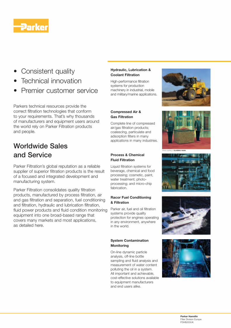
Hydraulic, Lubrication &
Coolant Filtration
High-performance filtration
systems for production
machinery in industrial, mobile
and military/marine applications.
Compressed Air &
Gas Filtration
Complete line of compressed
air/gas filtration products;
coalescing, particulate and
adsorption filters in many
applications in many industries.
Process & Chemical
Fluid Filtration
Liquid filtration systems for
beverage, chemical and food
processing; cosmetic, paint,
water treatment; photo-
processing; and micro-chip
fabrication.
Racor Fuel Conditioning
& Filtration
Parker air, fuel and oil filtration
systems provide quality
protection for engines operating
in any environment, anywhere
in the world.
System Contamination
Monitoring
On-line dynamic particle
analysis, off-line bottle
sampling and fluid analysis and
measurement of water content
polluting the oil in a system.
All important and achievable,
cost-effective solutions available
to equipment manufacturers
and end users alike.
Photo courtesy of GLASBAU HAHN.
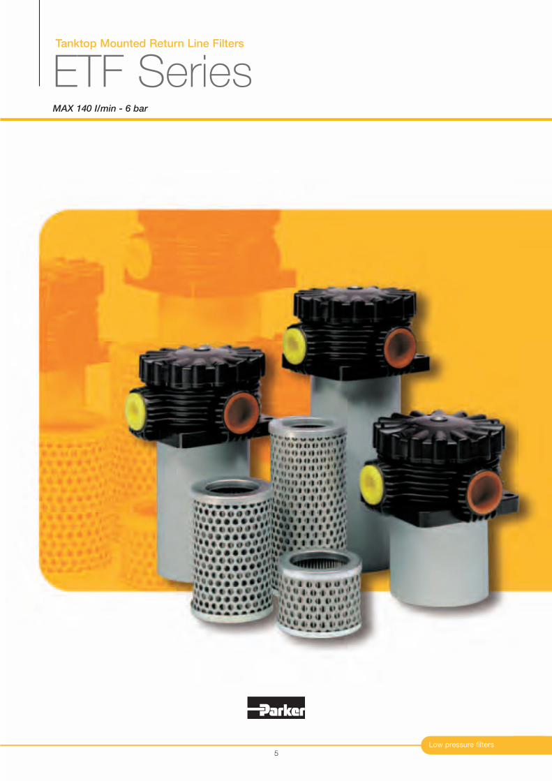
Tanktop Mounted Return Line Filters
ETF SeriesMAX 140 I/min - 6 bar
Low pressure filters
5
Tanktop Mounted Return Line Filters
ETF Series
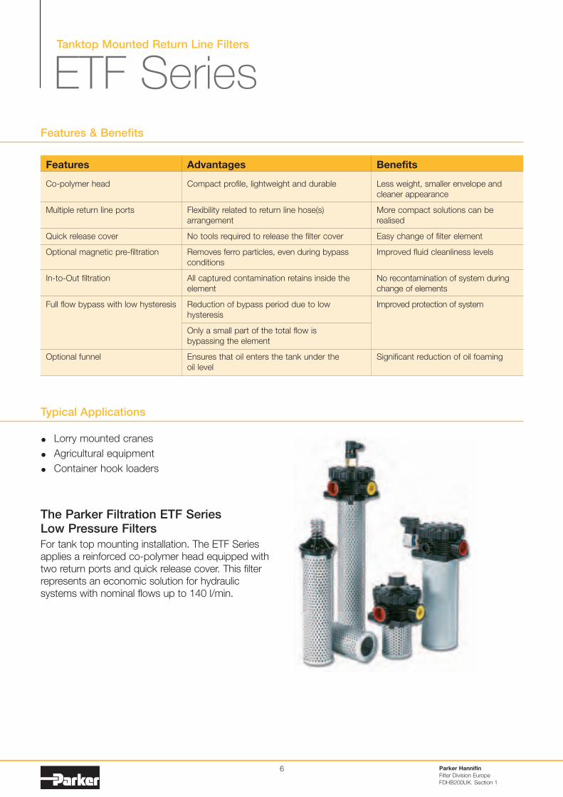
Typical Applications
Lorry mounted cranes
Agricultural equipment
Container hook loaders
The Parker Filtration ETF Series Low Pressure Filters
For tank top mounting installation. The ETF Series
applies a reinforced co-polymer head equipped with
two return ports and quick release cover. This filter
represents an economic solution for hydraulic
systems with nominal flows up to 140 l/min.
Features & Benefits
Features
Co-polymer head
Multiple return line ports
Quick release cover
Optional magnetic pre-filtration
In-to-Out filtration
Full flow bypass with low hysteresis
Optional funnel
Parker Hannifin
Filter Division Europe
FDHB200UK. Section 1
6
Advantages
Compact profile, lightweight and durable
Flexibility related to return line hose(s)
arrangement
No tools required to release the filter cover
Removes ferro particles, even during bypass
conditions
All captured contamination retains inside the
element
Reduction of bypass period due to low
hysteresis
Only a small part of the total flow is
bypassing the element
Ensures that oil enters the tank under the
oil level
Benefits
Less weight, smaller envelope and
cleaner appearance
More compact solutions can be
realised
Easy change of filter element
Improved fluid cleanliness levels
No recontamination of system during
change of elements
Improved protection of system
Significant reduction of oil foaming
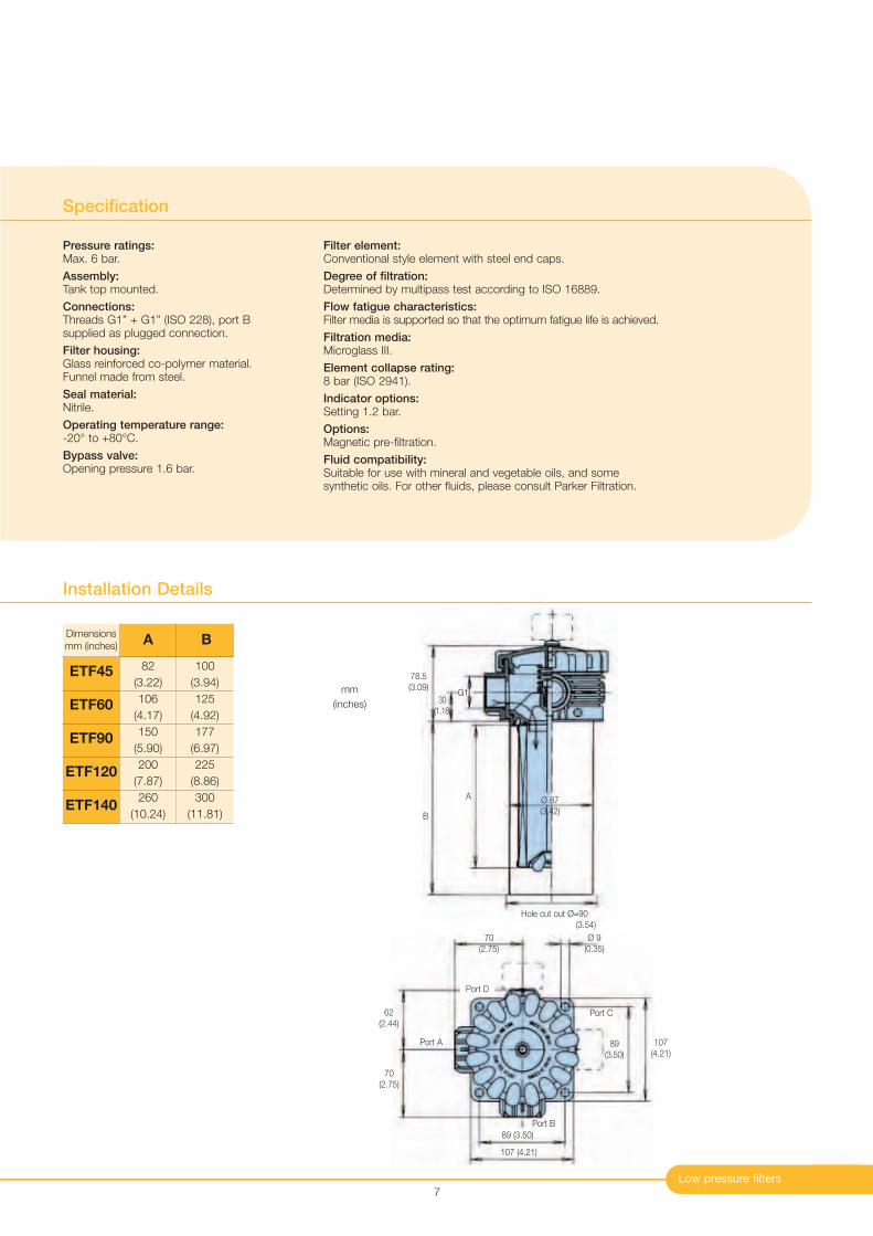
70
(2.75)
Port D
Ø 9
(0.35)
Port A
62
(2.44)
70
(2.75)
Port C
89
(3.50)
107
(4.21)
Port B
89 (3.50)
107 (4.21)
Low pressure filters
Installation Details
Dimensions
mm (inches)
82
(3.22)
106
(4.17)
150
(5.90)
200
(7.87)
260
(10.24)
100
(3.94)
125
(4.92)
177
(6.97)
225
(8.86)
300
(11.81)
ETF45
ETF60
ETF90
ETF120
ETF140
A B
Specification
Pressure ratings:Max. 6 bar.
Assembly:Tank top mounted.
Connections:Threads G1” + G1” (ISO 228), port Bsupplied as plugged connection.
Filter housing:Glass reinforced co-polymer material.Funnel made from steel.
Seal material:Nitrile.
Operating temperature range:-20° to +80°C.
Bypass valve:Opening pressure 1.6 bar.
Filter element:Conventional style element with steel end caps.
Degree of filtration:Determined by multipass test according to ISO 16889.
Flow fatigue characteristics:Filter media is supported so that the optimum fatigue life is achieved.
Filtration media:Microglass III.
Element collapse rating:8 bar (ISO 2941).
Indicator options:Setting 1.2 bar.
Options:Magnetic pre-filtration.
Fluid compatibility:Suitable for use with mineral and vegetable oils, and somesynthetic oils. For other fluids, please consult Parker Filtration.
7
78.5
(3.09)
B
G130
(1.18)
Ø 87
(3.42)
Hole cut out Ø=90
(3.54)
mm
(inches)
A
Tanktop Mounted Return Line Filters
ETF Series
8
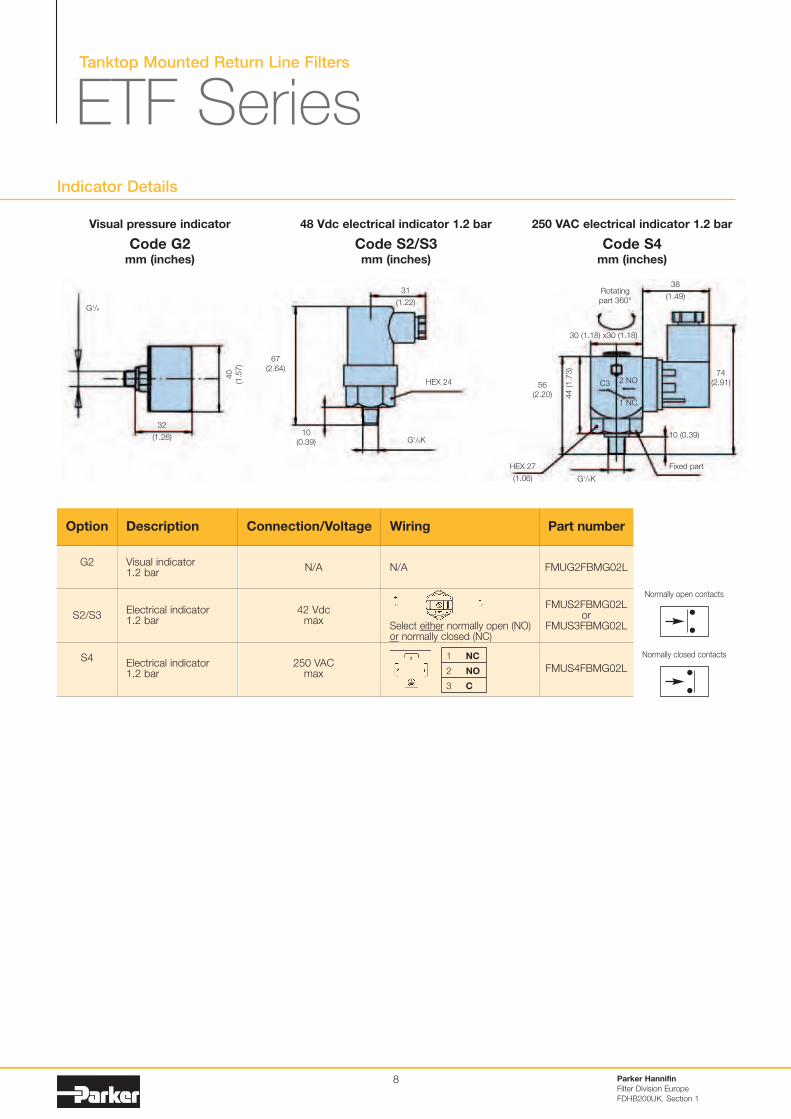
Indicator Details
Parker Hannifin
Filter Division Europe
FDHB200UK. Section 1
250 VAC electrical indicator 1.2 bar48 Vdc electrical indicator 1.2 barVisual pressure indicator
G1/8
67
(2.64)
31
(1.22)
10
(0.39)
HEX 27
(1.06)
30 (1.18) x30 (1.18)
74
(2.91)
38
(1.49)
10 (0.39)
56
(2.20) 44 (1.7
3)
N/A
Select either normally open (NO)or normally closed (NC)
FMUG2FBMG02L
FMUS2FBMG02Lor
FMUS3FBMG02L
FMUS4FBMG02L
Option Description Connection/Voltage Wiring Part number
G2
S2/S3
S4
Visual indicator1.2 bar
Electrical indicator1.2 bar
Electrical indicator1.2 bar
N/A
42 Vdcmax
250 VACmax
1 NC
2 NO
3 C
40
(1.5
7)
32
(1.26)
Rotating
part 360°
Fixed part
G1/8K
HEX 24
G1/8K
C3 2 NO
1 NC
Code G2mm (inches)
Code S2/S3mm (inches)
Code S4mm (inches)
Normally open contacts
Normally closed contacts
Low pressure filters
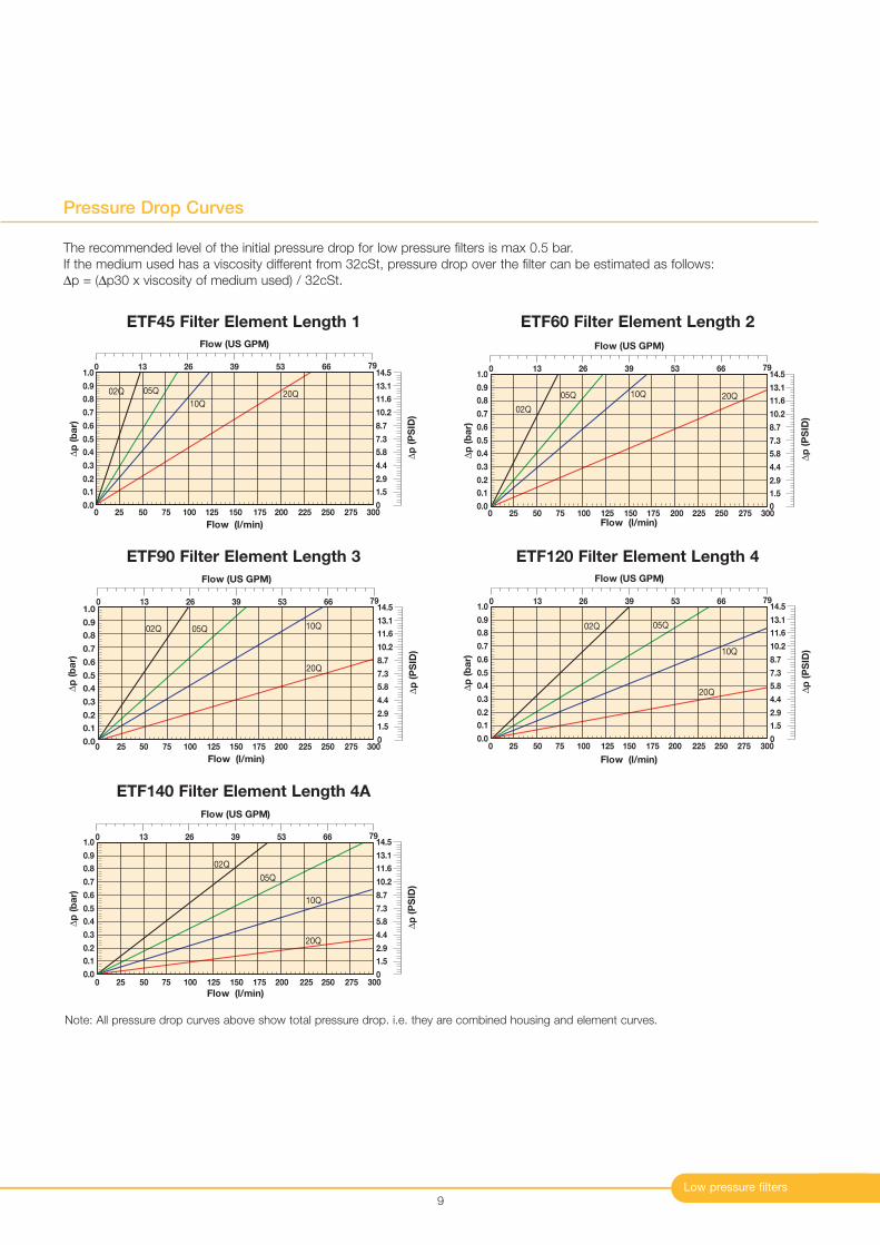
Pressure Drop Curves
9
The recommended level of the initial pressure drop for low pressure filters is max 0.5 bar.
If the medium used has a viscosity different from 32cSt, pressure drop over the filter can be estimated as follows:
∆p = (∆p30 x viscosity of medium used) / 32cSt.
0.0
0.1
0.2
0.3
0.4
0.5
0.6
0.7
0.8
0.9
1.0
0 25 50 75 100 125 150 175 200 225 250 275 300
Flow (l/min)
20Q10Q
05Q02Q
∆p
(b
ar)
Flow (US GPM)
0 13 26 39 53 66 79
∆p
(P
SID
)
0
1.5
2.9
4.4
5.8
7.3
8.7
10.2
11.6
13.1
14.5
0.0
0.1
0.2
0.3
0.4
0.5
0.6
0.7
0.8
0.9
1.0
0 25 50 75 100 125 150 175 200 225 250 275 300Flow (l/min)
∆p
(b
ar)
20Q10Q05Q
02Q
Flow (US GPM)
0 13 26 39 53 66 79
∆p
(P
SID
)
0
1.5
2.9
4.4
5.8
7.3
8.7
10.2
11.6
13.1
14.5
ETF45 Filter Element Length 1 ETF60 Filter Element Length 2
0.0
0.1
0.2
0.3
0.4
0.5
0.6
0.7
0.8
0.9
1.0
0 25 50 75 100 125 150 175 200 225 250 275 300
Flow (l/min)
∆p
(b
ar)
20Q
10Q05Q02Q
Flow (US GPM)
0 13 26 39 53 66 79
∆p
(P
SID
)
0
1.5
2.9
4.4
5.8
7.3
8.7
10.2
11.6
13.1
14.5
0.0
0.1
0.2
0.3
0.4
0.5
0.6
0.7
0.8
0.9
1.0
0 25 50 75 100 125 150 175 200 225 250 275 300
Flow (l/min)
∆p
(b
ar)
20Q
10Q
05Q02Q
Flow (US GPM)
0 13 26 39 53 66 79
∆p
(P
SID
)
0
1.5
2.9
4.4
5.8
7.3
8.7
10.2
11.6
13.1
14.5
ETF90 Filter Element Length 3 ETF120 Filter Element Length 4
0.0
0.1
0.2
0.3
0.4
0.5
0.6
0.7
0.8
0.9
1.0
0 25 50 75 100 125 150 175 200 225 250 275 300
Flow (l/min)
∆p
(b
ar)
20Q
10Q
05Q
02Q
Flow (US GPM)
0 13 26 39 53 66 79
∆p
(P
SID
)
0
1.5
2.9
4.4
5.8
7.3
8.7
10.2
11.6
13.1
14.5
ETF140 Filter Element Length 4A
Note: All pressure drop curves above show total pressure drop. i.e. they are combined housing and element curves.
Parker Hannifin
Filter Division Europe
FDHB200UK. Section 1
10
Tanktop Mounted Return Line Filters
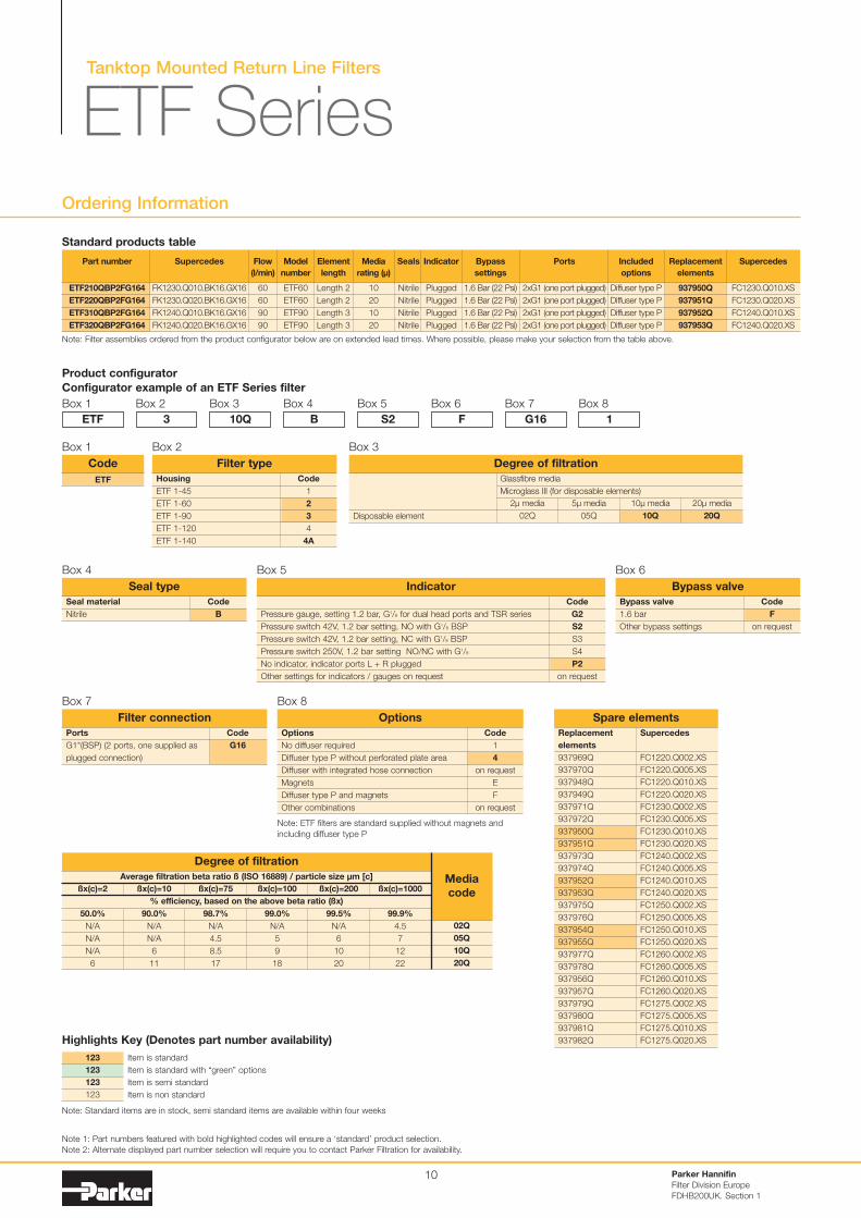
ETF SeriesOrdering Information
Product configurator
Configurator example of an ETF Series filter
Box 1
Code
1
2
3
4
4A
Housing
ETF 1-45
ETF 1-60
ETF 1-90
ETF 1-120
ETF 1-140
Filter type
Box 2
ETF
Box 2
3
Box 3
10Q
Box 4
B
Box 5
S2
Box 6
F
Box 7
G16
Box 8
1
Note 1: Part numbers featured with bold highlighted codes will ensure a ‘standard’ product selection.
Note 2: Alternate displayed part number selection will require you to contact Parker Filtration for availability.
ETF
Code
Box 1
Code
B
Seal material
Nitrile
Seal type
Box 4
Code
F
on request
Bypass valve
1.6 bar
Other bypass settings
Bypass valve
Box 6
Code
G2
S2
S3
S4
P2
on request
Pressure gauge, setting 1.2 bar, G1/8 for dual head ports and TSR series
Pressure switch 42V, 1.2 bar setting, NO with G1/8 BSP
Pressure switch 42V, 1.2 bar setting, NC with G1/8 BSP
Pressure switch 250V, 1.2 bar setting NO/NC with G1/8
No indicator, indicator ports L + R plugged
Other settings for indicators / gauges on request
Indicator
Box 5
Code
G16
Ports
G1"(BSP) (2 ports, one supplied as
plugged connection)
Filter connection
Box 7
Code
1
4
on request
E
F
on request
Options
No diffuser required
Diffuser type P without perforated plate area
Diffuser with integrated hose connection
Magnets
Diffuser type P and magnets
Other combinations
Options
Box 8
Note: ETF filters are standard supplied without magnets and
including diffuser type P
Note: Filter assemblies ordered from the product configurator below are on extended lead times. Where possible, please make your selection from the table above.
Part number
ETF210QBP2FG164
ETF220QBP2FG164
ETF310QBP2FG164
ETF320QBP2FG164
Supercedes
FK1230.Q010.BK16.GX16
FK1230.Q020.BK16.GX16
FK1240.Q010.BK16.GX16
FK1240.Q020.BK16.GX16
Flow
(l/min)
60
60
90
90
Model
number
ETF60
ETF60
ETF90
ETF90
Element
length
Length 2
Length 2
Length 3
Length 3
Media
rating (µ)
10
20
10
20
Seals
Nitrile
Nitrile
Nitrile
Nitrile
Indicator
Plugged
Plugged
Plugged
Plugged
Bypass
settings
1.6 Bar (22 Psi)
1.6 Bar (22 Psi)
1.6 Bar (22 Psi)
1.6 Bar (22 Psi)
Included
options
Diffuser type P
Diffuser type P
Diffuser type P
Diffuser type P
Replacement
elements
937950Q
937951Q
937952Q
937953Q
Supercedes
FC1230.Q010.XS
FC1230.Q020.XS
FC1240.Q010.XS
FC1240.Q020.XS
Ports
2xG1 (one port plugged)
2xG1 (one port plugged)
2xG1 (one port plugged)
2xG1 (one port plugged)
Standard products table
Average filtration beta ratio ß (ISO 16889) / particle size µm [c]
% efficiency, based on the above beta ratio (ßx)
ßx(c)=2
50.0%
N/A
N/A
N/A
6
Degree of filtration
Media
codeßx(c)=10
90.0%
N/A
N/A
6
11
ßx(c)=75
98.7%
N/A
4.5
8.5
17
ßx(c)=100
99.0%
N/A
5
9
18
ßx(c)=200
99.5%
N/A
6
10
20
ßx(c)=1000
99.9%
4.5
7
12
22
02Q
05Q
10Q
20Q
Disposable element
20µ media
20Q
10µ media
10Q
5µ media
05Q
2µ media
02Q
Glassfibre media
Microglass III (for disposable elements)
Degree of filtration
Box 3
Spare elements
Supercedes
FC1220.Q002.XS
FC1220.Q005.XS
FC1220.Q010.XS
FC1220.Q020.XS
FC1230.Q002.XS
FC1230.Q005.XS
FC1230.Q010.XS
FC1230.Q020.XS
FC1240.Q002.XS
FC1240.Q005.XS
FC1240.Q010.XS
FC1240.Q020.XS
FC1250.Q002.XS
FC1250.Q005.XS
FC1250.Q010.XS
FC1250.Q020.XS
FC1260.Q002.XS
FC1260.Q005.XS
FC1260.Q010.XS
FC1260.Q020.XS
FC1275.Q002.XS
FC1275.Q005.XS
FC1275.Q010.XS
FC1275.Q020.XS
Replacement
elements
937969Q
937970Q
937948Q
937949Q
937971Q
937972Q
937950Q
937951Q
937973Q
937974Q
937952Q
937953Q
937975Q
937976Q
937954Q
937955Q
937977Q
937978Q
937956Q
937957Q
937979Q
937980Q
937981Q
937982Q
Item is standard
Item is standard with “green” options
Item is semi standard
Item is non standard
123
123
123
123
Highlights Key (Denotes part number availability)
Note: Standard items are in stock, semi standard items are available within four weeks
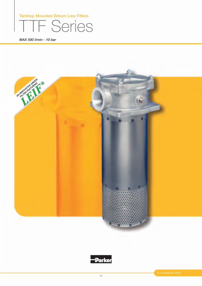
Tanktop Mounted Return Line Filters
TTF SeriesMAX 500 I/min - 10 bar
Low pressure filters
®
LEIF
LEIF
®
AN IN
NO
VATIV
E G
REEN
FIL
TER F
EATURIN
G
11
Tanktop Mounted Return Line Filters
TTF Series
Typical Applications
Waste management trucks
Mobile cranes
Power packs
Wheeled loaders
Drilling equipment
Features & Benefits
Parker Hannifin
Filter Division Europe
FDHB200UK. Section 2
12
Features
10 bar rated filter
Cast aluminium head
LEIF® elements
Magnetic pre-filtration
In-to-Out filtration
High level of customisation
Full flow bypass with low hysteresis
Standard or customised funnel
Advantages
Can be utilised for severe return line applications
Compact profile, lightweight and durable
Patented element safeguards the use of
genuine parts
Removes ferro particles, even during bypass
conditions
All captured contamination retains inside the
element
Dedicated system-matched solutions can be
easily made available
Reduction of bypass period due to low hysteresis
Only a small part of the total flow is bypassing
the element
Ensures that oil enters the tank under the oil level
Benefits
Reduced downtime due to premature
filter failures
Less weight, smaller envelop and
cleaner appearance
Guaranteed quality of filtration
Contributes to ISO 14001 certification
Improved fluid cleanliness levels
Extended element life time
No recontamination of system during
change of elements
Improved integration of filter in system
combined with lower initial system costs
Improved protection of system
Significant reduction of oil foaming
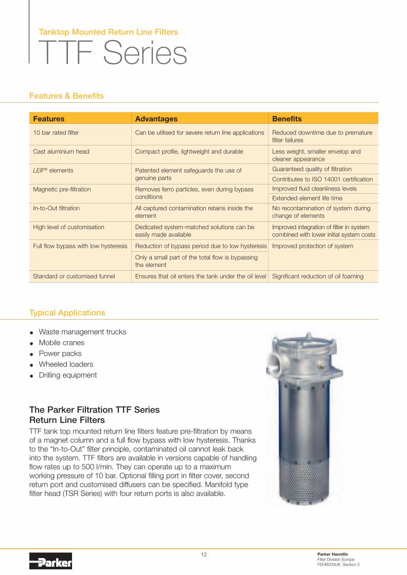
The Parker Filtration TTF SeriesReturn Line Filters
TTF tank top mounted return line filters feature pre-filtration by means
of a magnet column and a full flow bypass with low hysteresis. Thanks
to the “In-to-Out” filter principle, contaminated oil cannot leak back
into the system. TTF filters are available in versions capable of handling
flow rates up to 500 l/min. They can operate up to a maximum
working pressure of 10 bar. Optional filling port in filter cover, second
return port and customised diffusers can be specified. Manifold type
filter head (TSR Series) with four return ports is also available.
Low pressure filters
Specification
Operation pressure:Max. 10 bar.
Assembly:Tank top mounted.
Connections:Threaded BSP ports.Flanged ports on request.Manifold filter head type TSR on requestavailable for flows up to 250 l/min.
Filter housing:Aluminium head and cover.
Seal material:Nitrile, fluoroelastomer, neoprene.
Operation temperature range:-40 to +120°C.
Bypass settingOpening pressure 0.8 / 1.5 or 2 bar.Other settings on request.
Degree of filtration:Determined by multipass test according toISO 16889.
Flow fatigue characteristics:Filter media is supported so that theoptimum fatigue life is achieved.
Filtration media:Microglass III and Ecoglass III for LEIF
® elements.Also available 10µm cellulose and 40µm stainless steel mesh.
Element collapse rating:10 bar (ISO 2941)
Pressure indicator options:Setting 0.7 or 1.2 bar.Other settings on request.Visual pressure gauge.Electrical pressure switch.
Options:Diffuser with and without (type P) perforated flow area for optimumflow path in the reservoir.
Magnetic pack:Standard.
Filling port in cover: (optional)Plugged.
Filter element:LEIF
® element with reusable metal element sleeve.Optional conventional style element with steel end caps.The LEIF
® element is patented and safeguards the use of genuine parts.Note: LEIF
® element can be used with mineral and HEES type oils. For other fluids consult Parker Filtration.LEIF
® contributes to ISO 14001 quality standards.
13
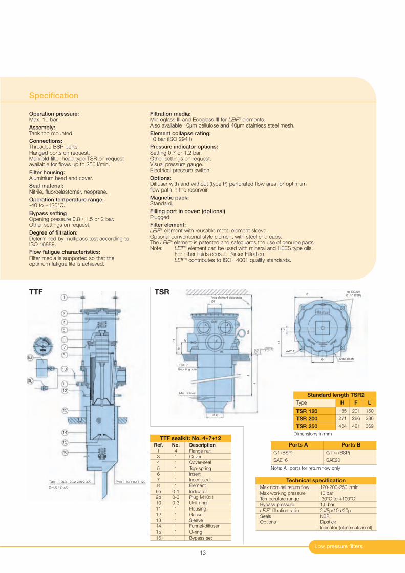
Type
Standard length TSR2
185
271
404
201
286
421
150
286
369
TSR 120
TSR 200
TSR 250
H F L
G1 (BSP)
SAE16
G11/4 (BSP)
SAE20
Ports A Ports B
Note: All ports for return flow only
Max nominal return flow 120-200-250 l/min
Max working pressure 10 bar
Temperature range -30°C to +100°C
Bypass pressure 1,5 bar
LEIF®-filtration ratio 2µ/5µ/10µ/20µ
Seals NBR
Options Dipstick
Indicator (electrical/visual)
Technical specification
Ref. No. Description
1 4 Flange nut
3 1 Cover
4 1 Cover-seal
5 1 Top-spring
6 1 Insert
7 1 Insert-seal
8 1 Element
9a 0-1 Indicator
9b 0-3 Plug M10x1
10 0-3 Unit-ring
11 1 Housing
12 1 Gasket
13 1 Sleeve
14 1 Funnel/diffuser
15 1 O-ring
16 1 Bypass set
TTF sealkit: No. 4+7+12
TTF TSR1
3
4
5
6
7
8
10
11
12
13
14
15
16
9a
9b
Type 1-125/2-170/2-230/2-300
2-400 / 2-500
Type 1-60/1-90/1-120
Free element clearance
F
81
36
Min. oil level
Mounting hole
B
137
L
H
Ø50
Ø102±1
Ø41
0.33.2
B
A A
Ø165 pitch64
81
814x ISO228
G1/8” (BSP)
4xØ11
12
Dimensions in mm
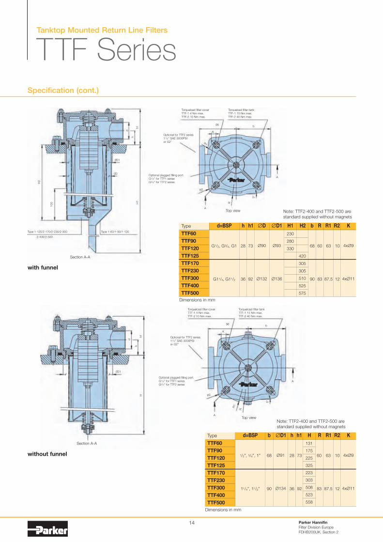
Tanktop Mounted Return Line Filters
TTF SeriesSpecification (cont.)
Type
1/2”, 3/4”, 1”
11/4”, 11/2”
68
90
28
36
73
92
60
83
10
12
4x∅9
4x∅11
63
87.5
∅91
∅134
131
175
225
325
223
303
508
523
558
TTF60
TTF90
TTF120
TTF125
TTF170
TTF230
TTF300
TTF400
TTF500
d=BSP b ∅D1 h h1 H R R1 R2 K
Parker Hannifin
Filter Division Europe
FDHB200UK. Section 2
14
Note: TTF2-400 and TTF2-500 are
standard supplied without magnets
Note: TTF2-400 and TTF2-500 are
standard supplied without magnets
Type
G1/2, G3/4, G1
G11/4, G11/2
28
36
73
92
68
90
60
83
10
12
4x∅9
4x∅11
63
87.5
∅90
∅132
∅93
∅136
230
280
330
420
305
305
510
525
575
TTF60
TTF90
TTF120
TTF125
TTF170
TTF230
TTF300
TTF400
TTF500
d=BSP h h1 ∅D ∅D1 H1 H2 b R R1 R2 KType 1-125/2-170/2-230/2-300 Type 1-60/1-90/1-120
2-400/2-500
Section A-A
Section A-A
Top view
H2
100 H1
h1
h
d
ØD1
96b
A
A
R
K
R1
ØD
Hh1
h
d
ØD1
Torqueload filter-cover
TTF-1 4 Nm max.
TTF-2 10 Nm max.
Optional for TTF2 series
11/2” SAE-3000PSI
or G2”
Optional plugged filling port:
G1/2” for TTF1 series
G3/4” for TTF2 series
Torqueload filter-tank
TTF-1 15 Nm max.
TTF-2 40 Nm max.
R2
5*
Top view
96b
A
A
R
K
R1
Torqueload filter-cover
TTF-1 4 Nm max.
TTF-2 10 Nm max.
Optional for TTF2 series
11/2” SAE-3000PSI
or G2”
Optional plugged filling port:
G1/2” for TTF1 series
G3/4” for TTF2 series
Torqueload filter-tank
TTF-1 15 Nm max.
TTF-2 40 Nm max.
R2
5*
with funnel
without funnel
Dimensions in mm
Dimensions in mm
0
0.2
0.4
0.8
1
0.6
1.6
1.4
1.2
0 60 120 180 210
02Q
05Q
20Q
Flow (l/min)
∆p
(b
ar)
10Q
∆p
(P
SID
)
0
2.9
5.8
8.7
11.6
14.5
17.4
23.2
20.3
Flow (US GPM)
560 16 4731
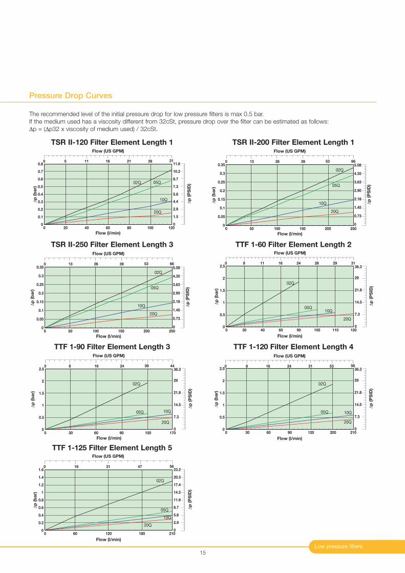
TTF 1-125 Filter Element Length 5
Low pressure filters
Pressure Drop Curves
15
0
0.1
0.2
0.4
0.5
0.6
0.7
0.3
0.8
0 20 40 60 80 100 120
02Q 05Q
10Q
20Q
Flow (l/min)
∆p
(b
ar)
Flow (US GPM)
21160 5 11 26 31
∆p
(P
SID
)
0
1.5
2.9
4.4
5.8
7.3
8.7
10.2
11.6
TSR II-120 Filter Element Length 1
0
0.05
0.1
0.2
0.25
0.3
0.15
0.35
0 50 100 150 200 250
02Q
05Q
10Q
20Q
Flow (l/min)
∆p
(b
ar)
Flow (US GPM)
66530 13 3926
∆p
(P
SID
)
0
0.73
2.90
3.63
5.08
4.35
1.45
2.18
TSR II-250 Filter Element Length 3
The recommended level of the initial pressure drop for low pressure filters is max 0.5 bar.
If the medium used has a viscosity different from 32cSt, pressure drop over the filter can be estimated as follows:
∆p = (∆p32 x viscosity of medium used) / 32cSt.
0
0.05
0.1
0.2
0.25
0.3
0.15
0.35
0 50 100 150 200 250
02Q
05Q
10Q
20Q
Flow (l/min)
∆p
(b
ar)
Flow (US GPM)
66530 13 3926
∆p
(P
SID
)
0
0.73
2.90
3.63
5.08
4.35
1.45
2.18
TSR II-200 Filter Element Length 1
0
0.5
1
2
1.5
2.5
0 30 40 60 90 100 110 120
02Q
05Q10Q
20Q
Flow (l/min)
∆p
(b
ar)
∆p
(P
SID
)
0
7.3
14.5
21.8
29
36.3
Flow (US GPM)
0 8 11 16 24 26 29 31
TTF 1-60 Filter Element Length 2
0
0.5
2.5
1.5
2
1
0 30 60 90 150 170
02Q
05Q 10Q
20Q
Flow (l/min)
∆p
(b
ar)
∆p
(P
SID
)
0
7.3
14.5
21.8
29
36.3
Flow (US GPM)
44390 8 2416
0
0.5
1
2
1.5
2.5
0 30 60 90 120 200 210
02Q
05Q 10Q
20Q
Flow (l/min)
∆p
(b
ar)
∆p
(P
SID
)
0
7.3
14.5
21.8
29
36.3
Flow (US GPM)
31240 8 16 53 56
TTF 1-90 Filter Element Length 3 TTF 1-120 Filter Element Length 4
Tanktop Mounted Return Line Filters
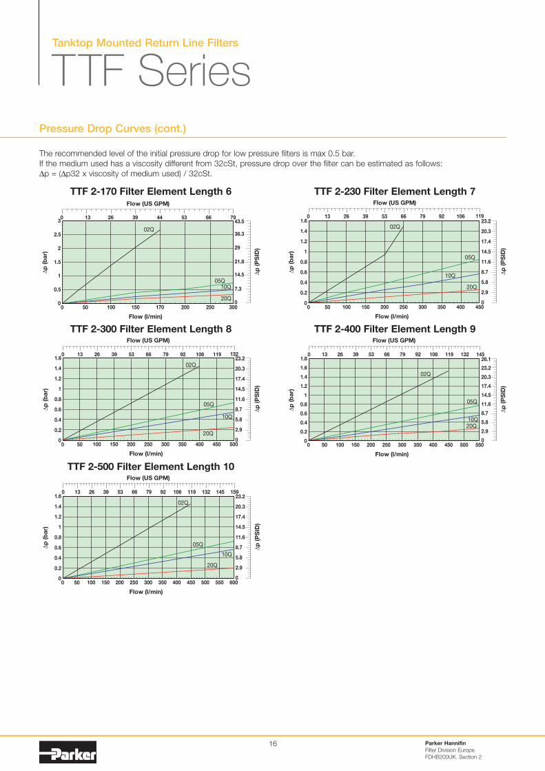
TTF SeriesPressure Drop Curves (cont.)
Parker Hannifin
Filter Division Europe
FDHB200UK. Section 2
16
00 50
1.2
1.4
0.8
0.6
0.4
0.2
1
1.6
100 150 200 250 300 350 400 450
Flow (l/min)
∆p
(b
ar)
02Q
05Q
10Q
20Q
∆p
(P
SID
)
0
2.9
5.8
8.7
11.6
14.5
17.4
23.2
20.3
Flow (US GPM)
530 13 26 39 66 79 92 106 119
00 50
1.2
0.8
0.6
0.4
0.2
1
1.4
1.6
100 150 200 250 300 350 400 450 500
Flow (l/min)
∆p
(b
ar)
02Q
05Q
10Q
20Q
∆p
(P
SID
)
0
2.9
5.8
8.7
11.6
14.5
17.4
23.2
20.3
Flow (US GPM)
53 66 92 106 119 1323926130 79
TTF 2-230 Filter Element Length 7
TTF 2-300 Filter Element Length 8
0
1.2
0.8
0.6
0.4
0.2
1
1.4
1.6
1.8
0 50 100 150 200 250 300 350 400 450 500 550
Flow (l/min)
∆p
(b
ar)
02Q
05Q
10Q
20Q
∆p
(P
SID
)
0
2.9
5.8
8.7
11.6
14.5
17.4
26.1
23.2
20.3
Flow (US GPM)
26130 6653 92 106 119 14513239 79
00 50
1.2
0.8
0.6
0.4
0.2
1
1.4
1.6
100 150 200 250 300 350 400 500450 550 600
Flow (l/min)
∆p
(b
ar)
02Q
05Q
10Q
20Q
∆p
(P
SID
)
0
2.9
5.8
8.7
11.6
14.5
17.4
23.2
20.3
Flow (US GPM)
26130 6653 92 106 119 15914513239 79
TTF 2-400 Filter Element Length 9
TTF 2-500 Filter Element Length 10
00 50
2
3
1.5
1
0.5
2.5
100 150 170 200 250 300
Flow (l/min)
∆p
(b
ar)
02Q
05Q10Q
20Q
∆p
(P
SID
)
0
7.3
14.5
21.8
29
36.3
43.5
Flow (US GPM)
0 13 26 39 44 53 66 79
TTF 2-170 Filter Element Length 6
The recommended level of the initial pressure drop for low pressure filters is max 0.5 bar.
If the medium used has a viscosity different from 32cSt, pressure drop over the filter can be estimated as follows:
∆p = (∆p32 x viscosity of medium used) / 32cSt.
Low pressure filters
17
00 15
0.08
0.12
0.06
0.04
0.02
0.1
30 45 60 75 90
Flow (l/min)
∆p
(b
ar)
10C
040W∆
p (
PS
ID)
0
0.29
0.58
0.87
1.16
1.45
1.74
Flow (US GPM)
0 4 8 12 16 20 24
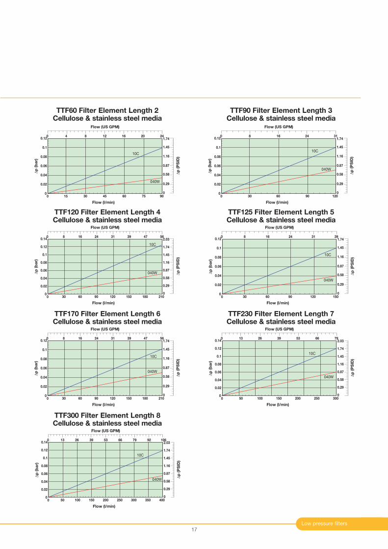
TTF60 Filter Element Length 2Cellulose & stainless steel media
00
0.08
0.12
0.06
0.04
0.02
0.1
30 60 90 120
Flow (l/min)
∆p
(b
ar)
10C
040W
∆p
(P
SID
)
0
0.29
0.58
0.87
1.16
1.45
1.74
Flow (US GPM)
0 8 16 24 31
TTF90 Filter Element Length 3Cellulose & stainless steel media
00
0.08
0.14
0.12
0.06
0.04
0.02
0.1
30 60 90 210180150120
Flow (l/min)
∆p
(b
ar)
10C
040W
∆p
(P
SID
)
0
0.29
0.58
0.87
1.16
1.45
2.03
1.74
Flow (US GPM)
0 8 16 24 56473931
TTF120 Filter Element Length 4Cellulose & stainless steel media
00
0.08
0.12
0.06
0.04
0.02
0.1
30 60 90 150120
Flow (l/min)
∆p
(b
ar)
10C
040W
∆p
(P
SID
)
0
0.29
0.58
0.87
1.16
1.45
1.74
Flow (US GPM)
0 8 16 24 3931
TTF125 Filter Element Length 5Cellulose & stainless steel media
00
0.08
0.12
0.06
0.04
0.02
0.1
30 60 90 210180150120
Flow (l/min)
∆p
(b
ar)
10C
040W
∆p
(P
SID
)
0
0.29
0.58
0.87
1.16
1.45
1.74
Flow (US GPM)
0 8 16 24 56473931
TTF170 Filter Element Length 6Cellulose & stainless steel media
00
0.08
0.14
0.12
0.06
0.04
0.02
0.1
50 100 150 300250200
Flow (l/min)
∆p
(b
ar)
10C
040W ∆p
(P
SID
)
0
0.29
0.58
0.87
1.16
1.45
2.03
1.74
Flow (US GPM)
0 13 26 39 796653
TTF230 Filter Element Length 7Cellulose & stainless steel media
00
0.08
0.14
0.12
0.06
0.04
0.02
0.1
50 100 150 400300 350250200
Flow (l/min)
∆p
(b
ar)
10C
040W
∆p
(P
SID
)
0
0.29
0.58
0.87
1.16
1.45
2.03
1.74
Flow (US GPM)
0 13 26 39 10679 926653
TTF300 Filter Element Length 8Cellulose & stainless steel media
Tanktop Mounted Return Line Filters
TTF Series
Parker Hannifin
Filter Division Europe
FDHB200UK. Section 1
18
Ordering Information
G1/8 (BSP)
Ø289
Protective cover
M10x1
24 A/F55
74
9
58
75
Elec.rating
Thread connection
Elec.connection
Protection
Code
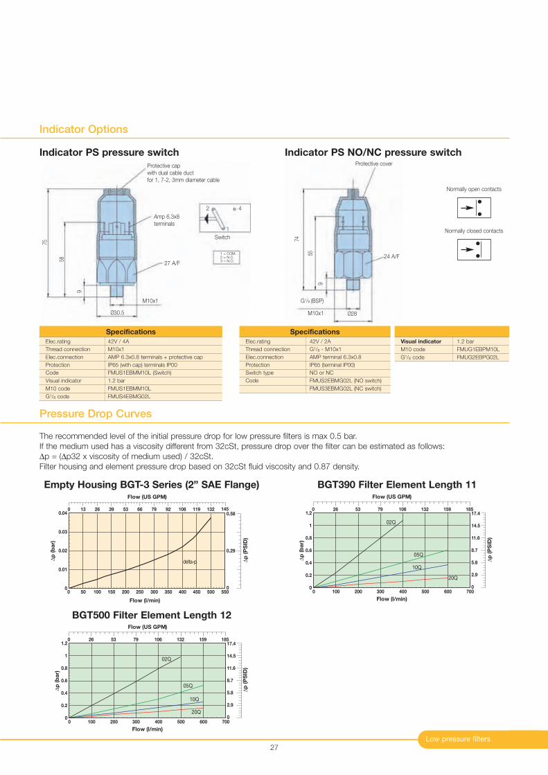
42V / 4A
M10x1
AMP 6.3x0.8 terminals + protective cap
IP65 (with cap) terminals IP00
FMUS1EBMM10L (Switch)
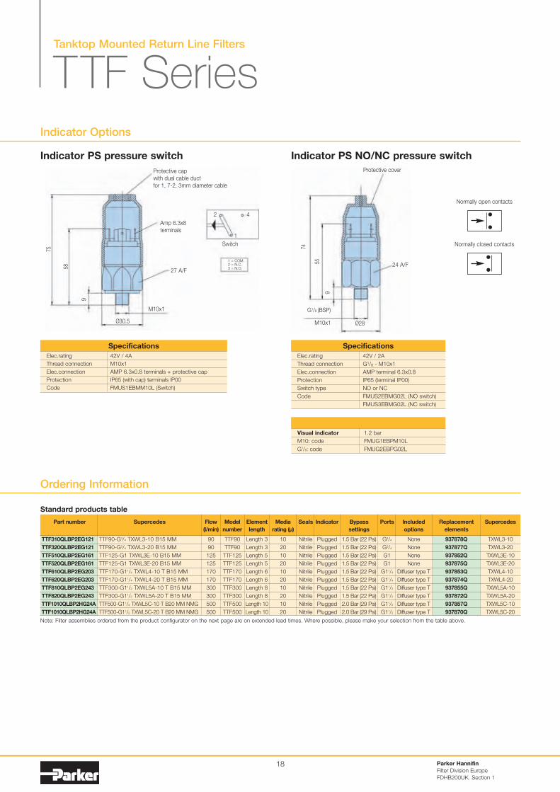
Specifications
Elec.rating
Thread connection
Elec.connection
Protection
Switch type
Code
42V / 2A
G1/8 - M10x1
AMP terminal 6.3x0.8
IP65 (terminal IP00)
NO or NC
FMUS2EBMG02L (NO switch)
FMUS3EBMG02L (NC switch)
Specifications
Indicator PS NO/NC pressure switch
Indicator Options
Protective cap
with dual cable duct
for 1, 7-2, 3mm diameter cable
27 A/F
Ø30.5
M10x1
Amp 6.3x8
terminals
2 4
1
Switch
1 = COM.2 = N.C.3 = N.O.
Indicator PS pressure switch
Note: Filter assemblies ordered from the product configurator on the next page are on extended lead times. Where possible, please make your selection from the table above.
Part number
TTF310QLBP2EG121
TTF320QLBP2EG121
TTF510QLBP2EG161
TTF520QLBP2EG161
TTF610QLBP2EG203
TTF620QLBP2EG203
TTF810QLBP2EG243
TTF820QLBP2EG243
TTF1010QLBP2HG24A
TTF1010QLBP2HG24A
Supercedes
TTF90-G3/4 TXWL3-10 B15 MM
TTF90-G3/4 TXWL3-20 B15 MM
TTF125-G1 TXWL3E-10 B15 MM
TTF125-G1 TXWL3E-20 B15 MM
TTF170-G11/4 TXWL4-10 T B15 MM
TTF170-G11/4 TXWL4-20 T B15 MM
TTF300-G11/2 TXWL5A-10 T B15 MM
TTF300-G11/2 TXWL5A-20 T B15 MM
TTF500-G11/2 TXWL5C-10 T B20 MM NMG
TTF500-G11/2 TXWL5C-20 T B20 MM NMG
Flow
(l/min)
90
90
125
125
170
170
300
300
500
500
Model
number
TTF90
TTF90
TTF125
TTF125
TTF170
TTF170
TTF300
TTF300
TTF500
TTF500
Element
length
Length 3
Length 3
Length 5
Length 5
Length 6
Length 6
Length 8
Length 8
Length 10
Length 10
Media
rating (µ)
10
20
10
20
10
20
10
20
10
20
Seals
Nitrile
Nitrile
Nitrile
Nitrile
Nitrile
Nitrile
Nitrile
Nitrile
Nitrile
Nitrile
Indicator
Plugged
Plugged
Plugged
Plugged
Plugged
Plugged
Plugged
Plugged
Plugged
Plugged
Bypass
settings
1.5 Bar (22 Psi)
1.5 Bar (22 Psi)
1.5 Bar (22 Psi)
1.5 Bar (22 Psi)
1.5 Bar (22 Psi)
1.5 Bar (22 Psi)
1.5 Bar (22 Psi)
1.5 Bar (22 Psi)
2.0 Bar (29 Psi)
2.0 Bar (29 Psi)
Included
options
None
None
None
None
Diffuser type T
Diffuser type T
Diffuser type T
Diffuser type T
Diffuser type T
Diffuser type T
Replacement
elements
937878Q
937877Q
937852Q
937875Q
937853Q
937874Q
937855Q
937872Q
937857Q
937870Q
Supercedes
TXWL3-10
TXWL3-20
TXWL3E-10
TXWL3E-20
TXWL4-10
TXWL4-20
TXWL5A-10
TXWL5A-20
TXWL5C-10
TXWL5C-20
Ports
G3/4
G3/4
G1
G1
G11/4
G11/4
G11/2
G11/2
G11/2
G11/2
Normally open contacts
Normally closed contacts
Standard products table
Visual indicator 1.2 bar
M10: code FMUG1EBPM10L
G1/8: code FMUG2EBPG02L
Low Pressure Filters
19
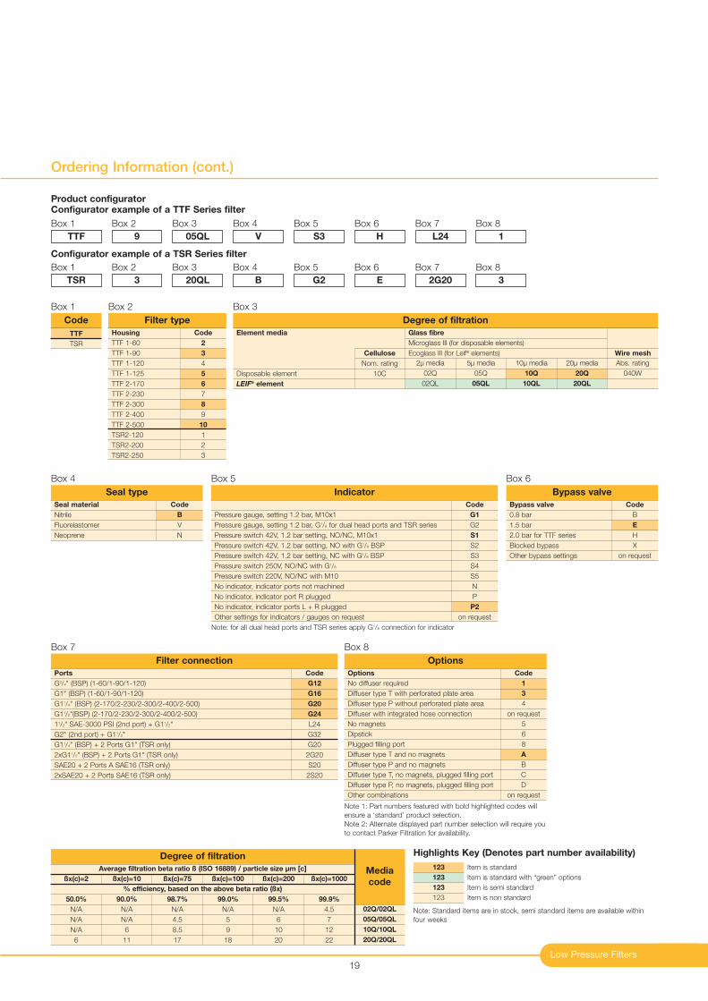
Ordering Information (cont.)
Code
2
3
4
5
6
7
8
9
10
1
2
3
Housing
TTF 1-60
TTF 1-90
TTF 1-120
TTF 1-125
TTF 2-170
TTF 2-230
TTF 2-300
TTF 2-400
TTF 2-500
TSR2-120
TSR2-200
TSR2-250
Filter type
Box 2
TTF
TSR
Code
Box 1
Code
B
V
N
Seal material
Nitrile
Fluorelastomer
Neoprene
Seal type
Box 4
Code
B
E
H
X
on request
Bypass valve
0.8 bar
1.5 bar
2.0 bar for TTF series
Blocked bypass
Other bypass settings
Bypass valve
Box 6
Code
G1
G2
S1
S2
S3
S4
S5
N
P
P2
on request
Pressure gauge, setting 1.2 bar, M10x1
Pressure gauge, setting 1.2 bar, G1/8 for dual head ports and TSR series
Pressure switch 42V, 1.2 bar setting, NO/NC, M10x1
Pressure switch 42V, 1.2 bar setting, NO with G1/8 BSP
Pressure switch 42V, 1.2 bar setting, NC with G1/8 BSP
Pressure switch 250V, NO/NC with G1/8
Pressure switch 220V, NO/NC with M10
No indicator, indicator ports not machined
No indicator, indicator port R plugged
No indicator, indicator ports L + R plugged
Other settings for indicators / gauges on request
Indicator
Box 5
Code
G12
G16
G20
G24
L24
G32
G20
2G20
S20
2S20
Ports
G3/4" (BSP) (1-60/1-90/1-120)
G1" (BSP) (1-60/1-90/1-120)
G11/4" (BSP) (2-170/2-230/2-300/2-400/2-500)
G11/2"(BSP) (2-170/2-230/2-300/2-400/2-500)
11/2" SAE-3000 PSI (2nd port) + G11/2"
G2" (2nd port) + G11/2"
G11/4" (BSP) + 2 Ports G1" (TSR only)
2xG11/2" (BSP) + 2 Ports G1" (TSR only)
SAE20 + 2 Ports A SAE16 (TSR only)
2xSAE20 + 2 Ports SAE16 (TSR only)
Filter connection
Box 7
Code
1
3
4
on request
5
6
8
A
B
C
D
on request
Options
No diffuser required
Diffuser type T with perforated plate area
Diffuser type P without perforated plate area
Diffuser with integrated hose connection
No magnets
Dipstick
Plugged filling port
Diffuser type T and no magnets
Diffuser type P and no magnets
Diffuser type T, no magnets, plugged filling port
Diffuser type P, no magnets, plugged filling port
Other combinations
Options
Box 8
Note 1: Part numbers featured with bold highlighted codes will
ensure a ‘standard’ product selection.
Note 2: Alternate displayed part number selection will require you
to contact Parker Filtration for availability.
Product configuratorConfigurator example of a TTF Series filter
Box 1
TTF
Box 2
9
Box 3
05QL
Box 4
V
Box 5
S3
Box 6
H
Box 7
L24
Box 8
1
Configurator example of a TSR Series filter
Box 1
TSR
Box 2
3
Box 3
20QL
Box 4
B
Box 5
G2
Box 6
E
Box 7
2G20
Box 8
3
Note: for all dual head ports and TSR series apply G1/8 connection for indicator
Average filtration beta ratio ß (ISO 16889) / particle size µm [c]
% efficiency, based on the above beta ratio (ßx)
ßx(c)=2
50.0%
N/A
N/A
N/A
6
Degree of filtration
Media
codeßx(c)=10
90.0%
N/A
N/A
6
11
ßx(c)=75
98.7%
N/A
4.5
8.5
17
ßx(c)=100
99.0%
N/A
5
9
18
ßx(c)=200
99.5%
N/A
6
10
20
ßx(c)=1000
99.9%
4.5
7
12
22
02Q/02QL
05Q/05QL
10Q/10QL
20Q/20QL
Element media
Disposable element
LEIF® element
Cellulose
Nom. rating
10C
20µ media
20Q
20QL
Abs. rating
040W
10µ media
10Q
10QL
5µ media
05Q
05QL
2µ media
02Q
02QL
Glass fibre
Microglass III (for disposable elements)
Ecoglass III (for Leif® elements) Wire mesh
Degree of filtration
Box 3
Item is standard
Item is standard with “green” options
Item is semi standard
Item is non standard
123
123
123
123
Highlights Key (Denotes part number availability)
Note: Standard items are in stock, semi standard items are available within
four weeks
Parker Hannifin
Filter Division Europe
FDHB200UK. Section 2
20
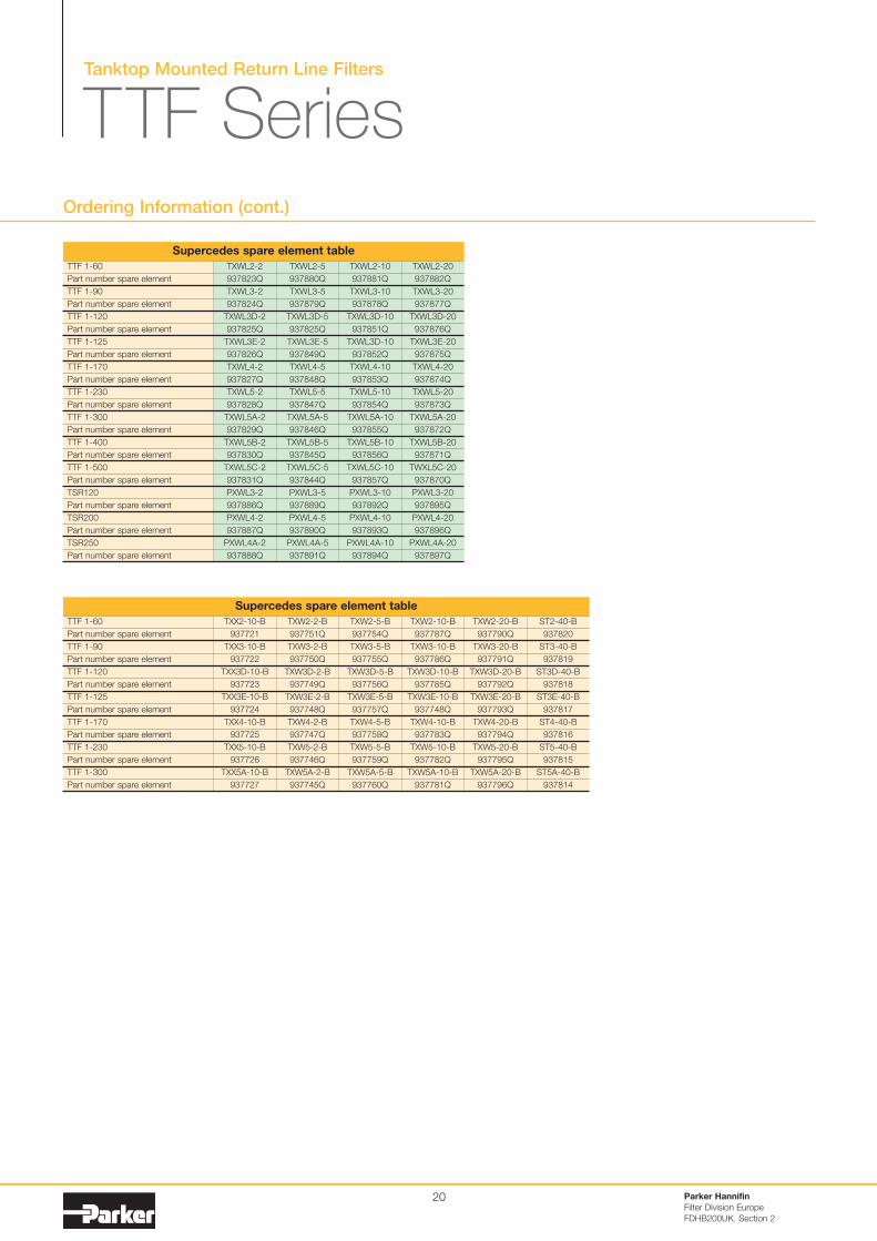
Tanktop Mounted Return Line Filters
TTF Series
TTF 1-60
Part number spare element
TTF 1-90
Part number spare element
TTF 1-120
Part number spare element
TTF 1-125
Part number spare element
TTF 1-170
Part number spare element
TTF 1-230
Part number spare element
TTF 1-300
Part number spare element
TXX2-10-B
937721
TXX3-10-B
937722
TXX3D-10-B
937723
TXX3E-10-B
937724
TXX4-10-B
937725
TXX5-10-B
937726
TXX5A-10-B
937727
TXW2-20-B
937790Q
TXW3-20-B
937791Q
TXW3D-20-B
937792Q
TXW3E-20-B
937793Q
TXW4-20-B
937794Q
TXW5-20-B
937795Q
TXW5A-20-B
937796Q
ST2-40-B
937820
ST3-40-B
937819
ST3D-40-B
937818
ST3E-40-B
937817
ST4-40-B
937816
ST5-40-B
937815
ST5A-40-B
937814
TXW2-10-B
937787Q
TXW3-10-B
937786Q
TXW3D-10-B
937785Q
TXW3E-10-B
937748Q
TXW4-10-B
937783Q
TXW5-10-B
937782Q
TXW5A-10-B
937781Q
TXW2-5-B
937754Q
TXW3-5-B
937755Q
TXW3D-5-B
937756Q
TXW3E-5-B
937757Q
TXW4-5-B
937758Q
TXW5-5-B
937759Q
TXW5A-5-B
937760Q
TXW2-2-B
937751Q
TXW3-2-B
937750Q
TXW3D-2-B
937749Q
TXW3E-2-B
937748Q
TXW4-2-B
937747Q
TXW5-2-B
937746Q
TXW5A-2-B
937745Q
Supercedes spare element table
TTF 1-60
Part number spare element
TTF 1-90
Part number spare element
TTF 1-120
Part number spare element
TTF 1-125
Part number spare element
TTF 1-170
Part number spare element
TTF 1-230
Part number spare element
TTF 1-300
Part number spare element
TTF 1-400
Part number spare element
TTF 1-500
Part number spare element
TSR120
Part number spare element
TSR200
Part number spare element
TSR250
Part number spare element
TXWL2-20
937882Q
TXWL3-20
937877Q
TXWL3D-20
937876Q
TXWL3E-20
937875Q
TXWL4-20
937874Q
TXWL5-20
937873Q
TXWL5A-20
937872Q
TXWL5B-20
937871Q
TWXL5C-20
937870Q
PXWL3-20
937895Q
PXWL4-20
937896Q
PXWL4A-20
937897Q
TXWL2-10
937881Q
TXWL3-10
937878Q
TXWL3D-10
937851Q
TXWL3D-10
937852Q
TXWL4-10
937853Q
TXWL5-10
937854Q
TXWL5A-10
937855Q
TXWL5B-10
937856Q
TXWL5C-10
937857Q
PXWL3-10
937892Q
PXWL4-10
937893Q
PXWL4A-10
937894Q
TXWL2-5
937880Q
TXWL3-5
937879Q
TXWL3D-5
937825Q
TXWL3E-5
937849Q
TXWL4-5
937848Q
TXWL5-5
937847Q
TXWL5A-5
937846Q
TXWL5B-5
937845Q
TXWL5C-5
937844Q
PXWL3-5
937889Q
PXWL4-5
937890Q
PXWL4A-5
937891Q
TXWL2-2
937823Q
TXWL3-2
937824Q
TXWL3D-2
937825Q
TXWL3E-2
937826Q
TXWL4-2
937827Q
TXWL5-2
937828Q
TXWL5A-2
937829Q
TXWL5B-2
937830Q
TXWL5C-2
937831Q
PXWL3-2
937886Q
PXWL4-2
937887Q
PXWL4A-2
937888Q
Supercedes spare element table
Ordering Information (cont.)
Tanktop Mounted Return Line Filters
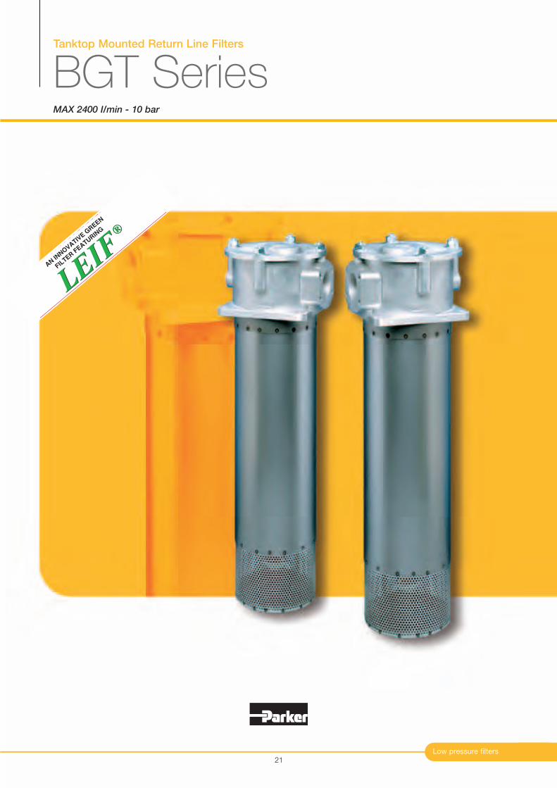
BGT SeriesMAX 2400 I/min - 10 bar
Low pressure filters
®
LEIF
LEIF
®
AN IN
NO
VATIV
E G
REEN
FIL
TER F
EATURIN
G
21
Tanktop Mounted Return Line Filters
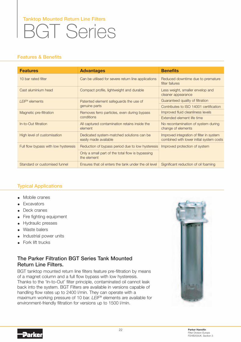
BGT Series
22
Typical Applications
Mobile cranes
Excavators
Deck cranes
Fire fighting equipment
Hydraulic presses
Waste balers
Industrial power units
Fork lift trucks
Features & Benefits
The Parker Filtration BGT Series Tank Mounted Return Line Filters.
BGT tanktop mounted return line filters feature pre-filtration by means
of a magnet column and a full flow bypass with low hysteresis.
Thanks to the ‘In-to-Out’ filter principle, contaminated oil cannot leak
back into the system. BGT Filters are available in versions capable of
handling flow rates up to 2400 l/min. They can operate with a
maximum working pressure of 10 bar. LEIF® elements are available for
environment-friendly filtration for versions up to 1500 l/min.
Parker Hannifin
Filter Division Europe
FDHB200UK. Section 3
Features
10 bar rated filter
Cast aluminium head
LEIF® elements
Magnetic pre-filtration
In-to-Out filtration
High level of customisation
Full flow bypass with low hysteresis
Standard or customised funnel
Advantages
Can be utilised for severe return line applications
Compact profile, lightweight and durable
Patented element safeguards the use of
genuine parts
Removes ferro particles, even during bypass
conditions
All captured contamination retains inside the
element
Dedicated system-matched solutions can be
easily made available
Reduction of bypass period due to low hysteresis
Only a small part of the total flow is bypassing
the element
Ensures that oil enters the tank under the oil level
Benefits
Reduced downtime due to premature
filter failures
Less weight, smaller envelop and
cleaner appearance
Guaranteed quality of filtration
Contributes to ISO 14001 certification
Improved fluid cleanliness levels
Extended element life time
No recontamination of system during
change of elements
Improved integration of filter in system
combined with lower initial system costs
Improved protection of system
Significant reduction of oil foaming
Low pressure filters
Specification
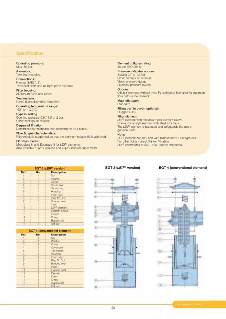
Operating pressure:Max. 10 bar.
Assembly:Tank top mounted.
Connections:Flanges SAE2”, 3”.Threaded ports and multiple ports available.
Filter housing:Aluminium head and cover.
Seal material:Nitrile, fluoroelastomer, neoprene.
Operating temperature range:-40° to +120°C.
Bypass settingOpening pressure 0.8 / 1.5 or 2 bar.Other settings on request.
Degree of filtration:Determined by multipass test according to ISO 16889.
Flow fatigue characteristics:Filter media is supported so that the optimum fatigue life is achieved.
Filtration media:Microglass III and Ecoglass III for LEIF
® elements.Also available 10µm Cellulose and 40µm stainless steel mesh.
Element collapse rating:10 bar (ISO 2941).
Pressure indicator options:Setting 0.7 or 1.2 bar.Other settings on request.Visual pressure gauge.Electrical pressure switch.
Options:Diffuser with and without (type P) perforated flow area for optimum flow path in the reservoir.
Magnetic pack:Standard.
Filling port in cover (optional):Plugged G11/2.
Filter element:LEIF
® element with reusable metal element sleeve.Conventional style element with steel end caps.The LEIF
® element is patented and safeguards the use of genuine parts.
Note:LEIF
® element can be used with mineral and HEES type oils. For other fluids consult Parker Filtration.LEIF
® contributes to ISO 14001 quality standards.
23
1
2
3
4
5
6
7
8
9
10
11
12
13
14
15
16
Ref. No. Description1 1 Nut
2 1 Washer
3 1 Cover
4 1 Cover-seal
5 1 Top-spring
6 1 Housing
7 1 Insert-seal
8 1 Plug M10x1
9 1 Bonded seal
10 1 Insert
11 1 LEIF® element
12 1 Element sleeve
13 1 Gasket
14 1 O-ring
15 1 Bypass set
16 1 Diffuser
BGT-3 (LEIF® version)
Ref. No. Description
1 1 Nut
2 1 Washer
3 1 Cover
4 1 Cover-seal
5 1 Top-spring
6 1 Housing
7 1 Insert-seal
8 1 Plug M10x1
9 1 Bonded seal
10 1 Insert
11 1 Element seal
12 1 Element
13 1 O-ring
14 1 O-ring
15 1 Bypass set
16 1 Diffuser
BGT-4 (conventional element)
1
2
3
4
5
6
7
8
9
10
11
12
13
14
15
16
BGT-3 (LEIF® version) BGT-4 (conventional element)
Tanktop Mounted Return Line Filters
BGT SeriesSpecification (cont.)
Parker Hannifin
Filter Division Europe
FDHB200UK. Section 3
24
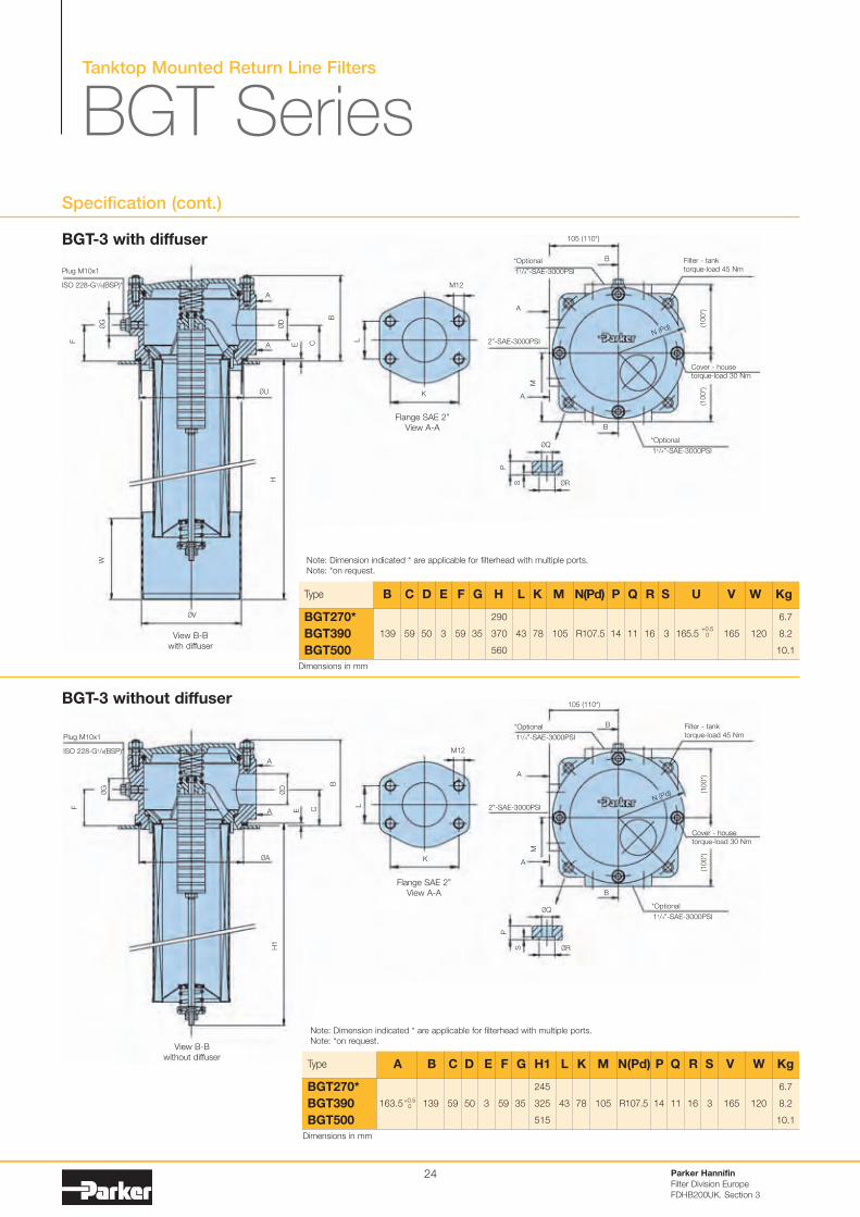
BGT-3 with diffuser
Type
139 59 50 3 59 35
290
370
560
43 78 105 R107.5 14 11 16 3 165 120
6.7
8.2
10.1
BGT270*
BGT390
BGT500
B C D E F G H L K M N(Pd) P Q R S U V W Kg
BGT-3 without diffuser
165.5+0.5
0
Note: Dimension indicated * are applicable for filterhead with multiple ports.
Note: *on request.
Note: Dimension indicated * are applicable for filterhead with multiple ports.
Note: *on request.
Type
163.5 139 59 50 3 59 35
245
325
515
43 78 105 R107.5 14 11 16 3 165 120
6.7
8.2
10.1
BGT270*
BGT390
BGT500
A B C D E F G H1 L K M N(Pd) P Q R S V W Kg
+0.50
ØU
A
M12
*Optional B
105 (110*)
B
11/4”-SAE-3000PSI
Filter - tank
torque-load 45 Nm
Cover - house
torque-load 30 Nm
A
Plug M10x1
ISO 228-G1/8(BSP)*
Flange SAE 2”
View A-A
View B-B
with diffuser
ØD
ØG
B
P
S
M
(100
*)(1
00
*)
L
H
W
CE
F
K
M12
Flange SAE 2”
View A-A
L
K
ØV
ØA
A
A
Plug M10x1
ISO 228-G1/8(BSP)*
View B-B
without diffuser
ØD
ØG
B
H1
CE
F
2”-SAE-3000PSI
A
A
*Optional
11/4”-SAE-3000PSIØQ
ØR
P
S
ØQ
ØR
N (Pd)
*Optional B
105 (110*)
B
11/4”-SAE-3000PSI
Filter - tank
torque-load 45 Nm
Cover - house
torque-load 30 Nm
M
(10
0*)
(100*)
2”-SAE-3000PSI
A
A
*Optional
11/4”-SAE-3000PSI
N (Pd)
Dimensions in mm
Dimensions in mm
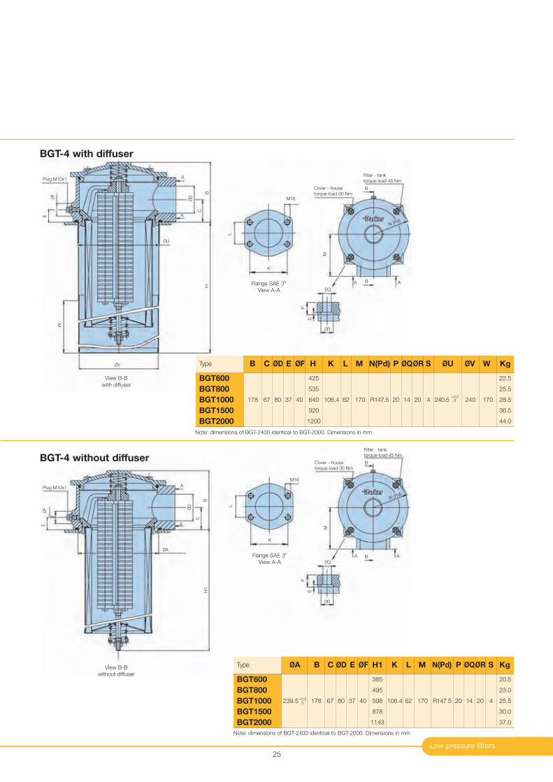
BGT-4 without diffuser
Low pressure filters
25
Type
239.5 178 67 80 37 40
385
495
598
878
1143
106.4 62 170 R147.5 20 14 20 4
20.5
23.0
25.5
30.0
37.0
BGT600
BGT800
BGT1000
BGT1500
BGT2000
ØA B C ØD E ØF H1 K L M N(Pd) P ØQØR S Kg
+0.50
BGT-4 with diffuser
Type
178 67 80 37 40
425
535
640
920
1200
106.4 62 170 R147.5 20 14 20 4 240 170
22.5
25.5
28.5
36.5
44.0
BGT600
BGT800
BGT1000
BGT1500
BGT2000
B C ØD E ØF H K L M N(Pd) P ØQØR S ØU ØV W Kg
240.5+0.5
0
Note: dimensions of BGT-2400 identical to BGT-2000. Dimensions in mm
Note: dimensions of BGT-2400 identical to BGT-2000. Dimensions in mm
ØU
A
A
Plug M10x1
View B-B
with diffuser
ØDØF
BH
W
C
E
ØV
ØA
A
A
Plug M10x1
View B-B
without diffuser
ØD
ØF
BH
1
C
E
B
B
Filter - tank
torque-load 45 Nm
Cover - house
torque-load 30 Nm
M
A A
B
B
Filter - tank
torque-load 45 Nm
Cover - house
torque-load 30 Nm
M
A A
P
S
ØQ
ØR
P
S
ØQ
ØR
N (Pd)
N (Pd)
M16
Flange SAE 3”
View A-A
L
K
M16
Flange SAE 3”
View A-A
L
K
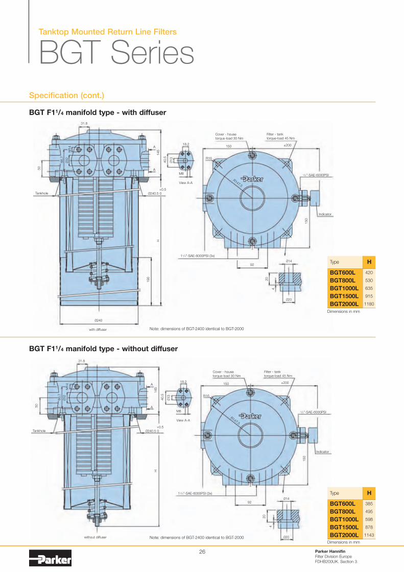
BGT F11/4 manifold type - without diffuser
BGT F11/4 manifold type - with diffuser
Tanktop Mounted Return Line Filters
BGT SeriesSpecification (cont.)
Parker Hannifin
Filter Division Europe
FDHB200UK. Section 3
26
Type
420
530
635
915
1180
BGT600L
BGT800L
BGT1000L
BGT1500L
BGT2000L
H
Type
385
495
598
878
1143
BGT600L
BGT800L
BGT1000L
BGT1500L
BGT2000L
H
Note: dimensions of BGT-2400 identical to BGT-2000
Note: dimensions of BGT-2400 identical to BGT-2000
Ø20
Ø240
Ø14
A
Filter - tank
torque-load 45 Nm
Cover - house
torque-load 30 Nm
Indicator
View A-A
150
20
4
1/2”-SAE-6000PSI
11/4”-SAE-6000PSI (3x)
with diffuser
without diffuser
±200150
92
18.2
M8
A
R16
+0.5Tankhole
31.8
40.5
H
190
50
66.7
M14
Ø32
145
Ø13
Ø240.5 0
R147.5
Ø20
Ø14
A
Filter - tank
torque-load 45 Nm
Cover - house
torque-load 30 Nm
Indicator
View A-A
150
20
4
1/2”-SAE-6000PSI
11/4”-SAE-6000PSI (3x)
±200150
92
18.2
M8
A
R16
+0.5Tankhole
31.8
40.5
H
50
66.7
M14
Ø32
145
Ø13
Ø240.5 0
R147.5
Dimensions in mm
Dimensions in mm
9
58
75
Protective cap
with dual cable duct
for 1, 7-2, 3mm diameter cable
27 A/F
Ø30.5
M10x1
Amp 6.3x8
terminals
2 4
1
Switch
1 = COM.2 = N.C.3 = N.O.
Low pressure filters
Pressure Drop Curves
Indicator Options
27
The recommended level of the initial pressure drop for low pressure filters is max 0.5 bar.
If the medium used has a viscosity different from 32cSt, pressure drop over the filter can be estimated as follows:
∆p = (∆p32 x viscosity of medium used) / 32cSt.
Filter housing and element pressure drop based on 32cSt fluid viscosity and 0.87 density.
0
0.01
0.02
0.03
0.04
0 50 100 150 200 250 300 350 400 450 500 550
Flow (l/min)
delta-p∆p
(b
ar)
∆p
(P
SID
)
0
0.29
0.58
Flow (US GPM)
0 13 39 53 66 79 92 106 119 132 14526
Empty Housing BGT-3 Series (2” SAE Flange)
0
0.2
0.4
1
0.6
0.8
1.2
0 100 200 300 400 500 600 700
02Q
05Q
10Q
20Q
Flow (l/min)
∆p
(b
ar)
Flow (US GPM)
0 26 53 79 106 132 159 185
∆p
(P
SID
)
0
5.8
8.7
17.4
14.5
11.6
2.9
0
0.2
0.4
1
0.6
0.8
1.2
0 100 200 300 400 500 600 700
02Q
05Q
10Q
20Q
Flow (l/min)
∆p
(b
ar)
Flow (US GPM)
0 26 53 79 106 132 159 185
∆p
(P
SID
)
0
5.8
8.7
17.4
14.5
11.6
2.9
BGT390 Filter Element Length 11
BGT500 Filter Element Length 12
Indicator PS pressure switch
G1/8 (BSP)
Ø289
Protective cover
M10x1
24 A/F55
74
Elec.rating
Thread connection
Elec.connection
Protection
Code
Visual indicator
M10 code
G1/8 code
42V / 4A
M10x1
AMP 6.3x0.8 terminals + protective cap
IP65 (with cap) terminals IP00
FMUS1EBMM10L (Switch)
1.2 bar
FMUS1EBMM10L
FMUS4EBMG02L
Specifications
Elec.rating
Thread connection
Elec.connection
Protection
Switch type
Code
42V / 2A
G1/8 - M10x1
AMP terminal 6.3x0.8
IP65 (terminal IP00)
NO or NC
FMUS2EBMG02L (NO switch)
FMUS3EBMG02L (NC switch)
Specifications
Indicator PS NO/NC pressure switch
Normally open contacts
Normally closed contacts
Visual indicator 1.2 bar
M10 code FMUG1EBPM10L
G1/8 code FMUG2EBPG02L
Tanktop Mounted Return Line Filters
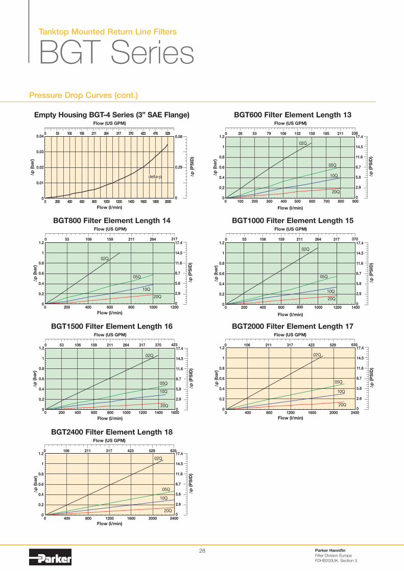
BGT SeriesPressure Drop Curves (cont.)
Parker Hannifin
Filter Division Europe
FDHB200UK. Section 3
28
0
0.2
0.4
1
0.6
0.8
1.2
0 100 200 300 400 500 600 700 800 900
02Q
05Q
10Q
20Q
Flow (l/min)
∆p
(b
ar)
Flow (US GPM)
0 26 53 79 106 132 159 185 211 238
∆p
(P
SID
)
0
5.8
8.7
17.4
14.5
11.6
2.9
0
0.2
0.4
1
0.6
0.8
1.2
0 200 400 600 800 1000 1200
02Q
05Q
10Q
20Q
Flow (l/min)
∆p
(b
ar)
Flow (US GPM)
0 53 106 159 211 264 317
∆p
(P
SID
)
0
5.8
8.7
17.4
14.5
11.6
2.9
BGT600 Filter Element Length 13
BGT800 Filter Element Length 14
0
0.2
0.4
1
0.8
0.6
1.2
0 200 400 600 800 1000 1200 1400
02Q
05Q
10Q
20Q
Flow (l/min)
∆p
(b
ar)
Flow (US GPM)
0 53 106 159 211 264 317 370
∆p
(P
SID
)
0
5.8
8.7
17.4
14.5
11.6
2.9
0
0.2
1
0.8
0.6
0.4
1.2
0 200 400 600 800 1000 1200 1400 1600
02Q
05Q
10Q
20Q
Flow (l/min)
∆p
(b
ar)
Flow (US GPM)
0 53 106 159 211 264 317 370 423
∆p
(P
SID
)
0
5.8
8.7
17.4
14.5
11.6
2.9
BGT1000 Filter Element Length 15
BGT1500 Filter Element Length 16
0
0.2
0.4
1
0.8
0.6
1.2
0 400 800 1200 1600 2000 2400
02Q
05Q
10Q
20Q
Flow (l/min)
∆p
(b
ar)
Flow (US GPM)
0 106 211 317 529 635423
∆p
(P
SID
)
0
5.8
8.7
17.4
14.5
11.6
2.9
BGT2000 Filter Element Length 17
0
0.01
0.02
0.03
0.04
0 200 400 600 800 1000 1200 1400 1600 1800 2000
Flow (l/min)
delta-p
∆p
(b
ar)
Flow (US GPM)
0 53 106 159 211 264 317 370 423 476 529
∆p
(P
SID
)
0
0.29
0.58
Empty Housing BGT-4 Series (3” SAE Flange)
0
0.2
0.4
1
0.8
0.6
1.2
0 400 800 1200 1600 2000 2400
02Q
05Q
10Q
20Q
Flow (l/min)
∆p
(b
ar)
Flow (US GPM)
0 106 211 317 529 635423
∆p
(P
SID
)
0
5.8
8.7
17.4
14.5
11.6
2.9
BGT2400 Filter Element Length 18

Low pressure filters
Pressure Drop Curves (cellulose and stainless steel media)
29
0
0.01
0.02
0.03
0.04
0.05
0.07
0.06
0 100 200 300 500
Flow (l/min)
040W
∆p
(b
ar)
400
10C
∆p
(P
SID
)
0
0.29
0.58
1.02
0.87
0.73
0.44
0.15
Flow (US GPM)
1321060 26 7953
0
0.01
0.02
0.03
0.04
0.05
0 100 200 300 400 500
Flow (l/min)
∆p
(b
ar)
040W
10C
∆p
(P
SID
)
Flow (US GPM)
132106
0
0.29
0.58
0.73
0.44
0.15
0 26 7953
BGT390 Filter Element Length 11 BGT500 Filter Element Length 12
0
0.01
0.02
0.03
0.04
0.05
0.07
0.06
0 100 200 300 400 600
Flow (l/min)
∆p
(b
ar)
700500
040W
10C
∆p
(P
SID
)
0
0.29
0.58
1.02
0.87
0.73
0.44
0.15
Flow (US GPM)
1067953260 132 159 185
0
0.01
0.02
0.03
0.04
0.05
0.06
0 100 200 300 400 800
Flow (l/min)
∆p
(b
ar)
500 600 700
10C
040W
∆p
(P
SID
)
Flow (US GPM)
0 26 53 106 211
0
0.29
0.58
0.87
0.73
0.44
0.15
79 132 159 185
BGT600 Filter Element Length 13 BGT800 Filter Element Length 14
0
0.01
0.02
0.03
0.04
0.05
0.06
0 200 400 600 800 1000
Flow (l/min)
∆p
(b
ar)
100 300 500 700 900
040W
10C
∆p
(P
SID
)
Flow (US GPM)
0 26 53 106 132 185 211 238 264
0
0.29
0.58
0.87
0.73
0.44
0.15
79 159
0
0.01
0.02
0.03
0.04
0.05
0.07
0.06
0 200 400 600 800
Flow (l/min)
∆p
(b
ar)
16001000 1200 1400
040W
10C
Flow (US GPM)
106530 423159 264211 317 370
∆p
(P
SID
)
0
0.29
0.58
1.02
0.87
0.73
0.44
0.15
BGT1000 Filter Element Length 15 BGT1500 Filter Element Length 16
0
0.01
0.02
0.03
0.04
0.05
0.07
0.06
0 400 800 1200 1600 22002000
Flow (l/min)
∆p
(b
ar)
200 600 1000 1400 1800
040W
10C
Flow (US GPM)
106530 264211 370 423 475 581528159 317
∆p
(P
SID
)
0
0.29
0.58
1.02
0.87
0.73
0.44
0.15
BGT2000 Filter Element Length 17
Cellulose and stainless steel media
Example: BGT2000 Filter Element Length 17 - cellulose and stainless steel media
Tanktop Mounted Return Line Filters
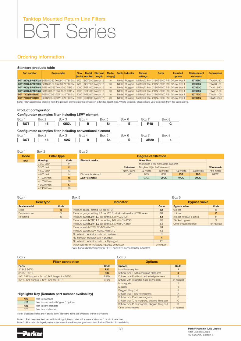
BGT SeriesOrdering Information
Parker Hannifin (UK) Limited
Filter Division Europe
FDHB200UK. Section 3
30
Note: Filter assemblies ordered from the product configurator below are on extended lead times. Where possible, please make your selection from the table above.
Product configurator
Configurator examples filter including LEIF® element
Box 1
Code
11
12
13
14
15
16
17
18
Housing
3-390 l/min
3-500 l/min
4-600 l/min
4-800 l/min
4-1000 l/min
4-1500 l/min
4-2000 l/min
4-2400 l/min
Filter type
Box 2
BGT
Box 2
15
Box 3
05QL
Box 4
B
Box 5
S1
Box 6
E
Box 7
R48
Box 8
C
Configurator examples filter including conventional element
Box 1
BGT
Box 2
18
Box 3
02Q
Box 4
B
Box 5
S4
Box 6
E
Box 7
3R20
Box 8
4
Note 1: Part numbers featured with bold highlighted codes will ensure a ‘standard’ product selection.
Note 2: Alternate displayed part number selection will require you to contact Parker Filtration for availability.
Part number
BGT1210QLBP1ER323
BGT1220QLBP1ER323
BGT1510QLBP1ER483
BGT1520QLBP1ER483
BGT1710QBP1ER483
BGT1720QBP1ER483
Supercedes
BGTS500-S2 TXWL8C-10 T B15 M
BGTS500-S2 TXWL8C-20 T B15 M
BGTS1000-S3 TXWL12-10 T B15 M
BGTS1000-S3 TXWL12-20 T B15 M
BGTS2000-S3 TXW14-10 T B15 M
BGTS2000-S3 TXW14-20 T B15 M
Flow
(l/min)
500
500
1000
1000
2000
2000
Model
number
BGT500
BGT500
BGT1000
BGT1000
BGT2000
BGT2000
Element
length
Length 12
Length 12
Length 15
Length 15
Length 17
Length 17
Media
rating (µ)
10
20
10
20
10
20
Seals
Nitrile
Nitrile
Nitrile
Nitrile
Nitrile
Nitrile
Indicator
Plugged
Plugged
Plugged
Plugged
Plugged
Plugged
Bypass
settings
1.5 Bar (22 Psi)
1.5 Bar (22 Psi)
1.5 Bar (22 Psi)
1.5 Bar (22 Psi)
1.5 Bar (22 Psi)
1.5 Bar (22 Psi)
Included
options
Diffuser type T
Diffuser type T
Diffuser type T
Diffuser type T
Diffuser type T
Diffuser type T
Replacement
elements
937859Q
937868Q
937862Q
937865Q
937772Q
937805Q
Supercedes
TXWL8L-10
TXWL8L-20
TXWL12-10
TXWL12-20
TXW14-10B
TXW14-20B
Ports
2"SAE-3000 PSI
2"SAE-3000 PSI
2"SAE-3000 PSI
2"SAE-3000 PSI
2"SAE-3000 PSI
2"SAE-3000 PSI
BGT
Code
Box 1
Code
B
V
N
Seal material
Nitrile
Fluorelastomer
Neoprene
Seal type
Box 4
Code
B
E
H
X
on request
Bypass valve
0.8 bar
1.5 bar
2.0 bar for BGT-3 series
Blocked bypass
Other bypass settings
Bypass valve
Box 6
Code
G1
G2
S1
S2
S3
S4
S5
N
P
P2
on request
Pressure gauge, setting 1.2 bar, M10x1
Pressure gauge, setting 1.2 bar, G1/8 for dual port head and TSR series
Pressure switch 24V, 1.2 bar setting, NO/NC, M10x1
Pressure switch 24V, 1.2 bar setting, NO with G1/8 BSP
Pressure switch 24V, 1.2 bar setting, NC with G1/8 BSP
Pressure switch 250V, NO/NC with G1/8
Pressure switch 220V, NO/NC with M10
No indicator, indicator ports not machined
No indicator, indicator port R plugged
No indicator, indicator ports L + R plugged
Other settings for indicators / gauges on request
Indicator
Box 5
Code
R32
R48
R32M
3R20
Ports
2" SAE BGT-3
3" SAE BGT-4
1x2" SAE flanged + 2x11/4" SAE flanged for BGT-3
3x11/4" SAE flanges + 1x1/2" SAE for BGT-4
Filter connection
Box 7
Code
1
3
4
on request
5
6
8
A
B
C
D
on request
Options
No diffuser required
Diffuser type T with perforated plate area
Diffuser type P without perforated plate area
Diffuser with integrated hose connection
No magnets
Dipstick
Plugged filling port
Diffuser type T and no magnets
Diffuser type P and no magnets
Diffuser type T, no magnets, plugged filling port
Diffuser type P, no magnets, plugged filling port
Other combinations
Options
Box 8
Standard products table
Note: For all dual head ports for BGTS apply G1/8 connection for indicators
Box 3
Element media
Disposable element
LEIF® element
Cellulose
Nom. rating
10C
20µ media
20Q
20QL
Abs. rating
040W
10µ media
10Q
10QL
5µ media
05Q
05QL
2µ media
02Q
02QL
Glass fibre
Microglass III (for disposable elements)
Ecoglass III (for Leif® elements) Wire mesh
Degree of filtration
Item is standard
Item is standard with “green” options
Item is semi standard
Item is non standard
123
123
123
123
Highlights Key (Denotes part number availability)
Note: Standard items are in stock, semi standard items are available within four weeks
Low Pressure Filters
Ordering Information (cont.)
31
BGT390
Part number spare element
BGT500
Part number spare element
BGT600
Part number spare element
BGT800
Part number spare element
BGT1000
Part number spare element
BGT1500
Part number spare element
BGT2000
Part number spare element
BGT2400
Part number spare element
TXX8A-10-B
937728
TXX8C-10-B
937729
TXX10-10-B
937730
TXX11-10-B
937731
TXX12-10-B
937732
TXX13-10-B
937733
TXX14-10-B
937734
-
TXWL8A-20-B
937799Q
TXWL8C-20-B
937800Q
TXWL10-20-B
937801Q
TXWL11-20-B
937802Q
TXWL12-20-B
937803Q
TXWL13-20-B
937804Q
TXW14-20-B
937805Q
TXWH14-20-B
937806Q
ST8A-40-B
937813
ST8C-40-B
937812
ST10-40-B
937811
ST11-40-B
937810
ST12-40-B
937809
ST13-40-B
937808
ST14-40-B
937807
-
TXWL8A-10-B
937778Q
TXWL8C-10-B
937777Q
TXWL10-10-B
937776Q
TXWL11-10-B
937775Q
TXWL12-10-B
937774Q
TXWL13-10-B
937773Q
TXW14-10-B
937772Q
TXWH14-10-B
937771Q
TXWL8A-5-B
937763Q
TXWL8C-5-B
937764Q
TXWL10-5-B
937765Q
TXWL11-5-B
937766Q
TXWL12-5-B
937767Q
TXWL13-5-B
937768Q
TXW14-5-B
937769Q
TXWH14-5-B
937770Q
TXWL8A-2-B
937742Q
TXWL8C-2-B
937741Q
TXWL10-2-B
937740Q
TXWL11-2-B
937739Q
TXWL12-2-B
937738Q
TXWL13-2-B
937737Q
TXW14-2-B
937736Q
TXWH14-2-B
937735Q
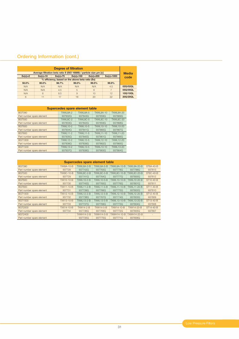
Supercedes spare element table
BGT390
Part number spare element
BGT500
Part number spare element
BGT600
Part number spare element
BGT800
Part number spare element
BGT1000
Part number spare element
BGT1500
Part number spare element
TXWL8A-20
937869Q
TXWL8C-20
937868Q
TXWL10-20
937867Q
TXWL11-20
937866Q
TXWL12-20
937865Q
TXWL13-20
937864Q
TXWL8A-10
937858Q
TXWL8C-10
937859Q
TXWL10-10
937860Q
TXWL11-10
937861Q
TXWL12-10
937862Q
TXWL13-10
937863Q
TXWL8A-5
937843Q
TXWL8C-5
937842Q
TXWL10-5
937841Q
TXWL11-5
937840Q
TXWL12-5
937839Q
TXWL13-5
937838Q
TXWL8A-2
937832Q
TXWL8C-2
937833Q
TXWL10-2
937834Q
TXWL11-2
937835Q
TXWL12-2
937836Q
TXWL13-2
937837Q
Supercedes spare element table
Average filtration beta ratio ß (ISO 16889) / particle size µm [c]
% efficiency, based on the above beta ratio (ßx)
ßx(c)=2
50.0%
N/A
N/A
N/A
6
Degree of filtration
Media
codeßx(c)=10
90.0%
N/A
N/A
6
11
ßx(c)=75
98.7%
N/A
4.5
8.5
17
ßx(c)=100
99.0%
N/A
5
9
18
ßx(c)=200
99.5%
N/A
6
10
20
ßx(c)=1000
99.9%
4.5
7
12
22
02Q/02QL
05Q/05QL
10Q/10QL
20Q/20QL

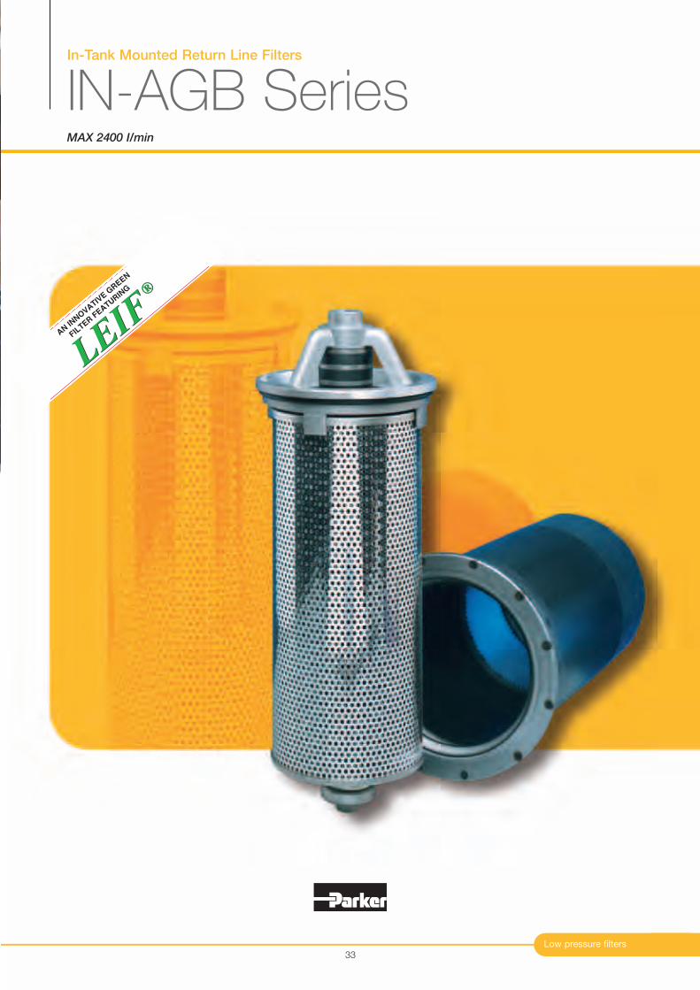
In-Tank Mounted Return Line Filters
IN-AGB SeriesMAX 2400 I/min
Low pressure filters
®
LEIF
LEIF
®
AN IN
NO
VATIV
E G
REEN
FIL
TER F
EATURIN
G
33

In-Tank Mounted Return Line Filters
IN-AGB Series
34
Typical Applications
Agricultural machines
Articulated dump trucks
Forestry equipment
Wheeled loaders
Lubrication systems
Excavators
Features & Benefits
The Parker Filtration IN-AGB In-Tank Mounted Return Line Filters.
The low-cost, high-performance return line IN-AGB filter
features Q3 filter media, a bypass construction with low
hysteresis, magnetic pre-filtration and a high dirt-holding
capacity. The range is capable of handling flow rates from
30 l/min up to 2400 l/min. LEIF® elements are available for flow
rates up to 1500 l/min, meeting the most stringent demands
for environmentally-friendly filtration and offering protection
against poor quality pirate elements.
Parker Hannifin
Filter Division Europe
FDHB200UK. Section 4
Features
Filter integrated in tank
LEIF® elements
Magnetic pre-filtration
In-to-Out filtration
High level of customisation
Full flow bypass with low hysteresis
Standard or customised funnel
Advantages
Compact low cost solution
Filter protected by reservoir
Patented element safeguards the use of genuine
parts
Removes ferro particles, even during bypass
conditions
All captured contamination retains inside the
element
Dedicated system-matched solutions can be
easily made available
Reduction of bypass period due to low hysteresis
Only a small part of the total flow is bypassing
the element
Ensures that oil enters the tank under the oil level
Benefits
Suitable for extreme heavy duty
applications or hazardous environments
No tank top parts contributes to
improved esthetical design
Guaranteed quality of filtration
Contributes to ISO 14001 certification
Improved fluid cleanliness levels
Extended element life time
No recontamination of system during
change of elements
Improved integration of filter in system
combined with lower initial system costs
Improved protection of system
Significant reduction of oil foaming
Low pressure filters
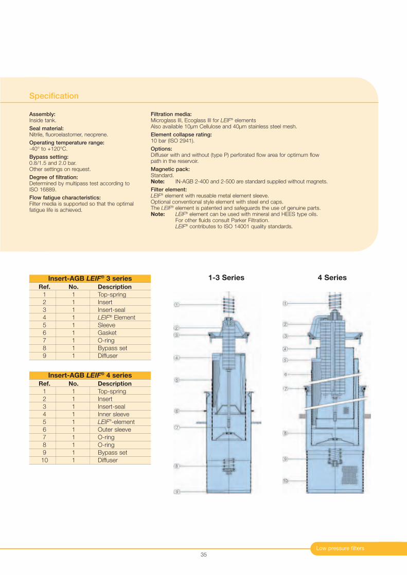
Specification
Assembly:Inside tank.
Seal material:Nitrile, fluoroelastomer, neoprene.
Operating temperature range:-40° to +120°C.
Bypass setting:0.8/1.5 and 2.0 bar.Other settings on request.
Degree of filtration:Determined by multipass test according toISO 16889.
Flow fatigue characteristics:Filter media is supported so that the optimalfatigue life is achieved.
Filtration media:Microglass III, Ecoglass III for LEIF
® elementsAlso available 10µm Cellulose and 40µm stainless steel mesh.
Element collapse rating:10 bar (ISO 2941).
Options:Diffuser with and without (type P) perforated flow area for optimum flow path in the reservoir.
Magnetic pack:Standard.Note: IN-AGB 2-400 and 2-500 are standard supplied without magnets.
Filter element:LEIF
® element with reusable metal element sleeve.Optional conventional style element with steel end caps.The LEIF
® element is patented and safeguards the use of genuine parts.Note: LEIF
® element can be used with mineral and HEES type oils.For other fluids consult Parker Filtration.LEIF
® contributes to ISO 14001 quality standards.
35
1-3 Series 4 Series
1
2
3
4
5
6
7
8
9
Ref. No. Description
1 1 Top-spring
2 1 Insert
3 1 Insert-seal
4 1 LEIF® Element
5 1 Sleeve
6 1 Gasket
7 1 O-ring
8 1 Bypass set
9 1 Diffuser
Insert-AGB LEIF® 3 series
Ref. No. Description
1 1 Top-spring
2 1 Insert
3 1 Insert-seal
4 1 Inner sleeve
5 1 LEIF®-element
6 1 Outer sleeve
7 1 O-ring
8 1 O-ring
9 1 Bypass set
10 1 Diffuser
Insert-AGB LEIF® 4 series
1
2
3
4
5
6
7
8
9
10
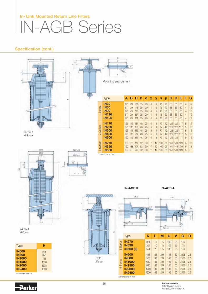
In-Tank Mounted Return Line Filters
IN-AGB SeriesSpecification (cont.)
Parker Hannifin
Filter Division Europe
FDHB200UK. Section 4
36
Type
324
364
554
445
555
660
940
1220
1220
110
110
125
183
183
183
183
183
183
175
175
175
239
239
239
239
239
239
106
106
106
145
145
145
145
145
145
55
55
55
60
60
60
60
60
60
178
178
178
250.5
250.5
250.5
250.5
250.5
250.5
2.5
2.5
2.5
2.5
2.5
2.5
IN270IN390IN500 (3)
IN600IN800IN1000IN1500IN2000IN2400
K L M U V Q R
without
diffuser
Mounting arrangement
IN-AGB 3 IN-AGB 4
with
diffuser
Type
87
87
87
87
87
125
125
125
125
125
150
150
150
79
79
79
79
79
116
116
116
116
116
138
138
138
122
173
217
267
381
284
360
559
579
599
325
407
599
35
35
35
35
35
48
48
48
48
48
62
62
62
20
20
20
20
20
25
25
25
25
25
30
30
30
4
4
4
4
4
5
5
5
5
5
7
7
7
6
6
6
6
6
8
8
8
8
8
12
12
12
45
45
45
45
45
77
77
77
77
77
100
100
100
20
20
20
20
20
42
42
42
42
42
55
55
55
88
88
88
88
88
126
126
126
126
126
151
151
151
85
85
85
85
85
122
122
122
122
122
149
149
149
80
80
80
80
80
117
117
117
117
117
139
139
139
4
4
4
4
4
5
5
5
5
5
5
5
5
12
12
12
12
12
15
15
15
15
15
18
18
18
IN30IN60IN90IN120IN125
IN170IN230IN300IN400IN500
IN270IN390IN500
A B H h d x y s p C D E F G
Type
543
653
758
1038
1303
1303
IN600IN800IN1000IN1500IN2000IN2400
H
without
diffuser
A
Bd
C
D
45°
E
yx
h
H
Ø230
Ø216
Ø231±0.2
R±0.1
Ø227±0.2
Ø203
Ø193
ØM
ØQ+1.0-1.5
ØM
ØQ 0-0.5
Ø20
60
146
6
H
s
p
F
G
0.8
Ø217±0.2
12.5
12.5
45°
15°
0.8
0.8
3.2
3.2
3.2
v
uL
K
Ø260
min
.12
1 S
eries
2 S
eries
3 S
eries
3 S
eries
4 S
eries
Dimensions in mm
Dimensions in mm
Dimensions in mm
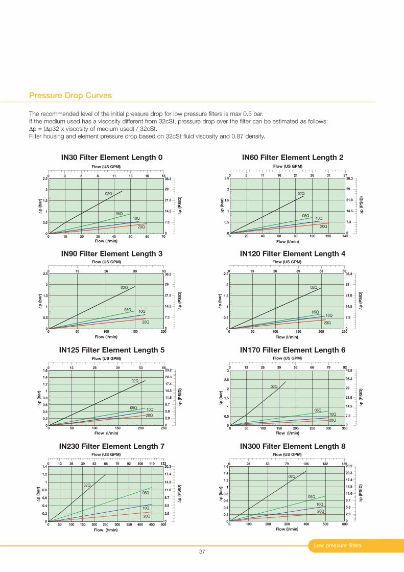
0
0.4
0.2
1
0.8
0.6
1.4
1.2
0 50 100 150 200 250 300 350 400 450 500
02Q
05Q
10Q
20Q
Flow (l/min)
∆p
(b
ar)
Flow (US GPM)
0 13 26 39 53 66 79 92 106 119 132
∆p
(P
SID
)
0
2.9
5.8
8.7
11.6
14.5
17.4
20.3
0
0.2
1
0.8
0.6
0.4
1.6
1.4
1.2
0 100 200 300 400 500 600
02Q
05Q
10Q
20Q
Flow (l/min)
∆p
(b
ar)
Flow (US GPM)
0 26 53 79 106 132 159
∆p
(P
SID
)
0
2.9
5.8
8.7
11.6
14.5
17.4
23.2
20.3
Low pressure filters
Pressure Drop Curves
37
0
0.5
1
1.5
2
2.5
0 10 20 30 40 50 60 70
02Q
05Q
10Q
20Q
Flow (l/min)
∆p
(b
ar)
∆p
(P
SID
)
0
7.3
14.5
21.8
29
36.3
Flow (US GPM)
0 3 5 8 11 13 16 18
0
0.5
1
1.5
2
2.5
0 20 40 60 80 100 120 140
02Q
05Q10Q
20Q
Flow (l/min)
∆p
(b
ar)
∆p
(P
SID
)
0
7.3
14.5
21.8
29
36.3
Flow (US GPM)
0 5 11 16 21 26 31 37
0
0.5
2
1.5
1
2.5
0 50 100 150 200
02Q
05Q 10Q
20Q
∆p
(b
ar)
Flow (l/min)
∆p
(P
SID
)
0
7.3
14.5
21.8
29
36.3
Flow (US GPM)
0 13 26 39 53
IN60 Filter Element Length 2
IN90 Filter Element Length 3
0
0.5
2
1.5
1
2.5
0 50 100 150 200 250
02Q
05Q10Q
20Q
Flow (l/min)
∆p
(b
ar)
∆p
(P
SID
)
0
7.3
14.5
21.8
29
36.3
Flow (US GPM)
0 13 26 39 53 66
0
0.2
1
0.8
0.6
0.4
1.6
1.4
1.2
0 50 100 150 200 250
02Q
05Q 10Q
20Q
Flow (l/min)
∆p
(b
ar)
Flow (US GPM)
0 13 26 39 53 66
∆p
(P
SID
)
0
2.9
5.8
8.7
11.6
14.5
17.4
23.2
20.3
IN120 Filter Element Length 4
IN125 Filter Element Length 5
The recommended level of the initial pressure drop for low pressure filters is max 0.5 bar.
If the medium used has a viscosity different from 32cSt, pressure drop over the filter can be estimated as follows:
∆p = (∆p32 x viscosity of medium used) / 32cSt.
Filter housing and element pressure drop based on 32cSt fluid viscosity and 0.87 density.
IN30 Filter Element Length 0
0
0.5
1
1.5
2
2.5
3
0 50 100 150 200 250 300 350
02Q
05Q
10Q
20Q
∆p
(b
ar)
Flow (l/min)
∆p
(P
SID
)
0
7.3
14.5
21.8
29
36.3
43.5
Flow (US GPM)
0 13 26 39 53 66 79 92
IN170 Filter Element Length 6
IN230 Filter Element Length 7 IN300 Filter Element Length 8
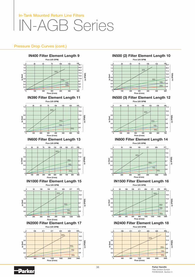
In-Tank Mounted Return Line Filters
IN-AGB SeriesPressure Drop Curves (cont.)
Parker Hannifin
Filter Division Europe
FDHB200UK. Section 4
38
0
0.2
1
0.8
0.6
0.4
1.8
1.6
1.4
1.2
0 100 200 300 400 500 600
02Q
05Q
10Q
20Q
Flow (l/min)
∆p
(b
ar)
Flow (US GPM)
0 26 53 79 106 132 159
∆p
(P
SID
)
0
2.9
5.8
8.7
11.6
14.5
17.4
26.1
23.2
20.3
0
0.2
1
0.8
0.6
0.4
1.6
1.4
1.2
0 100 200 300 400 500 600
02Q
05Q
10Q
20Q
Flow (l/min)
∆p
(b
ar)
Flow (US GPM)
0 26 53 79 106 132 159
∆p
(P
SID
)
0
2.9
5.8
8.7
11.6
14.5
17.4
23.2
20.3
IN400 Filter Element Length 9 IN500 (2) Filter Element Length 10
0
0.2
0.4
1
0.6
0.8
1.2
0 100 200 300 400 500 600 700
02Q
05Q
10Q
20Q
Flow (l/min)
∆p
(b
ar)
Flow (US GPM)
0 26 53 79 106 132 159 185
∆p
(P
SID
)
0
5.8
8.7
17.4
14.5
11.6
2.9
0
0.2
0.4
1
0.6
0.8
1.2
0 100 200 300 400 500 600 700
02Q
05Q
10Q
20Q
Flow (l/min)
∆p
(b
ar)
Flow (US GPM)
0 26 53 79 106 132 159 185
∆p
(P
SID
)
0
5.8
8.7
17.4
14.5
11.6
2.9
IN390 Filter Element Length 11 IN500 (3) Filter Element Length 12
0
0.2
0.4
1
0.6
0.8
1.2
0 100 200 300 400 500 600 700 800 900
02Q
05Q
10Q
20Q
Flow (l/min)
∆p
(b
ar)
Flow (US GPM)
0 26 53 79 106 132 159 185 211 238
∆p
(P
SID
)
0
5.8
8.7
17.4
14.5
11.6
2.9
0
0.2
0.4
1
0.6
0.8
1.2
0 200 400 600 800 1000 1200
02Q
05Q
10Q
20Q
Flow (l/min)
∆p
(b
ar)
Flow (US GPM)
0 53 106 159 211 264 317
∆p
(P
SID
)0
5.8
8.7
17.4
14.5
11.6
2.9
IN600 Filter Element Length 13 IN800 Filter Element Length 14
0
0.2
1
0.8
0.6
0.4
1.2
0 200 400 600 800 1000 1200 1400 1600
02Q
05Q
10Q
20Q
Flow (l/min)
∆p
(b
ar)
Flow (US GPM)
0 53 106 159 211 264 317 370 423
∆p
(P
SID
)
0
5.8
8.7
17.4
14.5
11.6
2.9
IN1500 Filter Element Length 16
0
0.2
0.4
1
0.8
0.6
1.2
0 400 800 1200 1600 2000 2400
02Q
05Q
10Q
20Q
Flow (l/min)
∆p
(b
ar)
Flow (US GPM)
0 106 211 317 529 635423
∆p
(P
SID
)
0
5.8
8.7
17.4
14.5
11.6
2.9
IN2400 Filter Element Length 18
0
0.2
0.4
1
0.8
0.6
1.2
0 200 400 600 800 1000 1200 1400
02Q
05Q
10Q
20Q
Flow (l/min)
∆p
(b
ar)
Flow (US GPM)
0 53 106 159 211 264 317 370
∆p
(P
SID
)
0
5.8
8.7
17.4
14.5
11.6
2.9
IN1000 Filter Element Length 15
0
0.2
0.4
1
0.8
0.6
1.2
0 400 800 1200 1600 2000 2400
02Q
05Q
10Q
20Q
Flow (l/min)
∆p
(b
ar)
Flow (US GPM)
0 106 211 317 529 635423
∆p
(P
SID
)
0
5.8
8.7
17.4
14.5
11.6
2.9
IN2000 Filter Element Length 17
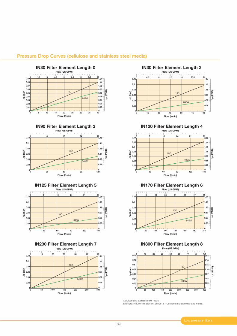
Low pressure filters
Pressure Drop Curves (cellulose and stainless steel media)
39
0
0.01
0.02
0.03
0.04
0.05
0.06
0.07
0.08
0.09
Flow (l/min)
040W
∆p
(b
ar)
403530252015105
10C
0
Flow (US GPM)
0 1.3 119.383 5 6.34.3
∆p
(P
SID
)
0
0.29
0.58
1.31
1.16
1.02
0.87
0.73
0.44
0.15
0
0.02
0.04
0.06
0.08
0.1
0.12
Flow (l/min)
040W
∆p
(b
ar)
15 30 45 60 90
10C
075
∆p
(P
SID
)
0
0.29
1.16
1.45
1.74
0.58
0.87
Flow (US GPM)
2420.30 8 12.3 164.3
IN30 Filter Element Length 0 IN30 Filter Element Length 2
0
0.02
0.04
0.06
0.08
0.1
0.12
Flow (l/min)
040W
∆p
(b
ar)
30 60 90 120
10C
0
∆p
(P
SID
)
0
0.29
1.16
1.45
1.74
0.58
0.87
Flow (US GPM)
310 8 2416
0
0.02
0.04
0.06
0.08
0.1
0.14
0.12
Flow (l/min)
040W
∆p
(b
ar)
30 60 90 120 150
10C
0
∆p
(P
SID
)
0
0.29
1.16
1.45
2.03
1.74
0.58
0.87
Flow (US GPM)
39310 8 2416
IN90 Filter Element Length 3 IN120 Filter Element Length 4
0
0.02
0.04
0.06
0.08
0.1
0.12
Flow (l/min)
∆p
(b
ar)
30 60 90 120 1500
10C
040W
∆p
(P
SID
)
0
0.29
1.16
1.45
1.74
0.58
0.87
Flow (US GPM)
39310 8 2416
0
0.02
0.04
0.06
0.08
0.1
0.12
Flow (l/min)
∆p
(b
ar)
30 60 90 120 150 180 2100
10C
040W
∆p
(P
SID
)
0
0.29
1.16
1.45
1.74
0.58
0.87
Flow (US GPM)
31241680 39 47 55
IN125 Filter Element Length 5 IN170 Filter Element Length 6
0
0.02
0.04
0.06
0.08
0.1
0.12
Flow (l/min)
∆p
(b
ar)
50 100 150 200 250 300
10C
0
040W
∆p
(P
SID
)
0
0.29
1.16
1.45
1.74
0.58
0.87
Flow (US GPM)
0 7913 26 5339 66
0
0.02
0.04
0.06
0.08
0.1
0.14
0.12
Flow (l/min)
040W
∆p
(b
ar)
50 100 150 300200 250
10C
0350 400
Flow (US GPM)
0 106927913 26 5339 66
∆p
(P
SID
)
0
0.29
1.16
1.45
2.03
1.74
0.58
0.87
IN230 Filter Element Length 7 IN300 Filter Element Length 8
Cellulose and stainless steel media
Example: IN300 Filter Element Length 8 - Cellulose and stainless steel media
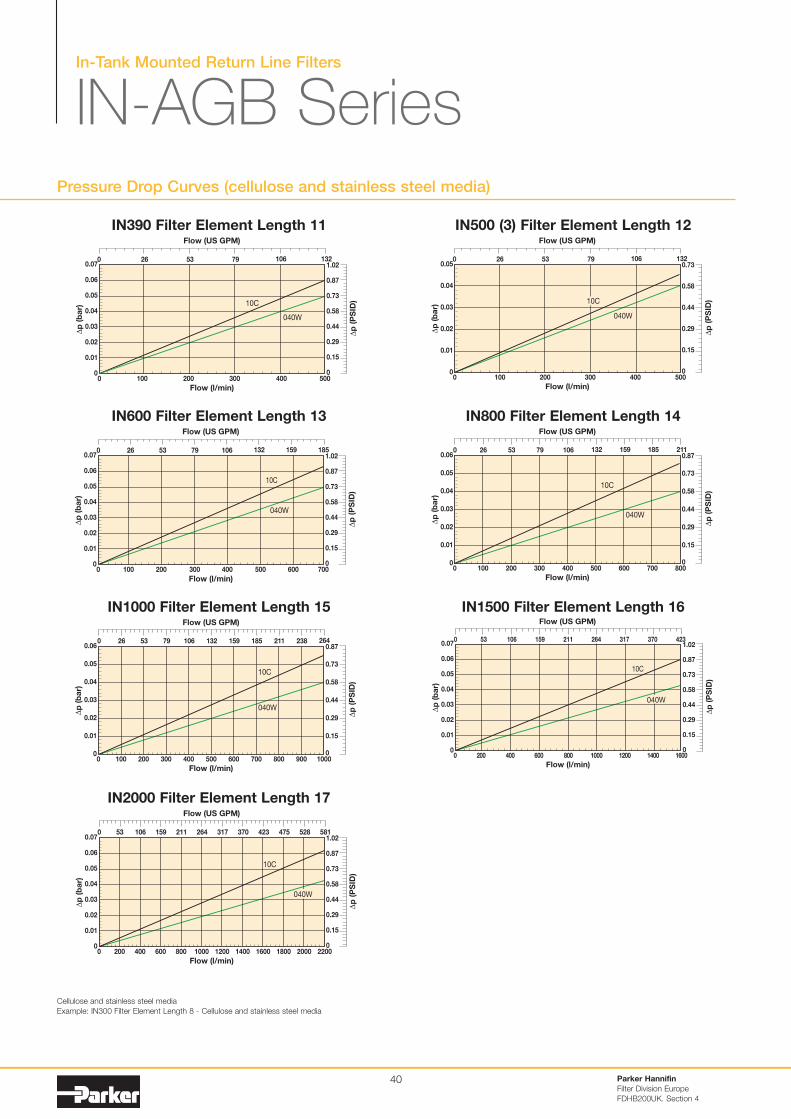
In-Tank Mounted Return Line Filters
IN-AGB SeriesPressure Drop Curves (cellulose and stainless steel media)
Parker Hannifin
Filter Division Europe
FDHB200UK. Section 4
40
0
0.01
0.02
0.03
0.04
0.05
0.07
0.06
0 100 200 300 500
Flow (l/min)
040W
∆p
(b
ar)
400
10C
∆p
(P
SID
)
0
0.29
0.58
1.02
0.87
0.73
0.44
0.15
Flow (US GPM)
1321060 26 7953
0
0.01
0.02
0.03
0.04
0.05
0 100 200 300 400 500
Flow (l/min)
∆p
(b
ar)
040W
10C
∆p
(P
SID
)
Flow (US GPM)
132106
0
0.29
0.58
0.73
0.44
0.15
0 26 7953
IN390 Filter Element Length 11 IN500 (3) Filter Element Length 12
0
0.01
0.02
0.03
0.04
0.05
0.07
0.06
0 100 200 300 400 600
Flow (l/min)
∆p
(b
ar)
700500
040W
10C
∆p
(P
SID
)
0
0.29
0.58
1.02
0.87
0.73
0.44
0.15
Flow (US GPM)
1067953260 132 159 185
0
0.01
0.02
0.03
0.04
0.05
0.06
0 100 200 300 400 800
Flow (l/min)
∆p
(b
ar)
500 600 700
10C
040W
∆p
(P
SID
)
Flow (US GPM)
0 26 53 106 211
0
0.29
0.58
0.87
0.73
0.44
0.15
79 132 159 185
IN600 Filter Element Length 13 IN800 Filter Element Length 14
0
0.01
0.02
0.03
0.04
0.05
0.06
0 200 400 600 800 1000
Flow (l/min)
∆p
(b
ar)
100 300 500 700 900
040W
10C
∆p
(P
SID
)
Flow (US GPM)
0 26 53 106 132 185 211 238 264
0
0.29
0.58
0.87
0.73
0.44
0.15
79 159
0
0.01
0.02
0.03
0.04
0.05
0.07
0.06
0 200 400 600 800
Flow (l/min)
∆p
(b
ar)
16001000 1200 1400
040W
10C
Flow (US GPM)
106530 423159 264211 317 370
∆p
(P
SID
)
0
0.29
0.58
1.02
0.87
0.73
0.44
0.15
IN1000 Filter Element Length 15 IN1500 Filter Element Length 16
0
0.01
0.02
0.03
0.04
0.05
0.07
0.06
0 400 800 1200 1600 22002000
Flow (l/min)
∆p
(b
ar)
200 600 1000 1400 1800
040W
10C
Flow (US GPM)
106530 264211 370 423 475 581528159 317
∆p
(P
SID
)
0
0.29
0.58
1.02
0.87
0.73
0.44
0.15
IN2000 Filter Element Length 17
Cellulose and stainless steel media
Example: IN300 Filter Element Length 8 - Cellulose and stainless steel media
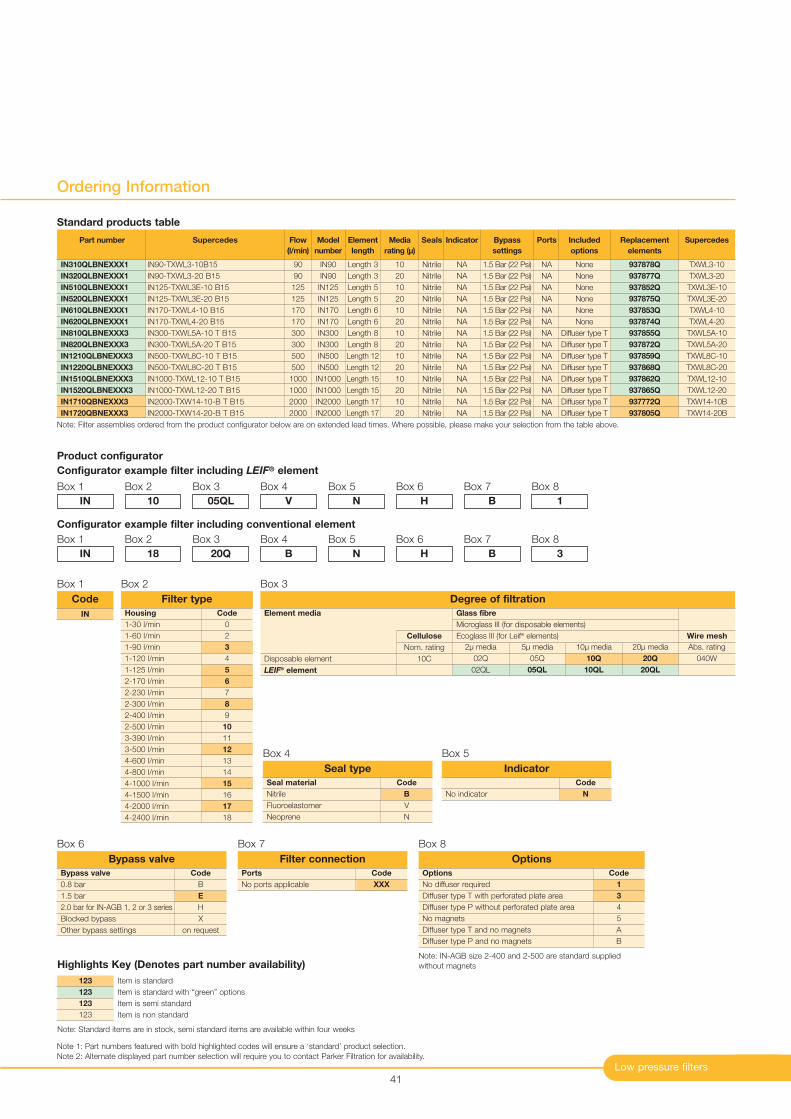
Low pressure filters
Ordering Information
41
Note: Filter assemblies ordered from the product configurator below are on extended lead times. Where possible, please make your selection from the table above.
Part number
IN310QLBNEXXX1
IN320QLBNEXXX1
IN510QLBNEXXX1
IN520QLBNEXXX1
IN610QLBNEXXX1
IN620QLBNEXXX1
IN810QLBNEXXX3
IN820QLBNEXXX3
IN1210QLBNEXXX3
IN1220QLBNEXXX3
IN1510QLBNEXXX3
IN1520QLBNEXXX3
IN1710QBNEXXX3
IN1720QBNEXXX3
Supercedes
IN90-TXWL3-10B15
IN90-TXWL3-20 B15
IN125-TXWL3E-10 B15
IN125-TXWL3E-20 B15
IN170-TXWL4-10 B15
IN170-TXWL4-20 B15
IN300-TXWL5A-10 T B15
IN300-TXWL5A-20 T B15
IN500-TXWL8C-10 T B15
IN500-TXWL8C-20 T B15
IN1000-TXWL12-10 T B15
IN1000-TXWL12-20 T B15
IN2000-TXW14-10-B T B15
IN2000-TXW14-20-B T B15
Flow
(l/min)
90
90
125
125
170
170
300
300
500
500
1000
1000
2000
2000
Model
number
IN90
IN90
IN125
IN125
IN170
IN170
IN300
IN300
IN500
IN500
IN1000
IN1000
IN2000
IN2000
Element
length
Length 3
Length 3
Length 5
Length 5
Length 6
Length 6
Length 8
Length 8
Length 12
Length 12
Length 15
Length 15
Length 17
Length 17
Media
rating (µ)
10
20
10
20
10
20
10
20
10
20
10
20
10
20
Seals
Nitrile
Nitrile
Nitrile
Nitrile
Nitrile
Nitrile
Nitrile
Nitrile
Nitrile
Nitrile
Nitrile
Nitrile
Nitrile
Nitrile
Indicator
NA
NA
NA
NA
NA
NA
NA
NA
NA
NA
NA
NA
NA
NA
Bypass
settings
1.5 Bar (22 Psi)
1.5 Bar (22 Psi)
1.5 Bar (22 Psi)
1.5 Bar (22 Psi)
1.5 Bar (22 Psi)
1.5 Bar (22 Psi)
1.5 Bar (22 Psi)
1.5 Bar (22 Psi)
1.5 Bar (22 Psi)
1.5 Bar (22 Psi)
1.5 Bar (22 Psi)
1.5 Bar (22 Psi)
1.5 Bar (22 Psi)
1.5 Bar (22 Psi)
Included
options
None
None
None
None
None
None
Diffuser type T
Diffuser type T
Diffuser type T
Diffuser type T
Diffuser type T
Diffuser type T
Diffuser type T
Diffuser type T
Replacement
elements
937878Q
937877Q
937852Q
937875Q
937853Q
937874Q
937855Q
937872Q
937859Q
937868Q
937862Q
937865Q
937772Q
937805Q
Supercedes
TXWL3-10
TXWL3-20
TXWL3E-10
TXWL3E-20
TXWL4-10
TXWL4-20
TXWL5A-10
TXWL5A-20
TXWL8C-10
TXWL8C-20
TXWL12-10
TXWL12-20
TXW14-10B
TXW14-20B
Ports
NA
NA
NA
NA
NA
NA
NA
NA
NA
NA
NA
NA
NA
NA
Product configurator
Configurator example filter including LEIF® element
Box 1
Code
0
2
3
4
5
6
7
8
9
10
11
12
13
14
15
16
17
18
Filter type
Box 2
IN
Box 2
10
Box 3
05QL
Box 4
V
Box 5
N
Box 6
H
Box 7
B
Box 8
1
Configurator example filter including conventional element
Box 1
IN
Box 2
18
Box 3
20Q
Box 4
B
Box 5
N
Box 6
H
Box 7
B
Box 8
3
Note 1: Part numbers featured with bold highlighted codes will ensure a ‘standard’ product selection.
Note 2: Alternate displayed part number selection will require you to contact Parker Filtration for availability.
IN
Code
Box 1
Code
B
V
N
Seal material
Nitrile
Fluoroelastomer
Neoprene
Seal type
Box 4
Code
B
E
H
X
on request
Bypass valve
0.8 bar
1.5 bar
2.0 bar for IN-AGB 1, 2 or 3 series
Blocked bypass
Other bypass settings
Bypass valve
Box 6
Code
NNo indicator
Indicator
Box 5
Code
XXX
Ports
No ports applicable
Filter connection
Box 7
Code
1
3
4
5
A
B
Options
No diffuser required
Diffuser type T with perforated plate area
Diffuser type P without perforated plate area
No magnets
Diffuser type T and no magnets
Diffuser type P and no magnets
Options
Box 8
Housing
1-30 l/min
1-60 l/min
1-90 l/min
1-120 l/min
1-125 l/min
2-170 l/min
2-230 l/min
2-300 l/min
2-400 l/min
2-500 l/min
3-390 l/min
3-500 l/min
4-600 l/min
4-800 l/min
4-1000 l/min
4-1500 l/min
4-2000 l/min
4-2400 l/min
Note: IN-AGB size 2-400 and 2-500 are standard supplied
without magnets
Standard products table
Box 3
Element media
Disposable element
LEIF® element
Cellulose
Nom. rating
10C
20µ media
20Q
20QL
Abs. rating
040W
10µ media
10Q
10QL
5µ media
05Q
05QL
2µ media
02Q
02QL
Glass fibre
Microglass III (for disposable elements)
Ecoglass III (for Leif® elements) Wire mesh
Degree of filtration
Item is standard
Item is standard with “green” options
Item is semi standard
Item is non standard
123
123
123
123
Highlights Key (Denotes part number availability)
Note: Standard items are in stock, semi standard items are available within four weeks
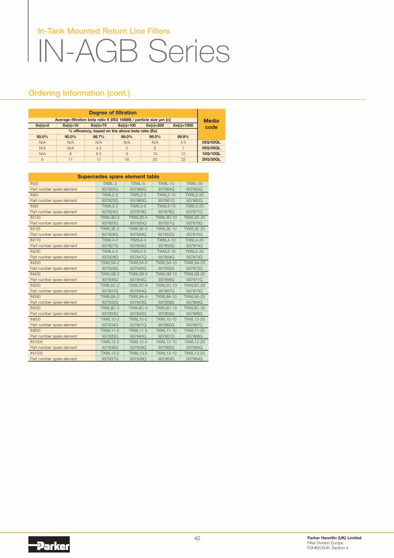
In-Tank Mounted Return Line Filters
IN-AGB SeriesOrdering Information (cont.)
Parker Hannifin (UK) Limited
Filter Division Europe
FDHB200UK. Section 4
42
IN30
Part number spare element
IN60
Part number spare element
IN90
Part number spare element
IN120
Part number spare element
IN125
Part number spare element
IN170
Part number spare element
IN230
Part number spare element
IN300
Part number spare element
IN400
Part number spare element
IN500
Part number spare element
IN390
Part number spare element
IN500
Part number spare element
IN600
Part number spare element
IN800
Part number spare element
IN1000
Part number spare element
IN1500
Part number spare element
TXWL-20
937883Q
TXWL2-20
937882Q
TXWL3-20
937877Q
TXWL3D-20
937876Q
TXWL3E-20
937875Q
TXWL4-20
937874Q
TXWL5-20
937873Q
TXWL5A-20
937872Q
TXWL5B-20
937871Q
TWXL5C-20
937870Q
TXWL8A-20
937869Q
TXWL8C-20
937868Q
TXWL10-20
937867Q
TXWL11-20
937866Q
TXWL12-20
937865Q
TXWL13-20
937864Q
TXWL-10
937884Q
TXWL2-10
937881Q
TXWL3-10
937878Q
TXWL3D-10
937851Q
TXWL3E-10
937852Q
TXWL4-10
937853Q
TXWL5-10
937854Q
TXWL5A-10
937855Q
TXWL5B-10
937856Q
TWXL5C-10
937857Q
TXWL8A-10
937858Q
TXWL8C-10
937859Q
TXWL10-10
937860Q
TXWL11-10
937861Q
TXWL12-10
937862Q
TXWL13-10
937863Q
TXWL-5
937885Q
TXWL2-5
937880Q
TXWL3-5
937879Q
TXWL3D-5
937850Q
TXWL3E-5
937849Q
TXWL4-5
937848Q
TXWL5-5
937847Q
TXWL5A-5
937846Q
TXWL5B-5
937845Q
TXWL5C-5
937844Q
TXWL8A-5
937843Q
TXWL8C-5
937842Q
TXWL10-5
937841Q
TXWL11-5
937840Q
TXWL12-5
937839Q
TXWL13-5
937838Q
TXWL-2
937822Q
TXWL2-2
937823Q
TXWL3-2
937824Q
TXWL3D-2
937825Q
TXWL3E-2
937826Q
TXWL4-2
937827Q
TXWL5-2
937828Q
TXWL5A-2
937829Q
TXWL5B-2
937830Q
TXWL5C-2
937831Q
TXWL8A-2
937832Q
TXWL8C-2
937833Q
TXWL10-2
937834Q
TXWL11-2
937835Q
TXWL12-2
937836Q
TXWL13-2
937837Q
Supercedes spare element table
Average filtration beta ratio ß (ISO 16889) / particle size µm [c]
% efficiency, based on the above beta ratio (ßx)
ßx(c)=2
50.0%
N/A
N/A
N/A
6
Degree of filtration
Media
codeßx(c)=10
90.0%
N/A
N/A
6
11
ßx(c)=75
98.7%
N/A
4.5
8.5
17
ßx(c)=100
99.0%
N/A
5
9
18
ßx(c)=200
99.5%
N/A
6
10
20
ßx(c)=1000
99.9%
4.5
7
12
22
02Q/02QL
05Q/05QL
10Q/10QL
20Q/20QL
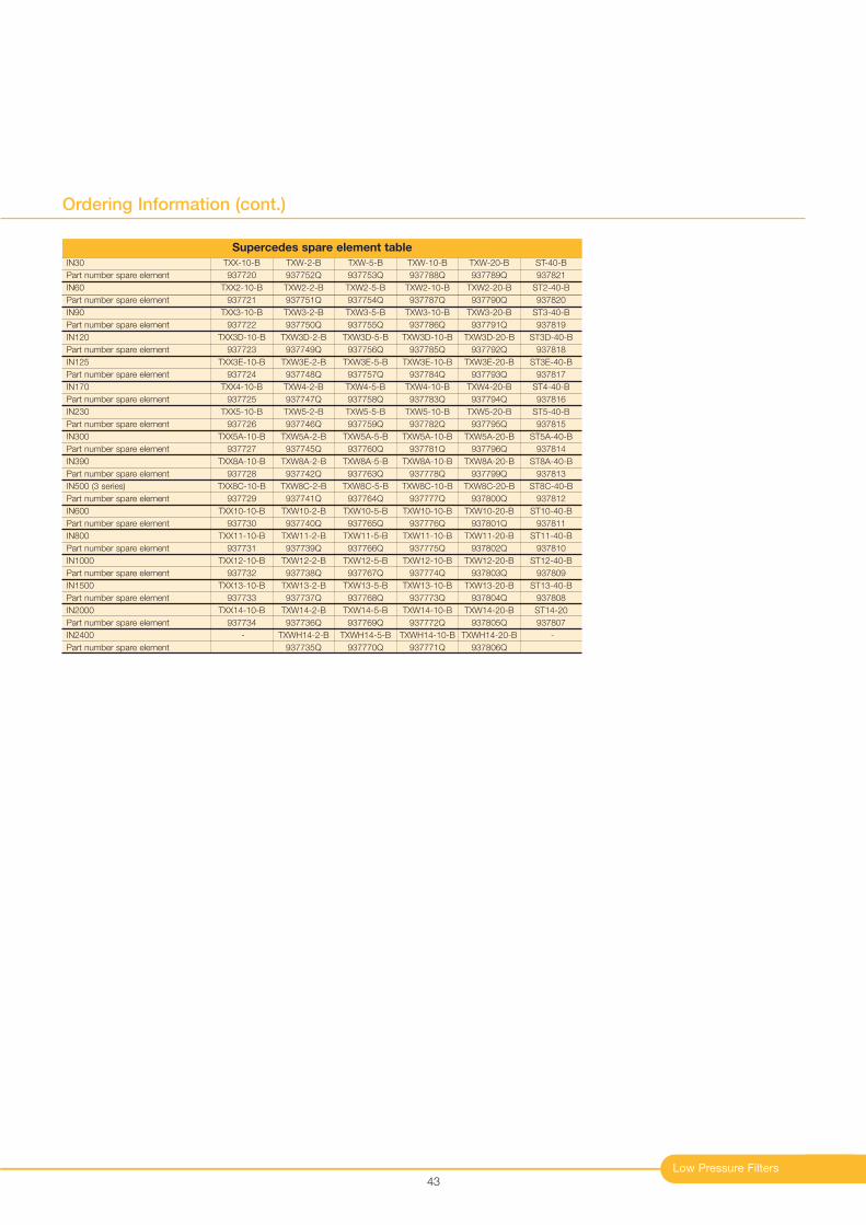
Low Pressure Filters
Ordering Information (cont.)
43
IN30
Part number spare element
IN60
Part number spare element
IN90
Part number spare element
IN120
Part number spare element
IN125
Part number spare element
IN170
Part number spare element
IN230
Part number spare element
IN300
Part number spare element
IN390
Part number spare element
IN500 (3 series)
Part number spare element
IN600
Part number spare element
IN800
Part number spare element
IN1000
Part number spare element
IN1500
Part number spare element
IN2000
Part number spare element
IN2400
Part number spare element
TXX-10-B
937720
TXX2-10-B
937721
TXX3-10-B
937722
TXX3D-10-B
937723
TXX3E-10-B
937724
TXX4-10-B
937725
TXX5-10-B
937726
TXX5A-10-B
937727
TXX8A-10-B
937728
TXX8C-10-B
937729
TXX10-10-B
937730
TXX11-10-B
937731
TXX12-10-B
937732
TXX13-10-B
937733
TXX14-10-B
937734
-
TXW-20-B
937789Q
TXW2-20-B
937790Q
TXW3-20-B
937791Q
TXW3D-20-B
937792Q
TXW3E-20-B
937793Q
TXW4-20-B
937794Q
TXW5-20-B
937795Q
TXW5A-20-B
937796Q
TXW8A-20-B
937799Q
TXW8C-20-B
937800Q
TXW10-20-B
937801Q
TXW11-20-B
937802Q
TXW12-20-B
937803Q
TXW13-20-B
937804Q
TXW14-20-B
937805Q
TXWH14-20-B
937806Q
ST-40-B
937821
ST2-40-B
937820
ST3-40-B
937819
ST3D-40-B
937818
ST3E-40-B
937817
ST4-40-B
937816
ST5-40-B
937815
ST5A-40-B
937814
ST8A-40-B
937813
ST8C-40-B
937812
ST10-40-B
937811
ST11-40-B
937810
ST12-40-B
937809
ST13-40-B
937808
ST14-20
937807
-
TXW-10-B
937788Q
TXW2-10-B
937787Q
TXW3-10-B
937786Q
TXW3D-10-B
937785Q
TXW3E-10-B
937784Q
TXW4-10-B
937783Q
TXW5-10-B
937782Q
TXW5A-10-B
937781Q
TXW8A-10-B
937778Q
TXW8C-10-B
937777Q
TXW10-10-B
937776Q
TXW11-10-B
937775Q
TXW12-10-B
937774Q
TXW13-10-B
937773Q
TXW14-10-B
937772Q
TXWH14-10-B
937771Q
TXW-5-B
937753Q
TXW2-5-B
937754Q
TXW3-5-B
937755Q
TXW3D-5-B
937756Q
TXW3E-5-B
937757Q
TXW4-5-B
937758Q
TXW5-5-B
937759Q
TXW5A-5-B
937760Q
TXW8A-5-B
937763Q
TXW8C-5-B
937764Q
TXW10-5-B
937765Q
TXW11-5-B
937766Q
TXW12-5-B
937767Q
TXW13-5-B
937768Q
TXW14-5-B
937769Q
TXWH14-5-B
937770Q
TXW-2-B
937752Q
TXW2-2-B
937751Q
TXW3-2-B
937750Q
TXW3D-2-B
937749Q
TXW3E-2-B
937748Q
TXW4-2-B
937747Q
TXW5-2-B
937746Q
TXW5A-2-B
937745Q
TXW8A-2-B
937742Q
TXW8C-2-B
937741Q
TXW10-2-B
937740Q
TXW11-2-B
937739Q
TXW12-2-B
937738Q
TXW13-2-B
937737Q
TXW14-2-B
937736Q
TXWH14-2-B
937735Q
Supercedes spare element table

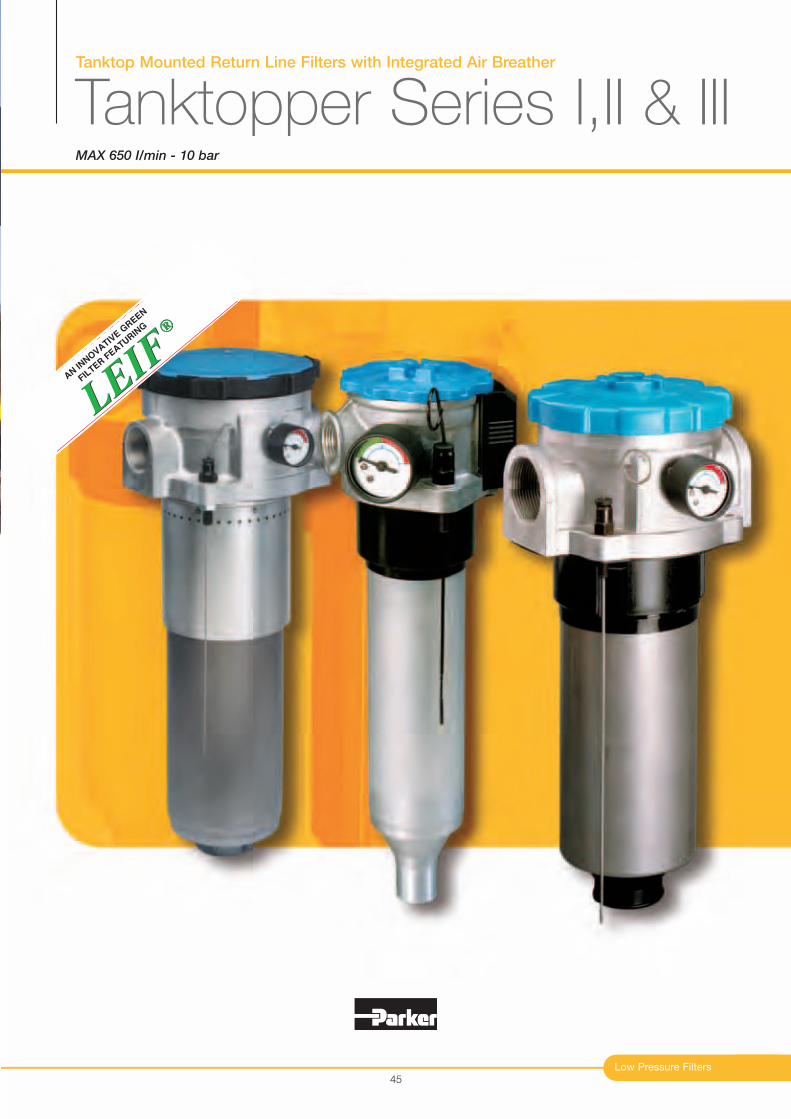
Tanktop Mounted Return Line Filters with Integrated Air Breather
Tanktopper Series I,II & IIIMAX 650 I/min - 10 bar
Low Pressure Filters
®
LEIF
LEIF
®
AN IN
NO
VATIV
E G
REEN
FIL
TER F
EATURIN
G
45
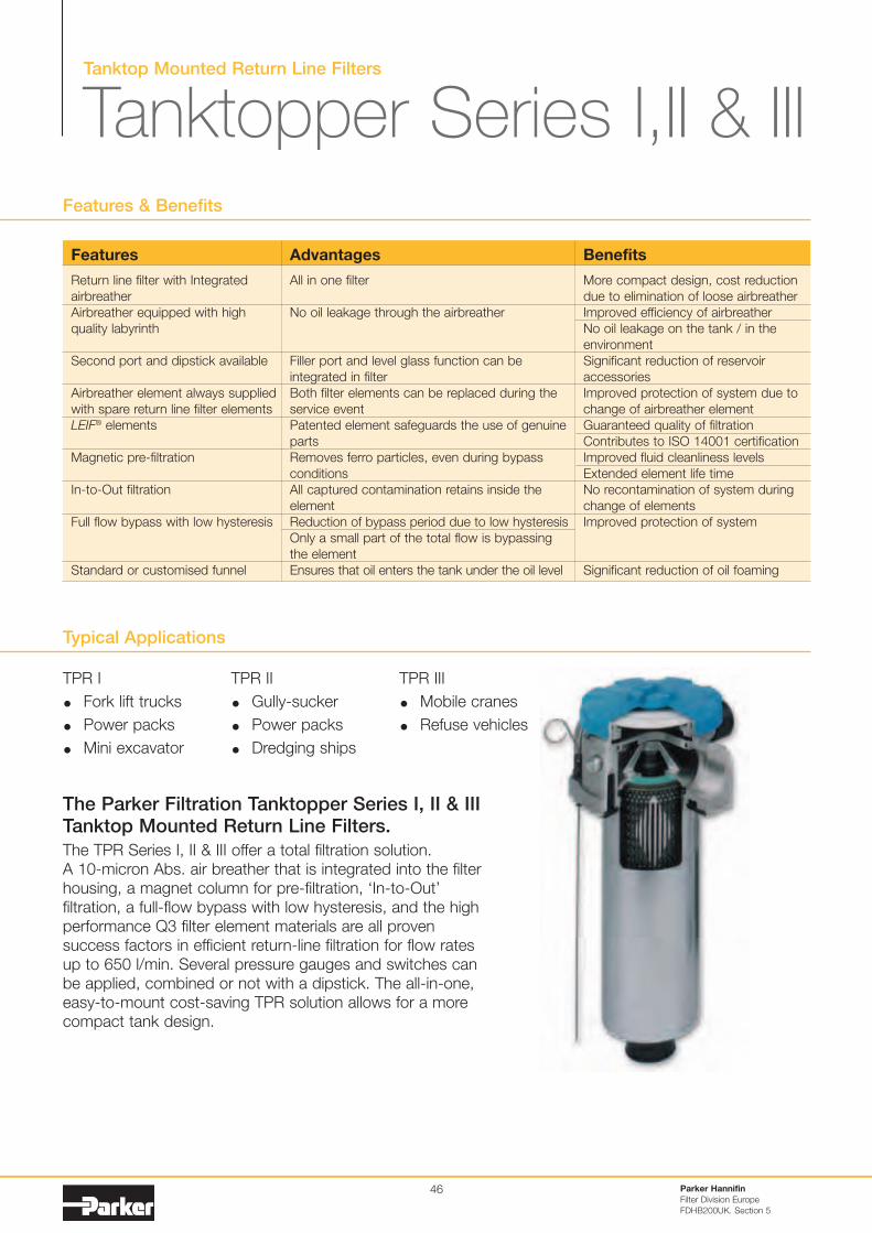
Tanktop Mounted Return Line Filters
Tanktopper Series I,II & III
Typical Applications
The Parker Filtration Tanktopper Series I, II & IIITanktop Mounted Return Line Filters.
The TPR Series I, II & III offer a total filtration solution.
A 10-micron Abs. air breather that is integrated into the filter
housing, a magnet column for pre-filtration, ‘In-to-Out’
filtration, a full-flow bypass with low hysteresis, and the high
performance Q3 filter element materials are all proven
success factors in efficient return-line filtration for flow rates
up to 650 l/min. Several pressure gauges and switches can
be applied, combined or not with a dipstick. The all-in-one,
easy-to-mount cost-saving TPR solution allows for a more
compact tank design.
Features & Benefits
Parker Hannifin
Filter Division Europe
FDHB200UK. Section 5
46
Features
Return line filter with Integrated
airbreather
Airbreather equipped with high
quality labyrinth
Second port and dipstick available
Airbreather element always supplied
with spare return line filter elements
LEIF® elements
Magnetic pre-filtration
In-to-Out filtration
Full flow bypass with low hysteresis
Standard or customised funnel
Advantages
All in one filter
No oil leakage through the airbreather
Filler port and level glass function can be
integrated in filter
Both filter elements can be replaced during the
service event
Patented element safeguards the use of genuine
parts
Removes ferro particles, even during bypass
conditions
All captured contamination retains inside the
element
Reduction of bypass period due to low hysteresis
Only a small part of the total flow is bypassing
the element
Ensures that oil enters the tank under the oil level
Benefits
More compact design, cost reduction
due to elimination of loose airbreather
Improved efficiency of airbreather
No oil leakage on the tank / in the
environment
Significant reduction of reservoir
accessories
Improved protection of system due to
change of airbreather element
Guaranteed quality of filtration
Contributes to ISO 14001 certification
Improved fluid cleanliness levels
Extended element life time
No recontamination of system during
change of elements
Improved protection of system
Significant reduction of oil foaming
TPR I
Fork lift trucks
Power packs
Mini excavator
TPR II
Gully-sucker
Power packs
Dredging ships
TPR III
Mobile cranes
Refuse vehicles
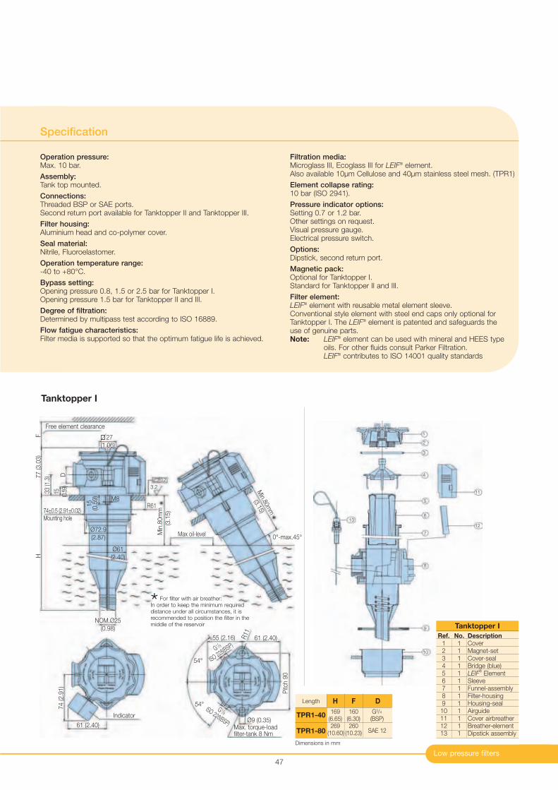
Low pressure filters
Specification
Operation pressure:Max. 10 bar.
Assembly:Tank top mounted.
Connections:Threaded BSP or SAE ports.Second return port available for Tanktopper II and Tanktopper III.
Filter housing:Aluminium head and co-polymer cover.
Seal material:Nitrile, Fluoroelastomer.
Operation temperature range:-40 to +80°C.
Bypass setting:Opening pressure 0.8, 1.5 or 2.5 bar for Tanktopper I.Opening pressure 1.5 bar for Tanktopper II and III.
Degree of filtration:Determined by multipass test according to ISO 16889.
Flow fatigue characteristics:Filter media is supported so that the optimum fatigue life is achieved.
Filtration media:Microglass III, Ecoglass III for LEIF
® element.Also available 10µm Cellulose and 40µm stainless steel mesh. (TPR1)
Element collapse rating:10 bar (ISO 2941).
Pressure indicator options:Setting 0.7 or 1.2 bar.Other settings on request.Visual pressure gauge.Electrical pressure switch.
Options:Dipstick, second return port.
Magnetic pack:Optional for Tanktopper I.Standard for Tanktopper II and III.
Filter element:LEIF
® element with reusable metal element sleeve.Conventional style element with steel end caps only optional forTanktopper I. The LEIF
® element is patented and safeguards the use of genuine parts.Note: LEIF
® element can be used with mineral and HEES type oils. For other fluids consult Parker Filtration.LEIF
® contributes to ISO 14001 quality standards
47
Ref. No. Description1 1 Cover2 1 Magnet-set3 1 Cover-seal4 1 Bridge (blue)5 1 LEIF
®Element
6 1 Sleeve7 1 Funnel-assembly8 1 Filter-housing9 1 Housing-seal10 1 Airguide11 1 Cover airbreather12 1 Breather-element13 1 Dipstick assembly
Tanktopper I
FH
77 (3.0
3)
27
(1.06)
3.2
33 (1
.3)
15 (0.5
9)
15
(0.5
9)
M8
Ø72.9
(2.87)
D
Free element clearance
R61
Ø61
(2.40)
Min
.80m
m
(3.1
5)74±0.5 (2.91±0.02)
Mounting hole
NOM.Ø25
(0.98)
Max oil-level
Min.80m
m
(3.15)
0°-max.45°
* For filter with air breather:In order to keep the minimum requireddistance under all circumstances, it isrecommended to position the filter in themiddle of the reservoir
54°
54°
61 (2.40)55 (2.16) R11
Pitc
h 9
0
Ø9 (0.35)
G 1/8ISO 228(BSP)
G1 /8
ISO 228(BSP)
Max. torque-loadfilter-tank 8 Nm
74 (2.9
1)
61 (2.40)
Indicator
Tanktopper I
169 160 G3/4
(6.65) (6.30) (BSP)269 260
SAE 12(10.60) (10.23)
Length H F D
TPR1-40
TPR1-80
0.2
1
2
3
4
5
6
7
8
9
10
11
12
13
Dimensions in mm
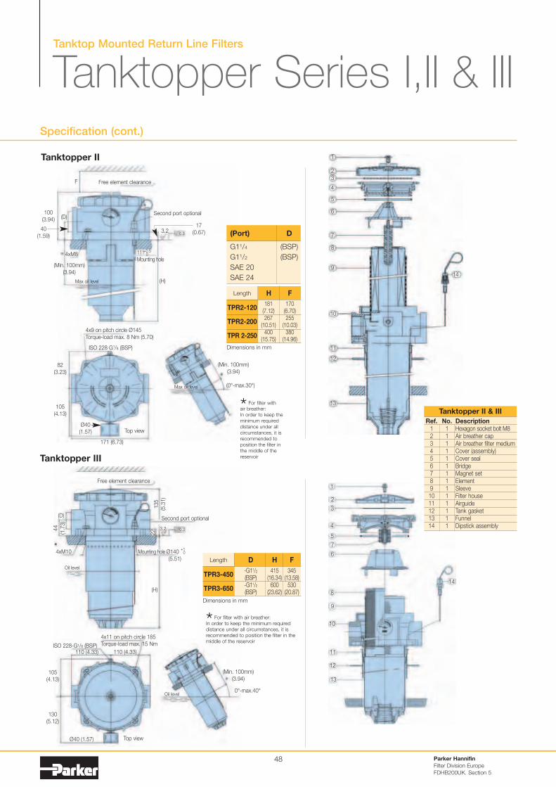
Tanktop Mounted Return Line Filters
Tanktopper Series I,II & IIISpecification (cont.)
Parker Hannifin
Filter Division Europe
FDHB200UK. Section 5
48
(D)
4xM8
(Min. 100mm)
(3.94)
Max oil level
Free element clearance
0.3
(H)
Second port optional
111
Mounting hole
+0.50
(Min. 100mm)
(3.94)
Max oil level (0°-max.30°)
4x9 on pitch circle Ø145
Torque-load max. 8 Nm (5.70)
ISO 228 G1/8 (BSP)
* For filter withair breather:
In order to keep the
minimum required
distance under all
circumstances, it is
recommended to
position the filter in
the middle of the
reservoir
1
2
3
4
5
6
7
8
9
10
11
12
13
14
Ref. No. Description1 1 Hexagon socket bolt M82 1 Air breather cap3 1 Air breather filter medium4 1 Cover (assembly)5 1 Cover seal6 1 Bridge7 1 Magnet set8 1 Element9 1 Sleeve10 1 Filter house11 1 Airguide12 1 Tank gasket13 1 Funnel14 1 Dipstick assembly
Tanktopper II & III
Tanktopper II
(D)
4xM10
Oil level
0.3
(H)
Second port optional
Mounting hole Ø140
(5.51)
(Min. 100mm)
(3.94)
Oil level0°-max.40°
4x11 on pitch circle 185
Torque-load max. 15 NmISO 228-G1/8 (BSP)
* For filter with air breather:In order to keep the minimum requireddistance under all circumstances, it isrecommended to position the filter in themiddle of the reservoir
Top view
Top view
110 (4.33)
1
2
3
4
5
6
7
8
9
10
11
12
14
3.2
Free element clearance
135
(5.3
1)
22
G11/4 (BSP)
G11/2 (BSP)
SAE 20
SAE 24
(Port) D
3.2
13
181 170(7.12) (6.70)267 255
(10.51) (10.03)400 380
(15.75) (14.96)
Length H F
TPR2-120
TPR2-200
TPR 2-250
F
100
(3.94)
40
(1.59)
17
(0.67)
82
(3.23)
105
(4.13)
171 (6.73)
Ø40
(1.57)
+10
105
(4.13)
130
(5.12)
44
(1.7
3)
Ø40 (1.57)
110 (4.33)
Tanktopper III
-G11/2 415 345(BSP) (16.34) (13.58)-G11/2 600 530(BSP) (23.62) (20.87)
Length D H F
TPR3-450
TPR3-650
Dimensions in mm
Dimensions in mm
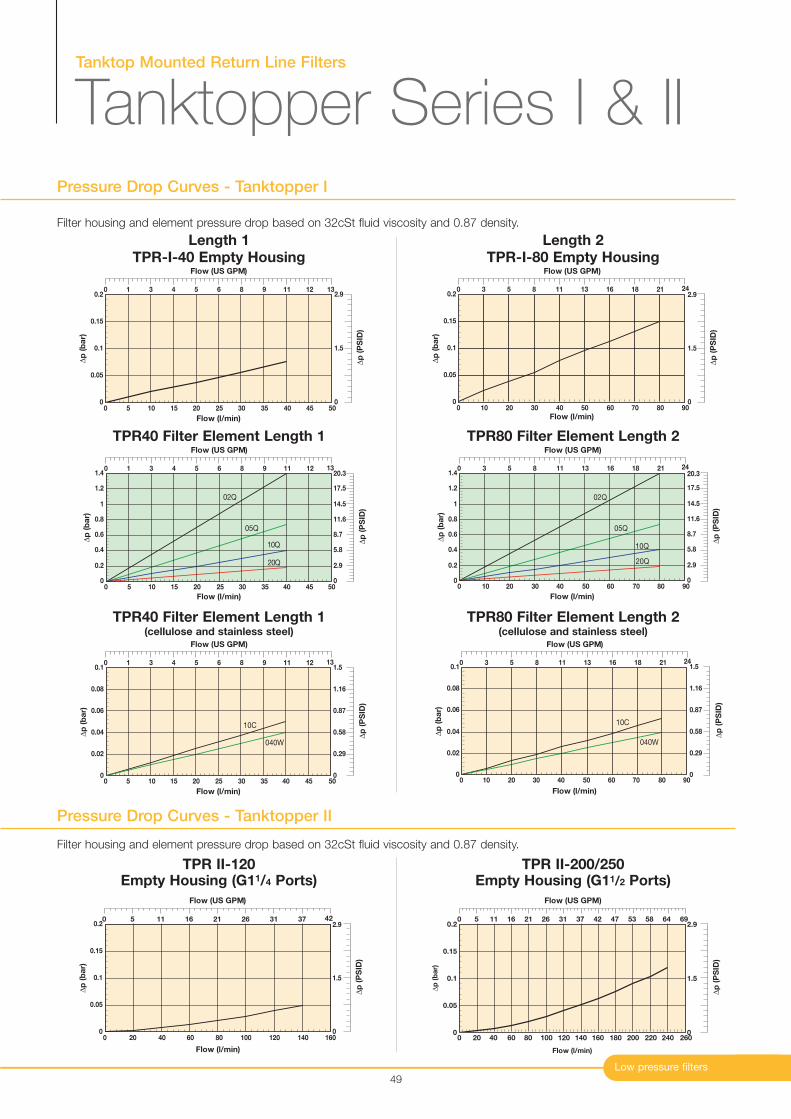
0
0.1
0.2
0 20 40 60 80 100 120 140 160
Flow (l/min)
∆p
(b
ar)
0.05
0.15
Flow (US GPM)
0 5 11 16 21 26 31 37 42
∆p
(P
SID
)
0
1.5
2.9
0
0.1
0 20 40 60 80 100 120 140 160 180 200 220 240 260
Flow (l/min)
∆p
(b
ar)
0.05
0.15
0.2
Flow (US GPM)
0 5 11 16 21 26 31 37 42 47 53 58 64 69
∆p
(P
SID
)
0
1.5
2.9
Filter housing and element pressure drop based on 32cSt fluid viscosity and 0.87 density.
TPR II-120 TPR II-200/250
Tanktop Mounted Return Line Filters
Tanktopper Series I & II
Low pressure filters
Pressure Drop Curves - Tanktopper I
49
Length 1 Length 2
Filter housing and element pressure drop based on 32cSt fluid viscosity and 0.87 density.
Pressure Drop Curves - Tanktopper II
0
0.1
0.2
0 5 10 15 20 25 30 35 40 45 50
Flow (l/min)
∆p
(b
ar)
0.05
0.15
Flow (US GPM)
0 1 3 4 5 6 8 9 11 12 13
∆p
(P
SID
)
0
1.5
2.9
TPR-I-40 Empty Housing
0
0.1
0.2
0 10 20 30 40 50 60 70 80 90
Flow (l/min)
∆p
(b
ar)
0.15
0.05
Flow (US GPM)
0 3 5 8 11 13 16 18 21 24
∆p
(P
SID
)
0
1.5
2.9
TPR-I-80 Empty Housing
0
0.2
0.4
0.6
0.8
1
1.2
1.4
0 5 10 15 20 25 30 35 40 45 50
02Q
05Q
10Q
20Q
∆p
(b
ar)
Flow (l/min)
Flow (US GPM)
0 1 3 4 5 6 8 9 11 12 13
∆p
(P
SID
)
0
2.9
5.8
8.7
11.6
14.5
17.5
20.3
0
0.02
0.04
0.06
0.08
0.1
0 10 20 30 40 50
10C
040W
Flow (l/min)
∆p
(b
ar)
5 15 25 35 45
Flow (US GPM)
0 1 3 4 5 6 8 9 11 12 13
∆p
(P
SID
)
0
0.29
0.58
0.87
1.16
1.5
TPR40 Filter Element Length 1
TPR40 Filter Element Length 1(cellulose and stainless steel)
0
0.2
0.4
0.6
0.8
1
1.2
1.4
0 10 20 30 40 50 60 70 80 90
02Q
05Q
10Q
20Q
Flow (l/min)
∆p
(b
ar)
Flow (US GPM)
0 3 5 8 11 13 16 18 21 24
∆p
(P
SID
)
0
2.9
5.8
8.7
11.6
14.5
17.5
20.3
0
0.02
0.04
0.06
0.08
0.1
0 10 20 30 40 50 60 70 80 90
10C
040W
Flow (l/min)
∆p
(b
ar)
Flow (US GPM)
0 3 5 8 11 13 16 18 21 24
∆p
(P
SID
)
0
0.29
0.58
0.87
1.16
1.5
TPR80 Filter Element Length 2
TPR80 Filter Element Length 2(cellulose and stainless steel)
Empty Housing (G11/4 Ports) Empty Housing (G11/2 Ports)
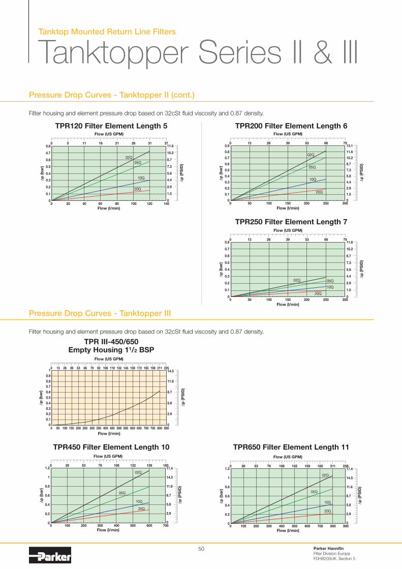
Tanktop Mounted Return Line Filters
Tanktopper Series II & III
50
Pressure Drop Curves - Tanktopper II (cont.)
Filter housing and element pressure drop based on 32cSt fluid viscosity and 0.87 density.
Parker Hannifin
Filter Division Europe
FDHB200UK. Section 5
0
0.2
0.4
0.6
0.8
1.2
1
0 100 200 400 500 600 700
02Q
05Q
10Q
20Q
Flow (l/min)
∆p
(b
ar)
300
Flow (US GPM)
26 53 106 132 159 1850 79
∆p
(P
SID
)
0
5.8
8.7
17.4
14.5
11.6
2.9
TPR450 Filter Element Length 10 TPR650 Filter Element Length 11
0
0.2
0.4
0.6
0.8
1.2
1
0 100 200 400 600 700 900
02Q
05Q
10Q
20Q
Flow (l/min)
∆p
(b
ar)
300 500 800
∆p
(P
SID
)
Flow (US GPM)
0
5.8
8.7
17.4
14.5
26 79 106 185 211 2380
11.6
2.9
53 159132
0
0.1
0.2
0.3
0.4
0.5
0.6
0.7
0.8
0 20 40 60 80 100 120 140
02Q
05Q
10Q
20Q
∆p
(b
ar)
Flow (l/min)
Flow (US GPM)
0 5 11 16 21 26 31 37
∆p
(P
SID
)
0
1.5
2.9
4.4
5.8
7.3
8.7
10.2
11.6
TPR120 Filter Element Length 5
0
0.1
0.2
0.3
0.4
0.5
0.6
0.7
0.9
0.8
0 50 100 150 200 250 300
02Q
05Q
10Q
20Q
Flow (l/min)
∆p
(b
ar)
Flow (US GPM)
0 13 26 39 53 66 79
∆p
(P
SID
)
0
1.5
2.9
4.4
5.8
7.3
8.7
10.2
13.1
11.6
TPR200 Filter Element Length 6
0
0.1
0.2
0.3
0.4
0.5
0.6
0.7
0.8
0 50 100 150 200 250 300
02Q 05Q
10Q
20Q
Flow (l/min)
∆p
(b
ar)
Flow (US GPM)
0 13 26 39 53 66 79
∆p
(P
SID
)
0
1.5
2.9
4.4
5.8
7.3
8.7
10.2
11.6
TPR250 Filter Element Length 7
TPR III-450/650
Filter housing and element pressure drop based on 32cSt fluid viscosity and 0.87 density.
Pressure Drop Curves - Tanktopper III
0
0.1
0.2
0.3
0.4
0.5
0.6
0.7
0.8
0.9
1
0 50 100 150 200 250 300 350 400 450 500 550 600 650 700 750 800 850
Flow (l/min)
∆p
(b
ar)
Flow (US GPM)
0 13 26 39 53 66 79 92 106 119 132 145 159 172 185 198 211 225
∆p
(P
SID
)
0
2.9
5.8
8.7
11.6
14.5
Empty Housing 11/2 BSP
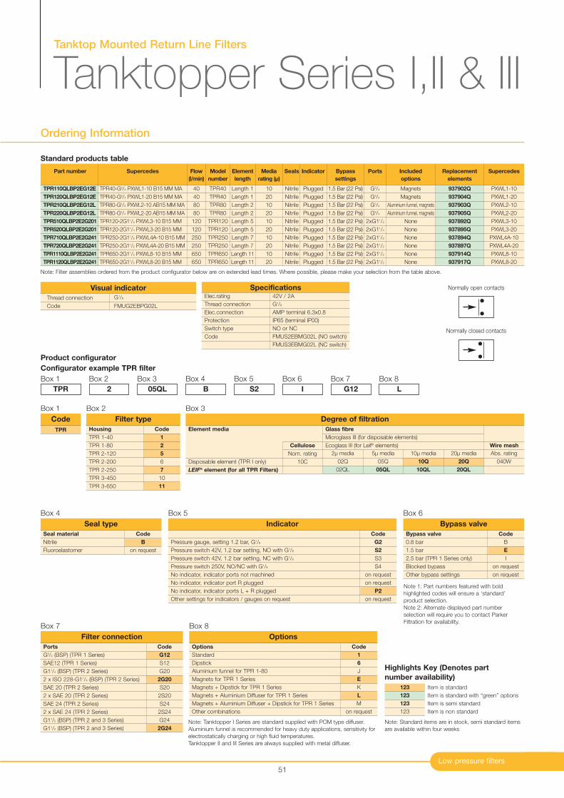
Tanktop Mounted Return Line Filters
Tanktopper Series I,II & III
Low pressure filters
Ordering Information
51
Part number
TPR110QLBP2EG12E
TPR120QLBP2EG12E
TPR210QLBP2EG12L
TPR220QLBP2EG12L
TPR510QLBP2E2G201
TPR520QLBP2E2G201
TPR710QLBP2E2G241
TPR720QLBP2E2G241
TPR1110QLBP2E2G241
TPR1120QLBP2E2G241
Supercedes
TPR40-G3/4 PXWL1-10 B15 MM MA
TPR40-G3/4 PXWL1-20 B15 MM MA
TPR80-G3/4 PXWL2-10 AB15 MM MA
TPR80-G3/4 PXWL2-20 AB15 MM MA
TPR120-2G11/4 PXWL3-10 B15 MM
TPR120-2G11/4 PXWL3-20 B15 MM
TPR250-2G11/2 PXWL4A-10 B15 MM
TPR250-2G11/2 PXWL4A-20 B15 MM
TPR650-2G11/2 PXWL8-10 B15 MM
TPR650-2G11/2 PXWL8-20 B15 MM
Flow
(l/min)
40
40
80
80
120
120
250
250
650
650
Model
number
TPR40
TPR40
TPR80
TPR80
TPR120
TPR120
TPR250
TPR250
TPR650
TPR650
Element
length
Length 1
Length 1
Length 2
Length 2
Length 5
Length 5
Length 7
Length 7
Length 11
Length 11
Media
rating (µ)
10
20
10
20
10
20
10
20
10
20
Seals
Nitrile
Nitrile
Nitrile
Nitrile
Nitrile
Nitrile
Nitrile
Nitrile
Nitrile
Nitrile
Indicator
Plugged
Plugged
Plugged
Plugged
Plugged
Plugged
Plugged
Plugged
Plugged
Plugged
Bypass
settings
1.5 Bar (22 Psi)
1.5 Bar (22 Psi)
1.5 Bar (22 Psi)
1.5 Bar (22 Psi)
1.5 Bar (22 Psi)
1.5 Bar (22 Psi)
1.5 Bar (22 Psi)
1.5 Bar (22 Psi)
1.5 Bar (22 Psi)
1.5 Bar (22 Psi)
Included
options
Magnets
Magnets
Aluminium funnel, magnets
Aluminium funnel, magnets
None
None
None
None
None
None
Replacement
elements
937902Q
937904Q
937903Q
937905Q
937892Q
937895Q
937894Q
937897Q
937914Q
937917Q
Supercedes
PXWL1-10
PXWL1-20
PXWL2-10
PXWL2-20
PXWL3-10
PXWL3-20
PXWL4A-10
PXWL4A-20
PXWL8-10
PXWL8-20
Ports
G3/4
G3/4
G3/4
G3/4
2xG11/4
2xG11/4
2xG11/2
2xG11/2
2xG11/2
2xG11/2
Product configurator
Configurator example TPR filter
Box 1
Code
1
2
5
6
7
10
11
Housing
TPR 1-40
TPR 1-80
TPR 2-120
TPR 2-200
TPR 2-250
TPR 3-450
TPR 3-650
Filter type
Box 2
TPR
Box 2
2
Box 3
05QL
Box 4
B
Box 5
S2
Box 6
I
Box 7
G12
Box 8
L
Note 1: Part numbers featured with bold
highlighted codes will ensure a ‘standard’
product selection.
Note 2: Alternate displayed part number
selection will require you to contact Parker
Filtration for availability.
TPR
Code
Box 1
Code
B
on request
Seal material
Nitrile
Fluoroelastomer
Seal type
Box 4
Code
B
E
I
on request
on request
Bypass valve
0.8 bar
1.5 bar
2.5 bar (TPR 1 Series only)
Blocked bypass
Other bypass settings
Bypass valve
Box 6
Code
G2
S2
S3
S4
on request
on request
P2
on request
Pressure gauge, setting 1.2 bar, G1/8
Pressure switch 42V, 1.2 bar setting, NO with G1/8
Pressure switch 42V, 1.2 bar setting, NC with G1/8
Pressure switch 250V, NO/NC with G1/8
No indicator, indicator ports not machined
No indicator, indicator port R plugged
No indicator, indicator ports L + R plugged
Other settings for indicators / gauges on request
Indicator
Box 5
Code
G12
S12
G20
2G20
S20
2S20
S24
2S24
G24
2G24
Ports
G3/4 (BSP) (TPR 1 Series)
SAE12 (TPR 1 Series)
G11/4 (BSP) (TPR 2 Series)
2 x ISO 228-G11/4 (BSP) (TPR 2 Series)
SAE 20 (TPR 2 Series)
2 x SAE 20 (TPR 2 Series)
SAE 24 (TPR 2 Series)
2 x SAE 24 (TPR 2 Series)
G11/2 (BSP) (TPR 2 and 3 Series)
G11/2 (BSP) (TPR 2 and 3 Series)
Filter connection
Box 7
Code
1
6
J
E
K
L
M
on request
Options
Standard
Dipstick
Aluminium funnel for TPR 1-80
Magnets for TPR 1 Series
Magnets + Dipstick for TPR 1 Series
Magnets + Aluminium Diffuser for TPR 1 Series
Magnets + Aluminium Diffuser + Dipstick for TPR 1 Series
Other combinations
Options
Box 8
Note: Tanktopper I Series are standard supplied with POM type diffuser.
Aluminium funnel is recommended for heavy duty applications, sensitivity for
electrostatically charging or high fluid temperatures.
Tanktopper II and III Series are always supplied with metal diffuser.
Elec.rating
Thread connection
Elec.connection
Protection
Switch type
Code
42V / 2A
G1/8
AMP terminal 6.3x0.8
IP65 (terminal IP00)
NO or NC
FMUS2EBMG02L (NO switch)
FMUS3EBMG02L (NC switch)
Specifications
Standard products table
Note: Filter assemblies ordered from the product configurator below are on extended lead times. Where possible, please make your selection from the table above.
Thread connection G1/8
Code FMUG2EBPG02L
Visual indicator Normally open contacts
Normally closed contacts
Box 3
Element media
Disposable element (TPR I only)
LEIF® element (for all TPR Filters)
Cellulose
Nom. rating
10C
20µ media
20Q
20QL
Abs. rating
040W
10µ media
10Q
10QL
5µ media
05Q
05QL
2µ media
02Q
02QL
Glass fibre
Microglass III (for disposable elements)
Ecoglass III (for Leif® elements) Wire mesh
Degree of filtration
Item is standard
Item is standard with “green” options
Item is semi standard
Item is non standard
123
123
123
123
Highlights Key (Denotes part
number availability)
Note: Standard items are in stock, semi standard items
are available within four weeks
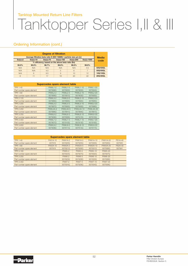
Parker Hannifin
Filter Division Europe
FDHB200UK. Section 5
52
Ordering Information (cont.)
TPR 1-40
Part number spare element
TPR 1-80
Part number spare element
TPR 2-120
Part number spare element
TPR 2-200
Part number spare element
TPR 2-250
Part number spare element
TPR 3-250
Part number spare element
TPR 3-450
Part number spare element
TPR 3-650
Part number spare element
PXWL1-20
937904Q
PXWL2-20
937905Q
PXWL3-20
937895Q
PXWL4-20
937896Q
PXWL4A-20
937897Q
PXWL6-20
937915Q
PXWL7-20
937916Q
PXWL8-20
937917Q
PXWL1-10
937902Q
PXWL2-10
937903Q
PXWL3-10
937892Q
PXWL4-10
937893Q
PXWL4A-10
937894Q
PXWL6-10
937912Q
PXWL7-10
937913Q
PXWL8-10
937914Q
PXWL1-5
937900Q
PXWL2-5
937901Q
PXWL3-5
937889Q
PXWL4-5
937890Q
PXWL4A-5
937891Q
PXWL6-5
937909Q
PXWL7-5
937910Q
PXWL8-5
937911Q
PXWL1-2
937898Q
PXWL2-2
937899Q
PXWL3-2
937886Q
PXWL4-2
937887Q
PXWL4A-2
937888Q
PXWL6-2
937906Q
PXWL7-2
937907Q
PXWL8-2
937908Q
Supercedes spare element table
TPR 1-40
Part number spare element
TPR 1-80
Part number spare element
TPR 3-160
Part number spare element
TPR 3-250
Part number spare element
TPR 3-450
Part number spare element
PXX1A-10
937918
PXX2A-10
937919
PXW1A-20
937935Q
PXW2A-20
937936Q
PXW5-20
937937Q
PXW6-20
937938Q
PXW7-20
937939Q
PS1A-40
937940
PS2A-40
937941
PXW1A-10
937930Q
PXW2A-10
937931Q
PXW5-10
937932Q
PXW6-10
937933Q
PXW7-10
937934Q
PXW1A-5
937925Q
PXW2A-5
937926Q
PXW5-5
937927Q
PXW6-5
937928Q
PXW7-5
937929Q
PXW1A-2
937920Q
PXW2A-2
937921Q
PXW5-2
937922Q
PXW6-2
937923Q
PXW7-2
937924Q
Supercedes spare element table
Tanktop Mounted Return Line Filters
Tanktopper Series I,II & III
Average filtration beta ratio ß (ISO 16889) / particle size µm [c]
% efficiency, based on the above beta ratio (ßx)
ßx(c)=2
50.0%
N/A
N/A
N/A
6
Degree of filtration
Media
codeßx(c)=10
90.0%
N/A
N/A
6
11
ßx(c)=75
98.7%
N/A
4.5
8.5
17
ßx(c)=100
99.0%
N/A
5
9
18
ßx(c)=200
99.5%
N/A
6
10
20
ßx(c)=1000
99.9%
4.5
7
12
22
02Q/02QL
05Q/05QL
10Q/10QL
20Q/20QL
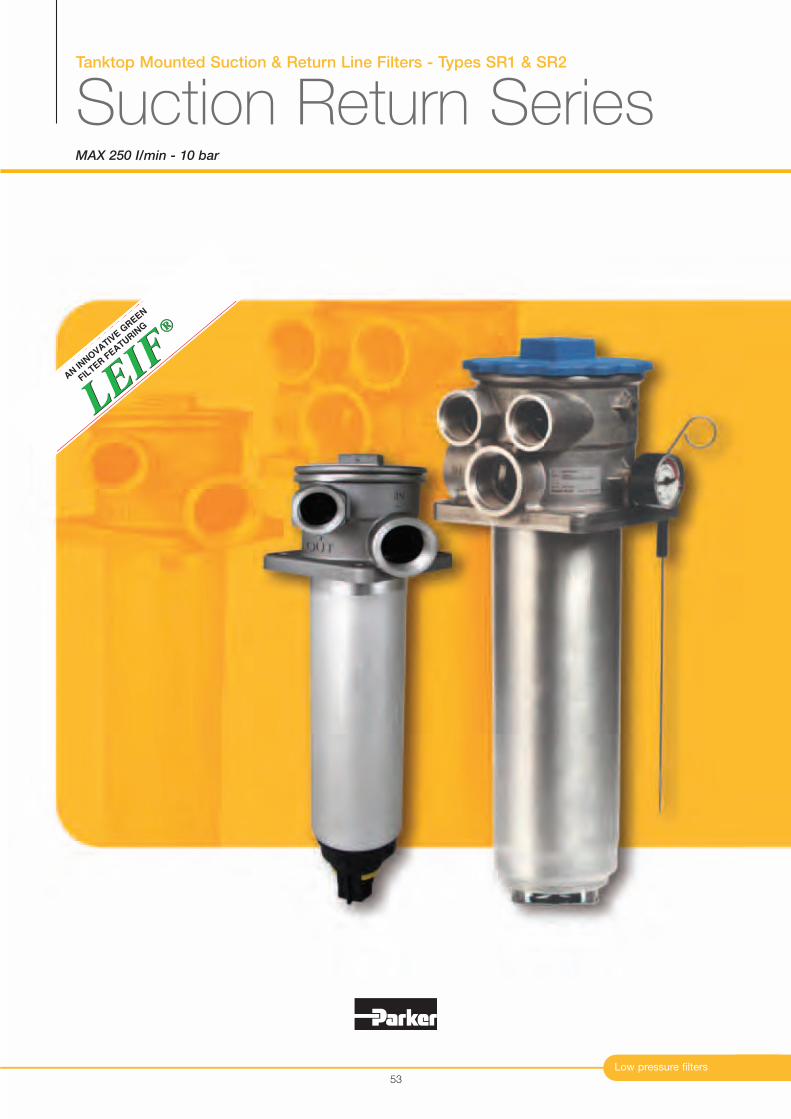
®
LEIF
LEIF
®
AN IN
NO
VATIV
E G
REEN
FIL
TER F
EATURIN
G
Tanktop Mounted Suction & Return Line Filters - Types SR1 & SR2
Suction Return SeriesMAX 250 I/min - 10 bar
Low pressure filters53
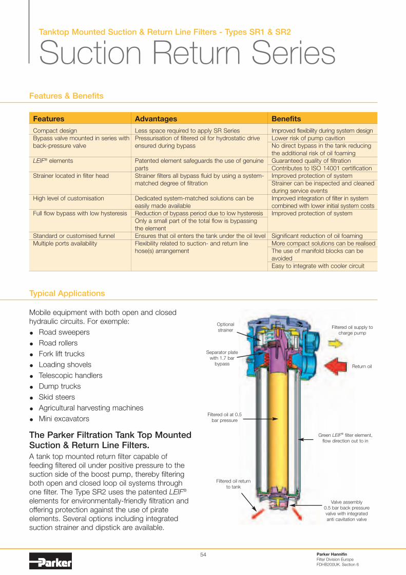
Tanktop Mounted Suction & Return Line Filters - Types SR1 & SR2
Suction Return Series
Typical Applications
Mobile equipment with both open and closedhydraulic circuits. For exemple:
Road sweepers
Road rollers
Fork lift trucks
Loading shovels
Telescopic handlers
Dump trucks
Skid steers
Agricultural harvesting machines
Mini excavators
The Parker Filtration Tank Top MountedSuction & Return Line Filters.
A tank top mounted return filter capable offeeding filtered oil under positive pressure to thesuction side of the boost pump, thereby filteringboth open and closed loop oil systems throughone filter. The Type SR2 uses the patented LEIF®
elements for environmentally-friendly filtration andoffering protection against the use of pirateelements. Several options including integratedsuction strainer and dipstick are available.
Features & Benefits
Parker Hannifin
Filter Division Europe
FDHB200UK. Section 6
54
Features
Compact designBypass valve mounted in series withback-pressure valve
LEIF® elements
Strainer located in filter head
High level of customisation
Full flow bypass with low hysteresis
Standard or customised funnelMultiple ports availability
Advantages
Less space required to apply SR SeriesPressurisation of filtered oil for hydrostatic driveensured during bypass
Patented element safeguards the use of genuinepartsStrainer filters all bypass fluid by using a system-matched degree of filtration
Dedicated system-matched solutions can beeasily made availableReduction of bypass period due to low hysteresisOnly a small part of the total flow is bypassingthe elementEnsures that oil enters the tank under the oil levelFlexibility related to suction- and return linehose(s) arrangement
Benefits
Improved flexibility during system designLower risk of pump cavitionNo direct bypass in the tank reducingthe additional risk of oil foamingGuaranteed quality of filtrationContributes to ISO 14001 certificationImproved protection of systemStrainer can be inspected and cleanedduring service eventsImproved integration of filter in systemcombined with lower initial system costsImproved protection of system
Significant reduction of oil foamingMore compact solutions can be realisedThe use of manifold blocks can beavoidedEasy to integrate with cooler circuit
Optionalstrainer
Filtered oil supply tocharge pump
Return oil
Green LEIF® filter element,flow direction out to in
Valve assembly0.5 bar back pressurevalve with integratedanti cavitation valve
Separator platewith 1.7 bar
bypass
Filtered oil at 0.5bar pressure
Filtered oil returnto tank
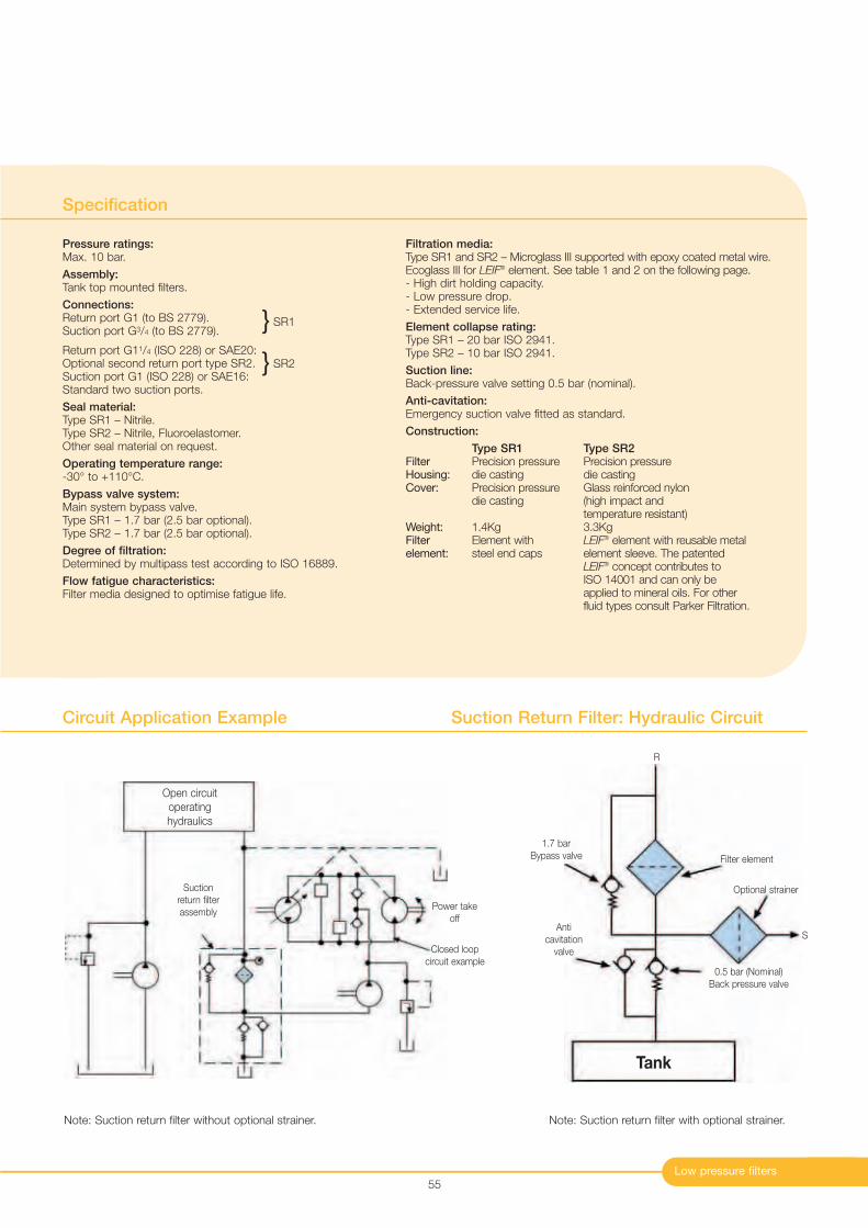
Low pressure filters
Specification
Pressure ratings:Max. 10 bar.
Assembly:Tank top mounted filters.
Connections:Return port G1 (to BS 2779).Suction port G3/4 (to BS 2779).
Return port G11/4 (ISO 228) or SAE20:Optional second return port type SR2.Suction port G1 (ISO 228) or SAE16:Standard two suction ports.
Seal material:Type SR1 – Nitrile.Type SR2 – Nitrile, Fluoroelastomer.Other seal material on request.
Operating temperature range:-30° to +110°C.
Bypass valve system:Main system bypass valve.Type SR1 – 1.7 bar (2.5 bar optional).Type SR2 – 1.7 bar (2.5 bar optional).
Degree of filtration:Determined by multipass test according to ISO 16889.
Flow fatigue characteristics:Filter media designed to optimise fatigue life.
Filtration media:Type SR1 and SR2 – Microglass III supported with epoxy coated metal wire.Ecoglass III for LEIF® element. See table 1 and 2 on the following page.- High dirt holding capacity.- Low pressure drop.- Extended service life.
Element collapse rating:Type SR1 – 20 bar ISO 2941.Type SR2 – 10 bar ISO 2941.
Suction line:Back-pressure valve setting 0.5 bar (nominal).
Anti-cavitation:Emergency suction valve fitted as standard.
Construction:
Type SR1 Type SR2Filter Precision pressure Precision pressureHousing: die casting die castingCover: Precision pressure Glass reinforced nylon
die casting (high impact andtemperature resistant)
Weight: 1.4Kg 3.3KgFilter Element with LEIF® element with reusable metal element: steel end caps element sleeve. The patented
LEIF® concept contributes to ISO 14001 and can only be applied to mineral oils. For other fluid types consult Parker Filtration.
55
Circuit Application Example Suction Return Filter: Hydraulic Circuit
Open circuitoperatinghydraulics
Power takeoff
Closed loopcircuit example
Filter element
0.5 bar (Nominal)Back pressure valve
Tank
1.7 barBypass valve
Anticavitation
valve
R
Suction return filterassembly
Note: Suction return filter without optional strainer.
Optional strainer
S
Note: Suction return filter with optional strainer.
SR1
SR2
}
}
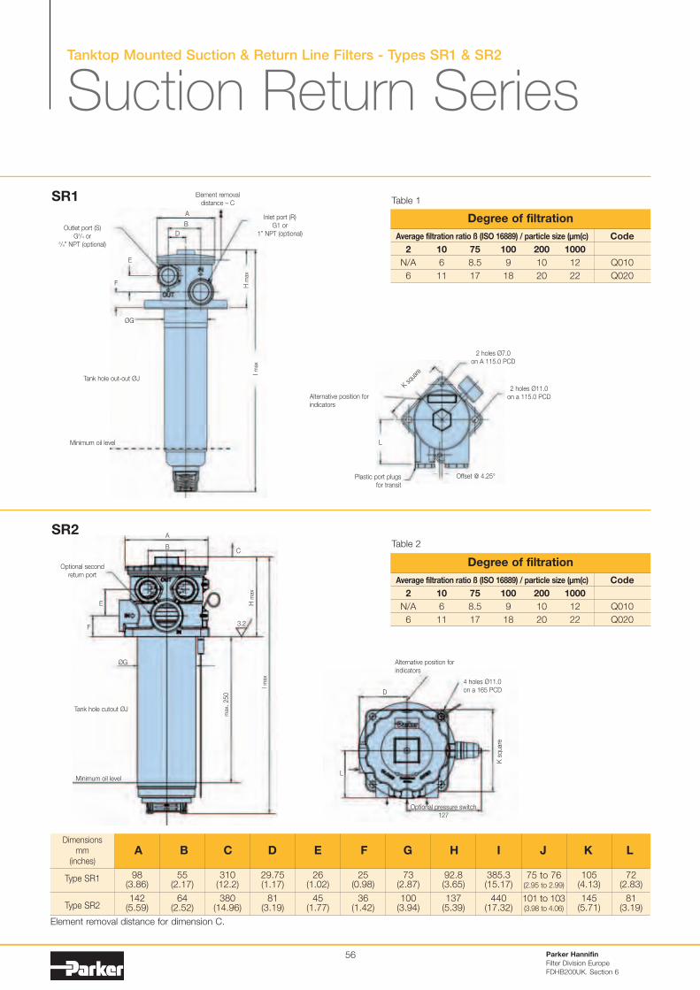
Tanktop Mounted Suction & Return Line Filters - Types SR1 & SR2
Suction Return Series
Parker Hannifin
Filter Division Europe
FDHB200UK. Section 6
56
Dimensionsmm
(inches)
98(3.86)
142(5.59)
Type SR1
Type SR2
55(2.17)
64(2.52)
310(12.2)
380(14.96)
29.75(1.17)
81(3.19)
26(1.02)
45(1.77)
25(0.98)
36(1.42)
73(2.87)
100(3.94)
92.8(3.65)
137(5.39)
385.3(15.17)
440(17.32)
75 to 76(2.95 to 2.99)
101 to 103(3.98 to 4.06)
105(4.13)
145(5.71)
72(2.83)
81(3.19)
A B C D E F G H I J K L
A
B
D
Element removaldistance – C
Inlet port (R)G1 or
1” NPT (optional)
H m
ax
E
F
ØG
Outlet port (S)G3/4 or
3/4” NPT (optional)
I max
Minimum oil level
Tank hole out-out ØJ
2 holes Ø7.0on A 115.0 PCD
2 holes Ø11.0on a 115.0 PCD
Offset @ 4.25°
Alternative position forindicators
Plastic port plugs for transit
L
K squ
are
Average filtration ratio ß (ISO 16889) / particle size (µm(c)
2 10 75 100 200 1000
N/A 6 8.5 9 10 12
6 11 17 18 20 22
Code
Q010
Q020
Degree of filtration
Table 1
Table 2
Element removal distance for dimension C.
3.2
Minimum oil level
Tank hole cutout ØJ
ØG
F
E
A
BC
H m
ax
I max
max
. 250
Alternative position forindicators
D
L
4 holes Ø11.0on a 165 PCD
K s
qua
re
Optional pressure switch127
SR1
SR2
Optional second return port
Average filtration ratio ß (ISO 16889) / particle size (µm(c)
2 10 75 100 200 1000
N/A 6 8.5 9 10 12
6 11 17 18 20 22
Code
Q010
Q020
Degree of filtration
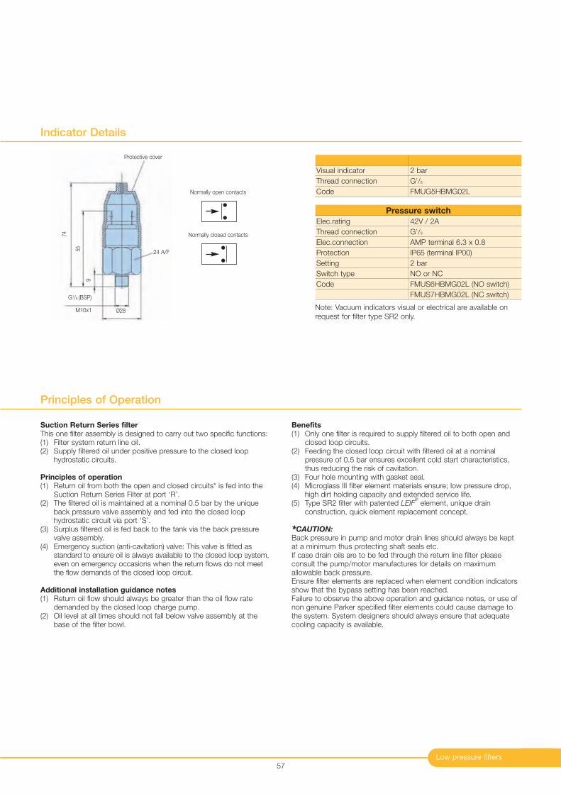
Low pressure filters57
Indicator Details
Elec.rating
Thread connection
Elec.connection
Protection
Setting
Switch type
Code
42V / 2A
G1/8
AMP terminal 6.3 x 0.8
IP65 (terminal IP00)
2 bar
NO or NC
FMUS6HBMG02L (NO switch)
FMUS7HBMG02L (NC switch)
Pressure switch
Note: Vacuum indicators visual or electrical are available onrequest for filter type SR2 only.
G1/8 (BSP)
Ø28
9
Protective cover
M10x1
24 A/F55
74
Normally open contacts
Normally closed contacts
Visual indicator
Thread connection
Code
2 bar
G1/8
FMUG5HBMG02L
Suction Return Series filterThis one filter assembly is designed to carry out two specific functions:(1) Filter system return line oil.(2) Supply filtered oil under positive pressure to the closed loop
hydrostatic circuits.
Principles of operation(1) Return oil from both the open and closed circuits* is fed into the
Suction Return Series Filter at port ‘R’.(2) The filtered oil is maintained at a nominal 0.5 bar by the unique
back pressure valve assembly and fed into the closed loophydrostatic circuit via port ‘S’.
(3) Surplus filtered oil is fed back to the tank via the back pressurevalve assembly.
(4) Emergency suction (anti-cavitation) valve: This valve is fitted asstandard to ensure oil is always available to the closed loop system,even on emergency occasions when the return flows do not meetthe flow demands of the closed loop circuit.
Additional installation guidance notes(1) Return oil flow should always be greater than the oil flow rate
demanded by the closed loop charge pump.(2) Oil level at all times should not fall below valve assembly at the
base of the filter bowl.
Benefits(1) Only one filter is required to supply filtered oil to both open and
closed loop circuits.(2) Feeding the closed loop circuit with filtered oil at a nominal
pressure of 0.5 bar ensures excellent cold start characteristics,thus reducing the risk of cavitation.
(3) Four hole mounting with gasket seal.(4) Microglass III filter element materials ensure; low pressure drop,
high dirt holding capacity and extended service life.(5) Type SR2 filter with patented LEIF
®
element, unique drainconstruction, quick element replacement concept.
*CAUTION:Back pressure in pump and motor drain lines should always be keptat a minimum thus protecting shaft seals etc. If case drain oils are to be fed through the return line filter pleaseconsult the pump/motor manufactures for details on maximumallowable back pressure.Ensure filter elements are replaced when element condition indicatorsshow that the bypass setting has been reached.Failure to observe the above operation and guidance notes, or use ofnon genuine Parker specified filter elements could cause damage tothe system. System designers should always ensure that adequatecooling capacity is available.
Principles of Operation
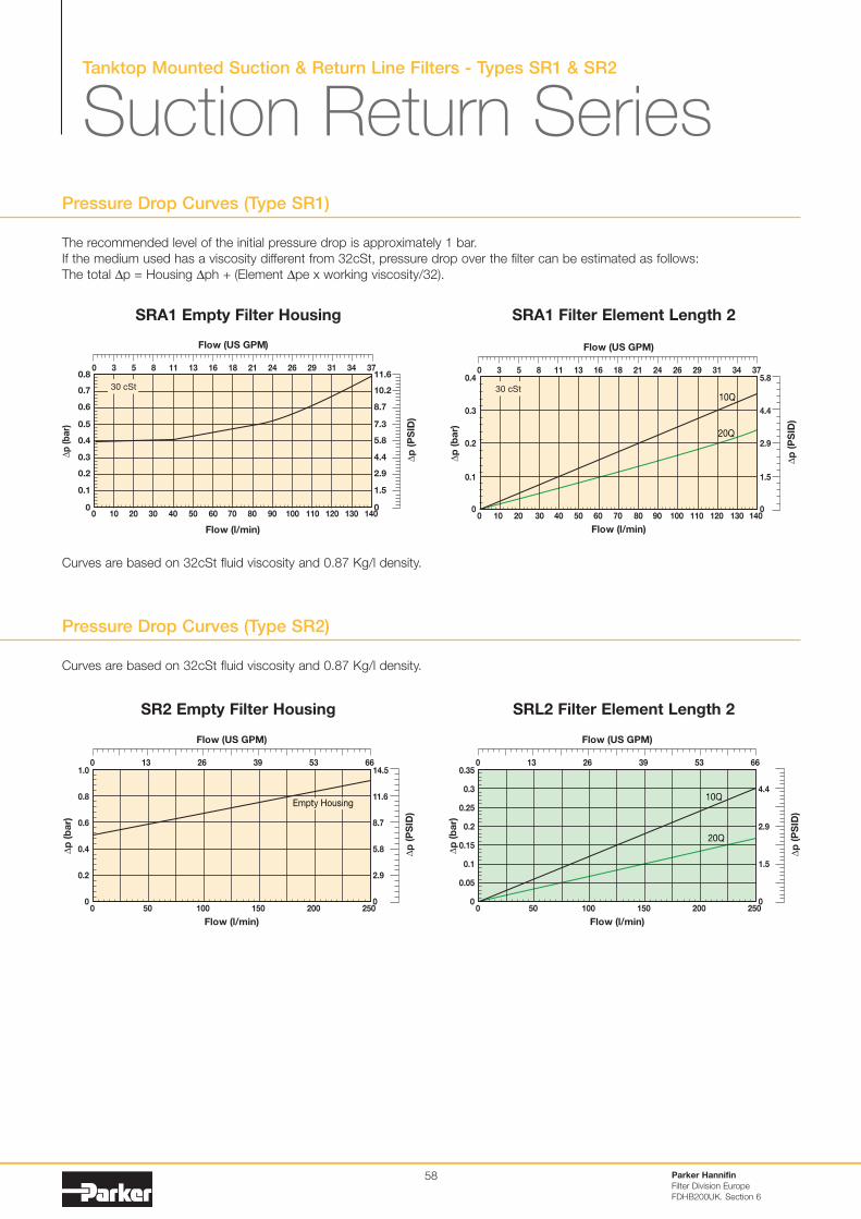
Tanktop Mounted Suction & Return Line Filters - Types SR1 & SR2
Parker Hannifin
Filter Division Europe
FDHB200UK. Section 6
58
Pressure Drop Curves (Type SR2)
Pressure Drop Curves (Type SR1)
The recommended level of the initial pressure drop is approximately 1 bar.If the medium used has a viscosity different from 32cSt, pressure drop over the filter can be estimated as follows:The total ∆p = Housing ∆ph + (Element ∆pe x working viscosity/32).
Flow (l/min)
0
0.1
0.2
0.3
0.4
0.5
0.6
0.7
0.8
∆p
(b
ar)
0 10 20 30 40 50 60 70 80 90 100 110 120 130 140
Flow (US GPM)
0 3 5 8 11 13 16 18 21 24 26 29 31 34 37
0
1.5
2.9
4.4
5.8
7.3
8.7
10.2
11.6
∆p
(P
SID
)
30 cSt
Flow (l/min)
10Q
20Q
0 10 20 30 40 50 60 70 80 90 100 110 120 130 1400
0.1
0.2
0.3
0.4
∆p
(b
ar)
Flow (US GPM)
∆p
(P
SID
)
0 3 5 8 11 13 16 18 21 24 26 29 31 34 37
0
1.5
2.9
4.4
5.8
30 cSt
SRA1 Empty Filter Housing SRA1 Filter Element Length 2
Flow (l/min)
0 50 100 150 200 2500
0.2
0.4
0.6
1.0
∆p
(b
ar)
Flow (US GPM)
∆p
(P
SID
)
0 13 26 39 53 66
0
5.8
14.5
0.8 11.6
8.7
2.9
Empty Housing
Flow (l/min)
0 50 100 150 200 2500
0.05
0.1
0.15
0.35
∆p
(b
ar)
Flow (US GPM)
∆p
(P
SID
)
0 13 26 39 53 66
0
1.5
4.4
0.2
0.3
0.25
2.9
20Q
10Q
SR2 Empty Filter Housing SRL2 Filter Element Length 2
Curves are based on 32cSt fluid viscosity and 0.87 Kg/l density.
Suction Return Series
Curves are based on 32cSt fluid viscosity and 0.87 Kg/l density.
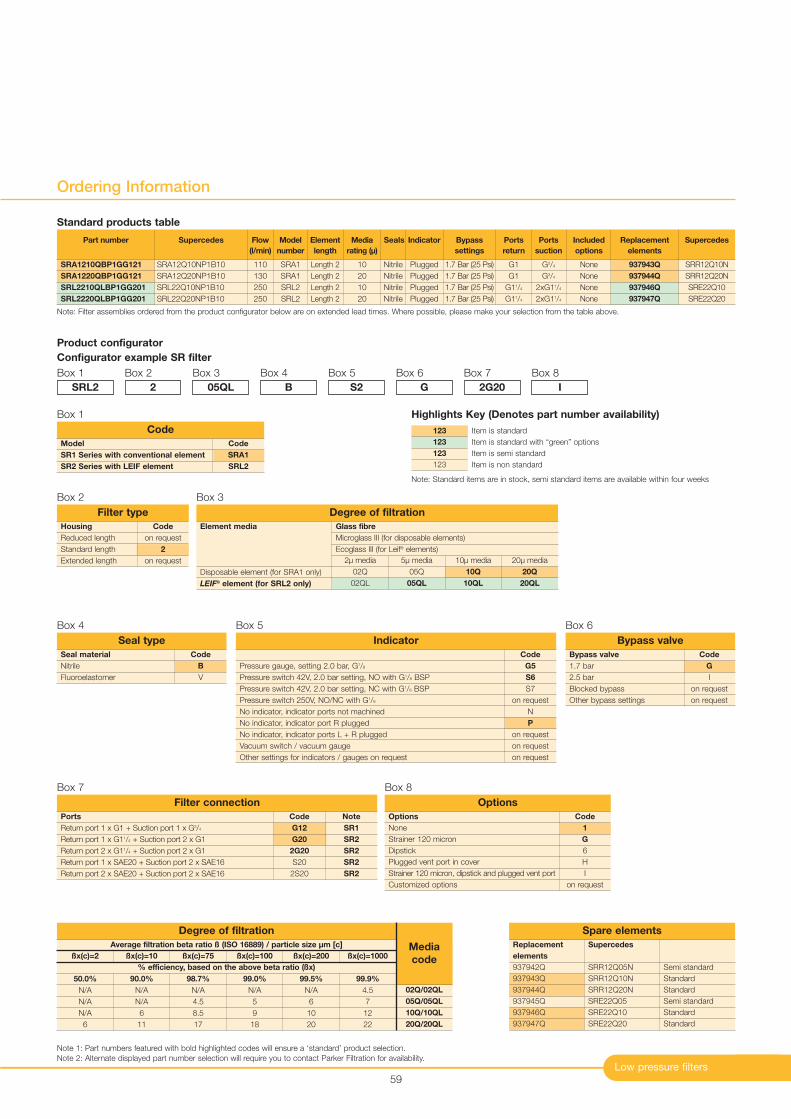
Low pressure filters59
Ordering Information
Note: Filter assemblies ordered from the product configurator below are on extended lead times. Where possible, please make your selection from the table above.
Product configurator
Configurator example SR filter
Box 1
Code
on request
2
on request
Housing
Reduced length
Standard length
Extended length
Filter type
Box 2
SRL2
Box 2
2
Box 3
05QL
Box 4
B
Box 5
S2
Box 6
G
Box 7
2G20
Box 8
I
Note 1: Part numbers featured with bold highlighted codes will ensure a ‘standard’ product selection.
Note 2: Alternate displayed part number selection will require you to contact Parker Filtration for availability.
Part number
SRA1210QBP1GG121
SRA1220QBP1GG121
SRL2210QLBP1GG201
SRL2220QLBP1GG201
Supercedes
SRA12Q10NP1B10
SRA12Q20NP1B10
SRL22Q10NP1B10
SRL22Q20NP1B10
Flow
(l/min)
110
130
250
250
Model
number
SRA1
SRA1
SRL2
SRL2
Element
length
Length 2
Length 2
Length 2
Length 2
Media
rating (µ)
10
20
10
20
Seals
Nitrile
Nitrile
Nitrile
Nitrile
Indicator
Plugged
Plugged
Plugged
Plugged
Bypass
settings
1.7 Bar (25 Psi)
1.7 Bar (25 Psi)
1.7 Bar (25 Psi)
1.7 Bar (25 Psi)
Included
options
None
None
None
None
Replacement
elements
937943Q
937944Q
937946Q
937947Q
Supercedes
SRR12Q10N
SRR12Q20N
SRE22Q10
SRE22Q20
Ports
return
G1
G1
G11/4
G11/4
Ports
suction
G3/4
G3/4
2xG11/4
2xG11/4
Code
B
V
Seal material
Nitrile
Fluoroelastomer
Seal type
Box 4
Code
G
I
on request
on request
Bypass valve
1.7 bar
2.5 bar
Blocked bypass
Other bypass settings
Bypass valve
Box 6
Code
G5
S6
S7
on request
N
P
on request
on request
on request
Pressure gauge, setting 2.0 bar, G1/8
Pressure switch 42V, 2.0 bar setting, NO with G1/8 BSP
Pressure switch 42V, 2.0 bar setting, NC with G1/8 BSP
Pressure switch 250V, NO/NC with G1/8
No indicator, indicator ports not machined
No indicator, indicator port R plugged
No indicator, indicator ports L + R plugged
Vacuum switch / vacuum gauge
Other settings for indicators / gauges on request
Indicator
Box 5
Note
SR1
SR2
SR2
SR2
SR2
Ports
Return port 1 x G1 + Suction port 1 x G3/4
Return port 1 x G11/4 + Suction port 2 x G1
Return port 2 x G11/4 + Suction port 2 x G1
Return port 1 x SAE20 + Suction port 2 x SAE16
Return port 2 x SAE20 + Suction port 2 x SAE16
Filter connection
Code
G12
G20
2G20
S20
2S20
Box 7
Code
1
G
6
H
I
on request
Options
None
Strainer 120 micron
Dipstick
Plugged vent port in cover
Strainer 120 micron, dipstick and plugged vent port
Customized options
Options
Box 8
Code
SRA1
SRL2
Model
SR1 Series with conventional element
SR2 Series with LEIF element
Code
Box 1
Standard products table
Semi standard
Standard
Standard
Semi standard
Standard
Standard
Spare elements
Supercedes
SRR12Q05N
SRR12Q10N
SRR12Q20N
SRE22Q05
SRE22Q10
SRE22Q20
Replacement
elements
937942Q
937943Q
937944Q
937945Q
937946Q
937947Q
Box 3
Element media
Disposable element (for SRA1 only)
LEIF® element (for SRL2 only)
20µ media
20Q
20QL
10µ media
10Q
10QL
5µ media
05Q
05QL
2µ media
02Q
02QL
Glass fibre
Microglass III (for disposable elements)
Ecoglass III (for Leif® elements)
Degree of filtration
Average filtration beta ratio ß (ISO 16889) / particle size µm [c]
% efficiency, based on the above beta ratio (ßx)
ßx(c)=2
50.0%
N/A
N/A
N/A
6
Degree of filtration
Media
codeßx(c)=10
90.0%
N/A
N/A
6
11
ßx(c)=75
98.7%
N/A
4.5
8.5
17
ßx(c)=100
99.0%
N/A
5
9
18
ßx(c)=200
99.5%
N/A
6
10
20
ßx(c)=1000
99.9%
4.5
7
12
22
02Q/02QL
05Q/05QL
10Q/10QL
20Q/20QL
Item is standard
Item is standard with “green” options
Item is semi standard
Item is non standard
123
123
123
123
Highlights Key (Denotes part number availability)
Note: Standard items are in stock, semi standard items are available within four weeks
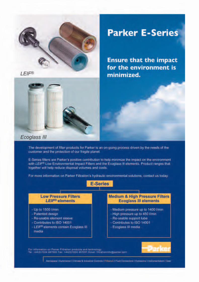
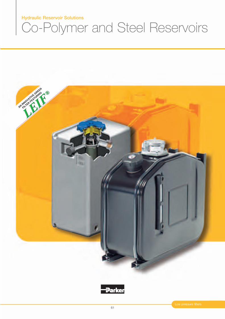
Hydraulic Reservoir Solutions
Co-Polymer and Steel Reservoirs
Low pressure filters
®
LEIF
LEIF
®
AN IN
NO
VATIV
E G
REEN
FIL
TER F
EATURIN
G
61
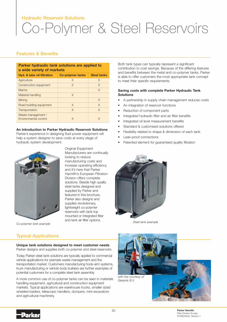
Hydraulic Reservoir Solutions
Co-Polymer & Steel Reservoirs
Unique tank solutions designed to meet customer needs
Parker designs and supplies both co-polymer and steel reservoirs.
Today Parker steel tank solutions are typically applied to commercialvehicle applications for example waste management and thetransportation market. Customers manufacturing hook-arm systems,truck manufacturing or vehicle body builders are further examples ofpotential customers for a complete steel tank assembly.
A more common use of co-polymer tanks can be seen in materialshandling equipment, agricultural and construction equipmentmarkets. Typical applications are warehouse trucks, smaller sizedwheeled loaders, telescopic handlers, dumpers, mini excavatorsand agricultural machinery.
Features & Benefits
Parker Hannifin
Filter Division Europe
FDHB200UK. Section 7
62
Parker hydraulic tank solutions are applied to
a wide variety of markets
Hyd. & lube oil filtration Co-polymer tanks Steel tanks
Agriculture X X
Construction equipment X X
Marine X
Material handling X
Mining X
Road building equipment X X
Transportation X X
Waste management /
Environmental control X X
An introduction to Parker Hydraulic Reservoir Solutions
Parker’s experience in designing fluid power equipment willhelp a system designer to save costs at every stage ofhydraulic system development.
Original EquipmentManufacturers are continuallylooking to reducemanufacturing costs andincrease operating efficiencyand it’s here that ParkerHannifin’s European FiltrationDivision offers completesolutions. Beside high qualitysteel tanks designed andsupplied by Parker andfeatured in this brochure,Parker also designs andsupplies revolutionary,lightweight co-polymerreservoirs with tank topmounted or integrated filterand tank air filter options.
Co-polymer tank exampleSteel tank example
Both tank types can typically represent a significantcontribution to cost savings. Because of the differing featuresand benefits between the metal and co-polymer tanks, Parkeris able to offer customers the most appropriate tank conceptto meet their specific requirements.
Saving costs with complete Parker Hydraulic Tank
Solutions
• A partnership in supply chain management reduces costs
• An integration of reservoir functions
• Reduction of component parts
• Integrated hydraulic filter and air filter benefits
• Integrated oil level measurement benefits
• Standard & customised solutions offered
• Flexibility related to shape & dimension of each tank
• Leak-proof connections
• Patented element for guaranteed quality filtration
Typical Applications
with the courtesy of
Geesink B.V.
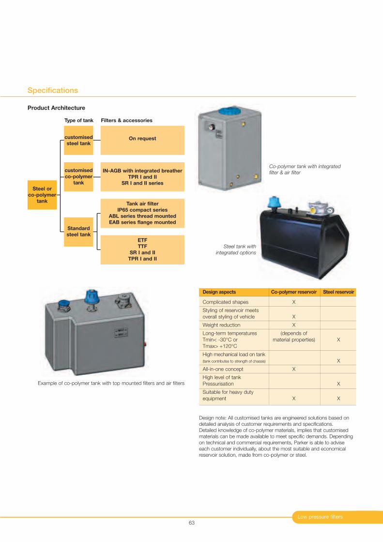
Low pressure filters
Specifications
63
Example of co-polymer tank with top mounted filters and air filters
Steel or
co-polymer
tank
customised
steel tankOn request
IN-AGB with integrated breather
TPR I and II
SR I and II series
Tank air filter
IP65 compact series
ABL series thread mounted
EAB series flange mounted
ETF
TTF
SR I and II
TPR I and II
customised
co-polymer
tank
Standard
steel tank
Co-polymer tank with integrated
filter & air filter
Steel tank with
integrated options
Design aspects Co-polymer reservoir Steel reservoir
Complicated shapes X
Styling of reservoir meets
overall styling of vehicle X
Weight reduction X
Long-term temperatures (depends of
Tmin< -30°C or material properties) X
Tmax> +120°C
High mechanical load on tank
(tank contributes to strength of chassis) X
All-in-one concept X
High level of tank
Pressurisation X
Suitable for heavy duty
equipment X X
Design note: All customised tanks are engineered solutions based ondetailed analysis of customer requirements and specifications. Detailed knowledge of co-polymer materials, implies that customisedmaterials can be made available to meet specific demands. Dependingon technical and commercial requirements, Parker is able to adviseeach customer individually, about the most suitable and economicalreservoir solution, made from co-polymer or steel.
Product Architecture
Type of tank Filters & accessories
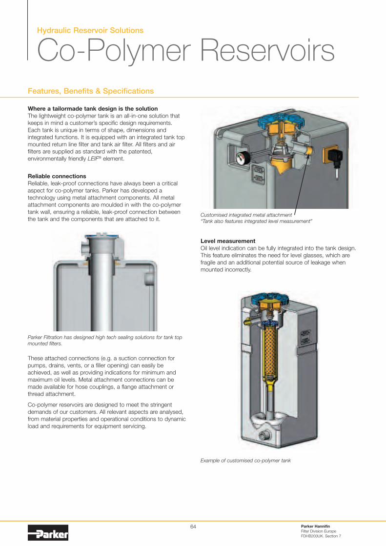
Hydraulic Reservoir Solutions
Co-Polymer ReservoirsFeatures, Benefits & Specifications
Where a tailormade tank design is the solution
The lightweight co-polymer tank is an all-in-one solution thatkeeps in mind a customer’s specific design requirements.Each tank is unique in terms of shape, dimensions andintegrated functions. It is equipped with an integrated tank topmounted return line filter and tank air filter. All filters and airfilters are supplied as standard with the patented,environmentally friendly LEIF® element.
Reliable connections
Reliable, leak-proof connections have always been a criticalaspect for co-polymer tanks. Parker has developed atechnology using metal attachment components. All metalattachment components are moulded in with the co-polymertank wall, ensuring a reliable, leak-proof connection betweenthe tank and the components that are attached to it.
These attached connections (e.g. a suction connection forpumps, drains, vents, or a filler opening) can easily beachieved, as well as providing indications for minimum andmaximum oil levels. Metal attachment connections can bemade available for hose couplings, a flange attachment orthread attachment.
Co-polymer reservoirs are designed to meet the stringentdemands of our customers. All relevant aspects are analysed,from material properties and operational conditions to dynamicload and requirements for equipment servicing.
Parker Hannifin
Filter Division Europe
FDHB200UK. Section 7
64
Parker Filtration has designed high tech sealing solutions for tank top
mounted filters.
Customised integrated metal attachment
“Tank also features integrated level measurement”
Example of customised co-polymer tank
Level measurement
Oil level indication can be fully integrated into the tank design.This feature eliminates the need for level glasses, which arefragile and an additional potential source of leakage whenmounted incorrectly.

Low pressure filters
Features, Benefits & Specifications
The ultimate all-in-one design
A more frequent use of co-polymer tanks located on the outsideof mobile equipment often results in specific requirementsrelating to styling.
Despite the compact design of Parker tank top mounted filtersand air filters, these parts can influence aspects related tostyling or cabin accessibility.
This concept is ideal for applications where space is at a premium.
Parker Filtration’s unique all-in-one design, where the returnline filter and air filter are both located under one cover is aconcept that offers great possibilities related to tank styling.The high quality of the co-polymer material ensures a long-term stability of the chosen colour.
This all-in-one design features the IN-AGB type return line andintegrated air filter with labyrinth. The labyrinth prevents oilleakage through the air filter. The connection(s) for return line(s)and filler port are integrated in the tank. This avoids having tohave hydraulic hoses placed on top of the tank.
Environmentally friendly
Parker considers care for the environment as a socialobligation. The environmentally friendly LEIF® element (LowEnvironmental Impact Filter) is applied to the return line filtersand breathers type ABL and EAB.
What makes this element so special is that the metal sleevecan be re-used. As a result, this filter element component nolonger ends up in the waste disposal; only the contaminatedfilter medium is disposed of as chemical waste. With LEIF®
filter elements, the disposal and processing cost may bereduced by as much as 50%.
The LEIF® concept safeguards the use of genuine Parker parts.
65
Example of a customised tank with an integrated return line filter and air filter
Integrated air breather(with optional water removal media)
Air flow through air breather labyrinth
Return line connection
Integrated return line filter type IN-AGB filter hasIn-to-Out flow direction
Pressure gauge or switch
Oil level indication
LEIF® elements:
• Environmentally friendly filtration• Re-usable steel element sleeve• Patented elements result in guaranteed quality of filtration• Saves element disposal costs typically by up to 50%• Supports ISO 14001 certification
Cost-effective
The advantages of this co-polymer concept are obvious:
• Lightweight• Flexibility with respect to tank shapes• Characteristics of plastic material can be customised to
meet specific requirements• Integration of several functions limits the use of individual
components• The tank can be purchased and supplied as a complete unit
IN-AGB with LEIF® element
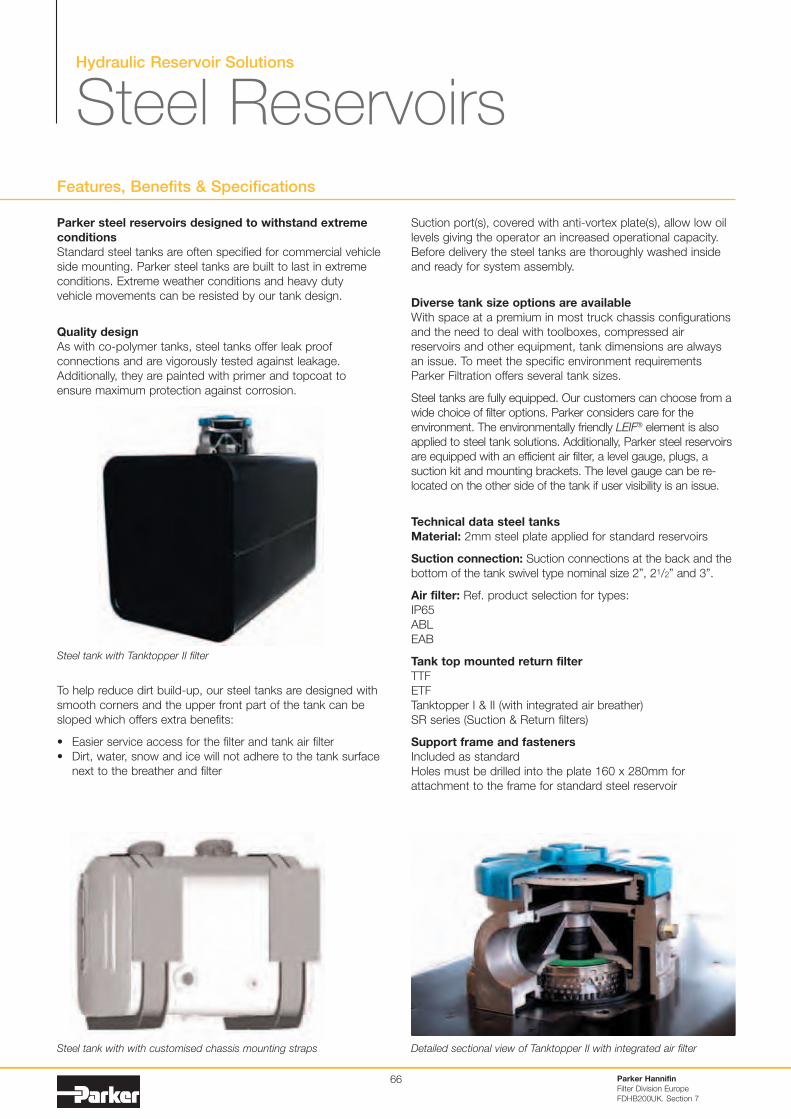
Hydraulic Reservoir Solutions
Steel ReservoirsFeatures, Benefits & Specifications
Parker Hannifin
Filter Division Europe
FDHB200UK. Section 7
66
Parker steel reservoirs designed to withstand extreme
conditions
Standard steel tanks are often specified for commercial vehicleside mounting. Parker steel tanks are built to last in extremeconditions. Extreme weather conditions and heavy dutyvehicle movements can be resisted by our tank design.
Quality design
As with co-polymer tanks, steel tanks offer leak proofconnections and are vigorously tested against leakage.Additionally, they are painted with primer and topcoat toensure maximum protection against corrosion.
To help reduce dirt build-up, our steel tanks are designed withsmooth corners and the upper front part of the tank can besloped which offers extra benefits:
• Easier service access for the filter and tank air filter• Dirt, water, snow and ice will not adhere to the tank surface
next to the breather and filter
Steel tank with Tanktopper II filter
Steel tank with with customised chassis mounting straps Detailed sectional view of Tanktopper II with integrated air filter
Suction port(s), covered with anti-vortex plate(s), allow low oillevels giving the operator an increased operational capacity.Before delivery the steel tanks are thoroughly washed insideand ready for system assembly.
Diverse tank size options are available
With space at a premium in most truck chassis configurationsand the need to deal with toolboxes, compressed airreservoirs and other equipment, tank dimensions are alwaysan issue. To meet the specific environment requirementsParker Filtration offers several tank sizes.
Steel tanks are fully equipped. Our customers can choose from awide choice of filter options. Parker considers care for theenvironment. The environmentally friendly LEIF® element is alsoapplied to steel tank solutions. Additionally, Parker steel reservoirsare equipped with an efficient air filter, a level gauge, plugs, asuction kit and mounting brackets. The level gauge can be re-located on the other side of the tank if user visibility is an issue.
Technical data steel tanks
Material: 2mm steel plate applied for standard reservoirs
Suction connection: Suction connections at the back and thebottom of the tank swivel type nominal size 2”, 21/2” and 3”.
Air filter: Ref. product selection for types:IP65ABLEAB
Tank top mounted return filter
TTFETFTanktopper I & II (with integrated air breather)SR series (Suction & Return filters)
Support frame and fasteners
Included as standardHoles must be drilled into the plate 160 x 280mm forattachment to the frame for standard steel reservoir
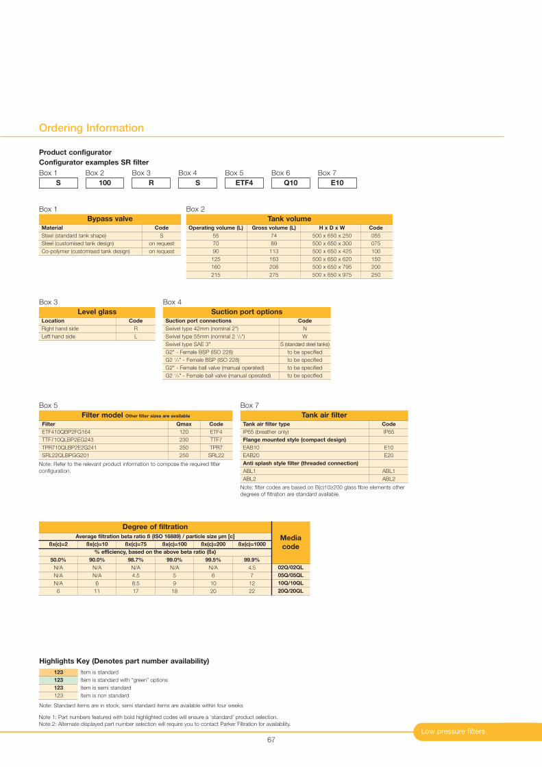
Low pressure filters
Ordering Information
67
Code
R
L
Location
Right hand side
Left hand side
Level glassCode
N
W
S (standard steel tanks)
to be specified
to be specified
to be specified
to be specified
Suction port connections
Swivel type 42mm (nominal 2")
Swivel type 55mm (nominal 2 1/2")
Swivel type SAE 3"
G2" - Female BSP (ISO 228)
G2 1/2" - Female BSP (ISO 228)
G2" - Female ball valve (manual operated)
G2 1/2" - Female ball valve (manual operated)
Suction port options
Code
IP65
E10
E20
ABL1
ABL2
Tank air filter type
IP65 (breather only)
Flange mounted style (compact design)
EAB10
EAB20
Anti splash style filter (threaded connection)
ABL1
ABL2
Tank air filter
Operating volume (L) Gross volume (L) H x D x W Code
55 74 500 x 650 x 250 055
70 89 500 x 650 x 300 075
90 113 500 x 650 x 425 100
125 163 500 x 650 x 620 150
160 208 500 x 650 x 795 200
215 275 500 x 650 x 975 250
Tank volume
Filter Qmax Code
ETF410QBP2FG164 120 ETF4
TTF710QLBP2EG243 230 TTF7
TPR710QLBP2E2G241 250 TPR7
SRL22QLBPGG201 250 SRL22
Filter model Other filter sizes are available
Box 7Box 5
Box 2
Box 3 Box 4
Note: filter codes are based on B(c)10≥200 glass fibre elements other
degrees of filtration are standard available.
Product configurator
Configurator examples SR filter
Box 1
S
Box 2
100
Box 3
R
Box 4
S
Box 5
ETF4
Box 6
Q10
Box 7
E10
Note 1: Part numbers featured with bold highlighted codes will ensure a ‘standard’ product selection.
Note 2: Alternate displayed part number selection will require you to contact Parker Filtration for availability.
Bypass valve
Box 1
Code
S
on request
on request
Material
Steel (standard tank shape)
Steel (customised tank design)
Co-polymer (customised tank design)
Item is standard
Item is standard with “green” options
Item is semi standard
Item is non standard
123
123
123
123
Highlights Key (Denotes part number availability)
Note: Standard items are in stock, semi standard items are available within four weeks
Average filtration beta ratio ß (ISO 16889) / particle size µm [c]
% efficiency, based on the above beta ratio (ßx)
ßx(c)=2
50.0%
N/A
N/A
N/A
6
Degree of filtration
Media
codeßx(c)=10
90.0%
N/A
N/A
6
11
ßx(c)=75
98.7%
N/A
4.5
8.5
17
ßx(c)=100
99.0%
N/A
5
9
18
ßx(c)=200
99.5%
N/A
6
10
20
ßx(c)=1000
99.9%
4.5
7
12
22
02Q/02QL
05Q/05QL
10Q/10QL
20Q/20QL
Note: Refer to the relevant product information to compose the required filter
configuration.

Spin-on Filters
Maxiflow SeriesMAX 360 I/min - 10 bar
Low pressure filters69
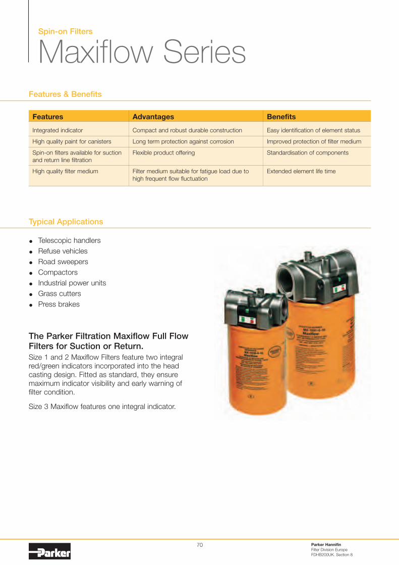
Spin-on Filters
Maxiflow Series
Typical Applications
Telescopic handlers
Refuse vehicles
Road sweepers
Compactors
Industrial power units
Grass cutters
Press brakes
The Parker Filtration Maxiflow Full FlowFilters for Suction or Return.
Size 1 and 2 Maxiflow Filters feature two integralred/green indicators incorporated into the headcasting design. Fitted as standard, they ensuremaximum indicator visibility and early warning offilter condition.
Size 3 Maxiflow features one integral indicator.
Features & Benefits
Parker Hannifin
Filter Division Europe
FDHB200UK. Section 8
70
Features
Integrated indicator
High quality paint for canisters
Spin-on filters available for suctionand return line filtration
High quality filter medium
Advantages
Compact and robust durable construction
Long term protection against corrosion
Flexible product offering
Filter medium suitable for fatigue load due tohigh frequent flow fluctuation
Benefits
Easy identification of element status
Improved protection of filter medium
Standardisation of components
Extended element life time
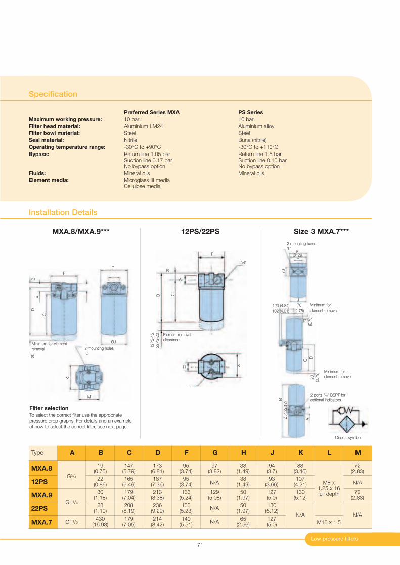
Low pressure filters
Installation Details
Specification
Preferred Series MXA PS Series
Maximum working pressure: 10 bar 10 bar
Filter head material: Aluminium LM24 Aluminium alloy
Filter bowl material: Steel Steel
Seal material: Nitrile Buna (nitrile)
Operating temperature range: -30°C to +90°C -30°C to +110°C
Bypass: Return line 1.05 bar Return line 1.5 barSuction line 0.17 bar Suction line 0.10 barNo bypass option No bypass option
Fluids: Mineral oils Mineral oils
Element media: Microglass III mediaCellulose media
71
F
C
DB
20
Minimum for elementremoval
G
H
M
2 mounting holes‘L’
K
ØJ
Filter selectionTo select the correct filter use the appropriatepressure drop graphs. For details and an exampleof how to select the correct filter, see next page.
A
Element removalclearance
D
12P
S-1
522P
S-2
0
C
B
A
F
Inlet
KH
L
MXA.8/MXA.9*** 12PS/22PS Size 3 MXA.7***
Type
G3/4
G11/4
G11/2
19(0.75)
22(0.86)
30(1.18)
28(1.10)
430(16.93)
147(5.79)
165(6.49)
179(7.04)
208(8.19)
179(7.05)
173(6.81)
187(7.36)
213(8.38)
236(9.29)
214(8.42)
95(3.74)
95(3.74)
133(5.24)
133(5.23)
140(5.51)
97(3.82)
N/A
129(5.08)
N/A
N/A
38(1.49)
38(1.49)
50(1.97)
50(1.97)
65(2.56)
94(3.7)
93(3.66)
127(5.0)
130(5.12)
127(5.0)
88(3.46)
107(4.21)
130(5.12)
N/A
M8 x1.25 x 16full depth
M10 x 1.5
72(2.83)
N/A
72(2.83)
N/A
MXA.8
12PS
MXA.9
22PS
MXA.7
A B C D F G H J K L M
Circuit symbol
J
Minimum forelement removal
102 (4.01)
70(2.75)
Minimum forelement removal
20
(0.7
9)
D
C123 (4.84)
20
(0.7
9)
2 mounting holes‘L’
70
F
HØ129
A
2 ports 1/8” BSPT foroptional indicators
Ø54 (2
.12)B
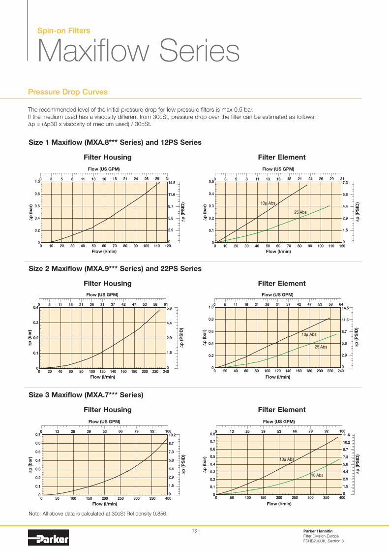
Spin-on Filters
Maxiflow SeriesPressure Drop Curves
Parker Hannifin
Filter Division Europe
FDHB200UK. Section 8
72
Filter Housing
Size 1 Maxiflow (MXA.8*** Series) and 12PS Series
0
0.2
0.4
0.6
0.8
1.0
0 10 20 30 12011010040 50 60 70 80 90
Flow (l/min)
∆p
(b
ar)
Flow (US GPM)
0 3 8 11 165 13 18 21 24 26 29∆
p (
PS
ID)
0
2.9
14.5
11.6
8.7
5.8
31
0
0.1
0.2
0.3
0.4
0.5
0 10 20 30 12011010040 50 60 70 80 90
Flow (l/min)
∆p
(b
ar)
Flow (US GPM)
10µ Abs
0 3 8 11 16 315 13 18 21 24 26 29
∆p
(P
SID
)
0
1.5
7.3
5.8
4.4
2.9
25 Abs
Filter Element
Filter Housing
Size 2 Maxiflow (MXA.9*** Series) and 22PS Series
0
0.1
0.2
0.4
0.3
∆p
(b
ar)
0 80 200 220 24018016014012010020 40 60
Flow (l/min)
Flow (US GPM)
0 5 16 21 3111 26 37 42 47 53 58
∆p
(P
SID
)
0
1.5
5.8
4.4
2.9
61
0 10020 40 60 80 200120 140 160 180 220 240
Flow (l/min)
0
0.2
0.4
0.6
0.8
1.0
∆p
(b
ar)
10µ Abs
Flow (US GPM)
0 5 16 21 3111 26 37 42 47 53 58
∆p
(P
SID
)
0
2.9
14.5
11.6
8.7
5.8
64
25 Abs
Filter Element
Filter Housing
Size 3 Maxiflow (MXA.7*** Series)
0
0.1
0.3
0.4
0.6
∆p
(b
ar)
0.7
0.5
0.2
0 100 200 300 40050 150 250 350
Flow (l/min)
Flow (US GPM)
0 26 5313 39 66 79 92
∆p
(P
SID
)
0
2.9
10.2
8.7
7.3
4.4
106
5.8
1.5
1000 40050 150 300 3502502000
0.1
0.8
0.7
0.6
0.5
0.4
0.3
0.2
Flow (l/min)
∆p
(b
ar) 10µ Abs
10 Abs
Flow (US GPM)
0 13 26 39 53 66 79 92
∆p
(P
SID
)
0
1.5
11.6
8.7
7.3
4.4
106
10.2
5.8
2.9
Filter Element
The recommended level of the initial pressure drop for low pressure filters is max 0.5 bar.If the medium used has a viscosity different from 30cSt, pressure drop over the filter can be estimated as follows:∆p = (∆p30 x viscosity of medium used) / 30cSt.
Note: All above data is calculated at 30cSt Rel density 0.856.
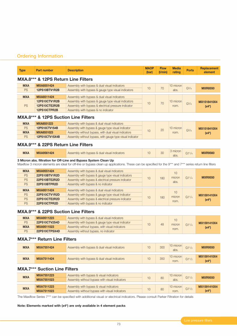
Low pressure filters
Ordering Information
73
MXA
PS
MXA8551424
12PS10BTV1R2B
Assembly with bypass & dual visual indicators
Assembly with bypass & gauge type visual indicatorsMXR8550G3/4
10 micron
abs.7010
MXA.8*** & 12PS Return Line Filters
Type Part number DescriptionMAOP Flow Media
PortsReplacement
(bar) (l/min) rating element
MXA MXA9561424 Assembly with bypass & dual visual indicators MXR9560G11/43 micron
abs.3010
MXA.9*** & 22PS Return Line Filters
MXA MXA7551424 Assembly with bypass & dual visual indicators MXR9550G11/210 micron
abs.30010
MXA.7*** Return Line Filters
MXA.7*** Suction Line Filters
MXA MXA7511424 Assembly with bypass & dual visual indicatorsMX1591410X4
(x4*)G11/2
10 micron
nom.35010
MXA
PS
MXA
PS
MXA8551223
12PS10CTV1S4B
MXA8551023
12PS10CTV1SX4B
Assembly with bypass & dual visual indicators
Assembly with bypass & gauge type visual indicator
Assembly without bypass, with dual visual indicators
Assembly without bypass, with gauge type visual indicator
MX1518410X4
(x4*)G3/4
10 micron
nom.2010
MXA.8*** & 12PS Suction Line Filters
MXA
PS
MXA
PS
MXA9511223
22PS10CTV2S4D
MXA9511023
22PS10CTPSX4D
Assembly with bypass & dual visual indicators
Assembly with bypass & gauge type visual indicator
Assembly without bypass, with visual indicators
Assembly without bypass, no indicator
MX1591410X4
(x4*)G11/4
10
micron
nom.
4810
MXA.9*** & 22PS Suction Line Filters
MXA
PS
PS
PS
MXA9511424
22PS10CTV1R2D
22PS10CTE2R2D
22PS10CTPR2D
Assembly with bypass & dual visual indicators
Assembly with bypass & gauge type visual indicator
Assembly with bypass & electrical pressure indicator
Assembly with bypass & no indicator
MX1591410X4
(x4*)G11/4
10
micron
nom.18010
MXA
PS
MXA8511424
12PS10CTV1R2B
12PS10CTE2R2B
12PS10CTPR2B
Assembly with bypass & dual visual indicators
Assembly with bypass & gauge type visual indicators
Assembly with bypass & electrical pressure indicator
Assembly with bypass & no indicator
MX1518410X4
(x4*)G3/4
10 micron
nom.7010
3 Micron abs. filtration for Off-Line and Bypass System Clean Up
Maxiflow 3 micron elements are ideal for off-line or bypass clean up applications. These can be specified for the 9*** and 7*** series return line filters
The Maxiflow Series 7*** can be specified with additional visual or electrical indicators. Please consult Parker Filtration for details
Note: Elements marked with (x4*) are only available in 4 element packs
MXA
PS
PS
PS
MXA9551424
22PS10BTV1R2D
22PS10BTE2R2D
22PS10BTPR2D
Assembly with bypass & dual visual indicators
Assembly with bypass & gauge type visual indicators
Assembly with bypass & electrical pressure indicator
Assembly with bypass & no indicator
MXR9550G11/4
10
micron
abs.18010
MXAMXA7551223
MXA7551023
Assembly with bypass & visual indicators
Assembly without bypass with visual indicatorsMXR9550G11/2
10 micron
abs.8010
MXAMXA7511223
MXA7511023
Assembly with bypass & visual indicators
Assembly without bypass with visual indicators
MX1591410X4
(x4*)G11/2
10 micron
nom.8010

Parker Hannifin
Filter Division Europe
FDHB200UK.
74
Notes
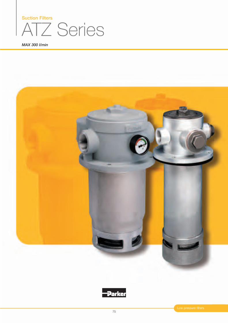
Suction Filters
ATZ SeriesMAX 300 I/min
Low pressure filters75
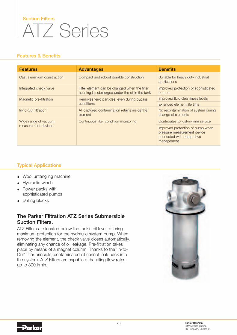
Suction Filters
ATZ Series
Typical Applications
Wool untangling machine
Hydraulic winch
Power packs withsophisticated pumps
Drilling blocks
The Parker Filtration ATZ Series SubmersibleSuction Filters.
ATZ Filters are located below the tank’s oil level, offeringmaximum protection for the hydraulic system pump. Whenremoving the element, the check valve closes automatically,eliminating any chance of oil leakage. Pre-filtration takesplace by means of a magnet column. Thanks to the ‘In-to-Out’ filter principle, contaminated oil cannot leak back intothe system. ATZ Filters are capable of handling flow rates up to 300 l/min.
Features & Benefits
Parker Hannifin
Filter Division Europe
FDHB200UK. Section 9
76
Features
Cast aluminium construction
Integrated check valve
Magnetic pre-filtration
In-to-Out filtration
Wide range of vacuummeasurement devices
Advantages
Compact and robust durable construction
Filter element can be changed when the filterhousing is submerged under the oil in the tank
Removes ferro particles, even during bypassconditions
All captured contamination retains inside theelement
Continuous filter condition monitoring
Benefits
Suitable for heavy duty industrialapplications
Improved protection of sophisticatedpumps
Improved fluid cleanliness levels
Extended element life time
No recontamination of system duringchange of elements
Contributes to just-in-time service
Improved protection of pump whenpressure measurement deviceconnected with pump drivemanagement
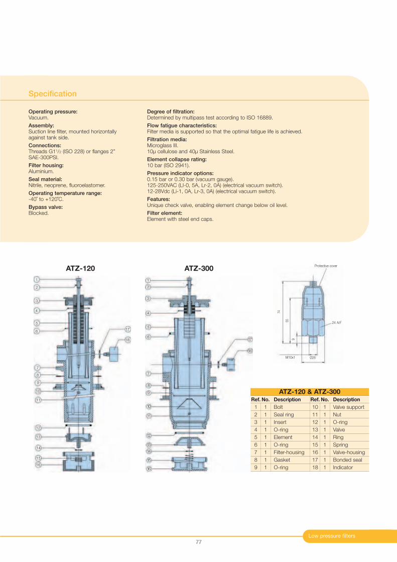
Low pressure filters
Specification
Operating pressure:Vacuum.
Assembly:Suction line filter, mounted horizontallyagainst tank side.
Connections:Threads G11/2 (ISO 228) or flanges 2” SAE-300PSI.
Filter housing:Aluminium.
Seal material:Nitrile, neoprene, fluoroelastomer.
Operating temperature range:-40˚ to +120˚C.
Bypass valve:Blocked.
Degree of filtration:Determined by multipass test according to ISO 16889.
Flow fatigue characteristics:Filter media is supported so that the optimal fatigue life is achieved.
Filtration media:Microglass III. 10µ cellulose and 40µ Stainless Steel.
Element collapse rating:10 bar (ISO 2941).
Pressure indicator options:0.15 bar or 0.30 bar (vacuum gauge).125-250VAC (LI-0, 5A, Lr-2, 0A) (electrical vacuum switch).12-28Vdc (Li-1, 0A, Lr-3, 0A) (electrical vacuum switch).
Features:Unique check valve, enabling element change below oil level.
Filter element:Element with steel end caps.
77
1
2
3
4
5
6
7
8
9
Ref. No. Description
1 1 Bolt
2 1 Seal ring
3 1 Insert
4 1 O-ring
5 1 Element
6 1 O-ring
7 1 Filter-housing
8 1 Gasket
9 1 O-ring
Ref. No. Description
10 1 Valve support
11 1 Nut
12 1 O-ring
13 1 Valve
14 1 Ring
15 1 Spring
16 1 Valve-housing
17 1 Bonded seal
18 1 Indicator
ATZ-120 & ATZ-300
ATZ-120 ATZ-300
10
11
12
13
14
15
16
17
18
1
2
3
4
5
6
7
8
9
10
11
12
13
14
15
16
17
18
Ø28
9
Protective cover
M10x1
24 A/F55
74
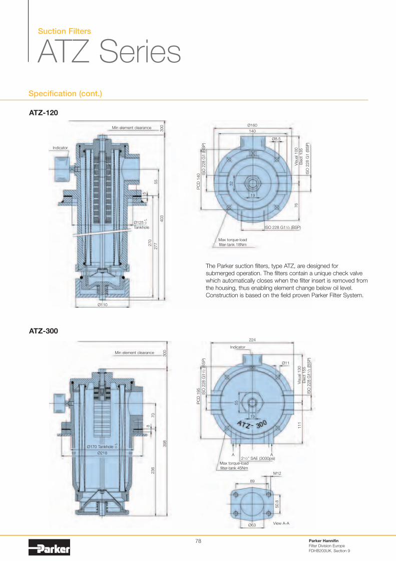
Suction Filters
ATZ SeriesSpecification (cont.)
ATZ-120
ATZ-300
Ø160
140
Ø8.5
Vis
ual 1
00
Ele
ct
135
76
ISO
228 G
1 (B
SP
)
ISO 228 G11/2 (BSP)
ISO
228 G
1 (B
SP
)
PC
D 1
40
32
19
Max torque-loadfilter-tank 18Nm
224
Ø11
Vis
ual 1
30
Ele
ct
155
111
ISO
228 G
11/2
(BS
P)
21/2” SAE (3000psi)
ISO
228 G
11/2
(BS
P)
PC
D 1
95
55
A A
Max torque-loadfilter-tank 45Nm
300
403
Min element clearance
Indicator
55
277270
5
Ø110
Ø125Tankhole
+10
30
03
98
Min element clearance
70
236
8
Ø170 Tankhole+10
Ø218
Ø63
50.8
89
M12
View A-A
Indicator
19
The Parker suction filters, type ATZ, are designed forsubmerged operation. The filters contain a unique check valvewhich automatically closes when the filter insert is removed fromthe housing, thus enabling element change below oil level.Construction is based on the field proven Parker Filter System.
Parker Hannifin
Filter Division Europe
FDHB200UK. Section 9
78
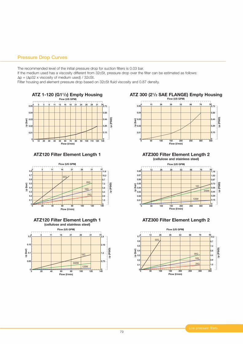
0
0.1
0.2
0.3
0.4
0.5
0.6
0.7
0 50 100 150 200 250 300 350
02Q
05Q
10Q
20Q
Flow (l/min)
∆p
(b
ar)
Flow (US GPM)
0 13 39 53 79 92
∆p
(P
SID
)
0
1.5
5.8
8.7
10.2
7.3
2.9
4.4
26 66
Low pressure filters
Pressure Drop Curves
79
The recommended level of the initial pressure drop for suction filters is 0.03 bar.If the medium used has a viscosity different from 32cSt, pressure drop over the filter can be estimated as follows:∆p = (∆p32 x viscosity of medium used) / 32cSt. Filter housing and element pressure drop based on 32cSt fluid viscosity and 0.87 density.
0
0.01
0.02
0.03
0.04
0.05
0 10 20 30 40 50 60 70 80 90 100 110 120 130
Flow (l/min)
∆p
(b
ar)
Flow (US GPM)
∆p
(P
SID
)
0 3 5 11 13 18 26 31 348 16
0
0.44
0.73
0.29
21 24 29
0.58
0.15
0
0.01
0.02
0.03
0.04
0.05
0 50 100 150 200 250 300 350
Flow (l/min)
∆p
(b
ar)
∆p
(P
SID
)
Flow (US GPM)
0 13 39 53 66 79 92
0
0.29
0.58
0.73
0.44
0.15
26
ATZ 1-120 (G11/2) Empty Housing ATZ 300 (21/2 SAE FLANGE) Empty Housing
0 20
0.1
0.2
0.3
0.4
0.5
0.6
0.7
0.8
0 40 60 80 100 120 140
02Q
05Q
10Q
20Q
∆p
(b
ar)
Flow (US GPM)
0 5 11 26 31 3716 21
∆p
(P
SID
)
0
2.9
4.4
7.3
10.2
11.6
8.7
5.8
1.5
Flow (l/min)
0
0.05
0.1
0.15
0.2
0 20 40 60 80 100 120 140
10C
040W
120W
∆p
(b
ar)
Flow (l/min)
Flow (US GPM)
0 5 11 16 31 37
∆p
(P
SID
)
0
0.73
1.5
2.18
2.92621
ATZ120 Filter Element Length 1
ATZ120 Filter Element Length 1(cellulose and stainless steel)
0
0.01
0.02
0.03
0.04
0.05
0.06
0.07
0.08
0 50 100 150 200 250 300 350
040W
10C
120W
∆p
(b
ar)
Flow (l/min)
∆p
(P
SID
)
0
0.15
0.58
0.87
1.16
1.02
0.73
0.29
0.44
Flow (US GPM)
0 13 39 53 79 9226 66
ATZ300 Filter Element Length 2(cellulose and stainless steel)
ATZ300 Filter Element Length 2
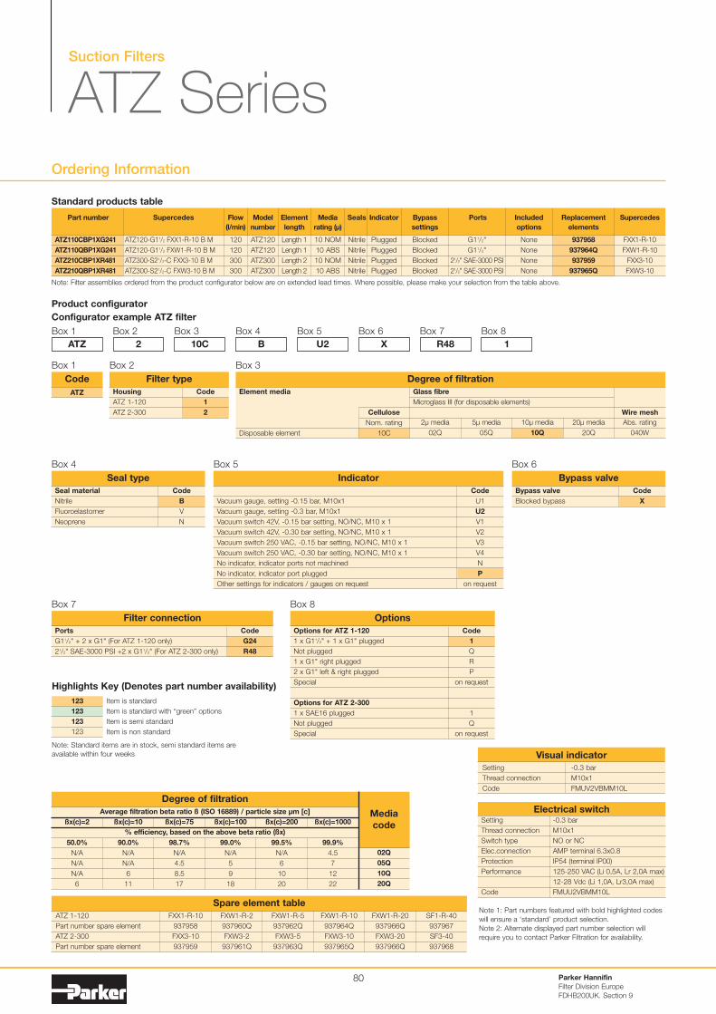
Parker Hannifin
Filter Division Europe
FDHB200UK. Section 9
80
Ordering Information
Note: Filter assemblies ordered from the product configurator below are on extended lead times. Where possible, please make your selection from the table above.
Product configurator
Configurator example ATZ filter
Box 1
Code
1
2
Housing
ATZ 1-120
ATZ 2-300
Filter type
Box 2
ATZ
Box 2
2
Box 3
10C
Box 4
B
Box 5
U2
Box 6
X
Box 7
R48
Box 8
1
Part number
ATZ110CBP1XG241
ATZ110QBP1XG241
ATZ210CBP1XR481
ATZ210QBP1XR481
Supercedes
ATZ120-G11/2 FXX1-R-10 B M
ATZ120-G11/2 FXW1-R-10 B M
ATZ300-S21/2-C FXX3-10 B M
ATZ300-S21/2-C FXW3-10 B M
Flow
(l/min)
120
120
300
300
Model
number
ATZ120
ATZ120
ATZ300
ATZ300
Element
length
Length 1
Length 1
Length 2
Length 2
Media
rating (µ)
10 NOM
10 ABS
10 NOM
10 ABS
Seals
Nitrile
Nitrile
Nitrile
Nitrile
Indicator
Plugged
Plugged
Plugged
Plugged
Bypass
settings
Blocked
Blocked
Blocked
Blocked
Included
options
None
None
None
None
Replacement
elements
937958
937964Q
937959
937965Q
Supercedes
FXX1-R-10
FXW1-R-10
FXX3-10
FXW3-10
Ports
G11/2"
G11/2"
21/2" SAE-3000 PSI
21/2" SAE-3000 PSI
ATZ
Code
Box 1
Code
B
V
N
Seal material
Nitrile
Fluoroelastomer
Neoprene
Seal type
Box 4
Code
X
Bypass valve
Blocked bypass
Bypass valve
Box 6
Code
U1
U2
V1
V2
V3
V4
N
P
on request
Vacuum gauge, setting -0.15 bar, M10x1
Vacuum gauge, setting -0.3 bar, M10x1
Vacuum switch 42V, -0.15 bar setting, NO/NC, M10 x 1
Vacuum switch 42V, -0.30 bar setting, NO/NC, M10 x 1
Vacuum switch 250 VAC, -0.15 bar setting, NO/NC, M10 x 1
Vacuum switch 250 VAC, -0.30 bar setting, NO/NC, M10 x 1
No indicator, indicator ports not machined
No indicator, indicator port plugged
Other settings for indicators / gauges on request
Indicator
Box 5
Code
G24
R48
Ports
G11/2" + 2 x G1" (For ATZ 1-120 only)
21/2" SAE-3000 PSI +2 x G11/2" (For ATZ 2-300 only)
Filter connection
Box 7
Code
1
Q
R
P
on request
1
Q
on request
Options for ATZ 1-120
1 x G11/2" + 1 x G1" plugged
Not plugged
1 x G1" right plugged
2 x G1" left & right plugged
Special
Options for ATZ 2-300
1 x SAE16 plugged
Not plugged
Special
Options
Box 8
Standard products table
Setting
Thread connection
Switch type
Elec.connection
Protection
Performance
Code
-0.3 bar
M10x1
NO or NC
AMP terminal 6.3x0.8
IP54 (terminal IP00)
125-250 VAC (Li 0,5A, Lr 2,0A max)
12-28 Vdc (Li 1,0A, Lr3,0A max)
FMUU2VBMM10L
Electrical switch
Setting -0.3 bar
Thread connection M10x1
Code FMUV2VBMM10L
Visual indicator
ATZ 1-120
Part number spare element
ATZ 2-300
Part number spare element
FXX1-R-10
937958
FXX3-10
937959
FXW1-R-20
937966Q
FXW3-20
937966Q
SF1-R-40
937967
SF3-40
937968
FXW1-R-10
937964Q
FXW3-10
937965Q
FXW1-R-5
937962Q
FXW3-5
937963Q
FXW1-R-2
937960Q
FXW3-2
937961Q
Spare element tableNote 1: Part numbers featured with bold highlighted codes
will ensure a ‘standard’ product selection.
Note 2: Alternate displayed part number selection will
require you to contact Parker Filtration for availability.
Suction Filters
ATZ Series
Box 3
Element media
Disposable element
Cellulose
Nom. rating
10C
20µ media
20Q
Abs. rating
040W
10µ media
10Q
5µ media
05Q
2µ media
02Q
Glass fibre
Microglass III (for disposable elements)
Wire mesh
Degree of filtration
Average filtration beta ratio ß (ISO 16889) / particle size µm [c]
% efficiency, based on the above beta ratio (ßx)
ßx(c)=2
50.0%
N/A
N/A
N/A
6
Degree of filtration
Media
codeßx(c)=10
90.0%
N/A
N/A
6
11
ßx(c)=75
98.7%
N/A
4.5
8.5
17
ßx(c)=100
99.0%
N/A
5
9
18
ßx(c)=200
99.5%
N/A
6
10
20
ßx(c)=1000
99.9%
4.5
7
12
22
02Q
05Q
10Q
20Q
Item is standard
Item is standard with “green” options
Item is semi standard
Item is non standard
123
123
123
123
Highlights Key (Denotes part number availability)
Note: Standard items are in stock, semi standard items are
available within four weeks
Throughout the world, Parker is serving more than 400,000 customers to improve productivity and reliability in thousands of industries.
Parker motion and control systems are in operation on satellites orbiting the Earth, in machine tools and mobile equipment, on oil rigs and
refineries, in hospitals and laboratories, in fact, wherever there’s a need for motion and control, you’ll find Parker components and system
solutions hard at work. For more information, visit Parker’s web site at www.parker.com/eu or call freefone 00800 27 27 5374
Key Markets• Commercial transports• Military aircraft• Regional transports• Aircraft engines• Business and general aviation
Key Products• Flight control systems and components• Hydraulic systems and components• Fuel systems and components• Pneumatic systems and components• Inert oxygen generating systems• Fluid metering, delivery and atomization devices• Wheels and brakes• Couplings, fittings, hoses and tubes
Aerospace
Key Markets• Factory automation• Transportation and automotive• Life sciences and medical• Machine tools• Semiconductor and electronics
Automation
Key Markets• Refrigeration and air conditioning• Transportation/mobile• Process• Industrial machinery• Medical/life sciences• Fuel cells• Precision cooling
Key Products• Pressure regulators• Check, ball and service valves• Value-added systems• Thermostatic and expansion valves• Electronic controllers• Contaminant controls• Heating/air conditioning hose• Gerotors
Climate & Industrial Controls
Key Markets• Industrial machinery• Process• Mobile• Marine• Oil & gas• Power generation and energy• Transportation• Food and beverage
Key Products• Hydraulic, lubrication and coolant filters• Process, chemical, water and microfiltration filters• Compressed air and gas purification filters• Condition monitoring• Analytical gas generators• Nitrogen, hydrogen and zero air generators• Engine air, fuel, oil filtration and systems
Filtration
Key Markets• Construction machinery• Agriculture• Transportation• Mobile• Industrial machinery• Oil & gas
Key Products• Rubber and thermoplastic hose• Industrial hose• Tube fittings and adaptors• Tubing and plastic fittings• Brass fittings and valves• Hose couplings• Quick disconnects
Fluid Connectors
Key Markets• Construction machinery• Agriculture• Industrial machinery• Oil & gas• Truck hydraulics• Power generation and energy
Key Products• Hydraulic cylinders and accumulators• Hydraulic valves and controls• Hydraulic motors and pumps• Power take-offs• Hydraulic systems
Hydraulics
Key Markets• Power generation• Oil & gas• Petrochemical• Microelectronics• Biopharmaceutical
Key Products• Medium/high pressure fittings and valves• Instrumentation fittings, valves, manifolds and regulators• High purity fittings, valves and regulators• Fluoropolymer fittings, valves, pumps and regulators• Analytical systems
Instrumentation
Key Markets• Transportation• Energy, oil & gas• Semiconductor• Aerospace• Fluid power• Life sciences• Telecommunications
Key Products• Elastomeric O-rings • Homogeneous and inserted elastomeric shapes and diaphragms• Metal and plastic retained composite seals• Polymeric and plastic dynamic seals• Rubber and plastic boots/bellows• Extruded and precision-cut/fabricated elastomeric seals• Thermoplastic engineered seals
Seal
Key Products• Pneumatic motion and control• Air preparation• Vacuum controls and sensors• Electromechanical stepper and servo motors, drives, and controls• Human machine interface• Electric actuators, gantry robots, slides and linear motors• Structural extrusion
The Ch ice is
Perfectly Clear
Parker Sales UK
Worldwide Sales
Locations
Tachbrook Park Drive
Tachbrook Park, Warwick
CV34 6TU, UK
Tel: +44 (0) 1926 317 878
Fax: +44 (0) 1926 317 855
Email: [email protected]
For international sales enquiries
contact the appropriate worldwide
sales location.
Argentina +54 (11) 4752 4129
Australia +61 (2) 9 634 777
Austria +43 2622 23501-0
Belgium +32 (67) 280900
Brazil +55 12 3955 1000
Canada +1 800 272 7537
Central & South
America/Caribbean +1 305 470 8800
China +86 (21) 6445 9339
Czech Republic +42 (0) 2 830 85 221
Denmark +45 (0) 43 56 04 00
Finland +358 20 7532 500
France +33 4 50 25 80 25
Germany +49 (0) 2131 40160
Hong Kong +852 (2) 428 8008
Hungary +36 (1) 252 8137
India +91 55907081 85
Indonesia +60 3 5638 1476
Italy +39 02 451921
Japan +81 3 6408 3900
Jordan +962 (6) 810679
Korea +82 31 379 2200
Malaysia +62 811 179135
Mexico +1 800 272 7537
Netherlands +31 (0) 541 585000
New Zealand +64 (9) 573 1523
Norway +47 64 91 1000
Philippines +63 34 4323 779
Poland +48 2257 32400
Russia +7 (495) 580-9145
Singapore +65 688 76300
South Africa +27 (11) 961 0700
Spain +34 (91) 675 7300
Sweden +46 8 5979 5000
Switzerland +41 31 917 1850
Taiwan +886 (2) 2298 8987
Thailand +662 693 3304
United Arab Emirates +971 2 6788587
United Kingdom +44 (0) 1926 317878
USA +1 800 272 7537
Venezuela +58 212 238 54 22
www.parker.com/eurofilt Email:[email protected]
For all other countries please contact: European Product
Information Centre (24 Hr.): 00800 27 27 5374
(AU, BE, CH, DE, EI, FR and UK only)
All other countries:
+44 (0)1442 358 429 (English)
+44 (0)1442 358 428 (Deutsch)
+44 (0)1442 358 427 (Français)
Distributor
©Parker Hannifin 2006 Brochure: Ref: FDHB200UK Issue Date: 06/06


