• How do we know the present in-line patch panel size (25 x 25 x 2.5 cm**3) will fit in the available space?
ECAL Barrel In-line optical patch panel sketch and considerationsJ. Grahl and W. Funk 23 March 2004
Questions this report addresses:
• What is the vertical and horizontal path of the fiber from the bottom of the patch panel box to the SM feedthrough?
• Will that path violate the 3cm (ideally 4cm) bending radius restriction?
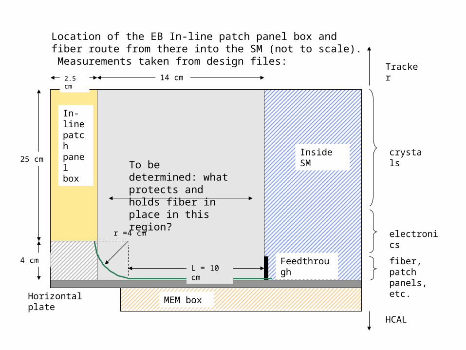
Horizontal plate
Inside SM
4 cm
14 cm
25 cm
MEM box
Feedthrough
r =4 cm
L = 10 cm
In-line patch panel box
Location of the EB In-line patch panel box and fiber route from there into the SM (not to scale). Measurements taken from design files:
2.5 cm
To be determined: what protects and holds fiber in place in this region?
crystals
electronics
fiber, patch panels, etc.
Tracker
HCAL
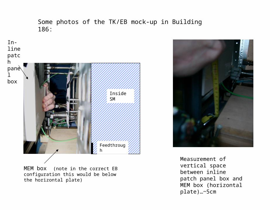
Some photos of the TK/EB mock-up in Building 186:
Measurement of vertical space between inline patch panel box and MEM box (horizontal plate)…~5cm
MEM box (note in the correct EB configuration this would be below the horizontal plate)
Inside SM
Feedthrough
In-line patch panel box
• The present in-line patch panel size (25 x 25 x 2.5 cm**3) will fit in the available space.
Conclusions:
• The fiber travels out the bottom of the box, in a 4cm-radius curve, then 10 cm horizontally to enter the SM feedthrough. It is not yet known what will protect and hold the fiber in place in this region.


