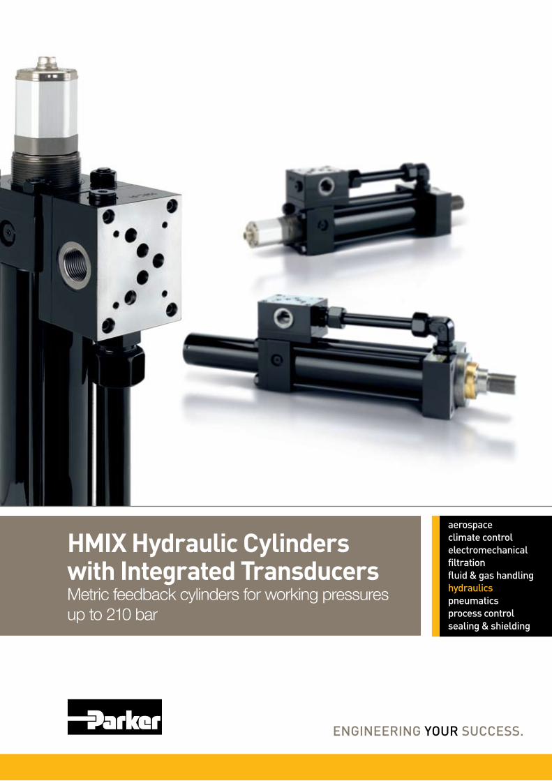
HMIX Hydraulic Cylinders with Integrated Transducers Metric feedback cylinders for working pressures up to 210 bar

2 Parker HannifinCylinder DivisionEurope
Catalogue HY07-1175/UK Electro-Hydraulic Tie Rod CylindersHMIX SeriesIntroduction
FAILURE OR IMPROPER SELECTION OR IMPROPER USE OF THE PRODUCTS DESCRIBED HEREIN OR RELATED ITEMS CAN CAUSE DEATH, PERSONAL INJURY AND PROPERTY DAMAGE.
This document and other information from Parker-Hannifin Corporation, its subsidiaries and authorized distributors provide product or system options for further investigation by users having technical expertise.
The user, through its own analysis and testing, is solely responsible for making the final selection of the system and components and assuring that all performance, endurance, maintenance, safety and warning requirements of the application are met. The user must analyze all aspects of the application, follow applicable industry standards, and follow the information concerning the product in the current product catalog and in any other materials provided from Parker or its subsidiaries or authorized distributors.
To the extent that Parker or its subsidiaries or authorized distributors provide component or system options based upon data or specifications provided by the user, the user is responsible for determining that such data and specifications are suitable and sufficient for all applications and reasonably foreseeable uses of the components or systems.
Offer of SalePlease contact your Parker representation for a detailed ”Offer of Sale”.
WARNING – USER RESPONSIBILITY
Contents PageHMIX Series Mounting Styles 3Design Features and Benefits 4Cylinder Dimensions 6Piston Rod End Selection 10Piston Rod End Dimensions 10 Dimensions – with Manifold Fitted 11Manifold Dimensions and Patterns 12Flow Rates and Valve Sizes 13Transducer Connection 14Technical Data – Transducer 14Mounting Information 15Maximum Operating Pressures 15Seals and Fluid Data 16Seal Kits for Pistons and Glands 16Service Assembly Parts 17Model Code 18
Parker Offers the Widest Range of Industrial CylindersParker Hannifin's Cylinder Division is the world's largest supplier of hydraulic cylinders for industrial applications.
Parker manufactures a vast range of standard and special tie rod, roundline and 'mill' type cylinders to suit all types of industrial cylinder applications. Our cylinders are available to ISO, DIN, NFPA, ANSI and JIC standards, with other certifications available on request. All Parker hydraulic cylinders are designed to deliver long, efficient service with low maintenance requirements, guaranteeing high productivity year after year.
About Parker HannifinParker Hannifin is the global leader in motion and control technologies, partnering with its customers to increase their productivity and profitability. The company employs more than 52,000 people in 48 countries, providing customers with technical excellence and first class customer service.
Visit us at www.parker.com
IntroductionThe addition of a transducer and conditioning electronics to a hydraulic cylinder creates a system which responds rapidly and accurately to control signals for position and velocity, without the need for mechanical re-setting. By combining the sophistication of electronics with the enormous power densities offered by hydraulic motion, greater machine flexibility is achieved and set-up times are cut to a minimum.
ApplicationsPosition feedback systems are suitable for precision control in a wide variety of applications, including:
Machine tools•Robots•Flight simulators•Woodworking machinery•Paper machinery•Valve mechanisms•Injection moulding equipment•Marine stabilisation systems•Rubber processing equipment•Aerial and antennae positioning systems•Welding equipment•Wind turbine blade pitch control•
HMIX Series CylindersThe HMIX series of electro-hydraulic cylinders is based on Parker's proven HMI metric tie rod cylinder range and is suitable for working pressures of up to 210 bar. A typical HMIX model comprises a single rod cylinder with integrated transducer and manifold, and is supplied ready to accept a suitable valve.
Cylinder specification details, eg: accessories, forces and cushioning, which are not specified in this catalogue, can be found in the HMI/HMD Series cylinder catalogue – please ask your Parker sales office for catalogue number HY07-1150/UK. Full details of suitable valves for use with HMIX electro-hydraulic cylinders can be found in catalogue number HY11-3341/UK.

3 Parker HannifinCylinder DivisionEurope
Catalogue HY07-1175/UK Electro-Hydraulic Tie Rod CylindersHMIX SeriesMounting Styles
TB (ISO MX3)– see page 6
TE (MX5 to NFE 48-016)– see page 6
JJ (ISO ME5)– see page 7
C (ISO MS2)– see page 7
D (ISO MT1)– see page 9
DD (ISO MT4)– see page 9
B (ISO MP3)– see page 8
SBd (ISO MP5)– see page 8
HMIX Series Mounting StylesHMIX cylinders are available in eight standard mounting styles, based on ISO 6020/2. Basic cylinder dimensions are shown on
pages 6 to 10, with additional dimensions for manifold blocks shown on pages 11 to 13.
4 Parker HannifinCylinder DivisionEurope
Catalogue HY07-1175/UK Electro-Hydraulic Tie Rod CylindersHMIX SeriesDesign Features and Benefits
A High Precision, Magnetostrictive TransducerThe magnetostrictive transducers fitted to HMIX cylinders provide analogue or digital information of actuator position through the interaction of two magnetic fields. In closed loop feedback applications, these transducers deliver accurate information of position, velocity and acceleration over the full stroke of the cylinder. In open loop systems, a transducer may be used as a continuous, infinite resolution position monitoring device.
non-contacting design delivers long working life•
internal transducer protects sensitive components, ensuring •accuracy and reliability
steel protection tube prevents physical damage to •transducer electronics module
Compact design adds little to overall build length, simplifying •machine design
Where a rear pivot-mounted cylinder is required, eg: Styles B or SBd, a 'dummy cylinder' is constructed to house the electronics module. See page 8.
Transducer SpecificationType magnetostrictive, absolute, non-contactingMounting Position internalStroke length 25-3000mmMax speed 1.5m/sOperating temperature -40°C to +85°C Outputs analogue and digital Fluid suitability allEnvironment medium levels of shock and vibration
The technical specification of the transducer is shown on page 14.
A Fully Integrated ManifoldHMIX is supplied with a pre-fitted manifold block, ready to accept your choice of valve. With pipework and connections already in place, assembly time is cut to a minimum and performance is guaranteed.
Directly-mounted valve blocks deliver precise positional •accuracy and simplify installation
Manifolds are available for different valve sizes, to deliver the •power and speed the machine requires
DIN NG6 / CETOP03 / NFPA D03•
DIN NG10 / CETOP05 / NFPA D05•
DIN NG16 / CETOP07 / NFPA D07•• Manifoldsareofferedforallcommonvalvesizes.
Their pattern corresponds to DIN 24340, ISO 4401 and ETOP RP121.
Full details of HMIX manifold blocks for valve assemblies are shown on pages 12 and 13.
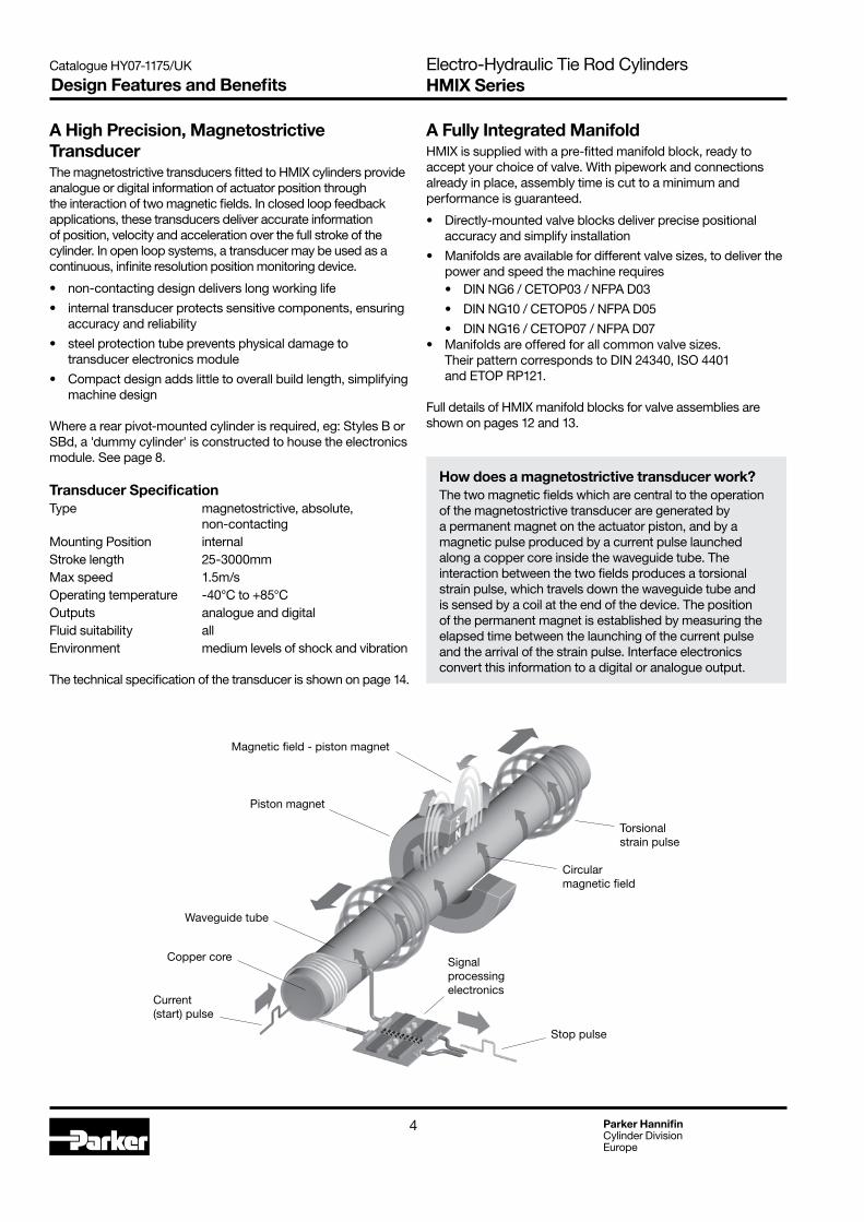
How does a magnetostrictive transducer work?The two magnetic fields which are central to the operation of the magnetostrictive transducer are generated by a permanent magnet on the actuator piston, and by a magnetic pulse produced by a current pulse launched along a copper core inside the waveguide tube. The interaction between the two fields produces a torsional strain pulse, which travels down the waveguide tube and is sensed by a coil at the end of the device. The position of the permanent magnet is established by measuring the elapsed time between the launching of the current pulse and the arrival of the strain pulse. Interface electronics convert this information to a digital or analogue output.
Current (start) pulse
Signal processing electronics
Copper core
Magnetic field - piston magnet
Waveguide tube
Piston magnet
Torsional strain pulse
Stop pulse
Circular magnetic field
5 Parker HannifinCylinder DivisionEurope
Catalogue HY07-1175/UK Electro-Hydraulic Tie Rod CylindersHMIX SeriesDesign Features and Benefits
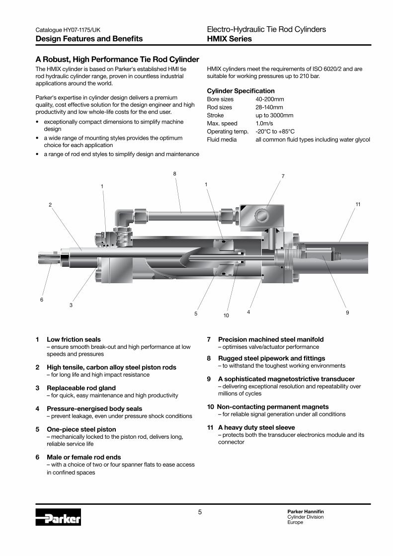
A Robust, High Performance Tie Rod CylinderThe HMIX cylinder is based on Parker's established HMI tie rod hydraulic cylinder range, proven in countless industrial applications around the world.
Parker's expertise in cylinder design delivers a premium quality, cost effective solution for the design engineer and high productivity and low whole-life costs for the end user.
exceptionally compact dimensions to simplify machine •design
a wide range of mounting styles provides the optimum •choice for each application
a range of rod end styles to simplify design and maintenance•
HMIX cylinders meet the requirements of ISO 6020/2 and are suitable for working pressures up to 210 bar.
Cylinder SpecificationBore sizes 40-200mmRod sizes 28-140mmStroke up to 3000mmMax. speed 1.0m/sOperating temp. -20°C to +85°CFluid media all common fluid types including water glycol
1 Low friction seals – ensure smooth break-out and high performance at low
speeds and pressures
2 High tensile, carbon alloy steel piston rods – for long life and high impact resistance
3 Replaceable rod gland – for quick, easy maintenance and high productivity
4 Pressure-energised body seals – prevent leakage, even under pressure shock conditions
5 One-piece steel piston – mechanically locked to the piston rod, delivers long,
reliable service life
6 Male or female rod ends – with a choice of two or four spanner flats to ease access
in confined spaces
7 Precision machined steel manifold – optimises valve/actuator performance
8 Rugged steel pipework and fittings – to withstand the toughest working environments
9 A sophisticated magnetostrictive transducer – delivering exceptional resolution and repeatability over
millions of cycles
10 Non-contacting permanent magnets – for reliable signal generation under all conditions
11 A heavy duty steel sleeve – protects both the transducer electronics module and its
connector
1 1
2
78
11
345 10
6
9

6 Parker HannifinCylinder DivisionEurope
Catalogue HY07-1175/UK Electro-Hydraulic Tie Rod CylindersHMIX Series
All dimensions are in millimetres unless otherwise stated.
Dimensions – TB & TE For rod end dimensions, see page 10
Tie Rod Mountings
Bore Ø
40
50
63
80
100
125
160
200
Style TBTie Rods Extended at Head EndISO Style MX3
Style TEThreaded Holes at Head EndNF E48-016 Style MX5
AA BB BG min
BXmax
BZmax
DD EEE 1
(BSPP) inches
F max
G GE J1 KB RT TG TX WH Y+ Stroke
PJ ZJ
59 35 12 121 54 2 M8x1 64 G3/8 10 45 55 55 6.5 M8 41.7 – 25 62 73 170
74 46 18 115 54 2 M12x1.25 76 G1/2 16 45 61 61 10 M12 52.3 – 25 67 74 182
91 46 18 98 60 M12x1.25 90 G1/2 16 45 61 61 10 M12 64.3 160 32 71 80 191
117 59 24 94 60 M16x1.5 115 G3/4 20 50 70 70 13 M16 82.7 160 31 77 93 215
137 59 24 92 60 M16x1.5 130 G3/4 22 50 72 72 13 M16 96.9 160 35 82 101 230
178 81 27 114 60 M22x1.5 165 G1 22 58 80 58 18 M22 125.9 176 35 86 117 232
219 92 32 114 60 M27x2 205 G1 25 58 83 58 22 M27 154.9 176 32 86 130 245
269 115 40 114 60 M30x2 245 G11/4 25 76 101 76 24 M30 190.2 176 32 98 165 299
1 Standard port thread if no manifold is fitted. 2 Across corners dimension of transducer nut. A protection tube is not available for 40mm and 50mm bore sizes.
WH
BB F G J1
Y
ZJ + stroke
PJ + stroke
Ø BZ
BX
TX
SW 46
E
TG E
TG
AA1
24
DD
EE EE
KB 3
SW 461
2
3
4
WH
BGGE
Y PJ + strokeZJ + stroke
BXTX
Ø BZ
AA
TG E
ETG
EE EE
RT
J1
See Notes 1, 2
See Notes 1, 2
7 Parker HannifinCylinder DivisionEurope
Catalogue HY07-1175/UK Electro-Hydraulic Tie Rod CylindersHMIX Series
All dimensions are in millimetres unless otherwise stated.
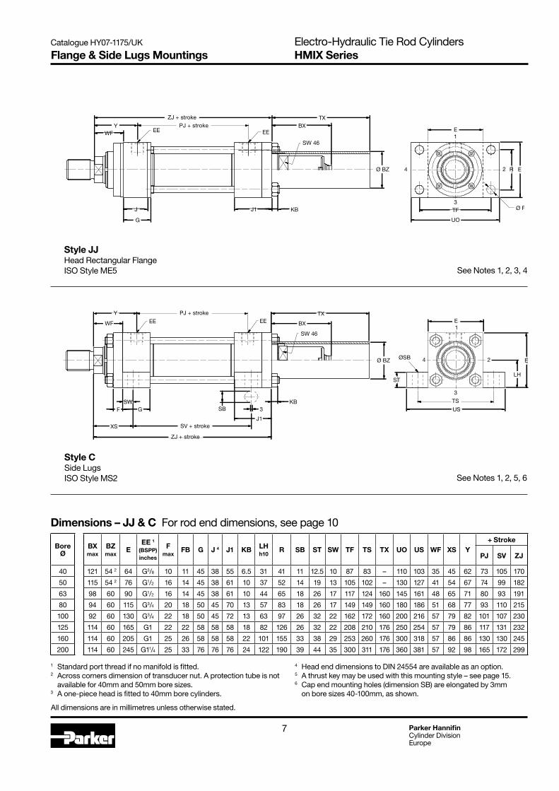
Dimensions – JJ & C For rod end dimensions, see page 10
Flange & Side Lugs Mountings
BXmax
BZmax
EEE 1
(BSPP) inches
F max
FB G J 4 J1 KB LHh10
R SB ST SW TF TS TX UO US WF XS Y+ Stroke
PJ SV ZJ
121 54 2 64 G3/8 10 11 45 38 55 6.5 31 41 11 12.5 10 87 83 – 110 103 35 45 62 73 105 170
115 54 2 76 G1/2 16 14 45 38 61 10 37 52 14 19 13 105 102 – 130 127 41 54 67 74 99 182
98 60 90 G1/2 16 14 45 38 61 10 44 65 18 26 17 117 124 160 145 161 48 65 71 80 93 191
94 60 115 G3/4 20 18 50 45 70 13 57 83 18 26 17 149 149 160 180 186 51 68 77 93 110 215
92 60 130 G3/4 22 18 50 45 72 13 63 97 26 32 22 162 172 160 200 216 57 79 82 101 107 230
114 60 165 G1 22 22 58 58 58 18 82 126 26 32 22 208 210 176 250 254 57 79 86 117 131 232
114 60 205 G1 25 26 58 58 58 22 101 155 33 38 29 253 260 176 300 318 57 86 86 130 130 245
114 60 245 G11/4 25 33 76 76 76 24 122 190 39 44 35 300 311 176 360 381 57 92 98 165 172 299
Style CSide LugsISO Style MS2
Bore Ø
40
50
63
80
100
125
160
200
Style JJHead Rectangular FlangeISO Style ME5
1 Standard port thread if no manifold is fitted. 2 Across corners dimension of transducer nut. A protection tube is not available for 40mm and 50mm bore sizes.3 A one-piece head is fitted to 40mm bore cylinders.
WF1
2
3
4
TF
UO
R E
Ø FB
E
KB
BXTX
Ø BZ
G
Y PJ + strokeZJ + stroke
J J1
EE EE
SW 46
E
E
STLH
TS
USF GSW
XS
WF EE
YEE
ØSB
PJ + stroke
KB
TX
BX
ZJ + stroke
Ø BZ
SW 46
2
3
4
1
SB 3
SV + strokeJ1
See Notes 1, 2, 3, 4
See Notes 1, 2, 5, 6
4 Head end dimensions to DIN 24554 are available as an option.5 A thrust key may be used with this mounting style – see page 15.6 Cap end mounting holes (dimension SB) are elongated by 3mm on bore sizes 40-100mm, as shown.

8 Parker HannifinCylinder DivisionEurope
Catalogue HY07-1175/UK Electro-Hydraulic Tie Rod CylindersHMIX SeriesPivot Mountings
All dimensions are in millimetres unless otherwise stated.
Dimensions – B & SBd For rod end dimensions, see page 10
CDH9
CX EEE 1
(BSPP) inches
EP EWh14
EX F max
G J JX KB L LR LT M MR MSmax
WF Y+ Stroke
PJ XE XF ZJ
14 20 -0.012 64 G3/8 13 20 16 10 45 38 77 6.5 19 17 25 14 16 29 35 62 73 354 360 192
20 25 -0.012 76 G1/2 17 30 20 16 45 38 87 10 32 29 31 20 25 33 41 67 74 366 365 208
20 30 -0.012 90 G1/2 19 30 22 16 45 38 87 10 32 29 38 20 25 40 48 71 80 377 383 217
28 40 -0.012 115 G3/4 23 40 28 20 50 45 84 13 39 34 48 28 34 50 51 77 93 401 410 229
36 50 -0.012 130 G3/4 30 50 35 22 50 45 74 13 54 50 58 36 44 62 57 82 101 432 436 232
45 60 -0.015 165 G1 38 60 44 22 58 58 58 18 57 53 72 45 53 80 57 86 117 472 487 232
56 80 -0.015 205 G1 47 70 55 25 58 58 58 22 63 59 92 59 59 100 57 86 130 499 528 245
70 100 -0.020 245 G11/4 57 80 70 25 76 76 76 24 82 78 116 70 76 120 57 98 165 598 632 299
Style BCap Fixed EyeISO Style MP3
Style SBdCap Fixed Eye with Spherical BearingISO Style MP5
Bore Ø
40
50
63
80
100
125
160
200
1 Standard port thread if no manifold is fitted.2 The connector is supplied in position 1 (illustrated) as standard.3 A pivot pin is not supplied with the cylinder.
WFY PJ + stroke
EE EE
JX JGF L M
XE + stroke
ZJ + stroke
MR
LR
KB
ØCD
E
EW
1
4
3
2
Connector 2
E
WF
F G
Y PJ + stroke
JX J LT
MS
ZJ + stroke
XF + stroke
EP
EX
1
3
E
E Ø CX
Connector 2 Greasenipple 4
KB
EE EE
4
3°
3°
2
See Notes 1, 2, 3, 4
See Notes 1, 2, 3
4 The M6 grease nipple illustrated is fitted to cylinders of 50mm bore and above. 40mm bore cylinders have a 2.5mm drilling for lubrication.
9 Parker HannifinCylinder DivisionEurope
Catalogue HY07-1175/UK Electro-Hydraulic Tie Rod CylindersHMIX SeriesTrunnion Mountings
Style DHead TrunnionISO Style MT1
All dimensions are in millimetres unless otherwise stated.
1 Standard port thread if no manifold is fitted.2 Across corners dimension of transducer nut. A protection tube is not available for 40mm and 50mm bore sizes.3 Without manifold fitted at end cap, otherwise see page 11.
Dimensions – D & DD For rod end dimensions, see page 10
BD BXmax
BZmax E
EE 1(BSPP) inches
F max
G G1 J1 KB TC TDf8
TL TM TX TY W WF XG Y+ Stroke Style
DD min stroke 3
Min XI dim'n 4
PJ ZJ
30 121 54 2 64 G3/8 10 45 - 55 6.5 63 20 16 76 – 76 - 35 57 62 73 170 15 97
40 115 54 2 76 G1/2 16 45 - 61 10 76 25 20 89 – 89 - 41 64 67 74 182 15 107
40 98 60 90 G1/2 16 45 - 61 10 89 32 25 100 160 95 - 48 70 71 80 191 15 114
50 94 60 115 G3/4 20 50 - 70 13 114 40 32 127 160 127 - 51 76 77 93 215 20 127
60 92 60 130 G3/4 22 50 72 72 13 127 50 40 140 160 140 35 57 71 82 101 230 20 138
73 114 60 165 G1 22 58 80 58 18 165 63 50 178 176 178 35 57 75 86 117 232 25 153
90 114 60 205 G1 25 58 88 58 22 203 80 63 215 176 216 32 57 75 86 130 245 30 161
110 114 60 245 G11/4 25 76 108 76 24 241 100 80 279 176 280 32 57 85 98 165 299 30 190
Bore Ø
40
50
63
80
100
125
160
200
Style DDIntermediate Fixed TrunnionISO Style MT4
F
1
24
3
TCTL TL
R3 mm
Ø TD E
G
XG
WF
G1W
YZJ + stroke
BXTX
Ø BZ
KB
PJ + stroke
J1
SW 46
EEEE
4
WFY
EE EEPJ + stroke
KB
1
2
3
R3 mm
Ø TD
TLTL TM
E TY
E
ZJ + stroke
F G
XI
BD
BX
TX
Ø BZ
SW 46
J1
See Notes 1, 2, 5
See Notes 1, 2, 3, 4
4 XI Dimension to be specified by customer5 A one-piece head and retainer is used on 100-200mm bore sizes – see G1 dimension. On 160 and 200mm bores, the bolted gland is recessed, with tie rods screwed into the head.

10 Parker HannifinCylinder DivisionEurope
Catalogue HY07-1175/UK Electro-Hydraulic Tie Rod CylindersHMIX Series
All dimensions are in millimetres unless otherwise stated.
Piston Rod End Dimensions – Check Maximum Operating Pressure on page 15
Rod End SelectionRod ends can be supplied with two or four wrench flats.The desired combination of rod diameter, rod end thread and number of wrench flats can be identified from the table below and selected in the order code on pages 18-19.Note the Maximum Operating Pressure information in the table on page 15.
The WH dimension for mounting styles TB and TE is shown on page 6.
Piston Rod End Data and Threads
Rod End Codes 5 & 9– JJ Mount
Rod End Codes 5 & 9– All Except JJ Mount
Rod End Codes 1, 2, 4 & 7– JJ Mount
Rod End Codes 1, 2, 4 & 7– All Except JJ Mount
Bore Ø
Rod No.
Rod Ø
MM
40 2 28
502 36
3 28
63
1 28
2 45
3 36
80
1 36
2 56
3 45
100
1 45
2 70
3 56
125
1 56
2 90
3 70
160
1 70
2 110
3 90
200
1 90
2 140
3 110
Code 1 (4 Flats) and
Code 4 (2 Flats)
Code 2 (4 Flats)and
Code 7 (2 Flats)
Code 5 (4 Flats) and
Code 9 (2 Flats)B f9
D NA VE WF
KK A KK A KF A
M20x1.5 28 M14x1.5 18 M20x1.5 28 42 22 26 22 35
M27x2 36 M16x1.5 22 M27x2 36 50 30 34 2541
M20x1.5 28 M16x1.5 22 M20x1.5 28 42 22 26 22
M20x1.5 28 – – M20x1.5 28 42 22 26 22
48M33x2 45 M20x1.5 28 M33x2 45 60 39 43 29
M27x2 36 M20x1.5 28 M27x2 36 50 30 34 25
M27x2 36 – – M27x2 36 50 30 34 25
51M42x2 56 M27x2 36 M42x2 56 72 48 54 29
M33x2 45 M27x2 36 M33x2 45 60 39 43 29
M33x2 45 – – M33x2 45 60 39 43 29
57M48x2 63 M33x2 45 M48x2 63 88 62 68 32
M42x2 56 M33x2 45 M42x2 56 72 48 54 29
M42x2 56 – – M42x2 56 72 48 54 29
57M64x3 85 M42x2 56 M64x3 85 108 80 88 32
M48x2 63 M42x2 56 M48x2 63 88 62 68 32
M48x2 63 – – M48x2 63 88 62 68 32
57M80x3 95 M48x2 63 M80x3 95 133 100 108 32
M64x3 85 M48x2 63 M64x3 85 108 80 88 32
M64x3 85 – – M64x3 85 108 80 88 32
57M100x3 112 M64x3 85 M100x3 112 163 128 138 32
M80x3 95 M64x3 85 M80x3 95 133 100 108 32
JJ Mount only
VL min
RD f8
VJ FJ
3 62 12 10
4 749
166
4
75 6
1688
13
9
4
82 5
20105 9
5
92 7
22125
10
7
5
105 9 20
150 10 22
5
125 10 22
170 7 25
5
150 10 22
210 7 25
WFAVE
VJ
RD NA KKB MM
DWrench
FlatsFJ
VL
WF
A
VE
NA KFB MM
DWrench
FlatsFJ
VL
A
NA KFB MM
DWrench
Flats
WFVE
VJ
RD
WFA
VE
NA KKB MM
DWrench
Flats
Rod End Codes 5 and 9 – Short Stroke CylindersCode 5 or 9 (female) rod ends should not be used on 160mm or 200mm bore cylinders with a stroke of 50mm or less. Please consult the factory, with details of the application.
Rod End Code 3Non-standard piston rod ends are designated Code 3. A dimensional sketch or description should accompany the order. Please specify dimensions KK or KF, A, rod stand out (WF – VE) and thread form.
11 Parker HannifinCylinder DivisionEurope
Catalogue HY07-1175/UK Electro-Hydraulic Tie Rod CylindersHMIX Series
Bore Ø
40
50
63
80
100
125
160
200
IDØ EE NW
With Standard Manifold Fitted
Minimum Stroke
XI min
+ StrokeNG6CH
NG10CH
NG16CHXI
maxXM
11 G1/2 11 50 97 70 165 47
11 G1/2 11 45 107 75 171 53
16 G3/4 14 80 114 67 193 60
16 G3/4 14 76 127 80 210 73
16 G3/4 14 76 138 85 223 80
16 G3/4 14 56 153 100 243 98
29 G11/4 18 100 161 80 264 127
29 G11/4 18 65 190 115 309 147
Cylinders with Manifold
Dimensions – with Manifold Fitted For other dimensions, see pages 6 to 10
Styles C, D, DD, JJ, TB, TEStyle DD illustrated
Styles B, SBdStyle SBd illustrated
NWEE
CH
XM + stroke
Manifold Block- see pages 12-13
41min
51max
ID
All dimensions are in millimetres unless otherwise stated.
min 66
max 76
XM + stroke
XI
NWEE
Manifold Block- see pages 12-13
ID
CH
12 Parker HannifinCylinder DivisionEurope
Catalogue HY07-1175/UK Electro-Hydraulic Tie Rod CylindersHMIX Series
Manifold for Valve SizeDIN NG6 / CETOP03 / NFPA D03Pattern corresponds to DIN 24340 / ISO 4401 / ETOP RP121
Manifold for Valve SizeDIN NG10 / CETOP05 / NFPA D05Pattern corresponds to DIN 24340 / ISO 4401 / ETOP RP121
All dimensions are in millimetres unless otherwise stated.
70
19.5
13
P
AB
T
P
B
T 35
34.5
70
100
17
22
49
TB TA
AB
P
T
P
B
50
80
Manifolds for Valve Assembly
Port P – G1/2
Port T – G1/2
Port B – G1/2
Port P – G3/4Port T – G3/4Port B – G3/4

13 Parker HannifinCylinder DivisionEurope
Catalogue HY07-1175/UK Electro-Hydraulic Tie Rod CylindersHMIX Series
Manifold for Valve SizeDIN NG16 / CETOP07 / NFPA D07Pattern corresponds to DIN 24340 / ISO 4401 / ETOP RP121
All dimensions are in millimetres unless otherwise stated.
Bore Ø
Rod No. 1
Rod Ø
40 2 28
502 36
3 28
63
1 28
2 45
3 36
80
1 36
2 56
3 45
100
1 45
2 70
3 56
125
1 56
2 90
3 70
160
1 70
2 110
3 90
200
1 90
2 140
3 110
Port P – G11/4 Port X – G1/2
Port T – G11/4 Port Y – G1/2
Port B – G11/4
HMIX Flow Rates and Standard Valve Sizes
Manifolds for Valve Assembly
1 Rod No.3 does not conform to ISO 6020/2.
Piston Area, Full Bore/Annular
cm2
Piston Area, Full Bore
cm2
Piston Area, Annular
cm2
Flow Rate @ 5m/s Fluid Velocity
l/minManifold
AB / AR AB AR Cap End Head End NG6 NG10 NG16
1.96 12.57 6.41 28.5 28.5 Std. Special N/A
2.0819.64
9.4628.5 28.5 Std. Special N/A
1.46 13.48
1.25
31.18
25.02
46.2 60.3 Special Std. N/A2.04 15.27
1.48 21.00
1.25
50.27
40.00
46.2 60.3 Special Std. N/A1.96 25.64
1.46 34.36
1.25
78.55
62.64
46.2 60.3 Special Std. Special1.96 40.06
1.46 53.92
1.25
122.72
98.09
46.2 60.3 Special Std. Special2.08 59.09
1.46 84.23
1.24
201.06
162.57
94.2 198.2 Special Special Std.1.90 106.01
1.46 137.43
1.25
314.16
250.53
94.2 198.2 Special Special Std.1.96 160.20
1.43 219.11
View A
View A
35.1
13.7
132
140
P T
B A
Y
90
32
130
X
76
44
14 Parker HannifinCylinder DivisionEurope
Catalogue HY07-1175/UK Electro-Hydraulic Tie Rod CylindersHMIX SeriesConnectors and Technical Data
Transducer ConnectionConnection to the transducer electronics is via a straight or angled connector. Both types are suitable for use with all cylinder mounting styles. Pin connections are shown in the table.
1
2
3
45
678
Straight ConnectorType LXES-0002
Right-Angled Connector Type LXES-0003
Connector Pin Arrangement(Solder Pin View)
Connector Pins Sensor with Analogue OutputCode A
Sensor with Analogue OutputCode C
Sensor with Digital OutputCodes S & T
1 Free 4 ... 20mA + Clock pulse
2 0V 0V + Data
3 10 ... 0V Free - Clock pulse
4 La La Must be free
5 0 ... 10V Free - Data
6 Ground Ground Ground
7 +24V +24V +24V
8 Lb Lb Must be free
Technical Data Analogue Digital Code A Code C Code T Code S Voltage Current SSI SSI
OutputSignal 0-10V 4-20mA 24-bit 24-bit Gray coded Binary codedLoad current ≤ 5mA Load resistance ≤ 500 OhmResolution ≤ 0.33mV ≤ 0.66µA 5µm
AccuracyLinearity ± 50µm @ nominal length ≤ 500mm ± 30µm ± 0.01% FS @ nominal length > 500 to ≤ 5500mm Temperature coefficient ≤ 30 ppm / K ≤ 15 ppm / KRepeatability ± 0.3mV ± 0.6µA ± 1 digitHysteresis ≤ 5µm ≤ 1 digit
Ambient ConditionsOperating temperature -40°C to +85°CProtection class IP67 when plug is connected
SupplyVoltage, stabilized 10-30V DCRipple ≤ 0.5VssCurrent draw (at 24V DC) ≤ 150mA ≤ 120mA
La and Lb are programmable inputs which allow the user to set start and end positions remotely.
15 Parker HannifinCylinder DivisionEurope
Catalogue HY07-1175/UK Electro-Hydraulic Tie Rod CylindersHMIX Series
Front Flange MountingsStyle JJ front flange-mounted cylinders, shown on page 7, incorporate a location diameter for accurate alignment on the mounting surface. The gland retainer is integral with the head on 40mm bore cylinders, while on 50mm bore sizes and above, the circular retainer is bolted to the head.
Extended Tie RodsCylinders may be ordered with extended tie rods in addition to another mounting style. The extended tie rods may then be used for mounting other systems or machine components. An additional set of mounting nuts is supplied.
Foot Mountings and Thrust KeysThe turning moment which results from the application of force by a foot-mounted cylinder (style C) must be resisted by secure mounting and effective guidance of the load. The option of a thrust key is recommended to provide positive cylinder location.
Foot-mounted cylinders use a separate key (supplied) fitted between keyways machined in the foot mounting at the head end of the cylinder and the machine bed. To order, select 'K' in the 'Mounting Modification' field of the model code on page 19. The key supplied corresponds to BS4235/DIN6885 type B.
Cylinder CushioningThe HMI Series of cylinders, on which the HMIX electro-hydraulic cylinder range is based, is available with the option of cushions at either or both ends. Cushioning works by restricting the flow of hydraulic fluid to the port during the final millimetres of travel. This option is not recommended for HMIX cylinders in closed loop applications; where specified, the user should ensure that the cushioned distance is outside the working stroke range.
All dimensions are in millimetres unless otherwise stated.
Mounting Information
COKeyCO/2KC
TP
* Not to ISO 6020/2
Gland DrainsThe accumulation of fluid between the gland seals of long stroke cylinders, cylinders with low friction seals, cylinders with constant back pressure or where the ratio of the extend speed to the retract speed is greater than 2 to 1, can be relieved by specifying an optional gland drain. As a general guide, Parker recommends the use of a gland drain where piston speeds will exceed 0.6m/s and/or where the stroke length is:≥ 30 x bore diameter for bore sizes up to and including 63mm≥ 20 x bore diameter for bore sizes of 80mm and above.
FiltrationFor maximum component life, the system should be protected from contamination by effective filtration. The rating of the filter medium depends on the system components and the application. The minimum required for hydraulic systems should be class 19/15 to ISO 4406, which equates to 25µ (ß10≥75) to ISO 4572.
Maximum Operating PressuresThe recommended maximum operating pressures of cylinders fitted with a transducer are lower than those of the standard cylinder, due to the internal drilling of the piston rod. Maximum operating pressures for individual bore/rod combinations are shown in the table.
Bore Ø Rod No. Rod
Ø
40 2 28
502 36
3 28
63
1 28
2 45
3 36
80
1 36
2 56
3 45
100
1 45
2 70
3 56
125
1 56
2 90
3 70
160
1 70
2 110
3 90
200
1 90
2 140
3 110
Max Operating Pressure
210
210
180
100
210
210
130
210
210
120
210
210
140
210
200
110
210
210
130
210
210
CON9
KC min
TP min
12 4 55
12 4.5 70
16 4.5 80
16 5 105
16 6 120
20 6 155
32* 8 190
40 8 220
Bore Ø
40
50
63
80
100
125
160
200
Key
Width Height Length Part No.
12 8 55 0941540040
12 8 70 0941540050
16 10 80 0941540063
16 10 105 0941540080
16 10 120 0941540100
20 12 155 0941540125
32 18 190 0941540160
40 22 220 0941540200

16 Parker HannifinCylinder DivisionEurope
Catalogue HY07-1175/UK Electro-Hydraulic Tie Rod CylindersHMIX Series
RodØ
28
36
45
56
70
90
110
140
Low Friction Gland Service Cartridge Kit*
RG2HMF0281
RG2HMF0361
RG2HMF0451
RG2HMF0561
RG2HMF0701
RG2HMF0901
RG2HMF1101
RG2HMF1401
* Replacement Seals – OrderingThe part numbers shown in the tables are for fluid group 1 seals, denoted by the last character of each part number. For seals in fluid groups 2 or 5, substitute a '2' or '5' for the '1' at the end of the number sequence.
Key to Parts1 Gland/bearing cartridge2 Wiper seal3 Step seal4 Pre-load ring for step seal (3)5 Scraper seal6 Pre-load ring for scraper seal (5)7 Piston8 Wear ring9 Piston seal10 Energising ring for piston seal
Seals and Fluid Data
FluidGroup
Seal Compounds – a combination of: Fluid Medium to ISO 6743/4-2001 Temperature Range
1NBR (nitrile butadiene rubber)PTFE (polytetrafluoroethylene)PUR (polyurethane)
Mineral Oil HH, HL, HLP, HLP-D, HM, HV, MIL-H-5606 oil, air, nitrogen -20°C to +80°C
2NBR (nitrile butadiene rubber)PTFE (polytetrafluoroethylene)PUR (polyurethane)
Water glycol (HFC) -20°C to +60°C
5FKM (fluorocarbon rubber)PTFE (polytetrafluoroethylene)
Fire resistant fluids based on phosphate esters (HFD-R). Also suitable for hydraulic oil at high temperatures or in hot environments. Not suitable for use with Skydrol. See fluid manufacturer's recommendations.
-20°C to +85°C
Low Friction Gland and Seals
RodØ
28
36
45
56
70
90
110
140
Ultra Low Friction Gland Service Cartridge Kit*
RG2HMU0281
RG2HMU0361
RG2HMU0451
RG2HMU0561
RG2HMU0701
RG2HMU0901
RG2HMU1101
RG2HMU1401
Ultra Low Friction Gland and Seals
Bore Ø
40
50
63
80
100
125
160
200
Piston Service Kit Low Friction Seals*
PF040HM001
PF050HM001
PF063HM001
PF080HM001
PF100HM001
PF125HM001
PF160HM001
PF200HM001
Low Friction PistonFor use with Low Friction and Ultra Low Friction Glands
Seal Kits for Pistons and Glands
Seals, Fluids and Seal Kits
All dimensions are in millimetres unless otherwise stated.
1
3
2
41
3
5
6
4
7
8
9
10
17 Parker HannifinCylinder DivisionEurope
Catalogue HY07-1175/UK Electro-Hydraulic Tie Rod CylindersHMIX SeriesCylinder and Manifold Parts
Sectioned View
1 Piston rod2 Piston3 Cylinder tube4 Retainer, head end5 Cylinder head6 Gland7 Cylinder cap8 Retainer, cap end9 Transducer10 Protective tube (not available for bore sizes 40mm and 50mm)11 Wiper seal 1
12 Rod seals 1
13 O-ring 1
14 Piston seal 2
15 Piston wear rings 2
16 O-ring 2
17 O-ring18 O-ring, adapter plate19 Manifold20 Subplate21 Tie rod 22 Tie rod nut
1 Included in Gland Service Kits and Gland Service Cartridge Kits2 Included in Piston Service Kits
1
23
45
6
7
9
1112 13
14 1617
1819
821 22
15
10
20

18 Parker HannifinCylinder DivisionEurope
Catalogue HY07-1175/UK Electro-Hydraulic Tie Rod CylindersHMIX Series
Mounting Style
Ports
Piston & Gland
Type
S
Special Features
Piston Rod
Number
Piston Rod End
Rod Thread
HMIX
Series
C
Head End CushionPage 15
Bore
K
Mounting Modifications
Code Special Features S To customer specification
Code Piston and Gland Page PF Low Friction – standard 16 LF Ultra Low Friction 16
Code Port Style Page R BSPP (ISO 228) – standard 6-9
Code Modification Page K Thrust Key (Style C only) 15
Code Mounting Style Page TB Tie Rods Extended at Head End 6 TE Threaded Holes at Head End 6 JJ Head Rectangular Flange 7 C Side Lug Mounting 7 B Cap Fixed Eye 8 SBd Cap Fixed Eye with Spherical Bearing 8 D Head Trunnion 9 DD Intermediate Fixed Trunnion 9
Code Thread Page M Metric 10
Code Rod Number Page 1 Rod No.1 10 2 Rod No.2 10 3 Rod No.3 10
Code Rod End Style Page 1 Male with four wrench flats 10 2 Male with four wrench flats 10 3 Special designs – please supply description or drawing 10 4 Male with two wrench flats 10 5 Female with four wrench flats 10 7 Male with two wrench flats 10 9 Female with two wrench flats 10
How to Order
KeyRequired for basic cylinder Indicate optional features or leave blank
19 Parker HannifinCylinder DivisionEurope
Catalogue HY07-1175/UK Electro-Hydraulic Tie Rod CylindersHMIX SeriesHow to Order
Net Stroke(mm)
FluidMedium
AirBleed– Cap
PortPosition– Head
C
Cap End Cushion Page 15
Code Fluid Page Group M Group 1 16 C Group 2 16 D Group 5 16
Code Port Position Pageeg: 1 Head end 1-4 6-9 1 Cap end 1-4 * 6-9* 2-4 only where no manifold is fitted
Code Air Bleed Positioneg: 4 Head end 1-4 * 4 Cap end 1-4 * 00 No air bleeds* where not occcupied by a port
Code Manifold Page X None – K NG6 12-13 L NG10 12-13 M NG16 12-13 Z Other – please specify
Manifold
ManifoldPosition
Code Manifold Position Page X None – R Rear 11 Z Other – please specify 11
Code Transducer Page V Prepared for customer fitting 4 P Magnetostrictive 4 Z Other – please specify
Transducer
OutputSignal
Code Output Signal Page X Not required A 0-10V 14 C 4-20mA 14 S SSI – binary 14 T SSI – gray 14 Z Other – please specify
PortPosition– Cap
AirBleed– Head
Port and Air Bleed PositionsThe positions of the ports and air bleed valves in the head and cap are selected by the position number (1 - 4) when viewed from the piston rod end.
1
2
3
4

Catalogue HY07-1175/UK POD 08/2010 TMCZ
Your local authorized Parker distributor
© 2010 Parker Hannifin Corporation. All rights reserved.
AE – UAE, Dubai Tel: +971 4 8127100 [email protected]
AR – Argentina, Buenos Aires Tel: +54 3327 44 4129
AT – Austria, Wiener Neustadt Tel: +43 (0)2622 23501-0 [email protected]
AT – Eastern Europe, Wiener Neustadt Tel: +43 (0)2622 23501 900 [email protected]
AU – Australia, Castle Hill Tel: +61 (0)2-9634 7777
AZ – Azerbaijan, Baku Tel: +994 50 2233 458 [email protected]
BE/LU – Belgium, Nivelles Tel: +32 (0)67 280 900 [email protected]
BR – Brazil, Cachoeirinha RS Tel: +55 51 3470 9144
BY – Belarus, Minsk Tel: +375 17 209 9399 [email protected]
CA – Canada, Milton, Ontario Tel: +1 905 693 3000
CH – Switzerland, Etoy Tel: +41 (0)21 821 87 00 [email protected]
CL – Chile, Santiago Tel: +56 2 623 1216
CN – China, Shanghai Tel: +86 21 2899 5000
CZ – Czech Republic, Klecany Tel: +420 284 083 111 [email protected]
DE – Germany, Kaarst Tel: +49 (0)2131 4016 0 [email protected]
DK – Denmark, Ballerup Tel: +45 43 56 04 00 [email protected]
ES – Spain, Madrid Tel: +34 902 330 001 [email protected]
FI – Finland, Vantaa Tel: +358 (0)20 753 2500 [email protected]
FR – France, Contamine s/Arve Tel: +33 (0)4 50 25 80 25 [email protected]
GR – Greece, Athens Tel: +30 210 933 6450 [email protected]
HK – Hong Kong Tel: +852 2428 8008
HU – Hungary, Budapest Tel: +36 1 220 4155 [email protected]
IE – Ireland, Dublin Tel: +353 (0)1 466 6370 [email protected]
IN – India, Mumbai Tel: +91 22 6513 7081-85
IT – Italy, Corsico (MI) Tel: +39 02 45 19 21 [email protected]
JP – Japan, Fujisawa Tel: +81 (0)4 6635 3050
KR – South Korea, Seoul Tel: +82 2 559 0400
KZ – Kazakhstan, Almaty Tel: +7 7272 505 800 [email protected]
LV – Latvia, Riga Tel: +371 6 745 2601 [email protected]
MX – Mexico, Apodaca Tel: +52 81 8156 6000
MY – Malaysia, Shah Alam Tel: +60 3 7849 0800
NL – The Netherlands, Oldenzaal Tel: +31 (0)541 585 000 [email protected]
NO – Norway, Asker Tel: +47 66 75 34 00 [email protected]
NZ – New Zealand, Mt Wellington Tel: +64 9 574 1744
PL – Poland, Warsaw Tel: +48 (0)22 573 24 00 [email protected]
PT – Portugal, Leca da Palmeira Tel: +351 22 999 7360 [email protected]
Parker Worldwide
RO – Romania, Bucharest Tel: +40 21 252 1382 [email protected]
RU – Russia, Moscow Tel: +7 495 645-2156 [email protected]
SE – Sweden, Spånga Tel: +46 (0)8 59 79 50 00 [email protected]
SG – Singapore Tel: +65 6887 6300
SK – Slovakia, Banská Bystrica Tel: +421 484 162 252 [email protected]
SL – Slovenia, Novo Mesto Tel: +386 7 337 6650 [email protected]
TH – Thailand, Bangkok Tel: +662 717 8140
TR – Turkey, Istanbul Tel: +90 216 4997081 [email protected]
TW – Taiwan, Taipei Tel: +886 2 2298 8987
UA – Ukraine, Kiev Tel +380 44 494 2731 [email protected]
UK – United Kingdom, Warwick Tel: +44 (0)1926 317 878 [email protected]
US – USA, Cleveland (industrial) Tel: +1 216 896 3000
US – USA, Lincolnshire (mobile) Tel: +1 847 821 1500
VE – Venezuela, Caracas Tel: +58 212 238 5422
ZA – South Africa, Kempton Park Tel: +27 (0)11 961 0700 [email protected]
European Product Information CentreFree phone: 00 800 27 27 5374(from AT, BE, CH, CZ, DE, EE, ES, FI, FR, IE, IL, IS, IT, LU, MT, NL, NO, PT, SE, SK, UK)US Product Information CentreFree phone: 1-800-27 27 537www.parker.com


