
HINO 500 SERIES
Body Mounting Manual
TRUCK CHASSISTRUCK CHASSIS
FG8JMODEL
KK-FG215

KK-FG215
No part of this manual may be reproduced or transmitted in any form without the express written permission of Hino Motors, Ltd. © 2012, All rights reserved. Printed in Japan.
BR OVERSEAS TECHNICAL SUPPORT DIVISION3-1-1, HINO-DAI, HINO-SHI, TOKYO, 191-8660 JAPAN
Telephone : 042-586-5887Facsimile : 042-586-4172
2012 - 10

KK-FG215
Request for alteration to make when reading MODEL NAME.
• TheMODELNAMEinthismanualofBODYMOUNTINGMANUALisdescribedaccording to the “PRODUCTION CODE” name.
• WhenmakinguseoftheBODYMOUNTINGMANUAL,usetheMODELNAMEafterreplacing it in accordance with the following table.
WARNING
(MODEL) (PRODUCTION CODE)
HINO 51526 FG8JMTB

KK-FG215
Purpose
This manual is provided to Body and Equipment Manufacturers, including inter-mediate and/or final stage manufacturers (hereinafter collectively referred to as Body and Equipment Manufacturers), to provide;
• TechnicalinstructionsforHinotruckchassiswithcabformodificationandmountingofbodies,
• AnaidtoBodyandEquipmentManufacturersforproducingsafevehiclesundertheirown discretion and responsibility,
• Othergeneraladviceforinstallation,modificationoralteration,
when Body and Equipment Manufacturers install any body or other equipment or device on Hino truck chassis with cab (hereinafter collectively referred to as Hino Chassis), or modify or alter a Hino Chassis.
Content
This manual contains chassis specifications and instructions particular to FG model of HINO 500 series EURO-4 emission control in the medium duty trucks.
Important
• TheCommonManualisavailableinthisCD-R.• Formoreinformationonmountingofbodiesandequipmentsoronchassis
modifications, refer to the appropriate workshop manuals, parts catalogs, and maintenance guides and owner's or driver's manual.
• TheinformationinthismanualisaccuratetothebestofHino'sknowledgeatthetimeof going to press.
Hino reserves the right to modify any and all information without notice and without obligation.
• Shouldmoredetaileddataorinformationbeneeded,pleasecontactauthorizedHino distributor.
ABOUT THIS MANUAL
This instruction manual must be used in combination with �the Common Manual, No. KC-AA201.

KK-FG215
Warning
• Thevehiclehasinstalledelectronicequipmentssuchasthevehicle'scontrolsystemand a computer for comply with vehicle regulation for each country. Inthatcase,domustnotalterofchassissuchaschangeofwheelbaseandtiresize. Deterioration of vehicle's capability and vehicle regulation violation may lead to serious traffic accident.
• ItistheresponsibilityofBodyandEquipmentManufacturersormodificationcompaniesto make sure that the completed vehicle with body and equipment, or after modification, conforms to all applicable laws and regulations of the country in which the vehicleistobeused(e.g.regulationsonlighting,tilt,overallsize,axleload,externalnoise control etc.)
• ThismanualdoesnotguaranteethesafetyofaHinochassisonceabodyorequipment has been mounted or modification has been made by a Body and Equipment Manufacturers or a modification company.
• Thismanualdoesnotaffectthatultimateresponsibilityforthemanufactureandmounting of the body, installation, modification or alteration on Hino Chassis devolves upon the Body and Equipment Manufacturer.
• EachindividualBodyandEquipmentManufacturerhasthesoleresponsibilityforthedesign, functions, materials and work concerning the body and equipment.
• AboutinstallationofT/MPTO(EngineforcompliedEuro-3,4&5regulation.) It can not control stable engine revolution because engine governor character is not switch to PTO mode if installed PTO unit whether Hino original or not by local market. Should not install the PTO unit at local market except mount body of unnecessary constant engine revolution such as dump truck.
• Aboutchassismass The chassis mass of chapter 3 shows standard specification of vehicle. (It is not included mass of option equipment.) Whenconsiderthemountingofbody,shouldincludemassofoptionequipment.
• HinoMotors,Ltd.doesnotassumeanyliabilitywhatsoeverforanyinjurytopersonsordamagetopropertycausedasaresultoftheutilizationofthismanual.
ABOUT THIS MANUAL
KK-FG215
1. VEHICLE SUMMARY
2. GENERAL PRECAUTIONS
3. CHASSIS MASS & FRAME SECTION MODULUS
4. SPRINGS & REAR AXLES
5. P.T.O. AND CONTROL
6. ELECTRICAL SYSTEMS
7. PAINTING
8. CHASSIS DRAWINGS
9. MOUNTING OF CHASSIS EQUIPMENT
10. OTHER
11. REGULATION
CONTENTS

KK-FG215
Chapter 1VEHICLE SUMMARY
1. MODEL CODE•••••••••••••••••••••••••••••••••••••••••••••••••••• 1 2. IDENTIFICATION NUMBER••••••••••••••••••••••••••••••••••• 2 3. CHASSIS SPECIFICATIONS•••••••••••••••••••••••••••••••••• 3

KK-FG215 1
VEHICLE SUMMARY11. MODEL CODE
NOTE• Refer to chassis specification for GVMR (Gross vehicle mass rating).
F D 7J J M A
GVMR DRIVE CODE MODEL CODE WHEELBASE(mm) CODE STEERING
POSITION MODIFY CODE BODY TYPEETC.
C 3000D 3000 3249E 3250 3499G 3750 3999H 4000 4249J 4250 4499K 4500 4749L 4750 4999M 5000 5249N 5250 5499P 5500 5749R 5750 5999S 6000 6249T 6250 6499W 7000 7249 Q DUMP & REAR AIR
SUSPENSION
U MIXER & REAR AIRSUSPENSION
HGENERAL CARGO
& REAR AIRSUSPENSION
M MIXER &LEAF SUSPENSIONT 10,000 13,000kg
CLASS4 x 4
17,000kgCLASS
26,000kgCLASS
26,000kgCLASS
4 x 2
6 x 2
6 x 4
L
M
7J J07E
8J J08E
9J J05E
1A A09C
2P P11C
G
VEHICLE TYPEENGINE CODE WHEELBASE CODE MODIFICATION CODE
10,400kgCLASS
10,000 12,000kgCLASS
D
C
APPLICABLE CODEGVMR & (DRIVE) CODE
K
RRH FIRST
4 x 6JF
G
CAB-OVER TRUCK
CAB-OVER TRUCK
GENERAL CARGO &LEAF SUSPENSIONA
D
4 x 2
2
GENERAL CARGO &LEAF SUSPENSIONB
4 x 2
J05D
GGENERAL CARGO
& REAR AIRSUSPENSION
FIRSTLH
DUMP &LEAF SUSPENSION
E DUMP &LEAF SUSPENSION
S SEMI-TRACTOR S
Z
14,000 15,500kgCLASS
H

VEHICLE SUMMARY1
KK-FG215 2
2. IDENTIFICATION NUMBER
CHASSIS NUMBER
ENGINE NUMBER
Located at the side�member of chassis frame.
RIGHT
VEHICLE MANUFACTURED STAMPING POSITION ( )
LOCAL
ORIGIN (JAPAN)
LOCAL or ORIGIN (JAPAN)
LEFT
LEFT
TAIWAN ONLY
DISTINATION
EXCEPT TAIWAN
A
B
Right side of�cylinder block
ENGINE MODEL
J05EA
BJ05DJ08EA09CP11C
: ENGINE NUMBER

KK-FG215 3
VEHICLE SUMMARY13. CHASSIS SPECIFICATIONS
DIMENSIONS & MASSFG-058
FG8JMTB
GENERAL CARGO
WHEEL BASE (mm) 5,050
TREAD FRONT (mm) 1,930
REAR (mm) 1,840
(kg) 15,100
FRONT (kg) 6,500
REAR (kg) 10,000
(kg) Refer to 3.1
(mm) Refer to 3.1
(mm) 2,455RECOMMENDED MAXIMUM BODY WIDTH
CHASSIS MASS ON STD SPECIFICATIONS
(INCLUDING WATER, OIL AND FULL FUEL)
HEIGHT OF CENTER OF GRAVITY
CLASSIFICATION NUMBER
PERMISSIBLE AXLE
CAPACITY
(GAM. RATING)
MAX. GVM/GCM CAPACITY
CHASSIS MODEL
ITEM
NOTE• Permissible axle capacity and GVM or GCM capacity listed above table must not be exceeded.• The front axle load must exceed 30% of the gross vehicle mass under full loaded condition for 4x2 and 4x4 drive vehicle.• The front axle load must exceed 20% of the gross vehicle mass under full loaded condition for 6x2 and 6x4 drive vehicle.• The height of center of gravity from ground on the unloaded vehicle with body mounted should be m or less for 16inches disc wheel.• The height of center of gravity from ground on the unloaded vehicle with body mounted should be 1.20 m or less for 20inches disc wheel.• Mass distribution on the left and right wheels should be balanced.• Both front axle and rear axle loads must not exceed the permissible load based on the tire load capacity according to the tire standards in your country.• The mass and dimension of tires to be mentioned in above chassis specification shows design figure according to JATMA or ETRTO standard.
KK-FG215 4
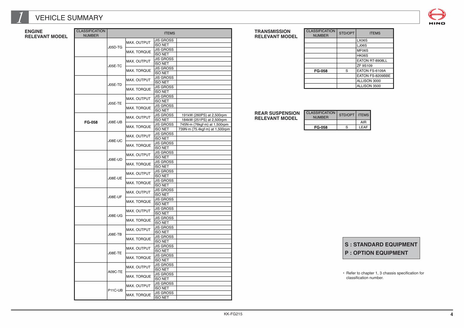
VEHICLE SUMMARY1ENGINE RELEVANT MODEL
CLASSIFICATION
NUMBER
JIS GROSS
ISO NET
JIS GROSS
ISO NET
JIS GROSS
ISO NET
JIS GROSS
ISO NET
JIS GROSS
ISO NET
JIS GROSS
ISO NET
JIS GROSS
ISO NET
JIS GROSS
ISO NET
JIS GROSS 191kW {260PS} at 2,500rpm
ISO NET 184kW {251PS} at 2,500rpm
JIS GROSS 745N·m {76kgf·m} at 1,500rpm
ISO NET 739N·m {75.4kgf·m} at 1,500rpm
JIS GROSS
ISO NET
JIS GROSS
ISO NET
JIS GROSS
ISO NET
JIS GROSS
ISO NET
JIS GROSS
ISO NET
JIS GROSS
ISO NET
JIS GROSS
ISO NET
JIS GROSS
ISO NET
JIS GROSS
ISO NET
JIS GROSS
ISO NET
JIS GROSS
ISO NET
JIS GROSS
ISO NET
JIS GROSS
ISO NET
JIS GROSS
ISO NET
JIS GROSS
ISO NET
JIS GROSS
ISO NET
JIS GROSS
ISO NET
JIS GROSS
ISO NET
MAX. TORQUE
MAX. TORQUE
MAX. OUTPUT
ITEMS
J05E-TE
MAX. OUTPUT
MAX. TORQUE
A09C-TE
MAX. OUTPUT
MAX. TORQUE
P11C-UB
MAX. OUTPUT
MAX. TORQUE
FG-058 J08E-UB
MAX. OUTPUT
MAX. TORQUE
J08E-UC
MAX. OUTPUT
MAX. TORQUE
MAX. OUTPUT
MAX. TORQUE
J05D-TG
J05E-TC
J05E-TD
MAX. OUTPUT
J08E-UE
MAX. OUTPUT
MAX. TORQUE
J08E-UD
MAX. OUTPUT
MAX. TORQUE
J08E-UG
MAX. OUTPUT
MAX. TORQUE
J08E-UF
MAX. OUTPUT
MAX. TORQUE
J08E-TE
MAX. OUTPUT
MAX. TORQUE
J08E-TB
MAX. OUTPUT
MAX. TORQUE
CLASSIFICATION
NUMBERSTD/OPT ITEMS
LX06S
LJ06S
MF06S
HK06S
EATON RT-8908LL
ZF 9S109
FG-058 S EATON FS-6109A
EATON FS-8209BBE
ALLISON 3000
ALLISON 3500
CLASSIFICATION
NUMBERSTD/OPT ITEMS
AIR
FG-058 S LEAF
TRANSMISSION RELEVANT MODEL
REAR SUSPENSION RELEVANT MODEL
S : STANDARD EQUIPMENT P : OPTION EQUIPMENT
• Refertochapter1,3chassisspecificationforclassificationnumber.
KK-FG215 5
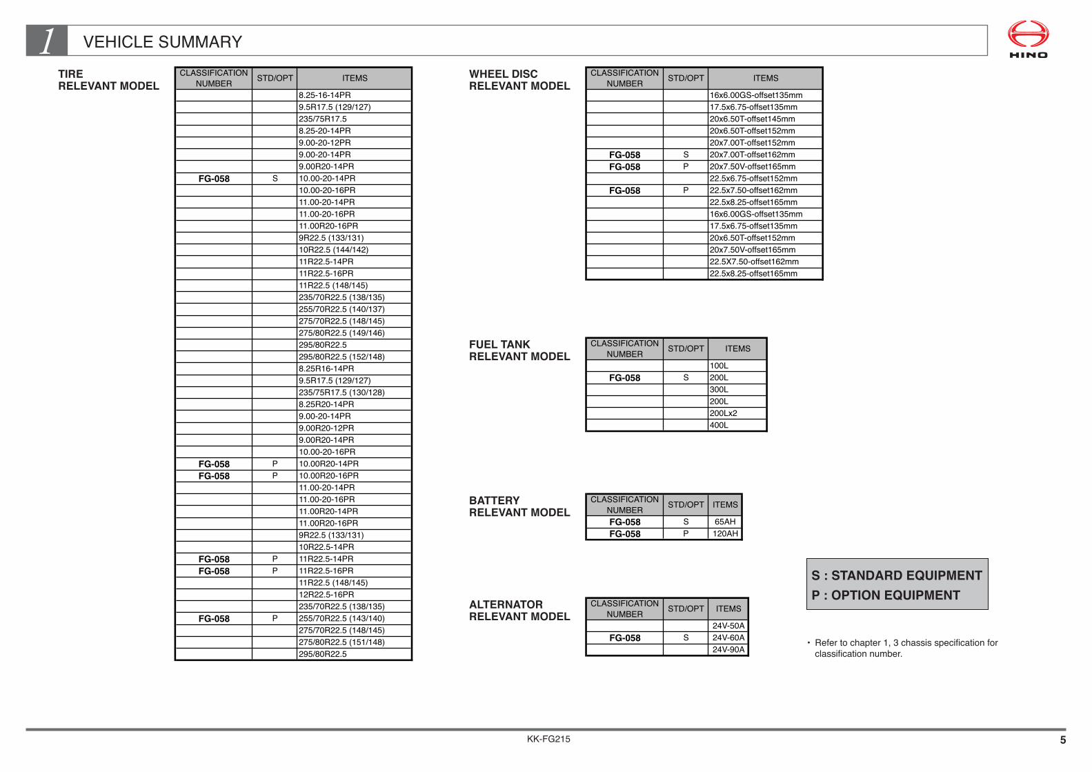
VEHICLE SUMMARY1CLASSIFICATION
NUMBERSTD/OPT ITEMS
8.25-16-14PR
9.5R17.5 (129/127)
235/75R17.5
8.25-20-14PR
9.00-20-12PR
9.00-20-14PR
9.00R20-14PR
FG-058 S 10.00-20-14PR
10.00-20-16PR
11.00-20-14PR
11.00-20-16PR
11.00R20-16PR
9R22.5 (133/131)
10R22.5 (144/142)
11R22.5-14PR
11R22.5-16PR
11R22.5 (148/145)
235/70R22.5 (138/135)
255/70R22.5 (140/137)
275/70R22.5 (148/145)
275/80R22.5 (149/146)
295/80R22.5
295/80R22.5 (152/148)
8.25R16-14PR
9.5R17.5 (129/127)
235/75R17.5 (130/128)
8.25R20-14PR
9.00-20-14PR
9.00R20-12PR
9.00R20-14PR
10.00-20-16PR
FG-058 P 10.00R20-14PR
FG-058 P 10.00R20-16PR
11.00-20-14PR
11.00-20-16PR
11.00R20-14PR
11.00R20-16PR
9R22.5 (133/131)
10R22.5-14PR
FG-058 P 11R22.5-14PR
FG-058 P 11R22.5-16PR
11R22.5 (148/145)
12R22.5-16PR
235/70R22.5 (138/135)
FG-058 P 255/70R22.5 (143/140)
275/70R22.5 (148/145)
275/80R22.5 (151/148)
295/80R22.5
CLASSIFICATION
NUMBERSTD/OPT ITEMS
16x6.00GS-offset135mm
17.5x6.75-offset135mm
20x6.50T-offset145mm
20x6.50T-offset152mm
20x7.00T-offset152mm
FG-058 S 20x7.00T-offset162mm
FG-058 P 20x7.50V-offset165mm
22.5x6.75-offset152mm
FG-058 P 22.5x7.50-offset162mm
22.5x8.25-offset165mm
16x6.00GS-offset135mm
17.5x6.75-offset135mm
20x6.50T-offset152mm
20x7.50V-offset165mm
22.5X7.50-offset162mm
22.5x8.25-offset165mm
CLASSIFICATION
NUMBERSTD/OPT ITEMS
100L
FG-058 S 200L
300L
200L
200Lx2
400L
CLASSIFICATION
NUMBERSTD/OPT ITEMS
FG-058 S 65AH
FG-058 P 120AH
CLASSIFICATION
NUMBERSTD/OPT ITEMS
24V-50A
FG-058 S 24V-60A
24V-90A
TIRE RELEVANT MODEL
FUEL TANK RELEVANT MODEL
WHEEL DISC RELEVANT MODEL
BATTERY RELEVANT MODEL
ALTERNATOR RELEVANT MODEL
S : STANDARD EQUIPMENT P : OPTION EQUIPMENT
• Refertochapter1,3chassisspecificationforclassificationnumber.

KK-FG215
Chapter 2GENERAL PRECAUTIONS
1. FIRE SHIELD•••••••••••••••••••••••••••••••••••••••••••••••••••••• 1 2. CLEARANCE BETWEEN CAB AND
REAR BODY OR EQUIPMENT•••••••••••••••••••••••••••• 2 3. RECOMMENDED POSITIONS OF U-BOLTS•••••••••••••• 11 4. RECOMMENDED POSITIONS OF REAR
FENDERS AND MUDGUARDS•••••••••••••••••••••••••••• 13 5. ELECTRIC WELDING WORK••••••••••••••••••••••••••••••••• 15 6. NOTES ON ADDITIONAL WIRING
IN THE ENGINE COMPARTMENT•••••••••••••••••••••••• 17 7. PRECAUTION OF THE ANTENNA POSITION•••••••••••• 18 8. NOTES ON SYSTEM CONTROL COMPUTERS•••••••••• 19 9. PRECAUTION FOR ADDITIONAL FUEL TANK••••••••••• 20 10. PRECAUTIONS FOR THE FUEL HOSE•••••••••••••••••••• 21 11. ADJUSTMENT OF LIGHT AXIS OF HEADLIGHT•••••••• 22

KK-FG215 1
GENERAL PRECAUTIONS21. FIRE SHIELD
GAP BETWEEN CAB REAR END AND BODY
If the vehicle has a flat bed or similar body, a fire shield should be fitted across the gap between the rear arch cover and the front end of the rear body (header board of rear body) on the chassis frame to prevent fires that may be caused by flammable materials falling off from the load platform onto the exhaust pipe. (See the illustration below.)
A fire shield is not necessary when the body is fitted with a sheet carrier attached directly to the top of header board.
A fire shield is also not necessary for such bodies as dump trucks, concrete mixer, tankers and aluminum vans, where there is no danger of falling - off of flammable materials.
FITTING THE FIRE SHIELD
CAB REAR ARCH
RUBBER
BOLT & NUT
BODY OREQUIPMENT
FIRE SHIELD
• Forapproximately50mmfromthefrontend (vehicle front), use rubber to match the shape of the fire shield to that of the rear arch.
• Theclearancebetweentheengineandfireshield material must be not less than 40mm.
• Youmayalsoinstallthefireshieldsothatit covers only the exhaust pipe.
NOTE•Whenyoumountthefireshield,usebolts,etc.,thatcanbetakenouttoallowforreplacement of the chassis parts which are located at the rear part of cab.
KK-FG215 2
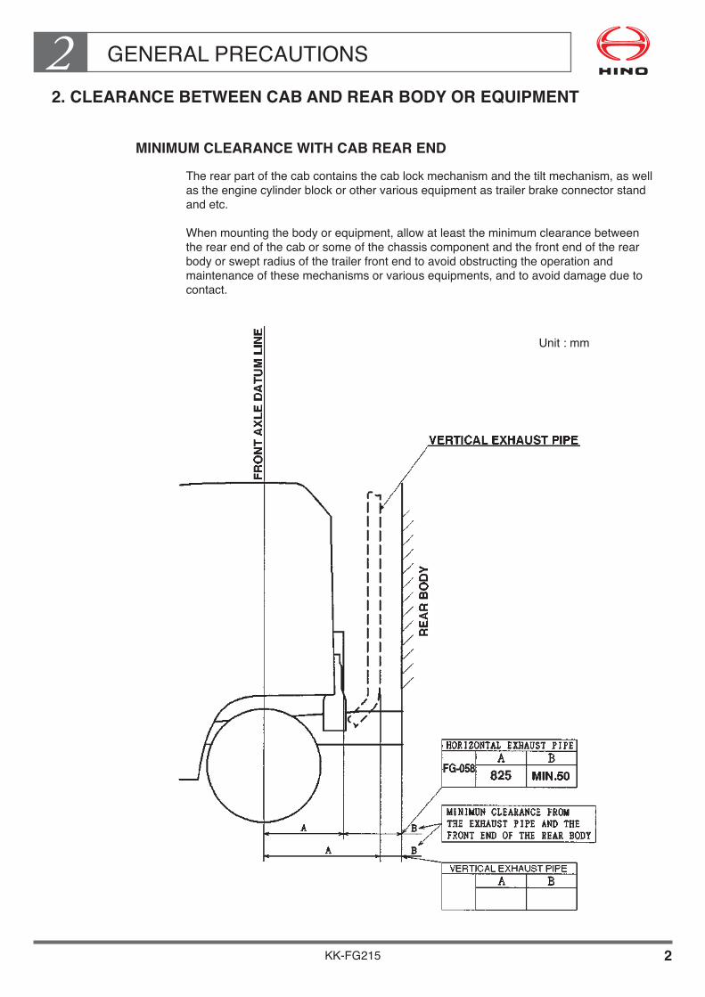
GENERAL PRECAUTIONS22. CLEARANCE BETWEEN CAB AND REAR BODY OR EQUIPMENT
MINIMUM CLEARANCE WITH CAB REAR END
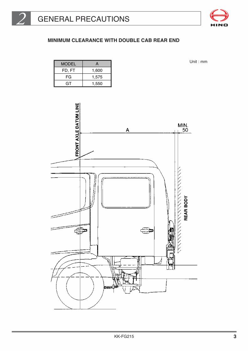
The rear part of the cab contains the cab lock mechanism and the tilt mechanism, as well as the engine cylinder block or other various equipment as trailer brake connector stand and etc.
Whenmountingthebodyorequipment,allowatleasttheminimumclearancebetweenthe rear end of the cab or some of the chassis component and the front end of the rear body or swept radius of the trailer front end to avoid obstructing the operation and maintenance of these mechanisms or various equipments, and to avoid damage due to contact.
Unit : mm
KK-FG215 3
GENERAL PRECAUTIONS2 MINIMUM CLEARANCE WITH DOUBLE CAB REAR END
Unit : mmMODEL AFD, FT 1,600
FG 1,575GT 1,550
KK-FG215 4
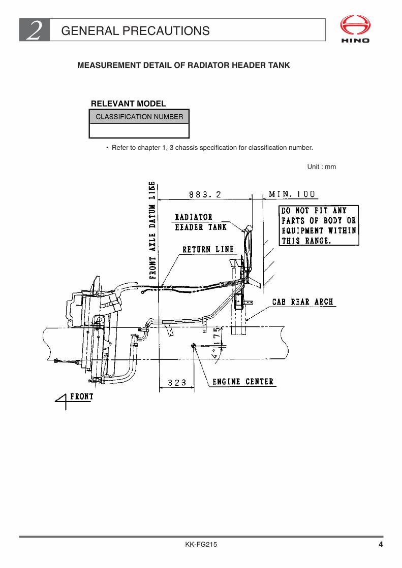
GENERAL PRECAUTIONS2 MEASUREMENT DETAIL OF RADIATOR HEADER TANK
Unit : mm
RELEVANT MODELCLASSIFICATION NUMBER
• Refertochapter1,3chassisspecificationforclassificationnumber.

KK-FG215 5
GENERAL PRECAUTIONS2 MEASUREMENT DETAIL OF CAB TILT MECHANISM (FOR SINGLE CAB) Unit : mm
RELEVANT MODELCLASSIFICATION NUMBER A
RELEVANT MODEL
CLASSIFICATION NUMBER A B
FG-058 813 564
• Refertochapter1,3chassisspecificationforclassification number.
• Refertochapter1,3chassisspecificationforclassification number.
KK-FG215 6
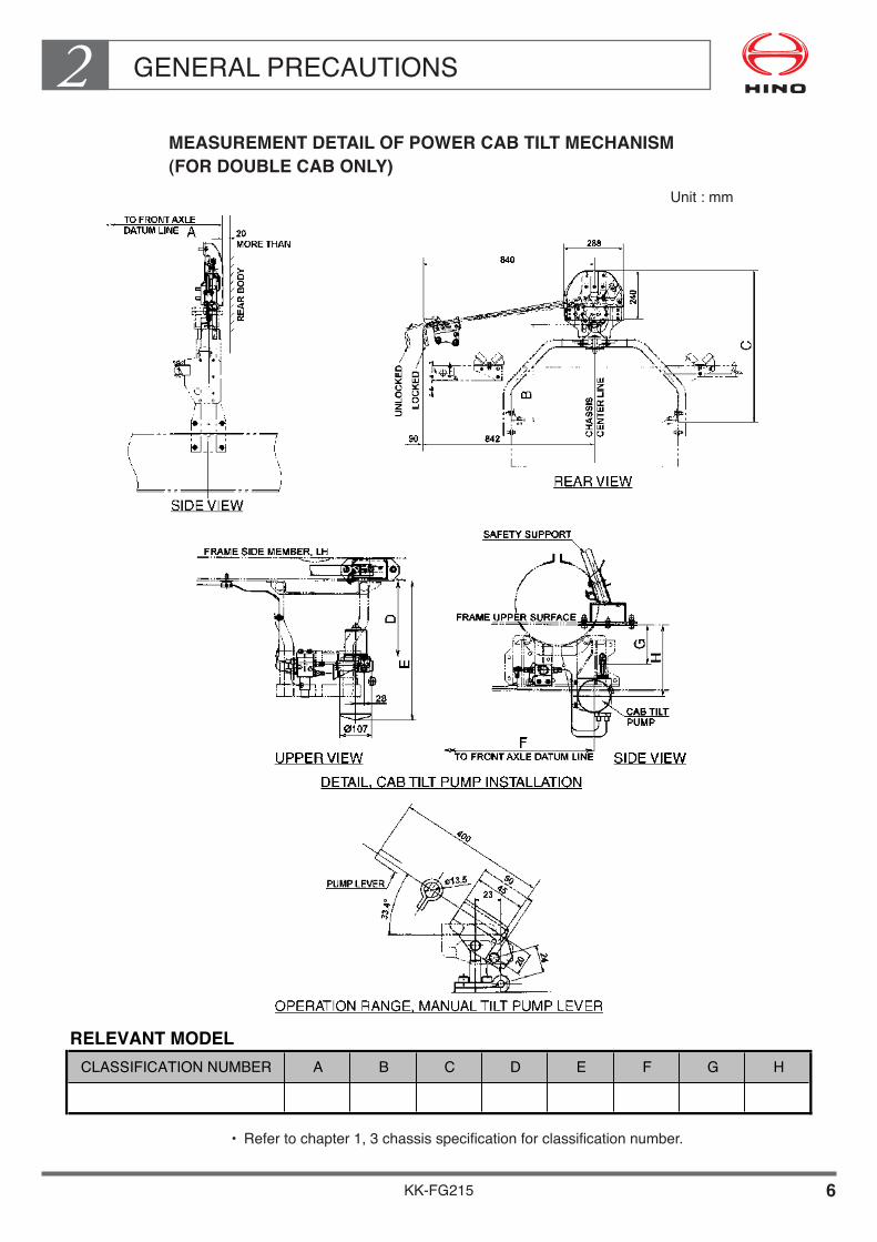
GENERAL PRECAUTIONS2 MEASUREMENT DETAIL OF POWER CAB TILT MECHANISM (FOR DOUBLE CAB ONLY)
Unit : mm
RELEVANT MODELCLASSIFICATION NUMBER A B C D E F G H
• Refertochapter1,3chassisspecificationforclassificationnumber.

KK-FG215 7
GENERAL PRECAUTIONS2 MEASUREMENT DETAIL OF ENGINE AIR INTAKE PORT
Unit : mm
The blocking of the smooth flow of air into the air intake pipecaused by any materials such as ropes, pieces of cloth, etc. leadsto the increase of exhaust temperature if driven long intervals.The increase in exhaust temperature is caused by the decreasedefficiency in the combustion process, as the proportion of air inthe combustion chamber is also decreased by the abovementioned factor. This situation will lead to major malfunctionssuch as the cracking of the exhaust manifold and the breakingdown of the turbocharger. To avoid such malfunctions, pleasekeep the air intake pipe free from any blocking materials at alltimes.
RELEVANT MODEL
CLASSIFICATION NUMBER A B C D
FG-058 1122.5 772.5 825 1551.5
• Refertochapter1,3chassisspecificationforclassificationnumber.

KK-FG215 8
GENERAL PRECAUTIONS2 MEASUREMENT DETAIL OF ENGINE AIR CLEANER (FOR SINGLE CAB)
Unit : mm
• Refertochapter1,3chassisspecificationforclassificationnumber.
RELEVANT MODEL CLASSIFICATION NUMBER : FG-058
B C D
634.5 1073.5 256.5
KK-FG215 9
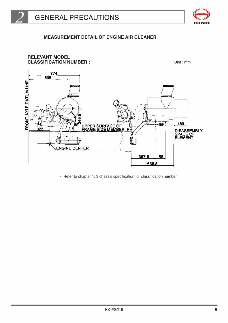
GENERAL PRECAUTIONS2 MEASUREMENT DETAIL OF ENGINE AIR CLEANER
RELEVANT MODEL CLASSIFICATION NUMBER : Unit : mm
• Refertochapter1,3chassisspecificationforclassificationnumber.

KK-FG215 10
GENERAL PRECAUTIONS2 MEASUREMENT DETAIL OF VERTICAL EXHAUST PIPE
RELEVANT MODEL CLASSIFICATION NUMBER : Unit : mm
• Refertochapter1,3chassisspecificationforclassificationnumber.

KK-FG215 11
GENERAL PRECAUTIONS23. RECOMMENDED POSITIONS OF U-BOLTS
• TheU-boltstobefastenedonthebodysub-frameandthechassisframemustbeprovided sufficient clearance to prevent contact with the brake pipes, hoses, and harness wires etc.
• TherecommendedsettingpositionsofU-boltsshouldbeobservedaccordingtothefigure shown below.
L1 L4
L3L2
BA
REAR AXLE DATUM LINE �OR TRUNNION SHAFT CENTER
No.1 U-BOLT No.2 U-BOLT No.3U-BOLT
X
No.2 CROSSMEMBER�DATUM LINE
PROHIBITION RANGE OF THE �U-BOLT SETTING ON BOTH SIDE.�(FORFL,FM,MODELONLY)
No.5 U-BOLTNo.4 U-BOLT
CLASSIFICATION
NUMBERX L1 L2 L3 L4 A B
RH 885 1560 150 2120 – – –
LH 435 1560 150 2120 – – –
RH
LH
RH
LH
RH
LH
RH
LH
RH
LH
RH
LH
FG-058
NOTE•WhenmountingonlywithU-bolts,useprops.Whenthesub-frameisopensectionsteelalsousethisprops.•Withrespecttohowtomountthem,refertothechapter12,item3Bodymountingmanual common version issued by HINO.•MakesuretocontroltighteningtorqueoftheU-bolts. Apply double nut system to prevent slackening of the nuts.•Whendeliveringthevehicle,securelycarryoutPDIandchecktoitthereisanyslackening of the U-bolts.
MOUNTING POSITION RELEVANT MODEL Unit : mm
• Refertochapter1,3chassisspecificationforclassificationnumber.

KK-FG215 12
GENERAL PRECAUTIONS2 DRILLING PROCESS FOR INSTALLING
THE MOUNTING BRACKET AROUND REAR AXLE
EXAMPLE DETAIL OF MOUNTING BRACKET
Unit : mm
Unit : mm
NOTE•Formoreinformationondrillingprocessofthechassisframetoinstallthemountingbracket,refertotheCommonManual,No.KC-AA001ForKC-AA201ofBodyMountingManual.
RELEVANT MODEL CLASSIFICATION NUMBER :
• Refertochapter1,3chassisspecificationforclassificationnumber.

KK-FG215 13
GENERAL PRECAUTIONS24. RECOMMENDED POSITIONS OF REAR FENDERS AND MUDGUARDS
Whenmountingrearfendersandmudguards,determinerequiredclearanceswith reference to the following table and figures of “MAXIMUM VERTICAL DEFLECTION OF REARWHEELS”in4-2.
16 or 17.5 150~200 200
20or22.5 200~250 300
FTIREWHEELSIZE (in) E
8.25-16-14PR
8.25R16-14PR
9.5R17.5 (129/127)
235/75R17.5 (130/128)
8.25-20-14PR
8.25R20-14PR
9.00-20-12PR/14PR
9.00R20-12PR/14PR
FG-058 STD 10.00-20-14PR 2435 2455 1840 177.5
FG-058 OPT 10.00R20-14PR 2435 2455 1840 177.5
FG-058 OPT 10.00R20-16PR 2445 2465 1840 172.5
11.00R20-14PR/16PR
9R22.5 (133/131)
10R22.5-14PR
10R22.5 (144/142)
FG-058 OPT 11R22.5-14PR/16PR 2435 2455 1840 177.5
11R22.5 (148/145)
12R22.5-16PR
235/70R22.5 (138/135)
255/70R22.5 (140/137)
FG-058 OPT 255/70R22.5 (143/140) 2420 2440 1840 185
275/70R22.5 (148/145)
275/80R22.5 (151/148)
295/80R22.5
295/80R22.5 (152/148)
B CCLASSIFICATION
NUMBERDREAR TIRE ASTD/OPT
NOTE•Thedimensionoftiretobementionedinabovetableshowsdesignfigureaccording to JATMA or ETRTO standard.
RELEVANT MODEL (FOR REAR SINGLE AXLE)
• Refertochapter1,3chassisspecificationforclassification number.
Unit : mm

KK-FG215 14
GENERAL PRECAUTIONS2
NOTE•Whenmountingthefenders(shadedinthefigure)makeadrainholeatEtoallowwater to escape.•Thedimensionoftiretobementionedinabovetableshowsdesignfigureaccording to JATMA or ETRTO standard.
8.25-16-14PR8.25R16-14PR9.5R17.5 (129/127)235/75R17.5(130/128)8.25-20-14PR8.25R20-14PR9.00-20-12PR/14PR9.00R20-12PR/14PR10.00-20-14PR/16PR10.00R20-14PR/16PR11.00-20-14PR/16PR11.00R20-14PR/16PR9R22.5(133/131)10R22.5-14PR10R22.5(144/142)11R22.5-14PR/16PR11R22.5 (148/145)12R22.5-16PR235/70R22.5(138/135)255/70R22.5(140/137)255/70R22.5(143/140)275/70R22.5(148/145)275/80R22.5(151/148)295/80R22.5295/80R22.5(152/148)
B CCLASSIFICATIONNUMBER DREAR TIRE ASTD/OPT
RELEVANT MODEL (FOR TANDEM REAR AXLE)
• Refertochapter1,3chassisspecificationforclassification number.
Unit : mm
KK-FG215 15
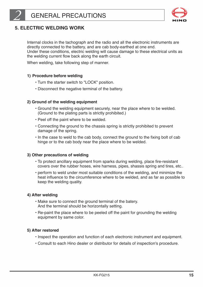
GENERAL PRECAUTIONS25. ELECTRIC WELDING WORK
Internal clocks in the tachograph and the radio and all the electronic instruments are directly connected to the battery, and are cab body-earthed at one end. Under these conditions, electric welding will cause damage to these electrical units as the welding current flow back along the earth circuit.Whenwelding,takefollowingstepofmanner.
1) Procedure before welding •Turnthestarterswitchto"LOCK"position. •Disconnectthenegativeterminalofthebattery.
2) Ground of the welding equipment •Groundtheweldingequipmentsecurely,neartheplacewheretobewelded.
(Ground to the plating parts is strictly prohibited.) •Peeloffthepaintwheretobewelded. •Connectingthegroundtothechassisspringisstrictlyprohibitedtoprevent
damage of the spring. •Inthecasetoweldtothecabbody,connectthegroundtothefixingboltofcab
hinge or to the cab body near the place where to be welded.
3) Other precautions of welding •Toprotectancillaryequipmentfromsparksduringwelding,placefire-resistant
covers over the rubber hoses, wire harness, pipes, shassis spring and tires, etc.. •performtoweldundermostsuitableconditionsofthewelding,andminimizethe
heat influence to the circumference where to be welded, and as far as possible to keep the welding quality.
4) After welding •Makesuretoconnectthegroundterminalofthebatery.
Andtheterminalshouldbehorizontallysetting. •Re-painttheplacewheretobepeeledoffthepaintforgroundingthewelding
equipment by same color.
5) After restored •Inspecttheoperationandfunctionofeachelectronicinstrumentandequipment. •ConsulttoeachHinodealerordistributorfordetailsofinspection'sprocedure.
KK-FG215 16
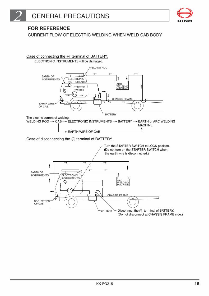
GENERAL PRECAUTIONS2 FOR REFERENCE
CURRENTFLOWOFELECTRICWELDINGWHENWELDCABBODY
WELDING ROD
BATTERY
BATTERY
CHASSIS FRAME
ARCWELDINGMACHINE
ARCWELDINGMACHINE
ELECTRONICINSTRUMENTS
ELECTRONICINSTRUMENTS
STARTERSWITCH
EARTH OFINSTRUMENTS
EARTH OFINSTRUMENTS
EARTH WIREOF CAB
EARTH WIREOF CAB
The electric current of welding.WELDING ROD CAB ELECTRONIC INSTRUMENTS BATTERY EARTH of ARC WELDING MACHINE
EARTH WIRE OF CAB
ELECTRONIC INSTRUMENTS will be damaged.
Case of connecting the – terminal of BATTERY.
Case of disconnecting the – terminal of BATTERY.
Disconnect the – terminal of BATTERY.(Do not disconnect at CHASSIS FRAME side.)
Turn the STARTER SWITCH to LOCK position.(Do not turn on the STARTER SWITCH when the earth wire is disconnected.)
CHASSIS FRAME
+ –
+ –

KK-FG215 17
GENERAL PRECAUTIONS26. NOTES ON ADDITIONAL WIRING IN THE ENGINE COMPARTMENT
Since the engines in HINO trucks are covered with sound arrest plates, the engine compartment tends to heat up.
Avoid wiring in the engine compartment if possible.
Additional wiring harness or cable should be kept away from heated elements, and should be wired along the main harness.

KK-FG215 18
GENERAL PRECAUTIONS27. PRECAUTION OF THE ANTENNA POSITION
• Theantennawhichisinstalledonroofcornertopofthecabuserightangle position in normal operation.
• Makesurethatnottoobstructthemovingrangeoftheantennaindescribedfollowingfigure when perform to mount body or equipment.
• Itmaycausethenoiseorpoorreceivingoftheradioifoccuraninterferencewiththeantenna and body part.
FOR RIGHT HAND DRIVE ONLY
FOR LEFT HAND DRIVE ONLY
• Refertochapter1,3chassisspecificationforclassification number.
RELEVANT MODELCLASSIFICATION NUMBER A B
Unit : mm
• Refertochapter1,3chassisspecificationforclassification number.
RELEVANT MODEL
CLASSIFICATION NUMBER A B
FG-0581,879~
2,456
-160~
1,373
KK-FG215 19
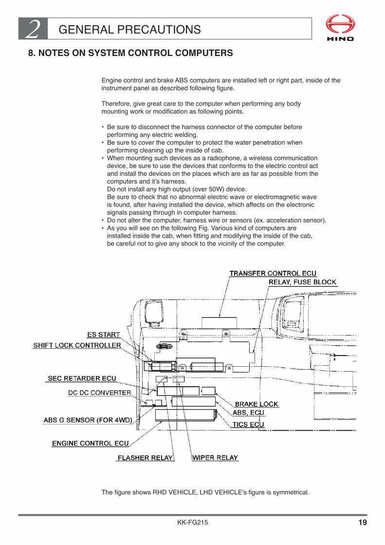
GENERAL PRECAUTIONS28. NOTES ON SYSTEM CONTROL COMPUTERS
Engine control and brake ABS computers are installed left or right part, inside of the instrument panel as described following figure.
Therefore, give great care to the computer when performing any body mounting work or modification as following points.
• Besuretodisconnecttheharnessconnectorofthecomputerbefore performing any electric welding.
• Besuretocoverthecomputertoprotectthewaterpenetrationwhen performing cleaning up the inside of cab.
• Whenmountingsuchdevicesasaradiophone,awirelesscommunication device, be sure to use the devices that conforms to the electric control act and install the devices on the places which are as far as possible from the computers and it’s harness. Donotinstallanyhighoutput(over50W)device. Be sure to check that no abnormal electric wave or electromagnetic wave is found, after having installed the device, which affects on the electronic signals passing through in computer harness.
• Donotalterthecomputer,harnesswireorsensors(ex.accelerationsensor).• AsyouwillseeonthefollowingFig.Variouskindofcomputersare
installed inside the cab, when fitting and modifying the inside of the cab, be careful not to give any shock to the vicinity of the computer.
ThefigureshowsRHDVEHICLE,LHDVEHICLE'sfigureissymmetrical.

KK-FG215 20
GENERAL PRECAUTIONS29. PRECAUTION FOR ADDITIONAL FUEL TANK
Wheninstalladditionalfueltank,makesuretocheckifthefuelsenderworkscorrectlyasfollowing.
1) The meter of this vehicle incorporates a computer that calculates the input signals and displays on different meters and gauges. In the case of a fuel gauge, in order to prevent it from moving of needle of the fuel sender with vehicle posture, its movement is intentionally dull, consequently if move float from [E] to [F] (or [F] to [E]) it will not follow. (The indicator moves only 2 degrees per minute.)
2) How to check if the fuel sender works correctly.
Disconnectbatterynegativeconnecterandwaitformorethan30seconds. Move the float of the fuel sender to the position corresponding to [F].
(The highest position of raised float.) Connect battery negative connecter and turn on starter switch to [ON] position.
( The fuel gauge indicates [F] position.) Disconnectbatterynegativeconnecteragainandwaitformorethan30seconds. Move the float of the fuel sender to the position corresponding to 1/2 position.
(Move float to mid position between the highest and the lowest position of the float.) Connect battery negative connecter and turn on starter switch to [ON] position.
( The fuel gauge indicates 1/2 position.)
As the result if the fuel gauge indicates [F] position in step and further indicate 1/2 position in step , there is no problem.
KK-FG215 21
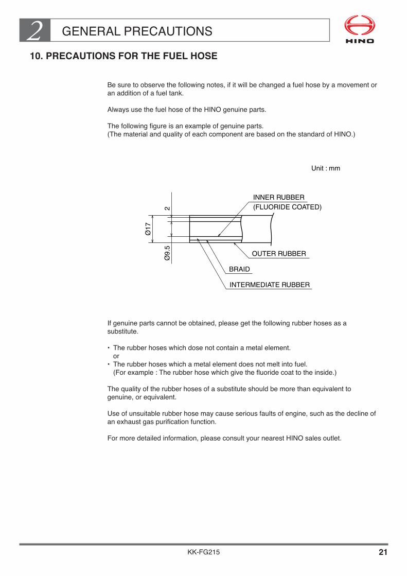
GENERAL PRECAUTIONS210. PRECAUTIONS FOR THE FUEL HOSE
Be sure to observe the following notes, if it will be changed a fuel hose by a movement or an addition of a fuel tank.
Always use the fuel hose of the HINO genuine parts.
The following figure is an example of genuine parts.(The material and quality of each component are based on the standard of HINO.)
If genuine parts cannot be obtained, please get the following rubber hoses as a substitute.
• Therubberhoseswhichdosenotcontainametalelement. or
• Therubberhoseswhichametalelementdoesnotmeltintofuel. (For example : The rubber hose which give the fluoride coat to the inside.)
The quality of the rubber hoses of a substitute should be more than equivalent to genuine, or equivalent.
Use of unsuitable rubber hose may cause serious faults of engine, such as the decline of an exhaust gas purification function.
For more detailed information, please consult your nearest HINO sales outlet.
Ø17
Ø9.
52
INNER RUBBER
Unit : mm
(FLUORIDE COATED)
OUTER RUBBER
BRAID
INTERMEDIATE RUBBER

KK-FG215 22
GENERAL PRECAUTIONS211. ADJUSTMENT OF LIGHT AXIS OF HEADLIGHT
HALOGEN OR DISCHARGE (HID) HEADLAMP
Light axis of headlight will be changed due to vehicle posture change to be influenced by the rear body or equipment to be mounted.
Therefore, consult the adjustment of light axis after rear body or equipment to be mountedtoauthorizedHinodistributororsalesdealer.
NOTES•Makesurethatthelightaxisofheadlampofthecompletedvehiclewithrear
body or equipment, conforms to all applicable laws and regulations of the country in which the vehicle is to be operated.
•Shouldmoredetailedinformationbeneeded,pleasecontactauthorizedHinodistributor or sales dealer.

KK-FG215
Chapter 3CHASSIS MASS & FRAME SECTION MODULUS
1. CHASSIS MASS•••••••••••••••••••••••••••••••••••••••••••••••••• 2 2. MASS OF THE OPTION EQUIPMENT•••••••••••••••••••••• 11 3. FRAME SECTION MODULUS•••••••••••••••••••••••••••••••• 12
CHASSIS MASS & FRAME SECTION MODULUS3
KK-FG215 1
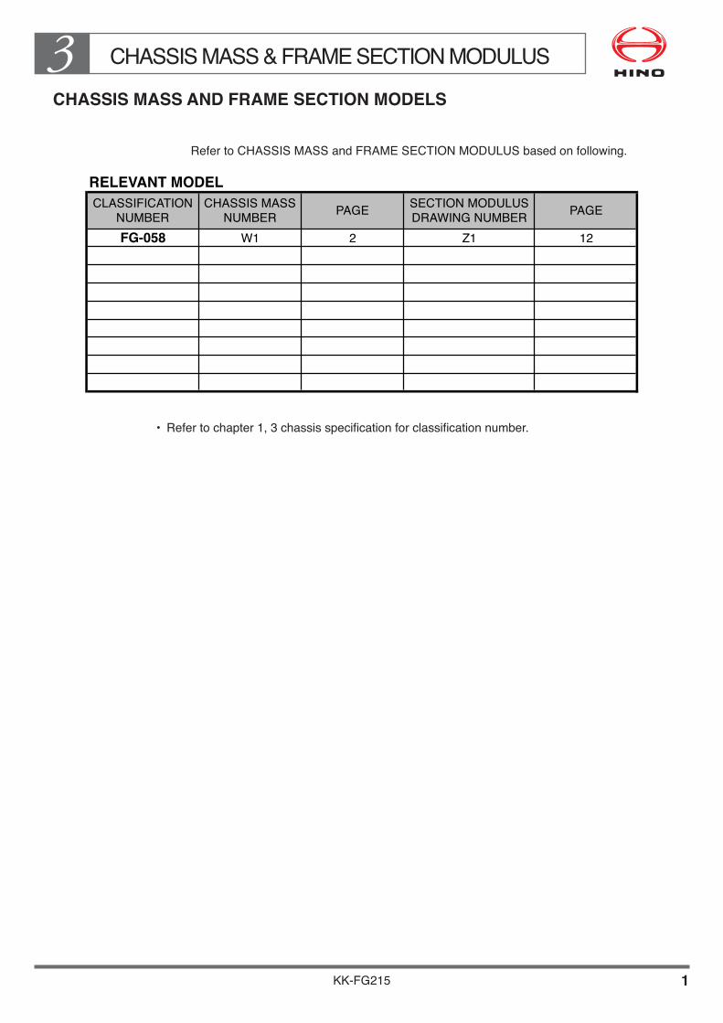
CHASSIS MASS AND FRAME SECTION MODELS
Refer to CHASSIS MASS and FRAME SECTION MODULUS based on following.
RELEVANT MODEL
CLASSIFICATION
NUMBER
CHASSIS MASS
NUMBERPAGE
SECTION MODULUS
DRAWING NUMBERPAGE
FG-058 W1 2 Z1 12
• Refertochapter1,3chassisspecificationforclassificationnumber.

CHASSIS MASS & FRAME SECTION MODULUS3
KK-FG215 2
1. CHASSIS MASS
No. W1Gravity Moment
Gravity Moment height from
ITEMS Mass position from from frame
from F.A.C frame upper
F.A.C upper surface
surface
( kg ) ( m ) ( kg·m ) ( m ) ( kg·m )
Front Bumper 27 -1.180 -31.860 -0.200 -5.400
Cab Front 338 -1.025 -346.450 0.725 245.050
Cab Front Mtg. 31 -1.025 -31.775 0.110 3.410
Step - - - - -
Steering 61 -0.800 -48.800 0.010 0.610
Radiator 40 -0.465 -18.600 0.070 2.800
Steering Control 7 0.100 0.700 0.045 0.315
Engine Front 352 0.050 17.600 -0.120 -42.240
Control 7 0.100 0.700 0.045 0.315
Engine Room - - - - -
Air Cleaner 18 0.615 11.070 0.255 4.590
Cab Rear 185 0.765 141.525 0.725 134.125
Cab Rear Mtg. 26 0.765 19.890 0.185 4.810
Engine Rear 504 0.890 448.560 -0.120 -60.480
Rear Splash 15 0.600 9.000 0.070 1.050
Brake System 83 2.460 204.180 -0.185 -15.355
Electoric System 15 1.690 25.350 -0.130 -1.950
Exhaust System 38 1.430 54.340 -0.385 -14.630
Battery 36 1.270 45.720 -0.185 -6.660
Fuel Tank 215 2.335 502.025 -0.225 -48.375
Properller Shaft 71 3.280 232.880 -0.395 -28.045
Frame etc. 691 3.340 2307.940 -0.148 -102.268
TIRE CARRIER - - - - -
CAR COOLER - - - - -
TOOL BOX - - - - -
2760 1.284 3543.995 0.026 71.672
FRONT 712 0.000 0.000 -0.455 -323.960
REAR 1335 5.050 6741.750 -0.510 -680.850
4807 2.140 10285.745 -0.194 -933.138
FRONT REAR TOTAL
SPRUNG MASS ( kg ) 2058 702 2760
UNSPRUNG MASS ( kg ) 713 1336 2049
CHASSIS MASS ( kg ) 2771 2038 4809
GRAVITY POSITION FROM F.A.C ( m ) 2.140
GRAVITY HEIGHT FROM FRAME UPPER SURFACE ( m ) -0.194
UNSPRUNGMASS
TOTAL
SUB TOTAL
NOTE• ThemassoftirefollowsdesignfigureaccordingtoJATMAorETRTOstandard.• Thechassismassshowsstandardspecificationofvehicle. (Itisnotincludedmassofoptionequipment.) Whenconsiderthemountingofbody,shouldincludemassofoptionequipment.
CHASSIS MASS & FRAME SECTION MODULUS3
KK-FG215 3
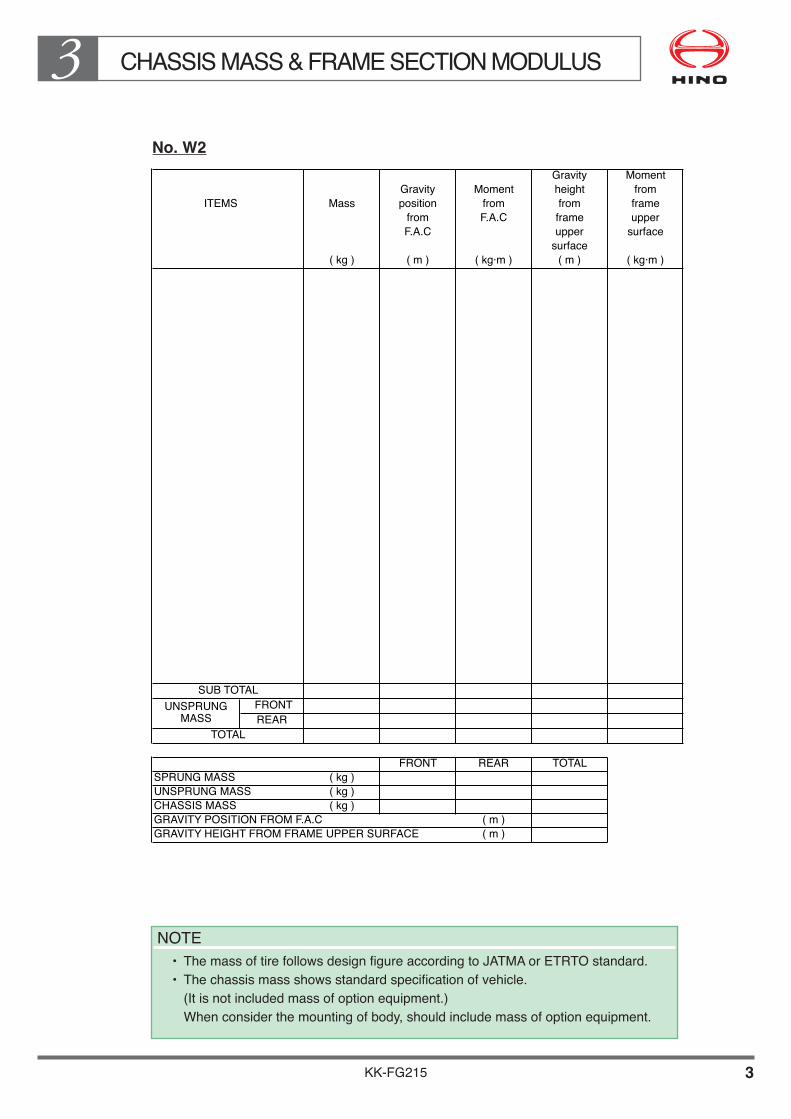
No. W2Gravity Moment
Gravity Moment height from
ITEMS Mass position from from frame
from F.A.C frame upper
F.A.C upper surface
surface
( kg ) ( m ) ( kg·m ) ( m ) ( kg·m )
FRONT
REAR
FRONT REAR TOTAL
SPRUNG MASS ( kg )
UNSPRUNG MASS ( kg )
CHASSIS MASS ( kg )
GRAVITY POSITION FROM F.A.C ( m )
GRAVITY HEIGHT FROM FRAME UPPER SURFACE ( m )
UNSPRUNGMASS
TOTAL
SUB TOTAL
NOTE• ThemassoftirefollowsdesignfigureaccordingtoJATMAorETRTOstandard.• Thechassismassshowsstandardspecificationofvehicle. (Itisnotincludedmassofoptionequipment.) Whenconsiderthemountingofbody,shouldincludemassofoptionequipment.

CHASSIS MASS & FRAME SECTION MODULUS3
KK-FG215 4
No. W3Gravity Moment
Gravity Moment height from
ITEMS Mass position from from frame
from F.A.C frame upper
F.A.C upper surface
surface
( kg ) ( m ) ( kg·m ) ( m ) ( kg·m )
FRONT
REAR
FRONT REAR TOTAL
SPRUNG MASS ( kg )
UNSPRUNG MASS ( kg )
CHASSIS MASS ( kg )
GRAVITY POSITION FROM F.A.C ( m )
GRAVITY HEIGHT FROM FRAME UPPER SURFACE ( m )
UNSPRUNGMASS
TOTAL
SUB TOTAL
NOTE• ThemassoftirefollowsdesignfigureaccordingtoJATMAorETRTOstandard.• Thechassismassshowsstandardspecificationofvehicle. (Itisnotincludedmassofoptionequipment.) Whenconsiderthemountingofbody,shouldincludemassofoptionequipment.

CHASSIS MASS & FRAME SECTION MODULUS3
KK-FG215 5
No. W4
ITEMS MASS(kg)
GRAVITYPOSITION
FROMF.A.C.(m)
MOMENTFROMF.A.C.(kg·m)
GRAVITYHEIGHTFROM
FRAMEUPPER
SURFACE(m)
MOMENTFROM
FRAMEUPPER
SURFACE(kg·m)
SubTotalFrontRear
Total
Front Rear TotalSprungMass(kg)UnsprungMass(kg)ChassisMass(kg)GravitypositionfromF.A.C.(m)Gravityheightfromframeuppersurface(m)
UnsprungMass
NOTE•ThemassoftirestobementionedinabovetableshowsdesignfigureaccordingtoJATMAor
ETRTO standard.

CHASSIS MASS & FRAME SECTION MODULUS3
KK-FG215 6
No. W5
ITEMS MASS(kg)
GRAVITYPOSITION
FROMF.A.C.(m)
MOMENTFROMF.A.C.(kg·m)
GRAVITYHEIGHTFROM
FRAMEUPPER
SURFACE(m)
MOMENTFROM
FRAMEUPPER
SURFACE(kg·m)
SubTotalFrontRear
Total
Front Rear TotalSprungMass(kg)UnsprungMass(kg)ChassisMass(kg)GravitypositionfromF.A.C.(m)Gravityheightfromframeuppersurface(m)
UnsprungMass
NOTE•ThemassoftirestobementionedinabovetableshowsdesignfigureaccordingtoJATMAor
ETRTO standard.
CHASSIS MASS & FRAME SECTION MODULUS3
KK-FG215 7
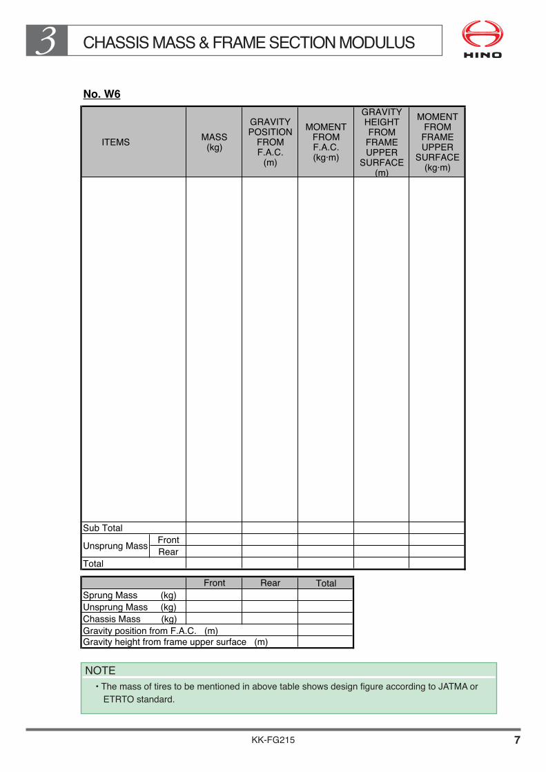
No. W6
ITEMS MASS(kg)
GRAVITYPOSITION
FROMF.A.C.(m)
MOMENTFROMF.A.C.(kg·m)
GRAVITYHEIGHTFROM
FRAMEUPPER
SURFACE(m)
MOMENTFROM
FRAMEUPPER
SURFACE(kg·m)
SubTotalFrontRear
Total
Front Rear TotalSprungMass(kg)UnsprungMass(kg)ChassisMass(kg)GravitypositionfromF.A.C.(m)Gravityheightfromframeuppersurface(m)
UnsprungMass
NOTE•ThemassoftirestobementionedinabovetableshowsdesignfigureaccordingtoJATMAor
ETRTO standard.

CHASSIS MASS & FRAME SECTION MODULUS3
KK-FG215 8
No. W7
ITEMS MASS(kg)
GRAVITYPOSITION
FROMF.A.C.(m)
MOMENTFROMF.A.C.(kg·m)
GRAVITYHEIGHTFROM
FRAMEUPPER
SURFACE(m)
MOMENTFROM
FRAMEUPPER
SURFACE(kg·m)
SubTotalFrontRear
Total
Front Rear TotalSprungMass(kg)UnsprungMass(kg)ChassisMass(kg)GravitypositionfromF.A.C.(m)Gravityheightfromframeuppersurface(m)
UnsprungMass
NOTE•ThemassoftirestobementionedinabovetableshowsdesignfigureaccordingtoJATMAor
ETRTO standard.

CHASSIS MASS & FRAME SECTION MODULUS3
KK-FG215 9
No. W8
ITEMS MASS(kg)
GRAVITYPOSITION
FROMF.A.C.(m)
MOMENTFROMF.A.C.(kg·m)
GRAVITYHEIGHTFROM
FRAMEUPPER
SURFACE(m)
MOMENTFROM
FRAMEUPPER
SURFACE(kg·m)
SubTotalFrontRear
Total
Front Rear TotalSprungMass(kg)UnsprungMass(kg)ChassisMass(kg)GravitypositionfromF.A.C.(m)Gravityheightfromframeuppersurface(m)
UnsprungMass
NOTE•ThemassoftirestobementionedinabovetableshowsdesignfigureaccordingtoJATMAor
ETRTO standard.

CHASSIS MASS & FRAME SECTION MODULUS3
KK-FG215 10
No. W9
ITEMS MASS(kg)
GRAVITYPOSITION
FROMF.A.C.(m)
MOMENTFROMF.A.C.(kg·m)
GRAVITYHEIGHTFROM
FRAMEUPPER
SURFACE(m)
MOMENTFROM
FRAMEUPPER
SURFACE(kg·m)
SubTotalFrontRear
Total
Front Rear TotalSprungMass(kg)UnsprungMass(kg)ChassisMass(kg)GravitypositionfromF.A.C.(m)Gravityheightfromframeuppersurface(m)
UnsprungMass
NOTE•ThemassoftirestobementionedinabovetableshowsdesignfigureaccordingtoJATMAor
ETRTO standard.
CHASSIS MASS & FRAME SECTION MODULUS3
KK-FG215 11
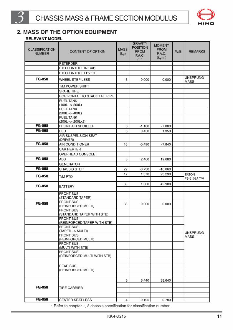
2. MASS OF THE OPTION EQUIPMENTRELEVANT MODEL
CLASSIFICATIONNUMBER
CONTENT OF OPTIONMASS(kg)
GRAVITYPOSITION
FROMF.A.C.
(m)
MOMENTFROMF.A.C.(kg·m)
W/B REMARKS
RETERDER
PTO CONTROL IN CAB
PTO CONTROL LEVER
FG-058 WHEEL STEP LESS -3 0.000 0.000UNSPRUNGMASS
T/M POWER SHIFT
SPARE TIRE
HORIZONTAL TO STACK TAIL PIPE
FUEL TANK(100L –> 200L)
FUEL TANK(200L –> 400L)
FUEL TANK(200L –> 200Lx2)
FG-058 FRONT AIR SPOILLER 6 -1.180 -7.080
FG-058 BED 3 0.450 1.350
AIR SUSPENSION SEAT(DRIVER)
FG-058 AIR CONDITIONER 16 -0.490 -7.840
CAR HERTER
OVERHEAD CONSOLE
FG-058 ABS 8 2.460 19.680
GENERATOR
FG-058 CHASSIS STEP 22 -0.730 -16.060
17 1.370 23.290
33 1.300 42.900
FRONT SUS.(STANDARD TAPER)
FG-058FRONT SUS.(REINFORCED MULTI)
38 0.000 0.000
FRONT SUS.(STANDARD TAPER WITH STB)
FRONT SUS.(REINFORCED TAPER WITH STB)
FRONT SUS.(TAPER –> MULTI)
FRONT SUS.(REINFORCED MULTI)
FRONT SUS.(MULTI WITH STB)
FRONT SUS.(REINFORCED MULTI WITH STB)
6 6.440 38.640
FG-058 CENTER SEAT LESS -4 -0.195 0.780
FG-058
FG-058
FG-058
UNSPRUNGMASS
T/M PTO
BATTERY
TIRE CARRIER
REAR SUS.(REINFORCED MULTI)
EATON
FS-6109A T/M
• Refertochapter1,3chassisspecificationforclassificationnumber.

KK-FG215 12
CHASSIS MASS & FRAME SECTION MODULUS33. FRAME SECTION MODULUS
Unit : mmFRAME SECTION MODULUS (MAIN FRAME ON BOTH SIDE)No. Z1

KK-FG215 13
CHASSIS MASS & FRAME SECTION MODULUS3FRAME SECTION MODULUS (MAIN FRAME ON BOTH SIDE)No. Z2
Unit : mm
KK-FG215 14
CHASSIS MASS & FRAME SECTION MODULUS3Unit : mmFRAME SECTION MODULUS (MAIN FRAME ON BOTH SIDE)
No. Z3

KK-FG215 15
CHASSIS MASS & FRAME SECTION MODULUS3
Unit : mm
FRAME SECTION MODULUS (MAIN FRAME ON BOTH SIDE)No. Z4

KK-FG215 16
CHASSIS MASS & FRAME SECTION MODULUS3
Unit : mm
FRAME SECTION MODULUS (MAIN FRAME ON BOTH SIDE)No. Z5
KK-FG215 17
CHASSIS MASS & FRAME SECTION MODULUS3
Unit : mm
FRAME SECTION MODULUS (MAIN FRAME ON BOTH SIDE)No. Z6

KK-FG215 18
CHASSIS MASS & FRAME SECTION MODULUS3
Unit : mm
FRAME SECTION MODULUS (MAIN FRAME ON BOTH SIDE)No. Z7

KK-FG215 19
CHASSIS MASS & FRAME SECTION MODULUS3
Unit : mm
FRAME SECTION MODULUS (MAIN FRAME ON BOTH SIDE)No. Z8

KK-FG215 20
CHASSIS MASS & FRAME SECTION MODULUS3
Unit : mm
FRAME SECTION MODULUS (MAIN FRAME ON BOTH SIDE)No. Z9

KK-FG215
Chapter 4SPRINGS & REAR AXLES
1. SPRING CHARACTERISTICS•••••••••••••••••••••••••••••••• 1 2. CALCULATION FOR HEIGHT OF FRAME
UPPER SURFACE FROM GROUND••••••••••••••••••••• 6 3. MAXIMUM VERTICAL
DEFLECTION OF REAR WHEELS•••••••••••••••••••••••• 8 4. MAXIMUM VERTICAL TRAVEL RANGE
OF REAR AXLE AND SUSPENSION••••••••••••••••••••• 9 5. MAXIMUM VERTICAL TRAVEL RANGE
OF REAR LATERAL ROD••••••••••••••••••••••••••••••••••• 10 6. PRECAUTION WHEN WELDING OPERATIONS
AROUND THE SUSPENSION PARTS•••••••••••••••••••• 11 7. TRAVEL RANGE OF REAR SPRING•••••••••••••••••••••••• 12 8. PRECAUTION FOR LEVELING VALVE LEVER•••••••••• 13 9. REAR SHOCK ABSORBER••••••••••••••••••••••••••••••••••• 14
SPRINGS & REAR AXLES4
KK-FG215 1
1. SPRING CHARACTERISTICS
SPRING COMBINATION
Refer to SPRING CHARACTERISTICS CHART based on following table.
SPRING COMBINATION TABLE
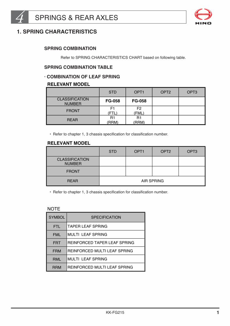
· COMBINATION OF LEAF SPRINGRELEVANT MODEL
STD OPT1 OPT2 OPT3
FG-058 FG-058
F1
(FTL)
F2
(FML)
R1
(RRM)
R1
(RRM)
CLASSIFICATION
NUMBER
FRONT
REAR
NOTESYMBOL SPECIFICATION
FTL TAPER LEAF SPRING
FML MULTI LEAF SPRING
FRT REINFORCED TAPER LEAF SPRING
FRM REINFORCED MULTI LEAF SPRING
RML MULTI LEAF SPRING
RRM REINFORCED MULTI LEAF SPRING
RELEVANT MODELSTD OPT1 OPT2 OPT3
FRONT
AIR SPRINGREAR
CLASSIFICATIONNUMBER
• Refertochapter1,3chassisspecificationforclassificationnumber.
• Refertochapter1,3chassisspecificationforclassificationnumber.

SPRINGS & REAR AXLES4
KK-FG215 2
LEAF SPRING• ••SPRING•CHARACTERISTICS•CHART•"F1"
• ••SPRING•CHARACTERISTICS•CHART•"F2"
VERTICAL SPRING DEFLECTION ON FRONT LEAF SPRINGLOAD VS. DEFLECTION
(mm)00
SP
RIN
G L
OA
D O
N O
NE
SID
E
86.0 145.7
CO
NTA
CT
ING
PO
INT
OF
BU
FF
ER
RU
BB
ER
HO
RIZ
ON
TAL
PO
INT
(kN)3 kgfx 10
1
2
3
4
50 100 150
10
20
40
30
c
b
a
a 0.291kN/mm {29.7kgf/mm}
b 25.030kN {2553.1kgf}
42.400kN {4324.8kgf}c
VERTICAL SPRING DEFLECTION ON FRONT LEAF SPRINGLOAD VS. DEFLECTION
(mm)00
SP
RIN
G L
OA
D O
N O
NE
SID
E
76.0 136.3
CO
NTA
CT
ING
PO
INT
OF
BU
FF
ER
RU
BB
ER
HO
RIZ
ON
TAL
PO
INT
(kN)3 kgfx 10
1
2
3
4
50 100 150
10
20
40
30
c
b
a
a 0.308kN/mm {31.4kgf/mm}
b 23.410kN {2387.8kgf}
41.980kN {4282.0kgf}c

SPRINGS & REAR AXLES4
KK-FG215 3
• ••SPRING•CHARACTERISTICS•CHART•"F3"
• ••SPRING•CHARACTERISTICS•CHART•"F4"

SPRINGS & REAR AXLES4
KK-FG215 4
• ••SPRING•CHARACTERISTICS•CHART•"R1"
• ••SPRING•CHARACTERISTICS•CHART•"R2"
0VERTICAL SPRING DEFLECTION ON REAR LEAF SPRING
LOAD VS. DEFLECTION
(mm)0
49.0 110.1
HO
RIZ
ON
TAL
POIN
T
98.0
CO
NTA
CTI
NG
PO
INT
OF
BUFF
ER R
UBB
ER
SPR
ING
LO
AD O
N O
NE
SID
E
(kN)3 kgfx 10
2
4
10
6
50 100 150
20
40
100
60b
c
a
d
e a 0.516kN/mm {52.6kgf/mm}
b 0.516+0.997=1.513kN/mm{52.6+101.7=154.3kgf/mm}
c 25.280kN {2578.6kgf}d 99.420kN {10140.8kgf}e 117.720kN {12007.4kgf}8 80

SPRINGS & REAR AXLES4
KK-FG215 5
• ••SPRING•CHARACTERISTICS•CHART•"R3"
• ••SPRING•CHARACTERISTICS•CHART•"R4"
SPRINGS & REAR AXLES4
KK-FG215 6
2. CALCULATION FOR HEIGHT OF FRAME UPPER SURFACE FROM GROUND
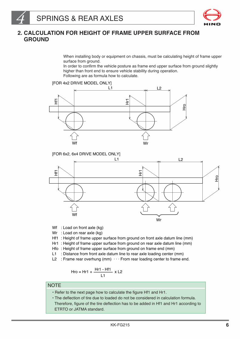
Wheninstallingbodyorequipmentonchassis,mustbecalculatingheightofframeuppersurfacefromground.Inordertoconfirmthevehiclepostureasframeenduppersurfacefromgroundslightlyhigherthanfrontendtoensurevehiclestabilityduringoperation.Followingareasformulahowtocalculate.
L1 L2
Hf1
Hr1
Hro
Wf Wr
[FOR 4x2 DRIVE MODEL ONLY]
L1 L2
Hf1
Hr1
Hro
WfWr
[FOR6x2,6x4DRIVEMODELONLY]
Wf� : Load on front axle (kg)�Wr� : Load on rear axle (kg)�Hf1� :Heightofframeuppersurfacefromgroundonfrontaxledatumline(mm)�Hr1� :Heightofframeuppersurfacefromgroundonrearaxledatumline(mm)�Hfo� :Heightofframeuppersurfacefromgroundonframeend(mm)�L1� :Distancefromfrontaxledatumlinetorearaxleloadingcenter(mm)�L2� :Framerearoverhung(mm)···Fromrearloadingcentertoframeend.
Hro = Hr1 + x L2Hr1 - Hf1L1
NOTE•RefertothenextpagehowtocalculatethefigureHf1andHr1.•Thedeflectionoftireduetoloadeddonotbeconsideredincalculationformula.Therefore,figureofthetiredeflectionhastobeaddedinHf1andHr1accordingto ETRTO or JATMA standard.
SPRINGS & REAR AXLES4
KK-FG215 7
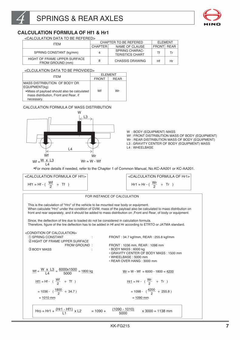
CALCULATION FORMULA OF Hf1 & Hr1<CALCULATION DATA TO BE REFERED>
<CLCULATION DATA TO BE PROVIDED>
ITEM
ITEM
CHAPTER TO BE REFERED ELEMENT
ELEMENT
CHAPTER NAME OF CLAUSE FRONT
FRONT
REAR
REAR
SPRING CONSTANT (kg/mm) SPRING CHARAC-TERISTICS CHART
HIGHT OF FRAME UPPER SURFACEFROM GROUND (mm) CHASSIS DRAWING
4
8
Tf Tr
Hf Hr
MASS DISTRIBUTION OF BODY OREQUIPMENT(kg)
Mass of payload should also be calculatedmass distribution, Front and Rear, ifnecessary.
Wf Wr
CALCULATION FORMULA OF MASS DISTRIBUTION
W : BODY (EQUIPMENT) MASSWf : FRONT DISTRIBUTION MASS OF BODY (EQUIPMENT)Wr : REAR DISTRIBUTION MASS OF BODY (EQUIPMENT)L3 : GRAVITY CENTER OF BODY (EQUIPMENT) MASSL4 : WHEELBASE
For more details if needed, refer to the Chapter 1 of Common Manual, No.KC-AA001 or KC-AA201.
<CALCULATION FORMULA OF Hf1>
<CONDITION OF CALCULATION>
<CALCULATION FORMULA OF Hr1>
Hf1 = Hf - ( ÷ Tf )Wf2 Hr1 = Hr - ( ÷ Tr )Wr
2
FOR INSTANCE OF CALCULATION
This is the calculation of "Hro" of the vehicle to be mounted rear body or equipment. When calculate "Hro" under the condition of GVM, mass of the payload also be calculated to mass distribution on front and rear separately, and it should be added to mass distribution on ,Front and Rear, of body or equipment.
Since, the deflection of tire due to loaded do not be considered in calculation formula. Therefore, figure of the tire deflection has to be added in Hf and Hr according to ETRTO or JATMA standard.
SPRING CONSTANT :
BODY MASS :
HIGHT OF FRAME UPPER SURFACE FROM GROUND :
FRONT : 34.7 kgf/mm, REAR : 255.8 kgf/mm
FRONT : 1036 mm, REAR : 1098 mm• BODY MASS : 6000 kg• GRAVITY CENTER OF BODY MASS : 1500 mm• WHEELBASE : 5000 mm• REAR OVER HANG : 3000 mm
Wf = = = 1800 kgW x L3L4
6000x15005000
Hf1 = Hf - ( ÷ Tf )Wf2 Hr1 = Hr - ( ÷ Tr )Wr
2
= 1036 - ( ÷ 34.7 )18002 = 1098 - ( ÷ 255.8 )4200
2= 1010 mm = 1090 mm
Wr = W - Wf = 6000 - 1800 = 4200
Hro = Hr1 + x L2 = 1090 + x 3000 = 1138 mm(Hr1 - Hf1)L1
(1090 - 1010)5000
WL3
L4Wf Wr
Wr = W - WfWf =W x L3L4

SPRINGS & REAR AXLES4
KK-FG215 8
3. MAXIMUM VERTICAL DEFLECTION OF REAR WHEELS
Measurementsforthemaximumdeflectionforonesidetireandforsimultaneousleftandrightdeflectionareshownbelow.Whenyoumountthebody,allowaclearanceofatleast30mmsoasnottoobstructtiredeflection.
DEFLECTION OF REAR TIRES
A : MAXIMUM DEFLECTION FOR� ONE SIDE WHEELS
B,C:MAXIMUMSIMULTANEOUSDEFLECTION� RIGHT AND LEFT WHEELS
� A BC
RELEVANT MODEL
8.25-16-14PR
8.25R16-14PR
9.5R17.5 (129/127)
235/75R17.5 (130/128)
8.25-20-14PR
8.25R20-14PR
9.00-20-12PR/14PR
9.00R20-12PR/14PR
FG-058 STD 10.00-20-14PR 240 160 115
FG-058 OPT 10.00R20-14PR/16PR 235 155 115
11.00-20-14PR/16PR
11.00R20-14PR/16PR
9R22.5 (133/131)
10R22.5-14PR
10R22.5 (144/142)
FG-058 OPT 11R22.5-14PR/16PR 235 155 115
11R22.5 (148/145)
12R22.5-16PR
235/70R22.5 (138/135)
255/70R22.5 (140/137)
FG-058 OPT 255/70R22.5 (143/140) 170 90 115
275/70R22.5 (148/145)
275/80R22.5 (151/148)
295/80R22.5PR
295/80R22.5 (152/148)
BCLASSIFICATION
NUMBERCREAR TIRE ASTD/OPT
Unit:mm
• Refertochapter1,3chassisspecificationforclassificationnumber.
NOTE•Whensnowchainsarefitted,add50mmtomeasurementsAandB.•ThedimensionoftiretobementionedinabovetableshowsdesignfigureaccordingtoETRTOorJATMAstandard.

SPRINGS & REAR AXLES4
KK-FG215 9
4. MAXIMUM VERTICAL TRAVEL RANGE OF REAR AXLE AND SUSPENSION
Measurementformaximumverticaltravelrangeofthereartorquerodisshownbelow.Whenyoumountabodyorequipment,allowaclearanceofatleast30mmsoasnottointerferewithreartorquerod.
VERTICAL TRAVEL RANGE OF REAR AXLE AND SUSPENSION
(FOR REAR TANDEM AXLE)
RELEVANT MODELCLASSIFICATION
NUMBER A B C D E F
Unit:mm
• Refertochapter1,3chassisspecificationforclassificationnumber.
SPRINGS & REAR AXLES4
KK-FG215 10
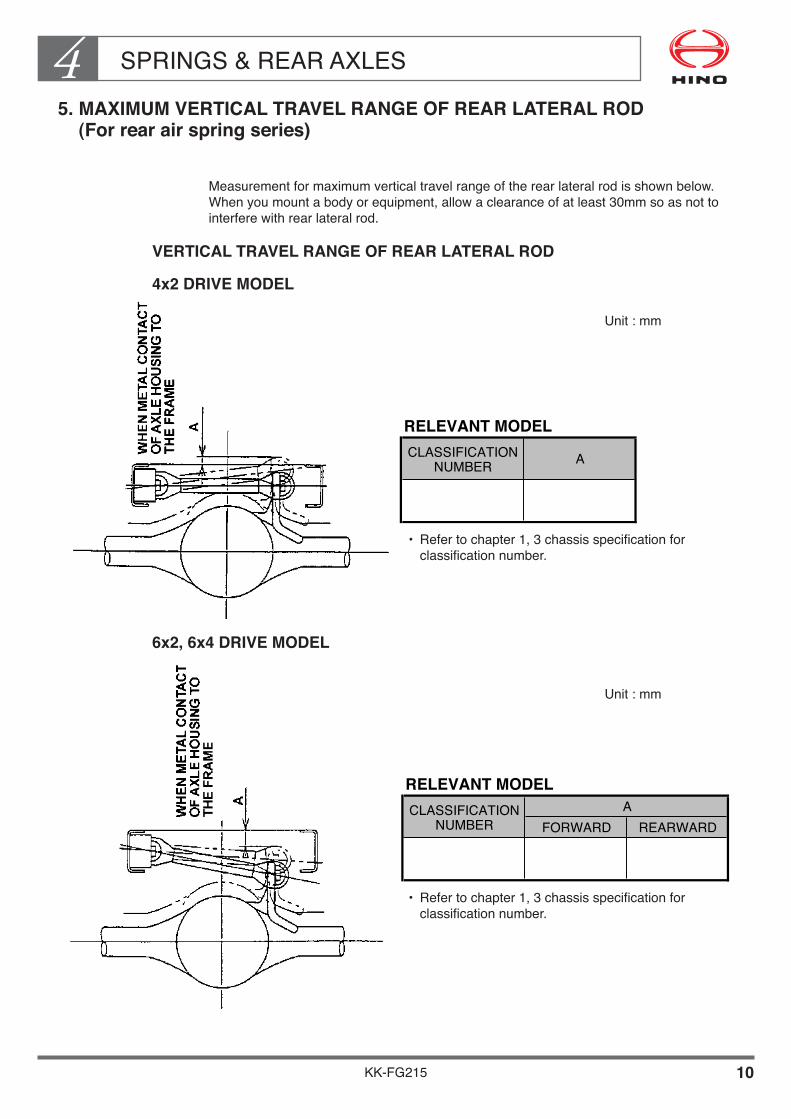
5. MAXIMUM VERTICAL TRAVEL RANGE OF REAR LATERAL ROD (For rear air spring series)
Measurementformaximumverticaltravelrangeoftherearlateralrodisshownbelow.Whenyoumountabodyorequipment,allowaclearanceofatleast30mmsoasnottointerferewithrearlateralrod.
VERTICAL TRAVEL RANGE OF REAR LATERAL ROD
4x2 DRIVE MODEL
6x2, 6x4 DRIVE MODEL
RELEVANT MODEL
FORWARD REARWARDACLASSIFICATION
NUMBER
RELEVANT MODELCLASSIFICATION
NUMBER A
Unit:mm
Unit:mm
• Refertochapter1,3chassisspecificationforclassificationnumber.
• Refertochapter1,3chassisspecificationforclassificationnumber.

SPRINGS & REAR AXLES4
KK-FG215 11
6. PRECAUTION WHEN WELDING OPERATIONS AROUND THE SUSPENSION PARTS
GENERAL PRECAUTION
• Suspensionpartsabsorbshocksfromtheroadsurfacereceivedwhiledrivingandarealwayschangingshape.
• Accordingly,thepartsaremanufacturedfromveryspecialmetalmaterialsorothermaterials.
• Accordingly,ifsubjectedtotheeffectsofheatorotherenvironmentalfactors,thisisdangerthatthematerialhardnessmayeasilydroporsufferdamage.
• Therefore,donotuseelectricalweldingofthesuspensionpartsoragastorchtoapplyheat.
• Thegroundusedduringelectricalweldingmustnotmakeconnectwiththesuspensionparts.
• Duringweldingoperationsaroundtheperipheryofsuspensionparts,besuretoprotectthesuspensionpartsusingacoverorsimilaritemsothepartsarenotsubjectedtoweldingsparks.
• Becauseintheperipheralportionofthebracketwherethesuspensionpartsareinstalledconstantlyalargeamountofstressisgeneratedwhilethevehicleisdriving,heatmustnotbeappliedtothisportionbyelectricalweldingoragastorch.
• Theabovesentencesonlydescribeamulti-leafsuspension.Thesameprecautionsalsoapplytoairbagtyperearsuspensionaswell.
Installation of suspension parts (For example)

SPRINGS & REAR AXLES4
KK-FG215 12
7. TRAVEL RANGE OF REAR SPRING
Duringdriving,theshackleofthemainspringmovesbeyondtheendoftherearbracket.Donotmountanypartsofbodyinsideofthehatchingrange.
Unit:mm
• Refertochapter1,3chassisspecificationforclassificationnumber.
RELEVANT MODEL
CLASSIFICATION
NUMBER
FG-058 775.2
A

SPRINGS & REAR AXLES4
KK-FG215 13
8. PRECAUTION FOR LEVELING VALVE LEVER
• Rearairsuspensionvehicleinstalledlevelingvalvetokeepvehicleheight.Whenmountingbodyorequipmentonthevehicle,mustbekeep30mmclearancebetweenleverandbodyorequipment.
RELEVANT MODEL CLASSIFICATION NUMBER :
• TheadjustmentofLevelingValvehasalreadybeenmadeunderthechassisconditionbeforedeliverthechassistobodyorequipmentmanufacturer.
Therefore,donotre-adjustanddisassemblytheLevelingValveatthetimeorafterrearbodymounted.
(ShouldmoredetaileddataorinformationregardingadjustmentofLevelingValvebeneeded,pleasecontactyournearestHINOsalesdealer.)
• Donotchangethelengthoflinkrod.
• Refertochapter1,3chassisspecificationforclassificationnumber.

SPRINGS & REAR AXLES4
KK-FG215 14
9. REAR SHOCK ABSORBER
RELEVANT MODEL CLASSIFICATION NUMBER :
• Refertochapter1,3chassisspecificationforclassificationnumber.
Unit:mm

KK-FG215
Chapter 5P.T.O. AND CONTROL
1. PROVISION OF P.T.O. AND CONTROL••••••••••••••••••••• 1 2. TRANSMISSION SIDE POWER TAKE OFF (OPT)••••••• 3 3. ENGINE REAR END POWER TAKE OFF ••••••••••••••••• 56 4. TRANSFER POWER TAKE OFF (OPT) •••••••••••••••••••• 57 5. ENGINE CONTROL FOR BODY OR EQUIPMENT •••••• 62 6. REAR BODY CONTROL LEVER••••••••••••••••••••••••••••• 75
NOTE• Mark to be mentioned in each table of relevant model shows applicable specification.

P.T.O. AND CONTROL5
KK-FG215 1
1. PROVISION OF P.T.O. AND CONTROL
When the body require transmission Power Take Off (P.T.O.) and Control, genuine P.T.O. and control should be supplied as option equipment.Refer to details for P.T.O. and CONTROL based on following table.
TRANSMISSION SIDE POWER TAKE OFF (OPT)
ENGINE REAR END POWER TAKE OFF
TRANSFER POWER TAKE OFF (OPT)
RELEVANT MODEL
LX06S TP-1
LJ06S TP-2
MF06S TP-3
HK06S TP-4 NOT PROVIDE
EATON RT-8908LL TP-5 NOT PROVIDE
ZF 9S109 TP-6
FG-058 EATON FS-6109A TP-7
EATON FS-8209BBE TP-8
ALLISON 3000 TP-9
ALLISON 3500 TP-10
CLASSIFICATION
NUMBERT/M MODEL T/M P.T.O. REMARKS
RELEVANT MODEL
GENERAL USECONCRETE MIXER
ENGINE REAR END P.T.O.
STANDARD EQUIPMENT
APPLICATIONCLASSIFICATIONNUMBER
RELEVANT MODELTRANSFER SERIES
MA12C
APPLICATIONCLASSIFICATIONNUMBER
GENERAL USE
• Refer to chapter 1, 3 chassis specification for classification number.
• Refer to chapter 1, 3 chassis specification for classification number.
• Refer to chapter 1, 3 chassis specification for classification number.
NOTE• Not install direct pump of transmission P.T.O..
P.T.O. AND CONTROL5
KK-FG215 2
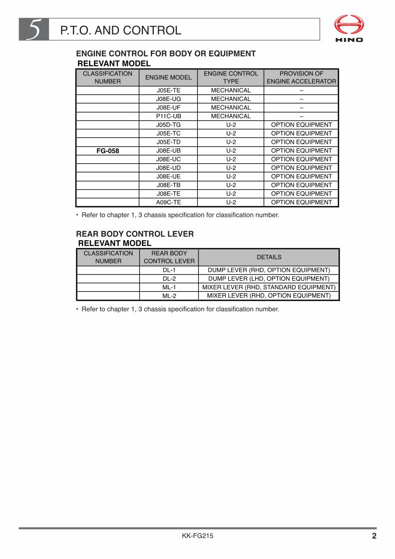
ENGINE CONTROL FOR BODY OR EQUIPMENT
REAR BODY CONTROL LEVER
RELEVANT MODEL
J05E-TE MECHANICAL –
J08E-UG MECHANICAL –
J08E-UF MECHANICAL –
P11C-UB MECHANICAL –
J05D-TG U-2 OPTION EQUIPMENT
J05E-TC U-2 OPTION EQUIPMENT
J05E-TD U-2 OPTION EQUIPMENT
FG-058 J08E-UB U-2 OPTION EQUIPMENT
J08E-UC U-2 OPTION EQUIPMENT
J08E-UD U-2 OPTION EQUIPMENT
J08E-UE U-2 OPTION EQUIPMENT
J08E-TB U-2 OPTION EQUIPMENT
J08E-TE U-2 OPTION EQUIPMENT
A09C-TE U-2 OPTION EQUIPMENT
CLASSIFICATION
NUMBERENGINE MODEL
ENGINE CONTROL
TYPE
PROVISION OF
ENGINE ACCELERATOR
RELEVANT MODEL
DL-1
DL-2
ML-1
ML-2
CLASSIFICATION
NUMBER
MIXER LEVER (RHD, OPTION EQUIPMENT)
REAR BODY
CONTROL LEVERDETAILS
DUMP LEVER (RHD, OPTION EQUIPMENT)
DUMP LEVER (LHD, OPTION EQUIPMENT)
MIXER LEVER (RHD, STANDARD EQUIPMENT)
• Refer to chapter 1, 3 chassis specification for classification number.
• Refer to chapter 1, 3 chassis specification for classification number.

P.T.O. AND CONTROL5
KK-FG215 3
2. TRANSMISSION SIDE POWER TAKE OFF (OPT)
[T/M P.T.O. : TP-1]When the body require transmission Power Take Off (P.T.O.) , genuine P.T.O. equipment and related parts should be supplied as shown below.
NOTE• Parts mentioned above table shows transmission P.T.O. unit only.• Other related parts of transmission P.T.O. control, please contact each Hino sales dealer.
TRANSMISSION�SERIES
PERMISSIBLE TORQUE�(N·m {kgf·m} at r/min)
P.T.O. CONTROL�TYPE
DIRECTION OF�ROTATION
LX06S 245 {25} / 1,000 Pneumatic�control
Reverse to�engine
••Data•of•the•P.T.O.•output•shaft
TRANSMISSION GEAR RATIO
POWER TAKE OFF ASSY
P.T.O. CONTROL TYPE
PARTS NAME
STUD, REAMER
POWER TAKE OFF SUB ASSY����
ADAPTER, P.T.O. CASE
TRANSMISSION MODELCLASSIFICATION NUMBER••Necessary•parts
6.0983.8582.3401.4221.0000.7615.672
LX06S
6.5154.1222.5001.7181.2611.0006.060
8.1905.0722.9811.8481.3431.0007.619
1ST2ND3RD4TH5TH6THREV
Parts No.
Pneumatic
S3661-05251S3661-05261
S3662-82770
0101
Q'ty /�unit Parts No. Q'ty /�
unit Parts No. Q'ty /�unit
0101
010208SL512-0103002SZ116-10086
or S3662-82780or S3662-82790
GASKET, P.T.O. CASE S3663-51560LOCK WASHER
STUD SZ116-10079 06NUT SZ170-10064 08VALVE ASS'Y, SOLENOID S2761-04550 01BOLT, FLANGE SH552-10825 02BRACKET, MAGNETIC VALVE S4458-23270 01BOLT, FLANGE SZ105-10041 02HOLDER, CLIP S7999-32610 01BOLT SH782-01020 SH782-01020 SH782-0102001
S3661-05391S3661-05201
S3662-82890
0101
0101
010208SL512-0103002SZ116-10086
or S3662-82900or S3662-82910
S3663-51560
SZ116-10079 06SZ170-10064 08S2761-04550 01SH552-10825 02S4458-23270 01SZ105-10041 02S7999-32610 01
01
S3661-05171S3661-05181
S3662-82740
01SWITCH ASSY, T/M POSITION���
S8422-01560 01 S8422-01560 01BRACKET, ELEC. PART���
S5591-23970 01 S5591-23970 01CONNECTOR, SUB ASSY���
SN352-10613 01 SN352-10613 01
01
0101
010208SL512-0103002SZ116-10084
or S3662-82750or S3662-82760
S3663-51560
SZ116-10085 06SZ170-10064 08S2761-04550 01SH552-10825 02S4458-23270 01SZ105-10041 02S7999-32610 01
01

P.T.O. AND CONTROL5
KK-FG215 4
DETAIL OF P.T.O., TRANSMISSION MODEL HINO LX06S
••P.T.O.•Installation•procedure
• Drain the transmission oil. (Do not remove the drain plug while the oil is hot, or you will scald yourself.)
• Remove the P.T.O. cover which is at the left of the transmission. ( Do not reuse the bolts and gasket that you remove at this time.)
• Clean the P.T.O. mounting surface on the transmission side.• Prepare the necessary parts, referring to table of necessary parts. • Apply liquid packing to all fitting surfaces, such as the P.T.O. mounting surface of the
transmission case and installation gasket, adaptor and P.T.O. body.• Fit the P.T.O. on the P.T.O. mounting and secure the mounting position by means of the
reamer bolts (See the part described with marked "R" in the section "P.T.O. mounting location on transmission case") and tighten the other fitting bolts.Tightening torque for bolts : 61±7 N·m {625±75 kgf·cm}
• After attaching the P.T.O., turn the output shaft coupling a few revolutions to be sure that it turns freely.
• When you refill the transmission oil, increase the amount by 2.5 liters to allow for the P.T.O..
••Gear•layout•and•gear•ratio
�LX06S
6.098 ~ 0.761�6.515 ~ 1.000�8.190 ~ 1.000
�PNEUMATIC
25�24�21
39�40�44
26�26�26
31�31�31
21�20�16
1.260�1.282�1.289
TRANSMISSION GEAR RATIO P.T.O. CONTROL�TYPE N1 N2 N3 N4 N5 i
Gera ratio : i = N2/N1xN4xN3xN5/N4
NOTE• Number of revolutions of P.T.O. output shaft
= number of revolutions of engine x1/ i• The P.T.O. output shaft turns in the opposite direction to the engine.

P.T.O. AND CONTROL5
KK-FG215 5
••How•to•check•the•gear•backlash
The gear backlash of the P.T.O. is important factor to prolong the P.T.O. gear life. The bigger backlash causes the noise from gears on the contrary the smaller backlash causes the damage of gears. When installing the P.T.O. measure and check the backlash according to the following procedures.
• Measurement of backlash (a) (between gear A and B) Attach a fuse (Ø1x10mm), with grease on the tooth surface of the P.T.O. gear B (3 places of gear tooth). After rotating gear B, measure the thickness of crashed fuses with a micro-meter.
• Adjustment of backlash (a) (between gear A and B) When the backlash is not within the following standard backlash adjust the backlash by selecting an appropriate adapter.
If specified gear backlash value cannot be obtained, check whether all the parts have been installed correctly. If the specified gear backlash value cannot be obtained despite correct installation, use another P.T.O. assembly.
MODEL GEAR POSITION
Between gear A�and gear B (a)
STANDARD�BACKLASH
0.08 ~�0.21mmLX

P.T.O. AND CONTROL5
KK-FG215 6
••P.T.O.•mounting•location•on•transmission•case
TRANSMISSION MODEL LX06ST/M GEAR RATIO 6.098 - 0.761
(A) GEAR SPECIFICATIONNUMBER OF TEETH 26
PITCH DIAMETER 98.859
COEFFICIENT OF PROFILE SHIFT +0.28628
OUTSIDE DIAMETER (D)FACE WIDTH (B) 30.5OFFSET (C) 3
OVER BALL DIAMETER / PIN DIAMETERMODULE 3.5PRESSURE ANGLE OF CUTTING TOOL 22° 30'HELIX ANGLE & DIRECTION 23° RH
108.1 +0.8+0.6
CHORDAL THICKNESS (5 TEETH) 48.763 0-0.04
110.018 / 6.350 0- 0.087
6.515 - 1.000, 8.190 - 1.000
26
98.859
+0.5798
30.53
3.522° 30'23° RH
110.0
49.549 0-0.04
113.661 / 7.000 0- 0.080
Unit : mm

KK-FG215 7
P.T.O. AND CONTROL5• Transmission P.T.O. mounting for pneumatic control type
25
130124
20
215.5
91.5 65
0.14��
A0.14���
123
�
12.25
76
OUTPUT FLANGE
ø34H
9
65
50
45
R7.570
45º�
END OF T/M CASE
3.0+0.2� 0
4 - ø8 +0.2�0
714.5
ø21.
5
1337
ø25
14 16
12
28 M14x1.5
DETAIL OF P.T.O. SHAFT
TAPER1/8
P.T.O. HOLE CENTER
±0.1
±0.1
COUNTER SHAFT�CENTER
MAIN SHAFT�CENTER
ADAPTOR A
GASKET
PARTS No.S3662-82770S3662-82780S3662-82790
t (mm)10.1910.07
9.97S3662-82890S3662-82900S3662-82910
8.158.047.94
S3662-82740S3662-82750
T/M GEAR RATIOA (ADAPTOR)
6.098 ~ 0.761
6.515 ~ 1.000
8.190 ~ 1.000S3662-82760
1.981.871.77
Unit : mm
NOTE• The devises on the body or equipment side (e. g. oil pump) must be
mounted at the same angle as engine to the body. (Direct mounting the devices to the P.T.O. output flange is strictly prohibited.)
• The three-dimensional angle of the universal joint of the drive shaft must be a Min. 1° to Max. 6°.

P.T.O. AND CONTROL5
KK-FG215 8
••Layout•of•power•line
FRO
NT
AXLE
DAT
UM
LIN
E
ENG
INE
CEN
TER
FLYW
HEE
L �
HO
USI
NG
CLU
TCH
�H
OU
SIN
G
TRANSMISSION CASEDRIVE SHAFT CENTER
215.5
124
CRANKCASE
SIDE RAIL UPPER FACE
Unit : mmCHASSIS �MODEL
FC6J, 9J
A
249
B
175
C
4.0º�
D
268
E
173.5
F
577
394 173.5 577
A
BC
D E F
FD8J 340 167.5 3.5º�
P.T.O. AND CONTROL5
KK-FG215 9
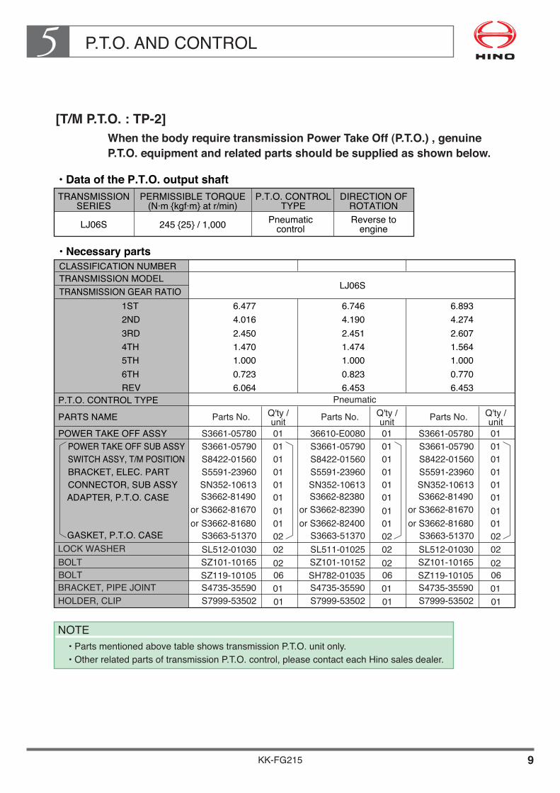
[T/M P.T.O. : TP-2]When the body require transmission Power Take Off (P.T.O.) , genuine P.T.O. equipment and related parts should be supplied as shown below.
••Data•of•the•P.T.O.•output•shaftTRANSMISSION�
SERIESPERMISSIBLE TORQUE�
(N·m {kgf·m} at r/min)P.T.O. CONTROL�
TYPEDIRECTION OF�
ROTATION
LJ06S 245 {25} / 1,000 Pneumatic�control
Reverse to�engine
NOTE• Parts mentioned above table shows transmission P.T.O. unit only.• Other related parts of transmission P.T.O. control, please contact each Hino sales dealer.
TRANSMISSION GEAR RATIO
POWER TAKE OFF ASSY
P.T.O. CONTROL TYPE
PARTS NAME
BOLT
POWER TAKE OFF SUB ASSY����
ADAPTER, P.T.O. CASE
TRANSMISSION MODELCLASSIFICATION NUMBER••Necessary•parts
6.4774.0162.4501.4701.0000.7236.064
LJ06S
6.7464.1902.4511.4741.0000.8236.453
6.8934.2742.6071.5641.0000.7706.453
1ST2ND3RD4TH5TH6THREV
Parts No.
Pneumatic
S3661-05780S3661-05790
S3662-81490
0101
Q'ty /�unit Parts No. Q'ty /�
unit Parts No. Q'ty /�unit
0101
010202SL512-0103002SZ101-10165
or S3662-81670or S3662-81680
GASKET, P.T.O. CASE S3663-51370LOCK WASHER
BOLT SZ119-10105 06BRACKET, PIPE JOINT S4735-35590 01HOLDER, CLIP S7999-53502 01
36610-E0080S3661-05790
S3662-82380
0101
0101
010202SL511-0102502SZ101-10152
or S3662-82390or S3662-82400
S3663-51370
SH782-01035 06S4735-35590 01S7999-53502 01
S3661-05780S3661-05790
S3662-81490
01SWITCH ASSY, T/M POSITION���
S8422-01560 01 S8422-01560 01BRACKET, ELEC. PART���
S5591-23960 01 S5591-23960 01CONNECTOR, SUB ASSY���
SN352-10613
S8422-01560S5591-23960SN352-10613 01
010101 SN352-10613 01
01
0101
010202SL512-0103002SZ101-10165
or S3662-81670or S3662-81680
S3663-51370
SZ119-10105 06S4735-35590 01S7999-53502 01
P.T.O. AND CONTROL5
KK-FG215 10
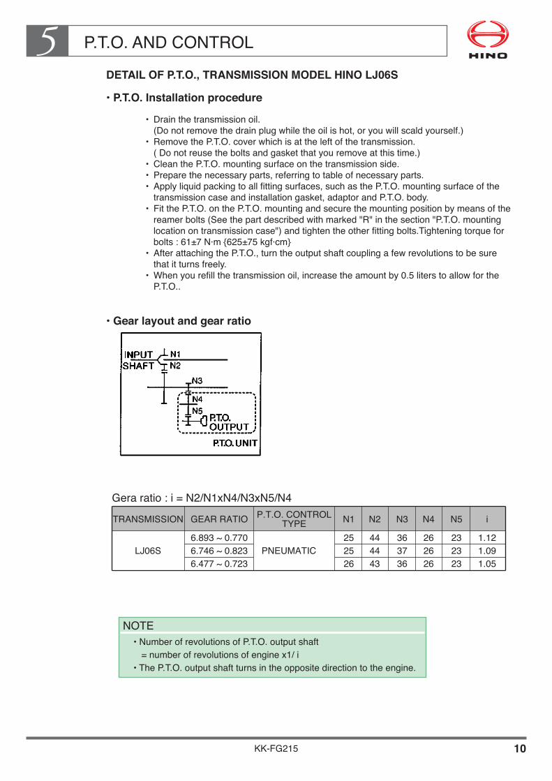
DETAIL OF P.T.O., TRANSMISSION MODEL HINO LJ06S
••P.T.O.•Installation•procedure
• Drain the transmission oil. (Do not remove the drain plug while the oil is hot, or you will scald yourself.)
• Remove the P.T.O. cover which is at the left of the transmission. ( Do not reuse the bolts and gasket that you remove at this time.)
• Clean the P.T.O. mounting surface on the transmission side.• Prepare the necessary parts, referring to table of necessary parts. • Apply liquid packing to all fitting surfaces, such as the P.T.O. mounting surface of the
transmission case and installation gasket, adaptor and P.T.O. body.• Fit the P.T.O. on the P.T.O. mounting and secure the mounting position by means of the
reamer bolts (See the part described with marked "R" in the section "P.T.O. mounting location on transmission case") and tighten the other fitting bolts.Tightening torque for bolts : 61±7 N·m {625±75 kgf·cm}
• After attaching the P.T.O., turn the output shaft coupling a few revolutions to be sure that it turns freely.
• When you refill the transmission oil, increase the amount by 0.5 liters to allow for the P.T.O..
••Gear•layout•and•gear•ratio
�LJ06S
6.893 ~ 0.770�6.746 ~ 0.823�6.477 ~ 0.723
�PNEUMATIC
25�25�26
44�44�43
36�37�36
26�26�26
23�23�23
1.12�1.09�1.05
TRANSMISSION GEAR RATIO P.T.O. CONTROL�TYPE N1 N2 N3 N4 N5 i
Gera ratio : i = N2/N1xN4/N3xN5/N4
NOTE• Number of revolutions of P.T.O. output shaft
= number of revolutions of engine x1/ i• The P.T.O. output shaft turns in the opposite direction to the engine.

P.T.O. AND CONTROL5
KK-FG215 11
••How•to•check•the•gear•backlash
The gear backlash of the P.T.O. is important factor to prolong the P.T.O. gear life. The bigger backlash causes the noise from gears on the contrary the smaller backlash causes the damage of gears. When installing the P.T.O. measure and check the backlash according to the following procedures.
• Measurement of backlash (a) (between gear A and B) Attach a fuse (ø1 X 10mm), with grease on the tooth surface of the P.T.O. gear B (3 places of gear tooth). After rotating gear B, measure the thickness of crashed fuses with a micro-meter.
• Adjustment of backlash (a) (between gear A and B) When the backlash is not within the following standard backlash adjust the backlash by selecting an appropriate adapter.
If specified gear backlash value cannot be obtained, check whether all the parts have been installed correctly. If the specified gear backlash value cannot be obtained despite correct installation, use another P.T.O. assembly.
MODEL GEAR POSITION
Between gear A�and gear B (a)
STANDARD�BACKLASH
0.09 ~�0.25mm
LJBetween gear B�and gear C (b)
0.09 ~�0.27mm
P.T.O. AND CONTROL5
KK-FG215 12
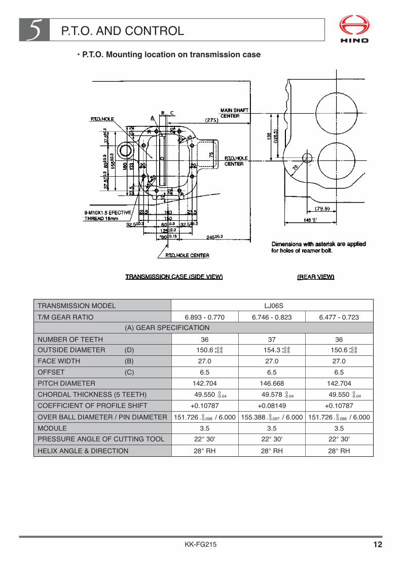
••P.T.O.•Mounting•location•on•transmission•case
TRANSMISSION MODEL LJ06ST/M GEAR RATIO 6.893 - 0.770
(A) GEAR SPECIFICATIONNUMBER OF TEETH 36
PITCH DIAMETER 142.704
COEFFICIENT OF PROFILE SHIFT +0.10787
OUTSIDE DIAMETER (D)FACE WIDTH (B) 27.0OFFSET (C) 6.5
OVER BALL DIAMETER / PIN DIAMETERMODULE 3.5PRESSURE ANGLE OF CUTTING TOOL 22° 30'HELIX ANGLE & DIRECTION 28° RH
150.6 +0.8+0.6 154.3 +0.8
+0.6
CHORDAL THICKNESS (5 TEETH) 49.550 0-0.04
151.726 / 6.000 0- 0.096
36
142.704
+0.10787
27.06.5
3.522° 30'28° RH
150.6 +0.8+0.6
49.550 0-0.04
151.726 / 6.000 0- 0.096
6.477 - 0.7236.746 - 0.823
37
146.668
+0.08149
27.06.5
3.522° 30'28° RH
49.578 0-0.04
155.388 / 6.000 0- 0.097

KK-FG215 13
P.T.O. AND CONTROL5• Transmission P.T.O. mounting for pneumatic control type
NOTE• The devises on the body or equipment side (e. g. oil pump) must be
mounted at the same angle as engine to the body. (Direct mounting the devices to the P.T.O. output flange is strictly prohibited.)
• The three-dimensional angle of the universal joint of the drive shaft must be a Min. 1° to Max. 6°.
Unit : mm
PARTS No.S3662-81490S3662-81670S3662-81680
t (mm)6.125.995.86
S3662-82380S3662-82390S3662-82400
8.027.897.76
S3662-81490S3662-81670
T/M GEAR RATIOA (ADAPTOR)
6.477 ~ 0.723
6.746 ~ 0.823
6.893 ~ 0.770S3662-81680
6.125.995.86
P.T.O. AND CONTROL5
KK-FG215 14
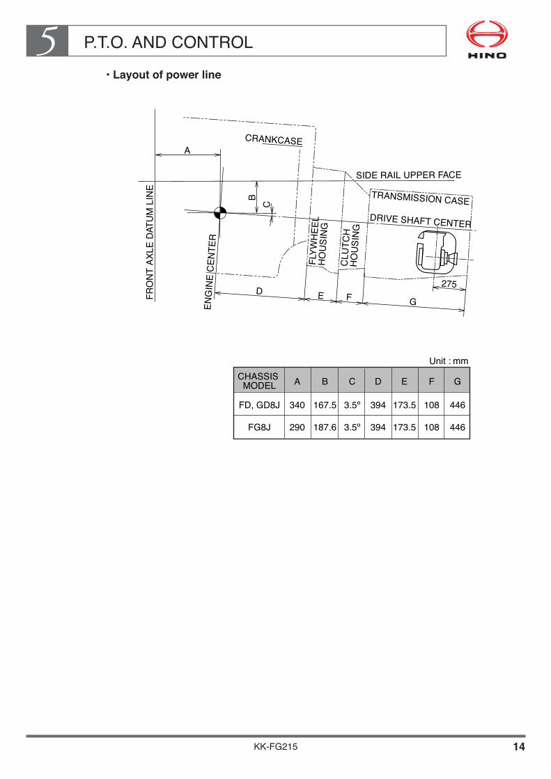
••Layout•of•power•line
FRO
NT
AXLE
DAT
UM
LIN
E
ENG
INE
CEN
TER
FLYW
HEE
L �
HO
USI
NG
CLU
TCH
�H
OU
SIN
G
TRANSMISSION CASEDRIVE SHAFT CENTER
275
CRANKCASE
SIDE RAIL UPPER FACE
Unit : mmCHASSIS �MODEL
FD, GD8J
A
340
B
167.5
C
3.5º�
D
394
E
173.5
F
108
G
446
394 173.5 108 446
A
BC
D E F G
FG8J 290 187.6 3.5º�
P.T.O. AND CONTROL5
KK-FG215 15
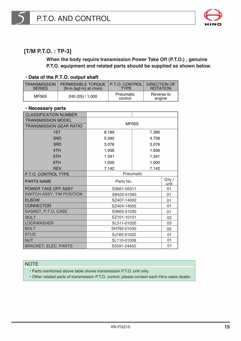
[T/M P.T.O. : TP-3]When the body require transmission Power Take Off (P.T.O.) , genuine P.T.O. equipment and related parts should be supplied as shown below.
••Data•of•the•P.T.O.•output•shaftTRANSMISSION�
SERIESPERMISSIBLE TORQUE�
(N·m {kgf·m} at r/min)P.T.O. CONTROL�
TYPEDIRECTION OF�
ROTATION
MF06S 245 {25} / 1,000 Pneumatic�control
Reverse to�engine
NOTE• Parts mentioned above table shows transmission P.T.O. unit only.• Other related parts of transmission P.T.O. control, please contact each Hino sales dealer.
TRANSMISSION GEAR RATIO
POWER TAKE OFF ASSY
P.T.O. CONTROL TYPEPARTS NAME
ELBOW
TRANSMISSION MODELCLASSIFICATION NUMBER••Necessary•parts
8.1895.3403.0761.9361.3411.0007.142
MF06S
7.3954.7583.0761.9361.3411.0007.142
1ST2ND3RD4TH5TH6THREV
Pneumatic
Parts No. Q'ty /�unit
SWITCH ASSY, T/M POSITION
CONNECTORGASKET, P.T.O. CASEBOLTLOCKWASHERBOLTSTUDNUT
01010101010203050101
BRACKET, ELEC. PARTS
S3661-05311S8422-01560SZ407-14002SZ404-14005S3663-51030SZ101-10151SL511-01025SH782-01030SJ182-01022SL110-01008S5591-24450 01

P.T.O. AND CONTROL5
KK-FG215 16
DETAIL OF P.T.O., TRANSMISSION MODEL HINO MF06S
••P.T.O.•Installation•procedure
• Drain the transmission oil. (Do not remove the drain plug while the oil is hot, or you will scald yourself.)
• Remove the P.T.O. cover which is at the left of the transmission. ( Do not reuse the bolts and gasket that you remove at this time.)
• Clean the P.T.O. mounting surface on the transmission side.• Prepare the necessary parts, referring to table of necessary parts. • Apply liquid packing to all fitting surfaces, such as the P.T.O. mounting surface of the
transmission case, installation gasket and P.T.O. body.• Fit the P.T.O. on the P.T.O. mounting and secure the mounting position by means of the
reamer bolts (See the part described with marked "R" in the section "P.T.O. mounting location on transmission case") and tighten the other fitting bolts.Tightening torque for bolts : 49±4.9 N·m {500±50 kgf·cm}
• After attaching the P.T.O., turn the output shaft coupling a few revolutions to be sure that it turns freely.
• When you refill the transmission oil, increase the amount by 0.3 liters to allow for the P.T.O..
••Gear•layout•and•gear•ratio
MF06S
N1
22
N2
47
N3
21
N4
29
N5
12
N6
—�
i
1.220
TRANSMISSION
Gera ratio : i = N2/N1xN4/N3xN5/N4
NOTE• Number of revolutions of P.T.O. output shaft
= number of revolutions of engine x1/ i• The P.T.O. output shaft turns in the opposite direction to the engine.

P.T.O. AND CONTROL5
KK-FG215 17
••How•to•check•the•gear•backlash
The gear backlash of the P.T.O. is important factor to prolong the P.T.O. gear life. The bigger backlash causes the noise from gears on the contrary the smaller backlash causes the damage of gears. When installing the P.T.O. measure and check the backlash according to the following procedures.
••Measuring•the•backlash•at•the•output•flange
• Measure the free play of the P.T.O. gear (gear A; the transmission P.T.O. unit gear) and the shaft spline. Fix the P.T.O. gear so that it will not turn when the P.T.O. is on, and use a dial gauge or similar to measure the change in position of one of the output flange bolt holes. This value is a1.
• Fix the reverse idler gear (gear B) such that it will not turn, and attach the P.T.O. to the transmission. With the P.T.O. on, use a dial gauge or similar to measure the change in position of one of the output flange bolt holes. This value is a2.
• Calculate the backlash using the formula below:
••Measuring•the•backlash•caused•with•a•fuse
Use grease to paste a fuse (ø1X10mm) to the surface of a tooth of P.T.O. gear B. Make the teeth interlock over the fuse, then measure the thickness of the crushed fuse with a micrometer (at three points on the perimeter). This value is the backlash.
If specified gear backlash value cannot be obtained, check whether all the parts have been installed correctly. If the specified gear backlash value cannot be obtained despite correct installation, use another P.T.O. assembly.
P.T.O. AND CONTROL5
KK-FG215 18
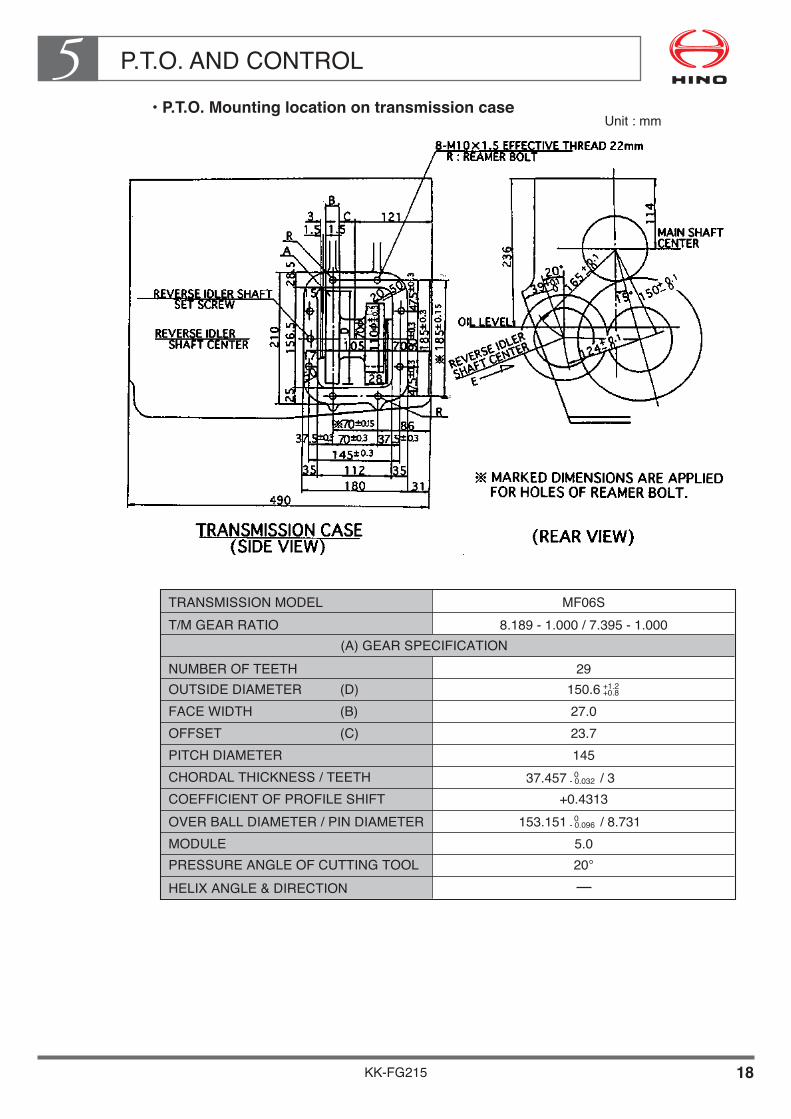
••P.T.O.•Mounting•location•on•transmission•case
TRANSMISSION MODEL MF06ST/M GEAR RATIO 8.189 - 1.000 / 7.395 - 1.000
(A) GEAR SPECIFICATIONNUMBER OF TEETH 29
PITCH DIAMETER 145
COEFFICIENT OF PROFILE SHIFT +0.4313
OUTSIDE DIAMETER (D)FACE WIDTH (B) 27.0OFFSET (C) 23.7
OVER BALL DIAMETER / PIN DIAMETERMODULE 5.0PRESSURE ANGLE OF CUTTING TOOL 20°HELIX ANGLE & DIRECTION
150.6 +1.2+0.8
CHORDAL THICKNESS / TEETH
153.151 / 8.731 0- 0.096
37.457 / 3 0- 0.032
Unit : mm

KK-FG215 19
P.T.O. AND CONTROL5• Transmission P.T.O. mounting for pneumatic control type
Unit : mm
NOTE• The devises on the body or equipment side (e. g. oil pump) must be mounted at the same angle as
engine to the body. (Direct mounting the devices to the P.T.O. output flange is strictly prohibited.)• The three-dimensional angle of the universal joint of the drive shaft must be a Min. 1° to Max. 6°.
P.T.O. AND CONTROL5
KK-FG215 20
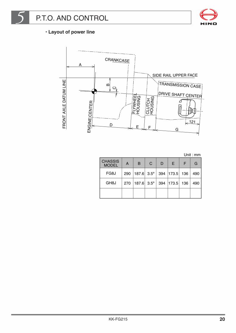
••Layout•of•power•line
CHASSIS �MODEL
FRO
NT
AXLE
DAT
UM
LIN
E
ENG
INE
CEN
TER
FLYW
HEE
L �
HO
USI
NG
CLU
TCH
�H
OU
SIN
G
TRANSMISSION CASEDRIVE SHAFT CENTER
121
CRANKCASE
SIDE RAIL UPPER FACE
Unit : mm
FG8J
A
290
B
187.6
C
3.5º�
D
394
E
173.5
F
136
G
490
A
BC
D E F G
394 173.5 136 490GH8J 270 187.6 3.5º�

P.T.O. AND CONTROL5
KK-FG215 21
[T/M P.T.O. : TP-4]Do not provide transmission Power Take Off (P.T.O.) as option equipment, consult•with•authorized•Hino•distributor•when•the•mounted•body•require•transmission P.T.O..
••Data•of•the•P.T.O.•output•shaftTRANSMISSION�
SERIESPERMISSIBLE TORQUE�
(N·m {kgf·m} at r/min)P.T.O. CONTROL�
TYPEDIRECTION OF�
ROTATION
HK06S———�
( 245 {25} / 1,000 )�( CAPACITY OF OUTPUT GEAR OF T/M. )
———� ———�
TRANSMISSION GEAR RATIO
POWER TAKE OFF ASSY
PARTS NAME
Power take off sub assy��
TRANSMISSION MODEL••Necessary•parts
HK06S
1ST2ND3RD4TH5TH6THREV
Parts No. Q'ty /�unit
Gasket, P.T.O. case
Knob sub assy,shift��Cap, shift lever��Booster assy, T/M��
7.0284.3892.4951.5921.0000.7436.987
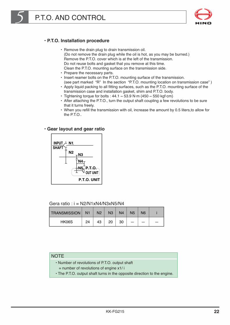
P.T.O. AND CONTROL5
KK-FG215 22
••P.T.O.•Installation•procedure
• Remove the drain plug to drain transmission oil. (Do not remove the drain plug while the oil is hot, as you may be burned.) Remove the P.T.O. cover which is at the left of the transmission. Do not reuse bolts and gasket that you remove at this time. Clean the P.T.O. mounting surface on the transmission side.
• Prepare the necessary parts.• Insert reamer bolts on the P.T.O. mounting surface of the transmission.
(see part marked “R” In the section “P.T.O. mounting location on transmission case” )• Apply liquid packing to all fitting surfaces, such as the P.T.O. mounting surface of the
transmission case and installation gasket, shim and P.T.O. body.• Tightening torque for bolts : 44.1 ~ 53.9 N·m {450 ~ 550 kgf·cm}• After attaching the P.T.O., turn the output shaft coupling a few revolutions to be sure
that it turns freely.• When you refill the transmission with oil, increase the amount by 0.5 liters,to allow for
the P.T.O..
••Gear•layout•and•gear•ratio
INPUT N1
N2 N3N4N5 P.T.O.
P.T.O. UNITOUT UNIT
SHAFT
HK06S
N1
24
N2
43
N3
20
N4
30
N5
—�
N6
—�
i
—�
TRANSMISSION
Gera ratio : i = N2/N1xN4/N3xN5/N4
NOTE• Number of revolutions of P.T.O. output shaft
= number of revolutions of engine x1/ i• The P.T.O. output shaft turns in the opposite direction to the engine.

P.T.O. AND CONTROL5
KK-FG215 23
••How•to•check•the•gear•backlash
The gear backlash of the P.T.O. is important factor to prolong the P.T.O. gear life. The bigger backlash causes the noise from gear, on the contrary the smaller backlash causes the damage of gear. When installing the P.T.O., measure and check the backlash according to the following procedures.
••Measuring•the•backlash•at•the•output•flange
• Measure the free play of the P.T.O. gear (gear A; the transmission P.T.O. unit gear) and the shaft spline. Fix the P.T.O. gear so that it will not turn when the P.T.O. is on, and use a dial gauge or similar to measure the change in position of one of the output flange bolt holes. The value is a1.
• Fix the reverse idler gear (gear B) such that it will not turn, and attach the P.T.O. to the transmission. With the P.T.O. on, use a dial gauge or similar to measure the change in position of the output flange bolt holes. This value is a2.
• Calculate the backlash using the formula below:
••Measuring•the•backlash•caused•with•a•fuse
Use grease to paste a fuse (ø1 x 10 mm) to the surface of a tooth of P.T.O. gear B. Make the teeth interlock over the fuse, then measure the thickness of the crushed fuse with a micrometer (at three points on the perimeter). This value is the backlash

KK-FG215 24
P.T.O. AND CONTROL5• P.T.O. mounting location of transmission case
NOTES• Hold the reverse idler adjust screw using a power take-off to avoid it coming loose.• Change HINO recommended gear oil to set level.• Use reamer bolts at all points embossed with "R".
Unit : mm

P.T.O. AND CONTROL5
KK-FG215 25
••Layout•of•power•line
CHASSIS �MODEL
FRO
NT
AXLE
DAT
UM
LIN
E
ENG
INE
CEN
TER
FLYW
HEE
L �
HO
USI
NG
CLU
TCH
�H
OU
SIN
G
TRANSMISSION CASEDRIVE SHAFT CENTER
CRANKCASE
SIDE RAIL UPPER FACE
Unit : mm
FM1A
A
270
B
217.6
C
3.5º�
D
438.5
E
197.5
F
147.5
G
468
A
BC
D E F G
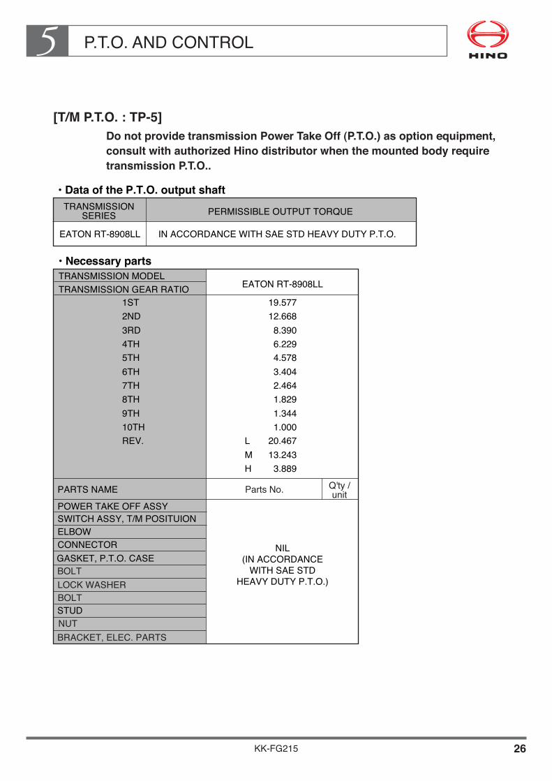
P.T.O. AND CONTROL5
KK-FG215 26
[T/M P.T.O. : TP-5]Do not provide transmission Power Take Off (P.T.O.) as option equipment, consult•with•authorized•Hino•distributor•when•the•mounted•body•require•transmission P.T.O..
••Data•of•the•P.T.O.•output•shaftTRANSMISSION�
SERIES PERMISSIBLE OUTPUT TORQUE
EATON RT-8908LL IN ACCORDANCE WITH SAE STD HEAVY DUTY P.T.O.
TRANSMISSION GEAR RATIO
POWER TAKE OFF ASSY
PARTS NAME
LOCK WASHER
TRANSMISSION MODEL••Necessary•parts
19.57712.6688.3906.2294.5783.4042.464
EATON RT-8908LL
NIL�(IN ACCORDANCE�
WITH SAE STD�HEAVY DUTY P.T.O.)
1ST2ND3RD4TH5TH6TH
1.8291.3441.000
20.46713.2433.889
LMH
7TH8TH9TH10THREV.
Parts No. Q'ty /�unit
GASKET, P.T.O. CASEBOLT
BOLTSTUDNUTBRACKET, ELEC. PARTS
SWITCH ASSY, T/M POSITUION���ELBOW��CONNECTOR��

P.T.O. AND CONTROL5
KK-FG215 27
DETAIL OF P.T.O., TRANSMISSION MODEL EATON RT-8908LL
••Gear•layout•and•gear•ratio
EATON RT-8908LL
N1
48
N2
69
N3
47
TRANSMISSION
NO. OF GEAR

KK-FG215 28
P.T.O. AND CONTROL5• P.T.O. mounting location on transmission case
NOTE• Gear data and backlash are specified by gear box manufacturer.• More detail information if needed, please contact with "EATON CORPORATION
(TRANSMISSION DIVISION)".
Unit : mm
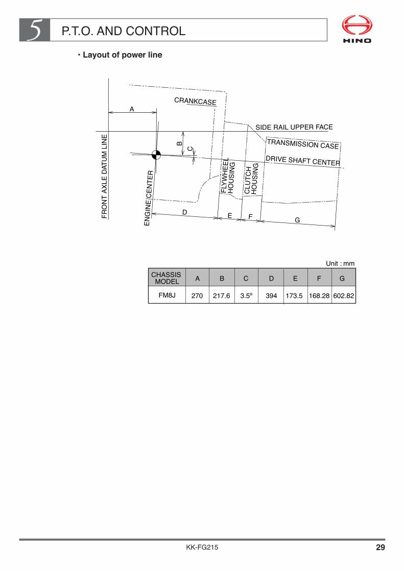
P.T.O. AND CONTROL5
KK-FG215 29
••Layout•of•power•line
CHASSIS �MODEL
FRO
NT
AXLE
DAT
UM
LIN
E
ENG
INE
CEN
TER
FLYW
HEE
L �
HO
USI
NG
CLU
TCH
�H
OU
SIN
G
TRANSMISSION CASEDRIVE SHAFT CENTER
CRANKCASE
SIDE RAIL UPPER FACE
Unit : mm
FM8J
A
270
B
217.6
C
3.5º�
D
394
E
173.5
F
168.28
G
602.82
A
BC
D E F G
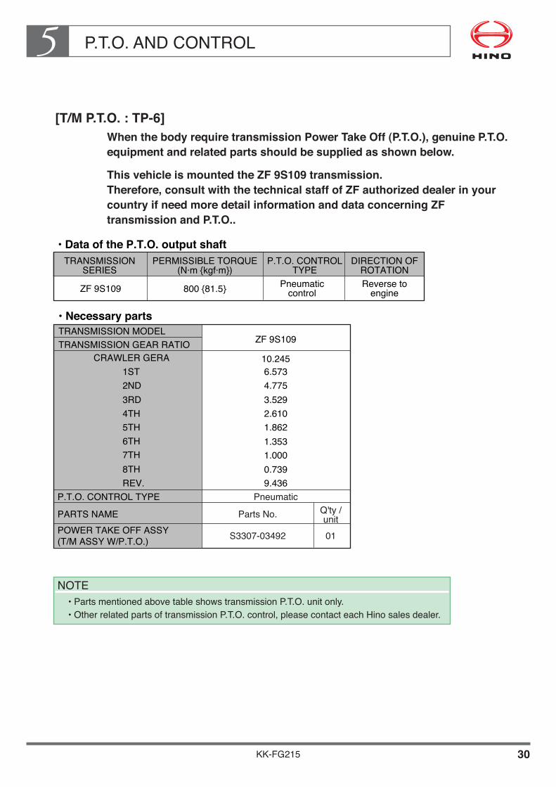
P.T.O. AND CONTROL5
KK-FG215 30
[T/M P.T.O. : TP-6]When the body require transmission Power Take Off (P.T.O.), genuine P.T.O. equipment and related parts should be supplied as shown below.
This•vehicle•is•mounted•the•ZF•9S109•transmission. Therefore,•consult•with•the•technical•staff•of•ZF•authorized•dealer•in•your•country•if•need•more•detail•information•and•data•concerning•ZF•transmission and P.T.O..
NOTE• Parts mentioned above table shows transmission P.T.O. unit only.• Other related parts of transmission P.T.O. control, please contact each Hino sales dealer.
••Data•of•the•P.T.O.•output•shaftTRANSMISSION�
SERIESPERMISSIBLE TORQUE�
(N·m {kgf·m})P.T.O. CONTROL�
TYPEDIRECTION OF�
ROTATION
ZF 9S109 800 {81.5} Pneumatic�control
Reverse to�engine
TRANSMISSION GEAR RATIO
POWER TAKE OFF ASSY�(T/M ASSY W/P.T.O.)
PARTS NAME
TRANSMISSION MODEL••Necessary•parts
6.5734.775
10.245
3.5292.6101.8621.3531.0000.7399.436
ZF 9S109
1ST2ND
CRAWLER GERA
3RD4TH5TH6TH7TH8THREV.
Parts No.
P.T.O. CONTROL TYPE PneumaticQ'ty /�unit01S3307-03492

P.T.O. AND CONTROL5
KK-FG215 31
••P.T.O.•Installation•procedure
• P.T.O. units is installed in place of the rear end plate of the layshaft. The adapter shaft required for driving the P.T.O. is engaged with the reverse intermediate gear of the main gearbox. The adapter shaft is included in the P.T.O. delivery specification.
• When installing the P.T.O., it is important to ensure that the temperature of the gearbox oil is not greatly affected by ambient conditions on the vehicle (e. g. exhaust pipe etc.). Check the oil temperature and if necessary provide forced cooling(e.g.a fan) so that an operating temperature of 110ºC is not exceeded. Brief temperature peaks of up to 130ºC are permissible(lasting not more than 30 minutes).
••Gear•layout•and•gear•ratio
ZF 9S109
N1
27
N2
33
N3
16
N4
22
N5
17
N6
—�
i
1.298
TRANSMISSION
Gera ratio : i = N2/N1xN4/N3xN5/N4
NOTES• Number of revolutions of P.T.O. output shaft
= number of revolutions of engine x1/ i• The P.T.O. output shaft turns in the opposite direction to the engine.

P.T.O. AND CONTROL5
KK-FG215 32
••Technical•data•of•P.T.O.
Model
Output-�torque Continuous operation
Input
[Nm] 800
Output speed�for transmission ratio�9S109 10.24-0.74
Speed factor f�0.77
Layshaft
Direction of output rotation Reverse to engine
NH/1
Required air pressure�for pneumatic engagement [bar] 6.2 to max. 10.0bar
Weight [kg] 3 - 5
Gravity torque
Output power�The permissible output power depends on permissible output torque and output speed.�It is calculated by the following formula :
Pperm. = perm. output torque X noutput
9552[kw]
[kg] 50
Mperm. = s X G [Nm]
s
G
CENTER OF GRAVITY
P.T.O.•calculationP� =� Power� [kw]�T� =� Torque� [Nm]�n� =� Speed� [rpm]�Q�=� Delivery volume� [l]�p� =� Pressure� [bar]�f� =� Speed factor� �M�=� Gravity torque� [Nm]�s� =� Distance between the ��� center of gravity of the��� flange mounting face� [m]�G� =� Pump weight� [kg]� � =� Efficiency
Output torque
T = 15.92 X Q X pn X
[Nm]
T = 9552 X Pperm.
n [Nm]
Perm. pump gravity torque
Speednoutput = f X nengine [rpm]
or

P.T.O. AND CONTROL5
KK-FG215 33
••P.T.O.•Mounting•location•of•transmission•case
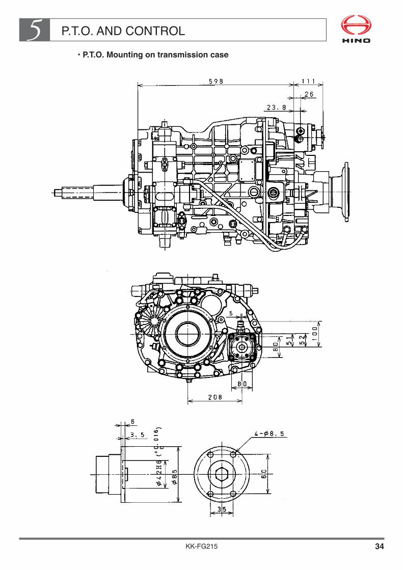
P.T.O. AND CONTROL5
KK-FG215 34
••P.T.O.•Mounting•on•transmission•case
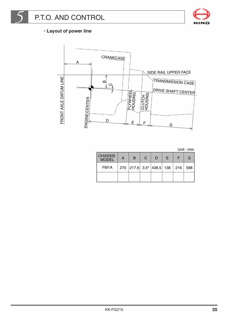
P.T.O. AND CONTROL5
KK-FG215 35
••Layout•of•power•line
CHASSIS �MODEL
FRO
NT
AXLE
DAT
UM
LIN
E
ENG
INE
CEN
TER
FLYW
HEE
L �
HO
USI
NG
CLU
TCH
�H
OU
SIN
G
TRANSMISSION CASEDRIVE SHAFT CENTER
CRANKCASE
SIDE RAIL UPPER FACE
Unit : mm
FM1A
A
270
B
217.6
C
3.5º�
D
438.5
E
138
F
216
G
598
A
BC
D E F G

P.T.O. AND CONTROL5
KK-FG215 36
[T/M P.T.O. : TP-7]When the body require transmission Power Take Off (P.T.O.) , genuine P.T.O. equipment and related parts should be supplied as shown below.
••Data•of•the•P.T.O.•output•shaftTRANSMISSION�
SERIESPERMISSIBLE TORQUE�
(N·m {kgf·m} at r/min)P.T.O. CONTROL�
TYPEDIRECTION OF�
ROTATION
EATON FS-6109A 235 {24} / 1,000 Pneumatic�control
Same to�engine
NOTE• Parts mentioned above table shows transmission P.T.O. unit only.• Other related parts of transmission P.T.O. control, please contact each Hino sales dealer.
••Necessary•parts
TRANSMISSION GEAR RATIO
P.T.O. CONTROL TYPEPARTS NAME
TRANSMISSION MODEL EATON FS-6109A
12.637�8.806�6.550�4.768�3.548�2.481�1.845�1.343�1.000�
13.210
LOW�1ST�2ND�3RD�4TH�5TH�6TH�7TH�8TH�REV
Parts No.
Pneumatic
POWER TAKE OFF ASSY�ADAPTER, SUB ASSY�HARNESS SUB ASSY, �TRANSMISSION�BRACKET, ELEC. PARTS�ELBOW�CONNECTOR
0101
Q'ty /�unit
01
01
0101
36610-E0460S3190-61230
S8206-51121
S5591-23920SZ407-10059SZ404-14004

P.T.O. AND CONTROL5
KK-FG215 37
DETAIL OF P.T.O. TRANSMISSION MODEL EATON FS-6109A
••P.T.O.•Installation•procedure
• Remove the drain plug to the transmission oil. (Do not remove the drain plug while the oil is hot, or you maybe burned.) Remove the P.T.O. cover which is at the left forward of the transmission. Do not reuse the bolts and gasket that you remove at this time. Clean the P.T.O. mounting surface on the transmission side.
• Prepare the necessary parts, referring to table of last page.• Tighten the elbow and connector to the P.T.O., after binding up a sealing tape at 1.5 to
2 times on the taper thread and make sure air do not leak from the taper thread. (When binding up a sealing tape on the taper thread, two thread from top of screw should not be binded and bind up counter direction of the taper thread. And also make sure a foreign material do not came into joint and control cylinder.)
• Installation angle of the elbow should be adjusted the tightening direction of the taper thread.
• Adjust the backlash of each gears, between transmission counter shaft gear and adapter gear, adapter gear and P.T.O. gear as described with paragraph "How to check the gear backlash".
• Apply liquid packing to all fitting surfaces, such as the P.T.O. mounting surface of the transmission case, adapter and P.T.O. body. (Do not apply liquid packing between contact surface of each other of the gasket.)
• Install the adapter with proper bolts (furnished with adapter) in the P.T.O. aperture of the transmission case and the P.T.O. with proper studs and nuts (furnished with P.T.O.) in the adapter.
• Tightening torque of bolt : 40 - 47 N·m {414 - 484 kgf·cm}• Tightening torque of stud and nut : 48 - 54 N·m {490 - 551 kgf·cm}• After attaching the P.T.O., turn the output shaft coupling a few revolutions to be sure
that it turns freely.• When you refill the transmission with oil, increase the amount by 0.5 liters, to allow for
the P.T.O.. And check the oil level of the transmission case with filler plug of main case.• More detail information if needed, please contact with "DANA CORPORATION".
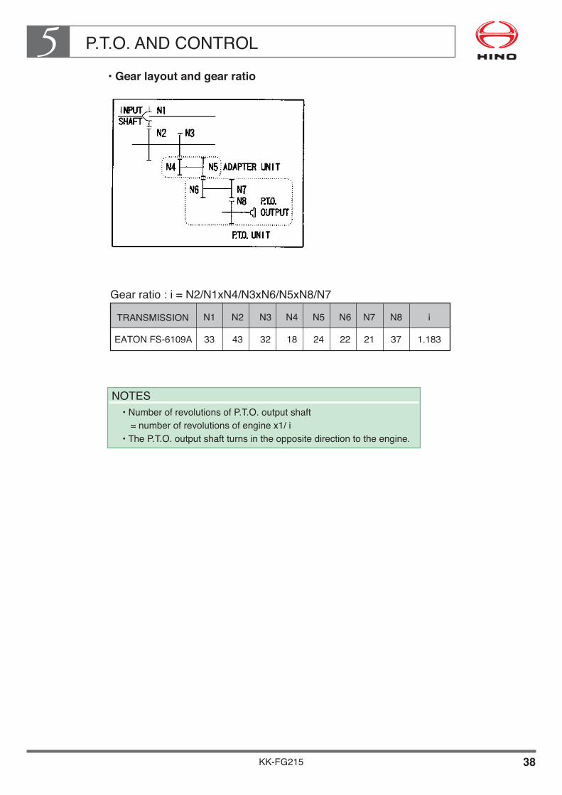
P.T.O. AND CONTROL5
KK-FG215 38
••Gear•layout•and•gear•ratio
Gear ratio : i = N2/N1xN4/N3xN6/N5xN8/N7
EATON FS-6109A
N1
33
N2
43
N3
32
N4
18
N5
24
N6
22
N7
21
N8
37
i
1.183
TRANSMISSION
NOTES• Number of revolutions of P.T.O. output shaft
= number of revolutions of engine x1/ i• The P.T.O. output shaft turns in the opposite direction to the engine.

P.T.O. AND CONTROL5
KK-FG215 39
••How•to•check•the•gear•backlash
The gear backlash of the P.T.O. is important factor to prolong the P.T.O. gear life. The bigger backlash causes the noise from gears, on the contrary the smaller backlash causes the damage of gears. When installing the P.T.O. measure and check the backlash according to the following procedures.
• Remove the P.T.O. shaft housing and/or inspection plate.• Mount the dial indicator so that it registers movement of the input gear (driven gear) of
the P.T.O.. (See Fig. 1.)
• Hold the P.T.O. driver gear in transmission with a screwdriver or bar and rock the P.T.O. input gear (driven gear) back and forth with your hand. Note the total movement on the dial indicator.
• Establish backlash at 0.15mm - 0.30mm by adding or subtracting gaskets. General rule -- A CHELSEA'S 0.25mm gasket will change backlash approx. 0.15mm, a 0.51mm gasket changes backlash approx. 0.30mm.
• Replace the shift housing and/or inspection plate and retorque four capscrews to 22 - 27 N·m {221 - 276 kgf·cm}.
• Use same procedure for mounting the adapter and checking backlash as was used when mounting the P.T.O. to transmission as described above.
••Pouring•gear•oil
When pouring gear oil into the transmission, add more oil (0.5L) for the lubrication of P.T.O. gears.
••Other•notices
After finishing P.T.O. installation, check whether the output shaft can be smoothly rotated when P.T.O. is in the neutral position.
NOTES• See figure 2 for proper location of dial indicator contact point.
(Two common type dial indicators shown.)
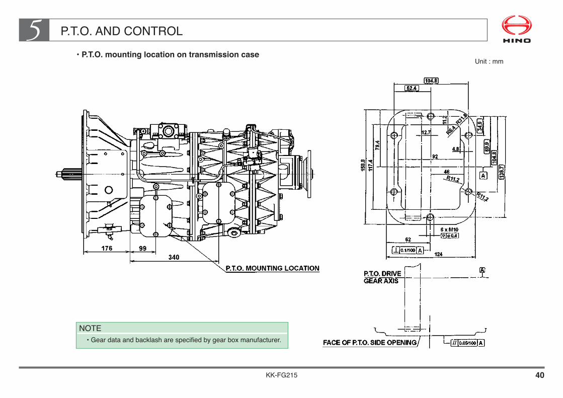
KK-FG215 40
P.T.O. AND CONTROL5• P.T.O. mounting location on transmission case
NOTE• Gear data and backlash are specified by gear box manufacturer.
Unit : mm

KK-FG215 41
P.T.O. AND CONTROL5• Transmission P.T.O. mounting
Unit : mm
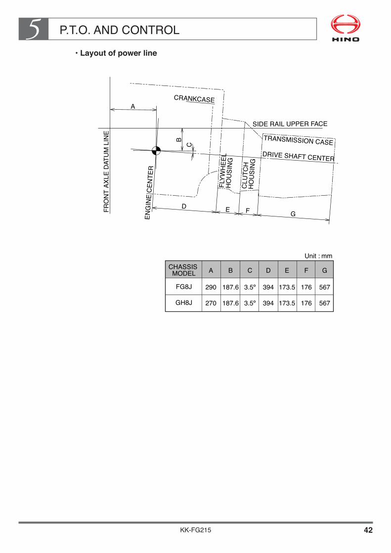
P.T.O. AND CONTROL5
KK-FG215 42
••Layout•of•power•line
FRO
NT
AXLE
DAT
UM
LIN
E
ENG
INE
CEN
TER
FLYW
HEE
L �
HO
USI
NG
CLU
TCH
�H
OU
SIN
G
TRANSMISSION CASEDRIVE SHAFT CENTER
CRANKCASE
SIDE RAIL UPPER FACE
Unit : mm
FG8J
A
290
GH8J 270
B
187.6
C
3.5º�
D
394
E
173.5
F
176
G
567
187.6 3.5º� 394 173.5 176 567
A
BC
D E F G
CHASSIS �MODEL

P.T.O. AND CONTROL5
KK-FG215 43
[T/M P.T.O. : TP-8]When the body require transmission Power Take Off (P.T.O.) , genuine P.T.O. equipment and related parts should be supplied as shown below.
••Data•of•the•P.T.O.•output•shaftTRANSMISSION�
SERIESPERMISSIBLE TORQUE�
(N·m {kgf·m} at r/min)P.T.O. CONTROL�
TYPEDIRECTION OF�
ROTATION
EATON FS-8209BBE 235 {24} / 1,000 Pneumatic�control
Same to�engine
NOTE• Parts mentioned above table shows transmission P.T.O. unit only.• Other related parts of transmission P.T.O. control, please contact each Hino sales dealer.
••Necessary•parts
TRANSMISSION GEAR RATIO
P.T.O. CONTROL TYPEPARTS NAME
TRANSMISSION MODEL EATON FS-8209BBE
12.637�8.806�6.550�4.768�3.548�2.481�1.845�1.343�1.000�
13.210
LOW�1ST�2ND�3RD�4TH�5TH�6TH�7TH�8TH�REV
Parts No.
Pneumatic
POWER TAKE OFF ASSY�ADAPTER, SUB ASSY�HARNESS SUB ASSY, �TRANSMISSION�BRACKET, ELEC. PARTS�ELBOW�CONNECTOR��
0101
Q'ty /�unit
01
01
0101
36610-E0460S3190-61230
S8206-51121
S5591-23920SZ407-10059SZ404-14004

P.T.O. AND CONTROL5
KK-FG215 44
DETAIL OF P.T.O. TRANSMISSION MODEL EATON FS-8209BBE
••P.T.O.•Installation•procedure
• Remove the drain plug to the transmission oil. (Do not remove the drain plug while the oil is hot, or you maybe burned.) Remove the P.T.O. cover which is at the left forward of the transmission. Do not reuse the bolts and gasket that you remove at this time. Clean the P.T.O. mounting surface on the transmission side.
• Prepare the necessary parts, referring to table of last page. • Tighten the elbow and connector to the P.T.O., after binding up a sealing tape at 1.5 to
2 times on the taper thread and make sure air do not leak from the taper thread. (When binding up a sealing tape on the taper thread, two thread from top of screw should not be binded and bind up counter direction of the taper thread. And also make sure a foreign material do not came into joint and control cylinder.)
• Installation angle of the elbow should be adjusted the tightening direction of the taper thread.
• Adjust the backlash of each gears, between transmission counter shaft gear and adapter gear, adapter gear and P.T.O. gear as described with paragraph "How to check the gear backlash".
• Apply liquid packing to all fitting surfaces, such as the P.T.O. mounting surface of the transmission case, adapter and P.T.O. body. (Do not apply liquid packing between contact surface of each other of the gasket.)
• Install the adapter with proper bolts (furnished with adapter) in the P.T.O. aperture of the transmission case and the P.T.O. with proper studs and nuts (furnished with P.T.O.) in the adapter.
• Tightening torque of bolt : 40 - 47 N·m {414 - 484 kgf·cm}• Tightening torque of stud and nut : 48 - 54 N·m {490 - 551 kgf·cm}• After attaching the P.T.O., turn the output shaft coupling a few revolutions to be sure
that it turns freely.• When you refill the transmission with oil, increase the amount by 0.5 liters, to allow for
the P.T.O.. And check the oil level of the transmission case with filler plug of main case.• More detail information if needed, please contact with "DANA CORPORATION".

P.T.O. AND CONTROL5
KK-FG215 45
••Gear•layout•and•gear•ratio
Gera ratio : i = N2/N1xN4/N3xN6/N5xN8/N7
EATON FS-8209BBE
N1
33
N2
43
N3
32
N4
18
N5
24
N6
22
N7
21
N8
37
i
1.183
TRANSMISSION
NOTES• Number of revolutions of P.T.O. output shaft
= number of revolutions of engine x1/ i• The P.T.O. output shaft turns in the opposite direction to the engine.

P.T.O. AND CONTROL5
KK-FG215 46
••How•to•check•the•gear•backlash
The gear backlash of the P.T.O. is important factor to prolong the P.T.O. gear life. The bigger backlash causes the noise from gears, on the contrary the smaller backlash causes the damage of gears. When installing the P.T.O. measure and check the backlash according to the following procedures.
• Remove the P.T.O. shaft housing and/or inspection plate.• Mount the dial indicator so that it registers movement of the input gear (driven gear) of
the P.T.O.. (See Fig. 1.)
• Hold the P.T.O. driver gear in transmission with a screwdriver or bar and rock the P.T.O. input gear (driven gear) back and forth with your hand. Note the total movement on the dial indicator.
• Establish backlash at 0.15mm - 0.30mm by adding or subtracting gaskets. General rule -- A CHELSEA'S 0.25mm gasket will change backlash approx. 0.15mm, a 0.51mm gasket changes backlash approx. 0.30mm.
• Replace the shift housing and/or inspection plate and retorque four capscrews to 22 - 27 N·m {221 - 276 kgf·cm}.
• Use same procedure for mounting the adapter and checking backlash as was used when mounting the P.T.O. to transmission as described above.
••Pouring•gear•oil
When pouring gear oil into the transmission, add more oil (0.5L) for the lubrication of P.T.O. gears.
••Other•notices
After finishing P.T.O. installation, check whether the output shaft can be smoothly rotated when P.T.O. is in the neutral position.
NOTES• See figure 2 for proper location of dial indicator contact point.
(Two common type dial indicators shown.)

KK-FG215 47
P.T.O. AND CONTROL5• P.T.O. mounting location on transmission case
NOTE• Gear data and backlash are specified by gear box manufacturer.
Unit : mm
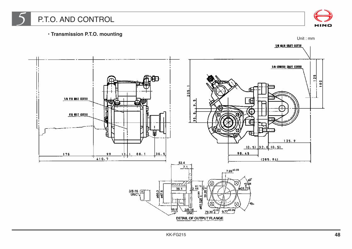
KK-FG215 48
P.T.O. AND CONTROL5• Transmission P.T.O. mounting
Unit : mm

P.T.O. AND CONTROL5
KK-FG215 49
••Layout•of•power•line
FL, FM8J
CHASSIS �MODEL
FRO
NT
AXLE
DAT
UM
LIN
E
ENG
INE
CEN
TER
FLYW
HEE
L �
HO
USI
NG
CLU
TCH
�H
OU
SIN
G
TRANSMISSION CASEDRIVE SHAFT CENTER
CRANKCASE
SIDE RAIL UPPER FACE
Unit : mm
A
270
B
217.6
C
3.5º�
D
394
E
173.5
F
176
G
567
A
BC
D E F G
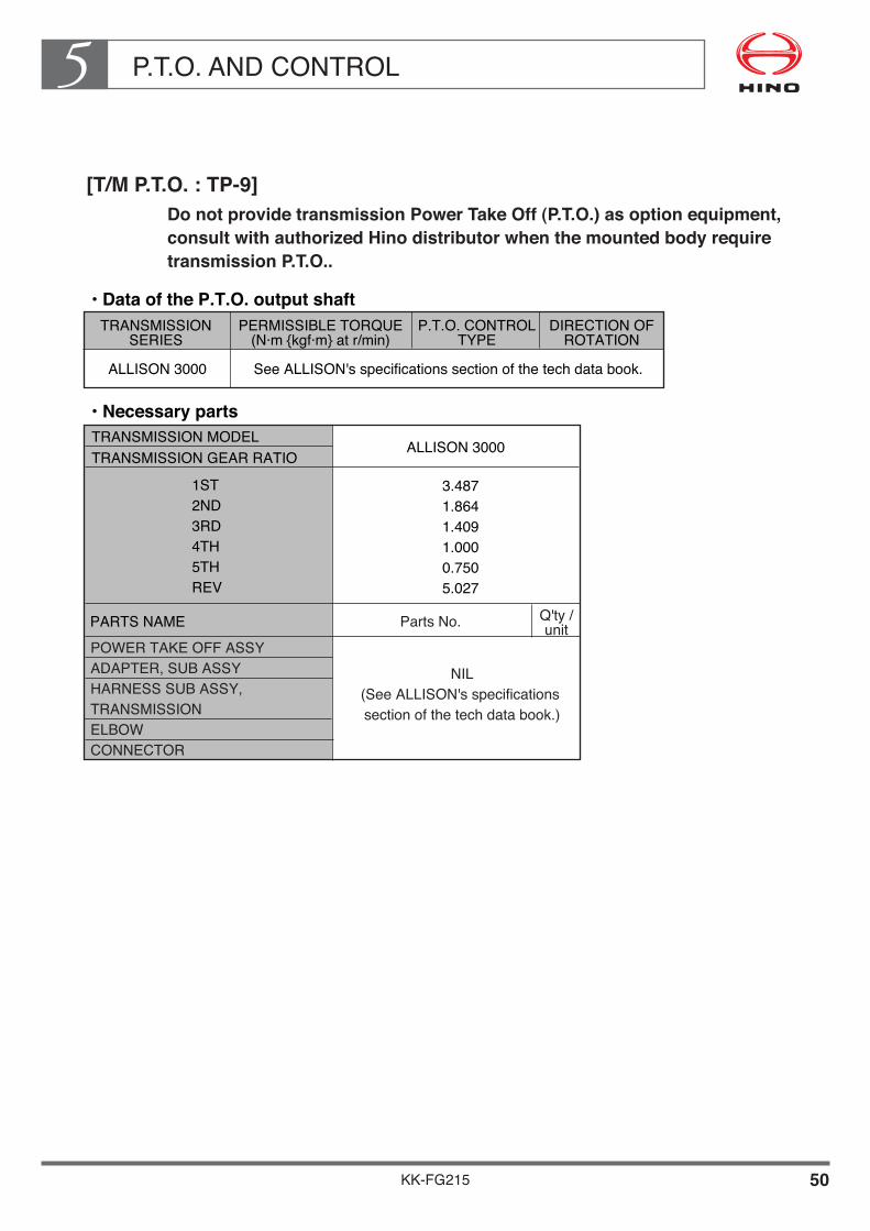
P.T.O. AND CONTROL5
KK-FG215 50
[T/M P.T.O. : TP-9]Do not provide transmission Power Take Off (P.T.O.) as option equipment, consult•with•authorized•Hino•distributor•when•the•mounted•body•require•transmission P.T.O..
••Data•of•the•P.T.O.•output•shaftTRANSMISSION�
SERIESPERMISSIBLE TORQUE�
(N·m {kgf·m} at r/min)P.T.O. CONTROL�
TYPEDIRECTION OF�
ROTATION
ALLISON 3000 See ALLISON's specifications section of the tech data book.
••Necessary•parts
TRANSMISSION GEAR RATIO
PARTS NAME
TRANSMISSION MODEL ALLISON 3000
3.487�1.864�1.409�1.000�0.750�5.027
1ST�2ND�3RD�4TH�5TH�REV
Parts No.
POWER TAKE OFF ASSY�ADAPTER, SUB ASSY�HARNESS SUB ASSY, �TRANSMISSION�ELBOW�CONNECTOR��
Q'ty /�unit
NIL�(See ALLISON's specifications �section of the tech data book.)
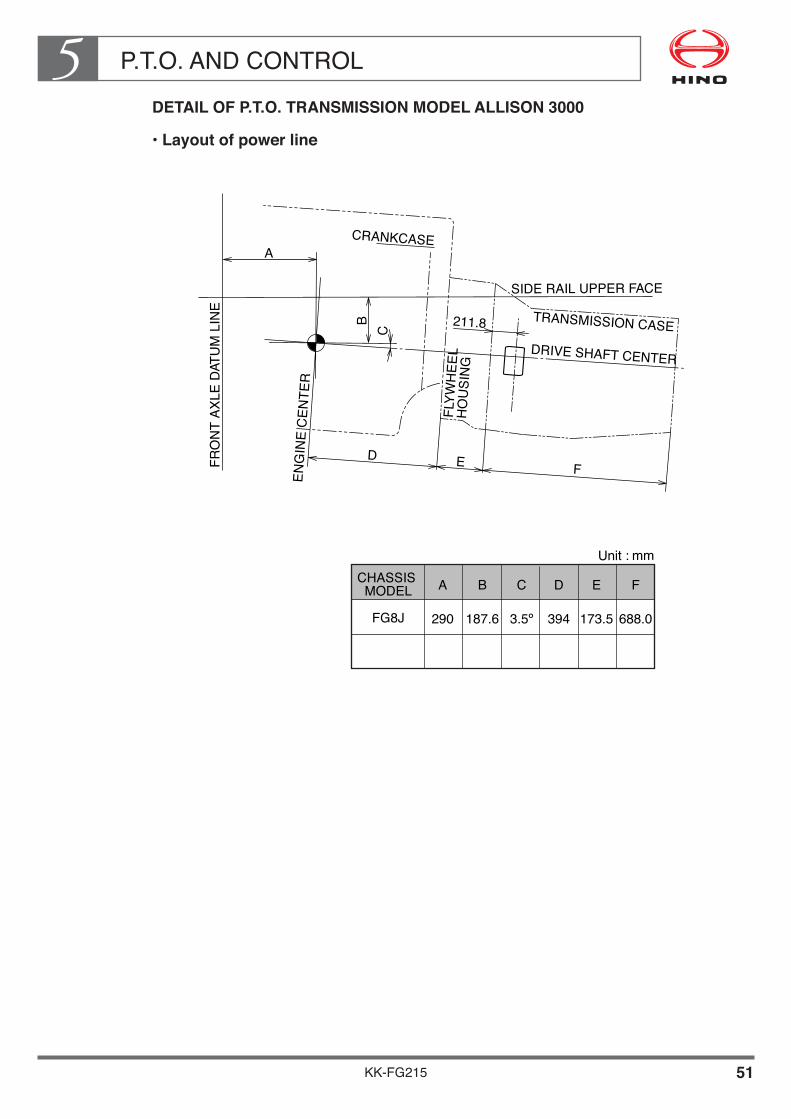
P.T.O. AND CONTROL5
KK-FG215 51
DETAIL OF P.T.O. TRANSMISSION MODEL ALLISON 3000
••Layout•of•power•line
FG8J
CHASSIS �MODEL
FRO
NT
AXLE
DAT
UM
LIN
E
ENG
INE
CEN
TER
FLYW
HEE
L �
HO
USI
NG
TRANSMISSION CASEDRIVE SHAFT CENTER
CRANKCASE
SIDE RAIL UPPER FACE
Unit : mm
A
290
B
187.6
C
3.5º�
D
394
E
173.5
F
688.0
A
BC
D E F
211.8

KK-FG215 52
P.T.O. AND CONTROL5• Mounting position of transmission P.T.O. ass'y for ALLISON 3000
• Provision of P.T.O. must only be left side.• Torques shown for customer-furnished fasteners and threaded components are
for plain (non-plated) threads. Torque requirements should be reviewed if plated items will be used. Consult the supplier.
P.T.O. output speed (rpm) : Engine speed x x
• For P.T.O. gear torque ratings. See transmission specifications section of the tech data book.
Drive gearDriven gear
P.T.O. input gearP.T.O. output gear
Unit : mm

P.T.O. AND CONTROL5
KK-FG215 53
[T/M P.T.O. : TP-10]Do not provide transmission Power Take Off (P.T.O.) as option equipment, consult•with•authorized•Hino•distributor•when•the•mounted•body•require•transmission P.T.O..
••Data•of•the•P.T.O.•output•shaftTRANSMISSION�
SERIESPERMISSIBLE TORQUE�
(N·m {kgf·m} at r/min)P.T.O. CONTROL�
TYPEDIRECTION OF�
ROTATION
ALLISON 3500 See ALLISON's specifications section of the tech data book.
••Necessary•parts
TRANSMISSION GEAR RATIO
PARTS NAME
TRANSMISSION MODEL ALLISON 3500
4.593�2.257�1.535�1.000�0.749�0.651�4.999
1ST�2ND�3RD�4TH�5TH�6TH�REV
Parts No.
POWER TAKE OFF ASSY�ADAPTER, SUB ASSY�HARNESS SUB ASSY, �TRANSMISSION�ELBOW�CONNECTOR��
Q'ty /�unit
NIL�(See ALLISON's specifications �section of the tech data book.)

P.T.O. AND CONTROL5
KK-FG215 54
DETAIL OF P.T.O. TRANSMISSION MODEL ALLISON 3500
••Layout•of•power•line
FM8J
CHASSIS �MODEL
FRO
NT
AXLE
DAT
UM
LIN
E
ENG
INE
CEN
TER
FLYW
HEE
L �
HO
USI
NG
TRANSMISSION CASEDRIVE SHAFT CENTER
CRANKCASE
SIDE RAIL UPPER FACE
Unit : mm
A
270
B
217.6
C
3.5º�
D
394
E
173.5
F
688
A
BC
D E F
211.8

KK-FG215 55
P.T.O. AND CONTROL5• Mounting position of transmission P.T.O. ass'y for ALLISON 3500
• Provision of P.T.O. must only be left side.• Torques shown for customer-furnished fasteners and threaded components are
for plain (non-plated) threads. Torque requirements should be reviewed if plated items will be used. Consult the supplier.
P.T.O. output speed (rpm) : Engine speed x x
• For P.T.O. gear torque ratings. See transmission specifications section of the tech data book.
Unit : mm
Drive gearDriven gear
P.T.O. input gearP.T.O. output gear
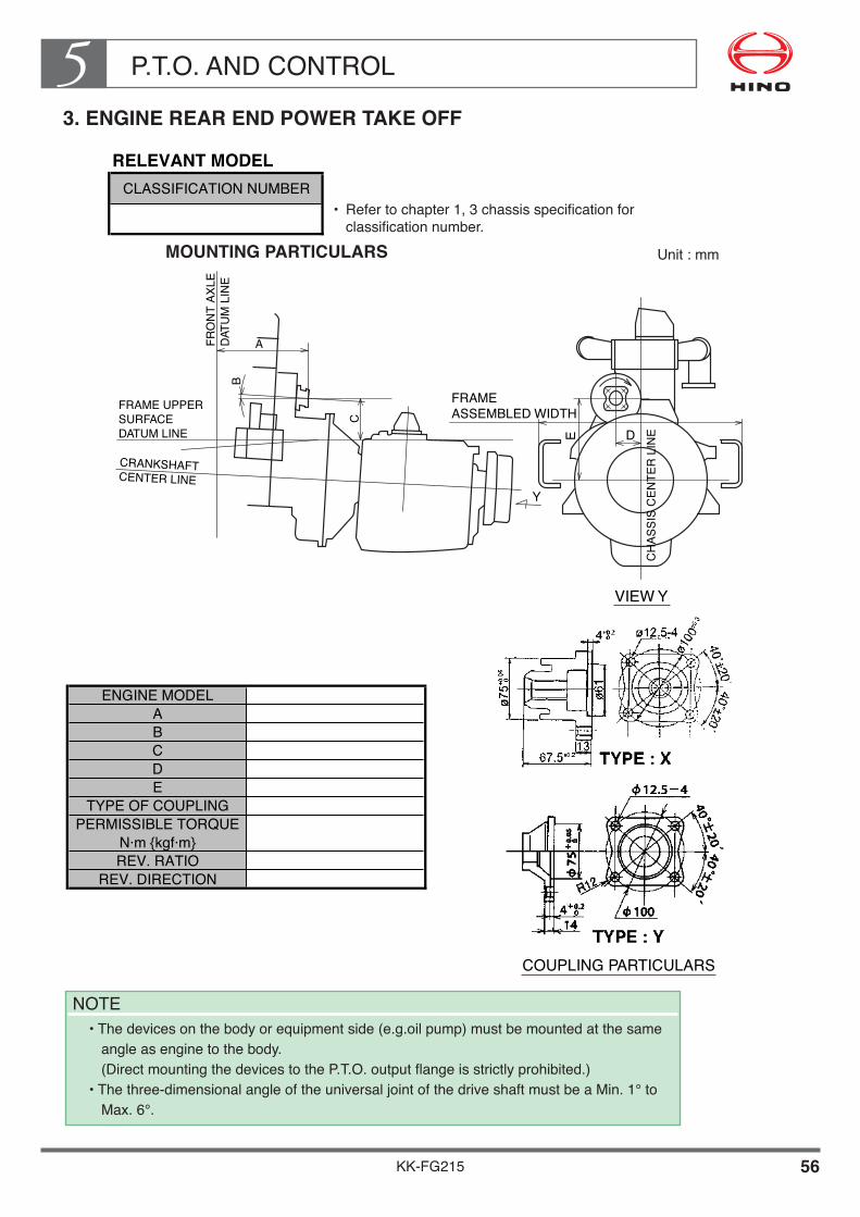
P.T.O. AND CONTROL5
KK-FG215 56
3. ENGINE REAR END POWER TAKE OFF
MOUNTING PARTICULARS Unit : mm
FRAME UPPER �SURFACE�DATUM LINE
FRO
NT
AXLE
�DA
TUM
LIN
E
CRANKSHAFT �CENTER LINE
A
B
C
Y
VIEW Y
COUPLING PARTICULARS
CH
ASSI
S C
ENTE
R L
INEE D
FRAME �ASSEMBLED WIDTH
ENGINE MODELABCDE
TYPE OF COUPLINGPERMISSIBLE TORQUE
N·m {kgf·m}REV. RATIO
REV. DIRECTION
RELEVANT MODELCLASSIFICATION NUMBER
NOTE• The devices on the body or equipment side (e.g.oil pump) must be mounted at the same
angle as engine to the body. (Direct mounting the devices to the P.T.O. output flange is strictly prohibited.)
• The three-dimensional angle of the universal joint of the drive shaft must be a Min. 1° to Max. 6°.
• Refer to chapter 1, 3 chassis specification for classification number.
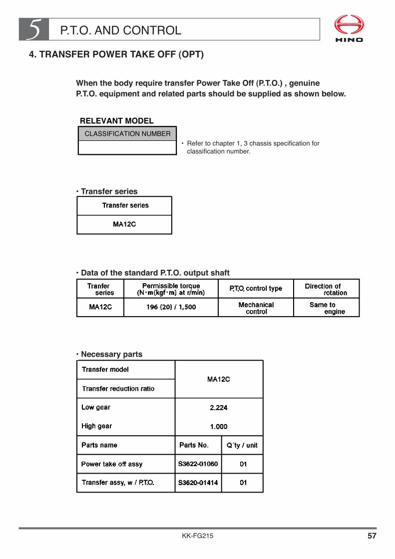
P.T.O. AND CONTROL5
KK-FG215 57
4. TRANSFER POWER TAKE OFF (OPT)
When the body require transfer Power Take Off (P.T.O.) , genuine P.T.O. equipment and related parts should be supplied as shown below.
••Transfer•series
••Data•of•the•standard•P.T.O.•output•shaft
••Necessary•parts
RELEVANT MODELCLASSIFICATION NUMBER
• Refer to chapter 1, 3 chassis specification for classification number.

KK-FG215 58
P.T.O. AND CONTROL5• Transfer P.T.O. mounting
Unit : mm

KK-FG215 59
P.T.O. AND CONTROL5• Transfer P.T.O. particulars
Unit : mm

KK-FG215 60
P.T.O. AND CONTROL5• Cautions for P.T.O.
Example layout of P.T.O. drive shaft is shown following figure.Make sure to details of cautions to be installed P.T.O. drive shaft as following page.
Unit : mm

P.T.O. AND CONTROL5
KK-FG215 61
Caution when installing the propeller shaft for T/F P.T.O.
Be sure to observe the following indications.
• Fitting a pulley or a sprocket directly to the output shaft of transfer P.T.O. is strictly prohibited.
• An oil pump, a pulley or a sprocket wheel should be supported properly with the support bracket which is fixed firmly to the mounted body.
• Indications for power taking out should be followed as the indicated below.
Length of drive shaft
To reduce the vibration of drive shaft during operation, HINO recommend that the drive shaft length should be less than the value shown in the table. If body builder must make the shaft which is longer than the value shown in the table, fit a center bearing for the reduction of excessive vibration.
NOTE• The support bracket for center bearing should be fixed on the mounted body.
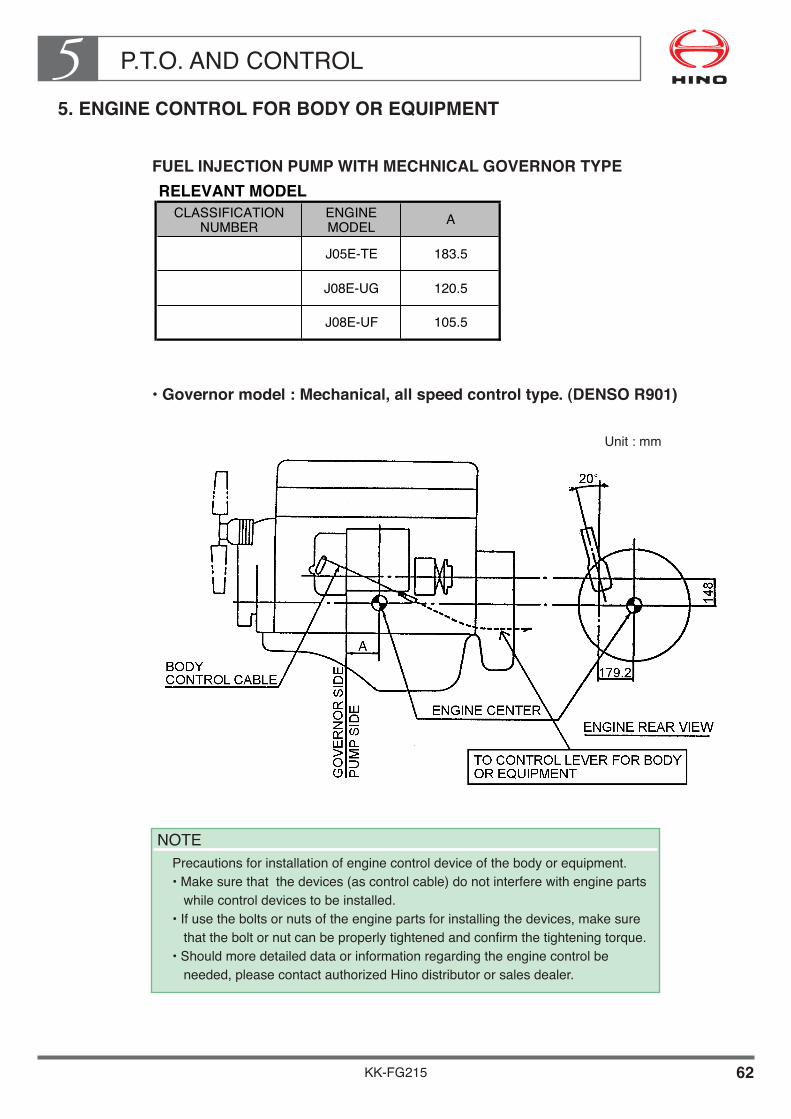
P.T.O. AND CONTROL5
KK-FG215 62
5. ENGINE CONTROL FOR BODY OR EQUIPMENT
FUEL INJECTION PUMP WITH MECHNICAL GOVERNOR TYPE
••Governor•model•:•Mechanical,•all•speed•control•type.•(DENSO•R901)
RELEVANT MODEL
183.5
120.5
105.5
J05E-TE
J08E-UG
J08E-UF
ACLASSIFICATIONNUMBER
ENGINEMODEL
NOTEPrecautions for installation of engine control device of the body or equipment.• Make sure that the devices (as control cable) do not interfere with engine parts
while control devices to be installed.• If use the bolts or nuts of the engine parts for installing the devices, make sure
that the bolt or nut can be properly tightened and confirm the tightening torque.• Should more detailed data or information regarding the engine control be
needed, please contact authorized Hino distributor or sales dealer.
Unit : mm

KK-FG215 63
P.T.O. AND CONTROL5• Governor lever for body control
Engine Model : J05E-TEUnit : mm

KK-FG215 64
P.T.O. AND CONTROL5• Governor lever for body control
Engine Model : J08E-UG & J08E-UFUnit : mm

P.T.O. AND CONTROL5
KK-FG215 65
ENGINE MODEL : P11C-UB
••Governor•model•:•Mechanical,•all•speed•control•type.•(BOSCH•RLD-J)
NOTEPrecautions for installation of engine control device of the body or equipment.• Make sure that the devices (as control cable) do not interfere with engine parts
while control devices to be installed.• If use the bolts or nuts of the engine parts for installing the devices, make sure
that the bolt or nut can be properly tightened and confirm the tightening torque.• Should more detailed data or information regarding the engine control be
needed, please contact authorized Hino distributor or sales dealer.
Unit : mm
RELEVANT MODELCLASSIFICATION NUMBER
• Refer to chapter 1, 3 chassis specification for classification number.

P.T.O. AND CONTROL5
KK-FG215 66
••Governor•lever•for•body•control
Engine Model : P11C-UB

P.T.O. AND CONTROL5
KK-FG215 67
••HOW•TO•INSTALL•THE•ENGINE•CONTROL•LINKAGES•FROM ENGINE INJECTION PUMP (ENGINE MODEL P11C-UB ONLY)
If body builder wants to install the engine control cable or linkage to engine, prepare the following parts.
• Speed meter cable (or the like)• Flared nuts for fixing the outer sheath of above control cable• Cable holder (clip) for holding outer sheath of above cable• Cable end connectors (crevice pins or the like)• Steel sheet (or small brackets) for supporting brackets of above cable• Etc.

P.T.O. AND CONTROL5
KK-FG215 68
••ENGINE•CONTROL•FOR•BODY
If you intend to fit a device to control engine revolutions when working with a body or equipment, make sure that the device is able to absorb the relative movement between the engine and the chassis (mounting of control lever for body or equipment, etc.). If the mechanism cannot absorb the relative motion, the control lever of the injection pump may be moved by the normal vibration of the engine (displacement) and abnormal vibrations may arise.
RELATIVE MOVEMENT OF ENGINE AND CHASSIS ABSORBED
RELATIVE MOVEMENT OF ENGINE AND CHASSIS NOT ABSORBED

P.T.O. AND CONTROL5
KK-FG215 69
U-2 FUEL INJECTION TYPE
ENGINE CONTROL
Hino engine is controlled by computer (hereinafter termed E/G ECU).
Take following measure when engine speed to be controlled for body or equipment installation.
••KIND•OF•METHOD
RELEVANT MODEL
CLASSIFICATION NUMBER ENGINE MODEL
J05D-TG
J05E-TC
J05E-TD
FG-058 J08E-UB
J08E-UC
J08E-UD
J08E-UE
J08E-TB
J08E-TE
A09C-TE
Device Range to be controlledengine speed Provision of device
Idle up switchIdle to 980 rpm(Can be controlled constant revo. Only)
To be provided bybody manufacturer
Engine acceleratorIdle to Max. revolution(Can be controlled variable revo.)
Related parts to be provided byoptional equipment
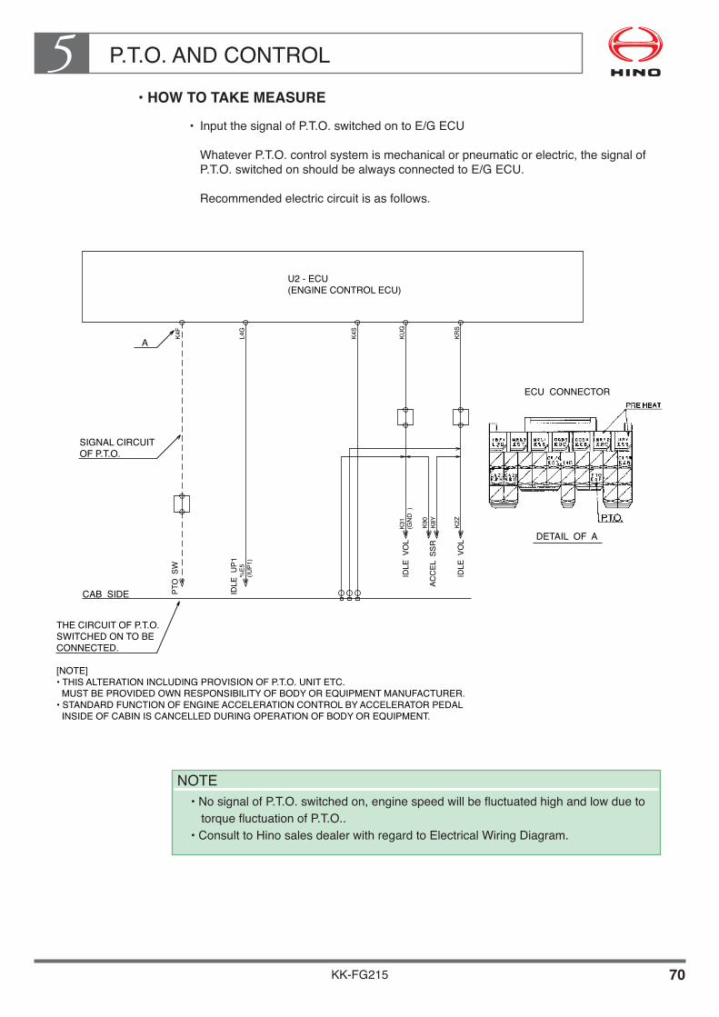
P.T.O. AND CONTROL5
KK-FG215 70
••HOW•TO•TAKE•MEASURE
• Input the signal of P.T.O. switched on to E/G ECU
Whatever P.T.O. control system is mechanical or pneumatic or electric, the signal of P.T.O. switched on should be always connected to E/G ECU.
Recommended electric circuit is as follows.
U2 - ECU�(ENGINE CONTROL ECU)
PTO
SW
%E5
K4F
L4G
K4S
KUG
KRS
K90
K8Y
K2Z
(IUP1
)
K31
(GN
D )
IDLE
UP1
IDLE
VO
L
IDLE
VO
L
ACC
EL S
SR
CAB SIDE
A
SIGNAL CIRCUIT�OF P.T.O.
THE CIRCUIT OF P.T.O.�SWITCHED ON TO BE�CONNECTED.
[NOTE]�• THIS ALTERATION INCLUDING PROVISION OF P.T.O. UNIT ETC.� MUST BE PROVIDED OWN RESPONSIBILITY OF BODY OR EQUIPMENT MANUFACTURER.�• STANDARD FUNCTION OF ENGINE ACCELERATION CONTROL BY ACCELERATOR PEDAL� INSIDE OF CABIN IS CANCELLED DURING OPERATION OF BODY OR EQUIPMENT.
ECU CONNECTOR
DETAIL OF A
NOTE• No signal of P.T.O. switched on, engine speed will be fluctuated high and low due to
torque fluctuation of P.T.O..• Consult to Hino sales dealer with regard to Electrical Wiring Diagram.
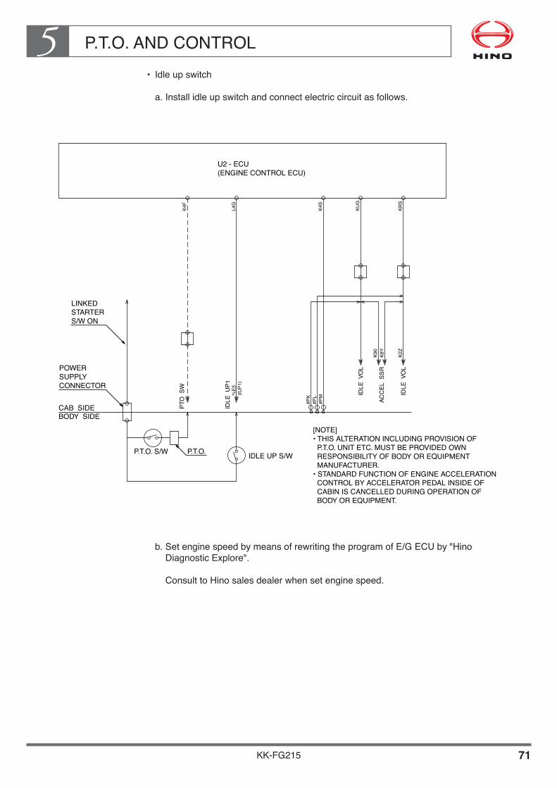
P.T.O. AND CONTROL5
KK-FG215 71
• Idle up switch
a. Install idle up switch and connect electric circuit as follows.
b. Set engine speed by means of rewriting the program of E/G ECU by "Hino Diagnostic Explore".
Consult to Hino sales dealer when set engine speed.
PTO
SW
%E5
#PK
#PL
#PM(IU
P1)
IDLE
UP1
IDLE
VO
L
IDLE
VO
L
ACC
EL S
SR
CAB SIDEBODY SIDE
LINKED�STARTER�S/W ON
POWER�SUPPLY�CONNECTOR
P.T.O. S/W P.T.O. IDLE UP S/W
[NOTE]�• THIS ALTERATION INCLUDING PROVISION OF � P.T.O. UNIT ETC. MUST BE PROVIDED OWN � RESPONSIBILITY OF BODY OR EQUIPMENT� MANUFACTURER.�• STANDARD FUNCTION OF ENGINE ACCELERATION CONTROL BY ACCELERATOR PEDAL INSIDE OF � CABIN IS CANCELLED DURING OPERATION OF � BODY OR EQUIPMENT.
U2 - ECU�(ENGINE CONTROL ECU)
L4G
K4S
KUG
KRS
K90
K8Y
K2Z
K4F

P.T.O. AND CONTROL5
KK-FG215 72
• Engine accelerator
a. Related parts, Engine accelerator unit and extension harness, are packed in cabin as optional equipment.
b. Connect the connector of Engine accelerator unit with spare connector which is provided forward No.2 crossmember at chassis frame LH side member.
Details of how to connect the connectors, see following figure.
• Other precautions
a. Conditions of change of E/G ECU to body or equipment control mode as following.
• Vehicle speed is Max. 20km/h or less. • Transmission shift position is neutral. • Engine speed is idling revolution. • Engine accelerator unit is idle position. • P.T.O. switch on signal is connected.
E/G ECU will be changed as body or equipment control mode with fully completed above conditions.
If a condition is loss, engine will run under normal vehicle operation to be controlled by accelerate pedal.
b. Details of installation of Engine accelerator to be controlled for body and equipment, refer to following page.

P.T.O. AND CONTROL5
KK-FG215 73
[HOW TO INSTALL ENGINE ACCELERATOR FOR BODY OR EQUIPMENT]
• Be sure to provide the body control lever with the full speed stopper for controlling the stroke of the sensor lever. In that case, adjust the body side stroke in such a way that the body side stopper comes in contact earlier than the sensor side stopper. The standard for adjustment is 1mm clearance between the sensor side lever and stopper under the condition than the body side lever touches the stopper. (See the following illustration.)
• Be sure to set the accelerator sensor lever that sensor lever should be contacted with idling stopper by adjusting body control lever while body or equipment do not operate (while vehicle is driving).
The clearance indicated for the stroke stopper of accelerator sensor is just for reference. If the sensor side stopper comes into contact earlier, a forcible stress will be imposed on the sensor shaft and it may result in the damage of the part in cause. Moreover if sensor lever do not came into contact with idling stopper may result in a bad condition of the engine while vehicle to be driving.

P.T.O. AND CONTROL5
KK-FG215 74
• When fitting the cable on the accelerator sensor lever, define the direction by pulling the cable parallelly to the direction of lever stroke so that an imbalanced load may not be imposed on the sensor shaft. (See the following illustration.)
• Cautiones when installing the Engine accelerator sensor (hereinafter termed the sensor).
• Never attempt to disassemble the sensor. Do not drop the sensor or do not shock it. Each above thing may lead malfunction and failure.
• The sensor is not integral waterproof type. Therefore, when installing it, pay attention to avoid the direct projection of vehicle washing water, tire splash etc.
• The usable range of temperature is -30~80°C. Use it in the said range.
• Avoid such places where there is risk of receiving falling matters or stones that give impact.
• Install the sensor where there is no possibility of exposing dust, oil mist, humidity, chemical product or vibration. If it is impossible to find such place, protect it with a cover.
• Install the wire harness certainly so that it may not twist or not bend extremely.
• For fitting and clipping the harness wires,refer to the COMMON manual.
• If the length of the sub-harness wire is too short, try to abtain the same kind of the harness wire for extension.
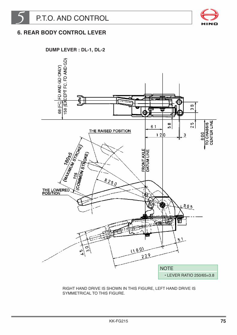
P.T.O. AND CONTROL5
KK-FG215 75
6. REAR BODY CONTROL LEVER
DUMP LEVER : DL-1, DL-2
RIGHT HAND DRIVE IS SHOWN IN THIS FIGURE, LEFT HAND DRIVE IS SYMMETRICAL TO THIS FIGURE.
NOTE• LEVER RATIO 250/65=3.8

P.T.O. AND CONTROL5
KK-FG215 76
MIXER LEVER : ML-1, ML-2
RIGHT HAND DRIVE IS SHOWN IN THIS FIGURE, LEFT HAND DRIVE IS SYMMETRICAL TO THIS FIGURE.
NOTE• LEVER RATIO 330/65=5.1

KK-FG215
Chapter 6ELECTRICAL SYSTEMS
1. FUSE BLOCK, RELAY PANEL AND FUSIBLE LINK BLOCK•••••••••••••••••••••••••••••••••••••• 1
2. SPARE POWER TERMINALS••••••••••••••••••••••••••••••••• 6 3. ELECTRIC WIRING OF SPARE OUTLET•••••••••••••••••• 11 4. PRECAUTION FOR INSTALLING WIRES, etc.,
TO CAB•••••••••••••••••••••••••••••••••••••••••••••••••••••••••• 15 5. REAR COMBINATION LAMP••••••••••••••••••••••••••••••••• 17 6. LICENSE PLATE LAMP•••••••••••••••••••••••••••••••••••••••• 18 7. BACK-UP BUZZER•••••••••••••••••••••••••••••••••••••••••••••• 19 8. ELECTRICAL WIRING DIAGRAMS••••••••••••••••••••••••• 20 9. SEMI-TRAILER ELECTRICAL CONNECTION•••••••••••• 21

ELECTRICAL SYSTEMS6
KK-FG215 1
1. FUSE BLOCK, RELAY PANEL AND FUSIBLE LINK BLOCK
LOCATION OF THE CAB SIDE
The fuse block and the relay panel are located inside the instrument panel as shown below.(The figure shown below is for RHD vehicle. LHD vehicle is symmetrical to this figure.)

ELECTRICAL SYSTEMS6
KK-FG215 2
Fuse block
NOTE• Be sure to use each capacity fuse designated in the above table. Never use the capacity fuse exceeding the designated one in the above, otherwise over current may damage the harness wires, and fusible linkage wires are in the same.• The figure mentioned above is example, consequently, for various particular items, check them on the actual vehicle.

ELECTRICAL SYSTEMS6
KK-FG215 3
Relay panel
••RHD•VEHICLE

ELECTRICAL SYSTEMS6
KK-FG215 4
••LHD•VEHICLE

ELECTRICAL SYSTEMS6
KK-FG215 5
LOCATION OF THE FUSIBLE LINK BLOCK
The fusible link block is located on left side of the cab rear arch as shown below.
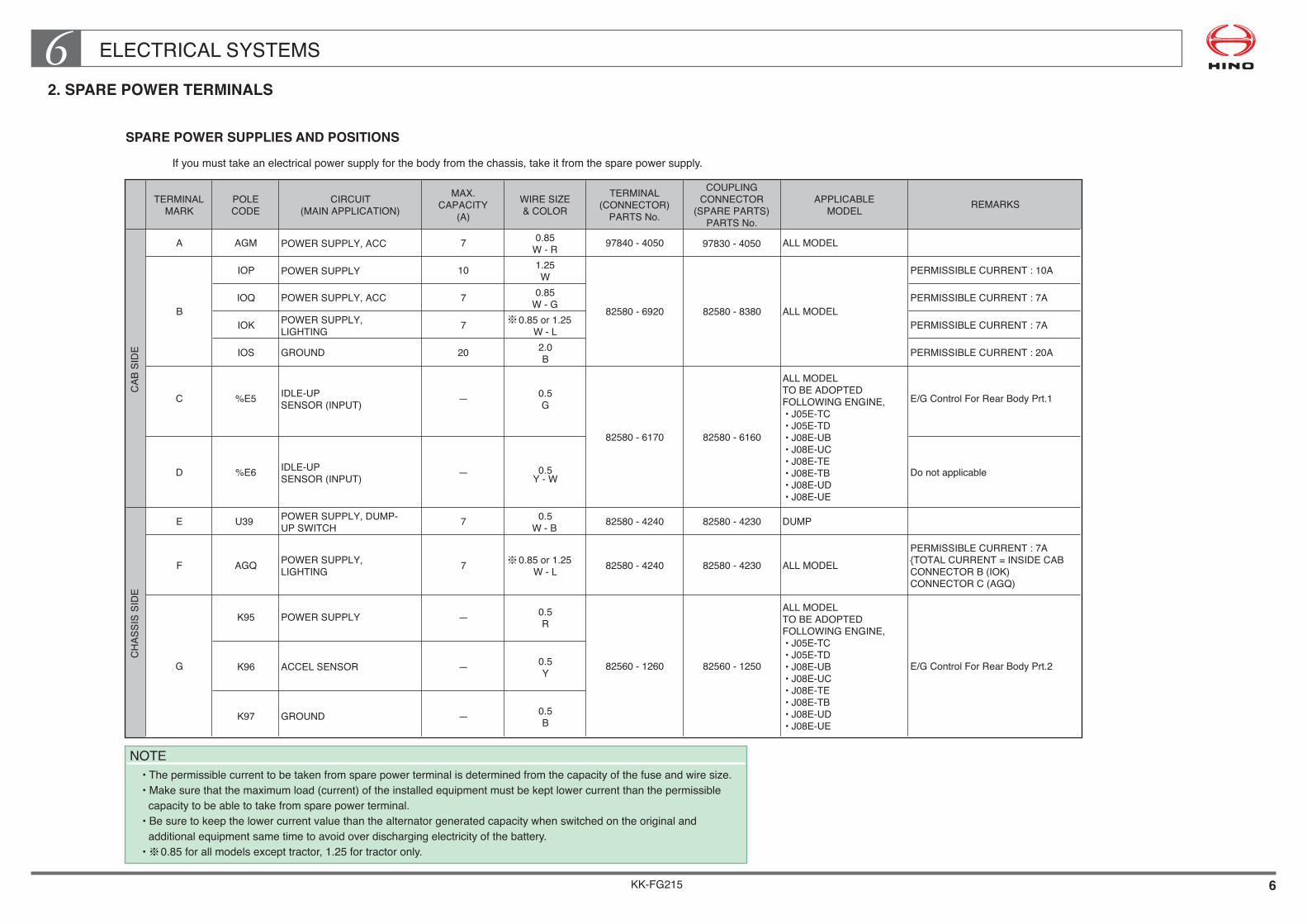
KK-FG215 6
ELECTRICAL SYSTEMS62. SPARE POWER TERMINALS
SPARE POWER SUPPLIES AND POSITIONS
If you must take an electrical power supply for the body from the chassis, take it from the spare power supply.
NOTE• The permissible current to be taken from spare power terminal is determined from the capacity of the fuse and wire size.• Make sure that the maximum load (current) of the installed equipment must be kept lower current than the permissible capacity to be able to take from spare power terminal.• Be sure to keep the lower current value than the alternator generated capacity when switched on the original and additional equipment same time to avoid over discharging electricity of the battery.• 0.85 for all models except tractor, 1.25 for tractor only.
TERMINALMARK
POLECODE
CIRCUIT(MAIN APPLICATION)
MAX.CAPACITY
(A)WIRE SIZE& COLOR
TERMINAL(CONNECTOR)
PARTS No.
COUPLINGCONNECTOR
(SPARE PARTS)PARTS No.
APPLICABLEMODEL REMARKS
A AGM POWER SUPPLY, ACC 7 0.85W - R 97840 - 4050 97830 - 4050 ALL MODEL
IOP POWER SUPPLY 10 1.25W PERMISSIBLE CURRENT : 10A
IOQ POWER SUPPLY, ACC 7 0.85W - G PERMISSIBLE CURRENT : 7A
IOK POWER SUPPLY,LIGHTING 7 0.85 or 1.25
W - L PERMISSIBLE CURRENT : 7A
IOS GROUND 20 2.0B PERMISSIBLE CURRENT : 20A
C %E5 IDLE-UPSENSOR (INPUT) — 0.5
G E/G Control For Rear Body Prt.1
D %E6 IDLE-UPSENSOR (INPUT) — 0.5
Y - W
82580 - 6170 82580 - 6160
Do not applicable
E U39 POWER SUPPLY, DUMP-UP SWITCH 7 0.5
W - B 82580 - 4240 82580 - 4230 DUMP
F AGQ POWER SUPPLY,LIGHTING 7 0.85 or 1.25
W - L 82580 - 4240 82580 - 4230 ALL MODELPERMISSIBLE CURRENT : 7A{TOTAL CURRENT = INSIDE CABCONNECTOR B (IOK)CONNECTOR C (AGQ)
K95 POWER SUPPLY — 0.5R
K96 ACCEL SENSOR — 0.5Y
K97 GROUND — 0.5B
B 82580 - 6920
CAB
SID
EC
HAS
SIS
SID
E
G 82560 - 1260
ALL MODELTO BE ADOPTEDFOLLOWING ENGINE, • J05E-TC • J05E-TD • J08E-UB • J08E-UC • J08E-TE • J08E-TB • J08E-UD • J08E-UE
E/G Control For Rear Body Prt.2
ALL MODELTO BE ADOPTEDFOLLOWING ENGINE, • J05E-TC • J05E-TD • J08E-UB • J08E-UC • J08E-TE • J08E-TB • J08E-UD • J08E-UE
82580 - 8380 ALL MODEL
82560 - 1250

ELECTRICAL SYSTEMS6
KK-FG215 7
OUTLET POSITION INSIDE CAB
••Center•of•instrument•panel
This figure is for RHD vehicle. LHD vehicle is symmetrical this figure.
POWER SUPPLY, ACC�POWER SUPPLY, LIGHTNING�GROUND POWER SUPPLY, DIRECT�TO BATTERYPOWER SUPPLY, ACC
A B
C (WIRE COLOR : GREEN)
D (DO NOT APPLICABLE)
�IDLE UP

ELECTRICAL SYSTEMS6
KK-FG215 8
OUTLET POSITION OF CHASSIS SIDE
HOW TO TAKE ELECTRICITY FROM POWER SUPPLY CIRCUIT
NOTE• As far as possible take power using sub-harness type.• If you must take power using direct connecting type, be sure to observe the precautions in described item “ELECTRICAL EQUIPMENT AND WIRING” of Common Manual.
No.2 CROSSMEMBER
POWER SUPPLY, LIGHTING
FRAME SIDE RAIL
POWER SUPPLY, DUMP-UP S/W
FRONT
F
E
ACCEL SENSOR
G

ELECTRICAL SYSTEMS6
KK-FG215 9
DETAIL OF CONNECTOR
••Cab•side
A
PARTS No. 97830 - 4050PARTS No. 97840 - 4050
AGM
PARTS No. 82580 - 6920 PARTS No. 82580 - 8380
12
4 3
ACCIOQ
ILLIOK
GNDIOS
+BIOPB
PARTS No. 82580 - 6170 PARTS No. 82580 - 6160
C
CONNECTOR
VEHICLE SIDE COMPANION SIDE
%E5 1
PARTS No. 82580 - 6170 PARTS No. 82580 - 6160
D%E6 1

ELECTRICAL SYSTEMS6
KK-FG215 10
• Chassis side
CONNECTOR
VEHICLE SIDE COMPANION SIDE
F
E1ON
U39
1AGQ
PARTS No. 82580 - 4230PARTS No. 82580 - 4240
PARTS No. 82580 - 4230PARTS No. 82580 - 4240
PARTS No. 82560 - 1250PARTS No. 82560 - 1260
G
VCCK95
SIGK96
GNDK97
2 1
4 3

ELECTRICAL SYSTEMS6
KK-FG215 11
3. ELECTRIC WIRING OF SPARE OUTLET
STANDARD WIRING CONFIGURATION
WIRING CONFIGURATION FOR INCREASED LOAD
TAKING POWER DIRECTLY FROM THE BATTERY
If you intend to take power for the body directly from the battery, secure the battery cable and the body power supply terminal together with the same nut (see drawing).In this case, you must install a fuse at a suitable point in the circuit and take precautions to prevent short circuits as these may lead vehicle fires.When securing the cable and power terminal, make sure you tighten the nut properly.

ELECTRICAL SYSTEMS6
KK-FG215 12
INSTALLATION OF ADDITIONAL EQUIPMENT AND SWITCHES
Layout•of•switches
• Standard layout of switches include option equipment are as following figure.• If you intend to install additional switches at instrument panel for the convenience of
body mounting, be sure to install it at empty space after confirmation of original condition on the actual vehicle.
• If you install additional switches, fit a caution plate showing the purpose of each switch, etc., to prevent accidental operation or confirmation.
RHD•VEHICLE
••Instrument•panel
Avoid•using•additional•switches•with•existing•switches
No. DESCRIPTION APPLICATION123456789
1011
1314
16171819
IDLE VOLUME SWICH STD (FOR VEHICLE WITH ENGINE TO BE CONTROLLED ECU ONLY)POWER WINDOW SWITCH (RH)�POWER WINDOW SWITCH (LH)
INSTALLATION BY VEHICLE SPECIFICATIONINSTALLATION BY VEHICLE SPECIFICATIONINSTALLATION BY VEHICLE SPECIFICATION
INSTALLATION BY VEHICLE SPECIFICATION
INSTALLATION BY VEHICLE SPECIFICATION
INSTALLATION BY VEHICLE SPECIFICATION
INSTALLATION BY VEHICLE SPECIFICATION
INSTALLATION BY VEHICLE SPECIFICATION
STD
STD
STD
OPTHEAD LAMP LEVELING SWITCHPARKING LAMP SWITCHFRONT FOG LAMP SWITCH
FRONT DRIVE OR TRAILER HAND BRAKE SWITCH�T/M PTO SWITCH
DIFF LOCK OR 2-SPEED HI/LO SWITCHCIGAR LIGHTERES START SWITCH
BRAKE LOCK OR AIR SUSPENSION SWITCHHOOK
12
15
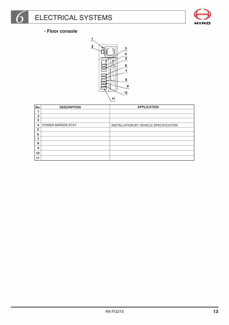
ELECTRICAL SYSTEMS6
KK-FG215 13
••Floor•console
No. DESCRIPTION APPLICATION123456789
POWER MIRROR STAY INSTALLATION BY VEHICLE SPECIFICATION
1011
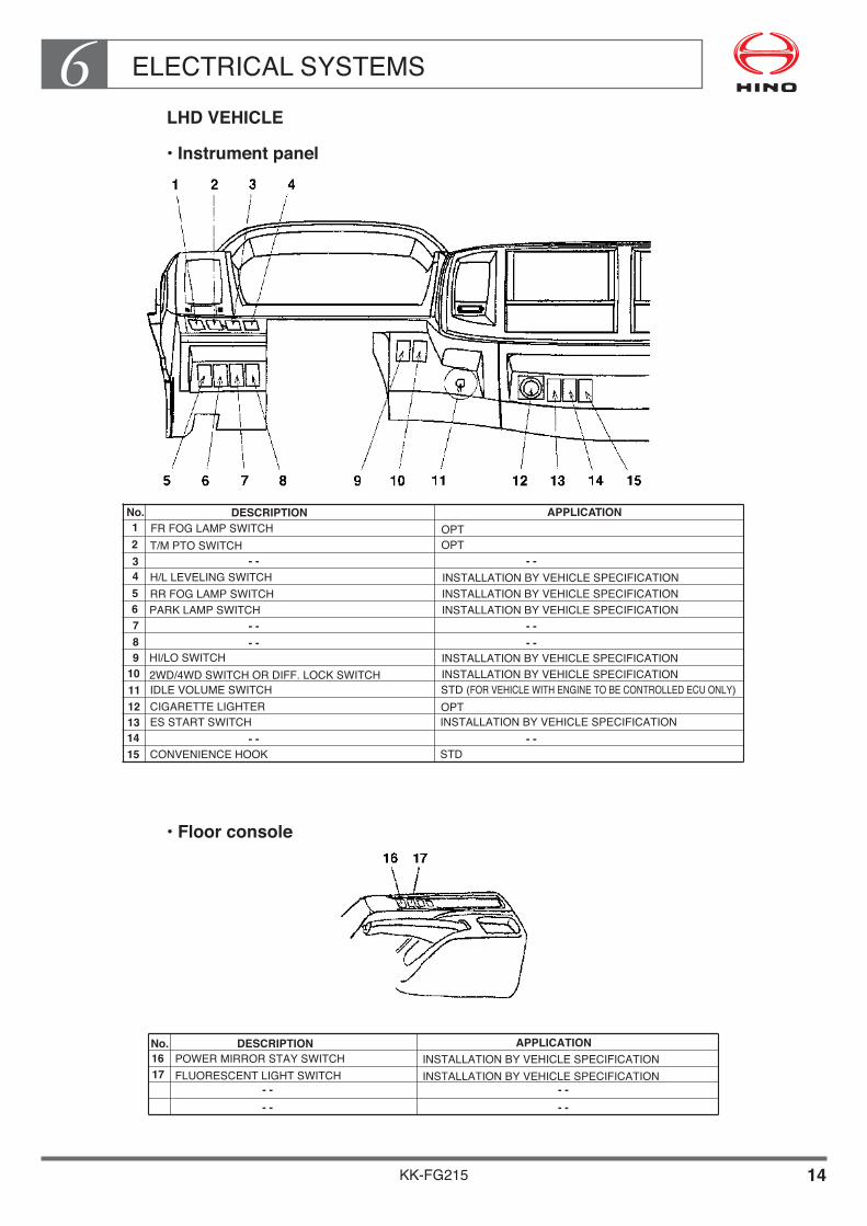
ELECTRICAL SYSTEMS6
KK-FG215 14
LHD•VEHICLE
••Instrument•panel
••Floor•console
No. DESCRIPTION APPLICATION123456789
1011
1314
FR FOG LAMP SWITCH OPTT/M PTO SWITCH� - - - -
- - - -- - - -
- - - -
OPT
INSTALLATION BY VEHICLE SPECIFICATION
INSTALLATION BY VEHICLE SPECIFICATIONINSTALLATION BY VEHICLE SPECIFICATIONSTD (FOR VEHICLE WITH ENGINE TO BE CONTROLLED ECU ONLY)
INSTALLATION BY VEHICLE SPECIFICATION
STD
INSTALLATION BY VEHICLE SPECIFICATIONINSTALLATION BY VEHICLE SPECIFICATION
H/L LEVELING SWITCHRR FOG LAMP SWITCHPARK LAMP SWITCH
HI/LO SWITCH
OPT
2WD/4WD SWITCH OR DIFF. LOCK SWITCH�IDLE VOLUME SWITCHCIGARETTE LIGHTERES START SWITCH
CONVENIENCE HOOK
12
15
No. DESCRIPTION APPLICATION1617
POWER MIRROR STAY SWITCH INSTALLATION BY VEHICLE SPECIFICATIONFLUORESCENT LIGHT SWITCH INSTALLATION BY VEHICLE SPECIFICATION
- - - -- - - -
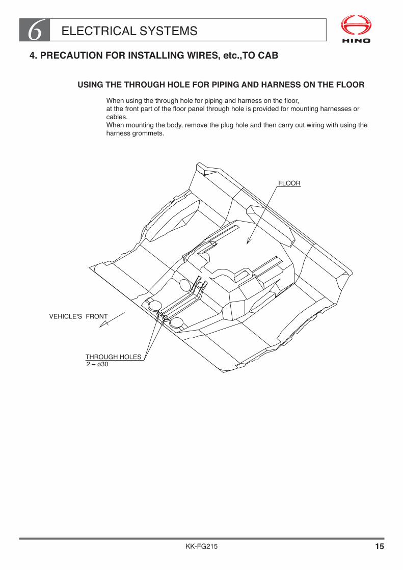
ELECTRICAL SYSTEMS6
KK-FG215 15
4. PRECAUTION FOR INSTALLING WIRES, etc.,TO CAB
USING THE THROUGH HOLE FOR PIPING AND HARNESS ON THE FLOOR
When using the through hole for piping and harness on the floor,at the front part of the floor panel through hole is provided for mounting harnesses or cables.When mounting the body, remove the plug hole and then carry out wiring with using the harness grommets.
VEHICLE'S FRONT
THROUGH HOLES2 – ø30
FLOOR

ELECTRICAL SYSTEMS6
KK-FG215 16
USING THROUGH HOLE OF BACK PANEL FOR WIRING
When using through hole of back panel for wiring, to secure the rust prevention and water proof before the said taken-in, carry out fitting and wiring according to the following instructions.
• A through hole of ø 36 is provided on the back panel but it is closed with a grommet.Make a slit on this grommet and, after the wiring, sufficiently seal its periphery with a sealing agent.
• In order to secure the water proofness, lower the wiring once as shown on “ Section A - A ” to drain the water and after that bring the wiring into the cab.
• It is prohibited to fix the wiring with a tapping screw etc., because this can be a cause of penetration of rust.
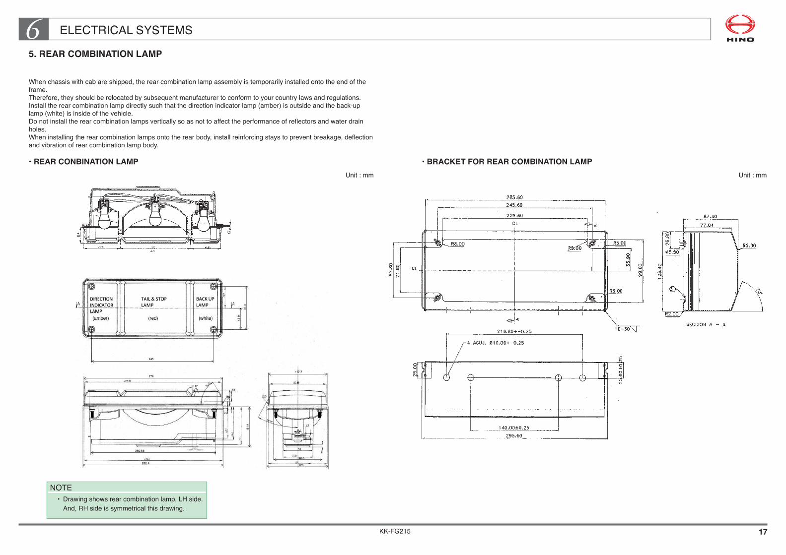
KK-FG215 17
ELECTRICAL SYSTEMS65. REAR COMBINATION LAMP
When chassis with cab are shipped, the rear combination lamp assembly is temporarily installed onto the end of the frame.Therefore, they should be relocated by subsequent manufacturer to conform to your country laws and regulations.Install the rear combination lamp directly such that the direction indicator lamp (amber) is outside and the back-up lamp (white) is inside of the vehicle.Do not install the rear combination lamps vertically so as not to affect the performance of reflectors and water drain holes.When installing the rear combination lamps onto the rear body, install reinforcing stays to prevent breakage, deflection and vibration of rear combination lamp body.
• REAR CONBINATION LAMPUnit : mm
• BRACKET FOR REAR COMBINATION LAMPUnit : mm
NOTE• Drawingshowsrearcombinationlamp,LHside. And,RHsideissymmetricalthisdrawing.
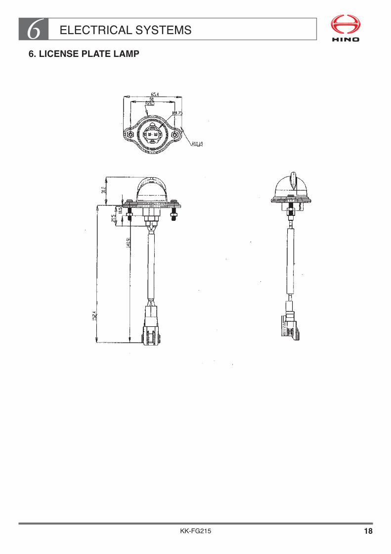
ELECTRICAL SYSTEMS6
KK-FG215 18
6. LICENSE PLATE LAMP

ELECTRICAL SYSTEMS6
KK-FG215 19
7. BACK-UP BUZZER
If move the back-up buzzer or modify the around parts of back-up buzzer on the chassis, be sure to observe the following precautions.
Installation•angle
• Must be kept the permissible range of installing angles shown in the figure below.• If the installing angle is not within range, water will accumulate inside the buzzer and
may lead to failure.
Installation•area
• Should install the buzzer the area which is the muddy water, rainwater and stone do not splash.
Precaution•for•painting
• Should put a cover on the buzzer during painting to prevent the paint into it for avoiding failure of no sound.
Unit : mm

ELECTRICAL SYSTEMS6
KK-FG215 20
8. ELECTRICAL WIRING DIAGRAMS
This manual does not contain electrical wiring diagrams.The electrical wiring diagrams are in the WORKSHOP MANUAL.For more details, please contact authorized Hino distributor.
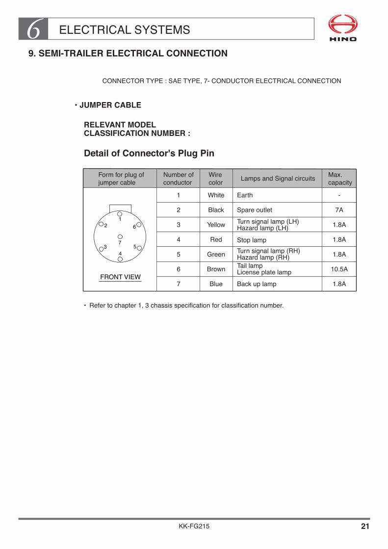
ELECTRICAL SYSTEMS6
KK-FG215 21
9. SEMI-TRAILER ELECTRICAL CONNECTION
CONNECTOR TYPE : SAE TYPE, 7- CONDUCTOR ELECTRICAL CONNECTION
••JUMPER•CABLE
Form for plug of �jumper cable
Number of �conductor Lamps and Signal circuits
1 Earth
2 Spare outlet
3 Turn signal lamp (LH) �Hazard lamp (LH)
4 Stop lamp
5 Turn signal lamp (RH)�Hazard lamp (RH)
6 Tail lamp�License plate lamp
7
Wire�color
White
Black
Yellow
Red
Green
Brown
Blue Back up lamp
Max. �capacity
-
1.8A
10.5A
1.8A
1.8A
1.8A
7A
FRONT VIEW
43 5
621
7
RELEVANT•MODEL CLASSIFICATION NUMBER :
Detail•of•Connector's•Plug•Pin
• Refer to chapter 1, 3 chassis specification for classification number.

KK-FG215
Chapter 7PAINTING
1. GENERAL PRECAUTIONS FOR PAINTING••••••••••••••• 1 2. NOTE ON THE TOP COAT OF PAINT••••••••••••••••••••••• 4 3. HOW TO REMOVE THE PARTS OF CAB•••••••••••••••••• 5 4. PROCEDURE FOR ADHERING ORNAMENTS••••••••••• 15 5. MOUNTING AND STICKING OF DOOR
WEATHER STRIP••••••••••••••••••••••••••••••••••••••••••••• 17 6. HOW TO MOUNT THE MAIN AND SUB SEAL•••••••••••• 19 7. CAUTIONS FOR PAINTING TILT CYLINDER ROD•••••• 22 8. HANDLING OF LAMINATED WINDSHIELD••••••••••••••• 23 9. HANDLING OF COMPUTERS (ECU)•••••••••••••••••••••••• 24 10. PRECAUTIONS FOR FITTING AND STORING
THE CAUTION PLATE••••••••••••••••••••••••••••••••••••••• 25 11. CAUTIONS FOR PAINTING
THE TIRE DISC WHEELS••••••••••••••••••••••••••••••••••• 26

PAINTING7
KK-FG215 1
1. GENERAL PRECAUTIONS FOR PAINTING
When you apply finish paint to the cab etc. observe the following precautions.
Some parts of the cab and chassis are sensitive to heat of the drying, some parts must not be painted and so require masking, etc.
GENERAL PRECAUTIONS FOR PAINTING
• Partstobemasked: Parts that must not be painted-ornaments, name plates (model names, Hino logo mark chassis number), caution plate, etc. must all be masked. (It is possible to take off the top mark.) Never paint the rubber hoses and nylon tubes or valves, the brake booster, or hoses or valves of the brake fluid reservoir.
• Ifyougetpaintonthecabcompartment,wipeitcleanwithgasoline. Never use thinner.
• Ifthebodyoftheaircleanerhasbeentakenout,sealofftheengineintakeport completely so that paint and dirt do not get in. When you replace the body of the air cleaner, make sure that the hose is properly fitted and securely clamped.
• Coverthebattery,wiringconnectionsandhosestoprotectthemfrompaint.
• Whencleaninsideofthecab,mustbecleanitwithaneutraldetergent. Never use gasoline and paint thinner.
• Payattentionwhendismountingandremovingthecabexteriorfittings. Theboltsthatthreaddiameterexceeds6mmtobetightentheexteriorpartsofthecabbodyhavebeenmodifiedfrom“+typescrewbolt”to“startypebolt(torxbolt)”inorderto improve stabilization of tightening torque and avoiding the damage of tool groove. Usepropertoolstofitwith“torxbolt”.
• Precautionforpreventpaintingtheresincoveroffuelprefilter If painted the resin cover of fuel pre filter, there will be a crack in the resin cover, then it may occur serious problems such as leaking of fuel and the engine hasn't started by suck the air. Therefore, make sure the following manner.
NOTES •Whenpainting,shouldputamaskcompletelyontheresincover. •Whenpainting,ifpaintedtheresincover,itneedreplaceanewone.
(There is nothing changed shortly after painted the resin cover but it may be a crack in resin cover proceed with time.)

PAINTING7
KK-FG215 2
GENERAL PRECAUTIONS FOR FORCED DRYING
• Whenyouuseforceddrying,atemperatureonthesurfaceofanypartstobepaintedmustbe80°Casanupperlimit.Removingoffanyplasticparts,rubberpartsfromthevehicle,paintthemwhenyouuseaforceddryingatover80°C.(Refertothefigureasshowninafter.)Takecaretothoseasplasticpartslikefender,aircleaner,etc.aremuchused.
• Whenavehiclewithair-conditioningwhosepipingandhosingareheatedatabnormaltemperature(morethan100°C),apressuresafetyvalvemayfunctionandcomeoutrefrigerantgas.
• Whenremovingoffaair-cleanerassy,sealcompletelytheinletportsideofenginetopreventanypenetrationofdirt,paintoretc.
• Removeoffthepartsshownbelow,whenyouuseforceddryingatover80°C.
NON-HEAT RESISTING PARTS AT THE HEATED AIR OR MORE THAN 80°C
NOTE•ThefigureshowsRHDvehicle,LHDvehicleisthesamewithabovefigure,exceptlocationofANTENNAFITTINGwhichissymmetrical.
•Whendryingwithheatedairmorethan80°Cthesepartsdescribedabovemustberemoved.
•Detailofoutsidemirrortobeequippedisshownfollowingpage.

PAINTING7
KK-FG215 3
DETAIL OF OUTSIDE MIRROR TO BE EQUIPPED
FLAT MIRROR TYPE [TYPE A]
CONVEX MIRROR TYPE [TYPE B]
CONVEX MIRROR TYPE [TYPE C]
RELEVANT MODEL
CLASSIFICATION MIRROR
NUMBER TYPE
FG-058 A
B
C
• Refertochapter1,3chassisspecificationforclassificationnumber.
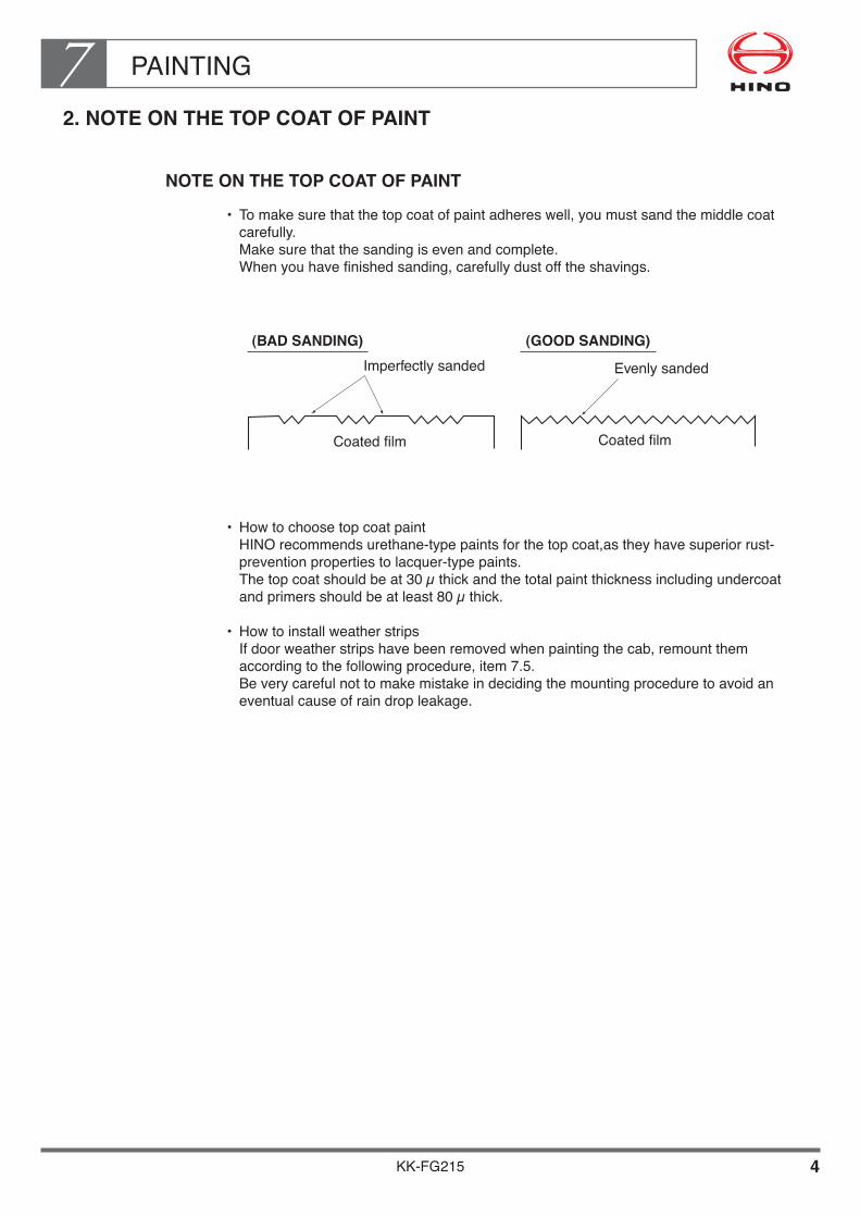
PAINTING7
KK-FG215 4
2. NOTE ON THE TOP COAT OF PAINT
NOTE ON THE TOP COAT OF PAINT
• Tomakesurethatthetopcoatofpaintadhereswell,youmustsandthemiddlecoatcarefully. Make sure that the sanding is even and complete. When you have finished sanding, carefully dust off the shavings.
• Howtochoosetopcoatpaint HINO recommends urethane-type paints for the top coat,as they have superior rust-prevention properties to lacquer-type paints. Thetopcoatshouldbeat30µthickandthetotalpaintthicknessincludingundercoatandprimersshouldbeatleast80µthick.
• Howtoinstallweatherstrips If door weather strips have been removed when painting the cab, remount them according to the following procedure, item 7.5. Be very careful not to make mistake in deciding the mounting procedure to avoid an eventual cause of rain drop leakage.
Imperfectly sanded
Coatedfilm Coatedfilm
(GOOD SANDING)
Evenly sanded
(BAD SANDING)

PAINTING7
KK-FG215 5
3. HOW TO REMOVE THE PARTS OF CAB
HOW TO REMOVE THE PARTS OF CAB FRONT
••Radiator•grille
• Openthefrontpanel.(frontinspectionlid)• Loosetheboltfrombacksideofthefrontpanel.• Removetheretainer.(16pieces)
••Top•mark
Loosethebolts(4pieces)frombacksideofradiatorgrille.

PAINTING7
KK-FG215 6
••Front•panel
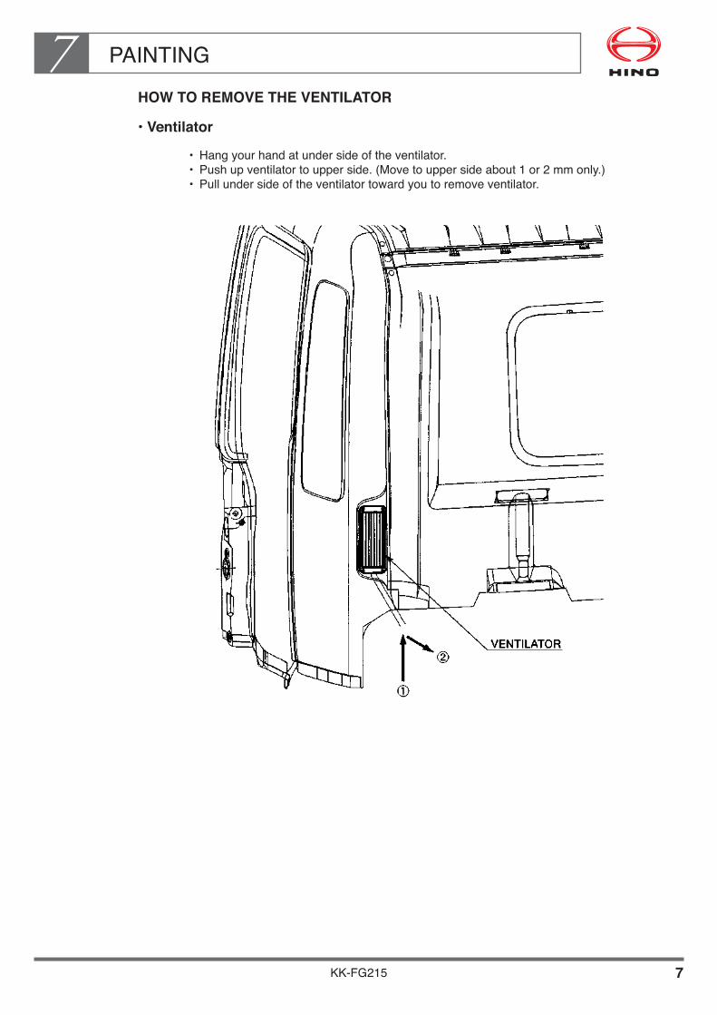
PAINTING7
KK-FG215 7
HOW TO REMOVE THE VENTILATOR
••Ventilator
• Hangyourhandatundersideoftheventilator.• Pushupventilatortoupperside.(Movetouppersideabout1or2mmonly.)• Pullundersideoftheventilatortowardyoutoremoveventilator.

PAINTING7
KK-FG215 8
HOW TO REMOVE THE QUARTER GARNISH (OPTION)
RELEVANT MODEL CLASSIFICATION NUMBER :
Quartergarnishisinstalledbyclips(Rightside:5numbers/Leftside:6numbers).It can be uninstalled with to remove one or two clips by screw driver.• Besuretoprotectthecabbody(outerpanel)wheretobeinsertthescrewdriverfrom
scratch or damage by clean waste.• Insertthescrewdriverbetweenthequartergarnishandthecabbodyneartheposition
where the clips are fitted. (See the following illustration)• Introducethetipofthescrewdriverintotheendandmoveittowardtheoutsideofthe
vehicle and the clips can be removed.• Removeoneortwoclips.• Fortherestofclips,holdthequartergarnishdirectlybyhand,applyforcetowardthe
outside of the vehicle and the remaining clips can be removed.
• Refertochapter1,3chassisspecificationforclassificationnumber.

PAINTING7
KK-FG215 9
REMOUNTING THE DISMOUNTED MIRROR STAY
• Whenremountingthedismountedmirrorstay,mountitafterthepainthasbeen completely hardened.
• Whentighteningthemirrorstay,becarefulnottoscratchthepaintedsurface.• Neverfailtoretouchwithclearlacquer,etc.,thosetoolscratcheswhichhavebeen
made by screws, bolts and nuts when dismounting and remounting the mirror stay.
• Whenremountingthemirrorstayadjustthetighteningtorques. Refer to the following figure for details.
••FLAT•MIRROR•TYPE•[TYPE•A]
RELEVANT MODEL CLASSIFICATION NUMBER : FG-058
• Refertochapter1,3chassisspecificationforclassificationnumber.
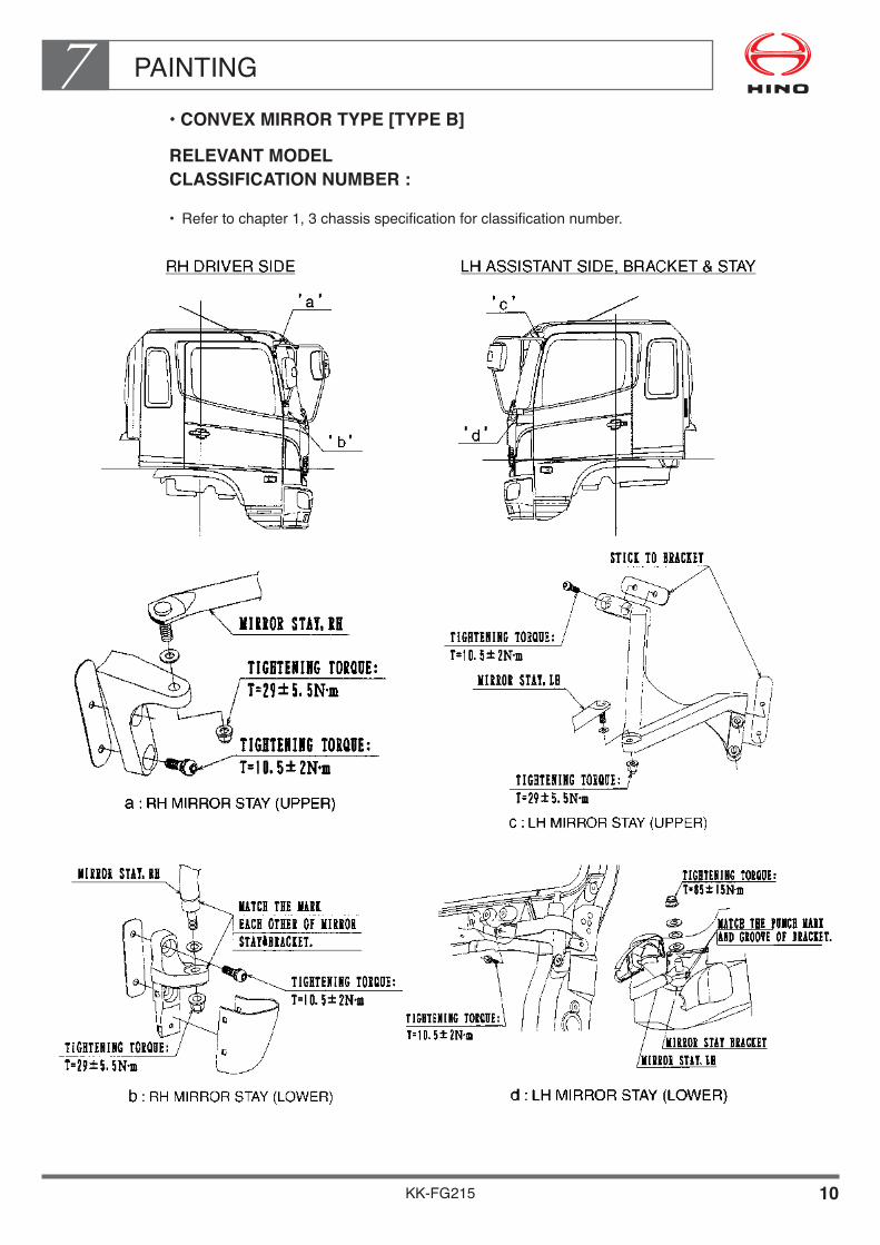
PAINTING7
KK-FG215 10
••CONVEX•MIRROR•TYPE•[TYPE•B]
RELEVANT MODEL CLASSIFICATION NUMBER :
• Refertochapter1,3chassisspecificationforclassificationnumber.
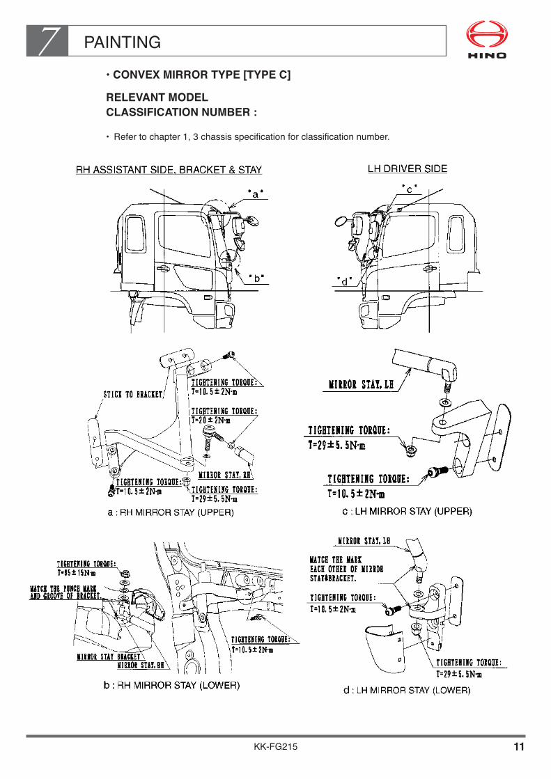
PAINTING7
KK-FG215 11
••CONVEX•MIRROR•TYPE•[TYPE•C]
RELEVANT MODEL CLASSIFICATION NUMBER :
• Refertochapter1,3chassisspecificationforclassificationnumber.

PAINTING7
KK-FG215 12
REMOUNTING THE WIPER
• Whendismountingandremountingthewiper,confirmbeforeremountingthatthewiperstays are at the automatic stop position. (After turning ON the wiper switch and then turn OFF the wiper switch, so that the wiper motor stops at the automatic stop position.)
• Whentighteningthewiperarms,tightenthembyadjustingthebladeposition(height)with in the limit as shown as the following illustration.
• Adjustthewiperarmsandthepivotpositionstothefollowingtighteningtorquevalues. •Wiperarmtighteningtorque 19.6±2N·m{200±20kgf·cm} •Wiperpivottighteningtorque 11.8±1N·m{120±10kgf·cm}
NOTE•Operatethewiperwiththefrontpanelshutdown.•Withthefrontpanelopened,youmayrisktohaveyourhandpinchedbythewiper
links.•Alsoafterstopofthewipermotor,takeoutthestarterkey.

PAINTING7
KK-FG215 13
WIPER BLADE SET POSITION (FOR RHD ONLY)
DETAIL OF WIPER ARM INSTALLATION FOR MODEL FC, FD & GD ONLY
DETAIL OF WIPER ARM INSTALLATION FOR MODEL FG, GH, SG, FL, FM, FT & GT ONLY
NOTE•Thesetpositionsofthebladesshowthegapsatthetopendsoftheblades.

PAINTING7
KK-FG215 14
WIPER BLADE SET POSITION (FOR LHD ONLY)
DETAIL OF WIPER ARM INSTALLATION FOR MODEL FC, FD & GD ONLY
DETAIL OF WIPER ARM INSTALLATION FOR MODEL FG, GH, FL, FM ONLY
NOTE•Thesetpositionsofthebladesshowthegapsatthetopendsoftheblades.
PAINTING7
KK-FG215 15
4. PROCEDURE FOR ADHERING ORNAMENTS
Ornaments adopt the inside adhesive system which is easy to fit.Adhere them according to the following procedures.
• Whattoprepare Cleanwaists
• Pointstopayattention•Reuseofornamentsonceadheredshouldbeavoidedbecausetheiradhering
power is reduced.•Performtheadheringoperationbyadjustingthesurfacetemperature(20to40°C).
If the ambient temperature is below the above, raise the temperature.•Wipeoffdust,dirt,stain,oil,water,etc.,depositedontheadheringsurface.
• Adheringprocedure•Afterhavingcleanedthesurfacetoadhere,takeoffthebackingpaperofthe
ornament.•Adheredoorboundarylineanddoorcharacterlinewiththeouterformofthe
ornament. (Detailsaredescribedinthefollowingfigure.)
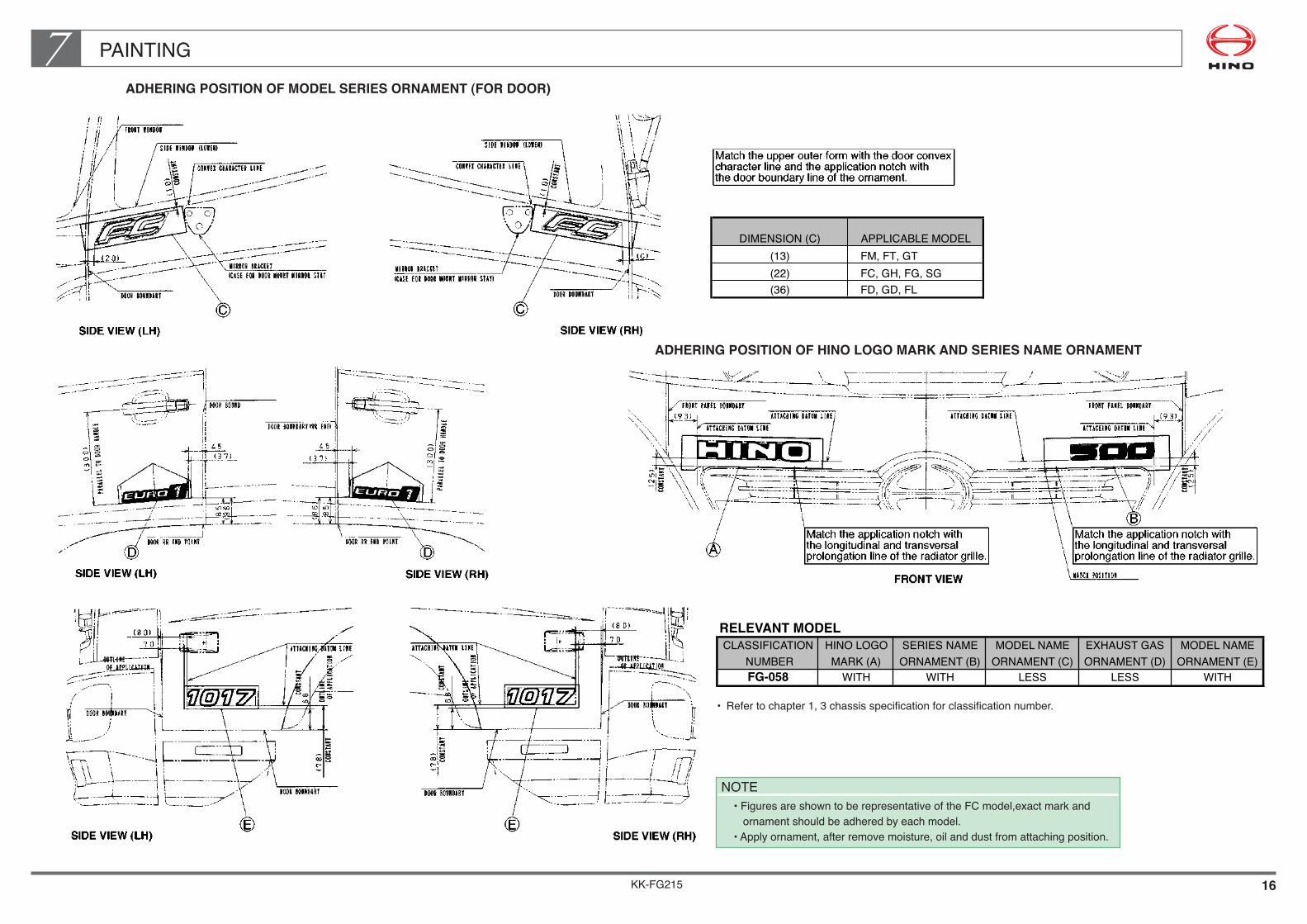
KK-FG215 16
PAINTING7ADHERING POSITION OF MODEL SERIES ORNAMENT (FOR DOOR)
DIMENSION (C) APPLICABLE MODEL(13) FM, FT, GT(22) FC, GH, FG, SG(36) FD, GD, FL
ADHERING POSITION OF HINO LOGO MARK AND SERIES NAME ORNAMENT
RELEVANT MODEL
CLASSIFICATION HINO LOGO SERIES NAME MODEL NAME EXHAUST GAS MODEL NAME
NUMBER MARK (A) ORNAMENT (B) ORNAMENT (C) ORNAMENT (D) ORNAMENT (E)
FG-058 WITH WITH LESS LESS WITH
• Refertochapter1,3chassisspecificationforclassificationnumber.
NOTE•FiguresareshowntoberepresentativeoftheFCmodel,exactmarkandornamentshouldbeadheredbyeachmodel.
•Applyornament,afterremovemoisture,oilanddustfromattachingposition.

PAINTING7
KK-FG215 17
5. MOUNTING AND STICKING OF DOOR WEATHER STRIP
In the case to disassemble the door weather strip when perform top coat paint, reassemble it as following procedure.
Pay special attention when reassemble the door weather strip, otherwise it will cause leakage of rain water.
MOUNTING AND STICKING OF WEATHER STRIP
• MatchthemarksAandBonbodysidenotchandthemarksontheweatherstripthenstart mounting from this point.
• Mountingofweatherstripsongeneralpositions Mount the weather strips on general positions after having finished mounting of point A and B and stick them in such a way that the slack of the weather strips concentrate on cornersofthepointAandofthepointB.Executethisoperationbysqueezingtheminthe direction of the arrow in the illustration of the weather strip position.
ILLUSTRATION OF THE WEATHER STRIP MOUNTING POSITION
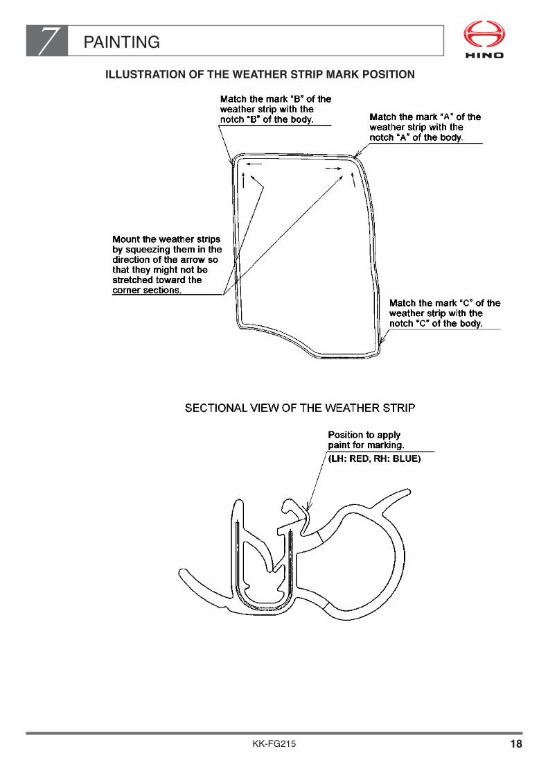
PAINTING7
KK-FG215 18
ILLUSTRATION OF THE WEATHER STRIP MARK POSITION

PAINTING7
KK-FG215 19
6. HOW TO MOUNT THE MAIN AND SUB SEAL
HOW TO MOUNT THE MAIN SEAL AT THE POSITION OF THE FRONT COWL
When you apply the top coating, apply masking on the main seal of the front cowl.
If you are obliged to remove the door sub seal, replace it with a new part in the following manner, Partnumberoffrontcowlmainseal:76821-1260(FC,FD,GD)1piece/vehicle76821-1270(FG,GH,SGFL,FM,FT,GT)
• Mountingprocedures•Definebothedgesofthemainsealinrelationtothelangesectionofthefront
cowl and insert it along the positioning ribs.•Insertthemainsealslowlyfromthebothedgestocenterofthevehicle.
• Caution•Inordertoavoidthepenetrationofwaterintothefrontpanelhavethebothend
of the front panels matched with the positioning ribs and tighten them together.•Mountthemainsealinsuchawaythatthesectionshapemightbecomeas
illustrated by Section A-A.

PAINTING7
KK-FG215 20
MOUNTING PROCEDURES OF MAIN SEAL AT THE POSITION OF THE FRONT CORNER PANEL
When applying top coating do it either by dismounting the main seal at the front corner panel or by masking the section concerned.
Partsnumberofmainsealatthefrontcornerpanel:76811-1120(2pieces/vehicle)
• Mountingprocedure•Insertthefrontcornermainsealintotheholeprovidedonthefrontcornerpanel.
• Caution•Securelyfixtheretaineronthefrontcornerpanelwhichismountedontomainseal.•Inordertoavoidthepenetrationofwater,mountitinsuchawaythatthesection
shape of the seal might become as illustrated on the Section B-B.

PAINTING7
KK-FG215 21
MOUNTING PROCEDURE FOR DOOR SUB SEAL
• Wipedirt,water,oilandwaxetc.withcleanwasteonthedouble-sidedtape's fitting surface of door panel.
• Inserttheclipofthedoorsubsealsufficientlywellandfixit.• Peeloffthereleasecoatedpaperofdouble-sidedtapeandpressfititonthedoor
panel.

PAINTING7
KK-FG215 22
7. CAUTIONS FOR PAINTING TILT CYLINDER ROD
• Makesureyoudonotgetpaintonthetiltcylinderrod.• Ifthereispaintonthetiltcylinderrodorthesealinsideofthecylinder,orifthesealis
damaged due to the paint, this may lead to cylinder oil leaks.
To prevent paint from adhering to the rod,make the rod carefully. If paint adheres to the rod,make sure to remove it completely. Take care not to dent or scratch the rod.
NOTES•Beforepainting,masktherodcompletely•Takegreatcarenottodentorscratchtherod.
PAINTING7
KK-FG215 23
8. HANDLING OF LAMINATED WINDSHIELD
A laminated glass is produced in such order that polyvinyl butyral film is inserted between 2 glasses and pressed with heat.Under driving general condition, there is no problem. But under a hot temperature and a high moisture when painting, intermediate film is fallen off or such defective occur as foaming may be caused. Therefore, a special caution needs to be taken.
••Caution•when•Painting
There is no problem when you use a natural drying. But when a forced drying is used withinfraredraylamp,etc.,besurethatthedryingshouldbeimplementedwithin30minutesatlessthan120°C.Whendryingatthetemperatureofmorethan120°C,removeoffthewindshieldglassorcover over the glass with something so that the temperature on the glass surface should notgoupmorethan120°C.
PAINTING7
KK-FG215 24
9. HANDLING OF COMPUTERS (ECU)
When paint by forced drying, must be care to handle the computers as following points.
1
2
3
CONDITION OF FORCED DRYING PAINT HANDLING OF COMPUTER
• INSIDE TEMPERATURE OF THE FORCED DRYING BOOTH• INSIDE TEMPERATURE OF THE CAB : LESS THAN 85°C (PLACE AT THE 50mm HEIGHT FROM UPPER SURFACE OF CAB FLOOR.)WHEN UNKNOWN THE TEMPERATURE OF THE FORCED DRYING BOOTH OR USEINFRARED LAMP INSIDE TEMPERATURE OF THE CAB : LESS THAN 85°C (PLACE AT THE 50mm HEIGHT FROM UPPER SURFACE OF CAB FLOOR.)
INSTALLED
WHEN EXPECT MORE HIGH TEMPERATURE THAN ABOVE MENTIONED CASES. REMOVE COMPUTER
: 120°C

PAINTING7
KK-FG215 25
10. PRECAUTIONS FOR FITTING AND STORING THE CAUTION PLATE
••How•to•Stick•It
a. Stick the caution plate to a dry place which is free from dust and dirt after the paint has completely dried up.
b.Cleanyourhandanddon'tusecottonworkgloves,etc..c.Completelyremovewater,oil,dust,etc.fromthesurfacetostick(surfaceofcab)with
ethyl alcohol if they are found remaining there.d.Whenthetemperatureislessthan10°C,warmupthesurfacetostickaswellasthecautionplatewithwarmwindofmorethan20°Cbeforestickingthecautionplate.
e. After sticking the caution plate, press it with a roller, etc., with a force of approximately49N/cm2{5kgf/cm2}.
f.Removelinerpaper(backingpaper)justbeforeusingit.g. When air remains inside, make a tiny hole with a needle or a cutter knife and press it
out with your fingers from the bubble area.
••How•to•Store•It
a. When storing the caution plate, select a dry place with an ambient temperature (of20to25°C)andwithoutdust,dirtandstain.
b. Also, store the caution plate at a flat place such as a shelf, etc., and do not place anything on it.
••Other•Precautions•for•the•Caution•Plate
a. As the caution plate is made from vinyl chloride, it is thin, soft and easily extensible. Therefore, take utmost care for handling it.
b. When removing the caution plate, etc., be careful not to damage the painted surface with a sharp knife, etc. On the other hand, removal of the caution plate can be done more easily by pulling the caution plate in perpendicular direction to the sticking surface while heating it with a hair dryer.
c.Donotthrowthecautionplatesawaybutkeepthemtogethertocomparewithnewcautionplatesandtopreventmixingupwiththenewones.

PAINTING7
KK-FG215 26
11. CAUTIONS FOR PAINTING THE TIRE DISC WHEELS
• Beforepaintingthetirewheel,coveritsinsideandoutsidesurfacetobecontactedwith the hub, the wheel, the brake drum and wheel nuts.Refer to the illustration below concerning the covering portions.
• Afterinstallingthetirewheelontothevehicle,painttheremainedportionswithsamecolor paint as thin as possible. It is because these surfaces are installation surface rotation tire.If the painting layer is thick, it causes wheel nuts loosen.
• PrecautionforcarryingouttirerotationSometimes, the mounting position of tire wheel may be changed and paint coated face may become contact face. Atthismoment,ifthethicknessofthepaintedlayerisexcessivelythick,thismayleadto the loosening of the wheel nuts. Therefore observe the following instructions when carrying out the tire rotation.
• Takeoffthepaintonthecontactface(includingthecontactsurfaceofwheelnut)of the tire wheel and after having completely cleaned the face with a wire brush etc., apply thin layer of paint for rust preventive purpose.
• Ifyouusethetirewheelwithouttakingoffthepaint,evenifthefaceiscompletelycleaned with wire brush, etc., the thick painted layer may lead to the loosening of wheel nuts.

KK-FG215
Chapter 8CHASSIS DRAWINGS
1. CAB DRAWINGS••••••••••••••••••••••••••••••••••••••••••••••••• 2 2. CAB BACK DRAWINGS•••••••••••••••••••••••••••••••••••••••• 8 3. CHASSIS DRAWINGS•••••••••••••••••••••••••••••••••••••••••• 14 4. CHASSIS FRAME DRAWINGS••••••••••••••••••••••••••••••• 21

CHASSIS DRAWINGS8
KK-FG215 1
Refer to detail of the cab, chassis and chassis frame drawing based on following table.
RELEVANT MODEL
CLASSIFICATION CHASSIS DRAWINGS
NUMBER CAB CAB BACK CHASSIS CHASSIS FRAME
FG-058 C-1 CB-1 CH-1 CF-1
• Refertochapter1,3chassisspecificationforclassificationnumber.

CHASSIS DRAWINGS8
KK-FG215 2
1. CAB DRAWINGS
No. C-1
••Front
Unit:mm

CHASSIS DRAWINGS8
KK-FG215 3
No. C-1
••Rear
Unit:mm

CHASSIS DRAWINGS8
KK-FG215 4
No. C-2
••Front
Scale:1/20
Unit:mm

CHASSIS DRAWINGS8
KK-FG215 5
No. C-2
••Rear
Scale:1/20
Unit:mm

CHASSIS DRAWINGS8
KK-FG215 6
No. C-3
••Front
Scale:1/20
Unit:mm

CHASSIS DRAWINGS8
KK-FG215 7
No. C-3
••Rear
Scale:1/20
Unit:mm
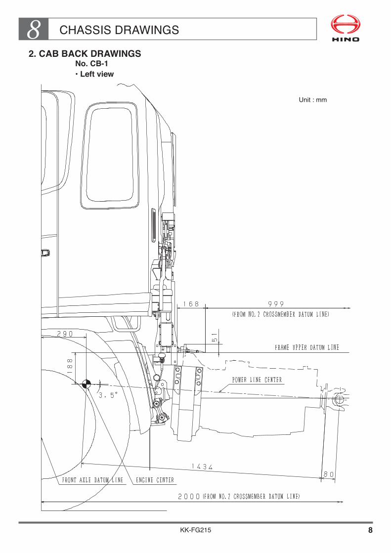
CHASSIS DRAWINGS8
KK-FG215 8
2. CAB BACK DRAWINGSNo. CB-1••Left•view
Unit:mm

CHASSIS DRAWINGS8
KK-FG215 9
No. CB-1
••Upper•view Unit:mm

CHASSIS DRAWINGS8
KK-FG215 10
No. CB-2
••Left•view Unit:mm

CHASSIS DRAWINGS8
KK-FG215 11
No. CB-2
••Upper•view Unit:mm

CHASSIS DRAWINGS8
KK-FG215 12
No. CB-3
••Left•view Unit:mm

CHASSIS DRAWINGS8
KK-FG215 13
No. CB-3
••Upper•view Unit:mm
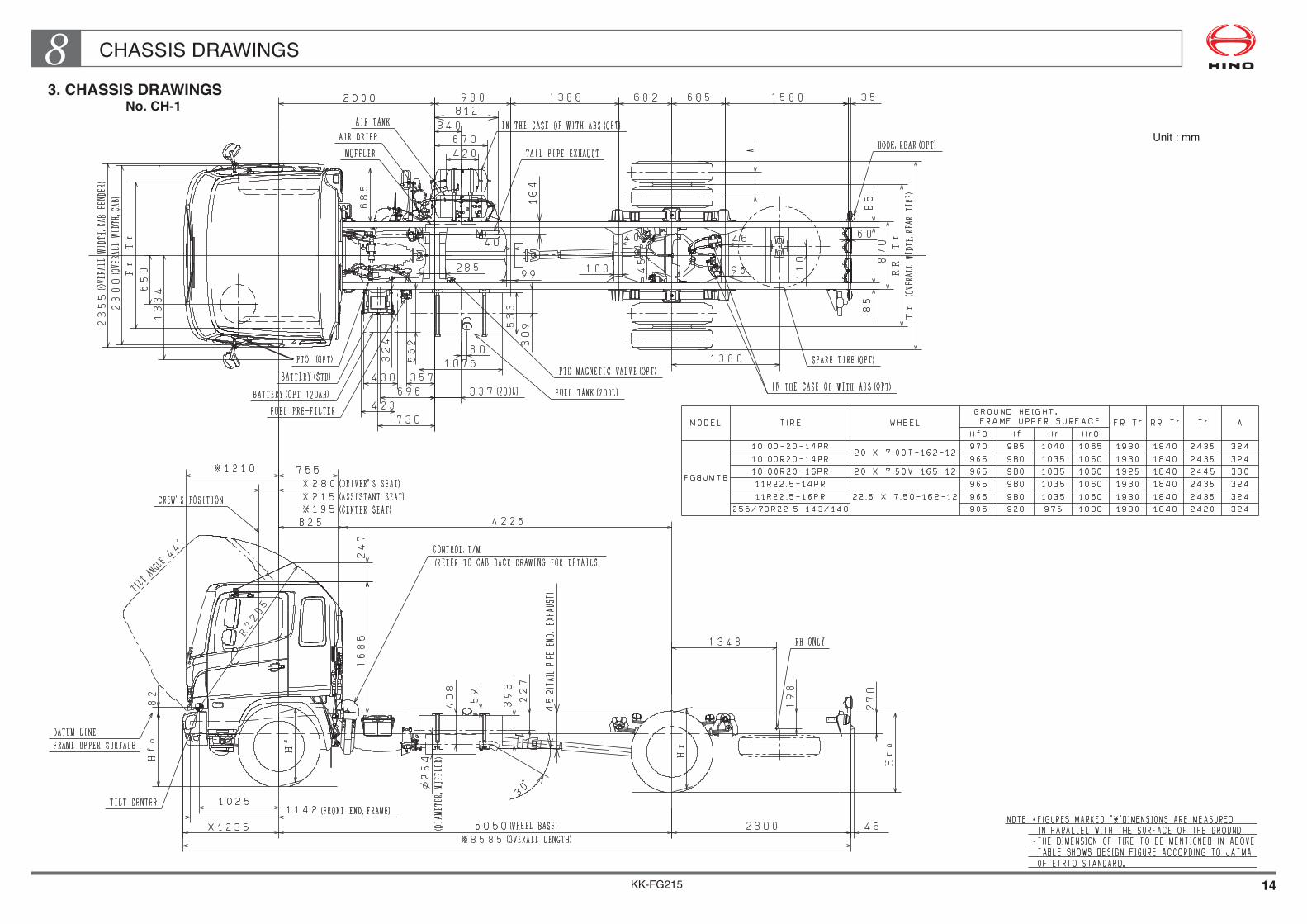
KK-FG215 14
CHASSIS DRAWINGS83. CHASSIS DRAWINGS
No. CH-1
Unit : mm
KK-FG215 15
CHASSIS DRAWINGS8No. CH-2 Unit : mm

KK-FG215 16
CHASSIS DRAWINGS8No. CH-3 Unit : mm

KK-FG215 17
CHASSIS DRAWINGS8No. CH-4 Scale : 1/40
Unit : mm
NOTE• Figures marked " " dimensions are measured in parallel with the surface of the ground.• The dimension of tire to be mentioned in above table shows design figure according to JATMA or ETRTO standard.

KK-FG215 18
CHASSIS DRAWINGS8No. CH-5 Scale : 1/40
Unit : mm
NOTE• Figures marked " " dimensions are measured in parallel with the surface of the ground.• The dimension of tire to be mentioned in above table shows design figure according to JATMA or ETRTO standard.

KK-FG215 19
CHASSIS DRAWINGS8No. CH-6 Scale : 1/40
Unit : mm
NOTE• Figures marked " " dimensions are measured in parallel with the surface of the ground.• The dimension of tire to be mentioned in above table shows design figure according to JATMA or ETRTO standard.
KK-FG215 20
CHASSIS DRAWINGS8No. CH-7 Scale : 1/40
Unit : mm
NOTE• Figures marked " " dimensions are measured in parallel with the surface of the ground.• The dimension of tire to be mentioned in above table shows design figure according to JATMA or ETRTO standard.

KK-FG215 21
CHASSIS DRAWINGS84. CHASSIS FRAME DRAWINGS
No. CF-1
• Detail of the chassis frame Unit : mm
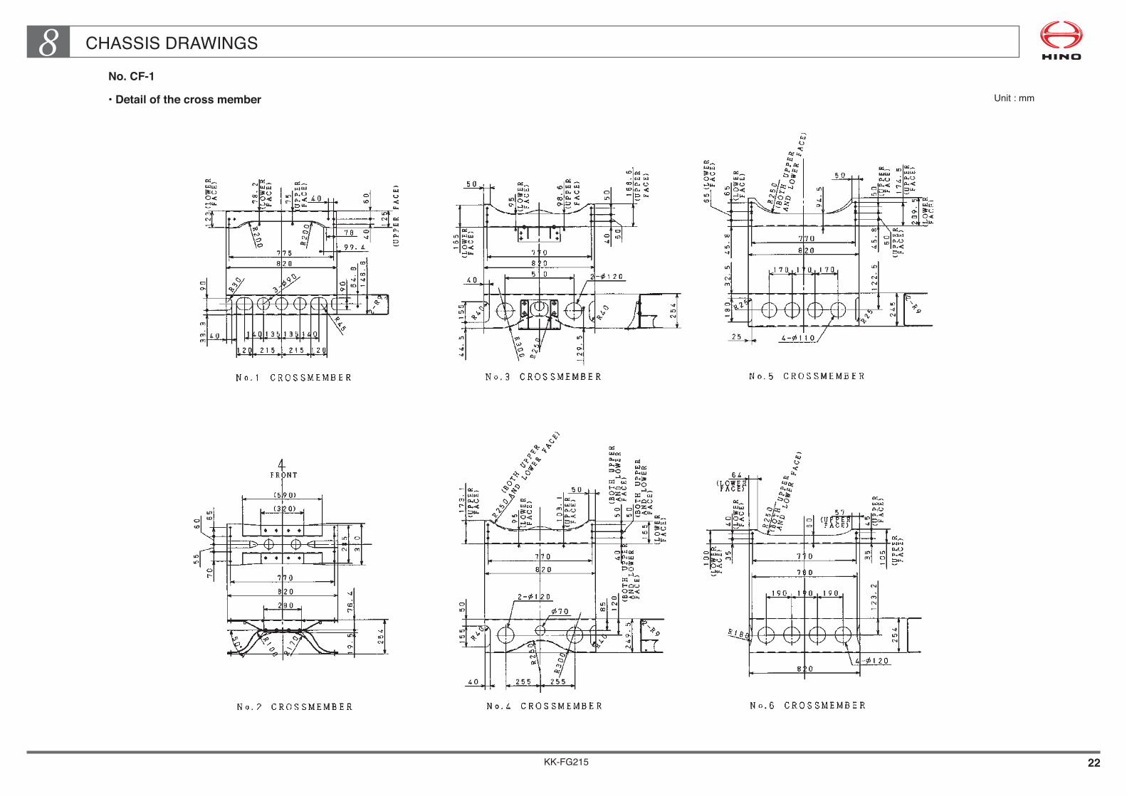
KK-FG215 22
CHASSIS DRAWINGS8No. CF-1
• Detail of the cross member Unit : mm

KK-FG215 23
CHASSIS DRAWINGS8
No. CF-2
• Detail of the chassis frame
Unit : mm
KK-FG215 24
CHASSIS DRAWINGS8No. CF-2
• Detail of the cross member
Unit : mm

KK-FG215 25
CHASSIS DRAWINGS8No. CF-3
• Detail of the chassis frame Unit : mm
KK-FG215 26
CHASSIS DRAWINGS8No. CF-3
• Detail of the cross member Unit : mm

KK-FG215 27
CHASSIS DRAWINGS8No. CF-4
• Detail of the chassis frame
Scale : 1/40
Unit : mm

KK-FG215 28
CHASSIS DRAWINGS8No. CF-4
• Detail of the cross member
Scale : 1/20
Unit : mm
KK-FG215 29
CHASSIS DRAWINGS8No. CF-5
• Detail of the chassis frame
Scale : 1/40
Unit : mm

KK-FG215 30
CHASSIS DRAWINGS8No. CF-5
• Detail of the cross member
Scale : 1/20
Unit : mm

KK-FG215 31
CHASSIS DRAWINGS8No. CF-6
• Detail of the chassis frame
Scale : 1/40
Unit : mm

KK-FG215 32
CHASSIS DRAWINGS8No. CF-6
• Detail of the cross member
Scale : 1/20
Unit : mm

KK-FG215
Chapter 9MOUNTING OF CHASSIS EQUIPMENT
1. FUEL TANK ••••••••••••••••••••••••••••••••••••••••••••••••••••••• 2 2. AIR TANK & AIR BOOSTER•••••••••••••••••••••••••••••••••• 7 3. BATTERY•••••••••••••••••••••••••••••••••••••••••••••••••••••••••• 17 4. EXHAUST SYSTEM •••••••••••••••••••••••••••••••••••••••••••• 20
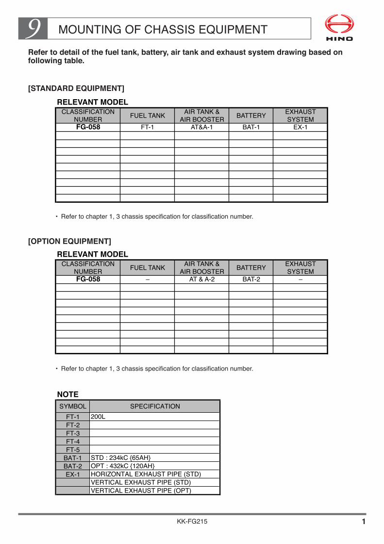
MOUNTING OF CHASSIS EQUIPMENT9
KK-FG215 1
Refer to detail of the fuel tank, battery, air tank and exhaust system drawing based on following table.
[STANDARD EQUIPMENT]
[OPTION EQUIPMENT]
RELEVANT MODEL
CLASSIFICATION AIR TANK & EXHAUST
NUMBER AIR BOOSTER SYSTEM
FG-058 FT-1 AT&A-1 BAT-1 EX-1
BATTERYFUEL TANK
RELEVANT MODEL
CLASSIFICATION AIR TANK & EXHAUST
NUMBER AIR BOOSTER SYSTEM
FG-058 – AT & A-2 BAT-2 –
BATTERYFUEL TANK
NOTESYMBOL SPECIFICATION
FT-1 200LFT-2FT-3FT-4FT-5
BAT-1 STD : 234kC {65AH}BAT-2 OPT : 432kC {120AH}EX-1 HORIZONTAL EXHAUST PIPE (STD)
VERTICAL EXHAUST PIPE (STD)VERTICAL EXHAUST PIPE (OPT)
• Refertochapter1,3chassisspecificationforclassificationnumber.
• Refertochapter1,3chassisspecificationforclassificationnumber.

MOUNTING OF CHASSIS EQUIPMENT9
KK-FG215 2
1. FUEL TANK
FT-1 Unit:mm

MOUNTING OF CHASSIS EQUIPMENT9
KK-FG215 3
FT-2 Unit:mm

MOUNTING OF CHASSIS EQUIPMENT9
KK-FG215 4
FT-3 Unit:mm

MOUNTING OF CHASSIS EQUIPMENT9
KK-FG215 5
FT-4 Unit:mm

MOUNTING OF CHASSIS EQUIPMENT9
KK-FG215 6
FT-5 Unit:mm

KK-FG215 7
MOUNTING OF CHASSIS EQUIPMENT92. AIR TANK & AIR BOOSTER
AT & A-1
STANDARD EQUIPMENT : WITHOUT ABS
Unit : mm
(FOR GH ONLY)

KK-FG215 8
MOUNTING OF CHASSIS EQUIPMENT9AT & A-2
OPTION EQUIPMENT : WITH ABS
Unit : mm
(FOR GH ONLY)

KK-FG215 9
MOUNTING OF CHASSIS EQUIPMENT9AT & A-3 Unit : mm
KK-FG215 10
MOUNTING OF CHASSIS EQUIPMENT9AT & A-4 Unit : mm

KK-FG215 11
MOUNTING OF CHASSIS EQUIPMENT9AT & A-5 Unit : mm

KK-FG215 12
MOUNTING OF CHASSIS EQUIPMENT9AT & A-6 Unit : mm

KK-FG215 13
MOUNTING OF CHASSIS EQUIPMENT9AT & A-7 Unit : mm

KK-FG215 14
MOUNTING OF CHASSIS EQUIPMENT9AT & A-8 Unit : mm

KK-FG215 15
MOUNTING OF CHASSIS EQUIPMENT9AT & A-9 Unit : mm

KK-FG215 16
MOUNTING OF CHASSIS EQUIPMENT9AT & A-10 Unit : mm

KK-FG215 17
MOUNTING OF CHASSIS EQUIPMENT93. BATTERY
BAT-1 Unit : mm
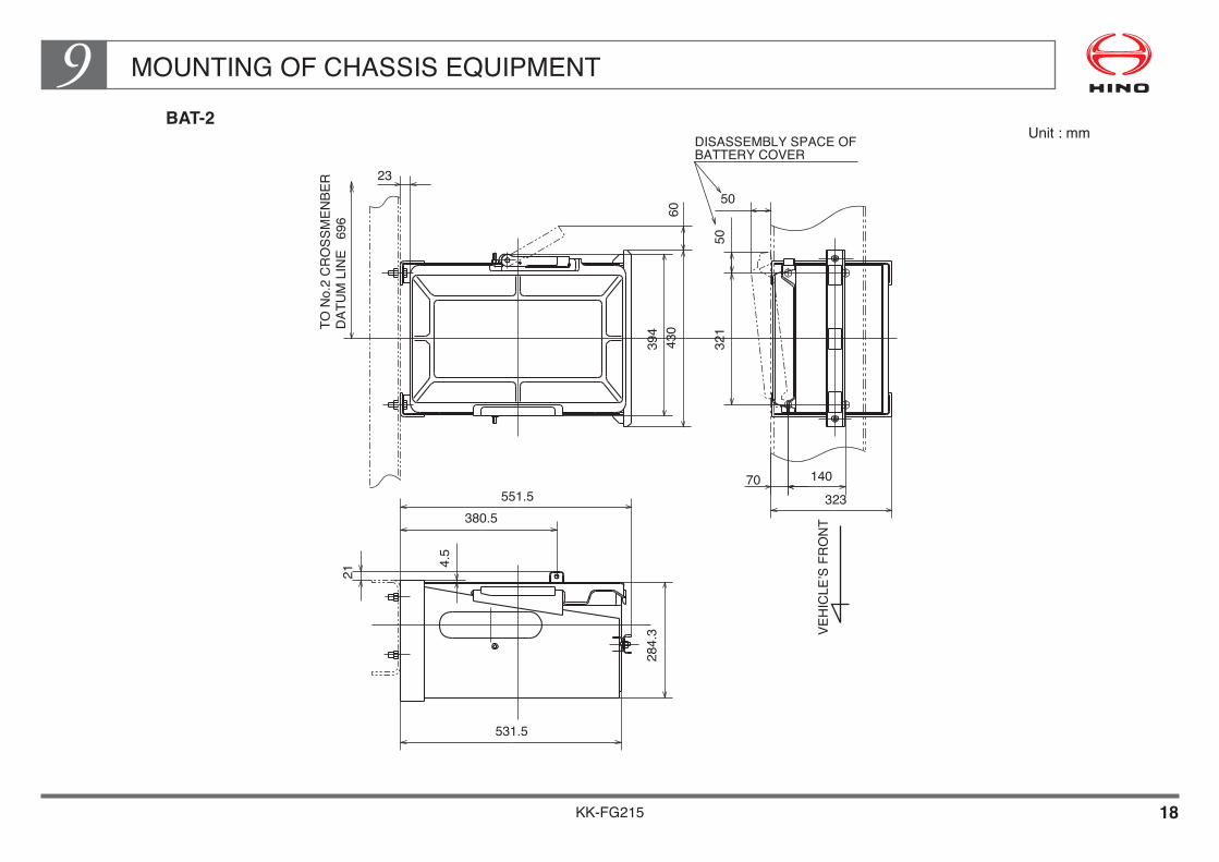
KK-FG215 18
MOUNTING OF CHASSIS EQUIPMENT9BAT-2
Unit : mm
50
284.
3
321
50
531.5
140
323551.5380.5
4.5
21
60
23
394
430
VEH
ICLE
’S F
RO
NT
TO N
o.2
CR
OSS
MEN
BER
D
ATU
M L
INE
696
DISASSEMBLY SPACE OFBATTERY COVER
70

KK-FG215 19
MOUNTING OF CHASSIS EQUIPMENT9BAT-3
Unit : mm

KK-FG215 20
MOUNTING OF CHASSIS EQUIPMENT94. EXHAUST SYSTEM (EXHAUST TAIL PIPE)
EX-1 Unit : mm

KK-FG215 21
MOUNTING OF CHASSIS EQUIPMENT9
EX-2 Unit : mm

KK-FG215 22
MOUNTING OF CHASSIS EQUIPMENT9EX-3 Scale : 1/20
Unit : mm
KK-FG215
Chapter 10OTHER
1. BRAKE PIPING DIAGRAM ••••••••••••••••••••••••••••••••••• 1 2. LICENSE PLATE BRACKET•••••••••••••••••••••••••••••••••• 5 3. SEMI-TRAILER BRAKE COUPLING
(FOR TRACTOR ONLY)••••••••••••••••••••••••••••••••••••• 7

KK-FG215 1
OTHER101. BRAKE PIPING DIAGRAM (1/4)
KK-FG215 2
OTHER10BRAKE PIPING DIAGRAM (2/4)

KK-FG215 3
OTHER10BRAKE PIPING DIAGRAM (3/4)

KK-FG215 4
OTHER10BRAKE PIPING DIAGRAM (4/4)
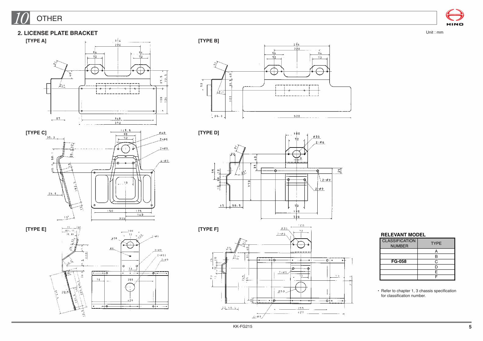
KK-FG215 5
OTHER102. LICENSE PLATE BRACKET Unit : mm
• Refertochapter1,3chassisspecificationforclassificationnumber.
RELEVANT MODEL
CLASSIFICATION
NUMBER
A
B
FG-058 C
D
E
F
TYPE
[TYPE A] [TYPE B]
[TYPE C] [TYPE D]
[TYPE E] [TYPE F]
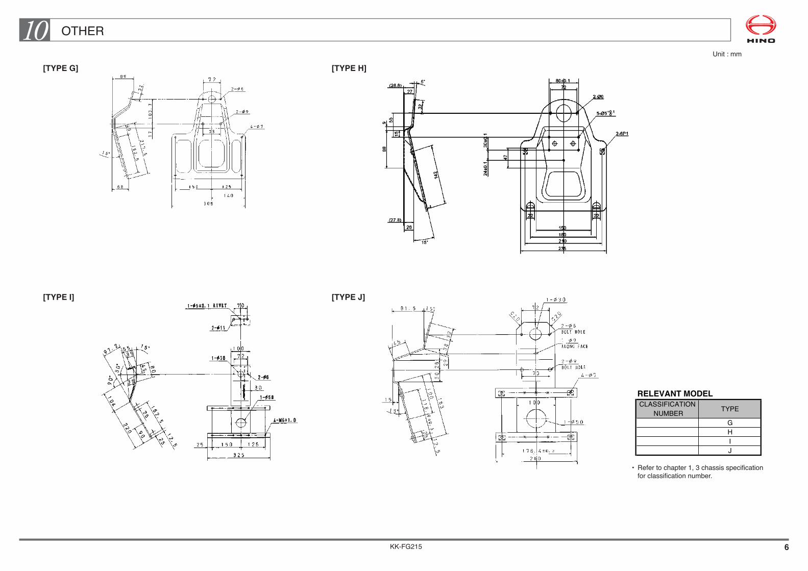
KK-FG215 6
OTHER10
• Refertochapter1,3chassisspecificationforclassificationnumber.
RELEVANT MODELCLASSIFICATION
NUMBERGHIJ
TYPE
Unit : mm
[TYPE G] [TYPE H]
[TYPE I] [TYPE J]

OTHER10
KK-FG215 7
3. SEMI-TRAILER BRAKE COUPLING (FOR TRACTOR ONLY)
The trailer brake system can be actuated by operating the foot brake and hand brake valves that are provided at the inside of the tractor cab.The trailer brake system is connected by a jumper hose and an air-coupling.The air-coupling equipped on the HINO vehicle complies with SAE standard and color distinction is made to clarify the purpose for use ; Blue being for Service purpose while Red being for an Emergency purpose.The actual form is as shown below.

KK-FG215
Chapter 11REGULATION
1. HANDLING PRECAUTIONS OF CATALYST MUFFLER••••••••••••••••••••••••••••••••••••••• 2

REGULATION11
KK-FG215 1
This section is described the informations in relation to vehicle’s lows and regulations that must be complied while body or equipment is mounted on the Hino truck chassis with cab as following contents.
• Itemswhichthebodyorequipmentmanufacturermustbeprovidedthefacilities.• Handlingprecautionsofpartswhichhasalreadybeenequippedonthechassis,thecab,andtheengine.
• Otherprecautionswhichmustbetakenduringtheworkofthebodyorequipmentmounting.
The body or equipment manufacturer must make sure the contents to be described in this section.
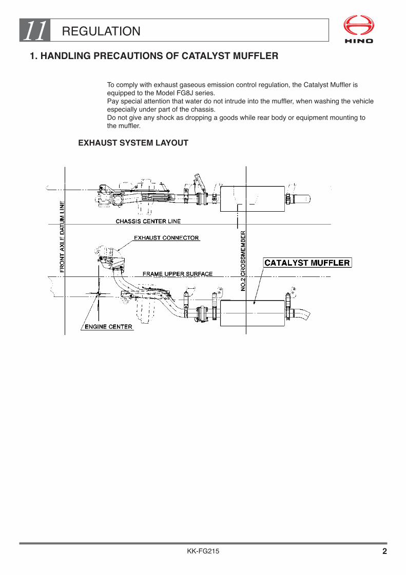
REGULATION11
KK-FG215 2
1. HANDLING PRECAUTIONS OF CATALYST MUFFLER
Tocomplywithexhaustgaseousemissioncontrolregulation,theCatalystMufflerisequippedtotheModelFG8Jseries.Payspecialattentionthatwaterdonotintrudeintothemuffler,whenwashingthevehicleespecially under part of the chassis.Do not give any shock as dropping a goods while rear body or equipment mounting to the muffler.
EXHAUST SYSTEM LAYOUT


