
Himod
Product Documentation
Englishcod. 272064 - rev. 10.04.2001
Issued by TDS


Himod
English
INDEX
1 - The series 1. . . . . . . . . . . . . . . . . . . . . . . . . . . . . . . . . . . . . . . . . . . . . . . . . . . . . . . . . . . . . . .
1.1 - Main features and advantages 1. . . . . . . . . . . . . . . . . . . . . . . . . . . . . . . . . . . . . . . . . . . . . . . . . . . .
2 - Configuration 2. . . . . . . . . . . . . . . . . . . . . . . . . . . . . . . . . . . . . . . . . . . . . . . . . . . . . . . . . . . .
2.1 - Version A 2. . . . . . . . . . . . . . . . . . . . . . . . . . . . . . . . . . . . . . . . . . . . . . . . . . . . . . . . . . . . . . . . . . . . . .
2.2 - Version W 3. . . . . . . . . . . . . . . . . . . . . . . . . . . . . . . . . . . . . . . . . . . . . . . . . . . . . . . . . . . . . . . . . . . . . .
2.3 - Version D 4. . . . . . . . . . . . . . . . . . . . . . . . . . . . . . . . . . . . . . . . . . . . . . . . . . . . . . . . . . . . . . . . . . . . . .
2.4 - Version H 5. . . . . . . . . . . . . . . . . . . . . . . . . . . . . . . . . . . . . . . . . . . . . . . . . . . . . . . . . . . . . . . . . . . . . .
2.5 - Version F 6. . . . . . . . . . . . . . . . . . . . . . . . . . . . . . . . . . . . . . . . . . . . . . . . . . . . . . . . . . . . . . . . . . . . . . .
2.6 - Version C 7. . . . . . . . . . . . . . . . . . . . . . . . . . . . . . . . . . . . . . . . . . . . . . . . . . . . . . . . . . . . . . . . . . . . . .
2.7 - Air control 8. . . . . . . . . . . . . . . . . . . . . . . . . . . . . . . . . . . . . . . . . . . . . . . . . . . . . . . . . . . . . . . . . . . . . .
3 - Operating limits 8. . . . . . . . . . . . . . . . . . . . . . . . . . . . . . . . . . . . . . . . . . . . . . . . . . . . . . . . . .
4 - Component features 9. . . . . . . . . . . . . . . . . . . . . . . . . . . . . . . . . . . . . . . . . . . . . . . . . . . . . .
4.1 - Fan 9. . . . . . . . . . . . . . . . . . . . . . . . . . . . . . . . . . . . . . . . . . . . . . . . . . . . . . . . . . . . . . . . . . . . . . . . . . . .
4.2 - Compressor 9. . . . . . . . . . . . . . . . . . . . . . . . . . . . . . . . . . . . . . . . . . . . . . . . . . . . . . . . . . . . . . . . . . . .
4.3 - Coils 9. . . . . . . . . . . . . . . . . . . . . . . . . . . . . . . . . . . . . . . . . . . . . . . . . . . . . . . . . . . . . . . . . . . . . . . . . . .
4.4 - Frame and panels 9. . . . . . . . . . . . . . . . . . . . . . . . . . . . . . . . . . . . . . . . . . . . . . . . . . . . . . . . . . . . . . .
4.5 - Filters 10. . . . . . . . . . . . . . . . . . . . . . . . . . . . . . . . . . . . . . . . . . . . . . . . . . . . . . . . . . . . . . . . . . . . . . . . .
4.6 - Refrigerants 10. . . . . . . . . . . . . . . . . . . . . . . . . . . . . . . . . . . . . . . . . . . . . . . . . . . . . . . . . . . . . . . . . . .
4.7 - Electrical panel 10. . . . . . . . . . . . . . . . . . . . . . . . . . . . . . . . . . . . . . . . . . . . . . . . . . . . . . . . . . . . . . . .
4.8 - Accessibility 10. . . . . . . . . . . . . . . . . . . . . . . . . . . . . . . . . . . . . . . . . . . . . . . . . . . . . . . . . . . . . . . . . . .
4.9 - Control system (Microface and Hiromatic G) 10. . . . . . . . . . . . . . . . . . . . . . . . . . . . . . . . . . . . . . .
4.10 - Packing 11. . . . . . . . . . . . . . . . . . . . . . . . . . . . . . . . . . . . . . . . . . . . . . . . . . . . . . . . . . . . . . . . . . . . . . .
4.11 - Product quality and safety 11. . . . . . . . . . . . . . . . . . . . . . . . . . . . . . . . . . . . . . . . . . . . . . . . . . . . . . .
5 - Condensing section 12. . . . . . . . . . . . . . . . . . . . . . . . . . . . . . . . . . . . . . . . . . . . . . . . . . . . .
5.1 - Air condensers 12. . . . . . . . . . . . . . . . . . . . . . . . . . . . . . . . . . . . . . . . . . . . . . . . . . . . . . . . . . . . . . . .
5.2 - Water condensers. 14. . . . . . . . . . . . . . . . . . . . . . . . . . . . . . . . . . . . . . . . . . . . . . . . . . . . . . . . . . . . .
5.3 - Dry coolers 14. . . . . . . . . . . . . . . . . . . . . . . . . . . . . . . . . . . . . . . . . . . . . . . . . . . . . . . . . . . . . . . . . . . .
6 - Technical notes 16. . . . . . . . . . . . . . . . . . . . . . . . . . . . . . . . . . . . . . . . . . . . . . . . . . . . . . . . .
6.1 - Optional alternative refrigerant, R407C. 16. . . . . . . . . . . . . . . . . . . . . . . . . . . . . . . . . . . . . . . . . . .
7 - Electrical characteristics 50/60 Hz unit 18. . . . . . . . . . . . . . . . . . . . . . . . . . . . . . . . . . . .
8 - Technical data and performances 50/60Hz unit 25. . . . . . . . . . . . . . . . . . . . . . . . . . . .
9 - Sound Pressure Level 69. . . . . . . . . . . . . . . . . . . . . . . . . . . . . . . . . . . . . . . . . . . . . . . . . . .
9.1 - Sound emission values 69. . . . . . . . . . . . . . . . . . . . . . . . . . . . . . . . . . . . . . . . . . . . . . . . . . . . . . . . .
9.2 - Sound emission spectra 71. . . . . . . . . . . . . . . . . . . . . . . . . . . . . . . . . . . . . . . . . . . . . . . . . . . . . . . .
10 -Aeraulic features 73. . . . . . . . . . . . . . . . . . . . . . . . . . . . . . . . . . . . . . . . . . . . . . . . . . . . . . . .
11 -Options 91. . . . . . . . . . . . . . . . . . . . . . . . . . . . . . . . . . . . . . . . . . . . . . . . . . . . . . . . . . . . . . . . .
11.1 - Filtration 91. . . . . . . . . . . . . . . . . . . . . . . . . . . . . . . . . . . . . . . . . . . . . . . . . . . . . . . . . . . . . . . . . . . . . .
11.2 - Reheating and humidity control 93. . . . . . . . . . . . . . . . . . . . . . . . . . . . . . . . . . . . . . . . . . . . . . . . . .
11.3 - Humidification and dehumidification system 100. . . . . . . . . . . . . . . . . . . . . . . . . . . . . . . . . . . . . .
11.4 - Water valve (models W/H) 101. . . . . . . . . . . . . . . . . . . . . . . . . . . . . . . . . . . . . . . . . . . . . . . . . . . . . .

Himod
English
11.5 - Flooding alarm (Liquistat) 101. . . . . . . . . . . . . . . . . . . . . . . . . . . . . . . . . . . . . . . . . . . . . . . . . . . . . .
11.6 - Smoke alarm (Smokestat) 101. . . . . . . . . . . . . . . . . . . . . . . . . . . . . . . . . . . . . . . . . . . . . . . . . . . . . .
11.7 - Fire alarm (Firestat) 101. . . . . . . . . . . . . . . . . . . . . . . . . . . . . . . . . . . . . . . . . . . . . . . . . . . . . . . . . . . .
11.8 - Fresh air kit 102. . . . . . . . . . . . . . . . . . . . . . . . . . . . . . . . . . . . . . . . . . . . . . . . . . . . . . . . . . . . . . . . . . .
11.9 - Intake and delivery hoods 102. . . . . . . . . . . . . . . . . . . . . . . . . . . . . . . . . . . . . . . . . . . . . . . . . . . . . .
11.10 - Silencing cartridges for supply hoods - Silent Carts (Over models) 102. . . . . . . . . . . . . . . . .
11.11 - HiSAS - Semi-activer silencer (Under models) 103. . . . . . . . . . . . . . . . . . . . . . . . . . . . . . . . . .
11.12 - Delivery plenum with horizontal flow (Over models) 103. . . . . . . . . . . . . . . . . . . . . . . . . . . . . . . .
11.13 - Adjustable Louvred Grille (Over models) 103. . . . . . . . . . . . . . . . . . . . . . . . . . . . . . . . . . . . . . . . .
11.14 - Base frames: TBD models 103. . . . . . . . . . . . . . . . . . . . . . . . . . . . . . . . . . . . . . . . . . . . . . . . . . . . . .
11.15 - Base modules (Over models) 104. . . . . . . . . . . . . . . . . . . . . . . . . . . . . . . . . . . . . . . . . . . . . . . . . . .
11.16 - Automatic pump for condensate discharge 104. . . . . . . . . . . . . . . . . . . . . . . . . . . . . . . . . . . . . . .
11.17 - Non-return valves (models A and D) 104. . . . . . . . . . . . . . . . . . . . . . . . . . . . . . . . . . . . . . . . . . . .
11.18 - Additional temperature and humidity sensor (EEAP) 104. . . . . . . . . . . . . . . . . . . . . . . . . . . . . . .
11.19 - Microprocessor control with graphic display (HIROMATIC G) 105. . . . . . . . . . . . . . . . . . . . . . .
11.20 - Special packing 106. . . . . . . . . . . . . . . . . . . . . . . . . . . . . . . . . . . . . . . . . . . . . . . . . . . . . . . . . . . . . . .
11.21 - Air intake from the bottom (Over models) 106. . . . . . . . . . . . . . . . . . . . . . . . . . . . . . . . . . . . . . . .
11.22 - Dampers 106. . . . . . . . . . . . . . . . . . . . . . . . . . . . . . . . . . . . . . . . . . . . . . . . . . . . . . . . . . . . . . . . . . . . .
11.23 - Accessory combination 107. . . . . . . . . . . . . . . . . . . . . . . . . . . . . . . . . . . . . . . . . . . . . . . . . . . . . . . .
12 -Overall dimensions 108. . . . . . . . . . . . . . . . . . . . . . . . . . . . . . . . . . . . . . . . . . . . . . . . . . . .

Himod
1All Versions English
1 - The seriesHIMOD is the series of air conditioners developed to meet the requirements of data processingcentres, for fixed telephone networks, Internet and other technological rooms with medium and highcapacity by applying the most advanced technologies. This series includes units with a rated coolingcapacity ranging from 20 to 85 kW.
A mark with four alphanumeric characters identifies the model.
20UA Version
A Direct expansion unit with external air cooled condenser
C Chilled water unit
D Dualfluid unit (direct expansion + chilled water) with exter�nal air cooled condenser
F Freecooler unit with water cooled condenser
H Dualfluid unit (direct expansion + chilled water) with watercooled condenser
W Direct expansion unit with water cooled condenser
Air distribution
U Underfloor air flow (Under)
O Upward air flow (Over)
Model
1.1 - Main features and advantages
� New ventilating section with single suction centrifugal fans and impeller with backward curvedblades; variable speed motor with external rotor.
� High sensible cooling capacity; high SHR (Sensible Heat Ratio)
� Very high energy efficiency thanks to the innovative motor fan and scroll compressors with highCOP (Coefficient Of Performance)
� Available power supply as follows: 400 V / 3 ph / 50 Hz, 208 � 230 V / 3ph / 60 Hz, 380 V / 3ph/ 60 Hz, 460 V / 3ph / 60 Hz.
� Low absorbed power in the humidification and dehumidification processes
� Low energy consumption (35% lower than conventional models); high EER (Energy EfficiencyRatio)
� Low operating cost
� Lower impact on the environment: all materials used are fully recyclable.
� Low internal air-side pressure drop
� Available static pressure up to 350 Pa, standard configuration
� Noise level and available static pressure adjustable by means of a transformer supplied as stan�dard.
� Filters up to F5 available, frame made in cardboard; filters with higher efficiency up to F9 locatedexternally.
� All cooling capacities available both for freecooler units and for dualfluid units
� Modular construction permits upgrading and extension
� Modular and standard optional accessories
� Sandwich construction with non-flammable - Class 0 (ISO 1182.2)
� Short delivery times
� Reduced cost of spare parts due to common components throughout the range modularity (e.g.one fan for the whole machine range).
Himod
2 All VersionsEnglish
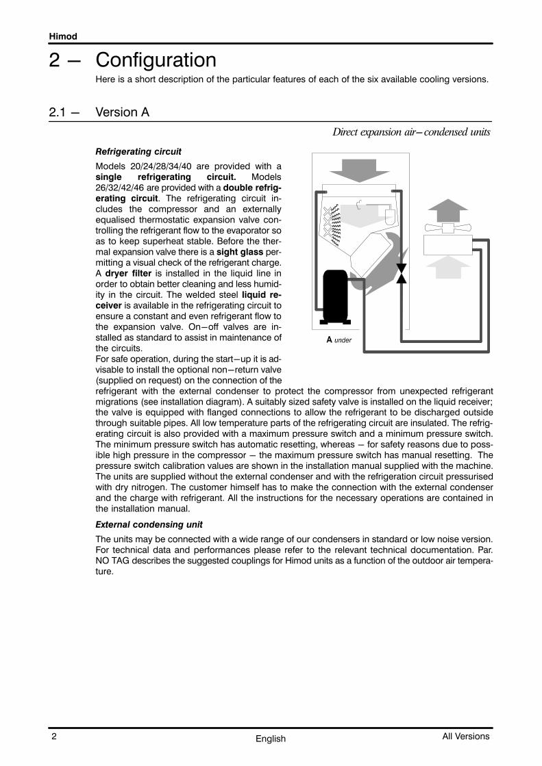
2 - ConfigurationHere is a short description of the particular features of each of the six available cooling versions.
2.1 - Version A
Direct expansion air-condensed units
Refrigerating circuit
Models 20/24/28/34/40 are provided with asingle refrigerating circuit. Models26/32/42/46 are provided with a double refrig�erating circuit. The refrigerating circuit in�cludes the compressor and an externallyequalised thermostatic expansion valve con�trolling the refrigerant flow to the evaporator soas to keep superheat stable. Before the ther�mal expansion valve there is a sight glass per�mitting a visual check of the refrigerant charge.A dryer filter is installed in the liquid line inorder to obtain better cleaning and less humid�ity in the circuit. The welded steel liquid re�ceiver is available in the refrigerating circuit toensure a constant and even refrigerant flow tothe expansion valve. On-off valves are in�stalled as standard to assist in maintenance ofthe circuits.For safe operation, during the start-up it is ad�visable to install the optional non-return valve(supplied on request) on the connection of therefrigerant with the external condenser to protect the compressor from unexpected refrigerantmigrations (see installation diagram). A suitably sized safety valve is installed on the liquid receiver;the valve is equipped with flanged connections to allow the refrigerant to be discharged outsidethrough suitable pipes. All low temperature parts of the refrigerating circuit are insulated. The refrig�erating circuit is also provided with a maximum pressure switch and a minimum pressure switch.The minimum pressure switch has automatic resetting, whereas - for safety reasons due to poss�ible high pressure in the compressor - the maximum pressure switch has manual resetting. Thepressure switch calibration values are shown in the installation manual supplied with the machine.The units are supplied without the external condenser and with the refrigeration circuit pressurisedwith dry nitrogen. The customer himself has to make the connection with the external condenserand the charge with refrigerant. All the instructions for the necessary operations are contained inthe installation manual.
External condensing unit
The units may be connected with a wide range of our condensers in standard or low noise version.For technical data and performances please refer to the relevant technical documentation. Par.NO TAG describes the suggested couplings for Himod units as a function of the outdoor air tempera�ture.

Himod
3All Versions English
2.2 - Version W
Direct expansion water-condensed units
Refrigerating circuit
Models 20/24/28/34/40 are provided with a single re�frigerating circuit. Models 26/32/42/46 are providedwith a double refrigerating circuit. The refrigeratingcircuit includes the compressor and an externallyequalised thermostatic expansion valve controllingthe refrigerant flow to the evaporator so as to keepsuperheat stable. Before the thermal expansion valvethere is a sight glass permitting a visual check of therefrigerant charge. A dryer filter is installed in theliquid line in order to obtain better cleaning and lesshumidity in the circuit. On-off valves are installed asstandard to assist in maintenance of the circuits.A suitably sized safety valve is installed after the con�denser; the valve is equipped with flanged connec�tions to allow the refrigerant to be discharged outsidethrough suitable pipes. All low temperature parts ofthe refrigerating circuit are insulated. The refrigerat�ing circuit is also provided with a maximum pressureswitch and a minimum pressure switch. The mini�mum pressure switch has automatic resetting,whereas - for safety reasons due to possible highpressure in the compressor - the maximum pres�sure switch has manual resetting. The pressureswitch calibration values are shown in the installationmanual supplied with the machine.
Condenser
The units are provided with one (single refrigerating circuit) or two (double refrigerating circuit) stain�less steel water condenser with braze-welded plates, each condenser has one pressostatic valvefor the condensation temperature control; this advanced exchanger type gives the highest efficiencyin heat exchange. In addition, a certain oversizing of the exchanger has been provided so as to re�duce pressure drops (and energy consumption of the water pump) as much as possible and thusto allow the unit to operate with the external chiller in closed circuit, even at high outdoor tempera�tures.The units operate with mains water, tower water or water in closed circuit with an external cooler.When operating in a closed circuit, the water is cooled by outdoor air in a heat exchanger; in thiscase, to avoid unwanted ice formation during winter, it is advisable to use a water/glycol mixture(refer to the installation manual for suitable percentages). The circulation of the water-glycol mixtureis forced (the pump is not supplied). If mains water or tower water is used, when installing the unit,fit a mechanical filter on the water line to protect the condenser against possible impurities con�tained in the water (for condenser cleaning see the installation manual).The 55U W and 65U W units are provided with two shell tube heat condensers easy for internal clean�ing.

Himod
4 All VersionsEnglish
2.3 - Version D
Air-condensed dualfluid units
Refrigerating circuit
Models 20/24/28/34/40 are providedwith a single refrigerating circuit. Mo�dels 26/32/42/46 are provided with adouble refrigerating circuit. The refrig�erating circuit includes the compressorand an externally equalised thermosta�tic expansion valve controlling the re�frigerant flow to the evaporator so as tokeep superheat stable. Before the ther�mal expansion valve there is a sightglass permitting a visual check of the re�frigerant charge. A dryer filter is in�stalled in the liquid line in order to obtainbetter cleaning and less humidity in thecircuit. The welded steel liquid receiveris available in the refrigerating circuit toensure a constant and even refrigerantflow to the expansion valve. On-offvalves are installed as standard to assistin maintenance of the circuits. For safeoperation, during the start-up it is ad�visable to install the optional non-return valve (supplied on request) on the connection of the re�frigerant with the external condenser to protect the compressor from unexpected refrigerant migra�tions (see installation diagramme).A suitably sized safety valve is installed on the liquid receiver; the valve is equipped with flanged con�nections to allow the refrigerant to be discharged outside through suitable pipes. All low temperatureparts of the refrigerating circuit are insulated. The refrigerating circuit is also provided with a maxi�mum pressure switch and a minimum pressure switch. The minimum pressure switch has auto�matic resetting, whereas - for safety reasons due to possible high pressure in the compressor -the maximum pressure switch has manual resetting. The pressure switch calibration values areshown in the installation manual supplied with the machine.The units are supplied without the external condenser and with refrigeration circuit pressurised withdry nitrogen. The customer himself has to make the connection with the external condenser andcharge with refrigerant. All the instructions for the necessary operations are contained in the installa�tion manual.
External condensing unit
The units may be connected to a wide range of our condensers in standard or low noise version.For technical data and performances please refer to the relevant technical documentation. Para. 5.1describes the suggested couplings for Himod units as a function of the outdoor air temperature.
Water circuit
The unit is provided with a 3-way modulating valve complete with incremental motor for the waterflow control to the coil; the opening or closing signals, generated by the electronic control, managethe valve actuator movement in order to keep the ambient temperature at the required value.Through a series of menus it is possible to set all parameters on the control for a correct adjustment,i.e. set-points, proportional bands, proportional or proportional+integral adjustment, integratingfactor and valve feature. It is possible to adjust the valve manually in closing position (coil side) bymeans of a suitable wrench.

Himod
5All Versions English
2.4 - Version H
Water-condensed dualfluid units
Refrigerating circuit
Models 20/24/28/34/40 are provided with a single re�frigerating circuit. Models 26/32/42/46 are providedwith a double refrigerating circuit. The refrigeratingcircuit includes the compressor and an externallyequalised thermostatic expansion valve controllingthe refrigerant flow to the evaporator so as to keepsuperheat stable. Before the thermal expansion valvethere is a sight glass permitting a visual check of therefrigerant charge. A dryer filter is installed in theliquid line in order to obtain better cleaning and lesshumidity in the circuit. On-off valves are installed asstandard to assist in maintenance of the circuits. Asuitably sized safety valve is installed after the con�denser; the valve is equipped with flanged connec�tions to allow the refrigerant to be discharged outsidethrough suitable pipes. All low temperature parts ofthe refrigerating circuit are insulated. The refrigerat�ing circuit is also provided with a maximum pressureswitch and a minimum pressure switch. The mini�mum pressure switch has automatic resetting,whereas - for safety reasons due to possible highpressure in the compressor - the maximum pressure switch has manual resetting. The pressureswitch calibration values are shown in the installation manual supplied with the machine.
Condenser
The units are provided with one (single refrigerating circuit) or two (double refrigerating circuit) stain�less steel water condenser with braze-welded plates, each condenser has one pressostatic valvefor the condensation temperature control; this advanced exchanger type gives the highest efficiencyin heat exchange. In addition, a certain oversizing of the exchanger has been provided so as to re�duce pressure drops (and energy consumption of the water pump) as much as possible and thusto allow the unit to operate with the external chiller in closed circuit, even at high outdoor tempera�tures.The units operate with mains water, tower water or water in closed circuit with an external chiller.When operating in a closed circuit, the water is cooled by outdoor air in a heat exchanger; in thiscase, in order to avoid unwanted ice formation during winter, it is advisable to use a water/glycolmixture(refer to the installation manual for suitable percentages). The circulation of the water-glycolmixture is forced (the pump is not supplied). If mains water or tower water is used, when installingthe unit fit a mechanical filter on the water line to protect the condenser against possible impuritiescontained in the water (for condenser cleaning see the installation manual).
Hydraulic circuit
The unit is provided with a 3-way modulating valve, complete with incremental motor for the waterflow control to the coil; the opening or closing signals, generated by the electronic control, adjustthe valve in order to keep the ambient temperature at the required value. Through a series of menusit is possible to set all parameters on the control for a correct adjustment, i.e. set-points, propor�tional bands, proportional or proportional+integral adjustment, integrating factor and valve feature.It is possible to adjust the valve manually closed (coil side) by means of a suitable wrench.

Himod
6 All VersionsEnglish
2.5 - Version F
Freecooler units
Refrigerating circuit
Models 20/24/28/34/40 are providedwith a single refrigerating circuit. Mo�dels 26/32/42/46 are provided with adouble refrigerating circuit. The refrig�erating circuit includes the compressorand an externally equalised thermosta�tic expansion valve controlling the re�frigerant flow to the evaporator so as tokeep superheat stable. Before the ther�mal expansion valve there is a sightglass permitting a visual check of the re�frigerant charge. A dryer filter is in�stalled in the liquid line in order to obtainbetter cleaning and less humidity in thecircuit. On-off valves are installed asstandard to assist in maintenance of thecircuits. A suitably sized safety valve isinstalled after the condenser; the valveis equipped with flanged connections toallow the refrigerant to be dischargedoutside through suitable pipes. All low temperature parts of the refrigerating circuit are insulated.The refrigerating circuit is also provided with a maximum pressure switch and a minimum pressureswitch.The minimum pressure switch has automatic resetting, whereas - for safety reasons due to poss�ible high pressure in the compressor - the maximum pressure switch has manual resetting. Thepressure switch calibration values are shown in the installation manual supplied with the machine.
Condenser
The units are provided with one (single refrigerating circuit) or two (double refrigerating circuit) stain�less steel water condensers with braze-welded plates, each condenser has one pressostatic valvefor the condensation temperature control; this advanced exchanger type gives the highest efficiencyin heat exchange. In addition, a certain oversizing of the exchanger has been provided so as to re�duce pressure drops (and energy consumption of the water pump) as much as possible and thusto allow the unit to operate with the external chiller in closed circuit, even at high outdoor tempera�tures.The units operate with water in closed circuit with an external cooler. When operating in a closedcircuit, the water is cooled by the outdoor air in a heat exchanger; in this case, in order to avoid un�wanted ice formation during winter, it is advisable to use a water/glycol mixture (refer to the installa�tion manual for the suitable percentages). The circulation of the water-glycol mixture is forced (thepump is not supplied). To minimize water consumption and the condensing pressure check duringthe different seasons of the year, the unit is provided with a water register supplied as standard onthe machine.
Hydraulic circuit
The unit is provided with a 2-way modulating valve, complete with incremental motor for the waterflow control to the freecooling coil; the opening or closing signals, generated by the electronic con�trol, manage the valve in order to keep the ambient temperature at the required level.

Himod
7All Versions English
2.6 - Version C
Chilled water units
Hydraulic circuit
The unit is provided with a 3-way modulating valve, com�plete with incremental motor for the water flow control to thecoil; the opening or closing signals, generated by the electroniccontrol, manage the valve in order to keep the ambient tem�perature at the required level.Through a series of menus it is possible to set all parameterson the control for a correct adjustment, i.e. set-points, propor�tional bands, proportional or proportional+integral adjust�ment, integrating factor and valve feature. It is possible to closethe valve manually (coil side) by means of a suitable wrench.
Here is a summary list of the particular features of the different versions:
Heat exchange Refrigerating circuit Installation
A
The unit cools the air by an air/refrigerantcoil (direct expansion).The refrigerating circuit condenser is ex�ternally mounted, air-cooled.
The refrigerating circuitsare not pre-charged withrefrigerant. There is a li�quid receiver on which thesafety valve is installed.
The unit must be connectedto the external condenser andthe refrigerant must be char�ged.
W
The unit cools the air by an air/refrigerantcoil (direct expansion).The refrigerating circuit plate condenseris indoor, water-cooled.
The refrigerating circuitsare pre-charged with re�frigerant. The safety valveis installed downstream ofthe condenser.
The unit must be connectedto external cooling water pi�pework.
D
The dualfluid unit cools the air flow bymeans of an air/refrigerant coil (direct ex�pansion) or, as an alternative, an air/wa�ter coil.The refrigerating circuit condenser is ex�ternally mounted, air-cooled.
The refrigerating circuitsare not pre-charged withrefrigerant. There is a li�quid receiver on which thesafety valve is installed.
It is necessary to connect theunit to the external conden�ser, to charge it with refrige�rant and to connect the chil�led water piping for the air/water coil.
H
The dualfluid unit cools the air flow bymeans of an air/refrigerant coil (direct ex�pansion) or, as an alternative, an air/wa�ter coil.The refrigerating circuit plate condenseris indoor, water-cooled.
The refrigerating circuitsare pre-charged with re�frigerantThe safety valve is installeddownstream of the con�denser.
The unit must be connectedto the chilled water piping forthe air/water coil and to thecooling water piping for thewater/refrigerant condenser.
F
The freecooler unit cools the air flow bymeans of an air/refrigerant coil (direct ex�pansion) or, as an alternative, an air/wa�ter coil. The water flow is cooled by an ex�ternal dry-cooler. When the externaltemperature is higher than the ZET, thewater exchanges heat with the refrigerantin the internal water/refrigerant plate con�denser. When the external temperature islower than the ZET, the water is cooled asmuch as sufficiently to cool the air directlyin the air/water coil.
The refrigerating circuitsare pre-charged with re�frigerantThe safety valve is installeddownstream of the con�denser.
The unit must be connectedto the closed water circuit withthe dry-cooler.
C The unit cools the air flow by an air/watercoil.
The unit has no refrigera�ting circuit.
The unit must be connectedto the chilled water piping.

Himod
8 All VersionsEnglish
2.7 - Air control
All units are available in the three configurations shown below.
UNDER OVER
3 - Operating limits
All versions
Himod units are suitable for operating within the following working ranges (the limits apply to newunits on which correct installation and maintenance has been carried out):
Ambient conditions:
from 18.0°C, 45% R.H. at 27.0°C, 55% R.H.
Air flow
The minimum and maximum values are shown in the tables of the available static pressure. However,safety devices are provided as standard to protect the various components from any damages dueto operation outside the indicated limits.
Voltage tolerances
400 V � 10% � Frequency: 50 Hz � 2 Hz208 � 230 V � 10% � Frequency: 60 Hz � 2 Hz380 V � 10% � Frequency: 60 Hz � 2 Hz460 V � 10% � Frequency: 60 Hz � 2 Hz
Versions A and D
Outdoor conditions:
low limit = 10°C (from 9°C to -20°C with Variex accessory installed on the condenser)
high limit determined by the size of the coupled condenser. Exceeding these limits causes the com�pressor to trip due to the safety pressure switch, which can only be reset manually.
Condenser installation:
Max. distance between ambient unit and external air condenser:30 m equivalent length.
Max. geodetic height difference between condenser and unit:3 m (if the condenser is placed underneath the ambient unit).

Himod
9All Versions English
4 - Component features
4.1 - Fan
Innovative application of single suction centrifugal fans incorporat�ing an impeller with backward curved blades in treated and paintedsteel.
High efficiency.
The motor is three-phase with protection degree IP54; providedwith internal thermal protection.
The fan wheel is statically and dynamically balanced; the bearingsare self-lubricating.
The fan is mounted on vibration-damping rubber supports toreduce the mechanical contact with the frame and, thus, tominimize the vibration.
Available head up to 350 Pa.
Modularity.
Variable speed: autotransformer with several different settings;possibility to optimize air flow, available head, dehumidificationoperation.
4.2 - Compressor
Hermetic SCROLL compressors
High COP.
High MTBF (Minimum Time Between Failures)
Low sound level.
Insulated against vibration.
Protection degree IP54.
Provided with internal thermal protection.
Low start current (equalization of the internal pressures).
4.3 - Coils
Large face area.
Comprising copper pipes and aluminium fins.
Fins treated to withstand corrosive atmospheres.
Low pressure drop.
High SHR (Sensible Heat Ratio).
4.4 - Frame and panels
Made of sheet steel.
Sandwich panels lined with non-flammable insulation ma�terial Class 0 (ISO 1182.2).
All surfaces in the air flow are washable in oder to reduce theformation of bacteria.
All materials are CFC-free and may be recycled.

Himod
10 All VersionsEnglish
4.5 - Filters
Removable filters.
Filtration from G4 to F9 (CEN EN779 - resp. correspondingto EU4 and EU9 according to Eurovent EU4/5).
The folded structure of the filters gives high filtration effi�ciency and low pressure drop.
The filter media used consists of synthetic fibre cells. Theframe is made of cardboard.
Pre-filtration system for Over models.
4.6 - Refrigerants
The units are designed for use with refrigerant R22 or, as option, R407C.
4.7 - Electrical panel
Manufactured in accordance with IEC204-1 standard.
It is housed at the front of the unit, isolated from the air flow and en�closed by a plastic cover to protect the parts which are suppliedwith a voltage higher than 24 V.
The units are designed for operating at 400V/3ph/50Hz;208-230V/3ph/60Hz; 380V/3ph/60Hz; 460V/3ph/60Hz.
4.8 - Accessibility
Access to the compressor is possible even when the unitis operating by removing the front panel.
Ordinary maintenance is easier thanks to the front ac�cess enabling the replacement of the air filters, the inter�vention on the components of the refrigerating circuit - such as compressor, liquid receiver, thermalexpansion valve, refrigerant sight glass, drying filter - or on the fan, the humidifier, the electric board,the electronic control, the heating elements.
4.9 - Control system (Microface and Hiromatic G)
Very simple user interface.
Easily understandable LCD display for immediate operationof the control system.
Net connectivity of several units with standard control.
Compatible with our Hiromatic graphic display.

4 53
2
6
1
7
8
Himod
11All Versions English
4.10 - Packing
The air conditioners are usually packed with wooden pallet (1),shockproof angulars in pressed cardboard (2, 3, 4)/polystyrene(5), panels in cardboard (6)/polystyrene (7) and extensible polythe�ne film (8).
On request, wooden crates or cases can be supplied for the seatransport.
4.11 - Product quality and safety
The product conforms to European Union direc�tives 98/37/CE (89/392/CEE; 91/368/CEE;93/68/CEE), 89/336/CEE; 73/23/CEE.
Further, the Company Quality System of Air Condi�tioning Division is approved by LRQA according tothe standards UNI EN ISO 9001: 1994 and theproduct is the result of activities performed in com�
pliance with the provisions contained in the Quality procedures and plans.
Units are supplied complete with a test certificate and conformity declaration and con�trol component list.
Himod units are marked as they comply with the European directives concerning mech�anical, electrical and electromagnetic safety.

Himod
12 All VersionsEnglish
5 - Condensing section
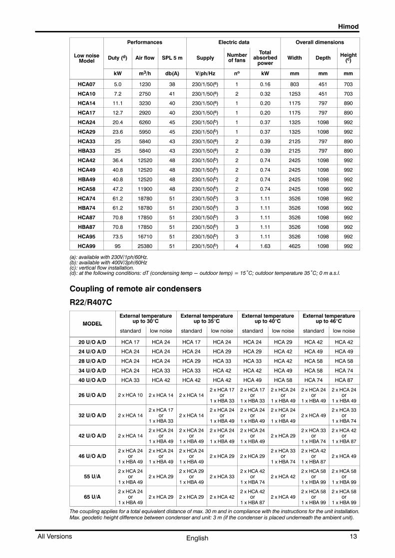
5.1 - Air condensers
The units may be connected to a wide range of our con�densers (single circuit HCA or double circuit HBA).
The following paragraphs describe the suggested couplingfor Himod units as a function of the outdoor air temperature.The data given below are approximate and must always beverified on the basis of the specific performances and differ�ent operating conditions.
Performances Electric data Overall dimensions
StandardModel
Duty (d) Air flow SPL 5 m SupplyNumberof fans
Totalabsorbed
powerWidth Depth
Height(c)
kW m3/h dB(A) V/ph/Hz nº kW mm mm mm
HCA07 7.1 1900 44 230/1/50(a) 1 0.18 803 451 703
HCA10 9.4 4100 47 230/1/50(a) 2 0.36 1253 451 703
HCA14 14.5 4430 44 230/1/50(a) 1 0.29 1175 797 890
HCA17 16.5 4160 44 230/1/50(a) 1 0.29 1175 797 890
HCA24 24.0 7950 51 230/1/50(b) 1 0.52 1325 1098 992
HCA29 28.3 7530 51 230/1/50(b) 1 0.52 1325 1098 992
HCA33 32.1 8320 47 230/1/50(a) 2 0.58 2125 797 890
HBA33 32.1 8320 47 230/1/50(a) 2 0.58 2125 797 890
HCA42 41.6 15900 54 230/1/50(b) 2 1.04 2425 1098 992
HCA49 47.9 15900 54 230/1/50(b) 2 1.04 2425 1098 992
HBA49 47.9 15900 54 230/1/50(b) 2 1.04 2425 1098 992
HCA58 56.6 15060 54 230/1/50(b) 2 1.04 2425 1098 992
HCA74 72 23850 57 230/1/50(b) 3 1.56 3526 1098 992
HBA74 72 23850 57 230/1/50(b) 3 1.56 3526 1098 992
HCA87 84.9 22590 57 230/1/50(b) 3 1.56 3526 1098 992
HBA87 84.9 22590 57 230/1/50(b) 3 1.56 3526 1098 992
HCA95 91.5 21750 57 230/1/50(b) 3 1.56 3526 1098 992
HCA99 113 30120 58 230/1/50(b) 4 2.08 4625 1098 992
Himod
13All Versions English
Performances Electric data Overall dimensions
Low noiseModel
Duty (d) Air flow SPL 5 m SupplyNumberof fans
Totalabsorbed
powerWidth Depth
Height(c)
kW m3/h db(A) V/ph/Hz nº kW mm mm mm
HCA07 5.0 1230 38 230/1/50(a) 1 0.16 803 451 703
HCA10 7.2 2750 41 230/1/50(a) 2 0.32 1253 451 703
HCA14 11.1 3230 40 230/1/50(a) 1 0.20 1175 797 890
HCA17 12.7 2920 40 230/1/50(a) 1 0.20 1175 797 890
HCA24 20.4 6260 45 230/1/50(b) 1 0.37 1325 1098 992
HCA29 23.6 5950 45 230/1/50(b) 1 0.37 1325 1098 992
HCA33 25 5840 43 230/1/50(a) 2 0.39 2125 797 890
HBA33 25 5840 43 230/1/50(a) 2 0.39 2125 797 890
HCA42 36.4 12520 48 230/1/50(b) 2 0.74 2425 1098 992
HCA49 40.8 12520 48 230/1/50(b) 2 0.74 2425 1098 992
HBA49 40.8 12520 48 230/1/50(b) 2 0.74 2425 1098 992
HCA58 47.2 11900 48 230/1/50(b) 2 0.74 2425 1098 992
HCA74 61.2 18780 51 230/1/50(b) 3 1.11 3526 1098 992
HBA74 61.2 18780 51 230/1/50(b) 3 1.11 3526 1098 992
HCA87 70.8 17850 51 230/1/50(b) 3 1.11 3526 1098 992
HBA87 70.8 17850 51 230/1/50(b) 3 1.11 3526 1098 992
HCA95 73.5 16710 51 230/1/50(b) 3 1.11 3526 1098 992
HCA99 95 25380 51 230/1/50(b) 4 1.63 4625 1098 992
(a): available with 230V/1ph/60Hz.(b): available with 400V/3ph/60Hz(c): vertical flow installation.(d): at the following conditions: dT (condensing temp - outdoor temp) = 15°C; outdoor temperature 35°C; 0 m a.s.l.
Coupling of remote air condensers
R22/R407C
MODEL
External temperatureup to 30�C
External temperatureup to 35�C
External temperatureup to 40�C
External temperatureup to 46�C
MODEL
standard low noise standard low noise standard low noise standard low noise
20 U/O A/D HCA 17 HCA 24 HCA 17 HCA 24 HCA 24 HCA 29 HCA 42 HCA 42
24 U/O A/D HCA 24 HCA 24 HCA 24 HCA 29 HCA 29 HCA 42 HCA 49 HCA 49
28 U/O A/D HCA 24 HCA 24 HCA 29 HCA 33 HCA 33 HCA 42 HCA 58 HCA 58
34 U/O A/D HCA 24 HCA 33 HCA 33 HCA 42 HCA 42 HCA 49 HCA 58 HCA 74
40 U/O A/D HCA 33 HCA 42 HCA 42 HCA 42 HCA 49 HCA 58 HCA 74 HCA 87
26 U/O A/D 2 x HCA 10 2 x HCA 14 2 x HCA 142 x HCA 17
or1 x HBA 33
2 x HCA 17or
1 x HBA 33
2 x HCA 24or
1 x HBA 49
2 x HCA 24or
1 x HBA 49
2 x HCA 24or
1 x HBA 49
32 U/O A/D 2 x HCA 142 x HCA 17
or1 x HBA 33
2 x HCA 142 x HCA 24
or1 x HBA 49
2 x HCA 24or
1 x HBA 49
2 x HCA 24or
1 x HBA 492 x HCA 49
2 x HCA 33or
1 x HBA 74
42 U/O A/D 2 x HCA 142 x HCA 24
or1 x HBA 49
2 x HCA 24or
1 x HBA 49
2 x HCA 24or
1 x HBA 49
2 x HCA 24or
1 x HBA 492 x HCA 29
2 x HCA 33or
1 x HBA 74
2 x HCA 42or
1 x HBA 87
46 U/O A/D2 x HCA 24
or1 x HBA 49
2 x HCA 24or
1 x HBA 49
2 x HCA 24or
1 x HBA 492 x HCA 29 2 x HCA 29
2 x HCA 33or
1 x HBA 74
2 x HCA 42or
1 x HBA 872 x HCA 49
55 U/A2 x HCA 24
or1 x HBA 49
2 x HCA 292 x HCA 29
or1 x HBA 49
2 x HCA 332 x HCA 42
or1 x HBA 74
2 x HCA 422 x HCA 58
or1 x HBA 99
2 x HCA 58or
1 x HBA 99
65 U/A2 x HCA 24
or1 x HBA 49
2 x HCA 29 2 x HCA 29 2 x HCA 422 x HCA 42
or1 x HBA 87
2 x HCA 492 x HCA 58
or1 x HBA 99
2 x HCA 58or
1 x HBA 99
The coupling applies for a total equivalent distance of max. 30 m and in compliance with the instructions for the unit installation.Max. geodetic height difference between condenser and unit: 3 m (if the condenser is placed underneath the ambient unit).

Himod
14 All VersionsEnglish
5.2 - Water condensers.
The water-condensed units are provided with a water/re�frigerant exchanger with braze-welded plates made ofstainless steel; this advanced exchanger type gives thehighest efficiency in heat exchange. In addition, a certainoversizing of the exchanger has been provided so as to re�duce pressure drops (and energy consumption of the waterpump) as much as possible and thus to allow the unit to op�erate with the external chiller in closed circuit, even at highoutdoor temperatures.The O/UW units are designed for operating with mains water,tower water or water in closed circuit with an external chiller.When operating in a closed circuit, the water is cooled by theoutdoor air in a heat exchanger; in this case, to avoid un�wanted ice formation during winter, it is advisable to use awater/glycol mixture. The circulation of the water-glycolmixture is forced (the pump is not supplied). If mains wateror tower water is used, when installing the unit fit a mechanical filter on the water line to protect thecondenser against possible impurities contained in the water (for condenser cleaning see the in�stallation manual).
5.3 - Dry coolers
Our dry-coolers are built with a copper/aluminium cooling coil and axial fan(s).The main data on dry coolers is shown in the following table:
Performances Electric data Overall dimensions
Standard
ModelDuty (a) Air flow
SPL
10 mSupply
Numberof fans
Totalabsorbed
powerWidth Depth
Height(b)
kW m3/h db(A) V/ph/Hz nº kW mm mm mm
DSM009 9 6.600 50 230/1/50 1 0.64 1.250 900 990
DSM013 13.5 5.100 50 230/1/50 1 0.64 1.250 900 990
DSM018 17.6 13.200 53 230/1/50 2 1.28 2.050 900 990
DSM022 22.4 12.600 53 230/1/50 2 1.28 2.050 900 990
DSM028 27.5 18.900 54 230/1/50 3 1.92 2.850 1.260 990
DST030 33 20.500 55 400/3/50 2 1.44 2.750 1.260 1.140
DST040 39 20.000 55 400/3/50 2 1.44 2.730 1.260 1.140
DST050 50 30.750 57 400/3/50 3 2.16 3.900 1.260 1.140
DST060 58 30.000 57 400/3/50 3 2.16 3.900 1.260 1.140
DST070 68 28.350 57 400/3/50 3 2.16 3.900 1.260 1.140
DST080 80 40.000 58 400/3/50 4 2.88 5.060 1.260 1.140
DST110 108 52.500 59 400/3/50 3 4.35 5.010 1.640 1.500
DST135 134 70.000 60 400/3/50 4 5.8 6.520 1.640 1.500
DST175 175 110.000 64 400/3/50 4 12.8 6.520 1.640 1.570
DST220 220 106.000 64 400/3/50 4 12.8 6.520 1.640 1.570
DST270 270 132.500 65 400/3/50 5 16 8.055 1.640 1.570
DST290 284 204.000 67 400/3/50 8 25.6 6.155 2.420 1.570
DST330 326 208.000 63 400/3/50 8 17.6 7.355 2.440 1.770
DST360 362 255.000 68 400/3/50 10 32 7.555 2.420 1.770
DST400 400 190.000 63 400/3/50 8 17.6 7.355 2.440 1.770
DST450 447 235.000 68 400/3/50 10 2 7.555 2.420 1.570
DST500 500 237.500 64 400/3/50 10 32 9.055 2.440 1.770

Himod
15All Versions English
Performances Electric data Overall dimensions
Low Noise
ModelDuty(a) Air flow
SPL
10 m (c)Supply
Numberof fans
Totalabsorbed
powerWidth Depth Height(b)
kW m3/h db(A) V/ph/Hz nº kW mm mm mm
DLM008 7.5 4.700 39 230/1/50 1 0.29 1250 900 990
DLM011 10.5 3.700 39 230/1/50 1 0.29 1250 900 990
DLM015 15.5 9.500 42 230/1/50 2 0.58 2.050 900 990
DLM018 18 9.000 42 230/1/50 2 0.58 2.050 900 990
DLM023 23 14.000 43 230/1/50 3 0.87 2.850 1260 990
DLT027 27.5 15.000 47 400/3/50 2 0.7 2.750 1260 1.140
DLT030 30 14.500 47 400/3/50 2 0.7 2.730 1260 1.140
DLT040 40 22.500 49 400/3/50 3 1.05 3.900 1260 1.140
DLT047 47 21.750 49 400/3/50 3 1.05 3.900 1260 1.140
DLT055 54 20.250 49 400/3/50 3 1.05 3.900 1260 1.140
DLT065 65 29.000 50 400/3/50 4 1.4 5.060 1260 1.140
DLT085 84 40.500 54 400/3/50 3 2.16 5.010 1.640 1.500
DLT110 112 54.000 55 400/3/50 4 2.88 6.520 1.640 1.500
DLT130 130 67.000 51 400/3/50 4 3.72 6.520 1.640 1.570
DLT160 157 62.000 51 400/3/50 4 3.72 6.520 1.640 1.570
DLT190 190 77.500 52 400/3/50 5 4.65 8.055 1.640 1.570
DLT210 212 123.000 54 400/3/50 8 7.44 6.155 2.420 1.570
DLT250 253 132.000 51 400/3/50 8 6.88 7.355 2.440 1.770
DLT270 270 153.750 55 400/3/50 10 9.3 7.555 2.420 1.770
DLT290 290 118.000 51 400/3/50 8 6.88 7.355 2.440 1.770
DLT310 310 137.500 55 400/3/50 10 9.3 7.555 2.420 1.570
DLT350 350 147.500 52 400/3/50 10 8.6 9.055 2.440 1.770
(a): at the following conditions: outdoor temperature = 35°C, inlet/outlet water temperature = 45°C/40°C.(b): vertical flow installation.(c): according to DIN45635.
Coupling of Dry-coolers
MODEL
External temperature up to30�C
External temperature up to35�C
External temperature up to40�C
MODEL
standard low noise standard low noise standard low noise
20 U/O W/F/H 1 x DSM 013 1 x DLM 015 1 x DSM 018 1 x DLM 018 1 x DSM 028 1 x DLT 027
24 U/O W/F/H 1 x DSM 018 1 x DLM 018 1 x DSM 022 1 x DLM 023 1 x DST 040 1 x DLT 040
28 U/O W/F/H 1 x DSM 018 1 x DLM 018 1 x DSM 028 1 x DLT 027 1 x DST 040 1 x DLT 040
34 U/O W/F/H 1 x DSM 022 1 x DLM 023 1 x DST 030 1 x DLT 030 1 x DST 050 1 x DLT 047
40 U/O W/F/H 1 x DSM 028 1 x DLT 027 1 x DST 040 1 x DLT 040 1 x DST 070 1 x DLT 065
26 U/O W/F/H 1 x DSM 018 1 x DLM 018 1 x DSM 028 1 x DLT 027 1 x DST 040 1 x DLT 040
32 U/O W/F/H 1 x DSM 022 1 x DLM 023 1 x DST 030 1 x DLT 030 1 x DST 050 1 x DLT 047
42 U/O W/F/H 1 x DSM 028 1 x DLT 027 1 x DST 050 1 x DLT 040 1 x DST 060 1 x DLT 065
46 U/O W/F/H 1 x DST 040 1 x DLT 040 1 x DST 060 1 x DLT 055 1 x DST 080 1 x DLT 085
55 U/W 1 x DST 050 1 x DLT 047 1 x DST 060 1 x DLT 055 1 x DST 110 1 x DLT 110
65 U/W 1 x DST 060 1 x DLT 055 1 x DST 070 1 x DLT 065 1 x DST 135 1 x DLT 130

AttentionThe differences between the unitsoperating with the fluid R407C and
those operating with the fluid R22 aredescribed below.
Himod
16 All VersionsEnglish
6 - Technical notes
6.1 - Optional alternative refrigerant, R407C.
The revision of the European regulation3093/94 and recent international agreements(Montreal, London, Copenhagen, Vienna andSan Josè) have abolished - with precise expirydates - the production of the HCFC fluids (e.g.:R22) considered as harmful for the ozone layer.The new HFC fluids (hydrofluorocarbons)which have to replace them contain no chlori�ne, a dangerous substance for the ozone layer.Refrigerant R407C is considered as the mostsuitable substance for replacing R22.
Its main features are:
� Non-azeotropic mixture made of R32/R125/R134a in which the percentage weight compositionis, in ratio, 23/25/52.
� Thermophysical features similar to R22.
� ODP (Ozone Depletion Potential) equal to 0.
� Not flammable in the air.
� Low toxicity.
The new HFC fluids are essentially incompatible with the mineral oils which are usually usedwith R12 and R22.
Therefore, new synthetic lubricants based on polyester molecules have been developed fortheir use.Note: Considering the unique thermophysical properties of RC407C the refrigeration cycle is illu�
strated in the diagram below.
IsotermsP (bar)
h (kJ/kg)
PC
PE
High pressure side Low pressure side
TCB: condensation temperaturebubble point (Liquid)
TCR: condensation temperaturedew point (Vapor)
TCM: average condensation temperature(TCB+TCM)/2
TL: temperature of the refrigerant atthe expansion valve inlet
Overheating = TAC - TER
TLV: liquid-steam temperature
TER: evaporation temperaturedew point (Vapor)
TEM: average evaporation temperature(TLV+TER)/2
TAC: temperature of the overheated vapourat the compressor inlet
Sub-cooling = TCB -TL

Himod
17All Versions English
Featuring of ethylene glycol mixture
0%
5%
10%
15%
20%
25%
30%
35%
40%
0 -5 -10 -15 -20 -25
Freezing temperature
Pe
rce
nta
ge
of
eth
yle
ne
gly
co
l m
ixe
d w
ith
wate
r
% in weight % in volume

Himod
18 All VersionsEnglish
7 - Electrical characteristics 50/60 Hz unit50 Hz 3 ph / 400 V
STANDARD R22 OPTIONAL R407C
Component FAN(3ph - 160 � 400V)
COMPRESSOR(3ph - 400V)
COMPRESSOR(3ph - 400V)
Model50 Hz
OA FLA LRAabsorbed
power
(kW)OA FLA LRA
absorbedpower(kW)
OA FLA LRAabsorbed
power(kW)
20U A/W 3.9 4.5 13 1.0 7.8 10.8 70.5 4.3 8.0 10.8 70.5 4.4
24U A/W 4.2 4.5 13 1.3 11.2 15.0 94 5.3 11.1 15 94 5.8
28U A/W 2 x 4.1 2 x 4.5 2 x 13 2 x 1.1 12.0 18.5 116 6.3 13.7 18.5 116 6.9
34U A/W 2 x 4.1 2 x 4.5 2 x 13 2 x 1.2 13.7 21.2 127 7.2 15.3 21.2 127 8.1
40U A/W 2 x 4.3 2 x 4.5 2 x 13 2 x 1.35 17.1 26.0 159 8.9 17.6 26 159 10.0
26U A/W 2 x 4.1 2 x 4.5 2 x 13 2 x 1.1 2 x 5.9 2 x 7.5 2 x 51 2 x 2.63 2 x 6.1 2 x 7.5 2 x 51 2 x 2.93
32U A/W 2 x 4.1 2 x 4.5 2 x 13 2 x 1.2 2 x 7.5 2 x 9.6 2x59.5 2 x 3.24 2 x 7.6 2 x 9.6 2x59.5 2 x 3.62
42U A/W 2 x 4.3 2 x 4.5 2 x 13 2 x 1.35 2 x 7.9 2x10.8 2x70.5 2 x 4.30 2 x 8.0 2x10.8 2x70.5 2 x 4.40
46U A/W 2 x 4.3 2 x 4.5 2 x 13 2 x 1.5 2x11.3 2x15.0 2 x 94 2 x 5.30 2x11.1 2x15.0 2 x 94 2 x 5.80
55U A/W 2 x 4.4 2 x 4.5 2 x 13 2 x 1.83 2x12.8 2x16.9 2x130 2 x 7.25 2x12.4 2x16.9 2x130 2 x 6.89
65U A/W 2 x 4.4 2 x 4.5 2 x 13 2 x 2.07 2x15.0 2x19.4 2x130 2 x 7.90 2x17.5 2x19.4 2x130 2 x 7.52
20O A/W 4.1 4.5 13 2.2 7.9 10.8 70.5 4.3 8.0 10.8 70.5 4.4
24O A/W 4.3 4.5 13 2.8 11.2 15.0 94 5.3 11.1 15 94 5.8
28O A/W 2 x 4.1 2 x 4.5 2 x 13 2 x 1.2 12.0 18.5 116 6.3 13.7 18.5 116 6.9
34O A/W 2 x 4.3 2 x 4.5 2 x 13 2 x 1.45 13.7 21.2 127 7.2 15.3 21.2 127 8.1
40O A/W 2 x 4.5 2 x 4.5 2 x 13 2 x 1.6 17.1 26.0 159 8.9 17.6 26 159 10.0
26O A/W 2 x 4.1 2 x 4.5 2 x 13 2 x 1.2 2 x 5.9 2 x 7.5 2 x 51 2 x 2.63 2 x 6.1 2 x 7.5 2 x 51 2 x 2.93
32O A/W 2 x 4.3 2 x 4.5 2 x 13 2 x 1.45 2 x 7.5 2 x 9.6 2x59.5 2 x 3.24 2 x 7.6 2 x 9.6 2x59.5 2 x 3.62
42O A/W 2 x 4.5 2 x 4.5 2 x 13 2 x 1.6 2 x 7.9 2x10.8 2x70.5 2 x 4.30 2 x 8.0 2x10.8 2x70.5 2 x 4.40
46O A/W 2 x 4.4 2 x 4.5 2 x 13 2 x 1.75 2x11.3 2x15.0 2 x 94 2 x 5.30 2x11.1 2x15.0 2 x 94 2 x 5.80
20U D/H 4.1 4.5 13 1.1 7.8 10.8 70.5 4.3 8.0 10.8 70.5 4.4
24U D/H 4.4 4.5 13 1.5 11.3 15.0 94 5.3 11.1 15 94 5.8
28U D/H 2 x 4.1 2 x 4.5 2 x 13 2 x 1.2 12.0 18.5 116 6.3 13.7 18.5 116 6.9
34U D/H 2 X 4.2 2 x 4.5 2 x 13 2 x 1.3 13.7 21.2 127 7.2 15.3 21.2 127 8.1
40U D/H 2 X 4.3 2 x 4.5 2 x 13 2 x 1.45 17.1 26.0 159 8.9 17.6 26 159 10.0
26U D/H 2 X 4.1 2 x 4.5 2 x 13 2 x 1.2 2 x 5.9 2 x 7.5 2 x 51 2 x 2.63 2 x 6.1 2 x 7.5 2 x 51 2 x 2.93
32U D/H 2 X 4.2 2 x 4.5 2 x 13 2 x 1.3 2 x 7.5 2 x 9.6 2x59.5 2 x 3.24 2 x 7.6 2 x 9.6 2x59.5 2 x 3.62
42U D/H 2 X 4.3 2 x 4.5 2 x 13 2 x 1.45 2 x 7.9 2x10.8 2x70.5 2 x 4.30 2 x 8.0 2x10.8 2x70.5 2 x 4.40
46U D/H 2 X 4.4 2 x 4.5 2 x 13 2 x 1.65 2x11.3 2x15.0 2 x 94 2 x 5.30 2x11.1 2x15.0 2 x 94 2 x 5.80
20O D/H 4.1 4.5 13 1.2 7.8 10.8 70.5 4.3 8.0 10.8 70.5 4.4
24O D/H 4.5 4.5 13 1.6 11.2 15.0 94 5.3 11.1 15 94 5.8
28O D/H 2 x 4.2 2 x 4.5 2 x 13 2 x 1.25 12.0 18.5 116 6.3 13.7 18.5 116 6.9
34O D/H 2 X 4.3 2 x 4.5 2 x 13 2 x 1.5 13.7 21.2 127 7.2 15.3 21.2 127 8.1
40O D/H 2 X 4.4 2 x 4.5 2 x 13 2 x 1.65 17.1 26.0 159 8.9 17.6 26 159 10.0
26O D/H 2 X 4.2 2 x 4.5 2 x 13 2 x 1.25 2 x 5.9 2 x 7.5 2 x 51 2 x 2.63 2 x 6.1 2 x 7.5 2 x 51 2 x 2.93
32O D/H 2 X 4.3 2 x 4.5 2 x 13 2 x 1.5 2 x 7.4 2 x 9.6 2x59.5 2 x 3.24 2 x 7.6 2 x 9.6 2x59.5 2 x 3.62
42O D/H 2 X 4.4 2 x 4.5 2 x 13 2 x 1.65 2 x 7.9 2x10.8 2x70.5 2 x 4.30 2 x 8.0 2x10.8 2x70.5 2 x 4.40
46O D/H 2 X 4.5 2 x 4.5 2 x 13 2 x 1.9 2x11.3 2x15.0 2 x 94 2 x 5.30 2x11.1 2x15.0 2 x 94 2 x 5.80
20U F 4.1 4.5 13 1.1 8.7 10.8 70.5 5.1 9.3 10.8 70.5 5.3
24U F 4.4 4.5 13 1.5 12.8 15.0 94 6.4 12.9 15 94 6.9
28U F 2 x 4.1 2 x 4.5 2 x 13 1.4 13.8 18.5 116 7.3 16.1 18.5 116 8.1
34U F 2 x 4.2 2 x 4.5 2 x 13 2 x 1.3 15.8 21.2 127 8.4 17.4 21.2 127 9.7
40U F 2 x 4.3 2 x 4.5 2 x 13 2 x 1.45 20.7 26.0 159 10.3 20.8 26 159 11.5
26U F 2 x 4.1 2 x 4.5 2 x 13 2 x 1.2 2 x 6.5 2 x 7.5 2 x 51 2 x 2.63 2 x 7.0 2 x 7.5 2 x 51 2 x 2.93
32U F 2 x 4.2 2 x 4.5 2 x 13 2 x 1.3 2 x 8.4 2 x 9.6 2x59.5 2 x 3.24 2 x 8.6 2 x 9.6 2x59.5 2 x 3.62
42U F 2 x 4.3 2 x 4.5 2 x 13 2 x 1.45 2 x 9.4 2x10.8 2x70.5 2 x 4.30 2 x 9.7 2x10.8 2x70.5 2 x 4.40
46U F 2 x 4.4 2 x 4.5 2 x 13 2 x 1.65 2x13.2 2x15.0 2 x 94 2 x 5.30 2x13.2 2x15.0 2 x 94 2 x 5.80
20O F 4.1 4.5 13 1.2 8.7 10.8 70.5 5.1 9.1 10.8 70.5 5.3
24O F 4.5 4.5 13 1.6 13.0 15.0 94.0 6.4 13.1 15 94 6.9
28O F 2 x 4.2 2 x 4.5 2 x 13 2 x 1.25 13.8 18.5 116.0 7.3 16.1 18.5 116 8.1
34O F 2 x 4.3 2 x 4.5 2 x 13 2 x 1.5 15.8 21.2 127.0 8.4 17.4 21.2 127 9.6
40O F 2 x 4.4 2 x 4.5 2 x 13 2 x 1.65 20.6 26.0 159.0 10.3 20.7 26 159 11.5
26O F 2 x 4.2 2 x 4.5 2 x 13 2 x 1.25 2 x 6.5 2 x 7.5 2 x 51 2 x 2.63 2 x 7.0 2 x 7.5 2 x 51 2 x 2.93
32O F 2 x 4.3 2 x 4.5 2 x 13 2 x 1.5 2 x 8.3 2 x 9.6 2x59.5 2 x 3.24 2 x 8.6 2 x 9.6 2x59.5 2 x 3.62

Himod
19All Versions English
Component
OPTIONAL R407CSTANDARD R22
Component COMPRESSOR(3ph - 400V)
COMPRESSOR(3ph - 400V)
FAN(3ph - 160 � 400V)
Model50 Hz
absorbedpower(kW)
LRAFLAOAabsorbed
power(kW)
LRAFLAOAabsorbed
power
(kW)LRAFLAOA
42O F 2 x 4.4 2 x 4.5 2 x 13 2 x 1.65 2 x 9.3 2x10.8 2x70.5 2 x 4.30 2 x 9.6 2x10.8 2x70.5 2 x 4.40
46O F 2 x 4.5 2 x 4.5 2 x 13 2 x 1.9 2x13.2 2x15.0 2 x 94 2 x 5.30 2x13.2 2x15.0 2 x 94 2 x 5.80
ComponentFAN
(3ph - 160 � 400V)
Model50 Hz
OA FLA LRA absorbed power (kW)
27U C 4.3 4.4 16 1.4
45U C 4.3 4.4 16 1.4
55U C 2 x 4.3 2 x 4.4 2 x 16 2 x 1.5
65U C 2 x 4.3 2 x 4.4 2 x 16 2 x 1.5
80U C 2 x 4.3 2 x 4.4 2 x 16 2 x 1.5
85U C 2 x 4.3 2 x 4.4 2 x 16 2 x 1.5
27O C 4.3 4.4 16 1.5
45O C 4.3 4.4 16 1.5
55O C 2 x 4.3 2 x 4.4 2 x 16 2 x 1.5
65O C 2 x 4.3 2 x 4.4 2 x 16 2 x 1.5
80O C 2 x 4.4 2 x 4.4 2 x 16 2 x 1.6
85O C 2 x 4.4 2 x 4.4 2 x 16 2 x 1.6

Himod
20 All VersionsEnglish
60 Hz 3 ph / 208 � 230 V
STANDARD R22 OPTIONAL R407C
Component FAN(3ph - 160 � 460V)
COMPRESSOR(3ph - 208 � 230V)
COMPRESSOR(3ph - 208 � 230V)
Model60 Hz
OA FLA LRAabsorbed
power
(kW)OA FLA LRA
absorbedpower
(kW)OA FLA LRA
absorbedpower
(kW)
20U A/W 3.2 3.5 16 0.81 14.8 20.7 133 4.5 14.8 20.7 133 4.6
24U A/W 3.4 3.5 16 1.1 15.7 22.7 172 5.2 15.7 22.7 172 5.3
28U A/W 2 x 3.3 2 x 3.5 2 x 16 2 x 0.9 22.3 32.0 203 6.5 23.1 32.0 203 6.9
34U A/W 2 x 3.3 2 x 3.5 2 x 16 2 x 0.95 25.3 39.4 232 7.9 26.3 39.4 232 8.4
40U A/W 2 x 3.4 2 x 3.5 2 x 16 2 x 1.1 29.0 42.3 278 9 30.8 42.3 278 9.6
26U A/W 2 x 3.3 2 x 3.5 2 x 16 2 x 0.9 2 x 7.8 2x13.9 2 x 91 2 x 2.85 2 x 8.2 2x13.9 2 x 91 2 x 2.95
32U A/W 2 x 3.3 2 x 3.5 2 x 16 2 x 0.95 2x10.8 2x17.1 2 x 98 2 x 3.65 2x11.5 2x17.1 2 x 98 2 x 3.6
42U A/W 2 x 3.4 2 x 3.5 2 x 16 2 x 1.1 2x14.8 2x20.7 2x133 2 x 4.5 2x14.9 2x20.7 2x133 2 x 4.6
46U A/W 2 x 3.3 2 x 3.5 2 x 16 2 x 1.2 2x15.9 2x22.7 2x172 2 x 5.25 2x15.9 2x22.7 2x172 2 x 5.3
20O A/W 3.3 3.5 16 0.9 14.7 20.7 133 4.5 14.8 20.7 133 4.6
24O A/W 3.4 3.5 16 1.2 15.7 22.7 172 5.2 15.7 22.7 172 5.3
28O A/W 2 x 3.3 2 x 3.5 2 x 16 2 x 0.95 22.3 32.0 203 6.5 23.1 32.0 203 6.9
34O A/W 2 x 3.3 2 x 3.5 2 x 16 2 x 1.15 25.3 39.4 232 7.9 26.3 39.4 232 8.4
40O A/W 2 x 3.3 2 x 3.5 2 x 16 2 x 1.25 29 42.3 278 9.0 30.8 42.3 278 9.6
26O A/W 2 x 3.3 2 x 3.5 2 x 16 2 x 0.95 2 x 7.8 2x13.9 2 x 91 2 x 2.85 2 x 8.2 2x13.9 2 x 91 2 x 2.95
32O A/W 2 x 3.3 2 x 3.5 2 x 16 2 x 1.15 2x10.8 2x17.1 2 x 98 2 x 3.6 2x11.5 2x17.1 2 x 98 2 x 3.6
42O A/W 2 x 3.3 2 x 3.5 2 x 16 2 x 1.25 2x14.8 2x20.7 2x133 2 x 4.5 2x14.9 2x20.7 2x133 2 x 4.6
46O A/W 2 x 3.3 2 x 3.5 2 x 16 2 x 1.35 2x15.8 2x22.7 2x172 2 x 5.25 2x15.8 2x22.7 2x172 2 x 5.3
20U D/H 3.3 3.5 16 1.0 14.7 20.7 133 4.5 14.8 20.7 133 4.6
24U D/H 3.3 3.5 16 1.3 15.8 22.7 172 5.2 15.8 22.7 172 5.3
28U D/H 2 x 3.3 2 x 3.5 2 x 16 2 x 1.0 22.3 32.0 203 6.5 23.1 32.0 203 6.9
34U D/H 2 X 3.4 2 x 3.5 2 x 16 2 x 1.1 25.3 39.4 232 7.9 26.3 39.4 232 8.4
40U D/H 2 X 3.3 2 x 3.5 2 x 16 2 x 1.2 29 42.3 278 9.0 30.8 42.3 278 9.6
26U D/H 2 X 3.3 2 x 3.5 2 x 16 2 x 1.0 2 x 7.8 2x13.9 2 x 91 2 x 5.85 2 x 8.2 2x13.9 2 x 91 2 x 2.95
32U D/H 2 X 3.4 2 x 3.5 2 x 16 2 x 1.1 2x10.8 2x17.1 2 x 98 2 x 3.6 2x11.5 2x17.1 2 x 98 2 x 3.55
42U D/H 2 X 3.3 2 x 3.5 2 x 16 2 x 1.1 2x14.8 2x20.7 2x133 2 x 4.5 2x14.9 2x20.7 2x133 2 x 4.6
46U D/H 2 X 3.2 2 x 3.5 2 x 16 2 x 1.35 2x15.9 2x22.7 2x172 2 x 5.25 2x15.9 2x22.7 2x172 2 x 5.3
20O D/H 3.4 3.5 16 1.0 14.7 20.7 133 4.4 14.7 20.7 133 4.6
24O D/H 3.3 3.5 16 1.3 15.7 22.7 172 5.2 15.7 22.7 172 5.3
28O D/H 2 x 3.4 2 x 3.5 2 x 16 2 x 1.05 22.3 32.0 203 6.5 23.1 32.0 203 6.9
34O D/H 2 X 3.3 2 x 3.5 2 x 16 2 x 1.2 25.3 39.4 232 7.9 26.3 39.4 232 8.4
40O D/H 2 X 3.2 2 x 3.5 2 x 16 2 x 1.35 29.0 42.3 278 9.0 30.8 42.3 278 9.6
26O D/H 2 X 3.4 2 x 3.5 2 x 16 2 x 1.05 2 x 7.8 2x13.9 2 x 91 2 x 2.85 2 x 8.2 2x13.9 2 x 91 2 x 2.95
32O D/H 2 X 3.3 2 x 3.5 2 x 16 2 x 1.2 2x10.8 2x17.1 2 x 98 2 x 3.6 2x11.5 2x17.1 2 x 98 2 x 3.65
42O D/H 2 X 3.2 2 x 3.5 2 x 16 2 x 1.35 2x14.8 2x20.7 2x133 2 x 4.5 2x14.9 2x20.7 2x133 2 x 4.6
46O D/H 2 X 3.1 2 x 3.5 2 x 16 2 x 1.5 2x15.8 2x22.7 2x172 2 x 5.25 2x15.8 2x22.7 2x172 2 x 5.3
20U F 3.3 3.5 16 1.0 15.7 20.7 133 4.9 15.9 20.7 133 5.1
24U F 3.3 3.5 16 1.3 17.1 22.7 172 5.8 17.1 22.7 172 5.9
28U F 2 x 3.3 2 x 3.5 2 x 16 2 x 1.0 24.0 32.0 203 7.2 25.2 32.0 203 7.9
34U F 2 x 3.4 2 x 3.5 2 x 16 2 x 1.1 27.1 39.4 232 8.8 28.7 39.4 232 9.6
40U F 2 x 3.3 2 x 3.5 2 x 16 2 x 1.2 31.0 42.3 278 10.0 33.7 42.3 278 11.0
26U F 2 x 3.3 2 x 3.5 2 x 16 2 x 1.0 2 x 8.5 2x13.9 2 x 91 2 x 3.2 2 x 8.9 2x13.9 2 x 91 2 x 3.3
32U F 2 x 3.4 2 x 3.5 2 x 16 2 x 1.1 2x11.8 2x17.1 2 x 98 2 x 3.95 2x12.9 2x17.1 2 x 98 2 x 4.15
42U F 2 x 3.3 2 x 3.5 2 x 16 2 x 1.2 2x15.8 2x20.7 2x133 2 x 4.95 2x16.2 2x20.7 2x133 2 x 5.2
46U F 2 x 3.2 2 x 3.5 2 x 16 2.7 2x17.5 2x22.7 2x172 2x 5.95 2x17.5 2x22.7 2x172 2 x 6.05
20O F 3.4 3.5 16 1.0 15.7 20.7 133 4.9 15.8 20.7 133 5.1
24O F 3.3 3.5 16 1.3 17.0 22.7 172 5.8 17.0 22.7 172 5.9
28O F 2 x 3.4 2 x 3.5 2 x 16 2 x 1.05 24.0 32.0 203 7.2 25.2 32.0 203 7.9
34O F 2 x 3.3 2 x .5 2 x 16 2 x 1.2 27.0 39.4 232 8.8 28.7 39.4 232 9.6
40O F 2 x 3.2 2 x 3.5 2 x 16 2 x 1.35 31.0 42.3 278 10.0 33.7 42.3 278 11.0
26O F 2 x 3.4 2 x 3.5 2 x 16 2 x 1.05 2 x 8.5 2x13.9 2 x 91 2 x 3.2 2 x 8.9 2x13.9 2 x 91 2 x 3.3
32O F 2 x 3.3 2 x 3.5 2 x 16 2 x 1.2 2x11.8 2x17.1 2 x 98 2 x 3.95 2x12.9 2x17.1 2 x 98 2 x 4.15
42O F 2 x 3.2 2 x 3.5 2 x 16 2 x 1.35 2x15.8 2x20.7 2x133 2 x 4.95 2x16.2 2x20.7 2x133 2 x 5.2
46O F 2 x 3.1 2 x 3.5 2 x 16 2 x 1.5 2x17.4 2x22.7 2x172 2 x 5.95 2x17.4 2x22.7 2x172 2 x 6.05

Himod
21All Versions English
60 Hz 3 ph / 380 V
STANDARD R22 OPTIONAL R407C
Component FAN(3ph - 160 � 460V)
COMPRESSOR(3ph - 380V)
COMPRESSOR(3ph - 380V)
Model60 Hz
OA FLA LRAabsorbed
power
(kW)OA FLA LRA
absorbedpower
(kW)OA FLA LRA
absorbedpower(kW)
20U A/W 3.2 3.5 16 0.8 8.9 12.0 64.0 4.5 - - - -
24U A/W 3.4 3.5 16 1.1 9.4 13.5 70.0 5.2 - - - -
28U A/W 2 x 3.3 2 x 3.5 2 x 16 2 x 0.9 11.3 18.2 112 4.5 11.5 18.2 112 6.9
34U A/W 2 x 3.3 2 x 3.5 2 x 16 2 x 0.95 15.1 23.5 144 5.2 16.1 23.5 144 8.4
40U A/W 2 x 3.4 2 x 3.5 2 x 16 2 x 1.1 17.3 28.8 151 6.5 18.0 28.8 151 9.6
26U A/W 2 x 3.3 2 x 3.5 2 x 16 2 x 0.9 - - - - - - - -
32U A/W 2 x 3.3 2 x 3.5 2 x 16 2 x 0.95 2 x 5.9 2 x 9.5 2x57.0 2 x 3.65 - - - -
42U A/W 2 x 3.4 2 x 3.5 2 x 16 2 x 1.1 2 x 8.9 2x12.0 2x64.0 2 x 4.5 - - - -
46U A/W 2 x 3.3 2 x 3.5 2 x 16 2 x 1.2 2 x 9.5 2x13.5 2x70.0 2 x 5.25 - - - -
20O A/W 3.3 3.5 16 0.9 7.4 12.0 64.0 4.5 - - - -
24O A/W 3.4 3.5 16 1.2 9.4 13.5 70.0 5.2 - - - -
28O A/W 2 x 3.3 2 x 3.5 2 x 16 2 x 0.95 11.3 18.2 112 6.5 11.5 18.2 112 6.9
34O A/W 2 x 3.3 2 x 3.5 2 x 16 2 x 1.15 15.1 21.8 144 7.9 16.1 21.8 144 8.4
40O A/W 2 x 3.3 2 x 3.5 2 x 16 2 x 1.25 17.3 25.1 151 9.0 18.0 25.1 151 9.6
26O A/W 2 x 3.3 2 x 3.5 2 x 16 2 x 0.95 - - - - - - - -
32O A/W 2 x 3.3 2 x 3.5 2 x 16 2 x 1.15 2 x 5.9 2 x 9.5 2x57.0 2 x 3.6 - - - -
42O A/W 2 x 3.3 2 x 3.5 2 x 16 2 x 1.25 2 x 8.9 2x12.0 2x64.0 2 x 4.5 - - - -
46O A/W 2 x 3.3 2 x 3.5 2 x 16 2 x 1.35 2 x 9.4 2x13.5 2x70.0 2 x 5.25 - - - -
20U D/H 3.3 3.5 16 1.0 8.8 12.0 64.0 4.5 - - - -
24U D/H 3.3 3.5 16 1.3 9.4 13.5 70.0 5.2 - - - -
28U D/H 2 x 3.3 2 x 3.5 2 x 16 2 x 1.0 11.3 18.2 112 6.5 11.5 18.2 112 6.9
34U D/H 2 X 3.4 2 x 3.5 2 x 16 2 x 1.1 15.1 21.8 144 7.9 16.1 21.8 144 8.4
40U D/H 2 X 3.3 2 x 3.5 2 x 16 2 x 1.2 17.3 25.1 151 9.0 18.0 25.1 151 9.6
26U D/H 2 X 3.3 2 x 3.5 2 x 16 2 x 1.0 - - - - - - - -
32U D/H 2 X 3.4 2 x 3.5 2 x 16 2 x 1.1 2 x 5.9 2 x 9.5 2x57.0 2 x 3.6 - - - -
42U D/H 2 X 3.3 2 x 3.5 2 x 16 2 x 1.2 2 x 8.9 2x12.0 2x64.0 2 x 4.5 - - - -
46U D/H 2 X 3.2 2 x 3.5 2 x 16 2 x 1.35 2 x 9.5 2x13.5 2x70.0 2 x 5.25 - - - -
20O D/H 3.4 3.5 16 1.0 8.8 12.0 64.0 4.4 - - - -
24O D/H 3.3 3.5 16 1.3 9.4 13.5 70.0 5.2 - - - -
28O D/H 2 x 3.4 2 x 3.5 2 x 16 2.1 11.3 18.2 112 6.5 11.5 18.2 112 6.9
34O D/H 2 X 3.3 2 x 3.5 2 x 16 2 x 1.2 15.1 21.8 144 7.9 16.0 21.8 144 8.4
40O D/H 2 X 3.2 2 x 3.5 2 x 16 2 x 1.35 17.3 25.1 151 9.0 18.0 25.1 151 9.6
26O D/H 2 X 3.4 2 x 3.5 2 x 16 2 x 1.05 - - - - - - - -
32O D/H 2 X 3.3 2 x 3.5 2 x 16 2 x 1.2 2 x 5.8 2 x 9.5 2x57.0 2 x 3.6 - - - -
42O D/H 2 X 3.2 2 x 3.5 2 x 16 2 x 1.35 2 x 8.9 2x12.0 2x64.0 2 x 4.5 - - - -
46O D/H 2 X 3.1 2 x 3.5 2 x 16 2 x 1.5 2 x 9.4 2x13.5 2x70.0 2 x 5.25 - - - -
20U F 3.3 3.5 16 1.0 9.5 12.0 64.0 4.9 - - - -
24U F 3.3 3.5 16 1.3 10.2 13.5 70.0 5.8 - - - -
28U F 2 x 3.3 2 x 3.5 2 x 16 2 x 1.0 11.9 18.2 112 7.2 12.4 18.2 112 7.9
34U F 2 x 3.4 2 x 3.5 2 x 16 2 x 1.1 16.1 21.8 144 8.8 17.6 21.8 144 9.6
40U F 2 x 3.3 2 x 3.5 2 x 16 2 x 1.2 18.5 25.1 151 10.0 19.7 25.1 151 11.0
26U F 2 x 3.3 2 x 3.5 2 x 16 2 x 1.0 - - - - - - - -
32U F 2 x 3.4 2 x 3.5 2 x 16 2 x 1.1 2 x 6.2 2 x 9.5 2x57.0 2 x 3.95 - - - -
42U F 2 x 3.3 2 x 3.5 2 x 16 2 x 1.2 2 x 9.5 2x12.0 2x64.0 2 x 4.95 - - - -
46U F 2 x 3.2 2 x 3.5 2 x 16 2 x 1.35 2x10.4 2x13.5 2x70.0 2 x 5.95 - - - -
20O F 3.4 3.5 16 1.0 9.4 12.0 64.0 4.9 - - - -
24O F 3.3 3.5 16 1.3 10.2 13.5 70.0 5.8 - - - -
28O F 2 x 3.4 2 x 3.5 2 x 16 2 x 0.95 11.9 18.2 112 7.2 12.4 18.2 112 7.9
34O F 2 x 3.3 2 x 3.5 2 x 16 2 x 1.2 16.1 21.8 144 8.8 17.5 21.8 144 9.6
40O F 2 x 3.2 2 x 3.5 2 x 16 2 x 1.35 18.5 25.1 151 10.0 19.7 25.1 151 11.0
26O F 2 x 3.4 2 x 3.5 2 x 16 2 x 0.95 - - - - - - - -
32O F 2 x 3.3 2 x 3.5 2 x 16 2 x 1.2 2 x 6.2 2 x 9.5 2x57.0 2 x 3.95 - - - -
42O F 2 x 3.2 2 x 3.5 2 x 16 2 x 1.35 2 x 9.5 2x12.0 2x64.0 2 x 4.95 - - - -
46O F 2 x 3.1 2 x 3.5 2 x 16 2 x 1.5 2x10.4 2x13.5 2x70.0 2 x 5.95 - - - -

Himod
22 All VersionsEnglish
60 Hz 3 ph / 460 V
STANDARD R22 OPTIONAL R407C
Component FAN(3ph - 160 � 460V)
COMPRESSOR(3ph - 460V)
COMPRESSOR(3ph - 460V)
Model60 Hz
OA FLA LRAabsorbed
power
(kW)OA FLA LRA
absorbedpower
(kW)OA FLA LRA
absorbedpower
(kW)
20U A/W 3.2 3.5 16 0.8 7.4 10.2 63 4.5 7.6 10.2 63 4.6
24U A/W 3.4 3.5 16 1.1 7.8 11.4 70.5 5.2 8.0 11.4 70.5 5.3
28U A/W 2 x 3.3 2 x 3.5 2 x 16 2 x 0.9 11.3 16.4 95.0 6.5 11.1 16.4 95.0 6.9
34U A/W 2 x 3.3 2 x 3.5 2 x 16 2 x 0.95 12.1 19.1 125.0 7.9 13.1 19.1 125.0 8.4
40U A/W 2 x 3.4 2 x .5 2 x 16 2 x 1.1 13.7 22.8 127.0 9 15.1 22.8 127.0 9.6
26U A/W 2 x 3.3 2 x 3.5 2 x 16 2 x 0.9 2 x 4.5 2 x 6.8 2x44.0 2 x 2.85 2 x 4.7 2 x 6.8 2x44.0 2 x 2.95
32U A/W 2 x 3.3 2 x 3.5 2 x 16 2 x 0.95 2 x 5.8 2 x 7.9 2x50.0 2 x 3.65 2 x 5.7 2 x 7.9 2x50.0 2 x 3.6
42U A/W 2 x 3.4 2 x 3.5 2 x 16 2 x 1.1 2 x 7.5 2x10.2 2x63.0 2 x 4.5 2 x 7.6 2x10.2 2x63.0 2 x 4.6
46U A/W 2 x 3.3 2 x 3.5 2 x 16 2 x 1.2 2 x 7.9 2x11.4 2x70.5 2 x 5.25 2 x 8.0 2x11.4 2x70.5 2 x 5.3
20O A/W 3.3 3.5 16 0.9 7.4 10.2 63 4.5 7.6 10.2 63 4.6
24O A/W 3.4 3.5 16 1.2 7.8 11.4 70.5 5.2 8.0 11.4 70.5 5.3
28O A/W 2 x 3.3 2 x 3.5 2 x 16 2 x 0.95 11.3 16.4 95.0 6.5 11.1 16.4 95.0 6.9
34O A/W 2 x 3.3 2 x 3.5 2 x 16 2 x 1.15 12.1 19.1 125.0 7.9 13.1 19.1 125.0 8.4
40O A/W 2 x 3.3 2 x 3.5 2 x 16 2 x 1.25 13.7 22.8 127.0 9.0 15.1 22.8 127.0 9.6
26O A/W 2 x 3.3 2 x 3.5 2 x 16 2 x 0.95 2 x 4.5 2 x 6.8 2x44.0 2 x 2.85 2 x 4.7 2 x 6.8 2x44.0 2 x 2.95
32O A/W 2 x 3.3 2 x 3.5 2 x 16 2 x 1.15 2 x 5.8 2 x 7.9 2x50.0 2 x 3.6 2 x 5.7 2 x 7.9 2x50.0 2 x 3.6
42O A/W 2 x 3.3 2 x 3.5 2 x 16 2 x 1.25 2 x 7.5 2x10.2 2x63.0 2 x 4.5 2 x 7.6 2x10.2 2x63.0 2 x 4.6
46O A/W 2 x 3.3 2 x 3.5 2 x 16 2 x 1.35 2 x 7.9 2x11.4 2x70.5 2 x 5.25 2 x 8.0 2x11.4 2x70.5 2 x 5.3
20U D/H 3.3 3.5 16 1.0 7.4 10.2 63 4.5 7.6 10.2 63 4.6
24U D/H 3.3 3.5 16 1.3 7.9 11.4 70.5 5.2 8.0 11.4 70.5 5.3
28U D/H 2 x 3.3 2 x 3.5 2 x 16 2 x 1.0 11.3 16.4 95.0 6.5 11.1 16.4 95.0 6.9
34U D/H 2 X 3.4 2 x 3.5 2 x 16 2 x 1.1 12.1 19.1 125.0 7.9 13.1 19.1 125.0 8.4
40U D/H 2 X 3.3 2 x 3.5 2 x 16 2 x 1.2 13.7 22.8 127.0 9.0 15.1 22.8 127.0 9.6
26U D/H 2 X 3.3 2 x 3.5 2 x 16 2 x 1.0 2 x 4.5 2 x 6.8 2x44.0 2 x 5.85 2 x 4.7 2 x 6.8 2x44.0 2 x 2.95
32U D/H 2 X 3.4 2 x 3.5 2 x 16 2 x 1.1 2 x 5.8 2 x 7.9 2x50.0 2 x 3.6 2 x 5.7 2 x 7.9 2x50.0 2 x 3.55
42U D/H 2 X 3.3 2 x 3.5 2 x 16 2 x 1.2 2 x 7.5 2x10.2 2x63.0 2 x 4.5 2 x 7.6 2x10.2 2x63.0 2 x 4.6
46U D/H 2 X 3.2 2 x 3.5 2 x 16 2 x 1.35 2 x 7.9 2x11.4 2x70.5 2 x 5.25 2 x 8.0 2x11.4 2x70.5 2 x 5.3
20O D/H 3.4 3.5 16 1.0 7.4 10.2 63 4.4 7.6 10.2 63 4.6
24O D/H 3.3 3.5 16 1.3 7.8 11.4 70.5 5.2 8.0 11.4 70.5 5.3
28O D/H 2 x 3.4 2 x 3.5 2 x 16 2 x 1.05 11.3 16.4 95.0 6.5 11.1 16.4 95.0 6.9
34O D/H 2 X 3.3 2 x 3.5 2 x 16 2 x 1.2 12.1 19.1 125.0 7.9 13.1 19.1 125.0 8.4
40O D/H 2 X 3.2 2 x 3.5 2 x 16 2 x 1.35 13.7 22.8 127.0 9.0 15.1 22.8 127.0 9.6
26O D/H 2 X 3.4 2 x 3.5 2 x 16 2 x 1.05 2 x 4.5 2 x 6.8 2x44.0 2 x 5.85 2 x 4.7 2 x 6.8 2x44.0 2 x 2.95
32O D/H 2 X 3.3 2 x 3.5 2 x 16 2 x 1.2 2 x 5.8 2 x 7.9 2x50.0 2 x 3.6 2 x 5.8 2 x 7.9 2x50.0 2 x 3.65
42O D/H 2 X 3.2 2 x 3.5 2 x 16 2 x 1.35 2 x 7.5 2x10.2 2x63.0 2 x 4.5 2 x 7.6 2x10.2 2x63.0 2 x 4.6
46O D/H 2 X 3.1 2 x 3.5 2 x 16 2 x 1.5 2 x 7.9 2x11.4 2x70.5 2 x 5.25 2 x 8.0 2x11.4 2x70.5 2 x 5.3
20U F 3.3 3.5 16 1.0 7.9 10.2 63 4.9 8.1 10.2 63 5.1
24U F 3.3 3.5 16 1.3 8.6 11.4 70.5 5.8 8.9 11.4 70.5 5.9
28U F 2 x 3.3 2 x 3.5 2 x 16 2 x 1.0 12.1 16.4 95.0 7.2 12.2 16.4 95.0 7.9
34U F 2 x 3.4 2 x 3.5 2 x 16 2 x 1.1 12.9 19.1 125.0 8.8 14.3 19.1 125.0 9.6
40U F 2 x 3.3 2 x 3.5 2 x 16 2 x 1.2 14.7 22.8 127.0 10.0 16.4 22.8 127.0 11.0
26U F 2 x 3.3 2 x 3.5 2 x 16 2 x 1.0 2 x 4.9 2 x 6.8 2x44.0 2 x 3.2 2 x 5.1 2 x 6.8 2x44.0 2 x 3.3
32U F 2 x 3.4 2 x 3.5 2 x 16 2 x 1.1 2 x 6.2 2 x 7.9 2x50.0 2 x 3.95 2 x 6.2 2 x 7.9 2x50.0 2 x 4.15
42U F 2 x 3.3 2 x 3.5 2 x 16 2 x 1.2 2 x 7.9 2x10.2 2x63.0 2 x 4.95 2 x 8.2 2x10.2 2x63.0 2 x 5.2
46U F 2 x 3.2 2 x 3.5 2 x 16 2 x 1.35 2 x 8.8 2x11.4 2x70.5 2 x 5.95 2 x 9.1 2x11.4 2x70.5 2 x 6.05
20O F 3.4 3.5 16 1.0 7.8 10.2 63 4.9 8.1 10.2 63 5.1
24O F 3.3 3.5 16 1.3 8.5 11.4 70.5 5.8 8.8 11.4 70.5 5.9
28O F 2 x 3.4 2 x 3.5 2 x 16 2 x 1.05 12.1 16.4 95.0 7.2 12.2 16.4 95.0 7.9
34O F 2 x 3.3 2 x 3.5 2 x 16 2 x 1.2 12.9 19.1 125.0 8.8 14.3 19.1 125.0 9.6
40O F 2 x 3.2 2 x 3.5 2 x 16 2 x 1.35 14.7 22.8 127.0 10.0 16.4 22.8 127.0 11.0
26O F 2 x 3.4 2 x 3.5 2 x 16 2 x 1.05 2 x 4.9 2 x 6.8 2x44.0 2 x 3.2 2 x 5.1 2 x 6.8 2x44.0 2 x 3.3
32O F 2 x 3.3 2 x 3.5 2 x 16 2 x 1.2 2 x 6.2 2 x 7.9 2x50.0 2 x 3.95 2 x 6.2 2 x 7.9 2x50.0 2 x 4.15
42O F 2 x 3.2 2 x 3.5 2 x 16 2 x 1.35 2 x 7.9 2x10.2 2x63.0 2 x 4.95 2 x 8.2 2x10.2 2x63.0 2 x 5.2
46O F 2 x 3.1 2 x 3.5 2 x 16 2 x 1.5 2 x 8.7 2x11.4 2x70.5 2 x 5.95 2 x 9.0 2x11.4 2x70.5 2 x 6.05

Himod
23All Versions English
ComponentFAN
(3ph - 160 � 460V)
Model60 Hz
OA FLA LRA absorbed power (kW)
27U C 3.4 3.5 16 1.1
45U C 3.4 3.5 16 1.2
55U C 2 x 3.3 2 x 3.5 2 x 16 2 x 1.2
65U C 2 x 3.4 2 x 3.5 2 x 16 2 x 1.2
80U C 2 x 3.2 2 x 3.5 2 x 16 2 x 1.2
85U C 2 x 3.3 2 x 3.5 2 x 16 2 x 1.2
27O C 3.3 3.5 16 1.2
45O C 3.3 3.5 16 1.2
55O C 2 x 3.3 2 x 3.5 2 x 16 2 x 1.2
65O C 2 x 3.3 2 x 3.5 2 x 16 2 x 1.2
80O C 2 x 3.3 2 x 3.5 2 x 16 2 x 1.3
85O C 2 x 3.3 2 x 3.5 2 x 16 2 x 1.3
The fan �OA" value and the absorbed power are refered to standard air flow; Under unit with underflow air discharge and 20 Pa availableexternal static pressure; Over unit with ducted air discharge and 50 Pa available external static pressure.
The compressor �OA" value is referred to: - ambient conditions: 24�C, 50% R.H.; condensation temperature: 45�C - A/W/D/H; ambientconditions: 24�C, 50% R.H.; external air temperature: 35�C - F. Under unit with underflow air discharge and 20 Pa available external staticpressure; Over unit with ducted air discharge and 50 Pa available external static pressure.
NOTE: the indicated fan currents are measured on their terminal boards; to calculate the current absorption ofthe fans at the machine supply terminals multiply the indicated values by the selected transforming ratio.

Himod
24 All VersionsEnglish
Optional electrical data - 50/60 Hz unit
ComponentELECTRICAL HEATING
(400V / 3Ph / 50Hz)
HUMIDIFIER
(400V / 3Ph / 50Hz)
Model
50 HzFLA rated power [kW] FLA rated power [kW]
20-24 U/O A/W/F/D/H8 5 5 85
27-45 U/O C8.5 5.85
26-28-34-40-46 U/O A/W/F/D/H17 0 11 70 15 5 7 30
55-65 U A/W17.0 11.70 15.5 7.30
55-65 U A/W (*) 25,4 17,55
55-65-80-85 U/O C 17.0 11.70
(*) Only for 17.55 kW electrical heating
ComponentELECTRICAL HEATING
(208-230V / 3Ph / 60Hz)
HUMIDIFIER
(208-230V / 3Ph / 60Hz)
Model
60 HzFLA rated power [kW] FLA rated power [kW]
20-24 U/O A/W/F/D/H15 4 5 85
27-45 U/O C15.4 5.85
25 8 6 2026-28-34-40-46 U/O A/W/F/D/H
30 8 11 70
25.8 6.20
55-65-80-85 U/O C30.8 11.70
ComponentELECTRICAL HEATING
(380V / 3Ph / 60Hz)
HUMIDIFIER
(380V / 3Ph / 60Hz)
Model
60 HzFLA rated power [kW] FLA rated power [kW]
20-24 U/O A/W/F/D/H8 9 5 85
27-45 U/O C8.9 5.85
16 3 7 3026-28-34-40-46 U/O A/W/F/D/H
17 8 11 70
16.3 7.30
55-65-80-85 U/O C17.8 11.70
ComponentELECTRICAL HEATING
(460V / 3Ph / 60Hz)
HUMIDIFIER
(460V / 3Ph / 60Hz)
Model
60 HzFLA rated power [kW] FLA rated power [kW]
20-24 U/O A/W/F/D/H7 4 5 85
27-45 U/O C7.4 5.85
13 7 7 3026-28-34-40-46 U/O A/W/F/D/H
14 7 11 70
13.7 7.30
55-65-80-85 U/O C14.7 11.70

Himod
25EnglishA- Version - 50Hz
8 - Technical data and performances 50/60Hz unitAir condensation � down flow
A UNDER R407C - 50 Hz
MODELL 20UA 24UA 28UA 34UA 40UA 26UA 32UA 42UA 46UA 55UA 65UA
REFRIGERANT CIRCUIT single single single single single double double double double double double
PERFORMANCES (1)
air flow m3/s 1.611 1.833 2.772 3.067 3.475 2.772 3.067 3.475 3.750 4.045 4.356
max available externalstatic pressure (2) Pa 450 400 430 400 370 430 400 370 320 230 165
fan absorbed power kW 0.98 1.31 2.18 2.34 2.64 2.18 2.34 2.64 2.96 3.66 4.14
fan absorbed current A 3.9 4.2 2 x 4.1 2 x 4.1 2 x 4.2 2 x 4.1 2 x 4.1 2 x 4.2 2 x 4.3 2 x 4.4 2 x 4.4
sound pressure level (3) dB(A) 51.1 54.4 56.4 57.5 59.0 56.4 57.5 59.0 60.8 62.8 64.8
total cooling capacity kW 20.6 25.8 30.9 35.9 44.8 29.5 36.1 43.4 54.4 58.7 66.6
sensible cooling capacity kW 19.2 23.5 29.9 34.1 43.3 28.6 33.6 41.3 47.7 54.0 60.6
total absorbed power kW 5.4 7.1 9.1 10.5 12.7 8.4 10.0 11.4 14.6 18.16 19.94
compressor absorbedpower kW 4.39 5.83 6.88 8.12 10.05 6.22 7.62 8.78 11.68 14.50 15.80
compressor absorbed cur�rent A 8.0 11.1 13.7 15.3 17.6 2 x 6.1 2 x 7.6 2 x 8.0 2x11.1 2x12.8 2x15.0
SHR (sensible/total ratio) - 0.93 0.91 0.97 0.95 0.97 0.97 0.93 0.95 0.88 0.92 0.91
EER (output/used energy) - 3.81 3.63 3.40 3.42 3.53 3.51 3.61 3.80 3.73 3.23 3.34
FANS
quantity n. 1 1 2 2 2 2 2 2 2 2 2
type - CENTRIFUGAL WITH BACKWARDS CURVED BLADES
motor rated power kW 2.5
COMPRESSOR
quantity n. 1 1 1 1 1 2 2 2 2 2 2
type - SCROLL
rated power HP 6 7.8 9 10 13 2 x 4 2 x 5 2 x 6 2 x 7.8 2 x 9.0 2x10.0
EVAPORATING COIL
quantity n. 1 1 1 1 1 1 1 1 1 2 2
pipes/fins COPPER/TREATED ALUMINIUM
front surface m2 0.74 0.74 1.49 1.49 1.49 1.49 1.49 1.49 1.49 2x1.49 2x1.49
configuration - INCLINED
REFRIGERANT CONNECTION
gas line (pipe to be weldedo.d.) mm 18 22 22 22 28 16 16 18 22 22 22
liquid line (pipe to bewelded o.d.) mm 16 18 18 18 22 14 14 16 18 18 18
DIMENSIONS
width mm 1000 1000 1750 1750 1750 1750 1750 1750 1750 1750 1750
depth mm 890
height mm 1950
footprint m2 0.89 0.89 1.56 1.56 1.56 1.56 1.56 1.56 1.56 1.56 1.56
WEIGHTS
net kg 380 385 580 585 590 580 585 590 605 630 630
gross kg 385 390 585 590 595 585 590 595 610 635 635
1. At the following standard conditions:power supply voltage 400/3/50 [V/Ph/Hz]; ambient conditions 24°C db; 50% R.H.(17°C wb); 20 Pa availableexternal static pressure; condensation temperature: 45°C
2. Max. external static pressure for the indicated air flow
3. Measured at 1 m height and 2 m front distance, in free field, with working fan(s) and compressor(s); 20 Pa available external static pressure, withdown flow air discharge
Cooling capacities are gross. To obtain the net cooling capaicities the fan heat load must be sudbtracted. EER refers to the ambient unit only. The airflow of the units refers to the standard configuration with filter of the G4 class. The standard diameters of the pipes only apply for lengths - between theair conditioner and the condensing unit - up to 30 equivalent m.

Himod
26 English A- Version - 50Hz
Air condensation � down flow
A UNDER R22 - 50 Hz
MODELL 20UA 24UA 28UA 34UA 40UA 26UA 32UA 42UA 46UA 55UA 65UA
REFRIGERANT CIRCUIT single single single single single double double double double double double
PERFORMANCES (1)
air flow m3/s 1.611 1.833 2.772 3.067 3.475 2.772 3.067 3.475 3.750 4.045 4.356
max available externalstatic pressure (2) Pa 450 400 430 400 370 430 400 370 320 230 165
fan absorbed power kW 0.98 1.31 2.18 2.34 2.64 2.18 2.34 2.64 2.96 3.66 4.14
fan absorbed current A 3.9 4.2 2 x 4.1 2 x 4.1 2 x 4.2 2 x 4.1 2 x 4.1 2 x 4.2 2 x 4.3 2 x 4.4 2 x 4.4
sound pressure level (3) dB(A) 51.1 54.4 56.4 57.5 59.0 56.4 57.5 59.0 60.8 62.8 64.8
total cooling capacity kW 20.2 25.3 30.5 35.4 44.2 29.1 35.5 42.5 53.7 57.5 65.1
sensible cooling capacity kW 19.4 23.8 29.9 34.7 42.9 29.1 34.1 41.7 47.2 54.5 59.7
total absorbed power kW 5.30 7.12 8.40 9.48 11.55 8.02 9.58 11.30 14.60 17.42 19.18
compressor absorbedpower kW 4.32 5.81 6.22 7.14 8.91 5.84 7.24 8.66 11.64 13.76 15.04
compressor absorbed cur�rent A 7.9 11.2 12.0 13.7 17.1 2 x 5.9 2 x 7.5 2 x 7.9 2x11.3 2x12.4 2x14.5
SHR (sensible/total ratio) - 0.96 0.94 0.98 0.98 0.97 1.00 0.96 0.98 0.88 0.95 0.92
EER (output/used energy) - 3.81 3.55 3.63 3.73 3.83 3.63 3.71 3.76 3.68 3.31 3.38
FANS
quantity n. 1 1 2 2 2 2 2 2 2 2 2
type - CENTRIFUGAL WITH BACKWARDS CURVED BLADES
motor rated power kW 2.5
COMPRESSOR
quantity n. 1 1 1 1 1 2 2 2 2 2 2
type - SCROLL
rated power HP 6 7.8 9 10 13 2 x 4 2 x 5 2 x 6 2 x 7.8 2 x 9.0 2x10.0
EVAPORATING COIL
quantity n. 1 1 1 1 1 1 1 1 1 2 2
pipes/fins COPPER/TREATED ALUMINIUM
front surface m2 0.74 0.74 1.49 1.49 1.49 1.49 1.49 1.49 1.49 2x1.49 2x1.49
configuration - INCLINED
REFRIGERANT CONNECTION
gas line (pipe to be weldedo.d.) mm 22 22 22 28 28 18 18 22 22 22 22
liquid line (pipe to bewelded o.d.) mm 18 18 18 22 22 16 16 18 18 18 18
DIMENSIONS
width mm 1000 1000 1750 1750 1750 1750 1750 1750 1750 1750 1750
depth mm 890
height mm 1950
footprint m2 0.89 0.89 1.56 1.56 1.56 1.56 1.56 1.56 1.56 1.56 1.56
WEIGHTS
net kg 380 385 580 585 590 580 585 590 605 630 630
gross kg 385 390 585 590 595 585 590 595 610 635 635
1. At the following standard conditions:power supply voltage 400/3/50 [V/Ph/Hz]; ambient conditions 24°C db; 50% R.H.(17°C wb); 20 Pa availableexternal static pressure; condensation temperature: 45°C
2. Max. external static pressure for the indicated air flow
3. Measured at 1 m height and 2 m front distance, in free field, with working fan(s) and compressor(s); 20 Pa available external static pressure, withdown flow air discharge.
Cooling capacities are gross. To obtain the net cooling capaicities the fan heat load must be sudbtracted. EER refers to the ambient unit only. The airflow of the units refers to the standard configuration with filter of the G4 class. The standard diameters of the pipes only apply for lengths - between theair conditioner and the condensing unit - up to 30 equivalent m.

Himod
27EnglishA- Version - 50Hz
Air condensation � up flow
A OVER R407C - 50 Hz
MODELL 20OA 24OA 28OA 34OA 40OA 26OA 32OA 42OA 46OA
REFRIGERANT CIRCUIT single single single single single double double double double
PERFORMANCES (1)
air flow m3/s 1.607 1.858 2.728 2.997 3.463 2.728 2.997 3.463 3.667
max available external static pres�sure (2) Pa 450 380 430 370 330 430 370 330 280
fan absorbed power kW 1.12 1.42 2.38 2.84 3.12 2.38 2.84 3.12 3.42
fan absorbed current A 4.1 4.3 2 x 4.1 2 x 4.3 2 x 4.4 2 x 4.1 2 x 4.3 2 x 4.4 2 x 4.4
sound pressure level (3) dB(A) 52.7 55.8 57.8 60.0 61.6 57.8 60.0 61.6 62.9
total cooling capacity kW 20.30 25.90 30.70 35.7 44.40 29.30 35.80 42.40 53.60
sensible cooling capacity kW 18.90 23.40 29.70 34.30 43.40 28.30 33.30 41.10 46.70
total absorbed power kW 5.5 7.3 9.3 11.0 13.2 8.6 10.5 11.9 15.1
compressor absorbed power kW 4.39 5.83 6.89 8.12 10.04 6.22 7.62 8.78 11.68
compressor absorbed current A 8.0 11.1 13.7 15.3 17.6 2 x 6.1 2 x 7.6 2 x 8.0 2 x 11.1
SHR (sensible/total ratio) - 0.93 0.90 0.97 0.96 0.98 0.97 0.93 0.97 0.87
EER (output/used energy) - 3.69 3.55 3.30 3.25 3.36 3.41 3.41 3.56 3.55
FANS
quantity n. 1 1 2 2 2 2 2 2 2
type - CENTRIFUGAL WITH BACKWARDS CURVED BLADES
motor rated power kW 2.5
COMPRESSOR
quantity n. 1 1 1 1 1 2 2 2 2
type - SCROLL
rated power HP 6 7.8 9 10 13 2 x 4 2 x 5 2 x 6 2 x 7.8
EVAPORATING COIL
quantity n. 1 1 1 1 1 1 1 1 1
pipes/fins COPPER/TREATED ALUMINIUM
front surface m2 0.74 0.74 1.49 1.49 1.49 1.49 1.49 1.49 1.49
configuration - INCLINED
REFRIGERANT CONNECTION
gas line (pipe to be welded o.d.) mm 22 22 22 28 28 18 18 22 22
liquid line (pipe to be welded o.d.) mm 18 18 18 22 22 16 16 18 18
width mm 1000 1000 1750 1750 1750 1750 1750 1750 1750
depth mm 890
height mm 1950
footprint m2 0.89 0.89 1.56 1.56 1.56 1.56 1.56 1.56 1.56
WEIGHTS
net kg 390 395 590 595 600 590 595 600 615
gross kg 395 400 595 600 605 595 600 605 620
1. At the following standard conditions:power supply voltage 400/3/50 [V/Ph/Hz]; ambient conditions 24°C db; 50% R.H.(17°C wb); 50 Pa availableexternal static pressure; condensation temperature: 45°C
2. Max. external static pressure for the indicated air flow
3. Measured at 1 m height and 2 m front distance, in free field, with working fan(s) and compressor(s); 50 Pa available external static pressure, withducted air discharge
Cooling capacities are gross. To obtain the net cooling capaicities the fan heat load must be sudbtracted. EER refers to the ambient unit only. The airflow of the units refers to the standard configuration with filter of the G4 class. The standard diameters of the pipes only apply for lengths - between theair conditioner and the condensing unit - up to 30 equivalent m.

Himod
28 English A- Version - 50Hz
Air condensation � up flow
A OVER R22 - 50 Hz
MODELL 20OA 24OA 28OA 34OA 40OA 26OA 32OA 42OA 46OA
REFRIGERANT CIRCUIT single single single single single double double double double
PERFORMANCES (1)
air flow m3/s 1.607 1.858 2.728 2.997 3.463 2.728 2.997 3.463 3.667
max available external static pres�sure (2) Pa 450 380 430 370 330 430 370 330 280
fan absorbed power kW 1.12 1.42 2.38 2.84 3.12 2.38 2.84 3.12 3.42
fan absorbed current A 4.1 4.3 2 x 4.1 2 x 4.3 2 x 4.4 2 x 4.1 2 x 4.3 2 x 4.4 2 x 5.8
sound pressure level (3) dB(A) 52.7 55.8 57.8 60.0 61.6 57.8 60.0 61.6 62.9
total cooling capacity kW 19.8 25.2 30.4 35.1 43.5 29.1 34.9 41.5 52.9
sensible cooling capacity kW 19.0 23.4 29.5 34.4 42.6 28.2 33.5 41.5 47.1
total absorbed power kW 5.4 7.2 8.6 10.0 12.0 8.2 10.1 11.8 15.1
compressor absorbed power kW 4.32 5.80 6.23 7.14 8.91 5.84 7.24 8.66 11.64
compressor absorbed current A 7.9 11.2 12.0 13.7 17.1 2 x 5.9 2 x 7.5 2 x 7.9 2 x 11.3
SHR (sensible/total ratio) - 0.96 0.93 0.97 0.98 0.98 0.97 0.96 1.00 0.89
EER (output/used energy) - 3.64 3.49 3.53 3.52 3.62 3.54 3.46 3.52 3.51
FANS
quantity n. 1 1 2 2 2 2 2 2 2
type - CENTRIFUGAL WITH BACKWARDS CURVED BLADES
motor rated power kW 2.5
COMPRESSOR
quantity n. 1 1 1 1 1 2 2 2 2
type - SCROLL
rated power HP 6 7.8 9 10 13 2 x 4 2 x 5 2 x 6 2 x 7.8
EVAPORATING COIL
quantity n. 1 1 1 1 1 1 1 1 1
pipes/fins COPPER/TREATED ALUMINIUM
front surface m2 0.74 0.74 1.49 1.49 1.49 1.49 1.49 1.49 1.49
configuration - INCLINED
REFRIGERANT CONNECTION
gas line (pipe to be welded o.d.) mm 18 22 22 22 28 16 16 18 22
liquid line (pipe to be welded o.d.) mm 16 18 18 18 22 14 14 16 18
DIMENSIONS
width mm 1000 1000 1750 1750 1750 1750 1750 1750 1750
depth mm 890
height mm 1950
footprint m2 0.89 0.89 1.56 1.56 1.56 1.56 1.56 1.56 1.56
WEIGHTS
net kg 390 395 590 595 600 590 595 600 615
gross kg 395 400 595 600 605 595 600 605 620
1. At the following standard conditions:power supply voltage 400/3/50 [V/Ph/Hz]; ambient conditions 24°C db; 50% R.H.(17°C wb); 50 Pa availableexternal static pressure; condensation temperature: 45°C
2. Max. external static pressure for the indicated air flow
3. Measured at 1 m height and 2 m front distance, in free field, with working fan(s) and compressor(s); 50Pa available external static pressure, withducted air discharge
Cooling capacities are gross. To obtain the net cooling capaicities the fan heat load must be sudbtracted. EER refers to the ambient unit only. The airflow of the units refers to the standard configuration with filter of the G4 class. The standard diameters of the pipes only apply for lengths - between theair conditioner and the condensing unit - up to 30 equivalent m.
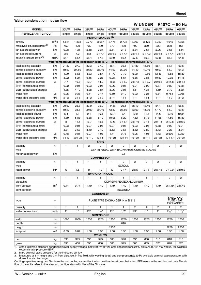
Himod
29EnglishW- Version - 50Hz
Water condensation � down flow
W UNDER R407C - 50 HzMODELL 20UW 24UW 28UW 34UW 40UW 26UW 32UW 42UW 46UW 55UW 65UW
REFRIGERANT CIRCUIT single single single single single double double double double double double
PERFORMANCES (1)
air flow m3/s 1.611 1.833 2.772 3.067 3.475 2.772 3.067 3.475 3.750 4.045 4.356
max avail ext. static pres.(2) Pa 450 400 430 400 370 430 400 370 320 230 165
fan absorbed power kW 0.98 1.31 2.18 2.34 2.64 2.18 2.34 2.64 2.96 3.66 4.14
fan absorbed current A 3.9 4.2 8.2 2 x 4.1 2 x 4.2 2 x 4.1 2 x 4.1 2 x 4.2 2 x 4.3 2 x 4.4 2 x 4.4
sound pressure level (3) dB(A) 51.1 54.4 56.4 57.3 59.0 56.4 57.5 59.0 60.8 62.8 64.8
water temperature at the condenser inlet: 15�C - condensation temperature: 40�C
total cooling capacity kW 21.30 27.0 32.3 37.0 46.4 30.6 37.80 45.80 56.4 61.7 69.6
sensible cooling capacity kW 19.60 24.50 30.20 35.10 44.60 29.00 34.40 42.10 49.00 54.9 61.3
total absorbed power kW 4.90 6.55 8.33 9.57 11.72 7.72 9.20 10.50 13.46 16.58 18.30
comp. absorbed power kW 3.92 5.24 6.15 7.23 9.08 5.54 6.86 7.86 10.50 12.92 14.16
comp. absorbed current A 7.7 10.3 12.7 14.2 16.3 2 x 5.7 2 x 7.2 2 x 7.7 2x10.3 2x11.8 2x14.1
SHR (sensible/total ratio) - 0.92 0.91 0.93 0.95 0.96 0.95 0.91 0.92 0.87 0.89 0.88
EER (output/used energy) - 4.35 4.12 3.88 3.87 3.96 3.96 4.11 4.36 4.19 3.72 3.80
water flow l/s 0.25 0.33 0.41 0.47 0.60 0.19 0.22 0.26 0.34 0.764 0.906
water side pressure drop kPa 2+3 3+5 3+2 3+2 3+4 1+1 1+1 1+1 1+1 1+2 2+2
water temperature at the condenser inlet: 30�C - condensation temperature: 45�C
total cooling capacity kW 20.60 25.8 33.9 35.9 44.8 29.5 36.10 43.40 54.4 58.7 66.6
sensible cooling capacity kW 19.20 23.5 29.90 34.10 43.30 28.60 33.60 41.30 47.70 54.0 60.6
total absorbed power kW 5.4 7.1 9.1 10.5 12.7 8.4 10.0 11.4 14.6 18.16 19.24
comp. absorbed power kW 4.39 5.83 6.88 8.12 10.05 6.22 7.62 8.78 11.68 14.50 15.80
comp. absorbed current A 8 11.1 13.7 15.3 17.6 2 x 6.1 2 x 7.6 2 x 8 2x11.1 2x12.8 2x15.0
SHR (sensible/total ratio) - 0.93 0.91 0.97 0.95 0.97 0.97 0.93 0.95 0.88 0.92 0.91
EER (output/used energy) - 3.84 3.63 3.40 3.42 3.53 3.51 3.62 3.80 3.73 3.23 3.34
water flow l/s 0.48 0.81 0.97 1.03 1.41 0.73 0.95 1.05 1.73 2.600 3.250
water side pressure drop kPa 7+10 20+28 16+10 12+11 16+21 12+14 19+24 8+11 22+31 17+17 26+27
FANS
quantity n. 1 1 2 2 2 2 2 2 2 2 2
type - CENTRIFUGAL WITH BACKWARDS CURVED BLADES
motor rated power kW 2.5
COMPRESSOR
quantity n. 1 1 1 1 1 2 2 2 2 2 2
type - SCROLL
rated power HP 6 7.8 9 10 13 2 x 4 2 x 5 2 x 6 2 x 7.8 2 x 9.0 2x10.0
EVAPORATIN COIL
quantity n. 1 1 1 1 1 1 1 1 1 2 2
pipes/fins COPPER/TREATED ALUMINIUM
front surface m2 0.74 0.74 1.49 1.49 1.49 1.49 1.49 1.49 1.49 2x1.49 2x1.49
configuration - INCLINED
CONDENSER
type - PLATE TYPE EXCHANGER IN AISI 316SHELL ANDTUBE HEAT
EXCHANGER
quantity n. 1 1 1 1 1 2 2 2 2 2 2
water connections inch 1" 1" 1¼" 1¼" 1¼" 1/2" 1/2" 1" 1" 11/4" 11/4"
DIMENSIONS
width mm 1000 1000 1750 1750 1750 1750 1750 1750 1750 1750 1750
depth mm 890
height mm 1950 2250 2250
footprint m2 0.89 0.89 1.56 1.56 1.56 1.56 1.56 1.56 1.56 1.56 1.56
WEIGHTS
net kg 390 395 590 595 600 590 595 600 615 810 810
gross kg 395 400 595 600 605 595 600 605 620 820 820
1. At the following standard conditions:power supply voltage 400/3/50 [V/Ph/Hz]; ambient conditions 24°C db; 50% R.H.(17°C wb); 20 Pa availableexternal static pressure (ESP)
2. Max. external static pressure for the indicated air flow3. Measured at 1 m height and 2 m front distance, in free field, with working fan(s) and compressor(s); 20 Pa available external static pressure, with
down flow air discharge.Cooling capacities are gross. To obtain the net cooling capaicities the fan heat load must be substracted. EER refers to the ambient unit only. The airflow of the units refers to the standard configuration with filter of the G4 class.

Himod
30 English W- Version - 50Hz
Water condensation � down flow
W UNDER R22 - 50 HzMODELL 20UW 24UW 28UW 34UW 40UW 26UW 32UW 42UW 46UW 55UW 65UW
REFRIGERANT CIRCUIT single single single single single double double double double double double
PERFORMANCES (1)
air flow m3/s 1.611 1.833 2.772 3.067 3.475 2.772 3.067 3.475 3.750 4.045 4.356
max avail ext. static pres.(2) Pa 450 400 420 400 370 430 400 370 320 230 165
fan absorbed power kW 0.98 1.31 2.18 2.34 2.64 2.18 2.34 2.64 2.96 3.66 4.14
fan absorbed current A 3.9 4.2 8.2 2 x 4.1 2 x 4.2 2 x 4.1 2 x 4.1 2 x 4.2 2 x 4.3 2 x 4.4 2 x 4.4
sound pressure level (3) dB(A) 51.1 54.4 56.4 57.3 59.0 56.4 57.5 59.0 60.8 62.8 64.8
water temperature at the condenser inlet: 15�C - condensation temperature: 40�C
total cooling capacity kW 20.90 26.3 31.90 36.60 45.80 30.10 36.40 44.10 55.70 60.5 68.6
sensible cooling capacity kW 19.60 24.40 30.30 35.20 43.50 29.20 34.30 42.40 48.50 55.7 61.1
total absorbed power kW 4.89 6.59 7.71 8.64 10.55 7.42 8.82 10.48 13.54 15.95 17.62
comp. absorbed power kW 3.91 5.28 5.53 6.30 7.91 5.24 6.48 7.84 10.58 12.28 13.48
comp. absorbed current A 7.3 10.6 11.0 12.6 15.8 2 x 5.6 2 x 7.1 2 x 7.3 2x10.7 2x11.4 2x13.7
SHR (sensible/total ratio) - 0.94 0.93 0.95 0.96 0.95 0.97 0.94 0.96 0.87 0.92 0.89
EER (output/used energy) - 4.27 4.00 4.14 4.24 4.34 4.06 4.13 4.21 4.11 3.80 3.89
water flow l/s 0.25 0.32 0.37 0.43 0.53 0.17 0.21 0.25 0.33 0.741 0.877
water side pressure drop kPa 2+3 3+4 2+1 2+2 2+3 1+1 1+1 0+1 1+1 1+1 2+2
water temperature at the condenser inlet: 30�C - condensation temperature: 45�C
total cooling capacity kW 20.2 25.3 30.5 35.4 44.2 29.1 35.5 42.5 53.7 57.6 65.1
sensible cooling capacity kW 19.4 23.8 29.9 34.7 42.9 29.1 34.1 41.7 47.2 54.5 59.7
total absorbed power kW 5.3 7.12 8.4 9.5 11.6 8.0 9.6 11.3 14.6 17.46 19.18
comp. absorbed power kW 4.32 5.81 6.22 7.14 8.91 5.84 7.24 8.66 11.64 13.76 15.04
comp. absorbed current A 7.9 11.2 12.0 13.7 17.1 2 x 5.9 2 x 7.5 2 x 7.9 2x11.3 2x12.4 2x14.5
SHR (sensible/total ratio) - 0.96 0.94 0.98 0.98 0.97 1.00 0.96 0.98 0.88 0.95 0.92
EER (output/used energy) - 3.81 3.44 3.63 3.73 3.83 3.63 3.71 3.76 3.68 3.31 3.38
water flow l/s 0.47 0.78 0.79 0.86 1.14 0.67 0.90 1.00 1.61 2.501 3.139
water side pressure drop kPa 6+9 18+25 11+6 8+8 10+13 10+12 17+22 7+10 19+27 15+16 24+26
FANS
quantity n. 1 1 2 2 2 2 2 2 2 2 2
type - CENTRIFUGAL WITH BACKWARDS CURVED BLADES
motor rated power kW 2.5
COMPRESSOR
quantity n. 1 1 1 1 1 2 2 2 2 2 2
type - SCROLL
rated power HP 6 7.8 9 10 13 2 x 4 2 x 5 2 x 6 2 x 7.8 2 x 9.0 2x10.0
EVAPORATIN COIL
quantity n. 1 1 1 1 1 1 1 1 1 2 2
pipes/fins COPPER/TREATED ALUMINIUM
front surface m2 0.74 0.74 1.49 1.49 1.49 1.49 1.49 1.49 1.49 2x1.49 2x1.49
configuration - INCLINED
CONDENSER
type - PLATE TYPE EXCHANGER IN AISI 316SHELL ANDTUBE HEAT
EXCHANGER
quantity n. 1 1 1 1 1 2 2 2 2 2 2
water connections inch 1" 1" 1¼" 1¼" 1¼" 1/2" 1/2" 1" 1" 11/4" 11/4"
DIMENSIONS
width mm 1000 1000 1750 1750 1750 1750 1750 1750 1750 1750 1750
depth mm 890
height mm 1950 2250 2250
footprint m2 0.89 0.89 1.56 1.56 1.56 1.56 1.56 1.56 1.56 1.56 1.56
WEIGHTS
net kg 390 395 590 595 600 590 595 600 615 810 810
gross kg 395 400 595 600 605 595 600 605 620 820 820
1. At the following standard conditions:power supply voltage 400/3/50 [V/Ph/Hz]; ambient conditions 24°C db; 50% R.H.(17°C wb); 20 Pa availableexternal static pressure (ESP)
2. Max. external static pressure for the indicated air flow
3. Measured at 1 m height and 2 m front distance, in free field, with working fan(s) and compressor(s); 20 Pa available external static pressure, withdown flow air discharge.
Cooling capacities are gross. To obtain the net cooling capaicities the fan heat load must be substracted. EER refers to the ambient unit only. The airflow of the units refers to the standard configuration with filter of the G4 class.

Himod
31EnglishW- Version - 50Hz
Water condensation � up flow
W OVER R407C - 50 Hz
MODELL 20OW 24OW 28OW 34OW 40OW 26OW 32OW 42OW 46OW
REFRIGERANT CIRCUIT single single single single single double double double double
PERFORMANCES (1)
air flow m3/s 1.607 1.858 2.728 2.997 3.463 2.728 2.997 3.463 3.667
max available ext. static pres. (2) Pa 450 380 430 370 330 430 370 330 280
fan absorbed power kW 1.12 1.42 2.38 2.84 3.12 2.38 2.84 3.12 3.42
fan absorbed current A 4.1 4.3 2 x 4.1 2 x 4.3 2 x 4.4 2 x 4.1 2 x 4.3 2 x 4.4 2 x 4.4
sound pressure level (3) dB(A) 52.7 55.8 57.8 60.0 61.6 57.8 60.0 61.6 62.9
water temperature at the condenser inlet: 15�C - condensation temperature: 40�C
total cooling capacity kW 21.20 27.00 32.1 37.3 46.4 30.3 37.30 44.50 55.5
sensible cooling capacity kW 19.30 24.00 30.00 34.70 43.90 28.90 33.90 41.90 47.90
total absorbed power kW 5.04 6.65 8.54 10.07 12.20 7.92 9.70 10.98 13.90
compressor absorbed power kW 3.92 5.23 6.16 7.23 9.08 5.54 6.86 7.86 10.48
compressor absorbed current A 7.7 10.3 12.7 14.2 16.3 2 x 5.7 2 x 7.2 2 x 7.7 2 x 10.3
SHR (sensible/total ratio) - 0.91 0.89 0.93 0.93 0.95 0.95 0.91 0.94 0.86
EER (output/used energy) - 4.21 4.06 3.76 3.70 3.80 3.83 3.85 4.05 3.99
water flow l/s 0.25 0.32 0.41 0.47 0.60 0.19 0.22 0.26 0.34
water side pressure drop kPa 2+3 3+4 3+2 2+2 3+4 1+1 1+1 1+1 1+1
water temperature at the condenser inlet: 30�C - condensation temperature: 45�C
total cooling capacity kW 20.3 26.1 30.7 35.7 44.4 29.3 35.8 42.4 53.6
sensible cooling capacity kW 18.9 23.5 29.7 34.3 43.4 28.3 33.3 41.1 46.7
total absorbed power kW 5.5 7.3 9.3 11.0 13.2 8.6 10.5 11.9 15.1
compressor absorbed power kW 4.39 5.83 6.89 8.12 10.04 6.22 7.62 8.78 11.68
compressor absorbed current A 8 11.1 13.7 15.3 17.6 2 x 6.1 2 x 7.6 2 x 8 2 x 11.1
SHR (sensible/total ratio) - 0.93 0.90 0.97 0.96 0.98 0.97 0.93 0.97 0.87
EER (output/used energy) - 3.69 3.57 3.30 3.25 3.36 3.41 3.41 3.56 3.55
water flow l/s 0.47 0.77 0.96 1.02 1.39 0.72 0.93 1.02 1.69
water side pressure drop kPa 7+9 17+24 16+10 12+11 16+20 11+14 19+24 8+11 21+30
FANS
quantity n. 1 1 2 2 2 2 2 2 2
type - CENTRIFUGAL WITH BACKWARDS CURVED BLADES
motor rated power kW 2.5
COMPRESSOR
quantity n. 1 1 1 1 1 2 2 2 2
type - SCROLL
rated power HP 6 7.8 9 10 13 2 x 4 2 x 5 2 x 6 2 x 7.8
EVAPORATIN COIL
quantity n. 1 1 1 1 1 1 1 1 1
pipes/fins COPPER/TREATED ALUMINIUM
front surface m2 0.74 0.74 1.49 1.49 1.49 1.49 1.49 1.49 1.49
configuration - INCLINED
CONDENSER
type - PLATE TYPE EXCHANGER IN AISI 316
quantity n. 1 1 1 1 1 2 2 2 2
water connections inch 1" 1" 1¼" 1¼" 1¼" 1/2" 1/2" 1" 1"
DIMENSIONS
width mm 1000 1000 1750 1750 1750 1750 1750 1750 1750
depth mm 890
height mm 1950
footprint m2 0.89 0.89 1.56 1.56 1.56 1.56 1.56 1.56 1.56
WEIGHTS
net kg 400 405 600 605 610 600 605 610 625
gross kg 405 410 605 610 615 605 610 615 630
1. At the following standard conditions:power supply voltage 400/3/50 [V/Ph/Hz]; ambient conditions 24°C db; 50% R.H.(17°C wb); 50 Pa availableexternal static pressure (ESP)
2. Max. external static pressure for the indicated air flow
3. Measured at 1 m height and 2 m front distance, in free field, with working fan(s) and compressor(s); 50 Pa available external static pressure, withducted air discharge
Cooling capacities are gross. To obtain the net cooling capaicities the fan heat load must be substracted. EER refers to the ambient unit only. The airflow of the units refers to the standard configuration with filter of the G4 class.

Himod
32 English W- Version - 50Hz
Water condensation � up flow
W OVER R22 - 50 Hz
MODELL 20OW 24OW 28OW 34OW 40OW 26OW 32OW 42OW 46OW
REFRIGERANT CIRCUIT single single single single single double double double double
PERFORMANCES (1)
air flow m3/s 1.607 1.858 2.728 2.997 3.463 2.728 2.997 3.463 3.667
max available ext. static pres. (2) Pa 450 380 430 370 330 430 370 330 280
fan absorbed power kW 1.12 1.42 2.38 2.84 3.12 2.38 2.84 3.12 3.42
fan absorbed current A 4.1 4.3 2 x 4.1 2 x 4.3 2 x 4.4 2 x 4.1 2 x 4.3 2 x 4.4 2 x 4.4
sound pressure level (3) dB(A) 52.7 55.8 57.8 60.0 61.6 57.8 60.0 61.6 62.9
water temperature at the condenser inlet: 15�C - condensation temperature: 40�C
total cooling capacity kW 20.70 26.40 31.70 36.70 45.50 30.10 36.20 43.50 54.80
sensible cooling capacity kW 19.40 24.00 30.10 34.90 43.20 28.90 34.00 42.20 47.70
total absorbed power kW 5.03 6.69 7.91 9.19 11.04 7.62 9.32 10.96 13.98
compressor absorbed power kW 3.91 5.27 5.53 6.35 7.92 5.24 6.48 7.84 10.56
compressor absorbed current A 7.2 10.5 11.0 12.6 15.8 2 x 5.6 2 x 7.1 2 x 7.3 2 x 10.7
SHR (sensible/total ratio) - 0.94 0.91 0.95 0.95 0.95 0.96 0.94 0.97 0.87
EER (output/used energy) - 4.12 3.95 4.01 3.99 4.12 3.95 3.88 3.97 3.92
water flow l/s 0.24 0.31 0.37 0.42 0.53 0.17 0.21 0.25 0.32
water side pressure drop kPa 2+2 3+4 2+1 2+2 2+3 1+1 1+1 1 1+1
water temperature at the condenser inlet: 30�C - condensation temperature: 45�C
total cooling capacity kW 19.80 25.18 30.37 35.10 43.50 29.10 34.90 41.50 52.90
sensible cooling capacity kW 19.00 23.66 29.46 34.40 42.60 28.20 33.50 41.50 47.10
total absorbed power kW 5.44 7.23 8.61 9.98 12.03 8.22 10.08 11.78 15.06
compressor absorbed power kW 4.32 5.81 6.23 7.14 8.91 5.84 7.24 8.66 11.64
compressor absorbed current A 7.9 11.2 12.0 13.7 17.1 2 x 5.9 2 x 7.5 2 x 7.9 2 x 11.3
SHR (sensible/total ratio) - 0.96 0.94 0.97 0.98 0.98 0.97 0.96 1.00 0.89
EER (output/used energy) - 3.64 3.48 3.53 3.52 3.62 3.54 3.46 3.52 3.51
water flow l/s 0.46 0.74 0.78 0.86 1.13 0.66 0.89 0.98 1.57
water side pressure drop kPa 6+9 16+23 10+6 8+8 10+13 10+12 17+22 7+10 18+26
FANS
quantity n. 1 1 2 2 2 2 2 2 2
type - CENTRIFUGAL WITH BACKWARDS CURVED BLADES
motor rated power kW 2.5
COMPRESSOR
quantity n. 1 1 1 1 1 2 2 2 2
type - SCROLL
rated power HP 6 7.8 9 10 13 2 x 4 2 x 5 2 x 6 2 x 7.8
EVAPORATIN COIL
quantity n. 1 1 1 1 1 1 1 1 1
pipes/fins COPPER/TREATED ALUMINIUM
front surface m2 0.74 0.74 1.49 1.49 1.49 1.49 1.49 1.49 1.49
configuration - INCLINED
CONDENSER
type - PLATE TYPE EXCHANGER IN AISI 316
quantity n. 1 1 1 1 1 2 2 2 2
water connections inch 1" 1" 1¼" 1¼" 1¼" 1/2" 1/2" 1" 1"
DIMENSIONS
width mm 1000 1000 1750 1750 1750 1750 1750 1750 1750
depth mm 890
height mm 1950
footprint m2 0.89 0.89 1.56 1.56 1.56 1.56 1.56 1.56 1.56
WEIGHTS
net kg 400 405 600 605 610 600 605 610 625
gross kg 405 410 605 610 615 605 610 615 630
1. At the following standard conditions:power supply voltage 400/3/50 [V/Ph/Hz]; ambient conditions 24°C db; 50% R.H.(17°C wb); 50 Pa availableexternal static pressure (ESP)
2. Max. external static pressure for the indicated air flow
3. Measured at 1 m height and 2 m front distance, in free field, with working fan(s) and compressor(s); 50 Pa available external static pressure, withducted air discharge
Cooling capacities are gross. To obtain the net cooling capaicities the fan heat load must be substracted. EER refers to the ambient unit only. The airflow of the units refers to the standard configuration with filter of the G4 class.

Himod
33EnglishD - Version - 50Hz
Dualfluid - Air condensation � down flow
D UNDER R407C - 50 Hz
MODELS 20UD 24UD 28UD 34UD 40UD 26UD 32UD 42UD 46UD
REFRIGERANT CIRCUIT single single single single single double double double double
PERFORMANCES (1)
air flow m3/s 1.547 1.744 2.772 3.044 3.308 2.772 3.044 3.308 3.639
max available external static pres�sure (2) Pa 435 325 410 390 340 410 390 340 280
fan absorbed power kW 1.15 1.57 2.46 2.68 3.00 2.46 2.68 3.00 3.46
fan absorbed current A 4.1 4.4 2 x 4.2 2 x 4.2 2 x 4.3 2 x 4.2 2 x 4.2 2 x 4.3 2 x 4.4
PERFORMANCES WITH MECHANICAL COOLING
total cooling capacity kW 20.20 25.5 30.9 35.9 44.6 29.5 35.80 43.20 54.5
sensible cooling capacity kW 19.00 23.60 29.90 34.40 43.50 28.60 33.70 41.50 48.60
total absorbed power kW 5.54 7.40 9.34 10.80 13.05 8.68 10.30 11.78 15.14
compressor absorbed power kW 4.39 5.83 6.88 8.12 10.05 6.22 7.62 8.78 11.68
compressor absorbed current A 8 11.1 13.7 15.3 17.6 2 x 6.1 2 x 7.6 2 x 8.0 2 x 11.1
SHR (sensible/total ratio) - 0.94 0.93 0.97 0.96 0.97 0.97 0.94 0.96 0.89
sound pressure level (3) dB(A) 51.3 55.4 55.8 57.6 59.1 55.8 57.6 59.1 61.2
EER (output/used energy) - 3.65 3.45 3.31 3.32 3.42 3.40 3.48 3.67 3.60
PERFORMANCES IN DUALFLUID MODE
total cooling capacity kW 28.0 33.5 51.70 63.50 67.30 51.70 63.50 67.30 71.90
sensible cooling capacity kW 22.5 26.1 42.40 48.90 52.50 42.40 48.90 52.50 56.80
sound pressure level (3) dB(A) 51.0 55.1 55.5 57.3 58.7 55.5 57.3 58.7 60.9
inlet/outlet water temperature °C 7/12 7/12 7/12 7/12 7/12 7/12 7/12 7/12 7/12
water flow l/s 1.34 1.60 2.46 3.03 3.21 2.46 3.03 3.21 3.43
water side pressure drop kPa 56 46 79 99 79 79 99 79 89
FANS
quantity n. 1 1 2 2 2 2 2 2 2
type - CENTRIFUGAL WITH BACKWARDS CURVED BLADES
motor rated power kW 2.5
COMPRESSOR
quantity n. 1 1 1 1 1 2 2 2 2
type - SCROLL
rated power HP 6 7.8 9 10 13 2 x 4 2 x 5 2 x 6 2 x 7.8
EVAPORATIN COIL
quantity n. 1 1 1 1 1 1 1 1 1
pipes/fins COPPER/TREATED ALUMINIUM
front surface m2 0.74 0.74 1.49 1.49 1.49 1.49 1.49 1.49 1.49
configuration - INCLINED
CHILLED WATER CONNECTIONS
water connections inch 1" 1¼" 1¼" 1¼" 1½" 1¼" 1¼" 1½" 1½"
REFRIGERANT CONNECTIONS
gas line (pipe to be welded, o.d.) mm 18 22 22 22 28 16 16 18 22
liquid line (pipe to be welded, o.d.) mm 16 18 18 18 22 14 14 16 18
DIMENSIONS
width mm 1000 1000 1750 1750 1750 1750 1750 1750 1750
depth mm 890
height mm 1950
footprint m2 0.89 0.89 1.56 1.56 1.56 1.56 1.56 1.56 1.56
WEIGHTS
net kg 500 510 790 795 800 790 795 800 815
gross kg 505 515 795 800 805 795 800 805 820
1. At the following standard conditions:power supply voltage 400/3/50 [V/Ph/Hz]; ambient conditions 24°C db; 50% R.H.(17°C wb); 20 Paavailable external static pressure (ESP); condensation tempertaure 45° C.
2. Max. external static pressure for the indicated air flow
3. Measured at 1 m height and 2 m front distance, in free field, with working fan(s); 20 Pa available external static pressure, with down flow airdischarge
Cooling capacities are gross. To obtain the net cooling capaicities the fan heat load must be substracted. EER refers to the ambient unit only.The air flow of the units refers to the standard configuration with filter of the G4 class. The standard diameters of the pipes only apply for lengths- between the air conditioner and the condensing unit - up to 30 equivalent m.
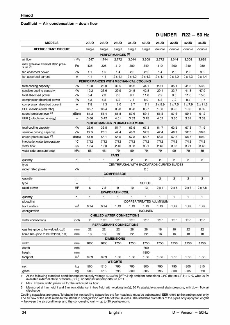
Himod
34 English D - Version - 50Hz
Dualfluid - Air condensation � down flow
D UNDER R22 - 50 Hz
MODELS 20UD 24UD 28UD 34UD 40UD 26UD 32UD 42UD 46UD
REFRIGERANT CIRCUIT single single single single single double double double double
PERFORMANCES (1)
air flow m3/s 1.547 1.744 2.772 3.044 3.308 2.772 3.044 3.308 3.639
max available external static pres�sure (2) Pa 435 325 410 390 340 410 390 340 280
fan absorbed power kW 1.1 1.5 1.4 2.6 2.9 1.4 2.6 2.9 3.3
fan absorbed current A 4.1 4.4 2 x 4.1 2 x 4.2 2 x 4.3 2 x 4.1 2 x 4.2 2 x 4.3 2 x 4.4
PERFORMANCES WITH MECHANICAL COOLING
total cooling capacity kW 19.8 25.0 30.5 35.2 44.1 29.1 35.1 41.8 53.9
sensible cooling capacity kW 19.2 23.6 29.9 34.5 42.8 29.1 33.7 41.8 47.9
total absorbed power kW 5.4 7.3 7.6 9.7 11.8 7.2 9.8 11.6 15.0
compressor absorbed power kW 4.3 5.8 6.2 7.1 8.9 5.8 7.2 8.7 11.7
compressor absorbed current A 7.8 11.3 12.0 13.7 17.1 2 x 5.9 2 x 7.5 2 x 7.9 2 x 11.3
SHR (sensible/total ratio) - 0.97 0.94 0.98 0.98 0.97 1.00 0.96 1.00 0.89
sound pressure level (3) dB(A) 51.3 55.4 55.8 57.6 59.1 55.8 57.6 59.1 61.2
EER (output/used energy) - 3.66 3.42 4.01 3.63 3.75 4.02 3.60 3.61 3.59
PERFORMANCES IN DUALFLUID MODE
total cooling capacity kW 28.0 33.5 51.7 63.5 67.3 51.7 63.5 67.3 71.9
sensible cooling capacity kW 22.5 26.1 42.4 48.9 52.5 42.4 48.9 52.5 56.8
sound pressure level (3) dB(A) 51.0 55.1 55.5 57.3 58.7 55.5 57.3 58.7 60.9
inlet/outlet water temperature °C 7/12 7/12 7/12 7/12 7/12 7/12 7/12 7/12 7/12
water flow l/s 1.34 1.60 2.46 3.03 3.21 2.46 3.03 3.21 3.43
water side pressure drop kPa 56 46 79 99 79 79 99 79 89
FANS
quantity n. 1 1 2 2 2 2 2 2 2
type - CENTRIFUGAL WITH BACKWARDS CURVED BLADES
motor rated power kW 2.5
COMPRESSOR
quantity n. 1 1 1 1 1 2 2 2 2
type - SCROLL
rated power HP 6 7.8 9 10 13 2 x 4 2 x 5 2 x 6 2 x 7.8
EVAPORATIN COIL
quantity n. 1 1 1 1 1 1 1 1 1
pipes/fins COPPER/TREATED ALUMINIUM
front surface m2 0.74 0.74 1.49 1.49 1.49 1.49 1.49 1.49 1.49
configuration - INCLINED
CHILLED WATER CONNECTIONS
water connections inch 1" 1¼" 1¼" 1¼" 1½" 1¼" 1¼" 1½" 1½"
REFRIGERANT CONNECTIONS
gas line (pipe to be welded, o.d.) mm 22 22 22 28 28 18 18 22 22
liquid line (pipe to be welded, o.d.) mm 18 18 18 22 22 16 16 18 18
DIMENSIONS
width mm 1000 1000 1750 1750 1750 1750 1750 1750 1750
depth mm 890
height mm 1950
footprint m2 0.89 0.89 1.56 1.56 1.56 1.56 1.56 1.56 1.56
WEIGHTS
net kg 500 510 790 795 800 790 795 800 815
gross kg 505 515 795 800 805 795 800 805 820
1. At the following standard conditions:power supply voltage 400/3/50 [V/Ph/Hz]; ambient conditions 24°C db; 50% R.H.(17°C wb); 20 Paavailable external static pressure (ESP); condensation tempertaure 45° C.
2. Max. external static pressure for the indicated air flow
3. Measured at 1 m height and 2 m front distance, in free field, with working fan(s); 20 Pa available external static pressure, with down flow airdischarge
Cooling capacities are gross. To obtain the net cooling capaicities the fan heat load must be substracted. EER refers to the ambient unit only.The air flow of the units refers to the standard configuration with filter of the G4 class. The standard diameters of the pipes only apply for lengths- between the air conditioner and the condensing unit - up to 30 equivalent m.

Himod
35EnglishD - Version - 50Hz
Dualfluid - Air condensation � up flow
D OVER R407C - 50 Hz
MODELS 20OD 24OD 28OD 34OD 40OD 26OD 32OD 42OD 46OD
REFRIGERANT CIRCUIT single single single single single double double double double
PERFORMANCES (1)
air flow m3/s 1.567 1.764 2.744 2.911 3.294 2.744 2.911 3.294 3.569
max available external static pres�sure (2) Pa 435 325 410 350 305 410 350 305 240
fan absorbed power kW 1.24 1.66 2.62 2.94 3.46 2.62 2.94 3.46 3.88
fan absorbed current A 4.2 4.4 2 x 4.2 2 x 4.3 2 x 4.4 2 x 4.2 2 x 4.3 2 x 4.4 2 x 4.4
PERFORMANCES WITH MECHANICAL COOLING
total cooling capacity kW 19.60 25.10 30.8 35.2 44.4 29.4 34.40 42.70 54.0
sensible cooling capacity kW 18.30 22.90 29.90 33.40 42.70 28.50 32.30 41.00 47.20
total absorbed power kW 5.62 7.49 9.50 11.05 13.50 8.84 10.56 12.24 15.56
compressor absorbed power kW 4.38 5.83 6.88 8.11 10.04 6.22 7.62 8.78 11.68
compressor absorbed current A 8 11.1 13.7 15.3 17.6 2 x 6.1 2 x 7.6 2 x 8 2 x 11.1
SHR (sensible/total ratio) - 0.93 0.91 0.97 0.95 0.96 0.97 0.94 0.96 0.87
sound pressure level (3) dB(A) 52.9 57.1 57.8 58.1 61.6 57.8 58.1 61.6 63.4
EER (output/used energy) - 3.49 3.35 3.24 3.19 3.29 3.33 3.26 3.49 3.47
PERFORMANCES IN DUALFLUID MODE
total cooling capacity kW 28.4 33.9 50.80 58.60 63.90 50.80 58.60 63.90 67.40
sensible cooling capacity kW 22.7 26.4 41.70 46.30 51.10 41.70 46.30 51.10 54.60
sound pressure level (3) dB(A) 52.50 56.70 57.40 57.60 61.10 57.40 57.60 61.10 62.90
inlet/outlet water temperature °C 7/12 7/12 7/12 7/12 7/12 7/12 7/12 7/12 7/12
water flow l/s 1.17 1.36 2.42 2.8 3.04 2.42 2.8 3.04 3.21
water side pressure drop kPa 58 47 77 86 72 77 86 72 79
FANS
quantity n. 1 1 2 2 2 2 2 2 2
type - CENTRIFUGAL WITH BACKWARDS CURVED BLADES
motor rated power kW 2.5
COMPRESSOR
quantity n. 1 1 1 1 1 2 2 2 2
type - SCROLL
rated power HP 6 7.8 9 10 13 2 x 4 2 x 5 2 x 6 2 x 7.8
EVAPORATIN COIL
quantity n. 1 1 1 1 1 1 1 1 1
pipes/fins COPPER/TREATED ALUMINIUM
front surface m2 0.74 0.74 1.49 1.49 1.49 1.49 1.49 1.49 1.49
configuration - INCLINED
CHILLED WATER CONNECTIONS
water connections inch 1" 1¼" 1¼" 1¼" 1½" 1¼" 1¼" 1½" 1½"
REFRIGERANT CONNECTIONS
gas line (pipe to be welded, o.d.) mm 18 22 22 22 28 16 16 18 22
liquid line (pipe to be welded, o.d.) mm 16 18 18 18 22 14 14 16 18
DIMENSIONS
width mm 1000 1000 1750 1750 1750 1750 1750 1750 1750
depth mm 890
height mm 1950
footprint m2 0.89 0.89 1.56 1.56 1.56 1.56 1.56 1.56 1.56
WEIGHTS
net kg 500 510 790 795 800 790 795 800 815
gross kg 505 515 795 800 805 795 800 805 820
1. At the following standard conditions:power supply voltage 400/3/50 [V/Ph/Hz]; ambient conditions 24°C db; 50% R.H.(17°C wb); 50 Paavailable external static pressure (ESP); condensation tempertaure 45° C.
2. Max. external static pressure for the indicated air flow
3. Measured at 1 m height and 2 m front distance, in free field, with working fan(s); 50 Pa available external static pressure, with ducted airdischarge
Cooling capacities are gross. To obtain the net cooling capaicities the fan heat load must be substracted. EER refers to the ambient unit only.The air flow of the units refers to the standard configuration with filter of the G4 class. The standard diameters of the pipes only apply for lengths- between the air conditioner and the condensing unit - up to 30 equivalent m.

Himod
36 English D - Version - 50Hz
Dualfluid - Air condensation � up flow
D OVER R22 - 50 Hz
MODELS 20OD 24OD 28OD 34OD 40OD 26OD 32OD 42OD 46OD
REFRIGERANT CIRCUIT single single single single single double double double double
PERFORMANCES (1)
air flow m3/s 1.567 1.764 2.744 2.911 3.294 2.744 2.911 3.294 3.569
max available external static pres�sure (2) Pa 435 325 410 350 305 410 350 305 240
fan absorbed power kW 1.24 1.66 2.62 2.94 3.46 2.62 2.94 3.46 3.88
fan absorbed current A 4.2 4.4 2 x 4.2 2 x 4.3 2 x 4.4 2 x 4.2 2 x 4.3 2 x 4.4 2 x 4.4
PERFORMANCES WITH MECHANICAL COOLING
total cooling capacity kW 19.40 24.70 30.60 34.50 43.90 29.00 33.90 41.90 53.30
sensible cooling capacity kW 18.60 22.90 29.70 33.50 42.20 29.00 32.50 41.10 46.90
total absorbed power kW 5.56 7.46 8.84 10.09 12.38 8.46 10.18 12.12 15.52
compressor absorbed power kW 4.32 5.80 6.22 7.15 8.92 5.84 7.24 8.66 11.64
compressor absorbed current A 7.8 11.2 12.0 13.7 17.1 2 x 5.9 2 x 7.4 2 x 7.9 2 x 11.3
SHR (sensible/total ratio) - 0.96 0.93 0.97 0.97 0.96 1.00 0.96 0.98 0.88
sound pressure level (3) dB(A) 52.9 57.1 57.8 58.1 61.6 57.8 58.1 61.6 63.4
EER (output/used energy) - 3.49 3.31 3.46 3.42 3.55 3.43 3.33 3.46 3.43
PERFORMANCES IN DUALFLUID MODE
total cooling capacity kW 28.4 33.9 50.80 58.60 63.90 50.80 58.60 63.90 67.40
sensible cooling capacity kW 22.7 26.4 41.70 46.30 51.10 41.70 46.30 51.10 54.60
sound pressure level (3) dB(A) 52.50 56.70 57.40 57.60 61.10 57.40 57.60 61.10 62.90
inlet/outlet water temperature °C 7/12 7/12 7/12 7/12 7/12 7/12 7/12 7/12 7/12
water flow l/s 1.35 1.62 2.42 2.8 3.04 2.42 2.8 3.04 3.21
water side pressure drop kPa 58 47 77 86 72 77 86 72 79
FANS
quantity n. 1 1 2 2 2 2 2 2 2
type - CENTRIFUGAL WITH BACKWARDS CURVED BLADES
motor rated power kW 2.5
COMPRESSOR
quantity n. 1 1 1 1 1 2 2 2 2
type - SCROLL
rated power HP 6 7.8 9 10 13 2 x 4 2 x 5 2 x 6 2 x 7.8
EVAPORATIN COIL
quantity n. 1 1 1 1 1 1 1 1 1
pipes/fins COPPER/TREATED ALUMINIUM
front surface m2 0.74 0.74 1.49 1.49 1.49 1.49 1.49 1.49 1.49
configuration - INCLINED
CHILLED WATER CONNECTIONS
water connections inch 1" 1¼" 1¼" 1¼" 1½" 1¼" 1¼" 1½" 1½"
REFRIGERANT CONNECTIONS
gas line (pipe to be welded, o.d.) mm 22 22 22 28 28 16 16 22 22
liquid line (pipe to be welded, o.d.) mm 18 18 18 22 22 16 16 18 18
DIMENSIONS
width mm 1000 1000 1750 1750 1750 1750 1750 1750 1750
depth mm 890
height mm 1950
footprint m2 0.89 0.89 1.56 1.56 1.56 1.56 1.56 1.56 1.56
WEIGHTS
net kg 500 510 790 795 800 790 795 800 815
gross kg 505 515 795 800 805 795 800 805 820
1. At the following standard conditions:power supply voltage 400/3/50 [V/Ph/Hz]; ambient conditions 24°C db; 50% R.H.(17°C wb); 50 Paavailable external static pressure (ESP); condensation tempertaure 45° C.
2. Max. external static pressure for the indicated air flow
3. Measured at 1 m height and 2 m front distance, in free field, with working fan(s) and compressor(s); 50 Pa available external static pressure,with ducted air discharge
Cooling capacities are gross. To obtain the net cooling capaicities the fan heat load must be substracted. EER refers to the ambient unit only.The air flow of the units refers to the standard configuration with filter of the G4 class. The standard diameters of the pipes only apply for lengths- between the air conditioner and the condensing unit - up to 30 equivalent m.

Himod
37EnglishH - Version - 50Hz
Dualfluid � water condensation � down flow
H UNDER R407C - 50 Hz
MODELL 20UH 24UH 28UH 34UH 40UH 26UH 32UD 42UH 46UH
REFRIGERANT CIRCUIT single single single single single double double double double
PERFORMANCES (1)
air flow m3/s 1.547 1.744 2.772 3.044 3.308 2.772 3.044 3.308 3.639
max available ext. static pressure (2) Pa 435 325 410 390 340 410 390 340 280
fan absorbed power kW 1.15 1.57 2.46 2.68 3.00 2.46 2.68 3.00 3.46
fan absorbed current A 4.1 4.4 2 x 4.2 2 x 4.2 2 x 4.3 2 x 4.1 2 x 4.2 2 x 4.3 2 x 4.4
sound pressure level (3) db(A) 51.30 55.40 55.80 57.60 58.7 55.8 57.60 59.10 61.20
water temperature at the condenser inlet: 15�C - condensation temperature: 40�C
total cooling capacity kW 21.20 26.4 32.3 37.1 46.1 30.5 38.00 45.60 56.6
sensible cooling capacity kW 19.50 24.10 30.20 35.30 43.90 29.34 34.20 42.40 49.60
total absorbed power kW 5.07 6.81 8.61 9.91 12.09 8.06 9.54 10.86 13.96
compressor absorbed power kW 3.92 5.24 6.15 7.23 9.09 5.60 6.86 7.86 10.50
compressor absorbed current A 7.7 10.3 12.7 14.2 16.3 2 x 5.8 2 x 7.2 2 x 7.7 2 x 10.3
SHR (sensible/total ratio) - 0.92 0.91 0.93 0.95 0.95 0.96 0.90 0.93 0.88
EER (output/used energy) - 4.18 3.88 3.75 3.74 3.81 3.78 3.98 4.20 4.05
water flow l/s 0.25 0.33 0.41 0.47 0.60 0.32 0.22 0.26 0.34
water side pressure drop kPa 2+3 3+5 3+2 2+2 3+4 2+3 1+1 1+1 1+1
water temperature at the condenser inlet: 30�C - condensation temperature: 45�C
total cooling capacity kW 20.20 25.5 30.9 35.9 44.6 29.5 35.80 43.20 54.5
sensible cooling capacity kW 19.00 23.60 29.90 34.40 43.50 28.60 33.70 41.50 48.60
total absorbed power kW 5.54 7.40 9.34 10.80 13.05 8.68 10.30 11.78 15.14
compressor absorbed power kW 4.39 5.83 6.88 8.12 10.05 6.22 7.62 8.78 11.68
compressor absorbed current A 8 11.1 13.7 15.3 17.6 2 x 6.1 2 x 7.6 2 x 8 2 x 11.1
SHR (sensible/total ratio) - 0.94 0.93 0.97 0.96 0.97 0.97 0.94 0.96 0.89
EER (output/used energy) - 3.65 3.45 3.31 3.32 3.42 3.40 3.48 3.67 3.60
water flow l/s 0.47 0.81 0.97 1.03 1.41 0.73 0.94 1.05 1.74
water side pressure drops kPa 7+9 19+27 16+10 12+11 16+21 12+14 19+24 8+11 23+32
PERFORMANCES IN DUALFLUID MODE
total cooling capacity kW 28.0 33.5 51.70 63.50 67.30 51.70 63.50 67.30 71.90
sensible cooling capacity kW 22.5 26.1 42.40 48.90 52.50 42.40 48.90 52.50 56.80
sound pressure level (3) db(A) 51.0 55.1 55.5 57.3 58.7 55.5 57.3 58.7 60.9
inlet/outlet water temperature °C 7/12 7/12 7/12 7/12 7/12 7/12 7/12 7/12 7/12
water flow l/s 1.34 1.60 2.46 3.03 3.21 2.46 3.03 3.21 3.43
water side pressure drop kPa 56 46 79 99 79 79 99 79 89
FANS
quantity n. 1 1 2 2 2 2 2 2 2
type - CENTRIFUGAL WITH BACKWARDS CURVED BLADES
motor rated power kW 2.5
COMPRESSOR
quantity n. 1 1 1 1 1 2 2 2 2
type - SCROLL
rated power HP 6 7.8 9 10 13 2 x 4 2 x 5 2 x 6 2 x 7.8
EVAPORATIN COIL/CHILLED WATER
quantity n. 2 2 2 2 2 2 2 2 2
pipes/fins COPPER/TREATED ALUMINIUM
front surface m2 0.74 0.74 1.49 1.49 1.49 1.49 1.49 1.49 1.49
configuration - INCLINED
CONDENSER
type - PLATE TYPE EXCHANGER IN AISI 316
quantity n. 1 1 1 1 1 2 2 2 2
water connections inch 1" 1" 1¼" 1¼" 1¼" 1/2" 1/2" 1" 1"
CHILLED WATER CONNECTIONS
water connections inch 1" 1¼" 1¼" 1¼" 1½" 1¼" 1¼" 1½" 1½"
DIMENSIONS
width mm 1000 1000 1750 1750 1750 1750 1750 1750 1750
depth mm 890
height mm 1950
footprint m2 0.89 0.89 1.56 1.56 1.56 1.56 1.56 1.56 1.56
WEIGHTS
net kg 500 510 790 795 800 790 795 800 815
gross kg 505 515 795 800 805 795 800 805 820
1. At the following standard conditions:power supply voltage 400/3/50 [V/Ph/Hz]; ambient conditions 24°C db; 50% R.H.(17°C wb); 20 Paavailable external static pressure (ESP)
2. Max. external static pressure for the indicated air flow
3. Measured at 1 m height and 2 m front distance, in free field, with working fan(s); 20 Pa available external static pressure, with down flow airdischarge
Cooling capacities are gross. To obtain the net cooling capaicities the fan heat load must be substracted. EER refers to the ambient unit only.The air flow of the units refers to the standard configuration with filter of the G4 class.

Himod
38 English H - Version - 50Hz
Dualfluid � water condensation � down flowH UNDER R22- 50 Hz
MODELL 20UH 24UH 28UH 34UH 40UH 26UH 32UD 42UH 46UH
REFRIGERANT CIRCUIT single single single single single double double double double
PERFORMANCES (1)
air flow m3/s 1.547 1.744 2.772 3.044 3.308 2.772 3.044 3.308 3.639
max available ext. static pressure (2) Pa 435 325 410 390 340 410 390 340 280
fan absorbed power kW 1.15 1.57 2.46 2.68 2.87 2.46 2.68 3.00 3.46
fan absorbed current A 4.1 4.4 2 x 4.2 2 x 4.2 2 x 4.3 2 x 4.2 2 x 4.2 2 x 4.3 2 x 4.4
sound pressure level (3) db(A) 51.30 55.40 55.80 57.60 58.70 55.80 57.60 59.10 61.20
water temperature at the condenser inlet: 15�C - condensation temperature: 40�C
total cooling capacity kW 20.60 26.0 31.90 36.50 45.66 30.10 36.20 43.50 55.90
sensible cooling capacity kW 19.60 24.10 30.30 35.00 43.38 29.20 34.00 42.10 48.60
total absorbed power kW 5.06 6.85 7.99 9.02 10.77 7.70 9.16 10.84 14.04
compressor absorbed power kW 3.91 5.28 5.53 6.34 7.90 5.24 6.48 7.84 10.58
compressor absorbed current A 7.2 10.7 11.0 12.6 15.8 2 x 5.6 2 x 7.1 2 x 7.3 2 x 10.7
SHR (sensible/total ratio) - 0.95 0.93 0.95 0.96 0.95 0.97 0.94 0.97 0.87
EER (output/used energy) - 4.07 3.80 3.99 4.05 4.24 3.91 3.95 4.01 3.98
water flow l/s 0.24 0.32 0.37 0.43 0.44 0.18 0.21 0.26 0.33
water side pressure drop kPa 2+2 3+4 2+1 2+2 2+2 1+1 1+1 0+1 1+1
water temperature at the condenser inlet: 30�C - condensation temperature: 45�C
total cooling capacity kW 19.80 25.0 30.50 35.20 44.10 29.10 34.90 42.40 53.80
sensible cooling capacity kW 19.20 23.70 29.90 34.50 42.81 29.10 33.80 41.60 47.90
total absorbed power kW 5.47 7.39 8.68 9.82 11.77 8.30 9.92 11.66 15.10
compressor absorbed power kW 4.32 5.82 6.22 7.14 8.90 5.84 7.24 8.66 11.64
compressor absorbed current A 7.8 11.3 12.0 13.7 17.1 2 x 5.9 2 x 7.5 2 x 7.9 2 x 11.3
SHR (sensible/total ratio) - 0.97 0.95 0.98 0.98 0.97 1.00 0.97 0.98 0.89
EER (output/used energy) - 3.62 3.38 3.51 3.58 3.75 3.51 3.52 3.64 3.56
water flow l/s 0.46 0.77 0.79 0.86 1.14 0.67 0.90 1.00 1.62
water side pressure drop kPa 6+9 18+25 11+6 8+8 10+14 10+12 17+22 7+10 19+27
PERFORMANCES IN DUALFLUID MODE
total cooling capacity kW 28.0 33.5 51.70 63.50 67.30 51.70 63.50 67.30 71.90
sensible cooling capacity kW 22.5 26.1 42.40 48.90 52.50 42.40 48.90 52.50 56.80
sound pressure level (3) db(A) 51.0 55.1 55.5 57.3 58.7 55.5 57.3 58.7 60.9
inlet/outlet water temperature °C 7/12 7/12 7/12 7/12 7/12 7/12 7/12 7/12 7/12
water flow l/s 1.34 1.60 2.46 3.03 3.21 2.46 3.03 3.21 3.43
water side pressure drop kPa 56 46 79 99 79 79 99 79 89
FANS
quantity n. 1 1 2 2 2 2 2 2 2
type - CENTRIFUGAL WITH BACKWARDS CURVED BLADES
motor rated power kW 2.5
COMPRESSOR
quantity n. 1 1 1 1 1 2 2 2 2
type - SCROLL
rated power HP 6 7.8 9 10 13 2 x 4 2 x 5 2 x 6 2 x 7.8
EVAPORATIN COIL/CHILLED WATER
quantity n. 2 2 2 2 2 2 2 2 2
pipes/fins COPPER/TREATED ALUMINIUM
front surface m2 0.74 0.74 1.49 1.49 1.49 1.49 1.49 1.49 1.49
configuration - INCLINED
CONDENSER
type - PLATE TYPE EXCHANGER IN AISI 316
quantity n. 1 1 1 1 1 2 2 2 2
water connections inch 1" 1" 1¼" 1¼" 1¼" 1/2" 1/2" 1" 1"
CHILLED WATER CONNECTIONS
water connections inch 1" 1¼" 1¼" 1¼" 1½" 1¼" 1¼" 1½" 1½"
DIMENSIONS
width mm 1000 1000 1750 1750 1750 1750 1750 1750 1750
depth mm 890
height mm 1950
footprint m2 0.89 0.89 1.56 1.56 1.56 1.56 1.56 1.56 1.56
WEIGHTS
net kg 500 510 790 795 800 790 795 800 815
gross kg 505 515 795 800 805 795 800 805 820
1. At the following standard conditions:power supply voltage 400/3/50 [V/Ph/Hz]; ambient conditions 24°C db; 50% R.H.(17°C wb); 20 Paavailable external static pressure (ESP)
2. Max. external static pressure for the indicated air flow3. Measured at 1 m height and 2 m front distance, in free field, with working fan(s); 20 Pa available external static pressure, with down flow air
dischargeCooling capacities are gross. To obtain the net cooling capaicities the fan heat load must be substracted. EER refers to the ambient unit only.The air flow of the units refers to the standard configuration with filter of the G4 class.

Himod
39EnglishH - Version - 50Hz
Dualfluid � water condensation � up flow
H OVER R407C - 50 HzMODELL 20OH 24OH 28OH 34OH 40OH 26OH 32OD 42OH 46OH
REFRIGERANT CIRCUIT single single single single single double double double double
PERFORMANCES (1)
air flow m3/s 1.567 1.764 2.744 2.911 3.294 2.744 2.911 3.294 3.569
max available ext. static pressure (2) Pa 435 325 410 350 305 410 350 305 240
fan absorbed power kW 1.24 1.66 2.62 2.94 3.46 2.62 2.94 3.46 3.88
fan absorbed current A 4.2 4.4 2 x 4.2 2 x 4.3 2 x 4.4 2 x 4.2 2 x 4.3 2 x 4.4 2 x 4.4
sound pressure level (3) db(A) 52.90 57.10 57.80 58.10 61.60 57.80 58.10 61.60 63.40
water temperature at the condenser inlet: 15�C - condensation temperature: 40�C
total cooling capacity kW 20.30 26.20 31.9 36.1 46.0 30.5 36.00 44.80 55.9
sensible cooling capacity kW 18.60 23.30 30.40 34.20 43.70 29.20 32.70 41.70 48.40
total absorbed power kW 5.16 6.89 8.77 10.16 12.54 8.16 9.78 11.32 14.36
compressor absorbed power kW 3.92 5.23 6.15 7.22 9.08 5.54 6.84 7.86 10.48
compressor absorbed current A 7.7 10.3 12.7 14.2 16.3 2 x 5.7 2 x 7.2 2 x 7.7 2 x 10.3
SHR (sensible/total ratio) - 0.92 0.89 0.95 0.95 0.95 0.96 0.91 0.93 0.87
EER (output/used energy) - 3.93 3.80 3.64 3.55 3.67 3.74 3.68 3.96 3.89
water flow l/s 0.24 0.31 0.41 0.46 0.59 0.19 0.21 0.26 0.34
water side pressure drop kPa 2+2 3+4 3+2 2+2 3+4 1+1 1+1 1+1 1+1
water temperature at the condenser inlet: 30�C - condensation temperature: 45�C
total cooling capacity kW 19.60 25.10 30.8 35.2 44.4 29.4 34.40 42.70 54.0
sensible cooling capacity kW 18.30 22.90 29.90 33.40 42.70 28.50 32.30 41.00 47.20
total absorbed power kW 5.62 7.49 9.50 11.05 13.50 8.84 10.56 12.24 15.56
compressor absorbed power kW 4.38 5.83 6.88 8.11 10.04 6.22 7.62 8.78 11.68
compressor absorbed current A 8 11.1 13.7 15.3 17.6 2 x 6.1 2 x 7.6 2 x 8 2 x 11.1
SHR (sensible/total ratio) - 0.93 0.91 0.97 0.95 0.96 0.97 0.94 0.96 0.87
EER (output/used energy) - 3.49 3.35 3.24 3.19 3.29 3.33 3.26 3.49 3.47
water flow l/s 0.44 0.74 0.97 0.99 1.39 0.73 0.89 1.02 1.69
water side pressure drop kPa 6+8 16+22 16+10 11+10 15+20 12+14 17+22 8+11 21+30
PERFORMANCES IN DUALFLUID MODE
total cooling capacity kW 28.4 33.9 50.80 58.60 63.90 50.80 58.60 63.90 67.40
sensible cooling capacity kW 22.7 26.4 41.70 46.30 51.10 41.70 46.30 51.10 54.60
sound pressure level (3) db(A) 52.50 56.70 57.40 57.60 61.10 57.40 57.60 61.10 62.90
inlet/outlet water temperature °C 7/12 7/12 7/12 7/12 7/12 7/12 7/12 7/12 7/12
water flow l/s 1.17 1.36 2.42 2.8 3.04 2.42 2.8 3.04 3.21
water side pressure drop kPa 58 47 77 86 72 77 86 72 79
FANS
quantity n. 1 1 2 2 2 2 2 2 2
type - CENTRIFUGAL WITH BACKWARDS CURVED BLADES
motor rated power kW 2.5
COMPRESSOR
quantity n. 1 1 1 1 1 2 2 2 2
type - SCROLL
rated power HP 6 7.8 9 10 13 2 x 4 2 x 5 2 x 6 2 x 7.8
EVAPORATIN COIL/CHILLED WATER
quantity n. 2 2 2 2 2 2 2 2 2
pipes/fins COPPER/TREATED ALUMINIUM
front surface m2 0.74 0.74 1.49 1.49 1.49 1.49 1.49 1.49 1.49
configuration - INCLINED
CONDENSER
type - PLATE TYPE EXCHANGER IN AISI 316
quantity n. 1 1 1 1 1 2 2 2 2
water connections inch 1" 1" 1¼" 1¼" 1¼" 1/2" 1/2" 1" 1"
CHILLED WATER CONNECTIONS
water connections inch 1" 1¼" 1¼" 1¼" 1½" 1¼" 1¼" 1½" 1½"
DIMENSIONS
width mm 1000 1000 1750 1750 1750 1750 1750 1750 1750
depth mm 890
height mm 1950
footprint m2 0.89 0.89 1.56 1.56 1.56 1.56 1.56 1.56 1.56
WEIGHTS
net kg 500 510 790 795 800 790 795 800 815
gross kg 505 515 795 800 805 795 800 805 820
1. At the following standard conditions:power supply voltage 400/3/50 [V/Ph/Hz]; ambient conditions 24°C db; 50% R.H.(17°C wb); 50 Paavailable external static pressure (ESP)
2. Max. external static pressure for the indicated air flow3. Measured at 1 m height and 2 m front distance, in free field, with working fan(s); 50 Pa available external static pressure, with ducted air
dischargeCooling capacities are gross. To obtain the net cooling capaicities the fan heat load must be substracted. EER refers to the ambient unit only.The air flow of the units refers to the standard configuration with filter of the G4 class.

Himod
40 English H - Version - 50Hz
Dualfluid � water condensation � up flowH OVER R22 - 50 Hz
MODELL 20OH 24OH 28OH 34OH 40OH 26OH 32OD 42OH 46OH
REFRIGERANT CIRCUIT single single single single single double double double double
PERFORMANCES (1)
air flow m3/s 1.567 1.764 2.744 2.911 3.294 2.744 2.911 3.294 3.569
max available ext. static pressure (2) Pa 435 325 410 350 305 410 350 305 240
fan absorbed power kW 1.24 1.66 2.62 2.94 3.46 2.62 2.94 3.46 3.88
fan absorbed current A 4.2 4.4 2 x 4.2 2 x 4.3 2 x 4.4 2 x 4.2 2 x 4.3 2 x 4.4 2 x 4.4
sound pressure level (3) db(A) 52.90 57.10 57.80 58.10 61.60 57.80 58.10 61.60 63.40
water temperature at the condenser inlet: 15�C - condensation temperature: 40�C
total cooling capacity kW 20.00 25.70 31.70 35.70 45.50 30.20 34.90 43.10 55.20
sensible cooling capacity kW 18.80 23.30 30.10 33.90 42.70 29.30 33.10 41.40 48.00
total absorbed power kW 5.14 6.92 8.15 9.29 11.38 7.86 9.40 11.30 14.44
compressor absorbed power kW 3.90 5.26 5.53 6.35 7.92 5.24 6.46 7.84 10.56
compressor absorbed current A 7.2 10.4 11.0 12.6 15.8 2 x 5.6 2 x 7.0 2 x 7.3 2 x 10.7
SHR (sensible/total ratio) - 0.94 0.91 0.95 0.95 0.94 0.97 0.95 0.96 0.87
EER (output/used energy) - 3.89 3.71 3.89 3.84 4.00 3.84 3.71 3.81 3.82
water flow l/s 0.24 0.31 0.37 0.42 0.53 0.18 0.21 0.25 0.32
water side pressure drop kPa 2+2 3+4 2+1 2+2 2+3 1+1 1+1 0+1 1+1
water temperature at the condenser inlet: 30�C - condensation temperature: 45�C
total cooling capacity kW 19.40 24.70 30.60 34.50 43.90 29.00 33.90 41.90 53.30
sensible cooling capacity kW 18.60 22.90 29.70 33.50 42.20 29.00 32.50 41.10 46.90
total absorbed power kW 5.56 7.46 8.84 10.09 12.38 8.46 10.18 12.16 15.52
compressor absorbed power kW 4.32 5.80 6.22 7.15 8.92 5.84 7.24 8.70 11.64
compressor absorbed current A 7.8 11.2 12.0 13.7 17.1 2 x 5.9 2 x 7.4 2 x 7.9 2 x 11.3
SHR (sensible/total ratio) - 0.96 0.93 0.97 0.97 0.96 1.00 0.96 0.98 0.88
EER (output/used energy) - 3.49 3.31 3.46 3.42 3.55 3.43 3.33 3.45 3.43
water flow l/s 0.44 0.71 0.79 0.83 1.12 0.67 0.86 0.98 1.57
water side pressure drop kPa 6+8 15+21 11+6 8+7 10+13 10+12 16+20 7+10 18+26
PERFORMANCES IN DUALFLUID MODE
total cooling capacity kW 28.4 33.9 50.80 58.60 63.90 50.80 58.60 63.90 67.40
sensible cooling capacity kW 22.7 26.4 41.70 46.30 51.10 41.70 46.30 51.10 54.60
sound pressure level (3) db(A) 52.50 56.70 57.40 57.60 61.10 57.40 57.60 61.10 62.90
inlet/outlet water temperature °C 7/12 7/12 7/12 7/12 7/12 7/12 7/12 7/12 7/12
water flow l/s 1.35 1.62 2.42 2.8 3.04 2.42 2.8 3.04 3.21
water side pressure drop kPa 58 47 77 86 72 77 86 72 79
FANS
quantity n. 1 1 2 2 2 2 2 2 2
type - CENTRIFUGAL WITH BACKWARDS CURVED BLADES
motor rated power kW 2.5
COMPRESSOR
quantity n. 1 1 1 1 1 2 2 2 2
type - SCROLL
rated power HP 6 7.8 9 10 13 2 x 4 2 x 5 2 x 6 2 x 7.8
EVAPORATIN COIL/CHILLED WATER
quantity n. 2 2 2 2 2 2 2 2 2
pipes/fins COPPER/TREATED ALUMINIUM
front surface m2 0.74 0.74 1.49 1.49 1.49 1.49 1.49 1.49 1.49
configuration - INCLINED
CONDENSER
type - PLATE TYPE EXCHANGER IN AISI 316
quantity n. 1 1 1 1 1 2 2 2 2
water connections inch 1" 1" 1¼" 1¼" 1¼" 1/2" 1/2" 1" 1"
CHILLED WATER CONNECTIONS
water connections inch 1" 1¼" 1¼" 1¼" 1½" 1¼" 1¼" 1½" 1½"
DIMENSIONS
width mm 1000 1000 1750 1750 1750 1750 1750 1750 1750
depth mm 890
height mm 1950
footprint m2 0.89 0.89 1.56 1.56 1.56 1.56 1.56 1.56 1.56
WEIGHTS
net kg 500 510 790 795 800 790 795 800 815
gross kg 505 515 795 800 805 795 800 805 820
1. At the following standard conditions:power supply voltage 400/3/50 [V/Ph/Hz]; ambient conditions 24°C db; 50% R.H.(17°C wb); 50 Paavailable external static pressure (ESP)
2. Max. external static pressure for the indicated air flow3. Measured at 1 m height and 2 m front distance, in free field, with working fan(s); 50 Pa available external static pressure, with ducted air
dischargeCooling capacities are gross. To obtain the net cooling capaicities the fan heat load must be substracted. EER refers to the ambient unit only.The air flow of the units refers to the standard configuration with filter of the G4 class.

Himod
41EnglishF - Version - 50Hz
Freecooler � down flow
F UNDER R407C - 50 Hz
MODELS 20UF 24UF 28UF 34UF 40UF 26UF 32UF 42UF 46UF
REFRIGERANT CIRCUIT single single single single single double double double double
PERFORMANCES (1)
air flow m3/s 1.547 1.744 2.772 3.044 3.308 2.772 3.044 3.308 3.639
max available external static pressure(2)
Pa 435 325 410 390 340 410 390 340 280
fan absorbed power kW 1.15 1.57 2.46 2.68 3.00 2.46 2.68 3.00 3.46
fan absorbed current A 4.1 4.4 2 x 4.2 2 x 4.2 2 x 4.3 2 x 4.2 2 x 4.2 2 x 4.3 2 x 4.4
glycol % 30 30 30 30 30 30 30 30 30
PERFORMANCES WITH MECANICAL COOLING
total cooling capacity kW 18.40 23.70 28.8 33.60 41.7 27.70 32.60 40.30 51.00
sensible cooling capacity kW 18.40 22.50 28.60 32.60 41.40 27.70 32.60 40.30 46.40
total absorbed power kW 6.52 8.96 11.14 12.73 15.68 1.06 12.06 13.24 17.83
compressor absorbed power kW 5.37 7.46 8.69 10.05 12.68 7.62 9.38 10.24 14.36
compressor absorbed current A 9.5 13.4 16.6 17.4 21.6 2 x 6.9 2 x 8.5 2 x 9.3 2 x 13.0
SHR (sensible/total ratio) - 1.00 0.95 0.99 0.97 0.99 1.00 1.00 1.00 0.91
sound pressure level (3) dB(A) 51.3 55.4 55.8 57.6 59.1 55.8 57.6 59.1 61.2
EER (output/used energy) - 2.83 2.64 2.59 2.64 2.66 2.75 2.70 3.04 2.86
inlet mixture temperature °C 42.4 42.0 42.7 42.0 42.5 41.5 40.8 39.5 39.9
condenser water pressure drop kPa 36 36 55 46 38 38 38 36 36
valve water pressure drop kPa 53 53 35 44 52 13 13 13 13
PERFORMANCES IN FREECOOLING MODE
sound pressure level (3) dB(A) 51.0 55.1 55.5 57.3 58.7 55.5 57.3 58.7 60.9
ZET Zero Energy Temperature °C 3.5 2.5 5.1 6.3 3.0 4.9 4.1 6.2 4.4
inlet mixture temperature °C 9.2 7.8 11.1 11.6 8.8 10.4 8.8 10.0 8.2
water flow l/s 1.12 1.12 1.71 1.92 2.08 1.28 1.28 2.11 2.11
water side pressure drop kPa 41 35 71 49 56 42 24 58 58
dry cooler pressure drop kPa 7 11 26 24 17 15 11 14 7
dry cooler (std version) mod. DSM018 DSM022 DSM028 DST030 DST040 DSM028 DST030 DST050 DST060
FANS
quantity n. 1 1 2 2 2 2 2 2 2
type - CENTRIFUGAL WITH BACKWARDS CURVED BLADES
motor rated power kW 2.5
COMPRESSOR
quantity n. 1 1 1 1 1 2 2 2 2
type - SCROLL
rated power HP 6 7.8 9 10 13 2 x 4 2 x 5 2 x 6 2 x 7.8
EVAPORATIN COIL
quantity n. 1 1 1 1 1 1 1 1 1
pipes/fins COPPER/TREATED ALUMINIUM
front surface m2 0.74 0.74 1.49 1.49 1.49 1.49 1.49 1.49 1.49
configuration - INCLINED
DRY COOLER
type - PLATE TYPE EXCHANGER IN AISI 316
quantity n. 1 1 1 1 1 2 2 2 2
water connections inch 1" 1" 1¼" 1¼" 1¼" 1¼" 1¼" 1¼" 1¼"
DIMENSIONS
width mm 1000 1000 1750 1750 1750 1750 1750 1750 1750
depth mm 890
height mm 1950
footprint m2 0.89 0.89 1.56 1.56 1.56 1.56 1.56 1.56 1.56
WEIGHTS
net kg 500 510 790 795 800 790 795 800 815
gross kg 505 515 795 800 805 795 800 805 820
1. At the following standard conditions:power supply voltage 400/3/50 [V/Ph/Hz]; ambient conditions 24°C db; 50% R.H.(17°C wb); 20 Paavailable external static pressure (ESP); outdoor temperature: 35° C.
2. Max. external static pressure for the indicated air flow
3. Measured at 1 m height and 2 m front distance, in free field, with working fan(s); 20 Pa available external static pressure, with down flow airdischarge
Cooling capacities are gross. To obtain the net cooling capaicities the fan heat load must be substracted. EER refers to the ambient unit only.The air flow of the units refers to the standard configuration with filter of the G4 class.

Himod
42 English F - Version - 50Hz
Freecooler � down flow
F UNDER R22 - 50 Hz
MODELS 20UF 24UF 28UF 34UF 40UF 26UF 32UF 42UF 46UF
REFRIGERANT CIRCUIT single single single single single double double double double
PERFORMANCES (1)
air flow m3/s 1.547 1.744 2.772 3.044 3.308 2.772 3.044 3.308 3.639
max available external static pressure(2) Pa 435 325 410 390 340 410 390 340 280
fan absorbed power kW 1.15 1.57 2.46 2.68 3.00 2.46 2.68 3.00 3.46
fan absorbed current A 4.1 4.4 2 x 4.1 2 x 4.2 2 x 4.3 2 x 4.1 2 x 4.2 2 x 4.3 2 x 4.4
glycol % 30 30 30 30 30 30 30 30 30
PERFORMANCES WITH MECANICAL COOLING
total cooling capacity kW 18.50 24.00 28.30 33.00 40.50 27.40 32.30 40.10 49.60
sensible cooling capacity kW 18.50 22.80 28.30 33.00 40.50 27.40 32.30 40.10 46.60
total absorbed power kW 6.34 8.71 10.13 11.37 14.10 9.38 11.56 12.93 17.36
compressor absorbed power kW 5.19 7.21 7.68 8.70 11.11 6.92 8.88 9.94 13.90
compressor absorbed current A 9.2 13.3 14.2 15.9 20.3 2 x 6.4 2 x 8.3 2 x 8.9 2 x 12.9
SHR (sensible/total ratio) - 1.00 0.95 1.00 1.00 1.00 1.00 1.00 1.00 0.94
sound pressure level (3) dB(A) 51.3 55.4 55.8 57.6 59.1 55.8 57.6 59.1 61.2
EER (output/used energy) - 2.92 2.75 2.79 2.91 2.87 2.92 2.80 2.66 2.85
inlet mixture temperature °C 42.3 42.0 42.1 41.7 41.9 41.3 40.7 39.7 39.8
condenser water pressure drop kPa 36 37 55 46 38 38 38 36 36
valve water pressure drop kPa 53 53 35 44 52 13 13 13 13
PERFORMANCES IN FREECOOLING MODE
sound pressure level (3) dB(A) 51.0 55.1 55.5 57.3 58.7 55.5 57.3 58.7 60.9
ZET Zero Energy Temperature °C 3.5 2.5 5.5 6.1 3.8 4.9 4.1 6.1 4.2
inlet mixture temperature °C 9.2 7.8 11.4 11.5 9.4 10.3 8.8 10.0 8.0
water flow l/s 1.12 1.12 1.71 1.92 2.08 1.28 1.28 2.11 2.11
water side pressure drop kPa 41 35 71 49 56 42 24 58 58
dry cooler pressure drop kPa 7 11 26 24 17 15 11 14 7
dry cooler (std version) mod. DSM018 DSM022 DSM028 DST030 DST040 DSM028 DST030 DST050 DST060
FANS
quantity n. 1 1 2 2 2 2 2 2 2
type - CENTRIFUGAL WITH BACKWARDS CURVED BLADES
motor rated power kW 2.5
COMPRESSOR
quantity n. 1 1 1 1 1 2 2 2 2
type - SCROLL
rated power HP 6 7.8 9 10 13 2 x 4 2 x 5 2 x 6 2 x 7.8
EVAPORATIN COIL
quantity n. 1 1 1 1 1 1 1 1 1
pipes/fins COPPER/TREATED ALUMINIUM
front surface m2 0.74 0.74 1.49 1.49 1.49 1.49 1.49 1.49 1.49
configuration - INCLINED
DRY COOLER
type - PLATE TYPE EXCHANGER IN AISI 316
quantity n. 1 1 1 1 1 2 2 2 2
water connections inch 1" 1" 1¼" 1¼" 1¼" 1¼" 1¼" 1¼" 1¼"
DIMENSIONS
width mm 1000 1000 1750 1750 1750 1750 1750 1750 1750
depth mm 890
height mm 1950
footprint m2 0.89 0.89 1.56 1.56 1.56 1.56 1.56 1.56 1.56
WEIGHTS
net kg 500 510 790 795 800 790 795 800 815
gross kg 505 515 795 800 805 795 800 805 820
1. At the following standard conditions:power supply voltage 400/3/50 [V/Ph/Hz]; ambient conditions 24°C db; 50% R.H.(17°C wb); 20 Paavailable external static pressure (ESP); outdoor temperature: 35° C.
2. Max. external static pressure for the indicated air flow
3. Measured at 1 m height and 2 m front distance, in free field, with working fan(s); 20 Pa available external static pressure, with down flow airdischarge
Cooling capacities are gross. To obtain the net cooling capaicities the fan heat load must be substracted. EER refers to the ambient unit only.The air flow of the units refers to the standard configuration with filter of the G4 class.

Himod
43EnglishF - Version - 50Hz
Freecooler � up flow
F OVER R407C - 50 HzMODELS 20OF 24OF 28OF 34OF 40OF 26OF 32OF 42OF 46OF
REFRIGERANT CIRCUIT single single single single single double double double double
PERFORMANCES (1)
air flow m3/s 1.567 1.764 2.744 2.911 3.294 2.744 2.911 3.294 3.569
max available external static pressure(2)
Pa 435 325 410 350 305 410 350 305 240
fan absorbed power kW 1.07 1.66 2.62 2.94 3.46 2.62 2.94 3.46 3.88
fan absorbed current A 4.1 4.4 2 x 4.2 2 x 4.3 2 x 4.4 2 x 4.2 2 x 4.3 2 x 4.4 2 x 4.4
glycol % 30 30 30 30 30 30 30 30 30
PERFORMANCES WITH MECANICAL COOLING
total cooling capacity kW 17.90 22.60 28.8 33.20 41.5 27.70 31.30 39.70 49.90
sensible cooling capacity kW 17.90 22.00 28.60 31.80 40.90 27.70 31.30 39.70 44.90
total absorbed power kW 6.56 8.96 11.31 12.95 16.10 10.23 12.23 13.66 18.18
compressor absorbed power kW 5.32 7.35 8.69 10.00 12.64 7.60 9.30 10.20 14.30
compressor absorbed current A 9.4 13.3 16.7 17.4 21.5 2 x 6.9 2 x 8.5 2 x 9.2 2 x 12.9
SHR (sensible/total ratio) - 1.00 0.97 0.99 0.96 0.99 1.00 1.00 1.00 0.90
sound pressure level (3) dB(A) 52.7 57.1 57.8 58.1 61.6 57.8 58.1 61.6 63.4
EER (output/used energy) - 2.73 2.53 2.55 2.56 2.58 2.70 2.56 2.91 2.74
inlet mixture temperature °C 42.2 41.7 42.7 42.0 42.5 41.5 40.6 39.7 39.9
condenser water pressure drop kPa 37 37 55 46 38 38 38 36 36
valve water pressure drop kPa 53 53 35 44 52 13 13 13 13
PERFORMANCES IN FREECOOLING MODE
sound pressure level (3) dB(A) 52.5 56.7 57.4 57.6 61.1 57.4 57.6 61.1 62.9
ZET Zero Energy Temperature °C 4.2 3.0 4.9 5.7 2.9 4.6 4.1 6.2 4.3
inlet mixture temperature °C 9.6 8.3 11.0 11.0 8.7 10.1 8.7 9.9 7.9
water flow l/s 1.12 1.12 1.71 1.92 2.08 1.28 1.28 2.11 2.11
water side pressure drop kPa 41 35 71 49 57 42 24 58 58
dry cooler pressure drop kPa 7 11 26 24 17 15 11 14 7
dry cooler (std version) mod. DSM018 DSM022 DSM028 DST030 DST040 DSM028 DST030 DST050 DST060
FANS
quantity n. 1 1 2 2 2 2 2 2 2
type - CENTRIFUGAL WITH BACKWARDS CURVED BLADES
motor rated power kW 2.5
COMPRESSOR
quantity n. 1 1 1 1 1 2 2 2 2
type - SCROLL
rated power HP 6 7.8 9 10 13 2 x 4 2 x 5 2 x 6 2 x 7.8
EVAPORATIN COIL
quantity n. 1 1 1 1 1 1 1 1 1
pipes/fins COPPER/TREATED ALUMINIUM
front surface m2 0.74 0.74 1.49 1.49 1.49 1.49 1.49 1.49 1.49
configuration - INCLINED
DRY COOLER
type - PLATE TYPE EXCHANGER IN AISI 316
quantity n. 1 1 1 1 1 2 2 2 2
water connections inch 1" 1" 1¼" 1¼" 1¼" 1¼" 1¼" 1¼" 1¼"
DIMENSIONS
width mm 1000 1000 1750 1750 1750 1750 1750 1750 1750
depth mm 890
height mm 1950
footprint m2 0.89 0.89 1.56 1.56 1.56 1.56 1.56 1.56 1.56
WEIGHTS
net kg 500 510 800 810 815 800 805 810 825
gross kg 505 515 805 815 820 805 810 815 830
1. At the following standard conditions:power supply voltage 400/3/50 [V/Ph/Hz]; ambient conditions 24°C db; 50% R.H.(17°C wb); 50 Paavailable external static pressure (ESP); outdoor temperature: 35° C.
2. Max. external static pressure for the indicated air flow
3. Measured at 1 m height and 2 m front distance, in free field, with working fan(s); 50 Pa available external static pressure, with ducted airdischarge
Cooling capacities are gross. To obtain the net cooling capaicities the fan heat load must be substracted. EER refers to the ambient unit only.The air flow of the units refers to the standard configuration with filter of the G4 class.

Himod
44 English F - Version - 50Hz
Freecooler � up flow
F OVER R22 - 50 HzMODELS 20OF 24OF 28OF 34OF 40OF 26OF 32OF 42OF 46OF
REFRIGERANT CIRCUIT single single single single single double double double double
PERFORMANCES (1)
air flow m3/s 1.567 1.764 2.744 2.911 3.294 2.744 2.911 3.294 3.569
max available external static pressure(2) Pa 435 325 410 350 305 410 350 305 240
fan absorbed power kW 1.07 1.66 2.62 2.94 3.46 2.62 2.94 3.46 3.88
fan absorbed current A 4.1 4.4 2 x 4.2 2 x 4.3 2 x 4.4 2 x 4.2 2 x 4.3 2 x 4.4 2 x 4.4
glycol % 30 30 30 30 30 30 30 30 30
PERFORMANCES WITH MECANICAL COOLING
total cooling capacity kW 18.00 23.00 28.20 32.30 40.50 27.30 31.60 39.60 49.40
sensible cooling capacity kW 18.00 22.30 28.20 32.30 40.50 27.30 31.60 39.60 45.40
total absorbed power kW 6.39 8.74 10.30 11.60 14.53 9.55 11.75 13.36 17.72
compressor absorbed power kW 5.15 7.13 7.68 8.66 11.07 6.92 8.82 9.90 13.84
compressor absorbed current A 9.1 13.2 14.2 15.8 2.2 2 x 6.4 2 x 8.2 2 x 8.9 2 x 12.8
SHR (sensible/total ratio) - 1.00 0.97 1.00 1.00 1.00 1.00 1.00 1.00 0.92
sound pressure level (3) dB(A) 52.7 57.1 57.8 58.1 61.6 57.8 58.1 61.6 63.4
EER (output/used energy) - 2.83 2.63 2.74 2.79 2.79 2.86 2.69 2.96 2.79
inlet mixture temperature °C 42.1 41.7 42.1 41.6 41.9 41.3 40.6 39.7 39.8
condenser water pressure drop kPa 36 37 55 46 38 38 38 36 36
valve water pressure drop kPa 53 53 35 44 52 13 13 13 13
PERFORMANCES IN FREECOOLING MODE
sound pressure level (3) dB(A) 52.5 56.7 57.4 57.6 61.1 57.4 57.6 61.1 62.9
ZET Zero Energy Temperature °C 4.2 0.0 5.4 5.9 3.6 4.7 4.0 6.0 3.9
inlet mixture temperature °C 9.6 5.4 11.3 11.2 9.1 10.2 8.5 9.8 7.6
water flow l/s 1.12 1.06 1.71 1.92 2.08 1.28 1.28 2.10 2.11
water side pressure drop kPa 41 27 71 49 57 42 24 58 58
dry cooler pressure drop kPa 7 11 26 24 17 15 11 14 7
dry cooler (std version) mod. DSM018 DSM022 DSM028 DST030 DST040 DSM028 DST030 DST050 DST060
FANS
quantity n. 1 1 2 2 2 2 2 2 2
type - CENTRIFUGAL WITH BACKWARDS CURVED BLADES
motor rated power kW 2.5
COMPRESSOR
quantity n. 1 1 1 1 1 2 2 2 2
type - SCROLL
rated power HP 6 7.8 9 10 13 2 x 4 2 x 5 2 x 6 2 x 7.8
EVAPORATIN COIL
quantity n. 1 1 1 1 1 1 1 1 1
pipes/fins COPPER/TREATED ALUMINIUM
front surface m2 0.74 0.74 1.49 1.49 1.49 1.49 1.49 1.49 1.49
configuration - INCLINED
DRY COOLER
type - PLATE TYPE EXCHANGER IN AISI 316
quantity n. 1 1 1 1 1 2 2 2 2
water connections inch 1" 1" 1¼" 1¼" 1¼" 1¼" 1¼" 1¼" 1¼"
DIMENSIONS
width mm 1000 1000 1750 1750 1750 1750 1750 1750 1750
depth mm 890
height mm 1950
footprint m2 0.89 0.89 1.56 1.56 1.56 1.56 1.56 1.56 1.56
WEIGHTS
net kg 500 510 800 810 815 800 805 810 825
gross kg 505 515 805 815 820 805 810 815 830
1. At the following standard conditions:power supply voltage 400/3/50 [V/Ph/Hz]; ambient conditions 24°C db; 50% R.H.(17°C wb); 50 Paavailable external static pressure (ESP); outdoor temperature: 35° C.
2. Max. external static pressure for the indicated air flow
3. Measured at 1 m height and 2 m front distance, in free field, with working fan(s); 50 Pa available external static pressure, with ducted airdischarge
Cooling capacities are gross. To obtain the net cooling capaicities the fan heat load must be substracted. EER refers to the ambient unit only.The air flow of the units refers to the standard configuration with filter of the G4 class.

Himod
45EnglishA- Version - 60Hz
Air condensation � down flow
A UNDER R407C - 60 Hz
MODELS 20UA 24UA 28UA 34UA 40UA 26UA 32UA 42UA 46UA
REFRIGERANT CIRCUIT single single single single single double double double double
PERFORMANCES (1)
air flow m3/s 1.611 1.833 2.772 3.067 3.475 2.772 3.067 3.475 3.750
max available external static pres�sure (2) Pa 320 240 290 270 235 290 270 235 190
fan absorbed power kW 0.81 4.07 1.80 1.94 2.18 1.80 1.94 2.18 2.38
fan absorbed current A 3.2 3.4 3.3x2 3.3x2 3.4x2 3.3x2 3.3x2 3.4x2 3.3x2
sound pressure level (3) dB(A) 51.1 54.4 56.4 57.5 59.0 56.4 57.5 59.0 60.8
total cooling capacity kW 21.3 24.3 30.5 37.5 44.4 28.5 33.8 43.2 50.8
sensible cooling capacity kW 19.6 23.1 29.6 35.4 43 28.3 33.5 42.1 46.3
total absorbed power kW 5.39 6.38 8.70 10.32 11.77 7.68 9.18 11.38 13.03
compressor absorbed power kW 4.58 5.31 6.89 8.38 9.59 5.88 7.24 9.20 10.64
compressor absorbed current208-230V A 14.8 15.7 23.1 26.3 30.8 8.2x2 11.5x2 14.9x2 15.9x2
compr. absorbed current 380V A n.a. n.a. 11.5 16.1 18.0 n.a n.a n.a n.a.
compr. absorbed current 460V A 7.6 8.0 11.1 13.1 15.0 4.7x2 5.7x2 7.6x2 8.0x2
SHR (sensible/total ratio) - 0.92 0.95 0.97 0.94 0.97 0.99 0.99 0.97 0.91
EER (output/used energy) - 3.95 3.81 3.51 3.63 3.77 3.72 3.68 3.80 3.90
FANS
quantity n. 1 1 2 2 2 2 2 2 2
type - CENTRIFUGAL WITH BACKWARDS CURVED BLADES
motor rated power kW 1.65
COMPRESSOR
quantity n. 1 1 1 1 1 2 2 2 2
type - SCROLL
rated power HP 5 6 7.8 9 10 3.4x2 4x2 5x2 6x2
EVAPORATIN COIL
quantity n. 1 1 1 1 1 1 1 1 1
pipes/fins COPPER/TREATED ALUMINIUM
front surface m2 0.74 0.74 1.49 1.49 1.49 1.49 1.49 1.49 1.49
configuration - INCLINED
REFRIGERANT CONNECTION
gas line (pipe to be welded o.d.) mm 18 22 22 22 28 16 16 18 22
liquid line (pipe to be welded o.d.) mm 16 18 18 18 22 14 14 16 18
DIMENSIONS
width mm 1000 1000 1750 1750 1750 1750 1750 1750 1750
depth mm 890
height mm 1950
footprint m2 0.89 0.89 1.56 1.56 1.56 1.56 1.56 1.56 1.56
WEIGHTS
net kg 380 369 580 585 590 580 585 590 573
gross kg 385 374 585 590 595 585 590 595 578
1. At the following standard conditions:power supply voltage 208-230-380-460/3/60 [V/Ph/Hz]; ambient conditions 24°C db; 50%R.H.(17°C wb); 20 Pa available external static pressure; condensation temperature: 45°C.
2. Max. external static pressure for the indicated air flow
3. Measured at 1 m height and 2 m front distance, in free field, with working fan(s) and compressor(s); 20 Pa available external static pressure,with down flow air discharge
Cooling capacities are gross. To obtain the net cooling capaicities the fan heat load must be substracted. EER refers to the ambient unit only.The air flow of the units refers to the standard configuration with filter of the G4 class. The standard diameters of the pipes only apply for lengths- between the air conditioner and the condensing unit - up to 30 equivalent m.

Himod
46 English A- Version - 60Hz
Air condensation � down flow
A UNDER R22 - 60 Hz
MODELS 20UA 24UA 28UA 34UA 40UA 26UA 32UA 42UA 46UA
REFRIGERANT CIRCUIT single single single single single double double double double
PERFORMANCES (1)
air flow m3/s 1.611 1.833 2.772 3.067 3.475 2.772 3.067 3.475 3.750
max available external static pres�sure (2) Pa 320 240 290 270 235 290 270 235 190
fan absorbed power kW 0.81 1.07 1.80 1.94 2.18 1.80 1.94 2.18 2.38
fan absorbed current A 3.2 3.4 3.3x2 3.3x2 3.4x2 3.3x2 3.3x2 3.4x2 3.3x2
sound pressure level (3) dB(A) 51.1 54.4 56.4 57.5 59.0 56.4 57.5 59.0 60.8
total cooling capacity kW 20.5 23.9 30.1 36.9 43.7 28.3 33.4 42.7 50.3
sensible cooling capacity kW 19.5 23.2 29.5 35.4 42.8 28.3 33.4 41.9 46.3
total absorbed power kW 5.28 6.30 8.29 9.81 11.2 7.55 9.19 11.20 12.90
compressor absorbed power kW 4.47 5.23 6.49 7.87 9.02 5.74 7.26 9.02 10.50
compressor absorbed current208-230V A 14.8 15.7 22.3 25.3 29.0 7.8x2 10.8x2 14.8x2 15.9x2
compr. absorbed current 380V A 8.8 9.4 11.3 15.1 17.3 n.a 5.9x2 8.9x2 9.5x2
compr. absorbed current 460V A 7.4 7.8 11.3 12.1 13.7 4.5x2 5.8x2 7.5x2 7.9x2
SHR (sensible/total ratio) - 0.95 0.97 0.98 0.96 0.98 1 1 0.98 0.92
EER (output/used energy) - 3.88 3.79 3.63 3.76 3.90 3.75 3.64 3.82 3.9
FANS
quantity n. 1 1 2 2 2 2 2 2 2
type - CENTRIFUGAL WITH BACKWARDS CURVED BLADES
motor rated power kW 1.65
COMPRESSOR
quantity n. 1 1 1 1 1 2 2 2 2
type - SCROLL
rated power HP 5 6 7.8 9 10 3.4x2 4x2 5x2 6x2
EVAPORATIN COIL
quantity n. 1 1 1 1 1 1 1 1 1
pipes/fins COPPER/TREATED ALUMINIUM
front surface m2 0.74 0.74 1.49 1.49 1.49 1.49 1.49 1.49 1.49
configuration - INCLINED
REFRIGERANT CONNECTION
gas line (pipe to be welded o.d.) mm 22 22 22 28 28 18 18 22 22
liquid line (pipe to be welded o.d.) mm 18 18 18 22 22 16 16 18 18
DIMENSIONS
width mm 1000 1000 1750 1750 1750 1750 1750 1750 1750
depth mm 890
height mm 1950
footprint m2 0.89 0.89 1.56 1.56 1.56 1.56 1.56 1.56 1.56
WEIGHTS
net kg 380 369 580 585 590 580 585 590 573
gross kg 385 374 585 590 595 585 590 595 578
1. At the following standard conditions:power supply voltage 208-230-380-460/3/60 [V/Ph/Hz]; ambient conditions 24°C db; 50%R.H.(17°C wb); 20 Pa available external static pressure; condensation temperature: 45°C.
2. Max. external static pressure for the indicated air flow
3. Measured at 1 m height and 2 m front distance, in free field, with working fan(s) and compressor(s); 20 Pa available external static pressure,with down flow air discharge
Cooling capacities are gross. To obtain the net cooling capaicities the fan heat load must be substracted. EER refers to the ambient unit only.The air flow of the units refers to the standard configuration with filter of the G4 class. The standard diameters of the pipes only apply for lengths- between the air conditioner and the condensing unit - up to 30 equivalent m.

Himod
47EnglishA- Version - 60Hz
Air condensation � up flow
A OVER R407C - 60 Hz
MODELS 20OA 24OA 28OA 34OA 40OA 26OA 32OA 42OA 46OA
REFRIGERANT CIRCUIT single single single single single double double double double
PERFORMANCES (1)
air flow m3/s 1.607 1.858 2.728 2.997 3.463 2.728 2.997 3.463 3.667
max available external static pres�sure (2) Pa 315 240 295 230 195 295 230 195 155
fan absorbed power kW 0.93 1.15 1.94 2.32 2.50 1.94 2.32 2.50 2.68
fan absorbed current A 3.3 3.3 3.3x2 3.3x2 3.3x2 3.3x2 3.3x2 3.3x2 3.2x2
sound pressure level (3) dB(A) 52.7 55.8 57.8 60.0 61.6 57.8 60.0 61.6 62.9
total cooling capacity kW 21 24 30.4 37.2 43.6 28.5 33.4 42.3 50.2
sensible cooling capacity kW 19.1 22.6 29.7 34.9 42.5 27.8 33.1 41.8 45.6
total absorbed power kW 5.50 6.46 8.84 10.70 12.10 7.83 9.55 11.70 13.32
compressor absorbed power kW 4.58 5.31 6.89 8.38 9.59 5.88 7.24 9.18 10.64
compressor absorbed current208-230V A 14.8 15.7 23.1 26.3 30.8 8.2x2 11.5x2 14.8x2 15.8x2
compr. absorbed current 380V A n.a. n.a. 11.5 16.0 18.0 n.a. n.a. n.a. n.a.
compr. absorbed current 460V A 7.6 8.0 11.1 13.1 15.1 4.7x2 5.7x2 7.6x2 8.0x2
SHR (sensible/total ratio) - 0.91 0.94 0.98 0.94 0.97 0.98 0.99 0.99 0.91
EER (output/used energy) - 3.81 3.72 3.44 3.48 3.60 3.64 3.50 3.62 3.77
FANS
quantity n. 1 1 2 2 2 2 2 2 2
type - CENTRIFUGAL WITH BACKWARDS CURVED BLADES
motor rated power kW 1.65
COMPRESSOR
quantity n. 1 1 1 1 1 2 2 2 2
type - SCROLL
rated power HP 5 6 7.8 9 10 3.4x2 4x2 5x2 6x2
EVAPORATIN COIL
quantity n. 1 1 1 1 1 1 1 1 1
pipes/fins COPPER/TREATED ALUMINIUM
front surface m2 0.74 0.74 1.49 1.49 1.49 1.49 1.49 1.49 1.49
configuration - INCLINED
REFRIGERANT CONNECTION
gas line (pipe to be welded o.d.) mm 22 22 22 28 28 18 18 22 22
liquid line (pipe to be welded o.d.) mm 18 18 18 22 22 16 16 18 18
DIMENSIONS
width mm 1000 1000 1750 1750 1750 1750 1750 1750 1750
depth mm 890
height mm 1950
footprint m2 0.89 0.89 1.56 1.56 1.56 1.56 1.56 1.56 1.56
WEIGHTS
net kg 390 379 590 595 600 590 595 600 583
gross kg 395 384 595 600 605 595 600 605 588
1. At the following standard conditions:power supply voltage 208-230-380-460/3/60 [V/Ph/Hz]; ambient conditions 24°C db; 50%R.H.(17°C wb); 50 Pa available external static pressure; condensation temperature: 45°C.
2. Max. external static pressure for the indicated air flow
3. Measured at 1 m height and 2 m front distance, in free field, with working fan(s) and compressor(s); 50 Pa available external static pressure,with ducted air discharge
Cooling capacities are gross. To obtain the net cooling capaicities the fan heat load must be substracted. EER refers to the ambient unit only.The air flow of the units refers to the standard configuration with filter of the G4 class. The standard diameters of the pipes only apply for lengths- between the air conditioner and the condensing unit - up to 30 equivalent m.

Himod
48 English A- Version - 60Hz
Air condensation � up flow
A OVER R22 - 60 Hz
MODELS 20OA 24OA 28OA 34OA 40OA 26OA 32OA 42OA 46OA
REFRIGERANT CIRCUIT single single single single single double double double double
PERFORMANCES (1)
air flow m3/s 1.607 1.858 2.728 2.997 3.463 2.728 2.997 3.463 3.667
max available external static pres�sure (2) Pa 315 240 295 230 195 295 230 195 155
fan absorbed power kW 0.93 1.15 1.94 2.32 2.50 1.94 2.32 2.50 2.68
fan absorbed current A 3.3 3.3 3.3x2 3.3x2 3.3x2 3.3x2 3.3x2 3.3x2 3.2x2
sound pressure level (3) dB(A) 52.7 55.8 57.8 60.0 61.6 57.8 60.0 61.6 62.9
total cooling capacity kW 20.4 23.8 30 36.6 42.9 28.3 33 41.8 49.5
sensible cooling capacity kW 19.1 22.8 29.4 35.1 42.9 28.3 33 41.8 45.5
total absorbed power kW 5.39 6.38 8.44 10.18 11.53 7.70 9.56 11.49 13.19
compressor absorbed power kW 4.46 5.23 6.49 7.87 9.02 5.74 7.24 8.98 10.50
compressor absorbed current208-230V A 14.7 15.7 22.3 25.3 29.0 7.8x2 10.8x2 14.8x2 15.8x2
compr. absorbed current 380V A 7.4 9.4 11.3 15.1 17.3 n.a. 5.9x2 8.9x2 9.4x2
compr. absorbed current 460V A 7.4 7.8 11.3 12.1 13.7 4.5x2 5.8x2 7.5x2 7.9x2
SHR (sensible/total ratio) - 0.94 0.96 0.98 0.96 1 1 1 1 0.92
EER (output/used energy) - 3.78 3.72 3.55 3.59 3.72 3.67 3.46 3.64 3.75
FANS
quantity n. 1 1 2 2 2 2 2 2 2
type - CENTRIFUGAL WITH BACKWARDS CURVED BLADES
motor rated power kW 1.65
COMPRESSOR
quantity n. 1 1 1 1 1 2 2 2 2
type - SCROLL
rated power HP 5 6 7.8 9 10 3.4x2 4x2 5x2 6x2
EVAPORATIN COIL
quantity n. 1 1 1 1 1 1 1 1 1
pipes/fins COPPER/TREATED ALUMINIUM
front surface m2 0.74 0.74 1.49 1.49 1.49 1.49 1.49 1.49 1.49
configuration - INCLINED
REFRIGERANT CONNECTION
gas line (pipe to be welded o.d.) mm 18 22 22 22 28 16 16 18 22
liquid line (pipe to be welded o.d.) mm 16 18 18 18 22 14 14 16 18
DIMENSIONS
width mm 1000 1000 1750 1750 1750 1750 1750 1750 1750
depth mm 890
height mm 1950
footprint m2 0.89 0.89 1.56 1.56 1.56 1.56 1.56 1.56 1.56
WEIGHTS
net kg 390 379 590 595 600 590 595 600 583
gross kg 395 384 595 600 605 595 600 605 588
1. At the following standard conditions:power supply voltage 208-230-380-460/3/60 [V/Ph/Hz]; ambient conditions 24°C db; 50%R.H.(17°C wb); 50 Pa available external static pressure; condensation temperature: 45°C.
2. Max. external static pressure for the indicated air flow
3. Measured at 1 m height and 2 m front distance, in free field, with working fan(s) and compressor(s); 50 Pa available external static pressure,with ducted air discharge
Cooling capacities are gross. To obtain the net cooling capaicities the fan heat load must be substracted. EER refers to the ambient unit only.The air flow of the units refers to the standard configuration with filter of the G4 class. The standard diameters of the pipes only apply for lengths- between the air conditioner and the condensing unit - up to 30 equivalent m.

Himod
49EnglishW- Version - 60Hz
Water condensation � down flow
W UNDER R407C - 60 Hz
MODELS 20UW 24UW 28UW 34UW 40UW 26UW 32UW 42UW 46UW
REFRIGERANT CIRCUIT single single single single single double double double double
PERFORMANCES (1)
air flow m3/s 1.611 1.833 2.772 3.067 3.475 2.772 3.067 3.475 3.750
max available external static pressure(2) Pa 320 240 290 270 235 290 270 235 190
fan absorbed power kW 0.81 1.07 1.80 1.94 2.18 1.80 1.94 2.18 2.38
fan absorbed current A 3.2 3.4 3.3X2 3.3X2 3.4X2 3.3X2 3.3X2 3.4X2 3.3X2
sound pressure level (3) dB(A) 51.1 54.4 56.4 57.3 59.0 56.4 57.5 59.0 60.8
water temperature at the condenser inlet: 15�C - condensation temperature: 40�C
total cooling capacity kW 22.5 25.7 31.7 38.9 46.6 29.8 35.2 44.2 52.7
sensible cooling capacity kW 20.1 23.4 30.2 35.9 43.6 28.7 34 42.9 47.2
total absorbed power kW 4.96 5.84 7.98 9.42 10.74 7 8.54 10.53 11.96
compressor absorbed power kW 4.15 4.77 6.18 7.49 8.56 5.20 6.60 8.34 9.56
compr. absorbed current 208-230V A 13.9 14.6 21.5 24.5 28.5 7.5x2 10.5X2 13.9x2 14.7x2
compr. absorbed current 380V A n.a. n.a. 10.8 14.9 16.9 n.a. n.a. n.a. n.a.
compr. absorbed current 460V A 7.2 7.5 10.3 12.3 14.1 4.3x2 5.5x2 7.2x2 7.6x2
SHR (sensible/total ratio) - 0.89 0.91 0.95 0.92 0.94 0.96 0.97 0.97 0.90
EER (output/used energy) - 4.55 4.40 3.97 4.13 4.34 4.26 4.12 4.20 4.41
water flow l/s 0.265 0.301 0.411 0.497 0.582 0.181 0.218 0.276 0.321
water side pressure drop kPa 2+3 3+4 3+2 3+3 3+4 1+1 1+1 1+1 1+1
water temperature at the condenser inlet: 30�C - condensation temperature: 45�C
total cooling capacity kW 21.6 24.7 30.5 37.5 44.4 28.5 33.8 43.2 50.8
sensible cooling capacity kW 19.7 23.2 29.9 35.2 42.6 28.3 33.8 41.9 46.3
total absorbed power kW 5.39 6.38 8.70 10.32 11.77 7.67 9.17 11.39 13.03
compressor absorbed power kW 4.58 5.31 6.89 8.38 9.59 5.86 7.22 9.20 10.64
compr. absorbed current 208-230V A 14.8 15.7 23.1 26.3 30.8 8.2x2 11.5x2 14.9x2 15.8x2
compr. absorbed current 380V A n.a. n.a. 11.5 16.1 18.0 n.a. n.a. n.a. n.a.
compr. absorbed current 460V A 7.6 8.0 11.1 13.1 15.0 4.6x2 5.7x2 7.6x2 8.0x2
SHR (sensible/total ratio) - 0.91 0.94 0.98 0.94 0.96 0.99 1.00 0.97 0.91
EER (output/used energy) - 4.01 3.86 3.51 3.63 3.77 3.72 3.69 3.79 3.90
water flow l/s 0.534 0.688 0.961 1.150 1.339 0.699 0.919 1.153 1.535
water side pressure drop kPa 8+12 14+20 16+10 15+14 14+19 11+13 18+23 10+14 18+24
FANS
quantity n. 1 1 2 2 2 2 2 2 2
type - CENTRIFUGAL WITH BACKWARDS CURVED BLADES
motor rated power kW 1.65
COMPRESSOR
quantity n. 1 1 1 1 1 2 2 2 2
type - SCROLL
rated power HP 5 3 7.8 9 10 2X3.34 2X4 2X5 2X6
EVAPORATIN COIL
quantity n. 1 1 1 1 1 1 1 1 1
pipes/fins COPPER/TREATED ALUMINIUM
front surface m2 0.74 0.74 1.49 1.49 1.49 1.49 1.49 1.49 1.49
configuration - INCLINED
CONDENSER
type - PLATE TYPE EXCHANGER IN AISI 316
quantity n. 1 1 1 1 1 2 2 2 2
water connections inch 1" 1" 1¼" 1¼" 1¼" 1/2" 1/2" 1" 1"
DIMENSIONS
width mm 1000 1000 1750 1750 1750 1750 1750 1750 1750
depth mm 890
height mm 1950
footprint m2 0.89 0.89 1.56 1.56 1.56 1.56 1.56 1.56 1.56
WEIGHTS
net kg 390 379 590 595 600 590 595 600 583
gross kg 395 384 595 600 605 595 600 605 588
1. At the following standard conditions:power supply voltage 208-230-380-460/3/60 [V/Ph/Hz]; ambient conditions 24°C db; 50%R.H.(17°C wb); 20 Pa available external static pressure (ESP)
2. Max. external static pressure for the indicated air flow
3. Measured at 1 m height and 2 m front distance, in free field, with working fan(s) and compressor(s); 20 Pa available external static pressure,with down flow air discharge
Cooling capacities are gross. To obtain the net cooling capaicities the fan heat load must be substracted. EER refers to the ambient unit only.The air flow of the units refers to the standard configuration with filter of the G4 class.

Himod
50 English W- Version - 60Hz
Water condensation � down flow
W UNDER R22 - 60 Hz
MODELS 20UW 24UW 28UW 34UW 40UW 26UW 32UW 42UW 46UW
REFRIGERANT CIRCUIT single single single single single double double double double
PERFORMANCES (1)
air flow m3/s 1.611 1.833 2.772 3.067 3.475 2.772 3.067 3.475 3.750
max available external static pressure(2) Pa 320 240 290 270 235 290 270 235 190
fan absorbed power kW 0.81 1.07 1.80 1.94 2.18 1.80 1.94 2.18 2.38
fan absorbed current A 3.2 3.4 3.3X2 3.3X2 3.4X2 3.3X2 3.3X2 3.4X2 3.3X2
sound pressure level (3) dB(A) 51.1 54.4 56.4 57.3 59.0 56.4 57.5 59.0 60.8
water temperature at the condenser inlet: 15�C - condensation temperature: 40�C
total cooling capacity kW 21.1 24.9 31 38.1 44.9 29.6 34.9 44.3 52.1
sensible cooling capacity kW 19.7 23.7 30 35.8 43.1 29 33.8 42.1 46.9
total absorbed power kW 4.87 5.81 7.67 9.02 10.30 6.92 8.58 10.38 11.91
compressor absorbed power kW 4.06 4.73 5.86 7.09 8.12 5.12 6.64 8.20 9.52
compr. absorbed current 208-230V A 13.9 14.6 20.9 23.8 27.3 7.3x2 9.9x2 13.9x2 14.7x2
compr. absorbed current 380V A 8.3x2 8.7 10.8 14.2 16.3 n.a. 5.6x2 8.4x2 8.7x2
compr. absorbed current 460V A 7.1 7.2 10.7 11.3 12.9 4.2x2 5.5x2 7.1x2 7.3x2
SHR (sensible/total ratio) - 0.93 0.95 0.97 0.94 0.96 0.98 0.97 0.95 0.9
EER (output/used energy) - 4.34 4.29 4.04 4.22 4.36 4.28 4.07 4.26 4.37
water flow l/s 0.25 0.292 0.365 0.444 0.525 0.170 0.206 0.259 0.305
water side pressure drop kPa 2+3 3+4 2+1 2+2 2+3 1+1 1+1 1+1 1+1
water temperature at the condenser inlet: 30�C - condensation temperature: 45�C
total cooling capacity kW 20.5 24.2 29.8 36.7 42.7 28.3 33.5 43.3 50.2
sensible cooling capacity kW 19.5 23.3 29.8 35.2 42.7 28.3 33.5 42 46.1
total absorbed power kW 5.28 6.31 8.29 9.81 11.20 7.55 9.19 11.20 12.9
compressor absorbed power kW 4.47 5.23 6.49 7.87 9.02 5.74 7.26 9.02 10.52
compr. absorbed current 208-230V A 14.8 15.7 22.3 25.3 29.0 7.8x2 10.8x2 14.8x2 15.8x2
compr. absorbed current 380V A 8.9 9.4 11.3 15.1 17.3 n.a. 7.8x2 8.9x2 9.5x2
compr. absorbed current 460V A 7.4 7.8 11.3 12.1 13.7 4.5x2 5.9x2 7.5x2 7.9x2
SHR (sensible/total ratio) - 0.95 0.96 1 0.96 1 1 1 0.97 0.92
EER (output/used energy) - 3.89 3.84 3.6 3.74 3.82 3.74 3.64 3.87 3.89
water flow l/s 0.49 0.657 0.769 0.939 1.112 0.643 0.851 1.041 1.423
water side pressure drop kPa 7+10 13+18 10+6 10+9 10+13 9+11 16+20 8+11 15+21
FANS
quantity n. 1 1 2 2 2 2 2 2 2
type - CENTRIFUGAL WITH BACKWARDS CURVED BLADES
motor rated power kW 1.65
COMPRESSOR
quantity n. 1 1 1 1 1 2 2 2 2
type - SCROLL
rated power HP 5 6 7.8 9 10 2X3.34 2X4 2X5 2X6
EVAPORATIN COIL
quantity n. 1 1 1 1 1 1 1 1 1
pipes/fins COPPER/TREATED ALUMINIUM
front surface m2 0.74 0.74 1.49 1.49 1.49 1.49 1.49 1.49 1.49
configuration - INCLINED
CONDENSER
type - PLATE TYPE EXCHANGER IN AISI 316
quantity n. 1 1 1 1 1 2 2 2 2
water connections inch 1" 1" 1¼" 1¼" 1¼" 1/2" 1/2" 1" 1"
DIMENSIONS
width mm 1000 1000 1750 1750 1750 1750 1750 1750 1750
depth mm 890
height mm 1950
footprint m2 0.89 0.89 1.56 1.56 1.56 1.56 1.56 1.56 1.56
WEIGHTS
net kg 390 379 590 595 600 590 595 600 583
gross kg 395 384 595 600 605 595 600 605 588
1. At the following standard conditions:power supply voltage 208-230-380-460/3/60 [V/Ph/Hz]; ambient conditions 24°C db; 50%R.H.(17°C wb); 20 Pa available external static pressure (ESP)
2. Max. external static pressure for the indicated air flow
3. Measured at 1 m height and 2 m front distance, in free field, with working fan(s) and compressor(s); 20 Pa available external static pressure,with down flow air discharge
Cooling capacities are gross. To obtain the net cooling capaicities the fan heat load must be substracted. EER refers to the ambient unit only.The air flow of the units refers to the standard configuration with filter of the G4 class.

Himod
51EnglishW- Version - 60Hz
Water condensation � up flow
W OVER R407C - 60 Hz
MODELS 20OW 24OW 28OW 34OW 40OW 26OW 32OW 42OW 46OW
REFRIGERANT CIRCUIT single single single single single double double double double
PERFORMANCES (1)
air flow m3/s 1.607 1.858 2.728 2.997 3.463 2.728 2.997 3.463 3.667
max available external static pressure(2)
Pa 315 240 295 230 195 295 230 195 155
fan absorbed power kW 0.93 1.15 1.94 2.32 2.50 1.94 2.32 2.50 2.68
fan absorbed current A 3.3 3.3 3.3X2 3.3X2 3.3X2 3.3X2 3.3X2 3.3X2 3.2X2
sound pressure level (3) dB(A) 52.7 55.8 57.8 60.0 61.6 57.8 60.0 61.6 62.9
water temperature at the condenser inlet: 15�C - condensation temperature: 40�C
total cooling capacity kW 22.4 25.6 31.6 38.8 45.4 29.4 34.8 43.5 51.8
sensible cooling capacity kW 19.7 23.6 30 35.8 43.8 28.5 33.8 42.5 46.8
total absorbed power kW 5.07 5.92 8.13 9.80 11.07 7.15 8.49 10.84 12.25
compressor absorbed power kW 4.14 4.77 6.18 7.49 8.57 5.20 6.18 8.34 9.56
compr. absorbed current 208-230V A 13.9 14.6 21.5 24.5 28.5 7.6x2 10.5X2 13.9x2 14.7x2
compr. absorbed current 380V A n.a. n.a. 10.8 14.9 16.9 n.a. n.a. n.a. n.a.
compr. absorbed current 460V A 7.2 7.5 10.3 12.3 14.1 4.3x2 5.5x2 7.2x2 7.6x2
SHR (sensible/total ratio) - 0.88 0.92 0.95 0.92 0.96 0.97 0.97 0.98 0.90
EER (output/used energy) - 4.41 4.32 3.89 3.96 4.10 4.11 4.10 4.01 4.23
water flow l/s 0.261 0.301 0.408 0.494 0.579 0.179 0.216 0.273 0.316
water side pressure drop kPa 2+3 3+4 3+2 3+3 3+4 1+1 1+1 1+1 1.+1
water temperature at the condenser inlet: 30�C - condensation temperature: 45�C
total cooling capacity kW 21.6 24.5 30.4 37.2 43.6 28.5 33.4 42.3 50.0
sensible cooling capacity kW 19.4 23.1 29.5 35.1 42.9 28.2 33.3 42.1 46.2
total absorbed power kW 5.51 6.46 8.84 10.69 12.10 7.83 9.41 11.70 13.32
compressor absorbed power kW 4.58 5.31 6.89 8.38 9.59 5.88 7.10 9.20 10.64
compr. absorbed current 208-230V A 14.8 15.7 23.1 26.3 30.8 8.2x2 11.5x2 14.8x2 15.8x2
compr. absorbed current 380V A n.a. n.a. 11.5 16.1 18.0 n.a. n.a. n.a. n.a.
compr. absorbed current 460V A 7.6 8.0 11.1 13.1 15.0 4.6x2 5.7x2 7.6x2 8.0x2
SHR (sensible/total ratio) - 0.90 0.94 0.97 0.94 0.98 0.99 1.00 0.99 0.92
EER (output/used energy) - 3.92 3.80 3.44 3.48 3.60 3.64 3.55 3.62 3.75
water flow l/s 0.521 0.688 0.953 1.136 1.323 0.691 0.916 1.129 1.498
water side pressure drop kPa 8+11 14+20 16+9 14+13 14+18 10+13 18+23 9+13 17+23
FANS
quantity n. 1 1 2 2 2 2 2 2 2
type - CENTRIFUGAL WITH BACKWARDS CURVED BLADES
motor rated power kW 1.65
COMPRESSOR
quantity n. 1 1 1 1 1 2 2 2 2
type - SCROLL
rated power HP 5 6 7.8 9 10 2X3.34 2X4 2X5 2X6
EVAPORATIN COIL
quantity n. 1 1 1 1 1 1 1 1 1
pipes/fins COPPER/TREATED ALUMINIUM
front surface m2 0.74 0.74 1.49 1.49 1.49 1.49 1.49 1.49 1.49
configuration - INCLINED
CONDENSER
type - PLATE TYPE EXCHANGER IN AISI 316
quantity n. 1 1 1 1 1 2 2 2 2
water connections inch 1" 1" 1¼" 1¼" 1¼" 1/2" 1/2" 1" 1"
DIMENSIONS
width mm 1000 1000 1750 1750 1750 1750 1750 1750 1750
depth mm 890
height mm 1950
footprint m2 0.89 0.89 1.56 1.56 1.56 1.56 1.56 1.56 1.56
WEIGHTS
net kg 400 389 600 605 610 600 605 610 593
gross kg 405 394 605 610 615 605 610 615 598
1. At the following standard conditions:power supply voltage 208-230-380-460/3/60 [V/Ph/Hz]; ambient conditions 24°C db; 50%R.H.(17°C wb); 50 Pa available external static pressure (ESP)
2. Max. external static pressure for the indicated air flow
3. Measured at 1 m height and 2 m front distance, in free field, with working fan(s) and compressor(s); 50 Pa available external static pressure,with ducted air discharge
Cooling capacities are gross. To obtain the net cooling capaicities the fan heat load must be substracted. EER refers to the ambient unit only.The air flow of the units refers to the standard configuration with filter of the G4 class.

Himod
52 English W- Version - 60Hz
Water condensation � up flow
W OVER R22 - 60 Hz
MODELS 20OW 24OW 28OW 34OW 40OW 26OW 32OW 42OW 46OW
REFRIGERANT CIRCUIT single single single single single double double double double
PERFORMANCES (1)
air flow m3/s 1.607 1.858 2.728 2.997 3.463 2.728 2.997 3.463 3.667
max available external static pressure(2) Pa 315 240 295 230 195 295 230 195 155
fan absorbed power kW 0.93 1.15 1.94 2.32 2.50 1.94 2.32 2.50 2.68
fan absorbed current A 3.3 3.3 3.3X2 3.3X2 3.3X2 3.3X2 3.3X2 3.3X2 3.2X2
sound pressure level (3) dB(A) 52.7 55.8 57.8 60.0 61.6 57.8 60.0 61.6 62.9
water temperature at the condenser inlet: 15�C - condensation temperature: 40�C
total cooling capacity kW 21.1 24.9 30.8 37.7 44.5 29.1 34.7 44 51.4
sensible cooling capacity kW 19.4 23.6 29.9 35.5 43.6 28.5 33.7 42.2 46.2
total absorbed power kW 4.98 5.89 7.81 9.40 10.63 7.07 8.95 10.68 12.20
compressor absorbed power kW 4.05 4.73 5.86 7.09 8.12 5.12 6.64 8.18 9.50
compr. absorbed current 208-230V A 13.9 14.6 20.9 23.8 27.3 7.3x2 9.9X2 13.9x2 14.7x2
compr. absorbed current 380V A 8.3 8.7 10.8 14.2 16.3 n.a. 5.6x2 8.4x2 8.7x2
compr. absorbed current 460V A 7.0 7.2 10.7 11.3 12.9 4.2x2 5.5x2 7.1x2 7.3x2
SHR (sensible/total ratio) - 0.92 0.95 0.97 0.94 0.98 0.98 0.97 0.96 0.90
EER (output/used energy) - 4.23 4.22 3.94 4.02 4.18 4.11 3.88 4.12 4.21
water flow l/s 0.248 0.292 0.363 0.443 0.522 0.169 0.205 0.256 0.302
water side pressure drop kPa 2+3 3+4 2+1 2+2 2+3 1+1 1+1 0+1 1+1
water temperature at the condenser inlet: 30�C - condensation temperature: 45�C
total cooling capacity kW 20.5 24.2 29.6 36.1 42.7 28.2 33.3 42.8 49.6
sensible cooling capacity kW 19.3 23.2 29.6 35 42.7 28.2 33.3 41.9 45.6
total absorbed power kW 5.39 6.39 8.43 10.18 11.53 7.70 9.56 11.50 13.19
compressor absorbed power kW 4.46 5.23 6.48 7.87 9.02 5.74 7.24 9 10.50
compr. absorbed current 208-230V A 14.7 15.7 22.3 25.3 29.1 7.8x2 10.8x2 14.8x2 15.8x2
compr. absorbed current 380V A 8.8 9.4 11.3 15.1 17.3 n.a. 5.9x2 8.9x2 9.4x2
compr. absorbed current 460V A 7.4 7.8 11.3 12.1 13.7 4.5x2 5.8x2 7.5x2 7.9x2
SHR (sensible/total ratio) - 0.94 0.96 1 0.97 1 1 1 0.98 0.92
EER (output/used energy) - 3.81 3.78 3.51 3.54 3.71 3.67 3.48 3.72 3.76
water flow l/s 0.48 0.657 0.761 0.939 1.098 0.639 0.842 1.021 1.394
water side pressure drop kPa 7+10 13+18 10+6 10+9 10+13 9+11 15+19 8+11 14+20
FANS
quantity n. 1 1 2 2 2 2 2 2 2
type - CENTRIFUGAL WITH BACKWARDS CURVED BLADES
motor rated power kW 1.65
COMPRESSOR
quantity n. 1 1 1 1 1 2 2 2 2
type - SCROLL
rated power HP 5 6 7.8 9 10 2x3.4 2x4 2x5 2x6
EVAPORATIN COIL
quantity n. 1 1 1 1 1 1 1 1 1
pipes/fins COPPER/TREATED ALUMINIUM
front surface m2 0.74 0.74 1.49 1.49 1.49 1.49 1.49 1.49 1.49
configuration - INCLINED
CONDENSER
type - PLATE TYPE EXCHANGER IN AISI 316
quantity n. 1 1 1 1 1 2 2 2 2
water connections inch 1" 1" 1¼" 1¼" 1¼" 1/2" 1/2" 1" 1"
DIMENSIONS
width mm 1000 1000 1750 1750 1750 1750 1750 1750 1750
depth mm 890
height mm 1950
footprint m2 0.89 0.89 1.56 1.56 1.56 1.56 1.56 1.56 1.56
WEIGHTS
net kg 400 389 600 605 610 600 605 610 593
gross kg 405 394 605 610 615 605 610 615 598
1. At the following standard conditions:power supply voltage 208-230-380-460/3/60 [V/Ph/Hz]; ambient conditions 24°C db; 50%R.H.(17°C wb); 50 Pa available external static pressure (ESP)
2. Max. external static pressure for the indicated air flow
3. Measured at 1 m height and 2 m front distance, in free field, with working fan(s) and compressor(s); 50 Pa available external static pressure,with ducted air discharge
Cooling capacities are gross. To obtain the net cooling capaicities the fan heat load must be substracted. EER refers to the ambient unit only.The air flow of the units refers to the standard configuration with filter of the G4 class.

Himod
53EnglishD - Version - 60Hz
Dualfluid - Air condensation � down flow
D UNDER R407C - 60 Hz
MODELL 20UD 24UD 28UD 34UD 40UD 26UD 32UD 42UD 46UD
REFRIGERANT CIRCUIT single single single single single double double double double
PERFORMANCES (1)
air flow m3/s 1.547 1.744 2.772 3.044 3.308 2.772 3.044 3.308 3.639
max available external static pressure (2) Pa 280 165 255 225 185 255 225 185 120
fan absorbed power kW 0.95 1.26 2.02 2.20 2.42 2.02 2.20 2.42 2.72
fan absorbed current A 3.3 3.3 3.3X2 3.4X2 3.3X2 3.3X2 3.4X2 3.3X2 3.2X2
PERFORMANCES WITH MECHANICAL COOLING
total cooling capacity kW 21 25.3 30.5 37.3 44.2 28.7 33.9 43.8 51.1
sensible cooling capacity kW 19.3 23.1 29.6 35.4 43.1 28.3 33 42 47.1
total absorbed power kW 5.53 6.57 8.90 10.58 12.01 7.89 9.28 11.62 13.36
compressor absorbed power kW 4.58 5.31 6.89 8.38 9.59 5.88 7.08 9.20 10.64
compr. absorbed current 208-230V A 14.8 15.8 23.1 26.3 30.8 8.2x2 11.5x2 14.9x2 15.9x2
compr. absorbed current 380V A n.a. n.a. 11.5 16.1 18.0 n.a. n.a. n.a. n.a.
compr. absorbed current 460V A 7.6 8.0 11.1 13.1 15.0 4.7x2 5.7x2 7.6x2 8.0x2
SHR (sensible/total ratio) - 0.92 0.91 0.97 0.95 0.97 0.99 0.97 0.96 0.92
sound pressure level (3) dB(A) 51.3 55.4 55.8 57.6 59.1 55.8 57.6 59.1 61.2
EER (output/used energy) - 3.80 3.86 3.43 3.52 3.68 3.64 3.65 3.77 3.82
PERFORMANCES IN DUALFLUID MODE
total cooling capacity kW 28.1 33.5 51.7 63.5 67.3 51.7 63.5 67.3 71.9
sensible cooling capacity kW 22.5 26.1 42.4 48.9 52.5 42.4 48.9 52.5 56.8
sound pressure level (3) dB(A) 51.0 55.1 55.5 57.3 58.7 55.5 57.3 58.7 60.9
inlet/outlet water temperature °C 7/12 7/12 7/12 7/12 7/12 7/12 7/12 7/12 7/12
water flow l/s 1.340 1.600 2.460 3.030 3.210 2.460 3.030 3.210 3.430
water side pressure drop kPa 57 46 79 99 79 79 99 79 89
FANS
quantity n. 1 1 2 2 2 2 2 2 2
type - CENTRIFUGAL WITH BACKWARDS CURVED BLADES
motor rated power kW 1.65
COMPRESSOR
quantity n. 1 1 1 1 1 2 2 2 2
type - SCROLL
rated power HP 5 6 7.8 9 10 2X3.34 2X4 2X5 2x6
EVAPORATIN COIL
quantity n. 1 1 1 1 1 1 1 1 1
pipes/fins COPPER/TREATED ALUMINIUM
front surface m2 0.74 0.74 1.49 1.49 1.49 1.49 1.49 1.49 1.49
configuration - INCLINED
CHILLED WATER CONNECTIONS
water connections inch 1" 1¼" 1¼" 1¼" 1½" 1¼" 1¼" 1½" 1½"
REFRIGERANT CONNECTIONS
gas line (pipe to be welded, o.d.) mm 18 22 22 22 28 16 16 18 22
liquid line (pipe to be welded, o.d.) mm 16 18 18 18 22 14 14 16 18
DIMENSIONS
width mm 1000 1000 1750 1750 1750 1750 1750 1750 1750
depth mm 890
height mm 1950
footprint m2 0.89 0.89 1.56 1.56 1.56 1.56 1.56 1.56 1.56
WEIGHTS
net kg 500 494 790 795 800 790 795 800 783
gross kg 505 499 795 800 805 795 800 805 788
1. At the following standard conditions:power supply voltage 208-230-380-460/3/60 [V/Ph/Hz]; ambient conditions 24°C db; 50%R.H.(17°C wb); 20 Pa available external static pressure (ESP)
2. Max. external static pressure for the indicated air flow
3. Measured at 1 m height and 2 m front distance, in free field, with working fan(s); 20 Pa available external static pressure, with down flow airdischarge
Cooling capacities are gross. To obtain the net cooling capaicities the fan heat load must be substracted. EER refers to the ambient unit only.The air flow of the units refers to the standard configuration with filter of the G4 class. The standard diameters of the pipes only apply for lengths- between the air conditioner and the condensing unit - up to 30 equivalent m.

Himod
54 English D - Version - 60Hz
Dualfluid - Air condensation � down flow
D UNDER R22 - 60 Hz
MODELL 20UD 24UD 28UD 34UD 40UD 26UD 32UD 42UD 46UD
REFRIGERANT CIRCUIT single single single single single double double double double
PERFORMANCES (1)
air flow m3/s 1.547 1.744 2.772 3.044 3.308 2.772 3.044 3.308 3.639
max available external static pressure (2) Pa 280 165 255 225 185 255 225 185 120
fan absorbed power kW 0.95 1.26 2.02 2.20 2.42 2.02 2.20 2.42 2.72
fan absorbed current A 3.3 3.3 3.3X2 3.4X2 3.3X2 3.3X2 3.4X2 3.3X2 3.2X2
PERFORMANCES WITH MECHANICAL COOLING
total cooling capacity kW 20.1 24.5 30.1 36.7 43.7 28.3 33.4 42.9 50.5
sensible cooling capacity kW 19.3 23.1 29.5 35.2 42.3 28.3 33.4 41.7 46.9
total absorbed power kW 5.41 6.50 8.50 10.07 11.44 7.76 9.45 11.43 13.23
compressor absorbed power kW 4.46 5.24 6.49 7.87 9.02 5.74 7.24 9.02 10.52
compr. absorbed current 208-230V A 14.7 15.8 22.3 25.3 29.0 7.8x2 10.8x2 14.8x2 15.9x2
compr. absorbed current 380V A 8.8 9.4 11.3 15.1 17.3 n.a. 5.9x2 8.9x2 9.5x2
compr. absorbed current 460V A 7.4 7.8 11.3 12.1 13.7 4.5x2 5.8x2 7.5x2 7.9x2
SHR (sensible/total ratio) - 0.96 0.94 0.98 0.96 0.97 1 1 0.97 0.93
sound pressure level (3) dB(A) 51.3 55.4 55.8 57.6 59.1 55.8 57.6 59.1 61.2
EER (output/used energy) - 3.71 3.77 3.54 3.64 3.82 3.65 3.54 3.76 3.81
PERFORMANCES IN DUALFLUID MODE
total cooling capacity kW 28.1 33.5 51.7 63.5 67.3 51.7 63.5 67.3 71.9
sensible cooling capacity kW 22.5 26.1 42.4 48.9 52.5 42.4 48.9 52.5 56.8
sound pressure level (3) dB(A) 51.0 55.1 55.5 57.3 58.7 55.5 57.3 58.7 60.9
inlet/outlet water temperature °C 7/12 7/12 7/12 7/12 7/12 7/12 7/12 7/12 7/12
water flow l/s 1.340 1.600 2.460 3.030 3.210 2.460 3.030 3.210 3.430
water side pressure drop kPa 57 46 79 99 79 79 99 79 89
FANS
quantity n. 1 1 2 2 2 2 2 2 2
type - CENTRIFUGAL WITH BACKWARDS CURVED BLADES
motor rated power kW 1.65
COMPRESSOR
quantity n. 1 1 1 1 1 2 2 2 2
type - SCROLL
rated power HP 5 6 7.8 9 10 3.34X2 4X2 5X2 6X2
EVAPORATIN COIL
quantity n. 1 1 1 1 1 1 1 1 1
pipes/fins COPPER/TREATED ALUMINIUM
front surface m2 0.74 0.74 1.49 1.49 1.49 1.49 1.49 1.49 1.49
configuration - INCLINED
CHILLED WATER CONNECTIONS
water connections inch 1" 1¼" 1¼" 1¼" 1½" 1¼" 1¼" 1½" 1½"
REFRIGERANT CONNECTIONS
gas line (pipe to be welded, o.d.) mm 22 22 22 28 28 18 18 22 22
liquid line (pipe to be welded, o.d.) mm 18 18 18 22 22 16 16 18 18
DIMENSIONS
width mm 1000 1000 1750 1750 1750 1750 1750 1750 1750
depth mm 890
height mm 1950
footprint m2 0.89 0.89 1.56 1.56 1.56 1.56 1.56 1.56 1.56
WEIGHTS
net kg 500 494 790 795 800 790 795 800 783
gross kg 505 499 795 800 805 795 800 805 788
1. At the following standard conditions:power supply voltage 208-230-380-460/3/60 [V/Ph/Hz]; ambient conditions 24°C db; 50%R.H.(17°C wb); 20 Pa available external static pressure (ESP)
2. Max. external static pressure for the indicated air flow
3. Measured at 1 m height and 2 m front distance, in free field, with working fan(s); 20 Pa available external static pressure, with down flow airdischarge
Cooling capacities are gross. To obtain the net cooling capaicities the fan heat load must be substracted. EER refers to the ambient unit only.The air flow of the units refers to the standard configuration with filter of the G4 class. The standard diameters of the pipes only apply for lengths- between the air conditioner and the condensing unit - up to 30 equivalent m.

Himod
55EnglishD - Version - 60Hz
Dualfluid - Air condensation � up flow
D OVER R407C - 60 Hz
MODELL 20OD 24OD 28OD 34OD 40OD 26OD 32OD 42OD 46OD
REFRIGERANT CIRCUIT single single single single single double double double double
PERFORMANCES (1)
air flow m3/s 1.567 1.764 2.744 2.911 3.294 2.744 2.911 3.294 3.569
max available external static pressure (2) Pa 285 170 260 215 145 260 215 145 80
fan absorbed power kW 1.02 1.32 2.14 2.36 2.7 2.14 2.36 2.70 3.02
fan absorbed current A 3.4 3.3 3.4X2 3.3X2 3.2X2 3.4X2 3.3X2 3.2X2 3.1X2
PERFORMANCES WITH MECHANICAL COOLING
total cooling capacity kW 20.4 23.5 30.1 36.6 43.5 28.6 32.7 43.3 50.5
sensible cooling capacity kW 18.6 22.3 29.6 34 42.3 28.3 32.1 41.4 45.6
total absorbed power kW 5.58 6.62 9.04 10.76 12.30 8.02 9.64 11.89 13.65
compressor absorbed power kW 4.56 5.30 6.89 8.39 9.59 5.88 7.28 9.18 10.64
compr. absorbed current 208-230V A 14.7 15.7 23.1 26.3 30.8 8.2x2 11.5x2 14.8x2 15.8x2
compr. absorbed current 380V A n.a. n.a. 11.5 16.0 18.0 n.a. n.a. n.a. n.a.
compr. absorbed current 460V A 7.6 8.0 11.1 13.1 15.1 4.7x2 5.8x2 7.6x2 8.0x2
SHR (sensible/total ratio) - 0.91 0.95 0.98 0.93 0.97 0.99 0.98 0.96 0.90
sound pressure level (3) dB(A) 52.9 57.1 57.8 58.1 61.6 57.8 58.1 61.6 63.4
EER (output/used energy) - 3.66 3.55 3.33 3.40 3.54 3.57 3.39 3.64 3.70
PERFORMANCES IN DUALFLUID MODE
total cooling capacity kW 28.4 33.9 50.8 58.6 63.9 50.8 58.6 63.9 67.4
sensible cooling capacity kW 22.7 26.4 41.7 46.3 51.1 41.7 46.3 51.1 54.6
sound pressure level (3) dB(A) 52.5 56.7 57.4 57.6 61.1 57.4 57.6 61.1 62.9
inlet/outlet water temperature °C 7/12 7/12 7/12 7/12 7/12 7/12 7/12 7/12 7/12
water flow l/s 1.350 1.620 2.420 2.8 3.040 2.420 2.8 3.040 3.210
water side pressure drop kPa 58 47 77 86 72 77 86 72 79
FANS
quantity n. 1 1 2 2 2 2 2 2 2
type - CENTRIFUGAL WITH BACKWARDS CURVED BLADES
motor rated power kW 1.65
COMPRESSOR
quantity n. 1 1 1 1 1 2 2 2 2
type - SCROLL
rated power HP 5 6 7.8 9 10 3.34x2 4x2 5x2 6x2
EVAPORATIN COIL
quantity n. 1 1 1 1 1 1 1 1 1
pipes/fins COPPER/TREATED ALUMINIUM
front surface m2 0.74 0.74 1.49 1.49 1.49 1.49 1.49 1.49 1.49
configuration - INCLINED
CHILLED WATER CONNECTIONS
water connections inch 1" 1¼" 1¼" 1¼" 1½" 1¼" 1¼" 1½" 1½"
REFRIGERANT CONNECTIONS
gas line (pipe to be welded, o.d.) mm 18 22 22 22 28 16 16 18 22
liquid line (pipe to be welded, o.d.) mm 16 18 18 18 22 14 14 16 18
DIMENSIONS
width mm 1000 1000 1750 1750 1750 1750 1750 1750 1750
depth mm 890
height mm 1950
footprint m2 0.89 0.89 1.56 1.56 1.56 1.56 1.56 1.56 1.56
WEIGHTS
net kg 500 494 790 795 800 790 795 800 783
gross kg 505 499 795 800 805 795 800 805 788
1. At the following standard conditions:power supply voltage 208-230-380-460/3/60 [V/Ph/Hz]; ambient conditions 24°C db; 50%R.H.(17°C wb); 50 Pa available external static pressure (ESP)
2. Max. external static pressure for the indicated air flow
3. Measured at 1 m height and 2 m front distance, in free field, with working fan(s); 50 Pa available external static pressure, with ducted airdischarge
Cooling capacities are gross. To obtain the net cooling capaicities the fan heat load must be substracted. EER refers to the ambient unit only.The air flow of the units refers to the standard configuration with filter of the G4 class. The standard diameters of the pipes only apply for lengths- between the air conditioner and the condensing unit - up to 30 equivalent m.

Himod
56 English D - Version - 60Hz
Dualfluid - Air condensation � up flow
D OVER R22 - 60 Hz
MODELL 20OD 24OD 28OD 34OD 40OD 26OD 32OD 42OD 46OD
REFRIGERANT CIRCUIT single single single single single double double double double
PERFORMANCES (1)
air flow m3/s 1.567 1.764 2.744 2.911 3.294 2.744 2.911 3.294 3.569
max available external static pres�sure (2) Pa 285 170 260 215 145 260 215 145 80
fan absorbed power kW 1.02 1.32 2.14 2.36 2.70 2.14 2.36 2.70 3.02
fan absorbed current A 3.4 3.3 3.4X2 3.3X2 3.2X2 3.4X2 3.3X2 3.2X2 3.1X2
PERFORMANCES WITH MECHANICAL COOLING
total cooling capacity kW 19.6 23.6 29.7 36 43 28.2 32.1 42.4 49.8
sensible cooling capacity kW 18.7 22.6 29.7 34.2 41.7 28.2 32.1 41.1 45.8
total absorbed power kW 5.46 6.54 8.63 10.24 11.72 7.89 9.53 11.69 13.52
compressor absorbed power kW 4.44 5.22 6.49 7.88 9.02 5.74 7.24 8.98 10.50
compr. absorbed current208-230V A 14.7 15.6 22.3 25.3 29.0 7.8x2 10.8x2 14.8x2 15.8x2
compr. absorbed current 380V A 8.8 9.4 11.3 15.1 17.3 n.a. 5.8x2 8.9x2 9.4x2
compr. absorbed current 460V A 7.4 7.8 11.3 12.1 13.7 4.5x2 5.8x2 7.5x2 7.9x2
SHR (sensible/total ratio) - 0.95 0.96 1 0.95 0.97 1 1 0.97 0.92
sound pressure level (3) dB(A) 52.9 57.1 57.8 58.1 61.6 57.8 58.1 61.6 63.4
EER (output/used energy) - 3.60 3.60 3.44 3.52 3.67 3.57 3.34 3.62 3.69
PERFORMANCES IN DUALFLUID MODE
total cooling capacity kW 28.4 33.9 50.8 58.6 63.9 50.8 58.6 63.9 67.4
sensible cooling capacity kW 22.7 26.4 41.7 46.3 51.1 41.7 46.3 51.1 54.6
sound pressure level (3) dB(A) 52.5 56.7 57.4 57.6 61.1 57.4 57.6 61.1 62.9
inlet/outlet water temperature °C 7/12 7/12 7/12 7/12 7/12 7/12 7/12 7/12 7/12
water flow l/s 1.350 1.620 2.420 2.8 3.040 2.420 2.8 3.040 3.210
water side pressure drop kPa 58 47 77 86 72 77 86 72 79
FANS
quantity n. 1 1 2 2 2 2 2 2 2
type - CENTRIFUGAL WITH BACKWARDS CURVED BLADES
motor rated power kW 1.65
COMPRESSOR
quantity n. 1 1 1 1 1 2 2 2 2
type - SCROLL
rated power HP 5 6 7.8 9 10 3.34X2 4X2 5X2 6X2
EVAPORATIN COIL
quantity n. 1 1 1 1 1 1 1 1 1
pipes/fins COPPER/TREATED ALUMINIUM
front surface m2 0.74 0.74 1.49 1.49 1.49 1.49 1.49 1.49 1.49
configuration - INCLINED
CHILLED WATER CONNECTIONS
water connections inch 1" 1¼" 1¼" 1¼" 1½" 1¼" 1¼" 1½" 1½"
REFRIGERANT CONNECTIONS
gas line (pipe to be welded, o.d.) mm 22 22 22 28 28 16 16 22 22
liquid line (pipe to be welded, o.d.) mm 18 18 18 22 22 16 16 18 18
DIMENSIONS
width mm 1000 1000 1750 1750 1750 1750 1750 1750 1750
depth mm 890
height mm 1950
footprint m2 0.89 0.89 1.56 1.56 1.56 1.56 1.56 1.56 1.56
WEIGHTS
net kg 500 494 790 795 800 790 795 800 783
gross kg 505 499 795 800 805 795 800 805 788
1. At the following standard conditions:power supply voltage 208-230-380-460/3/60 [V/Ph/Hz]; ambient conditions 24°C db; 50%R.H.(17°C wb); 50 Pa available external static pressure (ESP)
2. Max. external static pressure for the indicated air flow
3. Measured at 1 m height and 2 m front distance, in free field, with working fan(s); 50 Pa available external static pressure, with ducted airdischarge
Cooling capacities are gross. To obtain the net cooling capaicities the fan heat load must be substracted. EER refers to the ambient unit only.The air flow of the units refers to the standard configuration with filter of the G4 class. The standard diameters of the pipes only apply for lengths- between the air conditioner and the condensing unit - up to 30 equivalent m.
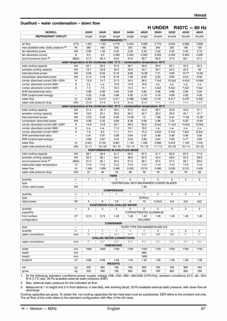
Himod
57EnglishH - Version - 60Hz
Dualfluid � water condensation � down flow
H UNDER R407C - 60 HzMODELL 20UH 24UH 28UH 34UH 40UH 26UH 32UD 42UH 46UH
REFRIGERANT CIRCUIT single single single single single double double double double
PERFORMANCES (1)
air flow m3/s 1.547 1.744 2.772 3.044 3.308 2.772 3.044 3.308 3.639
max available exter. static pressure (2) Pa 280 165 255 225 185 255 225 185 120
fan absorbed power kW 0.95 1.26 2.02 2.20 2.42 2.02 2.20 2.42 2.72
fan absorbed current A 3.3 3.3 3.3X2 3.4X2 3.3X2 3.3X2 3.4X2 3.3X2 3.2X2
sound pressure level (3) dB(A) 51.3 55.4 55.8 57.6 58.7 55.8 57.6 59.1 61.2
water temperature at the condenser inlet: 15�C - condensation temperature: 40�C
total cooling capacity kW 22.1 26.5 31.6 38.7 46.0 30.0 35.7 45.5 52.3
sensible cooling capacity kW 19.7 23.6 30.2 35.9 43.7 28.7 34.2 43.3 48
total absorbed power kW 5.09 6.04 8.19 9.68 10.98 7.21 8.80 10.77 12.29
compressor absorbed power kW 4.14 4.78 6.18 7.49 8.56 5.20 6.60 8.34 9.56
compr. absorbed current 208-230V A 13.9 14.7 21.5 24.5 28.5 7.5x2 10.5x2 14.0x2 14.8x2
compr. absorbed current 380V A n.a. n.a. 10.8 14.9 16.9 n.a. n.a. n.a. n.a.
compr. absorbed current 460V A 7.2 7.5 10.3 12.3 14.1 4.3x2 5.5x2 7.2x2 7.5x2
SHR (sensible/total ratio) - 0.89 0.89 0.95 0.93 0.95 0.96 0.96 0.95 0.92
EER (output/used energy) - 4.35 4.39 3.86 4.00 4.19 4.16 4.06 4.22 4.26
water flow l/s 0.261 0.310 0.411 0.496 0.582 0.181 0.217 0.276 0.322
water side pressure drop kPa 2+3 3+4 3+2 3+3 3+4 1+1 1+1 1+1 1+1
water temperature at the condenser inlet: 30�C - condensation temperature: 45�C
total cooling capacity kW 21.4 25.4 30.5 37.3 44.2 28.7 33.9 43.8 51.1
sensible cooling capacity kW 19.5 23.1 29.9 35.2 42.7 28.3 33.6 42.1 47.1
total absorbed power kW 5.53 6.58 8.90 10.58 12 7.88 9.43 11.63 13.36
compressor absorbed power kW 4.58 5.32 6.89 8.38 9.59 5.86 7.24 9.20 10.64
compr. absorbed current 208-230V A 14.8 15.8 23.1 26.3 30.8 8.2x2 11.5x2 14.9x2 15.9x2
compr. absorbed current 380V A n.a. n.a. 11.5 16.1 18.0 n.a. n.a. n.a. n.a.
compr. absorbed current 460V A 7.6 8.0 11.1 13.1 15.0 4.6x2 5.7x2 7.6x2 8.0x2
SHR (sensible/total ratio) - 0.91 0.91 0.98 0.94 0.97 0.99 0.99 0.96 0.92
EER (output/used energy) - 3.86 3.87 3.43 3.53 3.68 3.64 3.59 3.77 3.82
water flow l/s 0.521 0.722 0.961 1.143 1.339 0.699 0.916 1.156 1.544
water side pressure drop kPa 8+11 16+22 16+10 15+14 14+19 11+13 18+23 10+14 18+25
PERFORMANCES IN DUALFLUID MODE
total cooling capacity kW 28.1 33.5 51.7 63.5 67.3 51.7 63.5 67.3 71.9
sensible cooling capacity kW 22.5 26.1 42.4 48.9 52.5 42.4 48.9 52.5 56.8
sound pressure level (3) dB(A) 51.0 55.1 55.5 57.3 58.7 55.5 57.3 58.7 60.9
inlet/outlet water temperature °C 7/12 7/12 7/12 7/12 7/12 7/12 7/12 7/12 7/12
water flow l/s 1.340 1.600 2.460 3.030 3.210 2.460 3.030 3.210 3.430
water side pressure drop kPa 57 46 79 99 79 79 99 79 89
FANS
quantity n. 1 1 2 2 2 2 2 2 2
type - CENTRIFUGAL WITH BACKWARDS CURVED BLADES
motor rated power kW 1.65
COMPRESSOR
quantity n. 1 1 1 1 1 2 2 2 2
type - SCROLL
rated power HP 5 6 7.8 9 10 3.34x2 4x2 5x2 6x2
EVAPORATIN COIL/CHILLED WATER
quantity n. 2 2 2 2 2 2 2 2 2
pipes/fins COPPER/TREATED ALUMINIUM
front surface m2 0.74 0.74 1.49 1.49 1.49 1.49 1.49 1.49 1.49
configuration - INCLINED
CONDENSER
type - PLATE TYPE EXCHANGER IN AISI 316
quantity n. 1 1 1 1 1 2 2 2 2
water connections inch 1" 1" 1¼" 1¼" 1¼" 1/2" 1/2" 1" 1"
CHILLED WATER CONNECTIONS
water connections inch 1" 1¼" 1¼" 1¼" 1½" 1¼" 1¼" 1½" 1½"
DIMENSIONS
width mm 1000 1000 1750 1750 1750 1750 1750 1750 1750
depth mm 890
height mm 1950
footprint m2 0.89 0.89 1.56 1.56 1.56 1.56 1.56 1.56 1.56
WEIGHTS
net kg 500 494 790 795 800 790 795 800 783
gross kg 505 499 795 800 805 795 800 805 788
1. At the following standard conditions:power supply voltage 208-230-380-460/3/60 [V/Ph/Hz]; ambient conditions 24°C db; 50%R.H.(17°C wb); 20 Pa available external static pressure (ESP)
2. Max. external static pressure for the indicated air flow
3. Measured at 1 m height and 2 m front distance, in free field, with working fan(s); 20 Pa available external static pressure, with down flow airdischarge
Cooling capacities are gross. To obtain the net cooling capaicities the fan heat load must be substracted. EER refers to the ambient unit only.The air flow of the units refers to the standard configuration with filter of the G4 class.

Himod
58 English H - Version - 60Hz
Dualfluid � water condensation � down flowH UNDER R22 - 60 Hz
MODELL 20UH 24UH 28UH 34UH 40UH 26UH 32UD 42UH 46UH
REFRIGERANT CIRCUIT single single single single single double double double double
PERFORMANCES (1)
air flow m3/s 1.547 1.744 2.772 3.044 3.308 2.772 3.044 3.308 3.639
max available exter. static pressure (2) Pa 280 165 255 225 185 255 225 185 120
fan absorbed power kW 0.95 1.26 2.02 2.20 2.42 2.02 2.20 2.42 2.72
fan absorbed current A 3.3 3.3 3.3X2 3.4X2 3.3X2 3.3X2 3.4X2 3.3X2 3.2X2
sound pressure level (3) dB(A) 51.3 55.4 55.8 57.6 58.7 55.8 57.6 59.1 61.2
water temperature at the condenser inlet: 15�C - condensation temperature: 40�C
total cooling capacity kW 20.8 25.6 31 37.9 45.2 29.6 35.1 44.5 52.2
sensible cooling capacity kW 19.6 23.3 30 35.6 43 29 33.7 42.2 47.5
total absorbed power kW 5.01 6.01 7.88 9.28 10.54 7.13 8.84 10.62 12.25
compressor absorbed power kW 4.05 4.75 5.86 7.09 8.12 5.12 6.64 8.20 9.52
compr. absorbed current 208-230V A 13.9 14.6 20.9 23.8 27.3 7.3X2 9.9X2 13.9x2 14.7X2
compr. absorbed current 380V A 8.3 8.7 10.8 14.2 16.3 n.a. 5.6x2 8.4x2 8.8x2
compr. absorbed current 460V A 7.0 7.2 10.7 11.3 12.9 4.2x2 5.5X2 7.1x2 7.3x2
SHR (sensible/total ratio) - 0.94 0.91 0.97 0.94 0.95 0.98 0.96 0.95 0.91
EER (output/used energy) - 4.16 4.26 3.93 4.08 4.29 4.15 3.97 4.19 4.26
water flow l/s 0.248 0.299 0.365 0.444 0.523 0.170 0.205 0.259 0.306
water side pressure drop kPa 2+3 3+4 2+1 2+2 2+3 1+1 1+1 1+1 1+1
water temperature at the condenser inlet: 30�C - condensation temperature: 45�C
total cooling capacity kW 20.3 24.9 29.8 36.5 43.4 28.3 33.3 42.6 51
sensible cooling capacity kW 19.3 23.2 29.8 35 42.6 28.3 33.3 41.8 46.9
total absorbed power kW 5.42 6.50 8.50 10.07 11.44 7.76 9.45 11.44 13.23
compressor absorbed power kW 4.46 5.24 6.49 7.87 9.02 5.74 7.26 9.02 10.52
compr. absorbed current 208-230V A 14.7 15.8 22.3 25.3 29.0 7.8x2 10.8X2 14.8x2 15.9x2
compr. absorbed current 380V A 8.8 9.4 11.3 15.1 17.3 n.a. 5.9x2 8.9x2 9.5x2
compr. absorbed current 460V A 7.4 7.9 11.3 12.1 13.7 4.5x2 5.8x2 7.5x2 7.9x2
SHR (sensible/total ratio) - 0.95 0.93 1 0.96 0.98 1 1 0.98 0.92
EER (output/used energy) - 3.75 3.83 3.51 3.63 3.80 3.64 3.53 3.73 3.85
water flow l/s 0.480 0.683 0.769 0.939 1.104 0.643 0.850 1.046 1.423
water side pressure drop kPa 7+10 14+19 10+6 10+9 10+13 9+11 16+20 8+11 15+21
PERFORMANCES IN DUALFLUID MODE
total cooling capacity kW 28.1 33.5 51.7 63.5 67.3 51.7 63.5 67.3 71.9
sensible cooling capacity kW 22.5 26.1 42.4 48.9 52.5 42.4 48.9 52.5 56.8
sound pressure level (3) dB(A) 51.0 55.1 55.5 57.3 58.7 55.5 57.3 58.7 60.9
inlet/outlet water temperature °C 7/12 7/12 7/12 7/12 7/12 7/12 7/12 7/12 7/12
water flow l/s 1.340 1.600 2.460 3.030 3.210 2.460 3.030 3.210 3.430
water side pressure drop kPa 57 46 79 99 79 79 99 79 89
FANS
quantity n. 1 1 2 2 2 2 2 2 2
type - CENTRIFUGAL WITH BACKWARDS CURVED BLADES
motor rated power kW 1.65
COMPRESSOR
quantity n. 1 1 1 1 1 2 2 2 2
type - SCROLL
rated power HP 5 6 7.8 9 10 3.34X2 4X2 5X2 6X2
EVAPORATIN COIL/CHILLED WATER
quantity n. 2 2 2 2 2 2 2 2 2
pipes/fins COPPER/TREATED ALUMINIUM
front surface m2 0.74 0.74 1.49 1.49 1.49 1.49 1.49 1.49 1.49
configuration - INCLINED
CONDENSER
type - PLATE TYPE EXCHANGER IN AISI 316
quantity n. 1 1 1 1 1 2 2 2 2
water connections inch 1" 1" 1¼" 1¼" 1¼" 1/2" 1/2" 1" 1"
CHILLED WATER CONNECTIONS
water connections inch 1" 1¼" 1¼" 1¼" 1½" 1¼" 1¼" 1½" 1½"
DIMENSIONS
width mm 1000 1000 1750 1750 1750 1750 1750 1750 1750
depth mm 890
height mm 1950
footprint m2 0.89 0.89 1.56 1.56 1.56 1.56 1.56 1.56 1.56
WEIGHTS
net kg 500 494 790 795 800 790 795 800 783
gross kg 505 499 795 800 805 795 800 805 788
1. At the following standard conditions:power supply voltage 208-230-380-460/3/60 [V/Ph/Hz]; ambient conditions 24°C db; 50%R.H.(17°C wb); 20 Pa available external static pressure (ESP)
2. Max. external static pressure for the indicated air flow3. Measured at 1 m height and 2 m front distance, in free field, with working fan(s); 20 Pa available external static pressure, with down flow air
dischargeCooling capacities are gross. To obtain the net cooling capaicities the fan heat load must be substracted. EER refers to the ambient unit only.The air flow of the units refers to the standard configuration with filter of the G4 class.

Himod
59EnglishH - Version - 60Hz
Dualfluid � water condensation � up flow
H OVER R407C - 60 HzMODELL 20OH 24OH 28OH 34OH 40OH 26OH 32OD 42OH 46OH
REFRIGERANT CIRCUIT single single single single single double double double double
PERFORMANCES (1)
air flow m3/s 1.567 1.764 2.744 2.911 3.294 2.744 2.911 3.294 3.569
max available exter. static pressure (2) Pa 285 170 260 215 145 260 215 145 80
fan absorbed power kW 1.02 1.32 2.14 2.36 2.70 2.14 2.36 2.70 3.02
fan absorbed current A 3.4 3.3 3.4x2 3.3x2 3.2x2 3.4x2 3.3x2 3.2x2 3.1x2
sound pressure level (3) dB(A) 52.9 57.1 57.8 58.1 61.6 57.8 58.1 61.6 63.4
water temperature at the condenser inlet: 15�C - condensation temperature: 40�C
total cooling capacity kW 21.5 25.1 31.7 38.0 45.5 29.8 34.3 44.5 51.8
sensible cooling capacity kW 19.2 22.8 30.3 35 42.9 28.9 32.9 42.1 46.8
total absorbed power kW 5.15 6.08 8.32 9.86 11.27 7.34 8.98 11.04 12.58
compressor absorbed power kW 4.13 4.76 6.18 7.49 8.57 5.20 6.62 8.34 9.56
compr. absorbed current 208-230V A 13.8 14.7 21.5 24.6 28.5 7.5x2 10.5x2 13.9x2 14.8x2
compr. absorbed current 380V A n.a. n.a. 10.8 14.8 16.9 n.a. n.a. n.a. n.a.
compr. absorbed current 460V A 7.2 7.5 10.3 12.3 14.1 4.3x2 5.5x2 7.2x2 7.5x2
SHR (sensible/total ratio) - 0.89 0.91 0.96 0.92 0.94 0.97 0.96 0.95 0.90
EER (output/used energy) - 4.18 4.12 3.81 3.85 4.04 4.06 3.82 4.03 4.12
water flow l/s 0.254 0.295 0.411 0.486 0.577 0.180 0.210 0.272 0.317
water side pressure drop kPa 2+3 3+4 3+2 3+2 3+3 1+1 1+1 1+1 1+1
water temperature at the condenser inlet: 30�C - condensation temperature: 45�C
total cooling capacity kW 20.7 24.1 30.1 36.6 43.5 28.6 32.7 43.3 50.5
sensible cooling capacity kW 18.7 22.4 29.7 34 42.6 28.3 32.4 41.8 46.1
total absorbed power kW 5.59 6.63 9.03 10.75 12.30 8.02 9.66 11.9 13.66
compressor absorbed power kW 4.57 5.31 6.89 8.39 9.59 5.88 7.26 9.20 10.64
compr. absorbed current 208-230V A 14.7 15.7 23.1 26.3 30.8 8.2x2 11.5x2 14.9x2 15.8x2
compr. absorbed current 380V A n.a. n.a. 11.5 16.0 18.0 n.a. n.a. n.a. n.a.
compr. absorbed current 460V A 7.6 8.0 11.1 13.1 15.1 4.7x2 5.8x2 7.6x2 8.0x2
SHR (sensible/total ratio) - 0.90 0.93 0.98 0.93 0.98 0.99 0.99 0.96 0.914
EER (output/used energy) - 3.71 3.63 3.33 3.40 3.54 3.57 3.38 3.64 3.70
water flow l/s 0.496 0.661 0.961 1.109 1.315 0.696 0.872 1.125 1.503
water side pressure drop kPa 7+10 13+18 16+10 14+13 14+18 11+13 16+21 9+13 17+23
PERFORMANCES IN DUALFLUID MODE
total cooling capacity kW 28.4 29.8 50.8 58.6 63.9 50.8 58.6 63.9 67.4
sensible cooling capacity kW 22.7 25.6 41.7 46.3 51.1 41.7 46.3 51.1 54.6
sound pressure level (3) dB(A) 52.5 56.7 57.4 57.6 61.1 57.4 57.6 61.1 62.9
inlet/outlet water temperature °C 7/12 7/12 7/12 7/12 7/12 7/12 7/12 7/12 7/12
water flow l/s 1.350 1.420 2.420 2.8 3.040 2.420 2.8 3.040 3.210
water side pressure drop kPa 58 27 77 86 72 77 86 72 79
FANS
quantity n. 1 1 2 2 2 2 2 2 2
type - CENTRIFUGAL WITH BACKWARDS CURVED BLADES
motor rated power kW 1.65
COMPRESSOR
quantity n. 1 1 1 1 1 2 2 2 2
type - SCROLL
rated power HP 5 6 7.8 9 10 3.34x2 4x2 5x2 6x2
EVAPORATIN COIL/CHILLED WATER
quantity n. 2 2 2 2 2 2 2 2 2
pipes/fins COPPER/TREATED ALUMINIUM
front surface m2 0.74 0.74 1.49 1.49 1.49 1.49 1.49 1.49 1.49
configuration - INCLINED
CONDENSER
type - PLATE TYPE EXCHANGER IN AISI 316
quantity n. 1 1 1 1 1 2 2 2 2
water connections inch 1" 1" 1¼" 1¼" 1¼" 1/2" 1/2" 1" 1"
CHILLED WATER CONNECTIONS
water connections inch 1" 1¼" 1¼" 1¼" 1½" 1¼" 1¼" 1½" 1½"
DIMENSIONS
width mm 1000 1000 1750 1750 1750 1750 1750 1750 1750
depth mm 890
height mm 1950
footprint m2 0.89 0.89 1.56 1.56 1.56 1.56 1.56 1.56 1.56
WEIGHTS
net kg 500 494 790 795 800 790 795 800 783
gross kg 505 499 795 800 805 795 800 805 788
1. At the following standard conditions:power supply voltage 208-230-380-460/3/60 [V/Ph/Hz]; ambient conditions 24°C db; 50%R.H.(17°C wb); 50 Pa available external static pressure (ESP)
2. Max. external static pressure for the indicated air flow
3. Measured at 1 m height and 2 m front distance, in free field, with working fan(s); 50 Pa available external static pressure, with ducted airdischarge
Cooling capacities are gross. To obtain the net cooling capaicities the fan heat load must be substracted. EER refers to the ambient unit only.The air flow of the units refers to the standard configuration with filter of the G4 class.

Himod
60 English H - Version - 60Hz
Dualfluid � water condensation � up flow
H OVER R22 - 60 HzMODELL 20OH 24OH 28OH 34OH 40OH 26OH 32OD 42OH 46OH
REFRIGERANT CIRCUIT single single single single single double double double double
PERFORMANCES (1)
air flow m3/s 1.567 1.764 2.744 2.911 3.294 2.744 2.911 3.294 3.569
max available exter. static pressure (2) Pa 285 170 260 215 145 260 215 145 80
fan absorbed power kW 1.02 1.32 2.14 2.36 2.70 2.14 2.36 2.70 3.02
fan absorbed current A 3.4 3.3 3.4x2 3.3x2 3.2x2 3.4x2 3.3x2 3.2x2 3.1x2
sound pressure level (3) dB(A) 52.9 57.1 57.8 58.1 61.6 57.8 58.1 61.6 63.4
water temperature at the condenser inlet: 15�C - condensation temperature: 40�C
total cooling capacity kW 20.5 24.4 31.1 37.2 44.7 29.4 33.8 43.5 51.7
sensible cooling capacity kW 19 22.9 30.1 34.6 42.5 28.8 32.8 41.8 46.6
total absorbed power kW 5.06 6.04 8.01 9.45 10.83 7.26 8.98 10.88 12.53
compressor absorbed power kW 4.04 4.72 5.86 7.09 8.12 5.12 6.62 8.18 9.50
compr. absorbed current 208-230V A 13.8 14.6 20.9 23.8 27.3 7.3x2 9.9x2 13.9x2 14.7x2
compr. absorbed current 380V A 8.3 8.7 10.7 14.2 16.3 n.a 5.6x2 8.4x2 8.7x2
compr. absorbed current 460V A 7.0 7.2 10.7 11.3 12.9 4.2x2 5.5x2 7.1x2 7.3x2
SHR (sensible/total ratio) - 0.93 0.94 0.97 0.93 0.95 0.98 0.97 0.96 0.90
EER (output/used energy) - 4.05 4.03 3.88 3.94 4.13 4.05 3.76 4 4.13
water flow l/s 0.242 0.287 0.364 0.437 0.520 0.170 0.199 0.256 0.302
water side pressure drop kPa 2+2 2+3 2+1 2+2 2+3 1+1 1+1 0+1 1+1
water temperature at the condenser inlet: 30�C - condensation temperature: 45�C
total cooling capacity kW 19.9 23.5 29.8 36 43 28.2 32.2 42.3 49.9
sensible cooling capacity kW 18.7 22.6 29.8 34.5 41.8 28.2 32.2 41.1 45.9
total absorbed power kW 5.46 6.55 8.63 10.24 11.73 7.89 9.60 11.70 13.52
compressor absorbed power kW 4.44 5.22 6.49 7.88 9.02 5.74 7.24 9 10.50
compr. absorbed current 208-230V A 14.7 15.7 22.4 25.3 29.0 7.8x2 10.8x2 14.8x2 15.8x2
compr. absorbed current 380V A 8.8 9.4 11.3 15.1 17.3 n.a 5.9x2 8.9x2 9.4x2
compr. absorbed current 460V A 7.4 7.8 11.3 12.1 13.7 4.5x2 5.8x2 7.5x2 7.9x2
SHR (sensible/total ratio) - 0.94 0.96 1 0.96 0.97 1 1 0.97 0.92
EER (output/used energy) - 3.65 3.59 3.45 3.51 3.67 3.57 3.36 3.62 3.69
water flow l/s 0.459 0.636 0.769 0.908 1.092 0.643 0.813 1.021 1.394
water side pressure drop kPa 6+9 12+17 10+6 9+9 10+12 9+11 14+18 8+11 14+20
PERFORMANCES IN DUALFLUID MODE
total cooling capacity kW 28.4 33.9 50.8 58.6 63.9 50.8 58.6 63.9 67.4
sensible cooling capacity kW 22.7 26.4 41.7 46.3 51.1 41.7 46.3 51.1 54.6
sound pressure level (3) dB(A) 52.5 56.7 57.4 57.6 61.1 57.4 57.6 61.1 62.9
inlet/outlet water temperature °C 7/12 7/12 7/12 7/12 7/12 7/12 7/12 7/12 7/12
water flow l/s 1.350 1.620 2.420 2.8 3.040 2.420 2.80 3.040 3.210
water side pressure drop kPa 58 47 77 86 72 77 86 72 79
FANS
quantity n. 1 1 2 2 2 2 2 2 2
type - CENTRIFUGAL WITH BACKWARDS CURVED BLADES
motor rated power kW 1.65
COMPRESSOR
quantity n. 1 1 1 1 1 2 2 2 2
type - SCROLL
rated power HP 5 6 7.8 9 10 3.34x2 4x2 5x2 6x2
EVAPORATIN COIL/CHILLED WATER
quantity n. 2 2 2 2 2 2 2 2 2
pipes/fins COPPER/TREATED ALUMINIUM
front surface m2 0.74 0.74 1.49 1.49 1.49 1.49 1.49 1.49 1.49
configuration - INCLINED
CONDENSER
type - PLATE TYPE EXCHANGER IN AISI 316
quantity n. 1 1 1 1 1 2 2 2 2
water connections inch 1" 1" 1¼" 1¼" 1¼" 1/2" 1/2" 1" 1"
CHILLED WATER CONNECTIONS
water connections inch 1" 1¼" 1¼" 1¼" 1½" 1¼" 1¼" 1½" 1½"
DIMENSIONS
width mm 1000 1000 1750 1750 1750 1750 1750 1750 1750
depth mm 890
height mm 1950
footprint m2 0.89 0.89 1.56 1.56 1.56 1.56 1.56 1.56 1.56
WEIGHTS
net kg 500 494 790 795 800 790 795 800 783
gross kg 505 499 795 800 805 795 800 805 788
1. At the following standard conditions:power supply voltage 208-230-380-460/3/60 [V/Ph/Hz]; ambient conditions 24°C db; 50%R.H.(17°C wb); 50 Pa available external static pressure (ESP)
2. Max. external static pressure for the indicated air flow
3. Measured at 1 m height and 2 m front distance, in free field, with working fan(s); 50 Pa available external static pressure, with ducted airdischarge
Cooling capacities are gross. To obtain the net cooling capaicities the fan heat load must be substracted. EER refers to the ambient unit only.The air flow of the units refers to the standard configuration with filter of the G4 class.

Himod
61EnglishF - Version - 60Hz
Freecooler � down flow
F UNDER R407C - 60 Hz
MODELL 20UF 24UF 28UF 34UF 40UF 26UF 32UF 42UF 46UF
REFRIGERANT CIRCUIT single single single single single double double double double
PERFORMANCES (1)
air flow m3/s 1.547 1.744 2.772 3.044 3.308 2.772 3.044 3.308 3.639
max available external static pressure(2) Pa 280 165 255 225 185 255 225 185 120
fan absorbed power kW 0.95 1.26 2.02 2.20 2.42 2.02 2.20 2.42 2.72
fan absorbed current A 3.3 3.3 3.3x2 3.4x2 3.3x2 3.3x2 3.4x2 3.3x2 3.2x2
glycol % 30 30 30 30 30 30 30 30 30
PERFORMANCES WITH MECANICAL COOLING (Tc=50°C; mixture inlet temperature = 38°C)
total cooling capacity kW 20.4 24.5 30.3 35.2 42.5 28.5 33.8 41.8 50.3
sensible cooling capacity kW 19.2 22.8 29.1 34.4 41.8 27.9 32.8 41.3 45.8
total absorbed power kW 6.03 7.19 9.88 11.79 13.39 8.64 10.51 12.83 14.85
compressor absorbed power kW 5.08 5.93 7.87 9.60 10.97 6.62 8.30 10.40 12.12
compr. absorbed current 208-230V A 15.9 17.1 25.2 28.7 33.7 8.9x2 12.9x2 16.2x2 17.5x2
compr. absorbed current 380V A n.a. n.a. 12.4 17.6 19.7 n.a. n.a. n.a. n.a.
compr. absorbed current 460V A 8.1 8.1 12.2 14.3 16.4 5.1x2 6.2x2 8.2x2 9.1x2
SHR (sensible/total ratio) - 0.94 0.93 0.96 0.98 0.98 0.98 0.97 0.99 0.91
sound pressure level (3) dB(A) 51.3 55.4 55.8 57.6 59.1 55.8 57.6 59.1 61.2
EER (output/used energy) - 3.38 3.41 3.07 2.98 3.17 3.29 3.22 3.26 3.39
inlet mixture temperature °C 38 38 38 38 38 38 38 38 38
condenser water pressure drop kPa 40 83 49 46 44 39 49 30 56
valve water pressure drop kPa 59 122 32 45 60 53 67 44 83
PERFORMANCES IN FREECOOLING MODE
sound pressure level dB(A) 51.0 55.1 55.5 57.3 58.7 55.5 57.3 58.7 60.9
inlet mixture temperature °C 7 7 7 7 7 7 7 7 7
water flow l/s 1.110 1.590 1.620 1.920 2.240 1.290 1.450 1.920 2.620
water side pressure drop kPa 46 74 65 49 65 43 30 49 86
FANS
quantity n. 1 1 2 2 2 2 2 2 2
type - CENTRIFUGAL WITH BACKWARDS CURVED BLADES
motor rated power kW 1.65
COMPRESSOR
quantity n. 1 1 1 1 1 2 2 2 2
type - SCROLL
rated power HP 5 6 7.8 9 10 2x3.34 2x4 2x5 2x6
EVAPORATIN COIL
quantity n. 1 1 1 1 1 1 1 1 1
pipes/fins COPPER/TREATED ALUMINIUM
front surface m2 0.74 0.74 1.49 1.49 1.49 1.49 1.49 1.49 1.49
configuration - INCLINED
DRY COOLER
type - PLATE TYPE EXCHANGER IN AISI 316
quantity n. 1 1 1 1 1 2 2 2 2
water connections inch 1" 1" 1¼" 1¼" 1¼" 1¼" 1¼" 1¼" 1¼"
DIMENSIONS
width mm 1000 1000 1750 1750 1750 1750 1750 1750 1750
depth mm 890
height mm 1950
footprint m2 0.89 0.89 1.56 1.56 1.56 1.56 1.56 1.56 1.56
WEIGHTS
net kg 500 494 790 795 800 790 795 800 783
gross kg 505 499 795 800 805 795 800 805 788
1. At the following standard conditions:power supply voltage 208-230-380-460/3/60 [V/Ph/Hz]; ambient conditions 24°C db; 50%R.H.(17°C wb); 20 Pa available external static pressure (ESP); outdoor temperature: 35° C.
2. Max. external static pressure for the indicated air flow3. Measured at 1 m height and 2 m front distance, in free field, with working fan(s); 20 Pa available external static pressure, with down flow air
discharge
Cooling capacities are gross. To obtain the net cooling capaicities the fan heat load must be substracted. EER refers to the ambient unit only.The air flow of the units refers to the standard configuration with filter of the G4 class.
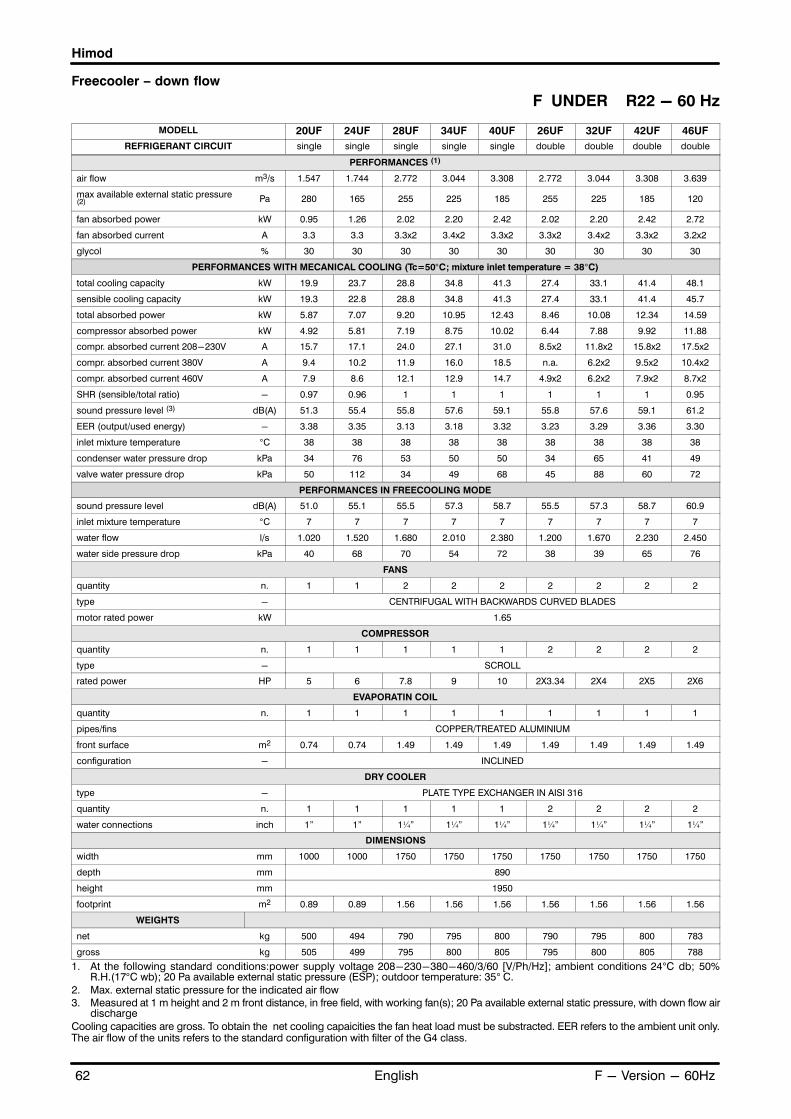
Himod
62 English F - Version - 60Hz
Freecooler � down flow
F UNDER R22 - 60 Hz
MODELL 20UF 24UF 28UF 34UF 40UF 26UF 32UF 42UF 46UF
REFRIGERANT CIRCUIT single single single single single double double double double
PERFORMANCES (1)
air flow m3/s 1.547 1.744 2.772 3.044 3.308 2.772 3.044 3.308 3.639
max available external static pressure(2) Pa 280 165 255 225 185 255 225 185 120
fan absorbed power kW 0.95 1.26 2.02 2.20 2.42 2.02 2.20 2.42 2.72
fan absorbed current A 3.3 3.3 3.3x2 3.4x2 3.3x2 3.3x2 3.4x2 3.3x2 3.2x2
glycol % 30 30 30 30 30 30 30 30 30
PERFORMANCES WITH MECANICAL COOLING (Tc=50°C; mixture inlet temperature = 38°C)
total cooling capacity kW 19.9 23.7 28.8 34.8 41.3 27.4 33.1 41.4 48.1
sensible cooling capacity kW 19.3 22.8 28.8 34.8 41.3 27.4 33.1 41.4 45.7
total absorbed power kW 5.87 7.07 9.20 10.95 12.43 8.46 10.08 12.34 14.59
compressor absorbed power kW 4.92 5.81 7.19 8.75 10.02 6.44 7.88 9.92 11.88
compr. absorbed current 208-230V A 15.7 17.1 24.0 27.1 31.0 8.5x2 11.8x2 15.8x2 17.5x2
compr. absorbed current 380V A 9.4 10.2 11.9 16.0 18.5 n.a. 6.2x2 9.5x2 10.4x2
compr. absorbed current 460V A 7.9 8.6 12.1 12.9 14.7 4.9x2 6.2x2 7.9x2 8.7x2
SHR (sensible/total ratio) - 0.97 0.96 1 1 1 1 1 1 0.95
sound pressure level (3) dB(A) 51.3 55.4 55.8 57.6 59.1 55.8 57.6 59.1 61.2
EER (output/used energy) - 3.38 3.35 3.13 3.18 3.32 3.23 3.29 3.36 3.30
inlet mixture temperature °C 38 38 38 38 38 38 38 38 38
condenser water pressure drop kPa 34 76 53 50 50 34 65 41 49
valve water pressure drop kPa 50 112 34 49 68 45 88 60 72
PERFORMANCES IN FREECOOLING MODE
sound pressure level dB(A) 51.0 55.1 55.5 57.3 58.7 55.5 57.3 58.7 60.9
inlet mixture temperature °C 7 7 7 7 7 7 7 7 7
water flow l/s 1.020 1.520 1.680 2.010 2.380 1.200 1.670 2.230 2.450
water side pressure drop kPa 40 68 70 54 72 38 39 65 76
FANS
quantity n. 1 1 2 2 2 2 2 2 2
type - CENTRIFUGAL WITH BACKWARDS CURVED BLADES
motor rated power kW 1.65
COMPRESSOR
quantity n. 1 1 1 1 1 2 2 2 2
type - SCROLL
rated power HP 5 6 7.8 9 10 2X3.34 2X4 2X5 2X6
EVAPORATIN COIL
quantity n. 1 1 1 1 1 1 1 1 1
pipes/fins COPPER/TREATED ALUMINIUM
front surface m2 0.74 0.74 1.49 1.49 1.49 1.49 1.49 1.49 1.49
configuration - INCLINED
DRY COOLER
type - PLATE TYPE EXCHANGER IN AISI 316
quantity n. 1 1 1 1 1 2 2 2 2
water connections inch 1" 1" 1¼" 1¼" 1¼" 1¼" 1¼" 1¼" 1¼"
DIMENSIONS
width mm 1000 1000 1750 1750 1750 1750 1750 1750 1750
depth mm 890
height mm 1950
footprint m2 0.89 0.89 1.56 1.56 1.56 1.56 1.56 1.56 1.56
WEIGHTS
net kg 500 494 790 795 800 790 795 800 783
gross kg 505 499 795 800 805 795 800 805 788
1. At the following standard conditions:power supply voltage 208-230-380-460/3/60 [V/Ph/Hz]; ambient conditions 24°C db; 50%R.H.(17°C wb); 20 Pa available external static pressure (ESP); outdoor temperature: 35° C.
2. Max. external static pressure for the indicated air flow3. Measured at 1 m height and 2 m front distance, in free field, with working fan(s); 20 Pa available external static pressure, with down flow air
discharge
Cooling capacities are gross. To obtain the net cooling capaicities the fan heat load must be substracted. EER refers to the ambient unit only.The air flow of the units refers to the standard configuration with filter of the G4 class.

Himod
63EnglishF - Version - 60Hz
Freecooler � up flow
F OVER R407C - 60 Hz
MODELL 20OF 24OF 28OF 34OF 40OF 26OF 32OF 42OF 46OF
REFRIGERANT CIRCUIT single single single single single double double double double
PERFORMANCES (1)
air flow m3/s 1.567 1.764 2.744 2.911 3.294 2.744 2.911 3.294 3.569
max available external static pressure(2) Pa 285 170 260 215 145 260 215 145 80
fan absorbed power kW 1.02 1.32 2.14 2.36 2.70 2.14 2.36 2.70 3.02
fan absorbed current A 3.4 3.3 3.4x2 3.3x2 3.2x2 3.4x2 3.3x2 3.2x2 3.1x2
glycol % 30 30 30 30 30 30 30 30 30
PERFORMANCES WITH MECANICAL COOLING (Tc=50°C; mixture inlet temperature = 38°C)
total cooling capacity kW 19.7 23.1 30.2 34.7 42.7 28.6 32.9 42.4 49.7
sensible cooling capacity kW 18.4 22.2 28.9 33.4 41.5 27.7 31.9 40.7 44.8
total absorbed power kW 6.09 7.24 10.01 11.97 13.69 8.78 10.69 13.11 15.14
compressor absorbed power kW 5.07 5.92 7.87 9.60 10.98 6.64 8.32 10.40 12.12
compr. absorbed current 208-230V A 15.8 17.0 25.2 28.7 33.7 8.9x2 12.9x2 16.2x2 17.4x2
compr. absorbed current 380V A n.a. n.a. 12.4 17.5 19.7 n.a. n.a. n.a. n.a.
compr. absorbed current 460V A 8.1 8.8 12.2 14.3 16.4 5.1x2 6.2x2 8.2x2 9.0x2
SHR (sensible/total ratio) - 0.93 0.96 0.96 0.96 0.97 0.97 0.97 0.96 0.90
sound pressure level (3) dB(A) 52.7 57.1 57.8 58.1 61.6 57.8 58.1 61.6 63.4
EER (output/used energy) - 3.24 3.19 3.02 2.90 3.12 3.25 3.08 3.24 3.29
inlet mixture temperature °C 38 38 38 38 38 38 38 38 38
condenser water pressure drop kPa 36 70 49 43 43 39 44 29 53
valve water pressure drop kPa 53 102 32 42 58 52 60 42 78
PERFORMANCES IN FREECOOLING MODE
sound pressure level dB(A) 52.5 56.7 57.4 57.6 61.1 57.4 57.6 61.1 62.9
inlet mixture temperature °C 7 7 7 7 7 7 7 7 7
water flow l/s 1.050 1.460 1.620 1.860 2.2 1.290 1.380 1.870 2.550
water side pressure drop kPa 42 63 65 47 63 43 28 47 82
FANS
quantity n. 1 1 2 2 2 2 2 2 2
type - CENTRIFUGAL WITH BACKWARDS CURVED BLADES
motor rated power kW 1.65
COMPRESSOR
quantity n. 1 1 1 1 1 2 2 2 2
type - SCROLL
rated power HP 5 6 7.8 9 10 2x3.34 2x4 2x5 2x6
EVAPORATIN COIL
quantity n. 1 1 1 1 1 1 1 1 1
pipes/fins COPPER/TREATED ALUMINIUM
front surface m2 0.74 0.74 1.49 1.49 1.49 1.49 1.49 1.49 1.49
configuration - INCLINED
DRY COOLER
type - PLATE TYPE EXCHANGER IN AISI 316
quantity n. 1 1 1 1 1 2 2 2 2
water connections inch 1" 1" 1¼" 1¼" 1¼" 1¼" 1¼" 1¼" 1¼"
DIMENSIONS
width mm 1000 1000 1750 1750 1750 1750 1750 1750 1750
depth mm 890
height mm 1950
footprint m2 0.89 0.89 1.56 1.56 1.56 1.56 1.56 1.56 1.56
WEIGHTS
net kg 500 494 800 810 815 800 805 810 783
gross kg 505 499 805 815 820 805 810 815 788
1. At the following standard conditions:power supply voltage 208-230-380-460/3/60 [V/Ph/Hz]; ambient conditions 24°C db; 50%R.H.(17°C wb); 50 Pa available external static pressure (ESP); outdoor temperature: 35° C.
2. Max. external static pressure for the indicated air flow3. Measured at 1 m height and 2 m front distance, in free field, with working fan(s); 50 Pa available external static pressure, with ducted air
discharge
Cooling capacities are gross. To obtain the net cooling capaicities the fan heat load must be substracted. EER refers to the ambient unit only.The air flow of the units refers to the standard configuration with filter of the G4 class.

Himod
64 English F - Version - 60Hz
Freecooler � up flow
F OVER R22 - 60 Hz
MODELL 20OF 24OF 28OF 34OF 40OF 26OF 32OF 42OF 46OF
REFRIGERANT CIRCUIT single single single single single double double double double
PERFORMANCES (1)
air flow m3/s 1.567 1.764 2.744 2.911 3.294 2.744 2.911 3.294 3.569
max available external static pressure(2) Pa 285 170 260 215 145 260 215 145 80
fan absorbed power kW 1.02 1.32 2.14 2.36 2.70 2.14 2.36 2.70 3.02
fan absorbed current A 3.4 3.3 3.4x2 3.3x2 3.2x2 3.4x2 3.3x2 3.2x2 3.1x2
glycol % 30 30 30 30 30 30 30 30 30
PERFORMANCES WITH MECANICAL COOLING (Tc=50°C; mixture inlet temperature = 38°C)
total cooling capacity kW 19.2 22.9 28.7 34.3 41.3 27.2 31.9 40.7 48.1
sensible cooling capacity kW 18.4 22.5 28.7 34.3 41.3 27.2 31.9 40.7 45.2
total absorbed power kW 5.92 7.11 9.33 11.12 12.72 8.59 10.24 12.61 14.88
compressor absorbed power kW 4.90 5.79 7.19 8.75 10.02 6.44 7.88 9.90 11.86
compr. absorbed current 208-230V A 15.7 17.0 24.0 27.0 31.0 8.5x2 11.8x2 15.8x2 17.4x2
compr. absorbed current 380V A 9.4 10.2 11.9 16.1 18.5 n.a. 6.2x2 9.5x2 10.4x2
compr. absorbed current 460V A 7.8 8.5 12.1 12.9 14.7 4.9x2 6.2x2 7.9x2 8.7x2
SHR (sensible/total ratio) - 0.96 0.98 1 1 1 1 1 1 0.94
sound pressure level (3) dB(A) 52.7 57.1 57.8 58.1 61.6 57.8 58.1 61.6 63.4
EER (output/used energy) - 3.24 3.22 3.08 3.09 3.24 3.17 3.12 3.23 3.23
inlet mixture temperature °C 38 38 38 38 38 38 38 38 38
condenser water pressure drop kPa 31 65 53 47 48 34 59 39 47
valve water pressure drop kPa 46 96 34 45 65 45 81 58 69
PERFORMANCES IN FREECOOLING MODE
sound pressure level dB(A) 52.5 56.7 57.4 57.6 61.1 57.4 57.6 61.1 62.9
inlet mixture temperature °C 7 7 7 7 7 7 7 7 7
water flow l/s 0.980 1.410 1.680 1.940 2.320 1.2 1.6 2.190 2.390
water side pressure drop kPa 37 59 70 50 69 38 36 62 73
FANS
quantity n. 1 1 2 2 2 2 2 2 2
type - CENTRIFUGAL WITH BACKWARDS CURVED BLADES
motor rated power kW 1.65
COMPRESSOR
quantity n. 1 1 1 1 1 2 2 2 2
type - SCROLL
rated power HP 5 6 7.8 9 10 2x3.34 2x4 2x5 2x6
EVAPORATIN COIL
quantity n. 1 1 1 1 1 1 1 1 1
pipes/fins COPPER/TREATED ALUMINIUM
front surface m2 0.74 0.74 1.49 1.49 1.49 1.49 1.49 1.49 1.49
configuration - INCLINED
DRY COOLER
type - PLATE TYPE EXCHANGER IN AISI 316
quantity n. 1 1 1 1 1 2 2 2 2
water connections inch 1" 1" 1¼" 1¼" 1¼" 1¼" 1¼" 1¼" 1¼"
DIMENSIONS
width mm 1000 1000 1750 1750 1750 1750 1750 1750 1750
depth mm 890
height mm 1950
footprint m2 0.89 0.89 1.56 1.56 1.56 1.56 1.56 1.56 1.56
WEIGHTS
net kg 500 494 800 810 815 800 805 810 793
gross kg 505 499 805 815 820 805 810 815 798
1. At the following standard conditions:power supply voltage 208-230-380-460/3/60 [V/Ph/Hz]; ambient conditions 24°C db; 50%R.H.(17°C wb); 50 Pa available external static pressure (ESP); outdoor temperature: 35° C.
2. Max. external static pressure for the indicated air flow3. Measured at 1 m height and 2 m front distance, in free field, with working fan(s); 50 Pa available external static pressure, with ducted air
discharge
Cooling capacities are gross. To obtain the net cooling capaicities the fan heat load must be substracted. EER refers to the ambient unit only.The air flow of the units refers to the standard configuration with filter of the G4 class.

English 65C - Version - 50/60Hz
Chilled water unit � down flow
C UNDER - 50/60 Hz
MODELS 27UC 45UC 55UC
PERFORMANCES (1)
air flow m3/s 2.348 2.107(4)
1.8222.455 2.210
(4)
1.9294.420 3.980
(4)
3.640
max available external static pressure (2)50Hz
Pa150 250 350 150 250 350 150 250 325
max available external static pressure (2)60Hz
Pa- 100 200 - 100 200 - 120 190
fan absorbed power50Hz
kW2.1 1.7 1,4 2.0 1.7 1.4 4.1 3.5 2.8
fan absorbed power60Hz
kW- 1.4 1.1 - 1.4 1.1 - 2.7 2.3
fan absorbed current50Hz
A4,4 4,4 4,3 4.4 4.4 8,6 4.5x2 4.4x2 4.3x2
fan absorbed current60Hz
A- 3.2 3.4 - 3.2 3.3 - 3.3x2 3.3x2
sound pressure level (3) dB(A) 60.6 57.6 53.9 61.9 58.7 55.2 62.6 59.9 57.6
inlet water temperature: 7�C - outlet water temperature: 12�C
total cooling capacity kW 30,4 29,0 26,8 46.6 43.3 39.1 64.2 60.5 57.4
sensible cooling capacity kW 30,4 27.8 24,9 39.2 35.8 31.6 59.7 55.1 51.1
SHR (sensible/total ratio) - 1.00 0.96 0.93 0.84 0.83 0.81 0.93 0.91 0.89
water flow l/s 1,45 1,38 1,28 2.22 2.06 1.87 3.06 2.88 2.74
water side pressure drop kPa 65 60 52 71 63 53 117 105 95
inlet water temperature: 10�C - outlet water temperature: 15�C
total cooling capacity kW 23,6 21.8 19.5 29.7 27.2 24.1 46.2 42.6 39.6
sensible cooling capacity kW 23,6 21.8 19.5 29.7 27.2 24.1 46.2 42.6 39.6
SHR (sensible/total ratio) - 1.00 1.00 1.00 1.00 1.00 1.00 1.00 1.00 1.00
water flow l/s 1,13 1,04 0,93 1.42 1.30 1.15 2.21 2.03 1.89
water side pressure drop kPa 41 36 29 34 30 25 64 56 49
FANS
quantity n. 1 1 2
type - CENTRIFUGAL WITH BACKWARDS CURVED BLADES
motor rated power 50Hz(60Hz)
kW 2.5 (1.6)
CHILLED WATER COIL
quantity n. 1 2 1
pipes/fins COPPER/TREATED ALUMINIUM
front surface m2 0.74 1.49 1.49
configuration - INCLINED
CHILLED WATER CONNECTIONS
water connections inch 1" 1¼" 1¼"
DIMENSIONS
width mm 1000 1000 1750
depth mm 890
height mm 1950
footprint m2 0.89 0.89 1.56
WEIGHTS
net kg 290 340 495
gross kg 295 345 500
4. At the following standard conditions: ambient conditions 24°C db; 50% R.H.(17°C wb); 20 Pa available external static pressure (ESP).
5. Max. external static pressure for the indicated air flow
6. Measured at 1 m height and 2 m front distance, in free field, with working fan(s); 20 Pa available external static pressure, with down flow airdischarge.
7. Standard air flow.
Cooling capacities are gross. To obtain the net cooling capaicities the fan heat load must be substracted. The air flow of the units refers to thestandard configuration with filter of the G4 class.

Himod
66 English C - Version - 50/60Hz
Chilled water unit � down flow
C UNDER - 50/60 Hz
MODELS 65UC 80UC 85UC
PERFORMANCES (1)
air flow m3/s 4.260 3.840(4)
3.5305.220 4.720
(4)
4.3005.180 4.680
(4)
4.250
max available external static pres�50Hz
Pa150 250 325 150 250 320 150 250 320
max available external static pres�sure (2)
60HzPa
- 130 190 - 100 170 - 100 180
fan absorbed power50Hz
kW4.2 3.5 2.8 4.1 3.5 2.8 4.1 3.5 2.8
fan absorbed power60Hz
kW- 2.8 2.3 - 2.7 2.3 - 2.7 2.3
fan absorbed current50Hz
A4.5x2 4.4x2 4.3x2 4.4x2 4.3x2 4.3x2 4.4x2 4.4x2 4.3x2
fan absorbed current60Hz
A- 3.2x2 3.3x2 - 3.1x2 3.2x2 - 3.1x2 3.2x2
sound pressure level (3) dB(A) 62.0 59.3 57.2 64.6 61.5 59.1 64.6 61.4 59.0
inlet water temperature: 7�C - outlet water temperature: 12�C
total cooling capacity kW 79.3 73.7 69.4 83.9 78.5 73.8 99.5 92.7 86.7
sensible cooling capacity kW 65.0 59.7 55.6 73.8 67.5 62.8 79.6 73.2 67.6
SHR (sensible/total ratio) - 0.82 0.81 0.80 0.88 0.86 0.85 0.80 0.79 0.78
water flow l/s 3.78 3.51 3.31 4.00 3.74 3.52 4.74 4.42 4.13
water side pressure drop kPa 105 93 83 98 88 79 120 107 96
inlet water temperature: 10�C - outlet water temperature: 15�C
total cooling capacity kW 50.8 46.5 43.3 58.0 53.6 49.8 63.8 58.6 54.0
sensible cooling capacity kW 50.8 46.5 43.3 58.0 53.6 49.8 63.8 58.6 54.0
SHR (sensible/total ratio) - 1.00 1.00 1.00 1.00 1.00 1.00 1.00 1.00 1.00
water flow l/s 2.42 2.22 2.07 2.77 2.56 2.38 3.04 2.80 2.58
water side pressure drop kPa 48 42 37 54 48 42 58 51 45
FANS
quantity n. 2 2 2
type - CENTRIFUGAL WITH BACKWARDS CURVED BLADES
motor rated power 50Hz[60Hz)
kW 2.5 (1.6)
CHILLED WATER COIL
quantity n. 1 2 2
pipes/fins COPPER/TREATED ALUMINIUM
front surface m2 1.49 2.98 2.98
configuration - INCLINED
CHILLED WATER CONNECTIONS
water connections inch 1½"
DIMENSIONS
width mm 1750
depth mm 890
height mm 1950
footprint m2 1.56
WEIGHTS
net kg 555 590 610
gross kg 560 595 615
1. At the following standard conditions: ambient conditions 24°C db; 50% R.H.(17°C wb); 20 Pa available external static pressure (ESP).
2. Max. external static pressure for the indicated air flow
3. Measured at 1 m height and 2 m front distance, in free field, with working fan(s); 20 Pa available external static pressure, with down flow airdischarge.
4. Standard air flow.
Cooling capacities are gross. To obtain the net cooling capaicities the fan heat load must be substracted. The air flow of the units refers to thestandard configuration with filter of the G4 class.

English 67C - Version - 50/60Hz
Chilled water unit � up flow
C OVER - 50/60 Hz
MODELS 27OC 45OC 55OC
PERFORMANCES (1)
air flow m3/s 2.532 2.263(4)
1.9502.583 2.331
(4)
2.0424.12 3.70
(4)
3.25
max available external static pressure (2)50Hz
Pa150 250 350 150 250 350 150 250 345
max available external static pressure (2)60Hz
Pa- 100 200 - 100 200 - 120 210
fan absorbed power50Hz
kW2,2 1.9 1.5 2.1 1.8 1.5 4.2 3.6 2.9
fan absorbed power60Hz
kW- 1.5 1.2 - 1.4 1.2 - 2.9 2.4
fan absorbed current50Hz
A4,4 4.4 4,3 4.4 4.4 4.3 4.4x2 4.4x2 4.3x2
fan absorbed current60Hz
A- 3.1 3.3 - 3.1 3.3 - 3.2x2 3.3x2
sound pressure level (3) dB(A) 65,5 61.8 58.2 65.3 61.8 58.6 66.4 63.5 60.5
inlet water temperature: 7�C - outlet water temperature: 12�C
total cooling capacity kW 31.9 30.5 28.1 47.3 44.2 40.2 66.8 62.4 57.5
sensible cooling capacity kW 31.9 29.3 26.1 39.3 36.3 32.5 58.8 53.7 48.3
SHR (sensible/total ratio) - 1.00 0.96 0.93 0.83 0.82 0.81 0.88 0.86 0.84
water flow l/s 1.52 1.45 1.34 2.26 2.11 1.91 3.18 2.98 2.74
water side pressure drop kPa 71 66 57 73 65 55 125 111 96
inlet water temperature: 10�C - outlet water temperature: 15�C
total cooling capacity kW 24.8 21,7 20.4 30.7 28.1 25.1 45.6 41.8 37.6
sensible cooling capacity kW 24.8 21,7 20.4 30.7 28.1 25.1 45.6 41.8 37.6
SHR (sensible/total ratio) - 1.00 21,7 1.00 1.00 1.00 1.00 1.00 1.00 1.00
water flow l/s 1.18 1,04 0.97 1.46 1.34 1.20 2.17 2.00 1.80
water side pressure drop kPa 45 27 32 36 31 26 63 54 45
FANS
quantity n. 1 1 2
type - CENTRIFUGAL WITH BACKWARDS CURVED BLADES
motor rated power 50Hz(60Hz)
kW 2.5 (1.6)
CHILLED WATER COIL
quantity n. 1 2 1
pipes/fins COPPER/TREATED ALUMINIUM
front surface m2 0.74 1.49 1.49
configuration - INCLINED
CHILLED WATER CONNECTIONS
water connections inch 1" 1¼" 1¼"
DIMENSIONS
width mm 1000 1000 1750
depth mm 890
height mm 1950
footprint m2 0.89 0.89 1.56
WEIGHTS
net kg 290 340 495
gross kg 295 345 500
1. At the following standard conditions: ambient conditions 24°C db; 50% R.H.(17°C wb); 50 Pa available external static pressure (ESP).
2. Max. external static pressure for the indicated air flow
3. Measured at 1 m height and 2 m front distance, in free field, with working fan(s); 50 Pa available external static pressure, with ducted airdischarge.
4. Standard air flow.
Cooling capacities are gross. To obtain the net cooling capaicities the fan heat load must be substracted. The air flow of the units refers to thestandard configuration with filter of the G4 class.

Himod
68 English C - Version - 50/60Hz
Chilled water unit � up flow
C OVER - 50/60 Hz
MODELS 65OC 80OC 85OC
PERFORMANCES (1)
air flow m3/s 4.040 3.620(4)
3.205.220 4.720
(4)
4.1305.120 4.620
(4)
4.040
max available external static pressure (2)50Hz
Pa150 250 355 150 250 335 150 250 330
max available external static pressure (2)60Hz
Pa- 140 220 - 95 200 - 90 190
fan absorbed power50Hz
kW4.2 3.6 3.0 4.2 3.7 3.0 4.2 3.7 3.0
fan absorbed power60Hz
kW- 2.9 2.4 - 2.9 2.4 - 2.9 2.4
fan absorbed current50Hz
A4.5x2 4.5x2 4.3x2 4.3x2 4.4x2 4.3x2 4.3x2 4.4x2 4.4x2
fan absorbed current60Hz
A- 3.2x2 3.3x2 - 3.1x2 3.3x2 - 3.1x2 3.3x2
sound pressure level (3) dB(A) 66 63.3 60.4 68 64.8 61.5 67.8 64.6 61.3
inlet water temperature: 7�C - outlet water temperature: 12�C
total cooling capacity kW 78.9 72.8 66.3 84.6 79.1 72.1 95.8 89.3 81.5
sensible cooling capacity kW 63.1 57.5 51.7 72.8 67.2 60.6 77.6 71.5 64.4
SHR (sensible/total ratio) - 0.80 0.79 0.78 0.86 0.85 0.84 0.81 0.80 0.79
water flow l/s 3.76 3.47 3.16 4.03 3.77 3.44 4.57 4.26 3.89
water side pressure drop kPa 104 91 77 99 89 76 113 101 87
inlet water temperature: 10�C - outlet water temperature: 15�C
total cooling capacity kW 49.5 45.1 40.5 57.6 53.2 47.8 62.2 57.2 51.1
sensible cooling capacity kW 49.5 45.1 40.5 57.6 53.2 47.8 62.2 57.2 51.1
SHR (sensible/total ratio) - 1.00 1.00 1.00 1.00 1.00 1.00 1.00 1.00 1.00
water flow l/s 2.36 2.15 1.93 2.75 2.54 2.28 2.97 2.73 2.44
water side pressure drop kPa 46 39 33 53 47 40 56 49 41
FANS
quantity n. 2 2 2
type - CENTRIFUGAL WITH BACKWARDS CURVED BLADES
motor rated power 50Hz(60Hz)
kW 2.5 (1.6)
CHILLED WATER COIL
quantity n. 1 2 2
pipes/fins COPPER/TREATED ALUMINIUM
front surface m2 1.49 2.98 2.98
configuration - INCLINED
CHILLED WATER CONNECTIONS
water connections inch 1½" 1½" 1½"
DIMENSIONS
width mm 1750
depth mm 890
height mm 1950
footprint m2 1.56
WEIGHTS
net kg 555 590 610
gross kg 560 595 615
1. At the following standard conditions: ambient conditions 24°C db; 50% R.H.(17°C wb); 50 Pa available external static pressure (ESP).
2. Max. external static pressure for the indicated air flow
3. Measured at 1 m height and 2 m front distance, in free field, with working fan(s); 50 Pa available external static pressure, with ducted airdischarge.
4. Standard air flow.
Cooling capacities are gross. To obtain the net cooling capaicities the fan heat load must be substracted. The air flow of the units refers to thestandard configuration with filter of the G4 class.

Himod
69All Versions English
9 - Sound Pressure LevelHimod units have been designed with particularcare to counteract sound and vibration problems.Exhaustive research in our laboratories has re�sulted in Himod units providing the highest poss�ible ventilation efficiency coupled with the lowestpossible noise levels. This has been achievedusing a combination of acoustic insulation, oversizing of various components and an aeraulic circuitenhancing an equalization and minimising pressure drop.
9.1 - Sound emission values
All tests performed in our laboratories in the conditions described. The instrument is placed at 1m from the ground in front of the machine at 2 m distance. Delivery head: Under unit with underflowair discharge and 20 Pa available external static pressure; Over unit with ducted air discharge and50 Pa available external static pressure. Standard air flow with clean G4 filters. Ambient temperature24°C and relative humidity 50%. Condensing temperature 45°C. The noise levels refer to free fieldconditions.
Air/water-cooled direct expansion version
Sound emissionUNDER Models
Sound emission20Ux 24Ux 28Ux 34Ux 40Ux 26Ux 32Ux 42Ux 46Ux 55Ux 65Ux
Only ventilation at 2 m in front of the unit, free field
SPL sound pressure level [dB(A)] 50.8 54.2 56.1 57.3 58.7 56.1 57.3 58.7 60.5 62.5 64.5
With compressor operating at 2 m in front of the unit in free field
SPL sound pressure level [dB(A)] 51.1 54.4 56.4 57.5 59.0 56.4 57.5 59.0 60.8 62.8 64.8
PWL sound power level at discharge [dB(A)] 74.0 77.2 76.0 77.4 79.6 76.0 77.4 79.6 81.5 84.2 86.3
Sound emissionOVER Models
Sound emission20Ox 24Ox 28Ox 34Ox 40Ox 26Ox 32Ox 42Ox 46Ox
Only ventilation at 2 m in front of the unit, free field
SPL sound pressure level [dB(A)] 52.2 55.8 57.3 59.5 61.1 57.3 59.5 61.1 62.5
With compressor operating at 2 m in front of the unit in free field
SPL sound pressure level [dB(A)] 52.7 55.4 57.8 60.0 61.6 57.8 60.0 61.6 62.9
PWL sound power level at discharge [dB(A)] 74.6 78.0 76.7 79.0 81.6 76.7 79.0 81.6 82.4
Freecooler and dualfluid version
Sound emissionUNDER Models
Sound emission20Ux 24Ux 28Ux 34Ux 40Ux 26Ux 32Ux 42Ux 46Ux
Only ventilation at 2 m in front of the unit, free field
SPL sound pressure level [dB(A)] 51.0 55.1 55.5 57.3 58.7 55.5 57.3 58.7 60.9
With compressor operating at 2 m in front of the unit in free field
SPL sound pressure level [dB(A)] 51.3 55.4 55.8 57.6 59.1 55.8 57.6 59.1 61.2
PWL sound power level at discharge [dB(A)] 74.4 78.2 77.0 78.4 80.2 77.0 78.4 80.2 82.4
Sound emissionOVER Models
Sound emission20Ox 24Ox 28Ox 34Ox 40Ox 26Ox 32Ox 42Ox 46Ox
Only ventilation at 2 m in front of the unit, free field
SPL sound pressure level [dB(A)] 52.5 56.7 57.4 57.6 61.1 57.4 57.6 61.1 62.9
With compressor operating at 2 m in front of the unit in free field
SPL sound pressure level [dB(A)] 52.9 57.1 57.8 58.1 61.6 57.8 58.1 61.6 63.4
PWL sound power level at discharge [dB(A)] 74.9 78.7 77.7 79.2 81.6 77.7 79.2 81.6 83.4

Himod
70 All VersionsEnglish
Chilled water version
Sound emissionsUNDER Models
Sound emissions27UC 45UC 55UC 65UC 80UC 85UC
Only ventilation at 2 m in front of the unit, free field
SPL sound pressure level [dB(A)] 53.9 55.2 57.6 57.2 59.1 59.0
PWL sound power level at discharge [dB(A)] 77.6 78.5 81.1 80.7 83.9 83.7
Sound emissionsOVER Models
Sound emissions27OC 45OC 55OC 65OC 80OC 85OC
Only ventilation at 2 m in front of the unit, free field
SPL sound pressure level [dB(A)] 58.2 58.6 60.5 60.4 61.5 61.3
PWL sound power level at discharge [dB(A)] 79.2 80.0 80.0 79.7 83.4 83.1

Himod
71All Versions English
9.2 - Sound emission spectra
UNDER Models
The following tables show sound levels for every octave band frequency.
Model Mode Leveloctave band frequency (Hz) Sound
Model Mode Level31.5 63 125 250 500 1000 2000 4000 8000
SoundLevel
(1) SPL 57.3 57.3 61.1 54.7 45 42.1 40.4 30.9 18.9 50.8
20 UA/W (2) SPL 58.0 58.0 61.4 54.9 45.1 42.5 41.0 31.2 20.7 51.120 UA/W(3) PWL 70.1 70.1 79.0 75.1 70.9 69.8 63.4 55.5 45.1 74.0
(1) SPL 59.1 59.1 65.5 57 48.4 45.2 43.8 35.1 22.8 54.2
24 UA/W (2) SPL 59.8 59.8 65.5 57.2 48.5 45.6 44.4 35.4 24.6 54.424 UA/W(3) PWL 72.2 72.2 83.1 77.5 74.3 53.0 66.7 59.4 48.8 77.2
(1) SPL 55.6 55.6 64.3 59.1 53.0 48.9 45.7 37.2 22.7 56.1
26-28 U A/W (2) SPL 56.3 56.3 64.6 59.3 53.1 49.3 46.3 37.5 24.5 56.426-28 U A/W(3) PWL 69.5 69.5 81.7 76.7 73.0 71.5 65.6 58.0 48.7 76.0
(1) SPL 56.7 56.7 65.9 59.9 54.2 50.1 46.8 38.5 23.7 57.3
32-34 U A/W (2) SPL 57.4 57.4 66.2 60.1 54.3 50.5 47.4 38.8 25.5 57.532-34 U A/W(3) PWL 71.1 71.1 83.5 77.8 74.4 73.0 66.9 59.5 49.7 77.4
(1) SPL 57.8 57.8 67.6 61.0 55.8 51.5 48.4 40.6 25.7 58.7
40-42 U A/W (2) SPL 58.5 58.0 67.9 61.2 55.9 51.9 49.0 41.2 27.5 59.040-42 U A/W(3) PWL 73.7 73.7 85.6 79.8 76.0 75.2 69.2 62.0 51.7 79.6
(1) SPL 59.8 59.8 68.7 62.9 57.6 53.6 50.6 42.9 27.9 60.5
46 U A/W (2) SPL 60.5 60.5 69.0 63.1 57.7 54.0 51.2 43.5 29.7 60.846 U A/W(3) PWL 75.7 75.7 86.7 81.7 78.5 77.3 71.4 64.3 53.9 81.5
(1) SPL 59.7 59.7 69.2 64.6 59.8 55.9 53.2 45.6 31.3 62.5
55 U A/W (2) SPL 60.4 60.4 69.5 64.8 59.9 56.2 53.8 46.2 33.0 62.855 U A/W(3) PWL 76.2 76.2 87.8 84.0 81.3 80.1 74.6 67.6 57.9 84.2
(1) SPL 61.5 61.5 70.7 67.2 61.7 57.8 55.1 47.5 33.2 64.5
65 U A/W (2) SPL 62.2 62.2 71.0 67.4 61.8 58.2 55.7 48.1 35.0 64.865 U A/W(3) PWL 78.0 78.0 89.3 87.0 83.2 82.1 76.5 69.5 58.8 86.3
(1) SPL 56.0 56.0 62.2 54.2 45.1 42.2 40.6 31.6 19.7 51.0
20 U F/D/H (2) SPL 56.7 56.7 62.5 54.4 45.2 42.6 41.2 31.9 21.5 51.320 U F/D/H(3) PWL 68.4 68.4 80.3 74.9 71.4 70.0 63.9 56.4 46.5 74.4
(1) SPL 58.7 58.7 65.3 58.2 49.4 46.7 45.8 37.9 26.5 55.1
24 U F/D/H (2) SPL 59.4 59.4 65.6 58.4 49.5 47.1 46.4 38.2 28.3 55.424 U F/D/H(3) PWL 71.0 71.0 83.2 78.3 75.1 73.9 68.3 61.6 51.9 78.2
(1) SPL 54.4 54.4 64.1 58.2 52.4 48.2 45.1 36.8 22.3 55.5
26-28 U F/D/H (2) SPL 55.1 55.1 64.4 58.4 52.5 48.6 45.7 37.1 24.1 55.826-28 U F/D/H(3) PWL 69.0 69.0 83.7 77.1 74.1 72.4 66.8 59.8 50.4 77.0
(1) SPL 55.6 55.6 66.3 59.5 54.3 50.0 47.1 39.4 24.8 57.3
32-34 U F/D/H (2) SPL 56.3 56.3 66.6 59.0 54.4 50.4 47.7 39.7 26.6 57.632-34 U F/D/H(3) PWL 70.8 70.8 84.8 78.4 75.5 73.9 68.2 61.4 51.8 78.4
(1) SPL 57.0 57.0 66.9 61.1 55.8 51.7 48.9 41.4 27.0 58.7
40-42 U F/D/H (2) SPL 57.7 57.7 67.2 61.4 55.9 52.1 49.5 41.7 28.8 59.140-42 U F/D/H(3) PWL 72.8 72.8 85.6 80.3 77.2 75.8 70.2 63.5 53.9 80.2
(1) SPL 58.5 58.5 68.1 63.3 57.9 54.2 51.5 43.9 29.6 60.9
46 U F/D/H (2) SPL 59.2 59.2 68.4 63.5 58.0 54.6 52.1 44.2 31.4 61.246 U F/D/H(3) PWL 74.3 74.3 86.8 82.4 79.3 78.3 72.8 66.0 56.5 82.4
27 UC(1) SPL 66.2 58.1 60.9 54.2 50.9 78.9 44.3 35.6 25.9 53.9
27 UC(4) PWL 72.0 72.0 83.2 77.8 74.6 73.3 67.3 60.1 49.7 77.6
45 UC(1) SPL 64.8 57.8 58.7 58.5 52.5 48.6 45.4 37.0 26.4 55.2
45 UC(4) PWL 73.6 73.6 83.8 78.8 75.5 74.3 68.3 61.1 50.4 78.5
55 UC(1) SPL 69.3 61.2 64.3 57.9 54.6 52.7 48.3 39.8 30.3 57.6
55 UC(4) PWL 74.9 74.9 86.4 81.3 78.1 76.9 71.1 64.1 53.9 81.1
65 UC(1) SPL 68.6 60.5 64.0 57.5 54.2 52.2 47.9 39.4 30.1 57.2
65 UC(4) PWL 74.2 74.2 86.1 80.9 77.7 76.4 70.7 63.7 53.7 80.7
80 UC(1) SPL 69.4 62.4 61.8 62.4 56.3 52.7 49.6 41.3 30.0 59.1
80 UC(4) PWL 79.6 79.6 88.3 84.1 80.7 79.8 73.9 66.8 55.4 83.9
85 UC(1) SPL 69.2 62.2 61.8 62.3 56.2 52.6 49.5 41.2 30.0 59.0
85 UC(4) PWL 79.3 79.3 88.2 83.9 80.5 79.6 73.7 66.6 55.3 83.7
NOTES
1. Only ventilation (20 Pa available external static pressure), 2 m in front of the unit and 1 m height, in free field conditions.
2. Working compressor (20 Pa available external static pressure), 2 m in front of the unit and 1 m height, in free field conditions.
3. Working compressor, on discharge.
4. Only ventilation, on discharge.
The sound pressure levels for each octave band are expressed in dB with a tolerance of (-0/+2) dB.

Himod
72 All VersionsEnglish
OVER Models
The following tables show sound levels for every octave band frequency.
Model Mode Leveloctave band frequency (Hz)
SoundLevelModel Mode Level
31.5 63 125 250 500 1000 2000 4000 8000 [dB(A)]
(1) SPL 57.8 57.8 55.5 56.4 48.1 46.2 42.1 32.4 22.3 52.2
20 OA/W (2) SPL 58.6 58.6 56.2 56.7 48.6 46.7 42.5 32.9 22.8 52.720 OA/W(3) PWL 69.4 69.4 80.4 75.3 71.6 70.3 64.1 56.5 46.4 74.6
(1) SPL 61.0 61.0 60.2 59.3 52.0 50.0 46.1 37.2 26.6 55.8
24 OA/W (2) SPL 60.2 60.2 59.5 59.0 51.5 49.5 45.7 36.7 26.1 55.424 OA/W(3) PWL 72.5 72.5 83.5 78.3 75.0 73.8 67.8 60.7 50.2 78.0
(1) SPL 55.1 55.1 62.8 57.7 54.3 51.5 49.1 43.6 30.9 57.3
26-28 O A/W (2) SPL 55.9 55.9 63.5 58.0 54.8 52.0 49.5 44.1 31.4 57.826-28 O A/W(3) PWL 68.9 68.9 83.1 76.9 73.8 72.1 66.4 59.3 50.0 76.7
(1) SPL 56.7 56.7 64.6 59.5 56.6 53.8 51.5 46.6 34.1 59.5
32-34 O A/W (2) SPL 57.5 57.5 65.3 59.8 57.1 54.3 51.9 47.1 34.6 60.032-34 O A/W(3) PWL 70.9 70.9 84.9 78.9 76.1 74.5 68.9 62.4 53.1 79.0
(1) SPL 57.0 57.0 64.6 61.0 57.8 55.5 53.6 48.9 36.8 61.1
40-42 O A/W (2) SPL 57.8 57.8 65.3 61.3 58.3 56.0 54.0 49.4 37.3 61.640-42 O A/W(3) PWL 72.5 72.5 86.1 81.5 78.5 77.4 72.1 65.6 56.6 81.6
(1) SPL 59.5 59.5 66.0 62.5 59.3 56.9 54.7 49.9 37.3 62.5
46 O A/W (2) SPL 60.3 60.3 66.7 62.8 59.8 57.4 55.1 50.4 37.8 62.946 O A/W(3) PWL 74.7 74.7 86.8 82.4 79.3 78.2 72.7 65.9 56.2 82.4
(1) SPL 56.4 56.4 57.1 56.0 48.8 46.4 42.8 33.8 23.6 52.5
20 O F/D/H (2) SPL 57.2 57.2 57.8 56.3 49.3 46.9 43.2 34.3 24.1 52.920 O F/D/H(3) PWL 68.3 68.3 81.4 75.2 72.0 70.5 64.5 57.3 47.4 74.9
(1) SPL 58.9 58.9 59.3 59.9 52.7 51.0 47.8 39.5 29.8 56.7
24 O F/D/H (2) SPL 59.7 59.7 60.0 60.2 53.2 51.5 448.2 40.0 30.3 57.124 O F/D/H(3) PWL 71.0 71.0 83.4 78.8 75.7 74.5 69.1 62.4 52.8 78.7
(1) SPL 54.2 54.2 63.2 57.3 54.4 51.5 49.3 44.2 31.6 57.4
26-28 O F/D/H (2) SPL 55.0 55.0 63.9 57.6 54.9 52.0 49.7 44.7 32.1 57.826-28 O F/D/H(3) PWL 69.1 69.1 84.3 77.5 74.8 73.1 67.6 61.0 51.7 77.7
(1) SPL 54.8 54.8 63.4 57.6 54.7 51.7 49.4 44.3 31.6 57.6
32-34 O F/D/H (2) SPL 55.6 55.6 64.1 57.9 55.2 52.2 49.8 44.8 32.1 58.132-34 O F/D/H(3) PWL 70.8 70.8 84.9 79.1 76.3 74.8 69.2 62.9 53.9 79.2
(1) SPL 57.0 57.0 64.6 61.0 57.8 55.5 53.6 48.9 36.8 61.1
40-42 O F/D/H (2) SPL 57.8 57.8 65.3 61.3 58.3 56.0 54.0 49.4 37.3 61.640-42 O F/D/H(3) PWL 72.5 72.5 86.1 81.5 78.5 77.4 72.1 65.6 56.6 81.6
(1) SPL 58.0 58.0 65.6 62.8 59.6 57.4 55.5 50.8 38.8 62.9
46 O F/D/H (2) SPL 58.8 58.8 66.3 63.1 60.1 57.9 55.9 51.3 39.3 63.446 O F/D/H(3) PWL 73.5 73.5 87.1 83.3 80.3 79.3 74.0 67.5 58.6 83.4
27 OC(1) SPL 63.8 63.8 61.2 61.8 54.2 52.4 48.8 39.7 28.5 58.2
27 OC(4) PWL 73.8 73.8 84.2 79.5 76.2 75.0 69.2 62.1 51.5 79.2
45 OC(1) SPL 65.0 65.0 61.5 60.6 53.6 53.1 49.4 40.3 28.7 58.6
45 OC(4) PWL 75.1 75.1 84.7 79.7 76.9 75.9 70.0 62.9 51.9 80.0
55 OC(1) SPL 58.5 58.5 65.3 60.9 56.7 55.1 52.8 47.9 35.1 60.5
55 OC(4) PWL 72.5 72.5 85.5 80.1 77.1 75.7 70.1 63.5 54.0 80.0
65 OC(1) SPL 58.4 58.4 65.3 60.8 56.7 54.9 52.6 47.5 34.8 60.4
65 OC(4) PWL 72.1 72.1 85.3 79.8 76.8 75.3 69.7 63.0 53.6 79.7
80 OC(1) SPL 62.1 62.1 65.3 62.0 57.5 56.3 53.9 48.4 34.0 61.5
80 OC(4) PWL 78.3 78.3 87.9 83.6 80.2 79.3 73.5 66.4 55.4 83.4
85 OC(1) SPL 61.5 61.5 65.2 61.9 57.3 56.1 53.7 47.2 34.1 61.3
85 OC(4) PWL 77.7 77.7 87.7 83.4 80.0 79.0 73.3 66.2 55.4 83.1
NOTES
1. Only ventilation (50 Pa available external static pressure), 2 m in front of the unit and 1 m height, in free field conditions.
2. Working compressor (50 Pa available external static pressure), 2 m in front of the unit and 1 m height, in free field conditions.
3. Working compressor, on discharge.
4. Only ventilation, on discharge.
The sound pressure levels for each octave band are expressed in dB with a tolerance of (-0/+2) dB.

+LPRG
��$OO 9HUVLRQV (QJOLVK
�����$HUDXOLFIHDWXUHV
7KHXVHIXOVWDWLFSUHVVXUH
YDOXHVIRUDOOXQLWV�IRUWKHYHQWLODWLQJVHFWLRQVRQDLUIORZ
FKDQJLQJ�DUH
JLYHQEHORZ�
Him
od
20U
A/W
- 50
Hz
-
050100
150
200
250
300
350
400
450
500
550
600
1,00
1,10
1,20
1,30
1,40
1,50
1,60
1,70
1,80
1,90
2,00
2,10
2,20
2,30
2,40
2,50
2,60
2,70
2,80
2,90
Q [m
3 /s]
Q=1,611 m3/s
355
185
200
215
230
245
260
275
280
295
310
340
325
370
385
400
Him
od
24U
A/W
- 50
Hz
-
050100
150
200
250
300
350
400
450
500
550
1,30
1,40
1,50
1,60
1,70
1,80
1,90
2,00
2,10
2,20
2,30
2,40
2,50
2,60
2,70
2,80
Q [m
3 /s]
Q=1,833 m3/s
355
185
200
215
230
245
260
275
280
295
310
325
340
370
385
400
Him
od
26/
28U
A/W
- 50
Hz
-
050100
150
200
250
300
350
400
450
500
550
2,10
2,20
2,30
2,40
2,50
2,60
2,70
2,80
2,90
3,00
3,10
3,20
3,30
3,40
3,50
3,60
3,70
3,80
3,90
4,00
4,10
4,20
4,30
4,40
4,50
4,60
4,70
Q [m
3 /s]
185
200
215
230
245
260
275
280
295
310
325
340
355
Q=2,772 m3/s
370
385
400
Him
od
32/
34U
A/W
- 50
Hz
-
050100
150
200
250
300
350
400
450
500
550
600
1,90
2,00
2,10
2,20
2,30
2,40
2,50
2,60
2,70
2,80
2,90
3,00
3,10
3,20
3,30
3,40
3,50
3,60
3,70
3,80
3,90
4,00
4,10
4,20
4,30
4,40
4,50
4,60
4,70
4,80
4,90
5,00
Q [m
3 /s]
Q=3,067 m3/s
185
200
215
230
245
260
275
280
295
310
325
340
355
370
385
400

+LPRG
��$OO 9HUVLRQV (QJOLVK
Him
od
40/
42/4
6UA
/W -
50 H
z -
050100
150
200
250
300
350
400
450
500
550
2,20
2,30
2,40
2,50
2,60
2,70
2,80
2,90
3,00
3,10
3,20
3,30
3,40
3,50
3,60
3,70
3,80
3,90
4,00
4,10
4,20
4,30
4,40
4,50
4,60
4,70
4,80
4,90
5,00
5,10
5,20
Q [m
3 /s]
Q=3,475 m3/s
185
200
215
230
245
275
280
295
310
325
340
355
370
385
400
260
Q=3,750 m3/s
(40/42)
(46)
+LP
RG��8
$�:
Him
od
55
UA
/W
050100
150
200
250
300
350
400
450
500
550
600
1,90
2,00
2,10
2,20
2,30
2,40
2,50
2,60
2,70
2,80
2,90
3,00
3,10
3,20
3,30
3,40
3,50
3,60
3,70
3,80
3,90
4,00
4,10
4,20
4,30
4,40
4,50
4,60
4,70
4,80
Q [m
3 /s]
Q=4,044 m3/s
230
245
260
275
280
295
310
325
340
355
370
185
215
200
+LP
RG��8$�:
Him
od
65
UA
/W
050100
150
200
250
300
350
400
450
500
550
600
1,90
2,00
2,10
2,20
2,30
2,40
2,50
2,60
2,70
2,80
2,90
3,00
3,10
3,20
3,30
3,40
3,50
3,60
3,70
3,80
3,90
4,00
4,10
4,20
4,30
4,40
4,50
4,60
4,70
4,80
Q [m
3 /s]
Q=4,356 m3/s
230
245
260
275
280
295
310
325
340
355
370
185
215
200
Him
od
20O
A/W
- 50
Hz-
050100
150
200
250
300
350
400
450
500
550
600
650
0,80
0,90
1,00
1,10
1,20
1,30
1,40
1,50
1,60
1,70
1,80
1,90
2,00
2,10
2,20
2,30
2,40
2,50
2,60
2,70
2,80
2,90
Q [m
3 /s]
Q=1,607 m3/s
355
185
200
215
230
245
260
275
280
295
310
325
340
370
385
400

+LPRG
��$OO 9HUVLRQV (QJOLVK
Him
od
24O
A/W
- 50
Hz
-
050100
150
200
250
300
350
400
450
500
550
600
650
0,80
0,90
1,00
1,10
1,20
1,30
1,40
1,50
1,60
1,70
1,80
1,90
2,00
2,10
2,20
2,30
2,40
2,50
2,60
2,70
2,80
Q [m
3 /s]
185
355
200
215
230
245
260
275
280
295
310
325
340
Q=1,858 m3/s
370
385
400
Him
od
26/
28O
A/W
- 5
0 H
z -
050100
150
200
250
300
350
400
450
500
550
600
2,102,202,30
2,402,502,60
2,702,802,903,00
3,103,203,30
3,403,503,603,70
3,803,904,00
4,104,204,304,40
4,504,604,70
4,804,905,005,105,205,305,40
5,505,605,70
Q [m
3 /s]
185
200
215
230
245
260
275
280
295
310
325
340
355
Q=2,728 m3/s
400
385
370
Him
od
32/
34O
A/W
- 5
0 H
z -
050100
150
200
250
300
350
400
450
500
550
1,90
2,00
2,10
2,20
2,30
2,40
2,50
2,60
2,70
2,80
2,90
3,00
3,10
3,20
3,30
3,40
3,50
3,60
3,70
3,80
3,90
4,00
4,10
4,20
4,30
4,40
4,50
4,60
Q [m
3 /s]
Q=2,997 m3/s
185
200
215
230
245
260
275
280
295
310
325
340
355
370
385
400
Him
od
40/
42/4
6OA
/W -
50 H
z -
050100
150
200
250
300
350
400
450
500
550
2,20
2,30
2,40
2,50
2,60
2,70
2,80
2,90
3,00
3,10
3,20
3,30
3,40
3,50
3,60
3,70
3,80
3,90
4,00
4,10
4,20
4,30
4,40
4,50
4,60
4,70
4,80
4,90
Q [m
3 /s]
Q=3,463 m3/s
185
200
215
230
245
260
275
280
325
340
355
370
385
400
310
295
(40/42)
Q=3,667 m3/s
(46)
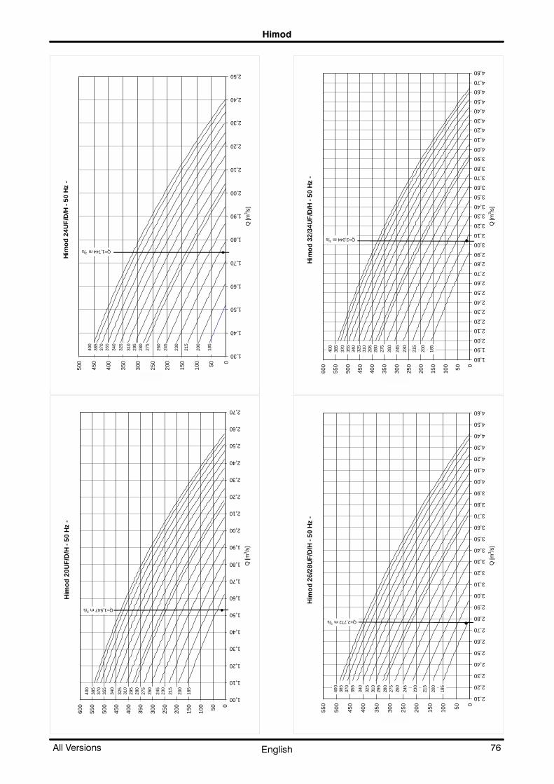
+LPRG
��$OO 9HUVLRQV (QJOLVK
Him
od
20U
F/D
/H -
50 H
z -
050
100
150
200
250
300
350
400
450
500
550
600
1,00
1,10
1,20
1,30
1,40
1,50
1,60
1,70
1,80
1,90
2,00
2,10
2,20
2,30
2,40
2,50
2,60
2,70
Q [m
3 /s]
Q=1,547 m3/s
185
200
215
230
245
260
275
280
295
310
325
340
355
370
385
400
Him
od
24U
F/D
/H -
50 H
z -
050100
150
200
250
300
350
400
450
500
1,30
1,40
1,50
1,60
1,70
1,80
1,90
2,00
2,10
2,20
2,30
2,40
2,50
Q [m
3 /s]
Q=1,744 m3/s
185
200
215
230
245
260
275
280
295
310
325
340
355
370
385
400
Him
od
26/
28U
F/D
/H -
50 H
z -
050100
150
200
250
300
350
400
450
500
550
2,10
2,20
2,30
2,40
2,50
2,60
2,70
2,80
2,90
3,00
3,10
3,20
3,30
3,40
3,50
3,60
3,70
3,80
3,90
4,00
4,10
4,20
4,30
4,40
4,50
4,60
Q [m
3 /s]
Q=2,772 m3/s
185
200
215
230
245
260
275
280
295
310
325
340
355
370
385
400
Him
od
32/
34U
F/D
/H -
50 H
z -
050100
150
200
250
300
350
400
450
500
550
600
1,80
1,90
2,00
2,10
2,20
2,30
2,40
2,50
2,60
2,70
2,80
2,90
3,00
3,10
3,20
3,30
3,40
3,50
3,60
3,70
3,80
3,90
4,00
4,10
4,20
4,30
4,40
4,50
4,60
4,70
4,80
Q [m
3 /s]
Q=3,044 m3/s
185
200
215
230
245
260
275
280
295
310
325
340
355
370
385
400

+LPRG
��$OO 9HUVLRQV (QJOLVK
Him
od
40/
42/4
6UF
/D/H
- 50
Hz-
050100
150
200
250
300
350
400
450
500
550
600
2,20
2,30
2,40
2,50
2,60
2,70
2,80
2,90
3,00
3,10
3,20
3,30
3,40
3,50
3,60
3,70
3,80
3,90
4,00
4,10
4,20
4,30
4,40
4,50
4,60
4,70
4,80
4,90
Q [m
3 /s]
Q=3,308 m3/s
185
200
215
230
245
260
275
280
295
310
325
340
355
370
385
400
(40/42)
Q=3,639 m3/s
(46)
Him
od
20O
F/D
/H -
50 H
z-
050100
150
200
250
300
350
400
450
500
550
600
1,00
1,10
1,20
1,30
1,40
1,50
1,60
1,70
1,80
1,90
2,00
2,10
2,20
2,30
2,40
2,50
2,60
2,70
Q [m
3 /s]
Q=1,567 m3/s
185
200
215
230
245
260
275
280
295
310
325
340
355
370
385
400
Him
od
24O
F/D
/H -
50 H
z -
050100
150
200
250
300
350
400
450
500
1,30
1,40
1,50
1,60
1,70
1,80
1,90
2,00
2,10
2,20
2,30
2,40
2,50
Q [m
3 /s]
Q=1,764 m3/s
185
200
215
230
245
260
275
280
295
310
325
340
355
370
385
400
Him
od
26/
28O
F/D
/H -
50 H
z -
050100
150
200
250
300
350
400
450
500
550
2,10
2,20
2,30
2,40
2,50
2,60
2,70
2,80
2,90
3,00
3,10
3,20
3,30
3,40
3,50
3,60
3,70
3,80
3,90
4,00
4,10
4,20
4,30
4,40
4,50
Q [m
3 /s]
Q=2,744 m3/s
185
200
215
230
245
260
275
280
295
310
325
340
355
370
385
400

+LPRG
��$OO 9HUVLRQV (QJOLVK
Him
od
32/
34O
F/D
/H -
50 H
z -
050100
150
200
250
300
350
400
450
500
550
600
1,80
1,90
2,00
2,10
2,20
2,30
2,40
2,50
2,60
2,70
2,80
2,90
3,00
3,10
3,20
3,30
3,40
3,50
3,60
3,70
3,80
3,90
4,00
4,10
4,20
4,30
4,40
4,50
Q [m
3 /s]
Q=2,911 m3/s
185
200
215
230
245
260
275
280
295
310
325
340
355
370
385
400
Him
od
40/
42/4
6OF
/D/H
- 50
Hz
-
050100
150
200
250
300
350
400
450
500
550
2,20
2,30
2,40
2,50
2,60
2,70
2,80
2,90
3,00
3,10
3,20
3,30
3,40
3,50
3,60
3,70
3,80
3,90
4,00
4,10
4,20
4,30
4,40
4,50
Q [m
3 /s]
Q=3,294 m3/s
185
200
215
230
245
260
275
280
295
310
325
340
355
370
385
400
(40/42)
Q=3,659 m3/s
(46)

+LPRG
��$OO 9HUVLRQV (QJOLVK
Him
od
27U
C -
50 H
z -
050100
150
200
250
300
350
400
450
500
550
600
0,90
1,00
1,10
1,20
1,30
1,40
1,50
1,60
1,70
1,80
1,90
2,00
2,10
2,20
2,30
2,40
2,50
2,60
2,70
Q [m
3 /s]
230
245
260
275
280
295
310
325
340
355
370
385
400
Q=1,822 m3/s
Q=2,107 m3/s
Q=2,348 m3/s
185
200
215
Him
od
45U
C -
50 H
z -
050100
150
200
250
300
350
400
450
500
550
600
0,90
1,00
1,10
1,20
1,30
1,40
1,50
1,60
1,70
1,80
1,90
2,00
2,10
2,20
2,30
2,40
2,50
2,60
2,70
2,80
Q [m
3 /s]
230
245
260
275
280
295
310
325
340
355
370
385
400
Q=1,929 m3/s
Q=2,21 m3/s
Q=2,455 m3/s
185
200
215
Him
od
55U
C -
50 H
z -
050100
150
200
250
300
350
400
450
500
550
600
1,90
2,00
2,10
2,20
2,30
2,40
2,50
2,60
2,70
2,80
2,90
3,00
3,10
3,20
3,30
3,40
3,50
3,60
3,70
3,80
3,90
4,00
4,10
4,20
4,30
4,40
4,50
4,60
4,70
4,80
Q [m
3 /s]
Q=3,64 m3/s
Q=3,98 m3/s
Q=4,42 m3/s
230
245
260
275
280
295
310
325
340
355
370
385
185
215
200
Him
od
65U
C -
50 H
z -
050100
150
200
250
300
350
400
450
500
550
600
1,90
2,00
2,10
2,20
2,30
2,40
2,50
2,60
2,70
2,80
2,90
3,00
3,10
3,20
3,30
3,40
3,50
3,60
3,70
3,80
3,90
4,00
4,10
4,20
4,30
4,40
4,50
4,60
4,70
Q [m
3 /s]
Q=3,53 m3/s
Q=3,84 m3/s
Q=4,26 m3/s
230
245
260
275
280
295
310
325
340
355
370
385
400
185
215
200
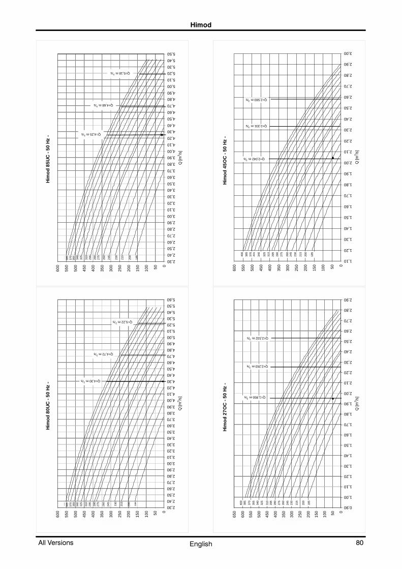
+LPRG
��$OO 9HUVLRQV (QJOLVK
Him
od
80U
C -
50 H
z -
050100
150
200
250
300
350
400
450
500
550
600
2,30
2,40
2,50
2,60
2,70
2,80
2,90
3,00
3,10
3,20
3,30
3,40
3,50
3,60
3,70
3,80
3,90
4,00
4,10
4,20
4,30
4,40
4,50
4,60
4,70
4,80
4,90
5,00
5,10
5,20
5,30
5,40
5,50
5,60
Q [m
3 /s]
Q=4,30 m3/s
230
245
260
275
280
295
310
325
340
355
370
385
400
185
215
200
Q=4,72 m3/s
Q=5,22 m3/s
Him
od
85U
C -
50 H
z -
050100
150
200
250
300
350
400
450
500
550
600
2,30
2,40
2,50
2,60
2,70
2,80
2,90
3,00
3,10
3,20
3,30
3,40
3,50
3,60
3,70
3,80
3,90
4,00
4,10
4,20
4,30
4,40
4,50
4,60
4,70
4,80
4,90
5,00
5,10
5,20
5,30
5,40
5,50
Q [m
3 /s]
Q=4,25 m3/s
Q=4,68 m3/s
Q=5,18 m3/s
230
245
260
275
280
295
310
325
340
355
370
385
400
185
215
200
Him
od
27O
C -
50 H
z -
050100
150
200
250
300
350
400
450
500
550
600
650
0,90
1,00
1,10
1,20
1,30
1,40
1,50
1,60
1,70
1,80
1,90
2,00
2,10
2,20
2,30
2,40
2,50
2,60
2,70
2,80
2,90
Q [m
3 /s]
230
245
260
275
280
295
310
325
340
355
370
385
400
Q=1,950 m3/s
Q=2,263 m3/s
Q=2,532 m3/s
185
200
215
Him
od
45O
C -
50
Hz
-
050100
150
200
250
300
350
400
450
500
550
600
1,10
1,20
1,30
1,40
1,50
1,60
1,70
1,80
1,90
2,00
2,10
2,20
2,30
2,40
2,50
2,60
2,70
2,80
2,90
3,00
Q [m
3 /s]
230
245
260
275
280
295
310
325
340
355
370
385
400
Q=2,042 m3/s
Q=2,331 m3/s
Q=2,583 m3/s
185
200
215

+LPRG
��$OO 9HUVLRQV (QJOLVK
Him
od
55O
C -
50 H
z -
050100
150
200
250
300
350
400
450
500
550
600
1,90
2,00
2,10
2,20
2,30
2,40
2,50
2,60
2,70
2,80
2,90
3,00
3,10
3,20
3,30
3,40
3,50
3,60
3,70
3,80
3,90
4,00
4,10
4,20
4,30
4,40
4,50
4,60
4,70
4,80
4,90
Q [m
3 /s]
Q=3,25 m3/s
Q=3,70 m3/s
Q=4,12 m3/s
200
215
230
245
260
275
280
295
310
340
355
370
385
400
325
Him
od
65O
C -
50 H
z -
050100
150
200
250
300
350
400
450
500
550
600
1,90
2,00
2,10
2,20
2,30
2,40
2,50
2,60
2,70
2,80
2,90
3,00
3,10
3,20
3,30
3,40
3,50
3,60
3,70
3,80
3,90
4,00
4,10
4,20
4,30
4,40
4,50
Q [m
3 /s]
Q=3,20 m3/s
Q=3,62 m3/s
Q=4,04 m3/s
185
200
215
230
245
260
275
280
295
310
340
355
370
385
400
325
Him
od
80O
C -
50 H
z -
050100
150
200
250
300
350
400
450
500
550
600
2,20
2,30
2,40
2,50
2,60
2,70
2,80
2,90
3,00
3,10
3,20
3,30
3,40
3,50
3,60
3,70
3,80
3,90
4,00
4,10
4,20
4,30
4,40
4,50
4,60
4,70
4,80
4,90
5,00
5,10
5,20
5,30
Q [m
3 /s]
Q=4,13 m3/s
Q=4,72 m3/s
Q=5,22 m3/s
185
200
215
230
245
260
275
280
295
310
340
355
370
385
325
Him
od
85O
C -
50 H
z -
050100
150
200
250
300
350
400
450
500
550
600
2,20
2,30
2,40
2,50
2,60
2,70
2,80
2,90
3,00
3,10
3,20
3,30
3,40
3,50
3,60
3,70
3,80
3,90
4,00
4,10
4,20
4,30
4,40
4,50
4,60
4,70
4,80
4,90
5,00
5,10
5,20
Q [m
3 /s]
295
325
Q=4,044 m
3/s
Q=4,62 m3/s
Q=5,12 m3/s
185
200
215
230
245
260
275
280
310
340
355
370
385
400

+LPRG
��$OO 9HUVLRQV (QJOLVK
Him
od
20U
A/W
- 60
Hz
-
050100
150
200
250
300
350
400
450
1,00
1,10
1,20
1,30
1,40
1,50
1,60
1,70
1,80
1,90
2,00
2,10
2,20
2,30
2,40
2,50
2,60
Q [m
3 /s]
Q=1,611 m3/s
420
190
208
210
230
250
270
290
320
340
360
380
400
440
460
Him
od
24U
A/W
- 60
Hz
-
050100
150
200
250
300
350
400
450
500
1,00
1,10
1,20
1,30
1,40
1,50
1,60
1,70
1,80
1,90
2,00
2,10
2,20
2,30
2,40
2,50
Q [m
3 /s]
Q=1,833 m3/s
420
190
208
210
230
250
270
290
320
340
360
380
400
440
460
Him
od
26/
28U
A/W
- 60
Hz
-
050100
150
200
250
300
350
400
2,10
2,20
2,30
2,40
2,50
2,60
2,70
2,80
2,90
3,00
3,10
3,20
3,30
3,40
3,50
3,60
3,70
3,80
3,90
4,00
4,10
4,20
Q [m
3 /s]
Q=2,772 m3/s
420
190
208
210
230
250
270
290
320
340
360
380
400
440
460
Him
od
32/
34U
A/W
- 60
Hz
-
050100
150
200
250
300
350
400
450
2,10
2,20
2,30
2,40
2,50
2,60
2,70
2,80
2,90
3,00
3,10
3,20
3,30
3,40
3,50
3,60
3,70
3,80
3,90
4,00
4,10
4,20
4,30
4,40
4,50
Q [m
3 /s]
Q=3,067 m3/s
420
190
208
210
230
250
270
290
320
340
360
380
400
440
460

+LPRG
��$OO 9HUVLRQV (QJOLVK
Him
od
40/
42/4
6UA
/W -
60 H
z -
050100
150
200
250
300
350
400
450
2,10
2,20
2,30
2,40
2,50
2,60
2,70
2,80
2,90
3,00
3,10
3,20
3,30
3,40
3,50
3,60
3,70
3,80
3,90
4,00
4,10
4,20
4,30
4,40
4,50
4,60
Q [m
3 /s]
Q=3,475 m3/s
420
190
208
210
230
250
270
290
320
340
360
380
400
440
460
Q=3,750 m3/s
(40/42)
(46)
Him
od
20O
A/W
- 60
Hz
-
050100
150
200
250
300
350
400
450
500
0,80
0,90
1,00
1,10
1,20
1,30
1,40
1,50
1,60
1,70
1,80
1,90
2,00
2,10
2,20
2,30
2,40
2,50
2,60
Q [m
3 /s]
Q=1,607 m3/s
360
190
208
210
230
250
270
290
320
420
400
380
340
440
460
Him
od
24O
A/W
- 60
Hz
-
050100
150
200
250
300
350
400
450
500
0,80
0,90
1,00
1,10
1,20
1,30
1,40
1,50
1,60
1,70
1,80
1,90
2,00
2,10
2,20
2,30
2,40
2,50
Q [m
3 /s]
190
420
208
210
230
250
270
290
320
340
360
380
400
Q=1,858 m3/s
440
460
Him
od
26/
28O
A/W
- 6
0 H
z -
050100
150
200
250
300
350
400
450
500
1,70
1,80
1,90
2,00
2,10
2,20
2,30
2,40
2,50
2,60
2,70
2,80
2,90
3,00
3,10
3,20
3,30
3,40
3,50
3,60
3,70
3,80
3,90
4,00
4,10
4,20
Q [m
3 /s]
190
208
210
230
250
270
290
320
340
360
380
400
420
Q=2,728 m3/s
440
460

+LPRG
��$OO 9HUVLRQV (QJOLVK
Him
od
32/
34O
A/W
- 6
0 H
z -
050100
150
200
250
300
350
400
450
1,70
1,80
1,90
2,00
2,10
2,20
2,30
2,40
2,50
2,60
2,70
2,80
2,90
3,00
3,10
3,20
3,30
3,40
3,50
3,60
3,70
3,80
3,90
4,00
4,10
Q [m
3 /s]
190
208
210
230
250
270
290
320
340
360
380
400
420
Q=2,997 m3/s
440
460
Him
od
40/
42/4
6OA
/W -
60
Hz
-
050100
150
200
250
300
350
400
450
500
1,70
1,80
1,90
2,00
2,10
2,20
2,30
2,40
2,50
2,60
2,70
2,80
2,90
3,00
3,10
3,20
3,30
3,40
3,50
3,60
3,70
3,80
3,90
4,00
4,10
4,20
4,30
4,40
Q [m
3 /s]
190
208
210
230
250
270
290
320
340
360
380
400
420
Q=3,463 m3/s
440
460
Q=3,667 m3/s
(40/42)
(46)

+LPRG
��$OO 9HUVLRQV (QJOLVK
Him
od
20U
F/D
/H -
60 H
z -
050100
150
200
250
300
350
400
450
1,00
1,10
1,20
1,30
1,40
1,50
1,60
1,70
1,80
1,90
2,00
2,10
2,20
2,30
2,40
Q [m
3 /s]
Q=1,547 m3/s
420
190
208
210
230
250
270
290
320
340
360
380
400
440
460
Him
od
24U
F/D
/H -
60 H
z -
050100
150
200
250
300
350
400
450
1,00
1,10
1,20
1,30
1,40
1,50
1,60
1,70
1,80
1,90
2,00
2,10
2,20
Q [m
3 /s]
Q=1,744 m3/s
420
190
208
210
230
250
270
290
320
360
340
380
400
440
460
Him
od
26/
28U
F/D
/H -
60 H
z -
050100
150
200
250
300
350
400
2,10
2,20
2,30
2,40
2,50
2,60
2,70
2,80
2,90
3,00
3,10
3,20
3,30
3,40
3,50
3,60
3,70
3,80
3,90
4,00
Q [m
3 /s]
Q=2,772 m3/s
420
190
208
210
230
250
270
290
320
340
360
380
400
440
460
Him
od
32/
34U
F/D
/H -
60
Hz
-
050100
150
200
250
300
350
400
2,10
2,20
2,30
2,40
2,50
2,60
2,70
2,80
2,90
3,00
3,10
3,20
3,30
3,40
3,50
3,60
3,70
3,80
3,90
4,00
4,10
4,20
Q [m
3 /s]
Q=3,044 m3/s
420
190
208
210
230
250
270
290
320
340
360
380
400
440
460

+LPRG
��$OO 9HUVLRQV (QJOLVK
Him
od
40/
42/4
6UF
/D/H
- 60
Hz
-
050100
150
200
250
300
350
400
2,10
2,20
2,30
2,40
2,50
2,60
2,70
2,80
2,90
3,00
3,10
3,20
3,30
3,40
3,50
3,60
3,70
3,80
3,90
4,00
4,10
4,20
4,30
Q [m
3 /s]
Q=3,308 m3/s
420
190
208
210
230
250
270
290
320
340
360
380
400
440
460
Q=3,639 m3/s
(40/42)
(46)
Him
od
20O
F/D
/H -
60 H
z -
050100
150
200
250
300
350
400
450
1,00
1,10
1,20
1,30
1,40
1,50
1,60
1,70
1,80
1,90
2,00
2,10
2,20
2,30
2,40
Q [m
3 /s]
Q=1,567 m3/s
420
190
208
210
230
250
270
290
320
340
360
380
400
440
460
Him
od
24O
F/D
/H -
60 H
z -
050100
150
200
250
300
350
400
450
1,00
1,10
1,20
1,30
1,40
1,50
1,60
1,70
1,80
1,90
2,00
2,10
2,20
Q [m
3 /s]
Q=1,764 m3/s
420
190
208
210
230
250
270
290
320
340
360
380
400
440
460
Him
od
26/
28O
F/D
/H -
60 H
z -
050100
150
200
250
300
350
400
2,10
2,20
2,30
2,40
2,50
2,60
2,70
2,80
2,90
3,00
3,10
3,20
3,30
3,40
3,50
3,60
3,70
3,80
3,90
4,00
Q [m
3 /s]
Q=2,744 m3/s
420
190
208
210
230
250
270
290
320
340
360
380
400
440
460

+LPRG
��$OO 9HUVLRQV (QJOLVK
Him
od
32/
34O
F/D
/H -
60 H
z -
050100
150
200
250
300
350
400
2,10
2,20
2,30
2,40
2,50
2,60
2,70
2,80
2,90
3,00
3,10
3,20
3,30
3,40
3,50
3,60
3,70
3,80
3,90
4,00
Q [m
3 /s]
Q=2,911 m3/s
190
208
210
230
250
270
290
320
340
360
380
400
440
460
420
Him
od
40/
42/4
6OF
/D/H
- 60
Hz
-
050100
150
200
250
300
350
400
2,10
2,20
2,30
2,40
2,50
2,60
2,70
2,80
2,90
3,00
3,10
3,20
3,30
3,40
3,50
3,60
3,70
3,80
3,90
4,00
4,10
Q [m
3 /s]
Q=3,294 m3/s
420
190
208
210
230
250
270
290
320
340
360
380
400
440
460
Q=3,569 m3/s
(40/42)
(46)

+LPRG
��$OO 9HUVLRQV (QJOLVK
Him
od
27U
C -
60 H
z -
050100
150
200
250
300
350
400
450
500
1,00
1,10
1,20
1,30
1,40
1,50
1,60
1,70
1,80
1,90
2,00
2,10
2,20
2,30
2,40
2,50
Q [m
3 /s]
Q=1,822 m3/s
420
190
208
210
230
250
270
290
320
340
360
380
400
440
460
Q=2,107 m3/s
Him
od
45U
C -
60
Hz
-
050100
150
200
250
300
350
400
450
1,00
1,10
1,20
1,30
1,40
1,50
1,60
1,70
1,80
1,90
2,00
2,10
2,20
2,30
2,40
2,50
2,60
Q [m
3 /s]
Q=1,929 m3/s
420
190
208
210
230
250
270
290
320
340
360
380
400
440
460
Q=2,210 m3/s
Him
od
55U
C -
60 H
z
050100
150
200
250
300
350
400
2,10
2,20
2,30
2,40
2,50
2,60
2,70
2,80
2,90
3,00
3,10
3,20
3,30
3,40
3,50
3,60
3,70
3,80
3,90
4,00
4,10
4,20
4,30
Q [m
3 /s]
Q=3,64 m3/s
Q=3,98 m3/s
190
208
210
230
250
270
290
320
340
360
380
Him
od
65U
C -
60 H
z
050100
150
200
250
300
350
400
2,10
2,20
2,30
2,40
2,50
2,60
2,70
2,80
2,90
3,00
3,10
3,20
3,30
3,40
3,50
3,60
3,70
3,80
3,90
4,00
4,10
4,20
4,30
Q [m
3 /s]
Q=3,53 m3/s
Q=3,84 m3/s
190
208
210
230
250
270
290
320
340
360
380
400

+LPRG
��$OO 9HUVLRQV (QJOLVK
Him
od
80U
C -
60 H
z
050100
150
200
250
300
350
400
450
2,30
2,40
2,50
2,60
2,70
2,80
2,90
3,00
3,10
3,20
3,30
3,40
3,50
3,60
3,70
3,80
3,90
4,00
4,10
4,20
4,30
4,40
4,50
4,60
4,70
4,80
4,90
Q [m
3 /s]
Q=4,30 m3/s
Q=4,72 m3/s
190
208
210
230
250
270
290
320
340
360
380
400
Him
od
85U
C -
60 H
z
050100
150
200
250
300
350
400
450
2,30
2,40
2,50
2,60
2,70
2,80
2,90
3,00
3,10
3,20
3,30
3,40
3,50
3,60
3,70
3,80
3,90
4,00
4,10
4,20
4,30
4,40
4,50
4,60
4,70
4,80
4,90
Q [m
3 /s]
Q=4,25 m3/s
Q=4,68 m3/s
190
208
210
230
250
270
290
320
340
360
380
400
Him
od
27O
C -
60 H
z -
050100
150
200
250
300
350
400
450
500
1,00
1,10
1,20
1,30
1,40
1,50
1,60
1,70
1,80
1,90
2,00
2,10
2,20
2,30
2,40
2,50
2,60
Q [m
3 /s]
Q=1,950 m3/s
420
190
208
210
230
250
270
290
320
340
360
380
400
440
460
Q=2,263 m3/s
Him
od
45O
C -
60 H
z -
050100
150
200
250
300
350
400
450
1,00
1,10
1,20
1,30
1,40
1,50
1,60
1,70
1,80
1,90
2,00
2,10
2,20
2,30
2,40
2,50
2,60
2,70
Q [m
3 /s]
Q=2,042 m3/s
420
190
208
210
230
250
270
290
320
340
360
380
400
440
460
Q=2,331 m3/s

+LPRG
��$OO 9HUVLRQV (QJOLVK
Him
od
55O
C -
60 H
z
050100
150
200
250
300
350
400
2,10
2,20
2,30
2,40
2,50
2,60
2,70
2,80
2,90
3,00
3,10
3,20
3,30
3,40
3,50
3,60
3,70
3,80
3,90
4,00
4,10
Q [m
3 /s]
Q=3,25 m3/s
Q=3,70 m3/s
190
208
210
230
250
270
290
320
340
360
380
400
420
Him
od
65O
C -
60 H
z
050100
150
200
250
300
350
400
2,10
2,20
2,30
2,40
2,50
2,60
2,70
2,80
2,90
3,00
3,10
3,20
3,30
3,40
3,50
3,60
3,70
3,80
3,90
4,00
Q [m
3 /s]
Q=3,20 m3/s
Q=3,62 m3/s
190
208
210
230
250
270
290
320
340
360
380
400
420
Him
od
80O
C -
60 H
z
050100
150
200
250
300
350
400
450
2,30
2,40
2,50
2,60
2,70
2,80
2,90
3,00
3,10
3,20
3,30
3,40
3,50
3,60
3,70
3,80
3,90
4,00
4,10
4,20
4,30
4,40
4,50
4,60
4,70
4,80
Q [m
3 /s]
Q=4,13 m3/s
Q=4,72 m3/s
190
208
210
230
250
270
290
320
340
360
380
400
Him
od
85O
C -
60 H
z
050100
150
200
250
300
350
400
450
2,30
2,40
2,50
2,60
2,70
2,80
2,90
3,00
3,10
3,20
3,30
3,40
3,50
3,60
3,70
3,80
3,90
4,00
4,10
4,20
4,30
4,40
4,50
4,60
4,70
Q [m
3 /s]
Q=4,044 m3/s
Q=4,62 m3/s
190
208
210
230
250
270
290
320
340
360
380
400

Himod
91All Versions English
11 -Options
11.1 - Filtration
High efficiency filters F5 height 100 mm
Optional high efficiency filters, of the folded type, 100mm height, interchangeable with the standard series,can be supplied in the filtration class F5 in accordancewith the CEN EN 779 standard. These filters have a high�er filtration efficiency than the standard ones with higherpressure drop.
Features of the high efficiency filters
Filtration class CEN EN 779 F5
Filter quantity for each unit 20÷24 A/W/F/D/H 27÷45 C 2
Filter quantity for each unit 26÷46 A/W/F/D/H 55÷65U A/W 55÷85 C 4
Height [mm] 100
ADDITIONAL PRESSURE DROP: F5 FILTERS SUBSTITUTING G4 FILTERS
The pressure drops shown in the tables below must be deducted from the static pressures givenin the tables of the aeraulic features.
HIMOD 20-24 U/O A/W/F/D/H 27-45 U/O C
0
50
100
150
200
1.0
0
1.1
0
1.2
0
1.3
0
1.4
0
1.5
0
1.6
0
1.7
0
1.8
0
1.9
0
2.0
0
2.1
0
2.2
0
2.3
0
2.6
0
Air flow rate [m3/s]
Pa
F5
2.4
0
2.5
0
2.7
0
3.0
0
2.8
0
2.9
0
HIMOD 26-46 U/O A/W/F/D/H 55-65 U A/W 55-85 U/O C
1.9
0
2.1
0
2.3
0
2.5
0
2.7
0
2.9
0
3.1
0
3.3
0
3.5
0
3.7
0
3.9
0
4.1
0
4.3
0
Air flow rate [m3/s]
F5
Pa
0
50
100
150
200
4.5
0
4.7
0
4.9
0

Himod
92 All VersionsEnglish
High efficiency filters F6, F7 and F9 height 290 mm
Optional high efficiency filters, filtration class F6, F7 and F9 in accordance with the CEN EN 779 stan�dard, are made of fibreglass filter media. The filters placed in "V" sections with a solid external framecan withstand remarkable pressure and flow variations. Features of high efficiency filters:
Filtration class CEN EN 779 F6 F7 F9
Filter quantity for each unit 20÷24 A/W/F/D/H 27÷45 C 1+1 1+1 1+1
Filter quantity for each unit 26÷46 A/W/F/D/H 55÷65U A/W 55÷85 C 2+1 2+1 2+1
Height [mm] 290 290 290
Installation of F6, F7 and F9 filters in addition to internal filter G4: additional pressure drops.
The pressure drops shown in the tables below must be deducted from the static pressures givenin the tables of the aeraulic features.
HIMOD 20-24 U/O A/W/F/D/H 27-45 U/O C
Air flow rate [m3/s]
Pa
0
50
100
150
200
250
300
350
F6
F9
1.0
0
1.1
0
1.2
0
1.3
0
1.4
0
1.5
0
1.6
0
1.7
0
1.8
0
1.9
0
2.0
0
2.1
0
2.2
0
2.3
0
2.4
0
2.5
0
2.6
0
2.7
0
2.8
0
2.9
0
3.0
0
F7
HIMOD 26-46 U/O A/W/F/D/H 55-65 U A/W 55-85 U/O C
Air flow rate[m3/s]
Pa
0
50
100
150
200
250
300
350
400
F6
F9
1.9
0
2.1
0
2.3
0
2.5
0
2.7
0
2.9
0
3.1
0
3.3
0
3.5
0
3.7
0
3.9
0
4.1
0
4.3
0
4.5
0
4.7
0
4.9
0
F7

Himod
93All Versions English
Filter holding duct
If 290 mm high filters are needed, a metal hood must be supplied to support them, of the same colouras the unit and installed on the top.
MODELS20�24 A/W/F/D/H
27�45C26�46 A/W/F/D/H
55�85 C
Length mm 1000 1750
Depth mm 890 890
Height mm 600 600
Clogged filter alarm
A differential flowmeter - which can be calibrated - may be installed to inform the microprocessorcontrol about the need to replace the filters when they are clogged.
11.2 - Reheating and humidity control
Electric heating (dehumidification system)
The heaters are made of aluminium with high efficien�cy fins to keep a low power density on the surfaces.The ionization effects are eliminated thanks to the lowsurface temperature of the heaters. The stages of theelectric heating coil are distributed on the threephases so as to avoid balancing problems. There arethree steps, two contactors, a temperature electroniccontrol of the ON-OFF type, a safety thermostat withmanual reset, a magnetothermal switch protectingfrom short circuits, harness protection from possible accidental contacts.When the hot water heating is installed, the dehumidification system is also operating and the rele�vant humidity sensor and indicator are provided (see "humidification and dehumidification system"for the dehumidification function). The electric heating can be installed combined with the hot gasor hot water reheating.In the 55U A/W and 65U A/W units can be installed two different electrical heating:with 11.7 kW or 17.55 kW.
Heating capacity (all electrical supply)
MODELS20�24 U/O A/W/F/D/H
27�45 U/O C
26�46 U/O A/W/F/D/H
55�85 U/O C
55�65 UA/W
55�65 UA/W
3 steps, total capacity [kW] 5.85 11.7 11.7 17.55
2 steps [kW] 3.90 7.8 7.8 11.70
1 step [kW] 1.95 3.9 3.9 5.85
Hot gas reheating (and dehumidification system for units A/W/F/D/H, optional)
Himod can be supplied with a reheating system using the heat which is normally transferred to thecondenser to heat the air, thus saving energy. This system is activated during the dehumidificationphase (in fact, the relevant humidity sensors and indicators are provided), when the temperatureis below the calibration value. In this way no additional energy is required for the reheating. A controlvalve prevents the refrigerant from flowing to the reheating coil when this is not required. Hot gasreheating is available as an alternative to hot water reheating.

Himod
94 All VersionsEnglish
Operation of electric heating and of hot gas reheating
Dehumidification function
first step second step
ON OFF ON OFF
hot gas reheatingelectric heating1st power step
hot gas reheating +electric heating 2 pow�
er steps
electric heating3rd power step
Features of hot gas reheating system
MODELSU/O A/W/F/D/H 20 24 26 28 32 34 40 42 46
55 UA/W
65 UA/W
rows [no.] 2 2 1 1 1 1 1 1 1 1 1
surface [m2] 0.432 0.432 0.882 0.882 0.882 0.882 0.882 0.882 0.882 0.882 0.882
heating capacitywith ambient tem�perature of 24�C,humidity 50%,condensing tem�perature 45�C
[kW] 12.4 15.9 10.2 20.4 12.1 23.2 29.6 14.3 18.6 20.1 22.5
Hot water heating (and dehumidification system)
The hot water heating coil made of copper pipes and aluminium fins, with one row, test pressure30 bar, includes an exhaust valve. A three-way on-off valve directly driven by the microprocessorcontrol depending on the ambient temperature and by a hot water thermostat (provided by the cus�tomer) is supplied as standard. When the hot water heating is installed, the dehumidification systemis also operating and the relevant humidity sensor and indicator are provided (see "humidificationand dehumidification system" for the dehumidification function). The hot water heating system canbe installed as an alternative to the hot gas reheating system. For the 55 and 65 HIMOD unit model,the �hot water heating" is only available in the A version at the present time.
Operation of electric heating and hot water reheating
Dehumidification function
first step second step
ON OFF ON OFF
hot water reheatingelectric heating1st power step
hot water reheating +electric heating 2 pow�
er steps
electric heating3rd power step

Himod
95All Versions English
Performances of DX units in post-heating (1)
MODELS
UNDER A/W/F/D/H20 24 26 28 32 34 40 42 46 55 65
rows [no.] 2 1
front surface [m2] 0.432 0.882
ambient temp. 24�C, 50% R.H. water inlet/outlet temperature 80/65�C.
power [kW] 21.7 22.2 29.8 29.8 29.4 29.4 32.8 32.8 34.7 24.9 26.7
water flow [l/s] 0.36 0.37 0.50 0.50 0.49 0.49 0.55 0.55 0.58 0.41 0.44
coil side pressure drops [kPa] 1 1 3 3 3 3 4 4 4 3 3
total pressure drops [kPa] 3 4 8 8 7 7 9 9 10 5 6
ambient temp. 20�C, 50% R.H. water inlet/outlet temperature 80/65�C.
power [kW] 23.3 23.8 31.7 31.7 31.3 31.3 34.8 34.8 37.0 26.4 28.3
water flow [l/s] 0.39 0.39 0.53 0.53 0.52 0.52 0.58 0.58 0.61 0.44 0.47
coil side pressure drops [kPa] 1 1 4 4 4 4 4 4 5 3 3
total pressure drops [kPa] 4 4 8 8 8 8 10 10 11 6 7
MODELS
OVER A/W/F/D/H20 24 26 28 32 34 40 42 46
rows [no.] 2 1
front surface [m2] 0.432 0.882
ambient temp. 24�C, 50% R.H. water inlet/outlet temperature 80/65�C.
power [kW] 19.9 22.7 27.2 27.2 29.4 29.4 28.1 28.1 34.9
water flow [l/s] 0.33 0.38 0.45 0.45 0.49 0.49 0.55 0.55 0.58
coil side pressure drops [kPa] 1 1 3 3 3 3 4 4 4
total pressure drops [kPa] 3 4 6 6 7 7 9 9 10
ambient temp. 20�C, 50% R.H. water inlet/outlet temperature 80/65�C.
power [kW] 21.4 24.4 28.8 28.8 31.3 31.3 35.2 35.2 37.2
water flow [l/s] 0.35 0.40 0.48 0.48 0.52 0.52 0.59 0.59 0.62
coil side pressure drops [kPa] 1 1 3 4 4 4 4 4 5
total pressure drops [kPa] 3 4 7 7 8 8 10 10 11
Performances of DX units: only heating
MODELS
UNDER A/W/F/D/H20 24 26 28 32 34 40 42 46 55 65
rows [no.] 2 1
front surface [m2] 0.432 0.882
ambient temp. 24�C, 50% R.H. water inlet/outlet temperature 80/65�C.
power [kW] 16.8 18.2 24.7 24.7 26.1 26.1 28.1 28.1 29.3 20.6 21.5
water flow [l/s] 0.28 0.30 0.41 0.41 0.43 0.43 0.47 0.47 0.49 0.34 0.36
coil side pressure drops [kPa] 1 1 3 3 3 3 3 3 3 2 2
total pressure drops [kPa] 2 3 5 5 6 6 7 7 7 4 4
ambient temp. 20�C, 50% R.H. water inlet/outlet temperature 80/65�C.
power [kW] 18.7 20.3 27.1 27.1 28.7 28.7 30.7 30.7 32.1 22.6 23.6
water flow [l/s] 0.31 0.34 0.45 0.45 0.48 0.48 0.51 0.51 0.53 0.37 0.39
coil side pressure drops [kPa] 1 1 3 3 3 3 4 4 4 2 2
total pressure drops [kPa] 3 3 6 6 7 7 8 8 9 5 5
MODELS
OVER A/W/F/D/H20 24 26 28 32 34 40 42 46
rows [no.] 2 1
front surface [m2] 0.432 0.882
ambient temp. 24�C, 50% R.H. water inlet/outlet temperature 80/65�C.
power [kW] 16.7 18.3 24.5 24.5 25.8 25.8 28.0 28.0 28.9
water flow [l/s] 0.28 0.30 0.41 0.41 0.43 0.43 0.46 0.46 0.48
coil side pressure drops [kPa] 1 1 3 3 3 3 3 3 3
total pressure drops [kPa] 2 3 5 5 6 6 7 7 7
ambient temp. 20�C, 50% R.H. water inlet/outlet temperature 80/65�C.
power [kW] 18.7 20.5 26.8 26.8 28.3 28.3 30.7 30.7 31.7
water flow [l/s] 0.31 0.34 0.44 0.44 0.47 0.47 0.51 0.51 0.53
coil side pressure drops [kPa] 1 1 3 3 3 3 4 4 4
total pressure drops [kPa] 3 3 6 6 7 7 8 8 8

Himod
96 All VersionsEnglish
Performances of CW units: post-heating (1)
UNDER C MODELS 27 45 55
Max. available pressure (2) 50 Hz [Pa] 150 250 350 150 250 350 150 250 325
Max. available pressure (2) 60 Hz [Pa] - 100 200 - 100 200 - 120 190
air flow rate [m3/s] 2.348 2.107 1.822 2.455 2.210 1.929 4.420 3.980 3.640
rows [no.] 1 2
front surface [m2] 0.432 0.882
ambient temp. 24�C, 50% R.H. water inlet/outlet temperature 80/65�C.
power [kW] 28.8 27.2 25.1 20.3 19.1 17.6 40.8 38.7 36.9
water flow [l/s] 0.48 0.45 0.42 0.34 0.32 0.29 0.68 0.64 0.61
coil side pressure drops [kPa] 2 2 2 1 1 1 6 5 5
total pressure drops [kPa] 6 5 4 3 3 2 14 13 12
ambient temp. 20�C, 50% R.H. water inlet/outlet temperature 80/65�C.
power [kW] 29.2 27.5 25.4 20.3 19.1 17.6 41 38.8 37.0
water flow [l/s] 0.48 0.46 0.42 0.34 0.32 0.29 0.68 0.65 0.62
coil side pressure drops [kPa] 2 2 2 1 1 1 6 5 5
total pressure drops [kPa] 6 5 5 3 3 2 15 13 12
UNDER C MODELS 65 80 85
Max. available pressure (2) 50 Hz [Pa] 150 250 325 150 250 320 150 250 320
Max. available pressure (2) 60 Hz [Pa] - 130 190 - 100 170 - 100 180
air flow rate [m3/s] 4.260 3.840 3.530 5.220 4.720 4.300 5.180 4.680 4.250
rows [no.] 2
front surface [m2] 0.882
ambient temp. 24�C, 50% R.H. water inlet/outlet temperature 80/65�C.
power [kW] 41 38.9 37.2 30.6 29.1 27.6 31.2 29.5 28.0
water flow [l/s] 0.68 0.65 0.62 0.51 0.48 0.46 0.52 0.49 0.46
coil pressure drops [kPa] 6 5 5 4 3 3 4 3 3
total pressure drops [kPa] 15 13 12 9 8 7 9 8 7
ambient temp. 20�C, 50% R.H. water inlet/outlet temperature 80/65�C.
power [kW] 41.0 38.8 37.1 30.9 29.3 27.8 31.3 29.6 28.1
water flow [l/s] 0.68 0.65 0.62 0.51 0.49 0.42 0.52 0.49 0.47
coil pressure drops [kPa] 6 5 5 4 3 3 4 3 3
total pressure drops [kPa] 15 13 12 9 8 7 9 8 7
OVER C MODELS 27 45 55
Max. available pressure (2) 50 Hz [Pa] 150 250 350 150 250 350 150 250 345
Max. available pressure (2) 60 Hz [Pa] - 100 200 - 100 200 - 120 210
air flow rate [m3/s] 2.532 2.263 1.950 2.583 2.331 2.042 4.120 3.700 3.250
rows [no.] 1 2
front surface [m2] 0.432 0.882
ambient temp. 24�C, 50% R.H. water inlet/outlet temperature 80/65�C.
power [kW] 29.9 28.2 26.0 20.9 19.7 18.2 39.7 37.5 35.1
water flow [l/s] 0.50 0.47 0.43 0.35 0.33 0.30 0.66 0.62 0.58
coil side pressure drops [kPa] 2 2 2 1 1 1 5 5 4
total pressure drops [kPa] 6 5 5 3 3 3 15 12 11
ambient temp. 20�C, 50% R.H. water inlet/outlet temperature 80/65�C.
power [kW] 30.4 28.6 26.3 20.9 19.7 18.2 39.8 37.6 35.1
water flow [l/s] 0.50 0.47 0.44 0.35 0.33 0.30 0.66 0.63 0.58
coil side pressure drops [kPa] 2 2 2 1 1 1 5 5 4
total pressure drops [kPa] 6 6 5 3 3 3 15 12 11

Himod
English 97All Versions
OVER C MODELS 65 80 85
Max. available pressure (2) 50 Hz [Pa] 150 250 355 150 250 335 150 250 330
Max. available pressure (2) 60 Hz [Pa] - 140 220 - 95 200 - 90 190
air flow rate [m3/s] 4.040 3.620 3.200 5.220 4.720 4.130 5.120 4.620 4.040
rows [no.] 2
front surface [m2] 0.882
ambient temp. 24�C, 50% R.H. water inlet/outlet temperature 80/65�C.
power [kW] 40.1 37.9 35.5 30.6 29.0 27.0 30.9 29.2 27.2
water flow [l/s] 0.67 0.63 0.59 0.51 0.48 0.45 0.51 0.49 0.45
coil pressure drops [kPa] 5 5 5 4 3 3 4 3 3
total pressure drops [kPa] 14 13 11 9 8 7 9 8 7
ambient temp. 20�C, 50% R.H. water inlet/outlet temperature 80/65�C.
power [kW] 40.0 37.8 35.3 30.9 29.2 27.2 31.0 29.3 27.3
water flow [l/s] 0.67 0.63 0.59 0.51 0.49 0.45 0.52 0.49 0.45
coil pressure drops [kPa] 5 5 5 4 3 3 4 3 3
total pressure drops [kPa] 14 12 11 9 8 7 9 8 7
Performances of CW units: only heating
UNDER C MODELS 27 45 55
Max. available pressure (2) 50 Hz [Pa] 150 250 350 150 250 350 150 250 325
Max. available pressure (2) 60 Hz [Pa] - 100 200 - 100 200 - 120 190
air flow rate [m3/s] 2.348 2.107 1.822 2.455 2.210 1.929 4.420 3.980 3.640
rows [no.] 1 2
front surface [m2] 0.432 0.882
ambient temp. 24�C, 50% R.H. water inlet/outlet temperature 80/65�C.
power [kW] 22.3 20.9 19.2 15.1 14.1 12.9 32.1 30.3 28.8
water flow [l/s] 0.37 0.35 0.32 0.25 0.23 0.21 0.53 0.50 0.48
coil side pressure drops [kPa] 1 1 1 1 1 1 4 4 3
total pressure drops [kPa] 4 3 3 3 2 1 9 8 8
ambient temp. 20�C, 50% R.H. water inlet/outlet temperature 80/65�C.
power [kW] 24.7 23.2 21.3 16.6 15.6 14.3 35.1 33.2 31.5
water flow [l/s] 0.41 0.38 0.35 0.27 0.26 0.24 0.58 0.55 0.52
coil side pressure drops [kPa] 2 1 1 1 1 1 4 4 4
total pressure drops [kPa] 4 4 3 2 2 2 11 10 9
UNDER C MODELS 65 80 85
Max. available pressure (2) 50 Hz [Pa] 150 250 325 150 250 320 150 250 320
Max. available pressure (2) 60 Hz [Pa] - 130 190 - 100 170 - 100 180
air flow rate [m3/s] 4.260 3.840 3.530 5.220 4.720 4.300 5.180 4.680 4.250
rows [no.] 2
front surface [m2] 0.882
ambient temp. 24�C, 50% R.H. water inlet/outlet temperature 80/65�C.
power [kW] 31.4 29.7 28.3 23.9 22.5 21.3 23.8 22.4 21.2
water flow [l/s] 0.52 0.49 0.47 0.39 0.37 0.35 0.39 0.37 0.35
coil pressure drops [kPa] 4 3 3 3 2 2 2 2 2
total pressure drops [kPa] 9 8 7 5 5 5 5 5 4
ambient temp. 20�C, 50% R.H. water inlet/outlet temperature 80/65�C.
power [kW] 34.5 32.5 31.0 26.1 24.7 23.4 26.4 24.6 23.2
water flow [l/s] 0.57 0.54 0.52 0.43 0.41 0.39 0.43 0.41 0.38
coil pressure drops [kPa] 4 4 4 3 3 2 3 3 2
total pressure drops [kPa] 11 10 9 6 6 5 6 6 5

Himod
98 All VersionsEnglish
OVER C MODELS 27 45 55
Max. available pressure (2) 50 Hz [Pa] 150 250 350 150 250 350 150 250 345
Max. available pressure (2) 60 Hz [Pa] - 100 200 - 100 200 - 120 210
air flow rate [m3/s] 2.532 2.263 1.950 2.583 2.331 2.042 4.120 3.700 3.250
rows [no.] 1 2
front surface [m2] 0.432 0.882
ambient temp. 24�C, 50% R.H. water inlet/outlet temperature 80/65�C.
power [kW] 23.4 21.9 20.0 15.5 14.6 13.4 30.9 29.1 27.0
water flow [l/s] 0.39 0.36 0.33 0.26 0.24 0.22 0.51 0.48 0.45
coil side pressure drops [kPa] 1 1 1 1 1 1 4 3 3
total pressure drops [kPa] 4 4 3 2 2 2 9 8 7
ambient temp. 20�C, 50% R.H. water inlet/outlet temperature 80/65�C.
power [kW] 25.9 24.2 22.1 17.2 16.2 14.9 31.3 31.8 29.6
water flow [l/s] 0.43 0.40 0.37 0.28 0.27 0.24 0.56 0.53 0.49
coil side pressure drops [kPa] 2 2 1 1 1 1 4 4 3
total pressure drops [kPa] 5 4 4 2 2 2 10 9 8
OVER C MODELS 65 80 85
Max. available pressure (2) 50 Hz [Pa] 150 250 355 150 250 335 150 250 330
Max. available pressure (2) 60 Hz [Pa] - 140 220 - 95 200 - 90 190
air flow rate [m3/s] 4.040 3.620 3.200 5.220 4.720 4.130 5.120 4.620 4.040
rows [no.] 2
front surface [m2] 0.882
ambient temp. 24�C, 50% R.H. water inlet/outlet temperature 80/65�C.
power [kW] 30.5 28.7 26.8 23.9 22.5 20.8 23.6 22.2 20.6
water flow [l/s] 0.51 0.48 0.44 0.39 0.37 0.34 0.39 0.37 0.34
coil pressure drops [kPa] 4 3 3 3 2 2 2 2 2
total pressure drops [kPa] 8 8 7 5 5 4 5 5 4
ambient temp. 20�C, 50% R.H. water inlet/outlet temperature 80/65�C.
power [kW] 33.5 31.5 29.3 26.1 24.7 22.8 25.9 24.4 22.6
water flow [l/s] 0.56 0.52 0.49 0.43 0.41 0.38 0.43 0.40 0.37
coil pressure drops [kPa] 4 4 3 3 3 2 3 3 2
total pressure drops [kPa] 10 9 8 6 6 5 6 6 4
1. Cooled water in/out 7/12 °C.
2. Max. available external static pressure for indicated air flow.
NOTE: Standard air flow for DX unit. Under unit ESP = 20 Pa - Over unit ESP = 50 Pa.

Himod
English 99All Versions
Additional pressure drop of the reheating coils
The pressure drops shown in the tables below must be deducted from the static pressures givenin the tables of the aeraulic features.
Pressure drop, MODELS 20÷24 U/O A/W/F/D/H 27÷45 U/O C
Pa
Air flow rate[m3/s]
0
10
20
30
40
50
60
70
1.00
1.10
1.20
1.30
1.40
1.50
1.60
1.70
1.80
1.90
2.00
2.10
2.20
2.30
2.40
2.50
2.60
2.70
2.80
2.90
3.00
Pressure drop, MODELS 26÷46 U/O A/W/F/D/H 55÷65 U A/W 55÷85 U/O C
Pa
Air flow rate[m3/s]
0
2
4
6
8
10
12
14
16
1.9
0
2.1
0
2.3
0
2.5
0
2.7
0
2.9
0
3.1
0
3.3
0
3.5
0
3.7
0
3.9
0
4.1
0
4.3
0
4.5
0
4.7
0
4.9
0

Himod
100 All VersionsEnglish
11.3 - Humidification and dehumidification system
The humidification system is provided by a HUMIDAIRelectronic humidifier. The dehumidification function,which is supplied as standard when the humidifier op�tion is installed, acts by switching on the compressorand reducing the fan speed with consequent reduc�tion of the air flow (models A/W/F/D/H) or by com�pletely opening the chilled water three-way valve(models C).
Electronic humidity control
The software of the Hiromatic microprocessor control includes the algorithm which manages theHUMIDAIR electronic modulating humidifier and provides the dehumidification function. There isalso a special function which automatically prevents the dehumidification if the temperature is belowthe required value; when the temperature reaches the correct values, the dehumidification functionis automatically reactivated. The dehumidification control may be of the proportional or of the on-offtype, according to the requirements of every installation: the on-off system is set as standard bythe manufacturer.
HUMIDAIR electric steam humidifier
HUMIDAIR is a steam cylinder with immersed electrodeswhich produces the required quantity of steam. It is suitablefor a large range of water qualities (with varying degrees ofhardness) provided that it isn't treated or demineralized. Italmost instantaneously produces clean, particle-freesteam, letting electric current pass through the water con�tained in the replaceable plastic cylinder, thus avoiding ener�gy losses which are typical of other systems. HUMIDAIR isprovided with the steam cylinder, water inlet and outletvalves and a maximum level sensor. The steam output canbe adjusted within a range of values which can be chosenmanually and are set by the manufacturer at 70% of the maxi�mum capacity (see the relevant features).
Humidifier features
The steam cylinder is installed out of the air flow to avoid heat losses; the steam is mixed with thedelivery air of the evaporating coil by means of a suitable distributor.The Hiromatic control can deter�mine when the cylinder has to be changed. Replacing the cylinder is extremely easy and quick. Aself-adaptive flow control system is fitted as standard and controls the current passing through thecylinder water.
HUMIDAIRMODEL
MAIN POWERSUPPLIES
SETTINGABSORBEDCURRENT
POWER
MODEL SUPPLIES[kg/h] [A] [kW]
HAK93H 400V / 3ph / 50Hz 10.3 7.3
HAK93L 208-230V / 3ph / 60Hz2 7 9 0
17.2 6.2
HAK93H 380V / 3ph / 60Hz2.7 - 9.0
10.8 7.3
HAK93H 460V / 3ph / 60Hz 9.1 7.3

Himod
101All Versions English
11.4 - Water valve (models W/H)
A modulating valve controls the condensing pressure by regulating thewater flow to the plate condenser. It is installed at the condenser outletwith the pressure probe positioned on the refrigerant discharge line. It isautomatically closed when the compressor is not operating. Thus it ispossible to obtain a cost reduction and to optimize water consumption.It is sized for inlet water flow values at a temperature lower than 17�C(mains/well water) resulting in low pressure drop values. To determine aproper water flow value depending on the specific operating conditionsrefer to the tables giving the performance of the W/H units. For higher wa�ter inlet temperatures (tower water/Dry cooler) higher water flows are re�quired.
Features of water regulating valves; inlet water temperature > 18�C/glycol 0% (valve completely open)
MODELS 20U/OW/H
24U/OW/H
28U/OW/H
34U/OW/H
40U/OW/H
26U/OW/H(*)
32U/OW/H(*)
42U/OW/H(*)
46U/OW/H(*)
55UW(*)
65UW(*)
outlet connectionsinch
BSP int.1" 1" 1 1/4" 1 1/4" 1 1/4" 3/4" 3/4" 1" 1" 11/4" 11/4"
code 378203 378203 378204 378204 378204 378202 378202 378203 378203 378204 378204
valve pressure drop at 0.4 l/s kPa 7 7 - - - - - - - - -
valve pressure drop at 0.5 l/s kPa 11 11 - - - - - - - - -
valve pressure drop at 0.6 l/s kPa 15 15 - - - - - - - - -
valve pressure drop at 0.7 l/s kPa 21 21 - - - 13 13 - -
valve pressure drop at 0.8 l/s kPa 27 27 7 7 7 18 18 7 7 7 7
valve pressure drop at 1.0 l/s kPa - - 10 10 10 27 27 11 11 10 10
valve pressure drop at 1.2 l/s kPa - - 15 15 15 40 40 15 15 15 15
valve pressure drop at 1.4 l/s kPa - - 20 20 20 - - 21 21 20 20
valve pressure drop at 1.6 l/s kPa - - 27 27 27 - - 27 27 27 27
valve pressure drop at 1.8 l/s kPa - - 35 35 35 - - 35 35 35 35
(*) Two valves are fitted, one for each refrigeration circuit.
11.5 - Flooding alarm (Liquistat)
The flooding alarm perceives the presence of water or of another conductive liquid and, openinga circuit, activates an alarm.There are no moving parts and it is not subject to dirt or vibration. Several sensors can be connectedto the same flooding alarm device to control many points in the room. The alarm device is suppliedwith a sensor. Additional sensors can be ordered separately.
11.6 - Smoke alarm (Smokestat)
A smoke alarm can be installed to stop the conditioning systemwhen the presence of smoke in the intake air is perceived. This isan optical smoke detector (it uses the Tyndall effect), which ab�sorbs very low current (100mA) and is absolutely insensitive to lightor wind.
11.7 - Fire alarm (Firestat)
In some applications the fire regulations require the installation of an alarm device (Firestat) whichdeactivates the air conditioner when the intake air temperature is too high.

Himod
102 All VersionsEnglish
11.8 - Fresh air kit
The fresh air kit, which has a G3 class filter installed on the intake side of the fan, is connected bya 100 mm diameter plastic duct. The connection is located in the lower part of the unit for an easierand quicker installation.As the fresh air intake is positioned close to the fan suction, it will easily mix with the recirculationair.
MODELSFresh air for clean filters, (dirty filters)**
(l/s)
20�24U A/W/F/D/H 33 (29) 30 (26)
26�46U A/W/F/D/H 55U/65U A/W 38 (33) 29 (27)
20�24O A/W/F/D/H 39 (34) 30 (26)
26�46O A/W/F/D/H 40 (36) 31 (29)
27�45 OC 39 (34) 30 (26)
27�45 U C 33 (29) 30 (26)
55�85 U/O C 41 (36) 31 (29)
equivalent length* (m) 12 24
* A 90� curve corresponds to approx. 2 m of linear duct.** Intake duct diameter �=100mm
11.9 - Intake and delivery hoods
Himod can be equipped with intake and supply ducts on the top for con�nection of the unit to a false ceiling. The air duct is manufactured to com�plement the design of the unit; it consists of sandwich panels lined withnon-flammable insulation material of class 0 (ISO 1182.2), density 30kg/m3; its height ranges between 500 mm and 1200 mm.
11.10 -Silencing cartridges for supply hoods - Silent Carts (Over models)
These are special cartridges made of self-extinguishing material with ahigh noise attenuation capacity. They are guaranteed against disintegra�tion and release of particles which could occur as a consequence of fric�tion within the duct.
It is possible to install one or two rows of cartridges in the supply hoodby fitting them from the top: one single row for a 600 mm or 900 highhood, two rows for a hood height ranging between 1200 mm and 1500mm.
Despite a small additional pressure drop, these cartridges provide a re�markable sound power level reduction: -8.5 dB(A) at 2 m front distanceand at 1.5 m from the ground; -13 dB(A) at 1 m front distance and at 45� from the unit top with acartridge row in a 1200-mm-high hood; -9.5 dB(A) and -14 dB(A), in the same conditions, withan additional cartridge row.
The reduction values refer to the comparison with noise values measured for each unit at free dis�charge.

Himod
103All Versions English
Features of the cartridges
ModelsDimensions Free section cartridge number
Models[mm] [mm] 1 row 2 rows
20�24 27�45 500 x 195 x 500 400 x 100 4 8
26�46 55�65 55�85 500 x 195 x 500 400 x 100 9 18
Attenuation in dB
row noAttenuation in dB at different frequency values (Hz)
row no.63 125 250 500 1000 2000 4000 8000
1 1 4 7 15 26 28 27 14
2 1 6 12 27 49 53 49 23
Pressure drops
row noPressure drops (Pa) for each module at the different air flows (m3/s)
row no.0.2 0.3 0.4 0.5 0.6
1 1 2 4 7 9
2 3 6 11 18 26
11.11 -HiSAS - Semi-activer silencer (Under models)
The control of noise is always assuming a great importance in thesector of precision air conditioning.HiSAS technologically represents the most advanced solution forthe noise control in the field of HPAC based on the principle of ac�tive noise control.The sound attenuation is equal to around 10 dB(A); the noise de�molition in frequency is superior to any other conventional system.(For more details refer to the manual code 271605).
11.12 -Delivery plenum with horizontal flow (Over models)
A supply plenum with horizontal air flow can be installed on top of theunit. The 600 or 900 mm high plenum has the same design as the unit;it consists of sandwich panels lined with non-flammable insulationmaterial of class 0 (ISO 1182.2), density 30 kg/m3. It is equipped witha double deflection grille.
A single deflection grille can be supplied on request.
11.13 -Adjustable Louvred Grille (Over models)
As an option, an adjustable louvre grille can be supplied separately; this may be installed on top ofthe unit or in the plenum opening. In this way, the supply air can be deflected from the horizontal,upwards or downwards. We advise against extreme deflection of the louvres which can obstruct theair flow and reduce cooling capacity of the unit.
11.14 -Base frames: TBD models
When required, a base frame adjustable in height by ±25 mm can besupplied. Three sizes are available: height � 300 mm; � 500 mm; �800mm.
MODELSwidth[mm]
depth[mm]
20�24 27�45 990 885
26�46 55�65 55�85 1740 885

Himod
104 All VersionsEnglish
11.15 -Base modules (Over models)
A 200 mm high base module can be supplied on request tosupport the Himod Over units and to allow pipework to enterthe base of the unit when a raised floor is not installed. In thiscase the air conditioning unit must be ordered with a blindfront panel.
11.16 -Automatic pump for condensate discharge
The Himod's condensate drain piping can be connected to a pump complete with a flow cutout al�lowing the pump to stop and reset automatically.
Features of the automatic pump for condensate discharge
water flow [l/s] 0.083 0.167 0.250 0.333
available head [kPa] 20 19 18 14
11.17 -Non-return valves (models A and D)
For air-condensed units, a non-return valve is supplied on request in a separate kit. It should beinstalled on the liquid line near the condenser, vertically with downward flow. The installation of thisvalve is absolutely necessary when the total charge of the system exceeds the values given in thetable:
MODELSMax. refrigerant charge without non-return valve
[kg x circuit]
20-24 xA/D 50-60Hz 4.5
28 xAD 50Hz 10.0
28 xAD 60Hz 4.5
34 xA/D 50-60Hz 10.0
40 xA/D 50Hz 7.7
40 xA/D 60Hz 10.0
26-32-42-46 xA/D (*) 50-60Hz 4.5
55-65 UA (*) 50Hz 4.5
(*) Models with double refrigeration circuit
11.18 -Additional temperature and humidity sensor (EEAP)
EEAP (Environmental Alarm Package) is an additional temperature and relative humidity sensor sim�ilar to the humitemp sensor.The sensor can be installed in a suitable place up to 20 m from the air conditioner which generatesan alarm if the temperature or the relative humidity exceeds one of the four thresholds that can beselected by the user:
High temperature (from 10�C to 50�C)low temperature (from 0�C to 30�C)high relative humidity (from 30% to 99%)low relative humidity (from 10% to 70%).

Himod
105All Versions English
11.19 -Microprocessor control with graphic display (HIROMATIC G)
The Hiromatic graphic terminal is particularly suitable for group management. Indeed, thanks to thegenerous dimensions of the display and to the exceptional contrast, it allows the user to movearound freely within the Microface network. Therefore, from a single point, it is possible to controlthe whole system without moving from one unit to another. The last 200 events occurring in the sys�tem; the graphic development of the last 24 hours for each of the units connected (stored since thelast start-up), the user's menus available in 8 languages and connectivity through RS 422 to theHirolink Communication Manager are just some of the features available with Hiromatic. Moreover,as Hiromatic can be supplied in kit form, it may be installed either on the unit or on a remote panelfor primary supervision of the system.
Hiromatic controls the date and time functions using them as operating information for the customerand as a reference whenever a status change occurs, causing the storage in the Report status. Inaddition, details of the event which occurred, the date and time at which the event occurred arestored as well. Thanks to the buffered RAM it is possible to store the operating hours of each compo�nent (compressor, fan, electric heaters, humidifier) of the various interconnected units.
In addition to the date-time function, there is a function for stand-by unit rotation which can beactivated only by means of Hiromatic at a preset time of day. This is different from the Microface func�tion, in which the rotation occurs when 24 operating hours of one unit have been reached.
Finally, Hiromatic allows the Microface units to be integrated with Hirolink; for this purpose it is neces�sary to install a RS422 card at the back of Hiromatic. In this way, Hiromatic can control up to 8 Micro�face units and communicate the relevant data to Hirolink.

Himod
106 All VersionsEnglish
Serial communication
Integration
Hirolink is the key to the integration; it works as 'communication manager' between the Hiromatic-Microface units and all the foremost supervision systems available on the market. It also providesthe link with our supervision system, which is the ideal solution for all integration requirements withinthe intelligent building. This permits local access to the units or, as an alternative, modem connectionto supervise several installations from a single point.
The components necessary for integration are shown in the picture above. The only 'variations' arethe software installed on Hirolink and the relevant hardware configuration which determines a differ�ent code.
11.20 -Special packing
Special packing for sea transport, consisting of a wooden box or crate, can be supplied on request.
11.21 -Air intake from the bottom (Over models)
Himod units can be supplied to permit air intake from below. In this case, the front panel with intakegrille is replaced by a special blind panel, which further reduces noise levels.
11.22 -Dampers
Himod units can be provided with motorised over-pressure dampers forthe Under version and gravity dampers for the Over model.

Himod
107All Versions English
11.23 -Accessory combination
Silencing cartridges
High efficiency filters
Horizontal input/outputgrille
Damper
Base frame
600/900
600/900 mm
Extension hood
500�1200

Himod
108 All VersionsEnglish
12 -Overall dimensions
5 5051740
40
890
19
50
1750
5 990 5
1000
5 5051740
40
890
19
50
1750
5 990 5
1000
20-24A/W/F/D/H
27-45C
26-46A/W/F/D/H
55-85C 55-65A
20-24A/W/F/D/H
27-45C
26-46A/W/F/D/H
55-85C
88550 5
300
1950
2250
5 51740
1750
55-65W
Un
de
r ve
rsio
nO
ve
r ve
rsio
n


Liebert HIROSS S.p.A.Zona Industriale TognanaVia Leonardo da Vinci, 8
35028 Piove di Sacco (PD)ITALY
TEL. +39.049.97.19.111FAX +39.049.58.41.257
Internet: www.Liebert-HIROSS.com


